

Page 1

SERVICE MANUAL
HFC
utilized
R410A
R410A REFRIGERANT
No. OBR01
CONTENTS
1. INFORMATION FOR THE AIR CONDITIONER
WITH R410A REFRIGERANT ···························2
2. TOOLS DEDICATED FOR THE AIR
CONDITIONER WITH R410A REFRIGERANT ·3
3. REFRIGERANT PIPING·····································3
4. REFRIGERANT OIL ·····················BACK COVER
5. ADDITIONAL CHARGE ···············BACK COVER
NOTE:
This service manual describes treatment of the air conditioner with R410A refrigerant.
Page 2
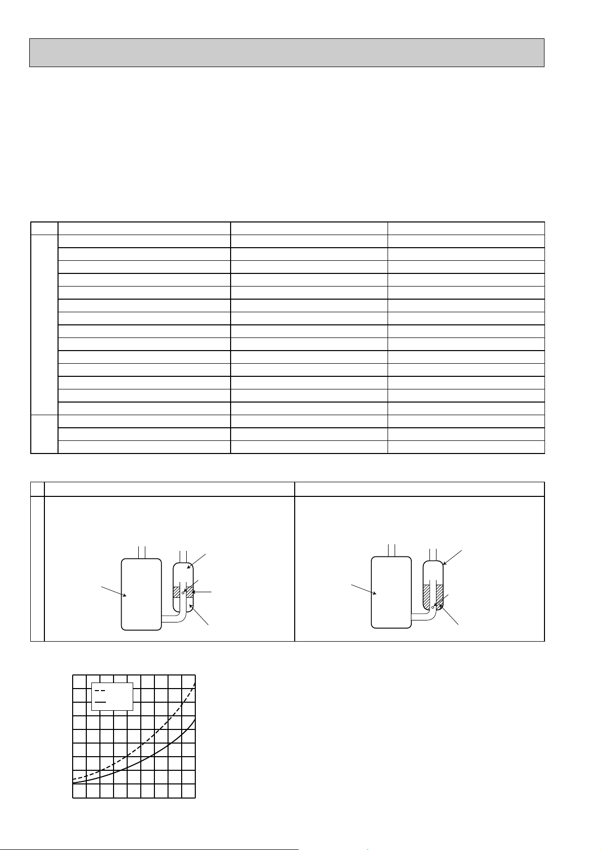
New Specification Current Specification
The incompatible refrigeration oil easily separates from
refrigerant and is in the upper layer inside the suction muffler.
Raising position of the oil back hole enables to back the
refrigeration oil of the upper layer to flow back to the
compressor.
Since refrigerant and refrigeration oil are compatible each,
refrigeration oil goes back to the compressor through the
lower position oil back hole.
Compressor
Suction muffler
Oil back hole
refrigeration oil
Refrigerant
Compressor
Suction muffler
Oil back hole
refrigeration oil /Refrigerant
Compressor
Refrigeration
oil
Refrigerant
New refrigerant
R410A
HFC-32: HFC-125 (50%:50%)
Pseudo-azeotropic refrigerant
Not included
A1/A1
72.6
-51.4
1.557
64
Non combustible
0
1730
From liquid phase in cylinder
Possible
Incompatible oil
Non
Non
Previous refrigerant
R22
R22 (100%)
Single refrigerant
Included
A1
86.5
-40.8
0.94
44.4
Non combustible
0.055
1700
Gas phase
Possible
Compatible oil
Light yellow
Non
Refrigerant
Composition (Ratio)
Refrigerant handling
Chlorine
Safety group (ASHRAE)
Molecular weight
Boiling point (:)
Steam pressure [25:](Mpa)
Saturated steam density [25:](Kg/K)
Combustibility
ODP w1
GWP w2
Refrigerant charge method
Additional charge on leakage
Kind
Color
Smell
w1:Ozone Destruction Parameter : based on CFC-11
w2 :Global Warmth Parameter : based on CO
2
1. INFORMATION FOR THE AIR CONDITIONER WITH R410A REFRIGERANT
-30 -20 -10 0 10 203040 50 60
-0.5
0.0
0.5
1.0
1.5
2.0
2.5
3.0
3.5
4.0
(MPa [Gauge])
R410A
R22
Conversion chart of refrigerant temperature and pressure
Saturated liquid pressure
(:)
• This room air conditioner adopts HFC refrigerant (R410A) which never destroys the ozone layer.
• Pay particular attention to the following points, though the basic installation procedure is same as that for R22 air
conditioners.
1 As R410A has working pressure approximate 1.6 times as high as that of R22, some special tools and piping parts/
materials are required. Refer to the table below.
2 Take sufficient care not to allow water and other contaminations to enter the R410Arefrigerant during storage and
installation, since it is more susceptible to contaminations than R22.
3 For refrigerant piping, use clean, pressure-proof parts/materials specifically designed for R410A.
(Refer to 3. REFRIGERANT PIPING.)
4 Composition change may occur in R410A since it is a mixed refrigerant. When charging, charge liquid refrigerant to prevent
composition change.
NOTE : The unit of pressure has been changed to MPa on the
international system of units(SI unit system).
The conversion factor is: 1(MPa [Gauge]) =10.2(kgf/
2
ff
[Gauge])
Page 3

2. TOOLS DEDICATED FOR THE AIR CONDITIONER WITH R410A REFRIGERANT
Wall thickness
(mm)
(mm)
6.35
9.52
12.7
15.88
0.8
0.8
0.8
1.0
Heat resisting foam plastic
Specific gravity 0.045 Thickness 8 mm
Insulation material
Outside diameter
of pipe
R410A
6.35
9.52
12.7
15.88
17
22
26
29
R22
17
22
24
27
R410A
Outside diameter
of pipe
6.35
9.52
12.7
15.88
9.1
13.2
16.6
19.7
B (mm)
R22
9
13
16.2
19.4
Pipe dimension for flaring work
Dimension of flare nut
( )
+0
-4
C (mm)
Outside diameter
of pipe
Outside diameter
of pipe
Carry out flaring work using flaring tool as shown below.
.
Firmly hold copper pipe in a die in the dimension shown in the table above.
A (mm)
Conventional flare tool
(mm)
Clutch type
[6.35
[9.52
[12.7
[15.88
0 to 0.5
0 to 0.5
0 to 0.5
0 to 0.5
1.0 to 1.5
1.0 to 1.5
1.0 to 1.5
1.0 to 1.5
Flare tool for R410A
Clutch type
A
Die
Copper pipe
Flaring tool
Clutch type
(mm)
Flare nut
Copper pipe
C
B
2 Flaring work and flare nut
(mm)
The following tools are required for R410A refrigerant. Some R22 tools can be substituted for R410A tools.
The diameter of the service port on the stop valve in outdoor unit has been changed to prevent any other refrigerant being
charged into the unit. Cap size has been changed from 7/16 UNF with 20 threads to 1/2 UNF with 20 threads.
R410A tools Can R22 tools be used?
Description
R410A has high pressures beyond the measurement range of existing
Gauge manifold
No
gauges. Port diameters have been changed to prevent any other refrigerant
from being charged into the unit.
Charge hose
Gas leak detector
Torque wrench
No
No
Yes
Hose material and cap size have been changed to improve the pressure
resistance.
Dedicated for HFC refrigerant.
6.35 mm and 9.52 mm
No 12.7 mm and 15.88 mm
Flare tool
Flare gauge
Vacuum pump
adapter
Electronic scale for
refrigerant charging
Yes
New
New
New
Clamp bar hole has been enlarged to reinforce the spring strength in the tool.
Provided for flaring work (to be used with R22 flare tool).
Provided to prevent the back flow of oil. This adapter enables you to use
vacuum pumps.
It is difficult to measure R410A with a charging cylinder because the
refrigerant bubbles due to high pressure and high-speed vaporization
No : Not Substitutable for R410A Yes : Substitutable for R410A
3. REFRIGERANT PIPING
1 Specifications
Use the copper or copper-alloy seamless pipe for refrigerant that meet the following specifications.
3
Page 4

4. REFRIGERANT OIL
Apply the special refrigeration oil (accessories: packed with indoor unit) to the flare and the union seat surfaces.
CAUTION
• Do not discharge the refrigerant into the atmosphere.
Take care not to discharge refrigerant into the atmosphere during installation, reinstallation, or repairs to the refrigerant
circuit.
• Use the vacuum pump for air purging for the purpose of environmental protection.
5. ADDITIONAL CHARGE
For additional charging, charge the refrigerant from liquid phase of the gas cylinder.
If the refrigerant is charged from the gas phase, composition change may occur in the refrigerant inside the cylinder and the
outdoor unit. In this case, ability of the refrigeration cycle decreases or normal operation can be impossible. However,
charging the liquid refrigerant all at once may cause the compressor to be locked. Thus, charge the refrigerant slowly.
Union
Stop valve
Indoor unit
Refrigerant gas
cylinder
operating valve
Charge hose (for R410A)
Refrigerant gas cylinder
for R410A with siphon
Liquid pipe
Gas pipe
Service port
Gauge manifold
valve (for R410A)
Outdoor unit
Refrigerant (liquid)
Electronic scale for refrigerant charging
HEAD OFFICE: TOKYO BLDG., 2-7-3, MARUNOUCHI, CHIYODA-KU, TOKYO 100-8310, JAPAN
CC
Copyright 2006 MITSUBISHI ELECTRIC ENGINEERING CO.,LTD
Distributed in Mar. 2006. No. OBR01 6
Made in Japan
New publication, effective Mar. 2006
Specifications subject to change without notice.
 Loading...