

Page 1

MELSEC iQ-R Motion Controller
User's Manual
-R16MTCPU
-R32MTCPU
-R64MTCPU
Page 2

Page 3
SAFETY PRECAUTIONS
WARNING
Indicates that incorrect handling may cause hazardous conditions, resulting in
death or severe injury.
CAUTION
Indicates that incorrect handling may cause hazardous conditions, resulting in
minor or moderate injury or property damage.
(Read these precautions before using this product.)
Before using this product, please read this manual and the relevant manuals carefully and pay full attention to safety to handle
the product correctly.
The precautions given in this manual are concerned with this product only. Refer to MELSEC iQ-R Module Configuration
Manual for a description of the PLC system safety precautions.
In this manual, the safety precautions are classified into two levels: " WARNING" and " CAUTION".
Under some circumstances, failure to observe the precautions given under " CAUTION" may lead to serious
consequences.
Observe the precautions of both levels because they are important for personal and system safety.
Make sure that the end users read this manual and then keep the manual in a safe place for future reference.
[Design Precautions]
WARNING
● Configure safety circuits external to the programmable controller to ensure that the entire system
operates safely even when a fault occurs in the external power supply or the programmable controller.
Failure to do so may result in an accident due to an incorrect output or malfunction.
(1) Emergency stop circuits, protection circuits, and protective interlock circuits for conflicting
operations (such as forward/reverse rotations or upper/lower limit positioning) must be configured
external to the programmable controller.
(2) When the programmable controller detects an abnormal condition, it stops the operation and all
outputs are:
• Turned off if the overcurrent or overvoltage protection of the power supply module is activated.
• Held or turned off according to the parameter setting if the self-diagnostic function of the CPU
module detects an error such as a watchdog timer error.
(3) All outputs may be turned on if an error occurs in a part, such as an I/O control part, where the
CPU module cannot detect any error. To ensure safety operation in such a case, provide a safety
mechanism or a fail-safe circuit external to the programmable controller. For a fail-safe circuit
example, refer to "General Safety Requirements" in the MELSEC iQ-R Module Configuration
Manual.
(4) Outputs may remain on or off due to a failure of a component such as a relay and transistor in an
output circuit. Configure an external circuit for monitoring output signals that could cause a
serious accident.
● In an output circuit, when a load current exceeding the rated current or an overcurrent caused by a
load short-circuit flows for a long time, it may cause smoke and fire. To prevent this, configure an
external safety circuit, such as a fuse.
● Configure a circuit so that the programmable controller is turned on first and then the external power
supply. If the external power supply is turned on first, an accident may occur due to an incorrect output
or malfunction.
1
Page 4

[Design Precautions]
WARNING
● For the operating status of each station after a communication failure, refer to manuals relevant to the
network. Incorrect output or malfunction due to a communication failure may result in an accident.
● When connecting an external device with a CPU module or intelligent function module to modify data
of a running programmable controller, configure an interlock circuit in the program to ensure that the
entire system will always operate safely. For other forms of control (such as program modification,
parameter change, forced output, or operating status change) of a running programmable controller,
read the relevant manuals carefully and ensure that the operation is safe before proceeding. Improper
operation may damage machines or cause accidents.
● Especially, when a remote programmable controller is controlled by an external device, immediate
action cannot be taken if a problem occurs in the programmable controller due to a communication
failure. To prevent this, configure an interlock circuit in the program, and determine corrective actions
to be taken between the external device and CPU module in case of a communication failure.
● Do not write any data to the "system area" and "write-protect area" of the buffer memory in the
module. Also, do not use any "use prohibited" signals as an output signal from the CPU module to
each module. Doing so may cause malfunction of the programmable controller system. For the
"system area", "write-protect area", and the "use prohibited" signals, refer to the user's manual for the
module used.
● If a communication cable is disconnected, the network may be unstable, resulting in a communication
failure of multiple stations. Configure an interlock circuit in the program to ensure that the entire
system will always operate safely even if communications fail. Failure to do so may result in an
accident due to an incorrect output or malfunction.
● To maintain the safety of the programmable controller system against unauthorized access from
external devices via the network, take appropriate measures. To maintain the safety against
unauthorized access via the Internet, take measures such as installing a firewall.
● Configure safety circuits external to the programmable controller to ensure that the entire system
operates safely even when a fault occurs in the external power supply or the programmable controller.
Failure to do so may result in an accident due to an incorrect output or malfunction.
● If safety standards (ex., robot safety rules, etc.,) apply to the system using the module, servo amplifier
and servo motor, make sure that the safety standards are satisfied.
● Construct a safety circuit externally of the module or servo amplifier if the abnormal operation of the
module or servo amplifier differs from the safety directive operation in the system.
● Do not remove the SSCNET cable while turning on the control circuit power supply of modules and
servo amplifier. Do not see directly the light generated from SSCNET connector of the module or
servo amplifier and the end of SSCNET cable. When the light gets into eyes, you may feel
something wrong with eyes. (The light source of SSCNET complies with class1 defined in JISC6802
or IEC60825-1.)
2
Page 5

[Design Precautions]
CAUTION
● Do not install the control lines or communication cables together with the main circuit lines or power
cables. Keep a distance of 100mm or more between them. Failure to do so may result in malfunction
due to noise.
● During control of an inductive load such as a lamp, heater, or solenoid valve, a large current
(approximately ten times greater than normal) may flow when the output is turned from off to on.
Therefore, use a module that has a sufficient current rating.
● After the CPU module is powered on or is reset, the time taken to enter the RUN status varies
depending on the system configuration, parameter settings, and/or program size. Design circuits so
that the entire system will always operate safely, regardless of the time.
● Do not power off the programmable controller or reset the CPU module while the settings are being
written. Doing so will make the data in the flash ROM and SD memory card undefined. The values
need to be set in the buffer memory and written to the flash ROM and SD memory card again. Doing
so also may cause malfunction or failure of the module.
● When changing the operating status of the CPU module from external devices (such as the remote
RUN/STOP functions), select "Do Not OPEN in Program" for "Open Method Setting" of "Module
Parameter". If "OPEN in Program" is selected, an execution of the remote STOP function causes the
communication line to close. Consequently, the CPU module cannot reopen the line, and external
devices cannot execute the remote RUN function.
[Installation Precautions]
WARNING
● Shut off the external power supply (all phases) used in the system before mounting or removing the
module. Failure to do so may result in electric shock or cause the module to fail or malfunction.
3
Page 6

[Installation Precautions]
CAUTION
● Use the programmable controller in an environment that meets the general specifications in the Safety
Guidelines included with the base unit. Failure to do so may result in electric shock, fire, malfunction,
or damage to or deterioration of the product.
● To mount a module, place the concave part(s) located at the bottom onto the guide(s) of the base unit,
and push in the module until the hook(s) located at the top snaps into place. Incorrect mounting may
cause malfunction, failure, or drop of the module.
● To mount a module with no module fixing hook, place the concave part(s) located at the bottom onto
the guide(s) of the base unit, push in the module, and fix it with screw(s). Incorrect mounting may
cause malfunction, failure, or drop of the module.
● When using the programmable controller in an environment of frequent vibrations, fix the module with
a screw.
● Tighten the screws within the specified torque range. Undertightening can cause drop of the screw,
short circuit, or malfunction. Overtightening can damage the screw and/or module, resulting in drop,
short circuit, or malfunction.
● When using an extension cable, connect it to the extension cable connector of the base unit securely.
Check the connection for looseness. Poor contact may cause malfunction.
● When using an SD memory card, fully insert it into the SD memory card slot. Check that it is inserted
completely. Poor contact may cause malfunction.
● Securely insert an extended SRAM cassette into the cassette connector of the CPU module. After
insertion, close the cassette cover and check that the cassette is inserted completely. Poor contact
may cause malfunction.
● Do not directly touch any conductive parts and electronic components of the module, SD memory
card, extended SRAM cassette, or connector. Doing so may cause malfunction or failure of the
module.
[Wiring Precautions]
WARNING
● Shut off the external power supply (all phases) used in the system before installation and wiring.
Failure to do so may result in electric shock or cause the module to fail or malfunction.
● After installation and wiring, attach the included terminal cover to the module before turning it on for
operation. Failure to do so may result in electric shock.
4
Page 7

[Wiring Precautions]
CAUTION
● Individually ground the FG and LG terminals of the programmable controller with a ground resistance
of 100 ohms or less. Failure to do so may result in electric shock or malfunction.
● Use applicable solderless terminals and tighten them within the specified torque range. If any spade
solderless terminal is used, it may be disconnected when the terminal screw comes loose, resulting in
failure.
● Check the rated voltage and signal layout before wiring to the module, and connect the cables
correctly. Connecting a power supply with a different voltage rating or incorrect wiring may cause fire
or failure.
● Connectors for external devices must be crimped or pressed with the tool specified by the
manufacturer, or must be correctly soldered. Incomplete connections may cause short circuit, fire, or
malfunction.
● Securely connect the connector to the module. Poor contact may cause malfunction.
● Do not install the control lines or communication cables together with the main circuit lines or power
cables. Keep a distance of 100mm or more between them. Failure to do so may result in malfunction
due to noise.
● Place the cables in a duct or clamp them. If not, dangling cable may swing or inadvertently be pulled,
resulting in damage to the module or cables or malfunction due to poor contact. Do not clamp the
extension cables with the jacket stripped. Doing so may change the characteristics of the cables,
resulting in malfunction.
● Check the interface type and correctly connect the cable. Incorrect wiring (connecting the cable to an
incorrect interface) may cause failure of the module and external device.
● Tighten the terminal screws or connector screws within the specified torque range. Undertightening
can cause drop of the screw, short circuit, fire, or malfunction. Overtightening can damage the screw
and/or module, resulting in drop, short circuit, fire, or malfunction.
● When disconnecting the cable from the module, do not pull the cable by the cable part. For the cable
with connector, hold the connector part of the cable. For the cable connected to the terminal block,
loosen the terminal screw. Pulling the cable connected to the module may result in malfunction or
damage to the module or cable.
● Prevent foreign matter such as dust or wire chips from entering the module. Such foreign matter can
cause a fire, failure, or malfunction.
● A protective film is attached to the top of the module to prevent foreign matter, such as wire chips,
from entering the module during wiring. Do not remove the film during wiring. Remove it for heat
dissipation before system operation.
● Programmable controllers must be installed in control panels. Connect the main power supply to the
power supply module in the control panel through a relay terminal block. Wiring and replacement of a
power supply module must be performed by qualified maintenance personnel with knowledge of
protection against electric shock. For wiring, refer to the MELSEC iQ-R Module Configuration Manual.
● For Ethernet cables to be used in the system, select the ones that meet the specifications in the user's
manual for the module used. If not, normal data transmission is not guaranteed.
5
Page 8
[Startup and Maintenance Precautions]
WARNING
● Do not touch any terminal while power is on. Doing so will cause electric shock or malfunction.
● Correctly connect the battery connector. Do not charge, disassemble, heat, short-circuit, solder, or
throw the battery into the fire. Also, do not expose it to liquid or strong shock. Doing so may cause the
battery to generate heat, explode, ignite, or leak, resulting in injury or fire.
● Shut off the external power supply (all phases) used in the system before cleaning the module or
retightening the terminal screws, connector screws, or module fixing screws. Failure to do so may
result in electric shock.
[Startup and Maintenance Precautions]
CAUTION
● When connecting an external device with a CPU module or intelligent function module to modify data
of a running programmable controller, configure an interlock circuit in the program to ensure that the
entire system will always operate safely. For other forms of control (such as program modification,
parameter change, forced output, or operating status change) of a running programmable controller,
read the relevant manuals carefully and ensure that the operation is safe before proceeding. Improper
operation may damage machines or cause accidents.
● Especially, when a remote programmable controller is controlled by an external device, immediate
action cannot be taken if a problem occurs in the programmable controller due to a communication
failure. To prevent this, configure an interlock circuit in the program, and determine corrective actions
to be taken between the external device and CPU module in case of a communication failure.
● Do not disassemble or modify the modules. Doing so may cause failure, malfunction, injury, or a fire.
● Use any radio communication device such as a cellular phone or PHS (Personal Handy-phone
System) more than 25cm away in all directions from the programmable controller. Failure to do so
may cause malfunction.
● Shut off the external power supply (all phases) used in the system before mounting or removing the
module. Failure to do so may cause the module to fail or malfunction.
● Tighten the screws within the specified torque range. Undertightening can cause drop of the
component or wire, short circuit, or malfunction. Overtightening can damage the screw and/or module,
resulting in drop, short circuit, or malfunction.
● After the first use of the product, do not mount/remove the module to/from the base unit, and the
terminal block to/from the module, and do not insert/remove the extended SRAM cassette to/from the
CPU module more than 50 times (IEC 61131-2 compliant) respectively. Exceeding the limit of 50 times
may cause malfunction.
● After the first use of the product, do not insert/remove the SD memory card to/from the CPU module
more than 500 times. Exceeding the limit of 500 times may cause malfunction.
● Do not touch the metal terminals on the back side of the SD memory card. Doing so may cause
malfunction or failure.
● Do not touch the integrated circuits on the circuit board of an extended SRAM cassette. Doing so may
cause malfunction or failure.
● Do not drop or apply shock to the battery to be installed in the module. Doing so may damage the
battery, causing the battery fluid to leak inside the battery. If the battery is dropped or any shock is
applied to it, dispose of it without using.
6
Page 9
[Startup and Maintenance Precautions]
CAUTION
● Startup and maintenance of a control panel must be performed by qualified maintenance personnel
with knowledge of protection against electric shock. Lock the control panel so that only qualified
maintenance personnel can operate it.
● Before handling the module, touch a conducting object such as a grounded metal to discharge the
static electricity from the human body. Failure to do so may cause the module to fail or malfunction.
● Before testing the operation, set a low speed value for the speed limit parameter so that the operation
can be stopped immediately upon occurrence of a hazardous condition.
● Confirm and adjust the program and each parameter before operation. Unpredictable movements
may occur depending on the machine.
● When using the absolute position system function, on starting up, and when the module or absolute
position motor has been replaced, always perform a home position return.
● Before starting the operation, confirm the brake function.
● Do not perform a megger test (insulation resistance measurement) during inspection.
● After maintenance and inspections are completed, confirm that the position detection of the absolute
position detection function is correct.
● Lock the control panel and prevent access to those who are not certified to handle or install electric
equipment.
[Operating Precautions]
CAUTION
● When changing data and operating status, and modifying program of the running programmable
controller from an external device such as a personal computer connected to an intelligent function
module, read relevant manuals carefully and ensure the safety before operation. Incorrect change or
modification may cause system malfunction, damage to the machines, or accidents.
● Do not power off the programmable controller or reset the CPU module while the setting values in the
buffer memory are being written to the flash ROM in the module. Doing so will make the data in the
flash ROM and SD memory card undefined. The values need to be set in the buffer memory and
written to the flash ROM and SD memory card again. Doing so also may cause malfunction or failure
of the module.
● Note that when the reference axis speed is specified for interpolation operation, the speed of the
partner axis (2nd, 3rd, or 4th axis) may exceed the speed limit value.
● Do not go near the machine during test operations or during operations such as teaching. Doing so
may lead to injuries.
[Disposal Precautions]
CAUTION
● When disposing of this product, treat it as industrial waste.
● When disposing of batteries, separate them from other wastes according to the local regulations. For
details on battery regulations in EU member states, refer to the MELSEC iQ-R Module Configuration
Manual.
7
Page 10

[Transportation Precautions]
CAUTION
● When transporting lithium batteries, follow the transportation regulations. For details on the regulated
models, refer to the MELSEC iQ-R Module Configuration Manual.
● The halogens (such as fluorine, chlorine, bromine, and iodine), which are contained in a fumigant
used for disinfection and pest control of wood packaging materials, may cause failure of the product.
Prevent the entry of fumigant residues into the product or consider other methods (such as heat
treatment) instead of fumigation. The disinfection and pest control measures must be applied to
unprocessed raw wood.
8
Page 11

CONDITIONS OF USE FOR THE PRODUCT
(1) Mitsubishi programmable controller ("the PRODUCT") shall be used in conditions;
i) where any problem, fault or failure occurring in the PRODUCT, if any, shall not lead to any major or serious accident;
and
ii) where the backup and fail-safe function are systematically or automatically provided outside of the PRODUCT for the
case of any problem, fault or failure occurring in the PRODUCT.
(2) The PRODUCT has been designed and manufactured for the purpose of being used in general industries.
MITSUBISHI SHALL HAVE NO RESPONSIBILITY OR LIABILITY (INCLUDING, BUT NOT LIMITED TO ANY AND ALL
RESPONSIBILITY OR LIABILITY BASED ON CONTRACT, WARRANTY, TORT, PRODUCT LIABILITY) FOR ANY
INJURY OR DEATH TO PERSONS OR LOSS OR DAMAGE TO PROPERTY CAUSED BY the PRODUCT THAT ARE
OPERATED OR USED IN APPLICATION NOT INTENDED OR EXCLUDED BY INSTRUCTIONS, PRECAUTIONS, OR
WARNING CONTAINED IN MITSUBISHI'S USER, INSTRUCTION AND/OR SAFETY MANUALS, TECHNICAL
BULLETINS AND GUIDELINES FOR the PRODUCT.
("Prohibited Application")
Prohibited Applications include, but not limited to, the use of the PRODUCT in;
• Nuclear Power Plants and any other power plants operated by Power companies, and/or any other cases in which the
public could be affected if any problem or fault occurs in the PRODUCT.
• Railway companies or Public service purposes, and/or any other cases in which establishment of a special quality
assurance system is required by the Purchaser or End User.
• Aircraft or Aerospace, Medical applications, Train equipment, transport equipment such as Elevator and Escalator,
Incineration and Fuel devices, Vehicles, Manned transportation, Equipment for Recreation and Amusement, and
Safety devices, handling of Nuclear or Hazardous Materials or Chemicals, Mining and Drilling, and/or other
applications where there is a significant risk of injury to the public or property.
Notwithstanding the above, restrictions Mitsubishi may in its sole discretion, authorize use of the PRODUCT in one or
more of the Prohibited Applications, provided that the usage of the PRODUCT is limited only for the specific
applications agreed to by Mitsubishi and provided further that no special quality assurance or fail-safe, redundant or
other safety features which exceed the general specifications of the PRODUCTs are required. For details, please
contact the Mitsubishi representative in your region.
INTRODUCTION
Thank you for purchasing the Mitsubishi Electric MELSEC iQ-R series programmable controllers.
This manual describes the system configuration, specifications, installation, wiring, maintenance and inspection, and
troubleshooting of the relevant products listed below.
Before using this product, please read this manual and the relevant manuals carefully and develop familiarity with the
functions and performance of the MELSEC iQ-R series programmable controller to handle the product correctly.
When applying the program examples provided in this manual to an actual system, ensure the applicability and confirm that it
will not cause system control problems.
Please make sure that the end users read this manual.
Relevant products
R16MTCPU, R32MTCPU, R64MTCPU
9
Page 12

COMPLIANCE WITH EMC AND LOW VOLTAGE DIRECTIVES
Method of ensuring compliance
To ensure that Mitsubishi programmable controllers maintain EMC and Low Voltage Directives when incorporated into other
machinery or equipment, certain measures may be necessary. Please refer to one of the following manuals.
MELSEC iQ-R Module Configuration Manual
Safety Guidelines (This manual is included with the base unit.)
The CE mark on the side of the programmable controller indicates compliance with EMC and Low Voltage Directives.
Additional measures
To ensure that this product maintains EMC and Low Voltage Directives, please refer to the following manual.
MELSEC iQ-R Motion Controller User's Manual
10
Page 13

CONTENTS
SAFETY PRECAUTIONS . . . . . . . . . . . . . . . . . . . . . . . . . . . . . . . . . . . . . . . . . . . . . . . . . . . . . . . . . . . . . . . . . . . .1
CONDITIONS OF USE FOR THE PRODUCT . . . . . . . . . . . . . . . . . . . . . . . . . . . . . . . . . . . . . . . . . . . . . . . . . . . .9
INTRODUCTION. . . . . . . . . . . . . . . . . . . . . . . . . . . . . . . . . . . . . . . . . . . . . . . . . . . . . . . . . . . . . . . . . . . . . . . . . . .9
COMPLIANCE WITH EMC AND LOW VOLTAGE DIRECTIVES . . . . . . . . . . . . . . . . . . . . . . . . . . . . . . . . . . . . .10
RELEVANT MANUALS . . . . . . . . . . . . . . . . . . . . . . . . . . . . . . . . . . . . . . . . . . . . . . . . . . . . . . . . . . . . . . . . . . . . .13
TERMS . . . . . . . . . . . . . . . . . . . . . . . . . . . . . . . . . . . . . . . . . . . . . . . . . . . . . . . . . . . . . . . . . . . . . . . . . . . . . . . . .14
MANUAL PAGE ORGANISATION . . . . . . . . . . . . . . . . . . . . . . . . . . . . . . . . . . . . . . . . . . . . . . . . . . . . . . . . . . . .15
CHAPTER 1 SYSTEM CONFIGURATION 16
1.1 Motion System Configuration . . . . . . . . . . . . . . . . . . . . . . . . . . . . . . . . . . . . . . . . . . . . . . . . . . . . . . . . . . . . . 16
Equipment configuration in system . . . . . . . . . . . . . . . . . . . . . . . . . . . . . . . . . . . . . . . . . . . . . . . . . . . . . . . . . . . 16
Peripheral device configuration . . . . . . . . . . . . . . . . . . . . . . . . . . . . . . . . . . . . . . . . . . . . . . . . . . . . . . . . . . . . . . 17
R64MTCPU/R32MTCPU/R16MTCPU system overall configuration. . . . . . . . . . . . . . . . . . . . . . . . . . . . . . . . . . 18
Function explanation of the Motion CPU modules . . . . . . . . . . . . . . . . . . . . . . . . . . . . . . . . . . . . . . . . . . . . . . . 19
Restrictions on Motion systems. . . . . . . . . . . . . . . . . . . . . . . . . . . . . . . . . . . . . . . . . . . . . . . . . . . . . . . . . . . . . . 19
1.2 System Configuration Equipment . . . . . . . . . . . . . . . . . . . . . . . . . . . . . . . . . . . . . . . . . . . . . . . . . . . . . . . . . . 22
Configuration equipment list . . . . . . . . . . . . . . . . . . . . . . . . . . . . . . . . . . . . . . . . . . . . . . . . . . . . . . . . . . . . . . . . 22
Software packages . . . . . . . . . . . . . . . . . . . . . . . . . . . . . . . . . . . . . . . . . . . . . . . . . . . . . . . . . . . . . . . . . . . . . . . 26
1.3 Checking Production Information and Operating System Software Version . . . . . . . . . . . . . . . . . . . . . . .27
Checking production information. . . . . . . . . . . . . . . . . . . . . . . . . . . . . . . . . . . . . . . . . . . . . . . . . . . . . . . . . . . . . 27
Checking operating system software version . . . . . . . . . . . . . . . . . . . . . . . . . . . . . . . . . . . . . . . . . . . . . . . . . . . 28
1.4 Restrictions by the Software's Version . . . . . . . . . . . . . . . . . . . . . . . . . . . . . . . . . . . . . . . . . . . . . . . . . . . . . . 29
1.5 Engineering Software Version . . . . . . . . . . . . . . . . . . . . . . . . . . . . . . . . . . . . . . . . . . . . . . . . . . . . . . . . . . . . . 30
CONTENTS
CHAPTER 2 EQUIPMENT SPECIFICATIONS 31
2.1 General Specifications . . . . . . . . . . . . . . . . . . . . . . . . . . . . . . . . . . . . . . . . . . . . . . . . . . . . . . . . . . . . . . . . . . . 31
2.2 Motion CPU Module. . . . . . . . . . . . . . . . . . . . . . . . . . . . . . . . . . . . . . . . . . . . . . . . . . . . . . . . . . . . . . . . . . . . . . 32
Name of parts . . . . . . . . . . . . . . . . . . . . . . . . . . . . . . . . . . . . . . . . . . . . . . . . . . . . . . . . . . . . . . . . . . . . . . . . . . . 32
LED display . . . . . . . . . . . . . . . . . . . . . . . . . . . . . . . . . . . . . . . . . . . . . . . . . . . . . . . . . . . . . . . . . . . . . . . . . . . . . 34
Rotary switch setting and operation mode . . . . . . . . . . . . . . . . . . . . . . . . . . . . . . . . . . . . . . . . . . . . . . . . . . . . . 36
Specifications . . . . . . . . . . . . . . . . . . . . . . . . . . . . . . . . . . . . . . . . . . . . . . . . . . . . . . . . . . . . . . . . . . . . . . . . . . . 39
2.3 Serial Absolute Synchronous Encoder . . . . . . . . . . . . . . . . . . . . . . . . . . . . . . . . . . . . . . . . . . . . . . . . . . . . . . 42
Specifications . . . . . . . . . . . . . . . . . . . . . . . . . . . . . . . . . . . . . . . . . . . . . . . . . . . . . . . . . . . . . . . . . . . . . . . . . . . 42
2.4 SSCNETIII Cables . . . . . . . . . . . . . . . . . . . . . . . . . . . . . . . . . . . . . . . . . . . . . . . . . . . . . . . . . . . . . . . . . . . . . . . 43
Specifications . . . . . . . . . . . . . . . . . . . . . . . . . . . . . . . . . . . . . . . . . . . . . . . . . . . . . . . . . . . . . . . . . . . . . . . . . . . 43
Connection between the Motion CPU module and servo amplifiers . . . . . . . . . . . . . . . . . . . . . . . . . . . . . . . . . .44
Setting of the axis No. and switch of servo amplifier . . . . . . . . . . . . . . . . . . . . . . . . . . . . . . . . . . . . . . . . . . . . . . 45
Precautions for SSCNETIII cables . . . . . . . . . . . . . . . . . . . . . . . . . . . . . . . . . . . . . . . . . . . . . . . . . . . . . . . . . . . 47
CHAPTER 3 INSTALLATION AND WIRING 50
3.1 Mounting Environment . . . . . . . . . . . . . . . . . . . . . . . . . . . . . . . . . . . . . . . . . . . . . . . . . . . . . . . . . . . . . . . . . . . 50
3.2 Module Installation . . . . . . . . . . . . . . . . . . . . . . . . . . . . . . . . . . . . . . . . . . . . . . . . . . . . . . . . . . . . . . . . . . . . . . 50
Mounting position . . . . . . . . . . . . . . . . . . . . . . . . . . . . . . . . . . . . . . . . . . . . . . . . . . . . . . . . . . . . . . . . . . . . . . . . 50
Installation of the base unit . . . . . . . . . . . . . . . . . . . . . . . . . . . . . . . . . . . . . . . . . . . . . . . . . . . . . . . . . . . . . . . . . 50
Installation and removal of module . . . . . . . . . . . . . . . . . . . . . . . . . . . . . . . . . . . . . . . . . . . . . . . . . . . . . . . . . . . 50
3.3 Installation and Removal of SD Memory Card . . . . . . . . . . . . . . . . . . . . . . . . . . . . . . . . . . . . . . . . . . . . . . . . 51
3.4 Mounting of Serial Absolute Synchronous Encoder . . . . . . . . . . . . . . . . . . . . . . . . . . . . . . . . . . . . . . . . . . . 53
3.5 Wiring . . . . . . . . . . . . . . . . . . . . . . . . . . . . . . . . . . . . . . . . . . . . . . . . . . . . . . . . . . . . . . . . . . . . . . . . . . . . . . . . . 54
11
Page 14

Power supply circuit. . . . . . . . . . . . . . . . . . . . . . . . . . . . . . . . . . . . . . . . . . . . . . . . . . . . . . . . . . . . . . . . . . . . . . . 54
Safety circuit . . . . . . . . . . . . . . . . . . . . . . . . . . . . . . . . . . . . . . . . . . . . . . . . . . . . . . . . . . . . . . . . . . . . . . . . . . . . 54
CHAPTER 4 START-UP PROCEDURES 56
4.1 Start-up Adjustment Procedure . . . . . . . . . . . . . . . . . . . . . . . . . . . . . . . . . . . . . . . . . . . . . . . . . . . . . . . . . . . . 56
CHAPTER 5 INSPECTION AND MAINTENANCE 59
5.1 Daily Inspection . . . . . . . . . . . . . . . . . . . . . . . . . . . . . . . . . . . . . . . . . . . . . . . . . . . . . . . . . . . . . . . . . . . . . . . . . 59
5.2 Periodic Inspection . . . . . . . . . . . . . . . . . . . . . . . . . . . . . . . . . . . . . . . . . . . . . . . . . . . . . . . . . . . . . . . . . . . . . . 60
5.3 Life . . . . . . . . . . . . . . . . . . . . . . . . . . . . . . . . . . . . . . . . . . . . . . . . . . . . . . . . . . . . . . . . . . . . . . . . . . . . . . . . . . . 61
CHAPTER 6 TROUBLESHOOTING 62
6.1 Troubleshooting Basics . . . . . . . . . . . . . . . . . . . . . . . . . . . . . . . . . . . . . . . . . . . . . . . . . . . . . . . . . . . . . . . . . . 62
6.2 Troubleshooting Procedure . . . . . . . . . . . . . . . . . . . . . . . . . . . . . . . . . . . . . . . . . . . . . . . . . . . . . . . . . . . . . . . 63
6.3 Checking LED Display . . . . . . . . . . . . . . . . . . . . . . . . . . . . . . . . . . . . . . . . . . . . . . . . . . . . . . . . . . . . . . . . . . . 64
Checking LED display of the Motion CPU module . . . . . . . . . . . . . . . . . . . . . . . . . . . . . . . . . . . . . . . . . . . . . . . 64
6.4 Checking With Engineering Tools . . . . . . . . . . . . . . . . . . . . . . . . . . . . . . . . . . . . . . . . . . . . . . . . . . . . . . . . . . 65
6.5 Troubleshooting by Circumstance . . . . . . . . . . . . . . . . . . . . . . . . . . . . . . . . . . . . . . . . . . . . . . . . . . . . . . . . . 66
When the READY LED of the Motion CPU module has turned OFF . . . . . . . . . . . . . . . . . . . . . . . . . . . . . . . . . 66
When an error is displayed or flickering in the dot matrix LED . . . . . . . . . . . . . . . . . . . . . . . . . . . . . . . . . . . . . .66
When cannot write to Motion CPU . . . . . . . . . . . . . . . . . . . . . . . . . . . . . . . . . . . . . . . . . . . . . . . . . . . . . . . . . . . 67
When cannot read from Motion CPU. . . . . . . . . . . . . . . . . . . . . . . . . . . . . . . . . . . . . . . . . . . . . . . . . . . . . . . . . . 67
When the servo amplifier does not start . . . . . . . . . . . . . . . . . . . . . . . . . . . . . . . . . . . . . . . . . . . . . . . . . . . . . . . 67
CHAPTER 7 EMC DIRECTIVES 68
7.1 Requirements for Compliance with the EMC Directive . . . . . . . . . . . . . . . . . . . . . . . . . . . . . . . . . . . . . . . . . 68
Standards relevant to the EMC directive . . . . . . . . . . . . . . . . . . . . . . . . . . . . . . . . . . . . . . . . . . . . . . . . . . . . . . . 69
Installation instructions for EMC directive . . . . . . . . . . . . . . . . . . . . . . . . . . . . . . . . . . . . . . . . . . . . . . . . . . . . . . 70
Parts of measure against noise . . . . . . . . . . . . . . . . . . . . . . . . . . . . . . . . . . . . . . . . . . . . . . . . . . . . . . . . . . . . . . 72
Measure against noise . . . . . . . . . . . . . . . . . . . . . . . . . . . . . . . . . . . . . . . . . . . . . . . . . . . . . . . . . . . . . . . . . . . . 73
APPENDICES 74
Appendix 1 Cables . . . . . . . . . . . . . . . . . . . . . . . . . . . . . . . . . . . . . . . . . . . . . . . . . . . . . . . . . . . . . . . . . . . . . . . . . . . . 74
SSCNETIII cables . . . . . . . . . . . . . . . . . . . . . . . . . . . . . . . . . . . . . . . . . . . . . . . . . . . . . . . . . . . . . . . . . . . . . . . . 74
Serial absolute synchronous encoder cable . . . . . . . . . . . . . . . . . . . . . . . . . . . . . . . . . . . . . . . . . . . . . . . . . . . . 77
SSCNETIII cables (SC-J3BUS□M-C) manufactured by Mitsubishi Electric System & Service. . . . . . . . . . . . . . 79
Appendix 2 Exterior Dimensions . . . . . . . . . . . . . . . . . . . . . . . . . . . . . . . . . . . . . . . . . . . . . . . . . . . . . . . . . . . . . . . . 80
Motion CPU module . . . . . . . . . . . . . . . . . . . . . . . . . . . . . . . . . . . . . . . . . . . . . . . . . . . . . . . . . . . . . . . . . . . . . . 80
Connector . . . . . . . . . . . . . . . . . . . . . . . . . . . . . . . . . . . . . . . . . . . . . . . . . . . . . . . . . . . . . . . . . . . . . . . . . . . . . . 82
Serial absolute synchronous encoder (Q171ENC-W8) . . . . . . . . . . . . . . . . . . . . . . . . . . . . . . . . . . . . . . . . . . . . 83
REVISIONS. . . . . . . . . . . . . . . . . . . . . . . . . . . . . . . . . . . . . . . . . . . . . . . . . . . . . . . . . . . . . . . . . . . . . . . . . . . . . .84
WARRANTY . . . . . . . . . . . . . . . . . . . . . . . . . . . . . . . . . . . . . . . . . . . . . . . . . . . . . . . . . . . . . . . . . . . . . . . . . . . . .85
TRADEMARKS . . . . . . . . . . . . . . . . . . . . . . . . . . . . . . . . . . . . . . . . . . . . . . . . . . . . . . . . . . . . . . . . . . . . . . . . . . .86
12
Page 15

RELEVANT MANUALS
Manual Name [Manual Number] Description Available form
MELSEC iQ-R Motion Controller User's Manual
[IB-0300235] (This manual)
MELSEC iQ-R Motion Controller Programming Manual
(Common)
[IB-0300237]
MELSEC iQ-R Motion Controller Programming Manual
(Program Design)
[IB-0300239]
MELSEC iQ-R Motion Controller Programming Manual
(Positioning Control)
[IB-0300241]
MELSEC iQ-R Motion Controller Programming Manual
(Advanced Synchronous Control)
[IB-0300243]
MELSEC iQ-R Motion Controller Programming Manual
(Machine Control)
[IB-0300309]
MELSEC iQ-R Motion Controller Programming Manual
(G-Code Control)
[IB-0300371]
This manual explains specifications of the Motion CPU modules,
SSCNET cables, synchronous encoder, troubleshooting, and
others.
This manual explains the Multiple CPU system configuration,
performance specifications, common parameters, auxiliary/applied
functions, error lists and others.
This manual explains the functions, programming, debugging for
Motion SFC and others.
This manual explains the servo parameters, positioning
instructions, device lists and others.
This manual explains the dedicated instructions to use
synchronous control by synchronous control parameters, device
lists and others.
This manual explains the dedicated instructions to use machine
control by machine control parameters, machine positioning data,
device lists and others.
This manual explains the dedicated instructions to use G-code
control by G-code control parameters and G-code programs.
Print book
e-Manual
PDF
Print book
e-Manual
PDF
Print book
e-Manual
PDF
Print book
e-Manual
PDF
Print book
e-Manual
PDF
Print book
e-Manual
PDF
Print book
e-Manual
PDF
e-Manual refers to the Mitsubishi FA electronic book manuals that can be browsed using a dedicated tool.
e-Manual has the following features:
• Required information can be cross-searched in multiple manuals.
• Other manuals can be accessed from the links in the manual.
• The hardware specifications of each part can be found from the product figures.
• Pages that users often browse can be bookmarked.
13
Page 16

TERMS
Unless otherwise specified, this manual uses the following terms.
Ter m Description
R64MTCPU/R32MTCPU/R16MTCPU or
Motion CPU (module)
MR-J4(W)-B Servo amplifier model MR-J4-B/MR-J4W-B
MR-J3(W)-B Servo amplifier model MR-J3-B/MR-J3W-B
AMP or Servo amplifier General name for "Servo amplifier model MR-J4-B/MR-J4W-B/MR-J3-B/MR-J3W-B"
RnCPU, PLC CPU or PLC CPU module Abbreviation for MELSEC iQ-R series CPU module
Multiple CPU system or Motion system Abbreviation for "Multiple PLC system of the R series"
CPUn Abbreviation for "CPU No.n (n = 1 to 4) of the CPU module for the Multiple CPU system"
Operating system software General name for "SW10DNC-RMTFW"
Engineering software package General name for MT Developer2/GX Works3
MELSOFT MT Works2 General product name for the Motion controller engineering software "SW1DND-MTW2"
MT Developer2 Abbreviation for the programming software included in the "MELSOFT MT Works2" Motion controller
GX Works3 General product name for the MELSEC PLC software package "SW1DND-GXW3"
Serial absolute synchronous encoder or
Q171ENC-W8
SSCNET/H
SSCNET
SSCNET(/H) General name for SSCNET/H, SSCNET
Absolute position system General name for "system using the servomotor and servo amplifier for absolute position"
Intelligent function module General name for module that has a function other than input or output such as A/D converter module and D/A
SSCNET/H head module
Optical hub unit or MR-MV200 Abbreviation for SSCNET/H Compatible Optical Hub Unit (MR-MV200)
Sensing module General name for SSCNET/H compatible sensing module MR-MT2000 series
Sensing SSCNET/H head module
MR-MT2010
Sensing extension module General name for I/O module (MR-MT2100), pulse I/O module (MR-MT2200), analog I/O module (MR-
Sensing I/O module or MR-MT2100 Abbreviation for I/O module (MR-MT2100)
Sensing pulse I/O module or MR-MT2200 Abbreviation for pulse I/O module (MR-MT2200)
Sensing analog I/O module or MR-MT2300 Abbreviation for analog I/O module (MR-MT2300)
Sensing encoder I/F module or MR-MT2400 Abbreviation for encoder I/F module (MR-MT2400)
*1
*1
*1
*1
Abbreviation for MELSEC iQ-R series Motion controller
engineering software
Abbreviation for "Serial absolute synchronous encoder (Q171ENC-W8)"
High speed synchronous network between Motion controller and servo amplifier
converter module.
Abbreviation for "MELSEC-L series SSCNET/H head module (LJ72MS15)"
or
Abbreviation for SSCNET/H head module (MR-MT2010)
MT2300), encoder I/F module (MR-MT2400)
*1 SSCNET: Servo System Controller NETwork
14
Page 17

MANUAL PAGE ORGANISATION
Representation of device No. used in this manual
The "R" and "Q" beside the device No. of positioning dedicated signals such as "[Rq.1140] Stop command (R: M34480+32n/
Q: M3200+20n)" indicate the device No. for the device assignment methods shown below. When "R" and "Q" are not beside
the device No., the device No. is the same for both device assignment methods.
Symbol Device assignment method
R MELSEC iQ-R Motion device assignment
Q Q series Motion compatible device assignment
15
Page 18
1 SYSTEM CONFIGURATION
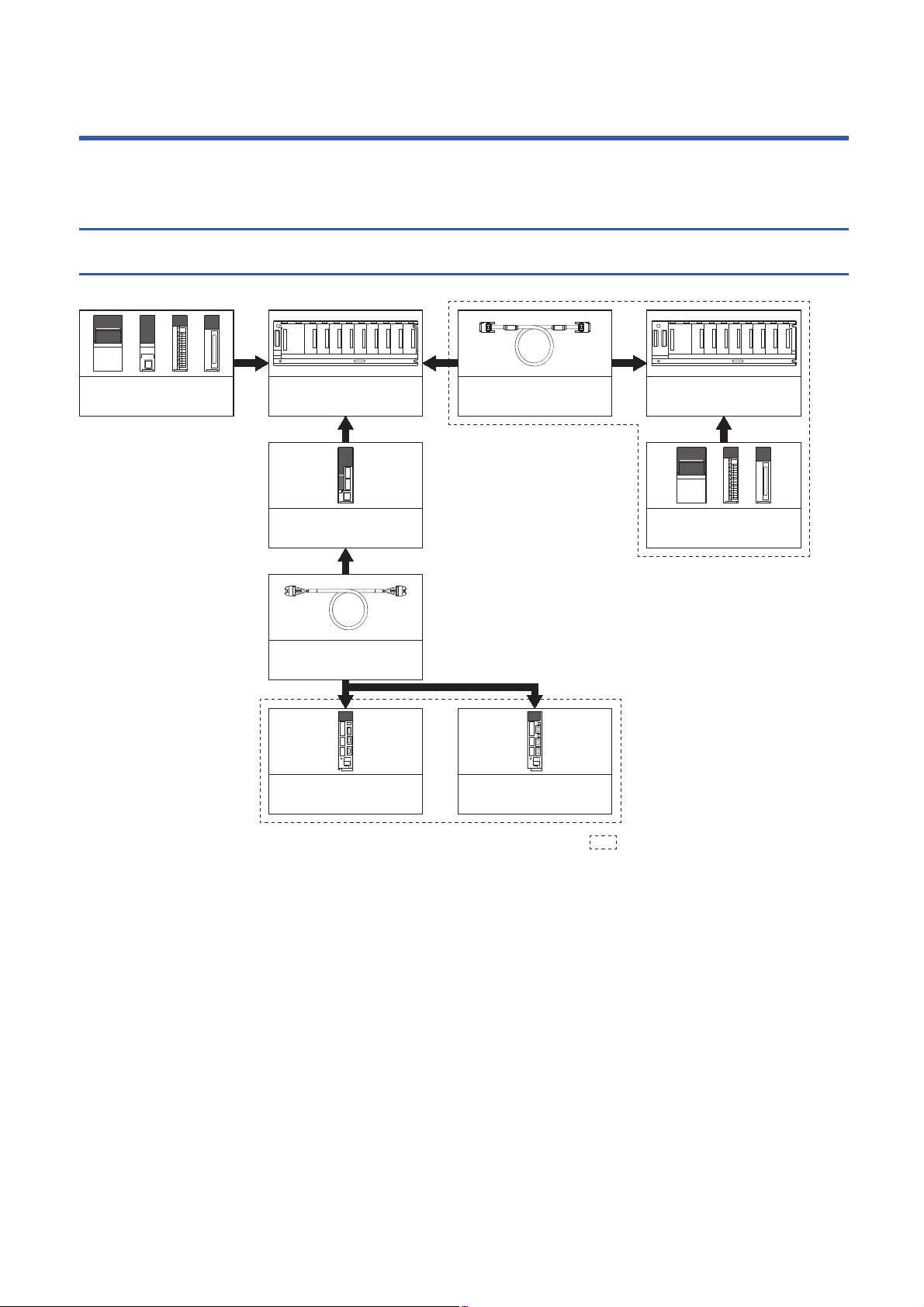
Extension of the R series module
Motion CPU module
(R64MTCPU/R32MTCPU/
R16MTCPU)
: Selected according to the system
Main base unit
(R35B, R38B, R312B)
Power supply module/RnCPU/
I/O module/Intelligent function
module of the R series
Power supply module/
I/O module/Intelligent function
module of the R series
Extension cable
(RCB)
Servo amplifier
(MR-J4(W)-B)
Servo amplifier
(MR-J3(W)-B)
R6B extension base unit
(R65B, R68B, R312B)
SSCNETµcable
(MR-J3BUSM(-A/-B))
This section describes the Motion controller system configuration, precautions on use of system and configured equipment.
1.1 Motion System Configuration
Equipment configuration in system
16
1 SYSTEM CONFIGURATION
1.1 Motion System Configuration
Page 19
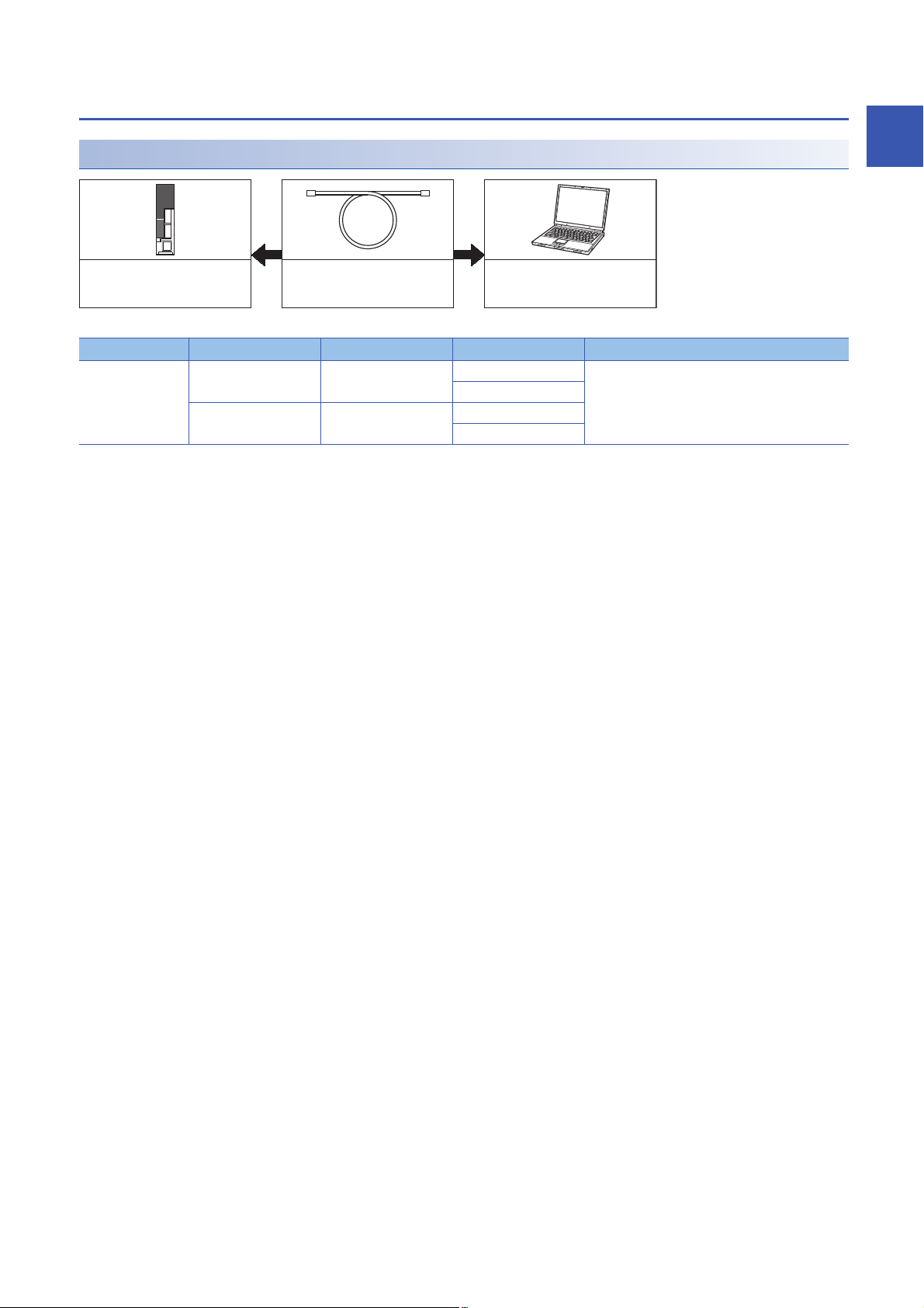
Peripheral device configuration
Ethernet cable
*1
Personal computer
Motion CPU module
(R64MTCPU/R32MTCPU/
R16MTCPU)
Ethernet configuration
*1 Corresponding Ethernet cables
Part name Connection type Cable type Ethernet standard Specification
Ethernet cable Connection with HUB Straight cable 10BASE-T Compliant with Ethernet standards, category 5 or
100BASE-TX
Direct connection Straight cable
Crossover cable
10BASE-T
100BASE-TX
■Selection criterion of cable
• Category : 5 or higher
• Diameter of lead: AWG26 or higher
• Shield: Copper braid shield and drain wire or copper braid shield and aluminium layered type shield
higher.
• Shielded twisted pair cable (STP cable)
1
1 SYSTEM CONFIGURATION
1.1 Motion System Configuration
17
Page 20

R64MTCPU/R32MTCPU/R16MTCPU system overall configuration
RMT
CPU
RCPU
R61P
PLC CPU/
Motion CPU
Main base unit
(R3B)
Extension base unit
(R6B)
Extension cable
(RCB)
Up to 7 extensions
RX
Line 1
SSCNETµ(/H)
(CN1)
Line 2
SSCNETµ(/H)
(CN2)
SSCNETµ cable
(MR-J3BUSM(-A/-B))
RY
Motion CPU controlled modules
RD62R6AD
/
R6DA
P Manual pulse generator x2/module
Incremental synchronous encoder x2/module
Intelligent
function module
E
I/O module/
Intelligent function module
Analog Input/Output
Input/Output
(Up to 4096 points)
External input signals
d01
M
E
d02 d16
M
E
d01
M
E
d02
M
E
M
E
d16
M
E
Power supply
module
Personal computer
GOT
USB/Ethernet
PERIPHERAL I/F
Cognex Corporation
vision system
Sensing module
MR-MT2000 series
*3
I/O module,
Intelligent
function module
L61P LJ72MS15
MELSEC-L series SSCNETµ/H
head module (LJ72MS15)
*3
Sensing module
MR-MT2000 series
*3
R64MTCPU: 2 lines (Up to 8 stations (Up to 4 stations/line))
R32MTCPU: 2 lines (Up to 8 stations (Up to 4 stations/line))
R16MTCPU: 1 line (Up to 4 stations)
I/O module,
Intelligent
function module
L61P LJ72MS15
R64MTCPU: 2 lines (Up to 64 axes (Up to 32 axes/line))
*2
R32MTCPU: 2 lines (Up to 32 axes (Up to 16 axes/line))
R16MTCPU: 1 line (Up to 16 axes)
External input signals of servo amplifier
Serial absolute synchronous
encoder
*1
(Q171ENC-W8)
Serial absolute synchronous
encoder cable
(Q170ENCCBLM-A)
E
MR-J3(W)-B/MR-J4(W)-B model servo
amplifier
Optical hub unit (MR-MV200)
Inverter FR-A800/FR-A700 series
VC´ series/VPH series servo driver
manufactured by CKD Nikki Denso Co., Ltd.
Stepping motor module AlphaStep/5-phase
manufactured by ORIENTAL MOTOR Co., Ltd.
IAI electric actuator controller manufactured
by IAI Corporation
Upper stroke limit
Lower stroke limit
Stop signal
Proximity dog/Speed-position switching
Upper stroke limit
Lower stroke limit
Proximity dog/Speed-position switching
18
*1 MR-J4-B-RJ only
*2 Up to 16 axes per line for R64MTCPU when communication type is SSCNET.
*3 SSCNET/H only
CAUTION
• Construct a safety circuit externally of the Motion controller or servo amplifier if the abnormal operation of the Motion controller or servo amplifier differ from
the safety directive operation in the system.
• The ratings and characteristics of the parts (other than Motion controller, servo amplifier and servomotor) used in a system must be compatible with the
Motion controller, servo amplifier and servomotor.
• Set the parameter values to those that are compatible with the Motion controller, servo amplifier, servomotor and regenerative resistor model and the system
application. The protective functions may not function if the settings are incorrect.
1 SYSTEM CONFIGURATION
1.1 Motion System Configuration
Page 21

Function explanation of the Motion CPU modules
• The following servo amplifiers can be controlled in Motion CPU module.
Motion CPU Servo amplifier control
R64MTCPU Up to 64 axes per 2 lines (up to 32 axes per 1 line)
R32MTCPU Up to 32 axes per 2 lines (up to 16 axes per 1 line)
R16MTCPU Up to 16 axes per 1 line
• It is possible to set the program which synchronized with the motion operation cycle and executed at fixed cycle (Min.
0.222ms).
• It is possible to execute a download of servo parameters to servo amplifier, servo ON/OFF to servo amplifier and position
commands, etc. by connecting between the Motion CPU module and servo amplifier with SSCNET cable.
• I/O modules and intelligent function modules (excluding some modules) can be controlled with the Motion CPU module.
(Page 24 PLC module which can be controlled by Motion CPU)
• Data exchange between CPU modules is possible by CPU buffer memory in the Multiple CPU system.
• Wiring is reduced by issuing the external signal (upper/lower stroke limit signal, proximity dog signal) via the servo amplifier.
• Battery is not required for the Motion CPU.
Restrictions on Motion systems
Combination of Multiple CPU system
• Motion CPU module cannot be used as standalone module. Be sure to install the MELSEC iQ-R series PLC CPU module
to CPU No.1. Refer to the following for the configurations in a Multiple CPU system with the PLC CPU module as CPU
No.1.
MELSEC iQ-R Module Configuration Manual
• Up to four modules of MELSEC iQ-R series PLC CPU modules/Motion CPU modules can be installed from the CPU slot
(the slot on the right side of power supply module) to the I/O slot 6 of the main base unit. CPU modules are called CPU
No.1 to CPU No.4 from the left sequentially. There is no restriction on the installation order of CPU No.2 to No.4. For CPU
module other than CPU No.1, CPU reservation setting (allocating a CPU No. without actually installing a CPU module) can
be made.
• It takes about 10 seconds to startup (a state where it can be controlled) the Motion CPU. After startup, each CPU requires
time for initializing. For a system that begins executing programs without waiting for the startup of other CPUs, change the
Multiple CPU synchronous startup setting.
1
Motion CPU module restrictions
• The Motion CPU module only controls MELSEC iQ-R series modules. It cannot control MELSEC Q series modules.
• To execute the forced stop input, use a device set in the forced stop input setting ([Motion CPU Common Parameter]
[Basic Setting])
• Refer to the following for details of installing Motion CPU module to a DIN rail.
MELSEC iQ-R Module Configuration Manual
• Use the Graphic Operation Terminal (GOT) that supports Motion CPU (R64MTCPU/R32MTCPU/R16MTCPU).
1 SYSTEM CONFIGURATION
1.1 Motion System Configuration
19
Page 22

SSCNET communication restrictions
• Set "SSCNET/H" or "SSCNET" for every line in the SSCNET setting ([Motion CPU Common Parameter] [Servo
Network Setting]) to communicate with the servo amplifiers and SSCNET compatible equipment. The following shows the
servo amplifiers and SSCNET compatible equipment that can be used when "SSCNET/H" and "SSCNET" are set.
: Usable, : Unusable
Servo amplifier/SSCNETIII compatible equipment SSCNET setting
SSCNETIII/H SSCNETIII
Servo amplifier MR-J4(W)-B
MR-J3(W)-B
Inverter FR-A800 series
FR-A700 series
Sensing module MR-MT2000 series
SSCNET/H head module LJ72MS15
VC series/VPH series servo driver manufactured by CKD Nikki Denso Co., Ltd
Stepping motor module AlphaStep/5-phase manufactured by ORIENTAL MOTOR Co., Ltd
IAI electric actuator controller manufactured by IAI Corporation
*1 Operated in J3 compatibility mode
• The maximum No. of control axes per line for the Motion CPU (R64MTCPU/R32MTCPU/R16MTCPU) are shown below by
the communication type set in SSCNET setting. Settings that exceed the maximum No. of control axes per line cannot be
made.
Motion CPU Communication type
SSCNETIII/H SSCNETIII
R64MTCPU 32 axes 16 axes
R32MTCPU 16 axes
R16MTCPU 16 axes
*1
• The following are restrictions for the communication type depending on the operation cycle.
: No restriction
Operation
cycle
0.222ms • Maximum 12 control axes per line.
0.444ms • Maximum 24 control axes per line.
0.888ms or more • Up to 4 stations per line can be set with the SSCNET/H head
*1 When the number of control axes per line setting exceeds the maximum number of control axes per line, operation is carried out at the
following operation cycles.
Maximum number of control axes per line Operation cycle
SSCNETIII/H SSCNETIII
13 to 24 axes 5 to 8 axes 0.444ms
25 axes or more 9 axes or more 0.888ms
Communication type
SSCNETIII/H SSCNETIII
*1
• MR-J4W3-B (software version A2 or earlier) cannot be used.
• 1 station per line can be set with the SSCNET/H head module
or sensing module.
• AlphaStep/5-phase cannot be used.
• Up to 2 axes per IAI electric actuator controller can be set.
• Up to 2 stations per line can be set with the SSCNET/H head
module and/or the sensing module.
• Up to 4 axes per IAI electric actuator controller can be set.
module and/or the sensing module.
*3
*4
*6
*1
*3
*6
*3
• The maximum number of control axes per line is 4 control axes.
*2
• Set the axis select rotary switch of the servo amplifier to "0 to 3".
If the axis select rotary switch of servo amplifier is set to "4 to F",
the servo amplifiers are not recognized.
• MR-J4W3-B (software version A2 or earlier) cannot be used.
•MR-J3W-B cannot be used.
• FR-A700 series, VC series, and VPH series cannot be used.
• The maximum number of control axes per line is 8 axes.
• Set the axis select rotary switch of the servo amplifier to "0 to 7".
If the axis select rotary switch of servo amplifier is set to "8 to F",
the servo amplifiers are not recognized.
*1
*1
*2
*5
*2 MR-J4W3-B (Software version "A3" or later) supports operation cycle 0.222ms. However, when using operation cycle 0.222ms, some
functions are restricted. Refer to the following for details.
Servo amplifier Instruction Manual
1 SYSTEM CONFIGURATION
20
1.1 Motion System Configuration
Page 23

*3 When using the sensing module in axis mode, there are no restrictions on the number of stations for the sensing module.
*4 When AlphaStep/5-phase is present, operation is carried out at 0.444ms operation cycle.
*5 When FR-A700 series, VC series, or VPH series are present, operation is carried out at 0.444ms operation cycle.
*6 When the setting exceeds the number of control axes per controller, a minor error (error code: 1C83H) occurs.
Set the operation cycle as follows according to the number of control axes per controller.
Number of control axes per controller Operation cycle
1 to 2 axes 0.222ms or more
3 to 4 axes 0.444ms or more
5 axes or more 0.888ms or more
• When using MR-J4W-B, if there is at least one axis which has not been set in servo network setting, all axes of the
applicable servo amplifier cannot be connected, and all servo amplifiers after the applicable servo amplifier cannot be
connected. Set "Not used" to the applicable axis with a dip switch for the axis which is not used by MR-J4W-B.
• When using a multi-axis servo amplifier (MR-J4W-B), there is a restriction on the number of connectable units (servo
amplifier (MR-J4(W)-B), SSCNET/H head module, other drivers etc.) between the Motion CPU and the multi-axis servo
amplifier. The number of connectable units are shown below. When more than the number of connectable units are
connected, a warning (error code: 0C82H) occurs. While communication with MR-J4W-B is still possible when the
warning occurs, communication becomes unstable, therefore the unit configuration should be reviewed. Furthermore, when
an optical hub unit is used, the number of connectable units is reduced. Refer to the following for details of when an optical
hub unit is connected.
MELSEC iQ-R Motion Controller Programming Manual (Common)
Servo amplifier Number of connectable units
MR-J4-B No restriction
MR-J4W2-B 1 axis set
2 axes set 14 units or less
MR-J4W3-B 1 axis set No restriction
2 axes set 14 units or less
3 axes set 13 units or less
1
1 SYSTEM CONFIGURATION
1.1 Motion System Configuration
21
Page 24

1.2 System Configuration Equipment
Configuration equipment list
Motion controller related module
Part name Model name
Motion CPU module R64MTCPU Up to 64 axes control, Operation cycle 0.222[ms] or more, Built-in Ethernet 1.20
R32MTCPU Up to 32 axes control, Operation cycle 0.222[ms] or more, Built-in Ethernet 1.20
R16MTCPU Up to 16 axes control, Operation cycle 0.222[ms] or more, Built-in Ethernet 1.20
*2
PLC CPU module
C Controller module
Power supply module
Main base unit
*2
R00CPU Program capacity 10k steps, LD instruction processing speed 31.3ns,
R01CPU Program capacity 15k steps, LD instruction processing speed 31.3ns,
R02CPU Program capacity 20k steps, LD instruction processing speed 3.92ns,
R04CPU Program capacity 40k steps, LD instruction processing speed 0.98ns,
R08CPU Program capacity 80k steps, LD instruction processing speed 0.98ns,
R16CPU Program capacity 160k steps, LD instruction processing speed 0.98ns,
R32CPU Program capacity 320k steps, LD instruction processing speed 0.98ns,
R120CPU Program capacity 1200k steps, LD instruction processing speed 0.98ns,
R04ENCPU Program capacity 40k steps, LD instruction processing speed 0.98ns,
R08ENCPU Program capacity 80k steps, LD instruction processing speed 0.98ns,
R16ENCPU Program capacity 160k steps, LD instruction processing speed 0.98ns,
R32ENCPU Program capacity 320k steps, LD instruction processing speed 0.98ns,
R120ENCPU Program capacity 1200k steps, LD instruction processing speed 0.98ns,
R08PCPU Program capacity 80k steps, LD instruction processing speed 0.98ns,
R16PCPU Program capacity 160k steps, LD instruction processing speed 0.98ns,
R32PCPU Program capacity 320k steps, LD instruction processing speed 0.98ns,
R120PCPU Program capacity 1200k steps, LD instruction processing speed 0.98ns,
*2
R12CCPU-V Endian format: Little endian, OS: VxWorks Version 6.9 1.26
*3
R61P 100 to 240VAC input, 5VDC 6.5A output
R62P 100 to 240VAC input, 5VDC 3.5A/24VDC 6.0A output
R63P 24VDC input, 5VDC 6.5A output
R64P 100 to 240VAC input, 5VDC 9A output
R35B Number of I/O modules: 5 slots 0.58
R38B Number of I/O modules: 8 slots 0.71
R312B Number of I/O modules: 12 slots 0.88
R310B-HT Number of I/O modules: 10 slots, extended temperature range 0.82
*1
Description Current
Built-in Ethernet port
Built-in Ethernet port
Built-in Ethernet port
Built-in Ethernet port
Built-in Ethernet port
Built-in Ethernet port
Built-in Ethernet port
Built-in Ethernet port
Built-in Ethernet port, Built-in CC-Link IE
Built-in Ethernet port, Built-in CC-Link IE
Built-in Ethernet port, Built-in CC-Link IE
Built-in Ethernet port, Built-in CC-Link IE
Built-in Ethernet port, Built-in CC-Link IE
Built-in Ethernet port
Built-in Ethernet port
Built-in Ethernet port
Built-in Ethernet port
Remark
consumption
5VDC[A]
0.67
0.67
0.67
0.67
0.67
0.67
0.67
0.67
1.49
1.49
1.49
1.49
1.49
0.76
0.76
0.76
0.76
22
1 SYSTEM CONFIGURATION
1.2 System Configuration Equipment
Page 25

Part name Model name
*1
Description Current
Remark
consumption
5VDC[A]
Extension base unit *2R65B Number of I/O modules: 5 slots 0.70
R68B Number of I/O modules: 8 slots 0.81
R612B Number of I/O modules: 12 slots 0.92
R610B-HT Number of I/O modules: 10 slots, extended temperature range 0.85
Extension cable RC06B Length 0.6m(1.97ft.)
RC12B Length 1.2m(3.94ft.)
RC30B Length 3m(9.84ft.)
RC50B Length 5m(16.40ft.)
DIN rail installation
adaptor
Serial absolute
synchronous encoder
Serial absolute
synchronous encoder
cable
Connector set for serial
absolute synchronous
encoder cable
SSCNET cable MR-J3BUSM • R64MTCPU/R32MTCPU/R16MTCPU MR-J4(W)-B/
R6DIN1 Length 5m(16.40ft.)
Q171ENC-W8 Resolution: 4194304pulse/rev
Q170ENCCBLM-A Serial absolute synchronous encoder Q171ENC-W8 MR-J4-B-RJ
MR-J3CN2 MR-J4-B-RJ side connector
MR-J3BUSM-A • R64MTCPU/R32MTCPU/R16MTCPU MR-J4(W)-B/
MR-J3BUSM-B
For connection of R35B/R38B/R312B/R65B/R68B/R612B
Permitted axial loads Radial load: Up to 19.6N, Thrust load: Up to 9.8N
Permitted speed: 3600r/min
2m(6.56ft.), 5m(16.40ft.), 10m(32.81ft.), 20m(65.62ft.), 30m(98.43ft.),
50m(164.04ft.)
Plug: 36210-0100PL
Shell: 36310-3200-008
Q171ENC-W8 side connector
Plug: D/MS3106B22-14S
Cable clamp: D/MS3057-12A
MR-J4(W)-B MR-J4(W)-B/MR-J4(W)-B LJ72MS15
• R64MTCPU/R32MTCPU/R16MTCPU MR-J3(W)-B/
MR-J3(W)-B MR-J3(W)-B
• Standard cord for inside panel
0.15m(0.49ft.), 0.3m(0.98ft.), 0.5m(1.64ft.), 1m(3.28ft.), 3m(9.84ft.)
MR-J4(W)-B MR-J4(W)-B/MR-J4(W)-B LJ72MS15
• R64MTCPU/R32MTCPU/R16MTCPU MR-J3(W)-B/
MR-J3(W)-B MR-J3(W)-
tandard cable for outside panel
S
•
5m(16.40ft.), 10m(32.81ft.), 20m(65.62ft.)
*4
• R64MTCPU/R32MTCPU/R16MTCPU MR-J4(W)-B/
MR-J4(W)-B MR-J4(W)-B/MR-J4(W)-B LJ72MS15
• R64MTCPU/R32MTCPU/R16MTCPU MR-J3(W)-B/
MR-J3(W)-B MR-J3(W)-B
• Long distance cable
30m(98.43ft.), 40m(131.23ft.), 50m(164.04ft.)
B
0.25
*1 =Cable length
(015: 0.15m(0.49ft.), 03: 0.3m(0.98ft.), 05: 0.5m(1.64ft.), 1: 1m(3.28ft.), 2: 2m(6.56ft.), 3: 3m(9.84ft.), 5: 5m(16.40ft.), 10: 10m(32.81ft.),
20: 20m(65.62ft.), 25: 25m(82.02ft.), 30: 30m(98.43ft.), 40: 40m(131.23ft.), 50:50m(164.04ft.)
*2 5VDC internal current consumption of shared equipment with PLC might be changed. Be sure to refer to the MELSEC iQ-R series PLC
Manuals.
*3 Be sure to use the power supply module within the range of power supply capacity.
*4 Please contact your nearest Mitsubishi sales representative for the cable of less than 30m(98.43ft.).
1
1 SYSTEM CONFIGURATION
1.2 System Configuration Equipment
23
Page 26

PLC module which can be controlled by Motion CPU
Part name Model name Description Current
consumption
*1
Remark
5VDC[A]
Input module RX10 AC input, input 16 points 0.11 Refer to the MELSEC
RX40C7 DC input, plus common/minus common shared type, input 16 points 0.11
RX41C4 DC input, plus common/minus common shared type, input 32 points 0.15
RX42C4 DC input, plus common/minus common shared type, input 64 points 0.18
RX40PC6H DC input, plus common type, input 16 points 0.10
RX40NC6H DC input, minus common type, input 16 points 0.10
RX41C6HS DC input, plus common/minus common shared type, input 32 points 0.15
RX61C6HS DC input, plus common/minus common shared type, input 32 points 0.15
Output module RY10R2 Contact output, output 16 points 0.45
RY40NT5P Transistor output, sink type, output 16 points 0.14
RY41NT2P Transistor output, sink type, output 32 points 0.18
RY41NT2H Transistor output, sink type, output 32 points 0.42
RY42NT2P Transistor output, sink type, output 64 points 0.25
RY40PT5P Transistor output, source type, output 16 points 0.13
RY41PT1P Transistor output, source type, output 32 points 0.19
RY41PT2H Transistor output, source type, output 32 points 0.41
RY42PT1P Transistor output, source type, output 64 points 0.29
Input/Output
composite
module
Analogue input
module
Analogue
output module
High-speed
counter module
Temperature
input module
RH42C4NT2P DC input, plus common/ minus common shared type, input 32 points,
transistor output, sink type, output 32 points
R60AD4 Voltage/current input, 4ch 0.22
R60ADV8 Voltage input, 8ch 0.23
R60ADI8 Current input, 8ch 0.22
R60AD8-G Voltage/current input, 8ch, channel isolated 0.33
R60AD16-G Voltage/current input, 16ch, channel isolated 0.52
R60DA4 Voltage/current output, 4ch 0.16
R60DAV8 Voltage output, 8ch 0.16
R60DAI8 Current output, 8ch 0.16
R60DA8-G Voltage/current output, 8ch, channel isolated 0.18
R60DA16-G Voltage/current output, 16ch, channel isolated 0.25
R60ADH4 Voltage/current output, 4ch 0.73
RD62P2 DC input, sink output type, 2ch 0.11
RD62P2E DC input, source type, 2ch 0.20
RD62D2 Differential input, sink output type, 2ch 0.17
R60TD8-G Thermocouple (B, R, S, K, E, J, T, N) input, 8ch, channel isolated 0.36
R60RD8-G RTD (Pt100, JPt100, Ni100, Pt50) input, 8ch, channel isolated 0.35
0.22
iQ-R series manuals for
each module.
*1 5VDC internal current consumption of shared equipment with PLC might be changed. Be sure to refer to the manuals for each module.
24
1 SYSTEM CONFIGURATION
1.2 System Configuration Equipment
Page 27

SSCNETIII(/H) compatible equipment
■SSCNETIII/H compatible equipment
Part name Model name Description Remarks
MR-J4 series servo amplifier MR-J4-B Refer to the servo amplifier instruction manuals.
MR-J4-B-RJ
MR-J4-B-LL
MR-J4W-B For 2-axis type, 3-axis type
Sensing module MR-MT2010 Sensing SSCNET/H head module Refer to the sensing module instruction manuals.
MR-MT2100 Sensing I/O module
MR-MT2200 Sensing pulse I/O module
MR-MT2300 Sensing analog I/O module
MR-MT2400 Sensing encoder I/F module
SSCNET/H head module LJ72MS15 Maximum link points: Input 64 bytes,
Output 64 bytes
Transmission cycle: 0.222ms,
0.444ms, 0.888ms
Optical hub unit MR-MV200 3 branches, 1 unit, 24VDC power
supply connector is attached
Refer to the MELSEC-L series PLC manuals.
■SSCNETIII compatible equipment
Part name Model name Description Remarks
MR-J3 series servo amplifier MR-J3-B Refer to the servo amplifier instruction manuals.
MR-J3W-B For 2-axis type
MR-J3-B-RJ006 For fully closed control
MR-J3-B-RJ004 For linear servo motor
MR-J3-B-RJ080W For direct drive motor
MR-J3-B Safety For drive safety servo
1
1 SYSTEM CONFIGURATION
1.2 System Configuration Equipment
25
Page 28

Software packages
Operating system software
Motion CPU Model name
R64MTCPU SW10DNC-RMTFW
R32MTCPU
R16MTCPU
*1 The operating system software is installed at the time of product purchases.
Engineering software
■Motion controller engineering software
Part name Model name
MELSOFT MT Works2
• MT Developer2
• MR Configurator2
*1 Included in Motion controller engineering software "MELSOFT MT Works2".
*2 The servo setup software "MR Configurator2" is included with MELSOFT MT Works2.
*1
*2
■PLC engineering software
Part name Model name
MELSOFT GX Works3 SW1DND-GXW3-E
SW1DND-MTW2-E
26
1 SYSTEM CONFIGURATION
1.2 System Configuration Equipment
Page 29

1.3 Checking Production Information and Operating
Rating plate
Production information
Production information
Marks of compliant standards
System Software Version
This section explains checking for the production information of Motion CPU module and the operating system software
version.
Checking production information
Checking with the Motion CPU module
■Rating plate
The rating plate is situated on the side face of the Motion CPU module. The SERIAL line displays the Motion CPU module
production information.
■Production information marking
The production information of the Motion CPU module is found on the production information marking on the front of the
Motion CPU module.
1
■Checking with GX Works3
The production information can be checked on the system monitor screen in GX Works3. (Page 28 Checking with GX
Works3)
■Checking with MT Developer2
Production information can be checked with MT Developer2 in the CPU information. (Page 28 Checking with MT
Developer2)
1 SYSTEM CONFIGURATION
1.3 Checking Production Information and Operating System Software Version
27
Page 30

Checking operating system software version
Operating system
software version
Production information
of Motion CPU module
Operating system
software version
Production information
of Motion CPU module
The operating system software version can be checked with MT Developer2 or GX Works3.
Checking with GX Works3
Check on the product information list screen.
[Diagnostics] [System monitor] [Product Information List] button
Checking with MT Developer2
■Installation screen
Check on the installation screen.
■CPU information screen
Check on the CPU information screen.
[Help] [CPU information]
■Device
Check with the special register "Operating system software version (SD740 to SD747)". Refer to for details on special
registers.
MELSEC iQ-R Motion Controller Programming Manual (Common)
28
1 SYSTEM CONFIGURATION
1.3 Checking Production Information and Operating System Software Version
Page 31

1.4 Restrictions by the Software's Version
There are restrictions in the function that can be used by the version of the operating system software and engineering
software. The combination of each version and a function is shown below.
: There is no restriction by the version.
Function Operating
system
software
version
Label access from external device 02 1.105K
File transmission at boot 03 1.111R
Event history 03 1.111R
ABS direction in degrees 03 1.111R
Clutch smoothing slippage method(Linear: Input value follow up) 03 1.111R
Pressure control 03 1.111R 1.37P
Optional data monitor (transient command) 03 1.111R
Optical hub unit connection 03 1.111R
Multiple CPU advanced synchronous control 03 1.111R
Extension of the number of vision system connections 03 1.111R
Motion dedicated PLC instructions (M(P).CHGA, M(P).CHGAS,
M(P).CHGV, M(P).CHGVS, M(P).CHGT)
Motion dedicated PLC instructions (M(P).BITWR, D(P).BITWR) 03 1.007H
Add-on function 03 1.111R
Add-on dedicated function (MCFUN) 03 1.111R
Servo amplifier (MR-J4-B-LL) compatible 03 1.111R 1.37P
Vibration suppression command filter 04 1.115V
Override function 04 1.115V
Test mode expansion 04 1.115V 1.41T
SD memory card compatible label function 04 1.115V
Parameter change function 05
Stepping motor module AlphaStep/5-phase manufactured by ORIENTAL
MOTOR Co., Ltd.
Home position return of driver home position return method 05 1.118Y
Device assignment method 07 1.120A
Machine control 07 1.120A
Motion dedicated function (MCNST) 07 1.120A
Multiple CPU advanced synchronous control (192 axis synchronization)*707 1.120A
Servo driver VPH series manufactured by CKD Nikki Denso Co., Ltd. 07 1.120A
Inverter FR-A800 series 07 1.120A
Override function compatible in machine control 08 1.120A
Sequential coordinate command control for machine control 08 1.120A
Data set method 3 home position return 08 1.125F
Indirect specification expansion for Motion SFC program 08 1.125F
IAI electric actuator controller manufactured by IAI Corporation 08 1.125F
Compatible with cam conversion data 08 1.125F
Motion dedicated PLC instructions (M(P).MCNST/D(P).MCNST) 07 1.025B
Sensing module connection 09 1.128J 1.55H
Expansion of the number of Motion SFC multi active steps 09 1.128J
Improvement of absolute positioning operation for servo driver VC/VPH
series manufactured by CKD Nikki Denso Co., Ltd., and stepping motor
module AlphaStep/5-phase manufactured by ORIENTAL MOTOR Co.,
Ltd.
Expansion of the number of positioning points for the Motion dedicated
function (MCNST)
1.007H
05 1.118Y
09
10 1.120A
Engineering software version Section
MELSOFT MT Works2 GX
*1
MT
Developer2
MR
Configurator2
Works3
of
reference
*2
*2
*2
*4
*4
*4
*2
*2
*5
*2
*3
*3
*2
*3
*4
*4
*2
*2
*2
*2
*4
*2
*6
*3
*5
*2
*2
*4
*6
*4
*3
*2
*3
*2
*3
*2
*6
1
1 SYSTEM CONFIGURATION
1.4 Restrictions by the Software's Version
29
Page 32

Function Operating
system
software
version
Expansion of the number of Motion SFC programs and servo programs 10 1.130L
Synchronous encoder via sensing module 10 1.130L 1.55H
Mixed operation cycle function 10 1.130L
RnENCPU Multiple CPU system compatible 10 1.118Y 1.032J
Actual coordinate value (world coordinate system) monitor for machine
control
Virtual servo amplifier function 12 1.137T
G-code control
Add-on library license authentication 14 1.140W
RnCPU (R00CPU, R01CPU, R02CPU) Multiple CPU system compatible 1.140W 1.040S
*8
11 1.135R
14 1.140W
Engineering software version Section
MELSOFT MT Works2 GX
*1
MT
Developer2
MR
Configurator2
Works3
of
reference
*3*4
*5
*2
*6
*2
*9
*2
*1 The operating system software version can be confirmed in MT Developer2, or GX Works3. (Page 28 Checking operating system
software version)
*2 MELSEC iQ-R Motion Controller Programming Manual (Common)
*3 MELSEC iQ-R Motion Controller Programming Manual (Program Design)
*4 MELSEC iQ-R Motion Controller Programming Manual (Positioning Control)
*5 MELSEC iQ-R Motion Controller Programming Manual (Advanced Synchronous Control)
*6 MELSEC iQ-R Motion Controller Programming Manual (Machine Control)
*7 Because the device assignment of status device settings are changed, the device assignment must be reviewed when updating the
operating system software to version "07" or later from version "05" or earlier
*8 Requires add-on library "SW10DND-GCD".
*9 MELSEC iQ-R Motion Controller Programming Manual (G-Code Control)
1.5 Engineering Software Version
The operating system software and engineering software versions that support Motion CPU are shown below.
Motion CPU Operating system software MELSOFT MT Works2
(MT Developer2)
R16MTCPU 01 or later 1.100E or later 1.000A or later
R32MTCPU
R64MTCPU 07 or later 1.120A or later 1.019V or later
GX Works3
30
1 SYSTEM CONFIGURATION
1.5 Engineering Software Version
Page 33

2 EQUIPMENT SPECIFICATIONS
2.1 General Specifications
General specifications of the Motion controller are shown below.
Item Specification
Operating ambient temperature 0 to 55 (32 to 131)
Storage ambient temperature -25 to 75 (-13 to 167)
Operating ambient humidity 5 to 95%RH, non-condensing
Storage ambient humidity 5 to 95%RH, non-condensing
Vibration resistance Compliant with
Shock resistance Compliant with JIS B 3502 and IEC 61131-2 (147m/s2 , 3 times in each of 3 directions X, Y, Z)
Operating ambience No corrosive gases
Operating altitude
Mounting location Inside control panel
Overvoltage category
Pollution level
Equipment class Class
*3
*4
*5
JIS B 3502 and
IEC 61131-2
0 to 2000m(0 to 6561.68ft.)
or less
2 or less
*1
Frequency Constant
Under intermittent
vibration
Under continuous
vibration
*2
, flammable gases, less conductive dust
5 to 8.4Hz 3.5mm(0.14inch) 10 times each in
8.4 to 150Hz 9.8m/s
5 to 8.4Hz 1.75mm(0.07inch)
8.4 to 150Hz 4.9m/s
acceleration
Half amplitude Sweep count
2
2
2
X, Y, Z directions
*1 When an extended temperature range base unit is used, each module can be used in the environment of 0 to 60 (32 to 140). All
modules mounted on the extended temperature range base unit offer the same performance as that for an operating ambient
temperature of 0 to 55 (32 to 131), and can be used in an operating ambient temperature of 0 to 60 (32 to 140). When using the
modules in the environment of 60 (140) or more, please consult your local representative.
*2 Use the special coated products which comply with the IEC 60721-3-3 3C2 in the environment with the corrosive gases. For details on
the special coated products, please consult your local representative.
*3 Do not use or store the Motion controller under pressure higher than the atmospheric pressure of altitude 0m. Doing so can cause an
operation failure. When using the Motion controller under pressure, please contact with our sales representative.
*4 This indicates the section of the power supply to which the equipment is assumed to be connected between the public electrical power
distribution network and the machinery within premises. Category applies to equipment for which electrical power is supplied from
fixed facilities. The surge voltage withstand level for up to the rated voltage of 300V is 2500V.
*5 This index indicates the degree to which conductive material is generated in terms of the environment in which the equipment is used.
Pollution level 2 is when only non-conductive pollution occurs. A temporary conductivity caused by condensing must be expected
occasionally.
CAUTION
• The Motion controller must be stored and used under the conditions listed in the table of specifications above.
• When not using the module for a long time, disconnect the power line from the Motion controller or servo amplifier.
• Place the Motion controller and servo amplifier in static electricity preventing vinyl bags and store.
• When storing for a long time, please contact with our sales representative. Also, execute a trial operation.
2 EQUIPMENT SPECIFICATIONS
2.1 General Specifications
31
Page 34

2.2 Motion CPU Module
(6)
(1)
(2)
(3)
(4)
(5)
(7)
(9)
(8)
(10)
(11)
(12)
(13)
(14)
(15)
With front cover open
Front face of R32MTCPU
(10)
(11)
(12)
(13)
(14)
(15)
Front face of R64MTCPU
(10)
(12)
(13)
(14)
(15)
Front face of R16MTCPU
(16)(17)
Side face
(18)
Name of parts
This section explains the names of the parts of the Motion CPU module.
32
2 EQUIPMENT SPECIFICATIONS
2.2 Motion CPU Module
Page 35

No. Name Details
(1) READY LED Indicates the operating status of the Motion CPU.
ON: Operating normally
Flickering: Initializing
OFF: Hardware error (Page 34 READY/ERROR LED display)
(2) ERROR LED Indicates an error occurrence in the Motion CPU module.
ON, flickering: Hardware error, or error occurrence (Page 34 READY/ERROR LED display)
OFF: Operating normally
(3) CARD READY LED Indicates whether SD memory card is usable or not.
ON : SD memory card is usable
Flickering : Preparing
OFF : No SD memory card inserted
(4) CARD ACCESS LED Indicates the access status of SD memory card.
ON : Accessing SD memory card
OFF : Not accessing SD memory card
(5) Dot matrix LED Indicates the operating status and error information. (Page 34 Dot matrix LED display)
(6) Mode select rotary switch • Set the operation mode. (Normal mode, Installation mode, etc.)
(7) RUN/STOP switch Move RUN/STOP to change the operating state of the Motion CPU module.
(8) SD memory card access control switch Switch for stopping card access when removing the SD memory card.
(9) SD memory card slot Slot for inserting the SD memory card.
(10) SSCNET CN1 connector
(11) SSCNET CN2 connector
(12) PERIPHERAL I/F connector For communication I/F with peripheral devices.
(13) SPEED LED ON: Communicating at 100Mbps
(14) SD/RD LED Flickering: Communicating data
(15) Production information marking Displays the production information described on the rating plate.
(16) Module fixing hook Hook used to fix the module to the base unit.
(17) Module fixing screw hole Screw hole used to fix to the base unit. (M312 screws supplied by user)
(18) Module fixing projection Projection used to fix to the base unit.
*1
*1*2
• Each switch setting is 0 to F. (Factory default: 0) (Page 36 Rotary switch setting)
RUN : Program is started.
STOP : Program is stopped.
Connector to connect the servo amplifier of line 1.
Connector to connect the servo amplifier of line 2.
OFF: Communicating at 10Mbps, or not connected.
OFF: Not communicating data
2
*1 Put the SSCNET cable in the duct or fix the cable at the closest part to the Motion CPU module with bundle material in order to
prevent SSCNET cable from putting its own weight on SSCNET connector.
*2 R64MTCPU/R32MTCPU only
2 EQUIPMENT SPECIFICATIONS
2.2 Motion CPU Module
33
Page 36

LED display
READY/ERROR LED display
The Motion CPU operating status is shown below by the READY LED and ERROR LED combination.
LED display status Operating status
READY ERROR
OFF OFF Power supply OFF
Flickering OFF Initializing
ON OFF Operating normally
OFF ON or flickering Major error occurrence
ON Flickering Moderate error occurrence
ON ON Minor error occurrence
Dot matrix LED display
The LED displays/flashes in the combination with errors.
Item Dot matrix LED Details
Normal mode Start Progress display It takes about 10 seconds to initialize (RUN/STOP
display). After startup, each CPU requires time for
initializing. Check the rotary switch setting, and execute
the Multiple CPU system power cycle if the operation
stops at initializing for several minutes. If the Motion
controller continues to stop at initializing, it may be
Motion controller's hardware fault.
Explain the error symptom (LED display) and get advice
from our sales representative for the modules with
failure.
"E" is displayed Hardware error or software error during initializing.
indicates the error code.
Explain the error symptom (LED display) and get advice
from our sales representative for the modules with
failure.
"Source > Destination" is
displayed
(Left: When files are
transmitted from the SD
memory card to the standard
ROM)
" delete target" is displayed
(Left: When files on the
standard ROM are deleted)
Executes file transmission at boot.
The following are used to indicate the source,
destination, delete target.
R: Standard ROM
S: SD memory card
34
STOP "STP" is displayed Stopped the program with the "[Rq.1120] PLC ready flag
RUN "RUN" is displayed Executed the program with the "[Rq.1120] PLC ready
Test mode RUN "TES" is displayed Mode to test Motion CPU operation.
Amplifier-less
operation mode
2 EQUIPMENT SPECIFICATIONS
2.2 Motion CPU Module
Displays "NAP" and "Mode"
alternately.(Left: When mode
is "RUN")
(R: M30000/Q: M2000)" OFF.
flag (R: M30000/Q: M2000)" ON.
Mode to operate without connecting servo amplifiers.
The mode displayed is the mode that the Motion CPU is
operating. ("STP", "RUN", "TES")
Page 37

Item Dot matrix LED Details
Normal mode Digital oscilloscope
RUN
Displays "LOG" and "Mode"
alternately.(Left: When mode
is "RUN")
Displays the status of the digital oscilloscope wait for
trigger.
The mode displayed is the mode that the Motion CPU is
operating. ("STP", "RUN", "TES")
Displays "TRG" and "Mode"
alternately.(Left: When mode
is "RUN")
Ethernet information display mode Refer to Ethernet information display mode for details of
the dot matrix LED display. (Page 37 Ethernet
information display mode)
Installation mode "INS" is displayed Mode to install the operating system software.
Displays "INS" "SDC"
alternately.
"FIN" is displayed Displays when the operating system software
"ER" is displayed
(Left: When there is a "SD
memory card access error")
Built-in memory clear "CLR" is displayed Mode to clear the built-in memory (standard ROM,
Target memory is displayed. The target memory for built-in memory clear is
Displays the status after the digital oscilloscope trigger
issue.
The mode displayed is the mode that the Motion CPU is
operating. ("STP", "RUN", "TES")
Displays information of IP address, subnet mask, default
router address, MAC address, link status.
Displays the status of the operating system software
installation from the SD memory card.
installation from the SD memory card is completed
normally.
Displays when there was an error in operating system
software installation from the SD memory card.
indicates the following errors.
0: SD memory card access error
1: Install file error
2: Built-in ROM access error
3: License key file error
backup RAM).
After displaying for 3 seconds, the display switches to
the target memory.
displayed.
The following are the displays for the target memory.
RB: Standard ROM and backup RAM
B: Backup RAM
R: Standard ROM
• Switch the memory displayed by pushing the SD
memory card access control switch.
2
Displays "CLR" "Target
memory" alternately.
(Left: When target memory is
"standard ROM and backup
RAM")
"FIN" is displayed Displays when built-in memory clear is completed
"ERR" is displayed Displays when an error occurred during built-in memory
Displays the status of the built-in memory clear.
normally.
clear.
2 EQUIPMENT SPECIFICATIONS
2.2 Motion CPU Module
35
Page 38

Item Dot matrix LED Details
0
8
F
7
E
6
D
5
C
4
B
3
A
2
9
1
Operating
system
software
Not installed "A00" is flickering It becomes the status of installation mode when the
operating system software is not installed.
File error "A01" is flickering Displays when there is a file error in the operating
system software that was installed.
WDT error "W" is displayed Hardware error or software error.
Self-diagnostic error
(Major/Moderate/Minor error)
" AL" flickers 3 times
4-digits error code is
displayed in two sequential
displays of 2-digits each.
(Left: error code [2200H])
Scrolled display of the file
name.
(Left: When file name is
"motnet01.csv")
When a continuous error
occurred, the mode is
displayed.
(Left: When mode is "RUN")
displays the error code of "Motion CPU WDT error
cause (SD512)".
Displays when a self-diagnostic error occurs (major/
moderate/minor error).
• Displays the applicable file name when a parameter,
or file error is detected.
• The mode that the Motion CPU is operating. ("STP",
"RUN", "TES") is displayed only for a continuous
error.
Refer to the following for details of error codes and file
names.
MELSEC iQ-R Motion controller Programming
Manual (Common)
• When an error is displayed on the dot matrix LED, confirm the error code etc. using MT Developer2.
• Refer to the Motion CPU error batch monitor or the following for error details.
MELSEC iQ-R Motion Controller Programming Manual (Common)
Rotary switch setting and operation mode
Rotary switch setting
Rotary switch Setting *1Mode Description
0 Normal mode Normal operation mode
8 Ethernet information
display mode
A Installation mode Installed the operating system software using MT Developer2.
C Built-in memory clear Initializes the built-in memory of the standard ROM and backup RAM.
*1 Do not set other than the above setting.
Displays IP address, MAC address, and Ethernet link status.
CAUTION
• Be sure to turn OFF the Multiple system power supply before the rotary switch setting change.
2.2 Motion CPU Module
36
2 EQUIPMENT SPECIFICATIONS
Page 39

Operation mode
Ex.
Disconnected
Connected
(10Mbps)
Connected
(100Mbps)
Full duplex
Half duplex
IP address
(192.168.3.39)
Subnet mask
(255.255.255.0)
Default router address
(192.168.3.1)
MAC address
(38-E0-8E-01-23-45)
Link status
■Normal mode
The Motion CPU module operates based on the parameters, user programs stored in the standard ROM or the SD memory
card.
■Ethernet information display mode
Displays Ethernet related information. Displays in the order of IP address, subnet mask, default router address, MAC address,
and link status.
During Ethernet information display mode, communication with MT Developer2, execution of Motion SFC programs, and axis
control cannot be performed.
The following is an example of a display in Ethernet information display mode.
IP address: 192.168.3.39
Subnet mask pattern: 255.255.255.0
Default router IP address: 192.168.3.1
MAC address: 38-E0-8E-01-23-45
2
When the Ethernet parameters are not written in the Motion CPU, the addresses are displayed as follows.
• IP address: 192.168.3.39
• IP address: 0.0.0.0
• Default router IP address: 0.0.0.0
■Installation mode
Mode for installing the operating system software. Only communication with MT Developer2 is possible. Execution of Motion
SFC programs, and axis control cannot be performed.
2 EQUIPMENT SPECIFICATIONS
2.2 Motion CPU Module
37
Page 40

■Built-in memory clear
RB:Clear the standard ROM and backup RAM
B:Clear the backup RAM
R :Clear the standard ROM
Clears the contents of the standard ROM and backup RAM of the Motion CPU. During built-in memory clear, communication
with MT Developer2, execution of Motion SFC programs, and axis control cannot be performed. The procedure for built-in
memory clear is shown below.
1. Set the rotary switch to "C".
2. Turn the Multiple CPU system power supply ON.
3. The READY LED turns ON, and the dot matrix LED displays "CLR". After 3 seconds, the dot matrix LED display switches
to the target memory.
4. Pushing the SD memory card access control switch changes the dot matrix display as shown below. Select the memory
for built-in memory clear.
5. By holding the SD memory card access control switch for longer than 3 seconds, "CLR" "Memory selected in
procedure 4." is displayed alternately, and clear processing begins.
6. When built-in memory clear is complete, "FIN" is displayed on the dot matrix LED.
7. Turn the Multiple CPU system power supply OFF.
8. Set the rotary switch to "0" to switch to normal mode.
• Do not turn Multiple system power supply OFF while the clear is processing.
• If Multiple CPU system power supply is turned OFF during clearing of standard ROM, accessing the
standard ROM may no longer be possible. Execute a drive format from MT Developer2, or perform a built-in
memory clear again.
• When an error is detected during the processing of a built-in memory clear, "ERR" is displayed on the dot
matrix LED, and the ERROR LED flickers. Perform a built-in memory clear again.
• The contents cleared in the standard ROM are every program, parameter, event history, and data for digital
oscilloscope. Refer to the following for details of each file.
MELSEC iQ-R Motion Controller Programming Manual (Common)
• The contents cleared in the backup RAM are latch device data, absolute positioning data, current value
history, and scroll monitor.
38
2 EQUIPMENT SPECIFICATIONS
2.2 Motion CPU Module
Page 41

Specifications
This section describes the Motion CPU specifications.
Module specifications
Item R64MTCPU R32MTCPU R16MTCPU
Number of control axes Up to 64 axes Up to 32 axes Up to 16 axes
SSCNET communication
*1
PERIPHERAL I/F
(Ethernet)
Memory card slot SD/SDHC memory card compatible
Memory capacity Standard ROM 12M bytes
Number of stages of extension base Up to 7 stages
Internal current consumption (5VDC) [A] 1.20
Mass [kg] 0.28
Exterior dimensions [mm(inch)] 106.0(4.17)(H)27.8(1.09)(W)110.0(4.33)(D)
*1 Servo amplifiers for SSCNET cannot be used.
*2 SSCNET and SSCNET/H cannot be combined within the same line. For R64MTCPU/R32MTCPU, SSCNET and SSCNET/H
can be set for each line.
*3 When using the optical hub unit, the maximum combined cable length depends on the system configuration.
*4 For half-duplex transmission, response time may be longer depending on the external device. When connecting with an external device
via a switching HUB, set to full-duplex transmission.
Communication type SSCNET/H, SSCNET
Number of lines 2 lines
Distance between stations
(maximum) [m(ft.)]
Combined cable length
(maximum) [m(ft.)]
Number of sensing module connection
stations
Number of SSCNET/H head module
connection stations
Number of optical hub unit connections Up to 32 units (Up to 16 units/line) Up to 16 units
Data transmission speed 100Mbps/10Mbps
Communication mode Full-duplex/Half-duplex
Transmission method Base band
Cable length (maximum) [m(ft.)] 30(98.43)
SD memory card Memory card capacity (Up to 32G bytes)
*3
SSCNET/H 100(328.08)
SSCNET 50(164.04)
SSCNET/H 3200(10498.69) 1600(5249.34)
SSCNET 800(2624.67)
*2
Up to 8 stations (Up to 4 stations/line) Up to 4 stations
*4
1 line
*2
2
2 EQUIPMENT SPECIFICATIONS
2.2 Motion CPU Module
39
Page 42

Motion control specifications
Item R64MTCPU R32MTCPU R16MTCPU
Number of control axes Up to 64 axes Up to 32 axes Up to 16 axes
Operation cycle
(default)
Interpolation functions Linear interpolation (Up to 4 axes), Circular interpolation (2 axes), Helical interpolation (3 axes)
Control modes PTP(Point to Point) control, Speed control, Speed-position switching control, Fixed-pitch feed,
Acceleration/deceleration control Trapezoidal acceleration/deceleration, S-curve acceleration/deceleration, Advanced S-curve
Compensation Backlash compensation, Electronic gear, Phase compensation
Programming language Motion SFC, Dedicated instruction
Program capacity Servo program 64k steps
Motion SFC program 8192k bytes
Number of programs Servo program 8192 (K0 to 8191)
Motion SFC program 512 (No.0 to 511)
Number of positioning points 6400 points (Positioning data can be designated indirectly)
Peripheral I/F PERIPHERAL I/F
Home position return function Proximity dog method (2 types), Count method (3 types), Data set method (3 types), Dog cradle
JOG operation function Provided
Manual pulse generator operation function Possible to connect 3 modules (High-speed counter module use)
Synchronous encoder operation function Possible to connect 12 modules
M-code function M-code output function provided, M-code completion wait function provided
Limit switch output function Number of output points 64 points 2 settings Output timing compensation
ROM operation function Provided
Multiple CPU advanced synchronous control Provided
External input signal External input signals (FLS/RLS/DOG) of servo amplifier, Bit device
Forced stop Motion controller forced stop (Device), Forced stop terminal of servo amplifier
Number of I/O points Total 4096 points
Mark detection function Mark detection mode setting Continuous detection mode, Specified number of detection mode, Ring buffer mode
Mark detection signal High-speed input request signal (bit device, input signal of servo amplifier (DI1 to DI3), input
Mark detection setting 64 settings
Clock function Provided
Security function Provided
All clear function Provided
Remote operation Remote RUN/STOP
File management function Available for program and parameter data, cam data, label data, sampling data etc.
Optional data monitor
function
Digital oscilloscope function Motion buffering method (Real-time waveform can be displayed)
Absolute position system Made compatible by setting battery to servo amplifier.
SSCNET/H Up to 14 data/axis (Communication data: Up to 6 points/axis)
SSCNET Up to 14 data/axis (Communication data: Up to 3 points/axis)
0.222ms/ 1 to 2 axes
0.444ms/ 3 to 8 axes
0.888ms/ 9 to 20 axes
1.777ms/21 to 38 axes
3.555ms/39 to 64 axes
Continuous trajectory control, Position follow-up control, Speed control with fixed position stop,
High-speed oscillation control, Speed-torque control, Pressure control
control, Machine control, G-code control
acceleration/deceleration
*2
*3
*4
*5
method, Stopper method (2 types), Limit switch combined method, Scale home position signal
detection method, Dogless home position signal reference method, Driver home position return
method
Home position return re-try function provided, home position shift function provided
(Via module (High-speed counter module use) + Via servo amplifier
CPU advanced synchronous control + Via sensing module)
Watch data: Motion control data/Word device
signal of sensing module)
Sampling data: Word 16CH, Bit 16CH
Offline sampling
(Possible to select the absolute data method or incremental method for each axis)
0.222ms/ 1 to 2 axes
0.444ms/ 3 to 8 axes
0.888ms/ 9 to 20 axes
1.777ms/21 to 32 axes
0.222ms/ 1 to 2 axes
0.444ms/ 3 to 8 axes
0.888ms/ 9 to 16 axes
*1
, Advanced synchronous
*6
+ Via device + Multiple
40
2 EQUIPMENT SPECIFICATIONS
2.2 Motion CPU Module
Page 43

Item R64MTCPU R32MTCPU R16MTCPU
Driver communication function
File transmission at boot function Provided
Parameter change function Provided
Mixed operation cycle function Provided
Event history function Provided
Add-on function Provided
Override function Provided
Vibration suppression command filter Provided
*1 Servo amplifier(MR-J4-B-LL) only.
*2 For operating system software version "09" or earlier, 32k steps.
*3 For operating system software version "09" or earlier, 4096k bytes.
*4 For operating system software version "09" or earlier, 4096 (K0 to 4095).
*5 For operating system software version "09" or earlier, 256 (No.0 to 255).
*6 Servo amplifier(MR-J4-B-RJ) only.
*7 Servo amplifier(MR-J3-B/MR-J4-B) only.
*7
Provided
2
2 EQUIPMENT SPECIFICATIONS
2.2 Motion CPU Module
41
Page 44

2.3 Serial Absolute Synchronous Encoder
Specifications
This section describes the specifications of serial absolute synchronous encoder
Item Specifications
Model name Q171ENC-W8
Ambient temperature -5 to 55(23 to 131)
Resolution 4194304pulse/rev
Transmission method Serial communications
Direction of increasing addresses CCW (viewed from end of shaft)
Protective construction Dustproof/Waterproof (IP67: Except for the shaft-through portion.)
Permitted speed at power ON 3600r/min
Permitted speed at power OFF
Permitted axial loads Radial load : Up to 19.6N, Thrust load : Up to 9.8N
Runout at input shaft tip 0.02mm(0.00079 inch) or less, (15mm(0.59 inch) from tip)
Start friction torque 0.04Nm(20(68))
Recommended coupling Bellows coupling
Permitted angular acceleration 40000rad/s2
Vibration resistance 5G(50 to 200Hz)
Shock resistance 50G(11ms or less)
Internal current consumption [A] 0.25
Mass [kg] 0.6
Connecting cable [m(ft.)] Q170ENCCBLM-A
Communications method Differential driver/receiver
Transmission distance Up to 50m(164.04ft.)
*2
500r/min
(=Cable length : 2(6.56), 5 (16.40), 10 (32.81), 20 (65.62), 30 (98.43), 50 (164.04))
*1
*1 When "o-ring" is required, please purchase separately by customers.
*2 If it exceeds a permitted speed at power OFF, a position displacement is generated.
The serial absolute synchronous encoder backs up the absolute position with the battery for back up of
absolute position data of the servo amplifier (MR-J4-B-RJ) it is connected to.
42
2 EQUIPMENT SPECIFICATIONS
2.3 Serial Absolute Synchronous Encoder
Page 45

2.4 SSCNETIII Cables
Between the Motion CPU module and servo amplifiers, or servo amplifier and servo amplifier connected by SSCNET cable.
When using the R16MTCPU, SSCNET cable for connection to servo amplifier can be used for only 1 line. (Connect to
CN1.) When using the R64MTCPU/R32MTCPU, SSCNET cables for connection to servo amplifier can be used for up to 2
lines. (Connect to CN1 and CN2.)
The following number of servo amplifiers can be connected per SSCNET(/H) line.
Motion CPU Communication type
SSCNETIII/H SSCNETIII
R64MTCPU Up to 32 Up to 16
R32MTCPU Up to 16
R16MTCPU Up to 16
Specifications
Model name Cable length [m(ft.)] Description
MR-J3BUSM
(Standard cord for inside panel)
MR-J3BUSM-A
(Standard cable for outside panel)
MR-J3BUSM-B
(Long distance cable)
MR-J3BUS015M 0.15(0.49) • Motion CPU Servo amplifier
MR-J3BUS03M 0.3(0.98)
MR-J3BUS05M 0.5(1.64)
MR-J3BUS1M 1(3.28)
MR-J3BUS3M 3(9.84)
MR-J3BUS5M-A 5(16.40)
MR-J3BUS10M-A 10(32.81)
MR-J3BUS20M-A 20(65.62)
MR-J3BUS30M-B 30(98.43)
MR-J3BUS40M-B 40(131.23)
MR-J3BUS50M-B 50(164.04)
• Servo amplifier Servo amplifier
2
2 EQUIPMENT SPECIFICATIONS
2.4 SSCNETIII Cables
43
Page 46

Connection between the Motion CPU module and servo
(1)
(1)
CN1A
CN1B
Cap
CN1A
CN1B
Servo amplifier Servo amplifier
Servo amplifier Servo amplifier
(1)
CN1A
CN1B
Cap
CN1A
CN1B
(1)
SSCNETµ cable length
MR-J3BUSM use
(1) ≤ 3m(9.84ft.)
MR-J3BUSM-A use
(1) ≤ 20m(65.62ft.)
MR-J3BUSM-B use
(1) ≤ 50m(164.04ft.)
CN2
*2
CN1
Motion CPU module
*1: If the CN1A and CN1B connection is incorrect,
the servo amplifiers cannot communicate.
*2: R64MTCPU/R32MTCPU only
Attach a cap to
connectors of line
not being used.
SSCNET
µ
(/H) LINE 2
SSCNETµ (/H) LINE 1
amplifiers
Connect the SSCNET cables to the following connectors.
44
2 EQUIPMENT SPECIFICATIONS
2.4 SSCNETIII Cables
Page 47

Setting of the axis No. and switch of servo amplifier
Set the Axis No. and Station No.
1234
ON
Auxiliary axis No.
setting switch
Axis select rotary switch
8
0
7
F
6
E
5
D
4
C
3
B
2
A
1
9
Axis No. is used to set the axis Nos. of servo amplifiers connected to SSCNET connector(CN) in the program. The
following range can be set in the Motion CPU module. Axis No. is set for each SSCNET(/H) line in servo network setting.
Axis No. is allocated and set for the setting axis No. (d01 to d16) of servo amplifier.
Motion CPU Axis No. setting range Setting range of station No.
SSCNETIII/H SSCNETIII
R64MTCPU 1 to 64 1 to 64 1 to 16
R32MTCPU 1 to 32
R16MTCPU 1 to 16
Setting of Axis No. and station No.
■When using communication type "SSCNET/H"
Set the station No. and axis No. of the servo amplifier.
The station No. and axis No. of the servo amplifier can each be set individually.
Match the servo amplifier station No. with the control axis No. by setting the axis select rotary switch (0 to F) and the auxiliary
axis No. setting switches (SW3, SW4) to the appropriate combination.
The table for setting the station No. with the axis select rotary switch and auxiliary axis No. setting switches of the servo
amplifier is shown in the table below.
2
Auxiliary axis
No. setting
switch
SW3 SW4 0 1 2 3 4 5 6 7 8 9 A B C D E F
OFF OFF d01 d02 d03 d04 d05 d06 d07 d08 d09 d10 d11 d12 d13 d14 d15 d16
OFF ON d17 d18 d19 d20 d21 d22 d23 d24 d25 d26 d27 d28 d29 d30 d31 d32
ON OFF d33 d34 d35 d36 d37 d38 d39 d40 d41 d42 d43 d44 d45 d46 d47 d48
ON ON d49 d50 d51 d52 d53 d54 d55 d56 d57 d58 d59 d60 d61 d62 d63 d64
Axis select rotary switch
2 EQUIPMENT SPECIFICATIONS
2.4 SSCNETIII Cables
45
Page 48

■When using communication type "SSCNET"
Axis select rotary switch
8
0
7
F
6
E
5
D
4
C
3
B
2
A
1
9
Set the Axis No. and Station No.
Set the axis No. for the station No. (d01 to d16) of each servo amplifier set on each line.
The station No. (d01 to d16) of servo amplifier on the servo network setting screen corresponds to axis select rotary switch (0
to F) of servo amplifier.
The table for setting the station No. and the axis select rotary switch of the servo amplifier is shown in the table below.
Axis select rotary switch
0 1 2 3 4 5 6 7 8 9 A B C D E F
d01 d02 d03 d04 d05 d06 d07 d08 d09 d10 d11 d12 d13 d14 d15 d16
*1 When using MR-J4(W)-B, turn the auxiliary axis No. setting switches to OFF.
Connector No. of Motion CPU module
Correspondence between SSCNET(/H) line and connector No. of Motion CPU module is shown in the table below.
SSCNETIII(/H) line No. Connector No. of Motion CPU
1 CN1
2 CN2
*1 Number of SSCNET(/H) lines: R64MTCPU/R32MTCPU: 2 lines/R16MTCPU: 1 line
The setting of axis select rotary switch and auxiliary axis No. setting switches differs depending on the servo
amplifier.
Refer to the following for details.
Servo amplifier Instruction Manual
46
2 EQUIPMENT SPECIFICATIONS
2.4 SSCNETIII Cables
Page 49

Precautions for SSCNETIII cables
SSCNET cable is made from optical fiber. If optical fiber is added a power such as a major shock, lateral pressure, haul,
sudden bending or twist, its inside distorts or breaks, and optical transmission will not be available. Especially, as optical fiber
for MR-J3BUSM and MR-J3BUSM-A is made of synthetic resin, it melts down if being left near the fire or high
temperature. Therefore, do not make it touched the part, which becomes high temperature, such as radiator or regenerative
option of servo amplifier, or servo motor.
Be sure to use optical fiber within the range of operating temperature described in this manual.
Read described item of this section carefully and handle it with caution.
Minimum bend radius
Make sure to lay the cable with greater radius than the minimum bend radius. Do not press the cable to edges of equipment
or others. For SSCNET cable, the appropriate length should be selected with due consideration for the dimensions and
arrangement of Motion controller and servo amplifier. When closing the door of control panel, pay careful attention for
avoiding the case that SSCNET cable is hold down by the door and the cable bend becomes smaller than the minimum
bend radius.
Model name of SSCNETIII cable Minimum bend radius[mm(inch)]
MR-J3BUSM 25(0.98)
MR-J3BUSM-A Enforced covering cord : 50 (1.97)
Cord : 25 (0.98)
MR-J3BUSM-B Enforced covering cord : 50 (1.97)
Cord : 30 (1.18)
2
Tension
If tension is added on the SSCNET cable, the increase of transmission loss occurs because of external force which
concentrates on the fixing part of SSCNET cable or the connecting part of SSCNET connector. At worst, the breakage of
SSCNET cable or damage of SSCNET connector may occur. For cable laying, handle without putting forced tension.
Model name of SSCNETIII cable Maximum tension[N]
MR-J3BUSM =015 70
=03 to 3 140
MR-J3BUSM-A 420 (enforced covering cord)
MR-J3BUSM-B 980 (enforced covering cord)
Lateral pressure
If lateral pressure is added on the SSCNET cable, the cable itself distorts, internal optical fiber gets stressed, and then
transmission loss will increase. At worst, the breakage of SSCNET cable may occur. As the same condition also occurs at
cable laying, do not tighten up SSCNET cable with a thing such as nylon band (TY-RAP).
Do not trample it down or tuck it down with the door of control panel or others.
Twistin g
If SSCNET cable is twisted, it will become the same stress added condition as when local lateral pressure or bend is added.
Consequently, transmission loss increases, and the breakage of SSCNET cable may occur at worst.
Disposal
When incinerating optical cable (cord) used for SSCNET cable, hydrogen fluoride gas or hydrogen chloride gas which is
corrosive and harmful may be generated. For disposal of SSCNET cable, request for specialized industrial waste disposal
services who has incineration facility for disposing hydrogen fluoride gas or hydrogen chloride gas.
2 EQUIPMENT SPECIFICATIONS
2.4 SSCNETIII Cables
47
Page 50

Wiring process of SSCNETIII cable
Bundle material
Recommended product
NK clamp SP type (NIX,INC.)
Panel
Cable
Cord loose
slack
Motion CPU moduleBase unit
Put the SSCNET cable in the duct or fix the cable at the closest part to the Motion CPU module with bundle material in order
to prevent SSCNET cable from putting its own weight on SSCNET connector.
■Putting in the duct
When putting in a duct, leave space for installing the module.
■Bundle fixing
Optical cord should be given loose slack to avoid from becoming smaller than the minimum bend radius, and it should not be
twisted. When bundling the cable, fix and hold it in position by using cushioning such as sponge or rubber which does not
contain migratable plasticizing. If using adhesive tape for bundling the cable, fire resistant acetate cloth adhesive tape 570F
(Teraoka Seisakusho Co., Ltd) is recommended.
48
2 EQUIPMENT SPECIFICATIONS
2.4 SSCNETIII Cables
Page 51

• Be sure to connect SSCNET cable with the above connector. If the connection is mistaken, between the
SSCNETµ cable
MR-J3BUSM
MR-J3BUSM-A
MR-J3BUSM-B
Cord
©
©
¨
Cable
«
©
¨
Optical cord Cable
¨
: Normally, cable is not affected by plasticizer.
©
: Phthalate ester plasticizer such as DBP and DOP may affect optical characteristic of cable.
Motion CPU module and servo amplifier cannot be communicated.
• Forced removal of the SSCNET cable from the Motion CPU module will damage the Motion CPU
modules and SSCNET cables.
• After removal of the SSCNET cable, be sure to put a cap on the SSCNET connector. Otherwise,
adhesion of dirt deteriorates in characteristic and it may cause malfunctions.
• Do not remove the SSCNET cable while turning on the power supply of Multiple CPU system and servo
amplifier. Do not see directly the light generated from SSCNET connector of Motion CPU module or servo
amplifier and the end of SSCNET cable. When the light gets into eye, may feel something is wrong for
eye. (The light source of SSCNET cable complies with class1 defined in JISC6802 or IEC60825-1.)
• Migrating plasticizer is used for vinyl tape. Keep the MR-J3BUSM, and MR-J3BUSM-A cables away
from vinyl tape because the optical characteristic may be affected. Generally, soft polyvinyl chloride (PVC),
polyethylene resin (PE) and fluorine resin contain non-migrating plasticizer and they do not affect the optical
characteristic of SSCNET cable. However, some wire sheaths and cable ties, which contain migrating
plasticizer (phthalate ester), may affect MR-J3BUSM and MR-J3BUSM-A cables (made of plastic). In
addition, MR-J3BUSM-B cable (made of quartz glass) is not affected by plasticizer.
2
• If the adhesion of solvent and oil to the cord part of SSCNET cable may lower the optical characteristic
and machine characteristic. If it is used such an environment, be sure to do the protection measures to the
cord part.
• When keeping the Motion CPU or servo amplifier, be sure to put on a cap to connector part so that a dirt
should not adhere to the end of SSCNET connector.
• SSCNET connector to connect the SSCNET cable is put a cap to protect light device inside connector
from dust. For this reason, do not remove a cap until just before connecting SSCNET cable. Then, when
removing SSCNET cable, make sure to put a cap.
• Keep the cap and the tube for protecting light cord end of SSCNET cable in a plastic bag with a zipper of
SSCNET cable to prevent them from becoming dirty.
• When exchanging the Motion controller or servo amplifier, make sure to put a cap on SSCNET connector.
When asking repair of Motion controller or servo amplifier for some troubles, make also sure to put a cap on
SSCNET connector. When the connector is not put a cap, the light device may be damaged at the transit.
In this case, exchange and repair of light device is required.
2 EQUIPMENT SPECIFICATIONS
2.4 SSCNETIII Cables
49
Page 52

3 INSTALLATION AND WIRING
3.1 Mounting Environment
Set the Motion controller system according to the mounting environment indicated in the general specifications.
Do not install the Motion controller system in the following environments.
• Where ambient temperature exceeds the range of 0 to 55[] (32 to 131[]).
• Where ambient humidity exceeds the range of 5 to 95[%]RH.
• Where condensing from sudden temperature changes occurs.
• Where there is corrosive or inflammable gas.
• Where there is a lot of conductible dust, iron filings, oil mist, or salt, organic solvents.
• Where there is direct exposure to sunlight.
• Where there is strong electrical or magnetic fields.
• Where there are direct vibrations or shocks to the Motion controller.
*1 When an extended temperature range base unit is used, each module can be used in the environment of 0 to 60[] (32 to 140[]).
3.2 Module Installation
Mounting position
When mounting the Motion controller to an enclosure or similar, fully consider its operability, maintainability and environmental
resistance.
Refer to the following for details of mounting position of modules.
MELSEC iQ-R Module Configuration Manual
*1
Installation of the base unit
Refer to the following for details of installation of base unit to control panel and installation of base unit to DIN rail.
MELSEC iQ-R Module Configuration Manual
Installation and removal of module
Refer to the following for details of how to install and remove a power supply module, PLC CPU module, Motion CPU module,
I/O module, intelligent function module or another module to and from the base unit, and installation precautions.
MELSEC iQ-R Module Configuration Manual
50
3 INSTALLATION AND WIRING
3.1 Mounting Environment
Page 53

3.3 Installation and Removal of SD Memory Card
SD memory card
CARD READY LED
CARD READY LED
SD memory card
SD memory card
access control switch
This section describes the methods for installation of a SD memory card to the Motion CPU module, and removal.
Installation of SD memory card
When installing a SD memory card to the Motion CPU module, take note of the SD memory card position, and install using the
following procedure.
1. With the notch facing downwards, insert the SD memory card
straight into the slot. After inserting check the SD memory card is
inserted all the way in. If the SD memory card is not inserted
properly, insufficient contact may cause an operation failure.
2. The CARD READY LED flickers until the SD memory card can be
used. When the CARD READY LED is ON, the SD memory card can
be used.
3. If the CARD READY LED does not turn on after installing a SD
memory card, check that "SD memory card forced disable instruction
(SM606)" and "SD memory card forced disable state (SM607)" are
OFF.
Removal of the SD memory card
When removing a SD memory card from the Motion CPU module, remove the SD memory card using the following procedure.
1. Hold the SD memory card control access switch for longer than 1s to
stop access of the SD memory card.
3
2. During the process of stopping access to the SD memory card, the
CARD READY LED flickers, then turns OFF when the process is
complete.
3. After pushing in the SD memory card once, pull the SD memory card
out straight.
3 INSTALLATION AND WIRING
3.3 Installation and Removal of SD Memory Card
51
Page 54

• Follow the above procedures for installation or removal of SD memory card while Multiple CPU system
power supply is ON. Not following the procedures may damage the data on the SD memory card.
• When removing the SD memory card, if there is a function accessing the SD memory card, the CARD
READY LED turns OFF after accessing the SD memory card is completed. Thus the time it takes for the
CARD READY LED to turn OFF differs depending on the function.
• When "Memory card remove/attach prohibit (SM605)" is ON, the CARD READY LED does not turn OFF
when the SD memory card access control switch is pushed. When the CARD READY LED will not turn OFF,
turning ON "SD memory card forced disable instruction (SM606)" will force the stop of the SD memory card.
• If the SSCNET cable connected to CN2 of R64MTCPU/R32MTCPU prevents removal of the SD memory
card, turn the Multiple CPU system power supply OFF and remove the SSCNET cable before removing
the SD memory card.
52
3 INSTALLATION AND WIRING
3.3 Installation and Removal of SD Memory Card
Page 55

3.4 Mounting of Serial Absolute Synchronous
Serial absolute
synchronous encoder
Coupling
Bearing
Gear
Encoder
This section describes precautions for handling the serial absolute synchronous encoder.
• If the serial absolute synchronous encoder is linked to a chain, timing belt, or gears, the machine rotating shaft should be
supported by a separate bearing and connected to serial absolute synchronous encoder through a coupling. Ensure that
excessive force (greater than the permitted shaft load) is not applied to the shaft of serial absolute synchronous encoder.
Radial direction Thrust direction
Permitted shaft load Up to 19.6N Up to 9.8N
• Excessive load is applied to the shaft of serial absolute synchronous encoder by the large mounting errors in eccentricity
and angle of deviation. As a result, it might damage the machine or shorten extremely the life. Minimize loads applied to the
shaft such that they make within the permitted shaft load range.
3
CAUTION
• The serial absolute synchronous encoder contains a glass disk and precision mechanism. Take care when handling it. The encoder performance may
deteriorate if it is dropped or subjected to shocks or vibration exceeding the prescribed limits.
• Do not connect the shaft of serial absolute synchronous encoder directly to machine side rotary shaft. Always after connecting the shaft of serial absolute
synchronous encoder to another bearing once, connect the shaft through a flexible coupling.
• Never hit the end of the serial absolute synchronous encoder coupling shaft with a hammer when connecting the coupling to it. The large loads applied to
serial absolute synchronous encoder will damage it.
• The serial absolute synchronous encoder uses optical parts. Mount it in an atmosphere where there are extremely few water drops and little oil and dust.
• In any place where the serial absolute synchronous encoder is exposed to water and/or oil, provide protection from oil and water, e.g. mount a cover. In
addition, run the cable downward to prevent oil and/or water from running on the cable into the serial absolute synchronous encoder. When it is inevitable to
mount the serial absolute synchronous encoder vertically or obliquely, trap for the cable.
• Use the serial absolute synchronous encoder within the specified temperature range (-5 to 55 (23 to 131)).
3 INSTALLATION AND WIRING
3.4 Mounting of Serial Absolute Synchronous Encoder
53
Page 56

3.5 Wiring
Refer to the following for details of wiring the power supply, and grounding.
MELSEC iQ-R Module Configuration Manual
Refer to EMC directives for measure against noise . (Page 68 EMC DIRECTIVES)
Power supply circuit
This section describes the noise suppression techniques of the power supply circuit.
Grounding
The Motion system may malfunction as it is affected by various noises such as electric path noises from the power supply
lines, radiated and induced noises from other equipment, servo amplifiers and their cables, and electromagnetic noises from
conductors. To avoid such troubles, connect the earthing ground of each equipment and the shield grounds of the shielded
cables to the earth.
For grounding, use the exclusive ground terminal wire of each equipment or a single-point earth method to avoid grounding by
common wiring, where possible, since noises may sneak from other equipment due to common impedances.
Refer to the following for details of grounding.
MELSEC iQ-R Module Configuration Manual
Servo amplifier Instruction Manual
Safety circuit
Concept of safety circuits
When the Multiple CPU system is powered on and off, normal control output may not be done momentarily due to a delay or a
startup time difference between the Multiple CPU system power supply and the external power supply (DC in particular) for
the control target.
Also, an abnormal operation may be performed if an external power supply fault or Motion controller failure takes place.
To prevent any of these abnormal operations from leading to the abnormal operation of the whole system and in a fail-safe
viewpoint, areas which can result in machine breakdown and accidents due to abnormal operations(e.g. emergency stop,
protective and interlock circuits) should be constructed outside the Multiple CPU system.
Emergency stop circuit
The circuit should be constructed outside of the Multiple CPU system or servo amplifier. Shut off the power supply to the
external servo amplifier by this circuit, make the electromagnetic brakes of the servomotor operated.
54
3 INSTALLATION AND WIRING
3.5 Wiring
Page 57

Forced stop circuit
R61P
RnCPU RX10
Xn
COM
Forced stop
Forced stop
100VAC
RMT
CPU
100VAC
TB17 RX10
LED
TB16
TB1
<Input module RX10>
*: The forced stop input can be set with parameters.
Internal
circuit
• The forced stop of all servo amplifiers is possible in a lump by using the forced stop input of input modules. After forced
stop, the forced stop factor is removed and the forced stop canceled. (The servo error detection signal does not turn on with
the forced stop.) The forced stop input can be set by allocation of the device number in [Motion CPU Common Parameter]
[Basic Setting] "Forced Stop Input Setting". A wiring example which uses an input module(RX10) for the forced stop
input is shown below.
3
• It is also possible to use the forced stop signal of the servo amplifier. Refer to the Servo amplifier Instruction Manual
about servomotor capacity. Operation status of the emergency stop, servo amplifier forced stop and the Motion controller
forced stop are as follows.
Item Operation of the signal ON Remark
Emergency stop Servo OFF The power supply of the servo amplifier is shut off by external circuit, and the
Servo amplifier forced stop A stop command from the external circuit to the servo amplifier is output, and the servo
Motion controller forced stop A stop command from the Motion controller to the servo amplifier is output, and the
servomotor stops.
amplifier stops the servomotor.
servo amplifier stops the servomotor.
3 INSTALLATION AND WIRING
3.5 Wiring
55
Page 58

4 START-UP PROCEDURES
4.1 Start-up Adjustment Procedure
This section explains the procedures for starting up the Motion controller system.
1. Turn OFF power supply of Multiple CPU system
Check that the power supply of Multiple CPU system is OFF.
2. Check wiring and module installation
• Check the installation position and condition of each module.
• Check the connecting condition of connectors.
• Check that all terminal screws are tight.
• Check the ground wires of servo amplifier etc.
• Check the servo motor wiring (U, V, W).
• Check the regenerative option wiring.
• Check the circuit of emergency stop, servo amplifier forced stop, and Motion controller forced stop. (Page 54 Safety
circuit)
Refer to the following for details of the installation of modules.
MELSEC iQ-R Module Configuration Manual
Refer to the following for details of servo amplifier.
Servo amplifier Instruction Manual
3. Servo amplifier setting
Set the station No. of servo amplifier. (Page 45 Setting of the axis No. and switch of servo amplifier)
4. Parameter setting of the PLC CPU module
Set the following parameters using GX Works3.
• System parameter
• CPU parameter
• Module parameter
(MELSEC iQ-R CPU Module User's Manual (Application))
5. Write parameters to PLC CPU module
Write the parameters set in GX Works3 to the PLC CPU module. (GX Works3 Operating Manual)
6. Selection of device assignment method for Motion CPU module
Select the device assignment method (MELSEC iQ-R Motion device assignment/Q series Motion compatible device
assignment) with MT Developer2.
(MELSEC iQ-R Motion Controller Programming Manual (Common))
7. Parameter setting of the Motion CPU module
Set the following parameters using MT Developer2.
• R series common parameter (Divert the system parameters of GX Works3.)
• Motion CPU common parameter
(MELSEC iQ-R Motion Controller Programming Manual (Common))
8. Positioning parameter setting for the Motion CPU module
Set the following positioning parameters using MT Developer2.
• Motion control parameter (MELSEC iQ-R Motion Controller Programming Manual (Positioning Control))
9. Write parameters to Motion CPU module
Write the parameters set in MT Developer2 to the Motion CPU module. (Help of MT Developer2)
10. Turn ON Multiple CPU system power supply again
Turn the Multiple CPU system power supply ON again, or reset the Multiple CPU system.
56
4 START-UP PROCEDURES
4.1 Start-up Adjustment Procedure
Page 59

11. Check external inputs
The wiring of the following external inputs can be checked in the monitor of MT Developer2.
• FLS (Upper stroke limit input)
• RLS (Lower stroke limit input)
• STOP (Stop signal)
• DOG (Proximity dog)
• Serial absolute synchronous encoder
• Incremental synchronous encoder
• Manual pulse generator
12. Check I/O module
Check the wiring of I/O modules.
13. Create sequence programs
Create the sequence programs for starting the Motion programs using GX Works3. (MELSEC iQ-R CPU Module User's
Manual (Startup))
14. Write sequence programs
Write the sequence programs created in GX Works3 to the PLC CPU module. (GX Works3 Operating Manual)
15. Create Motion programs
Create the Motion programs below using MT Developer2.
• Motion SFC program (MELSEC iQ-R Motion Controller Programming Manual (Program Design))
• Servo program (MELSEC iQ-R Motion Controller Programming Manual (Positioning Control))
• Advanced synchronous control parameters (MELSEC iQ-R Motion Controller Programming Manual (Advanced
Synchronous Control))
• Machine control parameters (MELSEC iQ-R Motion Controller Programming Manual (Machine Control))
• G-code control parameters (MELSEC iQ-R Motion Controller Programming Manual (G-Code Control))
4
16. Write Motion programs
Write the Motion programs created in MT Developer2 to the Motion CPU module. (Help of MT Developer2)
17. Turn ON power supply of Multiple CPU system again
Turn ON again or reset the Multiple CPU system power supply.
18. Turn ON control circuit power supply of servo amplifiers again
Check the emergency stop ON, servo amplifier forced stop ON, Motion controller forced stop ON, and turn ON the control
circuit power supply of servo amplifiers.
19. Check servo amplifiers
Check that the mounted servo amplifiers operate correctly.
20. Check upper/lower stroke limits
Check that the upper/lower stroke limits operate correctly.
21. Check machine operation
Check the following by making the machine operate with the JOG operation of MT Developer2.
• Machine operates correctly. (no vibration, hunting, etc.)
• Stroke limits operate correctly.
• Machine stops by the emergency stop or forced stop.
22. Check home position return
Check the following by executing the home position return.
• Home position return direction
• Home position return data
• Proximity dog position
4 START-UP PROCEDURES
4.1 Start-up Adjustment Procedure
57
Page 60

23. Check Motion program
Check that all positioning controls by Motion programs are correct.
24. Check by automatic operation
Check the sequence operation by executing the sequence program using an actual external input.
Also, refer to the following for details of the operation to check processing times.
MELSEC iQ-R Motion Controller Programming Manual (Common)
When the servo amplifier, servo motor is first turned on, check the operation before the servo motor is
mounted on a machine to avoid unexpected accidents such as machine breakage.
58
4 START-UP PROCEDURES
4.1 Start-up Adjustment Procedure
Page 61

5 INSPECTION AND MAINTENANCE
In order that you can use the Motion controller in normal and optimal condition, this section describes those items that must
be maintained or inspected daily or at regular intervals.
5.1 Daily Inspection
The items that must be inspected daily are shown below.
Item Inspection item Inspection Criterion Action
1 Installation modules Check that the module is mounted
properly and the module fixing hook is
engaged securely.
2 Motion CPU
module
READY LED Check the READY LED is ON. READY LED must be ON. Page 34 LED
ERROR LED Check the ERROR LED is OFF. ERROR LED must be OFF.
Dot matrix LED "RUN" is displayed.
The module must be mounted properly,
and module fixing hook must be engaged
securely.
"STP" is displayed.
"E" does not display. Page 66 When an
"W" does not display.
Engage the module
fixing hook securely.
display
error is displayed or
flickering in the dot
matrix LED
5
" AL" does not flicker.
3 Safety stops Perform an emergency stop. The main circuit power supply of the
servo amplifier is shut-off.
Perform a servo amplifier forced stop. AL.E6 (servo forced stop warning) occurs
at the servo amplifier.
Perform a Motion controller forced stop. AL.E7 (controller forced stop warning)
occurs at the servo amplifier.
Page 54 Safety
circuit
5 INSPECTION AND MAINTENANCE
5.1 Daily Inspection
59
Page 62

5.2 Periodic Inspection
The items that must be inspected one or two times every 6 months to 1 year are listed below. When the equipment is moved
or modified, or layout of the wiring is changed, also implement this inspection.
Item Inspection item Inspection Criterion Action
1 Ambient
environment
2 Installation Looseness, rattling Move the module to check for
3 Connection Looseness of
4 Module diagnostics Check with the module
Ambient
temperature
Ambient humidity Measure with a hygrometer. 5 to 95%RH
Atmosphere Measure corrosive gas. No corrosive gases.
Adhesion of dirt and
foreign matter
terminal screws
Proximity of
solderless terminals
to each other
Looseness of
connectors
*1
Measure with a thermometer. 0 to 55 (32 to 131)
looseness and rattling.
Visual inspection Dirt and foreign matter
Check for looseness of
terminal screws.
Visual inspection Solderless terminals must
Visual inspection Connectors must not be
diagnostics of GX Works3.
The module must be
installed firmly.
must not be present.
The connectors not being
used must have a cover
attached.
Screws must not be loose. Retighten the terminal screws.
be properly spaced.
loose.
An error has not occurred. Confirm details of the error, remove the error
*2
Make sure the environment satisfies all
measurement criteria.
Retighten the screws.
If the modules are loose, fix it with screws.
Remove dirt and foreign matter and clean.
Attach a connector cover to the connectors
that are not being used.
Correct spacing as appropriate.
Insert the connector securely so there is no
looseness.
factor.
*1 The temperature in the control panel where the Motion CPU module is installed is the ambient temperature.
*2 When an extended temperature range base unit is used, each module can be used in the environment of 0 to 60 (32 to 140).
60
5 INSPECTION AND MAINTENANCE
5.2 Periodic Inspection
Page 63

5.3 Life
The following parts must be changed periodically as listed below.
However, if any part is found faulty, it must be changed immediately even when it has not yet reached the end of its life, which
depends on the operating method and environmental conditions.
For parts replacement, please contact your sales representative.
Module name Part name Life guideline Remark
Synchronous encoder Capacitor 20,000 to 30,000 hours Life guideline is reference time.
Bearings
Synchronous encoder
Change the synchronous encoder in 20,000 to 30,000 hours as a guideline under rated speed. This differs on the operating
conditions. The bearings must also be changed if unusual noise or vibration is found during inspection.
If faulty, it must be changed immediately even when it has not yet reached
the life guideline.
5
5 INSPECTION AND MAINTENANCE
5.3 Life
61
Page 64

6 TROUBLESHOOTING
This section describes the various types of trouble that occur when the system is operated, and causes and corrective actions
of these troubles.
For troubleshooting on each individual module, refer to the manuals of each module.
6.1 Troubleshooting Basics
The basic three points that must be followed in troubleshooting are as follows.
Visual inspection
Visually check the following.
• Movement of machine (stopped condition, operating condition)
• Power supply ON/OFF
• Status of input/output devices
• Installation condition of the Power supply module, Motion CPU module, PLC CPU module, I/O module, intelligent function
module, SSCNET cable, Synchronous encoder cable
• State of wiring (I/O cables, cables)
• Display states of various types of indicators
CPU module LED display
PLC CPU module READY LED, ERROR LED, BATTERY LED, USER LED etc.
Motion CPU module READY LED, ERROR LED, dot matrix LED (Installation mode, Normal mode, STOP/RUN, etc.)
After checking all of the above, monitor the operating conditions of servomotors and error code using MT Developer2 and GX
Works3.
Check of trouble
Check to see how the operating condition varies while the Motion controller is operated as follows.
• Set the RUN/STOP switch of Motion CPU module to STOP.
• Reset the trouble with the RUN/STOP/RESET switch of PLC CPU module.
• Turn ON and OFF the Multiple CPU system power supply.
Narrowing down the range of trouble occurrence causes
Assess where the trouble is occurring based on the visual inspection and check of trouble above.
• Multiple CPU system or external devices
• Motion CPU or PLC CPU
• I/O module or others
• Servo program or Motion SFC program/Motion program
• Sequence program
62
6 TROUBLESHOOTING
6.1 Troubleshooting Basics
Page 65

6.2 Troubleshooting Procedure
When trouble occurs, conduct troubleshooting in the order of the following procedures.
1. Check LED of the power supply module.
(MELSEC iQ-R CPU Module User's Manual (Application))
2. Check LED of PLC CPU module.
(MELSEC iQ-R CPU Module User's Manual (Startup))
3. Check LED of Motion CPU module. (Page 64 Checking LED Display)
4. Check LED of every I/O module and intelligent function module. (User's Manual (Application) for each module)
5. Connect GX Works3, and start system monitor. Check the module where the error has occurred.
6. Select the module where the error has occurred, and start module diagnostics in GX Works3. Check the cause of the
error and corrective action.
7. When the cause cannot be specified using module diagnostics, check the operations and errors from the event history in
GX Works3 to specify the cause.
8. Connect MT Developer2 and start Motion CPU error batch monitor. Check the details of errors occurring in the Motion
CPU module.
9. When the cause cannot be specified in procedures 1. to 8., carry out troubleshooting by circumstance. (Page 66
Troubleshooting by Circumstance) (User's Manual (Application) for each module)
6
6 TROUBLESHOOTING
6.2 Troubleshooting Procedure
63
Page 66

6.3 Checking LED Display
Checking LEDs is a means for confirming the status of a module and should be performed as the primary diagnosis.
Checking LED display of the Motion CPU module
The following describes the items to check when checking the LED display of the Motion CPU module.
By checking the READY LED, ERROR LED, and dot matrix LED, confirming if an error has occurred is possible by visual
inspection.
READY LED, ERROR LED
LED display status Error status Program
READY ERROR
ON OFF No error Continued Operating normally
ON Minor error occurrence Due to an incorrect program or
Flickering Moderate error
occurrence
OFF ON/
flickering
OFF Hardware error Check the input of power supply. If the
Flickering OFF No error Initializing
Major error occurrence Due to a hardware error etc., operation
No error No power supply input, power failure
execution status
Stopped Due to an incorrect program or
Details Correction
parameter setting, or the status of
external signals, axis operation cannot
be started/continued. The program has
detected a minor error or warning and
can continue.
parameter setting, or momentary
noise, the program and axis operation
cannot continue.
is stopped.
Use MT Developer2 to specify the
cause and correct the error.
If the problem cannot be resolved after
troubleshooting, exchange the module
where the error is occurring.
power supply is correctly input, there
may be a hardware error.
If the problem cannot be resolved after
troubleshooting, exchange the module
where the error is occurring.
Dot matrix LED
Refer to dot matrix LED display for the dot matrix LED displays. (Page 34 Dot matrix LED display)
64
6 TROUBLESHOOTING
6.3 Checking LED Display
Page 67

6.4 Checking With Engineering Tools
Specify the error cause by using MT Developer2 and GX Works3 to check the errors occurring and the history. Checking with
engineering tools enables more detailed information, error causes, and error corrections to be checked than checking LEDs.
Checking with MT Developer2
Check with the following function in MT Developer2.
• Motion CPU error batch monitor
Refer to the following for details.
Help of MT Developer2
Checking with GX Works3
Check with the following functions in GX Works3.
• System monitor
• Module diagnostics
• Event history
Refer to the following for details.
GX Works3 Operating Manual
6
6 TROUBLESHOOTING
6.4 Checking With Engineering Tools
65
Page 68

6.5 Troubleshooting by Circumstance
When the Motion CPU module is not functioning normally, check for the applicable circumstance below, and troubleshoot
accordingly. If the ERROR LED is ON or flickering, use the engineering tool to remove the error factor.
When the READY LED of the Motion CPU module has turned OFF
When the READY LED of the Motion CPU module has turned OFF, check the following items.
Check item Corrective action
The Motion CPU module is not mounted to the main base unit correctly. Mount the Motion CPU module to the main base unit correctly.
The READY LEDs of other modules are ON. The Motion CPU module is detecting a major error.
Exchange the Motion CPU module.
After exchanging the power supply module, and turning ON the power
supply again, the READY LED turns ON.
(Also check power supply module on the extension base unit by
exchanging it.)
After exchanging the power supply module, and turning ON the power
supply again, the READY LED does not turn ON.
(Also check power supply module on the extension base unit by
exchanging it.)
If the READY LED does not turn ON after checking the above items, there may be a hardware error. Please consult your local
Mitsubishi representative.
An error is occurring in the original power supply module.
Exchange the power supply module.
An error is occurring in a module other than the power supply module.
Mount each module one at a time, turning ON the power supply each time an
additional module is mounted.
The module that was mounted last when the READY LED no longer turns ON is
the module where the error is occurring. Replace this module.
When an error is displayed or flickering in the dot matrix LED
When an error is displayed or flickering in the dot matrix LED, check the following items.
Check item Corrective action
"E" is displayed during initializing A hardware error, or software error is occurring.
Exchange the Motion CPU module.
*: is the error code
"A00" is flickering. The operating system software is not installed.
Put the Motion CPU module in installation mode, and install the operating system
software.
"A01" is displayed. There is an error in the operating system software file that was installed.
"ER0" is displayed during installation mode. An access error of the SD memory card from which the operating system
"ER1" is displayed during installation mode. An error in the install file of the operating system software installed from SD
"ER2" is displayed during installation mode. An access error of the internal ROM of the operating system software installed
"ER3" is displayed during installation mode. An error has occurred with the license key file in the SD memory card.
"ERR" is displayed during built-in memory clear. An error was detected during the built-in memory clear.
"W" is displayed. A watchdog timer error is occurring.
"AL" "" is displayed. A self-diagnostic error (major/moderate/minor error) is occurring.
Reinstall the operating system software.
software was installed is occurring.
Exchange the SD memory card, and reinstall the operating system software.
memory card is occurring.
Install the operating system software using another install file.
An error is occurring because installation of operating system version "05" or
earlier was executed on R64MTCPU. Operating system version "05" or earlier
cannot be installed on R64MTCPU. Install operating system version "07" or later.
from the SD memory card is occurring.
Exchange the Motion CPU module.
Check the license key file on the SD memory card.
Exchange the Motion CPU module.
Check the error cause with "Motion CPU WDT error cause (SD512)", and remove
the error.
Check the description of the error code displayed with "MELSEC iQ-R Motion
Controller Programming Manual (Common)", or MT Developer2, and remove the
error factor.
*: displays the 4-digit error code by displaying 2 digits at a time.
66
6 TROUBLESHOOTING
6.5 Troubleshooting by Circumstance
Page 69

If an error is still displayed or flickers in the dot matrix LED after checking the above items, there may be a hardware error.
Please consult your local Mitsubishi representative.
When cannot write to Motion CPU
When cannot write to Motion CPU, check the following items.
Check item Corrective action
Has a password been registered? Authenticate a password in MT Developer2.
With the SD memory card as the write target, is the SD memory card writeprotected?
With the SD memory card as the write target, has the SD memory card not
been formatted?
Does the writing data exceed the capacity of the standard ROM or the SD
memory card?
With the Multiple CPU system in an erroneous state (self-diagnostic errors
such as CPU configuration error, parameter error etc. occurring), is
transmission via Multiple CPU being performed?
If write to Motion CPU cannot be performed after checking the above items, there may be a hardware error. Please consult
your local Mitsubishi representative.
Remove the write-protect from the SD memory card.
Format the SD memory card.
Secure enough free-space on the standard ROM or the SD memory card.
Use the PERIPHERAL I/F of the Motion CPU to write to the Motion CPU.
When cannot read from Motion CPU
When cannot read from Motion CPU, check the following items.
Check item Corrective action
Has a password been registered? Authenticate a password in MT Developer2.
Is the specified target memory for reading incorrect? Check the target memory (standard ROM, SD memory card) for reading is
correct.
With the Multiple CPU system in an erroneous state (self-diagnostic errors
such as CPU configuration error, parameter error etc. occurring), is
transmission via Multiple CPU being performed?
Use the PERIPHERAL I/F of the Motion CPU to read from the Motion CPU.
If read from Motion CPU cannot be performed after checking the above items, there may be a hardware error. Please consult
your local Mitsubishi representative.
When the servo amplifier does not start
When the servo amplifier does not start, check the following items.
Check item Corrective action
An error is displayed or flickering in the dot matrix LED of the Motion CPU. Check the display of dot matrix LED, and remove the error factor.
Is the SSCNET cable connected correctly? Connect the SSCNET cable correctly.
Have the applicable axes been set in the parameters? Set the applicable axes in [Motion CPU Common Parameter] [Servo Network
Have the setting switches on the servo amplifier been set correctly? Set the axis select rotary switch and auxiliary axis No. setting switch correctly.
Are the servo amplifiers connected closer to the Motion controller than the
applicable axis started?
(Page 66 When an error is displayed or flickering in the dot matrix LED)
Setting] of MT Developer2.
Check the error on the servo amplifier that is not starting, and remove the error
factor.
6
If the servo amplifier does not start after checking the above items, there may be a hardware error. Please consult your local
Mitsubishi representative.
6 TROUBLESHOOTING
6.5 Troubleshooting by Circumstance
67
Page 70

7 EMC DIRECTIVES
Compliance to the EMC Directive, which is one of the EU Directives, has been a legal obligation for the products sold in
European countries since 1996 as well as the Low Voltage Directive since 1997.
Manufacturers who recognize their products are compliant to the EMC and Low Voltage Directives are required to declare that
print a "CE mark" on their products.
Authorized representative in Europe
Authorized representative in Europe is shown below.
Name: Mitsubishi Electric Europe B.V.
Address: Gothaer strase 8, 40880 Ratingen, Germany
7.1 Requirements for Compliance with the EMC
Directive
The EMC Directive specifies that products placed on the market must be so constructed that they do not cause excessive
electromagnetic interference (emissions) and are not unduly affected by electromagnetic interference (immunity)". This
section summarize the precautions on compliance with the EMC Directive of the machinery constructed with the MELSEC iQ-
R series modules.
These precautions are based on the requirements and the standards of the regulation, however, it does not guarantee that the
entire machinery constructed according to the descriptions will comply with above-mentioned directive. The method and
judgment for complying with the EMC Directive must be determined by the person who construct the entire machinery.
68
7 EMC DIRECTIVES
7.1 Requirements for Compliance with the EMC Directive
Page 71

Standards relevant to the EMC directive
The standards relevant to the EMC Directive are listed in table below.
Certification Test item Test details Standard value
EN61000-6-4: 2007
+A1: 2011
EN61131-2: 2007
EN61000-6-2: 2005
EN61131-2: 2007
EN61131-2: 2007 EN61000-4-11: 2004
CISPR16-2-3: 2010/A1: 2010
Radiated emission
CISPR16-2-1: 2008/A1: 2010
(Power line)
CISPR22: 2008
(Electrical communication port)
Conducted emission
EN61000-4-2: 2009
Electrostatic discharge immunity
EN61000-4-3: 2006+A1: 2008
+A2: 2010
Radiated immunity
EN61000-4-4: 2012
Electrical fast transient/burst
(EFT/B) immunity
EN61000-4-5: 2006
Surge immunity
EN61000-4-6: 2009
Conducted immunity
EN61000-4-11: 2004
Short interruptions immunity
EN61000-4-11: 2004
Voltage dip
Voltage dip immunity
*1
*3
*4
*1
*3
*3
*3
Radio waves from the product are
measured.
Noise from the product to the power
line and electrical communication port
is measured.
Immunity test in which electrostatic
discharge is applied to the product.
Immunity test in which electric fields
are radiated to the product.
Immunity test in which burst noise is
applied to the power cable and signal
line.
Immunity test in which surge is applied
to the power line and signal line.
Immunity test in which high frequency
noise is applied to the power line and
signal line.
Immunity test in which power supply
has short interruptions.
Test in which voltage dip is applied to
the power supply.
Immunity test in which voltage dip is
applied to the power supply.
• 30M-230MHz
*2
: 40dBV/m(10m (32.81ft.) in measurement
QP
range)
• 230M-1000MHz
QP: 47dBV/m(10m (32.81ft.) in measurement range)
• 1GHz-6GHz
AV: 56dBV/m
PK: 76dBV/m
AC power line
• 0.15M-0.5MHz
QP: 79dBV
*5
: 66dBV
AV
• 0.5M-30MHz
QP: 73dBV
AV: 60dBV
Electrical communication port
• 0.15M-0.5MHz
QP, AV: Logarithmic decrease
• 0.5M-30MHz
QP: 87dBV
AV: 74dBV
• 8kV: 10 times at 1 second interval, Air discharge
• 4kV: 10 times at 1 second interval, Contact discharge
80%AM modulation @1kHz
• 80-1000MHz 10V/m
• 1400M-2000MHz 3V/m
• 2000M-2700MHz 1V/m
• AC power line: 2kV/5kHz
• DC power line: 2kV/5kHz
• I/O, communication line: 1kV/5kHz
AC power line
• Common mode: 2.0kV
• Differential mode:1.0kV
DC power line
• Common mode: 0.5kV
• Differential mode: 0.5kV
I/O, communication line
• Common mode: 1kV
0.15-80MHz, 80%AM modulation @1kHz, 10Vrms
0% of rated voltage, 250cycle
• 40% of rated voltage, 10cycle
• 70% of rated voltage, 25cycle
0% of rated voltage, 0.5cycle 20 times
7
*1 This product is an open type device (a device designed to be housed inside other equipment) and must be installed inside a conductive
control panel. The corresponding test has been done with the programmable controller installed inside a control panel.
*2 QP : Quasi-peak value
*3 For the AC power supply line.
*4 For the electrical communication port.
*5 AV: Average value
7 EMC DIRECTIVES
7.1 Requirements for Compliance with the EMC Directive
69
Page 72

Installation instructions for EMC directive
Motion controller is an open type device and must be installed inside a control panel for use.
This not only ensures safety but also ensures effective shielding of Motion controller-generated electromagnetic noise.
Control panel
• Use a conductive control panel.
• When attaching to the control panel's top plate or base plate by bolt, mask the grounding parts to ensure they are not
coated.
• To ensure good electrical contact with the control panel, mask the installation bolts of the inner plate in the control panel so
that contact between surfaces can be ensured over the widest possible area.
• Ground the control panel with a thick wire so that a low impedance connection can be ensured even at high frequencies.
• Holes made in the control panel must be 10cm (3.94inch) diameter or less. If the holes are larger than 10cm (3.94inch),
radio frequency noise may be emitted. In addition, because radio waves leak through a clearance between the control
panel door and the main unit, reduce the clearance as much as practicable. The leakage of radio waves can be suppressed
by the direct application of an EMI gasket on the paint surface.
Connection of power line and ground wire
• Provide a grounding point near the power supply module. Ground the LG terminals and FG terminals of the power supply
module with the thickest and shortest wire possible. (The wire length must be 30cm (11.81inch) or shorter, and 2mm
(0.08inch) or less.)
• Twist the grounding wire from the grounding point with the power supply wire. Twisting the power supply wire and
grounding wire enables more noise from the power supply wire to run off to the ground. However, when a noise filter has
been installed on the power supply wire, twisting with the grounding wire is not required.
70
7 EMC DIRECTIVES
7.1 Requirements for Compliance with the EMC Directive
Page 73

Cables
Shield section
Clamp fitting
Screw
Exposed bare
metal surface
Shield cable
Solderless terminal, crimp contact
Shield cable
Wire
The cables extracted from the control panel contain a high frequency noise component. On the outside of the control panel,
therefore, they serve as antennas to emit noise. To prevent noise emission, use shielded cables for the cables which are
connected to the I/O modules and intelligent function modules and may be extracted to the outside of the control panel.
The use of a shielded cable also increases noise resistance.
The signal lines (including common line) of the programmable controller, which are connected to I/O modules, intelligent
function modules and/or extension cables, have noise durability in the condition of grounding their shields by using the
shielded cables. If a shielded cable is not used or not grounded correctly, the noise resistance will not meet the specified
requirements.
■Grounding of shield section of shield cable
• Ground as close to the module as possible. Make sure the grounded cables are not exposed to electromagnetic induction
from cables that are not grounded.
• Ground the exposed shield section to spacious area on the control panel.
• A clamp can be used as shown below. In this case, mask the inner wall surface and clamp when coating the control panel,
to prevent these from being coated as well.
7
• The method of grounding with a vinyl-coated wire soldered onto the shielded section of the shielded cable as shown below
is not recommended. Beware that doing so will raise the high-frequency impedance, resulting in loss of the shielding effect.
Precautions relevant to the electrostatic discharge
There is a weak part to electrostatic discharge in the surface of the module. Before touching the module, always touch
grounded metal, etc. to discharge static electricity from human body. Failure to do so may cause the module to fail or
malfunction. Do not directly touch the module's conductive parts and electronic components. Touching them could cause an
operation failure or damage the module.
7 EMC DIRECTIVES
7.1 Requirements for Compliance with the EMC Directive
71
Page 74

Parts of measure against noise
Noise filter Noise filter
Input side
(power supply side)
Input side
(power supply side)
Output side
(device side)
Induction
Output side
(device side)
Bundled example
The noise will be included when the
input and output wires are bundled.
Non-bundled example
Separate and lay the input and output
wires.
Ferrite core
A ferrite core has the effect of reducing noise in the 30MHz to 100MHz band.
It is not required to fit ferrite cores to cables, but it is recommended to fit ferrite cores if shield cables pulled out of the
enclosure do not provide sufficient shielding effects.
Note that the ferrite cores must be fitted to the cables in the position immediately before they are pulled out of the enclosure.
If the fitting position is improper, the ferrite will not produce any effect.
■Ferrite core (Recommended product)
Manufacturer Model name
TDK ZCAT3035-1330
Noise filter (power supply line filter)
A noise filter is a component which has an effect on conducted noise. The attachment of the noise filter to the power supply
line of the servo amplifier and Multiple CPU system's power supply is effective for the reducing noise. (The noise filter has the
effect of reducing conducted noise of 10 MHz or less.)
■Noise ferrite (Recommended product)
Manufacturer Model name
Mitsubishi electric FR-BLF
Soshin Electric HF3010A-UN
The precautions required when installing a noise filter are described below.
• Do not bundle the wires on the input side and output side of the noise filter. When bundled, the output side noise will be
induced into the input side wires from which the noise was filtered.
• Ground the noise filter grounding terminal to the control cabinet with the shortest wire possible (approx. 10cm (3.94 inch)).
72
7 EMC DIRECTIVES
7.1 Requirements for Compliance with the EMC Directive
Page 75

Cable clamp
Motion controller
Inside control panel
AD75CK
20 to 30cm
(7.87 to 11.81inch)
It is also possible to ground the exposed shielded part of the cable to the control panel with the cable clamp.
• Ground the shield at a position 20 to 30cm (7.87 to 11.81inch) away from the module.
■Cable clamp (Recommended product)
Manufacturer Model name
Mitsubishi electric AERSBAN-DSET
AERSBAN-ESET
AD75CK
7
CAUTION
• Do not ground the cable clamp to the top of control panel. Doing so may lead to damage by drop of screws, etc. during installation or removing the cable
clamp.
Measure against noise
• Refer to the following for details of wiring for the power supply module.
MELSEC iQ-R Module Configuration Manual
• When laying an Ethernet cable out from the control panel, ground with a cable clamp etc., at a position 20 to 30cm (7.87 to
11.81inch) from the module.
• Refer to peripheral device configuration for details of each cable (Ethernet cable). (Page 17 Peripheral device
configuration)
• In wiring inside the panel, the power line connected to the power or servo amplifier and the communication cable such as
bus connection cable or network cable must not be mixed. If the cables are installed closely with each other for wiring
reasons, using a separator (made of metal) can make the cables less influenced by noise. Mixing the power line and
communication cable may cause malfunction due to noise.
7 EMC DIRECTIVES
7.1 Requirements for Compliance with the EMC Directive
73
Page 76

APPENDICES
(0.09±0.003)
10.16
*2
(0.40)
2.2±0.07
2.2±0.07
4.4±0.1
(0.17±0.004)
(0.09±0.003)
4.4±0.1
(0.17±0.004)
6±0.2
(0.24±0.008)
2.2±0.07
(0.09±0.003)
4.4±0.4
(0.17±0.016)
7.6±0.5
(0.30±0.02)
2.2±0.2
(0.09±0.008)
Appendix 1 Cables
In this cable connection diagram, maker names of connectors are omitted. Refer to connector for maker names of connectors.
(Page 82 Connector)
SSCNETIII cables
Generally use the SSCNET cables available as our products. Refer to SSCNET cables manufactured by Mitsubishi
Electric System & Service for long distance cable up to 100(328.08)[m(ft.)] and ultra-long bending life cable. (Page 79
SSCNETIII cables (SC-J3BUS□M-C) manufactured by Mitsubishi Electric System & Service)
Model explanation
Numeral in the column of cable length on the table is a symbol put in the "" part of cable model. Cables of which symbol
exists are available.
Cable model Cable length [m(ft.)] Bending
0.15
0.3
0.5
1
3
5
(0.49
(0.98
(1.64
(3.28
(9.84
(16.40
)
)
)
)
)
)
MR-J3BUSM 015 03 05 1 3 Standard Standard cord
MR-J3BUSM-A 5 10 20 Standard Standard
MR-J3BUSM-B
*1
10
(32.81
)
20
(65.62
)
30
(98.43
)
30 40 50 Long
40
(131.23
)
50
(164.04
)
life
bending
life
Application
/remark
for inside
panel
cable for
outside panel
Long distance
cable
*1 For the cable of less than 30[m](98.43[ft.]), contact your nearest Mitsubishi sales representative.
Specifications
Item Description
SSCNET cable model MR-J3BUSM MR-J3BUSM-A MR-J3BUSM-B
SSCNET cable length [m(ft.)] 0.15(0.49) 0.3 to 3(0.98 to 9.84) 5 to 20(16.40 to 65.62) 30 to 50(98.43 to 164.04)
Optical
cable
(Cord)
*1 This temperature range for use is the value for optical cable (cord) only.
*2 Dimension of connector fiber insert location. The distance of two cords is changed by how to bend it.
Minimum bend
radius [mm(inch)]
Tension strength [N] 70 140 420 (Enforced covering cord) 980 (Enforced covering cord)
Temperature range
for use [()]
Ambient Indoors (no direct sunlight), No solvent or oil
External appearance
[mm(inch)]
25(0.98) Enforced covering cord: 50(1.97)
Cord: 25(0.98)
-40 to 80(-40 to 176) -20 to 70(-4 to 158)
*1
Enforced covering cord: 50(1.97)
Cord: 30(1.18)
74
APPENDICES
Appendix 1 Cables
Page 77

• If the end face of cord tip for the SSCNET cable is dirty, optical transmission is interrupted and it may
Type: MR-J3BUSM-*
Cable type
Standard cord for inside panel
Standard cable for outside panel
Long distance cable
Symbol
None
A
B
Cable length [m(ft.)]
0.15(0.49)
0.3(0.98)
0.5(1.64)
1(3.28)
3(9.84)
5(16.40)
10(32.81)
20(65.62)
30(98.43)
40(131.23)
50(164.04)
Symbol
015
03
05
1
3
5
10
20
30
40
50
Protective tube
2.3(0.09)
1.7(0.07)
13.4
(0.53)
15
(0.59)6.7(0.26)
20.9(0.82)
37.65(1.48)
8
+0
(0.31)
150 (5.91)
+50
-0
*1
100(3.94) 100(3.94)
L
Protective tube
cause malfunctions. If it becomes dirty, wipe with a bonded textile, etc. Do not use solvent such as alcohol.
• Do not add impossible power to the connector of the SSCNET cable.
• When incinerating the SSCNET cable (optical fiber), hydrogen fluoride gas or hydrogen chloride gas
which is corrosive and harmful may be generated. For disposal of the SSCNET cable (optical fiber),
request for specialized industrial waste disposal services who has incineration facility for disposing
hydrogen fluoride gas or hydrogen chloride gas.
■MR-J3BUSM
• Model explanation
■Exterior dimensions
• MR-J3BUS015M
[Unit: mm(inch)]
• MR-J3BUS03M to MR-J3BUS3M
Refer to model explanation for cable length (L). (Page 74 Model explanation)
[Unit: mm(inch)]
*1 Dimension of connector part is the same as that of MR-J3BUS015M.
APPENDICES
Appendix 1 Cables
A
75
Page 78

• MR-J3BUS5M-A to MR-J3BUS20M-A, MR-J3BUS30M-B to MR-J3BUS50M-B
(A) (B) (A)(B)
*1
L
Protective tube
Refer to model explanation for cable length (L). (Page 74 Model explanation)
SSCNETIII cable Variation [mm(inch)]
A B
MR-J3BUS5M-A to MR-J3BUS20M-A 100(3.94) 30(1.18)
MR-J3BUS30M-B to MR-J3BUS50M-B 150(5.91) 50(1.97)
[Unit: mm(inch)]
*1 Dimension of connector part is the same as that of MR-J3BUS015M.
Keep the cap and the tube for protecting light cord end of SSCNET cable in a plastic bag with a zipper of
SSCNET cable to prevent them from becoming dirty.
76
APPENDICES
Appendix 1 Cables
Page 79

Serial absolute synchronous encoder cable
Insulation sheathConductor
d
Generally use the serial absolute synchronous encoder cables available as our products. If the required length is not found in
our products, fabricate the cable on the customer side.
Selection
The following table indicates the serial absolute synchronous encoder cables used with the serial absolute synchronous
encoder. Connector sets are also available for your fabrication.
Type Length [m(ft.)] Wire model Remark
Q170ENCCBLM-A 2(6.56), 5(16.40), 10(32.81),
20(65.62), 30(98.43), 50(164.04)
Use the following or equivalent twisted pair cables as the serial absolute synchronous encoder cables.
Connector sets type Description Remark
MR-J3CN2 Servo amplifier connector Q171ENC-W8 MR-J4-B-RJ
J14B103715-00 12pair(BLACK) Q171ENC-W8 MR-J4-B-RJ
Wire model Core size
[mm2]
J14B103715-00 12pair(BLACK) 0.2 24(12pair) 40/0.08 105 or less 0.88(0.035) 9.0(0.35) Q171ENC-W8
*1 "d" is as shown below.
*2 Standard OD (Outside Diameter). Maximum OD is about 10% larger.
Number
of cores
Characteristics of one core Finished OD
Structure
[Number of
wires/mm]
Conductor
resistance
[/km]
Insulating
sheath OD
d[mm(inch)]
[mm(inch)]
*1
Remark
*2
MR-J4-B-RJ
CAUTION
• When fabricating the encoder cable, do not make incorrect connection. Wrong connection will cause runaway or explosion.
A
APPENDICES
Appendix 1 Cables
77
Page 80

Q170ENCCBL□M-A
Type: Q170ENCCBLM-A
Symbol
2
5
10
20
30
50
Cable length [m(ft.)]
2(6.56)
5(16.40)
10(32.81)
20(65.62)
30(98.43)
50(164.04)
: Twisted pair cable
MR-J4-B-RJ
Encoder connector
CN2L connector
Synchronous
encoder
50m(164.04ft.) or less
Synchronous encoder cable
Q171ENC-W8
Encoder connector
View A
A
G
T
P
F
J
E
L
M
C
S
R
H
D
NKB
U
V
View B
BA
Encoder side
D/MS3106B22-14S(plug)
D/MS3057-12A(cable clamp)
Cable length 50m(164.04[ft.]) or less
LG
BAT
MR2
MRR2
MD2
MDR2
P5
2
9
3
4
7
8
1
SD plate
R
E
K
L
H
J
S
N
MR-J4-B-RJ side
36210-0100PL(plug)
36310-3200-008(shell)
: Twisted pair for signal
(BAT/LG, MR/MRR, MD/MDR)
: Twisted pair (P5/LG)
: Core
Cable cross-section diagram
*: Wire the cable as shown in figure below so that twisted
pair for signal do not touch.
BAT
MR
MRR
MD
MDR
LG
P5
SHD
CN2L
2
LG
1
P5
4
MRR2
3
MR2
6
5
8
MDR2
7
MD2
10
9
BAT
A
B
C
D
E
F
G
H
J
Pin Signal
MD
MDR
BAT
MR
MRR
SHD
LG
P5
K
L
M
N
P
R
S
T
Pin Signal
■Model explanation
■Connection diagram
When fabricating a cable, use the recommended wire and connector set (MR-J3CN2) for encoder cable given in
selection(Page 77 Selection), and make the cable as shown in the following connection diagram. Maximum cable length
is 50m(164.04ft.).
78
APPENDICES
Appendix 1 Cables
Page 81

SSCNETIII cables (SC-J3BUS□M-C) manufactured by Mitsubishi Electric System & Service
• For the details of the SSCNET cables, contact your local sales office.
• Do not look directly at the light generated from CN1A/CN1B connector of servo amplifier or the end of
SSCNET cable. The light can be a discomfort when it enters the eye.
The cable is available per 1[m] up to 100[m]. The number of the length (1 to 100) will be in the part in the cable model.
Cable model Cable length [m(ft.)] Bending life Application/remark
1 to 100 (3.28 to 328.08)
SC-J3BUSM-C 1 to 100 Ultra-long bending life Long distance cable
A
APPENDICES
Appendix 1 Cables
79
Page 82

Appendix 2 Exterior Dimensions
27.8(1.09)110(4.33)
106(4.17)
4(0.16)98(3.86)
27.8(1.09)110(4.33)
106(4.17)
4(0.16)98(3.86)
Motion CPU module
R16MTCPU
[Unit: mm(inch)]
R32MTCPU
[Unit: mm(inch)]
80
APPENDICES
Appendix 2 Exterior Dimensions
Page 83

R64MTCPU
27.8(1.09)110(4.33)
106(4.17)
4(0.16)98(3.86)
[Unit: mm(inch)]
A
APPENDICES
Appendix 2 Exterior Dimensions
81
Page 84

Connector
22.7(0.89) 11
(0.43)
34.8(1.37)
22.4(0.88)
10
(0.39)
8
(0.31)
39.6(1.56)
2.3(0.09)
4.8(0.19)
20.9±0.2
17.6±0.2
(0.69±0.01)
(0.82±0.01)
8
(0.31)
1.7(0.07)
13.4(0.53)15(0.59)
9.3
(0.37)
6.7
(0.26)
Cable connector for serial absolute synchronous encoder
Sumitomo 3M Limited make (SCR type)
■Type
Plug: 36210-0100PL
Shell: 36310-3200-008
[Unit: mm(inch)]
SSCNETIII cable connector
[Unit: mm(inch)]
82
APPENDICES
Appendix 2 Exterior Dimensions
Page 85

Serial absolute synchronous encoder (Q171ENC-W8)
7(0.28)
Cross-section
diagram A-A’
40(1.57)58.5(2.30)22.25
(0.88)
123.25(4.85)
8.72
(0.34)
8.72
(0.34)
4-φ5.5(0.22)
45°
37.5(1.48)
42(1.65)
85(3.35)
58.5(2.30)
29(1.14)
2(0.08)
30(1.18)
A
A'
14(0.55)
φ
100(3.94)
0
-0.020
φ
75(2.95)
(0.37)
9.52
0
-0.008
[Unit: mm(inch)]
A
APPENDICES
Appendix 2 Exterior Dimensions
83
Page 86

REVISIONS
* The manual number is given on the bottom left of the back cover
Revision date *Manual number Description
June 2014 IB(NA)-0300235-A First edition
March 2015 IB(NA)-0300235-B ■Added models
MR-MV200, MR-J4-B-LL
■Added or modified parts
SAFETY PRECAUTIONS, RELEVANT MANUALS, TERMS, Section 1.2, 1.4, 1.5, 2.2
June 2015 IB(NA)-0300235-C ■Added models
R08PCPU, R16PCPU, R32PCPU, R120PCPU, R62P, R64P, RX40PC6H, RX40NC6H, R60AD8-G,
R60AD16-G, R60DA8-G, R60DA16-G, R60TD8-G, R60RD8-G
■Added or modified parts
TERMS, Section 1.2, 1.4, 1.5, 2.2
February 2016 IB(NA)-0300235-D ■Added models
June 2016 IB(NA)-0300235-E ■Added or modified parts
September 2016 IB(NA)-0300235-F ■Added models
December 2016 IB(NA)-0300235-G ■Added models
December 2017 IB(NA)-0300235-H ■Added models
R64MTCPU
■Added or modified parts
SAFETY PRECAUTIONS, INTRODUCTION, RELEVANT MANUALS, TERMS, MANUAL PAGE
ORGANIZATION, Section 1.1, 1.2, 1.4, 1.5, 2.2, 2.4, 3.3, 4.1, 6.5, Appendix 2, WARRANTY
SAFETY PRECAUTIONS, INTRODUCTION, Section 1.1, 1.2, 1.4, 2.1, 2.2, 2.4, 3.1, 5.2
MR-MT2010, MR-MT2100, MR-MT2200, MR-MT2300, MR-MT2400, RY41NT2H, RY41PT2H
■Added or modified parts
TERMS, Section 1.1, 1.2, 1.4, 1.5, 2.2
RX41C6HS, RX61C6HS, R60ADH4
■Added or modified parts
SAFETY PRECAUTIONS, Section 1.2, 1.4, 2.1, 2.2, 2.4
R00CPU, R01CPU, R02CPU, R04ENCPU, R08ENCPU, R16ENCPU, R32ENCPU, R120ENCPU
■Added or modified parts
SAFETY PRECAUTIONS, RELEVANT MANUALS, Section 1.2, 1.3, 1.4, 2.2, 4.1
Japanese manual number: IB-0300234-H
This manual confers no industrial property rights of any other kind, nor does it confer any patent licenses. Mitsubishi Electric Corporation cannot be held
responsible for any problems involving industrial property rights which may occur as a result of using the contents noted in this manual.
2014 MITSUBISHI ELECTRIC CORPORATION
84
Page 87

WARRANTY
Please confirm the following product warranty details before using this product.
1. Gratis Warranty Term and Gratis Warranty Range
If any faults or defects (hereinafter "Failure") found to be the responsibility of Mitsubishi occurs during use of the product
within the gratis warranty term, the product shall be repaired at no cost via the sales representative or Mitsubishi Service
Company.
However, if repairs are required onsite at domestic or overseas location, expenses to send an engineer will be solely at
the customer's discretion. Mitsubishi shall not be held responsible for any re-commissioning, maintenance, or testing
on-site that involves replacement of the failed module.
[Gratis Warranty Term]
The gratis warranty term of the product shall be for one year after the date of purchase or delivery to a designated place.
Note that after manufacture and shipment from Mitsubishi, the maximum distribution period shall be six (6) months, and
the longest gratis warranty term after manufacturing shall be eighteen (18) months. The gratis warranty term of repair
parts shall not exceed the gratis warranty term before repairs.
[Gratis Warranty Range]
(1) The range shall be limited to normal use within the usage state, usage methods and usage environment, etc., which
follow the conditions and precautions, etc., given in the instruction manual, user's manual and caution labels on the
product.
(2) Even within the gratis warranty term, repairs shall be charged for in the following cases.
1. Failure occurring from inappropriate storage or handling, carelessness or negligence by the user. Failure caused
by the user's hardware or software design.
2. Failure caused by unapproved modifications, etc., to the product by the user.
3. When the Mitsubishi product is assembled into a user's device, Failure that could have been avoided if functions
or structures, judged as necessary in the legal safety measures the user's device is subject to or as necessary by
industry standards, had been provided.
4. Failure that could have been avoided if consumable parts (battery, backlight, fuse, etc.) designated in the
instruction manual had been correctly serviced or replaced.
5. Failure caused by external irresistible forces such as fires or abnormal voltages, and Failure caused by force
majeure such as earthquakes, lightning, wind and water damage.
6. Failure caused by reasons unpredictable by scientific technology standards at time of shipment from Mitsubishi.
7. Any other failure found not to be the responsibility of Mitsubishi or that admitted not to be so by the user.
2. Onerous repair term after discontinuation of production
(1) Mitsubishi shall accept onerous product repairs for seven (7) years after production of the product is discontinued.
Discontinuation of production shall be notified with Mitsubishi Technical Bulletins, etc.
(2) Product supply (including repair parts) is not available after production is discontinued.
3. Overseas service
Overseas, repairs shall be accepted by Mitsubishi's local overseas FA Center. Note that the repair conditions at each FA
Center may differ.
4. Exclusion of loss in opportunity and secondary loss from warranty liability
Regardless of the gratis warranty term, Mitsubishi shall not be liable for compensation to:
(1) Damages caused by any cause found not to be the responsibility of Mitsubishi.
(2) Loss in opportunity, lost profits incurred to the user by Failures of Mitsubishi products.
(3) Special damages and secondary damages whether foreseeable or not, compensation for accidents, and
compensation for damages to products other than Mitsubishi products.
(4) Replacement by the user, maintenance of on-site equipment, start-up test run and other tasks.
5. Changes in product specifications
The specifications given in the catalogs, manuals or technical documents are subject to change without prior notice.
85
Page 88

TRADEMARKS
IB(NA)-0300235-H
Ethernet is a registered trademark of Fuji Xerox Corporation in Japan.
Microsoft, Microsoft Access, Excel, SQL Server, Visual Basic, Visual C++, Visual Studio, Windows, Windows NT, Windows
Server, Windows Vista, and Windows XP are either registered trademarks or trademarks of Microsoft Corporation in the
United States and/or other countries.
The company names, system names and product names mentioned in this manual are either registered trademarks or
trademarks of their respective companies.
In some cases, trademark symbols such as '
' or '' are not specified in this manual.
86
Page 89

Page 90

IB(NA)-0300235-H(1712)MEE
Specifications subject to change without notice.
When exported from Japan, this manual does not require application to the
Ministry of Economy, Trade and Industry for service transaction permission.
HEAD OFFICE : TOKYO BUILDING, 2-7-3 MARUNOUCHI, CHIYODA-KU, TOKYO 100-8310, JAPAN
NAGOYA WORKS : 1-14 , YADA-MINAMI 5-CHOME , HIGASHI-KU, NAGOYA , JAPAN
MODEL: RMT-U-E
MODEL CODE: 1XB002
 Loading...