

Page 1

MELSEC iQ-R MODBUS and MODBUS/TCP
Reference Manual
-RJ71C24
-RJ71C24-R2
-RJ71C24-R4
-RJ71EN71
-R04ENCPU
-R08ENCPU
-R16ENCPU
-R32ENCPU
-R120ENCPU
Page 2

Page 3

SAFETY PRECAUTIONS
(1) MELSEC programmable controller ("the PRODUCT") shall be used in conditions;
i) where any problem, fault or failure occurring in the PRODUCT, if any, shall not lead to any major or serious accident;
and
ii) where the backup and fail-safe function are systematically or automatically provided outside of the PRODUCT for the
case of any problem, fault or failure occurring in the PRODUCT.
(2) The PRODUCT has been designed and manufactured for the purpose of being used in general industries.
MITSUBISHI ELECTRIC SHALL HAVE NO RESPONSIBILITY OR LIABILITY (INCLUDING, BUT NOT LIMITED TO
ANY AND ALL RESPONSIBILITY OR LIABILITY BASED ON CONTRACT, WARRANTY, TORT, PRODUCT
LIABILITY) FOR ANY INJURY OR DEATH TO PERSONS OR LOSS OR DAMAGE TO PROPERTY CAUSED BY the
PRODUCT THAT ARE OPERATED OR USED IN APPLICATION NOT INTENDED OR EXCLUDED BY
INSTRUCTIONS, PRECAUTIONS, OR WARNING CONTAINED IN MITSUBISHI ELECTRIC USER'S, INSTRUCTION
AND/OR SAFETY MANUALS, TECHNICAL BULLETINS AND GUIDELINES FOR the PRODUCT.
("Prohibited Application")
Prohibited Applications include, but not limited to, the use of the PRODUCT in;
• Nuclear Power Plants and any other power plants operated by Power companies, and/or any other cases in which the
public could be affected if any problem or fault occurs in the PRODUCT.
• Railway companies or Public service purposes, and/or any other cases in which establishment of a special quality
assurance system is required by the Purchaser or End User.
• Aircraft or Aerospace, Medical applications, Train equipment, transport equipment such as Elevator and Escalator,
Incineration and Fuel devices, Vehicles, Manned transportation, Equipment for Recreation and Amusement, and
Safety devices, handling of Nuclear or Hazardous Materials or Chemicals, Mining and Drilling, and/or other
applications where there is a significant risk of injury to the public or property.
Notwithstanding the above restrictions, Mitsubishi Electric may in its sole discretion, authorize use of the PRODUCT in
one or more of the Prohibited Applications, provided that the usage of the PRODUCT is limited only for the specific
applications agreed to by Mitsubishi Electric and provided further that no special quality assurance or fail-safe,
redundant or other safety features which exceed the general specifications of the PRODUCTs are required. For details,
please contact the Mitsubishi Electric representative in your region.
(3) Mitsubishi Electric shall have no responsibility or liability for any problems involving programmable controller trouble and
system trouble caused by DoS attacks, unauthorized access, computer viruses, and other cyberattacks.
(Read these precautions before using this product.)
Before using MELSEC iQ-R series programmable controllers, please read the manuals for the product and the relevant
manuals introduced in those manuals carefully, and pay full attention to safety to handle the product correctly.
Make sure that the end users read this manual and then keep the manual in a safe place for future reference.
CONDITIONS OF USE FOR THE PRODUCT
1
Page 4

INTRODUCTION
Thank you for purchasing the Mitsubishi Electric MELSEC iQ-R series programmable controllers.
This manual describes the frame specifications and MODBUS standard functions to use the MODBUS slave function and
MODBUS/TCP slave function of the following modules.
Before using this product, please read this manual and the relevant manuals carefully and develop familiarity with the
functions and performance of the MELSEC iQ-R series programmable controller to handle the product correctly.
Relevant products
RJ71C24, RJ71C24-R2, RJ71C24-R4
RJ71EN71, R04ENCPU, R08ENCPU, R16ENCPU, R32ENCPU, R120ENCPU
2
Page 5

CONTENTS
SAFETY PRECAUTIONS . . . . . . . . . . . . . . . . . . . . . . . . . . . . . . . . . . . . . . . . . . . . . . . . . . . . . . . . . . . . . . . . . . . .1
CONDITIONS OF USE FOR THE PRODUCT . . . . . . . . . . . . . . . . . . . . . . . . . . . . . . . . . . . . . . . . . . . . . . . . . . . .1
INTRODUCTION. . . . . . . . . . . . . . . . . . . . . . . . . . . . . . . . . . . . . . . . . . . . . . . . . . . . . . . . . . . . . . . . . . . . . . . . . . .2
RELEVANT MANUALS . . . . . . . . . . . . . . . . . . . . . . . . . . . . . . . . . . . . . . . . . . . . . . . . . . . . . . . . . . . . . . . . . . . . . .5
TERMS . . . . . . . . . . . . . . . . . . . . . . . . . . . . . . . . . . . . . . . . . . . . . . . . . . . . . . . . . . . . . . . . . . . . . . . . . . . . . . . . . .5
GENERIC TERMS AND ABBREVIATIONS. . . . . . . . . . . . . . . . . . . . . . . . . . . . . . . . . . . . . . . . . . . . . . . . . . . . . . .5
CHAPTER 1 FRAME SPECIFICATIONS 6
1.1 MODBUS Protocol Frame Specifications . . . . . . . . . . . . . . . . . . . . . . . . . . . . . . . . . . . . . . . . . . . . . . . . . . . . . 6
RTU mode . . . . . . . . . . . . . . . . . . . . . . . . . . . . . . . . . . . . . . . . . . . . . . . . . . . . . . . . . . . . . . . . . . . . . . . . . . . . . . .6
ASCII mode . . . . . . . . . . . . . . . . . . . . . . . . . . . . . . . . . . . . . . . . . . . . . . . . . . . . . . . . . . . . . . . . . . . . . . . . . . . . . .8
1.2 MODBUS/TCP Protocol Frame Specifications . . . . . . . . . . . . . . . . . . . . . . . . . . . . . . . . . . . . . . . . . . . . . . . . 10
1.3 Protocol Data Unit Formats Grouped by Function. . . . . . . . . . . . . . . . . . . . . . . . . . . . . . . . . . . . . . . . . . . . . 11
CHAPTER 2 MODBUS STANDARD FUNCTION LIST 13
CHAPTER 3 MODBUS STANDARD FUNCTION DETAILS 14
3.1 Read Coils (FC: 01H). . . . . . . . . . . . . . . . . . . . . . . . . . . . . . . . . . . . . . . . . . . . . . . . . . . . . . . . . . . . . . . . . . . . .14
3.2 Read Discrete Inputs (FC: 02H) . . . . . . . . . . . . . . . . . . . . . . . . . . . . . . . . . . . . . . . . . . . . . . . . . . . . . . . . . . . .15
3.3 Read Holding Registers (FC: 03H). . . . . . . . . . . . . . . . . . . . . . . . . . . . . . . . . . . . . . . . . . . . . . . . . . . . . . . . . . 16
3.4 Read Input Registers (FC: 04H) . . . . . . . . . . . . . . . . . . . . . . . . . . . . . . . . . . . . . . . . . . . . . . . . . . . . . . . . . . . .17
3.5 Write Single Coil (FC: 05H). . . . . . . . . . . . . . . . . . . . . . . . . . . . . . . . . . . . . . . . . . . . . . . . . . . . . . . . . . . . . . . .18
3.6 Write Single Register (FC: 06H) . . . . . . . . . . . . . . . . . . . . . . . . . . . . . . . . . . . . . . . . . . . . . . . . . . . . . . . . . . . .19
3.7 Read Exception Status (FC: 07H). . . . . . . . . . . . . . . . . . . . . . . . . . . . . . . . . . . . . . . . . . . . . . . . . . . . . . . . . . .20
3.8 Diagnostics (FC: 08H) . . . . . . . . . . . . . . . . . . . . . . . . . . . . . . . . . . . . . . . . . . . . . . . . . . . . . . . . . . . . . . . . . . . .21
Return query data (sub-function code: 00H) . . . . . . . . . . . . . . . . . . . . . . . . . . . . . . . . . . . . . . . . . . . . . . . . . . . . 22
Restart communications option (sub-function code: 01H). . . . . . . . . . . . . . . . . . . . . . . . . . . . . . . . . . . . . . . . . .23
Return diagnostic register (sub-function code: 02H). . . . . . . . . . . . . . . . . . . . . . . . . . . . . . . . . . . . . . . . . . . . . .24
Change ASCII input delimiter (sub-function code: 03H) . . . . . . . . . . . . . . . . . . . . . . . . . . . . . . . . . . . . . . . . . . . 25
Force listen only mode (sub-function code: 04H) . . . . . . . . . . . . . . . . . . . . . . . . . . . . . . . . . . . . . . . . . . . . . . . . 26
Clear counters and diagnostic register (sub-function code: 0AH) . . . . . . . . . . . . . . . . . . . . . . . . . . . . . . . . . . . .27
Return bus message count (sub-function code: 0BH). . . . . . . . . . . . . . . . . . . . . . . . . . . . . . . . . . . . . . . . . . . . .28
Return bus communication error count (sub-function code: 0CH) . . . . . . . . . . . . . . . . . . . . . . . . . . . . . . . . . . . 29
Return bus exception error count (sub-function code: 0DH) . . . . . . . . . . . . . . . . . . . . . . . . . . . . . . . . . . . . . . . .30
Return slave message count (sub-function code: 0EH) . . . . . . . . . . . . . . . . . . . . . . . . . . . . . . . . . . . . . . . . . . . 31
Return slave no response count (sub-function code: 0FH). . . . . . . . . . . . . . . . . . . . . . . . . . . . . . . . . . . . . . . . .32
Return slave NAK count (sub-function code: 10H) . . . . . . . . . . . . . . . . . . . . . . . . . . . . . . . . . . . . . . . . . . . . . . .33
Return slave busy count (sub-function code: 11H) . . . . . . . . . . . . . . . . . . . . . . . . . . . . . . . . . . . . . . . . . . . . . . .34
Return bus character overrun count (sub-function code: 12H) . . . . . . . . . . . . . . . . . . . . . . . . . . . . . . . . . . . . . .35
Return IOP overrun error count (sub-function code: 13H). . . . . . . . . . . . . . . . . . . . . . . . . . . . . . . . . . . . . . . . . .36
Clear overrun counter and flag (sub-function code: 14H) . . . . . . . . . . . . . . . . . . . . . . . . . . . . . . . . . . . . . . . . . . 37
3.9 Get Communications Event Counter (FC: 0BH) . . . . . . . . . . . . . . . . . . . . . . . . . . . . . . . . . . . . . . . . . . . . . . . 38
3.10 Get Communications Event Log (FC: 0CH) . . . . . . . . . . . . . . . . . . . . . . . . . . . . . . . . . . . . . . . . . . . . . . . . . .39
3.11 Write Multiple Coils (FC: 0FH) . . . . . . . . . . . . . . . . . . . . . . . . . . . . . . . . . . . . . . . . . . . . . . . . . . . . . . . . . . . . . 41
3.12 Write Multiple Registers (FC: 10H). . . . . . . . . . . . . . . . . . . . . . . . . . . . . . . . . . . . . . . . . . . . . . . . . . . . . . . . . .42
3.13 Report Slave ID (FC: 11H) . . . . . . . . . . . . . . . . . . . . . . . . . . . . . . . . . . . . . . . . . . . . . . . . . . . . . . . . . . . . . . . . . 43
3.14 Read File Record (FC: 14H) (SC: 06H). . . . . . . . . . . . . . . . . . . . . . . . . . . . . . . . . . . . . . . . . . . . . . . . . . . . . . . 45
3.15 Write File Record (FC: 15H) (SC: 06H). . . . . . . . . . . . . . . . . . . . . . . . . . . . . . . . . . . . . . . . . . . . . . . . . . . . . . .47
CONTENTS
3
Page 6

3.16 Mask Write Register (FC: 16H) . . . . . . . . . . . . . . . . . . . . . . . . . . . . . . . . . . . . . . . . . . . . . . . . . . . . . . . . . . . . . 48
3.17 Read/Write Multiple Registers (FC: 17H). . . . . . . . . . . . . . . . . . . . . . . . . . . . . . . . . . . . . . . . . . . . . . . . . . . . . 49
CHAPTER 4 EXCEPTION CODES 50
INDEX 52
REVISIONS. . . . . . . . . . . . . . . . . . . . . . . . . . . . . . . . . . . . . . . . . . . . . . . . . . . . . . . . . . . . . . . . . . . . . . . . . . . . . .54
WARRANTY . . . . . . . . . . . . . . . . . . . . . . . . . . . . . . . . . . . . . . . . . . . . . . . . . . . . . . . . . . . . . . . . . . . . . . . . . . . . .55
TRADEMARKS . . . . . . . . . . . . . . . . . . . . . . . . . . . . . . . . . . . . . . . . . . . . . . . . . . . . . . . . . . . . . . . . . . . . . . . . . . .56
4
Page 7

RELEVANT MANUALS
Manual name [manual number] Description Available form
MELSEC iQ-R MODBUS and MODBUS/TCP
Reference Manual
[BCN-P5999-1060] (this manual)
e-Manual refers to the Mitsubishi Electric FA electronic book manuals that can be browsed using a dedicated
tool.
e-Manual has the following features:
• Required information can be cross-searched in multiple manuals.
• Other manuals can be accessed from the links in the manual.
• The hardware specifications of each part can be found from the product figures.
• Pages that users often browse can be bookmarked.
• Sample programs can be copied to an engineering tool.
Protocol (MODBUS, MODBUS/TCP) that reads and writes data from a target
device to a module
e-Manual
PDF
TERMS
Unless otherwise specified, this manual uses the following terms.
Ter m Description
Master A name for the side that requests function execution
MODBUS device A device used in communications via the MODBUS protocol
Request message A message that requests function execution to slaves.
Response message A message that returns execution results of functions from a slave to the master
Slave A name for the side that processes execution requests from the master and returns the execution results
In the MODBUS protocol, the master requests function execution to the slaves.
GENERIC TERMS AND ABBREVIATIONS
Unless otherwise specified, this manual uses the following generic terms and abbreviations.
Generic term/abbreviation Description
C24 A MELSEC iQ-R series serial communication module
FC An abbreviation of function code
SC An abbreviation of sub code
5
Page 8
1 FRAME SPECIFICATIONS
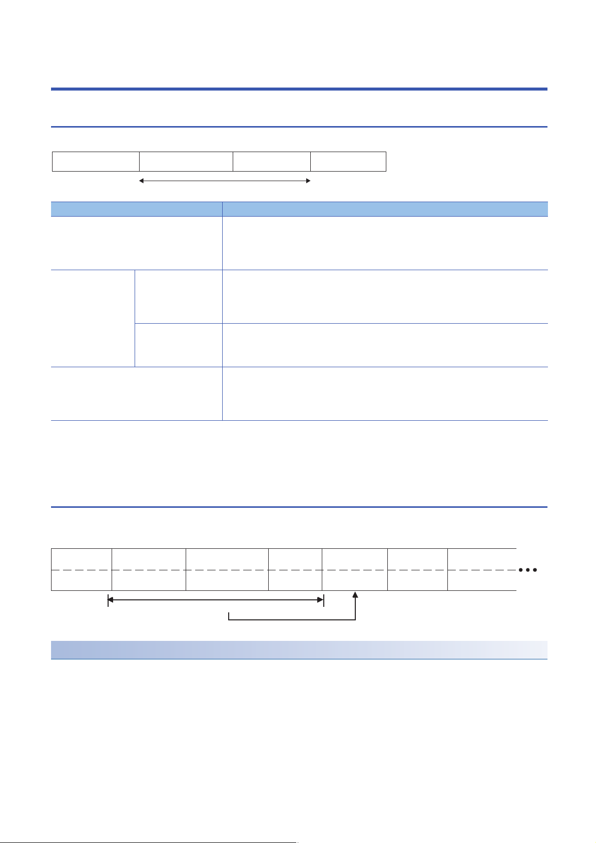
DataAddress field Function code Error check
Protocol data unit
Start
END
(Start)
DataAddress field Function code Error check Address field
3.5 character time
or more
1 byte 1 byte
0 to 252 bytes
2 bytes
3.5 character time
or more
1 byte
Error check calculation range
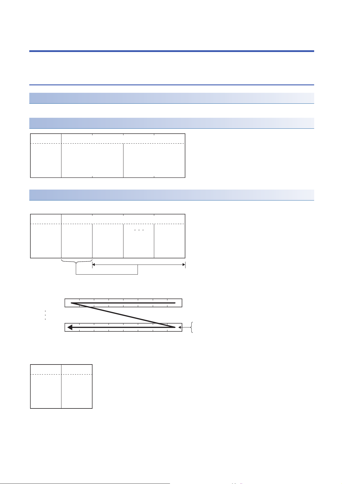
1.1 MODBUS Protocol Frame Specifications
This section describes the frame specifications of the MODBUS protocol.
Area name Description
Address field ■When request message is sent from the master to a slave
Protocol data unit Function code ■When request message is sent from the master to a slave
Data ■When request message is sent from the master to a slave
Error check The master adds a check code in a request message and transmits the request message.
The following frame modes are available.
• RTU mode
• ASCII mode
The frame mode of C24 must be consistent with that of the target device.
• 0: Sends a request message to all the slaves. (Broadcast)
• 1 to 247: Stores the target slave station number.
■When response message is sent from a slave to the master
The host station number is stored when sending a response message.
Specifies the content of the processing instructed from the master to a slave.
■When response message is sent from a slave to the master
A requested function code is stored in the case of normal completion.
The most significant bit turns ON in the case of error completion.
Stores the request content of the processing.
■When response message is sent from a slave to the master
Stores the execution result of the processing.
The slave, which received the request message, recalculates the check code in the request message
and determines whether the message is correct or not.
The message is discarded if it has an error.
The error check method differs depending on the frame mode.
6
RTU mode
In this mode, frames are received or sent in binary codes.
The frame specifications are compliant with the MODBUS protocol specifications.
Error check in RTU mode
The error check in the RTU mode is conducted by CRC (Cyclic Redundancy Check).
C24 calculates the CRC by the following steps.
Follow the same steps to calculate the CRC when conducting an error check on the target device.
1. Load the 16-bit register whose bits are all '1'.
2. The CRC is calculated every 8 bits from the upper bit of the frame.
Calculate the exclusive OR (XOR) from the 8 bits of the frame and the bits of the step 1.
3. Shift the result of step 2 by 1 bit to the right.
1 FRAME SPECIFICATIONS
1.1 MODBUS Protocol Frame Specifications
Page 9

4. If the least significant bit of the step 2 is '1', calculate the exclusive OR (XOR) from the result of step 3 and the generator
Ex.
polynomial (A001H).
If the least significant bit is '0', do not calculate the exclusive OR (XOR), but shift it by 1 bit to the right.
5. Repeat the step 3 and 4 until the bit is shifted up to 8 times.
6. Calculate the exclusive OR (XOR) from the result of step 5 and the next 8 bits of the frame.
7. Repeat the step 3 to 6.
8. Repeat the above operations until the end of the data unit is reached. The final value is a calculated CRC value.
9. The CRC value is stored in the frame in the order of lower 8 bits to upper 8 bits.
The following is a calculation example in the case where function code 07H is sent to station No.2.
Error check range is as follows:
• Address field (1 byte): 02H
• Function code (1 byte): 07H
• Data (0 bytes)
CRC error checking procedure 16-bit register (MSB) Flag
1 Loa d the 1 6 -b i t reg i ste r w hos e b its a re al l '1' . 16 - bit r egis t er w h o se b i ts a r e all ' 1'. 1111 1111 1111 1111
2 Calculate the exclusive OR (XOR) from the first 8 bits of the
frame and the bits in the above.
3 S h ift b y 1 bi t t o th e rig h t . Sh i ft 1 0111 1111 1111 111 0 1
4 Since the flag is '1', calculate the exclusive OR (XOR) from the
result in 'Shift 1' and generator polynomial (A001H).
5 S h ift b y 1 bi t t o th e rig h t . Sh i ft 2 011 0 1111 1111 1111 1
Since the flag is '1', calculate the exclusive OR (XOR) from the
result in 'Shift 2' and generator polynomial (A001H).
Sh i ft b y 1 bit t o the r igh t . Sh i f t 3 0110 0 111 1111 1111 0
Sh i ft b y 1 bit t o the r igh t . Sh i f t 4 0011 0 011 1111 1111 1
Since the flag is '1', calculate the exclusive OR (XOR) from the
result in 'Shift 4' and generator polynomial (A001H).
Sh i ft b y 1 bit t o the r igh t . Sh i f t 5 010 0 100 1 1111 1111 0
Sh i ft b y 1 bit t o the r igh t . Sh i f t 6 001 0 010 0 1111 1111 1
Since the flag is '1', calculate the exclusive OR (XOR) from the
result in 'Shift 6' and generator polynomial (A001H).
Sh i ft b y 1 bit t o the r igh t . Sh i f t 7 010 0 001 0 0111 1111 0
Shift by 1 bit to the right. Shift 8 0010 0001 0011 1111 1
Since the flag is '1', calculate the exclusive OR (XOR) from the
result in 'Shift 8' and generator polynomial (A001H).
6 Calculate the exclusive OR (XOR) from the next 8 bits of the
frame and the bits in the above.
Address field (02H) 0000 0010
Ex c lus i ve OR ( XOR ) 1111 1111 1111 11 0 1
Generator polynomial (A001H) 1010 0000 0000 0001
Ex c lus i ve OR ( XOR ) 110 1 1111 1111 1111
Generator polynomial (A001H) 1010 0000 0000 0001
Ex c lus i ve OR ( XOR ) 110 0 1111 1111 111 0
Generator polynomial (A001H) 1010 0000 0000 0001
Ex c lus i ve OR ( XOR ) 10 0 1 00 11 1111 111 0
Generator polynomial (A001H) 1010 0000 0000 0001
Ex c lus i ve OR ( XOR ) 10 0 0 01 0 0 1111 111 0
Generator polynomial (A001H) 1010 0000 0000 0001
Exclusive OR (XOR) 1000 0001 0011 1110
Function code (07H) 0000 0111
Exclusive OR (XOR) 1000 0001 0011 1001
*1
1
1 FRAME SPECIFICATIONS
1.1 MODBUS Protocol Frame Specifications
7
Page 10
Ex.
CRC error checking procedure 16-bit register (MSB) Flag
Start END
:
(3AH)
CR + LF
(0DH) (0AH)
Address field
2 characters
Function code
2 characters
Data Error check
n x 2 characters
(n = 0 to 252)
2 characters
Error check calculation range
7 Shift by 1 bit to the right. Shift 1 0100 0000 1001 1100 1
Since the flag is '1', calculate the exclusive OR (XOR) from the
result in 'Shift 1' and generator polynomial (A001H).
Shift by 1 bit to the right. Shift 2 0111 0000 0100 1110 1
Since the flag is '1', calculate the exclusive OR (XOR) from the
result in 'Shift 2' and generator polynomial (A001H).
Shift by 1 bit to the right. Shift 3 0110 1000 0010 0111 1
Since the flag is '1', calculate the exclusive OR (XOR) from the
result in 'Shift 3' and generator polynomial (A001H).
Shift by 1 bit to the right. Shift 4 0110 0100 0001 0011 0
Shift by 1 bit to the right. Shift 5 0011 0010 0000 1001 1
Since the flag is '1', calculate the exclusive OR (XOR) from the
result in 'Shift 5' and generator polynomial (A001H).
Shift by 1 bit to the right. Shift 6 0100 1001 0000 0100 0
Shift by 1 bit to the right. Shift 7 0010 0100 1000 0010 0
Shift by 1 bit to the right. Shift 8 0001 0010 0100 0001 0
8 The final value is a calculated CRC value. CRC value 12H 41H
*1 The least significant bit from the previous exclusive OR (XOR)
Generator polynomial (A001H) 1010 0000 0000 0001
Exclusive OR (XOR) 1110 0000 1001 1101
Generator polynomial (A001H) 1010 0000 0000 0001
Ex c lus i ve OR ( XOR ) 110 1 000 0 01 0 0 1111
Generator polynomial (A001H) 1010 0000 0000 0001
Exclusive OR (XOR) 1100 1000 0010 1110
Generator polynomial (A001H) 1010 0000 0000 0001
Exclusive OR (XOR) 1001 0010 0000 1000
Data is stored as follows:
Address field Function code Error check
Lower 8 bits of the CRC value Upper 8 bits of the CRC value
02H 07H 41H 12H
*1
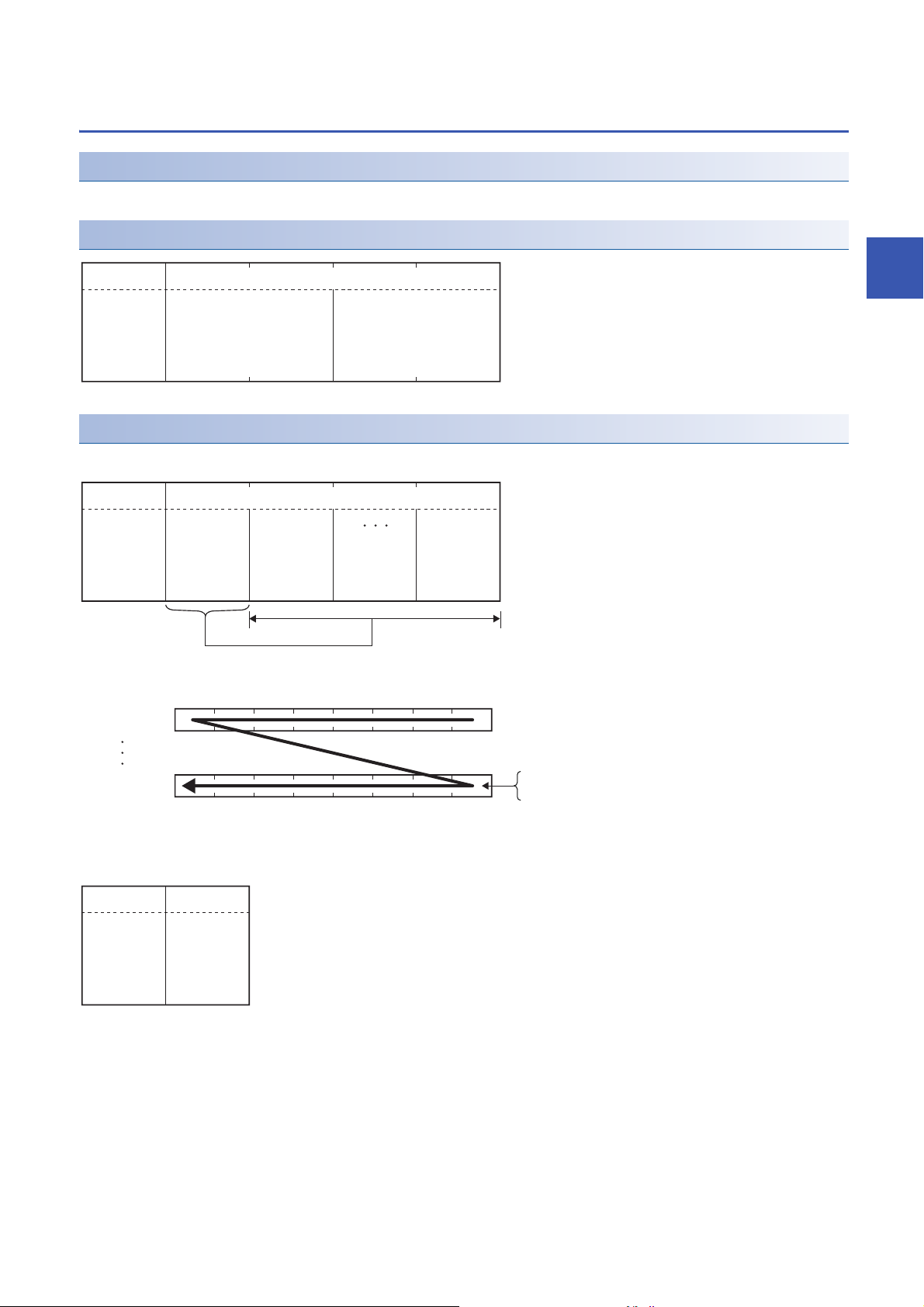
ASCII mode
In this mode, frames are received or sent in units of 2 characters (2 bytes) in ASCII codes.
The frame specifications are compliant with the MODBUS protocol specifications.
Error check in ASCII mode
The error check in the ASCII mode is conducted by LRC (Longitudinal Redundancy Check).
C24 calculates the LRC by the following steps.
Follow the same steps to calculate the LRC when conducting an error check on the target device.
1. To calculate the LRC, convert the ASCII codes within the error check range into the RTU format (binary).
2. Add the figures in units of contiguous 8 bits in the frame. (Excluding carries during addition.)
3. Change the result of step 2 to a 2's complement. (Reverse the bits and add 01H.)
4. Convert the result of step 3 to an ASCII code.
The following are calculation examples in the case where function code 01H is sent to station No.2.
Error check range of the request message is as follows:
• Address field (1 byte): 02H
• Function code (1 byte): 01H
8
1 FRAME SPECIFICATIONS
1.1 MODBUS Protocol Frame Specifications
Page 11

• Data (2 bytes): Start coil number specification (0000H), Number of read points (0008H)
Error check procedure LRC in request message transmission
1 Convert the ASCII codes within the error check range into the RTU format
(binary).
2 Add the figures. (Excluding carries during addition.) Addition result 0000 1011
3 C h ang e the r e sul t t o a 2 ' s com p leme n t. ( R eve r s e th e b its a n d ad d 01H . ) Rev e r sed b it va l ue 1111 010 0
4 Convert the result to an ASCII code. LRC value (ASCII code) F 5
Address field (02H) 0000 0010
Function code (01H) 0000 0001
Start coil number specification (H) 0000 0000
Start coil number specification (L) 0000 0000
Read points (H) 0000 0000
Read points (L) 0000 1000
01H 0000 0001
LR C val u e 1111 010 1
46H 35H
Data is stored in ASCII code as follows:
Data
category
Value 02H 01H 0000H 0008H F5H
Character0 2 0 1 00000008F5
RTU (binary) 0000 0010 0000 0001 0000 0000 0000 0000 0000 0000 0000 1000 1111 0101
ASCII code 30H 32H 30H 31H 30H 30H 30H 30H 30H 30H 30H 38H 46H 35H
Address field Function code Start coil number
specification
Read points Error check
1
The slave, which received the request message, recalculates the check code in the request message and determines
whether the message is correct or not.
Error check procedure LRC check when receiving a request message
1 Convert the ASCII codes within the error check range into the RTU format
(binary).
2 Add the LRC value. (Excluding carries during addition.)
Normally, the addition result is zero.
Address field (02H) 0000 0010
Function code (01H) 0000 0001
Start coil number specification (H) 0000 0000
Start coil number specification (L) 0000 0000
Read points (H) 0000 0000
Read points (L) 0000 1000
LR C val u e 1111 010 1
Addition result 0000 0000
1 FRAME SPECIFICATIONS
1.1 MODBUS Protocol Frame Specifications
9
Page 12
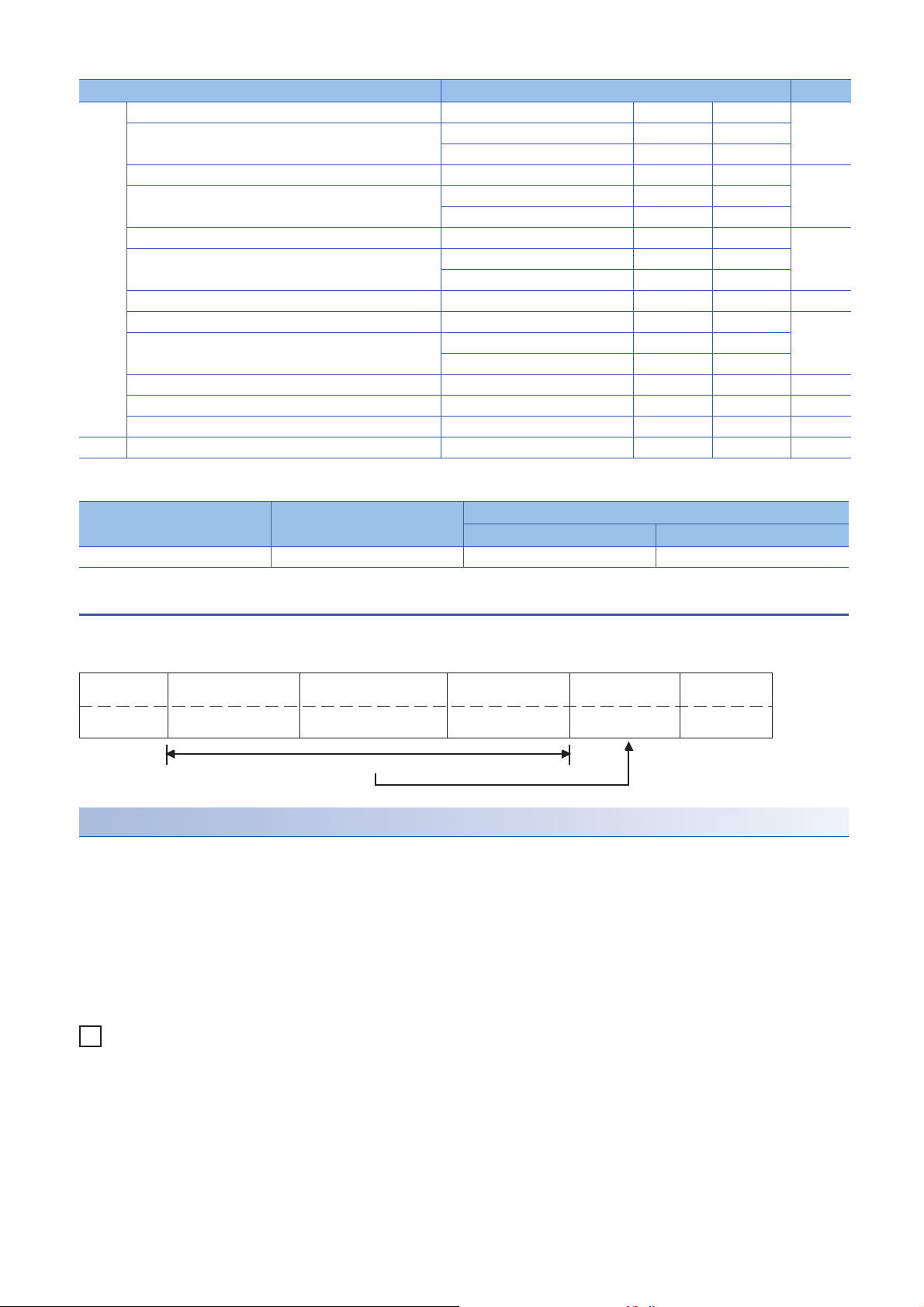
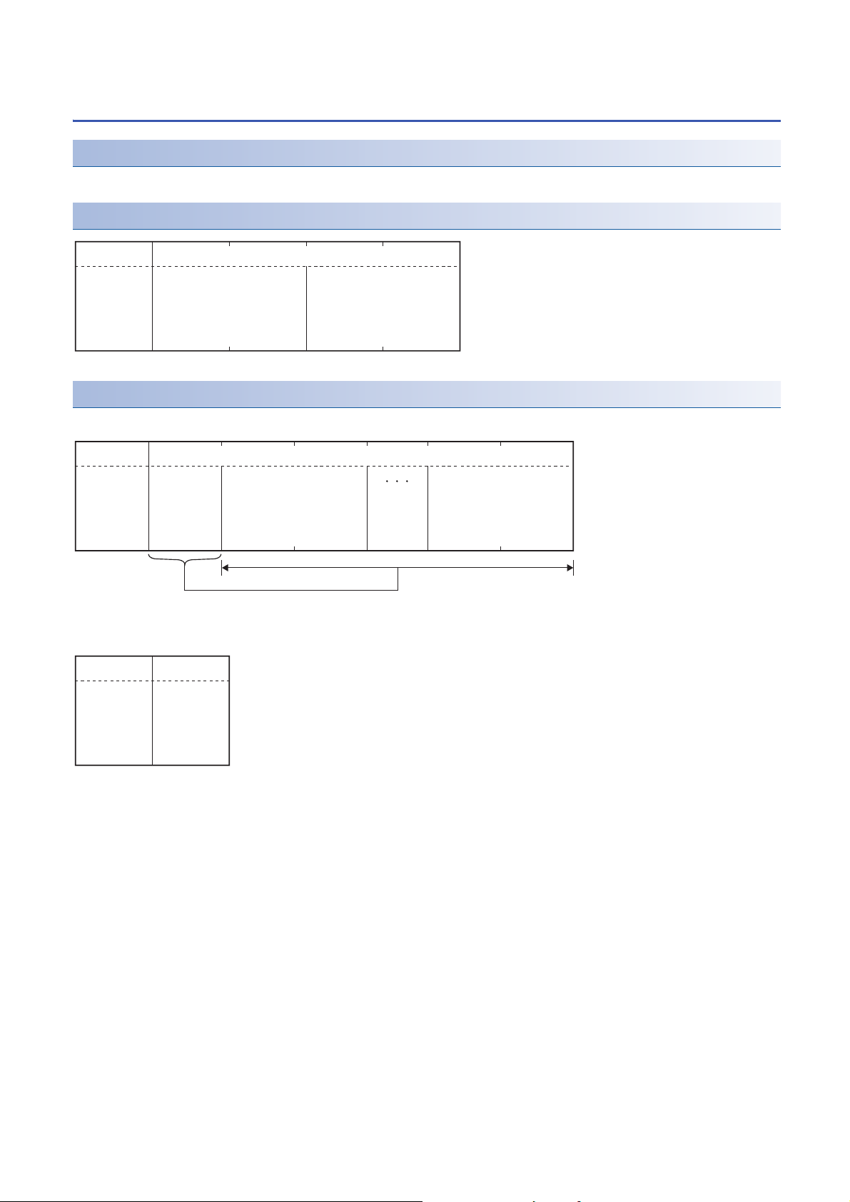
1.2 MODBUS/TCP Protocol Frame Specifications
FCSEthernet
header
Application dataIP header TCP header
(Error check)
MODBUS/TCP frame
MODBUS/TCP application data unit
MODBUS application header
Transaction IDProtocol ID Message
length
Module ID Function code Data
Protocol data unit
This section describes the frame specifications of the MODBUS/TCP protocol.
Area name Area size Description
MODBUS application header Communication ID 2 bytes Used by the master to match response messages from slaves.
Protocol ID 2 bytes Indicates the protocol of the protocol data unit.
For MODBUS/TCP, 0 is stored.
Message length 2 bytes Stores the message size in bytes.
Module ID 1 byte Used when specifying slaves connected to other lines, such as with
Protocol data unit Function code 1 byte Specifies the content of the processing instructed from the master to a
Data 1 to 252 bytes ■When request message is sent from the master to a slave
The stored message length indicates the length of the message in
areas subsequent to this area.
the MODBUS Serial protocol.
slave.
Stores the request content of the processing.
■When response message is sent from a slave to the master
Stores the execution result of the processing.
10
1 FRAME SPECIFICATIONS
1.2 MODBUS/TCP Protocol Frame Specifications
Page 13
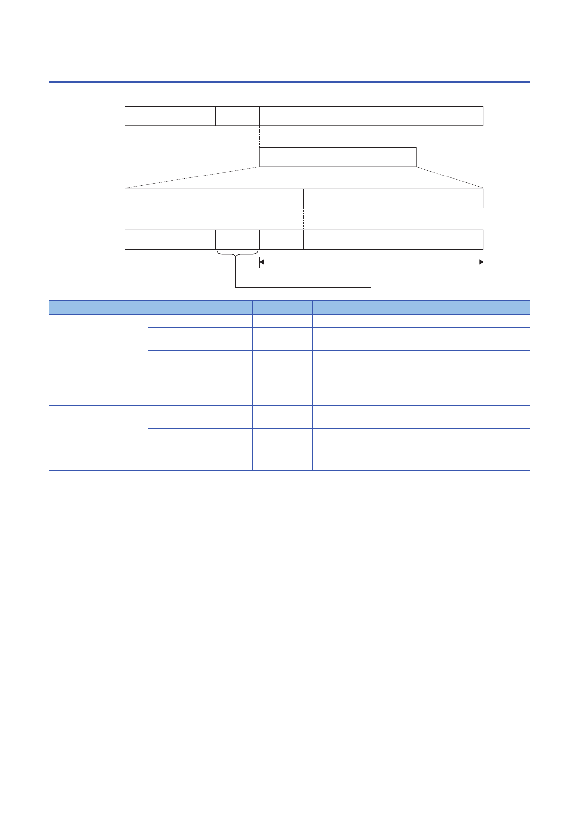
1.3 Protocol Data Unit Formats Grouped by Function
Ex.
(H) (L)
(1)
(H) (L)
02H 001FH 0001H
Start input number specification
Data
Number of read points
Function code
(H) (L) (H) (L)
01H
(1)
(2)
(3)
(4)
Start coil number specification
Data
Number of read points
Function code
1 byte
(8 bits)
1 byte
(8 bits)
(0000H to FFFFH) (0001H to 07D0H)
This section describes the protocol data unit formats of the MODBUS standard functions.
When the device number is specified within the message
When specifying the device number within the message, specify "device number - 1".
However, this instruction is not applicable to the file number and the device number specified for reading or writing extended
file register.
When the status of input 32 (100032) is read by the read discrete inputs (function code: 02H)
(1) When reading the status of input 32 (100032), specify 31 (001FH) for the start input number.
The device number stored in the response message is "the device number of the device that actually performed reading/
writing - 1".
Descriptions of request message and response message formats
This section describes descriptions of the request message and response message formats of the MODBUS standard
functions.
1
■ Message format for MODBUS RTU mode and MODBUS/TCP
(1) Area name
(2) Frame description
(3) For request message format: Setting range
For response message format: Value stored in the response message
(4) When one piece of data consists of two bytes, the upper byte (eight bits) is (H) and the lower byte (eight bits) is (L).
■ Message format for MODBUS ASCII mode
The message format shown in Chapter 3 is for RTU mode or MODBUS/TCP.
In the ASCII mode, read the values shown in Chapter 3 in ASCII code.
1 FRAME SPECIFICATIONS
1.3 Protocol Data Unit Formats Grouped by Function
11
Page 14

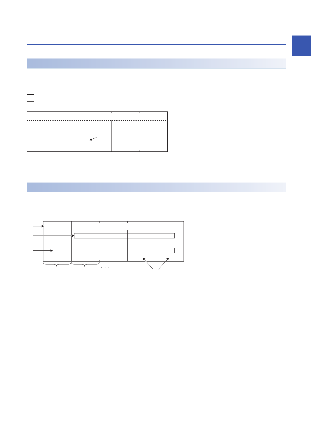
■ Response message format
(H) (L) (H) (L)
01H
(H) (L) (H) (L) (H)
(L)
(30H) (31H) (30H) (30H) (36H) (45H) (30H) (30H) (33H) (46H)
0 FE61 30000
(006EH) (003FH)
Start coil number specification
Data
Number of read points
Function code
Data
Start coil number specification
Number of read points
Function code
(RTU mode)
(ASCII mode)
Convert RTU mode to ASCII mode
The format of the response message sent from a slave to the master varies depending on whether the processing performed
by the slave completed successfully or completed with an error.
In the MODBUS standard function, the formats when completed successfully and completed with an error are described in the
response message format.
Storage locations of exception code and error code
When processing on a slave is completed with an error, an exception code is sent to the master.
For details on exception codes, refer to the following.
Page 50 EXCEPTION CODES
Exception codes are also stored in the buffer memory of modules.
The detailed cause is detected as an error by modules.
For details on the buffer memory and errors of modules, refer to the following.
MELSEC iQ-R Ethernet User's Manual (Application)
MELSEC iQ-R Serial Communication Module User's Manual(Application)
12
1 FRAME SPECIFICATIONS
1.3 Protocol Data Unit Formats Grouped by Function
Page 15

2 MODBUS STANDARD FUNCTION LIST
This chapter lists the MODBUS standard functions and availability for modules when using the slave function.
The modules are abbreviated as follows:
• C24: RJ71C24, RJ71C24-R2, RJ71C24-R4
• E71: RJ71EN71, R04ENCPU, R08ENCPU, R16ENCPU, R32ENCPU, R120ENCPU
: Available, : Not available
Function code
(FC)
01H Read coils Page 14 Read Coils (FC: 01H)
02H Read discrete inputs Page 15 Read Discrete Inputs (FC: 02H)
03H Read holding registers Page 16 Read Holding Registers (FC: 03H)
04H Read input registers Page 17 Read Input Registers (FC: 04H)
05H Write single coil Page 18 Write Single Coil (FC: 05H)
06H Write single register Page 19 Write Single Register (FC: 06H)
07H Read exception status Page 20 Read Exception Status (FC: 07H)
08H Page 13 Diagnosis function
0BH Get communications event
0CH Get communications event log Page 39 Get Communications Event Log (FC: 0CH)
0FH Write multiple coils Page 41 Write Multiple Coils (FC: 0FH)
10H Write multiple registers Page 42 Write Multiple Registers (FC: 10H)
11H Report slave ID Page 43 Report Slave ID (FC: 11H)
14H 06H Read file record Page 45 Read File Record (FC: 14H) (SC: 06H)
15H 06H Write file record Page 47 Write File Record (FC: 15H) (SC: 06H)
16H Mask write register Page 48 Mask Write Register (FC: 16H)
17H Read/Write multiple registers Page 49 Read/Write Multiple Registers (FC: 17H)
Sub code (SC) Function name C24 E71 Reference
Page 21 Diagnostics (FC: 08H)
details
Page 38 Get Communications Event Counter (FC: 0BH)
counter
2
Diagnosis function details
Function code
(FC)
08H 0000H Return query data Page 22 Return query data (sub-function code: 00H)
Sub-function
code
0001H Restart communications option Page 23 Restart communications option (sub-function code: 01H)
0002H Return diagnostic register Page 24 Return diagnostic register (sub-function code: 02H)
0003H Change ASCII input delimiter Page 25 Change ASCII input delimiter (sub-function code: 03H)
0004H Force listen only mode Page 26 Force listen only mode (sub-function code: 04H)
000AH Clear counters and diagnostic
000BH Return bus message count Page 28 Return bus message count (sub-function code: 0BH)
000CH Return bus communication error
000DH Return bus exception error count Page 30 Return bus exception error count (sub-function code: 0DH)
000EH Return slave message count Page 31 Return slave message count (sub-function code: 0EH)
000FH Return slave no response count Page 32 Return slave no response count (sub-function code: 0FH)
0010H Return slave NAK count Page 33 Return slave NAK count (sub-function code: 10H)
0011H Return slave busy count Page 34 Return slave busy count (sub-function code: 11H)
0012H Return bus character overrun
0013H Return IOP overrun error count Page 36 Return IOP overrun error count (sub-function code: 13H)
0014H Clear overrun counter and flag Page 37 Clear overrun counter and flag (sub-function code: 14H)
Function name Reference
Page 27 Clear counters and diagnostic register (sub-function code: 0AH)
register
Page 29 Return bus communication error count (sub-function code: 0CH)
count
Page 35 Return bus character overrun count (sub-function code: 12H)
count
2 MODBUS STANDARD FUNCTION LIST
13
Page 16
3 MODBUS STANDARD FUNCTION DETAILS
(H) (L) (H) (L)
01H
Data
Number of read pointsStart coil number specification
Function code
(0000H to FFFFH) (0001H to 07D0H)
01H
DataFunction code
Number of read
bytes n
Device data 1 Device data n
Number of read bytes n
b0b1b2b3b4b5b6b7
0: OFF
1: ON
Device data 1
Device data n
Bit device storage order
81H
Data
Exception code
Function code
This chapter describes protocol data unit formats.
3.1 Read Coils (FC: 01H)
Operation description
Reads the status (ON/OFF) of one or multiple coils.
Request message format (from master to slave)
Response message format (from slave to master)
■ When completed successfully
14
• Device data 1 to n
• The read coil status is stored in the order of lower bit to higher bit.
• If the number of read points is not a multiple of eight, the remaining bits are all set to 0.
■ When completed with an error
3 MODBUS STANDARD FUNCTION DETAILS
3.1 Read Coils (FC: 01H)
Page 17
3.2 Read Discrete Inputs (FC: 02H)
(H) (L) (H) (L)
02H
Start input number specification
Data
Number of read points
Function code
(0000H to FFFFH) (0001H to 07D0H)
02H
DataFunction code
Number of read
bytes n
Device data 1 Device data n
Number of read bytes n
b0b1b2b3b4b5b6b7
0: OFF
1: ON
Device data 1
Device data n
Bit device storage order
82H
Data
Exception code
Function code
Operation description
Reads the status (ON/OFF) of one or multiple inputs.
Request message format (from master to slave)
Response message format (from slave to master)
■ When completed successfully
3
• Device data 1 to n
• The read input status is stored in the order of lower bit to higher bit.
• If the number of read points is not a multiple of eight, the remaining bits are all set to 0.
■ When completed with an error
3 MODBUS STANDARD FUNCTION DETAILS
3.2 Read Discrete Inputs (FC: 02H)
15
Page 18
3.3 Read Holding Registers (FC: 03H)
(H) (L) (H) (L)
03H
Start holding register number
specification
Data
Number of read points
Function code
(0000H to FFFFH) (0001H to 007DH)
03H
(H) (L) (H) (L)
DataFunction code
Number of read
bytes n×2
Device data 1 Device data n
Number of read bytes n×2
83H
Data
Exception code
Function code
Operation description
Reads one or multiple holding register values.
Request message format (from master to slave)
Response message format (from slave to master)
■ When completed successfully
• For example, when n = 4, the number of read bytes is 4 2 = 8.
■ When completed with an error
16
3 MODBUS STANDARD FUNCTION DETAILS
3.3 Read Holding Registers (FC: 03H)
Page 19

3.4 Read Input Registers (FC: 04H)
(H) (L) (H) (L)
04H
Data
Number of read pointsStart input register number
specification
Function code
(0000H to FFFFH) (0001H to 007DH)
04H
(H) (L) (H) (L)
DataFunction code
Number of read
bytes n×2
Device data 1 Device data n
Number of read bytes n×2
84H
Data
Exception code
Function code
Operation description
Reads one or multiple input register values.
Request message format (from master to slave)
Response message format (from slave to master)
■ When completed successfully
3
• For example, when n = 4, the number of read bytes is 4 2 = 8.
■ When completed with an error
3 MODBUS STANDARD FUNCTION DETAILS
3.4 Read Input Registers (FC: 04H)
17
Page 20

3.5 Write Single Coil (FC: 05H)
(H) (L) (H) (L)
05H
FF00H: ON
0000H: OFF
Coil number specification
Data
ON/OFF specification
Function code
(0000H to FFFFH)
85H
Data
Exception code
Function code
Operation description
Writes a value (ON/OFF) to one coil.
Request message format (from master to slave)
Response message format (from slave to master)
■ When completed successfully
The slave returns the request message received from the master as-is.
■ When completed with an error
18
3 MODBUS STANDARD FUNCTION DETAILS
3.5 Write Single Coil (FC: 05H)
Page 21

3.6 Write Single Register (FC: 06H)
(H) (L) (H) (L)
06H
Holding register number
specification
Data
Write data
Function code
(0000H to FFFFH) (0000H to FFFFH)
86H
Data
Exception code
Function code
Operation description
Writes a value to one holding register area.
Request message format (from master to slave)
Response message format (from slave to master)
■ When completed successfully
The slave returns the request message received from the master as-is.
■ When completed with an error
3
3 MODBUS STANDARD FUNCTION DETAILS
3.6 Write Single Register (FC: 06H)
19
Page 22

3.7 Read Exception Status (FC: 07H)
07H
Function code
07H
Data
Error information
Function code
87H
Data
Exception code
Function code
Operation description
Reads the error status.
Request message format (from master to slave)
Response message format (from slave to master)
■ When completed successfully
In the error information, the specified device data by "Specifying the error status" of the parameter is stored.
MELSEC iQ-R Serial Communication Module User's Manual(Application)
■ When completed with an error
20
3 MODBUS STANDARD FUNCTION DETAILS
3.7 Read Exception Status (FC: 07H)
Page 23

3.8 Diagnostics (FC: 08H)
Executes the various diagnostics and checks the C24 status and communication status.
In the diagnostics, a sub-function code is specified after a function code with a request message.
Checking communication conditions using a diagnostic counter
When using the MODBUS slave function, the number of error occurrences during communication is stored in a diagnostic
counter.
The communication status of MODBUS can be checked by a diagnostic counter of the MODBUS standard function.
■ Diagnostic counter
Counter Buffer memory MODBUS standard function
Typ e Description CH1 CH2
Bus message count
Bus communication error
*1
count
Exception error count Counts the number of exception error occurrences.
Slave message count Counts the number of times that messages addressed to the
Slave no-response count Counts the number of times that broadcast request messages
Slave NAK count Refers to the number of times that NAK responses were
Slave busy count Refers to the number of times that busy responses were
Character overrun count Counts the number of times that the request message size
*1
Counts the number of messages detected on the line. 32512
Counts the number of the following error messages detected on
the line.
• CRC/LRC error message
• Overrun/parity error
• Short frame (less than 3 bytes)
• Character overrun (256 bytes or more)
Messages other than the above are counted by the bus
message count.
(Including broadcast messages)
host were processed.
(Including when broadcast request messages were received)
were received.
received in a master device.
It is always '0' in C24s.
received in a master device.
It is always '0' in C24s.
exceeded the upper limit.
(7F00H)
32513
(7F01H)
32522
(7F0AH)
32518
(7F06H)
32519
(7F07H)
32520
(7F08H)
32521
(7F09H)
32514
(7F02H)
32576
(7F40H)
32577
(7F41H)
32586
(7F4AH)
32582
(7F46H)
32583
(7F47H)
32584
(7F48H)
32585
(7F49H)
32578
(7F42H)
Page 28 Return bus message
count (sub-function code: 0BH)
Page 29 Return bus
communication error count (subfunction code: 0CH)
Page 30 Return bus exception
error count (sub-function code: 0DH)
Page 31 Return slave message
count (sub-function code: 0EH)
Page 32 Return slave no response
count (sub-function code: 0FH)
Page 33 Return slave NAK count
(sub-function code: 10H)
Page 34 Return slave busy count
(sub-function code: 11H)
Page 35 Return bus character
overrun count (sub-function code: 12H)
Page 36 Return IOP overrun error
count (sub-function code: 13H)
3
*1 The bus message count is in an exclusive relationship with the bus communication error count.
■ Count range
0000H to FFFFH are counted.
The count is stopped if it has reached FFFFH. To continue, clear the counter.
■ Methods for clearing a counter
A counter can be cleared by any of the following methods:
• Turning the power OFF and ON
• Resetting a CPU module
• Clearing the buffer memory to '0' by using a sequence program
• Receiving the following MODBUS standard functions
Counter to be cleared MODBUS standard function
All diagnostic counters shown above Page 23 Restart communications option (sub-function code: 01H)
Page 27 Clear counters and diagnostic register (sub-function code: 0AH)
Character overrun count Page 37 Clear overrun counter and flag (sub-function code: 14H)
3 MODBUS STANDARD FUNCTION DETAILS
3.8 Diagnostics (FC: 08H)
21
Page 24

Return query data (sub-function code: 00H)
(H) (L)
08H (0000H)
DataFunction code Sub-function code
Arbitrary data
88H
Data
Exception code
Function code
Operation description
Returns the contents of the request message without change.
Used to check if the network or the target device is operating normally. (Loopback test)
Request message format (from master to slave)
Response message format (from slave to master)
■ When completed successfully
The slave returns the request message received from the master as-is.
■ When completed with an error
22
3 MODBUS STANDARD FUNCTION DETAILS
3.8 Diagnostics (FC: 08H)
Page 25

Restart communications option (sub-function code: 01H)
(H) (L)
08H (0001H)
(H) (L)
DataFunction code Sub-function code
Clear setting of
Communications event log
FF00H: Clear
0000H: Not clear
88H
Data
Exception code
Function code
Operation description
Initializes the communication port of the receiving channel side and restarts the slave function.
Restart is performed after returning the response message corresponding to a request message.
The operation status returns to online mode when it was in the listen only mode.
The following data are cleared when executing the restart communications option.
• Data being received
• 'CH1/2 side LED lighting status and communication error status' of the buffer memory (Un\G513/Un\G514)
• 'CH1/2 side exception code storage area' of the buffer memory (Un\G28674/Un\G28676)
*1
• Diagnostic counter (Page 21 Checking communication conditions using a diagnostic counter)
• ERR LED and C ERR LED OFF
*2
• Communications event count (Page 38 Get Communications Event Counter (FC: 0BH))
*1 Clears only the receiving channel side area.
*2 Clears the errors of the channel that has received the request message.
As the errors of other channels are not cleared, the LED will not turn OFF if an error has occurred on any other channel.
Clears the the following data when "Clear setting of the communications event log" is specified with "FF00H (clear)" in the
request message.
• Communications event log (Page 39 Get Communications Event Log (FC: 0CH))
Request message format (from master to slave)
*1
3
Response message format (from slave to master)
■ When completed successfully
The slave returns the request message received from the master as-is.
■ When completed with an error
3 MODBUS STANDARD FUNCTION DETAILS
3.8 Diagnostics (FC: 08H)
23
Page 26

Return diagnostic register (sub-function code: 02H)
(H) (L)
08H (0002H) (0000H)
(H) (L)
DataFunction code Sub-function code
(H) (L)
08H (0002H)
(H) (L)
b0b1b2b3b4b5b6b7b8b9b10b11b12b13b14b15
0 0 0 1/0 1/0 1/0 1/0 1/0 0 0 0 1/0 1/0 1/0 1/0 1/0
CH1 C/N
CH1 P/S
CH1 PRO.
CH1 SIO
CH1 ERR.
CH2 C/N
CH2 P/S
CH2 PRO.
CH2 SIO
CH2 ERR.
DataFunction code Sub-function code
Diagnostic register value
CH1 side Detailed
LED status
(0: OFF, 1: ON)
CH2 side Detailed
LED status
(0: OFF, 1: ON)
Unused (Fixed to 0)
Unused (Fixed to 0)
88H
Data
Exception code
Function code
Operation description
Reads out the detailed LED status of C24 to the master.
Request message format (from master to slave)
Response message format (from slave to master)
■ When completed successfully
In the C24, the detailed LED status of 'CH1/2 side LED lighting status and communication error status' of the buffer memory
(Un\G513/Un\G514) is stored as the diagnostic register.
■ When completed with an error
24
3 MODBUS STANDARD FUNCTION DETAILS
3.8 Diagnostics (FC: 08H)
Page 27

Change ASCII input delimiter (sub-function code: 03H)
Start END
CR + LF
(0DH) (0AH)
:
(3AH)
Address field
2 characters
Function code
2 characters
Data Error check
n x 2 characters
(n = 0 to 252)
2 characters
Change this into a specified data.
(H) (L)
08H (0003H) (00H)
DataFunction code Sub-function code
Input delimiter
setting
(00H to FFH)
88H
Data
Exception code
Function code
Operation description
Changes the 2nd byte (LF(0AH)) of the end code in the ASCII mode to a specified data.
The specified data is stored in '2nd byte of end code' of the buffer memory (Un\G32524/Un\G32588).
Request message format (from master to slave)
Response message format (from slave to master)
3
■ When completed successfully
The slave returns the request message received from the master as-is.
■ When completed with an error
This function is used only for 1:1 connections.
Do not use this function for 1:n connections.
3 MODBUS STANDARD FUNCTION DETAILS
3.8 Diagnostics (FC: 08H)
25
Page 28

Force listen only mode (sub-function code: 04H)
(H) (L)
08H (0004H) (0000H)
(H) (L)
DataFunction code Sub-function code
88H
Data
Exception code
Function code
Operation description
Places a slave into the offline mode.
Used when disconnecting a slave from the network.
When C24 is set in the listen only mode, the status is as follows:
• Ignores all request messages except for those of restart communications option. (Page 23 Restart communications
option (sub-function code: 01H))
• Stops counting of the diagnostic counter. (Page 21 Checking communication conditions using a diagnostic counter)
• Continues recording with the communications event log. (Page 39 Get Communications Event Log (FC: 0CH))
Request message format (from master to slave)
Response message format (from slave to master)
■ When completed successfully
No response message is returned because the listen only mode (offline status) is active.
■ When completed with an error
Whether the C24 has been switched to listen only mode or not can be checked in the 'Communications mode'
of the buffer memory (Un\G32525/32589).
• 0000H: Online mode
• 0001H: Listen only mode
The listen only mode can be changed to online mode by either of the following:
• Restart communications option (Page 23 Restart communications option (sub-function code: 01H))
• Turn the power OFF and ON, or reset the programmable controller CPU.
26
3 MODBUS STANDARD FUNCTION DETAILS
3.8 Diagnostics (FC: 08H)
Page 29

Clear counters and diagnostic register (sub-function code: 0AH)
(H) (L)
08H (000AH) (0000H)
(H) (L)
DataFunction code Sub-function code
88H
Data
Exception code
Function code
Operation description
Clears counters (e.g. message count).
Also, clears the diagnostic register and the error of the channel where the request message has been received.
The following counters will be cleared.
• Diagnostic counter (Page 21 Checking communication conditions using a diagnostic counter)
• Communications event count (Page 38 Get Communications Event Counter (FC: 0BH))
The following diagnostic resisters will be cleared.
• 'CH1/2 side LED lighting status and communication error status' of the buffer memory (Un\G513/Un\G514)
• 'CH1/2 side exception code storage area' of the buffer memory (Un\G28674/Un\G28676)
*1 Clears only the receiving channel side area.
*1
Request message format (from master to slave)
*1
3
Response message format (from slave to master)
■ When completed successfully
The slave returns the request message received from the master as-is.
■ When completed with an error
3 MODBUS STANDARD FUNCTION DETAILS
3.8 Diagnostics (FC: 08H)
27
Page 30

Return bus message count (sub-function code: 0BH)
(H) (L)
08H (000BH) (0000H)
(H) (L)
DataFunction code Sub-function code
(H) (L)
(H) (L)
08H (000BH)
Function code Sub-function code
Bus message count value
Data
(0000H to FFFFH)
88H
Data
Exception code
Function code
Operation description
Reads out the number of messages detected on the line to the master.
Request message format (from master to slave)
Response message format (from slave to master)
■ When completed successfully
Returns the count value of the buffer memory listed below to the master.
• 'Bus message count' (Un\G32512/Un\G32576)
Refer to the following for the counter descriptions, count range, and count clear methods.
Page 21 Checking communication conditions using a diagnostic counter
■ When completed with an error
28
3 MODBUS STANDARD FUNCTION DETAILS
3.8 Diagnostics (FC: 08H)
Page 31

Return bus communication error count (sub-function code: 0CH)
(H) (L)
08H (000CH) (0000H)
(H) (L)
DataFunction code Sub-function code
(H) (L)
(H) (L)
08H (000CH)
Function code Sub-function code
Bus communication
error count value
Data
(0000H to FFFFH)
88H
Data
Exception code
Function code
Operation description
Reads out the number of error messages detected on the line to the master.
Request message format (from master to slave)
Response message format (from slave to master)
■ When completed successfully
3
Returns the count value of the buffer memory listed below to the master.
• 'Bus communication error count' (Un\G32513/Un\G32577)
Refer to the following for the counter descriptions, count range, and count clear methods.
Page 21 Checking communication conditions using a diagnostic counter
■ When completed with an error
3 MODBUS STANDARD FUNCTION DETAILS
3.8 Diagnostics (FC: 08H)
29
Page 32

Return bus exception error count (sub-function code: 0DH)
(H) (L)
08H (000DH) (0000H)
(H) (L)
DataFunction code Sub-function code
(H) (L)
(H) (L)
08H (000DH)
Function code Sub-function code
Exception error count value
Data
(0000H to FFFFH)
88H
Data
Exception code
Function code
Operation description
Reads out the frequency of exception errors to the master.
Request message format (from master to slave)
Response message format (from slave to master)
■ When completed successfully
Returns the count value of the buffer memory listed below to the master.
• 'Exception error count' (Un\G332522/Un\G32586)
Refer to the following for the counter descriptions, count range, and count clear methods.
Page 21 Checking communication conditions using a diagnostic counter
■ When completed with an error
30
3 MODBUS STANDARD FUNCTION DETAILS
3.8 Diagnostics (FC: 08H)
Page 33

Return slave message count (sub-function code: 0EH)
(H) (L)
08H (000EH) (0000H)
(H) (L)
DataFunction code Sub-function code
(H) (L)
(H) (L)
08H (000EH)
Function code Sub-function code
Slave message count value
Data
(0000H to FFFFH)
88H
Data
Exception code
Function code
Operation description
Reads out the number of the slave message processing to the master (including receive of request messages from
broadcast).
Request message format (from master to slave)
Response message format (from slave to master)
■ When completed successfully
3
Returns the count value of the buffer memory listed below to the master.
• 'Slave message count' (Un\G32518/Un\G32582)
Refer to the following for the counter descriptions, count range, and count clear methods.
Page 21 Checking communication conditions using a diagnostic counter
■ When completed with an error
3 MODBUS STANDARD FUNCTION DETAILS
3.8 Diagnostics (FC: 08H)
31
Page 34

Return slave no response count (sub-function code: 0FH)
(H) (L)
08H (000FH) (0000H)
(H) (L)
DataFunction code Sub-function code
(H) (L)
(H) (L)
08H (000FH)
Function code Sub-function code
Slave no-response count value
Data
(0000H to FFFFH)
88H
Data
Exception code
Function code
Operation description
Reads to out the number of broadcast request messages received to the master.
Request message format (from master to slave)
Response message format (from slave to master)
■ When completed successfully
Returns the count value of the buffer memory listed below to the master.
• 'Slave no-response count' (Un\G32519/Un\G32583)
Refer to the following for the counter descriptions, count range, and count clear methods.
Page 21 Checking communication conditions using a diagnostic counter
■ When completed with an error
32
3 MODBUS STANDARD FUNCTION DETAILS
3.8 Diagnostics (FC: 08H)
Page 35

Return slave NAK count (sub-function code: 10H)
(H) (L)
08H (0010H) (0000H)
(H) (L)
DataFunction code Sub-function code
(H) (L)
(H) (L)
08H (0010H)
Function code Sub-function code
Slave NAK count value
Data
(0000H)
88H
Data
Exception code
Function code
Operation description
Reads out the number of NAK responses to the master.
Request message format (from master to slave)
Response message format (from slave to master)
■ When completed successfully
3
Returns the count value of the buffer memory listed below to the master.
• 'Slave NAK count' (Un\G32520/Un\G32584)
It is always '0' in C24s.
■ When completed with an error
3 MODBUS STANDARD FUNCTION DETAILS
3.8 Diagnostics (FC: 08H)
33
Page 36

Return slave busy count (sub-function code: 11H)
(H) (L)
08H (0011H) (0000H)
(H) (L)
DataFunction code Sub-function code
(H) (L)
(H) (L)
08H (0011H)
Function code Sub-function code
Slave busy count value
Data
(0000H)
88H
Data
Exception code
Function code
Operation description
Reads out the number of busy responses to the master.
Request message format (from master to slave)
Response message format (from slave to master)
■ When completed successfully
Returns the count value of the buffer memory listed below to the master.
• 'Slave busy count' (Un\G32521/Un\G32585)
It is always '0' in C24s.
■ When completed with an error
34
3 MODBUS STANDARD FUNCTION DETAILS
3.8 Diagnostics (FC: 08H)
Page 37

Return bus character overrun count (sub-function code: 12H)
(H) (L)
08H (0012H) (0000H)
(H) (L)
DataFunction code Sub-function code
(H) (L)
(H) (L)
08H (0012H)
Function code Sub-function code
Bus character overrun
count value
Data
(0000H to FFFFH)
88H
Data
Exception code
Function code
Operation description
To the master, reads out the number of times the request message size exceeds the upper limit.
Request message format (from master to slave)
Response message format (from slave to master)
■ When completed successfully
3
Returns the count value of the buffer memory listed below to the master.
• 'Character overrun count' (Un\G32514/Un\G32578)
Refer to the following for the counter descriptions, count range, and count clear methods.
Page 21 Checking communication conditions using a diagnostic counter
■ When completed with an error
3 MODBUS STANDARD FUNCTION DETAILS
3.8 Diagnostics (FC: 08H)
35
Page 38

Return IOP overrun error count (sub-function code: 13H)
(H) (L)
08H (0013H) (0000H)
(H) (L)
DataFunction code Sub-function code
(H) (L)
(H) (L)
08H (0013H)
Function code Sub-function code Data
(0000H to FFFFH)
Bus character overrun
count value
88H
Data
Exception code
Function code
Operation description
Reads the IOP overrun error count value to the master.
C24 returns to the master the number of times the request message size exceeds the upper limit. (Same as the Return bus
character overrun count)
Request message format (from master to slave)
Response message format (from slave to master)
■ When completed successfully
Returns the count value of the buffer memory listed below to the master.
• 'Character overrun count' (Un\G32514/Un\G32578)
Refer to the following for the counter descriptions, count range, and count clear methods.
Page 21 Checking communication conditions using a diagnostic counter
■ When completed with an error
36
3 MODBUS STANDARD FUNCTION DETAILS
3.8 Diagnostics (FC: 08H)
Page 39

Clear overrun counter and flag (sub-function code: 14H)
(H) (L)
08H (0014H) (0000H)
(H) (L)
DataFunction code Sub-function code
88H
Data
Exception code
Function code
Operation description
Clears the overrun error counter and flag.
C24 clears the character overrun count value.
Request message format (from master to slave)
Response message format (from slave to master)
■ When completed successfully
The slave returns the request message received from the master as-is.
■ When completed with an error
3
3 MODBUS STANDARD FUNCTION DETAILS
3.8 Diagnostics (FC: 08H)
37
Page 40

3.9 Get Communications Event Counter (FC: 0BH)
0BH
Function code
(H) (L) (H) (L)
0BH
(0000H)
Program command status
Data
Communications
event count value
Function code
(0000H to FFFFH)
8BH
Data
Exception code
Function code
Operation description
Acquires the number of messages whose requested actions (read/write, diagnostics, etc.) have been normally completed.
Whether the action corresponding to the request message is normally completed or not can be checked.
Request message format (from master to slave)
Response message format (from slave to master)
■ When completed successfully
Since C24 does not support any program commands, 0000H is stored in the program command status.
Returns the count value of the buffer memory listed below to the master.
• 'Communications event count' (Un\G32523 to Un\G32587)
The count is stopped if it has reached FFFFH.
Reset the counter by any of the following methods when restarting the count.
• Restart communications option (Page 23 Restart communications option (sub-function code: 01H))
• Clear counters and diagnostic register (Page 27 Clear counters and diagnostic register (sub-function code: 0AH))
• Turn the power OFF and ON, or reset the programmable controller CPU.
■ When completed with an error
38
3 MODBUS STANDARD FUNCTION DETAILS
3.9 Get Communications Event Counter (FC: 0BH)
Page 41

3.10 Get Communications Event Log (FC: 0CH)
0CH
Function code
0CH
(H) (L) (H) (L) (H) (L)
(0000H)
DataFunction code
Communications event
count value
Program command status
Communications
event log No. 0
Bus message count value
Communications
event log No. 63
(0000H
to
FFFFH)
(0000H to FFFFH)
Number of
read bytes
Number of read bytes
8CH
Data
Exception code
Function code
Operation description
Acquires the communications event log into the master.
Request message format (from master to slave)
Response message format (from slave to master)
■ When completed successfully
3
Since C24 does not support any program commands, 0000H is stored in the program command status.
Returns the count values of the buffer memory listed below to the master.
• 'Communications event count' (Un\G32523 to Un\G32587)
• 'Bus message count' (Un\G32512/Un\G32576)
• 'Communications event log 1 to 64' (Un\G32544 to Un\G32575/Un\G32608 to Un\G32639)
Refer to the following for the counter descriptions, count range, and count clear methods.
Page 21 Checking communication conditions using a diagnostic counter
Page 38 Get Communications Event Counter (FC: 0BH)
For details on the communications event log, refer to the following.
Page 40 Communications event log
■ When completed with an error
3 MODBUS STANDARD FUNCTION DETAILS
3.10 Get Communications Event Log (FC: 0CH)
39
Page 42

Communications event log
10001/0 1/0 1/0 1/0
b0b1b2b3b4b5b6b7
When the get communications event log (FC: 0CH) is received from the master, C24 returns the following data of the buffer
memory.
• 'Communications event log 1 to 64' (Un\G32544 to Un\G32575/Un\G32608 to Un\G32639)
The number of communications event logs can be checked in the buffer memory 'Communications event log count'
(Un\G32543/Un\G32607).
If the number of communications event logs exceeds 64, the oldest log is deleted and the latest log is stored to
Communications event log 0.
Communications event logs are stored in the buffer memory at the following timing.
Timing to be stored in the buffer
memory
When receiving a request message C24 stores the communications event log before executing the processing of the request message.
When sending a response message C24 stores the communications event log after sending the response message.
When switching to the listen only mode C24 stores the communications event log when switching to the listen only mode.
When processing restart communications option C24 stores the communications event log when processing the restart communications option.
Description
For the relevant communications event, '1' is stored.
• b0: Unused (Fixed to 0)
• b1: Communication error
• b2, b3: Unused (Fixed to 0)
• b4: Bus character overrun error
• b5: In listen only mode
• b6: Broadcast message reception
• b7: Fixed to 1
For the relevant communications event, '1' is stored.
b0b1b2b3b4b5b6b7
0001001/01/0
• b0: Message error (exception code 01H to 03H)
• b1: Processing interruption (exception code 04H)
• b2 to b5: Unused (Fixed to 0)
While the occurrence of busy status (exception code 05H to 07H) is stored for the MODBUS protocol, '0' is
stored for C24 because this kind of events does not occur in it.
• b6: Fixed to 1
• b7: Unused (Fixed to '0')
04H is stored to the communications event log.
00H is stored to the communications event log.
The communications event can be cleared by either of the following:
• Clear setting of the communications event log with the restart communications option. (Page 23 Restart
communications option (sub-function code: 01H))
• Turn the power OFF and ON, or reset the programmable controller CPU.
40
3 MODBUS STANDARD FUNCTION DETAILS
3.10 Get Communications Event Log (FC: 0CH)
Page 43

3.11 Write Multiple Coils (FC: 0FH)
0FH
(H) (L) (H) (L)
DataFunction code
Number of write pointsStart coil number specification Device data 1Number of bytes
n
Device data n
Number of bytes n
(0000H to FFFFH) (0001H to 07B0H) (01H to F6H)
b0b1b2b3b4b5b6b7
0: OFF
1: ON
Device data 1
Device data n
Bit device storage order
(H) (L) (H) (L)
0FH
Data
Number of write pointsStart coil number
Function code
8FH
Data
Exception code
Function code
Operation description
Writes values (ON/OFF) to multiple coils.
Request message format (from master to slave)
• Device data 1 to n
3
• The values (ON/OFF) stored in device data 1 to n are written to the coils in the order of lower bit to higher bit of the device data.
Ensure that the specified number of write points matches the number of bits specified with the number of
bytes.
For example, when the specified number of write points is 16, set the number of bytes to 2 bytes (= 16 bits).
Response message format (from slave to master)
■ When completed successfully
• Start coil number: Stores the same value as the start coil number of the request message.
• Number of write points: Stores the same value as the number of write points of the request message.
■ When completed with an error
3 MODBUS STANDARD FUNCTION DETAILS
3.11 Write Multiple Coils (FC: 0FH)
41
Page 44

3.12 Write Multiple Registers (FC: 10H)
10H
(H) (L) (H) (L) (H) (L) (H) (L)
DataFunction code
Number of write points nStart holding register number
specification
Device data 1Number of
bytes n×2
Device data n
Number of bytes n×2
(0000H to FFFFH) (0001H to 007BH) (01H to F6H)
(H) (L) (H) (L)
10H
Start holding register number
Data
Number of write points
Function code
90H
Data
Exception code
Function code
Operation description
Writes values to multiple holding register areas.
Request message format (from master to slave)
Ensure that the specified number of write points matches the number of bits specified with the number of
bytes.
Response message format (from slave to master)
■ When completed successfully
• Start holding register number: Stores the same value as the start holding register number of the request message.
• Number of write points: Stores the same value as the number of write points of the request message.
■ When completed with an error
42
3 MODBUS STANDARD FUNCTION DETAILS
3.12 Write Multiple Registers (FC: 10H)
Page 45

3.13 Report Slave ID (FC: 11H)
11H
Function code
11H
(02H)
DataFunction code
Number of
bytes
Programmable
controller CPU
STOP/RUN
state
Programmable
controller
CPU type
91H
Data
Exception code
Function code
Operation description
Acquires the information of C24 mounted station into the master.
Request message format (from master to slave)
Response message format (from slave to master)
■ When completed successfully
3
• Programmable controller CPU type: Page 43 Programmable controller CPU type
• Programmable controller CPU STOP/RUN: STOP (00H), RUN (FFH)
■ When completed with an error
Programmable controller CPU type
C24 will return any of the following programmable controller CPU type data.
The programmable controller CPU type is the original for C24s.
Module name Model Programmable controller CPU type returned to Master
Programmable controller CPU R00CPU A0H
R01CPU A1H
R02CPU A2H
R04CPU 00H
R08CPU 01H
R16CPU 02H
R32CPU 03H
R120CPU 04H
R04ENCPU 05H
R08ENCPU 06H
R16ENCPU 07H
R32ENCPU 08H
R120ENCPU 09H
3 MODBUS STANDARD FUNCTION DETAILS
3.13 Report Slave ID (FC: 11H)
43
Page 46

Module name Model Programmable controller CPU type returned to Master
Process CPU R08PCPU 41H
R16PCPU 42H
R32PCPU 43H
R120PCPU 44H
SIL2 process CPU R08PSFCPU 51H
R16PSFCPU 52H
R32PSFCPU 53H
R120PSFCPU 54H
Safety CPU R08SFCPU 91H
R16SFCPU 92H
R32SFCPU 93H
R120SFCPU 94H
C Controller module R12CCPU-V 20H
Remote head module RJ72GF15-T2 60H
RJ72GF15-T2(SR) 61H
RJ72GF15-T2(LR) 62H
44
3 MODBUS STANDARD FUNCTION DETAILS
3.13 Report Slave ID (FC: 11H)
Page 47

3.14 Read File Record (FC: 14H) (SC: 06H)
(H) (L)
14H
(H) (L) (H) ( L)
(H) (L) (H) (L) (H) (L)
(06H)
(06H)
Number of
bytes m×7
Data
File number specification
Function code
Read start device number
Sub-request 1
Reference
number
Number of read points n1
Data
File number specification
Read start device number
Sub-request m
Reference
number
Number of read points nm
Number of bytes m×7
Number of bytes m×7
(0000H to FFFFH) (0000H to 270FH) (0001H to 007CH)
(0000H to FFFFH) (0000H to 270FH) (0001H to 007CH)
Operation description
Reads the values of multiple extended file register areas.
Request message format (from master to slave)
3
• File number specification: The upper limit of the file numbers that can be received by an Ethernet-equipped module is the file register size of the mounted
CPU module.
• Specify the number of sub requests, m, so that the size of the protocol data unit of the request message
does not exceed 253 bytes. The request message will be discarded if the following condition is not met.
[Conditional formula] 253 2 + (m 7)
• Specify the total number of read points of each sub request, N (n1 + ... + nm), so that the size of the protocol
data unit of the response message does not exceed 253 bytes. The slave will return an abnormal response
if the following condition is not met.
[Conditional formula] 253 2 + (m 2) + (N 2)
3 MODBUS STANDARD FUNCTION DETAILS
3.14 Read File Record (FC: 14H) (SC: 06H)
45
Page 48

Response message format (from slave to master)
14H
(L)(H) (H) (L)
(L)(H) (H) (L)
(06H)
(06H)
Number of
response data
bytes
m×2+N×2
Device data 1Number of
read bytes
n1×2+1
Number of read bytes n1×2+1
Reference
number
Device data n1
Number of response data bytes m×2+N×2
Device data 1
Number of
read bytes
nm×2+1
Reference
number
Device data nm
Number of response data bytes m×2+N×2
Number of read bytes nm×2+1
DataFunction code
Sub-request 1
Data
Sub-request m
94H
Data
Exception code
Function code
■ When completed successfully
N shown below is the total of the device data (n1 + ... + nm).
■ When completed with an error
46
3 MODBUS STANDARD FUNCTION DETAILS
3.14 Read File Record (FC: 14H) (SC: 06H)
Page 49

3.15 Write File Record (FC: 15H) (SC: 06H)
(H) (L) (H) (L) (H) (L) (H) (L) (H) (L)
(H) (L) (H) (L) (H) (L) (H) (L) (H) (L)
15H
(06H)
(06H)
Number of
bytes
m×7+N×2
Data
File number
specification
Function code
Write start device
number
Sub-request 1
Reference
number
Number of write points
n1
Number of bytes m×7+N×2
Number of bytes m×7+N×2
Device data 1 Device data n1
Data
File number
specification
Write start device
number
Reference
number
Number of write pointsnmDevice data 1 Device data nm
Sub-request m
(0001H to 007AH)(0000H to 270FH)(0000H to FFFFH)
(0000H to FFFFH) (0000H to 270FH) (0001H to 007AH)
95H
Data
Exception code
Function code
Operation description
Writes a value to one extended file register area or values to multiple extended file register areas.
Request message format (from master to slave)
N shown below is the total of the device data (n1 + ... + nm).
3
• File number specification: The upper limit of the file numbers that can be received by an Ethernet-equipped module is the file register size of the mounted
CPU module.
Specify the number of sub requests, m, and the total number of write points of each sub request, N (n1 + ... +
nm), so that the size of the protocol data unit of the request message does not exceed 253 bytes. The request
message will be discarded if the following condition is not met.
[Conditional formula] 253 2 + (m 7) + (N 2)
Response message format (from slave to master)
■ When completed successfully
The slave returns the request message received from the master as-is.
■ When completed with an error
3 MODBUS STANDARD FUNCTION DETAILS
3.15 Write File Record (FC: 15H) (SC: 06H)
47
Page 50

3.16 Mask Write Register (FC: 16H)
(H) (L) (H) (L)
16H
(H) (L)
Target holding register number
DataFunction code
AND mask value OR mask value
(0000H to FFFFH)(0000H to FFFFH)(0000H to FFFFH)
96H
Data
Exception code
Function code
Operation description
Writes the masked value obtained by performing AND and OR operations on the value stored in one holding register area.
The value is written to the holding register as shown below.
Write value = (current value of target register AND mask value) (OR mask value AND mask value
If the OR mask value is 0000H, only the AND processing of the AND mask value will be performed.
If the AND mask value is 0000H, the OR mask value will be the write value.
Request message format (from master to slave)
Response message format (from slave to master)
■ When completed successfully
The slave returns the request message received from the master as-is.
)
■ When completed with an error
With this function, the value stored in the holding register is read from the slave, the AND/OR processing is
performed on the master, and then the mask value is written to the holding register on the slave.
Therefore, if the holding register value is changed during AND/OR processing, the changed value will be
overwritten.
48
3 MODBUS STANDARD FUNCTION DETAILS
3.16 Mask Write Register (FC: 16H)
Page 51

3.17 Read/Write Multiple Registers (FC: 17H)
(H) (L)
17H
(H) (L) (H) (L) (H) (L) (H) (L)(H) (L)
Data
Read start holding
register number
Function code
Number of read pointsnWrite start holding
register number
Number of bytes m×2
Number of write pointsmNumber of
bytes m×2
Write device data 1 Write device data m
(0000H to FFFFH)
(00H to F2H)
(0001H to 0079H)(0000H to FFFFH)(0001H to 007DH)
(H) (L)
17H
(H) (L)
Read device data 1
DataFunction code
Number of bytes
n×2
Read device data n
Number of bytes n×2
97H
Data
Exception code
Function code
Operation description
Reads/writes data from/to multiple holding register areas.
During the processing, writing is performed first, followed by reading.
Request message format (from master to slave)
Ensure that the specified number of write points matches the number of bits specified with the number of
bytes.
Response message format (from slave to master)
■ When completed successfully
3
■ When completed with an error
3 MODBUS STANDARD FUNCTION DETAILS
3.17 Read/Write Multiple Registers (FC: 17H)
49
Page 52

4 EXCEPTION CODES
(2)(1)
·
·
b0b7b8b15
Exception codes are error codes that are common to the MODBUS protocol and are stored in the response message when a
slave returns an abnormal response for the request message from the master.
When the master receives an exception code from a slave, perform actions according to the description in this chapter.
The response message format when processing completed with an error is shown below.
(1) Abnormal response function code
(2) Exception code
Abnormal response function code list
This section lists the abnormal response function codes that are stored in the upper byte of the response message format.
Abnormal response function code Function name Details
81H Read coils 'Read coils' completed with an error.
82H Read discrete inputs 'Read discrete inputs' completed with an error.
83H Read holding registers 'Read holding registers' completed with an error.
84H Read input registers 'Read input registers' completed with an error.
85H Write single coil 'Write single coil' completed with an error.
86H Write single register 'Write single holding register' completed with an error.
87H Read exception status 'Read exception status' completed with an error.
88H Page 13 Diagnosis function details 'Diagnostics' completed with an error.
8BH Get communications event counter 'Get communications event counter' completed with
8CH Get communications event log 'Get communications event log' completed with an
8FH Write multiple coils 'Write multiple coils' completed with an error.
90H Write multiple registers 'Write multiple holding registers' completed with an
91H Report slave ID 'Report slave ID' completed with an error.
94H Read file record 'Read file record' completed with an error.
95H Write file record 'Write file record' completed with an error.
96H Mask write register 'Mask write register' completed with an error.
97H Read/Write multiple registers 'Read/Write multiple registers' completed with an
an error.
error.
error.
error.
50
4 EXCEPTION CODES
Page 53

Exception code list
This section lists the exception codes that are stored in the lower byte of the response message format.
Exception code Error name Error definition and cause Action
01H Function code error The slave received an unsupported function
code.
02H Device address error The specified MODBUS device address is
incorrect.
03H Data error The content of the protocol data unit of the
request message is abnormal.
04H Processing failure Processing was not possible because of an error
that occurred during request message
processing on the slave.
06H Slave busy The slave cannot execute the processing of the
request message because it is executing other
processing.
Check the function codes that are supported by the
slave, and then check the request message sent from
the master.
Check the types and sizes of the MODBUS devices
that are supported by the slave, and then check the
address specification of the request message sent
from the master.
Revise the data unit of the request message sent
from the master.
Eliminate the error factor that has occurred on the
slave.
If a module is issuing this code, use the module
diagnostics or a similar method to identify the
problem from the error that is occurring, and then
perform the appropriate actions.
Retry at a later time.
If a module is issuing this code, revise the settings so
that the number of request messages that can be
received at the same time is 64 or less.
4
4 EXCEPTION CODES
51
Page 54

INDEX
A
Abnormal response function code list . . . . . . . . . 50
D
Descriptions of request message and response
message formats
E
Exception code list . . . . . . . . . . . . . . . . . . . . . . 51
M
Master . . . . . . . . . . . . . . . . . . . . . . . . . . . . . . . . 5
S
Slave . . . . . . . . . . . . . . . . . . . . . . . . . . . . . . . . . 5
Storage locations of exception code and error code 12
. . . . . . . . . . . . . . . . . . . . . . . 11
52
Page 55

MEMO
I
53
Page 56

REVISIONS
*The manual number is given on the bottom left of the back cover.
Print date *Manual number Revision
October 2018 BCN-P5999-1060-A First edition
October 2020 BCN-P5999-1060-B ■Added models
Japanese manual number: BCN-P5999-1059-B
This manual confers no industrial property rights of any other kind, nor does it confer any patent licenses. Mitsubishi Electric cannot be held responsible for any
problems involving industrial property rights that may occur as a result of using the contents noted in this manual.
2018 MITSUBISHI ELECTRIC CORPORATION
RJ71C24, RJ71C24-R2, RJ71C24-R4
■Added functions
MODBUS slave function
■Added or modified parts
CONDITIONS OF USE FOR THE PRODUCT, INTRODUCTION, RELEVANT MANUALS, TERMS,
GENERIC TERMS AND ABBREVIATIONS, Chapter 1, Section 1.1, Section 1.2, Section 1.3,
Chapter 2, Chapter 3, Section 3.7, Section 3.8, Section 3.9, Section 3.10, Section 3.13, Chapter 4
54
Page 57

WARRANTY
Please confirm the following product warranty details before using this product.
1. Gratis Warranty Term and Gratis Warranty Range
If any faults or defects (hereinafter "Failure") found to be the responsibility of Mitsubishi occurs during use of the product
within the gratis warranty term, the product shall be repaired at no cost via the sales representative or Mitsubishi Service
Company.
However, if repairs are required onsite at domestic or overseas location, expenses to send an engineer will be solely at
the customer's discretion. Mitsubishi shall not be held responsible for any re-commissioning, maintenance, or testing
on-site that involves replacement of the failed module.
[Gratis Warranty Term]
The gratis warranty term of the product shall be for one year after the date of purchase or delivery to a designated place.
Note that after manufacture and shipment from Mitsubishi, the maximum distribution period shall be six (6) months, and
the longest gratis warranty term after manufacturing shall be eighteen (18) months. The gratis warranty term of repair
parts shall not exceed the gratis warranty term before repairs.
[Gratis Warranty Range]
(1) The range shall be limited to normal use within the usage state, usage methods and usage environment, etc., which
follow the conditions and precautions, etc., given in the instruction manual, user's manual and caution labels on the
product.
(2) Even within the gratis warranty term, repairs shall be charged for in the following cases.
1. Failure occurring from inappropriate storage or handling, carelessness or negligence by the user. Failure caused
by the user's hardware or software design.
2. Failure caused by unapproved modifications, etc., to the product by the user.
3. When the Mitsubishi product is assembled into a user's device, Failure that could have been avoided if functions
or structures, judged as necessary in the legal safety measures the user's device is subject to or as necessary by
industry standards, had been provided.
4. Failure that could have been avoided if consumable parts (battery, backlight, fuse, etc.) designated in the
instruction manual had been correctly serviced or replaced.
5. Failure caused by external irresistible forces such as fires or abnormal voltages, and Failure caused by force
majeure such as earthquakes, lightning, wind and water damage.
6. Failure caused by reasons unpredictable by scientific technology standards at time of shipment from Mitsubishi.
7. Any other failure found not to be the responsibility of Mitsubishi or that admitted not to be so by the user.
2. Onerous repair term after discontinuation of production
(1) Mitsubishi shall accept onerous product repairs for seven (7) years after production of the product is discontinued.
Discontinuation of production shall be notified with Mitsubishi Technical Bulletins, etc.
(2) Product supply (including repair parts) is not available after production is discontinued.
3. Overseas service
Overseas, repairs shall be accepted by Mitsubishi's local overseas FA Center. Note that the repair conditions at each FA
Center may differ.
4. Exclusion of loss in opportunity and secondary loss from warranty liability
Regardless of the gratis warranty term, Mitsubishi shall not be liable for compensation to:
(1) Damages caused by any cause found not to be the responsibility of Mitsubishi.
(2) Loss in opportunity, lost profits incurred to the user by Failures of Mitsubishi products.
(3) Special damages and secondary damages whether foreseeable or not, compensation for accidents, and
compensation for damages to products other than Mitsubishi products.
(4) Replacement by the user, maintenance of on-site equipment, start-up test run and other tasks.
5. Changes in product specifications
The specifications given in the catalogs, manuals or technical documents are subject to change without prior notice.
55
Page 58

TRADEMARKS
The company names, system names and product names mentioned in this manual are either registered trademarks or
trademarks of their respective companies.
In some cases, trademark symbols such as '
' or '' are not specified in this manual.
56
Page 59

Page 60

BCN-P5999-1060-B(2010)
Specifications subject to change without notice.
When exported from Japan, this manual does not require application to the
Ministry of Economy, Trade and Industry for service transaction permission.
HEAD OFFICE : TOKYO BUILDING, 2-7-3 MARUNOUCHI, CHIYODA-KU, TOKYO 100-8310, JAPAN
NAGOYA WORKS : 1-14 , YADA-MINAMI 5-CHOME , HIGASHI-KU, NAGOYA , JAPAN
 Loading...