


Mitsubishi QM200DY-HBK Datasheet
Feb.1999
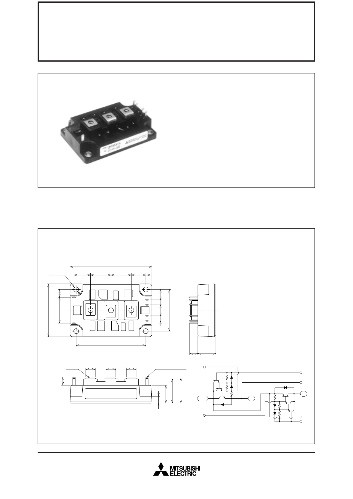
OUTLINE DRAWING & CIRCUIT DIAGRAM Dimensions in mm
APPLICATION
Inverters, Servo drives, DC motor controllers, NC equipment, Welders
QM100DY-HBK
• IC Collector current ........................ 100A
• V
CEX Collector-emitter voltage ........... 600V
• h
FE DC current gain.............................750
• Insulated Type
• UL Recognized
Yellow Card No. E80276 (N)
File No. E80271
MITSUBISHI TRANSISTOR MODULES
QM100DY-HBK
HIGH POWER SWITCHING USE
INSULATED TYPE
94
18.8 23 23 17.5
1.3
C2E1
E2 C1
80±
0.25
30 9
B2X
B1X
B2E2E1B1
612
6
12
48±
0.25
9.5 20.5
9±
0.1
(12) (12) (12)
20.5
8
28
29
+1.5
–0.5
B2X
C2E1
B1X
E2
B2
E2
E1
B1
C1
61
4–φ5.5
3–M5
Tab#110, t=0.5
LABEL
Feb.1999
Symbol
I
CEX
ICBO
IEBO
VCE (sat)
VBE (sat)
–VCEO
hFE
ton
ts
tf
Rth (j-c) Q
Rth (j-c) R
Rth (c-f)
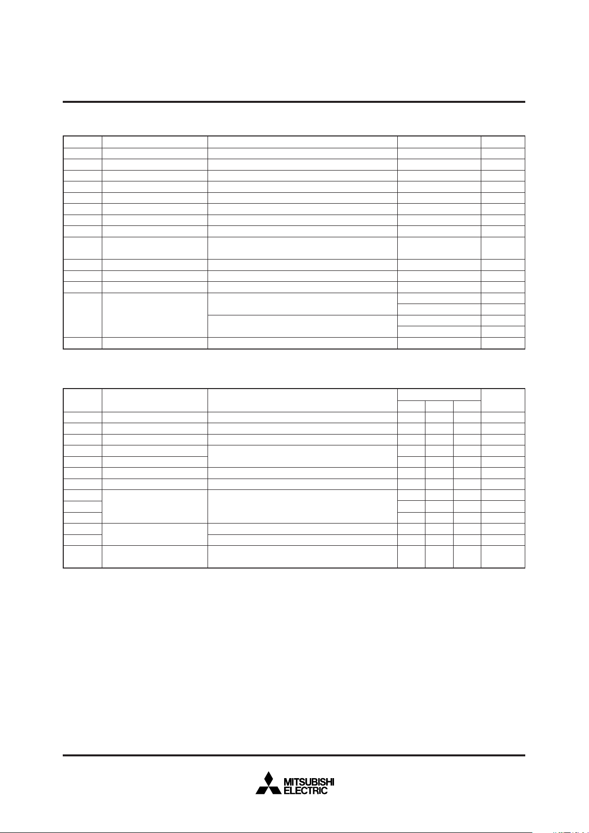
ABSOLUTE MAXIMUM RATINGS (Tj=25°C, unless otherwise noted)
ELECTRICAL CHARACTERISTICS (Tj=25°C, unless otherwise noted)
Unit
mA
mA
mA
V
V
V
—
µs
µs
µs
°C/W
°C/W
°C/W
Limits
Min.
—
—
—
—
—
—
750
—
—
—
—
—
—
Symbol
V
CEX (SUS)
VCEX
VCBO
VEBO
IC
–IC
PC
IB
–ICSM
Tj
Tstg
Viso
—
—
Parameter
Collector-emitter voltage
Collector-emitter voltage
Collector-base voltage
Emitter-base voltage
Collector current
Collector reverse current
Collector dissipation
Base current
Surge collector reverse current
(forward diode current)
Junction temperature
Storage temperature
Isolation voltage
Mounting torque
Weight
Conditions
I
C=1A, VEB=2V
V
EB=2V
Emitter open
Collector open
DC
DC (forward diode current)
T
C=25°C
DC
Peak value of one cycle of 60Hz (half wave)
Charged part to case, AC for 1 minute
Main terminal screw M5
Mounting screw M5
Typical value
Ratings
600
600
600
7
100
100
620
6
1000
–40~+150
–40~+125
2500
1.47~1.96
15~20
1.47~1.96
15~20
420
Unit
V
V
V
V
A
A
W
A
A
°C
°C
V
N·m
kg·cm
N·m
kg·cm
g
Parameter
Collector cutoff current
Collector cutoff current
Emitter cutoff current
Collector-emitter saturation voltage
Base-emitter saturation voltage
Collector-emitter reverse voltage
DC current gain
Switching time
Thermal resistance
(junction to case)
Contact thermal resistance
(case to fin)
Test conditions
V
CE=600V, VEB=2V
V
CB=600V, Emitter open
V
EB=7V
I
C=100A, IB=0.13A
–I
C=100A (diode forward voltage)
I
C=100A, VCE=2.5V
V
CC=300V, IC=100A, IB1=0.2A, –IB2=2.0A
Transistor part (per 1/2 module)
Diode part (per 1/2 module)
Conductive grease applied (per 1/2 module)
Typ.
—
—
—
—
—
—
—
—
—
—
—
—
—
Max.
2.0
2.0
100
2.5
3.0
1.8
—
2.5
10
2.0
0.2
0.65
0.1
MITSUBISHI TRANSISTOR MODULES
QM100DY-HBK
HIGH POWER SWITCHING USE
INSULATED TYPE