

MOTION CONTROLLERS
Q173CPU
Q172CPU
(N)
(N)
User's Manual
SAFETY PRECAUTIONS
(Read these precautions before using.)
When using this equipment, thoroughly read this manual and the associated manuals introduced in this
manual. Also pay careful attention to safety and handle the module properly.
These precautions apply only to this equipment. Refer to the Users manual of the QCPU module to use
for a description of the PLC system safety precautions.
These SAFETY PRECAUTIONS classify the safety precautions into two categories: "DANGER" and
"CAUTION".
DANGER
!
CAUTION
!
Depending on circumstances, procedures indicated by ! CAUTION may also be linked to serious
results.
In any case, it is important to follow the directions for usage.
Store this manual in a safe place so that you can take it out and read it whenever necessary. Always
forward it to the end user.
Indicates that incorrect handling may cause hazardous conditions,
resulting in death or severe injury.
Indicates that incorrect handling may cause hazardous conditions,
resulting in medium or slight personal injury or physical damage.
A - 1
For Safe Operations
1. Prevention of electric shocks
!
DANGER
Never open the front case or terminal covers while the power is ON or the unit is running, as
this may lead to electric shocks.
Never run the unit with the front case or terminal cover removed. The high voltage terminal and
charged sections will be exposed and may lead to electric shocks.
Never open the front case or terminal cover at times other than wiring work or periodic
inspections even if the power is OFF. The insides of the Motion controller and servo amplifier
are charged and may lead to electric shocks.
When performing wiring work or inspections, turn the power OFF, wait at least ten minutes, and
then check the voltage with a tester, etc.. Failing to do so may lead to electric shocks.
Be sure to ground the Motion controller, servo amplifier and servomotor. (Ground resistance :
or less) Do not ground commonly with other devices.
100
The wiring work and inspections must be done by a qualified technician.
Wire the units after installing the Motion controller, servo amplifier and servomotor. Failing to do
so may lead to electric shocks or damage.
Never operate the switches with wet hands, as this may lead to electric shocks.
Do not damage, apply excessive stress, place heavy things on or sandwich the cables, as this
may lead to electric shocks.
Do not touch the Motion controller, servo amplifier or servomotor terminal blocks while the
power is ON, as this may lead to electric shocks.
Do not touch the built-in power supply, built-in grounding or signal wires of the Motion controller
and servo amplifier, as this may lead to electric shocks.
2. For fire prevention
!
CAUTION
Install the Motion controller, servo amplifier, servomotor and regenerative resistor on
inflammable material. Direct installation on flammable material or near flammable material may
lead to fire.
If a fault occurs in the Motion controller or servo amplifier, shut the power OFF at the servo
amplifier’s power source. If a large current continues to flow, fire may occur.
When using a regenerative resistor, shut the power OFF with an error signal. The regenerative
resistor may abnormally overheat due to a fault in the regenerative transistor, etc., and may
lead to fire.
Always take heat measures such as flame proofing for the inside of the control panel where
the servo amplifier or regenerative resistor is installed and for the wires used. Failing to do so
may lead to fire.
A - 2
3. For injury prevention
!
CAUTION
Do not apply a voltage other than that specified in the instruction manual on any terminal.
Doing so may lead to destruction or damage.
Do not mistake the terminal connections, as this may lead to destruction or damage.
Do not mistake the polarity ( + / - ), as this may lead to destruction or damage.
Do not touch the servo amplifier's heat radiating fins, regenerative resistor and servomotor, etc.,
while the power is ON and for a short time after the power is turned OFF. In this timing, these
parts become very hot and may lead to burns.
Always turn the power OFF before touching the servomotor shaft or coupled machines, as
these parts may lead to injuries.
Do not go near the machine during test operations or during operations such as teaching.
Doing so may lead to injuries.
4. Various precautions
Strictly observe the following precautions.
Mistaken handling of the unit may lead to faults, injuries or electric shocks.
(1) System structure
!
CAUTION
Always install a leakage breaker on the Motion controller and servo amplifier power source.
If installation of an electromagnetic contactor for power shut off during an error, etc., is specified
in the instruction manual for the servo amplifier, etc., always install the electromagnetic
contactor.
Install the emergency stop circuit externally so that the operation can be stopped immediately
and the power shut off.
Use the Motion controller, servo amplifier, servomotor and regenerative resistor with the combi-
nations listed in the instruction manual. Other combinations may lead to fire or faults.
If safety standards (ex., robot safety rules, etc.,) apply to the system using the Motion controller,
servo amplifier and servomotor, make sure that the safety standards are satisfied.
Construct a safety circuit externally of the Motion controller or servo amplifier if the abnormal
operation of the Motion controller or servo amplifier differ from the safety directive operation in
the system.
In systems where coasting of the servomotor will be a problem during the forced stop,
emergency stop, servo OFF or power supply OFF, use dynamic brakes.
Make sure that the system considers the coasting amount even when using dynamic brakes.
A - 3
!
CAUTION
In systems where perpendicular shaft dropping may be a problem during the forced stop,
emergency stop, servo OFF or power supply OFF, use both dynamic brakes and
electromagnetic brakes.
The dynamic brakes must be used only on errors that cause the forced stop, emergency stop,
or servo OFF. These brakes must not be used for normal braking.
The brakes (electromagnetic brakes) assembled into the servomotor are for holding
applications, and must not be used for normal braking.
The system must have a mechanical allowance so that the machine itself can stop even if the
stroke limits switch is passed through at the max. speed.
Use wires and cables that have a wire diameter, heat resistance and bending resistance
compatible with the system.
Use wires and cables within the length of the range described in the instruction manual.
The ratings and characteristics of the parts (other than Motion controller, servo amplifier and
servomotor) used in a system must be compatible with the Motion controller, servo amplifier
and servomotor.
Install a cover on the shaft so that the rotary parts of the servomotor are not touched during
operation.
There may be some cases where holding by the electromagnetic brakes is not possible due to
the life or mechanical structure (when the ball screw and servomotor are connected with a
timing belt, etc.). Install a stopping device to ensure safety on the machine side.
(2) Parameter settings and programming
!
CAUTION
Set the parameter values to those that are compatible with the Motion controller, servo amplifier,
servomotor and regenerative resistor model and the system application. The protective functions
may not function if the settings are incorrect.
The regenerative resistor model and capacity parameters must be set to values that conform to
the operation mode, servo amplifier and servo power supply module. The protective functions
may not function if the settings are incorrect.
Set the mechanical brake output and dynamic brake output validity parameters to values that
are compatible with the system application. The protective functions may not function if the
settings are incorrect.
Set the stroke limit input validity parameter to a value that is compatible with the system
application. The protective functions may not function if the setting is incorrect.
A - 4
!
CAUTION
Set the servomotor encoder type (increment, absolute position type, etc.) parameter to a value
that is compatible with the system application. The protective functions may not function if the
setting is incorrect.
Set the servomotor capacity and type (standard, low-inertia, flat, etc.) parameter to values that
are compatible with the system application. The protective functions may not function if the
settings are incorrect.
Set the servo amplifier capacity and type parameters to values that are compatible with the
system application. The protective functions may not function if the settings are incorrect.
Use the program commands for the program with the conditions specified in the instruction
manual.
Set the sequence function program capacity setting, device capacity, latch validity range, I/O
assignment setting, and validity of continuous operation during error detection to values that are
compatible with the system application. The protective functions may not function if the settings
are incorrect.
Some devices used in the program have fixed applications, so use these with the conditions
specified in the instruction manual.
The input devices and data registers assigned to the link will hold the data previous to when
communication is terminated by an error, etc. Thus, an error correspondence interlock program
specified in the instruction manual must be used.
Use the interlock program specified in the special function module's instruction manual for the
program corresponding to the special function module.
(3) Transportation and installation
!
CAUTION
Transport the product with the correct method according to the mass.
Use the servomotor suspension bolts only for the transportation of the servomotor. Do not
transport the servomotor with machine installed on it.
Do not stack products past the limit.
When transporting the Motion controller or servo amplifier, never hold the connected wires or
cables.
When transporting the servomotor, never hold the cables, shaft or detector.
When transporting the Motion controller or servo amplifier, never hold the front case as it may
fall off.
When transporting, installing or removing the Motion controller or servo amplifier, never hold
the edges.
Install the unit according to the instruction manual in a place where the mass can be withstood.
A - 5
!
CAUTION
Do not get on or place heavy objects on the product.
Always observe the installation direction.
Keep the designated clearance between the Motion controller or servo amplifier and control
panel inner surface or the Motion controller and servo amplifier, Motion controller or servo
amplifier and other devices.
Do not install or operate Motion controller, servo amplifiers or servomotors that are damaged or
that have missing parts.
Do not block the intake/outtake ports of the servomotor with cooling fan.
Do not allow conductive matter such as screw or cutting chips or combustible matter such as oil
enter the Motion controller, servo amplifier or servomotor.
The Motion controller, servo amplifier and servomotor are precision machines, so do not drop
or apply strong impacts on them.
Securely fix the Motion controller and servo amplifier to the machine according to the instruction
manual. If the fixing is insufficient, these may come off during operation.
Always install the servomotor with reduction gears in the designated direction. Failing to do so
may lead to oil leaks.
Store and use the unit in the following environmental conditions.
Environment
Ambient
temperature
Ambient humidity
Storage
temperature
Atmosphere
Altitude
Vibration
Motion controller/Servo amplifier Servomotor
According to each instruction manual.
According to each instruction manual.
According to each instruction manual.
Indoors (where not subject to direct sunlight).
No corrosive gases, flammable gases, oil mist or dust must exist
1000m (3280.84ft.) or less above sea level
According to each instruction manual
Conditions
0°C to +40°C (With no freezing)
(32°F to +104°F)
80% RH or less
(With no dew condensation)
-20°C to +65°C
(-4°F to +149°F)
When coupling with the synchronization encoder or servomotor shaft end, do not apply impact
such as by hitting with a hammer. Doing so may lead to detector damage.
Do not apply a load larger than the tolerable load onto the servomotor shaft. Doing so may lead
to shaft breakage.
When not using the module for a long time, disconnect the power line from the Motion controller
or servo amplifier.
Place the Motion controller and servo amplifier in static electricity preventing vinyl bags and
store.
When storing for a long time, please contact with our sales representative.
A - 6
(4) Wiring
!
CAUTION
Correctly and securely wire the wires. Reconfirm the connections for mistakes and the terminal
screws for tightness after wiring. Failing to do so may lead to run away of the
servomotor.
After wiring, install the protective covers such as the terminal covers to the original positions.
Do not install a phase advancing capacitor, surge absorber or radio noise filter (option FR-BIF)
on the output side of the servo amplifier.
Correctly connect the output side (terminals U, V, W). Incorrect connections will lead the
servomotor to operate abnormally.
Do not connect a commercial power supply to the servomotor, as this may lead to trouble.
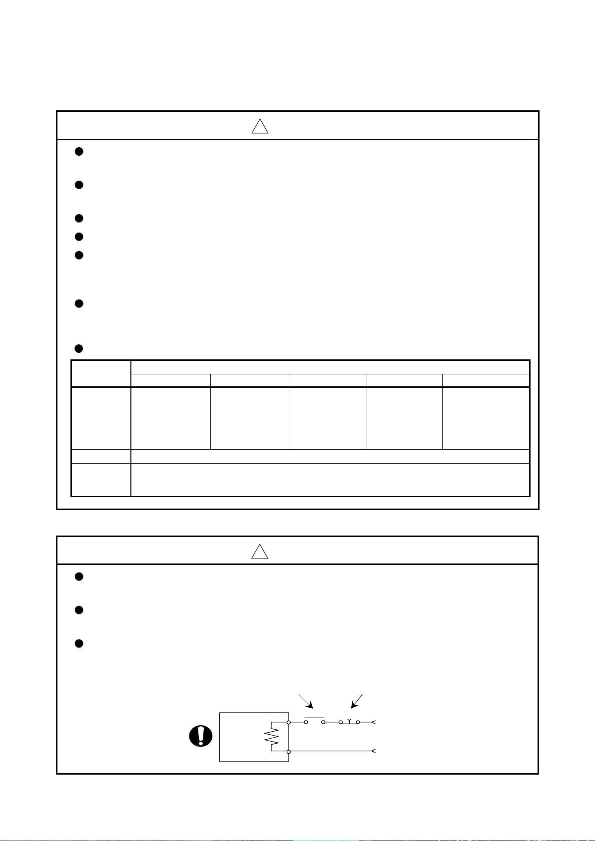
Do not mistake the direction of the surge absorbing diode
installed on the DC relay for the control signal output of
brake signals, etc. Incorrect installation may lead to signals
not being output when trouble occurs or the protective
functions not functioning.
Do not connect or disconnect the connection cables between
each unit, the encoder cable or PLC expansion cable while the
power is ON.
Servo amplifier
VIN
(24VDC)
Control output
signal
RA
Securely tighten the cable connector fixing screws and fixing mechanisms. Insufficient fixing
may lead to the cables combing off during operation.
Do not bundle the power line or cables.
(5) Trial operation and adjustment
!
CAUTION
Confirm and adjust the program and each parameter before operation. Unpredictable
movements may occur depending on the machine.
Extreme adjustments and changes may lead to unstable operation, so never make them.
When using the absolute position system function, on starting up, and when the Motion
controller or absolute value motor has been replaced, always perform a home position return.
A - 7
(6) Usage methods
!
CAUTION
Immediately turn OFF the power if smoke, abnormal sounds or odors are emitted from the
Motion controller, servo amplifier or servomotor.
Always execute a test operation before starting actual operations after the program or
parameters have been changed or after maintenance and inspection.
The units must be disassembled and repaired by a qualified technician.
Do not make any modifications to the unit.
Keep the effect or electromagnetic obstacles to a minimum by installing a noise filter or by using
wire shields, etc. Electromagnetic obstacles may affect the electronic devices used near the
Motion controller or servo amplifier.
When using the CE Mark-compliant equipment, refer to the "EMC Installation Guidelines"
(data number IB(NA)-67339) for the Motion controllers and refer to the corresponding EMC
guideline information for the servo amplifiers, inverters and other equipment.
Use the units with the following conditions.
Item
Input power
Input frequency 50/60Hz ±5%
Tolerable
momentary
power failure
Q61P-A1 Q61P-A2 Q62P Q63P Q64P
100 to 120VAC
(85 to 132VAC) (170 to 264VAC) (85 to 264VAC) (15.6 to 31.2VDC)
+10% +10% +10% +30% +10%
200 to 240VAC
-15%
200 to 240VAC
-15%
Conditions
100 to 240VAC
20ms or less
-15%
24VDC
-35%
100 to 120VAC
(7) Corrective actions for errors
!
CAUTION
If an error occurs in the self diagnosis of the Motion controller or servo amplifier, confirm the
check details according to the instruction manual, and restore the operation.
If a dangerous state is predicted in case of a power failure or product failure, use a servomotor
with electromagnetic brakes or install a brake mechanism externally.
Use a double circuit construction so that the electromagnetic brake operation circuit can be
operated by emergency stop signals set externally.
Shut off with servo ON signal OFF,
alarm, magnetic brake signal.
Servomotor
RA1
Shut off with the
emergency stop
signal(EMG).
EMG
-15%
+10%
-15%
(85 to 132VAC/
170 to 264VAC)
/
Electromagnetic
brakes
24VDC
A - 8
!
CAUTION
If an error occurs, remove the cause, secure the safety and then resume operation after alarm
release.
The unit may suddenly resume operation after a power failure is restored, so do not go near the
machine. (Design the machine so that personal safety can be ensured even if the machine
restarts suddenly.)
(8) Maintenance, inspection and part replacement
!
CAUTION
Perform the daily and periodic inspections according to the instruction manual.
Perform maintenance and inspection after backing up the program and parameters for the
Motion controller and servo amplifier.
Do not place fingers or hands in the clearance when opening or closing any opening.
Periodically replace consumable parts such as batteries according to the instruction manual.
Do not touch the lead sections such as ICs or the connector contacts.
Do not place the Motion controller or servo amplifier on metal that may cause a power leakage
or wood, plastic or vinyl that may cause static electricity buildup.
Do not perform a megger test (insulation resistance measurement) during inspection.
When replacing the Motion controller or servo amplifier, always set the new module settings
correctly.
When the Motion controller or absolute value motor has been replaced, carry out a home
position return operation using one of the following methods, otherwise position displacement
could occur.
1) After writing the servo data to the Motion controller using programming software, switch on
the power again, then perform a home position return operation.
2) Using the backup function of the programming software, load the data backed up before
replacement.
After maintenance and inspections are completed, confirm that the position detection of the
absolute position detector function is correct.
Do not short circuit, charge, overheat, incinerate or disassemble the batteries.
The electrolytic capacitor will generate gas during a fault, so do not place your face near the
Motion controller or servo amplifier.
The electrolytic capacitor and fan will deteriorate. Periodically replace these to prevent
secondary damage from faults. Replacements can be made by our sales representative.
A - 9
(9) About processing of waste
When you discard Motion controller, servo amplifier, a battery (primary battery) and other option articles,
please follow the law of each country (area).
!
CAUTION
This product is not designed or manufactured to be used in equipment or systems in situations
that can affect or endanger human life.
When considering this product for operation in special applications such as machinery or
systems used in passenger transportation, medical, aerospace, atomic power, electric power, or
submarine repeating applications, please contact your nearest Mitsubishi sales representative.
Although this product was manufactured under conditions of strict quality control, you are
strongly advised to install safety devices to forestall serious accidents when it is used in facilities
where a breakdown in the product is likely to cause a serious accident.
(10) General cautions
!
CAUTION
All drawings provided in the instruction manual show the state with the covers and safety
partitions removed to explain detailed sections. When operating the product, always return the
covers and partitions to the designated positions, and operate according to the instruction
manual.
A - 10
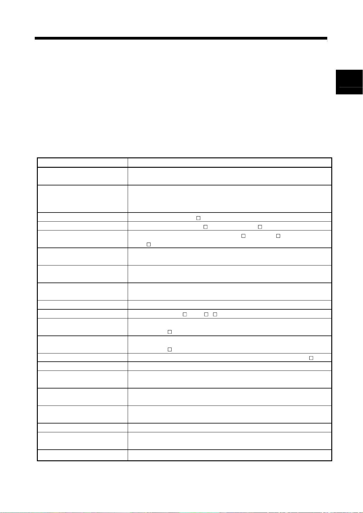
REVISIONS
The manual number is given on the bottom left of the back cover.
Print Date Manual Number Revision
Nov., 2001 IB(NA)-0300040-A First edition
May., 2002 IB(NA)-0300040-B
[Addition model]
Q173CPUN/Q172CPUN, MR-J2M-B, A10BD-PCF
[Addition function]
•
For Windows2000
•
ROM operation
•
MODE LED Installation mode/ROM writing mode
•
BOOT LED Installation mode/ROM writing mode
[Partial correction]
Sep., 2003 IB(NA)-0300040-C [Addition model]
Q173CPUN-T/Q172CPUN-T, A31TU-D3K13/A31TU-DNK13,
Q172EX-S1, Q173PX-S1, Q64AD, Q68ADV, Q68ADI, Q62DA, Q64DA,
Q68DAV, Q68DAI, A6TBXY36, A6TBXY54, A6TBX70,
Q170TUD3CBL3M, Q170TUDNCBL3M, Q170TUDNCBL03M-A,
Q170TUTM, A31TUD3TM, FR-V5
[Addition function]
For WindowsXP, Home position return function
[Additional correction/partial correction]
Safety precautions, About processing of waste, Discard of internal
rechargeable battery, Instructions for installation of operation system
software, Troubleshooting, Precautions for air transportation of battery,
etc,
Mar., 2006 IB(NA)-0300040-D [Addition model]
Q62P, Q172EX-S2, Q172EX-S3, Q170ENC
[Additional correction/partial correction]
Safety precautions, Operating environment of personal computer, System
design circuit example, Operating system software installation procedure,
Warranty, Model code(1CT780
1XB780), etc.
0- , Software for SV43
Japanese Manual Number IB(NA)-0300021
This manual confers no industrial property rights or any rights of any other kind, nor does it confer any patent
licenses. Mitsubishi Electric Corporation cannot be held responsible for any problems involving industrial property
rights which may occur as a result of using the contents noted in this manual.
© 2001 MITSUBISHI ELECTRIC CORPORATION
A - 11

INTRODUCTION
Thank you for choosing the Q173CPU(N)/Q172CPU(N) Motion Controller.
Please read this manual carefully so that equipment is used to its optimum.
CONTENTS
Safety Precautions .........................................................................................................................................A- 1
Revisions ........................................................................................................................................................A-11
Contents .........................................................................................................................................................A-12
About Manuals ...............................................................................................................................................A-15
1. OVERVIEW 1- 1 to 1- 2
1.1 Overview................................................................................................................................................... 1- 1
2. SYSTEM CONFIGURATION 2- 1 to 2-100
2.1 Motion System Configuration .................................................................................................................. 2- 1
2.1.1 Q173CPU(N) System overall configuration...................................................................................... 2- 8
2.1.2 Q172CPU(N) System overall configuration...................................................................................... 2-10
2.1.3 Function explanation of the Q173CPU(N)/Q172CPU(N) Motion CPU modules ............................ 2-12
2.1.4 Restrictions on Motion systems ........................................................................................................ 2-13
2.2 System Configuration Equipment............................................................................................................ 2-15
2.3 General Specifications .............................................................................................................................2-24
2.4 Specifications of Equipment and Settings............................................................................................... 2-26
2.4.1 Name of parts for CPU module ........................................................................................................ 2-26
2.4.2 Power supply module........................................................................................................................ 2-36
2.4.3 Base unit and extension cable.......................................................................................................... 2-43
2.4.4 Q172LX Servo external signals interface module ............................................................................ 2-46
2.4.5 Q172EX Serial absolute synchronous encoder interface module................................................... 2-51
2.4.6 Q173PX Manual pulse generator interface module......................................................................... 2-61
2.4.7 Manual pulse generator/Serial absolute synchronous encoder ...................................................... 2-70
2.4.8 A31TU-D3
2.4.9 SSCNET cables, terminal connector and connection method ........................................................ 2-82
2.4.10 External battery ............................................................................................................................... 2-96
2.4.11 Cooling fan unit (Q170FAN) (Q173CPU/Q172CPU only) ............................................................. 2-99
/A31TU-DN Teaching unit (Japanese version only) ................................................ 2-72
3. DESIGN 3- 1 to 3-20
3.1 System Designing Procedure .................................................................................................................. 3- 1
3.2 External Circuit Design ............................................................................................................................ 3- 4
3.2.1 Power supply circuit design .............................................................................................................. 3-12
3.2.2 Safety circuit design ..........................................................................................................................3-13
3.3 Layout Design within The Control Panel ................................................................................................. 3-15
3.3.1 Installation environment ....................................................................................................................3-15
3.3.2 Layout design of the base units ........................................................................................................ 3-16
3.3.3 Calculating heat generation by Motion controller ............................................................................. 3-17
3.4 Design Checklist ...................................................................................................................................... 3-20
A - 12

4. INSTALLATION AND WIRING 4- 1 to 4-20
4.1 Module Installation ...................................................................................................................................4- 1
4.1.1 Instructions for handling .................................................................................................................... 4- 1
4.1.2 Instructions for installation of the base unit ...................................................................................... 4- 3
4.1.3 Installation and removal of module ................................................................................................... 4- 5
4.2 Installation and Removal of Cable........................................................................................................... 4- 7
4.2.1 SSCNET cable ..................................................................................................................................4- 7
4.2.2 SSC I/F communication cable .......................................................................................................... 4- 8
4.2.3 Battery cable...................................................................................................................................... 4- 9
4.2.4 Cable for teaching unit ...................................................................................................................... 4-10
4.3 Installation of the Serial Absolute Synchronous Encoder....................................................................... 4-12
4.4 Replacement of the Cooling fan unit (Q170FAN) (Q173CPU/Q172CPU only) ..................................... 4-14
4.5 Wiring........................................................................................................................................................ 4-15
4.5.1 Instructions for wiring ........................................................................................................................ 4-15
4.5.2 Wiring to the power supply module .................................................................................................. 4-18
4.6 Installation/Wiring Checklist ..................................................................................................................... 4-19
5. TRIAL OPERATION AND ADJUSTMENT 5- 1 to 5- 8
5.1 Checklist before Trial Operation ..............................................................................................................5- 1
5.2 Trial Operation and Adjustment Procedure............................................................................................. 5- 2
5.3 Operating System Software Installation Procedure ................................................................................ 5- 7
5.4 Trial Operation and Adjustment Checklist............................................................................................... 5- 8
6. INSPECTION AND MAINTENANCE 6- 1 to 6-28
6.1 Maintenance Works .................................................................................................................................6- 2
6.1.1 Instruction of Inspection works ......................................................................................................... 6- 2
6.2 Daily Inspection ........................................................................................................................................ 6- 4
6.3 Periodic Inspection................................................................................................................................... 6- 6
6.4 External Battery........................................................................................................................................ 6- 7
6.4.1 Battery service life time ..................................................................................................................... 6- 8
6.4.2 Battery replacement procedure ........................................................................................................ 6- 9
6.5 Discard of internal rechargeable battery ................................................................................................. 6-11
6.6 Troubleshooting ....................................................................................................................................... 6-13
6.6.1 Basics of troubleshooting.................................................................................................................. 6-13
6.6.2 Troubleshooting of Motion CPU module and I/O modules ..............................................................6-14
6.6.3 I/O modules troubleshooting............................................................................................................. 6-25
6.7 Confirm method of Error Code ................................................................................................................ 6-28
A - 13

APPENDICES App- 1 to App-37
APPENDIX 1 Cables..................................................................................................................................App- 1
APPENDIX 1.1 SSCNET cables............................................................................................................App- 1
APPENDIX 1.2 Serial absolute synchronous encoder cable................................................................App-11
APPENDIX 1.3 Cable for the teaching unit ...........................................................................................App-14
APPENDIX 2 Exterior Dimensions ............................................................................................................App-20
APPENDIX 2.1 CPU module .................................................................................................................App-20
APPENDIX 2.2 Servo external signals interface module (Q172LX) ....................................................App-24
APPENDIX 2.3 Serial absolute synchronous encoder interface module
(Q172EX/Q172EX-S1/Q172EX-S2/Q172EX-S3).......................................................App-24
APPENDIX 2.4 Manual pulse generator interface module (Q173PX/Q173PX-S1).............................App-25
APPENDIX 2.5 Power supply module (Q61P-A1, Q61P-A2, Q62P, Q63P, Q64P) ............................App-26
APPENDIX 2.6 Dividing unit (Q173DV), Battery unit (Q170BAT) ........................................................App-27
APPENDIX 2.7 Connector .....................................................................................................................App-28
APPENDIX 2.8 Manual pulse generator (MR-HDP01) .........................................................................App-33
APPENDIX 2.9 Serial absolute synchronous encoder (MR-HENC/Q170ENC) ..................................App-34
APPENDIX 2.10 Teaching unit (A31TU-D3
APPENDIX 2.11 Cooling fan unit (Q170FAN) (Q173CPU/Q172CPU only) ........................................App-36
/A31TU-DN ) ..............................................................App-35
A - 14

About Manuals
This manual is only to explain hardware of the Motion controller.
The following manuals are related to this product.
Referring to this list, please request the necessary manuals.
This User's Manual do not describes hardware specification and handling methods of the PLC CPU
modules, power supply modules, base unit and I/O module in details.
The above contents, refer to the QCPU User's Manual and Building Block I/O Module User's Manual.
Related Manuals
(1) Motion controller
Q173CPU(N)/Q172CPU(N) Motion controller (SV13/SV22) Programming Manual
(Motion SFC)
This manual explains the Multiple CPU system configuration, performance specifications, functions,
programming, error codes and others of the Motion SFC.
(Optional)
Manual Name
Manual Number
(Model Code)
IB-0300042
(1XB781)
Q173CPU(N)/Q172CPU(N) Motion controller (SV13/SV22) Programming Manual
(REAL MODE)
This manual explains the servo parameters, positioning instructions, device list, error list and others.
(Optional)
Q173CPU(N)/Q172CPU(N) Motion controller (SV22) Programming Manual
(VIRTUAL MODE)
This manual describes the dedicated instructions use to the synchronous control by virtual main shaft,
mechanical system program create mechanical module.
This manual explains the servo parameters, positioning instructions, device list, error list and others.
(Optional)
Q173CPU(N)/Q172CPU(N) Motion controller (SV43) Programming Manual
This manual describes the dedicated instructions to execute the positioning control by Motion program of
EIA language (G-code).
This manual explains the Multiple CPU system configuration, performance specifications, functions,
programming, debugging, servo parameters, positioning instructions device list and error list and others.
(Optional)
IB-0300043
(1XB782)
IB-0300044
(1XB783)
IB-0300070
(1CT784)
A - 15

(2) PLC
QCPU User's Manual (Hardware Design, Maintenance and Inspection)
This manual explains the specifications of the QCPU modules, power supply modules, base modules,
extension cables, memory card battery and others.
(Optional)
QCPU User's Manual (Function Explanation, Program Fundamentals)
This manual explains the functions, programming methods and devices and others to create programs
with the QCPU.
(Optional)
QCPU User's Manual (Multiple CPU System)
This manual explains the functions, programming methods and cautions and others to construct the
Multiple CPU system with the QCPU.
(Optional)
QCPU (Q Mode)/QnACPU Programming Manual (Common Instructions)
This manual explains how to use the sequence instructions, basic instructions, application instructions and
micro computer program.
(Optional)
QCPU (Q Mode)/QnACPU Programming Manual (PID Control Instructions)
This manual explains the dedicated instructions used to exercise PID control.
(Optional)
QCPU (Q Mode)/QnACPU Programming Manual (SFC)
This manual explains the system configuration, performance specifications, functions, programming,
debugging, error codes and others of MELSAP3.
(Optional)
I/O Module Type Building Block User's Manual
This manual explains the specifications of the I/O modules, connector, connector/terminal block
conversion modules and others.
(Optional)
Manual Name
Manual Number
(Model Code)
SH-080483ENG
(13JR73)
SH-080484ENG
(13JR74)
SH-080485ENG
(13JR75)
SH-080039
(13JF58)
SH-080040
(13JF59)
SH-080041
(13JF60)
SH-080042
(13JL99)
A - 16
1 OVERVIEW
1. OVERVIEW
1.1 Overview
This User's Manual describes the hardware specifications and handling methods of the
Motion Controller's Model Q173CPU(N)/Q172CPU(N) for the Q series PLC Multiple
CPU system.
The Manual also describes those items related to the specifications of the option
module for the Motion controller, Manual pulse generator, Synchronous encoder,
Teaching unit and cables.
Generic term/Abbreviation Description
Q173CPU(N)/Q172CPU(N),
Motion CPU or Motion CPU module
Q172LX/Q172EX/Q173PX
or Motion module
MR-H-BN Servo amplifier model MR-H BN
MR-J2-B Servo amplifier model MR-J2S- B/MR-J2M-B/MR-J2- B/MR-J2-03B5
AMP or Servo amplifier
QCPU, PLC CPU
or PLC CPU module
Multiple CPU system
or Motion system
CPUn
Programming software package General name for "MT Developer" and "GX Developer"
Operating system software General name for "SW RN-SV Q "
SV13
SV22
SV43 Operating system software for machine tool peripheral use: SW5RN-SV43Q
MT Developer Abbreviation for Integrated start-up support software package "MT Developer"
GX Developer
Manual pulse generator
or MR-HDP01
Serial absolute synchronous encoder
or MR-HENC/Q170ENC
SSCNET
Absolute position system
(Note-2)
In this manual, the following abbreviations are used.
Q173CPUN/Q172CPUN/Q173CPUN-T/Q172CPUN-T/Q173CPU/Q172CPU
Motion CPU module
Q172LX Servo external signals interface module/
Q172EX(-S1/-S2/-S3) Serial absolute synchronous encoder interface module
Q173PX(-S1) Manual pulse generator interface module
General name for "Servo amplifier model MR-H
MR-J2- B/MR-J2-03B5, Vector inverter FREQROL-V500 series"
Qn(H)CPU
Abbreviation for "Multiple PLC system of the Q series"
Abbreviation for "CPU No.n (n= 1 to 4) of the CPU module for the Multiple CPU
system"
Operating system software for conveyor assembly use (Motion SFC) :
SW6RN-SV13Q
Operating system software for automatic machinery use (Motion SFC) :
SW6RN-SV22Q
Abbreviation for MELSEC PLC programming software package "GX Developer
(Version 6 or later)"
Abbreviation for "Manual pulse generator (MR-HDP01)"
Abbreviation for "Serial absolute synchronous encoder (MR-HENC/Q170ENC)"
High speed serial communication between Motion controller and servo amplifier
General name for "System using the servomotor and servo amplifier for absolute
position"
BN/MR-J2S- B/MR-J2M-B/
(Note-1)
1
/
Cooling fan unit Cooling fan unit (Q170FAN)
1 - 1
1 OVERVIEW
Generic term/Abbreviation Description
Dividing unit Dividing unit (Q173DV)
Battery unit Battery unit (Q170BAT)
A0BD-PCF A10BD-PCF/A30BD-PCF SSC I/F board
SSC I/F communication cable Abbreviation for "Cable for SSC I/F board/card"
Teaching Unit
or A31TU-D3
Intelligent function module
Vector inverter (FR-V500) Vector inverter FREQROL-V500 series
/A31TU-DN
A31TU-D3
Abbreviation for "MELSECNET/H module/Ethernet module/CC-Link module/
Serial communication module"
/A31TU-DN Teaching unit
(Note-3)
(Note-1) : Q172EX can be used in SV22.
(Note-2) : SSCNET: S
(Note-3) : Teaching unit can be used in SV13.
REMARK
ervo System Controller NETwork
For information about the each module, design method for program and parameter,
PLC CPU, peripheral devices for PLC program design, I/O modules
and intelligent function module
Operation method for MT Developer Help of each software
• Multiple CPU system configuration
• Performance specification
• Design method for common parameter
SV13/SV22
SV22
(Virtual mode)
SV43
• Auxiliary and applied functions
• Design method for positioning control program in
• Design method for positioning control parameter
• Design method for mechanical system program
• Multiple CPU system configuration
• Performance specification
• Design method for common parameter
• Design method for Motion program
• Motion dedicated PLC instruction
• Design method for positioning control parameter
refer to the following manuals relevant to each module.
Item Reference Manual
Manual relevant to each module
Q173CPU(N)/Q172CPU(N) Motion controller
(SV13/SV22) Programming Manual (Motion SFC)
the real mode
Q173CPU(N)/Q172CPU(N) Motion controller
(SV13/SV22) Programming Manual (REAL MODE)
Q173CPU(N)/Q172CPU(N) Motion controller
(SV22) Programming Manual (VIRTUAL MODE)
Q173CPU(N)/Q172CPU(N) Motion controller
(SV43) Programming Manual
1 - 2
g
2 SYSTEM CONFIGURATION
2. SYSTEM CONFIGURATION
This section describes the Q173CPU(N)/Q172CPU(N) system configuration,
2.1 Motion System Configuration
(Note)
precautions on use of system and configured equipments.
This section describes the equipment configuration, configuration with peripheral
devices and system configuration in the Q173CPU(N)/Q172CPU(N) system.
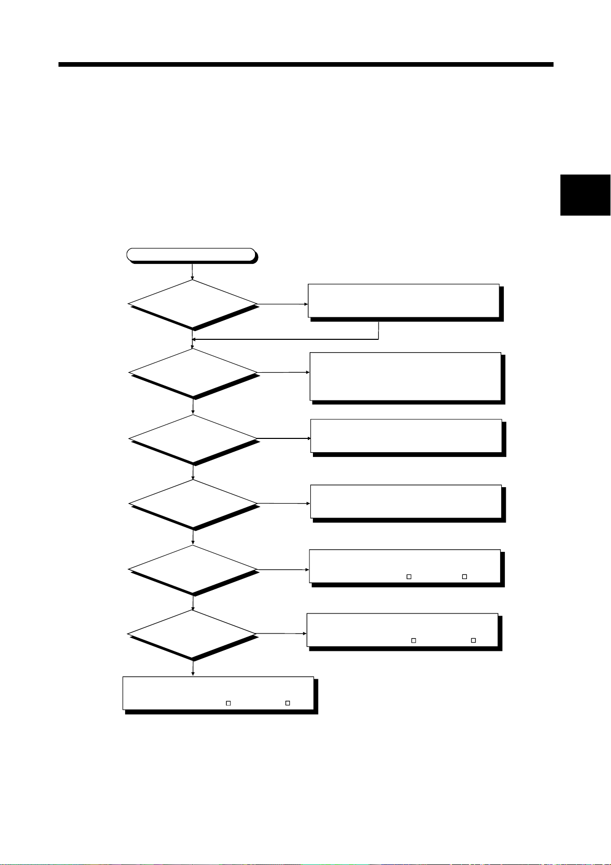
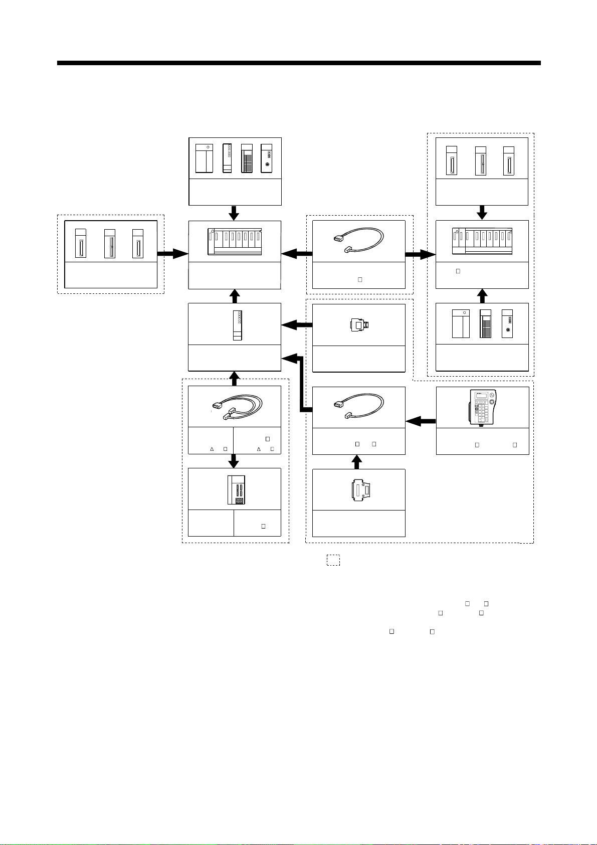
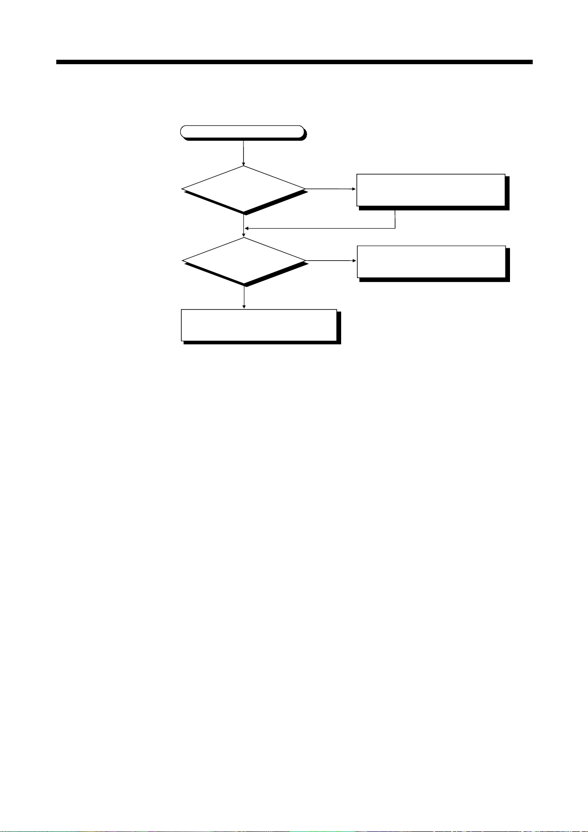
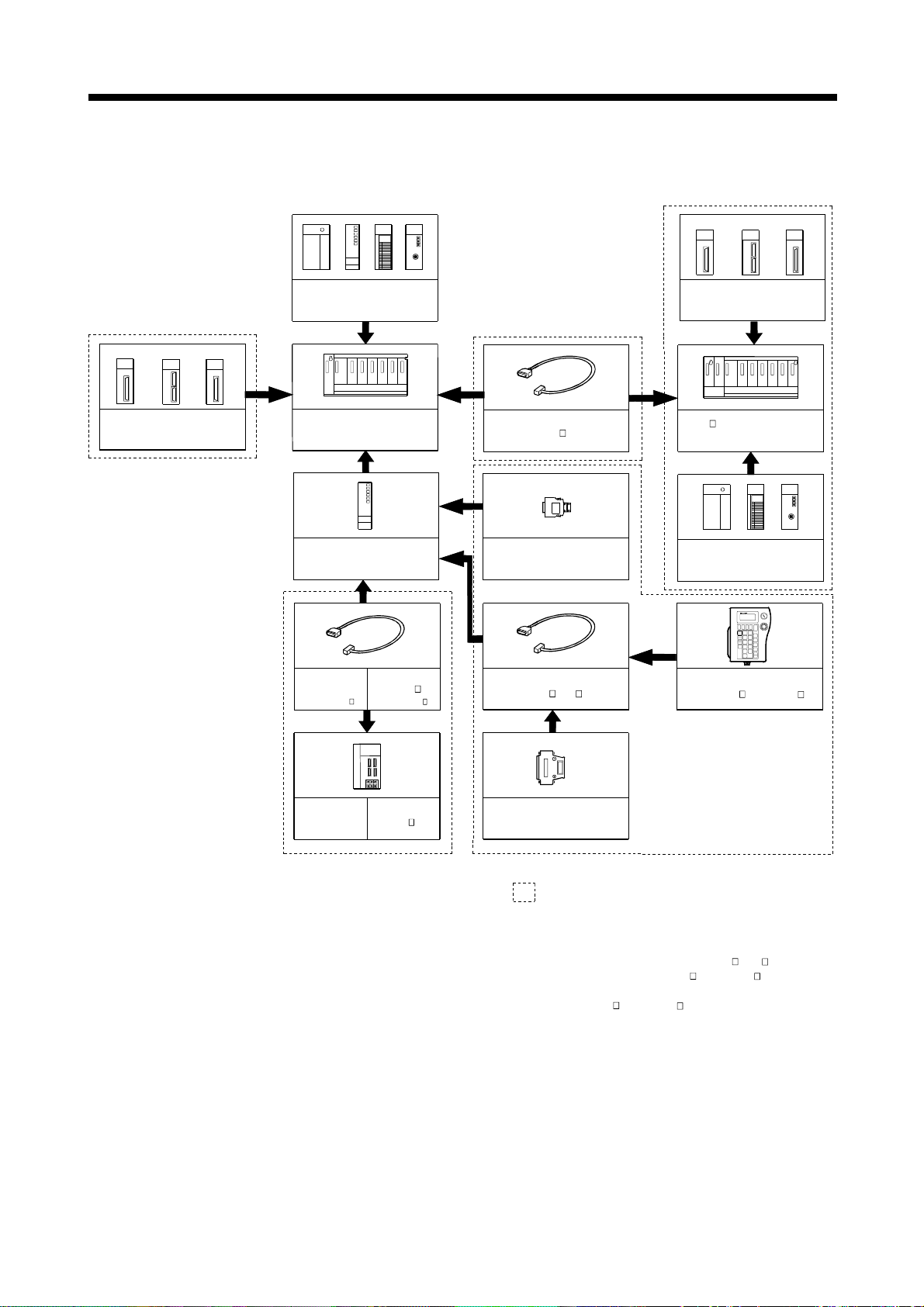
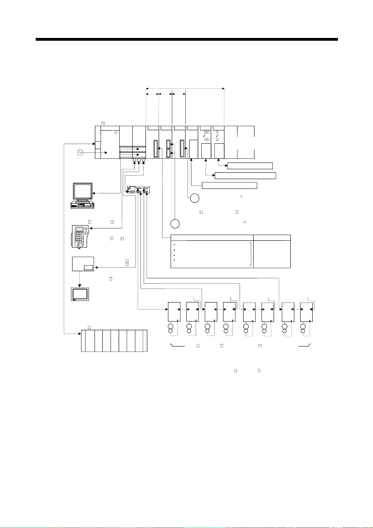
(1) Equipment configuration in Q173CPU(N) system
Q173CPU(N) System configuration
Is the teaching unit used?
NO
Is this system
continuously power off for 1000
hours or more running?
NO
YES
YES
Use a Q173CPUN-T.
Refer to equipment configuration of "(a) When using
the Dividing unit/external battery".
Note : Set the battery (A6BAT/MR-BAT) to the Dividing
unit (Q173DV).
2
Should the
dividing unit be used to divide
SSCNET Lines?
NO
of the amplifier used at 1st axis
Refer to equipment configuration of "(b) When using
the Dividing cable".
Note : Use a Q173J2B4CBL M/Q173HB4CBL M.
Is the type
of each SSCNET system
the same?
YES
Is only 1st
SSCNET system used?
NO
Is 1st and 2nd
SSCNET system used?
NO
YES
NO
YES
YES
Refer to equipment configuration of "(a) When using
the Dividing unit/external battery".
Refer to equipment configuration of "(a) When using
the Dividing unit/external battery".
Refer to equipment configuration of "(b) When using
the Dividing cable".
Note : Use a Q173J2BCBL M/Q173HBCBL M.
Refer to equipment configuration of "(b) When using
the Dividing cable".
Note : Use a Q173J2B2CBL M/Q173HB2CBL M.
(Note) : Continuous power failure time which can be backed up on the internal rechargeable battery
is different depending on the charge time. It is possible to continuously power off for 1100
hours because of char
e of 40 hours. Refer to the section 2.4.1(8) for details.
2 - 1
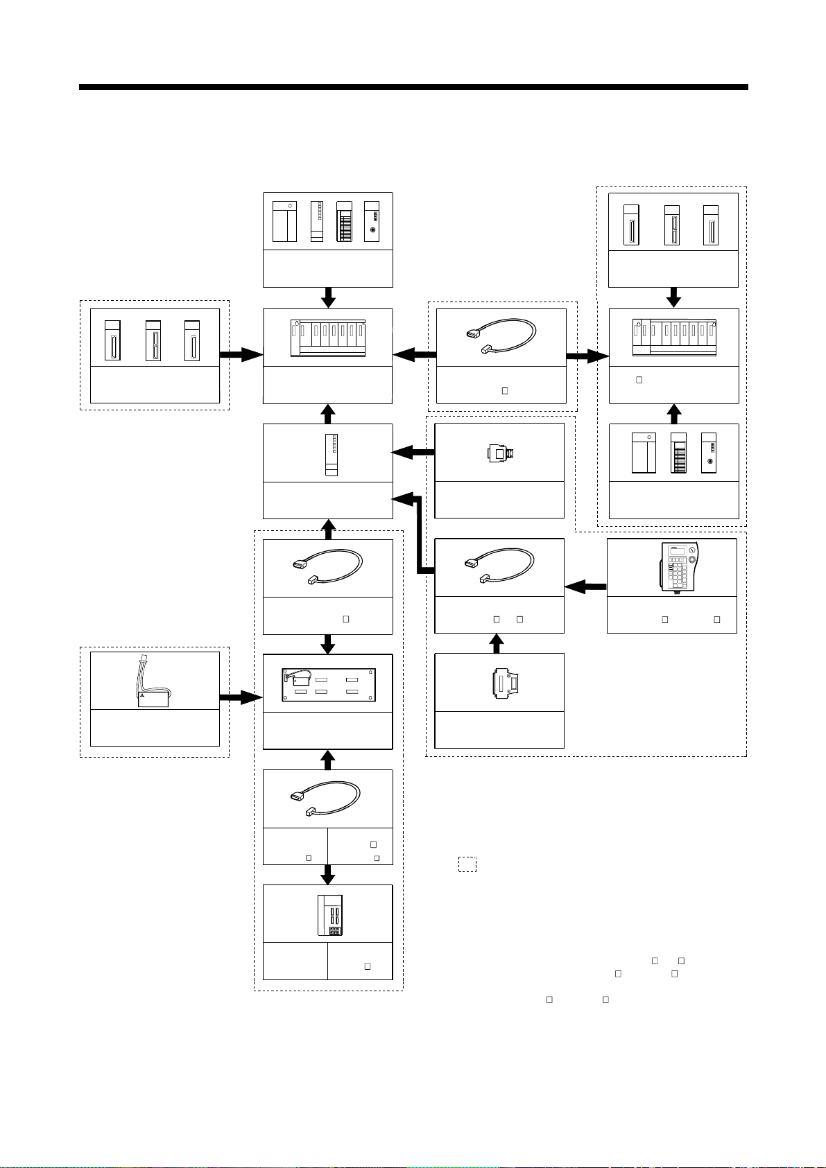
2 SYSTEM CONFIGURATION
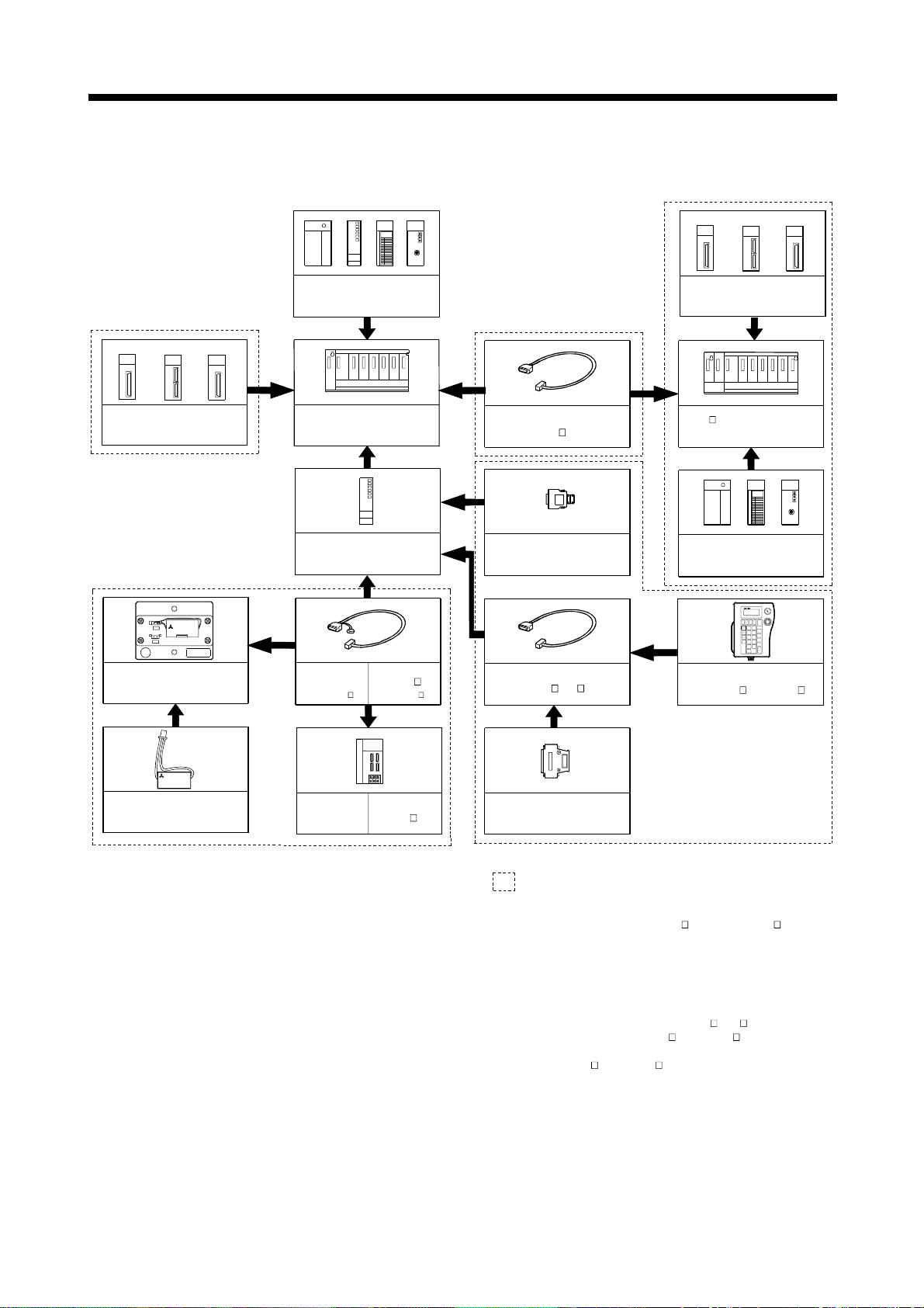
(a) When using the Dividing unit/external battery
Extension of the Q series module
Motion module
(Q172LX , Q172EX, Q173PX)
(Note-1)
MITSUBISHI
LITHIUM BATT ERY
Battery
(A6BAT/MR-BAT)
Power supply module/
QCPU/ I/O module/ Intelligent
function module of the Q series
CPU base unit
(Q33B, Q35B, Q38B, Q312B)
Motion CPU module
(Q173CPU(N))
SSCNET cable
(Q173DVCBL M)
SSCNET CN1
SSCNET CN2
SSCNET CN3
SSCNET CN4
MITSUBISHI
LITHIUM BATTE RY
Q173CPU
Dividing unit
(Q173DV)
(Note-5)
Extension cable
(QC B)
(Note-2)
Short-circuit connector for
the teaching unit
(Q170TU TM)
(Note-3)
Cable for the teaching unit
(Q170TUD CBL M(-A))
(Note-4)
Short-circuit connector for
the teac hing uni t
(A31TUD3TM)
Motion module
(Q172LX, Q172EX, Q173PX)
Q6 B extension base unit
(Q63B, Q65B, Q68B, Q612B)
Power supply module/
I/O module/Intelligent function
module of the Q series
(Note-5) (Note-6)
SVO ON
Teaching unit
(A31TU-D3 , A31TU-DN )
SSCNET cable
for MR-H-BN
(MR-J2HBUS M- A) (MR-J2HBUS M)
SSCNET cable
for MR-J2 -B
It is possible to select the best according to the system.
(Note-1) : When using the external battery, be sure to set the
MITSUBISHI
Battery(A6BAT/MR-BAT) to the Dividing unit(Q173DV).
Battery(A6BAT/MR-BAT) is optional.
(Note-2) : It is possible to use only Q173CPUN-T.
It is packed together with Q173CPUN-T.
Servo amplifier
(MR-H-BN)
Servo amplifier
(MR-J2 -B)
(Note-3) : It varies by the connecting teaching unit.
(Note-4) : It is packed together with Q170TUD CBL M.
(Note-5) : When using the A31TU-D3 /A31TU-DN , be sure to use
the Q173CPUN-T.
(Note-6) : A31TU-D3 /A31TU-DN corresponds to only Japanese.
It does not correspond to display for English.
2 - 2
p
2 SYSTEM CONFIGURATION
(b) When using the Dividing cable
Extension of the Q series module
Motion module
(Q172LX, Q172EX, Q173PX)
Power supply module/
QCPU/ I/O module/ Intelligent
function module of the Q series
CPU base unit
(Q33B, Q35B, Q38B, Q312B)
Motion CPU module
(Q173CPU(N) )
SSCNET cable
for MR-H-BN
(Q173HB CBL M)
SSCNET cable
for MR-J2 -B
(Q173J2B CBL M )
MITSUBIS HI
(Note-4)
Extension cable
(QC B)
(Note-1)
Short-circuit connector for
the teachi ng unit
(Q170TUTM)
(Note-2)
Cable for th e teaching un it
(Q170TUD CBL M(-A))
(Note-3)
Motion module
(Q172LX, Q172EX, Q173PX)
Q6 B extension base unit
(Q63B, Q65B, Q68B, Q612B)
Power supp ly module/
I/O module/Intelligent function
module of the Q series
(Note-5)
(Note-4)
SVO ON
Teaching unit
(A31TU-D3 , A31TU-DN )
Servo amplifi er
(MR-H-BN)
Servo amplifier
(MR-J2 -B)
Short-circuit connector for the
teaching unit
(A31TUD3TM)
It is possible to select the best according to the system.
(Note-1) : It is possible to use only Q173CPUN-T. It is packed
together with Q173CPUN-T.
(Note-2) : It varies by the connecting teaching unit.
(Note-3) : It is packed together with Q170TUD CBL M.
(Note-4) : When using the A31TU-D3 /A31TU-DN , be sure to use
the Q173CPUN-T.
(Note-5) : A31TU-D3 /A31TU-DN corresponds to only Japanese.
It does not corres
ond to display for English.
2 - 3
2 SYSTEM CONFIGURATION
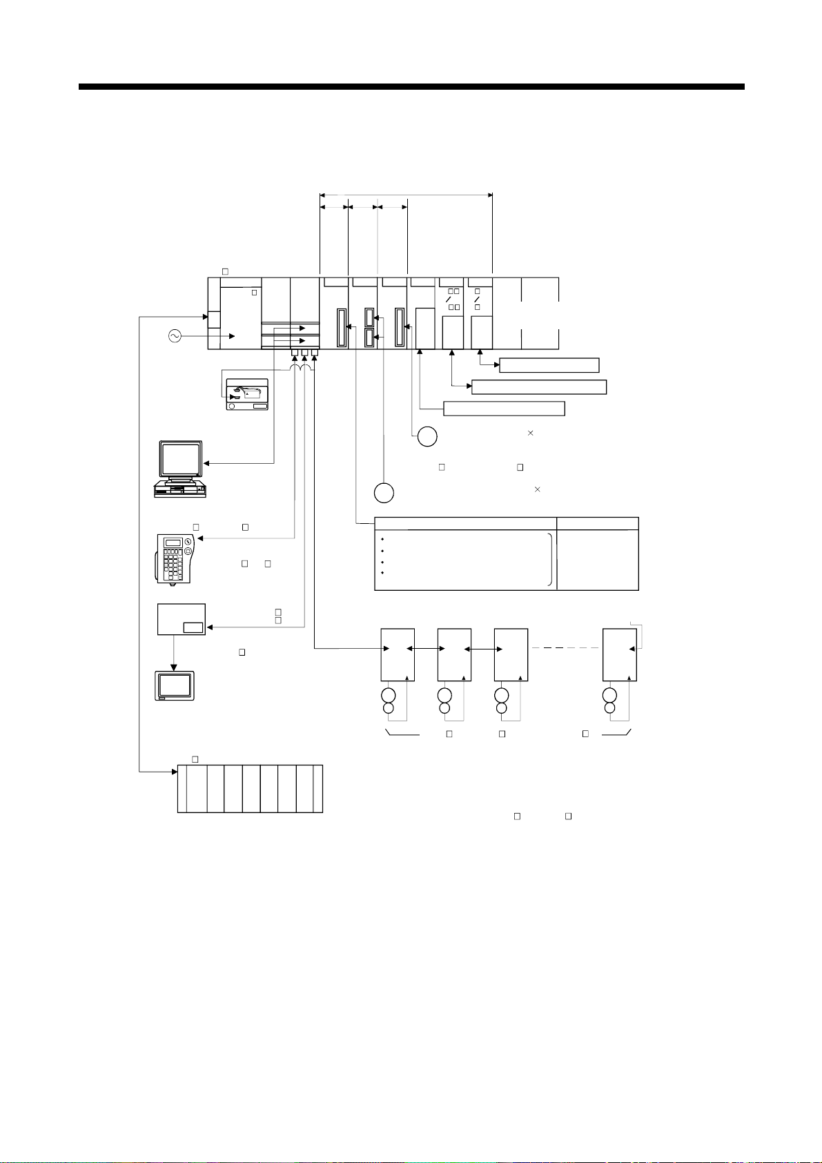
(2) Equipment configuration in Q172CPU(N) system
Q172CPU(N) System configuration
Is the teaching unit used?
NO
(Note)
Refer to equipment configuration of
"(b) When not using the external battery".
Is this system
continuously power off for 1000
hours or more running?
NO
YES
YES
Use a Q172CPUN-T.
Refer to equipment configuration of
"(a) When using the external battery".
(Note) : Continuous power off time which can be backed up on the internal
rechargeable battery is different depending on the charge time. It is
possible to continuously power off for 1100 hours because of charge of
40 hours. Refer to the section 2.4.1 (8) for details.
2 - 4
2 SYSTEM CONFIGURATION
(a) When using the external battery
Extension of the Q series module
Motion module
(Q172LX, Q172EX, Q173PX)
(Note-1)
BAT
LITHIUM BATTERY
CPU
PASSED
Battery unit
(Q170BAT)
MITSUBISHI
Power supply module/
QCPU/ I/O module/ Intelligent
function module of the Q series
CPU base unit
(Q33B, Q35B, Q38B, Q312B)
(Note-5)
Motion CPU module
(Q172CPU(N))
Extension cable
(QC B)
(Note-2)
Short-circuit connector for
the teaching unit
(Q170TU TM)
(Note-3)
Q17BAT
DATE
SSCNET cable
for MR-H-BN
(Q172HBCBL -M) (Q172J2BCBL M-B)
SSCNET cable
for MR-J2 -B
Cable for the teaching unit
(Q170TUD CBL M(-A))
Motion module
(Q172LX, Q172EX, Q173PX)
Q6 B extension base unit
(Q63B, Q65B, Q68B, Q612B)
Power supply module/
I/O module/Intelligent function
module of the Q series
(Note-5)
(Note-6)
SVO ON
Teaching unit
(A31TU-D3 , A31TU-DN )
(Note- 4)
MITSUBISHI
MITSUBISHI
LITHIUM BATTERY
Battery
(A6BAT/MR-BAT)
Servo amplifier
(MR-H-BN)
Servo amplifier
(MR-J2 -B)
Short-circuit connector for
the teaching unit
(A31TUD3TM)
It is possible to select the best according to the system.
(Note-1) : When using the external battery, be sure to use the
SSCNET cable(Q172J2BCBL M-B/Q172HBCBL M-B)
and to set the battery (A6BAT/MR-BAT). Also install
the battery(A6BAT/MR-BAT)in the Battery unit(Q170BAT).
Battery(A6BAT/MR-BAT) is optional.
(Note-2) : It is possible to use only Q172CPUN-T.
It is packed together with Q172CPUN-T.
(Note-3) : It varies by the connecting teaching unit.
(Note-4) : It is packed together with Q170TUD CBL M.
(Note-5) : When using the A31TU-D3 /A31TU-DN , be sure to use
the Q172CPUN-T.
(Note-6) : A31TU-D3 /A31TU-DN corresponds to only Japanese.
It does not correspond to display for English.
2 - 5
2 SYSTEM CONFIGURATION
(b) When not using the external battery
Extension of the Q series module
Motion module
(Q172LX, Q172EX, Q173PX)
Power supply module/
QCPU/ I/O module/ Intelligent
function module of the Q series
CPU base unit
(Q33B, Q35B, Q38B, Q312B)
Motion CPU module
(Q172CPU(N))
SSCNET cable
for MR-H-BN
(Q172HBCBL M) (Q172J2BCBL M )
SSCNET cable
for MR-J2 -B
MITSUBISHI
(Note-4)
Extension cable
(QC B)
(Note-1)
Short-circuit connector for
the teaching unit
(Q170TUTM)
(Note-2)
Cable for the teaching unit
(Q170TUD CBL M(-A))
(Note-3)
Motion module
(Q172LX, Q172EX, Q173PX)
Q6 B extension base unit
(Q63B, Q65B, Q68B, Q612B)
Power supply module/
I/O module/Intelligent function
module of the Q series
(Note-4)
(Note-5)
SVO ON
Teaching unit
(A31TU-D3 , A31TU-DN )
Servo amplifier
(MR-H-BN)
Servo amplifier
(MR-J2 -B)
2 - 6
Short-circuit connector for
the teaching unit
(A31TUD3TM)
It is possible to select the best according to the system.
(Note-1) : It is possible to use only Q172CPUN-T. It is packed
together with Q172CPUN-T.
(Note-2) : It varies by the connecting teaching unit.
(Note-3) : It is packed together with Q170TUD CBL M.
(Note-4) : When using the A31TU-D3 /A31TU-DN , be sure to use
the Q172CPUN-T.
(Note-5) : A31TU-D3 /A31TU-DN corresponds to only Japanese.
It does not correspond to display for English.
2 SYSTEM CONFIGURATION
(3) Peripheral device configuration for the Q173CPU(N)/ Q172CPU(N)
The following (a) (b) (c) can be used.
(a) RS-232 configuration
(b) USB configuration
(c) SSCNET configuration
Motion CPU module
(Q173CPU(N), Q172CPU(N))
RS-232 cable
(QC30R2)
Personal computer
Motion CPU module
(Q173CPU(N), Q172CPU(N))
USB cable
Personal computer
(Windows 98/2000/XP only)
R
Motion CPU module
(Q173CPU(N), Q172CPU(N))
SSC I/F communication cable
(Q170CDCBL M,
Q170BDCBL M)
MITSUBISHI
SSCNET
CARD
A30CD-PCF
SSC I/F Card/Board
(A30CD-PCF/A 0BD-PCF)
Personal computer
(Note) : For information about GPP functions of PLC CPU, refer to the operating
manual of PLC. Also, refer to the programming manual of the operating
system for information about creating Motion programs, and refer to the help
of each software for information about operation of each programming
software package.
2 - 7
(
2 SYSTEM CONFIGURATION
2.1.1 Q173CPU(N) System overall configuration
Motion CPU control module
e
e
l
l
u
u
d
d
e
o
o
s
l
m
m
u
r
p
o
e
r
e
t
l
c
c
e
a
a
r
a
a
d
f
f
u
e
r
o
r
n
c
n
e
e
a
t
t
n
e
n
n
i
e
g
i
M
QI60
CPU base
unit
(Q3 B)
Q61P-A
PLC CPU/
Motion CPU
Q173
Qn(H)
CPU(N)
CPU
e
l
l
u
a
d
s
n
o
u
r
o
e
m
t
n
x
e
o
e
r
c
s
l
h
a
o
f
a
c
r
v
n
r
n
e
t
g
y
e
i
n
S
i
s
S
Q172EX
Q172LX Q172PX
QX
QY
Q6 AD
Q6 DA
I/O module of the Q Series or
Special function module
100/200VAC
Personal Computer
IBM PC/AT
USB/RS-232
Teaching unit
A31TU-D3 /A31TU-DN
Panel Personal Computer
(WinNT/Win98/Win2000/WinXP)
Computer link SSC
Extension
cable
(Note-1)
Cable for the teaching
unit
(Q170TUD CBL M(-A))
SSC I/F
Communication
cable
(Q170CDCBL M/
Q170BDCBL M)
SSC I/F Card/Board
(A30CD-PCF/A 0BD-PCF)
Extension base unit
(Q6 B)
y
l
p
p
u
s
e
l
r
e
u
d
w
o
o
m
P
UP to 7 extensions
Dividing unit
(Q173DV)
MITSUBISHI
LITHIUM BATTERY
SSCNET SYSTEM1
SSCNET cable
M
E
(Note-2)
Analogue input/output
Input/output (Up to 256 points)
Interrupt signals (16 points)
Manual pulse generator 3/module
P
(MR-HDP01)
Serial absolute synchronous encoder cable
(MR-JHSCBL M-H/Q170ENCCBL M)
Serial absolute synchronous encoder 2/module
E
(MR-HENC/Q170ENC)
External input signals
FLS : Upper stroke limit
RLS : Lower stroke limit
STOP : Stop signal
DOG/CHANGE : Proximity dog/
Speed-position switching
SSCNET SYS TEM2
Terminal
connector
d8d1
M
E
MR-H BN/MR-J2S- B/MR-J2M-B/MR-J2- B/MR-J2-03B5 model
Servo amplifier, Vector inverter(FR-V500), Up to 32 axes
(Up to 1 mo dule)
(Up to 6 modules)
SSCNET SYST EM3
Terminal
connector
M
E
Number of Inputs
8 axes/module
(Up to 4 modules)
SSCNET SYSTEM4
Terminal
connector
d8d1
M
E
d1
M
M
E
E
Terminal
connector
d8
M
E
d8
d1
M
E
(Note-1) : Be sure to use the Q173CPUN-T.
A31TU-D3 /A31TU-DN corresponds to only Japanese.
It does not correspond to display for English.
Note-2) : QI60 can be used in SV13/SV22.
2 - 8

2 SYSTEM CONFIGURATION
CAUTION
Construct a safety circuit externally of the Motion controller or servo amplifier if the abnormal
operation of the Motion controller or servo amplifier differ from the safety directive operation in the
system.
The ratings and characteristics of the parts (other than Motion controller, servo amplifier and
servomotor) used in a system must be compatible with the Motion controller, servo amplifier and
servomotor.
Set the parameter values to those that are compatible with the Motion controller, servo amplifier,
servomotor and regenerative resistor model and the system application. The protective functions may
not function if the settings are incorrect.
When a teaching unit is used, the cable for the teaching unit is necessary between the Motion CPU
(Q173CPUN-T/Q172CPUN-T) and teaching unit. And, connect the short-circuit connector for teaching
unit, after removing the teaching unit or when not using it.
2 - 9
2 SYSTEM CONFIGURATION
2.1.2 Q172CPU(N) System overall configuration
Motion CPU control module
e
e
l
l
u
u
d
d
e
o
o
s
l
m
m
u
r
p
o
r
e
e
t
l
c
c
e
a
a
r
a
a
d
f
f
u
e
r
o
r
n
c
n
e
e
a
t
t
n
e
n
n
i
e
i
g
M
QI60
CPU base
unit
(Q3 B)
Q61P-A
PLC CPU/
Motion CPU
Q172
Qn(H)
CPU(N)
CPU
e
l
l
u
a
d
s
n
o
u
r
o
e
m
t
n
x
e
o
e
r
c
s
l
h
a
o
f
a
c
r
v
n
r
n
e
t
g
y
e
i
n
S
s
i
S
Q172EX
Q172LX Q172PX
QX
QY
Q6 AD
Q6 DA
I/O module of the Q Series or
Special function module
100/200VAC
Battery unit
(Q170BAT)
Personal Computer
IBM PC/AT
USB/RS-232
Teaching unit
A31TU-D3 /A31TU-DN
Panel Personal Computer
(WinNT/Win98/Win2000/WinXP)
Computer link SSC
Extension
cable
(Note-1)
Cable for the teaching
unit
(Q170TUD CBL M(-A))
SSC I/F
Communication
cable
(Q170CDCBL M/
Q170BDCBL M)
SSC I/F Card/Board
(A30CD-PCF/A 0BD-PCF)
Extension base unit
(Q6 B)
y
l
p
p
u
s
e
r
l
e
u
d
w
o
o
P
m
UP to 7 extensions
LITHIUM BATTERY
(Note-2)
Analogue input/output
MITSUBISHI
Input/output (Up to 256 points)
Interrupt signals (16 points)
Manual pulse generator 3/module
SSCNET cable
SSCNET SYST EM1
P
(MR-HDP01)
Serial absolute synchronous encoder cable
(MR-JHSCBL M-H/Q170ENCCBL M)
Serial absolute synchronous encoder 2/module
E
(MR-HENC/Q170ENC)
External input signals
FLS : Upper stroke limit
RLS : Lower stroke limit
STOP : Stop signal
DOG/CHANGE : Proximity dog/
Speed-position switching
d1 d2 d3
M
E
M
E
MR-H BN/MR-J2S- B/MR-J2M-B/MR-J2- B/
MR-J2-03B5 model Servo amplifier,
Vector inverter(FR-V500), Up to 8 axes
(Note-1) : Be sure to use the Q172CPUN-T.
A31TU-D3 /A31TU-DN corresponds to only Japanese.
It does not correspond to display for English.
-
(Up to 1 module)
(Up to 4 mo dules)
M
E
Number of Inputs
8 axes/module
(Up to 1 module)
Terminal
connector
M
E
d8
2 - 10

2 SYSTEM CONFIGURATION
CAUTION
Construct a safety circuit externally of the Motion controller or servo amplifier if the abnormal
operation of the Motion controller or servo amplifier differ from the safety directive operation in the
system.
The ratings and characteristics of the parts (other than Motion controller, servo amplifier and
servomotor) used in a system must be compatible with the Motion controller, servo amplifier and
servomotor.
Set the parameter values to those that are compatible with the Motion controller, servo amplifier,
servomotor and regenerative resistor model and the system application. The protective functions may
not function if the settings are incorrect.
When a teaching unit is used, the cable for the teaching unit is necessary between the Motion CPU
(Q173CPUN-T/Q172CPUN-T) and teaching unit. And, connect the short-circuit connector for teaching
unit, after removing the teaching unit or when not using it.
2 - 11

2 SYSTEM CONFIGURATION
2.1.3 Function explanation of the Q173CPU(N)/Q172CPU(N) Motion CPU modules
(1) Up to 32 axes servo amplifiers per 4 systems (up to 8 axes per 1 system) can be
used in Q173CPU(N). Up to 8 axes servo amplifiers per 1 system can be used in
Q172CPU(N).
(2) It is possible to set the program which synchronized with the motion operation
cycle and executed at fixed cycle (0.88[ms], 1.77[ms], 3.55[ms], 7.11[ms],
14.2[ms]).
(3) It is possible to execute a download of servo parameters to servo amplifier, servo
ON/OFF to servo amplifier and position commands, etc. by connecting between
the Q173CPU(N)/Q172CPU(N) and servo amplifier with SSCNET cable.
(4) It is possible to select the servo control functions/programming languages by
installing the corresponding operating system software in the Q173CPU(N)/
Q172CPU(N).
(5) It is possible to use the signals such as stroke limit signals and synchronous
encoder connected to various Motion modules for motion control by setting the
Q173CPU(N)/Q172CPU(N) as the control CPU of various motion modules
(Q172LX/Q172EX, etc.).
(6) It is possible to execute not only servo control but also DI/O input/output control
according to programs described in Motion SFC program by setting the
Q173CPU(N)/Q172CPU(N) as the control CPU of Q series PLC I/O modules
(When the Motion SFC is used as the operating system software.).
(Refer to Section 2.2 (2) for Q series PLC I/O modules that can be controlled by
Motion CPU.)
(7) It is possible to exchange a data among CPUs such as automatic refresh, as the
Q series PLC Multiple CPU system.
(8) There is no restriction for installation position of Q172LX/Q173PX(-S1)/
Q172EX(-S1) among modules controlled by Motion CPU. The installation position
of Q172EX-S2/S3 is only CPU base unit.
Set the installation position in the system settings.
(9) It is possible to change a servo program, monitor or execute JOG operation by
connecting the teaching unit (A31TU-D3
(Q173CPUN-T/Q172CPUN-T only).
(10) It is possible to execute the high-resolution (262144[PLS/rev]) synchronous
control by connecting the serial absolute synchronous encoder (Q170ENC) to
Q172EX-S2/S3.
/A31TU-DN ).
2 - 12

2 SYSTEM CONFIGURATION
2.1.4 Restrictions on Motion systems
(1) It is not allowed to use the Motion CPU as the control CPU of a module installed
on the QA1S6
CPU.
(2) The connector for installation of memory card on the Motion CPU module is for
future function expansion.
(3) Motion CPU module cannot be used as standalone module. It must always be
used in combination with the PLC CPU module (version that supports Multiple
CPU systems). Moreover, it must be installed on the right side of PLC CPU
module. PLC CPU module cannot be installed in a position to the right of Motion
CPU module.
(4) Personal computer CPU unit must be installed on the right side of Motion CPU
module. Motion CPU module cannot be installed in a position to the right of
personal computer CPU unit.
(5) Make sure to use the PLC CPU module in "Q mode".
(6) Motion CPU module cannot be set as the control CPU of intelligent function
module or Graphic Operation Terminal (GOT).
(7) SSCNET cable which connects the Motion CPU and servo amplifier, and the
teaching unit connecting cable which connects the Motion CPU and A31TUD3
/A31TU-DN
secure sufficient space for pulling out the cable when designing the control panel.
(8) Motion CPU module is one module element of Q series multiple PLC system. It
must be set the parameters of Q series multiple PLC system for each PLC CPU.
Motion CPU module must also be set to support the Multiple CPU system in the
system settings.
(9) Make sure to use the Motion CPU as the control CPU of motion modules
dedicated for Motion CPU (Q172LX, Q172EX
operate correctly if PLC CPU is set and installed as the control CPU by mistake.
Motion CPU is treated as a 32-point intelligent module by PLC CPU of other CPU.
It cannot be accessed from other CPU.
(10) When a Multiple CPU system is configured, make sure to configure the modules
so that the total current consumption of individual modules on the CPU base does
not exceed the 5VDC output capacity of power supply module.
(Refer to Section 2.4.2 (3), (4) "Selection of the power supply module".)
(11) Installation position of the Q172EX-S2/S3
(Note-1) : Teaching unit can be used in SV13. It cannot be used in SV22/SV43.
(Note-2) : Q172EX can be used in SV22. It cannot be used in SV13/SV43.
B extension base unit. PLC CPU must be used as the control
(Note-1)
are pulled from the bottom part of unit. Make sure to
(Note-2)
, Q173PX, etc.). They will not
(Note-2)
is only CPU base unit.
2 - 13

2 SYSTEM CONFIGURATION
(12) Number of Motion CPU modules and temperature conditions
(Q173CPU/Q172CPU only)
(a) It is possible to remove the Cooling fan unit(Q170FAN) in order to disperse
heat from inside the Motion CPU module according to the number of the
Motion CPU module and ambient temperature conditions.
Removable/Not removable of the Cooling fan unit (Q170FAN) by number of
Motion CPU modules and ambient temperature is as follows.
1) When using only one Motion CPU module
2) When using two or more Motion CPU modules
Ambient temperature
of the Motion CPU
Number of the Motion CPU
1 module Removable Not removable
It is possible to remove the Cooling fan unit if the ambient temperature
in which the Motion CPU module will be operating is 0 to 40°C (32 to
104°F).
Do not remove the Cooling fan unit(Q170FAN).
0 to 40
(
32 to 104
°C
°F)
Over 40 to 55
(Over
104 to 131
°C
°F)
2 modules or more Not removable
(13) When the backup time (when it is charged for 40 hours) for internal rechargeable
battery of Motion CPU is 1100 hours (Guaranteed time)/4300 hours (Actual time).
Set the external battery if the power failure time exceeds guaranteed time.
(Refer to Section 2.4.10 External battery)
Item
Internal rechargeable
(Note)
battery
External battery 60000 240000
Charging time: 8 hours or more
Charging time: 40 hours or more
(Note):Internal rechargeable battery is charged while power ON.
Continuous power failure time [h]
Guaranteed time (MIN) Actual time (TYP)
200 500
1100 4300
2 - 14

2 SYSTEM CONFIGURATION
2.2 System Configuration Equipment
Part name Model name
Q172CPUN Up to 8 axes control 1.14
Q172CPUN-T Up to 8 axes control, For teaching unit 1.45
Motion CPU
module
Servo external
signals
interface module
Serial absolute
synchronous
encoder
interface module
Manual pulse
generator
interface module
PLC CPU module
Power supply
(Note-3)
module
CPU base unit
Extension base
unit
Q172CPU Up to 8 axes control, With cooling fan unit 1.62
Q173CPUN Up to 32 axes control 1.25
Q173CPUN-T Up to 32 axes control, For teaching unit 1.56
Q173CPU Up to 32 axes control, With cooling fan unit 1.75
Q172LX
Q172EX
Q172EX-S1
Q172EX-S2
Q172EX-S3
Q173PX
Q173PX-S1
Q00CPU Program capacity 8k steps 0.25
Q01CPU Program capacity 14k steps 0.27
Q02CPU Program capacity 28k steps 0.60
Q02HCPU Program capacity 28k steps 0.64
Q06HCPU Program capacity 60k steps 0.64
Q12HCPU Program capacity 124k steps 0.64
Q25HCPU Program capacity 252k steps 0.64
Q61P-A1 100 to 120VAC input, 5VDC 6A output
Q61P-A2 200 to 240VAC input, 5VDC 6A output
Q62P 100 to 240VAC input, 5VDC 3A/24VDC 0.6A output
Q63P 24VDC input, 5VDC 6A output
Q64P 100 to 120VAC/200 to 240VAC input, 5VDC 8.5A output
Q33B Number of I/O modules installed 3 slots
Q35B Number of I/O modules installed 5 slots
Q38B Number of I/O modules installed 8 slots
Q312B Number of I/O modules installed 12 slots 0.121
Q63B Number of I/O modules installed 3 slots 0.105
Q65B Number of I/O modules installed 5 slots 0.110
Q68B Number of I/O modules installed 8 slots 0.114
Q612B Number of I/O modules installed 12 slots 0.121
(1) Table of Motion controller related module
(Note-1)
Description
Servo external signal input 8 axes
(FLS, RLS, STOP, DOG/CHANGE×8)
Serial absolute synchronous encoder MR-HENC interface×2,
Tracking input 2 points
(Note-2)
(Note-2)
(Note-2)
Serial absolute synchronous encoder MR-HENC interface×2,
Tracking input 2 points, Memory built-in for data exchange
Serial absolute synchronous encoder Q170ENC interface×2,
Tracking input 2 points
Serial absolute synchronous encoder Q170ENC interface×2,
Tracking input 2 points, Memory built-in for data exchange
Manual pulse generator MR-HDP01/Incremental synchronous encoder
interface ×3, Tracking input 3 points
Manual pulse generator MR-HDP01/Incremental synchronous encoder
interface ×3, Tracking input 3 points, Memory built-in for data exchange
Current
consumption
5VDC[A]
0.05
0.07
0.11
——
0.105
0.110
0.114
Remark
2 - 15

2 SYSTEM CONFIGURATION
Part name Model name
QC05B Length 0.45m(1.48ft.)
QC06B Length 0.6m(1.97ft.)
Extension cable
Manual pulse
generator
Teaching unit
Cable for the
teaching unit
Short-circuit
connector for
teaching unit
Serial absolute
synchronous
encoder
Serial absolute
synchronous
encoder cable
QC12B Length 1.2m(3.94ft.)
QC30B Length 3m(9.84ft.)
QC50B Length 5m(16.40ft.)
QC100B Length 10m(32.81ft.)
MR-HDP01
A31TU-D3K13 For SV13, With 3-position deadman switch, Only Japanese
A31TU-DNK13 For SV13, Without deadman switch, Only Japanese
Q170TUD3CBL3M
Q170TUDNCBL3M
Q170TUDNCBL03M-A
Q170TUTM
A31TUD3TM
MR-HENC
Q170ENC
MR-JHSCBL M-H
Q170ENCCBL
Table of Motion controller related module (continued)
(Note-1)
Description
Pulse resolution: 25PLS/rev(100PLS/rev after magnification by 4)
Permitted axial loads Radial load: Up to 19.6N
Thrust load: Up to 9.8N
Permitted speed: 200r/min(Normal rotation), Voltage output
Q173CPUN-T/Q172CPUN-T
(Attachment: Short-circuit connector (A31TUD3TM) for teaching unit)
Q173CPUN-T/Q172CPUN-T
(Attachment: Short-circuit connector (A31TUD3TM) for teaching unit)
Exchange cable for direct connection Q173CPUN-T/Q172CPUN-T
A31TU-DN
Short-circuit connector for teaching unit for direct connection to
Q173CPUN-T/Q172CPUN-T
It is packed together with Q173CPUN-T/Q172CPUN-T.
Short-circuit connector for teaching unit for connection to connect with
Q170TUD3CBL3M/Q170TUDNCBL3M
It is packed together with Q170TUD3CBL3M/Q170TUDNCBL3M.
Resolution: 16384PLS/rev
Permitted axial loads Radial load: Up to 98N
Thrust load: Up to 49N
Permitted speed: 4300r/min
Resolution: 262144PLS/rev
Permitted axial loads Radial load: Up to 19.6N
Thrust load: Up to 9.8N
Permitted speed: 3600r/min
Serial absolute synchronous encoder
2m(6.56ft.), 5m(16.40ft.), 10m(32.81ft.), 20m(65.62ft.), 30m(98.43ft.)
(Same as encoder cables for HC-SFS/RFS/UFS(2000r/min) series
motors)
Serial absolute synchronous encoder Q170ENC
2m(6.56ft.), 5m(16.40ft.), 10m(32.81ft.), 20m(65.62ft.), 30m(98.43ft.),
M
50m(164.04ft.)
, 0.3m(0.98ft.)
A31TU-D3 , 3m(9.84ft.)
A31TU-DN , 3m(9.84ft.)
Q172EX
Q172EX-S2/-S3
Current
consumption
5VDC[A]
——
0.06
0.26
——
——
——
——
——
0.15
0..20
——
Remark
2 - 16

2 SYSTEM CONFIGURATION
Part name Model name
MR-J2CNS
Connector set for
serial absolute
synchronous
encoder cable
Q170ENCCNS
Q172HBCBL M
Q172HBCBL M-B
Q172J2BCBL M
Q172J2BCBL M-B
Q173HB CBL M Q173CPU(N) Servo amplifier (MR-H BN)
SSCNET cable
Q173J2B CBL M Q173CPU(N) Servo amplifier MR-J2 -B
Table of Motion controller related module (continued)
(Note-1)
Description
Q172EX(-S1) side connector
Connector :10120-3000VE
Connector case : 10320-52F0-008
MR-HENC side connector
Plug : MS3106B20-29S
Cable clump : MS3057-12A
Q172EX-S2/-S3 side connector
Connector :10120-3000VE
Connector case : 10320-52F0-008
Q170ENC side connector
Plug : MS3106B22-14S
Cable clump : MS3057-12A
• Q172CPU(N)
• MR-H
Q172CPU(N)
(Q170BAT)
• Q172CPU(N)
• Servo amplifier (MR-J2
• Dividing unit (Q173DV)
Q172CPU(N)
(Q170BAT)
Servo amplifier (MR-H BN)
BN FR-V5NS
(Note-5)
Servo amplifier (MR-H BN) and Battery unit
Servo amplifier (MR-J2 -B)
(Note-4)
-B)
FR-V5NS
FR-V5NS
(Note-5)
Servo amplifier (MR-J2 -B)
(Note-4)
(Note-4)
(Note-5)
(Note-4)
and Battery unit
Current
consumption
Remark
5VDC[A]
——
——
Q173DVCBL M Q173CPU(N) Dividing unit(Q173DV)
FR-V5NSCBL
• Q172CPU(N)
• FR-V5NS
(Note-5)
FR-V5NS
FR-V5NS
(Note-5)
(Note-5)
MR-HBUS M Servo amplifier (MR-H BN) Servo amplifier (MR-H BN)
MR-J2HBUS M-A
MR-J2HBUS
M
• Servo amplifier (MR-H
BN) Servo amplifier (MR-J2 -B)
• Servo amplifier (MR-H BN) Dividing unit (Q173DV)
• Servo amplifier (MR-J2
• Servo amplifier (MR-J2 -B)
(Note-4)
-B)
Servo amplifier (MR-J2 -B)
(Note-4)
Dividing unit (Q173DV)
(Note-4)
(Note-4)
SSC I/F board A30BD-PCF ISA bus loading type, 2ch/board
——
SSC I/F card A30CD-PCF PCMCIA TYPE II, 1ch/card
Cable for SSC I/F
board
Cable for SSC I/F
card
Q170BDCBL
Q170CDCBL
Dividing unit Q173DV
Q173CPU(N)/Q172CPU(N)
M
3m(9.84ft.), 5m(16.40ft.), 10m(32.81ft.)
Q173CPU(N)/Q172CPU(N)
M
3m(9.84ft.), 5m(16.40ft.), 10m(32.81ft.)
SSC I/F board
SSC I/F card
For dividing the SSCNET systems of Q173CPU(N) into 4.
(Attachment: Battery holder for IC-RAM memory backup)
——
Battery unit Q170BAT For IC-RAM memory backup of Q172CPU(N) ——
For IC-RAM memory backup of Q173CPU(N)/Q172CPU(N) module
Battery A6BAT
(Motion SFC programs(SV13/SV22), Servo programs(SV13/SV22),
——
Motion programs(SV43), Parameters)
Cooling fan unit Q170FAN Cooling fan of the Motion CPU module 0.08
2 - 17

2 SYSTEM CONFIGURATION
Part name Model name
Q172CPU(N)
connector set
Q173CPU(N)
connector set
Q173DV
connector set
Connector/terminal
block conversion
module
Cable for
connector/terminal
block conversion
module
Q172CON
Q173CON
Q173DVCON
A6TBXY36
A6TBXY54
A6TBX70 For positive common sink type input module (3-wire type)
AC05TB Length 0.5m (1.64ft.)
AC10TB Length 1m (3.28ft.)
AC20TB Length 2m (6.56ft.)
AC30TB Length 3m (9.84ft.)
AC50TB Length 5m (16.40ft.)
AC80TB Length 8m (26.25ft.)
AC100TB Length 10m(32.81ft.)
(Note-1) : =Number of systems (none: 1 system, 2: 2 systems, 4: 4 systems)
(Note-2) : Q172EX-S1 and Q173PX-S1 can be used is only the operating system software of special specification that
(Note-3) : Be sure to use the power supply module within the range of power supply capacity.
(Note-4) : MR-J2S- B/MR-J2M-B/MR-J2- B/MR-J2-03B5 type servo amplifier
(Note-5) : SSCNET communication option for vector inverter
(Note-6) : Crimping terminal is not sold in Mitsubishi. The following jig is requested to be procured by customers.
Table of Motion controller related module (continued)
(Note-1)
Description
Connector for Q172CPU(N)
Connector : HDR-E14MG1
Case : HDR-E14LPA5
Q173CPU(N) side connector set
Connector : HDR-E26MG1
Case : HDR-E26LPA5
Q173CPU(N) side connector set
Connector : HDR-E26MG1
Case : HDR-E26LPA5
Q173DV side connector set
Connector : 10126-3000VE
Case : 10326-52F0-008
For positive common sink type input module, sink type output module
(standard type)
For positive common sink type input module, sink type output module (2-
wire type)
=Cable length (05: 0.5m(1.64ft.), 1: 1m(3.28ft.), 2: 2m(6.56ft.), 3: 3m(9.84ft.), 5: 5m(16.40ft.), 10: 10m(32.81ft.),
20: 20m(65.62ft.), 30: 30m(98.43ft.))
needs data exchange function.
Specified tool (Honda Connectors make) : FHAT-0029/FHPT-0004C
(Note-6)
(Note-6)
(Note-6)
Current
consumption
5VDC[A]
——
——
——
——
——
Remark
2 - 18

r
2 SYSTEM CONFIGURATION
(2) Q series PLC module which can be control by Motion CPU
Part name
AC QX10 100-120VAC, 7-8mA, 16 points, Terminal block
Input
module
Output
module
Input/Output
composite
module
Interrupt module QI60 DC24V/4mA, Positive common, 16 points, Terminal block
Analogue module
DC
Contact output
module
Sink Type
Transisto
Source Type
TTL•CMOS(Sink)
DC Input/
Transistor output
Model
name
QX40 24VDC/4mA, Positive common, 16 points, Terminal block
QX41 24VDC/4mA, Positive common, 32 points, Connector
QX42 24VDC/4mA, Positive common, 64 points, Connector
QX70
QX71
QX72
QX80 24VDC/4mA, Negative common, 16 points, Terminal block
QX81 24VDC/4mA, Negative common, 32 points, Connector
QY10 240VAC/24VDC, 2A/point, 8A/common, 16 points/common, Terminal block
QY40P 12V/24VDC, 0.1A/point, 1.6A/common, 16 points/common Terminal block
QY41P 12V/24VDC, 0.1A/point, 2A/common, 32 points/common Connector
QY42P
QY50
QY80
QY81P
QY70 5/12VDC, 16mA/point, 16 points(16 points/common), Terminal block
QY71 5/12VDC, 16mA/point, 32 points(32 points/common), Connector
QH42P
QX48Y57
Q64AD 4ch, A/D conversion, Voltage • Current input
Q68ADV 8ch, A/D conversion, Voltage input
Q68ADI 8ch, A/D conversion, Current input
Q62DA 2ch, D/A conversion, Voltage • Current output
Q64DA 4ch, D/A conversion, Voltage • Current output
Q68DAV 8ch, D/A conversion, Voltage output
Q68DAI 8ch, D/A conversion, Current output
12VDC/5V, Positive common/Negative common shared, 16 points,
Terminal block
12VDC/5V, Positive common/Negative common shared, 32 points,
Terminal block
12VDC/5V, Positive common/Negative common shared, 64 points,
Terminal block
12V/24VDC, 0.1A/point, 2A/common, 64 points(32 points/common),
Connector
12V/24VDC, 0.5A/point, 4A/common, 16 points(16 points/common),
Terminal block
12V/24VDC, 0.5A/point, 4A/common, 16 points(16 points/common),
Terminal block
12V/24VDC, 0.1A/point, 2A/common, 32 points(32 points/common),
Connector
24VDC Positive common: 32 points
DC12-24V/0.1A Output Sink type: 32 points, Connector,
Provided (Thermal protectors, protector against short circuit)
24VDC Positive common: 8 points
DC12-24V/0.5A Output Sink type: 7 points, Terminal block,
Provided (When face is broken, LED lights and signal is output to CPU)
Description Remark
Marked " ": connectors are not provided.
2 - 19

2 SYSTEM CONFIGURATION
(3) Table of servo amplifier
Part name Model name Description
MR-H BN MR-H series
servo amplifier
Battery MR-BAT Back-up for the absolute position detection
Terminal connector MR-TM Connected to the last servo amplifier (MR-H BN) by SSCNET.
SSCNET cable
Encoder cable
Encoder connector set
MR-H
MR-HBUS M
MR-J2HBUS M-A
Q172HBCBL
MR-HSCBL M
MR-EN1CBL M-H
MR-JCCBL M-L
MR-JCCBL
MR-JSCNS
MR-EN1CNS
The following servo amplifier series can be used.
(a) MR-H BN
KBN
(Note-1) : MR-J2S- B/MR-J2M-B/MR-J2- B/MR-J2-03B5 type servo amplifier
(Note-2) : SSCNET communication option for vector inverter
Refer to catalogue of the servo amplifier.
MR-H
BN MR-H BN
0.5m(1.64ft.), 1m(3.28ft.), 5m(16.40ft.)
• Q173DV
• MR-H
0.5m(1.64ft.), 1m(3.28ft.), 5m(16.40ft.)
MR-H
M
0.5m(1.64ft.), 1m(3.28ft.), 5m(16.40ft.)
HA-LH
2m(6.56ft.), 5m(16.40ft.), 10m(32.81ft.), 20m(65.62ft.), 30m(98.43ft.)
HA-FF, HC-MF/UF(3000r/min)
M-H
Servo amplifier side connector for HA-LH
Encoder side connector set
When the vector inverter (FR-V5
MR-H BN
BN MR-J2 -B
BN FR-V5NS
K, HC-SF/RF/UF(2000r/min) series motor MR-H BN
(Note-1)
(Note-2)
MR-H BN
K, HC-SF/RF/UF(2000r/min) series motor,
0- ) is connected, fix the ferrite core to the SSCNET cable.
2 - 20

2 SYSTEM CONFIGURATION
Part name Model name Description
MR-J2S- B MR-J2-Super series
servo amplifier
MR-J2M series
servo amplifier
MR-J2 series
servo amplifier
MR-J2-Jr series
servo amplifier
Battery MR-BAT Back-up for the absolute position detection.
Terminal connector MR-A-TM
SSCNET cable
Encoder cable
Encoder connector set
MR-J2S-
MR-J2M- DU Drive unit
MR-J2M-P8B Interface unit
MR-J2M-BU
MR-J2-
MR-J2-03B5
MR-J2HBUS M-A
MR-J2HBUS M
Q172J2BCBL
MR-JHSCBL M-L Standard cable
MR-JHSCBL M-H
MR-ENCBL M-H
MR-JCCBL M-L Standard cable
MR-JCCBL M-H
MR-JCCBL M-H
MR-JRBRCBL
MR-J2CNS
MR-ENCNS
MR-JRCNM Servo amplifier and Junction connector set for HC-AQ series motor.
MR-JRBRCNM
MR-JRBRCN Electromagnetic brake contact connector for HC-AQ series motor.
MR-J2CNM
(b) MR-J2S- B/MR-J2M-B/MR-J2- B/MR-J2-03B5
B1
B
(Note-1) : MR-J2S- B/MR-J2M-B/MR-J2- B/MR-J2-03B5 type servo amplifier
(Note-2) : SSCNET communication option for vector inverter
Refer to catalogue of the servo amplifier.
Refer to catalogue of the servo amplifier.
Base unit
Refer to catalogue of the servo amplifier.
Connected to the last servo amplifier(MR-J2S-
03B5) by SSCNET
• Q173DV
• MR-H
0.5m(1.64ft.), 1m(3.28ft.), 5m(16.40ft.)
• MR-J2
• MR-J2
0.5m(1.64ft.), 1m(3.28ft.), 5m(16.40ft.)
MR-J2
M
0.5m(1.64ft.), 1m(3.28ft.), 5m(16.40ft.)
Long fixing life
encoder cable
Long fixing life
encoder cable
M-H
Servo amplifier and junction side connector set for HC-SFS/RFS/UFS(2000r/min)
series motor, HC-SF/RF/UF(2000r/min) series motor.
Servo amplifier side(Motor cable for servomotor with electromagnetic brake) and HC-
AQ series motor. (Need MR-JRBRCN for electromagnetic brake contact)
Servo amplifier and junction side connector set for HC-MFS/KFS/UFS(3000r/min)
series and HA-FF, HC-MF/UF(3000r/min) series motor.
When the vector inverter (FR-V5
MR-H BN
BN MR-J2 -B
(Note-1)
-B
MR-J2 -B
(Note-1)
-B
Q173DV
(Note-1)
-B
FR-V5NS
• HC-SFS/RFS/UFS(2000r/min) series motor
MR-J2S-
• HC-SF/RF/UF(2000r/min) series motor
2m(6.56ft.), 5m(16.40ft.), 10m(32.81ft.), 20m(65.62ft.), 30m(98.43ft.)
• HC-MFS/KFS/UFS(3000r/min) series motor
MR-J2S-
• HC-MF/UF(3000r/min) and HA-FF series motor
2m(6.56ft.), 5m(16.40ft.), 10m(32.81ft.), 20m(65.62ft.), 30m(98.43ft.)
HC-AQ series motor
2m(6.56ft.), 5m(16.40ft.), 10m(32.81ft.), 20m(65.62ft.), 30m(98.43ft.)
HC-AQ series motor
2m(6.56ft.), 5m(16.40ft.), 10m(32.81ft.), 20m(65.62ft.), 30m(98.43ft.)
(Motor cable for servomotor with electromagnetic brake)
(Note-1)
(Note-1)
(Note-2)
B/MR-J2M-B
B/MR-J2M-B
0- ) is connected, fix the ferrite core to the SSCNET cable.
B/MR-J2M-B/MR-J2- B/MR-J2-
MR-J2- B
MR-J2- B
MR-J2-03B5
MR-J2-03B5
2 - 21

2 SYSTEM CONFIGURATION
Part name Model name Description
FR-V520- K FR-V500 series vector
inverter
SSCNET cable
FR-V540-
Q172J2BCBL M
FR-V5NSCBL
(c) FR-V5 0-
Refer to catalogue of the vector inverter.
K
• MR-J2
0.5m(1.64ft.), 1m(3.28ft.), 5m(16.40ft.)
• Q172CPU(N)
• FR-V5NS
0.5m(1.64ft.), 1m(3.28ft.), 5m(16.40ft.), 10m(32.81ft.), 20m(65.62ft.)
(Note-1) : MR-J2S- B/MR-J2M-B/MR-J2- B/MR-J2-03B5 type servo amplifier
(Note-2) : SSCNET communication option for vector inverter
When the vector inverter (FR-V5
-B
(Note-1)
(Note-2)
FR-V5NS
FR-V5NS
FR-V5NS
0- ) is connected, fix the ferrite core to the SSCNET cable.
(Note-2)
(Note-2)
(4) Software packages
Part name Model name Details
SW6RNC-GSVPROE
MT Developer
SW6RNC-GSVSETE
(Note) : Operating environment of the MT Developer is WindowsNTR4.0/WindowsR98/WindowsR2000/ WindowsRXP
English version) only.
(a) Operating system software packages
Application
For conveyor assembly SV13
(Motion SFC)
For automatic machinery SV22
(Motion SFC)
For machine tool peripheral SV43
Q173CPU(N) Q172CPU(N)
SW6RN-SV13QB SW6RN-SV13QD
SW6RN-SV22QA SW6RN-SV22QC
SW5RN-SV43QA SW5RN-SV43QC
(b) Integrated start-up support software package
Conveyor assembly software : SW6RN-GSV13P
Automatic machinery software : SW6RN-GSV22P
SW6RNC-GSVE
(Integrated start-up support
software
(1 CD-ROM) )
SW6RNC-GSVHELPE (Operation manual (1 CD-ROM) )
A30CD-PCF (SSC I/F card (PCMCIA TYPE II 1CH/card) )
Q170CDCBL3M (A30CD-PCF cable 3m (9.84ft.) )
Machine tool peripheral software : SW6RN-GSV43P
Cam data creation software : SW3RN-CAMP
Digital oscilloscope software : SW6RN-DOSCP
Communication system software : SW6RN-SNETP
Document print software : SW3RN-DOCPRNP,
SW20RN-DOCPRNP
(Note-2)
Software package
Installation manual
SW6RNC-GSVPROE
2 - 22

Size
2 SYSTEM CONFIGURATION
(5) Operating environment of personal computer
Operating environment is shown below.
Item
CPU Pentium133MHz or more Pentium II 233MHz or more Pentium II 450MHz or more
Memory
capacity
Hard disk free
space
Disk drive 3.5inch (1.44MB) floppy disk drive, CD-ROM disk drive
Display 800×600 pixels, 256 colors or more
WindowsNT
or later)
Recommended 32MB or more Recommended 64MB or more Recommended 192MB or more
IBM PC/AT with which WindowsNT4.0/98/2000/XP English version operates normally.
R
4.0(Service Pack 2
(Note)
or WindowsR98
Windows
Hard disk free space is as following list.
R
2000 WindowsRXP
(Note) : Impossible to use USB connection.
It is necessary the following capacity depending on the installed software.
Model name
SW6RN-GSV13P 60MB 38MB
SW6RN-GSV22P 60MB 42MB
SW6RN-GSV43P 45MB 29MB
SW3RN-CAMP 2MB 3MB
SW6RN-DOSCP 30MB 5MB
SW6RN-SNETP
SW3RN-DOCPRNP 30MB 5MB
SW20RN-DOCPRNP 30MB 5MB
(Note-1) : WindowsNTR, WindowsRare either registered trademarks or trademarks of Microsoft Corporation
in the United States and/or other countries.
(Note-2) : Pentium
United States and other countries.
R
Custom (When all selection) 60.5MB
are trademarks or registered trademarks of Intel Corporation or its subsidiaries in the
SW6RNC-GSVE SW6RNC-GSVHELPE
Standard 60MB
3MB
(6) Related software packages
(a) PLC software package
Model name Software package
GX Developer SW D5C-GPPW -E
(Note) : =used "6" or later.
POINTS
(1) When the operation of Windows is not unclear in the operation of this software,
refer to the manual of Windows or guide-book from the other supplier.
(2) The screen might not be correctly displayed depending on the system font size
of WindowsNT
Be sure to use the small size fonts.
R
4.0/WindowsR98/WindowsR2000/ WindowsRXP.
2 - 23
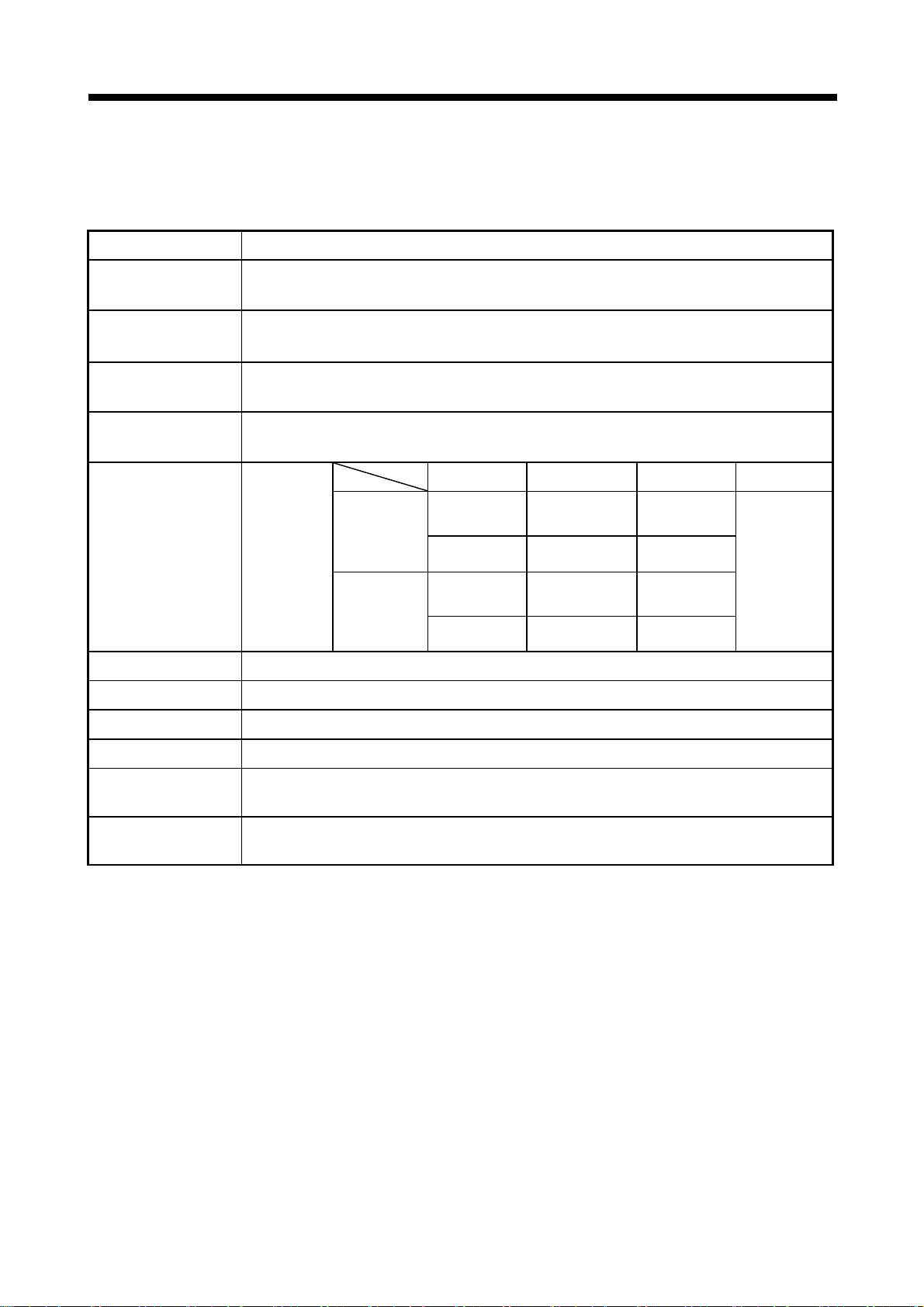
2 SYSTEM CONFIGURATION
2.3 General Specifications
General specifications of Q173CPU(N)/Q172CPU(N) module are shown below.
Item Specification
Operating ambient
temperature
Storage ambient
temperature
Operating ambient
humidity
Storage ambient
humidity
Vibration resistance Conforming
JIS B 3501,
IEC 61131-2
Under
intermittent
vibration
Under
continuous
vibration
0 to 55°C
(32 to 131°F)
-25 to 75°C
(Note-3)
(-13 to 167°F)
5 to 95% RH
5 to 95% RH
,
non-condensing
,
non-condensing
Frequency Acceleration Amplitude Sweep count
10 to 57Hz ——
0.075mm
(0.003inch)
10 times each
57 to 150Hz 9.8m/s2 ——
10 to 57Hz ——
57 to 150Hz 4.9m/s
2
——
0.035mm
(0.001inch)
in X, Y, Z
directions
(For 80 min.)
Shock resistance Conforming to JIS B 3501, IEC 61131-2(147m/s2 , 3 times in each of 3 directions X, Y, Z)
Operating ambience No corrosive gases
Operating altitude 2000m(6561.68ft.) or less
Installation location Inside control panel
Overvoltage category
(Note-1)
Pollution level
(Note-2
)
2 or less
II or less
(Note-1) : This indicates the section of the power supply to which the equipment is assumed to be connected between the
public electrical power distribution network and the machinery within premises.
Category II applies to equipment for which electrical power is supplied from fixed facilities.
The surge voltage withstand level for up to the rated voltage of 300V is 2500V.
(Note-2) : This index indicates the degree to which conductive material is generated in terms of the environment in which
the equipment is used.
Pollution level 2 is when only non-conductive pollution occurs. A temporary conductivity caused by condensing
must be expected occasionally.
(Note-3) : Do not use or store the Motion CPU module under pressure higher than the atmospheric pressure of altitude 0m.
Doing so can cause an operation failure. When using the PLC under pressure, please contact your sales
representative.
2 - 24

2 SYSTEM CONFIGURATION
!
CAUTION
The Motion controller must be stored and used under the conditions listed in the table of
specifications above.
When not using the module for a long time, disconnect the power line from the Motion controller
or servo amplifier.
Place the Motion controller and servo amplifier in static electricity preventing vinyl bags and store.
When storing for a long time, please contact with our sales representative.
2 - 25

2 SYSTEM CONFIGURATION
2.4 Specifications of Equipment and Settings
2.4.1 Name of parts for CPU module
This section explains the names and setting of the module.
(1) Q173CPUN(-T)/Q172CPUN(-T)
Put your finger here to open the cover.
Front face
Q17 CPUN T
MODE
RUN
ERR.
M.RUN
BOOT
CN2
PULL
CN1
USB
RS-232
BAT.
FRONT
SSCNET
2)
3)
4)
5)
6)
7)
TU
8)
9)
10)
11)
12)
With front cover open
MODE
RUN
ERR.
M.RU N
BAT.
BOOT
ON SW
1
2
3
4
5
STOP RUN
RESET L CLR
20)
13)
14)
15)
Side face
1)
16)
Q172CPUN(-T)
Bottom
19)
20)
Q173CPUN(-T)
18)
19)
20)
18)
17)
2 - 26

2 SYSTEM CONFIGURATION
(2) Q173CPU/Q172CPU
Front face
Q17 CPU
MODE
M.RUN
BOOT
PULL
RUN
ERR.
BAT.
SSCNET
FRONT
CN2
CN1
2)
3)
4)
5)
6)
7)
9)
10)
With front cover open
MODE
RUN
ERR.
M.R UN
BAT.
BOOT
ON SW
1
2
3
4
5
STOP RUN
RESET L CLR
13)
14)
15)
USB
RS-232
8)
Put your finger here to open the cover.
Side face
22)
1)
21)
Q172CPU
11)
12)
Bottom
Q173CPU
16)
19)
18)
19)
18)
17)
2 - 27

2 SYSTEM CONFIGURATION
No. Name Application
1) Module fixing hook • Hook used to fix the module to the base unit.(Quick release installation)
2) MODE LED (Mode judging)
3) RUN LED
4) ERR. LED
5) M. RUN LED
6) BAT. LED • Lit : Battery error occurrence (External battery use)
7) BOOT LED
8) Module loading lever • Used to install the module to the base unit.
9) Memory card EJECT button • Used to eject the memory card from the Motion CPU.
10) Memory card loading connector
11) USB connector
12) RS-232 connector
(Note) : When normally connecting a cable to the USB or RS-232 connector, clamp the cable to prevent it from coming off due to the
dangling, moving or careless pulling of the cable. Q6HLD-R2 type RS-232C connector disconnection prevention holder is
available as a clamp for RS-232 connector.
(Note)
(Note)
• Lit(green)
• Lit(orange)
• Lit : Motion CPU normal start
• Not lit : Motion CPU fault
• Lit : LED turns on at following error occurrence.
• Flickers : Detection of self diagnostic error which will stop the operation.
• Not lit : Normal
• Lit : During motion control
• Flickers : Latch clear start
• Not lit : Not during motion control or detection of self diagnostic error which will stop the
• Lit
• Not lit
• Connector used to connect the memory card to the Motion CPU. (The Motion CPU make use
of the memory card by operating system software package.)
• Connector for connection with USB-compatible peripheral device. (Connector type B)
• It can be connected by USB-dedicated cable.
• Connector for connection with a peripheral device.
• It can be connected by RS-232 connection cable (QC30R2)
: Normal mode
: Installation mode • mode written in ROM
LED turns off when the trouble occurred at Motion CPU start or WDT error
occurrence.
1) WDT error
2) System setting error
3) Servo error
4) Self diagnostic error which will not stop the operation (except battery error)
5) Operating system software is not installed.
operation
: Mode operated by ROM
: Mode operated by RAM/Installation mode • mode written in ROM
CPU module
RS-232 cable
2 - 28
Q6HLD-R2

2 SYSTEM CONFIGURATION
(3) Applications of switches, connectors on Q173CPU(N)/
No. Name Application
Dip switches
ON SW
1
13)
14) RUN/STOP switch
RESET/L.CLR switch
15)
(Momentary switch)
16) Module fixing screw hole Hole for the screw used to fix to the base unit. (M3×12 screw : Purchase from the other supplier)
2
3
4
5
Q172CPU(N)
Dip switch 1 Must not be used. (Shipped from the factory in OFF position)
• ROM operating setting (Shipped from the factory in OFF position)
Dip switch 2
Dip switch 3
Dip switch 4 Must not be used. (Shipped from the factory in OFF position)
Dip switch 5
(Installation •
ROM writing
switch)
Move to RUN/STOP.
RUN : Motion SFC program(SV13/SV22)/Motion program(SV43) is started.
STOP : Motion SFC program(SV13/SV22)/Motion program(SV43) is stopped.
RESET : Set the switch to the
L.CLR : Clear the latch area all data which set with the parameters.
(LATCH CLEAR also clears data outside the latch area at this time.)
(Note-1)
Latch clear operating method
1) Set the
2) Move the
flickers.
(
3) Move the
SW2
OFF
ON
OFF
ON
ON : Installation mode • mode written in ROM
OFF : Normal mode (Mode operated by RAM/Mode operated by ROM)
• Turn ON dip switch 5 when installed the operating system software into the
Motion CPU module from the peripheral device. After completing the installation,
move to switch and re-start.
Applies a reset after an operation error and initialized the operation.
"
RUN/STOP" switch to "STOP".
"
RESET/L.CLR" switch to "L.CLR" several times until the "M. RUN LED"
"
M. RUN LED" flickers : Latch clear completed. )
"
RESET/L.CLR" switch to "L.CLR" once more. ("M. RUN LED" turn off.)
SW3
OFF
OFF
ON
ON
"
RESET" position once to reset the hardware.
Mode operated by RAM
Must not be set
Must not be set
Mode operated by ROM
17) Module fixing hook Hook used to fix to the base unit
18) CN1 connector
19) CN2 connector Connector connect between personal computer via SSCNET
20) TU connector
21) Cooling fan connector
22) Cooling fan unit
(Note-1) : It is not possible to reset the Multiple CPU system by each of the PLC CPU/Motion CPU No.2 to 4.
If it is reset, other CPU occurred to stop of the overall Multiple CPU system where “MULTI CPU DOWN (Error code : 7000).
The overall Multiple CPU system reset is resetting the CPU No.1 of PLC CPU.
(Note-2) : For example of the Q173CPU(N), the connector CN1 divide signals allocated each of SSCNET SYSTEM 1 to 4.
The Dividing unit (Q173DV) or the Dividing cable (Q173J2B
servo amplifiers divide signals allocated in CN1 of the Q173CPU(N) into each of the four systems.
(Note-3) : Q173CPUN-T/Q172CPUN-T only. Teaching unit corresponds to only Japanese.
(Note-4) : When connecting the teaching unit, be sure to use the cable which adjusts to the model name of teaching unit.
(Note-5) : Q173CPU/Q172CPU only. Teaching unit corresponds to only Japanese.
(Note-2)
Connector connect between Motion CPU module and servo amplifier
(Note-3)(Note-4)
Connector connect between Motion CPU module and teaching unit
(Note-5)
Connector connect between Motion CPU module and Cooling fan unit (Q170 FAN)
(Note-5)
Cooling fan unit(Q170 FAN) designed exclusively for Motion CPU module
CBL M/Q173HB CBL M) between the Motion CPU and
2 - 29

2 SYSTEM CONFIGURATION
Item Q173CPUN Q173CPUN-T Q173CPU Q172CPUN Q172CPUN-T Q172CPU
Teaching unit —— Usable —— —— Usable ——
Internal current
consumption(5VDC) [A]
Mass [kg] 0.23 0.24 0.22 0.22 0.23 0.21
Exterior dimensions
[mm(inch)]
(4) Basic specifications of Q173CPU(N)/Q172CPU(N)
(a) Module specifications
1.25 1.56
98(3.86)(H) 27.4(1.08)(W)
114.3(4.50)(D)
(Note)
1.75 1.14 1.45
118(4.65)(H)
27.4(1.08)(W)
89.3(3.52)(D)
(Note) : Current consumption 0.26[A] of the teaching unit is included.
98(3.86)(H)
114.3(4.50)(D)
(Note)
27.4(1.08)(W)
1.62
118(4.65)(H)
27.4(1.08)(W)
89.3(3.52)(D)
(5) SV13/22 Motion control specifications/performance specifications
Item Q173CPUN(-T) Q173CPU Q172CPUN(-T) Q172CPU
(a) Motion control specifications
Number of control axes Up to 32 axes Up to 8 axes
0.88ms/ 1 to 8 axes
Operation cycle
(default)
SV13
SV22
1.77ms/ 9 to 16 axes
3.55ms/17 to 32 axes
0.88ms/ 1 to 4 axes
1.77ms/ 5 to 12 axes
3.55ms/13 to 24 axes
0.88ms/1 to 8 axes
0.88ms/1 to 4 axes
1.77ms/5 to 8 axes
7.11ms/25 to 32 axes
Interpolation functions
Linear interpolation (Up to 4 axes), Circular interpolation (2 axes),
Helical interpolation (3 axes)
PTP(Point to Point) control, Speed control, Speed-position control, Fixed-pitch feed,
Control modes
Constant speed control, Position follow-up control, Speed switching control,
High-speed oscillation control, Synchronous control (SV22)
Acceleration/
deceleration control
Automatic trapezoidal acceleration/deceleration,
S-curve acceleration/deceleration
Compensation Backlash compensation, Electronic gear
Programming language Motion SFC, dedicated instruction, Mechanical support language (SV22)
Servo program capacity 14k steps
Number of positioning
points
(Positioning data can be designated indirectly)
3200 points
Programming tool IBM PC/AT
Peripheral I/F USB/RS-232/SSCNET
Teaching operation
function
Home position return
function
Proximity dog type (2 types), Count type (3 types), Data set type (2 types), Dog cradle type,
(Home position return re-try function provided, home position shift function provided)
Provided (Q173CPUN-T/Q172CPUN-T, SV13 use)
Stopper type(2 types), Limit switch combined type
JOG operation function Provided
Manual pulse generator
operation function
Possible to connect 3 modules
2 - 30

2 SYSTEM CONFIGURATION
Item Q173CPUN(-T) Q173CPU Q172CPUN(-T) Q172CPU
Motion control specifications (continued)
Synchronous encoder
operation function
M-code function
Limit switch output
function
Absolute position system
Number of SSCNET I/F 5CH
Motion related interface
module
(Note-1) : Be sure to use the Dividing unit (Q170DV) or Dividing cable (Q173J2B CBL M/Q173HB CBL M).
(Note-2) : When using the incremental synchronous encoder by using SV22, you can use above number of modules.
When connecting the manual pulse generator, you can use only one module.
Possible to connect 12 modules Possible to connect 8 modules
M-code output function provided
M-code completion wait function provided
Number of output points 32 points
Watch data: Motion control data/Word device
Made compatible by setting battery to servo amplifier.
(Possible to select the absolute data method or incremental method for each axis)
(Note): When the vector inverter is used, only the increment method.
Q172LX : 4 modules usable Q172LX : 1 module usable
Q172EX : 6 modules usable Q172EX : 4 modules usable
Q173PX : 4 modules usable
(Note-1)
2CH
(Note-2)
Q173PX : 3 modules usable
(Note-2)
2 - 31

2 SYSTEM CONFIGURATION
Motion SFC program
capacity
(b) Motion SFC performance specifications
Item Q173CPU(N)/Q172CPU(N)
Code total
(Motion SFC chart+ Operation control+
Transition)
Text total
(Operation control+ Transition)
Number of Motion SFC programs 256(No.0 to 255)
Motion SFC chart size/program
287k bytes
224k bytes
Up to 64k bytes
(Included Motion SFC chart comments)
Motion SFC program
Operation control program
(F/FS)
/
Transition program
(G)
Execute specification
Number of I/O points (X/Y) 8192 points
Number of Motion SFC steps/program Up to 4094 steps
Number of selective branches/branch 255
Number of parallel branches/branch 255
Parallel branch nesting Up to 4 levels
Number of operation control programs
Number of transition programs 4096(G0 to G4095)
Code size/program Up to approx. 64k bytes (32766 steps)
( ) nesting/block Up to 32
Number of characters/block Up to 128 (comment included)
Number of operand/block
( ) nesting/block Up to 32 levels
Operation control
Descriptive
Expression
Number of multi execute programs Up to 256
Number of multi active steps Up to 256 steps/all programs
Executed
task
program
Transition program
Normal task Execute in motion main cycle
Event task
(Execution
can be
masked.)
NMI task
Fixed cycle
External
interrupt
PLC interrupt
4096 with F(Once execution type) and FS(Scan
execution type) combined.(F/FS0 to F/FS4095)
(operand: constants, word device, bit devices)
Calculation expression/bit conditional expression
Calculation expression/bit conditional
expression/comparison conditional expression
(0.88ms, 1.77ms, 3.55ms, 7.11ms, 14.2ms)
Execute when input ON is set among interrupt
Execute with interrupt instruction (S(P).GINT) from
Execute when input ON is set among interrupt module
Up to 64
Execute in fixed cycle
module QI60 (16 points).
PLC CPU.
QI60 (16 points).
2 - 32

2 SYSTEM CONFIGURATION
(6) SV43 Motion control specifications/performance specifications
Item Q173CPUN Q173CPU Q172CPUN Q172CPU
Operation cycle
(default)
Interpolation functions
Control modes PTP(Point to Point) control, Constant-speed positioning, High-speed oscillation control
Acceleration/
deceleration control
Compensation Backlash compensation, Electronic gear
Programming language Dedicated instruction (EIA language)
Motion program capacity 248k bytes
Number of programs 1024
Number of simultaneous start
programs
Number of positioning points
Number of I/O (X/Y) points 8192 points
Number of real I/O (PX/PY)
points
Programming tool IBM PC/AT
Peripheral I/F USB/RS-232/SSCNET
Teaching operation function None
Home position return function
JOG operation function Provided
Manual pulse generator
operation function
M-code function
Limit switch output function
Skip function Provided
Override ratio setting function Override ratio setting : 0 to 100 [%]
Absolute position system
Number of SSCNET I/F 5CH
Motion related interface module
(Note-1) : Be sure to use the Dividing unit (Q170DV) or Dividing cable (Q173J2B CBL M/Q173HB CBL M).
(a) Motion control specifications
0.88ms/ 1 to 4 axes
1.77ms/ 5 to 12 axes
3.55ms/13 to 24 axes
7.11ms/25 to 32 axes
Linear interpolation (Up to 4 axes), Circular interpolation (2 axes),
Helical interpolation (3 axes)
Automatic trapezoidal acceleration/deceleration,
S-curve acceleration/deceleration
Axis designation program: 32
Control program: 16
Approx. 10600 points
(Positioning data can be designated indirectly)
Total of 256 points
Proximity dog type (2 types), Count type (3 types), Data set type (2 types),
Dog cradle type, Stopper type (2 types), Limit switch combined type
(Home position return re-try function provided, home position shift function provided)
Possible to connect 3 modules
M-code output function provided
M-code completion wait function provided
Number of output points 32 points
Watch data: Motion control data/Word device
Made compatible by setting battery to servo amplifier.
(Possible to select the absolute data method or incremental method for each axis)
(Note): When the vector inverter is used, only the increment method.
Q172LX : 4 modules usable Q172LX : 1 module usable
Q173PX : 1 module usable Q173PX : 1 module usable
(Note-1)
2CH
0.88ms/1 to 4 axes
1.77ms/5 to 8 axes
Axis designation program: 8
Control program: 16
2 - 33

2 SYSTEM CONFIGURATION
Program capacity
Operation controls
G-codes Positioning command
M-codes Output command to data register M****
Special M-codes Program control command M00, M01, M02, M30, M98, M99, M100
Variable Device variable PX, PY, B, F, D, W, #
Functions
Instructions
Number of controls
Total of program files 248k bytes
Number of programs Up to 1024 (No. 1 to 1024)
Arithmetic operation
Comparison operation Equal to, Not equal to
Logical operation
Trigonometric function SIN, COS, TAN, ASIN, ACOS, ATAN
Numerical function
Start/end CALL, CLEAR
Home position return CHGA
Speed/torque setting TL, CHGV, CHGT
Motion control WAITON, WAITOFF, EXEON, EXEOFF
Jump/repetition processing
Data operation
Number of program calls
(GOSUB, GOSUBE)
Number of program calls (M98) Up to 8
(b) Motion program performance specifications
Item Q173CPU(N)/Q172CPU(N)
Unary operation, Additive operation,
Multiplicative operation, Remainder operation
Logical shift operation, Logical negation, Logical AND,
Logical OR, Exclusive OR
G00, G01, G02, G03, G04, G09, G12, G13, G23, G24, G25,
G26, G28, G30, G32, G43, G44, G49, G53, G54, G55, G56,
G61, G64, G90, G91, G92, G98, G99, G100, G101
ABS, SQR, BIN, LN, EXP, BCD, RND, FIX, FUP, INT, FLT,
DFLT, SFLT
CALL, GOSUB, GOSUBE, IF…GOTO,
IF…THEN…ELSE…END, WHILE…DO
BMOV, BDMOV, FMOV, BSET, BRST, SET, RST, MULTW,
MULTR, TO, FROM, ON, OFF, IF…THEN…SET/RST/OUT,
PB
Up to 8
2 - 34

2 SYSTEM CONFIGURATION
(7) Selection of Q172EX, Q173PX
Item
Q173CPU(N) 12 modules
Q172CPU(N) 8 modules
Module selection Q172EX Q173PX
(8) Q173CPU(N)/Q172CPU(N) internal rechargeable battery
• Initial charging of the Q173CPU(N)/Q172CPU(N)
Turn on the power supply and charge the internal rechargeable battery for
eight hours or more, before starting to use the Q173CPU(N)/Q172CPU(N).
It is possible to provide backup power for the IC-RAM memory for at least
200 hours by charging the internal rechargeable battery for eight hours or
more, even if it is empty.
If the battery is charged for five days while applying power eight hours a
day, i.e., 40 hours of normal operation, it will be able to provide backup
power for the IC-RAM memory for 1100 hours.
Battery backup by the external battery will be necessary if there is a
possibility that a continuous power off that lasts longer than the continuous
power failure hours for the internal rechargeable battery specified in the
table below may occur, for example when transporting the system on a
ship.
Internal rechargeable
(Note)
battery
Synchronous encoder
Serial absolute Incremental
Item
Charging time: 8 hours or more
Charging time: 40 hours or more
Manual pulse generator
3 modules
Continuous power failure time [h]
Guaranteed time (MIN) Actual time (TYP)
200 500
1100 4300
2 - 35

2 SYSTEM CONFIGURATION
2.4.2 Power supply module
(1) Table of the power supply module specifications
Item
Base loading position Power supply module loading slot
Applicable base unit Q33B, Q35B, Q38B, Q312B, Q65B, Q68B, Q612B
Input power supply
Input frequency 50/60Hz ±5%
Input voltage distortion factor 5% or less
Max. input apparent power 105VA
Inrush current 20A 8ms or less
Rated output current
External output voltage —— 24VDC±10%
protection
Overvoltage
protection
Efficiency 70% or more 65% or more
Permissible instantaneous power off
time
Dielectric withstand voltage
Insulation resistance
Noise immunity
Operation indication LED indication (Lit at 5VDC output)
Fuse Built-in (Unchangeable by user)
Contact
output
section
Terminal screw size M3.5 × 7
Applicable wire size 0.75 to 2mm2
Applicable crimping terminal RAV1.25 to 3.5, RAV2 to 3.5
Applicable tightening torque 0.59 to 0.78 N•m
Exterior dimensions[mm(inch)]
Mass [kg] 0.31 0.39
(Note-1)
(Note-2)
(Note-3)
Application
Rated switching
voltage/current
Minimum switching load 5VDC, 1mA
Response time OFF to ON: 10ms or less. ON to OFF: 12ms or less.
Life time
Surge suppressor None
Fuse None
5VDC 6A 3A
24VDC —— 0.6A
5VDC 6.6A or more 3.3A or more Overcurrent
24VDC —— 0.66A or more
5VDC 5.5 to 6.5V
This section describes the power supply modules specifications.
Performance specifications
Q61P-A1 Q61P-A2 Q62P
100 to 120VAC (+10%/-15%)
(85 to 132VAC)
2,830VAC rms / 3 cycles (Altitude : 2000m (6561.68ft.) )
Across inputs and outputs (LG and FG separated), across inputs and LG/FG, across outputs and
LG/FG.
10M
or more by insulation resistance tester(500VDC)
• By noise simulator of 1,500Vp-p noise voltage, 1µs noise width and 25 to 60Hz noise
frequency
• Noise voltage IEC61000-4-4, 2kV
ERR contact (contact switched off (opened: normally closed contact) at an error stop of CPU),
for CPU module operating status output
Mechanical : 2 million times or more
Electrical : 100 thousand times at rated switching voltage/current or more
200 to 240VAC (+10%/-15%)
(170 to 264VAC)
20ms or less
Across inputs/LG and outputs/FG
24VDC, 0.5A
98(H) × 55.2(W) × 90(D)
(3.86(H) × 2.17(W) × 3.54(D) )
100 to 240VAC (+10%/-15%)
(85 to 264VAC)
2 - 36

2 SYSTEM CONFIGURATION
Item
Base loading position Power supply module loading slot
Applicable base unit Q33B, Q35B, Q38B, Q312B, Q65B, Q68B, Q612B
Input power supply
Input frequency —— 50/60Hz ±5%
Input voltage distortion factor —— 5% or less
Max. input apparent power 45W 160VA
Inrush current 100A 1ms or less 20A 8ms or less
Rated output current
protection
protection
Efficiency 70% or more
Permissible instantaneous power off
time
Dielectric withstand voltage 500VAC across primary and 5VDC
Insulation resistance 10M or more by insulation resistance tester
Noise immunity
Operation indication LED indication (Lit at 5VDC output)
Fuse Built-in (Unchangeable by user)
Contact
output
section
Terminal screw size M3.5 × 7
Applicable wire size 0.75 to 2mm2
Applicable crimping terminal RAV1.25 to 3.5, RAV2 to 3.5
Applicable tightening torque 0.59 to 0.78 N•m
Exterior dimensions[mm(inch)]
Mass [kg] 0.33 0.40
(Note-1)
(Note-2)
(Note-3)
Application
Rated switching
voltage/current
Minimum switching load 5VDC, 1mA
Response time OFF to ON: 10ms or less. ON to OFF: 12ms or less
Life time
Surge suppressor None
Fuse None
5VDC 6A 8.5A
24VDC —— ——
5VDC 6.6A or more 9.9 to 14.4A Overcurrent
24VDC ——
5VDC 5.5 to 6.5V Overvoltage
24VDC ——
The power supply module specifications (continued)
Performance specifications
Q63P Q64P
24VDC (+30%/-35%)
(15.6 to 31.2VDC)
10ms or less(at 24VDC input) 20ms or less
• By noise simulator of 500Vp-p noise voltage,
1µs noise width and 25 to 60Hz noise
frequency
ERR contact (contact switched off (opened: normally closed contact) at an error stop of CPU),
for CPU module operating status output
Mechanical : 2 million times or more
Electrical : 100 thousand times at rated switching voltage/current or more
98(H) × 55.2(W) × 90(D)
(3.86(H) × 2.17(W) × 3.54(D) )
100 to 120VAC/200 to 240VAC (+10%/-15%)
(85 to 132VAC/170 to 264VAC)
Across inputs/LG and outputs/FG
2,830VAC rms/3 cycles
(Altitude : 2000m (6561.68ft.) )
Across inputs and outputs (LG and FG
separated), across inputs and LG/FG, across
outputs and LG/FG 10
resistance tester(500VDC)
• By noise simulator of 1,500Vp-p noise
voltage, 1µs noise width and 25 to 60Hz noise
frequency
• Noise voltage IEC61000-4-4, 2kV
24VDC, 0.5A
98(H) × 55.2(W) × 115(D)
(3.86(H) × 2.17(W) × 4.53(D) )
or more by insulation
2 - 37

2 SYSTEM CONFIGURATION
POINTS
(Note-1) : Overcurrent protection
The overcurrent protection device shuts off the 5VDC or 24VDC circuit
and stops the system if the current flowing in the circuit exceeds the
specified value. When this device is activated, the power supply module
LED is switched OFF or dimly lit. If this happens, eliminate the cause of
the overcurrent and start up the system again.
(Note-2) : Overvoltage protection
The overvoltage protection device shuts off the 5VDC circuit and stops
the system if a voltage of 5.5 to 6.5V is applied to the circuit. When this
device is activated, the power supply module LED is switched OFF. If
this happens, switch the input power OFF, then ON to restart the system.
The power supply module must be changed if the system is not booted
and the LED remains OFF.
(Note-3) : Permissible instantaneous power off time
Permissible instantaneous power off is selected to use the power supply
module.
2 - 38

2 SYSTEM CONFIGURATION
(2) Names of Parts and Setting
This section describes the names of the parts of each power module.
9) 1)
(a) Q61P-A1, Q61P-A2, Q62P, Q63P, Q64P
Q61P-A1
Q61P-A2
9) 1)
POWER
INPUT
100-120VAC
50/60Hz 105VA
OUTPUT 5VDC 6A
ERR.
L
+-
24VDC 0.5A
(FG)
(LG)
N
INPUT
100-120VAC
L
10)
Q62P
9) 1)
Q62P
INPUT
100-240VAC
50/60Hz 105VA
OUTPUT 5VDC 3A 24VDC 0.6A
6)
10)
ERR.
24V
+
L
24
G
24VDC 0.5A
(FG)
(LG)
INPUT
100-240VAC
Q62P
9) 1)
POWER
+-
N
L
Q64P
8)
2)
3)
4)
5)
7)
10)
Q61P-A 2
INPUT
200-240VAC
50/60Hz 105VA
OUTPUT 5VDC 6A
24VDC 0.5A
INPUT
200-240VAC
Q61P - A2
ERR.
POWER
L
+-
(FG)
(LG)
N
L
8)
2)
3)
4)
5)
7)
Q63P
9) 1)
Q61P-A2
8)
2)
3)
4)
5)
7)
4
INPUT
100-120/200-240VAC
50/60Hz 160VA
OUTPUT 5VDC 8.5A
INPUT
100-120/200-240VAC
4
Q61P-A2
10)
24VDC 0.5A
ERR.
L
(FG)
(LG)
POWER
+-
N
L
8)
2)
3)
4)
5)
7)
Q61P-A2
4
INPUT
100-120/200-240VAC
50/60Hz 160VA
OUTPUT 5VDC 8.5A
INPUT
100-120/200-240VAC
4
Q61P-A2
10)
ERR.
24VDC 0.5A
POWER
L
+-
(FG)
(LG)
N
L
8)
2)
3)
4)
5)
7)
2 - 39

2 SYSTEM CONFIGURATION
No. Name Application
1) POWER LED 5VDC power indicator LED
ERR
terminals
2)
3) FG terminal Ground terminal connected to the shield pattern of the printed circuit board.
4) LG terminal Grounding for the power supply filter.
5) Power input terminals
6) +24V, 24G terminals Used to supply 24VDC power to inside the output module. (using external wiring)
7) Terminal screw M3.5 7
8) Terminal cover Protective cover of the terminal block
9) Module fixing screw
10) Module loading lever Used to install the module into the base unit.
Turned OFF (opened) when a stop error occurs in the CPU module.
Normally off when loaded in an extension base unit.
• Used to connect a 100VAC or 200VAC power supply.(Q61P-A1, Q61P-A2, Q62P, Q64P)
• Used to connect a 24VDC power supply.(Q63P)
Used to fix the module to the base unit.
12 screw, tightening torque : 0.36 to 0.48 N•m)
(M3
POINTS
(1) The Q61P-A1 is dedicated for inputting a voltage of 100VAC. Do not input a
voltage of 200VAC into it or trouble may occur on the Q61P-A1.
module type
100VAC 200VAC
Supply power voltage Power
Q61P-A1 Operates normally. Power module causes trouble.
Power module does not
Q61P-A2
cause trouble.
Operates normally.
CPU cannot be operated.
(2) The Q63P is dedicated for inputting a voltage of 24VDC. Do not input a voltage of
except 24VDC into it or trouble may occur on the Q63P.
(3) Be sure to ground the earth terminal LG and FG. (Ground resistance: 100
less)
or
2 - 40
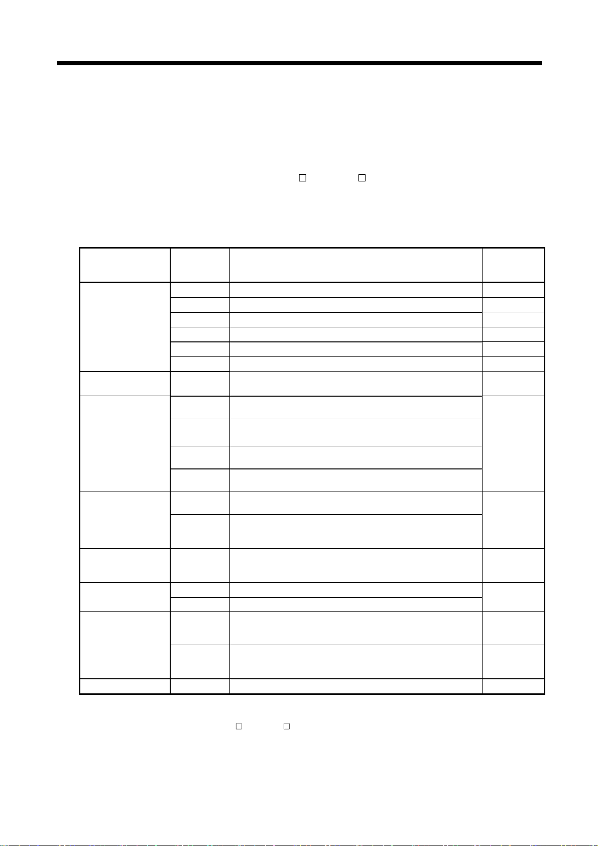
2 SYSTEM CONFIGURATION
(3) Selection of the power supply module
The power supply module is selected according to the total of current
consumption of the I/O modules, special function module, and peripheral devices
supplied by its power module. (Select the power supply module in consideration
of the current consumption of the peripheral device connected to the MR-HENC,
MR-HDP01 or A31TU-D3
For information about the current consumption of 5VDC of the I/O modules,
special function module, and peripheral device, refer to the QCPU User's
Manual(Hardware Design, Maintenance and Inspection).
Part name Model name Description
Motion CPU module
Servo external signal
interface module
Serial absolute
synchronous encoder
interface module
(Note-1)
Manual pulse generator
interface module
Manual pulse generator MR-HDP01
Teaching unit
Serial absolute
synchronous encoder
Cooling fan unit Q170FAN Cooling fan of the Motion CPU module
(Note-1) : Select the power supply module in consideration of the current consumption of connecting peripheral device (MR-HENC/
(Note-2) : Current consumption of A31TU-D3
(Note-1)
Q170ENC or MR-HDP01).
The current consumption of Motion controller is as follows.
Q173CPUN Up to 32 axes control
Q173CPUN-T Up to 32 axes control, For teaching unit
Q173CPU Up to 32 axes control, With cooling fan unit
Q172CPUN Up to 8 axes control
Q172CPUN-T Up to 8 axes control, For teaching unit
Q172CPU Up to 8 axes control, With cooling fan unit
Q172LX
Q172EX
Q172EX-S1
Q172EX-S2
Q172EX-S3
Q173PX
Q173PX-S1
A31TU-D3K13 For SV13, With 3-position deadman switch
A31TU-DNK13 For SV13, Without deadman switch
MR-HENC
Q170ENC
Servo external signal 8 axes
(FLS, RLS, STOP, DOG/CHANGE×8)
Serial absolute synchronous encoder MR-HENC interface×2,
Tracking input 2 points
Serial absolute synchronous encoder MR-HENC interface×2,
Tracking input 2 points, Memory built-in for data exchange
Serial absolute synchronous encoder Q170ENC interface×2,
Tracking input 2 points
Serial absolute synchronous encoder Q170ENC interface×2,
Tracking input 2 points, Memory built-in for data exchange
Manual pulse generator MR-HDP01/Incremental synchronous encoder
interface×3, Tracking input 3 points
Manual pulse generator MR-HDP01/Incremental synchronous encoder
interface×3,
Tracking input 3 points, Memory built-in for data exchange
Pulse resolution: 25PLS/rev (100 PLS/rev after magnification by 4)
Permitted axial loads Radial load: up to 19.6N/Thrust load: Up to 9.8N
Permitted speed: 200r/min (Normal rotation), Voltage output
Resolution: 16384PLS/rev
Permitted axial loads Radial load: up to 98N/Thrust load: up to 49N
Permitted speed: 4300r/min
Resolution: 262144PLS/rev
Permitted axial loads Radial load: up to 19.6N/Thrust load: up to 9.8N
Permitted speed: 3600r/min
/A31TU-DN is included.
/A31TU-DN , etc.)
Current
consumption
5VDC [A]
1.25
(Note-2)
1.56
1.75
1.14
(Note-2)
1.45
1.62
0.05
0.07
0.11
0.06
0.26
0.15
0.20
0.08
2 - 41

2 SYSTEM CONFIGURATION
(4) Example of the power supply selection calculation
(When using the Q173CPUN-T.)
(a) System configuration
Q61P-A1
Q02H
CPU
Q173
CPUN-T
Q172LX Q172EX QX40 QX40 QY10 QY10
Q173PX
Q38B
A31TU-D3K13
MR-HENC
MR-HDP01
MR-HDP01
(b) 5VDC current consumption of each module
Q02HCPU : 0.64 [A] Q173PX : 0.11 [A]
Q173CPUN-T
(Note)
: 1.56 [A] MR-HDP01 : 0.06 [A]
Q172LX : 0.05 [A] QX40 : 0.05 [A]
Q172EX : 0.07 [A] QY10 : 0.43 [A]
MR-HENC : 0.15 [A] Q38B : 0.114 [A]
(Note) : Current consumption of A31TU-D3K13(0.26A) is included.
(c) Power consumption of overall modules
I
5V
= 0.64 + 1.56 + 0.05 + 0.07 + 0.15 + 0.11 + 0.06
2 + 0.114 = 3.774[A]
2 + 0.05 2 + 0.43
Select of the power supply module(Q61P-A1(100VAC)6A) according to this
internal current consumption 3.774[A].
(Note) : Configure the system in such a way that the total current
consumption at 5VDC of all the modules is less than the allowable
value.
2 - 42
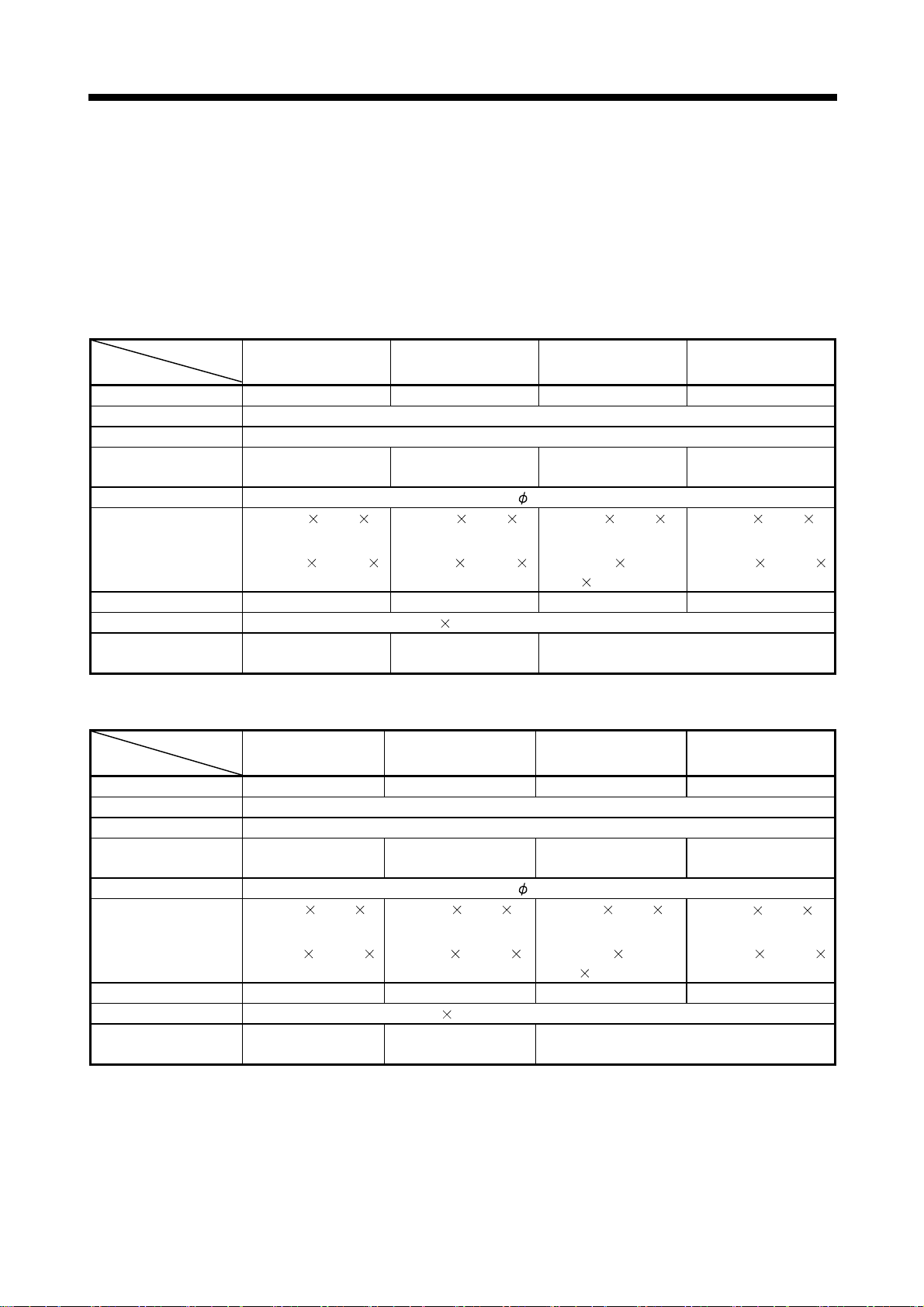
2 SYSTEM CONFIGURATION
2.4.3. Base unit and extension cable
This section describes the specifications of the extension cables for the base units
(CPU base unit or extension base unit) used in the system, and the specification
standards of the extension base unit.
(1) Table of the base unit specifications
(a) CPU base unit specifications
Type
Item
Number of I/O modules 3 5 8 12
Possibility of extension Extendable
Applicable module Q series modules
5VDC internal current
consumption [A]
Fixing hole size M4 screw hole or 4.5 hole (for M4 screw)
Exterior dimensions
[mm(inch)]
Mass [kg] 0.21 0.25 0.35 0.45
Attachment Fixing screw M4 14 4 pieces (DIN rail fixing adapter is optional)
DIN rail fixing adapter
type
Q33B Q35B Q38B Q312B
0.105 0.110 0.114 0.121
189(W)
(7.44(W) 3.86(H)
98(H)
44.1(D)
1.74(D) )
Q6DIN3 Q6DIN2 Q6DIN1
245(W)
44.1(D)
(9.65(W) 3.86(H)
1.74(D) )
98(H)
328(W)
44.1(D)
(12.91(W) 3.86(H)
1.74(D) )
98(H)
439(W) 98(H)
44.1(D)
(17.28(W) 3.86(H)
1.74(D) )
(b) Extension base unit specifications
Type
Item
Number of I/O modules 3 5 8
Possibility of extension Extendable
Applicable module Q series modules
5VDC internal current
consumption [A]
Fixing hole size M4 screw hole or 4.5 hole (for M4 screw)
Exterior dimensions
[mm(inch)]
Mass [kg] 0.23 0.25 0.35
Attachment Fixing screw M4 14 4 pieces(DIN rail fixing adapter is optional)
DIN rail fixing adapter
type
Q63B Q65B Q68B Q612B
12
439(W)
44.1(D)
1.74(D) )
0.121
98(H)
0.45
0.105 0.110 0.114
189(W)
(7.44(W) 3.86(H)
98(H)
44.1(D)
1.74(D) )
Q6DIN3 Q6DIN2
245(W)
(9.65(W) 3.86(H)
1.74(D) )
98(H)
44.1(D)
328(W)
(12.91(W) 3.86(H)
98(H)
44.1(D)
1.74(D) )
(17.28(W) 3.86(H)
Q6DIN1
2 - 43

2 SYSTEM CONFIGURATION
(2) Table of the extension cable specifications
The list below describes the specifications of the extension cables which can
be used for the QCPU system.
Type
Item
Cable length[m(ft.)] 0.45(1.48) 0.6(1.97) 1.2(3.94) 3.0(9.84) 5.0(16.40) 10.0(32.8)
Application
Mass [kg] 0.15 0.16 0.22 0.40 0.60 1.11
QC05B QC06B QC12B QC30B QC50B QC100B
Connection between the CPU base unit and extension base unit, or connection between the
extension base units.
POINT
When the extension cables are used in combination, limit the overall length of the
combined cable to 13.2m (43.31ft.).
(3) Names of parts of the base unit
Names of parts of the base unit are described below.
(a) CPU base unit (Q33B, Q35B, Q38B, Q312B)
5)
4)
1)
5V
56
2)
POWER
F6
CPU
3) 6)
No. Name Application
Extension cable
1)
connector
Connector for sending and receiving signals from the extension base unit, to which the
extension cables are connected.
Protective cover of extension cable connector. Before an extension cable is connected,
2) Base cover
the area of the base cover surrounded by the groove under the word "OUT" on the base
cover must be removed with a tool such as nippers.
Connector for installing the power supply module, CPU module, I/O modules, and
3) Module connector
intelligent function module.
To the connectors located in the spare space where these modules are not installed, attach
the supplied connector cover or the blank cover module QG60 to prevent entry of dirt.
4) Module fixing screw hole Screw hole for fixing the module to the base. Screw size: M3 12
5) Base fixing hole
DIN rail adapter fixing
6)
hole
Hole for fixing this base unit onto the panel of the control panel (for M4
Hole for fixing DIN rail adapter
I/11
I/10I/09I/08I/07I/06I/05I/04I/03I/02I/01I/ 00
0358
screw)
14
2 - 44

2 SYSTEM CONFIGURATION
(4) I/O allocations
It is possible to allocate unique I/O No.s for each Motion CPU independently of
the PLC’s I/O No.s. (I/O No.s are unique between the Q series PLC CPU within a
given system, but the I/O No.s of the Motion CPU are unique for each Motion
CPU.)
ON/OFF data input to the Motion CPU is handled via input devices PX
ON/OFF data output from the Motion CPU is handled via output devices PY
It is not mandatory to match the I/O device PX/PY No.s used in the Motion
program with the PLC I/O No.s; but it is recommended to make them match as
much as possible.
The following figure shows an example of I/O allocation.
, while
.
I/O Allocations
8123 45670
Q25H
CPU
O
U
T
Power supply
module
CPU No.1
Q25H
CPU
CPU No.2 CPU No.3
Q173
CPU(N)
QX41
X0 to X1F
Module of
control
CPU No.1
QY41
Y20 to Y3F
Module of
control
CPU No.1
QY41
Y40 to Y5F
Module of
control
CPU No.2
Q172LX
Intelligent
32 points
(X60 to X7F)
Module of
control
CPU No.3
QX41
PX0 to PX1F
(Y80 to Y9F)
Module of
control
CPU No.3
QY41
PY20 to PY3F
(YA0 to YBF)
Module of
control
CPU No.3
9
QY41
YC0 to YDF
Module of
control
CPU No.1
(Note-1) : When the number of modules to be installed is 32 points.
(Note-2) : When the PX/PY No. does not match the PLC I/O No.
Refer to the Programming Manual of the operating system software about the I/O
allocation setting method,.
Refer to the QCPU User's Manual(Function Explanation, Program Fundamentals)
about the I/O allocation setting method of the Qn(H)CPU.
POINT
I/O device of the Motion CPU can be set in the range PX/PY000 to PX/PYFFF.
The real I/O points must be 256 points or less. (As for the I/O No., it is possible not
to continue.)
2 - 45
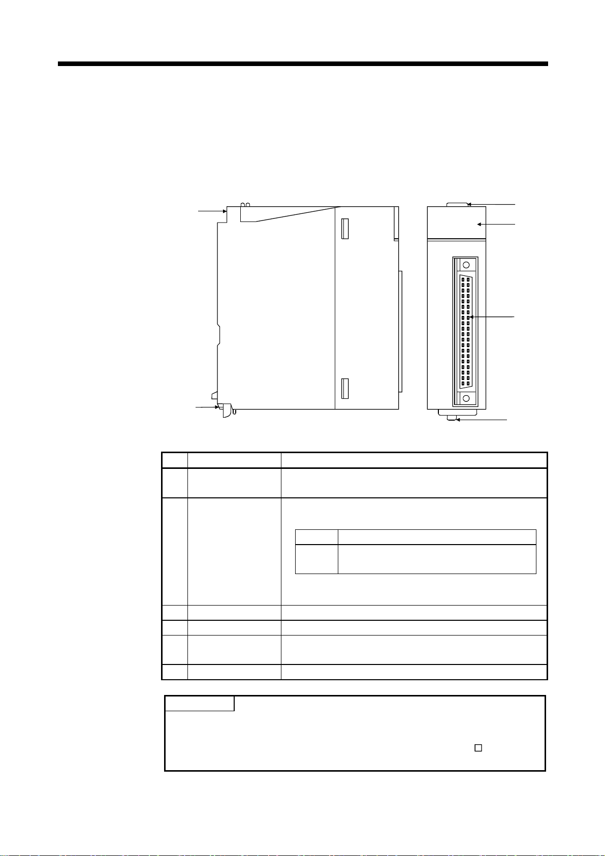
2 SYSTEM CONFIGURATION
2.4.4 Q172LX Servo external signals interface module
Q172LX receives external signals (servo external signals) required for positioning
control.
(1) Q172LX name of parts
5)
Q172LX
1)
2)
CTRL
6)
Q172LX
3)
4)
No. Name Application
1) Module fixing hook
2) Mode judging LED
3) CTRL connector The servo external signal input connector of each axis.
4) Module loading lever Used to install the module to the base unit.
Module fixing screw
5)
hole
6) Module fixing hook Hook used to fix to the base unit.
Hook used to fix the module to the base unit.
(Quick release installation)
Display the servo external input status from the external
equipment.
LED Details
0 to 1F
This LED is not turned on if it is not set the Q172LX in the
system settings.
Hole for the screw used to fix to the base unit.
(M3×12 screw : Purchase from the other supplier)
Indicates to display the servo external signal
input status of each axis.
POINT
Mode judging LED turns ON at the following conditions.
(1) DOG/CHANGE
(a) Q172LX is set on the system setting display of SW6RN-GSV
P.
(b) DOG/CHANGE signal is input.
2 - 46

2 SYSTEM CONFIGURATION
(2) Performance specifications
(a) Module specifications
Item Specifications
Number of I/O occupying points 32 points(I/O allocation: Intelligent, 32 points)
Internal current consumption(5VDC) [A] 0.05
Exterior dimensions [mm(inch)]
Mass [kg] 0.15
Number of input points
Input method Sink/Source type
Isolation method Photocoupler
Rated input voltage 12/24VDC
Rated input current 12VDC 2mA/24VDC 4mA
Operating voltage range
ON voltage/current 10VDC or more/2.0mA or more
OFF voltage/current 1.8VDC or less/0.18mA or less
Input resistance Approx. 5.6K
Response time of the
Upper/Lower stroke limit and
STOP signal
Response time of the
proximity dog, Speed-
position switching signal
Common terminal arrangement 32 points/common (Common terminal: B1, B2)
Indicates to display ON indication (LED)
External connector type 40 pin connector
Applicable wire size
Applicable connector for the external
connection
Applicable connector/
Terminal block converter module
(b) Input
Item Specifications
OFF to ON
ON to OFF
OFF to ON
ON to OFF
27.4(W) 90(D)
98(H)
(3.86(H) 1.08(W) 3.54(D) )
Servo external signals : 32 points
(Upper stroke limit, Lower stroke limit, Stop input,
Proximity dog/Speed-position switching signal)
1ms
0.3mm
8 axes)
2
(4 points
10.2 to 26.4VDC
(12/24VDC +10/ -15%, ripple ratio 5% or less)
0.4ms/0.6ms/1ms
(CPU parameter setting, Default 0.4ms)
A6CON1 (Attachment),
A6CON2, A6CON3 (Optional)
A6TBXY36, A6TBXY54, A6TBXY70 (Optional)
2 - 47

2 SYSTEM CONFIGURATION
(3) Connection of servo external signals interface module
(a) Servo external signals
There are the following servo external signals.
(Upper stroke limit is limit value of address increase direction/lower stroke
limit is limit value of an address decrease direction.)
The Q172LX is assigned a set of input No.s per axis. Make the system
setting of the positioning software package to determine the I/O No.s
Servo external signal Application
Upper stroke limit input (FLS)
Lower stroke limit input (RLS)
Stop signal input (STOP) For stopping under speed or positioning control.
Proximity dog/
Speed-position switching input
(DOG/CHANGE)
corresponding to the axis No.s.
For detection of upper and lower stroke limits.
For detection of proximity dog at proximity dog or count
type home position return of for switching from speed to
position switching control.
Number of points
on one Q172LX
32 points
(4 points/8 axes)
2 - 48

2 SYSTEM CONFIGURATION
(b) The pin layout of the CTRL connector
Use the CTRL connector at the Q172LX module front to connect the servo
external signals.
The following pin layout of the Q172LX CTRL connector viewed from the
front.
The pin layout and connection description of the CTRL connector are
described below.
Signal No.
1
2
3
4
Pin No.
B20
B19
B18
B17
B16
B15
B14
B13
B12
B11
B10
B9
B8
B7
B6
B5
B4
B3
B2
B1
CTRL connector
Signal Name
DOG1/CHANGE1
DOG2/CHANGE2
DOG3/CHANGE3
DOG4/CHANGE4
FLS1
RLS1
STOP1
FLS2
RLS2
STOP2
FLS3
RLS3
STOP3
FLS4
RLS4
STOP4
No connect
No connect
COM
COM
Pin No. Signal Name
A20
A19
A18
DOG5/CHANGE5
A17
A16
A15
A14
DOG6/CHANGE6
A13
A12
A11
A10
DOG7/CHANGE7
A9
A8
A7
A6
DOG8/CHANGE8
A5
A4
A3
A2
A1
FLS5
RLS5
STOP5
FLS6
RLS6
STOP6
FLS7
RLS7
STOP7
FLS8
RLS8
STOP8
No connect
No connect
No connect
No connect
Signal No.
5
6
7
8
Applicable connector model name
A6CON1 type soldering type connector
FCN-361J040-AU connector
FCN-360C040-B connector cover
A6CON2 type Crimp-contact type connector
A6CON3 type Pressure-displacement type connector
DOG/CHANGE, STOP, RLS, FLS functions of each axis(1 to 8)
DOG/CHANGE Proximity dog/Speed-position
switching signal
(FUJITSU TAKAMISAW A
COMPONENT LIMITED)
For information about
signal details, refer to
the programming manual.
(Attachment)
(Optional)
STOP Stop signal
RLS Lower stroke limit
FLS Upper stroke limit
(Note) : Connector/terminal block conversion modules and cables can be
used at the wiring of CTRL connector.
A6TBXY36/A6TBXY54/A6TBX70 : Connector/terminal block
conversion module
AC
TB ( :Length [ft.]) : Connector/terminal block
conversion cable
POINT
Signal No. 1 to 8 can be assigned to the specified axis. To make assignment, make
the system settings of the positioning software package.
2 - 49

2 SYSTEM CONFIGURATION
(4) Interface between CTRL connector and servo external signal
Input or
Output
Input
Signal name Internal circuit
FLS1
FLS2
FLS3
FLS4
FLS5
FLS6
FLS7
FLS8
RLS1
RLS2
RLS3
RLS4
RLS5
RLS6
RLS7
RLS8
STOP1
STOP2
STOP3
STOP4
STOP5
STOP6
STOP7
STOP8
DOG/CHANGE1
DOG/CHANGE2
DOG/CHANGE3
DOG/CHANGE4
DOG/CHANGE5
DOG/CHANGE6
DOG/CHANGE7
DOG/CHANGE8
Power supply
(Note)
CTRL
connector
B20
B16
B12
B8
A20
A16
A12
A8
B19
B15
B11
B7
A19
A15
A11
A7
B18
B14
B10
B6
A18
A14
A10
A6
B17
B13
B9
B5
A17
A13
A9
A5
B1 B2
LED
0
4
8
C
10
14
18
1C
1
5
9
D
11
15
19
1D
2
6
A
E
12
16
1A
1E
3
7
B
F
13
17
1B
1F
Wiring example
Upper stroke
limit input
Lower stroke
limit input
Stop signal
input
Proximity dog
/Speed-position
switching signal
12VDC to 24VDC
5.6K
5.6K
5.6K
5.6K
Specification
Supply voltage
12 to 24 VDC
(10.2 to 26.4 VDC,
stabilized power
supply)
High level
10.0 VDC or more/
2.0mA or more
Low level
1.8 VDC or less/
0.18mA or less
Description
FLS
RLS
STOP
DOG/CHANGE
Common terminals
for motion control
signals, external
signal.
(Note): As for the connection to power line (B1, B2), both "+" and "–" are possible.
CAUTION
Always use a shield cable for connection of the CTRL connector and external equipment, and
avoid running it close to or bundling it with the power and main circuit cables to minimize the
influence of electromagnetic interface. (Separate them more than 200mm (0.66ft.) away.)
Connect the shield wire of the connection cable to the FG terminal of the external equipment.
Make parameter setting correctly. Incorrect setting may disable the protective functions such as
stroke limit protection.
Always wire the cables when power is off. Not doing so may damage the circuit of modules.
Wire the cable correctly. Wrong wiring may damage the internal circuit.
2 - 50

2 SYSTEM CONFIGURATION
2.4.5 Q172EX Serial absolute synchronous encoder interface module
Q172EX receive external signals required for serial absolute synchronous encoder.
(1) Q172EX/Q172EX-S1/Q172EX-S2/Q172EX-S3 name of parts
5)
Q172EX
SY.ENC
1
2
TREN
1
2
1)
2)
SY.ENC1
8)
6)
LITHIUM BATTERY
MITSUBISHI
SY.ENC2
Q172EX
9)
7)
3)
4)
(Note): The installation position of Q172EX-S2/Q172EX_S3 is only CPU base unit.
No.
1) Module fixing hook
2) Mode judging LED
3) SY. ENC connector Input connector of the serial absolute synchronous encoder.
4) Module loading lever Used to install the module to the base unit.
5)
6) Module fixing hook Hook used to fix to the base unit.
7) Battery connector For connection of battery lead wire.
8) Battery holder Used to the Install the Battery (A6BAT/MR-BAT) to the holder.
9)
Name Application
Hook used to fix the module to the base unit.
(Quick release installation)
Display the input status from the external equipment.
LED Details
Indicates to display the signal input status of
SY.ENC
1, 2
each serial absolute synchronous encoder.
(When the serial absolute synchronous encoder
cable connected property, LED is turned on.)
Module fixing screw
hole
Battery
(A6BAT/MR-BAT)
TREN
1, 2
Hole for the screw used to fix to the base unit
(M3×12 screw : Purchase from the other supplier)
For Serial absolute synchronous encoder battery backup.
Indicates to display the signal status of tracking
enable.
2 - 51

2 SYSTEM CONFIGURATION
(2) Performance specifications
Memory for data exchange None Provided None Provided
Number of I/O occupying points 32 points(I/O allocation: Intelligent, 32 points)
Internal current consumption(5VDC)[A] 0.07
Exterior dimensions [mm(inch)]
Mass [kg] 0.15
Number of input points Tracking enable signal : 2 points
Input method Sink/Source type
Isolation method Photocoupler
Rated input voltage 12/24VDC
Rated input current 12VDC 2mA/24VDC 4mA
Operating voltage range
ON voltage/current 10VDC or more/2.0mA or more
OFF voltage/current 1.8VDC or less/0.18mA or less
Input resistance Approx. 5.6K
Response time
Common terminal arrangement 1 point/common (Common terminal: TREN.COM)
Indicates to display ON indication (LED)
(a) Module specifications
Item
(b) Tracking enable signal input
Item Specifications
OFF to ON
ON to OFF
Specifications
Q172EX Q172EX-S1 Q172EX-S2 Q172EX-S3
98(H)
(3.86(H) 1.08(W) 3.54(D) )
(12/24VDC +10/ -15%, ripple ratio 5% or less)
(CPU parameter setting, Default 0.4ms)
27.4(W) 90(D)
10.2 to 26.4VDC
0.4ms/0.6ms/1ms
2 - 52

2 SYSTEM CONFIGURATION
Item Specifications
Applicable signal types Differential-output type : (SN75C1168 or equivalent)
Transmission method Serial communications
Synchronous method Counter-clock-wise (viewed from end of shaft)
Communication speed 2.5Mbps
Applicable types MR-HENC
Position detection method Absolute(ABS) method
Resolution 16384PLS/rev(14bit)
Number of modules 2/module
External connector type 20 pin connector
Applicable connector for
the external connection
Applicable wire UL20276 AWG#22 6Pair
Connecting cable
Cable length Up to 30m (98.43ft.)
Back up the absolute position. Depends on A6BAT/MR-BAT.
Battery service life time(value in actual)
(c) Serial absolute synchronous encoder input
MR-J2CNS(Optional)
MR-JHSCBL
=cable length 2m(6.56ft.), 5m(16.40ft.), 10m(32.81ft.), 20m(65.62ft.),
(
30m(98.43ft.) )
15000[ h ], (Example of encoders 2, Ambient temperature 40°C (104°F) )
30000[ h ], (Example of encoders1, Ambient temperature 40°C (104°F) )
(Note) : You can use these cables when the tracking enable signal is not used.
When the tracking enable signal is used, fabricate the cable on the customer side.
(Note)
M-H
2 - 53

2 SYSTEM CONFIGURATION
(3) Select to number of the synchronous encoder modules
Synchronous encoders are available in voltage output type(incremental),
differential output type(incremental) and serial absolute output type(MR-HENC).
Q172EX(-S1) can be connected to only serial absolute output type(MR-HENC).
Q172EX-S2/-S3 can be connected to only serial absolute output type
(Q170ENC). When using the incremental synchronous encoder of voltage output
type or differential output type, must be used Q173PX. (The synchronous
encoders are used only in the SV22 virtual mode.)
In addition, the usable numbers of synchronous encoders differ depending on the
modules.
The following number of serial absolute synchronous encoders and incremental
synchronous encoders combined can be used.
• Tracking enable signal
Tracking enable signal of Q172EX is used as a high-speed reading
function. It cannot be used, as the input start signal which start the input
form serial absolute synchronous encoders.
When using the inputs start signal which start the input from synchronous
encoder, must be used Q173PX. (Type of synchronous encoder is voltage
output(incremental)or differential output(incremental). )
Tracking enable signal input High-speed reading function 2 points
The external input signal of the synchronous encoder is indicated below.
External input signal of the
synchronous encoder
Motion CPU module Synchronous encoder
Q173CPU(N)
Q172CPU(N)
Up to 12 modules
( Q172EX: Up to 6 modules )
Up to 8 modules
( Q172EX: Up to 4 modules )
Item
Number of points
on one Q172EX
2 - 54

G
A
2 SYSTEM CONFIGURATION
(4) Connection of synchronous encoder interface module.
(a) Connection with serial absolute synchronous encoder
(MR-HENC/Q170ENC)
Use the SY.ENC connector at the Q172EX module front to connect the
serial absolute synchronous encoder(MR-HENC/Q170ENC).
When tracking enable signal is not used, use the MR-JHSCBL
Q170ENCCBLM encoder cable between the serial absolute synchronous
encoder (MR-HENC/Q170ENC) and SY.ENC connector.
The following pin layout of the Q172EX SY.ENC connector viewed from the
front.
The pin layout and connection description of the SY.ENC connector are
described below.
M-H/
SY.ENC connector
Pin No.
1LG11 L
2 LG 12 LG
3 LG 13 No connect
4 TREN 14 TREN.CO
5 No connect 15 No connect
6 MD 16 MDR
7 MR 17 MRR
8 No connect 18 P5
9 BAT 19 P5
10 P5 20 P5
(Note) : Do not connect a wire to MD(6Pin), MDR(16Pin).
Signal
name
Pin No.
Signal
name
pplicable connector
model names
10120-3000VE connector
10320-52F0-008 connector cover
(3M m ake)
(b) Interface with external equipment
The interface between the SY.ENC connector and external equipment is
described below.
1) Wiring precautions
Ensure the connector lock after connecting the connector.
Q173CPU(N)/
Q172CPU(N)
Q172EX
Q173CPU(N)/Q172CPU(N) : Motion CPU module
Q172EX : Serial absolute synchronous
encoder interface module
SY.ENC connector
Serial absolute synchronous encoder cable
(MR-JHSCBL M-H/Q170ENCCBL M)
Serial absolute synchron ous encoder
(MR-HENC/Q170 ENC)
2 - 55

2 SYSTEM CONFIGURATION
(5) Interface between SY.ENC connector and external equipment
Input or
Output
Input
Signal
name
MR 7
MRR 17
P5 10 18 19 20
LG 1 2 3 11 12
BAT 9
(Note)
TREN 4
Pin No.
SY.ENC connector
Wiring example
Serial
absolute
synchronous
encoder
Internal circuit Specification Description
Transmission method:
serial communications
Position detection
method: absolute
5VDC
Battery
5.6K
(Note)
TREN.
COM
SD
14
plate
12VDC to 24VDC
(Note) : As for the connection to power line (TREN, TREN.COM), both "+" and "–" are possible.
CAUTION
Always use a shield cable for connection of the SY.ENC connector and external equipment, and
avoid running it close to or bundling it with the power and main circuit cables to minimize the
influence of electromagnetic interface. (Separate them more than 200mm (0.66 ft.) away.)
Connect the shield wire of the connection cable to the FG terminal of the external equipment.
When increasing the cable length, use the cable 30m(98.43ft.) or less. Note that the cable should
be run in the shortest possible distance to avoid induced noise.
Always wire the cables when power is off. Not doing so may damage the circuit of modules.
Wire the cable correctly. Wrong wiring may damage the internal circuit.
2 - 56
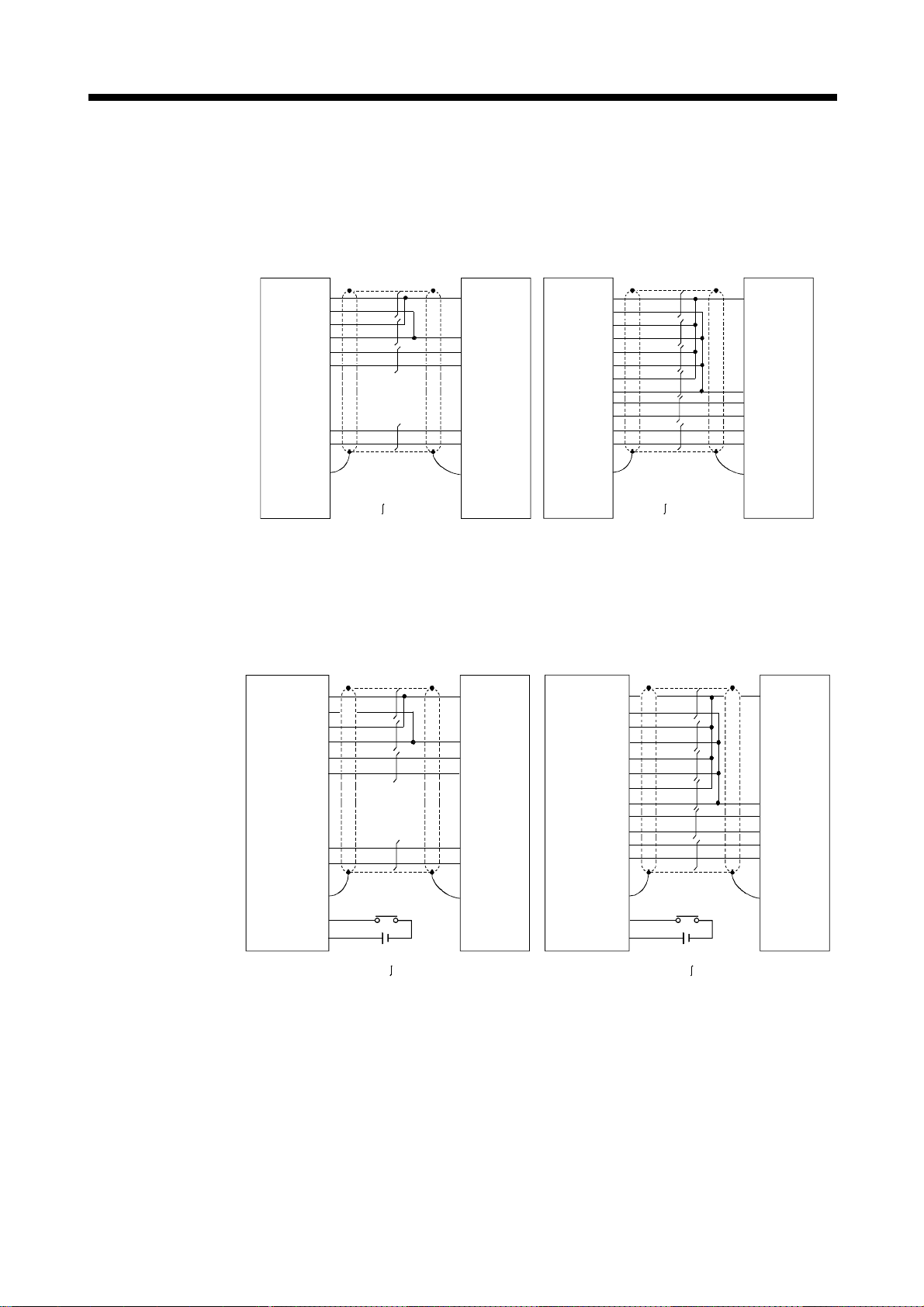
2 SYSTEM CONFIGURATION
(6) Details of encoder cable connections
(a) Q172EX(-S1)
1) When not using tracking enable signal
SY.ENC side
connector
10120-3000VE
Synchronous
encoder side
connector
MS3106B20-29S
SY.ENC side
connector
10120-3000VE
Synchronous
encoder side
connector
MS3106B20-29S
P5 19
LG
11
P5 20
LG 12
MR 7
MRR 17
BT
9
LG 1
Plate
SD
:Twisted pair cable :Twisted pair cable
MR-JHSCBL5M-H
(Less than 10m(32.81ft.) )
(Note-1),(Note-3)
SY.ENC side
connector
10120-3000VE
P5
LG
P5
LG
MR
MRR
BT
LG
TREN 4
TREN.COM 14
2) When using tracking enable signal
19
11
20
12
7
17
9
1
PlateSD
24VDC
:Twisted pair cable :Twisted pair cable
Cable length 10m (32.81ft.)
Model name for encoder connector set (MR-J2CNS)
S
R
C
D
F
G
N
Synchronous
encoder side
connector
MS3106B20-29S
S
R
C
D
F
G
N
(Note-3)
P5 19
LG
11
P5 20
LG 12
P5 18
LG 3
P5
10
LG
2
MR 7
MRR 17
BT 9
LG 1
Plate
SD
MR-JHSCBL10M-H to MR-JHSCBL30M-H
(10 to 30m (32.81 to 98.43ft.))
(Note-5)
S
R
C
D
F
G
N
(Note-1),(Note-4)
SY.ENC side
connector
10120-3000VE
P5 19
LG
P5 20
LG 12
P5 18
LG 3
P5
LG
MR 7
MRR 17
BT 9
LG 1
SD
TREN 4
TREN.COM 14
Cable length 10 to 30m (32.81 to 98.43ft.)
11
10
2
Plate
(Note-2)
24VDC
Synchronous
encoder side
connector
MS3106B20-29S
S
R
C
D
F
G
N
(Note-4)
(Note-1) : Encoder cables are the same as HC-SFS/HC-RFS/HC-UFS(2000r/min) series motor cable.
(Note-2) : Encoder connector sets are the same as HC-SFS/HC-RFS/HC-UFS(2000r/min) series motor encoder connector set.
(Note-3) : Be sure to use a wire model name AWG#24.
(Note-4) : Be sure to use a wire model name AWG#22.
(Note-5) : When using tracking enable signal, fabricate the encoder cable by customer side.
2 - 57

2 SYSTEM CONFIGURATION
(b) Q172EX-S2/Q172EX-S3
1) When not using tracking enable signal
SY.ENC side connector
10120-3000VE (connector)
10320-52F0-008(connector case)
(Note-1)
Synchronous encoder side connector(plug)
MS3106B22-14S(cable clump)
P5
LG
P5
LG
P5
LG
BAT
LG
MR
MRR
MD
MDR
SDplate
2) When using tracking enable signal
SY.ENC side connector
10120-3000VE (connector)
10320-52F0-008(connector case)
19
11
S
R
20
12
18
2
9
1
7
17
6
16
:Twisted pair cable
E
K
L
H
J
N
Q170ENCCBL2M to Q170ENCCBL50M(50m (164.04ft.) or less)
(Note-1), (Note-2)
Synchronous encoder side connector(plug)
MS3106B22-14S(cable clump)
P5
LG
P5
LG
P5
LG
BAT
LG
MR
MRR
MD
MDR
SDplate
TREN 4
TREN.COM 14
19
11
20
12
18
2
9
1
7
17
6
16
24VDC
:Twisted pair cable
E
Cable length 50m(164.04ft.) or less
S
R
K
L
H
J
N
(Note-1) : Be sure to use a wire model name AWG24.
(Note-2) : When using tracking enable signal, fabricate the encoder cable by customer side.
2 - 58
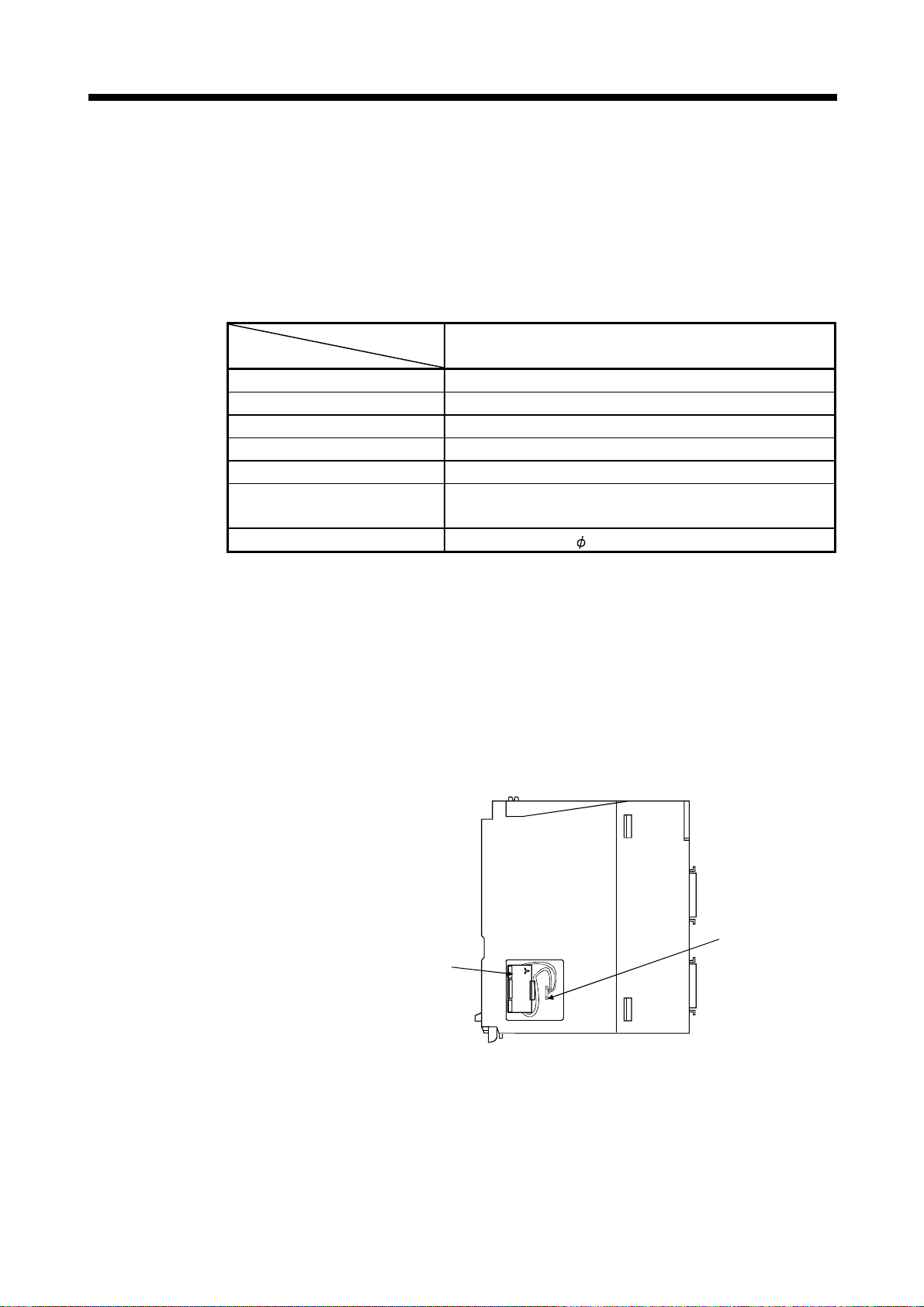
r
r
2 SYSTEM CONFIGURATION
(7) Connection of the battery
This section describes the battery specifications, handling precautions and
installation of the Q172EX.
(a) Specifications
The specifications of the battery for memory back-up are shown in the table
below.
Battery Specifications
Model name
Item
A6BAT/MR-BAT
Classification Manganese dioxide lithium primary battery
Normal voltage[V] 3.6
Battery discharge capacity [mAh] 1600
Battery warranty period 5 years
Lithium content [g] 0.48
Applications
For backup absolute positioning data of the serial absolute
synchronous encoder (MR-HENC/Q170ENC)
Exterior dimensions[mm(inch)] 16(0.63) × 30(1.18)
(Note) : The 44th Edition of the IATA (International Air Transportation Association) Dangerous Goods Regulations
was effected in January 1st, 2003 and administered immediately.
In this edition, the provisions relating to lithium and lithium ion batteries have been revised to strengthen
regulations on the air transportation of battery.
This battery is not dangerous goods (not class 9). Therefore, these batteries of 24 units or less are not
subject to the regulations.
These batteries more than 24 units require packing based on Packing Instruction 903.
If you need the self-certification form for the battery safety test, contact Mitsubishi.
For more information, contact Mitsubishi.
(b) Battery replacement
For Battery replacement procedure, refer to section 6.4.2.
Battery is supplied to the
serial absolute synchronous
encoder by the encode
cable.
A6BAT
/MR-BAT
LITHIUM BATTERY
MITSUBISHI
Battery connecto
2 - 59

2 SYSTEM CONFIGURATION
(c) Battery service life time
MR-HENC 1 pcs. 10000 30000
MR-HENC 2 pcs. 5000 15000
Q170ENC 1 pcs. 8000 24000
Q170ENC 2 pcs. 4000 12000
Do not short a battery.
Do not charge a battery.
Do not disassemble a battery.
Do not burn a battery.
Do not overheat a battery.
Do not solder the battery terminals.
Battery service life time
Guaranteed time(MIN) [ h ] Actual time(TYP) [ h ]
CAUTION
2 - 60

2 SYSTEM CONFIGURATION
2.4.6 Q173PX Manual pulse generator interface module
Q173PX receive external signals required for Manual pulse generator and Incremental
synchronous encoder (Voltage-output/Open collector type/Differential-output type).
(1) Q173PX/Q173PX-S1 name of parts
5)
Q173PX-S1
PLS.A
PLS.B
1
1
2
2
3
3
PULSER
TREN
1
2
3
1)
2)
3)
ON
123456
6)
7)
KSD06S
Q173PX
4)
No.
1) Module fixing hook
2) Mode judging LED
3) PULSER connector
4) Module loading lever Used to load the module to the base unit.
Module fixing screw
5)
hole
Name Application
Hook used to fix the module to the base unit.
(Quick release installation)
Display the input status from the external equipment.
LED Details
PLS.A 1 to 3
PLS.B 1 to 3
Input signal status of the Manual pulse
generator/Incremental synchronous
encoder phases A and B
TREN 1 to 3 Tracking enable signal
This LED is not turned on if it is not set the Q173PX in
the system settings.
Input connector of the Manual pulse generator/Incremental
synchronous encoder.
Hole for the screw used to fix to the base unit
(M3×12 screw : Purchase from the other supplier)
2 - 61

2 SYSTEM CONFIGURATION
No.
Dip switches
Name Application
(Note-1)(Note-2)
123456
6)
(Shipped from the
factory in OFF
position)
7) Module fixing hook Hook used to fix to the base unit.
(Note-1) : When using the Q173PX-S1 only.
(Note-2) : The function is different according to the operating system software installed.
POINTS
The lighting condition of input display LED is shown below.
(1) PLS.A 1 to 3, PLS.B 1 to 3
• Q173PX is set on the system setting display of SW6RN-GSV
• All axes servo ON command (M2042) turned on.
• Manual pulse generator enable flag (M2051, M2052, M2053) turned on.
• Manual pulse generator signal is input.
(2) TREN 1 to 3
• Q173PX is set on the system setting display of SW6RN-GSV
• Tracking signal is input.
Detection setting of TREN1 signal
Dip switch 1
Dip switch 2
ON
Dip switch 3
Dip switch 4
Dip switch 5
Dip switch 6
SW1 SW2
OFF OFF
ON ON
ON OFF
OFF ON
Detection setting of TREN2 signal
SW3 SW4
OFF OFF
ON ON
ON OFF
OFF ON
Detection setting of TREN3 signal
SW5 SW6
OFF OFF
ON ON
ON OFF
OFF ON
TREN is detected when
TREN signal turns off to on.
TREN is detected when TREN
signal turns on to off.
TREN is detected when
TREN signal turns off to on.
TREN is detected when TREN
signal turns on to off.
TREN is detected when
TREN signal turns off to on.
TREN is detected when TREN
signal turns on to off.
P.
P.
2 - 62
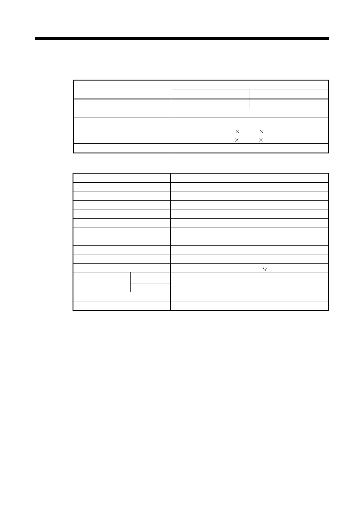
2 SYSTEM CONFIGURATION
(2) Performance specifications
Memory for data exchange None Provided
Number of I/O occupying points 32 points(I/O allocation: Intelligent, 32 points)
Internal current consumption(5VDC)[A] 0.11
Exterior dimensions [mm(inch)]
Mass [kg] 0.15
Number of input points Tracking enable signal : 3 points
Input method Sink/Source type
Isolation method Photocoupler
Rated input voltage 12/24VDC
Rated input current 12VDC 2mA/24VDC 4mA
Operating voltage range
ON voltage/current 10VDC or more/2.0mA or more
OFF voltage/current 1.8VDC or less/0.18mA or less
Input resistance Approx. 5.6K
Response time
Common terminal arrangement 1 point/common(Common contact: TREN.COM)
Indicates to display ON indication(LED)
(a) Module specifications
Item
(b) Tracking enable signal input
Item Specifications
OFF to ON
ON to OFF
Specifications
Q173PX Q173PX-S1
27.4(W) 90(D)
98(H)
(3.86(H) 1.08(W) 3.54(D) )
10.2 to 26.4VDC
(12/24VDC +10/ -15%, ripple ratio 5% or less)
0.4ms/0.6ms/1ms
(CPU parameter setting, Default 0.4ms)
2 - 63

2 SYSTEM CONFIGURATION
(c) Manual pulse generator/Incremental synchronous encoder
Number of modules 3/module
Open collector type
(26LS31 or equivalent)
Input frequency Up to 200kpps (After magnification by 4)
Applicable types
External connector type 40 pin connector
Applicable wire size
Applicable connector for the external
connection
Cable length
input
Item Specifications
Voltage-output/
Open collector type
Differential-output type
High-voltage 3.0 to 5.25VDC Voltage-output/
Low-voltage 0 to 1.0VDC
High-voltage 2.0 to 5.25VDC Differential-output type
Low-voltage 0 to 0.8VDC
Voltage-output type/Open-collector type (5VDC), Recommended
product: MR-HDP01
Differential-output type: (26LS31 or equivalent)
2
0.3mm
A6CON1(Attachment)
A6CON2, A6CON3(Optional)
30m (98.43ft.)
(Open collector type: 10m (32.81ft.) )
2 - 64

2 SYSTEM CONFIGURATION
(3) Connection of manual pulse generator
Manual pulse generators are available in voltage output/open collector type and
differential output type. Since these types differ in connection method, design
according to the connection method of section 2.4.6 (5).
In addition the usable numbers of manual pulse generator which can be used
with each CPU modules are up to 3 modules.
Motion CPU module Manual pulse generator
Q173CPU(N)
Q172CPU(N)
Up to 3 modules
( Up to 1 module )
(4) Connection of incremental synchronous encoder
Incremental synchronous encoders are available in voltage output/Open collector
type and differential output type. Since these types differ in connection method,
design according to the connection method of section 2.4.6 (5).
Serial type absolute synchronous encoder (MR-HENC/Q170ENC) not connected
to Q173PX. Then connect to Q172EX.
In addition, the usable numbers of synchronous encoders differ depending on the
modules.
The following number of serial absolute synchronous encoders and incremental
synchronous encoders combined can be used.
Motion CPU module Synchronous encoder
Q173CPU(N)
Q172CPU(N)
Up to 12 modules
( Q173PX: Up to 4 modules )
Up to 8 modules
( Q173PX: Up to 3 modules )
• Tracking enable signal
Tracking enable signal of Q173PX is used to start the input from
incremental synchronous encoders.
The external input signal of the incremental synchronous encoder is
indicated below.
This signal is used as the input start signal or high-speed reading function
from incremental synchronous encoder.
External input signal of the
incremental synchronous encoder
Item
Number of points on
one Q173PX
Tracking enable signal input
Input start function from incremental
synchronous encoder
Each 1 point
( Total 3 points )
2 - 65

2 SYSTEM CONFIGURATION
(5) Connection of manual pulse generator interface module
(a) The pin layout of the PULSER connector
Use the PULSER connector at the Q173PX module front to connect the
manual pulse signals, incremental synchronous encoder signals.
The following pin layout of the Q173PX PULSER connector viewed from
the front.
The pin layout and connection description of the PULSER connector are
described below.
PULSER connector
Pin No.
2)
3)
2)
3)
2)
3)
4)
B20
B19
B18
B17
B16
B15
B14
B13
B12
B11
B10
B9
B8
B7
B6
B5
B4
B3
B2
B1
Signal Name
HB1
SG
5V
HA1N
HB1N
HB2
SG
5V
HA2N
HB2N
HB3
SG
5V
HA3N
HB3N
No connect
TREN1
TREN2
TREN3
FG
Pin No. Signal Name
A20
A19
A18
A17
A16
A15
A14
A13
A12
A11
A10
A9
A8
A7
A6
A5
A4
A3
A2
A1
HA1
SG
HPSEL1
HA1P
HB1P
HA2
SG
HPSEL2
HA2P
HB2P
HA3
SG
HPSEL3
HA3P
HB3P
No connect
TREN1
TREN2
TREN3
FG
2)
1)
3)
2)
1)
3)
2)
1)
3)
4)
Applicable connector model name
A6CON1 type soldering type connector
FCN-361J040-AU connector
FCN-360C040-B connector cover
A6CON2 type Crimp-contact type connector
A6CON3 type Pressure-displacement type connector
Input type from manual pulse generator/incremental synchronous
1) :
(FUJITSU TAKAMISAWA
COMPONENT LIMITED)
(Attachment)
(Optional)
encoder switched by HPSEL .
Not connection : Voltage-output type/open collector type.
HPSEL -SG connection : Differential-output type.
(Switching is possible for each input 1 to 3)
Voltage output/open collector type
2) :
Connect the A-phase signal to HA1P/HA2P/HA3P, and the B-phase
signal to HB1P/HB2P/HB3P.
Differential output type
3) :
Connect the A-phase signal to HA1P/HA2P/HA3P, and the A-phase
inverse signal to HA1N/HA2N/HA3N.
Connect the B-phase signal to HB1P/HB2P/HB3P, and the B-phase
inverse signal to HB1N/HB2N/HB3N.
Connect the shield cable between manual pulse generator/incremental
4) :
synchronous encoder and Q173PX at the FG signal.
Connector/terminal block conversion modules cannot be used.5) :
2 - 66

2 SYSTEM CONFIGURATION
(b) Interface between PULSER connector and manual pulse
generator (Differential output type)/Incremental synchronous
encoder
Interface between Manual pulse generator (Differential output type)/
Incremental synchronous encoder
Input or
Output
Input
Power
supply
Signal name
Manual
pulse
generator,
phase A
Manual
pulse
generator,
phase B
Select type
signal
HPSEL
(Note-1)
P5
SG
PULSER connector
Voltage-Output
123
A
A17 A12 A7
HA P
A
B17
HA N
B
A16 A11 A6
HB P
B
B16 B11 B6
HB N
A18 A13 A8
B18 B13 B8
A19 A14 A9
B19 B14 B9
Pin No.
type
B12 B7
Wiring example Internal circuit Specification Description
Manual pulse
generator/
synchronous
encoder
(Note-2)
5V
SG
Rated input voltage
A
A
B
B
Power supply
5VDC
5.5VDC or less
HIGH level
2.0 to 5.25VDC
LOW level
0.8VDC or less
26LS31 or
equivalent
For connection
manual pulse
generator
Phases A, B
Pulse width
20 s or more
5 s
5 s
or more
(Duty ratio: 50% 25%)
Phase A
Phase B
(1) Positioning address
increases if Phase A
leads Phase B.
(2) Positioning address
decreases if Phase B
leads Phase A.
or more
Rise, fall time
1 s or less.
Phase difference
2.5 s or
more
(Note-1) :
(Note-2) :
The 5V(P5)DC power supply from the Q173PX must not be connected if a separated power
supply is used as the Manual pulse generator/Incremental synchronous encoder power supply.
Use a 5V stabilized power supply as a separated power supply. Any other power supply may
cause a failure.
Connect HPSEL to the SG terminal if the manual pulse generator (differential output type)
/incremental synchronous encoder is used.
2 - 67
2 SYSTEM CONFIGURATION
(c) Interface between PULSER connector and manual pulse
generator (Voltage output/Open collector type)/
Incremental synchronous encoder.
Interface between Manual pulse generator (Voltage-output/Open collector
type)/Incremental synchronous encoder
(Note)
PULSER connector
Voltage-Output
123
A20
B20 B15 B10
A18 A13 A8
B18 B13 B8
A19 A14 A9
B19 B14 B9
Input or
Output
Input
Power
supply
Signal name
Manual
pulse
generator,
phase A
HA
Manual
pulse
generator,
phase B
HB
Select type
signal
HPSEL
P5
SG
Pin No.
type
A15 A10
Wiring example Internal circuit
A
Manual pulse
generator/
synchronous
encoder
No connect
5V
SG
B
Power supply
5VDC
Specification
Rated input voltage
5.5VDC or less
HIGH level
3 to 5.25VDC/
2mA or less
LOW level
1VDC or less/
5mA or more
Description
For connection
manual pulse
generator
Phases A, B
Pulse width
20 s or more
5 s
5 s
or more
(Duty ratio: 50% 25%)
Rise, fall time
1 s or less
Phase difference
Phase A
Phase B
(1) Positioning addr ess
increases if Phase A
leads Phase B.
(2) Positioning address
decreases if Phase B
leads Phase A.
or more
2.5 s or
more
The 5V(P5)DC power supply from the Q173PX must not be connected if a separated power
(Note) :
supply is used as the Manual pulse generator/Incremental synchronous encoder power supply.
Use a 5V stabilized power supply as a separated power supply. Any other power supply
may cause a failure.
(d) Interface between PULSER connector and tracking enable
signal
Interface between tracking enable signal
Input or
Output
Input
Signal name
Tracking
enable
(Note)
TREN
TREN
(Note) : As for the connection to tracking enable (TREN+, TREN–), both "+" and "–" are possible.
Pin No.
PULSER connector
1 2 3
A4 A3 A2
B4 B3 B2
Wiring example Internal circuit Specification Description
Tracking enable
signal input.
12V to 24VDC
2 - 68

2 SYSTEM CONFIGURATION
(6) Connection examples of manual pulse generator
Connection of manual pulse generator Connection of manual pulse generator
(Voltage-output/Open collector type) (Differential-output type)
Q173PX
Signal name
HA
HB
SG
SG
SG
P5
FG
: 1 to 3
(Note-1) : The 5V(P5)DC power supply from the Q173PX must not be connected if a separated
(Note-2) : Connect HPSEL
Manual pulse
generator side
A
B
0V
(Note-2)
shield
:Twisted pair cable
power supply is used as the Manual pulse generator/Incremental synchronous
encoder power supply.
Use a 5V stabilized power supply as a separated power supply. Any other power supply
may cause a failure.
type/incremental synchronous encoder is used.
5V
(Note-1)
to the SG terminal if the manual pulse generator (differential output
Q173PX
Signal name
HA P
HA N
HB P
HB N
SG
P5
FG
SG
HPSEL
: 1 to 3
(Note-2)
Manual pulse
generator side
:Twisted pair cable
A
A
B
B
0V
5V
(Note-1)
CAUTION
If a separate power supply is used as the manual pulse generator/incremental synchronous
encoder power supply, use a 5V stabilized power supply. Any other power supply may cause a
failure.
2 - 69

2 SYSTEM CONFIGURATION
2.4.7 Manual pulse generator/Serial absolute synchronous encoder
(1) Table of the Manual pulse generator specifications
Item Specifications
Model name MR-HDP01
Ambient temperature -10 to 60°C(14 to 140°F)
Pulse resolution 25PLS/rev(100 PLS/rev after magnification by 4)
Output method
Power supply voltage 4.5 to 13.2VDC
Current consumption [mA] 60
Life time 1,000,000 revolutions (at 200r/min)
Permitted axial loads
Mass [kg] 0.4
Number of max. revolution Instantaneous Up to 600r/min. normal 200r/min
Pulse signal status
Friction torque 0.1N/m(at 20°C (68°F) )
Voltage-output(power supply voltage -1V or more),
Output current = Up to 20mA
Radial load : Up to 19.6N
Thrust load : Up to 9.8N
2 signals : A phase, B : phase, 90° phase
2 - 70

2 SYSTEM CONFIGURATION
Ambient temperature -5 to 55°C(23 to 131°F)
Resolution 16384PLS/rev 262144PLS/rev
Connectable encoder Q172EX(-S1) Q172EX-S2/-S3
Transmission method Serial communications
Direction of increasing addresses CCW(viewed from end of shaft)
Protective construction IP52
Permitted speed at power ON 4300r/min 3600r/min
(2) Table of the Serial absolute synchronous encoder specifications
Item
Specifications
MR-HENC Q170ENC
Dustproof/Waterproof
(IP65: Except for the shaft-
through portion.)
(Note-1)
Permitted speed at power OFF
Permitted axial loads
Runout at input shaft tip 0.02mm(0.00079 inch) or less,15mm(0.59 inch) from tip
Recommended coupling Bellows coupling
Permitted angular acceleration
Internal current consumption [A] 0.15 0.2
Mass [kg(lb)] 1.5 0.6
Connecting cable
Communications method Differential driver/receiver conforming to RS422A
Transmission distance Up to 30m(98.43ft.) Up to 50m(164.04ft.)
(Note-1): When "o-ring" is required, please purchase separately by customers.
(Note-2): If it exceeds a permitted speed at power OFF, a position displacement is generated.
(Note-1)
500r/min
Radial load : Up to 98N
Thrust load : Up to 49N
MR-JHSCBL
=Cable length :
2m(6.56ft.), 5m(16.40ft.),
10m(32.81ft.), 20m(65.62ft.),
30m(98.43ft.)
M-H
40000rad/s
Radial load : Up to 19.6N
Thrust load : Up to 9.8N
2
Q170ENCCBL
=Cable length:
2m(6.56ft.), 5m(16.40ft.),
10m(32.81ft.), 20m(65.62ft.),
30m(98.43ft.), 50m(164.04ft.)
M
2 - 71

2 SYSTEM CONFIGURATION
2.4.8 A31TU-D3 /A31TU-DN Teaching unit (Japanese version only)
Teaching unit A31TU-D3 /A31TU-DN can be easily set the teaching of positioning
point, each parameter settings, creation of servo program, servo monitor, servo test,
and so on without the peripheral devices. (Motion CPU module Q173CPUN-T/
Q172CPUN-T is usable only. Refer to the A31TU-D Teaching Unit Operating Manual
for the usable operating system software and version.)
(1) Selection of the teaching unit
There are no deadman switch and emergency stop terminal for the external
.
(Normally closed contact, double contact)
Normally closed contact is released by
pushing switch.
Normally closed contact is connected by
turning to the right this switch.
Connect directly the emergency stop
switch of A31TU-DN
(Normally closed contact input)
The emergency stop state of Motion CPU
occurs by pushing the emergency stop
switch of A31TU-DN
Q170TUDNCBL3M
(Control panel connecting type)
Q170TUDNCBL03M-A
(Direct connecting type)
Item A31TU-D3 A31TU-DN
3-position deadman switch
Emergency stop switch
(Push lock return reset type)
Terminal for external safety circuit
Emergency stop input to Motion CPU
Connecting cable with Motion CPU
safety circuit in a A31TU-DN
Use the A31TU-D3
safety circuit
(Note)
to raise safety more by the deadman switch or external
.
Refer to the following table for selection of the teaching unit.
Provided
(Normally open contact, double contact)
Normally open contact is connected by
gripping/releasing this switch.
Provided
(Normally closed contact, double contact)
Normally closed contact is released by
pushing switch.
Normally closed contact is connected by
turning to the right this switch.
Provided
(Emergency stop switch × 2,
Deadman switch × 2,
Emergency stop input to Motion CPU × 1)
Connect to the external safety circuit.
(Normally closed contact input)
The emergency stop state of Motion CPU
occurs by releasing the normally closed
contact of external safety circuit.
Q170TUD3CBL3M
(Control panel connecting type)
——
Provided
——
.
.
Remark
It is used as the following cases.
• When the deadman switch is used.
• When the double contact raises safety by
attaching the external safety circuit.
2 - 72
It is used as the following cases.
• When the deadman switch is not used.
• When the teaching unit is used with
simple connecting.

2 SYSTEM CONFIGURATION
REMARK
External safety circuit
Construct the circuit (power supply OFF of servomotor, etc.) of parts which may
occur machine breakdown and accidents due to abnormal operations outside of the
Motion CPU in a fail-safe viewpoint, to avoid abnormal operations of whole system.
!
CAUTION
If the teaching unit A31TU-D3 is released during operation, the emergency stop state of Motion
CPU occurs, and the servomotor becomes coasting state.
2 - 73

2 SYSTEM CONFIGURATION
(2) A31TU-D3 /A31TU-DN Name of parts
5)
A31TU
DISABLE
1)
ENABLE
2)
MONITOR
PROGRAM
DATA
INSTRUCTION
7
WRITE
STORE
FUNCTION
SHIFT
AXIS
NO.
4
1
TEST
STOP
;
DELETE
D
A
ERROR
RESET
ITEM
CLEAR
SP
#
8
9
OVERRIDE
INDIRECT
E
F
5
6
STEP -
B
3C2
STEP +
MDI
-
0
.
RETURN
CAN
JOG +
GO
JOG -
EMG.STOP
3)
4)
7)
6)
No. Name Application
1) Display
DISABLE/ENABLE key
2)
select switch
Emergency stop switch
3)
EMG.STOP button
4 lines × 16 characters LCD display
(With back-lighted auto light off)
Switch the operation of teaching unit to DISABLE/ENABLE
Input the emergency stop signal to the Motion CPU.
The emergency stop state of Motion CPU occurs by pushing the switch,
and the servomotor stops and becomes coasting state.
The emergency stop state is released by turning to the right this switch.
4) Operation keys
5) Contrast adjusting switch
3-position deadman switch
6)
(A31TU-D3
only)
7) Internal buzzer
Operation key of the teaching unit
Adjust the contrast of display.
The emergency stop signal is input to the Motion CPU by the external
safety circuit.
The Motion CPU will be in the state which can be operated by holding the
middle position of enable switch.
The emergency stop state of Motion CPU occurs by gripping or releasing
this switch, and the servomotor stops and becomes coasting state.
Buzzer sounds at the operation key input or any alarm occurrence.
(It is possible to switch off the buzzer at the key input by setting.)
2 - 74

2 SYSTEM CONFIGURATION
(3) Teaching unit specifications
Operation
Display method 4 lines × 16 characters LCD display
Interface Conforming RS-422
Protective construction IP54 equivalent
Ambient temperature 0 to 40°C (32 to 104°F)
5VDC power supply Supplied from Motion CPU
5VDC consumption current [A] 0.26
Mass [kg] 1.74 (Including cable 5m (16.40ft.))
POINTS
(1) The total extended distance of cable between the Motion CPU and teaching
unit is within [30m(98.43ft.)] including the A31TU-D3
[5m(16.40ft.)]
(2) The teaching unit is shipped, a protection sheet is attached in the surface of
the display and operation key to prevent the crack for conveyance. Remove a
protection sheet to use. Operation and display check without removing a
protection sheet are possible, however adhesives may remain in a teaching
unit by secular change.
(3) When the servomotor is operated by the JOG feed, etc. using the teaching unit
(A31TU-D3
middle position. The emergency stop state of Motion CPU occurs by gripping
or releasing this switch, and the servomotor stops and becomes coasting
state.
(4) Connection between the teaching unit and Motion CPU
(a) Connection between the teaching unit (A31TU-D3 ) and
1) Connect the cable for teaching unit (Q170TUD3CBL3M) between the
2) Connect the connector for external safety circuit (connector for
3) Connect the teaching unit (A31TU-D3
Items
Language Japanese
Tact switch 28 keys for SV
ENABLE/DISABLE switch Operation enable/disable
Emergency stop switch Push lock return reset type
Deadman switch 3-position switch None
Contrast adjusting switch Shade/light
A31TU-D3
Specifications
A31TU-DN
/A31TU-DN cable
) with deadman switch, operate it pushing the deadman switch at
Motion CPU (Q173CPUN-T/Q172CPUN-T)
TU connector of Motion CPU (Q173CPUN-T/Q172CPUN-T) and
control panel. (Refer to the exterior dimensions of "APPENDIX 1.3
Cable for the teaching unit" and "APPENDIX 2.7 Connector", when it is
fit to the control panel.)
emergency stop switch × 2 sets, connector for deadman switch × 2
sets and connector for emergency stop input to Motion CPU
the external safety circuit.
) to the cable for teaching unit
(Q170TUD3CBL3M) connected to the control panel.
× 1 set) to
2 - 75
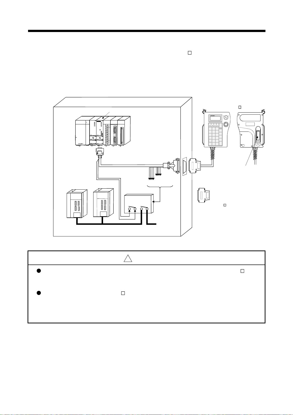
2 SYSTEM CONFIGURATION
4) When the teaching unit (A31TU-D3
Connection example between the cable for teaching unit (Q170TUD3CBL3M) and
external safety circuit is shown below.
) is not used, connect the shortcircuit connector for teaching unit (A31TUD3TM) to the control panel
side connector of the cable for teaching unit (Q170TUD3CBL3M).
PROGRAM
DATA
INSTRUCTION
ITEM
;
8
7
DELETE
WRITE
D
5
4
STORE
A
1
FUNCTION
.
ERROR
SHIFT
RESET
AXIS
JOG -
NO.
A31TU-D3
DISABLE
A31TU
MONITOR
TEST
STOP
CLEAR
#
SP
9
OVERRIDE
INDIRECT
E
F
6
STEP -
B
3C2
STEP +
MDI
-
0
RETURN
CAN
GO
JOG +
ENABLE
EMG.STOP
Control panel
MELSEC
Q173CPUN-T/Q172CPUN-T
Q172EX
Q173PX-S1
QX40
Q173CPUN-T
Q02HCPU
Q61P-A1
PULL
MODE
POWER
MODE
RUN
RUN
ERR.
ERR.
USER
M.RUN
BAT.
BAT.
BOOT
BOOT
FRONT
SSCNET
CN2
TU
CN1
PULL
PULL
USB
USB
RS-232
RS-232
0 1 2 3 4 5 6 7
8 9 A B C D E F
PLS.A
PLS.B
TREN
SY.ENC
TREN
1
1
1
1
1
2
2
2
2
2
3
3
3
SY.ENC1
PULSER
SY.ENC2
Q173PX
Q172EX
Q170TUD3CBL3M
Deadman switch
Servo amplifier
MITSUBISHI
Emergency stop input
MITSUBISHI
Deadman
contact point
Emergenc y stop
contact po int
A31TUD3TM
When the A31TU-D3
is not used.
Main circuit
power supply
External safety circuit
(Relay, MC, etc.)
!
CAUTION
Do not use it in the combination of the teaching unit without deadman switch (A31TU-DN ) and
cable for teaching unit with deadman switch (Q170TUD3CBL3M). The protective function stops
working.
When the teaching unit (A31TU-D3 ) is not used in the Motion CPU (Q173CPUN-T/
Q172CPUN-T), connect the short-circuit connector for teaching unit (A31TUD3TM) to the control
panel side connector of the cable for teaching unit (Q170TUD3CBL3M). If it is not connected,
the emergency stop state of Motion CPU occurs, and the servomotor becomes coasting state.
2 - 76

2 SYSTEM CONFIGURATION
(b) Connection between the teaching unit (A31TU-DN ) and
There are following two connecting method.
• When the connector is connected to the control panel.
• When the connector is connected directly in the control panel.
1) When the connector is connected to the control panel.
Motion CPU (Q173CPUN-T/Q172CPUN-T)
a) Connect the cable for teaching unit (Q170TUDNCBL3M) between
the TU connector of Motion CPU (Q173CPUN-T/Q172CPUN-T) and
control panel. (Refer to the exterior dimensions of "APPENDIX 1.3
Cable for the teaching unit" and "APPENDIX 2.7 Connector", when
it is fit to the control panel.)
b) Connect the teaching unit (A31TU-DN
unit (Q170TUDNCBL3M) connected to the control panel.
c) When the teaching unit (A31TU-DN
short-circuit connector for teaching unit (A31TUD3TM) to the control
panel side connector of the cable for teaching unit
(Q170TUDNCBL3M).
) to the cable for teaching
) is not used, connect the
2 - 77

2 SYSTEM CONFIGURATION
Connection example between the cable for teaching unit (Q170TUDNCBL3M) is
shown below.
PROGRAM
DATA
INSTRUCTION
ITEM
;
8
7
DELETE
WRITE
D
5
4
STORE
A
1
FUNCTION
.
ERROR
SHIFT
RESET
AXIS
JOG -
NO.
A31TU-DN
A31TU
MONITOR
TEST
STOP
CLEAR
#
SP
9
OVERRIDE
INDIRECT
E
F
6
STEP -
B
3C2
STEP +
MDI
-
0
RETURN
CAN
GO
JOG +
DISABLE
ENABLE
EMG.STOP
Control panel
MELSEC
Q61P-A1
Q173CPUN-T/Q172CPUN-T
Q172EX
Q173PX-S1
QX40
Q173CPUN-T
Q02HCPU
POWER
MODE
MODE
RUN
RUN
ERR.
ERR.
M.RUN
USER
BAT.
BAT.
BOOT
BOOT
FRONT
SSCNET
CN2
TU
CN1
PULL
PULL
USB
PULL
USB
RS-232
RS-232
0 1 2 3 4 5 6 7
8 9 A B C D E F
PLS.A
PLS.B
TREN
SY.ENC
TREN
1
1
1
1
1
2
2
2
2
2
3
3
3
SY.ENC1
PULSER
SY.ENC2
Q173PX
Q172EX
Q170TUDNCBL3M
No deadman switch
Servo amplifier
MITSUBISHI
MITSUBISHI
Main circuit
power supply
A31TUD3TM
When the A31TU-DNK
is not used.
!
CAUTION
Do not use it in the combination of the teaching unit with deadman switch (A31TU-D3 ) and cable for
teaching unit without deadman switch (Q170TUDNCBL3M). The protective function stops working.
When the teaching unit (A31TU-DN ) is not used in the Motion CPU (Q173CPUN-T/
Q172CPUN-T), connect the short-circuit connector for teaching unit (A31TUD3TM) to the control
panel side connector of the cable for teaching unit (Q170TUDNCBL3M). If it is not connected, the
emergency stop state of Motion CPU occurs, and the servomotor becomes coasting state.
2 - 78

2 SYSTEM CONFIGURATION
2) When the connector is connected directly in the control panel.
Connection example between the cable for teaching unit (Q170TUDNCBL03M-A) is
shown below.
a) Connect the cable for teaching unit (Q170TUDNCBL03M-A) to the
TU connector of Motion CPU (Q173CPUN-T/Q172CPUN-T) after
connecting to the teaching unit (A31TU-DN
b) When the teaching unit (A31TU-DN
) is not used, connect the
).
short-circuit connector for teaching unit (Q170TUTM) after removing
a TU connector of cable for teaching unit (Q170TUDNCBL03M-A)
from a TU connector of Motion CPU (Q173CPUN-T/Q172CPUN-T).
PROGRAM
DATA
INSTRUCTION
ITEM
;
8
7
DELETE
WRITE
D
5
4
STORE
A
1
FUNCTION
.
ERROR
SHIFT
RESET
AXIS
JOG -
NO.
A31TU-DN
DISABLE
A31TU
MONITOR
TEST
STOP
CLEAR
#
SP
9
OVERRIDE
INDIRECT
E
F
6
STEP -
B
3C2
STEP +
MDI
-
0
RETURN
CAN
GO
JOG +
ENABLE
EMG.STOP
Control panel
MELSEC
Q173CPUN-T/Q172CPUN-T
Q172EX
Q173PX-S1
QX40
Q173CPUN-T
Q02HCPU
Q61P-A1
POWER
MODE
MODE
RUN
RUN
ERR.
ERR.
M.RUN
USER
BAT.
BAT.
BOOT
BOOT
FRONT
SSCNET
CN2
TU
CN1
PULL
PULL
USB
PULL
USB
RS-232
RS-232
0 1 2 3 4 5 6 7
8 9 A B C D E F
PLS.A
PLS.B
TREN
SY.ENC
TREN
1
1
1
1
1
2
2
2
2
2
3
3
3
SY.ENC1
PULSER
SY.ENC2
Q173PX
Q172EX
Q170TUDNCBL03M-A
Q170TUTM
When the A31TU-DN
is not used.
Servo amplifier
MITSUBISHI
MITSUBISHI
No deadman switch
Main circuit
power supply
2 - 79

2 SYSTEM CONFIGURATION
!
CAUTION
Do not connect the A31TU-D3 to the cable for teaching unit (Q170TUDNCBL03M-A). The protective
function stops working.
Be sure to fix the relay portion of a connector which has connected the cable for teaching unit
(Q170TUDNCBL03M-A) with teaching unit (A31TU-DN
for the connector of Motion CPU (Q173CPUN-T/Q172CPUN-T). A connector may be damaged.
Do not pull a teaching unit (A31TU-DN ). A connector may be damaged.
When a teaching unit (A31TU-DN ) is removed, first be sure to remove a TU connector of Motion
CPU (Q173CPUN-T/Q172CPUN-T) so that impossible power is not applied for the connector.
If a connector of teaching unit (A31TU-DN
CPU (Q173CPUN-T/Q172CPUN-T), a TU connector of Motion CPU (Q173CPUN-T/
Q172CPUN-T) may be damaged.
When the teaching unit (A31TU-DN ) is not used in the Motion CPU (Q173CPUN-T/
Q172CPUN-T), connect the short-circuit connector for teaching unit (Q170TUTM) after removing
a TU connector of cable for teaching unit (Q170TUDNCBL03M-A) from a TU connector of Motion
CPU (Q173CPUN-T/Q172CPUN-T). If it is not connected, the emergency stop state of Motion
CPU occurs, and the servomotor becomes coasting state.
) is removed connecting a TU connector of Motion
) so that impossible power is not applied
2 - 80

2 SYSTEM CONFIGURATION
(c) When not using a teaching unit (A31TU-D3 /A31TU-DN )
Connect a short-circuit connector for teaching unit (Q170TUTM) to a TU
connector of Motion CPU (Q173CPUN-T/Q172CPUN-T).
Connection example without teaching unit (A31TU-D3
/A31TU-DN ) is
shown below.
Control panel
MELSEC
Q02HCPU
Q61P-A1
POWER
PULL
PULL
Q173CPUN-T/Q172CPUN-T
Q172EX
Q173PX-S1
QX40
Q173CPUN-T
MODE
MODE
RUN
RUN
ERR.
ERR.
M.RUN
USER
BAT.
BAT.
BOOT
BOOT
FRONT
SSCNET
CN2
TU
CN1
PULL
USB
USB
RS-232
RS-232
PLS.A
PLS.B
0 1 2 3 4 5 6 7
8 9 A B C D E F
TREN
SY.ENC
TREN
1
1
1
1
1
2
2
2
2
2
3
3
3
SY.ENC1
PULSER
SY.ENC2
Q173PX
Q172EX
Q170TUTM
When the A31TU-D3 /
A31TU-DN is not used.
Servo amplifier
MITSUBISHI
MITSUBISHI
Main circuit
power supply
!
CAUTION
When the teaching unit (A31TU-D3 /A31TU-DN ) is not used in the Motion CPU (Q173CPUN-T/
Q172CPUN-T), connect the short-circuit connector for teaching unit (Q170TUTM) to a TU connector
of Motion CPU (Q173CPUN-T/Q172CPUN-T). If it is not connected, the emergency stop state of
Motion CPU occurs, and the servomotor becomes coasting state.
2 - 81
 Loading...