

Page 1
Page 2
SAFETY PRECAUTIONS
(Please read these instructions before using this equipment.)
Before using this product, please read this manual and the relevant manuals introduced in this manual
carefully and pay full attention to safety to handle the product correctly.
These precautions apply only to this product. Refer to the Users manual of the QCPU module to use for a
description of the PLC system safety precautions.
In this manual, the safety instructions are ranke
Depending on circumstances, procedures indicated by
results.
In any case, it is important to follow the directions for usage.
Please save this manual to make it accessible when required and always forward it to the end user.
DANGER
CAUTION
d as "DANGER" and "CAUTION".
Indicates that incorrect handling may cause hazardous
conditions, resulting in death or severe injury.
Indicates that incorrect handling may cause hazardous
conditions, resulting in medium or slight personal injury or
physical damage.
CAUTION may also be linked to serious
A - 1
Page 3
For Safe Operations
1. Prevention of electric shocks
DANGER
Never open the front case or terminal covers while the power is ON or the unit is running, as this
may lead to electric shocks.
Never run the unit with the front case or terminal cover removed. The high voltage terminal and
charged sections will be exposed and may lead to electric shocks.
Never open the front case or terminal cover at times other than wiring work or periodic
inspections even if the power is OFF. The insides of the Motion controller and servo amplifier are
charged and may lead to electric shocks.
Completely turn off the externally supplied power used in the system before mounting or
removing the module, performing wiring work, or inspections. Failing to do so may lead to electric
shocks.
When performing wiring work or inspections, turn the power OFF, wait at least ten minutes, and
then check the voltage with a tester, etc.. Failing to do so may lead to electric shocks.
Be sure to ground the Motion controller, servo amplifier and servomotor. (Ground resistance :
or less) Do not ground commonly with other devices.
100
The wiring work and inspections must be done by a qualified technician.
Wire the units after installing the Motion controller, servo amplifier and servomotor. Failing to do
so may lead to electric shocks or damage.
Never operate the switches with wet hands, as this may lead to electric shocks.
Do not damage, apply excessive stress, place heavy things on or sandwich the cables, as this
may lead to electric shocks.
Do not touch the Motion controller, servo amplifier or servomotor terminal blocks while the power
is ON, as this may lead to electric shocks.
Do not touch the built-in power supply, built-in grounding or signal wires of the Motion controller
and servo amplifier, as this may lead to electric shocks.
2. For fire prevention
CAUTION
Install the Motion controller, servo amplifier, servomotor and regenerative resistor on
incombustible. Installing them directly or close to combustibles will lead to fire.
If a fault occurs in the Motion controller or servo amplifier, shut the power OFF at the servo
amplifier’s power source. If a large current continues to flow, fire may occur.
When using a regenerative resistor, shut the power OFF with an error signal. The regenerative
resistor may abnormally overheat due to a fault in the regenerative transistor, etc., and may lead
to fire.
Always take heat measures such as flame proofing for the inside of the control panel where the
servo amplifier or regenerative resistor is installed and for the wires used. Failing to do so may
lead to fire.
Do not damage, apply excessive stress, place heavy things on or sandwich the cables, as this
may lead to fire.
A - 2
Page 4
3. For injury prevention
CAUTION
Do not apply a voltage other than that specified in the instruction manual on any terminal.
Doing so may lead to destruction or damage.
Do not mistake the terminal connections, as this may lead to destruction or damage.
Do not mistake the polarity ( + / - ), as this may lead to destruction or damage.
Do not touch the heat radiating fins of controller or servo amplifier, regenerative resistor and
servomotor, etc., while the power is ON and for a short time after the power is turned OFF. In this
timing, these parts become very hot and may lead to burns.
Always turn the power OFF before touching the servomotor shaft or coupled machines, as these
parts may lead to injuries.
Do not go near the machine during test operations or during operations such as teaching.
Doing so may lead to injuries.
4. Various precautions
Strictly observe the following precautions.
Mistaken handling of the unit may lead to faults, injuries or electric shocks.
(1) System structure
CAUTION
Always install a leakage breaker on the Motion controller and servo amplifier power source.
If installation of an electromagnetic contactor for power shut off during an error, etc., is specified in
the instruction manual for the servo amplifier, etc., always install the electromagnetic contactor.
Install the emergency stop circuit externally so that the operation can be stopped immediately and
the power shut off.
Use the Motion controller, servo amplifier, servomotor and regenerative resistor with the correct
combinations listed in the instruction manual. Other combinations may lead to fire or faults.
Use the Motion controller, base unit and motion module with the correct combinations listed in the
instruction manual. Other combinations may lead to faults.
If safety standards (ex., robot safety rules, etc.,) apply to the system using the Motion controller,
servo amplifier and servomotor, make sure that the safety standards are satisfied.
Construct a safety circuit externally of the Motion controller or servo amplifier if the abnormal
operation of the Motion controller or servo amplifier differ from the safety directive operation in the
system.
In systems where coasting of the servomotor will be a problem during the forced stop, emergency
stop, servo OFF or power supply OFF, use dynamic brakes.
Make sure that the system considers the coasting amount even when using dynamic brakes.
In systems where perpendicular shaft dropping may be a problem during the forced stop,
emergency stop, servo OFF or power supply OFF, use both dynamic brakes and electromagnetic
brakes.
A - 3
Page 5
CAUTION
The dynamic brakes must be used only on errors that cause the forced stop, emergency stop, or
servo OFF. These brakes must not be used for normal braking.
The brakes (electromagnetic brakes) assembled into the servomotor are for holding applications,
and must not be used for normal braking.
The system must have a mechanical allowance so that the machine itself can stop even if the
stroke limits switch is passed through at the max. speed.
Use wires and cables that have a wire diameter, heat resistance and bending resistance
compatible with the system.
Use wires and cables within the length of the range described in the instruction manual.
The ratings and characteristics of the parts (other than Motion controller, servo amplifier and
servomotor) used in a system must be compatible with the Motion controller, servo amplifier and
servomotor.
Install a cover on the shaft so that the rotary parts of the servomotor are not touched during
operation.
There may be some cases where holding by the electromagnetic brakes is not possible due to the
life or mechanical structure (when the ball screw and servomotor are connected with a timing belt,
etc.). Install a stopping device to ensure safety on the machine side.
(2) Parameter settings and programming
CAUTION
Set the parameter values to those that are compatible with the Motion controller, servo amplifier,
servomotor and regenerative resistor model and the system application. The protective functions
may not function if the settings are incorrect.
The regenerative resistor model and capacity parameters must be set to values that conform to
the operation mode, servo amplifier and servo power supply module. The protective functions
may not function if the settings are incorrect.
Set the mechanical brake output and dynamic brake output validity parameters to values that are
compatible with the system application. The protective functions may not function if the settings
are incorrect.
Set the stroke limit input validity parameter to a value that is compatible with the system
application. The protective functions may not function if the setting is incorrect.
Set the servomotor encoder type (increment, absolute position type, etc.) parameter to a value
that is compatible with the system application. The protective functions may not function if the
setting is incorrect.
Set the servomotor capacity and type (standard, low-inertia, flat, etc.) parameter to values that
are compatible with the system application. The protective functions may not function if the
settings are incorrect.
Set the servo amplifier capacity and type parameters to values that are compatible with the
system application. The protective functions may not function if the settings are incorrect.
Use the program commands for the program with the conditions specified in the instruction
manual.
A - 4
Page 6
CAUTION
Set the sequence function program capacity setting, device capacity, latch validity range, I/O
assignment setting, and validity of continuous operation during error detection to values that are
compatible with the system application. The protective functions may not function if the settings
are incorrect.
Some devices used in the program have fixed applications, so use these with the conditions
specified in the instruction manual.
The input devices and data registers assigned to the link will hold the data previous to when
communication is terminated by an error, etc. Thus, an error correspondence interlock program
specified in the instruction manual must be used.
Use the interlock program specified in the intelligent function module's instruction manual for the
program corresponding to the intelligent function module.
(3) Transportation and installation
CAUTION
Transport the product with the correct method according to the mass.
Use the servomotor suspension bolts only for the transportation of the servomotor. Do not
transport the servomotor with machine installed on it.
Do not stack products past the limit.
When transporting the Motion controller or servo amplifier, never hold the connected wires or
cables.
When transporting the servomotor, never hold the cables, shaft or detector.
When transporting the Motion controller or servo amplifier, never hold the front case as it may fall
off.
When transporting, installing or removing the Motion controller or servo amplifier, never hold the
edges.
Install the unit according to the instruction manual in a place where the mass can be withstood.
Do not get on or place heavy objects on the product.
Always observe the installation direction.
Keep the designated clearance between the Motion controller or servo amplifier and control panel
inner surface or the Motion controller and servo amplifier, Motion controller or servo amplifier and
other devices.
Do not install or operate Motion controller, servo amplifiers or servomotors that are damaged or
that have missing parts.
Do not block the intake/outtake ports of the Motion controller, servo amplifier and servomotor with
cooling fan.
Do not allow conductive matter such as screw or cutting chips or combustible matter such as oil
enter the Motion controller, servo amplifier or servomotor.
The Motion controller, servo amplifier and servomotor are precision machines, so do not drop or
apply strong impacts on them.
Securely fix the Motion controller, servo amplifier and servomotor to the machine according to
the instruction manual. If the fixing is insufficient, these may come off during operation.
A - 5
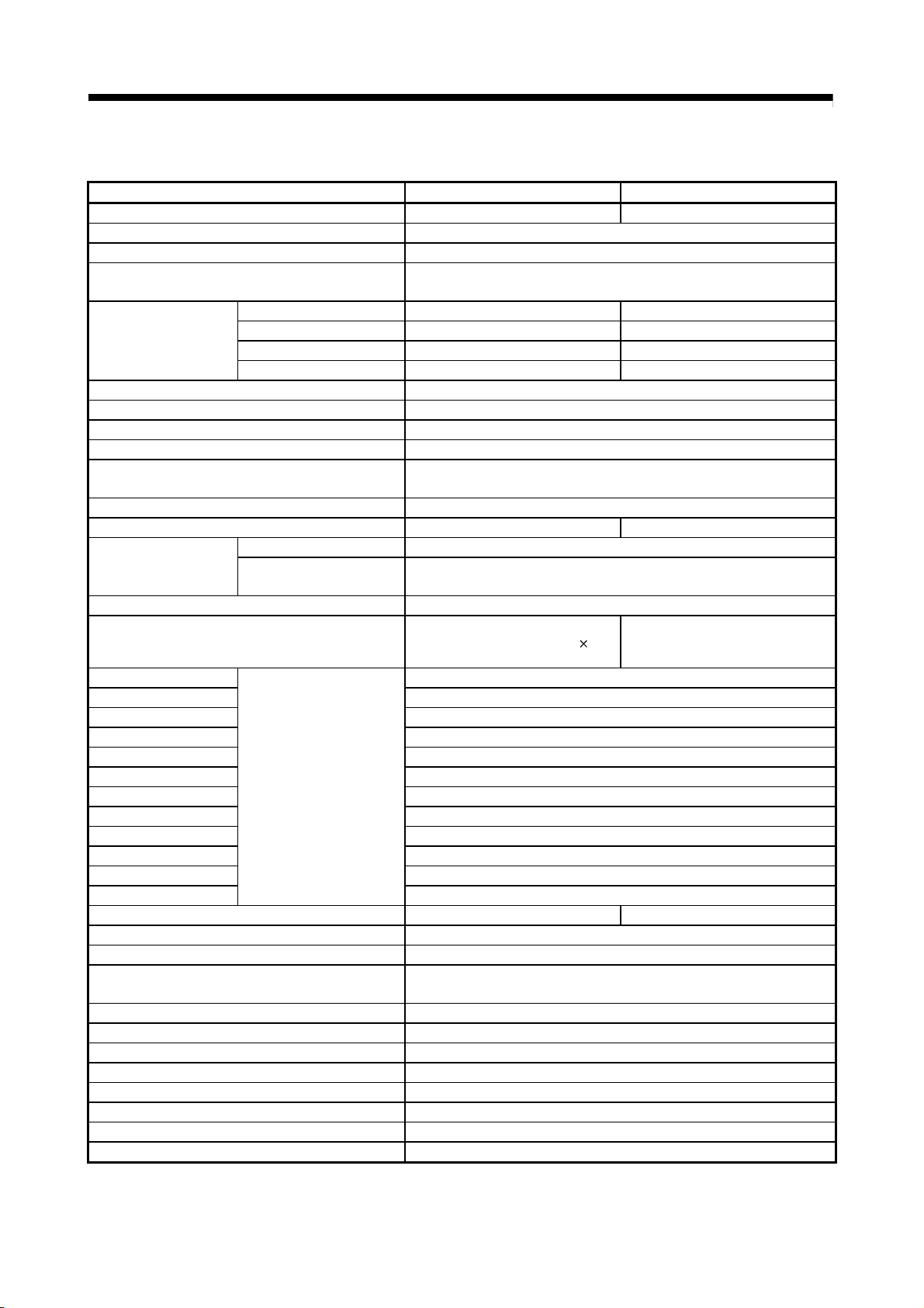
Page 7
CAUTION
Always install the servomotor with reduction gears in the designated direction. Failing to do so
may lead to oil leaks.
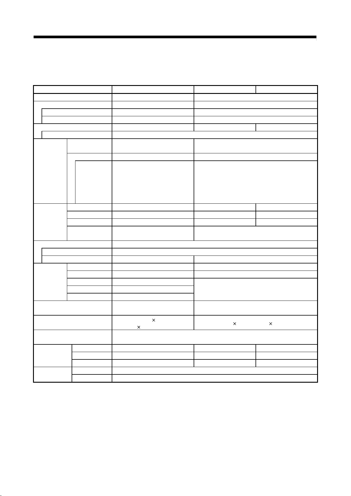
Store and use the unit in the following environmental conditions.
Environment
Ambient
temperature
Ambient humidity
Storage
temperature
Atmosphere
Altitude
Vibration
Motion controller/Servo amplifier Servomotor
According to each instruction manual.
According to each instruction manual.
According to each instruction manual.
Indoors (where not subject to direct sunlight).
No corrosive gases, flammable gases, oil mist or dust must exist
1000m (3280.84ft.) or less above sea level
According to each instruction manual
Conditions
0°C to +40°C (With no freezing)
(32°F to +104°F)
80% RH or less
(With no dew condensation)
-20°C to +65°C
(-4°F to +149°F)
When coupling with the synchronous encoder or servomotor shaft end, do not apply impact such
as by hitting with a hammer. Doing so may lead to detector damage.
Do not apply a load larger than the tolerable load onto the synchronous encoder and servomotor
shaft. Doing so may lead to shaft breakage.
When not using the module for a long time, disconnect the power line from the Motion controller
or servo amplifier.
Place the Motion controller and servo amplifier in static electricity preventing vinyl bags and store.
When storing for a long time, please contact with our sales representative.
Also, execute a trial operation.
A - 6
Page 8
(4) Wiring
CAUTION
Correctly and securely wire the wires. Reconfirm the connections for mistakes and the terminal
screws for tightness after wiring. Failing to do so may lead to run away of the servomotor.
After wiring, install the protective covers such as the terminal covers to the original positions.
Do not install a phase advancing capacitor, surge absorber or radio noise filter (option FR-BIF)
on the output side of the servo amplifier.
Correctly connect the output side (terminal U, V, W) and ground. Incorrect connections will lead
the servomotor to operate abnormally.
Do not connect a commercial power supply to the servomotor, as this may lead to trouble.
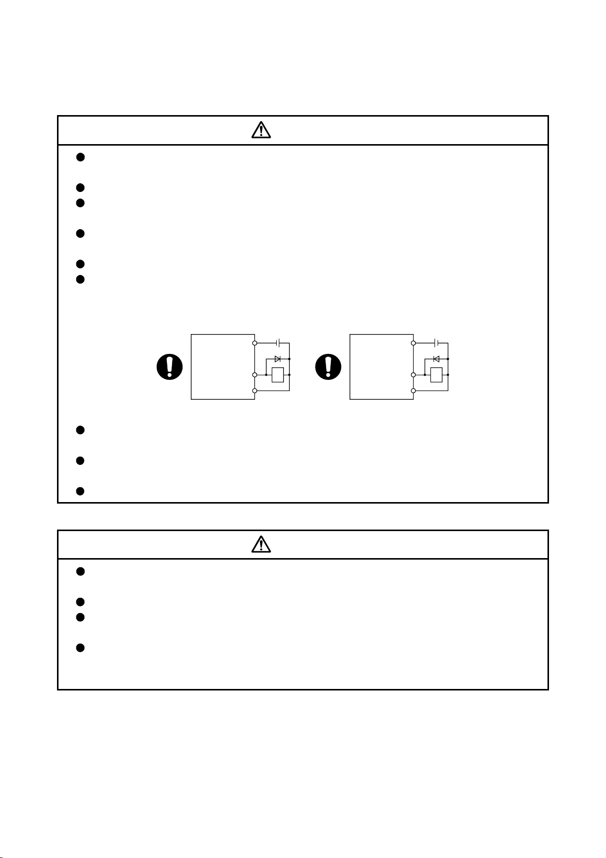
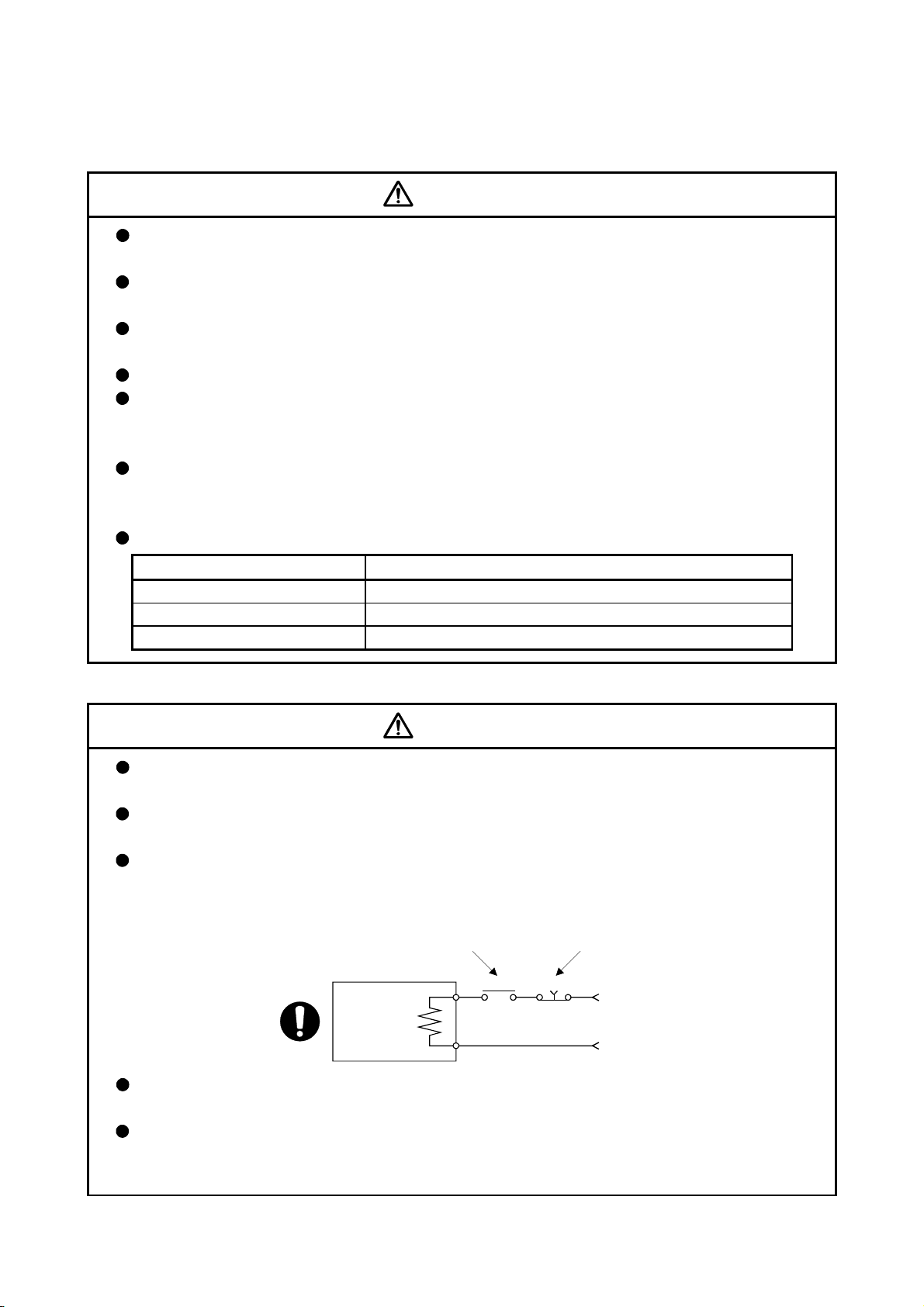
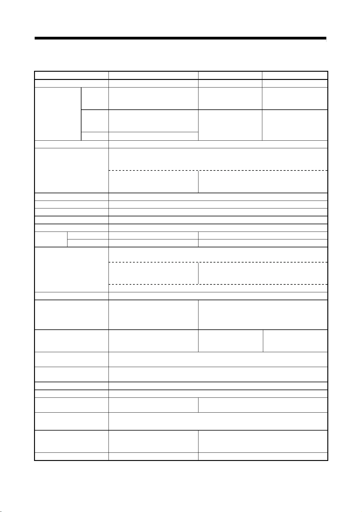
Do not mistake the direction of the surge absorbing diode installed on the DC relay for the control
signal output of brake signals, etc. Incorrect installation may lead to signals not being output
when trouble occurs or the protective functions not functioning.
Servo amplifier
DOCOM
Control output
signal
DICOM
For the sink output interface For the source output interface
24VDC
RA
Servo amplifier
DOCOM
Control output
signal
DICOM
24VDC
RA
Do not connect or disconnect the connection cables between each unit, the encoder cable or
PLC expansion cable while the power is ON.
Securely tighten the cable connector fixing screws and fixing mechanisms. Insufficient fixing may
lead to the cables combing off during operation.
Do not bundle the power line or cables.
(5) Trial operation and adjustment
CAUTION
Confirm and adjust the program and each parameter before operation. Unpredictable
movements may occur depending on the machine.
Extreme adjustments and changes may lead to unstable operation, so never make them.
When using the absolute position system function, on starting up, and when the Motion
controller or absolute value motor has been replaced, always perform a home position return.
Before starting test operation, set the parameter speed limit value to the slowest value, and
make sure that operation can be stopped immediately by the forced stop, etc. if a hazardous
state occurs.
A - 7
Page 9
(6) Usage methods
CAUTION
Immediately turn OFF the power if smoke, abnormal sounds or odors are emitted from the
Motion controller, servo amplifier or servomotor.
Always execute a test operation before starting actual operations after the program or
parameters have been changed or after maintenance and inspection.
Do not attempt to disassemble and repair the units excluding a qualified technician whom our
company recognized.
Do not make any modifications to the unit.
Keep the effect or electromagnetic obstacles to a minimum by installing a noise filter or by using
wire shields, etc. Electromagnetic obstacles may affect the electronic devices used near the
Motion controller or servo amplifier.
When using the CE Mark-compliant equipment, refer to this manual for the Motion controllers
and refer to the corresponding EMC guideline information for the servo amplifiers, inverters and
other equipment.
Use the units with the following conditions.
Item Conditions
Input power According to each instruction manual.
Input frequency According to each instruction manual.
Tolerable momentary power failure According to each instruction manual.
(7) Corrective actions for errors
CAUTION
If an error occurs in the self diagnosis of the Motion controller or servo amplifier, confirm the
check details according to the instruction manual, and restore the operation.
If a dangerous state is predicted in case of a power failure or product failure, use a servomotor
with electromagnetic brakes or install a brake mechanism externally.
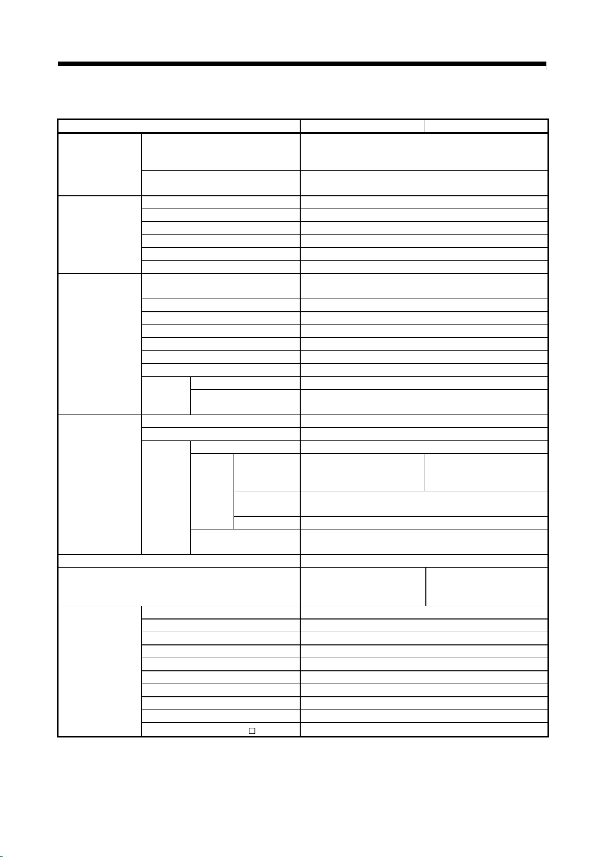
Use a double circuit construction so that the electromagnetic brake operation circuit can be
operated by emergency stop signals set externally.
Shut off with servo ON signal OFF,
alarm, electromagnetic brake signal.
Servomotor
Electromagnetic
brakes
RA1 EMG
Shut off with the
emergency stop
signal (EMG).
24VDC
If an error occurs, remove the cause, secure the safety and then resume operation after alarm
release.
The unit may suddenly resume operation after a power failure is restored, so do not go near the
machine. (Design the machine so that personal safety can be ensured even if the machine
restarts suddenly.)
A - 8
Page 10
(8) Maintenance, inspection and part replacement
CAUTION
Perform the daily and periodic inspections according to the instruction manual.
Perform maintenance and inspection after backing up the program and parameters for the Motion
controller and servo amplifier.
Do not place fingers or hands in the clearance when opening or closing any opening.
Periodically replace consumable parts such as batteries according to the instruction manual.
Do not touch the lead sections such as ICs or the connector contacts.
Before touching the module, always touch grounded metal, etc. to discharge static electricity from
human body. Failure to do so may cause the module to fail or malfunction.
Do not directly touch the module's conductive parts and electronic components.
Touching them could cause an operation failure or give damage to the module.
Do not place the Motion controller or servo amplifier on metal that may cause a power leakage
or wood, plastic or vinyl that may cause static electricity buildup.
Do not perform a megger test (insulation resistance measurement) during inspection.
When replacing the Motion controller or servo amplifier, always set the new module settings
correctly.
When the Motion controller or absolute value motor has been replaced, carry out a home
position return operation using one of the following methods, otherwise position displacement
could occur.
1) After writing the servo data to the Motion controller using programming software, switch on the
power again, then perform a home position return operation.
2) Using the backup function of the programming software, load the data backed up before
replacement.
After maintenance and inspections are completed, confirm that the position detection of the
absolute position detector function is correct.
Do not drop or impact the battery installed to the module.
Doing so may damage the battery, causing battery liquid to leak in the battery. Do not use the
dropped or impacted battery, but dispose of it.
Do not short circuit, charge, overheat, incinerate or disassemble the batteries.
The electrolytic capacitor will generate gas during a fault, so do not place your face near the
Motion controller or servo amplifier.
The electrolytic capacitor and fan will deteriorate. Periodically replace these to prevent secondary
damage from faults. Replacements can be made by our sales representative.
Lock the control panel and prevent access to those who are not certified to handle or install
electric equipment.
Do not burn or break a module and servo amplifier. Doing so may cause a toxic gas.
A - 9
Page 11

(9) About processing of waste
When you discard Motion controller, servo amplifier, a battery (primary battery) and other option
articles, please follow the law of each country (area).
CAUTION
This product is not designed or manufactured to be used in equipment or systems in situations
that can affect or endanger human life.
When considering this product for operation in special applications such as machinery or systems
used in passenger transportation, medical, aerospace, atomic power, electric power, or
submarine repeating applications, please contact your nearest Mitsubishi sales representative.
Although this product was manufactured under conditions of strict quality control, you are strongly
advised to install safety devices to forestall serious accidents when it is used in facilities where a
breakdown in the product is likely to cause a serious accident.
(10) General cautions
All drawings provided in the instruction manual show the state with the covers and safety
partitions removed to explain detailed sections. When operating the product, always return the
covers and partitions to the designated positions, and operate according to the instruction
manual.
A - 10
Page 12

REVISIONS
The manual number is given on the bottom left of the back cover.
Print Date Manual Number Revision
Feb., 2009 IB(NA)-0300156-A First edition
Jul., 2009 IB(NA)-0300156-B [Additional model]
QH40H, QX70H, QX80H, QX90H, Q170MICON, Q170MPWCON,
Q170MPWCBL2M-E
[Additional correction/partial correction]
Safety precautions, About manuals, Internal I/F, EMC directive,
Battery transportation, Symbol for the new EU battery directive,
Internal IO circuit troubleshooting, MC protocol communication, Mark
detection function, Synchronous encoder current value monitor in real
mode, Processing times, Troubleshooting
Dec., 2011 IB(NA)-0300156-C [Partial correction]
Safety Precautions, Section 4.2.1 Partial change of sentence
Japanese Manual Number IB(NA)-0300154
This manual confers no industrial property rights or any rights of any other kind, nor does it confer any patent
licenses. Mitsubishi Electric Corporation cannot be held responsible for any problems involving industrial property
rights which may occur as a result of using the contents noted in this manual.
© 2009 MITSUBISHI ELECTRIC CORPORATION
A - 11
Page 13

INTRODUCTION
Thank you for choosing the Mitsubishi Motion controller Q170MCPU.
Before using the equipment, please read this manual carefully to develop full familiarity with the functions
and performance of the Motion controller you have purchased, so as to ensure correct use.
CONTENTS
Safety Precautions .........................................................................................................................................A- 1
Revisions ........................................................................................................................................................A-11
Contents .........................................................................................................................................................A-12
About Manuals ...............................................................................................................................................A-15
1. OVERVIEW 1- 1 to 1-10
1.1 Overview................................................................................................................................................... 1- 1
1.2 Comparison between Q170MCPU and Q173DCPU/Q172DCPU ......................................................... 1- 3
1.3 Restrictions by the software's version or serial number ......................................................................... 1-10
2. SYSTEM CONFIGURATION 2- 1 to 2-64
2.1 Motion System Configuration .................................................................................................................. 2- 1
2.1.1 Q170MCPU System overall configuration........................................................................................ 2- 3
2.1.2 Q170MCPU System internal configuration ...................................................................................... 2- 4
2.1.3 Function explanation of the Q170MCPU Motion controller ............................................................. 2- 5
2.1.4 Restrictions on Motion controller ...................................................................................................... 2- 7
2.2 Checking Serial Number and Operating System Software Version....................................................... 2- 9
2.2.1 Checking serial number .................................................................................................................... 2- 9
2.2.2 Checking operating system software version .................................................................................. 2-11
2.3 System Configuration Equipment ............................................................................................................ 2-12
2.4 General Specifications ............................................................................................................................. 2-18
2.5 Specifications of Equipment .................................................................................................................... 2-19
2.5.1 Q170MCPU Motion controller........................................................................................................... 2-19
2.5.2. Extension base unit and extension cable ........................................................................................ 2-41
2.5.3 Q172DLX Servo external signals interface module ......................................................................... 2-44
2.5.4 Q173DPX Manual pulse generator interface module ...................................................................... 2-49
2.5.5 Manual pulse generator .................................................................................................................... 2-57
2.5.6 SSCNET
2.5.7 Battery ............................................................................................................................................... 2-60
2.5.8 Forced stop input terminal ................................................................................................................ 2-63
3. DESIGN 3- 1 to 3-16
cables ............................................................................................................................. 2-58
3.1 System Designing Procedure .................................................................................................................. 3- 1
3.2 External Circuit Design ............................................................................................................................ 3- 4
3.2.1 Power supply circuit design .............................................................................................................. 3- 7
3.2.2 Safety circuit design .......................................................................................................................... 3- 9
3.3 Layout Design within The Control Panel ................................................................................................. 3-11
3.3.1 Mounting environment....................................................................................................................... 3-11
3.3.2 Calculating heat generation by Motion controller............................................................................. 3-12
3.4 Design Checklist ...................................................................................................................................... 3-16
A - 12
Page 14

4. INSTALLATION AND WIRING 4- 1 to 4-28
4.1 Module Installation ...................................................................................................................................4- 1
4.1.1 Instructions for handling ....................................................................................................................4- 1
4.1.2 Instructions for mounting the modules ............................................................................................. 4- 3
4.1.3 Installation and removal of module to the base unit......................................................................... 4- 9
4.1.4 Mounting and removal of the battery holder..................................................................................... 4-12
4.2 Connection and Disconnection of Cable ................................................................................................. 4-17
4.2.1 SSCNET
4.2.2 Forced stop input cable..................................................................................................................... 4-23
4.2.3 24VDC power supply cable .............................................................................................................. 4-24
4.3 Wiring........................................................................................................................................................ 4-25
4.3.1 Instructions for wiring ........................................................................................................................4-25
4.3.2 Connecting to the power supply ....................................................................................................... 4-28
5. START-UP PROCEDURES 5- 1 to 5-10
5.1 Check Items before Start-up.................................................................................................................... 5- 1
5.2 Start-up Adjustment Procedure ............................................................................................................... 5- 3
5.3 Operating System Software Installation Procedure ................................................................................ 5- 7
5.4 Trial Operation and Adjustment Checklist ............................................................................................... 5- 9
cable ...............................................................................................................................4-17
6. INSPECTION AND MAINTENANCE 6- 1 to 6-32
6.1 Maintenance Works ................................................................................................................................. 6- 2
6.1.1 Instruction of inspection works.......................................................................................................... 6- 2
6.2 Daily Inspection ........................................................................................................................................6- 4
6.3 Periodic Inspection ................................................................................................................................... 6- 5
6.4 Life ............................................................................................................................................................ 6- 6
6.5 Battery ...................................................................................................................................................... 6- 7
6.5.1 Battery life.......................................................................................................................................... 6- 8
6.5.2 Battery replacement procedure ........................................................................................................ 6- 9
6.5.3 Resuming operation after storing the Motion controller ................................................................... 6-12
6.5.4 Symbol for the new EU Battery Directive ......................................................................................... 6-12
6.6 Troubleshooting ....................................................................................................................................... 6-13
6.6.1 Troubleshooting basics .....................................................................................................................6-13
6.6.2 Troubleshooting of Motion controller ................................................................................................6-14
6.6.3 Confirming error code ....................................................................................................................... 6-30
6.6.4 Internal I/O circuit troubleshooting .................................................................................................... 6-31
7. POSITIONING DEDICATED SIGNALS 7- 1 to 7- 6
7.1 Device List ................................................................................................................................................ 7- 1
7.2 Positioning Dedicated Signals ...........................................................................................................7- 2
7.2.1 Internal Relays................................................................................................................................... 7- 2
7.2.2 Data Registers................................................................................................................................... 7- 4
7.2.3 Motion Registers ............................................................................................................................... 7- 5
7.2.4 Special Relays................................................................................................................................... 7- 5
7.2.5 Special Registers .............................................................................................................................. 7- 5
A - 13
Page 15

8. EMC DIRECTIVES 8- 1 to 8- 8
8.1 Requirements for Compliance with the EMC Directive ..........................................................................8- 1
8.1.1 Standards relevant to the EMC Directive ......................................................................................... 8- 2
8.1.2 Installation instructions for EMC Directive........................................................................................ 8- 3
8.1.3 Parts of measure against noise ........................................................................................................ 8- 5
8.1.4 Example of measure against noise .................................................................................................. 8- 7
APPENDICES APP- 1 to APP-78
APPENDIX 1 Differences Between Q170MCPU and Q173DCPU/Q172DCPU ....................................APP- 1
APPENDIX 1.1 Differences of devices .................................................................................................APP- 2
APPENDIX 1.2 Differences of parameters ...........................................................................................APP- 3
APPENDIX 1.3 Differences of programs ..............................................................................................APP- 3
APPENDIX 1.4 Differences of error codes ...........................................................................................APP- 5
APPENDIX 1.5 Differences of peripheral device interface ..................................................................APP- 7
APPENDIX 1.6 MC Protocol Communication ......................................................................................APP-16
APPENDIX 1.7 Differences of CPU display and I/O assignment ........................................................APP-23
APPENDIX 1.8 Differences of I/O signals ............................................................................................APP-25
APPENDIX 1.9 Differences of synchronous encoder ..........................................................................APP-27
APPENDIX 1.10 Mark detection function .............................................................................................APP-29
APPENDIX 2 Creation of project ..............................................................................................................APP-38
APPENDIX 2.1 Sample data.................................................................................................................APP-39
APPENDIX 3 Processing Times...............................................................................................................APP-53
APPENDIX 3.1 Processing time of operation control/Transition instruction .......................................APP-53
APPENDIX 3.2 Processing time of Motion dedicated PLC instruction................................................APP-65
APPENDIX 4 Cables.................................................................................................................................APP-66
APPENDIX 4.1 SSCNET
APPENDIX 4.2 Forced stop input cable ...............................................................................................APP-69
APPENDIX 4.3 24VDC power supply cable.........................................................................................APP-70
APPENDIX 4.4 Internal I/F connector cable.........................................................................................APP-71
APPENDIX 5 Exterior Dimensions ...........................................................................................................APP-73
APPENDIX 5.1 Motion controller (Q170MCPU)................................................................................... APP-73
APPENDIX 5.2 Servo external signals interface module (Q172DLX).................................................APP-74
APPENDIX 5.3 Manual pulse generator interface module (Q173DPX)..............................................APP-74
APPENDIX 5.4 Battery holder ..............................................................................................................APP-75
APPENDIX 5.5 Connector ....................................................................................................................APP-76
APPENDIX 5.6 Manual pulse generator (MR-HDP01) ........................................................................APP-78
cables........................................................................................................APP-66
A - 14
Page 16

About Manuals
The following manuals are also related to this product.
In necessary, order them by quoting the details in the tables below.
Related Manuals
(1) Motion controller
Q170MCPU Motion controller User's Manual
This manual explains specifications of the Q170MCPU Motion controller, Q172DLX Servo external signal
interface module, Q173DPX Manual pulse generator interface module, Servo amplifiers, SSCNET
cables, and the maintenance/inspection for the system, trouble shooting and others.
(Optional)
Q173DCPU/Q172DCPU Motion controller Programming Manual (COMMON)
This manual explains the Multiple CPU system configuration, performance specifications, common
parameters, auxiliary/applied functions, error lists and others.
(Optional)
Manual Name
Manual Number
(Model Code)
IB-0300156
(1XB941)
IB-0300134
(1XB928)
Q173DCPU/Q172DCPU Motion controller (SV13/SV22) Programming Manual (Motion SFC)
This manual explains the functions, programming, debugging, error lists for Motion SFC and others.
(Optional)
Q173DCPU/Q172DCPU Motion controller (SV13/SV22) Programming Manual (REAL MODE)
This manual explains the servo parameters, positioning instructions, device lists, error lists and others.
(Optional)
Q173DCPU/Q172DCPU Motion controller (SV22) Programming Manual (VIRTUAL MODE)
This manual explains the dedicated instructions to use the synchronous control by virtual main shaft,
mechanical system program create mechanical module, servo parameters, positioning instructions, device
lists, error lists and others.
(Optional)
Motion controller Setup Guidance (MT Developer2 Version1)
This manual explains the items related to the setup of the Motion controller programming software
MT Developer2.
IB-0300135
(1XB929)
IB-0300136
(1XB930)
IB-0300137
(1XB931)
IB-0300142
(
— )
A - 15
Page 17

(2) PLC
QCPU User's Manual (Hardware Design, Maintenance and Inspection)
This manual explains the specifications of the QCPU modules, power supply modules, base units,
extension cables, memory card battery, and the maintenance/inspection for the system, trouble shooting,
error codes and others.
(Optional)
QnUCPU User's Manual (Function Explanation, Program Fundamentals)
This manual explains the functions, programming methods and devices and others to create programs
with the QCPU.
(Optional)
QCPU User's Manual (Multiple CPU System)
This manual explains the Multiple CPU system overview, system configuration, I/O modules,
communication between CPU modules and communication with the I/O modules or intelligent function
modules.
(Optional)
Manual Name
Manual Number
(Model Code)
SH-080483ENG
(13JR73)
SH-080807ENG
(13JZ27)
SH-080485ENG
(13JR75)
QnUCPU User's Manual (Communication via Built-in Ethernet Port)
This manual explains functions for the communication via built-in Ethernet port of the CPU module.
(Optional)
MELSEC-Q/L Programming Manual (Common Instruction)
This manual explains how to use the sequence instructions, basic instructions, application instructions and
micro computer program.
(Optional)
MELSEC-Q/L/QnA Programming Manual (PID Control Instructions)
This manual explains the dedicated instructions used to exercise PID control.
(Optional)
MELSEC-Q/L/QnA Programming Manual (SFC)
This manual explains the system configuration, performance specifications, functions, programming,
debugging, error codes and others of MELSAP3.
(Optional)
I/O Module Type Building Block User's Manual
This manual explains the specifications of the I/O modules, connector, connector/terminal block
conversion modules and others.
(Optional)
SH-080811ENG
(13JZ29)
SH-080809ENG
(13JW10)
SH-080040
(13JF59)
SH-080041
(13JF60)
SH-080042
(13JL99)
A - 16
Page 18
(3) Servo amplifier
SSCNET Compatible MR-J3- B Servo amplifier Instruction Manual
This manual explains the I/O signals, parts names, parameters, start-up procedure and others for
MR-J3-
(Optional)
SSCNET interface 2-axis AC Servo Amplifier MR-J3W- B Servo amplifier Instruction
Manual
This manual explains the I/O signals, parts names, parameters, start-up procedure and others for 2-axis
AC Servo Amplifier MR-J3W-
(Optional)
SSCNET Compatible Linear Servo MR-J3- B-RJ004 Instruction Manual
This manual explains the I/O signals, parts names, parameters, start-up procedure and others for Linear
Servo MR-J3-
(Optional)
SSCNET Compatible Fully Closed Loop Control MR-J3- B-RJ006 Servo amplifier
Instruction Manual
This manual explains the I/O signals, parts names, parameters, start-up procedure and others for Fully
Closed Loop Control MR-J3-
(Optional)
SSCNET interface Drive Safety integrated MR-J3- B Safety Servo amplifier Instruction
Manual
This manual explains the I/O signals, parts names, parameters, start-up procedure and others for safety
integrated MR-J3-
(Optional)
B Servo amplifier.
B-RJ004 Servo amplifier.
Manual Name
B Servo amplifier.
B-RJ006 Servo amplifier.
B Safety Servo amplifier.
Manual Number
(Model Code)
SH-030051
(1CW202)
SH-030073
(1CW604)
SH-030054
(1CW943)
SH-030056
(1CW304)
SH-030084
(1CW205)
A - 17
Page 19

MEMO
A - 18
Page 20
1 OVERVIEW
1. OVERVIEW
1.1 Overview
This User's Manual describes the hardware specifications and handling methods of the
Motion Controller Q170MCPU for the Q series PLC Multiple CPU system.
The Manual also describes those items related to the specifications of the option
module for the Motion controller, Manual pulse generator and cables.
Generic term/Abbreviation Description
Q170MCPU or Motion controller Q170MCPU Motion controller
Q172DLX/Q173DPX or
Motion module
MR-J3(W)- B Servo amplifier model MR-J3- B/MR-J3W- B
AMP or Servo amplifier General name for "Servo amplifier model MR-J3- B/MR-J3W- B"
Multiple CPU system or Motion system Abbreviation for "Multiple PLC system of the Q series"
PLC CPU area
Motion CPU area
CPUn
Operating system software General name for "SW DNC-SV Q "
SV13
SV22
Programming software package General name for MT Developer2/GX Developer/MR Configurator
MELSOFT MT Works2
MT Developer2
GX Developer
MR Configurator
Manual pulse generator or MR-HDP01 Abbreviation for "Manual pulse generator (MR-HDP01)"
SSCNET
Absolute position system
Intelligent function module
(Note-2)
In this manual, the following abbreviations are used.
Q172DLX Servo external signals interface module/
Q173DPX Manual pulse generator interface module
PLC control area (CPU No.1) of Q170MCPU Motion controller
Motion control area (CPU No.2) of Q170MCPU Motion controller
Abbreviation for "CPU No.n (n= 1 to 4) of the CPU module for the Multiple
CPU system"
Operating system software for conveyor assembly use (Motion SFC) :
(Note-1)
SW8DNC-SV13Q
Operating system software for automatic machinery use (Motion SFC) :
SW8DNC-SV22Q
Abbreviation for "Motion controller engineering environment
MELSOFT MT Works2"
(Note-1) : This software is included in Motion controller engineering environment "MELSOFT MT Works2".
(Note-2) : SSCNET: S
Abbreviation for "Motion controller programming software MT Developer2
(Version 1.05F or later)"
Abbreviation for "MELSEC PLC programming software package
GX Developer (Version 8.74C or later)"
Abbreviation for "Servo setup software package
MR Configurator (Version C2 or later)"
High speed synchronous network between Motion controller and servo
amplifier
General name for "system using the servomotor and servo amplifier for
absolute position"
Abbreviation for "CC-Link IE module/CC-Link module/MELSECNET/10(H)
module/Ethernet module/Serial communication module"
ervo System Controller NETwork
1
1 - 1
Page 21

1 OVERVIEW
REMARK
For information about each module, design method for program and parameter, refer
PLC CPU area, peripheral devices for PLC program design,
I/O modules and intelligent function module
Operation method for MT Developer2 Help of each software
• Multiple CPU system configuration
• Performance specification
• Design method for common parameter
• Auxiliary and applied functions (common)
• Design method for Motion SFC program
SV13/SV22
SV22
(Virtual mode)
• Design method for Motion SFC parameter
• Motion dedicated PLC instruction
• Design method for positioning control
• Design method for positioning control
• Design method for mechanical system
to the following manuals.
Item Reference Manual
program in the real mode
parameter
program
MELSEC-Q series PLC Manuals,
Manual relevant to each module
Q173DCPU/Q172DCPU Motion controller
Programming Manual (COMMON)
Q173DCPU/Q172DCPU Motion controller (SV13/SV22)
Programming Manual (Motion SFC)
Q173DCPU/Q172DCPU Motion controller (SV13/SV22)
Programming Manual (REAL MODE)
Q173DCPU/Q172DCPU Motion controller (SV22)
Programming Manual (VIRTUAL MODE)
1 - 2
Page 22
1 OVERVIEW
1.2 Comparison between Q170MCPU and Q173DCPU/Q172DCPU
Item Q170MCPU Q173DCPU Q172DCPU
Power supply Built-in (24VDC) Power supply module (24VDC, 100VAC, 200VAC)
PLC CPU area Q03UDCPU or equivalent (20k steps) QnUD(E)(H)CPU
Program capacity 20k steps 30k to 260k steps
LD instruction processing speed 0.02µs 0.0095 to 0.02µs
Motion CPU area Q172DCPU or equivalent (16 axes) Q173DCPU Q172DCPU
Forced stop input Use forced stop input terminal
Main base unit None
Extension base unit 1 extension (Q52B/Q55B usable) 7 extensions
Base unit
GOT bus
connection
Q172DLX 2 modules 4 modules 1 module
Motion
module
Battery Demand
Q6BAT Packed together with Motion controller
Q7BAT (Large capacity) Usable (sold separately) Unusable
Multiple CPU
system
Mounting method
Exterior dimensions [mm(inch)]
Medium of operating system
software
Model of
operating system
software
tool
Q172DEX Unusable 6 modules 4 modules
Q173DPX
Base unit for
installation
Number of CPUs 2 modules 2 to 4 modules
CPU No.1 PLC CPU area PLC CPU module, C controller module
CPU No.2 Motion CPU area
CPU No.3 —
CPU No.4 —
SV13 SW8DNC-SV13QG SW8DNC-SV13QB SW8DNC-SV13QD
SV22 SW8DNC-SV22QF SW8DNC-SV22QA SW8DNC-SV22QC
SV43 — SW7DNC-SV43QA SW7DNC-SV43QC
PLC CPU area GX Developer Programming
Motion CPU area MT Developer2
(1) Comparison of hardware
Multiple CPU high speed main base unit
(Q38DB/Q312DB)
• Extension base unit use:
Connection after the extension base
unit of stage 1
• Extension base unit not use:
Direct bus connection to Motion
controller
(Note-1)
Be sure to mount Motion controller on
control panel by fixing screws
178 (7.01)(H)
(Note-1): When using the incremental synchronous encoder (SV22 use), you can use above number of modules.
When connecting the manual pulse generator, you can use only 1 module.
3 modules 4 modules 3 modules
Extension base unit
52 (2.05)(W)
135 (5.31)(D)
Bus connection on main base unit or extension base unit
Main base unit, Extension base unit
(Impossible to install on I/O slots of 0 to 2 main base unit)
PLC CPU module, Motion CPU module,
C controller module
Be sure to install Motion CPU modules on main base unit
by fixing screws
98 (3.85)(H)
CD-ROM (1 disk)
27.4 (1.08)(W) 119.3 (4.69)(D)
1 - 3
Page 23
1 OVERVIEW
Item Q170MCPU Q173DCPU Q172DCPU
Number of control axes Up to 16 axes Up to 32 axes Up to 8 axes
Operation cycle
(default)
Interpolation functions Linear interpolation (Up to 4 axes), Circular interpolation (2 axes), Helical interpolation (3 axes)
Control modes
Acceleration/deceleration control Automatic trapezoidal acceleration/deceleration, S-curve acceleration/deceleration
Compensation Backlash compensation, Electronic gear, Phase compensation (SV22)
Programming language Motion SFC, Dedicated instruction, Mechanical support language (SV22)
Servo program capacity 16k steps
Number of positioning points 3200 points (Positioning data can be designated indirectly)
Peripheral I/F
Home position return function
JOG operation function Provided
Manual pulse generator
operation function
Synchronous encoder operation
function
M-code function
Limit switch output function
ROM operation function Provided
External input signal Q172DLX or External input signals (FLS/RLS/DOG) of servo amplifier
High-speed reading function
Forced stop
Number of I/O points
Mark detection function Provided Not provided
USB/RS-232 PLC CPU area control PLC CPU module control
PERIPHERAL I/F Motion CPU area control None
(2) Comparison of Motion control specifications
SV13
SV22
SV43 —
• Possible to connect 3 channels
(Q173DPX use)
• Possible to connect 1 channel
(Q170MCPU's internal I/F use)
0.44ms/ 1 to 6 axes
0.88ms/ 7 to 16 axes
0.44ms/ 1 to 4 axes
0.88ms/ 5 to 12 axes
1.77ms/13 to 16 axes
PTP(Point to Point) control, Speed control, Fixed-pitch feed, Constant speed control,
Position follow-up control, Speed control with fixed position stop, Speed switching control,
High-speed oscillation control, Synchronous control (SV22)
Speed-position control
(External input signal (DOG) of servo
amplifier usable)
Proximity dog type (2 types), Data set type (2 types), Dog cradle type,
Stopper type (2 types), Limit switch combined type
Count type (3 types)
(External input signal (DOG) of servo
amplifier usable)
Home position return re-try function provided, home position shift function provided
(Note-1)
Possible to connect 8 channels
(SV22 use)
ABS synchronous encoder unusable
Via internal I/F/input module,
Via tracking of Q173DPX
EMI connector of Motion controller, Forced stop input setting in the system setting,
Total 256 points
(Internal I/F (Input 4 points, Output 2
points) + I/O module)
(Note-2)
,
M-code output function provided,
M-code completion wait function provided
Number of output points 32 points
Watch data: Motion control data/Word device
Forced stop signal (EM1) of the servo amplifier
0.44ms/ 1 to 6 axes
0.88ms/ 7 to 18 axes
1.77ms/19 to 32 axes
0.44ms/ 1 to 4 axes
0.88ms/ 5 to 12 axes
1.77ms/13 to 28 axes
3.55ms/29 to 32 axes
Possible to connect 3 channels (Q173DPX use)
Possible to connect 12
channels (SV22 use)
Via input module, Via tracking of Q172DEX/Q173DPX
0.44ms/ 1 to 6 axes
0.88ms/ 7 to 8 axes
0.44ms/ 1 to 4 axes
0.88ms/ 5 to 8 axes
Speed-position control
Count type (3 types)
Possible to connect 8
channels (SV22 use)
Total 256 points
1 - 4
Page 24

1 OVERVIEW
Item Q170MCPU Q173DCPU Q172DCPU
Clock data setting Clock synchronization between Multiple CPU
Absolute position system
Number of SSCNET systems
(Note-3)
PLC module which can be control
by Motion CPU (area)
(Note-1) : When the manual pulse generator is used with the Q170MCPU's internal I/F, do not set the Q173DPX in the System Settings.
(Note-2) : Any incremental synchronous encoder connected to the Q170MCPU's internal I/F will automatically be assigned an Axis No.
one integer greater than the number of encoders connected to any Q173DPX modules.
(Note-3) : The servo amplifiers for SSCNET cannot be used.
Comparison of Motion control specifications (continued)
Made compatible by setting battery to servo amplifier.
(Possible to select the absolute data method or incremental method for each axis)
1 system 2 systems 1 system
Interrupt module, Input module, Output module, Input/Output composite module,
Analogue input module, Analogue output module
1 - 5
Page 25
1 OVERVIEW
Motion SFC program
capacity
Motion SFC program
Operation control
program (F/FS)
/
Transition program
(G)
Execute specification
Number of I/O points (X/Y) 8192 points
Number of real I/O points (PX/PY)
Number of devices
(Device In the Motion
CPU (area) only)
(Included the
positioning dedicated
device)
(3) Comparison of Motion SFC performance specifications
Item Q170MCPU Q173DCPU/Q172DCPU
Code total
(Motion SFC chart + Operation control +
Transition)
Text total
(Operation control + Transition)
Number of Motion SFC programs 256 (No.0 to 255)
Motion SFC chart size/program Up to 64k bytes (Included Motion SFC chart comments)
Number of Motion SFC steps/program Up to 4094 steps
Number of selective branches/branch 255
Number of parallel branches/branch 255
Parallel branch nesting Up to 4 levels
Number of operation control programs
Number of transition programs 4096(G0 to G4095)
Code size/program Up to approx. 64k bytes (32766 steps)
Number of blocks(line)/program Up to 8192 blocks (in the case of 4 steps(min)/blocks)
Number of characters/block Up to 128 (comment included)
Number of operand/block Up to 64 (operand: constants, word device, bit devices)
( ) nesting/block Up to 32 levels
Descriptive
expression
Number of multi execute programs Up to 256
Number of multi active steps Up to 256 steps/all programs
Executed
task
Internal relays (M) 12288 points
Link relays (B) 8192 points
Annunciators (F) 2048 points
Special relays (SM) 2256 points
Data registers (D) 8192 points
Link registers (W) 8192 points
Special registers (SD) 2256 points
Motion registers (#) 12288 points
Coasting timers (FT) 1 point (888μs)
Multiple CPU area devices (U
Operation control program Calculation expression/bit conditional expression
Transition program
Normal task Execute in main cycle of Motion controller
Event task
(Execution
can be
masked.)
NMI task
Fixed cycle
External interrupt
PLC interrupt Execute with interrupt instruction (D(P).GINT) from PLC.
\G)
4096 with F(Once execution type) and FS(Scan execution type)
combined. (F/FS0 to F/FS4095)
Calculation expression/bit conditional expression/
comparison conditional expression
Execute in fixed cycle
(0.44ms, 0.88ms, 1.77ms,
3.55ms, 7.11ms, 14.2ms)
Execute when input ON is set among interrupt module QI60
Execute when input ON is set among interrupt module QI60
Total 256 points
(Internal I/F (Input 4 points,
Output 2 points) + I/O module)
Up to 14336 points usable
(Note): Usable number of points changes according to the system settings.
543k bytes
484k bytes
(16 points).
(16 points).
Execute in fixed cycle
(0.88ms, 1.77ms, 3.55ms,
7.11ms, 14.2ms)
256 points
(Note)
1 - 6
Page 26
1 OVERVIEW
Drive module
Control units
Program language Dedicated instructions (Servo program + mechanical system program)
Number of
modules
which can be
set per CPU
Cam
Output
module
Drive module
Virtual axis
Transmission
module
Output
module
(4) Comparison of Mechanical system program specifications
Item Q170MCPU Q173DCPU Q172DCPU
Virtual servomotor
Synchronous encoder
Roller
Ball screw
Rotary table degree
Cam mm, inch, PLS
Virtual servomotor 16 32 8
Synchronous encoder 8
Virtual main shaft 16 32 8
Virtual auxiliary input
axis
Gear 32 64 16
Direct clutch
Smoothing clutch
Speed change gear 32 64 16
Differential gear 16 32 8
Differential gear to
main shaft
Roller 16 32 8
Ball screw 16 32 8
Rotary table 16 32 8
Cam 16
Types
Resolution per cycle
Memory capacity 132k bytes
Storage memory for
cam data
Stroke resolution 32767
Control mode Two-way cam/feed cam
(Note-1): Relation between a resolution per cycle of cam and type are shown below.
Resolution per cycle 256 512 1024 2048
Type 256 128 64 32
16
Total 24
Total 32
32 64 16
16 32 8
Total 16
256 • 512 • 1024 • 2048
CPU internal RAM memory
PLS
mm, inch
32
32
32
Up to 256
Total 44
Total 64
Total 32
(Note-1)
(Note-1)
8
8
8
Total 16
Total 16
Total 8
1 - 7
Page 27
1 OVERVIEW
PLC CPU area Q03UDCPU or equivalent (20k steps) QnUD(E)(H)CPU
Control method Sequence program control method
I/O control mode Refresh mode
Sequence control language
Processing speed
(sequence instruction)
Total number of instructions 858
Operation (floating point operation) instruction Yes
Character string processing instruction Yes
PID instruction Yes
Special function instruction (Trigonometric function,
square root, exponential operation, etc.)
Constant scan 0.5 to 2000ms (Setting available in 0.5ms unit.)
Program capacity 20k steps 30k to 260k steps
CPU shared memory
No. of I/O device points (X/Y) 8192 points
No. of I/O points (X/Y)
Internal relay (M) 8192 points
Latch relay (L) 8192 points
Link relay (B) 8192 points
Timer (T) 2048 points
Retentive timer (ST) 0 points
Counter (C) 1024 points
Data register (D) 12288 points
Link register (W) 8192 points
Annunciator (F) 2048 points
Edge relay (V) 2048 points
Link special relay (SB) 2048 points
Link special register (SW)
File register (R, ZR) 98304 points 98304 to 655360 points
Step relay (S) 8192 points
Index register/Standard devise register (Z) 20 points
Index register (Z)
(32-bit modification specification of ZR device)
Pointer (P) 4096 points
Interrupt pointer (I) 256 points
Special relay (SM) 2048 points
Special register (SD) 2048 points
Function input (FX) 16 points
Function output (FY) 16 points
Function register (FD) 5 points
Local device Yes
(5) Comparison of PLC CPU area control and performance
Item Q170MCPU Q173DCPU/Q172DCPU
Relay symbol language (ladder), logic symbolic language (list),
MELSAP3 (SFC), MELSAP-L, Structured text (ST)
LD instruction 0.02 μs 0.0095 to 0.02 μs
MOV instruction 0.04 μs 0.019 to 0.04 μs
PC MIX value (instruction/μs) 28 28 to 60
Floating point addition 0.12 μs 0.057 to 0.12 μs
Yes
QCPU standard memory 8k bytes
Multiple CPU high speed
transmission area
512 points
(Up to 320 points (64 points
modules) is usable with I/O module.)
Points by default
(changeable by parameters)
(Index register (Z) is used in double words.)
32k bytes
5
2048 points
Up to 10 points (Z0 to Z18)
4096 points
1 - 8
Page 28

1 OVERVIEW
Device initial values Yes
Extension base unit
PC type when program is made by GX Developer Q03UDCPU QnUD(E)(H)CPU
Comparison of PLC CPU area control and performance (continued)
Item Q170MCPU Q173DCPU/Q172DCPU
Number of extension 1 extension (Q52B/Q55B usable) 7 extensions
• Extension base unit use:
Connection after the extension base
GOT bus connection
unit of stage 1
• Extension base unit not use:
Direct bus connection to Motion
controller
Bus connection on main base unit or
extension base unit
1 - 9
Page 29

1 OVERVIEW
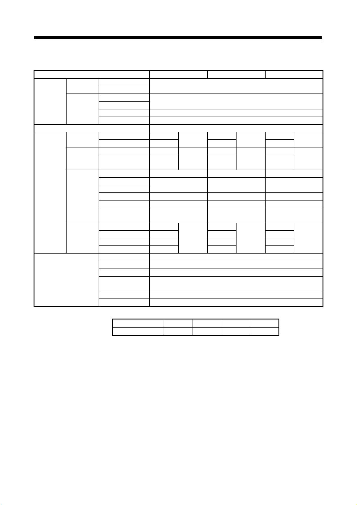
1.3 Restrictions by the software's version or serial number
There are restrictions in the function that can be used by the version of the operating
system software and programming software, or the serial number of Motion controller.
Function
Mark detection function 00H 1.06G
Q170MCPU's internal I/F
(I/O signals (DI/DO))
Q170MCPU's internal I/F
(Manual pulse generator, Incremental
synchronous encoder)
MC protocol communication 00H 1.06G — APPENDIX 1.6
Incremental synchronous encoder
current value in real mode
(Note-1): SV13/SV22 is the completely same version.
(Note-2): The operating system software version can be confirmed in the operating system software (CD-ROM), installation display of
MT Developer2 or system monitor of GX Developer. (Refer to Section 2.2 or 2.3.)
(Note-3): Be sure to use the Motion controller since the first digit "F" of serial number. The serial number can be confirmed with the rated
plate, or on the front of Motion controller. (Refer to Section 2.2.)
The combination of each version and a function is shown below.
Operating system
software version
(Note-1), (Note-2)
00H 1.06G
00H 1.06G —
00H — — APPENDIX 1.9
Programming software version
(MELSOFT MT Works2)
Serial number of
Motion controller
F********
F********
—: There is no restriction by the version.
(Note-3)
(Note-3)
Section of reference
APPENDIX 1.10
Section 2.5.1
1 - 10
Page 30
2 SYSTEM CONFIGURATION
2. SYSTEM CONFIGURATION
This section describes the Motion controller (Q170MCPU) system configuration,
precautions on use of system and configured equipments.
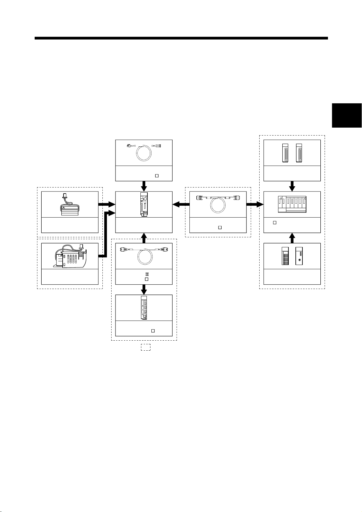
2.1 Motion System Configuration
(1) Equipment configuration in Q170MCPU system
Forced stop input cable
(Q170DEMICBL M)
(Note-1)
MITSUBISHI
LITHIUM BATTERY
PROGRAMMABLE CONTROLLER
Q6BAT
TYPE
Battery
(Q6BAT)
Motion controller
(Q170MCPU)
Extension cable
(QC B)
Extension of the Q series module
Motion module
(Q172DLX, Q173DPX)
Q5 B extension base unit
(Q52B, Q55B)
2
(Note-2)
MITSUBISHI
LITHIUM BATTERY
PROGRAMMABLE CONTROLLER
Large capacity battery holder
(Q170MBAT-SET)
PUSH
Q7BATTYPE
SSCNET cable
(MR-J3BUS M(-A/-B))
Servo amplifier
(MR-J3(W)- B)
It is possible to select the best according to the system.
(Note-1): Be sure to install the Battery (Q6BAT) to the Battery holder.
(It is packed together with Q170MCPU.)
(Note-2): Large capacity battery use (Q7BAT is included), sold separately.
I/O module/Intelligent
function module of the
Q series
2 - 1
Page 31

2 SYSTEM CONFIGURATION
(2) Peripheral device configuration for the Q170MCPU
The following (a)(b)(c) can be used.
(a) USB configuration (b) RS-232 configuration (c) Ethernet configuration
Motion controller
(Q170MCPU)
USB cable
Personal computer Personal computer
Motion controller
(Q170MCPU)
RS-232 communication cable
(QC30R2)
Personal computer
Part name Connection type Cable type Ethernet standard Module name
Connection with HUB Straight cable
Ethernet cable
Direct connection Crossover cable
(Note-1): Corresponding Ethernet cables
10BASE-T
100BASE-TX
10BASE-T
100BASE-TX
[Selection criterion of cable]
• Category : 5 or higher
• Diameter of lead : AWG26 or higher
• Shield : Copper braid shield and drain wire
Copper braid shield and aluminium layered type shield
Compliant with Ethernet standards, category 5 or higher.
• Shielded twisted pair cable (STP cable)
Motion controller
(Q170MCPU)
Ethernet cable
(Note-1)
2 - 2
Page 32

2 SYSTEM CONFIGURATION
2.1.1 Q170MCPU System overall configuration
Motion controller
Q170MCPU
USB/RS-232
PERIPHERAL I/F
Personal computer
IBM PC/AT
Forced stop input cable
(Q170DEMICBL M)
Forced stop input (24VDC)
GOT
24VDC
Extension cable
(QC B)
Extension base unit
(Q52B/Q55B)
Up to 1 extension
Q172DLX Q173DPX/QX
Panel personal computer
SSCNET cable
(MR-J3BUS M(-A/-B))
SSCNET
M
E
Manual pulse generator/
P
Incremental synchronous encoder
1 module
Input signal/Mark detection input signal (4 points)
Output signal (2 points)
(Note)
Motion CPU area
control module
Servo ext ernal
signals
interface module
Manual pulse
generator
interface module
P
FLS : Upper stroke limit
RLS : Lower stroke limit
STOP : Stop signal
DOG/CHANGE : Proximity dog/Speed-position switching
PLC CPU area
control module
I/O module/
Intelligent function
QY
module
(Up to 512 points)
Input/output (Up to 256 points)
Manual pulse generator/Incremental synchronous encoder 3/module
(MR-HDP01)
External input signals Number of Inputs
M
E
MR-J3- B model Servo amplifier, Up to 16 axes
(Note): Interrupt module (QI60) and analog I/O
module (Q6 AD/Q6 DA) can also be
used as the Motion CPU area control
module.
d02 d03 d16d01
M
E
External input sign als of servo amplifi er
Proximity dog/Speed-position switching
Upper stroke limit
Lower stroke limit
8 axes/module
M
E
CAUTION
Construct a safety circuit externally of the Motion controller or servo amplifier if the abnormal
operation of the Motion controller or servo amplifier differ from the safety directive operation in the
system.
The ratings and characteristics of the parts (other than Motion controller, servo amplifier and
servomotor) used in a system must be compatible with the Motion controller, servo amplifier and
servomotor.
Set the parameter values to those that are compatible with the Motion controller, servo amplifier,
servomotor and regenerative resistor model and the system application. The protective functions
may not function if the settings are incorrect.
2 - 3
Page 33

2 SYSTEM CONFIGURATION
2.1.2 Q170MCPU System internal configuration
(1) What is Multiple CPU system for Q170MCPU ?
A Multiple CPU system for Q170MCPU is a system in which between the PLC
CPU area and Motion CPU area are connected with the Multiple CPU high speed
bus in order to control the I/O modules and intelligent function modules.
PLC CPU area is fixed as CPU No.1, and Motion CPU area is fixed as CPU
No.2.
And, the Motion CPU area controls the servo amplifiers connected by SSCNET
cable.
PLC CPU area (CPU No.1 fixed) Motion CPU area (CPU No.2 fixed)
Motion controller
Power supply
24VDC
Personal computer
GX Developer
MT Developer2
PLC control
processor
PLC I/O module
(DI/O)
Device memory Device memory
Multiple CPU
high speed
transmission
memory
Multiple CPU
high speed
bus
Multiple CPU
high speed
transmission
memory
Motion control
processor
Q series PLC system bus
PLC intelligent
function module
(A/D, D/A, Network etc.)
Manual pulse generator/Incremental
synchronous encoder 1 module
Input signal/Mark detection input signal (4 points)
Output signal (2 points)
Motion module
(Proximity dog signal, manual
pulse generator input)
Forced stop input (24VDC)
P
PERIPHERAL I/F
Personal computer
MT Developer2
SSCNET
Servo
amplifier
M
Servo external
input signals
(FLS, RLS, DOG)
Servomotor
M
(a) The device memory is the memory area for the bit devices (X, Y, M, etc.)
and word devices (D, W, etc.).
(b) The Multiple CPU high speed transmission memory between the PLC CPU
area and Motion CPU area can be communicated at 0.88ms cycles.
2 - 4
Page 34

2 SYSTEM CONFIGURATION
2.1.3 Function explanation of the Q170MCPU Motion controller
(1) Whole
(a) The Multiple CPU high speed bus is equipped with between the PLC CPU
area and Motion CPU area. With this reserved Multiple CPU high speed bus,
data transfer of 0.88ms period is possible for up to 14k words.
(b) Data transfer between the PLC CPU area and Motion CPU area is possible
by Multiple CPU high speed transmission memory or automatic refresh.
(c) The Multiple CPU high speed transmission cycle is synchronized with the
motion control cycle thus optimizing the control system.
(2) PLC CPU area
(a) The I/O modules, analog I/O modules, pulse I/O modules, positioning
modules, information modules and network can be controlled with the
sequence program.
(b) The device data access and program start of the Motion CPU area can be
executed by the Motion dedicated PLC instructions.
(c) The real-time processing can be realized by the Multiple CPU synchronous
interrupt program.
(3) Motion CPU area
(a) Up to 16 axes servo amplifiers per 1 system can be controlled in
Q170MCPU.
(b) It is possible to set the program which synchronized with the motion
operation cycle and executed at fixed cycle (0.44[ms], 0.88[ms], 1.77[ms],
3.55[ms], 7.11[ms], 14.2[ms]).
(c) It is possible to execute a download of servo parameters to servo amplifier,
servo ON/OFF to servo amplifier and position commands, etc. by connecting
between the Q170MCPU and servo amplifier with SSCNET
(d) It is possible to select the servo control functions/programming languages by
installing the corresponding operating system software in the Q170MCPU.
(e) Motion modules (Q172DLX/Q173DPX) are controlled with the Motion CPU
area, and the signals such as stroke limit signals connected to Motion
modules and incremental synchronous encoder can be used as motion
control.
(f) The synchronous control can be executed by using the incremental
synchronous encoder (up to 8 axes). The incremental synchronous encoder
(1 axis) built-in Q170MCPU can also be used.
(g) The stroke limit signals and proximity dog signals connected to the servo
amplifiers can be used for the motion control.
(h) I/O controls (DI 4 points, DO 2 points) built-in Q170MCPU (Motion CPU
area) can be realized.
cable.
2 - 5
Page 35

2 SYSTEM CONFIGURATION
(i) PLC I/O modules can be controlled with the Motion CPU area.
(Refer to Section 2.3(2).)
(j) Wiring is reduced by issuing the external signal (upper/lower stroke limit
signal, proximity dog signal) via the servo amplifier.
2 - 6
Page 36

2 SYSTEM CONFIGURATION
2.1.4 Restrictions on Motion controller
(1) Only extension base unit (Q52B/Q55B) of type not requiring power supply module
can be used.
(2) Q170MCPU Multiple CPU system is composed of the PLC CPU area (CPU No.1
fixed) and Motion CPU area (CPU No.2 fixed). Other CPU (CPU No.3, CPU No.4)
cannot be set.
(3) It takes about 10 seconds to startup (state that can be controlled) of Motion
controller. Make a Multiple CPU synchronous startup setting suitable for the
system.
(4) Execute the automatic refresh of the Motion CPU area and PLC CPU area by
using the automatic refresh of Multiple CPU high speed transmission area setting.
(5) The Motion modules, I/O modules and intelligent function modules, etc. can be
installed on the extension base unit only.
(6) The CPU modules cannot be installed on the extension base unit.
(7) When using the GOT with bus connection, connect the GOT after the extension
base unit of stage 1 in the case with the extension base unit use, and connect
directly to the Motion controller in the case with the extension base unit unused.
(8) The synchronous encoder interface module Q172DEX/Q172EX(-S1/-S2/-S3)
cannot be used.
(9) Be sure to control the Motion modules (Q172DLX, Q173DPX) with the Motion
CPU area. They will not operate correctly if PLC CPU area is set by mistake.
(10) Q172LX/Q173PX(-S1) for Q173HCPU(-T)/ Q172HCPU(-T)/Q173CPUN(-T)/
Q172CPUN(-T)/Q173CPU/Q172CPU cannot be used.
(11) Motion CPU area cannot be set as the control CPU of intelligent function module
(except some modules) or Graphic Operation Terminal(GOT).
(12) Be sure to set the battery.
(13) There are following methods to execute the forced stop input.
• Use a EMI connector of Q170MCPU.
• Use a device set in the forced stop input setting of system setting
(14) Forced stop input for EMI connector of Q170MCPU cannot be invalidated by the
parameter.
When the device set in the forced stop input setting is used without use of EMI
connector of Q170MCPU, apply 24VDC voltage on EMI connector and invalidate
the forced stop input of EMI connector.
2 - 7
Page 37

2 SYSTEM CONFIGURATION
(15) Be sure to use the cable for forced stop input. The forced stop cannot be
released without using it. Fabricate the cable for forced stop input on the
customer side or purchase our products (sold separately).
(16) When the operation cycle is 0.4[ms], set the system setting as the axis select
rotary switch of servo amplifier "0 to 7".
If the axis select rotary switch of servo amplifier "8 to F" is set, the servo
amplifiers are not recognized.
(Note): The setting of axis select rotary switch differs according to the servo
(17) When the extension base units are used, make sure to configure the modules so
that the total current consumption of the Q170MCPU and individual modules on
the extension base do not exceed the 5VDC output capacity of Q170MCPU
power supply.
(18) The module name displayed by "System monitor" - "Product information list" of
GX Developer is different depending on the function version of Motion modules
(Q172DLX, Q173DPX).
(Note): Even if the function version "C" is displayed, it does not correspond to
Module name
Q172DLX Q172LX Q172DLX
Q173DPX MOTION-UNIT Q173DPX
amplifier. Refer to the "Servo amplifier Instruction Manual" for details.
the online module change.
Model display
Function version "B" Function version "C"
2 - 8
Page 38

2 SYSTEM CONFIGURATION
2.2 Checking Serial Number and Operating System Software Version
Checking for the serial number of Motion controller and Motion module, and the
operating system software version are shown below.
2.2.1 Checking serial number
(1) Motion controller (Q170MCPU)
(a) Rating plate
The rating plate is situated on the side face of the Motion controller.
(b) Front of Motion controller
The serial number is printed in the projection parts forward of the lower side
of Motion controller.
MITSUBISHI
MODE
ERR.
USER
BAT.
PULL
BOOT
USB
Q170MCPU
RUN
POWER
STOPRESET RUN
Rating plate
Serial number
MITSUBISHI
MOTION CONTROLLER
MODEL
Q170MCPU
SERIAL
B8Y054306
80M1 IND. CONT. EQ
U
C
L
US LISTED
MITSUBISHI ELECTRIC
JAPAN
RS-232
EMI
PASSED
PUSH
CARD
EJECT
FRONT
OUT
EXT.IO
24VDC
B8Y0 5 4 3 06
PERIPHERAL I/F
CN1
Serial number
(c) System monitor (product information list)
The serial number can be checked on the system monitor screen in
GX Developer. (Refer to Section 2.2.2.)
2 - 9
Page 39

r
2 SYSTEM CONFIGURATION
(2) Motion module (Q172DLX/Q173DPX)
(a) Rating plate
The rating plate is situated on the side face of the Motion module.
(b) Front of Motion module
The serial No. is printed in the projection parts forward of the lower side of
Motion module.
Q172DLX
Serial number
Q172DLX
CTRL
B86054999
MITSUBISHI
MOTION I/F UNIT
MODEL
Q172DLX
12/24VDC 2/4mA
SERIAL
B86054999
80M1 IND. CONT. EQ.
U
C
L
US LISTED
MITSUBISHI ELECTRIC
CLASS2 ONLY
JAPAN
PASSED
Rating plate
Serial numbe
REMARK
The serial number display was corresponded from the Motion modules
manufactured in early April 2008.
2 - 10
Page 40

2 SYSTEM CONFIGURATION
2.2.2 Checking operating system software version
The operating system software version can be checked on the system monitor screen
in GX Developer.
Select [Product Inf. List] button on the system monitor screen displayed on
[Diagnostics] – [System monitor] of GX Developer.
Serial number of
Motion controller
Operating system software version
2 - 11
Page 41

2 SYSTEM CONFIGURATION
2.3 System Configuration Equipment
Part name Model name
(1) Motion controller related module
(Note-1)
Motion controller Q170MCPU
Servo external
signals interface
Q172DLX
module
Manual pulse
generator interface
Q173DPX
module
Manual pulse
generator
MR-HDP01
Battery Q6BAT
Large capacity
battery
Large capacity
battery holder
Internal I/F
connector set
Cable for forced
stop input
(Note-3)
Q7BAT
Q170BAT-SET Battery holder for Q7BAT (Attachment Q7BAT) ——
Q170MIOCON
Q170DEMICBL
Connector for
forced stop input
Q170DEMICON
cable
24VDC power
supply cable
Q170MPWCBL2M Length 2m(6.56ft.), With solderless terminal R1.25-3.5 ——
Q170MPWCBL2M-E
24VDC power
supply connector
(Note-3)
set
Extension base
(Note-4)
unit
Q170MPWCON
Q52B
Q55B
Description
Power supply, PLC CPU, Motion CPU, all-in-one type
(Attachment battery (Q6BAT), Internal I/F connector, 24VDC power
supply connector and connector for forced stop input cable)
• Motion CPU area
Up to 16 axes control, Operation cycle 0.44[ms] or more, Servo
program capacity 16k steps, Internal I/F (Incremental synchronous
encoder interface 1ch, Input signal/Mark detection input signal 4
points, Output signal 2 points)
• PLC CPU area
Program capacity 20k steps, LD instruction processing speed 0.02μs
Servo external signal input 8 axes
(FLS, RLS, STOP, DOG/CHANGE×8)
Manual pulse generator MR-HDP01/Incremental synchronous encoder
interface ×3, Tracking input 3 points
Pulse resolution: 25PLS/rev(100PLS/rev after magnification by 4)
Permitted axial loads Radial load: Up to 19.6N
Thrust load: Up to 9.8N
Permitted speed: 200r/min(Normal rotation), Voltage-output
For memory data backup of RAM built-in Motion controller
Nominal current: 1800mAh
For memory data backup of RAM built-in Motion controller
Nominal current: 5000mAh
Incremental synchronous encoder/Mark detection signal interface
connector (Packed together Q170MCPU)
Length 0.5m(1.64ft), 1m(3.28ft), 3m(9.84ft), 5m(16.40ft), 10m(32.81ft),
M
15m(49.21ft), 20m(65.62ft), 25m(82.02ft), 30m(98.43ft)
Connector for forced stop input cable production
(Packed together Q170MCPU)
Length 2m(6.56ft.), With solderless terminal R1.25-3.5,
With EMI connector
Connector for 24VDC power supply cable
(Packed together Q170MCPU)
Number of I/O modules installed 2 slots, type not requiring power supply
module
Number of I/O modules installed 5 slots, type not requiring power supply
module
Current
consumption
5VDC[A]
(Note-2)
2.0
0.06
0.38
0.06
——
——
——
——
——
——
0.08
0.10
Remark
2 - 12
Page 42

2 SYSTEM CONFIGURATION
Part name Model name
Extension cable
SSCNET cable
Motion controller related module (continued)
(Note-1)
Description
QC05B Length 0.45m(1.48ft.)
QC06B Length 0.6m(1.97ft.)
QC12B Length 1.2m(3.94ft.)
QC30B Length 3m(9.84ft.)
QC50B Length 5m(16.40ft.)
QC100B Length 10m(32.81ft.)
• Q170MCPU
MR-J3BUS M
MR-J3BUS M-A
MR-J3BUS
(Note-5)
(Note-1) : =Cable length (015: 0.15m(0.49ft.), 03: 0.3m(0.98ft.), 05: 0.5m(1.64ft.), 1: 1m(3.28ft.), 2: 2m(6.56ft.),
(Note-2) : The manual pulse generator or incremental synchronous encoder that consumes less than 0.2[A] of
current can be connected to the internal I/F connector.
(Note-3) : Be sure to use the cable for forced stop input (sold separately). The forced stop cannot be released
(Note-4) : 5VDC internal current consumption of shared equipments with PLC might be changed.
Be sure to refer to the MELSEC-Q series PLC Manuals.
(Note-5) : Please contact your nearest Mitsubishi sales representative for the cable of less than 30m(98.43ft.).
• Standard cord for inside panel
0.15m(0.49ft.), 0.3m(0.98ft.), 0.5m(1.64ft.), 1m(3,28ft.), 3m(9.84ft.)
• Q170MCPU
• Standard cable for outside panel
5m(16.40ft.), 10m(32.81ft.), 20m(65.62ft.)
• Q170MCPU
M-B
• Long distance cable
30m(98.43ft.), 40m(131.23ft.), 50m(164.04ft.)
without using it.
Cable for forced stop input is not attached to the Motion controller. Please purchase the cable for length
according to system separately.
Current
consumption
5VDC[A]
——
MR-J3(W)- B/MR-J3(W)- B MR-J3(W)- B
——
MR-J3(W)- B/MR-J3(W)- B MR-J3(W)- B
——
MR-J3(W)- B/MR-J3(W)- B MR-J3(W)- B
——
3: 3m(9.84ft.), 5: 5m(16.40ft.), 10: 10m(32.81ft.), 20: 20m(65.62ft.), 25: 25m(82.02ft.),
30: 30m(98.43ft.), 40: 40m(131.23ft.), 50:50m(164.04ft.)
Remark
2 - 13
Page 43

2 SYSTEM CONFIGURATION
(2) PLC module which can be controlled by Motion CPU area
Part name Model name Description
AC QX10 100-120VAC, 7-8mA, 16 points, Terminal block
QX40 24VDC/4mA, Positive common, 16 points, Terminal block
High response, 24VDC/6mA, Positive common, 16 points,
Terminal block
High speed, 24VDC/6mA, Positive common, 16 points,
Terminal block
High response, 24VDC/4mA, Positive common, 32 points,
Connector
High response, 24VDC/4mA, Positive common, 64 points,
Connector
12VDC/5V, Positive common/Negative common shared,
16 points, Terminal block
High speed, 5VDC/6mA, Positive common, 16 points,
Terminal block
12VDC/5V, Positive common/Negative common shared,
32 points, Terminal block
12VDC/5V, Positive common/Negative common shared,
64 points, Terminal block
High speed, 24VDC/6mA, Negative common, 16 points,
Terminal block
High response, 24VDC/4mA, Negative common, 64 points,
Connector
High speed, 5VDC/6mA, Negative common, 16 points,
Terminal block
240VAC/24VDC, 2A/point, 8A/common,
16 points/common, Terminal block
12V/24VDC, 0.1A/point, 1.6A/common, 16 points/common,
Terminal block
12V/24VDC, 0.1A/point, 2A/common, 32 points/common,
Connector
12V/24VDC, 0.1A/point, 2A/common,
64 points(32 points/common), Connector
12V/24VDC, 0.5A/point, 4A/common,
16 points(16 points/common), Terminal block
12V/24VDC, 0.5A/point, 4A/common,
16 points(16 points/common), Terminal block
12V/24VDC, 0.1A/point, 2A/common,
32 points(32 points/common), Connector
5/12VDC, 16mA/point, 16 points(16 points/common),
Terminal block
5/12VDC, 16mA/point, 32 points(32 points/common),
Connector
Input
module
Output
module
DC
Contact output
module
Sink
Type
Transistor
Source
Type
TTL•CMOS
(Sink)
QX40-S1
QX40H
QX41 24VDC/4mA, Positive common, 32 points, Connector
QX41-S1
QX42 24VDC/4mA, Positive common, 64 points, Connector
QX42-S1
QX70
QX70H
QX71
QX72
QX80 24VDC/4mA, Negative common, 16 points, Terminal block
QX80H
QX81 24VDC/4mA, Negative common, 32 points, Connector
QX82-S1
QX90H
QY10
QY40P
QY41P
QY42P
QY50
QY80
QY81P
QY70
QY71
Current consumption
5VDC[A]
(Note-1)
0.05
(TYP, All points ON)
0.05
(TYP, All points ON)
0.06
(TYP, All points ON)
0.08
(TYP, All points ON)
0.075
(TYP, All points ON)
0.075
(TYP, All points ON)
0.09
(TYP, All points ON)
0.09
(TYP, All points ON)
0.055
(TYP, All points ON)
0.08
(TYP, All points ON)
0.07
(TYP, All points ON)
0.085
(TYP, All points ON)
0.05
(TYP, All points ON)
0.08
(TYP, All points ON)
0.075
(TYP, All points ON)
0.09
(TYP, All points ON)
0.08
(TYP, All points ON)
0.43
(TYP, All points ON)
0.065
(TYP, All points ON)
0.105
(TYP, All points ON)
0.15
(TYP, All points ON)
0.08
(TYP, All points ON)
0.08
(TYP, All points ON)
0.095
(TYP, All points ON)
0.095
(TYP, All points ON)
0.15
(TYP, All points ON)
Remark
(Note-2)
(Note-2)
(Note-2)
(Note-2)
(Note-2)
(Note-2)
(Note-2)
(Note-2)
(Note-2)
(Note-2)
2 - 14
Page 44

2 SYSTEM CONFIGURATION
Part name Model name Description
Input/Output
composite
module
Interrupt module QI60 24VDC/4mA, Positive common, 16 points, Terminal block
Analogue module
DC Input/
Transistor
output
PLC module which can be controlled by Motion CPU area(continued)
24VDC Positive common: 32 points
QH42P
QX48Y57
Q62AD-DGH
Q64AD 4ch, A/D conversion, Voltage • Current input 0.63
Q64AD-GH
Q68ADV 8ch, A/D conversion, Voltage input 0.64
Q68ADI 8ch, A/D conversion, Current input 0.64
Q62DA 2ch, D/A conversion, Voltage • Current output 0.33
Q62DA-FG
Q64DA 4ch, D/A conversion, Voltage • Current output 0.34
Q68DAV 8ch, D/A conversion, Voltage output 0.39
Q68DAI 8ch, D/A conversion, Current output 0.38
12-24VDC/0.1A Output Sink type: 32 points, Connector,
Provided (Thermal protectors, protector against short
circuit)
24VDC Positive common: 8 points
12-24VDC/0.5A Output Sink type: 7 points, Terminal block,
Provided (When face is broken, LED lights and signal is
output to CPU)
2ch, A/D conversion,
Current input (Channel-isolated • High resolution)
4ch, A/D conversion,
Voltage • Current input (Channel-isolated • High resolution)
2ch, D/A conversion,
Voltage • Current output (Channel-isolated)
(Note-1) : 5VDC internal current consumption of shared equipments with PLC might be changed.
Be sure to refer to the MELSEC-Q series PLC Manuals.
(Note-2) : Connectors are not provided.
(3) PLC module which can be controlled by PLC CPU area
They are the same modules as the PLC modules which can be controlled by the
universal model QCPU "Q03UDCPU".
Refer to the MELSEC-Q series PLC Manuals.
(4) Servo amplifier
Part name Model name Description Remarks
MR-J3- B
MR-J3W- B For 2-axis type
MR-J3 series
servo amplifier
Battery MR-J3BAT
MR-J3- B-RJ006 For fully closed control
MR-J3- B-RJ004 For linear servo motor
MR-J3- B-RJ080W For direct drive motor
MR-J3-
BS For safety servo
Back-up for the absolute
position detection
Refer to the servo amplifier instruction
manuals.
Current consumption
5VDC[A]
(TYP, All points ON)
(TYP, All points ON)
(TYP, All points ON)
(Note-1)
0.13
0.08
0.06
0.33
0.89
0.37
Remark
(Note-2)
2 - 15
Page 45

2 SYSTEM CONFIGURATION
(5) Operating system software
Application Software package
Conveyor assembly use SV13
Automatic machinery use SV22
(a) Operating system type/version
1) Confirmation method in the operating system (CD-ROM)
(b) Confirmation method in MT Developer2
The operating system(OS) type/version of connected Motion controller is
displayed on the installation screen of MT Developer2.
(OS software)
SW8DNC-SV13QG
SW8DNC-SV22QF
a)
b)
c)
a) OS software type
b) OS software version
c) Serial number
Example) When using Q170MCPU, SV22 and OS version 00G.
a) SW8DNC-SV22QF
b) 00G
SV2 2QFVER00G
F or G: Q170MCPU
3: Motion SFC compatibility
. : Motion SFC not compatibility
3
OS version
2 - 16
Page 46

2 SYSTEM CONFIGURATION
(6) Programming software packages
(a) Motion controller engineering environment
MELSOFT MT Works2
(MT Developer2
(Note-1) : This software is included in Motion controller engineering environment "MELSOFT MT Works2".
(b) PLC software package
(c) Servo set up software package
MR Configurator MRZJW3-SETUP221E
POINTS
When the operation of WindowsR is not unclear in the operation of this software,
refer to the manual of Windows
(Note): Windows
Corporation in the United States and/or other countries.
Part name Model name
)
(Note-1
)
Model name Software package
GX Developer SW8D5C-GPPW-E
Model name Software package
SW1DNC-MTW2-E
R
R
is either registered trademarks or trademarks of Microsoft
or guide-book from the other supplier.
2 - 17
Page 47

2 SYSTEM CONFIGURATION
2.4 General Specifications
Item Specification
Operating ambient temperature 0 to 55°C (32 to 131°F)
Storage ambient temperature -25 to 75°C (-13 to 167°F)
Operating ambient humidity 5 to 95% RH, non-condensing
Storage ambient humidity 5 to 95% RH, non-condensing
Vibration resistance
Shock resistance 147m/s2 , 3 times in each of 3 directions X, Y, Z
Operating ambience No corrosive gases
Operating altitude 2000m(6561.68ft.) or less
Mounting location Inside control panel
General specifications of the Motion controller are shown below.
(Note-3)
Frequency Acceleration Amplitude Sweep count
Under intermittent
vibration
Under continuous
vibration
5 to 9Hz ——
9 to 150Hz 9.8m/s
5 to 9Hz ——
9 to 150Hz 4.9m/s
2
——
2
——
3.5mm
(0.138inch)
1.75mm
(0.069inch)
10 times each
in X, Y, Z
directions
(For 80 min.)
Overvoltage category
Pollution level
(Note-1) : This indicates the section of the power supply to which the equipment is assumed to be connected between the
public electrical power distribution network and the machinery within premises.
Category
The surge voltage withstand level for up to the rated voltage of 300V is 2500V.
(Note-2) : This index indicates the degree to which conductive material is generated in terms of the environment in which
the equipment is used.
Pollution level 2 is when only non-conductive pollution occurs. A temporary conductivity caused by condensing
must be expected occasionally.
(Note-3) : Do not use or store the Motion controller under pressure higher than the atmospheric pressure of altitude 0m.
Doing so can cause an operation failure.
(Note-1)
II or less
(Note-2)
2 or less
applies to equipment for which electrical power is supplied from fixed facilities.
CAUTION
The Motion controller must be stored and used under the conditions listed in the table of
specifications above.
When not using the module for a long time, disconnect the power line from the Motion controller
or servo amplifier.
Place the Motion controller and servo amplifier in static electricity preventing vinyl bags and store.
When storing for a long time, please contact with our sales representative.
Also, execute a trial operation.
2 - 18
Page 48

2 SYSTEM CONFIGURATION
2.5 Specifications of Equipment
2.5.1 Q170MCPU Motion controller
This section describes the specification of the Motion controller.
(1) Basic specifications of Q170MCPU
Item Specification
Input voltage
(Note-1), (Note-2)
24VDC power supply
5VDC internal power
supply
Efficiency 80% (TYP)
Input method Connector
Allowable momentary power failure immunity
(Note-4), (Note-5)
Mass [kg] 0.9
Exterior dimensions [mm(inch)] 178 (7.01)(H) 52 (2.05)(W) 135 (5.31)(D)
POINTS
Inrush current
(Note-3)
Max. input current 1.36A
Max. supplied current 4.0A (Included Q170MCPU current consumption)
Q170MCPU current
consumption
(24VDC +/ -10%, ripple ratio 5% or less)
100A 1ms or less (at 24VDC input)
(Manual pulse generator/Incremental synchronous
21.6 to 26.4VDC
2.0A
encoder: 0.2A)
10ms (at 24VDC input)
(Note-1) : Input power supply
Q170MCPU is rated for use with a 24VDC input power only. The
Q170MCPU breaks down when 28VDC or more input.
(Note-2) : Select 24VDC power supply and electric wire within the range of 21.6 to
26.4VDC including any input ripple or spike voltage measured at the
input connector of the Q170MCPU.
(Note-3) : Inrush current
Take care that the inrush current of several amperes may flow when the
sharp square voltage is applied, or the power supply is turned ON with
the mechanical switch.
When selecting a fuse and breaker in the external circuit, take account of
the blow out, detection characteristics and above matters.
(Note-4) : Allowable momentary power failure period
(Note)
(1) An instantaneous power failure lasting less than 10ms
will cause
24VDC down to be detected, but operation will continue.
(Note)
(2) An instantaneous power failure lasting in excess of 10ms
may
cause the operation to continue or initial start to take place
depending on the power supply load.
(Note) : This is for a 24VDC input. This is 10ms or less for less than
24VDC.
(Note-5) : Select 24VDC power supply with allowable momentary power failure
period of 20ms or more.
2 - 19
Page 49

2 SYSTEM CONFIGURATION
(2) Motion control specifications/performance specifications
Item Specification
Number of control axes Up to 16 axes
SV13
Operation cycle
(default)
Interpolation functions
Control modes
Acceleration/
deceleration control
Compensation Backlash compensation, Electronic gear, Phase compensation (SV22)
Programming language Motion SFC, Dedicated instruction, Mechanical support language (SV22)
Servo program capacity 16k steps
Number of positioning
points
Peripheral I/F USB/RS-232 (PLC CPU area), PERIPHERAL I/F (Motion CPU area)
Home position return
function
JOG operation function Provided
Manual pulse generator
operation function
Synchronous encoder
operation function
M-code function
Limit switch output
function
ROM operation function Provided
External input signal Q172DLX or External input signals (FLS/RLS/DOG) of servo amplifier
High-speed reading
function
Forced stop
Number of I/O points Total 256 points (Internal I/F (Input 4 points, output 2 points) + I/O module)
Mark detection function Provided
Clock function Provided
SV22
(a) Motion control specifications
0.44ms/ 1 to 6 axes
0.88ms/ 7 to 16 axes
0.44ms/ 1 to 4 axes
0.88ms/ 5 to 12 axes
1.77ms/13 to 16 axes
Linear interpolation (Up to 4 axes), Circular interpolation (2 axes),
Helical interpolation (3 axes)
PTP (Point to Point) control, Speed control, Speed-position control (External input signal
(DOG) of servo amplifier usable), Fixed-pitch feed, Constant speed control,
Position follow-up control, Speed control with fixed position stop, Speed switching control,
High-speed oscillation control, Synchronous control (SV22)
Automatic trapezoidal acceleration/deceleration,
S-curve acceleration/deceleration
3200 points
(Positioning data can be designated indirectly)
Proximity dog type (2 types), Count type (3 types, External input signal (DOG) of servo
amplifier usable), Data set type (2 types), Dog cradle type, Stopper type (2 types),
Limit switch combined type
Home position return re-try function provided, home position shift function provided
Possible to connect 3 channels (Q173DPX use)
Possible to connect 1 channel (Q170MCPU's internal I/F use)
Possible to connect 8 channels (SV22 use, Incremental only)
M-code output function provided,
M-code completion wait function provided
Number of output points 32 points
Watch data: Motion control data/Word device
Provided
(Via internal I/F/input module, Via tracking of Q173DPX)
Motion controller forced stop (EMI connector, System setting),
Forced stop terminal of servo amplifier
(Note-1)
(Note-2)
2 - 20
Page 50

2 SYSTEM CONFIGURATION
Item Specification
Security function Provided
All clear function Provided
Remote operation Remote RUN/STOP, Remote latch clear
Digital oscillation function Provided
Absolute position system
Number of SSCNET
systems
Motion related interface
module
(Note-1) : When the manual pulse generator is used with the Q170MCPU's internal I/F, do not set the Q173DPX in the
(Note-2) : Any incremental synchronous encoder connected to the Q170MCPU's internal I/F will automatically be assigned
(Note-3) : The servo amplifiers for SSCNET cannot be used.
(Note-4) : When using the incremental synchronous encoder (SV22 use), you can use above number of modules.
(Note-3)
System Settings.
an Axis No. one integer greater than the number of encoders connected to any Q173DPX modules.
When connecting the manual pulse generator, you can use only 1 module.
Motion control specifications (continued)
Made compatible by setting battery to servo amplifier.
(Possible to select the absolute data method or incremental method for each axis)
1 system
Q172DLX : 2 module usable
Q173DPX : 3 modules usable
(Note-4)
2 - 21
Page 51

2 SYSTEM CONFIGURATION
Motion SFC program capacity
Motion SFC program
Operation control program
(F/FS)
/
Transition program
(G)
Execute specification
Number of I/O points (X/Y) 8192 points
Number of real I/O points (X/Y)
Number of devices
(Device In the Motion CPU
area only)
(Included the positioning
dedicated device)
(b) Motion SFC performance specifications
Item Specification
Code total
(Motion SFC chart + Operation control +
Transition)
Text total
(Operation control + Transition)
Number of Motion SFC programs 256 (No.0 to 255)
Motion SFC chart size/program Up to 64k bytes (Included Motion SFC chart comments)
Number of Motion SFC steps/program Up to 4094 steps
Number of selective branches/branch 255
Number of parallel branches/branch 255
Parallel branch nesting Up to 4 levels
Number of operation control programs
Number of transition programs 4096(G0 to G4095)
Code size/program Up to approx. 64k bytes (32766 steps)
Number of blocks(line)/program Up to 8192 blocks (in the case of 4 steps(min)/blocks)
Number of characters/block Up to 128 (comment included)
Number of operand/block Up to 64 (operand: constants, word device, bit devices)
( ) nesting/block Up to 32 levels
Descriptive
expression
Number of multi execute programs Up to 256
Number of multi active steps Up to 256 steps/all programs
Executed
task
Internal relays (M) 12288 points
Link relays (B) 8192 points
Annunciators (F) 2048 points
Special relays (SM) 2256 points
Data registers (D) 8192 points
Link registers (W) 8192 points
Special registers (SD) 2256 points
Motion registers (#) 12288 points
Coasting timers (FT)
Multiple CPU area devices (U
Operation control program Calculation expression/bit conditional expression
Transition program
Normal task Execute in main cycle of Motion controller
Event task
(Execution
can be
masked.)
NMI task
Fixed cycle
External
interrupt
PLC interrupt Execute with interrupt instruction (D(P).GINT) from PLC.
\G) Up to 14336 points
(Note): Usable number of points differs according to the system settings.
4096 with F(Once execution type) and FS(Scan execution type)
combined. (F/FS0 to F/FS4095)
Calculation expression/bit conditional expression/
comparison conditional expression
(0.44ms, 0.88ms, 1.77ms, 3.55ms, 7.11ms, 14.2ms)
Execute when input ON is set among interrupt module QI60
Execute when input ON is set among interrupt module QI60
(Internal I/F (Input 4 points, Output 2 points) + I/O module)
543k bytes
484k bytes
Execute in fixed cycle
(16 points).
(16 points).
Total 256 points
1 point (888µs)
(Note)
2 - 22
Page 52

2 SYSTEM CONFIGURATION
PLC CPU area
Control method Sequence program control method
I/O control mode Refresh mode
Sequence control language
Processing speed
(sequence instruction)
Total number of instructions 858
Operation (floating point operation) instruction Yes
Character string processing instruction Yes
PID instruction Yes
Special function instruction (Trigonometric function,
square root, exponential operation, etc.)
Constant scan 0.5 to 2000ms (Setting available in 0.5ms unit.)
Program capacity 20k steps (80k byte)
CPU shared memory
No. of I/O device points (X/Y) 8192 points
No. of I/O points (X/Y)
Internal relay (M) 8192 points
Latch relay (L) 8192 points
Link relay (B) 8192 points
Timer (T) 2048 points
Retentive timer (ST) 0 points
Counter (C) 1024 points
Data register (D) 12288 points
Link register (W) 8192 points
Annunciator (F) 2048 points
Edge relay (V) 2048 points
Link special relay (SB) 2048 points
Link special register (SW)
File register (R, ZR) 98304 points
Step relay (S) 8192 points
Index register/Standard devise register (Z) 20 points
Index register (Z)
(32-bit modification specification of ZR device)
Pointer (P) 4096 points
Interrupt pointer (I) 256 points
Special relay (SM) 2048 points
Special register (SD) 2048 points
Function input (FX) 16 points
Function output (FY) 16 points
Function register (FD) 5 points
Local device Yes
Device initial values Yes
(3) PLC control specifications
Item Specification
Program capacity, number of I/O points and number of extensions
were limited to Q03UDCPU
Relay symbol language (ladder), logic symbolic language (list),
MELSAP3 (SFC), MELSAP-L, Structured text (ST)
LD instruction 0.02 μs
MOV instruction 0.04 μs
PC MIX value (instruction/μs) 28
Floating point addition 0.12 μs
Yes
QCPU standard memory 8k bytes
Multiple CPU high speed
transmission area
(Up to 320 points (64 points
Points by default
(changeable by parameters)
(Index register (Z) is used in double words.)
32k bytes
512 points
5 modules) is usable with I/O module.)
2048 points
Up to 10 points (Z0 to Z18)
2 - 23
Page 53

2 SYSTEM CONFIGURATION
Item Specification
Extension base unit
PC type when program is made by GX Developer Q03UDCPU
PLC control specifications (continued)
Number of extensions 1 extension (Q52B/Q55B usable)
• Extension base unit use : Connection after the extension base unit of
GOT bus connection
• Extension base unit not use : Direct bus connection to Motion controller
stage 1
(4) Q170MCPU names of parts
23)
Side face Front face
17)
19)
MITSUBISHI
MODE
USER
PULL
BOOT
USB
RS-232
EJECT
Q170MCPU
RUN
ERR.
BAT.
EMI
20)
POWER
STOPRESET RUN
1)
4)
5)
6)
PERIPHERAL I/F
CN1
7)
With front cover open,
and battery holder remove
2)
11)
12)
13)
14)
15)
16)
18)
USB
EJECT
MODE
ERR.
USER
BAT.
BOOT
RUN
EMI
SW1 SW2
1
0
F
E
D
C
B
A
8
9
POWER
STOPRESET RUN
1)
1
0
2
2
F
3
3
E
4
4
D
5
5
C
6
6
B
7
7
A
3)
8
9
PERIPHERAL I/F
CN1
25)
Bottom face
EXT.IO
21)
CARD
FRONT
OUT
24VDC
(Note)
PUSH
22)24)
(Note): Unusable
8)
9)
10)
EXT.IO
CARD
FRONT
OUT
24VDC
RIO
2 - 24
Page 54

2 SYSTEM CONFIGURATION
No. Name Application
1) 7-segment LED Indicates the operating status and error information.
Rotary function select 1 switch
2)
(SW1)
Rotary function select 2 switch
3)
(SW2)
"POWER" LED
4)
RUN/STOP/RESET switch
5)
PERIPHERAL I/F connector
6)
SSCNET
7)
Internal I/F connector
8)
24VDC power supply connector The DC power of 24VDC is connected.
9)
Serial number display Displays the serial number described on the rating plate.
10)
"MODE" LED
11)
"RUN" LED
12)
CN1 connector
• Set the operation mode.
(Normal operation mode, Installation mode, Mode operated by ROM, etc)
• Each switch setting is 0 to F.
(Factory default in SW1 "A", SW2 "0" position)
• ON (red) : The internal power (5VDC) is ON.
• OFF : The internal power (5VDC) is OFF.
• Move to RUN/STOP
RUN : Sequence program/Motion SFC program is started.
STOP : Sequence program/Motion SFC program is stopped.
• RESET (Momentary switch)
Set the switch to the "RESET" position 1 second or more to reset the hardware.
For communication I/F with peripheral devices
• Upper LED
Remains flashing : It communicates with the personal computer.
ON : It does not communicate with the personal computer.
• Lower LED
Data transmission speed
ON : 100Mbps
OFF : 10Mbps
(Note-1)
Connector to connect the servo amplifier
Connector to connect the manual pulse generator/incremental synchronous
encoder, or to input/output the signals.
(Voltage-output/open-collector type, Differential-output type)
Indicates the mode of the PLC CPU area.
• ON (green) : Q mode
Indicates the operating status of the PLC CPU area.
• ON : During operation with the RUN/STOP/RESET switch set to "RUN".
• OFF : During stop with the RUN/STOP/RESET switch set to "STOP".
When an error is detected and operation must be halted due to the error.
• Remains flashing : Parameters or programs are written with the RUN/STOP/
RESET switch set to "STOP", and then the RUN/STOP/
RESET switch is turned from "STOP" to "RUN".
• To turn ON the "RUN" LED after writing the program, carry
out the following steps.
1) Set the RUN/STOP/RESET switch in the order of "RUN"
to "STOP" to "RUN".
2) Reset with the RUN/STOP/RESET switch.
3) Power ON the Motion controller again.
• To turn ON the "RUN" LED after writing the parameters,
carry out the following steps.
1) Reset with the RUN/STOP/RESET switch.
2) Power ON the Motion controller again.
(If the RUN/STOP/RESET is set in the order of "RUN" to
"STOP" to "RUN" after changing the parameters, network
parameters and intelligent function module parameters
will not be updated.
2 - 25
Page 55

2 SYSTEM CONFIGURATION
No. Name Application
Indicates the operating status of the PLC CPU area.
• ON : Detection of self-diagnosis error which will not stop operation, except
battery error. (When operation continued at error detection is set in the
13) "ERR." LED
• OFF : Normal
• Remains flashing :Detection of error whose occurrence stops operation.
Indicates the operating status of the PLC CPU area.
14) "USER" LED
• ON : Annunciator (F) turned ON
• OFF : Normal
Indicates the operating status of the PLC CPU area.
• ON (yellow) : Occurrence of battery error due to reduction in battery voltage of the
15) "BAT." LED
• ON (green) : Turned ON for 5 seconds after restoring of data backup to the
• Remains flashing (green): Backup of data to the standard ROM by latch data
• OFF : Normal
Indicates the operating status of the PLC CPU area.
16) "BOOT" LED
• ON : Start of boot operation
• OFF : Non-execution of boot operation
• Connector to connect the peripheral devices for USB connection
17) USB connector
• Connect with the dedicated cable for USB
18) RS-232 connector
Forced stop input connector (EMI)
(Note-2)
19)
• Connector to connect the peripheral devices for RS-232 connection
• Connect with the dedicated cable (QC30R2) for RS-232
Input to stop all axes of servo amplifier in a lump
20) Memory card EJECT button Used to eject the memory card from the Motion controller
21) Memory card loading connector Connector used to load the memory card to the Motion controller
22) Battery holder
23) Module fixing screw hole
24) FG terminal Ground terminal connected with the shield pattern of the printed circuit board
25) Extension cable connector Connector for transfer of signals to/from the extension base unit.
(Note-1) : Put the SSCNET cable in the duct or fix the cable at the closest part to the Motion controller with bundle
material in order to prevent SSCNET
(Note-2) : Be sure to use the cable for forced stop input (sold separately). The forced stop cannot be released without
using it.
If the cable for forced stop input is fabricated on the customer side, make it within 30m(98.43ft.).
(Note-3) : Be sure to set the battery. The data (Refer to Section 6.5.) of RAM built-in Motion controller are not backed up if
the battery cable is not set correctly.
(Note-4) : Purchase the M5 screws.
(Note-3)
Battery holder to set the Q6BAT/Q7BAT
(Note-4)
Hole for screw used to fix to the control panel
parameter setting.)
Resetting with the RUN/STOP/RESET switch becomes valid.
memory card.
standard ROM by the latch data backup is completed.
backup is completed.
(Connector type mini B)
EMI ON (opened) : Forced stop
EMI OFF (24VDC input) : Forced stop release
cable from putting its own weight on SSCNET connector.
2 - 26
Page 56

2 SYSTEM CONFIGURATION
(5) 7-segment LED display
Item 7-segment LED Remark
Start
The LED displays/flashes in the combination with errors.
Initializing
It takes about 10 seconds to initialize
(RUN/STOP display).
Execute the power cycle of the Motion controller
if the operation stopped at initializing. It may be
Motion controller's hardware fault when it is not
improved.
Explain the error symptom (LED display) and get
advice from our sales representative for the
modules with failure.
Normal
Installation mode
Mode operated by
RAM
Operation
mode
STOP
RUN
Battery
error
Operating system software
not installed
Mode operated by
ROM
Early stage warning
(2.7V or less)
Final stage warning
(2.5V or less)
"
" remains flashing Normal operation
Steady "INS" display,
"
" remains flashing
"
" remains flashing
Steady " . " display,
"
" remains flashing
Steady "STP" display
Steady "RUN" display
Steady "BT1" display
Steady "BT2" display
"A00" remains flashing
Mode to install the operating system software via
personal computer.
Mode to operate based on the user programs
and parameters stored in the RAM built-in Motion
controller.
Mode to operate after the user programs and
parameters stored in the FLASH ROM built-in
Motion controller are read to the RAM built-in
Motion controller.
Stopped the Motion SFC program with the PLC
READY flag (M2000) OFF.
Executed the Motion SFC with the PLC READY
flag (M2000) ON.
Displayed at battery voltage 2.7V or less.
Refer to Section "6.5 Battery".
Displayed at battery voltage 2.5V or less.
Refer to Section "6.5 Battery".
It becomes the status of installation mode when
the operating system software is not installed.
System setting error
Servo error
WDT error
" AL" flashes 3 times
Steady " L01" display
" AL" flashes 3 times
Steady " S01" display
Steady "..." display
2 - 27
System setting error of the Motion controller
Refer to the "Q173DCPU/Q172DCPU Motion
controller Programming Manual (COMMON)" for
details.
Servo error of the Motion controller
Refer to the Programming Manual of the
operating system software used for details.
Hardware fault or software fault
Refer to the Programming Manual of the
operating system software used for details.
Page 57

2 SYSTEM CONFIGURATION
Item 7-segment LED Remark
Self diagnostic error
(Error related for Multiple CPU)
POINTS
(1) An error is displayed at the 7-segment LED, confirm the error code etc. using
MT Developer2.
(2) Refer to the Motion CPU error batch monitor of MT Developer2 or error list of
Programming Manual for error details.
(6) Rotary switch assignment
Rotary switch
1
0
F
2
E
3
D
4
C
5
6
B
A
7
8
9
Rotary switch
(a) Rotary function select 1 switch (SW1)
(Note)
Setting
0 Normal mode Normal operation mode
A Installation mode
(b) Rotary function select 2 switch (SW2)
(Note)
Setting
" AL" flashes 3 times
Steady " A1" display
(Self-diagnosis error)
4-digits error code is
displayed in two sequential
flashes of 2-digits each.
(ex. error code [3012])
Setting error of the Multiple CPU system
Refer to the "Q173DCPU/Q172DCPU Motion
controller Programming Manual (COMMON)" for
details.
Mode Description
Installed the operating system software using
MT Developer2
(Note): Not to be set except above setting.
Mode Description
Normal operation mode
0 Mode operated by RAM
0
1
F
2
E
3
4
D
C
5
6
B
A
7
9
8
6 Mode operated by ROM
8
Ethernet IP address
display mode
(Operation by the setting data and parameters
stored in the RAM built-in Motion controller.)
Mode to operate based on the setting data and
parameters wrote to the FLASH ROM built-in
Motion controller.
Mode to display the Ethernet IP address.
C SRAM clear SRAM "0" clear
(Note): Not to be set except above setting.
CAUTION
Be sure to turn OFF the Motion controller's power supply before the rotary switch setting change.
2 - 28
Page 58

2 SYSTEM CONFIGURATION
(7) Operation mode
Operation mode 7-segment LED Operation overview
Installation mode
Mode operated by
RAM
Mode operated by
ROM
Ethernet IP address
display mode
SRAM clear
(a) Rotary switch setting and operation mode
Rotary switch setting
SW1 SW2
A Any setting (Except C) Installation mode
0 0 Mode operated by RAM
0 6 Mode operated by ROM
0 8 Ethernet IP address display mode
Any setting C SRAM clear
(Note) : The data (Refer to Section 6.5) of RAM built-in Motion controller are cleared.
Operation mode
(Note)
(b) Operation mode overview
• Steady "INS" display at the 7-segment LED.
• Operating system software can be installed.
• It is STOP status regardless of the RUN/STOP/RESET switch position at the
front side of Motion controller.
• Digital oscilloscope function cannot be used.
• " . " remains flashing in the first digit of 7-segment LED.
• It operates based on the user programs and parameters stored in the RAM
built-in Motion controller.
• " . " remains flashing in the first digit and steady" . "display in the second digit
of 7-segment LED.
• Operation starts after the user programs and parameters stored in the FLASH
ROM built-in Motion controller are read to the RAM built-in Motion controller at
power supply on or reset of the Motion controller.
If the ROM writing is not executed, even if the user programs and parameters
are changed using the MT Developer2 during mode operated by ROM,
operation starts with the contents of the FLASH ROM built-in Motion controller
at next power supply on or reset.
Also, If the ROM writing is not executed, even if the auto tuning data are
reflected on the servo parameter of Motion controller by operation in the auto-
tuning setting, operation starts with the contents of the FLASH ROM built-in
Motion controller at next power supply on or reset.
Refer to next
page (c)
POINTS
• Refer to next page "(c) Ethernet IP address display mode overview".
• Digital oscilloscope function cannot be used.
• " . " remains flashing in the first digit of 7-segment LED.
• The data (Refer to Section 6.5) of RAM built-in Motion controller are cleared by
turning ON the Motion controller’s power supply after the rotary switch2 is set to
"C".
Be sure to turn OFF the Motion controller's power supply before the rotary switch
setting change.
2 - 29
Page 59

2 SYSTEM CONFIGURATION
(c) Ethernet IP address display mode overview
7-segment LED Operation overview
Disconnect
IP address
(ex. 192.168.3.39)
Subnet mask pattern
(Note)
(ex. 255.255.255.0)
Default router IP
address
(ex. 192.168.3.1)
Link status
(Note)
(Note)
Connect
(10Mbps)
Connect
(100Mbps)
(Note): When the Ethernet parameters are not written in the Motion controller, the addresses
are displayed as follows.
• IP address : 192.168.3.39
• Subnet mask pattern : 255.255.255.0
• Default router IP address : 192.168.3.1
Full duplex
Half duplex
2 - 30
Page 60

2 SYSTEM CONFIGURATION
(8) Internal I/F connector
(a) The pin layout of the Q170MCPU's internal I/F connector
Use the internal I/F connector on the front of the Q170MCPU to connect to
manual pulse signals and incremental synchronous encoder signals.
The following is the pin layout of the internal I/F connector as viewed from
the front.
(Note-1)
(Note-6)
(Note-5)
(Note-4)
(Note-6)
Internal I/F connector
Pin No. Signal Name Pin No. Signal Name
G
5
0
4
9
4
8
4
7
4
6
4
5
4
4
4
3
4
2
4
1
4
0
3
9
3
8
3
7
3
6
3
5
3
4
3
3
3
2
3
1
0
3
2
9
2
8
2
7
2
6
S
L
E
S
G
S
G
S
5
V
5
V
o
c
o
n
n
N
n
n
o
N
c
o
c
o
n
n
o
N
n
n
o
N
c
o
c
o
n
n
o
N
n
o
N
c
o
n
o
N
c
o
n
n
n
o
N
c
o
n
o
N
c
o
n
n
o
N
c
o
n
n
N
o
c
o
n
n
o
N
c
o
n
n
2
M
O
C
2
O
D
1
M
O
C
I
D
4
I
D
2
o
N
c
o
n
n
o
N
c
o
n
n
2
5
2
4
2
3
2
2
2
1
2
0
1
e
e
e
e
e
e
e
e
e
e
e
e
e
e
9
c
t
c
t
1
8
1
7
c
t
1
6
c
t
1
5
c
t
1
4
c
t
t
1
3
c
1
2
c
t
1
1
c
t
1
0
c
t
9
c
t
8
c
t
7
6
5
4
3
2
t
c
1
c
t
L
B
H
H
B
H
L
A
H
H
A
H
B
H
A
H
o
c
o
n
n
e
N
N
N
N
N
N
N
N
N
N
N
N
N
N
c
n
n
e
c
o
c
o
c
o
n
n
e
c
o
n
n
e
c
o
c
o
c
o
n
n
e
c
o
n
e
c
o
c
o
n
o
c
o
n
n
e
c
n
e
c
o
c
o
n
o
c
o
n
n
e
c
e
c
o
c
o
n
n
o
c
o
n
n
e
c
e
c
o
c
o
n
n
2
M
O
C
1
O
D
1
M
O
C
I
D
3
I
D
1
o
c
o
n
n
e
c
o
c
o
n
n
e
c
t
t
t
t
t
t
t
t
t
t
t
t
t
t
(Note-3)
(Note-2)
(Note-6)
(Note-5)
(Note-4)
(Note-6)
Applicable connector model name
(Note-1): Input type from manual pulse generator/Incremental synchronous encoder
switched by SEL .
Not connected: Voltage-output/open-collector type
SEL-SG connection: Differential-output type
(Note-2): Voltage-output/open-collector type
Connect the A-phase signal to HA, and the B-phase signal to HB.
(Note-3): Differential-output type
Connect the A-phase signal to HAH, and the A-phase inverse signal to HAL.
Connect the B-phase signal to HBH, and the B-phase inverse signal to HBL.
(Note-4): "COM1" is the common terminal of DI1, DI2, DI3 and DI4.
(Note-5): "COM2" is the common terminal of DO1 and Do2.
(Note-6): Do not connect to any of the terminal is explained as "No connect".
HDR type connector (HONDA TSUSHIN KOGYO CO., LTD.)
HDR-E50MSG1+ connector
HDR-E50LPH connector case
(Attachment)
REMARK
Be sure to use the Motion controller since the first digit "F" of serial number to use
the mark detection function. Refer to Section 2.2 for the serial number.
2 - 31
Page 61

2 SYSTEM CONFIGURATION
(b) Input signal/Mark detection
Number of input points 4 points
Input method Positive common/Negative common shared
Isolation method Photocoupler
Rated input voltage 24VDC
Rated input current (IIN) Approx. 5mA
Operating voltage range
ON voltage/current 17.5VDC or more/3.5mA or more
OFF voltage/current 5VDC or less/0.9mA or less
Input resistance Approx. 5.6k
Response time
Common terminal arrangement 4 points/common (Common contact: COM1)
Indicates to display None
1) Specifications of input signal/mark detection input signal
Item Specifications
OFF to ON
ON to OFF
output
2) Interface between input signal/mark detection input signal
Signal name
(24VDC
Pin No. Input or
1 2 3 4
21.6 to 26.4VDC
10%, ripple ratio 5% or less)
1ms or less
Wiring
example
Internal circuit Description
(Note-1)
DI
COM1
Input
Input/
Mark detection
signal input
3 28 4 29
5
30
(Note-1): =1 to 4
(Note-2): As for the 24VDC sign, both "+" and "-" are possible.
+-
24VDC
(Note-2)
Signal input,
Mark detection
signal input
2 - 32
Page 62

2 SYSTEM CONFIGURATION
(c) Output signal
Number of output points 2 points
Output method Sink/Source type
Isolation method Photocoupler
Rated load voltage 24VDC 10%
Maximum load current (Iout) 40mA/point, 80mA/common
External power supply
Maximum voltage drop at ON (Vdorp) 2.75VDC or less
OFF voltage/current 11VDC or less/1.7mA or less
Input resistance Approx. 5.6k
Response time
Common terminal arrangement 2 points/common(Common contact: COM2)
Indicates to display None
1) Specifications of output signal
Item Specifications
OFF to ON
ON to OFF 1ms or less (Rated load, resistance load)
output
2) Interface between output signal
Signal name
(24VDC
Pin No. Input or
1 2
example
21.6 to 26.4VDC
10%, ripple ratio 5% or less)
1ms or less
Wiring
Internal circuit Description
(Note-1)
DO
Output Output
COM2
6 31
7
32
(Note-1): =1 to 2
(Note-2): As for the 24VDC sign, both "+" and "-" are possible.
load
+-
24VDC
(Note-2)
Signal output
2 - 33
Page 63

2 SYSTEM CONFIGURATION
(d) Manual pulse generator/Incremental synchronous encoder input
1) Specifications of manual pulse generator/incremental synchronous
Signal input form Phase A/Phase B
Differential-output
type
(26LS31 or
equivalent )
encoder
Item Specifications
Maximum input pulse
frequency
Pulse width 1µs or more
Leading edge/trailing edge
time
Phase difference 0.25µs or more
High-voltage 2.0 to 5.25VDC
Low-voltage 0 to 0.8VDC
Differential voltage 0.2V
Cable length 30m (98.43ft.)
1Mpps (After magnification by 4, up to 4Mpps)
0.25µs or less
0.5 s
1 s
0.5 s
Phase A
0.25 s
Example of waveform
Phase B
0.25 s 0.25 s
(Note): Duty ratio 50%
200kpps
Maximum input pulse
frequency
(After magnification by 4, up to 800kpps)
Pulse width 5µs or more
Leading edge/trailing edge
time
1.2µs or less
Phase difference 1.2µs or more
High-voltage 3.0 to 5.25 VDC
Voltage-output/
Open-collector
type
Low-voltage 0 to1.0VDC
Cable length 10m (32.81ft.)
5 s
2.5 s 2.5 s
Phase A
1.2 s
Example of waveform
Phase B
1.2 s
(Note): Duty ratio 50%
1.2 s
POINT
Use a manual pulse generator or an incremental synchronous encoder that
consumes less than 0.2[A] of current.
2 - 34
Page 64

2 SYSTEM CONFIGURATION
2) Interface between manual pulse generator (differential-output type)/
Input or
Output
Input
Power
supply
Signal name Pin No. Wiring example Internal circuit Specification Description
Manual
pulse
generator,
phase A
Manual
pulse
generator,
phase B
A+
HAH
A-
HAL
B+
HBH
B-
HBL
Select type
signal SEL
(Note-1)
P5
SG
incremental synchronous encoder
22
23
24
25
49
45
46
47
48
50
Manual pulse
generator/
Incremental
synchronous
encoder
A
A
B
B
(Note-2)
5V
SG
Power supply
5VDC
Rated input voltage
5.5VDC or less
HIGH level
2.0 to 5.25VDC
LOW level
0.8VDC or less
26LS31 or
equivalent
For connection manual
pulse generator/
incremental
synchronous encoder
Phases A, B
Pulse width
1 s or more
0.5 s
0.5 s
or more
or more
(Duty ratio: 50%)
Leading edge, Trailing
edge time 0.25 s or less
Phase difference
Phase A
Phase B
(1) Positioning address
increases if Phase A
leads Phase B.
(2) Positioning address
decreases if Phase B
leads Phase A.
2.5 s or
more
(Note-1): The 5V(P5)DC power supply from the Q170MCPU must not be used if a separate power supply
is applied to the manual pulse generator/incremental synchronous encoder.
If a separate power supply is used, be sure it is 5V voltage.
Anything else may cause a failure.
(Note-2): Connect SEL to the SG terminal if the manual pulse generator (differential-output type)
/incremental synchronous encoder is used.
2 - 35
Page 65

2 SYSTEM CONFIGURATION
3) Interface between manual pulse generator (voltage-output/open-
Input or
Output
Input
Power
supply
Signal name Pin No. Wiring example Internal circuit Specification Description
Manual
pulse
generator,
phase A
HA
Manual
pulse
generator,
phase B
HB
Select type
signal
SEL
(Note-1)
P5
SG
collector type)/incremental synchronous encoder
Rated input voltage
5.5VDC or less
HIGH level
3 to 5.25VDC/
2mA or less
LOW level
1VDC or less/
5mA or more
20
21
49
45
46
47
48
50
Manual pulse
generator/
Incremental
synchronous
encoder
No connec t
5V
SG
A
B
Power supply
5VDC
For connection manual
pulse generator/
incremental
synchronous encoder
Phases A, B
Pulse width
5 s or more
2.5 s
2.5 s
or more
or more
(Duty ratio: 50%)
Leading edge, Trailing
edge time 1.2 s or less
Phase difference
Phase A
Phase B
(1) Positioning address
increases if Phase A
leads Phase B.
(2) Positioning address
decreases if Phase B
leads Phase A.
2.5 s or
more
(Note-1): The 5V(P5)DC power supply from the Q170MCPU must not be used if a separate power supply
is applied to the manual pulse generator/incremental synchronous encoder.
If a separate power supply is used, be sure it is 5V voltage.
Anything else may cause a failure.
2 - 36
Page 66

2 SYSTEM CONFIGURATION
4) Connection examples of manual pulse generator/incremental
Manual pulse generator/
Q170MCPU
Signal name
HAH
HAL
HBH
HBL
SG
5V
SG
SEL
Shell
(Note-2)
Shield
: Twist pair cable
Incremental synchronous
encoder side
synchronous encoder
A
A
B
B
0V
5V
(Note-1)
Q170MCPU
Signal name
HA
HB
SG
SG
SG
5V
SEL
Shell
Voltage-output/Open-collector typeDifferential-output type
Manual pulse generator/
Incremental synchronous
encoder side
A
B
0V
5V
(Note-1)
Shield
: Twist pair cable
(Note-1): The 5V(P5)DC power supply from the Q170MCPU must not be used if a separate power
supply is applied to the manual pulse generator/incremental synchronous encoder.
If a separate power supply is used, be sure it is 5V voltage. Anything else may cause a failure.
(Note-2): Input type from manual pulse generator/incremental synchronous encoder switched by SEL.
Not connected: Voltage-output/open-collector type
SEL-SG connection: Difference-output type
CAUTION
If a separate power supply is applied to the manual pulse generator/incremental synchronous
encoder, be sure it is 5V voltage. Anything else may cause a failure.
Always wire the cables when power is off. Not doing so may damage the circuit of modules.
Wire the cable correctly. Wrong wiring may damage the internal circuit.
(e) Connection of manual pulse generator/incremental synchronous encoder
Manual pulse generators/incremental synchronous encoders of the voltageoutput/open-collector type and differential-output type can be connected.
Both connection methods are different. (Refer to this section (8)(a).)
Motion controller
Q170MCPU (Internal I/F) Up to 1 module
Connectable manual pulse generator/
incremental synchronous encoder
2 - 37
Page 67

2 SYSTEM CONFIGURATION
(f) Axis No. of manual pulse generator/incremental synchronous encoder
Any incremental synchronous encoder connected to the Q170MCPU's
internal I/F will automatically be assigned an axis No. one integer greater
than the number of encoders connected to any Q173DPX modules.
The setting for the axis No. of manual pulse generator/incremental
synchronous encoder used by the internal I/F and Q173DPX.
Q170M
CPU
Internal I/F
P
(Note-1)
(Note-3)
1st 2nd 3rd
Q173DPXQ173DPXQ173D
PX
P7 to P8
P4 to P6
P1 to P3
(Note): When the manual pulse generator is used with the internal I/F, do not set the Q173DPX in the
System Settings.
(Note-3)
(Note-2)
(Note-1): = Axis No.
The following Axis No.s are automatically set
depending on the number of Q173DPX modules.
0: P1
1: P4
2: P7
(Note-2): Q173DPX installed to the smallest slot number
of the extension base unit is the 1st.
(Note-3): Axis No. P1 to P3 of the ma nual pulse generator
can be used.
Axis No.
0 1 2 3
P1
P2
P3
P4
P5
—
P6
P7
P8
Number of Q173DPXs
1
1
2
—
—
: Usable by internal I/F.
: Usable only by the 1st Q173DPX
1
: Usable only by the 2nd Q173DPX
2
: Usable only by the 3rd Q173DPX
3
—: Unusable
1
2
3
(9) PERIPHERAL I/F connector
Item Specification
Data transmission speed 100Mbps/10Mbps
Transmission
Communication mode Full-duplex/Half-duplex
Transmission method Base band
Cable length [m(ft.)] Up to 30 (98.43)
2 - 38
Page 68

2 SYSTEM CONFIGURATION
(10) 24VDC power supply connector
24VDC power supply is supplied from the 24VDC power supply connector of
the front face of the Motion controller.
The pins layout (from front view) and connection of the 24VDC power supply
connector is shown below.
• Applicable connector model name
24VDC power supply connector set (Q170MPWCON) (Attachment)
1-1827864-2 connector (Tyco Electronics AMP K.K. make)
1827587-2 terminal
• Crimping tool
Tool type : 1762846-1
Maker name : Tyco Electronics AMP K.K.
• Conductor size for power line
0.34 to 0.37mm
1A 1B
2A 2B
Pin No. Signal name Pin No. Signal name
(Note)
1A
2A
(Note): Use "1A" and "2A" when the 24VDC voltage is applied
2
(Note)
on EMI connector and the forced stop input of EMI
connector is invalidated.
24V(+) 1B 24V(+)
24G 2B 24G
CAUTION
24V(+) pin is upper side and 24G pin is lower side of 24VDC power supply connector (from front
view) of Motion controller. If the polarity is wrong, the unit may be damaged.
Recommend the use of twisted pair cabling for 24VDC power line
Power off the Motion controller before wiring 24VDC power supply.
Use proper size wire for 24VDC power line.
2 - 39
Page 69

2 SYSTEM CONFIGURATION
(11) Selection of the modules used in the extension base unit
The modules used in the extension base unit are selected according to the total
of current consumption of the modules, and peripheral devices (Manual pulse
generator, Incremental synchronous encoder, etc.) supplied by the Motion
controller and Motion controller internal power supply.
5VDC internal current consumption of shared equipments with PLC might be
changed. Be sure to refer to the MELSEC-Q series PLC Manuals.
(a) Calculation example of module selection
<System configuration>
Q170M
CPU
Incremental synchronous encoder
QX40 QY40P Q62DAQ173D
PX
QJ71
LP21-25
MR-HDP01
MR-HDP01
Q55B
• 5VDC current consumption of each module
Q170MCPU : 2.00 [A] QY40P : 0.065 [A]
Incremental synchronous encoder: 0.20 [A] QJ71LP21-25 : 0.55 [A]
QX40 : 0.05 [A] Q62DA : 0.33 [A]
Q173DPX : 0.38 [A] Q55B : 0.10 [A]
MR-HDP01 : 0.06 [A]
• Power consumption of overall modules
5V = 2.00 + 0.20 + 0.05 + 0.38 + 0.06
I
2 + 0.065 + 0.55 + 0.33 + 0.10
= 3.795 [A]
System configuration is possible because of the total of current
consumption 3.795 [A] is the allowable value 4[A] or less.
POINT
Configure the system in such a way that the total current consumption at 5VDC of
all the modules is the allowable value 4 [A] or less.
2 - 40
Page 70

2 SYSTEM CONFIGURATION
2.5.2. Extension base unit and extension cable
This section describes the specifications of the extension cables for the base units
(Extension base unit), and the specification standards of the extension base unit.
5VDC internal current consumption of base unit might be changed. Be sure to refer to
the MELSEC-Q series PLC Manuals.
(1) Extension base unit specifications
Type
Item
Number of I/O modules 2 5
Possibility of extension Extendable
Applicable module Q series modules
5VDC internal current
consumption [A]
Fixing hole size M4 screw hole or 4.5 hole (for M4 screw)
Exterior dimensions
[mm(inch)]
Mass [kg] 0.14 0.23
Attachment Fixing screw M4 14 4 pieces
106(W) 98(H) 44.1(D)
(4.17(W) 3.86(H) 1.74(D) )
Q52B Q55B
0.08 0.10
189(W) 98(H) 44.1(D)
(7.44(W) 3.86(H) 1.74(D) )
(2) Extension cable specifications
The list below describes the specifications of the extension cables which can
Type
Item
Cable length[m(ft.)] 0.45(1.48) 0.6(1.97) 1.2(3.94) 3.0(9.84) 5.0(16.40) 10.0(32.81)
Application Connection between the Motion controller and extension base unit
Mass [kg] 0.15 0.16 0.22 0.40 0.60 1.11
be used.
QC05B QC06B QC12B QC30B QC50B QC100B
POINT
Use the extension cable of 10m (32.8ft.) or less.
2 - 41
Page 71

2 SYSTEM CONFIGURATION
(3) Names of parts of the extension base unit
Names of parts of the extension base unit are described below.
(a) Extension base unit (Q52B, Q55B)
3)
2)
1)
5)6)
IN
OUT
I/O0 I/O1 I/O2 I/O3 I/O4
4)
No. Name Application
Extension cable
1)
connector
2) Base cover
Stage No. setting
3)
connector
Connector for connecting an extension cable (for signal communications with the extension
base unit)
Protective cover of extension cable connector. Before the GOT is connected, the area
under the word "OUT" on the base cover must be removed with a tool such as nippers.
Connector for setting the number of stages of extension base units. (Used for setting in
stage 1.)
Connector for installing the Motion modules, I/O modules, and intelligent function module.
4) Module connector
To the connectors located in the spare space where these modules are not installed,
attach the supplied connector cover or the blank cover module (QG60) to prevent entry of
dirt.
5) Module fixing screw hole Screw hole for fixing the module to the extension base unit. Screw size: M3 12
6) Base mounting hole Hole for mounting this base unit onto the panel of the control panel (for M4 screw)
2 - 42
Page 72

2 SYSTEM CONFIGURATION
(4) I/O allocations
It is possible to allocate unique I/O No.s for each Motion CPU area independently
of the PLC CPU area’s I/O No.s.
ON/OFF data input to the Motion CPU area is handled via input devices PX
while ON/OFF data output from the Motion CPU area is handled via output
devices PY
It is not mandatory to match the I/O device PX/PY No.s used in the Motion
program with the PLC I/O No.s; but it is recommended to make them match as
much as possible.
The following figure shows an example of I/O allocation.
Q170MCPU
,
.
0
QX41
X0 to X1F
(Note-1): When the number of modules to be installed is 32 points.
(Note-2): When the PX/PY No. does not match the PLC I/O No.
Q62DA
20 to 3F
PLC CPU area
control module
QY41
Y80 to Y9F
312 4
QX41
PX0 to PX1F
(X40 to X5F)
Motion CPU area
control module
QY41
PY20 to PY3F
(Y60 to Y7F)
Refer to the Q173DCPU/Q172DCPU Motion Controller Programming Manual
(COMMON) about the I/O allocation setting method of the Motion CPU area, and refer
to APPENDIX 1.7 and the "QnUCPU User's Manual (Function Explanation, Program
Fundamentals)" about the I/O allocation setting method of the PLC CPU area.
POINT
I/O device of the Motion CPU area can be set in the range PX/PY000 to PX/PYFFF.
The real I/O points must be 256 points or less. (As for the I/O No., it is possible not
to continue.)
2 - 43
Page 73

2 SYSTEM CONFIGURATION
2.5.3 Q172DLX Servo external signals interface module
Q172DLX receives external signals (servo external signals) required for positioning
control.
(1) Q172DLX name of parts
5)
Q172DLX
1)
2)
CTRL
6)
No. Name Application
1) Module fixing hook
2) Input indicator LED
3) CTRL connector The servo external signal input connector of each axis.
4) Module mounting lever Used to install the module to the base unit.
Module fixing screw
5)
hole
6) Module fixing projection Projection used to fix to the base unit.
7) Serial number display Display the serial number described on the rating plate.
4)
Hook used to fix the module to the base unit.
(Single-motion installation)
Display the servo external input status from the external
equipment.
LED Details
0 to 1F
The proximity dog/speed-position switching signal (DOG/
CHANGE) does not turn ON without setting Q172DLX in the
system setting.
Hole for the screw used to fix to the base unit.
(M3×12 screw : Purchase from the other supplier)
Display for servo external signal input status of
each axis.
Q172DLX
3)
7)
POINT
Input indicator LED of the proximity dog/speed-position switching signal (DOG/
CHANGE) turns ON at the following conditions.
• Q172DLX is set on the system setting of MT Developer2.
• The proximity dog/speed-position switching signal (DOG/CHANGE) is input.
2 - 44
Page 74

2 SYSTEM CONFIGURATION
(2) Performance specifications
Number of I/O occupying points 32 points(I/O allocation: Intelligent, 32 points)
Internal current consumption(5VDC) [A] 0.06
Exterior dimensions [mm(inch)]
Mass [kg] 0.15
Number of input points
Input method Sink/Source type
Isolation method Photocoupler
Rated input voltage 12/24VDC
Rated input current 12VDC 2mA/24VDC 4mA
Operating voltage range
ON voltage/current 10VDC or more/2.0mA or more
OFF voltage/current 1.8VDC or less/0.18mA or less
Input resistance Approx. 5.6k
Upper/Lower stroke limit and
STOP signal
proximity dog, Speed-
position switching signal
Common terminal arrangement 32 points/common (common terminal: B1, B2)
Indicates to display ON indication (LED)
External connector type 40 pin connector
Applicable wire size
Applicable connector for the external
connection
Applicable connector/
Terminal block converter module
(a) Module specifications
Item Specifications
(b) Input
Item Specifications
OFF to ON Response time of the
ON to OFF
OFF to ON Response time of the
ON to OFF
27.4(W) 90(D)
98(H)
(3.86(H) 1.08(W) 3.54(D) )
Servo external signals : 32 points
(Upper stroke limit, Lower stroke limit, Stop input,
Proximity dog/Speed-position switching signal)
1ms
0.3mm
8 axes)
2
(4 points
10.2 to 26.4VDC
(12/24VDC +10/ -15%, ripple ratio 5% or less)
0.4ms/0.6ms/1ms
(CPU parameter setting, Default 0.4ms)
A6CON1 (Attachment),
A6CON2, A6CON3, A6CON4 (Optional)
A6TBXY36, A6TBXY54, A6TBX70 (Optional)
2 - 45
Page 75

2 SYSTEM CONFIGURATION
(3) Connection of servo external signals interface module
(a) Servo external signals
There are the following servo external signals.
(Upper stroke limit is limit value of address increase direction/lower stroke
limit is limit value of an address decrease direction.)
The Q172DLX is assigned a set of input No.s per axis. Make the system
setting of MT Developer2 to determine the I/O No.s corresponding to the
Servo external signal Application
Upper stroke limit input (FLS)
Lower stroke limit input (RLS)
Stop signal input (STOP) For stopping under speed or positioning control.
Proximity dog/
Speed-position switching input
(DOG/CHANGE)
axis No.s.
For detection of upper and lower stroke limits.
For detection of proximity dog at proximity dog or count
type home position return of for switching from speed to
position switching control.
Number of points
on one Q172DLX
32 points
(4 points/8 axes)
2 - 46
Page 76

2 SYSTEM CONFIGURATION
(b) The pin layout of the CTRL connector
Use the CTRL connector on the front of the Q172DLX module to connect to
servo external signals.
The following is the pin layout of the Q172DLX CTRL connector as viewed
from the front.
Signal No.
1
2
3
4
Pin No.
B20
B19
B18
B17
B16
B15
B14
B13
B12
B11
B10
B9
B8
B7
B6
B5
B4
B3
B2
B1
CTRL connector
Signal Name
DOG1/CHANGE1
DOG2/CHANGE2
DOG3/CHANGE3
DOG4/CHANGE4
FLS1
RLS1
STOP1
FLS2
RLS2
STOP2
FLS3
RLS3
STOP3
FLS4
RLS4
STOP4
No connect
No connect
COM
COM
Pin No. Signal Name
A20
A19
A18
DOG5/CHANGE5
A17
A16
A15
A14
DOG6/CHANGE6
A13
A12
A11
A10
DOG7/CHANGE7
A9
A8
A7
A6
DOG8/CHANGE8
A5
A4
A3
A2
A1
FLS5
RLS5
STOP5
FLS6
RLS6
STOP6
FLS7
RLS7
STOP7
FLS8
RLS8
STOP8
No connect
No connect
No connect
No connect
Signal No.
5
6
7
8
Applicable connector model name
A6CON1 type soldering type connector
FCN-361J040-AU connector
(FUJITSU COMPONENT LIMITED)
(Attachment)
FCN-360C040-B connector cover
A6CON2 type Crimp-contact type connector
A6CON3 type Pressure-displacement type connector
(Optional)
A6CON4 type soldering type connector
DOG/CHANGE, STOP, RLS, FLS functions of each axis(1 to 8)
DOG/CHANGE Proximity dog/Speed-position
switching signal
For information about
signal details, refer to
the programming manual.
STOP Stop signal
RLS Lower stroke limit
FLS Upper stroke limit
(Note) : Connector/terminal block conversion modules and cables can be
used at the wiring of CTRL connector.
A6TBXY36/A6TBXY54/A6TBX70 : Connector/terminal block
converter module
TB ( :Length [m]) : Connector/terminal block
AC
converter module cable
POINT
Signal No. 1 to 8 can be assigned to the specified axis. Make the assignment in the
system settings of MT Developer2.
2 - 47
Page 77

2 SYSTEM CONFIGURATION
(4) Interface between CTRL connector and servo external signal
Input or
Output
Input
Signal name Internal circuit
FLS1
FLS2
FLS3
FLS4
FLS5
FLS6
FLS7
FLS8
RLS1
RLS2
RLS3
RLS4
RLS5
RLS6
RLS7
RLS8
STOP1
STOP2
STOP3
STOP4
STOP5
STOP6
STOP7
STOP8
DOG/CHANGE1
DOG/CHANGE2
DOG/CHANGE3
DOG/CHANGE4
DOG/CHANGE5
DOG/CHANGE6
DOG/CHANGE7
DOG/CHANGE8
Power supply
(Note)
Pin No.
B20
B16
B12
B8
A20
A16
A12
A8
B19
B15
B11
B7
A19
A15
A11
A7
B18
B14
B10
B6
A18
A14
A10
A6
B17
B13
B9
B5
A17
A13
A9
A5
B1 B2
LED
0
4
8
C
10
14
18
1C
1
5
9
D
11
15
19
1D
2
6
A
E
12
16
1A
1E
3
7
B
F
13
17
1B
1F
Wiring example
Upper stroke
limit input
Lower stroke
limit input
Stop signal
input
Proximity dog/
Speed-position
switching signal
12VDC to 24VDC
5.6k
5.6k
5.6k
5.6k
Specification
Supply voltage
12 to 24 VDC
(10.2 to 26.4 VDC,
stabilized power
supply)
High level
10.0 VDC or more/
2.0mA or more
Low level
1.8 VDC or less/
0.18mA or less
Description
FLS
RLS
STOP
DOG/CHANGE
Common terminals
for servo external
input signal.
(Note): As for the connection to power line (B1, B2), both "+" and "–" are possible.
CAUTION
Always use a shield cable for connection of the CTRL connector and external equipment, and
avoid running it close to or bundling it with the power and main circuit cables to minimize the
influence of electromagnetic interface. (Separate them more than 200mm (0.66ft.) away.)
Connect the shield wire of the connection cable to the FG terminal of the external equipment.
Make parameter setting correctly. Incorrect setting may disable the protective functions such
as stroke limit protection.
Always wire the cables when power is off. Not doing so may damage the circuit of modules.
Wire the cable correctly. Wrong wiring may damage the internal circuit.
2 - 48
Page 78

2 SYSTEM CONFIGURATION
2.5.4 Q173DPX Manual pulse generator interface module
Q173DPX receive signals required for Manual pulse and Incremental synchronous
encoder (Voltage-output/Open-collector type/Differential-output type) input.
(1) Q173DPX name of parts
5)
Q173DPX
PLS.A
1
2
3
PLS.B
1
2
3
TREN
1
2
3
1)
2)
PULSER
ON
3)
6)
61 2345
7)
4)
Q173DPX
8)
No.
1) Module fixing hook
2) Input indicator LED
3) PULSER connector
4) Module mounting lever Used to install the module to the base unit.
5) Module fixing screw hole
Name Application
Hook used to fix the module to the base unit.
(Single-motion installation)
Display the input status from the external equipment.
LED Details
PLS.A 1 to 3
PLS.B 1 to 3
TREN 1 to 3
Display for input signal status of manual
pulse generator/incremental synchronous
encoder phases A, B
Display for signal status of tracking
enable.
The manual pulse generator/incremental synchronous
encoder phases A, B and tracking enable signal does not
turn ON without setting Q173DPX in the system setting.
Input connector of the Manual pulse generator/Incremental
synchronous encoder.
Hole for the screw used to fix to the base unit
(M3×12 screw : Purchase from the other supplier)
2 - 49
Page 79

2 SYSTEM CONFIGURATION
No.
Dip switches
123456
6)
(Factory default in OFF
position)
7) Module fixing projection Projection used to fix to the base unit.
8) Serial number display Display the serial number described on the rating plate.
(Note-1) : The function is different according to the operating system software installed.
Name Application
Detection setting of TREN1 signal
Dip switch 1
Dip switch 2
(Note-1)
ON
Dip switch 3
Dip switch 4
Dip switch 5
Dip switch 6
SW1 SW2
OFF OFF
ON ON
ON OFF
OFF ON
Detection setting of TREN2 signal
SW3 SW4
OFF OFF
ON ON
ON OFF
OFF ON
Detection setting of TREN3 signal
SW5 SW6
OFF OFF
ON ON
ON OFF
OFF ON
TREN is detected at leading
edge of TREN signal.
TREN is detected at trailing edge
of TREN signal.
TREN is detected at leading
edge of TREN signal.
TREN is detected at trailing edge
of TREN signal.
TREN is detected at leading
edge of TREN signal.
TREN is detected at trailing edge
of TREN signal.
CAUTION
Before touching the DIP switches, always touch grounded metal, etc. to discharge static
electricity from human body. Failure to do so may cause the module to fail or malfunction.
Do not directly touch the module's conductive parts and electronic components. Touching them
could cause an operation failure or give damage to the module.
POINTS
Input indicator LED of the manual pulse generator/incremental synchronous
encoder phases A, B and tracking enable signal turns ON at the following
conditions.
(1) PLS.A 1 to 3, PLS.B 1 to 3
• Q173DPX is set in the system setting of MT Developer2.
• All axes servo ON command (M2042) turned on.
• Manual pulse generator enable flag (M2051, M2052, M2053) turned on.
• Manual pulse generator signal is input.
(2) TREN 1 to 3
• Q173DPX is set in the system setting of MT Developer2.
• The tracking enable signal is input.
2 - 50
Page 80

2 SYSTEM CONFIGURATION
(2) Performance specifications
Number of I/O occupying points 32 points(I/O allocation: Intelligent, 32 points)
Internal current consumption(5VDC)[A] 0.38
Exterior dimensions [mm(inch)] 98(H) 27.4(W) 90(D) (3.86(H) 1.08(W) 3.54(D) )
Mass [kg] 0.15
Number of input points Tracking enable signal : 3 points
Input method Sink/Source type
Isolation method Photocoupler
Rated input voltage 12/24VDC
Rated input current 12VDC 2mA/24VDC 4mA
Operating voltage range
ON voltage/current 10VDC or more/2.0mA or more
OFF voltage/current 1.8VDC or less/0.18mA or less
Input resistance Approx. 5.6k
Response time
Common terminal arrangement 1 point/common(Common contact: TREN.COM)
Indicates to display ON indication(LED)
(a) Module specifications
Item Specifications
(b) Tracking enable signal input
Item Specifications
OFF to ON
ON to OFF
(Note): Functions are different depending on the operating system software installed.
(c) Manual pulse generator/Incremental synchronous encoder
Number of modules 3/module
Open-collector type
(26LS31 or equivalent)
Input frequency Up to 200kpps (After magnification by 4)
Applicable types
External connector type 40 pin connector
Applicable wire size
Applicable connector for the external
connection
Cable length
input
Item Specifications
Voltage-output/
Open-collector type
Differential-output type
10.2 to 26.4VDC
(12/24VDC +10/ -15%, ripple ratio 5% or less)
0.4ms/0.6ms/1ms
(CPU parameter setting, Default 0.4ms)
High-voltage 3.0 to 5.25VDC Voltage-output/
Low-voltage 0 to 1.0VDC
High-voltage 2.0 to 5.25VDC Differential-output type
Low-voltage 0 to 0.8VDC
Voltage-output type/Open-collector type (5VDC),
Recommended product: MR-HDP01,
Differential-output type: (26LS31 or equivalent)
2
0.3mm
A6CON1(Attachment)
A6CON2, A6CON3, A6CON4 (Optional)
30m (98.43ft.)
(Open-collector type: 10m (32.81ft.) )
2 - 51
Page 81

2 SYSTEM CONFIGURATION
(3) Connection of manual pulse generator
Manual pulse generators of the voltage-output/open-collector type and
differential-output type can be connected. Both connection methods are different.
(Refer to this section (5).)
When the manual pulse generator is connected to the Q173DPX, it cannot be
connected to the internal I/F.
Motion controller Connectable manual pulse generator
(4) Connection of incremental synchronous encoder
Incremental synchronous encoders of the voltage-output/Open-collector type and
differential-output type can be connected. Both connection methods are different.
(Refer to this section (5).)
Motion controller Connectable synchronous encoder
Q170MCPU
Up to 3 modules
(Q173DPX: Up to 1 module)
Q170MCPU
Q170MCPU
(Combination of Q173DPX
and internal I/F)
(Note): Refer to Section 2.5.1 for details of the internal I/F.
Up to 8 modules
(Q173DPX: Up to 3 modules)
Up to 7 modules
(Q173DPX: Up to 2 modules)
• Tracking enable signal
Tracking enable signal of Q173DPX is used to start the input from incremental
synchronous encoders.
The external input signal of the incremental synchronous encoder is indicated
below.
This signal is used as the input start signal or high-speed reading function from
incremental synchronous encoder.
External input signal of the
incremental synchronous encoder
Tracking enable signal input
Application
Input start function from incremental
synchronous encoder
Number of points on
one Q173DPX
Each 1 point
( Total 3 points )
2 - 52
Page 82

A
2 SYSTEM CONFIGURATION
(5) Connection of manual pulse generator interface module
(a) The pin layout of the PULSER connector
Use the PULSER connector on the front of the Q173DPX module to
connect to manual pulse signals and incremental synchronous encoder
signals.
The following is the pin layout of the Q173DPX PULSER connector as
viewed from the front.
PULSER connector
Pin No.
2)
3)
2)
3)
2)
3)
4)
B20
B19
B18
B17
B16
B15
B14
B13
B12
B11
B10
B9
B8
B7
B6
B5
B4
B3
B2
B1
Signal Name
HB1
SG
5V
HA1N
HB1N
HB2
SG
5V
HA2N
HB2N
HB3
SG
5V
HA3N
HB3N
No connect
TREN1
TREN2
TREN3
FG
Pin No. Signal Name
A20
A19
A18
A17
A16
A15
A14
A13
A12
A11
A10
A9
A8
A7
A6
A5
A4
A3
A2
A1
HA1
SG
HPSEL1
HA1P
HB1P
HA2
SG
HPSEL2
HA2P
HB2P
HA3
SG
HPSEL3
HA3P
HB3P
No connect
TREN1
TREN2
TREN3
FG
2)
1)
3)
2)
1)
3)
2)
1)
3)
4)
pplicable connector model name
A6CON1 type soldering type connector
FCN-361J040-AU connector
(FUJITSU COMPONENT LIMITED)
(Attachment)
FCN-360C040-B connector cover
A6CON2 type Crimp-contact type connector
A6CON3 type Pressure-displacement type connector
(Optional)
A6CON4 type soldering type connector
1) :
Input type from manual pulse generator/incremental synchronous
encoder switched by HPSEL .
Not connected : Voltage-output/open-collector type
HPSEL -SG connection : Differential-output type
(Switching is possible for each input 1 to 3)
2) :
Voltage-output/open-collector type
Connect the A-phase signal to HA1/HA2/HA3, and the B-phase signal
to HB1/HB2/HB3.
3) :
Differential-output type
Connect the A-phase signal to HA1P/HA2P/HA3P, and the A-phase
inverse signal to HA1N/HA2N/HA3N.
Connect the B-phase signal to HB1P/HB2P/HB3P, and the B-phase
inverse signal to HB1N/HB2N/HB3N.
Connect the shield cable between manual pulse generator/incremental
4) :
synchronous encoder and Q173DPX at the FG signal.
Connector/terminal block conversion modules cannot be used.5) :
2 - 53
Page 83

2 SYSTEM CONFIGURATION
(b) Interface between PULSER connector and manual pulse
generator (Differential-output type)/Incremental synchronous
encoder
Input or
Output
Input
Power
supply
Signal name
Manual
pulse
generator,
phase A
Manual
pulse
generator,
phase B
Select type
signal HPSEL
P5
HA N
HB N
(Note-1)
SG
123
A
A17 A12 A7
HA P
A
B17
B
A16 A11 A6
HB P
B
B16 B11 B6
A18 A13 A8
B18 B13 B8
A19 A14 A9
B19 B14 B9
Pin No.
B12 B7
Wiring example Internal circuit Specification Description
Manual pulse
generator/
Incremen tal
synchronous
encoder
(Note-2)
5V
SG
Rated input voltage
A
A
B
B
Power supply
5VDC
5.5VDC or less
HIGH level
2.0 to 5.25VDC
LOW level
0.8VDC or less
26LS31 or
equivalent
For connection
manual pulse
generator
Phases A, B
Pulse width
20 s or more
5 s
5 s
or more
(Duty ratio: 50% 25%)
Phase A
Phase B
(1) Positioning address
increases if Phase A
leads Phase B.
(2) Positioning address
decreases if Phase B
leads Phase A.
or more
Leading edge, Trailing
edge time 1 s or less.
Phase difference
2.5 s or
more
(Note-1) :
The 5V(P5)DC power supply from the Q173DPX must not be used if a separate power supply is
applied to the manual pulse generator/incremental synchronous encoder.
.
(Note-2) :
If a separate power supply is used, be sure it is 5V voltage. Anything else may cause a failure
Connect HPSEL to the SG terminal if the manual pulse generator (differential-output type)
/incremental synchronous encoder is used.
2 - 54
Page 84

2 SYSTEM CONFIGURATION
(c) Interface between PULSER connector and manual pulse
generator (Voltage-output/Open-collector type)/
Incremental synchronous encoder.
Input or
Output
Input
Power
supply
Signal name
Manual
pulse
generator,
phase A
HA
Manual
pulse
generator,
phase B
HB
Select type
signal
HPSEL
(Note)
P5
SG
123
A20
B20 B15 B10
A18 A13 A8
B18 B13 B8
A19 A14 A9
B19 B14 B9
Pin No.
A15 A10
Wiring example Internal circuit Specification Description
Manual pulse
generator/
Incremental
synchronous
encoder
No connect
5V
SG
Rated input voltage
A
B
Power supply
5VDC
5.5VDC or less
HIGH level
3 to 5.25VDC/
2mA or less
LOW level
1VDC or less/
5mA or more
For connection
manual pulse
generator
Phases A, B
Pulse width
20 s or more
5 s
5 s
or more
(Duty ratio: 50% 25%)
Leading edge, Trailing
edge time 1 s or less.
Phase difference
Phase A
Phase B
(1) Positioning address
increases if Phase A
leads Phase B.
(2) Positioning address
decreases if Phase B
leads Phase A.
or more
2.5 s or
more
The 5V(P5)DC power supply from the Q170MCPU must not be used if a separate power supply is
(Note) :
applied to the manual pulse generator/incremental synchronous encoder.
If a separate power supply is used, be sure it is 5V voltage. Anything else may cause a failure
.
(d) Interface between PULSER connector and tracking enable
signal
Input or
Output
Input
Signal name Wiring example Internal circuit Specification Description
TREN
Tracking
enable
TREN
Pin No.
1 2 3
A4 A3 A2
B4 B3 B2
Tracking enable
signal input.
12V to 24VDC
(Note) : As for the connection to tracking enable (TREN +, TREN –), both "+" and "–" are possible.
2 - 55
Page 85

2 SYSTEM CONFIGURATION
(6) Connection examples of manual pulse generator
Manual pulse generator
(Voltage-output/Open-collector type)
Manual pulse generator
(Differential-output type)
Q173DPX
Signal name
HA
HB
SG
SG
SG
P5
FG
: 1 to 3
Shield
Manual pulse
generator side
A
B
0V
5V
(Note-1)
:Twisted pair cable
(Note-1) : The 5V(P5)DC power supply from the Q173DPX must not be used if a separate power supply is
applied to the manual pulse generator/incremental synchronous encoder.
If a separate power supply is used, be sure it is 5V voltage. Anything else may cause a failure.
(Note-2) : Connect HPSEL to the SG terminal if the manual pulse generator (differential-output
type)/incremental synchronous encoder is used.
Q173DPX
Signal name
HA P
HA N
HB P
HB N
SG
P5
FG
SG
HPSEL
: 1 to 3
Shield
(Note-2)
CAUTION
If a separate power supply is applied to the manual pulse generator/incremental synchronous
encoder, be sure it is 5V voltage. Anything else may cause a failure.
Always wire the cables when power is off. Not doing so may damage the circuit of modules.
Wire the cable correctly. Wrong wiring may damage the internal circuit.
Manual pulse
generator side
A
A
B
B
0V
5V
(Note-1)
:Twisted pair cable
2 - 56
Page 86

2 SYSTEM CONFIGURATION
2.5.5 Manual pulse generator
(1) Manual pulse generator specifications
Item Specifications
Model name MR-HDP01
Ambient temperature -10 to 60°C(14 to 140°F)
Pulse resolution 25PLS/rev(100 PLS/rev after magnification by 4)
Output method Voltage-output/Output current : Up to 20mA
Power supply voltage 4.5 to 13.2VDC
Current consumption [mA] 60
Life time 1,000,000 revolutions or more (at 200r/min)
Permitted axial loads Radial load : Up to 19.6N, Thrust load : Up to 9.8N
Mass [kg] 0.4
Number of max. revolution Instantaneous Up to 600r/min. normal 200r/min
Pulse signal status
Start friction torque 0.06N•m (20°C (68°F) )
(Note-1) : Use MR-HDP01 by connecting with internal I/F or Q173DPX.
(Note-2) : If a separate power supply is used, be sure it is 5VDC ± 0.25V voltage.
2 signals : A phase, B : phase, 90° phase difference
(Note-1)
(Note-2)
2 - 57
Page 87

f
2 SYSTEM CONFIGURATION
2.5.6 SSCNET cables
Between the Motion controller and servo amplifiers, or servo amplifier and servo
amplifier connected by SSCNET
(1) SSCNET cable specifications
Model name Cable length [m(ft.)] Description
MR-J3BUS M
MR-J3BUS M-A
MR-J3BUS M-B
(2) Connection between the Q170MCPU and servo amplifiers
Connect the SSCNET cables to the following connectors.
Refer to Section 4.2.1 for the connection and disconnection of SSCNET
Q170MCPU
cable. Up to 16 servo amplifies can be connected.
MR-J3BUS015M 0.15 (0.49)
MR-J3BUS03M 0.3 (0.98)
MR-J3BUS05M 0.5 (1.64)
MR-J3BUS1M 1 (3.28)
MR-J3BUS3M 3 (9.84)
MR-J3BUS5M-A 5 (16.40)
MR-J3BUS10M-A 10 (32.81)
MR-J3BUS20M-A 20 (65.62)
MR-J3BUS30M-B 30 (98.43)
MR-J3BUS40M-B 40 (131.23)
MR-J3BUS50M-B 50 (164.04)
SSCNET cable length
MR-J3BUS M use
1) < 3m(9.84ft.)
MR-J3BUS M-A use
1) < 20m(65.62ft.)
MR-J3BUS M-B use
1) < 50m(164.04ft.)
• Q170MCPU
• MR-J3(W)-
MR-J3(W)- B
B MR-J3(W)- B
cable.
1)
Servo amplifier Servo amplifier
CN1A
1)
CN1B
(Note): It cannot communicate with that the connection o
CN1A and CN1B is mistaken.
CN1A
Cap
CN1B
2 - 58
Page 88

2 SYSTEM CONFIGURATION
(3) Setting of the axis No. and axis select rotary switch of servo
amplifier
Axis No. is used to set the axis numbers of servo amplifiers connected to
SSCNET
Axis No. is set in the system setting of MT Developer2. Axis No. (1 to 16) is
allocated and set for the setting axis number (d01 to d16) of servo amplifier.
Since the axis number (d01 to d16) of servo amplifier on the system setting
screen corresponds to axis select rotary switch (0 to F) of servo amplifier, set the
axis select rotary switch referring to the table below.
Setting display of axis No.
•
connector in the program. Axis No. of 1 to 16 can be set.
•
Axis select rotary switch
(Servo amplifier)
8
7
6
5
4
3
2
1
9
A
B
C
D
E
F
0
(Note) : Correspondence between dno. and axis select rotary switch of servo amplifiers is shown below.
Set the axis No. relative to axis number (dno.).
Correspondence between dno.s and axis select switches of servo amplifier
dno.
d01 1 "0" d09 1 "8"
d02 1 "1" d10 1 "9"
d03 1 "2" d11 1 "A"
d04 1 "3" d12 1 "B"
d05 1 "4" d13 1 "C"
d06 1 "5" d14 1 "D"
d07 1 "6" d15 1 "E"
d08 1 "7" d16 1 "F"
(Note) : The dno. is number of servo amplifier axis displayed with the system setting of MT Developer2.
system
Axis No. is set relative to dno. in the system settings.
SSCNET
(Note)
Axis select rotary switch
of servo amplifier
dno.
(Note)
SSCNET
system
Axis select rotary switch
of servo amplifier
REMARK
The setting of axis select rotary switch is different depending on the servo amplifier.
Refer to the "Servo amplifier Instruction Manual" for details.
2 - 59
Page 89

2 SYSTEM CONFIGURATION
2.5.7 Battery
This section describes the battery specifications and, handling precautions used in the
Item
Classification Manganese dioxide lithium primary battery
Initial voltage [V] 3.0
Nominal current [mAh] 1800 5000
Storage life Actually 5 years (Room temperature)
Lithium content [g] 0.49 1.52
Applications For memory data backup of RAM built-in Motion controller
Exterior dimensions [mm(inch)]
Motion controller.
(1) Battery specifications
Model name
(Note) : The following points are changed for lithium metal batteries transportation by sea or air
due to Recommendations of the United Nations Rev. 15 and ICAO-TI 2009-2010 edition.
1) A package containing 24 cells or 12 batteries or less that are not contained in
equipment are no longer exempt from the following: attachment of a handling label,
submission of the Shipper's Declaration for Dangerous Goods, and a 1.2m drop test.
2) A battery handling label (size: 120 x 110mm) is required. Emergency telephone
number must be filled out in the additional handling information of the Shipper's
Declaration for Dangerous Goods.
3) New label design containing battery illustration must be used (in air transportation
only).
Q6BAT Q7BAT
16(0.63)×32(1.26) 24(0.94)×52(2.05)
CAUTION!
IF DAMAGED
Lithium Metal batteries
DO NOT LOAD OR TRANSPORT
PACKAGE IF DAMAGED
For more information,call
+81-3-3218-3639
International
Fig.2.1 Example of Label with Battery Illustration
• Transportation precaution for customers
Documentations like the handling label in the specified design and the Shipper's
Declaration for Dangerous Goods are required for air and sea transportation. Please
attach documentations like the handling label in the specified design and the Shipper's
Declaration for Dangerous Goods to the package.
If you need the self-certification form for the battery safety test, contact Mitsubishi.
For more information, contact Mitsubishi.
2 - 60
Page 90

2 SYSTEM CONFIGURATION
(2) Data back-up of Motion controller by the battery
Be sure to set the battery to the Motion controller.
Set the battery (Q6BAT/Q7BAT) to battery holder.
The data (Refer to Section 6.5.) of RAM built-in Motion controller are backed up
without using the battery.
In the following status, the backup time after power OFF is 3 minutes.
• The Q6BAT/Q7BAT lead connector is disconnected.
Battery type
Q6BAT
Q7BAT
(Large capacity)
Power-on time ratio
(Note-1) : The actual service value indicates the average value, and the guaranteed value indicates the minimum value.
(Note-2) : The power-on time ratio indicates the ratio of Motion controller power-on time to one day (24 hours).
(When the total power-on time is 17 hours and the total power-off time is 7 hours, the power-on time ratio is 70%.)
(Note-3) : The guaranteed value (MIN) ; equivalent to the total power failure time that is calculated based on the characteristics value of
the memory (SRAM) supplied by the manufacturer and under the storage ambient temperature range of -25°C to 75°C (-13 to
167°F) (operating ambient temperature of 0°C to 55°C (32 to 131°F)).
(Note-4) : The guaranteed value (TYP) ; equivalent to the total power failure time that is calculated based on the normal air-conditioned
environment (40°C (104°F)).
(Note-5) : The actual service value (Reference value) ; equivalent to the total power failure time that is calculated based on the measured
value and under the storage ambient temperature of 25°C (77°F). This value is intended for reference only, as it varies with
characteristics of the memory.
• The lead wire of Q6BAT/Q7BAT is broken.
Battery life (Total power failure time) [h]
Guaranteed value
(Note-3)
(Note-2)
0% 13000 40000
30% 18000
50% 21000
70% 24000
100% 43800
0% 39000
30%
50%
70%
100%
POINTS
(MIN) (75°C (167°F))
43800
Guaranteed value
(Note-4)
(TYP) (40°C (104°F))
43800
43800 43800
(Note-1)
Actual service value
(Note-5)
(Reference value)
(TYP) (25°C (77°F))
43800
Backup time after
alarm
SM51/SM52 ON)
The self-discharge influences the life of battery without the connection to Motion
controller. The battery should be exchanged approximately every 4 or 5 years.
And, exchange the battery with a new one in 4 to 5 years even if a total power
failure time is guaranteed value or less.
90
(After
2 - 61
Page 91

r
2 SYSTEM CONFIGURATION
CAUTION
Do not short a battery.
Do not charge a battery.
Do not disassemble a battery.
Do not burn a battery.
Do not overheat a battery.
Do not solder the battery terminal.
The data (Refer to Section 6.5.) of RAM built-in Motion controller are backed up without using
the battery.
(3) Connection procedure with Motion controller
Set the battery (Q6BAT/Q7BAT) to the battery holder, and connect between the
lead connector of battery and connector of Motion controller.
Put the lead wire in the battery holder, and set it to the Motion controller.
Motion controller
PROGRAMMABLE CONTROLLE R
PUSH
Q6BAT
TYPE
Battery holde
Refer to Section 4.1.4 for the mounting and removal of the battery holder and the
connection of the battery lead wire.
2 - 62
Page 92

2 SYSTEM CONFIGURATION
2.5.8 Forced stop input terminal
(1) Table of the forced stop input terminal specifications
Item Specifications
Number of input points Forced stop signal : 1 point
Input method Sink/Source type
Rated input current 2.4mA
Isolation method Photocoupler
Operating voltage range
ON voltage/current 17.5VDC or more/2.0mA or more
OFF voltage/current 1.8VDC or less/0.18mA or less
Input resistance Approx. 10k
Response time
External connector type 2 pin connector
Applicable wire size
OFF to ON
ON to OFF
(+10/ -15%, ripple ratio 5% or less)
20.4 to 26.4VDC
1ms or less
2
0.3mm
(AWG22)
2 - 63
Page 93

2 SYSTEM CONFIGURATION
MEMO
2 - 64
Page 94

3 DESIGN
3. DESIGN
3.1 System Designing Procedure
System designing procedure is shown below.
Motion control system design
Select the operating system software to be installed according
to the machinery and equipment to be controlled.
Select the number of Q172DLX's and design according to the
each axis control system and whether servo external signals are
required or not.
When there is mechanical home position and home position
return is made: Proximity dog required
For speed control: Speed-position switching control signal
required
When overrun prevention is necessary: Stroke limit required
When each axis stop is necessary: STOP signal required
Select whether the manual pulse generators, incremental
synchronous encoders or I/O signals built-in Motion controller
are required or not.
Select Q173DPX and design according to whether manual pulse
generators and incremental synchronous encoders are required
or not.
Refer to section 2.5.3
Refer to section 2.5.1
Refer to section 2.5.4
3
Select interrupt module QI60 according to whether interrupt
input are required or not.
Select I/O modules/intelligent function modules according to the
specifications of the external equipment to be controlled.
Select the extension base units/extension cables, and make
I/O assignment according to necessary number of Q172DLXs,
Q173DPXs, I/O modules, intelligent function modules.
Select the servo amplifier and servo motor according to the
motor capacity and number of revolution from the machine
mechanism to be controlled each axis.
Set the servo amplifier connection by SSCNET and axis
numbers (dno.) and axis No..
Refer to MELSEC-Q
series manual.
Refer to section 2.5.3
Refer to section 2.5.4
Refer to MELSEC-Q
series manual.
Refer to the servo
amplifier manual.
Refer to section 2.5.6
3 - 1
Page 95

3 DESIGN
External circuit design
Power supply circuit design
Design the power supply circuit which supplies power to such
system components as the Motion controller, I/O equipment and
servo amplifiers, etc., taking into consideration the protective
coordination and noise suppression techniques.
Safety circuit design
Design the operation-ready circuit which stops the system at
occurrence of any alarm such as a Motion controller or servo
amplifier alarm or the emergency stop, the circuit which avoids
a malfunction while power is unstable at power-on, and the
electromagnetic brake circuit for servomotors.
Layout design within control panel
Layout design based on the design environment such as
temperatures and vibrations in consideration of heat generated
from modules and handling of module installation.
Refer to section 3.2
Refer to section 3.2.1
Refer to section 3.2.2
Refer to section 3.3
CAUTION
Provide appropriate circuits external to the Motion controller to prevent cases where danger may
result from abnormal operation of the overall system in the event of an external power supply fault
or Motion controller failure.
Mount the Motion controller, servo amplifier, servomotor and regenerative resistor on
incombustible. Mounting them directly or close to combustibles will lead to fire.
If a fault occurs in the Motion controller or servo amplifier, shut the power OFF at the servo
amplifier’s power source. If a large current continues to flow, fire may occur.
When using a regenerative resistor, shut the power OFF with an error signal. The regenerative
resistor may abnormally overheat due to a fault in the regenerative transistor, etc., and may lead
to fire.
Always take heat measures such as flame proofing for the inside of the control panel where the
servo amplifier or regenerative resistor is mounted and for the wires used. Failing to do so may
lead to fire.
Do not apply a voltage other than that specified in the instruction manual on any terminal. Doing
so may lead to destruction or damage.
Do not mistake the polarity ( + / - ), as this may lead to destruction or damage.
3 - 2
Page 96

3 DESIGN
CAUTION
Do not touch the heat radiating fins of controller or servo amplifier, regenerative resistor and
servomotor, etc. while the power is ON and for a short time after the power is turned OFF. In this
timing, these parts become very hot and may lead to burns.
Always turn the power OFF before touching the servomotor shaft or coupled machines, as these
parts may lead to injuries.
Do not go near the machine during test operations or during operations such as teaching.
Doing so may lead to injuries.
Always mount a leakage breaker on the Motion controller and servo amplifier power source.
If mounting of an electromagnetic contactor for power shut off during an error, etc., is specified in
the instruction manual for the servo amplifier, etc., always mount the electromagnetic contactor.
Mount an emergency stop circuit externally so that the operation can be stopped immediately and
the power shut off.
Use the Motion controller, servo amplifier, servomotor and regenerative resistor with the correct
combinations listed in the instruction manual. Other combinations may lead to fire or faults.
If safety standards (ex., robot safety rules, etc.,) apply to the system using the Motion controller,
servo amplifier and servomotor, make sure that the safety standards are satisfied.
Construct a safety circuit externally of the Motion controller or servo amplifier if the abnormal
operation of the Motion controller or servo amplifier differ from the safety directive operation in
the system.
In systems where coasting of the servomotor will be a problem during the forced stop, the
emergency stop, servo OFF or when the power is shut OFF, use dynamic brakes.
Make sure that the system considers the coasting amount even when using dynamic brakes.
In systems where perpendicular shaft dropping may be a problem during the forced stop, the
emergency stop, servo OFF or when the power is shut OFF, use both dynamic brakes and
electromagnetic brakes.
The dynamic brakes must be used only during the forced stop, the emergency stop and errors
where servo OFF occurs. These brakes must not be used for normal braking.
The brakes (electromagnetic brakes) assembled into the servomotor are for holding applications,
and must not be used for normal braking.
The system must have a mechanical allowance so that the machine itself can stop even if the
stroke limits switch is passed through at the max. speed.
Use wires and cables that have a wire diameter, heat resistance and bending resistance
compatible with the system.
Use wires and cables within the length of the range described in the instruction manual.
The ratings and characteristics of the parts (other than Motion controller, servo amplifier,
servomotor) used in a system must be compatible with the Motion controller, servo amplifier and
servomotor.
Install a cover on the shaft so that the rotary parts of the servomotor are not touched during
operation.
There may be some cases where holding by the electromagnetic brakes is not possible due to
the life or mechanical structure (when the ball screw and servomotor are connected with a
timing belt, etc.). Mount a stopping device to ensure safety on the machine side.
3 - 3
Page 97

3 DESIGN
3.2 External Circuit Design
As to the ways to design the external circuits of the Motion system, this section
describes the method and instructions for designing the power supply circuits and
safety circuits, etc.
(1) Sample system circuit design for Motion CPU area
3-phase
200 to 230VAC
NFB1
RST
Q170MCPU
Forced stop
(Note-1)
Q5 B
Power supply for Q170MCPU
CP1
CP2
CP3
CP4
+24V
24VDC
Power
supply
24G
Power supply for I/O
+24V
24VDC
Power
supply
24G
Power supply for
electromagnetic brake
+24V
24VDC
Power
supply
24G
EMI.
COM
EMI
Ra1
+24V
24G
FG
SSCNET
Emergency Stop
EMG
Operation
OFF
Ready
ON
MC
QC B
MC
SK
Output module
QY10
PYm
Servo normal
output
(Servo normal: ON,
Alarm: OFF)
(Note-2)
COM
EMG
Ra1
+24V
24G
3 - 4
Page 98

3 DESIGN
POINT
(1) (Note-1) : Make the forced stop input cable within 30m(98.43ft.).
(2) (Note-2) : Motion SFC program example is shown in the right record.
(3) (Note-3) : It is also possible to use a full wave rectified power supply as the
(4) (Note-4) : It is also possible to use forced stop signal of the servo amplifier.
(5) (Note-5) : When using the leakage breaker, it recommends using one leakage
The forced stop by the forced stop terminal of input module is also
possible.
power supply for the electromagnetic brake.
breaker for one servo amplifier.
When electric power is supplied to multiple servo amplifiers for one
leakage breaker, select the wire connected to the servo amplifier
according to the capacity of the leakage breaker.
<Example> For control axis 1 and axis 2
Servo error detection
[F 1]
SET PYm
[G 1]
M2408+M2428
[F 2]
RST PYm
END
PYm ON with initial
(ON : normal)
Servo error detection
of the axis 1, axis 2
OFF : abnormal (error)
MC
(Note-1) : When the control power supply of servo amplifier is shut off, it is not possible to communicate with the servo amplifier after that.
(Note-2) : Be sure to shut off the both of main circuit power supply L1/L2/L3 and control power supply L11/L21 at the time of exchange of
CP5
Example) When the control power supply L11/L21 of servo amplifier in above
communicate with the servo amplifier
If only a specific servo amplifier power supply is shut off, be sure to shut off the main circuit power supply L1/L2/L3, and do not
shut off the control power supply L11/L21.
servo amplifier. At this time, it is not possible to communicate between the servo amplifier and Motion controller. Therefore, be
sure to exchange the servo amplifier after stopping the operating of machine beforehand.
NFB2
SSCNET
NFB3
NFB4
(Note-5)
(Note-5)
(Note-5)
L1
L2
L3
L11
L21
L1
L2
L3
L11
L21
L1
L2
L3
L11
L21
MR-J3-B
CN1A
CN1B
MR-J3-B
CN1A
CN1B
MR-J3-B
CN1A
CN1B
A
DICOM
ALM
EM1
DOCOM
B
DICOM
ALM
EM1
DOCOM
C
DICOM
ALM
EM1
DOCOM
C
.
Ground
Ground
Ground
U
V
SM
W
Electromagnetic
brake
(Note-3)
U
V
SM
W
Electromagnetic
brake
(Note-3)
U
V
SM
W
Electromagnetic
brake
(Note-3)
B
figure is shut off, it is also not possible to
Ra2
Ra3
Ra4
+24V
24G
U
V
W
Ra2
(Note-4)
U
V
W
Ra3
(Note-4)
U
V
W
Ra4
(Note-4)
3 - 5
Page 99

3 DESIGN
(2) System design circuit example of the PLC CPU area
Power supply
Input switched when
power supply established
RUN/STOP circuit
interlocked with RA1
(run monitor relay)
START SW
MC
Transformer
Fuse
SM52
SM403
N0
M10
RA1
STOP SW
RA2
Output module
Ym
Yn
Transformer
PLC CPU area
Ym
Yn
XM
TM
TM
MC1 N0 M10
Program
MC
RA1
L
Fuse
XM
DC power
(-) ( )
+
Fuse
RA2
Set time for
DC power
supply to be
established
Voltage relay is
recommended
Low battery alarm
(Lamp or buzzer)
ON when run
by SM403
Interlock circuits as necessary.
Provide external interlock
circuits for conflicting
operations, such as forward
rotation and reverse rotation,
and for parts that could
damage the machine or cause
accidents if no interlock were
used.
Output module
MC2
MC1
MC1
MC2
MC
MC
Power to output
equipment switched
OFF when the STOP
signal is given.
In the case of an
emergency stop or
a stop caused by
a limit switch.
The start-up procedure is as follows
1) Switch the Motion controller power ON.
2) Set the Motion controller to RUN.
3) When DC power is established, RA2 goes ON.
4) Timer (TM) times out after the DC power reaches 100[%]. (The TM set value
should be the period of time from when RA2 goes ON to the establishment of
100[%] DC voltage. Set this value to approximately 0.5 seconds.)
5) Turn ON the start switch.
6) When the electromagnetic contactor (MC) comes on, the output equipment is
powered and may be driven by the program. (If a voltage relay is used at RA2,
no timer (TM) is required in the program.)
3 - 6
Page 100

3 DESIGN
3.2.1 Power supply circuit design
This section describes the protective coordination and noise suppression techniques of
the power supply circuit.
(1) Separation and protective coordination (leakage current protection,
over current protection) of power supply lines
Separate the lines for Motion controller's power supplies from the lines for I/O
devices and servo amplifiers as shown below.
When there is much noise, connect an insulation transformer.
The Motion controller may malfunction as it is affected by various noises such as
electric path noises from the power supply systems, and electromagnetic noises
from conductors. To avoid such troubles, set the 24VDC power supply according
to application.
100/200VAC
100/200/400VAC
Main power
supply
NFB
Motion
controller
power supply
CP
I/O power
supply
CP
Motor
power supply
CP
Main circuit power supply
for servo amplifier
NFB
Control power supply
for servo amplifier
Isolation
transformer
T1
24VDC
power
supply
I/O equipment
Motor equipment
Servo amplifier
Motion
controller
3 - 7
CP
 Loading...