


C Controller Module User's Manual
(Utility Operation, Programming)
-Q12DCCPU-V (Basic mode)
-Q06CCPU-V
-Q06CCPU-V-B
-SW3PVC-CCPU-E

SAFETY PRECAUTIONS
(Read these precautions before using this product.)
Before using this product, please read this manual and the relevant manuals carefully and pay full attention
to safety to handle the product correctly.
The instructions given in this manual are concerned with this product only. For the safety instructions of the
programmable controller system, please read the CPU module user's manual.
In this manual, the safety precautions are classified into two levels: " WARNING" and " CAUTION".
WARNING
CAUTION
Under some circumstances, failure to observe the precautions given under " CAUTION" may lead to
serious consequences.
Observe the precautions of both levels because they are important for personal and system safety.
Make sure that the end users read this manual and then keep the manual in a safe place for future
reference.
Indicates that incorrect handling may cause hazardous conditions,
resulting in death or severe injury.
Indicates that incorrect handling may cause hazardous conditions,
resulting in minor or moderate injury or property damage.
[Design Precautions]
WARNING
Configure safety circuits external to the C Controller module to ensure that the entire system
operates safely even when a fault occurs in the external power supply or the C Controller module.
For the following controls, configure an interlock circuit in the user program to ensure that the entire
system will always operate safely.
(1) Changing data of the running C Controller module from the development environment (personal
computer) connected
(2) Changing the operating status
(3) Operating from the development environment (personal computer)
Especially, in the case of control from an external device to a remote C Controller module, immediate
action cannot be taken for a problem on the C Controller module due to a communication failure.
To prevent this, configure an interlock circuit in the user program, and determine corrective actions to
be taken between the external device and C Controller module in case of a communication failure.
A - 1
[Setup and Maintenance Precautions]
WARNING
Configure safety circuits external to the C Controller module to ensure that the entire system
operates safely even when a fault occurs in the external power supply or the C Controller module.
For the following controls, configure an interlock circuit in the user program to ensure that the entire
system will always operate safely.
(1) Changing data of the running C Controller module from the development environment (personal
computer) connected
(2) Changing the operating status
(3) Operating from the development environment (personal computer)
Especially, in the case of control from an external device to a remote C Controller module, immediate
action cannot be taken for a problem on the C Controller module due to a failure of data
communication.
To prevent this, configure an interlock circuit in the user program, and determine corrective actions to
be taken between the external device and C Controller module in case of a failure of data
communication.
CAUTION
Before performing online operations (especially, program modification, forced output, and operation
status change) for the running C Controller module from the peripheral connected, read relevant
manuals carefully and ensure the safety.
Improper operation may damage machines or cause accidents.
A - 2

CONDITIONS OF USE FOR THE PRODUCT
(1) Mitsubishi C Controller system ("the PRODUCT") shall be used in conditions;
i) where any problem, fault or failure occurring in the PRODUCT, if any, shall not lead to any major
or serious accident; and
ii) where the backup and fail-safe function are systematically or automatically provided outside of
the PRODUCT for the case of any problem, fault or failure occurring in the PRODUCT.
(2) The PRODUCT has been designed and manufactured for the purpose of being used in general
industries.
MITSUBISHI SHALL HAVE NO RESPONSIBILITY OR LIABILITY (INCLUDING, BUT NOT
LIMITED TO ANY AND ALL RESPONSIBILITY OR LIABILITY BASED ON CONTRACT,
WARRANTY, TORT, PRODUCT LIABILITY) FOR ANY INJURY OR DEATH TO PERSONS OR
LOSS OR DAMAGE TO PROPERTY CAUSED BY the PRODUCT THAT ARE OPERATED OR
USED IN APPLICATION NOT INTENDED OR EXCLUDED BY INSTRUCTIONS, PRECAUTIONS,
OR WARNING CONTAINED IN MITSUBISHI'S USER, INSTRUCTION AND/OR SAFETY
MANUALS, TECHNICAL BULLETINS AND GUIDELINES FOR the PRODUCT.
("Prohibited Application")
Prohibited Applications include, but not limited to, the use of the PRODUCT in;
• Nuclear Power Plants and any other power plants operated by Power companies, and/or any
other cases in which the public could be affected if any problem or fault occurs in the PRODUCT.
• Railway companies or Public service purposes, and/or any other cases in which establishment of
a special quality assurance system is required by the Purchaser or End User.
• Aircraft or Aerospace, Medical applications, Train equipment, transport equipment such as
Elevator and Escalator, Incineration and Fuel devices, Vehicles, Manned transportation,
Equipment for Recreation and Amusement, and Safety devices, handling of Nuclear or
Hazardous Materials or Chemicals, Mining and Drilling, and/or other applications where there is a
significant risk of injury to the public or property.
Notwithstanding the above, restrictions Mitsubishi may in its sole discretion, authorize use of the
PRODUCT in one or more of the Prohibited Applications, provided that the usage of the PRODUCT
is limited only for the specific applications agreed to by Mitsubishi and provided further that no
special quality assurance or fail-safe, redundant or other safety features which exceed the general
specifications of the PRODUCTs are required. For details, please contact the Mitsubishi
representative in your region.
A - 3
REVISIONS
Partial correction
Partial correction
Addition
Section number
Partial correction
Partial correction
Partial correction
Partial correction
Addition
Partial correction
Partial correction
Partial correction
Print date
Jun., 2009 SH(NA)-080767ENG-A First edition
Jan., 2010 SH(NA)-080767ENG-B
Aug., 2010 SH(NA)-080767ENG-C
Mar., 2011 SH(NA)-080767ENG-D
Jul., 2011 SH(NA)-080767ENG-E
Dec., 2012 SH(NA)-080767ENG-F
Oct., 2013
*
Manual number
SH(NA)-080767ENG-G
SAFETY PRECAUTIONS, Chapter 11
GENERIC TERMS AND ABBREVIATIONS, GLOSSARY, Section 2.1, 2.2, 3.5,
3.6, 4.1,4.2, 4.4, 4.6, 4.7, 4.13, 5.1, 5.4, 6.1, 6.5, 7.1, 7.4, 8.9, 9.2, 9.6, 9.8, 9.10,
10.13.1 to 10.13.4, Chapter 12, Chapter 13, Appendix 1
CONDITIONS OF USE FOR THE PRODUCT, Section 4.8, 12.1
Section 4.8 to 4.13 Section 4.9 to 4.14
PRECAUTIONS, Section 9.2, 9.7.1, 9.7.2, Chapter 13
PRECAUTIONS, ABOUT MANUALS, GENERIC TERMS AND
ABBREVIATIONS, Section 1.1, 2.1, 9.4.1, 9.6, 12.1, Appendix 1
GENERIC TERMS AND ABBREVIATIONS, Section 8.13, 10.3.1, 10.13.2,
10.13.3, 10.13.4
ABOUT MANUALS, GENERIC TERMS AND ABBREVIATIONS, Chapter 1,
Appendix 2
*The manual number is given on the bottom left of the back cover.
Revision
Dec., 2013 SH(NA)-080767ENG-H
Mar., 2014 SH(NA)-080767ENG-I
Jul., 2014 SH(NA)-080767ENG-J
PRODUCT ORGANIZATION
GENERIC TERMS AND ABBREVIATIONS, Section 10.3.2, Section 10.3.3,
Section 10.3.4
GENERIC TERMS AND ABBREVIATIONS, Section 2.1, Section 10.13.1,
Section 10.13.2, Section 10.13.3, Section 10.13.4
ABOUT MANUALS, GENERIC TERMS AND ABBREVIATIONS, Chapter 1,
Section 3.2, Section 8.13, Section 10.13.1, Section 10.13.2, Section 10.13.3,
Section 10.13.4
A - 4
Print date
Partial correction
Addition
Partial correction
Partial correction
Jun., 2015 SH(NA)-080767ENG-K
*
Manual number
*The manual number is given on the bottom left of the back cover
Revision
ABOUT MANUALS, Section 10.13.1, Section 10.13.2, Section 10.13.3,
Section 10.13.4
WARRANTY
Dec., 2015 SH(NA)-080767ENG-L
Oct., 2017 SH(NA)-080767ENG-M
PACKING LIST, WARRANTY
ABOUT MANUALS, GENERIC TERMS AND ABBREVIATIONS, Chapter 1,
Section 2.1
This manual confers no industrial property rights or any rights of any other kind, nor does it confer any patent licenses.
Mitsubishi Electric Corporation cannot be held responsible for any problems involving industrial property rights which may
occur as a result of using the contents noted in this manual.
Japanese manual version SH-080765-O
© 2009 MITSUBISHI ELECTRIC CORPORATION
A - 5

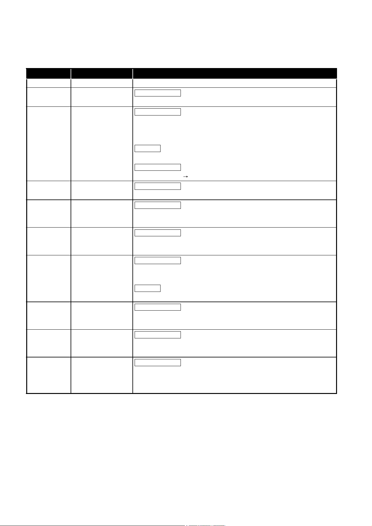
PRECAUTIONS
The following precautions are given in this section.
Precautions Reference page
For installation, uninstallation Page A-6
For each utility Page A-6
For programming Page A-7
For debugging a program Page A-11
For using FTP Page A-16
For the Wind River Systems product Page A-16
(1) Precautions for installation and uninstallation
(a) Installation by overwriting
• When installing utility by overwriting, the same folder where the existing one
is installed must be used.
Any other folders cannot be used.
• Installation by overwriting is available only onto the same version of
SW3PVC-CCPU.
To install another version of utility, uninstall existing one before installation.
(b) Uninstallation
Do not terminate uninstallation during processing.
If terminated, redo the uninstallation all over again.
If the uninstallation fails after terminating the uninstallation, reinstall the software
and then uninstall it again.
(2) Precautions for utility
(a) Communication error of utility
When the line is congested, communication errors (time out errors) are more likely
to occur (monitoring stops if running) in each utility.
If a utility communication error has occurred, set the connection target again in
Connection setting.
(b) Connection during script file processing
Connection from utility to a C Controller module may not be available during
processing a script file (while the RUN LED is flashing).
Finish the script file processing before connecting utility to a C Controller module.
If the RUN LED remains flashing, refer to the C Controller Module User's Manual
(Hardware Design, Function Explanation) and troubleshoot the problem.
®
(c) Terminating Microsoft
Do not terminate Microsoft® Windows® while utility other than Device monitoring
utility is running.
Terminate all the running utility (other than Device monitoring utility) first and then
®
Microsoft
Windows®.
Windows
®
A - 6

(d) Parameters
Parameters written from utility other than Device monitoring utility to a C
Controller module will take effect when the C Controller module is powered off and
then on or is reset.
Written parameters will not take effect by changing the C Controller module status
from STOP to RUN by remote operation or by a switch.
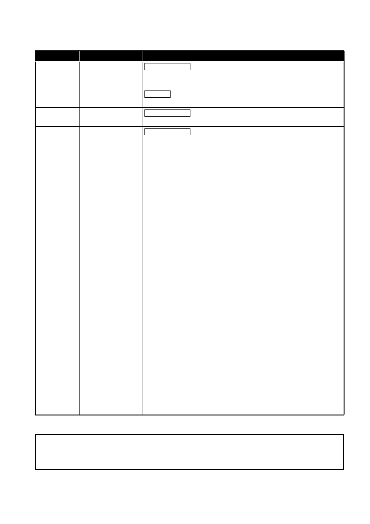
(3) Precautions for programming
(a) Restrictions on the bus interface functions and MELSEC data link functions
1) Endian format (memory layout)
There are two models of the Q06CCPU-V(-B), which are in little endian format
(memory layout) and in big endian format.
Create user programs in either little or big endian that is appropriate to the
model used.
(Set the compiler by selecting "A toolchain" when creating a project on
Tornado. ( Page 9-17, Section 9.4.2))
2) User program execution
Execute a user program by starting a task from the script file.
( Page 9-51, Section 9.9)
The system may malfunction if the user program is executed without a task
being started.
3) Execution type priority
Set the priority of a task for executing the FTP user program as described
below.
[When access is not made via FTP during user program execution]
Set the priority of the user program task to 100 or more (100 to 255).
If the priority is set within 0 to 99, the system may not operate properly.
[When access is made via FTP during user program execution]
The actual FTP processing (task) of the C Controller module is performed at
the priority of 200.
When accessing via FTP during executing a user program, perform
programming as described below.
• Set the priority of the user program task within 201 to 255.
• When setting the priority of the user program task within 100 to 200, insert
a wait processing (such as taskDalay) in the user program to let the actual
FTP processing operate.
A - 7
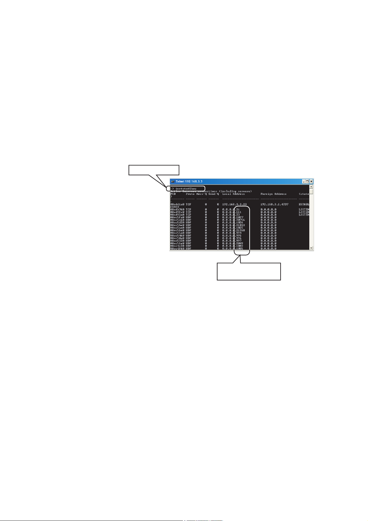
4) To communicate with a target device by Ethernet communication
Port numbers being used
in a C Controller module.
Command execution
(excluding utility communications)
Check the port number being used in the C Controller module by using the
VxWorks- standard "inetstatShow" command.
Do not use any port number that has already been used. Normal
communication may not be available if used.
Execute the "inetstatShow" command as follows:
[For the Q12DCCPU-V]
Use the Telnet tool.
[For the Q06CCPU-V(-B)]
Execute from the Tornado Shell.
Example) When using the Telnet tool on the Q12DCCPU-V
Figure A.1 When using Telnet tool on the Q12DCCPU-V
5) When writing a file from a user program in the Q06CCPU-V(-B)
Do not write a file to the standard ROM.
Write it to a CompactFlash card, network device (such as FTP/NFS/netDrv
driver) file, or RAM disk.
For details of network devices and RAM disks, refer to the manual for
VxWorks.
6) When the operation status is changed from RUN to STOP/PAUSE
When the operation status of the C Controller module is changed from RUN to
STOP/PAUSE, the user program task does not stop.
Use the QBF_Read StatusEx function when splitting the user program
processing according to the operation status of the C Controller module.
A - 8

7) Relation between system tasks and the system watchdog timer, user
watchdog timer, and link device refresh cycles
When using any of the following functions, set a sufficiently long time for each
of the system watchdog timer, user watchdog timer, and link device refresh
cycles.
• Shell command
• Workbench/Tornado connection
• File access
• Mount/unmount of CompactFlash card
• Ethernet communications
• NFS server communication
If any of the above is used, CPU utilization for a system task with high priority
may increase and a system watchdog timer error, a user watchdog timer error,
and link refresh timeout may occur more frequently.
For the link refresh timeout, the rate of occurrence may also increase when
bus interface driver processing (connections with peripheral devices or
communication with an intelligent function module, etc.) is used.
8) Common restrictions
For restrictions common to the bus interface functions and MELSEC data link
functions, refer to the following.
Page 9-26, "9.6 Precautions for Functions"
(b) Restrictions on the bus interface function
1) Clock setting
Do not set the clock of the C Controller module while the QBF_WaitEvent
function or the QBF_WaitUnitEvent function is in process.
2) Execution results of remote STOP/PAUSE and the bus interface function
When the operation status of the C Controller module is either the remote
STOP or remote PAUSE, the following execution results will be an error during
STOP/PAUSE.
• Output (Y) (QBF_Y_OutBitEx function, QBF_Y_OutWordEx function)
• Writing to buffer memory (QBF_ToBuf function)
The Y output and writing to buffer memory can be executed from the <<Module
monitoring>> tab of the C Controller setting utility.
3) Restrictions on the bus interface function
Refer to the following.
Page 9-23, "9.5 Programming Flow for Bus Interface Functions"
(c) Precautions on MELSEC data link functions
Opening and closing of a communication line (mdOpen and mdClose functions) is
allowed only once each at the start (task start) and the end (task end) of each user
program.
Repeating opening/closing in every communication degrades communication
performance.
For the Q06CCPU-V-B, the MELSEC data link functions cannot be used.
For restrictions on MELSEC data link functions, refer to the following.
Page 10-5, "10.5 MELSEC Data Link Function Programming Flow"
A - 9

(d) Login user
1) Default account
To prevent illegal access, delete the default account (User name and
password) using the loginUserDelete function.
2) Retaining login user setting
The login user settings are cleared and return to default when the C Controller
module is powered off or is reset.
To retain the login user settings, describe a registration (adding/deleting) of the
settings in a script file.
Describe either of the following in the script file.
• Directly describe the login user operation commands (loginUserAdd
function or loginUserDelete function).
• Provide a description that starts the user program task for login user
operation.
For login user settings, refer to the C Controller Module User's Manual
(Hardware Design, Function Explanation).
(e) Power off and reset during writing a user file
Data corruption or a file system error may occur if the C Controller system is
powered off or is reset (including remote RESET) during writing data to a user file
in the standard RAM, standard ROM, or CompactFlash card.
To power off or reset the C Controller system during writing data to a user file in
the standard RAM, standard ROM, or CompactFlash card, perform the following
first.
1) When writing data to a file in the standard RAM or standard ROM
Close the file where data are being written. (Program example Page 121, CHAPTER 12)
2) When writing data to a file in a CompactFlash card
Close the file where data are being written, and unmount the CompactFlash
card. (Program example Page 12-1, CHAPTER 12)
For the stop processing of the CompactFlash card, refer to the C Controller
Module User's Manual (Hardware Design, Function Explanation).
(f) Watchdog timer
A user watchdog timer error occurs when the user watchdog timer cannot be reset
due to some reasons such as user program runaway.
When a user watchdog timer occurs, perform the following.
• Increase the WDT time set by the QBF_StartWDT function.
• Lower the CPU utilization of tasks that require high utilization.
Or set them not to operate.
• Review user programs
After the above operations, reset the C Controller system.
For resetting, refer to the C Controller Module User's Manual (Hardware Design,
Function Explanation).
(g) IP address
The IP address of the C Controller module cannot be set from a user program.
Set in the <<Online operation>> tab of C Controller setting utility.
.
A - 10

(h) Script file "STARTUP.CMD"
In the script file, describe commands for setting a login user (adding/deleting) and
user program startups as necessary.
• Setting a login user
C Controller Module User's Manual (Hardware Design, Function
Explanation)
• Creating a script file
Page 9-51, "9.9 Creating a Script File "STARTUP.CMD""
(i) Task activation
Always specify the VX_FP_TASK option for the third argument of taskSpawn
when activating a task that:
• Performs floating-point operations.
• Calls a function that returns a floating-point value.
• Calls a function that takes a floating-point value as an argument.
If the above task is activated without the VX_FP_TASK option specified, the
operating system may run away.
When specifying the VX_FP_TASK option in a script file, refer to the following.
Page 9-51, Section 9.9 (2)
For details on the VX_FP_TASK option, refer to the following.
Manuals for VxWorks
(4) Precautions for program debugging
(a) VxWorks image file
When debugging a user program, specify the VxWorks image file same as the
one in the C Controller module to Workbench or to Tornado.
The serial No. and function version of the file to be specified must be identical with
those of the C Controller module. (Example for Q12DCCPU-V: Q12DCCPU-
V_10121-B) ( Page 9-31, Section 9.7)
1) When VxWorks image files are not identical
When the VxWorks image file in the development environment (personal
computer) and in the C Controller module are not identical, copy the image file
in the C Controller module into the development environment (personal
computer). ( Page 9-46, Section 9.8)
The image file of the C Controller is stored in the system drive (/SYSTEMROM/
OS_IMAGEFILE).
2) When connected with the different VxWorks image file specified
When the VxWorks image file in the C Controller module and in Workbench or
Tornado are not identical, a system watchdog timer error may occur in the C
Controller module.
In addition, debugging cannot be performed normally. ( Page 9-31,
Section 9.7)
A - 11
(b) Precautions for Telnet connection
If the line is disconnected during use of Telnet, it cannot be reconnected until TCP
connection including the Telnet on the C Controller module side is timed out.
If this occurs, reconnect it after timeout.
The timeout time for the C Controller module side Telnet (TCP) connection can be
changed by setting the values in the calculation formula by the following setting
methods.
[Calculation formula for the Q12DCCPU-V]
The timeout time is determined by the following calculation formula.
Timeout time = net.inet.tcp.keepidle
+ (net.inet.tcp.keepintvl 8 (number of retries)*1) [ms]
Initial value for C Controller module: 30000 (30 seconds)
Initial value for VxWorks: 7800000 (2 hours and 10 minutes)
net.inet.tcp.keepidle: Time from line disconnection to the first retry (ms)
Initial value for C Controller module: 22000
Initial value for VxWorks: 7200000
net.inet.tcp.keepintvl: Retry interval (ms)
Initial value for C Controller module: 1000
Initial value of VxWorks: 75000
* 1 The number of retries cannot be changed.
[Setting method for the Q12DCCPU-V]
The following explains how to set the initial value to 30 seconds.
• Setting while the C Controller module is in operation
1) Connect the line to the C Controller module with the Telnet tool.
2) Execute the following two Sysct1() commands with the Telnet tool to set
the timeout time to the initial value.
Sysctl("net.inet.tcp.keepidle = 22000")
Sysctl("net.inet.tcp.keepintvl = 1000")
3) Close the Telnet connection.
• Setting at the timing of starting C Controller module
1) Describe the following two Sysct1() commands on the script file,
"STARTUP.CMD".
Sysctl("net.inet.tcp.keepidle = 22000")
Sysctl("net.inet.tcp.keepintvl = 1000")
2) Write the above script file, "STARTUP.CMD" to a CompactFlash card,
and insert it into the C Controller module.
3) Upon start of the C Controller module, the timeout time is set to the
initial value.
A - 12

[Calculation for the Q06CCPU-V(-B)]
The timeout time is determined by the following calculation formula.
Timeout time =
tcp_keepidle: Time from line disconnection to the first retry (s)
tcp_keepintvl: Retry interval (in 0.5s units)
tcp_keepcnt: Number of retries
tcp_keepidle + (tcp_keepintvl 2 tcp_keepcnt) [s]
Initial value: 15000 (4 hours and 10 minutes)
Initial value: 14400
Initial value: 150
Initial value: 8
[Settings methods for the Q06CCPU-V(-B)]
The following explains how to set the initial value to 4 hours and 10 minutes.
• Setting while the C Controller module is in operation
1) Connect the line to the C Controller module with the Telnet tool.
2) Set the following three external variables with the Telnet tool to change
the timeout time to the initial value.
tcp_keepidle = 14400
tcp_keepintvl = 150
tcp_keepcnt = 8
3) Close the Telnet connection.
• Setting at the timing of starting the C Controller module
1) Describe the following three external variable settings on the script file,
"STARTUP.CMD".
tcp_keepidle = 14400
tcp_keepintvl = 150
tcp_keepcnt = 8
2) Write the above script file, "STARTUP.CMD" to a CompactFlash card,
and insert it into the C Controller module.
3) Upon start of the C Controller module, the timeout time is set to the
initial value.
A - 13

(c) Precautions for executing the Shell command from Workbench Shell or Tornado
Shell, or the Telnet tool
1) When executing the Shell command from Workbench Shell or Tornado Shell
Pay attention to the following since the entered Shell commands operate on
the task of priority 1 in the C Controller module.
• Only alphanumeric characters and special characters can be used.
• Some commands, such as those exclusively using the CPU module and
those including characters other than alphanumeric characters and
special characters, may be regarded as a command causing a watchdog
timeout error, a control code (such as "CTRL + X"), or being garbled. As a
result, a system error, such as a system watchdog timer error, or stop may
occur in the C Controller module. Pay full attention to the command when
entering it.
• Some commands (example: the status-indicating Show command) may
disable an interrupt for a long time.
During the time, processing called from an interrupt routine (interrupt
program) (example: bus interface function for ISR) is not executed.
Interrupts that are expected to occur at fixed intervals, such as multiple
CPU synchronous interrupt, may delay. When executing a command, pay
attention to the above.
A VxWorks message may appear on Shell during connecting from Shell to the
C Controller module.
For messages of VxWorks, refer to the manual for VxWorks, Workbench, or
Tornado.
2) When executing the Shell command from the Telnet tool
When executing a Shell command from the Telnet tool, make one-to-one
connection between the Telnet tool and the C Controller module.
Connection cannot be made from multiple Telnet tools to the same C
Controller module.
When exchanging the Telnet tool with another, first close the connection with
the currently used Telnet tool, and then connect the line to the C Controller
module from another Telnet tool.
For Telnet functions, refer to C Controller Module User's Manual (Hardware
Design, Function Explanation).
A - 14

The Shell commands entered by the Telnet tool of the development
environment (personal computer) operate on the task of the following priorities
in the C Controller module.
C Controller module Priority
Q12DCCPU-V 1
Q06CCPU-V(-B) 2
When using Shell commands, pay attention to the following:
• Only alphanumeric characters and special characters can be used.
• Some commands, such as those exclusively using the CPU module and
those including characters other than alphanumeric characters and
special characters, may be regarded as a command causing a watchdog
timeout error, a control code (such as "CTRL + X"), or being garbled. As a
result, a system error, such as a system watchdog timer error, or stop may
occur in the C Controller module. Pay full attention to the command when
entering it.
• Some commands (example: the status-indicating Show command) may
disable an interrupt for a long time.
During the time, processing called from an interrupt routine (interrupt
program) (example: bus interface function for ISR) is not executed.
Interrupts that are expected to occur at fixed intervals, such as multiple
CPU synchronous interrupt, may delay. When executing a command, pay
attention to the above.
A VxWorks message may appear on the Telnet tool screen during a Telnet
connection to the C Controller module.
For messages of VxWorks, refer to the manual for VxWorks, Workbench, or
Tornado.
3) When executing the Shell command from Workbench Shell or Tornado Shell,
or the Telnet tool
• Execution of VxWorks reboot command
Do not reboot VxWorks by executing the reboot function or pressing the
CTRL + X keys.
*1
If VxWorks is rebooted, the C Controller module does not start properly.
Reset it in the C Controller module.
For resetting, refer to the C Controller Module User's Manual (Hardware
Design, Function Explanation).
* 1 Do not enter characters other than alphanumeric characters or special characters in Shell either
since they may be regarded as a control code.
• Execution of command without argument specified
If a command that requires an argument is executed without an argument
specified, 0 is substituted for the argument. Some commands causes a
system error or stop (such as a system watchdog timer error) in the C
Controller module.
Before executing a command, confirm the specifications and specified
argument of the command.
Example)
Do not execute the "close" command without an argument. If executed,
the resource reserved in the VxWorks system will be closed.
A - 15

(5) Precautions for use of FTP
(a) When reading out files from the C Controller module
A 426 (Data connection error) occurs if many files are read (downloaded) by using
FTP.
In that case, take following actions and read files again.
• Decrease the number of files to read
• Read the files in several batches.
(6) Precautions for the Wind River Systems product
The C Controller module has an embedded real-time operating system, VxWorks,
made and sold by Wind River Systems, Inc. in the United States.
We, Mitsubishi, make no warranty for the Wind River Systems product and will not be
liable for any problems and damages caused by the Wind River Systems product
during use of the C Controller module.
For the problems or specifications of the Wind River Systems product, refer to the
corresponding manual or consult Wind River Systems, Inc.
Contact information is available on the following website.
www.windriver.com
A - 16

INTRODUCTION
Thank you for purchasing the C Controller module.
Before using this product, please read this manual carefully and develop familiarity with the functions and
performance of the C Controller module to handle the product correctly.
CONTENTS
SAFETY PRECAUTIONS ··········································································································· A - 1
CONDITIONS OF USE FOR THE PRODUCT ················································································· A - 3
REVISIONS ····························································································································· A - 4
PRECAUTIONS ························································································································ A - 6
INTRODUCTION ·····················································································································A - 17
CONTENTS ····························································································································A - 17
ABOUT MANUALS ···················································································································A - 21
MANUAL PAGE ORGANIZATION ·······························································································A - 22
HOW TO USE THIS MANUAL ····································································································A - 23
GENERIC TERMS AND ABBREVIATIONS ···················································································A - 24
GLOSSARY ····························································································································A - 29
PRODUCT ORGANIZATION ······································································································A - 30
PACKING LIST························································································································A - 30
CHAPTER 1 OVERVIEW 1 - 1 to 1 - 4
1.1 Features ····················································································································1 - 3
CHAPTER 2
2.1 Development Environment·····························································································2 - 1
2.2 Installation··················································································································2 - 4
2.3 Uninstallation ············································································································ 2 - 12
INSTALLATION AND UNINSTALLATION OF SOFTWARE PACKAGE
2 - 1 to 2 - 13
CHAPTER 3 COMMON UTILITY OPERATIONS 3 - 1 to 3 - 16
3.1 Utility List ···················································································································3 - 1
3.2 Activating Utility···········································································································3 - 2
3.3 Exiting Utility···············································································································3 - 3
3.4 Specifying CPU Type ···································································································3 - 4
3.5 Setting Connection Target ·····························································································3 - 5
3.6 Displaying the Help Screen ·························································································· 3 - 10
3.7 Checking Version ······································································································ 3 - 13
3.8 Parameter Setting File ································································································ 3 - 14
3.9 Displays on the Title Bar and Status Bar········································································· 3 - 16
A - 17

CHAPTER 4 C CONTROLLER SETTING UTILITY 4 - 1 to 4 - 50
4.1 C Controller Setting Utility Function List ··········································································· 4 - 1
4.2 Module Information Tab································································································ 4 - 2
4.3 Event History Tab ······································································································· 4 - 4
4.4 SRAM Monitoring Tab ·································································································· 4 - 8
4.5 Module Monitoring Tab································································································4 - 13
4.6 Online Operation Tab··································································································4 - 21
4.7 System Settings Tab···································································································4 - 30
4.8 Device Settings Tab ···································································································4 - 35
4.9 I/O Assignment Settings Tab ························································································4 - 37
4.10 Multiple CPU Settings Tab ···························································································4 - 41
4.11 Communication Diagnostics Tab ···················································································4 - 45
4.12 System Menu ············································································································4 - 46
4.13 Reading Initial Setting File and Importing Multiple CPU Parameters ·····································4 - 48
4.14 Precautions ··············································································································4 - 50
CHAPTER 5 CC-LINK UTILITY 5 - 1 to 5 - 23
5.1 CC-Link Utility Function List ·························································································· 5 - 1
5.2 Module Information Tab································································································ 5 - 2
5.3 Other Station Monitoring Tab························································································· 5 - 6
5.4 Online Operation Tab··································································································· 5 - 9
5.5 Parameter Settings Tab·······························································································5 - 11
5.6 Target Settings Tab ····································································································5 - 15
5.7 Test Tab ··················································································································5 - 18
5.8 System Menu ············································································································5 - 21
5.9 Precautions ··············································································································5 - 23
CHAPTER 6 MELSECNET/H UTILITY 6 - 1 to 6 - 44
6.1 MELSECNET/H Utility Function List ················································································ 6 - 1
6.2 Module Information Tab································································································ 6 - 2
6.3 Error History Monitoring Tab·························································································· 6 - 9
6.4 Other Station Monitoring Tab························································································6 - 14
6.5 Online Operation Tab··································································································6 - 25
6.6 Parameter Settings Tab·······························································································6 - 27
6.7 Target Settings Tab ····································································································6 - 39
6.8 System menu ············································································································6 - 42
6.9 Precautions ··············································································································6 - 44
A - 18

CHAPTER 7 CC IE CONTROL UTILITY 7 - 1 to 7 - 39
7.1 CC IE Control Utility Function List ···················································································7 - 1
7.2 Module Information Tab ································································································7 - 2
7.3 Diagnostics Result Screen ·····························································································7 - 5
7.4 Online Operation Tab ································································································· 7 - 20
7.5 Parameter Settings Tab ······························································································ 7 - 23
7.6 Target Settings Tab···································································································· 7 - 34
7.7 System Menu············································································································ 7 - 37
7.8 Precautions ·············································································································· 7 - 39
CHAPTER 8 DEVICE MONITORING UTILITY 8 - 1 to 8 - 19
8.1 Device Monitoring Utility Function List ··············································································8 - 1
8.2 Batch Monitoring ·········································································································8 - 2
8.3 16-Point Register Monitoring ··························································································8 - 4
8.4 Setting Monitoring Target ······························································································8 - 6
8.5 Setting Device to Be Monitored·······················································································8 - 7
8.6 Changing Word Device Values ·······················································································8 - 8
8.7 Continuously Changing Word Device Values ··································································· 8 - 10
8.8 Tuning On and Off Bit Device ······················································································· 8 - 12
8.9 Changing the Display Format ······················································································· 8 - 14
8.10 Start and Stop Monitoring ···························································································· 8 - 15
8.11 Numerical Pad ·········································································································· 8 - 16
8.12 Other Operations ······································································································· 8 - 17
8.13 Precautions ·············································································································· 8 - 19
CHAPTER 9 PROGRAMMING USING BUS INTERFACE FUNCTIONS 9 - 1 to 9 - 59
9.1 Outline of Bus Interface Functions···················································································9 - 1
9.2 Bus Interface Function List ····························································································9 - 3
9.3 Programming Procedure ·······························································································9 - 8
9.4 Creating and Compiling a New Project of User Program ······················································9 - 9
9.4.1 For the Q12DCCPU-V ····························································································9 - 9
9.4.2 For the Q06CCPU-V(-B) ······················································································· 9 - 17
9.5 Programming Flow for Bus Interface Functions ································································ 9 - 23
9.6 Precautions for Functions ···························································································· 9 - 26
9.7 Precautions for Program Debugging ·············································································· 9 - 31
9.7.1 For Q12DCCPU-V ······························································································· 9 - 31
9.7.2 For the Q06CCPU-V(-B) ······················································································· 9 - 38
9.8 Program Registration·································································································· 9 - 46
9.9 Creating a Script File "STARTUP.CMD" ········································································· 9 - 51
A - 19

9.10 Device Types for Bus Interface Functions ·······································································9 - 56
CHAPTER 10
10.1 Outline of MELSEC Data Link Functions ·········································································10 - 1
10.2 MELSEC Data Link Function List···················································································10 - 4
10.3 Programming Procedure······························································································10 - 4
10.4 Creating a New Project of User Program and Compiling ····················································10 - 5
10.5 MELSEC Data Link Function Programming Flow ······························································10 - 5
10.6 Precautions for the MELSEC Data Link Function ······························································10 - 9
10.7 Precautions for Program Debugging ··············································································10 - 9
10.8 Program Registration ··································································································10 - 9
10.9 Creating a Script File "STARTUP.CMD"··········································································10 - 9
10.10 Channel ···················································································································10 - 9
10.11 Station No. Setting for MELSEC Data Link Functions ······················································ 10 - 10
10.12 Device Types for the MELSEC Data Link Function·························································· 10 - 12
10.13 Accessible Ranges and Devices of the MELSEC Data Link Function ·································· 10 - 17
10.13.1 Access via a bus································································································ 10 - 17
10.13.2 Access via CC-Link ···························································································· 10 - 23
10.13.3 Access via MELSECNET/H·················································································· 10 - 29
10.13.4 Access via CC-Link IE Controller Network ······························································· 10 - 38
PROGRAMMING USING MELSEC DATA LINK FUNCTIONS
10 - 1 to 10 - 45
CHAPTER 11 PROGRAMMING USING VxWorks API FUNCTIONS 11 - 1 to 11 - 2
CHAPTER 12 SAMPLE PROGRAMS 12 - 1 to 12 - 10
12.1 Procedure for Opening Sample Programs ·······································································12 - 5
CHAPTER 13 EVENT NUMBER LIST 13 - 1 to 13 - 8
APPENDICES APPX - 1 to APPX - 17
Appendix 1 VxWorks Component List ·············································································· APPX - 1
Appendix 2 Precautions for Program Replacement··························································· APPX - 17
INDEX INDEX - 1 to INDEX - 2
A - 20

ABOUT MANUALS
Relevant manuals
The following manuals are relevant to this product.
Order each manual as needed, referring to the table below.
Manual name
C Controller Module User's Manual (Hardware Design, Function Explanation)
Describes the system configuration, specifications, functions, handling instructions, wiring, and
troubleshooting of the C Controller module (Q12DCCPU-V (Basic mode), Q06CCPU-V, Q06CCPU-V-
B).
(Sold separately)
MELSEC-Q C Controller Module User's Manual
Describes the system configuration, specifications, functions, handling instructions, wiring,
troubleshooting, and programming and function of C Controller module (Q24DHCCPU-V,
Q24DHCCPU-VG, Q24DHCCPU-LS, Q26DHCCPU-LS, and Q12DCCPU-V (Extended mode)).
(Sold separately)
Setting/Monitoring Tools for the C Controller Module Version 4 Operating Manual
Describes the system configuration and operation method of Setting/Monitoring Tools for the C
Controller Module (SW4PVC-CCPU).
(Sold separately)
CW Workbench Operating Manual
Describes the system configuration, installation/uninstallation, specifications, functions, and
troubleshooting of the product.
(Sold separately)
CW-Sim Operating Manual
Describes the system configuration, specifications, functions, and troubleshooting of CW-Sim.
(Sold separately)
QCPU User's Manual (Hardware Design, Maintenance and Inspection)
Describes the specifications of CPU modules, power supply modules, base units, extension cables.
and memory cards, and others.
(Sold separately)
QCPU User's Manual (Multiple CPU system)
Describes the information on configuring a multiple CPU system: overview, system configuration, I/O
numbers, communication between CPU modules, and communication with the I/O modules and
intelligent function modules.
(Sold separately)
MELSEC-Q CC-Link System Master/Local Module User's Manual
Describes the system configurations, performance specifications, functions, handling instructions,
wiring, and troubleshooting for the CC-Link modules.
(Sold separately)
Q Corresponding MELSECNET/H Network System Reference Manual (PLC to PLC network)
Describes the PLC-to-PLC network specifications, preparatory procedures and settings, parameter
setting, programing, and troubleshooting for the MELSECNET/H network system.
(Sold separately)
MELSEC-Q CC-Link IE Controller Network Reference Manual
Describes the system configurations, performance specifications, functions, handling instructions,
wiring, and troubleshooting for the CC-Link IE Controller Network system.
(Sold separately)
Manual number
(code)
SH-080766ENG
(13JZ17)
SH-081130ENG
(13JZ75)
SH-081131ENG
(13JU76)
SH-080982ENG
(13JU71)
SH-081159ENG
(13JU77)
SH-080483ENG
(13JR73)
SH-080485ENG
(13JR75)
SH-080394E
(13JR64)
SH-080049
(13JF92)
SH-080668ENG
(13JV16)
A - 21
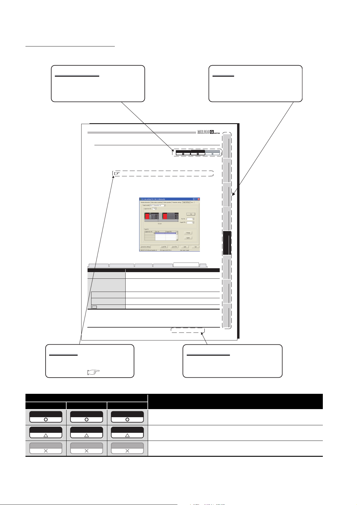
MANUAL PAGE ORGANIZATION
Relevant models
Whether the description of the section
applies to each model or not is shown
in the table.
CC-LINK UTILITY
5
5.6 Target Settings Tab
A logical station No. is set from the Target settings tab.
The logical station No. is used, when a target station is a multiple CPU system, to access
a programmable controller CPU other than the control CPU of the target station.
Note that the accesses indicated below does not require the logical station No. settings.
Page 5-17, "5.6 (4) Access that does not require a logical station No. setting"
(1) Precaution for the Target settings tab
Set a programmable controller CPU in "Target CPU"
(2) Target settings tab
The chapter of the current page can be
easily identified by this indication on the
right side.
Q12DCCPU-V Q06CCPU-V Q06CCPU-V-B
Chapter
1
OVERVIEW
2
INSTALLATION AND
UNINSTALLATION OF
SOFTWARE PACKAGE
3
COMMON UTILITY
OPERATIONS
4
C CONTROLLER
SETTING UTILITY
5
Table 5.14 Description of Target settings tab
Module information
Target module
Logical sta. No.
Sta. No.
Target CPU
Other station monitoring Online operation
Item Descriptio n
Set
button
Select a module to configure.
(Default: "Slot 1")
Specify a logical station No. for the module selected in "Target module".
(Default: 65, Setting range: 65 to 239)
The logical sta. No. is a logical number to be specified as "Sta. No." in Device monitoring utility and
an user program (MELSEC data link function).
Select a station No. of the CC-Link module controlled by a multiple CPU system.
(Default: 0, Setting range: 0 to 63)
Select a CPU of the access target (CPU No. in a multiple CPU system).
(Default: 1, Setting range: 1 to 4)
Enters the added and changed data (Logical sta. No., Sta. No., and Target CPU) to the Target list.
Reference
The section in this manual or another
relevant manual that can be referred
to is shown after .
* The above page illustration is for explanation purpose only, and is different from the actual page.
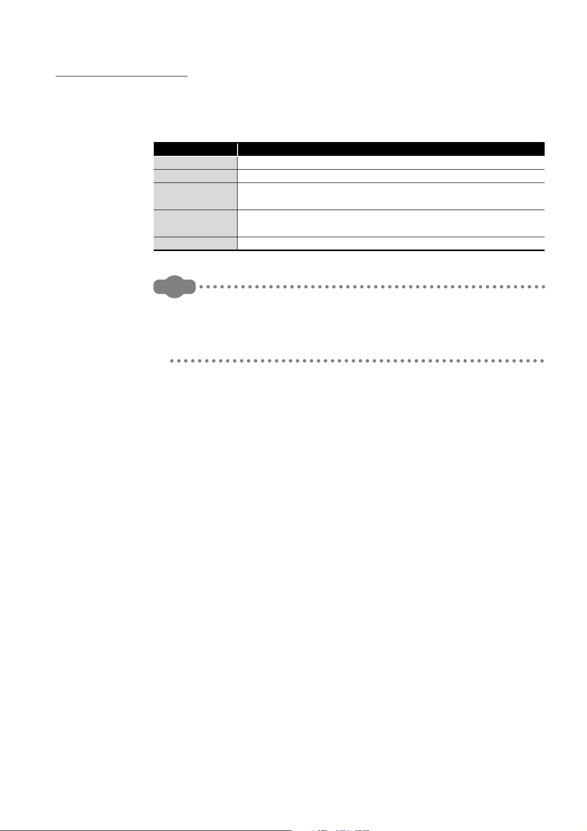
Icon
Q12DCCPU-V Q06CCPU-V Q06CCPU-V-B
Q12DCCPU-V Q06CCPU-V Q06CCPU-V-B
Figure 5.10 Target settings tab
Parameter settings
Target settings
5.6 Target Settings Tab
Test
(To the next page)
CC-LINK UTILITY
6
MELSECNET/H UTILITY
7
CC IE CONTROL UTILITY
8
DEVICE MONITORING
UTILITY
5
- 15
Section and title
The section number and title of the current
page can be easily identified.
Description
All or part of the description applies each model.
Q12DCCPU-V Q06CCPU-V Q06CCPU-V-B
Q12DCCPU-V Q06CCPU-V Q06CCPU-V-B
A - 22
The description applies to each model with some restrictions.
The description does not apply to each model.
HOW TO USE THIS MANUAL
Remark
This manual is used to develop familiarity with parameter settings, monitoring, and
programming required for using the C Controller module.
Refer to the following list when using this manual.
Chapter Description
CHAPTER 1 Features of SW3PVC-CCPU
CHAPTER 2 Operating environment, installing, uninstalling of SW3PVC-CCPU
CHAPTER 3 to
CHAPTER 8
CHAPTER 9 to
CHAPTER 12
CHAPTER 13 Event numbers of the C Controller module
Parameter settings and monitoring using utility
Programming of the C Controller module
This manual does not explain the features, system configurations, specifications,
handling instructions, wiring, or troubleshooting of the C Controller module.
For details of the above, refer to C Controller Module User's Manual (Hardware
Design, Function Explanation).
A - 23
GENERIC TERMS AND ABBREVIATIONS
Unless otherwise specified, this manual uses the following generic terms and
abbreviations to explain the C Controller module.
(1) C Controller module and SW3PVC-CCPU
Generic term/abbreviation Description
Abbreviation for the Q12DCCPU-V C Controller module
Q12DCCPU-V
Q12DCCPU-V
(Basic mode)
Q12DCCPU-V
(Extended mode)
Q06CCPU-V Abbreviation for the Q06CCPU-V C Controller module
Q06CCPU-V-B Abbreviation for the Q06CCPU-V-B C Controller module
Q06CCPU-V(-B) Generic term for the Q06CCPU-V and Q06CCPU-V-B
Q24DHCCPU-V
Q24DHCCPU-VG
Q24DHCCPU-LS
Q26DHCCPU-LS
C Controller module
SW3PVC-CCPU
SW4PVC-CCPU
In principle, 'Q12DCCPU-V' indicates Q12DCCPU-V (Basic mode).
When the classification is needed for such as comparison with other modes,
'Q12DCCPU-V (Basic mode)' and ‘Q12DCCPU-V (Extended mode)’ are mentioned.
Status that Q12DCCPU-V is initialized with the basic mode
Status that Q12DCCPU-V is initialized with the extended mode
For Q12DCCPU-V (Extended mode), refer to the following manual.
MELSEC-Q C Controller Module User's Manual
Abbreviation for the Q24DHCCPU-V C Controller module
For Q24DHCCPU-V, refer to the following manual.
MELSEC-Q C Controller Module User's Manual
Abbreviation for the Q24DHCCPU-VG C Controller module
For Q24DHCCPU-VG, refer to the following manual.
MELSEC-Q C Controller Module User's Manual
Abbreviation for the Q24DHCCPU-LS C Controller module
For Q24DHCCPU-LS, refer to the following manual.
MELSEC-Q C Controller Module User's Manual
Abbreviation for the Q26DHCCPU-LS C Controller module
For Q26DHCCPU-LS, refer to the following manual.
MELSEC-Q C Controller Module User's Manual
Generic term for the Q12DCCPU-V, Q06CCPU-V, Q06CCPU-V-B, Q24DHCCPU-V,
Q24DHCCPU-VG, Q24DHCCPU-LS, and Q26DHCCPU-LS
Abbreviation for Setting/Monitoring Tools for the C Controller Module (SW3PVC-CCPU-
E)
Abbreviation for Setting/Monitoring Tools for the C Controller Module (SW4PVC-CCPU-E)
For SW4PVC-CCPU, refer to the following manual.
Setting/Monitoring Tools for the C Controller Module Operating Manual
A - 24

(2) CPU modules
Generic term/abbreviation Description
Generic term for the A1NCPU, A0J2HCPU, A1SCPU, A1SHCPU, A1SJCPU,
ACPU
QnACPU
QCPU (A mode) Generic term for the Q02CPU-A, Q02HCPU-A, and Q06HCPU-A
Basic model QCPU Generic term for the Q00CPU and Q01CPU
High Performance model QCPU Generic term for the Q02CPU, Q02HCPU, Q06HCPU, Q12HCPU, and Q25HCPU
Process CPU Generic term for the Q02PHCPU, Q06PHCPU, Q12PHCPU, and Q25PHCPU
Redundant CPU Generic term for the Q12PRHCPU and Q25PRHCPU
Universal model QCPU
QCPU (Q mode)
LCPU Generic term for the L02CPU and L26CPU-BT
Motion CPU
CPU module Generic term for the C Controller module, QCPU(Q mode), and Motion CPU
Single CPU system Control system where the C Controller module is mounted in the CPU slot
Multiple CPU system Control system where multiple CPU modules are mounted on a main base unit
Control CPU
Controlled module
Non-controlled module
(Non-group module)
Non-control CPU
Battery Generic term for the Q6BAT and Q7BAT batteries for CPU module
PC CPU module
A1SJHCPU, A2CCPU, A2CJCPU, A2NCPU, A2NCPU-S1, A2SCPU, A2SHCPU,
A2ACPU, A2ACPU-S1, A2UCPU, A2UCPU-S1, A2USCPU, A2USCPU-S1,
A2USHCPU-S1, A3NCPU, A3ACPU, A3UCPU, and A4UCPU
Generic term for the Q2ACPU, Q2ACPU-S1, Q2ASCPU, Q2ASCPU-S1, Q2ASHCPU,
Q2ASHCPU-S1, Q3ACPU, Q4ACPU, and Q4ARCPU
Generic term for the Q00UJCPU, Q00UCPU, Q01UCPU, Q02UCPU, Q03UDCPU,
Q04UDHCPU, Q06UDHCPU, Q10UDHCPU, Q13UDHCPU, Q20UDHCPU,
Q26UDHCPU, Q03UDECPU, Q04UDEHCPU, Q06UDEHCPU, Q10UDEHCPU,
Q13UDEHCPU, Q20UDEHCPU, Q26UDEHCPU, Q50UDEHCPU, Q100UDEHCPU,
Q03UDVCPU, Q04UDVCPU, Q06UDVCPU, Q13UDVCPU, and Q26UDVCPU
Generic term for the Basic model QCPU, High Performance model QCPU, Process
CPU, Redundant CPU, and Universal model QCPU
Generic term for the Q172CPUN, Q172CPUN-T, Q172HCPU, Q172HCPU-T,
Q173CPUN, Q173CPUN-T, Q173HCPU, Q173HCPU-T, Q172DCPU and Q173DCPU
CPU module that controls I/O modules and intelligent function modules mounted on the
main base unit and extension base units.
Example: When CPU No. 2 controls a module mounted in Slot 3, CPU No.2 is the
control CPU of the module in Slot 3.
I/O module and intelligent function module controlled by a control CPU.
Example: When CPU No.2 controls a module mounted in Slot 3, the module in Slot 3 is
the controlled module of CPU No.2.
I/O module and intelligent function module other than controlled modules.
Example: When CPU No. 2 controls a module mounted in Slot 3, the module in the Slot
3 is the non-controlled module of CPU No.1 and 3.
CPU module that is not a control CPU.
Example: When CPU No. 2 controls the module mounted in Slot 3, the module in Slot 3
is a non-control CPU of CPUs No.1 and No.3.
Abbreviation for the MELSEC-Q series PC CPU module manufactured by CONTEC
Co., Ltd
A - 25

(3) Network modules and PC boards
Generic term/abbreviation Description
CC-Link module Generic term for the QJ61BT11 and QJ61BT11N
CC-Link/LT module Generic term for the QJ61CL12
Generic term for the Q81BD-J61BT11 and Q80BD-J61BT11N CC-Link system master/
CC-Link board
CC-Link IE Controller Network
module
CC-Link IE Controller Network
interface board
CC-Link IE Field Network master/
local module
MELSECNET/H module
MELSECNET/H interface board
local interface boards, A80BD-J61BT11 CC-Link system master/local interface board,
and A80BD-J61BT13 CC-Link interface board
Generic term for the QJ71GP21-SX and QJ71GP21S-SX
Generic term for the Q80BD-J71GP21-SX and Q80BD-J71GP21S-SX CC-Link IE
Controller Network interface boards
Abbreviation for the QJ71GF11-T2 CC-Link IE Field Network master/local module
Generic term for the QJ71LP21-25, QJ71LP21S-25, QJ71LP21G, QJ71LP21GE,
QJ72LP25-25, QJ72LP25G, QJ72LP25GE, QJ71BR11, QJ72BR15, and QJ71NT11B
Generic term for the Q81BD-J71LP21-25, Q80BD-J71LP21-25, Q80BD-J71LP21G,
Q80BD-J71LP21S-25, and Q80BD-J71BR11 MELSECNET/H interface boards
A - 26
(4) Power supply modules and base units
Generic term/abbreviation Description
Generic term for the Q33B, Q35B, Q38B, and Q312B main base units on which the CPU
Q3 B
Q3 SB
Q3 RB
Q3 DB
Q5 B
Q6 B
Q6 RB
QA1S6 B
Main base unit
Extension base unit
Slim type main base unit
Redundant power main base unit
Redundant power extension base
unit
Multiple CPU high speed main
base unit
Base unit
Redundant power supply base
unit
Q series power supply module
Slim type power supply module Generic term for the Q61SP slim type power supply module
Redundant power supply module
Power supply module
Extension cable
CPU slot The slot on the right side of the power supply module on the main base unit
modules, Q series power supply module, Q series I/O modules, and intelligent function
modules can be mounted
Generic term for the Q32SB, Q33SB, and Q35SB slim type main base units on which
the C Controller module, Basic model QCPU, High Performance model QCPU,
Universal model QCPU, slim type power supply module, Q series I/O modules, and
intelligent function modules can be mounted
Generic term for the Q38RB main base unit for redundant power supply system on
which the CPU modules, redundant power supply module, Q series I/O modules, and
intelligent function modules can be mounted
Generic term for the Q35DB, Q38DB, and Q312DB multiple CPU high speed main base
unit on which the CPU modules, Q series power supply module, Q series I/O modules,
and intelligent function modules can be mounted
Generic term for the Q52B and Q55B extension base units on which the Q series I/O
modules and intelligent function modules can be mounted
Generic term for the Q63B, Q65B, Q68B, and Q612B extension base units on which the
Q series power supply modules, Q series I/O modules, and intelligent function modules
can be mounted
Generic term for the Q68RB extension base unit for redundant power supply system on
which the redundant power supply modules, Q series I/O modules, and intelligent
function modules can be mounted
Generic term for the QA1S65B and QA1S68B extension base units on which the AnS
series power supply modules, AnS series I/O modules, and special function modules
can be mounted
Generic term for the Q3 B, Q3 SB, Q3 RB, and Q3 DB
Generic term for the Q5 B, Q6 B, Q6 RB, and QA1S6 B
Generic term for the Q3 SB
Generic term for the Q3 RB
Generic term for the Q6 RB
Generic term for the Q3 DB
Generic term for the main base unit, extension base unit, slim type main base unit,
redundant power main base unit, redundant power extension base unit, and multiple
CPU high speed main base unit
Generic term for the redundant power main base unit and redundant power extension
base unit
Generic term for the Q61P-A1, Q61P-A2, Q61P, Q61P-D, Q62P, Q63P, Q64P, and
Q64PN power supply modules
Generic term for the Q63RP, Q64RP power supply module for redundant power supply
system
Generic term for the Q series power supply module, slim type power supply module, and
redundant power supply module
Generic term for the QC05B, QC06B, QC12B, QC30B, QC50B, and QC100B extension
cables
A - 27

(5) Others
Generic term/abbreviation Description
Q series Abbreviation for the programmable controllers, MELSEC-Q series
AnS series Abbreviation for the programmable controllers, compact MELSEC-A series
Ethernet Generic term for the 100BASE-TX and 10BASE-T network systems
MELSECNET/H Generic term for the Q series MELSECNET/H network system
GOT Abbreviation for the Mitsubishi Graphic Operation Terminal
GX Works2
GX Developer
Windows Vista® or later
Windows® 7 or later Generic term for the Windows
CW Workbench The abbreviation for the engineering tool for C Controller, CW Workbench
Wind River Workbench
Workbench Generic term for the CW Workbench and Wind River Workbench
Tornado
VxWorks
Product name of the software package for the MELSEC programmable controllers
Generic term for the Windows Vista
Windows
®
10
®
7,
®
, Windows
Windows
®
7,
Windows
®
8, Windows® 8.1, Windows® 10
®
8, Windows® 8.1,
Abbreviation for Workbench 2.6.1 Update manufactured by Wind River Systems, Inc.
For specifications and inquiries of Wind River Workbench, visit the website of Wind
River Systems, Inc.: www.windriver.com
Abbreviation for Tornado 2.1.0 for Hitachi SuperH Cumulative patch 1 manufactured by
Wind River Systems, Inc.
For specifications and inquiries of Tornado, visit the website of Wind River Systems,
Inc.: www.windriver.com
Product name of the real-time operating system manufactured by Wind River Systems,
Inc.
A - 28
 Loading...