

Page 1

Programmable Controller
MITSUBISHI ELECTRIC
MITSUBISHI ELECTRIC
User's Manual
(Multiple CPU System)
01 12 2008
SH(NA)-080485ENG
Version H
QCPU
INDUSTRIAL AUTOMATION
Page 2
Page 3

Page 4
SAFETY PRECAUTIONS
(Read these precautions before using this product.)
Before using this product, please read this manual and the relevant manuals carefully and pay full
attention to safety to handle the product correctly.
In this manual, the safety precautions are classified into two levels: " DANGER" and " CAUTION".
DANGER
CAUTION
Under some circumstances, failure to observe the precautions given under " CAUTION" may lead to
serious consequences.
Make sure that the end users read this manual and then keep the manual in a safe place for future
reference.
Indicates that incorrect handling may cause hazardous conditions,
resulting in death or severe injury.
Indicates that incorrect handling may cause hazardous conditions,
resulting in medium or slight personal injury or physical damage.
A - 1
Page 5
[Design Precautions]
DANGER
Configure safety circuits external to the programmable controller to ensure that the entire system
operates safely even when a fault occurs in the external power supply or the programmable
controller. Failure to do so may result in an accident due to an incorrect output or malfunction.
(1) Configure external safety circuits, such as an emergency stop circuit, protection circuit, and
protective interlock circuit for forward/reverse operation or upper/lower limit positioning.
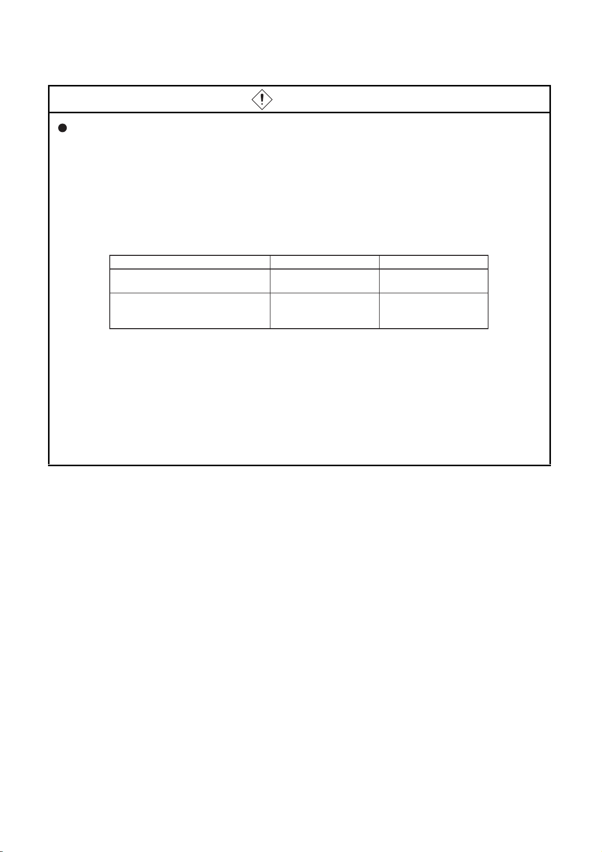
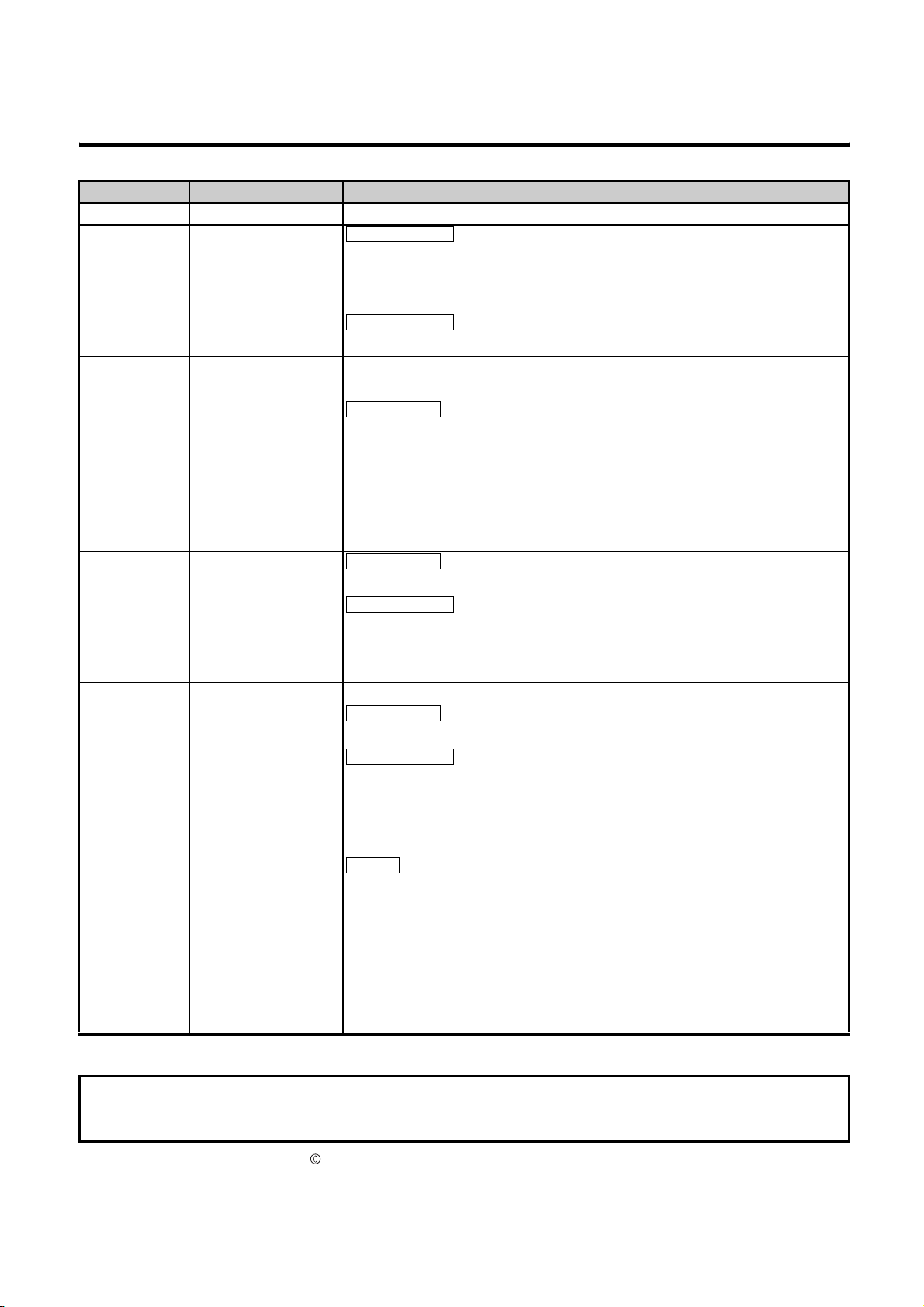
(2) The programmable controller stops its operation upon detection of the following status, and the
output status of the system will be as shown below.
Status
Overcurrent or overvoltage protection of
the power supply module is activated.
The CPU module detects an error such as
a watchdog timer error by the
self-diagnostic function.
Q series module AnS/A series module
All outputs are turned off All outputs are turned off
All outputs are held or
turned off according to the
parameter setting.
All outputs are turned off
All outputs may turn on when an error occurs in the part, such as I/O control part, where the CPU
module cannot detect any error. To ensure safety operation in such a case, provide a safety
mechanism or a fail-safe circuit external to the programmable controller. For a fail-safe circuit
example, refer to Chapter 10 LOADING AND INSTALLATION in the QCPU User's Manual
(Hardware Design, Maintenance and Inspection).
(3) Outputs may remain on or off due to a failure of an output module relay or transistor. Configure
an external circuit for monitoring output signals that could cause a serious accident.
A - 2
Page 6
[Design Precautions]
DANGER
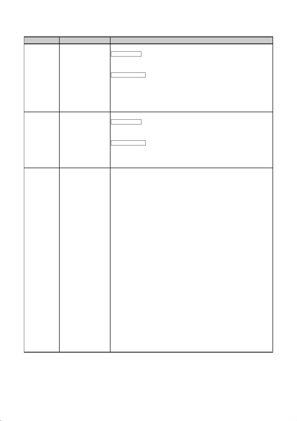
In an output module, when a load current exceeding the rated current or an overcurrent caused by a
load short-circuit flows for a long time, it may cause smoke and fire. To prevent this, configure an
external safety circuit, such as a fuse.
Configure a circuit so that the programmable controller is turned on first and then the external power
supply.
If the external power supply is turned on first, an accident may occur due to an incorrect output or
malfunction.
For the operating status of each station after a communication failure, refer to relevant manuals for
the network.
Incorrect output or malfunction due to a communication failure may result in an accident.
When changing data of the running programmable controller from a peripheral connected to the
CPU module or from a personal computer connected to an intelligent function module, configure an
interlock circuit in the sequence program to ensure that the entire system will always operate safely.
For program modification and operating status change, read relevant manuals carefully and ensure
the safety before operation.
Especially, in the case of a control from an external device to a remote programmable controller,
immediate action cannot be taken for a problem on the programmable controller due to a
communication failure.
To prevent this, configure an interlock circuit in the sequence program, and determine corrective
actions to be taken between the external device and CPU module in case of a communication
failure.
CAUTION
Do not install the control lines or communication cables together with the main circuit lines or power
cables.
Keep a distance of 100mm (3.94 inches) or more between them.
Failure to do so may result in malfunction due to noise.
When a device such as a lamp, heater, or solenoid valve is controlled through an output module, a
large current (approximately ten times greater than normal) may flow when the output is turned from
off to on.
Take measures such as replacing the module with one having a sufficient current rating.
A - 3
Page 7

[Installation Precautions]
CAUTION
Use the programmable controller in an environment that meets the general specifications in the
QCPU User's Manual (Hardware Design, Maintenance and Inspection).
Failure to do so may result in electric shock, fire, malfunction, or damage to or deterioration of the
product.
To mount the module, while pressing the module mounting lever located in the lower part of the
module, fully insert the module fixing projection(s) into the hole(s) in the base unit and press the
module until it snaps into place.
Incorrect mounting may cause malfunction, failure or drop of the module.
When using the programmable controller in an environment of frequent vibrations, fix the module
with a screw.
Tighten the screw within the specified torque range.
Undertightening can cause drop of the screw, short circuit or malfunction.
Overtightening can damage the screw and/or module, resulting in drop, short circuit, or malfunction.
When using an extension cable, connect it to the extension cable connector of the base unit securely.
Check the connection for looseness.
Poor contact may cause incorrect input or output.
When using a memory card, fully insert it into the memory card slot.
Check that it is inserted completely.
Poor contact may cause malfunction.
Shut off the external power supply for the system in all phases before mounting or removing the
module. Failure to do so may result in damage to the product.
A module can be replaced online (while power is on) on any MELSECNET/H remote I/O station or in
the system where a CPU module supporting the online module change function is used.
Note that there are restrictions on the modules that can be replaced online, and each module has its
predetermined replacement procedure.
For details, refer to the relevant sections in the QCPU User's Manual (Hardware Design,
Maintenance and Inspection) and in the manual for the corresponding module.
Do not directly touch any conductive part of the module.
Doing so can cause malfunction or failure of the module.
When using a Motion CPU module and modules designed for motion control, check that the
combinations of these modules are correct before applying power.
The modules may be damaged if the combination is incorrect.
For details, refer to the user's manual for the Motion CPU module.
A - 4
Page 8
[Wiring Precautions]
DANGER
Shut off the external power supply for the system in all phases before wiring.
Failure to do so may result in electric shock or damage to the product.
After wiring, attach the included terminal cover to the module before turning it on for operation.
Failure to do so may result in electric shock.
DANGER
Ground the FG and LG terminals to the protective ground conductor dedicated to the programmable
controller.
Failure to do so may result in electric shock or malfunction.
Use applicable solderless terminals and tighten them within the specified torque range. If any spade
solderless terminal is used, it may be disconnected when the terminal screw comes loose, resulting
in failure.
Check the rated voltage and terminal layout before wiring to the module, and connect the cables
correctly.
Connecting a power supply with a different voltage rating or incorrect wiring may cause a fire or
failure.
Connectors for external connection must be crimped or pressed with the tool specified by the
manufacturer, or must be correctly soldered.
Incomplete connections could result in short circuit, fire, or malfunction.
Tighten the terminal screw within the specified torque range.
Undertightening can cause short circuit, fire, or malfunction.
Overtightening can damage the screw and/or module, resulting in drop, short circuit, or malfunction.
Prevent foreign matter such as dust or wire chips from entering the module.
Such foreign matter can cause a fire, failure, or malfunction.
A - 5
Page 9
[Wiring Precautions]
DANGER
A protective film is attached to the top of the module to prevent foreign matter, such as wire chips,
from entering the module during wiring.
Do not remove the film during wiring.
Remove it for heat dissipation before system operation.
Mitsubishi programmable controllers must be installed in control panels.
Connect the main power supply to the power supply module in the control panel through a relay
terminal block.
Wiring and replacement of a power supply module must be performed by maintenance personnel
who is familiar with protection against electric shock. (For wiring methods, refer to the QCPU User's
Manual (Hardware Design, Maintenance and Inspection)).
[Startup and Maintenance Precautions]
DANGER
Do not touch any terminal while power is on.
Doing so will cause electric shock.
Correctly connect the battery connector.
Do not charge, disassemble, heat, short-circuit, solder, or throw the battery into the fire.
Doing so will cause the battery to produce heat, explode, or ignite, resulting in injury and fire.
Shut off the external power supply for the system in all phases before cleaning the module or
retightening the terminal screws or module fixing screws.
Failure to do so may result in electric shock.
Undertightening the terminal screws can cause short circuit or malfunction.
Overtightening can damage the screw and/or module, resulting in drop, short circuit, or malfunction.
A - 6
Page 10
[Startup and Maintenance Precautions]
CAUTION
Before performing online operations (especially, program modification, forced output, and operation
status change) for the running CPU module from the peripheral connected, read relevant manuals
carefully and ensure the safety.
Improper operation may damage machines or cause accidents.
Do not disassemble or modify the modules.
Doing so may cause failure, malfunction, injury, or a fire.
Use any radio communication device such as a cellular phone or PHS (Personal Handy-phone
System) more than 25cm (9.85 inches) away in all directions from the programmable controller.
Failure to do so may cause malfunction.
Shut off the external power supply for the system in all phases before mounting or removing the
module. Failure to do so may cause the module to fail or malfunction.
A module can be replaced online (while power is on) on any MELSECNET/H remote I/O station or in
the system where a CPU module supporting the online module change function is used.
Note that there are restrictions on the modules that can be replaced online, and each module has its
predetermined replacement procedure.
For details, refer to the relevant sections in the QCPU User's Manual (Hardware Design,
Maintenance and Inspection) and in the manual for the corresponding module.
After the first use of the product, do not mount/remove the module to/from the base unit, and the
terminal block to/from the module more than 50 times (IEC 61131-2 compliant) respectively.
Exceeding the limit of 50 times may cause malfunction.
Do not drop or apply shock to the battery to be installed in the module.
Doing so may damage the battery, causing the battery fluid to leak inside the battery.
If the battery is dropped or any shock is applied to it, dispose of it without using.
Before handling the module, touch a grounded metal object to discharge the static electricity from
the human body.
Failure to do so may cause the module to fail or malfunction.
A - 7
Page 11
[Disposal Precautions]
CAUTION
When disposing of this product, treat it as industrial waste.
When disposing of batteries, separate them from other wastes according to the local regulations.
(For details of the Battery Directive in EU countries, refer to the QCPU User's Manual (Hardware
Design, Maintenance and Inspection).)
[Transportation Precautions]
CAUTION
When transporting lithium batteries, follow the transportation regulations.
(For details of the regulated models, refer to the QCPU User's Manual (Hardware Design,
Maintenance and Inspection).)
A - 8
Page 12
REVISIONS
*The manual number is given on the bottom left of the back cover.
Print date Manual number Revision
Jun., 2004 SH(NA)-080485ENG-A First edition
May, 2005 SH(NA)-080485ENG-B Partial correction
GENERIC TERMS AND ABBREVIATIONS, Chapter 1, Section 1.1, 2.1, 2.3, 2.4,
3.1, 3.3.1, 3.3.2, 3.4.1, 3.4.2, 3.8, 3.9, 3.10, 4.1.1, 4.1.2, 4.1.3, 6.1, 6.1.1, 7.1,
8.1, 8.2.2, 8.2.3, 8.2.4, 8.3.1, 8.3.4, Appendix 1.1
Aug., 2005 SH(NA)-080485ENG-C Partial correction
GENERIC TERMS AND ABBREVIATIONS, Section 2.1
Apr., 2007 SH(NA)-080485ENG-D Universal model QCPU model addition
Revision involving Universal model QCPU serial No.09012
Model addition
Q02UCPU, Q03UDCPU, Q04UDHCPU, Q06UDHCPU, Q61P, QA65B, QA68B
Partial correction
SAFETY PRECAUTION, ABOUT MANUALS, GENERIC TERMS AND
ABBREVIATIONS, Section 1.1, 1.2, 1.3, 2.1.1, 2.1.2, 2.1.3, 2.2, 2.3, 2.4, 3.1.1,
3.1.2, 3.1.3, Chapter 4, Section 4.1, 4.1.1, 4.1.2, 4.1.3, 4.1.4, 4.1.5, 4.3.2, 5.1,
5.2, 6.1, 6.1.3, 6.1.4, 6.1.7, 6.1.8, 7.1, 8.1, 8.2.1, 8.2.2
Aug., 2007 SH(NA)-080485ENG-E Model addition
QA6ADP
Partial correction
GENERIC TERMS AND ABBREVIATIONS, Section 1.1, 1.2, 1.3, 2.1.1, 2.1.2,
2.1.3, 2.2, 2.3, 3.1, 3.1.2, 3.1.3, 3.3.1, 3.8, 4.1, 4.1.2, 4.2.1, 4.3.1, 8.2.2,
Appendix 1.1
Mar., 2008 SH(NA)-080485ENG-F Universal model QCPU model addition
Model addition
Q13UDHCPU, Q26UDHCPU
Partial correction
GENERIC TERMS AND ABBREVIATIONS, Section 1.1.1, 1.2, 1.3, 2.1.1, 2.1.2,
2.1.3, 2.3, 2.4, 3.1, 3.1.1, 3.1.2, 3.1.3, Chapter 4, Section 4.1.2, 4.1.3, 4.1.4,
4.1.5, 4.2.1, 4.3.1, 4.4, 4.5, 5.1, 5.2, 5.3, 6.1, 6.1.8, 7.1, 8.1, 8.2.1, 8.2.2, 8.3.1,
8.3.2
Addition
Section 4.3.3
Japanese manual version SH-080475-H
This manual confers no industrial property rights or any rights of any other kind, nor does it confer any patent licenses. Mit-
subishi Electric Corporation cannot be held responsible for any problems involving industrial property rights which may occur
as a result of using the contents noted in this manual.
2008 MITSUBISHI ELECTRIC CORPORATION
A - 9
Page 13
Print date Manual number Revision
May, 2008 SH(NA)-080485ENG-G Addition of Universal model QCPU and Process CPU models
Model addition
Q02PHCP, Q06PHCPU, Q03UDECPU, Q04UDEHCPU, Q06UDEHCPU,
Q13UDEHCPU, Q26UDEHCPU
Partial correction
A term "MELSECNET/G" has been revised to "CC-Link IE controller network"
through this manual,
GENERIC TERMS AND ABBREVIATIONS, Chapter 1, Section 1.1, 2.1.1,
2.1.2, 2.1.3, 2.2, 2.3, 2.4, 3.1, 3.8, 4.2, 4.3.1, 4.3.3, 5.1, 5.2, 6.1
Dec., 2008 SH(NA)-080485ENG-H Addition of Universal model QCPU and C Controller module
Model addition
Q00UCPU, Q01UCPU, Q10UDHCPU, Q20UDHCPU, Q10UDEHCPU,
Q20UDEHCPU, Q61P-D
Partial correction
ABOUT MANUALS, GENERIC TERMS AND ABBREVIATIONS, Chapter 1,
Section 1.1, 1.3, 2.1.1, 2.1.2, 2.1.3, 2.3, 2.4, 3.1, 3.1.2, 3.1.3, 3.2, 3.3.2, 3.7, 3.9,
4.1.1, 4.1.2, 4.1.3, 4.1.4, 4.1.5, 4.3.1, 4.3.3, 4.5, 5.1, 5.2, 7.1, 8.1, 8.2.2
A - 10
Page 14
INTRODUCTION
This manual is designed for users to understand the multiple CPU system including information of the system
configuration, functions, and communication with external devices that are required when the MELSEC-Q
series programmable controller is used in the multiple CPU system.
This manual is composed of the following parts and explains:
1) Chapter 1 and 2 Overview and system configuration of the multiple CPU system
2) Chapter 3 Multiple CPU system concept
3) Chapter 4 Communications between CPU modules in the multiple CPU system
4) Chapter 5 Processing time in the multiple CPU system
5) Chapter 6 Parameters used in the multiple CPU system
6) Chapter 7 Precautions for use of the AnS series module in the multiple CPU system
7) Chapter 8 Startup of the multiple CPU system
Before using the equipment, please read this manual carefully to develop full familiarity with the functions and
performance of the Q series programmable controller you have purchased, so as to ensure correct use.
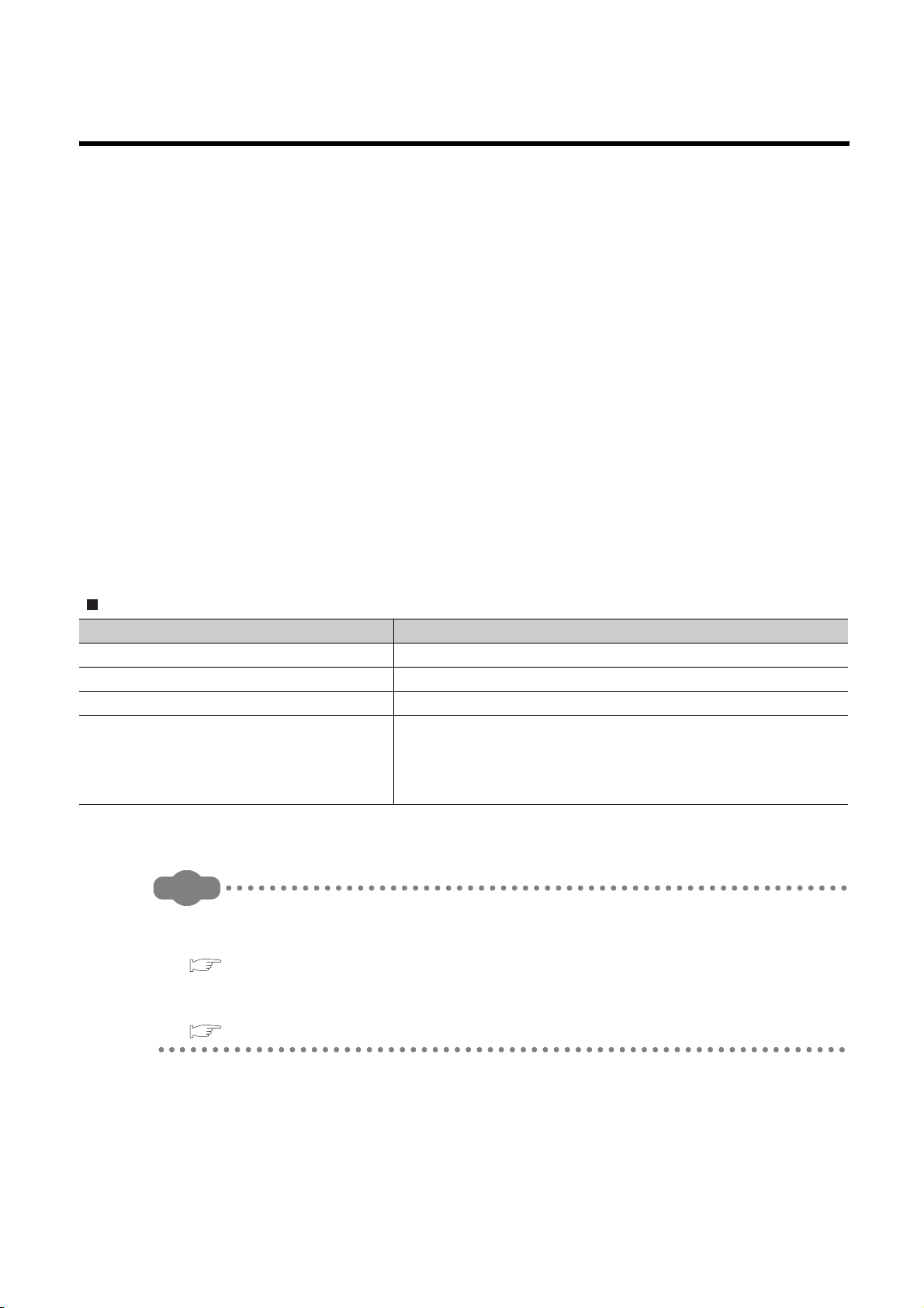
Relevant CPU module
CPU module Model
Basic model QCPU Q00CPU, Q01CPU
High Performance model QCPU Q02CPU, Q02HCPU, Q06HCPU, Q12HCPU, Q25HCPU
Process CPU Q02PHCPU, Q06PHCPU, Q12PHCPU, Q25PHCPU
Q00UCPU, Q01UCPU, Q02UCPU, Q03UDCPU, Q04UDHCPU,
Universal model QCPU
Q06UDHCPU, Q10UDHCPU, Q13UDHCPU, Q20UDHCPU,
Q26UDHCPU, Q03UDECPU, Q04UDEHCPU, Q06UDEHCPU,
Q10UDEHCPU, Q13UDEHCPU, Q20UDEHCPU, Q26UDEHCPU
Remark
This manual does not include the specifications of the power supply module, base unit, extension cables, memory cards
and batteries.
Refer to the following manual.
QCPU User's Manual (Hardware Design, Maintenance and Inspection)
This manual does not describe the functions of the CPU module.
For the functions, refer to the following.
Manuals for the CPU module used. (Function Explanation, Program Fundamentals)
A - 11
Page 15

CONTENTS
CONTENTS
SAFETY PRECAUTIONS......................................................................................................................A - 1
REVISIONS ...........................................................................................................................................A - 9
INTRODUCTION ................................................................................................................................... A - 11
MANUALS ............................................................................................................................................. A - 15
MANUAL PAGE ORGANIZATION.........................................................................................................A - 18
GENERIC TERMS AND ABBREVIATIONS ..........................................................................................A - 20
CHAPTER1 OUTLINE 1-1 to 1-23
1.1 What is multiple CPU system?............................................................................................... 1 - 1
1.2 Features of multiple CPU system .......................................................................................... 1 - 5
1.3 Difference from Single CPU System ...................................................................................... 1 - 11
CHAPTER2 SYSTEM CONFIGURATION 2-1 to 2-57
2.1 System configuration ............................................................................................................. 2 - 1
2.1.1 System configuration using Basic model QCPU (Q00CPU, Q01CPU)............................. 2 - 1
2.1.2 System configuration using High Performance model QCPU or Process CPU as
CPU No.1 ........................................................................................................ 2 - 10
2.1.3 System configuration using Universal model QCPU as CPU No.1...................................2 - 24
2.2 Configuration of peripheral devices ....................................................................................... 2 - 38
2.3 Configurable device and available software .......................................................................... 2 - 42
2.4 Precautions for system configuration..................................................................................... 2 - 52
CHAPTER3 CONCEPT FOR MULTIPLE CPU SYSTEM 3-1 to 3-41
3.1 Mounting Position of CPU Module ......................................................................................... 3 - 1
3.1.1 When CPU No.1 is Basic model QCPU............................................................................3 - 2
3.1.2 When CPU No.1 is High Performance model QCPU or Process CPU ............................. 3 - 6
3.1.3 When CPU No.1 is Universal model QCPU...................................................................... 3 - 11
3.2 CPU No. of CPU module ....................................................................................................... 3 - 18
3.3 Concept of I/O number assignment ....................................................................................... 3 - 20
3.3.1 I/O number assignment of each module ...........................................................................3 - 20
3.3.2 I/O number of each CPU module......................................................................................3 - 22
3.4 Access Range of CPU Module and Other Modules...............................................................3 - 23
3.4.1 Access range with controlled module................................................................................3 - 23
3.4.2 Access range with non-controlled module ........................................................................3 - 23
3.5 Access target under GOT connection .................................................................................... 3 - 30
3.6 Access with instruction using link direct device ..................................................................... 3 - 30
3.7 Access range of GX Developer..............................................................................................3 - 31
3.8 Clock data used by CPU module and intelligent function module .........................................3 - 34
3.8.1 Clock data used by CPU module ......................................................................................3 - 34
3.8.2 Clock data used by intelligent function module .................................................................3 - 35
3.9 Resetting the multiple CPU system .......................................................................................3 - 36
3.10 Operation for CPU module stop error .................................................................................... 3 - 37
3.11 Host CPU number of multiple CPU system ........................................................................... 3 - 40
A - 12
Page 16

CHAPTER4 COMMUNICATIONS BETWEEN CPU MODULES 4-1 to 4-56
4.1 Communications between CPU modules using CPU shared memory .................................. 4 - 3
4.1.1 CPU shared memory.........................................................................................................4 - 3
4.1.2 Communication by auto refresh using CPU shared memory............................................4 - 8
4.1.3 Communication by auto refresh using multiple CPU high speed transmission area.........4 - 23
4.1.4 Communication using CPU shared memory by program.................................................. 4 - 36
4.1.5 Communications between CPU modules when the error occurs...................................... 4 - 46
4.2 Communications with instructions dedicated to Motion CPU................................................. 4 - 47
4.2.1 Control instruction from QCPU to Motion CPU .................................................................4 - 47
4.3 Communication with Dedicated Instructions .......................................................................... 4 - 49
4.3.1 Writing/reading of device data from QCPU to Motion CPU...............................................4 - 49
4.3.2 Starting interrupt program from QCPU to C Controller module/PC CPU module.............. 4 - 51
4.3.3 Writing/reading of device data from QCPU to QCPU........................................................4 - 52
4.4 Multiple CPU Synchronous Interrupt...................................................................................... 4 - 53
4.5 Multiple CPU Synchronized Boot-up...................................................................................... 4 - 55
CHAPTER5 PROCESSING TIME OF QCPU IN MULTIPLE CPU SYSTEM 5-1 to 5-10
5.1 Concept of Scan Time ........................................................................................................... 5 - 1
5.2 Factors for prolonged Scan Time........................................................................................... 5 - 3
5.3 Reducing processing time...................................................................................................... 5 - 10
CHAPTER6 PARAMETER ADDED FOR MULTIPLE CPU SYSTEM 6-1 to 6-9
6.1 Parameter list ......................................................................................................................... 6 - 1
6.1.1 Number of CPUs setting ...................................................................................................6 - 6
6.1.2 Operating mode setting.....................................................................................................6 - 8
6.1.3 Online module change setting...........................................................................................6 - 8
6.1.4 I/O settings outside of the group .......................................................................................6 - 8
6.1.5 Communication area setting (Refresh setting).................................................................. 6 - 8
6.1.6 Control CPU settings.........................................................................................................6 - 9
6.1.7 Multiple CPU synchronized boot-up..................................................................................6 - 9
6.1.8 Multiple CPU high speed transmission area setting..........................................................6 - 9
CHAPTER7 PRECAUTIONS FOR USING AnS/A SERIES-COMPATIBLE MODULES
7-1 to 7-4
7.1 Precautions for use of AnS/A series compatible module.......................................................7 - 1
CHAPTER8 STARTING UP THE MULTIPLE CPU SYSTEM 8-1 to 8-39
8.1 Flow-chart for Starting Up the Multiple CPU System ............................................................. 8 - 1
8.2 Setting Up the Multiple CPU System Parameters.................................................................. 8 - 3
A - 13
Page 17

8.2.1 Parameter setting for the Basic model QCPU,High Paformance model QCPU,
Process CPU.................................................................................................... 8 - 3
8.2.2 Parameter setting for the Universal model QCPU ............................................................8 - 15
8.2.3 Reusing preset multiple CPU parameters......................................................................... 8 - 23
8.3 Communication program examples using auto refresh ......................................................... 8 - 28
8.3.1 Program examples for the Basic model QCPU, High Performance model QCPU and
Process CPU.................................................................................................... 8 - 28
8.3.2 Program examples for the Universal model QCPU...........................................................8 - 34
INDEX Index-1 to Index-2
A - 14
Page 18
MANUALS
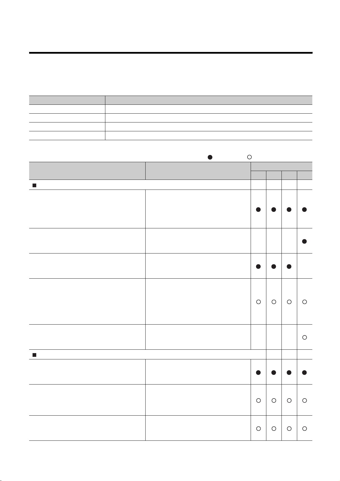
To understand the main specifications, functions, and usage of the CPU module, refer to the basic manuals.
Read other manuals as well when using a different type of CPU module and its functions.
Order each manual as needed, referring to the following lists.
The numbers in the "CPU module" and the respective modules are as follows.
Number CPU module
1) Basic model QCPU
2) High Performance model QCPU
3) Process CPU
4) Universal model QCPU
Basic manual, : Other CPU module manuals
:
Manual name
< Manual number (model code) >
User's manual
QCPU User's Manual (Hardware Design, Maintenance and Inspection)
< SH-080483ENG (13JR73) >
QnUCPU Users Manual (Function Explanation,
Program Fundamentals)
< SH-080807ENG (13JZ27) >
Qn(H)/QnPH/QnPRHCPU User's Manual (Function Explanation, Program Fundamentals)
< SH-080808ENG (13JZ28) >
QCPU User's Manual (Multiple CPU System)
< SH-080485ENG (13JR75) >
QnUCPU User's Manual (Communication via
Built-in Ethernet Port)
< SH-080811ENG (13JZ29) >
Programming manual
QCPU Programming Manual (Common Instructions)
< SH-080809ENG (13JW10) >
QCPU (Q Mode)/QnACPU Programming
Manual (SFC)
< SH-080041 (13JF60) >
QCPU (Q Mode) Programming Manual
(MELSAP-L)
< SH-080076 (13JF61) >
Description
Specifications of the hardware (CPU
modules, power supply modules, base units,
extension cables, and memory cards), system maintenance and inspection, troubleshooting, and error codes
Functions, methods, and devices for
programming
Functions, methods, and devices for
programming
Information for configuring a multiple CPU
system (system configuration, I/O
numbers, communication between CPU
modules, and communication with the input/
output modules and intelligent function modules)
Functions for the communication via built-in
Ethernet port of the CPU module
How to use sequence instructions, basic
instructions, and application instructions
System configuration, performance
specifications, functions, programming,
debugging, and error codes for SFC
(MELSAP3) programs
Programming methods, specifications, and
functions for SFC (MELSAP-L) programs
CPU module
1) 2) 3) 4)
A - 15
Page 19

Manual name
< Manual number (model code) >
QCPU (Q Mode) Programming Manual
(Structured Text)
< SH-080366E (13JF68) >
QCPU (Q Mode) / QnACPU Programming Manual (PID Control Instructions)
< SH-080040 (13JF59) >
QnPHCPU/QnPRHCPU Programming Manual
(Process Control Instructions)
< SH-080316E (13JF67) >
Description
Programming methods using structured languages
Dedicated instructions for PID control
Dedicated instructions for process control
CPU module
1) 2) 3) 4)
A - 16
Page 20

Other relevant manuals
Manual name Description
CC-Link IE Controller Network Reference
Manual
< SH-080668ENG (13JV16) >
Q Corresponding MELSECNET/H Network
System Reference Manual (PLC to PLC
network)
< SH-080049 (13JF92) >
Q Corresponding MELSECNET/H Network
System Reference Manual (Remote I/O
network)
< SH-080124 (13JF96) >
Q Corresponding Ethernet Interface Module
User's Manual (Basic)
< SH-080009 (13JL88) >
Q Corresponding Ethernet Interface Module
User's Manual (Application)
< SH-080010 (13JL89) >
CC-Link System Master/Local Module User's
Manual
< SH-080394E (13JR64) >
Q Corresponding Serial Communication
Module User's Manual (Basic)
< SH-080006 (13JL86) >
Q Corresponding Serial Communication
Module User's Manual (Application)
< SH-080007 (13JL87) >
Q Corresponding MELSEC Communication
Protocol Reference Manual
< SH-080008 (13JF89) >
GX Developer Version 8 Operating Manual
< SH-080373E (13JU41) >
Specifications, procedures and settings before system operation, parameter
setting, programming, and troubleshooting of the CC-Link IE controller
network module
Specifications, procedures and settings before system operation, parameter
setting, programming, and troubleshooting of a MELSECNET/H network
system (PLC to PLC network)
Specifications, procedures and settings before system operation, parameter
setting, programming, and troubleshooting of a MELSECNET/H network
system (remote I/O network)
Specifications, procedures for data communication with external devices,
line connection (open/close), fixed buffer communication, random access
buffer communication, and troubleshooting of the Ethernet module
E-mail function, programmable controller CPU status monitoring function,
communication via MELSECNET/H or MELSECNET/10, communication
using the data link instructions, and file transfer function (FTP server) of the
Ethernet module
System configuration, performance specifications, functions, handling,
wiring, and troubleshooting of the QJ61BT11N
Overview, system configuration, specifications, procedures before
operation, basic data communication method with external devices,
maintenance and inspection, and troubleshooting for using the serial
communication module
Special functions (specifications, usage, and settings and data
communication method with external devices of the serial communication
module
Communication method using the MC protocol, which reads/writes data to/
from the CPU module via the serial communication module or Ethernet
module
Operating methods of GX Developer, such as programming and printout
A - 17
Page 21
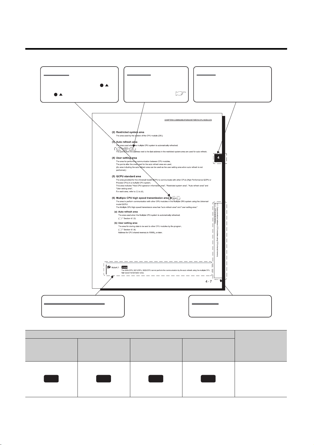
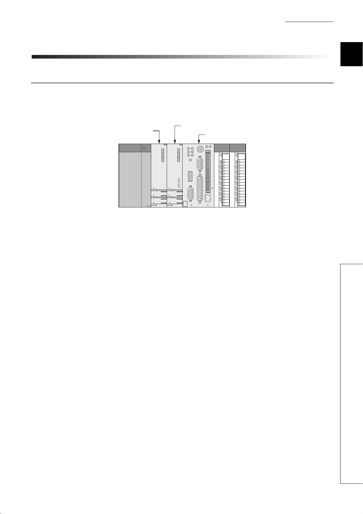
MANUAL PAGE ORGANIZATION
The detailed explanation of "Note." is
provided under the corresponding
"Note." at the bottom of the page.
ReferenceNote (icon)
The section in this manual or
another relevant manual that can
be referred to is shown with .
Chapter
The chapter of the current page can be
easily identified by this indication on the
right side.
Note (detailed explanation)
The detailed note corresponding to each icon
is described.
Basic model QCPU
Basic
Performance model
High
QCPU
High
performance
Icons
Process CPU
Process
Section title
The section number and title of the current
page can be easily identified.
Universal model
Description
QCPU
Icons indicate that
specifications
Universal
described on the page
contain some precautions.
A - 18
Page 22

In addition, this manual uses the following types of explanations.
In addition to description of the page, notes or functions that require special attention are described here.
Remark
The reference related to the page or useful information are described here.
A - 19
Page 23
GENERIC TERMS AND ABBREVIATIONS
Unless otherwise specified, this manual uses the following generic terms and abbreviations.
* indicates a part of the model or version.
(Example): Q33B, Q35B, Q38B, Q312B Q3 B
Generic term/abbreviation Description
Series
Q series Abbreviation for Mitsubishi MELSEC-Q series programmable controller
AnS series
A series
CPU module type
CPU module
Basic model QCPU Generic term for the Q00CPU, and Q01CPU
High Performance model QCPU Generic term for the Q02CPU, Q02HCPU, Q06HCPU, Q12HCPU, Q25HCPU
Process CPU Generic term for the Q02PHCPU, Q06PHCPU, Q12PHCPU, Q25PHCPU
Universal model QCPU
Built-in Ethernet port QCPU
Motion CPU
PC CPU module
C Controller module Generic term for the Q06CCPU-V, Q06CCPU-V-B C Controller modules
CPU module model
QnU(D)(H)CPU
Base unit type
Base unit
Main base unit
Extension base unit
Slim type main base unit
Redundant power main base unit
Redundant power extension base
unit
Generic term for compact types of Mitsubishi MELSEC-A Series Programmable
Controller
Generic term for large types of Mitsubishi MELSEC-A Series Programmable
Controller
Generic term for the Basic model QCPU, High Performance model QCPU,
Process CPU, Redundant CPU, Universal model QCPU
Generic term for the Q00UCPU, Q01UCPU, Q02UCPU, Q03UDCPU,
Q04UDHCPU, Q06UDHCPU, Q10UDHCPU, Q13UDHCPU, Q20UDHCPU,
Q26UDHCPU, Q03UDECPU, Q04UDEHCPU, Q06UDEHCPU, Q10UDEHCPU,
Q13UDEHCPU, Q20UDEHCPU, and Q26UDEHCPU
Generic term for the Q03UDECPU, Q04UDEHCPU, Q06UDEHCPU,
Q10UDEHCPU, Q13UDEHCPU, Q20UDEHCPU, and Q26UDEHCPU
Generic term for Mitsubishi motion controllers, Q172CPUN, Q173CPUN,
Q172HCPU, Q173HCPU, Q172CPUN-T, Q173CPUN-T, Q172HCPU-T,
Q173HCPU-T, Q172DCPU, and Q173DCPU
Generic term for MELSEC-Q series-compatible PC CPU module,
PPC-CPU686(MS)-64, PPC-CPU686(MS)-128, PPC-CPU852(MS)-512,
manufactured by CONTEC Co., Ltd.
Generic term for the Q00UCPU, Q01UCPU, Q02UCPU, Q03UDCPU,
Q04UDHCPU, Q06UDHCPU, Q10UDHCPU, Q13UDHCPU, Q20UDHCPU, and
Q26UDHCPU
Generic term for the main base unit, extension base unit, slim type main base
unit, redundant power main base unit, redundant type extension base unit, and
multiple CPU high speed main base unit
Generic term for the Q3 B, Q3 SB, Q3 RB, and Q3 DB
Generic term for the Q5 B, Q6 B, Q6 RB, Q6 WRB, QA1S6 B, QA6 B,
and QA6ADP+A5 B/A6 B
Another name for the Q3 SB
Another name for the Q3 RB
Another name for the Q6 RB
A - 20
Page 24
Generic term/abbreviation Description
Multiple CPU high speed main
base unit
Base unit model
Q3 B
Q3 SB
Q3 RB
Q3 DB
Q5 B
Q6 B
Q6 RB
QA1S6 B
QA6 B
A5 B
A6 B
QA6ADP+A5 B/A6 B
Power supply module
Power supply module
Q series power supply module
Slim type power supply module Abbreviation for the Q61SP slim type power supply module
AnS series power supply module Generic term for the A1S61PN, A1S62PN, and A1S63 power supply modules
A series power supply module
Redundant power supply module Generic term for the Q63RP and Q64RP redundant power supply modules
Network
MELSECNET/H Abbreviation for the MELSECNET/H network system
Ethernet Abbreviation for the Ethernet network system
CC-Link Abbreviation for the Control & Communication Link
Memory card
Memory card Generic term for the SRAM card, Flash card, and ATA card
Another name for the Q3 DB
Generic term for the Q33B, Q35B, Q38B, and Q312B main base units
Generic term for the Q32SB, Q33SB, and Q35SB slim type main base units
Another name for the Q38RB redundant power main base unit
Generic term for the Q38DB and Q312DB multiple CPU high speed main base units
Generic term for the Q52B and Q55B extension base units
Generic term for the Q63B, Q65B, Q68B, and Q612B extension base units
Another name for the Q68RB redundant power extension base unit
Generic term for the QA1S65B and QA1S68B
Generic term for the QA65B and QA68B extension base units
Generic term for the A52B, A55B, and A58B extension base units
Generic term for the A62B, A65B, and A68B extension base units
Abbreviation for a large type extension base unit where the QA6ADP is mounted
Generic term for the Q series power supply module, slim type power supply module, and redundant power supply module
Generic term for the Q61P-A1, Q61P-A2, Q61P, Q61P-D, Q62P, Q63P, Q64P, and
Q64PN power supply modules
Generic term for the A61P, A61PN, A62P, A63P, A68P, A61PEU, and A62PEU
power supply modules
SRAM card
Flash card Generic term for the Q2MEM-2MBF and Q2MEM-4MBF Flash cards
ATA ca r d
Others
GX Developer
PX Developer
QA6ADP Abbreviation for the QA6ADP QA conversion adapter module
Generic term for the Q2MEM-1MBS, Q2MEM-2MBS, Q3MEM-4MBS, and
Q3MEM-8MBS SRAM cards
Generic term for the Q2MEM-8MBA, Q2MEM-16MBA, and Q2MEM-32MBA ATA
cards
Product name for SW D5C-GPPW-E GPP function software package compatible
with the Q series
Product name for SW D5C-FBDQ process control FBD software package
A - 21
Page 25

Generic term/abbreviation Description
Extension cable
Tracking cable
Generic term for the QC05B, QC06B, QC12B, QC30B, QC50B, and QC100B
extension cables
Generic term for the QC10TR and QC30TR tracking cables for the Redundant
module
Battery
GOT
Generic term for the Q6BAT, Q7BAT, and Q8BAT CPU module batteries,
Q2MEM-BAT, SRAM card battery, and Q3MEM-BAT SRAM card battery
Generic term for Mitsubishi Graphic Operation Terminal, GOT-A*** series, GOT-F***
series, and GOT1000 series
A - 22
Page 26
CHAPTER1 OUTLINE
CHAPTER1 OUTLINE
1.1 What is multiple CPU system?
(1) Configuration of multiple CPU system
A multiple CPU system is a system in which more than one CPU module are mounted on several a main base
unit in order to control the I/O modules and intelligent function modules.
QCPU
Figure 1.1 Configuration of multiple CPU
Motion CPU
PC CPU
module
1
2
3
4
5
6
7
8
1.1 What is multiple CPU system?
1 - 1
Page 27

(2) Available CPU modules in multiple CPU system
Table1.1 shows the available CPU modules in multiple CPU system.
Refer to Section 2.3 for the compatible version of each module.
Table1.1 Applicable CPU modules
CPU module Model
Basic model QCPU Q00CPU, Q01CPU
High Performance model QCPU
Q
Process CPU Q02PHCPU,Q06PHCPU,Q12PHCPU,Q25PHCPU
C
P
U
Universal model QCPU
Motion CPU
C Controller module Q06CCPU-V,Q06CCPU-V-B
PC CPU module
*1
(manufactured by CONTEC CO., LTD.
)
Q02CPU,Q02HCPU,Q06HCPU,Q12HCPU,
Q25HCPU
Q00UCPU,Q01UCPU,Q02UCPU,Q03UDCPU,
Q04UDHCPU,Q06UDHCPU,Q10UDHCPU,
Q13UDHCPU,Q20UDHCPU,Q26UDHCPU,
Q03UDECPU,Q04UDEHCPU,Q06UDEHCPU,
Q10UDEHCPU,Q13UDEHCPU,Q20UDEHCPU,
Q26UDEHCPU
Q172CPUN,Q173CPUN,Q172HCPU,Q173HCPU,
Q172CPUN-T,Q173CPUN-T,Q172HCPU-T,
Q173HCPU-T
Q172DCPU,Q173DCPU
PPC-CPU686(MS)-64,
PPC-CPU686(MS)-128,
PPC-CPU852(MS)-512
Choose the CPU modules suitable for the system size and application to configure the system.
Some combinations of CPU modules in Table 1.1 cannot be used.
Refer to Section 3.1 for combinations of configurable CPU modules.
*1: For further information on PC CPU module, consult CONTEC Co.,Ltd.
Tel:+81-6-6472-7130
Remark
For details of the Motion CPU, C Controller module, and PC CPU module, refer to the manuals of each CPU module.
1 - 2
Page 28

CHAPTER1 OUTLINE
1 1 1 1 1
(3) Method for controlling I/O module and intelligent function module
It is necessary to set (control CPU setup) which CPU modules are to control which I/O modules and intelligent
function modules with a multiple CPU system.
CPU 0
*2: Indicates the grouping configuration on the GX Developer.
"1" on the CPU module indicates "CPU No.1," and "1" on the I/O module and intelligent function module indicates that
their "Control CPU is the CPU No.1."
The CPU module that controls the I/O modules and intelligent function modules is called as a "Control CPU".
The I/O modules and intelligent function modules controlled by the control CPU are called "controlled modules".
Other modules not controlled by the control CPU are called as "non-controlled modules".
1234567
2 222
Control with CPU module 1.
Control with CPU module 2.
Figure 1.2 Setting of control CPU
Slot number
Control CPU setting
*2
1
2
3
4
5
6
7
8
1.1 What is multiple CPU system?
1 - 3
Page 29

(4) Multiple CPU system setting
1 1 1 1 1
For control in the multiple CPU system, it is necessary to set up the "Number of mounted CPU modules" and the
"Control CPU" with PLC parameter for all CPU modules mounted on the main base unit.
User's Manual (Function Explanation, Program Fundamentals) for the CPU module used
(5) Access range of multiple CPU system
In the multiple CPU system, the access ranges are different between the controlled module and the non-con-
trolled module.
(a) Controlled module
The multiple CPU system's control CPU can refresh the I/O data of controlled modules and read/write the
buffer memory data of intelligent function modules in the same way as in a single CPU system.
(b) Non-controlled module
It is possible to access non-controlled modules in the following ways.
• Refreshing the input for I/O modules, I/O composite module and intelligent function modules
(the PLC parameter's multiple CPU setup is necessary.)
• Reading the intelligent function module's buffer memory.
• Downloading the output data from the output module, the I/O composite module and the intelligent func-
tion modules.
(the PLC parameter's multiple CPU setup is necessary.)
However, it is not possible to access non-controlled modules in the following ways.
• Outputting data to output modules, I/O composite module and intelligent function modules.
• Writing data into the intelligent function module's buffer memory.
CPU 0
12345 67
2 222
Readable with CPU module 2.
Readable with CPU module 1.
Figure 1.3 Access to non-controlled module
Slot number
Control CPU setting
(c) Range of access to other station's CPU module
To access to a CPU module on other station from GX Developer, access can be made through a network mod-
ule controlled by any CPU module in the multiple CPU system.
When other station has multiple CPUs, specifying the CPU No. allows access to the desired CPU.
User's manual for each network module
1 - 4
Page 30
CHAPTER1 OUTLINE
1.2 Features of multiple CPU system
(1) Multi-control system
(a) Configuration optimum for system
Since each system uses not only one QCPU but any combinations of the QCPU, Motion CPU, and PC CPU
module according to the system, the development efficiency and ease of maintenance of the system can be
enhanced.
(b) Module control
Each CPU module in the multiple CPU system controls the I/O module and intelligent function module on the
base unit by each slot.
GX Developer groups the I/O modules and intelligent function modules controlled by each CPU module in the
multiple CPU system.
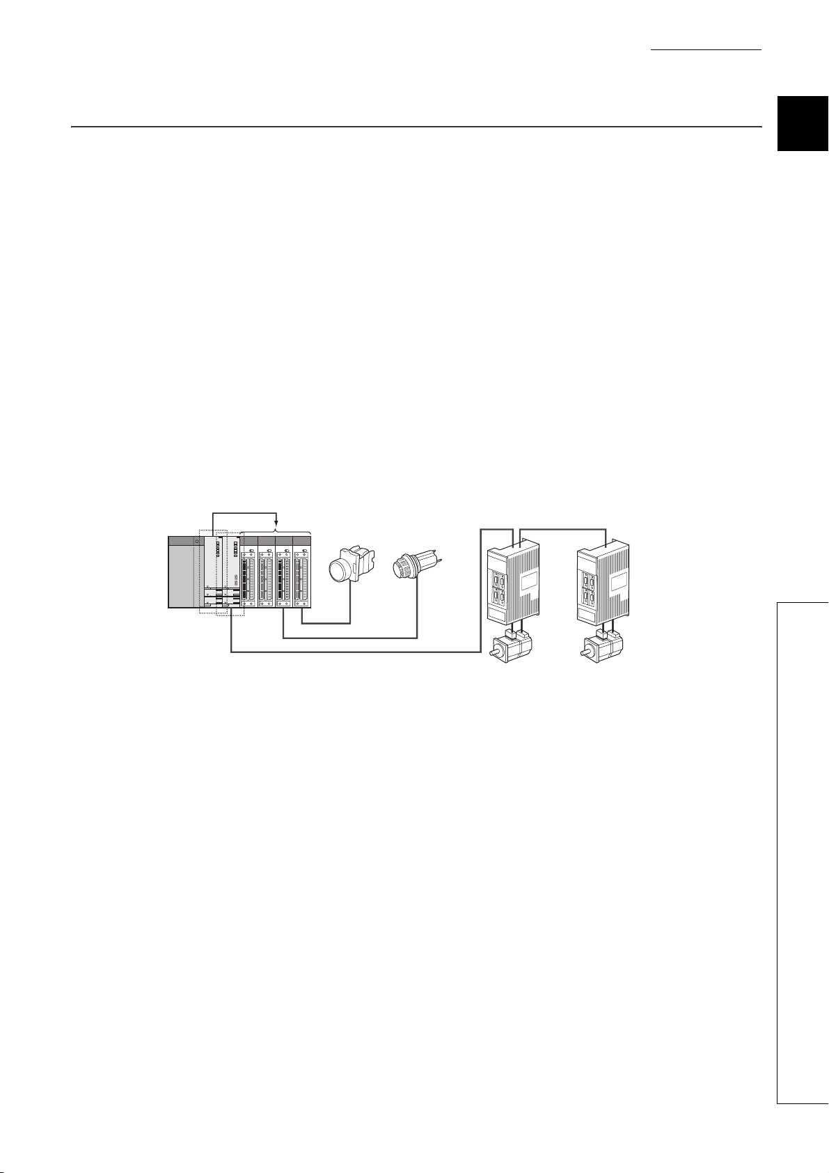
(2) Sequence control and motion control systems can be configured on the same
base.
In a Multiple CPU System consisting of the QCPU and Motion CPU, sequence control and motion control can be
implemented together to achieve a high-level motion system.
Sequence
control
Control
Motion control
Operation switch Operation status display
1
2
3
4
5
6
7
8
SSCNET
Figure 1.4 Motion system configuration
Servomotor
Servo
amplifier
Servomotor
Servo
amplifier
1.2 Features of multiple CPU system
1 - 5
Page 31

Interaction with a motion controller for motion control is enhanced in the Universal model QCPU.
(a) Speeding up data transfer between multiple CPUs
Maximum 14 k word-data and a sequence program can be transferred between multiple CPUs with parallel
processing. It enables high-speed data transfer independent of scan time, which leads to takt time shortening
of equipment.
CPU No.1
Sequence program Sequence program
X0
0
Speeding up data transfer between multiple CPUs is available when the following CPU modules are used.
• Universal model QCPU (except Q00UCPU, Q01UCPU, Q02UCPU )
• Motion CPU (Q172DCPU, Q173DCPU )
Multiple CPU high
speed transmission
Y20
END
Data transfer
Data transfer
Data transfer
Parallel processing with a sequence program
Figure 1.5 Multiple CPU data transfer
CPU No.2
Multiple CPU high
speed transmission
X100
0
Y120
END
1 - 6
Page 32

CHAPTER1 OUTLINE
(b) Enabling synchronous processing with a motion control
An interrupt program which is synchronized with the operation cycle of a motion controller (multiple CPU syn-
chronous interrupt program) can be executed.
Command I/O from a motion controller can be synchronized with the operation cycle of the motion controller,
which enables high-speed data transfer independent of scan time.
Motion
controller
Universal
model QCPU
Motion SFC program
Multiple CPU high
speed transmission
area
Multiple CPU high
speed transmission
Multiple CPU high
speed transmission
area
Sequence program
Multiple CPU
synchronous
interrupt program
Operation cycle
of a motion
controller
END 0
I45 IRET
Multiple CPU
high speed
transmission
cycle
Reading an
imposition signal
I45 IRET I45 IRET
I45 IRET
Reading an
imposition signal
END 0
I45 IRET
Reading an imposition
signal when multiple CPU
synchronous interrupt
program is not used
I45 IRET
1
2
3
4
5
6
7
8
Figure 1.6 Reading data using multiple CPU synchronous interrupt program
The synchronous processing with the Motion CPU is available when the following CPU modules are used.
• Universal model QCPU (except Q00UCPU, Q01UCPU, Q02UCPU )
• Motion CPU (Q172DCPU, Q173DCPU )
1.2 Features of multiple CPU system
1 - 7
Page 33

(c) Timing of data send/receive between the CPU modules can be checked
The sampling trace function of the Universal model QCPU enables to check the data send/receive timing with
the Motion controller.
(Timing of data send/receive can be checked between the Universal model QCPUs.)
Using the sampling trace function facilitates to check the data send/receive timing between CPU modules, and
reduces the debug time of the multiple CPU system.
Sampling trace result display by GX Developer
Figure 1.7 Sampling trace at the time of configuring multiple CPU system
The sampling trace of the other CPU module data can be executed, specifying the following CPU modules.
• Universal model QCPU (except Q00UCPU, Q01UCPU, Q02UCPU )
• Motion CPU (Q172DCPU, Q173DCPU )
1 - 8
Page 34

CHAPTER1 OUTLINE
(3) System configuration based on load distribution.
(a) Distribution of processing
By distributing the high-load processing performed on a single QCPU over several CPU modules, it is possible
to reduce the overall system scan time.
(Control in 1ms or less)
Data processing (low speed)
CPU module for machine control
Machine control (high speed)
QD75P1
QJ71C24-R2
RUN
AX1
RUN
ERR.
NEU
NEU
SD
SD
CH.1 CH.2
ERR
RD
RD
AX1
CH. 1
All controls are executed with one QCPU.
Machine control speed is further increased with
load distribution according to the control cycle.
Figure 1.8 Distribution of processing
(b) Distribution of memory
It is possible to increase the amount of memory used throughout the entire system by distributing the memory
used over several CPU modules.
Empty
memory
Empty
memory
(Control in several to several dozen ms)
CPU module for data processing
QD75P1
QJ71C24-R2
RUN
AX1
RUN
ERR.
NEU
NEU
SD
SD
CH.1 CH.2
ERR
RD
RD
AX1
CH. 1
Used
memory
Extendable for each CPU module.
1
2
3
4
5
6
7
8
Used
memory
Empty
memory
Used
memory
One CPU module is added.
Extension of program memory
Extension of device
Figure 1.9 Distribution of memory
(4) Enables system configuration through function distributing
By distributing the functions, control for production line A and control for production line B is performed on differ-
ent CPU modules, allowing easy program development.
1.2 Features of multiple CPU system
1 - 9
Page 35

(5) Communication between CPU modules in the multiple CPU system
The following data transfer can be made between CPU modules in the multiple CPU system.
(a) Data transfer between CPU modules
The following data transfer can be made between CPU modules in the multiple CPU system.
(b) Reading data in another CPU
The QCPU can read data in another CPU with the following instruction when necessary.
• The read instruction from another CPU shared memory
• Multiple CPU shared device (U3En\G )
(c) Control direction to the Motion CPU
The QCPU can direct control to the Motion CPU with the following instruction.
• Motion dedicated instruction
(d) Writing/reading device data from the QCPU to the Motion CPU
The QCPU can write/read device data to/from the Motion CPU with the following instructions.
• Multiple CPU transmission dedicated instruction
• Multiple CPU high-speed transmission dedicated instruction
(e) Event issue to the C Controller module or PC CPU module
The QCPU can issue an event to the C Controller module or PC CPU module with the following instruction.
• Multiple CPU transmission dedicated instruction
*1: Refer to the manual of the Motion CPU for instructions dedicated to Motion.
*2: For the multiple CPU transmission dedicated instruction, refer to the manuals of the Motion CPU, C Controller module,
and PC CPU module.
*3: For the multiple CPU high-speed transmission dedicated instruction, refer to the following manuals.
Writing/reading device data to/from the QCPU: QCPU Programming Manual (Common Instructions)
Writing/reading device data to/from the Motion CPU: Manual of the Motion CPU
*1
*2
*3
*2
The Universal model QCPU(except Q00UCPU, Q01UCPU, Q02UCPU) allows executing the motion CPU dedicated instruction several times in the same scan.
Since the motion CPU dedicated instruction can be executed consecutively to different axis numbers, delay time of servo
startup interval can be shortened.
1 - 10
Page 36

CHAPTER1 OUTLINE
1.3 Difference from Single CPU System
Differences between the single CPU system and the multiple CPU system are described in this section.
Refer to the manuals below for the single CPU system.
QCPU User's Manual (Hardware Design, Maintenance and Inspection)
User's Manual (Function Explanation, Program Fundamentals) for the CPU module used
(1) When using the Basic model QCPU
Table1.2 Difference from single CPU system
Item Single CPU system Multiple CPU system
System con-
figuration
Available
module
Available
software
package
Maximum number of extension
stages
Maximum number of mountable
I/O modules
Main base unit model
Extension base unit model
Extension cable type QC05B, QC06B, QC12B, QC30B, QC50B, QC100B
Overall distance of extension
cable
Power supply module model
Basic model QCPU Function version A or later Function version B
I/O module Function version A or later
Intelligent function module Function version A or later
GX Developer Version 7 or later Version 8 or later
GX Configurator-AD
GX Configurator-DA
GX Configurator-SC Version 1.10L or later
GX Configurator-CT
GX Configurator-TI
GX Configurator-TC Version 1.10L or later
GX Configurator-FL Version 1.10L or later
GX Configurator-QP Version 2.10L or later
GX Configurator-PT Version 1.10L or later
GX Configurator-AS Version 1.13P or later
GX Configurator-MB Version 1.00A or later
GX Configurator-DN Version 1.10L or later
24
Q3 RB
Q6 RB
Q6 RP
4 stages
25 - (No. of CPUs)
Q3 B, Q3 SB, Q3 DB
Q5 B, Q6 B
Within 13.2 m
Q6 P, Q6 SP
Function version B or later
(Function version A or later for QD62,
QD62D and QD62E. No version
restriction for QI60.)
Version 1.10L or later
Version 1.10L or later
Version 1.10L or later
Version 1.10L or later
*3
*3
*3
*3
-
-
-
*1,*2
Refer-
ence
Section
2.1.1
Section 2.3
1
2
3
4
5
6
7
8
1.3 Difference from Single CPU System
(To the next page)
1 - 11
Page 37

Concept
Access range
Clock func-
tion
Operation
Table1.2 Difference from single CPU system (continued)
Item Single CPU system Multiple CPU system Reference
CPU module mounting posi-
tion and CPU No.
I/O number assignment Slot 0 is 00
Restrictions on number of
mountable modules
Access from CPU module to
other modules
Access from GOT Accessible
Access with instruction using
link direct
Access to CC-Link Accessible Only control CPU is accessible.
Access from peripheral
devices
Clock data used by intelli-
gent function module (QD75,
etc.)
CPU module resetting oper-
ation
Operation for CPU module
stop error
CPU slot only (no CPU No.)
H.
The number of mountable mod-
ules per CPU module is
restricted depending on the
module type.
All modules can be controlled.
Accessible Only control CPU is accessible. Section 3.6
Accessible through RS-232
cable or via network.
Clock data of the Basic model
QCPU is used.
The entire system is reset by
resetting the Basic model
QCPU.
The system stops.
CPU slot = CPU No. 1
Slot 0 = CPU No. 2
Slot 1 = CPU No. 3
The number assigned to the right of the
CPU module placed in the rightmost
position in the multiple CPU setting is
*4
H.
00
The number of mountable modules per
QCPU and per system is restricted
depending on the module type.
Setting the relations between the CPU
module and other modules with the
PLC parameter (control CPU) is
required.
Accessible through RS-232 cable or via
network.
For access when the Motion CPU, or
PC CPU module is connected, refer to
the relevant manual.
Clock data of the Basic model QCPU
(CPU No. 1) is used.
The entire system is reset by resetting
the Basic model QCPU (CPU No. 1).
( Resetting CPU No. 2 and 3 individu-
ally is not allowed.)
For a stop error of the Basic model
QCPU of CPU No. 1, the multiple CPU
system stops. (CPU modules No. 2 and
3 are in "MULTI CPU DOWN (Error
code: 7000)" status.
For a stop error occurred in CPU No. 2
or 3, the operation depends on the
parameter setting of "Operation mode".
Section 3.1.1
Section 3.3.1
Section 2.4
Section 3.4
Manuals for
GOT
CC-Link sys-
tem master/
local module
manuals
Section 2.2
Section 3.8.2
Section 3.9
Section 3.10
(To the next page)
1 - 12
Page 38

CHAPTER1 OUTLINE
Table1.2 Difference from single CPU system (continued)
Item Single CPU system Multiple CPU system Reference
Basic model QCPU = 320 points
Communication using CPU
shared memory by auto
refresh
Communica-
tion between
CPU mod-
ules
Scan time
Parameter
Caution
*1: "No. of CPUs" indicates the number of CPU modules set at "No. of PLC" in the Multiple CPU settings screen of PLC parameter.
*2: When the PC CPU module is mounted, the maximum number of mountable I/O modules is the result of "25 - (No. of CPUs + 1)".
*3: For some intelligent function modules, different version may be used.
*4: When the PC CPU module is mounted, the slot to the right of the PC CPU module is 10
Communication using CPU
shared memory by programs
Communication from Basic
model QCPU to Motion CPU
Communication from Basic
model QCPU to PC CPU
module
Factors for increasing scan
time
Parameters added for multi-
ple CPU system
AnS/A series-compatible
module
Not available
Not available
Not available
Not available
Writing data during RUN or
communication processing
time setting, etc.
Not available
The AnS/A series-compatible modules cannot be used. Section 7.1
Motion CPU = 2048 points
C Controller module = 2048 points
PC CPU module = 2048 points
Total points of all CPU modules: 4416
points
With TO, S.TO and/or FROM instruc-
tions and instruction using the multiple
CPU area device (U3En\G ).
Instructions dedicated to the Motion
CPU: 5 types, Instructions dedicated to
the communication between multiple
CPUs: 3 types
Communication dedicated instruction
between multiple CPUs: 1 type
In addition to factors for the single CPU
system, refresh processing for CPU
modules in Multiple CPU system and
waiting time may increase the scan
time.
1)No. of CPU modules (Multiple CPU
setting)
2)Control CPU (detailed I/O assign-
ment setting)
3)Out-of-group I/O setting (Multiple
CPU setting)
4)Operation mode for CPU error stop
(Multiple CPU setting)
5)Communication area setting (refresh
setting) (Multiple CPU setting)
Some parameters must be set to the
same for all CPU modules while others
may be different for each CPU module.
H.
Section 4.1.2
Section 4.1.4
Section 4.2,
Section 4.3.1
Section 4.3.2
Section 5.2
Section 6.1
1
2
3
4
5
6
7
8
1.3 Difference from Single CPU System
1 - 13
Page 39

(2) When using the High Performance model QCPU
Table1.3 Difference from single CPU system
Item Single CPU system Multiple CPU system Reference
Maximum number of exten-
sion stages
Maximum number of mount-
System con-
figuration
Available
module
Available
software
able
I/O modules
Main base unit model
Extension base unit model
*3
*3
Q5 B, Q6 B, QA1S6 B, QA6 B, QA6ADP+A5 B/A6 B, Q6 RB
Extension cable type QC05B, QC06B, QC12B, QC30B, QC50B, QC100B
Overall distance of extension
cable
Power supply module
*3
model
High Performance model
QCPU
Function version A or later Function version B
I/O module Function version A or later
Intelligent function module Function version A or later
GX Developer Version 4 or later Version 6 or later
GX Configurator-AD
GX Configurator-DA
GX Configurator-SC
GX Configurator-CT
SW0D5C-QADU 00A or later
SW0D5C-QDAU 00A or later
SW0D5C-QSCU 00A or later
SW0D5C-QCTU 00A or later
GX Configurator-TI Version 1.00A or later
GX Configurator-TC SW0D5C-QCTU 00A or later
GX Configurator-FL SW0D5C-QFLU 00A or later
GX Configurator-QP Version 2.00A or later
GX Configurator-PT Version 1.00A or later
GX Configurator-AS Version 1.13P or later
GX Configurator-MB Version 1.00A or later
GX Configurator-DN Version 1.00A or later
64
Q3 B, Q3 SB, Q3 RB, Q3 DB
Q6 P, Q6 SP, Q6 RP, A1S6 P, A6 P
7 stages
65 - (No. of CPUs)
Within 13.2 m
Function version B or later
(Function version A or later for QD62,
QD62D and QD62E. No function
restriction for QI60.)
*4
SW05D5C-QADU 20C or later
*4
SW05D5C-QDAU 20C or later
*4
SW05D5C-QSCU 20C or later
*4
SW05D5C-QCTU 20C or later
*1,*2
*4
*4
*4
*4
Section 2.1.2
Section 2.3
1 - 14
(To the next page)
Page 40

CHAPTER1 OUTLINE
Concept
Access range
Clock func-
tion
Operation
Table1.3 Difference from single CPU system (continued)
Item Single CPU system Multiple CPU system Reference
CPU slot = CPU No. 1
CPU module mounting posi-
tion and CPU No.
I/O number assignment Slot 0 is 00
Restriction on number of
mountable modules
Access from CPU module to
other modules
Access from GOT Accessible
Access with instruction using
link direct
Access to CC-Link Accessible Only control CPU is accessible.
Access from peripheral
devices
Clock data used by intelli-
gent function module (QD75,
etc.)
CPU module resetting oper-
ation
Operation for CPU module
stop error
CPU slot only (no CPU No.)
H.
The number of mountable mod-
ules per CPU module is
restricted depending on the
module type.
All modules can be controlled.
Accessible Only control CPU is accessible. Section 3.6
Accessible through USB or RS-
232 cable, or via network.
Clock data of the High Perfor-
mance model QCPU is used.
The entire system is reset by
resetting the High Performance
model QCPU.
The system stops.
Slot 0 = CPU No. 2
Slot 1 = CPU No. 3
Slot 2 = CPU No. 4
The number assigned to the right of the
CPU module placed in the rightmost
position in the multiple CPU setting is
*5
H.
00
The number of mountable modules per
QCPU and per system is restricted
depending on the module type.
Setting the relations between the CPU
module and other modules with the
PLC parameter (control CPU) is
required.
Accessible to the High Performance
model QCPU of the specified CPU No.
Accessible through USB or RS-232
cable, or via network.
For access when the Motion CPU, PC
CPU module, or C Controller module is
connected, refer to the manual of each
CPU module.
Clock data of the High Performance
model QCPU (CPU No. 1) is used.
The entire system is reset by resetting
the High Performance model QCPU
(CPU No. 1). (Resetting CPU No. 2 to 4
individually is not allowed.)
For a stop error of the High Perfor-
mance model QCPU of CPU No. 1, the
multiple CPU system stops. (CPU mod-
ules No. 2 to 4 are in "MULTI CPU
DOWN (Error code: 7000)" status.
For a stop error occurred in any of CPU
No. 2 to 4, the operation depends on
the parameter setting of "Operation
mode".
Section 3.1.2
Section 3.3.1
Section 2.4
Section 3.4
Manuals for
GOT
CC-Link sys-
tem master/
local module
manuals
Section 2.2
Section 3.8.2
Section 3.9
Section 3.10
(To the next page)
1
2
3
4
5
6
7
8
1.3 Difference from Single CPU System
1 - 15
Page 41

Table1.3 Difference from single CPU system (continued)
Single CPU system Multiple CPU system Reference
Communication using CPU
shared memory by auto
refresh
Communication using CPU
Communica-
tion between
CPU mod-
ules
Scan time
Parameter
Caution
*1: "No. of CPUs" indicates the number of CPU modules set at "No. of PLC" in the Multiple CPU settings screen of PLC parameter.
*2: When the PC CPU module is mounted, the maximum number of mountable I/O modules is the result of "65 - (No. of CPUs + 1)".
*3: When the Motion CPU or PC CPU module is mounted on the multiple CPU system, Q3 RB, Q6 RB, and Q6 RP are not available.
*4: For some intelligent function modules, different version may be used.
*5: When the PC CPU module is mounted, the slot to the right of the PC CPU module is 10
shared memory by programs
Communication from High
Performance model QCPU
to Motion CPU
Communication from the
High Performance model
QCPU to the PC CPU mod-
ule/C Controller module
Factors for increasing scan
time
Parameters added for multi-
ple CPU system
AnS/A series-compatible
module
Not available
Not available
Not available
Not available
Writing data during RUN or
communication processing
time setting, etc.
Not available
Use is allowed.
Up to 2k words in total of 4 settings per
CPU. The total for all CPU modules is
8k words.
With S.TO / FROM instructions and
instruction using the multiple CPU area
device (U3En\G ).
Instructions dedicated to the Motion
CPU: 5 types, Instructions dedicated to
the communication between multiple
CPUs: 3 types
Instruction dedicated to the communi-
cation between multiple CPUs: 1 type
In addition to factors for the single CPU
system, refresh processing for CPU
modules in Multiple CPU system and
waiting time may increase the scan
time.
1)No. of CPU modules (Multiple CPU
setting)
2)Control CPU (detailed I/O assign-
ment setting)
3)Out-of-group I/O setting (Multiple
CPU setting)
4)Operation mode for CPU error stop
(Multiple CPU setting)
5)Communication area setting (refresh
setting) (Multiple CPU setting)
Some parameters must be set to the
same for all CPU modules while others
may be different for each CPU module.
Use is allowed when the High Perfor-
mance model QCPU is set to the con-
trol CPU.
H.
Section 4.1.2
Section 4.1.4
Section 4.2,
Section 4.3.1
Section 4.3.2
Section 5.2
Section 6.1
Section 7.1
1 - 16
Page 42

CHAPTER1 OUTLINE
(3) When using the Process CPU
Item Single CPU system Multiple CPU system Reference
Maximum number of exten-
sion stages
Maximum number of mount-
able
I/O modules
System con-
figuration
Available
module
Available
software
Main base unit model
Extension base unit model
Extension cable type QC05B, QC06B, QC12B, QC30B, QC50B, QC100B
Overall distance of extension
cable
Power supply module
*3
model
Process CPU No restrictions on function version
I/O module Function version A or later
Intelligent function module Function version A or later
GX Developer Version 7.10L or later
GX Configurator-AD
GX Configurator-DA
GX Configurator-SC Version 1.13P or later
GX Configurator-CT
GX Configurator-TI
GX Configurator-TC Version 1.13P or later
GX Configurator-FL Version 1.13P or later
GX Configurator-QP Version 2.13P or later
GX Configurator-PT Version 1.13P or later
GX Configurator-AS Version 1.13P or later
GX Configurator-MB Version 1.00A or later
GX Configurator-DN Version 1.13P or later
*3
*3
Table1.4 Difference from single CPU system
7 stages
64
Q3 B, Q3 RB, Q3 DB
Q5 B, Q6 B, Q6 RB
Within 13.2 m
Q6 P, Q6 RP
Function version B or later
(Function version A or later for QD62,
QD62D and QD62E. No version restric-
Version 1.13P or later
Version 1.13P or later
Version 1.13P or later
Version 1.13P or later
65 - (No. of CPUs)
tion for QI60.)
*4
*4
*4
*4
1
2
3
*1
Section 2.1.2
4
5
6
7
8
1.3 Difference from Single CPU System
Section 2.3
(To the next page)
1 - 17
Page 43

.
Concept
Access range
Clock func-
tion
Operation
Table1.4 Difference from single CPU system (continued)
Item Single CPU system Multiple CPU system Reference
CPU slot = CPU No. 1
CPU module mounting posi-
tion and CPU No.
I/O number assignment Slot 0 is 00
Restrictions on number of
mountable modules
Access from CPU module to
other modules
Access from GOT Accessible
Access with instruction using
link direct
Access to CC-Link Accessible Only control CPU is accessible.
Access from peripheral
devices
Clock data used by intelli-
gent function module (QD75,
etc.)
CPU module resetting oper-
ation
Operation for CPU module
stop error
CPU slot only
(no CPU No.)
H.
The number of mountable mod-
ules per CPU module is
restricted depending on the
module type.
All modules can be controlled.
Accessible Only control CPU is accessible. Section 3.6
Accessible through USB or RS-
232 cable, or via network.
Clock data of the Process CPU
is used.
The entire system is reset by
resetting the Process CPU.
The system stops.
Slot 0 = CPU No. 2
Slot 1 = CPU No. 3
Slot 2 = CPU No. 4
The number assigned to the right of the
CPU module placed in the rightmost
position in the multiple CPU setting is
*5
H.
00
The number of mountable modules per
CPU module and per system is
restricted depending on the module
type.
Setting the relations between the CPU
module and other modules with the
PLC parameter (control CPU) is
required.
Accessible to the Process CPU of the
specified CPU No.
Accessible through USB or RS-232
cable, or via network.
For access when the Motion CPU, PC
CPU module, or C Controller module is
connected, refer to the manual of each
CPU module.
Clock data of the Process CPU (CPU
No. 1) is used.
The entire system is reset by resetting
the Process CPU (CPU No. 1).
(Resetting CPU No. 2 to 4 individually
is not allowed.)
For a stop error of the Process CPU of
CPU No. 1, the multiple CPU system
stops. (CPU modules No. 2 to 4 are in
"MULTI CPU DOWN (Error code:
7000)" status.
For a stop error occurred in any of CPU
No. 2 to 4, the operation depends on
the parameter setting of "Operation
mode".
Section 3.1.2
Section 3.3.1
Section 2.4
Section 3.4
Manuals for
GOT
CC-Link sys-
tem master/
local module
manuals
Section 2.2
Section 3.8.2
Section 3.9
Section 3.10
(To the next page)
1 - 18
Page 44

CHAPTER1 OUTLINE
.
Table1.4 Difference from single CPU system (continued)
Item Single CPU system Multiple CPU system Reference
Communication using CPU
shared memory by auto
refresh
Communication using CPU
Communica-
tion between
CPU mod-
ules
Scan time
Parameter
Caution
*1: "No. of CPUs" indicates the number of CPU modules set at "No. of PLC" in the Multiple CPU settings screen of PLC parameter.
*2: When the PC CPU module is mounted, the maximum number of mountable I/O modules is the result of "65 - (No. of CPUs + 1)".
*3: When the Motion CPU or PC CPU module is mounted on the multiple CPU system, Q3 RB, Q6 RB, and Q6 RP are not available.
*4: For some intelligent function modules, different version may be used.
*5: When the PC CPU module is mounted, the slot to the right of the PC CPU module is 10
shared memory by programs
Communication from Pro-
cess CPU to Motion CPU
Communication from the
Process CPU to the PC CPU
module/C Controller module
Factors for increasing scan
time
Parameters added for multi-
ple CPU system
AnS/A series-compatible
module
Not available
Not available
Not available
Not available
Writing data during RUN or
communication processing
time setting, etc.
Not available
The AnS/A series-compatible modules cannot be used. Section 7.1
Up to 2k words in total of 4 settings per
CPU. The total for all CPU modules is
8k words.
With TO / FROM instructions and
instruction using the multiple CPU area
device (U3En\G ).
Instructions dedicated to the Motion
CPU: 5 types, Instructions dedicated to
the communication between multiple
CPUs: 3 types
Communication dedicated instruction
between multiple CPUs: 1 type
In addition to factors for the single CPU
system, refresh processing for CPU
modules in Multiple CPU system and
waiting time may increase the scan
time.
1)No. of CPU modules (Multiple CPU
setting)
2)Control CPU (detailed I/O assign-
ment setting)
3)Out-of-group I/O setting (Multiple
CPU setting)
4)Operation mode for CPU error stop
(Multiple CPU setting)
5)Communication area setting (auto
refresh setting) (Multiple CPU setting)
Some parameters must be set to the
same for all CPU modules while others
may be different for each CPU module.
H.
Section 4.1.2
Section 4.1.4
Section 4.2,
Section 4.3.1
Section 4.3.2
Section 5.2
Section 6.1
1
2
3
4
5
6
7
8
1.3 Difference from Single CPU System
1 - 19
Page 45

(4) When using the Universal model QCPU
Table1.5 Difference from single CPU system
Item Single CPU system Multiple CPU system Reference
System con-
figuration
Available
module
Available
*5
software
Concept
Maximum number of exten-
sion stages
Maximum number of mount-
able
I/O modules
Main base unit model
*3
Extension base unit model
Extension cable type QC05B, QC06B, QC12B, QC30B, QC50B, QC100B
Overall distance of extension
cable
Power supply module
*3
model
Universal model QCPU No restrictions on function version
I/O module Function version A or later
Intelligent function module Function version A or later
GX Developer Version 8.48A or later
GX Configurator-AD Version 2.05F or later
GX Configurator-DA Version 2.06G or later
GX Configurator-SC Version 2.12N or later
GX Configurator-CT Version 1.25B or later
GX Configurator-TI Version 1.24A or later
GX Configurator-TC Version 1.23Z or later
GX Configurator-FL Version 1.23Z or later
GX Configurator-QP Version 2.25B or later
GX Configurator-PT Version 1.23Z or later
GX Configurator-AS Version 1.21X or later
GX Configurator-MB Version 1.08J or later
GX Configurator-DN Version 1.23Z or later
CPU module mounting posi-
tion and CPU No.
I/O number assignment Slot 0 is 00
Restrictions on number of
mountable modules
7 stages (when the Q00UCPU, Q01UCPU, Q02UCPU is used:4 stages)
64(Use of Q00UCPU and
Q01UCPU:24, Use of
Q02CPU:36)
*3
CPU slot only
(no CPU No.)
H.
The number of mountable mod-
ules per CPU module is
restricted depending on the
module type.
65 - (Number of CPUs)
(Use of Q00UCPU and Q01UCPU:25-
(Number of CPUs),
when the Q02UCPU is used:37 - (Num-
ber of CPUs))
Q3 B, Q3 SB, Q3 RB, Q3 DB
Q5 B, Q6 B, Q6 RB
Within 13.2 m
Q6 P, Q6 SP, Q6 RP
Function version B or later
(Function version A or later for QD62,
QD62D and QD62E. No version restric-
tion for QI60.)
CPU slot = CPU No. 1
Slot 0 = CPU No. 2
Slot 1 = CPU No. 3
Slot 2 = CPU No. 4
The number assigned to the right of the
CPU module placed in the rightmost
position in the multiple CPU setting is
H.
00
The number of mountable modules per
CPU module and per system is
restricted depending on the module
type.
*1,*2
Section 2.1.3
Section 2.2
Section 3.1.3
*4
Section 3.3.1
Section 2.4
1 - 20
Page 46

CHAPTER1 OUTLINE
Access range
Clock func-
tion
Operation
Table1.5 Difference from single CPU system (continued)
Item Single CPU system Multiple CPU system Reference
Setting the relations between the CPU
Access from CPU module to
other modules
Access from GOT Accessible
Access with instruction using
link direct
Access to CC-Link Accessible Only control CPU is accessible.
Access from peripheral
devices
Clock data used by CPU
modules No.2 to No.4
Clock data used by intelli-
gent function module (QD75,
etc.)
CPU module resetting oper-
ation
Operation for CPU module
stop error
Multiple CPU system syn-
chronized boot-up
All modules can be controlled.
Accessible Only control CPU is accessible. Section 3.6
Accessible through USB, RS-
*6
232 or Ethernet cables
networks.
Not available
Clock data of the Universal
model QCPU is used.
The entire system is reset by
resetting the Universal model
QCPU.
The system stops.
Not available
, or via
module and other modules with the
PLC parameter (control CPU) is
required.
Accessible to the Universal model
QCPU of the specified CPU No.
Accessible through USB, RS-232 or
*6
Ethernet cables
For access when the Motion CPU, PC
CPU module, or C Controller module is
connected, refer to the manual of each
CPU module.
Clock data of the Universal model
QCPU (CPU No.1) is used.
Clock data of the Universal model
QCPU (CPU No. 1) is used.
The entire system is reset by resetting
the Universal model QCPU (CPU No.
1).
(Resetting CPU No. 2 to 4 individually
is not allowed.)
For a stop error of the Universal model
QCPU of CPU No. 1, the multiple CPU
system stops. (CPU modules No. 2 to 4
are in "MULTI CPU DOWN (Error code:
7000)" status.
For a stop error occurred in any of CPU
No. 2 to 4, the operation depends on
the parameter setting of "Operation
mode".
It is possible to choose whether to syn-
chronize the boot-up of CPU modules
in the Multiple CPU system or not. (The
default synchronizes the boot-up of all
CPU modules.)
, or via networks.
*7
Section 3.4
Manuals for
GOT
CC-Link sys-
tem master/
local module
manuals
Section 2.2
Section 3.8.1
Section 3.8.2
Section 3.9
Section 3.10
Section 4.5
1
2
3
4
5
6
7
8
1.3 Difference from Single CPU System
1 - 21
Page 47

Communica-
tion between
CPU mod-
ules
Scan time
Parameter
Caution
Table1.5 Difference from single CPU system (continued)
Item Single CPU system Multiple CPU system Reference
Communication using QCPU
standard area by auto
refresh
Communication using multi-
ple CPU high speed trans-
mission area by auto
*8
refresh
Communication using CPU
shared memory by a pro-
gram
Communication from Univer-
sal model QCPU to Motion
CPU
Communication from the
Universal model QCPU to
the PC CPU module/C Con-
troller module
Communication from the
Universal model QCPU to
the Universal model QCPU
Factors for increasing scan
time
Parameters added for multi-
ple CPU system
AnS/A series-compatible
module
Not available
Not available
Not available
Not available
Not available
Not available
Writing data during RUN or
communication processing
time setting, etc.
Not available
The AnS/A series-compatible modules cannot be used. Section 7.1
Transmission from each CPU module
is up to 2k words in total of four ranges.
The total for all CPU modules is 8k
words.
A memory size that can be used for all
CPU modules is as shown below.
Using two CPU modules: 14k words
Using three CPU modules: 13k words
Using four CPU modules: 12k words
Perform communication with the TO
instruction, FROM instruction, and/or
an instruction using the multiple CPU
shared device (U3En\G ).
Communication is available with the fol-
lowing:
Motion dedicated instruction: 5 types
Multiple CPU high-speed transmission
dedicated instruction: 3 types
Perform communication with the multi-
ple CPU transmission dedicated
instruction: 1 type.
Perform communication with the multi-
ple CPU high-speed transmission dedi-
cated instruction: 2 types.
In addition to factors for the single CPU
system, refresh processing for CPU
modules in Multiple CPU system and
waiting time may increase the scan
time.
1)No. of CPU modules (Multiple CPU
setting)
2)Control CPU (detailed I/O assign-
ment setting)
3)Out-of-group I/O setting (Multiple
CPU setting)
4)Operation mode for CPU error stop
(Multiple CPU setting)
5)Multiple CPU synchronized boot-up
(Multiple CPU settings)
6)Multiple CPU high speed transmis-
sion area setting (Multiple CPU set-
*9
tings)
7)Communication area setting(refresh
setting)
Some parameters must be set to the
same for all CPU modules while others
may be different for each CPU module.
Section 4.1.2
Section 4.1.3
Section 4.1.4
Section 4.2,
Section 4.3.1
Section 4.3.2
Section 4.3.3
Section 5.2
Section 6.1
1 - 22
Page 48

CHAPTER1 OUTLINE
*1: "No. of CPUs" indicates the number of CPU modules set at "No. of PLC" in the Multiple CPU settings screen of PLC parameter.
*2: When the PC CPU module is mounted, the maximum number of mountable I/O modules is the result of "65 - (Number of CPUs + 1)
(when using the Q00UCPU, Q01UCPU: 24 - (Number of CPUs + 1)) (when using the Q02UCPU: 37 - (Number of CPUs + 1))".
*3: When the Motion CPU or PC CPU module is mounted on the multiple CPU system, Q3 RB, Q6 RB, and Q6 RP are not available.
*4: When the Q00UCPU, Q01UCPU, Q02UCPU is used as the CPU module 1, up to three CPU modules can be mounted.
Therefore, the CPU No. 4 does not exist.
*5: These versions can be used for the Q02UCPU, Q03UDCPU, Q04UDHCPU, and Q06UDHCPU. For software versions available for a
Universal model QCPU other than the above, refer to Section 2.3.
*6: Available for Built-in Ethernet port QCPUs only.
*7: When a Universal model QCPU (except Q00UCPU, Q01UCPU, Q02UCPU) or Motion CPU (Q172DCPU or Q173DCPU) is used as any
of CPUs No.2 to No.4, clock data in CPU No.1 can be used.
*8: When CPU No.1 is the Q00UCPU, Q01UCPU, Q02UCPU, the communication by the auto refresh using the multiple CPU high speed
transmission area is not available.
*9: When CPU No.1 is the Q02UCPU, the multiple CPU high speed transmission area cannot be set up.
1
2
3
4
5
6
7
8
1.3 Difference from Single CPU System
1 - 23
Page 49

CHAPTER2 SYSTEM CONFIGURATION
This chapter explains the system configuration of Multiple CPU Systems, and the precautions for Multiple CPU System
configuration.
2.1 System configuration
2.1.1 System configuration using Basic model QCPU (Q00CPU, Q01CPU)
This following explains the system configuration using the Basic model QCPU.
(1) System using the main base unit (Q3 B)
(a) System configuration
Battery for
QCPU (Q6BAT)
3,*4,*6
1
C Controller
module *
2
1
6
5
Extension cable
Basic model
QCPU
Motion
3
CPU*
Q3 B type main base unit *
Q5 B type extension base unit *
Q6 B type extension base unit *
PC CPU
module *
Q series power supply/input/output/intelligent
function module/motion module *
*1: As a power supply module, use the Q series power supply module.
Make the power consumption within the rated output current value of the power supply module.
The Slim type power supply module and Redundant power supply module cannot be used as a power supply module.
*2: No Q series power supply module is required for the Q5 B type extension base unit.
*3: The QCPU battery (Q6BAT) cannot be installed to the Motion CPU and the PC CPU module.
*4: For further information on PC CPU module, consult CONTEC Co., Ltd
Tel: +81-6-6472-7130
*5: Be sure to set the control CPU of motion modules to the Motion CPU
*6: The PC CPU module and C Controller module cannot be mounted together.
Figure 2.1 System configuration when Basic model QCPU is used
2 - 1
Page 50

CHAPTER2 SYSTEM CONFIGURATION
1
When the multiple CPU system is configured using the Basic model QCPU as the CPU No.1, only the following CPU
modules can be used as the CPUs No.2 and 3.
• Motion CPU(Q172CPUN(-T), Q173CPUN(-T), Q172HCPU(-T), Q173HCPU(-T))
• PC CPU module
• C Controller module
Note that the PC CPU module and C Controller module cannot be mounted together.
2
3
4
5
6
7
8
2.1 System configuration
2.1.1 System configuration using Basic model QCPU (Q00CPU, Q01CPU)
2 - 2
Page 51

(b) Outline of system configuration
Main base unit.........32-point modules are mounted on each slot.
Q38B (8 slots occupied)
CPU 0 1 2 3 4 5 6 7
10 to 2F
30 to 4F
50 to 6F
70 to 8F
...... Slot number
...... I/O number
90 to AF
Q series power
supply module
Empty space of 16 points
CPU module 3
CPU module 2
1
*
CPU module 1
Extension base unit .........32-point modules are mounted on each slot.
Q65B (5 slots occupied)
8 9 10 11 12
B0 to CF
D0 to EF
Q55B (5 slots occupied)
13 14 15 16 17
150 to 16F
170 to 18F
190 to 1AF
1B0 to 1CF
Q65B (5 slots occupied)
18 19 20 21 22
1F0 to 20F
F0 to 10F
extension
1D0 to 1EF
210 to 22F
230 to 24F
extension
110 to 12F
130 to 14F
2nd
extension
250 to 26F
270 to 28F
1st
3rd
Q65B (5 slots occupied)
23 24 25 26 27
290 to 2AF
Inhibited.
Inhibited.
Inhibited.
Inhibited.
4th
extension
Error in mounting
*1: Shows when the CPU module 3 is the PC CPU module.
If the CPU module 3 is the C Controller module, a module can be mounted on the slot 2.
Figure 2.2 System configuration example for using Basic model QCPU
2 - 3
Page 52

CHAPTER2 SYSTEM CONFIGURATION
Table2.1 Restrictions on system configuration, available base units, extension cables, and power supply modules
CPU number
Maximum number of
extension stages
Maximum number of
mountable I/O
modules
Available main base
unit model
Available extension
base unit model
Available extension
cable model
Available power
supply module model
Precautions
• Do not use an extension cable longer than 13.2m (43.31 ft).
• When using an extension cable, keep it away from the main circuit (high voltage and large current) line.
• Set the number of extension stages so as not to be duplicated.
• The QA1S6 B, QA6 B, QA6ADP+A5 B/A6 B, or Q6R B cannot be connected as an extension base
unit.
• Although there is no restriction on the connection order of the Q5 B and the Q6 B, check the availability of
them by referring to QCPU User's Manual (Hardware Design, Maintenance and Inspection) when both the
Q5 B and the Q6 B exist as the extension base unit.
• Connect the OUT connector of an extension base unit and the IN connector of the adjacent extension base
unit by an extension cable.
• When 26 modules or more are mounted, an error "SP. UNIT LAY ERR." (error code: 2124) occurs. (The
number of mountable modules includes one CPU module.)
• The redundant base unit cannot be used when the Basic model QCPU is mounted on the multiple CPU
system.
• "No. of CPUs" is the number of CPUs set by [No. of PLC] of GX Developer.
• The PC CPU module occupies two slots. Therefore, when the PC CPU module is used, the maximum
number of I/O modules is decreased by 1 from the value indicated in Table2.1.
• The PC CPU module and C Controller module cannot be mounted together: therefore; mount either of them.
• For details of the Motion CPU, PC CPU module, and C Controller module, refer to the manuals of each CPU
module.
Model not requiring power supply module Q52B, Q55B
Model requiring Q series power supply
module
CPU1: CPU No. 1 (Basic model QCPU), CPU2: CPU No. 2 (Motion CPU),
CPU3: CPU No.3 (PC CPU module/C Controller module)
4 extension units
25 - (No. of CPUs)
Q33B, Q35B, Q38B, Q312B
Q63B, Q65B, Q68B, Q612B
QC05B, QC06B, QC12B, QC30B, QC50B, QC100B
Q61P-A1, Q61P-A2, Q61P, Q61P-D, Q62P, Q63P, Q64P, Q64PN
1
2
3
4
5
6
7
8
2.1 System configuration
2.1.1 System configuration using Basic model QCPU (Q00CPU, Q01CPU)
2 - 4
Page 53

(2) When using the slim type main base unit (Q3 SB)
(a) System configuration
Battery for
QCPU (Q6BAT)
Basic model
QCPU
C Controller
module
Slim type main base unit *1, *
Slim type power supply/input/output/intelligent
function module
2
*1: The slim type main base unit does not have an extension cable connector.
The extension base unit and GOT cannot be bus-connected.
*2: As a power supply module, use the slim type power supply module.
Keep the current consumption within the rated output current of the power supply module.
The Q series power supply module and the redundant power supply module are not available for the power supply
module.
Figure 2.3 System configuration when Q3 SB is used
2 - 5
When the multiple CPU system is configured using the Basic model QCPU as the CPU No.1, only the C Controller module
can be used as the CPU No.2.
Page 54

CHAPTER2 SYSTEM CONFIGURATION
(b) Outline of system configuration
Slim type main base unit
Q35SB (5 slots occupied)
CPU 0 1 2 3 4
PULL
Slim type
power supply
module
Figure 2.4 System configuration example for using Q3 SB
Table2.2 Restrictions on system configuration, available base units, extension cables, and power supply modules
CPU number CPU1: CPU No. 1 (Basic model QCPU), CPU2: CPU No. 2 (C Controller module)
Maximum number of
extension stages
Maximum number of
mountable I/O
modules
Available main base
unit model
Available power
supply module model
Q32SB 1
Q33SB 2
Q35SB 4
CPU module 1
32-point modules are mounted on each slot.
Slot number
I/O number
20 to 3F
00 to 1F
CPU module 2
60 to 7F
40 to 5F
Extension not allowed
Q32SB, Q33SB, Q35SB
Q61SP
1
2
3
4
5
6
7
8
Precautions
• The slim type main base unit has no extension cable connector.
The extension base unit and GOT cannot be bus-connected.
2.1 System configuration
2.1.1 System configuration using Basic model QCPU (Q00CPU, Q01CPU)
2 - 6
Page 55

(3) When using the Multiple CPU High speed main base unit (Q3 DB)
(a) System configuration
Battery for
QCPU (Q6BAT)
PC CPU
3,*4,*5
module *
Q3 DB type multiple CPU high speed main
base unit *
Q series power supply/input/output/intelligent
function module
Q5 B type extension base unit *
Q6 B type extension base unit *
C Controller
module *
1
5
2
1
Extension cable
Basic model
QCPU
*1: As a power supply module, use the Q series power supply module.
Make the power consumption within the rated output current value of the power supply module.
The Slim type power supply module and Redundant power supply module cannot be used as a power supply module.
*2: No Q series power supply module is required for the Q5 B type extension base unit.
*3: The QCPU battery (Q6BAT) cannot be installed to the PC CPU module.
*4: For further information on PC CPU module, consult CONTEC Co., Ltd
Tel: +81-6-6472-7130
*5: The PC CPU module and C Controller module cannot be mounted together.
Figure 2.5 System configuration when Basic model QCPU is used
2 - 7
When the multiple CPU system is configured using the Basic model QCPU as the CPU No.1, only the following CPU
modules can be used as the CPUs No.2.
• PC CPU module
• C Controller module
Note that the PC CPU module and C Controller module cannot be mounted together.
Page 56

CHAPTER2 SYSTEM CONFIGURATION
(b) Outline of system configuration
Main base unit.........32-point modules are mounted on each slot.
Q38DB (8 slots occupied)
Q series power
supply module
Extension base unit .........32-point modules are mounted on each slot.
Q65B (5 slots occupied)
Q55B (5 slots occupied)
13 14 15 16 17
CPU 0 1 2 3 4 5 6 7
CPU module 2 *
CPU module 1
8 9 10 11 12
D0 to EF
F0 to 10F
110 to 12F
130 to 14F
2nd
extension
10 to 2F
30 to 4F
50 to 6F
70 to 8F
Empty space of 16 points
1st
extension
150 to 16F
1
90 to AF
...... Slot number
...... I/O number
B0 to CF
1
2
3
4
5
6
7
170 to 18F
190 to 1AF
Q65B (5 slots occupied)
Q65B (5 slots occupied)
1F0 to 20F
1B0 to 1CF
1D0 to 1EF
18 19 20 21 22
210 to 22F
230 to 24F
250 to 26F
270 to 28F
23 24 25 26 27
Inhibited.
Inhibited.
Inhibited.
2B0 to 2CF
3rd
extension
290 to 2AF
4th
extension
Inhibited.
Error in mounting
*1: Shows when the CPU module 2 is the PC CPU module.
If the CPU module 2 is the C Controller module, a module can be mounted on the slot 1.
Figure 2.6 System configuration example for using Basic model QCPU
8
2.1 System configuration
2.1.1 System configuration using Basic model QCPU (Q00CPU, Q01CPU)
2 - 8
Page 57

Table2.3 Restrictions on system configuration, available base units, extension cables, and power supply modules
CPU number CPU1: CPU No. 1 (Basic model QCPU), CPU2: CPU No. 2 (PC CPU module C Controller module)
Maximum number of
extension stages
Maximum number of
mountable I/O
modules
Available main base
unit model
Available extension
base unit model
Available extension
cable model
Available power
supply module model
Model not requiring power supply module Q52B, Q55B
Model requiring Q series power supply
module
QC05B, QC06B, QC12B, QC30B, QC50B, QC100B
Q61P-A1, Q61P-A2, Q61P, Q61P-D, Q62P, Q63P, Q64P, Q64PN
4 extension units
25 - (No. of CPUs)
Q38DB, Q312DB
Q63B, Q65B, Q68B, Q612B
Precautions
• Do not use an extension cable longer than 13.2m (43.31 ft).
• When using an extension cable, keep it away from the main circuit (high voltage and large current) line.
• Set the number of extension stages so as not to be duplicated.
• The QA1S6 B, QA6 B, QA6ADP+A5 B/A6 B, or Q6R B cannot be connected as an extension base
unit.
• Although there is no restriction on the connection order of the Q5 B and the Q6 B, check the availability of
them by referring to QCPU User's Manual (Hardware Design, Maintenance and Inspection) when both the
Q5 B and the Q6 B exist as the extension base unit.
• Connect the OUT connector of an extension base unit and the IN connector of the adjacent extension base
unit by an extension cable.
• When 26 modules or more are mounted, an error "SP. UNIT LAY ERR." (error code: 2124) occurs. (The
number of mountable modules includes one CPU module.)
• The redundant base unit cannot be used when the Basic model QCPU is mounted on the multiple CPU
system.
• "No. of CPUs" is the number of CPUs set by [No. of PLC] of GX Developer.
• The PC CPU module occupies two slots. Therefore, when the PC CPU module is used, the maximum
number of I/O modules is decreased by 1 from the value indicated in Table2.3.
• The PC CPU module and C Controller module cannot be mounted together: therefore; mount either of them.
For details of the Motion CPU, PC CPU module, and C Controller module, refer to the manuals of each CPU
module.
2 - 9
Page 58

CHAPTER2 SYSTEM CONFIGURATION
2.1.2 System configuration using High Performance model QCPU or Process CPU as CPU No.1
This following explains the system configuration using the High Performance model QCPU and the Process CPU
as the CPU No.1.
(1) When using the main base unit (Q3 B)
(a) System configuration
Memory card *
Battery for QCPU (Q6BAT)
Q7BAT-SET
1
High Performance
model QCPU
Process CPU
Universal model
10
,
9
*
QCPU*
Motion
CPU*
5,*11
PC CPU
module *
5,*6,*8
C Controller
5,*6
module *
1
2
3
4
5
6
7
Battery for QCPU (Q7BAT)Battery holder
Q8BAT-SET
Battery for QCPU (Q8BAT)Q8BAT connection cable
2.1 System configuration
2.1.2 System configuration using High Performance model QCPU or Process CPU as CPU No.1
8
11
*
Extension cable
QA1S6 B type
extension base unit *
Q3 B type main base unit *
Q series power supply/input/output
/intelligent function module/motion module *
Q5 B type extension base unit *
Q6 B type extension base unit *
3
AnS series power supply/input/output/
special function module
2
7
4
2
QA6 B type extension base unit *3,*
12
Figure 2.7 System configuration when Q3 B is used
A series power supply/input/output/
special function module
2 - 10
Page 59

*1: Only one memory card can be mounted. Select an appropriate memory card from the SRAM, Flash and ATA in
accordance with application and capacity.
When a commercial memory card is used, the operation is not guaranteed.
*2: Use the Q series power supply module for the power supply module. Keep the current consumption within the rated
output current of the power supply module. The Slim power supply module and Redundant power supply module are not
available for the power supply module.
*3: Use of the Process CPU or the Universal model QCPU in combination with the AnS/A series compatible power supply
module, the I/O module and the special function module is not allowed.
( Refer to Section 7.1)
*4: The Q Series power supply module is not required for the Q5 B extension base unit.
*5: The motion CPU and PC CPU module do not accept battery for QCPU and memory card.
*6: For further information on PC CPU module, consult CONTEC Co., Ltd Tel: +81-6-6472-7130
*7: Be sure to set the control CPU of the motion module to the Motion CPU.
*8: The PC CPU module and C Controller module cannot be mounted together.
*9: When mounting the Universal model QCPU and the PC CPU module at the same time, use the PPC-CPU852 (MS)-512
as the PC CPU module.
*10: The Q00UCPU, Q01UCPU, Q02UCPU cannot be mounted.
The Universal model QCPU (except Q00UCPU, Q01UCPU, Q02UCPU) and the Motion CPU (Q172CPUN(-T),
Q173CPUN(-T), Q172HCPU(-T), and Q173HCPU(-T)) cannot be mounted at the same time.
*11: When the Q8BAT is used for the Universal model QCPU, use the connection cable whose connector part displays "A".
For details of connector part of a connection cable, refer to the following manual.
QCPU User's Manual (Hardware Design, Maintenance and Inspection)
*12: The QA6ADP+A5 B/A6 B is available. However, when using the QA1S6 B, the QA6ADP+A5 B/A6 B cannot be
connected.
When the multiple CPU system is configured using the High Performance model QCPU or the Process CPU as the CPU
No.1, only the following CPU modules can be used as the CPUs No.2 to No.4.
• High Performance model QCPU
• Process CPU
• Universal model QCPU (except Q00UCPU, Q01UCPU, Q02UCPU)
• Motion CPU(Q172CPUN(-T),Q173CPUN(-T),Q172HCPU(-T),Q173HCPU(-T))
• PC CPU module
• C Controller module
Note that the multiple CPU system cannot be configured using the following combinations.
• Combination of the Universal model QCPU (except Q00UCPU, Q01UCPU, Q02UCPU) and the Motion CPU
(Q172CPUN(-T), Q173CPUN(-T), Q172HCPU(-T), Q173HCPU(-T))
• Combination of the Universal model QCPU (except Q00UCPU, Q01UCPU, Q02UCPU) and the PC CPU module
(PPC-CPU686(MS)-64, PPC-CPU686(MS)-128)
• Combination of the PC CPU module and the C Controller module
2 - 11
Page 60

CHAPTER2 SYSTEM CONFIGURATION
(b) Outline of system configuration
Main base unit.........32-point modules are mounted on each slot.
Q312B (12 slots occupied)
Q series power
supply module
Extension base unit .........32-point modules are mounted on each slot.
Q612B (12 slots occupied)
Q55B (5 slots occupied)
24 25 26 27 28
CPU 0 1 2 3 4 5 6 7 8 9 10 11
00 to 1F
20 to 3F
CPU module 4
CPU module 3
CPU module 2
CPU module 1
12 13 14 15 16 17 18 19 20 21 22 23
120 to 13F
140 to 15F
160 to 17F
180 to 19F
1A0 to 1BF
2nd
extension
200 to 21F
1E0 to 1FF
1C0 to 1DF
40 to 5F
60 to 7F
220 to 23F
240 to 25F
260 to 27F
...... Slot number
...... I/O number
80 to 9F
extension
280 to 29F
QA1S68B (8 slots occupied)
A0 to BF
C0 to DF
1st
E0 to FF
100 to 11F
45 46 47 48 49 50 51 52
5th
extension
1
2
3
4
5
6
7
300 to 31F
320 to 33F
2E0 to 2FF
2A0 to 2BF
2C0 to 2DF
Q68B (8 slots occupied)
Q68B (8 slots occupied) QA68B (8 slots occupied)
29 30 31 32 33 34 35 36
340 to 35F
360 to 37F
380 to 39F
37 38 39 40 41 42 43 44
440 to 45F
460 to 47F
480 to 49F
3E0 to 3FF
3A0 to 3BF
3C0 to 3DF
4E0 to 4FF
4A0 to 4BF
4C0 to 4DF
extension
400 to 41F
420 to 43F
extension
500 to 51F
520 to 53F
3rd
4th
QA1S65B (5 slots occupied)
540 to 55F
560 to 57F
AnS series power supply module
53 54 55 56 57
640 to 65F
58 59 60 61 62 63
6E0 to 6FF
A series power supply
module
Figure 2.8 System configuration example for using Q3 B
580 to 59F
5A0 to 5BF
660 to 67F
680 to 69F
700 to 71F
720 to 73E
5E0 to 5FF
5C0 to 5DF
6A0 to 6BF
6C0 to 6DF
740 to 75E
760 to 77E
600 to 61F
620 to 63F
6th
extension
inhibited
780 to 79E
extension
inhibited
Error in
mounting
7th
2.1 System configuration
2.1.2 System configuration using High Performance model QCPU or Process CPU as CPU No.1
8
2 - 12
Page 61

Table2.4 Restrictions on system configuration, available base units, extension cables, and power supply modules
CPU number CPU module1: CPU No.1, CPU module 2: CPU No.2, CPU module 3: CPU No.3, CPU module 4: CPU No.4
Maximum number of
extension stages
Maximum number of
mountable I/O
modules
Available main base
unit model
Available extension
base unit model
Available extension
cable model
Available power
supply module model
Type not requiring power supply module
Type requiring Q series power supply
module
Type requiring AnS series power supply
module
Type requiring A series power supply
module
QC05B, QC06B, QC12B, QC30B, QC50B, QC100B
Q series power supply module Q61P-A1, Q61P-A2, Q61P, Q61P-D, Q62P, Q63P, Q64P, Q64PN
AnS series power supply module A1S61PN, A1S62PN, A1S63P
A series power supply module A61P, A61PN, A62P, A63P, A61PEU, A62PEU
7 extension stages
65 - (No. of CPUs)
Q33B, Q35B, Q38B, Q312B
Q52B, Q55B, QA6ADP+A5 B
Q63B, Q65B, Q68B, Q612B
QA1S65B, QA1S68B
QA65B, QA68B, QA6ADP+A6 B
Precautions
• Do not use an extension cable longer than 13.2m (43.31 ft).
• When using an extension cable, keep it away from the main circuit (high voltage and large current) line.
• Set the number of extension stages so as not to be duplicated.
• When the Q5 B, Q6 B, QA1S6 B, QA6 B, and QA6ADP+A5B/A6 B
*1
are used together as the
extension base unit, mount the Q5 B/Q6 B, QA1S6 B, QA6 B, and QA6ADP+A5 B/A6 B in order
from the nearest position of the main base unit.
Although there is no restriction on the connection order of the Q5 B and the Q6 RB, check the availability
of them by referring to QCPU User's Manual (Hardware Design, Maintenance and Inspection).
• The extension base units QA1S6 B, QA6 B, and QA6ADP+A5 B/A6 B can be extended when the High
Performance model QCPU is set as the control CPU of the AnS/A series.
When the Process CPU or the Universal model QCPU is used, extension is not allowed.
• The Q6 RB cannot be connected as an extension base unit.
• Connect the OUT connector of an extension base unit and the IN connector of the adjacent extension base
unit by an extension cable.
• When 66 modules or more are mounted, an error "SP. UNIT LAY ERR." (error code: 2124) occurs. (The
number of mountable modules includes one CPU module.)
• "No. of CPUs" is the number of CPUs set by [No. of PLC] of GX Developer.
• When mounting the Universal model QCPU and the PC CPU module at the same time, use the PPC-
CPU852 (MS)-512 as the PC CPU module.
• The PC CPU module and C Controller module cannot be mounted together: therefore; mount either of them.
• The PC CPU module occupies two slots. Therefore, when the PC CPU module is used, the maximum
number of I/O modules is decreased by 1 from the value indicated in Table2.4.
• For details of the Motion CPU, and PC CPU module, refer to the manual of each CPU module.
*1: When using the QA1S6 B, the QA6ADP+A5 B/A6 B cannot be connected.
2 - 13
Page 62

CHAPTER2 SYSTEM CONFIGURATION
(2) When using the redundant power main base unit (Q3 RB)
(a) System configuration
1
High Performance
model QCPU
Process CPU
Universal model
QCPU
Q3 RB type redundant
power main base unit *
Battery for QCPU (Q6BAT)
Q7BAT-SET
Battery holder
Q8BAT-SET *
Memory card *
Battery for QCPU (Q7BAT)
4
1
2
3
4
5
6
2
7
Battery for QCPU (Q8BAT)Q8BAT connection cable
Redundant power supply/input/output/
Extension cable
*1: Only one memory card can be mounted. Select an appropriate memory card from the SRAM, Flash and ATA in
accordance with application and capacity.
When a commercial memory card is used, the operation is not guaranteed.
*2: Use the redundant power supply module for the power supply module.
The redundant power supply modules Q63RP and Q64RP can be used on one redundant power supply base unit at the
same time.
The Q series power supply module and the slim type power supply module are not available for the power supply
module.
*3: The Q Series power supply module is not required for the Q5 B extension base unit.
*4: When the Q8BAT is used for the Universal model QCPU, use the connection cable whose connector part displays "A".
For details of connector part of a connection cable, refer to the following manual.
QCPU User's Manual (Hardware Design, Maintenance and Inspection)
intelligent function module
Q5 B type extension base unit *
Q6 RB type redundant power
extension base unit *
3
2
2.1 System configuration
2.1.2 System configuration using High Performance model QCPU or Process CPU as CPU No.1
8
Figure 2.9 System configuration when Q RB is used
2 - 14
Page 63

● When the multiple CPU system is configured using the High Performance model QCPU or the Process CPU as the
CPU No.1, only the following modules can be used as the CPUs No.2 to CPU No.4.
• High Performance model QCPU
• Process CPU
• Universal model QCPU (except Q00UCPU, Q01UCPU, Q02UCPU)
● When duplicating power supply, use the redundant power supply base unit and the redundant power supply module.
For the power supply module mounted on the redundant power supply base unit, only the redundant power supply
module can be used.
2 - 15
Page 64

CHAPTER2 SYSTEM CONFIGURATION
(b) Outline of system configuration
Redundant main base unit .........32-point module is mounted on each slot.
Q38RB (8 slots occupied)
Redundant Power
supply module
Extension base unit .........32-point modules are mounted on each slot.
Q55B
(5 slots occupied)
8
91011
E0 to FF
A0 to BF
C0 to DF
Q68RB (8 slots occupied)
12
100 to 11F
120 to 13F
1st
extension
13 14
CPU 0 1 2 3 4 5 6 7
CPU module 2
CPU module 1
15
16
17 18 19
CPU module 3
2nd
extension
20
00 to 1F
20 to 3F
40 to 5F
CPU module 4
Q68RB (8 slots occupied)
60 to 7F
80 to 9F
...... Slot number
...... I/O number
37 38
39
40
41 42 43
44
5th
extension
1
2
3
4
5
6
7
Q68RB (8 slots occupied)
21 22
Q68RB (8 slots occupied)
29 30
Figure 2.10 System configuration example for using Q3 RB
140 to 15F
160 to 17F
180 to 19F
23
24
240 to 25F
260 to 27F
280 to 29F
31
32
340 to 35F
360 to 37F
380 to 39F
1E0 to 1FF
1A0 to 1BF
1C0 to 1DF
25 26 27
2E0 to 2FF
2A0 to 2BF
2C0 to 2DF
33 34 35
3E0 to 3FF
3A0 to 3BF
3C0 to 3DF
200 to 21F
220 to 23F
3rd
extension
28
300 to 31F
320 to 33F
4th
extension
36
400 to 41F
420 to 43F
Q68RB (8 slots occupied)
45 46
Q68RB (8 slots occupied)
53 54
640 to 65F
440 to 45F
460 to 47F
480 to 49F
47
48
540 to 55F
560 to 57F
580 to 59F
55
56
660 to 67F
680 to 69F
4E0 to 4FF
4A0 to 4BF
4C0 to 4DF
49 50 51
5E0 to 5FF
5A0 to 5BF
5C0 to 5DF
57 58 59
6E0 to 6FF
6A0 to 6BF
6C0 to 6DF
500 to 51F
520 to 53F
6th
extension
52
600 to 61F
620 to 63F
7th
extension
60
700 to 71F
720 to 73F
2.1 System configuration
2.1.2 System configuration using High Performance model QCPU or Process CPU as CPU No.1
8
2 - 16
Page 65

Table2.5 Restrictions on system configuration, available base units, extension cables, and power supply modules
CPU number CPU module1: CPU No.1, CPU module 2: CPU No.2, CPU module 3: CPU No.3, CPU module 4: CPU No.4
Maximum number of
extension stages
Maximum number of
mounted I/O modules
Available main base
unit model
Available extension
base unit model
Available extension
cable model
Available power
supply module model
Type not requiring power supply module Q52B, Q55B
Type requiring redundant power supply
module
QC05B, QC06B, QC12B, QC30B, QC50B, QC100B
7 extension stages
65 - (No. of CPUs)
Q38RB
Q68RB
Q63RP, Q64RP
Precautions
• Do not use an extension cable longer than 13.2m (43.31 ft).
• When using an extension cable, keep it away from the main circuit (high voltage and large current) line.
• Set the number of extension stages so as not to be duplicated.
• Although there is no restriction on the connection order of the Q5 B and the Q6R B, check the availability
of them by referring to QCPU User's Manual (Hardware Design, Maintenance and Inspection).
• The Q6 B, QA1S6 B, QA6 B, or QA6ADP+A5 B/A6 B cannot be connected as an extension base
unit.
• Connect the OUT connector of an extension base unit and the IN connector of the adjacent extension base
unit by an extension cable.
• When 66 modules or more are mounted, an error "SP. UNIT LAY ERR." (error code: 2124) occurs. (The
number of mountable modules includes one CPU module.)
• "No. of CPUs" is the number of CPUs set by [No. of PLC] of GX Developer.
• When the redundant base unit is used, bus connection is not available for the GOT.
• When the redundant power main base unit is used, the Motion CPU, and PC CPU module cannot be used.
• When the redundant power main base unit is used, the Motion CPU, PC CPU module, and C Controller
module cannot be used.
2 - 17
Page 66

CHAPTER2 SYSTEM CONFIGURATION
(3) When using the slim type main base unit (Q3 SB)
(a) System configuration
1
High Performance
model QCPU
Universal model
4
QCPU *
Battery for QCPU (Q6BAT)
Q7BAT-SET
Battery holder
Q8BAT-SET *
Memory card *
Battery for QCPU (Q7BAT)
4
C Controller
4,*5
module *
Slim type main base unit *2,*
1
2
3
4
5
3
6
7
Battery for QCPU (Q8BAT)Q8BAT connection cable
*1: One memory card is installed. Select an appropriate memory card from the SRAM, Flash and ATA cards according to the
application and capacity.
When the memory card is used, operation is not guaranteed.
*2: The slim type main base unit does not have an extension cable connector.
The extension base unit and GOT cannot be bus-connected.
*3: As a power supply module, use the slim type power supply module.
Keep the current consumption within the rated output current of the power supply module.
The Q series power supply module and the redundant power supply module are not available for the power supply
module.
*4: When the Q8BAT is used for the Universal model QCPU, use the connection cable whose connector part displays "A".
For details of connector part of a connection cable, refer to the following manual.
QCPU User's Manual (Hardware Design, Maintenance and Inspection)
*5: For memory cards that can be used with the C Controller module, refer to the manual of the C Controller module.
Figure 2.11 System configuration when Q3 SB is used
When the multiple CPU system is configured using the High Performance model QCPU as the CPU No.1, only the following
CPU modules can be used as the CPUs No.2 and 3.
• High Performance model QCPU
• Universal model QCPU (except Q00UCPU, Q01UCPU, Q02UCPU)
• C Controller module
Slim type power supply/input/output/
intelligent function module
2.1 System configuration
2.1.2 System configuration using High Performance model QCPU or Process CPU as CPU No.1
8
2 - 18
Page 67

(b) Outline of system configuration
Slim type main base unit .........32-point module is mounted on each slot.
Slim type power
supply module
Table2.6 Restrictions on system configuration, available base units, extension cables, and power supply modules
CPU number CPU module 1: CPU No.1, CPU module 2: CPU No.2, CPU module 3: CPU No.3
Maximum number of
extension stages
Maximum number of
mountable I/O
modules
Available main base
unit model
Available power
supply module model
Q32SB 3 - (No. of CPUs)
Q33SB 4 - (No. of CPUs)
Q35SB 6 - (No. of CPUs)
Q35SB(5 slots occupied)
CPU 0 1 2 3 4
00 to 1F
CPU module 3
CPU module 2
CPU module 1
Figure 2.12 System configuration example for using Q3 SB
...... Slot number
...... I/O number
20 to 3F
40 to 5F
Extension not allowed
Q32SB, Q33SB, Q35SB
Q61SP
Precautions
• The slim type main base unit has no extension cable connector.
The extension base unit and GOT cannot be bus-connected.
• Since the current consumption of the CPU module exceeds the rated output current of the power supply
module (Q61SP), mounting 4 CPU modules is not allowed.
• When using the C Controller module, mounting three CPU modules is not allowed.
• "No. of CPUs" indicates the number of CPU modules set in the "No. of PLCs" of the GX Developer.
2 - 19
Page 68

CHAPTER2 SYSTEM CONFIGURATION
(4) When using the Multiple CPU high speed main base unit (Q3 DB)
(a) System configuration
1
High Performance
model QCPU
Process CPU
Universal model
7
QCPU*
PC CPU module
4,*5,*6,*7
*
C Controller
4,*6
module *
Q3 DB type multiple CPU high speed main
2
base unit *
Battery for QCPU (Q6BAT)
Q7BAT-SET
Battery holder
Q8BAT-SET *
Memory card *
Battery for QCPU (Q7BAT)
8
1
2
3
4
5
6
7
Battery for QCPU (Q8BAT)Q8BAT connection cable
Extension cable
Q series power supply/input/output/intelligent
function module
Q5 B type extension base unit *
Q6 B type extension base unit *
*1: Only one memory card can be mounted. Select an appropriate memory card from the SRAM, Flash and ATA in
accordance with application and capacity.
When a commercial memory card is used, the operation is not guaranteed.
*2: Use the Q series power supply module for the power supply module. Keep the current consumption within the rated
output current of the power supply module. The Slim power supply module and Redundant power supply module are not
available for the power supply module.
*3: The Q Series power supply module is not required for the Q5 B extension base unit.
*4: The PC CPU module do not accept battery for QCPU and memory card.
*5: For further information on PC CPU module, consult CONTEC Co., Ltd Tel: +81-6-6472-7130
*6: The PC CPU module and C Controller module cannot be mounted together.
*7: When the PC CPU module and the Universal model QCPU are mounted together, use the PC CPU module PPC-
CPU852(MS)-512.
*8: When the Q8BAT is used for the Universal model QCPU, use the connection cable whose connector part displays "A".
For details of connector part of a connection cable, refer to the following manual.
QCPU User's Manual (Hardware Design, Maintenance and Inspection).
3
2
2.1 System configuration
2.1.2 System configuration using High Performance model QCPU or Process CPU as CPU No.1
8
Figure 2.13 System configuration when Q3 DB is used
2 - 20
Page 69

When the multiple CPU system is configured using the High Performance model QCPU or the Process CPU as the CPU
No.1, only the following CPU modules can be used as the CPUs No.2 to No.4.
• High Performance model QCPU
• Process CPU
• Universal model QCPU (except Q00UCPU, Q01UCPU, Q02UCPU)
• PC CPU module
• C Controller module
Note that the multiple CPU system cannot be configured using the following combinations.
• Combination of the Universal model QCPU and the PC CPU module (PPC-CPU686(MS)-64, PPC-CPU686(MS)-
128)
• Combination of the PC CPU module and the C Controller module
2 - 21
Page 70

CHAPTER2 SYSTEM CONFIGURATION
(b) Outline of system configuration
Main base unit.........32-point modules are mounted on each slot.
Q312DB (12 slots occupied)
Q series power
supply module
Extension base unit .........32-point modules are mounted on each slot.
Q612B (12 slots occupied)
Q55B (5 slots occupied)
24 25 26 27 28
CPU 0 1 2 3 4 5 6 7 8 9 10 11
00 to 1F
CPU module 4
CPU module 3
CPU module 2
CPU module 1
12 13 14 15 16 17 18 19 20 21 22 23
120 to 13F
140 to 15F
160 to 17F
180 to 19F
2nd
extension
1A0 to 1BF
200 to 21F
1E0 to 1FF
1C0 to 1DF
20 to 3F
40 to 5F
220 to 23F
60 to 7F
80 to 9F
A0 to BF
1st
extension
240 to 25F
260 to 27F
280 to 29F
Q68B (8 slots occupied)
...... Slot number
...... I/O number
E0 to FF
C0 to DF
100 to 11F
45 46 47 48 49 50 51 52
5rd
extension
1
2
3
4
5
6
7
2E0 to 2FF
2A0 to 2BF
2C0 to 2DF
Q68B (8 slots occupied)
Q68B (8 slots occupied)
29 30 31 32 33 34 35 36
340 to 35F
37 38 39 40 41 42 43 44
440 to 45F
Figure 2.14 System configuration example for using Q3 DB
300 to 31F
320 to 33F
360 to 37F
380 to 39F
460 to 47F
480 to 49F
3E0 to 3FF
3A0 to 3BF
3C0 to 3DF
4E0 to 4FF
4A0 to 4BF
4C0 to 4DF
extension
400 to 41F
420 to 43F
extension
500 to 51F
520 to 53F
Q68B (8 slots occupied)
3rd
Q65B (5 slots occupied)
4th
540 to 55F
560 to 57F
580 to 59F
5A0 to 5BF
53 54 55 56 57 58 59 60
640 to 65F
660 to 67F
680 to 69F
6A0 to 6BF
61 62 63
760 to 77F
780 to 79F
Inhibited.
740 to 75F
600 to 61F
5E0 to 5FF
5C0 to 5DF
700 to 71F
6E0 to 6FF
6C0 to 6DF
7rd
extension
Inhibited.
Error in mounting
620 to 63F
6rd
extension
720 to 73F
2.1 System configuration
2.1.2 System configuration using High Performance model QCPU or Process CPU as CPU No.1
8
2 - 22
Page 71

Table2.7 Restrictions on system configuration, available base units, extension cables, and power supply modules
CPU number CPU module1: CPU No.1, CPU module 2: CPU No.2, CPU module 3: CPU No.3, CPU module 4: CPU No.4
Maximum number of
extension stages
Maximum number of
mountable I/O
modules
Available main base
unit model
Available extension
base unit model
Available extension
cable model
Available power
supply module model
Type not requiring power supply module Q52B, Q55B
Type requiring Q series power supply
module
QC05B, QC06B, QC12B, QC30B, QC50B, QC100B
Q61P-A1, Q61P-A2, Q61P, Q61P-D, Q62P, Q63P, Q64P, Q64PN
7 extension stages
65 - (No. of CPUs)
Q38DB, Q312DB
Q63B, Q65B, Q68B, Q612B
Precautions
• Do not use an extension cable longer than 13.2m (43.31 ft).
• When using an extension cable, keep it away from the main circuit (high voltage
• and large current) line.
• Set the number of extension stages so as not to be duplicated.
• Although there is no restriction on the connection order of the Q5 B and the Q6 B, check the availability of
them by referring to QCPU User's Manual (Hardware Design, Maintenance and Inspection) when both the
Q5 B and the Q6 B exist as the extension base unit.
• The QA1S6 B, QA6 B, QA6ADP+A5 B/A6 B, or Q6R B cannot be connected as an extension base
unit.
• Connect the OUT connector of an extension base unit and the IN connector of the adjacent extension base
unit by an extension cable.
• When 66 modules or more are mounted, an error "SP. UNIT LAY ERR." (error code: 2124) occurs. (The
number of mountable modules includes one CPU module.)
• "No. of CPUs" is the number of CPUs set by [No. of PLC] of GX Developer.
• When mounting the Universal model QCPU and the PC CPU module at the same time, use the PPC-
CPU852 (MS)-512 as the PC CPU module.
• The PC CPU module and C Controller module cannot be mounted together: therefore; mount either of them.
• The PC CPU module occupies two slots. Therefore, when the PC CPU module is used, the maximum
number of I/O modules is decreased by 1 from the value indicated in the table.
• For details of the PC CPU module and C Controller module, refer to the manuals of each CPU module.
2 - 23
Page 72

CHAPTER2 SYSTEM CONFIGURATION
2.1.3 System configuration using Universal model QCPU as CPU No.1
The following explains the system configuration using the Universal model QCPU as the CPU No.1.
(1) When using the Multiple CPU High speed main base unit (Q3 DB)
(a) System configuration
1
Universal model
QCPU
Process CPU
High Performance
model QCPU
Motion
CPU*
4
PC CPU
module *
Q3 DB type multiple CPU high speed main
base unit *
C Controller
4,*6
2
module *
4,*6
Battery for QCPU (Q6BAT)
Q7BAT-SET *
Battery for QCPU (Q7BAT)Battery holder
Memory card *
8
1
2
3
4
5
6
7
Extension cable
Q5 B type extension base unit *
Q6 B type extension base unit *
Figure 2.15 System configuration when Q3 DB is used
Q series power supply/input/output/intelligent
function module/motion module *
3
2
6
8
2.1 System configuration
2.1.3 System configuration using Universal model QCPU as CPU No.1
2 - 24
Page 73

*1: Only one memory card can be mounted. Select an appropriate memory card from the SRAM, Flash and ATA in
accordance with application and capacity.
When a commercial memory card is used, the operation is not guaranteed.
*2: Use the Q series power supply module for the power supply module. Keep the current consumption within the rated
output current of the power supply module. The Slim power supply module and Redundant power supply module are not
available for the power supply module.
*3: The Q Series power supply module is not required for the Q5 B extension base unit.
*4: The motion CPU and PC CPU module do not accept battery for QCPU and memory card.
For memory cards that can be used with the C Controller module, refer to the manual of the C Controller module.
*5: For the Motion CPU module, only the Q172DCPU and Q173DCPU can be mounted.
The Motion CPU module can be mounted when using the Universal model QCPU (except Q00UCPU, Q01UCPU,
Q02UCPU).
Any Motion CPU cannot be mounted with the Q00UCPU, Q01UCPU, Q02UCPU.
*6: The PC CPU module and C Controller module cannot be mounted together.
*7: Be sure to set the control CPU of the motion module to the Motion CPU.
*8: When the Q8BAT is used for the Universal model QCPU, use the connection cable whose connector part displays "A".
For details of connector part of a connection cable, refer to the following manual.
QCPU User's Manual (Hardware Design, Maintenance and Inspection)
*9: For further information on PC CPU module, consult CONTEC Co., Ltd Tel: +81-6-6472-7130)
When the multiple CPU system is configured using Q00UCPU, Q01UCPU. Q02UCPU as the CPU No.1, only the
●
following CPU modules can be used as the CPUs No.2.
• PC CPU module(PPC-CPU852(MS)-512)
• C Controller module
Note that the PC CPU module and C Controller module cannot be mounted together.
● When the multiple CPU system is configured using the Universal model QCPU (except Q00UCPU, Q01UCPU,
Q02UCPU) as the CPU No.1, only the following CPU modules can be used as the CPUs No.2 to No.4.
• Universal model QCPU(except Q00UCPU, Q01UCPU, Q02UCPU)
• High Performance model QCPU
• Process CPU
• Motion CPU(Q172DCPU,Q173DCPU)
• PC CPU module(PPC-CPU852(MS)-512)
• C Controller module
Note that the PC CPU module and C Controller module cannot be mounted together.
2 - 25
Page 74

CHAPTER2 SYSTEM CONFIGURATION
(b) Outline of system configuration
Main base unit.........32-point modules are mounted on each slot.
Q312DB (12 slots occupied)
Q series power
supply module
Extension base unit .........32-point modules are mounted on each slot.
Q612B (12 slots occupied)
Q55B (5 slots occupied)
24 25 26 27 28
CPU 0 1 2 3 4 5 6 7 8 9 10 11
00 to 1F
20 to 3F
CPU module 4 *
CPU module 3
CPU module 2
CPU module 1
12 13 14 15 16 17 18 19 20 21 22 23
120 to 13F
140 to 15F
160 to 17F
180 to 19F
2nd
extension
1A0 to 1BF
200 to 21F
1E0 to 1FF
1C0 to 1DF
40 to 5F
1
1
*
220 to 23F
60 to 7F
80 to 9F
A0 to BF
1st
extension
240 to 25F
260 to 27F
280 to 29F
Q68B (8 slots occupied)
...... Slot number
...... I/O number
E0 to FF
C0 to DF
100 to 11F
45 46 47 48 49 50 51 52
5rd
extension
1
2
3
4
5
6
3
*
7
2E0 to 2FF
2A0 to 2BF
2C0 to 2DF
Q68B (8 slots occupied)
Q68B (8 slots occupied)
29 30 31 32 33 34 35 36
340 to 35F
37 38 39 40 41 42 43 44
440 to 45F
300 to 31F
320 to 33F
360 to 37F
380 to 39F
460 to 47F
480 to 49F
3E0 to 3FF
3A0 to 3BF
3C0 to 3DF
4E0 to 4FF
4A0 to 4BF
4C0 to 4DF
2
*
extension
400 to 41F
420 to 43F
extension
500 to 51F
520 to 53F
Q68B (8 slots occupied)
3rd
Q65B (5 slots occupied)
4th
580 to 59F
5A0 to 5BF
53 54 55 56 57 58 59 60
640 to 65F
660 to 67F
680 to 69F
6A0 to 6BF
61 62 63
760 to 77F
780 to 79F
Inhibited.
740 to 75F
600 to 61F
5E0 to 5FF
5C0 to 5DF
700 to 71F
6E0 to 6FF
6C0 to 6DF
7rd
extension
Inhibited.
Error in mounting
620 to 63F
extension
720 to 73F
3
*
6rd
3
*
540 to 55F
560 to 57F
*1: When the Q00UCPU,Q01UCPU,and Q02UCPU are used as the CPU module 1, up to second CPU modules can be
mounted. Therefore, the CPU modules 3 and 4 do not exist.
*2: When the Q00UCPU,Q01UCPU,and Q02UCPUCPU are used as the CPU module 1, CPU modules cannot be
mounted on the 26th slot or later, or 38th or later on the following conditions.
Therfore, if a module is mounted on the following conditions, an error “SP.UNIT LAY ERR.(error code: 2124)” occurs.
• Maximum number of slots for the Q00UCPU,Q01UCPU: 25 slots
• Maximum number of slots for the Q02UCPU: 37 slots
*3: When the Q00UCPU, Q01UCPU, Q02UCPU is used as the CPU module 1, up to four extensions can be connected.
Therefore, five to seven extensions do not exist.
Figure 2.16 System configuration example for using Q3 DB
8
2.1 System configuration
2.1.3 System configuration using Universal model QCPU as CPU No.1
2 - 26
Page 75

Table2.8 Restrictions on system configuration, available base units, extension cables, and power supply modules
CPU number
Maximum number of
extension stages
Maximum number of
mountable I/O
modules
Available main base
unit model
Available extension
base unit model
Available extension
cable model
Available power
supply module model
*1: When the Q00UCPU,Q01UCPU,and Q02UCPU are used as the CPU module 1, up to second CPU modules can be mounted.
Therefore, the CPU modules 3 and 4 do not exist.
CPU module1: CPU No.1, CPU module 2: CPU No.2, CPU module 3: CPU No.3, CPU module 4: CPU No.4
7 extension stages(when the Q00UCPU, Q01UCPU, Q02UCPU is used: 4 extension stages)
65 - (No. of CPUs)
(when the Q00UCPU, Q01UCPU is used: 25-(No. of CPUs), Q02UCPU is used: 37-(No. of CPUs))
Q38DB, Q312DB
Type not requiring power supply module Q52B, Q55B
Type requiring Q series power supply
module
QC05B, QC06B, QC12B, QC30B, QC50B, QC100B
Q61P-A1, Q61P-A2, Q61P, Q61P-D, Q62P, Q63P, Q64P, Q64PN
Q63B, Q65B, Q68B, Q612B
Precautions
• Do not use an extension cable longer than 13.2 m (43.31 ft).
• When using an extension cable, keep it away from the main circuit (high voltage and large current) line.
• Set the number of extension stages so as not to be duplicated.
• Although there is no restriction on the connection order of the Q5 B and the Q6 B, check the availability of
them by referring to QCPU User's Manual (Hardware Design, Maintenance and Inspection) when both the
Q5 B and the Q6 B exist as the extension base unit.
• The QA1S6 B, QA6 B, QA6ADP+A5 B/A6 B, or Q6 RB cannot be used as the extension base unit.
• Connect the OUT connector of an extension base unit and the IN connector of the adjacent extension base
unit by an extension cable.
• When 66 modules or more are mounted (26 modules or more for the Q00UCPU or Q01UCPU, 38 modules
or more for the Q02UCPU), an error "SP. UNIT LAY ERR." (error code: 2124) occurs. (The number of
mountable modules includes one CPU module.)
• "No. of CPUs" is the number of CPUs set by [No. of PLC] of GX Developer.
• The PC CPU module and C Controller module cannot be mounted together: therefore; mount either of them.
• The PC CPU module occupies two slots. Therefore, when the PC CPU module is used, the maximum
number of I/O modules is decreased by 1 from the value indicated in the table.
• For details of the Motion CPU, C Controller module, and PC CPU module, refer to the manuals of each CPU
module.
*1
2 - 27
Page 76

CHAPTER2 SYSTEM CONFIGURATION
(2) When using the main base unit (Q3 B)
(a) System configuration
Memory card *
Battery for QCPU (Q6BAT)
Q7BAT-SET
Battery for QCPU (Q7BAT)Battery holder
Q8BAT-SET
1
High Performance
model QCPU
Process CPU
Universal model
QCPU
8
*
Motion
CPU*
PC CPU
4,*5
module *
Q3 B type main base unit *
4,*6,*7
C Controller
4,*7
module *
2
1
2
3
4
5
6
7
Battery for QCPU (Q8BAT)Q8BAT connection cable
Extension cable
Q5 B type extension base unit *
Q6 B type extension base unit *
Q series power supply/input/output
/intelligent function module/motion module *
3
2
9
*1: Only one memory card can be mounted. Select an appropriate memory card from the SRAM, Flash and ATA in
accordance with application and capacity.
When a commercial memory card is used, the operation is not guaranteed.
*2: Use the Q series power supply module for the power supply module. Keep the current consumption within the rated
output current of the power supply module. The Slim power supply module and Redundant power supply module are not
available for the power supply module.
*3: The Q Series power supply module is not required for the Q5 B extension base unit.
*4: The motion CPU, and PC CPU module do not accept battery for QCPU and memory card.
For memory cards that can be used with the C Controller module, refer to the manual of the C Controller module.
*5: Usable Motion CPUs are only the Q172CPUN(-T), Q173CPUN(-T), Q172HCPU(-T), and Q173HCPU(-T) when the
Q00UCPU, Q01UCPU, Q02UCPU is used.
When using the Universal model QCPU (except Q00UCPU, Q01UCPU, Q02UCPU), the Motion CPU cannot be
mounted.
*6: For further information on PC CPU module, consult CONTEC Co., Ltd Tel: +81-6-6472-7130
*7: The PC CPU module and C Controller module cannot be mounted together.
*8: When the Q8BAT is used for the Universal model QCPU, use the connection cable whose connector part displays "A".
For details of connector part of a connection cable, refer to the following manual.
QCPU User's Manual (Hardware Design, Maintenance and Inspection)
*9: Be sure to set the control CPU of the motion module to the Motion CPU.
8
2.1 System configuration
2.1.3 System configuration using Universal model QCPU as CPU No.1
Figure 2.17 System configuration when Q3 B is used
2 - 28
Page 77

When the multiple CPU system is configured using Q00UCPU, Q01UCPU, Q02UCPU as the CPU No.1, only the
●
following CPU modules can be used as the CPUs No.2 and No.3.
• Motion CPU (Q172CPUN(-T), Q173CPUN(-T), Q172HCPU(-T), and Q173HCPU(-T))
• PC CPU module (PPC-CPU852(MS)-512)
• C Controller module
Note that the PC CPU module and C Controller module cannot be mounted together.
● When the multiple CPU system is configured using the Universal model QCPU (except Q00UCPU, Q01UCPU,
Q02UCPU) as the CPU No.1, only the following CPU modules can be used as the CPUs No.2 to No.4.
• High Performance model QCPU
• Process CPU
• Universal model QCPU (except Q00UCPU, Q01UCPU, Q02UCPU)
• PC CPU module (PPC-CPU852(MS)-512)
• C Controller module
Note that the PC CPU module and C Controller module cannot be mounted together.
2 - 29
Page 78

CHAPTER2 SYSTEM CONFIGURATION
(b) Outline of system configuration
Main base unit.........32-point modules are mounted on each slot.
Q312B (12 slots occupied)
Q series power
supply module
Extension base unit .........32-point modules are mounted on each slot.
Q612B (12 slots occupied)
Q55B (5 slots occupied)
24 25 26 27 28
CPU 0 1 2 3 4 5 6 7 8 9 10 11
00 to 1F
CPU module 4
CPU module 3
CPU module 2
CPU module 1
12 13 14 15 16 17 18 19 20 21 22 23
120 to 13F
140 to 15F
160 to 17F
180 to 19F
2nd
extension
1E0 to 1FF
1A0 to 1BF
1C0 to 1DF
20 to 3F
40 to 5F
1
*
200 to 21F
220 to 23F
240 to 25F
60 to 7F
80 to 9F
A0 to BF
C0 to DF
1st
extension
260 to 27F
280 to 29F
Q68B (8 slots occupied)
...... Slot number
...... I/O number
E0 to FF
100 to 11F
45 46 47 48 49 50 51 52
5rd
extension
1
2
3
4
5
6
3
*
7
2E0 to 2FF
2A0 to 2BF
2C0 to 2DF
Q68B (8 slots occupied)
Q68B (8 slots occupied)
29 30 31 32 33 34 35 36
340 to 35F
37 38 39 40 41 42 43 44
440 to 45F
300 to 31F
320 to 33F
360 to 37F
380 to 39F
460 to 47F
480 to 49F
3E0 to 3FF
3A0 to 3BF
3C0 to 3DF
4E0 to 4FF
4A0 to 4BF
4C0 to 4DF
2
*
extension
400 to 41F
420 to 43F
extension
500 to 51F
520 to 53F
Q68B (8 slots occupied)
3rd
Q65B (5 slots occupied)
4th
580 to 59F
5A0 to 5BF
53 54 55 56 57 58 59 60
640 to 65F
660 to 67F
680 to 69F
6A0 to 6BF
61 62 63
760 to 77F
780 to 79F
Inhibited.
740 to 75F
600 to 61F
5E0 to 5FF
5C0 to 5DF
700 to 71F
6E0 to 6FF
6C0 to 6DF
7rd
extension
Inhibited.
Error in mounting
620 to 63F
extension
720 to 73F
3
*
6rd
3
*
540 to 55F
560 to 57F
*1: When the Q00UCPU,Q01UCPU,and Q02UCPU are used as the CPU module 1, up to third CPU modules can be
mounted. Therefore, the CPU module 4 does not exist.
*2: When the Q00UCPU,Q01UCPU,and Q02UCPUCPU are used as the CPU module 1, CPU modules cannot be
mounted on the 26th slot or later, or 38th slot or later on the following conditions.
Therfore, if a module is mounted on the following conditions, an error “SP.UNIT LAY ERR.(error code: 2124)” occurs.
• Maximum number of slots for the Q00UCPU,Q01UCPU: 25 slots
• Maximum number of slots for the Q02UCPU: 37 slots
*3: When the Q00UCPU, Q01UCPU, Q02UCPU is used as the CPU module 1, up to four extensions can be connected.
Therefore, five to seven extensions do not exist.
Figure 2.18 System configuration example for using Q3 B
8
2.1 System configuration
2.1.3 System configuration using Universal model QCPU as CPU No.1
2 - 30
Page 79

Table2.9 Restrictions on system configuration, available base units, extension cables, and power supply modules
CPU number
Maximum number of
extension stages
Maximum number of
mountable I/O
modules
Available main base
unit model
Available extension
base unit model
Available extension
cable model
Available power
supply module model
*1: When the Q00UCPU, Q01UCPU, Q02UCPU is mounted on the CPU slot 1, up to three CPU modules can be mounted.
Therefore, the CPU module 4 does not exist.
CPU module1: CPU No.1, CPU module 2: CPU No.2, CPU module 3: CPU No.3, CPU module 4: CPU No.4
7 extension stages (when the Q02UCPU is used: 4 extension stages)
65 - (No. of CPUs)
(when the Q00UCPU or Q01UCPU is used: 25-(No. of CPUs), when the Q02UCPU is used: 37-(No. of CPUs))
Q33B, Q35B, Q38B, Q312B
Type not requiring power supply module Q52B, Q55B
Type requiring Q series power supply
module
QC05B, QC06B, QC12B, QC30B, QC50B, QC100B
Q61P-A1, Q61P-A2, Q61P, Q61P-D, Q62P, Q63P, Q64P, Q64PN
Q63B, Q65B, Q68B, Q612B
Precautions
• Do not use an extension cable longer than 13.2m (43.31 ft).
• When using an extension cable, keep it away from the main circuit (high voltage and large current) line.
• Set the number of extension stages so as not to be duplicated.
• Although there is no restriction on the connection order of the Q5 B and the Q6 RB, check the availability
of them by referring to QCPU User's Manual (Hardware Design, Maintenance and Inspection).
• The QA1S6 B, QA6 B, QA6ADP+A5 B/A6 B, or Q6 RB cannot be connected as an extension base
unit.
• Connect the OUT connector of an extension base unit and the IN connector of the adjacent extension base
unit by an extension cable.
• When 66 modules or more (26 modules or more for the Q00UCPU or Q01UCPU, 38 modules or more for the
Q02UCPU) are mounted, an error "SP. UNIT LAY ERR." (error code: 2124) occurs. (The number of
mountable modules includes one CPU module.)
• "No. of CPUs" is the number of CPUs set by [No. of PLC] of GX Developer.
• The PC CPU module and C Controller module cannot be mounted together: therefore; mount either of them.
• The PC CPU module occupies two slots. Therefore, when the PC CPU module is used, the maximum
number of I/O modules is decreased by 1 from the value indicated in the Table2.9.
• For details of the Motion CPU, C Controller module, and PC CPU module, refer to the manuals of each CPU
module.
*1
2 - 31
Page 80

CHAPTER2 SYSTEM CONFIGURATION
(3) When using the redundant power main base unit (Q3 RB)
(a) System configuration
1
High Performance
model QCPU
Process CPU
Universal model
QCPU
Q3 RB type redundant power
main base unit *
Battery for QCPU (Q6BAT)
Q7BAT-SET
Battery holder
Q8BAT-SET *
Memory card *
Battery for QCPU (Q7BAT)
4
1
2
3
4
5
6
2
7
Battery for QCPU (Q8BAT)Q8BAT connection cable
Redundant power supply/input/output/
Extension cable
*1: Only one memory card can be mounted. Select an appropriate memory card from the SRAM, Flash and ATA in
accordance with application and capacity.
When a commercial memory card is used, the operation is not guaranteed.
*2: Use the redundant power supply module for the power supply module.
The redundant power supply modules Q63RP and Q64RP can be used on one redundant power supply base unit at the
same time.
The Q series power supply module and the slim type power supply module are not available for the power supply
module.
*3: The Q Series power supply module is not required for the Q5 B extension base unit.
*4: When the Q8BAT is used for the Universal model QCPU, use the connection cable whose connector part displays "A".
For details of connector part of a connection cable, refer to the following manual.
QCPU User's Manual (Hardware Design, Maintenance and Inspection)
intelligent function module
Q5 B type extension base unit *
Q6 RB type redundant power
extension base unit *
3
2
8
2.1 System configuration
2.1.3 System configuration using Universal model QCPU as CPU No.1
Figure 2.19 System configuration when Q RB is used
2 - 32
Page 81

● The Q00UCPU, Q01UCPU, Q02UCPU is not available for the multiple CPU system.
● When the multiple CPU system is configured using the Universal model QCPU (except Q00UCPU, Q01UCPU,
Q02UCPU) or the Process CPU as the CPU No.1, only the following modules can be used as the CPUs No.2 to CPU
No.4.
• High Performance model QCPU
• Process CPU
• Universal model QCPU (except Q00UCPU, Q01UCPU, Q02UCPU)
● When duplicating power supply, use the redundant power supply base unit and the redundant power supply module.
For the power supply module mounted on the redundant power supply base unit, only the redundant power supply
module can be used.
2 - 33
Page 82

CHAPTER2 SYSTEM CONFIGURATION
(b) Outline of system configuration
Redundancy main base unit .........32-point module is mounted on each slot.
Q38RB (8 slots occupied)
Redundant Power
supply module
Extension base unit .........32-point modules are mounted on each slot.
Q55B
(5 slots occupied)
8
91011
E0 to FF
A0 to BF
C0 to DF
Q68RB (8 slots occupied)
12
100 to 11F
120 to 13F
1st
extension
13 14
CPU 0 1 2 3 4 5 6 7
CPU module 2
CPU module 1
15
16
17 18 19
CPU module 3
2nd
extension
20
00 to 1F
20 to 3F
40 to 5F
CPU module 4
Q68RB (8 slots occupied)
60 to 7F
80 to 9F
...... Slot number
...... I/O number
37 38
39
40
41 42 43
44
5th
extension
1
2
3
4
5
6
7
Q68RB (8 slots occupied)
21 22
Q68RB (8 slots occupied)
29 30
Figure 2.20 System configuration example for using Q3 RB
140 to 15F
160 to 17F
180 to 19F
23
24
240 to 25F
260 to 27F
280 to 29F
31
32
340 to 35F
360 to 37F
380 to 39F
1E0 to 1FF
1A0 to 1BF
1C0 to 1DF
25 26 27
2E0 to 2FF
2A0 to 2BF
2C0 to 2DF
33 34 35
3E0 to 3FF
3A0 to 3BF
3C0 to 3DF
200 to 21F
220 to 23F
3rd
extension
28
300 to 31F
320 to 33F
4th
extension
36
400 to 41F
420 to 43F
Q68RB (8 slots occupied)
45 46
Q68RB (8 slots occupied)
53 54
640 to 65F
440 to 45F
460 to 47F
480 to 49F
47
48
540 to 55F
560 to 57F
580 to 59F
55
56
660 to 67F
680 to 69F
4E0 to 4FF
4A0 to 4BF
4C0 to 4DF
49 50 51
5E0 to 5FF
5A0 to 5BF
5C0 to 5DF
57 58 59
6E0 to 6FF
6A0 to 6BF
6C0 to 6DF
500 to 51F
520 to 53F
6th
extension
52
600 to 61F
620 to 63F
7th
extension
60
700 to 71F
720 to 73F
8
2.1 System configuration
2.1.3 System configuration using Universal model QCPU as CPU No.1
2 - 34
Page 83

Table2.10 Restrictions on system configuration, available base units, extension cables, and power supply modules
CPU number CPU module1: CPU No.1, CPU module 2: CPU No.2, CPU module 3: CPU No.3, CPU module 4: CPU No.4
Maximum number of
extension stages
Maximum number of
mounted I/O modules
Available main base
unit model
Available extension
base unit model
Available extension
cable model
Available power
supply module model
Type not requiring power supply module Q52B, Q55B
Type requiring redundant power supply
module
QC05B, QC06B, QC12B, QC30B, QC50B, QC100B
7 extension stages
65 - (No. of CPUs)
Q38RB
Q68RB
Q63RP, Q64RP
Precautions
• Do not use an extension cable longer than 13.2m (43.31 ft).
• When using an extension cable, keep it away from the main circuit (high voltage and large current) line.
• Set the number of extension stages so as not to be duplicated.
• Although there is no restriction on the connection order of the Q5 B and the Q6R B, check the availability
of them by referring to QCPU User's Manual (Hardware Design, Maintenance and Inspection).
• The Q6 B, QA1S6 B, QA6 B, or QA6ADP+A5 B/A6 B cannot be connected as an extension base
unit.
• Connect the OUT connector of an extension base unit and the IN connector of the adjacent extension base
unit by an extension cable.
• When 66 modules or more are mounted, an error "SP. UNIT LAY ERR." (error code: 2124) occurs. (The
number of mountable modules includes one CPU module.)
• "No. of CPUs" is the number of CPUs set by [No. of PLC] of GX Developer.
• When the redundant power main base unit is used, bus connection is not available for the GOT.
• When the redundant power main base unit is used, the Motion CPU, and PC CPU module cannot be used.
2 - 35
Page 84

CHAPTER2 SYSTEM CONFIGURATION
(4) When using the slim type main base unit (Q3 SB)
(a) System configuration
1
High Performance
model QCPU
Universal model
QCPU
Battery for QCPU (Q6BAT)
Q7BAT-SET
Battery holder
Q8BAT-SET *
Memory card *
Battery for QCPU (Q7BAT)
4
C Controller
5
module *
Slim type main base unit *2,*
1
2
3
4
5
3
6
7
Battery for QCPU (Q8BAT)Q8BAT connection cable
*1: One memory card is installed. Select an appropriate memory card from the SRAM, Flash and ATA cards according to the
application and capacity.
When the memory card is used, operation is not guaranteed.
*2: The slim type main base unit does not have an extension cable connector.
The extension base unit and GOT cannot be bus-connected.
*3: As a power supply module, use the slim type power supply module.
Keep the current consumption within the rated output current of the power supply module.
The Q series power supply module and the redundant power supply module are not available for the power supply
module.
*4: When the Q8BAT is used for the Universal model QCPU, use the connection cable whose connector part displays "A".
For details of connector part of a connection cable, refer to the following manual.
QCPU User's Manual (Hardware Design, Maintenance and Inspection)
*5: For memory cards that can be used with the C Controller module, refer to the manual of the C Controller module.
Figure 2.21 System configuration when Q3 SB is used
Slim type power supply/input/output/
intelligent function module
● When the multiple CPU system is configured using the Q00UCPU, Q01UCPU, Q02UCPU as the CPU No.1, only the
following CPU module can be used as the CPU No.2.
• C Controller module
● When the multiple CPU system is configured using the Universal model QCPU (except Q00UCPU, Q01UCPU,
Q02UCPU) as the CPU No.1, only the following CPU modules can be used as the CPUs No.2 and 3.
• High Performance model QCPU
• Universal model QCPU (except Q00UCPU, Q01UCPU, Q02UCPU)
• C Controller module
8
2.1 System configuration
2.1.3 System configuration using Universal model QCPU as CPU No.1
2 - 36
Page 85

(b) Outline of system configuration
Slim type main base unit .........32-point module is mounted on each slot.
Slim type power
supply module
Table2.11 Restrictions on system configuration, available base units, extension cables, and power supply modules
CPU number CPU module 1: CPU No.1, CPU module 2: CPU No.2, CPU module 3: CPU No.3
Maximum number of
extension stages
Maximum number of
mountable I/O
modules
Available main base
unit model
Available power
supply module model
Q32SB 3 - (No. of CPUs)
Q33SB 4 - (No. of CPUs)
Q35SB 6 - (No. of CPUs)
Q35SB(5 slots occupied)
CPU 0 1 2 3 4
00 to 1F
CPU module 3
CPU module 2
CPU module 1
Figure 2.22 System configuration example on using Q3 SB
...... Slot number
...... I/O number
20 to 3F
40 to 5F
Extension not allowed
Q32SB, Q33SB, Q35SB
Q61SP
*1: When the Q00UCPU, Q01UCPU, Q02UCPU is used as the CPU module 1, only the C Controller module can be mounted. Therefore,
the CPU modules 3 does not exist.
Precautions
• The slim type main base unit has no extension cable connector.
The extension base unit and GOT cannot be bus-connected.
• Since the current consumption of the CPU module exceeds the rated output current of the power supply
module (Q61SP), mounting 4 CPU modules is not allowed.
• "No. of CPUs" indicates the number of CPU modules set in the "No. of PLCs" of the GX Developer.
2 - 37
Page 86

CHAPTER2 SYSTEM CONFIGURATION
2.2 Configuration of peripheral devices
This section describes the system configurations of peripheral devices that can be used with the Basic model QCPU,
High Performance model QCPU, Process CPU and Universal model QCPU.
For connection between the Motion CPU, PC CPU module or C Controller module and peripheral in the multiple CPU
system, refer to the manual of each CPU module.
(1) When using the Basic model QCPU
Basic model QCPU
1
2
3
4
5
6
7
PC (GX Developer, GX Configurator)
*: The available version varies depending on the system configuration. ( Section 2.3)
Figure 2.23 Configuration of peripheral devices
*
RS-232 cable
8
2.2 Configuration of peripheral devices
2 - 38
Page 87

(2) When using the High Performance model QCPU
High Performance model QCPU
1
PC (GX Developer, GX Configurator) *
4
RS-232 cable
USB cable *
2,*3
Memory card *
Memory card *
1
PC card adapter
*1: Do not format the ATA card by other than GX Developer.
QCPU User's Manual (Hardware Design, Maintenance and Inspection)
*2: It is not used for the Q02CPU.
*3: For writing into memory card by GX Developer and information on USB cables, refer to the operating manual of the GX
Developer.
*4: The available version varies depending on the system configuration. (
Figure 2.24 Configuration of peripheral devices
Section 2.3)
2 - 39
Page 88

CHAPTER2 SYSTEM CONFIGURATION
(3) When using the Process CPU
Process CPU
Memory card *
Memory card *
*1: Do not format the ATA card by other than GX Developer.
1
PC card adapter
1
PC(GX Developer, GX Configurator,
PX Developer) *
3
RS-232 cable
USB cable *
QCPU User's Manual (Hardware Design, Maintenance and Inspection)
*2: For writing into memory card by GX Developer and information on USB cables, refer to the operating manual of the GX
Developer.
*3: The available version varies depending on the system configuration. ( Section 2.3)
Figure 2.25 Configuration of peripheral devices
(4) When using the Universal model QCPU
1
2
3
4
2
5
6
7
8
(a) For the QnU(D)(H)CPU
Universal model QCPU
Memory card *
Memory card *
*1: Do not format the ATA card by other than GX Developer.
1
PC card adapter
QCPU User's Manual (Hardware Design, Maintenance and Inspection)
*2: For writing into memory card by GX Developer and information on USB cables, refer to the operating manual of the GX
Developer.
*3: The available version varies depending on the system configuration. ( Section 2.3)
Figure 2.26 Configuration of peripheral devices
1
PC(GX Developer, GX Configurator) *
RS-232 cable
3
USB cable *
2
2.2 Configuration of peripheral devices
2 - 40
Page 89

(b) For the Built-in Ethernet port QCPU
Universal model QCPU
1
PC(GX Developer, GX Configurator) *
Ethernet cable*
3
USB cable *
4
2
Memory card *
Memory card *
1
PC card adapter
*1: Do not format the ATA card by other than GX Developer.
QCPU User's Manual (Hardware Design, Maintenance and Inspection)
*2: For writing into memory card by GX Developer and information on USB cables, refer to the operating manual of the GX
Developer.
*3: The available version varies depending on the system configuration. ( Section 2.3)
*4: Use the following Ethernet cables:
• 10BASE-T connection: Cables compliant with Ethernet standards, category 3 or higher (STP/UTP cables)
• 100BASE-TX connection: Cables compliant with Ethernet standards, category 5 or higher (STP/UTP cables (In an
environment subject to electric noise, use shielded twisted pair (STP) cables.))
Figure 2.27 Configuration of peripheral devices
2 - 41
Page 90

CHAPTER2 SYSTEM CONFIGURATION
2.3 Configurable device and available software
Information on devices and software packages used for the system configuration is described in this section.
(1) CPU modules available for multiple CPU system
There are some restrictions on the CPU module model and function version as shown in the table below.
The restriction of each CPU module is explained in Table2.12 to Table2.16.
(a) When Basic model QCPU(Q00CPU, Q01CPU) is used
Table2.12 Available CPU modules
CPU module Model Restrictions
Motion CPU
C Controller module Q06CCPU-V, Q06CCPU-V-B No version restriction
PC CPU module
*1: The Basic model QCPU whose function version B or later is available.
*2: When using the Motion CPU, install OS software.
For the OS types and versions, refer to the manual of the Motion CPU.
*2
Q172CPUN(-T), Q173CPUN(-T),
Q172HCPU(-T), Q173HCPU(-T)
PPC-CPU686(MS)-64,
PPC-CPU686(MS)-128,
PPC-CPU852(MS)-512
*1
Refer to the CPU module manual.
Refer to the CPU module manual.
1
2
3
4
5
6
7
8
2.3 Configurable device and available software
2 - 42
Page 91

(b) When High Performance model QCPU is used as CPU No.1
Table2.13 Available CPU modules
CPU module Model Restrictions
Q02CPU, Q02HCPU, Q06HCPU,
High Performance model QCPU
Process CPU
Universal model QCPU
Motion CPU
C Controller module Q06CCPU-V, Q06CCPU-V-B
PC CPU module
*1
*2
*2
Q12HCPU, Q25HCPU
Q02PHCPU, Q06PHCPU, Q12PHCPU,
Q25PHCPU
Q03UDCPU, Q04UDHCPU,
Q06UDHCPU, Q10UDHCPU, Q13UDHCPU,
Q20UDHCPU,
Q26UDHCPU, Q03UDECPU,
Q04UDEHCPU, Q06UDEHCPU,
Q10UDEHCPU, Q13UDEHCPU,
Q20UDEHCPU, Q26UDEHCPU
Q172CPUN(-T), Q173CPUN(-T),
Q172HCPU(-T), Q173HCPU(-T)
PPC-CPU686(MS)-64,
PPC-CPU686(MS)-128,
PPC-CPU852(MS)-512
Function version B
No version restriction
No version restriction
Refer to the CPU module manual.
When the C Controller module is
used in combination with the
Universal model QCPU
(Q13UDHCPU, Q26UDHCPU, and
Built-in Ethernet port QCPU ), the C
Controller module whose serial
number (first five digits) is “10012”
or later can be used.
Refer to the CPU module manual.
*1: When using the Motion CPU, install OS software.
For the OS types and versions, refer to the manual of the Motion CPU.
*2: When using the High Performance model QCPU together, use the following High Performance model QCPU.
• Function version B with the first 5 digits of the serial number, "03051" or later
2 - 43
Page 92

CHAPTER2 SYSTEM CONFIGURATION
(c) When Process CPU is used as CPU No.1
Table2.14 Available CPU modules
CPU module Model Restrictions
High Performance model QCPU
Process CPU
Universal model QCPU
Motion CPU
C Controller module Q06CCPU-V, Q06CCPU-V-B
PC CPU module
*1
Q02CPU, Q02HCPU, Q06HCPU,
Q12HCPU, Q25HCPU
Q02PHCPU, Q06PHCPU, Q12PHCPU,
Q25PHCPU
Q03UDCPU, Q04UDHCPU,
Q06UDHCPU, Q10UDHCPU, Q13UDHCPU,
Q20UDHCPU, Q26UDHCPU, Q03UDECPU,
Q04UDEHCPU, Q06UDEHCPU,
Q10UDEHCPU, Q13UDEHCPU,
Q20UDEHCPU, Q26UDEHCPU
Q172CPUN(-T), Q173CPUN(-T),
Q172HCPU(-T), Q173HCPU(-T)
PPC-CPU686(MS)-64,
PPC-CPU686(MS)-128,
PPC-CPU852(MS)-512
Function version B
No version restriction
No version restriction
Refer to the CPU module manual.
When the C Controller module is
used in combination with the
Universal model QCPU
(Q13UDHCPU, Q26UDHCPU, and
Built-in Ethernet port QCPU ), the C
Controller module whose serial
number (first five digits) is “10012”
or later can be used.
Refer to the CPU module manual.
1
2
3
4
5
6
7
8
*1: When using the Motion CPU, install OS software.
For the OS types and versions, refer to the manual of the Motion CPU.
2.3 Configurable device and available software
2 - 44
Page 93

(d) When Universal model QCPU is used as CPU No.1
1) When the Q00UCPU, Q01UCPU, Q02UCPU is used
Table2.15 Available CPU modules
CPU module Model Restrictions
Universal model QCPU Q00UCPU, Q01UCPU, Q02UCPU No version restriction
Motion CPU
C Controller module Q06CCPU-V, Q06CCPU-V-B
PC CPU module
*1: When using the Universal model QCPU together, use the following Universal model QCPU.
• First 5 digits of the serial number, "09072" or later
*2: When using a Motion CPU, install operating system software on the CPU.
For models and versions of the operating system software, refer to the Motion CPU manual.
*2
*1
Q172CPUN(-T), Q173CPUN(-T),
Q172HCPU(-T), Q173HCPU(-T)
PPC-CPU852(MS)-512 Refer to the CPU module manual.
Refer to the CPU module manual.
The C Controller module whose
serial number (first five digits) is
10102 or later can be used.
2 - 45
Page 94

CHAPTER2 SYSTEM CONFIGURATION
2) When except the Q00UCPU, Q01UCPU, Q02UCPU is used
Table2.16 Available CPU modules
CPU module Model Restrictions
Q03UDCPU, Q04UDHCPU,
Q06UDHCPU, Q10UDHCPU,
Universal model
QCPU
High Performance
model QCPU
Process CPU
Motion CPU
C Controller module Q06CCPU-V, Q06CCPU-V-B
PC CPU module
*2
Q13UDHCPU, Q20UDHCPU,
Q26UDHCPU, Q03UDECPU,
Q04UDEHCPU, Q06UDEHCPU,
Q10UDEHCPU, Q13UDEHCPU,
Q20UDEHCPU, Q26UDEHCPU
Q02CPU, Q02HCPU, Q06HCPU,
Q12HCPU, Q25HCPU
Q02PHCPU, Q06PHCPU, Q12PHCPU,
Q25PHCPU
Q172DCPU, Q173DCPU Refer to the CPU module manual.
• When the C Controller module is used in
combination with the Universal model QCPU
(Q13UDHCPU, Q26UDHCPU, Built-in Ethernet port
QCPU ), the
C Controller module whose serial number (first five
digits) is “10012” or later can be used.
• When the C Controller module is used in
combination with the Universal model QCPU
(Q10UD(E)HCPU, Q20UD(E)HCPU), the C
Controller module whose serial number (first five
digits) is “10012” or later can be used.
• When the PC CPU module is used in combination
with the Universal model QCPU
(Q03UDCPU,Q04UDHCPU,Q06UDHCPU), the
driver (PPC-DRV-02) whose version is 1.01 or later
can be used.
• When the PC CPU module is used in combination
*1
PPC-CPU852(MS)-512
with the Universal model QCPU (Q13UDHCPU,
Q26UDHCPU, Q03UDECPU, Q04UDEHCPU,
Q06UDEHCPU, Q13UDEHCPU, Q26UDEHCPU),
the driver (PPC-DRV-02) whose version is 1.02 or
later can be used.
• When the PC CPU module is used in
combination with the Q10UDEHCPU,
Q20UDEHCPU, the driver (PPC-DRV-02) whose
version is 1.03 or later can be used.
Function version B or later
No version restriction
No version restriction
1
2
3
4
5
6
7
8
2.3 Configurable device and available software
*1: When using the Universal model QCPU together, use the following Universal model QCPU.
• First 5 digits of the serial number, "09072" or later
*2: When using a Motion CPU, install operating system software on the CPU.
For models and versions of the operating system software, refer to the Motion CPU manual.
2 - 46
Page 95

(2) Precautions when using Q Series I/O modules and intelligent function modules
(a) Compatible I/O modules
All I/O modules (QX , QY ) are compatible with the multiple CPU system.
They can be used by setting any of CPU No.1 to No.4 as a control CPU.
(b) Compatible intelligent function modules
1) The intelligent function modules compatible with the multiple CPU system are those of function version B or
later.
They can be used by setting any of CPU No.1 to No.4 as a control CPU.
2) Q Series high speed counter modules (QD62, QD62D, QD62E) compatible with the multiple CPU system
are those of function version A or later.
They can be used by setting any of CPU No.1 to No.4 as a control CPU.
3) Q Series interrupt modules (QI60) do not have a function version, but are supported by the multiple CPU
system.
CPUs No.1 to No.4 can be set up as control CPUs.
4) Intelligent function modules of function version A can be used in the multiple CPU system by setting CPU
No.1 as a control CPU.
However, only control CPU can be accessed from serial communication modules and other external
modules. (MELSECNET/H, serial communication modules and other external modules cannot access non-
control CPUs.)
The "SP. UNIT VER. ERR. (error code: 2150)" occurs if any of CPU No.2 to No.4 has been set as a control
CPU, and the multiple CPU system will not start up.
(c) Ranges of access to controlled and non-controlled modules
In a multiple CPU system, non-controlled modules can be accessed by setting "Out-of-group I/O setting" at the
"Multiple CPU settings" dialog box in "PLC Parameter".
Refer to Section 3.4 for the details about accessibility to the controlled and non-controlled modules in the
multiple CPU system.
When all of the following conditions 1) to 4) are met, use a MELSECNET/H module whose first five digits of serial No. is
"10042" or later.
● A multiple CPU system containing a Built-in Ethernet port QCPU is configured.
● To the Ethernet port of the Built-in Ethernet port QCPU, GX Developer or GOT is connected.
● From GX Developer or GOT, access is made to another station through a MELSECNET/H module controlled by
another CPU.
● The access target on another station is an A/QnA series CPU module.
2 - 47
Page 96

CHAPTER2 SYSTEM CONFIGURATION
(3) Module replaceable online
(a) I/O modules and intelligent function modules
When a multiple CPU system includes a Process CPU, online module change is allowed.
The modules controlled by the Process CPU can be changed online.
The modules controlled by the High Performance model QCPU, Motion CPU, PC CPU module and Universal
model QCPU cannot be changed online.
Modules changeable online are shown in Table2.17.
Table2.17 Modules replaceable online
Module type Restriction
Input module
No restrictionOutput module
I/O composite module
Analog-digital converter module
Digital-analog converter module
Intelligent function module
Thermocouple input module
Temperature control module
Pulse input module
(b) CPU modules
To replace a module used with the Process CPU without stopping the system, configure a multiple CPU system
with the CPU modules given in Table2.18.
Function version "C" or later
1
2
3
4
5
6
7
8
Table2.18 CPU modules supporting online module change
CPU Module Type Model Function Version/Serial No.
High Performance model
QCPU
Process CPU
Universal model QCPU
Motion CPU
C Controller module Q06CCPU-V, Q06CCPU-V-B
PC CPU module
Q02CPU, Q02HCPU, Q06HCPU,
Q12HCPU, Q25HCPU
Q02PHCPU, Q06PHCPU, Q12PHCPU,
Q25PHCPU
Q03UDCPU, Q04UDHCPU,
Q06UDHCPU, Q10UDHCPU,
Q13UDHCPU, Q20UDHCPU,
Q26UDHCPU, Q03UDECPU,
Q04UDEHCPU, Q06UDEHCPU,
Q10UDEHCPU, Q13UDEHCPU,
Q20UDEHCPU, Q26UDEHCPU
Q172CPUN(-T), Q173CPUN(-T)
Q172HCPU(-T), Q173HCPU(-T)
PPC-CPU686(MS)-64,
PPC-CPU686(MS)-128,
PPC-CPU852(MS)-512
First 5 digits of serial No. "04012"
No version restriction
Version "A" or later
Refer to the manual of each CPU module.
2.3 Configurable device and available software
2 - 48
Page 97

(4) Applicable software
(a) GX Developer and PX Developer
Versions of the GX Developer and the PX Developer applicable in the multiple CPU system are shown in
Table2.19.
Table2.19 Applicable GX Developer and PX Developer
QCPU
Basic model QCPU
High Performance model QCPU Version 6.00A or later
Process CPU
Universal model QCPU
*1: When using PX Developer, use GX Developer of version 7.12N or later.
*2
Q02UCPU
Q03UDCPU
Q04UDHCPU
Q06UDHCPU
Q13UDHCPU
Q26UDHCPU
Q03UDECPU
Q04UDEHCPU
Q06UDEHCPU
Q13UDEHCPU
Q26UDEHCPU
Q00UCPU,
Q01UCPU,
Q10UD(E)HCPU,
Q20UD(E)HCPU
Version 8.00A or later
Version 7.10L or later
Version 8.48A or later
Version 8.62Q or later
Version 8.68W or later Not available
Version 8.78G or later Not available
GX Developer PX Developer
Applicable software version
*1
Version 1.00A or later
Not available
Not available
2 - 49
Page 98

CHAPTER2 SYSTEM CONFIGURATION
(b) Applicable GX Configurator
Versions of GX Configurator applicable in the multiple CPU system are shown in Table2.20
Available GX Configurator versions vary depending on the intelligent function module used.
For available GX Configurator versions, refer to the manual for the intelligent function module.
1) When Basic model QCPU, Hogh Performance model QCPU, and Process QCPU are
used
Table2.20 Applicable GX Configurator
QCPU
Basic model
QCPU
High
Performance
model QCPU
Process CPU
Product name Version
GX Configurator-AD Version 1.10L or later
GX Configurator-DA Version 1.10L or later
GX Configurator-SC Version 1.10L or later
GX Configurator-CT Version 1.10L or later
GX Configurator-TI Version 1.10L or later
GX Configurator-TC Version 1.10L or later
GX Configurator-FL Version 1.10L or later
GX Configurator-QP Version 2.10L or later
GX Configurator-PT Version 1.10L or later
GX Configurator-AS Version 1.13P or later
GX Configurator-MB Version 1.00A or later
GX Configurator-DN Version 1.10L or later
GX Configurator-AD SW0D5C-QADU 20C or later
GX Configurator-DA SW0D5C-QDAU 20C or later
GX Configurator-SC SW0D5C-QSCU 20C or later
GX Configurator-CT SW0D5C-QCTU 20C or later
GX Configurator-TI Version 1.00A or later
GX Configurator-TC SW0D5C-QCTU 00A or later
GX Configurator-FL SW0D5C-QFLU 00A or later
GX Configurator-QP Version 2.00A or later
GX Configurator-PT Version 1.00A or later
GX Configurator-AS Version 1.13P or later
GX Configurator-MB Version 1.00A or later
GX Configurator-DN Version 1.00A or later
GX Configurator-AD Version 1.13P or later
GX Configurator-DA Version 1.13P or later
GX Configurator-SC Version 1.13P or later
GX Configurator-CT Version 1.13P or later
GX Configurator-TI Version 1.13P or later
GX Configurator-TC Version 1.13P or later
GX Configurator-FL Version 1.13P or later
GX Configurator-QP Version 2.13P or later
GX Configurator-PT Version 1.13P or later
GX Configurator-AS Version 1.13P or later
GX Configurator-MB Version 1.00A or later
GX Configurator-DN Version 1.13P or later
Applicable software version
1
2
3
4
5
6
7
8
2.3 Configurable device and available software
2 - 50
Page 99

2) When Universal model QCPU is used
Product
GX Developer
GX Configurator-AD
GX Configurator-DA
GX Configurator-SC
GX Configurator-CT
GX Configurator-TI
GX Configurator-TC
GX Configurator-FL
GX Configurator-QP
GX Configurator-PT
GX Configurator-AS
GX Configurator-MB
GX Configurator-DN
Table2.20 Applicable GX Configurator (continued)
Version used in combination with Universal model QCPU
Q02U/Q03UD/
Q04UDH/
Q06UDHCPU in
use
Version 8.48A
or later
Version 2.05F
*1
or later
Version 2.06G
*1
or later
Version 2.12N
*1
or later
Version 1.25AB
*1
or later
Version 1.24AA
*1
or later
Version 1.23Z
*1
or later
Version 1.23Z
*1
or later
Version 2.25B
or later
Version 1.23Z
*1
or later
Version 1.21X
*1
or later
Version 1.08J
*1
or later
Version 1.23Z
*1
or later
Q13UDH/
Q26UDHCPU
in use
Version 8.62Q
or later
Version 2.05F
*2
or later
Version 2.06G
*2
or later
Version 2.12N
*2
or later
Version 1.25AB
*2
or later
Version 1.24AA
*2
or later
Version 1.23Z
*2
or later
Version 1.23Z
*2
or later
Version 2.29F
or later
Version 1.23Z
*2
or later
Version 1.21X
*2
or later
Version 1.08J
*2
or later
Version 1.23Z
*2
or later
Q03UDE/Q04UDEH/
Q06UDEH/
Q13UDEH/
Q26UDEHCPU in
use
Version 8.68W
or later
Version 2.05F
*3
or later
Version 2.06G
*3
or later
Version 2.17T
*3
or later
Version 1.25AB
*3
or later
Version 1.24AA
*3
or later
Version 1.23Z
*3
or later
Version 1.23Z
*3
or later
Version 2.29F
*5
or later
Version 1.23Z
*3
or later
Version 1.21X
*3
or later
Version 1.08J
*3
or later
Version 1.24AA
*3
or later
Q00U/Q01U/
Q10UDH/Q20UDH/
Q10UDEH/
Q20UDEHCPU
Version 8.78G
or later
Version 2.05F
*4
or later
Version 2.06G
*4
or later
Version 2.17T
*4
or later
Version 1.25AB
*4
or later
Version 1.24AA
*4
or later
Version 1.23Z
*4
or later
Version 1.23Z
*4
or later
Not available
Version 1.23Z
*4
or later
Version 1.21X
*4
or later
Version 1.08J
*4
or later
Version 1.24AA
*4
or later
*1: The software can be used by installing GX Developer Version 8.48A or later.
*2: The software can be used by installing GX Developer Version 8.62Q or later.
*3: The software can be used by installing GX Developer Version 8.68W or later.
*4: The software can be used by installing GX Developer Version 8.78G or later.
*5: The Built-in Ethernet port QCPU can use the software only by USB connection.
2 - 51
Page 100

CHAPTER2 SYSTEM CONFIGURATION
2.4 Precautions for system configuration
Restrictions on the system configuration using the Q series CPU module are provided in this section.
(1) Modules of restricted quantity
The number of mountable modules and supported functions are restricted depending on the module type.
For the number of modules that can be mounted for each Motion CPU or PC CPU module, refer to each CPU
module manual.
(a) When using the Basic model QCPU
Table2.21 Modules of restricted quantity
Number of modules that
Product Model
CC-Link IE controller network
module
Q series MELSECNET/H
network module
Q series Ethernet interface
module
Q series CC-Link system
master/local module
Interrupt module • QI60
GOT
• QJ71GP21-SX
• QJ71GP21S-SX
• QJ71LP21
•QJ71BR11
• QJ71LP21-25
• QJ71LP21S-25
• QJ71LP21G
• QJ71LP21GE
• QJ71NT11B
• QJ71E71
• QJ71E71-B2
• QJ71E71-B5
• QJ71E71-100
•QJ61BT11
• QJ61BT11N
• GOT-A900 series (Bus
connection only)
• GOT1000 series (Bus
connection only)
*3
*3
can be mounted per
system
Up to 4
modules
Up to 4
modules
(Controllable with QCPU only)
Up to 10 modules
(Up to 2 modules can be
controlled by QCPU.)
Up to 3 modules
(Only 1 module can be
controlled by QCPU.)
Up to 5 modules Up to 5 modules
Up to 4
modules in
total (Only one
module can be
controlled by
QCPU.)
Only 1 module
*1
*2
Quantity restriction per
QCPU
Only 1 module
One module
only on the
PLC to PLC
network
Only 1 module
Up to 2 modules
Only 1 module
Only 1 module
*1
*2
1
2
3
4
5
6
7
8
2.4 Precautions for system configuration
*1: Modules of function version B or later can be used.
*2: Indicates the number of interrupt modules to which the interrupt pointer setting has not been made.
When the interrupt pointer setting has been made, the number of modules are not restricted.
*3: For the available GOT model name, refer to the following manuals.
GOT-A900 Series User's Manual (GT Works2 Version2/GT Designer2 Version2 compatible Connection System Manual)
GOT1000 Series Connection User's Manual
2 - 52
 Loading...