

Page 1
QCPU(A mode)
CPU Module
User's Manual
(Hardware)
Q02CPU-A
Q02HCPU-A
Q06HCPU-A
Thank you for purchasing the Mitsubishi Electric programmable
controller MELSEC-Q series.
Prior to use, please read this and relevant manuals thoroughly to
fully understand the product.
MODEL QCPU-A(A)-U-H/W-E
MODEL
CODE
IB(NA)-0800084-P(1904)MEE
© 1999 MITSUBISHI ELECTRIC CORPORATION
13JR04
Page 2

Page 3
SAFETY PRECAUTIONS
(Read these precautions before using this product.)
Before using this product, please read this manual and the relevant manuals
carefully and pay full attention to safety to handle the product correctly.
In this manual, the safety precautions are classified into two levels:
" WARNING" and " CAUTION".
WARNING
CAUTION
Under some circumstances, failure to observe the precautions given under
" CAUTION" may lead to serious consequences.
Observe the precautions of both levels because they are important for personal
and system safety.
Make sure that the end users read this manual and then keep the manual in a safe
place for future reference.
Indicates that incorrect handling may cause
hazardous conditions, resulting in death or severe
injury.
Indicates that incorrect handling may cause
hazardous conditions, resulting in minor or moderate
injury or property damage.
A-1
Page 4

[DESIGN PRECAUTIONS]
WARNING
● Configure safety circuits external to the programmable controller to ensure
that the entire system operates safely even when a fault occurs in the external
power supply or the programmable controller. Failure to do so may result in an
accident due to an incorrect output or malfunction.
(1) Configure external safety circuits, such as an emergency stop circuit,
protection circuit, and protective interlock circuit for forward/reverse
operation or upper/lower limit positioning.
(2) When the programmable controller detects the following error conditions,
it stops the operation and turn off all the outputs.
• Overcurrent or overvoltage protection of the power supply module is
activated.
• The CPU module detects an error such as a watchdog timer error by
the self-diagnostics function.
All outputs may turn on when an error occurs in the part, such as I/O
control part, where the CPU module cannot detect any error. To
ensure safety operation in such a case, provide a safety mechanism
or a fail-safe circuit external to the programmable controller. For a failsafe circuit example, refer to Chapter 4 LOADING AND
INSTALLATION in this manual.
(3) Outputs may remain on or off due to a failure of an output module relay or
transistor. Configure an external circuit for monitoring output signals that
could cause a serious accident.
● In an output module, when a load current exceeding the rated current or an
overcurrent caused by a load short-circuit flows for a long time, it may cause
smoke and fire. To prevent this, configure an external safety circuit, such as a
fuse.
● Configure a circuit so that the programmable controller is turned on first and
then the external power supply. If the external power supply is turned on first,
an accident may occur due to an incorrect output or malfunction.
● For the operating status of each station after a communication failure, refer to
relevant manuals for the network.
Incorrect output or malfunction due to a communication failure may result in
an accident.
A-2
Page 5
[DESIGN PRECAUTIONS]
WARNING
● When controlling a running programmable controller from a peripheral
connected to the CPU module or from a personal computer connected to a
special function module, configure an interlock circuit in the sequence
program to ensure that the entire system will always operate safely.
For program modification and operating status change, read relevant manuals
carefully and ensure the safety before operation.
Especially, in the case of a control from an external device to a remote
programmable controller, immediate action cannot be taken for a problem on
the programmable controller due to a communication failure.
To prevent this, configure an interlock circuit in the sequence program, and
determine corrective actions to be taken between the external device and
CPU module in case of a communication failure.
● When setting up the system, do not allow any empty slot on the base unit.
If any slot is left empty, be sure to use a blank cover (A1SG60) or a dummy
module (A1SG62) for it.
Otherwise, internal parts of the module may be flied in the short circuit test or
when an overcurrent or overvoltage is accidentally applied to the external I/O
section.
CAUTION
● Do not install the control lines or communication cables together with the main
circuit lines or power cables.
Keep a distance of 100mm (3.9inches) or more between them.
Failure to do so may result in malfunction due to noise.
● When a device such as a lamp, heater, or solenoid valve is controlled through
an output module, a large current (approximately ten times greater than
normal) may flow when the output is turned from off to on. Take measures
such as replacing the module with one having a sufficient current rating.
● After the CPU module is powered on or is reset, the time taken to enter the
RUN status varies depending on the system configuration, parameter
settings, and/or program size.
Design circuits so that the entire system will always operate safely, regardless
of the time.
A-3
Page 6

[INSTALLATION PRECAUTIONS]
CAUTION
● Use the programmable controller under the environment that meets the
general specifications in this manual.
Failure to do so may result in electric shock, fire, malfunction, or damage to or
deterioration of the product.
● To mount the CPU module, while pressing the module mounting lever located
in the lower part of the module, fully insert the module fixing projection(s) into
the hole(s) in the base unit and press the module until it snaps into place.
Incorrect mounting may cause malfunction, failure or a drop of the module.
When using the programmable controller in an environment of frequent
vibrations, fix the module with the screw.
Tighten the screw within the specified torque range.
Undertightening can cause drop of the screw, short circuit or malfunction.
Overtightening can damage the screw and/or module, resulting in drop, short
circuit, or malfunction.
● Insert securely the module fixing projection at the bottom of the AnS series
module into the fixing hole in the base unit and then tighten the module fixing
screw within the specified torque.
When no screw is tightened, even if the module is installed correctly, it may
cause malfunctions, a failure or a drop of the module.
Tightening the screw excessively may damage the screw and/or the module,
resulting in a drop of the module, a short circuit or malfunctions.
● When using an extension cable, connect it to the extension cable connector of
the base unit securely.
Check the connection for looseness.
Poor contact may cause incorrect input or output.
● When using a memory card, fully insert it into the memory card slot.
Check that it is inserted completely.
Poor contact may cause malfunction.
● Shut off the external power supply for the system in all phases before
mounting or removing the module.
Failure to do so may result in damage to the product.
● Do not directly touch any conductive part of the module.
Doing so can cause malfunction or a failure of the module.
A-4
Page 7
[WIRING PRECAUTIONS]
WARNING
● Shut off the external power supply for the system in all phases before wiring.
Failure to do so may result in electric shock or damage to the product.
● After wiring, attach the included terminal cover to the module before turning it
on for operation.
Failure to do so may result in electric shock.
CAUTION
● Ground the FG and LG terminals to the protective ground conductor
dedicated to the programmable controller.
Failure to do so may result in electric shock or malfunction.
● Use applicable solderless terminals and tighten them with the specified torque
range. If any solderless terminal is used, it may be disconnected when the
terminal screw comes loose, resulting in failure.
● Check the rated voltage and terminal layout before wiring to the module, and
connect the cables correctly.
Connecting a power supply with a different voltage rating or incorrect wiring
may cause a fire or failure.
● Do not connect multiple power supply modules to one module in parallel. The
power supply modules may be heated, resulting in a fire or failure.
● Connectors for external connection must be crimped or pressed with the tool
specified by the manufacturer, or must be correctly soldered.
Incomplete connections could result in short circuit, fire or malfunction.
● Tighten the terminal screws within the specified torque range.
Undertightening can cause short circuit, fire, or malfunction.
Overtightening can damage the screw and/or module, resulting in drop, short
circuit, or malfunction.
● Prevent foreign matter such as dust or wire chips from entering the module.
Such foreign matter can cause a fire, failure or malfunction.
● A protective film is attached to the top of the module to prevent foreign matter,
such as wire chips, from entering during wiring.
Do not remove the film during wiring.
Remove it for heat dissipation before system operation.
A-5
Page 8
[WIRING PRECAUTIONS]
CAUTION
● Mitsubishi programmable controllers must be installed in control panels.
Connect the main power supply to the power supply module in the control
panel through a relay terminal block.
Wiring and replacement of a power supply module must be performed by
maintenance personnel who is familiar with protection against electric shock.
(For the wiring methods, refer to QCPU (A mode) User's Manual.)
[STARTUP AND MAINTENANCE PRECAUTIONS]
WARNING
● Do not touch any terminal while power is on.
Doing so will cause electric shock.
● Correctly connect the battery connector. Do not charge, disassemble, heat,
short-circuit, solder, or throw the battery into the fire.
Doing so will cause the battery to produce heat, explode, or ignite, resulting in
injury and fire.
● Shut off the external power supply for the system in all phases before cleaning
the module or retightening the terminal screws or module fixing screws.
Failure to do so may result in electric shock.
Undertightening the terminal screws can cause short circuit or malfunction.
Overtightening can damage the screw and/or module, resulting in drop, short
circuit, or malfunction.
CAUTION
● Before performing online operations (especially, program modification, forced
output and operating status change) for the running CPU module from the
peripheral connected, read relevant manuals carefully and ensure the safety.
Improper operation may damage machines or cause accidents.
● Do not disassemble or modify the modules.
Doing so may cause failure, malfunction, injury, or a fire.
● Use any radio communication device such as a cellular phone or PHS
(Personal Handy-phone System) more than 25cm (9.84inches) away in all
directions from the programmable controller.
Failure to do so may cause malfunction.
A-6
Page 9
[STARTUP AND MAINTENANCE PRECAUTIONS]
CAUTION
● Shut off the external power supply for the system in all phases before
mounting or removing the module. Failure to do so may cause the module to
fail or malfunction.
● After the first use of the product, do not perform each of the following
operations more than 50 times (IEC 61131-2/JIS B 3502 compliant):
• Mounting/removing the module to/from the base unit
• Mounting/removing the terminal block to/from the module
Exceeding the limit may cause malfunction.
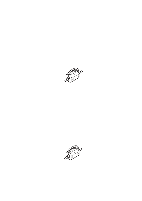
● Do not drop or apply any shock to the battery to be installed in the module.
Doing so may damage the battery, causing the battery fluid to leak inside the
battery. If the battery is dropped or any shock is applied to it, dispose of it
without using.
● Before handling the module, touch a grounded metal object to discharge the
static electricity from the human body.
Failure to do so may cause the module to fail or malfunction.
[DISPOSAL PRECAUTIONS]
CAUTION
● When disposing of the product, treat it as an industrial waste.
When disposing of batteries, separate them from other wastes according to
the local regulations.
(For details of the Battery Directive in EU member states, refer to QCPU-A (A
mode) User's Manual.)
[TRANSPORTATION PRECAUTIONS]
CAUTION
● When transporting lithium batteries, follow the transportation regulations. (For
details of the regulated models, refer to Chapter 7.)
A-7
Page 10
PRÉCAUTIONS DE SÉCURITÉ
(Lire ces précautions avant toute utilisation du produit.)
Avant d'utiliser ce produit, lire attentivement ce manuel ainsi que les manuels
auxquels il renvoie, et toujours considérer la sécurité comme de la plus haute
importance en manipulant le produit correctement.
Dans ce manuel, les précautions de sécurité sont classées en deux niveaux, à
savoir : " AVERTISSEMENT" et " ATTENTION".
AVERTISSEMENT
ATTENTION
Dans certaines circonstances, le non-respect d'une précaution de sécurité
introduite sous le titre " ATTENTION" peut avoir des conséquences graves.
Les précautions de ces deux niveaux doivent être observées dans leur intégralité
car elles ont trait à la sécurité des personnes et aussi du système.
Veiller à ce que les utilisateurs finaux lisent ce manuel qui doit être conservé
soigneusement à portée de main pour s'y référer autant que de besoin.
Attire l'attention sur le fait qu'une négligence peut
créer une situation de danger avec risque de mort
ou de blessures graves.
Attire l'attention sur le fait qu'une négligence peut
créer une situation de danger avec risque de
blessures légères ou de gravité moyennes ou
risque de dégâts matériels.
A-8
Page 11

[Précautions lors de la conception]
AVERTISSEMENT
● Configurer des circuits de sécurité extérieurs à l'automate programmable pour
garantir la sécurité du système dans son ensemble à la survenance d'une
anomalie dans l'alimentation externe comme dans l'automate programmable.
Faute de quoi, une instruction de sortie incorrecte ou un dysfonctionnement
pourrait être à l'origine d'un accident.
(1) Configurer des circuits de sécurité externes, comme un circuit d'arrêt
d'urgence, un circuit de protection et les circuits de verrouillage de
sécurité pour l'opération d'inversion de marche avant/arrière et de
positionnement en limite haute/basse.
(2) Quand l'automate programmable détecte l'un des états d'erreur ci-après, il
interrompt la marche et il désactive les sorties.
• La protection contre surintensité ou surtension du module
d'alimentation a déclenché.
• Le module CPU détecte une erreur, telle qu'une erreur d'horloge de
surveillance détectée par la fonction d'autodiagnostic.
Il se peut toutefois que toutes les sorties restent actives si l'erreur se
produit dans un organe où le module CPU ne peut pas détecter les
erreurs, comme par exemple un organe de commande d'entrée/sortie.
Pour garantir la sécurité en exploitation dans un telle éventualité, il
faut donc prévoir un mécanisme de sécurité ou un circuit de mise en
sécurité à l'extérieur de l'automate programmable. On trouvera un
exemple de circuit de mise en sécurité dans le présent manuel,
chapitre 4 "CHARGEMENT ET INSTALLATION".
(3) Une panne de relais ou de transistor dans un module de sortie pourrait
activer ou interrompre certaines sortie. Configurer un circuit de
surveillance externe pour le suivi des signaux de sortie susceptibles de
provoquer un accident grave.
● Dans un module de sortie, un courant de charge plus fort que le courant
nominal ou une surintensité produite par un court-circuit peuvent, s'ils se
prolongent, être à l'origine d'un dégagement de fumée ou d'un départ de feu.
Pour éviter cela, il faut configurer un circuit de sécurité, avec un fusible par
exemple.
● Configurer le circuit de façon à allumer d'abord l'automate programmable
avant l'alimentation externe. Si on commence par brancher l'alimentation
externe, ceci peut être une cause d'accident en cas de sortie incorrecte ou
autre dysfonctionnement.
A-9
Page 12

[Précautions lors de la conception]
AVERTISSEMENT
● Quant à l'état opérationnel de chacune des stations en cas de problème de
communication, voir les manuels correspondants pour le réseau.
Une sortie erronée ou un dysfonctionnement suite à une erreur de
communication peuvent être à l'origine d'un accident.
● Si l'automate programmable doit être commandé à partir d'un périphérique
raccordé au module CPU ou à partir d'un ordinateur personnel raccordé à un
module fonctionnel spécial, il faut dans le programme séquentiel constituer un
circuit de verrouillage permettant de garantir en tous temps la sécurité de
l'ensemble du système.
Avant de procéder à des modifications dans le programme ou à des
changements d'état fonctionnel, lire attentivement les manuels
correspondants et s'assurer de pouvoir opérer en toute sécurité.
En particulier, lorsqu'un automate programmable distant est commandé à
partir d'un dispositif externe, il faut tenir compte du fait qu'aucune action
immédiate ne sera possible s'il y a un problème de communication avec
l'automate programmable.
Pour éviter cela, constituer un circuit de verrouillage dans le programme
séquentiel, et prévoir les mesures correctives à prendre entre le dispositif
externe et le module CPU en cas de problème de communication.
● Au montage du système, il ne doit rester aucune fente à carte vide sur l'unité
de base.
S'il reste une fente à carte vide, il est indispensable de la boucher avec un
couvercle d'obturation (A1SG60) ou d'y insérer un module factice (A1SG62).
Sinon, des organes internes du module pourraient être projetés lors d'un
essai de court-circuit, ou si une surintensité ou une surtension est
accidentellement appliquée à une section entrée/sortie.
A-10
Page 13
[Précautions lors de la conception]
ATTENTION
● Ne pas entremêler les lignes de commandes ou câbles de communication
avec les lignes des circuits principaux ou les câbles d'alimentation.
Maintenir entre eux une distance d'au moins 100mm (3,9pouces).
Faute de quoi, il y a risque de dysfonctionnement par un bruit.
● Lorsque le module de sortie commande un dispositif comme une lampe, un
réchauffeur ou une électrovanne, un fort courant (jusqu'à 10 fois l'intensité
normale) traverse la sortie quand celle-ci passe de OFF à ON. Prendre les
mesures indispensables, comme le remplacement du module par un autre
ayant une capacité de courant suffisante.
● À la mise sous tension ou à la réinitialisation du module CPU, le temps
nécessaire à l'entrée en état RUN dépend de la configuration du système, du
paramétrage et/ou de la taille du programme.
Concevoir les circuits de manière que tout le système fonctionne en sécurité,
indépendamment de ce temps.
[Précautions d’installation]
ATTENTION
● Utiliser l'automate programmable dans un environnement en conformité avec
les spécifications générales que présente ce manuel.
Faute de quoi, il a risque d'électrocution, de départ de feu, de
dysfonctionnement, d'endommagement ou de détérioration du produit.
● Pour fixer le module CPU à sa place, tout en appuyant sur le levier de fixation
qui se trouve à la partie inférieure du module, engager le(s) ergot(s) de
fixation du module à fond dans le(s) trou(s) du socle et appuyer sur le module
jusqu'à encliquètement.
Une fixation incorrecte peut être à l'origine de pannes, de dysfonctionnements
ou d'une chute du module. Si l'automate programmable est installé dans un
environnement exposé aux vibrations, le module doit être immobilisé par une
vis de blocage.
Serrer la vis dans les limites du couples de serrage prescrit.
Si les vis sont insuffisamment serrées, le module risque de tomber et il peut y
avoir des court-circuits ou des dysfonctionnements. Un serrage excessif peut
endommager les vis et/ou le module, avec aussi un risque de chute, de courtcircuits et de dysfonctionnements.
A-11
Page 14

[Précautions d’installation]
ATTENTION
● Introduire fermement l'ergot de fixation à la base du module de série AnS
dans le trou de fixation du socle, puis serrer la vis de fixation du module au
couple prescrit.
Si on ne serre pas la vis, même si le module a bien pris sa place, il peut y
avoir dysfonctionnement, panne ou même chute du module.
Un serrage excessif pourrait endommager la vis et/ou le module et il y aurait
aussi risque de chute du module, de court-circuit ou de dysfonctionnements.
● Si on utilise un câble de rallonge, le raccorder fermement sur le connecteur
pour câble de rallonge sur l'unité de base.
Vérifier que les connexions ne sont pas desserrées.
Un mauvais contact peut être à l'origine d'une entrée ou sortie erronée.
● Quand on utilise une carte-mémoire, l'insérer bien à fond dans la fente pour
carte-mémoire.
Vérifier que la carte a été poussée bien à fond dans le logement.
Tout mauvais contact peut être source de dysfonctionnements.
● Couper l'alimentation externe du système sur toutes les phases avant la mise
en place ou le retrait du module.
Faute quoi, le produit risquerait d'être endommagé.
● Éviter tout contact direct avec les parties conductrices du module.
Cela pourrait être à l'origine de dysfonctionnements ou d'une panne du
module.
[Pécautions de câblage]
AVERTISSEMENT
● Couper l'alimentation externe du système sur toutes les phases avant de
commencer à câbler.
Faute de quoi, il y a risque d'électrocution et d'endommagement du produit.
● Après câblage, mettre le couvre-bornes fourni en place avant de procéder à la
mise sous tension pour mettre en marche.
Faute de quoi, il y a risque d'électrocution.
A-12
Page 15

[Pécautions de câblage]
ATTENTION
● Mettre à la masse les bornes FG et LG sur le conducteur réservé à la
protection à la terre de l'automate programmable.
Faute de quoi, il y a risque d'électrocution et de dysfonctionnement.
● Utiliser des bornes sans soudure du type prescrit en les serrant au couple
prescrit. Une borne sans soudure dont la vis se desserre peut être une source
de mauvais contact avec risque de panne.
● Vérifier la tension nominale et l'affectation des bornes avant le câblage du
module et raccorder les câbles correctement.
Le raccordement d'une alimentation d'une tension autre que la tension
nominale ou une erreur de câblage peut être à l'origine d'un départ de feu ou
d'une panne.
● Ne pas raccorder plusieurs modules d'alimentation en parallèle sur un même
module. La surchauffe des modules d'alimentation pourrait entraîner un
départ de feu ou être à l'origine d'une panne.
● Les connecteurs pour connexions externes doivent être sertis ou comprimés
avec l'outil prescrit par le fabricant ou, à défaut, doivent être soudés
correctement.
Une connexion imparfaite peut être à l'origine d'un court-circuit ou d'un départ
de feu, ou entraîner des dysfonctionnements.
● Serrer les vis de borne dans les limites du couple de serrage prescrit.
Si les vis sont insuffisamment serrées, il y a risque de court-circuits, départ de
feu ou dysfonctionnement.
Un serrage excessif peut endommager les vis et/ou le module, avec aussi un
risque de chute, de court-circuits et de dysfonctionnements.
● Veiller à ne pas laisser la poussière, les copeaux métalliques ou d'autres
corps étrangers pénétrer dans le module. Tout corps étranger peut être à
l'origine d'un départ de feu, d'une panne ou d'un dysfonctionnement.
● Le haut du module est recouvert d'un film protecteur pour éviter toute
pénétration de corps étrangers comme des copeaux métalliques pendant le
câblage.
Ne pas retirer le film protecteur avant de terminer le câblage.
Il doit cependant être retiré avant la mise en service du système pour une
meilleure dispersion de la chaleur.
A-13
Page 16
[Pécautions de câblage]
ATTENTION
● Les automates programmable Mitsubishi doivent être installés en tableau ou
armoire de commande.
Raccorder l'alimentation principale au module d'alimentation dans le tableau
de commande sur une plaque à bornes avec relais.
Le câblage et le remplacement d'un module d'alimentation doivent être
effectués par un personnel d'entretien averti des risques d'électrocution. (À
propos des méthodes de câblage, se reporter au Manuel de l'utilisateur
QCPU (mode A).)
[Précautions de mise en service et de maintenance]
AVERTISSEMENT
● Ne toucher à aucun des bornes quand le système est sous tension.
Il y aurait risque d'électrocution.
● Raccorder correctement le connecteur des piles. Les piles ne doivent pas être
rechargées, démontées, court-circuitées ou soudées. Elles ne doivent pas
non plus être jetées au feu.
Ceci risquerait de faire surchauffer ou éclater les piles qui, si elles
s'enflammaient, pourraient être à l'origine de blessures ou d'un départ de feu.
● Couper l'alimentation du système sur toutes les phases avant le nettoyage du
module ou avant le resserrage des vis de bornes ou des vis de fixation du
module. Faute de quoi, il y a risque d'électrocution.
Un serrage insuffisant des vis de bornes peut être à l'origine d'un court-circuit
ou de dysfonctionnement.
Un serrage excessif peut endommager les vis et/ou le module, avec aussi un
risque de chute, de court-circuits et de dysfonctionnements.
A-14
Page 17

[Précautions de mise en service et de maintenance]
ATTENTION
● Avant d'effectuer une opération en ligne (en particulier une modification de
programme, une sortie forcée ou un changement d'état fonctionnel) sur un
module CPU en marche à partir d'un périphérique connecté, consulter les
manuels correspondants pour être sûr de pouvoir opérer en toute sécurité.
Une fausse manœuvre pourrait être à l'origine d'un accident ou de dégâts
matériels.
● Ne pas démonter ni modifier les modules.
Cela pourrait entraîner des pannes ou dysfonctionnements et être à l'origine
de blessures ou de départs de feu.
● Tout type d'appareil de communication radio, y compris les téléphones
portables et les appareils PHS (Personal handy-phone system), doit être
tenus éloignés de plus de 25cm (9,84pouces) de l'automate programmable,
dans tous les sens.
Le non-respect de cette précaution expose à des dysfonctionnements.
● Couper l'alimentation externe du système sur toutes les phases avant la mise
en place ou le retrait du module. Le non-respect de cette précaution peut être
à l'origine de pannes ou de dysfonctionnements du module.
● Après la première utilisation du produit, ne pas effectuer les opérations
suivantes plus de 50 fois (conformément à CEI 61131-2/JIS B 3502).
• Montage/dépose du module sur le corps de l'appareil
• Montage/dépose du bornier sur le module
Dépasser ce nombre maximum de 50 opérations d'insertion/retrait peut être à
l'origine de dysfonctionnements.
● Ne pas faire tomber ou soumettre à de forts chocs les piles à installer dans les
modules.
Cela pourrait endommager les piles, avec risque de fuite du liquide à
l'intérieur des piles. Toute pile qu'on a laissé tomber ou qui a subi un choc
violent doit être jetée avant usage.
● Avant de manipuler un module, se débarrasser de la charge électrostatique
qu'accumule le corps humain en touchant un objet métallique raccordé à la
terre.
Le non-respect de cette précaution peut être à l'origine de pannes ou de
dysfonctionnements du module.
A-15
Page 18
[Précautions de mise au rebut]
ATTENTION
● Pour le mettre au rebut, ce produit doit être traité comme un déchet industriel.
Les piles ou batteries doivent être mises au rebut séparément des autres
déchets et conformément à la réglementation locale.
(Pour le détail des directives sur les piles et batteries dans les pays de l'Union
Européenne, voir le Manuel de l'utilisateur QCPU-A (mode A).)
[Précautions de transport]
ATTENTION
● Pour le transport des piles au lithium, respecter la réglementation afférente à
ce transport. (Pour le détail des modèles soumis à une réglementation, se
reporter au chapitre 7.)
A-16
Page 19
A-17
Page 20
A-18
Page 21
A-19
Page 22
A-20
Page 23
A-21
Page 24
A-22
Page 25
A-23
Page 26

CONDITIONS OF USE FOR THE PRODUCT
(1) Mitsubishi programmable controller ("the PRODUCT") shall be used in
conditions;
i) where any problem, fault or failure occurring in the PRODUCT, if any,
shall not lead to any major or serious accident; and
ii) where the backup and fail-safe function are systematically or
automatically provided outside of the PRODUCT for the case of any
problem, fault or failure occurring in the PRODUCT.
(2) The PRODUCT has been designed and manufactured for the purpose of
being used in general industries.
MITSUBISHI SHALL HAVE NO RESPONSIBILITY OR LIABILITY
(INCLUDING, BUT NOT LIMITED TO ANY AND ALL RESPONSIBILITY
OR LIABILITY BASED ON CONTRACT, WARRANTY, TORT, PRODUCT
LIABILITY) FOR ANY INJURY OR DEATH TO PERSONS OR LOSS OR
DAMAGE TO PROPERTY CAUSED BY the PRODUCT THAT ARE
OPERATED OR USED IN APPLICATION NOT INTENDED OR
EXCLUDED BY INSTRUCTIONS, PRECAUTIONS, OR WARNING
CONTAINED IN MITSUBISHI'S USER, INSTRUCTION AND/OR SAFETY
MANUALS, TECHNICAL BULLETINS AND GUIDELINES FOR the
PRODUCT.
("Prohibited Application")
Prohibited Applications include, but not limited to, the use of the PRODUCT
in;
• Nuclear Power Plants and any other power plants operated by Power
companies, and/or any other cases in which the public could be
affected if any problem or fault occurs in the PRODUCT.
• Railway companies or Public service purposes, and/or any other cases
in which establishment of a special quality assurance system is
required by the Purchaser or End User.
• Aircraft or Aerospace, Medical applications, Train equipment, transport
equipment such as Elevator and Escalator, Incineration and Fuel
devices, Vehicles, Manned transportation, Equipment for Recreation
and Amusement, and Safety devices, handling of Nuclear or
Hazardous Materials or Chemicals, Mining and Drilling, and/or other
applications where there is a significant risk of injury to the public or
property.
A-24
Page 27

Notwithstanding the above, restrictions Mitsubishi may in its sole discretion,
authorize use of the PRODUCT in one or more of the Prohibited
Applications, provided that the usage of the PRODUCT is limited only for
the specific applications agreed to by Mitsubishi and provided further that
no special quality assurance or fail-safe, redundant or other safety features
which exceed the general specifications of the PRODUCTs are required.
For details, please contact the Mitsubishi representative in your region.
A-25
Page 28

REVISIONS
Addition of model
Addition of model
Addition
Partial correction
Partial correction
Addition
Partial correction
Partial correction
Partial correction
Addition
Partial correction
Partial correction
* The manual number is given on the bottom right of the front cover.
Print Date *Manual Number Revision
Dec.,1999 IB (NA)-0800084-A First edition
Mar.,2000 IB (NA)-0800084-B
Dec.,2003 IB (NA)-0800084-C
Dec.,2004 IB (NA)-0800084-D
Jul.,2005 IB (NA)-0800084-E
Oct.,2006 IB (NA)-0800084-F
May,2007 IB (NA)-0800084-G
Sep.,2008 IB (NA)-0800084-H
Sep.,2009 IB (NA)-0800084-I
QA1S33B
A1SY42P
Chapter 7
SAFETY PRECAUTIONS,
Section 5.2.1, 5.2.2
SAFETY PRECAUTIONS, CONTENTS, Section
2.1, 2.2, Chapter 3,
Section 3.1.3, 3.1.4, 3.1.5, 3.2, 3.2.1, 3.2.2, 3.2.4,
4.1, 4.1.1, 4.1.4, 4.2, 4.3, 4.3.1, 4.3.2, 4.3.3,
Chapter 5,
Chapter 6, Section 6.2, Chapter 7
USER PRECAUTONS
SAFETY PRECAUTIONS,
Section 2.1, 2.2, 3.1.1, 3.1.3, 3.1.5, 3.2.2, 4.1,
4.2, 4.3.2, 4.5.2, 4.5.3,
Chapter 5, Section 6.2
SAFETY PRECAUTIONS,
Section 2.1, 2.2, 3.1.3, 3.2.4, 3.2.6, 4.1.2, 4.3.1,
4.3.2, 4.3.3, 5.2.1, 5.2.2, 6.2
Section 3.1.1, 3.1.3, 3.2.7, 4.3.2, 4.3.3, 5.1.2,
5.2.1
Section 3.1.7
SAFETY PRECAUTIONS, CONTENTS, USER
PRECAUTONS, Section 2.1, 2.2, 3.1, 3.1.1,
3.1.2, 3.1.3, 3.2, 3.2.3, 3.2.4, 3.2.5, 3.2.6, 3.2.7,
4.1, 4.1.1, 4.1.4, 4.2, 4.3.1, 4.3.2, 5.1.1, 5.2.1,
Chapter 6
SAFETY PRECAUTIONS, CO NTENTS, Chapter
3, Section 4.5.1, 7.1
A-26
Page 29
* The manual number is given on the bottom right of the front cover.
Partial correction
Addition
Partial correction
Addition
Partial correction
Partial correction
Partial correction
Addition
Addition
Partial correction
Print Date *Manual Number Revision
Jan., 2011 IB (NA)-0800084-J
Aug., 2011 IB (NA)-0800084-K
Oct., 2011 IB (NA)-0800084-L
May, 2014 IB (NA)-0800084-M
Dec., 2016 IB(NA)-0800084-N
Jun., 2018 IB(NA)-0800084-O
Apr., 2019 IB(NA)-0800084-P
SAFETY PRECAUTIONS, Section 2.1,
Chapter 3, Section 3.1, 3.1.3, 3.1.4,
3.1.5, 3.1.7, 4.2, 4.3.2, 4.4, 5.1.2, 5.2.2, 5.3.2, 6.2
CONDITIONS OF USE FOR THE PRODUCT,
Section 3.1.8
SAFETY PRECAUTIONS, Section 2.1, 2.2, 2.3,
3.1.1, 4.1, 4.2, 4.3.2, 5.1.2, 5.2.2, 5.3.2
SAFETY PRECAUTIONS (Chine se)
Section 1.1, 2.3, 4.1.1, 4.1.2
SAFETY PRECAUTIONS, Section 3.1.3, 4.1.1
Section 2.1, 2.2, 4.3.1
Appendix 1
Appendix 2
Section 7.1
Japanese Manual Version IB(NA)-0800028-P
This manual confers no industrial property rights or any rights of any other kind, nor does it
confer any patent licenses. Mitsubishi Electric Corporation cannot be held responsible for any
problems involving industrial property rights which may occur as a result of using the contents
noted in this manual.
© 1999 MITSUBISHI ELECTRIC CORPORATION
A-27
Page 30

CONTENTS
1. OVERVIEW .................................................................................................... 1
1.1 Supplied Parts....................................................................................... 1
2. GENERAL SPECIFICATIONS ....................................................................... 3
2.1 General Specifications .......................................................................... 3
2.2 Performance Specifications of CPU Modules ....................................... 5
2.3 Specifications of Base Units ................................................................. 7
3. EMC DIRECTIVES AND LOW VOLTAGE DIRECTIVES............................... 8
3.1 Requirements for Compliance with EMC Directive ............................... 8
3.1.1 Standards applicable to the EMC Directive ................................. 9
3.1.2 Installation inside the control panel ........................................... 11
3.1.3 Cables ....................................................................................... 13
3.1.4 Power supply module ................................................................ 21
3.1.5 Ferrite core ................................................................................ 21
3.1.6 Noise filter (power supply line filter)........................................... 22
3.1.7 Power line for external power supply terminal ........................... 23
3.1.8 Installation environment of the CC-Link/LT module and the AS-I
3.2 Requirements for Compliance with Low Voltage Directive ................. 24
4. LOADING AND INSTALLATION .................................................................. 29
4.1 Module Installation .............................................................................. 29
4.2 Fail-Safe Circuit Concept .................................................................... 44
4.3 Wiring.................................................................................................. 48
module....................................................................................... 23
3.2.1 Standard applied for MELSEC-AnS series programmable
controller.................................................................................... 24
3.2.2 Precautions when using the MELSEC-AnS series programmable
controller.................................................................................... 25
3.2.3 Power supply ............................................................................. 26
3.2.4 Control panel ............................................................................. 26
3.2.5 Module installation..................................................................... 28
3.2.6 External wiring ........................................................................... 28
4.1.1 Handling instructions ................................................................. 29
4.1.2 Instructions for mounting the base unit...................................... 31
4.1.3 Installation and removal of dustproof cover ............................... 34
4.1.4 Installation and removal of modules .......................................... 35
4.1.5 Setting the extension number of the extension base unit.......... 39
4.1.6 Connection and disconnection of extension cable .................... 41
4.3.1 Power supply module specifications.......................................... 48
4.3.2 The precautions on the wiring ................................................... 51
4.3.3 Connecting to the power supply module .................................. 55
A-28
Page 31

4.4 Precautions when Connecting the Uninterruptible Power Supply (UPS)
............................................................................................................ 56
4.5 Part Names and Settings of the CPU Module ..................................... 57
4.5.1 Part names and settings............................................................ 57
4.5.2 Switch operation after program write ......................................... 60
4.5.3 Latch clear operation ................................................................. 60
4.5.4 Installation and removal of memory card during power-on........ 60
5. SPECIFICATIONS AND CONNECTIONS OF I/O MODULES ..................... 62
5.1 Input modules...................................................................................... 62
5.1.1 Input module specifications ....................................................... 62
5.1.2 Input module connections.......................................................... 66
5.2 Output modules ................................................................................... 72
5.2.1 Output module specifications .................................................... 72
5.2.2 Output module connections ....................................................... 78
5.3 Input/output combined modules .......................................................... 88
5.3.1 Input/output combined module specifications ............................ 88
5.3.2 Input/output composite module connections ............................. 90
6. ERROR CODES........................................................................................... 92
6.1 Reading the Error Code ...................................................................... 92
6.2 Error Code List .................................................................................... 93
7. TRANSPORTATION PRECAUTIONS ....................................................... 113
7.1 Relevant Models ............................................................................... 113
7.2 Transportation Guidelines ................................................................. 113
APPENDIX...................................................................................................... 114
Appendix 1 Marking and Information Disclosure for the Restriction on Use of
Hazardous Substances in Electrical and Electronic Products
Required by the New China RoHS......................................... 114
Appendix 2 Information for the Chinese standardized low ........................ 114
A-29
Page 32

ABOUT THE MANUALS
The following manuals are related to this product.
Referring to this list, please request the necessary manuals.
Detailed manual
Manual name
QCPU-A (A mode) User's Manual
This manual describes information on the performance,
functions and handling of the QCPU-A (A mode) and on the
specifications and handling of the memory cassettes, power
supply modules and base units.
Related Manuals
Manual name
Type ACPU/QCPU-A (A Mode) Programming Manual
(Fundamentals)
This manual describes programming methods required to create
programs, device names, parameters, types of program,
configuration of the memory area, etc.
Type ACPU/QCPU-A (A Mode) Programming Manual
(Common Instructions)
This manual describes how to use the sequence instructions,
basic instructions, application instructions and micro-computer
programs.
Type AnSHCPU/AnACPU/AnUCPU/QCPU-A (A Mode)
Programming Manual (Dedicated Instructions)
This manual describes the extended instructions for the
A2ASCPU(S1/30).
Type AnACPU/AnUCPU (AD57 control Instructions)
Programming Manual
This manual describes the dedicated instructions used to control
AD57(S1)/ AD58 CRT/LCD control modules with an
A2ASCPU(S1/30).
(Sold separately)
(Sold separately)
(Sold separately)
(Sold separately)
(Sold separately)
Manual Number
(Model code)
SH-080065
(13JR10)
Manual Number
(Model code)
IB-66249
(13J740)
IB-66250
(13J741)
IB-66251
(13J742)
IB-66257
(13J743)
A-30
Page 33

Manual name
Type AnACPU/AnUCPU/QCPU-A (A mode)
Programming Manual (PID control instructions)
This manual describes the dedicated instructions used to
execute PID control with an A2ASCPU(S1/30).
Type MELSAP-II (SFC) Programming Manual
Describes the specifications, functions, instructions, and
programming methods for SFC programming using MELSAP II.
AnS Module Type I/O User's Manual
This manual gives the specifications for AnS module type I/O
modules.
(Sold separately)
(Sold separately)
(Sold separately)
Manual Number
(Model code)
IB-66258
(13J744)
IB-66361
(13JF40)
IB-66541
(13JE81)
A-31
Page 34

USER PRECAUTIONS
PRECAUTIONS WHEN USING THE Q SERIES
For a new CPU module, which has never used before, the contents of
built-in RAM and device data are undefined.
Make sure to clear the built-in RAM memory (PC memory all clear) in
the CPU module by peripheral devices and operate latch clear by RUN/
STOP key switches.
PRECAUTIONS FOR BATTERY
(1) The operation after a battery is unmounted and the programmable
controller is stored.
When reoperating after a battery is uncounted and the
programmable controller is stored, the contents of built-in RAM and
device data may be undefined. For this reason, make sure to clear
the built-in RAM memory (PC memory all clear) in the CPU module
by peripheral devices and operate latch clear by RUN/STOP key
switch before start the operation again.
(2) If a battery exceeded its guaranteed life is stored and reoperated.
If a battery exceeded its guaranteed life is stored and reoperated,
the contents of built-in RAM and device data may be undefined. For
this reason, make sure to clear the built-in RAM memory (PC
memory all clear) in the CPU module by peripheral devices and
operate latch clear by RUN/STOP key switches before start the
operation again.
After the built-in RAM clear and latch clear of the CPU module,
write the backed-up memory contents to the CPU module before
saving.
POINT
Make sure to back-up each memory contents before storing the programmable
controller.
* Refer to the following manuals for details of built-in RAM clear
(programmable controller memory all clear) by peripheral devices.
•
GX Developer Operating Manual
•
A6GPP/A6PHP Operating Manual
SWSRX/SWNX/SWIVD-GPPA Operating Manual
•
Refer to Section 4.5.3 for latch clear operation by RUN/STOP key
switch of the CPU module.
A-32
Page 35

1. OVERVIEW
This user's manual provides the performance specifications, loading
and installation, part names and settings, I/O module specifications and
installation, and error code reading method of the Q02CPU-A,
Q02HCPU-A and Q06HCPU-A (hereinafter referred to as the "QCPUA").
1.1 Supplied Parts
The following tables list the parts packed with the corresponding
modules.
(1) CPU module
Product Name Type Quantity
CPU module
Battery Q6BAT 1
(2) Main base unit for A series modules
Product Name Type Quantity
Main base unit
Base unit mounting screw M5 screw 4
Dustproof cover ————— 1
This manual ————— 1
(3) Extension base unit for A series modules
Product Name Type Quantity
Extension base unit
Base unit mounting screw M5 screw 3/4
Supplementary Description for
QA1S51B Extension Base
Unit
(BCN-P5920)
Dustproof cover
*1 Screws as many as the number of mounting holes are supplied.
*2 This document is included only with the QA1S5B.
*2
*2
Q02CPU-A
Q06HCPU-A
QA1S33B
QA1S38B
QA1S51B
QA1S68B
—————
—————
1
1Q02HCPU-A
1QA1S35B
1QA1S65B
*1
1
Page 36

(4) Power supply module
Product Name Type Quantity
Power supply module
A1S61PN
A1S63P
1A1S62PN
2
Page 37

2. GENERAL SPECIFICATIONS
2.1 General Specifications
This section provides specifications common to various modules used.
Item Specifications
Ambient
operating
temperature
Température
ambiante de
fonctionnement
Ambient storage
temperature
Ambient
operating
humidity
Ambient storage
humidity
Compliant
Vibration
resistance *4
Shock
resistance
Operating
atmosphere
Operating
altitude *3
Installation
location
Overvoltage
category *1
Pollution degree
*2
Equipment class Class I
*1 This indicates the section of the power supply to which the equipment is assumed to be
connected between the public electrical power distribution network and the machinery
within premises. Category II applies to equipment for which electrical power is supplied
from fixed facilities. The surge voltage withstand level for up to the rated voltage of 300V is
2500V.
with
JIS B 3502,
and IEC
61131-2
Compliant with JIS B 3502 and IEC 61131-2 (147 m/ s2, 3 times each in
3 directions X, Y, Z)
General Specification
0 to 55 °C
0 à 55 °C
-20 to 75 °C
10 to 90 % RH, No-condensing
Frequency
Under
intermittent
vibration
Under
continuous
vibration
5 to 9Hz ——— 3.5mm 10 times
9 to 150Hz 9.8m/s
5 to 9Hz ——— 1.75mm
9 to 150Hz 4.9m/s2———
No corrosive gases
0 to 2000m
Inside a control panel
II or ress
2 or less
Constant
acceleration
2
Half
amplitude
———
Sweep
count
each in
X, Y, Z
directio ns
———
3
Page 38

*2 This index indicates the degree to which conductive material is generated in terms of the
environment in which the equipment is used. Pollution level 2 is when only non-conductive
pollution occurs. A temporary conductivity caused by condensing must be expected
occasionally.
*3 Do not use or store the programmable controller under pressure higher than the
atmospheric pressure of altitude 0m. Doing so may cause malfunction.
When using the programmable controller under pressure, please consult your local
Mitsubishi Electric representative.
*4 When an A series extension base unit (A52B, A55B, A58B, A62B, A65B, A68B) is used in
the system, the following specifications apply.
Frequency Acceleration Amplitude Sweep count
Under
intermittent
vibration
Under
continuous
vibration
10 to 57Hz ——— 0.075mm
57 to 150Hz 9.8m/s
2
———
10 to 57Hz ——— 0.035mm
57 to 150Hz 4.9m/s
2
———
10 times each in
X, Y, Z directions
———
4
Page 39

2.2 Performance Specifications of CPU Modules
This section gives the performance specifications of the CPU modules.
Performance List
Item
Control system Stored program cyclic operation
I/O control method Refresh mode
Programming language
Processing speed
(sequence instruction)
Constant scan
Built-in RAM 144k bytes
Memory
When using memory
capacity
card (RAM)
Built-in ROM 144k bytes
Main sequence
program
Program
capacity
Sub sequence
program
I/O device points
I/O points
Output mode switching at
STOP RUN
Self-diagnostics functions
Operation mode at error
occurrence
Starting method at RUN
Q02CPU-A Q02HCPU-A Q06HCPU-A
Language dedicated to sequence control
Relay symbol type and logic symbolic
language, MELSAP-II (SFC)
0.079 µs/
LD
steps
0.474 µs/
MOV
steps
(can be specified in 10ms increments)
Max. 28k steps
(Total points available on programs
(Points can be controlled on basic and
Re-output of operation at time of STOP
(default)/output after operation execution
Watchdog error monitor (watchdog timer
fixed to 200ms)
Memory, CPU, I/O, battery and other error
detection
STOP/CONTINUE selection
Initial start
(Automatic restart made when "RUN"
switch of CPU is moved to ON position at
power-on or at power restoration after
power failure)
Type
0.034 µs/steps
0.204 µs/steps
10 to 190 ms
448k bytes
Unavailable
8192 points (X/Y0 to 1FFF)
including remote I/O)
4096 points (X/Y0 to FFF)
expansion base modules)
Max. 30k
steps
Max. 30k
steps
Remarks
Partial direct I/O
possible
depend-ing on
instruction
Set to special
register D9020
Parameter
setting
Parameter
setting
Parameter
setting
5
Page 40

Performance List (Continued)
Item
Latch (pow er failure
compensation) range
Remote RUN/PAUSE contact
Clock function
Allowable momentary power
interruption time
5VDC internal current
consumption
Weight 0.20kg 0.20kg 0.20kg
External dimensions
CAUTION
When using the conventional type peripheral device and GPP function software package,
set the programmable controller type to "Q02(H)-A/Q06H-A".
When the GPP used is incompatible with the "Q02(H)-A/Q06H-A", make the following
setting.
GPP-
Compatible CPU
Programmable
controller type
Note that the setting of the programmable controller type to "A3ACPU" or "A3HCPU" will
limit the usable ranges of the devices.
Q02CPU-A Q02HCPU-A Q06HCPU-A
Defaults to L1000 to L2047
(Latch range can be set for L, B, T, C, D and
W)
One RUN contact and one PAUSE contact
can be set within the range from X0 to
X1FFF.
Year, month, day, hour, minute, second,
day of week (Automatically recognizes leap
years.)
Accuracy
-3.18 to +5.25s(TYP.+2.12s)/d at 0°C
-3.93 to +5.25s(TYP.+1.90s)/d at 25°C
-14.69 to +3.53s(TYP.-3.67s)/d at 55°C
Depends on power supply module
0.60A 0.64A 0.64A
98(3.86)(H)×27.4(1.08)(W)×89.3(3.52)(D)
"Q02(H)-A/Q06H-A"-
Incompatible
A4UCPU A3ACPU A3HCPU
Type
mm(inches)
"A4UCPU"-
Incompatible
Remarks
Set range in
parameters
Parameter
setting
"A3ACPU"-
Incompatible
6
Page 41

2.3 Specifications of Base Units
(1) Main Base Unit
Item
Number of I/O modules
accepted
5VDC internal current
consumption
External dimensions
Weight 0.57kg 0.75kg 1.00kg
* The parenthesized values are for those products not provided for CE mark.
Type
(2) Extension Base Unit
Item
Number of I/O modules
accepted
5VDC internal current
consumption
External dimensions
Weight 0.23kg 0.75kg 1.00kg
* The parenthesized values are for those products not provided for CE mark.
Type
QA1S33B QA1S35B QA1S38B
358
0.107A 0.117A(0.086A) * 0.118A(0.086A) *
255(10.04)(W)×
130(5.12)(H)×
51.2(2.02)(D)
mm(inches)
QA1S51B QA1S65B QA1S68B
158
0.12A 0.117A(0.088A) * 0.118A(0.090A) *
100(3.94)(W)×
130(5.12)(H)×
50.7(2.00)(D)
mm(inches)
325(12.80)(W)×
130(5.12)(H)×
51.2(2.02)(D)
mm(inches)
315(12.40)(W)×
130(5.12)(H)×
51.2(2.02)(D)
mm(inches)
430(16.93)(W)×
130(5.12)(H)×
51.2(2.02)(D)
mm(inches)
420(16.54)(W)×
130(5.12)(H)×
51.2(2.02)(D)
mm(inches)
7
Page 42

3. EMC DIRECTIVES AND LOW VOLTAGE DIRECTIVES
The products sold in the European countries have been required by law
to comply with the EMC Directives and Low Voltage Directives of the EU
Directives since 1996 and 1997, respectively.
The manufacturers must confirm by self-declaration that their products
meet the requirements of these directives, and put the CE mark on the
products.
(1) Authorized representative in Europe
Authorized representative in Europe is shown below.
Name : MITSUBISHI ELECTRIC EUROPE B.V.
Address: Mitsubishi-Electric-Platz 1, 40882 Ratingen, Germany
3.1 Requirements for Compliance with EMC Directive
The EMC Directives specifies emission and immunity criteria and
requires the products to meet both of them, i.e., not to emit excessive
electromagnetic interference (emission): to be immune to
electromagnetic interference outside (immunity).
Guidelines for complying the machinery including MELSEC-Q series
programmable controller with the EMC Directives are provided in
Section 3.1.1 to 3.1.8 below.
The guidelines are created based on the requirements of the
regulations and relevant standards, however, they do not guarantee that
the machinery constructed according to them will not comply with the
Directives.
Therefore, the manufacturer of the machinery must finally determine
how to make it comply with the EMC Directives: if it is actually compliant
with the EMC Directives.
8
Page 43

3.1.1 Standards applicable to the EMC Directive
(1) Regulations regarding emission
Standard Test item Test description Value specified in standard
CISPR16-2-3
Radiated emission
EN61131-2:
2007
*1 QP: Quasi-peak value, Mean: Average value
*2 Programmable controllers are open-type devices (devices designed to be housed inside
other equipment) and must be installed inside a conductive control panel. The
corresponding tests were conducted with the programmable controller installed inside a
control panel.
*2
CISPR16-2-1,
CISPR16-1-2
Conducted emission
*2
Radio waves from
the product are
measured.
Noise from the
product to the power
line is measured.
• 30M-230MHz
QP: 40dBµV/m (10m in
measurement range) *1
• 230M-1000MHz
QP: 47dBµV/m (10m in
measurement range)
• 150k-500kHz
QP: 79dB, Mean: 66dB *1
• 500k-30MHz
QP: 73dB, Mean: 60dB
9
Page 44

(2) Regulations regarding immunity
Standard Test item Test description Value specified in standard
EN61000-4-2
Electrostatic
discharge immunity
*1
EN61000-4-3
Radiated, radiofrequency,
electromagnetic field
immunity *1
EN61000-4-4
Electrical fast
EN61131-2:
2007
EN61131-2:
2007
*1 Programmable controllers are open-type devices (devices designed to be housed inside
other equipment) and must be installed inside a conductive control panel. The
corresponding tests were conducted with the programmable controller installed inside a
control panel.
*2 The accuracy of an analog-digital converter module may temporary vary within 10%.
transient/burst
immunity *1
EN61000-4-5
Surge immunity *1
EN61000-4-6
Immunity to
conducted
disturbances,
induced by radiofrequency fields *1
EN61000-4-8
Power-frequency
magnetic field
immunity *1
EN61000-4-11
Voltage dips and
interruption
immunity
Immunity test in
which electrostatic
is applied to the
cabinet of the
equipment.
Immunity test in
which el ectric fi elds
are irradiated to the
product.
Immunity test in
which burst noise is
applied to the power
line and signal line.
Immunity test in
which lightning
surge is applied to
the power line and
signal line.
Immunity test in
which high
frequency noise is
applied to the power
line and signal line
Immunity test in
which the product is
installed in inductive
magnetic field
Immunity test in
which power supply
voltage is
momentarily
interrupted
• 8kV Air discharge
• 4kV Contact discharge
• 80% AM modulation@1kHz
• 80M-1000MHz: 10V/m
• 1.4G-2.0GHz: 3V/m
• 2.0G-2.7GHz: 1V/m
• AC/DC main power, I/O power,
AC I/O (unshielded): 2kV
• DC I/O, analog, communication:
1kV
• AC power line, AC I/O power,
AC I/O (unshielded)
: 2kV CM, 1kV DM
• DC power line, DC I/O power
: 0.5kV CM, DM
• DC I/O, AC I/O (shielded),
analog*2, communication: 1kV
CM
0.15M-80MHz, 80% AM
modulation@1kHz, 10Vrms
50Hz/60Hz, 30A/m
• Apply at 0%, 0.5 cycles and
zero-cross point
• 0%, 250/300 cycles (50/60Hz)
• 40%, 10/12 cycles (50/60Hz)
• 70%, 25/30 cycles (50/60Hz)
10
Page 45

3.1.2 Installation inside the control panel
The programmable controller is open equipment and must be installed
within a control panel for use.* This not only ensures safety but also
ensues effective shielding of programmable controller-generated
electromagnetic noise.
*
Also, each network remote station needs to be installed inside the
control panel.
However, the waterproof type remote station can be installed outside
the control panel.
(1) Control panel
(a) Use a conductive control panel.
(b) When attaching the control panel's top plate or base plate,
mask painting and weld so that good surface contact can be
made between the panel and the bolt.
(c) To ensure good electrical contact with the control panel, mask
the paint on the installation bolts of the inner plate in the control
panel so that contact between surfaces can be ensured over
the widest possible area.
(d) Earth the control panel with a thick wire so that a low
impedance connection to ground can be ensured even at high
frequencies.
(e) Holes made in the control panel must be 10 cm (3.94 in.)
diameter or less. If the holes are 10 cm (3.94 in.) or larger,
radio frequency noise may be emitted.
(2) Connection of power and earth wires
Earthing and power supply wires for the programmable controller
system must be connected as described below.
(a) Provide an earthing point near the power supply module. Earth
the power supply's LG and FG terminals (LG : Line Ground, FG
: Frame Ground) with the thickest and shortest wire possible.
(The wire length must be 30 cm (11.18 in.) or shorter.) The LG
and FG terminals function is to pass the noise generated in the
programmable controller system to the ground, so an
impedance that is as low as possible must be ensured. As the
wires are used to relieve the noise, the wire itself carries a
large noise content and thus short wiring means that the wire is
prevented from acting as an antenna.
11
Page 46

(b) The earth wire led from the earthing point must be twisted with
the power supply wires. By twisting with the earthing wire,
noise flowing from the power supply wires can be relieved to
the earthing. However, if a filter is installed on the power
supply wires, the wires and the earthing wire may not need to
be twisted.
12
Page 47

3.1.3 Cables
Shield section
The cables extracted from the control panel contain a high frequency
noise component. On the outside of the control panel, therefore, they
serve as antennas to emit noise. To prevent noise emission, use
shielded cables for the cables which are connected to the I/O modules
and intelligent function modules and may be extracted to the outside of
the control panel.
The use of a shielded cable also increases noise resistance.
The signal lines (including common line) of the programmable
controller, which are connected to I/O modules, intelligent function
modules and/or extension cables, have noise durability in the condition
of grounding their shields by using the shielded cables. If a shielded
cable is not used or not grounded correctly, the noise resistance will not
meet the specified requirements.
(1) Shield grounding
(a) When grounding the shied, position the grounding point closer
to the module and take care so that the electromagnetic
induction will not occur between the grounded cable and
ungrounded one.
(b) When grounding the shield, strip a part of the outer insulation
layer to expose the shield, and make the shield contact with
the control panel in the largest area as possible. The clamp
fitting as shown below can be used. In this case, however, the
contact area on the panel’s inner surface must be masked
during painting.
Screw
Clamp fitting
Paint mask
Shielded cable
Note) The method of earthing by soldering a wire onto the shield section of
the shielded cable as shown below is not recommended. The high
frequency impedance will increase and the shield will be ineffective.
Shielded cable
Wire
Crimp terminal
13
Page 48

(2) MELSECNET (II) and MELSECNET/10 modules
(a) Use a double-shielded coaxial cable for the MELSECNET
module which uses coaxial cables such as A1SJ71AR21,
A1SJ71LR21 and A1SJ71BR11. Noise in the range of 30 MHz
or higher in radiation noise can be suppressed by the use of
double-shielded coaxial cables (manufactured by MITSUBISHI
CABLE INDUSTRIES, LTD: 5C-2V-CCY). Earth the outer
shield to the ground.
Shield
Earth here
For the shield grounding, refer to item (1).
(b) Make sure to attach a ferrite core to the double-shielded
coaxial cable connected to the MELSECNET module. In
addition, position the ferrite core on each cable near the outlet
of the control panel. The ferrite core manufactured by TDK
Corporation, ZCAT3035-1330, is recommended.
(3) Ethernet module
Precautions for using AUI cables, twisted pair cables and coaxial
cables are described below.
(a) Always earth the AUI cables
*1
connected to the 10BASE5
connectors. Because the AUI cable is of the shielded type,
strip part of the outer cover and earth the exposed shield
section to the ground on the widest contact surface as shown
below.
AUI cable
Shield
Refer to (1) for the earthing of the shield.
*1 Make sure to install a ferrite core for the cable.
The ferrite core manufactured by TDK Corporation, ZCAT20320930, is recommended.
14
Page 49

(b) Use shielded twisted pair cables as the twisted pair cables
connected to the 10BASE-T connectors. For the shielded
twisted pair cables, strip part of the outer cover and earth the
exposed shield section to the ground on the widest contact
surface as shown below.
Shielded twisted pair cables
Shield
Refer to (1) for the earthing of the shield.
(c) Always use double-shielded coaxial cables as the coaxial
*2
cables
connected to the 10BASE2 connectors. Earth the
double-shielded coaxial cable by connecting its outer shield to
the ground.
Earth hereShield
Refer to (1) for the earthing of the shield.
*2 Make sure to install a ferrite core for the cable.
The ferrite core manufactured by TDK Corporation, ZCAT30351330, is recommended.
Ethernet is a registered trademark of Xerox Corporation in the USA.
(4) I/O and other communication cables
For the I/O signal lines (including common line) and other
communication cables (RS-232, RS-422 etc), if extracted to the
outside of the control panel, also ensure to earth the shield section
of these lines and cables in the same manner as in item (1) above.
15
Page 50

(5) Positioning Modules
Precautions to be followed when the machinery conforming to the
EMC Directive is configured using the A1SD75P-S3 are
described below.
(a) When wiring with a 2 m (6.56 ft.) or less cable
• Ground the shield section of the external wiring cable with
the cable clamp.
(Ground the shield at the closest location to the A1SD75
external wiring connector.)
• Wire the external wiring cable to the drive unit and external
device with the shortest practicable length of cable.
• Install the drive unit in the same panel.
A1SD75
module
CPU module
Power supply
module
(b) When wiring with cable that exceeds 2 m (6.56 ft.), but is 10 m
(32.81 ft.) or less
• Ground the shield section of the external wiring cable with
the cable clamp.
(Ground the shield at the closest location to the AISD75
external wiring connector.)
• Install a ferrite core.
• Wire the external wiring cable to the drive unit and external
device with the shortest practicable length of cable.
A1SD75
module
CPU module
Power supply
module
External wiring connector
Cable clamp
External wiring cable (within 2 m (6.56 ft.))
Drive
unit
External wiring connector
Ferrite core
Cable clamp
External wiring cable (2 m to 10 m (6.56 ft. to 32.81 ft.))
Drive
unit
16
Page 51

(c) Ferrite core and cable clamp types and required quantities
• Cable clamp
Type : AD75CK (manufactured by Mitsubishi Electric
Corporation)
• Ferrite core
Type : ZCAT3035-1330 (manufactured by TDK
Corporation)
Contact: TDK Corporation
• Required quantity
Cable length Prepared part
Within 2 m (6.56 ft.) AD75CK 1 1 1
2 m (6.56 ft.) to 10m
(32.81 ft.)
AD75CK 1 1 1
ZCAT3035-1330 1 2 3
Inside control panel
A1SD75
20 to 30cm
AD75CK
(7.87 to 11.81inches)
Required Qty
1 axis 2 axes 3 axes
17
Page 52

(6) CC-Link Module
r
[Simplified diagram]
Terminal resistor
(a) Be sure to ground the cable shield that is connected to the CC-
Link module close to the exit of control panel or to any of the
CC-Link stations within 30 cm (11.8 in.) from the module or
stations.
The CC-Link dedicated cable is a shielded cable. As shown in
the illustration below, remove a portion of the outer covering
and ground as large a surface area of the exposed shield part
as possible.
CC-Link dedicated cable
Shield
(b) Always use the specified CC-Link dedicated cable.
(c) The CC-Link module, the CC-Link stations and the FG line
inside the control panel should be connected at the FG
terminal as shown in the diagram below.
Master module
DA
DB
DG
SLD
FG
CC-Link
dedicated
cable
DA
DB
DG
SLD
FG
Local moduleRemote module
CC-Link
dedicated
cable
DA
DB
DG
SLD
FG
Terminal resisto
(d) Each power line connecting to the external power supply
terminal or module power supply terminal must be 30m (98.43
ft) or less.
(e) Install a noise filter to the external power supply. Use a noise
filter with an attenuation characteristic equivalent to that of the
MA1206 (TDK-Lambda Corporation). Note that a noise filter is
not required when the module is used in Zone A defined in
EN61131-2.
18
Page 53
(f) Keep the length of signal cables connected to the analog input
terminals of the following modules to 30m or less.
Wire cables connected to the external power supply and
module power supply terminal in the control panel where the
module is installed.
• AJ65BT-64RD3
• AJ65BT-64RD4
• AJ65BT-68TD
(g) For the cable connected to the power supply terminal of the
AJ65SBT-RPS, AJ65SBT-RPG or AJ65BT-68TD, attach a
ferrite core with an attenuation characteristic equivalent to that
of the ZCAT3035- 1330 from TDK Corporation. Twist the cable
around the ferrite core by one as shown below.
(h) To supply the module power supply terminal of the AJ65BTB2-
16R/16DR, AJ65SBTB2N-8A/8R/8S/16A/16R/16S with power
using the AC/DC power supply, follow as shown below.
• Install the AC/DC power supply in the control panel where
the module is installed.
• Use a CE-marked AC/DC power supply and ground the FG
terminals. (The AC/DC power supply used for the tests
conducted by Mitsubishi: TDK-Lambda Corporation: DLP120-24-1)
• For the cable connected to the AC input terminal and DC
output terminals of the AC/DC power supply, attach a ferrite
core. Twist the cable around the ferrite core by one as
shown below. (Ferrite core used for the tests conducted by
Mitsubishi: NEC TOKIN Corporation: ESD-SR-250)
(7) CC-Link/LT module
To supply the CL2DA2-B and CL2AD4-B with 24VDC power using
the CL1PAD1, keep the length of the power cable from the
CL1PAD1 to the 24VDC power supply to 30m (98.43ft) or less.
19
Page 54

(8) Measures against static electricity
When using an insulation displacement connector without
connector cover, a connected cable for the connector is thin in
applicable wire size and coating. Therefore, note that the module
may cause an electric discharge failure.
As measures against the failure, using pressure-displacement type
connector whose applicable wire size is thick or soldering type
connector is recommended.
20
Page 55

3.1.4 Power supply module
The precautions required for each power supply module are described
below. Always observe the items noted as precautions.
Model Precautions
A1S61PN, A1S62PN
*1
A1S63P
A1SJHCPU(S8) Make sure to short and ground the LG and FG terminals.
*1 Filter attachment to the power cable is not required for the A1S63P product with the version
(F) and later. However, use the 24VDC panel power equipment that conforms to the CE.
*2 Make sure to attach two ferrite cores to the power line.
Attach them as close to the power supply module as possible.
Use a ferrite core whose damping characteristic is equivalent to that of the RFC-H13
produced by KITAGAWA INDUSTREIS CO., LTD.
Make sure to short the LG and FG terminals with a cable of 6 to 7cm
and ground the cable.
Use the 24VDC panel power equipment conforming to the EU
Directive.
*2
*2
3.1.5 Ferrite core
Use of ferrite cores is effective in reducing the conduction noise in the
band of about 10 MHz and radiated noise in 30 to 100 MHz band.
It is recommended to attach ferrite cores when the shield of the shielded
cable coming out of control panel does not work effectively, or when
emission of the conduction noise from the power line has to be
suppressed.
We tested using ferrite cores from TDK Corporation, ZCAT3035-1330
and ZCAT2032-0930, and RFC-H13 from KITAGAWA INDUSTREIS
CO., LTD.
Make sure to attach a ferrite core to a cable at the position closest to the
outlet of control panel as possible. If attached at an improper position,
the ferrite core will not work effectively.
•Ferrite core
Type : ZCAT3035-1330, ZCAT2032-0930
Contact : TDK Corporation
Typ e : R FC-H1 3
Contact : KITAGAWA INDUSTREIS CO., LTD
21
Page 56

3.1.6 Noise filter (power supply line filter)
A noise filter is a component which has an effect on conducted noise.
With the exception of some models, it is not required to fit the noise filter
to the power supply line, but fitting it can further suppress noise. (The
noise filter has the effect of reducing conducted noise of 10 M Hz or
less.) Use any of the following noise filters (double type filters) or
equivalent.
Model name FN343-3/01 FN660-6/06 ZHC2203-11
Manufacturer SCHAFFNER SCHAFFNER TDK
Rated current 3 A 6 A 3 A
Rated voltage 250 V
The precautions required when installing a noise filter are described
below.
(1) Do not bundle the wires on the input side and output side of the
noise filter. When bundled, the output side noise will be induced
into the input side wires from which the noise was filtered.
Input side
(power supply side)
Input side
(power supply side)
Filter
(a) The noise will be included
when the input and output
wires are bundled.
Introduction
Output side
(device side)
(b) Separate and lay the input
and output wires.
Filter
Introduction
Output side
(device side)
(2) Earth the noise filter earthing terminal to the control panel with the
shortest wire possible (approx. 10 cm (3.94 in.)).
22
Page 57

3.1.7 Power line for external power supply terminal
Use a CE-marked AC/DC power supply for an external power supply of
the modules, and the power cable length needs to be less than 30m
(98.43 ft.).
*1
*1 The power cable length for the A1SJ71E71N-B5 needs to be less than 3m
(9.84 ft.).
Install noise filters to external supply power terminals of the I/O module
and the modules below.
Use noise filters whose damping characteristic is equivalent to that of
the MA1206 produced by TDK Lambda Corporation.
• Analog-digital converter module
• Digital-analog converter module
• Analog I/O module
• Temperature input module
• Temperature control module
• Pulse input module
• High-speed counter module
• Positioning module
3.1.8 Installation environment of the CC-Link/LT module and the AS-I module
(1) CC-Link/LT module
Use the module under the environment of Zone A*1.
For the categories of the following products, refer to the manual
came with each product.
•CL1Y4-R1B1
•CL1Y4-R1B2
• CL1XY4-DR1B2
• CL1XY8-DR1B2
• CL1PSU-2A
(2) AS-i module
Use the module under the environment of Zone A*1.
*1 Zone defines categories according to industrial environment,
specified in the EMC and Low Voltage Directives, EN61131-2.
Zone C: Factory mains (isolated from public mains by
dedicated transformer)
Zone B: Dedicated power distribution, secondary surge
protection (rated voltage: 300V or less)
Zone A: Local power distribution, protected from dedicated
power distribution by AC/DC converter and insulation
transformer (rated voltage: 120V or less)
23
Page 58

3.2 Requirements for Compliance with Low Voltage Directive
The Low Voltage Directives apply to the electrical equipment operating
from 50 to 1000VAC or 75 to 1500VDC; the manufacturer must ensure
the adequate safety of the equipment.
Guidelines for installation and wiring of MELSEC-AnS series
programmable controller are provided in Section 3.2.1 to 3.2.7 for the
purpose of compliance with the EMC Directives.
The guidelines are created based on the requirements of the
regulations and relevant standards, however, they do not guarantee that
the machinery constructed according to them will comply with the
Directives.
Therefore, the manufacturer of the machinery must finally determine
how to make it comply with the EMC Directives: if it is actually compliant
with the EMC Directives.
3.2.1 Standard applied for MELSEC-AnS series
programmable controller
The standard applied for MELSEC-AnS series programmable controller
is EN61010-1 safety of devices used in measurement rooms, control
rooms, or laboratories.
For the modules which operate with the rated voltage of 50 VAC/75
VDC or above, we have developed new models that conform to the
above standard.
For the modules which operate with the rated voltage under 50 VAC/75
VDC, the conventional models can be used, because they are out of the
low-voltage directive application range.
24
Page 59

3.2.2 Precautions when using the MELSEC-AnS series programmable controller
Module selection
(1) Power module
For a power module with rated input voltage of 100/200 VAC,
select a model in which the internal part between the first order and
second order is intensively insulated, because it generates
hazardous voltage (voltage of 42.4 V or more at the peak) area.
For a power module with 24 VDC rated input, a conventional model can
be used.
(2) I/O module
For I/O module with rated input voltage of 100/200 VAC, select a
model in which the internal area between the first order and
second order is intensively insulated, because it has hazardous
voltage area.
For I/O module with 24 VDC rated input, a conventional model can
be used.
(3) CPU module, memory card, base unit
Conventional models can be used for these modules, because
they only have a 5 VDC circuit inside.
(4) Special function module
Conventional models can be used for the special function modules
including analog module, network module, and positioning module,
because the rated voltage is 24 VDC or smaller.
(5) Display device
Use the CE marked product.
25
Page 60

3.2.3 Power supply
The insulation specification of the power module was designed
assuming installation category II. Be sure to use the installation
category II power supply to the programmable controller.
The installation category indicates the durability level against surge
voltage generated by a thunderbolt. Category I has the lowest durability;
category IV has the highest durability.
Category IV
Figure 1. : Installation Category
Category IICategory III
Category I
Category II indicates a power supply whose voltage has been reduced
by two or more levels of isolating transformers from the public power
distribution.
3.2.4 Control panel
Because the programmable controller is an open device (a device
designed to be stored within another module), be sure to use it after
storing in the control panel.*
* Also, each network remote station needs to be installed inside the
control panel.
However, the waterproof type remote station can be installed
outside the control panel.
(1) Electrical shock prevention
In order to prevent persons who are not familiar with the electric
facility such as the operators from electric shocks, the control
panel must have the following functions :
(a) The control panel must be equipped with a lock so that only
the personnel who has studied about the electric facility and
have enough knowledge can open it.
(b) The control panel must have a structure which automatically
stops the power supply when the box is opened.
(c) For electric shock protection, use IP20 or greater control
panel.
26
Page 61

(2) Dustproof and waterproof features
The control box also has the dustproof and waterproof functions.
Insufficient dustproof and waterproof features lower the insulation
withstand voltage, resulting in insulation destruction. The insulation
in our programmable controller is designed to cope with the
pollution level 2, so use in an environment with pollution level 2 or
below.
Pollution level 1:An environment where the air is dry and
conductive dust does not exist.
Pollution level 2: An environment where conductive dust does not
usually exist, but occasional temporary
conductivity occurs due to the accumulated dust.
Generally, this is the level for inside the control
box equivalent to IP54 in a control room or on the
floor of a typical factory.
Pollution level 3: An environment where conductive dust exits and
conductivity may be generated due to the
accumulated dust.
An environment for a typical factory floor.
Pollution level 4: Continuous conductivity may occur due to rain,
snow, etc. An outdoor environment.
As shown above, the programmable controller can realize the
pollution level 2 when stored in a control panel equivalent to IP54.
27
Page 62

3.2.5 Module installation
(1) Installing modules contiguously
In AnS series programmable controllers, the left side of each I/O
module is left open. When installing an I/O module to the base, do
not make any open slots between any two modules. If there is an
open slot on the left side of a module with 100/200 VAC rating, the
printed board which contains the hazardous voltage circuit
becomes bare. When it is unavoidable to make an open slot, be
sure to install the blank module (A1SG60).
3.2.6 External wiring
(1) Module power supply and external power supply
For the remote module which requires 24VDC as module power
supply, the 5/12/24/48VDC I/O module, and the intelligent function
module (special function module) which requires the external
power supply, use the 5/12/24/48VDC circuit which is doubly
insulated from the hazardous voltage circuit or use the power
supply whose insulation is reinforced.
(2) External devices
When a device with a hazardous voltage circuit is externally
connected to the programmable controller, use a model whose
circuit section of the interface to the programmable controller is
intensively insulated from the hazardous voltage circuit.
(3) Intensive insulation
Intensive insulation refers to the insulation with the dielectric
withstand voltage shown below.
Intensive Insulation Withstand Voltage
(Installation Category II, source : IEC664)
Rated voltage of hazardous voltage area Surge withstand voltage (1.2/50 µs)
150 VAC or below 2500 V
300 VAC or below 4000 V
28
Page 63

4. LOADING AND INSTALLATION
4.1 Module Installation
4.1.1 Handling instructions
The precautions when using the CPU, I/O module, special function
module, power supply module and base unit are provided below.
(1) Do not drop or allow any impact to the module case, memory card,
terminal block connector, or pin connector.
(2) Do not remove the printed-circuit board from the module case.
Doing so may cause failure.
(3) Use caution to prevent foreign matter, such as wire chips, from
entering the module during wiring.
If any foreign matter has entered the module, remove it.
(4) When using the extension base unit (QA1S6B), be sure to install
the power supply module. Although modules with light load may
operate without the power supply module, stable operation is not
guaranteed.
(5) Tighten the screws such as module fixing screws within the
following ranges.
QCPU-A module fixing screw (M3×12) 36 to 48 N•cm
AnS series module mounting screw (M4) 78 to 118 N•cm
I/O module terminal block mounting screw
(M3.5)
Power supply module terminal screw (M3.5)
(6) When using extension cables, do not install them together with the
main circuit cables (high voltage, large current), or bring them
close to each other.
(7) When installing the programmable controller in a control panel,
fully consider its operability, maintainability, and environmental
resistance. Securely mount all the MELSEC-Q series modules
used on the base unit. For details on the mounting method, refer to
the QCPU-A (A mode) User's Manual.
Screw Tightening Torque
59 to 88 N•cm
29
Page 64

(7) Pour installer l'automate programmable dans un tableau de
commande, prendre en compte tous les aspects d'opérabilité, de
maintenabilité et de résistance à l'environnement. Monter
fermement sur l'unité de base tous les modules de la série
MELSEC-Q à utiliser. Pour le détail de la méthode de montage,
voir le QCPU-A (A mode) User's Manual (Manuel de l'utilisateur
QCPU-A (A mode)).
30
Page 65
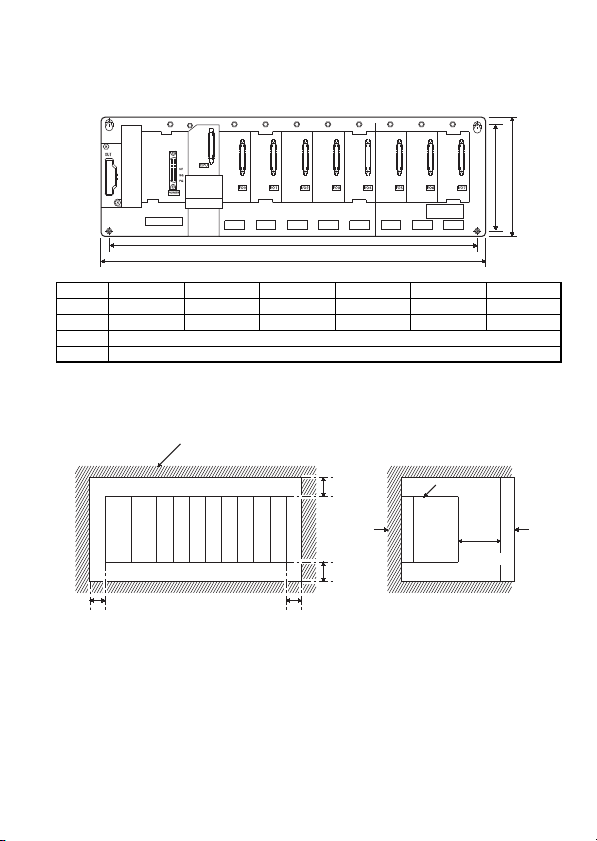
4.1.2 Instructions for mounting the base unit
r
(1) Mounting dimensions
Mounting dimensions of each base unit are as follows:
H
Hs
Ws
W
QA1S33B QA1S35B QA1S38B QA1S51B QA1S65B QA1S68B
W 255(10.04) 325(12.80) 430(16.93) 100(3.94) 315(12.40) 420(16.54)
Ws *1 235(9.25) 305(12.01) 410(16.14) 80(3.15) 295(11.61) 400(15.75)
H130(5.12)
Hs *1 110(4.33)
*1 The tolerances of Ws and Hs are ±0.3 mm, respectively.
(2) Unit mounting position
This shows the position of the panel's ceiling,
wiring duct, or components.
30mm
(1.18inches)
or more *1
Panel
30mm
(1.18inches)
or more
5mm (0.20inches)
or more *2
*1 For wiring duct height of 50mm(1.97inches) or less. 40mm(1.57inches) or more for other
cases.
*2 20mm(0.79inches) or more when the extension cable is connected without removal of the
adjacent module.
*3 80mm(3.15inches) or more for the connector type.
5mm (0.20inches)
or more
Unit: mm (inches)
Programmable
controller
20mm
(0.79inches)
or more
*3
Doo
31
Page 66

(3) Unit mounting orientation
Vertical Flat
(a) Since the programmable controller generates heat, it should
be mounted on a well ventilated location in the orientation
shown below.
(b) Do not mount it in either of the orientations shown below.
(4) Mount base unit on a flat surface. If the mounting surface is not
even, this may strain the printed circuit boards and cause
malfunctions.
(5) Avoid mounting base unit in proximity to vibration sources such as
large magnetic contractors and no-fuse circuit breakers; mount
these on a separate panel or at a distance.
(6) In order to avoid the effects of radiated noise and heat, provide the
clearances indicated below between the programmable controller
and devices that generate noise or heat (contactors and relays).
• Required clearance in front of programmable controller: at least
100 mm (3.94 inches)
• Required clearance on the right and left of programmable
controller: at least 50 mm (1.97 inches)
At least 100mm
(3.94 inches)
Contactor,
relay, etc.
32
At least 50mm
(1.97 inches)
At least 50mm
(1.97 inches)
Page 67

(7) If you want to mount base units on a DIN rail, please note the
following points.
(a) Suitable DIN rail types are listed as follows(JIS C 2812):
TH35-7.5Fe
TH35-7.5Al
TH35-15Fe
*JIS: Japanese Industrial Standard
(b) Spacing intervals for DIN rail mounting screws
When using a TH35-7.5Fe or TH35-7.5Al DIN rail, rail
mounting screws should be placed at a pitch of 200 mm (7.87
inches) or less in order to ensure that the rail has sufficient
strength.
DIN rail mounting screwDIN rail
35mm
(1.38inches)
PPP
P=200mm (7.87 inches) or less
(8) When installing the base unit to DIN rail in an environment with
large vibration, use a vibration-proofing bracket (A1S-PLT-D).
Mounting the vibration-proofing bracket (A1S-PLT-D) enhances the
resistance to vibration.
Depending on the environment to set up the base unit, it is also
recommended to fix the base unit to the control panel directly.
33
Page 68

4.1.3 Installation and removal of dustproof cover
When the QCPU-A is used, the dustproof cover supplied with the main
base unit must be installed to the I/O module loaded on the right hand
side of the QCPU-A to prevent the ingress of foreign matter into the I/O
module.
Always install the dustproof cover. Without the dustproof cover, foreign
matter will enter the I/O module, causing a failure.
How to install and remove the dustproof cover will be described below.
(1) Installation of dustproof cover
I/O module
Dustproof cover
To insert the dustproof cover into the I/O module, insert it into the
connector or terminal side slit first as shown above. Then push the
opposite side of the dustproof cover into the I/O module to
complete installation.
(2) Removal of dustproof cover
I/O module
Removing
hole
Dustproof cover
To remove the dustproof cover from the I/O module, insert the tip of
a flat-blade screwdriver into the removing hole as shown above,
move the screwdriver toward the back of the module, and take the
catch of the dustproof cover off the removing hole.
34
Page 69

4.1.4 Installation and removal of modules
This section explains how to install and remove a power supply, CPU,
I/O, special function and other modules to and from the base unit.
(1) Installation and removal of QCPU-A
(a) Installation of QCPU-A
Insert the module fixing
hook into the module
fixing hole of the base
unit.
Push the module in the
direction of arrow to
load it into the base unit.
Make sure that the
module is inserted in
the base unit securely.
Completion
Module
connector
Module fixing
hole
Base unit
POINT
(1) Insert the module fixing hook into the module fixing hole, making sure that
the module is mounted vertically against the base unit. Failure to insert the
hook or pressing the module to the base unit at an incorrect angle will
damage the module and connector.
(2) When using the programmable controller in a place where there is large
vibration or impact, screw the CPU module to the base unit.
QCPU-A module fixing screw: M3×12(user-prepared)
Module
Module fixing hook
Module
fixing hook
Module fixing
hole
Base unit
35
Page 70

(b) Removal of QCPU-A
Module
connector
Module fixing
hole
Base unit
Module
Remove the module
fixing screw, and using
the bottom of the module
as a support, pull the top
of the module toward you.
While lifting the module,
take the module fixing
hook off the module
fixing hole.
Completion
POINT
When the module fixing screw is used, always remove the module by removing
the module fixing screw and then taking the module fixing hook off the module
fixing hole of the base unit.
Forcibly removing the module will damage the module.
36
Page 71

(2) Installation and removal of module other than QCPU-A
(a) Installation of module other than QCPU-A
Insert the module fixing
hook into the module
fixing hole of the base
unit.
Push the module in the
direction of arrow to load
it into the base unit.
Make sure that the
module is inserted in the
base module securely,
and fix it with the module
mounting screw.
Completion
Base unit
Module
connector
Module
fixing hole
Module
Module fixing
hook
Module mounting screw
Base unit
Module
POINT
Always insert the module fixing hook of the module into the module fixing hole.
Forcing the hook into the hole will damage the module connector and module.
37
Page 72

(b) Removal of module other than QCPU-A
Remove the module
mounting screw, and
using the bottom of the
module as a support,
pull the top of the
module toward you.
While lifting the module,
take the module fixing
hook off the module
fixing hole.
Completion
POINT
Always remove the module by first removing the module fixing screw and then
taking the module fixing hook off the module fixing hole of the base unit.
Forcibly removing the module will damage the module.
Base unit
Module
connector
Module
fixing hole
Module
38
Page 73

4.1.5 Setting the extension number of the extension base unit
When using two or more extension base units, their extension numbers
must be set with their extension number setting connectors. Extension 1
need not be set since the extension number is factory-set to 1.
Make this setting in the following procedure.
(1) The extension number setting connector of the extension base unit
is located under the IN side base cover.
First, loosen the upper and lower screws in the IN side base cover
and remove the base cover from the extension base unit.
(2) Insert the connector pin in the required extension number location
of the connector (PIN1) existing between the IN and OUT sides of
the extension cable connector.
Setting of Number of Stages of Extension Base Units
Setting of Number of Extension Stages
Setting of No.
of stages
setting
connector
1st stage 2nd stage 3rd stage 4th stage 5th stage 6th stage 7th stage
POINT
Set the number setting connector to any of numbers 1 to 7 in ascending order.
If two or more modules have the same number or any module has no setting, for
example, false input and output will occur.
39
Page 74

(3) Install the base cover to the extension base unit and tighten the
base cover screw.
40
Page 75

4.1.6 Connection and disconnection of extension cable
(1) Instructions for handling an extension cable
• Do not stamp an extension cable.
• An extension cable must be connected to the base unit when the
base cover has been installed.
(After you have set the extension number to the extension base
unit, reinstall and screw the base cover.)
• When running an extension cable, the minimum bending radius
of the cable should be 55mm(2.17inches) or more.
If it is less than 55mm(2.17inches), a malfunction may occur due
to characteristic deterioration, open cable or the like.
• When connecting or disconnecting an extension cable, do not
hold the ferrite cores mounted at both ends of the cable.
Hold the connector part of the cable for connection or
disconnection.
Holding the ferrite core may cause the cable to open within the
connector.
Also, if the ferrite core is shifted, the characteristic will change.
When handling the cable, take care not to shift the ferrite core
positions.
41
Page 76

(2) Connection of extension cable
POINT
When connecting an extension base unit to the main base unit with an extension
cable, always plug the OUT side connector of the main base unit and the IN side
connector of the extension base unit with an extension cable. The system will not
operate properly if the extension cable is connected in the form of IN IN, OUT
OUT or OUT IN.
When connecting two or more extension base units, plug the OUT side
connector of the first extension base unit and the IN side connector of the second
extension base unit with an extension cable.
(a) To connect an extension cable to the main base unit, remove
the portion under the OUT characters on the base cover with a
tool such as a flat-blade screwdriver (5.5×75, 6×100).
Insert the driver edge into the gap between the base cover and
the section to be removed. Then raise up the driver edge so
that the section will come off.
Make sure not to insert the driver edge until it damages the
connector inside the base cover.
This also applies to a case where an extension cable is
connected to the OUT side connector of the extension base
unit.
Base cover
(b) To connect the extension cable to the next extension base unit,
remove the seal applied under the IN characters on the base
cover.
Seal
42
Page 77

(c) When plugging the extension cable to any base unit, hold the
connector part of the extension cable.
(d) After fitting the extension cable, always tighten the extension
cable connector fixing screws.
(Tightening torque: 20N•cm)
(3) Disconnection of extension cable
When unplugging the extension cable, hold and pull the connector
part of the extension cable after making sure that the fixing screws
have been removed completely.
43
Page 78

4.2 Fail-Safe Circuit Concept
To prevent the programmable controller from providing false output or
input, make up the circuit and program so that the programmable
controller system will be started up in the following procedure.
(1)
Turn on the power to the programmable controller.
(2)
Turn on the external power supply used for the process control.
(3)
Turn on the START switch.
(4)
Turn on the power to the output devices by using a program.
(5) Confirm that all external power supplies are turned on, and then,
an I/O control program should be executed.
For example, if the processing external supply power of a DC output
module is switched on and then the programmable controller is powered
on, the DC output module may provide false output instantaneously.
Though Mitsubishi programmable controllers are manufactured under
strict quality control, they may cause failure or abnormal operations due
to unspecific reasons. To prevent the abnormal operation of the whole
system, machine breakdown, and accidents (e.g. emergency stop,
protective and interlock circuits), fail-safe circuitry against failure of the
programmable controller must be constructed outside the
programmable controller.
The following page gives an example of system designing that conforms
to the explanation mentioned above and an example of fail-safe
measures when the programmable controller causes a failure.
44
Page 79

(1) System design circuit example
ALL AC
POWER
TRANSFORMER
FUSE
CPU module
START SW
MC
RA2
OUTPUT module
MC
M9006
M9039
XM
PROGRAM
RA1
STOP SW
INPUT module
Ym
Yn
OUTPUT module
MC2
MC2
Y1
Ym
Yn
Y1
M9084
MC
RA1
MC1
MC2
RA2
XM
L
Input switched
when power supply
established.
RUN/STOP circuit
interlocked with RA1
(run monitor relay)
Low battery alarm
(Lamp or buzzer)
RA1 switched ON by
M9039
(run monitor relay)
MC
Power to output equipment
switched OFF when the
STOP signal is given.
In the case of an emergency
stop or a stop caused
by a limit switch.
Interlock circuits as
necessary.
Provide external interlock
circuits for conflicting
operations, such as forward
rotation and reverse rotation,
and for parts that could
damage the machine or
cause accidents if no
interlock were used.
The power-ON procedure is as follows:
For AC For AC/DC
1)
Set the ON the power.
2)
Switch CPU to RUN.
3)
Turn on the start switch.
4)
When the magnetic contactor (MC)
comes in, the output equipment is
powered and may be driven by the
program.
Mixed AC and DC
POWER
TRANSFORMER
FUSE
CPU module
M9006
M9039
XM
TM
TM
M10
N0
START SW
RA1
MC
STOP SW
RA2
OUTPUT module
Ym
Yn
OUTPUT module
1)
Set the ON the power.
2)
Switch CPU to RUN.
3)
When DC power is established, RA2 goes ON.
4)
Timer (TM) times out after the DC power
reaches 100%. (The TM set value should be
the period of time from when RA2 goes ON to
the establishment of 100% DC voltage. Set
this value to approximately 0.5 seconds.)
5)
Turn on the start switch.
6)
When the magnetic contactor (MC) comes in,
the output equipment is powered and may be
driven by the program. (If a voltage relay is
used at RA2, no timer (TM) is required in the
program.)
Ym
Yn
TM
M9084
M10N0MC1
PROGRAM
MC
INPUT module
XM
L
RA1
MC2
MC1
MC1
MC2
TRANSFORMER
FUSE
DC
POWER
SUPPLY
(-)
(+)
FUSE
RA2
MCMC
Voltage relay is
recommended
Set time for DC
power supply to
be established.
Low battery alarm
(Lamp or buzzer)
RA1 switched ON by
M9039
(run monitor relay)
Power to output equipment
switched OFF when the
STOP signal is given.
In the case of an emergency stop or a stop
caused by a limit switch.
45
Page 80

(2) Fail-safe measures to cover the possibility of programmable
controller failure
Although a CPU module detects failures of programmable
controller CPU and memory by using the self-diagnostics function,
it may not detect those of I/O control area.
In such cases, all I/O points may turn on or off depending on the
failure, or the control target may malfunction or the safety may not
be ensured.
Mitsubishi programmable controllers are manufactured under strict
quality control, however, build a fail-safe circuit outside the
programmable controller in order that the programmable controller
failure due to unspecified reasons will not result in the machinery
breakdown or accidents.
The system example including fail safe circuit and fail safe circuit
example are provided below.
<System example>
Output
Power
Input
Input
CPU
supply
16
16
module
module
points
points
Extension cable
*1 The output module for fail-safe purpose should be mounted on the last slot of the system.
(YB0 to YBF in the above system.)
Input
points
Output
Input
Output
Output
points
Output
16
16
16
points
points
16
16
16
points
points
Power
supply
module
Output
16
points
Output module for fail-safe purpose*1
Output
points
16
Output
points
16
16
Vacant
YB0
points
to
YBF
46
Page 81

<Fail-safe circuit example>
Internal program
M9032
YB0
YB0
YB1
ON delay timer
OFF delay timer *3
External load
L
T1
1s
T2
1s
MC
YB0
0.5s 0.5s
CPU module
*2 YB0 turns on and then off at alternatively 0.5 second intervals.
Use a contactless output module (transistor is used in the above example).
*3 If an OFF delay timer (especially miniature timer) is not available, construct the fail-safe
circuit using an ON delay timer shown on the next page.
YBF
24V
0V
Output module
*2
L
T1 T2
-+
24VDC
MC
When constructing a fail-safe circuit using ON delay timers only
M1
M1
T2
M2
External load
L
L
-+
T1
ON delay timer
*4
ON delay timer
24VDC
M2
T1
1s
M1
T2
1s
M2
MC
MC
Internal program
M9032
YB0
YB0
0.5s 0.5s
CPU module
Output module
*4 Use a solid state relay for the M1 relay.
YB0
YB1
YBF
24V
0V
47
Page 82
4.3 Wiring
4.3.1 Power supply module specifications
This section gives the specifications of the power supply modules.
Power Supply Module Specifications
Item
Base loading slot Power supply module loading slot
Rated input voltage
Rated input frequency 50/60Hz ± 5% ———
Input voltage distortion
factor
Max. input apparent power 105VA 41W
Inrush current 20A 8ms or lower *4 81A 1ms or lower
Rated output
current
Overcurrent
protection *1
Overvoltage
protection *2
Efficiency 65% or higher
Allowable momentary
power failure time *3
Dielectric withstand
voltage
Insulation resistance
Noise durability
Power indication Power LED indication (light at the time of output of 5 VDC)
Fuse Built-in (Unchangeable by user)
Terminal screw size
Taille des vis de borne
Applicable wire size
Taille du fil à utiliser
Applicable solderless
terminal
Borne sans soudure à
utiliser
5VDC 5A 3A 5A
24VDC ——— 0.6A ———
5VDC 5.5A or higher 3.3A or higher 5.5A or higher
24VDC ——— 0.66A or higher ———
5VDC 5.5 to 6.5V
24VDC ———
A1S61PN A1S62PN A1S63P
100 to 240VAC
(85 to 264VAC) (15.6 to 31.2VDC)
20ms or lower
Across inputs/LG and outputs/FG
2,830VAC rms/3 cycles (2000m)
Across inputs and outputs (LG and FG
separated), across inputs and LG/FG,
across outputs and FG/LG
10M or higher by 500VDC insulation
resistance tester
Noise voltage 1,500 Vp-p, Noise width
1µs, Noise frequency 25 to 60 Hz (noise
simulator condition)
Noise voltage IEC61000-4-4, 2kV
Specifications
+10%
-15%
Within 5% ———
M3.5×7
M3,5×7
0.75 to 2mm
0,75 à 2mm
RAV 1.25 to 3.5, RAV 2 to 3.5
RAV 1,25 à 3,5, RAV 2 à 3,5
24VDC
10ms or lower
(at 24VDC input)
500VAC acr oss
primary a nd 5VDC
5M or more by
insulation resistance
tester
Noise voltage 500
Vp-p, Noise width
1µs, Noise frequency 25 to 60 Hz
(noise simulator
condition)
2
2
+30%
-35%
48
Page 83

Power Supply Module Specifications
Applicable tightening
torque
Couple de serrage à
appliquer
External dimension 130 × 55 × 93.6 (5.12 × 2.17 × 36.9) mm (inches)
Weight 0.60 kg 0.60 kg 0.50 kg
POINT
*1 Overcurrent protection
The overcurrent protection device shuts off the 5VDC and/or 24VDC circuit(s) and stops
the system if the current exceeding the specified value flows in the circuit(s). As this
results in voltage drop, the power supply module LED turns off or is dimly lit. After that,
power off the input power supply to eliminate the causes of overcurrent, e.g., insufficient
current capacity and short circuit, and then power on the input power supply to start the
system. When the current has reached the normal value, the initial start up of the system
will be performed.
*2 Overvoltage protection
The overvoltage protection shuts off the 5VDC circuit and stops the system if the
overvoltage of 5.5V is applied to the circuit. This results in the power supply module LED
turning off. When restarting the system, power OFF and ON the input power supply, and
the initial start up of the system will be performed. If the system is not booted and the
LED remains off, this means that the power supply module has to be replaced. the LED
remains off, this means that the power supply module has to be replaced.
*3 Allowable momentary power failure period
The programmable controller CPU allowable momentary power failure period varies
with the power supply module used. In case of the A1S63P power supply module, the
allowable momentary power failure period is defined as the time from when the primary
side of the stabilized power supply for supplying 24VDC to the A1S63P is turned off until
when the voltage (secondary side) has dropped from 24VDC to the specified value
(15.6VDC) or less.
*4 Inrush current
If the power supply module is re-powered on right after powered off (within 5s), the
inrush current exceeding the specified value (2ms or less) may be generated.
Therefore, make sure to re-power on the module 5seconds after power off. When
selecting a fuse or breaker for external circuit, consider the above point as well as
meltdown and detection characteristics.
59 to 88N•cm
59 à 88N•cm
49
Page 84

(1) A1S61PN (2) A1S62PN
9)
3)
4)
5)
7)
9)
3)
4)
6)
7)
9)
1)
8)
2)
3)
4)
5)
7)
1)
8)
(3) A1S63P
No. Name Description
1) POWER LED The indicator LED for the 5 VDC power.
2) 24 V and 24 G terminals
3) FG terminal
4) LG terminal
5) Power supply input terminals Used to connect 100VAC to 200VAC power supply.
6) Power supply input terminals Used to connect a 24VDC power supply.
7) Terminal screw M3.5 × 7
8) Terminal cover The protective cover of the terminal block.
9) Module fixing screw
POINT
(1) Do not use the terminal which is printed NC on the terminal block.
(2) Be sure to ground the terminal LG and FG to the protective ground conductor.
Used to supply 24VDC to inside the output module
(using external wiring).
The grounding terminal connected to the shield pattern of
the printed circuit board.
Grounding for the power supply filter. The potential of
A1S61PN or A1S62PN terminal is 1/2 of the input voltage.
Used to fix the module to the base unit. (M4 screw,
tightening torque : 59 to 88 N•cm)
50
1)
8)
Page 85

4.3.2 The precautions on the wiring
This section gives instructions for wiring the power supply.
(1) Wiring of power supply
(a) When voltage fluctuations are larger than the specified value,
connect a constant-voltage transformer.
Constant
voltage
transformer
(b) Use a power supply which generates minimal noise between
wires and between the programmable controller and ground. If
excessive noise is generated, connect an insulating
transformer.
Programmable
controller
Insulating
transformer
(c) When a power transformer or insulating transformer is
employed to reduce the voltage from 200 VAC to 100 VAC,
use one with a capacity greater than those indicated in the
following table.
Power Supply Module Transformer Capacity
A1S61PN 110VA × n
A1S62PN 110VA × n
(d) Separate the programmable controller ’s power supply line
from the lines for I/O devices and power devices as shown
below.
When there is much noise, connect an insulation transformer.
(e) Taking rated current or inrush current into consideration when
wiring the power supply, be sure to connect a breaker or an
external fuse that have proper blown and detection.
Programmable
controller
Insulating
transformer
I/O
equipment
n: Stands for the number of
power supply modules.
51
Page 86

When using a single programmable controller, a 10A breaker
or an external fuse are recommended for wiring protection.
200VAC
Main
power supply
Relay
terminal block
I/O power supply
On a control panel
Programmable
controller
power supply
Main circuit
power supply
Insulation
Transformer
T1
Programmable
controller
I/O equipment
Main circuit equipment
(f) Note on using the 24 VDC output of the A1S62PN power
supply module.
If the 24 VDC output capacity is insufficient for one power
supply module, supply 24 VDC from the external 24 VDC
power supply as shown below:
24VDC
24VDC
unit
Power supply
unit
Power supply
I/O module
24VDC
External power supply
unit
Power supply
I/O module
(g) 100 VAC, 200 VAC and 24 VDC wires should be twisted as
dense as possible. Connect the modules with the shortest
distance.
Also, to reduce the voltage drop to the minimum, use the
thickest wires possible (maximum 2mm
2
).
(h) Do not bind 100VAC and 24VDC wires together with main
circuit (high tension and large current) wires or I/O signal line
(including common line) nor place them near each other.
Provide 100mm (3.94 inches) clearance between the wires if
possible.
52
Page 87

Surge absorber for lightening
Programmable
controller
I/O
devices
AC
E1
E2
(i) As a countermeasure to power surge due to lightening,
connect a surge absorber for lightening as shown below.
POINT
(1) Separate the ground of the surge absorber for lightening (E1) from that of the
programmable controller (E2).
(2) Select a surge absorber for lightening whose power supply voltage does no
exceed the maximum allowable circuit voltage even at the time of maximum
power supply voltage elevation.
(2) Wiring to I/O device
(a) The solderless terminal with insulation sleeve is inapplicable to
a terminal block.
It is advisable to cover the wire connection part of a terminal
with a mark tube or insulation tube.
(b) Install wiring to a terminal block using the cable of core
diameter 0.3 to 0.75mm
2
, and outside diameter 2.8mm or less.
(c) Run the I/O line and output line away from each other.
(d) When the main circuit line and power line cannot be
separated, use a shielding cable and ground it on the
programmable controller side.
However, ground it on the opposite side in some cases.
Programmable controller
Input
Output
(e) When cables are run through pipes, securely ground the
pipes.
(f) Run the 24VDC input line away from the 100VAC and 200
VAC lines.
DC
Shielded cable
Shield jacket
RA
53
Page 88
(g) The cabling of 200m (656.2ft.) or longer distance may produce
leakage current depending on the capacity between lines and
result in an accident.
(h) As a countermeasure against the power surge due to lightning,
separate the AC wiring and DC wiring and connect a surge
absorber for lightning as shown in (i) of item (1).
Failure to do so increases the risk of I/O device failure due to
lightning.
(3) Grounding
(a) Carry out the independent grounding if possible. (Grounding
resistance 100 or less.)
(b) If the independent grounding is impossible, carry out the
shared grounding (2) as shown below.
Class 3
grounding
Other
device
Programmable
controller
(1) Independent grounding.....Best
(c) Use thick cables up to 2mm
to the programmable controller as much as possible so that
the ground cable can be shortened.
(d) If a malfunction occurs due to earthling, separate either LG or
FG of the base module, the device combination, or all the
connection from the earthling.
Class 3
grounding
Other
device
Programmable
controller
(2) Shared grounding.....Good (3) Common grounding.....Not allowed
Programmable
controller
2
. Bring the grounding point close
Other
device
54
Page 89

4.3.3 Connecting to the power supply module
Terminal blockSolderless terminals
with insulation sleeves
The following diagram shows the wiring example of power lines,
grounding lines, etc. to the main and extension bases.
Main base unit
100/110VAC
AC
Connect to 24VDC terminals
of I/O module that requires
24VDC internally.
*1 Ground the LG and FG terminals by using a ground wire as thick and short as possible
(2mm in diameter).
200/220VAC
FUSE
AC
DC
Extension cable
100-240VAC
Ground wire
24VDC
24VDC
Grounding
POINT
(1) Use the thickest possible (max. 2 mm2 (14 AWG)) wires for the 100/200 VAC
and 24 VDC power cables. Be sure to twist these wires starting at the
connection terminals. For wiring a terminal block, be sure to use a solderless
terminal. To prevent short-circuit due to loosening screws, use the solderless
terminals with insulation sleeves of 0.8 mm (0.03 inches) or less thick. The
number of the solderless terminals to be connected for one terminal block are
limited to 2.
(QA1S38B)
CPUA1S62PN
+24V
24G
(FG)
(LG)
INPUT
100-240VAC
Extension base unit
(QA1S68B)
I/OA1S62PN
+24V
24G
(FG)
(LG)
INPUT
100-240VAC
*1
*1
*1
*1
(2) Be sure to ground the LG and FG terminals. Failure to do so may cause the
programmable controller to be susceptible to noise. Note that LG terminals
include the potential as half as that of input voltage; you might get an electric
shock when you touch them.
(3) A1S61PN and A1S62PN do not need to be switched as the are 100 to
240VAC wide-range.
55
Page 90

4.4 Precautions when Connecting the Uninterruptible Power Supply (UPS)
Connect the QCPU-A system to the uninterruptible power supply (UPS),
while paying attention to the followings.
When connecting an uninterruptible power supply (UPS) to the
programmable controller system, use an online UPS or line-interactive
UPS with a voltage distortion rate of 5% or less.
When connecting a standby UPS, use a Mitsubishi FREQUPS FW-F
series UPS (hereinafter FW-F series UPS)
0.3K/0.5K)
Do not use any standby UPS other than the FW-F series UPS.
*1 The FW-F series UPS whose serial number starts with the letter "P" or later, or
ends with the letters "HE" is applicable.
*1
. (Example: FW-F10-
Starts with "P" or later
Ends with "HE"
56
Page 91

4.5 Part Names and Settings of the CPU Module
4.5.1 Part names and settings
This section explains the names and settings of the CPU module.
Front face With front cover open
Q02HCPU
PULL
MODE
USER
BOOT
USB
RUN
ERR.
BAT.
1)
2)
3)
9)
4)
5)
6)
7)
10)
Q02HCPU
MODE
RUN
ERR.
USER
BAT.
BOOT
ON
L.CLRRESET
SW
1
2
3
4
5
RUNSTOP
11)*1
13)
14)
15)
RS-232
When opening the cover, put
your finger here.
12)
8)
*1 Not provided for Q02CPU-A.
Side face
16)
17)
20)
19)
18)
57
Page 92

No. Name Applications
1) Module fixing hook
2) Mode LED
3) RUN LED
4) ERR. LED
5) USER LED
6) BAT. LED
7) BOOT LED
8) Serial number Shows the serial number printed on the rating plate.
Memory card EJECT
9)
button
Memory card loading
10)
connector
11) USB connector *2 Unusable (Usable for Q mode only)
12) RS-232 connector *2
*2 When normally connecting a cable to the USB connector or RS-232 connector, clamp the
cable to prevent it from coming off due to the dangling, moving or carelessly pulling of the
cable.
Hook used to fix the module to the base unit.
(Single-motion installation)
Indicates the mode of the CPU.
Lit (orange)
Lit (green)
Indicates the operating status of the CPU.
On
Off
On
Off
Flicker
On
Off
Flicker
On
Off
On
Off
Used to eject the memory card from the CPU.
Connector used to load the memory card to the CPU.
Connector for connection with a peripheral device.
Can be connected by RS-232C connection cable (QC30R2).
: A mode
: Q mode
::During operation in "RUN" or "STEP RUN" mode.
During a stop in "STOP", "PAUSE" or "STEP RUN"
mode or detection of error whose occurrence stops
operation.
:
Detection of self-diagnostics error which will not
stop operation, except battery error.
(When operation continued at error detection is set
in the parameter)
:
Normal
:
Detection of error whose occurrence stops
operation.
:
Annunciator ON
:
Normal
:
Execution of latch clear
::Occurrence of battery error due to reduction in
battery voltages of CPU and memory card.
Normal
::Execution of boot operation
Non-execution of boot operation
58
Page 93

No. Name Applications
DIP switches
13)
14) RUN/STOP switch
15) RESET/L.CLR switch
Module fixing screw
16)
hole
17) Module fixing hook Hook used to fix to the base unit.
18) Battery connector pin
19) Battery
20) Module loading lever Used to load the module to the base unit.
Used to set the items for operation of the CPU.
SW1: Must not be used. Normally off.
(Shipped in off position)
SW2: Must not be used. Normally off.
(Shipped in off position)
SW3: RAM/boot operation designation.
(Shipped in off position)
On
: Boot operation
: RAM operation
Off
SW4: Must not be used. Normally off.
(Shipped in off position)
SW5: Must not be used. Normally off.
(Shipped in off position)
:
RUN
STOP
RESET
L.CLR
Hole for the screw used to fix to the base unit.
(M3 × 12 screw)
For connection of battery lead wires.
(When shipped from the factory, the lead wires are disconnected
from the connector to prevent the battery from consuming.)
Backup battery for use of built-in RAM and power failure
compensation function.
Executes sequence program operation.
Stops sequence program operation.
:
:
Used to perform hardware reset, operation fault rest,
operation initialization, etc.
If this switch is left in the RESET position, the whole
system will be reset and the system will not operate
properly. After performing reset, always return this
switch to the neutral position.
Used to turn "OFF" or "zero" all data in the
:
parameter-set latch area.
Used to clear the sampling trace and status latch
registration.
59
Page 94

4.5.2 Switch operation after program write
(1) When writing a program during STOP of CPU
Write a program during STOP of the CPU in the following
procedure.
1) RUN/STOP switch: STOP
RUN LED: Off...................CPU STOP status Program write
2) RUN/STOP switch: STOP RUN
RUN LED: On...................CPU RUN status
(2) When you wrote a program during RUN
When you wrote a program during RUN of the CPU, do not operate
the switch.
4.5.3 Latch clear operation
To perform latch clear, operate the RESET/L.CLR switch in the following
procedure.
1) RESET/L.CLR switch: Move the switch to L.CLR several times
USER LED: Flicker.............Ready for latch clear.
2) RESET/L.CLR switch: Move the switch to L.CLR once more.
USER LED: Off...................Latch clear complete.
POINT
Latch clear can be set to be valid or invalid device-by-device by making device
setting in the parameter.
For the operation method, refer to the operating manual of GPP function.
until the USER LED flickers.
(Do not move it to RESET.)
4.5.4 Installation and removal of memory card during power-on
Do not install or remove the memory card while power is on.
POINT
If you installed or removed the memory card while power was on, the data within
the memory card may be corrupted.
60
Page 95

Memo
61
Page 96

5. SPECIFICATIONS AND CONNECTIONS OF I/O MODULES
5.1 Input modules
5.1.1 Input module specifications
Operating Voltage
No. of
Model Type
Points
Rated Input
Voltage
Input
Current
ON voltage OFF voltage
A1SX10
A1SX10EU 7mA
A1SX20
A1SX20EU 11mA
A1SX30
A1SX40
A1SX40-S1
A1SX40-S2
A1SX41
A1SX41-S1
A1SX41-S2
A1SX42
A1SX42-S1
A1SX42-S2
AC input
DC/AC
input
DC input
(sink type)
100 to
120VAC
200 to
240VAC
12/24VDC
16
12/24VAC
12/24VDC 3/7mA
24VDC 7mA
12/24VDC 3/7mA
32
24VDC 7mA
12/24VDC 2/5mA
64
24VDC 5mA
6mA
9mA
4.2/
8.6mA
62
80VAC or
higher
7VDC/AC or
higher
8VDC or
higher
14VDC or
higher
8VDC or
higher
17VDC or
higher
14VDC or
higher
8VDC or
higher
18.5VDC or
higher
17.5VDC or
higher
30VAC or
lower
2.7VDC/AC or
lower
4VDC or lower
6.5VDC or
lower
4VDC or lower
3.5VDC or
lower
6.5VDC or
lower
4VDC or lower
3VDC or lower
7VDC or lower
Page 97

Maximum
Simultaneous
Input Points
(Percentage
Simultaneously
ON)
100%(110VAC)
60%(132VAC)
100%(110VAC)
60%(220VAC)
75%(26.4VDC)
100%(26.4VDC)
60%(26.4VDC)
50%(24VDC)
Max. Response Time
OFF to ON ON to OFF
20ms or
lower
30ms or
lower
20ms or
lower
25ms or
lower
10ms or
lower
0.1ms or
lower
10ms or
lower
0.3ms or
lower
10ms or
lower
0.3ms or
lower
10ms or
lower
35ms or
lower
55ms or
lower
20ms or
lower
20ms or
lower
10ms or
lower
0.2ms or
lower
10ms or
lower
0.3ms or
lower
10ms or
lower
0.3ms or
lower
10ms or
lower
Internal
Field Wiring
Terminal 16 0.05A 16
40-pin
connector
40-pin
connector
Points/
Common
×2
Current
Con-
sumption
(5VDC)
0.08A
0.12A
0.08A
32
0.09A
0.16A
0.09A
NO. of
Occupied
Points
32
64
63
Page 98

Model Type
No. of
Points
Rated Input
Voltage
Input
Current
Operating Voltage
ON voltage OFF voltage
A1SX71
A1SX80
A1SX80-S1 24VDC
A1SX80-S2 24VDC
A1SX81
DC input
(sink/source
type)
A1SX81-S2 24VDC 7mA
32 5/12/24VDC
12/24VDC 3/7mA
16
12/24VDC 3/7mA
32
1.2/3.3/
7mA
7mA
A1SX82-S1 64 24VDC 5mA
A1S42X
DC input
(dynamic)
*2
16/32
48/64
12/24VDC 4/9mA
3.5VDC or
higher
8VDC or
higher
17VDC or
higher
13VDC or
higher
8VDC or
higher
13VDC or
higher
18.5VDC or
higher
8VDC or
higher
1VDC or lower
4VDC or lower
5VDC or lower
6VDC or lower
4VDC or lower
6VDC or lower
3VDC or lower
4VDC or lower
64
Page 99

Maximum
Simultaneous
Input Points
(Percentage
Simultaneously
ON)
65%(24VDC)
100%(26.4VDC)
100%(26.4VDC)
60%(26.4VDC)
50%(26.4VDC)
Max. Response Time
OFF to ON ON to OFF
1.5ms or
lower
10ms or
lower
0.4ms or
lower
10ms or
lower
10ms or
lower
0.3ms or
lower
3ms or
lower
10ms or
lower
0.5ms or
lower
10ms or
lower
10ms or
lower
0.3ms or
lower
Internal
Field Wiring
40-pin
connector
Points/
Common
Current
Con-
sumption
Occupied
(5VDC)
32 0.075A 32
Terminal 16 0.05A 1685%(26.4VDC)
37-pin
D-sub
connector
40-pin
connector×232 0.16A 64
32 0.08A 32
NO. of
Points
100%(26.4VDC)
0.4ms or
lower
0.4ms or
*1
lower
*1
24-pin
connector
- 0.08A
16/32/48/
For all modules, the insulation system is photocoupler insulation and the input
indications are LED indications.
*1.....The dynamic scan cycle is 13.3ms.
*2.....Set using the DIP switch on the module front.
65
64
Page 100

5.1.2 Input module connections
Input module connections
X01
X03
X05
X07
X08
X0A
X0C
X0E
COM
Vacant
Rated Input
Voltage
100 to 120
VAC
200 to 240
VAC
X00
1
2
X02
3
4
X04
5
6
X06
7
8
COM
9
10
X09
11
12
X0B
13
14
X0D
15
16
X0F
17
18
Vacant
19
20
Model
A1SX10
(1)
A1SX10EU
A1SX20
A1SX20EU
9 and 18 areconnected internally.
Model
(2)
A1SX30 12/24 VAC/DC
X01
X03
X05
X07
X08
X0A
X0C
X0E
COM
-
+
12/24VAC
12/24VDC
+
-
9 and 18 areconnected internally.
Rated Input
Voltage
X00
1
2
X02
3
4
X04
5
6
X06
7
8
COM
9
10
X09
11
12
X0B
13
14
X0D
15
16
X0F
17
18
19
20
Model
A1SX40 12/24 VDC A1SX80 12/24 VDC
(3)
A1SX40-S1
A1SX40-S2 A1SX80-S2
-+
9 and 18 areconnected internally.
100 to 120 VAC de 100 à 120 V ca 12/24 VAC/DC 12/24 V ca/cc
200 to 240 VAC de 200 à 240 V ca 24 VDC 24 V cc
9 and 18 are connected internally 9 et 18 sont connectés à l'intérieur Model Modèle
Rated Load Voltage Tension nominale de charge Vacant Libre
Rated Input
Voltage
24 VDC
X00
1
X01
2
X03
X05
X07
X08
X0A
X0C
X0E
COM
Vacant
English French English French
X02
3
X04
4
5
X06
6
7
COM
8
9
X09
10
11
X0B
12
13
X0D
14
15
X0F
16
17
18
Vacant
19
20
Model
(4)
A1SX80-S1
-
+
-
+
9 and 18 areconnected internally.
X01
X03
X05
X07
X08
X0A
X0C
X0E
COM
Vacant
Rated Input
Voltage
24 VDC
X00
1
2
X02
3
4
X04
5
6
X06
7
8
COM
9
10
X09
11
12
X0B
13
14
X0D
15
16
X0F
17
18
Vacant
19
20
66
 Loading...