

Page 1
C Controller Module User's Manual
(Hardware Design, Function Explanation)
-Q12DCCPU-V(Basic mode)
-Q06CCPU-V
-Q06CCPU-V-B
-SW3PVC-CCPU-E
Page 2

Page 3
SAFETY PRECAUTIONS
WARNING
CAUTION
Indicates that incorrect handling may cause hazardous conditions,
resulting in death or severe injury.
Indicates that incorrect handling may cause hazardous conditions,
resulting in minor or moderate injury or property damage.
(Read these precautions before using this product.)
Before using this product, please read this manual and the relevant manuals carefully and pay full attention
to safety to handle the product correctly.
The precautions given in this manual are concerned with this product only. For the safety precautions of the
programmable controller system, refer to the user's manual for the CPU module used.
In this manual, the safety precautions are classified into two levels: " WARNING" and " CAUTION".
Under some circumstances, failure to observe the precautions under " CAUTION" may lead to serious
consequences.
Observe the precautions of both levels because they are important for personal and system safety.
Make sure that the end users read this manual and then keep the manual in a safe place for future
reference.
[Design Precautions]
WARNING
Configure safety circuits external to the C Controller module to ensure that the entire system
operates safely even when a fault occurs in the external power supply or the C Controller module.
Failure to do so may result in an accident due to an incorrect output or malfunction.
(1) Configure external safety circuits, such as an emergency stop circuit, protection circuit, and
protective interlock circuit for forward/reverse operation or upper/lower limit positioning.
(2) If the following status (a) or (b) occurs, the system will behave accordingly.
(a) When overcurrent or overvoltage protection of the power supply module is activated, the
outputs (Y) from the user program and writing to the buffer memory are disabled, and all
outputs are turned off.
(b) When the C Controller module detects an error such as a watchdog timer error by the self-
diagnostic function, the outputs (Y) from the user program and writing to the buffer memory
are disabled. Whether to hold or turn off all outputs can be set by parameters.
All outputs may turn on when an error occurs in the part, such as I/O control part, where the C
Controller module cannot detect any error.
To ensure safety operation in such a case, provide a safety mechanism or a fail-safe circuit
external to the C Controller module. For a fail-safe circuit example, refer to "CHAPTER 6
PREPARATORY PROCEDURES AND SETTING" in this manual.
A - 1
Page 4
[Design Precautions]
WARNING
(3) Outputs may remain on or off due to a failure of an output module relay or transistor.
Configure an external circuit for monitoring output signals that could cause a serious accident.
In an output module, when a load current exceeding the rated current or an overcurrent caused by a
load short-circuit flows for a long time, it may cause smoke and fire. To prevent this, configure an
external safety circuit, such as a fuse.
Configure a circuit so that the C Controller system is turned on first and then the external power
supply. If the external power supply is turned on first, an accident may occur due to an incorrect
output or malfunction.
For the operating status of each station after a communication failure, refer to the relevant manuals
for the network.
Incorrect output or malfunction may result in an accident.
For the following controls, configure an interlock circuit in the user program to ensure that the entire
system will always operate safely.
(1) Changing data of a running C Controller module from the development environment (personal
computer) connected
(2) Changing the operating status
(3) Operation from the development environment (personal computer)
Especially, in the case of a control from an external device to a remote C Controller module,
immediate action cannot be taken for a problem on the C Controller module due to a communication
failure.
To prevent this, configure an interlock circuit in the user program, and determine corrective actions to
be taken between the external device and C Controller module in case of a communication failure.
To maintain the safety of the C Controller system against unauthorized access from external devices
via the network, take appropriate measures. To maintain the safety against unauthorized access via
the Internet, take measures such as installing a firewall.
When configuring the system, do not leave any slot empty on the base unit.
If a slot is to be left empty, attach a blank cover (QG60).
Failure to do so may cause internal parts of the mounted modules to fly apart during a short-circuit
test or when an excess current or voltage is applied to an external I/O part by mistake.
A - 2
Page 5
[Design Precautions]
CAUTION
Do not install the control lines or communication cables together with the main circuit lines or power
cables.
Keep a distance of 100mm (3.94 inches) or more between them.
Failure to do so may result in malfunction due to noise.
When a device such as a lamp, heater, or solenoid valve is controlled through an output module, a
large current (approximately ten times greater than normal) may flow when the output is turned from
off to on. Take measures such as replacing the module with one having a sufficient current rating.
After the C Controller module is powered on or is reset, the time taken to enter the RUN status varies
depending on the system configuration, parameter setting, and/or program size.
Design circuits so that the entire system will always operate safely, regardless of the time.
[Installation Precautions]
CAUTION
Use the C Controller module in an environment that meets the general specifications in this manual.
Failure to do so may result in an electric shock, fire, malfunction, or damage to or deterioration of the
product.
To mount the module, while pressing the module mounting lever located in the lower part of the
module, fully insert the module fixing projection(s) into the hole(s) in the base unit and press the
module until it snaps into place.
Incorrect mounting may cause malfunction, failure or drop of the module.
When using the module in an environment of frequent vibrations, fix the module with a screw.
Tighten the screw within the specified torque range.
Undertightening can cause drop of the screw, short circuit or malfunction.
Overtightening can damage the screw and/or module, resulting in drop, short circuit, or malfunction.
A - 3
Page 6
[Installation Precautions]
CAUTION
When using an extension cable, connect it to the connector of the base unit or module securely.
Check the connection for looseness.
Poor contact may cause incorrect input or output.
When using a CompactFlash card, fully insert it into the CompactFlash card slot.
Check that it is inserted completely.
Poor contact may cause malfunction.
Shut off the external power supply for the system in all phases before mounting or removing the
module.
Failure to do so may result in damage to the product.
Do not directly touch any conductive part of the module.
Doing so can cause malfunction or failure of the module.
[Wiring Precautions]
WARNING
Shut off the external power supply for the system in all phases before wiring.
Failure to do so may result in electric shock or damage to the product.
After wiring, attach the included terminal cover to the module before turning it on for operation.
Failure to do so may result in electric shock.
A - 4
Page 7
[Wiring Precautions]
CAUTION
Ground the FG and LG terminals to the protective ground conductor dedicated to the programmable
controller.
Failure to do so may result in electric shock or malfunction.
Prevent foreign matter such as dust or wire chips from entering the module.
Such foreign matter can cause a fire, failure, or malfunction.
Check the rated voltage and terminal layout before wiring to the module, and connect the cables
correctly.
Connecting a power supply with a different voltage rating or incorrect wiring may cause a fire or
failure.
Securely connect the Ethernet and RS-232 cables to respective connectors of the C Controller
module.
Do not install the control lines or the communication cables together with the main circuit lines or
power cables.
Doing so may result in malfunction due to noise.
Tighten the terminal screw within the specified torque range.
Undertightening can cause short circuit, fire, or malfunction.
Overtightening can damage the screw and/or module, resulting in drop, short circuit, or malfunction.
Place the communication and power cables in a duct or clamp them.
If not, dangling cable may swing or inadvertently be pulled, resulting in damage to the module or
cables or malfunctions due to poor contact.
When disconnecting a communication or power cable from the module, do not hold and pull the
cable part.
Doing so may cause malfunction or damage to the module or cable.
For a cable with connector, hold the connected connector by hand to disconnect the cable.
For a screw-type cable, loosen the screw to disconnect the cable.
Do not connect outputs of multiple power supply modules in parallel.
The power supply modules may produce heat, causing a fire or failure.
Connectors for external connection must be crimped or pressed with the tool specified by the
manufacturer, or must be correctly soldered.
For the tool, refer to the user's manual for the relevant I/O module.
Incomplete connections could result in short circuit, fire or malfunction.
A - 5
Page 8
[Startup and Maintenance Precautions]
WARNING
Do not touch any terminal while power is on.
Doing so will cause electric shock.
Correctly connect the battery connector.
Do not charge, disassemble, heat, short-circuit, solder, or throw the battery into the fire.
Doing so will cause the battery to produce heat, explode, or ignite, resulting in injury and fire.
Shut off the external power supply for the system in all phases before cleaning the module or
retightening the terminal screws or module fixing screws.
Failure to do so may result in electric shock.
Undertightening the terminal screws can cause short circuit or malfunction.
Overtightening can damage the screw and/or module, resulting in drop, short circuit, or malfunction.
For the following controls, configure an interlock circuit in the user program to ensure that the entire
system will always operate safely.
(1)
Changing data of the running C Controller module from the development environment (personal
computer) connected
(2) Changing the operating status
3) Operation from the development environment (personal computer)
(
Especially, in the case of a control from an external device to a remote C Controller module,
immediate action cannot be taken for a problem on the C Controller module due to a communication
failure.
To prevent this, configure an interlock circuit in the user program, and determine corrective actions to
be taken between the external device and C Controller module in case of a communication failure.
A - 6
Page 9
[Startup and Maintenance Precautions]
CAUTION
Do not disassemble or modify the modules.
Doing so may cause failure, malfunction, injury, or a fire.
Before performing online operations (especially, program modification, forced output, and operation
status change) for the running C Controller module from the peripheral connected, read relevant
manuals carefully and ensure the safety.
Improper operation may damage machines or cause accidents.
Shut off the external power supply for the system in all phases before mounting or removing the
module.
Failure to do so may cause the module to fail or malfunction.
After the first use of the product, do not mount/remove the module to/from the base unit more than
50 times. (IEC 61131-2 compliant)
Exceeding the limit of 50 times may cause malfunction.
Use any radio communication device such as a cellular phone or PHS (Personal Handy-phone
System) more than 25cm (9.85 inches) away in all directions from the C Controller system.
Failure to do so may cause malfunction.
Do not drop or apply shock to the battery to be installed in the module.
Doing so may damage the battery, causing the battery fluid to leak inside the battery.
If the battery is dropped or any shock is applied to it, dispose of it without using.
Before handling the module, touch a grounded metal object to discharge the static electricity from
the human body.
Failure to do so may cause the module to fail or malfunction.
A - 7
Page 10
[Disposal Precautions]
CAUTION
When disposing of this product, treat it as industrial waste.
When disposing of batteries, separate them from other wastes according to the local regulations.
(For details of the Battery Directive in EU countries, refer to Appendix 4.)
[Transportation Precautions]
CAUTION
When transporting lithium batteries, follow the transportation regulations. (For details of the
regulated models, refer to Appendix 3.)
A - 8
Page 11

CONDITIONS OF USE FOR THE PRODUCT
(1) Mitsubishi C Controller system ("the PRODUCT") shall be used in conditions;
i) where any problem, fault or failure occurring in the PRODUCT, if any, shall not lead to any major
or serious accident; and
ii) where the backup and fail-safe function are systematically or automatically provided outside of
the PRODUCT for the case of any problem, fault or failure occurring in the PRODUCT.
(2) The PRODUCT has been designed and manufactured for the purpose of being used in general
industries.
MITSUBISHI SHALL HAVE NO RESPONSIBILITY OR LIABILITY (INCLUDING, BUT NOT
LIMITED TO ANY AND ALL RESPONSIBILITY OR LIABILITY BASED ON CONTRACT,
WARRANTY, TORT, PRODUCT LIABILITY) FOR ANY INJURY OR DEATH TO PERSONS OR
LOSS OR DAMAGE TO PROPERTY CAUSED BY the PRODUCT THAT ARE OPERATED OR
USED IN APPLICATION NOT INTENDED OR EXCLUDED BY INSTRUCTIONS, PRECAUTIONS,
OR WARNING CONTAINED IN MITSUBISHI'S USER, INSTRUCTION AND/OR SAFETY
MANUALS, TECHNICAL BULLETINS AND GUIDELINES FOR the PRODUCT.
("Prohibited Application")
Prohibited Applications include, but not limited to, the use of the PRODUCT in;
• Nuclear Power Plants and any other power plants operated by Power companies, and/or any
other cases in which the public could be affected if any problem or fault occurs in the PRODUCT.
• Railway companies or Public service purposes, and/or any other cases in which establishment of
a special quality assurance system is required by the Purchaser or End User.
• Aircraft or Aerospace, Medical applications, Train equipment, transport equipment such as
Elevator and Escalator, Incineration and Fuel devices, Vehicles, Manned transportation,
Equipment for Recreation and Amusement, and Safety devices, handling of Nuclear or
Hazardous Materials or Chemicals, Mining and Drilling, and/or other applications where there is a
significant risk of injury to the public or property.
Notwithstanding the above, restrictions Mitsubishi may in its sole discretion, authorize use of the
PRODUCT in one or more of the Prohibited Applications, provided that the usage of the PRODUCT
is limited only for the specific applications agreed to by Mitsubishi and provided further that no
special quality assurance or fail-safe, redundant or other safety features which exceed the general
specifications of the PRODUCTs are required. For details, please contact the Mitsubishi
representative in your region.
A - 9
Page 12
REVISIONS
Partial correction
Partial correction
Addition
Modification
Partial correction
Addition
Modification
Partial correction
Partial correction
Partial correction
*The manual number is given on the bottom left of the back cover.
Print date *Manual number Revision
Jun., 2009 SH(NA)-080766ENG-A First edition
Jan., 2010 SH(NA)-080766ENG-B
PRECAUTIONS
Aug., 2010 SH(NA)-080766ENG-C
SAFETY PRECAUTIONS, ABOUT MANUALS, HOW TO USE THIS MANUAL,
GENERIC TERMS AND ABBREVIATIONS, GLOSSARY, Section 1.1, 2.1.3,
2.1.4, 2.2.1, 2.2.2, 2.3, 2.4, 3.2, 3.4.2, 4.1, 4.4, 4.5, 4.13, 5.2 to 5.4, 6.2, 6.11.2,
8.1.1, 8.2.2, 10.1, 11.1.4, 11.3, 13.1, 13.2, 13.6, 14.1, 15.2.4, 16.3, 16.4.1,
16.5.1, Appendix 8, Appendix 9.1, Appendix 10, Appendix 11
CONDITIONS OF USE FOR THE PRODUCT, Section 2.1.5, 4.4, 4.16, 6.8.5,
Chapter 9, Section 16.4.2, Appendix 6, Appendix 7, Appendix 9
Section 2.1.5 Section 2.1.6, Section 4.4 to 4.14 Section 4.5 to 4.15,
Chapter 9 to 15 Chapter10 to 16,
Appendix 6 to 8, Appendix7 to 8 Appendix10 to 11
Mar., 2011 SH(NA)-080766ENG-D
OPERATING PRECAUTIONS, Section 1.1, 2.1.3, 2.3, 2.4, 3.3.1, 3.3.2, 4.3.3,
4.15, 4.16, 5.3.2, 5.4.2, 6.3, 8.2.2, 16.4.1, Appendix 7, Appendix 9, Appendix 12
Jul., 2011 SH(NA)-080766ENG-E
Jan., 2012 SH(NA)-080766ENG-F
Dec., 2012
SH(NA)-080766ENG-G
Appendix 10
Appendix 10 to 11 Appendix 11 to 12
ABOUT MANUALS, GENERIC TERMS AND ABBREVIATIONS, Section 2.1.2,
2.1.4, 2.2.1, 2.2.2, 11.1.4
Section 2.2.1, 2.2.2, 2.4, 3.1
GENERIC TERMS AND ABBREVIATIONS, OPERATING PRECAUTIONS,
Section 2.2.1, 2.3, 3.2, 3.3.2, 4.5, 6.3, 6.4.1, 6.6, 10.1, 11.1, 11.2.1, 11.3, 12.1,
13.3.3, 13.3.4, 13.9, 16.2.3
A - 10
Page 13
Print date *Manual number Revision
Partial correction
Addition
Delete
Modification
Partial correction
Partial correction
Partial correction
Partial correction
Partial correction
Partial correction
Addition
Partial correction
Oct., 2013
SH(NA)-080766ENG-H
ABOUT MANUALS, HOW TO USE THIS MANUAL,
GENERIC TERMS AND ABBREVIATIONS, GLOSSARY, PACKING LIST,
CHAPTER 1, Section 1.1, 2.1.2, 2.2.1, 2.2.2, 2.3, 2.4, 2.5, 2.5.1, 4.14, 6.3, 6.4.1,
6.7, 6.10, 6.10.1, 6.10.2, 6.12.1, 8.2.1, 10.1, 11.1, 12.1, 13.3.1, 16.2, 16.2.2,
16.2.7, 16.2.8, 16.2.11, 16.5.1, Appendix7
PRODUCT ORGANIZATION
Appendix 11
Appendix 12 Appendix 11
Dec., 2013
Mar., 2014
Jul., 2014 SH(NA)-080766ENG-K
Feb., 2015 SH(NA)-080766ENG-L
Dec., 2015
Jun., 2016
Oct., 2017
SH(NA)-080766ENG-I
SH(NA)-080766ENG-J
SH(NA)-080766ENG-M
SH(NA)-080766ENG-N
SH(NA)-080766ENG-O
GENERIC TERMS AND ABBREVIATIONS, Section 10.1
GENERIC TERMS AND ABBREVIATIONS, Section 11.2.1, Section 12.1,
Section 12.7, Section 13.3.2, Section 13.3.3, Section 13.3.4, Section 13.9,
Appendix11
ABOUT MANUALS, GENERIC TERMS AND ABBREVIATIONS, CHAPTER 1,
Section 11.1, Section 11.3
Section 2.2.2, Section 6.7.1
PACKING LIST, Section 2.1.3, Section 2.5.1, Section 3.2, Section 6.4.1,
Appendix 2.1, WARRANTY
SAFETY PRECAUTIONS, GENERIC TERMS AND ABBREVIATIONS,
Section 6.6, Section 6.11
DISCONTINUED MODELS
ABOUT MANUALS, GENERIC TERMS AND ABBREVIATIONS, CHAPTER 1,
Section 6.7.1, Section 11.1, Appendix 11
This manual confers no industrial property rights or any rights of any other kind, nor does it confer any patent licenses.
Mitsubishi Electric Corporation cannot be held responsible for any problems involving industrial property rights which may
occur as a result of using the contents noted in this manual.
Japanese manual version SH-080764-Q
© 2009 MITSUBISHI ELECTRIC CORPORATION
A - 11
Page 14
OPERATING PRECAUTIONS
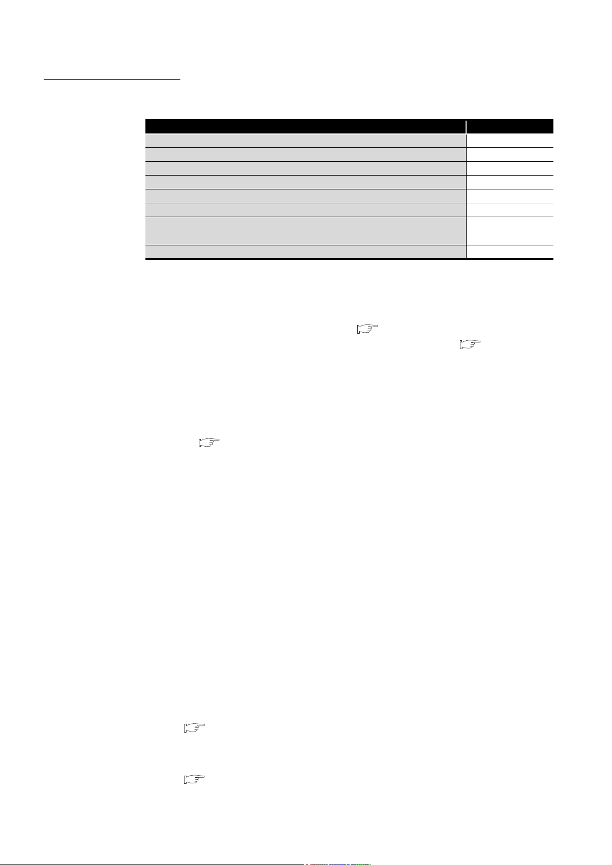
This section provides the following precautions.
System configurations
Standard RAM, standard ROM, and CompactFlash card
Battery
Clock setting
Starting the C Controller module
Network configurations
Relation between system tasks and the system watchdog timer, user
watchdog timer, and link device refresh cycles
For the Wind River Systems product
(1) Precautions for system configurations
(a) Supported modules
Precautions for Refer to
Page A-12
Page A-13
Page A-15
Page A-16
Page A-16
Page A-17
Page A-17
Page A-17
In a system configuration where a C Controller module is used, some main and
extension base units cannot be used ( Page 2-16, Section 2.1.6), and also
use of some modules is restricted by their function versions ( Page 2-17,
Section 2.2).
(b) Multiple CPU system
1) Applicable CPU modules
For the CPU modules that can be used with a C Controller module in a multiple
CPU system, refer to the following.
Page 11-11, Section 11.2.1
2) MT Developer connection (Version 00Y or earlier) in a multiple CPU system
When a multiple CPU system includes a C Controller module set as CPU No.1
and a Motion CPU, a communication test of MT Developer (Version 00Y or
earlier) cannot be performed. (The Motion CPU communication test error
(error code: 12288) will occur.)
To perform the communication test from MT Developer, use either of the
following methods.
• Use MT Developer Version 00Z or later.
• When using MT Developer Version 00Y or earlier, modify the multiple
CPU system configuration so that CPU No.1 is a programmable controller
CPU.
(c) Time adjustment and time notification of GOT
In a multiple CPU system configuration, when time adjustment or time notification
is performed in a GOT connected to C Controller modules for CPU No. 2 to No. 4,
it is executed to CPU No. 1.
In this case, to match the clock data between the C Controller modules assigned
to CPU No. 2 to No. 4 and the GOT, use the multiple CPU clock synchronization
function.
Page 4-33, Section 4.7.1
A - 12
(d) Connection with GX Works2/GX Developer
For the connection with GX Works2/GX Developer, refer to the following.
Page 2-29, Section 2.4 (7)
Page 15
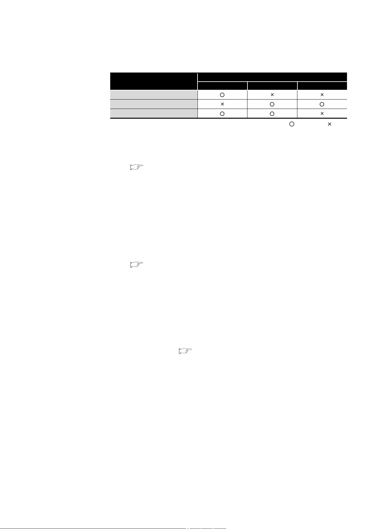
(2) Precautions for standard RAM, standard ROM, and CompactFlash card
Table A.1 Memory availability
Memory
Standard RAM
Standard ROM
CompactFlash card
(a) Standard RAM formatting
1) When formatting the standard RAM
Be sure to perform the method described in the following section.
Page 6-77, Section 6.10.1 (6)
Do not format it by using a command from Workbench Shell.
2) During standard RAM formatting
Do not power off or reset the C Controller module during standard RAM
formatting.
Doing so causes the standard RAM to be formatted again when the C
Controller module is started the next time.
(b) Standard ROM formatting
Q12DCCPU-V Q06CCPU-V Q06CCPU-V-B
Availability
: Available, : N/A
1) When formatting the standard ROM
Be sure to perform the method described in the following section.
Page 6-85, Section 6.10.2 (4)
Do not format it by using a command from Tornado Shell.
2) During standard ROM formatting
Do not power off or reset the C Controller module during standard ROM
formatting.
Doing so causes the standard ROM to be formatted again when the C
Controller module is started the next time.
(c) Allowable number of writes to the standard ROM (service life)
A flash ROM is used for the standard ROM and it has a limit in the number of
writes (service life). ( Page 6-71, Section 6.9)
A - 13
Page 16

(d) Allowable number of writes to a CompactFlash card (service life)
• For the live of the QD81MEM and GT05-MEM, refer to the following.
Page 6-70, Section 6.8.5
• For the live of commercially available CompactFlash cards, refer to the
specifications of each product.
(e) CompactFlash card replacement
Do not power off or reset the system or remove the CompactFlash card while
writing file data to the CompactFlash card.
Doing so can cause corruption of the CompactFlash card data or a file system
error.
• To remove a CompactFlash card during file writing:
Page 6-64, Section 6.8.2
• To power off or reset the system:
Page 8-9, Section 8.2.2
(f) File name and directory name
Use alphanumeric characters and special characters (excluding \, /, *, ?, <, >, |, :,
and ") for the names of a file and a directory stored in the following memories in
the C Controller module:
• Standard RAM
• Standard ROM
• CompactFlash card
If a file or a directory with a name including characters other than alphanumeric
characters and special characters (excluding \, /, *, ?, <, >, |, :, and ") is stored in
the memories above in the C Controller module, the following phenomena may
occur:
• Character corruption on file names and directory names
• Loss of files and directories
(g) Unmounting a CompactFlash card by the RESET/SELECT switch
1) When unmounting during access
Unmounting a CompactFlash card by the RESET/SELECT switch during file
writing to the CompactFlash card can cause corruption of the CompactFlash
card data or a file system error.
Stop the access to the CompactFlash card before removing the card.
( Page 6-64, Section 6.8.2)
2) When powering off or resetting the system
Before powering off or resetting the system, refer to the following.
Page 8-9, Section 8.2.2
3) Switch operation
If the RESET/SELECT switch is held in the RESET position by mistake, the C
Controller module will be reset.
Be careful when unmounting a CompactFlash card by operating the RESET/
SELECT switch. ( Page 6-67, Section 6.8.3)
A - 14
Page 17

(3) Precautions for battery
(a) For the Q12DCCPU-V
1) About file corruption
The battery must be installed before operation.
• If the C Controller system is operated without a battery and then is
powered off or reset
The data in the standard RAM and battery-backed-up RAM may be
damaged, or a file system error may occur.
• When the battery is not replaced even after a battery error
The standard RAM or battery-backed-up RAM data or clock data may be
corrupted, or a file system error may occur.
2) Battery replacement
For battery replacement, observe the procedures described in this manual.
( Page 6-53, Section 6.7.3 (4))
(b) For the Q06CCPU-V(-B)
1) About file corruption
• When the battery is not replaced even after a battery error
The standard ROM and battery-backed-up RAM data being accessed and
clock data may be corrupted, or a file system error may occur.
• If the C Controller system is operated without a battery and then shut
down improperly
The standard ROM and battery-backed-up RAM data being accessed
may be corrupted, or a file system error may occur.
• When the procedures shown in Page 6-54, Section 6.7.4 are not observed
The standard ROM and battery-backed-up RAM data being accessed
may be corrupted, or a file system error may occur.
2) Restrictions on operations without a battery
• Powering on the system without a battery
If the C Controller system is powered on with no battery installed in the C
Controller module, the system will start with unreliable clock data.
Set clock data in this case. Otherwise, event history files and programs
using clock data cannot function properly. ( Page 6-54, Section 6.7.4)
• Operating the system without a battery
If the system was operated with no battery installed in the C Controller
module, perform the shutdown operation before powering off or resetting
the C Controller system. ( Page 6-55, Section 6.7.4 (2))
3) Battery replacement
For battery replacement, observe the procedures described in this manual.
( Page 6-53, Section 6.7.3 (4))
A - 15
Page 18

(4) Precautions for clock setting
(a) Clock setting
1) Setting method
Set the clock of the C Controller module as described in Page 4-30, Section
4.7 (4) (a).
If the year 2100 is exceeded after clock setting, clock data of the year 2100
and later can be used until the C Controller module is restarted.
At the time of restart, year data of the C Controller module will be reset to those
of 2000 to 2099.
2) Condition for the setting
The clock of the C Controller module must be set with the QBF_WaitEvent and
QBF_WaitUnitEvent functions not being executed.
(5) Precautions for starting the C Controller module
(a) Time required for connection from each utility to the C Controller module
After power-on or reset, the C Controller module is ready to connect to each utility
at the following timing.
• When executing the script file, "STARTUP.CMD":
Upon completion of the RUN LED flashing
• When not executing the script file, "STARTUP.CMD":
Fifteen (15) seconds after completion of the start or reset process
Do not attempt a connection before the above timing after power-on or reset.
Changing "Priority" to a larger value in the Option tab of C Controller setting utility
increases the time after which the C Controller module can be connected.
(b) Flashing "01" or "02" of the 7-segment LED (Q12DCCPU-V only)
At start-up of the C Controller module, "01" or "02" flashes on the 7-segment LED
in the following cases.
• When the C Controller module is in factory-default state
(Because the standard RAM is not initialized)
• When the C Controller module is left unused for a long period of time with no
battery installed
(Because the standard and battery-backed-up RAM data are corrupted)
If "01" or "02" flashes on the 7-segment LED, install a battery and perform the
module initialization setting procedure. ( Page 6-77, Section 6.10.1 (6))
A - 16
Page 19

(6) Precautions for network configurations
(a) Precautions for using two Ethernet channels (Q12DCCPU-V only)
When using two channels as Ethernet ports, two different network addresses
must be set for CH1 and CH2 of the C Controller module.
In the above case, a response to the message received through each channel is
sent as follows:
• Messages (including response packets such as ping) to the device having the
same network address as CH1 are sent from CH1.
• Messages (including response packets such as ping) to the device having the
same network address as CH2 are sent from CH2.
(7) Relation between system tasks and the system watchdog timer, user
watchdog timer, and link device refresh cycles
When using any of the following functions, set a sufficiently long time for each of the
system watchdog timer, user watchdog timer, and link device refresh cycles.
• Shell command
• Workbench/Tornado connection
• File access
• Mount/unmount of CompactFlash card
• Ethernet communications
• NFS server communication
If any of the above is used, CPU utilization for a system task with high priority may
increase and a system watchdog timer error, a user watchdog timer error, and link
refresh timeout may occur more frequently.
For the link refresh timeout, the rate of occurrence may also increase when bus
interface driver processing (connections with peripheral devices or communication
with an intelligent function module, etc.) is used.
(8) Precautions for the Wind River Systems product
The C Controller module has an embedded real-time operating system, VxWorks,
made and sold by Wind River Systems, Inc. in the United States.
We, Mitsubishi, make no warranty for the Wind River Systems product and will not be
liable for any problems and damages caused by the Wind River Systems product
during use of the C Controller module.
For the problems or specifications of the Wind River Systems product, refer to the
corresponding manual or consult Wind River Systems, Inc.
Contact information is available on the following website.
www.windriver.com
A - 17
Page 20

INTRODUCTION
Thank you for purchasing the Mitsubishi C Controller module.
Before using the product, please read this manual carefully to understand the features and performance of
the C Controller module and use it correctly.
CONTENTS
SAFETY PRECAUTIONS············································································································ A - 1
CONDITIONS OF USE FOR THE PRODUCT ················································································· A - 9
REVISIONS ··························································································································· A - 10
OPERATING PRECAUTIONS···································································································· A - 12
INTRODUCTION····················································································································· A - 18
CONTENTS ··························································································································· A - 18
ABOUT MANUALS ·················································································································· A - 25
MANUAL PAGE ORGANIZATION ······························································································ A - 26
HOW TO USE THIS MANUAL ··································································································· A - 27
GENERIC TERMS AND ABBREVIATIONS ·················································································· A - 28
GLOSSARY ··························································································································· A - 33
PACKING LIST ······················································································································· A - 34
DISCONTINUED MODELS ······································································································· A - 34
CHAPTER 1 OVERVIEW 1 - 1 to 1 - 16
1.1 Features ··················································································································· 1 - 4
CHAPTER 2 SYSTEM CONFIGURATION 2 - 1 to 2 - 38
2.1 System Configuration··································································································· 2 - 1
2.1.1 Devices used for each base unit··············································································· 2 - 2
2.1.2 Connection with a development environment ······························································ 2 - 5
2.1.3 Connection with peripheral devices··········································································· 2 - 7
2.1.4 System configuration overview················································································· 2 - 9
2.1.5 Connecting a GOT in a bus topology········································································2 - 14
2.1.6 Precautions for system configuration········································································2 - 16
2.2 Applicable Modules ····································································································2 - 17
2.2.1 Applicable I/O modules and intelligent function modules···············································2 - 17
2.2.2 Precautions for using I/O modules and intelligent function modules ································2 - 19
2.3 Software Packages ····································································································2 - 24
2.4 Applicable Devices ·····································································································2 - 25
2.5 Checking Function Version, Serial No., and Software Version ·············································2 - 35
2.5.1 Checking the function version and serial No. of the C Controller module··························2 - 35
2.5.2 Checking the software version of software package ····················································2 - 38
CHAPTER 3 SPECIFICATIONS 3 - 1 to 3 - 9
3.1 General Specifications ································································································· 3 - 1
A - 18
Page 21

3.2 Performance Specifications ···························································································3 - 2
3.3 RS-232 Connector Specifications····················································································3 - 4
3.3.1 RS-232 connector specifications for the Q12DCCPU-V ·················································3 - 4
3.3.2 RS-232 connector specifications for the Q06CCPU-V(-B)···············································3 - 5
3.4 Operation Processing ···································································································3 - 6
3.4.1 Initial processing····································································································3 - 6
3.4.2 I/O access timing ···································································································3 - 7
3.4.3 RUN, STOP and PAUSE status operation processing ···················································3 - 8
3.4.4 Operation processing during momentary power failure ··················································3 - 9
CHAPTER 4 FUNCTIONS 4 - 1 to 4 - 55
4.1 Function List ···············································································································4 - 1
4.2 I/O Module and Intelligent Function Module Access Function ················································4 - 4
4.3 Remote Operation Function ···························································································4 - 5
4.3.1 Remote RUN/STOP ·······························································································4 - 6
4.3.2 Remote PAUSE ····································································································4 - 9
4.3.3 Remote RESET··································································································· 4 - 11
4.3.4 Relation between remote operation and RUN/STOP status ··········································4 - 16
4.4 Device Function ········································································································ 4 - 18
4.5 Self-Diagnostic Function ····························································································· 4 - 20
4.6 Output (Y) Status Setting for Switching STOP to RUN ······················································· 4 - 26
4.7 Clock Function ·········································································································· 4 - 29
4.7.1 Multiple CPU Clock Synchronization Function···························································· 4 - 33
4.8 Input Response Time Selection (I/O Response Time)························································ 4 - 34
4.9 Error Time Output Mode Setting ··················································································· 4 - 36
4.10 Hardware Error Time CPU Operation Mode Setting ·························································· 4 - 37
4.11 Switch Settings for I/O and Intelligent Function Modules ····················································4 - 38
4.12 Watchdog Timer (WDT) ······························································································ 4 - 40
4.13 Interrupt from Intelligent Function Module ······································································· 4 - 42
4.14 Connection Between C Controller Module and GOT (Microcomputer Connection) ··················· 4 - 47
4.15 Telnet Function ········································································································· 4 - 48
4.16 Functions for Communicating with Peripheral Devices through an Ethernet Port ·····················4 - 53
CHAPTER 5 ACCESS VIA NETWORK MODULES 5 - 1 to 5 - 64
5.1 Network Module Access Function List ··············································································5 - 1
5.2 CC-Link Module Access Function····················································································5 - 2
5.2.1 Block data assurance per station ··············································································5 - 3
5.3 MELSECNET/H Module Access Function ······································································· 5 - 10
5.3.1 Message communication······················································································· 5 - 11
5.3.2 Link device access ······························································································· 5 - 15
5.3.3 Parameter settings ······························································································· 5 - 20
5.3.4 Link device refresh setting ····················································································· 5 - 21
5.3.5 Link data transfer processing time specifications ························································ 5 - 31
A - 19
Page 22

5.4 CC-Link IE Controller Network Module Access Function ····················································5 - 38
5.4.1 Message communication ·······················································································5 - 39
5.4.2 Link device access ·······························································································5 - 42
5.4.3 Parameter settings ·······························································································5 - 47
5.4.4 Link device refresh setting ·····················································································5 - 48
5.4.5 Link data transfer processing time specifications ························································5 - 58
CHAPTER 6 PREPARATORY PROCEDURES AND SETTING 6 - 1 to 6 - 95
6.1 Handling Precautions··································································································· 6 - 2
6.2 Fail-Safe Circuit ·········································································································· 6 - 4
6.3 Preparatory Procedure and Setting ················································································6 - 11
6.4 Part Names and Functions ···························································································6 - 24
6.4.1 Part names and functions of the Q12DCCPU-V··························································6 - 24
6.4.2 Part names and functions of the Q06CCPU-V(-B) ·······················································6 - 31
6.5 Cable Connection ······································································································6 - 37
6.5.1 Compliance of the C Controller module with the EMC Directive ·····································6 - 38
6.6 Network Settings for 1:1 Connection ··············································································6 - 39
6.7 Specifications, Installation, and Replacement of the Battery ················································6 - 47
6.7.1 Battery specifications ····························································································6 - 47
6.7.2 Battery installation ································································································6 - 48
6.7.3 Battery replacement ·····························································································6 - 49
6.7.4 When the module has been operated without battery···················································6 - 54
6.7.5 Removing a battery before storage ··········································································6 - 57
6.8 Inserting/Removing a CompactFlash Card and Access Stop ···············································6 - 60
6.8.1 Inserting/removing the CompactFlash card································································6 - 60
6.8.2 Stopping access to the CompactFlash card ·······························································6 - 64
6.8.3 Unmounting the CompactFlash card by the RESET/SELECT switch·······························6 - 67
6.8.4 Measures against static electricity for commercially available CompactFlash cards in
compliance with the EMC directives ·········································································6 - 68
6.8.5 Life of CompactFlash card ·····················································································6 - 70
6.9 Checking the Number of Erasures on the Standard ROM ···················································6 - 71
6.10 Initializing/Changing Mode of C Controller Module ····························································6 - 72
6.10.1 Initializing/Changing mode of Q12DCCPU-V······························································6 - 72
6.10.2 Setting the Q06CCPU-V(-B) back to the factory-set status············································6 - 81
6.11 Login User Setting and Restriction·················································································6 - 88
6.11.1 Functions that can be restricted by login user setting···················································6 - 88
6.11.2 Setting a login user·······························································································6 - 89
6.12 Maintenance and Inspection ·························································································6 - 92
6.12.1 Daily inspection ···································································································6 - 94
6.12.2 Periodical inspection ·····························································································6 - 95
CHAPTER 7 I/O NUMBER ASSIGNMENT 7 - 1 to 7 - 28
7.1 Number of Base Units and Number of Slots······································································ 7 - 1
7.2 Connecting Extension Base Units and Setting the Number of Stages····································· 7 - 3
7.3 Base Unit Assignment (Base Mode)················································································ 7 - 7
A - 20
Page 23

7.4 What is I/O Number? ·································································································· 7 - 13
7.5 I/O Number Assignment ······························································································ 7 - 14
7.5.1 I/O numbers of a base unit····················································································· 7 - 14
7.6 I/O Assignment by C Controller Setting Utility ·································································· 7 - 17
7.6.1 Purposes of I/O assignment by C Controller setting utility············································· 7 - 17
7.6.2 Details of I/O assignment by C Controller setting utility ················································ 7 - 19
7.7 I/O Assignment Example ····························································································· 7 - 24
7.8 Checking I/O Numbers································································································ 7 - 28
CHAPTER 8 MEMORIES AND FILES 8 - 1 to 8 - 10
8.1 Memories of the C Controller Module ···············································································8 - 1
8.1.1 User memories······································································································8 - 1
8.1.2 System memory ····································································································8 - 6
8.2 File Operation and Handling Precautions ··········································································8 - 7
8.2.1 File operation ········································································································8 - 7
8.2.2 Precautions for handling files ···················································································8 - 9
CHAPTER 9 DEVICE DESCRIPTION 9 - 1 to 9 - 5
9.1 Applicable Devices with C Controller Modules ···································································9 - 1
9.2 I/O Device ··················································································································9 - 2
9.2.1 Input (X)···············································································································9 - 2
9.2.2 Output (Y) ············································································································9 - 2
9.3 Internal User Device ·····································································································9 - 3
9.3.1 Internal relay (M) ···································································································9 - 3
9.3.2 Data register (D) ····································································································9 - 3
9.4 Internal System Device ·································································································9 - 3
9.4.1 Special relay (SM) ·································································································9 - 3
9.4.2 Special register (SD) ······························································································9 - 3
9.5 Link Direct Device ········································································································9 - 4
9.6 Module Access Device··································································································9 - 5
9.6.1 Intelligent function module device··············································································9 - 5
9.6.2 Multiple CPU area device ························································································9 - 5
CHAPTER 10 MULTIPLE CPU SYSTEM OVERVIEW 10 - 1 to 10 - 3
10.1 What is the Multiple CPU System? ················································································ 10 - 1
CHAPTER 11 MULTIPLE CPU SYSTEM CONFIGURATION 11 - 1 to 11 - 15
11.1 System Configuration ································································································· 11 - 1
11.1.1 Devices used for each base unit ············································································· 11 - 2
11.1.2 Connection with a development environment····························································· 11 - 5
11.1.3 Connection with peripheral devices ········································································· 11 - 5
11.1.4 System configuration overview (when CPU No.1 is a C Controller module) ······················ 11 - 6
11.2 Applicable Modules ·································································································· 11 - 11
A - 21
Page 24

11.2.1 Applicable CPU modules ····················································································· 11 - 11
11.2.2 Precautions for using I/O modules and intelligent function modules ······························ 11 - 13
11.3 Precautions for System Configuration··········································································· 11 - 14
CHAPTER 12 CONCEPT OF MULTIPLE CPU SYSTEM 12 - 1 to 12 - 24
12.1 Mounting Positions of CPU Modules ··············································································12 - 1
12.2 CPU No. of CPU Module ·····························································································12 - 9
12.3 I/O Number Assignment ···························································································· 12 - 11
12.3.1 I/O number assignment for the module ··································································· 12 - 11
12.3.2 I/O number of each CPU module··········································································· 12 - 12
12.4 Access Ranges Between a CPU Module and Other Modules ············································ 12 - 13
12.4.1 Access to controlled modules ··············································································· 12 - 13
12.4.2 Access to non-controlled modules ········································································· 12 - 13
12.5 Access to Link Devices ····························································································· 12 - 20
12.6 Resetting CPU Modules ···························································································· 12 - 21
12.7 When a CPU Module Stop Error Occurs ······································································· 12 - 22
CHAPTER 13 COMMUNICATIONS BETWEEN CPU MODULES 13 - 1 to 13 - 49
13.1 Data Communications by MELSEC Data Link Functions ····················································13 - 2
13.2 Interrupt from Another CPU··························································································13 - 3
13.2.1 Multiple CPU synchronous interrupt function···························································· 13 - 11
13.3 Data Communications Using CPU Shared Memory ························································· 13 - 12
13.3.1 CPU shared memory structure·············································································· 13 - 14
13.3.2 Data communications using auto refresh································································· 13 - 17
13.3.3 Communication using the multiple CPU high speed transmission area and auto refresh ··· 13 - 24
13.3.4 Data communications without using auto refresh ······················································ 13 - 32
13.4 Programmable Controller Remote Control Function ························································ 13 - 42
13.5 Sequence Program Control Function············································································ 13 - 43
13.6 Issuing an Interrupt to Another CPU············································································· 13 - 44
13.7 Motion CPU Control Instruction ··················································································· 13 - 46
13.8 Motion CPU Device Access························································································ 13 - 47
13.9 Multiple CPU Synchronized Boot-Up············································································ 13 - 48
CHAPTER 14 PARAMETERS ADDED FOR MULTIPLE CPU SYSTEMS 14 - 1 to 14 - 7
14.1 Parameter List···········································································································14 - 1
14.1.1 Setting the number of CPUs (required) ·····································································14 - 4
14.1.2 Operation mode setting (optional) ············································································14 - 6
14.1.3 Online module change (optional) ·············································································14 - 6
14.1.4 I/O sharing when using Multiple CPUs (optional) ························································14 - 6
14.1.5 Communication area setting (refresh setting) (optional)················································14 - 6
14.1.6 Control CPU settings (required) ··············································································14 - 7
14.1.7 Multiple CPU synchronous startup setting (optional) ····················································14 - 7
14.1.8 Multiple CPU high speed transmission area setting (required) ·······································14 - 7
A - 22
Page 25

CHAPTER 15 STARTING A MULTIPLE CPU SYSTEM 15 - 1 to 15 - 17
15.1 Flowchart for Starting a Multiple CPU System·································································· 15 - 1
15.2 Setting Parameters Added for Multiple CPU Systems ························································ 15 - 4
15.2.1 System configuration ···························································································· 15 - 4
15.2.2 Parameters required for the multiple CPU system······················································· 15 - 5
15.2.3 When creating a new system ················································································· 15 - 7
15.2.4 Importing existing multiple CPU parameters ···························································· 15 - 14
CHAPTER 16 TROUBLESHOOTING 16 - 1 to 16 - 93
16.1 Troubleshooting Basics ······························································································· 16 - 2
16.2 Troubleshooting ········································································································ 16 - 3
16.2.1 When the POWER LED on the power supply module turned off ···································· 16 - 4
16.2.2 When the MODE LED is not lit················································································ 16 - 5
16.2.3 When the ERR. LED is on or flashing······································································· 16 - 7
16.2.4 When the RUN LED remains flashing ······································································ 16 - 8
16.2.5 When UNIT VERIFY ERR. occurred ········································································ 16 - 9
16.2.6 When CONTROL-BUS.ERR. occurred ··································································· 16 - 10
16.2.7 When no communication is available between the development environment
(personal computer) and C Controller module ·························································· 16 - 12
16.2.8 When a file (program) cannot be written ································································· 16 - 15
16.2.9 When an error occurs during user program execution················································ 16 - 16
16.2.10 When a file system error occurred ········································································· 16 - 18
16.2.11 When no LED on an output module turn on ····························································· 16 - 20
16.2.12 When an output load device of an output module does not turn on ······························· 16 - 21
16.2.13 When operation is not normal due to script file execution ··········································· 16 - 22
16.2.14 When an error occurred during user program download or ld command execution ·········· 16 - 25
16.2.15 When unable to read from or write to the specified device ·········································· 16 - 27
16.2.16 When an error occurred during reading from or writing to the standard RAM,
standard ROM, CompactFlash card, or RAM disk using FTP ······································ 16 - 28
16.2.17 When unable to make a Telnet connection ······························································ 16 - 30
16.2.18 When unable to make an FTP connection ······························································· 16 - 32
16.3 Actions to be Taken When the ERR. LED is On or Flashing·············································· 16 - 34
16.4 Error Code List ········································································································ 16 - 59
16.4.1 Error codes and actions (for errors occurred in function execution)······························· 16 - 59
16.4.2 Error codes and actions (for errors occurred in communication)··································· 16 - 73
16.5 Hardware Self-Diagnostic Function·············································································· 16 - 75
16.5.1 Hardware self-diagnostic test and initialization setting of the Q12DCCPU-V ··················· 16 - 75
16.5.2 Hardware self-diagnostic test and initialization setting of the Q06CCPU-V(-B) ················ 16 - 84
16.6 Diagnostics and Restoration of the Standard RAM, Standard ROM, and CompactFlash Card
Drives ··················································································································· 16 - 91
APPENDICES APPX - 1 to APPX - 48
Appendix 1 Function Processing Time ············································································· APPX - 1
Appendix 2 External Dimensions ···················································································· APPX - 6
Appendix 2.1 Q12DCCPU-V ····················································································· APPX - 6
Appendix 2.2 Q06CCPU-V························································································ APPX - 8
A - 23
Page 26

Appendix 2.3 Q06CCPU-V-B ····················································································· APPX - 9
Appendix 3 Transportation Precautions·········································································· APPX - 10
Appendix 3.1 Regulated models··············································································· APPX - 10
Appendix 3.2 Handling for transportation···································································· APPX - 10
Appendix 4 Handling of Batteries and Devices with Built-in Batteries in EU Member States ······ APPX - 11
Appendix 4.1 Disposal precautions ··········································································· APPX - 11
Appendix 4.2 Exportation precautions········································································ APPX - 12
Appendix 5 Characters Applicable to User Names and Passwords ······································ APPX - 13
Appendix 6 List of Special Relays ················································································· APPX - 15
Appendix 7 List of Special Registers·············································································· APPX - 16
Appendix 8 Parameter Number List··············································································· APPX - 22
Appendix 9 Connection with GX Works2/GX Developer····················································· APPX - 25
Appendix 9.1 When accessing another CPU of a multiple CPU system ···························· APPX - 25
Appendix 9.2 Accessing other stations······································································· APPX - 34
Appendix 10 Connection with MX Component··································································· APPX - 37
Appendix 10.1 Accessing the host station ···································································· APPX - 37
Appendix 10.2 Accessing other stations······································································· APPX - 43
Appendix 11 Functions Added by Version Upgrade ···························································· APPX - 45
INDEX INDEX - 1 to INDEX - 2
A - 24
Page 27

ABOUT MANUALS
Relevant Manuals
The following manuals are relevant to this product.
Order each manual as needed, referring to the table below.
Manual name
C Controller Module User's Manual (Utility Operation, Programming)
Describes the installation and uninstallation of VxWorks-based setting and monitoring tool for C
Controller module (SW3PVC-CCPU), utility operations, and functions and programming.
(Sold separately)
MELSEC-Q C Controller Module User's Manual
Describes the system configuration, specifications, functions, handling methods, wiring,
troubleshooting, and programming and function of C Controller module (Q24DHCCPU-V,
Q24DHCCPU-VG, Q24DHCCPU-LS, Q26DHCCPU-LS, and Q12DCCPU-V (Extended mode)).
(Sold separately)
Setting/Monitoring Tools for the C Controller Module Version 4 Operating Manual
Describes the system configuration and operation method of Setting/Monitoring Tools for the C
Controller Module (SW4PVC-CCPU).
(Sold separately)
CW Workbench Operating Manual
Describes the system configuration, installation/uninstallation, specifications, functions, and
troubleshooting of the product.
(Sold separately)
CW-Sim Operating Manual
Describes the system configuration, specifications, functions, and troubleshooting of CW-Sim.
(Sold separately)
QCPU User's Manual (Hardware Design, Maintenance and Inspection)
Describes the specifications of CPU modules, power supply modules, base units, extension cables,
memory cards, and others.
(Sold separately)
QCPU User's Manual (Multiple CPU System)
Describes the multiple CPU system overview, system configurations, I/O numbers, communications
between CPU modules, and communication with I/O modules or intelligent function modules.
(Sold separately)
MELSEC-Q CC-Link System Master/Local Module User's Manual
Describes the system configurations, performance specifications, functions, handling instructions,
wiring, and troubleshooting of CC-Link modules.
(Sold separately)
Q Corresponding MELSECNET/H Network System Reference Manual (PLC to PLC network)
Describes the PLC-to-PLC network specifications, preparatory procedures and settings, parameter
setting, programming, and troubleshooting of the MELSECNET/H network system.
(Sold separately)
MELSEC-Q CC-Link IE Controller Network Reference Manual
Describes the system configurations, performance specifications, functions, handling instructions,
wiring, and troubleshooting of the CC-Link IE controller network system.
(Sold separately)
Manual number
(code)
SH-080767ENG
(13JZ18)
SH-081130ENG
(13JZ75)
SH-081131ENG
(13JU76)
SH-080982ENG
(13JU71)
SH-081159ENG
(13JU77)
SH-080483ENG
(13JR73)
SH-080485ENG
(13JR75)
SH-080394E
(13JR64)
SH-080049
(13JF92)
SH-080668ENG
(13JV16)
A - 25
Page 28
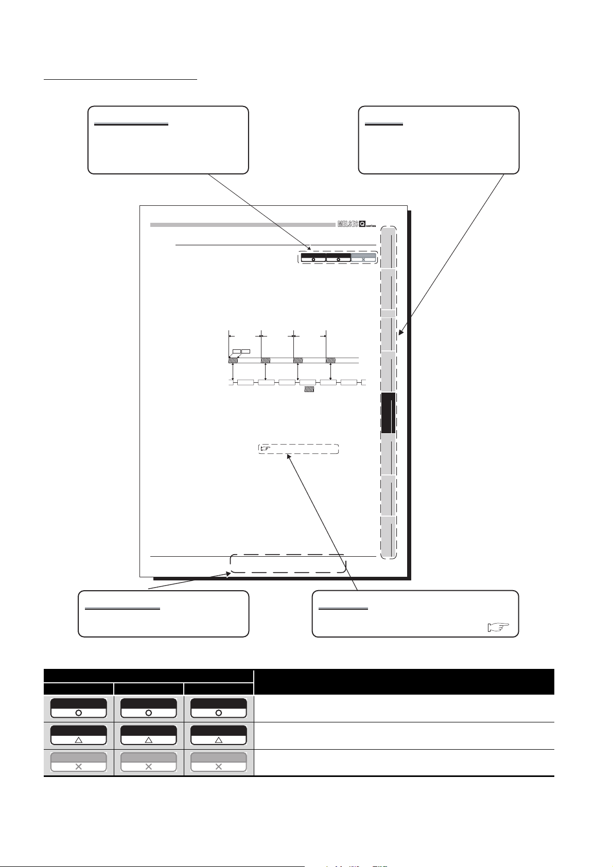
MANUAL PAGE ORGANIZATION
Q06CCPU-V
Relevant model
Whether the description of the section
applies to each model or not is shown as
in the table below.
ACCESS VIA NETWORK MODULES
5
5.4.4 Link device refresh setting
Link device refresh setting is required when using the internal buffer access in user
programs.
To enable the link device refresh, set a link device refresh cycle and refresh parameters in
CC IE Control utility.
(1) Link device refresh cycle
The link device refresh cycle is an interval of time during which the internal link device
buffers of the C Controller module and link devices of a CC-Link IE controller network
module are refreshed.
The concept of the link device refresh cycle is shown below.
C Controller
module processing
(a) Total link device refresh time
Link device
refresh cycle
Link device
refresh
Start End
Link device
refresh
Link scan
Figure 5.45 Conceptual diagram of link device refresh cycle
1) What is total link device refresh time?
This is a processing time for refreshing the link devices of all CC-Link IE
controller network modules that are controlled by the C Controller module.
2) How to obtain the total link device refresh time
A theoretical value for the total link device refresh time can be obtained by a
calculation formula. ( Page 5-59, Section 5.4.5 (1) (b))
Link device
refresh
Link device
refresh cycle
Link device
refresh
Q12DCCPU-V
Link device
refresh cycle
Link device
refresh
Total link device refresh time
Chapter
The chapter of the current page can be
easily identified by this indication on the
right side.
1
Q06CCPU-V-B
OVERVIEW
2
SYSTEM
CONFIGURATION
3
SPECIFICATIONS
4
FUNCTIONS
5
ACCESS VIA NETWORK
MODULES
6
5.4 CC-Link IE Controller Network Module Access Function
Section and title
The section number and title of the current
page can be easily identified.
* The above page illustration is for explanation purpose only, and is different from the actual page.
Icon
Q12DCCPU-V Q06CCPU-V Q06CCPU-V-B
Q12DCCPU-V Q06CCPU-V Q06CCPU-V-B
Q12DCCPU-V Q06CCPU-V Q06CCPU-V-B
Q12DCCPU-V Q06CCPU-V Q06CCPU-V-B
PREPARATORY
PROCEDURES AND
SETTING
7
I/O NUMBER
ASSIGNMENT
8
MEMORIES AND FILES
5.4.4 Link device refresh setting
5 - 48
Reference
The section in this manual or another relevant
manual that can be referred to is shown after .
Description
All or part of the description applies to each model.
The description applies to each model with some restrictions.
The description does not apply to each model.
A - 26
Page 29
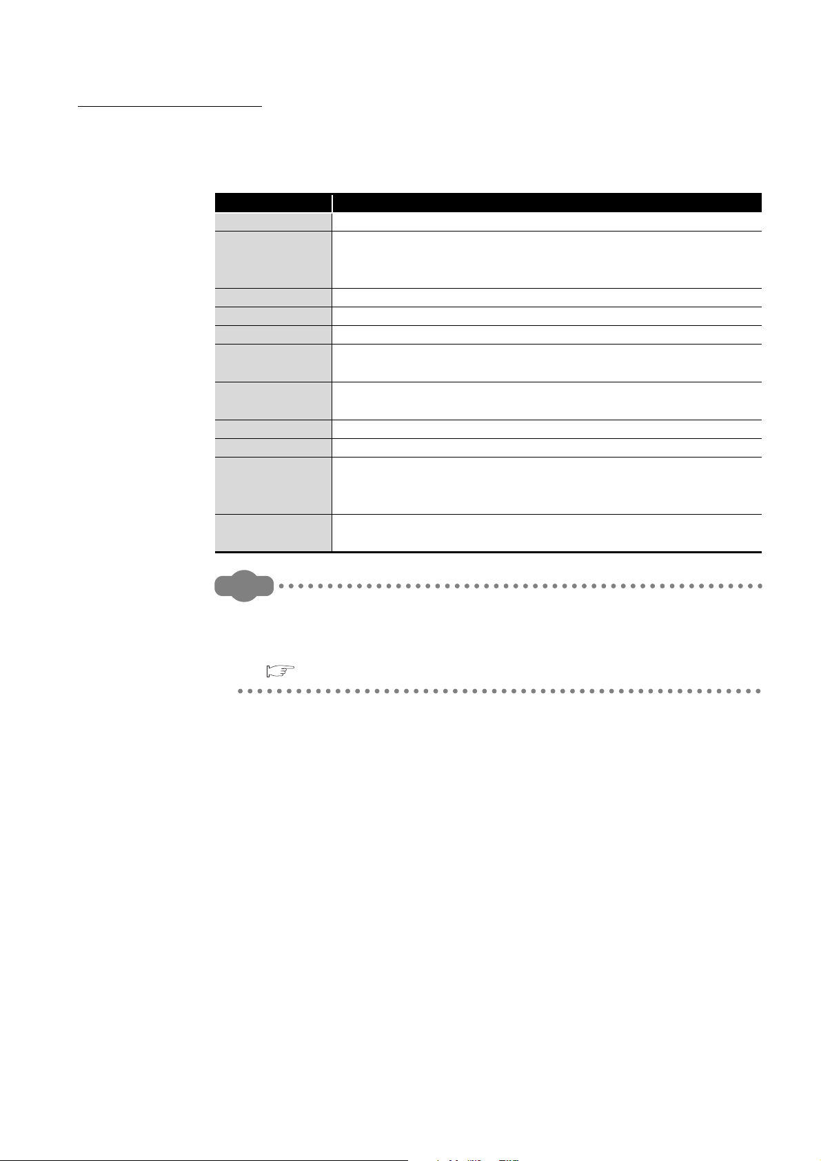
HOW TO USE THIS MANUAL
Remark
This manual is intended to help you understand the system configurations, specifications,
functions, preparatory procedures, and troubleshooting of the C Controller module.
Utilize this manual, referring to the following.
CHAPTER 1 Describes the features of the C Controller module.
CHAPTER 2
CHAPTER 3 Describes the specifications and performance of the C Controller module.
CHAPTER 4 Describes the functions of the C Controller module.
CHAPTER 5 Describes the network module access function of the C Controller module.
CHAPTER 6
CHAPTER 7
CHAPTER 8 Describes the memories of the C Controller module.
CHAPTER 9 Describes devices that can be used with C Controller modules.
CHAPTER 10 to
CHAPTER 15
CHAPTER 16
Item Description
Describes system configurations that include the C Controller module, and
provides a list of the modules that are accessible from the C Controller
module.
Explains the procedures for starting the system operation using the C
Controller module.
Describes the stage number setting for extension base units and I/O number
assignment.
Describes multiple CPU system configurations, I/O numbers,
communications among programmable controller CPUs, I/O modules, and
intelligent function modules, and how to start a multiple CPU system.
Provides corrective actions to be taken for respective errors, and the error
codes that may be generated during function execution.
This manual does not explain the SW3PVC-CCPU installation and uninstallation
procedures, utility operations, functions, and programming.
For details, refer to the following.
C Controller Module User's Manual (Utility Operation, Programming)
A - 27
Page 30
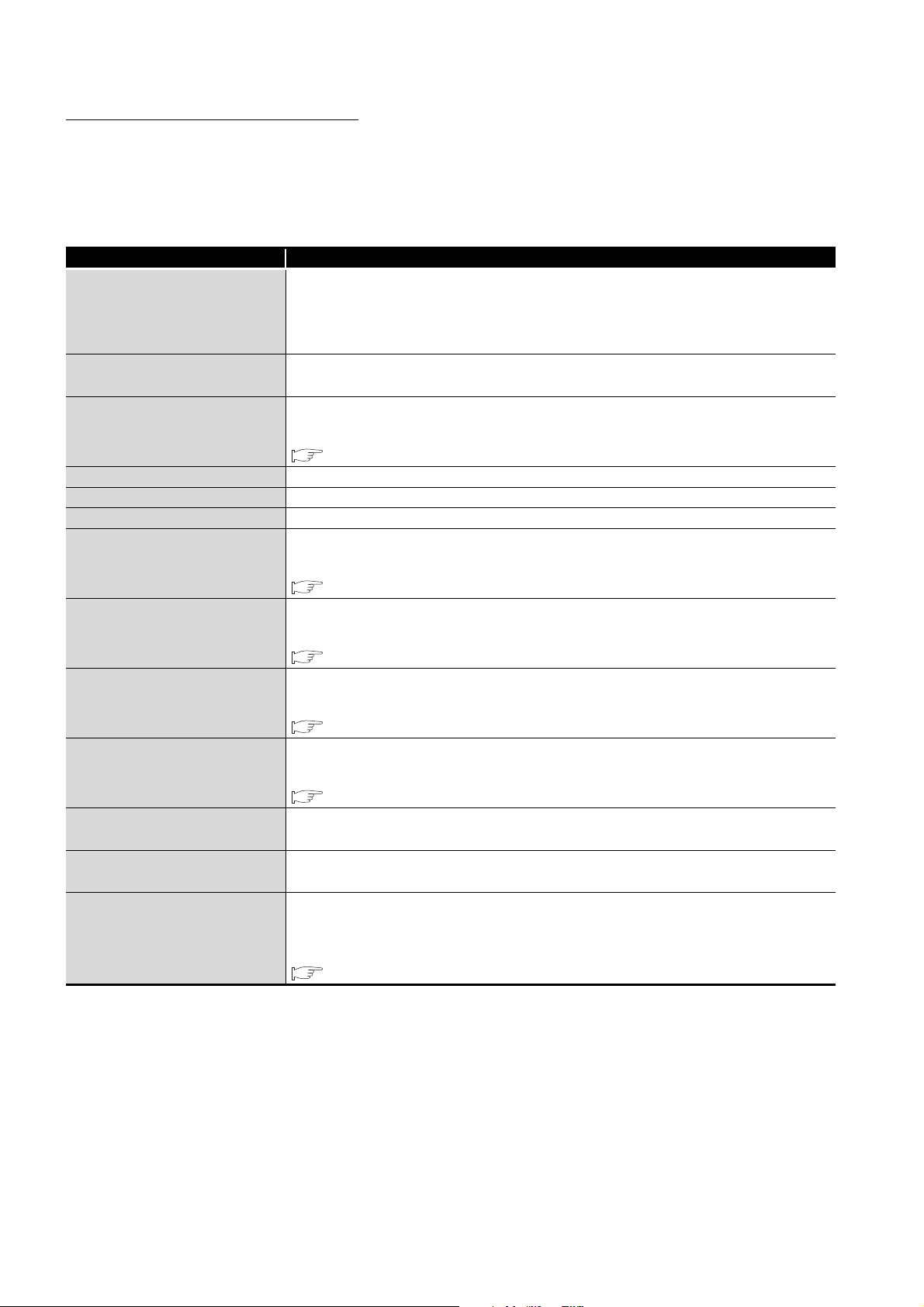
GENERIC TERMS AND ABBREVIATIONS
Unless otherwise specified, this manual uses the following generic terms and
abbreviations to explain the C Controller module.
(1) C Controller modules and SW3PVC-CCPU
Generic term/abbreviation Description
Abbreviation for the Q12DCCPU-V C Controller module
Q12DCCPU-V
Q12DCCPU-V
(Basic mode)
Q12DCCPU-V
(Extended mode)
Q06CCPU-V Abbreviation for the Q06CCPU-V C Controller module
Q06CCPU-V-B Abbreviation for the Q06CCPU-V-B C Controller module
Q06CCPU-V(-B) Generic term for the Q06CCPU-V and Q06CCPU-V-B
Q24DHCCPU-V
Q24DHCCPU-VG
Q24DHCCPU-LS
Q26DHCCPU-LS
C Controller module
SW3PVC-CCPU
SW4PVC-CCPU
In principle, 'Q12DCCPU-V' indicates Q12DCCPU-V (Basic mode).
When the classification is needed for such as comparison with other modules,
'Q12DCCPU-V (Basic mode)' and ‘Q12DCCPU-V (Extended mode)’ are mentioned.
Status that Q12DCCPU-V is initialized with the basic mode
Status that Q12DCCPU-V is initialized with the extended mode
For Q12DCCPU-V (Extended mode), refer to the following manual.
MELSEC-Q C Controller Module User's Manual
Abbreviation for the Q24DHCCPU-V C Controller module
For Q24DHCCPU-V, refer to the following manual.
MELSEC-Q C Controller Module User's Manual
Abbreviation for the Q24DHCCPU-VG C Controller module
For Q24DHCCPU-VG, refer to the following manual.
MELSEC-Q C Controller Module User's Manual
Abbreviation for the Q24DHCCPU-LS C Controller module
For Q24DHCCPU-LS, refer to the following manual.
MELSEC-Q C Controller Module User's Manual
Abbreviation for the Q26DHCCPU-LS C Controller module
For Q26DHCCPU-LS, refer to the following manual.
MELSEC-Q C Controller Module User's Manual
Generic term for the Q06CCPU-V, Q06CCPU-V-B, Q12DCCPU-V, Q24DHCCPU-V,
Q24DHCCPU-VG, Q24DHCCPU-LS, and Q26DHCCPU-LS
Abbreviation for the Setting/Monitoring Tools for the C Controller Module
(SW3PVC-CCPU-E)
Abbreviation for the Setting/Monitoring Tools for the C Controller Module
(SW4PVC-CCPU-E)
For SW4PVC-CCPU, refer to the following manual.
A - 28
Setting/Monitoring Tools for the C Controller Module Version 4 Operating Manual
Page 31

(2) CPU modules
Generic term/abbreviation Description
QnACPU
Basic model QCPU Generic term for the Q00CPU and Q01CPU
High Performance model QCPU Generic term for the Q02CPU, Q02HCPU, Q06HCPU, Q12HCPU, and Q25HCPU
Process CPU Generic term for the Q02PHCPU, Q06PHCPU, Q12PHCPU, and Q25PHCPU
Redundant CPU Generic term for the Q12PRHCPU and Q25PRHCPU
Universal model QCPU
QCPU (Q mode)
Motion CPU
CPU module Generic term for C Controller modules, QCPUs (Q mode), and Motion CPUs
Single CPU system Control system where a C Controller module is mounted in the CPU slot
Multiple CPU system Control system where multiple CPU modules are mounted on a main base unit
Control CPU
Controlled module
Non-controlled module
(Module outside an I/O sharing
group)
Non-control CPU
Battery Generic term for the Q6BAT and Q7BAT batteries for CPU modules
PC CPU module
Generic term for the Q2ACPU, Q2ACPU-S1, Q2ASCPU, Q2ASCPU-S1, Q2ASHCPU,
Q2ASHCPU-S1, Q3ACPU, Q4ACPU, and Q4ARCPU
Generic term for the Q00UJCPU, Q00UCPU, Q01UCPU, Q02UCPU, Q03UDCPU,
Q04UDHCPU, Q06UDHCPU, Q10UDHCPU, Q13UDHCPU, Q20UDHCPU,
Q26UDHCPU, Q03UDECPU, Q04UDEHCPU, Q06UDEHCPU, Q10UDEHCPU,
Q13UDEHCPU, Q20UDEHCPU, Q26UDEHCPU, Q50UDEHCPU, Q100UDEHCPU,
Q03UDVCPU, Q04UDVCPU, Q06UDVCPU, Q13UDVCPU, and Q26UDVCPU
Generic term for the Basic model QCPUs, High Performance model QCPUs, Process
CPUs, Redundant CPUs, and Universal model QCPUs
Generic term for the Q172CPUN, Q172CPUN-T, Q172HCPU, Q172HCPU-T,
Q173CPUN, Q173CPUN-T, Q173HCPU, Q173HCPU-T, Q172DCPU, and Q173DCPU
CPU module that can control I/O modules and intelligent function modules on main and
extension base units.
For example, when CPU No.2 controls a module mounted in Slot 3, CPU No.2 is a
control CPU of the module in Slot 3.
I/O module or intelligent function module that is controlled by a control CPU.
For example, when CPU No.2 controls a module mounted in Slot 3, the module in Slot 3
is a controlled module of CPU No.2.
I/O module or intelligent function module other than controlled modules of a CPU.
For example, when CPU No.2 controls a module mounted in Slot 3, the module in Slot 3
is a non-controlled module of CPUs No.1 and No.3.
CPU module that is not a control CPU.
For example, when CPU No.2 controls a module mounted in Slot 3, CPUs No.1 and
No.3 are non-control CPUs of the module in Slot 3.
Abbreviation for the MELSEC-Q series PC CPU module manufactured by CONTEC
CO., Ltd.
A - 29
Page 32

(3) Network modules and PC boards
Generic term/abbreviation Description
CC-Link module Generic term for the QJ61BT11 and QJ61BT11N
CC-Link/LT module Generic term for the QJ61CL12
Abbreviation for the Q81BD-J61BT11 or Q80BD-J61BT11N CC-Link system master/
CC-Link board
CC-Link IE controller network
module
CC-Link IE controller network
interface board
CC-Link IE field network master/
local module
MELSECNET/H Generic term for the Q series MELSECNET/H network system
MELSECNET/H module
MELSECNET/H board
local interface board, the A80BD-J61BT11 CC-Link system master/local interface board,
and the A80BD-J61BT13 CC-Link interface board.
Generic term for the QJ71GP21-SX and QJ71GP21S-SX
Abbreviation for the Q80BD-J71GP21-SX or Q80BD-J71GP21S-SX CC-Link IE
controller network interface board
Abbreviation for the QJ71GF11-T2 CC-Link IE field network master/local module
Generic term for the QJ71LP21-25, QJ71LP21S-25, QJ71LP21G, QJ71LP21GE,
QJ72LP25-25, QJ72LP25G, QJ72LP25GE, QJ71BR11, QJ72BR15, and QJ71NT11B
Abbreviation for the Q81BD-J71LP21-25, Q80BD-J71LP21-25, Q80BD-J71LP21G,
Q80BD-J71LP21S-25, or Q80BD-J71BR11 MELSECNET/H interface board
A - 30
Page 33

(4) Power supply modules and base units
Generic term/abbreviation Description
Generic term for the Q33B, Q35B, Q38B, and Q312B main base units, to each of which
Q3 B
Q3 SB
Q3 RB
Q3 DB
Q5 B
Q6 B
Q6 RB
QA1S6 B
Main base unit
Extension base unit
Slim type main base unit
Redundant power main base unit
Redundant power extension base
unit
Multiple CPU high speed main
base unit
Base unit
Redundant power supply base
unit
Q series power supply module
Slim type power supply module Generic term for the Q61SP slim type power supply module
Redundant power supply module Generic term for the Q63RP, Q64RP, and Q64RPN redundant power supply modules
Power supply module
Extension cable
CPU slot Slot on the immediate right side of the power supply module on a main base unit
a CPU module, Q series power supply module, Q series I/O modules, intelligent function
modules can be mounted.
Generic term for the Q32SB, Q33SB, and Q35SB slim type main base units, to each of
which a C Controller modules, Basic model QCPU, High Performance model QCPU,
Universal model QCPU, slim type power supply module, Q series I/O modules, and
intelligent function modules can be mounted
Generic term for the Q38RB main base unit for redundant power supply system, to each
of which a CPU module, a redundant power supply module, Q series I/O modules,
intelligent function modules can be mounted
Generic term for the Q35DB, Q38DB, and Q312DB multiple CPU high speed main base
units, to each of which a CPU module, a Q series power supply module, Q series I/O
modules, intelligent function modules can be mounted
Generic term for the Q52B and Q55B extension base units, to which Q series I/O
modules and intelligent function modules can be mounted
Generic term for the Q63B, Q65B, Q68B, and Q612B extension base units, to which Q
series power supply modules, Q series I/O modules, and intelligent function modules
can be mounted
Generic term for the Q68RB extension base unit for redundant power supply system, to
which a redundant power supply module, Q series I/O modules, and intelligent function
modules can be mounted
Generic term for the QA1S65B and QA1S68B extension base units, to which AnS series
power supply modules, AnS series I/O modules, and special function modules can be
mounted
Generic term for the Q3 B, Q3 SB, Q3 RB, and Q3 DB
Generic term for the Q5 B, Q6 B, Q6 RB, and QA1S6 B
Generic term for the Q3 SB
Generic term for the Q3 RB
Generic term for the Q6 RB
Generic term for the Q3 DB
Generic term for the main base unit, extension base unit, slim type main base unit,
redundant power main base unit, redundant power extension base unit, and multiple
CPU high speed main base unit
Generic term for the redundant power main base unit and redundant power extension
base unit
Generic term for the Q61P-A1, Q61P-A2, Q61P, Q61P-D, Q62P, Q63P, Q64P, and
Q64PN power supply modules
Generic term for the Q series power supply modules, slim type power supply modules,
and redundant power supply modules
Generic term for the QC05B, QC06B, QC12B, QC30B, QC50B, and QC100B extension
cables
A - 31
Page 34

(5) Others
Generic term/abbreviation Description
Q series Abbreviation for the programmable controllers, MELSEC-Q series
AnS series
Ethernet Generic term for the 100BASE-TX and 10BASE-T network systems
QD81MEM
GT05-MEM Generic term for the GT05-MEM-128MC and GT05-MEM-256MC
GOT Abbreviation for the Mitsubishi Graphic Operation Terminal
GX Works2
GX Developer
CW Workbench The abbreviation for the engineering tool for C Controller, CW Workbench
Wind River Workbench
Workbench Generic term for the CW Workbench and Wind River Workbench
Tornado
VxWorks
Abbreviation for the programmable controllers, MELSEC-AnS series, which are the
downsized series of the MELSEC-A series
Generic term for the QD81MEM-512MBC, QD81MEM-1GBC, QD81MEM-2GBC,
QD81MEM-4GBC and QD81MEM-8GBC
Product name for the MELSEC programmable controller software package
Abbreviation for Workbench 2.6.1 manufactured by Wind River Systems, Inc.
For specifications and inquiries of Wind River Workbench, visit the website of Wind
River Systems, Inc.: www.windriver.com
Abbreviation for Tornado 2.1.0 for Hitachi SuperH Cumulative patch 1 manufactured by
Wind River Systems, Inc.
For specifications and inquiries of Tornado, visit the website of Wind River Systems,
Inc.: www.windriver.com
Product name for the real-time operating system manufactured by Wind River Systems,
Inc.
A - 32
Page 35

GLOSSARY
The following lists the terms used in C Controller module manuals and the meanings of the
terms.
Term Description
FTP FTP is an abbreviation for File Transfer Protocol, which is used to transfer data files.
Telnet Network protocol, or virtual terminal software, that enables remote login in TCP/IP networks.
CompactFlash card (CF
card)
Bus interface function
MELSEC data link function
Storage card stipulated in the "CF+ and CompactFlash Specification" issued by CompactFlash
Association.
Function offered by SW3PVC-CCPU.
This allows input from or output to I/O modules controlled by the C Controller module, access to
the buffer memory of an intelligent function module, and the read out or control of the C
Controller module status.
Function offered by SW3PVC-CCPU.
Standardized communication library that does not depend on communication protocols.
When creating a program for communicating with a programmable controller CPU or C
Controller module, there is no need to consider the hardware or communication protocol of the
target.
The MELSEC data link functions support the following.
• Q series bus interface communication
• CC-Link communication
• MELSECNET/H communication
• CC-Link IE controller network communication
The MELSEC data link functions cannot be used for the Q06CCPU-V-B.
A - 33
Page 36

PRODUCT ORGANIZATION
The following shows the C Controller-compatible software.
Supported
software
SW4PVC-CCPU
SW3PVC-CCPU
PACKING LIST
One of the listed C Controller modules is included in the product package.
Model Product name Quantity
Q12DCCPU-V
Q06CCPU-V
Q06CCPU-V-B
SW3PVC-CCPU-E
*1
C Controller module
Q12DCCPU-V
"15102" or later
Extended mode
* 1 First five digits of serial number
* 2 For Q12DCCPU-V earlier than "15102", the mode cannot be changed. Q12DCCPU-V earlier than
"15102" is regarded as the basic mode in this manual.
Q12DCCPU-V C Controller module (Endian format (memory layout): Little
endian)
Battery (Q6BAT) 1
Q06CCPU-V C Controller module (Endian format (memory layout): Little
endian)
Battery (Q6BAT) 1
Q06CCPU-V-B C Controller module (Endian format (memory layout): Big
endian)
Battery (Q6BAT) 1
Setting/Monitoring Tools for the C Controller Module
(Volume license product)
Software License Agreement 1
Software Registration Form 1
License Agreement 1
Industrial development tool purchasing form (Wind River Workbench)
Industrial development tool purchasing form (Tornado)
*1
Basic mode
Earlier than
"15102"
*2
*1
: Applicable, : Not applicable
Q06CCPU-V
Q06CCPU-V-B
-
-
(CD-ROM)
1
1
1
1
1
* 1 Production of the Q06CCPU-V-B was discontinued in November, 2015.
DISCONTINUED MODELS
The following models are described in this manual, but have no longer been produced.
For the onerous repair term after discontinuation of production, refer to "WARRANTY".
Model Production discontinuation
Q61P-A1 March 2009
Q61P-A2 March 2009
Q64P February 2010
Q64RP October 2015
A - 34
Page 37

1
Remark
OVERVIEW
CHAPTER 1 OVERVIEW
This manual describes the specifications, functions, preparatory procedures, and
troubleshooting of the C Controller module.
Development environment
(personal computer)
C Controller module
CC-Link IE controller network module
MELSECNET/H module
CC-Link module
Access by bus interface function!
1
2
3
OVERVIEW
SYSTEM
CONFIGURATION
SW3PVC-CCPU,
Workbench, or Tornado
GOT
Figure 1.1 Example of a system that includes a C Controller module
For the utilities and functions offered by the Setting/Monitoring Tools for the C
Controller Module (SW3PVC-CCPU), refer to the following.
C Controller Module User's Manual (Utility Operation, Programming)
CC-Link IE
controller network
Access by MELSEC
data link function!
MELSECNET/H
Access by MELSEC
data link function!
Access by MELSEC
data link function!
CC-Link
SPECIFICATIONS
4
FUNCTIONS
5
ACCESS VIA NETWORK
MODULES
6
PREPARATORY
PROCEDURES AND
SETTING
7
I/O NUMBER
ASSIGNMENT
8
MEMORIES AND FILES
1 - 1
Page 38

1
Hardware
Design
Multiple CPU
System
Details
Details
Details
Details
Details
Outline
Details
Details
Details
Details
Details
OVERVIEW
(1) List of related manuals
The following table lists the manuals that are related to the C Controller module.
For further information such as manual numbers, refer to "ABOUT MANUALS". (
Page A-25)
Table 1.1 List of related manuals
Purpose
Checking part names and
specifications of the C Controller
module
Checking specifications of power
supply modules and base units, and
selection and installation methods
Checking how to connect power
supply modules, base units, and I/O
modules
Checking the functions of the C
Controller module
Single CPU system construction
(checking the start-up procedure and
I/O No. assignment method)
Multiple CPU system construction
(checking the start-up procedure and
I/O No. assignment method)
Hardware
(Packed)
C Controller
Module User's
Manual
(Hardware)
Outline
Outline
C Controller
Module User's
Manual
(Hardware
Design, Function
Explanation)
*1
*1
*1
*1
*1
Utility
Operation
C Controller
Module User's
Manual (Utility
Operation,
Programming)
Maintenance
and
Inspection
QCPU User's
Manual
(Hardware
Design,
Maintenance and
Inspection)
QCPU User's
Manual (Multiple
CPU System)
Checking parameter setting and
monitoring
Checking programming
Checking troubleshooting and error
codes
Checking event No. and error
messages in respective utilities
1 - 2
*2
*1
*1
*1
* 1
For Q24DHCCPU-V, Q24DHCCPU-VG, Q24DHCCPU-LS, Q26DHCCPU-LS, or Q12DCCPU-V (Extended mode), refer to the following manual.
MELSEC-Q C Controller Module User's Manual
For Q24DHCCPU-V, Q24DHCCPU-VG, Q24DHCCPU-LS, Q26DHCCPU-LS, or Q12DCCPU-V (Extended mode), refer to the following manual.
* 2
Setting/Monitoring Tools for the C Controller Module Version 4 Operating Manual
Page 39

1
Remark
OVERVIEW
Checking the power supply module specifications to make a
selection
Checking the specifications of base units and extension cables to
make a selection, and configuring the system
Compliance of the C Controller system with the EMC and Low
Voltage Directives
Calculating the heat value of the C Controller system Section 10.2
Mounting modules Section 10.3
Checking how to set the number of extension base units Section 10.4
Connecting/disconnecting extension cables Section 10.5
Wiring the power supply module Section 10.6
Checking I/O module troubleshooting cases Section 12.5
Checking external dimensions of power supply modules and base
units
This manual mainly describes the C Controller module itself.
For the C Controller system information listed below, refer to the following.
QCPU User's Manual (Hardware Design, Maintenance and Inspection)
When reading the above manual, interpret the terms, "CPU module" and
"programmable controller" as "C Controller module" and "C Controller system"
accordingly.
Table 1.2 List of referenced sections
Item Refer to
Chapter 5
Chapter 6
Chapter 9
Appendix 1
1
OVERVIEW
2
SYSTEM
CONFIGURATION
3
SPECIFICATIONS
4
FUNCTIONS
5
ACCESS VIA NETWORK
MODULES
6
PREPARATORY
PROCEDURES AND
SETTING
7
I/O NUMBER
ASSIGNMENT
8
MEMORIES AND FILES
1 - 3
Page 40

1
Drive unit
Drive unit
Motor
Motor
OVERVIEW
1.1 Features
The features of the C Controller module are described below.
(1) Development environment can reduce the development period and
engineering cost.
By adopting a real-time operating system "VxWorks", a highly reliable and robust
system can be constructed.
User application (C or C language)
Standard I/O library
Standard RAM, standard ROM,
and CompactFlash card driver
Engineering cost is reduced.
Serial
driver
VxWorks (OS)
Figure 1.2 Development environment
++
Socket communication library
Ethernet driver
Highly real-time system can be constructed!
Dedicated library
Dedicated driver
Pre-implemented
(2) With a wide range of MELSEC-Q series I/O modules and intelligent
function modules, more scalable and flexible systems can be
constructed.
Without using sequence programs, the C Controller module can control I/O modules
and intelligent function modules from the user programs created with the bus interface
functions.
1 - 4
1.1 Features
Figure 1.3 Control of I/O modules and intelligent function modules
Page 41

1
OVERVIEW
(3) The system suitable for the scale and control purpose is constructible.
The C Controller module can be used in a multiple CPU system in combination with
programmable controller CPU(s) and Motion CPU(s).
In a multiple CPU system, each CPU module can perform the most suitable kind of
tasks to obtain the optimum results in the system operation.
Note that the C Controller module set as CPU No.1 can compose a multiple CPU
system in combination with Motion CPU(s) (without a programmable controller CPU).
The C Controller module can be also used in a single CPU system configuration.
CPU No.1: C Controller module or
programmable controller CPU
CPU No.2 to No.4: Programmable controller CPU, Motion CPU, or C Controller module
Figure 1.4 Multiple CPU system
1
2
3
4
OVERVIEW
SYSTEM
CONFIGURATION
SPECIFICATIONS
Multiple CPU
system
(4) Takt time for the system can be reduced. (Q12DCCPU-V only)
Without using any program, the Q12DCCPU-V can transfer a large volume of data (up
to 14K words) at a high speed in cycles of 0.88ms, and can share the data with other
CPU modules.
This can reduce the takt time (the maximum time allowed to produce a product in
order to meet demand) without considering the multiple CPU system configuration.
Motion CPU
(Q172DCPU,Q173DCPU)
Motion program
CPU No.1 data
CPU No.2 data
Large
volume of
14K words!!
C Controller module Motion CPU
Figure 1.5 Reduced takt time for the system
C Controller module
Program runs in
User program
CPU No.1 data
CPU No.2 data
Access from program does not affect high-speed
cyclic transmissions at 0.88ms intervals.
parallel with cyclic
transmissions.
Multiple CPU high
speed transmission area
5
ACCESS VIA NETWORK
6
PREPARATORY
PROCEDURES AND
7
I/O NUMBER
8
FUNCTIONS
MODULES
SETTING
ASSIGNMENT
1.1 Features
MEMORIES AND FILES
1 - 5
Page 42

1
C Controller module
Motion CPU
(Q172DCPU,Q173DCPU)
Interrupt program
Synchronous
execution in cyclic
transmission timing
Operation cycle
0.88ms
Motion program
Synchronized!!
CPU No.1 data
CPU No.2 data
CPU No.1 data
CPU No.2 data
Cyclic
transmission
cycle 0.88ms
Stroke
Ideal trajectory
Actual trajectory
Operation
cycle
0.88ms
Motion CPU
C Controller module
Interrupt program User program
Operation cycle
OVERVIEW
(5) Sophisticated and high-precision sequential and tracking controls
(Q12DCCPU-V only)
The C Controller module can execute an interrupt routine (interrupt program) when
one of the following interrupts occurs.
Interrupt routine (interrupt program) execution does not produce a delay that could be
caused by user program execution or priority in multitasking.
For this reason, high-performance and high-accuracy sequential controls and tracking
controls that respond in real-time can be realized for occurred interrupts.
(a) Multiple CPU synchronous interrupt
The multiple CPU synchronous interrupt is an interrupt that is issued in the same
cycles (0.88ms) as Motion CPU (Q172DCPU or Q173DCPU) control cycles.
Data acquisition is available in each operation cycle of a Motion CPU by running
an interrupt routine (interrupt program) for the multiple CPU synchronous
interrupt.
The multiple CPU synchronous interrupt can also be used for real-time sequential
controls synchronized with motion control and also for tracking controls in which
the target value is changing every second.
1 - 6
1.1 Features
Figure 1.6 Multiple CPU synchronous interrupt
Page 43

1
OVERVIEW
(b) Interrupt from an intelligent function module or an interrupt module
(c) Interrupts from other CPUs
Interrupt routines (interrupt programs) can be executed, corresponding to the
interrupts from the intelligent function module or the interrupt module.
An interrupt routine (interrupt program) allows a real-time control responding to an
event occurred in the intelligent function module or an input from an external
device to the interrupt module.
Interrupt routines (interrupt programs) cannot be executed for the following C
Controller modules.
• Q12DCCPU-V with a serial number whose first five digits are "12041" or
earlier
Interrupt routines (interrupt programs) can be executed for interrupts from other
CPUs (programmable controller CPUs or C Controller modules).
Real-time sequential controls synchronized with controls from another CPU can
be used through interrupt routines (interrupt programs).
Interrupt routines (interrupt programs) cannot be executed for the following C
Controller modules.
• Q12DCCPU-V with a serial number whose first five digits are "12041" or
earlier
1
2
3
4
OVERVIEW
SYSTEM
CONFIGURATION
SPECIFICATIONS
5
ACCESS VIA NETWORK
6
PREPARATORY
PROCEDURES AND
7
I/O NUMBER
8
FUNCTIONS
MODULES
SETTING
ASSIGNMENT
1.1 Features
MEMORIES AND FILES
1 - 7
Page 44

1
High-speed communication
for each channel
Intercommunication with
higher-level servers
MES server
SECS/GEM
communication
HSMS protocol
Ethernet1 (100Mbps)
EES server
Manufacturing
device
Inspection
device
Ethernet2 (100Mbps)
Devices
Only one C Controller
module!!
Device level network
CC-Link IE controller network
MELSECNET/H
CC-Link
Flowmeter
Pump Sensor
Vacuometer
Microcomputer, etc
Stable network operation Enhanced network security
Ethernet (network for communication
with a higher level)
Error Error
By separating the host from the device
level network, an error occurred in between
does not affect the device level network.
Prevents an illegal access from the
higher-level network (end user) to the
device level network (manufacturer).
Manufacturing
device
Inspection
device
Devices
Only one C Controller
module!!
Device level network
Ethernet
Microcomputer, etc.
OVERVIEW
(6) Flexible and easy network construction
The C Controller module is equipped with Ethernet port(s).
Ethernet communication programs can be created easily using the VxWorks
communication library (socket functions).
With two built-in Ethernet ports (two channels), the Q12DCCPU-V can perform realtime communication that will improve the machine operation rates and productivity.
(a) Case 1: Real-time communication with MES and EES
The C Controller module communicates data such as lot and recipe information
with an MES server and time-stamped process data with an EES server, and
thereby the system productivity can be improved.
(b) Case 2: Enhanced device level network security
1 - 8
1.1 Features
Figure 1.7 Real-time communication with MES and EES
Figure 1.8 Enhanced device level network security
Page 45

1
OVERVIEW
(7) More efficient debugging and easy device monitoring and
troubleshooting using the 7-segment LED display (Q12DCCPU-V only)
Without a computer, users can debug programs, check the operating status, and
diagnose some failure easily by viewing the LED display. (Monitoring is available from
a personal computer.)
End user Manufacturer
"2.2" is flashing in the control
panel. Why?
Figure 1.9 7-segment LED display
The cause of "2.2" flashing is
xxx. Our service representative
will visit you as soon as possible.
1
2
3
4
OVERVIEW
SYSTEM
CONFIGURATION
SPECIFICATIONS
(8) Easy configuration and startup of positioning modules (Q12DCCPU-V
only)
By using GX Configurator-QP, which is a setting, monitoring and testing tool for
positioning modules, the engineering cost can be reduced because parameter-setting
programs are no more needed.
The programming and debugging efficiency for positioning modules will be
remarkably improved.
USB
Development environment (personal computer)
GX Configurator-QP
Figure 1.10 Easy configuration and startup of positioning modules
Drive unit
Drive unit
Motor
Motor
5
ACCESS VIA NETWORK
6
PREPARATORY
PROCEDURES AND
7
FUNCTIONS
MODULES
SETTING
1.1 Features
I/O NUMBER
ASSIGNMENT
8
MEMORIES AND FILES
1 - 9
Page 46

1
OVERVIEW
(9) More scalable and flexible system construction utilizing various
MELSEC-Q series network products
The following access methods are available through network modules.
(a) Message communication
Using a bus interface function or MELSEC data link function, a message can be
transmitted via the following network module. (Message communication with the
SEND/RECV function)
• Via a MELSECNET/H module
• Via a CC-Link IE controller network module
Note that, for the Q06CCPU-V-B, MELSEC data link functions cannot be used.
Message communication is available!
C Controller module
CC-Link IE controller network
Figure 1.11 Message communication via a CC-Link IE controller network module
1 - 10
1.1 Features
Page 47

1
Access via CC-Link IE controller network
C Controller module
CC-Link IE controller network
OVERVIEW
(b) Access to another station's programmable controller CPU or C Controller module
From a user program created with MELSEC data link functions, the C Controller
module can access another station's programmable controller CPU or C
Controller module via the following network module.
• CC-Link module
• MELSECNET/H module
• CC-Link IE controller network module
The Q06CCPU-V-B cannot access another station's programmable controller
CPU.
The following C Controller modules cannot access another station's C Controller
module.
• Q12DCCPU-V with a serial number whose first five digits are "12041" or
earlier
• Q06CCPU-V(-B)
1
2
3
4
OVERVIEW
SYSTEM
CONFIGURATION
SPECIFICATIONS
Figure 1.12 Access to another station's programmable controller via a CC-Link IE controller
network module
5
ACCESS VIA NETWORK
6
PREPARATORY
PROCEDURES AND
7
I/O NUMBER
8
FUNCTIONS
MODULES
SETTING
ASSIGNMENT
1.1 Features
MEMORIES AND FILES
1 - 11
Page 48

1
C Controller module
Serial communications
OVERVIEW
(10)Control of a wide variety of CC-Link products
The C Controller module can control a wide variety of CC-Link products using user
programs.
Up to eight CC-Link modules can be mounted.
C Controller module
CC-Link module
Remote I/O station
Remote device station
Local station
Partner manufacturer's
product
Figure 1.13 Control of CC-Link products
Intelligent device station
(11)Easy serial communication programming
The C Controller module is equipped with an RS-232 port.
Using the VxWorks communication library, serial communication programs can be
created.
The microcomputer connection with a GOT is also available. ( Page 4-47,
Section 4.14)
1 - 12
Figure 1.14 Serial communications using RS-232 port
1.1 Features
Page 49

1
OVERVIEW
(12)Simple remote debugging of the C Controller module with the supported
Telnet function
By executing a Shell command from the Telnet tool of the development environment
(personal computer), remote debugging of the C Controller module (task information
display, memory dumping, etc.) can be performed with ease.
Simple remote debugging without using Workbench or Tornado is available.
1
2
3
4
OVERVIEW
SYSTEM
CONFIGURATION
SPECIFICATIONS
Telnet
C Controller module
Remote control
Development environment
(personal computer)
Figure 1.15 Telnet function
by Telnet!
(13)Login user access restriction can prevent illegal access.
Login users can be set (added/deleted) for the C Controller module.
This can restrict parameter writing with FTP or from each utility as well as the usage of
the Telnet function.
5
ACCESS VIA NETWORK
6
PREPARATORY
PROCEDURES AND
7
FUNCTIONS
MODULES
SETTING
Figure 1.16 Login user access restriction
1.1 Features
I/O NUMBER
ASSIGNMENT
8
MEMORIES AND FILES
1 - 13
Page 50

1
OVERVIEW
(14)User programs can be stored in the built-in standard RAM or ROM.
The C Controller module has a built-in standard RAM or ROM.
Therefore, user programs can be stored even if there is no external memory such as a
CompactFlash card.
Data stored in the standard RAM are retained by battery power even if the C
Controller module is powered off or reset.
For the memory capacity, refer to the following.
Page 8-5, Section 8.1.1 (3)
(15)CompactFlash card allows large-volume data storage.
By using a CompactFlash card, the C Controller module can store large volumes of
data depending on the capacity of the card.
(16)Retention and monitoring of battery-backed-up RAM data
Once data are stored in the battery-backed-up RAM using a user program
(QBF_ReadSRAM, QBF_WriteSRAM, QBF_ReadSRAM_ISR, and
QBF_WriteSRAM_ISR functions), they will be retained by battery power even if the C
Controller module is powered off or reset.
This allows the user program to be executed with the data stored last time (when
power is turned off or reset) every time the power is turned on, even if the power is
turned off or reset.
The data in the battery-backed-up RAM can be monitored in C Controller setting
utility.
For the memory capacity, refer to the following.
Page 8-5, Section 8.1.1 (3)
(17)RAM disk function
The C Controller module can create a RAM disk on the work RAM using a user
program.
The FTP function allows transfer of files including user program files from a personal
computer to the created RAM disk in the C Controller module.
Compared with the standard ROM or CompactFlash cards, the speed of file access
from/to the RAM disk is faster.
Therefore, the RAM disk is a storage medium suitable for the data that do not need
battery backup or that will be used only during system operation.
The RAM disk is formatted when the C Controller module is powered off or reset.
For the memory capacity, refer to the following.
Page 8-5, Section 8.1.1 (3)
1 - 14
1.1 Features
Page 51

1
Reads devices of C Controller module (CPU No.1) to C Controller
module (CPU No.2).
Writes data to devices of C Controller module (CPU No.1) from
C Controller module (CPU No.2).
1)
2)
C Controller module
Device
C Controller module
/*Read devices of C Controller module (CPU No.1). */
ret = mdReceive (Path, stno, devtyp, devno, size, data);
/*Write data to devices of C Controller module (CPU No.1). */
ret = mdSend (Path, stno, devtyp, devno, size, data);
1)
2)
OVERVIEW
(18)The device function allows an access similar to that of a programmable
controller CPU.
A device such as a programmable controller CPU can be created in the work RAM of
the C Controller module.
Access methods from peripheral devices (GOT or MX Component and others) are the
same as those for the programmable controller CPU. Therefore, connectivity is
improved.
Device functions cannot be used for the following C Controller modules.
(a) Communication with a GOT without using any program (connecting a GOT in a
• Q12DCCPU-V with a serial number whose first five digits are "12041" or earlier
• Q06CCPU-V(-B)
bus topology)
C Controller module
1
2
3
OVERVIEW
SYSTEM
CONFIGURATION
Connection cable
GOT
Figure 1.17 Connecting a GOT in a bus topology
(b) Data exchange between two C Controller modules
Device
4
5
ACCESS VIA NETWORK
6
PREPARATORY
PROCEDURES AND
7
SPECIFICATIONS
FUNCTIONS
MODULES
SETTING
Figure 1.18 Data exchange between two C Controller modules
1.1 Features
I/O NUMBER
ASSIGNMENT
8
MEMORIES AND FILES
1 - 15
Page 52

1
t
OVERVIEW
(c) Connection with MX Component
C Controller module
MX Componen
Ethernet communications
Figure 1.19 Connection with MX Component
(19)Mode change expands the function
(For Q12DCCPU-V with a serial number whose first five digits are
"15102" or later)
By switching the mode (from basic mode to extended mode) using the module
initialization setting, the function of Q12DCCPU-V, such as the dedicated instructions,
memory, and network, are added.
For the extended mode, refer to the following manual.
MELSEC-Q C Controller Module User's Manual
1 - 16
1.1 Features
Page 53

2
SYSTEM CONFIGURATION
CHAPTER 2 SYSTEM CONFIGURATION
This chapter explains system configurations, applicable modules, and connectable
devices when using the C Controller module.
2.1 System Configuration
This section introduces C Controller system configurations, including devices used for
each base unit, connection with an environment development, and entire system
overview. For the multiple CPU system configuration, refer to CHAPTER 10 and
CHAPTER 11.
1
2
3
4
OVERVIEW
SYSTEM
CONFIGURATION
SPECIFICATIONS
5
ACCESS VIA NETWORK
6
PREPARATORY
PROCEDURES AND
7
I/O NUMBER
8
FUNCTIONS
MODULES
SETTING
ASSIGNMENT
2.1 System Configuration
MEMORIES AND FILES
2 - 1
Page 54

2
Remark
Battery
*2
C Controller module
Main base unit
Q series power supply, I/O, Intelligent function modules
Extension cable
Extension base unit
CompactFlash card (sold
separately)
*1
SYSTEM CONFIGURATION
2.1.1 Devices used for each base unit
(1) When using the main base unit (Q3 B)
Figure 2.1 When a main base unit is used
* 1 For the Q06CCPU-V-B, CompactFlash cards cannot be used.
* 2 For the Q06CCPU-V(-B), the Q7BAT cannot be used.
• For applicable base units, extension cables, and power supply modules, refer to
the following.
Page 2-9, Section 2.1.4 (1)
• For applicable I/O modules and intelligent function modules, refer to the
following.
Page 2-17, Section 2.2.1
2 - 2
2.1 System Configuration
2.1.1 Devices used for each base unit
Page 55

2
Remark
C Controller module
Slim type main base unit
Q series power supply, I/O, Intelligent function modules
CompactFlash card (sold
separately)
*1
Battery
*2
SYSTEM CONFIGURATION
(2) When using the slim type main base unit (Q3 SB)
1
2
3
4
OVERVIEW
SYSTEM
CONFIGURATION
SPECIFICATIONS
* 1 For the Q06CCPU-V-B, CompactFlash cards cannot be used.
* 2 For the Q06CCPU-V(-B), the Q7BAT cannot be used.
• For applicable base units and power supply modules, refer to the following.
• For applicable I/O modules and intelligent function modules, refer to the
following.
Figure 2.2 When a slim type main base unit is used
Page 2-11, Section 2.1.4 (2)
Page 2-17, Section 2.2.1
5
ACCESS VIA NETWORK
6
PREPARATORY
PROCEDURES AND
7
I/O NUMBER
8
FUNCTIONS
MODULES
SETTING
ASSIGNMENT
2.1.1 Devices used for each base unit
2.1 System Configuration
MEMORIES AND FILES
2 - 3
Page 56

2
Remark
SYSTEM CONFIGURATION
(3) When using the multiple CPU high speed main base unit (Q3 DB)
CompactFlash card (sold
separately)
*1
Battery
*2
Extension cable
C Controller module
Q3 DB multiple CPU high
speed main base unit
Q series power supply, I/O, Intelligent function modules
Extension base unit
Figure 2.3 When a multiple CPU high speed main base unit is used
* 1 For the Q06CCPU-V-B, CompactFlash cards cannot be used.
* 2 For the Q06CCPU-V(-B), the Q7BAT cannot be used.
• For applicable base units and power supply modules, refer to the following.
Page 2-12, Section 2.1.4 (3)
• For applicable I/O modules and intelligent function modules, refer to the
following.
Page 2-17, Section 2.2.1
2 - 4
2.1 System Configuration
2.1.1 Devices used for each base unit
Page 57

2
SYSTEM CONFIGURATION
1
2.1.2 Connection with a development environment
(1) For the Q12DCCPU-V
CompactFlash card
(sold separately)*
C Controller module
OVERVIEW
2
CompactFlash card (sold
separately)*
3
SYSTEM
CONFIGURATION
3
Development environment*1 (personal computer)
1
3
Adaptor*
(sold separately)
Twisted pair cable
(Straight cable or crossing
cable)
(sold separately)
SPECIFICATIONS
4
FUNCTIONS
5
SW3PVC-CCPU
Figure 2.4 Connection with a development environment
* 1 To write a user file to a CompactFlash card, a personal computer such as a laptop that has the
PCMCIA interface, or a personal computer with a CompactFlash card reader/writer connected is
required.
* 2 CW Workbench or Wind River Workbench (sold separately).
For Wind River Workbench specifications and inquiries, visit the website of Wind River Systems,
Inc.
www.windriver.com
Workbench*
2
ACCESS VIA NETWORK
MODULES
6
PREPARATORY
PROCEDURES AND
SETTING
7
I/O NUMBER
ASSIGNMENT
8
2.1 System Configuration
2.1.2 Connection with a development environment
MEMORIES AND FILES
2 - 5
Page 58

2
C Controller module
Development environment*1 (personal computer)
Twisted pair cable
(Crossing cable) (sold separately)
Adaptor*
1
(sold separately)
Tornado*
2
(sold separately)
SW3PVC-CCPU
CompactFlash card
(sold separately)*
3
CompactFlash card
(sold separately)*
3
SYSTEM CONFIGURATION
(2) For the Q06CCPU-V(-B)
Figure 2.5 Connection with a development environment
* 1 To write a user file to a CompactFlash card, a personal computer such as a laptop that has the
PCMCIA interface, or a personal computer with a CompactFlash card reader/writer connected is
required.
* 2 For Tornado specifications and inquiries, visit the website of Wind River Systems, Inc.
www.windriver.com
* 3 For the Q06CCPU-V-B, the CompactFlash card cannot be used.
2 - 6
2.1 System Configuration
2.1.2 Connection with a development environment
Page 59

2
SYSTEM CONFIGURATION
1
2.1.3 Connection with peripheral devices
(1) For the Q12DCCPU-V
C Controller module
Hub (sold separately)
(Straight cable) (sold separately)
Target devices (personal computer, C Controller module, GOT, etc)
Twisted pair cable
Hub (sold separately)
OVERVIEW
2
SYSTEM
CONFIGURATION
3
SPECIFICATIONS
4
FUNCTIONS
5
GOT, RS-232 cable (sold separately)
Personal computer
(GX Works2, GX Developer, GX Configurator-QP,
MT Works2, MT Developer, MX Component, etc.)
Figure 2.6 Connection with peripheral devices
RS-232 conversion cable
(Q12DCCPU-CBL) (sold separately)
USB cable (sold separately)
ACCESS VIA NETWORK
MODULES
6
PREPARATORY
PROCEDURES AND
SETTING
7
I/O NUMBER
ASSIGNMENT
8
2.1 System Configuration
2.1.3 Connection with peripheral devices
MEMORIES AND FILES
2 - 7
Page 60

2
SYSTEM CONFIGURATION
(2) For the Q06CCPU-V(-B)
C Controller module
Target devices (such as personal computer and C Controller
module)
Hub (sold separately)*1
Twisted pair cable
(Straight cable)
(sold separately)
GOT, RS-232 cable (sold separately)
Figure 2.7 Connection with peripheral devices
* 1 Q06CCPU-V does not support the IEEE802.3x flow control.
Therefore, when the load of an Ethernet line is high in the connection with the hub supporting
IEEE802.3x, the data to be sent to the module may be lost.
If the above mentioned phenomenon occurs, add the hubs and reduce the load on the Ethernet
line applied on single hub.
2 - 8
2.1 System Configuration
2.1.3 Connection with peripheral devices
Page 61

2
C Controller module
Q35B (exclusive 5 slots)
Q68B (exclusive 8 slots)
Q65B (exclusive 5 slots)
00 to 0F
10 to 1F
20 to 2F
30 to 3F
40 to 4F
50 to 5F
60 to 6F
70 to 7F
80 to 8F
90 to 9F
A0 to AF
B0 to BF
C0 to CF
D0 to DF
E0 to EF
F0 to FF
100 to 10F
110 to 11F
CPU 0 1 2 3 4
5 6 7 8 9 101112
13 14 15 16 17
Q series
power supply
module
Number of
Ext.Bases: 3
Slot No.: 0
The extension base image for GOT connection by C Controller module side
120 to 12F
130 to 13F
140 to 14F
150 to 15F
160 to 16F
18 19 20 21 22 23 24 25 26 27
1) 2) 3) 4) 5)
1) 2) 3) 4) 5)
Number of
Ext.Bases: 3
Slot No.: 1
Number of
Ext.Bases: 3
Slot No.: 2
Number of
Ext.Bases: 3
Slot No.: 3
Number of
Ext.Bases: 3
Slot No.: 4
Setting
by GOT
Sets data as empty in "I/O assignment setting" of
C Controller setting utility.
Slot No.
I/O No.
GOT (extension base number: 3)
16 points exclusive 10 slots
Main base unit A 16-point module is mounted on each slot
Extension base unit A 16-point module is mounted on each slot
SYSTEM CONFIGURATION
2.1.4 System configuration overview
(1) When using the main base unit (Q3 B)
1
2
3
OVERVIEW
SYSTEM
CONFIGURATION
4
5
ACCESS VIA NETWORK
6
PREPARATORY
PROCEDURES AND
7
SPECIFICATIONS
FUNCTIONS
MODULES
SETTING
Figure 2.8 Configuration example of a system using a main base unit
2.1 System Configuration
2.1.4 System configuration overview
2 - 9
I/O NUMBER
8
ASSIGNMENT
MEMORIES AND FILES
Page 62

2
SYSTEM CONFIGURATION
Table 2.1 Restrictions on the system configuration
Maximum number of
extension base units
Maximum number of I/O
modules
Main base unit model Q33B, Q35B, Q38B, Q312B
Extension base unit
model
Extension cable model QC05B, QC06B, QC12B, QC30B, QC50B, QC100B
Q series power supply
module model
No power supply module required Q52B, Q55B
Q series power supply module required Q63B, Q65B, Q68B, Q612B
Q61P-A1, Q61P-A2, Q61P, Q61P-D, Q62P, Q63P, Q64P, Q64PN
Precautions
• The total extension cable length must be 13.2m (43.31 feet) or less.
• Do not install extension cables together with the main circuit lines (high
voltage and large current).
• Set a unique number for each extension base.
• The Q6 RB and QA1S6 B extension base units cannot be used.
• Connect an extension cable from OUT of the extension cable connector of
the base unit to IN of the next extension base unit.
• Mounting 65 or more modules causes an error.
7 units
64 modules
2 - 10
2.1 System Configuration
2.1.4 System configuration overview
Page 63

2
Slim type
power supply
module
C Controller module
Q35SB (5 slots occupied)
....
....
I/O number
Slot number
00 to 1F
20 to 3F
40 to 5F
60 to 7F
80 to 9F
CPU 0 1 2 3 4
Slim type main base unit A 32-point module is mounted on each slot
...
SYSTEM CONFIGURATION
(2) When using the slim type base unit (Q3 SB)
Figure 2.9 Configuration example of a system using a slim type base unit
Table 2.2 Restrictions on the system configuration
Maximum number of I/O
modules
Slim type base unit model Q32SB, Q33SB, Q35SB
Slim type power supply
module model
5 modules
Q61SP
1
2
3
4
OVERVIEW
SYSTEM
CONFIGURATION
SPECIFICATIONS
Precautions
• The slim type main base unit has no extension cable connector.
Connection of extension base units or GOT (in a bus topology) is not allowed.
5
ACCESS VIA NETWORK
6
PREPARATORY
PROCEDURES AND
7
FUNCTIONS
MODULES
SETTING
2.1 System Configuration
2.1.4 System configuration overview
2 - 11
I/O NUMBER
8
ASSIGNMENT
MEMORIES AND FILES
Page 64

2
SYSTEM CONFIGURATION
(3) When using the multiple CPU high speed main base unit (Q3 DB)
Multiple CPU high speed main base unit ...A 32-point module is mounted on each slot
Q312DB (12 slots occupied)
CPU 0 1 2 3 4 5 6 7 8 9 10 11
00 to 1F
20 to 3F
40 to 5F
60 to 7F
80 to 9F
A0 to BF
C0 to DF
E0 to FF
100 to 11F
120 to 13F
140 to 15F
.... Slot number
.... I/O number
160 to 17F
Q series power
supply module
C Controller module
Extension base unit ... A 32-point module is mounted on each slot
Q612B (12 slots occupied)
Q55B (5 slots occupied)
Q68B (8 slots occupied)
12 13 14 15 16 17 18 19 20 21 22 23
180 to 19F
1A0 to 1BF
24 25 26 27 28
300 to 31F
320 to 33F
340 to 35F
360 to 37F
29 30 31 32 33 34 35 36
3A0 to 3BF
3C0 to 3DF
200 to 21F
1E0 to 1FF
1C0 to 1DF
Extension
2
380 to 39F
400 to 41F
420 to 43F
3E0 to 3FF
220 to 23F
240 to 25F
440 to 45F
460 to 47F
260 to 27F
280 to 29F
2A0 to 2BF
Extension
3
480 to 49F
2E0 to 2FF
2C0 to 2DF
Q68B (8 slots occupied)
Q68B (8 slots occupied)
Extension
1
45 46 47 48 49 50 51 52
600 to 61F
620 to 63F
640 to 65F
5E0 to 5FF
5A0 to 5BF
5C0 to 5DF
53 54 55 56 57 58 59 60
700 to 71F
6E0 to 6FF
6A0 to 6BF
6C0 to 6DF
660 to 67F
720 to 73F
740 to 75F
760 to 77F
Extension
5
680 to 69F
Extension
6
780 to 79F
2 - 12
Q68B (8 slots occupied)
37 38 39 40 41 42 43 44
4A0 to 4BF
4C0 to 4DF
Figure 2.10 Configuration example of a system using a multiple CPU high speed main base unit
2.1 System Configuration
2.1.4 System configuration overview
500 to 51F
520 to 53F
4E0 to 4FF
540 to 55F
560 to 57F
580 to 59F
Extension
4
Q65B (5 slots occupied)
61 62 63
7A0 to 7BF
7C0 to 7DF
Prohibited
Prohibited
7E0 to 7FF
Extension
7
When module is mounted
an error occurs.
Page 65

2
SYSTEM CONFIGURATION
Table 2.3 Restrictions on the system configuration
Maximum number of
extension base units
Maximum number of I/O
modules
Applicable main base
unit model
Applicable extension
base unit model
Extension cable model QC05B, QC06B, QC12B, QC30B, QC50B, QC100B
Q series power supply
module model
No power supply module required Q52B, Q55B
Q series power supply module required Q63B, Q65B, Q68B, Q612B
Q61P-A1, Q61P-A2, Q61P, Q61P-D, Q62P, Q63P, Q64P, Q64PN
Q35DB, Q38DB, Q312DB
Precautions
• The total extension cable length must be 13.2m (43.31 feet) or less.
• Do not install the extension cables together with the main circuit lines (high
voltage and large current).
• Set a unique number for each extension base.
• The Q6 RB and QA1S6 B extension base units cannot be used.
• Connect the extension cable from OUT of the extension cable connector of
the base unit to IN of the next extension base unit.
• Mounting 65 or more modules causes an error.
7 units
64 modules
1
2
3
4
OVERVIEW
SYSTEM
CONFIGURATION
SPECIFICATIONS
5
ACCESS VIA NETWORK
6
PREPARATORY
PROCEDURES AND
7
I/O NUMBER
8
FUNCTIONS
MODULES
SETTING
ASSIGNMENT
2.1 System Configuration
2.1.4 System configuration overview
MEMORIES AND FILES
2 - 13
Page 66

2
SYSTEM CONFIGURATION
2.1.5 Connecting a GOT in a bus topology
A GOT can be connected in a bus topology using the extension cable connector of a main
or extension base unit in the systems where the C Controller module is used.
This section describes the system configuration for the case where a GOT is connected to
the bus.
For details, refer to the following.
GOT1000 Series Connection Manual (Mitsubishi Products)
A GOT cannot be connected in a bus topology with the following C Controller modules.
• Q12DCCPU-V with a serial number whose first five digits are "12041" or earlier
• Q06CCPU-V(-B)
(1) How the C Controller module recognizes the GOT
If a GOT is connected in a bus topology, the C Controller module recognizes the GOT
as an intelligent function module of 16 I/O points.
For this reason, the I/O points must be assigned to the C Controller module in GOT
setup.
(When a GOT is connected in a bus topology, it needs to occupy one extension base
(16 points 10 slots).)
For details of the GOT setup, refer to the following.
GOT1000 Series Connection Manual (Mitsubishi Products)
(2) Maximum number of GOTs
Up to five GOTs can connected in a bus topology.
(3) Precautions
• In a bus topology, the GOT must be connected to the last base unit. A GOT
cannot be connected between base units.
Figure 2.11 Precautions for connecting a GOT in a bus topology
• Select an appropriate extension cable for connecting the GOT to the bus so that
the total extension cable length is 13.2 m at maximum.
• A bus extension connector box (A9GT-QCNB) must be used if the first GOT is to
be placed at a distance of more than 13.2 meters away.
A9GT-QCNB type Bus extension connector box User's Manual
• Configure the bus connection settings (extension base number and slot number
settings) on the GOT before activating the C Controller module and GOT.
• Power on the C Controller module and GOT in any of the following sequences.
• Power on the C Controller module and GOT at the same time.
• Power on the C Controller module and then GOT.
• Only the GOT 1000 series can be used.
2 - 14
2.1 System Configuration
2.1.5 Connecting a GOT in a bus topology
Page 67

2
C Controller module
Q35B (exclusive 5 slots)
Q68B (exclusive 8 slots)
Q65B (exclusive 5 slots)
00 to 0F
10 to 1F
20 to 2F
30 to 3F
40 to 4F
50 to 5F
60 to 6F
70 to 7F
80 to 8F
90 to 9F
A0 to AF
B0 to BF
C0 to CF
D0 to DF
E0 to EF
F0 to FF
100 to 10F
110 to 11F
CPU 0 1 2 3 4
5 6 7 8 9 101112
13 14 15 16 17
Q series
power supply
module
Number of
Ext.Bases: 3
Slot No.: 0
The extension base image for GOT connection by C Controller module side
120 to 12F
130 to 13F
140 to 14F
150 to 15F
160 to 16F
18 19 20 21 22 23 24 25 26 27
1) 2) 3) 4) 5)
1) 2) 3) 4) 5)
Number of
Ext.Bases: 3
Slot No.: 1
Number of
Ext.Bases: 3
Slot No.: 2
Number of
Ext.Bases: 3
Slot No.: 3
Number of
Ext.Bases: 3
Slot No.: 4
Setting
by GOT
Sets data as empty in "I/O assignment setting" of
C Controller setting utility.
Slot No.
I/O No.
GOT (extension base number: 3)
16 points exclusive 10 slots
Main base unit A 16-point module is mounted on each slot
Extension base unit A 16-point module is mounted on each slot
SYSTEM CONFIGURATION
• The following system alarm may occur in the GOT at start-up, depending on the
system configuration and GOT settings.
"402 A communication timeout occurred. Check the communication path or
module."
To avoid the occurrence of the above system alarm, set the GOT title display time
to be sufficiently longer than the C Controller module start-up time.
For how to set the GOT title display time, refer to the following.
GT Designer3 Version1 Screen Design Manual (Fundamentals)
(4) System configuration overview
1
2
3
OVERVIEW
SYSTEM
CONFIGURATION
4
5
ACCESS VIA NETWORK
6
PREPARATORY
PROCEDURES AND
7
SPECIFICATIONS
FUNCTIONS
MODULES
SETTING
Figure 2.12 Example of a system configuration using GOT
2.1 System Configuration
2.1.5 Connecting a GOT in a bus topology
2 - 15
I/O NUMBER
8
ASSIGNMENT
MEMORIES AND FILES
Page 68

2
Remark
SYSTEM CONFIGURATION
2.1.6 Precautions for system configuration
This section explains the precautions for system configuration
(1) Main base unit not applicable to the C Controller module
The following main base unit is not applicable.
• Redundant power main base unit (Q3 RB)
(2) Extension base units not applicable to the C Controller module
The following extension main base units are not applicable.
• Redundant power extension base unit (Q6 RB)
• AnS series extension base unit (QA1S6 B)
For applicable base units, extension cables, and power supply modules, refer to
the following.
Page 2-9, Section 2.1.4
2 - 16
2.1 System Configuration
2.1.6 Precautions for system configuration
Page 69

2
SYSTEM CONFIGURATION
2.2 Applicable Modules
This section introduces modules applicable to the C Controller module.
Precautions for using I/O modules and intelligent function modules, refer to the following.
Page 2-19, Section 2.2.2
2.2.1 Applicable I/O modules and intelligent function modules
The following table indicates the MELSEC-Q series I/O modules and intelligent function
modules that can be used with the C Controller module.
The MELSEC-AnS/Q2AS series I/O modules and special function modules are not
applicable.
Table 2.4 Applicable modules
Module type Model Restrictions
AC input module Q series modules are applicable.
DC input module
DC/AC input module
High-speed input module QX40H, QX70H, QX80H, QX90H High-speed output module QY41H Contact output module
Triac output module
Transistor output module
DC input/transistor output
combined module
Interrupt module
A/D converter module Q64AD, Q68ADV, Q68ADI Use the product of function version B or later.
Channel isolated A/D
converter module
D/A converter module
Channel-isolated D/A
converter module
Analog Input/Output Module Q64AD2DA Load Cell Input Module Q61LD -
Channel-isolated
temperature input module
Temperature input module Q64RD -
Temperature control module
Loop control module Q62HLC -
For details, refer to the manual for respective
modules.
Q series modules are applicable.
For details, refer to the manual for respective
modules.
QI60
QX40H, QX70H, QX80H, QX90H
(The module is available only when the
interrupt module is selected by setting the
function selector switch (SW2) to OFF.)
Q64AD-GH, Q62AD-DGH, Q68AD-G,
Q66AD-DG
Q62DAN, Q64DAN, Q68DAVN, Q68DAIN Q62DA, Q64DA, Q68DAV, Q68DAI Use the product of function version B or later.
Q66DA-G, Q62DA-FG -
Q64TD, Q68TD-G-H01, Q68TD-G-H02,
Q68RD3-G
Q64TDV-GH, Q64RD-G Use the product of function version B or later.
Q64TCTTN, Q64TCTTBWN, Q64TCRTN,
Q64TCRTBWN
Q64TCTT, Q64TCTTBW, Q64TCRT,
Q64TCRTBW
Use the product of function version B or later.
-
-
-
-
-
-
1
2
SYSTEM
3
4
5
ACCESS VIA NETWORK
6
PREPARATORY
PROCEDURES AND
7
I/O NUMBER
8
OVERVIEW
CONFIGURATION
SPECIFICATIONS
FUNCTIONS
MODULES
SETTING
ASSIGNMENT
2.2 Applicable Modules
2.2.1 Applicable I/O modules and intelligent function modules
(To the next page)
MEMORIES AND FILES
2 - 17
Page 70

2
SYSTEM CONFIGURATION
Table 2.4 Applicable modules (continued)
Module type Model Restrictions
High-speed counter module
Channel-isolated pulse input
module
MODBUS® interface module
Positioning module
High-speed data logger
module
MES interface module
FL-net module
CC-Link module
CC-Link/LT module QJ61CL12 Use the product of function version B or later.
AnyWire DB A20 master
module
AS-i module QJ71AS92 Use the product of function version B or later.
Energy measuring module QE81WH, QE82LG Serial communication
*6
module
CC-Link IE controller network
module
CC-Link IE field network
master/local module
MELSECNET/H module
ID interface module QD35ID1, QD35ID2 DeviceNet module QJ71DN91 Use the product of function version B or later.
PROFIBUS-DP module
GOT
QD62, QD62D, QD62E, QD64D2, QD63P6,
QD65PD2
QD60P8-G -
QJ71MB91, QJ71MT91 QD75M1, QD75MH1, QD75M2, QD75MH2,
QD75M4, QD75MH4, QD74MH8,
QD74MH16, QD70D4, QD70D8, QD72P3C3,
QD75P1N, QD75P2N, QD75P4N, QD75D1N,
QD75D2N, QD75D4N
QD75P1, QD75P2, QD75P4, QD75D1,
QD75D2, QD75D4, QD70P4, QD70P8
QD81DL96
QJ71MES96
QJ71FL71-T-F01, QJ71FL71-B5-F01,
QJ71FL71-T, QJ71FL71-B5
QJ71FL71, QJ71FL71-F01, QJ71FL71-B2F01, QJ71FL71-B2
QJ61BT11N QJ61BT11 Use the product of function version B or later.
QJ51AW12D2 -
QJ71C24, QJ71C24-R2 Use the product of function version B or later.
QJ71C24N, QJ71C24N-R2, QJ71C24N-R4 -
QJ71GP21-SX
QJ71GF11-T2
QJ71LP21-25, QJ71LP21S-25, QJ71LP21G,
QJ71LP21GE, QJ71BR11
QJ71PB93D, QJ71PB92V QJ71PB92D Use the product of function version B or later.
GOT1000 series (in a bus topology)
For applicable GOT models, refer to the following.
*1*2
*1*2
*3*4
, QJ71GP21S-SX
*1*5
GOT1000 Series Connection Manual (Mitsubishi Products)
*3*4
*1*2
Use the product of function version B or later.
Use the product with a serial number (first
five digits) "12062" or later.
Use the product with a serial number (first
five digits) "12092" or later.
Use the product of function version B or later.
Use the product with a serial number (first
five digits) "09042" or later.
Use the product with a serial number (first
five digits) "12062" or later.
Use the product of function version B or later.
-
-
-
2 - 18
* 1 This cannot be used with the Q12DCCPU-V with a serial number (first five digits) "12041" or
earlier.
* 2 This cannot be used with the Q06CCPU-V(-B)
* 3 This cannot be used with the Q06CCPU-V with a serial number (first five digits) "10011" or earlier.
* 4 This cannot be used with the Q06CCPU-V-B
* 5 This cannot be used with the Q06CCPU-V(-B) with a serial number (first five digits) "12081" or
earlier.
* 6 Only Non-Procedural protocol is supported
2.2 Applicable Modules
2.2.1 Applicable I/O modules and intelligent function modules
Page 71

2
POINT
SYSTEM CONFIGURATION
2.2.2 Precautions for using I/O modules and intelligent function modules
This section explains the precautions for using I/O modules and intelligent function
modules.
For the access range with a non-controlled module in a multiple CPU system
configuration, refer to the following.
QCPU User's Manual (Multiple CPU System)
1
OVERVIEW
2
The instructions dedicated to intelligent function modules cannot be used for C
Controller modules.
(1) Number of connectable modules
The number of connectable modules is shown below by module type.
Table 2.5 Number of connectable modules
Module type
CC-Link module Up to 8
CC-Link IE controller network module
MELSECNET/H module
Interrupt module
Other I/O module, intelligent function module Up to 64
GOT (only in a bus topology) Up to 5
* 1 When the interrupt event setting is specified in the following C Controller modules, up to 64
modules can be installed.
•Q12DCCPU-V with a serial number whose first five digits are "12042" or later
Number of connectable
modules
Up to 4
Up to 1
(2) Precautions for using a CC-Link module
The following restrictions are applied to the CC-Link module controlled by the C
Controller module.
• The CC-Link dedicated instructions cannot be used.
• Interrupt sequence program start is not applicable.
• Automatic CC-Link start is not applicable.
• The standby master function cannot be used.
• The remote I/O network mode is not available.
SYSTEM
CONFIGURATION
3
SPECIFICATIONS
4
*1
FUNCTIONS
5
ACCESS VIA NETWORK
MODULES
6
PREPARATORY
PROCEDURES AND
SETTING
7
2.2 Applicable Modules
2.2.2 Precautions for using I/O modules and intelligent function modules
2 - 19
I/O NUMBER
8
ASSIGNMENT
MEMORIES AND FILES
Page 72

2
SYSTEM CONFIGURATION
(3) Precautions for using a MELSECNET/H module
The following restrictions are applied to the MELSECNET/H module controlled by the
C Controller module.
• The MELSECNET/H module cannot be used on a remote I/O network.
Use of the module is allowed on a PLC-to-PLC network only.
• The module cannot be used as a relay station for the data link transfer function or
the routing function.
When using either of these functions, use a MELSECNET/H module controlled
by a programmable controller CPU as a relay station.
• In a multiple CPU system, the host CPU (C Controller module) cannot
communicate via the MELSECNET/H module controlled by another CPU.
Another CPU also cannot communicate via the MELSECNET/H module
controlled by the host CPU.
The above is applied to the following communications.
• Communications with MELSOFT connection
• Communications using dedicated instructions
• Communications using intelligent function modules
• The link dedicated instructions for MELSECNET/H cannot be used.
Note that the message communication function equivalent to the SEND and
RECV instructions are available. ( Page 5-10, Section 5.3)
• Interrupt sequence program start is not applicable.
• The network diagnostics (test) function is not available.
• The simple dual-structure network function is not applicable.
(The network type cannot be set to "MNET/H standby station")
• When accessing to a redundant CPU on another station, the system of the
redundant CPU cannot be specified. Only host system access (station-numberspecified access) is available.
• The mode cannot be set to "Debug mode".
• The MELSEC data link functions cannot be used for the Q06CCPU-V-B.
For how to access a CPU module on another station when using the Q06CCPUV-B, refer to the following.
Page 5-10, Section 5.3
2 - 20
2.2 Applicable Modules
2.2.2 Precautions for using I/O modules and intelligent function modules
Page 73

2
SYSTEM CONFIGURATION
(4) Precautions for using a CC-Link IE controller network module
The following restrictions are applied to the CC-Link IE controller network module
controlled by the C Controller module.
• The module cannot be used as a relay station for the data link transfer function or
the routing function.
When using either of these functions, use a CC-Link IE controller network module
controlled by a programmable controller CPU as a relay station.
• In a multiple CPU system, the host CPU (C Controller module) cannot
communicate via the CC-Link IE Controller Network module controlled by another
CPU. Another CPU also cannot communicate via the CC-Link IE Controller
Network module controlled by the host CPU.
The above is applied to the following communications.
• Communications with MELSOFT connection
• Communications using dedicated instructions
• Communications using intelligent function modules
• The link dedicated instructions for the CC-Link IE controller network cannot be
used.
Note that the message communication function equivalent to the SEND and
RECV instructions are available. ( Page 5-38, Section 5.4)
• Interrupt sequence program start is not applicable.
• When accessing to a redundant CPU on another station, the system of the
redundant CPU cannot be specified. Only host system access (station-numberspecified access) is available.
• The group cyclic transmission function is not applicable.
• The pairing setting for the redundant system is not applicable.
• For the Q06CCPU-V-B, CC-Link IE controller network modules cannot be used.
1
OVERVIEW
2
SYSTEM
CONFIGURATION
3
SPECIFICATIONS
4
FUNCTIONS
5
2.2 Applicable Modules
2.2.2 Precautions for using I/O modules and intelligent function modules
2 - 21
ACCESS VIA NETWORK
MODULES
6
PREPARATORY
PROCEDURES AND
SETTING
7
I/O NUMBER
ASSIGNMENT
8
MEMORIES AND FILES
Page 74

2
SYSTEM CONFIGURATION
(5) Precautions for using the CC-Link IE field network master/local module
The following restrictions are applied to the CC-Link IE field network master/local
module controlled by the C Controller module.
(a) There are some unsupported functions.
For the unsupported functions, refer to the following.
MELSEC-Q CC-Link IE Field Network Master/Local Module User's Manual
(b) There is no module configuration/monitoring tool for the CC-Link IE field network
master/local module.
• To configure parameters, write them to the buffer memory of the CC-Link IE
field network master/local module.
For the parameter setting method, refer to the following.
MELSEC-Q CC-Link IE Field Network Master/Local Module User's
Manual
• For troubleshooting of the CC IE field network master/local module, use
either of the following methods.
• If the C Controller module is connected to a CC-Link IE field network
master/local module that is mounted with a programmable controller CPU,
troubleshoot the problem from the CC-Link IE field network diagnostics in
GX Works2.
• Check the error code in the buffer memory, link special relay (SB), and link
special register (SW) of the CC-Link IE field network master/local module.
For the CC-Link IE field network diagnostics, error codes, link special relays
(SB), and link special registers (SW), refer to the following.
MELSEC-Q CC-Link IE Field Network Master/Local Module User's
Manual
(6) Precautions for using a serial communication module
The serial communication module controlled by the C Controller module supports
nonprocedural protocol communications only.
(a) The following are not supported.
• MC protocol and bidirectional protocol
• The instructions dedicated to serial communication modules
• The programmable controller CPU monitoring function
• The modem function
(b) The following settings are required for using an interrupt program.
• Set the interrupt event No. in the <<System settings>> tab of C Controller
setting utility.
• Write "1" to the buffer memory (address 2010
communication module.
• Modify the user program so that an interrupt event will be received by the
QBF_WaitUnitEvent function to start relevant processing.
H/2110H) of the serial
2 - 22
2.2 Applicable Modules
2.2.2 Precautions for using I/O modules and intelligent function modules
Page 75

2
SYSTEM CONFIGURATION
(7) Precautions for using an FL-net module
The following restrictions are applied to the FL-net module controlled by the C
Controller module.
• The word block read/write request messages using the message transmission
function cannot be received.
• The auto refresh function is not applicable.
(8) Precautions on interrupt processing
Interrupts are used for communications of the C Controller module.
These communications may be disabled if a program that disables interrupts is
executed.
Also, communication may become slow if a program with frequent interrupts is
executed.
(9) Precautions for using GX Configurator
The default intelligent function module parameter settings can be read out from a
project file of GX Developer into C Controller setting utility.
GX Works2 project, data can be read out if the project is saved in the GX Developer
format.
For precautions on readable project files of GX Developer, refer to the following.
C Controller Module User's Manual (Utility Operation, Programming)
1
2
3
4
OVERVIEW
SYSTEM
CONFIGURATION
SPECIFICATIONS
(10) Precautions for using MODBUS® interface module
The following restrictions are applied to the MODBUS® interface module controlled by
the C Controller module.
• The dedicated instruction cannot be used.
®
•The MODBUS
device assignment cannot be used.
5
ACCESS VIA NETWORK
6
PREPARATORY
PROCEDURES AND
7
I/O NUMBER
8
FUNCTIONS
MODULES
SETTING
ASSIGNMENT
2.2 Applicable Modules
2.2.2 Precautions for using I/O modules and intelligent function modules
MEMORIES AND FILES
2 - 23
Page 76

2
SYSTEM CONFIGURATION
2.3 Software Packages
The following software packages can be used for the C Controller module.
Software Version
SW3PVC-CCPU Version 3.03D or later
SW4PVC-CCPU
GX Works2 Version 1.50C or later
GX Developer
GX Configurator-QP Version 2.31H or later
MT Works2 Versions that must be appropriate to the
MT Developer
MX Component Version 3.14Q or later
* 1 Can be connected when using Q12DCCPU-V with a serial number whose first five digits are
"15102" or later with the extended mode.
*1
Table 2.6 Software packages
Version 4.04E or later
Version 8.76E or later and must be appropriate
to the connected CPU.
connected Motion CPU
(2) For the Q06CCPU-V
(1) For the Q12DCCPU-V
Table 2.7 Software package
Software Version
SW3PVC-CCPU Version 3.00A or later
(3) For the Q06CCPU-V-B
SW3PVC-CCPU
Table 2.8 Software package
Software Version
Version 3.01B or later
2 - 24
2.3 Software Packages
Page 77

2
POINT
SYSTEM CONFIGURATION
2.4 Applicable Devices
This section introduces devices connectable to the C Controller module.
1
(1) CompactFlash card
One CompactFlash card can be installed for a C Controller module.
Use a CompactFlash card manufactured by Mitsubishi listed in the following table.
Failure to do so may cause a problem such as data corruption in the CompactFlash
card and system stop.
Table 2.9 Applicable CompactFlash cards
Model name
GT05-MEM-128MC 128MB CompactFlash card
GT05-MEM-256MC 256MB CompactFlash card
QD81MEM-512MBC 512MB CompactFlash card
QD81MEM-1GBC 1GB CompactFlash card
QD81MEM-2GBC 2GB CompactFlash card
QD81MEM-4GBC 4GB CompactFlash card
QD81MEM-8GBC 8GB CompactFlash card
CompactFlash cards have limited lives (the limited number of writes).
Applicable models
Q12DCCPU-V Q06CCPU-V
• For the live of QD81MEM and GT05-MEM, refer to the following.
Page 6-70, Section 6.8.5
• For the live of commercially available CompactFlash cards, refer to the
specifications of each product.
• For countermeasures against static electricity for commercially available
CompactFlash cards to comply with the EMC directives, refer to Page 668, Section 6.8.4.
Description
: Available, : N/A
OVERVIEW
2
SYSTEM
CONFIGURATION
3
SPECIFICATIONS
4
FUNCTIONS
5
ACCESS VIA NETWORK
MODULES
6
2.4 Applicable Devices
PREPARATORY
PROCEDURES AND
SETTING
7
I/O NUMBER
ASSIGNMENT
8
MEMORIES AND FILES
2 - 25
Page 78

2
POINT
SYSTEM CONFIGURATION
(2) Twisted pair cable
Use the twisted pair cables that meet IEEE802.3 10BASE-T/100BASE-TX standards.
(a) At 100Mbps
Use either of the following cables.
• Unshielded twisted pair (UTP) cable
Straight cable: Category 5 or higher
Crossing cable: Category 5 or 5e
• Shielded twisted pair (STP) cable
Straight cable: Category 5 or higher
Crossing cable: Category 5 or 5e
(b) At 10Mbps
Use either of the following cables.
• Unshielded twisted pair (UTP) cable
Straight cable: Category 3 or higher
Crossing cable: Category 3 to 5e
• Shielded twisted pair (STP) cable
Straight cable: Category 3 or higher
Crossing cable: Category 3 or 5e
In the high-speed communication (100Mbps) by 100BASE-TX connection, a
communication error may occur due to high frequency noise generated from a
device other than the C Controller module, depending on the installation
environment.
When configuring a network system, take the following measures on the C
Controller module side to eliminate the influence of high frequency noise.
1. Wiring
• Do not install the twisted pair cables together with the main circuit lines or
power cables.
• Place the twisted pair cables in a duct.
2. Cable
• In an environment where the system is susceptible to noise, use shielded
twisted pair (STP) cables.
3. Retry processing
• In an environment where the system is susceptible to noise, include the
retry processing in the user program.
4. 10Mbps communication
• Replace the devices connected to the C Controller module with 10Mbps
devices for communication at a speed of 10Mbps.
2 - 26
2.4 Applicable Devices
Page 79

2
POINT
SYSTEM CONFIGURATION
(3) Hub
The C Controller module discriminates between 10BASE-T and 100BASE-TX and
between full-duplex and half-duplex communication modes according to the hub.
When connecting a hub that does not have the auto negotiation function, set the hub
to the half-duplex communication mode.
(a) For the Q12DCCPU-V
CH1 and CH2 of the C Controller module are assigned to different sub-networks.
Do not connect CH1 and CH2 of the C Controller module to the same hub
(excluding switching hubs).
(4) RS-232 cable
Use an RS-232-compliant cable that is 15m (49.21 feet) or less in length.
[Recommended cable]
7/0.127 P HRV-SV ••• Specify the number of pairs in (For 13 pairs, use 7/0.127
13P HRV-SV.) (Oki Electric Cable Company, Limited)
In RS-232 connection, a communication error may occur due to noise generated
from the devices other than the C Controller system depending on the installation
environment.
In the environment where the system is susceptible to noise, include the retry
processing in the user program.
1
OVERVIEW
2
SYSTEM
CONFIGURATION
3
SPECIFICATIONS
4
FUNCTIONS
5
2.4 Applicable Devices
ACCESS VIA NETWORK
MODULES
6
PREPARATORY
PROCEDURES AND
SETTING
7
I/O NUMBER
ASSIGNMENT
8
MEMORIES AND FILES
2 - 27
Page 80

2
Development environment
(personal computer)
C Controller module
C Controller module
USB hub
USB
cable
USB
cable
USB
cable
Development environment
(personal computer)
C Controller module
C Controller module
USB
cable
Connection from multiple USB ports on a personal computer to multiple C Controller modules
Connection to multiple C Controller modules via a USB hub
USB
cable
<Inappropriate configurations>
SYSTEM CONFIGURATION
(5) USB cable (Q12DCCPU-V only)
(a) The C Controller module is accessible from the following software packages by
pre-installing a USB driver in Windows
(For how to install the USB driver, refer to the manual for the software package to
be used.)
•GX Works2
• GX Developer
• GX Configurator-QP
•MT Works2
• MT Developer
• MX Component
(b) For use of USB cables, only one C Controller module can be connected.
The following are inappropriate configuration examples.
®
.
Figure 2.13 Configurations where USB cables cannot be used
2 - 28
2.4 Applicable Devices
Page 81

2
SYSTEM CONFIGURATION
(6) Connection of a HMI (Human Machine Interface)
The C Controller module can be connected to a GOT with the following methods.
• Microcomputer connection through the RS-232 interface on the C Controller
module
• Bus connection through an extension cable connector of a main or extension
base unit
For the system configurations for connecting a GOT in a bus topology, refer to the
following.
• MELSECNET/H connection (PLC-to-PLC network)
• MELSECNET/10 connection (PLC-to-PLC network)
• CC-Link IE controller network connection
• CC-Link connection (intelligent device station)
• CC-Link connection (via G4)
• Ethernet connection by the 10BASE-T/100BASE-TX interface of the C Controller
module
* 1 For applicable GOT models, refer to the following.
* 2 The module cannot be connected to the following C Controller modules.
*1
*1*2
Page 2-14, Section 2.1.5
*1*2
GOT1000 Series Connection Manual (Mitsubishi Products)
• Q12DCCPU-V with a serial number whose first five digits are "12041" or earlier
• Q06CCPU-V(-B)
*1*2
*1*2
*1*2
*1*2
*1*2
1
2
3
4
OVERVIEW
SYSTEM
CONFIGURATION
SPECIFICATIONS
(7) Connection from GX Works2/GX Developer
(a) Direct connection to the C Controller module
1) For the Q12DCCPU-V
Connection from GX Works2/GX Developer via an RS-232 interface of the C
Controller module is not allowed.
Connect the cable to the 10BASE-T/100BASE-TX interface
interface.
* 1 Connection via the 10BASE-T/100BASE-TX interface is not available with the following C
Controller modules.
• Q12DCCPU-V with a serial number whose first five digits are "12041" or earlier
* 2 For connection via the 10BASE-T/100BASE-TX interface, it is necessary to configure the built-in
Ethernet port open setting in the <<System Settings>> tab of C Controller setting utility.
For details, refer to the following manual.
C Controller Module User's Manual (Utility Operation, Programming)
For methods for connecting GX Works2/GX Developer, refer to the following.
Page App-25, Appendix 9
*1 *2
or to the USB
5
ACCESS VIA NETWORK
6
PREPARATORY
PROCEDURES AND
7
I/O NUMBER
8
FUNCTIONS
MODULES
SETTING
ASSIGNMENT
2.4 Applicable Devices
MEMORIES AND FILES
2 - 29
Page 82

2
SYSTEM CONFIGURATION
2) For the Q06CCPU-V(-B)
GX Works2/GX Developer is not connectable to the C Controller module.
GX Works2/GX Developer
Figure 2.14 Direct connection (not available)
C Controller module
2 - 30
2.4 Applicable Devices
Page 83

2
MELSECNET/H
GX Works2/GX Developer
CC-Link
Transfer Setup in GX Works2/GX Developer
Programmable controller CPU
Programmable controller CPU
Accessible
via network module controlled
by the C Controller module!
SYSTEM CONFIGURATION
(b) Access to a programmable controller CPU via a network module controlled by a C
Controller module
GX Works2/GX Developer connected to a programmable controller CPU can
access another programmable controller CPU on another station via a network
module (CC-Link module, MELSECNET/H module, or CC-Link IE controller
network module) controlled by a C Controller module.
However, GX Developer cannot access a programmable controller CPU on
another station via a serial communication module controlled by a C Controller
module.
1) Other station access via CC-Link and MELSECNET/H
1
2
3
4
OVERVIEW
SYSTEM
CONFIGURATION
SPECIFICATIONS
5
ACCESS VIA NETWORK
6
PREPARATORY
PROCEDURES AND
7
I/O NUMBER
8
FUNCTIONS
MODULES
SETTING
ASSIGNMENT
Figure 2.15 Other station access via CC-Link and MELSECNET/H
2.4 Applicable Devices
MEMORIES AND FILES
2 - 31
Page 84

2
SYSTEM CONFIGURATION
2) Other station access via MELSECNET/H and CC-Link
Transfer Setup in GX Works2/GX Developer
Programmable controller CPU
MELSECNET/H
GX Works2/GX Developer
Accessible
via network module controlled
by the C Controller module!
Programmable controller CPU
Figure 2.16 Other station access via MELSECNET/H and CC-Link
CC-Link
2 - 32
2.4 Applicable Devices
Page 85

2
SYSTEM CONFIGURATION
(8) Connection from GX Configurator-QP (Q12DCCPU-V only)
Connection from GX Configurator-QP via the following interfaces of the C Controller
module is not allowed.
• RS-232 interface
• 10BASE-T/100BASE-TX interface
Connect the cable to the USB interface.
For connection details, refer to the following.
GX Configurator-QP Operating Manual
1
OVERVIEW
2
(9) Connection from MT Works2 (Q12DCCPU-V only)
Connection from MT Works2 via the RS-232 interface of the C Controller module is
not allowed.
*1 *2
Connect the cable to the 10BASE-T/100BASE-TX interface
interface.
For details on the connection from MT Works2, refer to the user's manual of the
Motion CPU module.
* 1 Connection via the 10BASE-T/100BASE-TX interface is not available with the following C
Controller modules.
• Q12DCCPU-V with a serial number whose first five digits are "12041" or earlier
* 2 For connection via the 10BASE-T/100BASE-TX interface, it is necessary to configure the built-in
Ethernet port open setting in the <<System Settings>> tab of C Controller setting utility.
For details, refer to the following manual.
C Controller Module User's Manual (Utility Operation, Programming)
or to the USB
(10)Connection from MT Developer (Q12DCCPU-V only)
Connection from MT Developer via the following interfaces of the C Controller module
is not allowed.
• RS-232 interface
• 10BASE-T/100BASE-TX interface
Connect the cable to the USB interface.
For details on the connection from MT Developer, refer to the user's manual of the
Motion CPU module.
SYSTEM
CONFIGURATION
3
SPECIFICATIONS
4
FUNCTIONS
5
ACCESS VIA NETWORK
MODULES
6
(11)Connection from MX Component (Q12DCCPU-V only)
Connection from MX Component via the RS-232 interface of the C Controller module
is not allowed.
*1 *2
Connect the cable to the 10BASE-T/100BASE-TX interface
interface.
* 1 Connection via the 10BASE-T/100BASE-TX interface is not available with the following C
Controller modules.
• Q12DCCPU-V with a serial number whose first five digits are "12041" or earlier
* 2 For connection via the 10BASE-T/100BASE-TX interface, it is necessary to configure the built-in
Ethernet port open setting in the <<System Settings>> tab of C Controller setting utility.
For details, refer to the following manual.
C Controller Module User's Manual (Utility Operation, Programming)
For details on the connection from MX Component, refer to the following.
Page App-37, Appendix 10
2.4 Applicable Devices
or to the USB
2 - 33
PREPARATORY
PROCEDURES AND
SETTING
7
I/O NUMBER
ASSIGNMENT
8
MEMORIES AND FILES
Page 86

2
SYSTEM CONFIGURATION
(12)Connection to external devices
(a) RS-232 device
The following are precautions for connecting an RS-232 device to the RS-232
interface of the C Controller module.
• A receive error may occur on the target device when the C Controller module
or the target device connected to the C Controller module is powered on or
off, or reset.
• A receive error occurs on the target device if the target device side system is
started during data transmission from the C Controller module to the target
device.
• If an error occurred on the target device, take corrective actions according to
the instruction manual for the target device.
(b) Ethernet device
The following are precautions for connecting an Ethernet device to the 10BASE-T/
100BASE-TX interface of the C Controller module.
1) When the C Controller module was replaced and the IP address was changed
Reset the Ethernet device as well.
(If the Ethernet device retains the Ethernet address (MAC address) of the
communication target, ongoing communication may be disabled because the
C Controller module replacement and IP address change also changes the
Ethernet address (MAC address).)
Likewise, restart the C Controller module if the Ethernet device was replaced.
2) When an error occurred on the Ethernet device side
Take corrective actions according to the instruction manual for the Ethernet
device.
3) When VxWorks output an event or a message
VxWorks may output an event or an error message upon detection of a
network error when any of the following tools is connected to the C Controller
module.
• Workbench Shell or Tornado Shell
• Telnet
For events and messages, take corrective actions according to the following.
• Manual for VxWorks
• Help of Workbench or Tornado
For events and messages that cannot be handled, consult Wind River
Systems, Inc.
2 - 34
To contact Wind River Systems, Inc., visit the website below.
www.windriver.com
2.4 Applicable Devices
Page 87

2
Relevant regulation standards
Function version
Serial number (first five digits)
Relevant regulation standards
Function version
Serial number (first five digits)
SYSTEM CONFIGURATION
2.5 Checking Function Version, Serial No., and Software Version
This section explains how to check the function version of the C Controller module and
software version of SW3PVC-CCPU.
2.5.1 Checking the function version and serial No. of the C Controller
module
The function version and serial No. of the C Controller module can be checked on the
rating plate, the serial number display, or the System information screen of SW3PVCCCPU.
(1) Checking on the rating plate
The rating plate is located on the side face of the module.
(a) For the Q12DCCPU-V
1
2
3
4
OVERVIEW
SYSTEM
CONFIGURATION
SPECIFICATIONS
(b) For the Q06CCPU-V(-B)
Figure 2.18 Rating plate (for the Q06CCPU-V)
Figure 2.17 Rating plate
5
ACCESS VIA NETWORK
6
PREPARATORY
PROCEDURES AND
7
I/O NUMBER
8
FUNCTIONS
MODULES
SETTING
ASSIGNMENT
2.5 Checking Function Version, Serial No., and Software Version
2.5.1 Checking the function version and serial No. of the C Controller module
MEMORIES AND FILES
2 - 35
Page 88

2
Remark
Serial number
Serial number display
100911102450001-B
Function version
SYSTEM CONFIGURATION
(2) Checking on the serial number display
The serial number and function version is printed on the serial number display on the
front (at the bottom) of the module.
Figure 2.19 Front of the module
Serial No. printing on the front of the module was started from December in 2008.
Note that some of the modules manufactured around the time of change may not
have any serial No. printed.
2 - 36
2.5 Checking Function Version, Serial No., and Software Version
2.5.1 Checking the function version and serial No. of the C Controller module
Page 89

2
System info
Serial number
Function version
Product number
Serial No.
Function version
Product No.
SYSTEM CONFIGURATION
1
(3) Checking in C Controller setting utility
Check the version in either of the following ways.
(a) System information screen
To display the System information screen, click the button on the
Module monitoring screen of C Controller setting utility.
Figure 2.20 System information screen
1) Product number display
The serial number (product number) printed on the rating plate of the module is
displayed in the "Product No." column.
Note that "-" is displayed for the module that does not support the product
number display.
* 1 The Product number fields are active only for the Q12DCCPU-V.
*1
OVERVIEW
2
SYSTEM
CONFIGURATION
3
SPECIFICATIONS
4
FUNCTIONS
5
(b) Version information screen
To display the version information screen, select [Version information] from the
System menu of C Controller setting utility.
Figure 2.21 Version information screen
1) Product number display
The serial number (product number) printed on the rating plate of the module is
displayed in the "Product No." column.
Note that "-" is displayed for the Q06CCPU-V(-B) because it does not support
the product number display.
ACCESS VIA NETWORK
MODULES
6
PREPARATORY
PROCEDURES AND
SETTING
7
I/O NUMBER
ASSIGNMENT
8
2.5 Checking Function Version, Serial No., and Software Version
2.5.1 Checking the function version and serial No. of the C Controller module
MEMORIES AND FILES
2 - 37
Page 90

2
POINT
SYSTEM CONFIGURATION
The serial number displayed on the Version information screen of C Controller
setting utility may differ from the ones printed on the rating plate and the front of
the module.
• The serial numbers on the rating plate and the front of the module
indicate the management information.
• The serial number displayed on the version information screen of C
Controller module utility indicates the functional information of the
product.
The functional information of the product will be updated when a function
is added.
2.5.2 Checking the software version of software package
To display the version information screen, select [Version information] from the System
menu of C Controller setting utility.
( C Controller Module User's Manual (Utility Operation, Programming))
2 - 38
2.5 Checking Function Version, Serial No., and Software Version
2.5.2 Checking the software version of software package
Page 91

3
Q12DCCPU-V
Q06CCPU-V
Q06CCPU-V-B
Q12DCCPU-V
Q06CCPU-V
SPECIFICATIONS
CHAPTER 3 SPECIFICATIONS
3.1 General Specifications
The following indicates the general specifications of the C Controller module.
Table 3.1 General specifications
Item
Operating ambient temperature
Storage ambient temperature
Specifications
0 to 55
-25 to 75
*3
1
OVERVIEW
2
Q06CCPU-V-B
SYSTEM
CONFIGURATION
*6
3
Operating ambient humidity
Storage ambient humidity
Compliant
Vibration resistance
Shock resistance
Operating atmosphere No corrosive gases
Operating altitude
Installation location Inside a control panel
Overvoltage category
Pollution degree
*5
*1
*2
with JIS B
3502 and IEC
61131-2
Compliant with JIS B 3502 and IEC 61131-2 (147m/s
* 1 This indicates the section of the power supply to which the equipment is assumed to be connected
between the public electrical power distribution network and the machinery within premises.
Category II applies to equipment for which electrical power is supplied from fixed facilities. The
surge voltage withstand level for up to the rated voltage of 300V is 2500V.
* 2 This index indicates the degree to which conductive material is generated in terms of the
environment in which the equipment is used.
Pollution level 2 is when only non-conductive pollution occurs. A temporary conductivity caused by
condensing must be expected occasionally.
* 3 The storage ambient temperature is -20 to 75 if the system includes an AnS series module.
* 4 The operating ambient humidity and storage ambient humidity are 10 to 90%RH if the system
includes an AnS series module.
* 5 Do not use or store the C Controller system under pressure higher than the atmospheric pressure
at sea level.
Doing so can cause malfunction.
For use in a pressurized environment, please consult your local Mitsubishi representative.
* 6 When installing a commercial CompactFlash card into the C Controller module, please follow the
specifications of the C Controller module or the CompactFlash card, whichever is lower.
Under
intermittent
vibration
Under
continuous
vibration
5 to 95%RH
Frequency
5 to 8.4Hz 3.5mm
8.4 to 150Hz
5 to 8.4Hz 1.75mm
8.4 to 150Hz
*4
, non-condensing
Constant
acceleration
9.8m/s
4.9m/s
0 to 2000m
II or less
2 or less
2
, 3 times each in 3 directions X, Y, Z)
SPECIFICATIONS
Half
amplitude
2
Sweep count
10 times
each in X, Y
and Z
directions
4
FUNCTIONS
5
2
ACCESS VIA NETWORK
MODULES
6
PREPARATORY
PROCEDURES AND
SETTING
7
I/O NUMBER
ASSIGNMENT
8
3.1 General Specifications
MEMORIES AND FILES
3 - 1
Page 92

3
Q12DCCPU-V
Q06CCPU-V
Q06CCPU-V-B
SPECIFICATIONS
3.2 Performance Specifications
This section explains the performance specifications of the C Controller module.
Table 3.2 Performance specifications
Item
Hardware specifications
Endian format (Memory layout) Little endian Big endian
Standard RAM 3M bytes
User file capacity
(For user file storage)
Work RAM
(for OS, driver, user program execution)
Battery-backed-up RAM
Number of writes to standard ROM Max.100,000 times to the same area
Software specifications
Operating system
Programming language C language (C/C++)
10BASE-T/100BASE-TX
Number of channels
Interface
Communication method Full- or half-duplex communication mode
Flow control
Data transmission speed 10Mbps(10BASE-T)/100Mbps(100BASE-TX)
Transmission method Base band
Number of cascaded stages
Maximum segment length (distance
between hub and node)
Connector applicable to external wiring RJ45
Supported function
RS-232
Interface Compliant with RS-232
Communication method Full-duplex/half-duplex communication method
Synchronization method asynchronous communication
Transmission speed 9600, 14400, 19200, 28800, 38400, 57600, 115200 bps
Transmission distance Up to 15m (49.21 feet)
Data format
Parity check Parity check Yes (Even/Odd)/No
Sum check code Sum check Yes/No
Transmission control Flow control (RS/CS control)
Recommended cable
Connector applicable to external wiring Round connector (10-pin) 9-pin D-sub (male) screw type
*3
Standard ROM 6M bytes
CompactFlash
card
*2
Start bit 1
Data bit 7/8
Parity bit 1/None
Stop bit 1/2
Q12DCCPU-V Q06CCPU-V Q06CCPU-V-B
Depends on the CompactFlash card used
(Up to 8G bytes) (Up to 1G bytes)
128M bytes 64M bytes
512K bytes
VxWorks Version 6.4 VxWorks Version 5.4
2 channels (same specification
for CH1 and CH2)
Full-duplex: Supported
(Support to the IEEE802.3x)
Auto negotiation function (automatically recognizes 10BASE-T or 100BASE-TX)
Auto-MDIX function (automatically
recognizes straight or crossing cable)
(Oki Electric Cable Company, Limited Specify the number of pairs in .)
*1
Half-duplex: Back pressure congestion control
Up to 4
7/0.127 P HRV-SV outside diameter: 8.5mm (0.33 inches) or larger
Specifications
128K bytes
1 channel
10BASE-T/100BASE-TX
Full-duplex: None (Does not support to the IEEE802.3x)
*4
(10BASE-T)/Up to 2*4 (100BASE-TX)
100m (328.08 feet)
3 - 2
(To the next page)
3.2 Performance Specifications
Page 93

3
SPECIFICATIONS
Table 3.2 Performance specifications (continued)
Item
USB
Transmission speed
Power supply Self-Powered
Connector
Other electric characteristics
CompactFlash card
Supply power voltage
Supply power capacity Up to 150mA
Card size
Number of loadable cards 1
Number of I/O points (number of points
accessible to actual I/O modules)
Clock function Year, month, day, hour, minute, second, day of week (automatic leap year detection)
Clock accuracy during power ON
Clock accuracy during power OFF
Allowable momentary power failure time Depends on the power supply module
5V DC internal current consumption 0.97A 0.75A 0.71A
External dimensions
Weight 0.24kg 0.17kg
* 1 The number of bytes for the following C Controller modules is 128K bytes.
•Q12DCCPU-V with a serial number whose first five digits are "12041" or earlier
* 2 For the development environment (personal computer), refer to the following manual.
* 3 The C Controller module differentiates 10BASE-T and 100BASE-TX according to the target device.
* 4 This number applies when a repeater hub is used.
When using a switching hub, check the number of cascaded stages with the manufacturer of the
hub to be used.
Q12DCCPU-V Q06CCPU-V Q06CCPU-V-B
12Mbps (Full Speed Mode:
FS)
USB series
mini-B connector
(Compliant with Universal
Serial Bus Specification)
Compliant with USB
Specification Revision 2.0
Use of a hub is not allowed.
3.3V 5%
TYPE I card
TYPE II card is not allowed.
I/O cards, such as a modem card are not allowed.
Accuracy of VxWorks POSIX Clock
Accuracy may vary by the operation program.
(
Page 4-31, Section 4.7 (5) (a))
Daily error -10.89 to +8.64 seconds (0 to 55 )
Daily error -4.32 to +5.25 seconds (25 )
Before applying power, an additional error of -0.5 to +0.5 seconds may occur.
98 (3.86 in.) (H)
27.4 (1.08 in.) (W)
115 (4.53 in.) (D)[mm]
C Controller Module User's Manual (Utility Operation, Programming)
Specifications
4096 points (X/Y 0 to FFF)
98 (3.86 in.) (H)
27.4 (1.08 in.) (W)
89.3 (3.52 in.) (D)[mm]
1
2
SYSTEM
3
4
5
ACCESS VIA NETWORK
6
PREPARATORY
PROCEDURES AND
7
OVERVIEW
CONFIGURATION
SPECIFICATIONS
FUNCTIONS
MODULES
SETTING
3.2 Performance Specifications
I/O NUMBER
ASSIGNMENT
8
MEMORIES AND FILES
3 - 3
Page 94

3
Q12DCCPU-V
Q06CCPU-V
Q06CCPU-V-B
Q12DCCPU-V
1
2
3
4
5
6
7
8
9
SPECIFICATIONS
3.3 RS-232 Connector Specifications
The RS-232 connector specifications are shown below.
3.3.1 RS-232 connector specifications for the Q12DCCPU-V
(1) Cable connection to the C Controller module through the Q12DCCPU-
CBL (RS-232 connector conversion cable)
(a) RS-232 connector specifications
Table 3.3 RS-232 connector specifications
Pin No. Mnemonic Signal name
Q06CCPU-V Q06CCPU-V-B
Signal direction
Q12DCCPU-CBL RS-232 device
1 CD(DCD) Data Carrier Detect
2 RD(RXD) Received Data
3 SD(TXD) Transmitted Data
4 ER(DTR) Data Terminal Ready
5 SG Signal Ground
6 DR(DSR) Data Set Ready
7 RS(RTS) Request To Send
8 CS(CTS) Clear To Send
9 CI(RI) Ring Indicator
(b) Connector shell for connection cable
Use the following connector shell on the Q12DCCPU-CBL side.
•DDK Ltd.
Plug, shell: 17JE-23090-02(D8A)(-CG)
• Connector fitting screw (M2.6)
3 - 4
3.3 RS-232 Connector Specifications
3.3.1 RS-232 connector specifications for the Q12DCCPU-V
Page 95

3
Q12DCCPU-V
Q06CCPU-V
1
2
3
4
5
6
7
8
9
SPECIFICATIONS
3.3.2 RS-232 connector specifications for the Q06CCPU-V(-B)
(1) RS-232 connector specifications
Table 3.4 RS-232 connector specifications
Signal direction
Pin No. Mnemonic Signal name
C Controller module RS-232 device
1
Q06CCPU-V-B
OVERVIEW
2
1 CD(DCD) Data Carrier Detect
2 RD(RXD) Received Data
3 SD(TXD) Transmitted Data
4 ER(DTR) Data Terminal Ready
5 SG Signal Ground
6 DR(DSR) Data Set Ready
7 RS(RTS) Request To Send
8 CS(CTS) Clear To Send
9 CI(RI) Ring Indicator
(2) RS-232 interface connector
For the RS-232 interface connector of C Controller module, 9-pin D-sub (female)
screw type (fitting screw M2.6) is used.
First six digits of serial
number for C Controller
module
"140313" or lower DDK Ltd. 17L-10090-27(D9AC)-FA
"140314" or higher OMRON Corporation XM3B-0922-014 www.omron.com
Use the following connector shell on the C Controller module side.
Manufacturer Model Where to contact
www.ddknet.co.jp/English/
index.html
Manufacturer Model Where to contact
DDK Ltd. 17JE-23090-02(D8A)(-CG)
www.ddknet.co.jp/English/
index.html
SYSTEM
CONFIGURATION
3
SPECIFICATIONS
4
FUNCTIONS
5
ACCESS VIA NETWORK
MODULES
6
PREPARATORY
PROCEDURES AND
SETTING
7
I/O NUMBER
ASSIGNMENT
8
3.3.2 RS-232 connector specifications for the Q06CCPU-V(-B)
3.3 RS-232 Connector Specifications
3 - 5
MEMORIES AND FILES
Page 96

3
Q12DCCPU-V
Q06CCPU-V
Q06CCPU-V-B
Q12DCCPU-V
Q06CCPU-V
Q06CCPU-V-B
SPECIFICATIONS
3.4 Operation Processing
3.4.1 Initial processing
The initial processing is preprocessing executed upon startup of the C Controller module.
When the initial processing is completed, the C Controller module is placed in the status
preset by the RUN/STOP/MODE switch.
The following lists the initial processing details performed when the C Controller module is
powered on or reset.
Initial processing
I/O module initialization
Parameter check
Automatic assignment of mounted module I/O
numbers
IP address setting of C Controller module
CC-Link information setting
MELSECNET/H information setting
CC-Link IE controller network information setting
Intelligent function module switch setting
Intelligent function module initial value setting
Script file execution
(e.g. starting a user program from the standard RAM,
standard ROM, or a CompactFlash card)
Table 3.5 Initial processing list
C Controller module status
When powered on When reset
3 - 6
3.4 Operation Processing
3.4.1 Initial processing
Page 97

3
Remark
Q12DCCPU-V
Q06CCPU-V
SPECIFICATIONS
1
3.4.2 I/O access timing
Q06CCPU-V-B
This section explains the input (X) and output (Y) data transfer timings of the C Controller
module.
(1) Input (X) loading timing
The C Controller module loads input (X) data at one of the following timings.
• When a bus interface function (such as the QBF_X_In_BitEx function) is
executed in the user program
• When input (X) data are read out from a peripheral device (such as GOT)
(2) Output (Y) writing timing
The C Controller module writes output (Y) data at one of the following timings.
• When a bus interface function (such as the QBF_Y_Out_BitEx function) is
executed in the user program
• When output (Y) data are written from a peripheral device (such as GOT)
1. For details of the bus interface functions, refer to the following.
C Controller User's Manual (Utility Operation, Programming)
2. For processing time of the bus interface functions, refer to the following.
Appendix 1
OVERVIEW
2
SYSTEM
CONFIGURATION
3
SPECIFICATIONS
4
FUNCTIONS
5
3.4 Operation Processing
3.4.2 I/O access timing
3 - 7
ACCESS VIA NETWORK
MODULES
6
PREPARATORY
PROCEDURES AND
SETTING
7
I/O NUMBER
ASSIGNMENT
8
MEMORIES AND FILES
Page 98

3
POINT
Q12DCCPU-V
SPECIFICATIONS
3.4.3 RUN, STOP and PAUSE status operation processing
Q06CCPU-V Q06CCPU-V-B
The C Controller module has three different operation states: RUN, STOP and PAUSE.
This section explains the operation processing of the C Controller module in each
operation status.
(1) Operation processing in the RUN status
In the RUN status, output (Y) to each module and buffer memory writing are enabled
from the user program in the C Controller module.
(a) Output status when entering the RUN status
When entering the RUN status, the C Controller module may output the output
status data saved before entering the STOP status, according to the parameter
setting ("Output mode at STOP to RUN").
(2) Operation processing in the STOP status
In the STOP status, output (Y) to each module and buffer memory writing from the
user program of the C Controller module are disabled by the RUN/STOP/MODE
switch setting or the remote STOP function. ( Page 4-6, Section 4.3.1)
The C Controller module is also set in the STOP status when a stop error occurs in it.
(a) Output status when entering the STOP status
When entering the STOP status, the C Controller module saves the output status
data and clears all outputs (Y) to OFF.
(3) Operation processing in the PAUSE status
In the PAUSE status, output (Y) to each module and buffer memory writing from the
user program of the C Controller module are disabled, with the ON/OFF output data
(Y) held by the remote PAUSE function. ( Page 4-9, Section 4.3.2)
1. In any of the RUN, STOP, and PAUSE states, output (Y) operation and buffer
memory writing are executable from the <<Module monitoring>> tab of C
Controller setting utility.
2. In any of the RUN, STOP, and PAUSE states, the C Controller module
internally continues user program operation.
When changing the program processing according to the operation status of
the C Controller module, use a bus interface function (QBF_ReadStatusEx)
for programming.
3 - 8
3.4 Operation Processing
3.4.3 RUN, STOP and PAUSE status operation processing
Page 99

3
Q12DCCPU-V
Q06CCPU-V
SPECIFICATIONS
1
3.4.4 Operation processing during momentary power failure
Q06CCPU-V-B
The C Controller module detects a momentary power failure when the input power voltage
supplied to the power supply module falls below the specified range.
On detection of a momentary power failure, the following operation is performed.
(1) When momentary power failure time is within the allowable range
When a momentary power failure occurs, the output status is held and the operation
stops.
After power is restored, the error information is registered to the event history file.
(The initial time only)
(a) Confirming the number of detections
The C Controller module counts how many time momentary power failure has
been detected and holds the data.
The number of momentary power failure detections can be confirmed by the
QBF_ReadStatusEx function.
(b) After recovering from a momentary power failure
The operation processing is resumed when the module recovers from a
momentary power failure.
(2) When power failure lasts longer than the allowable momentary power
failure time
Initial start is needed for the C Controller module.
The same operation processing as the one of the following is performed.
• Powering on the C Controller system
• Resetting by the RESET/SELECT switch
• Remote resetting by C Controller setting utility or QBF_Reset function
OVERVIEW
2
SYSTEM
CONFIGURATION
3
SPECIFICATIONS
4
FUNCTIONS
5
ACCESS VIA NETWORK
MODULES
6
3.4 Operation Processing
3.4.4 Operation processing during momentary power failure
3 - 9
PREPARATORY
PROCEDURES AND
SETTING
7
I/O NUMBER
ASSIGNMENT
8
MEMORIES AND FILES
Page 100

4
Q12DCCPU-V
Q06CCPU-V
Q06CCPU-V-B
Q12DCCPU-V
FUNCTIONS
CHAPTER 4 FUNCTIONS
This chapter explains the C Controller module functions.
4.1 Function List
The following lists the C Controller module functions.
Table 4.1 List of C Controller module functions
Function Description
I/O module access
function
Intelligent function
module access function
Remote operation
function
Device function
Self-diagnostic function
Self-diagnostic
function
Hardware selfdiagnostic function
Output (Y) setting for
switching from STOP to
RUN
Clock function
Multiple CPU clock
synchronization
function
Input response time
selection
Controls I/O modules or intelligent function modules from
the user program of the C Controller module.
Controls the execution status of the C Controller module
from its user program or development environment.
Creates a device such as a programmable controller CPU in
work RAM of the C Controller module.
Monitors the operating status of each module, and when an
error has occurred, displays error information.
For the Q06CCPU-V(-B), the following cannot be detected.
•SRAM error
• Built-in ROM error
Perform the specified hardware self-diagnostics in the
hardware self-diagnostic mode.
For the Q06CCPU-V(-B), the following is not available.
• USB diagnostic test
• Bus diagnostic test
• 7-segment LED test
Set the output status (Y) for the case where the STOP
status is switched to the RUN status.
Reads clock data in the C Controller module by the user
program, and uses them for time control.
Allows clock data synchronization with CPU No.1 when the
C Controller module is set as CPU No.2, No.3 or No.4 in a
multiple CPU system.
Allows selection of the response time for the Q series input
modules, I/O combined modules, high-speed input
modules, and interrupt modules.
Q12DC
CPU-V
Availability
Q06C
CPU-V
Q06CCPU-V Q06CCPU-V-B
Q06C
CPU-V-B
Reference
section
Page 4-4,
Section 4.2
Page 4-5,
Section 4.3
Page 4-18,
Section 4.4
Page 4-20,
Section 4.5
Page 16-75,
Section 16.5
Page 4-26,
Section 4.6
Page 4-29,
Section 4.7
Page 4-33,
Section 4.7.1
Page 4-34,
Section 4.8
4 - 1
4.1 Function List
: Available, : Available but partially restricted,
(To the next page)
: N/A
 Loading...