

QCPU-A (A Mode)
User's Manual
-Q02CPU-A
-Q02HCPU-A
-Q06HCPU-A

SAFETY PRECAUTIONS
WARNING
CAUTION
Indicates that incorrect handling may cause hazardous conditions,
resulting in death or severe injury.
Indicates that incorrect handling may cause hazardous conditions,
resulting in minor or moderate injury or property damage.
(Read these precautions before using this product.)
Before using the product, please read this manual and the relevant manuals carefully and pay full attention
to safety to handle the product correctly.
In this manual, the safety precautions are classified into two levels: " WARNING" and " CAUTION".
Under some circumstances, failure to observe the precautions given under " CAUTION" may lead to
serious consequences.
Observe the precautions of both levels because they are important for personal and system safety.
Make sure that the end users read this manual and then keep the manual in a safe place for future
reference.
[DESIGN PRECAUTIONS]
WARNING
Configure safety circuits external to the programmable controller to ensure that the entire system
operates safely even when a fault occurs in the external power supply or the programmable
controller. Failure to do so may result in an accident due to an incorrect output or malfunction.
(1) Configure external safety circuits, such as an emergency stop circuit, protection circuit, and
protective interlock circuit for forward/reverse operation or upper/lower limit positioning.
(2) When the programmable controller detects the following error conditions, it stops the operation
and turn off all the outputs.
• Overcurrent or overvoltage protection of the power supply module is activated.
• The CPU module detects an error such as a watchdog timer error by the self-diagnostic
function.
All outputs may turn on when an error occurs in the part, such as I/O control part, where the
CPU module cannot detect any error. To ensure safety operation in such a case, provide a
safety mechanism or a fail-safe circuit external to the programmable controller. For a fail-safe
circuit example, refer to Chapter 9 LOADING AND INSTALLATION in this manual.
(3) Outputs may remain on or off due to a failure of an output module relay or transistor. Configure
an external circuit for monitoring output signals that could cause a serious accident.
In an output module, when a load current exceeding the rated current or an overcurrent caused by a
load short-circuit flows for a long time, it may cause smoke and fire. To prevent this, configure an
external safety circuit, such as a fuse.
A - 1
[DESIGN PRECAUTIONS]
WARNING
Configure a circuit so that the programmable controller is turned on first and then the external power
supply. If the external power supply is turned on first, an accident may occur due to an incorrect
output or malfunction.
For the operating status of each station after a communication failure, refer to relevant manuals for
the network.
Incorrect output or malfunction due to a communication failure may result in an accident.
When controlling a running programmable controller from a peripheral connected to the CPU module
or from a personal computer connected to a special function module, configure an interlock circuit in
the sequence program to ensure that the entire system will always operate safely.
For program modification and operating status change, read relevant manuals carefully and ensure
the safety before operation.
Especially, in the case of a control from an external device to a remote programmable controller,
immediate action cannot be taken for a problem on the programmable controller due to a
communication failure.
To prevent this, configure an interlock circuit in the sequence program , and determine corrective
actions to be taken between the external device and CPU module in case of a communication
failure.
When setting up the system, do not allow any empty slot on the base unit.
If any slot is left empty, be sure to use a blank cover (A1SG60) or a dummy module (A1SG62) for it.
Otherwise, internal parts of the module may be flied in the short circuit test or when an overcurrent or
overvoltage is accidentally applied to the external I/O section.
CAUTION
Do not install the control lines or communication cables together with the main circuit lines or power
cables.
Keep a distance of 100mm or more between them.
Failure to do so may result in malfunction due to noise.
When a device such as a lamp, heater, or solenoid valve is controlled through an output module, a
large current (approximately ten times greater than normal) may flow when the output is turned from
off to on.
Take measures such as replacing the module with one having a sufficient current rating.
After the CPU module is powered on or is reset, the time taken to enter the RUN status varies
depending on the system configuration, parameter settings, and/or program size.
Design circuits so that the entire system will always operate safely, regardless of the time.
A - 2
[INSTALLATION PRECAUTIONS]
CAUTION
Use the programmable controller under the environment that meets the general specifications in this
manual.
Failure to do so may result in electric shock, fire, malfunction, or damage to or deterioration of the
product.
To mount the CPU module, while pressing the module mounting lever located in the lower part of the
module, fully insert the module fixing projection(s) into the hole(s) in the base unit and press the
module until it snaps into place.
Incorrect mounting may cause malfunction, failure or a drop of the module.
When using the programmable controller in an environment of frequent vibrations, fix the module
with the screw.
Tighten the screw within the specified torque range.
Undertightening can cause drop of the screw, short circuit or malfunction.
Overtightening can damage the screw and/or module, resulting in drop, short circuit, or malfunction.
Insert securely the module fixing projection at the bottom of the AnS series module into the fixing
hole in the base unit and then tighten the module fixing screw within the specified torque.
When no screw is tightened, even if the module is installed correctly, it may cause malfunctions, a
failure or a drop of the module.
Tightening the screw excessively may damage the screw and/or the module, resulting in a drop of
the module, a short circuit or malfunctions.
When using an extension cable, connect it to the extension cable connector of the base unit
securely.
Check the connection for looseness.
Poor contact may cause incorrect input or output.
When using a memory card, fully insert it into the memory card slot.
Check for incomplete connection after installing it.
Poor electrical contact may cause malfunctions.
Shut off the external power supply for the system in all phases before mounting or removing the
module.
Failure to do so may result in damage to the product.
Do not directly touch any conductive part of the module.
Doing so can cause malfunction or a failure of the module.
A - 3

[WIRING PRECAUTIONS]
WARNING
Shut off the external power supply for the system in all phases before wiring.
Failure to do so may result in electric shock or damage to the product.
After wiring, attach the included terminal cover to the module before turning it on for operation.
Failure to do so may result in electric shock.
A - 4
[WIRING PRECAUTIONS]
CAUTION
Ground the FG and LG terminals to the protective ground conductor dedicated to the programmable
controller.
Failure to do so may result in electric shock or malfunction.
Use applicable solderless terminals and tighten them within the specified torque range. If any spade
solderless terminal is used, it may be disconnected when the terminal screw comes loose, resulting
in failure.
Check the rated voltage and terminal layout before wiring to the module, and connect the cables
correctly.
Connecting a power supply with a different voltage rating or incorrect wiring may cause a fire or
failure.
Do not connect multiple power supply modules to one module in parallel.
The power supply modules may be heated, resulting in a fire or failure.
Connectors for external connection must be crimped or pressed with the tool specified by the
manufacturer, or must be correctly soldered.
Incomplete connections could result in short circuit, fire or malfunction.
Tighten the terminal screw within the specified torque range.
Undertightening can cause short circuit, fire, or malfunction.
Overtightening can damage the screw and/or module, resulting in drop, short circuit, or malfunction.
Prevent foreign matter such as dust or wire chips from entering the module.
Such foreign matter can cause a fire, failure or malfunction.
A protective film is attached to the top of the CPU module to prevent foreign matter, such as wire
chips, from entering during wiring.
Do not remove the film during wiring.
Remove it for heat dissipation before system operation.
Mitsubishi Electric programmable controllers must be installed in control panels.
Connect the main power supply to the power supply module in the control panel through a relay
terminal block.
Wiring and replacement of a power supply module must be performed by maintenance personnel
who is familiar with protection against electric shock. (For the wiring methods, refer to Section 9.5.)
A - 5
[STARTUP AND MAINTENANCE PRECAUTIONS]
WARNING
Do not touch any terminal while power is on.
Doing so will cause electric shock.
Correctly connect the battery connector.
Do not charge, disassemble, heat, short-circuit, solder, or throw the battery into the fire.
Doing so will cause the battery to produce heat, explode, or ignite, resulting in injury and fire.
Shut off the external power supply for the system in all phases before cleaning the module or
retightening the terminal screws or module fixing screws.
Failure to do so may result in electric shock.
Undertightening the terminal screws can cause short circuit or malfunction.
Overtightening can damage the screw and/or module, resulting in drop, short circuit, or malfunction.
A - 6
[STARTUP AND MAINTENANCE PRECAUTIONS]
CAUTION
Before performing online operations (especially, program modification, forced output and operation
status change) for the running CPU module from the peripheral connected, read relevant manuals
carefully and ensure the safety.
Improper operation may damage machines or cause accidents.
Do not disassemble or modify the modules.
Doing so may cause failure, malfunction, injury, or a fire.
Use any radio communication device such as a cellular phone or PHS (Personal Handy-phone
System) more than 25cm away in all directions from the programmable controller.
Shut off the external power supply for the system in all phases before mounting or removing the
module. Failure to do so may cause the module to fail or malfunction.
After the first use of the product, do not perform each of the following operations more than 50 times
(IEC 61131-2/JIS B 3502 compliant).
Exceeding the limit may cause malfunction.
• Mounting/removing the module to/from the base unit
• Mounting/removing the terminal block to/from the module
Do not drop or apply any shock to the battery to be installed in the module.
Doing so may damage the battery, causing the battery fluid to leak inside the battery. If the battery is
dropped or any shock is applied to it, dispose of it without using.
Before handling the module, touch a grounded metal object to discharge the static electricity from
the human body.
Failure to do so may cause the module to fail or malfunction.
A - 7
[DISPOSAL PRECAUTIONS]
CAUTION
When disposing of the product, treat it as an industrial waste.
When disposing of batteries, separate them from other wastes according to the local regulations.
(For details of the Battery Directive in EU member states, refer to Appendix 7.)
[TRANSPORTATION PRECAUTIONS]
CAUTION
When transporting lithium batteries, follow the transportation regulations. (For details of the
regulated models, refer to Appendix 6.)
A - 8

CONDITIONS OF USE FOR THE PRODUCT
(1) Mitsubishi programmable controller ("the PRODUCT") shall be used in conditions;
i) where any problem, fault or failure occurring in the PRODUCT, if any, shall not lead to any major or serious accident;
and
ii) where the backup and fail-safe function are systematically or automatically provided outside of the PRODUCT for the
case of any problem, fault or failure occurring in the PRODUCT.
(2) The PRODUCT has been designed and manufactured for the purpose of being used in general industries.
MITSUBISHI SHALL HAVE NO RESPONSIBILITY OR LIABILITY (INCLUDING, BUT NOT LIMITED TO ANY AND ALL
RESPONSIBILITY OR LIABILITY BASED ON CONTRACT, WARRANTY, TORT, PRODUCT LIABILITY) FOR ANY
INJURY OR DEATH TO PERSONS OR LOSS OR DAMAGE TO PROPERTY CAUSED BY the PRODUCT THAT ARE
OPERATED OR USED IN APPLICATION NOT INTENDED OR EXCLUDED BY INSTRUCTIONS, PRECAUTIONS, OR
WARNING CONTAINED IN MITSUBISHI'S USER, INSTRUCTION AND/OR SAFETY MANUALS, TECHNICAL
BULLETINS AND GUIDELINES FOR the PRODUCT.
("Prohibited Application")
Prohibited Applications include, but not limited to, the use of the PRODUCT in;
• Nuclear Power Plants and any other power plants operated by Power companies, and/or any other cases in which the
public could be affected if any problem or fault occurs in the PRODUCT.
• Railway companies or Public service purposes, and/or any other cases in which establishment of a special quality
assurance system is required by the Purchaser or End User.
• Aircraft or Aerospace, Medical applications, Train equipment, transport equipment such as Elevator and Escalator,
Incineration and Fuel devices, Vehicles, Manned transportation, Equipment for Recreation and Amusement, and
Safety devices, handling of Nuclear or Hazardous Materials or Chemicals, Mining and Drilling, and/or other
applications where there is a significant risk of injury to the public or property.
Notwithstanding the above restrictions, Mitsubishi may in its sole discretion, authorize use of the PRODUCT in one or
more of the Prohibited Applications, provided that the usage of the PRODUCT is limited only for the specific
applications agreed to by Mitsubishi and provided further that no special quality assurance or fail-safe, redundant or
other safety features which exceed the general specifications of the PRODUCTs are required. For details, please
contact the Mitsubishi representative in your region.
A - 9
REVISIONS
Addition of model
Addition of model
Partial correction
Addition
Partial correction
Addition
Partial correction
Addition
Partial correction
Addition
Partial correction
Addition
The manual number is given on the bottom left of the back cover.
Print Date *Manual Number Revision
Dec., 1999 SH (NA) 080065-A First printing
Mar., 2000 SH (NA) 080065-B
QA1S33B
Dec., 2003 SH (NA) 080065-C
A1SY42P
About Manual, Section 2.2.1, 2.3, 3.1, 4.1.3, 6.1, 6.3, 7.2, 8.1.3, 9.1.2, 9.1.4,
9.1.5, 9.1.6, 9.2, 9.6, 11.3, 11.4.1, Appendix 2.1, 2.3, 4, 5.3
Appendix 6
Delete
Appendix 5 List of Instruction Processing Time
Oct., 2006 SH (NA) 080065-D
SAFETY PRECAUTIONS, Section 1.1, 2.2.1, 2.2.3, 2.3, Chapter 3, Section 3.1,
4.1, 4.1.1, 4.1.3, 4.1.4, 4.2.1, 4.2.2, 4.2.3, 4.2.6, 4.3, 4.4.1, 4.5, 4.6.1, 4.6.3, 5.1,
5.2, 6.1.1, 6.2, 7.2.1, 7.3, 7.7, 7.7.1, 7.7.2, Chapter 8, Section 8.1.3, 8.2.4, 8.2.6,
9.1.1, 9.1.2, 9.1.3, 9.1.4, 9.2, 9.2.4, 9.5, 9.5.1, 9.5.2, 10.3, 10.4, 11.2.8, 11.3.2,
11.4.1, Appendix 2.1, 2.3, 4.1, WARRANTY
May, 2007 SH (NA) 080065-E
Oct., 2008 SH (NA) 080065-F
Mar., 2010 SH (NA) 080065-G
Section 9.5.1, 9.5.2, 11.2.10
Section 2.3, 8.1.3, 8.2.7, 9.5.1, 9.5.2, 11.4.2
Section 8.1.7
SAFETY PRECAUTIONS, Chapter 3, Section 4.2.2, 5.1, 7.2.1, 7.7, 9.5.1, 11.4.1
Appendix 7, 7.1, 7.2
"PLC" was changed to "programmable controller".
SAFETY PRECAUTIONS, Section 2.2.1, 2.3, 4.1, 4.2.6, 4.4.3, 4.6.1, 5.1, 7.6,
7.7.2, Chapter 8, Section 9.1.2, 9.2, 9.5.1, 11.3.2, 11.4.1, Appendix 2.1, 2.2, 4.1,
5.1, 6.1, WARRANTY
CONDITIONS OF USE FOR THE PRODUCT
A - 10
The manual number is given on the bottom left of the back cover.
Partial correction
Addition
Partial correction
Addition
Partial correction
Partial correction
Partial correction
Partial correction
Partial correction
Print Date *Manual Number Revision
Jan., 2011 SH (NA) 080065-H
Section 4.1.4, 8.8, Chapter 9, Section 9.1, 9.1.1, 9.1.2, 9.1.3, 9.1.4, 9.1.5, 9.1.6,
Section 9.1.7, 9.1.8
Oct., 2011 SH (NA) 080065-I
Introduction, Section 2.1, 2.3, 2.4.1, Chapter 3, Section 4.5, 6.1.1, 6.1.2, 6.2,
8.1.1, 9.1.1, 9.1.2, 9.1.3, 9.3, 9.5.1, Chapter 10, Section 11.2.4, 11.2.5, 11.2.6,
11.2.7, 11.2.8, 11.2.9, 11.2.10, Appendix 2.1, 2.2, 5.2, 5.3
Section 6.4
Apr., 2012 SH (NA) 080065-J
USER PRECAUTIONS, Chapter 3, Chapter 7, Section 10.3, 10.4, 11.3.2
Feb., 2015 SH(NA)-080065-K
Chapter 3, Section 4.6.1, 5.1, 5.2, 7.2.1, 7.7.2, 8.1.3, 8.2.6, 9.5.2, Appendix 5.1
Dec., 2015 SH(NA)-080065-L
Section 2.1, 7.4, Appendix 5.3, WARRANTY
Dec., 2017 SH(NA)-080065-M
Jun., 2019 SH(NA)-080065-N
Section 7.2.1
Section 2.1, 2.3, 7.1.1, 11.2.9, Appendix 6.1
This manual confers no industrial property rights or any rights of any other kind, nor dose it confer any patent licenses.
Mitsubishi Electric Corporation cannot be held responsible for any problems involving industrial property rights which may
occur as a result of using the contents noted in this manual.
Japanese Manual Version SH-080066-P
1999 MITSUBISHI ELECTRIC CORPORATION
A - 11

Introduction
Thank you for purchasing the Mitsubishi Electric programmable controller MELSEC-Q series.
Before using your new programmable controller, please read this manual thoroughly to gain an
understanding of its functions so you can use it properly.
When applying the program examples introduced in this manual to the actual system, ensure the
applicability and confirm that it will not cause system control problems.
Please forward a copy of this manual to the end user.
Table of Contents
1 OVERVIEW 1 - 1 to 1 - 2
1.1 Features ........................................................................................................................................1 - 2
2 SYSTEM CONFIGURATION 2 - 1 to 2 - 23
2.1 System Configuration ....................................................................................................................2 - 1
2.2 Precautions When Configuring the System...................................................................................2 - 2
2.2.1 Hardware...............................................................................................................................2 - 2
2.2.2 Software package .................................................................................................................2 - 4
2.2.3 Precautions when using GPP function software packages and A8PUE peripheral devices
which are not compatible with AnU .......................................................................................2 - 7
2.3 System Equipment ........................................................................................................................2 - 8
2.4 System Configuration Overview ..................................................................................................2 - 22
2.4.1 QCPU-A system ..................................................................................................................2 - 23
3 SPECIFICATIONS 3 - 1 to 3 - 2
4 CPU MODULE 4 - 1 to 4 - 46
4.1 Performance Specifications...........................................................................................................4 - 1
4.1.1 Overview of operation processing.........................................................................................4 - 4
4.1.2 Operation processing of RUN, STOP, PAUSE, and STEP-RUN..........................................4 - 7
4.1.3 Operation processing upon instantaneous power failure ......................................................4 - 9
4.1.4 Self-diagnostics functions ...................................................................................................4 - 10
4.1.5 Device list ............................................................................................................................4 - 13
4.2 Parameter Setting Ranges ..........................................................................................................4 - 15
4.2.1 List of parameter setting range ...........................................................................................4 - 15
4.2.2 Memory capacity setting (for main program, file register, comment, etc.) ..........................4 - 18
4.2.3 Setting ranges of timer and counter ....................................................................................4 - 22
4.2.4 I/O devices ..........................................................................................................................4 - 24
4.2.5 I/O assignment of special function module .........................................................................4 - 25
4.2.6 MELSECNET/MINI-S3 auto refresh processing .................................................................4 - 26
4.3 Function List ................................................................................................................................4 - 31
4.4 Functions added to QCPU-A .......................................................................................................4 - 33
4.4.1 Boot operation from built-in ROM........................................................................................4 - 33
4.4.2 Usage of 1ms timer .............................................................................................................4 - 36
4.4.3 Sequence accumulation time processing............................................................................4 - 39
A - 12

4.5 Handling Precautions ..................................................................................................................4 - 41
4.6 Part Names and Settings ............................................................................................................4 - 43
4.6.1 Part names..........................................................................................................................4 - 43
4.6.2 Switch operation after program write ..................................................................................4 - 46
4.6.3 Latch clear operation...........................................................................................................4 - 46
4.6.4 Handling of the memory card at power-on ..........................................................................4 - 46
5 POWER SUPPLY MODULE 5 - 1 to 5 - 4
5.1 Specifications ................................................................................................................................5 - 1
5.2 Part Names ...................................................................................................................................5 - 3
6 BASE UNIT AND EXTENSION CABLE 6 - 1 to 6 - 8
6.1 Specifications ................................................................................................................................6 - 1
6.1.1 Base unit specifications.........................................................................................................6 - 1
6.1.2 Extension cables specifications ............................................................................................6 - 2
6.2 Part Names and Settings ..............................................................................................................6 - 3
6.3 Setting the Extension Stage Numbers ..........................................................................................6 - 6
6.4 Voltage drop when an extension base unit is used .......................................................................6 - 7
7 MEMORY CARD AND BATTERY 7 - 1 to 7 - 13
7.1 Memory Card.................................................................................................................................7 - 1
7.1.1 Specifications ........................................................................................................................7 - 1
7.2 Battery Specifications (CPU Module and Memory Card Batteries) ...............................................7 - 2
7.2.1 Specifications ........................................................................................................................7 - 2
7.2.2 Handling precautions ............................................................................................................7 - 3
7.3 Handling Memory Cards................................................................................................................7 - 4
7.4 Part Names of Memory Card.........................................................................................................7 - 5
7.5 Installing/Removing a Memory Card .............................................................................................7 - 6
7.6 Installing Batteries (CPU Module and Memory Card Batteries) ....................................................7 - 7
7.7 Battery Replacement.....................................................................................................................7 - 8
7.7.1 Battery life .............................................................................................................................7 - 9
7.7.2 Battery replacement procedure...........................................................................................7 - 11
8 EMC AND LOW VOLTAGE DIRECTIVES 8 - 1 to 8 - 15
8.1 Requirements for Compliance with EMC Directive .......................................................................8 - 1
8.1.1 EMC Directive related standards ..........................................................................................8 - 2
8.1.2 Installation inside the control panel .......................................................................................8 - 3
8.1.3 Cable.....................................................................................................................................8 - 4
8.1.4 Power supply module ............................................................................................................8 - 9
8.1.5 Ferrite core..........................................................................................................................8 - 10
8.1.6 Noise filter (power supply line filter) ....................................................................................8 - 10
8.1.7 Power line for external power supply terminal ....................................................................8 - 11
8.1.8 Installation environment of the CC-Link/LT module and the AS-i module...........................8 - 11
8.2 Requirements for Compliance with Low Voltage Directive..........................................................8 - 12
8.2.1 Standard applied for MELSEC-AnS series programmable controller .................................8 - 12
8.2.2 Precautions when using the MELSEC-AnS series programmable controller......................8 - 12
A - 13

8.2.3 Supply power ......................................................................................................................8 - 13
8.2.4 Control panel.......................................................................................................................8 - 14
8.2.5 Module installation ..............................................................................................................8 - 15
8.2.6 External wiring.....................................................................................................................8 - 15
9 LOADING AND INSTALLATION 9 - 1 to 9 - 30
9.1 Module Installation ........................................................................................................................9 - 1
9.1.1 Handling precautions ............................................................................................................9 - 1
9.1.2 Precautions on base unit installation.....................................................................................9 - 2
9.1.3 Installation and removal of the dustproof cover ....................................................................9 - 5
9.1.4 Installation and removal of modules......................................................................................9 - 7
9.1.5 Extension stage number setting for the extension base unit...............................................9 - 11
9.1.6 Connecting/disconnecting the extension cable ...................................................................9 - 12
9.2 Concept of Fail Safe Circuit.........................................................................................................9 - 15
9.3 Installation Environment ..............................................................................................................9 - 21
9.4 Calculation Method of Heat Amount Generated by the Programmable Controller......................9 - 22
9.5 Wiring ..........................................................................................................................................9 - 24
9.5.1 Wiring precautions ..............................................................................................................9 - 24
9.5.2 Wiring to module terminals..................................................................................................9 - 29
9.6 Precautions when Connecting the Uninterruptible Power Supply (UPS) ....................................9 - 30
10 MAINTENANCE AND INSPECTION 10 - 1 to 10 - 5
10.1 Daily Inspection ...........................................................................................................................10 - 2
10.2 Periodic Inspection ......................................................................................................................10 - 3
10.3 Operating a CPU Module After Being Stored Without a Battery .................................................10 - 4
10.4 Operating a CPU Module After Being Stored Over the Battery Life............................................10 - 5
11 TROUBLESHOOTING 11 - 1 to 11 - 27
11.1 Fundamentals of Troubleshooting...............................................................................................11 - 1
11.2 Troubleshooting...........................................................................................................................11 - 2
11.2.1 Troubleshooting flowchart ...................................................................................................11 - 2
11.2.2 Flow for actions when the POWER LED is turned off .........................................................11 - 3
11.2.3 Flow for actions when the MODE LED turns off..................................................................11 - 4
11.2.4 Flow for actions when the RUN LED is turned off...............................................................11 - 5
11.2.5 Flow for actions when the RUN LED is flashing..................................................................11 - 6
11.2.6 Flow for actions when the ERR. LED is turned on ..............................................................11 - 7
11.2.7 Flow for actions when the ERR. LED is flashing .................................................................11 - 8
11.2.8 Flow for actions when the output module's output load does not turn on ...........................11 - 9
11.2.9 Flow for actions when the program cannot be written.......................................................11 - 10
11.2.10 Flow for actions when the CPU module is not started up ................................................11 - 11
11.3 Error Code List ..........................................................................................................................11 - 12
11.3.1 Procedure to read an error code .......................................................................................11 - 12
11.3.2 Error code list for the QCPU-A (A Mode) ..........................................................................11 - 13
11.4 Fault Examples with I/O Modules ..............................................................................................11 - 22
11.4.1 Faults with the input circuit and the corrective actions ......................................................11 - 22
11.4.2 Faults in the output circuit .................................................................................................11 - 24
A - 14

APPENDICES Appendix - 1 to Appendix - 61
Appendix 1 Instruction List .............................................................................................................. App - 1
Appendix 1.1 Precautions for write during RUN of a dedicated instruction ............................ App - 14
Appendix 2 Lists of Special Relays and Special Registers .......................................................... App - 15
Appendix 2.1 Special relays................................................................................................... App - 15
Appendix 2.2 Special Registers ............................................................................................. App - 27
Appendix 3 Peripheral Device....................................................................................................... App - 46
Appendix 4 Precautions for Utilizing the Existing Sequence Programs for the QCPU-A.............. App - 48
Appendix 4.1 Instructions with different specifications............................................................ App - 49
Appendix 4.2 Special relays and special registers with different specifications...................... App - 50
Appendix 4.3 Parameter setting.............................................................................................. App - 50
Appendix 4.4 I/O control mode ............................................................................................... App - 51
Appendix 4.5 Microcomputer program .................................................................................... App - 52
Appendix 4.6 Index register processing.................................................................................. App - 53
Appendix 5 External Dimensions .................................................................................................. App - 54
Appendix 5.1 Q02CPU-A, Q02HCPU-A and Q06HCPU-A QCPU-A module ......................... App - 54
Appendix 5.2 A1S61PN, A1S62PN and A1S63P power supply module ................................ App - 55
Appendix 5.3 Base unit ........................................................................................................... App - 56
Appendix 6 Transportation Precautions ........................................................................................ App - 58
Appendix 6.1 Relevant models ............................................................................................... App - 58
Appendix 6.2 Transportation Guidelines................................................................................. App - 59
Appendix 7 Handling of Batteries and Devices with Built-in Batteries in EU Member States ....... App - 60
Appendix 7.1 Disposal precautions......................................................................................... App - 60
Appendix 7.2 Exportation precautions .................................................................................... App - 61
INDEX Index - 1 to Index - 3
A - 15
About This Manual
Related manuals
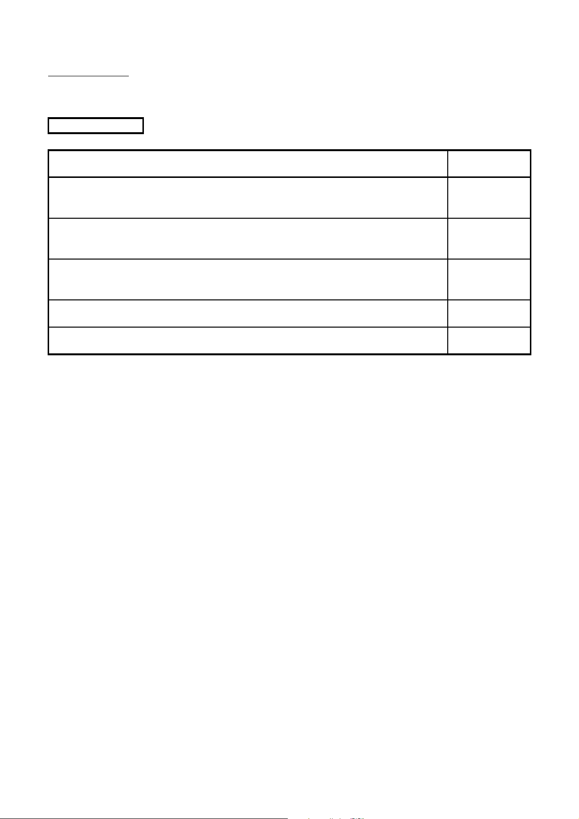
The following manuals are related to this product.
Manual Name
ACPU/QCPU-A (A mode) Programming Manual (Fundamentals)
Describes programming methods necessary for creating programs, device names, parameters,
program types, memory area configuration, and so on. (Sold separately)
ACPU/QCPU-A (A mode) Programming Manual (Common Instructions)
Describes how to use the sequence instruction, basic instructions, applied instructions and
microcomputer programs. (Sold separately)
AnSHCPU/AnACPU/AnUCPU/QCPU-A (A mode) Programming Manual (Dedicated Instructions)
Describes instructions that have been expanded.
(Sold separately)
AnACPU/AnUCPU/QCPU-A (A mode) Programming Manual (PID Instructions)
Describes dedicated instructions to perform the PID control. (Sold separately)
AnS Module type I/O User's Manual
Describes the specification of the compact building block type I/O module. (Sold separately)
Manual No.
(Model Code)
IB-66249
(13J740)
IB-66250
(13J741)
IB-66251
(13J742)
IB-66258
(13J744)
IB-66541
(13JE81)
A - 16

USER PRECAUTIONS
Precautions for using a CPU module
When a CPU module is used for the first time, data in the CPU module (built-in RAM, device
data) and in the memory card are undefined.
Before writing data (parameters, programs) to the CPU module, clear data in the built-in RAM
using a peripheral (PC memory clear operation) and also clear data using the RESET/L.CLR
switch of the CPU module (latch clear operation).
Precautions for battery
(1) Operating a CPU module after being stored without a battery
When a CPU module is operated again after being stored without a battery, data in the
CPU module (built-in RAM, device data) and a memory card may be undefined.
Before operating the CPU module again, clear data in the built-in RAM using a
peripheral (PC memory clear operation) and also clear data using the RESET/L.CLR
switch of the CPU module (latch clear operation).*
After all data are cleared, write the backed-up data in the CPU module or the memory
card.
(2) Operating a CPU module after being stored over the battery life
When a CPU module is operated again after being stored over the battery life, data in
the CPU module (built-in RAM, device data) and a memory card may be undefined.
Before operating the CPU module again, clear data in the built-in RAM using a
peripheral (PC memory clear operation) and also clear data using the RESET/L.CLR
switch of the CPU module (latch clear operation).*
After all data are cleared, write the backed-up data in the CPU module or the memory
card.
POINT
Make sure to back up each memory contents before storing the programmable
controller.
* For details of the PC memory clear operation using a peripheral, refer to the following manuals.
GX Developer Operating Manual
A6GPP/A6PHP Operating Manual
SW IVD-GPPA Operating Manual
For the latch clear operation using the RESET/L.CLR switch of the CPU module, refer to Section
4.6.3.
A - 17
1. OVERVIEW
1 OVERVIEW
This user's manual describes the performance, functions, and handling method of the
QCPU-A, as well as the specifications and handling of the memory card, power supply
module and the base unit.
The programming modules and software packages have to be compatible with the
upgraded A2UCPU, A2UCPU-S1, A3UCPU, and A4UCPU (abbreviated as AnUCPU
hereafter).
When the conventional programming modules and software packages are used, the
usable range varies depending on the model of the CPU (programmable controller model
name).(Refer to Section 2.2.3.)
Related to each module used in the CPU modules, check "System equipment list" in
Section 2.3.
Refer to Section 2.2.1 for the special function modules which have limited usable devices
range.
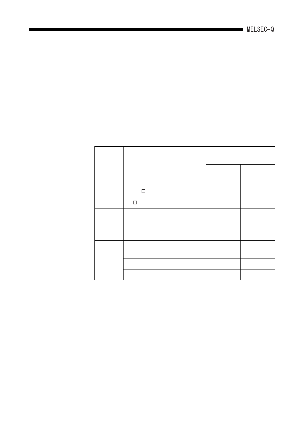
(1) Bundled parts
Product Name Model Quantity
CPU module
Battery Q6BAT 1
Q02CPU-A
1Q02HCPU-A
Q06HCPU-A
1 - 1
OVERVIEW1.
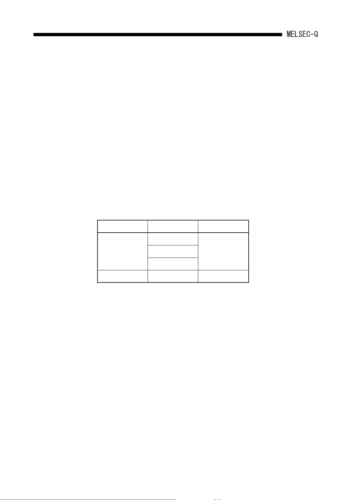
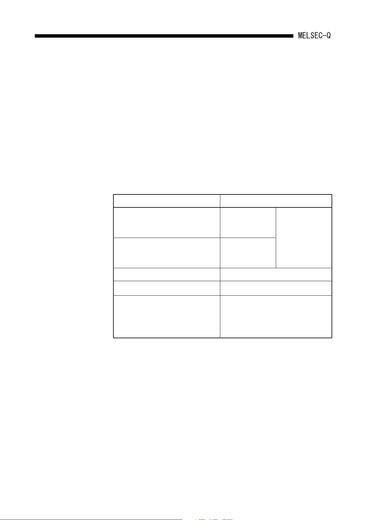
1.1 Features
QCPU-A (A mode) has the following features compared with A2USHCPU-S1.
(1) High-speed operation processing speed
QCPU-A offers significantly higher operation processing than that of A2USHCPU-S1.
Item Q02CPU-A
Operation processing
1
*
speed
*1 I/O processing: At refresh or LD instruction
79ns 34ns 90ns
Q02HCPU-A,
Q06HCPU-A
A2USHCPU-S1
(2) Greater program capacity
By using Q06HCPU-A, the program capacity can be expanded.
Moreover, Q06HCPU-A can create subprograms.
Item Q06HCPU-A A2USHCPU-S1
30k steps (Main program)
Program capacity
30k steps (Subprogram)
+
30k steps
(3) Increased actual I/O points
QCPU-A offers 4096 actual I/O points, 4 times as increased as that of A2USHCPUS1.
Item
Actual I/O points 4096 points 1024 points
Q02CPU-A, Q02HCPU-A,
Q06HCPU-A
A2USHCPU-S1
(4) Increased extension stages
Up to 7 stages of extension base unit can be added.
(5) Higher communication speed with peripheral devices
The communication speed with peripheral devices is considerably improved
compared with A2USHCPU-S1.
Item
Communication speed
(kbps)
* 1 Designate 9.6kbps when using GPP of SW3D5C-GPPW or earlier.
Q02CPU-A, Q02HCPU-A,
Q06HCPU-A
1
*
115 .2
A2USHCPU-S1
9.6
1 - 2
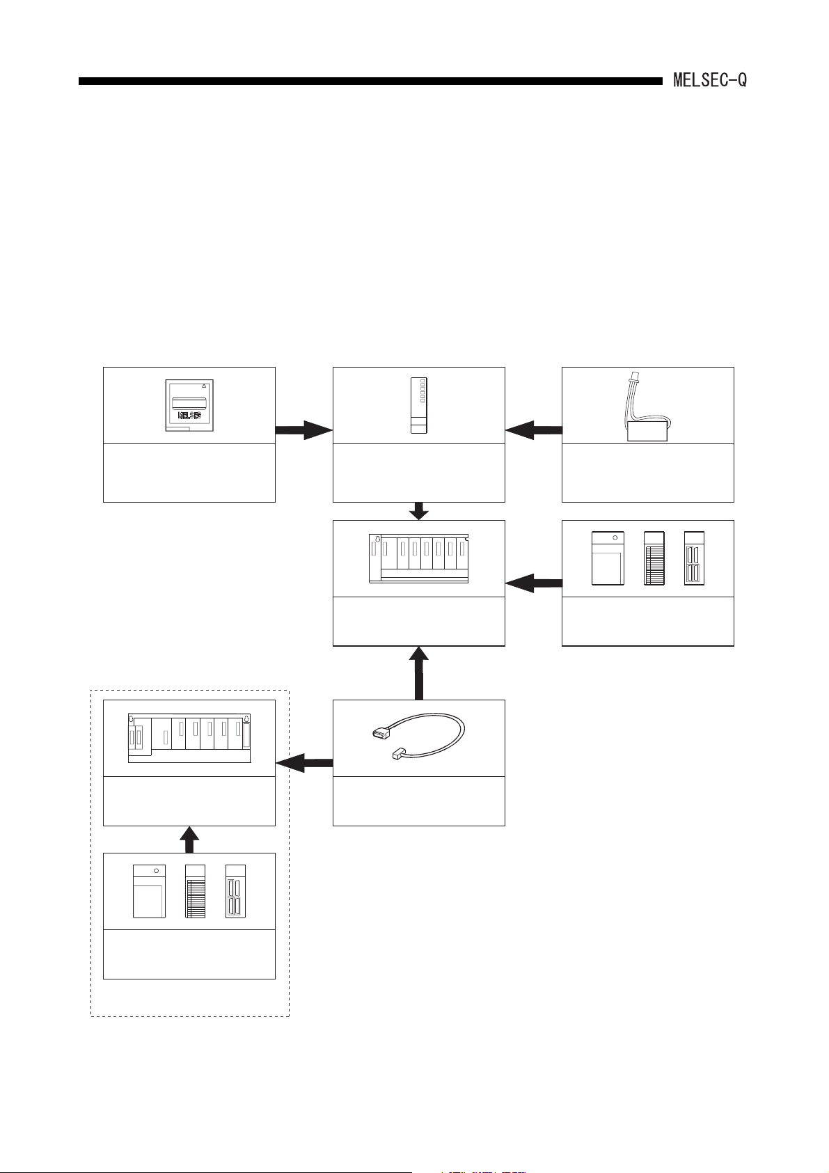
2. SYSTEM CONFIGURATION
LITHIUM BATTERY
QCPU-A
(Q02CPU-A, Q02HCPU-A,
Q06HCPU-A)
Battery
(Q6BAT)
Main base unit
(QA1S33B,QA1S35B,QA1S38B)
Extension cable
(QC05B,QC06B,QC12B,
QC30B,QC50B,QC100B)
Extension base unit
(QA1S51B,QA1S65B,QA1S68B)
Expansion of AnS series modules
*1
AnS series power supply
*2
, I/O,
or special function modules
The operation is not guaranteed
for the use of commercially
available memory cards.
*2
The power supply module cannot
be mounted on the QA1S51B.
Q series power supply, I/O, or
intelligent function modules
Memory card
*1
(Q2MEM-1MBSN,
Q2MEM-1MBS)
2 SYSTEM CONFIGURATION
This chapter shows the system configuration of QCPU-A, the relevant precautions and
system equipment.
2.1 System Configuration
This section describes the configuration of the QCPU-A system, the configuration of
peripheral devices, and the overview of the system configuration.
(1) Configuration of the QCPU-A system
2 - 1
2. SYSTEM CONFIGURATION
2.2 Precautions When Configuring the System
The following shows the precautions when configuring the QCPU-A system:
2.2.1 Hardware
(1) Up to 64 I/O modules or special function modules can be mounted to each of the
basic base unit or the extension base unit.
(2) Up to 7 extension base units can be connected in the system.
(Up to 8 modules including the main base unit.)
(3) The total length of the extension cable should be 13.2m or less.
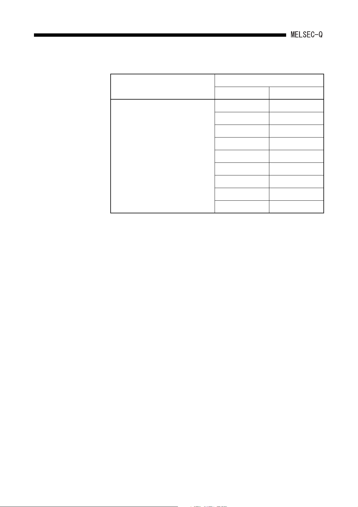
(4) The following shows the modules that have some limitations for the number of
modules to be mounted.
Module No. of Mountable Modules
MELSECNET/10 network module
A1SJ71LP21(GE), A1SJ71LR21,
A1SJ71BR11
MELSECNET(II)/B data link module
A1SJ71AP21, A1SJ71AR21,
Up to 4 modules
Up to 4 modules in
total
Up to 2 modules
A1SJ71AT21B
Interruption module: A1SI61 1 module
AnS series special function module
*
Up to 6 modules in total
1
GOT-A900 Series (Only when the bus
2
connection is used.)
GOT1000 Series (Only when the bus
connection is used.)
*1 Applies to the following modules. Any modules but the following modules do not have the
number of limitations to be mounted.
Ethernet interface module: A1SJ71E71N-B2 (-B5/-T)
Calculating machine link module: A1SJ71UC24-R2 (-R4/-PRF)
CC-Link module (in intelligent mode): A1SJ61BT11
Intelligent communication module: A1SD35ID1(2)
ID interface module: A1SD35ID1(2)
*2 Refer to the following manual for the GOT models.
• GOT-A900 Series User's Manual (GT Works Versions2/GT Designer2 Version2 Compatible
Connection System Manual)
• GOT1000 Series Connection Manual (Mitsubishi Products)
*
Connection disable
2
*
2 - 2
SYSTEM CONFIGURATION2.
(5) The accessible device ranges have limit when the following modules are used:
Accessible Device Range in CPU
Applicable Module
Device Accessible Range
Input (X), output (Y) X/Y0 to X/Y7FF
Internal relay (M) M0 to M8191
latch relay (L) L0 to L8191
MELSECNET(II) data link module:
A1SJ71AP21, A1SJ71AR21
MELSECNET/B data link module:
A1SJ71AT21B
Link relay (B) B0 to BFFF
Timer (T) T0 to T2047
Counter (C) C0 to C1023
Data register (D) D0 to D6143
Link register (W) W0 to WFFF
Annunciator (F) F0 to F2047
(6) It is recommended that the network and data link modules are mounted to the basic
base unit.
When these modules are mounted to the extension base unit, the link refresh time
becomes longer than the case where they are mounted to the basic base unit.
2 - 3
2. SYSTEM CONFIGURATION
2.2.2 Software package
(1) GPP function software packages and model name setting at the start-up
The following table shows the GPP function software package that can be used to
create the QCPU-A program, and the programmable controller type setting at startup.
When using SW4D5C-GPPW or later, select the programmable controller type from
Q02(H)-A or Q06H-A according to the CPU to be used.
When using the peripheral devices and GPP function software package of SW3D5CGPPW or earlier, specify the programmable controller type name as "A4U". If "A4U"
is not found in PLC type names, specify "A3A." If both "A4U" and "A3A" are not
found, specify "A3H."
Note that when "A4U" is specified, the available device range is limited.
Peripheral
device
Software package for system start-up
Programmable controller CPU
model setting
Q02(H)-A Q06H-A
PC/AT
personal
computer
A6PHP SW3GP-GPPA A3H A3H
A6GPP SW3-GPPA
SW4D5C-GPPW or later Q02(H)-A Q06H-A
SW3D5 -GPPW or earlier
A4U A4U
SW IVD-GPPA
SW4GP-GPPA A3A A3A
SW1GP-GPPAU A4U A4U
SW3GP-GPPA
SW4GP-GPPA A3A A3A
SW1GP-GPPAU A4U A4U
A3H A3H
2 - 4

SYSTEM CONFIGURATION2.
POINT
(1) Old software packages other than listed above cannot be used.
(2) To construct MELSECNET/10 network system with QCPU-A, use the AnU-
compatible GPP function software package (which includes "A4U" in its
programmable controller type name).
A network cannot be constructed with the GPP function software package
which is not compatible with AnU (which does not include "A4U" in its
programmable controller type name).
(3) Communication with GX Developer at 115.2kbps may not be available
depending on the peripheral devices. In such a case, select the lower
communication speed.
(4) When using Q02(H)CPU-A and conventional peripheral devices and setting
the programmable controller type as "A4U," designate the main program
setting to 28k steps or less with parameters. When "Main + parameter" is
written with the programmable controller with the setting of 29k steps or more,
"Cannot communicate with PC" is displayed, and writing to the CPU module is
disabled.
(5) Subprograms cannot be used with Q02(H)CPU-A. When using conventional
peripheral devices and setting the programmable controller type as "A4U," do
not specify any subprograms. If any subprograms are specified, "Cannot
communicate with PC" is displayed.
With Q06HCPU, subprogram 1 can be used, but subprograms 2 and 3
cannot.
When subprogram 2 or 3 is specified, the same message above is displayed.
2 - 5
SYSTEM CONFIGURATION2.
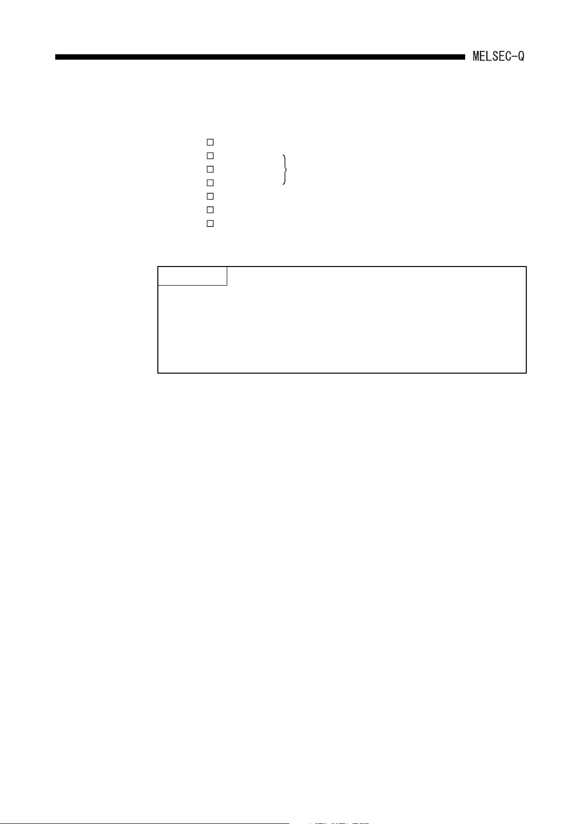
(2) Utility package
(a) None of the following utility packages for A6GPP/A6PHP can be used:
The packages marked with * can
•SW -AD57P
• SW -UTLP-FN0
• SW -UTLP-FN1
•SW -UTLP-PID
•SW -SIMA
• SW -UTLP-FD1
•SW -SAPA
POINT
*
(1) The utility package, which specifies the device and accesses the QCPU-A,
can be used only in the device range for the A3ACPU, A3HCPU equivalent.
(Refer to Section 2.2.3.)
(2) Use an AnU-compatible utility package to use the device range for the
QCPU-A.
(Example: SW1IVD-SAP2, etc.)
*
execute the same functions using the
dedicated instructions.
For details, refer to type AnSHCPU/
AnACPU/AnUCPU/QCPU-A (A Mode)
Programming Manual (Dedicated
Instructions).
2 - 6
2. SYSTEM CONFIGURATION
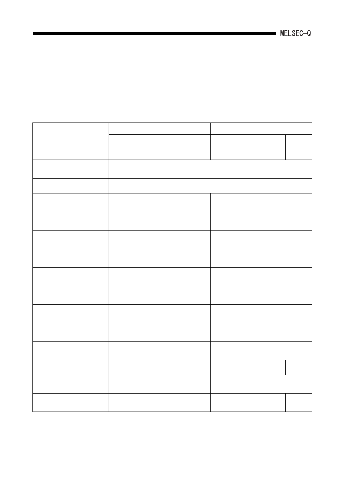
2.2.3 Precautions when using GPP function software packages and A8PUE peripheral devices which are not compatible with AnU
When starting with GPP function software packages not compatible with the AnU, QCPUA (starting with the programmable controller model name "A3A" or "A3H") or a A8PUE
peripheral device (including A7PUS), the usable device ranges are limited as follows.
(1) List of usable device range
AnACPU-compatible Module A3HCPU-compatible Module
Item
Instruction (sequence/basic/
application/dedicated)
Program capacity Max. 14k steps can be used for the main program.
I/O device points (X/Y)
M, L, S relay M/L/S0 to M/L/S8191 can be used.
Link relay (B)
Timer (T) T0 to T2047 can be used.
Counter (C) C0 to C1023 can be used.
Data register (D)
Programmable controller Model
"A3A"
at System FD Start-up
X/Y0 to X/Y7FF can be used.
(X/Y800 to X/Y1FFF cannot be used.)
B0 to BFFF can be used.
(B1000 to B1FFF cannot be used.)
D0 to D6143 can be used.
(D6144 to D8191 cannot be used.)
A8PUE
All instructions can be used.
Programmable controller Model
"A3H"
at System FD Start-up
X/Y0 to X/Y7FF can be used.
(X/Y800 to X/Y1FFF cannot be used.)
M/L/S0 to M/L/S2047 can be used.
(M/L/S2048 to M/L/S8191 cannot be used.)
B0 to B3FF can be used.
(B400 to B1FFF cannot be used.)
T0 to T255 can be used.
(T256 to T2047 cannot be used.)
C0 to C255 can be used.
(C256 to C1023 cannot be used.)
D0 to D1023 can be used.
(D1024 to D8191 cannot be used.)
A7PUS
Link register (W)
Annunciator (F) F0 to F2047 can be used.
Index register (V, Z) V, V1 to V6, Z, Z1 to Z6can be used.
Expanded comment Max. 3968 points – Unusable –
Latch (power failure compensation)
range
I/O assignment
The device range shown above can be latched. The device range shown above can be latched.
Possible to register occupied I/O
points and module model names.
W0 to WFFF can be used.
(W1000 to W1FFF cannot be used.)
Number of I/O occupied points can
–
W0 to W3FF can be used.
(W400 to W1FFF cannot be used.)
F0 to F255 can be used.
(F256 to F2047 cannot be used.)
V and Z can be used.
(V1 to V6, Z1 to Z6 cannot be used.)
be registered.
(1) The device range other than listed above is the same as that of QCPU-A.
(2) Refer to Operating Manual for peripheral devices to be used for available functions.
2 - 7
–
2. SYSTEM CONFIGURATION
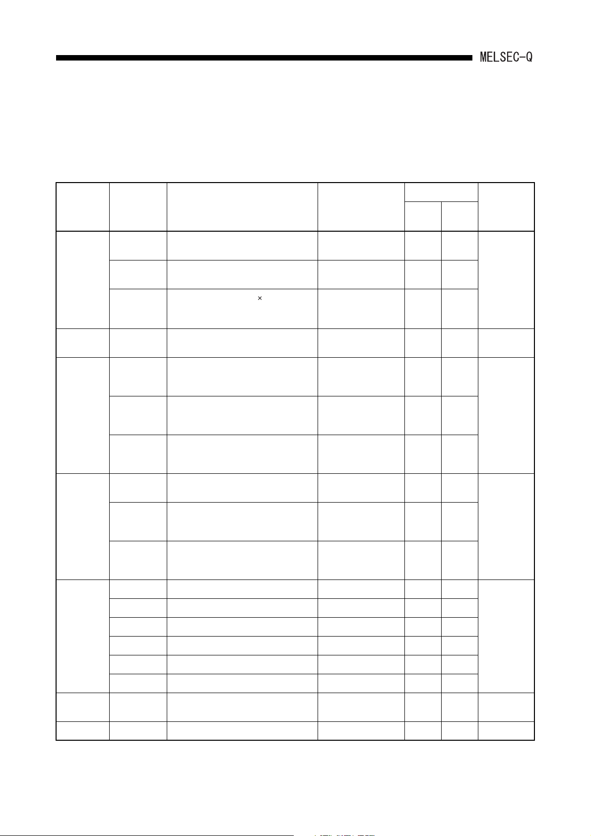
2.3 System Equipment
The following shows various components of each module and peripheral device which can
be used by the QCPU-A.
(1) Modules dedicated to AnS
Product Name Model Name Description
Program capacity: 28k steps, I/O points: 4096,
Processing speed for basic instruction: 79ns
Program capacity: 28k steps, I/O points: 4096,
Processing speed for basic instruction: 34ns
Program capacity: 30k steps 2 (Main/sub),
I/O points: 4096, Processing speed for basic
instruction: 34ns
SRAM type: 1MB – – –
AnS series module mounting base (power
supply module + CPU module + 3 slots for other
module)
AnS series module mounting base (power
supply module + CPU module + 5 slots for other
module)
AnS series module mounting base (power
supply module + CPU module + 8 slots for other
module)
CPU module
Memory card
Main base unit
Q02CPU-A
Q02HCPU-A
Q06HCPU-A
Q2MEM-1MBSN,
Q2MEM-1MBS
QA1S33B
QA1S35B
QA1S38B
Number of Occupied
Points (points)
[I/O Assignment
Module Type]
–0.60–
–0.64–
–0.64–
– 0.107 –
–
–
Current Consumption
5VDC(A) 24VDC(A)
0.117
(0.086)*
0.118
(0.086)*
–
–
Remark
QA1S51B
Extension base
unit
Extension cable
Battery Q6BAT
Cable QC30R2 Communication cable for peripheral devices – – –
QA1S65B
QA1S68B
QC05B 0.45m extension base cable – – –
QC06B 0.6m extension base cable – – –
QC12B 1.2m extension base cable – – –
QC30B 3.0m extension base cable – – –
QC50B 5.0m extension base cable – – –
QC100B 10.0m extension base cable – – –
AnS series module mounting base, 1 slot for
other module
AnS series module mounting base (power
supply module + CPU module + 5 slots for other
module)
AnS series module mounting base (power
supply module + CPU module + 8 slots for other
module)
Battery for retaining the contents of built-in RAM
and devices in case of power failure
–0.12–
–
–
–––
0.117
(0.088)*
0.118
(0.090)*
–
–
2 - 8
SYSTEM CONFIGURATION2.
POINT
(1) A USB port cannot be used with QCPU-A.
(2) A RS232/422 conversion cable is required to use the conventional peripheral
devices (A6GPP, A8PUE, etc.).
Recommended cable: FA-CNV2402CBL (2m), FA-CNV2405CBL (5m)
Contact: Mitsubishi Electric Engineering Corp.
Product Name Model Name Description
A1S61PN 5VDC, 5A
Power supply
module
A1S62PN 5VDC, A/24VDC, 0.6A
A1S63P 5VDC, 5A 24VDC input
* The parenthesized values are for those which is not compliant with CE.
100/200VAC
input
Number of Occupied
Points (points)
[I/O Assignment
Module Type]
–––
Current Consumption
Remark
5VDC(A) 24VDC(A)
Installed in the
power supply
slot of the main
base and
extension base.
2 - 9
 Loading...