

Page 1

C
MIT
SUBIS
C
HI ELECTRI
MELSEC System Q
Programmable Logic Controllers
User’s Manual
High Performance Model QCPU
Art. no.: 130000
01 10 2002
SH (NA)-080037-F
Q02CPU, Q02HCPU,
Q06HCPU, Q12HCPU,
Q25HCPU
MITSUBISHI ELECTRI
INDUSTRIAL AUTOMATION
Page 2
SAFETY PRECAUTIONS
(Read these precautions before using.)
When using Mitsubishi equipment, thoroughly read this manual and the associated manuals introduced in
this manual. Also pay careful attention to safety and handle the module properly .
These SAFETY PRECAUTIONS classify the safety precautions int o two cat egories: "DANG ER" and
"CAUTION".
DANGER
!
CAUTION
!
Depending on circumstances, procedures indicated by ! CAUTION may also be linked to serious
results.
In any case, it is important to follow the directions for usage.
Store this manual in a safe place so that you can take it out and read it whenever necessary . Alw ay s
forward it to the end user.
Indicates that incorrect handling may cause hazardous conditions,
resulting in death or severe injury.
Indicates that incorrect handling may cause hazardous conditions,
resulting in medium or slight personal injury or physical damage.
[DESIGN PRECAUTIONS]
!
DANGER
Install a safety circuit external to the PLC that keeps the ent ire syst em safe even when t here
are problems with the external power supply or the PLC module. Otherwise, t rouble could result
from erroneous output or erroneous operation.
(1) Outside the PLC, construct mechanical damage preventing interlock circuits such as
emergency stop, protective circuits, positioning upper and low er limits switches and
interlocking forward/reverse operations.
(2) When the PLC detects the following problems, it will stop calculation and turn off all out put
in the case of (a). In the case of (b), it will st op calculation and hold or t urn off all out put
according to the parameter setting.
Note that the AnS series module will turn off the out put in eit her of cases (a) and (b).
(a) The power supply module has over current protection equipment and over voltage
protection equipment.
(b) The PLC CPUs self-diagnosis functions, such as the watch dog timer error, detect
problems.
In addition, all output will be turned on when t here are pr oblems that t he PLC CPU cannot
detect, such as in the I/O controller. Build a fail safe circuit exterior to the PLC that will make
sure the equipment operates safely at such times. See section 9.1 of this manual for
example fail safe circuits.
(3) Output could be left on or off when there is trouble in the outputs module relay or transist or.
So build an external monitoring circuit that will monit or any single output s that could cause
serious trouble.
A - 1 A - 1
Page 3
[DESIGN PRECAUTIONS]
!
DANGER
When overcurrent which exceeds the rating or caused by short-circuited load flows in the output
module for a long time, it may cause smoke or fire. To prevent this, configure an external safety
circuit, such as fuse.
Build a circuit that turns on the external power supply w hen the PLC main module power is
turned on. If the external power supply is turned on first, it could result in erroneous out put or
erroneous operation.
When there are communication problems with the data link, refer to the corresponding data link
manual for the operating status of each station. Not doing so could result in erroneous output or
erroneous operation.
When connecting a peripheral device to the CPU module or connecting a personal computer or
the like to the intelligent function module to exercise control (data change) on the running PLC,
configure up an interlock circuit in the sequence program to ensure that t he whole sy stem w ill
always operate safely.
Also before exercising other control (program change, operating status change (status control))
on the running PLC, read the manual carefully and fully confirm safety.
Especially for the above control on the remote PLC from an external device, an immediate
action may not be taken for PLC trouble due to a data communication fault.
In addition to configuring up the interlock circuit in the sequence program, corrective and other
actions to be taken as a system for the occurrence of a data communication fault should be
predetermined between the external device and PLC CPU.
!
CAUTION
Do not bunch the control wires or communication cables with the main circuit or power wires, or
install them close to each other. They should be installed 100 mm (3.94 inch) or more from
each other. Not doing so could result in noise that would cause erroneous operation.
When controlling items like lamp load, heater or solenoid valve using an output module, large
current (approximately ten times greater than that present in normal circumstances) may flow
when the output is turned OFF to ON.
Take measures such as replacing the module with one having sufficient rated current.
A - 2 A - 2
Page 4
[INSTALLATION PRECAUTIONS]
!
CAUTION
Use the PLC in an environment that meets the general specifications contained in this manual.
Using this PLC in an environment outside the range of the general specifications could result in
electric shock, fire, erroneous operation, and damage to or deterioration of the product.
Hold down the module loading lever at the module bottom, and securely insert the module
fixing latch into the fixing hole in the base unit.
Incorrect loading of the module can cause a malfunction, failure or drop.
When using the PLC in the environment of much vibration, tighten the module with a screw.
Tighten the screw in the specified torque range. Undertightening can cause a drop, short circuit
or malfunction. Overtightening can cause a drop, short circuit or malfunction due to damage to
the screw or module.
When installing extension cables, be sure that the connectors of base unit are installed
correctly. After installation, check them for looseness. Poor connections could cause an input or
output failure.
Securely load the memory card into the memory card loading connector. After loading, check
for lifting. Lifting can cause a malfunction due to a contact fault.
Completely turn off the external power supply before loading or unloading the module. Not
doing so could result in electric shock or damage to the product.
Do not directly touch the module's conductive parts or electronic components. Touching the
conductive parts could cause an operation failure or give damage to the module.
[WIRING PRECAUTIONS]
!
DANGER
Completely turn off the external pow er supply when inst alling or placing w iring. Not completely
turning off all power could result in electric shock or damage to the product.
When turning on the power supply or operating the module after installation or wiring work, be
sure that the module's terminal covers are correctly attached. Not at taching the t erminal cover
could result in electric shock.
A - 3 A - 3
Page 5
[WIRING PRECAUTIONS]
!
CAUTION
Be sure to ground the FG terminals and LG terminals to the protective ground conductor. Not
doing so could result in electric shock or erroneous operation.
When wiring in the PLC, be sure that it is done correctly by checking the product's rated voltage
and the terminal layout. Connecting a power supply that is different from the rating or incorrectly
wiring the product could result in fire or damage.
External connections shall be crimped or pressure welded with the specified tools, or correctly
soldered. Imperfect connections could result in short circuit, fires, or erroneous operation.
Tighten the terminal screws with the specified torque. If the terminal screws are loose, it could
result in short circuits, fire, or erroneous operation. Tightening the terminal screws too far may
cause damages to the screws and/or the module, resulting in fallout, short circuits, or
malfunction.
Be sure there are no foreign substances such as sawdust or wiring debris inside the module.
Such debris could cause fires, damage, or erroneous operation.
The module has an ingress prevention label on its top to prevent foreign matter, such as wire
offcuts, from entering the module during wiring.
Do not peel this label during wiring.
Before starting system operation, be sure to peel this label because of heat dissipation.
[STARTUP AND MAINTENANCE PRECAUTIONS]
!
DANGER
Do not touch the terminals while power is on.
Doing so could cause shock or erroneous operation.
Correctly connect the battery.
Also, do not charge, disassemble, heat, place in fire, short circuit, or solder the battery .
Mishandling of battery can cause overheating or cracks which could result in injury and fires.
Switch all phases of the external power supply off when cleaning the module or retightening the
terminal or module mounting screws. Not doing so could result in electric shock.
Undertightening of terminal screws can cause a short circuit or malfunction. Overtightening of
screws can cause damages to the screws and/or the module, resulting in fallout, short circuits,
or malfunction.
A - 4 A - 4
Page 6
[STARTUP AND MAINTENANCE PRECAUTIONS]
!
DANGER
The online operations conducted for the CPU module being operated, connecting the peripheral
device (especially, when changing data or operation status), shall be conducted after the
manual has been carefully read and a sufficient check of safety has been conducted.
Operation mistakes could cause damage or problems with of the module.
Do not disassemble or modify the modules.
Doing so could cause trouble, erroneous operation, injury, or fire.
Use any radio communication device such as a cellular phone or a PHS phone more than 25cm
(9.85 inch) away from the PLC.
Not doing so can cause a malfunction.
Switch all phases of the external power supply off before mounting or removing the module.
If you do not switch off the external pow er supply , it will cause failur e or malfunction of t he
module.
Do not drop or give an impact to the battery installed in t he module.
Otherwise the battery w ill be broken, possibly causing inter nal leakage of electrolyt e.
Do not use but dispose of the battery if it has fallen or an impact is given to it .
[DISPOSAL PRECAUTIONS]
!
CAUTION
When disposing of this product, treat it as industrial waste.
A - 5 A - 5
Page 7
REVISIONS
The manual number is given on the bottom left of the back cover.
Print Date Manual Number Revision
Dec., 1999 SH(NA)-080037-A First edition
Sep., 2000 SH(NA)-080037-B
Addition model
Q33B, Q63B, Q63P
Addition
Section 2.3, 4.5, 11.2.3, 11.2.10, 11.2.11
Partial correction
Section 1.2, 2.2, 4.1, 4.2, 5.1.1, 5.2, 8.1.5, 11.2.1, 11.3.2, 11.5.1, 11.6,
11.7
Jun., 2001 SH(NA)-080037-C
Addition model
Q62P, Q52B, Q55B, QC05B
Addition
Section 6.6
Partial correction
Section 2.1, 2.2, 4.1, 4.2, 5.1.5, 6.1, 6.2, 6.3, 8.1.5, 11.2.4, 11.7
Sep., 2001 SH(NA)-080037-D
Addition model
Q64P
Partial correction
CONTENTS, Section 4.1, 5.1.1, 5.1.2, 5.2, 6.1, 6.2, 8.1.5, 11.5.1,
Appendix1.2, 2.2
Apr., 2002 SH(NA)-080037-E
Partial correction
Chapter 1, Section 1.1, 2.1, 2.2, 2.3, 4.1, 5.1.1, 7.1, 7.2, 7.3, 10.3.1,
10.3.2
Oct., 2002 SH(NA)-080037-F
Complete review
Addition model
Q32SB, Q33SB, Q35SB, Q61SP
Japanese Manual Version SH-080019-I
This manual confers no industrial property rights or any rights of any other kind, nor does it confer any patent
licenses. Mitsubishi Electric Corporation cannot be held responsible for any problems involving industrial property
rights which may occur as a result of using the contents noted in this manual.
1999 MITSUBISHI ELECTRIC CORPORATION
A - 6 A - 6
Page 8

INTRODUCTION
Thank you for choosing the Mitsubishi MELSEC-Q Series of General Purpose Programmable Controllers.
Please read this manual carefully so that equipment is used to its optimum.
CONTENTS
SAFETY PRECAUTIONS............................................................................................................................A- 1
REVISIONS ..................................................................................................................................................A- 6
CONTENTS ..................................................................................................................................................A- 7
About Manual................................................................................................................................................A-17
How to Use This Manuals ............................................................................................................................A-18
About the Generic Terms and Abbreviations...............................................................................................A-19
1 OVERVIEW 1- 1 to 1- 4
1.1 Features..................................................................................................................................................1- 2
2 SYSTEM CONFIGURATION FOR SINGLE CPU SYSTEM 2- 1 to 2- 8
2.1 System Configuration............................................................................................................................. 2- 1
2.2 Precaution on System Configuration.....................................................................................................2- 6
2.3 Confirming the Serial Number and Function Version............................................................................2- 8
3 GENERAL SPECIFICATIONS 3- 1 to 3- 2
4 HARDWARE SPE CI F I CATI ON O F TH E CPU MODULE 4- 1 to 4 - 9
4.1 Performance Specification .....................................................................................................................4- 1
4.2 Part Names and Settings .......................................................................................................................4- 4
4.3 Switch Operation After Writing in Program............................................................................................4- 7
4.4 Latch Clear Operation ............................................................................................................................4- 8
4.5 Executing Automatic Write to Standard ROM....................................................................................... 4- 8
5 POWER SUPPLY MODULE 5- 1 to 5- 11
5.1 Specification............................................................................................................................................5- 1
5.1.1 Power supply module specifications .............................................................................................. 5- 1
5.1.2 Selecting the power supply module................................................................................................5- 6
5.1.3 Precauti on wh en connect in g th e unin te r rupt ive powe r supply......................................................5- 8
5.2 Names of Parts and Settings .................................................................................................................5- 9
6 BASE UNIT AND EXTENSION CABLE 6- 1 to 6- 11
6.1 Base Unit Specification Table ................................................................................................................ 6- 1
6.2 Extension Cable Specification Table.....................................................................................................6- 3
6.3 Parts Names of Base Unit......................................................................................................................6- 3
6.4 Setting the Extension Base Unit ............................................................................................................6- 6
A - 7 A - 7
Page 9

6.5 I/O Number Allocation ............................................................................................................................6- 7
6.6 Guideline fo r U se o f Ex ten si on Ba se Un it s (Q5B) .............................................................................6- 8
7 MEMORY CARD AND BATTERY 7- 1 to 7- 6
7.1 Memory Card Specifications.................................................................................................................. 7- 1
7.2 Battery Specifications (For CPU Module and SRAM Card)..................................................................7- 2
7.3 Handling the Memory Card....................................................................................................................7- 3
7.4 The Names of The Parts of The Memory Card.....................................................................................7- 4
7.5 Memory Card Loading/Unloading Procedures...................................................................................... 7- 5
7.6 Installation of Battery (For CPU Module and Memory Card)................................................................ 7- 6
8 EMC AND LOW VOLTAGE DIRECTIVE 8- 1 to 8-11
8.1 Requirements for Conformance to EMC Directive................................................................................8- 1
8.1.1 Standards applicable to the EMC Directive....................................................................................8- 1
8.1.2 Installation instructions for EMC Directive......................................................................................8- 2
8.1.3 Cables..............................................................................................................................................8- 3
8.1.4 Power supply module......................................................................................................................8- 5
8.1.5 When using QA1S6
8.1.6 Others..............................................................................................................................................8- 8
8.2 Requirement to Conform to the Low Voltage Directive.........................................................................8- 9
8.2.1 Standard applied for MELSEC-Q series PLC................................................................................8- 9
8.2.2 MELSEC-Q series PLC selection...................................................................................................8- 9
8.2.3 Power supply..................................................................................................................................8- 10
8.2.4 Control box.....................................................................................................................................8- 10
8.2.5 Grounding.......................................................................................................................................8- 11
8.2.6 External wiring................................................................................................................................8- 11
B type base unit ........................................................................................ 8- 5
9 LOADING AND INSTALLATION 9- 1 to 9-26
9.1 General Safety Requirements................................................................................................................ 9- 1
9.2 Calculating Heat Generation by PLC..................................................................................................... 9- 6
9.3 Module Installation..................................................................................................................................9- 9
9.3.1 Precaution on installation................................................................................................................9- 9
9.3.2 Instructions for mounting the base unit ..........................................................................................9-12
9.3.3 Installation and removal of module................................................................................................. 9-15
9.4 How to Set Stage Numbers for the Extension Base Unit......................................................................9-19
9.5 Connection and Disconnection of Extension Cable ..............................................................................9-20
9.6 Wiring......................................................................................................................................................9-23
9.6.1 The precautions on the wiring.........................................................................................................9-23
9.6.2 Connecting to the power supply module ........................................................................................ 9-26
10 MAINTENANCE AND INSPECTION 10- 1 to 10- 8
10.1 Daily Inspection ..................................................................................................................................10- 2
10.2 Periodic Inspection.............................................................................................................................10- 3
10.3 Battery Replacement..........................................................................................................................10- 4
10.3.1 Battery life....................................................................................................................................10- 5
10.3.2 Battery replacement procedure..................................................................................................10- 7
A - 8 A - 8
Page 10

11 TROUBLESHOOTING 11- 1 to 11-99
11.1 Troubleshooting Basics......................................................................................................................11- 1
11.2 Troubleshooting..................................................................................................................................11- 2
11.2.1 Troubleshooting flowchart...........................................................................................................11- 2
11.2.2 Flowchart for when the "MODE" LED is not turned on..............................................................11- 3
11.2.3 Flowchart for when the "MODE" LED is flickering.....................................................................11- 4
11.2.4 Flowchart for when the "POWER" LED is turned off .................................................................11- 5
11.2.5 Flowchart for when the "RUN" LED is turned off .......................................................................11- 6
11.2.6 When the "RUN" LED is flickering..............................................................................................11- 7
11.2.7 Flowchart for when the "ERR." LED is on/flickering ..................................................................11- 7
11.2.8 When the "USER" LED is turned on...........................................................................................11- 8
11.2.9 When the "BAT." LED is turned on.............................................................................................11- 8
11.2.10 Flowchart for when the "BOOT" LED is flickering.................................................................... 11- 9
11.2.11 Flowchart for when output module LED is not turned on ........................................................11-10
11.2.12 Flowchart for when output load of output module does not turn on........................................11-11
11.2.13 Flowchart for when unable to read a program.........................................................................11-12
11.2.14 Flowchart for when unable to write a program.........................................................................11-13
11.2.15 Flowchart for when it is unable to perform boot operation from memory card .......................11-15
11.2.16 Flowchart for when UNIT VERIFY ERR. occurs......................................................................11-16
11.2.17 Flowchart for when CONTROL BUS ERR. occurs..................................................................11-17
11.3 Error Code List....................................................................................................................................11-18
11.3.1 Procedure for reading error codes..............................................................................................11-18
11.3.2 Error code list ..............................................................................................................................11-19
11.4 Canceling of Errors.............................................................................................................................11-37
11.5 I/O Module Troubleshooting...............................................................................................................11-38
11.5.1 Input circuit troubleshooting........................................................................................................11-38
11.5.2 Output circuit troubleshooting.....................................................................................................11-41
11.6 Special Relay List...............................................................................................................................11-42
11.7 Special Register List...........................................................................................................................11-64
APPENDICES App- 1 to App-17
APPENDIX 1 Error Code Return to Origin During General Data Processing........................................App- 1
APPENDIX 1.1 Error code overall explanation ...................................................................................App- 1
APPENDIX 1.2 Description of the errors of the error codes (4000
H
to 4FFFH) .................................App- 2
APPENDIX 2 External Dimensions .........................................................................................................App- 7
APPENDIX 2.1 CPU module ...............................................................................................................App- 7
APPENDIX 2.2 Power supply module.................................................................................................App- 7
APPENDIX 2.3 Main base unit ............................................................................................................App-10
APPENDIX 2.4 Slim type main base unit............................................................................................App-12
APPENDIX 2.5 Extension base unit....................................................................................................App-13
APPENDIX 3 Upgraded Functions of High Performance Model QCPU ................................................App-16
APPENDIX 3.1 Specification comparison ...........................................................................................App-16
APPENDIX 3.2 Function comparison..................................................................................................App-16
APPENDIX 3.3 Added functions and the corresponding GX Developer versions.............................App-17
INDEX Index- 1 to Index- 2
A - 9 A - 9
Page 11

(Related manual) ....................................................High Performance model QCPU (Q Mode) User's Manual
(Function Explanation, Program Fundamentals)
CONTENTS
1 OVERVIEW
1.1 Features
1.2 Programs
1.3 Convenient Programming Devices and Instructions
2 SYSTEM CONFIGURATION FOR SINGLE CPU SYSTEM
2.1 System Configuration
2.2 Precaution on System configuration
2.3 Confirming the Serial Number and Function Version
3 PERFORMANCE SPECIFICATION
4 SEQUENCE PROGRAM CONFIGURATION & EXECUTION CONDITIONS
4.1 Sequence Program
4.1.1 Main routine program
4.1.2 Sub-routine programs
4.1.3 Interrupt programs
4.2 Program Execute Type
4.2.1 Initial execution type program
4.2.2 Scan execution type program
4.2.3 Low speed execution type program
4.2.4 Stand-by type program
4.2.5 Fixed scan execution type program
4.3 Operation processing
4.3.1 Initial processing
4.3.2 I/O refresh (I/O module refresh processing)
4.3.3 Automatic refresh of the intelligent function module
4.3.4 END processing
4.4 RUN, STOP, PAUSE Operation Processing
4.5 Operation Processing during Momentary Power Failure
4.6 Data Clear Processing
4.7 I/O Processing and Response Lag
4.7.1 Refresh mode
4.7.2 Direct mode
4.8 Numeric Values which Can Be Used in Sequence Programs
4.8.1 BIN (Binary code)
4.8.2 HEX (Hexadecimal)
4.8.3 BCD (Binary Coded Decimal)
A - 10 A - 10
Page 12

4.8.4 Real numbers (floating decimal point data)
4.9 Character String Data
5 ASSIGNMENT OF I/O NUMBERS
5.1 Relationship Between the Number of Stages and Slots of the Extension Base Unit
5.2 Installing Extension Base Units and Setting the Number of Stages
5.3 Base Unit Assignment (Base Mode)
5.4 What are I/O Numbers?
5.5 Concept of I/O Number Assignment
5.5.1 I/O numbers of main base unit and extension base units
5.5.2 Remote station I/O number
5.6 I/O Assignment by GX Developer
5.6.1 Purpose of I/O assignment by GX Developer
5.6.2 Concept of I/O assignment using GX Developer
5.7 Examples of I/O Number Assignment
5.8 Checking the I/O Numbers
6 HIGH PERFORMANCE MODEL QCPU FILES
6.1 About the High Performance model QCPU's Memory
6.2 Program Memory
6.3 About the Standard ROM
6.4 About the Standard RAM
6.5 Memory Card
6.6 Writing Data to the Standard ROM or the Flash Card
6.6.1 Writing Data to the standard ROM or to the Flash card using GX Developer
6.6.2 Automatic write to standard ROM
(Auto Down load all data from Memory card to standard ROM)
6.7 Executing Standard ROM/Memory Card Programs (Boot Run)
6.8 Program File Configuration
6.9 GX Developer File Operation and File Handling Precautions
6.9.1 File operation
6.9.2 File handling precautions
6.9.3 File size
7 FUNCTION
7.1 Function List
7.2 Constant Scan
7.3 Latch Functions
7.4 Setting the Output (Y) Status when Changing from/to STOP Status to/from RUN Status
7.5 Clock Function
A - 11 A - 11
Page 13

7.6 Remote Operation
7.6.1 Remote RUN/STOP
7.6.2 Remote PAUSE
7.6.3 Remote RESET
7.6.4 Remote latch clear
7.6.5 Relationship of the remote operation and High Performance model QCPU RUN/STOP switch
7.7 Changing the Input Response Speed of the Q Series Compatible Module (I/O Response Time)
7.7.1 Selecting the response time of the input module
7.7.2 Selecting the response time of the high speed input module
7.7.3 Selecting the response time of the interrupt module
7.8 Setting the Switches of the Intelligent Function Module
7.9 Monitoring Function
7.9.1 Monitor condition setting
7.9.2 Monitoring test for local device
7.9.3 Forced ON/OFF of external I/O
7.10 Writing in Program during High Performance model QCPU RUN
7.10.1 Writing data in the circuit mode during the RUN status
7.10.2 Writing a batch of files during RUN
7.11 Execution Time Measurement
7.11.1 Program monitor list
7.11.2 Interrupt program monitor list
7.11.3 Scan time measurement
7.12 Sampling Trace Function
7.13 Debug Function with Multiple Users
7.13.1 Multiple-user monitoring function
7.13.2 Multiple-user RUN write function
7.14 Watch dog timer (WDT)
7.15 Self-Diagnosis Function
7.15.1 Interrupt due to error occurrence
7.15.2 LED display when error occurs
7.15.3 Cancel error
7.16 Failure History
7.17 System Protect
7.17.1 Password registration
7.17.2 Remote password
7.18 Monitoring High Performance model QCPU System Status from GX Developer (System Monitor)
7.19 LED Display
7.19.1 LED display
7.19.2 Priority setting
7.20 High Speed Interrupt Function
7.21 Module Service Interval Time Reading
A - 12 A - 12
Page 14

8 COMMUNICATION WITH INTELLIGENT FUNCTION MODULE/SPECIAL FUNCTION MODULE
8.1 Communication Between High Performance model QCPU and Q-series Intelligent Function Modules
8.1.1 Initial setting and automatic refresh setting using GX Configurator
8.1.2 Communication using device initial value
8.1.3 Communication using FROM/TO instruction
8.1.4 Communication using the intelligent function module device
8.1.5 Communication using the instructions dedicated for intelligent function modules
8.2 Request from Intelligent Function Module to High Performance model QCPU
8.2.1 Interrupt from the intelligent function module
8.3 Communication Between High Performance model QCPU and AnS-Series Special Function Modules
8.3.1 Communication using device initial value
8.3.2 Communication using FROM/TO instruction
8.3.3 Communication using the intelligent function module device
8.3.4 Effects of quicker access to the special function module and countermeasures against them
9 PARAMETER LIST
10 DEVICES
10.1 Device List
10.2 Internal User Devices
10.2.1 Inputs (X)
10.2.2 Outputs (Y)
10.2.3 Internal relays (M)
10.2.4 Latch relays (L)
10.2.5 Anunciators (F)
10.2.6 Edge relay (V)
10.2.7 Link relays (B)
10.2.8 Link special relays (SB)
10.2.9 Step relays (S)
10.2.10 Timers (T)
10.2.11 Counters (C)
10.2.12 Data registers (D)
10.2.13 Link registers (W)
10.2.14 Link special registers (SW)
10.3 Internal System Devices
10.3.1 Function devices (FX, FY, FD)
10.3.2 Special relays (SM)
10.3.3 Special registers (SD)
10.4 Link Direct Devices (J
\ )
A - 13 A - 13
Page 15

10.5 Intelligent Function Module Devices (U
10.6 Index Registers (Z)
10.6.1 Switching between scan execution type programs and low speed execution type programs
10.6.2 Switching between scan/low speed execution programs and interrupt/fixed scan execution type
programs
10.7 File Registers (R)
10.7.1 File register capacity
10.7.2 Differences in memory card access method by memory card type
10.7.3 Registering the file registers
10.7.4 File register designation method
10.7.5 Precautions in using file registers
10.8 Nesting (N)
10.9 Pointers
10.9.1 Local pointers
10.9.2 Common pointers
10.10 Interrupt Pointers (I)
10.11 Other Devices
10.11.1 SFC block device (BL)
10.11.2 SFC transition device (TR)
10.11.3 Network No. designation device (J)
10.11.4 I/O No. designation device (U)
10.11.5 Macro instruction argument device (VD)
10.12 Constants
10.12.1 Decimal constants (K)
10.12.2 Hexadecimal constants (H)
10.12.3 Real numbers (E)
10.12.4 Character string ( " " )
10.13 Convenient Uses for Devices
10.13.1 Global devices & local devices
10.13.2 Device initial values
\G )
11 HIGH PERFORMANCE MODEL QCPU PROCESSING TIME
11.1 Reading High Performance model QCPU's Scan Time
11.2 Factors Responsible for Extended Scan Time
Factors Responsible for Shortened Scan Time
12 PROCEDURE FOR WRITING PROGRAMS TO HIGH PERFORMANCE MODEL QCPU
12.1 Writing Procedure for 1 Program
12.1.1 Items to consider when creating one program
12.1.2 Procedure for writing programs to the High Performance model QCPU
12.2 Procedure for Multiple Programs
12.2.1 Items to consider when creating multiple programs
12.2.2 Procedure for writing programs to the High Performance model QCPU
A - 14 A - 14
Page 16

13 OUTLINE OF MULTIPLE CPU SYSTEMS
13.1 Features
13.2 Outline of Multiple CPU Systems
13.3 Differences with Single CPU Systems
14 SYSTEM CONFIGURATION OF MULTIPLE CPU SYSTEMS
14.1 System Configuration
14.2 Precautions During Multiple CPU System Configuration
14.2.1 Function versions of High Performance model QCPU , motion CPUs and PC CPU module that
can be sued, and their mounting positions
14.2.2 Precautions when using Q series corresponding I/O modules and intelligent function modules
14.2.3 Limitations when mounting AnS series corresponding I/O modules and special function modules
14.2.4 Modules that have mounting restrictions
14.2.5 Usable GX Developers and GX Configurators
14.2.6 Parameters that enable the use of multiple CPU systems
14.2.7 Resetting the multiple CPU system
14.2.8 Processing when High Performance model QCPU stop errors occur
14.2.9 Reducing the time required for multiple CPU system processing
15 ALLOCATING MULTIPLE CPU SYSTEM I/O NUMBERS
15.1 Concept behind Allocating I/O Numbers
15.1.1 I/O modules and intelligent function module I/O numbers
15.1.2 I/O number of High Performance model QCPU, Motion CPU and PC CPU module
15.2. Purpose of PC Parameter I/O Allocations with the GX Developer
16 COMMUNICATION BETWEEN THE MULTIPLE CPU SYSTEM'S QCPUS AND MOTION CPUs
16.1 Automatic Refresh of Common CPU Memory
16.2 Communication with Multiple CPU Commands and Intelligent Function Module Devices
16.3 Interactive Communications between The High Performance model QCPU and Motion CPU
16.3.1 Control instructions from the High Performance model QCPU to the Motion CPU
16.3.2 Reading and writing device data
16.4 Common CPU Memory
17 COMMUNICATIONS BETWEEN THE MULTIPLE CPU SYSTEM'S I/O MODULES AND
INTELLIGENT FUNCTION MODULES
17.1 Range of Control PLC Communications
17.2 Range of Non-control PLC Communications
A - 15 A - 15
Page 17

18 PROCESSING TIME FOR MULTIPLE CPU SYSTEM HIGH PERFORMANCE MODEL
QCPUs
18.1 Concept behind QCPU Scanning Time
18.2 Factor to Prolong the Scan Time
19 STARTING UP THE MULTIPLE CPU SYSTEM
19.1 Flow-chart for Starting Up the Multiple CPU System
19.2 Setting Up the Multiple CPU System Parameters (Multiple PLC Settings, Control PLC Settings)
19.2.1 System configuration
19.2.2 Creating new systems
19.2.3 Using existing preset multiple CPU settings and I/O allocations
APPENDICES
APPENDIX 1 Special Relay List
APPENDIX 2 Special Register List
APPENDIX 3 List of Interrupt Pointer Nos. and Interrupt Factors
INDEX
A - 16 A - 16
Page 18
About Manuals
The following manuals are related to this product.
Referring to this list, please request the necessary manuals.
Related Manuals
Manual Name
High Performance model QCPU (Q Mode) User's M anual (Function Explanation, Program
Fundamentals)
This manual explains the functions, programming methods, devices and so on necessary to create
programs with the High Performance model QCPU. (sold separately)
Manual Number
(Model Code)
SH-080038
(13JL98)
QCPU (Q Mode)/QnACPU Programming Manual (Common Instructions)
This manual describes how to use the sequence instructions, basic instructions and application
instructions. (sold separately)
QCPU (Q Mode)/QnACPU Programming Manual (PID Control Instructions)
This manual describes the dedicated instructions used to exercise PID control. (sold separately)
QCPU (Q Mode)/QnACPU Programming Manual (SFC)
This manual explains the system configuration, performance specifications, functions, programming,
debugging, error codes and others of MELSAP3. (sold separately)
QCPU (Q Mode) Programming Manual (MELSAP-L)
This manual describes the programming methods, specifications, functions, and so on that are
necessary to create the MELSAP-L type SFC programs. (sold separately)
SH-080039
(13JF58)
SH-080040
(13JF59)
SH-080041
(13JF60)
SH-080076
(13JF61)
A - 17 A - 17
Page 19

How to Use This Manual
This manual is prepared for users to understand the hardware specifications of those modules such as the
CPU modules, power supply modules, and base units, maintenance and inspections of the system, and
troubleshooting required when you use MELSEC-Q series PLCs.
The manual is classified roughly into three sections as shown below.
1) Chapters 1 and 2 Describe the outline of the CPU module and the system
configuration.
The basics of the system configuration of CPU module are
described.
2) Chapters 3 to 7 Describe the general specifications indicating the operating
environments of the CPU module, power supply module, and
base units, and the performance specifications of these
modules.
3) Chapters 8 to 10 Describe the overall maintenance such as the installation of the
CPU module, daily inspections, and troubleshooting.
REMARK
This manual does not explain the functions of the CPU module.
For these functions, refer to the manual shown below.
• High Performance model QCPU (Q Mode) User's Manual (Function Explanation,
Program Fundamentals)
A - 18 A - 18
Page 20
About the Generic Terms and Abbreviations
This manual uses the following general names and abbreviations in the descriptions of the High
Performance model QCPU unless otherwise specified.
Generic Term/Abbreviation Description
High Performance model
QCPU
Q Series Abbreviation for Mitsubishi MELSEC-Q Series Programmable Logic Controller.
AnS Series
GX Developer General name for GX Developer Version 4 or later.
Q3 B
Q3 SB
Q5 B
Q6 B
QA1S6 B
Main base unit
Slim type main base unit
Extension base unit General name for Q5 B, Q6 B and QA1S6 B.
SRAM card Abbreviation for Q2MEM-1MBS, Q2MEM-2MBS type SRAM card.
Flash card General name for Q2MEM-2MBF and Q2MEM-4MBF types Flash card.
ATA card
Memory card General name for SRAM card, Flash card and ATA card.
Power supply module
Slim type power supply module General name for Q61SP slim type power supply module
Battery
Extension cable
General name for Q02CPU, Q02HCPU, Q06HCPU, Q12HCPU, and Q25HCPU
modules.
Abbreviation for small types of Mitsubishi MELSEC-A Series Programmable Logic
Controller.
General name for Q33B, Q35B, Q38B, Q312B type main base unit with High
Performance model QCPU and Q Series power supply module, I/O module and
intelligent function module attachable.
General name for Q32SB, Q33SB, Q35SB slim type main base unit with High
Performance model QCPU and slim type power supply module, I/O module and
intelligent function module attachable.
General name for Q52B and Q55B type extension base unit with Q Series I/O module
and intelligent function module attachable.
General name for Q63B, Q65B, Q68B and Q612B type extension base unit with Q
Series power supply module, I/O module and intelligent function module attachable.
General name for QA1S65B and QA1S68B type extension base unit with AnS Series
power supply module, I/O module and special function module attachable.
General name for Q33B, Q35B, Q38B, Q312B type main base unit with High
Performance model QCPU and Q Series power supply module, I/O module and
intelligent function module attachable.
General name for Q32SB, Q33SB, Q35SB slim type main base unit with High
Performance model QCPU and slim type power supply module, I/O module and
intelligent function module attachable.
General name for Q2MEM-8MBA, Q2MEM-16MBA and Q2MEM-32MBA types ATA
card.
General name for Q61P-A1, Q61P-A2, Q62P, Q63P, Q64P, A1S61PN, A1S62P and
A1S63P types power supply module.
General name for battery for Q6BAT type CPU module and Q2MEM-BAT type SRAM
card.
General name for QC05B, QC06B, QC12B, QC30B, QC50B, QC100B type extension
cable.
A - 19 A - 19
Page 21
1 OVERVIEW
1 OVERVIEW
MELSEC-Q
1
This Manual describes the hardware specifications and handling methods of the High
Performance model QCPU.
The Manual also describes those items related to the specifications of the power
supply module, main base unit, extension base unit, extension cable, memory card
and battery.
Functions are added when the High Performance model QCPU is updated.
The added functions can be discriminated by the function version/serial number of the
CPU module.
Table 1.1 gives the added functions and the corresponding GX Developer versions.
When using the added function, confirm the function version/serial number and the GX
Developer version.
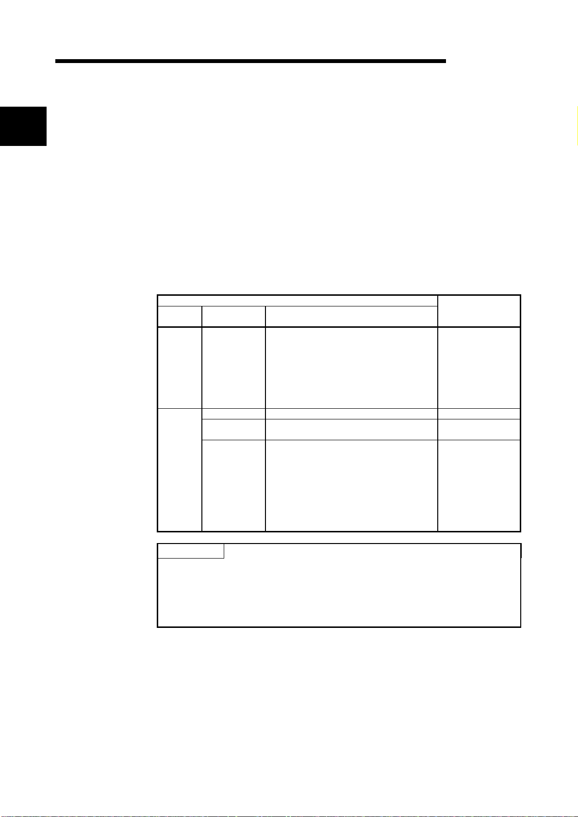
Table 1.1 List of Functions Added to High Performance Model QCPU and Function
Versions/Serial Numbers
Function
version
A
B
Update Details of High Performance Model QCPU
Serial No. Added functions
• Automatic write to standard ROM
• Enforced ON/OFF for external I/O
• Remote password setting
02092" or later
"
— • Compatibility with the multiple CPU system Version 6 or later
03051" or later
"
04012" or later
"
• Increased standard RAM capacity of
Q12HCPU, Q25HCPU
• Compatibility with MELSECN ET /H remote
I/O network
• Interrupt module (QI60) compatibility
• Installation of PC CPU module into the
multiple CPU system
• High speed interrupt function
• Compatibility with index modification for
module designation of dedicated instruction
• Selection of refresh item for COM
instruction
• Extended life battery of SRAM card
• Compatibility with 2Mbyte SR AM card
• Increased standard RAM capacity of
Q02HCPU, Q06HCPU
Corresponding
GX Developer
Version 6 or later
Version 7 or later
Version 7.10L
or later
POINT
(1) For the details of the added functions in Table 1.1, refer to the High
Performance model QCPU (Q mode) User's Manual (Function Explanation,
Program Fundamentals).
(2) Refer to Section 2.3 for the serial No. and function version of the High
Performance model QCPU.
1 - 1 1 - 1
Page 22

1 OVERVIEW
MELSEC-Q
1.1 Features
High Performance model QCPU has the following new features:
(1) Controllable multiple I/O points
All High Performance model QCPUs support 4096 points (X/Y0 to FFF) as the
number of actual I/O points capable of getting access to the I/O module installed
on the base unit.
They also support 8192 points max. (X/YO to 1FFF) as the number of I/O
devices which can be used in the remote I/O stations such as MELSECNET/H
remote I/O NET, CC-Link data link and MELSECNET/MINI-S3 data link.
(2) Lineup according to progr am capaci ty
The optimum CPU module for the program capacity to be used can be selected.
Q02CPU, Q02HCPU : 28k step
Q06HCPU : 60k step
Q12HCPU : 124k step
Q25HCPU : 252k step
(3) Realised high speed processing
Depending on the type of the sequencer, high speed processing has been
realized.(Example: when LD instruction is used)
Q02CPU : 0.079
Q02HCPU, Q06HCPU, Q12HCPU, Q25HCPU : 0.034
In addition, an access to the intelligent function module or an increase in speed
of the link refresh of the network have been realized by the connection system
(System bus connection) of the newly developed base unit.
Access to the intelligent function module : 20
MELSECNET/H link refresh processing : 4.6ms/8k word (approx. 4.3 times)
1: Where Q02HCPU is compared with Q2ASHCPU-S1.
s /word (approx. 7 times) 1
s
s
(4) Increase in debugging efficiency thr oug h high speed
communication with GX Dev el oper
In the High Performance model QCPU, a time required for writing/reading of a
program or monitoring has been reduced through the high speed communication
at a speed of 115.2kbps max. by the RS-232, and a communication time
efficiency at the time of debugging has been increased.
In the Q02HCPU, Q06HCPU, Q12HCPU, and Q25HCPU, a high speed
communication at a speed of 12Mbps is allowed through the USB.
26k step program transfer time
1
1
Q25HCPU(USB)
Q25HCPU(RS-232)
Q2ASHCPU
A2USHCPU-S1
12
30
0 1020304050607080
86
94
90 100
(Unit:s)
(5) AnS series I/O module or special function module are available.
For Q series, if an appropriate module is not available, the AnS series I/O
module or special function module can also be used for the High Performance
model QCPU through the use of the QA1S65B/QA1S68B extension base unit.
1 - 2 1 - 2
Page 23
1 OVERVIEW
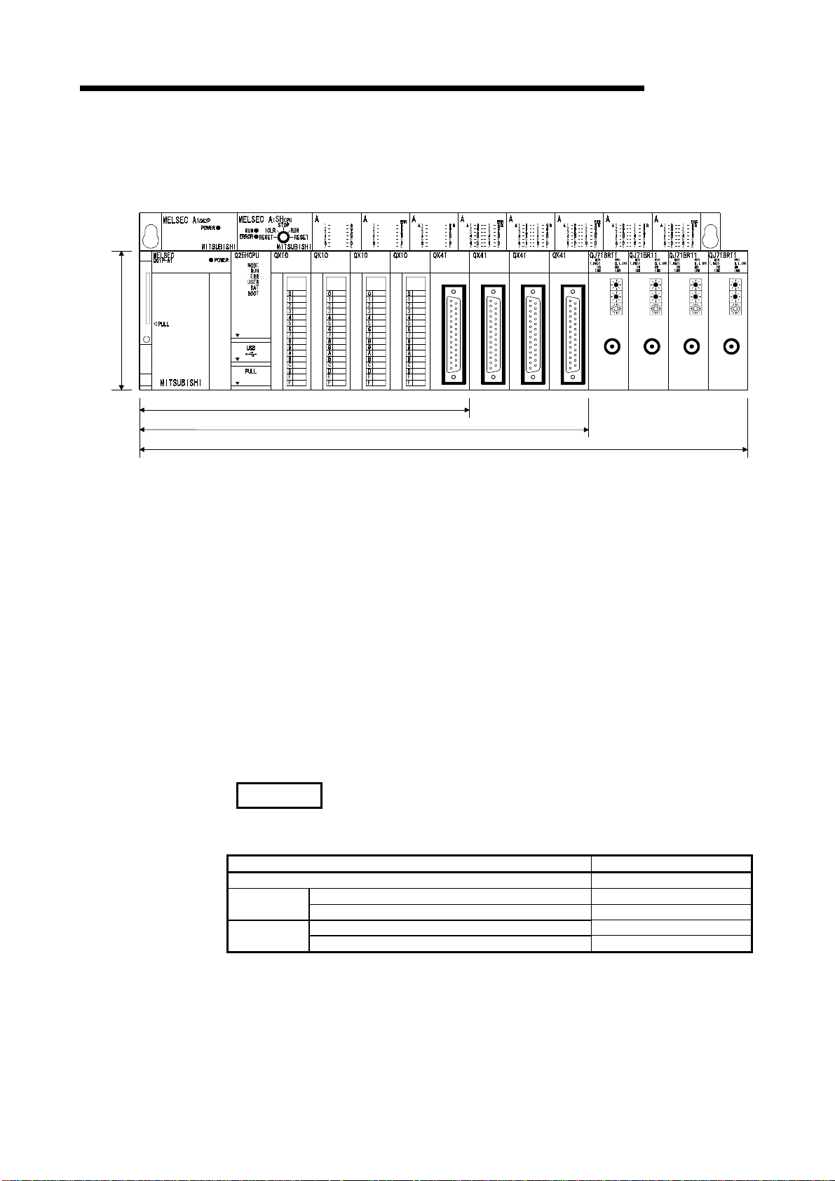
Comparison of installation space
98mm
(3.86
inch)
(6) Saved space by a reduction in si z e
The installation space for Q series has been reduced by approx. 60 % of the
space for AnS series.
1SX10 1SY50 1SX41 1SY41 1SX81 1SY81 1SX42 1SY42
PULL
MELSEC-Q
5 Slot Main Base Unit 245mm(9.65inch)
8 Slot Main Base Unit 328mm(12.92inch)
12 Slot Main Base Unit 439mm(17.30inch)
(depth:98mm(3.86inch))
(7) Connection of up to seven extension base units.
(a) The High Performance model QCPU can connect to seven extension base
units (eight base units including the main) and accept up to 64 modules.
(b) The overall distance of the extension cables is up to 13.2m to ensure high
degree of extension base unit arrangement.
(8) Memory extension by memory card
The High Performance model QCPU is provided with a memory card installation
connector to which a memory card of 32 Mbyte max. can be connected (32
Mbyte is available when a ATA card is used).
When a memory card of large capacity is installed, a large capacity of file can be
controlled, comments to all data devices can be set up, and the programs in the
past can be stored in the memory as they are in the form of the corrected
histories.
If a memory card is not installed, a program can be stored onto the standard
ROM built in the CPU module, and file registers can be handled by the standard
RAM.
REMARK
• The number of file registers that can be handled changes depending on the
function version/serial number of the CPU module used.
CPU Module Type Number of File Registers
Q02CPU 32k points
First 5 digits of serial number are "04011" or earlier 32k points Q02HCPU
Q06HCPU
Q25HCPU
First 5 digits of serial number are "04012" or later 64k points
First 5 digits of serial number are "02091" or earlier 32k points Q12HCPU
First 5 digits of serial number are "02092" or later 128k points
Refer to Section 2.3 to confirm the function version and serial number of the High
Performance model QCPU.
1 - 3 1 - 3
Page 24

1 OVERVIEW
MELSEC-Q
(9) Data can be written automatical ly to standard ROM
You need not use GX Developer to write parameters/programs on a memory
card to the standard ROM of the High Performance model QCPU.
When the standard ROM is used to perform ROM operation, you can load a
memory card into the High Performance model QCPU and write
parameters/programs on the memory card to the standard ROM. Hence, you
need not carry GX Developer (personal computer) to rewrite the
parameters/programs.
(10) External I/O can be turned ON/OFF forcibly
If the High Performance model QCPU is in the RUN mode, you can operate GX
Developer to turn external inputs/outputs ON/OFF forcibly, independently of the
program execution status.
You need not put the High Performance model QCPU in the STOP mode to
perform wiring/operation tests by forced ON/OFF of outputs.
(11) Remote password can be set
When access to an Ethernet module or serial communication module is made
externally, whether access to the High Performance model QCPU can be made
or not can be selected with a remote password.
(12) Remote I/O network of MELSECNET/H can be configured
You can load the remote master station of the MELSECNET/H to configure an
MELSECNET/H remote I/O system.
REMARK
• Features (9) to (12) are functions added to the High Performance model QCPU
whose serial number is "02092" or later in its upper 5 digits.
• The remote password facility can be executed when the Ethernet module or serial
communication module of function version B and GX Developer Version 6 or later
are used.
• In addition to the remote password, there are the following protection facilities for
the High Performance model QCPU.
(a) Protection of the whole CPU module by making system protection settings of
the High Performance model QCPU
(b) Protection of the memory card by setting the write protect switch of the memory
card
(c) File-by-file protection using password
• The MELSECNET/H remote I/O network facility can be executed when the
MELSECNET/H network module of function version B and GX Developer (Version
6 or later) are used.
1 - 4 1 - 4
Page 25
2 SYSTEM CONFIGURATION FOR SINGLE CPU SYSTEM
2 SYSTEM CONFIGURATION FOR SINGLE CPU SYSTEM
MELSEC-Q
2.1 System Configuration
2
Memory card
(Q2MEM-1MBS,Q2MEM-2MBS,
Q2MEM-2MBF,Q2MEM-4MBF,
Q2MEM-8MBA,Q2MEM-16MBA,
Q2MEM-32MBA)
This section describes the system configuration of the High Performance model
QCPU, cautions on use of the system, and configured equipment.
The outline of the equipment configuration, configuration with peripheral devices, and
system configuration in the High Performance model QCPU system is described below.
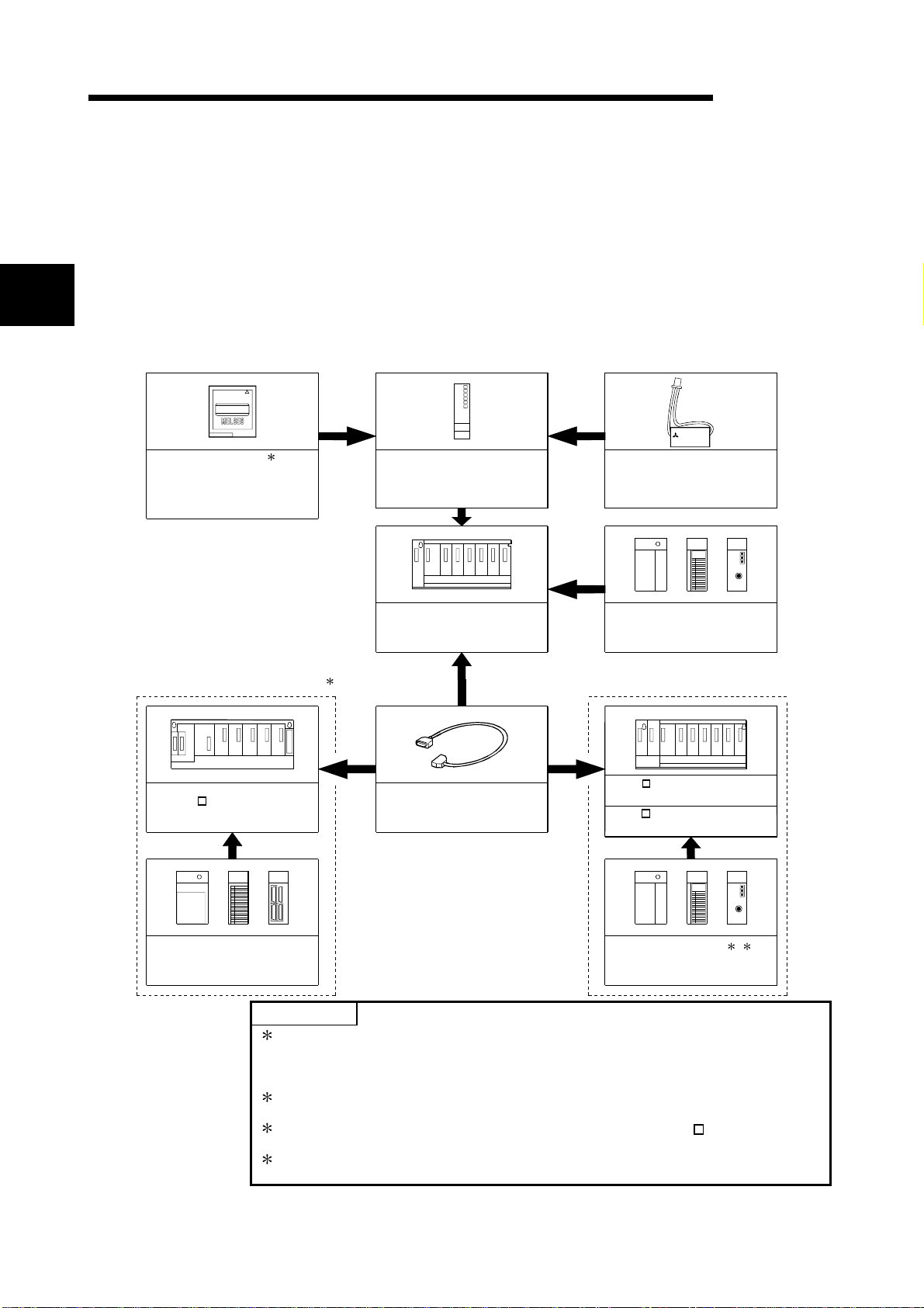
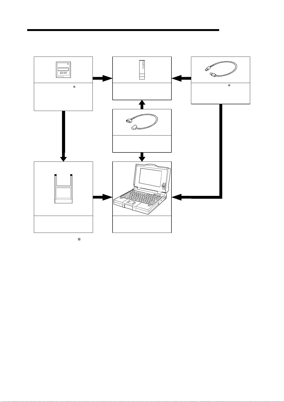
(1) Equipment configuration
(a) If the main base unit (Q3B) is used
MITSUBISHI
MITSUBISHI
LITHIUM BAT TERY
1
High Performance model QCPU
(Q02CPU,Q02HCPU,Q06HCPU,
Q12HCPU,Q25HCPU)
Main base unit
(Q33B, Q35B,Q38B,Q312B)
Battery
(Q6BAT)
Power supply module ,
I/O module , Inte l l igent function
module of the Q Series
Extension of the AnS Series module Extension of the Q Series module
2
QA1S6 extension base unit
(QA1S65B,QA1S68B)
Extension cable
(QC05B,QC06B,QC12B,
QC30B, QC50B,QC100B)
Q5 B extension base unit
(Q52B, Q55B)
Q6 B extension base unit
(Q63B, Q65B,Q68B,Q612B)
Power supply module ,
I/O module , Intelligent function
module of the AnS Series
POINTS
1: The number of memory cards to be installed is one sheet.
The memory card must be selected from SRAM card, Flash card, and ATA
Power supply module ,
I/O module , Inte l l igent function
module of the Q Series
3
4
card according to the application and capacity.
With commercial memory cards, the Operation is not assured.
2: QA1S65B and QA1S68B extension base units are used for the power supply
module, I/O module, and special function module of the AnS series.
3: The Q series power supply module is not required for the Q5 B type
extension base unit.
4: Q61SP cannot be used for the power supply module.
Use Q61P-A1, Q61P-A2, Q62P, or Q64P for the power supply module.
2 - 1 2 - 1
Page 26
2 SYSTEM CONFIGURATION FOR SINGLE CPU SYSTEM
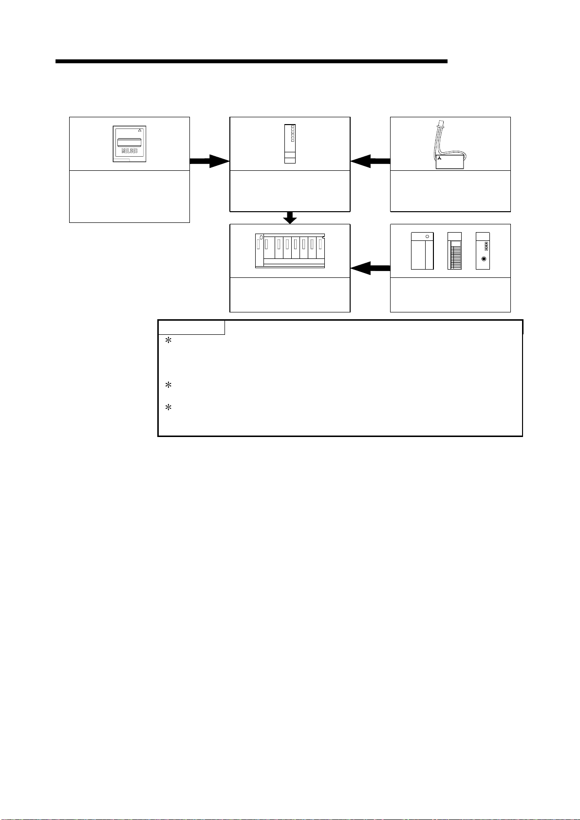
(b) If the slim type main base unit (Q3SB) is used
MITSUBISHI
(Q2MEM-1MBS,Q2MEM-2MBS,
Memory card
Q2MEM-2MBF,Q2MEM-4MBF,
Q2MEM-8MBA,Q2MEM-16MBA,
Q2MEM-32MBA)
*1
High Performance model QCPU
(Q02CPU,Q02HCPU,Q06HCPU,
Q12HCPU,Q25HCPU)
MELSEC-Q
MITSUBISHI
LITHIUM BATTERY
Battery
(Q6BAT)
Slim type main base unit
(Q32SB,Q33SB,Q35SB)
*2
Slim type power supply module,
I/O module ,
Intelligent function module
POINTS
*3
1: The number of memory cards to be installed is one sheet.
The memory card must be selected from SRAM card, Flash card, and ATA
card according to the application and capacity.
With commercial memory cards, the Operation is not assured.
2: The slim type main base unit does not have an extension cable connector. The
extension base unit and GOT cannot be connected.
3: Q61P-A1, Q61P-A2, Q62P, or Q64P cannot be used for the power supply
module.
Use Q61SP for the power supply module.
2 - 2 2 - 2
Page 27
2 SYSTEM CONFIGURATION FOR SINGLE CPU SYSTEM
(2) Configuration of peripheral devices
MITSUBISHI
MELSEC-Q
Memory card 1
(Q2MEM-1MBS,Q2MEM-2MBS,
Q2MEM-2MBF,Q2MEM-4MBF,
Q2MEM-8MBA,Q2MEM-16MBA,
Q2MEM-32MBA)
PC card adapter
(Q2MEM-ADP)
High Performance model QCPU
(Q02CPU,Q02HCPU,Q06HCPU,
Q12HCPU,Q25HCPU)
RS-232 cable
(QC30R2)
Personal Computer
GX Developer Version 4 or later
(SW4D5C-GPPW-E or later)
USB cable 1
(To be procured yourself)
Only Q02HCPU, Q06HCPU
Q12HCPU and Q25HCPU
can be used.
1: For how to write data to the memory card and the details of the USB cable, refer to
the GX Developer Operating Manual.
2 - 3 2 - 3
Page 28
2 SYSTEM CONFIGURATION FOR SINGLE CPU SYSTEM
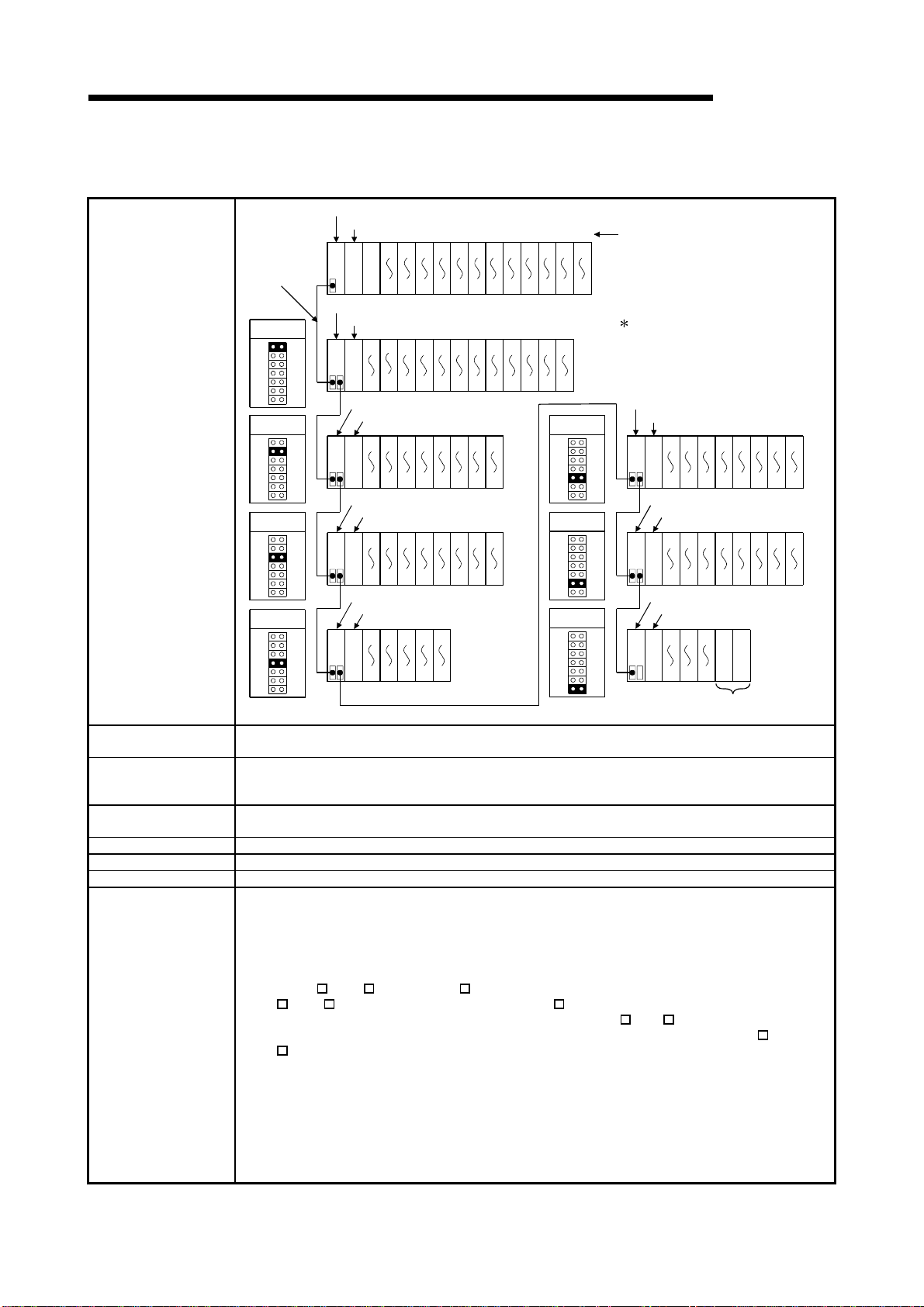
(3) Outline of system configuration
(a) If the main base unit (Q3B) is used
Main base unit(Q312B)
Power supply module
01234567891011
Extension
cable
O
U
T
001F203F405F607F809FA0BFC0DFE0FF100
CPU module
11F
120
13F
140
15F
Extension base unit(Q612B)
1st extension
stage
Power supply module
1E0
1C0
180
1A0
O
I
U
N
T
19F
1BF
1DF
1FF
200
21F
220
23F
240
25F
260
27F
280
29F
2A0
2BF
2221201918171615141312
2C0
2DF
23
2E0
2FF
Extension base unit(Q68B)
Power supply module
320
300
O
I
U
N
T
33F
31F
340
35F
360
37F
380
39F
3A0
3BF
3C0
3DF
3130292827262524
3E0
3FF
5th extension
stage
System configuration
2nd extension
stage
Extension base unit(Q68B)
3rd extension
stage
Power supply module
420
400
O
I
U
N
T
43F
41F
440
45F
460
47F
480
49F
4A0
4BF
4C0
4DF
3938373635343332
4E0
4FF
6th extension
stage
Extension base unit(Q65B)
Maximum number of
Extension Stages
4th extension
stage
Power supply module
520
500
O
I
U
N
T
53F
51F
540
55F
4443424140
580
560
59F
57F
Seven Extension Stages
7th extension
stage
Maximum number of
I/O modules to be
64 modules
installed
Maximum number of
occupied I/O points
4096
Main base unit Q33B, Q35B, Q38B, Q312B
Extension base unit Q52B, Q55B, Q63B, Q65B, Q68B, Q612B, QA1S65B, QA1S68B
Extension cable QC05B, QC06B, QC12B, QC30B, QC50B, QC100B
(1) Extension bases unit of up to seven stages can be used.
(2) Do not use extension cable longer than an overall extension length of 13.2m(43.31ft.).
(3) When using an extension cable, do not bind it together with the main circuit (high voltage and
heavy current) line or do not lay down them closely to each other.
(4) When setting the No. of the expansion stages, set it in the ascending order so that the same
No. is not set simultaneously by two extension base units.
(5) When Q5
B, Q6 B and QA1S6 B types of extension base units are mix ed, first connect the
Q5 B, Q6 B type and then connect the QA1S6 B type.
When setting the No. of the extension stages, set it from Q5
Notes
Although there are no particular restrictions in the order of the installation of the Q5
Q6 B, refer to Section 6.6 for usability.
(6) Connect the extension cable from OUT of the ex tension cable connector of the base unit to IN
of the extension base unit on the next stage.
(7) If 65 or more modules are installed, an error will occur.
(8) When the GOT is bus-connected, it occupies one extension stage and one slot.
(9) The High Performance model QCPU processes the GOT as a 16-point intelligent function
module. Hence, connecting one GOT decreases 16 points available for the base unit.
(10) Q61SP cannot be used for the power supply module.
Use Q61P-A1, Q61P-A2, Q62P, or Q64P for the power supply module.
160
17F
Slot No.
The figure shows the configuration
when 32-I/O modules are
loaded to each slot.
Extension base unit(QA1S68B)
Power supply module
600
5E0
5C0
5A0
O
I
U
N
T
5BF
5DF
5FF
61F
Extension base unit(QA1S68B)
Power supply module
700
6E0
6C0
6A0
O
I
U
N
T
6BF
6DF
6FF
71F
Extension base unit(QA1S65B)
Power supply module
636261
7E0
7C0
7A0
O
I
U
N
T
7FF
7DF
7BF
When module is installed,
an error occurs.
B/Q6 B in order.
MELSEC-Q
5251504948474645
680
660
640
620
69F
67F
65F
63F
6059585756555453
780
760
740
720
79F
77F
75F
73F
Prohibit
Prohibit
B and
2 - 4 2 - 4
Page 29
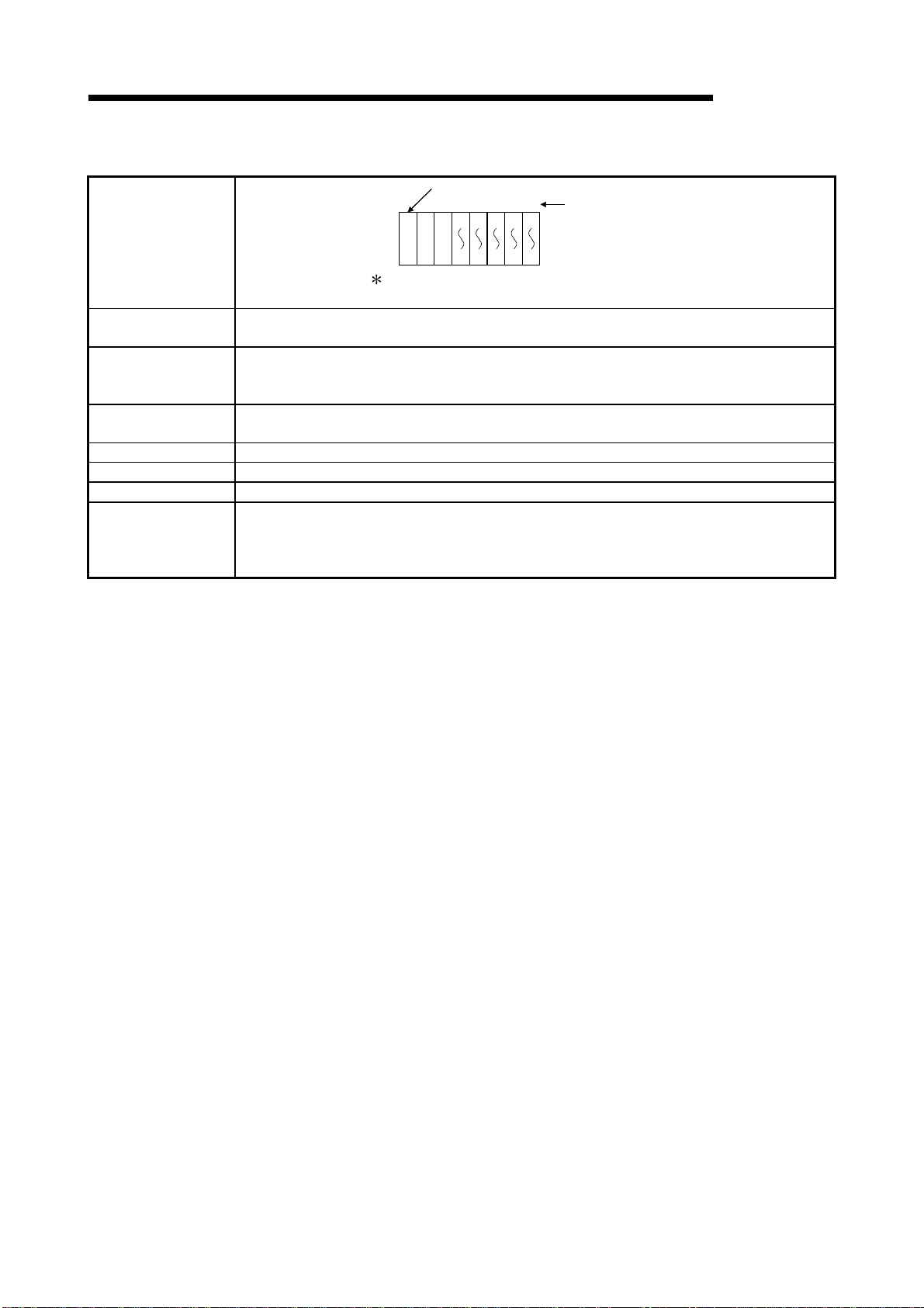
2 SYSTEM CONFIGURATION FOR SINGLE CPU SYSTEM
(b) If the slim type main base unit (Q3SB) is used
Slim type main base unit (Q35SB)
01234
001F203F405F607F80
Slot No.
MELSEC-Q
System configuration
The above system assumes that each slot is loading with
a 32-point module.
Maximum number of
Extension Stages
CPU module
Power supply
module
No extension allowed
9F
Maximum number of
I/O modules to be
5 modules
installed
Maximum number of
occupied I/O points
4096
Main base unit Q32SB, Q33SB, Q35SB
Extension base unit Cannot be connected.
Extension cable C annot be connected.
(1) Q61P-A1, Q61P-A2, Q62P, or Q64P cannot be used for the power supply module.
Notes
Use Q61SP for the power supply module.
(2) The slim type main base unit does not have an extension cable connector.
The extension base unit and GOT cannot be connected.
2 - 5 2 - 5
Page 30
2 SYSTEM CONFIGURATION FOR SINGLE CPU SYSTEM
MELSEC-Q
2.2 Precaution on System Configuration
This section describes hardware and software packages compatible with QCPU.
(1) Hardware
(a) The number of modules to be installed and functions are limited depending on
the type of the modules.
Applicable Module Type
• QJ71LP21
Q Series MELSECNET/H
network module
Q series Ethernet interface
module
Q series CC-Link system
master local module
MELSECNET/MIN I-S3 data
link module
AnS series special function
module shown on the right
Interrupt module
• QJ71BR11
• QJ71LP21-25
• QJ71LP21G
• QJ71LP21GE
• QJ71E71
• QJ71E71-B2
• QJ71E71-100
• QJ61BT11 No limit
• A1SJ71PT32-S3
• A1SJ71T32-S3
• A1SD51S
• A1SD21-S1
• A1SJ71J92-S3
(When GET/PUT service is used)
• A1SI61
• QI60
1: A maximum of 4 modules if the network parameters for CC-Link are set and
controlled by the GX Developer. There is no restriction in the number of modules
when the parameters are set by the special-purpose instructions for the CC-Link.
For details on the CC-Link System Master Local Unit that can set parameters with
the special-purpose instructions, refer to the user's manual for the CC-Link Master
Local module.
(b) When the AnS series special-function modules shown below are used, a
limitation is given to an accessible device range.
• A1SJ71J92-S3 type JEMANET interface module
• A1SD51S type intelligent communication
Device Accessible device range
Input (X), Output (Y) X/Y0 to 7FF
Internal relay (M), Latch relay (L) M0 to 8191
Link relay (B) B0 to FFF
Timer (T) T0 to 2047
Counter (C) C0 to 1023
Data register (D) D0 to 6143
Link register (W) W0 to FFF
Annunciator (F) F0 to 2047
(c) A graphic operation terminal can be used only for the GOT900 series (Basic
OS matching Q mode and communication driver must be installed).
The GOT800 series, A77GOT, and A64GOT cannot be used.
2 - 6 2 - 6
Limit of number of modules
to be installed
Up to 4 in total of inter-PLC
network and remote I/O
network modules
Up to 4 units
1
No limit
(setting of automatic refresh
function not allowed)
Total of 6 units
One unit only
Page 31

2 SYSTEM CONFIGURATION FOR SINGLE CPU SYSTEM
(d) The modules shown below cannot be used.
Module Name Type
MELSECNET/10 network
module
MELSECNET (II), /B data link
module
Ethernet interface module
Serial communication module,
computer link module
CC-Link master-local module A1SJ61QBT11, A1SJ61BT11
Modem interface module A1SJ71CMO-S3
ME-NET interface module A1SJ71ME81
A1SJ71LP21, A1SJ71BR11, A1SJ71QLP21,
A1SJ71QLP21S, A1SJ71QLP21GE, A1SJ71QBR11
A1SJ71AP21, A1SJ71AR21, A1SJ71AT21B
A1SJ71QE71-B2-S3(-B5-S3),
A1SJ71E71-B2-S3(-B5-S3)
A1SJ71QC24(N), A1SJ71UC24-R2(-R4/-PRF)
(e) A dedicated instruction for the next module which was present in the QnA/A
series program instruction cannot be used for the High Performance model
QCPU.
Re-writing using FROM/TO instruction is required.
Module Name Type
High speed counter module A1SD61, A1SD62, A1SD62D(-S1), A1SD62E
MELSECNET/MINI-S3 A1SJ71PT32-S3, A1SJ71T32-S3
Positioning module A1SD75P1-S3(P2-S3/P3-S3)
ID module A1SJ71ID1-R4, A1SJ71ID2-R4
(f) Some system configurations and functions are restricted when writing the
parameter of the "High speed interrupt fixed scan interval" setting.
Refer to the following manual for the restrictions when the parameter of the
"High speed interrupt fixed scan interval" setting has been written.
•
High Performance model QCPU (Q mode) User's Manual
(Function Explanation, Program Fundamentals)
Note that the above restrictions do not apply to the High Performance model
QCPU of serial number "04011" or earlier since it ignores the "High speed
interrupt fixed scan interval" setting.
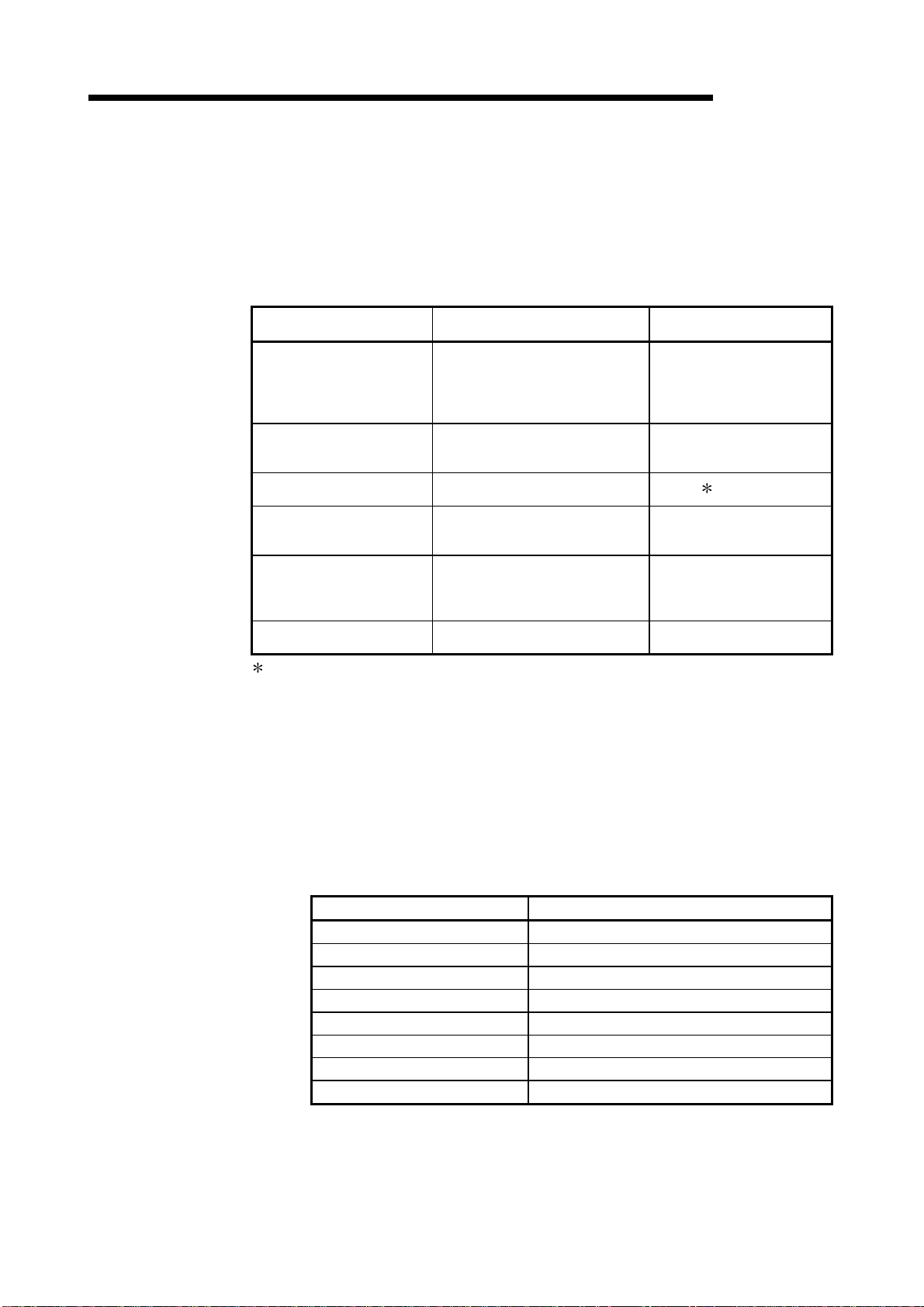
(2) Software package
GX Developer that can use the functions added to the High Performance model
QCPU changes depending on the function version/serial number of the CPU
module.
Function Version Serial Number GX Dev eloper
A — Version 4 (SW4D5C-GPPW-E) or later
— Functions added to "02092"
B —
— Functions added to "03052" Version 7 (SW7D5C-GPPW-E) or later
— Functions added to "04012"
Refer to Section 2.3 to confirm the function version and serial number of the High
Performance model QCPU.
MELSEC-Q
Version 6 (SW6D5C-GPPW-E) or later
Version 7.10L (SW7D5C-GPPW-E)
or later
2 - 7 2 - 7
Page 32

2 SYSTEM CONFIGURATION FOR SINGLE CPU SYSTEM
2.3 Confirming the Serial Number and Functi on Ver si on
The CPU module serial No. can be confirmed on the rated plate and GX Developer's
system monitor.
(1) Confirming the serial N o. on the r ated plate
The serial No. and function version can be confirmed on the rating plate.
MELSEC-Q
MODEL
SERIAL 020920000000000-B
LISTED 80M1
IND. CONT. EQ.
MADE IN JAPAN
Serial No. (First five digits)
Function version
(2) Confirming the serial N o. on the sy stem moni tor ( li st of product
information)
The CPU module serial No. and function version can be confirmed with the list of
product information on the GX Developer (Version 6 or later) system monitor.
Serial Nos. and function versions of the intelligent function module and CPU
module can also be confirmed.
Serial number Function version
2 - 8 2 - 8
Page 33

3 GENERAL SPECIFICATIONS
3 GENERAL SPECIFICATIONS
MELSEC-Q
Item Specifications
Operating ambient
temperature
Storage ambient
temperature
3
Operating ambient
humidity
Storage ambient
humidity
Vibration resistance
Shock resistance
Operating ambience No corrosive gases
Operating altitude 2000m (6562ft.) max.
Installation location Inside control panel
Overvoltage
category
Pollution level 2 2 max.
1
Performance specification of PLC is as follows:
0 to 55°C
-25 to 75°C
5 to 95%RH
5 to 95%RH
Frequency Acceleration Amplitude Sweep count
Conforming
to
JIS B 3502,
IEC 61131-2
Conforming to JIS B 3502, IEC 61131-2 (147 m/s
Under
intermittent
vibration
Under
continuous
vibration
10 to 57Hz ———
57 to 150Hz
10 to 57Hz ———
57 to 150Hz
4, non-condensing
4, non-condensing
II max.
3
0.075mm
(0.003inch)
———
0.035mm
(0.001inch)
———
2
9.8m/s
2
4.9m/s
2
, 3 times in each of 3 directions X, Y, Z)
10 times each in
X, Y, Z directions
(for 80 min.)
1 : This indicates the section of the power supply to which the equipment is assumed to be connected
between the public electrical power distribution network and the machinery within premises. Category II
applies to equipment for which electrical power is supplied from fixed facilities.
The surge voltage withstand level for up to the rated voltage of 300 V is 2500 V.
2 : This index indicates the degree to which conductive material is generated in terms of the environment in
which the equipment is used.
Pollution level 2 is when only non-conductive pollution occurs. A temporary conductivity caused by
condensing must be expected occasionally.
3 : The storage ambient temperature is -20 to 75°C if the system includes the AnS series modules.
4 : The operating ambient humidity and storage ambient humidity are 10 to 90%RH if the system includes the
AnS series modules.
5 : Do not use or store the PLC under pressure higher than the atmospheric pressure of altitude 0m.
Doing so can cause a malfunction.
When using the PLC under pressure, please contact your sales representative.
3 - 1 3 - 1
Page 34

3 GENERAL SPECIFICATIONS
MELSEC-Q
MEMO
3
3 - 2 3 - 2
Page 35

4 HARDWARE SPECIFICATION OF THE CPU MODULE
4 HARDWARE SPECIFICATION OF THE CPU MODULE
4.1 Performance Specification
MELSEC-Q
The table below shows the performance specifications of the CPU module.
Performance Specifications
Item
Control method Repetitive operation of stored program
I/O control mode Refresh mode
Q02CPU Q02HCPU Q06HCPU Q12HCPU Q25HCPU
Programming language
(Sequence control dedicated language)
(Sequence instruction)
4
Total number of instructions
Constant scan
(Function for setting the scan timer to fixed
settings)
Program 2
capacity
Memory
capacity
Maximum number
of stored files
Program memory
(Drive 0)
Program memory
(Drive 0)
Memory card (RAM)
(Drive 1)
Memory card (ROM)
(Drive 2)
Standard RAM
(Drive 3)
Standard ROM
(Drive 4)
CPU shared memory
4
Program memory 28 60 124 252 1
Memory card (RAM) 256
card
(ROM)
LD X0 0.079 s 0.034 s
MOV D0 D1 0.237
Flash card 288
ATA card 512
Relay symbol language, logic symbolic language,
MELSAP3 (SFC), MEL SAP- L , Fu n ction b lo ck
s 0.102 s
(excluding intelligent function module dedicated instructions)
0.5 to 2000 ms (configurable in increments of 0.5 ms)
28k step 60k step 124k step 252k step
112 kbyte 240 kbyte 496 kbyte 1008 kbyte
Capacity of loading memory cards(2Mbyte max.)
Installed memory card capacity
(Flash card: 4 Mbyte max., ATA card: 32 Mbyte max.)
64kbyte 128kbyte
112 kbyte 240 kbyte 496 kbyte 1008 kbyte
Standard RAM 2
Standard ROM number of writings Max. 100000 times
Number of I/O device points 8192 points (X/Y0 to 1FFF)
Number of occupied I/O points 4096 points (X/Y0 to FFF)
1:124 is the maximum number of programs that can be executed on High Performance model QCPU.
2: The maximum number of sequence steps that can be executed for one program by the High Performance model QCPU with the
parameters stored in another drive is calculated with the following expression.
(Program size) - (File header size (default: 34 steps))
Refer to the High Performance model QCPU User's Manual (Function Explanation, Program Fundamentals) for details on the program
size and file.
3: The memory capacity of the Q12HCPU or Q25HCPU whose first five digits of serial No. are "02091" or earlier is 64K bytes.
(Refer to Section 2.3 for the way to confirm the serial No.)
4:The CPU shared memory is not latched. The CPU shared memory is cleared when the power is turned on to the PLC or when the CPU
module is reset.
5:The memory capacity of the Q02HCPU or Q06HCPU whose first five digits of serial No. are "04011" or earlier is 64K bytes.
(Refer to Section 2.3 for the way to confirm the serial No.)
Standard ROM 28 60 124 252
Model
360
5 256kbyte 3
8 kbyte
Remark
Direct I/O is possible by
direct I/O specification
(DX
, DY )
——
Processing speed
——
——
——
Set parameter values to
specify
——
——
For memory capacity,
refer to Section 7.1.
——
——
——
——
——
Memory
——
——
Only one file register and
one local device
——
——
Number of devices
usable on program
Number of points
accesible to actual I/O
modules
4 - 1 4 - 1
Page 36

4 HARDWARE SPECIFICATION OF THE CPU MODULE
Performance Specifications (continued)
MELSEC-Q
Internal relay [M]
Latch relay [L]
Link relay [B]
Timer [T]
Retentive timer [ST]
Counter [C]
Data register [D ]
Link register [W]
Annunciator [F]
Edge relay [V]
Number of device points
File register
Item
[R]
[ZR]
Model
Q02CPU Q02HCPU Q06HCPU Q12HCPU Q25HCPU
Default 8192 points (M0 to 8191)
Default 8192 points (L0 to 8191)
Default 8192points (B0 to 1FFF)
Default 2048 points (T0 to 2047) (for low / high speed timer)
Select between low / high speed timer by instructions.
The measurement unit of the low / high speed timer is set with
parameters.
(Low speed timer : 1 to 1000ms, 1ms
(High speed timer : 0.1 to 100ms, 0.1ms
Default 0 point(for low / high speed retentive timer)
Switchover between the low / high speed retentive timer is set by
instructions.
The measurement unit of the low /high speed retentive timer is set with
parameters.
(Low speed retentive timer : 1 to 1000ms, 1ms
(High speed retentive timer : 0.1 to 100ms, 0.1ms
• Normal counter default 1024 points (C0 to 1023)
• Interrupt counter maximum 256 points
(default 0 point, set with parameters)
Default 12288 points (D0 to 12287)
Default 8192 points (W0 to 1FFF)
Default 2048 points (F0 to 2047)
Default 2048 points (V0 to 2047)
• When a standard RAM is used:
Q02CPU..........................32768 points (R0 to 32767)
Q02HCPU, Q06HCPU.....The number of points of up to 65536 points
can be used by block conversion in
increments of 32768 points (R0 to 32767)
Q12HCPU, Q25HCPU.....The number of points of up to 131072
points can be used by block conversion in
increments of 32768 points (R0 to 32767)
• When a SRAM card (1Mbyte) is used:
The number of points of up to 517120 points can be used by block
conversion in increments of 32768 points (R0 to 32767).
• When a SRAM card (2Mbyte) is used:
The number of points of up to 1041408 points can be used by block
conversion in increments of 32768 points (R0 to 32767).
• When a Flash card (2Mbyte) is used:
The number of points of up to 1041408 points can be used by block
conversion in increments of 32768 points (R0 to 32767).
• When a Flash card (4Mbyte) is used:
The number of points of up to 1042432 points can be used by block
conversion in increments of 32768 points (R0 to 32767).
• When a standard RAM is used:
Q02CPU..........................32768 points (ZR0 to 32767)
Q02HCPU, Q06HCPU.....65536 points (ZR0 to 65535), No block
conversion necessary.
Q12HCPU, Q25HCPU.....131072 points (ZR0 to 131071), No block
conversion necessary.
• When a SRAM card (1Mbyte) is used:
517120 points (ZR0 to 517119) , No block conversion necessary.
• When a SRAM card (2Mbyte) is used:
1041408 points (ZR0 to 1041407), No block conversion necessary.
• When a Flash card (2Mbyte) is used:
1041408 points (ZR0 to 1041407), No block conversion necessary.
• When a Flash card (4Mbyte) is used:
1042432 points (ZR0 to 1042431), No block conversion necessary.
, default 100ms)
/unit
, default 10ms)
/uni t
, default 100ms)
/unit
, default 10ms)
/unit
Remark
Number of use points
is set with parameters.
When a Flash card is
used, read only is
possible.
The ATA card cannot
be used.
4
4 - 2 4 - 2
Page 37

4 HARDWARE SPECIFICATION OF THE CPU MODULE
Performance Specifications (continued)
MELSEC-Q
Item
Link special relay [SB] 2048 points (SB0 to 7FF)
Link special register [SW] 2048 points (SW0 to 7FF)
Step relay [S] 8192 points (S0 to 8191)
Index register [Z] 16 points (Z0 to 15)
Pointer [P]
Interrupt poin ter [ I ]
Number of device points
Special relay [SM] 2048 points (SM0 to 2047)
Special register [SD] 2048 points (SD0 to 2047)
Function input [FX] 16 points (FX0 to F)
Function output [FY] 16 points (FY0 to F)
Function register[FD] 5 points (FD0 to 4)
Link direct device
Intelligent function module device
Latch (power failure compensation) range
Remote RUN/PAUSE contact
Clock function
Allowable momentary power failure period Varies according to the type of power supply module.
5VDC internal current consumption 0.60A 0.64A 0.64A 0.64A 0.64A
External dimensions
Weight 0.20kg 0.20kg 0.20kg 0.20kg 0.20kg
Q02CPU Q02HCPU Q06HCPU Q12HCPU Q25HCPU
4096 points (P0 to 4095), set parameter values to select usable range
of in-file pointer / shared pointers.
The specified intervals of the system interrupt pointers I28 to I31 can
be set with parameters.(0.5 to 1000ms, 0.5 ms
Default I28 : 100ms I29 : 40ms I30 : 20ms I31 : 10ms
Device having a direct access to link device.
MELSECNET/10(H) use only.
Specified form : J
Device having a direct access to the buffer memory of the intelligent
function module. Specified form : U
(Latch range can be set for B, F, V, T, ST, C, D, and W.)
RUN and PAUSE contacts can be set from among X0 to 1FFF,
respectively.
Year, month, day, hour, minute, second, day of the week
(leap year automatic distinction)
Accuracy -3.18 to +5.25s (TYP. +2.12s) /d at 0° C
Accuracy -3.93 to +5.25s(TYP. +1.90s)/d at 25°C
Accuracy -14.69 to +3.53s(TYP. -3.67s)/d at 55°C
H 98mm (3.86inch)
W 27.4mm (1.08inch)
D 89.3mm (3.52inch)
\X
J
B
\
Model
256 points (I0 to 255)
, J
, J
L0 to 8191 (default)
\
SW
\
, J
Y
, J
G
\
)
/unit
,
W
\
SB
\
Remark
The number of device
points is fixed.
——
——
Set parameter values
to specify
——
——
——
——
——
——
——
4 - 3 4 - 3
Page 38

W
4 HARDWARE SPECIFICATION OF THE CPU MODULE
4.2 Part Names and Settings
MELSEC-Q
Q02HCPU
PULL
hen opening the front cover, put your finger here.
This section explains the part names and settings of the module.
Front face
MODE
RUN
ERR.
USER
BAT.
BOOT
USB
RS-232
1)
2)
9)
3)
4)
5)
6)
10)
7)
11) 1
12)
8)
With front cover open
MODE
BOOT
STOP RUN
RESET L CLR
RUN
ERR.
USER
BAT.
ON SW
1
2
3
4
5
13)
14)
15)
Side face
16)
17)
19)
18)
1: Not provided for Q02CPU.
4 - 4 4 - 4
Page 39

4 HARDWARE SPECIFICATION OF THE CPU MODULE
No. Name Application
1) Module fixing hook Hook used to fix the module to the base unit. (Single-motion installation)
Indicates the mode of the CPU module.
2) "Mode" LED
3) "RUN" LED
4) "ERR." LED
5) "USER" LED
6) "BAT." LED
7) "BOOT" LED
8) Module loading lever Used to load the module to the base unit.
ON (green) : Q mode
ON (orange) : A mode
Flicker (green) : Enforced ON/OFF for external I/O registered
Indicates the operating status of the CPU module.
ON : During operation in "RUN" status.
OFF : During a stop in "STOP" status or detection of error whose occurrence stops
operation.
Flicker : When parameter/program is written at STOP and RUN/STOP switch is
changed from "STOP" to "RUN".
To turn ON the RUN LED after writing the program, carry out the following
steps.
Set the RUN/STOP switch from "RUN" → "STOP" → "RUN".
y
Reset with the RESET/L.CLR switch.
y
Restart the PLC power.
y
To turn ON the RUN LED after writing the parameters, carry out the following
steps.
Reset with the RESET/L.CLR switch.
y
Restart the PLC power.
y
(If the RUN/STOP switch is set from "RUN" → "STOP" → "RUN" after
changing the parameters, the parameters related to the intelligent function
module, such as the network parameters, will not be reflected.)
ON : Detection of self-diagnosis error which will not stop operation, except battery
error.
(When operation continued at error detection is set in the parameter.)
OFF : Normal
Flicker : Detection of error whose occurrence stops operation.
When automatic write to standard ROM is completed normally. ("BOOT" LED
also flickers.)
ON : Error detected by CHK instruction or annunciator ON
OFF : Normal
Flicker : Execution of latch clear
ON : Occurrence of battery error due to reduction in battery voltages of CPU module
or memory card.
OFF : Normal
ON : Start of boot operation
OFF : Non-execution of boot operation
Flicker : When automatic write to standard ROM is completed normally. ("ERR." LED
also flickers.)
MELSEC-Q
4 - 5 4 - 5
Page 40

4 HARDWARE SPECIFICATION OF THE CPU MODULE
MELSEC-Q
No. Name Application
9) Memory card EJECT button Used to eject the memory card from the CPU module.
Memory card loading
10)
connector
11) USB connector 1
12) RS-232 connector 1
DIP switches
ON SW
1
13)
2
3
4
5
14) RUN/STOP switch
15) RESET/L.CLR switch
16) Module fixing screw hole Hole for the screw used to fix to the base unit. (M3 12 screw)
17) Module fixing latch Hook used to fix to the base unit.
18) Battery connector pin
19) Battery
1 : When normally connecting a cable to the USB connector or RS-232 connector, clamp the cable to prevent it from
coming off due to the dangling, moving or carelessly pulling of the cable.
Q6HLD-R2 type RS-232 Connector Disconnection Prevention H older is available as a clamp for R S-232 connector.
Connector used to load the memory card to the CPU module.
Connector for connection with USB-compatible peripheral device. (Connector type B)
Can be connected by USB-dedicated cable.
Not available for Q02CPU.
Connector for RS-232 connection
Can be connected by RS-232 connection cable (QC30R2).
Used to set the items for operation of the CPU module.
For system protection and parameter-valid drive functions, refer to the High
Performance model QCPU (Q mode) User's Manual (Function Ex planation, Program
Fundamentals).
SW1 : Used to set system protection. Batch-inhibits write and control directives to the
CPU module. (Shipped in OFF position)
OFF : No protection
ON : Protection
SW2, SW3: Used to specify parameter-valid drive.
(Both SW2 and SW3 are shipped in OFF position)
SW2 SW3 Parameter Drive
OFF OFF Program memory (Drive 0)
ON OFF SRAM card (Drive 1)
OFF ON Flash card/ATA card (Drive 2)
ON ON Standard ROM (Drive 4)
Note: Parameters cannot be stored in standard RAM (Drive 3).
SW4 : Must not be used. Normally OFF. (Shipped in OFF position)
SW5 : Must not be used. Normally OFF. (Shipped in OFF position)
RUN : Executes sequence program operation.
STOP : Stops sequence program operation.
RESET : Used to perform hardware reset, operation fault rest, operation initialization,
etc.
If this switch is left in the RESET position, the whole system w ill be reset and
the system will not operate properly.
After performing reset, always return this switch to the neutral position.
L.CLR : Used to turn "OFF" or "zero" all data in the parameter-set latch area.
Used to clear the sampling trace and status latch registration.
For connection of battery lead wires.
(When shipped from the factory, the lead wires are disconnected from the connector to
prevent the battery from consuming.)
Backup battery for use of program memory, standard RAM and power failure
compensation function.
CPU module
Q6HLD-R2
RS-232 cable
4 - 6 4 - 6
Page 41

4 HARDWARE SPECIFICATION OF THE CPU MODULE
4.3 Switch Operation After Writing in Program
When writing a program into the CPU module, do not turn off the system protect set
switch SW1 in advance (When the switch is turned off, the system will not be
protected).
(1) When a program is written whil e CPU modul e i s stopped:
When a program is written while the CPU module is stopped, operate the switch
in the order shown below.
1) RUN / STOP switch : STOP
"RUN" LED: Turns off CPU module in stop status
2) RESET / L.CLR switch : Tilt this switch to RESET once, and return it to the
original center position.
3) RUN / STOP switch : STOP
"RUN" LED: Turns on CPU module in running status
RUN
(2) When a program is written whil e C PU modul e is r unni ng :
When a program is written while the CPU module is running, the switch need not
be operated.
POINTS
(1) Even if the RUN/STOP switch is set to RUN immediately after a program is
written when the CPU module is in the stop status, CPU module will not come
into RUN status.
When the CPU module is reset with the RESET / L.CLR switch and the
RUN/STOP switch is set to RUN after a program has been written, the CPU
module can be brought into RUN status.
(2) If the CPU module is desired to be brought into RUN status without resetting it,
operate the RUN/STOP switch from STOP to RUN, RUN to STOP, and STOP
to RUN in that order.
After the seconds STOP to RUN switch operation, the CPU module is brought
into RUN status.
(3) When a program is written while the CPU module is running in boot operation,
the program written during the running is written into the program memory.
After a program has been written while the CPU module is running, write the
program also into the boot original memory. Failure to write a program into the
boot original memory will run an old program at the time of the next boot
operation.
(For details of the boot operation, refer to the High Performance model QCPU
(Q mode) User's Manual (Function Explanation, Program Fundamentals) ).
MELSEC-Q
Write a program.
4 - 7 4 - 7
Page 42

4 HARDWARE SPECIFICATION OF THE CPU MODULE
4.4 Latch Clear Operation
To perform latch clear, operate the RESET/L.CLR switch in the following procedure.
1) RUN/STOP switch : STOP
2) RESET/L.CLR switch : Move the switch to L.CLR several times until the
USER LED flickers.
"USER" LED: Flicker Ready for latch clear.
3) RESET/L.CLR switch : Move the switch to L.CLR once more.
"USER" LED: OFF Latch clear complete.
POINTS
(1) The ineffective range for latch clear can be set for each device by the device
setting parameter.
(2) In addition to the way of using the RESET/L.CLR switch for latch clear, remote
latch clear may be performed from GX Developer.
For details of the remote latch clear operation using GX Developer, refer to the
High Performance model QCPU (Q mode) User's Manual (Function
Explanation, Program Fundamentals).
4.5 Executing Automatic Write to Standard ROM.
MELSEC-Q
(1) Order of execution for automatic write to standard ROM
Automatic write to the standard ROM is carried out with the following procedures.
(a) Operation with GX Developer (setting automatic write to standard ROM)
1) Check the
ROM
Set the parameter and program to be booted at the "Boot file setting"
section.
(Set the "Transfer from" to "Standard ROM".)
"
Auto Download all Data from Memory card to Standard
"
item in the PLC parameter boot file setting.
Check "Auto Download all
Data from Memory card to
Standard ROM ".
Set the "Transfer from"
to "Standard ROM".
2) Store the set parameters and programs to be booted in the memory
4 - 8 4 - 8
card.
Page 43

4 HARDWARE SPECIFICATION OF THE CPU MODULE
(b) Operations with CPU module (automatic write to standard ROM)
1) Switch OFF the power supply to the PLC.
2) Mount the memory card that contains the parameters and programs to
be booted onto the CPU module.
3) Set the parameter's valid drive in the mounted memory card with the
CPU module's dip switches.
• When a SRAM card is mounted: SW2 : ON, SW3 : OFF
• When a Flash card/ATA card is mounted: SW2 : OFF, SW3 : ON
4) Switch on the power supply to the PLC.
5) "BOOT" LED will flicker when automatic write to standard ROM has
been completed, and the CPU module will assume a suspension error
status.
6) Switch OFF the power supply to the PLC.
7) Remove the memory card, and then set the parameter's valid drive in
the standard ROM with the CPU module's dip switches.
• Standard ROM: SW2 : ON, SW3 : ON
(c) The parameters and programs will be booted from the standard ROM to the
program memory when the PLC is switched on to enable actual operations.
MELSEC-Q
4 - 9 4 - 9
Page 44

5 POWER SUPPLY MODULE
MELSEC-Q
5 POWER SUPPLY MODULE
5.1 Specification
5.1.1 Power supply module specifications
Item
Base loading position Power supply module loading slot
Applicable base unit Q3B, Q6B
Input power supply
Input frequency 50/60Hz ±5% ——
Input voltage distortion factor Within 5% (refer to section 5.1.3) ——
Max. input apparent power 105VA ——
Max. input power —— 45W
Inrush current 20A within 8ms 100A within 1ms
current
External output voltage —— 24VDC ±10% ——
protection
protection
Efficiency 70% or more 65% or more 70% or more
Allowable momentary power failure
period
Dielectric withstand voltage
Insulation resistance
Noise durability
Operation indication LED indication (lit at 5VDC output)
Fuse Built-in (Unchangeable by user)
Contact
output
section
Terminal screw size M3.5 × 7
Applicable wire size 0.75 to 2mm2
Applicable solderless terminal RAV1.25 to 3.5, RAV2 to 3.5
Applicable tightening torque 66 to 89N•cm
External
dimensions
Weight 0.31kg 0.39kg 0.33kg
1
2
3
Application
Rated switching voltage,
current
Minimum switching load 5VDC, 1mA
Response time OFF to ON: 10ms max. ON to OFF: 12ms max.
Life
Surge suppressor No
Fuse No
This section gives the specifications of the power supply modules.
Performance Specifications
Q61P-A1 Q61P-A2 Q62P Q63P
100 to 120VAC
(85 to 132VAC) (170 to 264VAC) (85 to 264VAC) (15.6 to 31.2VDC)
5VDC 6A 3A 6A Rated output
24VDC —— 0.6A ——
5VDC 6.6A or more 3.3A or more 6.6A or more Overcurrent
24VDC —— 0.66A or more ——
5VDC 5.5 to 6.5V Overvoltage
24VDC ——
Across inputs/LG and outputs/FG
2830VAC rms/3 cycles (2000 m (6562 ft.))
Across inputs and outputs (LG and FG separated), across inputs and
LG/FG, across outputs and FG/LG 10M or more by insulation
resistance tester
• By noise simulator of 1500Vp-p noise voltage, 1
to 60Hz noise frequency
• Noise voltage IEC61000-4-4, 2kV
ERR contact (contact switched off (opened: normally closed contact) at an error stop of CPU
module), for CPU module operating status output
Mechanical : More than 2 million times
Electrical : More than 100 thousand times at rated switching voltage, current
H 98mm (3.86inch)
W 55.2mm (2.33inch)
D 90mm (3.55inch)
+10%
-15%
200 to 240VAC
Within 20ms
+10%
100 to 240VAC
-15%
s noise width and 25
24VDC, 0.5A
+10%
-15%
24VDC
Within 10ms
(at 24VDC input)
500VAC across
primary and 5VDC
10M
insulation resistance
By noise simulator of
500Vp-p noise voltage,
1
s noise width and
25 to 60Hz noise
frequency
+30%
-35%
or more by
tester
5
5 - 1 5 - 1
Page 45

5 POWER SUPPLY MODULE
Item
Base loading position Power supply module loading slot
Applicable base unit Q3B, Q6B
Input power supply
Input frequency 50/60Hz ±5%
Input voltage distortion factor Within 5% (refer to section 5.1.3)
Max. input apparent power 160VA
Inrush current 20A within 8ms
current
protection*1
protection*2
Efficiency 70% or more
Allowable momentary power failure
period*3
5
Dielectric withstand voltage
Insulation resistance
Noise durability
Operation indication LED indication (lit at 5VDC output)
Fuse Built-in (Unchangeable by user)
Contact
output
section
Terminal screw size M3.5 × 7
Applicable wire size 0.75 to 2mm2
Applicable solderless terminal RAV1.25 to 3.5, RAV2 to 3.5
Applicable tightening torque 66 to 89N•cm
External
dimensions
Weight 0.40kg
Application
Rated switching voltage,
current
Minimum switching load 5VDC, 1mA
Response time OFF to ON: 10ms max. ON to OFF: 12ms max.
Life
Surge suppressor No
Fuse No
H 98mm (3.86inch)
W 55.2mm (2.33inch)
D 115mm (4.53inch)
Power Supply Module Specifications (Continued)
Performance Specifications
Q64P
100 to 120VAC/200 to 240VAC
(85V to 132VAC/170 to 264VAC)
5VDC 8.5A Rated output
24VDC ——
5VDC 9.9A or more Overcurrent
24VDC ——
5VDC 5.5 to 6.5V Overvoltage
24VDC ——
Within 20ms
Across inputs/LG and outputs/FG
2830VAC rms/3 cycles (2000 m (6562 ft.))
Across inputs and outputs (LG and FG separated), across inputs and LG/FG, across outputs
and FG/LG 10M
• By noise simulator of 1500Vp-p noise voltage, 1
frequency
• Noise voltage IEC61000-4-4, 2kV
ERR contact (contact switched off (opened: normally closed contact) at an error stop of CPU
Mechanical : More than 2 million times
Electrical : More than 100 thousand times at rated switching voltage, current
or more by insulation resistance tester
module), for CPU module operating status output
24VDC, 0.5A
MELSEC-Q
+10%
-15%
s noise width and 25 to 60Hz noise
5 - 2 5 - 2
Page 46

5 POWER SUPPLY MODULE
Item
Base loading position Slim type power supply module loading slot
Applicable base unit Q3SB
Input power supply
Input frequency 50/60Hz ±5%
Input voltage distortion factor Within 5% (refer to section 4.3.1)
Max. input apparent power 40VA
Inrush current 20A within 8ms
5VDC 2A Rated output
current
protection*1
protection*2
Efficiency 70% or more
Allowable momentary power failure
period*3
Dielectric withstand voltage
Insulation resistance
Noise durability
Operation indication LED indication (lit at 5VDC output)
Fuse Built-in (Unchangeable by user)
Contact
output
section
Terminal screw size M3.5 × 7
Applicable wire size 0.75 to 2mm2
Applicable solderless terminal RAV1.25 to 3.5, RAV2 to 3.5
Applicable tightening torque 66 to 89N•cm
External
dimensions
Weight 0.18kg
24VDC ——
5VDC 2.2A or more Overcurrent
24VDC ——
5VDC 5.5 to 6.5V Overvoltage
24VDC ——
Across inputs/LG and outputs/FG
2830VAC rms/3 cycles (2000 m (6562 ft.))
Across inputs and outputs (LG and FG separated), across inputs and LG/FG, across outputs
and FG/LG 10M
• By noise simulator of 1500Vp-p noise voltage, 1
frequency
• Noise voltage IEC61000-4-4, 2kV
Application
Rated switching voltage,
current
Minimum switching load 5VDC, 1mA
Response time OFF to ON: 10ms max. ON to OFF: 12ms max.
Life
Surge suppressor No
Fuse No
H 98mm (3.86inch)
W 27.4mm (1.08inch)
D 104mm (4.09inch)
ERR contact (contact switched off (opened: normally closed contact) at an error stop of CPU
Mechanical : More than 20 million times
Electrical : More than 100 thousand times at rated switching voltage, current
or more by insulation resistance tester
module), for CPU module operating status output
Performance Specifications
Q61SP
100 to 240VAC
(85 to 264VAC)
+10%
-15%
Within 20ms
s noise width and 25 to 60Hz noise
24VDC, 0.5A
MELSEC-Q
5 - 3 5 - 3
Page 47

5 POWER SUPPLY MODULE
MELSEC-Q
Item
Base loading position Power supply module loading slot
Applicable base unit QA1S65B, QA1S68B
Input power supply
Input frequency 50/60Hz ±5% ——
Input voltage distortion factor Within 5%
Max. input apparent power 105VA ——
Max. input power —— 41W
Inrush current 20A within 8ms 81A within 1ms
5VDC 5A 3A 5A Rated output
current
protection
protection
Efficiency 65% or more
Allowable momentary power failure
period
Dielectric withstand voltage
Insulation resistance
Noise durability
Operation indication LED indication (lit at 5VDC output)
Fuse Built-in (Unchangeable by user)
Contact output section No
Terminal screw size M3.5 × 7
Applicable wire size 0.75 to 2mm2
Applicable solderless terminal RAV1.25 to 3.5, RAV2 to 3.5
Applicable tightening torque 66 to 89N•cm
External
dimensions
Weight 0.60kg 0.50kg
3
24VDC —— 0.6A ——
5VDC 5.5A or more 3.3A or more 5.5A or more Overcurrent
1
24VDC —— 0.66A or more ——
5VDC 5.5 to 6.5V Overvoltage
2
24VDC ——
H 130mm (5.12inch)
W 55mm (2.17inch)
D 93.6mm (3.69inch)
Power Supply Module Specifications (Continued)
Performance Specifications
A1S61PN A1S62PN A1S63P
100 to 240VAC
(85 to 264VAC) (15.6 to 31.2VDC)
Within 20ms
Across inputs/LG and outputs/FG
2830VAC rms/3 cycles (2000 m (6562 ft.))
Across inputs and outputs (LG and FG separated), across inputs
and LG/FG, across outputs and FG/LG 10M or more by
insulation resistance tester
• By noise simulator of 1500Vp-p noise voltage, 1
and 25 to 60Hz noise frequency
• Noise voltage IEC61000-4-4, 2kV
+10%
-15%
s noise width
+30%
24VDC
-35%
Within 10ms
(at 24VDC input)
500VAC across primary and
5VDC
5M
or more by insulation
resistance tester
By noise simulator of 500Vp-p
noise voltage, 1
and 25 to 60Hz noise
frequency
s noise width
5 - 4 5 - 4
Page 48

5 POWER SUPPLY MODULE
POINTS
1 : Overcurrent protection
The overcurrent protection device shuts off the 5 V, 24 VDC circuit and stops
the system if the current flowing in the circuit exceeds the specified value. The
LED of the power supply module is unlit or lit dimly upon a voltage drop.
If this device is activated, switch the input power supply off and eliminate the
cause such as insufficient current capacity or short. Then, a few minutes later,
switch it o n t o re sta rt th e system.
The initial start for the system takes place when the current value becomes
normal.
2 : Overvoltage protection
The overvoltage protection device shuts off the 5 VDC circuit and stops the
system if a voltage of 5.5 VDC is applied to the circuit. When this device is
activated, the power supply module LED is switched OFF. If this happens,
switch the input power OFF, then a few minutes later ON. This causes the
initial start for the system to take place. The power supply module must be
changed if the system is not booted and the LED remains OFF.
3 : Allowable momentary power failure period
(1) For AC input power supply
y An instantaneous power failure lasting less than 20ms will cause AC
down to be detected, but operation will continue.
y An instantaneous power failure lasting more than 20ms may cause the
operation to continue or initial start to take place depending on the power
supply load.
Furthermore, by using the same AC power supply for the AC input
module and the power supply module, it is possible to prevent the
sensor, to which the AC input module is connected, from turning OFF
when it is ON when the power is turned OFF.
However, if only the AC input module is connected to the AC line, which
is connected to the power suppludetection of the AC down for the power
supply module may be delayed by the capacitor in the AC input module.
Thus, connect a load of approx. 30mA per QX10 unit to the AC line.
(2) For DC input power supply
y An instantaneous power failure lasting less than 10ms (*4) will cause
24VDC down to be detected, but operation will continue.
y An instantaneous power failure lasting more than 10ms (*4) may cause
the operation to continue or initial start to take place depending on the
power supply load.
(
4: This is for a 24VDC input. This is 10ms or less for 24VDC or less.)
MELSEC-Q
5 - 5 5 - 5
Page 49

5 POWER SUPPLY MODULE
5.1.2 Selecting the power supply modul e
The power supply module is selected according to the total of current consumption
of the base units, I/O modules, intelligent function module, special
function module, and peripheral devices supplied by its power supply module.
For the internal current consumption of 5 VDC of the base unit, refer to Chapter 6.
For the internal current consumption of 5 VDC of the I/O modules,
intelligent function module, special function module, and peripheral
devices, refer to the Manuals of their respective modules.
For the devices obtained by a user, see the manual for the respective device.
(1) When the base unit is of Q3B or Q6B:
MELSEC-Q
Power supply module
Q61P-A1, Q61P-A2,
etc.
Base unit
Q35B, Q65B, etc.
CPU module
Q02CPU, Q06HCPU, etc.
I/O module
QX10, QY10, etc.
Intelligent function module
Q64AD, QJ71LP21-25, etc.
1
Peripheral devices, converter,
cables, etc. (for connection
between CPU module and PC)
1: The CPU module is loaded on the Q3 B main base
unit.
(a) Selection of power supply module for use of Q52B or Q55B extension base
unit
Using the Q52B or Q55B supplies 5VDC power from the power supply
module of the main base unit through the extension cable.
Therefore, note the following when using the Q52B or Q55B.
1) The power supply module to be loaded on the main base unit should be
selected to cover also the 5VDC used on the Q52B or Q55B.
For example, either of the following power supply modules must be
mounted on the main base unit, when the current consumption on the
main base unit is 3A and that on the Q52B or Q55B is 1A.
5VDC Rated output current Type
6A Q61P-A1, Q61P-A2, Q63P
8.5A Q64P
2) Since 5VDC is supplied to the Q52B or Q55B through the extension
cable, a voltage drop occurs at the extension cable.
You must select the power supply module and extension cable length to
ensure that the "IN" connector voltage of the Q52B or Q55B is 4.75VDC
or more.
For details of a voltage drop, refer to Section 6.6.
5 - 6 5 - 6
Page 50

5 POWER SUPPLY MODULE
(b) Ideas for reducing voltage drops
The following methods are effective to reduce voltage drops at the extension
cables.
1) Changing the module loading positions
2) Using short extension cables
(2) When the base unit is of Q3SB:
MELSEC-Q
Load large current consumption modules on the main base unit.
Load small current consumption modules on the extension base unit.
The shorter the extension cable is, the smaller the resistance and voltage
drops are.
Use the shortest possible extension cables.
Slim type power
supply module
Q61SP
Slim type main base unit
Q32SB, Q33SB, Q35SB
CPU module
Q02(H)CPU, Q06HCPU, etc.
I/O module
QX10, QY10, etc.
Intelligent function module
Q64AD, QJ71LP21-25, etc.
1
Peripheral devices, converter,
cables, etc. (for connection
between CPU module and PC)
1: The CPU module is loaded on the Q3
B slim type
S
main base unit.
(a) To use the slim type main base unit and slim type power supply module, pay
attention to the capacity of the 5VDC power supply.
1) The capacity of the 5VDC power supply of the power supply module
(Q61SP) installed to the slim type main base unit is 2A. Choose modules
with total capacity of 2A or less.
5VDC Rated output current Type
2.0A Q61SP
5 - 7 5 - 7
Page 51

5 POWER SUPPLY MODULE
(3) When the base unit is of QA1S6B:
MELSEC-Q
Power supply module
A1S61PN, A1S62PN,
A1S63P
Base unit
QA1S65B and QA1S68B
I/O module
A1SX10, A1SY1 0, etc.
Special function module
A1SD61, A1SD75P1-S3, etc.
2: Select the power supply module also in
consideration of the current consumption of the
peripheral devices connected to the special
function module.
For example, when the AD75TU is connected
to the A1SD75P1-S3, the current consumption
of the AD75TU must also be taken into
account.
5.1.3 Precaution when connecting the uninterr upti v e power supply
peripheral devices
AD75TU
2
Be sure of the following terms when connecting the High Performance model QCPU
system to the uninterruptive power supply (abbreviated as UPS hereafter):
Use a UPS which employs the constant inverter power supply method with 5 % or less
voltage fluctuation.
Do not use a UPS with the constant commercial power supply method.
5 - 8 5 - 8
Page 52

)
5 POWER SUPPLY MODULE
5.2 Names of Parts and Settings
MELSEC-Q
The names of the parts of each power supply module are described below.
(1) Q61P-A1, Q61P-A2, Q62P, Q63P, Q64P, Q61SP
8)
POWER
INPUT
100-120VAC
50/60Hz 105VA
OUTPUT 5VDC 6A
ERR.
+
L
+-
24VDC 0.5A
INPUT
100-120VAC
9)
(FG)
(LG)
+
+
+
N
+
L
+
Q61P-A1
6)
8)
Q62P
INPUT
100-240VAC
50/60Hz 105VA
OUTPUT 5VDC 3A 24VDC 0.6A
Q62P
+
+
INPUT
100-240VAC
ERR.
+24V
24G
24VDC 0.5A
(FG)
(LG)
L
5)
9)
8)
+-
N
L
POWER
+
+
+
+
+
+
6)
Q62P
1)
7)
2)
3)
4)
10
1)
7)
2)
3)
4)
12)
1)
8)
Q61P-A2
INPUT
200-240VAC
50/60Hz 105VA
OUTPUT 5VDC 6A
ERR.
24VDC 0.5A
(FG)
(LG)
INPUT
200-240VAC
Q61P-A2
9)
12)
Q63P
INPUT
24VDC
MAX 45W
OUTPUT 5VDC 6A
ERR.
24VDC 0.5A
(FG)
(LG)
+24V
INPUT
24VDC
24G
Q63P
9)
L
+-
N
L
L
+
-
POWER
+
+
+
+
+
+
6)
Q61P-A2
POWER
6)
Q63P
8)
1)
7)
2)
3)
4)
11)
1)
7)
2)
3)
4)
13)
1)
Q64P
INPUT
100-120/200-240VAC
50/60Hz 160VA
OUTPUT 5VDC 8.5A
ERR.
L
24VDC 0.5A
(FG)
(LG)
INPUT
100-120/200-240VAC
Q64P
9)
POWER
+-
N
L
Q64P
7)
2)
3)
4)
14)
6)
Q61SP
POWER
Q61SP
INPUT
100-240VAC
50/60Hz 40VA
OUTPUT 5VDC 2A
ERR.
24VDC
0.5A
(FG)
(LG)
N
L
INPUT
100-
240V
AC
MITSUBISHI
9)
Q61SP
2)
3)
4)
12)
6)
5 - 9 5 - 9
Page 53

5 POWER SUPPLY MODULE
MELSEC-Q
No. Name Application
1) POWER LED 5VDC power indicator LED
1) Turned ON when the whole sy stem operates normally .
2) Turned OFF (opened) when a stop error occurs in the CPU module.
2) ERR
3) FG terminal Ground terminal connected to the shield pattern of the printed circuit board.
4) LG terminal
5) +24V, 24G terminals Used to supply 24VDC power to inside the output module (using external w iring).
6) Terminal screw M3.5 × 7 screw
7) Terminal cover Protective cover of the terminal block
8) Module fixing screw hole
9) Module loading lever Used to load the module into the base unit.
10) Power input terminals Used to connect a 100VAC power supply.
11) Power input terminals Used to connect a 200VAC power supply.
12) Power input terminals Used to connect a 100VAC to 200VAC power supply.
13) Power input terminals Used to connect a 24VAC power supply.
14) Power input terminals Used to connect a 100VAC/200VAC power supply.
terminals
3) In a multiple CPU system configuration, turned OFF when a stop error occurs in
any of the CPU modules.
Normally off when loaded in an extension base unit.
Grounding for the power supply filter. The potential of Q61P-A1, Q61P-A2, Q62P,
Q64P and Q61SP terminal is 1/2 of the input voltage
Used to fix the module to the base unit. M3 × 12 screw (user-prepared)
(Tightening torque : 36 to 48N•cm)
POINTS
(1) The Q61P-A1 is dedicated for inputting a voltage of 100 VAC.
Do not input a voltage of 200 VAC into it or trouble may occur on the Q61P-A1.
module type
100VAC 200VAC
Q61P-A1 Operates normally.
Supply power voltage Power
Power supply module
causes trouble.
Power supply module does
Q61P-A2
not cause trouble.
CPU module cannot be
Operates normally.
operated.
(2) Q64P automatically switches the input range 100/200VAC.
Therefore, it is not compatible with the intermediate voltage (133 to 169VAC).
The CPU module may not work normally if the above intermediate voltage is
applied.
(3) Ensure that the earth terminals LG and FG are grounded.
5 - 10 5 - 10
Page 54

5 POWER SUPPLY MODULE
(2) A1S61PN, A1S62PN and A1S63P
MELSEC-Q
9)
MELSECA
INPUT
100-240VAC
105VA
50 / 60Hz
1S61PN
POWER
MITSUBISHI
OUTPUT
5VDC 5A
3) 4) 5) 7)
A1S61PN
1)
NC
NC
(FG)
(LG)
INPUT
100-240VAC
A1S61PN
MELSECA
8)
INPUT
100-240VAC
105VA
50 / 60Hz
3) 4) 5) 7)
2)
9)
1S62PN
POWER
MITSUBISHI
OUTPUT
5VDC 3A
24VDC 0.6A
A1S62PN
1)
+24V
24G
(FG)
(LG)
INPUT
100-240VAC
A1S62PN
9)
MELSECA
8)
INPUT
DC15.6 31.2V
1S63P
POWER
MITSUBISHI
OUTPUT
DC 5V 5A
NC
NC
FG
NC
NC
LG
+24V
INPUT
24G
3) 4) 6) 7)
A1S63P
No. Name Application
1) POWER LED 5VDC power indicator LED
2) +24V, 24G terminals Used to supply 24VDC pow er to inside the output module (using external wiring).
3) FG terminals Ground terminal connected to the shield pattern of the printed circuit board.
4) LG terminals
Grounding for the power supply filter. The potential of A1S61PN or A1S62PN terminal is
1/2 of the input voltage.
5) Power input terminals Used to connect a 100VAC to 200VAC power supply.
6) Power input terminals Used to connect a 24 VDC power supply.
7) Terminal screw M3.5 7 screw
8) Terminal cover Protective cover of the terminal block
9) Module fixing screw
Used to fix the module to the base unit.
(M4 screw, tightening torque : 66 to 89N•cm)
POINTS
(1) Do not wire to those terminals for which NC is stamped on the terminal block.
(2) Ensure that the earth terminals LG and FG are grounded.
1)
8)
5 - 11 5 - 11
Page 55

6 BASE UNIT AND EXTENSION CABLE
6 BASE UNIT AND EXTENSION CABLE
MELSEC-Q
This section describes the specifications of the extension cables for the
base units (main, slim type and extension base unit) used in the PLC
system and the specification standards of the extension base unit.
6.1 Base Unit Specification Table (1) Main base unit specifications
Item
Number of I/O modules
installed
Possibility of extension Extendable
Applicable module Q series modules
5 VDC internal current
consumption
Mounting hole size M4 screw hole or 4.5 hole (for M4 screw)
External
dimensions
Weight 0.21kg 0.25 kg 0.35 kg 0.45 kg
Attachment Mounting screw M4 14 4 pieces (DIN rail mounting adapter to be sold separately)
6
DIN rail mounting
Adapter type
Type
H 98mm (3.86inch)
W 189mm (7.44inch) 245mm (9.65inch) 328mm (12.92inch) 439mm (17.30inch)
D 44.1mm (1.74inch)
Q33B Q35B Q38B Q312B
3 5 8 12
0.105A 0.110A 0.114A 0.121A
Q6DIN3 Q6DIN2 Q6DIN1
(2) Slim type main base unit specifications
Type
Item
Number of I/O modules
installed
Possibility of extension Cannot connect extension modules.
Applicable module Q series modules
5 VDC internal current
consumption
Mounting hole size M4 screw hole or 4.5 hole (for M4 screw)
H 98mm (3.86inch)
External
dimensions
Weight 0.12kg 0.15 kg 0.21 kg
Attachment Mounting screw M4 12 4 pieces (DIN rail mounting adapter to be sold separately)
DIN rail mounting
Adapter type
W 114mm (4.49inch) 142mm (5.59inch) 198mm (7.80inch)
D 18.5mm (0.73inch)
Q32SB Q33SB Q35SB
2 3 5
0.086A 0.086A 0.091A
Q6DIN3
6 - 1 6 - 1
Page 56

6 BASE UNIT AND EXTENSION CABLE
MELSEC-Q
(3) Extension base unit specifications (Type not r eq ui ri ng power supply
module)
Type
Item
Number of I/O modules
installed
Possibility of extension
Applicable module
5 VDC internal current
consumption
Mounting hole size
External
dimensions
Weight
Attachment
DIN rail mounting
Adapter type
H
W
D
Mounting screw M4
Q52B Q55B
2 5
Extendable
Q series modules
0.080A 0.100A
M4 screw hole or 4.5 hole (for M4 screw)
98mm (3.86inch)
106mm (4.17inch) 189mm (7.44inch)
44.1mm (1.74inch)
0.14kg 0.23kg
14 4 pieces (DIN rail mounting adapter to be sold separately)
Q6DIN3
(4) Extension base unit specifications (Power supply loaded type)
Type
Item
Number of I/O
modules installed
Possibility of
extension
Applicable module Q series modules AnS series modules
5 VDC internal current
consumption
Mounting hole size
H
External
dimensions
Weight 0.23kg 0.25 kg 0.35 kg 0.45 kg 0.75 kg
Attachment
DIN rail mounting
Adapter type
W
D
Q63B Q65B Q68B Q612B QA1S65B QA1S68B
3 5 8 12 5
Extendable
0.105A 0.110A 0.114A 0.121A 0.117A
M4 screw hole or
(for M4 screw)
98mm (3.86inch) 130mm (5.12inch)
189mm
(7.44inch)
(DIN rail mounting adapter sold separately)
Q6DIN3 Q6DIN2 Q6DIN1 ———
245mm
(9.65inch)
44.1mm (1.74inch) 51.2mm (2.02inch)
Mounting screw M4
4.5 hole
328mm
(12.92inch)
14 , 4 pieces
439mm
(17.30inch)
M5 screw hole or 5.5 hole
(for M5 screw)
315mm
(12.41inch)
Mounting screw M5 25
4 pieces
0.118A
420mm
(16.55inch)
1.00 kg
———
6
8
6 - 2 6 - 2
Page 57

6 BASE UNIT AND EXTENSION CABLE
MELSEC-Q
6.2 Extension Cable Specification Table
The list below shows the specifications of the extension cables which can
be used for the High Performance model QCPU system.
Type
Item
Cable length 0.45m (1.48ft.) 0.6m (1.97ft.) 1.2m (3.93ft.) 3.0m (9.84ft.) 5.0m (16.39ft.) 10.0m (32.79ft.)
Application Connection across the main base unit and extension base unit or across the extension base units.
Weight 0.15 kg 0.16 kg 0.22 kg 0.40 kg 0.60 kg 1.11 kg
QC05B QC06B QC12B QC30B QC50B QC100B
POINT
When the extension cables are used in combination, limit the overall distance
of the combined cable to 13.2 m(43.28 ft.).
6.3 Parts Names of Base Unit
The names of the parts of the base unit are described below.
(1) Main base unit(Q33B, Q35B, Q38B, Q312B)
5)
1)
5V
56
2)
POWER
F6
No. Name Application
Extension cable
1)
connector
2) Base cover
3) Module connector
4) Module fixing screw hole Screw hole for fixing the module to the base unit. Screw size:M3 12
5) Base mounting hole Hole for mounting this base unit onto the panel of the control panel (for M4 screw)
DIN rail adapter
6)
mounting hole
4)
CPU
3) 6)
I/11I/10I/09I/08I/07I/06I/05I/04I/03I/02I/01I/00
Connector for sending and receiving signals from the extension base unit, to which the
extension cables are connected.
Protective cover of extension cable connector. Before an extension cable is connected,
the area of the base cover surrounded by the groove under the word "OUT " on the base
cover must be removed with a tool such as nippers.
Connector for installing the power supply module, CPU module, I/O modules, and
intelligent function module.
To the connectors located in the spare space where these modules are not installed, attach
the supplied connector cover or the blank cover module (QG60) to prevent entry of dirt.
Hole for mounting DIN rail adapter
6 - 3 6 - 3
Page 58

6 BASE UNIT AND EXTENSION CABLE
(2) Slim type main base unit(Q32SB, Q33SB, Q35SB)
3)
POWER
2)
5V
56
CPU
MELSEC-Q
5V
I/O1
SG
I/O3I/O2 I/O4I/O0
4)
1)
No. Name Application
Connector for installing the power supply module, CPU module, I/O modules, and
1) Module connector
intelligent function module.
To the connectors located in the spare space where these modules are not installed, attach
the supplied connector cover or the blank cover module (QG60) to prevent entry of dirt.
2) Module fixing screw hole Screw hole for fixing the module to the base unit. Screw size:M3 12
3) Base mounting hole Hole for mounting this base unit onto the panel of the control panel (for M4 screw)
DIN rail adapter
4)
mounting hole
Hole for mounting DIN rail adapter
6 - 4 6 - 4
Page 59

6 BASE UNIT AND EXTENSION CABLE
Q52B, Q55B
(3) Extension base unit (Q5 B, Q6 B, QA1S6 B)
6)
OUTIN
3)
MELSEC-Q
5)
Q63B,Q65B, Q68B, Q612B
6)
3)
OUTIN
2)
1)
QA1S65B, QA1S68B
6)
IN OUT
3)
2)
1)
5V
56
POWER
2)
1)
POWER
I/O2I/O1I/O0 I/O3 I/O4
7) 4)
5)
I/11I/10I/09I/08I/07I/06I/05I/04I/03I/02I/01I/00
4) 7)
5)
5V
SG
FG
I/O0 I/O7I/O6I/O5I/O4I/O3I/O2I/O1
QA1S68B
4)
No. Name Application
Extension cable
1)
connector
Connectors for sending and receiving signals from the main base unit or the other
extension base units, to which the extension cables are connected.
Do not remove the supplied connector cover.
2) Base cover Protective cover of extension cable connector.
Stage No. setting
3)
connector
Connector for setting the number of stages of the extension base unit.
For setting method, refer to Section 6.4.
Connectors for installing the power supply module, I/O modules, and intelligent function
module/ special function module.
4) Module connector
To those connectors located in the spare space where these modules are not installed,
apply the supplied connector cover or the blank cover module to prevent entry of dirt.
Blank cover module applicable to Q52B, Q55B, Q63B,Q65B, Q68B and Q612B :QG60
Blank cover module applicable to QA1S65B and QA1S68B :A1SG60
Screw hole for fixing the module to the base unit.
5) Module fixing screw hole
Q52B, Q55B, Q63B,Q65B,Q68B and Q612B.............Screw size: M3 12
QA1S65B and QA1S68B.............................................Screw size: M4 12
Hole for mounting this base unit on the panel of the control panel.
6) Base mounting hole
Q52B, Q55B, Q65B,Q68B and Q612B..........For M4 screw
QA1S65B and QA1S68B................................For M5 screw
DIN rail adapter
7)
mounting hole
DIN rail adapter mounting hole.
6 - 5 6 - 5
Page 60

6 BASE UNIT AND EXTENSION CABLE
6.4 Setting the Extension Base Unit
The number of stages setting method of each extension base unit to be used when
extension base units are installed is described below.
MELSEC-Q
PIN1
1
2
3
4
5
6
7
OUT
IN
Stage No.
setting connector
Setting of Stage Number for Extension Base Units
Setting of stage
No. setting
connector
1st stage 2nd stage 3rd stage 4th stage 5th stage 6th stage 7th stage
Number Setting for Extension Stages
POINTS
To set the stages No. setting connector, set a number from 1 to 7 according to the
number of extension stages.
Do not set the same stage number at two or more positions or do not fail to set a
number. A miss-input or miss-output may occur.
6 - 6 6 - 6
Page 61

6 BASE UNIT AND EXTENSION CABLE
6.5 I/O Number Allocation
The I/O numbers are automatically allocated in the system loading status.
O
U
T
Power supply
module
X/Y
1st
extension
stage
2nd
extension
stage
3rd
extension
stage
For the I/O number setting method using GX Developer, refer to the Operating Manual
of GX Developer.
For details of I/O number allocation, refer to the following manual.
• High Performance Model QCPU (Q mode) User's Manual (Function Explanation,
Program Fundamentals)
POINT
For the extension using the Q5 B, Q6B B and QA1S6 B, allocate the I/O
numbers on the modules starting from the Q series module installed on the Q5
Q6
B base unit.
<Example> Where 32 modules are installed in all slots with the configuration
I
N
A0
O
U
T
Power supply
module
X/Y
I
N
1A0
O
U
T
Power supply
module
X/Y
I
N
2A0
O
U
T
Power supply
module
shown below.
MELSEC-Q
01234
X/Y0X/Y20X/Y40X/Y60X/Y
80
CPU
module
6 7 8 9 10 11 125
X/YC0X/YE0X/Y
100
X/Y
120
X/Y
140
X/Y
160
X/Y
180
14 15 16 17 18 19 2013
X/Y
X/Y
X/Y
X/Y
X/Y
X/Y
X/Y
1C0
1E0
200
220
240
260
280
22 23 24 2521
X/Y
X/Y
X/Y
X/Y
2C0
2E0
300
320
In this system, 32-point modules are loaded on slots 0 to 25.
B,
Q38B main base unit
Q68B extension base unit
QA1S68B extension base unit
QA1S68B extension base unit
00 to FF
100 to 1FF
200 to 2FF
300 to 3FF
6 - 7 6 - 7
Page 62

6 BASE UNIT AND EXTENSION CABLE
6.6 Guideline for Use of Extension Base Units (Q5B)
Since the Q5B is supplied with 5VDC from the power supply module on the main
base unit, a voltage drop occurs at extension cables.
Improper I/O may be provided if the specified voltage (4.75VDC or higher) is not
supplied to the "IN" connector of the Q5B.
When using the Q5B, make sure that the "IN" connector of the Q5B is supplied
with 4.75VDC or higher.
And it is recommend to connect it with the shortest possible extension cable right after
connecting the main base unit, so as to minimize the effects of voltage drop.
(1) When only the Q5B is connected to the extension base unit
(a) Selection condition
4.75VDC or higher should be supplied to the "IN" connector of the Q5B in
the final extension stage.
(b) How to calculate v oltage to "IN" connector
The 5VDC output voltage of the power supply module on the main base
unit is set to at least 4.90VDC.
Therefore, the Q5B can be used if the voltage drop is 0.15VDC or lower
(4.9VDC - 4.75VDC = 0.15VDC).
Main base unit (Q3 B)
Power
supply
module
V1
V2
R1
R2
Extension base unit (Q5 B)
l1
Extension base unit (Q5 B)
l2
Extension stage 1
Extension stage 2
MELSEC-Q
Extension Cable
Type
QC05B 0.044
QC06B 0.051
QC12B 0.082
QC30B 0.172
QC50B 0.273
QC100B 0.530
Extension Cable
Conductor
Resistance (
)
R7
R7
Symbol Description
V1 Voltage drop at the extension cable between the main base unit and extension base unit
Vn
R1 Cable resistance between the main base unit and extension base unit
Rn
l1 to l7 5VDC current consumption among extension stage 1 to 7 1
1: Sum total of current consumed by Q5B and currents consumed by the I/O, intelligent function modules loaded on the
Voltage drop at the extension cable between the extension base unit (extension stage n-1) and extension base
unit (extension stage n)
Cable resistance between the extension base unit (ext ension stage n-1) and extension base unit (extension
stage n)
Q5B.
The symbols including "I" (I1 to I7) vary with the modules loaded on the extension base unit. For details of the symbol,
refer to the user's manuals of the module used.
Extension base unit (Q5 B)
l7
Extension stage 7
6 - 8 6 - 8
Page 63

6 BASE UNIT AND EXTENSION CABLE
MELSEC-Q
List for Calculating Voltage Drops Occurring at Extension Cables in System Consisting of Extensions 1 to 7
Q5B
Loading
Position
Extension
stage 1
Extension
stage 2
Extension
stage 3
Extension
stage 4
Extension
stage 5
Extension
stage 6
Extension
stage 7
Voltage Drop at Extension Cable on Corresponding Extension Unit
V1 V2 V3 V4 V5 V6 V7
R1 • I1 ---- ---- ---- ---- ---- ---- V=V1
R1(I1+I2) R2 • I2 ---- ---- ---- ---- ---- V=V1+V2
R1(I1+I2+I3) R2(I2+I3) R3 • I3 ---- ---- ---- ---- V=V1+V2+V3
R1(I1+I2+I3+I4) R2(I2+I3+I4) R3(I3+I4) R4 • I4 ---- ---- ---- V=V1+V2+V3+V4
R1(I1+I2+I3+I4
+I5)
R1(I1+I2+I3+I4
+I5+I6)
R1(I1+I2+I3+I4
+I5+I6+I7)
R2(I2+I3+I4+I5) R3(I3+I4+I5) R4(I4+I5) R5 • I5 ---- ---- V=V1+V2+V3+V4+V5
R2(I2+I3+I4+I5
+I6)
R2(I2+I3+I4+I5
+I6+I7)
R3(I3+I4+I5+I6) R4(I4+I5+I6) R5(I5+I6) R6 • I6 ---R3(I3+I4+I5+I6
+I7)
R4(I4+I5+I6+I7) R5(I5+I6+I7) R6(I6+I7) R7 • I7
Sum Total of Voltage
Drops to "IN" Connector
of Q5B (V)
V=V1+V2+V3+V4+V5+
V6
V=V1+V2+V3+V4+V5+
V6+V7
The voltage supplied to "IN" connector of the Q5B in the final extension reaches 4.75
VDC or higher on the condition that the sum total of voltage drop to "IN" connector of
Q5B (V) is 0.15V or lower.
(2) When the Q6 B is connected between the Q3 B and the Q5 B
(a) Selection condition
4.75VDC or higher should be supplied to the "IN" connector of the Q5B in
the final extension.
(b) How to calculate v oltage to "IN" connector
The 5VDC output voltage of the power supply module on the main base
unit is set to at least 4.90VDC.
Therefore, the Q5B can be used if the voltage drop is 0.15VDC or lower
[When the Q5 B is connected to Extension stage 2.]
Main base unit (Q3 B)
Power
supply
module
R1
V
Extension base unit (Q6 B)
Power
supply
module
Extension base unit (Q5 B)
I1
Symbol Description
V
In
Rn
Rn+1
Voltage drop at the extension cable between the main base unit and extension base unit (Q 5
5VDC current consumption when the Q5B is used as Extension n+1, n = 1 to 6, n: Extension No. of Q6B
connected
(Sum total of current consumed by Q5
loaded on the Q5B.)
Extension cable resistance between the main base unit or the extension base unit (Q 6B) and the extension
base unit (Q6
B)
Extension cable resistance between the extension base unit (Q 6
(4.9VDC - 4.75VDC = 0.15VDC).
Extension stage 1
Extension stage 2
B and currents consumed by the I/O, intelligent function modules
Extension Cable
Type
Extension Cable
Conductor
Resistance (
)
QC05B 0.044
QC06B 0.051
QC12B 0.082
QC30B 0.172
QC50B 0.273
QC100B 0.530
B)
B) and extension base unit (Q5B)
6 - 9 6 - 9
Page 64

s
6 BASE UNIT AND EXTENSION CABLE
List for Calculating Voltage Drops Occurring at Extension Cables when connecting
Q6B between Q3B and Q5B
Position of extension base unit
Q6B Q5B
Extension stage 1 Extension stage 2 V=(R1+R2)I1
Extension stage 1,
Extension stage 2
Extension stage 1 to 3 Extension stage 4 V=(R1+R2+R3+R4)I1
Extension stage 1 to 4 Extension stage 5 V=(R1+R2+R3+R4+R5)I1
Extension stage 1 to 5 Extension stage 6 V=(R1+R2+R3+R4+R5+R6)I1
Extension stage 1 to 6 Extension stage 7 V=(R1+R2+R3+R4+R5+R6+R7)I1
The voltage supplied to the "IN" connector of the Q5B reaches 4.75 VDC or
higher on the condition that the voltage drop (V) at the extension cable between
the main base unit and Q5B is 0.15 VDC or lower.
(3) When the GOT is bus-connected
(a) Selection condition
4.75VDC or higher should be supplied to the "IN" connector of the Q5B.
(b) How to calculate v oltage to "IN" connector
The 5VDC output voltage of the power supply module on the main base
unit is set to at least 4.90VDC.
Therefore, the Q5B can be used if the voltage drop is 0.15VDC or lower
Main base unit (Q3 B)
Power
supply
module
R1
I2
Extensi on base uni t (Q5 B)
I1
GOT
GOT
Num ber of G OTs connected : M ax. 5 uni t
(4.9VDC - 4.75VDC = 0.15VDC).
Voltage drop caused by extension
cable from the main base unit to the
B IN connector (V)
Q5
Extension stage 3 V=(R1+R2+R3)I1
Extension Cable
Type
QC05B 0.044
QC06B 0.051
QC12B 0.082
QC30B 0.172
QC50B 0.273
QC100B 0.530
MELSEC-Q
Extension Cable
Conductor
Resistance (
)
Symbol Description
V Voltage drop at the extension cable between the main base unit and extension base unit (Q5B)
5VDC current consumption when the Q5B is used as Extension n+1, n = 1 to 5, n: Extension No. of the
In
Im
Rn
Rn+1 Extension cable resistance between the ex tension base unit (Q 6B) and extension base unit (Q5B)
Q6B connected
(Sum total of current consumed by Q5B and currents consumed by I/O, intelligent function modules loaded
on the Q5B)
5VDC current consumption of the GOT (current consumption per GOT is 254mA)
• Im = 254
Extension cable resistance between the main base unit or the extension base unit (Q 6B) and ex tension
base unit (Q6B)
c (c: Number of GOTs connected (c: 1 to 5))
6 - 10 6 - 10
Page 65

6 BASE UNIT AND EXTENSION CABLE
POINT
When connecting GOT by extension cable that is 13.2 m (43.31ft) or longer, the
bus extension connector box A9GT-QCNB is required.
Since the A9GT-QCNB is supplied with 5VDC from the power supply module
loaded on the main base unit, 29mA must be added to "Im" as the current
consumption of the A9GT-QCNB.
For details of the GOT-bus connection, refer to the GOT-A900 Series User's
Manual (Connection).
MELSEC-Q
6 - 11 6 - 11
Page 66

7 MEMORY CARD AND BATTERY
MELSEC-Q
7 MEMORY CARD AND BATTERY
This section describes the specifications and handling of the memory card and battery
which can be used on the High Performance model QCPU.
The memory card is necessary for sampling tracing.
The memory card is also used to handle file registers of more than the number of
points that can be stored in the standard RAM. (Refer to Section 4.1)
7.1 Memory Card Specifications
The specifications of the memory card which can be used on the High Performance
model QCPU adheres to the PCMCIA small PC card.
On the High Performance model QCPU, only one memory card can be installed.
(1) SRAM card
Item
Memory capacity after format 1011.5 kbyte 2034 kbyte
Storable number of files 256 288
Number of insertions and extractions 5000 times
External dimensions
Weight 15g
(2) Flash card
Item
Memory capacity after format 2035 kbyte 4079 kbyte
Storable number of files 288
Number of insertions and extractions 5000 times
Number of writings 100000 times
External dimensions
Weight 15g
(3) ATA card
Item
Memory capacity after format 7940 kbyte 15932 kbyte 31854 kbyte
Storable number of files 512
Number of insertions and extractions 5000 times
Number of writings 1000000 times
External dimensions
Weight 15g
Type
H 45mm (1.77inch)
W 42.8mm (1.69inch)
D 3.3mm (0.13inch)
Type
H 45mm (1.77inch)
W 42.8mm (1.69inch)
D 3.3mm (0.13inch)
Type
H 45mm (1.77inch)
W 42.8mm (1.69inch)
D 3.3mm (0.13inch)
Q2MEM-1MBS Q2MEM-2MBS
Q2MEM-2MBF Q2MEM-4MBF
Q2MEM-8MBA Q2MEM-16MBA Q2MEM-32MBA
7
7 - 1 7 - 1
Page 67

7 MEMORY CARD AND BATTERY
7.2 Battery Specifications (For CPU Modul e and SR AM C ar d)
MELSEC-Q
(1) For CPU module
Type
Item
Classification
Initial voltage 3.0V
Nominal current 1800mAh
Storage life 10 years (room temperature)
Total power failure time Refer to Section 10.3.1.
Application
Manganese dioxide lithium primary
battery
Power failure backup for program
memory, standard RAM and latch
devices
Q6BAT
(2) For SRAM card
Type
Item
Classification Graphite fluoride primary battery
Initial voltage 3.0V
Nominal current 48mAh
Storage life 5 years (room temperature)
Total power failure time Refer to Section 10.3.1.
Application Power failure backup for SRAM card
Q2MEM-BAT
7
REMARK
Refer to Section 10.3.1 for the battery life.
7 - 2 7 - 2
Page 68

7 MEMORY CARD AND BATTERY
7.3 Handling the Memory C ar d (1) Formatting of memory card
Any SRAM or ATA card must have been formatted to use on the High
Performance model QCPU.
Since the SRAM or ATA card purchased is not yet formatted, format it using GX
Developer before use.
(The Flash card need not be formatted.)
For the formatting procedure, refer to the Operating Manual of the GX Developer.
(2) Installation of SRAM card battery
A power interrupt hold-on battery is furnished with the SRAM card you
purchased.
Before using the SRAM card, install the battery.
POINTS
Even if the battery is installed on the CPU module, if a battery is not installed on the
SRAM card, the memory of the SRAM card will not be backed up. Ensure to install
the battery on the SRAM card.
Also, if the battery is installed on the SRAM card but the CPU module has no
battery, the program memory, standard RAM and latch devices of the CPU module
are not backed up. Similarly ensure to install the battery on the CPU module.
(3) Kind of file which can be stored on memory car d
Please refer to the High Performance model QCPU (Q mode) User's Manual
(Function Explanation, Program Fundamentals) of section 6.1 for the kind of the
file which can be stored on each memory card.
MELSEC-Q
7 - 3 7 - 3
Page 69

7 MEMORY CARD AND BATTERY
7.4 The Names of The Parts of The Memory Card
The names of the parts of the memory card are described below.
1)
3)
"RELEASE"
direction
Write-protected ON
"LOCK"
direction
MELSEC-Q
4)
2)
No. Name Descriptions
1) Connector area Connector area connected to the CPU module
2) Battery holder
Battery holder fixing
3)
switch
4) Write protect switch
Used to set the lithium battery for data backup of the SRAM memory
(SRAM card only)
Switch for fixing the battery holder to the memory card main module
Locked at LOCK position (write protect switch side)
LOCK: Locked, RELEASE: Unlocked
(SRAM card only)
Used to set write inhibit in the memory. At the time of shipping, it is
set at OFF.
(SRAM card and Flash card only)
ON: Data write inhibited
OFF: Data write enabled
: The battery holder fixing switch is returned automatically from RELEASE to LOCK
when the battery holder is disconnected.
7 - 4 7 - 4
Page 70

7 MEMORY CARD AND BATTERY
7.5 Memory Card Loading/U nl oading Pr ocedur es (1) To install the memory card
Install the memory card into the CPU module, while paying attention to the
orientation of the memory card. Insert the memory card securely into the
connector until the height of the memory card reaches that of the memory card
EJECT button.
Memory card EJE CT button
MELSEC-Q
CPU
module
Insert it in this
direction.
"Precautions"
on this side
Memory card
(2) To remove the memory card
To remove the memory card from the CPU module, press the memory card
EJECT button to push out the card.
Memory card EJECT button
Push
CPU
module
Memory card
Remove the card
in this direction.
(3) To extract the memory card while the power is turned on
Before removing the memory card, make sure that the special relays "SM604",
"SM605" are OFF.
• When "SM604" is ON, the memory card cannot be removed since the CPU
module is using the memory card.
• When "SM605" is ON, turn it OFF.
When "SM604" and "SM605" are OFF, remove the memory card in the
following procedure.
1) Turn on the special relay "SM609" using the sequence program or by the
device test of GX Developer etc.
2) By monitoring GX Developer etc., check that the special relays "SM600" is
turned off.
3) Extract the memory card.
SM600 (Memory card usable flag) : The system is turned on when memory
card is ready for use by user.
SM604 (memory card use flag) : The system is turned on when the CPU
module uses a memory card.
SM605 (memory card detach inhibit flag) :
This is turned on by the user to disable
the memory card from being detached.
(4) To install the memory card w hi l e the pow er i s tur ned on
1) Install the memory card.\
2) By monitoring GX Developer etc., check that the special relays "SM600" is
turned on.
POINTS
Install and remove the memory card while the power is turned on, paying
attention to the following.
(1) If the procedures specified above are not followed, the data stored in the
memory card may be destroyed.
When the CPU module operation at the time of occurrence of a parameter error
is set to STOP, the CPU module operation is stopped by the occurrence of
"ICM.OPE.ERROR."
(2) When the memory card is installed, its mount processing is performed again.
As a result, the scanning time is increased by several 10 ms max.
7 - 5 7 - 5
Page 71

7 MEMORY CARD AND BATTERY
7.6 Installation of Battery (for CPU Module and M emor y C ar d)
(1) The battery for the CPU module is shipped with its connector disconnected.
Connect the connector as follows.
Refer to Section 10.3 for the service life of the battery and how to replace the
battery.
Open the cover at the CPU module's
bottom.
Confirm that the battery is loaded
correctly.
Insert the battery connector into the
connector pin on the case. Be sure
that the insertion direction is correct.
Side of the CPU module
MELSEC-Q
Front
Completion
(2) The battery for the SRAM card is shipped separately from the battery holder.
Before installing the SRAM card into the CPU module, set the battery holder in the
following procedure.
Set the battery holder's locking switch
to the "RELEASE" position.
Remove the battery holder from the
SRAM card.
Set the battery onto the battery
holder with the "plus" face up.
Insert the battery holder with which
the battery is installed firmly, into
the SRAM card.
Bottom
"Model name"
on this side
Connector
Battery
Battery holder's locking switch
"RELEASE" position
'+' sign
Battery holder
Confirm that the battery holder's locking
switch is set to th e "L O C K" position.
"LOCK" position
The battery holder's locking switch is set
Completion
automatically to the "LOCK" position when
the battery holder is removed. In its position,
insert the battery holder firmly.
7 - 6 7 - 6
Page 72

8 EMC AND LOW VOLTAGE DIRECTIVE
MELSEC-Q
8 EMC AND LOW VOLTAGE DIRECTIVE
For the products sold in European countries, the conformance to the EMC Directive,
which is one of the European Directive, has been a legal obligation since 1996. Also,
conformance to the Low Voltage Directive, another European Directive, has been a
legal obligation since 1997.
Manufacturers who recognize their products must conform to the EMC and Low
Voltage Directive required to declare that their products conform to these Directives
and put a "CE mark" on their products.
8.1 Requirements for Conformance to EMC Directi ve
The EMC Directive specifies that products placed on the market must "be so
constructed that they do not cause excessive electromagnetic interference (emissions)
and are not unduly affected by electromagnetic interference (immunity)".
The applicable products are requested to meet these requirements. The sections 8.1.1
through 8.1.6 summarize the precautions on conformance to the EMC Directive of the
machinery constructed using the MELSEC-Q series PLCs.
The details of these precautions has been prepared based on the control requirements
and the applicable standards control. However, we will not assure that the overall
machinery manufactured according to these details conforms to the above-mentioned
directives. The method of conformance to the EMC Directive and the judgment on
whether or not the machinery conforms to the EMC Directive must be determined
finally by the manufacturer of the machinery.
8.1.1 Standards applicable to the EMC Directi ve
Specification Test item Test details Standard value
EN55011
EN50081-2 :
1995
EN61131-2 :
1996
( 1) QP : Quasi-peak value, Mean : Average value
(
2) The PLC is an open type device (device installed to another device) and must be installed in a conductive control panel.
The tests for the corresponding items were performed while the PLC was installed inside a control panel.
Radiated noise
EN55011
Conducted noise
EN61000-4-2
Electrostatic immunity
EN61000-4-4
Fast transient burst noise
EN61000-4-3
Radiated field AM
modulation
EN61000-4-12
Damped oscillatory wave
immunity
The standards applicable to the EMC Directive are listed below.
30 M-230 MHz QP : 30 dB
2
2
Electromagnetic emissions from the
product are measured.
Electromagnetic emissions from the
product to the power line is
measured.
Immunity test in which static
electricity is applied to the cabinet of
2
the equipment.
Immunity test in which burst noise is
applied to the power line and signal
2
lines.
Immunity test in which field is
irradiated to the product.
Immunity test in which a damped
oscillatory wave is superimposed on
the power line.
(30 m in measurement range)
230 M-1000 MHz QP : 37 dB
(30 m in measurement range)
150 k-500 kHz QP : 79 dB, Mean : 66 dB
500 k-30 MHz QP : 73 dB, Mean : 60 dB
15 k V Aerial discharge
Power line : 2 kV
Digital I/O (24 V or higher) : 1 kV
(Digital I/O (24 V or less)) > 250 V
(Analog I/O, signal lines) > 250 V
10 V/m, 26-1000 MHz,
80%AM modulation@1 kHz
Power line : 1 kV
Digital I/O (24 V or higher) : 1 kV
V/m
1
V/m
8
1
8 - 1 8 - 1
Page 73

8 EMC AND LOW VOLTAGE DIRECTIVE
8.1.2 Installation instructions for EMC Directiv e
MELSEC-Q
8
The PLC is open equipment and must be installed within a control cabinet for use. This
not only ensures safety but also ensures effective shielding of PLC-generated
electromagnetic noise.
(1) Control cabinet
(a) Use a conductive control cabinet.
(b) When attaching the control cabinet's top plate or base plate, mask painting
and weld so that good surface contact can be made between the cabinet
and plate.
(c) To ensure good electrical contact with the control cabinet, mask the paint on
the installation bolts of the inner plate in the control cabinet so that contact
between surfaces can be ensured over the widest possible area.
(d) Earth the control cabinet with a thick wire so that a low impedance
connection to ground can be ensured even at high frequencies.
(e) Holes made in the control cabinet must be 10 cm (3.94 inch) diameter or
less. If the holes are 10 cm (3.94 inch) or larger, radio frequency noise may
be emitted.
In addition, because radio waves leak through a clearance between the
control panel door and the main unit, reduce the clearance as much as
practicable.
The leakage of radio waves can be suppressed by the direct application of
an EMI gasket on the paint surface.
Our tests have been carried out on a panel having the damping
characteristics of 37 dB max. and 30 dB mean (measured by 3 m method
with 30 to 300 MHz).
(2) Connection of power and earth w ir es
Earthing and power supply wires for the PLC system must be connected as
described below.
(a) Provide an earthing point near the power supply module. Earth the power
supply's LG and FG terminals (LG : Line Ground, FG : Frame Ground) with
the thickest and shortest wire possible. (The wire length must be 30 cm
(11.81 inch) or shorter.) The LG and FG terminals function is to pass the
noise generated in the PLC system to the ground, so an impedance that is
as low as possible must be ensured. As the wires are used to relieve the
noise, the wire itself carries a large noise content and thus short wiring
means that the wire is prevented from acting as an antenna.
(b) The earth wire led from the earthing point must be twisted with the power
supply wires. By twisting with the earthing wire, noise flowing from the power
supply wires can be relieved to the earthing. However, if a filter is installed
on the power supply wires, the wires and the earthing wire may not need to
be twisted.
8 - 2 8 - 2
Page 74

g
8 EMC AND LOW VOLTAGE DIRECTIVE
8.1.3 Cables
The cables extracted from the control panel contain a high frequency noise
component. On the outside of the control panel, therefore, they serve as antennas to
emit noise. To prevent noise emission, use shielded cable for the cables which are
connected to the I/O modules and intelligent function modules and may be extracted to
the outside of the control panel.
The use of a shielded cable also increases noise resistance. The signal lines
connected to the PLC I/O modules and intelligent function modules use shielded
cables to assure noise resistance under the conditions where the shield is earthed. If a
shielded cable is not used or not earthed correctly, the noise resistance will not meet
the specified requirements.
When the shield of a shielded cable is earthed to the cabinet body, please ensure that
the shield contact with the body is over a large surface area. If the cabinet body is
painted it will be necessary to remove paint from the contact area. All fastenings must
be metallic and the shield and earthing contact must be made over the largest
available surface area. If the contact surfaces are too uneven for optimal contact to be
made either use washers to correct for surface inconsistencies or use an abrasive to
level the surfaces. The following diagrams show examples of how to provide good
surface contact of shield earthing by use of a cable clamp.
(1) Earthing of shielded of shield cable
(a) Earth the shield of the shielded cable as near the module as possible taking
care so that the earthed cables are not induced electromagnetically by the
cable to be earthed.
(b) Take an appropriate measures so that the shield section of the shielded
cable from which the outer cover was partly removed for exposure is earthed
to the control panel on an increased contact surface. A clamp may also be
used as shown in the figure below. In this case, however, apply a cover to
the painted inner wall surface of the control panel which comes in contact
with the clamp.
MELSEC-Q
Screw
Shield section
Paint mask
Shielded cable
Note) The method of earthing by soldering a wire onto the shield section of the
shielded cable as shown below is not recommended. The high frequency
impedance will increase and the shield will be ineffective.
Shielded cable
Wire
Crimp terminal
8 - 3 8 - 3
Clamp fittin
Page 75

8 EMC AND LOW VOLTAGE DIRECTIVE
(2) MELSECNET/H module
Always use a double-shielded coaxial cable (MITSUBISHI CABLE INDUSTRIES,
LTD.: 5C-2V-CCY) for the coaxial cables MELSECNET/H module. Radiated
noise in the range of 30MHz or higher can be suppressed by use of the doubleshielded coaxial cables. Earth the double-shielded coaxial cable by connecting its
outer shield to the ground.
MELSEC-Q
Earth hereShield
Refer to (1) for the earthing of the shield.
(3) Ethernet module, Web server module
Precautions for using AUI cables, twisted pair cables and coaxial cables are
described below.
(a) Always earth the AUI cables connected to the 10BASE5 connectors.
Because the AUI cable is of the shielded type, strip part of the outer cover
and earth the exposed shield section to the ground on the widest contact
surface as shown below.
AUI cable
Shield
Refer to (1) for the earthing of the shield.
(b) Use shielded twisted pair cables as the twisted pair cables connected to the
10BASE-T/100BASE-TX connectors. For the shielded twisted pair cables,
strip part of the outer cover and earth the exposed shield section to the
ground on the widest contact surface as shown below.
Shielded twisted pair cables
Shield
Refer to (1) for the earthing of the shield.
(c) Always use double-shielded coaxial cables as the coaxial cables connected
to the 10BASE2 connectors. Earth the double-shielded coaxial cable by
connecting its outer shield to the ground.
Earth hereShield
Refer to (1) for the earthing of the shield.
Ethernet is the registered trademark of XEROX, Co., LTD.
(4) I/O signal lines and other communicati on cables
For the I/O signal lines and other communication cables lines (RS-232, RS-422, CCLink, etc.), if extracted to the outside of the control panel, also ensure to earth the
8 - 4 8 - 4
shield section of these lines and cables in the same manner as in item (1) above.
Page 76

g
8 EMC AND LOW VOLTAGE DIRECTIVE
8.1.4 Power supply module
Always ground the LG and FG terminals after short-circuiting them.
8.1.5 When using QA1S6 B type base unit
MELSEC-Q
(1) Cable
(a) Earthing of shielded cable
• Earth the shield of the shielded cable as near the unit as possible taking
care so that the earthed cables are not induced electromagnetically by the
cable to be earthed.
• Take appropriate measures so the shield that was partly removed for
exposure is earthed to the control panel over a large contact surface area.
A clamp may also be used as shown in the figure below. In this case,
however, apply a cover to the painted inner wall surface of the control
panel which comes in contact with the clamp.
Screw
Shield section
Paint mask
Note) The method of earthing by soldering a wire onto the shield section of the
shielded cable as shown below is not recommended. The high frequency
impedance will increase and the shield will be ineffective.
Clamp fittin
Shielded cable
Shielded cable
Wire
Crimp terminal
8 - 5 8 - 5
Page 77

8 EMC AND LOW VOLTAGE DIRECTIVE
(b) Positioning modules
Precautions to be followed when the machinery conforming to the EMC
Directive is configured using the A1SD75P1-S3/A1SD75P2-S3/A1SD75P3S3 (hereafter referred to as the A1SD75) are described below.
1) When wiring with a 2 m (6.56 ft.) or less cable
• Ground the shield section of the external wiring cable with the cable
clamp. (Ground the shield at the closest location to the A1SD75
external wiring connector.)
• Wire the external wiring cable to the drive unit and external device with
the shortest practicable length of cable.
• Install the drive unit in the same panel.
MELSEC-Q
Extern al wiring c onnector
module
A1SD75
module
Power supply
Cable clamp
External wiring cable (within 2 m (6.56 ft.))
Drive unit
2) When wiring with cable that exceeds 2 m (6.56 ft.), but is 10 m (32.79 ft.)
or less
• Ground the shield section of the external wiring cable with the cable
clamp. (Ground the shield at the closest location to the A1SD75
external wiring connector.)
• Install a ferrite core.
• Wire the external wiring cable to the drive unit and external device with
the shortest practicable length of cable.
External wiring connector
module
A1SD75
module
Power supply
Ferrite core
Cable clamp
External wiring cable (2 m to 10 m (6.56 ft. to 32.79 ft.))
3) Ferrite core and cable clamp types and required quantities
• Cable clamp
Type : AD75CK (Mitsubishi Electric)
• Ferrite core
Type : ZCAT3035-1330 (TDK ferrite core)
• Required quantity
Cable length Prepared part
Within 2 m (6.56 ft.) AD75CK 1 1 1
(32.79ft.)
AD75CK 1 1 1 2 m (6.56 ft.) to 10m
ZCAT3035-1330 1 2 3
1 axis 2 axes 3 axes
Required Qty
8 - 6 8 - 6
Drive unit
Page 78
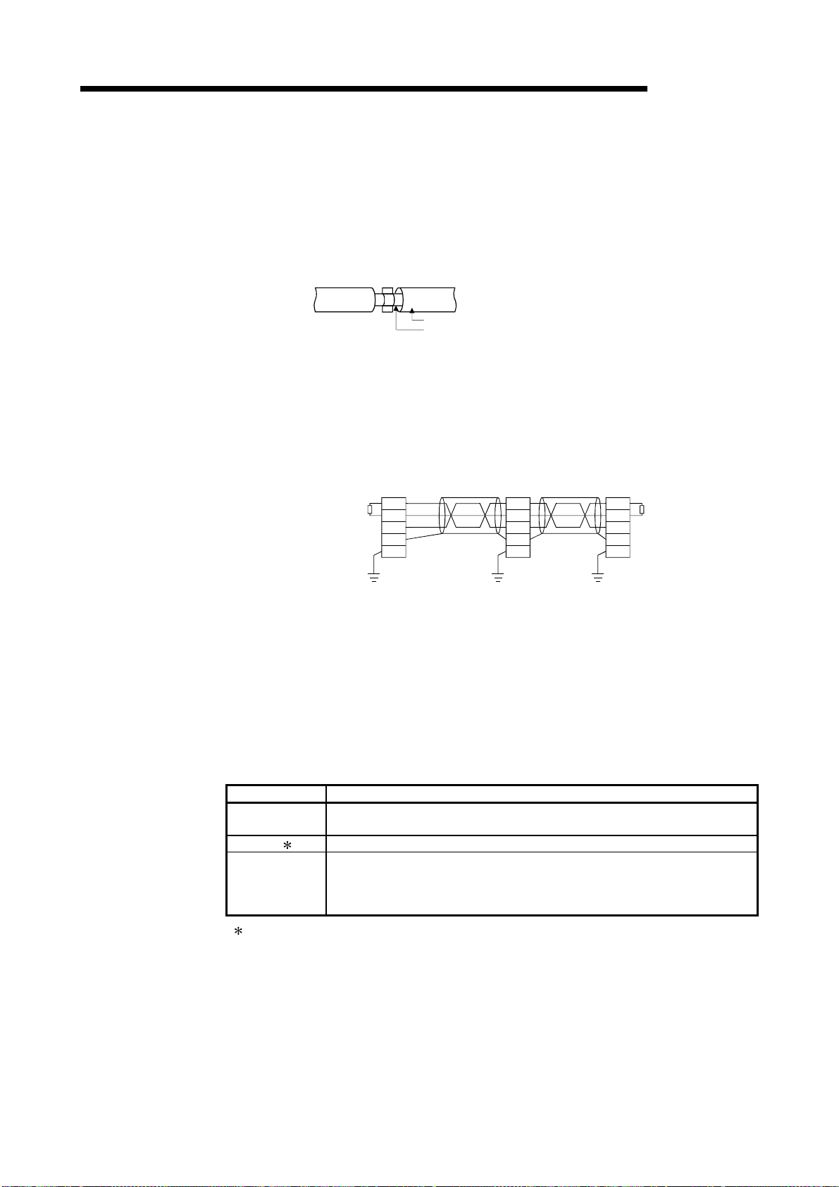
T
r
8 EMC AND LOW VOLTAGE DIRECTIVE
(c) CC-Link module
1) Be sure to ground the cable shield that is connected to the CC-Link
module close to the exit of control panel or to any of the CC-Link stations
within 30 cm (11.81 inch) from the module or stations.
The CC-Link dedicated cable is a shielded cable. As shown in the
illustration below, remove a portion of the outer covering and ground as
large a surface area of the exposed shield part as possible.
2) Always use the specified CC-Link dedicated cable.
3) Do not use a ferrite core for the CC-Link module or CC-Link stations.
4) The CC-Link module, the CC-Link stations and the FG line inside the
control panel should be connected at both the FG terminal and the SLD
terminal as shown in the diagram below.
[Simplified diagram]
CC-Link dedicated cable
Shield
MELSEC-Q
Local stat ion
DA
DB
DG
SLD
FG
Terminal resisto
erminal resistor
Master station
DA
(White)
DB
(Yellow)
DG
SLD
FG
(Blue)
CC-Link
dedicated
cable
Remote I/O station
DA
DB
DG
SLD
CC-Link
FG
dedicated
cable
(d) I/O signal lines
For the I/O signal lines, if extracted to the outside of the control panel, also
ensure to earth the shield section of these lines and cables in the same
manner as in item (1) above.
(2) Power supply modul e
The precautions required for each power supply module are described below.
Always observe the items noted as precautions.
Model Precautions
A1S61P
A1S62P
A1S63P ( 1) Use the C E marked 24VDC panel power equipment.
A1S61PEU
A1S62PEU
A1S61PN
A1S62PN
( 1) If sufficient filter circuitry is built into the 24VDC external power supply module, the noise
generated by A1S63P will be absorbed by that filter circuit, so a line filter may not be
required.
Filtering circuitry of version F or later of A1S63P is improved so that a external line filter is
not required.
Not usable
Always ground the LG and FG terminals after short-circuiting them.
8 - 7 8 - 7
Page 79

8 EMC AND LOW VOLTAGE DIRECTIVE
8.1.6 Others (1) Ferrite core
A ferrite core has the effect of reducing radiated noise in the 30MHz to 100MHz
band.
It is not required to fit ferrite cores to cables, but it is recommended to fit ferrite
cores if shield cables pulled out of the enclosure do not provide sufficient
shielding e ffects.
It should be noted that the ferrite cores should be fitted to the cables in the
position immediately before they are pulled out of the enclosure. If the fitting
position is improper, the ferrite will not produce any effect.
In the CC-Link system, however, ferrite cores cannot be fitted to cables.
(2) Noise filter (pow er supply line filter)
A noise filter is a component which has an effect on conducted noise.
It is not required to fit the noise filter to the power supply line, but fitting it can
further suppress noise.
(The noise filter has the effect of reducing conducted noise of 10 MHz or less.)
The precautions required when installing a noise filter are described below.
(a) Do not bundle the wires on the input side and output side of the noise filter.
When bundled, the output side noise will be induced into the input side wires
from which the noise was filtered.
(power supply side)
Input side
Input side
(power supply side)
MELSEC-Q
Introduction
Filter
Output side
(device side)
1) The noise will be included when the
input and output wires are bundled.
2) Separate and lay the input
Filter
and output wires.
(b) Earth the noise filter earthing terminal to the control cabinet with the shortest
wire possible (approx. 10 cm (3.94 inch)).
Reference
Noise Filter
Model Name
Manufacturer SCHAFFNER SCHAFFNER TDK
Rated current 3 A 6 A 3 A
Rated voltage 250 V
FN343-3/01 FN660-6/06 ZHC2203-11
8 - 8 8 - 8
Output side
(device side)
Page 80

8 EMC AND LOW VOLTAGE DIRECTIVE
8.2 Requirement to Conform to the Low Voltag e D i r ective
The Low Voltage Directive requires each device that operates with the power supply
ranging from 50 to 1000VAC and 75 to 1500VDC to satisfy the safety requirements.
In Sections 8.2.1 to 8.2.6, cautions on installation and wiring of the MELSEC-Q series
PLC to conform to the Low Voltage Directive are described.
We have put the maximum effort to develop this material based on the requirements
and standards of the regulation that we have collected. However, compatibility of the
devices which are fabricated according to the contents of this manual to the above
regulation is not guaranteed. Each manufacturer who fabricates such device should
make the final judgement about the application method of the Low Voltage Directive
and the product compatibility.
8.2.1 Standard applied for MELSEC-Q series PLC
The standard applied for MELSEC-Q series PLC is EN61010-1 safety of devices used
in measurement rooms, control rooms, or laboratories.
The MELSEC-Q series PLC modules which operate at the rated voltage of
50VAC/75VDC or above are also developed to conform to the above standard.
The modules which operate at the rated voltage of less than 50VAC/75VDC are out of
the Low Voltage Directive application range.
8.2.2 MELSEC-Q series PLC selection
MELSEC-Q
(1) Power supply modul e
There are dangerous voltages (voltages higher than 42.4V peak) inside the
power supply modules of the 100/200VAC rated I/O voltages. Therefore, the CE
marked models are enhanced in insulation internally between the primary and
secondary.
(2) I/O module
There are dangerous voltages (voltages higher than 42.4V peak) inside the I/O
modules of the 100/200VAC rated I/O voltages. Therefore, the CE marked
models are enhanced in insulation internally between the primary and secondary.
The I/O modules of 24VDC or less rating are out of the Low Voltage Directive
application range.
(3) CPU module, memory car d, base unit
Using 5VDC circuits inside, the above modules are out of the Low Voltage
Directive application range.
(4) Intelligent function modules (special function modules)
The intelligent function modules (special function modules) such as the analog,
network and positioning modules are 24VDC or less in rated voltage and are
therefore out of the Low Voltage Directive application range.
(5) Display dev i ce
Use the CE marked display device.
8 - 9 8 - 9
Page 81

8 EMC AND LOW VOLTAGE DIRECTIVE
8.2.3 Power supply
The insulation specification of the power supply module was designed assuming
installation category II. Be sure to use the installation category II power supply to the
PLC.
The installation category indicates the durability level against surge voltage generated by
a thunderbolt. Category I has the lowest durability; category IV has the highest durability.
MELSEC-Q
Category III Category II Category ICategory IV
Category II indicates a power supply whose voltage has been reduced by two or more
levels of isolating transformers from the public power distribution.
Figure 8.1: Installation Category
8.2.4 Control box
Because the PLC is an open device (a device designed to be stored within another
module), be sure to use it after storing in the control box.
(1) Electrical shock preventi on
In order to prevent persons who are not familiar with the electric facility such as
the operators from electric shocks, the control box must have the following
functions :
(a) The control box must be equipped with a lock so that only the personnel who
has studied about the electric facility and have enough knowledge can open it.
(b) The control box must have a structure which automatically stops the power
supply when the box is opened.
(2) Dustproof and waterproof features
The control box also has the dustproof and waterproof functions. Insufficient
dustproof and waterproof features lower the insulation withstand voltage, resulting
in insulation destruction. The insulation in our PLC is designed to cope with the
pollution level 2, so use in an environment with pollustion level 2 or below.
Pollution level 1 : An environment where the air is dry and conductive
dust does not exist.
Pollution level 2 : An environment where conductive dust
does not usually exist, but occasional temporary
conductivity occurs due to the accumulated dust. Generally,
this is the level for inside the control box equivalent to IP54
in a control room or on the floor of a typical factory.
Pollution level 3 : An environment where conductive dust exits and conductivity
may be generated due to the accumulated dust.
An environment for a typical factory floor.
Pollution level 4 : Continuous conductivity may occur due to rain, snow,
etc. An outdoor environment.
As shown above, the PLC can realize the pollution level 2 when stored in a
control box equivalent to IP54.
8 - 10 8 - 10
Page 82

8 EMC AND LOW VOLTAGE DIRECTIVE
MELSEC-Q
8.2.5 Grounding
8.2.6 External wiri ng
There are the following two different grounding terminals.
Use either grounding terminal in an earthed status.
Protective grounding
Functional grounding
: Maintains the safety of the PLC and improves the
noise resistance.
: Improves the noise resistance.
(1) 24VDC external power supply
For the MELSEC-Q series PLC 24VDC I/O modules and the intelligent function
modules (special function modules) which require external supply power, use a
model whose 24VDC circuit is intensively insulated from the hazardous voltage
circuit.
(2) External devic es
When a device with a hazardous voltage circuit is externally connected to the
PLC, use a model whose circuit section of the interface to the PLC is intensively
insulated from the hazardous voltage circuit.
(3) Intensive insulation
Intensive insulation refers to the insulation with the dielectric withstand voltage
shown in Table 8.1.
Table 8.1 : Intensive Insulation Withstand Voltage
(Installation Category II, source : IEC664)
Rated voltage of hazardous voltage area Surge withstand voltage (1.2/50 s)
150VAC or below 2500 V
300VAC or below 4000 V
8 - 11 8 - 11
Page 83

9 LOADING AND INSTALLATION
9 LOADING AND INSTALLATION
MELSEC-Q
9.1 General Safety Requirements
9
In order to increase the reliability of the system and exploit the maximum performance
of its functions, this section describes the methods and precautions for the mounting
and installation of the system.
!
DANGER
Install a safety circuit external to the PLC that keeps the entire
system safe even when there are problems with the external power
supply or the PLC module. Otherwise, trouble could result from
erroneous output or erroneous operation.
(1) Outside the PLC, construct mechanical damage preventing
interlock circuits such as emergency stop, protective circuits,
positioning upper and lower limits switches and interlocking
forward/reverse operations.
(2) When the PLC detects the following problems, it will stop
calculation and turn off all output in the case of (a).
In the case of (b), it will stop calculation and hold or turn off all
output according to the parameter setting.
Note that the A1S series module will turn off the output in either
of cases (a) and (b).
All outputs of AnS Series Module will be switched off in the
followin g ca se s:
(a) The power supply module has over current protection
equipment and over voltage protection equipment.
(b) The PLC CPUs self-diagnosis functions, such as the watch
dog timer error, detect problems.
In addition, all output will be turned on when there are problems
that the PLC CPU cannot detect, such as in the I/O controller.
(3) Output could be left on or off when there is trouble in the outputs
module relay or transistor. So build an external monitoring circuit
that will monitor any single outputs that could cause serious
trouble.
When overcurrent which exceeds the rating or caused by short-
circuited load flows in the output module for a long time, it may
cause smoke or fire. To prevent this, configure an external safety
circuit, such as fu se.
Build a circuit that turns on the external power supply when the PLC
main module power is turned on. If the external power supply is
turned on first, it could result in erroneous output or erroneous
operation.
When there are communication problems with the data link, refer to
the corresponding data link manual for the operating status of each
station. Not doing so could result in erroneous output or erroneous
operation.operating status of each station. Not doing so could result
in erroneous output or erroneous operation.
9 - 1 9 - 1
Page 84

9 LOADING AND INSTALLATION
MELSEC-Q
!
DANGER
!
CAUTION
When the PLC power supply is switched ON-OFF, correct control output may not be
performed temporarily due to differences in delay time and starting time between the
PLC power supply and the external power supply for the controlled object (especially
DC).
For example, if the external power supply for the controlled object is switched on in a
DC output module and then the PLC power supply is switched on, the DC output
module may provide false output instantaneously at power-on of the PLC. Therefore, it
is necessary to make up a circuit that can switch on the PLC power supply first.
Also, an abnormal operation may be performed if an external power supply fault or
PLC failure takes place.
To prevent any of these abnormal operations from leading to the abnormal operation of
the whole system and in a fail-safe viewpoint, areas which can result in machine
breakdown and accidents due to abnormal operations (e.g. emergency stop, protective
and interlock circuits) should be constructed outside the PLC.
The following page gives examples of system designing in the above viewpoint.
When connecting a peripheral device to the CPU module or connecting
a personal computer or the like to the special function module to
exercise control (data change) on the running PLC, configure up an
interlock circuit in the sequence program to ensure that the whole
system will always operate safely.
Also before exercising other control (program change, operating status
change (status control)) on the running PLC, read the manual carefully
and fully confirm safety.
Especially for the above control on the remote PLC from an external
device, an immediate action may not be taken for PLC trouble due to a
data communication fault.
In addition to configuring up the interlock circuit in the sequence
program, corrective and other actions to be taken as a system for the
occurrence of a data communication fault should be predetermined
between the external device and PLC CPU.
Do not bunch the control wires or communication cables with the main
circuit or power wires, or install them close to each other. They should
be installed 100 mm (3.94 inch) or more from each other.
Not doing so could result in noise that would cause erroneous
operation.
When controlling items like lamp load, heater or solenoid valve using an
output module, large current (approximately ten times greater than that
present in normal circumstances) may flow when the output is turned
OFF to ON. Take measures such as replacing the module with one
having sufficient rated current.
9
9 - 2 9 - 2
Page 85
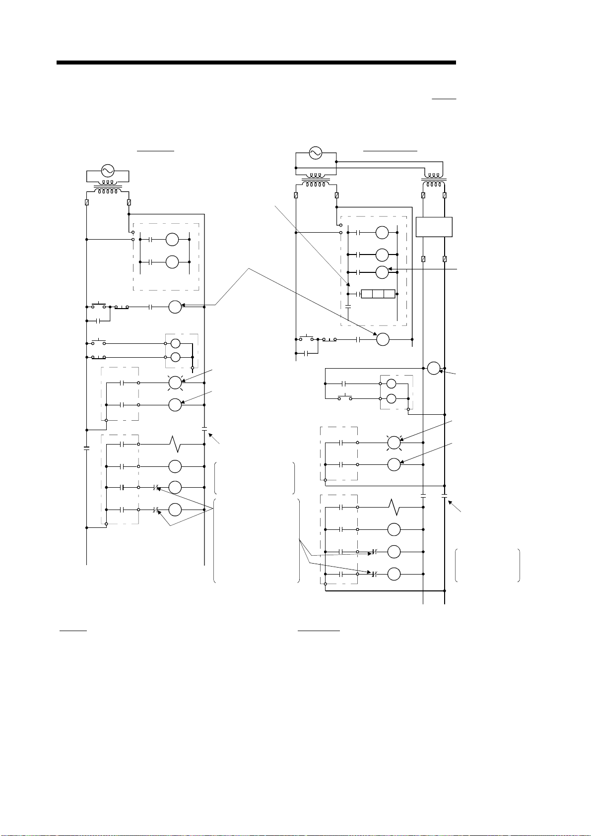
9 LOADING AND INSTALLATION
(1) System design circui t ex ampl e ( when not using ERR contact of
power supply module)
POWER
SUPPLY
TRANSFORMER
FUSE
CPU MODULE
SM52
START
SW
MC
OUTPUT MODULE
OUTPUT MODULE
MC
STOP
SW
Ym
Yn
Ym
SM403
Yn
PROGRAM
RA1
MC
INPUT MODULE
L
RA1
MC2
MC1
MC1
MC2
RUN/STOP circuit
interlocked with RA1
(run monitor relay)
Low battery alarm
(Lamp or buzzer)
RA1 switched ON by
SM403
(run monitor relay)
MC
Power to output equipment
switched OFF when the
STOP signal is given.
In the case of an
emergency stop or a
stop caused by a limit
switch.
Interlock circuits as
necessary.Provide
external interlock
circuits for conflicting
operations, such as
forward rotation and
reverse rotation, and
for parts that could
damage the machine
or cause accidents if
no interlock were used.
Input switched
when power
supply
established.
POWER
SUPPLY
TRANSFORMER
NO
START
SW
STOP
MC
SW
RA2
OUTPUT MODULE
Ym
Yn
OUTPUT MODULE
FOR AC/DCFOR AC
FUSE FUSE
CPU MODULE
SM52
Ym
SM403
Yn
XM
TM
TM
MC1 NO M10
M10
PROGRAM
RA1
MC
XM
L
RA1
MC2
MC1
MC1
MC2
DC
POWER
SUPPLY
(-) (+)
RA2
MC
MELSEC-Q
TRANSFORMER
FUSE
Set time for DC
power supply to
be established.
Voltage relay is
recommended
Low battery alarm
(Lamp or buzzer)
ON when run by
SM403
MC
Power to output
equipment
switched OFF
when the STOP
signal is given.
In the case of an
emergency stop
or a stop caused
by a limit switch.
The power-ON procedure is as follows:
For AC/DC
For AC
1) Switch power ON.
2) Set CPU to RUN.
3) Turn ON the start switch.
4) When the magnetic contactor (MC) comes on, the output
equipment is powered and may be driven by the program.
1) Switch power ON.
2) Set CPU to RUN.
3) When DC power is established, RA2 goes ON.
4) Timer (TM) times out after the DC pow er reaches 100%.
(The TM set value should be the period of time from w hen
RA2 goes ON to the establishment of 100% DC voltage.
Set this value to approximately 0.5 seconds.)
5) Turn ON the start switch.
6) When the magnetic contactor (MC) comes on, the output
equipment is powered and may be driven by the program.
(If a voltage relay is used at RA2, no timer (TM) is required
in the program.)
9 - 3 9 - 3
Page 86

9 LOADING AND INSTALLATION
(2) System design circui t ex ampl e ( when using ERR contact of power
supply module)
POWER
SUPPLY
FOR AC/DC
MELSEC-Q
Input switched
when power
supply
established.
RUN/STOP circuit
interlocked with
RA1
(run monitor relay)
TRANSFORMER
FUSE
NO
STRAT
SW
MC
RA1
STOP
SW
RA2
OUTPUT MODULE
Ym
Yn
CPU MODULE
SM52
Ym
SM403
Yn
XM
TM
TM
MC1 NO M10
M10
PROGRAM
RA3
MC
L
RA1
FUSE
XM
DC
POWER
SUPPLY
(+)
(-)
RA2
TRANSFORMER
FUSE
Set time for DC
power supply to
be established.
Voltage relay is
recommended
Low battery alarm
(Lamp or buzzer)
MC
MC
OFF at stop error
from ERR
Power to output equipment
switched OFF when ERR
contact turns OFF.
In the case of an
emergency stop or a stop
caused by a limit switch.
POWER SUPPLY
MODULE
Interlock circuits asnecessary.
Provide external interlock
circuits for conflicting operations,
such as forward rotation and
reverse rotation, and for parts
that could damage the machine
or cause accidents if no interlock
were used.
ERR
OUTPUT MODULE
MC2
MC1
RA3
MC1
MC2
The power-ON procedure is as follows:
For AC/DC
1) Switch power ON.
2) Set CPU to RUN.
3) When DC power is established, RA2 goes ON.
4) Timer (TM) times out after the DC pow er reaches 100%. (The TM set value should be the period of time
from when RA2 goes ON to the establishment of 100% DC voltage. Set this value to approximately 0.5s.)
5) Turn ON the start switch.
6) When the magnetic contactor (MC) comes on, the output equipment is powered and may be driven by the
program. (If a voltage relay is used at RA2, no timer (TM) is required in the program.)
9 - 4 9 - 4
Page 87

9 LOADING AND INSTALLATION
(3) Fail-safe measures against failure of the PLC
Failure of a CPU module or memory can be detected by the self-diagnosis
function. However, failure of I/O control area may not be detected by the CPU
module.
In such cases, all I/O points turn ON or OFF depending on a condition of
problem, and normal operating conditions and operating safety cannot
sometimes be maintained.
Though Mitsubishi PLCs are manufactured under strict quality control, they may
cause failure or abnormal operations due to unspecific reasons. To prevent the
abnormal operation of the whole system, machine breakdown, and accidents,
fail-safe circuitry against failure of the PLC must be constructed outside the PLC.
Examples of a system and its fail-safe circuitry are described below:
<System example>
CPU module
Power supply
module
Input 16 points
Input 16 points
MELSEC-Q
Vacant
Power supply
Input 16 points
Input 16 points
Output 16 poi nts
module
Output 16 poi nts
Output 16 poi nts
Output 16 poi nts
Y80 to Y8F
Output 16 poi nts
Output module for
fail-safe purpose 1
1: The output module for fail-safe purpose should be loaded in the last slot of
the system. (Y80 to Y8F in the above system.)
<Fail-safe circuit example>
Internal program
SM412
Y80
Y80
0.5s0.5s
CPU module
Y80
Y81
Y8F
24V
0V
Output module
2
ON delay timer
OFF delay timer
External load
L
L
T1
T2
T2T1
-
1s
1s
MC
+
24V DC
MC
2: Y80 repeats turning ON and then OFF at 0.5s intervals.
Use a no-contact output module (transistor in the example shown above).
9 - 5 9 - 5
Page 88

9 LOADING AND INSTALLATION
9.2 Calculating Heat Generation by PLC
The ambient temperature inside the board storing the PLC must be suppressed to a
PLC usable ambient temperature of 55°C.
For the design of radiation from the storing board, it is necessary to know the average
power consumption (heating value) of the devices and instruments stored in the board.
Here the method of obtaining the average power consumption of the PLC system is
described.
From the power consumption, calculate a rise in ambient temperature inside the board.
How to calculate average power consumption
The power consuming parts of the PLC are roughly classified into six
blocks as shown below.
(1) Power consumption of power suppl y module
The power conversion efficiency of the power supply module is approx. 70 %,
i.e., 30 % of the output power is consumed by heating. As a result, 3/7 of the
output power becomes the power consumption.
Therefore the calculation formula is as follows.
3
Wpw = (I
5V
I
: Current consumption of logic 5 VDC circuit of each module
7
5
v 5) (W)
(2) Power consumption of a total of 5 VDC logic secti on of each
module
The power consumption of the 5 VDC output circuit section of the power supply
module is the power consumption of each module (including the current
consumption of the base unit).
5V
W
= I5V 5 (W)
A total of 24 VDC average power consumption of the output module
(3)
(power consumption for simultaneous ON points)
The average power of the external 24 VDC power is the total power consumption
of each module.
24V
= I
24V
24 (W)
W
(4) Average pow er consumption due to voltage drop in the output
section of the output module
(Power consumption for simultaneous ON points)
OUT
W
OUT
I
Vdrop : Voltage drop in each output module (V)
OUT
= I
Vdrop Number of outputs Simultaneous ON rate (W)
: Output current (Current in actual use) (A)
(5) Average pow er consumpti on of the input section of the input
module(Power consumption for simultaneous ON poi nts)
IN
= IIN E Number of input points Simultaneous ON rate (W)
W
IN
I
E : Input voltage (Voltage in actual use) (V)
: Input current (Effective value for AC) (A)
MELSEC-Q
9 - 6 9 - 6
Page 89

9 LOADING AND INSTALLATION
(6) Power consumption of the power supply section of the intelligent
function module
S
= I5V 5 + I
W
The total of the power consumption values calculated for each block becomes
the power consumption of the overall sequencer system.
W = W
From this overall power consumption (W), calculate the heating value and a rise
in ambient temperature inside the board.
The outline of the calculation formula for a rise in ambient temperature inside the
board is shown below.
T =
POINT
When a rise in ambient temperature inside the board exceeds the specified limit, it
is recommended that you install a heat exchanger in the board to lower the ambient
temperature inside the board.
If a normal ventilating fan is used, dust will be sucked into the PLC together with
the external air, and it may affect the performance of the PLC.
PW
+ W5V + W
W
(°C)
UA
W : Power consumption of overall sequencer system (value obtained above)
A : Surface area inside the board
When the ambient temperature inside the board is uniformed by a fan
U :
When air inside the board is not circulated..............................................4
(7) Example of calculation of average power consumption
(a) System configuration
24V
24 + I
24V
+ W
100V
100 (W)
OUT
+ WIN + WS (W)
MELSEC-Q
.........6
Q35B
QX40
QX40
Q61P-A1
Q02HCPU
QY10
QJ71LP21-25
Vacant
(b) 5 VDC current consumption of each module
Q02HCPU : 0.64 (A)
QX40 : 0.05 (A)
QY10 : 0.43 (A)
QJ71LP21-25 : 0.55 (A)
Q35B : 0.074 (A)
(c) Power consumption of power supply module
PW
W
= 3/7 (0.64+0.05+0.05+0.43+0.55+0.074) 5) = 3.84 (W)
(d) Power consumption of a total of 5 VDC logic section of each module
5V
W
= (0.64+0.05+0.05+0.43+0.55+0.074) 5) = 8.97 (W)
(e) A total of 24 VDC average power consumption of the output module
24V
W
= 0 (W)
9 - 7 9 - 7
Page 90

9 LOADING AND INSTALLATION
(f) Average power consumption due to voltage drop in the output section of the
output module
OUT
W
= 0 (W)
(g) Average power consumption of the input section of the input module
IN
W
= 0.004 24 32 1 = 3.07 (W)
(h) Power consumption of the power supply section of the intelligent function
module
S
W
= 0 (W)
(i) Power consumption of overall system.
W = 3.84 + 8.97 + 0 + 0 + 3.07 + 0 = 15.88 (W)
MELSEC-Q
9 - 8 9 - 8
Page 91

9 LOADING AND INSTALLATION
9.3 Module Installation
9.3.1 Precaution on installation
!
CAUTION
This section gives instructions for handling the CPU, I/O, intelligent function and power
supply modules, base units and so on.
(1) Module enclosure, terminal block connectors and pin connectors are made of resin;
do not drop them or subject them to strong impact.
(2) Do not remove modules' printed circuit boards from the enclosure in order to avoid
changes in operation.
(3) Tighten the module fixing screws and terminal block screws within the tightening
torque range specified below.
Module fixing screw (M3 12 screw) 36 to 48 N • cm
I/O module terminal block screw (M3 screw) 42 to 58 N • cm
I/O module terminal block fixing screw (M3.5 screw) 66 to 89 N • cm
Power supply module terminal screw (M3.5 screw) 66 to 89 N • cm
(4) Be sure to install the power supply module in the Q3
Even if the power supply module is not installed, when the I/O modules and
intelligent function module installed on the base units are of light load type, the
modules may be operated. In this case, because a voltage becomes unstable, we
cannot guarantee the operation.
(5) When an extension cable is used, do not bind the cable together with the main
circuit (high voltage, heavy current) line or lay them close to each other.
Use the PLC in an environment that meets the general specifications
Hold down the module loading lever at the module bottom, and
When installing more cables, be sure that the base unit and the module
Securely load the memory card by pushing it into the memory card
Completely turn off the external power supply before loading or
Do not directly touch the module's conductive parts or electronic
MELSEC-Q
contained in this manual. Using this PLC in an environment outside the
range of the general specifications could result in electric shock, fire,
erroneous operation, and damage to or deterioration of the product.
securely insert the module fixing latch into the fixing hole in the base
unit. Incorrect loading of the module can cause a malfunction, failure or
drop.When using the PLC in the environment of much vibration, tighten
the module with a screw.
Tighten the screw in the specified torque range. Undertightening can
cause a drop, short circuit or malfunction. Overtightening can cause a
drop, short circuit or malfunction due to damage to the screw or
module.
connectors are installed correctly. After installation, check them for
looseness. Poor connections could cause an input or output failure.
loading slot. Check for insecure loading after loading the memory card.
Not doing so can cause a malfunction due to a contact fault.
unloading the module. Not doing so could result in electric shock or
damage to the product.
components. Touching the conductive parts could cause an operation
failure or give damage to the module.
Location of Screw Tightening Torque Range
B, Q6 B and QA1S6 B.
9 - 9 9 - 9
Page 92

9 LOADING AND INSTALLATION
(6) Install the main base unit (by screwing) in the following procedure.
1) Fit the two base unit top mounting screws into the enclosure.
MELSEC-Q
2) Place the right-hand side notch of the base unit onto the right-hand side screw.
3) Place the left-hand side pear-shaped hole onto the left-hand side screw.
4) Fit the mounting screws into the mounting screw holes in the base unit bottom
and retighten the four mounting screws.
Note1 : Install the main base unit to a panel, with no module loaded in the right-end
slot.
Remove the base unit after unloading the module from the right-end slot.
Note2 : The mounting screws that included with the slim type main base unit differ
from those included with other types of the base unit. When ordering
mounting screws for the slim type main base unit, specify "cross recessed
head bind screw M4 x 12 (black)."
Panel
Panel
Panel
9 - 10 9 - 10
Page 93

g
ess
9 LOADING AND INSTALLATION
(7) Note the following points when mounting a DIN rail.
Mounting a DIN rail needs special adaptors (optional), which are to be userprepared.
(a) Applicable adaptor types
For Q38B, Q312B, Q68B, Q612B : Q6DIN1
For Q35B, Q65B : Q6DIN2
For Q33B, Q52B, Q55B, Q63B, Q32SB, Q33SB, Q35SB : Q6DIN3
(b) Adaptor installation method
The way to install the adaptors for mounting a DIN rail to the base unit is given
below.
Base unit rear
MELSEC-Q
Insert the adaptor (large) into the grooves
of the base unit from below.
Place the hook of the adaptor
(small) in the lower hole.
Push the bottom of the adaptor (large) far
h until it "clicks".
enou
Push the top of the adaptor
(small) far enough until it
"clicks".
(c) Applicable DIN rail types (JIS C 2812)
TH35-7.5Fe
TH35-7.5Al
TH35-15Fe
(d) DIN rail mounting screw intervals
When using a TH35-7.5Fe or TH35-7.5Al DIN rail, rail mounting screws should
be tightened at a pitch of 200 mm (7.88 inch) or less in order to ensure that the
rail has sufficient strength.
DIN rail
DIN rail mounting screw
35mm
(1.38 inch)
PPP
P=200mm (7.88 inch) or l
9 - 11 9 - 11
Page 94

9 LOADING AND INSTALLATION
9.3.2 Instructions for mounting the base unit
When mounting the PLC to an enclosure or similar, fully consider its operability,
maintainability and environmental resistance.
(1) Module mounting position
For enhanced ventilation and ease of module replacement, leave the following
clearances between the module top/bottom and structure/parts.
(a) In case of main base unit or extension base unit
Indicates the panel top, wiring
duct or any part position.
30mm
(1.18 inch)
or more 1
PLC
MELSEC-Q
DoorPanel
5mm (0.20 inch) or more 2
30mm
(1.18 inch)
or more
5mm (0.20 inch) or more
20mm
(0.79 inch)
or more 3
1 : For wiring duct with 50mm (1.97 inch) or less height.
40mm (1.58 inch) or more for other cases.
2 : 20mm (0.79 inch) or more when the adjacent module is not removed and the
extension cable is connected.
3 : 80mm (3.15 inch) or more for the connector type.
9 - 12 9 - 12
Page 95

9 LOADING AND INSTALLATION
(b) In case of slim type main base unit
Indicates the panel top, wiring
duct or any part position.
30 mm
(1.18 inch)
or more 1
PLC
MELSEC-Q
Door
3
17 mm (0.67 inch) or more 2
30 mm
(1.18 inch)
or more
5 mm (0.20 inch) or more
Panel
20 mm
(0.79 inch)
or more
1 : For wiring duct with 50 (1.97 inch) mm or less height.
40 mm (1.58 inch) or more for other cases.
2 : The cable of the power supply module of the slim type main base unit protrudes
out of the left end of the module. Install the module while reserving 17 mm (0.67
inch) or more wiring space. If the cable sheath is susceptible to damage caused
by a structural object or part on the left side of the module, take a protective
measure with spiral tube or a similar insulator.
3 : 80 mm (3.15 inch) mm or more for the connector type.
9 - 13 9 - 13
Page 96

9 LOADING AND INSTALLATION
(2) Module mounting orientati on
(a) Since the PLC generates heat, it should be mounted on a well ventilated
location in the orientation shown below.
(b) Do not mount it in either of the orientations shown below.
MELSEC-Q
Vertical Flat
(3) Installation surface
Mount the base unit on a flat surface. If the mounting surface is not even, this
may strain the printed circuit boards and cause malfunctions.
(4) Installation of unit in an area where the other devices are installed
Avoid mounting base unit in proximity to vibration sources such as large
magnetic contractors and no-fuse circuit breakers; mount these on a separate
panel or at a distance.
(5) Distances from the other devices
In order to avoid the effects of radiated noise and heat, provide the clearances
indicated below between the PLC and devices that generate noise or heat
(contactors and relays).
• Required clearance in front of PLC : at least 100 mm (3.94 inch)
• Required clearance on the right and left of PLC : at least 50 mm (1.97 inch)
At least 50mm
(1.97 inch)
At least 100mm
(3.94 inch)
Conta ctor, r elay, etc.
At least 50mm
(1.97 inch)
9 - 14 9 - 14
Page 97

9 LOADING AND INSTALLATION
9.3.3 Installation and removal of module
This section explains how to install and remove a power supply, CPU, I/O, intelligent
function or another module to and from the base unit.
(1) Installation and removal of the module from Q3 B, ,Q5 B and
Q6 B
The installation and removal of the module from Q3 B/Q6 B base unit are
described below.
(a) Installation of module on Q3
B, Q5 B and Q6 B
MELSEC-Q
Base unit
Insert the module fixing latch
into the module fixing hole of
the base unit.
Push the module in the
direction of arrow to load it
into the base unit.
Make sure that the module
is inserted in the base unit
securely.
Completion
Module
Module loading
lever
Module
fixing latch
Module fixing hole
Module
connector
POINTS
Base unit
Module fixing
hole
Module fixing latch
(1) Always insert the module fixing latch of the module into the module fixing hole.
Forcing the hook into the hole will damage the module connector and module.
(2) When using the PLC in a place where there is large vibration or impact, screw
the CPU module to the base unit.
Module fixing screw : M3
12 (user-prepared)
9 - 15 9 - 15
Page 98

9 LOADING AND INSTALLATION
(b) Removal from Q3
Hold the module with both
hands, and push the unit fixing
hook on the top of the module
with a finger until it stops.
While pushing the unit fixing
hook, and using the bottom of
the module as a support, pull
the module toward you.
Lift the module upwards and
remove the module fixing
latch from the module
fixing hole.
B, Q5 B and Q6 B
Base unit
Module
connector
Module fixing hole
Module
MELSEC-Q
Completion
POINT
When the module fixing screw is used, always remove the module by removing the
module fixing screw and then taking the module fixing latch off the module fixing
hole of the base unit.
Do not try to remove the module forcibly since this may damage the module.
9 - 16 9 - 16
Page 99

9 LOADING AND INSTALLATION
(2) Installation and removal of the module from QA1S6 B
The procedure for installing and removing the module from the QA1S6 B base
unit is described below.
(a) Installation of module on QA1S6
Insert the module fixing
projections into the module
fixing hole in the base unit.
Base unit
Module
connector
B
MELSEC-Q
Module
Install the module onto the
base unit by pushing the
top forward.
Make sure that the module is
firmly inserted in the base
unit.
Then, secure it with
the module mounting screw.
Completion
Module
fixing hole
Base unit
Module fixing
projections
Module mounting screw
Module
POINT
Make sure to install the module, with the module fixing projection inserted into the
module fixing hole, using the module fixing screws.
Do not try to forcibly install the module without inserting the projection into the hole,
since this may damage the module connector and the module.
9 - 17 9 - 17
Page 100

9 LOADING AND INSTALLATION
(b) Removal from QA1S6
Remove the module mounting
screw, and using the bottom
of the module as a support,
pull the top of the module
toward you.
Lift the module upwards and
remove the module fixing
projections from the module
fixing hole.
Completion
Base unit
Module
connector
Module
fixing hole
B
Module
MELSEC-Q
POINT
To remove the module, make sure to remove the module fixing screws, and then
disengage the module fixing projection from the module fixing hole.
Do not try to remove the module forcibly since this may damage the module fixing
projection.
9 - 18 9 - 18
 Loading...