

Page 1

QCPU User's Manual
(Hardware Design, Maintenance and Inspection)
-Q00(J)CPU -Q26UD(E)HCPU
-Q01CPU -Q26UDVCPU
-Q02(H)CPU -Q50UDEHCPU
-Q06HCPU -Q100UDEHCPU
-Q12HCPU
-Q25HCPU
-Q02PHCPU
-Q06PHCPU
-Q12PHCPU
-Q25PHCPU
-Q12PRHCPU
-Q25PRHCPU
-Q00U(J)CPU
-Q01UCPU
-Q02UCPU
-Q03UD(E)CPU
-Q03UDVCPU
-Q04UD(E)HCPU
-Q04UDVCPU
-Q06UD(E)HCPU
-Q06UDVCPU
-Q10UD(E)HCPU
-Q13UD(E)HCPU
-Q13UDVCPU
-Q20UD(E)HCPU
Page 2

Page 3
SAFETY PRECAUTIONS
WARNING
CAUTION
Indicates that incorrect handling may cause hazardous conditions,
resulting in death or severe injury.
Indicates that incorrect handling may cause hazardous conditions,
resulting in minor or moderate injury or property damage.
Overcurrent or overvoltage protection of
the power supply module is activated.
The CPU module detects an error such as a
watchdog timer error by the self-diagnostic function.
All outputs are turned off All outputs are turned off
All outputs are turned off
All outputs are held or turned off
according to the parameter setting.
Q series module AnS/A series module
(Read these precautions before using this product.)
Before using this product, please read this manual and the relevant manuals carefully and pay full attention
to safety to handle the product correctly.
In this manual, the safety precautions are classified into two levels: " WARNING" and " CAUTION".
Under some circumstances, failure to observe the precautions given under " CAUTION" may lead to
serious consequences.
Observe the precautions of both levels because they are important for personal and system safety.
Make sure that the end users read this manual and then keep the manual in a safe place for future
reference.
[Design Precautions]
WARNING
● Configure safety circuits external to the programmable controller to ensure that the entire system
operates safely even when a fault occurs in the external power supply or the programmable controller.
Failure to do so may result in an accident due to an incorrect output or malfunction.
(1) Configure external safety circuits, such as an emergency stop circuit, protection circuit, and
protective interlock circuit for forward/reverse operation or upper/lower limit positioning.
(2) The programmable controller stops its operation upon detection of the following status, and the
output status of the system will be as shown below.
All outputs may turn on when an error occurs in the part, such as I/O control part, where the CPU
module cannot detect any error. To ensure safety operation in such a case, provide a safety
mechanism or a fail-safe circuit external to the programmable controller. For a fail-safe circuit
example, refer to Page 670, Appendix 9.
(3) Outputs may remain on or off due to a failure of an output module relay or transistor. Configure an
external circuit for monitoring output signals that could cause a serious accident.
1
Page 4
[Design Precautions]
WARNING
● In an output module, when a load current exceeding the rated current or an overcurrent caused by a
load short-circuit flows for a long time, it may cause smoke and fire. To prevent this, configure an
external safety circuit, such as a fuse.
● Configure a circuit so that the programmable controller is turned on first and then the external power
supply. If the external power supply is turned on first, an accident may occur due to an incorrect output
or malfunction.
● For the operating status of each station after a communication failure, refer to relevant manuals for the
network. Incorrect output or malfunction due to a communication failure may result in an accident.
● When changing data of the running programmable controller from a peripheral connected to the CPU
module or from a personal computer connected to an intelligent function module, configure an
interlock circuit in the sequence program to ensure that the entire system will always operate safely.
For program modification and operating status change, read relevant manuals carefully and ensure
the safety before operation. Especially, in the case of a control from an external device to a remote
programmable controller, immediate action cannot be taken for a problem on the programmable
controller due to a communication failure. To prevent this, configure an interlock circuit in the
sequence program, and determine corrective actions to be taken between the external device and
CPU module in case of a communication failure.
[Design Precautions]
CAUTION
● Do not install the control lines or communication cables together with the main circuit lines or power
cables. Keep a distance of 100mm or more between them. Failure to do so may result in malfunction
due to noise.
● When a device such as a lamp, heater, or solenoid valve is controlled through an output module, a
large current (approximately ten times greater than normal) may flow when the output is turned from
off to on. Take measures such as replacing the module with one having a sufficient current rating.
● After the CPU module is powered on or is reset, the time taken to enter the RUN status varies
depending on the system configuration, parameter settings, and/or program size. Design circuits so
that the entire system will always operate safely, regardless of the time.
2
Page 5
[Installation Precautions]
CAUTION
● Use the programmable controller in an environment that meets the general specifications in this
manual. Failure to do so may result in electric shock, fire, malfunction, or damage to or deterioration of
the product.
● To mount the module, while pressing the module mounting lever in the lower part of the module, fully
insert the module fixing projection(s) into the hole(s) in the base unit and press the module until it
snaps into place. Incorrect mounting may cause malfunction, failure, or drop of the module. When
using the programmable controller in an environment of frequent vibrations, fix the module with a
screw. Tighten the screw within the specified torque range. Undertightening can cause drop of the
screw, short circuit or malfunction. Overtightening can damage the screw and/or module, resulting in
drop, short circuit, or malfunction.
When using an extension cable, connect it to the extension cable connector of the base unit securely.
●
Check the connection for looseness. Poor contact may cause incorrect input or output.
● When using a memory card, fully insert it into the memory card slot. Check that it is inserted
completely. Poor contact may cause malfunction.
● When using an SD memory card, fully insert it into the SD memory card slot. Check that it is inserted
completely. Poor contact may cause malfunction.
● When using an extended SRAM cassette, fully insert it into the connector for cassette connection of
the CPU module. Close the cassette cover after inserting to avoid looseness of the extended SRAM
cassette. Poor contact may cause malfunction.
● Shut off the external power supply (all phases) used in the system before mounting or removing the
module. Failure to do so may result in damage to the product. A module can be replaced online (while
power is on) on any MELSECNET/H remote I/O station or in the system where a CPU module
supporting the online module change function is used. Note that there are restrictions on the modules
that can be replaced online, and each module has its predetermined replacement procedure. For
details, refer to this manual and in the manual for the corresponding module.
● Do not directly touch any conductive part of the module, the memory card, the SD memory card, or
the extended SRAM cassette. Doing so can cause malfunction or failure of the module.
● When using a Motion CPU module and modules designed for motion control, check that the
combinations of these modules are correct before applying power. The modules may be damaged if
the combination is incorrect. For details, refer to the user's manual for the Motion CPU module.
[Wiring Precautions]
WARNING
● Shut off the external power supply (all phases) used in the system before wiring. Failure to do so may
result in electric shock or damage to the product.
● After installation and wiring, attach the included terminal cover to the module before turning it on for
operation. Failure to do so may result in electric shock.
3
Page 6

[Wiring Precautions]
CAUTION
● Individually ground the FG and LG terminals of the programmable controller with a ground resistance
of 100 or less. Failure to do so may result in electric shock or malfunction.
● Use applicable solderless terminals and tighten them within the specified torque range. If any spade
solderless terminal is used, it may be disconnected when the terminal screw comes loose, resulting in
failure.
● Check the rated voltage and terminal layout before wiring to the module, and connect the cables
correctly. Connecting a power supply with a different voltage rating or incorrect wiring may cause a fire
or failure.
● Connectors for external connection must be crimped or pressed with the tool specified by the
manufacturer, or must be correctly soldered. Incomplete connections could result in short circuit, fire,
or malfunction.
● Install the connector to the module securely. Poor contact may cause malfunction.
● Do not install the control lines or communication cables together with the main circuit lines or power
cables. Keep a distance of 100mm or more between them. Failure to do so may result in malfunction
due to noise.
● Place the wires or cables in a duct or clamp them. If not, dangling cable may swing or inadvertently be
pulled, resulting in damage to the module or cables or malfunction due to poor connection.
● Connect the cable correctly after confirming the interface type to be connected. Connecting to the
wrong interface or incorrect wiring can result in a failure of the module or external devices.
● Tighten the terminal screw within the specified torque range. Undertightening can cause short circuit,
fire, or malfunction. Overtightening can damage the screw and/or module, resulting in drop, short
circuit, or malfunction.
● Prevent foreign matter such as dust or wire chips from entering the module. Such foreign matter can
cause a fire, failure, or malfunction.
● A protective film is attached to the top of the module to prevent foreign matter, such as wire chips,
from entering the module during wiring. Do not remove the film during wiring. Remove it for heat
dissipation before system operation.
● Do not pull the cable section of a cable for disconnection. When disconnecting a cable with a
connector, hold the connector and pull it. When disconnecting a cable on a terminal block, loosen the
terminal screw before disconnection. Pulling the connected cable can result in malfunction or damage
of the module or the cable.
● Mitsubishi Electric programmable controllers must be installed in control panels. Connect the main
power supply to the power supply module in the control panel through a relay terminal block. Wiring
and replacement of a power supply module must be performed by maintenance personnel who is
familiar with protection against electric shock. (For wiring methods, refer to Page 103, Section 4.8.1.)
4
Page 7
[Startup and Maintenance Precautions]
WARNING
● Do not touch any terminal while power is on. Doing so will cause electric shock.
● Correctly connect the battery connector. Do not charge, disassemble, heat, short-circuit, solder, or
throw the battery into the fire, or apply liquid or a strong shock to the battery. Doing so will cause the
battery to produce heat, explode, ignite, or liquid spill, resulting in injury and fire.
● Shut off the external power supply (all phases) used in the system before cleaning the module or
retightening the terminal screws, connector screws, or module fixing screws. Failure to do so may
result in electric shock or cause the module to fail or malfunction.
[Startup and Maintenance Precautions]
CAUTION
● Before performing online operations (especially, program modification, forced output, and operation
status change) for the running CPU module from the peripheral connected, read relevant manuals
carefully and ensure the safety. Improper operation may damage machines or cause accidents.
● Do not disassemble or modify the modules. Doing so may cause failure, malfunction, injury, or a fire.
● Use any radio communication device such as a cellular phone or PHS (Personal Handy-phone
System) more than 25cm away in all directions from the programmable controller. Failure to do so
may cause malfunction.
● Shut off the external power supply (all phases) used in the system before mounting or removing the
module. Failure to do so may cause the module to fail or malfunction. A module can be replaced
online (while power is on) on any MELSECNET/H remote I/O station or in the system where a CPU
module supporting the online module change function is used. Note that there are restrictions on the
modules that can be replaced online, and each module has its predetermined replacement procedure.
For details, refer to this manual and the manual for the corresponding module.
● After the first use of the product, do not mount/remove the module to/from the base unit, the extended
SRAM cassette to/from the CPU module, or the terminal block to/from the module more than 50 times
(IEC 61131-2 compliant) respectively. Exceeding the limit of 50 times may cause malfunction.
● After the first use of the product, do not mount/remove the SD memory card more than 500 times.
Exceeding the limit of 500 times may cause malfunction.
● Do not drop or apply shock to the battery to be installed in the module. Doing so may damage the
battery, causing the battery fluid to leak inside the battery. If the battery is dropped or any shock is
applied to it, dispose of it without using.
● Before handling the module, touch a grounded metal object to discharge the static electricity from the
human body. Failure to do so may cause the module to fail or malfunction.
5
Page 8
[Disposal Precautions]
CAUTION
● When disposing of this product, treat it as industrial waste. When disposing of batteries, separate
them from other wastes according to the local regulations. (For details of the Battery Directive in EU
countries, refer to Page 678, Appendix 12.)
[Transportation Precautions]
CAUTION
● When transporting lithium batteries, follow the transportation regulations. (For details of the regulated
models, refer to Page 677, Appendix 11.)
6
Page 9

CONDITIONS OF USE FOR THE PRODUCT
(1) Mitsubishi programmable controller ("the PRODUCT") shall be used in conditions;
i) where any problem, fault or failure occurring in the PRODUCT, if any, shall not lead to any major
or serious accident; and
ii) where the backup and fail-safe function are systematically or automatically provided outside of
the PRODUCT for the case of any problem, fault or failure occurring in the PRODUCT.
(2) The PRODUCT has been designed and manufactured for the purpose of being used in general
industries.
MITSUBISHI SHALL HAVE NO RESPONSIBILITY OR LIABILITY (INCLUDING, BUT NOT
LIMITED TO ANY AND ALL RESPONSIBILITY OR LIABILITY BASED ON CONTRACT,
WARRANTY, TORT, PRODUCT LIABILITY) FOR ANY INJURY OR DEATH TO PERSONS OR
LOSS OR DAMAGE TO PROPERTY CAUSED BY the PRODUCT THAT ARE OPERATED OR
USED IN APPLICATION NOT INTENDED OR EXCLUDED BY INSTRUCTIONS, PRECAUTIONS,
OR WARNING CONTAINED IN MITSUBISHI'S USER, INSTRUCTION AND/OR SAFETY
MANUALS, TECHNICAL BULLETINS AND GUIDELINES FOR the PRODUCT.
("Prohibited Application")
Prohibited Applications include, but not limited to, the use of the PRODUCT in;
• Nuclear Power Plants and any other power plants operated by Power companies, and/or any
other cases in which the public could be affected if any problem or fault occurs in the PRODUCT.
• Railway companies or Public service purposes, and/or any other cases in which establishment of
a special quality assurance system is required by the Purchaser or End User.
• Aircraft or Aerospace, Medical applications, Train equipment, transport equipment such as
Elevator and Escalator, Incineration and Fuel devices, Vehicles, Manned transportation,
Equipment for Recreation and Amusement, and Safety devices, handling of Nuclear or
Hazardous Materials or Chemicals, Mining and Drilling, and/or other applications where there is a
significant risk of injury to the public or property.
Notwithstanding the above, restrictions Mitsubishi may in its sole discretion, authorize use of the
PRODUCT in one or more of the Prohibited Applications, provided that the usage of the PRODUCT
is limited only for the specific applications agreed to by Mitsubishi and provided further that no
special quality assurance or fail-safe, redundant or other safety features which exceed the general
specifications of the PRODUCTs are required. For details, please contact the Mitsubishi
representative in your region.
7
Page 10
INTRODUCTION
Remark
This manual provides hardware specifications, maintenance and inspection of the system, and troubleshooting of the CPU
modules, power supply modules, and base units required for operating the Q series programmable controllers.
Before using this product, please read this manual and the relevant manuals carefully and develop familiarity with the
functions and performance of the Q series programmable controller to handle the product correctly.
When applying the program examples introduced in this manual to the actual system, ensure the applicability and confirm that
it will not cause system control problems.
Relevant CPU module
CPU module Model
Basic model QCPU Q00(J)CPU, Q01CPU
High Performance model QCPU Q02(H)CPU, Q06HCPU, Q12HCPU, Q25HCPU
Process CPU Q02PHCPU, Q06PHCPU, Q12PHCPU, Q25PHCPU
Redundant CPU Q12PRHCPU, Q25PRHCPU
Q00U(J)CPU, Q01UCPU, Q02UCPU, Q03UD(E)CPU, Q03UDVCPU,
Universal model QCPU
Q04UD(E)HCPU, Q04UDVCPU, Q06UD(E)HCPU, Q06UDVCPU,
Q10UD(E)HCPU, Q13UD(E)HCPU, Q13UDVCPU, Q20UD(E)HCPU,
Q26UD(E)HCPU, Q26UDVCPU, Q50UDEHCPU, Q100UDEHCPU
Precautions when using the Q series CPU module for the first time
Memory must be formatted using a programming tool before first use of the CPU module.
For details of memory formatting, refer to the following.
Operating manual for the programming tool used
Precautions for batteries
(1) When resuming operation with the CPU module which has been stored without battery:
The CPU module memory must be formatted using a programming tool. ( Page 264, Section 13.4)
This manual does not describe the functions of the CPU module.
For the functions, refer to the following.
Manuals for the CPU module used. (Function Explanation, Program Fundamentals)
For multiple CPU systems, refer to the following.
QCPU User's Manual (Multiple CPU System)
For redundant systems, refer to the following.
QnPRHCPU User's Manual (Redundant System)
8
Page 11

Memo
9
Page 12

CONTENTS
CONTENTS
SAFETY PRECAUTIONS . . . . . . . . . . . . . . . . . . . . . . . . . . . . . . . . . . . . . . . . . . . . . . . . . . . . . . . . . . . . . 1
CONDITIONS OF USE FOR THE PRODUCT . . . . . . . . . . . . . . . . . . . . . . . . . . . . . . . . . . . . . . . . . . . . . 7
INTRODUCTION . . . . . . . . . . . . . . . . . . . . . . . . . . . . . . . . . . . . . . . . . . . . . . . . . . . . . . . . . . . . . . . . . . . . 8
MANUALS . . . . . . . . . . . . . . . . . . . . . . . . . . . . . . . . . . . . . . . . . . . . . . . . . . . . . . . . . . . . . . . . . . . . . . . . 15
MANUAL PAGE ORGANIZATION. . . . . . . . . . . . . . . . . . . . . . . . . . . . . . . . . . . . . . . . . . . . . . . . . . . . . . 19
TERMS . . . . . . . . . . . . . . . . . . . . . . . . . . . . . . . . . . . . . . . . . . . . . . . . . . . . . . . . . . . . . . . . . . . . . . . . . . 21
PACKING LIST . . . . . . . . . . . . . . . . . . . . . . . . . . . . . . . . . . . . . . . . . . . . . . . . . . . . . . . . . . . . . . . . . . . . 24
DISCONTINUED MODELS . . . . . . . . . . . . . . . . . . . . . . . . . . . . . . . . . . . . . . . . . . . . . . . . . . . . . . . . . . . 25
CHAPTER 1 OVERVIEW 26
1.1 Features . . . . . . . . . . . . . . . . . . . . . . . . . . . . . . . . . . . . . . . . . . . . . . . . . . . . . . . . . . . . . . . . . . 26
CHAPTER 2 SYSTEM CONFIGURATION 33
2.1 Overall Configuration . . . . . . . . . . . . . . . . . . . . . . . . . . . . . . . . . . . . . . . . . . . . . . . . . . . . . . . . 34
2.2 Component List. . . . . . . . . . . . . . . . . . . . . . . . . . . . . . . . . . . . . . . . . . . . . . . . . . . . . . . . . . . . . 35
2.3 Precautions for System Configuration . . . . . . . . . . . . . . . . . . . . . . . . . . . . . . . . . . . . . . . . . . . 39
2.3.1 Bus connection of GOT . . . . . . . . . . . . . . . . . . . . . . . . . . . . . . . . . . . . . . . . . . . . . . . . . . . . . .47
2.3.2 Peripheral device configuration . . . . . . . . . . . . . . . . . . . . . . . . . . . . . . . . . . . . . . . . . . . . . . . .51
CHAPTER 3 CPU MODULE START-UP PROCEDURES 57
CHAPTER 4 INSTALLATION AND WIRING 59
4.1 Installation Environment and Installation Position . . . . . . . . . . . . . . . . . . . . . . . . . . . . . . . . . . 59
4.1.1 Installation environment . . . . . . . . . . . . . . . . . . . . . . . . . . . . . . . . . . . . . . . . . . . . . . . . . . . . . .59
4.1.2 Installation position. . . . . . . . . . . . . . . . . . . . . . . . . . . . . . . . . . . . . . . . . . . . . . . . . . . . . . . . . .60
4.2 Mounting a Module . . . . . . . . . . . . . . . . . . . . . . . . . . . . . . . . . . . . . . . . . . . . . . . . . . . . . . . . . . 63
4.2.1 Mounting precautions. . . . . . . . . . . . . . . . . . . . . . . . . . . . . . . . . . . . . . . . . . . . . . . . . . . . . . . .63
4.2.2 Base unit installation . . . . . . . . . . . . . . . . . . . . . . . . . . . . . . . . . . . . . . . . . . . . . . . . . . . . . . . .64
4.2.3 Installation and removal of module . . . . . . . . . . . . . . . . . . . . . . . . . . . . . . . . . . . . . . . . . . . . .71
4.3 Connecting an Extension Base Unit . . . . . . . . . . . . . . . . . . . . . . . . . . . . . . . . . . . . . . . . . . . . . 78
4.3.1 Setting the extension base number . . . . . . . . . . . . . . . . . . . . . . . . . . . . . . . . . . . . . . . . . . . . .78
4.3.2 Connection and disconnection of extension cable . . . . . . . . . . . . . . . . . . . . . . . . . . . . . . . . . .85
4.3.3 Extension cable specifications . . . . . . . . . . . . . . . . . . . . . . . . . . . . . . . . . . . . . . . . . . . . . . . . .87
4.3.4 Voltage drop when an extension base unit is used . . . . . . . . . . . . . . . . . . . . . . . . . . . . . . . . .88
4.4 Mounting and Removing a Terminal Block . . . . . . . . . . . . . . . . . . . . . . . . . . . . . . . . . . . . . . . . 94
4.5 Installing and Removing a Memory Card . . . . . . . . . . . . . . . . . . . . . . . . . . . . . . . . . . . . . . . . . 95
4.6 Installing and Removing an SD Memory Card . . . . . . . . . . . . . . . . . . . . . . . . . . . . . . . . . . . . . 99
4.7 Installing and Removing an Extended SRAM Cassette . . . . . . . . . . . . . . . . . . . . . . . . . . . . . 101
4.8 Wiring . . . . . . . . . . . . . . . . . . . . . . . . . . . . . . . . . . . . . . . . . . . . . . . . . . . . . . . . . . . . . . . . . . . 103
4.8.1 Wiring power supplies . . . . . . . . . . . . . . . . . . . . . . . . . . . . . . . . . . . . . . . . . . . . . . . . . . . . . .103
4.8.2 Wiring of 18-point screw terminal block . . . . . . . . . . . . . . . . . . . . . . . . . . . . . . . . . . . . . . . . .109
4.8.3 Wiring to connectors . . . . . . . . . . . . . . . . . . . . . . . . . . . . . . . . . . . . . . . . . . . . . . . . . . . . . . . 111
4.8.4 Grounding . . . . . . . . . . . . . . . . . . . . . . . . . . . . . . . . . . . . . . . . . . . . . . . . . . . . . . . . . . . . . . .116
CHAPTER 5 GENERAL SPECIFICATIONS 117
10
Page 13

CHAPTER 6 CPU MODULE 119
6.1 Part Names. . . . . . . . . . . . . . . . . . . . . . . . . . . . . . . . . . . . . . . . . . . . . . . . . . . . . . . . . . . . . . . 119
6.1.1 Basic model QCPU . . . . . . . . . . . . . . . . . . . . . . . . . . . . . . . . . . . . . . . . . . . . . . . . . . . . . . . .119
6.1.2 High Performance model QCPU, Process CPU and Redundant CPU . . . . . . . . . . . . . . . . .125
6.1.3 Universal model QCPU . . . . . . . . . . . . . . . . . . . . . . . . . . . . . . . . . . . . . . . . . . . . . . . . . . . . .130
6.2 Specifications . . . . . . . . . . . . . . . . . . . . . . . . . . . . . . . . . . . . . . . . . . . . . . . . . . . . . . . . . . . . . 145
6.2.1 Basic model QCPU . . . . . . . . . . . . . . . . . . . . . . . . . . . . . . . . . . . . . . . . . . . . . . . . . . . . . . . .145
6.2.2 High Performance model QCPU . . . . . . . . . . . . . . . . . . . . . . . . . . . . . . . . . . . . . . . . . . . . . .148
6.2.3 Process CPU . . . . . . . . . . . . . . . . . . . . . . . . . . . . . . . . . . . . . . . . . . . . . . . . . . . . . . . . . . . . .152
6.2.4 Redundant CPU . . . . . . . . . . . . . . . . . . . . . . . . . . . . . . . . . . . . . . . . . . . . . . . . . . . . . . . . . . .156
6.2.5 Universal model QCPU . . . . . . . . . . . . . . . . . . . . . . . . . . . . . . . . . . . . . . . . . . . . . . . . . . . . .160
6.3 Switch Operation at the Time of Writing Program. . . . . . . . . . . . . . . . . . . . . . . . . . . . . . . . . . 180
6.3.1 Basic model QCPU and Universal model QCPU . . . . . . . . . . . . . . . . . . . . . . . . . . . . . . . . . .180
6.3.2 High Performance model QCPU, Process CPU and Redundant CPU . . . . . . . . . . . . . . . . .181
6.4 Reset Operation . . . . . . . . . . . . . . . . . . . . . . . . . . . . . . . . . . . . . . . . . . . . . . . . . . . . . . . . . . . 182
6.4.1 Basic model QCPU and Universal model QCPU . . . . . . . . . . . . . . . . . . . . . . . . . . . . . . . . . .182
6.4.2 High Performance model QCPU, Process CPU and Redundant CPU . . . . . . . . . . . . . . . . .183
6.5 Latch Clear Operation. . . . . . . . . . . . . . . . . . . . . . . . . . . . . . . . . . . . . . . . . . . . . . . . . . . . . . . 184
6.5.1 Basic model QCPU and Universal model QCPU . . . . . . . . . . . . . . . . . . . . . . . . . . . . . . . . . .184
6.5.2 High Performance model QCPU, Process CPU and Redundant CPU . . . . . . . . . . . . . . . . .184
6.6 Automatic Write to the Standard ROM . . . . . . . . . . . . . . . . . . . . . . . . . . . . . . . . . . . . . . . . . . 185
CHAPTER 7 POWER SUPPLY MODULE 187
7.1 Part Names and Settings . . . . . . . . . . . . . . . . . . . . . . . . . . . . . . . . . . . . . . . . . . . . . . . . . . . . 188
7.1.1 Base unit that can be used in combination with power supply module . . . . . . . . . . . . . . . . .194
7.2 Specifications . . . . . . . . . . . . . . . . . . . . . . . . . . . . . . . . . . . . . . . . . . . . . . . . . . . . . . . . . . . . . 196
7.2.1 Power supply module specifications . . . . . . . . . . . . . . . . . . . . . . . . . . . . . . . . . . . . . . . . . . .196
7.2.2 Specifications . . . . . . . . . . . . . . . . . . . . . . . . . . . . . . . . . . . . . . . . . . . . . . . . . . . . . . . . . . . . .213
7.2.3 Selecting the power supply module . . . . . . . . . . . . . . . . . . . . . . . . . . . . . . . . . . . . . . . . . . . .215
7.2.4 Precautions on power supply capacity. . . . . . . . . . . . . . . . . . . . . . . . . . . . . . . . . . . . . . . . . .218
7.2.5 Life detection power supply module. . . . . . . . . . . . . . . . . . . . . . . . . . . . . . . . . . . . . . . . . . . .219
CHAPTER 8 BASE UNIT 223
8.1 Part Names. . . . . . . . . . . . . . . . . . . . . . . . . . . . . . . . . . . . . . . . . . . . . . . . . . . . . . . . . . . . . . . 223
8.2 Extension Base Units that can be Combined with the Main Base Unit. . . . . . . . . . . . . . . . . . 230
8.3 Specification Table . . . . . . . . . . . . . . . . . . . . . . . . . . . . . . . . . . . . . . . . . . . . . . . . . . . . . . . . . 231
CHAPTER 9 MEMORY CARD 235
9.1 Part Names. . . . . . . . . . . . . . . . . . . . . . . . . . . . . . . . . . . . . . . . . . . . . . . . . . . . . . . . . . . . . . . 235
9.1.1 List of usable memory cards . . . . . . . . . . . . . . . . . . . . . . . . . . . . . . . . . . . . . . . . . . . . . . . . .236
9.2 Specifications . . . . . . . . . . . . . . . . . . . . . . . . . . . . . . . . . . . . . . . . . . . . . . . . . . . . . . . . . . . . . 237
9.2.1 Memory card specifications . . . . . . . . . . . . . . . . . . . . . . . . . . . . . . . . . . . . . . . . . . . . . . . . . .237
9.2.2 Specifications of the memory card battery . . . . . . . . . . . . . . . . . . . . . . . . . . . . . . . . . . . . . . .239
9.3 Handling . . . . . . . . . . . . . . . . . . . . . . . . . . . . . . . . . . . . . . . . . . . . . . . . . . . . . . . . . . . . . . . . . 240
11
Page 14

9.3.1 Battery installation into the memory card . . . . . . . . . . . . . . . . . . . . . . . . . . . . . . . . . . . . . . . .241
CHAPTER 10 SD MEMORY CARD 243
10.1 Part Names. . . . . . . . . . . . . . . . . . . . . . . . . . . . . . . . . . . . . . . . . . . . . . . . . . . . . . . . . . . . . . . 243
10.2 Specifications . . . . . . . . . . . . . . . . . . . . . . . . . . . . . . . . . . . . . . . . . . . . . . . . . . . . . . . . . . . . . 244
10.3 Handling . . . . . . . . . . . . . . . . . . . . . . . . . . . . . . . . . . . . . . . . . . . . . . . . . . . . . . . . . . . . . . . . . 244
10.4 Forcibly Disabling the SD Memory Card. . . . . . . . . . . . . . . . . . . . . . . . . . . . . . . . . . . . . . . . . 245
CHAPTER 11 EXTENDED SRAM CASSETTE 246
11.1 Part Names. . . . . . . . . . . . . . . . . . . . . . . . . . . . . . . . . . . . . . . . . . . . . . . . . . . . . . . . . . . . . . . 246
11.2 Specifications . . . . . . . . . . . . . . . . . . . . . . . . . . . . . . . . . . . . . . . . . . . . . . . . . . . . . . . . . . . . . 247
11.3 Handling . . . . . . . . . . . . . . . . . . . . . . . . . . . . . . . . . . . . . . . . . . . . . . . . . . . . . . . . . . . . . . . . . 247
CHAPTER 12 BATTERY 248
12.1 Battery Specifications . . . . . . . . . . . . . . . . . . . . . . . . . . . . . . . . . . . . . . . . . . . . . . . . . . . . . . . 248
12.2 Battery Installation . . . . . . . . . . . . . . . . . . . . . . . . . . . . . . . . . . . . . . . . . . . . . . . . . . . . . . . . . 249
CHAPTER 13 MAINTENANCE AND INSPECTION 253
13.1 Daily Inspection . . . . . . . . . . . . . . . . . . . . . . . . . . . . . . . . . . . . . . . . . . . . . . . . . . . . . . . . . . . 253
13.2 Periodic Inspection . . . . . . . . . . . . . . . . . . . . . . . . . . . . . . . . . . . . . . . . . . . . . . . . . . . . . . . . . 254
13.3 Replacement Procedure of the Battery. . . . . . . . . . . . . . . . . . . . . . . . . . . . . . . . . . . . . . . . . . 255
13.3.1 Replacement procedure of the CPU module battery . . . . . . . . . . . . . . . . . . . . . . . . . . . . . . .255
13.3.2 SRAM card battery replacement procedure. . . . . . . . . . . . . . . . . . . . . . . . . . . . . . . . . . . . . .261
13.4 Operating the Programmable Controller that Has been Stored . . . . . . . . . . . . . . . . . . . . . . . 264
CHAPTER 14 MODULE CHANGE DURING SYSTEM OPERATION 265
14.1 Online Module Change. . . . . . . . . . . . . . . . . . . . . . . . . . . . . . . . . . . . . . . . . . . . . . . . . . . . . . 265
14.2 Change of Redundant Power Supply Module. . . . . . . . . . . . . . . . . . . . . . . . . . . . . . . . . . . . . 275
CHAPTER 15 TROUBLESHOOTING 276
15.1 Visual Inspection. . . . . . . . . . . . . . . . . . . . . . . . . . . . . . . . . . . . . . . . . . . . . . . . . . . . . . . . . . . 277
15.1.1 When the POWER LED does not turn on . . . . . . . . . . . . . . . . . . . . . . . . . . . . . . . . . . . . . . .278
15.1.2 When the POWER LED does not turn on in green . . . . . . . . . . . . . . . . . . . . . . . . . . . . . . . .278
15.1.3 When the LIFE LED does not turn on in green or orange . . . . . . . . . . . . . . . . . . . . . . . . . . .279
15.1.4 When the MODE LED does not turn on . . . . . . . . . . . . . . . . . . . . . . . . . . . . . . . . . . . . . . . . .280
15.1.5 When the RUN LED does not turn on . . . . . . . . . . . . . . . . . . . . . . . . . . . . . . . . . . . . . . . . . .281
15.1.6 When the BOOT LED flickers . . . . . . . . . . . . . . . . . . . . . . . . . . . . . . . . . . . . . . . . . . . . . . . .281
15.2 Checking the Error Details . . . . . . . . . . . . . . . . . . . . . . . . . . . . . . . . . . . . . . . . . . . . . . . . . . . 282
15.3 Checking for Functional Errors . . . . . . . . . . . . . . . . . . . . . . . . . . . . . . . . . . . . . . . . . . . . . . . .285
15.3.1 Write to PLC and Read from PLC . . . . . . . . . . . . . . . . . . . . . . . . . . . . . . . . . . . . . . . . . . . . .286
15.3.2 Boot operation . . . . . . . . . . . . . . . . . . . . . . . . . . . . . . . . . . . . . . . . . . . . . . . . . . . . . . . . . . . .287
15.3.3 Errors caused by hardware . . . . . . . . . . . . . . . . . . . . . . . . . . . . . . . . . . . . . . . . . . . . . . . . . .288
15.3.4 Ethernet communication . . . . . . . . . . . . . . . . . . . . . . . . . . . . . . . . . . . . . . . . . . . . . . . . . . . .289
12
Page 15

15.3.5 Socket communication function . . . . . . . . . . . . . . . . . . . . . . . . . . . . . . . . . . . . . . . . . . . . . . .294
15.3.6 MC protocol function . . . . . . . . . . . . . . . . . . . . . . . . . . . . . . . . . . . . . . . . . . . . . . . . . . . . . . .295
15.3.7 Predefined protocol function . . . . . . . . . . . . . . . . . . . . . . . . . . . . . . . . . . . . . . . . . . . . . . . . .296
15.3.8 Transmission from an external device . . . . . . . . . . . . . . . . . . . . . . . . . . . . . . . . . . . . . . . . . .297
15.3.9 Operating status of the CPU module . . . . . . . . . . . . . . . . . . . . . . . . . . . . . . . . . . . . . . . . . . .297
15.3.10 Errors caused by SFC program instruction . . . . . . . . . . . . . . . . . . . . . . . . . . . . . . . . . . . . . .298
15.3.11 I/O module . . . . . . . . . . . . . . . . . . . . . . . . . . . . . . . . . . . . . . . . . . . . . . . . . . . . . . . . . . . . . . .299
15.3.12 Power supply module. . . . . . . . . . . . . . . . . . . . . . . . . . . . . . . . . . . . . . . . . . . . . . . . . . . . . . .300
15.4 Saving Data . . . . . . . . . . . . . . . . . . . . . . . . . . . . . . . . . . . . . . . . . . . . . . . . . . . . . . . . . . . . . . 302
APPENDICES 306
Appendix 1 Error Codes. . . . . . . . . . . . . . . . . . . . . . . . . . . . . . . . . . . . . . . . . . . . . . . . . . . . . . . . . . 306
Appendix 1.1 Error codes . . . . . . . . . . . . . . . . . . . . . . . . . . . . . . . . . . . . . . . . . . . . . . . . . . . . . . . .307
Appendix 1.2 Reading error codes . . . . . . . . . . . . . . . . . . . . . . . . . . . . . . . . . . . . . . . . . . . . . . . . .307
Appendix 1.3 List of error codes (1000 to 1999) . . . . . . . . . . . . . . . . . . . . . . . . . . . . . . . . . . . . . . .308
Appendix 1.4 List of error codes (2000 to 2999) . . . . . . . . . . . . . . . . . . . . . . . . . . . . . . . . . . . . . . .328
Appendix 1.5 List of error codes (3000 to 3999) . . . . . . . . . . . . . . . . . . . . . . . . . . . . . . . . . . . . . . .357
Appendix 1.6 List of error codes (4000 to 4999) . . . . . . . . . . . . . . . . . . . . . . . . . . . . . . . . . . . . . . .375
Appendix 1.7 List of error codes (5000 to 5999) . . . . . . . . . . . . . . . . . . . . . . . . . . . . . . . . . . . . . . .391
Appendix 1.8 List of error codes (6000 to 6999) . . . . . . . . . . . . . . . . . . . . . . . . . . . . . . . . . . . . . . .393
Appendix 1.9 List of error codes (7000 to 10000) . . . . . . . . . . . . . . . . . . . . . . . . . . . . . . . . . . . . . .402
Appendix 1.10 Clearing an error . . . . . . . . . . . . . . . . . . . . . . . . . . . . . . . . . . . . . . . . . . . . . . . . . . . .410
Appendix 1.11 Error codes returned to request source during communication with CPU module . .411
Appendix 2 List of Special Relay Areas . . . . . . . . . . . . . . . . . . . . . . . . . . . . . . . . . . . . . . . . . . . . . .454
Appendix 3 List of Special Register Areas . . . . . . . . . . . . . . . . . . . . . . . . . . . . . . . . . . . . . . . . . . . . 506
Appendix 4 Battery Life . . . . . . . . . . . . . . . . . . . . . . . . . . . . . . . . . . . . . . . . . . . . . . . . . . . . . . . . . . 600
Appendix 4.1 Display of battery consumption and reduction measures of the consumption . . . . . .601
Appendix 4.2 Battery lives of CPU modules . . . . . . . . . . . . . . . . . . . . . . . . . . . . . . . . . . . . . . . . . .603
Appendix 4.3 SRAM card battery life . . . . . . . . . . . . . . . . . . . . . . . . . . . . . . . . . . . . . . . . . . . . . . . .630
Appendix 5 Checking Serial Number and Function Version . . . . . . . . . . . . . . . . . . . . . . . . . . . . . . 632
Appendix 5.1 Applicable software versions . . . . . . . . . . . . . . . . . . . . . . . . . . . . . . . . . . . . . . . . . . .634
Appendix 5.2 GX Configurator versions applicable to a single CPU system . . . . . . . . . . . . . . . . . .635
Appendix 6 Added or Changed Functions . . . . . . . . . . . . . . . . . . . . . . . . . . . . . . . . . . . . . . . . . . . . 637
Appendix 6.1 Basic model QCPU upgrade . . . . . . . . . . . . . . . . . . . . . . . . . . . . . . . . . . . . . . . . . . .637
Appendix 6.2 High Performance model QCPU upgrade . . . . . . . . . . . . . . . . . . . . . . . . . . . . . . . . . 639
Appendix 6.3 Precautions for using older versions of the High Performance model QCPU . . . . . . 641
Appendix 6.4 Process CPU upgrade . . . . . . . . . . . . . . . . . . . . . . . . . . . . . . . . . . . . . . . . . . . . . . . .644
Appendix 6.5 Redundant CPU upgrade. . . . . . . . . . . . . . . . . . . . . . . . . . . . . . . . . . . . . . . . . . . . . .645
Appendix 6.6 Universal model QCPU upgrade . . . . . . . . . . . . . . . . . . . . . . . . . . . . . . . . . . . . . . . .646
Appendix 7 Specifications of L1MEM-2GBSD and L1MEM-4GBSD . . . . . . . . . . . . . . . . . . . . . . . . 650
Appendix 8 EMC and Low Voltage Directives . . . . . . . . . . . . . . . . . . . . . . . . . . . . . . . . . . . . . . . . . 651
Appendix 8.1 Requirements for compliance with the EMC Directive . . . . . . . . . . . . . . . . . . . . . . . .651
Appendix 8.1.1 Standards relevant to the EMC Directive . . . . . . . . . . . . . . . . . . . . . . . . . . . .652
Appendix 8.1.2 Installation instructions for EMC Directive . . . . . . . . . . . . . . . . . . . . . . . . . . . 654
Appendix 8.1.3 Cables . . . . . . . . . . . . . . . . . . . . . . . . . . . . . . . . . . . . . . . . . . . . . . . . . . . . . .655
Appendix 8.1.4 Installation environment of the CC-Link/LT module and the AS-i module . . .662
13
Page 16

Appendix 8.1.5 Power supply part of the power supply module, Q00JCPU, and Q00UJCPU
. . . . . . . . . . . . . . . . . . . . . . . . . . . . . . . . . . . . . . . . . . . . . . . . . . . . . . . . . . . .662
Appendix 8.1.6 Precautions when using a MELSEC-A series module . . . . . . . . . . . . . . . . . . 663
Appendix 8.1.7 Others. . . . . . . . . . . . . . . . . . . . . . . . . . . . . . . . . . . . . . . . . . . . . . . . . . . . . . .665
Appendix 8.2 Requirements to compliance with the Low Voltage Directive. . . . . . . . . . . . . . . . . . .667
Appendix 8.2.1 Standard applied for MELSEC-Q series programmable controller . . . . . . . . .667
Appendix 8.2.2 MELSEC-Q series programmable controller selection . . . . . . . . . . . . . . . . . .667
Appendix 8.2.3 Power supply . . . . . . . . . . . . . . . . . . . . . . . . . . . . . . . . . . . . . . . . . . . . . . . . .668
Appendix 8.2.4 Control panel . . . . . . . . . . . . . . . . . . . . . . . . . . . . . . . . . . . . . . . . . . . . . . . . .668
Appendix 8.2.5 External wiring . . . . . . . . . . . . . . . . . . . . . . . . . . . . . . . . . . . . . . . . . . . . . . . .669
Appendix 9 General Safety Requirements. . . . . . . . . . . . . . . . . . . . . . . . . . . . . . . . . . . . . . . . . . . . 670
Appendix 10Calculating Heat Generation of Programmable Controller . . . . . . . . . . . . . . . . . . . . . . 674
Appendix 11 Precautions for Battery Transportation . . . . . . . . . . . . . . . . . . . . . . . . . . . . . . . . . . . . . 677
Appendix 12Handling of Batteries and Devices with Built-in Batteries in EU Member States . . . . . 678
Appendix 12.1 Disposal precautions . . . . . . . . . . . . . . . . . . . . . . . . . . . . . . . . . . . . . . . . . . . . . . . . .678
Appendix 12.2 Exportation precautions . . . . . . . . . . . . . . . . . . . . . . . . . . . . . . . . . . . . . . . . . . . . . . .679
Appendix 13 External Dimensions . . . . . . . . . . . . . . . . . . . . . . . . . . . . . . . . . . . . . . . . . . . . . . . . . . . 680
Appendix 13.1 CPU modules. . . . . . . . . . . . . . . . . . . . . . . . . . . . . . . . . . . . . . . . . . . . . . . . . . . . . . .680
Appendix 13.2 Power supply modules. . . . . . . . . . . . . . . . . . . . . . . . . . . . . . . . . . . . . . . . . . . . . . . .686
Appendix 13.3 Main base units . . . . . . . . . . . . . . . . . . . . . . . . . . . . . . . . . . . . . . . . . . . . . . . . . . . . .690
Appendix 13.4 Extension base units . . . . . . . . . . . . . . . . . . . . . . . . . . . . . . . . . . . . . . . . . . . . . . . . .696
Appendix 13.5 Other optional items. . . . . . . . . . . . . . . . . . . . . . . . . . . . . . . . . . . . . . . . . . . . . . . . . .703
INDEX 706
REVISIONS . . . . . . . . . . . . . . . . . . . . . . . . . . . . . . . . . . . . . . . . . . . . . . . . . . . . . . . . . . . . . . . . . . . . . . 709
WARRANTY . . . . . . . . . . . . . . . . . . . . . . . . . . . . . . . . . . . . . . . . . . . . . . . . . . . . . . . . . . . . . . . . . . . . . 715
TRADEMARKS . . . . . . . . . . . . . . . . . . . . . . . . . . . . . . . . . . . . . . . . . . . . . . . . . . . . . . . . . . . . . . . . . . . 716
14
Page 17
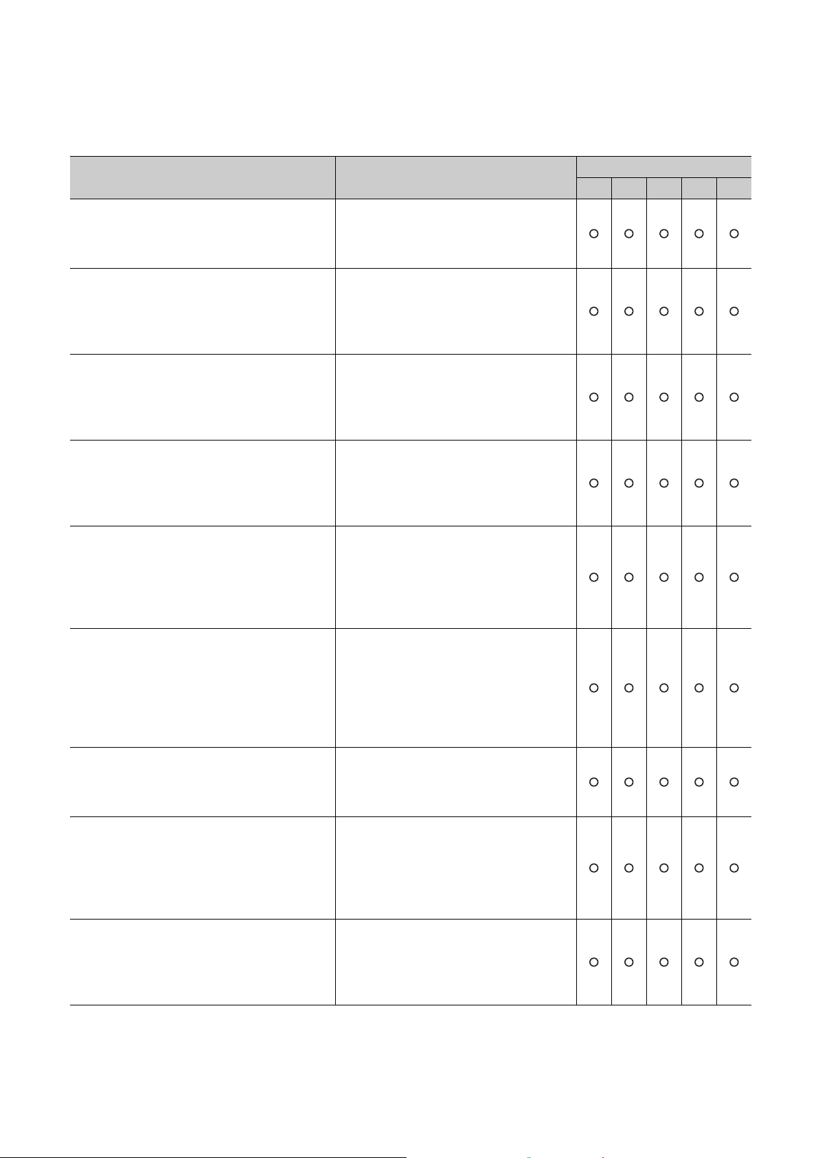
MANUALS
To understand the main specifications, functions, and usage of the CPU module, refer to the basic manuals.
Read other manuals as well when using a different type of CPU module and its functions.
Order each manual as needed, referring to the following lists.
The numbers in the "CPU module" and the respective modules are as follows.
Number CPU module
1) Basic model QCPU
2) High Performance model QCPU
3) Process CPU
4) Redundant CPU
5) Universal model QCPU
● : Basic manual, : Other CPU module manuals/Use them to utilize functions.
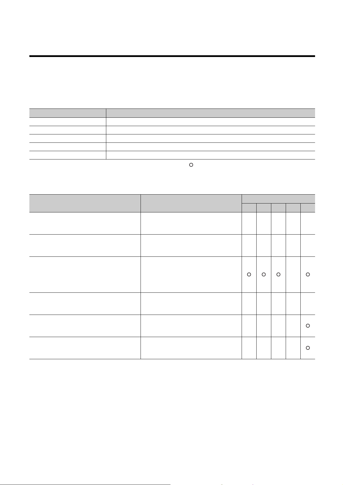
(1) CPU module user's manual
Manual name
< Manual number (model code) >
QnUCPU Users Manual (Function Explanation,
Program Fundamentals)
<SH-080807ENG, 13JZ27>
Qn(H)/QnPH/QnPRHCPU User's Manual (Function
Explanation, Program Fundamentals)
<SH-080808ENG, 13JZ28>
QCPU User's Manual (Multiple CPU System)
<SH-080485ENG, 13JR75>
QnPRHCPU User's Manual (Redundant System)
<SH-080486ENG, 13JR76>
QnUCPU User's Manual (Communication via Built-in
Ethernet Port)
<SH-080811ENG, 13JZ29>
MELSEC-Q Programming/Structured Programming
Manual (Process Control Instructions)
<SH-080893ENG, 13JZ39>
Description
Functions, methods, and devices for
programming
Functions, methods, and devices for
programming
Information on building multiple CPU systems
(system configurations, I/O numbers,
communications between CPU modules, and
communications with I/O modules and
intelligent function modules)
Redundant system configuration, functions,
communication with external devices, and
troubleshooting
Detailed description of communication via the
built-in Ethernet ports of the CPU module
Detailed description of the data logging function
of the CPU module
CPU module
1) 2) 3) 4) 5)
●
●●●●
●
15
Page 18
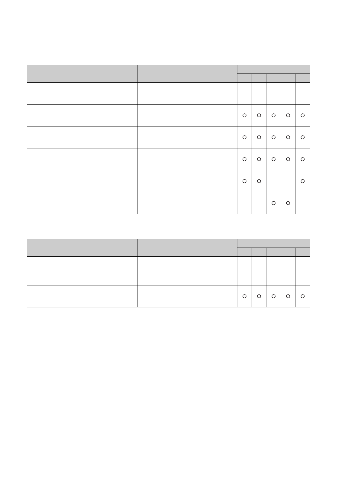
(2) Programming manual
Manual name
< Manual number (model code) >
MELSEC-Q/L Programming Manual (Common
Instruction)
<SH-080809ENG, 13JW10>
MELSEC-Q/L/QnA Programming Manual (SFC)
<SH-080041, 13JF60>
MELSEC-Q/L Programming Manual (MELSAP-L)
<SH-080076, 13JF61>
MELSEC-Q/L Programming Manual (Structured
Te xt )
<SH-080366E, 13JF68>
MELSEC-Q/L/QnA Programming Manual (PID
Control Instructions)
<SH-080040, 13JF59>
QnPHCPU/QnPRHCPU Programming Manual
(Process Control Instructions)
<SH-080316E, 13JF67>
(3) Operating manual
Description
Detailed description and usage of instructions
used in programs
System configuration, specifications, functions,
programming, and error codes for SFC
(MELSAP3) programs
System configuration, specifications, functions,
programming, and error codes for SFC
(MELSAP-L) programs
System configuration and programming using
structured text language
Dedicated instructions for PID control
Dedicated instructions for process control
CPU module
1) 2) 3) 4) 5)
●●●●●
Manual name
< Manual number (model code) >
GX Works2 Version 1 Operating Manual (Common)
<SH-080779ENG, 13JU63>
GX Developer Version 8 Operating Manual
<SH-080373E, 13JU41>
Description
System configuration, parameter settings, and
online operations of GX Works2, which are
common to Simple projects and Structured
projects
Operating methods of GX Developer, such as
programming, printing, monitoring, and
debugging
CPU module
1) 2) 3) 4) 5)
●●●●●
16
Page 19
(4) Intelligent function module manual
Manual name
< Manual number (model code) >
CC-Link IE Controller Network Reference Manual
<SH-080668ENG, 13JV16>
MELSEC-Q CC-Link IE Field Network Master/Local
Module User's Manual
<SH-080917ENG, 13JZ47>
Q Corresponding MELSECNET/H Network System
Reference Manual (PLC to PLC network)
<SH-080049, 13JF92>
Q Corresponding MELSECNET/H Network System
Reference Manual (Remote I/O network)
<SH-080124, 13JF96>
Q Corresponding Ethernet Interface Module User's
Manual (Basic)
<SH-080009, 13JL88>
MELSEC-Q/L Ethernet Interface Module User's
Manual (Application)
<SH-080010, 13JL89>
MELSEC-Q CC-Link System Master/Local Module
User's Manual
<SH-080394E, 13JR64>
Q Corresponding Serial Communication Module
User's Manual (Basic)
<SH-080006, 13JL86>
MELSEC-Q/L Serial Communication Module User's
Manual (Application)
<SH-080007, 13JL87>
Description
Specifications, procedures and settings before
system operation, parameter setting,
programming, and troubleshooting of the CC-
Link IE Controller Network module
Specifications, procedures and settings before
system operation, parameter setting,
programming, and troubleshooting of the CC-
Link IE Field Network module
Specifications, procedures and settings before
system operation, parameter setting,
programming, and troubleshooting of a
MELSECNET/H network system (PLC to PLC
network)
Specifications, procedures and settings before
system operation, parameter setting,
programming, and troubleshooting of a
MELSECNET/H network system (remote I/O
network)
Specifications, procedures for data
communication with external devices, line
connection (open/close), fixed buffer
communication, random access buffer
communication, and troubleshooting of the
Ethernet module
E-mail function, programmable controller CPU
status monitoring function, communication via
CC-Link IE Controller Network, CC-Link IE
Field Network, MELSECNET/H, or
MELSECNET/10, communication using the
data link instructions, and file transfer function
(FTP server) of the Ethernet module
System configuration, performance
specifications, functions, handling, wiring, and
troubleshooting of the QJ61BT11N
Overview, system configuration, specifications,
procedures before operation, basic data
communication method with external devices,
maintenance and inspection, and
troubleshooting for using the serial
communication module
Special functions (specifications, usage, and
settings) and data communication method with
external devices of the serial communication
module
CPU module
1) 2) 3) 4) 5)
17
Page 20

(5) Others
Manual name
< Manual number (model code) >
iQ Sensor Solution Reference Manual
<SH-081133ENG, 13JV28>
CC-Link IE Field Network Basic Reference Manual
<SH-081684ENG, 13JX62>
Description
Operating methods of iQ Sensor Solution, such
as programming and monitoring
Specifications, procedures before operation,
system configuration, programming, functions,
parameter settings, and troubleshooting of CC-
Link IE Field Network Basic
CPU module
1) 2) 3) 4) 5)
18
Page 21
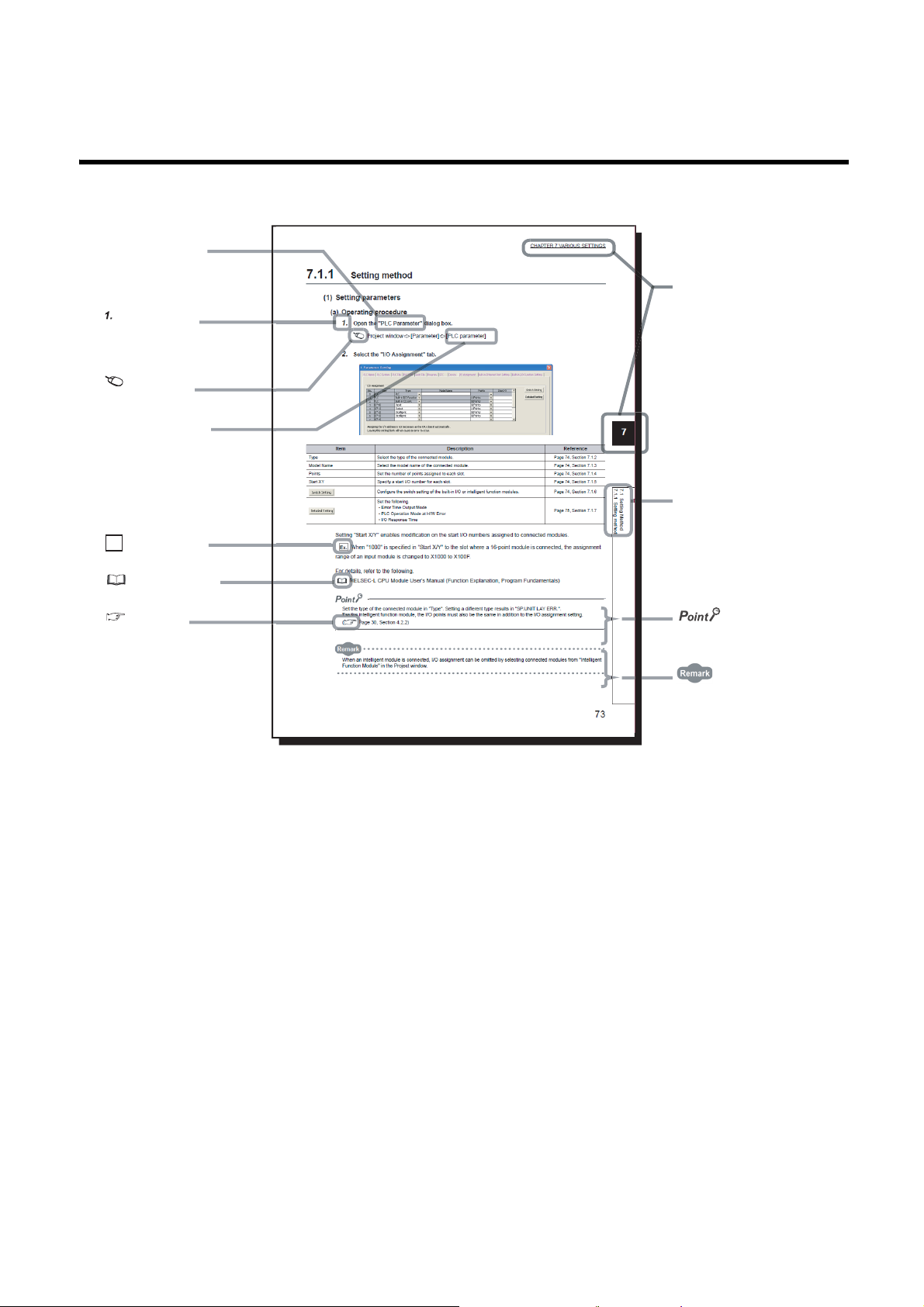
MANUAL PAGE ORGANIZATION
The section of
the current page is shown.
The chapter of
the current page is shown.
"" is used for
screen names and items.
[ ] is used for items
in the menu bar and
the project window.
shows operating
procedures.
shows reference
manuals.
shows notes that
requires attention.
shows mouse
operations.
*1
shows
reference pages.
shows setting or
operating examples.
Ex.
shows useful
information.
In this manual, pages are organized and the symbols are used as shown below.
The following page illustration is for explanation purpose only, and is different from the actual pages.
*1 The mouse operation example is provided below. (For GX Works2)
19
Page 22
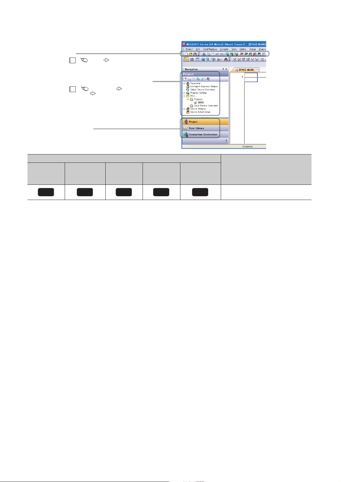
Basic model
A window selected in the view selection area is displayed.
View selection area
[Online] [Write to PLC...]
Select [Online] on the menu bar,
and then select [Write to PLC...].
Project window
[Parameter]
[PLC Parameter]
Select [Project] from the view selection
area to open the Project window.
Menu bar
Ex.
Ex.
In the Project window, expand [Parameter] and
select [PLC Parameter].
Basic
QCPU
High
Performance
model QCPU
High
performance
Icon
Process
CPU
Process
Redundant
CPU
Redundant
Universal model
QCPU
Universal
Description
Icons indicate that specifications described
on the page contain some precautions.
20
Page 23

TERMS
Unless otherwise specified, this manual uses the following generic terms and abbreviations.
* indicates a part of the model or version.
(Example): Q33B, Q35B, Q38B, Q312B Q3B
Ter m Description
CPU module type
CPU module
Basic model QCPU Generic term for the Q00JCPU, Q00CPU, and Q01CPU
High Performance model QCPU Generic term for the Q02CPU, Q02HCPU, Q06HCPU, Q12HCPU, and Q25HCPU
Process CPU Generic term for the Q02PHCPU, Q06PHCPU, Q12PHCPU, and Q25PHCPU
Redundant CPU Generic term for the Q12PRHCPU and Q25PRHCPU
Universal model QCPU
Built-in Ethernet port QCPU
High-speed Universal model QCPU
Motion CPU
PC CPU module
C Controller module
High-speed Universal model QCPU
Built-in Ethernet port QCPU
CPU module model
QnU(D)(H)CPU
QnUDVCPU
QnUDE(H)CPU
Generic term for the Basic model QCPU, High Performance model QCPU, Process CPU,
Redundant CPU, and Universal model QCPU
Generic term for the Q00UJCPU, Q00UCPU, Q01UCPU, Q02UCPU, Q03UDCPU,
Q03UDVCPU, Q03UDECPU, Q04UDHCPU, Q04UDVCPU, Q04UDEHCPU, Q06UDHCPU,
Q06UDVCPU, Q06UDEHCPU, Q10UDHCPU, Q10UDEHCPU, Q13UDHCPU, Q13UDVCPU,
Q13UDEHCPU, Q20UDHCPU, Q20UDEHCPU, Q26UDHCPU, Q26UDVCPU, Q26UDEHCPU,
Q50UDEHCPU, and Q100UDEHCPU
Generic term for the Q03UDVCPU, Q03UDECPU, Q04UDVCPU, Q04UDEHCPU,
Q06UDVCPU, Q06UDEHCPU, Q10UDEHCPU, Q13UDVCPU, Q13UDEHCPU,
Q20UDEHCPU, Q26UDVCPU, Q26UDEHCPU, Q50UDEHCPU, and Q100UDEHCPU
Generic term for the Q03UDVCPU, Q04UDVCPU, Q06UDVCPU, Q13UDVCPU, and
Q26UDVCPU
Generic term for the Mitsubishi Electric motion controllers: Q172CPUN, Q173CPUN,
Q172HCPU, Q173HCPU, Q172CPUN-T, Q173CPUN-T, Q172HCPU-T, Q173HCPU-T,
Q172DCPU, Q173DCPU, Q172DCPU-S1, Q173DCPU-S1, Q172DSCPU, and Q173DSCPU
Generic term for the MELSEC-Q series-compatible PC CPU modules manufactured by
CONTEC Co., Ltd.: PPC-CPU686(MS)-64, PPC-CPU686(MS)-128, and PPC-CPU852(MS)-
512
Generic term for the C Controller modules: Q06CCPU-V, Q06CCPU-V-B, Q12DCCPU-V,
Q24DHCCPU-V, and Q24DHCCPU-LS
Generic term for the Q03UDVCPU, Q04UDVCPU, Q06UDVCPU, Q13UDVCPU, and
Q26UDVCPU
Generic term for the Q03UDVCPU, Q03UDECPU, Q04UDVCPU, Q04UDEHCPU,
Q06UDVCPU, Q06UDEHCPU, Q10UDEHCPU, Q13UDVCPU, Q13UDEHCPU,
Q20UDEHCPU, Q26UDVCPU, Q26UDEHCPU, Q50UDEHCPU, and Q100UDEHCPU
Generic term for the Q00UJCPU, Q00UCPU, Q01UCPU, Q02UCPU, Q03UDCPU,
Q04UDHCPU, Q06UDHCPU, Q10UDHCPU, Q13UDHCPU, Q20UDHCPU, and Q26UDHCPU
Generic term for the Q03UDVCPU, Q04UDVCPU, Q06UDVCPU, Q13UDVCPU, and
Q26UDVCPU
Generic term for the Q03UDECPU, Q04UDEHCPU, Q06UDEHCPU, Q10UDEHCPU,
Q13UDEHCPU, Q20UDEHCPU, Q26UDEHCPU, Q50UDEHCPU, and Q100UDEHCPU
21
Page 24

Term Description
Base unit type
Generic term for the main base unit, extension base unit, slim type main base unit, redundant
Base unit
Main base unit
Extension base unit
Slim type main base unit
Redundant power main base unit
Redundant power extension base unit
Redundant type extension base unit
Multiple CPU high speed main base
unit
Redundant base unit
Redundant power supply base unit Generic term for the redundant power main base unit and redundant power extension base unit
Base unit model
Q3B
Q3SB
Q3RB
Q3DB
Q5B
Q6B
Q6RB
Q6
WRB
QA1S5
B
QA1S6
B
QA6
B
A5B Generic term for the A52B, A55B, and A58B extension base units
A6
B
QA6ADP+A5
QA1S6ADP+A1S5
Power supply module
Power supply module
Q series power supply module
AnS series power supply module Generic term for the A1S61PN, A1S62PN, and A1S63P power supply modules
A series power supply module
Slim type power supply module Abbreviation for the Q61SP slim type power supply module
Redundant power supply module Generic term for the Q63RP, Q64RPN and Q64RP redundant power supply modules
Life detection power supply module Abbreviation for the Q61P-D life detection power supply module
B/A6B
B/A1S6B
power main base unit, redundant power extension base unit, redundant type extension base
unit base unit, and multiple CPU high speed main base unit
Generic term for the Q3
Generic term for the Q5
QA1S6ADP+A1S5
Another term for the Q3
Another term for the Q3
Another term for the Q6
Another term for the Q6
Another term for the Q3
Generic term for the redundant power main base unit, redundant power extension base unit,
and redundant type extension base unit
Generic term for the Q33B, Q35B, Q38B, and Q312B main base units
Generic term for the Q32SB, Q33SB, and Q35SB slim type main base units
Another term for the Q38RB main base unit for redundant power supply system
Generic term for the Q35DB, Q38DB and Q312DB multiple CPU high speed main base units
Generic term for the Q52B and Q55B extension base units
Generic term for the Q63B, Q65B, Q68B, and Q612B extension base units
Another term for the Q68RB extension base unit for redundant power supply system
Another term for Q65WRB extension base unit for redundant system
Another term for the QA1S51B extension base unit
Generic term for the QA1S65B and QA1S68B extension base units
Generic term for the QA65B and QA68B extension base units
Generic term for the A62B, A65B, and A68B extension base units
Abbreviation for A large type extension base unit where the QA6ADP is mounted
Abbreviation for A small type extension base unit where the QA1S6ADP is mounted
Generic term for the Q series power supply module, AnS series power supply module, A series
power supply module, slim type power supply module, redundant power supply module, and life
detection power supply module
Generic term for the Q61P-A1, Q61P-A2, Q61P, Q61P-D, Q62P, Q63P, Q64P, and Q64PN
power supply modules
Generic term for the A61P, A61PN, A62P, A63P, A68P, A61PEU, and A62PEU power supply
modules
B, Q3SB, Q3RB, and Q3DB
B, Q6B, Q6RB, Q6WRB, QA1S5B, QA1S6B,
B/A1S6B, QA6B, and QA6ADP+A5B/A6B
SB
RB
RB
WRB
DB
22
Page 25

Ter m Description
Network module
CC-Link IE module
MELSECNET/H module Abbreviation for the MELSECNET/H network module
Ethernet module Abbreviation for the Ethernet interface module
CC-Link module Abbreviation for the CC-Link system master/local module
Network
CC-Link IE Generic term for the CC-Link IE Controller Network and the CC-Link IE Field Network
MELSECNET/H Abbreviation for the MELSECNET/H network system
Memory extension
Memory card Generic term for the SRAM card, Flash card, and ATA cards
SRAM card
Flash card Generic term for the Q2MEM-2MBF and Q2MEM-4MBF Flash cards
ATA card Generic term for the Q2MEM-8MBA, Q2MEM-16MBA, and Q2MEM-32MBA ATA cards
SD memory card
Extended SRAM cassette
Software package
Programming tool Generic term for GX Works2 and GX Developer
GX Works2
GX Developer
PX Developer
Others
Control CPU
Controlled module I/O modules and intelligent function modules which are controlled by a control CPU
MC protocol
QA6ADP Abbreviation for the QA6ADP QA conversion adapter module
QA1S6ADP Generic term for the QA1S6ADP and QA1S6ADP-S1 Q-AnS base unit conversion adapters
Extension cable Generic term for the QC05B, QC06B, QC12B, QC30B, QC50B, and QC100B extension cables
Tracking cable Generic term for the QC10TR and QC30TR tracking cables for the Redundant CPU
Battery
GOT
Generic term for the CC-Link IE Controller Network module and the CC-Link IE Field Network
module
Generic term for the Q2MEM-1MBS, Q2MEM-2MBS, Q3MEM-4MBS, and Q3MEM-8MBS
SRAM cards
Generic term for the NZ1MEM-2GBSD, NZ1MEM-4GBSD, NZ1MEM-8GBSD, NZ1MEM-
16GBSD, L1MEM-2GBSD, and L1MEM-4GBSD SD memory cards.
A memory device which consists of flash memory (abbreviation for Secure Digital Memory
Card)
Generic term for the Q4MCA-1MBS, Q4MCA-2MBS, Q4MCA-4MBS, and Q4MCA-8MBS
extended SRAM cassette
Product name for the MELSEC programmable controller software package
Product name for SW
A CPU module which controls each I/O module and intelligent function module
In a multiple CPU system, the CPU module which executes the control can be set for each
module.
Abbreviation for the MELSEC communication protocol. The MELSEC communication protocol
is a communication method to access from an external device to the CPU module according to
the communication procedure for the Q series programmable controller (such as a serial
communication module, Ethernet module).
Generic term for the Q6BAT, Q7BAT, and Q8BAT CPU module batteries, Q2MEM-BAT SRAM
card battery, and Q3MEM-BAT SRAM card battery
Generic term for Mitsubishi Electric Graphic Operation Terminal, GOT-A*** series, GOT-F***
series, GOT1000 series, and GOT2000 series
D5C-FBDQ process control FBD software package
23
Page 26

PACKING LIST
The following items are included in the package of this product. Before use, check that all the items are included.
(1) CPU module
(a) Q00JCPU or Q00UJCPU
Item Quantity
Module 1
Battery (Q6BAT) 1
Base unit installation screw (M4 × 14 screw) 4
Safety Guidelines (IB-0800423) 1
(b) Other than Q00JCPU and Q00UJCPU
Item Quantity
Module 1
Battery (Q6BAT) 1
(2) Main base unit
Item Quantity
Unit 1
*1
Base unit installation screw (M4 × 14 screw
Safety Guidelines (IB-0800423) 1
)4/5
*2
*1 For the slim type main base unit, M4 × 12 screws are supplied.
*2 Screws as many as the number of installation holes are supplied.
(3) Extension base unit
Item Quantity
Unit 1
Base unit installation screw (M4 × 14 screw)
*3 Screws as many as the number of installation holes are supplied.
(4) Power supply module or I/O module
Item Quantity
Module 1
4/5
*3
24
Page 27

DISCONTINUED MODELS
The following models are described in this manual, but have no longer been produced.
For the onerous repair term after discontinuation of production, refer to "WARRANTY".
Model Production discontinuation
Q61P-A1 March 2009
Q61P-A2 March 2009
Q64P February 2010
L1MEM-2GBSD July 2015
L1MEM-4GBSD July 2015
Q64RP September 2015
25
Page 28

CHAPTER 1 OVERVIEW
1.1 Features
This section describes the features of Q series CPU modules.
(1) Large number of I/O points
The Q Series CPU module supports the following number of actual I/O points accessible to the I/O modules
mounted on the base unit.
(a) Basic model QCPU
• Q00JCPU: 256 points (X/Y0 to FF)
• Q00CPU, Q01CPU: 1024 points (X/Y0 to 3FF)
Up to 2048 points (X/Y0 to 7FF) are supported as the number of I/O device points usable for refreshing the
remote I/O of the CC-Link and link I/O (LX, LY) of the MELSECNET/H.
(b) High Performance model QCPU
One module can support 4096 points (X/Y0 to FFF).
Up to 8192 points (X/Y0 to 1FFF) are supported as the number of I/O device points usable for the remote I/O
stations in the MELSECNET/H remote I/O network, the CC-Link data link, and the MELSECNET/MINI-S3 data
link.
(c) Process CPU and Redundant CPU
One module can support 4096 points (X/Y0 to FFF).
Up to 8192 points (X/Y0 to 1FFF) are supported as the number of I/O device points usable for the remote I/O
stations in the MELSECNET/H remote I/O network and CC-Link data link.
(d) Universal model QCPU
• Q00UJCPU: 256 points (X/Y0 to FF)
• Q00UCPU, Q01UCPU: 1024 points (X/Y0 to 3FF)
• Q02UCPU: 2048 points (X/Y0 to 7FF)
• Q03UD(E)CPU, Q03UDVCPU,
Q04UD(E)HCPU, Q04UDVCPU,
Q06UD(E)HCPU, Q06UDVCPU,
Q10UD(E)HCPU, Q13UD(E)HCPU,
Q13UDVCPU, Q20UD(E)HCPU,
Q26UD(E)HCPU, Q26UDVCPU,
Q50UDEHCPU, Q100UDEHCPU: 4096 points (X/Y0 to FFF)
Up to 8192 points (X/Y0 to 1FFF) are supported as the number of I/O device points usable for the remote I/O
stations in the MELSECNET/H remote I/O network and CC-Link data link.
26
Page 29

CHAPTER 1 OVERVIEW
(2) Large selection of CPU modules
The following lists the lineup of CPU available for various program size.
CPU module type Program size
Basic model QCPU
High Performance model QCPU
Process CPU
Redundant CPU
Universal model QCPU
Q00(J)CPU 8K steps
Q01CPU 14K steps
Q02(H)CPU 28K steps
Q06HCPU 60K steps
Q12HCPU 124K steps
Q25HCPU 252K steps
Q02PHCPU 28K steps
Q06PHCPU 60K steps
Q12PHCPU 124K steps
Q25PHCPU 252K steps
Q12PRHCPU 124K steps
Q25PRHCPU 252K steps
Q00U(J)CPU 10K steps
Q01UCPU 15K steps
Q02UCPU 20K steps
Q03UD(E)CPU, Q03UDVCPU 30K steps
Q04UD(E)HCPU, Q04UDVCPU 40K steps
Q06UD(E)HCPU, Q06UDVCPU 60K steps
Q10UD(E)HCPU 100K steps
Q13UD(E)HCPU, Q13UDVCPU 130K steps
Q20UD(E)HCPU 200K steps
Q26UD(E)HCPU, Q26UDVCPU 260K steps
Q50UDEHCPU 500K steps
Q100UDEHCPU 1000K steps
1
1.1 Features
27
Page 30

(3) High-speed processing
High speed processing has been achieved.
CPU module type LD instruction processing speed
Q00JCPU 200ns
Basic model QCPU
High Performance model QCPU
Process CPU
Redundant CPU Q12PRHCPU, Q25PRHCPU
Universal model QCPU
The MELSEC Q series base unit high-speed system bus has achieved faster access to an intelligent function
module and link refresh with a network module.
Q00CPU 160ns
Q01CPU 100ns
Q02CPU 79ns
Q02HCPU, Q06HCPU, Q12HCPU,
Q25HCPU
Q02PHCPU, Q06PHCPU, Q12PHCPU,
Q25PHCPU
Q00UJCPU 120ns
Q00UCPU 80ns
Q01UCPU 60ns
Q02UCPU 40ns
Q03UD(E)CPU 20ns
Q04UD(E)HCPU, Q06UD(E)HCPU,
Q10UD(E)HCPU, Q13UD(E)HCPU,
Q20UD(E)HCPU, Q26UD(E)HCPU,
Q50UDEHCPU, Q100UDEHCPU
Q03UDVCPU, Q04UDVCPU,
Q06UDVCPU, Q13UDVCPU,
Q26UDVCPU
34ns
9.5ns
1.9ns
(a) Basic model QCPU
MELSECNET/H link refreshing: 2.2ms/2K words
*1 The Q01CPU is used without using SB and SW, and the MELSECNET/H network module is mounted on the main base
unit.
*1
(b) High Performance model QCPU, Process CPU, Redundant CPU or
Universal model QCPU
Access to the intelligent function module: 20µs/word (approximately 7 times*2)
*2
MELSECNET/H link refreshing: 4.6ms/8K words (approximately 4.3 times
*2 These are the values resulted from the following comparison:
• Comparing Q02HCPU with Q2ASHCPU-S1
• Comparing Q25PHCPU with Q4ARCPU
• Comparing Q25PRHCPU with Q4ARCPU
)
28
Page 31

CHAPTER 1 OVERVIEW
0 1020304050607080
Q25HCPU(USB)
Q25HCPU(RS-232)
Q2ASHCPU
A2USHCPU-S1
12
30
86
94
90 100
(Unit:s)
(4) Increase in debugging efficiency through high-speed communication with a
programming tool
High-speed communications at 115.2Kbps maximum are available by using RS-232 which reducing the time
required for writing and reading of programs and monitoring. Also, the communication time efficiency of
debugging has been increased.
In addition, High Performance model QCPUs (except for the Q02CPU), Process CPUs, Redundant CPUs and
Universal model QCPUs support USB, so that high-speed communications of 12Mbps are available.
(5) Use of AnS/A series I/O modules and special function modules
The AnS/A series compatible extension base units (QA1S5B, QA1S6B, QA1S6ADP+A1S5B/A1S6B,
QA6B, and QA6ADP+A5B/A6B) can be connected to the main base unit where the High Performance
model QCPU or Universal model QCPU
special function modules.
*1 The Universal model QCPU whose serial number (first five digits) is "13102" or later is applicable.
*1
is mounted. This enables the use of AnS/A series I/O modules and
1
(6) Miniaturized modules (space-saving size)
The installation space for the Q series has been reduced by approx. 60% compared with the AnS series.
98mm
5-slot main base unit: 245mm
8-slot main base unit: 328mm
12-slot main base unit: 439mm
(Depth: 98mm)
AnS series
Q series
1.1 Features
29
Page 32

(7) Connection of up to 7 extension base units
Remark
Up to seven extension base units can be connected to the Q series CPU module.
The overall extension cable length is 13.2m, which allows flexible layout of base units.
(8) Memory extension
By extending the memory capacity of a CPU module, large size files can be managed. Comments can be set to
all data devices and old programs can be saved as correction history.
(a) Memory card
A memory card (maximum 32M bytes) can be installed. (The maximum size is available only for ATA cards.)
Memory cards are used for the following operations.
• Boot operation
• Restoring backup data
• Writing programs to the ROM
Data that cannot be stored in the built-in memory of the CPU module, such as sampling trace data and file
register data, can be stored as well.
(b) SD memory card
SD memory cards are used for the following operations.
• Boot operation
• Restoring backup data
• Data backup
• Data logging
(c) Extended SRAM cassette
An extended SRAM cassette extends the capacity of the standard RAM in a CPU module.
• An extended SRAM cassette can be used together with an SD memory card, allowing users to store data
separately (for example, boot data in an SD memory card and device data in an extended SRAM
cassette). This improves maintainability.
• With existing CPU modules, file register areas in the standard RAM and an SRAM card cannot be
accessed sequentially, and the boundary needs to be considered at programming. If the standard RAM
capacity is extended using an extended SRAM cassette, the device area can be extended without
considering the boundary.
Memory extension methods differ depending on the CPU module. ( Page 35, Section 2.2)
30
Page 33

CHAPTER 1 OVERVIEW
Note 1.1, Note 1.2
Note 1.1
Note 1.1
(9) Automatic write to the standard ROM Note 1.1 Note 1.2
Parameters and programs in a memory card or SD memory card can be written to the standard ROM of the CPU
module without using a programming tool.
If the boot operation is being performed from the standard ROM, parameters and programs in a memory card or
SD memory card can be written to the standard ROM by inserting it to the CPU module. Users do not need a
programming tool (personal computer) on hand to modify parameters and programs.
(10)External input/output forced on/off
Forced on and off of external input and output is available using a programming tool even when the CPU module
is running or program is being processed.
Also, wiring test and operation test can be conducted without halting the CPU module by forcibly turning on or off
the I/O.
(11)Remote password function
When the built-in Ethernet port QCPU, Ethernet module, or serial communication module is externally accessed,
an access to the CPU module can be controlled by setting a remote password.
(12)Remote I/O network of MELSECNET/H
A MELSECNET/H remote I/O system can be configured by installing a MELSECNET/H remote master station.
1
● The remote password can be set up when the Ethernet module, or serial communication module of function version B or
later is used.
● The MELSECNET/H remote I/O network can be implemented when the MELSECNET/H network module of function
version B or later is used.
(13)Support of multiple CPU systems
CPU module supports the multiple CPU system.
Multiple CPU systems can be constructed in combination with CPU modules, motion CPU(s), PC CPU module(s),
and C Controller module.
For details of the multiple CPU system, refer to the following.
QCPU User's Manual (Multiple CPU System)
Note 1.1
Basic
The Basic model QCPU does not support the following functions.
• Automatic write to the standard ROM
• External input/output forced on/off
• MELSECNET/H remote I/O network
1.1 Features
Note 1.2
Universal
The Universal model QCPU does not support the following function.
• Parameter setting of automatic write to the standard ROM
31
Page 34

(14)Support of redundant power supply systems
Note 1.3
The redundant power supply system can be configured using a redundant base unit and redundant power supply
modules.
The system can continue operation even if one of the power supply modules fails, since the other will supply the
power.
(15)Direct connection to Ethernet Note 1.3
The Built-in Ethernet port QCPU module allows direct connections to Ethernet.
For details of the functions, refer to the following.
QnUCPU User's Manual (Communication via Built-in Ethernet Port)
Note 1.3
Universal
Only the Built-in Ethernet port QCPU supports this function.
32
Page 35

CHAPTER 2 SYSTEM CONFIGURATION
CHAPTER 2 SYSTEM CONFIGURATION
This chapter describes system configurations, precautions, and components of the Q Series CPU module.
This section describes system configurations for a single CPU system with the Basic model QCPU, High Performance
model QCPU, Process CPU, or Universal model QCPU, and a system configuration when using GOT by bus
connection.
For a multiple CPU system and redundant system (when using the Redundant CPU), refer to the following.
QCPU User's Manual (Multiple CPU System)
QnPRHCPU User's Manual (Redundant System)
2
33
Page 36

2.1 Overall Configuration
Extended SRAM cassette
Memory card, SD memory card
Battery for QCPU (Q6BAT)
Q7BAT-SET
Battery holder
Q8BAT-SET
Q8BAT connection cable
Battery for QCPU (Q7BAT)
Extension cable
Battery for QCPU (Q8BAT)
Basic model QCPU
High Performance model QCPU
Process CPU
Universal model QCPU
Q3 B main base unit
Q3 RB redundant power main base unit
Q3 SB slim type main base unit
Q3 DB multiple CPU high speed main base unit
Power supply module/I/O module/Intelligent function module/Special function module
Q5 B extension base unit
Q6 B extension base unit
Q6 RB redundant power extension base unit
QA1S5 B extension base unit
QA1S6 B extension base unit
QA6 B extension base unit
The combination of modules depends on the devices used in the configuration.
For the applicable combinations, refer to the following.
• CPU modules and base units, batteries, memory cards, SD memory cards, and/or extended SRAM
cassettes ( Page 35, Section 2.2)
• Base units and power supply modules ( Page 187, CHAPTER 7)
• Main base units and extension base units ( Page 223, CHAPTER 8)
• CPU modules and intelligent function modules or special function modules
( User's manual for each module)
34
To correctly configure a system, observe precautions described in Page 39, Section 2.3.
Page 37

CHAPTER 2 SYSTEM CONFIGURATION
2.2 Component List
(1) Basic model QCPU
Item Description
Main base unit Q33B, Q35B, Q38B, Q312B
Applicable main base
*1
unit
Applicable extension base
unit
Maximum number of
connectable extension
base units
Maximum number of
mountable modules
Extension cable QC05B, QC06B, QC12B, QC30B, QC50B, QC100B
Total length of extension
cables
Memory extension ----
Applicable battery Q6BAT
*1 The Q00JCPU does not require a power supply module and the main base unit since the module is an integrated
combination of a power supply module and the main base unit.
Redundant power main base unit Q38RB
Slim type main base unit Q32SB, Q33SB, Q35SB
Multiple CPU high speed main base unit Q35DB, Q38DB, Q312DB
Model requiring no power supply module Q52B, Q55B
Model requiring a Q series power supply module Q63B, Q65B, Q68B, Q612B
Redundant power extension base unit Q68RB
Q00JCPU: 2
Q00CPU, Q01CPU: 4
Q00JCPU: 16 (max. 16 slots)
Q00CPU, Q01CPU: 24 (max. 24 slots)
13.2m
2
2.2 Component List
35
Page 38

(2) High Performance model QCPU
Item Description
Main base unit Q33B, Q35B, Q38B, Q312B
Applicable main base unit
Applicable extension base
unit
Maximum number of
connectable extension
base units
Maximum number of
mountable modules
Extension cable QC05B, QC06B, QC12B, QC30B, QC50B, QC100B
Total length of extension
cables
Memory extension
Applicable battery Q6BAT, Q7BAT, Q8BAT
*1 The A/AnS series extension base units are applicable only when the Q3B is used as a main base unit.
*2 When the QA1S6ADP+A1S5B/A1S6B is used, the maximum number of extension base units is 1, and the maximum
number of modules that can be mounted is 20 (with a maximum of 20 slots available). When the QA1S6ADPS1+A1S5B/A1S6B is used, the maximum number of extension base units is 3, and the maximum number of
modules that can be mounted is 36 (with a maximum of 36 slots available).
Redundant power main base unit Q38RB
Slim type main base unit Q32SB, Q33SB, Q35SB
Multiple CPU high speed main base unit Q35DB, Q38DB, Q312DB
Model requiring no power supply module Q52B, Q55B
Model requiring a Q series power supply module Q63B, Q65B, Q68B, Q612B
Redundant power extension base unit Q68RB
Model requiring no AnS series power supply
*1
module
Model requiring a AnS series power supply module*1QA1S65B, QA1S68B, QA1S6ADP+A1S6B
Model requiring A series power supply module
Model requiring no A series power supply module
SRAM card Q2MEM-1MBS, Q2MEM-2MBS, Q3MEM-4MBS
Flash card Q2MEM-2MBF, Q2MEM-4MBF
ATA card Q2MEM-8MBA, Q2MEM-16MBA, Q2MEM-32MBA
*1
64 (max. 64 slots)
QA1S51B, QA1S6ADP+A1S5B
QA65B, QA68B, QA6ADP+A6B
*1
QA6ADP+A5B
7
13.2m
*2
*2
36
Page 39

CHAPTER 2 SYSTEM CONFIGURATION
(3) Process CPU
Item Description
Main base unit Q33B, Q35B, Q38B, Q312B
Applicable main base unit
Applicable extension base
unit
Maximum number of
connectable extension
base units
Maximum number of
mountable modules
Extension cable QC05B, QC06B, QC12B, QC30B, QC50B, QC100B
Total length of extension
cables
Memory extension
Applicable battery Q6BAT, Q7BAT, Q8BAT
Redundant power main base unit Q38RB
Multiple CPU high speed main base unit Q35DB, Q38DB, Q312DB
Model requiring no power supply module Q52B, Q55B
Model requiring a Q-series power supply module Q63B, Q65B, Q68B, Q612B
Redundant power extension base unit Q68RB
7
64 (max. 64 slots)
13.2m
SRAM card Q2MEM-1MBS, Q2MEM-2MBS, Q3MEM-4MBS
Flash card Q2MEM-2MBF, Q2MEM-4MBF
ATA card Q2MEM-8MBA, Q2MEM-16MBA, Q2MEM-32MBA
2
2.2 Component List
37
Page 40

(4) Universal model QCPU
Item Description
Main base unit Q33B, Q35B, Q38B, Q312B
Applicable main base
*1
unit
Applicable extension base
unit
Maximum number of
connectable extension
base units
Maximum number of
mountable modules
Extension cable QC05B, QC06B, QC12B, QC30B, QC50B, QC100B
Total length of extension
cables
Other than
QnUDVCPU
*2
Memory
extension
QnUDVCPU
Applicable battery Q6BAT, Q7BAT, Q8BAT
*1 The Q00JCPU does not require a power supply module and the main base unit since the module is an integrated
combination of a power supply module and the main base unit.
*2 Memory cards cannot be used in the Q00U(J)CPU and Q01UCPU.
*3 The A/AnS series extension base units can be used when the following conditions are satisfied.
• The serial number (first five digits) of the Universal model QCPU used is "13102" or later.
• The Q3B or Q3DB is used as a main base unit, or the Q00UJCPU is used.
*4 When the QA1S6ADP+A1S5B/A1S6B is used, the maximum number of extension base units is 1, and the maximum
number of modules that can be mounted is 20 (with a maximum of 20 slots available). When the QA1S6ADPS1+A1S5B/A1S6B is used, the maximum number of extension base units is 3, and the maximum number of
modules that can be mounted is 36 (with a maximum of 36 slots available).
Redundant power main base unit Q38RB
slim type main base unit Q32SB, Q33SB, Q35SB
Multiple CPU high speed main base unit Q35DB, Q38DB, Q312DB
Model requiring no power supply module Q52B, Q55B
Model requiring a Q-series power supply module Q63B, Q65B, Q68B, Q612B
Redundant power extension base unit Q68RB
Model requiring no AnS series power supply
*3
module
Model requiring an AnS series power supply
*3
module
Model requiring no A series power supply module
Model requiring an A series power supply module
Q00UCPU, Q01UCPU, Q02UCPU: 4
Other than above: 7
Q00UJCPU: 16 (max. 16 slots)
Q00UCPU, Q01UCPU: 24 (max. 24 slots)
Q02UCPU: 36 (max. 36 slots)
Other than above: 64 (max. 64 slots)
SRAM card
Flash card Q2MEM-2MBF, Q2MEM-4MBF
ATA card Q2MEM-8MBA, Q2MEM-16MBA, Q2MEM-32MBA
SD memory card
Extended SRAM cassette
QA1S51B, QA1S6ADP+A1S5B
QA1S65B, QA1S68B, QA1S6ADP+A1S6B
*3
QA65B, QA68B, QA6ADP+A6B
*3
QA6ADP+A5B
Q00UJCPU: 2
13.2m
Q2MEM-1MBS, Q2MEM-2MBS, Q3MEM-4MBS,
Q3MEM-8MBS
NZ1MEM-2GBSD, NZ1MEM-4GBSD, NZ1MEM-
8GBSD, NZ1MEM-16GBSD, L1MEM-2GBSD,
L1MEM-4GBSD
Q4MCA-1MBS, Q4MCA-2MBS, Q4MCA-4MBS,
Q4MCA-8MBS
*4
*4
38
Page 41

2.3 Precautions for System Configuration
This section describes restrictions on the system configuration using the Q series CPU module.
(1) Number of mountable modules
The number of mountable modules and supported functions are restricted depending on the module type.
(a) When the Basic model QCPU is used
CHAPTER 2 SYSTEM CONFIGURATION
2
Product Model
CC-Link IE Controller Network module
MELSECNET/H module
Ethernet module
CC-Link module
Interrupt module
High speed data logger module • QD81DL96
High speed data communication module • QJ71DC96
GOT
*1 The number is a total of the CC-Link IE Controller Network module and MELSECNET/H module.
*2 Modules of function version B or later are available.
*3 The number is for interrupt modules with no interrupt pointer setting.
With interrupt pointer setting, there is no restriction on the number of modules.
For interrupt pointer setting, refer to the following.
Qn(H)/QnPH/QnPRHCPU User's Manual (Function Explanation, Program Fundamentals)
*4 For the available GOT models, refer to the following.
GOT-A900 Series User's Manual (GT Works2 Version2/GT Designer2 Version2 Compatible Connection System
Manual)
GOT1000 Series Connection Manual (Mitsubishi Products) for GT Works3
GOT2000 Series Connection Manual (Mitsubishi Products) For GT Works3 Version1
*5 One module can be mounted for one control CPU.
*6 The module is available only when the interrupt module is selected by setting the function selector switch (SW2) to OFF.
• QJ71GP21-SX
• QJ71GP21S-SX
• QJ71LP21
• QJ71BR11
• QJ71LP21-25
• QJ71LP21S-25
• QJ71LP21G
• QJ71LP21GE
• QJ71NT11B
• QJ71E71
• QJ71E71-B2
• QJ71E71-B5
• QJ71E71-100
• QJ61BT11
• QJ61BT11N
*1
•QI60
• QX40H
• QX70H
• QX80H
• QX90H
• GOT-A900 Series (for bus
• GOT1000 Series (for bus
• GOT2000 Series (for bus
*6
*6
*6
*6
connection only)
connection only)
connection only)
*4
*4
*4
Maximum number of
modules/units per system
Only 1 module
Only 1 module
Up to 2 modules
Only 1 module
Only 1 module
Only 1 module
Up to 5 units
*1
*2
*3
*5
*5
2.3 Precautions for System Configuration
39
Page 42

(b) When the High Performance model QCPU or Process CPU is used
Product Model
CC-Link IE Controller Network
*1
module
MELSECNET/H module
Ethernet module
CC-Link module
MELSECNET/MINI-S3 data link
*3
module
AnS Series special function
*3
module
Interrupt module
High speed data logger module • QD81DL96
High speed data communication
*7
module
GOT
• QJ71GP21-SX
• QJ71GP21S-SX
• QJ71LP21
• QJ71BR11
• QJ71LP21-25
• QJ71LP21S-25
• QJ71LP21G
• QJ71LP21GE
•QJ71NT11B
•QJ71E71
• QJ71E71-B2
• QJ71E71-B5
• QJ71E71-100
• QJ61BT11
•QJ61BT11N
• A1SJ71PT32-S3
• A1SJ71T32-S3
• A1SD51S
• A1SD21-S1
• A1SJ71J92-S3(When using GET/PUT service)
• A1SJ71AP23Q
• A1SJ71AR23Q
• A1SJ71AT23BQ
*3
•A1SI61
•QI60
*5
• QX40H
*5
• QX70H
*5
• QX80H
*5
• QX90H
• QJ71DC96
• GOT-A900 Series (only for bus connection)
• GOT1000 Series (only for bus connection)
• GOT2000 Series (for bus connection only)
*4
*4
*4
Maximum number of modules/units
per system
Up to 2 modules
Up to 4 modules in
Up to 4 modules
Up to 4 modules
No restriction
No restriction
(Auto refresh setting not allowed)
Up to 6 modules in total
Only 1 module
Only 1 module
Only 1 module
Up to 5 units
*2
total
*6
*6
*1 Only the High Performance model QCPU whose serial number (first five digits) is "09012" or later and Process CPU
whose serial number (first five digits) is "10042" or later can be used.
*2 One CPU module can control the following number of modules by setting CC-Link network parameters in a programming
tool.
• CPU modules whose serial number (first five digits) is "08031" or earlier: up to 4 modules
• CPU modules whose serial number (first five digits) is "08032" or later: up to 8 modules
There is no restriction on the number of modules when the parameters are set with the CC-Link dedicated instructions.
For the CC-Link system master/local modules whose parameters can be set by the dedicated instructions, refer to the
following.
MELSEC-Q CC-Link System Master/Local Module User's Manual
*3 The module is available only when the High Performance model QCPU is used.
*4 For the available GOT models, refer to the following.
GOT-A900 Series User's Manual (GT Works2 Version2/GT Designer2 Version2 Compatible Connection System
Manual)
GOT1000 Series Connection Manual (Mitsubishi Products) for GT Works3
GOT2000 Series Connection Manual (Mitsubishi Products) For GT Works3 Version1
*5 The module is available only when the interrupt module is selected by setting the function selector switch (SW2) to OFF.
*6 One module can be mounted for one control CPU.
*7 The function version of the High-Performance model QCPU must be B or later.
40
Page 43

CHAPTER 2 SYSTEM CONFIGURATION
(c) When the Redundant CPU is used
For the modules with restriction on the number of mountable modules, refer to the following.
QnPRHCPU User's Manual (Redundant System)
(d) When the Universal model QCPU is used
Product Model
CC-Link IE Controller Network
*1
module
MELSECNET/H module
CC-Link IE Field network module • QJ71GF11-T2
Ethernet module
CC-Link module
MELSECNET/MINI-S3 data link
*11
module
AnS series special function module
Interrupt module
High speed data logger module
*12
High speed data communication
module
GOT
*1 Only the CC-Link IE Controller Network module whose serial number (first five digits) is "09042" or later can be used.
*2 The number is a total of the CC-Link IE Controller Network modules and MELSECNET/H network modules.
*3 The number of mountable modules for the Q00UJCPU, Q00UCPU, and Q01UCPU is only one module, and two
modules for the Q02UCPU.
*4 The function version of the Universal model QCPU must be B or later.
• QJ71GP21-SX
• QJ71GP21S-SX
•QJ71LP21
•QJ71BR11
• QJ71LP21-25
• QJ71LP21S-25
• QJ71LP21G
• QJ71LP21GE
• QJ71NT11B
• QJ71E71
• QJ71E71-B2
• QJ71E71-B5
• QJ71E71-100
•QJ61BT11
•QJ61BT11N
• A1SJ71PT32-S3
• A1SJ71T32-S3
• A1SD51S
• A1SD21-S1
• A1SJ71J92-S3
*11
(When using GET/PUT service)
• A1SJ71AP23Q
• A1SJ71AR23Q
• A1SJ71AT23BQ
•A1SI61
• QX40H
• QX70H
• QX80H
• QX90H
*11
*10
*10
*10
*10
• QD81DL96
• QJ71DC96
• GOT1000 Series (only for bus
connection)
*7
• GOT2000 Series (for bus connection
*7
only)
Maximum number of
modules/units per system
Up to 4 modules
No restriction
Up to 4 modules
No restriction
No restriction
(Auto refresh setting not allowed)
Up to 6 modules in total
Only 1 module
Only 1 module
Only 1 module
Up to 5 units
*2*3
*8
*3
*4*5
*6
*9
*9
2
2.3 Precautions for System Configuration
41
Page 44

*5 One CPU module can control the following number of modules by setting CC-Link network parameters in a programming
tool.
• Q00UJCPU, Q00UCPU, Q01UCPU: up to 2 modules
• Q02UCPU: up to 4 modules
• CPU modules other than above: up to 8 modules
There is no restriction on the number of modules when the parameters are set with the CC-Link dedicated instructions.
For the CC-Link system master/local modules whose parameters can be set with the dedicated instructions, refer to the
following.
CC-Link System Master/Local Module User's Manual
*6 The number is for interrupt modules with no interrupt pointer setting.
With interrupt pointer setting, there is no restriction on the number of modules.
For interrupt pointer setting, refer to the following.
QnUCPU User's Manual (Function Explanation, Program Fundamentals)
*7 For the available GOT models, refer to the following.
GOT1000 Series Connection Manual (Mitsubishi Products) for GT Works3
GOT2000 Series Connection Manual (Mitsubishi Products) For GT Works3 Version1
*8 One CPU module can control the following number of modules by setting CC-Link network parameters in a programming
tool.
• Q00UJCPU, Q00UCPU, Q01UCPU: up to 2 modules
• Q02UCPU: up to 4 modules
• CPU modules other than above: up to 8 modules
There is no restriction on the number of modules when the parameters are set with the CC-Link IE Field Network
dedicated instructions.
For the CC-Link IE Field Network modules whose parameters can be set with the dedicated instructions, refer to the
following.
MELSEC-Q CC-Link IE Field Network Master/Local Module User's Manual
*9 One module can be mounted for one control CPU.
*10 The module is available only when the interrupt module is selected by setting the function selector switch (SW2) to OFF.
*11 This module is applicable only when the Universal model QCPU whose serial number (first five digits) is "13102" or later
is used.
*12 The High-speed Universal model QCPU supports only the high speed data logger module whose serial number (first five
digits) is "14122" or later.
42
Page 45
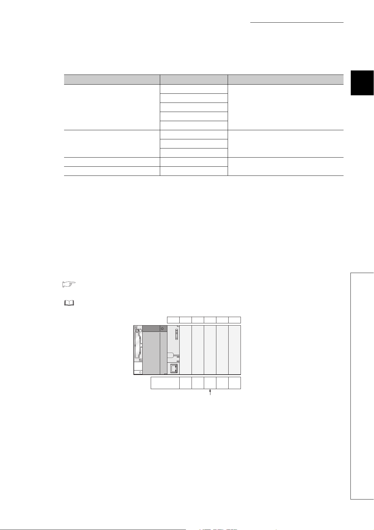
CHAPTER 2 SYSTEM CONFIGURATION
(2) Modules with restrictions when used with the Built-in Ethernet port QCPU
The following table lists modules with restrictions when used with the Built-in Ethernet port QCPU.
Product Model Serial number (first five digits)
QJ71LP21-25
QJ71LP21S-25
MELSECNET/H module
Serial communication module
Web server module QJ71WS96
MES interface module QJ71MES96
*1 If the following conditions are all met, use the MELSECNET/H module whose serial number (first five digits) is "10042" or
later.
1) A multiple CPU system containing the Built-in Ethernet port QCPU is configured.
2) A programming tool or GOT is connected to an Ethernet port of the Built-in Ethernet port QCPU.
3) The programming tool or GOT connected accesses another station via the MELSECNET/H module controlled by
another CPU module.
4) The access target CPU module on another station is A/QnA series.
QJ71LP21G
QJ71LP21GE
QJ71BR11
QJ71C24N
QJ71C24N-R2
QJ71C24N-R4
Some modules have restrictions depending on
the use conditions.
"10042" or later
(No restrictions when used with the QnUDVCPU)
"10012" or later
("14122" or later when used with the QnUDVCPU)
*1
2
(3) Number of available slots
Empty slots are included in the number of available slots (modules) in the base unit.
(One slot is occupied even when "empty" and "0 points" are set for the slot 2 as shown in the following figure.)
The number of available slots (modules) varies depending on the base unit.
Page 223, CHAPTER 8
For the assignment concepts of base units and I/O numbers, refer to the following.
User's manual for the CPU module used (Function Explanation, Program Fundamentals)
0CPU 1 3 42
Input OutputEmptyInputInput
Number of
slot points
16
points
16
points
16
0
points
point
Occupies 1 slot.
points
16
(4) Power capacity
The power may be insufficient depending on the combination of the mounted modules or the number of the
mounted modules. When mounting modules, consider the power capacity.
If the power is insufficient, change the combination of modules so that the power is sufficient.
2.3 Precautions for System Configuration
(5) External devices connected to Built-in Ethernet port QCPU
When connecting external devices to Built-in Ethernet port QCPU, power off the module and the external devices
before connecting.
43
Page 46

Power supply
module
CPU module
Extension 1
Main base unit
Slot number
CPU 0 1 2 3 4 5 6 7 8 9 10 11
12 13 14 15 16 17 18 19 20 21 22 23
Extension 2
24 25 26 27 28 29 30 31 32 33 34 35
Extension 3
36 37 38 39 40 41 42 43 44 45 46 47
Extension 4
48 49 50 51 52 53 54 55 56 57 58 59
Extension 5
Prohibit
Prohibit
Prohibit
Prohibit
Prohibit
Prohibit
Prohibit
Prohibit
60 61 62 63
Extension base unit
Modules can be
installed.
Modules cannot be installed.
(Installing modules will result in error.)
Q312B
Q612B
Q612B
Q612B
Q612B
Q612B
When the GOT has been busconnected, one slot of extension
base 1 is used.
Also one GOT occupies 16 I/O
points.
When using the GOT, consider
the number of slots and the
number of I/O points.
Refer to the GOT Manual for
details of busconnecting the GOT.
(6) Precautions for the number of mountable modules
Mount modules so that the total number of I/O points does not exceed the point range of the CPU module.
Modules can be mounted in any slot within the available range.
Even if the total number of slots of the main base unit and extension base units exceeds the number of available
slots (for example, even if six12-slot base units are used), no error occurs as long as modules are mounted within
the available range.
If a module is mounted exceeding the available range, "SP.UNIT LAY ERR." (error code: 2124) occurs.
44
Page 47

CHAPTER 2 SYSTEM CONFIGURATION
(7) Precautions when using AnS/A series modules
1) When using the AnS series special function modules shown below, a limitation is placed on an accessible
device range.
• A1SJ71J92-S3 type JEMANET interface module
• A1SD51S type intelligent communication module
Device Accessible device range
Input (X), Output (Y) X/Y0 to 7FF
Internal relay (M), Latch relay (L) M/L0 to 8191
Link relay (B) B0 to FFF
Timer (T) T0 to 2047
Counter (C) C0 to 1023
Data register (D) D0 to 6143
Link register (W) W0 to FFF
Annunciator (F) F0 to 2047
2
2) The modules listed below cannot be used.
Product Model
MELSECNET/10 network module
MELSECNET(II), /B data link module A1SJ71AP21, A1SJ71AR21, A1SJ71AT21B
Ethernet module
Serial communication module, computer link module
Computer link/multidrop link module
CC-Link system master/local module A1SJ61BT11, A1SJ61QBT11
ME-NET interface module A1SJ71ME81
*1 Only multidrop link function can be used. The computer link function and printer function cannot be used.
A1SJ71LP21, A1SJ71BR11, A1SJ71LR21, A1SJ71QLP21,
A1SJ71QLP21S, A1SJ71QBR11, A1SJ71QLR21
A1SJ71E71N-T, A1SJ71E71N3-T, A1SJ71E71N-B2(-B5),
A1SJ71QE71N-T, A1SJ71QE71N3-T, A1SJ71QE71N-B2(-B5)
A1SJ71UC24-R2(-PRF), A1SJ71QC24(-R2), A1SJ71QC24N(-R2),
A1SJ71QC24N1(-R2)
A1SJ71UC24-R4
*1
3) The AnS/A series dedicated instructions for the following modules cannot be used.
Rewriting using the FROM or TO instruction is required.
Product Model
High speed counter module A1SD61, A1SD62, A1SD62D(-S1), A1SD62E
MELSECNET/MINI-S3 A1SJ71PT32-S3, A1SJ71T32-S3
Positioning module A1SD75P1-S3(P2-S3/P3-S3)
ID module A1SJ71ID1-R4, A1SJ71ID2-R4
2.3 Precautions for System Configuration
45
Page 48

System configurations and functions are partially restricted when writing the parameters set under the "High
4)
speed interrupt fixed scan interval" setting.
For the restrictions, refer to the following.
User's manual for the CPU module used (Function Explanation, Program Fundamentals)
For the restrictions on mounting an AnS series module on the QA1S6ADP+A1S5oB/A1S6oB, refer to the
5)
following.
QA1S6ADP Q-AnS Base Unit Conversion Adapter User's Manual
QA1S6ADP-S1 Q-AnS Base Unit Conversion Adapter User's Manual
For restrictions on mounting the A series module on the QA6B or QA6ADP+A5B/A6B, refer to the
6)
following.
QA65B/QA68B Extension Base Unit User's Manual
QA6ADP QA Conversion Adapter Module User's Manual
7) For restrictions on using varying AnS/A series compatible extension base units, refer to Page 78, Section
4.3.
46
Page 49

CHAPTER 2 SYSTEM CONFIGURATION
2.3.1 Bus connection of GOT
In the system with the Q series CPU module, the GOT can be bus-connected using the extension cable connector of
the main base unit or extension base unit.
This section describes the system configuration when a GOT is bus-connected to the CPU module.
For details of bus-connection of GOT, refer to the following.
GOT-A900 Series User's Manual (Connection)
GOT1000 Series Connection Manual (Mitsubishi Products) for GT Works3
GOT2000 Series Connection Manual (Mitsubishi Products) For GT Works3 Version1
(1) GOT recognized by CPU module
When a GOT is bus-connected, the CPU module recognizes the GOT as an intelligent function module with 16
I/O points.
For this reason, the I/O numbers must be assigned to the CPU module in the GOT setup.
(When bus-connecting a GOT, one extension level (16 points x 10 slots) must be occupied.)
For details of the GOT setup, refer to the following.
GOT-A900 Series Operating Manual (Extension Function /Option Function)
GT15 User's Manual
GT16 User's Manual (Basic Utility)
2
(2) Maximum number of GOTs
Up to five GOTs can be bus-connected.
2.3 Precautions for System Configuration
2.3.1 Bus connection of GOT
47
Page 50

(3) Precautions
• When a GOT is bus-connected to the CPU module, connect the GOT after the last base unit in the system.
Do not position the GOT between base units.
• Extension cables for connecting a GOT on the bus must be a maximum of 13.2m in total length.
• A bus extension connector box (A9GT-QCNB) is required when a first GOT connected on the bus is installed
13.2m or more away from the main base unit. (Note that the bus extension connector box cannot be used for
the Q00JCPU.)
For details of the A9GT-QCNB, refer to the following.
A9GT-QCNB Type Bus Extension Connector Box User's Manual
• When a redundant base unit (Q3RB/Q6RB/Q6WRB) is used, a GOT cannot be bus-connected.
• When the QA1S6B extension base unit is used, connect the GOT after the last extension base unit in the
system, but assign I/O numbers subsequent to those of the Q6B/Q5B.
Q38B main base unit
Extension
stage number
I/O number
00 to 7F
Q68B extension base unit
QA1S68B extension base unit
GOT
1
3
2
80 to FF
1A0 to 21F
100 to 19F
• When the QA1S5B, QA1S6ADP+A1S5B/A1S6B, QA6B, or QA6ADP+A5B/A6B extension base
unit is used, a GOT cannot be bus-connected.
• Before starting up the CPU module, set the extension level number and slot number (initial setting) in the
GOT to be bus-connected.
• Apply the power to the CPU module and GOT by either of the following way.
1) Simultaneously power on the CPU module and GOT.
2) Power on the CPU module first, and then the GOT.
• For the applicable GOT, refer to Page 39, Section 2.3 (1).
• Ground the FG wire of the cable connecting the programmable controller and the GOT on the GOT side.
For the grounding method, refer to the manual for the GOT used.
48
Page 51

(4) Outline of system configuration
CPU module
Q35B (5 slots occupied)
Q68B (8 slots occupied)
Q65B (5 slots occupied)
00 to 0F
10 to 1F
20 to 2F
30 to 3F
40 to 4F
50 to 5F
60 to 6F
70 to 7F
80 to 8F
90 to 9F
A0 to AF
B0 to BF
C0 to CF
D0 to DF
E0 to EF
F0 to FF
100 to 10F
110 to 11F
CPU 0 1 2 3 4
5 6 7 8 9 101112
13 14 15 16 17
Q series
power supply
module
No. of extension stages: 3
slots No.: 0
Stage extension image for GOT connection viewed from CPU module
120 to 12F
130 to 13F
140 to 14F
150 to 15F
160 to 16F
18 19 20 21 22 23 24 25 26 27
1) 2) 3) 4) 5)
1) 2) 3) 4) 5)
No. of extension stages: 3
slots No.: 1
No. of extension stages: 3
slots No.: 2
No. of extension stages: 3
slots No.: 3
No. of extension stages: 3
slots No.: 4
Set on
the GOT
side.
Set to empty in "I/O assignment setting"
of PLC parameter
GOT (No. of extension stages: 3)
16 points ×10 slots occupied
Main base unit The figure shows the configuration when 16-point modules are loaded to each slot.
...
Extension base unit The figure shows the configuration when 16-point modules are loaded to each slot.
...
....
....
I/O number
Slot number
CHAPTER 2 SYSTEM CONFIGURATION
2
2.3 Precautions for System Configuration
2.3.1 Bus connection of GOT
49
Page 52

Note 2.1
Note 2.2
Note 2.1
Note 2.2
Maximum number
of connectable
extension base units
(for GOT bus
connection)
Maximum number
of mountable
modules
Applicable main
base unit
Applicable
extension base unit
Applicable
extension cable
Q series power
supply module
AnS series power
supply module
• Q00JCPU and Q00UJCPU: 2
• Q00CPU, Q01CPU, Q00UCPU, Q01UCPU, or
Q02UCPU: 4
• CPU modules other than above: 7
• Q00JCPU or Q00UJCPU: 16 - (number of connected GOTs)
• Q00CPU, Q01CPU, Q00UCPU, or Q01UCPU: 24 - (number of connected GOTs)
• Q02UCPU: 36 - (number of connected GOTs)
• CPU modules other than above: 64 - (number of connected GOTs)
Q33B, Q35B, Q38B, Q312B, Q35DB, Q38DB, Q312DB
Model requiring no power supply module Q52B, Q55B
Model requiring a Q-series power supply module Q63B, Q65B, Q68B, Q612B
Model requiring a AnS series power supply
module
QC05B, QC06B, QC12B, QC30B, QC50B, QC100B
Q61P-A1, Q61P-A2, Q61P, Q61P-D, Q62P, Q63P, Q64P, Q64PN
A1S61PN, A1S62PN, A1S63P
The final level is for GOT only.
QA1S65B, QA1S68B
Note 2.2
Note 2.1
Basic
Since the Q00JCPU and Q00UJCPU are modules integrated with a power supply module and main base unit, the main
base unit (Q3
Universal
B) and Q series power supply module are not required.
High
Note 2.2
performance
Only the High Performance model QCPU or the Universal model QCPU whose serial number (first five digits) is "13102"
or later supports the use of these extension base units.
Universal
50
Page 53

CHAPTER 2 SYSTEM CONFIGURATION
Basic model QCPU
RS-232 cable
Personal Computer (GX Works2, GX Developer, GX Configurator) *
1
2.3.2 Peripheral device configuration
This section describes peripheral devices that can be used in a system where the Basic model QCPU, High
Performance model QCPU, Process CPU, or Universal model QCPU is installed.
(1) When the Basic model QCPU is used
2
*1 For the versions of GX Works2, GX Developer, and GX Configurator that can be used with the Basic model QCPU, refer
to Page 634, Appendix 5.1.
2.3 Precautions for System Configuration
2.3.2 Peripheral device configuration
51
Page 54

(2) When the High Performance model QCPU is used
RS-232 cable
USB cable
(Connector type B)
*2, *3
High Performance model QCPU
Personal Computer
(GX Works2, GX Developer, GX Configurator)
*4
Programming unit, connection cable
*5, *6
Memory card
*1
Memory card
*1
PC card
adapter
*1 Format ATA cards by a programming tool only. ( Page 240, Section 9.3)
*2 Not applicable to the Q02CPU.
*3 For the writing method to a memory card and USB cables, refer to the following.
Operating manual for the programming tool used
*4 For the GX Works2, GX Developer and GX Configurator versions that can be used with the High Performance model
QCPU, refer to Page 634, Appendix 5.1.
*5 For inquiries and orders of a programming unit (EPU01) and connection cable (EPU20R2CBL), please contact your
local Mitsubishi Electric Engineering Co., Ltd. sales office.
*6 Programming units cannot be used when the "High speed interrupt fixed scan interval" parameter is written to the High
Performance model QCPU whose serial number (first five digits) is “04012” or later.
52
Page 55

(3) When the Process CPU is used
Memory card
*1
Memory card
*1
PC card
adapter
RS-232 cable
USB cable
(Connector type B)
*2
Personal Computer
(GX Works2, GX Developer,
GX Configurator, PX Developer)
*3
Process CPU
CHAPTER 2 SYSTEM CONFIGURATION
2
*1 Format ATA cards by a programming tool only. ( Page 240, Section 9.3)
*2 For the writing method to a memory card and USB cables, refer to the following.
Operating manual for the programming tool used
*3 For the GX Works2, GX Developer, GX Configurator, and PX Developer versions that can be used with the Process
CPU, refer to Page 634, Appendix 5.1.
2.3 Precautions for System Configuration
2.3.2 Peripheral device configuration
53
Page 56

(4) When the Universal model QCPU is used
Universal model QCPU
Memory card
*1
PC card
adapter
Personal Computer
(GX Works2, GX Developer,
GX Configurator)
*3
USB cable
(Connector type B)
*2
Memory card
*1
RS-232 cable
(a) QnU(D)(H)CPU
*1 Format ATA cards by a programming tool only. ( Page 240, Section 9.3)
*2 For the writing method to a memory card and USB cables, refer to the following.
Operating manual for the programming tool used
*3 For the GX Works2, GX Developer and GX Configurator versions that can be used with the Universal model QCPU,
refer to Page 634, Appendix 5.1.
54
Page 57

(b) QnUDVCPU
Extended SRAM cassette
CHAPTER 2 SYSTEM CONFIGURATION
Universal model QCPU
2
SD memory card
1
Personal Computer
(GX Works2)
3
Ethernet cable
USB cable
(Connector type miniB)
4
2
*1 For the writing method to an SD memory card, refer to the following.
GX Works2 Version 1 Operating Manual (Common)
*2 For USB cables, refer to the following.
GX Works2 Version 1 Operating Manual (Common)
*3 For the GX Works2 versions that can be used with the Universal model QCPU, refer to Page 634, Appendix 5.1.
*4 Use the following Ethernet cables.
• For 10BASE-T connection: Cables compliant to Ethernet standards, category 3 or higher (STP/UTP cables (In an
environment subject to electric noise, use shielded twisted pair (STP) cables.))
• For 100BASE-TX connection: Cables compliant to Ethernet standards, category 5 or higher (STP cables)
2.3 Precautions for System Configuration
2.3.2 Peripheral device configuration
55
Page 58

(c) QnUDE(H)CPU
Universal model QCPU
Memory card
*1
Memory card
*1
PC card
adapter
Personal Computer
(GX Works2, GX Developer,
GX Configurator)
*3
Ethernet cable
*4
USB cable
(Connector type miniB)
*2
*1 Format ATA cards by a programming tool only. ( Page 240, Section 9.3)
*2 For the writing method to a memory card and USB cables, refer to the following.
Operating manual for the programming tool used
*3 For the GX Works2, GX Developer and GX Configurator versions that can be used with the Universal model QCPU,
refer to Page 634, Appendix 5.1.
*4 Use the following Ethernet cables
• For 10BASE-T connection: Cables compliant to Ethernet standards, category 3 or higher (STP/UTP cables (In an
environment subject to electric noise, use shielded twisted pair (STP) cables.))
• For 100BASE-TX connection: Cables compliant to Ethernet standards, category 5 or higher (STP cables)
56
Page 59

CHAPTER 3 CPU MODULE START-UP PROCEDURES
Start
CHAPTER 3 CPU MODULE START-UP
PROCEDURES
This chapter provide the start-up procedure for the Q Series CPU module on the assumption that programs and
parameters have been created separately.
For the start-up procedures for a redundant system configured with a Redundant CPU, refer to the following.
QnPRHCPU User's Manual (Redundant System)
3
Module installation
Install any of the following modules required for the system configuration to the
base unit.
• Power supply module
• CPU module (Install a memory card, SD memory card, or extended SRAM
cassette as needed.)
• Intelligent function module and/or special function module
• Network module
• I/O module
Wiring/connection
1) Wire the power supply to the power supply module.
2) Wire external device(s) to intelligent function module(s), special function
module(s), and/or I/O module(s).
3) Install wiring between network modules.
4) Install the battery to the CPU module.
5) Connect the main base unit to an extension base unit and also between
extension base units by extension cables and then set the number of bases
to extension base units.
Module initial settings
1) Halt the CPU module.
2) Set up switches of the intelligent function module(s) and/or special function
module(s).
3) Set up switches of the network module.
• • •
• • •
• • •
Page 59, CHAPTER 4
Page 59, CHAPTER 4,
Page 243, CHAPTER 10,
Page 246, CHAPTER 11
Page 119, CHAPTER 6
System power on
Confirm the following items of the system, and then power on the system.
• Wiring of the power supply
• Power supply voltage
• Operating status of the CPU module: Stop status (reset canceled)
Connection of the PC in which a programming tool is installed
1) Start up Programming tool on the personal computer in which the
programming tool is installed.
2) Connect the personal computer in which the programming tool is installed,
to the CPU module.
(To next page)
• • •
• • •
Page 119, CHAPTER 6,
Page 187, CHAPTER 7,
Page 59, CHAPTER 4
Operating manual for the
programming tool used
57
Page 60

Memory formatting
(From previous page)
Completed
Format the memory to be used by the "PC Memory Formatting" of Programming
*3
tool.
• • •
Operating manual for the
programming tool used
Writing the parameters and programs
Write the parameters and programs created by the programming tool into the
CPU module.
System reboot
Turn off and on the system power supply, or reset the CPU module.
Error check
Confirm that the ERR.LED of the CPU module is off.
If the ERR.LED is on or flashing, identify the error cause by the system monitor
*1
or diagnostics of the programming tool
If the error is related to the parameters or programs, correct them.
Running of the CPU module
Run the CPU module, and then confirm that the RUN LED of the CPU module
turns on.
*1 The following types of diagnostics are available.
• PLC diagnostics
• Ethernet diagnostics
• CC IE Control diagnostics
• CC IE Field diagnostics
• MELSECNET diagnostics
• CC-Link and CC-Link/LT diagnostics
*2 CPU modules with a large-capacity program memory may require time before they go into the RUN status.
*3 The Basic model QPCU of the function version B or later does not require formatting the standard RAM, but it requires
clearing the standard RAM. For clearing the standard RAM (file register), refer to the following.
Qn(H)/QnPH/QnPRHCPU User's Manual (Function Explanation, Program Fundamentals)
*2
to eliminate the error cause.
• • •
• • •
• • •
• • •
Operating manual for the
programming tool used
Page 119, CHAPTER 6
Page 276, CHAPTER 15
Page 119, CHAPTER 6
58
For details of the wiring, connection, and initial settings of intelligent function modules, special function modules, and
network modules, refer to manuals for intelligent function modules, special function modules, and network module used.
Page 61

CHAPTER 4 INSTALLATION AND WIRING
CHAPTER 4 INSTALLATION AND WIRING
4.1 Installation Environment and Installation Position
4.1.1 Installation environment
Install the programmable controller according to the installation environment shown in the general specifications.
( Page 117, CHAPTER 5)
Do not install the programmable controller to the place where:
• An ambient temperature is outside the range of 0 to 55°C;
• Ambient humidity is outside the range of 5 to 95%RH,
• Condensation occurs due to rapid temperature change;
• Corrosive gas or combustible gas is present;
• Conductive powder such as dust and iron powder, oil mist, salinity, or organic solvent is filled;
• The programmable controller is exposed to direct sunlight;
• A strong electric field or strong magnetic field is generated; and
• The programmable controller is subject to vibration and shock.
4
4.1 Installation Environment and Installation Position
4.1.1 Installation environment
59
Page 62

4.1.2 Installation position
*4
Indicates the control panel top,
wiring duct or any part position.
*5, *6
30mm or
more
*1, *5
Programmable
controller
Door
Control
panel
20mm or
more
*3
30mm or
more
*4, *5
5mm or more
*6
5mm or more
*2, *6
When installing the programmable controller to a control panel, fully consider its operability, maintainability, and
environmental resistance.
(1) Installation position
To ensure good ventilation and ease module change, provide clearance between the module top/bottom and
structures/parts as shown below.
(a) In case of main base unit or extension base unit
*1 For wiring duct with 50mm or less height.
40mm or more for other cases.
*2 20mm or more when the adjacent module is not removed and the extension cable is connected.
*3 80mm or more for the connector type. 140mm or more for installing a tracking cable when using a Redundant CPU.
80mm or more for installing the Q8BAT cable when using the Q8BAT.
*4 45mm or more when the Q7BAT is mounted.
*5 30mm or more from the top and bottom of the Q8BAT when the Q8BAT is mounted.
*6 5mm or more from the right and left of the Q8BAT when the Q8BAT is mounted.
60
Page 63

CHAPTER 4 INSTALLATION AND WIRING
*4
Indicates the control panel top,
wiring duct or any part position.
Control
panel
30mm or
more
*4, *5
Programmable
controller
Door
30mm or
more
*1, *5
5mm or more
*6
17mm or more
*2, *6
20mm or
more
*3
*5, *6
(b) In case of slim type main base unit
*1 For wiring duct with 50mm or less height.
40mm or more for other cases.
*2 The cable of the power supply module of the slim type main base unit protrudes out of the left end of the module. Install
the module while reserving 17mm or more wiring space.
If the cable sheath is susceptible to damage caused by a structural object or part on the left side of the module, take a
protective measure with spiral tube or a similar insulator.
*3 80mm or more for the connector type. 80mm or more for installing the Q8BAT cable when using the Q8BAT.
*4 45mm or more when the Q7BAT is mounted.
*5 30mm or more from the top and bottom of the Q8BAT when the Q8BAT is mounted.
*6 5mm or more from the right and left of the Q8BAT when the Q8BAT is mounted.
4
(2) Module mounting orientation
• To ensure good ventilation for heat dispassion, install the programmable controller in the orientation as
shown below.
• Do not mount the programmable controller in the orientations as shown below.
Vertical mounting
Horizontal installation
4.1 Installation Environment and Installation Position
4.1.2 Installation position
61
Page 64

(3) Installation surface
Contactor, relay, etc.
At least
50mm
At least
50mm
At least
100mm
*1
Install the base unit on a flat surface. If the surface where the base unit is installed is not even, this may strain the
printed circuit boards and cause malfunctions.
(4) Installation in an area where other devices are installed
Do not install a base unit in proximity to vibration sources such as large magnetic contractors and no-fuse circuit
breakers. Install a base unit on a separate control panel or away from vibration sources.
(5) Distances from other devices
In order to avoid the effects of radiated noise and heat, provide the clearances indicated below between the
programmable controller and devices that generate noise or heat (contactors and relays).
• Required clearance in front of programmable controller : at least 100mm
• Required clearance on the right and left of programmable controller : at least 50mm
*1
*1 When using a Redundant CPU, keep a distance of 100mm or more between the programmable controller and the
tracking cable.
62
Page 65

CHAPTER 4 INSTALLATION AND WIRING
4.2 Mounting a Module
4.2.1 Mounting precautions
This section describes precautions for handling CPU modules, I/O modules, intelligent function modules, power supply
modules, and base units.
• Do not drop or apply strong shock to the module case, memory card, SD memory card, extended SRAM
cassette, terminal block connector, and pin connector.
• Do not remove the printed-circuit board of a module or extended SRAM cassette from the case.
Doing so may cause failure of the module and/or printed-circuit board.
• Tighten the module fixing screws and terminal block screws within the specified torque range shown in the
following table.
Screw Tightening torque range
Module fixing screw (M3 × 12) 0.36 to 0.48N•m
I/O module terminal block screw (M3) 0.42 to 0.58N•m
I/O module terminal block fixing screw (M3.5) 0.66 to 0.89N•m
Power supply module terminal screw (M3.5) 0.66 to 0.89N•m
• Be sure to install a power supply module in the power supply installation slot of Q3B, Q3SB, Q3RB,
Q3DB, Q6B, Q6RB, Q6WRB, QA1S6B or QA6B.
Even if the power supply module is not installed, when the I/O modules and intelligent function module
installed on the base units are of light load type, the modules may be operated.
In this case, because a voltage becomes unstable, we cannot guarantee the operation.
• When using an extension cable or a tracking cable, keep it away from the main circuit cable (high voltage
and large current).
Keep a distance of 100mm or more from the main circuit.
• The following are precautions on use in combination with a module whose depth is 130mm or more (such as
Q66DA-G).
1) A module that is less than 130mm in depth cannot be mounted between modules that are 130mm or
more in depth.
2) A module that is less than 130mm in depth cannot be mounted on the right side of a module that is
130mm or more in depth.
3) When the power supply module Q64P(N) is used and a module that is 130mm or more in depth is
mounted in slot 0, it may be difficult to mount/remove a CPU module or insert/remove a memory card.
Although there is no problem with the system operation, if it is inconvenient, mount a module that is less
than 130mm in depth in slot 0 or leave the slot empty.
4
4.2 Mounting a Module
4.2.1 Mounting precautions
In case of using the QA1S6B, when installing the base unit to DIN rail in an environment of frequent vibration, use a
vibration-proofing bracket (A1S-PLT-D). Mounting the vibration-proofing bracket (A1S-PLT-D) enhances the resistance to
vibration.
Depending on the environment to install the base unit, it is also recommended to secure the base unit directly to the control
panel.
63
Page 66

4.2.2 Base unit installation
Panel
(1) Installing a base unit on a control panel
Install a main base unit, Q00JCPU, and Q00UJCPU (by screwing) in the following procedure.
1. Fit the two base unit top installation screws into the enclosure.
2. Place the right-hand side notch of the base unit onto the right-hand side screw.
Panel
3. Place the left-hand side pear-shaped hole onto the left-hand side screw.
Panel
4. Fit the installation screws into the holes at the bottom of the base unit, and then retighten all the
installation screws.
● Install the main base unit, Q00JCPU, and Q00UJCPU on the panel while no module is mounted in the right-end slot on
the base.
When removing the base from the panel, remove the module mounted on the right-end slot first and then the base unit.
● The installation screws that provided with the slim type main base unit differ from those provided with other types of the
base unit.
For installation screws for the slim type main base unit, order "cross recessed head bind screw M4 x 12 (black)".
64
Page 67

CHAPTER 4 INSTALLATION AND WIRING
Base unit rear
Place the hook of the adaptor
(small) in the lower hole.
Push the top of the adaptor
(small) far enough until it
"clicks".
Insert the adaptor (large) into the grooves of
the base unit from below.
Push the bottom of the adaptor (large) far enough
until it "clicks".
(2) Mounting a base unit on a DIN rail
Note the following when mounting a DIN rail.
Mounting a DIN rail needs special adaptors (optional), which are user-prepared.
(a) Applicable adaptor types
For Q38B, Q312B, Q68B, Q612B, Q38RB, Q68RB,
Q65WRB, Q38DB, Q312DB : Q6DIN1
For Q35B, Q35DB, Q65B, Q00JCPU, Q00UJCPU : Q6DIN2
For Q33B, Q52B, Q55B, Q63B, Q32SB, Q33SB, Q35SB : Q6DIN3
DIN rail mounting
adaptors
Q6DIN1 2 4 3 3 2
Q6DIN2 2 3 2 2 2
Q6DIN3 1 2 2 2 2
Adaptor(Large) Adaptor(small)
(b) Adaptor installation method
The following figures show how to attach adaptors for mounting a base unit on a DIN rail.
Quantity of included parts
Mounting screw
(M5 × 10)
Square washer Stopper
4
(c) Applicable DIN rail types (IEC 60715)
TH35-7.5Fe
TH35-7.5Al
TH35-15Fe
4.2 Mounting a Module
4.2.2 Base unit installation
65
Page 68

(d) Distance between DIN rail mounting screws
35mm
P=200mm or less
DIN rail
DIN rail mounting screw
(obtained by user)
PPP
DIN rail
35mm
P
PPP
Stopper
Stopper
A *2B *3 B *3
P=200mm or less
Mounting screws (included with adaptors)
Square washers necessary *1
Mounting screws (obtained by user)
No square washers
When using DIN rail, DIN rail mounting screws must be inserted in 200mm distances or less in order to ensure
that the rail has sufficient strength.
When installing the DIN rail in a frequent vibration and/or shock prone environment, insert the mounting screws
in 200mm intervals or less by the following method show below.
• For Q38B, Q312B, Q68B, Q612B, Q38RB, Q68RB, Q65WRB, Q38DB or Q312DB type
Screw the DIN rail in three places using the mounting screws and square washers included with the DIN
rail mounting adaptors (hereafter referred to as the adaptors) in 'Position A' (bottom of base unit).
66
Page 69

CHAPTER 4 INSTALLATION AND WIRING
DIN rail
35mm
P
P=200mm or less
PP
Stopper
Stopper
A *2B *3 B *3
Mounting screws
(included with adaptors)
Square washers necessary*1
Mounting screws (obtained by user)
No square washers
DIN rail
Mounting screws
(M5 10)
Square washer
Side view A
DIN railsquare washer DIN railsquare washer
• For Q00JCPU, Q00UJCPU, Q33B, Q35B, Q35DB, Q65B, Q52B, Q55B, Q63B, Q32SB, Q33SB or Q35SB
type
Screw the DIN rail in two places using the mounting screws and square washers included with the
adaptors in 'Position A' (bottom of base unit).
*1 The following shows where to position the square washers.
DIN railMounting screws
4
square washer
Side view A
*2 Screw the DIN rail to a control panel using the mounting screws and square washers included with the adaptors in
'Position A' (bottom of base unit).
*3 Screw the DIN rail with mounting screws(obtained by user) in 'Position B' (Where the base unit is not installed). In this
method the supplied mounting screws and square washers are not used.
● Use only one washer for each mounting screw. Use only the square washers supplied with the adaptors.
If two or more washers are used together for one mounting screw, the screw may interfere with the base unit.
● Make sure to align the square washer sides with the DIN rail.
● Use the DIN rail that is compatible with M5 size screws.
Mounting side
(e.g. Control panel)
4.2 Mounting a Module
4.2.2 Base unit installation
67
Page 70

(e) Stopper mounting
4)
5)
Stopper
(Left side)
4)
5)
Stopper
(Right side)
2)
3)
1)
Stopper
Hook
Hook
Stopper Stopper
Hitch hook to top of
DIN rail
Hitch hook to bottom
of DIN rail
DIN rail
DIN rail
Complete
1)
2)
3)
4)
Loosen the screw at the top of the
stopper. (2 stoppers)
Hitch the lower hook of the stopper
to the bottom of the DIN rail. Install
the stopper with the arrowhead side
facing up.
Hitch the upper hook of the stopper
to the top of the DIN rail.
Slide the stopper to the end of the
base unit so that they are fully in
contact. Pay attention when the DIN
rail has been installed on the right side.
The stopper needs to be attached
upside down.
Make sure that the left and right
stoppers are fixed securely to the
DIN rail.
5)
Press the stopper toward the opposite
direction from the arrow incised on the
stopper. Then tighten the screw with a
screwdriver.
(Tightening torque 1.00 to 1.35N m)
When using the DIN rail in the environment with frequent vibration, use stoppers included with the DIN rail
mounting adaptor shown in (a).
An example of the use of the DIN rail stopper is described in the following procedure. Fix the module according to the
manual of the DIN rail stopper used.
68
Page 71

CHAPTER 4 INSTALLATION AND WIRING
In addition, when three or more modules with 130mm or more in depth (such as Q66DA-G etc.) are mounted,
or when the base unit is used in the environment with extremely frequent vibration, use the Q6DIN1A Q-type
base DIN rail mounting adaptor (vibration-proofing bracket kit) where the large mounting bracket is included.
The large mounting bracket enables to enhance the resistance to vibration. Depending on the environment, it is
recommended to mount the base unit directly on the control panel.
1) Q6DIN1A applicable models
Q00JCPU, Q00UJCPU, Q33B, Q35B, Q38B, Q312B, Q32SB, Q33SB, Q35SB, Q38RB, Q35DB, Q38DB,
Q312DB, Q52B, Q55B, Q63B, Q65B, Q68B, Q612B, Q68RB, Q65WRB
Quantity of included parts
DIN rail mounting
adaptor (Vibration-
proofing bracket kit)
Q6DIN1A 2 4 4 3 2 1 1 3
When stoppers are used, the dimension of stoppers need to be considered in the unit installation dimensions. For the base
unit dimensions (W), refer to Page 231, Section 8.3.
Adaptor
(Large)
Adaptor
(small)
Module
mounting
screw
(M4 × 10)
Square
washer
Stopper
Mounting
bracket L
Mounting
bracket R
Mounting
screw
(M5 × 10)
4
35
DIN rail
Stopper
Base unit width : W
W+18
Base unit
Stopper
DIN rail center
49 49
Unit: mm
98
4.2 Mounting a Module
4.2.2 Base unit installation
69
Page 72

(f) Dimensions when DIN rail is attached (Side view).
7.5D
3
DIN rail depth (D)
Control board side
DIN rail adaptor
Base unit
Example) Q64PN Power supply module = 115
Power supply module
DIN rail: TH35-7.5Fe,
TH35-7.5Al,
TH35-15Fe
TH35-7.5Fe, TH35-7.5Al:7.5
TH35-15Fe:15
35
98
(49)(49)
5
Unit: mm
70
Page 73

CHAPTER 4 INSTALLATION AND WIRING
Module fixing hole
Module fixing
projection
Base unit
Module
mounting lever
Make sure that the module
is inserted in the base unit
securely.
Completed
Module
module
fixing hook
(*2)
Base unit
Module fixing hole
Module
mounting lever
Module fixing
projection (*1)
Base unit
Module connector
Securely insert the module
fixing projection (*1) into the
module fixing hole so that the
latch is not misaligned.
Using the module fixing hole
as a supporting point, push
the module in the direction
of arrow until it clicks.
4.2.3 Installation and removal of module
This section explains how to install and remove a power supply, CPU, I/O, intelligent function or another module to and
from the base unit.
(1) Installation and removal of the module on/from Q3B, Q3SB, Q3RB,
Q3DB, Q5B, Q6B, Q6RB and Q6WRB
(a) Installation of module on Q3B, Q3SB, Q3RB, Q3DB, Q5B, Q6B, Q6RB
and Q6
WRB
4
*1 If the module has two module fixing projections, insert the two module fixing projections on the right and left into the
module fixing holes so that they are not misaligned.
Module fixing hook
Base unit hook
Q63RP
Center top
*2 If the module has two module fixing hooks on its top, push the center top of the module so that the two module fixing
hooks on the right and left are securely engaged with the base unit hooks.
Push
4.2 Mounting a Module
4.2.3 Installation and removal of module
71
Page 74

● When mounting the module, always insert the module fixing projection into the module fixing hole of the base unit.
At that time, securely insert the module fixing projection so that it does not come off from the module fixing hole.
Failure to do so may damage the module connector and module.
● When using the programmable controller in an environment of frequent vibration or impact, secure the module to the
base unit using screws.
Module fixing screw : M3 × 12 (user-prepared)
● After first use of the product, do not mount or remove the module onto or from the base unit more than 50 times (IEC
61131-2 compliant). Exceeding the limit of 50 times may cause malfunction.
72
Page 75

CHAPTER 4 INSTALLATION AND WIRING
(b) Removal of module from Q3B, Q3SB, Q3RB, Q3DB, Q5B, Q6B, Q6RB,
and Q6
WRB
Support the module with both
hands and securely press the
module fixing hook(*1) with your
finger.
Pull the module straight toward
you supporting it at its bottom
while pressing the module fixing
hook (*1).
While lifting the module, take off
the module fixing projection (*2)
from the module fixing hole.
Completed
Push
Module fixing
hook
1
Module
connector
Module
Base unit
Module fixing hole
Lifting
*1 If the module has two module fixing hooks on its top, push the two modules fixing hooks on the right and left of the
module top simultaneously with your fingers until they stop.
4
Push simultaneously
Module fixing hook
*2 If the module has two module fixing projections, remove the two module fixing projections on the right and left of the
module bottom from the module fixing holes.
● When removing the module which is secured by module fixing screw, remove the module fixing screw first and then
module fixing projection off the module fixing hole of the base unit.
Failure to do so may damage the module fixing projection.
● Please do not touch the module during turning on electricity and immediately after power supply interception. There is
fear of a burn.
4.2 Mounting a Module
4.2.3 Installation and removal of module
73
Page 76

(2) Installation and removal of the module on/from QA1S5B and QA1S6B
Base unit
Module
connector
Module fixing
hole
Module
Module fixing
projection
Module mounting screw
Module
Base unit
Completed
Make sure that the
module is firmly inserted
in the base unit. Then,
secure it with the module
mounting screw.
Insert the module fixing
projections into the module
fixing hole in the base unit.
Using the module fixing hole as
a support, install the module
onto the base unit by pushing it
in the direction of arrow.
(a) Installation of module on QA1S5B and QA1S6B
● Make sure to mount the module with the module fixing projection inserted into the module fixing hole, using the module
mounting screws.
Failure to do so may damage the module connector and module.
● Attach a provided dustproof cover on the left side of the module that is to be mounted to the QA1S5B. If not, foreign
matter will get in the module and cause failure.
74
Page 77

(b) Removal of module from QA1S5B and QA1S6B
Remove the module
mounting screw, and
using the bottom of the
module as a support,
pull the top of the
module toward you.
Module connector
Base unit
CHAPTER 4 INSTALLATION AND WIRING
Module
Lift the module upwards
and remove the module
fixing projection from the
module fixing hole.
Completed
When removing the module which is secured by module mounting screw, remove the module mounting screw first and then
module fixing projection off the module fixing hole of the base unit.
Failure to do so may damage the module fixing projection.
Module fixing hole
4
4.2 Mounting a Module
4.2.3 Installation and removal of module
75
Page 78

(3) Installation and removal of on/from QA6B
Insert the two module fixing projections
into the module fixing hole (B) in the
base unit.
Check if the hook of the module is
securely inserted in the module fixing
hole (A) in the base unit.
Mount the module into the base unit by
pushing it in the direction of the arrow.
Completed
Module fixing hole (A)
Hook
Module fixing hole (B)
Two module
fixing
projections
Module
Base unit
Module
connector
(a) Installation of module on QA6B
For use in an environment with particularly frequent vibrations and/or shock, secure the module to the base with screws.
Module fixing screw: M4 × 0.7 × 12mm (User-prepared)
76
Page 79

(b) Removal from QA6B
CHAPTER 4 INSTALLATION AND WIRING
Hold the module with both hands and
press the hook on the top of module.
Pull the module straight toward you
supporting it at its bottom while
pressing the hook.
Lift the module upwards and remove
the module fixing projection from the
module fixing hole (B).
Completed
Base unit
Module fixing hole (A)
Module
connector
Module
fixing hole (B)
Hook
4
Module
Disengage the hook from the module fixing hole (A) and then remove the module fixing projection from the module fixing
hole (B). Attempting to remove the module forcibly may damage the hook or module fixing projection.
4.2 Mounting a Module
4.2.3 Installation and removal of module
77
Page 80

4.3 Connecting an Extension Base Unit
When using two or more extension base units, the base number must be set with their base number setting
connectors.
(The number of extension bases is set to 1 by factory default.)
4.3.1 Setting the extension base number
Set the extension base number in the following procedure.
*1
*1 Since the Q6WRB is fixed to the extension 1, extension base No. setting is not required.
1. The base number setting connector of the extension base unit is located under the IN side base
cover. First, loosen the upper and lower screws in the IN side base cover and remove the base
cover from the extension base unit.
Fixing screw
Extension base unit
Base cover
Flat blade screwdriver
Base cover
78
Page 81

CHAPTER 4 INSTALLATION AND WIRING
2. Insert the connector pin in the required base number location of the connector (PIN1) existing
between the IN and OUT sides of the extension cable connector.
Connector pin
Number setting for extension bases
Extension 1Extension 2Extension 3Extension 4Extension 5Extension 6Extension
CPU module
4
7
Q12PRHCPU*2, Q25PRHCPU
Q00JCPU, Q00UJCPU Setting available
Q00CPU, Q01CPU, Q00UCPU,
Q01UCPU, Q02UCPU
Modules other than above Setting available
*1 If these base numbers are set, "BASE LAY ERROR" (error code: 2010) occurs.
*2 The extension base unit can be connected only when the serial number (first five digits) of the Redundant CPU is
"09012" or later and the redundant system is configured.
The extension base unit cannot be connected when the serial number (first five digits) of the Redundant CPU is "09011"
or earlier.
*3 Connect the Q6WRB to the first extension base. Since the Q6WRB is fixed to the first extension base, base number
setting is not required.
*4 The Q6WRB cannot be connected to the second extension base or later bases. Use the Q6RB for the second
extension base or later bases.
*2
Setting not
available
*3
Setting available
Setting prohibited
Setting available
*4
*1
Setting prohibited
*1
4.3 Connecting an Extension Base Unit
4.3.1 Setting the extension base number
79
Page 82

3. Install the base cover to the extension base unit and tighten the base cover screw. (Tightening
torque: 0.36 to 0.48N•m)
Base cover
Extension base unit
● Set extension base numbers in the order of connection, starting from the extension base unit connected to the main base
unit.
● Set correct extension base number for the base number setting connector. Do not set the same extension base number
for two or more extension base units and do not skip extension base number setting. Doing so may cause incorrect input
or incorrect output.
Fixing screw
Base cover
Flat blade screwdriver
80
Page 83

CHAPTER 4 INSTALLATION AND WIRING
Power supply
module
CPU module
Extension 1
Main base unit
Slot number
CPU01234567891011
12 13 14 15 16 17 18 19
Extension 2
00000000
Extension 3
20 21 22 23 24 25 26 27
Extension base unit
Skipped
stage number
Q312B
Q68B
Q68B
Q68B
(1) Precautions for setting the extension base numbers
(a) Setting order
Set the extension base number consecutively.
In Auto mode, when any extension base number is skipped, no slots will be allocated to an empty extension
base so that the slots cannot be reserved.
For details of the base mode, refer to the following.
Manuals for the CPU module used (Function Explanation, Program Fundamentals)
4
4.3 Connecting an Extension Base Unit
4.3.1 Setting the extension base number
81
Page 84

(b) When the same number is set
Power supply
module
CPU module
Extension 1
Main base unit
Slot number
CPU01234567891011
Extension 1
Extension base unit
Q312B
Q68B
Q68B
The same extension stage
number cannot be set!
Extension stage number
setting connector
The same extension number cannot be set for multiple extension base unit.
82
Page 85

CHAPTER 4 INSTALLATION AND WIRING
(c) When connector pins are connected in more than 2 positions, or no pin is used
The extension base unit cannot be used when connector pins for base number setting are inserted in more
than two positions and when not using any connector pin.
Main base unit
Q312B
Power supply
module
Extension base unit
Q68B
CPU01234567891011
CPU module
Extension 1
Connector pins must not be
inserted in 2 or more positions!
Slot number
4
Q68B
Extension 2
Connector pin must be inserted!
(d) Position of the AnS/A series-compatible extension base unit
(QA1S6ADP+A1S5B/A1S6B) in the system
For precautions when using the QA1S6ADP+A1S5B/A1S6B in the system, refer to the following.
QA1S6ADP Q-AnS Base Unit Conversion Adapter User's Manual
QA1S6ADP-S1 Q-AnS Base Unit Conversion Adapter User's Manual
4.3 Connecting an Extension Base Unit
4.3.1 Setting the extension base number
83
Page 86

(e) Extension base positioning for AnS/A series-compatible extension base units
CPU01234567891011
12 13 14 15 16 17 18 19
20 21 22 23 24 25 26 27
28 29 30 31 32 33 34 35
Q312B
Q68B
QA1S68
QA68B
Main base unit
Slot number
Power supply
module
CPU module
Extension base unit
Extension base unit for mounting
the Q series-compatible module
(Q5 B/Q6 B is connected to
the main base unit or Q5 B/
Q6 B.)
Extension base unit for mounting
the A series-compatible module
*1
(QA6 B is connected to the
main base unit, the end of the
Q5 B/Q6 B/QA1S6 B or
QA6 B)
Extension 1
Extension 2
Extension 3
Extension base unit for mounting
the AnS series-compatible
module (QA1S5 B/QA1S6 B
is connected to the main base
unit, the end of the Q5 B/Q6 B
or QA1S6 B)
(QA1S5B, QA1S6B, QA6B, and QA6ADP+A5B/A6B)
When using AnS/A series-compatible extension base units in combination, follow the instructions described
below.
• Connect the units in order of Q5B/Q6B, QA1S5B/QA1S6B, QA6B, and QA6ADP+A5B/A6B
from the nearest position of the main base unit.
• The QA1S6B and QA6ADP+A5B/A6B cannot be used in combination.
• The QA1S51B, which does not have an extension cable connector (OUT), cannot be used with the
QA6B or QA6ADP+A5B/A6B.
*1 When using the QA6ADP+A5B/A6B, connect it below the QA6B.
84
Page 87

CHAPTER 4 INSTALLATION AND WIRING
Main base unit
Connector
Extension cable
Ferrite core
4.3.2 Connection and disconnection of extension cable
(1) Instructions for handling an extension cable
• Do not step on an extension cable.
• Connect the extension cable to the base unit with the base cover installed to the base unit.
(After you have set the extension number to the extension base unit, reinstall and screw the base cover.)
• When laying an extension cable, secure 55mm or more as the minimum cable bending radius.
If it is less than 55mm, a malfunction may occur due to characteristic deterioration, cable disconnection or
the like.
• The overall length of extension cables must be up to 13.2m.
• Do not install extension cables with the main circuit (high voltage and large current) line.
• When connecting or disconnecting an extension cable, do not hold the ferrite cores mounted at both ends of
the cable.
Hold the connector part of the cable for connection or disconnection.
4
Holding the ferrite core may cause the cable disconnection in the connector.
Also, if the ferrite core position is shifted, the characteristic will change. When handling the cable, do not to shift
the ferrite core position.
4.3 Connecting an Extension Base Unit
4.3.2 Connection and disconnection of extension cable
85
Page 88

(2) Connection of extension cable
Main base unit
Base cover
Flat blade screwdriver
Cut at 2 places
of thin wall
Extension base unit
Flat blade screwdriver
OUT side of
base cover
Cut at 2 places
of thin wall
When connecting an extension base unit to the main base unit with an extension cable, plug the OUT side connector of the
main base unit and the IN side connector of the extension base unit with an extension cable. The system will not operate
properly if the extension cable is connected in the form of IN to IN, OUT to OUT or IN to OUT.
When connecting two or more extension base units, plug the OUT side connector of the first extension base unit and the IN
side connector of the second extension base unit with an extension cable.
1. To connect an extension cable to the main base unit, remove the portion under the OUT characters
on the base cover with a tool such as a flat blade screwdriver (5.5 × 75, 6 × 100).
This also applies to a case where an extension cable is connected to the OUT side connector of
the extension base unit. When connecting an extension cable to the Q00JCPU and Q00UJCPU,
remove the base cover manually. To remove the base cover, insert the tip of a screwdriver into a
clearance below the base cover and pry it up. Be careful not to damage the connector when
inserting the screw driver since a connector is located inside the base cover.
2. To connect the extension cable to the next extension base unit, remove the seal put under the IN
characters on the base cover.
Extension base unit
Seal
IN side of
base cover
86
Page 89

CHAPTER 4 INSTALLATION AND WIRING
Main base unit
Connector
Extension cable
Flat blade screwdriver
Main base unit
Fixing screw
3. When plugging the extension cable to any base unit, hold the connector part of the extension
cable.
4. After fitting the extension cable, always tighten the extension cable connector fixing screws.
(Tightening torque: 0.20N•m)
4
(3) Disconnection of extension cable
When disconnection the extension cable, hold and pull the connector part of the extension cable after confirming
that the fixing screws have been completely removed.
4.3.3 Extension cable specifications
The extension cables are connected to transfer signals between a main base unit and an extension base unit or
between extension base units.
Item
Cable length 0.45m 0.6m 1.2m 3.0m 5.0m 10.0m
Conductor resistance value 0.044 0.051 0.082 0.172 0.273 0.530
Weight 0.15kg 0.16kg 0.22kg 0.40kg 0.60kg 1.11kg
When the extension cables are used in combination, overall distance of the combined cable must be 13.2m or less.
QC05B QC06B QC12B QC30B QC50B QC100B
Type
4.3 Connecting an Extension Base Unit
4.3.3 Extension cable specifications
87
Page 90

4.3.4 Voltage drop when an extension base unit is used
Since the extension base unit (Q5B or QA1S5B) is supplied with 5VDC from the power supply module on the main
base unit, a voltage drop occurs at extension cables. Improper I/O may occur if the specified voltage (4.75VDC or
higher) is not supplied to the "IN" connector of the Q5B or QA1S5B.
When using the Q5B or QA1S5B, make sure that the "IN" connector of the Q5B or QA1S5B is supplied with
4.75VDC or higher.
And it is recommended to connect either of the extension base units as close as possible to the main base unit by
using the short extension cable, so as to minimize the effects of voltage drop.
(1) When only the Q5B or QA1S5B is connected to the extension base unit
(a) Selection condition
4.75VDC or higher must be supplied to the "IN" connector of the Q5B or QA1S5B in the final extension
base.
88
Page 91

CHAPTER 4 INSTALLATION AND WIRING
Extension
stage 1
Extension
stage 2
Extension
stage 7
V1
V2
V7
R1
R2
R7
Main base unit
I1
I2
I7
Power
supply
module
Extension base unit (Q5 B)
Extension base unit (Q5 B)
Extension base unit (Q5 B, QA1S5 B)
(b) How to calculate voltage to "IN" connector
The 5VDC output voltage of the power supply module on the main base unit is set to at least 4.90VDC.
Therefore, the Q5B or QA1S5B can be used if the voltage drop at the extension cable is 0.15VDC or lower
(4.9VDC - 4.75VDC = 0.15VDC).
.
Extension cable type
QC05B 0.044
QC06B 0.051
QC12B
QC30B
QC50B
QC100B
Extension cable conductor
resistance
0.082
0.172
0.273
0.530
4
Symbol Description
V1 Voltage drop at the extension cable between the main base unit and extension base unit (Q5B, QA1S5B)
Voltage drop at the extension cable between the extension base unit (Q5B, QA1S5B) (extension stage n-1) and extension
Vn
base unit (Q5B, QA1S5B) (extension stage n)
R1 Extension cable resistance between the main base unit and extension base unit (Q5B, QA1S5B)
Rn
l1 to l7
Extension cable resistance between the extension base unit (Q5B, QA1S5B) (extension stage n-1) and extension base
unit (Q5B, QA1S5B) (extension stage n)
5VDC current consumption among extension base 1 to 7
*1 Sum total of currents consumed by Q5B, QA1S5B and currents consumed by the I/O modules, intelligent function
modules mounted on the Q5B, QA1S5B. The symbols including "I" (I1 to I7) vary with the modules mounted on the
Q5B, QA1S5B. For details of the symbol, refer to the user's manuals for the modules used.
4.3 Connecting an Extension Base Unit
4.3.4 Voltage drop when an extension base unit is used
*1
89
Page 92

Q5B,
QA1S5B
Installation
V1 V2 V3 V4 V5 V6 V7
position
Extension 1 R1•I1 ---- ---- ---- ---- ---- ---- V=V1
Extension 2 R1 (I1+I2) R2•I2 ---- ---- ---- ---- ---- V= V1+V2
Extension 3 R1 (I1+I2+I3) R2 (I2+I3) R3•I3 ---- ---- ---- ---- V=V1+V2+V3
Extension 4 R1 (I1+I2+I3+I4) R2 (I2+I3+I4) R3 (I3+I4) R4•I4 ---- ---- ---- V=V1+V2+V3+V4
Extension 5 R1 (I1+I2+I3+I4+I5) R2 (I2+I3+I4+I5) R3 (I3+I4+I5) R4 (I4+I5) R5•I5 ---- ----
Extension 6
Extension 7
R1
(I1+I2+I3+I4+I5+I6)
R1
(I1+I2+I3+I4+I5+I6+I7)
Voltage drop at extension cable on corresponding extension unit Sum total of
voltage drops to
"IN" connector
of Q5B or
QA1S5B (V)
V=V1+V2+V3+V4+
V5
R2
(I2+I3+I4+I5+I6)
R2
(I2+I3+I4+I5+I6+I7)
R3
(I3+I4+I5+I6)
R3
(I3+I4+I5+I6+I7)
R4 (I4+I5+I6) R5 (I5+I6) R6•I6 ----
R4
(I4+I5+I6+I7)
R5 (I5+I6+I7) R6 (I6+I7) R7•I7
V=V1+V2+V3+V4+
V5+V6
V=V1+V2+V3+V4+
V5+V6+V7
The voltage supplied to "IN" connector of the Q5B or QA1S5B in the final extension base reaches 4.75 VDC or
higher on the condition that the sum total of voltage drop to "IN" connector of Q5B or QA1S5B (V) is 0.15V or
lower.
90
Page 93

CHAPTER 4 INSTALLATION AND WIRING
Extension
stage 1
Extension
stage 2
V
R1
R2
I1
Power
supply
module
Power
supply
module
Main base unit
Extension base unit (Q6 B, QA1S6 B)
Extension base unit (Q5 B, QA1S5 B)
(2) When the Q6B or QA1S6B is connected between the main base unit and
the Q5B or QA1S5B
(a) Selection condition
4.75VDC or higher must be supplied to the "IN" connector of the Q5B or QA1S5B in the final extension
base.
(b) How to calculate voltage to "IN" connector
The 5VDC output voltage of the power supply module on the main base unit is set to at least 4.90VDC.
Therefore, the Q5B or QA1S5B can be used if the voltage drop at the extension cable is 0.15VDC or lower
(4.9VDC - 4.75VDC = 0.15VDC).
4
[When the Q5B or QA1S5B is connected
to Extension stage 2]
Extension cable type
QC05B 0.044
QC06B 0.051
QC12B 0.082
QC30B 0.172
QC50B 0.273
QC100B 0.530
Extension cable conductor
Symbol Description
V Voltage drop at the extension cable between the main base unit and extension base unit (Q5B, QA1S5B)
5VDC current consumption when the extension base unit (Q5B, QA1S5B) is used as Extension stage n+1
n = 1 to 6, n: Extension number of extension base unit (Q6B) connected
In
(Sum total of currents consumed by Q5B, QA1S5B and currents consumed by the I/O modules, intelligent function
modules mounted on the Q5B, QA1S5B.)
Rn
R
Extension cable resistance between the main base unit and the extension base unit (Q6B, QA1S6B) or the extension base
unit (Q6B, QA1S6B) and the extension base unit (Q6B, QA1S6B)
Extension cable resistance between the extension base unit (Q6B, QA1S6B) and extension base unit (Q5B, QA1S5B)
n+1
resistance
4.3.4 Voltage drop when an extension base unit is used
4.3 Connecting an Extension Base Unit
Position of extension base unit
Q6B, QA1S6B Q5B, QA1S5B
Extension1 Extension 2 V=(R1+R2)I1
Extension 1, Extension 2 Extension 3 V=(R1+R2+R3)I2
Extension 1 to 3 Extension 4 V=(R1+R2+R3+R4)I3
Extension 1 to 4 Extension 5 V=(R1+R2+R3+R4+R5)I4
Extension 1 to 5 Extension 6 V=(R1+R2+R3+R4+R5+R6)I5
Extension 1 to 6 Extension 7 V=(R1+R2+R3+R4+R5+R6+R7)I6
The voltage supplied to the "IN" connector of the Q5B or QA1S5B reaches 4.75 VDC or higher on the condition
Voltage drop caused by extension cable from the main
base unit to IN connector of the Q5B or QA1S5B (V)
that the voltage drop (V) at the extension cable between the main base unit and Q5B or QA1S5B is 0.15 VDC or
lower.
91
Page 94

(3) When the GOT is bus-connected
R1
V
R2
Im
GOT GOT
Power
supply
module
Power
supply
module
Extension
stage 1
I1
Extension
stage 2
Extension
stage 3
[When the Q5B is connected to Extension stage 2.]
Main base unit
Extension base unit (Q6B)
Extension base unit (Q5B)
Number of connectable GOTs: up to 5
(a) Selection condition
4.75VDC or higher should be supplied to the "IN" connector of the Q5B in the final extension.
(b) How to calculate voltage to "IN" connector
The 5VDC output voltage of the power supply module on the main base unit is set to at least 4.90VDC.
Therefore, the Q5B can be used if the voltage drop is 0.15VDC or lower (4.9VDC -4.75VDC = 0.15VDC).
Extension cable type
QC05B 0.044
QC06B 0.051
QC12B 0.082
QC30B 0.172
QC50B 0.273
QC100B 0.530
Symbol Description
V Voltage drop at the extension cable between the main base unit and extension base unit (Q5B)
5VDC current consumption when the extension base unit (Q5B) is used as Extension n+1,
In
n = 1 to 5, n: Extension number of the extension base unit (Q6B) connected
(Sum total of current consumed by Q5B and currents consumed by I/O, intelligent function modules loaded on the Q5B)
5VDC current consumption of the GOT (current consumption per GOT is 255mA)
Im
Rn
R
n+1
• Im = 255 × c (c: Number of GOTs connected (c: 1 to 5))
Extension cable resistance between the main base unit and extension base unit (Q6B) or the extension base unit (Q6B)
and extension base unit (Q6B)
Extension cable resistance between the extension base unit (Q6B) and extension base unit (Q5B)
Extension cable conductor
resistance
92
Page 95

CHAPTER 4 INSTALLATION AND WIRING
Position of extension base unit Number of bases
Q6B Q5B
Extension 1 Extension 2 Extension 3 V=(R1+R2)(I1+Im)
Extension 1, Extension 2 Extension 3 Extension 4 V=(R1+R2+R3)(I2+Im)
Extension 1 to 3 Extension 4 Extension 5 V=(R1+R2+R3+R4)(I3+Im)
Extension 1 to 4 Extension 5 Extension 6 V=(R1+R2+R3+R4+R5)(I4+Im)
Extension 1 to 5 Extension 6 Extension 7 V=(R1+R2+R3+R4+R5+R6)(I5+Im)
for GOT bus
connection
Voltage drop caused by extension cable from the
main base unit to the Q5B IN connector (V)
The voltage supplied to the "IN" connector of the Q5B reaches 4.75 VDC or higher on the condition that the voltage drop (V)
at the extension cable between the main base unit and Q5B is 0.15 VDC or lower.
When connecting GOT by extension cable that is 13.2m or longer, the bus extension connector box A9GT-QCNB is
required.
Since the A9GT-QCNB is supplied with 5VDC from the power supply module loaded on the main base unit, 30mA must be
added to "Im" as the current consumption of the A9GT-QCNB.
For details of the method for GOT bus connection, refer to the following.
GOT-A900 Series User's Manual (Connection)
GOT1000 Series Connection Manual (Mitsubishi Products) for GT Works3
GOT2000 Series Connection Manual (Mitsubishi Products) For GT Works3 Version1
4
4.3.4 Voltage drop when an extension base unit is used
4.3 Connecting an Extension Base Unit
93
Page 96

4.4 Mounting and Removing a Terminal Block
Terminal block
mounting screw
This section describes a procedure for mounting and removing an 18-point terminal block.
(1) Removal procedure
1. Open the terminal cover and loosen the terminal
block mounting screw.
2. Remove the terminal block.
(2) Mounting procedure
Place the terminal block in position, and then tighten the two terminal block mounting screws (upper and lower).
For mounting and removal of other terminal blocks, refer to the user's manual for the module used.
94
Page 97

CHAPTER 4 INSTALLATION AND WIRING
Note 4.1
Memory card
Push
Memory card
EJECT button
CPU module
4.5 Installing and Removing a Memory Card
This section describes a procedure for installing and removing a memory card. Note 4.1
(1) For Q2MEM type memory cards
(a) Installing a memory card
Pay attention to the direction of a memory card.
Insert the card securely into the connector of a CPU module until the height of the card reaches that of the
memory card EJECT button.
Memory card
EJECT button
Memory card
CPU module
4
Insertion direction check
( mark)
(b) Removing a memory card
Press the memory card EJECT button and pull out the memory card.
4.5 Installing and Removing a Memory Card
Note 4.1
Basic
The Basic model QCPU, Q00U(J)CPU, Q01UCPU, and QnUDVCPU do not support the use of a memory card.
Universal
95
Page 98
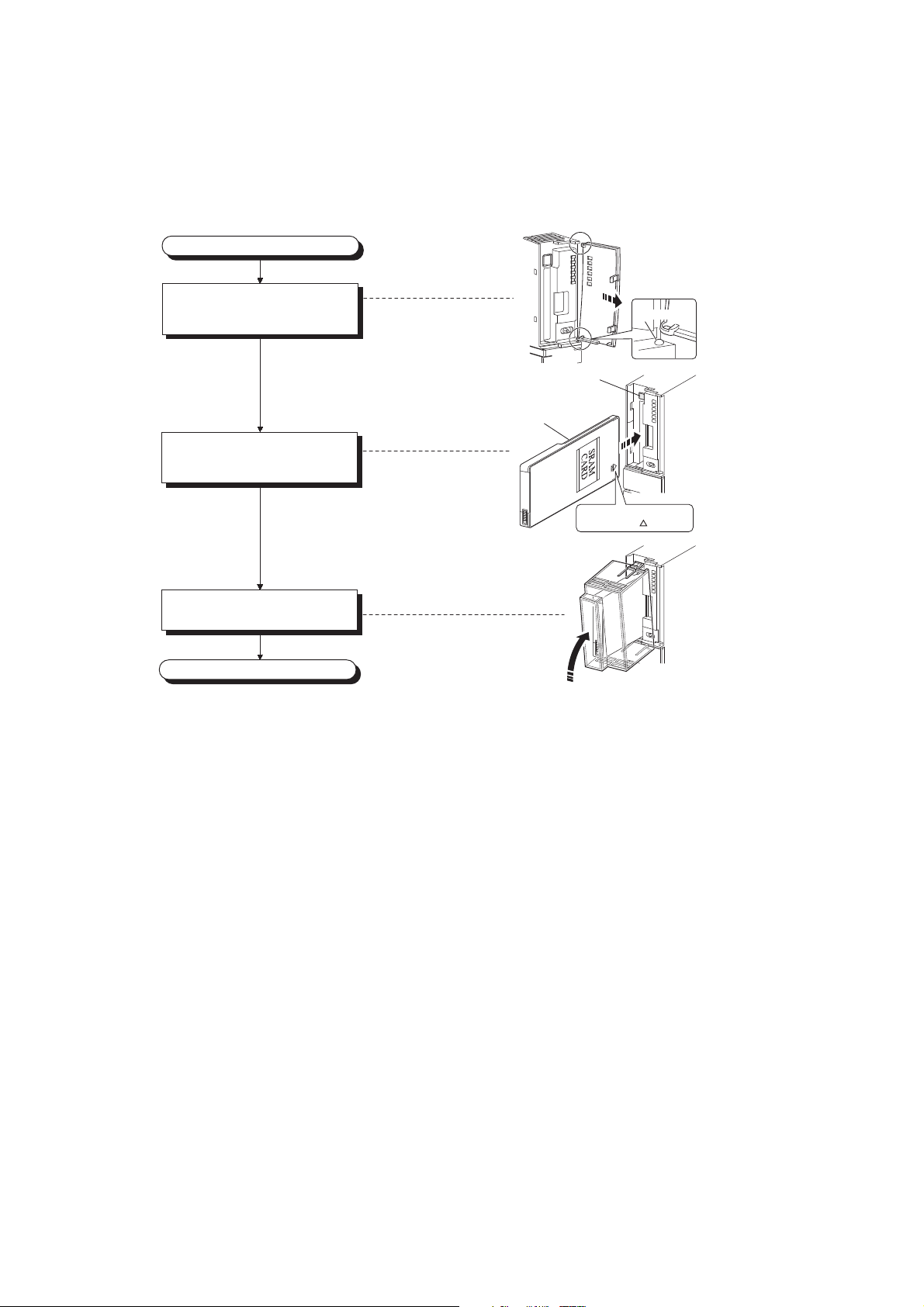
(2) For Q3MEM type memory cards
(a) Installing a memory card
Pay attention to the direction of a memory card and install the card according to the following procedure.
Install the memory card
Power off the CPU module,
and remove the cover
from the module.
Insert a memory card into
the memory card slot.
Attach a memory card protective
cover to the CPU module.
Completed
CPU module
Memory card
Memory card
EJECT button
Remove the cover, slightly bending
the center of the cover to make
space between the projection
and the mounting hole.
Projection
CPU module
*Check the insertion
direction. ( mark)
CPU module
96
Page 99

CHAPTER 4 INSTALLATION AND WIRING
Remove the memory card
Completed
Power off the CPU module, and
remove the memory card
protective cover.
Press the EJECT button to
remove the memory card.
CPU module
Remove the protective
cover, pressing the
fixing claws located on
the top and bottom of
the cover.
CPU module
Push
Memory card
EJECT button
(b) Removing a memory card
When removing a memory card from the CPU module, remove a memory card protective cover and press the
EJECT button to pull out the memory card.
Remove a memory card protective cover, press the memory card EJECT button, and pull out the memory card.
4
(3) Removing a memory card during power-on
Check that the corresponding special relay areas (SM604 and SM605) are off.
When both "SM604" and "SM605" are off, remove the memory card according to the following procedure.
(4) Installing a memory card during power-on
• The memory card cannot be removed while "SM604" is on because the CPU module is using the card.
• Turn off "SM605" if it is on.
1. Turn on the special relay "SM609" using the sequence program or by the device test of a
programming tool.
2. By monitoring the programming tool, check that the special relay "SM600" is turned off.
3. Remove the memory card.
SM600 (Memory card usable flag) : The system turns on this flag when a memory card is
ready to be used.
SM604 (Memory card in-use flag) : The system turns on this flag when a memory card is being
used.
SM605 (Memory card remove/insert
prohibit flag)
1. Install a memory card.
2. Check that the special relay "SM600" is on by monitoring the programming tool.
: The user turns on this flag to disable insertion/removal of a
memory card.
4.5 Installing and Removing a Memory Card
97
Page 100

Observe the following precautions when installing or removing a memory card while power is on.
● Note that the data in a memory card may be damaged if the above procedure is not followed. If the operating status of the
CPU module at the time of an error is set to "Stop" in parameter, the CPU module stops its operation upon the occurrence
of "ICM.OPE.ERROR".
● When a memory card is installed, the scan time of the CPU module increases by several 10ms (maximum). The scan
time increases for only one scan where the CPU module performs the mount processing.
● Poor insertion of the memory card may result in "ICM.OPE.ERROR".
● Using the tweezers below is effective when the memory card cannot be removed smoothly.
Product Model name
Plastic tweezers NK-2539
98
 Loading...