

Page 1

Type QD70 Positioning Module
U
Type QD70 Positioning Module User's Manual
Mitsubishi Programmable
Logic Controller
QD70P4
QD70P8
GX Configurator-PT
(SW1D5C-QPTU-E)
Page 2
A - 1 A - 1
SAFETY INSTRUCTIONS
(Always read these instructions before using this equipment.)
Before using this product, please read this manual and the relevant manuals introduced in this manual
carefully and pay full attention to safety to handle the product correctly.
The instructions given in this manual are concerned with this product. For the safety instructions of the
programmable logic controller system, please read the CPU module User's Manual.
In this manual, the safety instructions are ranked as "DANGER" and "CAUTION".
!
DANGER
CAUTION
!
Indicates that incorrect handling may cause hazardous conditions,
resulting in death or severe injury .
Indicates that incorrect handling may cause hazardous conditions,
resulting in medium or slight personal injury or physical damage.
Note that the !CAUTION level may lead to a serious consequence according to the circumstances.
Always follow the instructions of both levels because they are important to personal safety.
Please save this manual to make it accessible when required and always forward it to the end user.
[DESIGN INSTRUCTION]
!
DANGER
Provide a safety circuit outside the programmable logic controller so that the entire system will
operate safely even when an external power supply error or PLC fault occurs.
Failure to observe this could lead to accidents for incorrect outputs or malfunctioning.
(1) Configure an emergency stop circuit and interlock circuit such as a positioning control
upper limit/lower limit to prevent mechanical damage outside the PLC.
(2) The OPR operation is controlled by the OPR direction and OPR speed data. Deceleration
starts when the near-point dog turns ON. Thus, if the OPR direction is incorrectly set,
deceleration will not start and the machine will continue to travel. Configure an interlock
circuit to prevent mechanical damage outside the PLC.
(3) When the module detects an error, deceleration st op will t ake place.
Make sure that the OPR data and positioning data are within the parameter setting values.
Page 3
A - 2 A - 2
!
CAUTION
Do not bundle or adjacently lay the control wire or communication cable with the main circuit or
power wire.
Separate these by 100mm (3.94in.) or more.
Failure to observe this could lead to malfunctioning caused by noise.
[MOUNTING INSTRU CT ION S ]
!
CAUTION
Use the PLC within the general specifications environment given in t his manual.
Using the PLC outside the general specification range environment could lead t o elect ric
shocks, fires, malfunctioning, product damage or deterioration.
Hold down the module loading lever at the bottom of the module and insert the module fixing
hooks into the base unit fixing holes securely to load the module. Improper loading of the
module can cause a malfunction, failure or drop.
For use in vibratory environment, tighten the module with screws.
Tighten the screws within the specified torque range.
Undertightening can cause a drop, short circuit or malfunction.
Overtightening can cause a drop, short circuit or malfunction due to damage to the screws or
module.
Always load or unload the module after switching power off externally in all phases. Not doing
so may damage the product.
[WIRING INSTRUCTIONS]
!
DANGER
Always confirm the terminal layout before connecting the wires to the module.
[STARTUP/MAINTENANCE INSTRUCTIONS]
!
DANGER
Always turn all phases of the power supply OFF externally before cleaning or tightening the
screws.
Failure to turn all phases OFF could lead to electric shocks.
Page 4

A - 3 A - 3
[STARTUP/MAINTENANCE INSTRUCTIONS]
!
CAUTION
Never disassemble or modify the module.
Failure to observe this could lead to trouble, malfunctioning, injuries or fires.
Always turn all phases of the power supply OFF externally before installing or removing the
module.
Failure to turn all phases OFF could lead to module trouble or malfunctioning.
Before starting test operation, set the parameter speed limit value to the slowest value, and
make sure that operation can be stopped immediately if a hazardous state occurs.
[DISPOSAL INSTRUCTIONS]
!
CAUTION
When disposing of the product, handle it as industrial waste.
Page 5

A - 4 A - 4
REVISIONS
The manual number is given on the bottom left of the back cover
.
Print Date
Manual Number Revision
Jun., 2001 SH (NA)-080171-A First edition
Feb., 2002 SH (NA)-080171-B
Modifications
About Manuals, Section 2.3, Section 2.4, Section 4.6.1, Section 5.3,
Section 5.7, Section 6.2.2, Section 8.2.3, Section 8.2.4, Section
8.2.5, Section 8.2.6, Section 10.3, Appendix 8
Jul., 2002 SH (NA)-080171-C
Modifications
CONTENS, Section .1.1.1, Section 4.2, Section 11.3, Section 11.4,
Section 11.5, Section 13.2, Appendix 2, Appendix 8, INDEX
Japanese Manual Version SH-080138-D
This manual confers no industrial property rights or any rights of any other kind, nor does it confer any patent
licenses. Mitsubishi Electric Corporation cannot be held responsible for any problems involving industrial property
rights which may occur as a result of using the contents noted in this manual.
2001 MITSUBISHI ELECTRIC CORPORATION
Page 6

A - 5 A - 5
INTRODUCTION
Thank you for purchasing the Mitsubishi programmable logic controller MELSEC-Q Series.
Always read through this manual, and fully comprehend the functions and performance of the Q Series PLC
before starting use to ensure correct usage of this product.
CONTENTS
SAFETY INSTRUCTIONS.............................................................................................................................A- 1
REVISIONS....................................................................................................................................................A- 4
CONTENTS....................................................................................................................................................A- 5
About Manuals ...............................................................................................................................................A- 9
Using This Manual..........................................................................................................................................A- 9
Conformation to the EMC Directive and Low Voltage Instruction ................................................................A- 9
Generic Terms and Abbreviations................................................................................................................A- 10
Component List .............................................................................................................................................A- 10
SECTION 1 PRODUCT SPECIFICATIONS AND HANDLING
1 PRODUCT OUTLINE 1- 1 to 1- 10
1.1 Positioning control....................................................................................................................................1- 1
1.1.1 Features of QD70..............................................................................................................................1- 1
1.1.2 Mechanism of positioning control ......................................................................................... ............1- 2
1.1.3 Outline design of positioning control system....................................................................................1- 4
1.1.4 Communicating signals between QD70 and each module..............................................................1- 7
1.2 Positioning control....................................................................................................................................1- 9
1.2.1 Outline of starting ...................................................................................................... ........................1- 9
1.2.2 Outline of stopping ...........................................................................................................................1- 10
2 SYSTEM CONFIGURATION 2- 1 to 2- 5
2.1 General image of system.........................................................................................................................2- 1
2.2 Component list .........................................................................................................................................2- 2
2.3 Applicable system....................................................................................................................................2- 3
2.4 How to check the function version and the software version ................................................................. 2- 4
3 SPECIFICATIONS AND FUNCTIONS 3- 1 to 3- 11
3.1 Performance specifications......................................................................................................................3- 1
3.2 List of functions ........................................................................................................................................3- 2
3.3 Specifications of input/output signal with PLC CPU ...............................................................................3- 4
3.3.1 List of input/output signals with PLC CPU........................................................................................3- 4
3.3.2 Details of input signal (QD70
PLC CPU) .....................................................................................3- 5
3.3.3 Details of output signals (PLC CPU
QD70).................................................................................3- 6
3.4 Specifications of input/output interfaces with external device ................................................................3- 7
3.4.1 Electrical specifications of input/output signals................................................................................ 3- 7
3.4.2 Signal layout for external device connection connector...................................................................3- 9
3.4.3 List of input/output signal details......................................................................................................3- 10
3.4.4 Input/output interface internal circuit................................................................................................3- 11
Page 7

A - 6 A - 6
4 DATA USED FOR POSITIONI NG CON TROL ( LIS T OF BU FFER MEM ORY ADDRE SSES ) 4- 1 to 4- 31
4.1 Type of data .............................................................................................................................................4- 1
4.1.1 Parameters and data required for control.........................................................................................4- 1
4.1.2 Setting items for parameters.............................................................................................................4- 3
4.1.3 Setting items for OPR data...............................................................................................................4- 4
4.1.4 Setting items for JOG data................................................................................................................4- 5
4.1.5 Setting items for positioning data...................................................................................................... 4- 6
4.1.6 Type and roles of monitor data.........................................................................................................4- 7
4.1.7 Type and roles of control data ..........................................................................................................4- 8
4.2 List of parameters ....................................................................................................................................4- 9
4.3 List of OPR data......................................................................................................................................4- 14
4.4 List of JOG data ......................................................................................................................................4- 20
4.5 List of positioning data ............................................................................................................................4- 21
4.6 List of monitor data..................................................................................................................................4- 27
4.6.1 Axis monitor data..............................................................................................................................4- 27
4.6.2 Module information monitor data.....................................................................................................4- 29
4.7 List of control data...................................................................................................................................4- 30
4.7.1 Axis control data...............................................................................................................................4- 30
5 SETUP AND PROCEDURES BEFORE OPERATION 5- 1 to 5- 20
5.1 Handling precautions ...............................................................................................................................5- 1
5.2 Procedures before operation ...................................................................................................................5- 3
5.3 Part identification nomenclature ..............................................................................................................5- 4
5.4 Wiring .......................................................................................................................................................5- 7
5.4.1 Wiring precautions.............................................................................................................................5- 7
5.5 Confirming the wiring ..............................................................................................................................5- 12
5.5.1 Confirmation items at completion of wiring......................................................................................5- 12
5.6 Switch setting for intelligent function module.........................................................................................5- 14
5.7 Simple reciprocating operation...............................................................................................................5- 18
6 UTILITY PACKAGE(GX Configurator-PT) 6- 1 to 6- 17
6.1 Utility package functions .......................................................................................................................... 6- 1
6.2 Installing and uninstalling the utility package..........................................................................................6- 2
6.2.1 User precautions ...............................................................................................................................6- 2
6.2.2 Operating environment......................................................................................................................6- 4
6.3 Explanation of utility package operations................................................................................................6- 5
6.3.1 How to perform common utility package operations........................................................................ 6- 5
6.3.2 Operation overview ...........................................................................................................................6- 7
6.3.3 Starting the intelligent function module utility ................................................................................... 6- 9
6.4 Initial setting.............................................................................................................................................6- 11
6.5 Auto refresh setting.................................................................................................................................6- 13
6.6 Monitor/test..............................................................................................................................................6- 15
6.6.1 Monitor/Test screen..........................................................................................................................6- 15
7 SEQUENCE PROGRAM USED FOR POSITIONING CONTROL 7- 1 to 7- 20
7.1 Precautions for creating program............................................................................................................7- 1
7.2 List of devices used..................................................................................................................................7- 3
Page 8

A - 7 A - 7
7.3 Creating a program ..................................................................................................................................7- 5
7.3.1 General configuration of program.....................................................................................................7- 5
7.3.2 Positioning control operation program..............................................................................................7- 6
7.4 Positioning control program examples....................................................................................................7- 8
7.5 Program details.......................................................................................................................................7- 12
7.5.1 Initialization program ........................................................................................................................7- 12
7.5.2 Start method setting program ..........................................................................................................7- 13
7.5.3 Start program....................................................................................................................................7- 13
7.5.4 Sub program.....................................................................................................................................7- 18
SECTION 2 CONTROL DETAILS AND SETTING
8 OPR CONTROL 8- 1 to 8- 16
8.1 Outline of OPR control.............................................................................................................................8- 1
8.1.1 Two types of OPR control.................................................................................................................8- 1
8.2 Machine OPR control...............................................................................................................................8- 2
8.2.1 Outline of the machine OPR operation.............................................................................................8- 2
8.2.2 Machine OPR method.......................................................................................................................8- 3
8.2.3 OPR method (1): Near-point dog method ........................................................................................8- 4
8.2.4 OPR method (2): Stopper 1 .............................................................................................................. 8- 6
8.2.5 OPR method (3): Stopper 2 .............................................................................................................. 8- 8
8.2.6 OPR method (4): Stopper 3 .............................................................................................................8- 10
8.2.7 OPR method (5): Count 1 ................................................................................................................8- 12
8.2.8 OPR method (6): Count 2 ................................................................................................................8- 14
8.3 Fast OPR control.....................................................................................................................................8- 16
8.3.1 Outline of the fast OPR control operation........................................................................................8- 16
9 POSITIONING CONTROL 9- 1 to 9- 17
9.1 Outline of positioning controls..................................................................................................................9- 1
9.1.1 Data required for positioning control.................................................................................................9- 1
9.1.2 Operation patterns of positioning controls........................................................................................9- 2
9.1.3 Designating the positioning address.................................................................................................9- 8
9.1.4 Confirming the current value.............................................................................................................9- 9
9.2 Setting the positioning data ....................................................................................................................9- 10
9.2.1 Relation between each control and positioning data ......................................................................9- 10
9.2.2 1-axis linear control ..........................................................................................................................9- 11
9.2.3 Speed-position switching control ..................................................................................................... 9- 13
9.2.4 Current value changing....................................................................................................................9- 16
9.3 Multiple axes simultaneous start control ................................................................................................9- 17
10 JOG OPERATION 10- 1 to 10- 6
10.1 Outline of JOG operation.....................................................................................................................10- 1
10.2 JOG operation execution procedure ...................................................................................................10- 3
10.3 JOG operation example.......................................................................................................................10- 4
11 SUB FUNCTIONS 11- 1 to 11- 13
11.1 Outline of sub functions .......................................................................................................................11- 1
Page 9
A - 8 A - 8
11.2 Speed limit function..............................................................................................................................11- 1
11.3 Speed change function........................................................................................................................11- 2
11.4 Software stroke limit function...............................................................................................................11- 5
11.5 Acceleration/deceleration processing function....................................................................................11- 8
11.6 Restart function...................................................................................................................................11- 12
12 COMMON FUNCTIONS 12- 1 to 12- 3
12.1 Outline of common functions ...............................................................................................................12- 1
12.2 External I/O signal switching function..................................................................................................12- 1
12.3 External I/O signal monitor function ....................................................................................................12- 2
13 TROUBLESHOOTING 13- 1 to 13- 14
13.1 Error and warning details.....................................................................................................................13- 1
13.2 List of errors .........................................................................................................................................13- 3
13.3 List of warnings ...................................................................................................................................13- 11
13.4 LED display function...........................................................................................................................13- 13
13.5 Confirming the error definition using system monitor of GX Developer............................................13- 14
APPENDIX App- 1 to App- 18
Appendix 1 External dimension drawing ...................................................................................................App- 1
Appendix 2 Operation timing and processing time in each control ..........................................................App- 2
Appendix 3 Connection examples with servo amplifiers manufactured by MITSUBISHI Electric Corporation
.................................................................................................................................................App- 6
Appendix 3.1 Connection example of QD70P
and MR-H A...........................................................App- 6
Appendix 3.2 Connection example of QD70P
and MR-J2/J2S- A................................................App- 7
Appendix 3.3 Connection example of QD70P
and MR-C A...........................................................App- 8
Appendix 4 Connection examples with stepping motors manufactured by ORIENTALMOTOR Co., Ltd.
.................................................................................................................................................App- 9
Appendix 4.1 Connection example of QD70P
and VEXTA UPD .....................................................App- 9
Appendix 5 Connection examples with servo amplifiers manufactured by Matsushita Electric Industrial Co.,
Ltd...........................................................................................................................................App- 10
Appendix 5.1 Connection example of QD70P
and MINAS A series ...............................................App- 10
Appendix 6 Connection examples with servo amplifiers manufactured by Yamayo Electric Co., Ltd...App- 11
Appendix 6.1 Connection example of QD70P
and PZ series..........................................................App- 11
Appendix 7 Connection examples with servo amplifiers manufactured by Yasukawa Electric Co., Ltd
................................................................................................................................................App- 12
Appendix 7.1 Connection example of QD70P
and Σ- series .........................................................App- 12
Appendix 8 Comparisons with type QD75 positioning module................................................................App- 13
Appendix 9 List of buffer memory addresses...........................................................................................App- 16
INDEX Index- 1 to Index- 5
Page 10

A - 9 A - 9
About Manuals
The following manuals are also related to this product.
In necessary, order them by quoting the details in the tables below.
Detailed Manuals
Manual Name
Manual Number
(Model Code)
Type QD70 Positioning Module User's Manual (Hardware)
Describes the performance, specifications, I/O interface, component names, and startup procedure of
the respective positioning modules: QD70P4 and QD70P8. (The manual is supplied with the module.)
IB-0800169
(13JT42)
Using This Manual
The symbols used in this manual are shown below.
Pr.
...... Symbol indicating positioning parameter and OPR parameter item.
OPR.
....... Symbol indicating OPR data item.
JOG.
....... Symbol indicating JOG data item.
Da.
...... Symbol indicating positioning data item.
Md.
...... Symbol indicating monitor data item.
Cd.
....... Symbol indicating control data item.
(A serial No. is inserted in the
mark. )
Numeric values used in this manual
• The buffer memory addresses, error codes and warning codes are represented
in decimal.
• The X/Y devices are represented in hexadecimal.
• The setting data and monitor data are represented in either decimal or
hexadecimal. The data ended b y "H" are repres en ted in hex a dec imal.
(Example) 10.........10 Decimal
10H......16 Hexadecimal
Conformation to the EMC Directive and Low Voltage Instruction
For details on making Mitsubishi PLC conform to the EMC directive and low
voltage instruction when installing it in your product, please refer to Chapter 3,
“EMC Directive and Low Voltage Instruction” of the using PLC CPU module
User’s Manual (Hardware).
The CE logo is printed on the rating plate on the main body of the PLC that
conforms to the EMC directive and low voltage instruction.
To make this product conform to the EMC directive and low voltage instruction,
please refer to Section 5.4.1 "Wiring precautions".
Page 11

A - 10 A - 10
Generic Terms and Abbreviations
Unless specially noted, the following generic terms and abbreviations are used in
this manual.
Generic term/abbreviation Details of generic term/abbreviation
PLC CPU Generic term for PLC CPU on which QD70 can be mounted.
AD75 Generic term for type A1SD75P1-S3/P2-S3/P3-S3, AD75P1-S3/P2-S3/P3-S3 Positioning
module.
The module type is described to indicate a specific modul e.
QD70 Generic term for type QD70 positioning module QD70P4/QD70P8.
The module type is described to indicate a specific modul e.
QD75
Generic term for positioning module QD75P1, QD75P2, QD75P4, QD75D1, QD 75D2, and
QD75D4.
The module type is described to indicate a specific modul e.
Peripheral device
Generic term for DOS/V personal computer where following "GX Configurator-PT" and ""GX
Developer" have been installed.
GX Configurator-PT
Abbreviation for GX Configurator-PT (SW1D5C-QPTU-E) utility package for QD70 positioning
module.
GX Developer Abbreviation for GX Developer (SW4D5C-GPPW-E or later).
Drive unit
Abbreviation for open collector pulse input compatible drive unit (servo amplifier or stepping
motor).
DOS/V personal computer IBM PC/AT® and compatible DOS/V compliant personal computer.
Personal computer Generic term for DOS/V personal computer.
Workpiece Generic term for moving body such as workpiece and tool, and for v arious control targ ets.
Axis 1, axis 2, axis 3,
axis 4, axis 5, axis 6,
axis 7, axis 8
Indicates each axis connected to QD70.
1-axis, 2-axes, 3-axes,
4-axes, 5-axes, 6-axes,
7-axes, 8-axes
Indicates the number of axes. (Example: 2-axes = Indicates two axes such as axis 1 and axis
2, axis 2 and axis 3, and axis 3 and axis 1.)
Component List
The component list of this product is given below.
Type Component Quantity
QD70P4 Type QD70P4 Positioning Module (4-axes open-collector output type) 1
QD70P8 Type QD70P8 Positioning Module (8-axes open-collector output type) 1
SW1D5C-QPTU-E GX Configurator-PT Version 1 (1-license product) (CD-ROM) 1
SW1D5C-QPTU-EA GX Configurator-PT Version 1 (Multiple-license product) (CD-ROM) 1
Page 12

SECTION 1 PRODUCT SPECIFICATIONS
AND HANDLING
Section 1 is configured for the following purposes (1) to (4).
(1) To understand the outline of positioning control, and the QD70 specifications
and functions
(2) To carry out actual work such as installation and wiring
(3) To set parameters and data required for positioning control
(4) To create a sequence program required for positioning control
Read "Section 2" for details on each control.
CHAPTER 1 PRODUCT OUTLINE ................................................................................. 1- 1 to 1- 10
CHAPTER 2 SYSTEM CONFIGURATION..................................................................... 2- 1 to 2- 5
CHAPTER 3 SPECIFICATIONS AND FUNCTIONS...................................................... 3- 1 to 3- 11
CHAPTER 4 DATA USED FOR POSITIONING CONTROL.......................................... 4- 1 to 4- 31
CHAPTER 5 SETUP AND PROCEDURES BEFORE OPERATION............................. 5- 1 to 5- 20
CHAPTER 6 UTILITY PACKAGE.................................................................................... 6- 1 to 6- 17
CHAPTER 7 SEQUENCE PROGRAM USED FOR POSITIONING CONTROL........... 7- 1 to 7- 20
SECTION 1
Page 13

MEMO
SECTION 1
Page 14

1 - 1 1 - 1
MELSEC-Q
1 PRODUCT OUTLINE
CHAPTER 1 PRODUCT OUTLINE
This user's manual provides the specifications, handling, programming methods and
other information of the QD70 positioning module used with the MELSEC-Q series
CPU module.
1.1 Positioning control
1.1.1 Features of QD70
The following are the features of the QD70.
(1) Wide assortment of 4-axes and 8-ax es modul es
The QD70 is a positioning module used in a multi-axes system that does not
need complex control.
It is not compatible with the MELSEC-A series AD70 positioning module in I/O
signals, functio n s, et c.
(2) About positioning control functions
(a) The QD70 has a number of functions required for a positioning control
system, such as posi ti oni ng cont r ol to any po sit io n an d equa l - spee d contr ol .
1) You can set up to 10 pieces of positioning data, which include
positioning address, control method, operation pattern and like, per axis.
These positioning data are used to exercise positioning control axis-byaxis.
2) Axis-by-axis positioning control allows linear control (up to 8 axes can be
controlled simul tane ou sly ) .
This control can perform positioning termination with one piece of
positioning data or exercise continuous positioning control by continuous
execution of multi pl e pi e ces of po sit ion in g da ta.
(b) As the control method, any of position control, speed-position switching
control and current value changing may be specified in each positioning
data.
(c) The following six different OPR methods are available for "machine OPR
control": nea r-p oi nt do g meth od (o ne met h od ), stop pe r (t hree met h od s) an d
count (two methods).
(d) Varying finely in speed to ensure smooth acceleration/deceleration, the
QD70 is suitable fo r co nne ctio n t o a st epping motor.
(e) You can change the I/O signal logic according to the specifications of the
external device.
This allows the input signals to be used with either of "normally open" and
"normally closed" contacts, and the output signals to be used according to
the specifications of the drive unit.
(3) Fast start processing
Processing at a position control start has been speeded up to shorten the start
processing time of one axis to 0.1ms.
At a simultaneous start of multiple axes (the positioning start signals are turned
ON at the same time within one scan), there are no starting delays between the
axes.
(4) Ease of maintenance
In the QD70, error definitions have been subdivided to improve maintenance
performance.
(5) Ease of utility package settings
The optionally available utility package (GX Configurator-PT) allows initial setting
and auto refresh setting to be made on the screen, reducing sequence programs
and facilitating the confirmation of the setting status and operating status.
1
Page 15
1 - 2 1 - 2
MELSEC-Q
1 PRODUCT OUTLINE
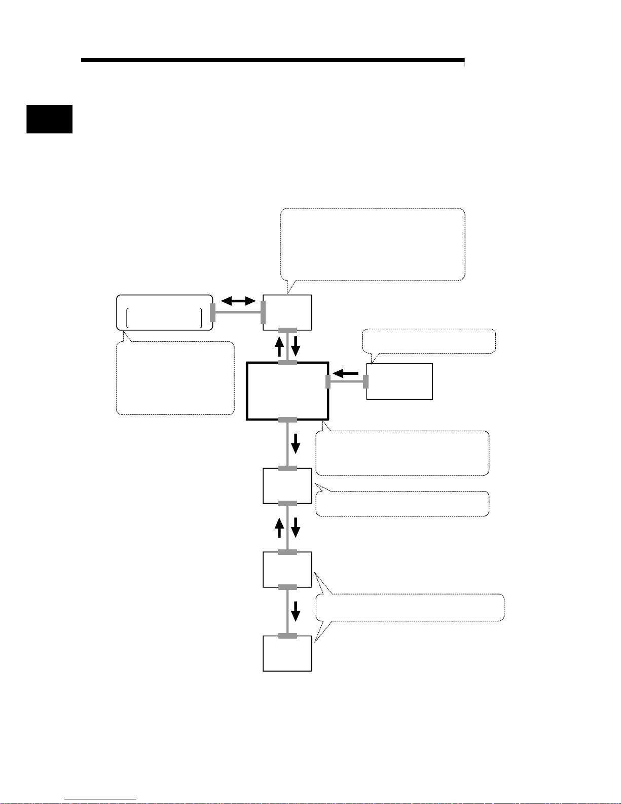
1.1.2 Mechanism of positioning control
Positioning control using the QD70 is exercised using "pulse signals". (The QD70 is a
module that outputs pulses.)
In a positioning control system using the QD70, a variety of software and external
devices are used to play their roles as shown below.
The QD70 imports various signals, parameters and data, and exercises control with
the PLC CPU to realiz e co mpl e x po siti oni ng con tro l.
Stores the created program.
The QD70 outputs the positioning start signal and
axis stop signal following the stired program.
QD70 errors, etc., are detected.
PLC CPU
Peripheral device
GX Developer/
GX Configurator-PT
QD70
positioning
module
Drive
unit
Stores the parameter and data
Outputs to the drive unit according to the
instructins from the PLC CPU.
Receives pulses commands from QD70,
and drives the motor.
Carries out the actual work according to
commands from the drive unit
Motor
Workpiece
Using GX Developer, create
control sequence and conditions
as sequence program.
Adding in GX Configurator-PT
enables initial setting of
parameters and data.
Input near-point dog signal and speed
-position switching signal to QD70.
Mechanical
system inputs
(Switches)
1
Page 16
1 - 3 1 - 3
MELSEC-Q
1 PRODUCT OUTLINE
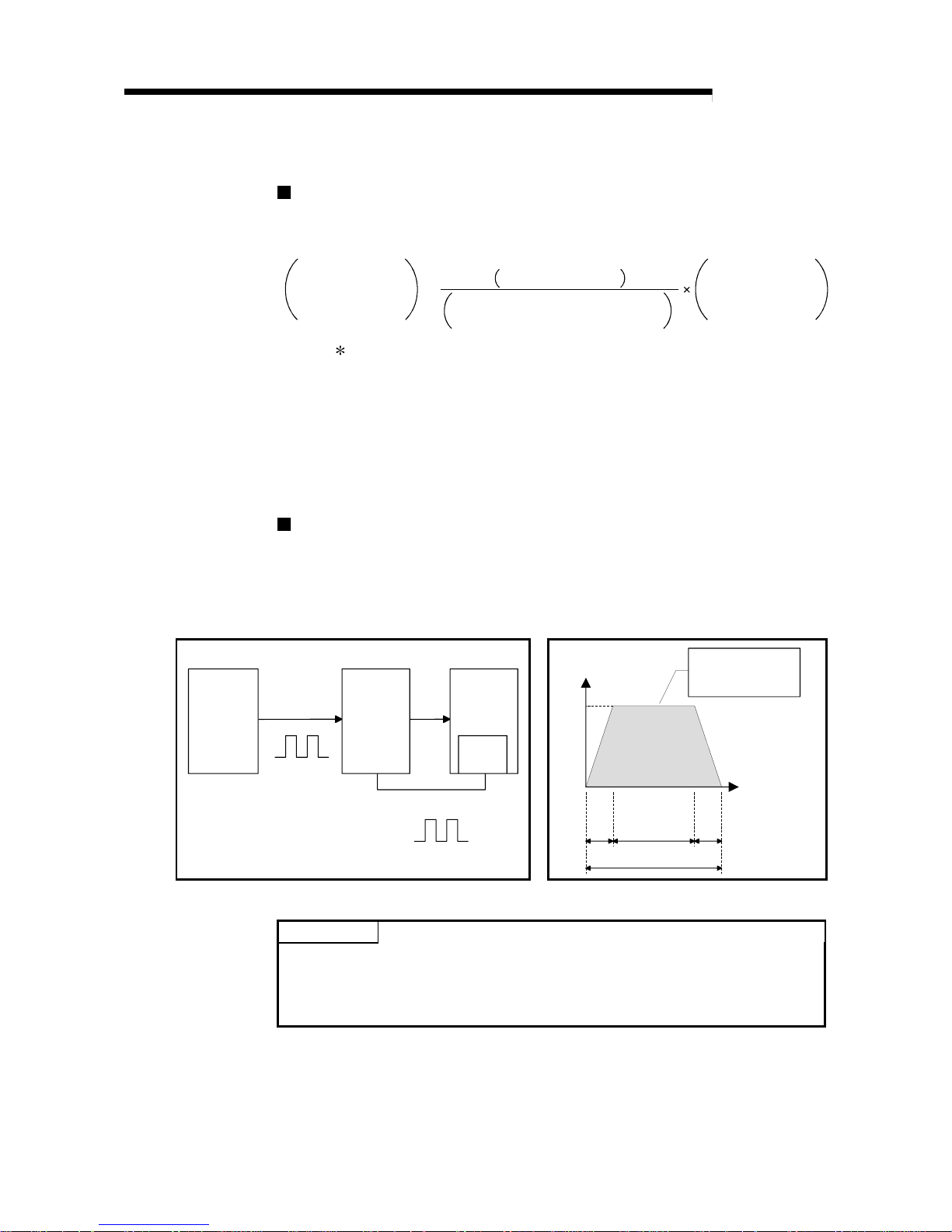
The principle of "position control" and "speed control" operation is shown below.
Position control
The total No. of pulses required to move the designated distance is obtained in the
following manner.
Total No. of pulses
required to move
designated distance
Designated distance
Movement amount of machine (load)
side when motor rotates once
No. of pulses
required for motor to
rotate once
=
The No. of pulses required for the motor to rotate once is the "encoder resolution"
described in the motor catalog specification list.
When this total No. of pulses is issued from the QD70 to the drive unit, control to move
the designated distance can be executed.
The machine side movement amount when one pulse is issued to the drive unit is
called the "movement amount per pulse". This value is the min. value for the workpiece
to move, and is also the electrical positioning control precision.
Speed control
Though the above "total No. of pulses" is an element needed to control the
movement amount, speed must be controlled to perform equal-speed operation.
This "speed" is controlled by the "pulse frequency" output from the QD70 to the drive
unit.
Speed=Pulses frequency
Movement amount=No. of puleses
Feedback pulses=
Pulses generated by detector
Positioning
module
Servo
amplifiter
Servo
motor
Detector
Pulses generated by detector
A
ta td
0.4 0.41.2
(s)
Pulse frequency
[pps]
This area is hte total
No. of commanded
pulses.
Movement amount t = 2
Fig. 1.1 Relationship between position control and speed control
POINT
• The "movement amount per pulse" is the value determined on the machine side.
(Refer to Section 1.1.3.)
• The QD70 uses the "total No. of pulses" to control the position, and uses the
"pulse frequency" to control the speed.
Page 17
1 - 4 1 - 4
MELSEC-Q
1 PRODUCT OUTLINE
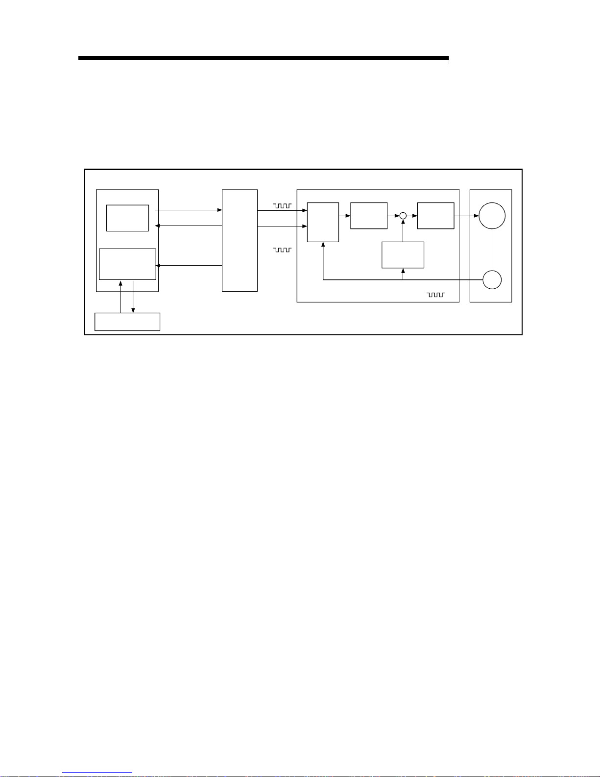
1.1.3 Outline design of positioning control sy stem
The outline of the positioning control system operation and design, using the QD70, is
shown below.
(1) Positioning control system using QD70
Positioning module
QD70
PLC CPU
M
PG
GX Configurator-PT
Program
Intelligent
function module
parameter
Read, write, etc.
Monitor date read
Initial setteng /Auto rofresh setting/Monitor
Drive unit
Buffer
memories
/XY
device
Forward run
pulse train
Reverse run
pulse train
Deviation
counter
D/A
converter
Speed
command
Servo
amplifiter
Interface
Feedback pulse
Servomotor
Fig. 1.2 Outline of the operation of positioning control system using QD70
(a) Positioning operation by the QD70
1) The QD70 output is a pulse train.
The pulse train output by the QD70 is counted by and stored in the
deviation counter in the drive unit.
The D/A converter outputs an analog DC current proportionate to the
count maintained by the deviation counter (called "pulse droop"). The
analog DC current serves as the servo motor speed control signal.
2) The servo motor rotation is controlled by the speed control signal from
the drive unit.
As the servo motor rotates, the pulse generator (PG) attached to the
servo motor generates feedback pulses, the frequency of which is
proportionate to the rotation speed.
The feedback pulses are fed back to the drive unit and decrements the
pulse droop, the pulse count maintained by the deviation counter.
The motor keeps on rotating as the pulse droop is maintained at a
certain level.
3) When the QD70 terminates the output of a pulse train, the servo motor
decelerates as the pulse droop decreases and stops when the count
drops to zero.
Thus, the servo motor rotation speed is proportionate to the pulse
frequency, while the overall motor rotation angle is proportionate to the
total number o f pu l ses ou tp ut by the QD70.
Therefore, when a movement amount per pulse is given, the overall
movement amount can be determined by the number of pulses in the
pulse train.
The pulse frequency, on the other hand, determines the servo motor
rotation speed (feed speed).
Page 18
1 - 5 1 - 5
MELSEC-Q
1 PRODUCT OUTLINE
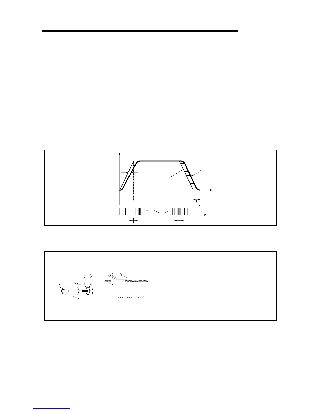
(b) Pulse train output from the QD70
1) As shown in Fig. 1.3, the pulse frequency increases as the servo motor
accelerates. The pulses are sparse when the servo motor starts and
more frequent when the servo motor speed comes close to the target
speed.
2) The pulse frequency stabilizes when the motor speed equals the target
speed.
3) The QD70 decreases the pulse frequency (sparser pulses) to
decelerate the servo motor before it finally stops the output.
There will be a little difference in timing between the decrease in the
pulse frequency and the actual deceleration and stopping of the servo
motor.
This difference, called "the stop settling time", is required for gaining a
stopping accuracy.
Speed V Pulse droop
amount
Pulse
distribution
Servomotor
speed
Acceleration
Deceleration
Time t
Stop
setting time
Pulse train Rough Dense
Rough
Fig. 1.3 QD70 output pulses
(2) Movement amount and speed in a system usi ng w orm g ear s
V
L
P0
P
Workpiece
Worm pear
Table
Pulse
generator
(PG)
Servomotor
A : Movement amount per pulse (mm/pulse)
Vs : Command pulse frequency (pulse/s)
n : No. of pulse generator slits
"
No. of pulses" (pulse/rev)
L : Worm gear lead (mm/rev)
R : Deceleration ratio
V : Movable section speed (mm/s)
N : Motor speed (r/min)
K : Position loop gain (1/s)
ε
: Deviation counter droop pulse amount
P0 : OP (pulse)
P : Address (pulse)
Fig. 1.4 System using worm gears
Page 19

1 - 6 1 - 6
MELSEC-Q
1 PRODUCT OUTLINE
In the system shown in Fig. 1.4, the movement amount per pulse,
command pulse frequency, and the deviation counter droop pulser amount
are determined as follows:
1) Movement amount per pulse
The movement amount per pulse is determined by the worm gear lead,
deceleration ratio, and the No. of pulse generator slites.
The movement amount, therefore, is given as follows: (Number of
pulses output) × (Movement amount per pulse).
L
A =
R
×
n
[mm/pulse]
2) Command pulse frequency
The command pulse frequency is determined by the speed of the
moving part and movement amount per pulse.
V
Vs =
A
[pulse/s]
3) Deviation counter droop pulser amount.
The deviation counter droop pulser amount is determined by the
command pulse frequency and position loop gain.
Vs
ε
=
K
[pulse]
Page 20
1 - 7 1 - 7
MELSEC-Q
1 PRODUCT OUTLINE
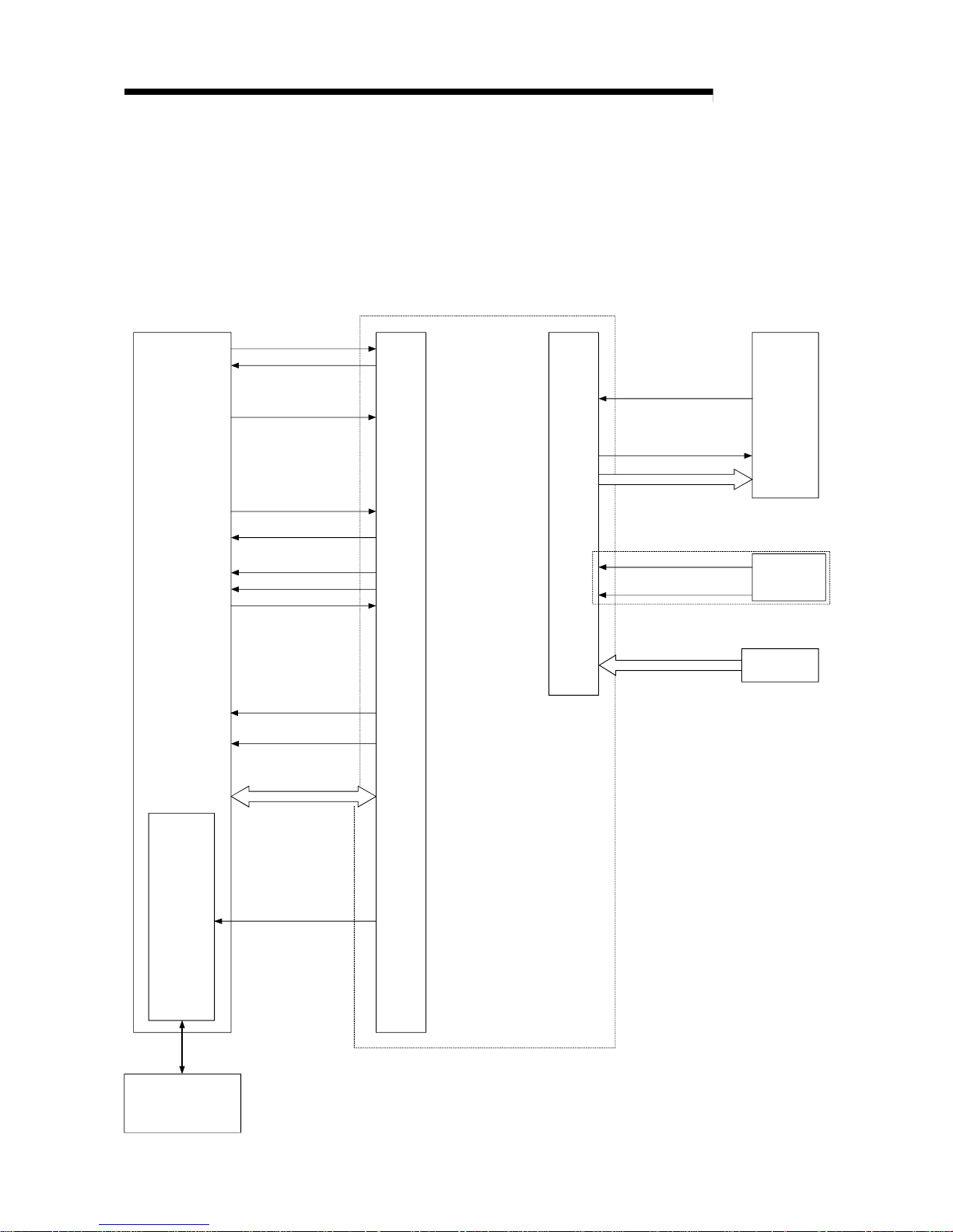
1.1.4 Communicating signals between QD 70 and each mo dul e
The outline of the signal communication between the QD70 (positioning module) and
PLC CPU, peripheral device (GX Configurator-PT) and drive unit, etc., is shown below.
(A peripheral device communicates with the QD70 via the PLC CPU to which it is
connected)
Refer to Chap te r 3 fo r de tails of the I/O si gn al s.
PLC READY signal
Module READY signal
JOG start signal
BUSY signal
Drive
unit
Deviation counter clear
Pulse train
QD70
Y0
X0
PLC CPU
Near-point dog singal
Monitor data
Y18 to Y1F
X10 to X17
Y10 to Y17
X1
Y8 to YF
X18 to X1F
X8 to XF
X2
Axis warning occurrence
signal
24VDC
Power supply
Peripheral device
(GX Configurator-PT)
Initial setting/ Auto refresh/
Operation monitor
Positioning start
Start comple te signal
Axis stop signal
Positioning complete
signal
Axis error occurrence
signal
Mechanical
system inputs
(Switches)
Speed-position switching
signal
(For pulse train output)
Zero signal
Date write/read
Interface
with
PLC CPU
Peripheral
device
interface
External
interface
Page 21
1 - 8 1 - 8
MELSEC-Q
1 PRODUCT OUTLINE
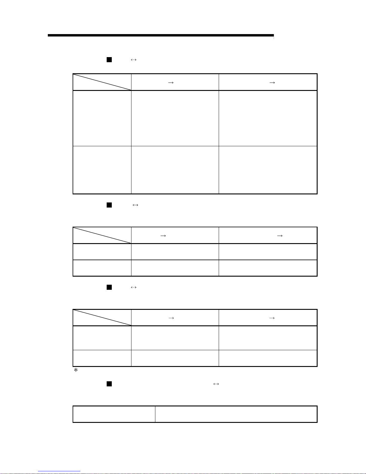
QD70 PLC CPU
The QD70 and PLC CPU communicate the following data via the base unit.
Direction
Communication
QD70
PLC CPU PLC CPU QD70
Control signal
Signal indication QD70 state.
•
Module READY (X0)
•
Axis error occurrence (X1)
•
Axis warning occurrence (X2)
•
BUSY (X8 to XF)
•
Start complete (X10 to X17)
•
Positioning complete (X18 to X1F)
Signal related to commands.
•
PLC READY (Y0)
•
Positioning start (Y8 to YF)
•
Axis stop (Y10 to Y17)
•
JOG start (Y18 to Y1F)
Data (read/write)
•
Parameter
•
OPR data
•
JOG data
•
Positioning data
•
Control data
•
Monitor data
•
Parameter
•
OPR data
•
JOG data
•
Positioning data
•
Control data
QCPU Peripheral device (GX Configurator-PT)
The QCPU and peripheral device make the following communications. (Refer to
Chapter 6 for de ta il s. )
Direction
Communication
QCPU
Peripheral device Peripheral device QCPU
Data –
•
Initial setting
•
Auto refresh setting
Operation monitor
•
Monitor data (QD70 buffer
memory/XY devices)
–
QD70 Drive unit
The QD70 and drive unit communicate the following data via the external device
connection connector.
Direction
Communication
QD70
Drive unit Drive unit QD70
Control signal
Signals related to commands
•
Deviation counter clear signal
(CLEAR)
Signal indicating OP
•
Zero signal (PG0)
Pulse train
•
Pulse train output (PULSE F/
PULSE R)
–
: External 24VDC must be supplied to output the pulse train.
Mechanical system inputs (switches) QD70
The input signals from the mechanical system inputs (switches) are entered into the
QD70 via the exte r nal dev i c e con ne cti on conn e cto r .
Mechanical system inputs (switches)
•
Near-point dog signal (DOG)
•
Speed-position switching signal (CHG)
Page 22
1 - 9 1 - 9
MELSEC-Q
1 PRODUCT OUTLINE
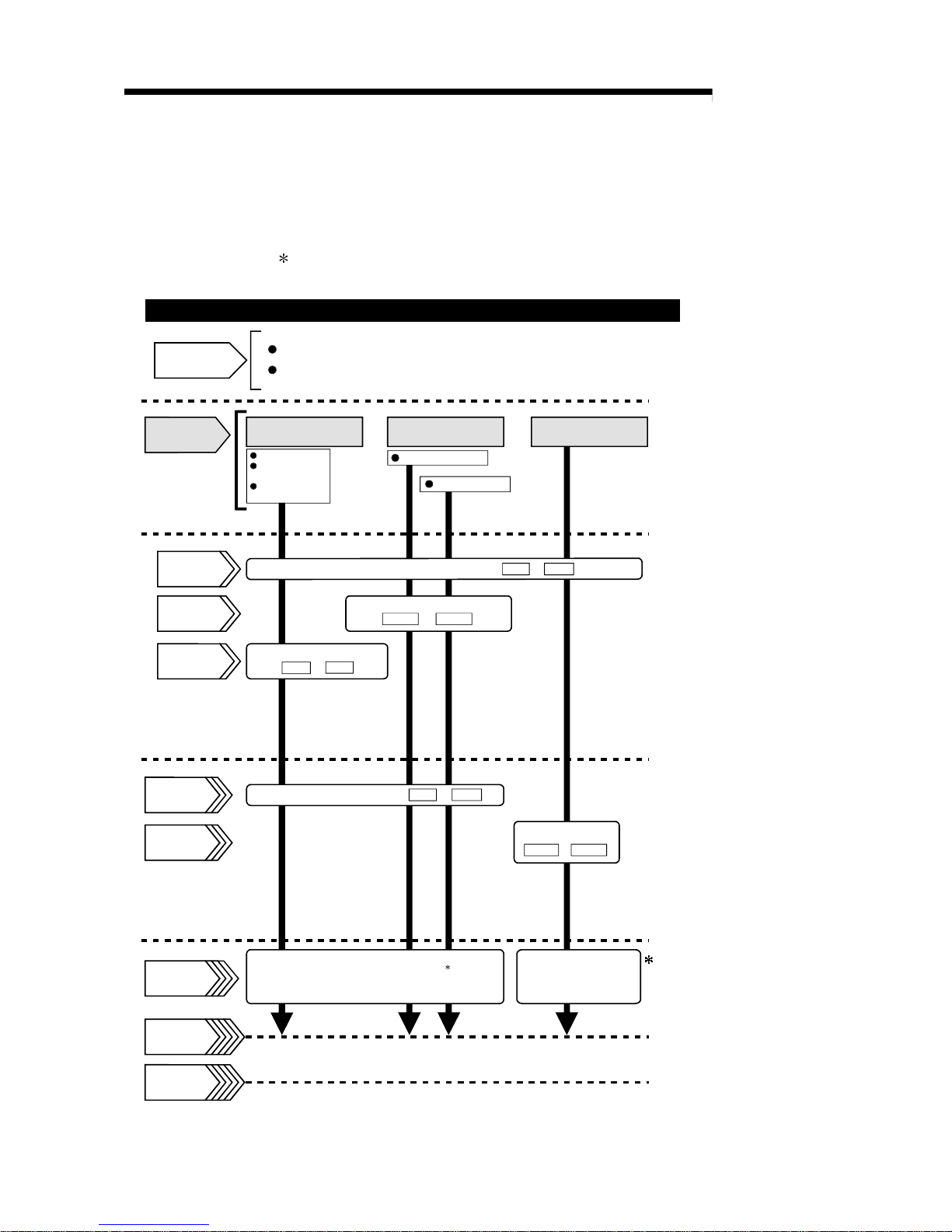
1.2 Positioning control
1.2.1 Outline of starting
The outline for starting each control is shown with the following flowchart.
It is assumed that each module is installed, and the required system configuration,
etc., has been prepared.
Machine OPR control
Fast OPR control
OPR control
Set the OPR data.
OPR. 1 to
OPR. 9
Preparation
Control
functions
Flow of starting
Installation and connection of module
Setting of hardware
Position control
Speed-position
switching control
Current value
changing
Positioning control
JOG operation
Parameter
Positioning
data
OPR data
Control data
Start signal
Control start
Control end
Set the parameters.
Set the start method.( Da. 1 to Da. 7 )
Operation
Stop
Turn ON the QD70 start signal
from the PLC CPU
Set the positioning data.
( Da. 1 to Da. 7 )
Set the JOG data
( JOG. 1 to JOG. 4 )
JOG data
( Pr. 1 to Pr. 10 )
: Positioning control can make a
multiple axes simultaneous start.
(Refer to "Section 9.3" for details.)
Turn the QD70 JOG
start signal ON from
the PLC CPU
Page 23
1 - 10 1 - 10
MELSEC-Q
1 PRODUCT OUTLINE
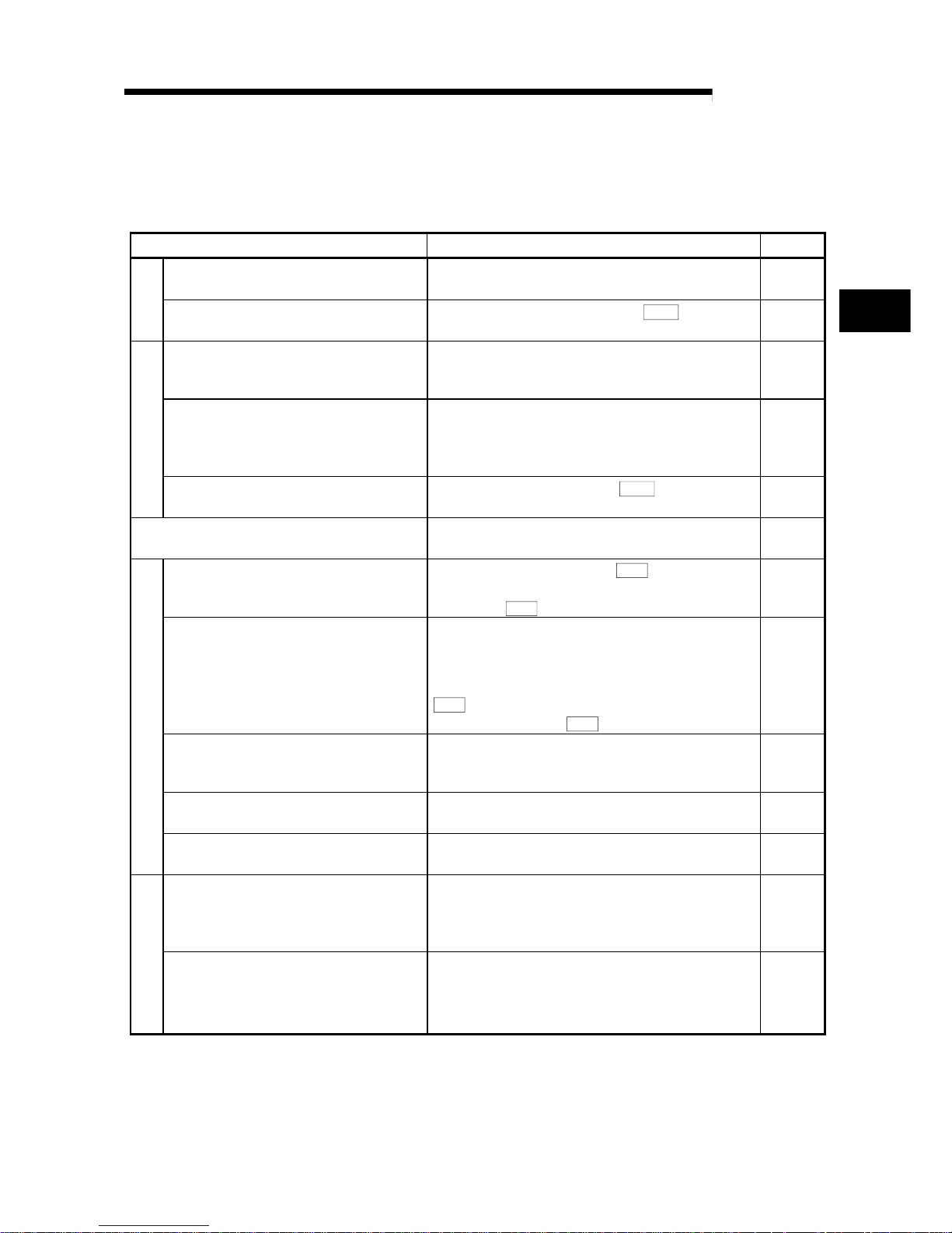
1.2.2 Outline of stopping
The possible causes of a control stop are as follows.
(1) Control ended normally
(2) An error occurred in the PLC CPU
(3) An error occurred in the QD70
(4) The axis stop signal from the PLC CPU turned ON
Stop processings performed in the above cases are outlined in the following table.
(Except the case (1) where control sto pped normally)
Stop processing
Stop factor
Stopped
axis
Axis operation
status (
Md. 4
)
after stop
OPR control
Positioning
control
JOG operation
PLC CPU error All axes Error Deceleration stop
Software stroke limit
upper/lower limit error
1
Axis by axis Error Deceleration stop
QD70 error
Other error Axis by axis Error
Deceleration stop
2
"Axis stop signal" from PLC CPU turned
ON
Axis by axis Stopped
Deceleration stop
3
1: By making parameter setting, you can set the software stroke limit valid/invalid. When the stroke limit is set invalid, a
deceleration stop is not made. (Refer to Section 4.2.)
2: If an illegal positioning data setting value caused an error during posit ion control (operation pattern: continuous path
control), an immediate stop is made at the positioning data prec eding th at illega l setting v alue. (R efer to Secti on 9.1.2.)
3: For position control (operation pattern: continuous path control), you can make parameter setting to select the
stopping method (position match stop or deceleration stop). (Refer to Section 4.2.)
Stop after multiple axes simultaneous start under positioning control
The axes started will not stop simultaneously. The stop command (axis stop signal
ON) must be given to each axis.
Page 24
2 - 1 2 - 1
MELSEC-Q
2 SYSTEM CONFIGURATION
CHAPTER 2 SYSTEM CONFIGURATION
This chapter explains the system configuration of the QD70.
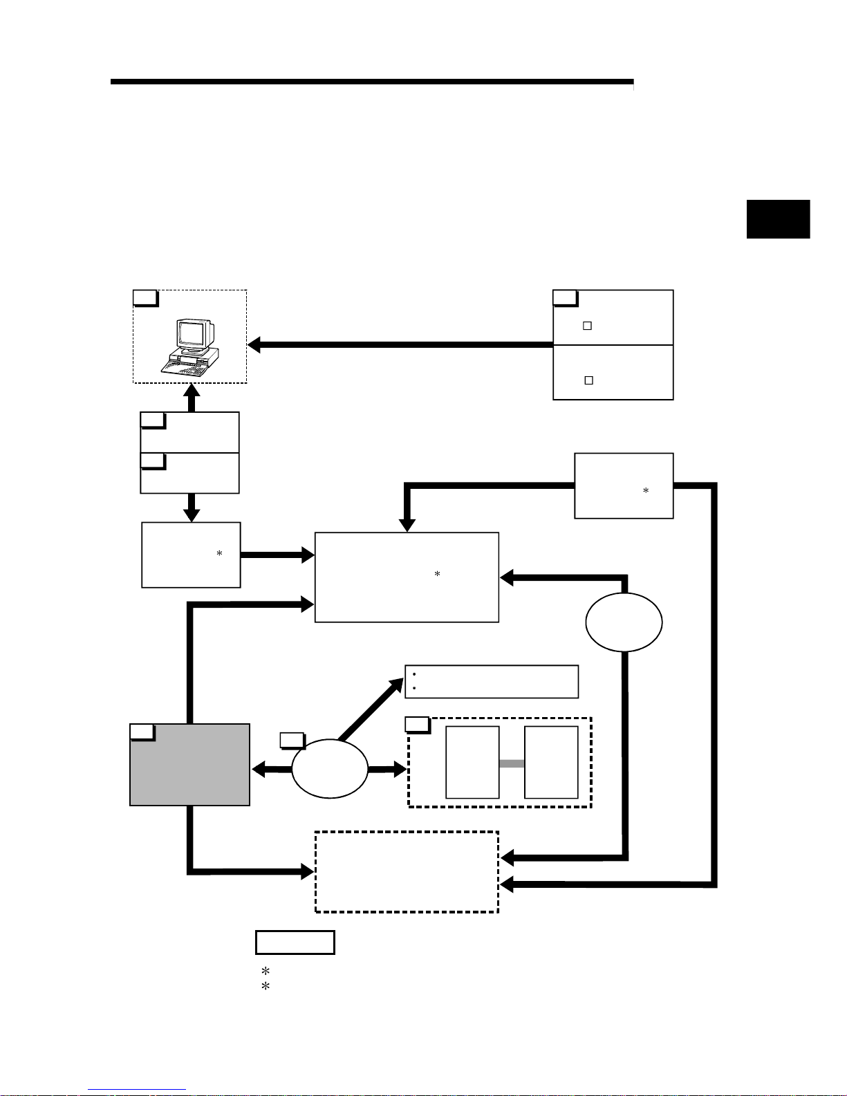
2.1 General image of system
The following is the general configuration including the QD70, PLC CPU, peripheral
device and others.
(The numbers in the sketch correspond to the "Nos." in the table in "Section 2.2
Component list" on the next page.)
Extension system
6
Drive
unit
Motor
4
5
RS-232
cable
USB cable
1
Positioning module
QD70P4/QD70P8
7
Connection
cable
Mechanical system inputs (switches)
Near-point dog signal
Speed-position switching signal
Extension
cable
Power supply
module
Main base unit
CPU module
3 2
GX Developer
(SW D5C-GPPW-E)
GX Configurator-PT
(SW D5C-QPTU-E)
Peripheral device
Personal
computer
1
2
2
REMARK
1: For the usable CPU module, refer to "Section 2.3 Applicable system".
2: For the usable base unit and power supply module, refer to the CPU Module
User's Manual.
2
Page 25

2 - 2 2 - 2
MELSEC-Q
2 SYSTEM CONFIGURATION
2.2 Component list
A positioning system using the QD70 consists of the following components.
No. Product Type Remarks
1 Positioning module
QD70P4
QD70P8
QD70P
No. of control axes
Open collector output typeP
GX Developer SW D5C-GPPW-E
2
GX Configurator-PT SW
D5C-QPTU-E
For details, refer to the GX Developer Operating Manual and
"CHAPTER 6 UTILITY PACKAGE (GX Configurator-PT)".
3 Personal computer
DOS/V personal
computer
(User-prepared)
Refer to the GX Developer Operating Manual for details.
4 RS-232 cable QC30R2
(User-prepared)
RS-232 cable for connection of the CPU module and DOS/V personal
computer.
Refer to the GX Developer Operating Manual for details.
5 USB cable –
(User-prepared)
USB cable for connection of the CPU module and DOS/V personal
computer.
Refer to the GX Developer Operating Manual for details.
6 Drive unit –
(User-prepared)
Refer to the drive unit manual for details.
7
Connection cable
(for connection of
QD70 and drive unit)
–
(User-prepared)
Cable for connection of the QD70 and drive unit or mechanical system
input signals.
(To be fabricated in reference to the connected device manual and
Section 3.4.2)
2
Page 26
2 - 3 2 - 3
MELSEC-Q
2 SYSTEM CONFIGURATION
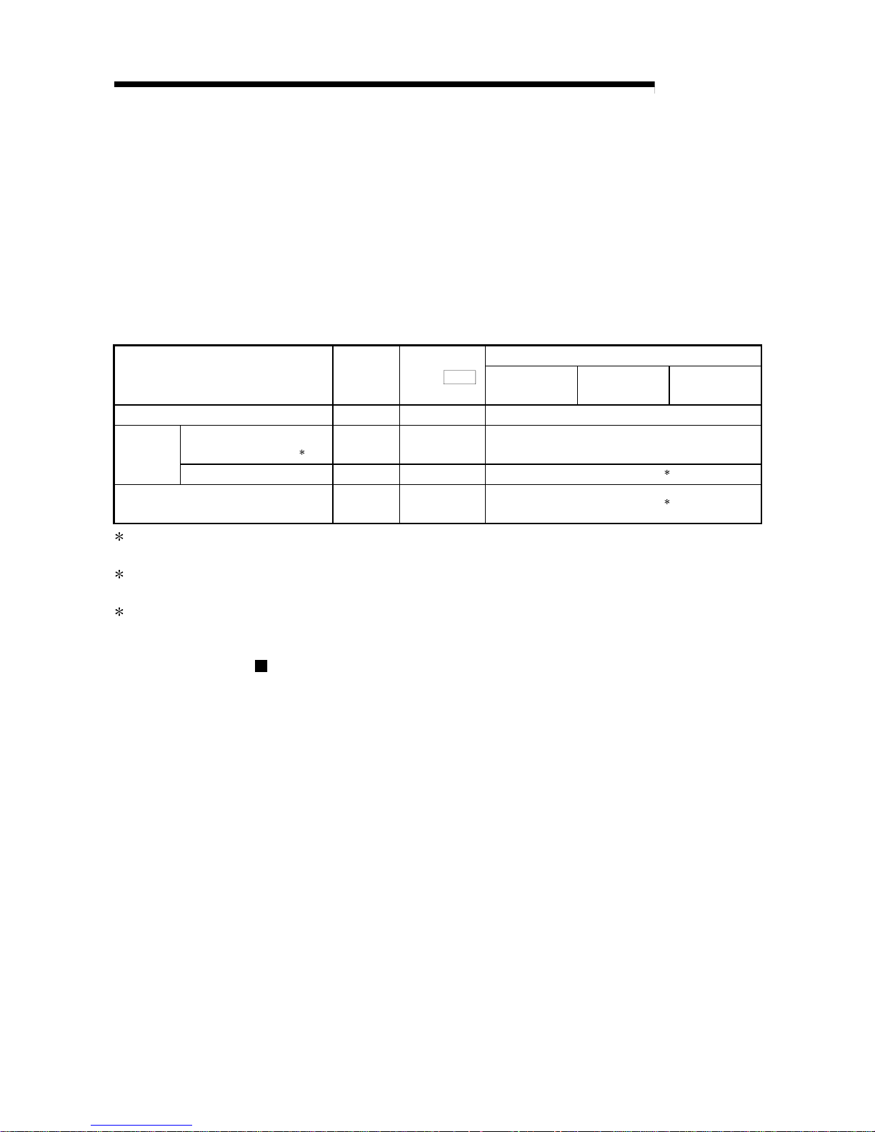
2.3 Applicable system
The QD70 is usable with the following system.
(1) Applicable module and the number o f modules that ca n be i nstal led
The following are the CPU module and network module (for remote I/O stations)
in which the QD70 can be installed and the number of modules that can be
installed.
Applicable module
Number of modules that
can be installed
Remarks
Q00JCPU Maximum 16
Q00CPU
Q01CPU
Maxi mum 24
(
1
)
Q02CPU
Q02HCPU
Q06HCPU
Q12HCPU
Q25HCPU
Maxi mum 64
Can be installed in Q mode only
(
1
)
CPU module
Q12PHCPU
Q25PHCPU
Maxi mum 64
(
1
)
Network module
QJ72LP25-25
QJ72BR15
QJ72LP25G
QJ71LP25GE
Maxi mum 64
MELSECNET/H Remote I/O
station (
2
)
1 See User's Manual (Function Explanation, Program Fundamentals) for the CPU module to use.
2 See Q Corresponding MELSECNET/H Network System Reference Manual (Remote I/O
network).
(2) Base unit in which the QD70 can be installed
The QD70 can be installed in any I/O slot ( 3) of the base unit. However, a
power shortage may occur depending on the combination with other installed
modules and the number of modules used, so always take into consideration the
power supply capa city when installing mod ule s.
3 Limited to the range of the number of I/O points in the CPU module and network module (for
remote I/O stations) .
(3) Compatibility with a multiple PLC system
First read the QCPU (Q mode) User's Manual (Function Explanation, Program
Fundamentals) if the QD70 is used with a multiple PLC system.
Intelligent function module parameters
Perform PLC write of the intelligent function module parameters to the
control PLC of the QD70 only.
(4) Software packages supported
Correspondence between systems which use a QD70 and software packages
are as shown below.
The GX Developer is necessary when using a QD70.
Software version
GX Developer GX Configurator-PT
If installed in the Q00J/Q00/Q01CPU Version 7 or later
If installed in the Q02/Q02H/Q06H/Q12H/
Q25HCPU
Version 4 or later
Version 1.10L or later
If installed in the Q12PH/Q25PHCPU Version 7.10L or later Version 1.13P or later
If installed in a multiple PLC sy stem Version 6 or later
If installed in a MELSEC N ET/H r e mote I/O
station
Version 6 or later
Version 1.10L or later
Page 27
2 - 4 2 - 4
MELSEC-Q
2 SYSTEM CONFIGURATION
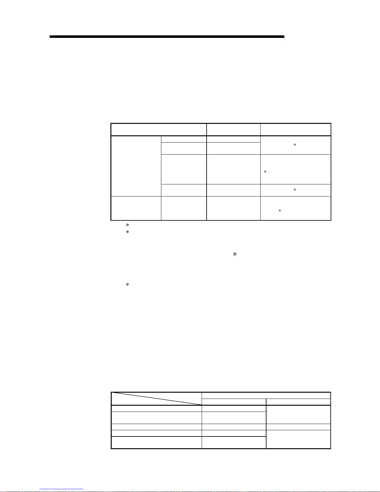
2.4 How to check the function version and the softwar e v ersion
The function version of the QD70 and the software version of the GX Configurator-PT
can be checked in the following methods.
[1] How to check the function version of the QD70
(a) Method using the rated plate on the module side face
Check the alphabet at the end of "SERIAL".
09021
SERIAL No. (The first five digits)
Function version
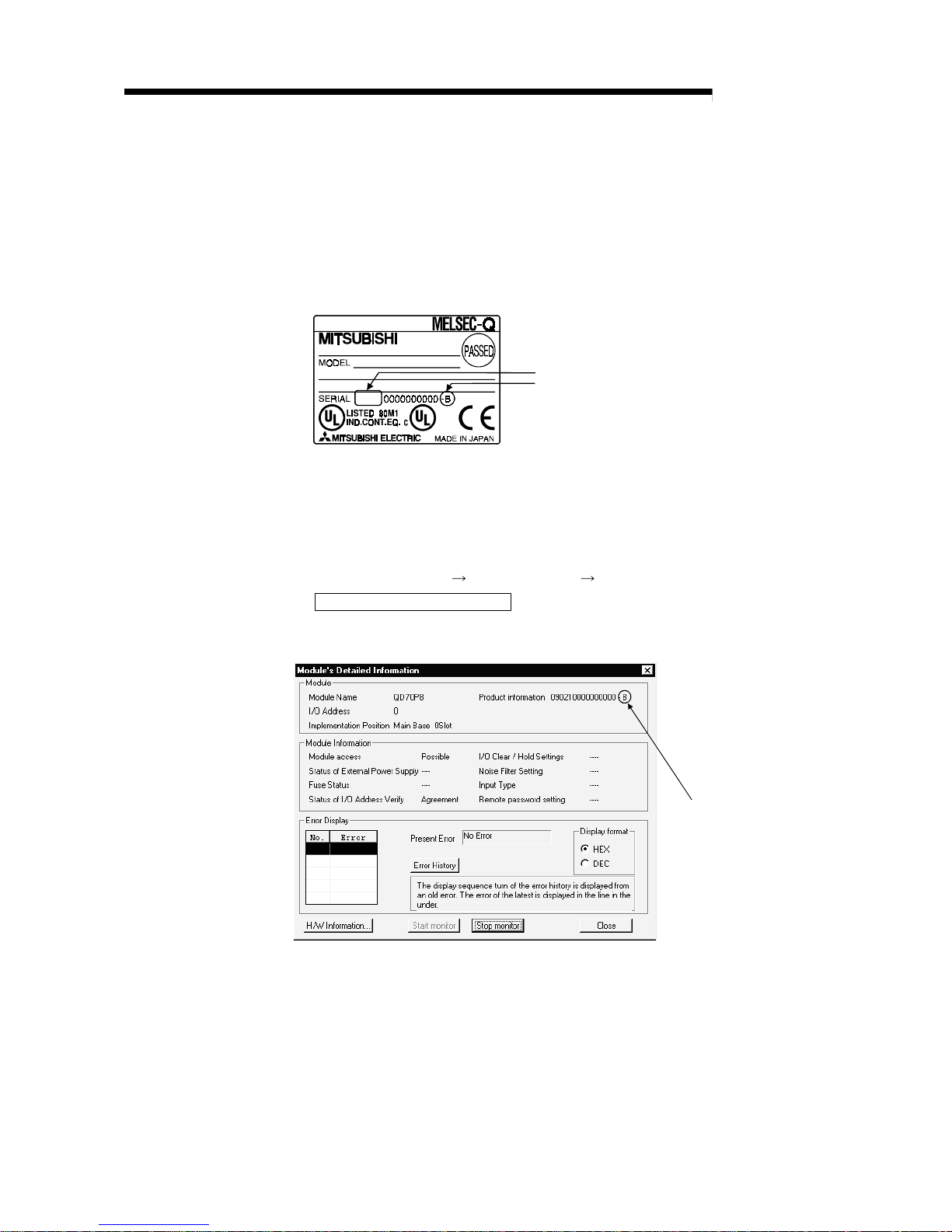
(b) Method using the peripheral device
Check the alphabet at the end of "Product information" displayed on
System monitor "Module's Detailed Information" of GX Developer.
[Operation of GX Developer]
Choose [Diagnostics] [System monitor] "QD70 module" and choose
Module's Detailed Information
.
<GX Developer display screen>
Function version
Page 28
2 - 5 2 - 5
MELSEC-Q
2 SYSTEM CONFIGURATION
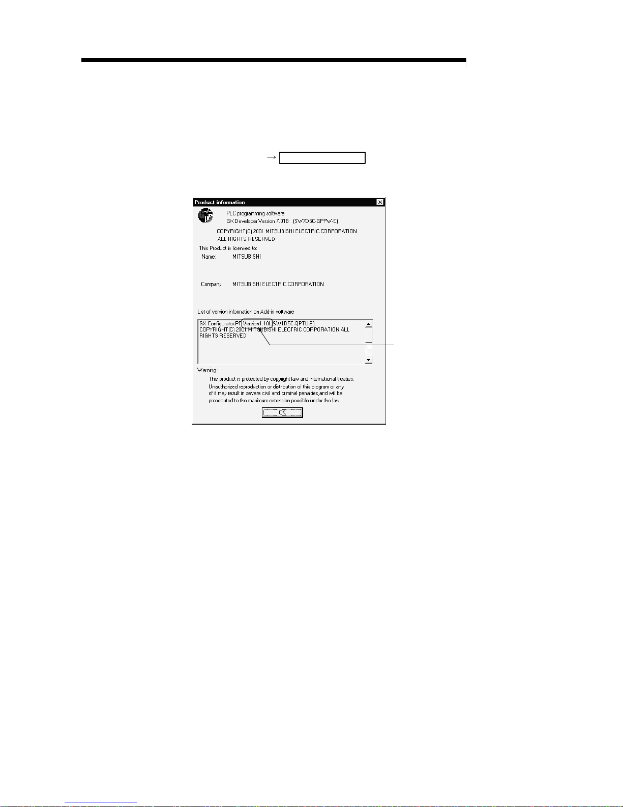
[2] How to check the software version of the GX Configur ator -PT
Check the "Product information" displayed on "Help" of GX Developer.
[Operation of GX Developer]
Choose [Help] Product information
<GX Developer display screen>
Software version
Page 29
3 - 1 3 - 1
MELSEC-Q
3 SPECIFICATIONS AND FUNCTIONS
CHAPTER 3 SPECIFICATIONS AND FUNCTIONS
This chapter describes the performance specifications of the QD70 and the
specifications of the I/O signals transferred to/from the PLC CPU and external device.
For the general specifications of the QD70, refer to the user's manual (hardware) of the
CPU module used.
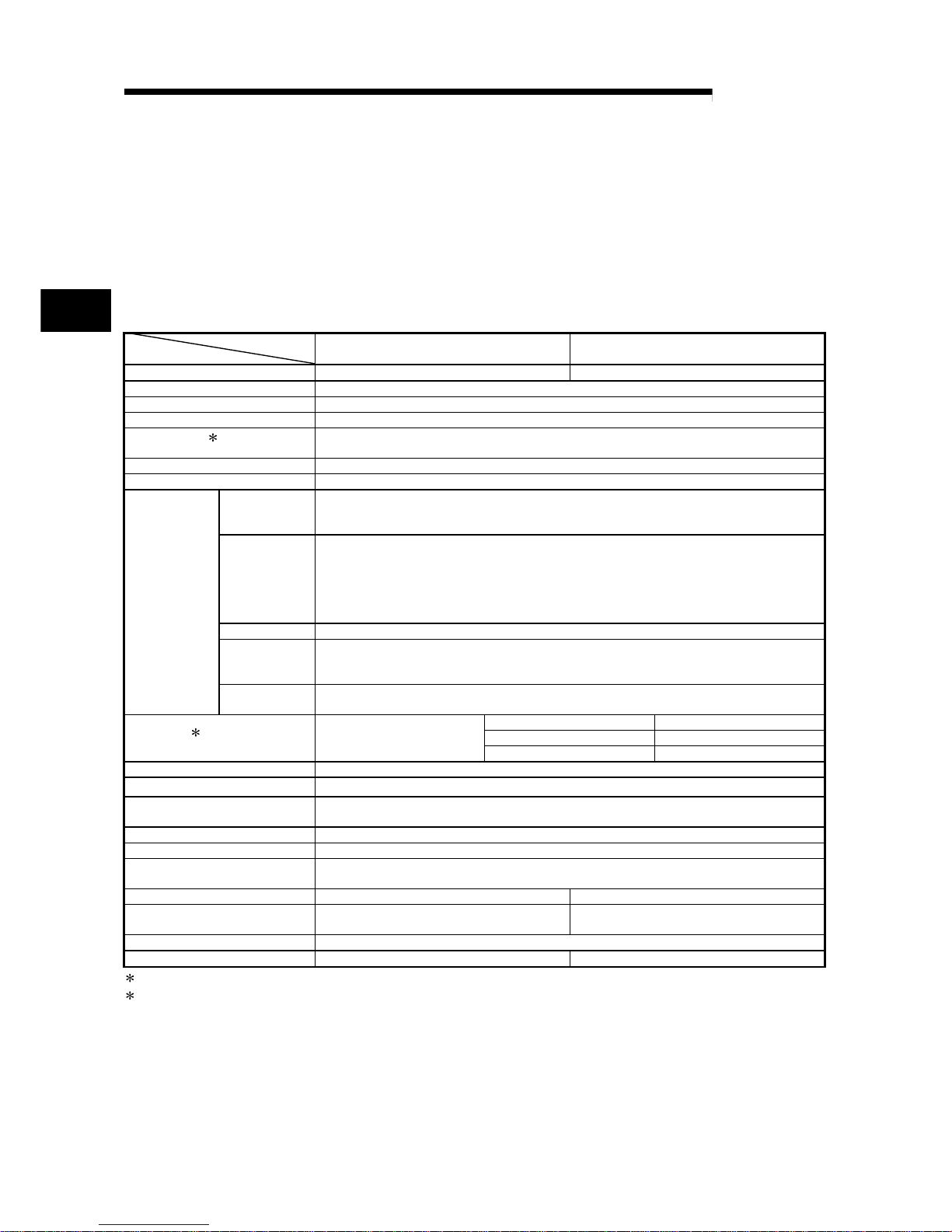
3.1 Performance specifications
Model
Item
QD70P4 QD70P8
No. of control axes 4 axes 8 axes
Interpolation function No
Control method PTP (Point To Point) control, path control (linear only), speed-position switching control
Control unit pulse
Positioning data
1
10 pieces of data (positioning data No. 1 to 10)/axis
(can be set using GX Configurator-PT or sequence program)
Peripheral device/utility package GX Configurator-PT (option)
Data backup No
Positioning
control method
PTP control : Incremental system/absolute system
Speed-position switching control : Incremental system
Path control : Incremental system/absolute system
Positioning
control range
[Absolute system]
-2147483648 to 2147483647pulse
[Incremental system]
-2147483648 to 2147483647pulse
[Speed-position switching control]
0 to 2147483647pulse
Speed command 0 to 200000pulse/s
Acceleration/
deceleration
processing
Trapezoidal acceleration/deceleration
Positioning
control
Acceleration/
deceleration time
0 to 32767ms
1-axis start 0.1ms
4-axes simultaneous start 0.2ms
Starting time
2
Position control
8-axes simultaneous start 0.4ms
External wiring connection system 40-pin connector
Applicable wire size 0.3mm2 (for use of A6CON1), AWG#24 (for use of A6CON2)
External device connection
connector
A6CON1, A6CON2 (option)
Pulse output method Open collector output
Max. output pulse 200kpps
Max. connection distance between
QD70 and drive unit
2m
Internal current consumption (5VDC) 0.55A 0.74A
External 24V current consumption
(24VDC)
0.065A 0.12A
No. of occupied I/O points 32 points (I/O assignment: Intelligent function module 32 points)
Weight 0.15kg 0.17kg
1
: Positioning data can be started from No.1 only. (Cannot be started from any of No.2 to No.10.)
2
: A delay may occur depending on the operating conditions and starting conditions (control method, bias speed, ACC/DEC time, etc.) of
the other axes.
3
Page 30
3 - 2 3 - 2
MELSEC-Q
3 SPECIFICATIONS AND FUNCTIONS
3.2 List of functions
The following table lists the functions of the QD70.
(Read "SECTION 2 CONTROL DETAILS AND SETTING" for details of the functions.)
Function name Description Reference
Machine OPR control
Mechanically establishes the positioning control start
point using a near-point dog or stopper.
Section
8.2
OPR control
Fast OPR control
Positions a target to the OP address (
Md. 1
Current feed
value) stored in the QD70 using machine OPR control.
Section
8.3
Position control (1-axis linear control)
Positions a target using a linear path to the address set in
the positioning data or to the position designated with the
movement amount.
Section
9.2.2
Speed-position switching control
First, carries out speed control, and then carries out
position control (positioning control with designated
address or movement amount) by turning the "speedposition switching signal" ON.
Section
9.2.3
Positioning control
Current value changing
Changes the Current feed value (
Md. 1
) to the address
set in the positioning data.
Section
9.2.4
JOG operation
Outputs a pulse to drive unit while the JOG start signal is
ON.
Chapter
10
Speed limit function
If the command speed exceeds "
Pr. 5
Speed limit value"
during control, this function limits the commanded speed
to within the "
Pr. 5
Speed limit value" setting range.
Section
11.2
Speed change function
This function changes the speed at any point during
speed control of speed-position switching control or
during JOG operation.
Set the new speed in the speed change buffer memory
(
Pr. 7
New speed value), and change the speed with the
Speed change request (
Pr. 6
).
Section
11.3
Software stroke limit function
If a command outside of the upper/lower limit stroke limit
setting range, set in the parameters, is issued, this
function will not execute positioning for that command.
Section
11.4
Acceleration/deceleration processing function
This function adjusts the acceleration/deceleration
processing of control.
Section
11.5
Sub function
Restart function
This function resumes positioning control during a stop of
the axis from where it had stopped.
Section
11.6
External I/O signal logic switching function
This function changes the external I/O signal logic to
match the externally connected device.
It can be changed by making the intelligent function
module switch setting.
Section
12.2
Common function
External I/O signal monitor function
This function monitors the external I/O signal states using
GX Developer.
Section
5.5
Section
12.3
3
Page 31

3 - 3 3 - 3
MELSEC-Q
3 SPECIFICATIONS AND FUNCTIONS
With the "positioning control", whether or not to continuously execute the positioning
data can be set with the "operation pattern". Outlines of the "operation patterns" are
given below.
Da.1
Operation pattern
Description Reference
Positioning termination
When "Positioning termination" is set for the operation pattern
of the started positioning data, only the designated positioning
data will be executed, and then the positioning control will end.
Continuous positioning control
When "continuous positioning control" is set for the operation
pattern of the started positioning data, after the designated
positioning data is executed, the program will stop once, and
then the next following positioning data will be ex ecuted.
Continuous path control
When "continuous path control" is set for the operation pattern
of the started positioning data, the designated positioning data
will be executed, and then without decelerating, the next
following positioning data will be executed.
9.1.2
Page 32

3 - 4 3 - 4
MELSEC-Q
3 SPECIFICATIONS AND FUNCTIONS
3.3 Specifications of input/output signal w ith PLC CPU
3.3.1 List of input/output signals with PLC CPU
The QD70 uses 32 input points and 32 output points for exchanging data with the PLC
CPU.
The input/output signals when the QD70 is mounted in slot No. 0 of the main base unit
are shown below.
Device X refers to the signals input from the QD70 to the PLC CPU, and device Y
refers to the signals output from the PLC CPU to the QD70.
Signal direction: QD70 PLC CPU Signal direction: PLC CPU QD70
Device No. Signal name Device No. Signal name
X0 Module READY Y0 PLC READY
X1 Axis error occurrence Y1
X2 Axis warning occurrence Y2
X3 Y3
X4 Y4
X5 Y5
X6 Y6
X7
Use prohibited
Y7
Use prohibited
X8 Axis 1 Y8 Axis 1
X9 Axis 2 Y9 Axis 2
XA Axis 3 YA Axis 3
XB Axis 4 YB Axis 4
XC Axis 5 YC Axis 5
XD Axis 6 YD Axis 6
XE Axis 7 YE Axis 7
XF Axis 8
BUSY
YF Axis 8
Positioning start
X10 Axis 1 Y10 Axis 1
X11 Axis 2 Y11 Axis 2
X12 Axis 3 Y12 Axis 3
X13 Axis 4 Y13 Axis 4
X14 Axis 5 Y14 Axis 5
X15 Axis 6 Y15 Axis 6
X16 Axis 7 Y16 Axis 7
X17 Axis 8
Start complete
Y17 Axis 8
Axis stop
X18 Axis 1 Y18 Axis 1
X19 Axis 2 Y19 Axis 2
X1A Axis 3 Y1A Axis 3
X1B Axis 4 Y1B Axis 4
X1C Axis 5 Y1C Axis 5
X1D Axis 6 Y1D Axis 6
X1E Axis 7 Y1E Axis 7
X1F Axis 8
Positioning complete
Y1F Axis 8
JOG start
Important
[Y1 to Y7], and [X3 to X7] are used by the system, and cannot be used by the user.
If these devices are used, the operation of the QD70 will not be guaranteed.
Page 33

3 - 5 3 - 5
MELSEC-Q
3 SPECIFICATIONS AND FUNCTIONS
3.3.2 Details of input signal (QD70 PLC CPU)
The ON/OFF timing and conditions of the input signals are shown below.
Device
No.
Signal name Description
X0 Module READY ON: Prepared
OFF: Not
prepared
watch dog
timer error
•
When the PLC READY signal [Y0] turns from OFF to ON, the parameter and the
OPR data setting range is checked. If no error is found, this signal turns ON. (When
the axis error occurrence signal [X1] is ON, this signal does not turn ON if the PLC
READY signal [Y0] is turned from OFF to ON.)
•
When the PLC READY signal [Y0] turns OFF, this signal turns OFF.
•
When a watch dog timer (WDT) error occurs, this signal turns OFF.
•
This signal is used for interlock in a sequence program, etc.
OFF
ON
OFF
ON
PLC READY signal [Y0]
Module READY signal [X0]
X1 Axis error
occurrence
OFF: No error
ON: Error
occurrence
•
This signal turns ON if an error occurs in any of axes 1 to 8, and turns OFF when
"
Cd. 1
Axis error rese t" is set for all axe s.
(Use "
Md. 10
Error status" to confirm the error status of the corresponding axis.)
X2 Axis warning
occurrence
OFF: No warning
ON: Warning
occurrence
•
This signal turns ON if a warning occurs in any of axes 1 to 8, and turns OFF when
"
Cd. 1
Axis error rese t" is set for all axe s.
(Use "
Md. 11
Warning status" to confirm the warning status of the corresponding
axis.)
X8
X9
XA
XB
XC
XD
XE
XF
Axis 1
Axis 2
Axis 3
Axis 4
Axis 5
Axis 6
Axis 7
Axis 8
BUSY OFF: Not BUSY
ON: BUSY
•
This signal turns ON at the start of positioning control, OPR control or JOG operation.
It turns OFF when the "
Da. 7
Dwell time" has passed after positioning control stops.
(This signal remains ON during positioning control.)
•
This signal turns OFF at error or stop.
X10
X11
X12
X13
X14
X15
X16
X17
Axis 1
Axis 2
Axis 3
Axis 4
Axis 5
Axis 6
Axis 7
Axis 8
Start
complete
OFF: Start
incomplete
ON: Start
complete
•
This signal turns ON when the positioning start signal turns ON and the QD70 starts
the positioning control process.
(The start complete signal also turns ON during OPR control.)
OFF
ON
OFF
ON
Positioning start signal [Y8]
Start complete signal [X10]
X18
X19
X1A
X1B
X1C
X1D
X1E
X1F
Axis 1
Axis 2
Axis 3
Axis 4
Axis 5
Axis 6
Axis 7
Axis 8
Positioning
complete
OFF: Positioning
incomplete
ON: Positioning
complete
(Refer to
"Important")
•
This signal turns ON for the time set in "
Pr. 7
Positioning complete signal output
time" from completion of position control of the corresponding axis.
(It does not turn ON if 0 is set in "
Pr. 7
Positioning complete signal output time".)
•
While ON, this signal turns OFF if a positioning control start (including OPR control)
or JOG operation start is made.
•
This signal does not turn ON at the termination of JOG operation.
•
This signal does not turn ON if position control is stopped midway.
Important
: "Position control c o mpl e te" o f the Q D70 re fe r s to th e po i nt w hen th e pu l se ou tp ut fro m
QD70 is completed.
Thus, even if the QD70's positioning complete signal turns ON, the system may continue
operation.
Page 34

3 - 6 3 - 6
MELSEC-Q
3 SPECIFICATIONS AND FUNCTIONS
3.3.3 Details of output signals (PLC CPU QD70)
The ON/OFF timing and conditions of the output signals are shown below.
Device No. Signal name Description
Y0 PLC READY OFF:
PLC READY OFF
ON:
PLC READY ON
(a) This signal notifies the QD70 that the PLC CPU is normal.
•
It is turned ON/OFF with the sequence program.
•
The PLC READY signal is turned ON during positioning
control, OPR control and JOG operation.
(b) When parameters and OPR data are changed, the PLC READY
signal is turned OFF.
(c) The following processes are carried out when the PLC READY
signal turns from OFF to ON.
•
The parameter and OPR data setting range is checked.
•
The module READY signal [X0] turns ON.
(d) The following processes are carried out when the PLC READY
signal turns from ON to OFF.
In these cases, the OFF time should be set to 100ms or more.
•
The module READY signal [X0] turns OFF.
•
The operating axis stops.
Y8
Y9
YA
YB
YC
YD
YE
YF
Axis 1
Axis 2
Axis 3
Axis 4
Axis 5
Axis 6
Axis 7
Axis 8
Positioning start OFF:
Positioning start not
requested
ON:
Positioning start
requested
•
OPR control and positioning control is started.
•
The positioning start signal is valid at the rising edge, and the
operation is started.
•
When the positioning start signal turns ON during BUSY, the
operation starting warning will occur (warning code: 10).
Y10
Y11
Y12
Y13
Y14
Y15
Y16
Y17
Axis 1
Axis 2
Axis 3
Axis 4
Axis 5
Axis 6
Axis 7
Axis 8
Axis stop OFF:
Axis stop not
requested
ON:
Axis stop requested
•
When the axis stop signal turns ON, the OPR control, positioning
control and JOG operation. In these cases, the ON time should be
set to 4ms or mor e.
•
Turning ON the axis stop signal during operation decelerates the
axis to a stop. At this time, "
Md. 4
Axis operation status" changes
from "Deceleration (Axis Stop ON)" to "Stopped".
Y18
Y19
Y1A
Y1B
Y1C
Y1D
Y1E
Y1F
Axis 1
Axis 2
Axis 3
Axis 4
Axis 5
Axis 6
Axis 7
Axis 8
JOG start OFF:
JOG not started
ON:
JOG started
•
When the JOG start signal is ON, JOG operation will be carried
out at the "
JOG. 1
JOG speed". When the JOG start signal turns
OFF, the operation will decelerate and stop. At this time, "
Md. 4
Axis operation status" changes from "Deceleration (JOG Start
OFF)" to "Standby".
•
Set the rotation direction in "
JOG. 4
JOG direction flag". (Refer to
Chapter 10.)
Page 35

3 - 7 3 - 7
MELSEC-Q
3 SPECIFICATIONS AND FUNCTIONS
3.4 Specifications of input/output interfaces w ith exter nal devi ce
3.4.1 Electrical specifications of input/output sig nal s
Input specifications
Signal name
Rated input
voltage/current
Working voltage
range
ON voltage/
current
OFF voltage/
current
Input resistance Response time
5VDC/18mA 4.5 to 5.5VDC
2.7VDC or more/
5.5mA or more
1.0VDC or less/
0.5mA or less
Approx. 270
Ω
0.1ms or less
Zero signal (PG0)
3µs or less
1ms or mo re
3µs or less
Near-point dog signal
(DOG)
Speed-position switching
signal (CHG)
24VDC/5mA 19.2 to 26.4VDC
17.5VDC or
more/3mA or
more
7VDC or less/
0.9mA or less
Approx. 6.8k
Ω
1ms or less
Output specifications
Signal name
Rated load
voltage
Working load
voltage range
Max. load
current/rush
current
Max. voltage
drop at ON
Leakage current
at OFF
Response time
•
Set the pulse output mode and pulse output logic selection in "intelligent function module switch setting"
(Refer to Section 5.6).
•
The following are the relationships between pulse outputs depending on the "pulse output mode" and "pulse
output logic selection".
Pulse output logic selection
Positive logic Negative logic
Pulse output
mode
Forward run Reverse run Forward run Reverse run
CW
CCW
PULSE
SIGN
High Low
Low High
The table next page shows the rising/falling edge time and duty ratio.
tr
OFF
tf
ON
Pulse output
(CW/PULSE/A phase)
Pulse sign
(CCW/SIGN/B phase)
5 to 24VDC 4.75 to 30VDC
50mA/1 point/
200mA 10ms or
less
0.5VDC (TYP) 0.1mA or less —
Deviation counter clear
(CLEAR)
5 to 24VDC 4.75 to 30VDC
0.1A/1 point/0.4A
10ms or less
1VDC (TYP)
2.5VDC (MAX)
0.1mA or less
2ms or less
(resistance load)
Page 36

3 - 8 3 - 8
MELSEC-Q
3 SPECIFICATIONS AND FUNCTIONS
: Pulse rising/falling edge time (Unit for "tr" and "tf": µs, unit for "Duty": %)
... When ambient temperature is room temperature.
Load voltage (V) 26.4
Cable length (m) 1 2
Load current
(mA)
Pulse speed
(kpps)
tr
(Rising edge)tf(Falling edge)
Duty
tr
(Rising edge)tf(Falling edge)
Duty
200 1.902 0.3178 28.20 2.129 0.2724 28.09
100 2.869 0.3388 38.44 3.691 0.3549 40.12
2
10 3.710 0.3616 50.22 5.187 0.3613 49.63
200 1.776 0.3036 35.45 1.763 0.3395 36.48
100 2.134 0.3285 43.90 2.394 0.3445 41.11
5
10 2.357 0.3982 50.88 3.105 0.3899 50.50
200 1.336 0.3174 40.92 1.429 0.3228 40.44
100 1.644 0.3814 48.05 1.812 0.3793 46.40
10
10 2.028 0.4197 51.31 1.996 0.4200 51.22
200 1.236 0.3807 45.64 1.269 0.3949 45.14
100 1.772 0.4453 49.90 1.734 0.4660 49.73
20
10 1.957 0.4776 51.63 1.727 0.4749 51.55
200 1.122 0.6809 51.78 1.019 0.6684 51.42
100 1.359 0.7407 53.09 1.544 0.7897 52.90
50
10 1.750 0.9833 52.05 1.819 0.9130 52.03
Load voltage (V) 4.75
Cable length (m) 1 2
Load current
(mA)
Pulse speed
(kpps)
tr
(Rising edge)tf(Falling edge)
Duty
tr
(Rising edge)tf(Falling edge)
Duty
200 0.8352 0.2093 45.21 1.484 0.1924 36.94
100 1.880 0.2679 44.44 1.848 0.2536 45.03
2
10 1.942 0.2765 51.03 2.039 0.2873 51.13
200 1.220 0.1726 39.35 1.191 0.2345 41.56
100 1.422 0.2652 48.15 1.589 0.2631 47.89
5
10 1.705 0.2893 51.35 1.604 0.3116 51.40
200 0.8736 0.2739 46.99 1.167 0.2519 44.97
100 1.041 0.3075 49.87 1.371 0.3028 50.02
10
10 1.576 0.3295 51.49 1.672 0.3212 51.41
200 1.021 0.3479 49.65 0.7345 0.3452 48.94
100 1.277 0.3671 51.67 1.222 0.3780 52.12
20
10 1.473 0.4207 51.84 1.287 0.3999 51.73
200 0.8312 0.6302 55.37 0.7978 0.5752 55.34
100 0.9714 0.6290 55.38 1.025 0.6218 55.64
50
10 0.9884 0.7037 52.09 1.105 0.6799 52.05
External power source (For driving the pulse output circuit)
Signal name Rated input voltage Current consumption
External power source input (+24V/24G)
24VDC
(+20%/-15) (Ripple rate within 5%)
QD70P4:0.065A, QD70P8:0.12A
Page 37

3 - 9 3 - 9
MELSEC-Q
3 SPECIFICATIONS AND FUNCTIONS
3.4.2 Signal layout for external dev ice connecti on connector
The specifications of the connector section, which is the input/output interface for the
QD70 and externa l dev i ce, are sh ow n be low.
The signal layout for the QD70 external device connection connector is shown.
QD70P4
CON1
RUN
ERR.
AX2
AX1
AX4
AX3
QD70P4
QD70P8
CON2
RUN
ERR.
AX6
AX5
AX8
AX7
CON1
AX2
AX1
AX4
AX3
QD70P8
CON 2 (for Axes 5 to 8) CON 1 (for Axes 1 to 4)
Pin layout
Pin No. Signal name Pin No. Signal name Pin No. Signal name Pin No. Signal name
B20 PG06 COM 1 A20 PG08 COM 1 B20 PG02 COM 1 A20 PG04 COM 1
B19 PG06 A19 PG08 B19 PG02 A19 PG04
B18 PG05 COM 1 A18 PG07 COM 1 B18 PG01 COM 1 A18 PG03 COM 1
B17 PG05 A17 PG07 B17 PG01 A17 PG03
B16
CLEAR6
COM
2
A16
CLEAR8
COM 2
B16
CLEAR2
COM 2
A16
CLEAR4
COM 2
B15 CLEAR6 A15 CLEAR8 B15 CLEAR2 A15 CLEAR4
B14
CLEAR5
COM
2
A14
CLEAR7
COM
2
B14
CLEAR1
COM
2
A14
CLEAR3
COM
2
B13 CLEAR5 A13 CLEAR7 B13 CLEAR1 A13 CLEAR3
B12 CHG6 A12 CHG8 B12 CHG2 A12 CHG4
B11 CHG5 A11 CHG7 B11 CHG1 A11 CHG3
B10 DOG6 A10 DOG8 B10 DOG2 A10 DOG4
B9 DOG5 A9 DOG7 B9 DOG1 A9 DOG3
B8 COM 5-6 3A8COM 7-83B8COM 1-23A8COM 3-43
B7 PULSE F6 A7 PULSE F8 B7 PULSE F2 A7 PULSE F4
B6
PULSE
COM6
4
A6
PULSE
COM8
4
B6
PULSE
COM2
4
A6
PULSE
COM4
4
B5 PULSE R6 A5 PULSE R8 B5 PULSE R2 A5 PULSE R4
B4 PULSE F5 A4 PULSE F7 B4 PULSE F1 A4 PULSE F3
B3
PULSE
COM5
4
A3
PULSE
COM7 4
B3
PULSE
COM1 4
A3
PULSE
COM3 4
B2 PULSE R5 A2 PULSE R7 B2 PULSE R1 A2 PULSE R3
B20
B19
B18
B17
B16
B15
B14
B13
B12
B11
B10
B9
B8
B7
B6
B5
B4
B3
B2
B1
A20
A19
A18
A17
A16
A15
A14
A13
A12
A11
A10
A9
A8
A7
A6
A5
A4
A3
A2
A1
B1 Vacant A1 Vacant B1 +24V 5 A1 +24G 5
1: Common for PG0 . (Axis No. 1 to 8 goes into ).
2: Common for CLEAR . (Axis No. 1 to 8 goes into ).
3: Common for DOG , CHG .(Axis No. 1 to 8 goes into ).
4: Common for PULSE F , PULSE R . (Axis No. 1 to 8 goes into ).
5: The external power source (24VDC) should be connected in order to output a command pulse.
(When outputing a command pulse of axis 5 to 8, the external power source (24VDC) should be connected to A1 and B1 of the
connector CON1 (for axis 1 to 4 use).)
Page 38

3 - 10 3 - 10
MELSEC-Q
3 SPECIFICATIONS AND FUNCTIONS
3.4.3 List of input/output signal details
The details of each QD70 external device connection connector are shown below:
Signal name Pin No. Symbol
Signal details
(Negative logic is selected by I/O signal logic selection)
Near-point dog signal
A10A9B10
B9
DOG
•
This signal is used for detecting the near-point dog during OPR control.
•
The near-point dog OFF ON is detected at the rising edge.
•
The near-point dog ON
OFF is detected at the falling edge.
Speed-position switching signal
A12
A11
B12
B11
CHG
•
This signal is input as a control switching signal in speed-position switching
control.
Common A8 B8 COM
•
Common for near-point dog signal and speed-position switching control
signal.
Zero signal
A19
A17
B19
B17
PGO
•
Input the zero signal for OPR control.
Use the pulse encoder's zero signal and so on.
•
Also use this signal when the OPR method is the stopper method and the
OPR complete is input from an external source.
•
The OP is detected at the falling edge.
Zero signal common
A20
A18
B20
B18
PGO COM•Common for zero signal.
External power input (0V) A1 (COM1) 24G
External power input (+24V) B1 (COM1) +24V
•
These signals are used to input 24VDC power for driving the pulse output
circuit. (Common to all axes)
Pulse output F
A7A4B7
B4
PULSE F
•
This signal is used to output command pulses to the open collector
compatible drive unit.
CW/CCW mode: CW, PULSE/SIGN mode: PULSE
Pulse output R
A5A2B5
B2
PULSE R
•
This signal is used to output command pulses to the open collector
compatible drive unit.
CW/CCW mode: CCW, PULSE/SIGN mode: SIGN
Pulse output common
A6A3B6B3PULSE
COM
•
Common for pulse output F and pulse output R.
Deviation counter clear
A15
A13
B15
B13
CLEAR
•
This signal is output during machine OPR control.
(Example) When carry out OPR control with stopper 2.
CLEAR
OPR. 4
OPR. 5
Pr. 8
Pr. 6 Bias
speed at star
t
Speed
OPR speed
Creep speed
Stopper
Near-point dog
Deviation counter
clear signal output time
Time
After feed pulse output stops
Zero signal
•
The output time of the deviation counter clear signal is set in "
Pr. 8
Deviation
counter clear signal output time".
•
Use the drive unit that can reset the droop pulse amount in the internal
deviation counter when the QD70 turns this signal ON.
(Note) The deviation counter clear is a signal output by the QD70 during
machine OPR control. It cannot be output randomly.
Deviation counter clear common
A16
A14
B16
B14
CLEAR
COM
•
Common for deviation counter clear
Page 39

3 - 11 3 - 11
MELSEC-Q
3 SPECIFICATIONS AND FUNCTIONS
3.4.4 Input/output interface internal cir cui t
Shows summary image of the internal circuit of the interface for connection to external
devices of the QD70. (For QD70P4, axis 1).
Input/output
class
External wiring Pin No. Internal circuit Signal name
B9 Near-point dog signal DOG1
B11 Speed-position switching signal CHG1
B8 Common COM1-2
B17 Zero signal PG01
B18 Zero signal common PG01 COM
A1 External power input (0V) 24G
Input
24VDC
24VDC
*
B1 External power input (24VDC) +24V
B4 Pulse output F (CW/PULSE) PULSE F1
B2
Pulse output R
(CCW/SIGN)
PULSE R1
B3 Pulse output common PULSE COM1
B13 Deviation counter clear CLEAR1
Output
B14
D/D
converter
circuit
Deviation counter clear common CLEAR1 COM
: Either polarity can be connected to the common (COM1-2).
Page 40

4 - 1 4 - 1
MELSEC-Q
4 DATA USED FOR POSITIONING CONTROL
CHAPTER 4 DATA USED FOR POSITIONING CONTROL
This chapter explains the specifications of the data to be set to the QD70.
4.1 Type of data
4.1.1 Parameters and data required for contr ol
The parameters and data required to carry out control with the QD70 include the
"setting data", "monitor data" and "control data" shown below.
Setting data
( Pr. 1 to Pr. 10 )
Parameters
OPR data
( OPR. 1 to OPR. 9 )
JOG data
( JOG. 1 to JOG. 4 )
( Da. 1 to Da. 7 )
Positioning data
(Switches 1 to 5)
Set at a system startup according to the machinery, equipment and applications.
(Storage destination: QD70 buffer memory)
Set values required to exercise "OPR control".
(Storage destination: QD70 buffer memory)
Set values required to perform "JOG operation".
(Storage destination: QD70 buffer memory)
Set values required to exercise "positioning control".
(Storage destination: QD70 buffer memory)
Set the pulse output mode and external I/O signal logic.
(Storage destination: "I/O assignment setting" PLC
parameter of QCPU)
Intelligent function mo dul e sw it che s
The parameters and OPR data are made valid when the PLC READY signal [Y0]
turns from OFF to ON.
The JOG data or positioning data are made valid when a JOG operation start or
positioning control start is made.
Use GX Developer to set the intelligent function module switches. (For details, refer
to "Section 5.6 Switch setting for intelligent function module".)
4
Page 41

4 - 2 4 - 2
MELSEC-Q
4 DATA USED FOR POSITIONING CONTROL
Monitor data
( Md. 1 to Md. 9 )
( Md. 10 to Md. 11 )
Axis monitor data
Module information monitor data
Data related to the operations of the running axes, e.g. the current positions
and speeds, are monitored.
(Storage destination: QD70 buffer memory)
The error status and warning status of the QD70 are monitored.
(Storage destination: QD70 buffer memory)
( Cd. 1 to Cd. 9 )
Control data
Axis control data
Make operation-related settings and exercise such control as speed changing
during operation and operation restart.
(Storage destination: QD70 buffer memory)
How to set "setting da ta"
Setting means
Setting item
Sequence program GX Configurator-PT GX Developer
Parameters
(initial setting
)
OPR data
(initial setting
)
JOG data
Positioning data
(initial setting
)
Intelligent function module
switches
: Initial setting is made to the intelligent function module parameters of t he Q C PU.
: Can be set.
: Can be set in the "I/O assignment setting" PLC parameter of the QCPU.
: Cannot be set.
POINT
(1) The "setting data" is created for each axis.
(2) The "setting data" parameters have determined default values, and are set to
the default values before shipment from the factory. (Parameters related to
axes that are not used are left at the default value.)
(3) The "setting data" set in the QD70 buffer memory are not backed up. All data
are initialized at the time of system power-on or PLC CPU reset.
4
Page 42

4 - 3 4 - 3
MELSEC-Q
4 DATA USED FOR POSITIONING CONTROL
4.1.2 Setting items for parameters
The table below lists items set to the positioning parameters. Setting of parameters is
similarly done for individual axes for all controls achieved by the QD70.
For details of controls, refer to SECTION 2 "CONTROL DETAILS AND SETTING". For
details of setting items, refer to "4.2 List of parameters".
Positioning control
Control
Parameter
OPR
control
Position
control
Speedposition
switching
control
Current
value
changing
JOG
operation
Related
sub
function
Pr. 1
Software stroke limit upper limit value –
Pr. 2
Software stroke limit low er limit v a lue –
Pr. 3
Software stroke limit valid /in v a lid se tting –
Section
11.4
Pr. 4
Current feed value during speed control – – –––
Pr. 5
Speed limit value –
Section
11.2
Pr. 6
Bias speed at start –
Section
11.5
Pr. 7
Positioning complete signal output time –––
Pr. 8
Deviation counter clear signal output time –––––
Pr. 9
PULSE/SIGN method selection setup/hold time – –
Pr. 10
Stop mode during path control – ––––
: Always set
: Set as required (Read "–" when not required.)
– : Setting not required. (This is an irrelevant item, so the set value will be ignored. If the value is the default value or within the setting
range, there is no problem.)
Checking the parameters
Pr. 1
to
Pr. 10
are checked for the setting ranges when the "PLC READY signal
(Y0)" output from the PLC CPU to the QD70 changes from OFF to ON. At this time,
an error occurs in the parameter whose value has been set outside the setting
range. (For details, refer to "CHAPTER 13 TROUBLESHOOTING".)
Page 43

4 - 4 4 - 4
MELSEC-Q
4 DATA USED FOR POSITIONING CONTROL
4.1.3 Setting items for OPR data
When carrying out "OPR control", the "OPR data" must be set. The setting items for
the "OPR data" are shown below.
The "OPR data" are set commonly for each axis.
Refer to "Chapter 8 OPR CONTROL" for details on the "OPR CONTROL", and to
section "4.3 List of OPR data" for details on each setting item.
OPR control
OPR data
Machine OPR control Fast OPR control
OPR. 1
OPR method
Near-point
dog method
Stopper 1
Stopper 2
Stopper 3
Count 1
Count 2
OPR. 2
OPR direction
OPR. 3
OP address
OPR. 4
OPR speed
OPR. 5 Creep speed
OPR. 6 ACC/DEC time at OPR
OPR. 7 DEC/STOP time at OPR
OPR. 8
Setting for the movement amount after near-point
dog ON
––––
OPR. 9
OPR dwell time – ––––
Data set for machin e
OPR control are used.
: Always set
– : Setting not required (This is an irrelevant item, so the setting value will be ignored. If the value is the default value or within the setting
range, there is no problem.)
Checking the OPR data
OPR. 1
to
OPR. 9
are checked for the setting ranges when the "PLC READY
signal (Y0)" output from the PLC CPU to the QD70 changes from OFF to ON. At this
time, an error occurs in the OPR data whose value has been set outside the setting
range. (For details, refer to "CHAPTER 13 TROUBLESHOOTING".)
Page 44

4 - 5 4 - 5
MELSEC-Q
4 DATA USED FOR POSITIONING CONTROL
4.1.4 Setting items for JOG data
The "JOG data" must be set to perform "JOG operation". The following are the setting
items of the "JOG data".
The "JOG data" are set commonly for each axis.
Refer to "CHA P TE R 10 J OG OPE RA TIO N" for details o f "JO G op e ra ti on" an d to
"Section 4.4 List of JOG data" for details of the setting items.
JOG data JOG operation
JOG. 1
JOG speed
JOG. 2
JOG ACC time
JOG. 3
JOG DEC time
JOG. 4
JOG direction flag
: Always set
– : Setting not required (This is an irrelevant item, so the setting value will be ignored. If the value is the
default value or within the setting range, there is no problem.)
Checking the JOG data
JOG. 1
to
JOG. 4
are checked for the setting ranges when JOG operation is
started. At this time, an error occurs in the JOG data whose value has been set
outside the setting range. (For details, refer to "CHAPTER 13
TROUBLESHOOTING".)
Page 45

4 - 6 4 - 6
MELSEC-Q
4 DATA USED FOR POSITIONING CONTROL
4.1.5 Setting items for positioning data
Positioning data must be set for carrying out any "positioning control". The table below
lists the items to be set for producing the positioning data.
1 to 10 positioning data items can be set for each axis.
For details of the positioning controls, refer to "Chapter 9 POSITIONING CONTROL".
For details of the individual setting items, refer to "4.5 List of positioning data".
Positioning control
Positioning data
Position control
Speed-position
switching control
Current value changing
Positioning termination
Continuous positioning
control
Da. 1 Operation pattern
Continuous path control
Da. 2
Control method
1-axis linear control
(ABS)
1-axis linear control
(INC)
Speed.Position Ctrl.
(Forward)
Speed.Position Ctrl.
(Reverse)
Current value changing
Da. 3 ACC/DEC time –
Da. 4 DEC/STOP time –
Da. 5 Command speed –
Da. 6
Positioning address/movement amount
Change destination
address
Da. 7
Dwell time
: Always set
: Set as required (Read "–" when not required.)
:Setting not possible
– : Setting not required.
(This is an irrelevant item, so the set value will be ignored. If the value is the default value or within the setting range, there is no
problem.)
Checking the positioning data
Da. 1
to
Da. 7
are checked for the setting ranges when positioning control is
started. At this time, an error occurs in the positioning data whose value has been
set outside the setting range. (For details, refer to "CHAPTER 13
TROUBLESHOOTING".)
Page 46
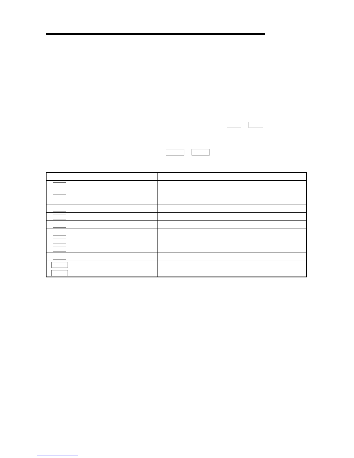
4 - 7 4 - 7
MELSEC-Q
4 DATA USED FOR POSITIONING CONTROL
4.1.6 Type and roles of monitor data
The monitor data area in the buffer memory stores data relating to the control state of
the positioning control system, which are monitored as required while the positioning
system is operating.
The following da t a a re avai l able for monitori ng .
• Axis operation monitoring:
Monitoring of the current position and speed, and other data related to the
movements of axes (through the axis monitor data
Md. 1
to
Md. 9
)
• Module information monitoring:
Monitoring of the QD70 error status and warning status (through the module
information monitor data
Md. 10
to
Md. 11
)
Refer to "Section 4.6 List of monitor data" for details of the monitor data.
Monitor data Monitor details
Md. 1
Current feed value Monitor the current "current feed value"
Md. 2
Movement amount after near-point dogONMonitor the movement amount after the near-point dog has turned
ON
Md. 3
Current speed Monitor the current speed
Md. 4
Axis operation status Monitor the axis operation state
Md. 5
Axis error code Monitor the latest error code that occurred with the axis
Md. 6
Axis warning code Monitor the latest w arning code that oc curred with the axis
Md. 7
Status Monitor the flag
Md. 8
External I/O signal Monitor the external input/output signal
Md. 9
Executing positioning data No. Monitor the "positioning data No." currently being executed
Md. 10
Error status Monitor the error status of each axis
Md. 11
Warning status Monitor the warning status of each axis
Page 47

4 - 8 4 - 8
MELSEC-Q
4 DATA USED FOR POSITIONING CONTROL
4.1.7 Type and roles of control data
Operation of the positioning control system is achieved through the execution of
necessary controls. (Data required for controls are given through the default values
when the power is switched ON, which can be modified as required by the sequence
program.)
Controls are performed over system data or machine operation.
• Controlling the operation :
Setting operation parameters, changing speed during operation, restarting operation
(through the a xi s con t rol da t a
Cd. 1
to
Cd. 9
)
Refer to "Section 4.7 List of control data" for details of the control data.
Control data Control details
Cd. 1
Axis error reset
Clear (reset) the axis error code (
Md. 5
) and warning code (
Md. 6
).
Cd. 2
OPR request flag OFF request Change OP R request flag from "O N to O FF".
Cd. 3
Start method Set which control will be executed (start method).
Cd. 4
Restart request Give a restart command during an axis operation stop.
Cd. 5
Speed-position switching request Validate speed-position switching signal from external source.
Cd. 6
Speed change request
Issue instruction to change speed in operation to
Cd. 7
value.
(Made valid during speed control of speed-position sw itching control
or during JOG operation)
Cd. 7
New speed value Set new speed when changing speed during operation.
Cd. 8
ACC/DEC time at speed change
Set the time taken at a speed change to reach the new speed from
the old speed.
Cd. 9
DEC/STOP time at speed change
Set the time taken at axis stop factor occurrence (axis stop signal ON
or error occurrence) to make a stop after reaching "
Pr. 6
Bias speed
at start" from the speed after a speed change.
Page 48

4 - 9 4 - 9
MELSEC-Q
4 DATA USED FOR POSITIONING CONTROL
4.2 List of parameters
Setting value buffer memory address
Item
Setting value, setting
range
Default value
Axis 1Axis 2Axis 3Axis 4Axis 5Axis 6Axis 7Axis 8
Pr. 1
Software stroke limit upper
limit value
2147483647
01100
101
200
201
300
301
400
401
500
501
600
601
700
701
Pr. 2
Software stroke limi t lo wer
limit value
-2147483648 to
2147483647 (pulse)
-2147483648
23102
103
202
203
302
303
402
403
502
503
602
603
702
703
0: ValidPr. 3
Software stroke limit
valid/invalid setting
1: Invalid
0 4 104 204 304 404 504 604 704
0: No update
1: Update
Pr. 4
Current feed value during
speed control
2: Clear to 0 and no
update
0 5 105 205 305 405 505 605 705
Pr. 5
Speed limit value 1 to 200000 (pulse/s) 10000
67106
107
206
207
306
307
406
407
506
507
606
607
706
707
Pr. 6
Bias speed at start 0 to 200000 (pulse/s) 0
89108
109
208
209
308
309
408
409
508
509
608
609
708
709
Pr. 7
Positioning complete signal
output time
0 to 65535 (ms) 300 10 110 210 310 410 510 610 710
Pr. 8
Deviation counter clear
signal output time
1 to 32 (ms) 10 11 111 211 311 411 511 611 711
0: 10µs
1: 100µs
2: 1ms
Pr. 9
PULSE/SIGN method
selection setup/hold time
3: 2ms
0 12 112 212 312 412 512 612 712
0: Position match stop
Pr. 10
Stop mode during path
control
1: Deceleration stop
0 13 113 213 313 413 513 613 713
Pr. 1
Software stroke limit upper limit value
Set the upper limit for the machine's movement range.
Pr. 2
Software stroke limit lower limit value
Set the lower limit for the machine's movement range.
(Machine movement range)
Software stroke
limit lower limit
OP
Emergency stop
limit switch
Software stroke
limit upper limit
Emergency stop
limit switch
1) Generally, the OP is set at the lower limit or upper limit of the stroke
limit.
2) By setting the upper limit value or lower limit value of the software
stroke limit, overrun can be prevented in the software. However, an
emergency stop limit switch must be installed nearby outside the range.
Pr. 3
Software stroke limit valid/invalid setting
Set whether to va li da te th e so ftware stroke li mi t.
0: Valid
1: Invalid
Page 49

4 - 10 4 - 10
MELSEC-Q
4 DATA USED FOR POSITIONING CONTROL
Pr. 4
Current feed value during speed control
Specify whether you wish to enable or disable the update of "
Md. 1
Current feed
value" while operations are performed under the speed control (including the
speed-position and position-speed switching control).
0: No update
The current feed value will not change.
(The value at the beginning of the speed control will be kept.)
1: Update
The current feed value will be updated.
(The current feed value will change from the initial.)
2: Clear to 0 and no update
The current feed will be set initially to zero and not
updated. (The value be kept "0".)
Pr. 5
Speed limit value
Set the maximum speed for OPR control, positioning control and JOG operation.
The speed limit value is determined by the following two conditions.
• Motor speed • Workpiece movement speed
Pr. 6
Bias speed at start
Set the minimum starting speed for OPR control, positioning control and JOG
operation. When using a stepping motor or like, set this speed to start the motor
smoothly. (A stepping motor does not start smoothly if the motor speed is low at
a start.)
Set a value not more than "
Pr. 5
Speed limit va lue". If it is more than "
Pr. 5
Speed limit value", th e "Se t ti ng rang e out sid e bi a s speed " e rr o r (er ro r code : 90 6 )
will occur.
Page 50

4 - 11 4 - 11
MELSEC-Q
4 DATA USED FOR POSITIONING CONTROL
Pr. 7
Positioning complete signal output time
Set the output time of the positioning complete signal [X8 to XF] output from the
QD70.
Positioning co mple te in di cat e s tha t the pre set dw ell ti me ha s el ap sed aft e r th e
QD70 ended pulse ou tput .
If the setting value is 0 (ms) or if the axis stop signal was used to make a stop
during JOG operation or speed control of speed-position switching control, the
positioning complete signal is not output.
M
[Y8 to YF]
[X18 to X1F]
PLC
CPU
PLC
Positioning
start signal
Positioning
complete signal
Positioning control
Positioning start signal
Positioning start
complete
BUSY signal
Positioning complete signal
Positioning complete signal
(after elapse of dwell time)
Output time
QD70
Positioning complete signal output time
Pr. 8
Deviation counter clear signal output time
Set the duratio n of the devi a tio n coun te r cl ea r sig nal ou t put du ring an OPR
control operation using any of the following methods: the near-point dog method,
stopper 1 to 3, and count 1. (For details, refer to your drive unit manual.)
Page 51

4 - 12 4 - 12
MELSEC-Q
4 DATA USED FOR POSITIONING CONTROL
Pr. 9
PULSE/SIGN method selection setup/hold time
Set the setup/hold time when PULSE/SIGN is selected in the pulse output mode
to output inverted pulses.
0: 10µs
1: 100µs
2: 1ms
3: 2ms
The following is an example for negative logic.
PULSE
SIGN
Pr. 9
Pr. 9
Set in Set in
Movement in
+ direction
Movement in
- direction
Forward
run
Reverse
run
PULSE/SIGN mode (set the pulse output mode with the intelligent function
module switch. Refer to Section 5.6.)
Page 52

4 - 13 4 - 13
MELSEC-Q
4 DATA USED FOR POSITIONING CONTROL
Pr. 10
Stop mode during path control
Set the stoppi ng met ho d u sing th e a xis sto p sign al inpu t when t he ope ra tio n
pattern for position control is continuous path control.
0: Position match stop .......Deceleration starts when the axis stop signal is input,
and the axis stops immediately when the address
preset to the positioning data in execution is reached.
1: Deceleration stop...........When the axis stop signal is input, the axis stops after
decelerating to "
Pr. 6
Bias speed at start". (The axis
does not stop at the address preset to the positioning
data in execution.)
Da. 5
Command speed
Pr. 6
Bias speed at start
Da. 5
Command speed
Da. 6
Positioning address / movement amount
Continuous path control performed
when axis stop signal is not input
Da. 6
Positioning address / movement amount
Da. 5
Command speed
Da. 6
Pr. 6
Bias speed at start
Da. 4
stop time
Deceleration
Pr. 6
Bias speed at start
0: Position match stop
Axis stop signal input
Continuous path control performed
when axis stop signal is not input
In a pattern where the positioning address is reached during deceleration, an immediate stop is made
when the positioning address is reached. However, if the positioning address is not reached during
deceleration, a position match stop cannot be made. (Refer to the following chart.)
Axis stop signal input
1: Deceleration stop
Axis stop signal input
Continuous path control performed
when axis stop signal is not input
Deceleration stop
If the axis passes through the positioning address, it does not stop and decelerates to a stop.
Da. 4
Deceleration
stop time
Da. 4
stop time
Deceleration
Positioning address / movement amount
Immediate stop after the address set to
Da. 6
" Positioning address/movement
amount" is reached
Deceleration stop before the address set to "
Da. 6
Positioning address/movement amount" is reached
No stop if the address set to " Positioning
Da. 6
address/ movement am ount" is reached
Page 53

4 - 14 4 - 14
MELSEC-Q
4 DATA USED FOR POSITIONING CONTROL
4.3 List of OPR data
Setting value buffer memory address
Item
Setting value, setting
range
Default value
Axis 1Axis 2Axis 3Axis 4Axis 5Axis 6Axis 7Axis 8
0: Near-point dog
method
1: Stopper 1
2: Stopper 2
3: Stopper 3
4: Count 1
OPR. 1
OPR method
5: Count 2
0 20 120 220 320 420 520 620 720
0: Forward direction
OPR. 2
OPR direction
1: Reverse direction
0 21 121 221 321 421 521 621 721
OPR. 3
OP address
-2147483648 to
2147483647 (pulse)
0
2223122
123
222
223
322
323
422
423
522
523
622
623
722
723
OPR. 4
OPR speed 1 to 200000 (pulse/s) 1
2425124
125
224
225
324
325
424
425
524
525
624
625
724
725
OPR. 5
Creep speed 1 to 200000 (pulse/s) 1
2627126
127
226
227
326
327
426
427
526
527
626
627
726
727
OPR. 6
ACC/DEC time at OPR
0 to 32767 (ms) 1000 28 128 228 328 428 528 628 728
OPR. 7
DEC/STOP time at OPR
0 to 32767 (ms) 1000 29 129 229 329 429 529 629 729
OPR. 8
Setting for the movement
amount after near-point
dog ON
0 to 2147483647
(pulse)
0
3031130
131
230
231
330
331
430
431
530
531
630
631
730
731
OPR. 9
OPR dwell time
0 to 65535 (ms)
0 32 132 232 332 432 532 632 732
: When making setting in a sequence program, set 0 to 32767 in decimal as-is, and 32768 to 65535 in hexadecimal.
OPR. 1
OPR method
Set the "OPR method " fo r ca rry ing ou t machi ne OP R co ntr ol .
0 : Near-point dog method....After decelerating at the near-point dog ON, stop at
the zero signal an d co mpl ete t he OPR co nt rol .
1 : Stopper 1..........................After decelerating at the near-point dog ON, stop
with the stopper, and complete the OPR control
after the OPR dwell ti me ha s pa ssed.
2 : Stopper 2..........................After decelerating at the near-point dog ON, stop
with the stopp e r , an d co mplete the OPR co nt rol with
the zero signal.
3 : Stopper 3..........................After starting with the creep speed, stop with the
stopper, and complete the OPR control with the
zero signal.
4 : Count 1.............................After decelerating at the near-point dog ON, move
the designated distan ce , an d co mpl ete the OPR
control with the zero signal.
5 : Count 2.............................After decelerating at the near-point dog ON, move
the designated distan ce , an d co mpl ete the OPR
control.
Note) Refer to "8. 2 .2 Ma ch i ne OPR met ho d" for details o n th e OP R met ho d s.
Page 54

4 - 15 4 - 15
MELSEC-Q
4 DATA USED FOR POSITIONING CONTROL
OPR method
0 : Near-point dog method
(1) Start machine OPR control.
(Start movement at the "
OPR. 4
OPR speed" in the
"
OPR. 2
OPR direction".)
(2) Detect the near-point dog ON, and start deceleration.
(3) Decelerate to "
OPR. 5
Creep speed", and move with the
creep speed.
(At this time, the near-point dog must be ON.)
(4) When the first zero signal (one pulse of which is output
when the motor turns one revolution) after near-point dog
OFF is detected, the pulse output from the QD70 stops and
OPR control is completed.
t
V
ON
(1)
(2)
(3)
(4)
OPR. 4 OPR speed
Pr. 6 Bias speed
at start
OPR. 5 Creep speed
Near-point dog OFF
Zero signal
First zero after
near-point dog OFF
1 : Stopper 1
(1) Start machine OPR control.
(Start movement at the "
OPR. 4
OPR speed" in the
"
OPR. 2
OPR direction".)
(2) Detect the near-point dog ON, and start deceleration.
(3) Decelerate to "
OPR. 5
Creep speed", and move with the
creep speed.
(At this time, a torque limit is needed for the motor. If there is
no torque limit, the motor may fail at (4).)
(4) The axis contacts against the stopper at "
OPR. 5
Creep
speed", and then stops.
(5) When the near-point dog turns ON and the "
OPR. 9
OPR
dwell time" is passed, the pulse output from the QD70
stops, and the OPR control is completed.
t
V
(1)
(2)
(3) (4)
(5)
ON
OPR. 4 OPR speed
Pr. 6 Bias speed
at start
OPR. 5 Creep speed
Range where motor
rotation is forcibly
stopped by stopper
Near-point dog OFF
Dwell time out
Dwell time
counting
2 : Stopper 2
(1) Start machine OPR control.
(Start movement at the "
OPR. 4
OPR speed" in the
"
OPR. 2
OPR direction".)
(2) Detect the near-point dog ON, and start deceleration.
(3) Decelerate to "
OPR. 5
Creep speed", and move with the
creep speed.
(At this time, a torque limit is needed for the motor. If there is
no torque limit, the motor may fail at (4).)
(4) The axis contacts against the stopper at "
OPR. 5
Creep
speed", and then stops.
(5) When the zero signal (signal output on detection of contact
with the stopper) is detected after a stop, the pulse output
from the QD70 stops and OPR control is completed.
t
V
ON
(1)
(2)
(3) (4)
(5)
OPR. 4 OPR speed
Pr. 6 Bias speed
at start
OPR. 5 Creep speed
Stopped by stopper
Zero signal
Near-point dog OFF
Page 55

4 - 16 4 - 16
MELSEC-Q
4 DATA USED FOR POSITIONING CONTROL
3 : Stopper 3
(1) Start machine OPR control.
(Start movement at the "
OPR. 5
Creep speed" in the
"
OPR. 2
OPR direction". (At this time, a torque limit is
needed for the motor. If there is no torque limit, the motor
may fail at (2).)
(2) The axis contacts against the stopper at "
OPR. 5
Creep
speed", and then stops.
(3) When the zero signal (signal output on detection of contact
with the stopper) is detected after a stop, the pulse output
from the QD70 stops and OPR control is completed.
t
V
(1)
(2)
(3)
OPR. 5 Creep speed
Pr. 6 Bias speed at start
Stopped by stopper
Zero signal
4 : Count 1
(1) Start machine OPR control.
(Start movement at the "
OPR. 4
OPR speed" in the
"
OPR. 2
OPR direction".)
(2) Detect the near-point dog ON, and start deceleration.
(3) Decelerate to "
OPR. 5
Creep speed", and move with the
creep speed.
(4) When the first zero signal (one pulse of which is output
when the motor turns one revolution) is detected after the
movement amount set in "
OPR. 8
Setting for the
movement amount after near-point dog ON" has been
travelled after near-point dog ON, the pulse output from the
QD70 stops and OPR control is completed.
t
V
ON
(4)
(3)
(2)
(1)
OPR. 4 OPR speed
Pr. 6 Bias speed
at start
OPR. 8 Setting for the movement
amount after near-point dog ON
OPR. 5 Creep speed
Md. 2 Movement amount
after near-point dog ON
Near-point dog OFF
Zero signal
Near-point dog should be
turned OFF with enough distance
provided from OP position.
First zero after movement amount
has been traveled after near-point
do
g
OFF
5 : Count 2
(1) Start machine OPR control.
(Start movement at the "
OPR. 4
OPR speed" in the
"
OPR. 2
OPR direction".)
(2) Detect the near-point dog ON, and start deceleration.
(3) Decelerate to "
OPR. 5
Creep speed", and move with the
creep speed.
(4) After the near-point dog turns ON and the movement
amount set in "
OPR. 8
Setting for the movement amount
after near-point dog ON" has passed, the pulse output from
the QD70 stops with the first zero signal, and the OPR
control is completed.
t
V
ON
(1)
(2)
(3)
(4)
OPR. 4 OPR speed
Pr. 6 Bias speed
at start
OPR. 8 Setting for the movemen
t
amount after near-p oint dog ON
OPR. 5 Creep speed
Md. 2 Movement amount
after near-point dog ON
Near-point dog OFF
Page 56

4 - 17 4 - 17
MELSEC-Q
4 DATA USED FOR POSITIONING CONTROL
OPR. 2
OPR direction
Set the direction to start movement when starting machine OPR control.
0: Forward direction
Moves in the direction that the address increments. (Arrow 2))
1: Reverse direction
Moves in the direction that the address decrements. (Arrow 1))
Normally, the OP is set near the lower limit or the upper limit, so "
OPR. 2
OPR
direction" is set as shown below.
Lower limit
Address increment
direction
Address decremwnt
direction
Upper limit
When the zero point is set at r\the lower
limit side, the OPR directiion is in the
direction of arrow 1).
Set "1" for OPR. 2
OP
1)
2)
OP
Address decremwnt
direction
Address increment
direction
Upper limit
Lower limit
When th eOP is set st the upper
limit side, th eOPR diredtion
is in direction of arrow 2).
Set "0" for OPR. 2
OPR. 3
OP address
Set the address used as the reference point for position control (ABS system).
(When the machine OPR control is completed, the stop position address is
changed to the address set in "
OPR. 3
OP address". At the same time, the
"
OPR. 3
OP address" is stored in "
Md. 1
Current feed value".)
OPR. 4
OPR speed
Set the speed fo r OPR con t rol .
Note) • Set the "OPR spee d " to le s s th an "
Pr. 5
Speed limit value". If the "speed
If the "speed limit value" is exceeded, the "Setting range outside OPR
speed" error (error code: 913) will occur.
• Set the "OPR spee d" t o a val ue no t le ss th a n "
Pr. 6
Bias speed at start".
If it is less than the "bias speed at start", the "Setting range outside OPR
speed" error (error code: 913) will occur.
Page 57

4 - 18 4 - 18
MELSEC-Q
4 DATA USED FOR POSITIONING CONTROL
OPR. 5
Creep speed
Set the creep speed after near-point dog ON (the low speed just before stopping
after decelerating from the OPR speed).
The creep speed is set within the following range.
(
OPR. 4
OPR speed ) ≥ (
OPR. 5
Creep speed) ≥ (
Pr. 6
Bias speed at start)
Note) • The creep speed is related to the detection error when using the OPR
method with zero signal, and the size of the collision if a collision occurs
during OPR using the stopper.
• Set the "creep speed" to a value not more than "
OPR. 4
OPR speed". If
the "OPR speed" is exceeded, "the "Setting range outside creep speed"
error (error code: 914) will occur.
• Set the "creep speed" to a value not less than "
Pr. 6
Bias speed at start".
If it is less than the "bias speed at start", the "Setting range outside creep
speed" error (error code: 914) will occur.
ON
V
OPR. 4
OPR. 5
Pr. 6
OPR control start
Near-point dog signal OFF
Z
ero signal
Bias speed at start
OPR speed
Creep speed
OPR. 6
ACC/DEC time at OPR
Set the time taken under OPR control to reach "
OPR. 4
OPR speed" from "
Pr. 6
Bias speed at start" or to reach "
OPR. 5
Creep speed" from "
OPR. 4
OPR
speed".
Pr. 6
OPR. 6
OPR. 6
OPR. 4
OPR. 5
t
V
t
V
OPR. 6
Pr. 6
OPR. 5
(When OPR method is other than "Stopper 3") (When OPR method is "Stopper 3")
Page 58

4 - 19 4 - 19
MELSEC-Q
4 DATA USED FOR POSITIONING CONTROL
OPR. 7
DEC/STOP time at OPR
Set the time taken to make a stop after reaching "
Pr. 6
Bias speed at start" from
"
OPR. 5
Creep speed" under "Count 2" OPR control or to make a stop after
reaching "
Pr. 6
Bias speed at start" from the speed during OPR control at axis
stop factor occurrence (axis stop signal ON or error occurrence).
Pr. 6
OPR. 7
OPR. 4
OPR. 5
t
V
t
V
OPR. 4
OPR. 5
Pr. 6
OPR. 7
(When OPR method is "Count 2")
(When axis stop signal is turned ON during
OPR control (Common to all OPR methods))
Axis stop factor occurrence
OPR. 8
Setting for the movement amount after near- poi nt dog ON
When the OPR method is Count 1 or 2, set a value not less than the deceleration
distance after the near-point dog signal has turned ON.
=
1
2
2000
Vz
t + t'
1000
2000
10 10 (320 + 80)
3
2000
80ms : t'
OFF
ON
Setting example of " OPR. 8 Setting for the movement am ount after near-point do g O N "
When 10kpulse/s is set in " OPR. 4 OPR speed", 2kpulse/s in " OPR. 5 Creep speed",
and 320ms in " OPR. 6 ACC/DEC time at OPR", calculate " OPR. 8 Setting for the movement amount
after near-point dog ON" as indicated below.
[OPR control operation]
OPR. 4 OPR speed : Vz=10kpulse/s
Near-point dog
OPR. 5 Creep speed: Vc=2 kpulse/s
OPR. 6 ACC/DEC time at OPR : t=320ms
[Deceleration distance]
*Set 2000 pulse or more in " OPR. 8 Setting for the
movement amount after near-point dog ON".
=
Vz (t + t')
=
=
OPR. 9
OPR dwell time
When the OPR method is Stopper 1, set the time from when the near-point dog
turns ON until OPR control is complet ed.
Set not less than the movement time from when the near-point dog turns ON until
a stop is made by the stopper.
(When the OPR method is other than "Stopper 1", the "
OPR. 9
OPR dwell time"
value need not be set.)
Page 59
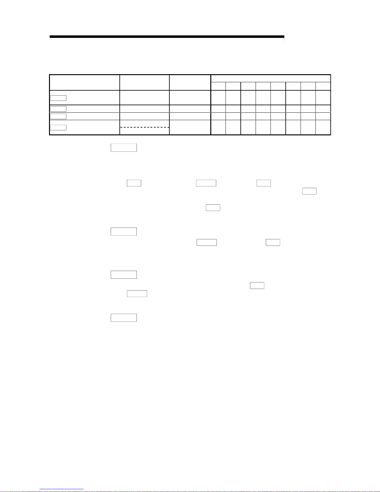
4 - 20 4 - 20
MELSEC-Q
4 DATA USED FOR POSITIONING CONTROL
4.4 List of JOG data
Setting value buffer memory address
Item
Setting value, setting
range
Default value
Axis 1Axis 2Axis 3Axis 4Axis 5Axis 6Axis 7Axis 8
JOG. 1
JOG speed 1 to 200000 (pulse/s) 0
4041140
141
240
241
340
341
440
441
540
541
640
641
740
741
JOG. 2
JOG ACC time 0 to 32767 (ms) 1000 42 142 242 342 442 542 642 742
JOG. 3
JOG DEC time 0 to 32767 (ms) 1000 43 143 243 343 443 543 643 743
0: Forward run JOG
JOG. 4
JOG direction flag
1: Reverse run JOG
0 44 144 244 344 444 544 644 744
JOG. 1
JOG speed
Set the speed for JOG operation. (This value is used for both forward run JOG
and reverse run JOG.)
Set the JOG speed in the following range.
(
Pr. 5
Speed limit value) ≥ (
JOG. 1
JOG speed) ≥ (
Pr. 6
Bias speed at start)
If the "JOG speed" is more than the "speed limit value", it is limited to "
Pr. 5
Speed limit value".
If the "JOG speed" is less th an "
Pr. 6
Bias speed at start", it is limited to "Pr. 6
Bias speed at start".
JOG. 2
JOG ACC time
Set the time t a ken to re a c h "
JOG. 1
JOG speed" from "
Pr. 6
Bias speed at
start" at a JOG operation start (JOG start signal ON). (This value is used for both
forward run JOG and rev e rse run JOG. )
JOG. 3
JOG DEC time
Set the time taken to make a stop after reaching "
Pr. 6
Bias speed at start" from
"
JOG. 1
JOG speed" at a JOG operation st op (JOG sta rt sign al OFF, erro r
occurrence). (This value is used for both forward run JOG and reverse run JOG.)
JOG. 4
JOG direction flag
Set the forward/reverse direction for JOG operation.
0: Forward run JOG
1: Reverse run JOG
Page 60

4 - 21 4 - 21
MELSEC-Q
4 DATA USED FOR POSITIONING CONTROL
4.5 List of positioning data
Before explaining the positioning data setting items
Da. 1
to
Da. 7
, the configuration
of the positioning data will be shown below.
The positioning data stored in the QD70 buffer memory has the following type of
configuration.
²‚P
890
891
892
894
895
898
893
896
897
899
10
²‚P
880
881
882
884
885
888
883
886
887
889
9
²‚P
820
821
822
824
825
828
823
826
827
829
3
²‚P
810
811
812
814
815
818
813
816
817
819
2
²‚P
Da. 1 Operation pattern
Da. 2 Control method
800
801
802
804
805
808
803
806
807
809
Positioning data No. 1
Axis 1
²‚P
1199
10
²‚P
1189
9
²‚P
1129
3
²‚P
1119
2
²‚P
1109
1190
1191
1192
1194
1195
1198
1193
1196
1197
1180
1181
1182
1184
1185
1188
1183
1186
1187
1120
1121
1122
1124
1125
1128
1123
1126
1127
1110
1111
1112
1114
1115
1118
1113
1116
1117
1100
1101
1102
1104
1105
1108
1103
1106
1107
²‚P
999
10
²‚P
989
9
²‚P
929
3
²‚P
919
2
²‚P
909
990
991
992
994
995
998
993
996
997
980
981
982
984
985
988
983
986
987
920
921
922
924
925
928
923
926
927
910
911
912
914
915
918
913
916
917
900
901
902
904
905
908
903
906
907
²‚P
1099
10
²‚P
1089
9
²‚P
1029
3
²‚P
1019
2
²‚P
1009
1090
1091
1092
1094
1095
1098
1093
1096
1097
1080
1081
1082
1084
1085
1088
1083
1086
1087
1020
1021
1022
1024
1025
1028
1023
1026
1027
1010
1011
1012
1014
1015
1018
1013
1016
1017
1000
1001
1002
1004
1005
1008
1003
1006
1007
Da. 3 ACC/DEC time
Da. 4 DEC/STOP time
Da. 5 Command speed
Da. 7 Dwell time
Reserved (Cannot Be
Used)
Da. 6 Positioning
address/movement
amount
Buffer memory ad dress
Axis 2
Da. 1 Operation pattern
Da. 2 Control method
Da. 3 ACC/DEC time
Da. 4 DEC/STOP time
Da. 5 Command speed
Da. 7 Dwell time
Reserved (Cannot Be
Used)
Da. 6 Positioning
address/movement
amount
Positioning data No. 1
Buffer memory ad dress
Da. 1 Operation pattern
Da. 2 Control method
Positioning data No. 1
Axis 3
Da. 3 ACC/DEC time
Da. 4 DEC/STOP time
Da. 5 Command speed
Da. 7 Dwell time
Reserved (Cannot Be
Used)
Da. 6 Positioning
address/movement
amount
Buffer memory ad dress
Da. 1 Operation pattern
Da. 2 Control method
Positioning data No. 1
Axis 4
Da. 3 ACC/DEC time
Da. 4 DEC/STOP time
Da. 5 Command speed
Da. 7 Dwell time
Reserved (Cannot Be
Used)
Da. 6 Positioning
address/movement
amount
Buffer memory ad dress
: Write to Reserved (Cannot be used) is prohibited.
Page 61

4 - 22 4 - 22
MELSEC-Q
4 DATA USED FOR POSITIONING CONTROL
²‚P
1399
10
²‚P
1389
9
²‚P
1329
3
²‚P
1319
2
1309
1390
1391
1392
1394
1395
1398
1393
1396
1397
1380
1381
1382
1384
1385
1388
1383
1386
1387
1320
1321
1322
1324
1325
1328
1323
1326
1327
1310
1311
1312
1314
1315
1318
1313
1316
1317
1300
1301
1302
1304
1305
1308
1303
1306
1307
²‚P
1599
10
²‚P
1589
9
²‚P
1529
3
²‚P
1519
2
²‚P
1509
1590
1591
1592
1594
1595
1598
1593
1596
1597
1580
1581
1582
1584
1585
1588
1583
1586
1587
1520
1521
1522
1524
1525
1528
1523
1526
1527
1510
1511
1512
1514
1515
1518
1513
1516
1517
1500
1501
1502
1504
1505
1508
1503
1506
1507
²‚P
1299
10
²‚P
1289
9
²‚P
1229
3
²‚P
1219
2
²‚P
1209
1290
1291
1292
1294
1295
1298
1293
1296
1297
1280
1281
1282
1284
1285
1288
1283
1286
1287
1220
1221
1222
1224
1225
1228
1223
1226
1227
1210
1211
1212
1214
1215
1218
1213
1216
1217
1200
1201
1202
1204
1205
1208
1203
1206
1207
²‚P
1499
10
²‚P
1489
9
²‚P
1429
3
²‚P
1419
2
²‚P
1409
1490
1491
1492
1494
1495
1498
1493
1496
1497
1480
1481
1482
1484
1485
1488
1483
1486
1487
1420
1421
1422
1424
1425
1428
1423
1426
1427
1410
1411
1412
1414
1415
1418
1413
1416
1417
1400
1401
1402
1404
1405
1408
1403
1406
1407
Da. 1 Operation pattern
Da. 2 Control method
Positioning data No. 1
Axis 1
Da. 3 ACC/DEC time
Da. 4 DEC/STOP time
Da. 5 Command speed
Da. 7 Dwell time
Reserved (Cannot Be
Used)
Da. 6 Positioning
address/movement
amount
Buffer memory address
Da. 1 Operation pattern
Da. 2 Control method
Positioning data No. 1
Axis 2
Da. 3 ACC/DEC time
Da. 4 DEC/STOP time
Da. 5 Command speed
Da. 7 Dwell time
Reserved (Cannot Be
Used)
Da. 6 Positioning
address/movement
amount
Buffer memory address
Da. 1 Operation pattern
Da. 2 Control method
Positioning data No. 1
Axis 3
Da. 3 ACC/DEC time
Da. 4 DEC/STOP time
Da. 5 Command speed
Da. 7 Dwell time
Reserved (Cannot Be
Used)
Da. 6 Positioning
address/movement
amount
Buffer memory address
Da. 1 Operation pattern
Da. 2 Control method
Positioning data No. 1
Axis 4
Da. 3 ACC/DEC time
Da. 4 DEC/STOP time
Da. 5 Command speed
Da. 7 Dwell time
Reserved (Cannot Be
Used)
Da. 6 Positioning
address/movement
amount
Buffer memory address
: Write to Reserved (Cannot be used) is prohibited.
The descriptions that follow relate to the positioning data set items
Da. 1
to
Da. 7
.
(The buffer memory addresses shown are those of the "positioning data No. 1" for the
axes 1 to 8.)
Page 62

4 - 23 4 - 23
MELSEC-Q
4 DATA USED FOR POSITIONING CONTROL
Setting value buffer memory address
Item
Setting value,
setting range
Default value
Axis 1Axis 2Axis 3Axis 4Axis 5Axis 6Axis 7Axis 8
0: Positioning
termination
1: Continuous
positioning control
Da. 1
Operation pattern
2: Continuous path
control
0 800 900 1000 1100 1200 1300 1400 1500
0: No control method
1: 1-axis linear control
(ABS)
2: 1-axis linear control
(INC)
3: Speed.Position Ctrl.
(Forward)
4: Speed.Position Ctrl.
(Reverse)
Da. 2
Control method
5: Current value
changing
0 801 901 1001 1101 1201 1301 1401 1501
Da. 3
ACC/DEC time 0 to 32767 (ms) 1000 802 902 1002 1102 1202 1302 1402 1502
Da. 4
DEC/STOP time 0 to 32767 (ms) 1000 803 903 1003 1103 1203 1303 1403 1503
Da. 5
Command speed 0 to 200000 (pulse/s) 0
804
805
904
905
1004
1005
1104
1105
1204
1205
1304
1305
1404
1405
1504
1505
Da. 6
Positioning address/
movement amount
-2147483648 to
2147483647 (pulse)
1
0
806
807
906
907
1006
1007
1106
1107
1206
1207
1306
1307
1406
1407
1506
1507
Da. 7
Dwell time 0 to 65535 (ms)
2 0 808 908 1008 1108 1208 1308 1408 1508
1: 0 to 2147483647 (pulse) when "
Da. 2
Control method" is "3: Speed.Position Ctrl. (Forward)" or "4: Speed.Position Ctrl. (Reverse)".
2: When making setting in a sequence program, set 0 to 32767 in decimal as-is, and 32768 to 65535 in hexadecimal.
Da. 1
Operation pattern
The operation pattern designates whether positioning control of a certain data
No. is to be ende d wi th ju st t ha t da t a, or wh ethe r th e po si t io ni ng con tro l fo r th e
next data No. is to be carried out in succession.
[Operation pattern]
Countinue
0 : Positioning termination
1 : Continuous positioning control
2 : Continuous path control
Continuous posotioning control
with one start signal
Continupus path positioning
control with speed change
End
1) Positioning termination..................Set to execute positioning control to the
designated address, and then complete
positioning control.
2) Continuous positioning control......Positioning control is carried out
successively in order of data Nos. with one
start signal.
The operation halt s at ea ch po sit io n
indicated by a positioning data.
3) Continuous path control ................Positioning control is carried out
successively in order of data Nos. with one
start signal.
The operation does not stop at each
positioning data.
Note) Refe r to " CHAPTER 9 POSITI ON IN G CON TRO L " fo r de t ails of the
operation pattern.
Page 63

4 - 24 4 - 24
MELSEC-Q
4 DATA USED FOR POSITIONING CONTROL
Da. 2
Control method
Set the "contr ol met hod" for position in g con t rol .
0: No control met h od
1: 1-axis linear control (ABS)
2: 1-axis linear control (INC)
3: Speed.Position Ctrl. (Forward)......Speed-position switching control (forward
run)
4: Speed.Position Ctrl. (Reverse)......Speed-position switching control (reverse
run)
5: Current value changing
Note) • Refer to "CHAP TE R 9 POS I TI ON I N G CO NTR OL" for details o f th e
control method.
• Setting "0: No con tr ol met hod" wi ll re sul t in the "Se t ti ng ra ng e ou t sid e
control method" error (error code: 506).
Da. 3
ACC/DEC time,
Da. 4
DEC/STOP time
Set the acceleration/deceleration time for positioning control.
["
Da. 1
Operation pattern" is "0: Positioning termination" or "1: Continuous
positioning control"]
Da. 3
ACC/DEC time : Set the time taken to reach "
Da. 5
Command speed"
from "
Pr. 6
Bias speed at start".
Da. 4
DEC/STOP time : Set the time taken to make a stop after reaching
"
Pr. 6
Bias speed at start" from "
Da. 5
Command
speed" at position control completion or axis stop
factor occurrence (axis stop signal ON or error
occurrence).
V
t
Da. 3
Da. 7 Dwell time
Pr. 6 Bias speed at start
Da. 4
Da. 5
Da. 7 Dwell time
Positioning data No. 1
(Continuous positioning control)
Positioning data No. 2
(Positioning termination)
Da. 3
Da. 4
Da. 5
Page 64

4 - 25 4 - 25
MELSEC-Q
4 DATA USED FOR POSITIONING CONTROL
["
Da. 1
Operation pattern" is "2: Continuous path control"]
Da. 3
ACC/DEC time : Set the time taken to reach "
Da. 5
Command speed"
set in the "positioning data to be executed next" from
"
Da. 5
Command speed" set in the "positioning data
currently being executed".
Da. 4
DEC/STOP time : Set any value within the setting range (0 to 32767ms).
(This does not function.)
V
t
Da. 3
Da. 3
Da. 7 Dwell tim
e
Da. 4
Da. 5
Pr. 6
Bias speed at start
Da. 5
Da. 5
Da. 5
Da. 3
Da. 3
Positionin g da t a
No. 1
Continuous path control
Positioning termination
Positionin g da t a
No. 2
Positionin g da t a
No. 3
Positionin g da t a
No. 4
Da. 5
Command speed
Set the speed for po siti onin g cont r ol .
If the set command speed exceeds "
Pr. 5
Speed limit value", positioning control
will be carried out at the speed limit value. If the set command speed is less than
"
Pr. 6
Bias speed at start", positioning control will be carried out at the bias
speed at start.
Da. 6
Positioning address/movement amount
Set the address or movement amount as the target value of positioning control.
The setting value differs in the setting range depending on "
Da. 2
Control
method". ((1) to (3))
(1) 1-axis linear control (ABS), current v alue chang i ng
Set the value (positioning address) for 1-axis linear control (ABS) or current value
changing using the absolute address (address from the OP).
-1000 30001000
Stopping position
(positioning control starting address)
Movement
amount : 2000
Movement
amount : 2000
Page 65

4 - 26 4 - 26
MELSEC-Q
4 DATA USED FOR POSITIONING CONTROL
(2) 1-axis linear control (INC)
Set a signed movement amount as the setting value (movement amount) for 1axis linear control (INC).
When the movement amount is positive: The axis moves in the positive direction
(address increasing direction).
When the movement amount is negative: The axis moves in the negative
direction (address decrea sin g dire cti on) .
-30000 30000
Stopping position
(positioning control starting position)
(Movement amount)
(Movement amount)
Movement in
negative direction
Movement in
positive directio n
(3) Speed.Position Ctrl. (Forward/Reverse)
Set the movement amount (value more than 0) after speed control has been
switched to position control.
Speed
Speed
control
Position
control
Movement
amount setting
Time
Speed-position switching command
Da. 7
Dwell time
When the "dwell time" is set, the setting details of the "dwell time" will be as
follows according to "
Da. 1
Operation pattern".
Set the time from when the positioning control ends to when the
"positioning complete signal" turns ON as "dwell time".
Positioning complete signal OFF
ON
Dwell time
Da. 7
V
t
2) When " Da. 1 Operation pattern" is "1 : Continuous positioning control"
Set the time from when position control ends to when
the next position control start as the "dwell time".
Dwell time
Da. 7
V
t
Position control
Next position
control
3) When " Da. 1 Operation pattern" is "2 : Continuous path control
The setting value irrelevant to the control.
(The "dwell time" is 0ms.)
No dwell time (0ms)
V
t
1) When " Da. 1 Operation patt ern" in "0 : Positioning termination"
Position control
Position control
Next position
control
Page 66

4 - 27 4 - 27
MELSEC-Q
4 DATA USED FOR POSITIONING CONTROL
4.6 List of monitor data
4.6.1 Axis monitor data
Storage buffer memory address
Item Storage details
Default
value
Axis 1Axis 2Axis 3Axis 4Axis 5Axis 6Axis 7Axis 8
Md. 1
Current
feed value
•
The current position is stored.
Update timing: 1ms for QD70P4
2ms for QD70P8
•
On completion of OPR control, the OP address is
stored.
•
Under speed control of speed-position switching
control, whether the current feed value is
updated or not or cleared to zero can be selected
by parameter setting.
•
The software stroke limit can be activated by
parameter setting.
•
If the current value has been changed by the
current value change function, the new value is
stored.
[Range: -2147483648 to 2147483647 pulse]
0
7071170
171
270
271
370
371
470
471
570
571
670
671
770
771
Md. 2
Movement
amount
after nearpoint dog
ON
•
At an OPR control start, "0" is stored.
•
After an OPR control start, the movement
amount from near-point dog ON up to OPR
control completion is stored.
(Movement amount: Indicates the movement
amount up to completion of OPR control when
near-point dog ON is defined as "0".
•
For near-point dog-free stopper type method, the
value is always "0".
[Range: 0 to 2147483647 pulse]
0
7273172
173
272
273
372
373
472
473
572
573
672
673
772
773
Md. 3
Current
speed
•
The current speed is stored.
(The fraction is ignored. "0" may be displayed if
the speed is less than 1 pulse/s.)
Update timing: 1ms for QD70P4
2ms for QD70P8
[Range: 0 to 200000 pulse]
0
7475174
175
274
275
374
375
474
475
574
575
674
675
774
775
Md. 4
Axis
operation
status
The operating status of the axis is stored.
-1: Error
0: Standby
2: Stopped
3: JOG Operation
4: OPR
5: Position • Control
(during speed control of speed-position
switching control)
6: Speed • Position Speed
(during position control of speed-position
switching control)
7: Deceleration (Axis Stop ON)
8: Deceleration (JOG Start OFF)
9: Fast OPR
0 76 176 276 376 476 576 676 776
Md. 5
Axis error
code
At axis error occurrence, the error code
corresponding to the error definition is stored.
•
If another error occurs during axis error
occurrence, the latest error code is ignored.
However, if a system-affecting error (error code:
800 to 840) has occurred, the old error code is
overwritten by the newest error code, which is
stored.
•
The error codes 800 to 840 are stored into
Md. 5
for all axes.
•
When "
Cd. 1
Axis error reset" (axis control data)
of the corresponding axis is turned ON, the axis
error code is cleared (to zero).
(Refer to "Section 13.2" for details of the error
codes.)
0 77 177 277 377 477 577 677 777
Page 67

4 - 28 4 - 28
MELSEC-Q
4 DATA USED FOR POSITIONING CONTROL
Storage buffer memory address
Item Storage details
Default
value
Axis 1Axis 2Axis 3Axis 4Axis 5Axis 6Axis 7Axis 8
Md. 6
Axis
warning
code
At axis warning occurrence, the warning code
corresponding to the warning definition is stored.
•
The latest warning code is always stored. (When
a new axis warning occurs, the old warning code
is overwritten.)
•
When "
Cd. 1
Axis error reset" (axis control data)
of the corresponding axis is turned ON, the axis
warning code is cleared (to zero).
(Refer to "Section 13.3" for details of the warning
codes.)
0 78 178 278 378 478 578 678 778
Md. 7
Status
The ON/OFF states of the following flags are
stored.
The following items are stored.
•
OPR request flag
(Refer to "Chapter 8" for details)
This flag turns ON at power-on or at machine
OPR control start, and turns OFF on
completion of machine OPR control.
•
OPR complete flag
(Refer to "Chapter 8" for details)
This flag turns ON on normal completion of
machine OPR control, and turns OFF at an
OPR control, positioning control or JOG
operation start.
•
0 speed (Refer to "Section 11.3" for details)
This flag turns on when JOG operation or
speed control of speed-position switching
control is started with the speed set to "0".
When a speed change is made, this flag turns
ON when a speed change request of new
speed value 0 is given, and turns OFF when a
speed change request of other than new
speed value 0 is given.
b15 b0b4b8b12
0 : OFF
1 : ON
Not used
Storage item
Meaning
OPR request flag
OPR complete flag
0 speed
0001H79 179 279 379 479 579 679 779
Md. 8
External I/O
signal
The ON/OFF states of the external I/O signals are
stored.
The following items are stored.
•
Zero signal
•
Near-point dog signal
•
Speed-position switching signal
•
Deviation counter clear signal
b15 b0b4b8b12
0 : OFF
1 : ON
Storage item
Meaning
Not used
Zero signal
Near-point dog
signal
Speed-position
switching signal
Deviation counter
clear signal
0000H80 180 280 380 480 580 680 780
Md. 9
Executing
positioning
data No.
•
The positioning data No. currently being
executed is stored. (The stored value is held until
the next start is executed.)
•
When JOG operation or machine OPR control is
started, 0 is stored.
•
When fast OPR control is started, 1 is stored.
0 81 181 281 381 481 581 681 781
Page 68

4 - 29 4 - 29
MELSEC-Q
4 DATA USED FOR POSITIONING CONTROL
4.6.2 Module information monitor data
Item Storage details Default value
Storage buffer memory address
(Common for axis 1 to axis 8)
Md. 10
Error
status
At error occurrence, the bit corresponding to the
error occurrence axis turns ON.
0: Normal (OFF)
1: Error (ON)
(The error occurrence axis cannot be run)
When "
Cd. 1
Axis error reset" (axis control data)
of the corresponding axis is turned ON, the error
status of the corresponding axis is cleared (to
zero). (Refer to "Chapter 13" for details.)
b15 b0b4b8b12
0 : OFF
1 : ON
Not used
Storage item
Meaning
Axis 1 error
Axis 2 error
Axis 3 error
Axis 4 error
Axis 5 error
Axis 6 error
Axis 7 error
Axis 8 error
(For the QD70P4, b4 to b7 are "0" fixed.)
0000
H
1600
Md. 11
Warning
status
At warning occurrence, the bit corresponding to the
warning occurrence axis turns ON.
0: Normal (OFF)
1: Warning (ON)
When "
Cd. 1
Axis error reset" (axis control data)
of the corresponding axis is turned ON, the
warning status of the corresponding axis is cleared
(to zero). (Refer to "Chapter 13" for details.)
b15 b0b4b8b12
0 : OFF
1 : ON
Not used
Storage item
Meaning
Axis 1 warning
Axis 2 warning
Axis 3 warning
Axis 4 warning
Axis 5 warning
Axis 6 warning
Axis 7 warning
Axis 8 warning
(For the QD70P4, b4 to b7 are "0" fixed.)
0000
H
1601
Page 69

4 - 30 4 - 30
MELSEC-Q
4 DATA USED FOR POSITIONING CONTROL
4.7 List of control data
4.7.1 Axis control data
Setting buffer memory address
Item Setting details
Default
value
Axis 1Axis 2Axis 3Axis 4Axis 5Axis 6Axis 7Axis 8
Cd. 1
Axis error
reset
By setting "1", the following operation is
performed.
•
Axis error occurrence (X1), "
Md. 5
Axis error
code", axis warning occurrence (X2) or "
Md. 6
Axis warning code" is cleared.
(X1 and X2 are cleared when "1" is set in
Cd. 1
of all axes.)
•
If "
Md. 4
Axis operation status" is "Error", the
error is cleared and returned to the "Standby"
status.
(The data automatically changes to "0" after
completion of axis error reset or axis warning
reset.)
0 50 150 250 350 450 550 650 750
Cd. 2
OPR
request flag
OFF request
When the OPR request flag (b0 of
Md. 7
) is ON,
setting "1" forcibly turn s th is data OFF.
(The data automatically changes to "0" after the
OPR request flag turns OFF.)
0 51 151 251 351 451 551 651 751
Cd. 3
Start
method
Set this data when starting the corresponding
control.
0 : Positioning control (starting from No. 1)
9000 : Machine OPR control
9001 : Fast OPR control
0 52 152 252 352 452 552 652 752
Cd. 4
Restart
request
•
If positioning control is stopped midway by the
axis stop signal (Y10 to Y17) (when "
Md. 4
Axis
operation status" is "Stopped"), setting "1"
restarts positioning control to the end point of the
positioning data from where it had stopped.
•
For speed control of speed-position switching
control, speed control is exercised at the speed
used before the stop.
(After completion of restart request acceptance,
the data changes to "0" automatically.)
0 53 153 253 353 453 553 653 753
Cd. 5
Speedposition
switching
request
Set whether the speed-position switching signal is
made valid or not.
0: Invalidates the speed-position switching
signal.
(Disable)
1: Validates the speed-position switching signal.
(Enable)
0 54 154 254 354 454 554 654 754
Page 70

4 - 31 4 - 31
MELSEC-Q
4 DATA USED FOR POSITIONING CONTROL
Setting buffer memory address
Item Setting details
Default
value
Axis 1Axis 2Axis 3Axis 4Axis 5Axis 6Axis 7Axis 8
Cd. 6
Speed
change
request
Set "1" to request speed change processing
(make the "
Cd. 7
New speed value" value valid)
after setting "
Cd. 7
New speed value" for JOG
operation or speed control of speed-position
switching control.
(The data changes automatically to "0" after
completion of speed change request acceptance.)
0 55 155 255 355 455 555 655 755
Cd. 7
New speed
value
Set the new speed for JOG operation or speed
control of speed-position switching control.
•
Set the value not more than "
Pr. 5
Speed limit
value".
•
Set the value not less than "
Pr. 6
Bias speed at
start".
[Setting range: 0 to 200000 pulse/s]
0
5657156
157
256
257
356
357
456
457
556
557
656
657
756
757
Cd. 8
ACC/DEC
time at
speed
change
Set the time taken at a speed change to reach the
new speed from the old speed.
[Setting range: 0 to 32767ms]
1000 58 158 258 358 458 558 658 758
Cd. 9
DEC/STOP
time at
speed
change
Set the time taken at axis stop factor occurrence
(axis stop signal ON or error occurrence) to make
a stop after reaching "
Pr. 6
Bias speed at start"
from the speed after a speed change.
[Setting range: 0 to 32767ms]
1000 59 159 259 359 459 559 659 759
Page 71

5 - 1 5 - 1
MELSEC-Q
5 SETUP AND PROCEDURES BEFORE OPERATION
CHAPTER 5 SETUP AND PROCEDURES BEFORE OPERATION
This chapter describes the procedure up to the operation of the QD70 and the part
identification nomenclature and setting and wiring methods of the QD70.
5.1 Handling precautions
This section provides the precautions for handling the QD70.
!
DANGER
Always turn all phases of the power supply OFF externally before cleaning or tightening the
screws.
Failure to turn all phases OFF could lead to electric shocks.
!
CAUTION
Use the PLC within the general specifications environment given in t his manual.
Using the PLC outside the general specification range environment could lead t o elect ric
shocks, fires, malfunctioning, product damage or deterioration.
Do not directly touch the conductive section and electronic parts of the module.
Failure to observe this could lead to module malfunctioning or trouble.
Make sure that foreign matter, such as cutting chips or wire scraps, do not enter the module.
Failure to observe this could lead to fires, trouble or malfunctioning.
Never disassemble or modify the module.
Failure to observe this could lead to trouble, malfunctioning, injuries or fires.
5
Page 72

5 - 2 5 - 2
MELSEC-Q
5 SETUP AND PROCEDURES BEFORE OPERATION
!
CAUTION
Never disassemble or modify the module.
Failure to observe this could lead to trouble, malfunctioning, injuries or fires.
Always turn all phases of the power supply OFF exter nally befor e installing or r emov ing the
module.
Failure to turn all phases OFF could lead to module trouble or malfunctioning.
Use the PLC within the general specifications environment giv en in this manual.
Using the PLC outside the general specification range environment could lead t o elect ric
shocks, fires, malfunctioning, product damage or deterioration.
Hold down the module mounting lever at the bottom of the module and securely insert the
module fixing projection into the fixing holes of the base module. Improper mounting of the
module may lead to malfunctioning, faults, or dropping.
When using the module in the environment subject to much vibration, secure the module w ith a
screw.
Tighten the screw within the range of the specified tightening torque.
Insufficient tightening may lead to dropping, short-circuit, or malfunctionin g.
Excessive tightening may damage the screw or module, leading to dropping, short-circuit , or
malfunctioning
.
(1) Main body
• The main body case is made of plastic. Take care not to drop or apply strong
impacts onto the case.
• Do not remove the QD 70 PCB fro m th e case. Fa ilur e to obse rv e this coul d le ad
to faults.
(2) Cable
• Do not press on the cable with a sharp object.
• Do not twist the cable with force.
• Do not forcibly pull on the cable.
• Do not step on the cable.
• Do not place objects on the cable.
• Do not damage the cable sheath.
(3) Installation environment
Do not install the module in the following type of environment.
• Where the ambient temperature exceeds the 0 to 55°C range.
• Where the ambient humidity exceeds the 5 to 95%RH range.
• Where there is sudden temperature changes, or where dew condenses.
• Where there is corrosive gas or flammable gas.
• Where there are high levels of dust, conductive powder, such as iron chips, oil
mist, salt or organic solvents.
• Where the module will be subject to direct sunlight.
• Where there are strong electric fields or magnetic fields.
• Where vibration or impact could be directly applied onto the main body.
5
Page 73

5 - 3 5 - 3
MELSEC-Q
5 SETUP AND PROCEDURES BEFORE OPERATION
5.2 Procedures before operation
This section gives the procedure up to the operation of the QD70.
Yes
No
No
Yes
Start
Module installation
Install the QD70 in the specified slot.
Wiring
Wire the external device to the QD70.
(Refer to Section 5.4.)
Intelligent function module switch setting
Make setting using GX Developer.
(Refer to Section 5.6.)
Connection confirmation
Confirm connection using GX Developer or
GX Configurator-PT. (Refer to Section 5.5.)
Drive unit operation confirmation
Make confirmation with a simple program in
the factory-set status. (Refer to Section 5.7.)
Do you use
GX Configurator-PT?
Initial setting
Using the FROM/TO instructions, create
an initial value write sequence program.
(Refer to Chapter 7.)
Programming, debugging
Create and confirm a sequence program.
(Refer to Chapter 7.)
System operation
Initial setting
Using GX Configurator-PT, make initial setting.
(Refer to Section 6.4.)
Do you make auto
refresh setting?
Auto refresh setting
Using GX Configurator-PT, make auto refresh
setting. (Refer to Section 6.5.)
Page 74

5 - 4 5 - 4
MELSEC-Q
5 SETUP AND PROCEDURES BEFORE OPERATION
5.3 Part identification nomenclature
(1) The following are the part names of the QD70.
QD70P8
CON2
RUN
ERR.
AX6
AX5
AX8
AX7
CON1
AX2
AX1
AX4
AX3
QD70P8
1) RUN indicator LED, ERR. indicator LED
2) Axis display LED
3) External device connection connector
(40 pins)
*For details, refer to "Section 3.4.2 Signal layout for
external device connection connector"
No. Name Details
1)
RUN indicator LED, ERR. indicator
LED
2) Axis display LED (Axn, n: Axis No.)
Refer to the next page.
3)
External device connection
connector
Connector for connection of the drive unit and
mechanical system inputs.
Page 75

5 - 5 5 - 5
MELSEC-Q
5 SETUP AND PROCEDURES BEFORE OPERATION
(2) The LED display indicates the following operation statuses of the QD70 and axes.
QD70P8
RUN
ERR.
AX6
AX5
AX8
AX7
AX2
AX1
AX4
AX3
Display Attention point Description Display Attention point Description
RUN
AX5 AX1 RUN AX5 AX1
AX6 AX2 AX6 AX2
AX7 AX3 AX7 AX3
ERR. AX8 AX4
RUN is OFF.
ERR. and AX1
to AX8 states
are unfixed.
Hardware
failure.
ERR.
AX8 AX4
AX1 to AX8 are
OFF.
The axes are
stopped or on
standby.
RUN AX5 AX1 RUN AX5 AX1
AX6 AX2 AX6 AX2
AX7 AX3 AX7 AX3
ERR. AX8 AX4
RUN
illuminates.
ERR. is OFF.
The module
operates
normally.
ERR.
AX8 AX4
AX1 (or other
axis) illuminates.
The
corresponding
axis is in
operation.
RUN AX5 AX1 RUN AX5 AX1
AX6 AX2 AX6 AX2
AX7 AX3 AX7 AX3
ERR. AX8 AX4
ERR.
illuminates.
System error.
ERR.
AX8 AX4
ERR. flashes.
AX1 (or other
axis) flashes.
An error occurs
on the
corresponding
axis.
The symbols in the Display column indicate the foll owing
statuses:
: Turns OFF. : Illuminates. : Flashes.
(3) The interface of each QD70 is as shown below.
QD70P4
CON1
RUN
ERR.
AX2
AX1
AX4
AX3
QD70P4
QD70P8
CON2
RUN
ERR.
AX6
AX5
AX8
AX7
CON1
AX2
AX1
AX4
AX3
QD70P8
Page 76

5 - 6 5 - 6
MELSEC-Q
5 SETUP AND PROCEDURES BEFORE OPERATION
External device connection connector
The connectors for use with the QD70 should be purchased separately by the user.
The connector types and pressure displacement tool are listed below.
(a) Connector types
Type Model name
Soldering type, straight out A6CON1
Pressure displacement type, straight out A6CON 2
(b) Pressure-displacement tool
Type Model name
Applicable
wire size
Supplier's office
Pressuredisplacement
tool
FCN-363TT005/H
AWG#24
•
FUJITSU AMERICA,INC.
250E Caribbean Drive Sunnyvale, CA 94089
U.S.A
Tel: (1-408)745-4900
•
FUJITSU EUROPE B.V.
Jupiterstaat 13-15, our 2132 Hoofddorp, The
Netherland
Tel: (31)23-5560910
•
FUJITSU EUROPE B.V. Zweiniederlassung
Deutschland
Schatzbogen 86 D-81829 Munchen
Germany
Tel: (49)89-42742320
•
FUJITSU EUROPE (UK)
Network House, Morres Drive, Maidenhead,
Berkshire, SL6 4FH United Kingdom
Tel: (44)1628-504600
•
FUJITSU EUROPE B.V.
127 Chemin Des Bassins, Europarc, Cleteril
94035 Cleterll 94035 France
Tel: (33)145139940
•
FUJITSU ASIA PACIFIC PTE LIMITED
102E Pasir Panjang Road, #04-01 Citilink
Warehouse Complex, Singapore 118529
Tel: (65)375-8560
•
FUJITSU HONG KONG CO., LTD.
Suite 913 Ocean Centre, 5 Canton Road,
TST, Kowloon, Hong Kong
Tel: (852)2881-8495
Page 77

5 - 7 5 - 7
MELSEC-Q
5 SETUP AND PROCEDURES BEFORE OPERATION
5.4 Wiring
This section explains how to wire the drive unit and mechanical system inputs to the
QD70.
The following are the precautions for wiring the QD70. Read these precautions
together with "Section 5.1 Handling precautions" to ensure work safety.
5.4.1 Wiring precautions
(1) Always confirm the terminal layout before connecting the wires to the QD70.
(2) Correctly solder the external device connection connector. An incomplete
soldering could lead to malfunctioning.
(3) Make sure that foreign matter su ch as cutt ing chi p s and wire scrap s do es not
enter the QD70. Failure to observe this could lead to fires, faults or malfunctioning.
(4) A protective label is attached on the top of the QD70 to avoid foreign matter such
as wire scraps from entering inside during wiring process. Do not remove the label
until the wiring is completed. Before starting the system, however, be sure to
remove the label to ensure heat radiation.
(5) Securely mount the exterd device connection connector to the connector on the
QD70 with two s cr ews .
(6) Do not disconnect the external wiring cable connected to the QD70 or drive unit by
pulling the cable section. When the cable has a connector, be sure to hold the
connector connected to the QD70 or drive unit. Pulling the cable while it is
connected to the QD70 or drive unit may lead to malfunctioning or damage of the
QD70, drive unit or cable.
(7) Do not bundle or adjacently lay the connection cable connected to the QD70
external input/output signals or drive unit with the main circuit line, power line, or
the load line other than that for the PLC. Separate these by 100mm as a guide.
Failure to observe this could lead to malfunctioning caused by noise, surge, or
induction.
(8) If cables to connect to QD70 absolutely must be positioned near (within 100mm)
the power line, use a general shielded cable. The shield must be grounded on the
QD70 side. (Wiring examples are given on the following pages.)
Page 78

5 - 8 5 - 8
MELSEC-Q
5 SETUP AND PROCEDURES BEFORE OPERATION
[Wiring example using shielded cables]
The following are wiring examples for noise reduction.
To external
devices
Connector
Shielded
cable
Drive
unit
Connector
(A6CON1/A6CON2)
To drive units
Use the shortest posible ingth to
graound the 2mm or more FG wire.
(The shield must be grounded on
the QD70 side)
The length between the connector and the shielded
cable chould be the shortest possible.
To QD70
To external
device
2
[Processing example of shielded cables]
Coat the wire with
insulaing tape
Remove the coverring from all shielded cables and bind
the apperared shield with a conductive tape.
Solder the shield of any one of the
shielded cables to the FG wire.
Page 79

5 - 9 5 - 9
MELSEC-Q
5 SETUP AND PROCEDURES BEFORE OPERATION
Assembling of connector (A6CON1/A6CON2)
Wrap the coated parts
with a heat contractile
tube.
Page 80
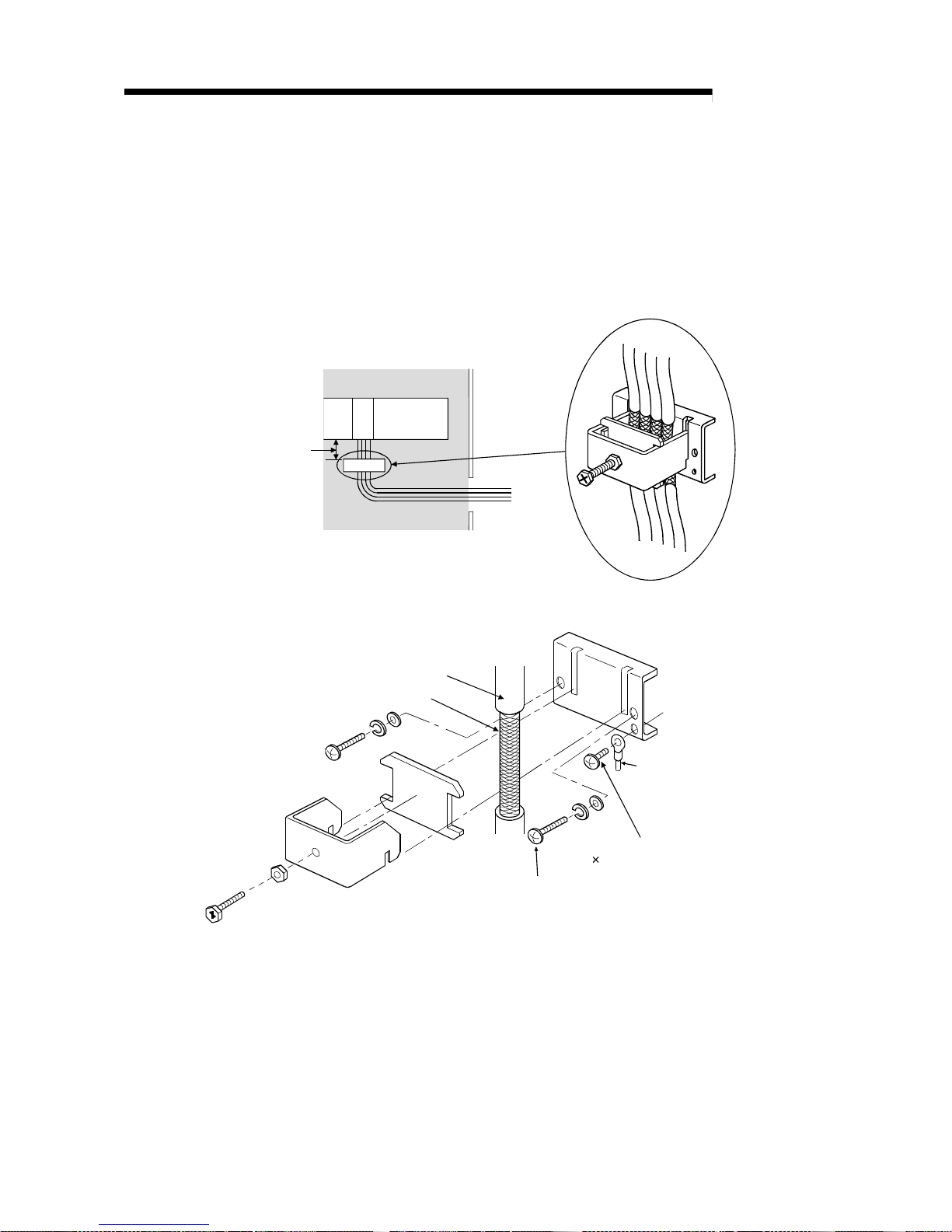
5 - 10 5 - 10
MELSEC-Q
5 SETUP AND PROCEDURES BEFORE OPERATION
(9) The cables connected to the QD70 should be placed in a duct or fixed. Not doing
so can cause the QD70, drive unit or cables to be damaged when the cables
swing, move or are pulled carelessly, for example, or to malfunction due to poor
cable connection.
(10) To comply with the EMC Directive and Low-Voltage Directive, always ground the
QD70 to the control box using the shielded cables and AD75CK cable clamping
(Mitsubishi Electric make).
QD70
20cm (7.88 inch)
to 30cm (11.82 inch)
Inside control box
AD75CK
[How to ground shielded cables using AD75C K]
Shield cable
Shield
Installation screw to control box (M4 screw)
Ground terminal
Ground terminal installation scre
w
(M4 8 screw )
Using the AD75CK, you can tie four cables of about 7mm outside diameter
together fo r g roun di ng .
(For details, refe r to th e AD75 CK - ty pe Cabl e Cla mpi ng Inst r u ctio n Ma nual
<IB-68682>.
Page 81
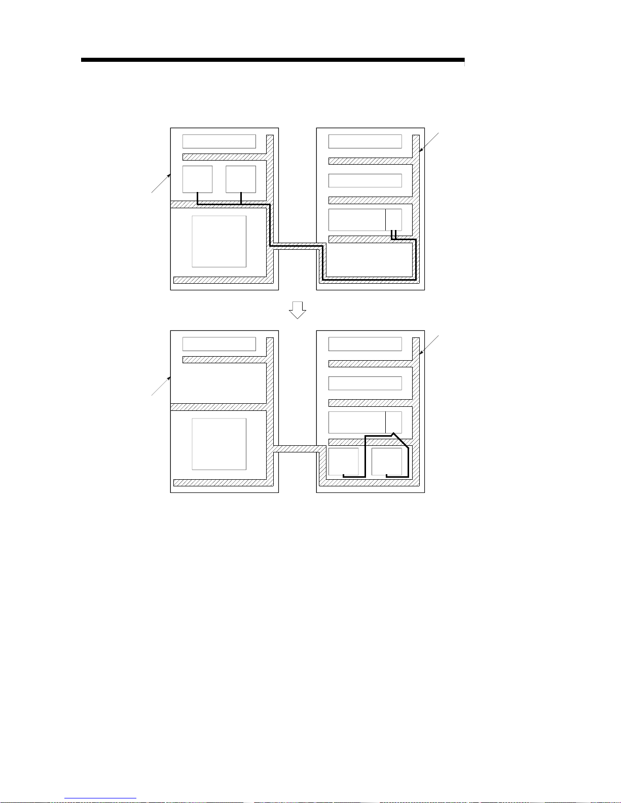
5 - 11 5 - 11
MELSEC-Q
5 SETUP AND PROCEDURES BEFORE OPERATION
[Wiring examples using duct (impr oper ex ampl e and i mproved
example)]
Relay
Drive
unit
Drive
unit
Noise source
Relay
Relay
PLC CPU
QD
70
Relay Realy
Relay
PLC CPU
QD
70
Drive
unit
Changed
Wiring duct
Wiring duct
Control box
Control pane l
The QD70 and drive units are
placed closely.The connection
cable between the QD70 and
drive units is separately laid
from teh power line (in this
example, the cable is outside of
the duct) and is as short as possible.
(Power system,
etc.)
Noise source
(power system,
etc.)
The deive units are placed
near the noise source.
The connection cable between
the QD70 and drive units is
too long.
Drive
unit
Page 82

5 - 12 5 - 12
MELSEC-Q
5 SETUP AND PROCEDURES BEFORE OPERATION
5.5 Confirming the wiring
5.5.1 Confirmation items at completion o f wiring
Check the following points when completed with the QD70 installation and wiring.
• Is the module correctly wired?..............................."Connection confirmation"
By making "connection conformation", you can check whether the "QD70 recognizes
the external I/O signals such as the near-point dog and speed-position switching
signals", for example.
The following i s the way to make " con ne ct io n confi r mati o n".
(1) Method using GX Developer
Read the "
Md. 8
External I/O signal" axis monitor data with the monitor function
(Buffer memory batch) and check the read values.
Buffer memory address
Axis 1 Axis 2 Axis 3 Axis 4 Axis 5 Axis 6 Axis 7 Axis 8
Md. 8
External I/O signal
80 180 280 380 480 580 680 780
[Bit pattern]
b15 b0b4b8b12
0 : OFF
1 : ON
Not used
Storage item
Meaning
Zero signal
Near-point dog signal
Speed-position switching signal
Deviation counter clear signal
(Example) Checking the external I/O signals of Axis 1
<GX Developer display screen>
b0 (Zero signal ON)
b1 (Near-point dog signal ON)
b2 (Speed-position switching signal OFF)
b3 (Deviation counter clear signal OFF)
Set the buffer memory address of " Md. 8
External I/O signal" of Axis 1 in decimal.
The states of the external I/O signals can also be checked by system monitor.
For details, re fe r to "Se ctio n 12. 3 E xte r nal I/ O sig nal monitor function".
Page 83

5 - 13 5 - 13
MELSEC-Q
5 SETUP AND PROCEDURES BEFORE OPERATION
(2) Method using GX Configurator-PT
Monitor the external I/O signal states on the "Monitor/Test screen".
(For details, refer to "Section 6.6 Monitor/test".)
(Example) Checking the external I/O signals of Axis 1 (1 Axis OPR Monitor)
<GX Configurator-PT display screen>
Important
If the QD70 is faulty or does not recognize necessary signals, such as the nearpoint dog and speed-position switching signals, an unexpected accident, e.g. "the
axis collides wi th th e st oppe r wi th ou t decelerating at th e ne a r- p oint dog du ri ng
machine OPR control" or "speed control is not switched to position control".
Always make "con ne cti on con fi r mation" not only whe n t h e po siti oni ng con t rol
system has been configured but also when any modifications have been made to
the system, e.g. modules have been changed or the system has been rewired.
Page 84

5 - 14 5 - 14
MELSEC-Q
5 SETUP AND PROCEDURES BEFORE OPERATION
5.6 Switch setting for intelligent function module
By making the intelligent function module switch setting, the QD70 allows you to set
the pulse output mode, external I/O signal logic and rotation direction. (However, you
cannot set the speed-position switching signal (CHG) logic. It is fixed at the negative
logic.)
Make the intelligent function module switch setting in the "I/O assignment setting" PLC
parameter of the QCPU using GX Developer.
• There are intelligent function module switches 1 to 5, which are set with 16-bit data.
• When you do not make the intelligent function module switch setting, switches 1 to 5
default to 0.
The settings made with the intelligent function module switches are made valid after
power-on or PLC CPU reset. You cannot change the settings during operation.
Switch No. Setting item Setting details/bit assignment Default value
Switch 1 Pulse output mode
1)2)3)4)5)6)7)8)
b15 b8 b7 b0
1 to 8 indicate the axis Nos.
00 : CW/CCW mode
01 : PULSE/SIGN mode
0000
Pulse output logic selection
Switch 2
Deviation counter clear output
logic selection
1)2)3)4)5)6)7)8)1)2)3)4)5)6)7)8)
b15 b8 b7 b0
1 to 8 indicate the axis Nos.
0 : Negative logic
1 : Positive logic
Pulse output logic selection
Deviation counter clear output logic
selection
0000
Zero signal input logic selection
Switch 3
Rotation direction setting
1)2)3)4)5)6)7)8)1)2)3)4)5)6)7)8)
b15 b8 b7 b0
Rotation direction setting Zero signal input logic selection
<Zero signal input logic selection>
0 : Negative logic
1 : Positive logic
1 to 8 indicate the axis Nos.
<Rotation direction setting>
0 : Forward run pulse output increases
the current feed value.
1 : Reverse run pulse output increases
the current feed value.
0000
Switch 4
Near-point dog signal input logic
selection
1)2)3)4)5)6)7)8)
b15 b8 b7 b0
1 to 8 indicate the axis Nos.
0 : Negative logic
1 : Positive logic
0000
Switch 5 Vacant
[Setting example]
Setting details
Setting item
Axis 8 Axis 7 Axis 6 Axis 5 Axis 4 Axis 3 Axis 2 Axis 1
Target
signal
names
Switch
setting
Pulse output mode PULSE/SIGN mode CW/CCW mode
Switch 1:
5500H
Pulse output logic selection + - + - + - + -
PULSE F
PULSE R
Deviation counter clear output
logic selection
-+-+-+-+CLEAR
Switch 2:
55AAH
Zero signal input logic selection - - - - + + + + PGO
Rotation direction setting
Reverse run pulse output increases the
current feed value.
Forward run pulse output increases the
current feed value.
–
Switch 3:
F00FH
Near-point dog signal input
logic selection
++----++DOG
Switch 4:
00C3H
+: Positive logic -: Negative logic
Page 85

5 - 15 5 - 15
MELSEC-Q
5 SETUP AND PROCEDURES BEFORE OPERATION
[Switch 1] Pulse output mode
Set the pulse output mode that matches the drive unit used.
Use "Switch 2" to change between the positive logic and negative logic of the
pulse.
The following are pulse output mode examples.
(1) CW/CCW mode
During forward run, the forward run feed pulse (CW) will be output.
During reverse run, the reverse run feed pulse (CCW) will be output.
Positive logic Negative logic
Forward
run
CW
CCW
Reverse
run
Forward
run
CW
CCW
Reverse
run
CW is output from the "PULSE F" external I/O signal and CCW from "PULSE R". (Refer to "Section 3.4.3".)
(2) PULSE/SIGN mode
Positive logic Negative logic
Forward run and reverse run are controlled with the ON/OFF
of the direction sign (SIGN).
•
The motor will forward run when the direction sign is HIGH.
•
The motor will reverse run when the direction sign is LO W.
Forward run and reverse run are controlled with the ON/OFF
of the direction sign (SIGN).
•
The motor will forward run when the direction sign is LO W.
•
The motor will reverse run when the direction sign is HIGH.
Forward
run
Reverse
run
PULSE
SIGN
Move in +
direction
Move in direction
Forward
run
Reverse
run
PULSE
SIGN
Move in +
direction
move in direction
PULSE is output from the "PULSE F" external I/O signal and SIGN from "PULSE R". (Refer to "Section 3.4.3".)
[Switch 2] Pulse output logic selection, deviation counter cl ear output
logic selection
Set the pulse ou tp ut si gn al (P ULSE F/PULSE R) logic and devi at io n cou nte r
clear output signal (CLEAR) logic according to the externally connected device.
Page 86

5 - 16 5 - 16
MELSEC-Q
5 SETUP AND PROCEDURES BEFORE OPERATION
[Switch 3] Zero signal input logic selection, rotati on dir ection setting
<Zero signal input logic selection>
Set the zero signal (PG0) input logic according to the externally connected
device.
<Rotation direction setting>
Set the relation of the motor rotation direction and current value address
increment/decrement.
[Setting procedure]
1) Set "0", and carry out forward run JOG operation.
("0" is set as the default value.)
2) When the workpiece "W" is moving toward the address increment direction, the current setting is O.K.
When the workpiece "W" is moving toward the address decrement direction, set "1".
3) Carry out forward run JOG operation again, and if "W" moves toward the increment direction, the
setting is complete.
M
QD70
Motor
Workpiece
W
3)
Forward run pulse
Address decrement direction
Address incre
-
ment direction
OP
1)
2)
[Switch 4] Near-point dog signal input log ic selection
Set the near-poi nt do g sig nal (D OG) inp ut logi c a cco rdin g to th e e xte rna lly
connected device.
Important
Incorrect setting of any I/O signal logic may disable normal operation. Make the
setting carefully when changing the initial setting.
Page 87

5 - 17 5 - 17
MELSEC-Q
5 SETUP AND PROCEDURES BEFORE OPERATION
Operating procedure
Using GX Developer, make settings starting with the QCPU PLC parameter "I/O
assignment setting" screen.
(a) I/O assignment setting screen
Specify the following for the slot where the QD70
is mounted.
Type : Select "Intelli."
Model name : Enter the module's model name.
Points : Select 32 points.
Start XY : Enter the start I/ O sig nal fo r th e
QD70.
(b) Switch setting for I/O and intelligent function
module
Click o n Swi t ch setti ng
on the I/O assignment
setting screen to di spl ay the scree n at le ft and set
switches 1 to 4. The setting can easily be done if
values are entered in hexadecimal. Change the
input format to hexadecimal and enter values.
POINT
The values set in the "I/O assignment setting" PLC parameter of the QCPU can be
confirmed using the module's detailed information that can be displayed on the
system monitor of GX Developer. Refer to Section 12.3 for details.
Page 88

5 - 18 5 - 18
MELSEC-Q
5 SETUP AND PROCEDURES BEFORE OPERATION
5.7 Simple reciprocating operation
Before operating the system, check the operation of the drive unit.
(Make this check after making sure that the installation, wiring, intelligent function
module switch setting and connection confirmation of the QD70 are normal. For details
of the drive unit, refer to the manual of the drive unit used.)
The following is the way to perform "simple reciprocating operation".
(1) Operation method
Using a sequence program, perform forward run/reverse run of JOG operation.
(Refer to Chapter 10 for details of JOG operation.)
(2) Setting items
Set JOG data in the sequence program. The other data (parameters, positioning
data, etc.) may be initial values.
(Change the JOG data setting values according to the machine specifications.)
Buffer memory addresses
JOG data Setting value Setting details
Axis 1Axis 2Axis 3Axis 4Axis 5Axis 6Axis 7Axis 8
JOG. 1
JOG speed 5000pulse/s
Set the speed for JOG
operation.
4041140
141
240
241
340
341
440
441
540
541
640
641
740
741
JOG. 2
JOG ACC time 1000ms
Set the acceleration time
for JOG operation.
42 142 242 342 442 542 642 742
JOG. 3
JOG DEC time 1000ms
Set the deceleration time
for JOG operation.
43 143 243 343 443 543 643 743
JOG. 4
JOG direction flag
0: Forward run JOG
1: Reverse run JOG
Set the rotation direction
for JOG operation.
44 144 244 344 444 544 644 744
Refer to "Section 4.4 List of JOG data" for more information on the setting details.
(3) Reciprocating operation program using JOG oper ati on
The following is a program example for Axis 1.
(When the QD70 is installed in slot 0 of the main base unit)
[Used devices]
Device name
Device Application ON details Remarks
SM400 Normally ON
––
Special relay
SM402 ON one scan after RUN
––
X0 Module READY QD70 normal
–
Input
X8 Axis 1 BUSY Axis 1 running –
Y0 PLC READY PLC CPU no r mal –
QD70 I/O
Output
Y18 Axis 1 JOG start Axis JOG starting –
X28
Forward run JOG
command
Forward run JOG operation
command being given
External input (command)
X29
Reverse run JOG
command
Reverse run JOG operation
command being given
JOG operation is disabled if
X28 and X29 are both ON
or both OFF.
Internal relay M1 JOG operation flag JOG operation in progress –
Page 89

5 - 19 5 - 19
MELSEC-Q
5 SETUP AND PROCEDURES BEFORE OPERATION
JOG speed 5000pulse/s
JOG ACC/DEC time 1000ms
X28 : Forward run JOG command, X29 : Reverse run JOG command
Reciprocating operation program using JOG operation
Page 90

5 - 20 5 - 20
MELSEC-Q
5 SETUP AND PROCEDURES BEFORE OPERATION
(4) Confirming the operation status
(a) Method using GX Developer
Read the follow i ng axi s mon it o r da t a wi th th e mon itor functio n (Bu ffe r
memory batch).
Buffer memory address
Axis monitor data Monitor details
Axis 1Axis 2Axis 3Axis 4Axis 5Axis 6Axis 7Axis 8
Md. 1
Current feed value Monitor the current position.
7071170
171
270
271
370
371
470
471
570
571
670
671
770
771
Md. 3
Current speed Monitor the current speed.
7475174
175
274
275
374
375
474
475
574
575
674
675
774
775
Md. 4
Axis operation status
Monitor the operation status "2: JOG Operation"
of the axis.
76 176 276 376 476 576 676 776
Md. 5
Axis error code Monitor the error occurrence definition. 77 177 277 377 477 577 677 777
For more information on the monitor details, refer to "Section 4.6 List of monitor data".
(Example) Operation status of Axis 1
<GX Developer display screen>
(b) Method using GX Configurator-PT
Monitor the "current feed value", "current speed", "axis operation status"
and "axis error code" on the "Monitor/Test screen".
(For details, refer to "Section 6.6 Monitor/test".)
(Example) Operation monitor of Axis 1 (Axis #1 Monitor/Test)
<GX Configurator-PT display screen>
Page 91

6 - 1 6 - 1
MELSEC-Q
6 UTILITY PACKAGE (GX Configurator- PT)
CHAPTER 6 UTILITY PACKAGE (GX Configurator-PT)
The QD70 utility package (GX Configurator-PT) is software designed to make initial
setting, auto refresh setting, monitor and others of the QD70 using dedicated screens,
without being co n sci ou s of the I / O signal s an d bu ffe r memo ry.
Use the utility package with GX Developer (SW4D5C-GPPW-E or later).
6.1 Utility package functions
The following table lists the functions of the utility package.
Function Description Reference
Initial setting
Make initial setting axis-by-axis for the QD70 to operate.
Set the values of the items that need initial setting.
[Setting items]
•
Parameters
•
OPR data
•
Positioning data
(The initially set data are registered to the PLC CPU parameters, and when the PLC
CPU is placed in the RUN status, they are written to the QD70 automatically.)
Section 6.4
Auto refresh setting
Set the QD70 buffer memory values to be automatically refreshed.
[Auto refresh target buffer memory values]
[Common to all axes]
•
Error status
•
Warning status
[Axis by axis]
•
Current feed value
•
Current speed
•
Axis operation status
•
Axis error code
•
Axis warning code
•
Executing positioning data No.
(The values stored in the automatically refreshed QD70 buffer memory are read
automatically when the END instruction of the PLC CPU is ex ecuted.)
Section 6.5
Monitor/test
Monitor/test the buffer memory and I/O signals of the QD70.
•
Axis monitor/test
•
OPR monitor
•
X/Y monitor
Section 6.6
6
Page 92

6 - 2 6 - 2
MELSEC-Q
6 UTILITY PACKAGE (GX Configurator- PT)
6.2 Installing and uninstalling the utility package
For installing and uninstalling the utility package (SW0D5C-QCTU-E), see the GPP
Function Software for Windows SW4D5C-GPPW-E (V) Operating Manual (Startup).
6.2.1 User precautions
The following explains the precautions on using the Utility package:
(1) Important safety information
Since the utility is add-in software for GX Developer, make sure to read "Safety
Precautions" and the basic operating procedures in the GX Developer Operating
Manual.
(2) About installation
GX Configurator-PT is an add-in software package for SW4D5C-GPPW-E or
later versions. Therefore, install GX Configurator-PT in a peripheral device in
which SW4D5C-GPPW-E or later version has been installed.
(3) About display screen errors while using the i ntell igent function
module utility
There may be cases in which the screen will not properly display while the
intelligent function module utility is being used, due to a lack of system resources.
If this occurs, close the intelligent function module utility first, and then close GX
Developer (program, comments, etc.) and other applications. Next, restart GX
Developer and the intelligent function module utility.
(4) To start the intelligent function module utility
(a) In GX Developer, select "QCPU (Q mode)" for the PLC series and specify the
project. If anything other than "QCPU (Q mode)" is selected for the PLC
series, or if no p roj e ct i s spe ci fie d, the intelligent function module utility will not
start.
(b) Multiple intelligent function module utilities can be started.
However, the [Open file]/[Save file] parameter operations of the intelligent
function module can only be performed by a single intelligent function
module utility. Other intelligent function module utilities can perform the
[Monitor/test] operation only.
(5) How to switch screens when two or more intell ig ent function
module utilities are started
When two or more intelligent function module utility screens cannot be displayed
side by side, use the task bar to display the desired intelligent function module
utility screen on top of other screens.
6
Page 93
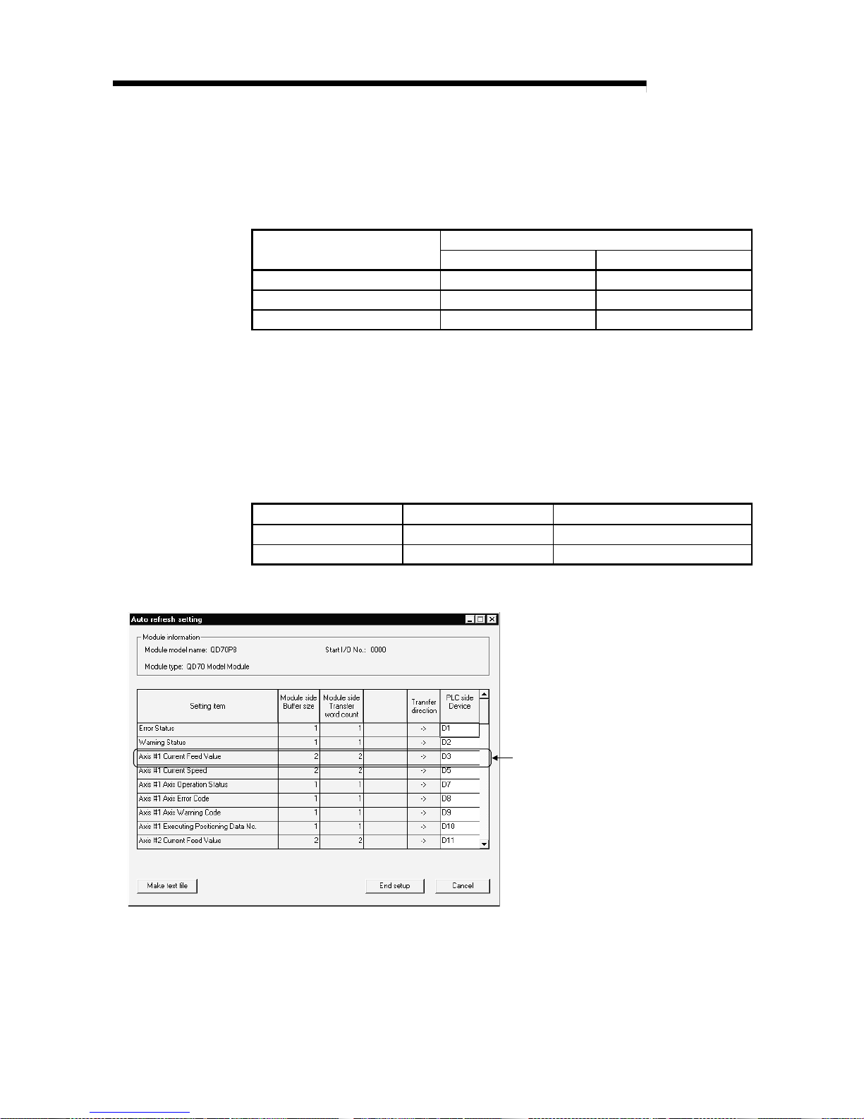
6 - 3 6 - 3
MELSEC-Q
6 UTILITY PACKAGE (GX Configurator- PT)
(6) About the number of parameters that can be set i n GX
Configurator-PT
The number of parameters that can be set by the GX Configurator for an
intelligent function module installed in the CPU module and in a remote I/O
station of the MELSECNET/H network system is limited.
Maximum number of parameter settings
Intelligent function module
installation object
Initial setting Auto refresh setting
Q00J/Q00/Q01CPU 512 256
Q02/Q02H/Q06H/Q12H/Q25HCPU 512 256
MELSECNET/H remote I/O station 512 256
For example, if multiple intelligent function modules are installed in a remote I/O
station, set the GX Configurator so that the number of parameter settings of all
the intelligent function modules does not exceed the maximum number of
parameter settings.
The total number of parameter settings is calculated separately for the initial
setting and fo r th e au to re fr e sh se tt in g.
The number of parameter settings that can be set for one module in the GX
Configurator-PT is as shown below.
Object Module Initial setting Auto refresh setting
QD70P4 12 (Fixed) 26 (Maximum number of settings)
QD70P8 24 (Fixed) 50 (Maximum number of settings)
Example) Counting the number of parameter settings in the auto refresh setting
The number of settings in the one line is
counted as one setting.
The number of settings is not counted by columns.
Add up all the setting items in this setting screen,
then add them to the total for the other intelligent
function modules to get a grand total.
Page 94
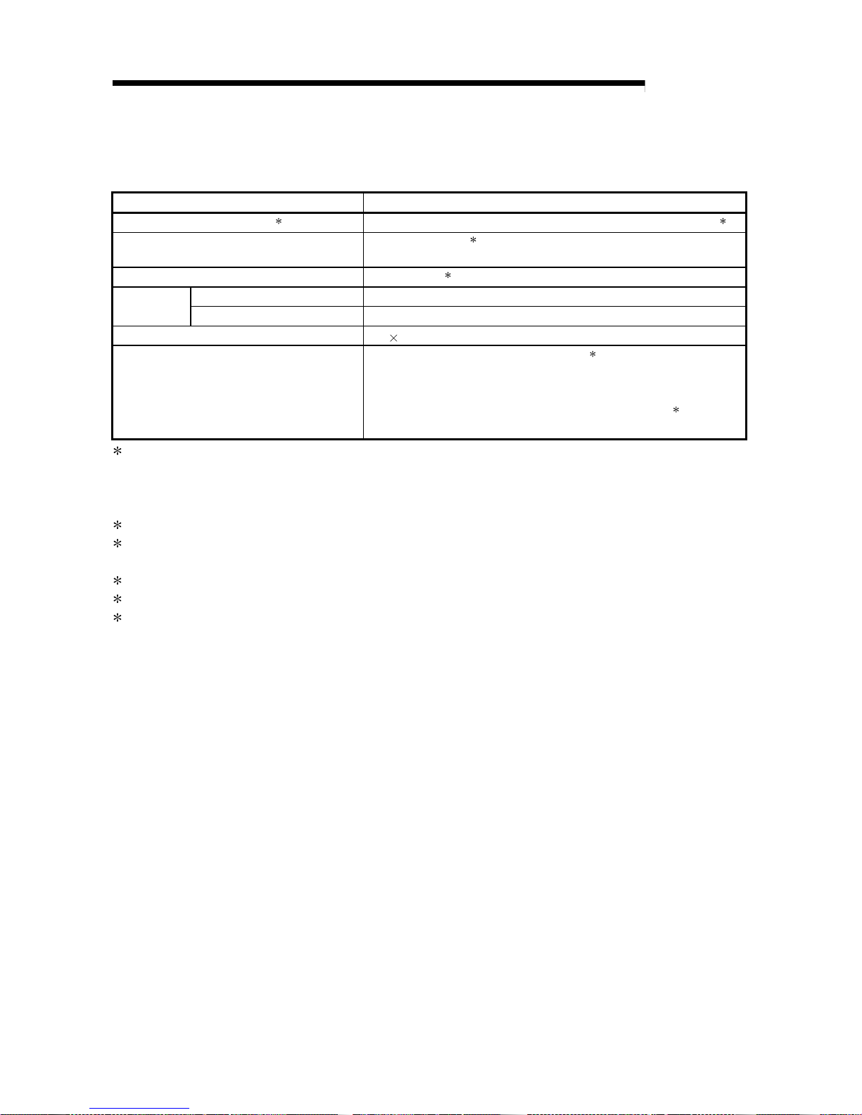
6 - 4 6 - 4
MELSEC-Q
6 UTILITY PACKAGE (GX Configurator- PT)
6.2.2 Operating environment
This section explains the operating environment of GX Configurator-PT.
Item Peripheral devices
Installation (Add-in) destination
1
Add-in to GX Developer Version4 (English language version) or later
2
Computer main unit
Pentium
®
(133 MHz3 or faster recommended) based personal
computers that are compatible with Windows
®
Operating System
Required memory
32 MB or more
4
For installation 25 MB or moreAvailable hard
disk space
For operation 10 MB or more
Display 800 600 pixels or higher resolution
Operating system
Microsoft® Windows® 95 Operating System
5
Microsoft® Windows® 98 Operating System
Microsoft
®
Windows® Millennium Edition Operating System
Microsoft® Windows NT® Workstation4.0 Operating System
6
Microsoft® Windows® 2000 Professional Operating System
1 : Install the GX Configurator-PT in GX Developer Version 4 or later in the same language.
GX Developer (English language version) and GX Configurator- PT (Japanese language version) cannot
be used in combination, and GX Developer (Japanese language version) and GX Configurator-PT
(English language version) cannot be used in configuration.
2 : GX Configurator-PT cannot be used as an add-in with GX Developer Version 3 or earlier versions.
3 : Pentium® 150 MHz or more is recommended for use of Microsoft® Windows® Millennium Edition Oper a ting
System.
4 : 64MB or more is recommended for use of Microsoft® Windows® 2000 Professional Oper atin g Sy ste m
.
5 : Service Pack 1 or later is required for use of Microsoft® Windows® 95 Operating System.
6 : Service Pack 3 or later is required for use of Microsoft® Windows NT® Workstation4.0 Operating System.
Page 95

6 - 5 6 - 5
MELSEC-Q
6 UTILITY PACKAGE (GX Configurator- PT)
6.3 Explanation of utility package operations
6.3.1 How to perform common utility package operations
(1) Available control keys
Special keys that can be used during operations of the utility package and their
application s ar e show n in th e ta ble bel ow .
Name of key Application
Esc
Cancels a newly entered value when entering data in a cell.
Closes the window.
Tab
Moves between controls in the window.
Ctrl
Uses together with the mouse when multiple cells are sele cted
in the Test selected.
Delete
Deletes the character where the cursor is positioned.
When a cell is selected, clears all of the setting contents.
Back
Space
Deletes the character where the cursor is positioned.
Moves the cursor.
Page
Up
Moves the cursor one page up.
Page
Down
Moves the cursor one page down.
Enter
Confirms the value entered in the cell.
(2) Data to be created with the utility package
The data and files shown below that are created with the utility package are also
used by GX Developer operations. Figure 6.1 shows which operation uses which
data or file.
<Intelligent module parameters>
(a) This data is created with the auto refresh setting, and stored in the intelligent
module parameter file of the project to be created using GX Developer.
Project
Program
Parameters
PLC Parameters
Network Parameters
Intelligent Module Parameters
(b) Steps 1) to 3) shown in Figure 6.1 are performed using the following
operations.
1) Operating using GX Developer.
[Project]
[Open project] / [Save] / [Save as]
2) Operating on the intelligent module parameter setting module selection
screen of the utility.
[File]
[Open file] / [Save file]
Page 96

6 - 6 6 - 6
MELSEC-Q
6 UTILITY PACKAGE (GX Configurator- PT)
3) Operating using GX Developer.
[Online]
[Read from PLC] / [Write to PLC] "Intelligent module
parameter"
Or, operate on the intelligent module parameter setting module selection
screen of the utility.
[Online]
[Read from PLC] / [Write to PLC]
<Text file>
(a) A text file can be created by performing the initial setting or auto refresh
setting, or selecting Make text file
on the monitor/test screen. Text files
can be utilized to create user documents.
(b) Text files can be saved to any direct o ry.
QCPU
RUN.
ERR.
USER.
BAT.
BOOT.
RS-232
USB
Q25HCPU
MODE.
A
GX Developer/
GX Configurator-PT
Disk
Project
AA
B
Personal computer
A : Indicates intelligent module parameters.
B : Indicates the date saved by text file creation.
1)
2)
3)
Project
Figure 6.1 correlation diagram for data created using the utility package
Page 97

6 - 7 6 - 7
MELSEC-Q
6 UTILITY PACKAGE (GX Configurator- PT)
6.3.2 Operation overview
[Tools] - [Intelligent function utility] - [Start]
Intelligent function module parameter
setting module select
Enter "Start I/O No." then select "Package name"
and "Module model neme".
Refer to Section 6. 3. 3
Initial setting screen
Refer to Section 6. 4
Initial setting Auto refresh
Auto refresh setting screen
Refer to Section 6. 5
1)
GX Developer screen
Page 98

6 - 8 6 - 8
MELSEC-Q
6 UTILITY PACKAGE (GX Configurator- PT)
[Online] - [Monitor/test]
Select monitor/test module screen
Monitor/Test screen
Refer to Section 6. 6
Enter "Start I/O No." then select" Package name"
and "Module model neme".
1)
Monitor/test
Page 99

6 - 9 6 - 9
MELSEC-Q
6 UTILITY PACKAGE (GX Configurator- PT)
6.3.3 Starting the intelligent function module utility
[Purpose of operation]
Start the utility from GX Developer, and display the intelligent module parameter
setting module selection screen. The initial setting, auto refresh setting and select
monitor/test module (selecting the module for which monitoring/testing is to be
performed) screens can be started from this screen.
[Startup procedure]
[Tools] [Intelligent function utility] [Start]
[Setting screen]
[Explanation of items]
(1) How to start each screen
(a) Starting the initial setting
"Start I/O No. *"
"Package name" "Module model name"
Initial setting
(b) Starting the au to re fr e sh s etting
"Start I/O No. *"
"Package name" "Module model na me"
Auto refresh
(c) Select monitor/test module screen
[Online]
[Monitor/test]
* Enter the start I/O No. in hexadecimal.
(2) Explanation of the screen command buttons
Delete
Deletes the initial settings and auto refresh setting for the selected
module.
Exit
Ends the intelligent module parameter setting module selection screen.
Page 100

6 - 10 6 - 10
MELSEC-Q
6 UTILITY PACKAGE (GX Configurator- PT)
(3) Menu bar
(a) File items
File operations are performed for the intelligent module parameters for the
project opened by GX Developer.
[Open file] : Opens the parameter file.
[Close file] : Closes the parameter file. If changes have been made,
the dialog box asking whether to save the file appears.
[Save file] : Saves the parameter file.
[Delete file] : Deletes the parameter file.
[Exit] : Ends the intelligent module parameter setting module
selection screen.
(b) Online items
[Monitor/test] : Starts the select monitor/test module screen.
[Read from PLC] : Reads the intelligent module parameters from the CPU
module.
[Write to PLC] : Writes the intelligent module parameters to the CPU
module.
POINT
(1) Saving the intelligent module par a meter files
Since these files cannot be saved using the GX Developer's project save
operation, save the files using the intelligent module parameter setting
module selection screen mentioned above.
(2) Reading and writing the intell ig ent modul e param eter s to and
from a PLC using GX Developer.
(a) Once the intelligent module parameters are saved in a file, they can be
read from and written to the PLC.
(b) Set the target PLC CPU using [Online]
[Transfer setup] of GX
Developer.
(c) When the QD70 is mounted to the remote I/O station, use “Read from
PLC” and “Write to PLC” of GX Developer.
(3) Checking for the required utility
The head I/O is displayed in the Intelligent function module utility setting
screen, but a "
" may be displayed fo r th e mode l na me.
This means that either the required utility is not installed or that the utility
cannot be started from the GX Developer.
Check for the required utility in [Tools] - [Intelligent function utility] - [Utility
list...] in GX Developer, and set it.
 Loading...