

Mitsubishi LGH-150RVXT-E, LGH-200RVXT-E, LGH-250RVXT-E, PZ-250RTF-E, PZ-61DR-E User Manual
...
LOSSNAY
HANDBOOK
MODELS
LGH-150RVXT-E
LGH-200RVXT-E
LGH-250RVXT-E
March 2016 No. U213
Nameplate
Remote controller (Optional)
PZ-61DR-E
Filter (Optional)
PZ-150RTF-E
PZ-250RTF-E
Warning:
Repair work must be performed by the manufacturer, its service
agent or a similarly qualified person in order to avoid hazards.

Contents
1. Safety precautions
2. Specifications
3. Outside dimensions
4. Electrical wiring diagrams
5. Circuit board diagrams
6. Troubleshooting
7. Overhauling procedures
8. Parts catalog
LGH-150RVXT-E
LGH-200RVXT-E
LGH-250RVXT-E
........................................................................
.......................................................................
...............................................................................
......................................................................
.............................................................
....................................................................
.......................................................
............................................................
............................................................
............................................................
.........................................................
10-34
35-51
52-82
53-62
63-72
73-82
3
4
5
6-7
8-9
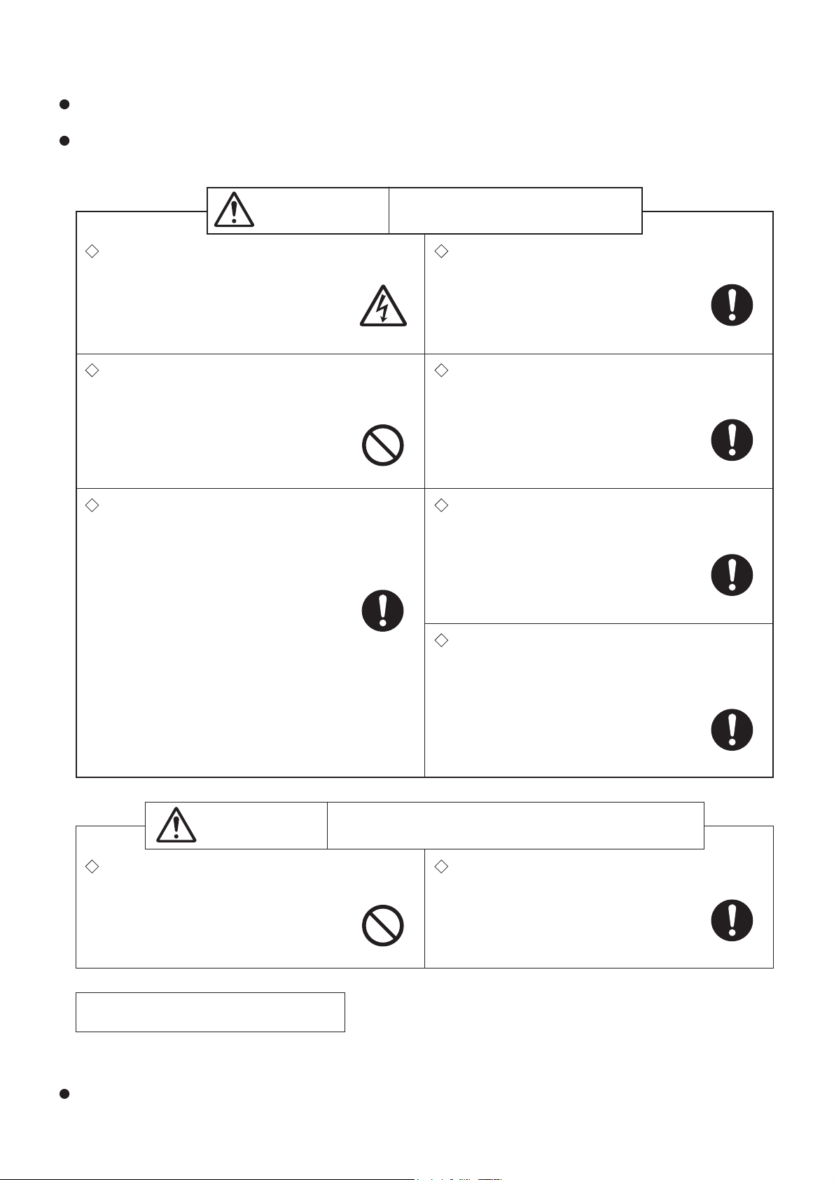
1. Safety precautions
Read the following precautions thoroughly before the maintenance, and then inspect and repair the product in a
safe manner.
The types and levels of danger that may arise if the product is handled incorrectly are described with the warning
symbols shown below.
Incorrect handling of the product may
Warning
result in serious injury or death.
Electric shock
If you must inspect the circuitry while the power is
on, do not touch the live parts.
(Failure to heed this warning may result
in electric shock.)
Caution against
electric shock
Modification is prohibited
Do not modify the unit.
(Failure to heed this warning may result
in electric shock, fire and/or injury.)
Prohibited
Proper electric work
Use the electric wires designated for electric work,
and conduct electric work in accordance with your
local "Electric Installation Engineering Standard",
the "Indoor Wiring Regulations" and the installation
instructions.
(Improper connection or wiring installation
may result in electric shock and/or fire.)
Be sure to follow
this instruction.
Turn off the power supply
Be sure to shut off the power supply isolator before
disassembling the unit for repair.
(Failure to heed this warning may result
in electric shock.)
Be sure to follow
this instruction.
Use proper parts and tools
For repair, be sure to use the parts listed in the
service parts catalog of the applicable model and
use the proper tools.
(Failure to heed this warning may result in
electric shock, fire and/or injury.)
Be sure to follow
this instruction.
Replace damaged and/or degraded parts
Be sure to replace the power cord and lead wires if
they are damaged and/or degraded.
(Failure to heed this warning may result
in electric shock and/or fire.)
Be sure to follow
this instruction.
Check insulation
Upon completing repair work, always measure the
insulation resistance. Verify that it is at least 10 MΩ
(with a 500-V DC insulation resistance tester), and
then turn on the power.
(Inadequate insulation may result in
electric shock.)
Be sure to follow
this instruction.
Incorrect handling of the product may result in injury or
Caution
Caution for injury
Do not work at a location where you do not have a
damage to properties including buildings and equipment.
Wear gloves
Wear gloves when servicing.
sure footing.
(Failure to heed this caution may result in
(Failure to heed this caution may result in
a fall.)
Prohibited
injury to your hands from sharp metal or
other edges.)
Be sure to follow
this instruction.
Notes for servicing
● Inspect the earth condition, and repair it if it is incomplete. Make sure that a power supply isolator or an overload protection device is installed, if it is not installed, recommend the customer to install one.
Make sure that the product operates properly upon completion of repair. Clean the product and the surrounding
area, and then notify the customer of the completion of repair.
─ 3 ─
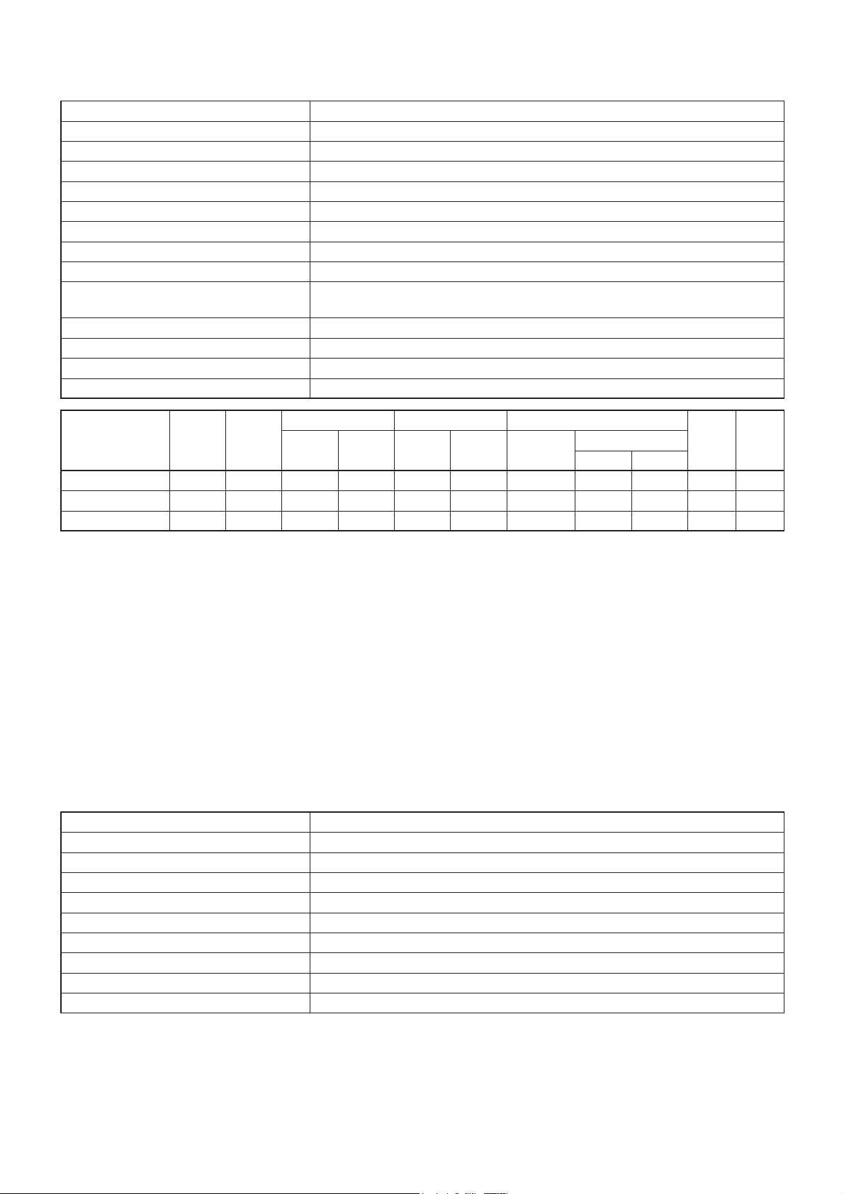
2. Specifications
Model name LGH-150RVXT-E, LGH-200RVXT-E, LGH-250RVXT-E
Heat exchange system Heat recovery ventilating system
Heat exchanger material Special treated paper plate heat exchanger
Cladding Galvanized steel sheet
Heat insulation material Self-extinguishing urethane foam
Motor EC motor
Filter Non-woven fabrics filter (Gravitational method 82% EU-G3)
Surrounding air condition Shall be between -10°C and 40°C, 80%RH or less
Suction air condition Shall be lower than 40°C, 80%RH
Supply fan operation under low outdoor
temperature
Function Energy recovery mode/Bypass mode, Fan speed 1, 2, 3, 4
Electrical power supply 220-240 V/50 Hz, 220 V/60 Hz
Insulation resistance 10 MΩ or more
Dielectric strength 1500 V AC 1 minute
-10°C to -15°C: Intermittent operation 60 min ON, 10 min OFF
-15°C or less: Intermittent operation 55 min OFF, 5 min ON
Running
Model name
LGH-150RVXT-E
LGH-200RVXT-E 5.4 1000 2000 556 175 100 80 72.5 70 39.5 159
LGH-250RVXT-E
* The above values apply during Heat recovery mode ventilation when the fan speed is set to Fan speed 4 at the rating pressure
loss and 230 V / 50 Hz.
*For the specifications at the other fan speeds, see the spec. sheets.
* The values given in the table for the noise level reflect the levels measured at a position 1.5 meters immediately below the unit
in an anechoic chamber.
* Noise change or increase may occur because of the Bypass-Automatic function or Automatic fan speed change by timer setting
and/or other functions.
*Temperature exchange efficiency (%) are based on winter condition.
* Mitsubishi Electric measures products according to Japan Industrial Standard (JIS B 8628), therefore Q-H curves are meas-
ured by chamber method.
* On-site commissioning measurements by pitot tube method could be as much 20% different from JIS test room conditions. If
the measuring point is close to sources of turbulence like bends, contractions and dampers etc, it is difficult to measure air vol-
ume correctly. A straight duct length more than 10D (D=duct diameter) from the source of turbulence is recommended for cor-
rect measurement. On-site measurement should therefore be measured in accordance with BSRIA guideline (Commissioning
Air System. Application procedures for buildings AG3/89.3(2001))
Model name PZ-61DR-E
Power supply requirement 12 V DC (Supplied from Lossnay unit)
Power consumption 0.3 W
Transmission cable Non polarized 2-wire (0.3 mm
Total wiring length 200 m maximum
Number of controllable Lossnay units 15 Lossnay units maximum (Max. 2 remote controllers installable)
Environmental condition Temperature: 0 to 40°C, Humidity: 30% to 90% relative humidity (no condensation)
Size 120 x 120 x 19 mm
Weight 0.25 kg
Color Munsell 1.0Y9.2/0.2
current
(A)
4.3 792 1500 417 175 100 80 70 69 39.5 156
7.6 1446 2500 694 175 100 77 68 65.5 43.0 198
Input
power
(W)
Air volume Static pressure Exchange efficiency (%)
3
(m
/h) (L/S)
Supply
(Pa)
Exhaust
(Pa)
Temperature
2
(AWG22) sheathed cable)
Enthalpy
Heating Cooling
Noise
(dB)
Weight
(kg)
─ 4 ─
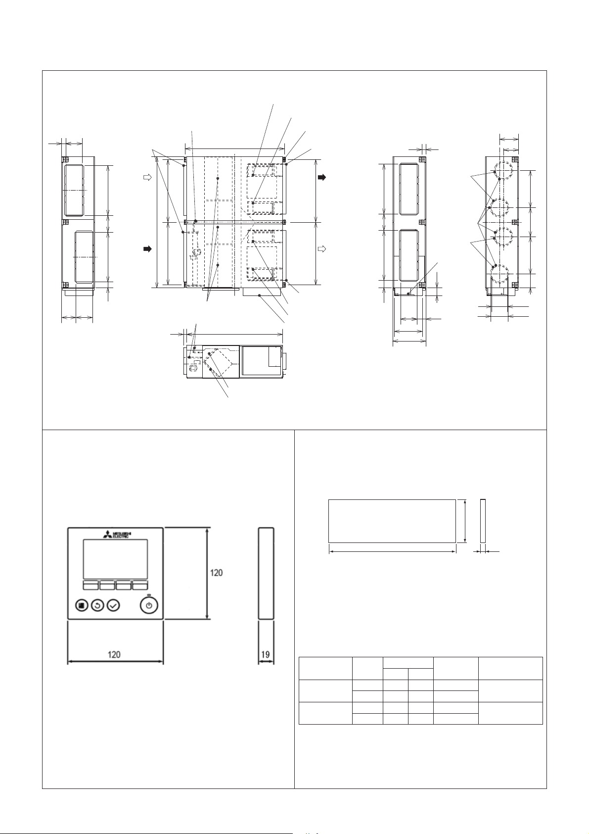
3. Outside dimensions
LGH-150RVXT-E, LGH-200RVXT-E, LGH-250RVXT-E
Air exhaust fan (Outside)
By-pass damper plate
250
60
Flange
1500
Air exhaust fan (Inside)
Ceiling suspension fixture
(6-15 X 30 oval)
Flange
:KHQXVLQJijGXFW
58
287
227
OA EA
(outside air
intake)
750
255
RA SA
(return air) (supply air)
75090
1980
945.7 945.7
(exhaust air
outlet)
945.7 945.7
750750115
250
Flange
215
250
Lossnay cores
By-pass damper plate
50 1450
RA air filters
Air supply fan (Inside)
Air supply fan (Outside)
Control box
* The appearance varies depending on the model.
250
424
500
OA air filters
PZ-61DR-E PZ-150RTF-E, PZ-250RTF-E
Exhaust
Pipe guide
Supply
Power supply
cable opening
116
132
560560210
440
ij
242
ij
258
Unit (mm)
B
15
Applicable
Lossnay model
LGH-150RVXT-E
LGH-200RVXT-E
LGH-250RVXT-E
Model Air
PZ-150RTF-E
PZ-250RTF-E
Supply
Exhaust
Supply
Exhaust
A
Dimensions
AB
655 290 2
655 250 2
985 290 2
985 250 2
The number of
filters per set
Unit (mm) Unit (mm)
─ 5 ─
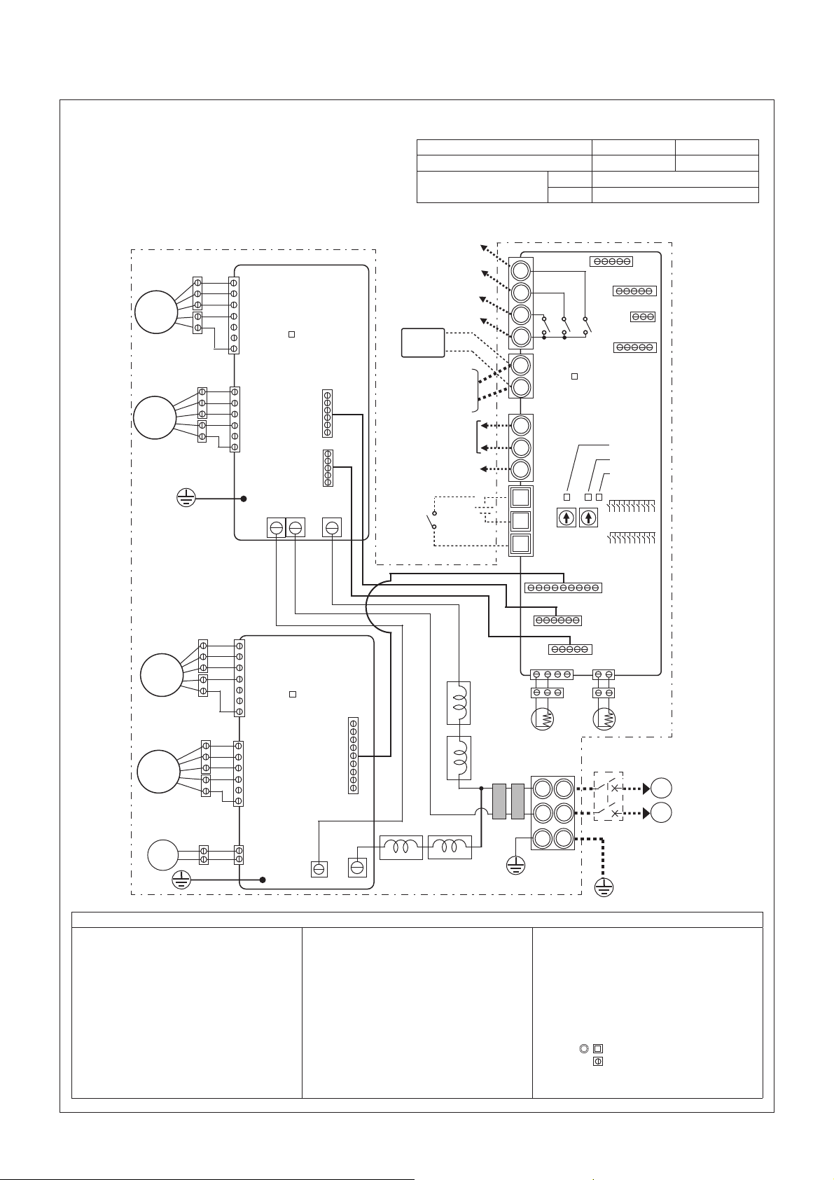
4. Electrical wiring diagrams
LGH-150RVXT-E, LGH-200RVXT-E
* TM1, TM2, TM3, TM4, TB5 shown in dotted lines are fi eld work.
* Be sure to connect the earth wire.
* A power supply isolator must be installed.
* Always use an isolator for the main switch power connection.
* Select proper circuit breaker according to the electrical current
shown in the right chart.
Bypass monitor or Preheater signal output (*1)
Printed Circuit Board 1
(Power circuit board 1)
M
3
EXHAUST
FAN MOTOR
(Inside)
M
2
SUPPLY
FAN MOTOR
(Inside)
CN9
CN10
TAB5
LED6
CN119
CN118
TAB2 TAB1
2nd remote controller
(Max. 2 controllers)
2nd Lossnay unit
(Max. 15 units)
M-NETtransmission cable
Volt-free
contact
Model
LGH-150RVXT-E LGH-200RVXT-E
Maximum current when operating 5.6 A 6.4 A
Inrush current after
power supply turned ON
Malfunction monitor
output (*1)
Operation monitor
output (*1)
COM
PZ61DR-E
Shielded Wire
12 V or
24 V DC
Mr. Slim
(non-polar)
(*1)
MAX 240 V AC 1 A MIN 220 V AC 100 mA
24 V DC 1 A 5 V DC 100 mA
10 ms 12.1 A
100 ms 6.6 A
TM3
7
8
9
10
X15
1
TM4
2
Printed Circuit Board
X14
CN20(GR)
CN26(WH)
CN32(WH)
X13
LED3
for control
(Control circuit board)
A
TB5
B
S
TM2
1
2
3
SA2 SA1
CN17(RE)
LED4
LED2
LED1
SW2
SW5
CN21
Printed Circuit Board 2
(Power circuit board 2)
M
4
EXHAUST
FAN MOTOR
(Outside)
M
1
SUPPLY
FAN MOTOR
(Outside)
CN9
CN10
CN7
GM
M1: Motor for supply fan (outside)
M2: Motor for supply fan (inside)
M3: Motor for exhaust fan (inside)
M4: Motor for exhaust fan (outside)
GM: Motor for By-pass damper
TH1: Thermistor for outside air
TH2: Thermistor for return air
SW2,5: Switch (Function selection)
TM1: Terminal block (Power supply)
TM2: Terminal block (External control input)
TM3: Terminal block (Monitor output)
TM4: Terminal block (Transmission cable)
TB5: Terminal block (M-NET Transmission cable)
LED6
CN121
TAB2
TAB1
REACTOR
Definition of symbols
TAB1, TAB2, (TAB5): Connector (Power supply)
X13: Relay contact
X14: Relay contact
X15: Relay contact
CN5: Connector (Thermistor RA)
CN7: Connector (Motor for By-pass damper)
CN9: Connector (Fan motor)
CN10: Connector (Fan motor)
CN17: Connector (Fan speed 1/2/3/4)
CN18: Connector
CN118: Connector
CN19: Connector
CN119: Connector
REACTOR
LINE
FILTER
CN19
CN18
CN5
CN22
TH1(OA)
TH2(RA)
Isolator
(Field supply)
L
N
PE
TM1
CN20: For optional components
CN22: Connector (Thermistor OA)
CN26: Connector
CN32: Connector (Remote control selection)
SA1: Address setting rotary switch (tens digit)
SA2: Address setting rotary switch (ones digit)
LED1, LED2: Inspection indicator lamp
LED3:
Remote controller power supply indicator lamp
LED4, LED6: Power supply indicator lamp
SYMBOL : Terminal block
: Connector on PCB
(By-pass, 0 - 10 V DC Fan speed control)
L
N
POWER SUPPLY
220-240V/ 50Hz
220V/ 60Hz
─ 6 ─
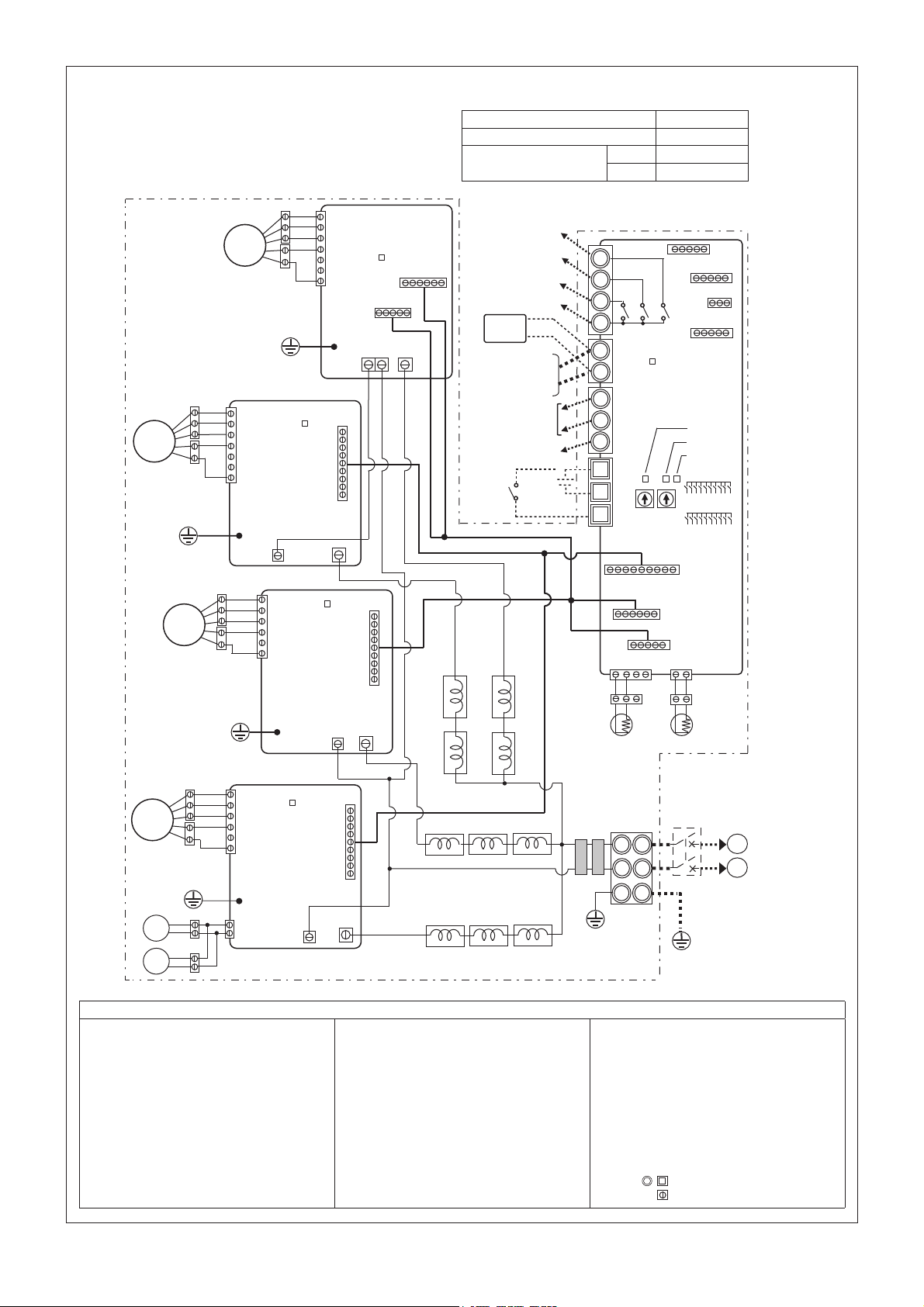
LGH-250RVXT-E
* TM1, TM2, TM3, TM4, TB5 shown in dotted lines are field work.
* Be sure to connect the earth wire.
* A power supply isolator must be installed.
* Always use an isolator for the main switch power connection.
* Select proper circuit breaker according to the electrical current
shown in the right chart.
Top Right Printed Circuit Board
M
4
EXHAUST
FAN MOTOR
(Outside)
(EA Inside)
M
3
EXHAUST
FAN MOTOR
(Inside)
(Top right power circuit board)
CN9
TAB5
LED6
CN9
Top Left Printed Circuit
Board (EA Outside)
(Top left power circuit board)
TAB2
CN121
TAB1
TAB2
LED6
CN118
TAB1
CN119
Model
LGH-250RVXT-E
Maximum current when operating 10.8 A
Inrush current after
power supply turned ON
COM
12 V or
24 V DC
Mr. Slim
(non-polar)
Bypass monitor or Preheater signal output (*1)
Malfunction monitor
output (*1)
Operation monitor
output (*1)
PZ61DR-E
2nd remote controller
(Max. 2 controllers)
2nd Lossnay unit
(Max. 15 units)
M-NETtransmission cable
Shielded Wire
Volt-free
contact
10 ms 21.8 A
100 ms 11.9 A
(*1)
MAX 240 V AC 1 A MIN 220 V AC 100 mA
24 V DC 1 A 5 V DC 100 mA
TM3
7
8
9
10
X15
1
TM4
2
Printed Circuit Board for Control
A
(Control circuit board)
B
TB5
S
TM2
1
2
3
X14
CN20(GR)
CN26(WH)
CN32(WH)
X13
CN17(RE)
LED3
LED4
LED2
LED1
SW2
SA2 SA1
SW5
CN21
M
SUPPLY
FAN MOTOR
(Inside)
M
1
SUPPLY
FAN MOTOR
(Outside)
GM
2
CN10
Bottom Right Printed
Circuit Board
(Bottom right
power circuit board)
CN10
Bottom left Printed
Circuit Board
(Bottom left
power circuit board)
CN7
TAB2
GM
M1: Motor for supply fan (outside)
M2: Motor for supply fan (inside)
M3: Motor for exhaust fan (inside)
M4: Motor for exhaust fan (outside)
GM: Motor for By-pass damper
TH1: Thermistor for outside air
TH2: Thermistor for return air
SW2, 5: Switch (Function selection)
TM1: Terminal block (Power supply)
TM2: Terminal block (External control input)
TM3: Terminal block (Monitor output)
TM4: Terminal block (Transmission cable)
TB5: Terminal block (M-NET Transmission cable)
LED6
(SA Inside)
CN121
TAB1
TAB2
LED6
CN121
(SA Outside)
REACTOR
TAB1
REACTOR
Definition of symbols
TAB1, TAB2, TAB5: Connector (Power supply)
X13: Relay contact
X14: Relay contact
X15: Relay contact
CN5: Connector (Thermistor RA)
CN7: Connector (Motor for By-pass damper)
CN9: Connector (Fan motor)
CN10: Connector (Fan motor)
CN17: Connector (Fan speed 1/2/3/4)
CN18: Connector
CN118: Connector
CN19: Connector
CN119: Connector
CN19
CN18
CN5
CN22
TH1(OA)
TH2(RA)
LINE
FILTER
Isolator
(Field supply)
L
N
PE
TM1
CN20: For optional components
CN21: Connector
CN121: Connector
CN22: Connector (Thermistor OA)
CN26: Connector
CN32: Connector (Remote control selection)
SA1: Address setting rotary switch (tens digit)
SA2: Address setting rotary switch (ones digit)
LED1, LED2: Inspection indicator lamp
LED3:
Remote controller power supply indicator lamp
LED4, LED6: Power supply indicator lamp
SYMBOL
: Connector on PCB
: Terminal block
L
N
POWER SUPPLY
220-240V/ 50Hz
220V/ 60Hz
(By-pass, 0 - 10 V DC Fan speed control)
─ 7 ─
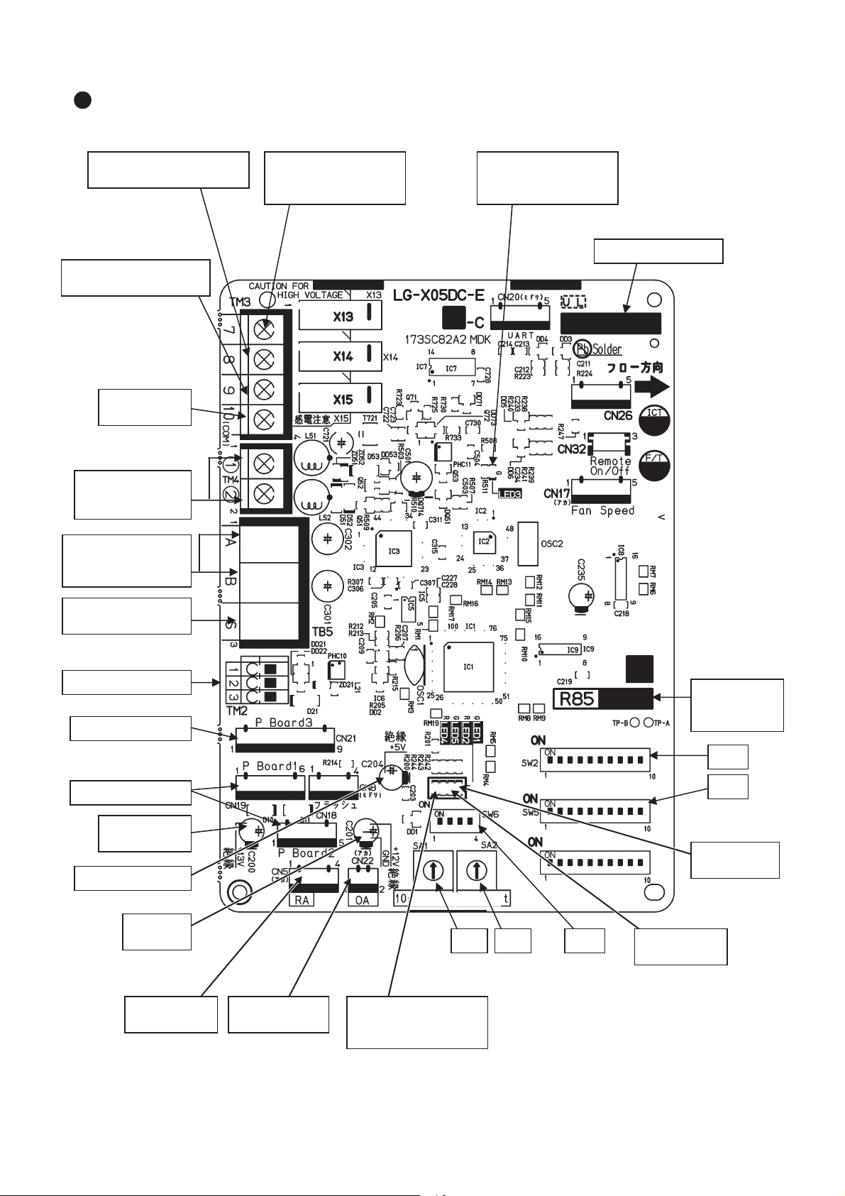
1s digit10s digit
Power circuit board
Fed with power: lit
Not fed with power: unlit
Lot number indication
Remote controller
power supply indicator
(LED3 Green)
Bypass monitor output
Pre-heater output
(Between 7 and 0)
During bypass mode or
when the pre-heater is operating: 0 ȍ
During heat recovery mode or
when the pre-heater is stopped:
ȍ
Malfunction monitor output
(Between 8 and 0)
Error: 0 ȍ
Normal: ȍ
Operation monitor output
(Between 9 and 0)
When Lossnay is operating: 0 ȍ
When Lossnay is stopped:
ȍ
Monitor output
COM
Remote controller
(PZ-61DR-E, etc.)
10 to 13 V DC
M-NET transmission
cable (Power supply
unit, etc.)
M-NET transmission
cable (Shielded)
External control input
Power circuit board
5 V DC (Insulated)
Power for the circuit
12 to 14 V DC
(Insulated)
GND
(Insulated)
Fed with power: lit
Not fed with power: unlit
SA1 SA2 SW6
Address setting
switch
Model selection
switch
SW2
SW5
Function selection
switch
Indication of the
microcomputer
software version
Error indicator
(LED1 Green)
Normal: unlit
Error: blinking
During delay operation: lit
M-NET indicator
(LED2 Red)
Registered: unlit
Not registered: lit
M-NET communication error: blinking
Power supply indicator
for the circuit
(LED4 Red)
Outdoor air (OA)
thermistor
Return air (RA)
thermistor
5. Circuit board diagrams
Circuit board diagram and check points
(1)
Control circuit board
─ 8 ─
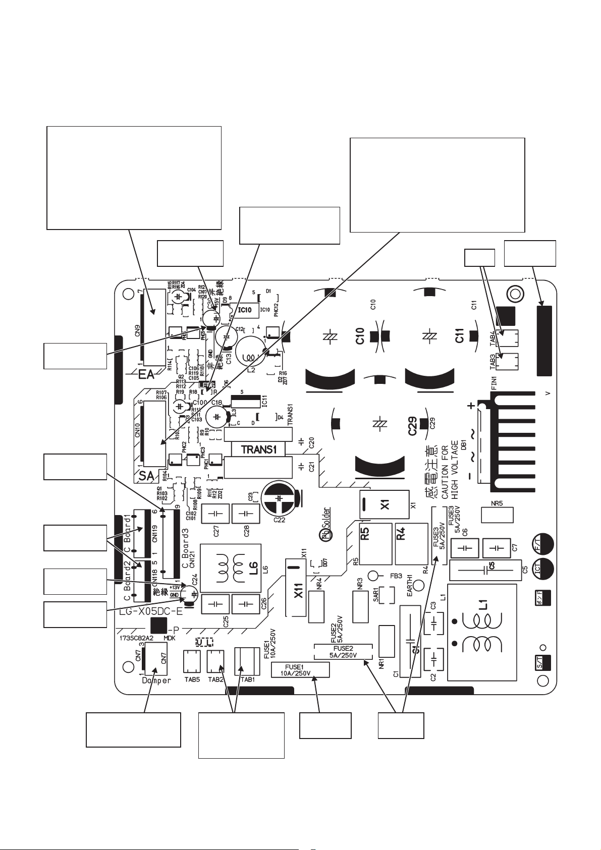
(2)
Power circuit board
Caution:
The power circuit board is not insulated from the power line (high voltage part), except for the connection part
(CN118,CN119, and CN121) with the control circuit board. Also, even when the power supply is cut off, the
capacitor is charged. Therefore, wait for at least five minutes before starting work.
Exhaust fan motor (CN9)
Pin No. of the connector
1Power for the motor: 280 to 360 V DC
2Not used
3Not used
4GND
5Power for motor control: 14 to 16 V DC
6Speed command voltage: 0 to 6 V DC
7Rotational speed pulse
14 to 16 V DC
(Not insulated)
Power supply indicator
for motor control
(LED6 Red)
Fed with power: lit
Not fed with power: unlit
Supply fan motor (CN10)
Pin No. of the connector
1Power for the motor: 280 to 360 V DC
2Not used
3GND
4Power for motor control: 14 to 16 V DC
5Speed command voltage: 0 to 6 V DC
6Rotational speed pulse
Short
Lot number
indication
GND
(Not insulated)
Control circuit
board
Control circuit
board
12 to 14 V DC
(Insulated)
GND
(Insulated)
Damper motor output
220 to 240 V/50 Hz
220 V/60 Hz
Power supply input
(Reactor)
220 to 240 V/50 Hz
220 V/60 Hz
Fuse
10 A/250 V
─ 9 ─
Fuse
5 A/250 V
6. Troubleshooting
Work precautions
• Before starting the service, the power supply isolator must be turned off. Pay sufficient attention to avoid
electric shock or injury.
When removing or touching the cables, circuit boards or other parts, make sure to turn off the power supply isolator.
•
• Even after the power supply isolator is turned off, the capacitor on the circuit board retains high voltage for a
while. Therefore, before servicing, wait for at least five minutes, and then use a tester to check that the voltage has dropped.
• Once the power supply is turned off, be sure to wait for at least five minutes before turning the power back
on again.
•
When servicing, power supply to M-NET must be turned off. Live-line working may cause a circuit board failure.
• When servicing, be sure to reproduce the malfunction two or three times before starting repairs.
• When servicing, always take care to keep proper footing.
• When disconnecting the motor connectors, make sure that the power supply is turned off. Even when the
fan motor is stopped, disconnecting the live-line connectors will cause a motor malfunction.
• When removing the circuit board, always hold it at both ends and remove carefully so as not to apply force
to the surface mounted parts.
• When removing the circuit board, be careful of the metal edges on the board.
• When removing or inserting the connectors for the circuit board, hold the entire housing section. Never pull
on the lead wires.
• If it is thought that there is a circuit board malfunction, check for disconnected wires in the print pattern,
burnt parts or discoloration.
•
If the circuit board is replaced, make sure that the switch settings on the new board are the same as the old board.
• Make sure to connect the power supply wires correctly.
• When carrying out wiring, power supply to M-NET must be turned off, otherwise it will cause a malfunction.
The part names in the texts are standardized with the part names in the parts catalog.
(There are some exceptions.)
6-1 Service flowchart
After checking the check items below, follow the troubleshooting for servicing.
Applicable Device Applicable Model
Lossnay Energy Recovery Ventilator LGH-150RVXT-E, LGH-200RVXT-E, LGH-250RVXT-E
Lossnay Remote Controller PZ-61DR-E, PZ-43SMF-E
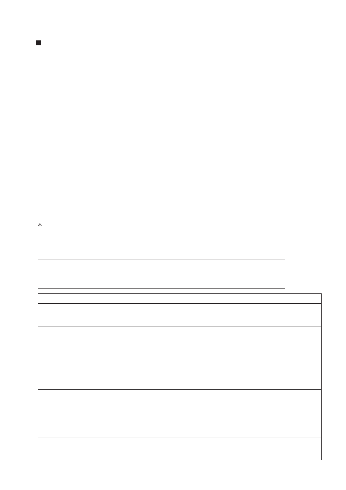
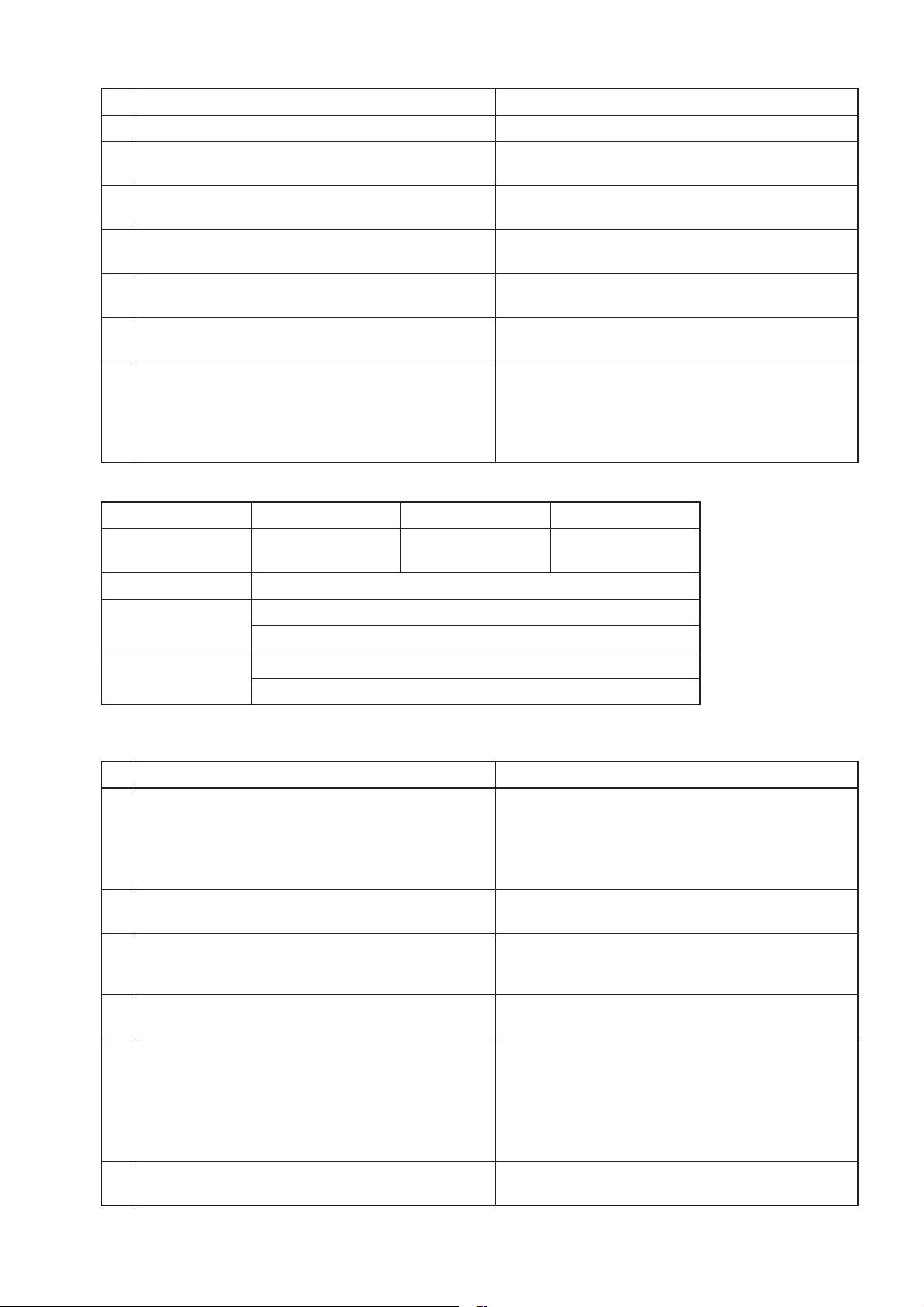
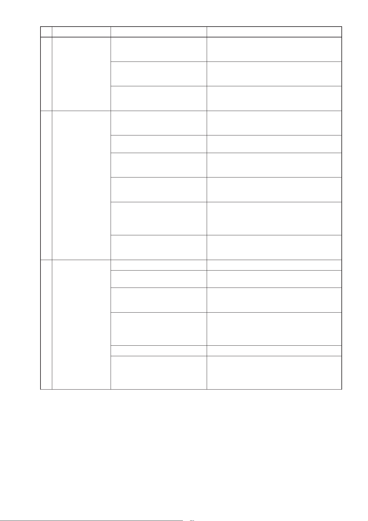
No. Preliminary check item Details
1 Product information • Model name of the product
• Serial number of the product, manufacturing lot number of the circuit board
• Microcomputer software version marked on the circuit board
2 Fault status • Fault status (For example, the fan does not operate.)
• Error code display on the remote controller
• Operation setting of the remote controller (ventilation mode setting, fan
speed setting, etc.)
3 Frequency of fault occur-
rence
4 Timing of fault occurrence • Remote controller operation performed before fault occurrence
5 System settings • Function selection switch settings and address setting of the Lossnay unit
6 System drawings • System Configuration
• Frequency of fault occurrence (frequency of date and time of occurrence,
regularity of occurrence, etc.)
• Operating time up to fault occurrence
• Date of start of use, date of fault occurrence
• Operating status, etc.
• Model name and address setting of the Lossnay remote controller or system
controller, etc.
• Function settings on PZ-61DR-E when PZ-61DR-E is used
• Wiring
• Record of the Lossnay function setting statuses
─ 10 ─
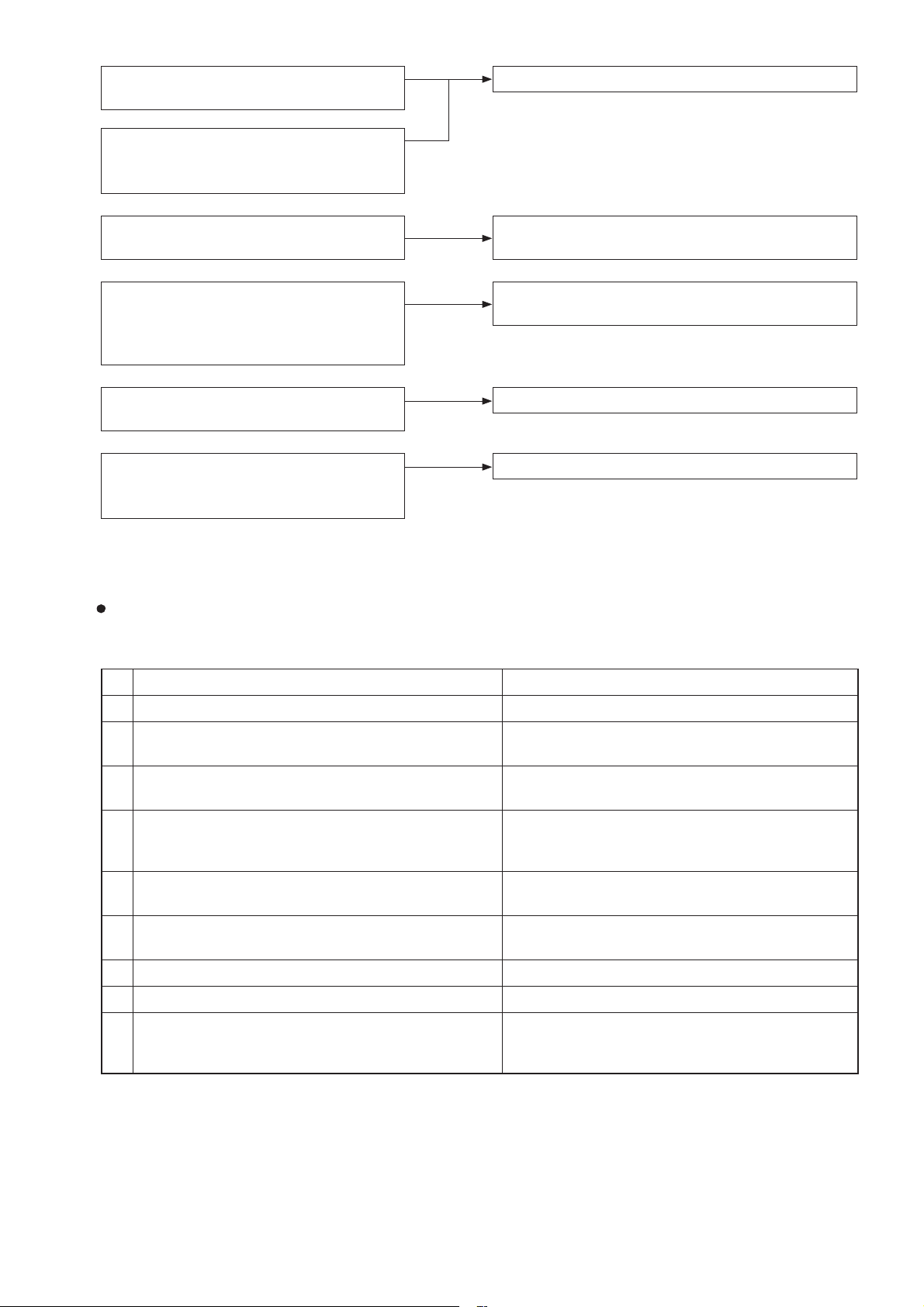
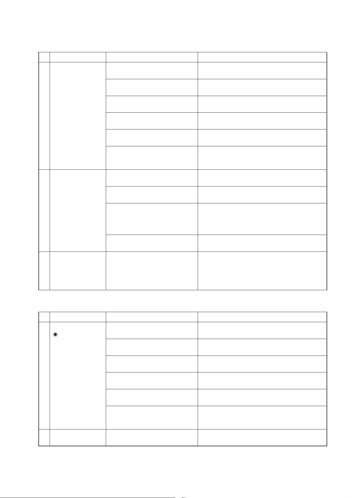
Lossnay does not work after installation is
completed.
Lossnay does not work in trial operation
after installation is completed, or Lossnay
stops working during use.
(1) Failure mode 1: Lossnay does not work.
The remote controller does not work after
installation is completed.
Operations such as ON/OFF, fan speed or
ventilation mode switching are not possible on the remote controller after installation is completed.
Lossnay does not work properly after
installation is completed.
• An error code is displayed on the remote
controller.
• LEDs on the circuit board blink or light.
(2) Failure mode 2: The remote controller does not
(3) Failure mode 3: Operations on the remote con-
(4) Failure mode 4:
(5) Failure mode 5: Error code and LED display
6-2 Check Details
(1) Failure mode 1: Lossnay does not work.
Initial Check Items
Check the following details if Lossnay does not work after installation is completed.
1 Power supply
work.
troller are not possible.
Lossnay does not work properly.
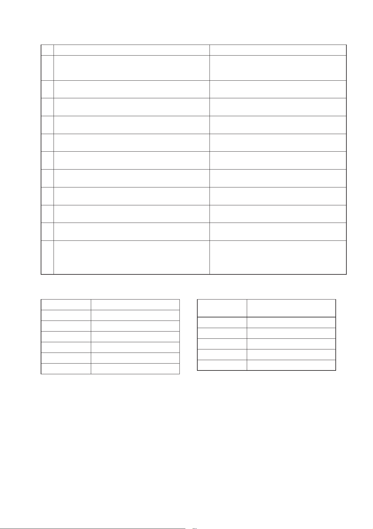
No. Check Item Corrective action
1 Is the main power supply on? Turn the main power supply on.
2 Is the current capacity of the power supply isolator
appropriate?
3 Is the designated cable used for the power supply
cable?
4 Is the specified power supply supplied to the power
supply terminal (TM1)?
220-240 V/50 Hz, 220 V/60 Hz
5 Is the power supply cable incorrectly wired, is there
a faulty connection or are screws loose?
6 Is there a faulty connection on the power supply
terminals (TM1, TAB1, TAB2, and TAB5)?
7 Is there a faulty connection on the reactor terminals? Connect the lead wires securely.
8 Is the jumper connected to TAB3 and TAB4? Connect the jumper properly.
9 Are the power supply indicator lamps (LED4 and
LED6, red) lit?
Check LEDs6 on all the power circuit boards.
Use an appropriate power supply isolator.
Use the designated cable.
Supply the designated power supply.
Connect the cable securely and correctly, and
tighten the screws firmly.
Connect the lead wires securely.
Check the above items.
─ 11 ─
2 Transmission cables (remote controller transmission cable, M-NET transmission cable, and external input/
output signal cable)
No. Check Item Corrective action
1 Are the designated cables used for the remote control-
Use the designated transmission cables.
ler transmission cable and M-NET transmission cable?
(See Table 2-1 and Table 2-2.)
2 Are the designated cables used for the external input/
Use the designated cables.
output signal cable? (See Table 2-3.)
3 Are the transmission cables wired using multicore
Use the designated transmission cables.
cables?
4 Are multiple transmission cables wired in the same pip-
ing duct?
5 Is the power supply cable wired at least 5 cm away
from transmission cables?
6 Are the transmission cables connected to the desig-
nated terminal block? (See Table 2-1 and Table 2-2.)
7 Are the transmission cables incorrectly wired, is there a
faulty connection or are screws loose?
8 Is the wiring length of the transmission cable within the
Wire the transmission cable away from one
another.
Wire the power supply cable at least 5 cm away
from the transmission cables.
Connect the transmission cables to the desig-
nated terminal blocks.
Connect the cable securely and correctly, and
tighten the screws firmly.
Wire the cables within the regulations.
regulations? (See Table 2-1 and Table 2-2.)
9 Does the external input signal match the specifica-
Input the signal that matches the specifications.
tions? (See Table 2-3.)
10 Is the external input signal input to the Lossnay set as
the main Lossnay?
11 Is the function selection for the external output signal
set correctly?
Input the signal to the Lossnay set as the main
Lossnay (SW5-10 ON).
Set the function selection switches (SW2-8, 5-2,
and 5-6) on the circuit board correctly.
Set the function settings (No. 57 and 58) of PZ-
61DR-E correctly.
Table 2-1
M-NET transmission cable specifications
Cable M-NET transmission cable
Type Shielded cable CVVS, CPEVS
Number of cores 2-core cable
Cable diameter 1.25 mm
2
to 2.0 mm
2
Max. extension 200 m (Note 1)
Total extension 500 m (Note 2)
Terminal block TB5 [A] [B]
Table 2-2
Remote controller transmission cable specifications
Cable
PZ-61DR-E or PZ-43SMF-E
transmission cable
Type Sheathed cable
Number of cores 2-core cable
2
Cable diameter 0. 3 mm
(AWG22)
Total extension 200 m
Terminal block
TM4 12
When carrying out wiring, power supply to M-NET must be turned off, otherwise it will cause a malfunction.
(Note 1) Distance from the power supply unit to the furthest unit or system controller
(Note 2) Overall length of the cable between the units and the system controllers
─ 12 ─
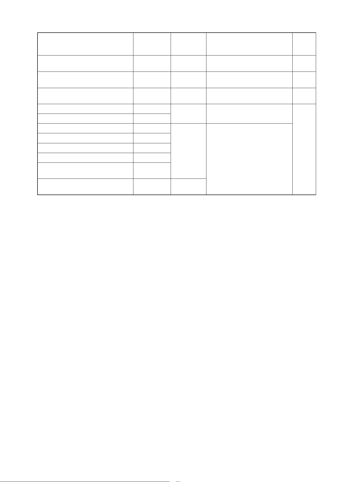
Table 2-3 External input/output specifications
Function Name
External control input
(volt-free contact)
External control input
(12 V DC, 24 V DC)
Mr. Slim indoor unit control signal
Remote/local switching
Remote ON/OFF input
Fan speed 4 input (volt-free contact)
Fan speed 3 input (volt-free contact)
Fan speed 2 input (volt-free contact)
Fan speed 1 input (volt-free contact)
Bypass mode input
(volt-free contact)
Fan speed switching input
(0 to 10 V DC)
Terminal or
connector on
the circuit board
TM2 13
TM2 12
TM2 12
CN32 13
CN32 12
CN17 12
CN17 13
CN17 14
CN17 15
CN26 12
CN26 45
Signal
specifications
Level/pulse
(Note 1)
Level/pulse
(Note 1)
Serial signal
Level
(Note 1)
Level
(Note 1)
Analog
Materials Used
Single-lead 0.8 to 1.2 mm dia. or
twisted lead 0.5 to 1.5 mm
2
Single-lead 0.8 to 1.2 mm dia. or
twisted lead 0.5 to 1.5 mm
2
Slim-Lossnay connection cable
(Accessory parts)
Remote ON/OFF adaptor
(PAC-SE55RA-E)
Remote display adaptor
(PAC-SA88HA-E)
Total
extension
500 m
(Note 2)
500 m
10 m
<Caution>
• Input the signals to the Lossnay (SW5-10 ON, with the smallest address setting) set as the main Lossnay in
the group.
(Note 1) The input signal must conform to the following specifications:
Level signal Volt-free contact, 12 V DC, 24 V DC, the duration of ON and OFF should be 10-second
or more.
Pulse signal Volt-free contact, 12 V DC, 24 V DC, the duration of ON should be 200 msec. or more,
and minimum 10-second absence is necessary to the next pulse .
In the case of relay contact input, use a relay having a contact rating of 15 V DC/0.1 A or higher and a
minimum applicable load of 1 mA or less.
(Note 2) Check the specifications of the external device.
─ 13 ─
3 Monitor output signal cable
No. Check Item Corrective action
1 Is the signal cable wired by multicore cable? Wire the cable using a 2-core cable.
2 Are the signal cables and transmission cables wired
in the same piping duct?
3 Is the power supply cable wired at least 5 cm away
from signal cables?
4 Is the signal cable connected to the designated
terminal block? (See Table 3-1.)
5 Is the signal cable incorrectly wired, is there a faulty
connection or are screws loose?
6 Is the output capacity of the signal cable within rat-
Wire the signal cables away from the transmission
cables.
Wire the power supply cable at least 5 cm away
from the signal cables.
Connect the signal cable to the designated terminal
block.
Connect the cable securely and correctly, and
tighten the screws firmly.
Use the signal cable within rating.
ing? (See Table 3-1.)
7 Is the function selection for the external output
signal set correctly?
Set the function selection switches (SW2-8, 5-2,
and 5-6) on the circuit board correctly.
Set the function settings (No. 57 and 58) of PZ61DR-E correctly.
(See the Lossnay technical manual.)
Table 3-1 Monitor Output Specifications
Terminal block
Function Name Operation monitor Malfunction monitor
TM3 90 TM3 80 TM3 70
Bypass monitor or
Pre-heater
Signal specifications Volt-free contact
240 V AC, 1 A
Output rating
24 V DC, 1 A
220 V AC, 100 mA
Min. applicable load
5 V DC, 100 mA
4 Function setting (See the Lossnay technical manual for details.)
No. Check Item Corrective action
1 Is the main Lossnay set correctly? Check the function selection switch (SW5-10) on
the circuit board.
When an external signal is input to multiple Lossnay
units, set one of the units in the group as the main
Lossnay (SW5-10 ON).
2 Are the function selection switches on the circuit
board set correctly to suit the required application?
3 Is the applicable model used as the Lossnay re-
mote controller?
Set the function selection switches (SW2 and SW5)
on the circuit board correctly.
Use PZ-61DR-E or PZ-43SMF-E.
(The air conditioner remote controller including
PAR-31MAA cannot be used.)
4 When PZ-61DR-E is used, are the function selec-
Set the function selections correctly.
tions set correctly to suit the required application?
5 Was a function set with the function selection
switches on the circuit board after the function is set
with PZ-61DR-E?
Set the function again with PZ-61DR-E.
For the function that can be set with both PZ61DR-E and the function selection switches, if the
function is set to other than "DIP-SW priority" with
PZ-61DR-E, setting with the function selection
switches is disabled.
6 Is the Lossnay address set correctly? Set the address setting switches (SA1 and SA2)
correctly.
─ 14 ─
5 LED Indications on the circuit board
No. LED Contents Check Item Corrective action
1 LED1
(green)
Lossnay main unit
error indicator
Blinking: Starting up, or error oc-
curred
See Failure Mode 5.
Lit: During delay operation Lossnay operates after the delay time
has passed.
Unlit: Other than above It is normal.
2 LED2
(red)
M-NET System
error indicator
Blinking: Error occurred See Failure Mode 5.
Lit: No M-NET connection informa-
tion
When using M-NET, perform group registration with the system controller.
Unlit: Other than above It is normal.
3 LED3
(green)
4 LED4
(red)
Remote controller power supply
indicator
Power supply
indicator (control
Lit: Power supplied to the remote
controller (Main Lossnay)
Unlit: Power not supplied to the re-
mote controller (Sub Lossnay)
The LED goes out when power is supplied to the remote controller from other
Lossnay units in a multiple Lossnay
group.
Check that this LED is lit The LED lights while power is being
supplied to the control circuit board.
circuit board)
5 LED6
(red)
Power supply
indicator (power
circuit board)
Check that this LED is lit The LED lights while power is being
supplied to the power circuit board.
(Do not touch components on the circuit
board when the LED is lit.)
─ 15 ─
Individual function check items
If Lossnay does not work in the trial operation after installation is completed, or if Lossnay stops working during use, check the following items.
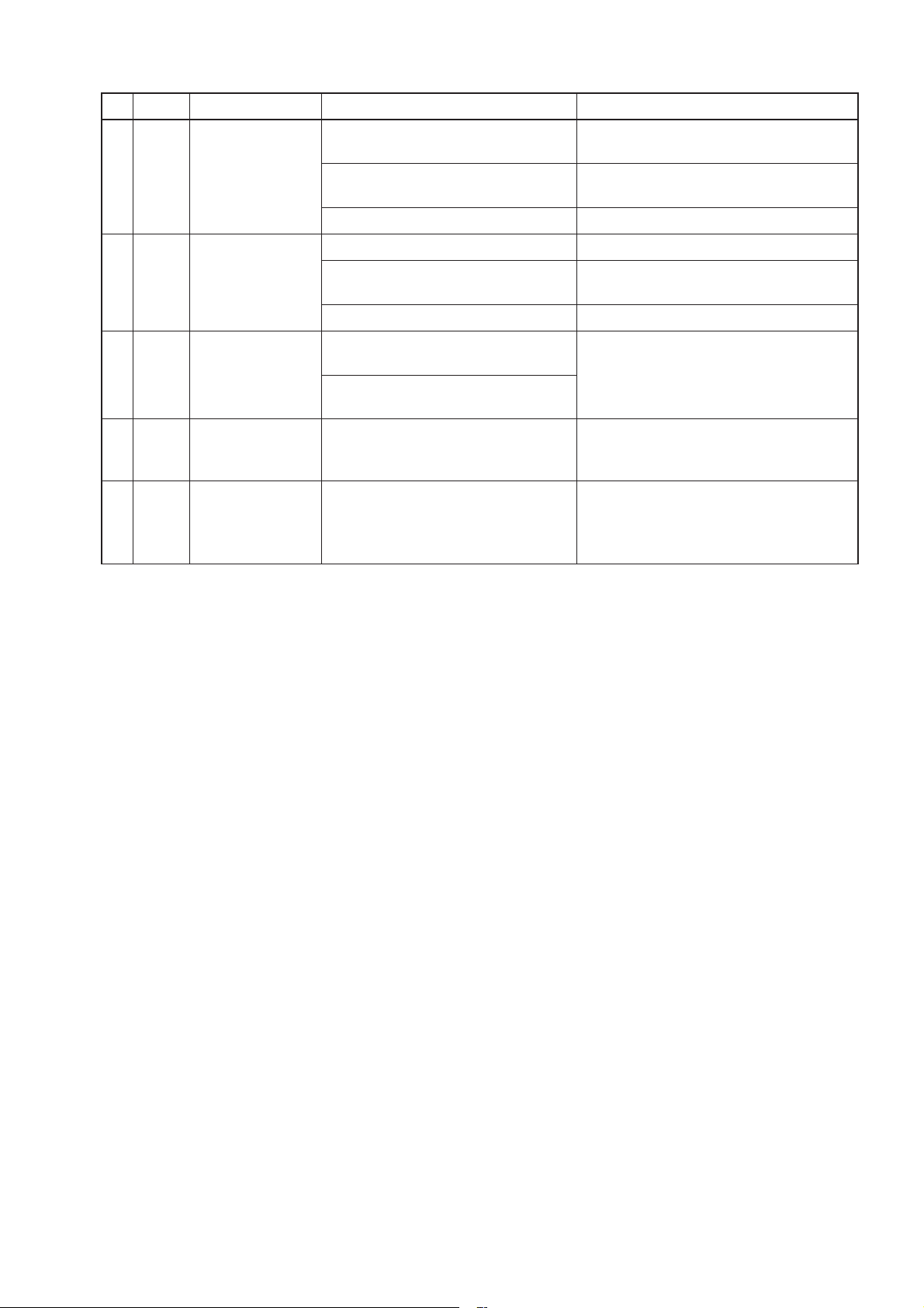
No.
Problem Factor Corrective action
1 The fan does not
operate even
though the trial
operation switch
(SW2-1) on the circuit board is turned
ON.
2 Though the remote
controller display
indicates the fan
is running, the fan
stops by itself.
The connector between the fan
motor and circuit board is disconnected.
The connector between the control circuit board and power circuit
Check the connector (CN9) for the exhaust fan
motor and the connector (CN10) for the supply
fan motor.
Check the connector connections (CN18-CN118,
CN19-CN119, and CN21-CN121).
board is disconnected.
The wiring for the reactors is
Check the wiring for the reactors.
incorrect.
The jumper is not connected to
Connect the jumper to TAB3 and TAB4.
TAB3 and TAB4.
The model selection switch (SW6)
is not set correctly.
The temperature around the product is high.
Make the SW6 setting appropriate for the model.
(See chapter 7. (11) Setting status record (page 51).)
Use the product at a temperature of 40°C or
lower.
Fan motor failure Check the resistance between the motor leads.
(See chapter 6. (7) Motor resistance table (page 34).)
If the measured value is significantly different
from the values specified in the table, replace
the motor.
Circuit board failure Disconnect the connectors (CN9 and CN10),
and check the output voltage of each pin of the
connectors within one minute after turning the
switch (SW2-1) ON. (One minute later, the error
will occur.)
(See chapter 5. (2) Power circuit board (page 9).)
If the voltage value is abnormal, replace the
circuit board.
If the problem persists, replace the motor.
The Lossnay unit is operating in
the protective mode (intermittent
operation).
When PZ-61DR-E is used, it displays the icon
" that indicates the protective operation is in-
"
progress. For details, see the Lossnay technical
manual or remote controller manual.
The Lossnay unit is set to the
delay operation.
When PZ-61DR-E is used, it displays the icon
" that indicates the delay operation is in-
"
progress.
LED1 (green) on the control circuit board lights.
Lossnay operates in 30 minutes (or 15 minutes)
after the air conditioner is operated to run.
Check the function selection switch (SW5-1) on
the circuit board or the function setting (No. 9) of
PZ-61DR-E. (See the Lossnay technical manual.)
The interlocked air conditioner
(Mr. Slim indoor unit or City Multi
indoor unit) is defrosting.
The supply fan has been stopped to prevent
cold air from blowing out. When the air condi-
tioner finishes defrosting, the fan operation is
started automatically.
The system is switching the ventilation mode.
When switching the ventilation mode (Energy
recovery mode/Bypass mode), the fan stops (for
approx. 30 seconds).
The temperature around the product is high.
When the ambient temperature of the product
is high (higher than 40°C), the fan may stop to
prevent the fan motor from overheating.
─ 16 ─
No.
Problem Factor Corrective action
3 The fan does not
stop even though
the remote controller is operated to
stop operation.
4 Even though the
remote controller is
operated to change
the fan speed, the
fan speed does not
change.
The pre-heater or operation monitor with delay operation is set to
be used.
The indoor negative pressure
setting or the indoor positive pressure setting is set.
The external fan speed input is
set. (CN17)
If the pre-heater or operation monitor with delay
operation is set to be used, the fan continues op-
erating for three minutes after the stop operation.
Check the function selection switches (SW2-8
and 5-6) on the circuit board or the function set-
tings (No. 57 and 58) of PZ-61DR-E. (See the
Lossnay technical manual.)
Check the function selection switches (SW2-
4 and 2-5) on the circuit board or the function
settings (No. 6 and 7) of PZ-61DR-E. (See the
Lossnay technical manual.)
When PZ-61DR-E is used, it displays the icon " ".
Check the fan speed switching input (CN17).
5 The fan operation is
unstable.
6 Air volume is abnor-
mally large or small.
7 The damper does
not operate even
though the trial
operation switch
(SW2-1) on the circuit board is turned
ON.
The external fan speed input is
set. (CN26)
When PZ-61DR-E is used, it displays the icon " ".
Check the function selection switches (SW2-3
and 2-6) on the circuit board or the function set-
ting (No. 63) of PZ-61DR-E. (See the Lossnay
technical manual.)
The system is operating in the
protective mode (intermittent
operation).
When PZ-61DR-E is used, it displays the icon
" that indicates the protective operation is
"
in-progress.
For details, see the Lossnay technical manual
or remote controller manual.
The pre-heater is ON. When the pre-heater is ON, Lossnay runs at
Fan speed 2 or higher speed. Even when Fan
speed 1 is selected with the remote controller or
external fan speed input, Lossnay runs at Fan
speed 2.
The motor rotation speed is under
control.
This product controls the motor by detecting the
motor rotation speed. The fan operation may be
unstable during rotation speed control (for maxi-
mum about 10 minutes).
The model selection switch (SW6)
is not set correctly after the circuit
board is replaced.
The connector between the
damper motor and circuit board is
Make the SW6 setting appropriate for the model.
( See chapter 7. (11) Setting status record (page
51).)
Check the connection of the connector (CN7) on
the power circuit board.
disconnected.
Mechanical failure Remove the rod of the damper board and check
if the damper board can be moved by hand.
Damper motor failure Remove the rod of the damper board and turn
the trial operation switch (SW2-1) ON.
The damper motor operates in about 30 seconds.
If the damper motor does not operate, replace
the GM assembly.
Circuit board failure Disconnect the connector (CN7) from the power
circuit board and check the voltage value between the pins of CN7 when the trial operation
switch (SW2-1) is turned ON.
(Voltage is output in about 30 seconds after
switch ON.)
If there is no voltage value, replace the circuit
board.
If the problem persists, replace the GM assembly.
─ 17 ─
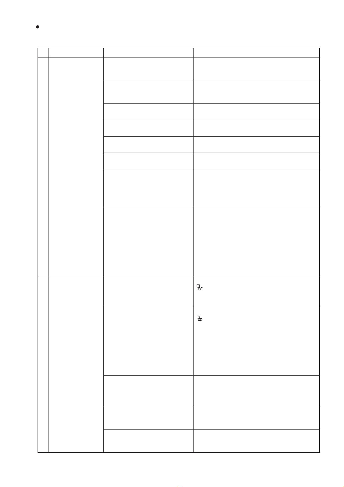
No.
8
Problem Factor Corrective action
Even though the
remote controller is
operated to change
the ventilation mode,
the ventilation mode
is not changed.
9 The ventilation
mode cannot be
switched when
Lossnay is operating in the automatic
mode.
10 Air volume is too
small.
The outdoor temperature is 8°C
or lower.
When the outdoor temperature is 8°C or lower,
the ventilation mode is fixed to the Energy recovery mode.
The signal is input to the Bypass
mode switching input (CN26
Check the Bypass mode switching input (CN26
12). (See the Lossnay technical manual.)
12).
The pre-heater is ON, or within
one hour after the pre-heater is
turned OFF.
Temperature condition for Energy
recovery mode or Bypass mode is
When the pre-heater is ON, or for one hour after
the pre-heater is turned OFF, the ventilation
mode is fixed to the Energy recovery mode.
Check the temperature map.
For details, see the Lossnay technical manual.
not satisfied.
It has not passed 30 minutes since
the ventilation mode is switched.
The outdoor temperature is 8°C
or lower.
Switching of the ventilation mode is controlled in
30 minutes cycle.
When the outdoor temperature is 8°C or lower,
the ventilation mode is fixed to the Energy recovery mode.
The signal is input to the Bypass
mode switching input (CN26
Check the Bypass mode switching input (CN26
12). (See the Lossnay technical manual.)
12).
The operation mode of the interlocked air conditioner (Mr. Slim indoor unit or City Multi indoor unit)
is set to fan operation or heating.
The pre-heater is ON, or within
one hour after the pre-heater is
turned OFF.
If the operation mode of the interlocked air
conditioner is fan operation or heating, the ventilation mode of Lossnay is fixed to the Energy
recovery mode.
When the pre-heater is ON, or for one hour after
the pre-heater is turned OFF, the ventilation
mode is fixed to the Energy recovery mode.
Is the air filter clogged? Clean the air filter.
Pressure loss in the duct is too
high.
The model selection switch (SW6)
is not set correctly after the circuit
board is replaced.
The indoor negative pressure
setting or the indoor positive pressure setting is set.
Set the supply/exhaust fan power up setting.
(See the Lossnay technical manual.)
Make the SW6 setting appropriate for the model.
( See chapter 7. (11) Setting status record (page
51).)
Check the function selection switches (SW24 and 2-5) on the circuit board or the function
settings (No. 6 and 7) of PZ-61DR-E. (See the
Lossnay technical manual.)
Power supply voltage is low. Check the power supply voltage.
In interlock with the air conditioner,
the outdoor air intake port of the
Lossnay unit is connected with the
air conditioner by using a duct.
─ 18 ─
In this case, even if the Lossnay remote controller is operated to start Lossnay while the air
conditioner is stopped, Lossnay will not supply
air.
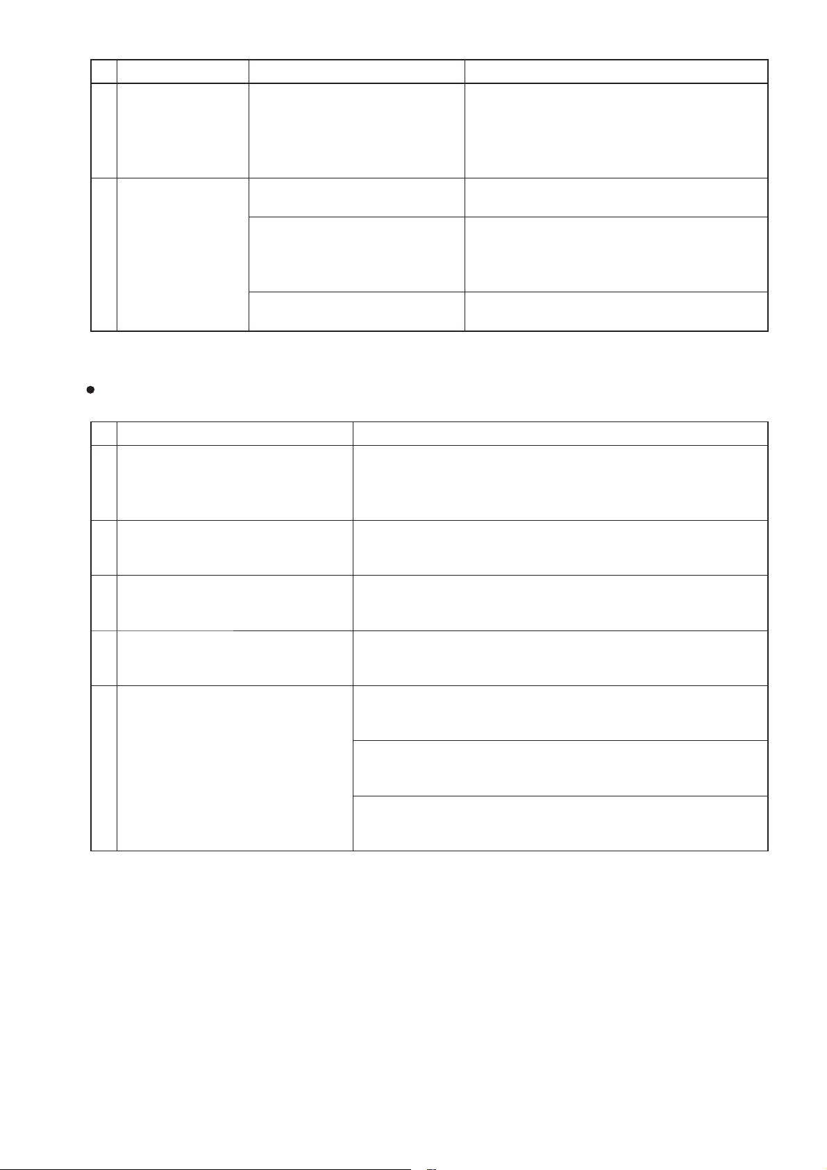
(2) Failure mode 2: The remote controller does not work.
If the remote controller does not work after installation is completed, check the following items.
1 PZ-61DR-E
No.
1 Nothing is displayed
2 The remote control-
3 It takes time for the
Problem Factor Corrective action
on the remote controller.
The ON/OFF lamp
does not blink.
ler continues to display "Please Wait".
Error code "6831" is
displayed.
remote controller to
be fed with power
after turning the
Lossnay unit ON.
The power of the Lossnay unit is
not ON.
Faulty connection of the remote
controller transmission cable
In one group, three or more PZ61DR-E controllers are connected.
In one group, 16 or more Lossnay
units are connected.
The wiring length of the remote
controller exceeds 200 m.
In one group, two or more
Lossnay units are set as the main
Lossnay (SW5-10 ON).
The remote controller is starting
up.
Faulty connection of the remote
controller transmission cable
The remote controller transmission cable is connected to the
terminal block (TB5 [A] [B]) for the
M-NET transmission cable.
PZ-43SMF-E is used together. PZ-61DR-E and PZ-43SMF-E cannot be used
The Lossnay unit is starting up. The remote controller is not fed with power dur-
Check the items described in (1) 1.
Check the items described in (1) 2.
Only up to two PZ-61DR-E controllers can be
connected in one group.
Only up to 15 Lossnay units can be connected
in one group.
The wiring length of the remote controller shall
be within 200 m.
Only one Lossnay unit can be set as the main
Lossnay in one group.
The remote controller displays "Please Wait"
during start-up for maximum four minutes.
Check the items described in (1) 2.
Connect the remote controller transmission
cable to the terminal block (TM4 12).
together.
ing start-up of the Lossnay unit for maximum
one minute.
2 PZ-43SMF-E
No.
1 The power indicator
2
Problem Factor Corrective action
"
" is not displayed.
"H0" is displayed on
the remote controller.
The power of the Lossnay unit is
not ON.
Faulty connection of the remote
controller transmission cable
In one group, three or more PZ43SMF-E controllers are connected.
In one group, 16 or more Lossnay
units are connected.
The wiring length of the remote
controller exceeds 200 m.
In one group, two or more
Lossnay units are set as the main
Lossnay (SW5-10 ON).
The remote controller is starting
up.
─ 19 ─
Check the items described in (1) 1.
Check the items described in (1) 2.
Only up to two PZ-43SMF-E controllers can be
connected in one group.
Only up to 15 Lossnay units can be connected
in one group.
The wiring length of the remote controller shall
be within 200 m.
Only one Lossnay unit can be set as the main
Lossnay in one group.
(See the Lossnay technical manual.)
The remote controller displays "H0" during startup for a maximum of one minute.
No.
3 It takes time for the
4 The inspection
Problem Factor Corrective action
The Lossnay unit is starting up. The remote controller is not fed with power durremote controller to
be fed with power
after turning the
Lossnay unit ON.
number "6801" is
displayed on the
remote controller.
Faulty connection of the remote
controller transmission cable
The remote controller transmis-
sion cable is connected to the
terminal block (TB5 [A] [B]) for the
M-NET transmission cable.
PZ-61DR-E is used together. PZ-43SMF-E and PZ-61DR-E cannot be used
ing start-up of the Lossnay unit for a maximum
of one minute.
Check the items described in (1) 2.
Connect the remote controller transmission
cable to the terminal block (TM4 12).
together.
(3) Failure mode 3: Operations on the remote controller are not possible.
Initial Check Items
If the system cannot be operated with the remote controller after installation is completed, check the following items.
No.
1 Are the function selection switches
(SW2 and SW5) on the Lossnay
circuit board set correctly to suit the
required application?
2 When PZ-61DR-E is used, are the
function selections set correctly to
suit the required application?
3 When PZ-61DR-E is used, are icons
and characters displayed on the PZ61DR-E screen?
4 Is the system controller of M-NET
used?
5 Is the external input used? If the interlock mode is set to the "External input priority ON/OFF
Check item Notes
Depending on the settings of the function selection switches,
Lossnay may automatically operate or stop, or specific operation
may be unable to be performed with the remote controller.
Depending on the settings of the function selections, Lossnay may
automatically operate or stop, or specific operation may be unable
to be performed with the remote controller.
Based on the icon and characters, you can check statuses such
as the timer operation, Night-purge, and protective operation.
(See the Lossnay technical manual.)
The system controller can be used to start/stop Lossnay, change
fan speed or ventilation mode, and prohibit the start/stop operation
by PZ-61DR-E.
interlock" and if the external device is operating, the stop operation
by PZ-61DR-E is prohibited. (See the Lossnay technical manual.)
If the Remote/Local switching (CN32) is set to remote, the start/
stop operation by the Lossnay remote controller is prohibited.
(See the Lossnay technical manual.)
Priority is given to the operation by the fan speed switching input
and Bypass mode switching input. (CN17, CN26)
(See the Lossnay technical manual.)
─ 20 ─
Individual check items
If the system cannot be started/stopped using the remote controller after installation is completed, check the
following items.
1 PZ-61DR-E
No.
Problem Factor Corrective action
1 Some Lossnay units
in the group do not
operate.
2 The screen display
of the remote controller changes by
itself. Even if you
press the buttons,
the screen returns
to the original
screen right away.
3 The ventilation
mode cannot be
changed with the
remote controller.
Even though the
4
function settings (No.
37 and/or 38) of PZ61DR-E are set to
"1", the indoor temperature and/or supply air temperature
are not displayed.
5 Even though the
function settings
(No. 36, 37 and/or
38) of PZ-61DR-E
are set to "1", the
outdoor temperature, indoor temperature and/or supply
air temperature are
not displayed.
6 The indoor, outdoor,
and/or supply air
temperature display
of PZ-61DR-E blink.
The power of the Lossnay unit is
not ON.
Faulty connection of the remote
controller transmission cable
The remote controller transmission
cables are not correctly connected
between the terminals (TM4 12)
of the Lossnay units in the group.
The system is operating in the
protective mode (intermittent
operation).
Faulty connection of the remote
controller transmission cable
The group wiring and the group
setting of the system controller do
not match.
When the system controller is
used, the Lossnay unit, which is
set as the main Lossnay (SW5-10
ON), is not set to the address with
the smallest number in the group.
The Lossnay unit is performing
the Night-purge operation.
The signal is input to the Bypass
mode switching input (CN26
12).
The Lossnay unit is performing
the Bypass mode ventilation.
The setting of PZ-61DR-E is not
correct.
The indoor, outdoor, and/or supply
air temperature are outside the
measurement range.
─ 21 ─
Check the items described in (1) 1.
Check the items described in (1) 2.
Connect the remote controller transmission
cables correctly between the terminals (TM4
12) of the Lossnay units in the group.
For details, see the Lossnay technical manual.
Check the items described in (1) 2.
Check the group wiring or the group setting of
the system controller.
Set the Lossnay unit, which is set as the main
Lossnay (SW5-10 ON) to the address with the
smallest number.
(See the Lossnay technical manual.)
The ventilation mode cannot be changed during
the Night-purge operation. (See the Lossnay
technical manual.)
Check the Bypass mode switching input (CN26
12). (See the Lossnay technical manual.)
The indoor temperature and/or supply air temperature are not displayed during the Bypass
mode.
Select "Yes" at "Temp. display" menu of PZ61DR-E. For details, see the installation manual
of PZ-61DR-E.
In the following cases, the temperature display
blinks.
Outdoor temperature:
0°C or lower, 38°C or higher
Indoor and supply air temperature:
8°C or lower, 38°C or higher
2 Interlocking with air conditioners (Mr. Slim indoor unit or City Multi indoor unit) or external devices
No.
Problem Factor Corrective action
1 Lossnay interlock
settings cannot be
performed with the
remote controller.
2 Lossnay does not
perform interlock
operation.
The power of the Lossnay unit is
not ON.
Faulty connection of the remote
controller transmission cable
Lossnay address setting is incorrect.
The power of the Lossnay unit is
not ON.
Faulty connection of the remote
controller transmission cable or
external input/output signal cables
The Lossnay unit is not set for
interlock operation.
The terminal block connected and
the type of external signal do not
match (charged or volt-free)
The type of external signal and
input setting do not match (level
signal or pulse signal).
The Lossnay unit is set to the
delay operation.
The interlock mode of the Lossnay
unit is set to "ON Interlock" or
"OFF Interlock".
In a group of multiple Lossnay
units, no Lossnay unit is set to the
main Lossnay.
In a group of multiple Lossnay
units, external control signal is
input to a Lossnay unit other than
the main Lossnay.
The Lossnay unit is operating in
the protective mode (intermittent
operation).
Check the items described in (1) 1.
Check the items described in (1) 2.
Check the Lossnay address.
Check the items described in (1) 1.
Check the items described in (1) 2.
Set the interlock setting.
Check the type of external signal and the connections of the external control input terminal
(TM2).
Check the type of external signal and the setting
of the input (level or pulse).
(See the Lossnay technical manual.)
When PZ-61DR-E is used, it displays the icon
"
" that indicates the delay operation is inprogress.
LED1 (green) on the control circuit board lights.
The Lossnay unit starts operation in 30 minutes
(or 15 minutes) after starting operation by the air
conditioner or external signal.
Check the function selection switch (SW5-1) on
the circuit board or the function setting (No. 9) of
PZ-61DR-E. (See the Lossnay technical manual.)
Check the interlock mode setting.
(See the Lossnay technical manual.)
For a group of multiple Lossnay units, set one
Lossnay unit as the main Lossnay (SW5-10 ON)
to input external control signal.
(See the Lossnay technical manual.)
For details, see the Lossnay technical manual.
─ 22 ─
3 System controller
No.
Problem Factor Corrective action
1 The group of
Lossnay cannot be
set with the system
controller.
2 Some Lossnay units
in the group do not
operate.
3 The screen display
of the system controller changes by
itself. Even if you
press the buttons,
the screen returns
to the original
screen right away.
The power of the Lossnay unit is
not ON.
M-NET transmission cable is connected to the remote controller
terminal block (TM4
12
).
Lossnay address setting is incorrect.
Power is not supplied to the
M-NET transmission cable.
The wiring length of the M-NET
transmission cable is longer than
specified. (Longer than 200 m
from the power supply unit, or
longer than 500 m in total length)
The power of the Lossnay unit is
not ON.
Faulty connection of the M-NET
transmission cable
The remote controller transmission
cables are not correctly connected
between the terminals (TM4 12)
of the Lossnay units in the group.
The Lossnay unit is operating in
the protective mode (intermittent
operation).
Faulty connection of the remote
controller transmission cable
When PZ-61DR-E is used, the
group wiring and the group setting
of the system controller do not
match.
The Lossnay unit, which is set as
the main Lossnay (SW5-10 ON),
is not set to the address with the
smallest number in the group.
Check the items described in (1) 1.
Connect the M-NET transmission cable to the
M-NET transmission cable terminal block (TB5
[A] [B]).
Check the address setting switches (SA1 and
SA2) on the Lossnay circuit board.
If the system is configured with only Lossnay
units, connect the power supply unit.
(See the Lossnay technical manual.)
Check the wiring length of the transmission
cable. (See the Lossnay technical manual.)
Check the items described in (1) 1.
Check the items described in (1) 2.
Connect the remote controller transmission cables correctly between the terminals (TM4
12
of the Lossnay units in the group.
For details, see the Lossnay technical manual.
Check the items described in (1) 2.
Check the group wiring or the group setting of
the system controller.
Set the Lossnay unit, which is set as the main
Lossnay (SW5-10 ON) to the address with the
smallest number.
(See the Lossnay technical manual.)
)
─ 23 ─
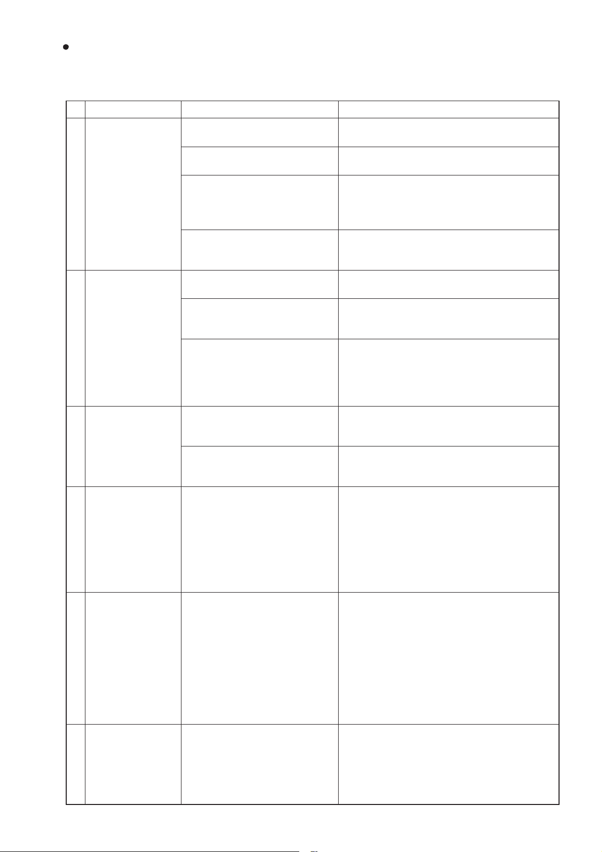
(4) Failure mode 4: Lossnay does not work properly.
Initial Check Items
If Lossnay does not work properly after installation is completed, check the following items.
No.
1 Are the function selection switches
(SW2 and SW5) on the Lossnay
circuit board set correctly to suit the
required application?
2 When PZ-61DR-E is used, are the
function selections set correctly to
suit the required application?
3 When PZ-61DR-E is used, are icons
and characters displayed on the PZ61DR-E screen?
4 Is the system controller of M-NET
used?
5 Is the external input used? If the interlock mode is set to the "External input priority ON/OFF
Check item Notes
Depending on the settings of the function selection switches,
Lossnay may automatically operate or stop, or specific operation
may be unable to be performed with the remote controller.
Depending on the settings of the function selections, Lossnay may
automatically operate or stop, or specific operation may be unable
to be performed with the remote controller.
Based on the icon and characters, you can check statuses such
as the timer operation, Night-purge, and protective operation.
(See the Lossnay technical manual.)
The system controller can be used to start/stop Lossnay, change
fan speed or ventilation mode, and prohibit the start/stop operation
by PZ-61DR-E.
interlock" and if the external device is operating, the stop operation
by PZ-61DR-E is prohibited. (See the Lossnay technical manual.)
If the Remote/Local switching (CN32) is set to remote, the start/
stop operation by the Lossnay remote controller is prohibited.
(See the Lossnay technical manual.)
Priority is given to the operation by the fan speed switching input
and Bypass mode switching input. (CN17, CN26)
(See the Lossnay technical manual.)
Individual check items
If Lossnay does not work after installation is completed, check the following items.
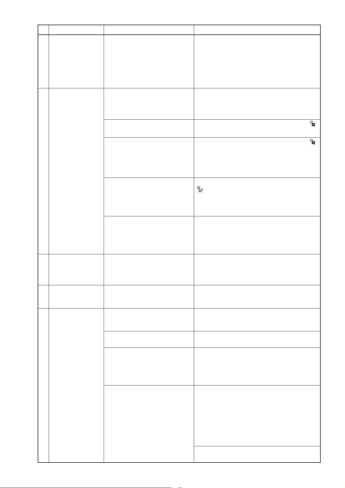
No.
1 Actual fan speed
Problem Factor Corrective action
of the Lossnay unit
differs from the fan
speed set with the
remote controller.
The signal is input to the fan
speed input (CN17).
The signal is input to the fan speed
switching input (CN26 45).
Function setting (No. 8) of PZ61DR-E "Max. fan speed setting
during the first 30 minutes" is
enabled.
The indoor negative pressure
setting or the indoor positive pressure setting is set.
The system is operating in the
protective mode (intermittent
operation).
The pre-heater is ON. When the pre-heater is ON, Lossnay runs at fan
Check the fan speed input (CN17).
(See the Lossnay technical manual.)
Check the fan speed switching input (CN26
45
). (See the Lossnay technical manual.)
Lossnay operates at fan speed 4 for 30 minutes
when operation starts.
(See the Lossnay technical manual.)
Check the function selection switches (SW2-4
and 2-5) on the circuit board or the function settings (No. 6 and 7) of PZ-61DR-E.
(See the Lossnay technical manual.)
When PZ-61DR-E is used, it displays the icon
" that indicates the protective operation is
"
in-progress.
For details, see the Lossnay technical manual
or remote controller manual.
speed 2 or higher speed. Even when fan speed
1 is selected with the remote controller or external fan speed input, Lossnay runs at fan speed
2.
─ 24 ─
No.
Problem Factor Corrective action
2 Even though the
remote controller is
operated to change
the ventilation
mode, the ventilation mode is not
changed.
3 The Night-purge
operation cannot be
stopped with PZ61DR-E.
4 Even though the
Night-purge is set,
Lossnay does not
perform the Nightpurge operation.
5 The Night-purge
operation stops in
halfway through.
6 Abnormal noise
comes from the
damper motor
The outdoor temperature is 8°C
or lower.
The signal is input to the Bypass
mode switching input (CN26
12).
The Lossnay unit is performing
the Night-purge operation.
The pre-heater is ON, or within
one hour after the pre-heater is
turned OFF.
Usual start/stop button operation
cannot stop the Night-purge operation.
Conditions of the Night-purge are
not satisfied.
The Night-purge schedule is not
set.
The operating condition became
outside the Night-purge conditions.
The Lossnay remote controller or
the system controller was operated to start or stop the operation
of the Lossnay unit.
A controller other than PZ-61DR-E
or a controller that is not supporting Night-purge is operated to
change the ventilation mode.
Mis-assembling of the damper
motor
When the outdoor temperature is 8°C or lower,
the ventilation mode is fixed to the Energy recovery mode.
Check the Bypass mode switching input (CN26
12). (See the Lossnay technical manual.)
The ventilation mode cannot be changed during
the Night-purge operation. (See the Lossnay
technical manual.)
When the pre-heater is ON, or for one hour after
the pre-heater is turned OFF, the ventilation
mode is fixed to the Energy recovery mode.
Press the start/stop button once to display the
operation screen, and then press the start/stop
button again.
When the Night-purge conditions such as the
indoor/outdoor temperature are not satisfied,
Lossnay does not perform the Night-purge
operation.
For details, see the Lossnay technical manual.
Check the setting of PZ-61DR-E or the system
controller that supports Night-purge operation.
For details, see the Lossnay technical manual.
When the operating condition becomes outside
the Night-purge conditions, the Night-purge
operation ends.
For details, see the Lossnay technical manual.
When the start or stop operation is performed
during the Night-purge operation, the Nightpurge operation ends.
When a controller other than those supporting
Night-purge is operated to change the ventilation mode, the system performs the normal
ventilating operation. (See the Lossnay technical manual.)
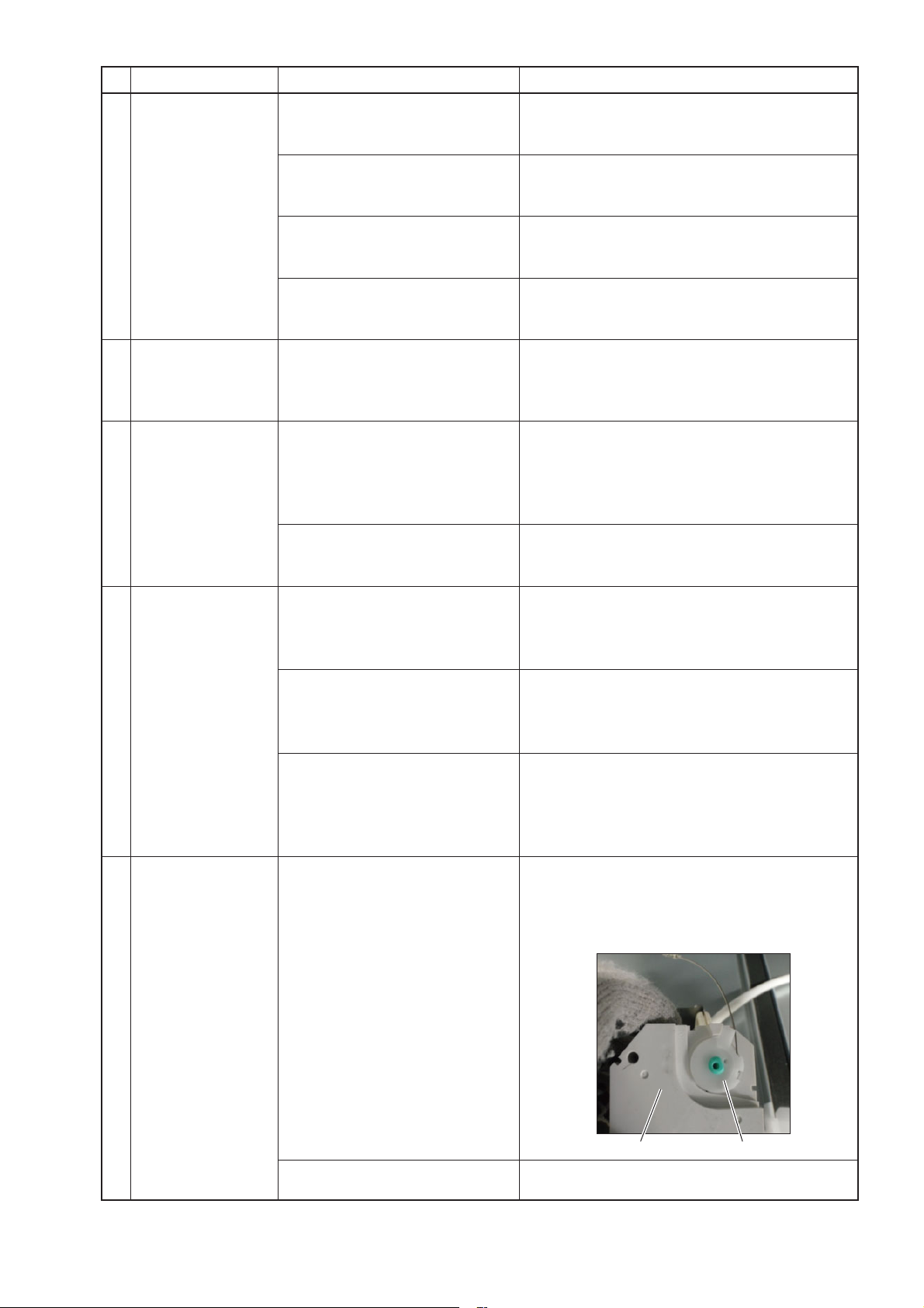
Remove the GM assembly from the main unit, and
then remove the damper motor from the damper motor casing to check the pulley position. If the position
is incorrect, adjust it as shown in the picture below,
and then reassemble the GM assembly.
Damper motor failure
PulleyDamper motor
If no error is found around the pulley and wire, replace the GM assembly.
─ 25 ─
 Loading...