

Page 1
h
16 16
ø6
20
25
25
20
102
54
ø6
620
10
44
0
9
8
7
6
5
4
3
2
1
SW1
0
9
8
7
6
5
4
3
2
1
SW2
GB
CENTRAL
HEAT EX.
BY-PASS
AUTO
CHECK
INTERLOCKED
FILTER
ON/OFF
NOT
AVAILABLE
FILTER
3
52
qu
4
6
0412873HC1902
Building Air-Conditioning Control System
Lossnay Remote Controller PZ-52SF-E
Installation Manual
This manual contains only the installation procedure for the Lossnay remote controller. For information about how to wire and install the Lossnay
units and the Lossnay adaptor, see their installation manuals.
In the remainder of this manual, the term “Lossnay unit” implies the Lossnay with which the Lossnay adaptor is connected unless it is specified.
For your safety, thoroughly read
1 Safety Precautions
● The following two symbols are used to denote dangers that may be caused by incorrect use:
WARNING
CAUTION
● After reading this installation manual, keep it in a safe place where the user can refer to it whenever necessary.
Make sure that this manual is forwarded to the next user.
Ask your dealer or technical representative to install the unit.
Any deficiency caused by your own installation may result in an electric
shock or fire.
Install in a place which is strong enough to withstand the weight of
the PZ-52SF-E.
Any lack of strength may cause the PZ-52SF-E to fall down, resulting in
personal injury.
Firmly connect the wiring using the specified cables. Carefully check
that the cables do not exert any force on the terminals.
Improper wiring connections may produce heat and possibly a fire.
Never modify or repair the PZ-52SF-E by yourself.
Any deficiency caused by your modification or repair may result in an electric shock or fire.
Consult with your dealer about repairs.
1 Safety Precautions
described below before installing the Lossnay remote controller correctly.
This symbol denotes what could lead to serious injury or death if the Lossnay remote controller is misused.
This symbol denotes what could lead to personal injury or property damage if the Lossnay remote controller is
misused.
WARNING
Ensure that installation work is done correctly following this installation manual.
Any deficiency caused by installation may result in an electric shock or fire.
All electrical work must be performed by a licensed technician, according to local regulations and the instructions given in this manual.
Any lack of electric circuit or any deficiency caused by installation may result in an electric shock or fire.
Do not move and re-install the PZ-52SF-E yourself.
Any deficiency caused by installation may result in an electric shock or fire.
Ask your distributor or special vendor for moving and installation.
(2) The switch box is necessary for mounting. Use the switch box specified in the right.
83.5 ± 0.4
73 or more
1.5 or less
Restriction when the Lossnay units are connected with the central control-
4
ler transmission cable
When the Lossnay units and the Lossnay remote controllers are connected with the central controller transmission cable, the number of the
Lossnay remote controllers is restricted because of the capacity of the power supply unit.
The following table shows how many Lossnay remote controllers can be used.
The number of the Lossnay units that isn’t supplied power from the cable doesn’t concern about it.
For details on electrical connections, please refer to the power supply unit catalogue.
Power supply unit
PA C-SC34KUA Max. 30 units Max. 26 units Max. 22 units Max. 18 units Max. 14 units
No. system controllers
System controller
Tr ansmission cable
power supply unit
No units 1 unit 2 units 3 units 4 units
Lossnay unit
Lossnay remote controller
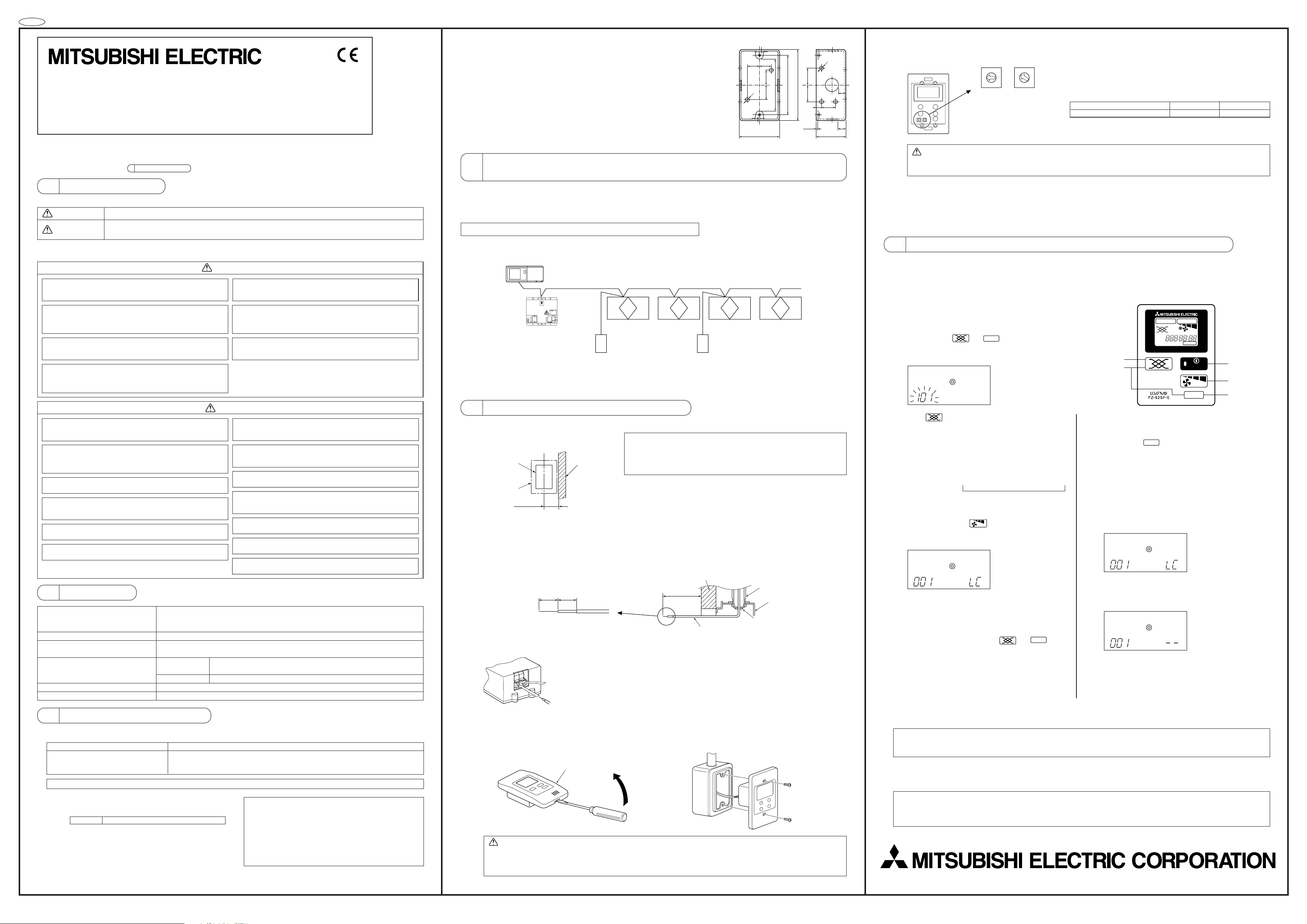
(5) Set the Lossnay remote controller address.
Set the Lossnay remote controller address using the rotary switches SW1
and SW2 on the front of the Lossnay remote controller.
■ Setting range: 101 to 200
Rotary switch SW1 indicates the tens digit and SW2 indicates the ones digit.
Rotary switches
In addition, 100 is automatically added to the setting as shown below.
Rotary switch setting 01 - 99 00
Lossnay remote controller address 101 - 199 200
The address is set to 01 when the Lossnay remote controller is shipped
from the manufacturer.
CAUTION: The address must be set if the Lossnay remote controller is used as a part of a multiunit system. Set the address
according to its position in the system. In addition, refer to the Lossnay Adaptor Installation Manual for more
information concerning the setting of the addresses.
(6) After setting the Lossnay remote controller address, attach the Lossnay remote controller cover.
When attaching the Lossnay remote controller cover, set the top of the cover onto the two top hooks, then push in on the bottom of the
cover until it snaps into place.
If the bottom of the cover is attached first, the top of the cover cannot be attached. Forcefully pushing in the top of the cover to attach
it may break the hooks.
6 Registering the Lossnay Unit With the Lossnay Remote Controller
(Initial registration mode operation)
A Lossnay unit must be registered with the Lossnay remote controller in a group arrangement. Register a Lossnay unit using the initial registration mode as shown below. In addition, the initial registration mode can be used to search for a Lossnay unit registered to the group or to delete
a registration.
Setting Procedure
1 Tu rn off the unit.
(Perform the following operation after “H0” flashes on the display.)
2 Hold down both
This starts the initial registration mode and the set Lossnay remote controller address flashes on the display.
and
FILTER
for more than 2 seconds.
CAUTION
Do not install in any place exposed to flammable gas leakage.
Flammable gases accumulated around the body of PZ-52SF-E may cause
an explosion.
Do not use in any special environment.
Using in any place exposed to oil (including machine oil), steam and sulfuric gas may deteriorate the performance significantly or give damage to the
component parts.
Wire so that it does not receive any tension.
Tension may cause wire breakage, heating or fire.
Completely seal the wire lead-in port with putty etc.
Any dew, moisture, cockroaches, insects entering the unit may cause an
electric shock or a malfunction.
Do not wash with water.
Doing so may cause an electric shock or a malfunction.
Do not install in any place at a temperature of more than 40°C or less
than 0°C or exposed to direct sunlight.
Do not install in any steamy place such a bathroom or kitchen.
Avoid any place where moisture is condensed into dew. Doing so may cause
an electric shock or a malfunction.
Do not install in any place where acidic or alkaline solution or special
spray are often used.
Doing so may cause an electric shock or malfunction.
Use standard wires in compliance with the current capacity.
A failure to this may result in an electric leakage, heating or fire.
Do not touch any PCB (Printed Circuit Board) with your hands or with
tools. Do not allow dust to collect on the PCB.
Doing so may cause fire or an electric shock.
Do not touch any control button with your wet hands.
Doing so may cause an electric shock or a malfunction.
Do not press any control button using a sharp object.
Doing so may cause an electric shock or a malfunction.
Never contact the power supply with the control wiring terminals.
Doing so will certainly cause the controller to catch fire.
2Specification
Source power requirement Input voltage 17VDC - 30VDC, 0.02 A
Power received from an outdoor unit or a power supply unit via M-NET trans-
mission line.
Interface condition for transmission line M-NET transmission line ; 30VDC+AMI signal (±5VDC)
Number of M-NET controlled Lossnay
unit controlled by PZ-52SF-E
1 - 16
Environmental condition Temperature Operating 0 - 40°C
Non operating 0 - 70°C
Humidity 30 - 90%RH (No condensation)
Dimensions 120 (High) × 70 (Width) × 8.41 (Depth) mm
Weight 0.12 kg
3Checking the Supplied Parts
Check that the box includes the following parts in addition to this installation manual:
Lossnay Remote Controller Model Name Enclosed Parts
PZ-52SF-E (2) Cross-recessed pan-head screws .................................................................................................. 2
(1) Lossnay remote controller .............................................................................................................. 1
(3) Operation manual ........................................................................................................................... 1
5 Installing the Lossnay Remote Controller
1. Mount the switch box.
(1) Install the switch box (purchased separately) as
explained below.
Projecting
Switch box
Outline of Lossnay
remote controller
40 mm or more
object such as
a stud
(2) Purchase the thin-copper wiring pipe and locknuts and bushings separately.
2. Install the Lossnay remote controller.
(1) Pull out about 80 mm of cable from the wall and remove the insulation from its end.
(2) Use putty to seal the cable lead-in hole in order to prevent insects from damaging the wiring and to prevent air from condensing on the
Lossnay remote controller circuit board. If the hole is not sealed well, the Lossnay remote controller circuit board may be damaged.
11 10
Leading
wire
(3) Connect the cable to the terminal board in the bottom rear of the Lossnay remote controller unit.
(4) Remove the Lossnay remote controller cover using a standard screwdriver, then attach the Lossnay remote controller unit to the switch
box using the two enclosed cross-recessed pan-head screws. Use a standard screwdriver with a blade that is 4 mm or wider to remove
the cover.
Insulation
Button:
Press here.
Insert the cable.
Sheath
Lossnay remote controller cover
NOTE: • Be sure to install the switch box with the clearance shown in the
illustration at the left. (Check the space between the unit and any
projection such as a stud.)
• Leave a space of 120 mm or more below the Lossnay remote
controller so that the screwdriver can be used.
Wall
80mm
Cable
Wiring pipe
One switch box (with cover)
Seal with putty
• The cable does not have polarity.
•When connecting stranded cable, hold down the button on the terminal board while
inserting the cable.
• The cable connects to the main terminal board when it is inserted into the bottom
terminal.
• When disconnecting the cable, hold down the button while pulling out the cable.
• After inserting the cable, slightly tug on it to check that it does not easily disconnect.
If the cable is not securely connected, a short-circuit or malfunction may occur.
3 Press to select the address of the Lossnay unit that
you wish to register with this Lossnay remote controller.
After the button is pressed once, the Lossnay remote controller address, and then the Lossnay unit address is displayed.
Afterwards, each press of the button increases the Lossnay
unit address by 1 as shown below. Holding down the button
changes the address more quickly.
[101] ➝ [- - -] ➝ [001] ➝ [002] ➝ · · · ➝ [098] ➝ [099]
(Set Lossnay remote controller address)
Flashes
▲
4 When the address of the Lossnay unit that you wish to regis-
ter is displayed, press
to begin registering.
If the registration is completed correctly, the display appears
as shown below.
The Lossnay unit type,
“LC”, is displayed.
If the registration is not completed correctly, “88” flashes in
the display. Check that the selected Lossnay unit address or
the wiring are correct.
Up to 16 Lossnay units can be registered.
5 After registering, hold down both
and
FILTER
for more
than 2 seconds to end the initial registration mode and the
normal display appears.
NOTE: • Up to 16 Lossnay units can be registered.
• If the registration cannot be completed or deleted correctly, either the set address or the wiring of the Lossnay unit whose
registration you wish to add or delete may be incorrect. Check the wiring and the address that is set.
Confirmation of registered address
6 Display the addresses of the Lossnay units that are regis-
tered with this Lossnay remote controller.
Each press of
FILTER
in step 2 or 4 displays the address of a
registered Lossnay unit and its type, “LC”.
If no Lossnay unit is registered, “– – –” appears in the address
display and no type is displayed.
Address deletion
7 Delete the address of a Lossnay unit registered with this
Lossnay remote controller.
Hold down [ON/OFF] twice for 2 seconds each time either in
step 4 or after the registration is complete to delete the registration of the Lossnay unit that is currently displayed.
When the display appears as shown above, hold down [ON/
OFF] twice for 2 seconds each time.
↓
If the registration is deleted correctly, “– – ” appears in the
display.
If the registration is not deleted correctly, “88” flashes in the
display. Check that the selected Lossnay unit address and
the wiring are correct.
NOTE: The parts listed below must be purchased separately.
(1) Cable connecting the Lossnay remote controller to the
Lossnay unit: Use the cable specified below.
Cable type CVV (2-core): 0.75 - 1.25 mm2 or equivalent
* CVV is a control cable which is sheathed in polyvinyl chlo-
ride with polyvinyl insulated wires inside.
NOTE: If you need to use a cable extension longer than 10
meters, select an electric wire that meets the following
specifications:
Wire specification ..... CPEVS: ø1.2 mm - ø1.6 mm or equivalent
CVVS: 1.25 mm
2
- 2 mm2 or equivalent
*CPEVS: PE insulated PVC jacketed shielded communication
cable
*CVVS : PVC insulated PVC jacketed shielded control cable
This product is designed and intended for use in a residential, commercial or light-industrial environment.
The product at hand is based on the following EU regulations:
• Low Voltage Defective 73/23/EEC
• Electromagnetic Compatibility Directive 89/336/EEC
CAUTION: • Forcing off the cover using a screwdriver that is less than 4 mm wide may result in damage to the equipment
or injuries.
• Attach the Lossnay remote controller to a level surface. Do not overtighten the screws, otherwise the case
may become deformed or break.
2-3 Marunouchi, 2-chome Chiyoda-ku, Tokyo, 100-8310 Japan
 Loading...