


PWFY-1PWFY-P-NMU-E-BU/PWFY-P-NMU-E-AU (Sept. 2010)
PWFY-P-NMU-E-BU
PWFY-P-NMU-E-AU
PWFY-P-NMU-E-BU/-AU
1. GENERAL DESCRIPTION .................................................................................................................................... PWFY-2
2. SPECIFICATIONS ................................................................................................................................................. PWFY-3
3. EXTERNAL DIMENSIONS .................................................................................................................................... PWFY-6
4. CENTER OF GRAVITY .........................................................................................................................................PWFY-8
5. ELECTRICAL WIRING DIAGRAMS ...................................................................................................................... PWFY-9
6. REFRIGERANT CIRCUIT DIAGRAMS ...............................................................................................................PWFY-11
7. SOUND PRESSURE LEVELS AND NC CURVES .............................................................................................PWFY-12
8. VIBRATION LEVELS ........................................................................................................................................... PWFY-13
9. CAPACITY TABLES .............................................................................................................................................PWFY-14
9-1. Correction by Temperature ........................................................................................................................PWFY-14
9-2. Water Pressure Drop ................................................................................................................................. PWFY-24
10. OPTIONAL PARTS .............................................................................................................................................. PWFY-25
11. SYSTEM DESIGN ............................................................................................................................................... PWFY-26
11-1. Electrical Work .......................................................................................................................................... PWFY-26
11-2. M-NET Control ..........................................................................................................................................PWFY-27
11-3. Installation .................................................................................................................................................PWFY-32
HYDRONIC HEAT EXCHANGER UNITS
PWFY-2
PWFY-P-NMU-E-BU/PWFY-P-NMU-E-AU (Sept. 2010)
PWFY-P-NMU-E-BU
PWFY-P-NMU-E-AU
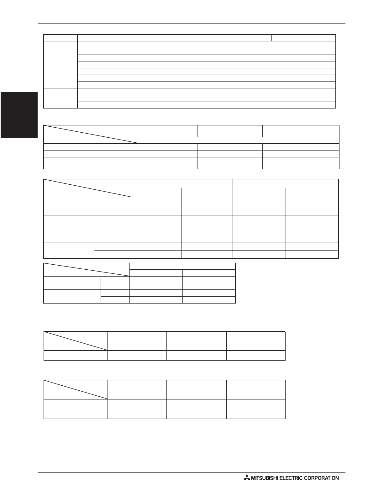
1. GENERAL DESCRIPTION
Unit Conguration
50 to 100%R2/WR2 series
PWFY with
standard indoor units
Only standard
indoor units
50 to 150% 50 to 150%
Only PWFY
<PWFY-P36NMU-E-BU>
50 to 100%R2/WR2 series
PWFY with
standard indoor units
Only standard
indoor units
50 to 150% 50 to 150%
Only PWFY
<PWFY-P36,P72NMU-E-AU>
50 to 100%Y/H2i/WY series
50 to 130% 50 to 130%
Model PWFY-P36NMU-E-BU PWFY-P36NMU-E-AU PWFY-P72NMU-E-AU
Outdoor unit
- PUHY-P*T(S)HMU-A(-BS)/PUHY-P*Y(S)HMU-A(-BS)
- PUHY-P*T(S)JMU-A(-BS)/PUHY-P*Y(S)JMU-A(-BS)
- PUHY-HP*T(S)JMU-A(-BS)
- PQHY-P*T(S)HMU-A/PQHY-P*Y(S)HMU-A
PURY-P*T(S)HMU-A(-BS)/PURY-P*Y(S)HMU-A(-BS) PURY-P*T(S)HMU-A(-BS)/PURY-P*Y(S)HMU-A(-BS)
PURY-P*T(S)JMU-A(-BS)/PURY-P*Y(S)JMU-A(-BS) PURY-P*T(S)JMU-A(-BS)/PURY-P*Y(S)JMU-A(-BS)
PQRY-P*T(S)HMU-A/PQRY-P*Y(S)HMU-A PQRY-P*T(S)HMU-A/PQRY-P*Y(S)HMU-A
BC
Controllers
BC Controllers: CMB-P104,105,106,108,1010,1016NU-G
Main BC Controllers: CMB-P108,1010,1013, 1016-GA / CMB-P1016NU-HA
Sub BC Controllers: CMB-P104,108NU-GB / CMB-P1016NU-HB
Operation Temperature Range
PWFY-P36NMU-E-BU
Only PWFY
PWFY with
standard indoor unit
Only standard indoor units
Heating (WB)
Inlet water temperature R2/WR2 series 50 to 160°F (10 to 71°C) 50 to 160°F (10 to 71°C) ―
Outdoor temperature R2 series -4 to 90°F (-20 to 32°C) -4 to 90°F (-20 to 32°C) -4 to 60°F (-20 to 15.5°C)
Circulating Water
temperature
WR2 series 50 to 113°F (10 to 45°C) 50 to 113°F (10 to 45°C) 50 to 113°F (10 to 45°C)
PWFY-P36, 72NMU-E-AU
Connectable outdoor unit capacity range
Only standard indoor units
Cooling (DB) Heating (WB)
Outdoor temperature
R2 series
23 to 109°F(-5 to 43°C) -4 to 60°F(-20 to 15.5°C)
Y series
23 to 109°F(-5 to 43°C) -4 to 60°F(-20 to 15.5°C)
Circulating Water
temperature
WR2 series 50 to 113°F (10 to 45°C) 50 to 113°F (10 to 45°C)
WY series 50 to 113°F (10 to 45°C) 50 to 113°F (10 to 45°C)
Only PWFY PWFY with standard indoor units
Cooling Heating Cooling Heating
Inlet water temperature
R2/WR2 series
50 to 95°F (10 to 35°C) 50 to 105°F (10 to 41°C) 50 to 95°F (10 to 35°C) 50 to 105°F (10 to 41°C)
Y/H2i/WY series
50 to 95°F (10 to 35°C) 50 to 105°F (10 to 41°C) 50 to 95°F (10 to 35°C) 50 to 105°F (10 to 41°C)
Outdoor temperature
R2 series
23 to 115°F (-5 to 46°C) -4 to 90°F(-20 to 32°C) 23 to 115°F (-5 to 46°C) -4 to 90°F(-20 to 32°C)
Y series
23 to 115°F(-5 to 46°C) -4 to 60°F(-20 to 15.5°C) 23 to 115°F(-5 to 46°C) -4 to 60°F(-20 to 15.5°C)
H2i series
23 to 109°F(-5 to 43°C) -13 to 60°F(-25 to 15.5°C) 23 to 109°F(-5 to 43°C) -13 to 60°F(-25 to 15.5°C)
Circulating Water
temperature
WR2 series 50 to 113°F (10 to 45°C) 50 to 113°F (10 to 45°C) 50 to 113°F (10 to 45°C) 50 to 113°F (10 to 45°C)
WY series 50 to 113°F (10 to 45°C) 50 to 113°F (10 to 45°C) 50 to 113°F (10 to 45°C) 50 to 113°F (10 to 45°C)
PWFY-3PWFY-P-NMU-E-BU/PWFY-P-NMU-E-AU (Sept. 2010)
PWFY-P-NMU-E-BU
PWFY-P-NMU-E-AU
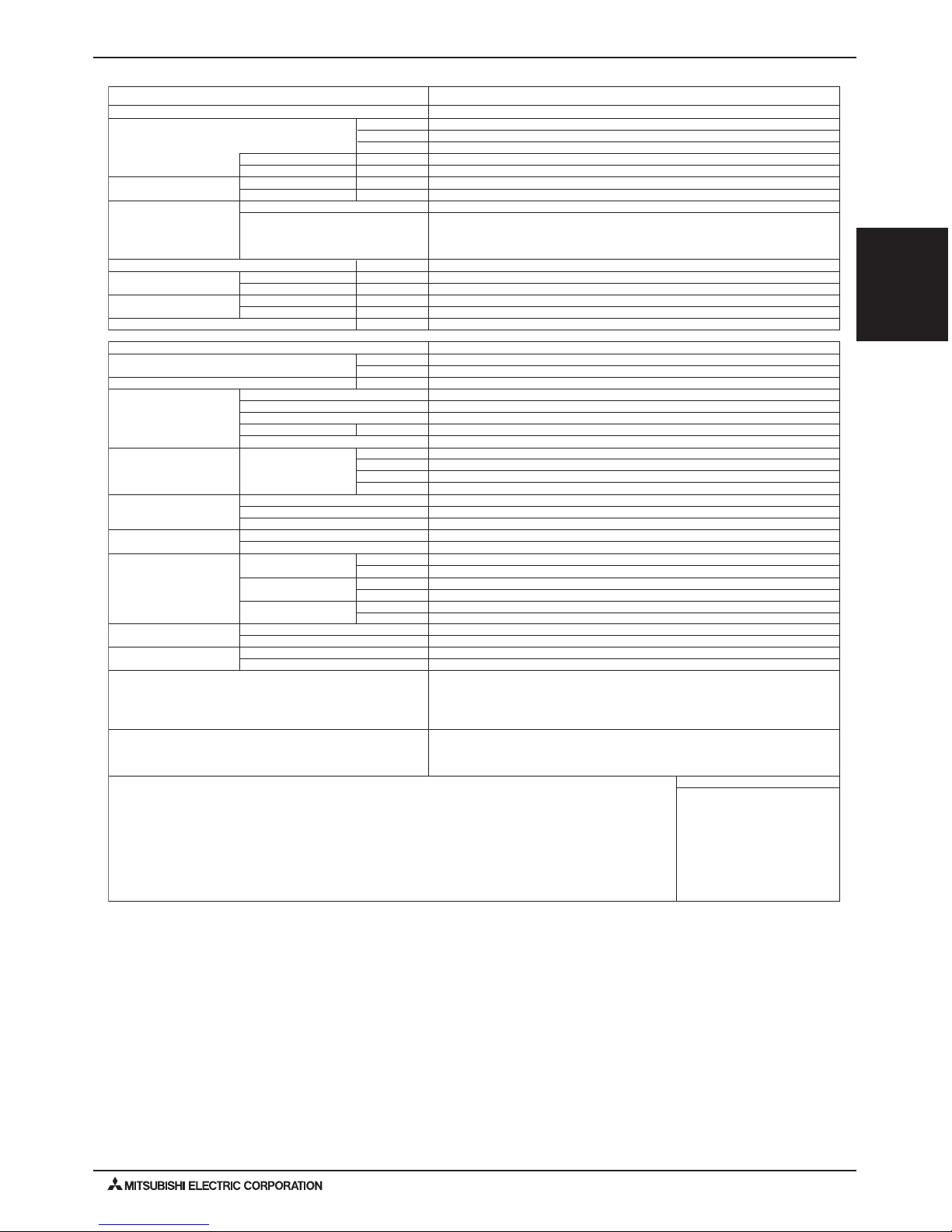
2. SPECIFICATIONS
Model
Power source
kWHeating capacity
kcal / h(Nominal )
BTU / h
kW
A
W.B
dB<A>
in.(mm)
in.(mm)
in.(mm)
in.(mm)
in.(mm)
mm
in.
lbs(kg)
kW
-
Power input
Liquid
Gas
Current input
Outdoor temp.
Inlet Water temp.
Total capacity
Temp. range of
heating
Connectable
outdoor unit Model / Quantity
Sound pressure level (measured in anechoic room)
Diameter of
refrigerant pipe
Diameter of
water pipe
Field drain pipe size
External dimension H × W × D
Net weight
Compressor
Maker
Type
Starting method
Motor output
Circulating water
Range
Protection on Internal circuit
(R134a)
High pressure protection
Inverter circuit (COMP)
Compressor
Type × original chargeRefrigerant
Control
R410ADesign pressure
R134a
Water
ExternalDrawing
Standard attachment
Optional parts
Remark
Note:
*1 Nominal heating conditions
Outdoor Temp. : 47°FDB / 43°FWB (8.3°CDB/6.1°CWB)
kcal = kW x 860
BTU/h = kW x 3,412
cfm = m
3
/min x 35.31
G(us) = L × 0.2642
lbs = kg / 0.4536
psi = MPa×145.038
Pipe length : 7.6 m (25 ft)
Level difference : 0m (0ft)
Inlet water Temp 149°F (65°C) Water flow rate 2.15m
3
/h (555G/h)
* Due to continuing improvement, the above specifications may be subject to change without notice. * Install the unit in an environment where the
wet bulb Temp. will not exceed 90°F (32°C).
* The unit is not designed for outside installations.
* Please don't use steel for the water piping material. * The water circuit must use the closed circuit.
* Please do not use it as a drinking water. Discharge water from unit is not potable. Do not connect the output directly to a potable system.
* Please always make water circulate or add brine to the circulation water when the ambient temperature becomes 32°F (0°C) or less.
* Please do not use groundwater and well water.
* The specification data is subject
to rounding variation.
Unit converter
Lubricant
Operation volume
Inlet
Outlet
Accessory
Wiring
Document
m
3
/h
G/h
G/min
L/min
MPa
MPa
psi
psi
psi
MPa
1.00
Installation Manual, Instruction Book
800 (785 without legs) × 450 × 300
KE94C344
Inverter
1.0
Over-heat protection, Over-current protection
R134a x ( 2lbs + 7oz) ( 1.1kg )
10,100
11.7
WKB94T460
NONE
44
Strainer, Heat insulation material, 2 × Connector sets, 2 × Washer
PWFY-P36NMU-E-BU
1-phase 208-230V 60Hz
PT3/4 (27.2) Screw
MITSUBISHI ELECTRIC CORPORATION
NEO22
Φ1-1/4 (Φ32)
Inverter rotary hermetic compressor
31-1/2" (30-15/16" without legs) × 17-3/4” × 11-13/16”
133 (60)
PT3/4 (27.2) Screw
12.30 - 11.12
50~100% of outdoor unit capacity
PURY-P*T(S)HMU/Y(S)HMU-A(-BS)
PURY-P*T(S)JMU/P*Y(S)JMU-A(-BS)
PQRY-P*T(S)HMU/-P*Y(S)HMU-A(-BS)
Φ5/8 (Φ15.88) Brazed
-4~90°F (-20~32°C)
Φ3/8 (Φ9.52) Brazed
39,900
50~160°F (10~71°C)
2.48
0.6~2.15
156~555
2.6~9.2
10~35
LEV
601
4.15
522
3.60
High pressure sensor, High pressure switch at 3.60 MPa (522 psi)
Discharge thermo protection, Over-current protection
145
Details on foundation work, duct work, insulation work, electrical wiring, power source switch, and
other items shall be referred to the Installation Manual.
PWFY-4
PWFY-P-NMU-E-BU/PWFY-P-NMU-E-AU (Sept. 2010)
PWFY-P-NMU-E-BU
PWFY-P-NMU-E-AU
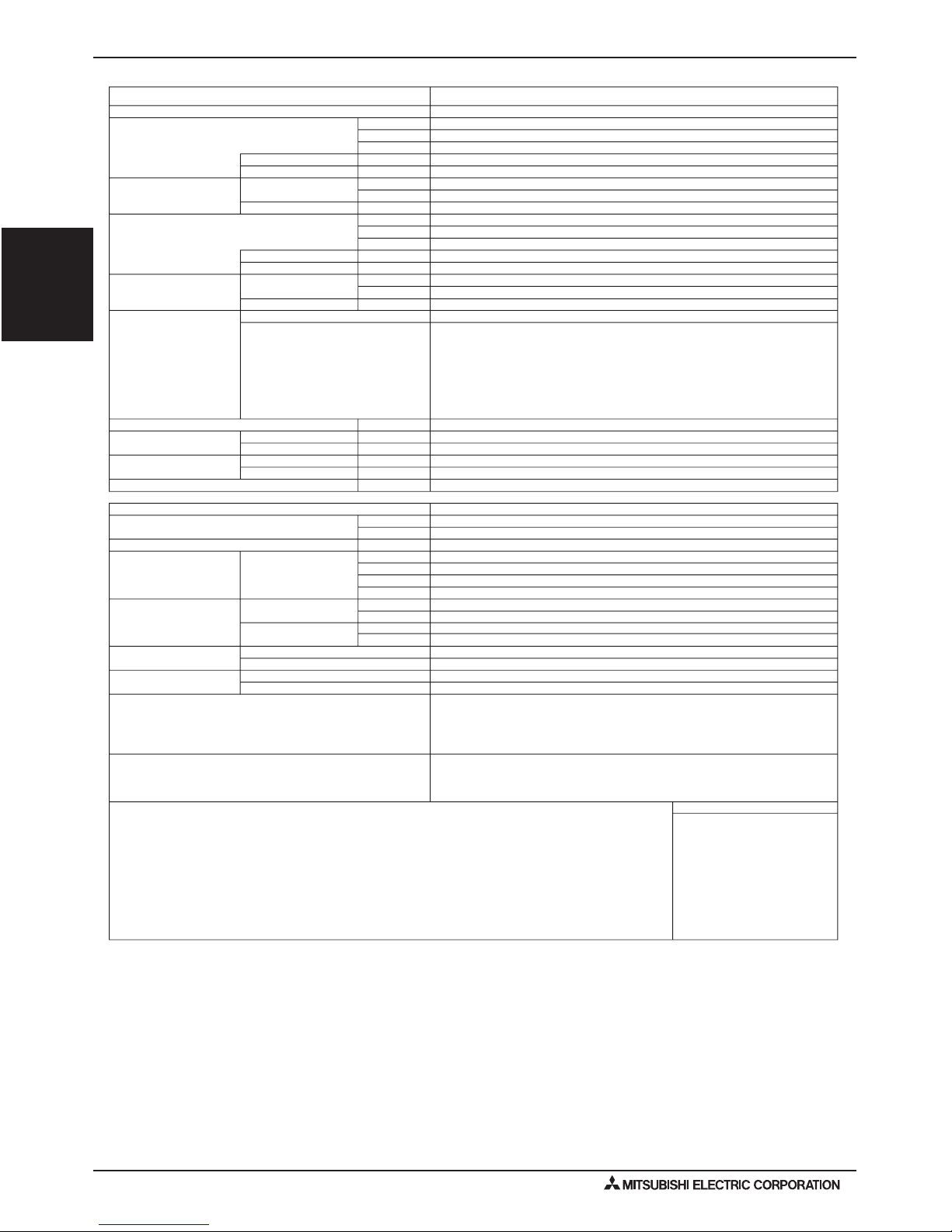
2. SPECIFICATIONS
Model
Power source
kW*1Heating capacity
kcal / h
BTU / h
kW
A
W.B
*1(Nominal)
*1
Power input
Current input
Outdoor temp.
Temp. range of
W.B
-
heating
Inlet Water temp.
kW*2Cooling capacity
kcal / h
BTU / h
kW
A
D.B
*2(Nominal)
*2
Power input
Current input
Outdoor temp.Temp. range of cooling
D.B
-Inlet Water temp.
Total capacity
Model / Quantity
Connectable
outdoor unit
Sound pressure level (measured in anechoic room) dB<A>
in.(mm)
in.(mm)
Diameter of
refrigerant pipe
in.(mm)
in.(mm)
Diameter of
water pipe
in.(mm)
mm
Field drain pipe size
External finish
External dimension H × W × D
in.
lbs(kg)
Net weight
Circulating water
Range
Design pressure
Water
R410A
Drawing
Standard attachment
Optional parts
Remark
Note:
*2 Nominal cooling conditions *1 Nominal heating conditions
Outdoor Temp. : 47°FDB/43°FWB (8.3°CDB / 6.1°CWB) Outdoor Temp. : 95°FDB (35°CDB)
Pipe length : 7.6 m (25 ft)Pipe length : 7.6 m (25 ft)
Level difference : 0m (0ft)Level difference : 0m (0ft)
Inlet water Temp 86°F (30°C)
Water flow rate 2.15m
3
/h (555G/h)
Inlet water Temp 149°F (23°C)
Water flow rate 1.93m
3
/h (498G/h)
* Install the unit in an environment where the
* Due to continuing improvement, the above specifications may be subject to change without notice.
wet bulb Temp. will not exceed 92°F (32°C) * The unit is not designed for outside installations.
* Please don't use steel for the water piping material. * The water circuit must use the closed circuit.
* Please always make water circulate or add the brine to the circulation water when the ambient temperature becomes 32°F (0°C) or less.
Inlet
Outlet
Operation Volume
Liquid
Gas
Accessory
External
Wiring
Document
Details on foundation work, duct work, insulation work, electrical wiring, power source switch, and
other items shall be referred to the Installation Manual.
Unit converter
36,200
50~95°F (10~35°C)
0.015
Φ5/8 (Φ15.88) Brazed
Φ3/8 (Φ9.52) Brazed
PT3/4 (27.2) Screw
Installation Manual, Instruction Book
PT3/4 (27.2) Screw
NO
WKB94T461
0.072 - 0.065
50~100% of outdoor unit capacity
PUHY-P*T(S)HMU/P*Y(S)HMU-A(-BS)
PUHY-P*T(S)JMU/P*Y(S)JMU-A(-BS)
PQHY-P*T(S)HMU/P*Y(S)HMU-A(-BS)
23~109°F (-5~43°C) PURY - series
23~109°F (-5~43°C) PUHY - series
0.6~2.15
2.6~9.2
4.15
145
10~35
156~555
1.00
Strainer, Heat insulation material, 2 × Connector sets , 2 × Washer
Φ1-1/4 (Φ32)
PWFY-P36NMU-E-AU
1-phase 208 - 230 V 60Hz
9,100
10.6
29
11.7
800 (785 without legs) × 450 × 300
KE94C345
601
NONE
10,100
39,900
-4~60°F (-20~15.5°C) PUHY - series
50~105°F (10~41°C)
0.015
0.072 - 0.065
-4~90°F (-20~32°C) PURY - series
31-1/2" (30-15/16" without legs) × 17-3/4” × 11-13/16”
78 (35)
* Please do not use it as a drinking water. Discharge water from unit is not possible. Do not connect the output directly to a potable system.
* Please do not use groundwater and well water.
m3/h
G/h
G/min
L/min
MPa
psi
MPa
psi
kcal = kW x 860
BTU/h = kW x 3,412
cfm = m
3
/min x 35.31
G(us) = L × 0.2642
lbs = kg / 0.4536
psi = MPa×145.038
* The specification data is subject
to rounding variation.
PURY-P*T(S)HMU/Y(S)HMU-A(-BS)
PURY-P*T(S)JMU/P*Y(S)JMU-A(-BS)
PQRY-P*T(S)HMU/-P*Y(S)HMU-A(-BS)
PWFY-5PWFY-P-NMU-E-BU/PWFY-P-NMU-E-AU (Sept. 2010)
PWFY-P-NMU-E-BU
PWFY-P-NMU-E-AU
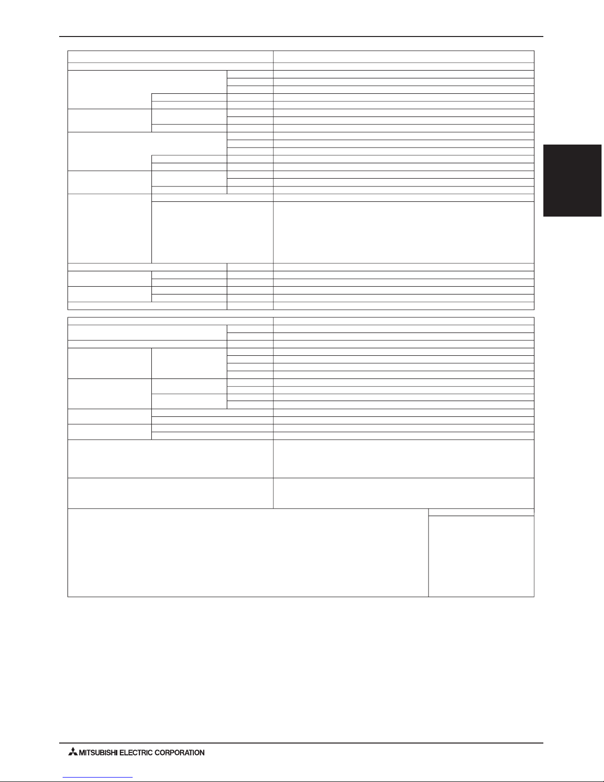
2. SPECIFICATIONS
Model
Power source
kW*1Heating capacity
kcal / h
BTU / h
kW
A
W.B
*1(Nominal)
*1
Power input
Current input
Outdoor temp.
Temp. range of
W.B
-
heating
Inlet Water temp.
kW*2Cooling capacity
kcal / h
BTU / h
kW
A
D.B
*2(Nominal)
*2
Power input
Current input
Outdoor temp.Temp. range of cooling
D.B
-Inlet Water temp.
Total capacity
Model / Quantity
Connectable
outdoor unit
Sound pressure level (measured in anechoic room) dB<A>
in.(mm)
in.(mm)
Diameter of
refrigerant pipe
in.(mm)
in.(mm)
Diameter of
water pipe
in.(mm)
mm
Field drain pipe size
External finish
External dimension H × W × D
in.
lbs(kg)
Net weight
Circulating water
Range
Design pressure
Water
R410A
Drawing
Standard attachment
Optional parts
Remark
Note:
*2 Nominal cooling conditions *1 Nominal heating conditions
Outdoor Temp. : 47°FDB/43°FWB (8.3°CDB / 6.1°CWB) Outdoor Temp. : 95°FDB (35°CDB)
Pipe length : 7.6 m (25 ft)Pipe length : 7.6 m (25 ft)
Level difference : 0m (0ft)Level difference : 0m (0ft)
Inlet water Temp 86°F (30°C)
Water flow rate 4.30m
3
/h (1110G/h)
Inlet water Temp 149°F (23°C)
Water flow rate 3.86m
3
/h (996G/h)
* Install the unit in an environment where the
* Due to continuing improvement, the above specifications may be subject to change without notice.
wet bulb Temp. will not exceed 92°F (32°C) * The unit is not designed for outside installations.
* Please don't use steel for the water piping material. * The water circuit must use the closed circuit.
* Please always make water circulate or add the brine to the circulation water when the ambient temperature becomes 32°F (0°C) or less.
Inlet
Outlet
Operation Volume
Liquid
Gas
Accessory
External
Wiring
Document
Details on foundation work, duct work, insulation work, electrical wiring, power source switch, and
other items shall be referred to the Installation Manual.
Unit converter
72,000
50~95°F (10~35°C)
0.015
Φ3/4 (Φ19.05) Brazed
Φ3/8 (Φ9.52) Brazed
PT 1 ( 34 ) Screw
Installation Manual, Instruction Book
PT 1 ( 34 ) Screw
NO
WKB94T461
0.072 - 0.065
50~100% of outdoor unit capacity
23~109°F (-5~43°C) PURY - series
23~109°F (-5~43°C) PUHY - series
1.2~4.30
5.2~18.4
4.15
145
20~72
312~1110
1.00
Strainer , Connecter , Heat insulation material, 2 × Connector sets , Expansion joint , 2 × Washer
Φ1-1/4 (Φ32)
PWFY-P72NMU-E-AU
1-phase 208 - 230 V 60Hz
18,100
21.1
29
23.4
800 (785 without legs) × 450 × 300
KE94C345
601
NONE
20,100
79,800
-4~60°F (-20~15.5°C) PUHY - series
50~105°F (10~41°C)
0.015
0.072 - 0.065
-4~90°F (-20~32°C) PURY - series
31-1/2" (30-15/16" without legs) × 17-3/4” × 11-13/16”
84 (38)
* Please do not use it as a drinking water. Discharge water from unit is not potable. Do not connect the output directly to a potable system.
* Please do not use groundwater and well water.
m3/h
G/h
G/min
L/min
MPa
psi
MPa
psi
kcal = kW x 860
BTU/h = kW x 3,412
cfm = m
3
/min x 35.31
G(us) = L × 0.2642
lbs = kg / 0.4536
psi = MPa×145.038
* The specification data is subject
to rounding variation.
PURY-P*T(S)HMU/Y(S)HMU-A(-BS)
PURY-P*T(S)JMU/P*Y(S)JMU-A(-BS)
PQRY-P*T(S)HMU/-P*Y(S)HMU-A(-BS)
PUHY-P*T(S)HMU/P*Y(S)HMU-A(-BS)
PUHY-P*T(S)JMU/P*Y(S)JMU-A(-BS)
PQHY-P*T(S)HMU/P*Y(S)HMU-A(-BS)
PWFY-6
PWFY-P-NMU-E-BU/PWFY-P-NMU-E-AU (Sept. 2010)
PWFY-P-NMU-E-BU
PWFY-P-NMU-E-AU
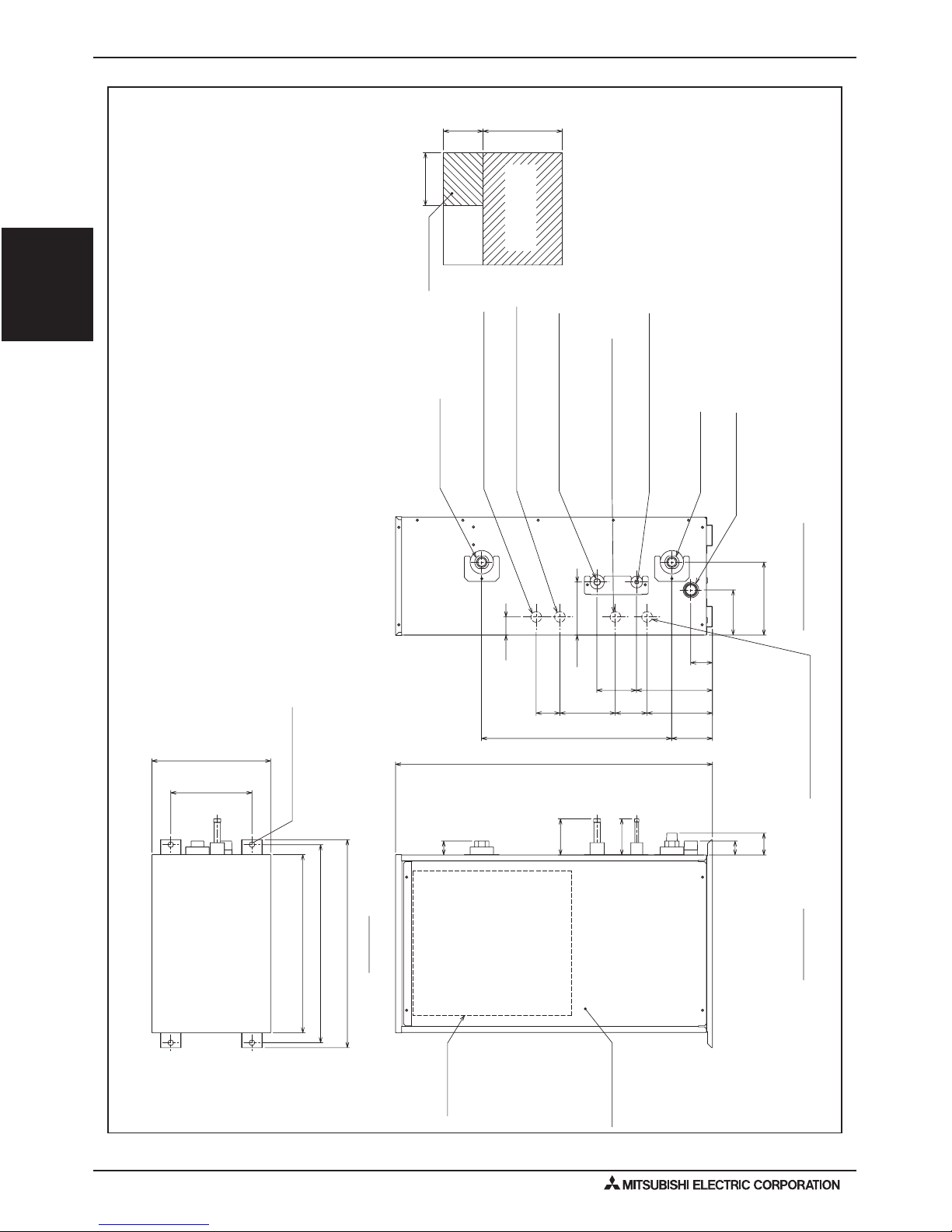
3. EXTERNAL DIMENSIONS
(11-13/16)(23-5/8)
Piping space
(right side)
Top view
Fig. A
Service space
(front side)
300
400(15-3/4)
600
Drain (R1 screw)
Control box
Water outlet
(RC3/4 screw)
ø27(1-3/32) Knockout hole
<Hole for external wiring input>
ø27(1-3/32) Knockout hole
<Hole for external wiring output>
ø27(1-3/32) Knockout hole
<Hole for power supply>
ø27(1-3/32) Knockout hole
<Hole for control wiring>
Service panel
Top view
Right side view
Front view
2X2-ø14(9/16) Hole
Connection pipe of outdoor unit
(Liquid)
ø15.88(5/8) <Brazed>
ø9.52(3/8) <Brazed>
Connection pipe of outdoor unit
(Gas)
Water inlet
(R3/4 screw)
Note 1. Ensure no water or debris can enter the unit through any gaps around
wiring or piping.
2. Ensure adequate service space is right around the unit, according to Fig A.
3. Please always make water circulate or add the brine to the circulation water
when the ambient temperature becomes 0degC(32°F )or less.
4. The unit is not designed for outside installations.
5. Install the unit in an environment where the wet bulb Temp.
will not exceed 32degC(90°F).
6. The water circuit must use the closed circuit.
7. Please don't use the steel material for the water piping material.
8. Connect the strainer which is put as accessory to water inlet pipe.
<Accessories>
• Y-type strainer (RC3/4) ················ 1pc.
•
Heat Insulation material ·············· 1pc.
•
Connector set ······························ 2set
•
Washer ········································ 2pcs.
(4-1/32)
(3-15/16)
(3-5/32) (5-17/32) (2-3/8)
(6-1/2)
(2-5/32)
(7-17/32)
102
(1-13/32)
(1-13/16)
(5-9/32)
(4-1/2)
(7-1/4)
(2-3/16)
525(20-11/16)
55
35(1-13/32)
35
91(3-19/32)
91(3-19/32)
134
480(18-29/32)
46
60
140
100
191
80
165
54
184
114
(Mounting pitch)
(Mounting pitch)
205(8-3/32)
800(31-1/2)
300(11-13/16)
450(17-23/32)
500(19-11/16)
<Unit:mm(in)>
PWFY-P36NMU-E-BU

PWFY-7PWFY-P-NMU-E-BU/PWFY-P-NMU-E-AU (Sept. 2010)
PWFY-P-NMU-E-BU
PWFY-P-NMU-E-AU
3. EXTERNAL DIMENSIONS
(23-5/8)
(11-13/16)
300
600
Fig. A
Service space
(front side)
Top view
400(15-3/4)
Piping space
(right side)
Drain (R1 screw)
ø9.52(3/8) <Brazed>
P72:Use the Expansion joint of accessories
ø27(1-3/32) Knockout hole
<Hole for control wiring>
ø27(1-3/32) Knockout hole
<Hole for power supply>
Water outlet
(RC3/4 screw)
Water inlet
(R3/4 screw)
P36:ø15.88(5/8) <Brazed>
P72:ø19.05(3/4) <Brazed>
ø27(1-3/32) Knockout hole
<Hole for external wiring input>
ø27(1-3/32) Knockout hole
<Hole for external wiring output>
Connection pipe of outdoor unit
(Gas)
Connection pipe of outdoor unit
(Liquid)
Front view
Right side view
Control box
Service panel
Top view
2X2-ø14(9/16) Hole
<Accessories>
• Y-type strainer (RC3/4) ················ 1pc.
•
Heat Insulation material ·············· 1pc.
•
Connector set ······························ 2set
•
Washer ········································ 2pcs.
•
Expansion joint(P72) ··················· 2pcs.
[From RC3/4 to RC1]
(3-15/16)
(8-1/8)
(4-1/2)
(2-3/8)
(3-5/32)
(5-17/32)
(5-9/32)
(1-13/16)
(7-17/32)
(6-1/2)
(2-5/32)
(4-1/32)
(1-13/32)
(2-3/16)
525(20-11/16)
91(3-19/32)
91(3-19/32)
35(1-13/32)
55
35
480(18-29/32)
102
206
134
114
100
191
46
6014080
165
54
(Mounting pitch)
450(17-23/32)
300(11-13/16)
(Mounting pitch)
205(8-3/32)
800(31-1/2)
500(19-11/16)
<Unit:mm(in)>
Note 1. Ensure no water or debris can enter the unit through any gaps around
wiring or piping.
2. Ensure adequate service space is right around the unit, according to Fig A.
3. Please always make water circulate or add the brine to the circulation water
when the ambient temperature becomes 0degC(32°F )or less.
4. The unit is not designed for outside installations.
5. Install the unit in an environment where the wet bulb Temp.
will not exceed 32degC(90°F).
6. The water circuit must use the closed circuit.
7. Please don't use the steel material for the water piping material.
8. Connect the strainer which is put as accessory to water inlet pipe.
PWFY-P36,72NMU-E-AU
PWFY-8
PWFY-P-NMU-E-BU/PWFY-P-NMU-E-AU (Sept. 2010)
PWFY-P-NMU-E-BU
PWFY-P-NMU-E-AU
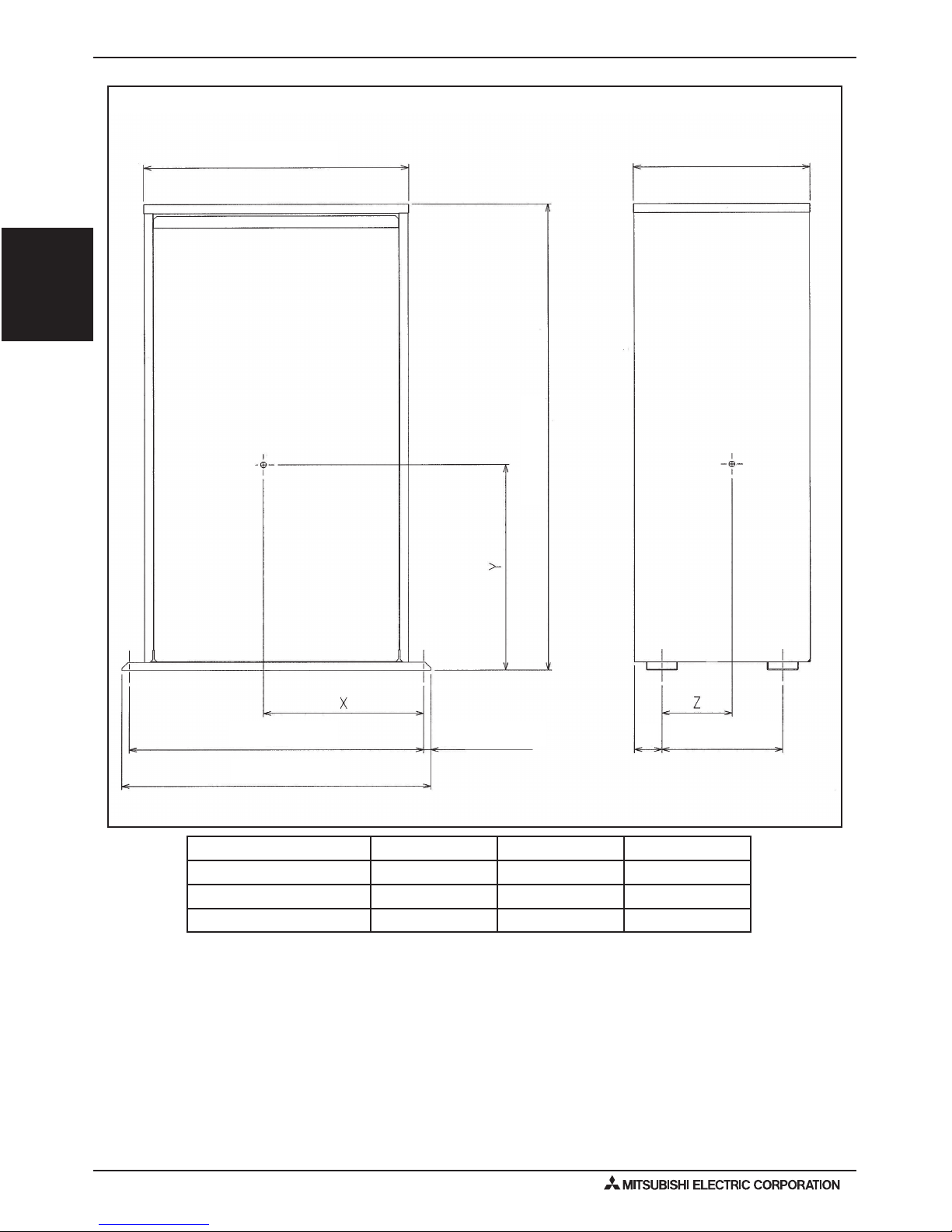
4. CENTER OF GRAVITY
17-23/32 (450) 11-13/16 (300)
31-1/2 (800)
17/32 (13)19-11/16 (500)
20-11/16 (525)
8-3/32 (205)
1-7/8 (47)
in. (mm)
Model X Y Z
PWFY-P36NMU-E-BU 10-23/32 (272) 13 (355) 4-11/16 (119)
PWFY-P36NMU-E-AU 11-13/32 (289) 13-5/8 (346) 4-1/16 (103)
PWFY-P72NMU-E-AU 10-29/32 (277) 13-11/16 (347) 3-29/32 (99)
PWFY-9PWFY-P-NMU-E-BU/PWFY-P-NMU-E-AU (Sept. 2010)
PWFY-P-NMU-E-BU
PWFY-P-NMU-E-AU
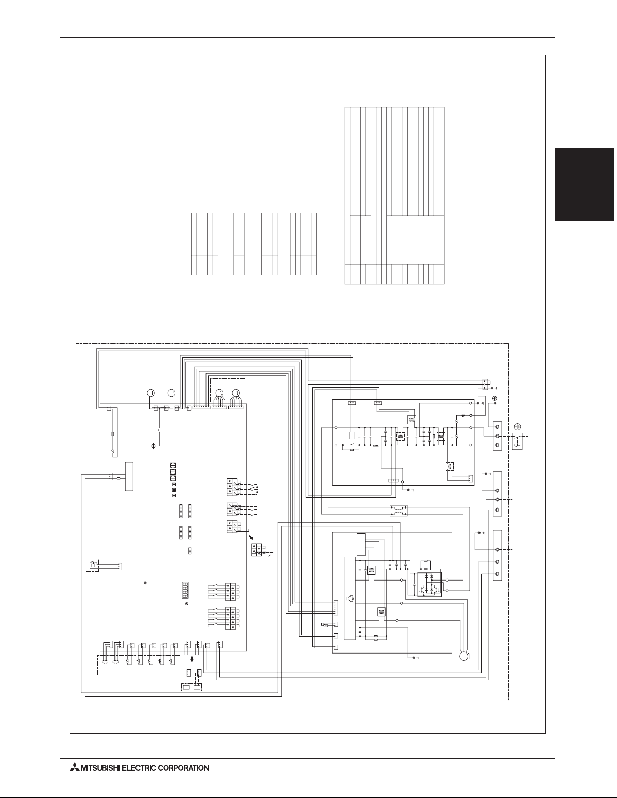
5. ELECTRICAL WIRING DIAGRAMS
gray
2
1
gray
black
To outdoor unit/
BC controller
To MA remote
controller
Power Supply
~208/230V
60Hz
3
2
1
blue
red
yellow/green
bluered
CN4
63LS
CN63HS
1
1
3
2
2
3
THHS
12
CN63LS
123
TH8
2
1
CN403
red
TH6
1
2
CN404
black
31
CT1
Moter
3~
CYN
RS4
MS
RS3
(Compressor)
CN3A
blue
U
t
t
t
t
t
red
yellow
TH22
CN405
IPM
W
V
U
black
1
63HS
7
2
1
3
1
2
CN3
2
1
t
CN401
CN2
256
red
CN5
2
1
TH11
1
2
TH13
2
1
white
CN402
green
red
5
6
RS1
black
2
CN52C
R1
LO
U
CNAC2
red
2
CN5
1
1
2
red
blue red
LEV2W
M
M
LI
24V
blue
+
CB3
Z2
1
U
CT1
LEV1W
1
CN2
63H1
6
5
CNAC
2
red
1
CX2
L1
CN506A
L3
L2 G
6
5
N
CN-E1
CN631
DSA
pink
E2
3
1
E1
432
1
CY4
P
CY3
31
L4
Z1
NI
CB1
+
1
TB2
CN661
2L23
X506
W
4
CN4
blue
U
CN52C
1
2
+
CX3
INV control
circuit
PFC
E3
1
L1
2
M
ZNR01
ACL
CY1CY2
CT2
Noise
Filter
red
Fan motor
1
3
(DC)
CX5
CYP
CIS
CX6
1
2
7
V
yellow
LED3:Lit when powered
INV Board
Control Board
CB2
(DC)
CY6
S
CX4
R
CNAC1
M
CNLVA
NO
Fan motor
3
1
2
RS2
CY5
P
CNLVB
blue
CX1
CX7
CN506B
CPS
+
RS
F01
AC250V
6.3A T
F631
DC700V
4A T
Power
Supply circuit
bluered
TB5
M1 M2 S(SHIELD)
S(SHIELD)
TB15
yellow
purple
black
orange
green
red
black
white
green
gray
52C
1
2
CN2M
blue
31
*4
*8
IN2
TB141B
TB142B
IN6
COM+
OUT5
TB142C
OUT7
OUT6
X515 X517
X516
IN8
IN5IN7
TB142A
X514
OUT2
X512
X511 X513
OUT1 OUT3
OUT4
TB141A
*5 *6 *7
IN3 IN4
COM+
LED4:Remote controller
when powered
At factory
shipment
At factory
shipment
SWU1
10
SW1
5
ON
OFF
1
Unit address setting(SWU1,SWU2)
Connection No.(SWU3)
LED1 Display setting(SW2)
Function setting(SW1,SW3,SW4)
SWP3
SW5
SWP1
SWU3
SWP2
SWU2
OFF
ON
1
10
SW4
OFF
ON
110
LED1
OFF
ON
1
SW3
OFF
ON
110
SW2
IN1
gray
CN421
black
31
CN422
blue
IN1
IN2
31
CN421
4-20mA
4-20mA
black
31
CN422
blue
2
2
2
2
AC reactor
Pressure
switch
High pressure switch
(High pressure protection for the booster unit)
Discharge pressure
Low pressure
TB2
LEV1W
TB5
LEV2W
TB15
TH11
OUT1
IN1
IN3
COM+
IN4
IN5
IN6
IN7
TH13
OUT2
TH22
OUT3
TH6
OUT4
TH8
CT1,CT2
ACL
THHS
Magnetic relay(main circuit)
Current sensor(AC)
Explanation
Function
Function
Function
Function
Terminal
block
Linear
expansion valve
Power supply
BC controller/outdoor unit
Outdoor unit/BC controller
Booster unit
MA remote controller
Compressor discharge temp
Operation ON/OFF
Pump interlock
Connection demand
Common
Operation ON/OFF
Hot water/Heating
Heating ECO
Anti-freeze
Evaporator outlet temp
Defrost
liquid pipe temp
Compressor
water inlet temp
Error signal
water outlet temp
IGBT temp
Pressure
sensor
Symbol
Symbol
Symbol
Symbol
Symbol
63H1
*4 TB141A(output)
*5 TB142A(input)
*6 TB142B(input)
*7 TB142C(input)
*8. Use copper supply wires.
63HS
63LS
Thermistor
52C
<Symbol explanation>
<HIGH VOLTAGE WARNING>
· Control box houses high-voltage parts.
Before inspecting the inside of the control box, turn off the power,
keep the unit off for at least 10 minutes, and confirm that the voltage
CN631 on Control Board has dropped to DC20V or less.
<CAUTION FOR INSTALLATION>
· Prior to installation, read the Installation Manual carefully.
*1. Single-dotted lines indicate wiring not supplied with the unit.
*2. Dot-dash lines indicate the control box boundaries.
*3. Faston terminals have a locking function.
Make sure the terminals are securely locked in place after insertion.
Press the tab on the terminals to removed them.
°
°
°
°
°
°
PWFY-P36NMU-E-BU
PWFY-10
PWFY-P-NMU-E-BU/PWFY-P-NMU-E-AU (Sept. 2010)
PWFY-P-NMU-E-BU
PWFY-P-NMU-E-AU
TH8
TH6
TH23
blue
CN2M
2
1
2
1
CN402
green
2
1
CN403
red
1
2
CN404
black
yellow
CN405
t
TH22
1
2
S(SHIELD)
2
M2
1
M1
To MA remote
controller
To outdoor unit/
BC controller/
Power Supply
~208/230V
60Hz
L2 G
L1
Unit address setting(SWU1,SWU2)
Connection No.(SWU3)
LED1
TB15TB5
ZNR1
U
DSA1
CN1
1
3
SWU2
SWU1
SWP3
SWP2
SWP1
OFF
ON
110
SW4
OFF
ON
110
SW3
OFF
ON
110
SW1
OFF
ON
110
SW2
LED4:Remote controller
when powered
At factory
shipment
At factory
shipment
5
CNLVC
6
1
LEV1Wb
1223344
X502
CN507
3
1
M
M
5
5
6
ON
OFF
1
SW5
SWU3
LED3:Lit when powered
Control Board
CNLVB
LEV1Wa
TB2
SV1
*3
*8
DSA Board
CN3T
red
13
T01
ZNR01
3
1
CN502
black
1
2
CNAC
red
U
F01
AC250V
6.3A T
LED1 Display setting(SW2)
Function setting(SW1,SW3,SW4)
OUT4
OUT3
OUT2
X514
X513
X512
TB141A
OUT1
X511
3
33
33
22
22
1
11
11
CN3A
CN421
CN421
4-20mA
4-20mA
CN422CN422
blue
black
black
blue
blue
TB142C
COM+ IN6 IN8
COM+ IN5 IN7
TB142B
X516
X517X515
OUT6
OUT7OUT5
TB141B
red
red
green
blue
yellow/green
TB142A
IN2
IN1
IN1
IN3IN4
*4
*5 *6 *7
orange
yellow
black
purple
TB2
LEV1Wa
SV1
TB5
LEV1Wb
TB15
OUT1
IN1
IN3
P36
COM+
IN4
P72
IN5
IN6
IN7
IN8
OUT2
TH22
TH23
TH6
OUT4
TH8
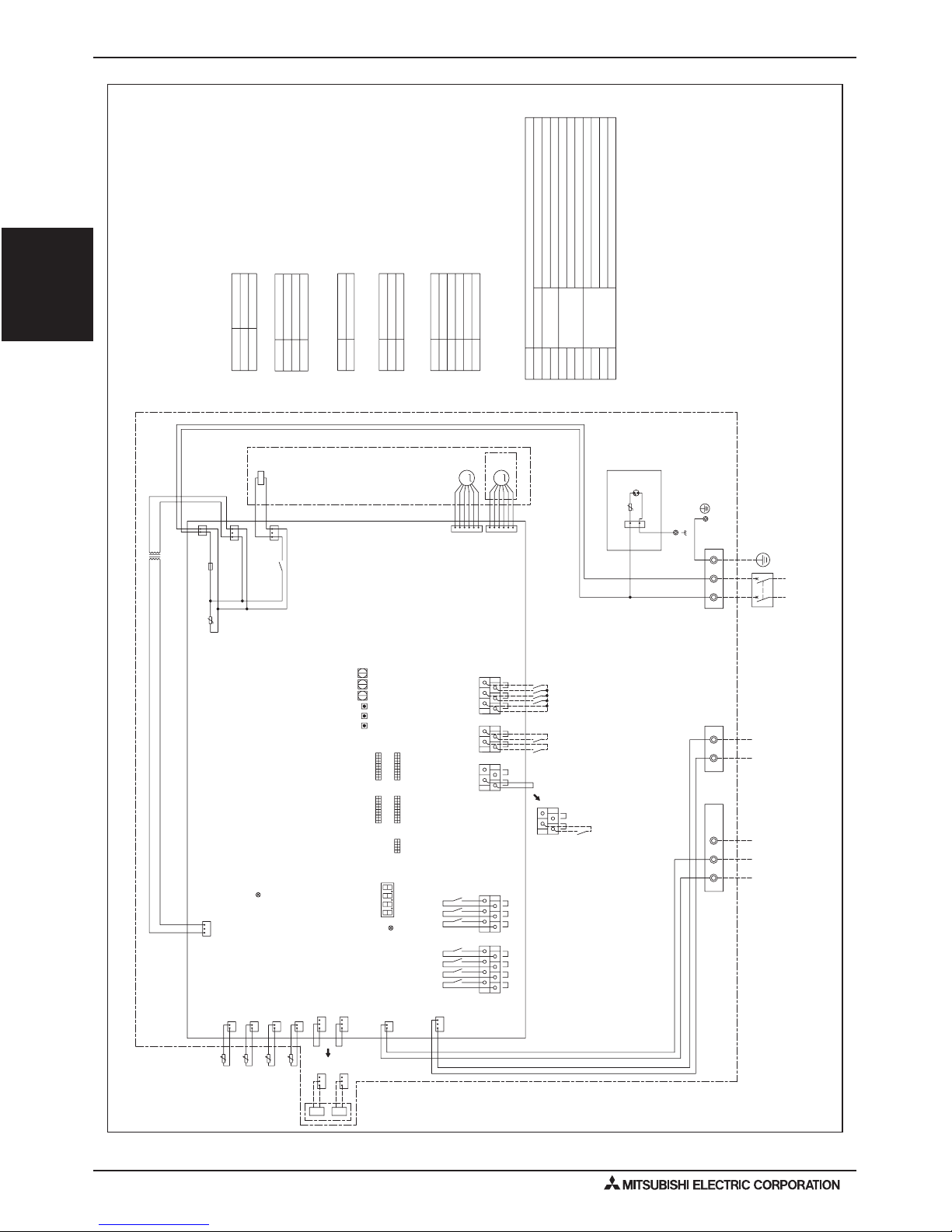
Explanation
Function
Function
Function
Function
Appliance
Terminal
block
Linear
expansion valve
Solenoid valve
Power supply
BC controller/outdoor unit
For opening/closing the bypass circuit
Outdoor unit/BC controller
BC controller/outdoor unit
*3
MA remote controller
Operation ON/OFF
Pump interlock
Connection demand
*3 do not exist
Common
Operation ON/OFF
*3 exist
Heating
Heating ECO
Anti-freeze
Cooling
Defrost
liquid pipe temp
gas pipe temp
water inlet temp
Error signal
water outlet temp
Symbol
Symbol
Symbol
Symbol
Model name
Symbol
Thermistor
<Symbol explanation>
<CAUTION FOR INSTALLATION>
· Prior to installation, read the Installation Manual carefully.
*1. Single-dotted lines indicate wiring not supplied with the unit.
*2. Dot-dash lines indicate the control box boundaries.
*3. Difference of appliance
*4 TB141A(output)
*5 TB142A(input)
*6 TB142B(input)
*7 TB142C(input)
*8. Use copper supply wires.
°t°
t
°
t
°
5. ELECTRICAL WIRING DIAGRAMS
PWFY-P36,72NMU-E-AU
PWFY-11PWFY-P-NMU-E-BU/PWFY-P-NMU-E-AU (Sept. 2010)
PWFY-P-NMU-E-BU
PWFY-P-NMU-E-AU
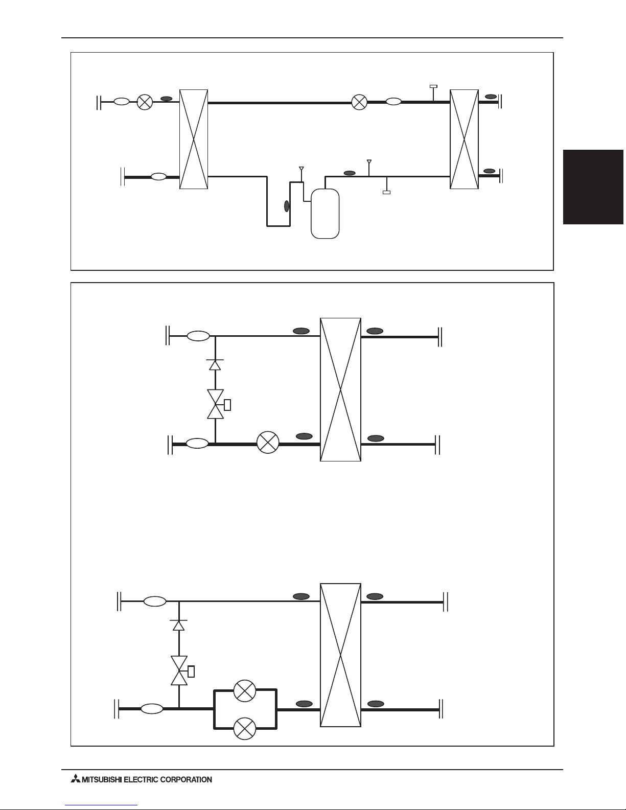
6. REFRIGERANT CIRCUIT DIAGRAMS
TH6
TH23
LEV1Wa
TH8
TH22
SV
CV1
ST2
ST3
Water inlet
Water outlet
screw
screw
Brazed
Brazed
TH6
TH23
LEV1Wa
TH8
TH22
LEV1Wb
SV
ST2
ST4
CV1
Water inlet
Water outlet
screw
screw
Brazed
Brazed
PWFY-P36NMU-E-AU
PWFY-P72NMU-E-AU
PWFY-P36NMU-E-BU
TH11
63H1
63HS
63LS
TH13
TH22
LEV1W
LEV2W
COMP
Water outlet
TH6
TH8
ST3
ST1
ST2
CJ
Brazed
Brazed
screw
screw
Water inlet
Hex
Hex
PWFY-12
PWFY-P-NMU-E-BU/PWFY-P-NMU-E-AU (Sept. 2010)
PWFY-P-NMU-E-BU
PWFY-P-NMU-E-AU
7. SOUND PRESSURE LEVELS
0
10
30
20
40
50
60
70
80
90
63 125 250 500 1k 2k 4k 8k
NC-40
NC-30
NC-20
NC-60
NC-50
NC-70
Octave band sound level (dB)
Sound pressure level of PWFY-P36NMU-E-BU
Measurement condition
PWFY-P36NMU-E-BU
60Hz
Octave band center frequencies <Hz>
Octave band sound level (dB)
Sound pressure level of PWFY-P36, 72NMU-E-AU
dB(A)
29.0
8k
12.0
4k
15.0
2k
14.5
1k
22.5
500
25.0
250
33.0
125
32.0
63
42.0
60Hz
dB(A)
44.0
8k
27.0
4k
27.5
2k
32.0
1k
39.0
500
42.0
250
37.0
125
53.5
63
41.0
Measurement condition
PWFY-P36, 72NMU-E-AU
Measurement
location
3-1/4 ft. (1m)
3-1/4 ft. (1m)
Measurement
location
3-1/4 ft. (1m)
3-1/4 ft. (1m)
Octave band center frequencies <Hz>
Approximate minimum
audible limit on
continuous noise
0
10
30
20
40
50
60
70
80
90
63 125 250 500 1k 2k 4k 8k
NC-40
NC-30
NC-20
NC-60
NC-50
NC-70
Approximate minimum
audible limit on
continuous noise
7-1. Sound Pressure Levels and NC Curves

PWFY-13PWFY-P-NMU-E-BU/PWFY-P-NMU-E-AU (Sept. 2010)
PWFY-P-NMU-E-BU
PWFY-P-NMU-E-AU
8. VIBRATION LEVELS
PWFY-P36NMU-E-BU
PWFY-P36NMU-E-BU
Model Vibration Levels[dBA]
34
3-15/16 in (100mm)
7-7/8 in (200mm)
Measurement
location
Service
panel
Concrete
VIBRATION LEVELS

PWFY-14
PWFY-P-NMU-E-BU/PWFY-P-NMU-E-AU (Sept. 2010)
PWFY-P-NMU-E-BU
PWFY-P-NMU-E-AU
9. CAPACITY TABLES
9-1. Correction by Temperature
Y-Series + PWFY-P36/72NMU-E-AU
PUHY-P72,96T(Y)JMU-A-BS
Cooling
0. 4
0. 6
0. 8
1. 0
1. 2
1. 4
20 30 40 50 60 70 80 90 100 110 120
Outdoor Temperature(FDB)
Inlet water Temperature(F)
Ratio of cooling capacity
0. 5
0. 6
0. 7
0. 8
0. 9
1. 0
1. 1
1. 2
1. 3
1. 4
20 30 40 50 60 70 80 90 100 110 120
Outdoor Temperature(FDB)
Ratio of cooling input
Inlet water Temperature(F)
Heating
0. 2
0. 4
0. 6
0. 8
1. 0
1. 2
-5 0 5 10 15 20 25 30 35 40 45 50 55 60
Inlet Water Temperature(F)
Ratio of heating capacity
Outdoor Temperature(FDB)
0. 4
0. 5
0. 6
0. 7
0. 8
0. 9
1. 0
1. 1
1. 2
-5 0 5 10 15 20 25 30 35 40 45 50 55 60
Outdoor Temperature(FWB)
Ratio of heating input
Inlet water Temperature(F)
PUHY-P120,144Y(T)JMU-A-BS
Cooling
Heating
0. 4
0. 6
0. 8
1. 0
1. 2
1. 4
20 30 40 50 60 70 80 90 100 110 120
Inlet Water Temperature(F)
Ratio of cooling capacity
95
86
77
68
59
50
Outdoor Temperature(FWB)
0. 2
0. 4
0. 6
0. 8
1. 0
1. 2
-5 0 5 10 15 20 25 30 35 40 45 50 55 60
Outdoor Temperature(FWB)
Inlet Water Temperature(F)
Ratio of heating capacity
50
68
86
95
105
0. 5
0. 6
0. 7
0. 8
0. 9
1. 0
1. 1
1. 2
1. 3
1. 4
20 30 40 50 60 70 80 90 100 110 120
Outdoor Temperature(FDB)
Inlet Water Temperature(F)
Ratio of cooling input
95
86
77
68
59
50
0. 4
0. 5
0. 6
0. 7
0. 8
0. 9
1. 0
1. 1
1. 2
-5 0 5 10 15 20 25 30 35 40 45 50 55 60
Outdoor Temperature(FWB)
Inlet Water Temperature(F)
Ratio of heating input
105
95
86
68
50
95
86
77
68
59
50
50
68
86
95
105
95
86
77
68
59
50
105
95
86
68
50

PWFY-15PWFY-P-NMU-E-BU/PWFY-P-NMU-E-AU (Sept. 2010)
PWFY-P-NMU-E-BU
PWFY-P-NMU-E-AU
9. CAPACITY TABLES
PUHY-P168,192,216,240Y(T)SJMU-A-BS
HeatingCooling
0. 4
0. 6
0. 8
1. 0
1. 2
1. 4
20 30 40 50 60 70 80 90 100 110 120
Outdoor Temperature(FDB)
Inlet Water Temperature(F)
Ratio of cooling capacity
95
86
77
68
59
50
0. 4
0. 6
0. 8
1. 0
1. 2
1. 4
-5 0 5 10 15 20 25 30 35 40 45 50 55 60
Outdoor Temperature(FWB)
Inlet Water Temperature(F)
Ratio of heating capacity
50
68
86
95
105
0. 5
0. 6
0. 7
0. 8
0. 9
1. 0
1. 1
1. 2
1. 3
1. 4
20 30 40 50 60 70 80 90 100 110 120
Outdoor Temperature(FDB)
Inlet Water Temperature(F)
Ratio of cooling input
95
86
77
68
59
50
0. 4
0. 5
0. 6
0. 7
0. 8
0. 9
1. 0
1. 1
1. 2
-5 0 5 10 15 20 25 30 35 40 45 50 55 60
Outdoor Temperature(FWB)
Inlet Water Temperature(F)
Ratio of heating input
105
95
86
68
50
PUHY-P264,288T(Y)SJMU-A-BS
HeatingCooling
0. 4
0. 6
0. 8
1. 0
1. 2
1. 4
20 30 40 50 60 70 80 90 100 110 120
Outdoor Temperature(FDB)
Inlet Water Temperature(F)
Ratio of cooling capacity
95
86
77
68
59
50
0. 4
0. 5
0. 6
0. 7
0. 8
0. 9
1. 0
1. 1
1. 2
1. 3
-5 0 5 10 15 20 25 30 35 40 45 50 55 60
Outdoor Temperature(FWB)
Inlet Water Temperature(F)
Ratio of heating capacity
50
68
86
95
105
0. 5
0. 6
0. 7
0. 8
0. 9
1. 0
1. 1
1. 2
1. 3
1. 4
20 30 40 50 60 70 80 90 100 110 120
Outdoor Temperature(FDB)
Inlet Water Temperature(F)
Ratio of cooling input
95
86
77
68
59
50
0. 4
0. 5
0. 6
0. 7
0. 8
0. 9
1. 0
1. 1
1. 2
1. 3
-5 0 5 10 15 20 25 30 35 40 45 50 55 60
Outdoor Temperature(FWB)
Inlet Water Temperature(F)
Ratio of heating input
105
95
86
68
50

PWFY-16
PWFY-P-NMU-E-BU/PWFY-P-NMU-E-AU (Sept. 2010)
PWFY-P-NMU-E-BU
PWFY-P-NMU-E-AU
9. CAPACITY TABLES
PUHY-P312,336,360T(Y)SJMU-A-BS
HeatingCooling
0. 4
0. 5
0. 6
0. 7
0. 8
0. 9
1. 0
1. 1
1. 2
1. 3
-5 0 5 10 15 20 25 30 35 40 45 50 55 60
Outdoor Temperature(FWB)
Inlet Water Temperature(F)
Ratio of heating capacity
50
68
86
95
105
0. 5
0. 6
0. 7
0. 8
0. 9
1. 0
1. 1
1. 2
1. 3
1. 4
20 30 40 50 60 70 80 90 100 110 120
Outdoor Temperature(FDB)
Inlet Water Temperature(F)
Ratio of cooling input
95
86
77
68
59
50
0. 4
0. 6
0. 8
1. 0
1. 2
1. 4
20 30 40 50 60 70 80 90 100 110 120
Outdoor Temperature(FDB)
Inlet Water Temperature(F)
Ratio of cooling capacity
95
86
77
68
59
50
0. 4
0. 5
0. 6
0. 7
0. 8
0. 9
1. 0
1. 1
1. 2
-5 0 5 10 15 20 25 30 35 40 45 50 55 60
Outdoor Temperature(FWB)
Inlet Water Temperature(F)
Ratio of heating input
105
95
86
68
50

PWFY-17PWFY-P-NMU-E-BU/PWFY-P-NMU-E-AU (Sept. 2010)
PWFY-P-NMU-E-BU
PWFY-P-NMU-E-AU
9. CAPACITY TABLES
R2-Series + PWFY-P36/72NMU-E-AU
PURY-P72,96T(Y)JMU-A-BS
Cooling
Heating
0. 4
0. 6
0. 8
1. 0
1. 2
1. 4
20 30 40 50 60 70 80 90 100 110 120
Outdoor Temperature(FDB)
Inlet water Temperature(F)
Ratio of cooling capacity
95
86
77
68
59
50
0. 4
0. 5
0. 6
0. 7
0. 8
0. 9
1. 0
1. 1
1. 2
1. 3
-5 0 5 10 15 20 25 30 35 40 45 50 55 60 65 70 75 80 85 90
Outdoor Temperature(FWB)
Inlet Water Temperature(F)
Ratio of heating capacity
50
68
86
95
105
0. 5
0. 6
0. 7
0. 8
0. 9
1. 0
1. 1
1. 2
1. 3
1. 4
20 30 40 50 60 70 80 90 100 110 120
Outdoor Temperature(FDB)
Inlet water Temperature(F)
Ratio of cooling input
95
86
77
68
59
50
0. 4
0. 5
0. 6
0. 7
0. 8
0. 9
1. 0
1. 1
1. 2
-5 0 5 10 15 20 25 30 35 40 45 50 55 60 65 70 75 80 85 90
Outdoor Temperature(FWB)
Inlet Water Temperature(F)
Ratio of heating input
105
95
86
68
50
PURY-P120,144T(Y)JMU-A-BS
Cooling
Heating
0. 4
0. 6
0. 8
1. 0
1. 2
1. 4
20 30 40 50 60 70 80 90 100 110 120
Outdoor Temperature(FDB)
Inlet Water Temperature(F)
Ratio of cooling capacity
95
86
77
68
59
50
0. 2
0. 4
0. 6
0. 8
1. 0
1. 2
-5 0 5 10 15 20 25 30 35 40 45 50 55 60 65 70 75 80 85 90
Outdoor Temperature(FWB)
Inlet Water Temperature(F)
Ratio of heating capacity
50
68
86
95
105
0. 5
0. 6
0. 7
0. 8
0. 9
1. 0
1. 1
1. 2
1. 3
1. 4
20 30 40 50 60 70 80 90 100 110 120
Outdoor Temperature(FDB)
Inlet Water Temperature(F)
Ratio of cooling input
95
86
77
68
59
50
0. 4
0. 5
0. 6
0. 7
0. 8
0. 9
1. 0
1. 1
1. 2
1. 3
-5 0 5 10 15 20 25 30 35 40 45 50 55 60 65 70 75 80 85 90
Outdoor Temperature(FWB)
Inlet Water Temperature(F)
Ratio of heating input
105
95
86
68
50

PWFY-18
PWFY-P-NMU-E-BU/PWFY-P-NMU-E-AU (Sept. 2010)
PWFY-P-NMU-E-BU
PWFY-P-NMU-E-AU
9. CAPACITY TABLES
PURY-P168,192,216,240T(Y)JMU-A-BS
Cooling
Heating
0. 4
0. 6
0. 8
1. 0
1. 2
1. 4
20 30 40 50 60 70 80 90 100 110 120
Outdoor Temperature(FDB)
Inlet Water Temperature(F)
Ratio of cooling capacity
95
86
77
68
59
50
0. 2
0. 4
0. 6
0. 8
1. 0
1. 2
-5 0 5 10 15 20 25 30 35 40 45 50 55 60 65 70 75 80 85 90
Outdoor Temperature(FWB)
Inlet Water Temperature(F)
Ratio of heating capacity
50
68
86
95
105
0. 5
0. 6
0. 7
0. 8
0. 9
1. 0
1. 1
1. 2
1. 3
1. 4
20 30 40 50 60 70 80 90 100 110 120
Outdoor Temperature(FDB)
Inlet Water Temperature(F)
Ratio of cooling input
95
86
77
68
59
50
0. 2
0. 4
0. 6
0. 8
1. 0
1. 2
-5 0 5 10 15 20 25 30 35 40 45 50 55 60 65 70 75 80 85 90
Outdoor Temperature(FWB)
Inlet Water Temperature(F)
Ratio of heating input
105
95
86
68
50
PURY-P264,288T(Y)JMU-A-BS
Cooling
Heating
0. 4
0. 6
0. 8
1. 0
1. 2
1. 4
20 30 40 50 60 70 80 90 100 110 120
Ratio of cooling capacity
Outdoor Temperature(FDB)
Inlet Water Temperature(F)
95
86
77
68
59
50
0. 4
0. 5
0. 6
0. 7
0. 8
0. 9
1. 0
1. 1
1. 2
1. 3
-5 0 5 10 15 20 25 30 35 40 45 50 55 60 65 70 75 80 85 90
Outdoor Temperature(FWB)
Inlet Water Temperature(F)
Ratio of heating capacity
50
68
86
95
105
0. 5
0. 6
0. 7
0. 8
0. 9
1. 0
1. 1
1. 2
1. 3
1. 4
20 30 40 50 60 70 80 90 100 110 120
Outdoor Temperature(FDB)
Inlet Water Temperature(F)
Ratio of cooling input
95
86
77
68
59
50
0. 4
0. 5
0. 6
0. 7
0. 8
0. 9
1. 0
1. 1
1. 2
1. 3
-5 0 5 10 15 20 25 30 35 40 45 50 55 60 65 70 75 80 85 90
Outdoor Temperature(FWB)
Inlet Water Temperature(F)
Ratio of heating input
105
95
86
68
50

PWFY-19PWFY-P-NMU-E-BU/PWFY-P-NMU-E-AU (Sept. 2010)
PWFY-P-NMU-E-BU
PWFY-P-NMU-E-AU
9. CAPACITY TABLES
H2I Series + PWFY-P36/72NMU-E-AU
PUHY-HP72,96Y(T)JMU-A-BS
PUHY-HP144,192Y(T)SJMU-A-BS
0. 4
0. 6
0. 8
1. 0
1. 2
1. 4
20 30 40 50 60 70 80 90 100 110 120
Outdoor Temperature(FDB)
Inlet Water Temperature(F)
Ratio of cooling capacity
95
86
77
68
59
50
0. 2
0. 4
0. 6
0. 8
1. 0
1. 2
- 15 - 10 -5 0 5 10 15 20 25 30 35 40 45 50 55 60
Outdoor Temperature(FWB)
Inlet Water Temperature(F)
Ratio of heating capacity
50
68
86
104
0. 5
0. 6
0. 7
0. 8
0. 9
1. 0
1. 1
1. 2
1. 3
1. 4
20 30 40 50 60 70 80 90 100 110 120
Outdoor Temperature(FDB)
Inlet Water Temperature(F)
Ratio of cooling input
95
86
77
68
59
50
0. 4
0. 6
0. 8
1. 0
1. 2
1. 4
1. 6
1. 8
- 15 - 10 -5 0 5 10 15 20 25 30 35 40 45 50 55 60
Outdoor Temperature(FWB)
Inlet Water Temperature(F)
Ratio of heating input
86
68
50
104

PWFY-20
PWFY-P-NMU-E-BU/PWFY-P-NMU-E-AU (Sept. 2010)
PWFY-P-NMU-E-BU
PWFY-P-NMU-E-AU
9. CAPACITY TABLES
0.5
0.6
0.7
0.8
0.9
1.0
1.1
-5 5 15 25 35 45 55 65 75 85
Outdoor temp. [ FWB]
Ratio of heat i ng capacity
68
50
86
104
122
140
149
Booster uni t inlet - water t emp. [F]
0.2
0.3
0.4
0.5
0.6
0.7
0.8
0.9
1.0
1.1
-5 5 15 25 35 45 55 65 75 85
Outdoor temp. [ FWB]
Ratio of boos t er uni t input
685086
104
Booster uni t inlet - water t emp.[F]
122
140
149
0.6
0.7
0.8
0.9
1.0
1.1
-5 5 15 25 35 45 55 65 75 85
Outdoor temp. [ FWB]
Ratio of out door unit input
104
122
86
140
68
149
50
Booster uni t inlet - water t emp. [F]
R2-Series + PWFY-P36NMU-E-BU
PURY-P72,96T(Y)JMU-A-BS

PWFY-21PWFY-P-NMU-E-BU/PWFY-P-NMU-E-AU (Sept. 2010)
PWFY-P-NMU-E-BU
PWFY-P-NMU-E-AU
9. CAPACITY TABLES
0.5
0.6
0.7
0.8
0.9
1.0
1.1
-5 5 15 25 35 45 55 65 75 85
Outdoor temp. [ FWB]
Ratio of heati ng capacity
Booster uni t inlet - wat er t emp. [F]
68
50
86
104
122
140
149
0.2
0.3
0.4
0.5
0.6
0.7
0.8
0.9
1.0
1.1
-5 5 15 25 35 45 55 65 75 85
Outdoor temp. [ FWB]
Ratio of boost er uni t input
Booster uni t inlet - wat er t emp. [F]
68
50
86
104
122
140
149
0.5
0.6
0.7
0.8
0.9
1.0
1.1
-5 5 15 25 35 45 55 65 75 85
Out door t emp. [FWB]
Ratio of outdoor unit input
Booster uni t inlet - wat er t emp. [F]
104
122
86
140
68
149
50
0.5
0.6
0.7
0.8
0.9
1.0
1.1
-5 5 15 25 35 45 55 65 75 85
Outdoor temp. [ FWB]
Ratio of heati ng capacity
Booster uni t inlet - wat er t emp. [F]
685086
104
122
140
149
0.2
0.3
0.4
0.5
0.6
0.7
0.8
0.9
1.0
1.1
-5 5 15 25 35 45 55 65 75 85
Outdoor temp. [ FWB]
Ratio of boost er uni t input
Booster uni t inlet - wat er t emp. [F]
68
50
86
104
122
140
149
0.5
0.6
0.7
0.8
0.9
1.0
1.1
-5 5 15 25 35 45 55 65 75 85
Outdoor temp. [ FWB]
Ratio of outdoor unit input
Booster uni t inlet - wat er t emp. [F]
104
122
86
140
68
149
50
0.5
0.6
0.7
0.8
0.9
1.0
1.1
-5 5 15 25 35 45 55 65 75 85
Outdoor temp. [ FWB]
Ratio of heati ng capacity
Booster uni t inlet - wat er t emp. [F]
685086
104
122
140
149
0.2
0.3
0.4
0.5
0.6
0.7
0.8
0.9
1.0
1.1
-5 5 15 25 35 45 55 65 75 85
Outdoor temp. [ FWB]
Ratio of boost er uni t input
Booster uni t inlet - wat er t emp. [F]
68
50
86
104
122
140
149
0.6
0.7
0.8
0.9
1.0
1.1
-5 5 15 25 35 45 55 65 75 85
Outdoor temp. [ FWB]
Ratio of outdoor unit input
Booster uni t inlet - wat er t emp. [F]
104
122
86
140
68
149
50
R2-Series + PWFY-P36NMU-E-BU
PURY-P120,144T(Y)JMU-A-BS

PWFY-22
PWFY-P-NMU-E-BU/PWFY-P-NMU-E-AU (Sept. 2010)
PWFY-P-NMU-E-BU
PWFY-P-NMU-E-AU
0.5
0.6
0.7
0.8
0.9
1.0
1.1
-5 5 15 25 35 45 55 65 75 85
Outdoor temp. [ FWB]
Ratio of heati ng capacity
Booster uni t inlet - wat er t emp. [F]
68
50
86
104
122
140
149
0.2
0.3
0.4
0.5
0.6
0.7
0.8
0.9
1.0
1.1
-5 5 15 25 35 45 55 65 75 85
Outdoor temp. [ FWB]
Ratio of boost er uni t input
Booster uni t inlet - wat er t emp. [F]
68
50
86
104
122
140
149
0.5
0.6
0.7
0.8
0.9
1.0
1.1
-5 5 15 25 35 45 55 65 75 85
Outdoor temp. [ FWB]
Ratio of outdoor unit input
Booster uni t inlet - wat er t emp. [F]
104
122
86
140
68
149
50
0.5
0.6
0.7
0.8
0.9
1.0
1.1
-5 5 15 25 35 45 55 65 75 85
Outdoor temp. [ FWB]
Ratio of heati ng capacity
Booster uni t inlet - wat er t emp. [F]
68
50
86
104
122
140
149
0.2
0.3
0.4
0.5
0.6
0.7
0.8
0.9
1.0
1.1
-5 5 15 25 35 45 55 65 75 85
Outdoor temp. [ FWB]
Ratio of boost er uni t input
Booster uni t inlet - wat er t emp. [F]
68
50
86
104
122
140
149
0.6
0.7
0.8
0.9
1.0
1.1
-5 5 15 25 35 45 55 65 75 85
Outdoor temp. [ FWB]
Ratio of outdoor unit input
Booster uni t inlet - wat er t emp. [F]
104
122
86
140
68
149
50
R2-Series + PWFY-P36NMU-E-BU
PURY-P168,192,216,240T(Y)JMU-A-BS
9. CAPACITY TABLES

PWFY-23PWFY-P-NMU-E-BU/PWFY-P-NMU-E-AU (Sept. 2010)
PWFY-P-NMU-E-BU
PWFY-P-NMU-E-AU
0.5
0.6
0.7
0.8
0.9
1.0
1.1
-5 5 15 25 35 45 55 65 75 85
Outdoor temp. [ FWB]
Ratio of heati ng capacity
Booster uni t inlet - wat er t emp. [F]
68
50
86
104
122
140
149
0.2
0.3
0.4
0.5
0.6
0.7
0.8
0.9
1.0
1.1
-5 5 15 25 35 45 55 65 75 85
Outdoor temp. [ FWB]
Ratio of boost er uni t input
Booster uni t inlet - wat er t emp. [F]
68
50
86
104
122
140
149
0.6
0.7
0.8
0.9
1.0
1.1
-5 5 15 25 35 45 55 65 75 85
Outdoor temp. [ FWB]
Ratio of outdoor unit input
Booster uni t inlet - wat er t emp. [F]
104
122
86
140
68
149
50
9. CAPACITY TABLES
R2-Series + PWFY-P36NMU-E-BU
PURY-P264,288T(Y)JMU-A-BS

PWFY-24
PWFY-P-NMU-E-BU/PWFY-P-NMU-E-AU (Sept. 2010)
PWFY-P-NMU-E-BU
PWFY-P-NMU-E-AU
9. CAPACITY TABLES
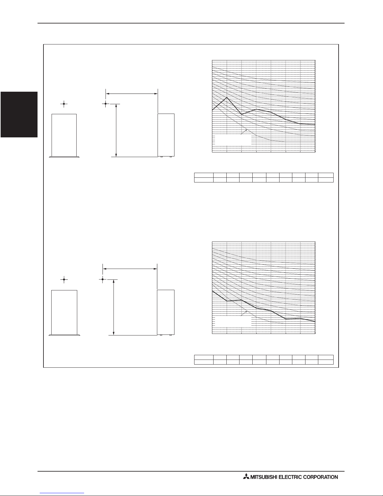
9-2. Water Pressure Drop
PWFY-P36NMU-E-BU
0
3.3 (10)
6.6 (20)
10 (30)
13.3 (40)
16.6 (50)
2.2 (0.5) 4.4 (1) 6.6 (1.5
)8
.8 (2)
Water flow rate (GPM [m3/h])
Water-pressure drop (ft. [kPa])
PWFY-P36,72NMU-E-AU
0
3.3 (10)
6.6 (20)
10 (30)
13.6 (40)
16.6 (50)
20 (60)
23.3 (70)
26.6 (80)
30 (90)
33.3 (100)
Water flow rate (GPM [m3/h])
Water-pressure drop (ft. [kPa])
PWFY-P36NMU-E-AU
PWFY-P72NMU-E-AU
2.2 (0.5)
4.4 (1)
6.6 (1.5)
8.8 (2)
11 (2.5)
13.2 (3)
15.4 (3.5)
17.6 (4)
19 (4.5)

PWFY-25PWFY-P-NMU-E-BU/PWFY-P-NMU-E-AU (Sept. 2010)
PWFY-P-NMU-E-BU
PWFY-P-NMU-E-AU
10. OPTIONAL PARTS
Optional Parts Line Up for the Indoor Unit
(A) Strainer (B)
Heat insulation material
*1. PWFY-P72NMU-E-AU only
(C) Connecter sets 2(D) Washer 2
*1
(E) Expansion joint 2
(A) Install the strainer at the water pipe inlet.
(B) This insulation is for exclusive use with the strainer. Wrap the strainer with the insulation after water
pipes are installed.
(C) These are analog input connectors. Cut the wire before using.
(D) Fix power source wiring to terminal bed box by using buffer bushing for tensile force. (Conduit or the like.)
Connect transmission wiring to transmission terminal bed through the knockout hole of terminal bed box using
ordinary bushing.
(E) Supplied only with the PWFY-P72NMU-E-AU. Install them at the strainer inlet.

PWFY-26
PWFY-P-NMU-E-BU/PWFY-P-NMU-E-AU (Sept. 2010)
PWFY-P-NMU-E-BU
PWFY-P-NMU-E-AU
11-1-2. Electrical characteristics of Indoor unit
• Provideaswitchwithatleast3mm(1/8in)contactseparationineachpolewheninstallingtheairconditioner.
Model
Unit
Hz Volts
Voltage
range
RLA(A) MCA(A)
Max.
Fuse(A)
PWFY-P36NMU-E-AU
PWFY-P72NMU-E-AU
60Hz 208/230V 188 to 253V 0.072/0.065 0.09 15
Model
Unit Compressor
Hz Volts
Voltage
range
RLA(A) MCA(A)
Max.
Fuse(A)
SC(A)
PWFY-P36NMU-E-BU 60Hz 208/230V 188 to 253V 12.30/11.12 25 25 1.25
Symbols: MCA: Min. Circuit Amps (=1.25 x FLA)
11. SYSTEM DESIGN
11-1. Electrical Work
11-1-1. General Cautions
Warning:
Electricalworkshouldbeperformedbyqualiedelectricalengineersinaccordancewith“EngineeringStandardsForElectrical
Installation” and the supplied installation manuals. Special circuits should also be used. If the power circuit lacks capacity or has an
installationfailure,itmaycauseariskofelectricshockorre.
1. Follow ordinances of your government organization for technical standard related to electrical equipment, wiring regulations,
and guidances of each electrical power company.
2. Power should be taken from the special branch circuit.
3. Install a ground breaker to the power.
4. Install the unit so that the control circuit cables (remote controller, transmission cables, or external input/output line) is not
in direct contact with the power cable outside the unit.
5. Ensure that there is no slack on all wire connections.
6. Vermin may have access to and damage the power, remote controller, and transmission cables. To prevent damage, insert
cables into metal piping.
7. Do not connect the power cables to the transmission cable leads.
8. Connect control cables to the indoor unit, remote controller, and the outdoor unit.
9. Ground the unit.
10. Select control cables following instructions.
Caution:
Be sure to put the unit to the ground on the outdoor unit side. Do not connect the ground cable to any gas pipe, water pipe,
lightening rod, or telephone cable. Improper grounding may cause electric shock.

PWFY-27PWFY-P-NMU-E-BU/PWFY-P-NMU-E-AU (Sept. 2010)
PWFY-P-NMU-E-BU
PWFY-P-NMU-E-AU
11. SYSTEM DESIGN
11-2. M-NET Control
11-2-1. Transmission Cable Specications
*1 Connected with simple remote controller. CVVS, MVVS: PVC insulated PVC jacketed shielded control cable
CVV, MVV : PVC insulated PVC sheathed control cable
CPEVS : PE insulated PVC jacketed shielded communication cable
PWFY-P36NMU-E-BU
Transmission Cables MA Remote Controller Cables External Input External Output
Type of
Cable
Shielding wire (2-core)
CVVS, CPEVS or MVVS
Sheathed 2-core cable (shielded)
CVVS
Sheathed multi-core cable
(shielded)
CVVS or MVVS
Sheathed multi-core cable (unshielded)
CVV or MVV
Cable
Diameter
More than 1.25 mm
2
[AWG16]
1.25 mm
2
[AWG16]
(1.25 mm
2
[AWG16]
)*1
1.25 mm
2
[AWG16]
1.25 mm
2
[AWG16]
Remarks -
Max.length: 200 m [656 ft] Max. length: 100 m [328 ft]
Rated voltage: L1-N: 220
~240 V
Rated load: 0.6 A
Transmission Cables MA Remote Controller Cables External Input External Output
Type of
Cable
Shielding wire (2-core)
CVVS, CPEVS or MVVS
Sheathed 2-core cable CVV
(unshielded)
Sheathed multi-core cable
CVV or MVV (unshielded)
Sheathed multi-core cable
(unshielded) CVV or MVV
Cable
Diameter
More than 1.25 mm
2
[AWG16]
1.25 mm
2
[AWG16]
(1.25 mm
2
[AWG16]
)*1
1.25 mm
2
[AWG16]
1.25 mm
2
[AWG16]
Remarks -
Max.length: 200 m [656 ft] Max. length: 100 m [328 ft]
Rated voltage: L1-N: 220
~240 V
Rated load: 0.6 A
PWFY-P36,72NMU-E-AU
11-2-2. Address Setting
Switch Operation
Operate with the main power turned OFF
•Therearetwotypesofrotaryswitchsettingavailable:settingaddresses1to9andover10,andsettingbranchnumbers.
a) How to set addresses
Example:IfAddressis“3”,remainSWU2(forover10)at“0”,andmatchSWU1(for1to9)with“3”.
b) How to set branch numbers SWU3 (Series R2 only)
Matchtheindoorunit’srefrigerantpipewiththeBCcontroller’sendconnectionnumber.RemainotherthanR2at“0”.
•Therotaryswitchesareallsetto“0”whenshippedfromthefactory.Theseswitchescanbeusedtosetunitaddressesand
branch numbers at will.
SWU2 SWU3
SWU1

PWFY-28
PWFY-P-NMU-E-BU/PWFY-P-NMU-E-AU (Sept. 2010)
PWFY-P-NMU-E-BU
PWFY-P-NMU-E-AU
11. SYSTEM DESIGN
11-2-3. Setting Addresses
Unit
PWFY unit
Standard indoor unit
ME, LOSSNAY
Remote controller
(Main)
ME, LOSSNAY
Remote controller
(Sub)
Address setting
01 ~ 50
52 ~ 99, 100
101 ~ 150
151 ~ 199, 200
NoteExample
The address of outdoor unit + 1
Please reset one of them to an address between 52
and 99 when two addresses overlap.
The address automatically becomes "100" if it is set
as "01~ 50"
The smallest address of indoor unit in the group + 100
The place of "100" is fixed to "1"
System remote
controller
ON/OFF remote
controller
AG-150
GB-50
000, 201 ~ 250
000, 201 ~ 250
000, 201 ~ 250
Local remote controller
System controller
The address of main remote controller + 50
The address automatically becomes "200" if it is set
as "00"
10 1
10 1
0
1
2
3
4
5
6
7
8
9
0
1
2
3
4
5
6
7
8
9
10 1
10 1
0
1
2
3
4
5
6
7
8
9
0
1
2
3
4
5
6
7
8
9
0
1
2
3
4
5
6
7
8
9
0
1
2
3
4
5
6
7
8
9
0
1
2
3
4
5
6
7
8
9
0
1
2
3
4
5
6
7
8
9
0
1
2
3
4
5
6
7
8
9
0
1
2
3
4
5
6
7
8
9
0
1
2
3
4
5
6
7
8
9
10 1
10 1100
0
1
2
3
4
5
6
7
8
9
0
1
2
3
4
5
6
7
8
9
0
1
2
3
4
5
6
7
8
9
10 1100
10 1100
LMAP03U
201 ~ 250
1
1
Fixed
Fixed
Group remote
controller
201 ~ 250
The smallest group No. to be managed + 200
10 1
2
Fixed
2
Fixed
Outdoor unit
BC controller
(Main)
53 ~ 99, 100
Lowest address within the indoor units connected to
the BC controller (Sub) plus 50.
10 1
BC controller
(Sub)
51 ~ 99, 100
The smallest address of indoor unit in same refrigerant
system + 50
Assign sequential address numbers to the outdoor
units in one refrigerant circuit system. OC and OS are
automatically detected. (Note 2)
Please reset one of them to an address between 51
and 99 when two addresses overlap.
The address automatically becomes "100" if it is set
as "01~ 50"
Use the most recent address within the same group of
indoor units. Make the indoor units address connected
to the BC controller (Sub) larger than the indoor units
address connected to the BC controller (Main).
If applicable, set the sub BC controllers in an PURY
system in the following order:
(1)
Indoor unit to be connected to the BC controller (Main)
(2)
Indoor unit to be connected to the BC controller (No.1 Sub)
(3)
Indoor unit to be connected to the BC controller (No.2 Sub)
Set the address so that (1)<(2)<(3)
0
1
2
3
4
5
6
7
8
9
0
1
2
3
4
5
6
7
8
9
0
1
2
3
4
5
6
7
8
9
0
1
2
3
4
5
6
7
8
9
0
1
2
3
4
5
6
7
8
9
0
1
2
3
4
5
6
7
8
9
0
1
2
3
4
5
6
7
8
9
0
1
2
3
4
5
6
7
8
9
10 1
(Note1)
0,2 0~50~9
BAC-HD150
000, 201 ~ 250
10 1100
0,20~5 0~9
Settings are made with setting tool of BM ADAPTER.
Note1: To set the address to "100", set it to "50"
Note2: Outdoor units OC and OS in one refrigerant circuit system are automatically detected.
OC and OS are ranked in descending order of capacity. If units are the same capacity, they are ranked in ascending
order of their address.

PWFY-29PWFY-P-NMU-E-BU/PWFY-P-NMU-E-AU (Sept. 2010)
PWFY-P-NMU-E-BU
PWFY-P-NMU-E-AU
11-2-4. System Examples
11. SYSTEM DESIGN
2. Address should be set to Indoor units, LOSSNAY and central controller.
3. M-NET power is supplied by the Outdoor unit at TB3, while Indoor unit and MA RC consume the M-NET power for transmission
use. For details, refer System configuration restrictions".
NOTE:
1. Outdoor units OC and OS in one refrigerant circuit system are automatically detected.
OC and OS are ranked in descending order of capacity. If units are the same capacity, they are ranked in ascending order
of their address.
Indoor unit
Indoor unit
PWFY-P36NMU-E-BU
PWFY-P36NMU-E-AU
PWFY-P72NMU-E-AU
PWFY-P36NMU-E-BU
PWFY-P36NMU-E-AU
PWFY-P72NMU-E-AU
C/R AMWMA
(Main) (Sub)
MA R/C
SRU
Wireless R/C
*1
*2 System controller should connect to TB7 at Outdoor and use power supply unit together in Multi-Refrigerant-System.
*1
01
BC controller
53
BC controller
(Main)
93
033020
TB15
TB5 5BT20BT 2BT5BT
Transmission Booster
PAC-SF46EPA
TB5
3BT51BT51BT
TB15
MA R/C
(Main) (Sub)
MA R/C
TB15
ME R/C
MA R/C
PZ-52SF
SRU
Wireless R/C
*1
*1 142 143
41 42
43
95
45 46
TB15
TB5 5BT20BT
LOSSNAY
5BT5BT5BT
TB15
*1 For Wireless R/C and Signal receiver unit (SRU), channel 1, 2 and 3 are selectable and should be set to same channel.
BC controller
(Sub1)
Group 2
12 puorG1 puorG
Group 32 43 puorG33 puorG13 puorG
TB3
TB7 7BT7BT7BT
TB7
TB3
201
PSU
5251
OC OS
PURY-P-TSHMU/YSHMU
SC
TB3TB3
9291
OC OS
PURY-P-TSHMU/YSHMU
TB3
97
OC
CN41CN40CN41CN40 CN41CN40CN41 14NC04NC CN40
ON
DipSW2-1
ON
DipSW2-1
ON
DipSW2-1
ON
DipSW2-1
ON
DipSW2-1
PURY-P-TSHMU/YSHMU
4. Indoor units should be set with a branch number.
5. Assign an address to each of the sub BC controllers (SC1 and SC2) which equals the sum of the smallest address of the indoor
units that are connected to each sub BC controller and 50.
*2
MA Remote Controller, Multi-refrigerant system, System Controller at TB7 side.
PWFY-P36NMU-E-BU/PWFY-P36,72NMU-E-AU with R2-Series Outdoor Units

PWFY-30
PWFY-P-NMU-E-BU/PWFY-P-NMU-E-AU (Sept. 2010)
PWFY-P-NMU-E-BU
PWFY-P-NMU-E-AU
PWFY-P36,72NMU-E-AU with Y-Series Outdoor Units
11. SYSTEM DESIGN
2. Address should be set to Indoor units, LOSSNAY and central controller.
3. M-NET power is supplied by the Outdoor unit at TB3, while Indoor unit and MA consume the M-NET power for transmission use.
For details, refer to "System configuration restrictions".
NOTE:
1. Outdoor units OC, OS1 and OS2 in one refrigerant circuit system are automatically detected.
OC, OS1 and OS2 are ranked in descending order of capacity. If units are the same capacity, they are ranked in ascending order
of their address.
Indoor unit
PWFY-P36NMU-E-AU
PWFY-P72NMU-E-AU
PWFY-P36NMU-E-AU
PWFY-P72NMU-E-AU
MA
(Main)
WMA
MA
*2 System controller should connect to TB7 at Outdoor and use power supply unit together in Multi-Refrigerant-System.
03302010
TB15
5BT5B
T2
BT5BT
Transmission Booster
PAC-SF46EPA
TB5
3BT51BT51BT
TB15
MA
(Main)MA(Sub)
TB15
PWFY-P36NMU-E-AU
PWFY-P72NMU-E-AU
WMA MA
41 42
43
45 46
TB15
5BT5BT
LOSSNAY
5BT5BT5BT
TB15
SRU
Wireless R/C
*1
*1
*1 For Wireless R/C and Signal receiver unit (SRU), channel 1, 2 and 3 are selectable and should be set to same channel.
Group 2
12 puorG1 puorG
Group 32 43 puorG33 puorG13 puorG
TB3 TB3
TB7 7BT7BT7BT7BT
TB7
TB3
201
PSU
*2
535251
OC OS1 OS2
PUHY-P-YSHMU
SC
TB3TB3
9291
OC OS1
PUHY-P-YSHMU
TB3
97
OC
CN41CN40CN41CN40CN41CN40 CN41CN40CN4114NC04NC CN40
ON
DipSW2-1
ON
DipSW2-1
ON
DipSW2-1
ON
DipSW2-1
ON
DipSW2-1
ON
DipSW2-1
PUHY-P-YHMU
Wireless R/C
*1
*1

PWFY-31PWFY-P-NMU-E-BU/PWFY-P-NMU-E-AU (Sept. 2010)
PWFY-P-NMU-E-BU
PWFY-P-NMU-E-AU
11. SYSTEM DESIGN
11-2-5. External Input/Output Function
Preset temperature input (external analog input: 4mA-20mA)
External input is input through CN421, CN422 on the circuit board. (Fig. 1)
[Fig. 1]
Use the supplied connector.
If no temperature settings are made via the MA remote controller, the temperature changes with the current of generator.
Refer to the instructions manual that came with the MA remote controller for how to make the settings.
4 mA → 50 °F (10 °C) 20 mA → 160 °F (71 °C)
External output terminal
External output terminal (refer to Fig. 2) is ineffective when the circuit is open.
Refer to Table 1 for information about each contact.
The current in the circuit to be connected to the external output terminal must be 0.6A or less.
External input terminal
Wiring length must be within 328 ft. (100 m).
External input terminal (refer to Fig. 2).
Refer to Table 2 through Table 4 for information about each contact.
Onlythe“pumpinterlock”functionisineffectivewhenthecircuitisshort-circuited.
Connect a relay circuit to the external output terminal as shown in Fig. 3.
Thespecicationsoftherelaycircuittobeconnectedmustmeetthefollowingconditions.
Contact rating voltage >= DC15V
Contact rating current >= 0.1A
Minimum applicable load =< 1mA at DC
*1 PWFY-P36NMU-E-BU: Hot Water
PWFY-P36, 72NMU-E-AU: Heating
*2 Effective when SW 4-3 is set to ON.
*3 Effective when SW 4-4 is set to ON.
*4 PWFY-P36, 72NMU-E-AU only
*5 When Heating ECO mode is effective, the outlet water temp. will be changed based on ambient temp. automatically.
*6 When Anti-freeze mode is effective, the unit will work for keeping set water temp. automatically.
Note: Dip S/W 1-1 OFF: Water Inlet Temp.
Dip S/W 1-1 ON : Water Outlet Temp.
The factory setting for Dip SW 1-1 is OFF.
Signal priority = External input > centralized controller > remote controller
CN421
(BK)
(BU)
CN422
3
2
+
211
3
current
direction
Current generator
External
analog input
+
current
direction
CN421
(BK)(BU)
CN422
32211
3
[Fig. 2]
OUT4OUT3OUT2
TB141A
OUT1
IN1 IN2 IN3 IN4
IN5IN6 IN7 IN8
TB142CTB142BTB142A
COM+
[Table. 1]
OUT1 Operation ON/OFF
OUT2 Defrost
OUT3 Compressor
OUT4 Error Signal
IN1 Pump Interlock
[Table 2 TB142A]
IN3 Connection Demand
IN4 Operation ON/OFF
[Table 3 TB142B]
[Fig. 3]
COM+ Common
IN5 *1 Hot Water/Heating
IN6 *2 Heating ECO *5
IN7 *3 Antifreeze *6
IN8 *4 Cooling Operation
[Table 4 TB142C]

PWFY-32
PWFY-P-NMU-E-BU/PWFY-P-NMU-E-AU (Sept. 2010)
PWFY-P-NMU-E-BU
PWFY-P-NMU-E-AU
11. SYSTEM DESIGN
11-3-1. Installation
Selecting an installation site
• Do not install outdoors. The unit is not waterproof.
• Back up system is recommended in case of PWFY unit breakdown.
• The unit will get hot. Do not install in a location where heat gets trapped inside.
• Be sure to install unit in a place strong enough to withstand its weight.
Any lack of strength may cause unit to fall down, resulting in a personal injury.
• Do not install the unit where corrosive gas is generated.
• Have installation work in order to protect against earthquake.
Any installation deciency may cause unit to fall down, resulting in a personal injury.
• Pay a special attention to the place, such as a basement, etc. where refrigeration gas can stay, since refrigeration is
heavier than the air.
• Do not install the unit where combustible gas may leak.
- If the gas leaks and accumulates around the unit, an explosion may result.
• When installing the unit in a hospital, communication station, or similar place, provide sufcient protection against
noise.
- The inverter equipment, private power generator, high-frequency medical equipment, or radio communication equipment
may cause the air conditioner to operate erroneously, or fail to operate. Also, the air conditioner may affect such equipment
by creating noise that disturbs medical treatment or image broadcasting.
• Do not install the unit on a structure that may cause leakage.
- When the room humidity exceeds 80 % or when the drain pipe is clogged, condensation may drip from the indoor unit.
Perform collective drainage work together with the unit, as required.
Securing installation and service space
•Please secure the following service spaces after installation.
(All servicing can be performed from the front of the unit)
[Fig. 4]
(B)
a
b
c
(C)
(A)
Model
a
15-3/4
(400)
11-13/16
(300)
23-5/8
(600)
15-3/4
(400)
11-13/16
(300)
23-5/8
(600)
15-3/4
(400)
PWFY-P36NMU-E-BU PWFY-P36NMU-E-AU PWFY-P72NMU-E-AU
Unit : in (mm)
11-13/16
(300)
23-5/8
(600)
b
c
(A) Piping Space (right side)
(B) Top View
(C) Service Space (front side)
Combining indoor units with BC controllers and outdoor units
For combining indoor units with BC controllers and outdoor units, refer to section BC controllers and outdoor units installation
manual.
Warning:
• Be sure to install the unit in a location which can adequately support its weight.
- Ifthereisinsufcientstrengthtosupporttheunit’sweight,itcouldfallandcauseinjuries.

PWFY-33PWFY-P-NMU-E-BU/PWFY-P-NMU-E-AU (Sept. 2010)
PWFY-P-NMU-E-BU
PWFY-P-NMU-E-AU
11. SYSTEM DESIGN
+
+
A
. For Air conditioning using such as Panel Heaters, Floor Heating and Fan coil units
Required total heating capacity BTU
Safety factor; %
B. For Sanitary use such as Shower and Bathrooms
Conditions
Tank inlet water Temp.; °F
Tank outlet water Temp.; °F
(Set Temp 23 °F)
Safety factor for Heat Loss;%
Operating time;Hours
For Shower; G/Person xPerson= G (Water Temp. Condition °F)
°F)
For Bathrooms; G/Person xPerson= G (Water Temp. Condition
The conversion of water volume to
°F
x( -)/(
-)
+x(-)/(-)
=G/day
Heating Capacity Calculation for sanitary usage
/ 1,000 x (-) / 2 =M BTU / day
The conversion of M BTU to BTU
x 1,000 / =BTU
C. Total (A+B)
Total Heating Capacity
x (100%
+x (100%
%) + x (100% %)
=B
TU
D. No. of units required
Safety factor; %
%) / 39900BTU = units
units are required
TankPWFY unit
4
3
3
3
3
7
11-3-2. Calculating the Necessary Heat Capacity

PWFY-34
PWFY-P-NMU-E-BU/PWFY-P-NMU-E-AU (Sept. 2010)
PWFY-P-NMU-E-BU
PWFY-P-NMU-E-AU
11-3-3. Refrigerant and Drain Piping Specications
11. SYSTEM DESIGN
To avoid condensation, install insulation and antisweating materials on the refrigerant and drain pipes.
When using commercially available refrigerant pipes, be sure to install commercially available insulating material (with a heatresistant temperature of more than 212°F (100°C) and thickness given below) onto both the liquid and gas pipes.
Bealsosuretoinstallcommerciallyavailableinsulatingmaterial(withaformpolyethylene’sspecicgravityof0.03andthickness
given below) onto all pipes that pass through rooms.
1) Select the thickness of insulating material by pipe size.
Model PWFY-P36NMU-E-BU PWFY-P36NMU-E-AU PWFY-P72NMU-E-AU
Gas ø15.88 (5/8) ø15.88 (5/8) ø19.05 (3/4)
Liquid ø9.52 (3/8) ø9.52 (3/8) ø9.52 (3/8)
Drain ø32 (1-1/4)
Thickness of Insulation Material More than 10 mm (13/32 in.)
2) If the unit is used on the highest story of a building and under conditions of high temperature and humidity, it is necessary
to use pipe size and insulating material’s thickness more than those given in the table above.
3) Followcustomer’sspecications,ifapplicable.
Refrigerant Piping, Drain Pipe, and Filling Port
(D)
(A)
(B)
(C)
(E)
480 (18-29/32)
100 (3-15/16)(17-17/32) 191
(4-1/32) 102
114
(4-1/2)
134
(5-9/32)
184 (7-1/4)
206 (8-1/8)*1
(A) Refrigerant piping (gas)
(B) Refrigerant piping (liquid)
(C) Water inlet
(D) Water outlet
(E) Drain outlet
*1: PWFY-P36, 72NMU-E-AU

PWFY-35PWFY-P-NMU-E-BU/PWFY-P-NMU-E-AU (Sept. 2010)
PWFY-P-NMU-E-BU
PWFY-P-NMU-E-AU
11-3-4. Water Piping Installation
11. SYSTEM DESIGN
Water-side
heat exchanger
Solid arrows in the figure indicate
the direction of water flow.
PWFY
Field supply
Tank Outlet
Inlet
City water
Overflowed water
Roof
To drain outlet
Uphill gradient ≥ 1/200
P
P
T
T
P
1)
1)
1)
1)
2)
2)
3)
3) 3)
4)
4) 4)4)
5)
5)
5)
6)
7)
8)
8)
9)
11)11)
12)
Water Circuit Sample
Considerthefollowingwhendesigningandinstallingawaterpipingsystem.(Items(1)-(12)inthegureareexplainedbelow.)
1) Unionjoints/angejointsetc.
Installaangeetc.toallowforeasyreplacementofconnectedequipment.
2) Thermometer
For checking unit performance and operation monitoring
3) Water pressure gauge
For operation status monitoring
4) Valve
Installavalveforeasyreplacementandcleaningoftherefrigerantowcontroldevice.
Installarefrigerantowcontrolvalveonthefancoiloutletside.
5) Flexible joint
Recommended to prevent the noise and vibration from the pump from being transmitted.
6) Drain pipe
Installthedrainpipewithaninclinationofbetween1/100and1/200toprovideadownwardowofdrainwater.
For cold climate installation, take an appropriate measure (e.g., drain heater) to prevent the drain water from freezing.
7) Pump
Useapumpthatislargeenoughtocompensateforthetotalwaterpressurelossandtosupplysufcientwatertotheunit.
8) Air vent valve
Provide air vent valves on the pipes.
9) Expansion tank
Install an expansion tank to accommodate expanded water and to supply water.
10) Cold/Hot water pipe
Usepipesthatallowforeasyairpurging,andprovidesufcientinsulation.
11) Drain valve
Install drain valves so that water can be drained for servicing.
12) Strainer
Install a strainer near the PWFY unit to keep foreign materials from entering the water-side heat exchanger.
Sample of water circuit for ATW

PWFY-36
PWFY-P-NMU-E-BU/PWFY-P-NMU-E-AU (Sept. 2010)
PWFY-P-NMU-E-BU
PWFY-P-NMU-E-AU
11-3-5. Pump Interlock
11. SYSTEM DESIGN
The unit may become damaged if it is operated with no water circulating through the pipes.
Be sure to interlock unit operation and the water-circuit pump. Use the terminal blocks for interlocking TB142A (IN1)
that can be found on the unit.
IN1
TB142A
Water Pump
Strainer
Control Box
Broken lines are field
supply products.
Operation signal
Pump interlock
Pump Interlock Example Diagram

PWFY-37PWFY-P-NMU-E-BU/PWFY-P-NMU-E-AU (Sept. 2010)
PWFY-P-NMU-E-BU
PWFY-P-NMU-E-AU
11-3-6. Water Processing and Water Quality Control
11. SYSTEM DESIGN
To preserve water quality, use closed water loops for the unit. When the circulating water quality is poor, the water heat exchanger
can develop scales, leading to a reduction in heat-exchange power and possible corrosion of the heat exchanger. Please pay
careful attention to water processing and water quality control when installing the water circulation system.
• Removeofforeignobjectsorimpuritieswithinthepipes.
During installation, take extreme care that foreign objects such as welding fragments, sealant particles, or rust, do not enter
the pipes.
• WaterQualityProcessing
a) Depending on the quality of the cold-temperature water used in the air-conditioner, the copper piping of the heat
exchanger may become corroded. We recommend regular water quality processing.
Cold water circulation systems using open heat storage tanks are particularly prone to corrosion.
When using an open-type heat storage tank, install a water-to-water heat exchanger, and use a closed-loop circuit on the
air conditioner side. If a water supply tank is installed, keep contact with air to a minimum, and keep the level of dissolved
oxygen in the water no higher than 1mg/liter.
b) Water quality standard
Reference : Guideline of Water Quality for Refrigeration and Air Conditioning Equipment. (JRA GL02E-1994)
c) Please consult with a water quality control specialist about water quality control methods and water quality calculations
before using anti-corrosive solutions for water quality management.
d) Whenreplacingapreviouslyinstalledairconditioningdevice(evenwhenonlytheheatexchangerisbeingreplaced),rst
conduct a water quality analysis and check for possible corrosion.
Corrosion can occur in cold-water systems even if there has been no prior signs of corrosion.
Ifthewaterqualitylevelhasdropped,pleaseadjustwaterqualitysufcientlybeforereplacingtheunit.
Do not exceed the maximum of 100L circulating water in the water pipe.
pH77˚F(25˚C)
Electricconductivity(mS/m)77˚F(25˚C)
(µs/cm)77˚F(25˚C)
Chloride ion (mg Cl-/liter)
Sulfate ion (mg SO42-/liter)
Acid consumption (pH4.8)
(mg CaCO3/liter)
Total hardness (mg CaCO3/liter)
Calcium hardness (mg CaCO3/liter)
Ionic silica (mg SiO2/liter)
Iron (mg Fe/liter)
Copper (mg Cu/liter)
Ammonium ion (mg NH
4
+
/liter)
Residual chlorine (mg Cl/liter)
Free carbon dioxide (mg CO2/liter)
Ryzner stability index
Standard
items
Reference
items
Items
Lower mid-range temperature water
system Water Temp.
=<
140˚F(60˚C)
7.0 ~ 8.0
30 or less
[300 or less]
50 or less
50 or less
50 or less
70 or less
50 or less
30 or less
1.0 or less
1.0 or less
not to be
detected
0.3 or less
0.25 or less
0.4 or less
–
7.0 ~ 8.0
30 or less
[300 or less]
50 or less
50 or less
50 or less
70 or less
50 or less
30 or less
0.3 or less
1.0 or less
not to be
detected
0.1 or less
0.3 or less
4.0 or less
–
Tendency
Recirculating water
Make-up water Corrosive
Scale-forming
Higher mid-range temperature water
system Water Temp. > 140˚F(60˚C)
Recirculating water
Make-up water
7.0 ~ 8.0
30 or less
[300 or less]
30 or less
30 or less
50 or less
70 or less
50 or less
30 or less
1.0 or less
1.0 or less
not to be
detected
0.1 or less
0.1 or less
0.4 or less
–
7.0 ~ 8.0
30 or less
[300 or less]
30 or less
30 or less
50 or less
70 or less
50 or less
30 or less
0.3 or less
1.0 or less
not to be
detected
0.1 or less
0.3 or less
4.0 or less
–
SuldeIon(mgS2-/liter)

PWFY-38
PWFY-P-NMU-E-BU/PWFY-P-NMU-E-AU (Sept. 2010)
PWFY-P-NMU-E-BU
PWFY-P-NMU-E-AU
 Loading...