

Mitsubishi PWFY-P100VM-E-BU, PWFY-P100VM-E-AU, PWFY-P200VM-E-AU, WCB CMB-PW202V-J DATA BOOK
Page 1

DATA BOOK
2nd edition
AIR CONDITIONERS
MODEL
PWFY-P100VM-E-BU
PWFY-P100VM-E-AU
PWFY-P200VM-E-AU
Page 2
• Do not use steel pipes as water pipes.
- Copper pipes are recommended.
• The water circuit should be a closed circuit.
• Ask the dealer or an authorized technician to
install the air conditioner.
- Improper installation by the user may result in water
leakage, electric shock, or re.
• Install the unit in a place that can withstand its
weight.
- Inadequate strength may cause the unit to fall down,
resulting in injuries.
• Do not touch the unit. The unit surface can be hot.
• Do not install the unit where corrosive gas is
generated.
• Usethespeciedcablesforwiring.Makethe
connections securely so that the outside force of
the cable is not applied to the terminals.
- Inadequate connection and fastening may generate
heat and cause a re.
• Prepare for rain and other moisture and
earthquakesandinstalltheunitatthespecied
place.
- Improper installation may cause the unit to topple
and result in injury.
• Always use an strainer and other accessories
speciedbyMitsubishiElectric.
- Ask an authorized technician to install the accesso
-
ries. Improper installation by the user may result in
water leakage, electric shock, or re.
• Never repair the unit. If the air conditioner must
be repaired, consult the dealer.
- If the unit is repaired improperly, water leakage,
electric shock, or re may result.
• Do not touch the refrigerant pipes and Water
pipes.
- Improper handling may result in injury.
• When handling this product, always wear protec
-
tive equipment.
EG:Gloves,fullarmprotectionnamelyboilersuit,
and safety glasses.
- Improper handling may result in injury.
• If refrigerant gas leaks during installation work,
ventilate the room.
- If the refrigerant gas comes into contact with a ame,
poisonous gases will be released.
• InstalltheunitaccordingtothisInstallationManual.
- If the unit is installed improperly, water leakage,
electric shock, or re may result.
• Have all electric work done by a licensed electri
-
cianaccordingto“ElectricFacilityEngineering
Standard” and “Interior Wire Regulations”and the
instructions given in this manual and always use
a special circuit.
- If the power source capacity is inadequate or electric
work is performed improperly, electric shock and re
may result.
• Keep the electric parts away from water (washing
water etc.).
- It might result in electric shock, catching re or
smoke.
• Securely install the heat source unit terminal
cover (panel).
- If the terminal cover (panel) is not installed properly,
dust or water may enter the heat source unit and re
or electric shock may result.
• When installing and moving the air conditioner
to another site, do not charge it with a refrigerant
differentfromtherefrigerant(R410A)speciedon
the unit.
- If a different refrigerant or air is mixed with the origi
nal refrigerant, the refrigerant cycle may malfunction
and the unit may be damaged.
• If the air conditioner is installed in a small room,
measures must be taken to prevent the refriger
ant concentration from exceeding the safety limit
even if the refrigerant should leak.
- Consult the dealer regarding the appropriate meas
ures to prevent the safety limit from being exceeded.
Should the refrigerant leak and cause the safety
limit to be exceeded, hazards due to lack of oxygen
in the room could result.
• When moving and reinstalling the air conditioner,
consult the dealer or an authorized technician.
- If the air conditioner is installed improperly, water
leakage, electric shock, or re may result.
- i -
Page 3
• After completing installation work, make sure that
refrigerant gas is not leaking.
- If the refrigerant gas leaks and is exposed to a fan
heater, stove, oven, or other heat source, it may gen
erate noxious gases.
• Do not reconstruct or change the settings of the
protection devices.
- If the pressure switch, thermal switch, or other
protection device is shorted and operated forcibly,
or parts other than those specied by Mitsubishi
Electric are used, re or explosion may result.
• To dispose of this product, consult your dealer.
• The installer and system specialist shall secure
-
safety against leakage according to local regula
tion or standards.
- Following standards may be applicable if local regu
lation are not available.
• Pay a special attention to the place, such as a
basement, etc. where refrigeration gas can stay,
since refrigeration is heavier than the air.
-
-
• Do not use the existing refrigerant piping.
- The old refrigerant and refrigerant oil in the existing
piping contains a large amount of chlorine which
may cause the refrigerant oil of the new unit to dete
riorate.
- R410A is a high-pressure refrigerant and can cause
the existing piping to burst.
• Use refrigerant piping made of C1220 (CU-DHP)
phosphorusdeoxidizedcopperasspeciedinthe
JIS H3300 “Copper and copper alloy seamless
pipes and tubes”. In addition, be sure that the in
ner and outer surfaces of the pipes are clean and
free of hazardous sulphur, oxides, dust/dirt, shaving particles, oils, moisture, or any other contaminant.
- Contaminants on the inside of the refrigerant piping
may cause the refrigerant residual oil to deteriorate.
• Store the piping to be used during installation
indoors and keep both ends of the piping sealed
until just before brazing. (Store elbows and other
joints in a plastic bag.)
- If dust, dirt, or water enters the refrigerant cycle,
deterioration of the oil and compressor trouble may
result.
• Apply a small amount of ester oil, ether oil, or
alkylbenzenetoares.(forindoorunit)
- Inltration of a large amount of mineral oil may
cause the refrigerant oil to deteriorate.
• Useliquidrefrigeranttollthesystem.
- If gas refrigerant is used to seal the system, the
composition of the refrigerant in the cylinder will
change and performance may drop.
-
• Do not use a refrigerant other than R410A.
- If another refrigerant (R22, etc.) is mixed with
-
R410A, the chlorine in the refrigerant may cause the
refrigerant oil to deteriorate.
• Useavacuumpumpwithareverseowcheck
valve.
- The vacuum pump oil may ow back into the refrig
erant cycle and cause the refrigerant oil to deteriorate.
• Do not use the following tools that are used with
conventional refrigerants.
(Gaugemanifold,chargehose,gasleakdetector,
reverseowcheckvalve,refrigerantchargebase,
refrigerant recovery equipment)
- If the conventional refrigerant and refrigerant oil are
mixed in the R410A, the refrigerant may deterio
rated.
- If water is mixed in the R410A, the refrigerant oil
may deteriorate.
- Since R410A does not contain any chlorine, gas
leak detectors for conventional refrigerants will not
react to it.
• Do not use a charging cylinder.
- Using a charging cylinder may cause the refrigerant
to deteriorate.
• Do not use antioxidant or leak-detection additive.
• Be especially careful when managing the tools.
- If dust, dirt, or water gets in the refrigerant cycle, the
refrigerant may deteriorate.
-
-
- ii -
Page 4

• Do not install the unit where combustible gas may
leak.
- If the gas leaks and accumulates around the unit, an
explosion may result.
• Do not use the air conditioner where food, pets,
plants, precision instruments, or artwork are kept.
- The quality of the food, etc. may deteriorate.
• Do not use the air conditioner in special environ
ments.
- Oil, steam, sulfuric smoke, etc. can signicantly reduce
the performance of the air conditioner or damage its
parts.
-
• When installing the unit in a hospital, communica
tionstation,orsimilarplace,providesufcient
protection against noise.
- The inverter equipment, private power generator,
high-frequency medical equipment, or radio commu
nication equipment may cause the air conditioner to
operate erroneously, or fail to operate. On the other
hand, the air conditioner may affect such equipment
by creating noise that disturbs medical treatment or
image broadcasting.
• Do not install the unit on a structure that may
cause leakage.
- When the room humidity exceeds 80 % or when the
drain pipe is clogged, condensation may drip from
the indoor unit. Perform collective drainage work
together with the unit, as required.
-
-
- iii -
Page 5

• Groundtheunit.
- Do not connect the ground wire to gas or water
pipes, lightning rods, or telephone ground lines.
Improper grounding may result in electric shock.
• Install the power cable so that tension is not
applied to the cable.
- Tension may cause the cable to break and generate
heat and cause a re.
• Install a leak circuit breaker, as required.
- If a leak circuit breaker is not installed, electric shock
may result.
• Usepowerlinecablesofsufcientcurrent
carrying capacity and rating.
- Cables that are too small may leak, generate heat,
and cause a re.
• Use only a circuit breaker and fuse of the
speciedcapacity.
- A fuse or circuit breaker of a larger capacity or a
steel or copper wire may result in a general unit
failure or re.
• Do not wash the air conditioner units.
- Washing them may cause an electric shock.
• Be careful that the installation base is not
damaged by long use.
- If the damage is left uncorrected, the unit may fall
and cause personal injury or damage property.
• Install the drain piping according to this
InstallationManualtoensureproperdrainage.
Wrap thermal insulation around the pipes to
prevent condensation.
- Improper drain piping may cause water leakage and
damage to furniture and other possessions.
• Be very careful about product transportation.
- If the unit weighs more than 20kg, carry the unit with
more than one person.
- Some products use PP bands for packaging. Do not
use any PP bands for a means of transportation. It
is dangerous.
- When transporting the unit, support it at the specied
positions on the unit base. Also support the unit at
four points so that it cannot slip side ways.
• Safely dispose of the packing materials.
- Packing materials, such as nails and other metal or
wooden parts, may cause stabs or other injuries.
- Tear apart and throw away plastic packaging bags
so that it is out of reach of children. If children play
with a plastic bag which was not torn apart, they
face the risk of suffocation.
- iv -
Page 6

• Turn on the power at least 12 hours before
starting operation.
- Starting operation immediately after turning on the
main power switch can result in severe damage
to internal parts. Keep the power switch turned on
during the operational season.
• Donottouchtheswitcheswithwetngers.
- Touching a switch with wet ngers can cause elec
tric shock.
• Do not touch the refrigerant pipes during and im
mediately after operation.
- During and immediately after operation, the
refrigerant pipes are may be hot and may be cold,
depending on the condition of the refrigerant owing
through the refrigerant piping, compressor, and
other refrigerant cycle parts. Your hands may suffer
burns or frostbite if you touch the refrigerant pipes.
• Do not operate the air conditioner with the panels
and guards removed.
- Rotating, hot, or high-voltage parts can cause
injuries.
-
• Do not turn off the power immediately after
stopping operation.
- Always wait at least ve minutes before turning off
the power. Otherwise, water leakage and trouble
may occur.
• Do not touch the surface of the compressor
during servicing.
- If unit is connected to the supply and not running,
crank case heater at compressor is operating.
-
• Do not touch the panels near the fan outlet with
barehands:theycangethotwhiletheunitisin
operation (even if it is stopped) or immediately
after operation to prevent burns. Wear gloves to
protect your hands when it is necessary to touch
the panels.
• While the unit is in operation or immediately after
operation, high-temperature exhaust air may blow
out of the fan exhaust outlet. Do not hold your
hands over the outlet or touch the panels near the
outlet.
• Be sure to provide a pathway for the exhaust air
from the fan.
• Water pipes can get very hot, depending on the
preset temperature. Wrap the water pipes with
insulating materials to prevent burns.
- v -
Page 7

Contents
Safety Precautions
IGeneralEquipmentDescriptions
1. Unit conguration table ············································ 1
2. Operable temperature range ··································· 1
3. Connectable outdoor unit/heat source unit
capacity range ·························································
IIProductSpecications
1. Specications ·························································· 2
(1) PWFY-P100VM-E-BU
(2) PWFY-P100VM-E-AU
(3) PWFY-P200VM-E-AU
(4) CMB-P104V-G
(5) CMB-PW202V-J
2. External Dimensions
(1) PWFY-P100VM-E-BU
(2) PWFY-P100, 200VM-E-AU
(3) CMB-P104,105,106,108,1010,1013,1016V-G
(4) CMB-PW202V-J
3. Electrical Wiring Diagrams ····································
(1) PWFY-P100VM-E-BU
(2) PWFY-P100, 200VM-E-AU
(3) CMB-P104V-G
(4) CMB-PW202V-J
4. Accessories ···························································
(1) PWFY
(2) CMB-P104V-G
(3) CMB-PW202V-J
················································ 6
10
14
III Product Data
1. Capacity tables ······················································ 15
(1) Correction by temperature
(2) Correction by water ow rate
(3) Correction by total indoor
(4) Correction by refrigerant piping length
(5) Correction at frosting and defrosting
(6) Water pressure drop
(7) Operation temperature range
2. Sound pressure levels ··········································· 41
(1) PWFY-P100VM-E-BU
(2) PWFY-P100, 200VM-E-AU
3. Vibration levels ······················································
(1) PWFY-P100VM-E-BU
4. Refrigerant circuit diagrams and
thermal sensors ····················································· 43
(1) PWFY-P100VM-E-BU
(2) PWFY-P100VM-E-AU
(3) PWFY-P200VM-E-AU
42
IV Installation
1. How to calculate the necessary heating capacity ·· 44
(1) Heating capacity calculation
(2) Calculation example
2. Installation ·····························································
(1) Selecting an installation site
1
(2) Installing the unit
(3) Refrigerant pipe and drain pipe specications
(4) Connecting refrigerant pipes and drain pipes
3. Water pipe installation ···········································
(1) Water circuit sample
(2) Selecting a water pump
(3) Installing the strainer
(4) Precautions during installation
(5) Example of unit installation
(6) Insulation installation
(7) Water processing and water quality control
(8) Pump interlock
(9) Anti freeze mode
V System Design
1. Electrical work ······················································· 56
(1) General cautions
(2) Power supply for PWFY unit
(3) Connecting remote controller,
indoor and outdoor transmission cables
(4) Transmission cable specications
(5) Connecting electrical connections
(6) Indoor unit address setting
(7) External input/output function
(8) BC controller piping design
(9) WCB piping design
VI Controller
1. PAR-W21MAA specications ································· 67
2. Dip switch functions ···············································
VIIMaintenanceCycle
1. Routine maintenance checks ································ 69
2. Parts Replacement Cycle ······································ 69
VIII Product Data (additional
information for chapter III.)
1. Outdoor unit capacity tables ·································· 70
(1) Correction by total indoor
(2) Correction by refrigerant piping length
(3) Correction at frosting and defrosting
45
51
68
Page 8
GeneralEquipmentDescriptions
I
1.Unitcongurationtable
Model PWFY-P100VM-E-BU
Outdoor unit
Connection
PURY-(E)P•Y(S)HM-A(-BS) / PQRY-P•Y(S)HM-A
BC controller
WCB
BC controller: CMB-P104,105,106,108,1010,1013,1016V-G
Main BC controller: CMB-P108,1010,1013,1016V-GA / CMB-P1016V-HA
Sub BC controller: CMB-P104,108V-GB / CMB-P1016V-HB
PWFY-P100VM-E-AU PWFY-P200VM-E-AU
PUHY-(E)/(H)P•Y(S)HM-A(-BS) / PQHY-P•(S)HM-A
PURY-(E)P•Y(S)HM-A(-BS) / PQRY-P•Y(S)HM-A
CMB-PW202V-J
2. Operable temperature range
<PWFY-P100VM-E-BU>
Only PWFY
Inlet water temperature R2/WR2 series 10 to 70ºC 10 to 70ºC ―
Outdoor temperature R2 series -20 to 32ºCWB -20 to 32ºCWB -20 to 15.5ºCWB
Circulating water
temperature
WR2 series 10 to 45ºC 10 to 45ºC 10 to 45ºC
PWFY with
standard indoor unit
Heating
<PWFY-P100,200VM-E-AU>
Only PWFY PWFY with standard indoor units
Cooling Heating Cooling Heating
Inlet water temperature
Outdoor temperature
Circulating water
temperature
R2/WR2 series
Y/HP/WY series
R2 series
Y series
HP series
WR2 series
WYseries
10 to 35ºC 10 to 40ºC 10 to 35ºC 10 to 40ºC
10 to 35ºC 10 to 40ºC 10 to 35ºC 10 to 40ºC
-5 to 43ºCDB -20 to 32ºCWB -5 to 43ºCDB -20 to 32ºCWB
-5 to 43ºCDB
-5 to 43ºCDB -25 to 15.5ºCWB -5 to 43ºCDB -25 to 15.5ºCWB
10 to 45ºC 10 to 45ºC 10 to 45ºC 10 to 45ºC
10 to 45ºC 10 to 45ºC 10 to 45ºC 10 to 45ºC
-20 to 15.5ºCWB -5 to 43ºCDB
Only standard
indoor units
-20 to 15.5ºCWB
Only standard indoor units
Cooling Heating
Outdoor temperature
Circulating water
temperature
R2 series
Y series
HP series
WR2 series
WYseries
-5 to 43ºCDB -20 to 15.5ºCWB
-5 to 43ºCDB -20 to 15.5ºCWB
-5 to 43ºCDB -25 to 15.5ºCWB
10 to 45ºC 10 to 45ºC
10 to 45ºC 10 to 45ºC
3. Connectable outdoor unit/heat source unit capacity range
<PWFY-P100VM-E-BU>
Only PWFY
R2/WR2 series
*1 In case of WCB connection, the capacity range will be "50 to 130%".
50 to 100% 50 to 150%
PWFY with
standard indoor unit
*1
<PWFY-P100,200VM-E-AU>
Only PWFY
R2/WR2 series
Y/HP/WY series 50 to 100% 50 to 130% 50 to 130%
*1 In case of WCB connection, the capacity range will be "50 to 130%".
50 to 100% 50 to 150%
PWFY with
standard indoor unit
*1
<BC controller>
Connectable unit
CMB-P104/P105/106/107/1010/
1013/1016V-G
CMB-P108/1010/1013/1016V-GA
CMB-P1016V-HA PURY-P700-800YSHM-A(-BS)
CMB-P104/108V-GB, CMB-P1016V-HB CMB-P108/1010/1013/1016V-GA, CMB-P1016V-HA
PURY-(E)P200-350YHM-A(-BS)
PQRY-P200-300YHM-A
PURY-(E)P200-650Y(S)HM-A(-BS)
PQRY-P200-600Y(S)HM-A
<WCB>
Connectable unit
CMB-PW202V-J
PURY-(E)P200-350YHM-A(BS)
PQRY-P200-300YHM-A
Only standard
indoor units
50 to 150%
Only standard
indoor units
50 to 150%
*1
*1
- 1 -
Page 9
II
Model
Power source
kWHeating capacity
*1
*1*1kcal / h(Nominal )
BTU / h
kW
A
W.B
dB<A>
mm(in.)
mm(in.)
mm(in.)
mm(in.)
mm(in.)
mm
in.
kg(lb)
kW
-
Power input
Liquid
Gas
Current input
Outdoor temp.
Inlet Water temp.
-Circulating Water temp.
Total capacity
Temp. range of
heating
Connectable
outdoor unit
/heat source unit
Model / Quantity
Sound pressure level (measured in anechoic room)
Diameter of
refrigerant pipe
Diameter of
water pipe
Field drain pipe size
External finish
External dimension H × W × D
Net weight
Compressor
Maker
Type
Starting method
Motor output
Circulating water
Range
Protection on Internal circuit
(R134a)
High pressure protection
Inverter circuit (COMP)
Compressor
Type × original charge
Refrigerant
Control
R410a
Design pressure
R134a
Water
External
Drawing
Standard attachment
Optional parts
Remark
Note:
*1 Nominal heating conditions
<PURY-series>
Outdoor Temp. : 7°CDB/6°CWB (45°FDB / 43°FWB)
kcal = kW × 860
Pipe length : 7.5 m (24-9/16 ft)
BTU/h = kW × 3,412
Level difference : 0m (0ft)
cfm = m3/min x 35.31
Inlet water Temp 65°C Water flow rate 2.15m3/h
<PQRY-series>
Circulating water Temp. : 20°C (68°F)
Pipe length : 7.5 m (24-9/16 ft)
Level difference : 0m (0ft)
Inlet water Temp 65°C Water flow rate 2.15m3/h
lb = kg / 0.4536
* Due to continuing improvement, the above specifications may be subject to change without notice. * Install the unit in an environment where the
wet bulb Temp. will not exceed 32degC.
* The unit is not designed for outside installations.
* Please don't use the steel material for the water piping material. * The water circuit must use the closed circuit.
* Please do not use it as a drinking water.
* Please always make water circulate or add the brine to the circulation water when the ambient temperature becomes 0°C or less.
* Please always make water circulate or pull out the circulation water completely when not using it.
* Please do not use groundwater and well water.
* The specification data is subject
to rounding variation.
Unit converter
Lubricant
Operation volume
Inlet
Outlet
Accessory
Wiring
Document
m3/h
MPa
MPa
MPa
1.00
Installation Manual, Instruction Book
800 (785 without legs) × 450 × 300
E64C226X01
Inverter
1.0
Over-heat protection, Over-current protection
R134a × 1.1kg (0.50lb)
10,800
12.5
WKB94L762
NONE
44
NO
Strainer, Heat insulation material, 2 × Connector sets
PWFY-P100VM-E-BU
1-phase 220-230-240V 50/60Hz
PT3/4 Screw
MITSUBISHI ELECTRIC CORPORATION
NEO22
Φ32 (1-1/4'')
Inverter rotary hermetic compressor
31-1/2" (30-15/16" without legs) × 17-3/4” × 11-13/16”
60 (133)
PT3/4 Screw
11.63 - 11.12 - 10.66
50~100% of outdoor unit/heat source unit capacity
PURY-(E)P • Y(S)HM-A(-BS)
PQRY-P • Y(S)HM-A
Φ15.88 (Φ5/8") Brazed
-20~32°C (-4~90°F) PURY-series
10~45°C (50~113°F) PQRY-series
Φ9.52 (Φ3/8") Brazed
42,700
10~70°C (50~158°F)
2.48
0.6~2.15
LEV
4.15
High pressure sensor, High pressure switch at 3.60 MPa (601 psi)
Discharge thermo protection, Over-current protection
3.60
Details on foundation work, duct work, insulation work, electrical wiring, power source switch, and
other items shall be referred to the Installation Manual.
ProductSpecications
1.Specications
(1) PWFY-P100VM-E-BU
- 2 -
Page 10

Model
Power source
kW*1Heating capacity
kcal / h
BTU / h
kW
A
W.B
*1(Nominal)
*1
Power input
Current input
Outdoor temp.
Temp. range of
W.B
-
-
-
heating
Inlet Water temp.
Circulating Water temp.
kW*2Cooling capacity
kcal / h
BTU / h
kW
A
D.B
*2(Nominal)
*2
Power input
Current input
Outdoor temp.
Temp. range of cooling
D.B
-Inlet Water temp.
Total capacity
Model / Quantity
Connectable
outdoor unit
/heat source unit
Sound pressure level (measured in anechoic room) dB<A>
mm(in.)
mm(in.)
Diameter of
refrigerant pipe
mm(in.)
mm(in.)
Diameter of
water pipe
mm(in.)
mm
Field drain pipe size
External finish
External dimension H × W × D
in.
kg(lb)
Net weight
Circulating water
Range
Design pressure
Water
R410a
Drawing
Standard attachment
Optional parts
Remark
Note:
*2 Nominal cooling conditions
*1 Nominal heating conditions
Outdoor Temp. : 7°CDB/6°CWB (45°FDB / 43°FWB)
Outdoor Temp. : 35°CB (95°FDB)
kcal = kW × 860
BTU/h= kW × 3,412
Pipe length : 7.5 m (24-9/16 ft)
Pipe length : 7.5 m (24-9/16 ft)
Level difference : 0m (0ft)
Level difference : 0m (0ft)
<PUHY/PURY-series>
<PUHY/PURY-series>
Circulating water Temp. : 20°C (68°F)
Pipe length : 7.5 m (24-9/16 ft)
Level difference : 0m (0ft)
<PQHY/PQRY-series>
<PQHY/PQRY-series>
cfm = m3/min × 35.31
Inlet water Temp 30°C
Water flow rate 2.15m3/h
Inlet water Temp 30°C
Water flow rate 2.15m3/h
Inlet water Temp 23°C
Water flow rate 1.93m3/h
Circulating water Temp. : 30°C (86°F)
Pipe length : 7.5 m (24-9/16 ft)
Level difference : 0m (0ft)
Inlet water Temp 23°C
Water flow rate 1.93m3/h
* Install the unit in an environment where the
lb = kg / 0.4536
* Due to continuing improvement, the above specifications may be subject to change without notice.
wet bulb Temp. will not exceed 32degC. * The unit is not designed for outside installations.
* Please don't use the steel material for the water piping material. * The water circuit must use the closed circuit.
* Please always make water circulate or add the brine to the circulation water when the ambient temperature becomes 0°C or less.
* Please always make water circulate or pull out the circulation water completely when not using it.
Inlet
Outlet
Operation Volume
Liquid
Gas
m3/h
MPa
MPa
Accessory
External
Wiring
Document
Details on foundation work, duct work, insulation work, electrical wiring, power source switch, and
other items shall be referred to the Installation Manual.
Unit converter
* The specification data is subject
to rounding variation.
38,200
10~35°C (50~95°F)
0.015
Φ15.88 (Φ5/8") Brazed
Φ9.52 (Φ3/8") Brazed
PT3/4 Screw
Installation Manual, Instruction Book
PT3/4 Screw
NO
WKB94L763
0.068 - 0.065 - 0.063
50~100% of outdoor unit/heat source unit capacity
PUHY-(E)/(H)P • Y(S)HM-A(-BS)
PQHY-P • Y(S)HM-A
PURY-(E)P • Y(S)HM-A(-BS)
PQRY-P • Y(S)HM-A
-5~43°C (23~110°F) PURY - series
-5~43°C (23~110°F) PUHY - series
0.6~2.15
1.00
Strainer, Heat insulation material, 2 × Connector sets
Φ32 (1-1/4'')
PWFY-P100VM-E-AU
1-phase 220-230-240V 50/60Hz
9,600
11.2
29
12.5
800 (785 without legs) × 450 × 300
E00C223
4.15
NONE
10,800
42,700
-20~15.5°C (-4~60°F) PUHY - series
10~45°C (50~113°F) PQRY - series
10~45°C (50~113°F) PQHY - series
-
-
Circulating Water temp.
10~45°C (50~113°F) PQRY - series
10~45°C (50~113°F) PQHY - series
10~40°C (50~104°F)
0.015
0.068 - 0.065 - 0.063
-20~32°C (-4~90°F) PURY - series
31-1/2" (30-15/16" without legs) × 17-3/4” × 11-13/16”
35 (78)
* Please do not use it as a drinking water.
* Please do not use groundwater and well water.
(2) PWFY-P100VM-E-AU
- 3 -
Page 11

Model
Power source
kW*1Heating capacity
kcal / h
BTU / h
kW
A
W.B
*1(Nominal)
*1
Power input
Current input
Outdoor temp.
Temp. range of
W.B
-
heating
Inlet Water temp.
kW*2Cooling capacity
kcal / h
BTU / h
kW
A
D.B
*2(Nominal)
*2
Power input
Current input
Outdoor temp.
Temp. range of cooling
D.B
-Inlet Water temp.
Total capacity
Model / Quantity
Connectable
outdoor unit
/heat source unit
Sound pressure level (measured in anechoic room) dB<A>
mm(in.)
mm(in.)
Diameter of
refrigerant pipe
mm(in.)
mm(in.)
Diameter of
water pipe
mm(in.)
mm
Field drain pipe size
External finish
External dimension H × W × D
in.
kg(lb)
Net weight
Circulating water
Range
Design pressure
Water
R410a
Drawing
Standard attachment
Optional parts
Remark
Note:
Inlet
Outlet
Operation Volume
Liquid
Gas
m3/h
MPa
MPa
Accessory
External
Wiring
Document
Unit converter
*2 Nominal cooling conditions
*1 Nominal heating conditions
Outdoor Temp. : 7°CDB/6°CWB (45°FDB / 43°FWB)
Outdoor Temp. : 35°CDB (95°FDB)
Pipe length : 7.5 m (24-9/16 ft)
Pipe length : 7.5 m (24-9/16 ft)
Level difference : 0m (0ft)
Level difference : 0m (0ft)
Inlet water Temp 30°C Water flow rate 4.30m3/h Inlet water Temp 30°C Water flow rate 4.30m3/h
Inlet water Temp 23°C
Water flow rate 3.86m3/h
Inlet water Temp 23°C
Water flow rate 3.86m3/h
* Due to continuing improvement, the above specifications may be subject to change without notice.
* Install the unit in an environment where the
wet bulb Temp. will not exceed 32degC.
* The unit is not designed for outside installations.
* Please don't use the steel material for the water piping material. * The water circuit must use the closed circuit.
* Please always make water circulate or add the brine to the circulation water when the ambient temperature becomes 0°C or less.
* Please always make water circulate or pull out the circulation water completely when not using it.
Details on foundation work, duct work, insulation work, electrical wiring, power source switch, and
other items shall be referred to the Installation Manual.
10~40°C (50~104°F)
0.015
0.068 - 0.065 - 0.063
-20~32°C (-4~90°F) PURY - series
21,500
85,300
-20~15.5°C (-4~60°F) PUHY - series
E94C228X01
NONE
Φ32 (1-1/4'')
PWFY-P200VM-E-AU
1-phase 220-230-240V 50/60Hz
19,300
22.4
29
25.0
1.2~4.30
1.00
Strainer, Connecter, Heat insulation material, 2 × Connector sets, Expansion joint
PT 1 Screw
Installation Manual, Instruction Book
NO
WKB94L763
31-1/2" (30-15/16" without legs) × 17-3/4” × 11-13/16”
38 (84)
800 (785 without legs) × 450 × 300
4.15
0.015
Φ19.05 (Φ3/4") Brazed
Φ9.52 (Φ3/8") Brazed
PT 1 Screw
0.068 - 0.065 - 0.063
76,400
10~35°C (50~95°F)
50~100% of outdoor unit/heat source unit capacity
PUHY-(E)/(H)P • Y(S)HM-A(-BS)
PQHY-P • Y(S)HM-A
PURY-(E)P • Y(S)HM-A(-BS)
PQRY-P • Y(S)HM-A
-5~43°C (23~110°F) PURY - series
-5~43°C (23~110°F) PUHY - series
kcal = kW × 860
BTU/h = kW × 3,412
cfm = m3/min × 35.31
lb = kg / 0.4536
* The specification data is subject
to rounding variation.
-
-
Circulating Water temp.
10~45°C (50~113°F) PQRY - series
10~45°C (50~113°F) PQHY - series
-
-
Circulating Water temp.
10~45°C (50~113°F) PQRY - series
10~45°C (50~113°F) PQHY - series
<PUHY/PURY-series>
<PUHY/PURY-series>
Circulating water Temp. : 20°C (68°F)
Pipe length : 7.5 m (24-9/16 ft)
Level difference : 0m (0ft)
<PQHY/PQRY-series>
<PQHY/PQRY-series>
Circulating water Temp. : 30°C (86°F)
Pipe length : 7.5 m (24-9/16 ft)
Level difference : 0m (0ft)
* Please do not use it as a drinking water.
* Please do not use groundwater and well water.
(3) PWFY-P200VM-E-AU
- 4 -
Page 12
Model
Power source
Number of branch
Power input
Current
External finish
Connectable outdoor unit/heat source unit
Indoor unit capacity connectable to 1 branch
External dimension H x W x D
Field drain pipe size
Net weight
Accessories
kW
A
kW
mm(in.)
mm(in.)
mm(in.)
mm(in.)
mm(in.)
kg(lb)
Refrigerant
piping
diameter
To
outdoor unit
/heat source
unit
To
indoor
unit
High press. pipe
Low press. pipe
Liquid pipe
Gas pipe
Note:
*1. Installation/foundation work, electrical connection work, duct work, insulation work, power source switch, and other items shall be referred to the Installation Manual.
*2. The equipment is for R410A refrigerant.
*3. Install this product in a location where noise (refrigerant noise) emitted by the unit will not disturb the neighbors.
(For use in quiet environments with low background noise, position the BC CONTROLLER at least 5m away from any indoor units.)
*4. Indoor units P100,P125,P140 can be connected to 1 branch. (In this case, cooling capacity decrease a little.)
PURY-(E)P200/250/300/350YHM-A(-BS) / PQRY-P200/250/300YHM-A
Cooling : 0.067/0.076/0.085
Heating : 0.030/0.034/0.038
Cooling : 0.054/0.061/0.067
Heating : 0.024/0.027/0.030
Cooling : 0.31/0.34/0.36
Heating : 0.14/0.15/0.16
Cooling : 0.25/0.27/0.28
Heating : 0.11/0.12/0.13
Galvanized steel plate
(Lower part drain pan painting N1.5)
CMB-P104V-G
1N ~ 220/230/240V
50Hz 60Hz
24 (53) 27 (60)
4
Model P80 or smaller
(Use optional joint pipe combining 2 branches when the total capacity exceeds 81.)
(Use the reducer (standard accessory) when the indoor unit Model 50 or smaller is connected.)
O.D. 32mm (1-1/4)
284 x 648 x 432 (11-3/16 x 25-9/16 x 17-1/16)
Connectable outdoor unit capacity
ø19.05 (ø3/4) Brazed
ø9.52 (ø3/8) Flare
(ø6.35 (ø1/4) with attached reducer used, ø12.7 (ø1/2) with optional joint pipe used.)
·Drain Connection pipe (with flexible hose and insulation)
·Reducer
ø15.88 (ø5/8) Flare
(ø12.7 (ø1/2) with attached reducer used, ø19.05 (ø3/4) with optional joint pipe used.)
P200
ø15.88 (ø5/8) Brazed
ø22.2 (ø7/8) Brazed
P250/P300
ø19.05 (ø3/4) Brazed
ø28.58 (ø1-1/8) Brazed
P350
ø19.05 (ø3/4) Brazed
(4) CMB-P104V-G
Model
Power source
Number of branch
Power input
Current
External finish
Connectable outdoor unit
Connectable unit capacity
External dimension H x W x D
Field drain pipe size
Net weight
Accessories
kW
A
Total
Indoor / PWFY
branch
PWFY branch
mm(in.)
mm(in.)
mm(in.)
mm(in.)
mm(in.)
kg(lb)
Refrigerant
piping
diameter
To
outdoor unit
/heat source
unit
To
indoor/
PWFY unit
High press. pipe
Low press. pipe
Liquid pipe
Gas pipe
Note:
*1. For installation/foundation work, electrical connection work, insulation work, and power source switch etc., refer to the Installation Manual.
*2. The equipment is for R410A refrigerant.
*3. Install this product in a location where noise (refrigerant noise) emitted by the unit will not disturb the neighbors.
(For use in quiet environments with low background noise, position the Water system Connection Box at least 5m away from any indoor units.)
*4. Install the unit horizontally.
*5. The indoor / PWFY unit branch is for cooling / heating. The indoor / PWFY unit cannot be simultaneously operated in different operation modes.
*6. The PWFY unit branch is for the heating only.
*7. Seal the unused branch using the optional cover cap (CMY-S202-J).
PURY-(E)P200/250/300/350YHM-A (-BS)
PQRY-P200/250/300YHM-A
Cooling : 0.019/0.020/0.021
Heating : 0.020/0.022/0.024
Cooling : 0.018/0.019/0.019
Heating : 0.019/0.020/0.021
Cooling : 0.09/0.09/0.09
Heating : 0.10/0.10/0.10
Cooling : 0.09/0.09/0.09
Heating : 0.09/0.09/0.09
Galvanized steel plate
(Lower part drain pan painting N1.5)
CMB-PW202V-J
1N ~ 220/230/240V
50Hz 60Hz
20 (45)
2
O.D. 32mm (1-1/4" )
284 x 648 x 432 (11-3/16" x 25-9/16" x 17-1/16" )
50% ~ 130% of outdoor unit/heat source unit
up to 130% of outdoor unit/heat source unit
up to 100% of outdoor unit/heat source unit
Total down-stream Indoor unit capacity
Connectable outdoor unit capacity
ø19.05 (ø3/4" ) Brazed
·Drain Connection pipe (with flexible hose and insulation)
·Refrigerant connection pipe
P200
ø15.88 (ø5/8" ) Brazed
ø15.88 (ø5/8" )
Brazed
~P140
ø9.52 (ø3/8" )
Brazed
ø19.05 (ø3/4" )
Brazed
P141~P200
ø9.52 (ø3/8" )
Brazed
ø22.2 (ø7/8" )
Brazed
P201~P300
ø9.52 (ø3/8" )
Brazed
ø28.58 (ø1-1/8" )
Brazed
P301~P400
ø12.70 (ø1/2" )
Brazed
ø28.58 (ø1-1/8" )
Brazed
P401~
ø15.88 (ø5/8" )
Brazed
ø22.2 (ø7/8" ) Brazed
P250/P300
ø19.05 (ø3/4" ) Brazed
ø28.58 (ø1-1/8" ) Brazed
P350
ø19.05 (ø3/4" ) Brazed
*Other models of BC controller are available. For unit information, refer to the Data Book.
(5) CMB-PW202V-J
- 5 -
Page 13
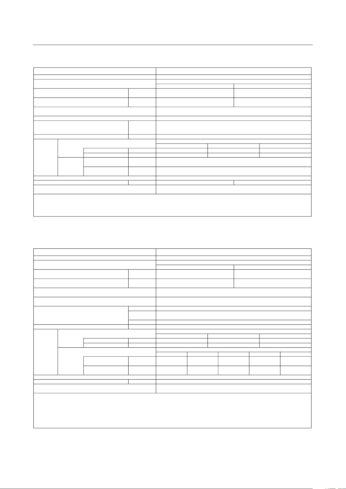
2.ExternalDimensions
Piping space
(right side)
Fig. A
Service space
(front side)
Top view
300
400
600
ø27 Knockout hole
<Hole for external wiring output>
Drain (R1 screw)
Control box
Water outlet
(RC3/4 screw)
ø27 Knockout hole
<Hole for external wiring input>
ø27 Knockout hole
<Hole for power supply>
ø27 Knockout hole
<Hole for control wiring>
Service panel
Top view
Right side view
Front view
2X2-ø14 Hole
Connection pipe of outdoor unit
(Liquid)
ø15.88 <Brazed>
ø9.52 <Brazed>
Connection pipe of outdoor unit
(Gas)
Water inlet
(R3/4 screw)
525
(Mounting pitch)
(Mounting pitch)
205
800 300
450
500
55
35
35
91
91
134
480
46
60140
100191
80165
102
54
184
114
Note 1.Ensure no rain water or debris can enter the unit through any gaps around
wiring or piping.
2.Ensure adequate service space is right around the unit, according to Fig A.
3.Please always make water circulate or add the brine to the circulation water
when the ambient temperature becomes 0°C or less.
4.The unit is not designed for outside installations.
5.Install the unit in an environment where the wet bulb Temp.
will not exceed 32degC.
6.Please always make water circulate or pull out the circulation
water completely when not using it.
7.The water circuit must use the closed circuit.
8.Please don't use the steel material for the water piping material.
9.Connect the strainer which is put as accessory to water inlet pipe.
<Accessories>
●Y-type strainer (RC3/4) ·························· 1pc.
●Heat Insulation material ························· 1pc.
●Connector set ········································ 2set
<Unit:mm>
(1) PWFY-P100VM-E-BU
- 6 -
Page 14
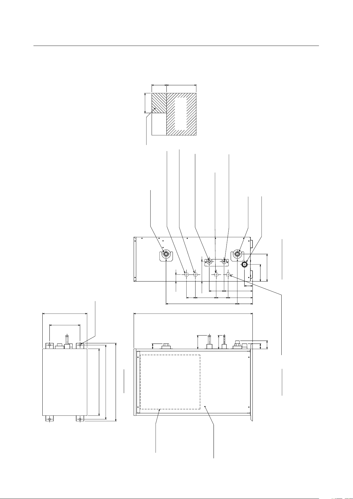
(2) PWFY-P100, 200VM-E-AU
300600
Fig. A
Service space
(front side)
Top view
400
Piping space
(right side)
P200:Use the Expansion joint
of accessories
Drain (R1 screw)
ø9.52 <Brazed>
ø27 Knockout hole
<Hole for control wiring>
ø27 Knockout hole
<Hole for power supply>
Water outlet
(RC3/4 screw)
Water inlet
(R3/4 screw)
P100:ø15.88 <Brazed>
P200:ø19.05 <Brazed>
ø
27 Knockout hole
<Hole for external wiring input>
ø27 Knockout hole
<Hole for external wiring output>
Connection pipe of outdoor unit
(Gas)
Connection pipe of outdoor unit
(Liquid)
Front view
Right side view
Control box
Service panel
Top view
2X2-ø14 Hole
525
(Mounting pitch)
450
(Mounting pitch)
300800
205
500
<Accessories>
●Y-type strainer (RC3/4) ····························· 1pc.
●Heat Insulation material
····························
1pc.
●Connector set
············································
2set
●Expansion joint (P200) ······························ 2pcs.
[From RC3/4 to RC1]
Note 1.Ensure no rain water or debris can enter the unit through any gaps around
wiring or piping.
2.Ensure adequate service space is right around the unit, according to Fig A.
3.Please always make water circulate or add the brine to the circulation water
when the ambient temperature becomes 0°C or less.
4.The unit is not designed for outside installations.
5.Install the unit in an environment where the wet bulb Temp.
will not exceed 32degC.
6.Please always make water circulate or pull out the circulation
water completely when not using it.
7.The water circuit must use the closed circuit.
8.Please don't use the steel material for the water piping material.
9.Connect the strainer which is put as accessory to water inlet pipe.
91
91
35
55
35
480102
206
134
114
100191
46
6014080165
54
<Unit:mm>
- 7 -
Page 15
<Accessories>
• Refrigerant<Low pressure> conn. pipe ··············· 2pcs.
• Refrigerant<High pressure> conn. pipe ·············· 1pc.
• Reducer(Large,Small) ········································· Quantity for all connections
• Drain hose I.D. 32 (1-1/4") ··································· 1pc.
• Hose band ··························································· 1pc.
• Tie band ······························································ 1pc.
Note1. Suspension bolt(
ø10),washer(M10),and nut(M10)
prepare in the field.
2. Take notice of service space as follows.
(Please give attention not to occupy service
space by letting ducts and pipes through.)
PURY-P200 : ø
19.05 <Brazed> (use attachment pipe)
PURY-P250, P300 :
ø
22.2 <Brazed>
PURY-P350 :
ø
28.6 <Brazed> (use attachment pipe)
Service
space
ø19.05 <Brazed>
Detail of X section
Detail of Y section
Control box
12
14
30
Drain pipe O.D. 32 (1-1/4")
B
A
Connection pipe of outdoor unit (Low pressure)
103
Connection pipe of
outdoor unit
(High pressure)
248
ø31
A B C D
ø9.52 <Flare>
161514
1312
11
109
876543
2
1
ø15.88 <Flare>
Access
door
450
(Lifting bolt pitch)
(Lifting bolt pitch)
345
7
9
12
15
180
240
300
420
540
720
900
702
1152
648
1098
CMB-P104V-G
CMB-P105V-G
CMB-P108V-G
CMB-P106V-G
CMB-P1010V-G
CMB-P1016V-G
CMB-P1013V-G
298
181
200
130 23
60
Y
362 70
Drain hose I.D. 32 (1-1/4")
Band (Accessory)
X
70
200
27
700
250
Connection pipe of
indoor unit (Gas)
Connection pipe of
indoor unit (Liquid)
64
64
58
128
255
284
200
60XC=D76
<Unit:mm>
(3) CMB-P104,105,106,108,1010,1013,1016V-G
- 8 -
Page 16

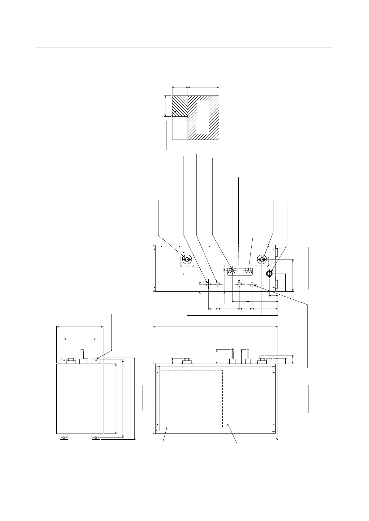
(4) CMB-PW202V-J
Connection pipe of
PWFY (Gas)
Connection pipe of
PWFY (Liquid)
Connection pipe of
indoor unit/PWFY (Liquid)
Connection pipe of
indoor unit/PWFY (Gas)
Liquid line
Indoor unit/PWFY
(Cooling/Heating)
PWFY(Heating only)
Gas line
Liquid line
Gas line
(Lifting bolt pitch)
(Lifting bolt pitch)
250
700
200
200
Access
door
450
~P300: ø9.52<Brazed>(use attachment pipe)
P301~P400: ø12.7<Brazed>(use attachment pipe)
P401~: ø15.88<Brazed>
~P140: ø15.88<Brazed>(use attachment pipe)
P141~P200: ø19.05<Brazed>(use attachment pipe)
P201~P300: ø22.2<Brazed>(use attachment pipe)
P301~: ø28.58<Brazed>(use attachment pipe)
~P140: ø15.88<Brazed>(use attachment pipe)
P141~P200: ø19.05<Brazed>
P201~P300: ø22.2<Brazed>(use attachment pipe)
~P300: ø9.52<Brazed>
Drain hose(Accessory)
Band(Accessory)
Connection pipe of outdoor unit (Low pressure)
Connection pipe of outdoor unit (High pressure)
12
14
30
ø
31
27
Y
X
Dtail of Y section
284
648
90
Drain piping
VP-25 connection
Control box
200
255
Detail of X section
298
702
190423
300
252
103
58
90
127 21
90 181
255
70362
103
PURY-P200: ø19.05<Brazed>(use attachment pipe)
PURY-P250,P300: ø22.2<Brazed>
PURY-P350: ø28.58<Brazed>(use attachment pipe)
PURY-P200: ø15.88<Brazed>(use attachment pipe)
PURY-P250,P300,P350: ø19.05<Brazed>
<Accessories>
Refrigerant<Low pressure> conn. pipe
Refrigerant<High pressure> conn. pipe
Refrigerant<Gas> conn. pipe
Refrigerant<Liquid> conn. pipe
Drain hose(VP-25 connection)
Hose band
Tie band
2pcs.
1pc.
6pcs.
2pcs.
1pc.
1pc.
1pc.
Note1. Suspension bolt (ø10), washer (M10), and nut (M10)
prepare in the field.
2. Take notice of service space as follows.
(Please give attention not to occupy service
space by letting ducts and pipes through.)
3. Install this product in a location where noise (refrigerant noise)
emitted by the unit will not disturb the neighbors.
(For use in quiet enviroments with low background noise, position
the BC CONTROLLER at least 5m away from any indoor units.)
4. Install the unit horizontally.
5. The indoor unit/PWFY branch is for cooling/heating.The indoor unit/PWFY
cannot be simultaneously operated in different operation modes.
6. The PWFY unit branch is for the heating only.
Service
space
<Unit:mm>
- 9 -
Page 17
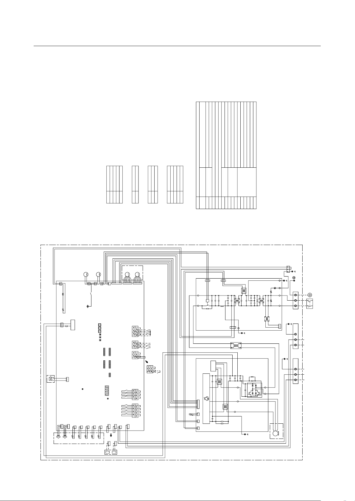
3.ElectricalWiringDiagrams
M
4-20mA
4-20mA
gray
2
1
gray
black
To outdoor unit/
BC controller/WCB
To MA remote
controller
Power Supply
~220/230/240V
50Hz/60Hz
3
2
1
blue
red
yellow/green
bluered
CN4
63LS
CN63HS
1
1
3
2
2
3
THHS
12
CN63LS
123
t°
TH8
2
1
CN403
red
t°
TH6
1
2
CN404
black
t°
3 1
CT1
Moter
3~
CYN
RS4
MS
RS3
(Compressor)
CN3A
blue
U
t°
red
yellow
TH22
CN405
IPM
W
V
U
black
1
63HS
7
2
1
3
1
2
CN3
2
1
t°
CN401
CN2
2 5 6
t°
red
CN5
2
1
TH11
1
2
TH13
2
1
white
CN402
green
red
5
6
RS1
black
2
CN52C
R1
LO
U
CNAC2
red
2
CN5
1
1
2
red
blue
red
LEV2W
M
LI
24V
blue
+
CB3
Z2
1
U
CT1
LEV1W
1
CN2
63H1
6
5
CNAC
2
red
1
CX2
L
CN506A
L3
N
6
5
N
CN-E1
CN631
DSA
pink
E2
3
1
E1
432
1
CY4
P
CY3
31
L4
Z1
NI
CB1
+
1
TB2
CN661
2L23
X506
W
4
CN4
blue
U
CN52C
1
2
+
CX3
INV control
circuit
PFC
E3
1
L1
2
M
ZNR01
ACL
CY1CY2
CT2
Noise
Filter
red
Fan motor
1
3
(DC)
CX5
CYP
CIS
CX6
1
2
7
V
yellow
LED3:Lit when powered
INV Board
Control Board
CB2
(DC)
CY6
S
CX4
R
CNAC1
M
CNLVA
NO
Fan motor
3
1
2
RS2
CY5
P
CNLVB
blue
CX1
CX7
CN506B
CPS
+
RS
F01
AC250V
6.3A
F631
DC700V
4A
Power
Supply circuit
blue
red
TB5
M1 M2
S(SHIELD) S(SHIELD)
TB15
yellow
purple
black
orange
gray
red
black
white
gray
gray
52C
1
2
CN2M
blue
3 1
*4
IN2
TB141B
TB142B
IN6
COM+
OUT5
TB142C
OUT7
OUT6
X515 X517
X516
IN8
IN5 IN7
TB142A
X514
OUT2
X512
X511 X513
OUT1 OUT3
OUT4
TB141A
*5 *6 *7
IN3 IN4
COM+
LED4:Remote controller
when powered
SWU1
10
SW1
5
ON
OFF
1
Unit address setting(SWU1,SWU2)
Connection No.(SWU3)
LED1 Display setting(SW2)
Function setting(SW1,SW3,SW4)
SWP3
SW5
SWP1
SWU3
SWP2
SWU2
OFF
ON
1 10
SW4
OFF
ON
1 10
LED1
OFF
ON
1
SW3
OFF
ON
1 10
SW2
IN1
gray
CN421
black
3 1
CN422
blue
IN1
IN2
3 1
CN421
black
3 1
CN422
blue
2
2
2
2
BC controller/WCB/outdoor unit
Booster unit
Linear
expansion valve
LEV1W
LEV2W
IN7 Anti-freeze
IN6 Heating ECO
Symbol
Function
COM+ Common
IN5 Hot water
IN4 Operation ON/OFF
Connection demand
Symbol
IN3
Function
Symbol
Pump interlock
Function
IN1
*4 TB141A(output)
*5 TB142A(input)
*6 TB142B(input)
*7 TB142C(input)
Function
Symbol
OUT1 Operation ON/OFF
OUT2 Defrost
OUT3 Compressor
OUT4 Error signal
<HIGH VOLTAGE WARNING>
·Control box houses high-voltage parts.
Before inspecting the inside of the control box, turn off the power,
keep the unit off for at least 10 minutes,and confirm that the voltage
CN631 on Control Board has dropped to DC20V or less.
<CAUTION FOR INSTALLATION>
·Prior to installation,read the Installation Manual carefully.
*1.Single-dotted lines indicate wiring not supplied with the unit.
*2.Dot-dash lines indicate the control box boundaries.
*3.Faston terminals have a locking function.
Make sure the terminals are securely locked in place after insertion.
Press the tab on the terminals to removed them.
TH8 water outlet temp
TH6 water inlet temp
TH22 liquid pipe temp
TH13 Evaporator outlet temp
Compressor discharge tempTH11 Thermistor
TB15 MA remote controller
TB5 Outdoor unit/BC controller/WCB
AC reactor
Pressure
switch
High pressure switch
(High pressure protection for the booster unit)
Discharge pressure
Low pressure
TB2
CT1,CT2
ACL
THHS
Magnetic relay(main circuit)
Current sensor(AC)
Explanation
Terminal
block
Power supply
IGBT temp
Pressure
sensor
Symbol
63H1
63HS
63LS
52C
<Symbol explanation>
(1) PWFY-P100VM-E-BU
- 10 -
Page 18
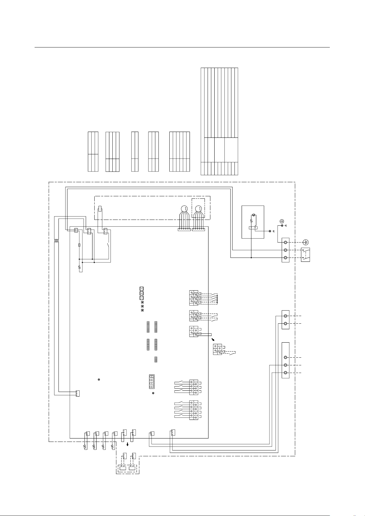
(2) PWFY-P100, 200VM-E-AU
gray
red
M
For opening/closing the bypass circuit
Solenoid valve
SV1
IN1
TB5
M1 M2
S(SHIELD)
To outdoor unit/
BC controller/
WCB
4-20mA
4-20mA
132
CN421
black
132
CN422
blue
132
CN422
blue
2
black
CN421
13
IN1
234
5
yellow/green
LEV1Wa
LEV1Wb
Linear
expansion valve
BC controller/WCB/outdoor unit
BC controller/WCB/outdoor unit
Function
Function
Function
black
yellow purple
bluered
NL
IN7
IN8IN6
IN5COM+
IN4IN3
orange
*3.Difference of appliance
*4 TB141A(output)
*5 TB142A(input)
*6 TB142B(input)
*7 TB142C(input)
Model name
Appliance
P100 *3 do not exist
P200 *3 exist
*7*6*5
*4
Cooling
TH23 gas pipe temp
CN502
black
COM+
TH8
TH6
TH23
t°
t°
t°
blue
CN2M
2
1
2
1
CN402
green
2
1
CN403
red
1
2
CN404
black
yellow
CN405
t°
TH22
1
2
21
To MA remote
controller
Power Supply
~220/230/240V
50Hz/60Hz
Unit address setting(SWU1,SWU2)
Connection No.(SWU3)
LED1
TB15
ZNR1
U
DSA1
CN1
1
3
SWU2
SWU1
SWP3
SWP2
SWP1
OFF
ON
1 10
SW4
OFF
ON
1 10
SW3
OFF
ON
1 10
SW1
OFF
ON
1 10
SW2
LED4:Remote controller
when powered
5
CNLVC
6
1
LEV1Wb
123
4
X502
CN507
3
1
M
5
6
ON
OFF
1
SW5
SWU3
LED3:Lit when powered
Control Board
CNLVB
LEV1Wa
TB2
SV1
*3
DSA Board
CN3T
red
13
T01
ZNR01
3
1
1
2
CNAC
red
U
F01
AC250V
6.3A
LED1 Display setting(SW2)
Function setting(SW1,SW3,SW4)
OUT4
OUT3
OUT2
X514
X513
X512
TB141A
OUT1
X511
3 1
CN3A
blue
TB142CTB142B
X516
X517X515
OUT6
OUT7OUT5
TB141B
TB142A
IN2
IN8
IN7 Anti-freeze
IN6 Heating ECO
Symbol
COM+ Common
IN5 Heating
IN4 Operation ON/OFF
Connection demand
Symbol
IN3
Symbol
Pump interlockIN1
Function
Symbol
OUT1 Operation ON/OFF
OUT2 Defrost
OUT4 Error signal
<CAUTION FOR INSTALLATION>
·
Prior to installation,read the Installation Manual carefully.
*1.Single-dotted lines indicate wiring not supplied with the unit.
*2.Dot-dash lines indicate the control box boundaries.
TH8 water outlet temp
TH6 water inlet temp
TH22 liquid pipe temp
Thermistor
TB15 MA remote controller
TB5 Outdoor unit/WCB/BC controller
TB2
Explanation
Terminal
block
Power supply
Symbol
<Symbol explanation>
- 11 -
Page 19

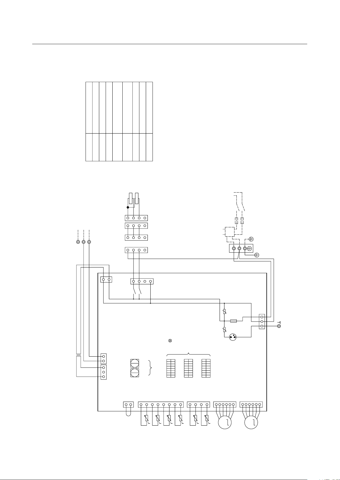
(3) CMB-P104V-G
CONT.B
Pressure sensor
TR
TH11,12,15,16
LEV1,3
PS1,3
Symbol Name
Transformer
Thermistor sensor
Expansion valve
SV1
~
4A,B,C Solenoid valve
TB01
Terminal block
(for power source)
TB02
Terminal block
(for Transmission)
T1~4 Terminal
F01
Fuse AC250V 6.3A F
Solenoid valve
SVM1
TR
TB02
CN26
3
1
CN12
1
5
3
CN05
6
5
4
3
2
1
CONT.B
1
2
CN02
3
CNP1
1
2
3
CNP3
211
2
3
4
567
8
4
3
2
1
123 2 1
CN03
CN13
CN10
CN11
CN07
TH11
TH12
TH15
TH16
PS1
PS3
6
5
4
3
2
1
TB01
1VEL
3
VEL
S(SHIELD)
M2
M1
220V~240V
20V
~
22V
L
1
234
10
9
8
423
10
2
143
SV3A
SV3B
SV2B
SV3C
SV2C
SV2A
243
756
4
3
2
1
2
3
4
1
234
2
3
4
9
8
7
6
5
SV1C
SV1A
SV1B
7
5
3
1
7
5
3
1
7
5
3
1
X2
X1
X30
X4
X3
X31
X6
X5
X32
CN27(Red)
CN28(Blue)
1
1
1
1
234
13
12
11
16
15
14
13
12
11
SV4B
SV4C
SV4A
15
16
14
1
2
3
4
1
7
5
3
1
X8
X7
X33
CN29(Green)
SVM1
123
1
2
3
1
3
CN36(Green)
X21
N
ZNR01
ZNR02
CNTR
(Red)
2
2
PE
3
1
3
1
T2
T3
T1
T4
PE
TO NEXT INDOOR UNIT
PULL BOX
FUSE(16A)
BREAKER(16A)
POWER SUPPLY
~220V-240V
50Hz/60Hz
Indoor/outdoor
Transmission Line
ON
OFF
1
SW5
OFF
8
SW4
ON
1
8
BC controller
Circuit
board
SW2 SW1
1
10
F01
250VAC
6.3A F
(Black)
(Red)
(Yellow)
(Red)
(Yellow)
DSA
Note:1.TB02 is transmission terminal block.
Never connect power line to it.
2.The initial set values of switch on
CONT.B are as follows.
SW1:0
SW2:0
Symbol explanation
*Other models of BC controller are available. For unit information, refer to the Data Book.
- 12 -
Page 20
(4) CMB-PW202V-J
TB01
M1
M2
WCB Board
Note:1. TB02 is transmission terminal block.
Never connect power line to it.
2. The initial set values of switch on
WCB Board are as follows.
SW1:0
SW2:0
Expansion valve
Thermistor sensor
Transformer
(Symbol explanation)
Name
Symbol
TB01
Terminal block
(for power source)
Terminal block
(for Transmission)
TB02
Solenoid valve
SVM1
21S4a
4-way valve
TO NEXT
INDOOR UNIT
PULL BOX
FUSE(16A)
BREAKER(16A)
50Hz/60Hz
POWER SUPPLY
~220V-240V
S(SHIELD)
TB02
Indoor/outdoor
Transmission line
1
2
3
6
5
4
CN05
CN07
1
2
3
6
5
4
TH16
TH15
123
4
CN11
TH12
TH11
112
CN13
2
3
CN10
45678
F01
AC250V
6.3A F
ZNR01
ZNR02
CN12
1
3 5
1
3
20V~22V
TR
220V~240V
1 13 2 2
CN02
CN03
F01
Fuse AC250V 6.3A F
TH13
TH14
TR
TH11~16
LEV1,3
Yellow
Red
Red
Yellow
SW1SW2
ON
OFF
ON
OFF
ON
OFF
81
81
81
SW4
SW5
SW6
1
3
X02
CN26
5
7
X01
SVM1
21S4a
123
4
4
3
2
1
1132
4
324
T1
CNTR
Red
N
L
DSA
UU
LEV3
LEV1
M
M
LD1:CPU in
operation
1's
digit
Unit address
setting
10's
digit
Function
setting
317
5
- 13 -
Page 21
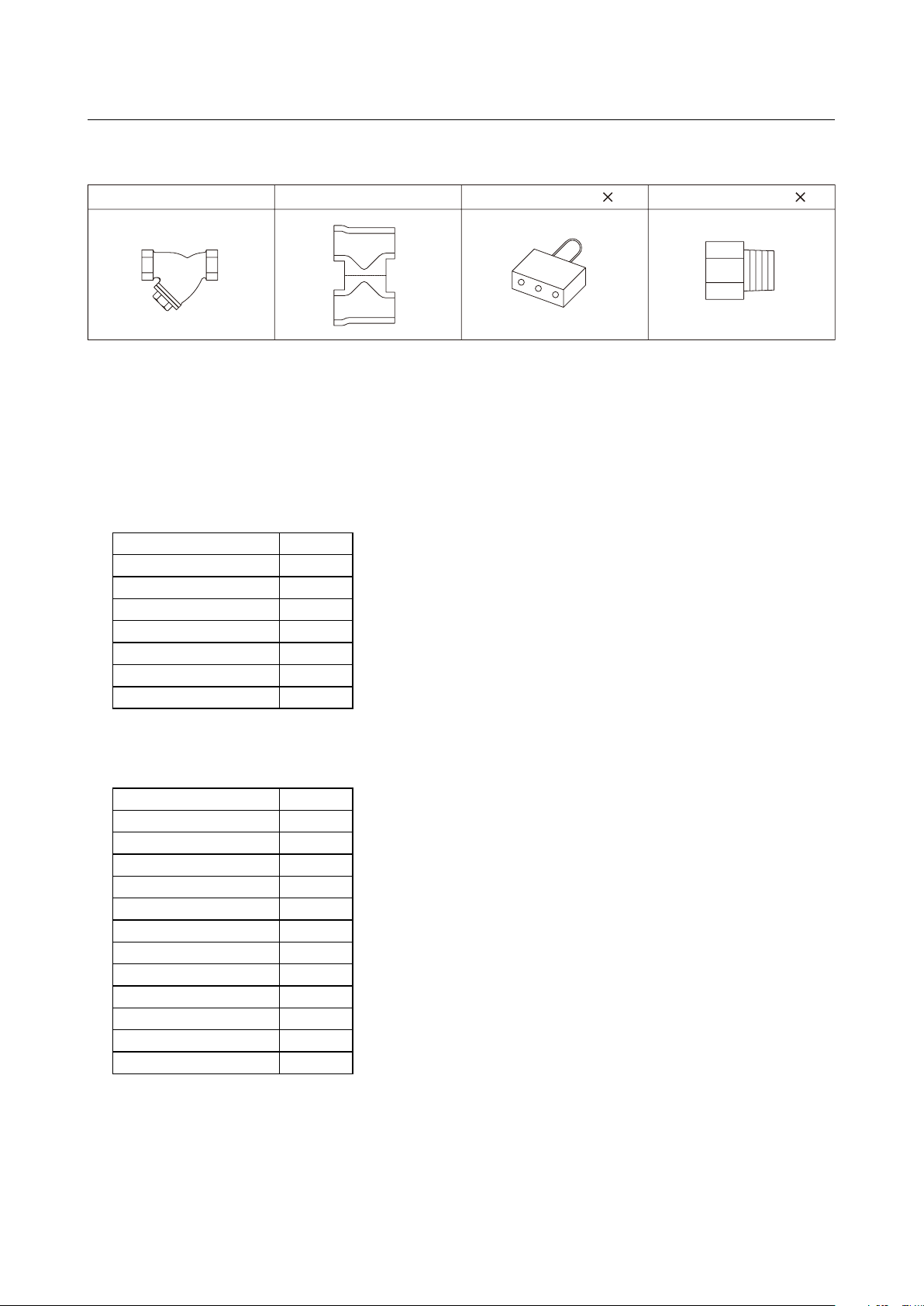
4. Accessories
(A) Strainer (B) Heat insulation material
*1
*1. PWFY-P200VM-E-AU only
(C) Connecter sets 2 (D) Expansion joint 2
(1) PWFY
(A) Install the strainer at the water pipe inlet.
(B) This insulation is for exclusive use with the strainer. Wrap the strainer with the insulation after water pipes are
installed.
(C) These are analog input connectors. Cut the wire before using.
(D) Supplied only with the PWFY-P200VM-E-AU. Install them at the strainer inlet. Refer to P53 for details.
(2) CMB-P104V-G
SIZE Unit
ø15.88 are - IDø12.8 4
ø9.52 are - IDø6.45 4
ODø19.05 - IDø15.88 1
ODø22.2 - IDø19.05 1
ODø22.2 - IDø28.6 1
Drain hose set
Installation Manual 1
1set
(3) CMB-PW202V-J
SIZE Unit
ODø19.05 - IDø15.88 2
ODø22.2 - IDø19.05 1
ODø15.88 - IDø9.52 1
ODø15.88 - IDø12.7 1
ODø25.4 - IDø19.05 1
ODø25.4 - IDø22.2 1
ODø19.05 - IDø22.2 1
ODø25.4 - IDø28.6 1
ODø22.2 - IDø28.6 1
ODø25.4 - IDø15.88 1
Drain hose set
Installation Manual 1
1 set
- 14 -
Page 22
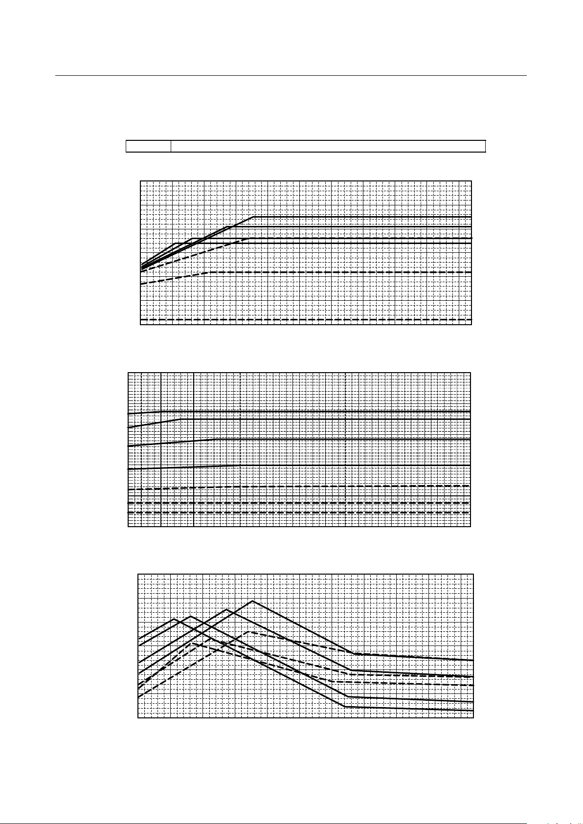
III
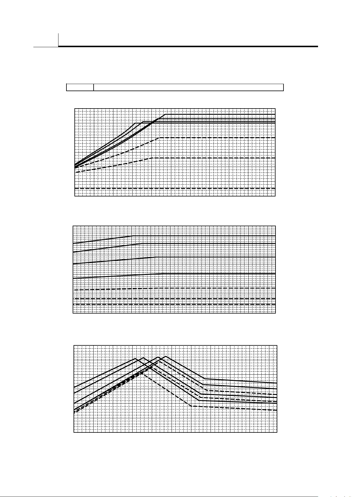
PURY- P200,250YHM-A(-BS)
EP200,250YHM-A(-BS)
0.5
0.6
0.7
0.8
0.9
1.0
1.1
Outdoor temp. [°CWB]
Ratio of heating capacity
30°C
20°C
10°C
40°C
50°C
60°C
65°C
0.2
0.3
0.4
0.5
0.6
0.7
0.8
0.9
1.0
1.1
Outdoor temp. [°CWB]
Ratio of booster unit input
65°C
60°C
50°C
40°C
30°C
20°C
10°C
0.5
0.6
0.7
0.8
0.9
1.0
1.1
Outdoor temp. [°CWB]
Ratio of outdoor unit input
40°C
50°C
60°C
65°C
30°C
20°C
10°C
-20
-15 -10 -5
0
5
10
15 20 25 30
-20
-15 -10 -5
0
5
10
15 20 25 30
-20
-15
-10 -5
0
5
10
15 20 25 30
Booster unit inlet-water temp. [°C]
Booster unit inlet-water temp. [°C]
Booster unit inlet-water temp. [°C]
Product Data
1. Capacity tables
(1) Correction by temperature
(1)-1 R2 series + PWFY-P100VM-E-BU
- 15 -
Page 23
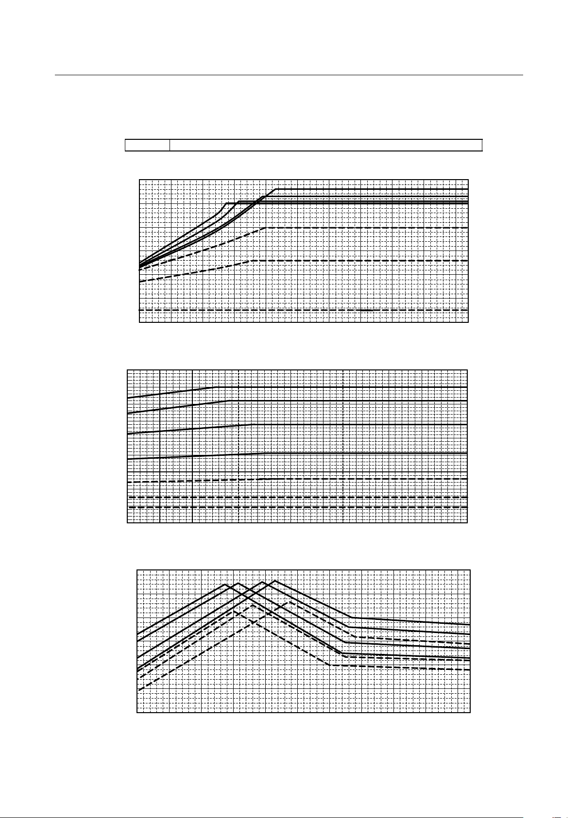
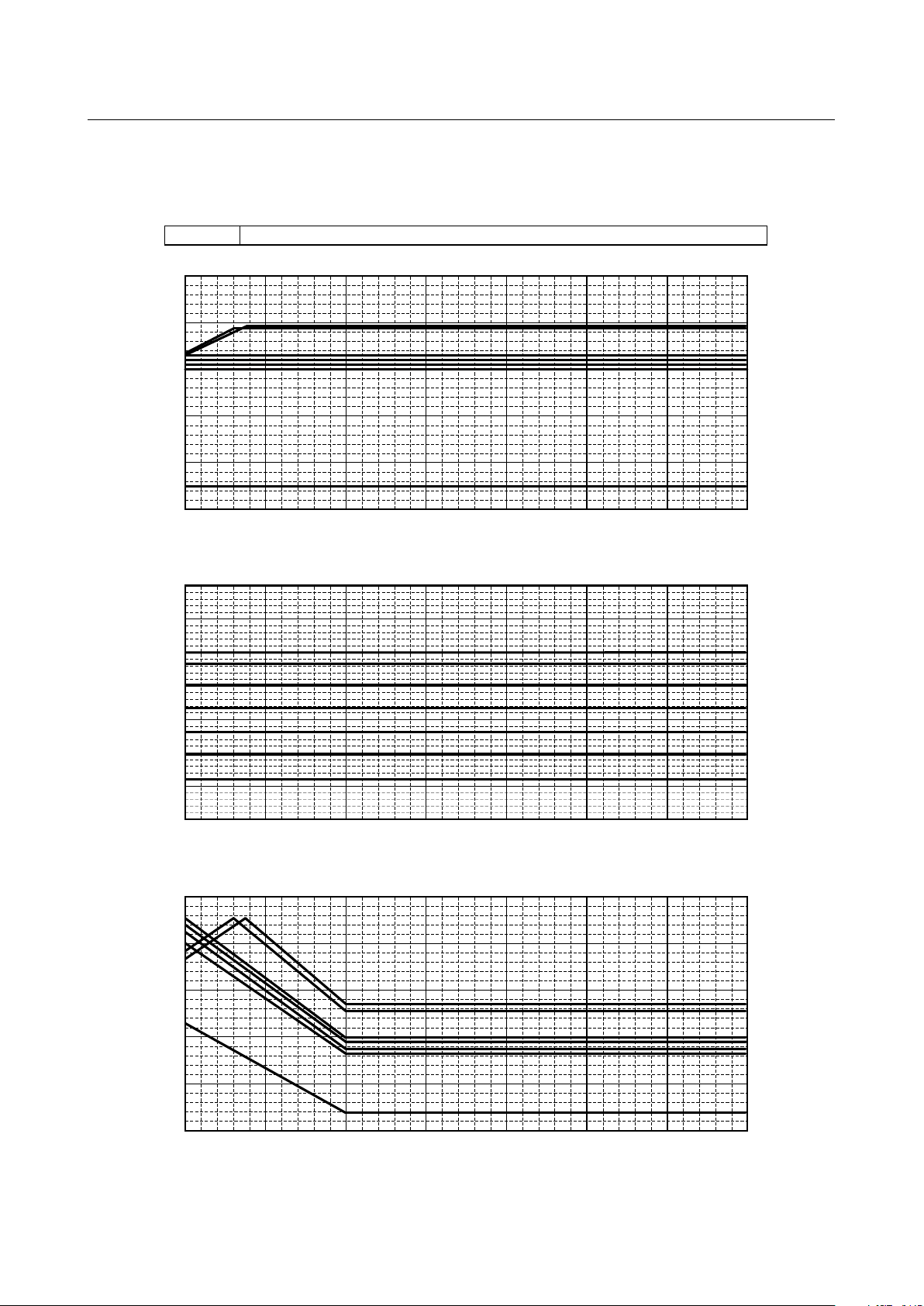
PURY- P300,350,400YHM-A(-BS) EP300,400Y(S)HM-A(-BS)
Outdoor temp. [°CWB]
Ratio of heating capacity
0.2
0.3
0.4
0.5
0.6
0.7
0.8
0.9
1.0
1.1
Outdoor temp. [°CWB]
Ratio of booster unit input
65°C
60°C
50°C
40°C
30°C
20°C
10°C
0.5
0.6
0.7
0.8
0.9
1.0
1.1
Outdoor temp. [°CWB]
Ratio of outdoor unit input
40°C
50°C
60°C
65°C
30°C
20°C
10°C
0.5
0.6
0.7
0.8
0.9
1.0
1.1
30°C
20°C
10°C
40°C
50°C
60°C
65°C
-20
-15
-10 -5
0
5
10
15 20 25 30
-20
-15 -10 -5
0
5
10
15 20 25 30
-20
-15 -10 -5
0
5
10
15 20 25 30
Booster unit inlet-water temp. [°C]
Booster unit inlet-water temp. [°C]
Booster unit inlet-water temp. [°C]
- 16 -
Page 24

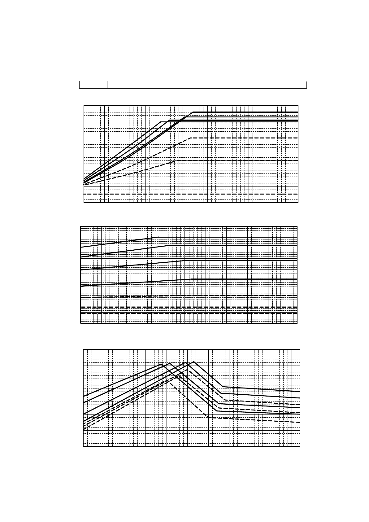
30°C
20°C
10°C
40°C
50°C
60°C
65°C
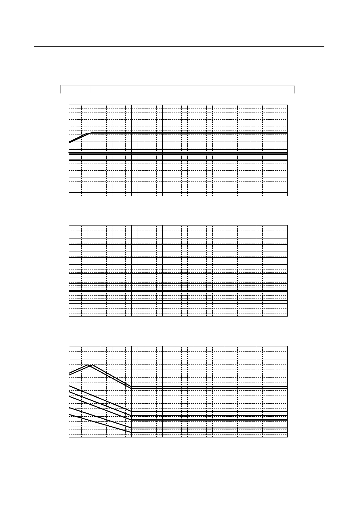
PURY-
P450,500,550,600,650YSHM-A(-BS) EP450,500,550,600YSHM-A(1)(-BS)
0.5
0.6
0.7
0.8
0.9
1.0
1.1
Outdoor temp. [°CWB]
Ratio of heating capacity
0.2
0.3
0.4
0.5
0.6
0.7
0.8
0.9
1.0
1.1
Outdoor temp. [°CWB]
Ratio of booster unit input
65°C
60°C
50°C
40°C
30°C
20°C
10°C
0.5
0.6
0.7
0.8
0.9
1.0
1.1
Outdoor temp. [°CWB]
Ratio of outdoor unit input
40°C
50°C
60°C
65°C
30°C
20°C
10°C
-20
-15 -10 -5
0
5
10
15 20 25 30
-20
-15 -10 -5
0
5
10
15 20 25 30
-20
-15 -10 -5
0
5
10
15 20 25 30
Booster unit inlet-water temp. [°C]
Booster unit inlet-water temp. [°C]
Booster unit inlet-water temp. [°C]
- 17 -
Page 25
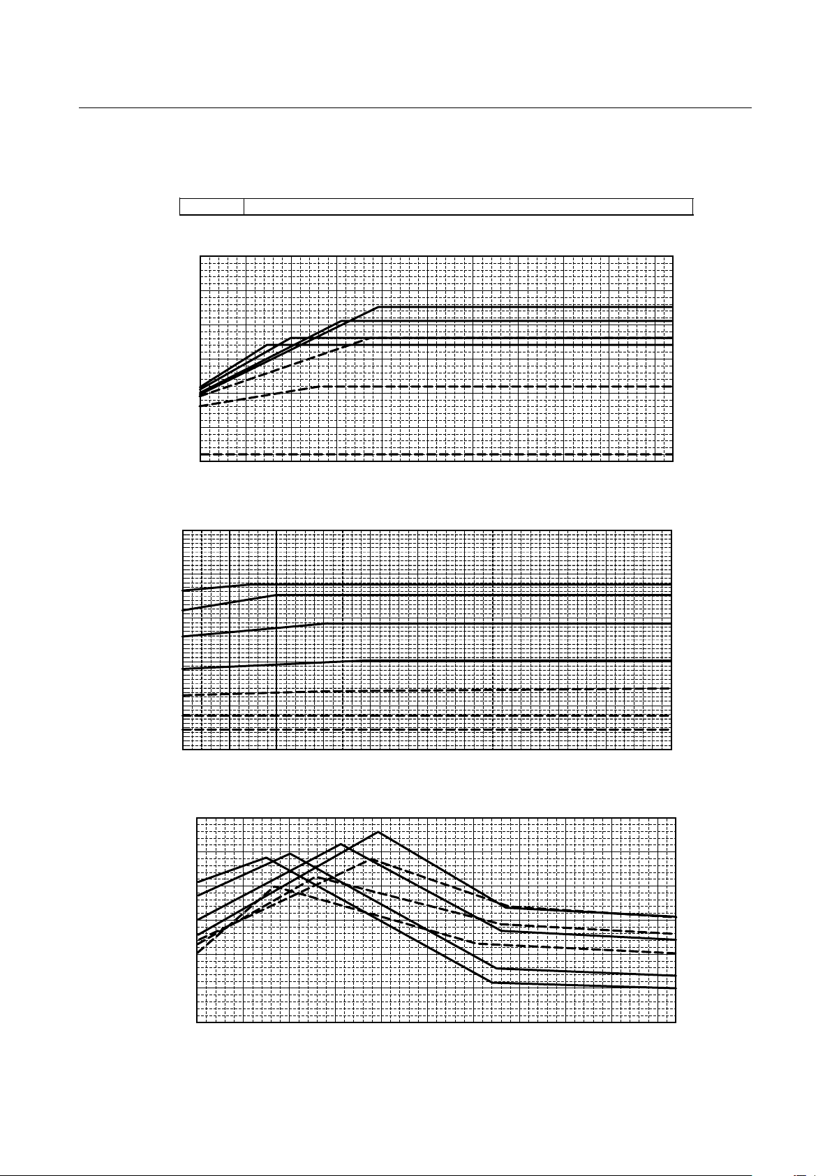
PURY- P700,750,800YSHM-A(-BS)
0.5
0.6
0.7
0.8
0.9
1.0
1.1
Ratio of heating capacity
0.2
0.3
0.4
0.5
0.6
0.7
0.8
0.9
1.0
1.1
Ratio of booster unit input
65°C
60°C
50°C
40°C
30°C
20°C
10°C
0.5
0.6
0.7
0.8
0.9
1.0
1.1
Ratio of outdoor unit input
40°C
50°C
60°C
65°C
30°C
20°C
10°C
Outdoor temp. [°CWB]
Outdoor temp. [°CWB]
Outdoor temp. [°CWB]
30°C
20°C
10°C
40°C
50°C
60°C
65°C
-20
-15 -10 -5
0
5
10
15 20 25 30
-20
-15
-10 -5
0
5
10
15 20 25 30
-20
-15 -10 -5
0
5
10
15 20 25 30
Booster unit inlet-water temp. [°C]
Booster unit inlet-water temp. [°C]
Booster unit inlet-water temp. [°C]
- 18 -
Page 26
PURY- P200,250YHM-A(-BS) EP200,250YHM-A(-BS)
Outdoor temp. [°CWB]
Ratio of heating capacity
0.2
0.4
0.6
0.8
1.0
1.2
Outdoor temp. [°CWB]
Ratio of booster unit input
65°C
60°C
50°C
40°C
30°C
20°C
10°C
0.4
0.5
0.6
0.7
0.8
0.9
1.0
Outdoor temp. [°CWB]
Ratio of outdoor unit input
40°C
50°C
60°C
65°C
30°C
20°C
10°C
0.5
0.6
0.7
0.8
0.9
1.0
1.1
30°C
20°C
10°C
40°C
50°C
60°C
65°C
-20
-15
-10 -5
0
5
10
15 20 25 30
-20
-15 -10 -5
0
5
10
15 20 25 30
-20
-15 -10 -5
0
5
10
15 20 25 30
Booster unit inlet-water temp. [°C]
Booster unit inlet-water temp. [°C]
Booster unit inlet-water temp. [°C]
(1)-2 R2 series + PWFY-P100VM-E-BU + WCB Energy saving mode*
*For energy saving mode, set WCB DIP SW 6-5 ON.
- 19 -
Page 27
PURY- P300,350YHM-A(-BS) EP300YHM-A(-BS)
Outdoor temp. [°CWB]
Ratio of heating capacity
0.2
0.4
0.6
0.8
1.0
1.2
Outdoor temp. [°CWB]
Ratio of booster unit input
65°C
60°C
50°C
40°C
30°C
20°C
10°C
0.5
0.6
0.7
0.8
0.9
1.0
1.1
Outdoor temp. [°CWB]
Ratio of outdoor unit input
40°C
50°C
60°C
65°C
30°C
20°C
10°C
0.5
0.6
0.7
0.8
0.9
1.0
1.1
30°C
20°C
10°C
40°C
50°C
60°C
65°C
-20
-15
-10 -5
0
5
10
15 20 25 30
-20
-15 -10 -5
0
5
10
15 20 25 30
-20
-15 -10 -5
0
5
10
15 20 25 30
Booster unit inlet-water temp. [°C]
Booster unit inlet-water temp. [°C]
Booster unit inlet-water temp. [°C]
- 20 -
Page 28
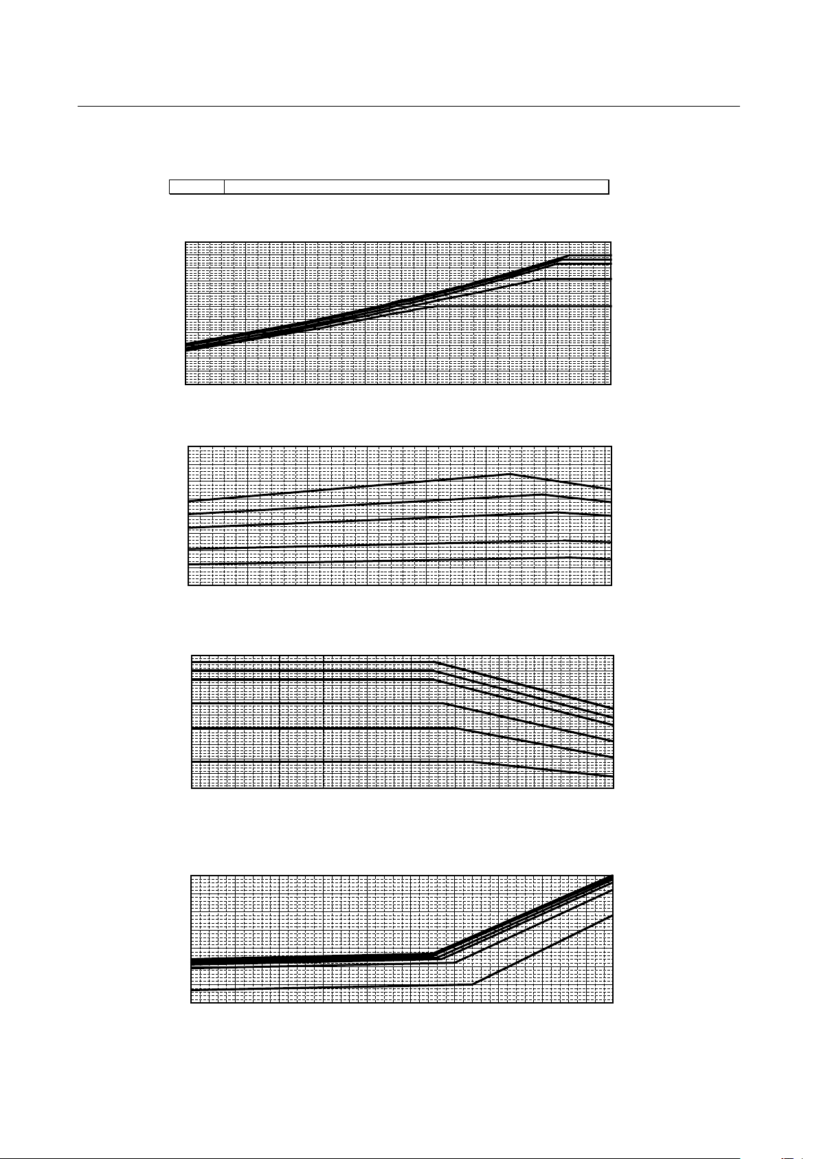
(1)-3 WR2 series + PWFY-P100VM-E-BU
Booster unit inlet-water temp. [°C]
Booster unit inlet-water temp. [°C]
Booster unit inlet-water temp. [°C]
Heat source unit (WR2) inlet-water temp. [°C]
Ratio of Heat source unit input
40°C
50°C
60°C
65°C
10°C
30°C
20°C
0.2
0.0
0.4
0.6
0.8
1.0
1.2
1.4
Heat source unit (WR2) inlet-water temp. [°C]
Ratio of Booster unit input
40°C
30°C
20°C
10°C
50°C
60°C
65°C
0.7
0.8
0.9
1.0
1.1
1.2
Heat source unit (WR2) inlet-water temp. [°C]
Ratio of Booster unit capacity
40°C
50°C
10°C
10
15 20 25 30 35 40 45
0.7
0.8
0.9
1.0
1.1
1.2
10
15 20 25 30 35 40 45
10
15 20 25 30 35 40 45
60°C
65°C
30°C
20°C
PQRY- P200,250,300,400,450,500,550,600Y(S)HM-A
- 21 -
Page 29
(1)-4 WR2 series + PWFY-P100VM-E-BU + WCB Energy saving mode*
Booster unit inlet-water temp. [°C]
Booster unit inlet-water temp. [°C]
Booster unit inlet-water temp. [°C]
Heat source unit (WR2) inlet-water temp. [°C]
Ratio of Heat source unit input
40°C
50°C
60°C
65°C
10°C
30°C
20°C
0.2
0.0
0.4
0.6
0.8
1.0
1.2
1.4
Heat source unit (WR2) inlet-water temp. [°C]
Ratio of Booster unit input
40°C
30°C
20°C
10°C
50°C
60°C
65°C
0.7
0.8
0.9
1.0
1.1
1.2
Heat source unit (WR2) inlet-water temp. [°C]
Ratio of Booster unit capacity
40°C
50°C
60°C
65°C
30°C
20°C
10°C
10
15 20 25 30 35 40 45
10
15 20 25 30 35 40 45
10
15 20 25 30 35 40 45
0.6
0.5
0.7
0.8
0.9
1.0
1.1
1.2
PQRY- P200,250,300,400,450,500,550,600Y(S)HM-A
*For energy saving mode, set WCB DIP SW 6-5 ON.
- 22 -
Page 30
(1)-5 Y series + PWFY-P100,200VM-E-AU
PUHY- P200,250YHM-A(-BS) EP200,250YHM-A(-BS)
Heating
Cooling
0.4
0.5
0.6
0.7
0.8
0.9
1.0
1.2
1.1
Outdoor temp. [°CWB]
Ratio of outdoor unit input
0.2
0.3
0.4
0.5
0.6
0.7
0.8
0.9
1.0
1.1
1.2
1.3
Outdoor temp. [°CWB]
Ratio of heating capacity
10°C
20°C
30°C
35°C
40°C
10°C
20°C
30°C
35°C
40°C
HEX unit inlet-water temp. [°C]
HEX unit inlet-water temp. [°C]
HEX unit inlet-water temp. [°C]
HEX unit inlet-water temp. [°C]
0.5
0.6
0.7
0.8
0.9
1.0
1.1
1.2
1.3
1.4
Outdoor temp. [°CDB]
Ratio of cooling capacity
35°C
30°C
25°C
20
°C
15°C
10°C
0.5
0.6
0.7
0.8
0.9
1.0
1.1
1.2
Outdoor temp. [°CDB]
Ratio of outdoor unit input
35°C
30°C
25°C
20°C
15°C
10
°C
-20
-15
-10 -5
0
5
10
15
-20
-15
-10 -5
0
5
10
15
-5
0
5
10
15
20
25
30
35
40
-5
0
5
10
15
20
25
30
35
40
- 23 -
Page 31

0.4
0.5
0.6
0.7
0.8
0.9
1.0
1.2
1.1
Heating
Cooling
Outdoor temp. [°CWB]
Ratio of outdoor unit input
40°C
30°C
35°C
20°C
10°C
0.2
0.3
0.4
0.5
0.6
0.7
0.8
0.9
1.0
1.1
1.2
1.3
Outdoor temp. [°CWB]
Ratio of heating capacity
10°C
20°C
30°C
35°C
40°C
0.5
0.6
0.7
0.8
0.9
1.0
1.1
1.2
1.3
1.4
Outdoor temp. [°CDB]
Ratio of cooling capacity
35°C
30°C
25°C
20
°C
15°C
10°C
0.5
0.6
0.7
0.8
0.9
1.0
1.1
1.2
Outdoor temp. [°CDB]
Ratio of outdoor unit input
35°C
30°C
25°C
20°C
15°C
10
°C
EP300,400Y(S)HM-A(-BS)PUHY- P300,350,400YHM-A(-BS)
-20
-15
-10 -5
0
5
10
15
-20
-15
-10 -5
0
5
10
15
-5
0
5
10
15
20
25
30
35
40
-5
0
5
10
15
20
25
30
35
40
HEX unit inlet-water temp. [°C]
HEX unit inlet-water temp. [°C]
HEX unit inlet-water temp. [°C]
HEX unit inlet-water temp. [°C]
- 24 -
Page 32

PUHY-
Heating
Cooling
Outdoor temp. [°CWB]
Ratio of outdoor unit input
Outdoor temp. [°CWB]
Ratio of heating capacity
Outdoor temp. [°CDB]
Ratio of cooling capacity
Outdoor temp. [°CDB]
Ratio of outdoor unit input
0.5
0.6
0.7
0.8
0.9
1.0
1.1
1.2
0.5
0.6
0.7
0.8
0.9
1.0
1.1
1.2
1.3
1.4
0.2
0.3
0.4
0.5
0.6
0.7
0.8
0.9
1.0
1.1
1.2
1.3
10°C
20°C
30°C
35°C
40°C
40°C
30°C
35°C
20°C
10°C
35°C
30°C
25°C
20°C
15°C
10°C
35°C
30°C
25°C
20°C
15°C
10°C
-20
-15
-10 -5
0
5
10
15
-20
-15
-10 -5
0
5
10
15
-5
0
5
10
15
20
25
30
35
40
-5
0
5
10
15
20
25
30
35
40
P450,500,550,600,650Y(S)HM-A(-BS) EP450,500,550,600,650YSHM-A(1)(-BS)
0.4
0.5
0.6
0.7
0.8
0.9
1.0
1.2
1.1
HEX unit inlet-water temp. [°C]
HEX unit inlet-water temp. [°C]
HEX unit inlet-water temp. [°C]
HEX unit inlet-water temp. [°C]
- 25 -
Page 33

0.4
0.5
0.6
0.7
0.8
0.9
1.0
1.2
1.1
PUHY-
EP700,750,800YSHM-A(1)(-BS)
Heating
Cooling
Outdoor temp. [°CWB]
Ratio of outdoor unit input
40°C
30°C
35°C
20°C
10°C
0.2
0.3
0.4
0.5
0.6
0.7
0.8
0.9
1.0
1.1
1.2
1.3
Outdoor temp. [°CWB]
Ratio of heating capacity
10°C
20°C
30°C
35°C
40°C
0.5
0.6
0.7
0.8
0.9
1.0
1.1
1.2
1.3
1.4
Outdoor temp. [°CDB]
Ratio of cooling capacity
35°C
30°C
25°C
20°C
15°C
10°C
0.5
0.6
0.7
0.8
0.9
1.0
1.1
1.2
Outdoor temp. [°CDB]
Ratio of outdoor unit input
30°C
35°C
25°C
20°C
15°C
10°C
-20
-15
-10 -5
0
5
10
15
-20
-15 -10 -5
0
5
10
15
-5
0
5
10
15
20
25
30
35
40
-5
0
5
10
15
20
25
30
35
40
P700,750,800YSHM-A(-BS)
HEX unit inlet-water temp. [°C]
HEX unit inlet-water temp. [°C]
HEX unit inlet-water temp. [°C]
HEX unit inlet-water temp. [°C]
- 26 -
Page 34

PUHY-
P850,900,950,1000,1050,1100,1150,1200,1250YSHM-A(-BS) EP850,900YSHM-A(1)(-BS)
Heating
Cooling
Outdoor temp. [°CWB]
Ratio of outdoor unit input
40°C
30°C
35°C
20°C
10°C
0.2
0.3
0.4
0.5
0.6
0.7
0.8
0.9
1.0
1.1
1.2
1.3
Outdoor temp. [°CWB]
Ratio of heating capacity
10°C
20°C
30°C
35°C
40°C
0.5
0.6
0.7
0.8
0.9
1.0
1.1
1.2
1.3
1.4
Outdoor temp. [°CDB]
Ratio of cooling capacity
35°C
30°C
25°C
20°C
15°C
10°C
0.5
0.6
0.7
0.8
0.9
1.0
1.1
1.2
Outdoor temp. [°CDB]
Ratio of outdoor unit input
30°C
35°C
25°C
20°C
15°C
10°C
-20
-15 -10 -5
0
5
10
15
-20
-15 -10 -5
0
5
10
15
-5
0
5
10
15
20
25
30
35
40
-5
0
5
10
15
20
25
30
35
40
0.4
0.5
0.6
0.7
0.8
0.9
1.0
1.2
1.1
HEX unit inlet-water temp. [°C]
HEX unit inlet-water temp. [°C]
HEX unit inlet-water temp. [°C]
HEX unit inlet-water temp. [°C]
- 27 -
Page 35

PUHY- HP200,250,400,500Y(S)HM-A(-BS)
Heating
Cooling
0.4
0.6
0.8
1.0
1.2
1.4
1.6
2.0
2.2
1.8
0.5
0.6
0.7
0.8
0.9
1.0
1.1
1.3
1.2
Outdoor temp. [°CWB]
Ratio of outdoor unit input
Outdoor temp. [°CWB]
Ratio of heating capacity
10°C
20°C
30°C
40°C
10°C
20°C
30°C
40°C
0.5
0.6
0.7
0.8
0.9
1.0
1.1
1.2
1.3
1.4
Outdoor temp. [°CDB]
Ratio of cooling capacity
35°C
30°C
25°C
20
°C
15°C
10°C
0.5
0.6
0.7
0.8
0.9
1.0
1.1
1.2
Outdoor temp. [°CDB]
Ratio of outdoor unit input
35°C
30°C
25°C
20°C
15°C
10
°C
-20-25
-15
-10 -5
0
5
10
15
-20-25
-15
-10 -5
0
5
10
15
-5
0
5
10
15
20
25
30
35
40
-5
0
5
10
15
20
25
30
35
40
HEX unit inlet-water temp. [°C]
HEX unit inlet-water temp. [°C]
HEX unit inlet-water temp. [°C]
HEX unit inlet-water temp. [°C]
(1)-6 HP (ZUBADAN) series + PWFY-P100,200VM-E-AU
- 28 -
Page 36

PURY- P200,250YHM-A(-BS) EP200,250YHM-A(-BS)
Heating
Cooling
0.5
0.6
0.7
0.8
0.9
1.0
1.1
1.2
1.3
-5 5 15 25 35
35°C
30°C
25°C
20°C
15°C
10°C
0.5
0.6
0.7
0.8
0.9
1.0
1.1
1.2
-5 5 15 25 35
35°C
30°C
25°C
20°C
15°C
10°C
0.2
0.3
0.4
0.5
0.6
0.7
0.8
0.9
1.0
1.1
1.2
1.3
Outdoor Temp. [°CWB]
Ratio of heating capacity
40°C
10°C
20°C
30°C
35°C
Outdoor Temp. [°CWB]
Ratio of outdoor unit input
-20
-10
0
10
20
30
-20
-15
-10
0-5
5
10
15
20
25
30
40°C
30°C
35°C
20°C
10°C
1.4
Outdoor temp. [°CDB]
Ratio of cooling capacity
Outdoor temp. [°CDB]
Ratio of outdoor unit input
0.4
0.5
0.6
0.7
0.8
0.9
1.0
1.2
1.1
HEX unit inlet-water temp. [°C]
HEX unit inlet-water temp. [°C]
HEX unit inlet-water temp. [°C]
HEX unit inlet-water temp. [°C]
(1)-7 R2 series + PWFY-P100,200VM-E-AU
- 29 -
Page 37

0.4
0.5
0.6
0.7
0.8
0.9
1.0
1.2
1.1
PURY- P300,350,400YHM-A(-BS)
EP300,400Y(S)HM-A(-BS)
Heating
Cooling
0.5
0.6
0.7
0.8
0.9
1.0
1.1
1.2
1.3
1.4
35°C
30°C
25°C
20°C
15°C
10°C
0.5
0.6
0.7
0.8
0.9
1.0
1.1
1.2
30°C
35°C
25°C
20°C
15°C
10°C
0.2
0.3
0.4
0.5
0.6
0.7
0.8
0.9
1.0
1.1
1.2
1.3
Outdoor Temp. [°CWB]
Ratio of heating capacity
40°C
10°C
20°C
30°C
35°C
Outdoor Temp. [°CWB]
Ratio of outdoor unit input
40°C
30°C
35°C
20°C
10°C
-20
-10
0
10
20 30
-20
-15
-10 -5
0
5
10
15 20 25 30
-5
5
15
25
35
-5
5
15
25
35
Outdoor temp. [°CDB]
Ratio of cooling capacity
Outdoor temp. [°CDB]
Ratio of outdoor unit input
HEX unit inlet-water temp. [°C]
HEX unit inlet-water temp. [°C]
HEX unit inlet-water temp. [°C]
HEX unit inlet-water temp. [°C]
- 30 -
Page 38

0.4
0.5
0.6
0.7
0.8
0.9
1.0
1.2
1.1
PURY-
Heating
Cooling
0.5
0.6
0.7
0.8
0.9
1.0
1.1
1.2
1.3
1.4
35°C
30°C
25°C
20°C
15°C
10°C
0.5
0.6
0.7
0.8
0.9
1.0
1.1
1.2
35°C
30°C
25°C
20°C
15°C
10°C
0.2
0.3
0.4
0.5
0.6
0.7
0.8
0.9
1.0
1.1
1.2
1.3
Outdoor Temp. [°CWB]
Ratio of heating capacity
40°C
10°C
20°C
30°C
35°C
Outdoor Temp. [°CWB]
Ratio of outdoor unit input
40°C
30°C
35°C
20°C
10°C
-20
-10
0
10
20 30
-20
-15 -10 -5
0
5
10
15 20 25 30
-5
5
15
25
35
-5
5
15
25
35
Outdoor temp. [°CDB]
Ratio of cooling capacity
Outdoor temp. [°CDB]
Ratio of outdoor unit input
P450,500,550,600,650YSHM-A(-BS) EP450,500,550,600YSHM-A(1)(-BS)
HEX unit inlet-water temp. [°C]
HEX unit inlet-water temp. [°C]
HEX unit inlet-water temp. [°C]
HEX unit inlet-water temp. [°C]
- 31 -
Page 39

PURY- P700,750,800YSHM-A(-BS)
Heating
Cooling
0.5
0.6
0.7
0.8
0.9
1.0
1.1
1.2
1.3
1.4
35°C
30°C
25°C
20°C
15°C
10°C
0.5
0.6
0.7
0.8
0.9
1.0
1.1
1.2
35°C
30°C
25°C
20°C
15°C
10°C
0.2
0.3
0.4
0.5
0.6
0.7
0.8
0.9
1.0
1.1
1.2
1.3
Outdoor Temp. [°CWB]
Ratio of heating capacity
40°C
10°C
20°C
30°C
35°C
0.4
0.5
0.6
0.7
0.8
0.9
1.0
1.1
1.2
Outdoor Temp. [°CWB]
Ratio of outdoor unit input
40°C
35°C
30°C
20°C
10°C
-20
-10
0
10
20 30
-20
-15 -10 -5
0
5
10
15 20 25 30
-5
5
15
25
35
-5
5
15
25
35
Outdoor temp. [°CDB]
Ratio of cooling capacity
Outdoor temp. [°CDB]
Ratio of outdoor unit input
HEX unit inlet-water temp. [°C]
HEX unit inlet-water temp. [°C]
HEX unit inlet-water temp. [°C]
HEX unit inlet-water temp. [°C]
- 32 -
Page 40

(1)-8 WY + PWFY-P100,200VM-E-AU
Heating
Cooling
23°C 25°C
30°C 35°C
20°C
15°C
10°C
23°C
25°C
20°C
15°C
10°C
30°C
35°C
Heat source unit (WY) inlet-water temp. [°C]
Ratio of HEX unit heatling capacity
0.5
0.9
0.8
0.7
0.6
1.0
1.1
1.2
1.3
1.4
1.5
Heat source unit (WY) inlet-water temp. [°C]
Ratio of Heat source unit input
40°C
30°C
20°C
10°C
10
15 20 25
30
35
40
45
10
15 20 25
30
35
40
45
Heat source unit (WY) inlet-water temp. [°C]
Ratio of HEX unit cooling capacity
Heat source unit (WY) inlet-water temp. [°C]
Ratio of Heat source unit input
0.5
0.9
0.8
0.7
0.6
1.0
1.1
1.2
1.3
1.4
1.5
HEX unit inlet-water temp. [°C]
0.5
0.6
0.7
0.8
0.9
1.0
1.1
10
15
20 25
30
35
40
45
10
15
20 25
30
35
40
45
0.5
0.6
0.7
0.8
0.9
1.0
1.1
40°C
10°C, 20°C, 30°C
HEX unit inlet-water temp. [°C]
HEX unit inlet-water temp. [°C]
HEX unit inlet-water temp. [°C]
PQHY- P200,250,300,400,450,500,550,600,650,700,750,800,850,900Y(S)HM-A
- 33 -
Page 41

(1)-9 WR2 + PWFY-P100,200VM-E-AU
Heating
Cooling
23°C 25°C
30°C 35°C
20°C
15°C
10°C
23°C
25°C
20°C
15°C
10°C
30°C
35°C
Heat source unit (WR2) inlet-water temp. [°C]
Ratio of HEX unit heatling capacity
0.5
0.9
0.8
0.7
0.6
1.0
1.1
1.2
1.3
1.4
1.5
Heat source unit (WR2) inlet-water temp. [°C]
Ratio of Heat source unit input
40°C
30°C
20°C
10°C
10
15
20 25
30
35
40
45
10
15
20 25
30
35
40
45
Heat source unit (WR2) inlet-water temp. [°C]
Ratio of HEX unit cooling capacity
Heat source unit (WR2) inlet-water temp. [°C]
Ratio of Heat source unit input
0.5
0.9
0.8
0.7
0.6
1.0
1.1
1.2
1.3
1.4
1.5
HEX unit inlet-water temp. [°C]
0.5
0.6
0.7
0.8
0.9
1.0
1.1
10
15 20 25
30
35
40
45
10
15 20 25
30
35
40
45
0.5
0.6
0.7
0.8
0.9
1.0
1.1
40°C
10°C, 20°C, 30°C
HEX unit inlet-water temp. [°C]
HEX unit inlet-water temp. [°C]
HEX unit inlet-water temp. [°C]
PQRY- P200,250,300,400,450,500,550,600Y(S)HM-A
- 34 -
Page 42
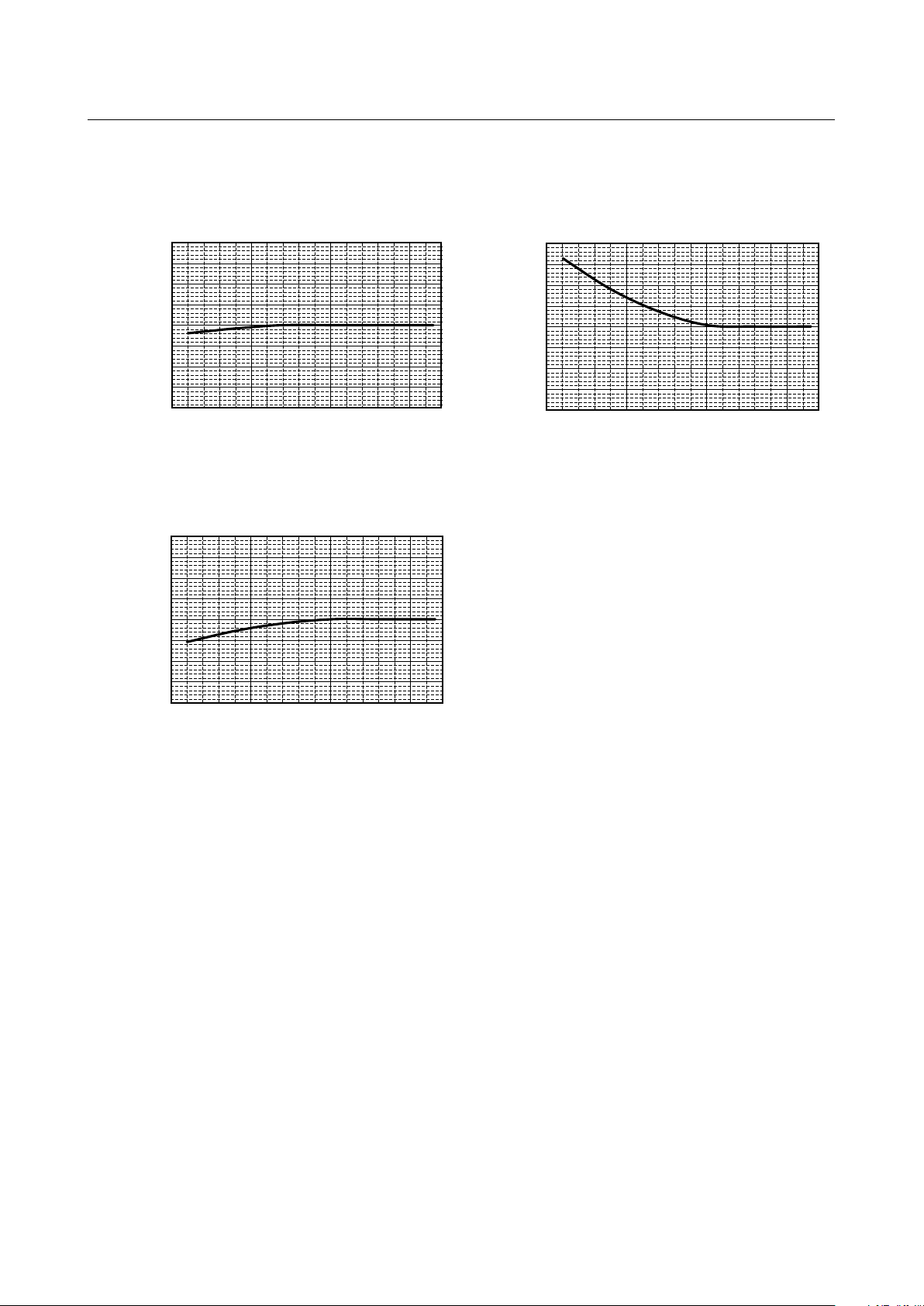
0.80
0.85
0.90
0.95
1.00
1.05
1.10
1.15
1.20
Water Flow rate [m3/h]
Ratio of heating capacity
0.80
0.85
0.90
0.95
1.00
1.05
1.10
1.15
1.20
Water Flow rate [m3/h]
Ratio of booster unit input
0.80
0.85
0.90
0.95
1.00
1.05
1.10
1.15
1.20
Water Flow rate [m3/h]
Ratio of outdoor unit input
(2) Correction by water flow rate
<PWFY-P100VM-E-BU>
0.5
1
1.5
2
0.5
1
1.5
2
0.5
1
1.5
2
(2) Correction by water ow rate
(2)-1 PWFY-P100VM-E-BU
- 35 -
Page 43

(2)-2 PWFY-P100VM-E-AU
<PWFY-P100VM-E-AU>
Heating Cooling
0.80
0.85
0.90
0.95
1.00
1.05
1.10
1.15
0.5 1.0 1.5 2.0
0.5 1.0 1.5 2.0
0.5 1.0 1.5 2.0
0.5 1.0 1.5 2.0
Water flow rate [m3/h]
Ratio of heating capacity
0.80
0.85
0.90
0.95
1.00
1.05
1.10
1.15
Water flow rate [m3/h]
Ratio of outdoor unit input
0.80
0.85
0.90
0.95
1.00
1.05
1.10
1.15
Water flow rate [m3/h]
Ratio of cooling capacity
0.80
0.85
0.90
0.95
1.00
1.05
1.10
1.15
Water flow rate [m3/h]
Ratio of outdoor unit input
<PWFY-P100VM-E-AU>
Heating Cooling
<PWFY-P200VM-E-AU>
Heating Cooling
0.80
0.85
0.90
0.95
1.00
1.05
1.10
1.15
0.5 1.0 1.5 2.0
0.5 1.0 1.5 2.0
0.5 1.0 1.5 2.0
0.5 1.0 1.5 2.0
Water flow rate [m3/h]
Ratio of heating capacity
0.80
0.85
0.90
0.95
1.00
1.05
1.10
1.15
Water flow rate [m3/h]
Ratio of outdoor unit input
0.80
0.85
0.90
0.95
1.00
1.05
1.10
1.15
Water flow rate [m3/h]
Ratio of cooling capacity
0.80
0.85
0.90
0.95
1.00
1.05
1.10
1.15
Water flow rate [m3/h]
Ratio of outdoor unit input
0.80
0.85
0.90
0.95
1.00
1.05
1.10
1.15
1.0 1.5 2.0 2.5 3.0 3.5 4.0 4.5
1.0 1.5 2.0 2.5 3.0 3.5 4.0 4.5
1.0 1.5 2.0 2.5 3.0 3.5 4.0 4.5
1.0 1.5 2.0 2.5 3.0 3.5 4.0 4.5
Water flow rate [m3/h]
Ratio of heating capacity
0.80
0.85
0.90
0.95
1.00
1.05
1.10
1.15
Water flow rate [m3/h]
Ratio of outdoor unit input
0.80
0.85
0.90
0.95
1.00
1.05
1.10
1.15
Water flow rate [m3/h]
Ratio of cooling capacity
0.80
0.85
0.90
0.95
1.00
1.05
1.10
1.15
Water flow rate [m3/h]
Ratio of outdoor unit input
(2)-3 PWFY-P200VM-E-AU
- 36 -
Page 44

0
10
20
30
40
50
0.5 1 1.5 2
Water flow rate [m3/h]
Water-pressure drop [kPa]
Refer to Chapter .
Refer to Chapter .
Refer to Chapter .
(3) Correction by total indoor
(6) Water pressure drop
<PWFY-P100/P200VM-E-AU>
0
10
20
30
40
50
60
70
80
90
100
Water flow rate [m3/h]
Water-pressure drop [kPa]
PWFY-P100VM-E-AU
PWFY-P200VM-E-AU
0.5
1
1.5
2
2.5
3
3.5
4
4.5
Refer to Chapter VIII.
(4) Correction by refrigerant piping length
Refer to Chapter VIII.
(5) Correction at frosting and defrosting
Refer to Chapter VIII.
(6) Water pressure drop
(6)-1 PWFY-P100VM-E-BU
(6)-2 PWFY-P100, 200VM-E-AU
- 37 -
Page 45

0
10
20
30
40
50
60
70
80
Inlet water temp. [°C]
-5
-10-15-20
0
5
10
15
20
25
30
35
40 45 50
Heating
PURY-(E)P.Y(S)HM-A(-BS)
Outdoor temp. [°CWB]
Heating
0
10
20
30
40
50
Outdoor temp. [°CWB]
Inlet water temp. [°C]
PUHY-(E)P.Y(S)HM-A(-BS)
-5
-10-15-20
0
5
10
15
20
25
30
35
40 45 50
(7) Operation temperature range
0
10
20
30
40
50
60
70
80
Circulating water temp. [°C]
Inlet water temp. [°C]
Heating
PQRY-P.Y(S)HM-A
-5
-10-15-20
0
5
10
15
20
25
30
35
40 45 50
Heating
0
10
20
30
40
50
Circulating water temp. [°C]
Inlet water temp. [°C]
PQHY-P.Y(S)HM-A
-5
-10-15-20
0
5
10
15
20
25
30
35
40 45 50
(7)-1 PWFY-P100VM-E-BU
(7)-2 PWFY-P100, 200VM-E-AU
- 38 -
Page 46

PURY-(E)P.Y(S)HM-A(-BS)
0
10
20
30
40
50
Outdoor temp. [°CWB]
Inlet water temp. [°C]
-5-10-15-20
0
5
10
15
20
25
30
35
40 45 50
Heating
Cooling
0
10
20
30
40
50
Outdoor temp. [°CDB]
Inlet water temp. [°C]
PUHY-(E)P.Y(S)HM-A(-BS)
PURY-(E) P.Y(S)HM-A(-BS)
-5
-10-15-20
0
5
10
15
20
25
30
35
40 45 50
PQRY-P.Y(S)HM-A
0
10
20
30
40
50
Circulating water temp. [°C]
Inlet water temp. [°C]
-5-10-15-20
0
5
10
15
20
25
30
35
40 45 50
Heating
Cooling
0
10
20
30
40
50
Circulating water temp. [°C]
Inlet water temp. [°C]
PQHY-P.Y(S)HM-A
PQRY-P.Y(S)HM-A
-5-10-15-20
0
5
10
15
20
25
30
35
40 45 50
- 39 -
Page 47

Heating
Cooling
0
10
20
30
40
50
Outdoor temp. [°CWB]
Inlet water temp. [°C]
0
10
20
30
40
50
Outdoor temp. [°CDB]
Inlet water temp. [°C]
PUHY-HP.Y(S)HM-A
PUHY-HP.Y(S)HM-A
-5-10-15-20 0 5 10 15 20
25 30
35
40 45 50-25
-5-10-15-20 0 5 10 15 20
25 30
35
40 45 50-25
- 40 -
Page 48

2. Sound pressure levels
When Low noise mode is set,the A/C system's capacity is limited. The system could return to normal operation
from Low noise mode automatically in the case that the operation condition is severe.
10
20
30
40
50
60
70
80
90
63 125 250 500 1k 2k 4k 8k
NC-40
NC-30
NC-20
NC-60
NC-50
NC-70
Octave band sound level (dB)
Approximate minimum
audible limit on
continuous noise
Sound level of PWFY-P100VM-E-BU
Measurement condition
PWFY-P100VM-E-BU
50/60Hz
When Low noise mode is set,the A/C system's capacity is limited. The system could return to normal operation
from Low noise mode automatically in the case that the operation condition is severe.
10
20
30
40
50
60
70
80
90
63 125 250 500 1k 2k 4k 8k
NC-40
NC-30
NC-20
NC-60
NC-50
NC-70
Octave band central frequency (Hz)
Octave band sound level (dB)
Sound level of PWFY-P100, 200VM-E-AU
Approximate minimum
audible limit on
continuous noise
dB(A)
29.0
8k
12.0
4k
15.0
2k
14.5
1k
22.5
500k
25.0
250
33.0
125
32.0
63
42.0
50/60Hz
dB(A)
44.0
8k
27.0
4k
27.5
2k
32.0
1k
39.0
500k
42.0
250
37.0
125
53.5
63
41.0
Measurement condition
PWFY-P100, 200VM-E-AU
Measurement
location
1m
1m
Measurement
location
1m
1m
Octave band center frequency <Hz>
(1) PWFY-P100VM-E-BU
(2) PWFY-P100, 200VM-E-AU
- 41 -
Page 49

3. Vibration levels
PWFY-P100VM-E-BU
PWFY-P100VM-E-BU
Model Vibration Levels[dBA]
34
10cm
20cm
Measurement
location
Service
panel
Concrete
VIBRATION LEVELS
(1) PWFY-P100VM-E-BU
- 42 -
Page 50

TH6
TH23
LEV1Wa
TH8
TH22
SV1
CV1
ST2
ST3
Water inlet
Water outlet
screw
screw
Hex
Hex
Brazed
Brazed
TH6
TH23
LEV1Wa
TH8
TH22
LEV1Wb
SV1
ST2
ST4
CV1
Water inlet
Water outlet
screw
screw
Brazed
Brazed
4. Refrigerant circuit diagrams and thermal sensors
Refrigerant Circuit Diagrams And Termal Sensors
TH11
63H1
63HS
63LS
TH13
TH22
LEV1W
LEV2W
COMP
Water outlet
TH6
TH8
ST3
ST1
ST2
CJ
Brazed
Brazed
screw
screw
Water inlet
Hex
Hex
(1) PWFY-P100VM-E-BU
(2) PWFY-P100VM-E-AU
(3) PWFY-P200VM-E-AU
- 43 -
Page 51

+
+
A
. For Air conditioning using such as Panel Heaters, Floor Heating and Fan coil units
Required total heating capacity kW
Safety factor; %
B. For Sanitary use such as Shower and Bathrooms
Conditions
Tank inlet water Temp.; °C
Tank outlet water Temp.; °C
(Set Temp -5 °C)
Safety factor for Heat Loss; %
Operating time; Hours
For Shower; /person x Person = (Water Temp. Condition °C)
°C)
For Bathrooms; /Person x Person = (Water Temp. Condition
The conversion of water volume to °C
x ( - ) / ( - )
+ x ( - ) / ( - )
= ℓ /day
Heating Capacity Calculation for sanitary usage
/
1,000 x ( - ) = M cal / day
The conversion of M cal to kW
/ 860 x 1,000 /
= kW
C. Total (A+B)
Total Heating Capacity
x
(100%
+x
(100%
%) +
x (100% %) = kW
D. No. of units required
Safety factor; %
%) / 12.5 kW = units
units are required
TankPWFY unit
4
3 3
3
3
7
IV
+
+
A
. For Air conditioning using such as Panel Heaters, Floor Heating and Fan coil units
Required total heating capacity 20
10
10
60
60
15
8
20
30
1,200
240
40
45
1,200
240
40
45
10
10
60
60
10
10
888
888
44.4
20
29.42 20
3
2.82
10
20
6.45 15 29.42
8 6.45
60 10 44.4
kW
Safety factor; %
B. For Sanitary use such as Shower and Bathrooms
Conditions
Tank inlet water Temp.; °C
Tank outlet water Temp.; °C
(Set Temp -5 °C)
Safety factor for Heat Loss; %
Operating time; Hours
For Shower; 60 /person x Person = (Water Temp. Condition °C)
°C)
For Bathrooms; 8 /Person x Person = (Water Temp. Condition
The conversion of water volume to °C
x ( - ) / ( - )
+ x ( - ) / ( - )
= ℓ /day
Heating Capacity Calculation for sanitary usage
/1,000 x ( - ) = M cal / day
The conversion of M cal to kW
/ 860 x 1,000 /
= kW
C. Total (A+B)
Total Heating Capacity
x
(100%
+x
(100%
%) +
x (100% %) = kW
D. No. of units required
Safety factor; %
%) / 12.5 kW = units
units are required
TankPWFY unit
4
3 3
3
3
7
Installation
1. How to calculate the necessary heating capacity
(1) Heating capacity calculation
(2) Calculation example
- 44 -
Page 52

2. Installation
(B)
400mm
300mm
600mm
(C)
(A)
(1) Selecting an installation site
• Do not install outdoors. The unit is not waterproof.
• BackupsystemisrecommendedincaseofPWFYunitbreakdown.
• The unit will get hot. Do not install in a location where heat gets trapped inside.
• Be sure to install unit in a place strong enough to withstand its weight.
Any lack of strength may cause unit to fall down, resulting in a personal injury.
• Do not install the unit where corrosive gas is generated.
• Have installation work in order to protect against earthquake.
Anyinstallationdeciencymaycauseunittofalldown,resultinginapersonalinjury.
• Pay a special attention to the place, such as a basement, etc. where refrigeration gas can stay, since refrigera
tion is heavier than the air.
• Do not install the unit where combustible gas may leak.
- If the gas leaks and accumulates around the unit, an explosion may result.
• Wheninstallingtheunitinahospital,communicationstation,orsimilarplace,providesufcientprotection
against noise.
- The inverter equipment, private power generator, high-frequency medical equipment, or radio communication
equipment may cause the air conditioner to operate erroneously, or fail to operate. On the other hand, the air
conditioner may affect such equipment by creating noise that disturbs medical treatment or image broadcasting.
• Do not install the unit on a structure that may cause leakage.
- When the room humidity exceeds 80 % or when the drain pipe is clogged, condensation may drip from the indoor
unit. Perform collective drainage work together with the unit, as required.
• ItisrecommendedthatawaterpumpisconnectedtoeachPWFYunit.
-
(1)-1 Securing installation and service space
• Please secure the following service spaces after installation.
(All servicing can be performed from the front of the unit)
[Fig. IV. 2. (1). 1]
(A) Piping space (right side)
(B) Top view
(C) Service space (front side)
Warning:
• Be sure to install the unit in a location which can adequately support its weight.
- If there is insufcient strength to support the unit’s weight, it could fall and cause injuries.
(1)-2 Combining indoor units with BC controllers/WCB and outdoor units
For combining indoor units with BC controllers and outdoor units, refer to section BC controllers and outdoor units
installation manual.
- 45 -
Page 53

(2) Installing the unit
X Y Z
Unit : mm
272 355 119
Model
PWFY-P100VM-E-BU
450 300
800
Y
X Z
500
525
13 47 205
(2)-1 Lifting method
Caution:
Be very careful when carrying the product.
- Do not have only one person to carry product if it is more than 20 kg.
- Do not tilt the unit while transporting.
- PP bands are used to pack some products. Do not use them as a mean for transportation because they are
dangerous.
- Tear plastic packaging bag and scrap it so that children cannot play with it. Otherwise plastic packaging bag may
suffocate children to death.
(2)-2 Product net weight
Model
Net weight
(2)-3 Center of gravity
(2)-3-1 PWFY-P100VM-E-BU
PWFY-P100VM-E-BU
60 kg
PWFY-P100VM-E-AU
35 kg
PWFY-P200VM-E-AU
38 kg
- 46 -
Page 54

(A)
(B)
205
300
450
500
525
Unit : mm
(2)-3-2 PWFY-P100, 200VM-E-AU
X
289
277
Model
PWFY-P100VM-E-AU
PWFY-P200VM-E-AU
Z
103
99
Y
346
347
20513
X
Y
800
500
525
300
450
Z
47
Unit : mm
(2)-4 Installation method
• Using the anchoring holes shown below, rmly bolt the unit to the base.
[Fig. IV. 2. (2). 1]
(A) 4-ø14 (Anchoring hole)
(B) (Top view)
Bases
• Be sure to install unit in a place strong enough to withstand its weight. If the base is unstable, reinforce with a con
crete base.
• The unit must be anchored on a level surface. Use a level to check after installation.
• If the unit is installed near a room where noise is a problem, using an anti-vibration stand on the base of the unit is
recommended.
- 47 -
-
Page 55

(3) Refrigerant pipe and drain pipe specications
(D)
(A)
(B)
(C)
(E)
480
100191
54
102
114
134
184 (206*1)
Unit : mm
(3)-1 Refrigerant pipe and drain pipe specications
To avoid dew drops, provide sufcient antisweating and insulating work to the refrigerant and drain pipes.
When using commercially available refrigerant pipes, be sure to wind commercially available insulating material (with a
heat-resisting temperature of more than 100 °C and thickness given below) onto both liquid and gas pipes.
Be also sure to wind commercially available insulating material (with a form polyethylene’s specic gravity of 0.03 and
thickness given below) onto all pipes which pass through rooms.
1) Select the thickness of insulating material by pipe size.
Unit : mm
Model
Gas
Liquid
Drain
Insulating material's thickness
PWFY-P100VM-E-BU
ø
15.88
ø
9.52
PWFY-P100VM-E-AU
ø
15.88
ø
9.52
ø
32
More than 10 mm
PWFY-P200VM-E-AU
ø
19.05
ø
9.52
2) If the unit is used on the highest story of a building and under conditions of high temperature and humidity, it is
necessary to use pipe size and insulating material’s thickness more than those given in the table above.
3) If there are customer’s specications, simply follow them.
(3)-2 Refrigerant pipe, drain pipe and lling port
(A) Refrigerant piping (gas)
(B) Refrigerant piping (liquid)
(C) Water inlet
(D) Water outlet
(E) Drain outlet
*1: PWFY-P100, 200VM-E-AU
- 48 -
Page 56

(4) Connecting refrigerant pipes and drain pipes
(A)
(A)
(E)
(C)
(F)
(B)
(D)
(4)-1 Refrigerant piping work
This piping work must be done in accordance with the installation manuals for both outdoor unit and BC controller/WCB
(simultaneous cooling and heating R2 series).
• R2 series is designed to operate in a system that the refrigerant pipe from an outdoor unit is received by BC
controller/WCB and branches at the BC controller/WCB to connect between indoor units.
• The PWFY unit should be connected to 2 ports on the BC controller. (Set BC controller DIP SW 4-6 to ON)
• For constraints on pipe length and allowable difference of elevation, refer to the outdoor unit manual.
• The method of pipe connection is brazing connection.
Caution:
• Install the refrigerant piping for the indoor unit in accordance with the following.
1. Cut the tip of the indoor unit piping, remove the gas, and then remove the brazed cap.
[Fig. IV. 2. (4). 1]
(A) Cut here
(B) Remove brazed cap
2. Pull out the thermal insulation on the site refrigerant piping, braze the unit piping, and replace the insulation in its
original position.
Wrap the piping with insulating tape.
Note:
• Pay strict attention when wrapping the copper piping since wrapping the piping may cause condensation
instead of preventing it.
* Before brazing the refrigerant piping, always wrap the piping on the main body, and the thermal insulation
piping, with damp cloths to prevent heat shrinkage and burning the thermal insulation tubing.
ensure that the ame does not come into contact with the main body itself.
[Fig. IV. 2. (4). 2]
Take care to
(A) Thermal insulation
(B) Pull out insulation
(C) Wrap with damp cloth
(D) Return to original position
(E) Ensure that there is no gap here
(F) Wrap with insulating tape
- 49 -
Page 57

Cautions On Refrigerant Piping
(A)
(B)
(a)
(C) (C) (C)
(D) (b)
(E)
• Be sure to use non-oxidative brazing for brazing to ensure that no foreign matter or moisture enter
into the pipe.
• esuretoapplyrefrigeratingmachineoilovertheareconnectionseatingsurfaceandtightenthe
connection using a double spanner.
• Provide a metal brace to support the refrigerant pipe so that no load is imparted to the indoor
unitendpipe.Thismetalbraceshouldbeprovided500mmawayfromtheindoorunit’sare
connection.
Warning:
When installing and moving the unit, do not charge it with refrigerant other than the refrigerant (R407C or R22)
speciedontheunit.
- Mixing of a different refrigerant, air, etc. may cause the refrigerant cycle to malfunction and result in severe damage.
Caution:
• UserefrigerantpipingmadeofC1220(CU-DHP)phosphorusdeoxidizedcopperasspeciedintheJISH3300
“Copper and copper alloy seamless pipes and tubes”. In addition, be sure that the inner and outer surfaces of
the pipes are clean and free of hazardous sulphur, oxides, dust/dirt, shaving particles, oils, moisture, or any
other contaminant.
• Never use existing refrigerant piping.
- The large amount of chlorine in conventional refrigerant and refrigerator oil in the existing piping will cause the new
refrigerant to deteriorate.
• Store the piping to be used during installation indoors and keep both ends of the piping sealed until just
before brazing.
- If dust, dirt, or water gets into the refrigerant cycle, the oil will deteriorate and the compressor may fail.
(4)-2 Drain piping work
1. Ensure that the drain piping is downward (pitch of more than 1/100) to the outdoor (discharge) side. Do not provide
any trap or irregularity on the way. (a)
2. Ensure that any cross-wise drain piping is less than 20 m (excluding the difference of elevation). If the drain piping
is long, provide metal braces to prevent it from waving. Never provide any air vent pipe. Otherwise drain may be
ejected.
3. Use a hard vinyl chloride pipe VP-25 (with an external diameter of 32 mm) for drain piping.
4. Ensure that collected pipes are 100 mm lower than the unit body’s drain port as shown in (b).
5. Do not provide any odor trap at the drain discharge port.
6. Put the end of the drain piping in a position where no odor is generated.
7. Do not put the end of the drain piping in any drain where ionic gases are generated.
[Fig. IV. 2. (4).3]
(A) Downward slope 1/100 or more
(B) Drain hose
(C) Unit
(D) Collective piping
(E) Maximize this length to approx. 100 mm
- 50 -
Page 58

3. Water pipe installation
Water-side
heat exchanger
Solid arrows in the figure indicate
the direction of water flow.
PWFY
Field supply
Tank Outlet
Inlet
City water
Overflowed water
Roof
To drain outlet
Uphill gradient ≥ 1/200
P
P
T
T
P
1)
1)
1)
1)
2)
2)
3)
3) 3)
4)
4) 4)4)
5)
5)
5)
6)
7)
8)
8)
9)
11) 11)
12)
(1) Water circuit sample
Sample of water circuit for PWFY
Consider the following when designing and installing a water piping system. (Items (1)-(12) in the gure are explained
below.)
1) Union joints/ange joints etc.
Install a ange etc. to allow for easy replacement of connected equipment.
2) Thermometer
For checking unit performance and operation monitoring
3) Water pressure gauge
For operation status monitoring
4) Valve
Install a valve for easy replacement and cleaning of the refrigerant ow control device.
Install a refrigerant ow control valve on the fan coil outlet side.
5) Flexible joint
Recommended to prevent the noise and vibration from the pump from being transmitted.
6) Drain pipe
Install the drain pipe with an inclination of between 1/100 and 1/200 to provide a downward ow of drain water.
For cold climate installation, take an appropriate measure (e.g., drain heater) to prevent the drain water from
freezing.
7) Pump
Use a pump that is large enough to compensate for the total water pressure loss and to supply sufcient water to the
unit.
8) Air vent valve
Provide air vent valves on the pipes.
9) Expansion tank
Install an expansion tank to accommodate expanded water and to supply water.
10) Cold/Hot water pipe
Use pipes that allow for easy air purging, and provide sufcient insulation.
11) Drain valve
Install drain valves so that water can be drained for servicing.
12) Strainer
Install a strainer near the PWFY unit to keep foreign materials from entering the water-side heat exchanger.
- 51 -
Page 59

(1)-1 Caution for water pipe installation
(A)
45°
Consider the following when designing and installing a water piping system.
• Do not use steel pipes as water pipes.
- Copper pipes or stainless steel pipes are recommended.If iron pipes are used in the existing system, do not connect
a new circuit to the old one. Keep the existing and new circuits separate.
• Light pipes are similar to other air-conditioning pipes, however, please observe the following precautions during
installation.
• Before a long period of non use, purge the water out of the pipes and thoroughly let them dry.
• Use a closed water circuit.
• When using the unit for cooling, add brine to the circulating water to prevent it from freezing.
• When installed in a low-ambient temperature environment, keep the water circulating at all times. If that is not
possible, purge the water out of the pipes completely.
• Do not use the water used for this unit for drinking or food manufacturing.
• When the ambient temperature is 0 ˚C or lower during stop operation, keep the water circulating at all times, or
purge the water out of the pipes completely.
Model
PWFY-P100VM-E-BU
PWFY-P100VM-E-AU
PWFY-P200VM-E-AU
*1 When the attached expan-
sion joints are installed.
Water inlet
PT 3/4 Screw
PT 3/4 Screw
PT 1 Screw*1
Water outlet
PT 3/4 Screw
PT 3/4 Screw
PT 1 Screw*1
(2) Selecting a water pump
Use a pump that is large enough to compensate for the total water pressure loss and to supply sufcient water to the unit.
(3) Installing the strainer
• Install the strainer at the angle of 45˚ or less as shown in [Fig. IV 3.(3).1].
• Install the supplied strainer at the water inlet.
[Fig. IV 3.(3).1]
(A) Y-type strainer
(4) Precautions during installation
• Use the reverse-return method to insure proper pipe resistance to each unit.
• To insure easy maintenance, inspection, and replacement of the unit, use a proper joint, valve, etc. on the water
intake and outlet port. In addition, be sure to install a strainer on the water intake pipe. (In order to maintain the heat
source unit, a strainer on the circulating water inlet is necessary.)
* An example of the heat source unit installation is shown in the diagram below.
• Install a suitable air vent on the water pipe. After sending water through the pipe, be sure to vent the excess air.
• Compressed water may form in the low-temperature sections of heat source unit. Use a drainage pipe connected to
the drain valve at the base of the unit to drain the water.
• Install a back ow-prevention valve on the pump and a exible joint to prevent excess vibration.
• Use a sleeve to protect the pipes where they go through a wall.
• Use metal ttings to secure the pipes, and install them so that they have maximum protection against breakage and
bending.
• Do not confuse the water intake and outlet valves.
• This unit doesn’t have any heater to prevent freezing within tubes. When the water ow is stopped on low ambient,
take out the water from tubes.
• The unused knockout holes should be closed and the opening of refrigerant pipes, water pipes, power source and
transmission wires should be lled with putty and so on to prevent from rain. (eld construction)
• Wrap some sealing tape around the screw part to prevent water leakage.
• Wrap the sealing tape as follows.
1. Wrap the joint with sealing tape in the direction of the threads (clockwise), and do not let the tape run over
the edge.
2. Overlap the sealing tape by two-thirds to three-fourths of its width on each turn. Press the tape with your ngers
so that it is pressed rmly against each thread.
3. Leave the 1.5th through 2nd farthest threads away from the pipe and unwrapped.
• Hold the pipe on the unit side in place with a spanner when installing the pipes or strainer. Tighten screws to a torque
of 50 N.m.
• Water pipes can get very hot, depending on the preset temperature. Wrap the water pipes with insulating materials
to prevent burns.
• On the PWFY-P200VM-E-AU model, install the expansion joint (accessory) at the inlet after installing the strainer,
and outlet.
- 52 -
Page 60

(5) Example of unit installation
(A)
(A)
(D)
(C)
(B)
(E)
(F)
(E)
(B)
(C)
(G)
(G)
(A)
(B)
[Fig. IV. 3.(5).1]
PWFY- P200VM-E-AU
(A) Close valve
(B) Water inlet
(C) Water outlet
(E) Y-type strainer
(F) Drain pipe
(G) Expansion joint
(D) Refrigerant piping
(6) Insulation installation
The surface temperature of the water pipe would be very high, depending on the set temperature. Insulate the pipe
to prevent burns. When operating PWFY-P100, P200VM-E-AU with cold water, insulate the water pipe to prevent
condensation.
Wrap insulation material around water pipes as shown in [Fig. IV. 3.(6).1].
• Any heat source piping.
• Indoor piping in cold-weather regions where frozen pipes are a problem.
• When air coming from the outside causes condensation to form on piping.
• Any drainage piping.
[Fig. IV. 3.(6).1]
(A) Heat insulation material (accessory)
(B) Inject with caulking material
- 53 -
Page 61

(7) Water processing and water quality control
0
100
200
300
400
500
0 10 20 30 40 50 60 70
Total hardness [mg/L]
Water volume limitation [L]
0
500
1000
1500
2000
2500
3000
0 10 20 30 40 50 60 70
Total hardness [mg/L]
Water volume limitation [L]
PWFY-P100VM-E-BU
Condition: Water outlet temp. 70°C Condition: Water outlet temp. 45°C
PWFY-P100/200VM-E-AU
Available water volume area Available water volume area
To preserve water quality, use the closed type of cooling tower for unit. When the circulating water quality is poor, the
water heat exchanger can develop scales, leading to a reduction in heat-exchange power and possible corrosion of the
heat exchanger. Please pay careful attention to water processing and water quality control when installing the water
circulation system.
• Removal of foreign objects or impurities within the pipes.
During installation, be careful that foreign objects, such as welding fragments, sealant particles, or rust, do not enter
the pipes.
• Water Quality Processing
a) Depending on the quality of the cold-temperature water used in the air-conditioner, the copper piping of the heat
exchanger may become corroded. We recommend regular water quality processing.
Cold water circulation systems using open heat storage tanks are particularly prone to corrosion.
When using an open-type heat storage tank, install a water-to-water heat exchanger, and use a closed-loop
circuit on the air conditioner side. If a water supply tank is installed, keep contact with air to a minimum, and
keep the level of dissolved oxygen in the water no higher than 1mg/liter.
b) Water quality standard
Items
pH (25 ˚C)
Electric conductivity (mS/m) (25 ˚C)
(µ s/cm) (25 ˚C)
Chloride ion (mg Cl
Sulfate ion (mg SO4
Standard
Acid consumption (pH4.8)
items
Total hardness (mg CaCO
Calcium hardness (mg CaCO
Ionic silica (mg SiO
Refer-
Iron (mg Fe/liter)
ence
Copper (mg Cu/liter)
items
Sulde ion
Ammonium ion (mg NH
Residual chlorine (mg Cl/liter)
Free carbon dioxide (mg CO
Ryzner stability index
-
/liter)
2-
/liter)
(mg CaCO3/liter)
3
/liter)
3
/liter)
2
/liter)
(mg S2-/liter)
+
4
/liter)
2
/liter)
Lower mid-range temperature water system
Water Temp.
Recirculating water
7.0 ~ 8.0
30 or less
[300 or less]
50 or less
50 or less
50 or less
70 or less
50 or less
30 or less
1.0 or less
1.0 or less
not to be
detected
0.3 or less
0.25 or less
0.4 or less
–
=<
60 ˚C
Make-up water
7.0 ~ 8.0
30 or less
[300 or less]
50 or less
50 or less
50 or less
70 or less
50 or less
30 or less
0.3 or less
1.0 or less
not to be
detected
0.1 or less
0.3 or less
4.0 or less
–
Higher mid-range temperature water system
Recirculating water
Water Temp. > 60 ˚C
7.0 ~ 8.0
30 or less
[300 or less]
30 or less
30 or less
50 or less
70 or less
50 or less
30 or less
1.0 or less
1.0 or less
not to be
detected
0.1 or less
0.1 or less
0.4 or less
–
Make-up water
7.0 ~ 8.0
30 or less
[300 or less]
30 or less
30 or less
50 or less
70 or less
50 or less
30 or less
0.3 or less
1.0 or less
not to be
detected
0.1 or less
0.3 or less
4.0 or less
–
Corrosive
Reference : Guideline of Water Quality for Refrigeration and Air Conditioning Equipment. (JRA GL02E-1994)
c) Please consult with a water quality control specialist about water quality control methods and water quality
calculations before using anti-corrosive solutions for water quality management.
d) When replacing a previously installed air conditioning device (even when only the heat exchanger is being
replaced), rst conduct a water quality analysis and check for possible corrosion.
Corrosion can occur in cold-water systems even if there has been no prior signs of corrosion.
If the water quality level has dropped, please adjust water quality sufciently before replacing the unit.
Refer to the below graph for the maximum amount of circulating water in the water pipe. Make sure that this
amount does not exceed.
[Fig. IV. 3. (7).1] Maximum circulating water
Tendency
Scale-forming
- 54 -
Page 62

(8) Pump interlock
IN1
TB142A
Water Pump
Strainer
Control Box
In broken lines are field
supply products.
Operation signal
Pump interlock
Pump operation
TB141A
TB142A
OUT1
IN1
TM1
52P
MCB
䌾220/230/240V
52P
MP
Control Box (field supply)
L N
Unit
TM1
Operation ON signal
Terminal No. TB141A OUT1
Relay contacts output Rated voltage : L-N : 220 㨪 240V
When Dip switch 3-6 is OFF
The relay closes during reception of cooling or heating operation signal from the remote controller.
(Note : it is output even if the thermostat is OFF (when the compressor is stopped).)
When Dip switch 3-6 is ON
The relay closes during compressor operation.
Rated load : 0.6A
Output
Operation
Pump interlock
Terminal No.
Input
Operation
TB142A IN1
Level signal
If the circuit of TB142A IN1 is open, compressor operation is prohibited.
Use of PWFY unit with the water pump can cause a heat exchanger freeze depending on the ambient air temperature or the
operation status of other indoor units in the same refrigerant system. This problem has become preventable by connecting the
water pump to the external output (TB141A : OUT1) contact so that when thermistors detect low water temperature, the water
pump is actuated to prevent heat exchanger from freezing.
The freeze prevention control is not associated with DipSW3-6.
Set DipSW1-10 to ON to invalidate the control for cases where there is no risk of freeze.
The unit may be damaged if it is operated with no water circulating through the pipes.
Be sure to interlock unit operation and the water-circuit pump. Use the terminal blocks for interlocking TB142A (IN1) on
the unit.
[Fig. IV. 3. (8).1]
[Fig. IV. 3. (8).3]
[Fig. IV. 3. (8).2]
Example drawing for pump interlock
Relay
X :
TM1 :
Timer relay (closes after elapsing the
set time when it is powerd, while opens
promptly when it is not powerd.)
Magnetic contactor for water pump
52P :
Water pump
MP :
MCB :
Circuit breaker
*Remove the short circuit wire of IN1 when wiring to
TB142A.
*Decide TM1 time lag considering circuit water volume
and pump specication so that the PWFY unit start its
operation when the water is fully circulated.
(9) Anti freeze mode (Dip SW4-4 ON)
Anti freeze mode is to prevent water pipe from freezing.
The Anti freeze mode can set the heating temperature range between 10ºC~45ºC enabling the unit to maintain low water
temperature to prevent water pipes from freezing.
- 55 -
Page 63

V
(A) (B)
(A) (B)
(C)
(E) (E)
PE
PE
PE
(D)
PE
(D) (D)
PWFY-P100VM-E-BU
PWFY-P100,200VM-E-AU
System Design
1.Electricalwork
(1) General cautions
Warning:
Electricalworkshouldbedonebyqualiedelectricalengineersinaccordancewith“EngineeringStandards
ForElectricalInstallation”andsuppliedinstallationmanuals.Specialcircuitsshouldalsobeused.Ifthepower
circuitlackscapacityorhasaninstallationfailure,itmaycauseariskofelectricshockorre.
1. Be sure to take power from the special branch circuit.
2. Be sure to install an earth leakage breaker to the power.
3. Install the unit to prevent that any of the control circuit cables (remote controller, transmission cables, or external
input/output line) is brought in direct contact with the power cable outside the unit.
4. Ensure that there is no slack on all wire connections.
5. Some cables (power, remote controller, transmission cables external input/output line) above the ceiling may be
bitten by mouses. Use as many metal pipes as possible to insert the cables into them for protection.
6. Never connect the power cable to leads for the transmission cables. Otherwise the cables would be broken.
7. Be sure to connect control cables to the indoor unit, remote controller, and the outdoor unit.
8. Be sure to ground the unit.
9. Select control cables from the conditions given in page
56.
Caution:
Be sure to put the unit to the ground on the outdoor unit side. Do not connect the earth cable to any gas pipe,
water pipe, lightening rod, or telephone earth cable. Incomplete grounding may cause a risk of electric shock.
(2) Power supply for PWFY unit
(2)-1 Electrical characteristics of PWFY unit
• Power supply cords of appliances shall not be lighter than design 245 IEC 57 or 227 IEC 57.
• A switch with at least 3 mm contact separation in each pole shall be provided by the Air conditioner installation.
Model
PWFY-P100VM-E-BU
Model
PWFY-P100VM-E-AU
PWFY-P200VM-E-AU
Hz
50/60
50/60
220-230-240 V
Hz
Power supply Compressor
Volts
220-230-240 V
Voltage range
Max. 264 V
Min. 198 V
Power supply
Volts
MCA (A)
15.71
Voltage range
Max. 264 V
Min. 198 V
Output (kW)
1.0
MCA (A)
0.085
SC (A)
1.25
Cooling
RLA (A)
Heating
11.63-11.12-10.66
RLA (A)
Heating
0.068-0.065-0.063
(2)-2 Power cable specications
Model
PWFY-P100VM-E-BU
Model
PWFY-P100VM-E-AU
PWFY-P200VM-E-AU
[Fig. V. 1.(2).1]
Minimum wire thickness (mm2)
Main cable
2.5
Total
operating
current
16 A or less
25 A or less
32 A or less
branch
-
Minimum wire thickness (mm2)
Main cable
1.5
2.5
4.0
Ground
2.5
branch
Breaker for
current leakage
30 A 30 mA 0.1 sec or less
Ground
1.5
2.5
4.0
1.5
2.5
4.0
20 A 30 mA 0.1 sec. or less
30 A 30 mA 0.1 sec. or less
40 A 30 mA 0.1 sec. or less
Breaker for current
leakage
Local swich (A)
capacity
25
fuse
25
Local swich (A)
capacity
fuse
16
25
32
Breaker for wiring (NFB) (A)
30
Breaker for wiring (NFB) (A)
16
25
32
20
30
40
Caution:
Do not use anything other than the correct capacity breaker and fuse. Using fuse, wire or copper wire with too
largecapacitymaycauseariskofmalfunctionorre.
- 56 -
(A) Breaker for current leakage
(B) Local switch or breakers for wiring
(C) PWFY-P100VM-E-BU
(D) PWFY-P100, 200VM-E-AU
(E) Pull box
Page 64

(3) Connecting remote controller, indoor and outdoor transmission cables
TB02
TB15
earth cable
(shielded)
TB5
SM1M2 SM1M2
TB3
M1M2
(A) (B) (C)
(D)
(E)
(E)
1 2 S
TB15TB5
SM1M2 1 2
(shielding wire)
(B)
(A)
S
2
1
L
N
DC10~13V
1 2
A B
(C)
S
M2
M1
(D)
(E)
2
S
M2
M1
(A)
(B)
(D)
(E)
1
L
N
DC10~13V
A B
1 2
(C)
• Connect unit TB5 and outdoor unit TB3. (Non-polarized 2-wire (shield))
The “S” on unit TB5 is a shielding wire connection. For specications about the connecting cables, refer to the
outdoor unit installation manual.
• Install a remote controller following the manual supplied with the remote controller.
(3)-1 Power supply examples
(3)-1-1 Using MA Remote controller (Remote controller is optionally available)
• Connect the “1” and “2” on unit TB15 to a MA remote controller. (Non-polarized 2-wire)
[Fig. V. 1. (3). 1] MA Remote controller
(A) Outdoor unit
(B) BC controller/WCB
(C) PWFY-P100VM-E-BU
(D) PWFY-P100, 200VM-E-AU
(E) MA remote controller
• DC 10 to 13 V between 1 and 2 (MA remote controller)
[Fig. V. 1. (3). 2] MA Remote controller
PWFY- P100VM-E-BU PWFY- P100, 200VM-E-AU
• The MA remote controller cannot be used at the same time or interchangeably.
Note:
Ensurethatthewiringisnotpinchedwhenttingtheterminalboxcover.Pinchingthewiringmaycutit.
Caution:
• Use wire with supplemental insulation.
• Input to TB142A, TB142B, and TB142C should not carry voltage.
• Cables from equipment connected to external input/output should have supplemental insulation.
• Use a single multiple-core cable for external input/output to allow for connection to the PG screw.
Caution:
Wirethepowersupplysothatnotensionisimparted.Otherwisedisconnection,heatingorreresult.
(A) Non-polarized
(B) TB15 (MA remote controller cables)
(C) MA remote Controller
(D) TB5 (Transmission cables)
(E) TB2 (Power supply wiring)
- 57 -
Page 65

(4) Transmission cable specications
(A)
(C)
(B)
(C)
(A)
(A)
(A)
(B)
(D)
(E)
(G)
(F)
(4)-1 Transmission cables
PWFY-P100VM-E-BU
Type of cable
Cable diameter
Remarks
Transmission cables
Shielding wire (2-core)
CVVS, CPEVS or MVVS
More than 1.25 mm
2
-
MA Remote controller cables
Sheathed 2-core cable (shielded)
CVVS
0.3 ∼ 1.25 mm2 (0.75 ∼ 1.25 mm2)*1
Max.length: 200 m
External input
Sheathed multi-core cable (shielded)
CVVS or MVVS
0.3 ∼ 0.5 mm
Max.length: 100 m
2
External output
Sheathed multi-core cable (unshielded)
CVV or MVV
0.3 ∼ 1.25 mm
Rated voltage: L1-N: 220
Rated load: 0.6 A
2
∼ 240 V
PWFY-P100, 200VM-E-AU
Transmission cables
Type of cable
Cable diameter
Remarks
Shielding wire (2-core)
CVVS, CPEVS or MVVS
More than 1.25 mm
2
-
*1 Connected with simple remote controller. CVVS, MVVS: PVC insulated PVC jacketed shielded control cable
CVV, MVV : PVC insulated PVC sheathed control cable
CPEVS : PE insulated PVC jacketed shielded communication cable
MA Remote controller cables
Sheathed 2-core cable
CVV (unshielded)
0.3 ∼ 1.25 mm2 (0.75 ∼ 1.25 mm2)*1
Max.length: 200 m
External input
Sheathed multi-core cable
CVV or MVV (unshielded)
0.3 ∼ 0.5 mm
Max.length: 100 m
2
External output
Sheathed multi-core cable (unshielded)
CVV or MVV
0.3 ∼ 1.25 mm
Rated voltage: L1-N: 220
Rated load: 0.6 A
2
∼ 240 V
(5) Connecting electrical connections
Verify that the model name on the operating instructions on the cover of the control box is the same as the model name
on the nameplate.
Step 1
Remove the screws holding the terminal box cover in place.
[Fig. V.1.(5).1]
(A) Screws
(B) Front panel
(C) Control box
Note:
Ensurethatthewiringisnotpinchedwhenttingtheterminalboxcover.Pinchingthewiringmaycutit.
Caution:
Install wiring so that it is not tight and under tension. Wiring under tension may break, or overheat and burn.
• Fix power source external input/output line wiring to control box by using buffer bushing for tensile force to prevent
electric shock. (PG connection or the like.) Connect transmission wiring to transmission terminal block through the
knockout hole of control box using ordinary bushing.
• After wiring is complete, make sure again that there is no slack on the connections, and attach the cover onto the
control box in the reverse order removal.
[Fig. IV. 1.(5).2]
(A) To prevent external tensile force from applying to the wiring
connection section of power source terminal block use buffer
bushing like PG connection or the like.
(B) External signal input cable
(C) External signal output cable
(D) Power source wiring
(E) Tensile force
(F) Use ordinary bushing
(G) Transmission cable and MA remote controller cable
Caution:
Wirethepowersupplysothatnotensionisimparted.Otherwisedisconnection,heatingorreresult.
- 58 -
Page 66

(6) Indoor unit address setting
SWU2 SWU3
SWU1
㧨BC controller㧪
OC
IC2
IC1
29(;
29(;
BC
0 1 1
2
3
3
4
0
0
SWU2 SWU1 SWU3
1234
IC1
IC2
㧨BC controller㧪
㧨WCB㧪
OC
IC2
IC1
29(;
29(;
29(;
29(;
BC
0 1 1
2
3
3
4
0
0
SWU2 SWU1 SWU3
IC2
IC3
IC1
0 1 1
2
3
0
0
0
4
0
0
0
SWU2 SWU1 SWU3
1234
IC1
IC2
IC1
IC2
IC3
OC
WCB
PWFY connecting
branch
Indoor/PWFY
connecting branch
(Be sure to operate with the main power turned OFF.)
[Fig. V. 1.(6).1]
<Address board>
(6)-1 Switch operation (BC controller)
• There are two types of rotary switch setting available: setting addresses 1 to 9 and over 10, and setting branch
numbers.
a) How to set addresses
Example: If Address is “3”, SWU2 (for over 10) remains at “0”, and match SWU1 (for 1 to 9) to “3”.
b) How to set branch numbers SWU3 (only for R2 series)
Branch number matches the BC controller branch number. If two branches are used, SWU3 should be set to a
smaller branch number. For other than R2 series, remain SWU3 as "0".
- example -
(6)-2 Switch operation (WCB)
a) How to set addresses
Example: If Address is “3”, SWU2 (for over 10) remains at “0”, and match SWU1 (for 1 to 9) to “3”.
b) How to set branch numbers SWU3 (only for R2 series)
There are two branches for WCB. Indoor unit/PWFY connecting branch should be set as "0" and PWFY connecting
branch as "1".
- example -
- 59 -
Page 67

(6)-2 Rule of setting address
Unit
PWFY unit
Standard indoor unit
ME, LOSSNAY
Remote controller
(Main)
ME, LOSSNAY
Remote controller
(Sub)
Address setting
01 ~ 50
52 ~ 99, 100
101 ~ 150
151 ~ 199, 200
NoteExample
The address of outdoor unit + 1
Please reset one of them to an address between 52
and 99 when two addresses overlap.
The address automatically becomes "100" if it is set
as "01~ 50"
The smallest address of indoor unit in the group + 100
The place of "100" is fixed to "1"
System remote
controller
ON/OFF remote
controller
G-50A
GB-50A
AG-150A
000, 201 ~ 250
000, 201 ~ 250
000, 201 ~ 250
Local remote controller
System controller
The address of main remote controller + 50
The address automatically becomes "200" if it is set
as "00"
10 1
10 1
0
1
2
3
4
5
6
7
8
9
0
1
2
3
4
5
6
7
8
9
10 1
10 1
0
1
2
3
4
5
6
7
8
9
0
1
2
3
4
5
6
7
8
9
0
1
2
3
4
5
6
7
8
9
0
1
2
3
4
5
6
7
8
9
0
1
2
3
4
5
6
7
8
9
0
1
2
3
4
5
6
7
8
9
0
1
2
3
4
5
6
7
8
9
0
1
2
3
4
5
6
7
8
9
0
1
2
3
4
5
6
7
8
9
10 1
10 1100
0
1
2
3
4
5
6
7
8
9
0
1
2
3
4
5
6
7
8
9
0
1
2
3
4
5
6
7
8
9
10 1100
10 1100
LMAP02-E
201 ~ 250
1
1
Fixed
Fixed
Group remote
controller
201 ~ 250
The smallest group No. to be managed + 200
10 1
2
Fixed
2
Fixed
Outdoor unit
BC controller
(Main)/WCB
53 ~ 99, 100
Lowest address within the indoor units connected to
the BC controller (Sub) plus 50.
10 1
BC controller
(Sub)
51 ~ 99, 100
The smallest address of indoor unit in same refrigerant
system + 50
Assign sequential address numbers to the outdoor
units in one refrigerant circuit system. OC and OS are
automatically detected. (Note 2)
Please reset one of them to an address between 51
and 99 when two addresses overlap.
The address automatically becomes "100" if it is set
as "01~ 50"
Use the most recent address within the same group of
indoor units. Make the indoor units address connected
to the BC controller (Sub) larger than the indoor units
address connected to the BC controller (Main).
If applicable, set the sub BC controllers in an PURY
system in the following order:
(1)
Indoor unit to be connected to the BC controller (Main)
(2)
Indoor unit to be connected to the BC controller (No.1 Sub)
(3)
Indoor unit to be connected to the BC controller (No.2 Sub)
Set the address so that (1)<(2)<(3)
0
1
2
3
4
5
6
7
8
9
0
1
2
3
4
5
6
7
8
9
0
1
2
3
4
5
6
7
8
9
0
1
2
3
4
5
6
7
8
9
0
1
2
3
4
5
6
7
8
9
0
1
2
3
4
5
6
7
8
9
0
1
2
3
4
5
6
7
8
9
0
1
2
3
4
5
6
7
8
9
10 1
(Note1)
0,2 0~5 0~9
Note1: To set the address to "100", set it to "50"
Note2: Outdoor units OC and OS in one refrigerant circuit system are automatically detected.
OC and OS are ranked in descending order of capacity. If units are the same capacity, they are ranked in ascending
order of their address.
- 60 -
Page 68

(6)-3 System examples
2. Address should be set to Indoor units, LOSSNAY and central controller.
3. M-NET power is supplied by the Outdoor unit at TB3, while Indoor unit and MA RC consume the M-NET power for transmission
use. The power balance is needed to consider for long M-NET wiring. Details refer to Data book G4 2-3 "System configuration
restrictions".
NOTE:
1. Outdoor units OC and OS in one refrigerant circuit system are automatically detected.
OC and OS are ranked in descending order of capacity. If units are the same capacity, they are ranked in ascending order
of their address.
Indoor unit
Indoor unit
PWFY-P100VM-E-BU
PWFY-P100VM-E-AU
PWFY-P200VM-E-AU
PWFY-P100VM-E-BU
PWFY-P100VM-E-AU
PWFY-P200VM-E-AU
PWFY-P100VM-E-BU
PWFY-P100VM-E-BU
WMAWMA
(Main) (Sub)
WMA
SRU
Wireless R/C
*1
*1 For Wireless R/C and Signal receiver unit (SRU), channel 1, 2 and 3 are selectable and should be set to same channel.
*2 System controller should connect to TB7 at Outdoor and use power supply unit together in Multi-Refrigerant-System.
*3 Do not group PWFY-P100VM-E-BU and PWFY-P100, 200VM-E-AU together in the same group.
*1
01
BC controller
53
BC controller
(Main)
93
03
64
3020
TB15
TB5 5BT20BT 2BT5BT
Transmission Booster
PAC-SF46EPA
TB5
3BT51BT51BT
TB15
WMA
(Main) (Sub)
WMA
TB15
ME R/C
MA R/C
PZ-52SF
SRU
Wireless R/C
*1
*1 142 143
41 42
43 95
45
TB15
TB5 5BT20BT
LOSSNAY
5BT5BT5BT
TB15
BC controller
(Sub1)
Group 2 *3
12 puorG1 puorG
Group 32 33 puorG13 puorG
TB3
TB7 7BT7BT7BT
TB7
TB3
201
PSU
5251
OC OS
PURY-(E)P-YSHM
SC
TB3TB3
9291
OC OS
PURY-(E)P-YSHM
TB3
97
OC
CN41CN40CN41CN40 CN41CN40CN41 14NC04NC CN40
ON
DipSW2-1
ON
DipSW2-1
ON
DipSW2-1
ON
DipSW2-1
ON
DipSW2-1
PURY-(E)P-YHM
4. Indoor units should be set with a branch number.
5. Assign an address to each of the sub BC controllers (SC1 and SC2) which equals the sum of the smallest address of the indoor
units that are connected to each sub BC controller and 50.
*2
(6)-3-1 MA remote controller, Multi-refrigerant-system, System Controller at TB7 side, Booster for long
M-NET wiring
PWFY-P100VM-E-BU/PWFY-P100,200VM-E-AUwithR2seriesoutdoorunits
- 61 -
Page 69

PWFY-P100,200VM-E-AUwithYseriesoutdoorunits
2. Address should be set to Indoor units, LOSSNAY and central controller.
3. M-NET power is supplied by the Outdoor unit at TB3, while Indoor unit and MA consume the M-NET power for transmission use.
The power balance is needed to consider for long M-NET wiring. Details refer to Data book G4 2-3 "System configuration
restrictions".
NOTE:
1. Outdoor units OC, OS1 and OS2 in one refrigerant circuit system are automatically detected.
OC, OS1 and OS2 are ranked in descending order of capacity. If units are the same capacity, they are ranked in ascending order
of their address.
Indoor unit
PWFY-P100VM-E-AU
PWFY-P200VM-E-AU
PWFY-P100VM-E-AU
PWFY-P200VM-E-AU
PWFY-P100VM-E-AU
PWFY-P200VM-E-AU
PWFY-P100VM-E-AU
PWFY-P200VM-E-AU
WMA
(Main)
WMA
MA
*2 System controller should connect to TB7 at Outdoor and use power supply unit together in Multi-Refrigerant-System.
03302010
TB15
5BT5BT 2BT5BT
Transmission Booster
PAC-SF46EPA
TB5
3BT51BT51BT
TB15
TB15
PWFY-P100VM-E-AU
PWFY-P200VM-E-AU
WMA MA
4341 42
45
TB15
5BT5BT
LOSSNAY
5BT5BT5BT
TB15
SRU
Wireless R/C
*1
*1
*1 For Wireless R/C and Signal receiver unit (SRU), channel 1, 2 and 3 are selectable and should be set to same channel.
Group 2
12 puorG
1 puorG
Group 32 33 puorG
13 puorG
TB3 TB3
TB7 7BT7BT7BT7BT
TB7
TB3
201
PSU
*2
535251
OC OS1 OS2
PUHY-(E)P-YSHM
SC
TB3TB3
9291
OC OS1
PUHY-(E)P-YSHM
TB3
97
OC
CN41CN40CN41CN40CN41CN40 CN41CN40CN41 14NC04NC CN40
ON
DipSW2-1
ON
DipSW2-1
ON
DipSW2-1
ON
DipSW2-1
ON
DipSW2-1
ON
DipSW2-1
PUHY-(E)P-YHM
Wireless R/C
*1
*1
64
- 62 -
Page 70

(7) External input/output function
OUT4OUT3OUT2
TB141A
OUT1
IN1 IN2 IN3 IN4
IN5IN6 IN7 IN8
TB142CTB142BTB142A
COM+
CN421
(BK)(BU)
CN422
32211
3
CN421
(BK)
(BU)
CN422
3
2
+
211
3
current
direction
Current generator
External
analog input
+
current
direction
Method
Input T(A), T(B)
4mA :T(A)
20mA:T(B)
S/W default
T(A)=10°C
T(B)=70°C.
*All setting with a controller.
T(B)°C
T(A)°C
4mA 20mA
la
Conversion equation:To=[{T(B) - T(A)}/16] × Ia + [ T(A) - {T(B) - T(A)}/4]
To: set temperature, Ia: analogue input value (mA)
Calculation example: T(A)=30°C, T(B)=70°C, Ia=10mA
Conversion equation: To=2.5 × Ia+20 To=45°C
Changeable with
PAR-W21MAA
Presettemperatureinput(externalanaloginput:4mA-20mA)
•Externalinput
Input through CN421, CN422 on the circuit board. (Fig. V. 1.(7).1)
•Externalanaloginput
Use the supplied connector.
If no temperature settings are made via the MA remote controller,
the temperature changes with the current of generator.
Externaloutputterminal
External output terminal (refer to Fig. V. 1.(7).2) is ineffective when the circuit is open.
Refer to Table V. 1.(7).1 for information about each contact.
The current in the circuit to be connected to the external output terminal must be 0.6A or less.
Table V. 1.(7).1
OUT1
OUT2
OUT3
OUT4
Operation ON/OFF
Defrost
Compressor
Error signal
[Fig. V. 1.(7).1]
[Fig. V. 1.(7).2]
Externalinputterminal
The piping length must be within 100 m.
External input terminal (refer to Fig. V. 1.(7).2 is ineffective when the circuit is open.
Refer to Table V. 1.(7).2 through Table V. 1.(7).4 for information about each contact.
Only the “pump interlock” function is ineffective when the circuit is short-circuited.
Connect a relay circuit to the external output terminal as shown in Fig. IV. 3.(8).1.
The specications of the relay circuit to be connected must meet the following conditions.
Contact rating voltage >= DC15V
Contact rating current >= 0.1A
Minimum applicable load =< 1mA at DC
[Table V. 1.(7).2] TB142A [Table V. 1.(7).4] TB142C
IN1
Pump interlock
[Table V. 1.(7).3] TB142B
IN3
IN4
*1 PWFY-P100VM-E-BU Hot Water
PWFY-P100, 200VM-E-AU Heating
*2 Effective when SW 4-3 is set to ON.
*3 Effective when SW 4-4 is set to ON.
*4 PWFY-P100, 200VM-E-AU only
*5 When Heating ECO mode is effective, the outlet water temp. will be changed
based on ambient temp. automatically. (Except for PQHY/PQRY-series)
*6 When Anti-freeze mode is effective, the unit will set the heating temperature range
between 10ºC~45ºC enabling the unit to maintain low water temperature to prevent
water pipes from freezing.
Note: When setting Heating ECO or Anti-freeze mode, reset all power supply of all units (outdoor/indoor units).
Note:DipS/W1-1OFF:WaterInletTemp.
DipS/W1-1ON:WaterOutletTemp.
ThefactorysettingforDipSW1-1isOFF.
Signal priority = External input > centralized controller > remote controller
Connection demand
Operation ON/OFF
COM+
IN5
IN6
IN7
IN8
- 63 -
Common
*1
*2
*3
*4
Hot Water/Heating
Heating ECO
Anti-freeze
*5
*6
Cooling operation
[Fig. V. 1.(7).3]
Page 71

(8) BC controller piping design
Table
(8)-1-1
. Piping length limitation
Table (8)-1-2. Bent equivalent length "M"
)]tneb/.tf[ tneb/m( MledoM roodtuOhtgnel tnelaviuqe .xaMhtgnel .xaMerugif eht ni gnipiPmetI
]'51.1[ 53.0MHY002P)E(-1*d+c+b+a+B+Ahtgnel gnipip latoT
]'83.1[ 24.0MHY052P)E(]'326[ 091 ]'145[ 561d+B+AUO morf UI tsehtraF
Distance between OU and BC A 110 [360'] *1 110 [360'] *1 (E)P300YHM 0.42 [1.38']
Farthest IU from BC controller B+d 40 [131'] *2*3 40 [131'] *3 P350YHM 0.47 [1.54']
Heignt between OU and IU (OU above IU) H 50 [164'] *5 - P400YHM 0.50 [1.64']
Heignt between OU and IU (OU under IU) H' 40 [131'] *6 Height between IU and BC h1 15 [49'] (10 [32']) *4 Height between IU and IU h2 15 [49'] (10 [32']) *4 -
Fig. (8)-1-1 Piping length and height between IU and BC controller
Table (8)-1-3. Piping "A"size selection rule (mm [in.])
(m [ft.])
Outdoor Model Pipe(High pressure) Pipe(Low pressure)
(E)P200YHM ø15.88 [5/8"] ø19.05 [3/4"]
(E)P250YHM ø19.05 [3/4"] ø22.20 [7/8"]
(E)P300YHM ø19.05 [3/4"] ø22.20 [7/8"]
P350YHM ø19.05 [3/4"] ø28.58 [1-1/8"]
P400YHM ø22.20 [7/8"] ø28.58 [1-1/8"]
Table (8)-1-4. Piping "B" size seleciton rule (mm [in.])
Total down-stream Indoor capacity
Pipe(Liquid) Pipe(Gas)
P140 or less ø9.52 [3/8"] ø15.88 [5/8"]
Table (8)-1-5. Piping "a", "b", "c", "d" size selection rule
(mm [in.])
Indoor Unit size Pipe(Liquid) Pipe(Gas)
P15 to P50, GUF-50RD(H) ø6.35 [1/4"] ø12.70 [1/2"]
P63 to P140, GUF-100RD(H) ø9.52 [3/8"] ø15.88 [5/8"]
]"4/3[ 50.91ø]"8/3[ 25.9ø002P
]"8/7[ 02.22ø]"8/3[ 25.9ø052P
Note1. No Header usable on PURY system.
Note2. Indoor unit sized P100-P250 should be connected to BC controller via Y shape joint CMY-R160-J ;
Note3. Indoor unit sized P100-P250 does NOT share BC controller ports with other Indoor units ;
Note4. As bents cause pressure loss on transportation of refrigerant, fewer bents design is better ;
Piping length needs to consider the actual length and equivalent length which bents are counted.
Equivalent piping length (m)=Actual piping length+"M" x Quantity of bent.
Note5. Set DIP-SW 4-6 to ON of BC controller, in case of connected Indoor unit sized P100-P140 with 2 ports.
Note6. It is also possible to connect Indoor unit sized P100-P140 with 1 port (set DIP-SW 4-6 to OFF).
Note7. Individual indoor units grouped together to connect to the BC controller via one port cannot operate
individually in heating and cooling modes at the same time. I.e., they must all function in either heating
However, the cooling capacity decreases a little (For details, refer to the chapter OUTDOOR UNITS,
R2 SERIES, 6-4. Correction by port counts of the BC controller).
or cooling together.
Note8. Indoor capactiy is described as its model size. For example, PEFY-P63VML-E, its capacity is P63.
Note9. Total down-stream Indoor capacity is the summary of the model size of Indoors down-stream.
For example, PEFY-P63VML-E + PEFY-P32VML-E : Total Indoor capacity = P63 + P32 = P95.
OU : Outdoor Unit ; IU : Indoor Unit ; BC : BC controller
*1. Refer to the section (8)-2.
*2. Details refer to Fig.(8)-1-1
*3. Farthest Indoor from BC controller "B+d" can exceed 40m till 60m if no Indoor sized P200, P250 connected. Details refer to Fig.(8)-1-1
*4. Distance of Indoor sized P200, P250 from BC must be less than 10m, if any.
*5. 90m is available depending on the model and installation conditions. For more detailed information, contact your local distributor.
*6. 60m is available depending on the model and installation conditions. For more detailed information, contact your local distributor.
0
10
20
30
40
50
60
70
0 5 10 15
Height difference between the main BC controller
and farthest indoor unit (m)
Pipe length between the main BC
controller and farthest indoor unit (m)
(P100-250)
BC controller
a
b
H
H'
h1
IU
(P15-P80)
Joint
(CMY-R160-J)
IU
Joint
(CMY-Y102S-G2)
Max.3 sets for 1 port.
Total capacity <= P80
B
c
d
IU
A
OU
Reducer (P15~P50)
(attached with BC controller)
IU
h2
For outdoor units equal to or larger than a size P400, on
the BC controller please ensure CMB-P•V-GA is used.
S
T
M
N
CMY-R160-J
(
Gas
side)
IU
CMY-R160-J
(
Liquid
side)
BC controller
(T)ø19.05ID
(N)ø9.52ID
(M)ø3/8"(Flare)
(M)ø3/8"(Flare)
(S)ø5/8"(Flare)
Joint CMY-R160-J Gas side
Joint CMY-R160-J Liquid side
(S)ø5/8"(Flare)
234
234
Fig. (8)-1AA
Fig. (8)-1A Piping scheme
(8)-1
IF 16 ports or less are in use, I.e., if only one BC controller is in use with no sub BC controller
- 64 -
Page 72

(8)-2 Total piping length restrictions
[PURY-(E)P200,250,300YHM-A / PQRY-P200,250,300YHM-A] [PURY-P350, 400YHM-A, PURY-EP250,300YHM-A]
[PURY-(E)P400,450,500,550YSHM-A(1)
/ PQRY-P400,450,500,550,600YSHM-A]
]A-MHSY054P-YRUP[
[PURY-P600, 650YSHM-A, PURY-EP600YSHM-A] [PURY-P700, 750, 800YSHM-A]
200
300
400
500
600
700
800
900
1000
10 20 30 40 50 60 70 80 90 100 110
Distance between outdoor unit and BC controller(m)
Tot al extended pipe length (m)
200
300
400
500
600
700
800
900
1000
10 20 30 40 50 60 70 80 90 100 110
Distance between outdoor unit and BC controller(m)
Tot al extended pipe length (m)
200
300
400
500
600
700
800
900
1000
10 20 30 40 50 60 70 80 90 100 110
Distance between outdoor unit and BC controller(m)
Tot al extended pipe length (m)
200
300
400
500
600
700
800
900
1000
10 20 30 40 50 60 70 80 90 100 110
Distance between outdoor unit and BC controller(m)
Tot al extended pipe length
(m)
200
300
400
500
600
700
800
900
1000
10 20 30 40 50 60 70 80 90 100 110
Distance between outdoor unit and BC controller(m)
Tot al extended pipe length
(m)
200
300
400
500
600
700
800
900
1000
10 20 30 40 50 60 70 80 90 100 110
Distance between outdoor unit and BC controller(m)
Tot al extended pipe length
(m)
- 65 -
Page 73

(9) WCB piping design
WCB
A
C
D E
d e f
g
Header branch
a
b
c
B
H H1
h1
h2
Capped
Line branch
0
10
20
30
40
50
60
70
0 5 10 15
Height difference between WCB
and farthest indoor unit (m)
Pipe length between WCB and
farthest indoor unit (m)
*1. Refer to Fig. (2)-1 "Restrictions on piping length" .
*2. Please refer to Fig. (2)-2 "Distance between WCB and farthest Indoor unit" when the distance between WCB controller and farthest indoor unit exceeds 40 m.
(Not applicable to the P250 model indoor unit).
*3. The values in the parenthesis show the maximum piping length when the capacity of the connected indoor unit is 200 or more.
NOTE:
Joint branching is not possible after header branching.
Cover the unused branch using the optional cover cap (CMY-S202-J).
Top-bottom differential 90m(OU above IU) or 60m(OU below IU) is not available.
200
300
400
500
600
700
800
900
1000
10 20 30 40 50 60 70 80 90 100 110
Piping length between outdoor unit and WCB
(m)
Total piping length (m)
PURY-(E)P200,250,300YHM-A / PQRY-P200,250,300YHM-A
200
300
400
500
600
700
800
900
1000
10 20 30 40 50 60 70 80 90 100 110
Piping length between outdoor unit and WCB
(m)
Total piping length (m)
PURY-(E)P250,300,350YHM-A
OU
IU
IU IU AU
BU AU
AU
L1
L2
(Header branch
possible)
(Line branch
possible)
Indoor/
PWFY branch
PWFY branch
Piping in the figure Maximum length
A+B+C+D+E+a+b+c+d+e+f+
g
*1
A+C+D+E+g / A+B+c
165 m
(
Max. equivalent length of 190 m or less
)
011A
C+D+E+g / B+c
40
*2
05HUI evoba UO
041HUI woleb UO
h1
15
(10)
*3
h2
15(10
)
*3
Item
Total piping length
Farthest IU from OU
Distance between OU and WCB
Distance between IU and WCB
Height between IU and OU
Height between IU and WCB
Height between indoor units
Fig.(2)-1 Restrictions on piping length
Fig.(2)-2 Distance between WCB and fartherest indoor unit
Table (2)-1. Piping "B", "C", "D", "E" size selection rule (mm)
(mm)
Total capacity of indoor units Liquid pipe Gas pipe
-140 ø9.52 ø 15.88
14 - 200 ø 9.52 ø19.05
201 - 300
ø9.52 ø22.2
301 - 400 ø12.7 ø28.58
401 - ø15.88 ø28.58
Table (2)-2.
Piping "a", "b", "c", "d", "e", "f", "g" size selection rule
Model number Liquid pipe Gas pipe
20,25,32,40,50
ø
6.35
ø
12.7
63,71,80,100,125,140
ø
9.52
ø
15.88
200
ø
9.52
ø
19.05
250
ø
9.52
ø
22.2
Table (2)-3. Selection rule for branch pipe (joint)
Downstream unit model total Joint
-200 CMY-Y102S-G2
201 - 400 CMY-Y102L-G2
401 - CMY-Y202-G2
Table (2)-4. Selection rule for branch pipe (header)
4-Branching header
(Downstream unit
model total 200)
8-Branching header
(Downstream unit
model total 400)
10-Branching header
(Downstream unit
model total 650)
CMY-Y104-G CMY-Y108-G CMY-Y1010-G
- 66 -
Page 74

VI
FUNCTION
ON/OFF
Operation mode switching
Water temperature setting
Preset temperature range
Water temperature display
Permit / Prohibit
local operation
Weekly scheduler
Error
Self check (Error history)
Test run
Circulating water
replacement warning
LANGUAGE setting
Operation locking function
Runs and stops the operation of a group of units
Switches between Hot Water / Heating / Heating ECO / Anti-freeze / Cooling
* Available operation modes vary depending on the unit to be connected.
* Switching limit setting can be made via a remote controller.
Temperature can be set within the ranges below. (in increments of 1°C or 1°F)
Hot Water 30°C ~ 70°C
Heating 30°C ~ 45°C
Heating ECO 30°C ~ 45°C
Anti-freeze 10°C ~ 45°C
Cooling 10°C ~ 30°C
* The settable range varies depending on the unit to be connected.
Preset temperature range setting can be limited via a remote controller.
10°C ~ 90°C
(in increments of 1°C or 1°F)
* The settable range varies depending on the unit to be connected.
Individually prohibits operations of each local remote control function :ON/OFF,
Operation modes,water temperature setting, Circulating water replacement
warning reset.
*
Upper level controller may not be connected depending on the unit to be connected.
ON / OFF / Water temperature setting can be done up to 6 times one day in the week.
(in increments of a minute)
When an error is currently occurring on a unit, the afflicted unit and the error code
are displayed.
Searches the latest error history by pressing the CHECK button twice.
Enables the Test run mode by pressing the TEST button twice.
* Test run mode is not available depending on the unit to be connected.
Displays the circulating water replacement warning via the unit message.
Clears the display by pressing the CIR.WATER button twice.
* Circulating water replacement warning is not available depending on the unit to
be connected.
The language on the dot matrix LCD can be changed. (Seven languages)
English/German/Spanish/Russian/Italian/French/Swedish
Remote controller operation can be locked or unlocked.
·All-switch locking
·Locking except ON/OFF switch
Item Description
Operations
Display
Controller
1.PAR-W21MAAspecications
- 67 -
Page 75

2. Dip switch functions
Switch Function
Function according to switch setting
Switch setting timing
OFF ON
SW1
1 T
Operation after power recovery
*1
Operation after power recovery
H0 thermistor selection Water inlet thermistor TH6 Water outlet thermistor TH8 Before power on
Before power on
Before power on
2 - - - -
3
Remains stopped
Depends on the SW1-3 setting
Auto recovery (to the status
before power failure)
Forced to operate
*1 Valid only when SW1-4 is set to OFF
4
5 - - - -
6 - - - -
7 Test-run mode OFF ON Any time
8 Error history deleted Normal Deleted Any time
Interlocked operation with the
pump
Effective Ineffective Any time
9
Effective only when SW1-7 is
set to ON and only on the HEX
models.
Heating Cooling Any time
10
SW2 1-10
For self-diagnosis/operation
monitoring
- - Any time
SW3
1 Capacity setting (HEX unit only) 4HP 8HP (HEX unit only) Before power on
2 Service LED display selection Display in Centigrade Display in Fahrenheit Any time
3 - - - -
4 - - - -
5
Cumulative compressor operation time is deleted.
Normal Deleted Any time
6 - - - -
7 - - - -
8 - - - -
9 - - - -
10 - - - -
SW4
1
2
3
Use to change pr
Do not change from factory setting.
Do not change from factory setting.
eset temperature range for the Heating ECO
mode.
Booster : Ineffective
HEX : Ineffective
Booster : 30°C to 45°C
HEX : 30°C to 45°C
Before power on
4
Use to change preset temperature range for the Anti-freeze
mode.
BU : Ineffective
WH : Ineffective
BU : 10°C to 45°C
WH : 10°C to 45°C
Before power on
5 - - - -
6 - - - -
7 - - - -
8 - - - -
9 - - - -
10 - - - -
SW5
1 Error detection enabled
Enabling/disabling ACCT sensor
error detection
Error detection disable
(No load operation is possible)
Any time
2 - - - -
3 - - - -
4 - - - -
- 68 -
Page 76

VII
Components
Refrigerant
circuit
components
Electric circuit
parts
What to look for
Maintenance cycle
(times/year)
Replacement cycle
Compressor
Water-refrigerant heat exchanger
Solenoid valve
(PWFY-P100, 200VM-E-AU)
Check valve
(PWFY-P100, 200VM-E-AU)
Linear expansion valve
Strainer
Capillary tube
Pipes
Electromagnetic contactor
Overcurrent relay
Relay
Solenoid valve
Fuse
Electronic board
Switch
Pressure switch
Terminal block
Cable/connector
Fan
Motor
High/low pressure, vibration, noise
Insulation resistance, loose terminals
High/low pressure, water pressure loss
Operation, leakage, clogging
Operation, leakage, clogging
Operation
Inlet/outlet temperature difference
Contact wear, Vibration
Contact wear, Vibration
Corroded contact, loose terminals
Insulation resistance
loose terminals
Operation, Contact resistance.
Insulation resistance
Insulation resistance
External appearance
External appearance
Operation, Contact resistance.
Contact resistance.
loose terminals
Looseness, corrosion, and wearing
Balance
Insulation resistance, noise, vibration
20,000 hours
10 Years
7 Years
10 Years
7 Years
While in heavy use
10 Years
10 Years
8 Years
7 to 10Years
6 Years
7 Years
8 Years
8 Years
8 Years
7 to 10Years
8 Years
10 Years
10 Years
6 to 10Years
2
2
2
1
2
1
1
1
2
2
2
2
2
2
2
2
2
2
2
2
Regular preventive maintenance and parts replacement help keep the unit running smoothly and minimize problems.
The table below shows the maintenance schedule. Use the replacement timing in the table only as a guide. Some parts
may need to be replaced sooner, depending on the usage.
MaintenanceCycle
1. Routine maintenance checks
• Periodically and thoroughly check the circulating water circuit. (See table below.)
• Consult a maintenance technician.
2. Parts Replacement Cycle
- 69 -
Page 77

VIII
Capa
city
(kW)
Input
(kW)
Total capacit y of indoor units
10.0
10.0
20.0
30.0
40.0
50.0
0.0
5.0
100 200 300 400
Cooling
Heating
Cooling
Heating
P200 P250
Total capacit y of indoor units
Total capacit y of indoor units
Total capacit y of indoor units
Total capacit y of indoor units
100 200 300 400 500
Capacity(k
W
)
Input(k
W
)
Total capacit y of indoor units
Total capacit y of indoor units
Total capacit y of indoor units
Cooling
Heating
Cooling
Heating
P300 P350
10.0
20.0
30.0
40.0
50.0
0.0
5.0
10.0
Ca
p
acit
y(kW
)
Input(kW
)
200 300 400 500 600
Cooling
Heating
Cooling
Heating
P400 P450
20.0
10.0
10.0
15.0
30.0
40.0
50.0
60.0
0.0
5.0
200 300 400 500 600 700 800
Ca
p
acit
y(kW
)
Input(kW
)
30.0
40.0
50.0
60.0
70.0
0.0
5.0
15.0
20.0
10.0
Cooling
Heating
Cooling
Heating
P500 P550
Capa
city
(kW)
Input
(k
W
)
50.0
40.0
30.0
20.0
60.0
70.0
80.0
90.0
0.0
10.0
200 300 400 500 600 700 800 900
Cooling
Heating
Cooling
Heating
P600 P650
300 400 500 600 700 800 900 1000
Capa
city
(kW)
Input(
kW
)
40.0
20.0
60.0
80.0
100.0
120.0
0.0
10.0
30.0
20.0
Cooling
Heating
Cooling
Heating
P700 P750
Capac
it
y
(kW
)
Input(
kW
)
40.0
20.0
60.0
80.0
100.0
120.0
0.0
10.0
40.0
30.0
400 500 600 700 800 1200900 1000 1100
Cooling
Heating
Cooling
Heating
P800 P850
400 600 800 1000 14001200
Ca
p
acity(kW
)
In
p
ut
(
kW
)
60.0
40.0
80.0
100.0
120.0
140.0
0.0
10.0
30.0
20.0
Cooling
Heating
Cooling
Heating
P900 P950
PUHY-P200,250YHM-A
PUHY-P600,650YSHM-A
PUHY-P300,350YHM-A PUHY-P700,750YSHM-A
PUHY-P400,450YHM-A PUHY-P800,850YSHM-A
PUHY-P500,550YSHM-A PUHY-P900,950YSHM-A
Product Data (additional information for chapter III.)
1. Outdoor unit capacity tables
(1) Correction by total indoor
(1)-1 Y series
- 70 -
Page 78

Total capacit y of indoor units
Total capacit y of indoor units
Total capacit y of indoor units
Capa
city
(kW)
Input
(kW)
400 600 800 1000 1200 1400
Cooling
Heating
Cooling
Heating
P1000 P1050
80.0
60.0
20.0
30.0
40.0
100.0
120.0
140.0
160.0
0.0
10.0
400 600 800 1000 1200 1400 1600
Capa
city
(kW)
Input(
kW
)
80.0
100.0
120.0
140.0
160.0
0.0
10.0
30.0
40.0
20.0
Cooling
Heating
P1150
Cooling
Heating
P1100
Capa
city
(k
W
)
Input
(kW)
100.0
80.0
60.0
40.0
120.0
140.0
160.0
180.0
0.0
20.0
400 600 800 1000 1200 1400 1600 1800
Cooling
Heating
Cooling
Heating
P1250P1200
PUHY-P1000,1050YSHM-A
PUHY-P1200,1250YSHM-A
PUHY-P1100,1150YSHM-A
- 71 -
Page 79

Capa
city
(kW)
Input
(kW)
Total capacit y of indoor units
Total capacit y of indoor units
Total capacit y of indoor units
Total capacit y of indoor units
Total capacit y of indoor units
Capacity(k
W
)
Input(k
W
)
Total capacit y of indoor units
Total capacit y of indoor units
Total capacit y of indoor units
Ca
p
acit
y(kW
)
Input(kW
)
Ca
p
acit
y(kW
)
Input(kW
)
Capa
city
(kW)
Input
(k
W
)
300 400 500 600 700 800 900 1000
Capa
city
(kW)
Input(
kW
)
Capac
it
y
(kW
)
Input(
kW
)
400 500 600 700 800 1200900 1000 1100
400 600 800 1000 1200
Ca
p
acity(kW
)
In
p
ut
(
kW
)
10.0
10.0
20.0
30.0
40.0
50.0
0.0
5.0
400300200100
400300200100
Cooling
Heating
Cooling
Heating
EP200 EP250
10.0
10.0
20.0
30.0
40.0
50.0
0.0
5.0
Cooling
Heating
EP300
600500400300200
20.0
30.0
40.0
50.0
60.0
0.0
10.0
20.0
Cooling
Heating
Cooling
Heating
EP400 EP450
40.0
30.0
10.0
15.0
50.0
60.0
70.0
80.0
0.0
5.0
300 800700600500400200
Cooling
Heating
Cooling
Heating
EP500 EP550
200ޓޓޓޓ300ޓޓޓޓ400ޓޓޓޓ500ޓޓޓޓ600ޓޓޓޓ700ޓޓޓ800ޓޓޓޓ900
50.0
40.0
60.0
70.0
80.0
90.0
0.0
10.0
20.0
Cooling
Heating
EP650
Cooling
Heating
EP600
40.0
20.0
20.0
30.0
60.0
80.0
100.0
120.0
0.0
10.0
Cooling
Heating
Cooling
Heating
EP700 EP750
40.0
20.0
60.0
80.0
100.0
120.0
0.0
10.0
30.0
20.0
Cooling
Heating
Cooling
Heating
EP800 EP850
60.0
40.0
80.0
100.0
120.0
140.0
0.0
10.0
30.0
20.0
Cooling
Heating
EP900
PUHY-EP200,250YHM-A
PUHY-EP600,650YSHM-A
PUHY-EP300YHM-A PUHY-EP700,750YSHM-A(1)
PUHY-EP400,450YSHM-A(1) PUHY-EP800,850YSHM-A(1)
PUHY-EP500,550YSHM-A(1) PUHY-EP900YSHM-A
(1)-2 Y (High COP) series
- 72 -
Page 80

Capa
city
(kW)
Input
(kW)
Total capacit y of indoor units
Total capacit y of indoor units
Total capacit y of indoor units
100 200 300 400 500
Capacity(k
W
)
Input(k
W
)
Total capacit y of indoor units
Capa
city
(k
W
)
Input
(k
W
)
200 300 400 500 600
200 400 500 600 700 800
Capa
city
(k
W
)
Input(
kW
)
10.0
10.0
20.0
30.0
40.0
50.0
0.0
5.0
400300200100
Cooling
Heating
HP200
10.0
20.0
30.0
40.0
50.0
0.0
5.0
10.0
Cooling
Heating
HP250
Cooling
Heating
HP400
20.0
10.0
10.0
15.0
30.0
40.0
50.0
60.0
0.0
5.0
Cooling
Heating
HP500
30.0
40.0
50.0
60.0
70.0
0.0
5.0
15.0
20.0
10.0
300
PUHY-HP200YHM-A
PUHY-HP400YSHM-A
PUHY-HP250YHM-A PUHY-HP500YSHM-A
(1)-3 HP (ZUBADAN) series
- 73 -
Page 81

Capa
city
(kW)
Input
(kW)
Total capacit y of indoor units
100 200 300 400
Total capacit y of indoor units
Total capacit y of indoor units
Total capacit y of indoor units
Capacity(k
W
)
Input(k
W
)
Total capacit y of indoor units
Total capacit y of indoor units
Total capacit y of indoor units
Ca
p
acit
y(kW
)
Input(kW
)
Ca
p
acit
y(kW
)
Input(kW
)
Capa
city
(kW)
Input
(k
W
)
Capa
city
(kW)
Input(
kW
)
Capac
it
y
(kW
)
Input(
kW
)
Cooling
Heating
Cooling
Heating
P200 P250
15.0
10.0
10.0
20.0
25.0
30.0
35.0
2.0
6.0
8.0
4.0
100 200 300 400 500
Cooling
Heating
P350
Cooling
Heating
P300
10.0
20.0
30.0
40.0
50.0
4.0
8.0
6.0
12.0
14.0
10.0
200 300 400 500 600 700 800
Cooling
Heating
Cooling
Heating
P400 P450
20.0
20.0
10.0
30.0
40.0
50.0
60.0
0
10.0
15.0
5.0
50.0
40.0
60.0
70.0
80.0
90.0
15.0
20.0
10.0
5.0
200 300 500 600 700400 800 900 1000
Cooling
Heating
Cooling
Heating
P600 P650
400300 500 600 700 800 900 1000 1100 1200
40.0
60.0
80.0
100.0
10.0
5.0
20.0
25.0
30.0
15.0
Cooling
Heating
P750
Cooling
Heating
P700
400 500 600 800 1000700 900 1100 1200 1300
60.0
40.0
80.0
100.0
120.0
15.0
10.0
25.0
30.0
20.0
Cooling
Heating
P800
200 300 500 700400 600 800 900
50.0
40.0
30.0
60.0
70.0
80.0
10.0
5.0
20.0
15.0
Cooling
Heating
P550
Cooling
Heating
P500
PURY-P200,250YHM-A(-BS)
PURY-P600,650YSHM-A(-BS)
PURY-P300,350YHM-A(-BS) PURY-P700,750YSHM-A(-BS)
PURY-P400,450Y(S)HM-A(-BS) PURY-P800YSHM-A(-BS)
PURY-P500,550YSHM-A(-BS)
(1)-4 R2 series
- 74 -
Page 82

Capa
city
(kW)
Input
(kW)
Total capacit y of indoor units
Total capacit y of indoor units
Total capacit y of indoor units
100 200 300 400 500
100 200 300 400 500
Capacity(k
W
)
Input(k
W
)
Total capacit y of indoor units
Capa
city
(kW)
Input
(k
W
)
200 300 400 500 600 700
Capa
city
(k
W
)
Input(
kW
)
10.0
10.0
20.0
30.0
40.0
50.0
2.0
6.0
8.0
4.0
Cooling
Heating
Cooling
Heating
EP200 EP250
10.0
10.0
20.0
30.0
40.0
50.0
2.0
6.0
8.0
4.0
Cooling
Heating
EP300
Cooling
Heating
EP450
Cooling
Heating
EP400
20.0
30.0
40.0
50.0
60.0
4.0
8.0
6.0
12.0
14.0
10.0
40.0
30.0
20.0
50.0
60.0
70.0
80.0
15.0
20.0
10.0
5.0
200 600400 800300 700500 900
Cooling
Heating
Cooling
Heating
EP500 EP550
PURY-EP200,250YHM-A(-BS)
PURY-EP400,450YSHM-A(1)(-BS)
PURY-EP300YHM-A(-BS) PURY-EP500,550YSHM-A(1)(-BS)
(1)-5 R2 (High COP) series
- 75 -
Page 83

Capa
city
(kW)
Input
(kW)
Total capacit y of indoor units
100 200 300 400
100 200 300 400
Total capacit y of indoor units
Total capacit y of indoor units
Total capacit y of indoor units
Total capacit y of indoor units
100 200 300 400 500
Capacity(k
W
)
Input(k
W
)
Total capacit y of indoor units
Total capacit y of indoor units
Total capacit y of indoor units
Ca
p
acit
y(kW
)
Input(kW
)
200 300 400 500 600
Ca
p
acit
y(kW
)
Input(kW
)
Capa
city
(kW)
Input
(k
W
)
Capa
city
(kW)
Input(
kW
)
Capac
it
y
(kW
)
Input(
kW
)
Ca
p
acity(kW
)
In
p
ut
(
kW
)
10.0
10.0
20.0
30.0
40.0
50.0
0.0
5.0
Cooling
Heating
P200
20.0
30.0
40.0
50.0
0.0
5.0
10.0
Cooling
Heating
P250
10.0
10.0
20.0
30.0
40.0
50.0
0.0
5.0
Cooling
Heating
P300
10.0
Cooling
Heating
20.0
10.0
15.0
30.0
40.0
50.0
60.0
0.0
5.0
Cooling
Heating
P400
10.0
200 300 400 500 600
200 300 400 500 800600 700
200 300 400 500 800 900600 700
200 300 400 500 800 900600 700
20.0
10.0
10.0
15.0
30.0
40.0
50.0
60.0
0.0
5.0
Cooling
Heating
P450
Cooling
Heating
P500
30.0
40.0
50.0
60.0
70.0
0.0
5.0
15.0
20.0
10.0
50.0
40.0
30.0
20.0
60.0
70.0
80.0
90.0
0.0
10.0
Cooling
Heating
P550
50.0
40.0
30.0
20.0
60.0
70.0
80.0
90.0
0.0
10.0
Cooling
Heating
P600
PQHY-P200YHM-A
PQHY-P450YSHM-A
PQHY-P250YHM-A PQHY-P500YSHM-A
PQHY-P300YHM-A PQHY-P550YSHM-A
PQHY-P400YSHM-A PQHY-P600YSHM-A
(1)-6 WY series
- 76 -
Page 84

Capa
city
(kW)
Input
(kW)
Total capacit y of indoor units
Total capacit y of indoor units
Total capacit y of indoor units
Capacity(k
W
)
Input(k
W
)
Total capacit y of indoor units
Total capacit y of indoor units
Total capacit y of indoor units
Ca
p
acit
y(kW
)
Input(kW
)
Ca
p
acit
y(kW
)
Input(kW
)
Capa
city
(kW)
Input
(k
W
)
Capa
city
(k
W
)
Input(
kW
)
Cooling
Heating
P650
20.0
40.0
60.0
80.0
100.0
5.0
15.0
10.0
20.0
25.0
200 600400 800 1000
Cooling
Heating
P700
20.0
40.0
60.0
80.0
100.0
5.0
15.0
10.0
20.0
25.0
200 600400 800 1000
Cooling
Heating
P750
20.0
40.0
60.0
80.0
100.0
5.0
15.0
10.0
20.0
25.0
200 600400 800 1000
Cooling
Heating
P800
40.0
60.0
80.0
100.0
120.0
5.0
15.0
10.0
20.0
25.0
200 800500 1100 1400
Cooling
Heating
P850
40.0
60.0
80.0
100.0
120.0
5.0
15.0
10.0
20.0
25.0
200 800500 1100 1400
Cooling
Heating
P900
40.0
60.0
80.0
100.0
120.0
5.0
15.0
10.0
20.0
25.0
200 800500 1100 1400
PQHY-P650YSHM-A
PQHY-P850YSHM-A
PQHY-P700YSHM-A PQHY-P900YSHM-A
PQHY-P750YSHM-A
PQHY-P800YSHM-A
- 77 -
Page 85

Capa
city
(kW)
Input
(kW)
Total capacit y of indoor units
100 200 300 400
Total capacit y of indoor units
Total capacit y of indoor units
Total capacit y of indoor units
Total capacit y of indoor units
100 200 300 400 500
100 200 300 400 500
Capacity(k
W
)
Input(k
W
)
Total capacit y of indoor units
Total capacit y of indoor units
Total capacit y of indoor units
Ca
p
acit
y(kW
)
Input(kW
)
200100 300 400 500 600 700
Ca
p
acit
y(kW
)
Input(kW
)
Capa
city
(kW)
Input
(k
W
)
Capa
city
(kW)
Input(
kW
)
Capac
it
y
(kW
)
Input(
kW
)
Ca
p
acity(kW
)
In
p
ut
(
kW
)
200 300 400 500 800600 700
200 300 400 500 800600 700
200 300 400 500 800 900600 700
300 400 500 600 900 1000700 800
Cooling
Heating
P200
10.0
10.0
20.0
30.0
40.0
50.0
0.0
5.0
Cooling
Heating
P250
10.0
20.0
30.0
40.0
50.0
0.0
5.0
10.0
Cooling
Heating
P300
10.0
20.0
30.0
40.0
50.0
0.0
5.0
10.0
Cooling
Heating
P400
20.0
30.0
40.0
50.0
60.0
0.0
2.50
7.50
10.0
5.00
30.0
40.0
50.0
60.0
70.0
0.0
5.0
15.0
20.0
10.0
Cooling
Heating
P450
30.0
40.0
50.0
60.0
70.0
0.0
5.0
15.0
20.0
10.0
Cooling
Heating
P500
Cooling
Heating
P550
Cooling
Heating
P600
50.0
40.0
30.0
20.0
60.0
70.0
80.0
90.0
0.0
10.0
50.0
40.0
30.0
20.0
60.0
70.0
80.0
90.0
0.0
10.0
PQRY-P200YHM-A
PQRY-P450YSHM-A
PQRY-P250YHM-A PQRY-P500YSHM-A
PQRY-P300YHM-A PQRY-P550YSHM-A
PQRY-P400YSHM-A PQRY-P600YSHM-A
(1)-7 WR2 series
- 78 -
Page 86

(2) Correction by refrigerant piping length
Piping equivalent length (m)
1.00
0.90
0.80
0.95
0.85
0.75
0.65
0.70
Cooling capacity correction factor
PUHY-(E)P200YHM-A
Ref.: PUHY_YHM-A_CbRPL_EUDB_P200_C
Total capacity of indoor unit
100
150
200
260
0 20 40 60 80 100 120 140 160 180
Piping equivalent length (m)
1.00
0.90
0.80
0.95
0.85
0.75
0.65
0.70
Cooling capacity correction factor
0 20 40 60 80 100 120 140 160 180
PUHY-(E)P400Y(S)HM-A
Ref.: PUHY_YHM-A_CbRPL_EUDB_P400_C
Total capacity of indoor unit
200
300
400
520
Piping equivalent length (m)
1.00
0.90
0.80
0.95
0.85
0.75
0.65
0.70
Cooling capacity correction factor
PUHY-
(E)P
250YHM-A
Ref.: PUHY_YHM-A_CbRPL_EUDB_P250_C
Total capacity of indoor unit
125
188
250
325
0 20 40 60 80 100 120 140 160 180
Piping equivalent length (m)
1.00
0.90
0.80
0.95
0.85
0.75
0.65
0.70
Cooling capacity correction factor
PUHY-(E)P450Y(S)HM-A
Ref.: PUHY_YHM-A_CbRPL_EUDB_P450_C
225
338
450
585
Total capacity of indoor unit
0 20 40 60 80 100 120 140 160 180
Piping equivalent length (m)
1.00
0.90
0.80
0.95
0.85
0.75
0.65
0.70
Cooling capacity correction factor
PUHY-(E)P300YHM-A
Ref.: PUHY_YHM-A_CbRPL_EUDB_P300_C
Total capacity of indoor unit
150
225
300
390
0 20 40 60 80 100 120 140 160 180
0 20 40 60 80 100 120 140 160 180
Piping equivalent length (m)
1.00
0.90
0.80
0.95
0.85
0.75
0.65
0.70
Cooling capacity correction factor
PUHY-(E)P500YSHM-A
Ref.: PUHY_YHM-A_CbRPL_EUDB_P500_C
Total capacity of indoor unit
250
375
500
650
Piping equivalent length (m)
1.00
0.90
0.80
0.95
0.85
0.75
0.65
0.70
Cooling capacity correction factor
0 20 40 60 80 100 120 140 160 180
PUHY-P350YHM-A
Ref.: PUHY_YHM-A_CbRPL_EUDB_P350_C
Total capacity of indoor unit
175
263
350
455
Piping equivalent length [m]
1.00
0.90
0.80
0.95
0.85
0.75
0.65
0.70
Cooling capacity correction factor
PUHY-(E)P550YSHM-A
Ref.: PUHY_YHM-A_CbRPL_EUDB_P550_C
275
413
550
715
Total capacity of indoor unit
0 20 40 60 80 100 120 140 160 180
(2)-1 Y series
(2)-1-1 Cooling capacity correction
- 79 -
Page 87

Piping equivalent length (m)
1.00
0.90
0.80
0.95
0.85
0.75
0.65
0.70
0 20 40 60 80 100 120 140 160 180
PUHY-(E)P600YSHM-A
Ref.: PUHY_YHM-A_CbRPL_EUDB_P600_C
Total capacity of indoor unit
300
450
600
780
Piping equivalent length (m)
1.00
0.90
0.80
0.95
0.85
0.75
0.65
0.70
PUHY-(E)P800YSHM-A
Ref.: PUHY_YHM-A_CbRPL_EUDB_P800_C
Total capacity of indoor unit
400
600
800
1040
0 20 40 60 80 100 120 140 160 180
Piping equivalent length (m)
1.00
0.90
0.80
0.95
0.85
0.75
0.65
0.70
PUHY-(E)P650YSHM-A
Ref.: PUHY_YHM-A_CbRPL_EUDB_P650_C
Total capacity of indoor unit
325
488
650
845
0 20 40 60 80 100 120 140 160 180
Piping equivalent length (m)
1.00
0.90
0.80
0.95
0.85
0.75
0.65
0.70
0 20 40 60 80 100 120 140 160 180
PUHY-(E)P850YSHM-A
Ref.: PUHY_YHM-A_CbRPL_EUDB_P850_C
Total capacity of indoor unit
425
637
850
1105
Piping equivalent length (m)
1.00
0.90
0.80
0.95
0.85
0.75
0.65
0.70
PUHY-(E)P700YSHM-A
Ref.: PUHY_YHM-A_CbRPL_EUDB_P700_C
Total capacity of indoor unit
350
525
700
910
0 20 40 60 80 100 120 140 160 180
Piping equivalent length (m)
1.00
0.90
0.80
0.95
0.85
0.75
0.65
0.70
PUHY-(E)P900YSHM-A
Ref.: PUHY_YHM-A_CbRPL_EUDB_P900_C
Total capacity of indoor unit
450
675
900
1170
0 20 40 60 80 100 120 140 160 180
Piping equivalent length (m)
1.00
0.90
0.80
0.95
0.85
0.75
0.65
0.70
PUHY-(E)P750YSHM-A
Ref.: PUHY_YHM-A_CbRPL_EUDB_P750_C
Total capacity of indoor unit
375
563
750
975
0 20 40 60 80 100 120 140 160 180
Piping equivalent length (m)
1.00
0.90
0.80
0.95
0.85
0.75
0.65
0.70
PUHY-P950YSHM-A
Ref.: PUHY_YHM-A_CbRPL_EUDB_P950_C
Total capacity of indoor unit
475
712
950
1235
0 20 40 60 80 100 120 140 160 180
Cooling capacity correction factor
Cooling capacity correction factor
Cooling capacity correction factor
Cooling capacity correction factor
Cooling capacity correction factor
Cooling capacity correction factor
Cooling capacity correction factor
Cooling capacity correction factor
- 80 -
Page 88

Piping equivalent length (m)
1.00
0.90
0.80
0.95
0.85
0.75
0.65
0.70
0 20 40 60 80 100 120 140 160 180
PUHY-P1000YSHM-A
Ref.: PUHY_YHM-A_CbRPL_EUDB_P1000_C
Total capacity of indoor unit
500
750
1000
1300
Piping equivalent length (m)
1.00
0.90
0.80
0.95
0.85
0.75
0.65
0.70
0 20 40 60 80 100 120 140 160 180
PUHY-P1150YSHM-A
Ref.: PUHY_YHM-A_CbRPL_EUDB_P1150_C
Total capacity of indoor unit
575
862
1150
1495
Piping equivalent length (m)
1.00
0.90
0.80
0.95
0.85
0.75
0.65
0.70
0 20 40 60 80 100 120 140 160 180
PUHY-P1050YSHM-A
Ref.: PUHY_YHM-A_CbRPL_EUDB_P1050_C
Total capacity of indoor unit
525
787
1050
1365
Piping equivalent length (m)
1.00
0.90
0.80
0.95
0.85
0.75
0.65
0.70
PUHY-P1200YSHM-A
Ref.: PUHY_YHM-A_CbRPL_EUDB_P1200_C
Total capacity of indoor unit
600
900
1200
1560
0 20 40 60 80 100 120 140 160 180
Piping equivalent length (m)
1.00
0.90
0.80
0.95
0.85
0.75
0.65
0.70
PUHY-P1100YSHM-A
Ref.: PUHY_YHM-A_CbRPL_EUDB_P1100_C
Total capacity of indoor unit
550
825
1100
1430
0 20 40 60 80 100 120 140 160 180
Piping equivalent length (m)
1.00
0.90
0.80
0.95
0.85
0.75
0.65
0.70
0 20 40 60 80 100 120 140 160 180
PUHY-P1250YSHM-A
Ref.: PUHY_YHM-A_CbRPL_EUDB_P1250_C
Total capacity of indoor unit
625
937
1250
1625
Cooling capacity correction factor
Cooling capacity correction factor
Cooling capacity correction factor
Cooling capacity correction factor
Cooling capacity correction factor
Cooling capacity correction factor
- 81 -
Page 89

0.90
0 20 40 60 80 100 120 140 160 180
Heating capacity correction factor
0.95
1.00
Piping equivalent length (m)
PUHY-(E)P200,250YHM-A
Ref.: PUHY_YHM-A_CbRPL_EUDB_P200-P250_H
0.90
0 20 40 60 80 100 120 140 160 180
Heating capacity correction factor
0.95
1.00
Piping equivalent length (m)
PUHY-(E)P700,750,800YSHM-A
Ref.: PUHY_YHM-A_CbRPL_EUDB_P700-P800_H
0.90
0 20 40 60 80 100 120 140 160 180
Heating capacity correction factor
0.95
1.00
Piping equivalent length (m)
PUHY-(E)P300,350,400,450Y(S)HM-A
Ref.: PUHY_YHM-A_CbRPL_EUDB_P300-P450_H
0.90
0 20 40 60 80 100 120 140 160 180
Heating capacity correction factor
0.95
1.00
Piping equivalent length (m)
PUHY-(E)P850,900,950,1000YSHM-A
Ref.: PUHY_YHM-A_CbRPL_EUDB_P850-P1000_H
0.90
0 20 40 60 80 100 120 140 160 180
Heating capacity correction factor
0.95
1.00
Piping equivalent length (m)
PUHY-(E)P500,550,600,650YSHM-A
Ref.: PUHY_YHM-A_CbRPL_EUDB_P500-P650_H
0.85
0.90
0 20 40 60 80 100 120 140 160 180
Heating capacity correction factor
0.95
1.00
Piping equivalent length (m)
PUHY-P1050,1100,1150,1200,1250YSHM-A
Ref.: PUHY_YHM-A_CbRPL_EUDB_P1050-P1250_H
(2)-1-2 Heating capacity correction
- 82 -
Page 90

Piping equivalent length (m)
1.00
0.90
0.80
0.95
0.85
0.75
0.65
0.70
Cooling capacity correction factor
0 20 40 60 80 100 120 140 160
PUHY-HP200,250,400,500Y(S)HM-A
Total capacity of indoor unit
50
75
100
130
0.90
0 20 40 60 80 100 120 140 160
Heating capacity correction factor
0.95
1.00
Piping equivalent length (m)
PUHY-HP200,250,400,500Y(S)HM-A
1 PUHY-HP200YHM
Equivalent length = (Actual piping length to the farthest indoor unit) + (0.35 x number of bends in the piping) m
2 PUHY-HP250YHM
Equivalent length = (Actual piping length to the farthest indoor unit) + (0.42 x number of bends in the piping) m
3 PUHY-HP400,500YSHM
Equivalent length = (Actual piping length to the farthest indoor unit) + (0.50 x number of bends in the piping) m
(2)-2 HP (ZUBADAN) series
(2)-2-1 Cooling capacity correction
(2)-2-2 Heating capacity correction
(2)-2-3 How to obtain the equivalent piping length
- 83 -
Page 91

Piping equivalent length (m)
1.00
0.90
0.80
0.95
0.85
0.75
0.65
0.70
Cooling capacity correction factor
PURY-(E)P200YHM-A(-BS)
Ref.: PURY_YHM-A_CbRPL_EUDB_P200_C
Total capacity of indoor unit
100
150
200
300
0 20 40 60 80 100 120 140 160 180
Piping equivalent length (m)
1.00
0.90
0.80
0.95
0.85
0.75
0.65
0.70
Cooling capacity correction factor
0 20 40 60 80 100 120 140 160 180
PURY-(E)P400Y(S)HM-A(-BS)
Ref.: PURY_YHM-A_CbRPL_EUDB_P400_C
Total capacity of indoor unit
200
300
400
600
Piping equivalent length (m)
1.00
0.90
0.80
0.95
0.85
0.75
0.65
0.70
Cooling capacity correction factor
PURY-P250YHM-A(-BS)
Ref.: PURY_YHM-A_CbRPL_EUDB_P250_C
Total capacity of indoor unit
125
188
250
375
0 20 40 60 80 100 120 140 160 180
Piping equivalent length (m)
1.00
0.90
0.80
0.95
0.85
0.75
0.65
0.70
Cooling capacity correction factor
PURY-(E)P450YSHM-A(-BS)
Ref.: PURY_YHM-A_CbRPL_EUDB_P450_C
225
338
450
675
Total capacity of indoor unit
0 20 40 60 80 100 120 140 160 180
Piping equivalent length (m)
1.00
0.90
0.80
0.95
0.85
0.75
0.65
0.70
Cooling capacity correction factor
PURY-(E)P300YHM-A(-BS)
Ref.: PURY_YHM-A_CbRPL_EUDB_P300_C
Total capacity of indoor unit
150
225
300
450
0 20 40 60 80 100 120 140 160 180
0 20 40 60 80 100 120 140 160 180
Piping equivalent length (m)
1.00
0.90
0.80
0.95
0.85
0.75
0.65
0.70
Cooling capacity correction factor
PURY-(E)P500YSHM-A(-BS)
Ref.: PURY_YHM-A_CbRPL_EUDB_P500_C
Total capacity of indoor unit
250
375
500
750
Piping equivalent length (m)
1.00
0.90
0.80
0.95
0.85
0.75
0.65
0.70
Cooling capacity correction factor
0 20 40 60 80 100 120 140 160 180
PURY-P350YHM-A(-BS)
Ref.: PURY_YHM-A_CbRPL_EUDB_P350_C
Total capacity of indoor unit
175
263
350
525
Piping equivalent length [m]
1.00
0.90
0.80
0.95
0.85
0.75
0.65
0.70
Cooling capacity correction factor
PURY-(E)P550YSHM-A(-BS)
Ref.: PURY_YHM-A_CbRPL_EUDB_P550_C
275
413
550
825
Total capacity of indoor unit
0 20 40 60 80 100 120 140 160 180
(2)-3 R2 series
(2)-3-1 Cooling capacity correction
- 84 -
Page 92

Piping equivalent length (m)
1.00
0.90
0.80
0.95
0.85
0.75
0.65
0.70
Cooling capacity correction factor
0 20 40 60 80 100 120 140 160 180
PURY-(E)P600YSHM-A(-BS)
Ref.: PURY_YHM-A_CbRPL_EUDB_P600_C
Total capacity of indoor unit
300
450
600
900
Piping equivalent length (m)
1.00
0.90
0.80
0.95
0.85
0.75
0.65
0.70
Cooling capacity correction factor
PURY-P750YSHM-A(-BS)
Ref.: PURY_YHM-A_CbRPL_EUDB_P750_C
Total capacity of indoor unit
375
563
750
1125
0 20 40 60 80 100 120 140 160 180
Piping equivalent length (m)
1.00
0.90
0.80
0.95
0.85
0.75
0.65
0.70
Cooling capacity correction factor
PURY-P650YSHM-A(-BS)
Ref.: PURY_YHM-A_CbRPL_EUDB_P650_C
Total capacity of indoor unit
325
488
650
975
0 20 40 60 80 100 120 140 160 180
Piping equivalent length (m)
1.00
0.90
0.80
0.95
0.85
0.75
0.65
0.70
Cooling capacity correction factor
PURY-P800YSHM-A(-BS)
Ref.: PURY_YHM-A_CbRPL_EUDB_P800_C
Total capacity of indoor unit
400
600
800
1200
0 20 40 60 80 100 120 140 160 180
Piping equivalent length (m)
1.00
0.90
0.80
0.95
0.85
0.75
0.65
0.70
Cooling capacity correction factor
PURY-P700YSHM-A(-BS)
Ref.: PURY_YHM-A_CbRPL_EUDB_P700_C
Total capacity of indoor unit
350
525
700
1050
0 20 40 60 80 100 120 140 160 180
- 85 -
Page 93

0.80
0 20 40 60 80 100 120 140 160
Heating capacity correction factor
0.90
1.00
Piping equivalent length (m)
PURY-(E)P200YHM-A(-BS)
Ref.: PURY_YHM-A_CbRPL_EUDB_P200_H
0.80
0 20 40 60 80 100 120 140 160
Heating capacity correction factor
0.90
1.00
PURY-(E)P450,500YSHM-A(-BS)
Ref.: PURY_YHM-A_CbRPL_EUDB_P450_H
Piping equivalent length (m)
0.80
0 20 40 60 80 100 120 140 160
Heating capacity correction factor
0.90
1.00
Piping equivalent length (m)
PURY-(E)P250,300YHM-A(-BS)
Ref.: PURY_YHM-A_CbRPL_EUDB_P250_H
0.80
0 20 40 60 80 100 120 140 160
Heating capacity correction factor
0.90
1.00
PURY-(E)P550,600,650YSHM-A(-BS)
Ref.: PURY_YHM-A_CbRPL_EUDB_P550_H
Piping equivalent length (m)
0.80
0 20 40 60 80 100 120 140 160
Heating capacity correction factor
0.90
1.00
PURY-P350YHM-A(-BS)
Ref.: PURY_YHM-A_CbRPL_EUDB_P350_H.
Piping equivalent length (m)
0.80
0 20 40 60 80 100 120 140 160
Heating capacity correction factor
0.90
1.00
PURY-P700,750,800YSHM-A(-BS)
Ref.: PURY_YHM-A_CbRPL_EUDB_P700_H
Piping equivalent length (m)
0.80
0 20 40 60 80 100 120 140 160
Heating capacity correction factor
0.90
1.00
PURY-(E)P400Y(S)HM-A(-BS)
Ref.: PURY_YHM-A_CbRPL_EUDB_P400_H
Piping equivalent length (m)
(2)-3-2 Heating capacity correction
- 86 -
Page 94

(2)-4 WY series
Piping equivalent length (m)
1.00
0.90
0.80
0.95
0.85
0.75
0.65
0.70
Cooling capacity correction factor
PQHY-P200YHM-A
100
150
200
260
0 20 40 60 80 100 120 140 160 180
Piping equivalent length (m)
1.00
0.90
0.80
0.95
0.85
0.75
0.65
0.70
Cooling capacity correction factor
0 20 40 60 80 100 120 140 160 180
PQHY-P450YSHM-A
225
338
450
585
Piping equivalent length (m)
1.00
0.90
0.80
0.95
0.85
0.75
0.65
0.70
Cooling capacity correction factor
0 20 40 60 80 100 120 140 160 180
PQHY-P250YHM-A
125
188
250
325
Piping equivalent length (m)
1.00
0.90
0.80
0.95
0.85
0.75
0.65
0.70
Cooling capacity correction factor
0 20 40 60 80 100 120 140 160 180
PQHY-P500YSHM-A
250
375
500
650
Piping equivalent length (m)
1.00
0.90
0.80
0.95
0.85
0.75
0.65
0.70
Cooling capacity correction factor
0 20 40 60 80 100 120 140 160 180
PQHY-P300YHM-A
150
225
300
390
Piping equivalent length (m)
1.00
0.90
0.80
0.95
0.85
0.75
0.65
0.70
Cooling capacity correction factor
0 20 40 60 80 100 120 140 160 180
PQHY-P550YSHM-A
275
413
550
715
Piping equivalent length (m)
1.00
0.90
0.80
0.95
0.85
0.75
0.65
0.70
Cooling capacity correction factor
0 20 40 60 80 100 120 140 160 180
PQHY-P400YSHM-A
200
300
400
520
Piping equivalent length (m)
1.00
0.90
0.80
0.95
0.85
0.75
0.65
0.70
Cooling capacity correction factor
0 20 40 60 80 100 120 140 160 180
PQHY-P600YSHM-A
300
450
600
780
(2)-4-1 Cooling capacity correction
- 87 -
Page 95

Piping equivalent length (m)
Cooling capacity correction factor
PQHY-P650YSHM-A
Piping equivalent length (m)
Cooling capacity correction factor
PQHY-P850YSHM-A
Piping equivalent length (m)
Cooling capacity correction factor
PQHY-P700, 750YSHM-A
Piping equivalent length (m)
Cooling capacity correction factor
PQHY-P900YSHM-A
Piping equivalent length (m)
Cooling capacity correction factor
PQHY-P800YSHM-A
325
488
650
845
0 20 40 60 80 100 120 140 160 180 0 20 40 60 80 100 120 140 160 180
1.00
0.90
0.80
0.95
0.85
0.75
0.65
0.70
350
525
700
910
0 20 40 60 80 100 120 140 160 180
1.00
0.90
0.80
0.95
0.85
0.75
0.65
0.70
400
600
800
1040
0 20 40 60 80 100 120 140 160 180
1.00
0.90
0.80
0.95
0.85
0.75
0.65
0.70
425
638
850
1105
1.00
0.90
0.80
0.95
0.85
0.75
0.65
0.70
450
675
900
1170
0 20 40 60 80 100 120 140 160 180
1.00
0.90
0.80
0.95
0.85
0.75
0.65
0.70
- 88 -
Page 96

Piping equivalent length (m)
1.00
0.90
0.80
0.95
0.85
0.75
0.65
0.70
Cooling capacity correction factor
0 20 40 60 80 100 120 140 160 180
PQHY-P200YHM-A
Piping equivalent length (m)
1.00
0.90
0.80
0.95
0.85
0.75
0.65
0.70
Cooling cap acity correction factor
0 20 40 60 80 100 120 140 160 180
PQHY-P400, 450, 500YSHM-A
Piping equivalent length (m)
1.00
0.90
0.80
0.95
0.85
0.75
0.65
0.70
Cooling capacity correction factor
0 20 40 60 80 100 120 140 160 180
PQHY-P250, 300YHM-A
Piping equivalent length (m)
Cooling capacity correction factor
PQHY-P650YSHM-A
Piping equivalent length (m)
Cooling capacity correction factor
PQHY-P850, 900YSHM-A
Piping equivalent length (m)
Cooling capacity correction factor
PQHY-P700, 750, 800YSHM-A
Piping equivalent length (m)
1.00
0.90
0.80
0.95
0.85
0.75
0.65
0.70
Cooling capacity correction factor
0 20 40 60 80 100 120 140 160 180
PQHY-P550, 600YSHM-A
1.00
0.90
0.80
0 20 40 60 80 100 120 140 160 180
1.00
0.90
0.80
0 20 40 60 80 100 120 140 160 180
1.00
0.90
0.80
0 20 40 60 80 100 120 140 160 180
(2)-4-2 Heating capacity correction
- 89 -
Page 97

(2)-4-3 How to obtain the equivalent piping length
Equivalent length = (Actual piping length to the farthest indoor unit) + (0.35 x number of bends in the piping) m
Equivalent length = (Actual piping length to the farthest indoor unit) + (0.42 x number of bends in the piping) m
Equivalent length = (Actual piping length to the farthest indoor unit) + (0.50 x number of bends in the piping) m
Equivalent length = (Actual piping length to the farthest indoor unit) + (0.70 x number of bends in the piping) m
Equivalent length = (Actual piping length to the farthest indoor unit) + (0.80 x number of bends in the piping) m
- 90 -
Page 98

Piping equivalent length (m)
1.00
0.90
0.80
0.95
0.85
0.75
0.65
0.70
Cooling capacity correction factor
PQRY-P200YHM-A
100
150
200
300
0 20 40 60 80 100 120 140 160 180
Piping equivalent length (m)
1.00
0.90
0.80
0.95
0.85
0.75
0.65
0.70
Cooling capacity correction factor
0 20 40 60 80 100 120 140 160 180
PQRY-P450YSHM-A
225
338
450
675
Piping equivalent length (m)
1.00
0.90
0.80
0.95
0.85
0.75
0.65
0.70
Cooling capacity correction factor
0 20 40 60 80 100 120 140 160 180
PQRY-P250YHM-A
125
188
250
375
Piping equivalent length (m)
1.00
0.90
0.80
0.95
0.85
0.75
0.65
0.70
Cooling capacity correction factor
0 20 40 60 80 100 120 140 160 180
PQRY-P500YSHM-A
250
375
500
750
Piping equivalent length (m)
1.00
0.90
0.80
0.95
0.85
0.75
0.65
0.70
Cooling capacity correction factor
0 20 40 60 80 100 120 140 160 180
PQRY-P300YHM-A
150
225
300
450
Piping equivalent length (m)
1.00
0.90
0.80
0.95
0.85
0.75
0.65
0.70
Cooling capacity correction factor
0 20 40 60 80 100 120 140 160 180
PQRY-P550YSHM-A
275
413
550
825
Piping equivalent length (m)
1.00
0.90
0.80
0.95
0.85
0.75
0.65
0.70
Cooling capacity correction factor
0 20 40 60 80 100 120 140 160 180
PQRY-P400YSHM-A
200
300
400
600
Piping equivalent length (m)
1.00
0.90
0.80
0.95
0.85
0.75
0.65
0.70
Cooling capacity correction factor
0 20 40 60 80 100 120 140 160 180
PQRY-P600YSHM-A
300
450
600
900
(2)-5 WR2 series
(2)-5-1 Cooling capacity correction
- 91 -
Page 99

Indoor unit sizes P200 and P250 must be connected to 2 ports on the BC controller.
Indoor unit sizes from P100 to P140 should normally be connected to 2 ports on the BC controller (set BC controller
DIP-SW 4-6 to its ON position).
In cases whereby indoor unit sizes from P100 to P140 are connected to only 1port on the BC controller (set BC controller
DIP-SW 4-6 to its OFF position), the cooling capacity of the indoor unit should be multiplied by a correction factor of
0.97.
Piping equivalent length (m)
1.00
0.90
0.80
0.95
0.85
0.75
0.65
0.70
Cooling capacity correction factor
0 20 40 60 80 100 120 140 160 180
PQRY-P200YHM-A
Piping equivalent length (m)
1.00
0.90
0.80
0.95
0.85
0.75
0.65
0.70
Cooling capa city correction fa ctor
0 20 40 60 80 100 120 140 160 180
PQRY-P400, 450, 500YSHM-A
Piping equivalent length (m)
1.00
0.90
0.80
0.95
0.85
0.75
0.65
0.70
Cooling capacity correction factor
0 20 40 60 80 100 120 140 160 180
PQRY-P250, 300YHM-A
Piping equivalent length (m)
1.00
0.90
0.80
0.95
0.85
0.75
0.65
0.70
Cooling capacity correction factor
0 20 40 60 80 100 120 140 160 180
PQRY-P550, 600YSHM-A
1 PQRY-P200YHM
Equivalent length = (Actual piping length to the farthest indoor unit) + (0.35 x number of bends in the piping) m
2 PQRY-P250, 300YHM
Equivalent length = (Actual piping length to the farthest indoor unit) + (0.42 x number of bends in the piping) m
3 PQRY-P400, 450, 500, 550, 600YSHM
Equivalent length = (Actual piping length to the farthest indoor unit) + (0.50 x number of bends in the piping) m
(2)-5-2 Heating capacity correction
(2)-5-3 How to obtain the equivalent piping length
(2)-5-4 Correction by port counts of the BC controller
- 92 -
Page 100

(3) Correction at frosting and defrosting
<R2 series>
Ref.: PURY_YHM-A_CbFROST_EUDB_ALL
PURY-(E)P200YHM-A(-BS)
PURY-(E)P250YHM-A(-BS)
PURY-(E)P300YHM-A(-BS)
PURY-P350YHM-A(-BS)
PURY-(E)P400Y(S)HM-A(-BS)
PURY-(E)P450YSHM-A(-BS)
PURY-(E)P500YSHM-A(-BS)
PURY-(E)P550YSHM-A(-BS)
PURY-(E)P600YSHM-A(-BS)
PURY-P650YSHM-A(-BS)
PURY-P700YSHM-A(-BS)
PURY-P750YSHM-A(-BS)
PURY-P800YSHM-A(-BS)
1.00
1.00
1.00
1.00
1.00
1.00
1.00
1.00
1.00
1.00
1.00
1.00
1.00
0.95
0.95
0.93
0.93
0.95
0.98
0.98
0.94
0.94
0.94
0.98
0.98
0.98
0.84
0.84
0.82
0.85
0.90
0.89
0.89
0.87
0.84
0.84
0.89
0.89
0.89
0.83
0.83
0.80
0.83
0.87
0.87
0.86
0.86
0.86
0.86
0.88
0.88
0.88
0.83
0.83
0.82
0.84
0.88
0.89
0.89
0.87
0.87
0.87
0.89
0.89
0.89
0.87
0.87
0.86
0.86
0.89
0.90
0.90
0.88
0.88
0.88
0.90
0.90
0.90
0.90
0.90
0.90
0.90
0.90
0.92
0.92
0.90
0.90
0.90
0.92
0.92
0.92
0.95
0.95
0.90
0.90
0.95
0.95
0.95
0.90
0.90
0.90
0.95
0.95
0.95
0.95
0.95
0.95
0.95
0.95
0.95
0.95
0.93
0.93
0.93
0.95
0.95
0.95
0.95
0.95
0.95
0.95
0.95
0.95
0.95
0.93
0.93
0.93
0.95
0.95
0.95
0.95
0.95
0.95
0.95
0.95
0.95
0.95
0.93
0.93
0.93
0.95
0.95
0.95
Table of correction factor at frost and defrost
6
43
1.00
4
39
0.95
2
36
0.85
1
34
0.85
0
32
0.85
-2
28
0.87
-4
25
0.87
-6
21
0.87
-8
18
0.87
-10
14
0.92
-25
-13
0.95
Outdoor inlet air temp.
Outdoor inlet air temp.
PUHY-HP200,250,400,500Y(S)HM
F
C
Due to frosting at the outdoor heat exchanger and the automatical defrosting operation, the heating capacity of the
outdoor unit should be considered by multiplying the correction factor which shown in the table below.
(3)-1 Y series
(3)-2 HP (ZUBADAN) series
(3)-3 R2 series
- 93 -
 Loading...