

Page 1

INDOOR UNIT OF CITY MULTI R410A SERIES
PWFY-P36NMU-E-BU
PWFY-P36NMU-E-AU
PWFY-P72NMU-E-AU
OPERATION MANUAL
For safe and correct use, please read this operation manual thoroughly before operating the indoor unit.
MODE D’EMPLOI
Avant de mettre en marche l’appareil intérieur, prière de lire ce mode d’emploi avec attention pour un usage correct et en toute sécurité.
I
GB
F
Page 2
Operation Section
FGB
Section d'opération
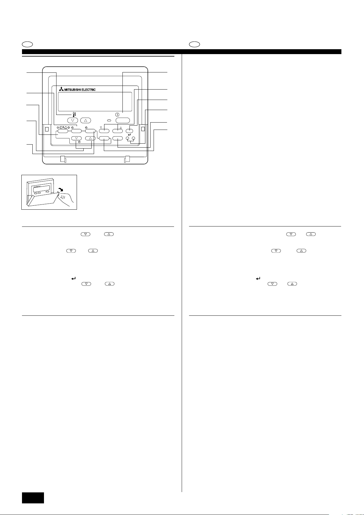
1
2
3
TEMP.
4
MENU
ON/OFF
INITIAL SETTING
CHECK TEST
5
MONITOR/SET
BACK DAY
PAR-W21MAA
CLOCK CLEAR
GB
D
*
F
1 [Set Temperature] buttons ( Down/ Up buttons)
2 [TIMER MENU] button (MONITOR/SET button)
3 [Mode] button (Return button)
4 [Set Time] buttons (
5 [TIMER ON/OFF] button (SET DAY button)
6 [CHECK] button (CLEAR button)
7 [TEST RUN] button
IE
8 Not available
9 [CIR. WATER] button (
0 [INITIAL SETTING] button (
A [ON/OFF] button
* Opening the lid.
Back/ Ahead buttons)
<Enter> button)
Down/ Up buttons)
ON/OFF
CIR.WATER
A
0
9
8
7
6
1 Touches [Réglage de la température] (Touches
2 Touche [TIMER MENU] (Touche MONITOR/SET)
3 Touche [Mode] (Touche de retour)
4 Touches [Réglage de l’heure] (Touches
5 Touche [TIMER ON/OFF] (Touche SET DAY)
6 Touche [CHECK] (Touche CLEAR)
7 Touche [TEST RUN]
8 Non disponible
9 Touche [CIR. WATER] (Touche
0 Touche [INITIAL SETTING] (Touches
A Touche [ON/OFF]
* Ouverture du couvercle.
<Validation>)
Arrière/ Avant)
Bas/ Haut)
Bas/ Haut)
PGRRUTR
2
Page 3
GB
Display Section
1
2
3
0A
TIME SUN MON TUE WED THU FRI SAT
TIMER
AFTER
ERROR CODE
˚F˚C
˚F˚C
Hr
AFTER
ON
OFF
FUNCTION
WEEKLY
SIMPLE
AUTO OFF
9
8
F
Section de visualisation
4
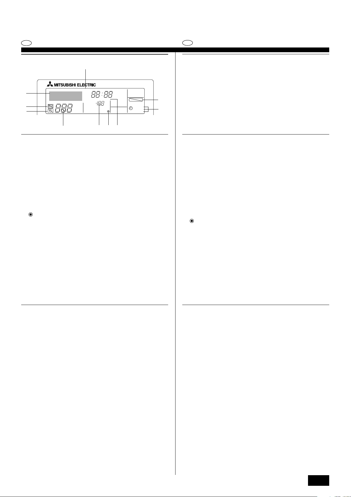
• For purposes of this explanation, all parts of the display are shown as lit. During actual operation, only the relevant items will be lit.
1 Identifies the current operation
Shows the operating mode, etc.
* Multilanguage display is supported.
2 “Centrally Controlled” indicator
Indicates that operation of the remote controller has been prohibited by a main
controller.
3 “Timer Is Off” indicator
Indicates that the timer is off.
4 Temperature Setting
Shows the target temperature.
5 Water Temperature Display
Shows the water temperature during water temperature display operation.
6 (Power On indicator)
Indicates that the power is on.
7 Error indicator
Comes on when error occurs
8 Timer indicators
The indicator comes on if the corresponding timer is set.
9 “Locked” indicator
Indicates that remote controller buttons have been locked.
0 Day-of-Week
Shows the current day of the week.
A Time/Timer Display
Shows the current time, unless the simple or Auto Off timer is set.
If the simple or Auto Off timer is set, shows the time remaining.
5
6
7
•Pour les explications, tous les éléments de l’affichage sont éclairés. En réalité,
tous ces éléments ne s’éclairent pas en même temps.
1 Identifie l’opération actuelle
Indique le mode de fonctionnement, etc.
* L’affichage est disponible en plusieurs langues.
2 Indicateur “Contrôle centralisé”
Indique que la commande à distance a été mise hors service par le contrôle
centralisé.
3 Indicateur “Minuterie hors service”
Indique que la minuterie est hors service.
4 Réglage de la température
Indique la température souhaitée.
5 Indication de la température de l’eau
Indique la température de l’eau lors d’une opération causant l’affichage de la
température de l'eau.
6 (Indication En service)
Indique que l’appareil est en service.
7 Indicateur d’erreur
Apparaît lorsqu’une erreur se produit
8 Indicateurs de minuterie
L’indicateur apparaît si la minuterie correspondante est active.
9 Indicateur “Verrouillé”
Indique que les touches de la commande à distance ont été verrouillées.
0 Jour de la semaine
Indique le jour de la semaine actuel.
A Indication de l’heure/de la minuterie
Indique l’heure actuelle, à moins que la minuterie simple ou de mise hors
service automatique soit active.
Si la minuterie simple ou de mise hors service automatique soit active, indique
le temps restant.
GB
D
F
E
INL
PGRRUTR
3
Page 4
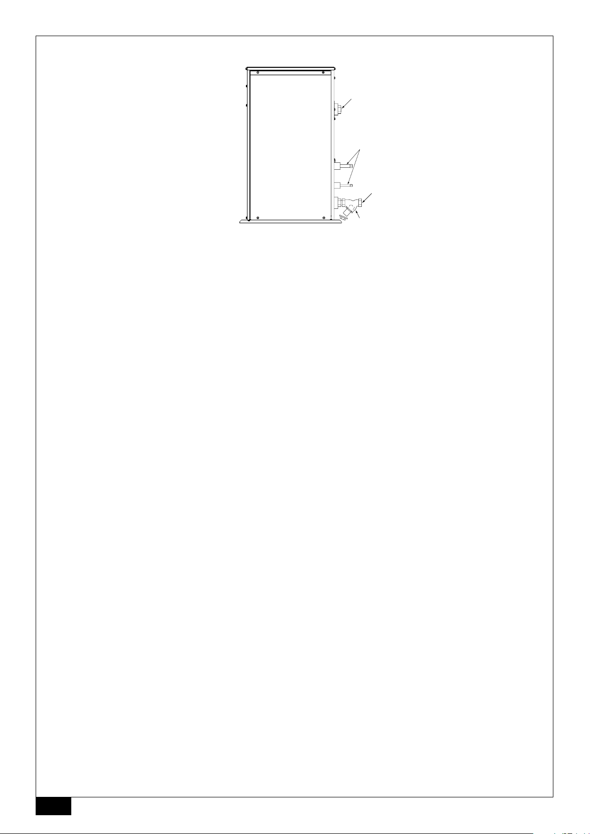
[Fig. A]
D
C
B
A
A:Y-type strainer B:Water inlet C: Refrigerant piping D:Water outlet
Vanne de type en Y Arrivée d’eau Tuyaux de réfrigérant Evacuation de l’eau
4
Page 5
Contents
1. Safety precautions ........................................................................................ 5
1.1. Installation .................................................................................. 5
1.2. During operation ......................................................................... 5
1.3. Disposing of the unit ................................................................... 6
2. How to operate ............................................................................................. 6
2.1. Using the Remote Controller ...................................................... 6
2.2. Water temperature adjustment ................................................... 7
2.3. Setting the Day of the Week and Time ....................................... 7
2.4. Using the Timer .......................................................................... 7
1. Safety precautions
s Before operating the unit, make sure you read all the “Safety
precautions”.
s “Safety precautions” lists important points about safety.
Please be sure to follow them.
Symbols used in the text
Warning:
Describes precautions that should be observed to avoid the risk of injury or
death to the user.
Caution:
Describes precautions that should be observed to prevent damage to the
unit.
Symbols used in the illustrations
: Indicates an action that must be avoided.
: Indicates that important instructions must be followed.
: Indicates a part which must be grounded.
: Beware of electric shock. (This symbol is displayed on the main unit label.)
<Color: yellow>
: Beware of hot surface.
Warning:
Carefully read the labels affixed to the main unit.
1.1. Installation
s After you have read this manual, keep it and the Installation Manual in a
safe place for easy reference whenever a question arises. If the unit is
going to be operated by another person, make sure that this manual is
given to him or her.
Warning:
• The unit should not be installed by the user. Ask the dealer or an authorized company to install the unit. If the unit is installed improperly, water
leakage, electric shock or fire may result.
• Use only accessories authorized by Mitsubishi Electric and ask your
dealer or an authorized company to install them. If accessories are installed improperly, water leakage, electric shock or fire may result.
• Do not touch the unit. The unit surface can be hot.
• Do not install the unit where corrosive gas is generated.
• The Installation Manual details the suggested installation method. Any
structural alteration necessary for installation must comply with local
building code requirements.
•Never repair the unit or transfer it to another site by yourself. If repair is
performed improperly, water leakage, electric shock or fire may result. If
you need to have the unit repaired or moved, consult your dealer.
•Keep the electric parts away from water (washing water) etc.
• It might result in electric shock, catching fire or smoke.
Note1: When washing the Heat Exchanger and Drain Pan, ensure the
Control Box, Motor and LEV remain dry, using a water proof covering.
Note2: Never drain the washing water for the Drain Pan and the Heat
Exchanger using the Drain Pump. Drain separately.
• The appliance is not intended for use by young children or infirm persons without supervision.
•Young children should be supervised to ensure that they do not play
with the appliance.
• Do not use a leak detection additive.
3. Function Selection ...................................................................................... 11
4. Caring for the machine ............................................................................... 13
5. Troubleshooting .......................................................................................... 13
6. Installation, transferring works, and checking ............................................ 14
7. Specifications ............................................................................................. 14
1) Outdoor unit
Warning:
• The outdoor unit must be installed on a stable, level surface, in a place
where there is no accumulation of snow, leaves or rubbish.
• Do not stand on, or place any items on the unit. You may fall down or the
item may fall, causing injury.
Caution:
The outdoor unit should be installed in a location where air and noise emitted by the unit will not disturb the neighbours.
2) Indoor unit
Warning:
The indoor unit should be securely installed. If the unit is loosely mounted, it
may fall, causing injury.
3) Remote controller
Warning:
The remote controller should be installed in such a way that children cannot
play with it.
4) Drain hose
Caution:
Make sure that the drain hose is installed so that drainage can go ahead
smoothly. Incorrect installation may result in water leakage, causing damage to furniture.
I
5) Power line, fuse or circuit breaker
Warning:
• Make sure that the unit is powered by a dedicated supply. Other appliances connected to the same supply could cause an overload.
• Make sure that there is a main power switch.
• Be sure to adhere to the unit’s voltage and fuse or circuit breaker ratings.
Never use a piece of wire or a fuse with a higher rating than the one
specified.
6) Grounding
Caution:
• The unit must be properly grounded. Never connect the grounding wire
to a gas pipe, water pipe, lightning conductor or telephone grounding
wire. If the unit is not grounded properly, electric shock may result.
• Check frequently that the ground wire from the outdoor unit is properly
connected to both the unit’s ground terminal and the grounding electrode.
1.2. During operation
Caution:
• Do not use any sharp object to push the buttons, as this may damage the
remote controller.
• Do not twist or tug on the remote controller cord as this may damage the
remote controller and cause malfunction.
•Never remove the upper case of the remote controller. It is dangerous to
remove the upper case of the remote controller and touch the printed
circuit boards inside. Doing so can result in fire and failure.
•Never wipe the remote controller with benzene, thinner, chemical rags,
etc. Doing so can result in discoloration and failure. To remove heavy
stains, soak a cloth in neutral detergent mixed with water, wring it out
thoroughly, wipe the stains off, and wipe again with a dry cloth.
•Never block or cover the indoor or outdoor unit’s intakes or outlets. Tall
items of furniture underneath the indoor unit, or bulky items such as
large boxes placed close to the outdoor unit will reduce the unit’s efficiency.
5
GB
Page 6
Warning:
• Do not splash water over the unit and do not touch the unit with wet
hands. An electric shock may result.
• Do not spray combustible gas close to the unit. Fire may result.
• Do not place a gas heater or any other open-flame appliance where it will
be exposed to the air discharged from the unit. Incomplete combustion
may result.
Warning:
• Do not remove the front panel or the fan guard from the outdoor unit
when it is running. You could be injured if you touch rotating, hot or highvoltage parts.
•Never insert fingers, sticks etc. into the intakes or outlets, otherwise injury may result, since the fan inside the unit rotates at high speed. Exercise particular care when children are present.
• If you detect odd smells, stop using the unit, turn off the power switch
and consult your dealer. Otherwise, a breakdown, electric shock or fire
may result.
• When you notice exceptionally abnormal noise or vibration, stop operation, turn off the power switch, and contact your dealer.
• Do not over-cool. The most suitable inside temperature is one that is
within 5 °C of the outside temperature.
GB
• Do not leave handicapped people or infants sitting or standing in the path
of the airflow from the air-conditioner. This could cause health problems.
Caution:
• Do not direct the airflow at plants or caged pets.
•Ventilate the room frequently. If the unit is operated continuously in a
closed room for a long period of time, the air will become stale.
In case of failure
Warning:
•Never remodel the air conditioner. Consult your dealer for any repair or service. Improper repair work can result in water leakage, electric shock, fire, etc.
• If the remote controller displays an error indication, the air conditioner
does not run, or there is any abnormality, stop operation and contact
your dealer. Leaving the unit as it is under such conditions can result in
fire or failure.
• If the power breaker is frequently activated, get in touch with your dealer.
Leaving it as it is can result in fire or failure.
• If the refrigeration gas blows out or leaks, stop the operation of the air
conditioner, thoroughly ventilate the room, and contact your dealer. Leaving the unit as it is can result in accidents due to oxygen deficiency.
When the air conditioner is not to be used for a long
time
• If the air conditioner is not to be used for a long time due to a seasonal
change, etc., run it for 4 - 5 hours with the air blowing until the inside is
completely dry. Failing to do so can result in the growth of unhygienic,
unhealthy mold in scattered areas throughout the room.
• When it is not to be used for an extended time, keep the [power supply]
turned OFF.
If the power supply is kept on, several watts or several tens of watts will
be wasted. Also, the accumulation of dust, etc., can result in fire.
•Keep the power switched ON for more than 12 hours before starting operation. Do not turn the power supply OFF during seasons of heavy use.
Doing so can result in failure.
• When not operating the unit for a long time during the winter season,
remove the water inside the water pipe to prevent freeze.
2. How to operate
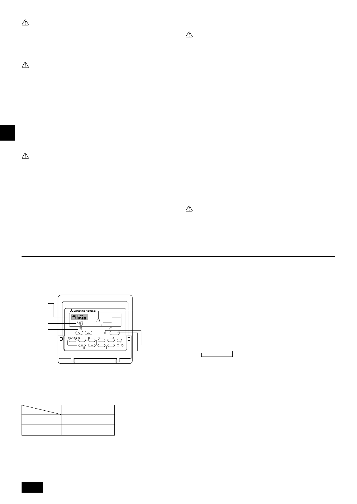
2.1. Using the Remote Controller
How to Start, Stop, Change the Mode, and Adjust the
Water Temperature
2
4
˚C
3
3
2
PAR-W21MAA
To Start Operation
1. Press the ON/OFF button 1.
The ON lamp 1 and the display area come on.
Note:
• When the unit is restarted, initial settings are as follows.
Remote Controller settings
Mode
Temperature setting
˚C
TEMP.
MENU
ON/OFF
MONITOR/SET
BACK DAY
CLOCK CLEAR
Last operation mode
Last set temperature
INITIAL SETTING
CHECK TEST
ON/OFF
CIR.WATER
1
1
1.3. Disposing of the unit
Warning:
When you need to dispose of the unit, consult your dealer. If pipes are removed incorrectly, refrigerant (fluorocarbon gas) may blow out and come
into contact with your skin, causing injury. Releasing refrigerant into the
atmosphere also damages the environment.
To Stop Operation
1. Press the ON/OFF button 1 again.
The ON lamp 1 and the display area go dark.
Selecting the Mode
1. With the unit running, press the Mode button 2 as many times as necessary.
• Each press switches operation to the next mode, in the sequence shown
below.
The currently selected mode is shown at 2.
PWFY-P36NMU-E-BU
Hot water only
PWFY-P36/P72NMU-E-AU
Heating → Cooling
6
Page 7
To Change the Temperature Setting...
1. To lower the temperature: Press the Set Temperature button 3.
2. To raise the temperature: Press the
Set Temperature button 3.
• Each press changes the setting by 1 °C (1 °F). The current setting is dis-
played at 3.
• The available ranges are as follows. *1, *2
Hot Water CoolingHeating
30 °C - 71 °C
86 °F - 160 °F
30 °C - 46 °C
86 °F - 115 °F
10 °C - 30 °C
50 °F - 86 °F
Note:
*1 Available ranges vary according to the type of unit connected.
*2 If temperature range limits have been set at Function Selection of remote
controller, the available ranges will be narrower than shown above. If you attempt
to set a value outside of the restricted range, the display will show a message
indicating that the range is currently restricted.
For information about how to set and clear these range limits, refer to section 3,
item [3]–2 (3).
*3 If Function Selection of remote controller are set to display the temperature in
Fahrenheit. For information about how to select °C or °F , refer to section 3, item
[3]–4 (1).
2.2. Water temperature adjustment
To change water temperature
Press the
perature of your choice.
Pressing
If the pressing is continued, the setting continues to change by 1 °C (1 °F).
• Indoor temperature can be set within the following range.
• It is impossible to set the water temperature by the Inlet Water Temp. or Outlet
* The range of water temperature display is 0 °C (32 °F) to 100 °C (212 °F).
2.3.
Use this screen to change the current day of the week
and time setting.
Note:
The day and time will not appear if clock use has been disabled at Function Selection
of remote controller.
11
1 [water temperature adjustment] button and set the water tem-
11
once changes the setting by 1 °C (1 °F).
or
Hot Water CoolingHeating
30 °C - 71 °C
86 °F - 160 °F
30 °C - 46 °C
86 °F - 115 °F
10 °C - 30 °C
50 °F - 86 °F
Water Temp.
Outside this range, the display flashes either 0 °C (32 °F) or 100 °C (212 °F) to
inform you if the water temperature is lower or higher than the displayed temperature.
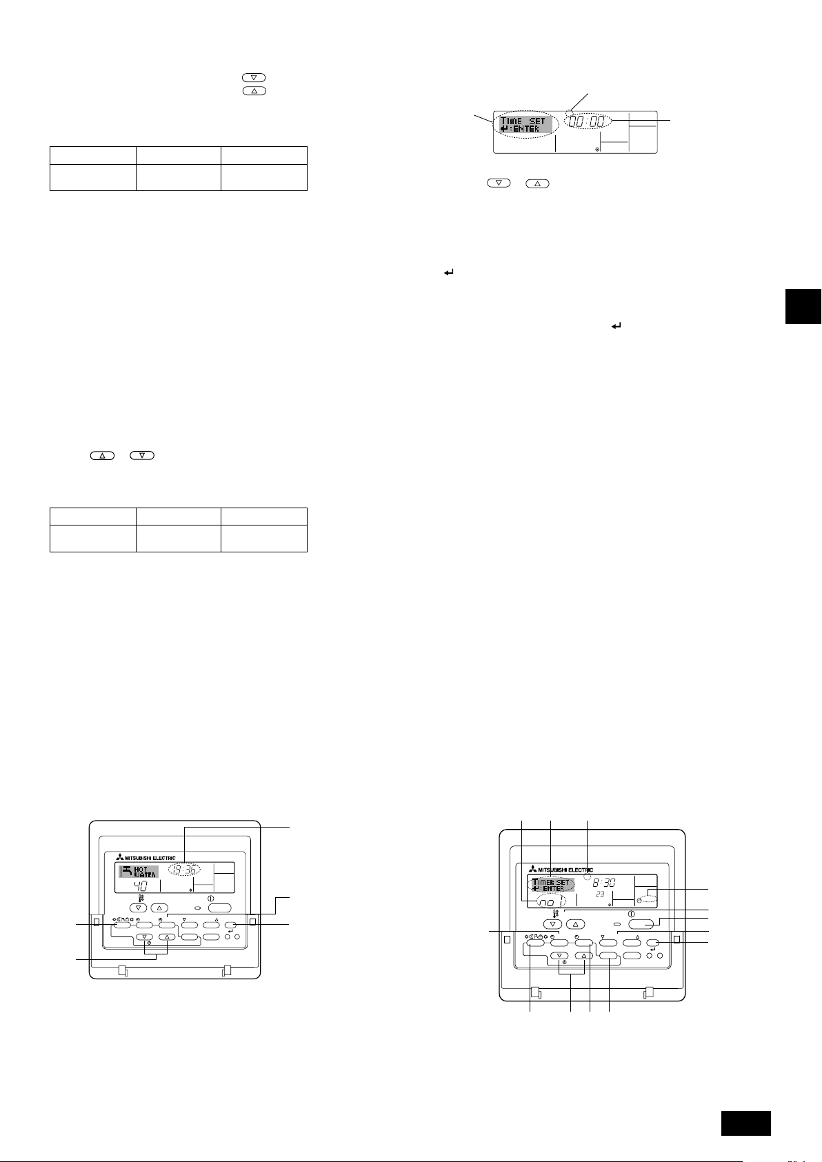
Setting the Day of the Week and Time
1
Day of the Week &
Time display
TIME SUN
˚C
9
4
2
A
MENU
MONITOR/SET
BACK DAY
PAR-W21MAA
TEMP.
ON/OFF
CLOCK CLEAR
INITIAL SETTING
CHECK TEST
ON/OFF
CIR.WATER
How to Set the Day of the Week and Time...
3
Day of the Week Setting
2
TIME SUN
4
Time Setting
1. Press the or Set Time button A to show display 2.
2. Press the TIMER ON/OFF (SET DAY) button 9 to set the day.
* Each press advances the day shown at 3 : Sun → Mon → ... → Fri → Sat.
3. Press the appropriate Set Time button A as necessary to set the time.
* As you hold the button down, the time (at 4) will increment first in minute
intervals, then in ten-minute intervals, and then in one-hour intervals.
4. After making the appropriate settings at Steps 2 and 3, press the CIR.WATER
button 4 to lock in the values.
Note:
Your new entries at Steps 2 and 3 will be cancelled if you press the Mode (Return)
button 2 before pressing the CIR.WATER button 4.
5. Press the Mode (Return) button 2 to complete the setting procedure. This will
return the display to the standard control screen, where 1 will now show the
newly set day and time.
2.4. Using the Timer
This section explains how to set and use the timer. You can use Function Selection
of remote controller to select which of three types of timer to use: 1 Weekly timer,
2 Simple timer, or 3 Auto Off timer.
For information about how to set the Function Selection of remote controller, refer
to section 3, item [3]–3 (3).
Using the Weekly Timer
1. The weekly timer can be used to set up to six operations for each day of the
week.
• Each operation may consist of any of the following: ON/OFF time together
with a temperature setting, or ON/OFF time only, or temperature setting only.
• When the current time reaches a time set at this timer, the unit carries out the
action set by the timer.
2. Time setting resolution for this timer is 1 minute.
Note:
*1. Weekly Timer/Simple Timer/Auto Off Timer cannot be used at the same time.
*2. The weekly timer will not operate when any of the following conditions is in
effect.
The timer feature is off; the system is in an malfunction state; a test run is in
progress; the remote controller is undergoing self-check or remote controller
check; the user is in the process of setting a function; the user is in the process
of setting the timer; the user is in the process of setting the current day of the
week or time; the system is under central control. (Specifically, the system will
not carry out operations (unit on, unit off, or temperature setting) that are
prohibited during these conditions.)
Operation No.
42 3
SUN
TEMP.
B
MENU
MONITOR/SET
BACK DAY
PAR-W21MAA
ON/OFF
CLOCK CLEAR
˚C
INITIAL SETTING
CHECK TEST
ON
WEEKLY
ON/OFF
CIR.WATER
I
1
3
1
7 8
4
GB
2
A90
7
Page 8
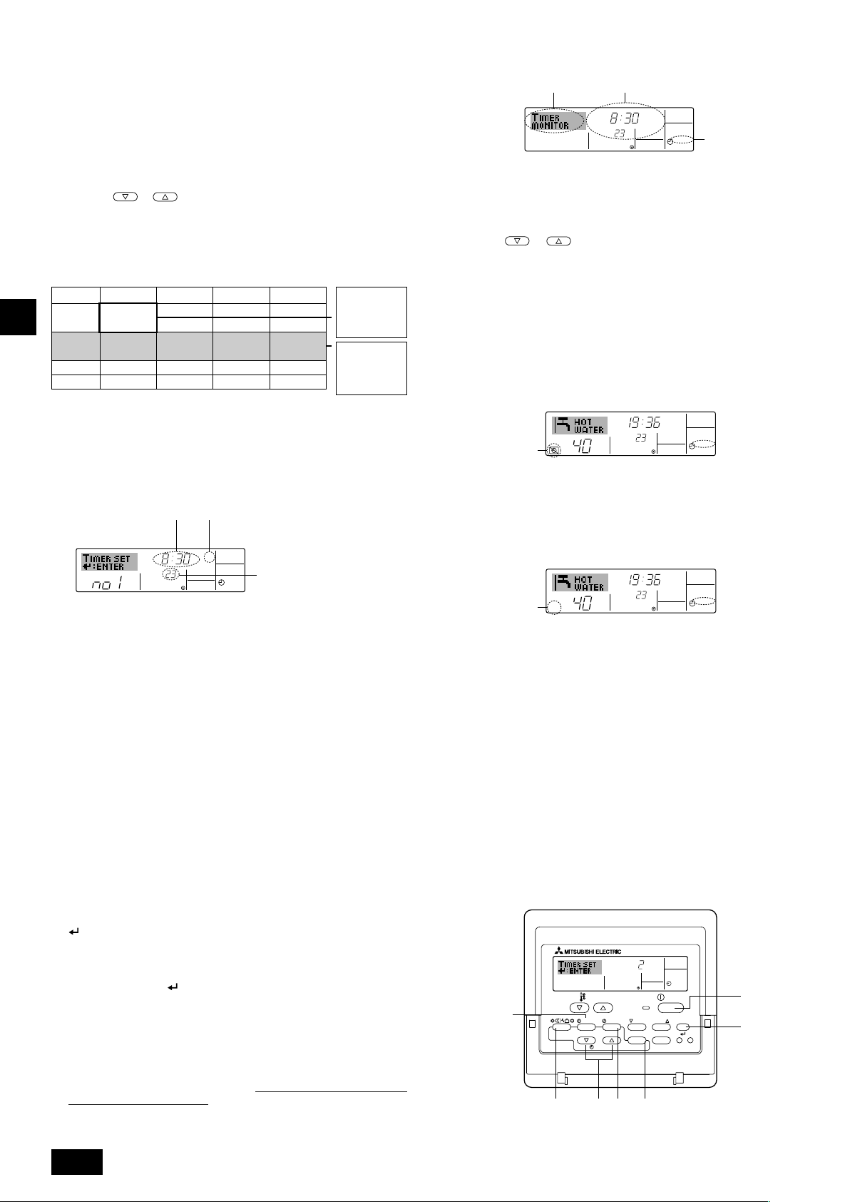
How to Set the Weekly Timer
1. Be sure that you are at a standard control screen, and that the weekly timer
indicator 1 is shown in the display.
2. Press the TIMER MENU button B, so that the “Set Up” appears on the screen
(at 2). (Note that each press of the button toggles the display between “Set
Up” and “Monitor”.)
3. Press the TIMER ON/OFF (SET DAY) button 9 to set the day. Each press
advances the display at 3 to the next setting, in the following sequence: “Sun
Mon Tues Wed Thurs Fri Sat” → “Sun” → ... → “Fri” → “Sat” → “Sun Mon Tues
Wed Thurs Fri Sat”...
4. Press the
select the appropriate operation number (1 to 6) 4.
*Your inputs at Steps 3 and 4 will select one of the cells from the matrix illus-
trated below.
(The remote-controller display at left shows how the display would appear
when setting Operation 1 for Sunday to the values indicated below.)
Setup Matrix
Op No.
No. 1
GB
No. 2
…
No. 6
Note:
By setting the day to “Sun Mon Tues Wed Thurs Fri Sat”, you can set the same
operation to be carried out at the same time every day.
(Example: Operation 2 above, which is the same for all days of the week.)
or INITIAL SETTING button (7 or 8) as necessary to
Sunday Monday … Saturday
• 8:30
•ON
•
23 °C (73 °F)
• 10:00
• OFF
• 10:00
• OFF
• 10:00
• OFF
• 10:00
• OFF
▲
▲
<Operation 1 settings for Sunday>
Start the unit at 8:30,
with the temperature
set to 23 °C (73 °F).
<Operation 2 settings for every
day>
Turn off the unit at
10:00.
How to View the Weekly Timer Settings
SUN
Timer Settings
9
˚C
ON
OFF
WEEKLY
1
8
TIMER
1. Be sure that the weekly timer indicator is visible on the screen (at 1).
2. Press the TIMER MENU button B so that “Monitor” is indicated on the
screen (at 8).
3. Press the TIMER ON/OFF (SET DAY) button 9 as necessary to select
the day you wish to view.
4. Press the
change the timer operation shown on the display (at 9).
* Each press will advance to the next timer operation, in order of time
setting.
5. To close the monitor and return to the standard control screen, press the
Mode (Return) button 2.
or INITIAL SETTING (7 or 8) as necessary to
To Turn Off the Weekly Timer
Press the TIMER ON/OFF button 9 so that “Timer Off” appears at 0.
TIME SUN
˚C
WEEKLY
0
˚C
Setting the Weekly Timer
Shows the time setting
5
SUN
˚C
5. Press the appropriate Set Time button A as necessary to set the desired time
(at 5).
* As you hold the button down, the time first increments in minute intervals,
then in ten-minute intervals, and then in one-hour intervals.
6. Press the ON/OFF button 1 to select the desired operation (ON or OFF), at
6.
* Each press changes the next setting, in the following sequence: No display
(no setting) → “ON” → “OFF”
7. Press the appropriate Set Temperature button 3 to set the desired tempera-
ture (at 7).
* Each press changes the setting, in the following sequence: No display (no
setting) ⇔ 5 (41) ⇔ 6 (43) ⇔ ... ⇔ 89 (192) ⇔ 90 (194) ⇔ No display.
(Available range: The range for the setting is 5 °C (41 °F) to 90 °C (194 °F).
The actual range over which the temperature can be controlled, however, will
vary according to the type of the connected unit.)
8. To clear the currently set values for the selected operation, press and quickly
release the CHECK (CLEAR) button 0 once.
* The displayed time setting will change to “—:—”, and the ON/OFF and tem-
perature settings will all disappear.
(To clear all weekly timer settings at once, hold down the CHECK (CLEAR)
button 0 for two seconds or more. The display will begin flashing, indicating
that all settings have been cleared.)
9. After making the appropriate settings at Steps 5, 6. and 7, press the CIR.WATER
button 4 to lock in the values.
Shows the selected operation (ON or
6
OFF)
* Does not appear if operation is not set.
ON
7
WEEKLY
Shows the temperature
setting
* Does not appear if tempera-
ture is not set.
To Turn On the Weekly Timer
Press the TIMER ON/OFF button 9 so that the “Timer Off” indication (at 0) goes
dark.
TIME SUN
˚C
WEEKLY
0
˚C
Using the Simple Timer
1. You can set the simple timer in any of three ways.
• Start time only : The unit starts when the set time has elapsed.
• Stop time only : The unit stops when the set time has elapsed.
• Start & stop times: The unit starts and stops at the respective elapsed
2. The simple timer (start and stop) can be set only once within a 72-hour period.
The time setting is made in hour increments.
Note:
*1. Weekly Timer/Simple Timer/Auto Off Timer cannot be used at the same time.
*2. The simple timer will not operate when any of the following conditions is in effect.
The timer is off; the system is in malfunction state; a test run is in progress; the
remote controller is undergoing self-check or remote controller check; the user
is in the process of selecting a function; the user is in the process of setting the
timer; the system is under central control. (Under these conditions, ON/OFF
operation is prohibited.)
times.
Note:
Your new entries will be cancelled if you press the Mode (Return) button 2 before
pressing the CIR.WATER button 4.
If you have set two or more different operations for exactly the same time, only the
operation with the highest Operation No. will be carried out.
10. Repeat Steps 3 to 8 as necessary to fill as many of the available cells as you
wish.
11. Press the Mode (Return) button 2 to return to the standard control screen and
complete the setting procedure.
12. To activate the timer, press the TIMER ON/OFF button 9, so that the “Timer
Off” indication disappears from the screen.
Be sure that the “Timer Off” indi-
cation is no longer displayed.
* If there are no timer settings, the “Timer Off” indication will flash on the screen.
8
ONHr
AFTER
INITIAL SETTING
0
SIMPLE
ON/OFF
CIR.WATER
TEMP.
B
MENU
ON/OFF
MONITOR/SET
BACK DAY
PAR-W21MAA
CLOCK CLEAR
2A9
CHECK TEST
1
4
Page 9
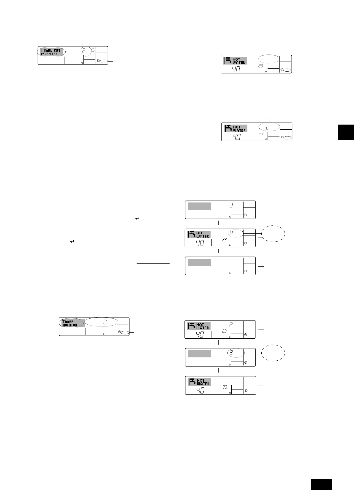
How to Set the Simple Timer
˚C
˚C
SIMPLE
7
ONHr
AFTER
SIMPLE
SIMPLE
˚C
˚C
OFFHrAFTER
SIMPLE
˚C
˚C
SIMPLE
Timer Setting
2
1. Be sure that you are at a standard control screen, and that the simple timer
indicator is visible in the display (at 1).
When something other than the Simple Timer is displayed, set it to SIMPLE
TIMER using the function selection of remote controller (see 3.[3]–3 (3)) timer
function setting.
2. Press the TIMER MENU button B, so that the “Set Up” appears on the screen
(at 2). (Note that each press of the button toggles the display between “Set
Up” and “Monitor”.)
3. Press the ON/OFF button 1 to display the current ON or OFF simple timer
setting. Press the button once to display the time remaining to ON, and then
again to display the time remaining to OFF. (The ON/OFF indication appears at
4).
• “ON” timer: The unit will start operation when the specified number of
hours has elapsed.
• “OFF” timer: The unit will stop operation when the specified number of
hours has elapsed.
4. With “ON” or “OFF” showing at 3: Press the appropriate Set Time button A as
necessary to set the hours to ON (if “ON” is displayed) or the hours to OFF (if
“OFF” is displayed) at 4.
•Available Range: 1 to 72 hours
5. To set both the ON and OFF times, repeat Steps 3 and 4.
* Note that ON and OFF times cannot be set to the same value.
6. To clear the current ON or OFF setting: Display the ON or OFF setting (see
step 3) and then press the CHECK (CLEAR) button 0 so that the time setting
clears to “—” at 4. (If you want to use only an ON setting or only an OFF
setting, be sure that the setting you do not wish to use is shown as “—”.)
7. After completing steps 3 to 6 above, press the CIR.WATER
in the value.
Note:
Your new settings will be cancelled if you press the Mode (Return) button 2 before
pressing the CIR.WATER button 4.
8. Press the Mode (Return) button 2 to return to the standard control screen.
9. Press the TIMER ON/OFF button 9 to start the timer countdown. When the
timer is running, the timer value is visible on the display.
timer value is visible and appropriate.
4
AFTER
ONHr
SIMPLE
Action (On or Off)
3
* “— —” is displayed if there is
no setting.
1
button 4 to lock
Be sure that the
To Turn Off the Simple Timer...
Press the TIMER ON/OFF button 9 so that the timer setting no longer appears on
the screen (at 7).
To Turn On the Simple Timer...
Press the TIMER ON/OFF button 9 so that the timer setting becomes visible at 7.
7
ONHr
AFTER
SIMPLE
˚C
At Timer
Start
At 3 hours
after timer
start
At 7 hours
after timer
start
SIMPLE
Display shows the timer’s ON
setting (hours remaining to
ON).
Display changes to show the
timer’s OFF setting (hours
remaining to OFF).
The time displayed is OFF
setting (7 hours) – ON setting (3 hours) = 4 hours.
I
The unit goes off, and will
remain off until someone restarts it.
˚C
Examples
If ON and OFF times have both been set at the simple timer, operation and display
are as indicated below.
Example 1:
Start the timer, with ON time set sooner than OFF time
ON Setting: 3 hours
OFF Setting: 7 hours
▲
OFFHrAFTER
˚C
˚C
▲
GB
Viewing the Current Simple Timer Settings
5
1. Be sure that the simple timer indicator is visible on the screen (at 1).
2. Press the TIMER MENU button B, so that the “Monitor” appears on the screen
(at 5).
• If the ON or OFF simple timer is running, the current timer value will appear
at 6.
• If ON and OFF values have both been set, the two values appear alternately.
3. Press the Mode (Return) button 2 to close the monitor display and return to
the standard control screen.
6
Timer Setting
TIMER ON
OFFHrAFTER
SIMPLE
1
Example 2:
Start the timer, with OFF time is sooner than ON time
ON Setting: 5 hours
OFF Setting: 2 hours
At Timer
Start
▲
SIMPLE
At 2 hours
after timer
start
AFTER
ONHr
▲
At 5 hours
after timer
start
Display shows the timer’s
OFF setting (hours remaining to OFF).
Display changes to show the
timer’s ON setting (hours remaining to ON).
The time displayed is ON
setting (5 hours) – OFF setting (2 hours) = 3 hours.
The unit comes on, and will
continue to run until someone turns it off.
9
Page 10

Using the Auto Off Timer
AUTO OFF
7
1. This timer begins countdown when the unit starts, and shuts the unit off when
the set time has elapsed.
2. Available settings run from 30 minutes to 4 hours, in 30-minute intervals.
Note:
*1. Weekly Timer/Simple Timer/Auto Off Timer cannot be used at the same time.
*2. The Auto Off timer will not operate when any of the following conditions is in
effect.
The timer is off; the system is in malfunction state; a test run is in progress; the
remote controller is undergoing self-check or remote controller check; the user
is in the process of selecting a function; the user is in the process of setting the
timer; the system is under central control. (Under these conditions, ON/OFF
operation is prohibited.)
Checking the Current Auto Off Timer Setting
Timer Setting
TIMER
AFTER
5
OFF
AUTO OFF
1
4
1. Be sure that the “Auto Off” is visible on the screen (at 1).
2. Hold down the TIMER MENU button B for 3 seconds, so that “Monitor” is
indicated on the screen (at 4).
• The timer remaining to shutdown appears at 5.
3. To close the monitor and return to the standard control screen, press the Mode
(Return) button 2.
AFTER OFF
GB
TEMP.
B
MENU
MENU
BACK
MONITOR/SET
BACK DAY
PAR-W21MAA
ON/OFF
ON/OFF
CLOCK
CLOCK CLEAR
INITIAL SETTING
INITIAL SETTING
CHECK TEST
CHECK TEST
CLEAR
AUTO OFF
ON/OFF
CIR.WATER
CIR.WATER
4
2A9
How to Set the Auto Off TIMER
Timer Setting
2
1. Be sure that you are at a standard control screen, and that the Auto Off timer
indicator is visible in the display (at 1).
When something other than the Auto Off Timer is displayed, set it to AUTO
OFF TIMER using the function selection of remote controller (see 3.[3]–3 (3))
timer function setting.
2. Hold down the TIMER MENU button B for 3 seconds, so that the “Set Up”
appears on the screen (at 2).
(Note that each press of the button toggles the display between “Set Up” and
“Monitor”.)
3. Press the appropriate Set Time button A as necessary to set the OFF time (at
3).
4. Press the CIR.WATER
Note:
Your entry will be cancelled if you press the Mode (Return) button 2 before pressing
the CIR.WATER
button 4.
3
AFTER OFF
AUTO OFF
1
button 4 to lock in the setting.
To Turn Off the Auto Off Timer...
• Hold down the TIMER ON/OFF button 9 for 3 seconds, so that “Timer Off”
appears (at 6) and the timer value (at 7) disappears.
7
AFTER OFF
6
˚C
• Alternatively, turn off the unit itself. The timer value (at 7) will disappear from the
screen.
˚C
AUTO OFF
To Turn On the Auto Off Timer...
• Hold down the TIMER ON/OFF button 9 for 3 seconds. The “Timer Off”
indication disappears (at 6), and the timer setting comes on the display (at 7).
• Alternatively, turn on the unit. The timer value will appear at 7.
7
AFTER OFF
˚C
AUTO OFF
6
˚C
5. Press the Mode (Return) button 2 to complete the setting procedure and re-
turn to the standard control screen.
6. If the unit is already running, the timer starts countdown immediately.
Be sure
to check that the timer setting appears correctly on the display.
10
Page 11

3. Function Selection
Function selection of remote controller
The setting of the following remote controller functions can be changed using the remote controller function selection mode. Change the setting when needed.
Item 1
1. Change Language
Language setting to display
Item 2
Item 3 (Setting content)
• Display in multiple languages is possible
(“CHANGE
LANGUAGE”)
2. Function limit
(“FUNCTION
SELECTION”)
3. Mode selection
(“MODE SELECTION”)
(1) Operation function limit setting (operation lock) (“LOCKING
FUNCTION”)
(2) Operation mode skip setting (“SELECT MODE”)
(3) Temperature range limit setting (“LIMIT TEMP FUNCTION”)
(1) Remote controller main/sub setting (“CONTROLLER MAIN/
SUB”)
(2) Use of clock setting (“CLOCK”)
(3) Timer function setting (“WEEKLY TIMER”)
(4) Contact number setting for error situation (“CALL.”)
• Setting the range of operation limit (operation lock)
• Setting the use or non-use of each operation mode
• Setting the temperature adjustable range (maximum, minimum)
• Selecting main or sub remote controller
* When two remote controllers are connected to one group, one
controller must be set to sub.
• Setting the use or non-use of clock function
• Setting the timer type
• Contact number display in case of error
• Setting the telephone number
4. Display change
(“DISP MODE
SETTING”)
(5) Temp off set setting (“TEMP OFF SET FUNCTION”)
(1) Temperature display °C/°F setting (“TEMP MODE °C/°F”)
(2) Water temperature display setting (“WATER TEMP DISP
SELECT”)
• Setting the use or non-use of setback amount setting
• Setting the temperature unit (°C or °F) to display
• Setting the use or non-use of the display of water temperature
Function selection flowchart
[1] Stop the unit to start remote controller function selection mode. → [2] Select from item 1. → [3] Select from item 2. → [4] Make the setting. (Details are specified in item
3) → [5] Setting completed. → [6] Change the display to the normal one. (End)
Normal display (Display when
the unit is not running)
(Hold down the E button and press the D button for two
seconds.)
* The display cannot be changed during the test run and
the self diagnosis.
Item 1 Remote Controller Function
Change Language
(“CHANGE LANGUAGE”)
Press the G button.
Selection Mode
Item 2
Function limit
(“FUNCTION
SELECTION”)
Press the
E button.
Mode selection
SELECTION”)
Press the
E button.
Press the
E button.
(“MODE
Press the
E button.
Press the
G button.
Press the
G button.
→
Operation function limit setting (“LOCKING FUNCTION”)
→
→
Operation mode skip setting (“SELECT MODE”)
Press the G button.
Temperature range limit setting (“LIMIT TEMP FUNCTION”)
→
Remote controller main/sub setting (“CONTROLLER MAIN/SUB”)
→→→
Use of clock setting (“CLOCK”)
Press the G button.
Timer function setting (“WEEKLY TIMER”)
→
Contact number setting for error situation (“CALL.”)
Temp off set setting (“TEMP OFF SET FUNCTION”)
Display change
(“DISP MODE
SETTING”)
Press the
G button.
→
Temperature display °C/°F setting (“TEMP MODE °C/°F”)
→
Press the G button.
Water temperature display setting (“WATER TEMP DISP SELECT”)
(Hold down the E button and press
the D button for two seconds.)
* The remote controller records the
setting that is made in this way.
See [3]–1
Item 3
(Setting content)
Press the
D button.
See [3]–2. (1)
See [3]–2. (2)
See [3]–2. (3)
Press the
D button.
See [3]–3. (1)
See [3]–3. (2)
See [3]–3. (3)
See [3]–3. (4)
See [3]–3. (5)
Press the
D button.
See [3]–4. (1)
See [3]–4. (2)
NOTE
Timer operation stops when the display for
remote controller function selection is
changed to the normal one.
Dot display
The language that is selected in
CHANGE LANGUAGE mode appears on this display. English is
set in this manual.
F
E
BACK DAY
PAR-W21MAA
G
TEMP.
MENU
MONITOR/SET
CLOCK CLEAR
C
ON/OFF
I
INITIAL SETTING
CHECK TEST
ON/OFF
CIR.WATER
H
D
GB
I
A
B
11
Page 12

Detailed setting
[3]–1. CHANGE LANGUAGE setting
The language that appears on the dot display can be selected.
• Press the [
1 English (GB), 2 German (D), 3 Spanish (E), 4 Russian (RU),
5 Italian (I), 6 French (F), 7 Swedish
[3]–2. Function limit
(1) Operation function limit setting (operation lock)
• To switch the setting, press the [
1 no1 : Operation lock setting is made on all buttons other than the
2 no2 : Operation lock setting is made on all buttons.
3 OFF (Initial setting value) : Operation lock setting is not made.
* To make the operation lock setting valid on the normal screen, it is necessary to
press buttons (Press and hold down the [CIR.WATER] and [
at the same time for two seconds.) on the normal screen after the above setting
is made.
(2) Operation mode skip setting
After setting is changed, the operation mode can not be changed within the changed
GB
range.
• To switch the following settings, press the [
1 Heating mode : Sets the use or non-use of the Heating mode.
2 Heating ECO mode : Sets the use or non-use of the Heating ECO
3 Hot Water mode : Sets the use or non-use of the Hot Water mode.
4 Anti-freeze mode : Sets the use or non-use of the Anti-freeze
5 Cooling mode : Sets the use or non-use of the Cooling mode.
6 OFF (Initial setting value) : Operation mode skip is not executed.
* When the setting, other than OFF, is made, the skip settings of the Heating,
Heating ECO, Hot Water, Anti-freeze, and Cooling modes are executed at the
same time.
*A mode that is not available on the unit to connect cannot be used even if the
setting is “AVAILABLE.”
(3) Temperature range limit setting
After this setting is made, the temperature can be changed within the set range.
• To switch the setting, press the [
1 LIMIT TEMP HEATING MODE:
The temperature range can be changed on heating mode.
2 LIMIT TEMP HOT WATER MODE:
The temperature range can be changed on heating/hot water mode.
3 LIMIT TEMP ANTI-FREEZE MODE:
The temperature range can be changed on anti-freeze mode.
4 LIMIT TEMP COOLING MODE:
The temperature range can be changed on cooling mode.
5 OFF (Initial setting) : The temperature range limit is not active.
* When the setting, other than OFF, is made, the temperature range limit setting
on hot water, anti-freeze and cooling mode is made at the same time. However,
the range cannot be limited when the set temperature range has not changed.
• To increase or decrease the temperature, press the [
button.
• Settable range
Hot Water mode : Lower limit: 30 ~71 °C (86 ~160 °F)
Heating mode : Lower limit: 30 ~45 °C (86 ~115 °F)
Cooling mode : Lower limit: 10 ~30 °C (50 ~ 86 °F)
* The settable range varies depending on the unit to connect.
MENU] button to change the language.
ON/OFF] button.
[
ON/OFF] button.
mode.
mode.
ON/OFF] button.
Upper limit: 71 ~30 °C (160 ~ 86 °F)
Upper limit: 45 ~30 °C (115 ~ 86 °F)
Upper limit: 30 ~10 °C (86 ~ 50 °F)
ON/OFF] buttons
ON/OFF] button.
TEMP. or ]
[3]–3. Mode selection setting
(1) Remote controller main/sub setting
• To switch the setting, press the [
1 Main : The controller will be the main controller.
2 Sub : The controller will be the sub controller.
(2) Use of clock setting
• To switch the setting, press the [
1 ON : The clock function can be used.
2 OFF : The clock function cannot be used.
(3) Timer function setting
• To switch the setting, press the [
followings.).
1 WEEKLY TIMER (Initial setting value): The weekly timer can be used.
2 AUTO OFF TIMER : The auto off timer can be used.
3 SIMPLE TIMER : The simple timer can be used.
4 TIMER MODE OFF : The timer mode cannot be used.
* When the use of clock setting is OFF, the “WEEKLY TIMER” cannot be used.
(4) Contact number setting for error situation
• To switch the setting, press the [
1 CALL OFF : The set contact numbers are not displayed in case of error.
2 CALL **** *** **** : The set contact numbers are displayed in case of error.
CALL_ : The contact number can be set when the display is as
shown on the left.
• Setting the contact numbers
To set the contact numbers, follow the following procedures.
Move the flashing cursor to set numbers. Press the [
] button F to move the cursor to the right (left). Press the [ CLOCK
or ] button C to set the numbers.
(5) Temp off see. setting
• To switch the following settings, press the [
1 ON : The setback amount setting is displayed under the water temperature
initial setting mode.
2 OFF : The setback amount setting is not displayed under the water tempera-
ture initial setting mode.
ON/OFF] button D.
ON/OFF] button D.
ON/OFF] button D (Choose one of the
ON/OFF] button D.
TEMP. or
ON/OFF] button D.
[3]–4. Display change setting
(1) Temperature display °C/°F setting
• To switch the setting, press the [
1 °C: The temperature unit °C is used.
2 °F: The temperature unit °F is used.
(2) Water temperature display setting
• To switch the setting, press the [
1 ON : The water temperature is displayed.
2 OFF : The water temperature is not displayed.
ON/OFF] button D.
ON/OFF] button D.
12
Page 13

4. Caring for the machine
Always have strainer maintenance performed by a service person.
Before care-taking, turn the power supply OFF.
Caution:
• Before you start cleaning, stop operation and turn OFF the power supply.
Remember that the fan is rotating inside at high speed, posing a serious
risk of injury.
• Indoor units are equipped with strainer to remove the dust of sucked-in
air. Clean the strainer using the methods shown in the following sketches.
• The life of the strainer depends on where the unit is installed and how it
is operated.
5. Troubleshooting
Before you ask for repair service, check the following points:
State of Machine
It does not run.
Water out but it does
not cool enough or heat
enough.
Cool water or warm
water does not come
out.
It runs briefly, but soon
stops.
Remote Controller
“'” display is not lit up
No display appears even
when the [ON/OFF] button is pressed.
The liquid crystal display
shows that it is in the
state of operation.
The liquid crystal display
shows that it is in operation.
The “CHECK” and check
code flashes on the liquid
crystal display.
Power failure
The power supply is turned OFF.
The fuse in the power supply is gone.
The earth leakage breaker is gone.
Improper temperature adjustment
The restart-preventing circuit is in operation for 3 minutes.
Indoor unit operation was restarted during the heating
and defrosting operation.
There are some obstacles at the air inlet and outlet of
the indoor and outdoor units.
The strainer is filled with dust and dirt.
Cause
How to clean
• When washing the strainer, remove the cover and scrub the strainer inside
with brush.
Caution:
• Do not dry the strainer by exposing it to direct sunlight or warming it
using fire, etc. Doing so can result in the deformation of the strainer.
Caution:
Never pour water or flammable sprays onto the air conditioner. Cleaning using
these methods can result in the failure of the air conditioner, electric shock,
or fire.
Troubleshooting
Press the [ON/OFF] button after power restoration.
Tu rn the power supply ON.
Replace fuse.
Put in the earth leakage breaker.
After checking the set temperature and inlet temperature
on the liquid crystal display, refer to [Water temperature adjustment], and operate the adjustment button.
Wait for a while.
(To protect the compressor, a 3-minute restart-preventing
circuit is built into the indoor unit. Therefore, there are occasions sometimes when the compressor does not start running immediately. There are cases when it does not run for
as long as 3 minutes.)
Wait for a while.
(Heating operation starts after ending defrosting operation.)
Rerun after removal
Rerun after cleaning the strainer. (Refer to [Caring for the
machine].)
GB
• If operation stops due to a power failure, the [restart-preventing circuit at power failure] operates and disables unit operation even after power restoration. In this case,
press the [ON/OFF] button again and start operation.
If malfunctions persist after you have checked the above, turn the power supply OFF and contact your dealer with information about the product name, the nature of the
malfunction, etc. If the display of “[CHECK]” and (4 digit) check code flashes, tell the dealer contents of the display (check code). Never attempt to repair by yourself.
The following symptoms are not air conditioner failures:
• The air blown out from the air conditioner can sometimes give off odors. This is due to cigarette smoke contained in the air of the room, the smell of cosmetics, the walls,
furniture, etc., absorbed in the air conditioner.
•A hissing noise can be heard immediately after the air conditioner is started or stopped. This is the sound of the refrigeration flowing inside the air conditioner. This is
normal.
• The air conditioner sometimes snaps or clicks at the beginning or end of cooling/heating operation. This is the sound of friction on the front panel and other sections due
to expansion and contraction caused by temperature change. This is normal.
I
13
Page 14

6. Installation, transferring works, and checking
Regarding place for installation
Consult with your dealer for details on installation and transferring the installation.
Caution:
Never install the air conditioner where there is a risk of leakage of flammable
gas.
If gas leaks and accumulates around the unit, fire can result.
Never install the air conditioner at the following place:
• where there is a lot of machine oil
• near the ocean and beach areas where there is salt air.
• where humidity is high
• where there are hot springs nearby
• where there is sulphurous gas
• where there is a high-frequency processing machinery (a high-frequency welder,
etc.)
• where acid solution is frequently used
GB
• where special sprays are frequently used
• Install the indoor unit horizontally. Otherwise, water leakage can result.
•Take sufficient measures against noise when installing the air conditioners at
hospitals or communication-related businesses.
If the air conditioner is used in any of the above-mentioned environments, frequent
operational failure can be expected. It is advisable to avoid these types of installation sites.
For further details, consult with your dealer.
Regarding electrical work
Caution:
• The electrical work must be undertaken by a person who is qualified as
an electrical engineer according to the [technical standard respecting
electrical installation], [internal wiring rules], and the installation instruction manual with the absolute use of exclusive circuits. The use of other
products with the power source can result in burnt-out beakers and fuses.
•Never connect the grounding wire to a gas pipe, water pipe, arrester, or
telephone grounding wire. For details, consult with your dealer.
• In some types of installation sites, the installation of an earth leakage
breaker is mandatory. For details, consult with your dealer.
Regarding water pipe installation
• Do not use steel pipes as water pipes. Copper pipes are recommended.
• The water circuit should be a closed circuit.
Regarding transfer of installation
• When removing and reinstalling the air conditioner when you enlarge your
home, remodel, or move, consult with your dealer in advance to ascertain the
cost of the professional engineering work required for transferring the installation.
Caution:
When moving or reinstalling the air conditioner, consult with your dealer.
Defective installation can result in electric shock, fire, etc.
Regarding noise
• In installing work, choose a place that can fully bear the weight of the air conditioner, and where noise and vibration can be reduced.
• Choose a place where cool or warm air and noise from the outdoor air outlet of
the air conditioner does not inconvenience the neighbors.
• If any alien object is placed near the outdoor air outlet of the air conditioner,
decreased performance and increased noise can result. Avoid placing any
obstacles adjacent to the air outlet.
• If the air conditioner produces any abnormal sound, consult with your dealer.
Maintenance and inspection
• If the air conditioner is used throughout several seasons, the insides can get
dirty, reducing the performance.
Depending upon the conditions of usage, foul odors can be generated and
drainage can deteriorate due to dust and dirt, etc.
7. Specifications
Model
Power source
Heating capacity
Cooling capacity
Noise level
Net weight
Height mm
Dimension
Width mm
Depth mm
Accessory
Water Flow rate gal/min
*1 Nominal heating conditions
Outdoor Temp.: 7 °C DB/6 °C WB (45 °F DB/43 °F WB)
Pipe length: 7.5 m (24-9/16 ft)
Level difference: 0 m (0 ft)
Inlet water Temp 65 °C
Water flow rate 2.15 m
3
/h 35 L/min 9.5 G/min
*3 Nominal cooling conditions
Outdoor Temp.: 35 °C DB (95 °F DB)
Pipe length: 7.5 m (24-9/16 ft)
Level difference: 0 m (0 ft)
Inlet water Temp 23 °C
Water flow rate 1.93 m
3
/h 32 L/min 8.5 G/min
BTU/h
kW
BTU/h
kW
[in]
[in]
[in]
3
m
L/min
/h
PWFY-P36NMU-E-BU
1
40000 *
1
11.7 *
–
–
44 dB<A>
133 lb (60 kg)
PWFY-P36NMU-E-AU
1-phase 208-230V 60Hz
40000 *
11.7 *
36000 *
10.6 *
2
2
3
3
29 dB<A>
78 lb (35 kg)
PWFY-P72NMU-E-AU
80000 *
72000 *
29 dB<A>
84 lb (38 kg)
800
450
300
Strainer, Heat insulation material, Connecter sets × 2, Washer × 2,
Expansion joint × 2 (PWFY-P72NMU-E-AU)
0.6-2.15
2.6-9.5
10-35
0.6-2.15
2.6-9.5
10-35
5.3-18.9
*2 Nominal heating conditions
Outdoor Temp.: 7 °C DB/6 °C WB (45 °F DB/43 °F WB)
Pipe length: 7.5 m (24-9/16 ft)
Level difference: 0 m (0 ft)
Inlet water Temp 30 °C
Water flow rate 2.15 m
3
/h 35 L/min 9.5 G/min
*4 Nominal heating conditions
Outdoor Temp.: 7 °C DB/6 °C WB (45 °F DB/43 °F WB)
Pipe length: 7.5 m (24-9/16 ft)
Level difference: 0 m (0 ft)
Inlet water Temp 30 °C
Water flow rate 4.30 m
3
/h 70 L/min 18.9 G/min
23.4 *
21.2 *
1.2-4.3
20-70
4
4
5
5
*5 Nominal cooling conditions
Outdoor Temp. : 35 °C DB (95 °F DB)
Pipe length: 7.5 m (24-9/16 ft)
Level difference: 0 m (0 ft)
Inlet water Temp 23 °C
Water flow rate 3.86 m
3
/h 64 L/min 17.0 G/min
14
Page 15

Table des matières
1. Consignes de sécurité ................................................................................ 15
1.1. Installation ................................................................................ 15
1.2. Pendant le fonctionnement ....................................................... 15
1.3. Rangement de l’appareil ........................................................... 16
2. Comment faire fonctionner le climatiseur ................................................... 16
2.1. Utiliser la télécommande .......................................................... 16
2.2. Réglage de la température de l’eau ......................................... 17
1. Consignes de sécurité
s Avant de faire fonctionner le climatiseur, lire attentivement
toutes les “consignes de sécurité”.
s Les “consignes de sécurité” sont réparties en listes de points
importants concernant la sécurité. Veiller à bien les respecter.
Symboles utilisés dans le texte
Avertissement:
Décrit les précautions à suivre pour éviter tout risque de blessure ou de
danger mortel pour l’utilisateur.
Précaution:
Décrit les précautions qui doivent être prises pour éviter d’endommager l’appareil.
Symboles utilisés dans les illustrations
: Indique une action qui doit être évitée.
: Indique que des instructions importantes doivent être prises en considéra-
tion.
: Indique un élément qui doit être mis à la terre.
: Danger d’électrocution (Ce symbole se trouve sur l’étiquette de l’appareil
principal) <Couleur: jaune>
: Attention surface chaude
Avertissement:
Prendre soin de lire les étiquettes se trouvant sur l’appareil principal.
1.1. Installation
s Lorsque vous aurez lu le présent manuel, veuillez le conserver avec le
manuel d’installation dans un endroit sûr afin de pouvoir le consulter
ultérieurement, lorsqu’une question se pose. Si une autre personne va
être chargée de faire fonctionner l’appareil, veiller à bien lui remettre le
présent manuel.
Avertissement:
• Cet appareil ne doit pas être installé par l’utilisateur. Demander au revendeur ou à une société agréée de l’installer. Si l’appareil n’est pas correctement installé il peut y avoir un risque de fuite d’eau, d’électrocution ou
d’incendie.
• Utiliser uniquement les accessoires agréés par Mitsubishi Electric et demander à votre revendeur ou à une société agréée de les installer. Si les
accessoires ne sont pas correctement installés, il peut y avoir un risque
de fuite d’eau, d’électrocution ou d’incendie.
• Ne pas toucher l’appareil. Sa surface peut être très chaude.
• Ne pas installer l’appareil à un endroit exposé à des gaz corrosifs.
• Le manuel d’installation décrit en détails la méthode d’installation suggérée. Toute modification de structure nécessaire pour l’installation doit
être conforme aux normes locales de l’édifice.
• Ne jamais réparer ou déménager personnellement l’appareil. Si les réparations effectuées ne sont pas correctes, il peut y avoir un risque de fuite
d’eau, d’électrocution ou d’incendie. En cas de panne ou de déménagement de l’appareil, veuillez contacter votre revendeur.
• Maintenez les pièces électriques à l’écart de l’eau (eau de lavage) etc.
• Cela pourrait provoquer une électrocution, une inflammation ou de la
fumée.
Note 1: Au lavage de l’échangeur thermique et de la cuvette d’écoule-
ment, assurez-vous que la boîte de commande, le moteur et le
LEV restent secs en utilisant une couverture étanche.
Note 2: N’évacuez jamais l’eau de lavage pour la cuvette d’écoulement et
l’échangeur thermique avec la pompe de drainage. Evacuez-la
séparément.
2.3. Régler le jour de la semaine et l’heure ..................................... 17
2.4. Utiliser le programmateur ......................................................... 17
3. Sélection des fonctions .............................................................................. 21
4. Entretien de l’appareil ................................................................................ 23
5. Guide de dépannage .................................................................................. 23
6. Installation, travaux en cas de déplacement et vérifications ...................... 24
7. Spécifications techniques ........................................................................... 24
• Ne pas permettre l’usage de cet appareil à des enfants en bas âge ou à
des handicapés sans supervision.
•Toujours prendre toutes les précautions nécessaires pour éviter que des
enfants en bas âge jouent avec cet appareil.
• N’utilisez pas d’additif de détection des fuites.
1) Appareil extérieur
Avertissement:
•L’appareil extérieur doit être installé sur une surface plane et stable, dans
un endroit non sujet à l’accumulation de neige, de feuilles ou de détritus.
• Ne pas marcher sur l’appareil ni y déposer des objets. La personne ou
l’objet risqueraient de tomber et de se blesser ou de blesser quelqu’un.
Précaution:
L’appareil extérieur doit être placé dans un endroit où l’air et le bruit engendrés ne risquent pas de déranger les voisins.
2) Appareil intérieur
Avertissement:
L’appareil intérieur doit être correctement fixé car dans le cas contraire, il
pourrait tomber et blesser quelqu’un.
3) Commande à distance
Avertissement:
La commande à distance doit être installée de telle sorte que les enfants ne
puissent pas y avoir accès.
4) Tuyau d’évacuation
Précaution:
Assurez-vous que le tuyau d’évacuation est installé de telle façon à ce que
l’évacuation se fasse sans problèmes. Si l’installation n’est pas faite correctement, il pourrait en résulter des fuites d’eau, ce qui endommagerait les
meubles.
5) Ligne d’alimentation électrique, fusible, ou coupe-
circuit
Avertissement:
• Vérifier si l'appareil est alimenté par un circuit réservé. La connexion
d'autres appareils au même circuit pourrait provoquer une surcharge.
• S’assurer de la présence d’un interrupteur secteur principal.
•Veiller à toujours respecter la tension indiquée sur l’appareil ou le voltage du fusible ou du coupe-circuit. Ne jamais utiliser un morceau de
câble ou un fusible d’un voltage supérieur à celui spécifié.
6) Mise à la terre
Précaution:
•L’appareil doit être correctement raccordé à la terre pour éviter tout risque d’électrocution. Ne jamais raccorder le câble de mise à la terre à un
tuyau de gaz ou d’eau, à un paratonnerre ou à un câble de terre du téléphone.
• Vérifier régulièrement que le câble de terre de l’appareil extérieur est
correctement raccordé à la borne de terre de l’appareil et à l’électrode de
mise à la terre.
1.2. Pendant le fonctionnement
Précaution:
• Ne pas utiliser d’objet pointu pour enfoncer les boutons car cela risquerait d’endommager la commande à distance.
• Ne pas tordre le câble de la commande à distance ni tirer dessus car cela
risquerait de l’endommager et de provoquer un mauvais fonctionnement.
F
15
Page 16

• Ne jamais retirer la partie supérieure de la commande à distance car vous
risqueriez de toucher les cartes de circuits imprimés qui se trouvent à
l’intérieur et de provoquer un court-circuit ou une panne.
• Ne jamais essuyer la commande à distance avec du benzène, du thinner,
des produits chimiques, etc. Vous risqueriez de la décolorer et de provoquer des pannes. Pour nettoyer les taches persistantes, tremper un chiffon dans un détergent neutre non abrasif dilué avec de l’eau, le tordre
convenablement, essuyer les taches puis essuyer à nouveau avec un
chiffon sec.
• Ne jamais obstruer les entrées et sorties des appareils extérieurs et intérieurs. Un mobilier élevé placé sous l’appareil intérieur ou des objets
volumineux comme des grandes boîtes laissées à proximité de l’appareil extérieur vont en réduire l’efficacité.
Avertissement:
• Ne jamais éclabousser l’appareil ni le toucher avec des mains humides.
Il pourrait en résulter un risque d’électrocution.
• Ne pas vaporiser de gaz inflammable à proximité de l’appareil sous risque d’incendie.
• Ne pas placer de chauffage au gaz ou tout autre appareil fonctionnant
avec une flamme vive là où il serait exposé àl’échappement d’air du climatiseur. Cela risquerait de provoquer une mauvaise combustion.
Avertissement:
• Ne pas retirer la face avant ou la protection du ventilateur de l’appareil
F
extérieur pendant son fonctionnement. Vous risqueriez de vous blesser
si vous touchez les éléments rotatifs, les parties chaudes ou sous haute
tension.
• Ne jamais mettre les doigts, des bâtons, etc. dans les entrées et sorties
d’air sous risque de blessure car le ventilateur situé à l’intérieur de l’appareil tourne à grande vitesse. Faire tout particulièrement attention en
présence d’enfants.
• Si vous sentez des odeurs étranges, arrêter l’appareil, le mettre hors
tension et contacter le revendeur. Si vous ne procédez pas de cette façon, il pourrait y avoir risque de panne, d’électrocution ou d’incendie.
• Si vous remarquez des vibrations ou des bruits particulièrement anormaux, arrêter l’appareil, éteindre l’interrupteur et prendre contact avec le
revendeur.
• Ne pas refroidir exagérément. La température intérieure idéale se situe
sur une plage de 5 °C de différence par rapport à la température extérieure.
• Ne pas laisser des enfants ou des personnes handicapées assis ou debout sur le passage du flux d’air provenant du climatiseur. Cela pourrait
provoquer des problèmes de santé.
Précaution:
• Ne pas diriger le flux d’air vers des plantes ou des animaux en cages.
• Aérer fréquemment la pièce. Si l’appareil fonctionne continuellement dans
une pièce fermée pendant un long moment, l’air va devenir vicié.
En cas de panne
Avertissement:
• Ne jamais tenter aucune réparation sur le climatiseur. Consulter votre
revendeur pour toute réparation ou intervention technique. Une mauvaise réparation peut causer des fuites d’eau, une électrocution voire un
incendie etc.
• Si la commande à distance affiche un code d’erreur, si le climatiseur ne
fonctionne pas ou si vous détectez une anomalie quelconque, arrêter
l’appareil et contacter le revendeur. Si l’appareil est laissé dans de telles
conditions il risque de tomber en panne ou de provoquer un incendie.
• Si le coupe-circuits fonctionne fréquemment, prendre contact avec le
revendeur. S’il n’est pas remédié à la situation, l’appareil risque de tomber en panne ou de provoquer un incendie.
• Si le gaz de réfrigérant fuit, arrêter le fonctionnement du climatiseur, aérer convenablement la pièce et prendre contact avec le revendeur. S’il
n’est pas remédié à la situation, des accidents risquent de se produire
suite à un manque d’oxygène.
Lorsque le climatiseur ne doit pas être utilisé pendant
une certaine période
• Si le climatiseur ne doit pas être utilisé pendant une certaine période à
cause d’un changement de climat, etc. le faire fonctionner pendant 4 – 5
heures avec la soufflerie d’air jusqu’à ce que l’intérieur soit complètement sec. Sinon de la moisissure non hygiénique et insalubre risque de
se développer à des endroits divers.
• Lorsqu’il ne doit pas être utilisé pendant un certain temps, mettre
l’[alimentation] hors tension (sur OFF).
Si l’appareil est maintenu sous tension, vous risquez en effet de gaspiller plusieurs watts voire des dizaines de watts et l’accumulation de
poussières, etc. pourrait être la cause de court-circuits.
• Allumer l’interrupteur d’alimentation au moins 12 heures avant le début
de la mise en fonctionnement. Ne jamais couper l’alimentation pendant
les périodes de forte utilisation sinon le climatiseur risque de tomber en
panne.
• Si l’appareil ne doit pas être utilisé pendant un certain temps durant l’hiver, purger l’eau des tuyaux pour qu’elle ne risque pas de geler.
1.3. Rangement de l’appareil
Avertissement:
Lorsque vous devez ranger l’appareil, veuillez consulter votre revendeur. Si
les tuyaux ne sont pas correctement retirés, du produit réfrigérant (gaz
fluorocarbonique) pourrait s’échapper et entrer en contact avec votre peau,
causant ainsi des blessures. L’échappement de produit réfrigérant dans l’atmosphère pollue également l’environnement.
2. Comment faire fonctionner le climatiseur
2.1. Utiliser la télécommande
Comment démarrer, arrêter, changer de mode et ajuster la température
Pour commencer l’opération
1. Appuyez sur le bouton ON/OFF 1.
Le témoin de marche 1 et la zone d’affichage s’allument.
Remarque:
• Quand l’unité est relancée, les réglages de base sont les suivants.
Réglages de télécommande
Mode
Réglage de température
Dernier mode de fonctionnement
Dernière température réglée
Pour arrêter le fonctionnement
1. Appuyez de nouveau sur le bouton ON/OFF 1.
Le témoin de marche 1 et la zone d’affichage s’éteignent.
Sélectionner le mode
1. Quand l’unité est en fonction, appuyez sur le bouton 2 Mode autant de fois
que nécessaire.
•À chaque fois que vous appuyez, vous passez au mode de fonctionnement
suivant, selon la séquence indiquée ci-dessous :
Le mode actuel est indiqué en 2.
PWFY-P36NMU-E-BU
Eau chaude seulement
PWFY-P36/P72NMU-E-AU
Chaud → Froid
16
Page 17

Pour changer le réglage de température...
1. Pour baisser la température : Appuyez sur le bouton 3 de réglage de tem-
2. Pour augmenter la température : Appuyez sur le bouton 3 de réglage de tem-
•À chaque fois que vous appuyez sur le bouton, vous changez le réglage de
1 °C (1 °F). Le réglage actuel est affiché en 3.
• Les plages disponibles sont les suivantes : *1, *2
pérature
pérature
.
.
Comment régler le jour de la semaine et l’heure…
Réglage du jour de la semaine
Réglage de l’heure
Eau chaude FroidChaud
30 °C - 71 °C
86 °F - 160 °F
Remarque :
*1 Les portées possibles varient en fonction du type d’unité connecté.
*2 Si les limites de la plage de température ont été réglées à partir de la sélection
des fonctions, les plages disponibles seront plus faibles que celles indiquées cidessus.
Si vous tentez de régler une valeur hors de la plage restreinte, l’affichage
indiquera un message expliquant que la portée est actuellement limitée.
Pour de plus amples informations sur comment régler et réinitialiser cette
fonction, voyez la section 3, paragraphe [3]–2 (3).
*3 Si les sélection de fonctions sont réglées sur l’affichage de la température en
Fahrenheit. Pour de plus amples informations sur comment sélectionner °C ou
°F, voyez la section 3, paragraphe [3]–4 (1).
30 °C - 46 °C
86 °F - 115 °F
10 °C - 30 °C
50 °F - 86 °F
2.2. Réglage de la température de l’eau
Pour changer la température de l’eau
Appuyer sur la touche
température de l’eau.
La température change de 1 °C (1 °F) à chaque pression sur
Une pression continue permet de changer en continu la température de 1 °C
(1 °F).
• La température intérieure peut être réglée dans la plage suivante.
Eau chaude FroidChaud
30 °C - 71 °C
86 °F - 160 °F
• Il est possible de régler la température pour l’entrée et la sortie de l’eau.
* La température est indiquée de 0 °C (32 °F) à 100 °C (212 °F). Hors de cette
plage, 0 °C (32 °F) ou 100 °C (212 °F) clignote pour signaler que la température de l’eau est inférieure ou supérieure à la température indiquée.
2.3.
Régler le jour de la semaine et l’heure
Utilisez cet écran pour changer le jour de la semaine et
l’heure.
Remarque:
Le jour et l’heure n’apparaîtront pas si l’horloge a été déconnectée dans la sélection
des fonctions.
11
1 [réglage de la température de l’eau] et régler la
11
ou
30 °C - 46 °C
86 °F - 115 °F
10 °C - 30 °C
50 °F - 86 °F
Affichage du jour
de la semaine et
de l’heure
.
1. Appuyez sur le bouton de réglage horaire A ou pour appeler
l’affichage 2.
2. Appuyez sur le bouton 9 TIMER ON/OFF (SET DAY) pour régler le jour.
*À chaque fois que vous appuyez, vous avancez le jour affiché en 3 : Dim →
Lun → ... → Ven → Sam.
3. Appuyez sur le bouton de réglage correspondant A afin de régler l’heure.
*À chaque fois que vous maintenez le bouton appuyé, l’heure (en 4) aug-
mentera d’abord toutes les minutes, puis toutes les 10 minutes, puis toutes
les heures.
4. Après avoir effectué les réglages nécessaires des étapes 2 et 3, appuyez sur
le bouton 4 CIR.WATER
Remarque:
Vos nouvelles informations des étapes 2 et 3 seront effacées si vous tapez le bouton
2 Mode (Retour) avant d’appuyer sur le bouton 4 CIR.WATER .
5. Appuyez sur le bouton 2 Mode (Retour) pour terminer la procédure de ré-
glage. Cela ramènera l’affichage sur l’écran de contrôle standard, où 1 vous
indiquera le nouveau jour et la nouvelle heure.
pour valider ces informations.
2.4. Utiliser le programmateur
Cette section explique comment régler et utiliser le minuteur. Vous pouvez utiliser
la sélection des fonctions pour sélectionner le type de programmateur, entre les
trois disponibles.
1 Hebdomadaire, 2 Simple, ou 3 Arrêt auto.
Pour de plus amples informations sur comment régler la sélection des fonctions,
voyez la section 3, paragraphe [3]–3 (3).
Utiliser le programmateur hebdomadaire
1. Le programmateur hebdomadaire peut servir à régler les six opérations pour
chaque jour de la semaine.
• Chaque opération permet l’une ou l’autre des fonctions suivantes : Program-
mateur ON/OFF un réglage de température ou programmateur ON/OFF
seulement, ou réglage de température seulement.
•À l’heure dite, le l’unité d’air effectue l’action programmée.
2. La précision horaire de ce programmateur est de 1 minute.
Remarque:
*1. Les programmateurs hebdomadaire / simple / Arrêt auto ne peuvent être
utilisés en même temps.
*2. Le programmateur hebdomadaire ne fonctionne pas dans les conditions
suivantes.
La fonction de temporisateur est désactivée ; le système est dans un état
anormal ; une exécution de test est en cours ; la télécommande est soumise à
un auto-diagnostic ou à un diagnostic externe ; l’utilisateur est en train de définir
une fonction ; l’utilisateur est en train de régler le temporisateur ; l’utilisateur est
en train de régler l’heure ou le jour de la semaine ; le système est sous
commande centralisée. (Précisément, le système n’exécute pas les opérations
(allumage, extinction ou réglage de la température) désactivées dans ces
situations.)
N° de fonctionnement
F
SUN
ON
˚C
WEEKLY
17
Page 18

Comment régler le programmateur hebdomadaire
1. Assurez-vous que vous êtes sur l’écran de contrôle standard, et que le témoin
du programmateur hebdomadaire 1 s’affiche.
2. Appuyez sur le bouton TIMER MENU B, de manière à ce que le “Réglage”
apparaisse à l’écran (en 2). (Notez qu’à chaque fois que vous appuyez sur le
bouton, vous passez de “Réglage” à “Moniteur” (moniteur).)
3. Appuyez sur le bouton TIMER ON/OFF (SET DAY) 9 pour régler le jour. À
chaque fois que vous appuyez, vous changez le réglage en 3, selon la séquence suivante : “Dim Lun Mar Mer Jeu Ven Sam” → “Dim” → ... → “Ven” →
“Sam” → “Dim Lun Mar Mer Jeu Ven Sam”...
4. Appuyez sur le bouton (7 ou 8) INITIAL SETTING
ou autant de
fois que nécessaire pour sélectionner le numéro d’opération approprié (1 à 6)
4.
*Vos choix aux étapes 3 et 4 sélectionneront l’une des cellules de la matrice
affichée ci-dessous
(l’affichage de la commande à distance à gauche montre comment l’affichage devrait apparaître lors du réglage de l’opération 1 pour dimanche aux
valeurs indiquées cidessous).
Matrice de réglage
N ° d’op.
No. 1
F
No. 2
No. 6
Remarque:
En réglant le jour sur “Dim Lun Mar Mer Jeu Ven Sam”, vous pouvez régler la même
Sunday Monday … Saturday
• 8:30
•ON
•
23 °C (73 °F)
• 10:00
• OFF
…
• 10:00
• OFF
• 10:00
• OFF
• 10:00
• OFF
<Réglage de l’opération
1 pour dimanche>
▲
Démarrer l’unité à 8:30,
avec la température à
23 °C (73 °F).
▲
<Réglage de
l’opération 2 pour
tous les jours>
Éteindre l’unité à
10:00.
opération à effectuer au même moment tous les jours.
(Exemple : L’opération 2 ci-dessus, qui est la même pour tous les jours de la
semaine.)
Régler le programmateur hebdomadaire
12. Pour activer le programmateur, appuyez sur le bouton TIMER ON/OFF (programmateur Marche/arrêt) 9, de manière à ce que l’indication “Timer Off”
(arrêt programmateur) disparaisse de l’écran.
Veillez à ce que l’indication
“Timer Off” ne s’affiche plus.
* Si le programmateur n’est pas réglé, l’indication “arrêt programmateur” cli-
gnote à l’écran.
Comment visualiser les réglages du programmateur
hebdomadaire
Réglage du programmateur
1. Assurez-vous que l’indication du programmateur hebdomadaire apparaisse à
l’écran (en 1).
2. Appuyez sur le bouton TIMER MENU B, de manière à ce que l’écran affiche
“Moniteur” (en 8).
3. Appuyez sur le bouton TIMER ON/OFF (SET DAY) 9 tant qu’il faut pour choi-
sir le jour.
4. Appuyez sur le bouton (7 ou 8) INITIAL SETTING
ou autant
que nécessaire pour changer l’opération du programmateur à l’affichage (en
9).
*À chaque fois que vous appuyez, vous passez à l’opération du programma-
teur suivante, dans l’ordre du réglage horaire.
5. Pour fermer le moniteur et retourner à l’écran de contrôle standard, appuyez
sur le bouton 2 Mode (Retour).
Pour éteindre le programmateur hebdomadaire
Appuyez sur le bouton TIMER ON/OFF 9 , de manière à ce que
l’indication “arrêt programmateur” apparaisse en 0.
Affiche le réglage de
l’heure
Affiche l’opération choisie (Marche ou
Arrêt)
* N’apparaît pas si l’opération n’est pas réglée.
Affiche le réglage de la
température
*N’apparaît pas si la
température n’est pas réglée.
5. Appuyez sur le bouton de réglage de l’heure A approprié autant de fois que
nécessaire pour régler l’heure choisie (en 5).
* Quand vous maintenez le bouton appuyé, l’heure augmentera d’abord tou-
tes les minutes, puis toutes les 10 minutes, puis toutes les heures.
6. Appuyez sur le bouton ON/OFF 1 pour sélectionner l’opération choisie (ON
ou OFF : marche ou arrêt), en 6.
*À chaque fois que vous appuyez vous passez au réglage suivant, selon la
séquence suivante : aucun affichage (pas dé réglage) → “ON” → “OFF”
7. Appuyez sur le bouton de réglage de température 3 approprié pour régler la
température choisie (en 7).
*À chaque fois que vous appuyez vous changez le réglage, selon la séquence
suivante : aucun affichage (pas de réglage) ⇔ 5 (41) ⇔ 6 (43) ⇔ ... ⇔ 89
(192) ⇔ 90 (194) ⇔ pas d’affichage.
(Plage disponible : La plage disponible pour ce réglage va de 5 °C (41 °F) till
90 °C (194 °F). La plage réelle au-delà de laquelle la température peut être
contrôlée, toutefois, peut changer en fonction du type d’unité connectée.)
8. Pour effacer les valeurs actuelles de l’opération choisie, appuyez et relâchez
rapidement le bouton 0 CHECK (CLEAR) une fois.
* Le réglage du temps affiché devient “—:—”, et les réglages de température
et ON/OFF s’éteignent tous.
(Pour effacer tous les réglages du programmateur hebdomadaire d’un coup,
appuyez sur le bouton 0 CHECK (CLEAR) pendant 2 secondes ou plus.
L’affichage commencera à clignoter, ce qui indiquera que tous les réglages
ont été effacés.)
9. Après avoir effectué les réglages nécessaires des étapes 5, 6 et 7, appuyez
sur le bouton 4 CIR.WATER
pour valider ces informations.
Pour allumer le programmateur hebdomadaire
Appuyez sur le bouton TIMER ON/OFF 9 , de manière à ce que l’indication “arrêt
programmateur” s’éteigne en 0.
Utiliser le programmateur simple
1. Vous pouvez régler le programmateur simple de trois manières possible.
• Heure de démarrage uniquement : L’unité démarre quand le temps indiqué s’est écoulé.
• Heure d’arrêt uniquement : L’unité s’arrête quand le temps indiqué
s’est écoulé.
• Horaires de marche & d’arrêt : L’unité démarre et s’arrête quand les
temps indiqués se sont écoulés.
2. Le programmateur simple (démarrage et arrêt) peut être régler une fois seulement sur une période de 72 heures. Le réglage se fait heure par heure.
Remarque:
*1. Les programmateurs hebdomadaire / simple / Arrêt auto ne peuvent être
utilisés en même temps.
*2. Le programmateur simple n’opérera pas dans les cas suivants.
La fonction programmateur est éteinte ; anomalie du système ; un test est en
cours ; la commande à distance effectue un auto-test ou un diagnostic ;
l’utilisateur est en train de sélectionner une fonction ; l’utilisateur est en train de
régler le programmateur ; le système est sous contrôle central. (Dans ces
conditions, l’opération ON/OFF est désactivée.)
Remarque:
Vos nouvelles informations seront effacées si vous tapez le bouton 2 Mode
(Retour) avant d’appuyer sur le bouton 4 CIR.WATER .
Si vous avez réglé deux opérations différentes ou plus pour le même temps
exactement, seule l’opération ayant le n °le plus élevé sera effectuée.
10. Répétez les étapes 3 à 8 autant de fois que nécessaire pour remplir les cellules disponibles que vous souhaitez.
11. Appuyez sur le bouton 2 Mode (Retour) pour revenir à l’écran de contrôle
standard et terminer la procédure de réglage.
18
Page 19

Comment régler le programmateur simple
ONHr
AFTER
SIMPLE
SIMPLE
Réglage du programmateur
Action (Marche ou Arrêt)
* “— —” s’affiche s’il n’ y a pas
de réglage.
1. Assurez-vous que vous êtes sur un écran de contrôle standard, et que le témoin du programmateur simple s’affiche (en 1).
Lorsque qu’une fonction autre que le temporisateur simple est affichée, réglez
la télécommande sur SIMPLE TIMER en utilisant le paramètre de fonction
temporisateur de la sélection des fonctions (voir 3.[3]–3 (3)).
2. Appuyez sur le bouton TIMER MENU B, de manière à ce que le “Réglage”
apparaisse à l’écran (en 2). (Notez qu’à chaque fois que vous appuyez sur le
bouton, vous passez de “Réglage” à “Moniteur”.)
3. Appuyez sur le bouton ON/OFF 1 pour afficher le réglage du programmateur
simple (Marche ou Arrêt : marche ou arrêt). Appuyez une fois sur le bouton
pour afficher le temps restant sur Marche, et une fois encore pour afficher le
temps restant sur Arrêt (l’indication ON/OFF apparaît en 4).
• Programmateur “ON”: L’unité démarre quand le nombre d’heures indiqué
• Programmateur “OFF”: L’unité s’arrête quand le nombre d’heures indiqué
4. Avec l’indication “Marche ” ou “Arrêt” en 3: Appuyez sur le bouton de réglage
d’heure A approprié autant de fois que nécessaire pour régler l’heure sur ON
(si “ON” s’affiche) ou sur OFF (si “OFF” s’affiche en 4).
• Plage disponible : 1 à 72 heures
5. Pour régler à la fois pour ON et pour OFF, répéter les étapes 3 et 4.
* Notez que les temps pour ON et OFF ne peuvent avoir la même valeur.
6. Pour effacer le réglage ON ou OFF actuel : Afficher le réglage ON ou OFF (voir
étape 3) puis appuyer sur le bouton CHECK (CLEAR) 0 de manière à ce que
le réglage passe à “—” en 4. (Si vous souhaitez utiliser un réglage ON ou OFF
uniquement, assurez vous que le réglage dont vous ne voulez pas est bien sur
“—”.)
7. Après avoir effectué les étapes 3 à 6, appuyez sur le bouton 4 CIR.WATER
pour valider ces informations.
Remarque:
Vos nouvelles informations seront effacées si vous tapez le bouton 2 Mode
(Retour) avant d’appuyer sur le bouton 4 CIR.WATER
8. Appuyez sur le bouton 2 Mode (Retour) pour retourner à l’écran de contrôle
standard.
9. Appuyez sur le bouton TIMER ON/OFF 9 pour lancer le compte à rebours.
Pendant que le programme s’exécute, l’affichage indique l’état du programmateur.
Veillez à ce que la valeur du programmateur soit visible et convena-
ble.
s’est écoulé.
s’est écoulé.
.
Pour éteindre le programmateur simple...
Appuyez sur le bouton TIMER ON/OFF 9 de manière à ce que le réglage du
programmateur n’apparaisse plus à l’écran (en 7).
Pour lancer le programmateur simple…
Appuyez sur le bouton TIMER ON/OFF 9 de manière à ce que le réglage du
programmateur apparaisse en 7.
Exemples
Si les horaires de marche et d’arrêt ont été réglés pour le programmateur simple,
l’opération et l’affichage sont comme indiqués comme ci-dessous.
Exemple 1:
Démarrer le programmateur, avec l’heure de démarrage avant l’heure d’arrêt
Réglage Marche : 3 heures
Réglage Arrêt : 7 heures
Au démarrage du
programmateur
▲
3 heures après le
démarrage du
programmateur
▲
7 heures après
le démarrage du
programmateur
Affiche le réglage de démarrage
du programmateur (les heures
restant avant le démarrage).
l’Affichage change pour montrer
le réglage d’arrêt du
programmateur (les heures
restant avant l’arrêt). L’affichage
indique l’horaire de la manière
suivante : ARRÊT (7 heures) –
MARCHE (3 heures) = 4 heures.
L’unité s’éteint et restera
éteinte jusqu’à ce que
quelqu’un la relance.
F
Afficher les réglages actuels du programmateur
simple
Réglage du programmateur
1. Assurez-vous que l’indication du programmateur simple apparaisse à l’écran
(sur 1).
2. Appuyez sur le bouton TIMER MENU B, de manière à ce que le “Moniteur”
apparaisse à l’écran (en 5).
• Si le programmateur simple ON ou OFF est en fonction, son état actuel
apparaîtra en 6.
• Si les valeurs ON et OFF ont été réglées toutes les deux, les deux valeurs
apparaîtront alternativement.
3. Appuyez sur le bouton 2 Mode (Retour) pour fermer le moniteur et retourner
à l’écran de contrôle standard.
Exemple 2:
Démarrer le programmateur, avec l’heure d’arrêt avant l’heure de démarrage
Réglage Marche : 5 heures
Réglage Arrêt : 2 heures
Au démarrage du
programmateur
▲
SIMPLE
2 heures après le
démarrage du
programmateur
AFTER
ONHr
▲
5 heures après
le démarrage du
programmateur
Affiche le réglage d’arrêt du
programmateur (les heures
restant avant l’arrêt).
l’Affichage change pour montrer le
réglage de démarrage du
programmateur (les heures restant
avant le démarrage).
L’affichage indique l’horaire de la
manière suivante : MARCHE (5 heures)
– ARRÊT (2 heures) = 3 heures.
L’unité s’allume et restera
allumée jusqu’à ce que
quelqu’un l’éteigne.
19
Page 20

Utiliser le programmateur Arrêt Auto
AUTO OFF
7
1. Ce programmateur commence le compte à rebours au démarrage de l’unité et
éteint l’unité quand le temps indiqué s’est écoulé.
2. les réglages possibles vont de 30 minutes à 4 heures, par tranches de 30
minutes.
Remarque:
*1. Les programmateurs hebdomadaire / simple / Arrêt auto ne peuvent être
utilisés en même temps.
*2. Le programmateur Arrêt Auto n’opérera pas quand l’une des conditions
suivantes est en fonction.
La fonction programmateur est éteinte ; anomalie du système ; un test est en
cours ; la commande à distance effectue un auto-test ou un diagnostic ;
l’utilisateur est en train de sélectionner une fonction ; l’utilisateur est en train de
régler le programmateur ; le système est sous contrôle central. (Sous ces
conditions, l’opération ON/OFF est désactivée.)
F
Comment régler le programmateur Arrêt Auto
Vérifier le réglage actuel du programmateur Arrêt Auto
Réglage du programmateur
1. Assurez-vous que l’indication “Arrêt Auto” apparaisse à l’écran (sur 1).
2. Appuyez sur le bouton TIMER MENU B pendant 3 secondes, de manière à
ce que “Moniteur” apparaisse à l’écran (en 4).
• Le temps restant avant l’extinction apparaît en 5.
3. Pour fermer le moniteur et retourner à l’écran de contrôle standard, appuyez
sur le bouton 2 Mode (Retour).
Pour éteindre le programmateur Arrêt Auto...
• Appuyez sur le bouton TIMER ON/OFF 9 pendant 3 secondes, de manière à
ce que l’indication “Arrêt programmateur” apparaisse (en 6) et que la valeur du
programmateur (en 7) disparaisse.
• Sinon, il est possible d’éteindre l’unité elle-même. La valeur du programmateur
(en 7) disparaîtra de l’écran.
Réglage du programmateur
1. Assurez-vous que vous êtes sur un écran de contrôle standard, et que le témoin du programmateur Arrêt Auto s’affiche (en 1).
Lorsque qu’une fonction autre que le temporisateur à extinction automatique
est affichée, réglez la télécommande sur AUTO OFF TIMER en utilisant le
paramètre de fonction temporisateur de la sélection des fonctions (see 3.[3]–
3 (3)).
2. Appuyez sur le bouton TIMER MENU B pendant 3 secondes, de manière à
ce que le “Réglage”apparaisse à l’écran (en 2).
(Notez qu’à chaque fois que vous appuyez sur le bouton, vous passez de
“Réglage” à “Moniteur”.)
3. Appuyez sur le bouton de réglage d’heure A approprié autant de fois que
nécessaire pour régler l’heure d’arrêt (en 3).
4. Appuyez sur le bouton 4 CIR.WATER
Remarque:
Vos informations seront effacées si vous tapez le bouton 2 Mode (Retour) avant
d’appuyer sur le bouton 4 CIR.WATER
5. Appuyez sur le bouton 2 Mode (Retour) pour terminer la procédure de ré-
glage et retourner à l’écran de contrôle standard.
6. Si l’unité est déjà en fonctionnement, le programmateur démarre le compte à
rebours immédiatement.
teur apparaisse correctement à l’écran.
Veillez à vérifier que le réglage du programma-
pour enregistrer le réglage.
.
Pour démarrer le programmateur Arrêt Auto...
• Appuyez sur le bouton TIMER ON/OFF 9 pendant 3 secondes. L’indication
“Arrêt programmateur” disparaît (en 6), et le réglage du programmateur apparaît
(en 7).
• Sinon, il est possible d’allumer l’unité elle-même. La valeur du programmateur
apparaît en 7.
20
Page 21

3. Sélection des fonctions
Sélection des fonctions de la commande à distance
Le réglage des fonctions de la commande suivantes peut être modifié à l’aide du mode de sélection des fonctions de la commande à distance. Modifiez le réglage au besoin.
Elément 1
1. Modification de la
langue (“CHANGE
LANGUAGE”)
2. Limitation des
fonctions
(“SELECTION
FONCTIONS”)
3. Sélection des
modes
(“SELECTION DU
MODE”)
4. Modification de
l’affichage
(“AFFICHAGE
SOUS MENU”)
Réglage des langues d’affichage
(1)
Réglage de la limitation des fonctions de fonctionnement
(verrouillage de fonctionnement) (“BLOCAGE FONCTIONS”)
(2)
Réglage de la désactivation du mode de fonctionnement (“SELECTION MODE INACTIF”)
(3)
Réglage de la limite de la plage de températures (“LIMITATION TEMPERATURE”)
(1) Réglage de la commande à distance principale/secondaire
(“TELCOMMANDE MAITRE/ESCLAVE”)
(2)
Utilisation du réglage de l’horloge (“AFFICHAGE HORLOGE”)
(3)
Réglage de la fonction de minuterie (“PROG HEBDO MADAIRE”)
(4) Réglage du numéro à contacter en cas d’erreur (“CALL.”)
(5)
Réglage du décalage de température (“REGLAGE DELTA T EAU”)
(1)
Réglage de l’affichage de la température °C/°F (“TEMPERATURE °C/°F”)
(2) Réglage de l’affichage de la température de l’eau
(“AFFICHAGE TEMP EAU”)
Elément 2
Elément 3 (contenu de réglage)
• L’affichage en plusieurs langues est possible
• Réglage de la plage de limitation de fonctionnement (verrouillage de
fonctionnement)
•
Réglez l’utilisation ou la non utilisation de chaque mode de fonctionnement
• Réglage de la plage de températures ajustable (maximum, minimum)
• Sélection de la commande à distance principale ou secondaire
* Lorsque deux commandes à distance sont connectées à un groupe,
l’une des deux doit être réglée en tant que commande secondaire.
• Activation ou désactivation de la fonction d’horloge
• Réglage du type de minuterie
• Affichage du numéro à contacter en cas d’erreur
• Réglage du numéro de téléphone
Réglez l’utilisation ou la non utilisation du réglage de la quantité de décrochement
•
• Réglage de l’unité de température (°C ou °F) à afficher
• Activation ou désactivation de l’affichage de la température de l’eau
Organigramme de sélection des fonctions
[1] Arrêtez l’unité pour activer le mode de sélection des fonctions de la commande à distance. → [2] Sélectionnez l’élément 1. → [3] Sélectionnez l’élément 2. → [4] Effectuez
le réglage (vous trouverez plus de détails dans la colonne Elément 3).→ [5] Réglage terminé. → [6] Repassez à l’affichage normal (fin).
Affichage normal (affichage
lorsque l’unité ne fonctionne pas)
(Maintenez la touche E enfoncée et appuyez sur la touche
D pendant deux secondes.)
* L’affichage ne peut pas être modifié pendant l’essai de
fonctionnement et l’auto-diagnostic.
Elément 1 Mode de sélection des fonctions
Change Language
(“CHANGE LANGUAGE”)
Limitation des fonctions
(“SELECTION
FONCTIONS”)
Appuyez sur
la touche E.
Appuyez sur
la touche E.
Sélection des modes
(“SELECTION DU
MODE”)
Modification de l’affichage
(“AFFICHAGE SOUS
MENU”)
Appuyez sur la touche G.
Appuyez sur
la touche E.
Appuyez sur
la touche G.
Appuyez sur
la touche G.
Appuyez sur
la touche E.
Appuyez sur
la touche G.
→
Réglage de la limitation des fonctions de fonctionnement (“BLOCAGE FONCTIONS”)
Réglage de la désactivation du mode de fonctionnement (“SELECTION MODE INACTIF”)
Réglage de la limitation de la plage de températures (“LIMITATION TEMPERATURE”)
→
Réglage de la commande à distance principale/secondaire (“TELCOMMANDE MAITRE/ESCLAVE”)
Utilisation du réglage de l’horloge (“AFFICHAGE HORLOGE”)
Réglage de la fonction de minuterie (“PROG HEBDO MADAIRE”)
Réglage du numéro à contacter en cas d’erreur (“CALL.”)
Réglage du décalage de température (“REGLAGE DELTA T EAU”)
→
Réglage de l’affichage de la température °C/°F (“TEMPERATURE °C/°F”)
Réglage de l’affichage de la température de l’eau (“AFFICHAGE TEMP EAU”)
de la commande à distance
Elément 2
→
→
→→→
→
→
Appuyez sur la touche G.
Appuyez sur la touche G.
Appuyez sur la touche G.
(Maintenez la touche E enfoncée et
appuyez sur la touche D pendant
deux secondes.)
* De la sorte, la commande à
distance enregistre les réglages
effectués.
Reportez-vous
au point [3]–1
Elément 3
(contenu de réglage)
Appuyez sur
la touche D.
Appuyez sur
la touche D.
Appuyez sur
la touche D.
Reportez-vous
au point [3]–2. (1)
Reportez-vous
au point [3]–2. (2)
Reportez-vous
au point [3]–2. (3)
Reportez-vous
au point [3]–3. (1)
Reportez-vous
au point
Reportez-vous
au point [3]–3. (3)
Reportez-vous
au point [3]–3. (4)
Reportez-vous
au point [3]–3. (5)
Reportez-vous
au point [3]–4. (1)
Reportez-vous
au point [3]–4. (2)
[3]–3. (2)
REMARQUE
Le fonctionnement de la minuterie est
interrompu lorsque l’affichage de sélection
des fonctions de la commande à distance
passe à l’affichage normal.
Ecran à pixels
Cet écran s’affiche dans la langue sélectionnée dans le mode
CHANGE LANGUAGE (Modification de la langue). L’anglais
est sélectionné dans ce manuel.
F
21
Page 22

Réglage détaillé
[3]–1. Réglage CHANGE LANGUAGE (Modification de la langue)
La langue d’affichage de l’écran à pixels peut être sélectionnée.
• Appuyez sur la touche [
1 Anglais (GB), 2 Allemand (D), 3 Espagnol (E), 4 Russe (RU),
5 Italien (I), 6 Français (F), 7 Suédois
[3]–2. Limitation des fonctions
(1)
Réglage de la limitation des fonctions de fonctionnement (verrouillage de fonctionnement)
• Pour commuter le réglage, appuyez sur la touche [ ON/OFF].
1 no1 : Le réglage du verrouillage de fonctionnement est appliqué à toutes
les touches autres que la touche [
2 no2 : Le réglage du verrouillage de fonctionnement est appliqué à toutes les
touches.
3 OFF (valeur de réglage initial) : Le réglage du verrouillage de fonctionnement
* Pour appliquer le réglage du verrouillage de fonctionnement à l’écran normal, il
est nécessaire d’appuyer sur les touches (Appuyez simultanément sur les
touches [CIR.WATER] et [
pendant deux secondes.) sur l’écran normal après avoir effectué le réglage cidessus.
(2) Réglage de la désactivation du mode de fonctionnement
Une fois ce réglage modifié, vous pouvez modifier le mode de fonctionnement dans
F
la plage modifiée.
• Pour basculer parmi les réglages suivants, appuyez sur le bouton [
1 Mode Chaud : Règle l’utilisation ou la non utilisation du mode
2 Mode Chauffage ECO : Règle l’utilisation ou la non utilisation du mode
3 Mode Eau chaude : Règle l’utilisation ou la non utilisation du mode
4 Mode Anti givre : Règle l’utilisation ou la non utilisation du mode
5 Mode Froid : Règle l’utilisation ou la non utilisation du mode
6 INACTIF (valeur initiale du réglage)
* Lorsqu’un autre réglage que OFF est sélectionné, les modes Chaud, Chauffage
* Si un mode n’est pas disponible sur l’unité à connecter, il ne peut être utilisé
(3) Réglage de la limitation de la plage de températures
Une fois ce réglage effectué, la température peut être modifiée dans la plage
définie.
• Pour commuter le réglage, appuyez sur la touche [
1 MODE LIMITE TEMP INACTIF:
2 MODE LIMITE TEMP EAU CHAUDE:
3 MODE LIMITE TEMP ANTI GIVRE:
4 MODE LIMITE TEMP EN FROID:
5 OFF (programmation initiale) :
* Lorsqu’un réglage autre que OFF est sélectionné, le réglage de la limitation de
la plage de températures des modes refroidissement, chauffage et automatique
s’effectue en même temps. Toutefois, la plage ne peut pas être limitée lorsque
la plage de températures réglée n’a pas été modifiée.
• Pour augmenter ou diminuer la température, appuyez sur la touche [
• Plage réglable
Mode Eau chaude : Limite inférieure: 30 ~71 °C (86 ~160 °F)
Mode Chaud : Limite inférieure: 30 ~45 °C (86 ~115 °F)
Mode Froid : Limite inférieure: 10 ~30 °C (50 ~ 86 °F)
* La plage réglable varie en fonction de l’appareil à connecter.
n’est pas appliqué.
ECO, Eau chaude, Anti givre et Froid sont désactivés simultanément.
même si le réglage est “disponible.”
Vous pouvez modifier la plage de températures sur le mode Chaud.
Vous pouvez modifier la plage de températures sur le mode Chaud/Eau
chaude.
Vous pouvez modifier la plage de températures sur le mode Anti givre.
Vous pouvez modifier la plage de températures sur le mode Froid.
La limitation de la plage de températures n’est pas active.
ou ].
MENU] pour modifier la langue.
ON/OFF].
ON/OFF] en même temps et les maintenir enfoncées
Chaud.
Chauffage ECO.
Eau chaude.
Anti givre.
Froid.
: Le mode de fonctionnement n’est pas activé.
ON/OFF].
Limite supérieure: 71 ~30 °C (160 ~ 86 °F)
Limite supérieure: 45 ~30 °C (115 ~ 86 °F)
Limite supérieure: 30 ~10 °C (86 ~ 50 °F)
ON/OFF].
TEMP.
[3]–3. Réglage de la sélection des modes
(1) Réglage de la commande à distance principale/secondaire
• Pour commuter le réglage, appuyez sur la touche [
1 Maitre : La commande devient la commande principale.
2 Esclave : La commande devient la commande secondaire.
(2) Utilisation du réglage de l’horloge
• Pour commuter le réglage, appuyez sur la touche [
1 ON : La fonction d’horloge peut être utilisée.
2 OFF : La fonction d’horloge ne peut pas être utilisée.
(3) Réglage de la fonction de minuterie
• Pour commuter le réglage, appuyez sur la touche [
l’une des fonctions suivantes.).
1 PROG HEBDO MADAIRE (Valeur de réglage initial):
2 PROG HORAIRE ARRET AUTO:
3 PROG HORAIRE SIMPLIFIE: La minuterie simple peut être utilisée.
4 PROG HORAIRE INACTIF: Le mode de minuterie ne peut pas être utilisé.
* Lorsque l’utilisation du réglage de l’horloge est définie sur OFF, la fonction
“PROG HEBDO MADAIRE” ne peut pas être utilisée.
(4) Réglage du numéro à contacter en cas d’erreur
• Pour commuter le réglage, appuyez sur la touche [
1 CALL OFF : Les numéros à contacter définis ne s’affichent pas en cas
2 CALL **** *** **** : Les numéros à contacter définis s’affichent en cas
CALL_ : Le numéro à contacter peut être réglé lorsque l’affichage
• Réglage des numéros à contacter
Pour régler les numéros à contacter, effectuez la procédure suivante.
Déplacez le curseur clignotant sur les numéros réglés. Appuyez sur la touche
[
TEMP. ou ] F pour déplacer le curseur vers la droite (gauche).
Appuyez sur la touche [
(5) Réglage du décalage de température
• Pour basculer parmi les réglages suivants, appuyez sur le bouton
[
ON/OFF] D.
1 ON : Le réglage de la quantité de décrochement apparaît sous le mode de
2 OFF : Le réglage de la quantité de décrochement n’apparaît pas sous le
réglage initial de la température de l’eau.
mode de réglage initial de la température de l’eau.
La minuterie hebdomadaire peut être utilisée.
L’arrêt différé automatique peut être utilisé.
d’erreur.
d’erreur.
est tel qu’illustré à gauche.
CLOCK ou ] C pour régler les numéros.
ON/OFF] D.
ON/OFF] D.
ON/OFF] D (Choisissez
ON/OFF] D.
[3]–4. Réglage de l’affichage
(1) Réglage de l’affichage de la température °C/°F
• Pour commuter le réglage, appuyez sur la touche [
1 °C: L’unité de température °C est utilisée.
2 °F: L’unité de température °F est utilisée.
(2) Réglage de l’affichage de la température de l’eau
• Pour commuter le réglage, appuyez sur la touche [
1 ON : La température de l’eau s’affiche.
2 OFF : La température de l’eau ne s’affiche pas.
ON/OFF] D.
ON/OFF] D.
22
Page 23

4. Entretien de l’appareil
Toujours demander à la personne responsable de la maintenance d’effectuer l’entretien de la crépine.
Avant d’effectuer tout entretien, mettre le système hors tension (OFF).
Précaution:
•Avant de commencer le nettoyage, arrêter l’appareil et couper l’alimentation (OFF). Ne pas oublier que le ventilateur interne tourne à grande
vitesse et peut être la cause de sérieuses blessures.
• Les appareils intérieurs sont équipés de crépines servant à extraire les
poussières que l’air aspire. Nettoyer le filtre à tamis de la façon indiquée
sur les dessins suivants.
• La durée de vie de la crépine dépend de l’endroit où l’appareil est installé
et de la façon dont il fonctionne.
Comment nettoyer les filtres
•Pour nettoyer la crépine, déposer le couvercle et frotter l’intérieur de la crépine
avec un brosse.
Précaution:
• Ne pas faire sécher la crépine en l’exposant à la lumière directe du soleil
ou le chauffant près d’un feu, etc. Elle pourrait se déformer.
Précaution:
Ne jamais verser de l’eau ou vaporiser des produits inflammables dans le
climatiseur car cela pourrait provoquer des pannes, un danger d’électrocution, voire un incendie.
5. Guide de dépannage
Avant de faire appel au service après-vente, veuillez vérifier les points suivants:
Etat de l’appareil
L’appareil ne fonctionne pas.
L’eau sort mais elle ne
refroidit pas assez ou
ne chauffe pas assez.
L’eau froide ou l’eau
chaude ne sort pas.
Le climatiseur fonctionne pendant un bref
instant puis s’arrête
aussitôt.
• Si le fonctionnement s’arrête à cause d’une interruption de courant, la fonction [d’empêchement de redémarrage des circuits après une interruption de courant] s’active
et empêche le fonctionnement de l’appareil même (la touche [ON/OFF]) après le rétablissement de l’alimentation.
Si le mauvais fonctionnement persiste après avoir vérifié tous les points ci-dessus, mettre l’appareil hors tension (OFF) et contacter votre revendeur en lui donnant toutes les
informations concernant le nom du produit, la nature du problème, etc. Si l’affichage de “[CHECK]” et le code de vérification (à 4 chiffres) clignote, expliquer au revendeur le
contenu de l’affichage (et lui donner le code de vérification). Ne jamais essayer d’effectuer les réparations vous-même.
Commande à distance
Le témoin“'” ne s’allume pas.
Aucun affichage n’apparaît
même quand on appuie sur la
touche [ON/OFF].
L’affichage à cristaux liquides indique que l’appareil est
en cours de fonctionnement.
L’affichage à cristaux liquides indique que l’appareil est en cours de
fonctionnement.
Le code et la mention de
vérification “CHECK” clignotent sur l’affichage à
cristaux liquides
Panne de courant.
L’alimentation est coupée (OFF).
Le fusible de la prise d’alimentation a sauté.
Le coupe-circuit de fuite à la terre s’est déclenché.
Mauvais réglage de la température.
Le circuit empêchant la remise en marche trop rapide
fonctionne pendant 3 minutes après l’arrêt.
L’appareil intérieur a été remis en fonctionnement pendant l’opération de chauffage et de dégivrage.
Des obstacles bloquent l’arrivée et la sortie d’air des
appareils intérieurs et extérieurs.
La crépine est remplie de poussière et de saleté.
Cause
Appuyer sur la touche [ON/OFF] après la remise sous tension.
Brancher l’alimentation (ON).
Remplacer le fusible.
Remettre le coupe-circuit de fuite à la terre.
Après avoir vérifié le réglage de température et la température ambiante sur l’affichage à cristaux liquides, se reporter au paragraphe
[Réglage de la température de l’eau] et utiliser la touche de réglage.
Attendre un instant.
(Pour protéger le compresseur, un circuit empêchant la remise en marche dans les 3 minutes est incorporé à l’appareil intérieur. C’est pourquoi, dans certains cas, le compresseur ne se met pas en marche immédiatement et il se peut
qu’il ne fonctionne pas pendant 3 minutes.)
Attendre un instant.
(L’opération de chauffage commence lorsque l’opération de dégivrage est terminée.)
Remettre en marche après le retrait des obstacles.
Remettre en marche après le nettoyage de la crépine. (Se
reporter [Entretien de l’appareil].)
Remède
F
Les symptômes suivants ne constituent pas des pannes provenant du climatiseur:
•L’air soufflé par le climatiseur peut parfois dégager certaines odeurs. Cela est dû notamment à la fumée de cigarettes contenue dans l’air de la pièce, aux odeurs de
cosmétiques, des murs, des meubles, etc. absorbées par le climatiseur.
• Un bruit de sifflement peut être audible immédiatement après la mise en marche ou l’arrêt du climatiseur. Il s’agit du bruit du réfrigérant qui se répand à l’intérieur du
climatiseur, cela n’a rien d’anormal.
• Le climatiseur émet parfois un bruit ou un déclic au début ou à la fin de l’opération de refroidissement/de chauffage. Il s’agit du son de frottement sur le panneau avant
et sur d’autres éléments suite à l’expansion et à la contraction provoquées par les changements de température. Cela n’a rien d’anormal.
23
Page 24

6. Installation, travaux en cas de déplacement et vérifications
A propos de l’emplacement de l’installation
Veuillez prendre contact avec votre revendeur pour les détails concernant l’installation et son déménagement.
Précaution:
Ne jamais installer le climatiseur dans un endroit sujet à des fuites de gaz
inflammable.
Un incendie pourrait se déclarer suite à des fuites ou à une accumulation de
gaz à proximité de l’appareil.
Ne jamais installer le climatiseur dans les endroits suivants:
• dans des endroits où on utilise beaucoup d'huile pour machines
•à proximité de l'océan et des zones balnéaires où l'air est salé.
• où le taux d’humidité est important
•à proximité de sources chaudes
• en présence de gaz sulfuriques
• en présence de machines fonctionnant à haute fréquence (soudeuse à hautefréquence, etc.)
• où on utilise fréquemment des solutions acides
F
• où on vaporise régulièrement des produits spéciaux
• Installer l’appareil intérieur à l’horizontale sinon il risque d’y avoir des fuites
d’eau.
• Prendre des mesures suffisantes contre les interférences en cas d’installation
du climatiseur dans des hôpitaux ou dans des centres de communications.
Si le climatisuer doit servir dans un des milleux repris cidessus, il faut s’attendre à
des pannes de fonctionnement fréquentes. Il est dès lors conseillé d’éviter de
l’installer dans ce genre d’endroits.
Pour plus de détails, prendre contact avec votre revendeur.
A propos de l’installation électrique
Précaution:
• Les travaux électriques doivent être menés à bien par des électriciens
qualifiés, conformément aux normes à respecter “pour les installations
électriques” et conformément aux explications données dans les manuels d’installation. Des circuits spéciaux doivent être utilisés. L’utilisation d’autres équipements sur la même source d’alimentation risque de
faire sauter les coupe-circuits et les fusibles.
• Ne jamais raccorder le câble de terre à une conduite de gaz, à une conduite d’eau, à un paratonnerre ou à un câble de terre téléphonique. Pour
plus de détails, veuillez prendre contact avec votre revendeur.
• Dans certains types d’installations, l’introduction d’un coupe-circuit de
fuite à la terre est obligatoire. Pour plus de détails à ce sujet, veuillez
prendre contact avec votre revendeur.
A propos de l’installation des tuyaux d’eau
• Ne pas utiliser de tuyaux en acier comme tuyaux d’eau. Les tuyaux en cuivre
sont recommandés.
• Le circuit d’eau devrait être un circuit fermé.
En ce qui concerne le déménagement de l’installation
• Pour retirer et réinstaller le climatiseur en cas de déménagement ou de réaménagement de votre habitation, veuillez prendre contact au préalable avec
le revendeur pour une estimation du coût des travaux requis pour le déménagement de l’installation.
Précaution:
Lors du déménagement et de la réinstallation du climatiseur, veuillez prendre contact avec votre revendeur car une installation défectueuse peut être
la cause d’électrocution, d’incendie, etc.
Faire également attention au bruit
• Lors des travaux d’installation, choisir un endroit capable de supporter entièrement le poids du climatiseur et où le bruit et les vibrations sont atténués.
• Choisir un emplacement où l’air froid ou chaud et le bruit causé par la sortie de
l’air à l’extérieur n’incommodent pas les voisins.
• Si un corps étranger doit se trouver à proximité de la sortie d’air extérieure du
climatiseur, son rendement risque de diminuer et il peut en résulter un bruit
accru. Eviter de placer tout obstacle à proximité de la sortie d’air extérieure.
• En cas de bruit anormal provenant du climatiseur, contacter votre revendeur.
Vérification et maintenance
•Si le climatiseur est utilisé pendant plusieurs saisons, ses parties internes peuvent s’encrasser, ce qui en diminue le rendement.
En fonction des conditions d’utilisation, il peut générer de mauvaises odeurs
et l’écoulement peut être perturbé par les poussières et la saleté, etc.
7. Spécifications techniques
Modèle
Source d’alimentation
Capacité de chauffage
Capacité de BTU/h
refroidissement kW
Niveau sonore
Poids net
Dimension
Hauteur mm
Largeur mm
Profondeur mm
[pouces]
[pouces]
[pouces]
Accessoire
Débit d’eau gal/min
*1 Conditions de chauffage nominales
Temp. extérieure.: 7 °C DB/6 °C WB (45 °F DB/43 °F WB)
Longueur de tuyau: 7,5 m (24-9/16 ft)
Différence de niveau: 0 m (0 ft)
Temp. eau à l’aspiration 65 °C
Débit d’eau 2,15 m
3
/h 35 L/min 9,5 G/min
*3 Conditions de refroidissement nominales
Temp. extérieure.: 35 °C DB (95 °F DB)
Longueur de tuyau: 7,5 m (24-9/16 ft)
Différence de niveau: 0 m (0 ft)
Temp. eau à l’aspiration 23 °C
Débit d’eau 1,93 m
3
/h 32 L/min 8,5 G/min
PWFY-P36NMU-E-BU
BTU/h
kW
m3/h
L/min
PWFY-P72NMU-E-AU
4
80 000 *
4
23,4 *
5
72 000 *
5
21,2 *
29 dB<A>
84 lb (38 kg)
1
40 000 *
1
11,7 *
–
–
44 dB<A>
133 lb (60 kg)
PWFY-P36NMU-E-AU
1-phase 208-230V 60Hz
40 000 *
11,7 *
36 000 *
10,6 *
2
2
3
3
29 dB<A>
78 lb (35 kg)
800
450
300
Crépine, Matière isolant contre la chaleur, Jeu de connecteurs × 2,
Rondelle × 2, Joint d’expansion × 2 (PWFY-P72NMU-E-AU)
0,6-2,15
2,6-9,5
10-35
0,6-2,15
2,6-9,5
10-35
1,2-4,3
5,3-18,9
20-70
*2 Conditions de chauffage nominales
Temp. extérieure.: 7 °C DB/6 °C WB (45 °F DB/43 °F WB)
Longueur de tuyau: 7,5 m (24-9/16 ft)
Différence de niveau: 0 m (0 ft)
Temp. eau à l’aspiration 30 °C
Débit d’eau 2,15 m
3
/h 35 L/min 9,5 G/min
*4 Conditions de chauffage nominales
Temp. extérieure.: 7 °C DB/6 °C WB (45 °F DB/43 °F WB)
Longueur de tuyau: 7,5 m (24-9/16 ft)
Différence de niveau: 0 m (0 ft)
Temp. eau à l’aspiration 30 °C
Débit d’eau 4,30 m
3
/h 70 L/min 18,9 G/min
*5 Conditions de refroidissement nominales
Temp. extérieure. : 35 °C DB (95 °F DB)
Longueur de tuyau: 7,5 m (24-9/16 ft)
Différence de niveau: 0 m (0 ft)
Temp. eau à l’aspiration 23 °C
Débit d’eau 3,86 m
3
/h 64 L/min 17,0 G/min
24
Page 25

Page 26

Page 27

Page 28

This product is designed and intended for use in the residential, commer-
cial and light-industrial environment.
WT05716X01
Please be sure to put the contact address/telephone number on
this manual before handing it to the customer.
HEAD OFFICE: TOKYO BLDG., 2-7-3, MARUNOUCHI, CHIYODA-KU, TOKYO 100-8310, JAPAN
Printed in Japan
 Loading...