

Mitsubishi PV-MJE265FB, PV-MJE270FB Installation Instructions Manual
INSTALLATION INSTRUCTIONS
PHOTOVOLTAIC MODULE
1.INTRODUCTION
• BEFORE INSTALLATION, OPERATION, AND MAINTENANCE, BE SURE TO READ THESE INSTRUCTIONS IN ORDER TO USE
THE PV MODULES SAFELY.
• FOR INSTALLATIONS IN THE USA, REFER TO THE NATIONAL ELECTRIC CODE (NEC) AND ALL APPLICABLE LOCAL CODES.
FOR INSTALLATIONS IN CANADA, REFER TO THE CANADIAN ELECTRIC CODE (CEC) AND ALL APPLICABLE LOCAL CODES.
•
FAILURE TO OBSERVE THE FOLLOWING INSTRUCTIONS MAY RESULT IN DEATH OR PERSONAL INJURY AND PROPERTY DAMAGE.
• KEEP THIS MANUAL FOR FUTURE REFERENCE.
En-1
WARNING
1. GENERAL USE
• Avoid touching the front surface of the module with bare
hands.
• DO NOT handle except for installation and maintenance.
• Ensure that unauthorised personnel, including children,
are not allowed to access the modules.
2. GENERAL HANDLING
• DO NOT alter or remove any component.
• DO NOT stand or step on the modules.
• DO NOT damage the front or rear surface of the PV
modules. The rear surface can be damaged by sharp
objects.
• DO NOT throw or drop the PV modules.
• DO NOT lift the modules by the connectors or cables.
3. INSTALLATION
• Only licensed professionals should handle the modules.
• Secure yourself to avoid falling from the installation area.
• DO NOT use damaged PV modules.
A damaged PV module may cause fire and/or an
electrical shock resulting in personal injury or even
death.
• DO NOT expose the PV modules to artificially
concentrated sunlight.
• Cover the front surfaces of the PV modules with an
opaque cloth to prevent the generation of high voltage
and electric current during installation.
• Securely fasten the PV modules to the mounting
framework to prevent them from falling due to wind or
snow loads. The modules should be installed as
instructed in this installation manual.
• Securely ground the PV module frame and the mounting
framework following local regulations.
• Install a residual current device (RCD) as prescribed by
local regulations.
• DO NOT expose the backside of the module to sunlight.
• DO NOT install the modules in places where they can be
shaded by objects such as buildings or trees.
ELECTRICAL SPECIFICATIONS
The electrical characteristics are within ±10% of the indicated values of Isc, Voc, and within +5/-0% of Pmax under
standard test conditions (irradiance of 1000 W/m
2
, AM1.5 spectrum, and a cell temperature of 25°C (77°F)).
Standard: IEC61215 ed. 2 (2005), IEC61730 ed. 1 (2004) Application Class A, UL1703
MODEL
PV-MJE265FB
PV-MJE270FB
Pmax
265 W
270 W
Voc
38.0 V
38.2 V
Isc
9.10 A
9.23 A
Vmp
30.9 V
31.1 V
Imp
8.59 A
8.69 A
*1 [A]
15
15
*2 [A]
12.5
12.5
MAXIMUM SYSTEM VOLTAGE
ETL LISTED
CONFORMS TO STANDARD UL 1703
CERTIFIED TO ULC ORD C1703
*1 FUSE RATING BASED ON MAX. BYPASS DIODE AMPACITY WITHIN THE PV MODULE
*2 MINIMUM BYPASS DIODE RATING
*3 +5/-0% OF NOMINAL VALUE
SYMBOL DEFINITIONS
Pmax
Voc
Isc
Vmp
Imp
MAXIMUM POWER
OPEN CIRCUIT VOLTAGE
SHORT CIRCUIT CURRENT
MAXIMUM POWER VOLTAGE
MAXIMUM POWER CURRENT
TOLERANCE *3 - - - - - -
1000V
(IEC61215,IEC61730,UL1703)
-
2-3-2. Mounting using the "Clipping method"
"The clipping method" is a way to secure modules on steady
base profiles (rail structures. etc.,) with "clipping" materials to
hold the top of the frame, without directly securing it with bolts
and nuts on the back of the module.
Mitsubishi Electric Corp.
doesn't specify or
warrant any materials,
e.g. base profile and
clipping materials etc.,
related to the clipping
method.
• The base profile should be perpendicular to the longer side
of the module (see figure below).
• The
•
Refer to the figure for the proper attachment.
• Secure the clips using M6 (1/4”) or larger (M8 (5/16”)) bolts
for where heavy snow loads are expected.
• Make to use clips that reach at least 5mm in from the edge
of the module frame.
• Use clipping material with sufficient strength and proper
form that can withstand forces from wind pressure and
snowfall pressure specific to the local climate.
• Secure bolts with the appropriate torque to avoid
deformation of the module frame.
• Take precaution in utilizing locking fasteners to avoid
loosening of the panel from its original anchored position.
• Note that the drainage holes at each corner of module
should not be blocked by the base profile.
En-2
2-3. MOUNTING
• Use mounting framework that can withstand forces from wind
pressure and snowfall pressure specific to your local climate.
• Use mounting framework and brackets that can withstand the
environment where the PV modules are to be used. Select
proper corrosion resistant materials and coatings.
• Use appropriate safeguards and components to install the
modules.
• PV modules shall be mounted over a fire resistant roof
covering rated for the application and on any slope less than
5in/ft (127mm/305mm) to maintain a fire Class rating.
• Installing the modules at an angle less than 2°can result in
decreased module output due to dirt and dust accumulating
on the module surface.
• Make sure there is enough space for air circulation behind
the PV modules to dissipate heat.
• DO NOT open any additional holes in the modules.
• The module is Type 2 of Fire Performance.
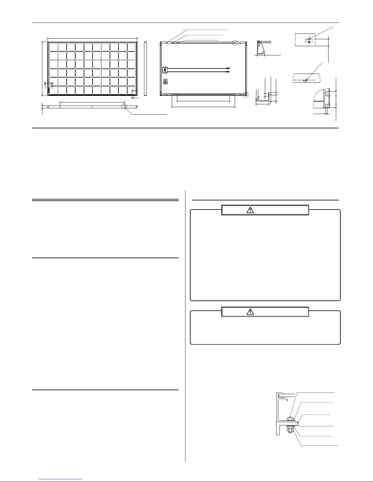
2-3-1. Mounting using bolt holes
Mounting examples:
• Fasten the corner holes of the PV module with M8 (5/16”)
stainless steel bolts to the mounting framework with a
torque of 4.5 to 6N·m (3.3 to 4.4 ft-lb).
•
Use spring washers and flat washers to fasten the PV module as
shown in figure1.
• Install the PV module securely
by fastening the appropriate
bolts with double nuts and
locking washers.
• Make sure that there is more
than a 5 mm gap between
modules to prevent buckling
caused by thermal expansion.
CAUTION
WARNING
2.INSTALLATION
Refer to Local Code (US: National Electrical Code) standards,
construction rules and safety instructions regarding installation
of the PV modules.
Electrical installations in Canada shall be in accordance with
CSA. C22. 1, Safety Standard for Electrical Installations,
Canadian Electrical Code, Part1.
2-1. CLIMATE CONDITIONS
Install the PV module within the following conditions:
•
Ambient monthly mean temperature: -20°C to 40°C (-4 to 104 °F)
• Operating temperature: -30°C to 83°C (-22 to 181 °F)
• Allowable pressure: up to +2400/-3000Pa
• Water resistance/damage: The PV modules shall not be
immersed in water and shall not be continually exposed to
a source of water, such as a sprinkler, fountain, etc.
• Corrosion warning: The PV modules shall not be installed in
corrosive areas such as:
-- Salty areas: areas where salty water such as ocean
spray comes in direct contact with the module, or
-- Sulfurous areas: areas near sulfurous volcanos and
sulfurous springs.
Note
In case of installation in Asian countries, PV modules shall
not be installed in corrosive areas within 500m from a body
of salt water and/or areas where there is direct contact with
salty wind.
2-2. ORIENTATION
• Install the PV modules facing South in the Northern
Hemisphere or North in the Southern Hemisphere.
• PV modules connected in series should be installed in the
same orientation and angle. Different orientation or angles
may cause loss of output power due to the different
amount of sunlight being absorbed by the modules.
• Do not allow the modules to be shaded at anytime.
Shade causes loss of electrical output, even though the
factory fitted bypass diode will reduce such loss to some
extent.
1-2. MULTIPLYING FACTOR
Under normal conditions, the PV module is likely to experience conditions that produce more current and/or voltage than reported
under Standard Test Conditions. Accordingly, the values of Isc and Voc marked on this module should be multiplied by a factor of
1.25 when determining component voltage ratings, conductor capacities (cross sectional area), fuse sizes, and size of controls
connected to the PV output. Customers in US should refer to article 690.8 the National Electrical Code for an additional multiplying
factor of 125 percent (80 percent derating), which may be applicable. Customers in other locations should refer to the codes relevant to
the location of installation for further guidance. Voc should be increased by a factor based on the lowest ambient temperature
recorded for the location. To determine the corrected value for Maximum System Voltage follow the guidelines in article 690.7 of the
NEC or applicable section in the CEC. The voltage temperature coefficient for the module in use should be used when determining
Maximum System Voltage.
1-1. STRUCTURE
Fig. 1 Module mounting
2-4. GROUNDING
• The grounding method should satisfy the Local Codes and
the NEC or CEC accordingly.
• Securely ground the PV modules and the mounting
framework.
Examples of proper grounding technique:
2 Nuts
(Stainless steel, 5/16(M8))
Spring washer
(Stainless steel, 5/16)
Flat Washer
(Stainless steel, 5/16)
Mounting structure
(Alminium)
Flat Washer
(Stainless steel, 5/16)
Bolt
(Stainless steel, 5/16(M8))
E(4 PLACES)
Drainage holes
15[0.59]
20[0.79]
6[0.24]
35[1.38]
1657[65.2]
1000[39.4]
1200[47.2]
1199[47.2]
994[39.1]
46[1.81]
A A
B
B
C
φ4.09[φ0.16](4 PLACES)
6[0.24]×20[0.79](4 PLACES)
φ4.09[φ0.16](4 PLACES)
φ9[φ0.35](4 PLACES)
D
E
(+)(–)
994 (39.1)
φ9[φ0.35]
21.5[0.85]
30[1.18]
46[1.81]
φ4.09
[φ0.16]
D(4 PLACES)
φ4.09
[φ0.16]
Grounding Mark
25.3[1.00]
Grounding Mark
25.3[1.00]
C(4 PLACES)
A−A
B−B
24.5[0.96]
 Loading...