

Mitsubishi Electric PVFY-P12, PVFY-P36, PVFY-P48, PVFY-P54NAMU-E1, PVFY-P18 Service Manual
...
SPLIT-TYPE, HEAT PUMP AIR CONDITIONERS
SERVICE MANUAL
2015
Air-Conditioners
PVFY-P12, 18, 24, 30, 36, 48, 54NAMU-E1
Multi-Position Air Handler
SPLIT-TYPE, HEAT PUMP AIR CONDITIONERS
SERVICE MANUAL
Model name
<Indoor unit>
Model name
<Indoor unit>
Series PVA
2015


Contents
1 SAFETY PRECAUTION ................................................................................................................................................... 2
2 FEATURES ......................................................................................................................................................................5
3 PART NAMES AND FUNCTIONS ....................................................................................................................................6
4 SPECIFICATION ..............................................................................................................................................................9
5 OUTLINES & DIMENSIONS .......................................................................................................................................... 13
6 WIRING DIAGRAM ........................................................................................................................................................ 15
7 REFRIGERANT SYSTEM DIAGRAM ............................................................................................................................ 16
8 MICROPROCESSOR CONTROL ..................................................................................................................................17
9 TROUBLESHOOTING ................................................................................................................................................... 29
10 DISASSEMBLY PROCEDURE ......................................................................................................................................39
Specications are subject to change without notice. © 2017 Mitsubishi Electric US, Inc.
2
SAFETY PRECAUTION1
Safety Precautions
Read before installation and performing electrical work
Symbol explanations
Thoroughly read the following safety precautions prior to installation.
Observe these safety precautions for your safety.
This equipment may have adverse effects on the equipment on the same power supply system.
Contact the local power authority before connecting to the system.
WARNING
This symbol indicates that failure to follow the instructions exactly as stated poses the risk of serious injury or death.
CAUTION
This symbol indicates that failure to follow the instructions exactly as stated poses the risk of serious injury or dam-
age to the unit.
Indicates an action that must be avoided.
Indicates important instructions.
Indicates a parts that requires grounding.
Indicates that caution must be taken with rotating parts. (This symbol is on the main unit label.) <Color: Yellow>
Indicates that the parts that are marked with this symbol pose a risk of electric shock. (This symbol is on the main
unit label.) <Color: Yellow>
WARNING
Carefully read the labels affixed to the main unit.
WARNING
Do not use refrigerant other than the type indicated in the
manuals provided with the unit and on the nameplate.
Doing so may cause the unit or pipes to burst, or result in
explosion or fire during use, during repair, or at the time of
disposal of the unit.
It may also be in violation of applicable laws.
MITSUBISHI ELECTRIC CORPORATION cannot be held
responsible for malfunctions or accidents resulting from the
use of the wrong type of refrigerant.
Ask your dealer or a qualified technician to install the unit.
Improper installation by the user may result in water leakage, electric shock, or fire.
Properly install the unit on a surface that can withstand its
weight.
Unit installed on an unstable surface may fall and cause injury.
Only use specified cables. Securely connect each cable so
that the terminals do not carry the weight of the cable.
Improperly connected cables may produce heat and start a
fire.
Take appropriate safety measures against wind gusts and
earthquakes to prevent the unit from toppling over.
Improper installation may cause the unit to topple over and
cause injury or damage to the unit.
Only use accessories (i.e., air cleaners, humidifiers, electric
heaters) recommended by Mitsubishi Electric.
Do not make any modifications or alterations to the unit.
Consult your dealer for repair.
Improper repair may result in water leakage, electric shock,
or fire.
Do not touch the heat exchanger fins with bare hands.
The fins are sharp and pose a risk of cuts.
In the event of a refrigerant leak, thoroughly ventilate the
room.
If gaseous refrigerant leaks out and comes in contact with
an open flame, toxic gases will be generated.
Properly install the unit according to the instructions in the
Installation Manual.
Improper installation may result in water leakage, electric
shock, or fire.
Specications are subject to change without notice. © 2017 Mitsubishi Electric US, Inc.
3
Have all electrical work performed by an authorized electrician according to the local regulations and the instructions
in this manual. Use a dedicated circuit.
Insufficient power supply capacity or improper installation
of the unit may result in malfunctions of the unit, electric
shock, or fire.
Keep electrical parts away from water.
Wet electrical parts pose a risk of electric shock, smoke, or
fire.
Securely attach the control box cover.
If the cover is not installed properly, dust or water may infiltrate and pose a risk of electric shock, smoke, or fire.
Only use the type of refrigerant that is indicated on the unit
when installing or relocating the unit.
Infiltration of any other types of refrigerant or air into the unit
may adversely affect the refrigerant cycle and may cause
the pipes to burst or explode.
When installing the unit in a small space, take appropriate
precautions to prevent leaked refrigerant from reaching the
limiting concentration.
Leaked refrigerant gas will displace oxygen and may cause
oxygen starvation. Consult your dealer before installing the
unit.
Consult your dealer or a qualified technician when moving
or reinstalling the unit.
Improper installation may result in water leakage, electric
shock, or fire.
After completing the service work, check for a refrigerant
leak.
If leaked refrigerant is exposed to a heat source, such as a
fan heater, stove, or electric grill, toxic gases will be generated.
Do not try to defeat the safety features of the unit.
Forced operation of the pressure switch or the temperature
switch by defeating the safety features for these devices, or
the use of accessories other than the ones that are recommended by Mitsubishi Electric may result in smoke, fire, or
explosion.
Consult your dealer for proper disposal method.
Do not use a leak detection additive.
4
Specications are subject to change without notice. © 2017 Mitsubishi Electric US, Inc.
Precautions for handling units for use with R410A
CAUTION
Do not use the existing refrigerant piping.
A large amount of chlorine that may be contained in the residual refrigerant and refrigerator oil in the existing piping
may cause the refrigerator oil in the new unit to deteriorate.
Use refrigerant piping materials made of phosphorus deoxidized copper. Keep the inner and outer surfaces of the
pipes clean and free of such contaminants as sulfur, oxides,
dust, dirt, shaving particles, oil, and moisture.
Contaminants in the refrigerant piping may cause the refrigerator oil to deteriorate.
Store the piping materials indoors, and keep both ends of
the pipes sealed until immediately before brazing. (Keep elbows and other joints wrapped in plastic.)
Infiltration of dust, dirt, or water into the refrigerant system
may cause the refrigerator oil to deteriorate or cause the
compressor to malfunction.
Use a small amount of ester oil, ether oil, or alkyl benzene
to coat flares and flanges.
Infiltration of a large amount of mineral oil may cause the refrigerator oil to deteriorate.
Charge the system with refrigerant in the liquid phase.
If gaseous refrigerant is drawn out of the cylinder first, the
composition of the remaining refrigerant in the cylinder will
change and become unsuitable for use.
Only use R410A.
The use of other types of refrigerant that contain chloride
may cause the refrigerator oil to deteriorate.
Use a vacuum pump with a check valve.
If a vacuum pump that is not equipped with a check valve is
used, the vacuum pump oil may flow into the refrigerant cycle and cause the refrigerator oil to deteriorate.
Prepare tools for exclusive use with R 410A. Do not use the
following tools if they have been used with the conventional
refrigerant: gauge manifold, charging hose, gas leak detector, check valve, refrigerant charge base, vacuum gauge,
and refrigerant recovery equipment.
If the refrigerant or the refrigerator oil that may be left on these
tools are mixed in with R410A, it may cause the refrigerator oil
in the new system to deteriorate.
Infiltration of water may cause the refrigerator oil to deteriorate.
Leak detectors for conventional refrigerants will not detect an
R410A leak because R410A is free of chlorine.
Do not use a charging cylinder.
If a charging cylinder is used, the composition of the refrigerant
in the cylinder will change and become unsuitable for use.
Exercise special care when handling tools for use with R410A.
Infiltration of dust, dirt, or water into the refrigerant system
may cause the refrigerator oil to deteriorate.
5
Specications are subject to change without notice. © 2017 Mitsubishi Electric US, Inc.
FEATURES2
Model
Cooling capacity/Heating capacity
Btu/h kW
PVFY-P12NAMU-E1 12000/13500 3.5/4.0
PVFY-P18NAMU-E1 18000/20000 5.3/5.9
PVFY-P24NAMU-E1 24000/27000 7.0/7.9
PVFY-P30NAMU-E1 30000/34000 8.8/10.0
PVFY-P36NAMU-E1 36000/40000 10.6/11.7
PVFY-P48NAMU-E1 48000/54000 14.1/15.8
PVFY-P54NAMU-E1 54000/60000 15.8/17.6
6
Specications are subject to change without notice. © 2017 Mitsubishi Electric US, Inc.
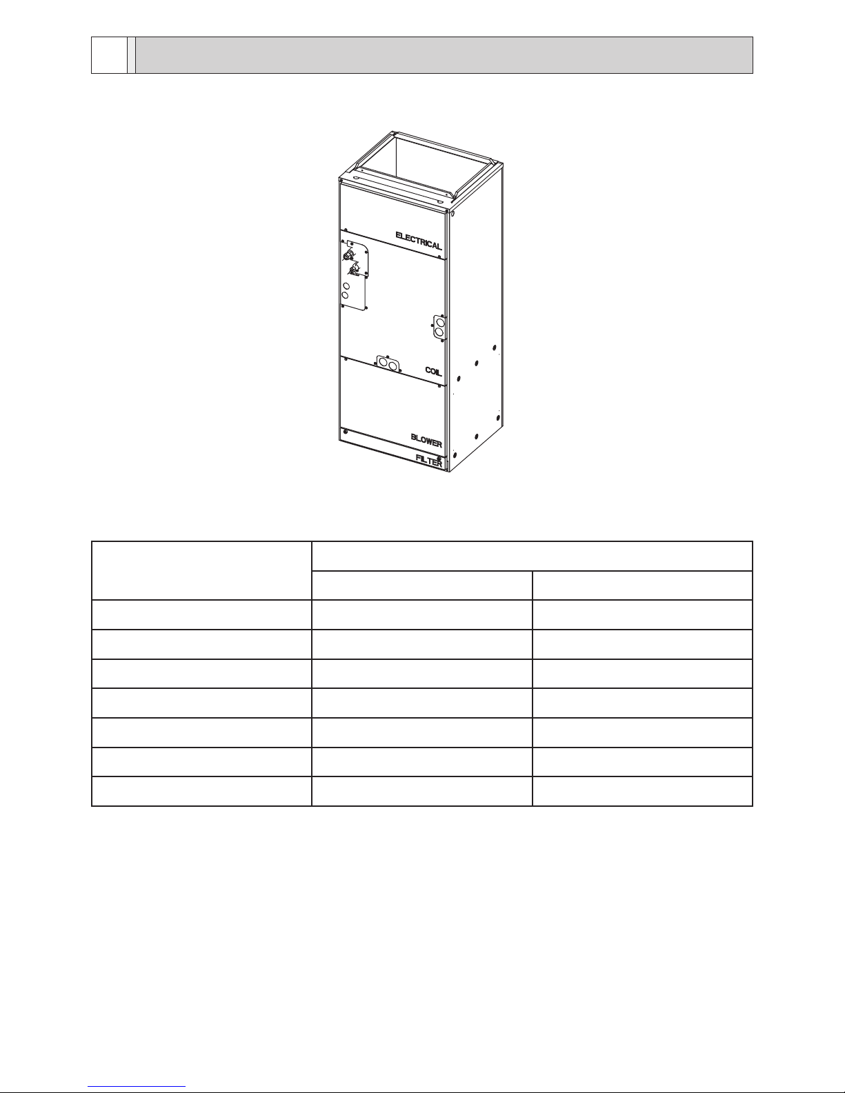
PART NAMES AND FUNCTIONS3
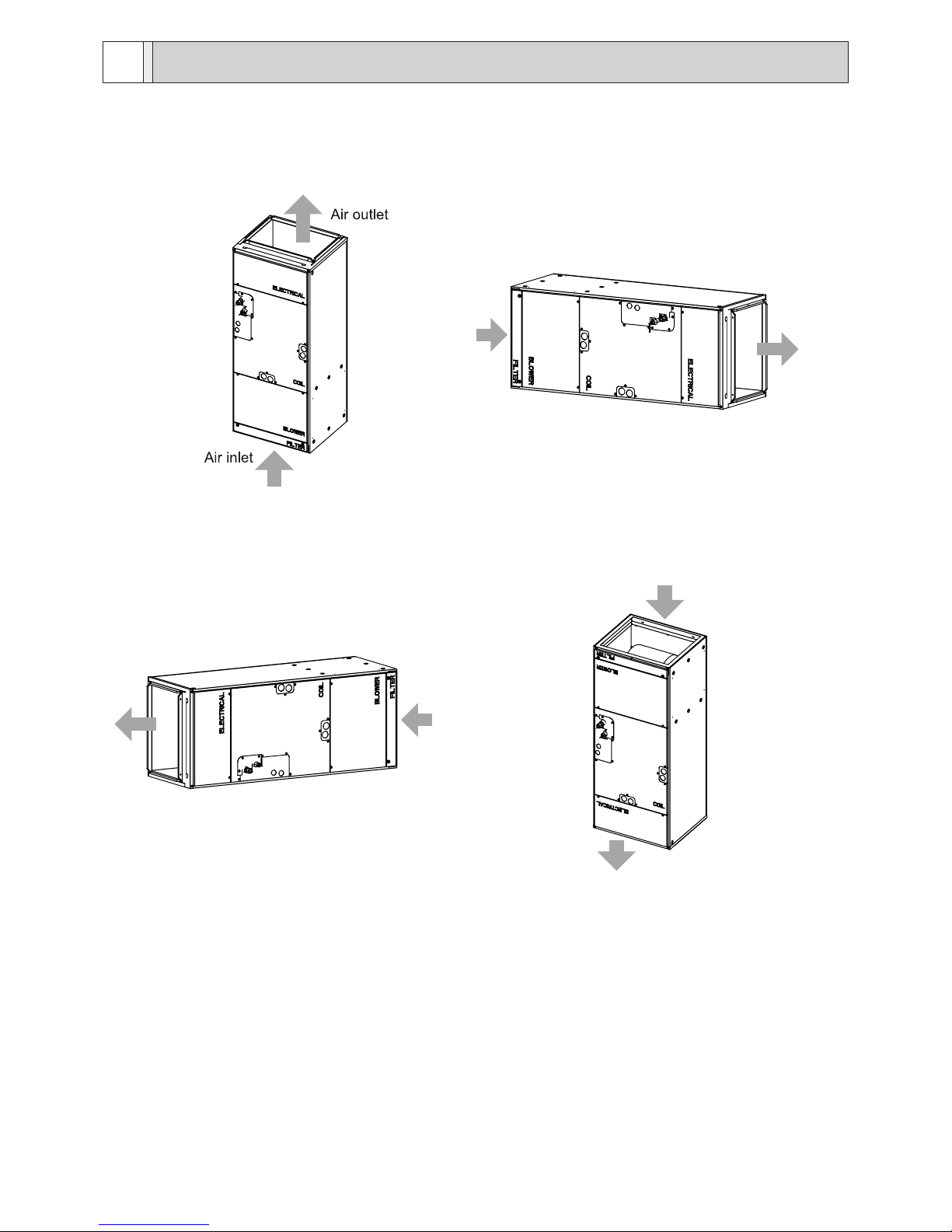
1. Indoor Unit
Air
inlet
Air
outlet
(1)Vertical
(2)Horizontal Right
Air
inlet
Air
outlet
Air inlet
Air outlet
(3)Horizontal left
(4)Down flow
7
Specications are subject to change without notice. © 2017 Mitsubishi Electric US, Inc.
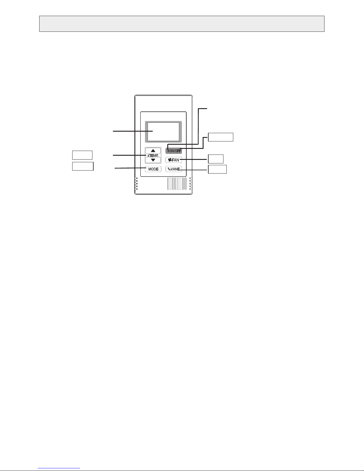
1. Remote Controller
[PAC-YT53CRAU]
Once the operation mode is selected, the unit will remain in the selected mode until changed.
(1) Remote Controller Buttons
.
Backlit LCD
TEMP. button
MODE button
ON/OFF lamp
ON/OFF button
FAN button
VANE button
The lamp will light up in green when
turned on, and blink during startup
and when an error occurs.
Pressing this button starts and
stops the operation.
• Keep the remote controller out of direct sunlight to ensure accurate measurement of room temperature.
• The thermistor at the lower right-hand section of the remote controller must be free from obstructions to
ensure accurate measurement of room temperature.
• To set the functions that are not available on this controller (PAC-YT53CRAU), use MA remote controller or
the centralized controller.
8
Specications are subject to change without notice. © 2017 Mitsubishi Electric US, Inc.
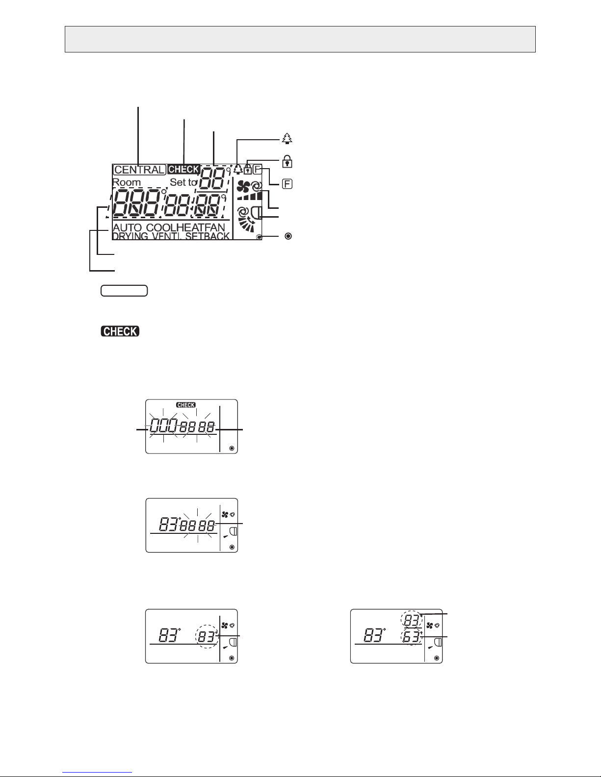
*2 icon
For M-Series and P-Series, when an error occurs, power indicator will blink, and refrigerant address (two digits),
error code (two digits), and unit No. will blink.
For City Multi, when an error occurs, power indicator will blink, and unit address (three digits) and error code (four
digits) will blink.
Check the error status, stop the operation, and consult your dealer.
When only error code blinks, air conditioning units stay in operation, but an error may have occurred.
Check the error code, and consult your dealer.
Room
Set to
AUTO COOLHEATFAN
DRYING VENTI. SETBACK
Unit address
blinks.
Error code
blinks.
Room
Set to
AUTO COOL HEATFAN
DRYING VENTI. SETBACK
Error code
blinks.
icon appears while the unit is operated in the
energy-save mode
* All icons are displayed for explanation.
icon appears when Operation lock setting is
effective.
icon appears when indoor unit functions are set up.
(Refer to the Installation Manual.)
Fan speed icon
Vane icon
icon appears when the power is on.
Indoor temperature
Operation modes
CENTRAL icon *1
CHECK icon *2
Preset temperature *3
*1 icon
Appears when one of the following local operations is prohibited: ON/OFF; operation mode; preset temperature;
fan speed; vane.
CENTRAL
*3 Preset temperature
* Centigrade or Fahrenheit is selectable. Refer to the Installation Manual for details.
In COOL, DRYING, HEAT, or
AUTO (single set point) modes
In AUTO (dual set point) or
SETBACK modes
Room
Set to
AUTO COOL HEATFAN
DRYING VENTI. SETBACK
Preset
temperature
Room
Set to
AUTO COOLHEATFAN
DRYING VENTI. SETBACK
Heating preset
temperature
Cooling preset
temperature
(2) Remote Controller Display
9
Specications are subject to change without notice. © 2017 Mitsubishi Electric US, Inc.
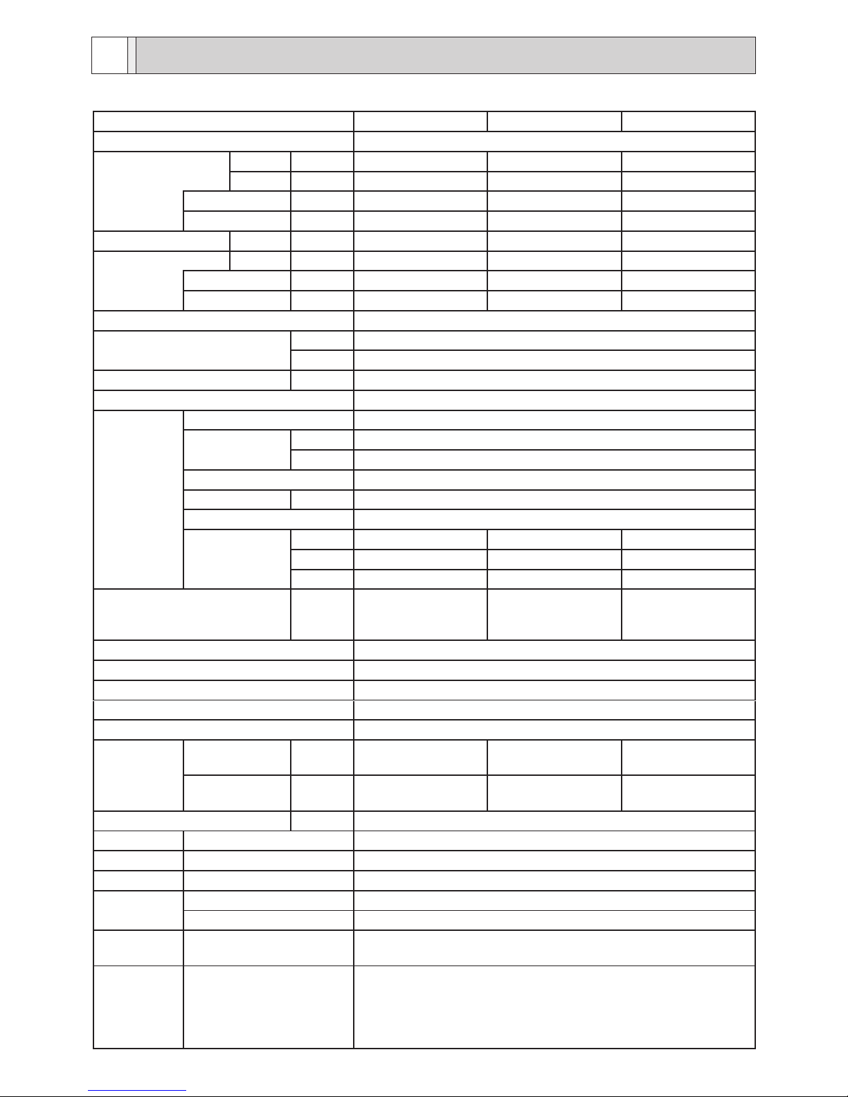
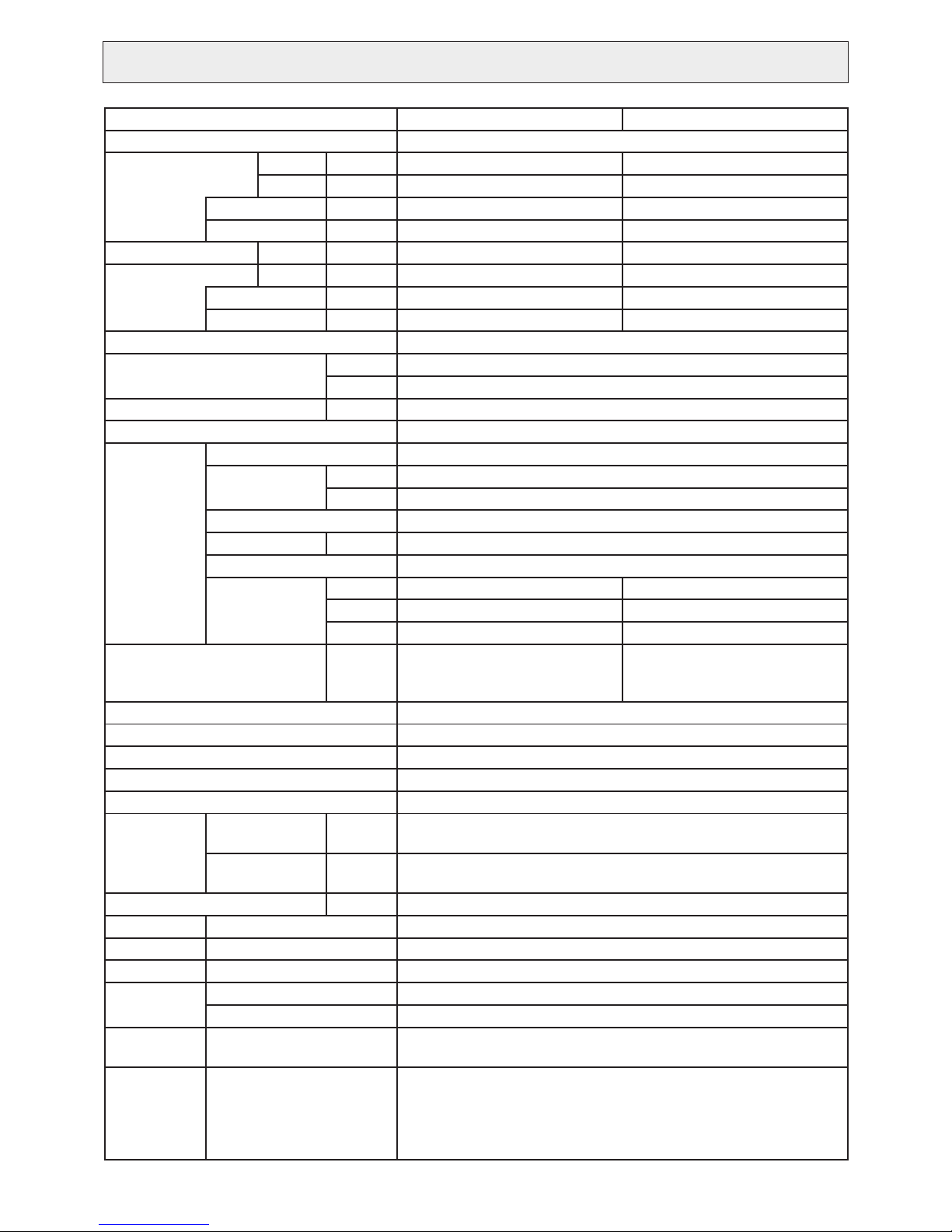
1. Specifications
Model PVFY-P12NAMU-E1 PVFY-P18NAMU-E1 PVFY-P24NAMU-E1
Power source 1-phase 208/230V 60Hz
Cooling capacity
(Nominal)
*1 Btu / h 12,000 18,000 24,000
*1 kW 3.5 5.3 7.0
Power input kW 0.08 0.13 0.18
Current input A 0.80/0.70 1.20/1.10 1.60/1.40
Heating capacity *2 Btu / h 13,500 20,000 27,000
(Nominal) *2 kW 4.0 5.9 7.9
Power input kW 0.08 0.13 0.18
Current input A 0.80/0.70 1.20/1.10 1.60/1.40
External finish Galvanized steel cabinet -Powder coated slate gray
External dimension
H x W x D
In. 50-1/4x17x21-5/8
mm 1275 x 432 x 548
Net weight Lbs. (kg) 113(51)
Heat exchanger Cross fin (Aluminium fin and copper tube)
FAN
Type x Quantity Sirocco fan x 1
External
static press.
In.WG <0.30>-0.50-<0.80>
Pa <75>-125-<200>
Motor type DC motor
Motor output kW 0.121
Driving mechanism Direct-driven by motor
Airflow rate
(Low-Mid-High)
CFM 280-340-400 410-497-585 515-625-735
m³ / min 7.9-9.6-11.3 11.6-14.1-16.6 14.6-17.7-20.8
L / s 132-160-188 193-235-277 243-295-347
Sound pressure level
(Low-Mid-High)
(measured in anechoic room)
dB <A> 27-31-35 28-32-36 30-34-38
Insulation material EPS, Polyethylene foam, Urethane foam, Polyester
Air filter PP honeycomb fabric
Protection device Fuse
Refrigerant control device LEV
Connectable outdoor unit R410A CITY MULTI
Diameter of
refrigerant
pipe
(O.D.)
Liquid
(R410A)
In. (mm) 1/4 (6.35) Brazed 1/4 (6.35) Brazed 3/8 (9.52) Brazed
Gas
(R410A)
In. (mm) 1/2 (12.7) Brazed 1/2 (12.7) Brazed 5/8 (15.88) Brazed
Diameter of drain pipe In. (mm) 3/4 (19.05) FPT
Drawing External PA94C593
Wiring PA94C598
Refrigerant cycle -
Standard
attachment
Document Installation Manual, Instruction Book
Accessory Tie band, Plastic tube, Drain pan seal
Optional
parts
External heater adapter CN24RELAY-KIT-CM3
Remark Installation
Details on foundation work, duct work, insulation work, electrical
wiring, power source switch, and other items shall be referred to
the Installation Manual.
Due to continuing improvement, above specifications may be
subject to change without notice.
SPECIFICATION4
10
Specications are subject to change without notice. © 2017 Mitsubishi Electric US, Inc.
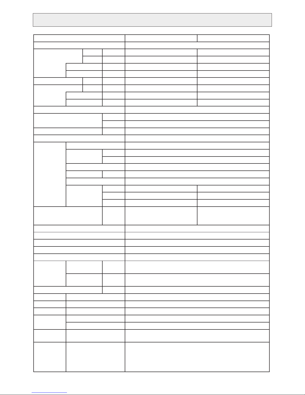
Model PVFY-P30NAMU-E1 PVFY-P36NAMU-E1
Power source 1-phase 208/230V 60Hz
Cooling capacity
(Nominal)
*1 Btu / h 30,000 36,000
*1 kW 8.8 10.6
Power input kW 0.21 0.34
Current input A 2.00/1.70 3.00/2.70
Heating capacity *2 Btu / h 34,000 40,000
(Nominal) *2 kW 10.0 11.7
Power input kW 0.21 0.34
Current input A 2.00/1.70 3.00/2.70
External finish Galvanized steel cabinet -Powder coated slate gray
External dimension
H x W x D
In. 54-1/4x21x21-5/8
mm 1378 x 534 x 548
Net weight Lbs. (kg) 141(64)
Heat exchanger Cross fin (Aluminium fin and copper tube)
FAN
Type x Quantity Sirocco fan x 1
External
static press.
in.WG <0.30>-0.50-<0.80>
Pa <75>-125-<200>
Motor type DC motor
Motor output kW 0.244
Driving mechanism Direct-driven by motor
Airflow rate
(Low-Mid-High)
CFM 613-744-875 767-931-1095
m³ / min 17.3-21.1-24.8 21.7-26.4-31.0
L / s 290-352-413 362-440-517
Sound pressure level
(Low-Mid-High)
(measured in anechoic room)
dB <A> 32-36-40 35-39-43
Insulation material EPS, Polyethylene foam, Urethane foam, Polyester
Air filter PP honeycomb fabric
Protection device Fuse
Refrigerant control device LEV
Connectable outdoor unit R410A CITY MULTI
Diameter of
refrigerant
pipe
(O.D.)
Liquid
(R410A)
In. (mm) 3/8 (9.52) Brazed
Gas
(R410A)
In. (mm) 5/8 (15.88) Brazed
Diameter of drain pipe In. (mm) 3/4 (19.05) FPT
Drawing External PA94C593
Wiring PA94C598
Refrigerant cycle -
Standard
attachment
Document Installation Manual, Instruction Book
Accessory Tie band, Plastic tube, Drain pan seal
Optional
parts
External heater adapter CN24RELAY-KIT-CM3
Remark Installation
Details on foundation work, duct work, insulation work, electrical
wiring, power source switch, and other items shall be referred to
the Installation Manual.
Due to continuing improvement, above specifications may be
subject to change without notice.
11
Specications are subject to change without notice. © 2017 Mitsubishi Electric US, Inc.
Model PVFY-P48NAMU-E1 PVFY-P54NAMU-E1
Power source 1-phase 208/230V 60Hz
Cooling capacity
(Nominal)
*1 Btu / h 48,000 54,000
*1 kW 14.1 15.8
Power input kW 0.42 0.48
Current input A 3.50/3.30 3.90/3.70
Heating capacity *2 Btu / h 54,000 60,000
(Nominal) *2 kW 15.8 17.6
Power input kW 0.42 0.48
Current input A 3.50/3.30 3.90/3.70
External finish Galvanized steel cabinet -Powder coated slate gray
External dimension
H x W x D
In. 59-1/2x25x21-5/8
mm 1511 x 635 x 548
Net weight Lbs. (kg) 172(78)
Heat exchanger Cross fin (Aluminium fin and copper tube)
FAN
Type x Quantity Sirocco fan x 1
External
static press.
In.WG <0.30>-0.50-<0.80>
Pa <75>-125-<200>
Motor type DC motor
Motor output kW 0.430
Driving mechanism Direct-driven by motor
Airflow rate
(Low-Mid-High)
CFM 980-1190-1400 1040-1262-1485
m³ / min 27.7-33.7-39.6 29.4-35.7-42.0
L / s 463-562-660 492-595-702
Sound pressure level
(Low-Mid-High)
(measured in anechoic room)
dB <A> 35-39-43 36-40-44
Insulation material EPS, Polyethylene foam, Urethane foam, Polyester
Air filter PP honeycomb fabric
Protection device Fuse
Refrigerant control device LEV
Connectable outdoor unit R410A CITY MULTI
Diameter of
refrigerant
pipe
(O.D.)
Liquid
(R410A)
In. (mm) 3/8 (9.52) Brazed
Gas
(R410A)
In. (mm) 5/8 (15.88) Brazed
Diameter of drain pipe In. (mm) 3/4 (19.05) FPT
Drawing External PA94C593
Wiring PA94C598
Refrigerant cycle -
Standard
attachment
Document Installation Manual, Instruction Book
Accessory Tie band, Plastic tube, Drain pan seal
Optional
parts
External heater adapter CN24RELAY-KIT-CM3
Remark Installation
Details on foundation work, duct work, insulation work, electrical
wiring, power source switch, and other items shall be referred to
the Installation Manual.
Due to continuing improvement, above specifications may be
subject to change without notice.
12
Specications are subject to change without notice. © 2017 Mitsubishi Electric US, Inc.
Notes
Note : *1 Nominal cooling conditions *2 Nominal heating conditions Unit convertor
Indoor : 80° F D.B. / 67° F W.B. 70° F D.B. kcal/h = kW x 860
(26.7° C D.B. / 19.4° C W.B.) (21.1° C D.B.) Btu/h = kW x 3,412
Outdoor : 95° F D.B. 47° F D.B. / 43° gF W.B. cfm = m3/min x 35.31
(35° C D.B.) (8.3° C D.B. / 6.1° C W.B.) lbs = kg / 0.4536
Pipe length : 25 ft. (7.6 m) 25 ft. (7.6 m) *Above specification
data is subject to
rounding variation.
Level difference : 0 ft. (0 m) 0 ft. (0 m)
*The external static pressure is set to 0.50in. WG(125Pa) at factory shipment.
*Due to continuing improvement, above specification may be subject to change without notice.
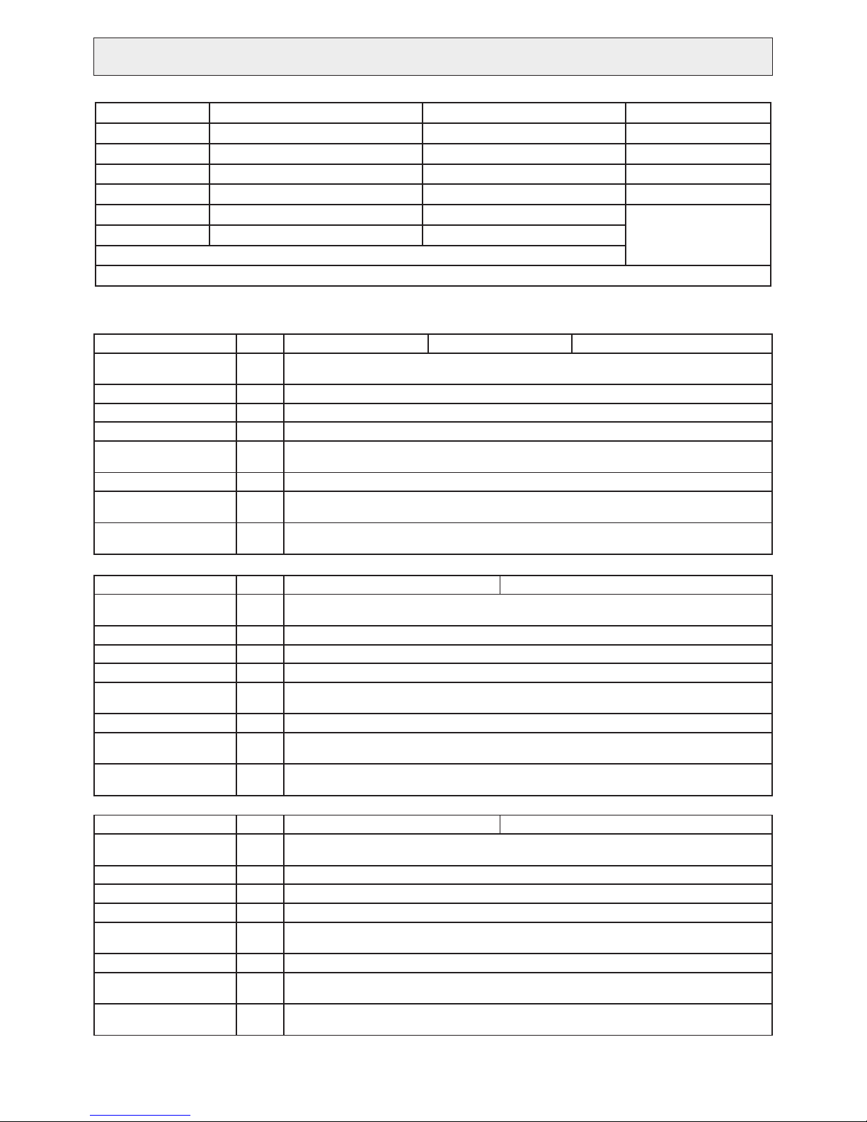
Component Symbol PVFY-P12NAMU-E1 PVFY-P18NAMU-E1 PVFY-P24NAMU-E1
Room temperature
thermistor
TH21 Resistance 0°C/15kΩ, 10°C/9.6kΩ, 20°C/6.3kΩ, 25°C/5.4kΩ, 30°C/4.3kΩ, 40°C/3.0kΩ
Liquid pipe thermistor TH22 Resistance 0°C/15kΩ, 10°C/9.6kΩ, 20°C/6.3kΩ, 25°C/5.4kΩ, 30°C/4.3kΩ, 40°C/3.0kΩ
Gas pipe thermistor TH23 Resistance 0°C/15kΩ, 10°C/9.6kΩ, 20°C/6.3kΩ, 25°C/5.4kΩ, 30°C/4.3kΩ, 40°C/3.0kΩ
Fuse FUSE 250V 6.3A
Fan motor
8-pole, Output 121W
SIC-71FW-D8121-3
Linear expansion valve LEV 12VDC Stepping motor drive port diameter ø3.2 (0~2000 pulse)
Power supply terminal
block
TB2 (L1, L2, G) 250V 20A
Transmission terminal
block
TB5
TB15
(1, 2) 250V 15A, (M1, M2, S) 250V 20A
Component Symbol PVFY-P30NAMU-E1 PVFY-P36NAMU-E1
Room temperature
thermistor
TH21 Resistance 0°C/15kΩ, 10°C/9.6kΩ, 20°C/6.3kΩ, 25°C/5.4kΩ, 30°C/4.3kΩ, 40°C/3.0kΩ
Liquid pipe thermistor TH22 Resistance 0°C/15kΩ, 10°C/9.6kΩ, 20°C/6.3kΩ, 25°C/5.4kΩ, 30°C/4.3kΩ, 40°C/3.0kΩ
Gas pipe thermistor TH23 Resistance 0°C/15kΩ, 10°C/9.6kΩ, 20°C/6.3kΩ, 25°C/5.4kΩ, 30°C/4.3kΩ, 40°C/3.0kΩ
Fuse FUSE 250V 6.3A
Fan motor
8-pole, Output 244W
SIC-81FW-D8244-1
Linear expansion valve LEV 12VDC Stepping motor drive port diameter ø3.2 (0~2000 pulse)
Power supply terminal
block
TB2 (L1, L2, G) 250V 20A
Transmission terminal
block
TB5
TB15
(1, 2) 250V 15A, (M1, M2, S) 250V 20A
Component Symbol PVFY-P48NAMU-E1 PVFY-P54NAMU-E1
Room temperature
thermistor
TH21 Resistance 0°C/15kΩ, 10°C/9.6kΩ, 20°C/6.3kΩ, 25°C/5.4kΩ, 30°C/4.3kΩ, 40°C/3.0kΩ
Liquid pipe thermistor TH22 Resistance 0°C/15kΩ, 10°C/9.6kΩ, 20°C/6.3kΩ, 25°C/5.4kΩ, 30°C/4.3kΩ, 40°C/3.0kΩ
Gas pipe thermistor TH23 Resistance 0°C/15kΩ, 10°C/9.6kΩ, 20°C/6.3kΩ, 25°C/5.4kΩ, 30°C/4.3kΩ, 40°C/3.0kΩ
Fuse FUSE 250V 6.3A
Fan motor
8-pole, Output 430W
M-MW-430-A-1
Linear expansion valve LEV 12VDC Stepping motor drive port diameter ø3.2 (0~2000 pulse)
Power supply terminal
block
TB2 (L1, L2, G) 250V 20A
Transmission terminal
block
TB5
TB15
(1, 2) 250V 15A, (M1, M2, S) 250V 20A
2. Electrical component specifications
 Loading...