

Mitsubishi PVFY-P30NAMU-E, PVFY-P12NAMU-E, PVFY-P18NAMU-E, PVFY-P24NAMU-E, PVFY-P36NAMU-E Technical & Service Manual
...
WARNING
CAUTION
WARNING
WARNING
Safety Precautions
Read before installation and performing electrical work
Thoroughly read the following safety precautions prior to installation.
Observe these safety precautions for your safety.
This equipment may have adverse effects on the equipment on the same power supply system.
Contact the local power authority before connecting to the system.
Symbol explanations
This symbol indicates that failure to follow the instructions exactly as stated poses the risk of serious injury or death.
This symbol indicates that failure to follow the instructions exactly as stated poses the risk of serious injury or dam-
age to the unit.
Indicates an action that must be avoided.
Indicates important instructions.
Indicates a parts that requires grounding.
Indicates that caution must be taken with rotating parts. (This symbol is on the main unit label.) <Color: Yellow>
Indicates that the parts that are marked with this symbol pose a risk of electric shock. (This symbol is on the main
unit label.) <Color: Yellow>
Carefully read the labels affixed to the main unit.
Do not use refrigerant other than the type indicated in the
manuals provided with the unit and on the nameplate.
Doing so may cause the unit or pipes to burst, or result in
explosion or fire during use, during repair, or at the time of
disposal of the unit.
It may also be in violation of applicable laws.
MITSUBISHI ELECTRIC CORPORATION cannot be held
responsible for malfunctions or accidents resulting from the
use of the wrong type of refrigerant.
Ask your dealer or a qualified technician to install the unit.
Improper installation by the user may result in water leakage, electric shock, or fire.
Properly install the unit on a surface that can withstand its
weight.
Unit installed on an unstable surface may fall and cause injury.
Only use specified cables. Securely connect each cable so
that the terminals do not carry the weight of the cable.
Improperly connected cables may produce heat and start a
fire.
Take appropriate safety measures against wind gusts and
earthquakes to prevent the unit from toppling over.
Improper installation may cause the unit to topple over and
cause injury or damage to the unit.
Only use accessories (i.e., air cleaners, humidifiers, electric
heaters) recommended by Mitsubishi Electric.
Do not make any modifications or alterations to the unit.
Consult your dealer for repair.
Improper repair may result in water leakage, electric shock,
or fire.
Do not touch the heat exchanger fins with bare hands.
The fins are sharp and pose a risk of cuts.
In the event of a refrigerant leak, thoroughly ventilate the
room.
If gaseous refrigerant leaks out and comes in contact with
an open flame, toxic gases will be generated.
Properly install the unit according to the instructions in the
Installation Manual.
Improper installation may result in water leakage, electric
shock, or fire.
HWE1405A GB
ii
Have all electrical work performed by an authorized electrician according to the local regulations and the instructions
in this manual. Use a dedicated circuit.
Insufficient power supply capacity or improper installation
of the unit may result in malfunctions of the unit, electric
shock, or fire.
Keep electrical parts away from water.
Wet electrical parts pose a risk of electric shock, smoke, or
fire.
Consult your dealer or a qualified technician when moving
or reinstalling the unit.
Improper installation may result in water leakage, electric
shock, or fire.
After completing the service work, check for a refrigerant
leak.
If leaked refrigerant is exposed to a heat source, such as a
fan heater, stove, or electric grill, toxic gases will be generated.
Securely attach the control box cover.
If the cover is not installed properly, dust or water may infiltrate and pose a risk of electric shock, smoke, or fire.
Only use the type of refrigerant that is indicated on the unit
when installing or relocating the unit.
Infiltration of any other types of refrigerant or air into the unit
may adversely affect the refrigerant cycle and may cause
the pipes to burst or explode.
When installing the unit in a small space, take appropriate
precautions to prevent leaked refrigerant from reaching the
limiting concentration.
Leaked refrigerant gas will displace oxygen and may cause
oxygen starvation. Consult your dealer before installing the
unit.
Do not try to defeat the safety features of the unit.
Forced operation of the pressure switch or the temperature
switch by defeating the safety features for these devices, or
the use of accessories other than the ones that are recommended by Mitsubishi Electric may result in smoke, fire, or
explosion.
Consult your dealer for proper disposal method.
Do not use a leak detection additive.
HWE1405A GB
ii
CAUTION
Precautions for handling units for use with R410A
Do not use the existing refrigerant piping.
A large amount of chlorine that may be contained in the residual refrigerant and refrigerator oil in the existing piping
may cause the refrigerator oil in the new unit to deteriorate.
Use refrigerant piping materials made of phosphorus deoxidized copper. Keep the inner and outer surfaces of the
pipes clean and free of such contaminants as sulfur, oxides,
dust, dirt, shaving particles, oil, and moisture.
Contaminants in the refrigerant piping may cause the refrigerator oil to deteriorate.
Store the piping materials indoors, and keep both ends of
the pipes sealed until immediately before brazing. (Keep elbows and other joints wrapped in plastic.)
Infiltration of dust, dirt, or water into the refrigerant system
may cause the refrigerator oil to deteriorate or cause the
compressor to malfunction.
Use a small amount of ester oil, ether oil, or alkyl benzene
to coat flares and flanges.
Infiltration of a large amount of mineral oil may cause the refrigerator oil to deteriorate.
Charge the system with refrigerant in the liquid phase.
If gaseous refrigerant is drawn out of the cylinder first, the
composition of the remaining refrigerant in the cylinder will
change and become unsuitable for use.
Only use R410A.
The use of other types of refrigerant that contain chloride
may cause the refrigerator oil to deteriorate.
Use a vacuum pump with a check valve.
If a vacuum pump that is not equipped with a check valve is
used, the vacuum pump oil may flow into the refrigerant cycle and cause the refrigerator oil to deteriorate.
Prepare tools for exclusive use with R 410A. Do not use the
following tools if they have been used with the conventional
refrigerant: gauge manifold, charging hose, gas leak detector, check valve, refrigerant charge base, vacuum gauge,
and refrigerant recovery equipment.
If the refrigerant or the refrigerator oil that may be left on these
tools are mixed in with R410A, it may cause the refrigerator oil
in the new system to deteriorate.
Infiltration of water may cause the refrigerator oil to deteriorate.
Leak detectors for conventional refrigerants will not detect an
R410A leak because R410A is free of chlorine.
Do not use a charging cylinder.
If a charging cylinder is used, the composition of the refrigerant
in the cylinder will change and become unsuitable for use.
Exercise special care when handling tools for use with R410A.
Infiltration of dust, dirt, or water into the refrigerant system
may cause the refrigerator oil to deteriorate.
HWE1405A GB
iiiiii

HWE1405A GB
iv

CONTENTS
I
II
III
IV
V
VI
VII
VIII
IX
Features
[1] Features.................................................................................................................................... 1
Components and Functions
[1] Components and Functions...................................................................................................... 2
Specifications
[1] Specifications............................................................................................................................ 5
1.Specifications.......................................................................................................................... 5
2.Electrical component specifications........................................................................................ 7
Outlines and Dimensions
[1] Outlines and Dimensions.......................................................................................................... 8
Wiring Diagram
[1] Wiring Diagram ....................................................................................................................... 10
Refrigerant System Diagram
[1] Refrigerant system diagram.................................................................................................... 11
Microprocessor Control
[1] Microprocessor Control........................................................................................................... 12
1.Cool operation ...................................................................................................................... 12
2.Fan operation........................................................................................................................ 13
3.Heat operation ...................................................................................................................... 14
4.Auto operation [Automatic cool / heat change over operation] ............................................. 15
5.Heater control ....................................................................................................................... 16
6.Humidifier control.................................................................................................................. 21
7.Fan indication ....................................................................................................................... 21
Troubleshooting
[1] Troubleshooting ...................................................................................................................... 22
1.Check methods..................................................................................................................... 22
2.DC fan motor (fan motor/indoor control board)..................................................................... 26
3.Address switch setting .......................................................................................................... 27
4.Voltage test points on the control board ............................................................................... 28
5.Dipswitch setting (Factory setting)........................................................................................ 29
Disassembly Procedure
[1] Disassembly Procedure.......................................................................................................... 32
1.Control box ........................................................................................................................... 32
2.Thermistor (Return Air) ......................................................................................................... 33
3.Coil Assembly (thermistor, drainpan, heat exchanger)......................................................... 34
4.Blower/Fan Assembly ...........................................................................................................36
HWE1405A GB

HWE1405A GB
[ I Features ]
I Features
[1] Features
Model Cooling capacity/Heating capacity
BTU/h kW
PVFY-P12NAMU-E 12000/13500 3.5/4.0
PVFY-P18NAMU-E 18000/20000 5.3/5.9
PVFY-P24NAMU-E 24000/27000 7.0/7.9
PVFY-P30NAMU-E 30000/34000 8.8/10.0
PVFY-P36NAMU-E 36000/40000 10.6/11.7
PVFY-P48NAMU-E 48000/54000 14.1/15.8
PVFY-P54NAMU-E 54000/60000 15.8/17.6
HWE1405A GB
- 1 -
[ II Components and Functions ]
II Components and Functions
[1] Components and Functions
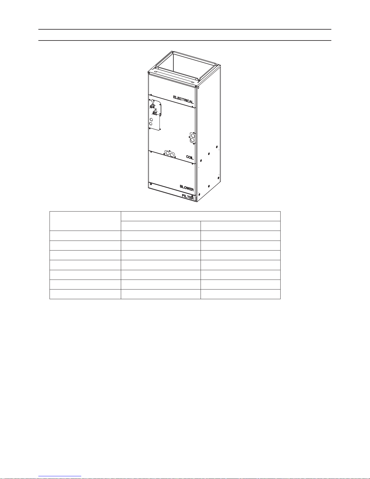
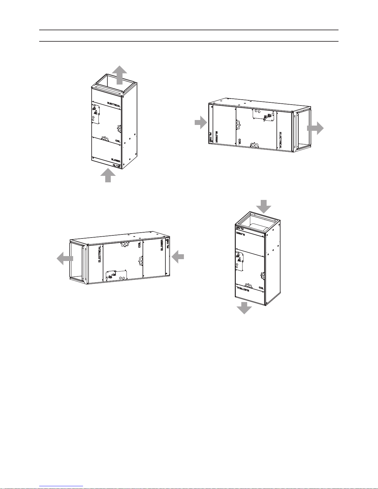
1. Indoor (Main) Unit
(1) Vertical (2) Horizontal Right
Air outlet
Air
inlet
Air inlet
(3) Horizontal Left (4) Down Flow
Air
outlet
Air
outlet
Air
inlet
Air inlet
Air outlet
HWE1405A GB
- 2 -
[ II Components and Functions ]
.
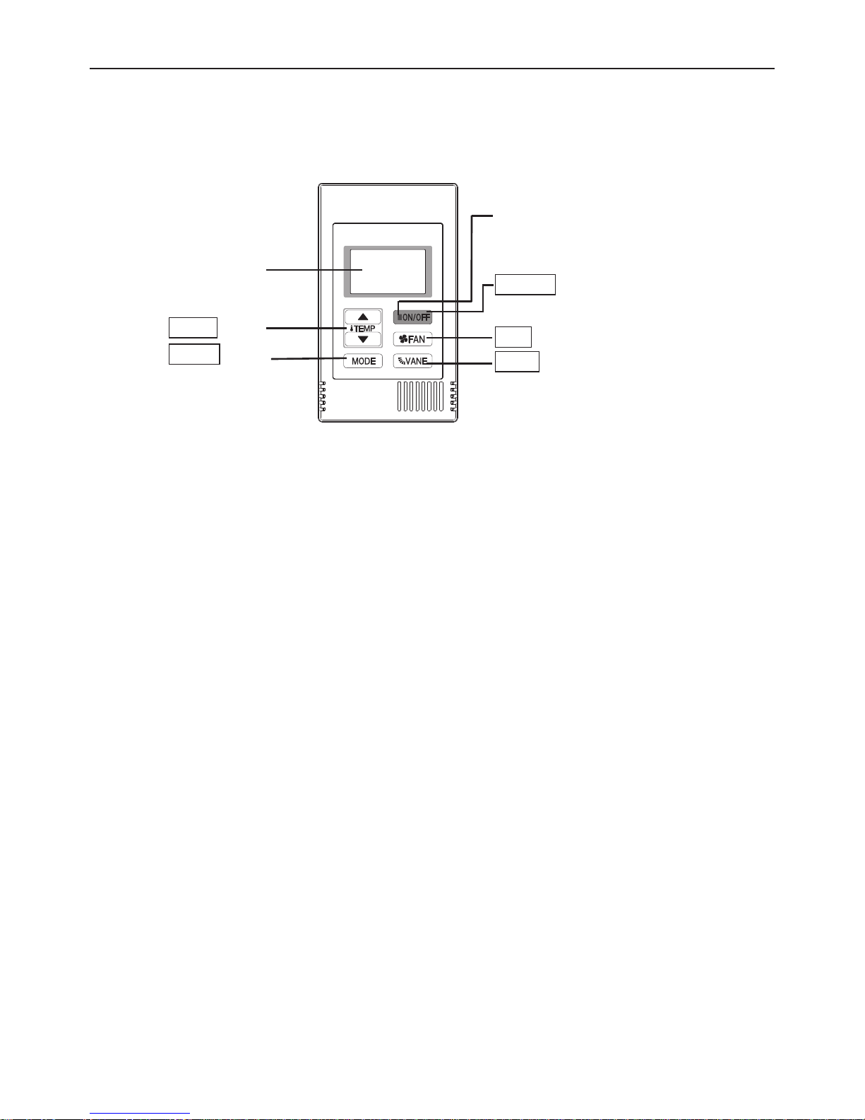
2. Remote Controller
[PAC-YT53CRAU]
Once the operation mode is selected, the unit will remain in the selected mode until changed.
(1) Remote Controller Buttons
ON/OFF lamp
The lamp will light up in green when
turned on, and blink during startup
Backlit LCD
and when an error occurs.
ON/OFF button
Pressing this button starts and
TEMP. button
MODE button
stops the operation.
FAN button
VANE button
Keep the remote controller out of direct sunlight to ensure accurate measurement of room temperature.
The thermistor at the lower right-hand section of the remote controller must be free from obstructions to ensure accurate mea-
surement of room temperature.
To set the functions that are not available on this controller (PAC-YT53CRAU), use MA remote controller or the centralized
controller.
HWE1405A GB
- 3 -
[ II Components and Functions ]
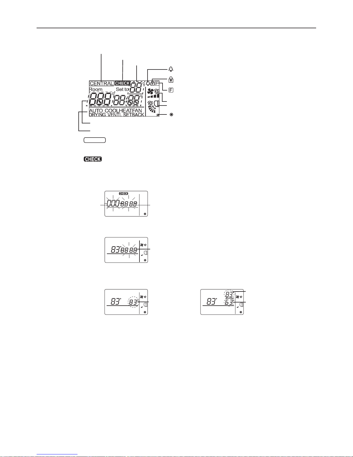
(2) Remote Controller Display
CENTRAL icon *1
* All icons are displayed for explanation.
CHECK icon *2
Preset temperature *3
icon appears while the unit is operated in the
energy-save mode
icon appears when Operation lock setting is
effective.
icon appears when indoor unit functions are set up.
(Refer to the Installation Manual.)
Fan speed icon
Vane icon
icon appears when the power is on.
Indoor temperature
Operation modes
*1 icon
CENTRAL
Appears when one of the following local operations is prohibited: ON/OFF; operation mode; preset temperature;
fan speed; vane.
*2 icon
For M-Series and P-Series, when an error occurs, power indicator will blink, and refrigerant address (two digits),
error code (two digits), and unit No. will blink.
For City Multi, when an error occurs, power indicator will blink, and unit address (three digits) and error code (four
digits) will blink.
Check the error status, stop the operation, and consult your dealer.
Set to
Room
Unit address
blinks.
AUTO COOLHEATFAN
DRYING VENTI. SETBACK
Error code
blinks.
When only error code blinks, air conditioning units stay in operation, but an error may have occurred.
Check the error code, and consult your dealer.
Set to
Room
AUTO COOLHEATFAN
DRYING VENTI. SETBACK
Error code
blinks.
*3 Preset temperature
* Centigrade or Fahrenheit is selectable. Refer to the Installation Manual for details.
In COOL, HEAT, or
AUTO (single set point) modes
Set to
Room
AUTO COOLHEATFAN
DRYING VENTI. SETBACK
Preset
temperature
In AUTO (dual set point) or
SETBACK modes
Set to
Room
AUTO COOLHEATFAN
DRYING VENTI. SETBACK
Cooling preset
temperature
Heating preset
temperature
HWE1405A GB
- 4 -
[ III Specifications ]
III Specifications
[1] Specifications
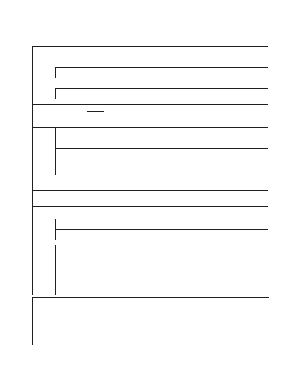
1. Specifications
Model PVFY-P12NAMU-E PVFY-P18NAMU-E PVFY-P24NAMU-E PVFY-P30NAMU-E
Power source 1-phase 208/230V 60Hz
Cooling capacity *1 BTU / h 12,000 18,000 24,000 30,000
(Nominal) *1 kW 3.5 5.3 7.0 8.8
Power input kW 0.08 0.13 0.18 0.21
Current input A 0.80/0.70 1.20/1.10 1.60/1.40 2.00/1.70
Heating capacity *2 BTU / h 13,500 20,000 27,000 34,000
(Nominal) *2 kW 4.0 5.9 7.9 10.0
Power input kW 0.08 0.13 0.18 0.21
Current input A 0.80/0.70 1.20/1.10 1.60/1.40 2.00/1.70
External finish Galvanized steel cabinet -Powder coated slate gray
External dimension H x W x D in. 50-1/4x17x21-5/8 54-1/4x21x21-5/8
mm 1275 x 432 x 548 1378 x 534 x 548
Net weight lbs (kg) 113(51) 141(64)
Heat exchanger Cross fin (Aluminium fin and copper tube)
FAN Type x Quantity Sirocco fan x 1
External in.WG <0.30>-0.50-<0.80>
static press. Pa <75>-125-<200>
Motor type DC motor
Motor output kW 0.121 0.244
Driving mechanism Direct-driven by motor
Airflow rate cfm 280-340-400 410-497-585 515-625-735 613-744-875
(Low-Mid-High) m
Sound pressure level
(Low-Mid-High)
(measured in anechoic room)
Insulation material EPS, Polyethylene foam, Urethane foam
Air filter PP honeycomb fabric
Protection device Fuse
Refrigerant control device LEV
Connectable outdoor unit R410A CITY MULTI
Diameter of
refrigerant
pipe
(O.D.)
Diameter of drain pipe in. (mm) 3/4 (19.05) FPT
Drawing External PA94C316
Standard Document Installation Manual, Instruction Book
attachment Accessory Tie band, Plastic tube, Drain pan seal
Optional
parts
Remark Installation Details on foundation work, duct work, insulation work, electrical wiring, power source switch, and other
Note : *1 Nominal cooling conditions *2 Nominal heating conditions Unit convertor
*The external static pressure is set to 0.50in. WG(125Pa) at factory shipment. subject to rounding variation.
*Due to continuing improvement, above specification may be subject to change without notice.
Liquid (R410A) in. (mm) 1/4 (6.35) Brazed 1/4 (6.35) Brazed 3/8 (9.52) Brazed 3/8 (9.52) Brazed
Gas (R410A) in. (mm) 1/2 (12.7) Brazed 1/2 (12.7) Brazed 5/8 (15.88) Brazed 5/8 (15.88) Brazed
Wiring PA94C110
Refrigerant cycle -
External heater adapter PAC-YU25HT
Indoor : 80degF D.B. / 67degF W.B. 70degF D.B. kcal/h = kW x 860
(26.7degC D.B. / 19.4degC W.B.) (21.1degC D.B.) BTU/h = kW x 3,412
Outdoor : 95degF D.B. 47degF D.B. / 43degF W.B. cfm = m
(35degC D.B.) (8.3degC D.B. / 6.1degC W.B.) lbs = kg / 0.4536
Pipe length : 25 ft. (7.6 m) 25 ft. (7.6 m)
Level difference : 0 ft. (0 m) 0 ft. (0 m) *Above specification data is
3
/ min 7.9-9.6-11.3 11.6-14.1-16.6 14.6-17.7-20.8 17.3-21.1-24.8
L / s 132-160-188 193-235-277 243-295-347 290-352-413
dB <A> 27-31-35 28-32-36 30-34-38 32-36-40
items shall be referred to the Installation Manual.
Due to continuing improvement, above specifications may be subject to change without notice.
3
/min x 35.31
HWE1405A GB
- 5 -
[ III Specifications ]
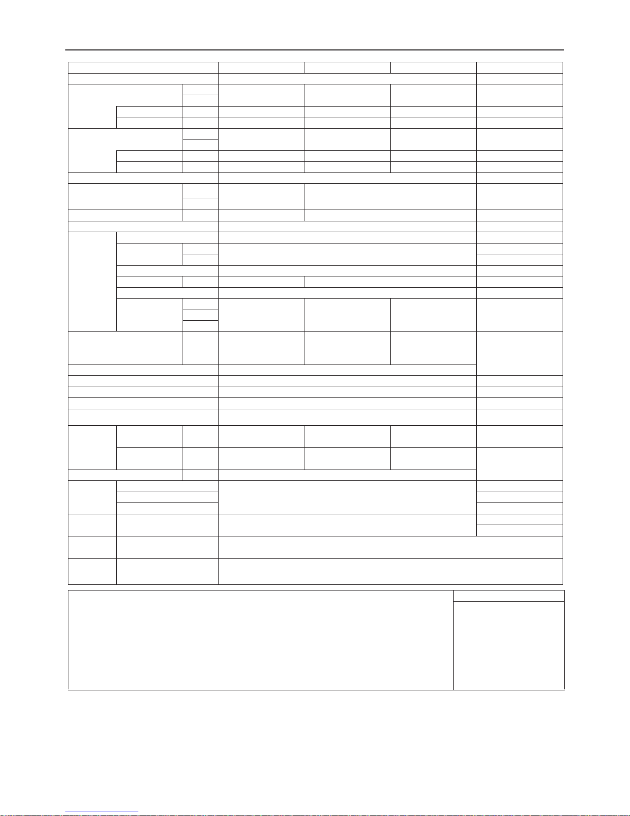
Model PVFY-P36NAMU-E PVFY-P48NAMU-E PVFY-P54NAMU-E
Power source 1-phase 208/230V 60Hz
Cooling capacity *1 BTU / h 36,000 48,000 54,000
(Nominal) *1 kW 10.6 14.1 15.8
Power input kW 0.34 0.42 0.48
Current input A 3.00/2.70 3.50/3.30 3.90/3.70
Heating capacity *2 BTU / h 40,000 54,000 60,000
(Nominal) *2 kW 11.7 15.8 17.6
Power input kW 0.34 0.42 0.48
Current input A 3.00/2.70 3.50/3.30 3.90/3.70
External finish Galvanized steel cabinet - Powder coated slate gray
External dimension H x W x D in. 54-1/4x21x21-5/8 59-1/2x25x21-5/8
mm 1378 x 534 x 548 1511 x 635 x 548
Net weight lbs (kg) 141(64) 172(78)
Heat exchanger Cross fin (Aluminium fin and copper tube)
FAN Type x Quantity Sirocco fan x 1
External in.WG <0.30>-0.50-<0.80>
static press. Pa <75>-125-<200>
Motor type DC motor
Motor output kW 0.244 0.430
Driving mechanism Direct-driven by motor
Airflow rate cfm 767-931-1095 980-1190-1400 1040-1262-1485
(Low-Mid-High) m
Sound pressure level
(Low-Mid-High)
(measured in anechoic room)
Insulation material EPS, Polyethylene foam,Urethane foam
Air filter PP honeycomb fabric
Protection device Fuse
Refrigerant control device LEV
Connectable outdoor unit R410A CITY MULTI
Diameter of
refrigerant
pipe
(O.D.)
Diameter of drain pipe in. (mm) 3/4 (19.05) FPT
Drawing External PA94C316
Standard Document Installation Manual, Instruction Book
attachment Accessory Tie band, Plastic tube, Drain pan seal
Optional
parts
Remark Installation Details on foundation work, duct work, insulation work, electrical wiring, power source switch, and other
Note : *1 Nominal cooling conditions *2 Nominal heating conditions Unit convertor
*The external static pressure is set to 0.50in. WG(125Pa) at factory shipment. subject to rounding variation.
*Due to continuing improvement, above specification may be subject to change without notice.
Liquid (R410A) in. (mm) 3/8 (9.52) Brazed 3/8 (9.52) Brazed 3/8 (9.52) Brazed
Gas (R410A) in. (mm) 5/8 (15.88) Brazed 5/8 (15.88) Brazed 5/8 (15.88) Brazed
Wiring PA94C110
Refrigerant cycle -
External heater adapter PAC-YU25HT
Indoor : 80degF D.B. / 67degF W.B. 70degF D.B. kcal/h = kW x 860
(26.7degC D.B. / 19.4degC W.B.) (21.1degC D.B.) BTU/h = kW x 3,412
Outdoor : 95degF D.B. 47degF D.B. / 43degF W.B. cfm = m3/min x 35.31
(35degC D.B.) (8.3degC D.B. / 6.1degC W.B.) lbs = kg / 0.4536
Pipe length : 25 ft. (7.6 m) 25 ft. (7.6 m)
Level difference : 0 ft. (0 m) 0 ft. (0 m) *Above specification data is
3
/ min 21.7-26.4-31.0 27.7-33.7-39.6 29.4-35.7-42.0
L / s 362-440-517 463-562-660 492-595-702
dB <A> 35-39-43 35-39-43 36-40-44
items shall be referred to the Installation Manual.
Due to continuing improvement, above specifications may be subject to change without notice.
HWE1405A GB
- 6 -
[ III Specifications ]
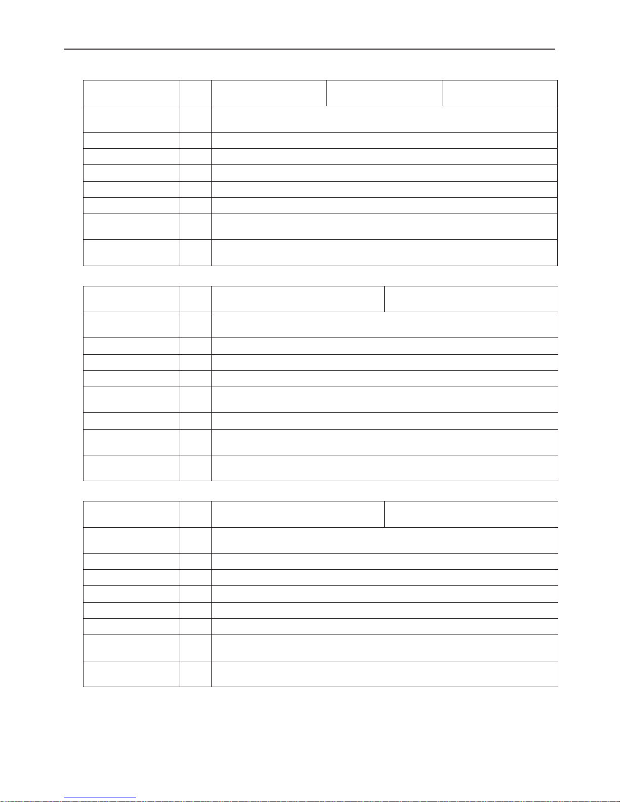
2. Electrical component specifications
Component Sym-
bol
Room temperature
TH21
thermistor
Resistance 0°C/15k, 10°C/9.6k, 20°C/6.3k, 25°C/5.4k, 30°C/4.3k, 40°C/3.0k
PVFY-
P12NAMU-E
PVFY-
P18NAMU-E
PVFY-
P24NAMU-E
Liquid pipe thermistor TH22 Resistance 0°C/15k, 10°C/9.6k, 20°C/6.3k, 25°C/5.4k, 30°C/4.3k, 40°C/3.0k
Gas pipe thermistor TH23 Resistance 0°C/15k, 10°C/9.6k, 20°C/6.3k, 25°C/5.4k, 30°C/4.3k, 40°C/3.0k
Fuse FUSE 250V 6.3A
Fan motor 8-pole, Output 121W SIC-71FW-D8121-3
Linear expansion valve LEV 12VDC Stepping motor drive port diameter ø3.2 (0~2000 pulse)
Power supply terminal
block
Transmission terminal
block
Component Sym-
Room temperature
TB2
TB5
TB15
bol
(1, 2) 250V 15A, (M1, M2, S) 250V 20A
PVFY-
P30NAMU-E
(L1, L2, G) 250V 20A
PVFY-
P36NAMU-E
TH21 Resistance 0°C/15k, 10°C/9.6k, 20°C/6.3k, 25°C/5.4k, 30°C/4.3k, 40°C/3.0k
thermistor
Liquid pipe thermistor TH22 Resistance 0°C/15k, 10°C/9.6k, 20°C/6.3k, 25°C/5.4k, 30°C/4.3k, 40°C/3.0k
Gas pipe thermistor TH23 Resistance 0°C/15k, 10°C/9.6k, 20°C/6.3k, 25°C/5.4k, 30°C/4.3k, 40°C/3.0k
Fuse FUSE 250V 6.3A
Fan motor 8-pole, Output 244W
SIC-81FW-D8244-1
Linear expansion valve LEV 12VDC Stepping motor drive port diameter ø3.2 (0~2000 pulse)
Power supply terminal
TB2 (L1, L2, G) 250V 20A
block
Transmission terminal
block
TB5
TB15
(1, 2) 250V 15A, (M1, M2, S) 250V 20A
Component Sym-
bol
Room temperature
TH21
thermistor
Liquid pipe thermistor TH22 Resistance 0°C/15k, 10°C/9.6k, 20°C/6.3k, 25°C/5.4k, 30°C/4.3k, 40°C/3.0k
Gas pipe thermistor TH23 Resistance 0°C/15k, 10°C/9.6k, 20°C/6.3k, 25°C/5.4k, 30°C/4.3k, 40°C/3.0k
Fuse FUSE 250V 6.3A
Fan motor 8-pole, Output 430W M-MW-430-A-1
Linear expansion valve LEV 12VDC Stepping motor drive port diameter ø3.2 (0~2000 pulse)
Power supply terminal
TB2
block
Transmission terminal
block
HWE1405A GB
TB5
TB15
PVFY-
P48NAMU-E
PVFY-
P54NAMU-E
Resistance 0°C/15k, 10°C/9.6k, 20°C/6.3k, 25°C/5.4k, 30°C/4.3k, 40°C/3.0k
(L1, L2, G) 250V 20A
(1, 2) 250V 15A, (M1, M2, S) 250V 20A
- 7 -

[ IV Outlines and Dimensions ]
IV Outlines and Dimensions
[1] Outlines and Dimensions
1. PVFY-P12,18, 24, 30, 36, 48, 54NAMU-E
(Duct)
402(15-7/8)
548(21-5/8)
view
Right side
376X402
(14-13/16X15-7/8)
Duct Connection
477X402
579X402
(18-13/16X15-7/8)
(22-13/16X15-7/8)
Unit : mm(in.)
117.4(4-5/8)
Ø26 Knockout Hole
Note 1.Keep the service space for maintenance at the front.
Ø26 Knockout Hole
(Remote controller transmission)
Front
24(15/16)
13.2(9/16)
76(3)
28.8(1-3/16)
C
Air outlet
B(Duct)
view
(Remote controller transmission)
To p
55(2-3/16)
Primary drain pipe
(Gravity drain)
Terminal block
(Indoor / Outdoor unit connection)
Terminal block
43(1-3/4)
(Remote controller transmission)
Control box
8(3/8)
E
8(3/8)
Ø19.05(3/4) 3/4"FPT
(Horizontal Right)
Secondary drain pipe
(Emergency draining)
Ø19.05(3/4) 3/4"FPT
Primary drain pipe
Bottom
F
525.5(20-3/4)
D
(Gravity drain)
Ø19.05(3/4) 3/4"FPT
Air inlet
A
(20X16X1)
508X508X25.4
508X406.4X25.4
Nominal Filter Size
3
Model
PVFY-P12NAMU-E
PVFY-P18NAMU-E
PVFY-P24NAMU-E
PVFY-P30NAMU-E
470(18-9/16) 50.8(2)
36.8(1-1/2)
J
(20X24X1)
(20X20X1)
508X609.6X25.4
PVFY-P36NAMU-E
PVFY-P48NAMU-E
PVFY-P54NAMU-E
(1/4)
Ø6.35
2
Unit:mm(in.)
(1/2)
Ø12.7
Gas pipe Liquid pipe
1
360
(14-3/16)
Ø9.52
Ø15.88
461
(18-3/16)
(3/8)
(5/8)
563
(22-3/16)
To p
view
Ø26 Knockout Hole
2-Ø4.6 Burring Holes
for electric heat installation
Primary drain pipe
Secondary drain pipe
(Emergency draining)
(Indoor / Outdoor unit connection)
HWE1405A GB
brazing connection(gas)
Refrigerant piping
1
Ø19.05(3/4) 3/4"FPT
brazing connection(liquid)
Refrigerant piping
2
26 Knockout Hole
Ø
unit connection)
(Indoor / Outdoor
(Gravity drain)
Ø19.05(3/4) 3/4"FPT
(Horizontal left)
55(2-3/16)
70(2-13/16)
104.5(4-1/8)
105.7(4-3/16)
43(1-3/4) 8(3/8)
92(3-5/8) 30(1-3/16)
55(2-3/16)
Secondary drain pipe
Ø19.05(3/4) 3/4"FPT
(Emergency draining)
H
G
- 8 -
view
Left side
Air filter
3
view
Bottom
(29)
792
735.5
823
FG
680
1275
224
281
376
432
Model A B C D E H J
PVFY-P12NAMU-E
(31-3/16)
953.5
(32-7/16)
(37-9/16)
737
(29-1/16)
(26-13/16)
1378
(50-1/4)
(54-1/4)
(8-7/8)
266.5
(10-1/2)
382.6
(11-1/8)
(15-1/8)
477
(14-13/16)
(18-13/16)
(17)
(21)
534
PVFY-P18NAMU-E
PVFY-P24NAMU-E
PVFY-P30NAMU-E
853.5
(33-5/8)
1053
(41-1/2)
798.5
(31-7/16)
1511
(59-1/2)
317.5
(12-1/2)
484.6
(19-1/8)
579
(22-13/16)
(25)
635
PVFY-P36NAMU-E
PVFY-P48NAMU-E
PVFY-P54NAMU-E

[ IV Outlines and Dimensions ]
Unit : mm(in.)
609.6(24)
Length of Unit
Horizontal Installation
Clearance Area
HWE1405A GB
609.6(24)
Width of Unit
Vertical Installation
- 9 -

[ V Wiring Diagram ]
V Wiring Diagram
[1] Wiring Diagram
1. PVFY-P12, 18, 24, 30, 36, 48, 54NAMU-E
TB15
INSIDE SECTION OF CONTROL BOX
CONTROLLER
TO MA REMOTE
1
2
(SHIELD)
S
I.B.
BC CONTROLLER
TO OUTDOOR UNIT
M2
POWER SUPPLY
REMOTE CONTROLLER
M1
TB5
AC208/230V
TB2
L2GL1
P. B .
(RED)
(RED)
CN105
LED1
1
3
LED2
CN3A
(BLUE)
(BLUE)(YELLOW)
CN24-2CN24-1
CN25
SW1
SW2
SW4
SW14
SWA
SW5
60Hz
CND
351
CN2A
(BLACK)
SWE
OFF
SW3
SW12
SWC
DSA
SW11
2
1
CN2M
(BLUE)
CN90
ON
F01
U
CN32
ZNR01
ZNR02
(RED)
(BLUE)
(GREEN)
CN60
1
CN7V
U
CNEC2
CNXA2
1
CNXB2
(GREEN)
CN41
CN51
CN52
(RED)
CN4F
CN44
(GREEN)
21653
2
CNEC1
2
1
CNXC2
3
CNF
1
CN20
3
213
CN22
4
534
6
DC280-340V
5321476
431
2
542
2
4
4
7
RECTIFIER
CIRCUIT
X10
(BLUE)
1
4567
1232153214 4
CNXC1 CNMFCNXA1
CNXB1
MS
3~
FAN MOTOR
(Heavy dotted line):Field wiring
:Connector
:Terminal
UTILISER DES FILS D'ALIMENTATION EN CUIVRE.
2.Use copper supply wires.
NOTE:1.Symbols used in wiring diagram above are,
Switch (for static pressure selection)
Switch (for static pressure selection)
Switch (for capacity code)
Switch (for mode selection)
Switch (for model selection)
Switch (for mode selection)
Switch (1st digit address set)
Switch (for mode selection)
SYMBOL
SW1(I.B.)
SW2(I.B.)
SW3(I.B.)
TH21
°
t
Connector (HA terminal-A)
Connector (Centrally control)
Connector (Remote switch)
TH23
°
t
TH22
°
SYMBOL
t
M
LEV
CN32
CN41
CN51
Switch (10ths digit address set)
SW4(I.B.)
SW5(I.B.)
SW11(I.B.)
SW12(I.B.)
Connector (0-10V Analog input)
Connector (IT terminal)
Connector (Wireless)
Connector (Remote indication)
CN52
CN90
CN105
CN2A
NAME NAME NAME
Connector (emergency operation)
LED (Power supply)
Switch (connection No.set)
SW14(I.B.)
SWA(I.B.)
Connector (Humidity input)
Connector (FAN indication)
CNEC2
CNF
LED (Remote controller supply)
SWC(I.B.)
SWE(I.B.)
LED1
LED2
Thermistor (inlet air temp.detection)
Thermistor (piping temp.detection/liquid)
Thermistor (piping temp.detection/gas)
TH21
TH22
TH23
HWE1405A GB
- 10 -
Indoor controller board
Power supply board
Power source terminal block
Transmission terminal block
SYMBOL
SYMBOL EXPLANATION
I.B.
P.B.
TB2
TB5
Transmission terminal block
Fuse AC250V 6.3A
Varistor
Arrester
Aux. relay
Connector (Fan control)
Connector (Heater control 1st)
Connector (Heater control 2nd)
Connector (Humidity output)
TB15
F01
ZNR01,02
DSA
X10
CN24-1
CN22
CN24-2
CN25

[ VI Refrigerant System Diagram ]
VI Refrigerant System Diagram
[1] Refrigerant system diagram
(A)
(B)
(G)
(D)
(H)
(C)
(F)
(I)
(A) Gas pipe thermistor TH23
(B) Gas pipe
(C) Liquid pipe
(D) Brazed connections
(E) Strainer (#100 mesh)
(F) Linear expansion valve
(G) Liquid pipe thermistor TH22
(H) Heat exchanger
(I) Room temperature thermistor TH21
Capacity PVFY-P12, 18NAMU-E PVFY-P24, 30, 36, 48, 54NAMU-E
Gas pipe ø12.7 [1/2] ø15.88 [5/8]
Liquid pipe ø6.35 [1/4] ø9.52 [3/8]
(E)(E)
HWE1405A GB
- 11 -

[ VII Microprocessor Control ]
.
ON/OFF
VII Microprocessor Control
[1] Microprocessor Control
1. Cool operation
<How to operate>
1. Press POWER button.
2. Press the operation button to display COOL.
3. Press the button to set the desired temperature.
TEMP.
MODE
The set temperature changes 2°F when the button is
TEMP.
pressed one time. Cooling 67 to 87°F
1. Termoregulating function
(1) Thermoregulating function (Function to prevent restarting for 3 minutes)
When indoor units are connected to the PUHY/PURY/PQHY/PQRY series of outdoor units.
Room temperature desired temperature + 0.9°F ···Thermo ON
Room temperature desired temperature - 0.9°F···Thermo OFF
When indoor units are connected to the PUMY series of outdoor units.
Room temperature desired temperature + 1.8°F ···Thermo ON
Room temperature desired temperature ···Thermo OFF
(2) Anti-freezing control
Detected condition :
When the liquid pipe temp. (TH22) is 32°F or less in 16 minutes from compressors start up, anti-freezing control starts and
the thermo OFF.
Released condition :
The timer which prevents reactivating is set for 3 minutes, and anti-freezing control is cancelled when any one of the following
conditions is satisfied.
1) Liquid pipe temp. (TH22) turns 50°F or above.
2) The condition of the thermo OFF has become complete by thermoregulating, etc.
3) The operation modes became mode other than COOL.
4) The operation stopped.
2. Fan
(1) By the remote controller setting (switch of 3 speeds+Auto)
Type Fan speed notch
3 speeds + Auto type [Low], [Med], [High], [Auto]
When [Auto] is set, fan speed is changed depending on the value of: Room temperature - Desired temperature
HWE1405A GB
- 12 -

[ VII Microprocessor Control ]
.
ON/OFF
2. Fan operation
1. Fan
(1) Set by remote controller.
3 speeds + Auto type [Low], [Med], [High], [Auto]
<How to operate>
1. Press POWER button.
2. Press the operation button to display FAN.
MODE
Type Fan speed notch
When [Auto] is set, fan speed becomes [Low].
HWE1405A GB
- 13 -

[ VII Microprocessor Control ]
.
ON/OFF
TEMP.
3. Heat operation
<How to operate>
1. Press POWER button.
2. Press the operation button to display HEAT.
3. Press the button to set the desired temperature.
TEMP.
The set temperature changes 2°F when the button is
pressed one time. Heating 63 to 83°F.
1. Termoregulating function
(1) Thermoregulating function (Function to prevent restarting for 3 minutes)
When indoor units are connected to the PUHY/PURY/PQHY/PQRY series of outdoor units.
Room temperature desired temperature -0.9°F ···Thermo ON
Room temperature desired temperature +0.9°F ···Thermo OFF
MODE
When indoor units are connected to the PUMY series of outdoor units.
Room temperature desired temperature -1.8°F ···Thermo ON
Room temperature desired temperature ···Thermo OFF
2. Fan
(1) By the remote controller setting (switch of 3 speeds+Auto)
Type Fan speed notch
3 speeds + Auto type [Low], [Med], [High], [Auto]
When [Auto] is set, fan speed is changed depending on the value of:
Desired temperature - Room temperature
Give priority to under-mentioned controlled mode
1) Hot adjust mode
2) Preheating exclusion mode
3) Thermo OFF mode (When the compressor off by the thermoregulating)
4) Cool air prevention mode (Defrosting mode)
5) Capacity increasing mode
(2) Hot adjust mode
The fan controller becomes the hot adjuster mode for the following conditions.
1) When starting the HEAT operation
2) When the thermoregulating function changes from OFF to ON.
3) When release the HEAT defrosting operation
Hot adjust mode
Set fan speed by the remote controller
[Low]
*1
[Extra Low]
A: Hot adjust mode starts.
B: 5 minutes have passed since the condition A or the indoor liquid pipe temperature turned 95°F or more.
C: 2 minutes have passed since the condition A. (Terminating the hot adjust mode)
*1 The fan may stop, depending on the operation status of the indoor units or on the unit settings.
HWE1405A GB
CAB
- 14 -

[ VII Microprocessor Control ]
.
ON/OFF
(3) Preheating exclusion mode
When the condition changes the auxiliary heater ON to OFF (thermoregulating or operation stop, etc.), the indoor fan operates
in [Low] mode for 1 minute.
This control is same for the model without auxiliary heater.
(4) Thermo OFF mode
When the thermoregulating function changes to OFF, the indoor fan operates in [Extra low].
(5) Heat defrosting mode
The indoor fan stops.
4. Auto operation [Automatic cool / heat change over operation]
<How to operate>
1. Press POWER button.
2. Press the operation button to display AUTO.
3. Press the button to set the desired temperature.
TEMP.
MODE
The set temperature changes 2°F when the button is
pressed one time. Automatic 67 to 83°F
1. Initial value of operation mode
(1) HEAT mode for room temperature < Desired temperature
(2) COOL mode for room temperature Desired temperature
2. Mode change
(1) HEAT mode -> COOL mode
Room temperature Desired temperature + 3°F. or 3 min. has passed
(2) COOL mode -> HEAT mode
Room temperature Desired temperature - 3°F. or 3 min. has passed
3. COOL mode
(1) Same control as cool operation
4. HEAT mode
(1) Same control as heat operation
The value "3°F" is modifiable from 1.8°F to 9°F by maintenance tool.
TEMP.
HWE1405A GB
- 15 -

[ VII Microprocessor Control ]
5. Heater control
1. Control specifications and DIP S/W setting
Table 1 shows how the field-installed heater is controlled. Select the desired pattern in the table below, and set the DIP S/W
on the outdoor and indoor units as shown in Table 1. See section 3 "Installation" for details. The table below shows Heater
Control patterns #1, 2, and 3.
Table.1
Outdoor unit
setting
DIP S/W OFF
In the case of:
TGMU:
S/W5-2 OFF
THMU/YHMU/
TJMU/YJMU:
S/W5-10 OFF
TKMU/YKMU:
SW4: 932 OFF
PUMY:
S/W4-4 OFF
Condition of outdoor unit
N / A
DIP S/W
(Indoor unit)
SW3-2 SW3-4 Pattern Defrost Error
- OFF #1 OFF OFF
OFF ON #2 OFF ON
ON ON #3 OFF ON
PVFY-NAMU-E
Heater control
*1
*1
DIP S/W ON
In the case of:
TGMU:
S/W5-2 ON
THMU/YHMU/
TJMU/YJMU:
S/W5-10 ON
TKMU/YKMU:
SW4: 932 ON
PUMY:
S/W4-4 ON
Norm al drive
Defrost drive
Condition of O/U
abcd
Outdoor temp.
㻼㼍㼞㼍㼙㼑㼠㼑㼞㼟㻌a/b/c/d are set by㻌
maintenance tool.
Normal drive
H/P drive
H/P stop
Defrost drive
H/P drive
H/P stop
- OFF #1 OFF OFF
OFF ON OFF OFF OFF
ON ON OFF OFF OFF
- OFF #1 OFF OFF
OFF ON #2 OFF ON
ON ON #3 OFF ON
*1. Not applicable to communication error, return air thermistor error, and motor error.
*1
*1
HWE1405A GB
- 16 -

[ VII Microprocessor Control ]
Heater control DIP switch
setting
Initial
setting
Pattern Output Details SW3-2 SW3-4
#1
(Enable
heater
basic
control)
1
st
st
nd
st
nd
Table 2
When indoor units are connected to the PUHY/PURY/PQHY/PQRY series of outdoor units
Heater OFF
Inlet air temp. set temp.≥ +0.9°F(+0.5°C)
Heater ON
Inlet air temp.< set temp. -2.7°F(- 1.5°C)
· The fan will stop and the heater will turn off when [ DEFROST ] or [ERROR] is disp layed.
Set temp.+0.9°F(+0.5°C)
Inlet air temp.
Heater output
#2
(Enable
heater
comfort
mode)
1
2
Heater OFF
Inlet air temp.≥ set temp. +0.9°F(+0.5°C)
Heater ON
Inlet air t emp.< set temp. -0.9°F(- 0.5°C)
· The fan will stop and the heater will turn off when [DEFROST] is displayed.
Inlet air temp.
Heater output
Heater OFF
Set temp.(Room temperature setting)
Set temp.-0.9°F(-0.5°C)
Set temp.-2.7°F(-1.5°C)
ON
OFF
Set temp.+0.9°F(+0.5°C)
Set temp.(Room temperature setting)
Set temp.-0.9°F(-0.5°C)
ON
OFF
Inlet air temp.≥ set temp. +0.9°F(+0.5°C)
Heater ON
Inlet air t emp.< set temp. -1.8°F( -1°C)
· The fan will stop and the heater will turn off when [DEFROST] is displayed.
Set temp.+0.9°F(+0.5°C)
Inlet air temp.
Heater output
Set temp.(Room temperature setting)
Set temp.-0.9°F(-0.5°C)
Set temp.-1.8°F(-1°C)
ON
OFF
OFF ON
OFF
#3
(Enable
heater
economy
mode)
1
Heater OFF
Inlet air temp.≥ set temp.-0.9°F(-0.5°C)
Heater ON
Inlet air t emp.< s et temp. -2.7°F(-1.5°C)
· The fan will stop and the heater will turn off when [DEFROST] is displayed.
Inlet air temp.
Heater output
2
Inlet air temp. ≥ set temp.-0.9 °F(-0.5°C)
Heater ON
Inlet air t emp.< set temp. -3.6°F(- 2°C)
· The fan will stop and the heater will turn off when [DEFROST] is displayed.
Inlet air temp.
Heater output
1st: Heater output from CN24-1(yellow) on the indoor unit control board
nd
2
: Heater outp ut from CN2 4-2(blu e) on the indoor unit contr ol board
Set temp.+0.9°F(+0.5°C)
Set temp.(Room temperature setting)
Set temp.-0.9°F(-0.5°C)
Set temp.-2.7°F(-1.5°C)
Set temp.+0.9°F(+0.5°C)
Set temp.(Room temperature setting)
Set temp.-0.9°F(-0.5°C)
Set temp.-3.6°F(-2°C)
ON
OFF
ON ON
HWE1405A GB
- 17 -

[ VII Microprocessor Control ]
Heater control DIP switch
setting
Initial
setting
Pattern Output Details SW3-2 SW3-4
#1
(Enable
heater
basic
control)
1
st
st
nd
st
nd
Table 3
When indoor units are connected to the PUMY series of outdoor units
Heater OFF
Inlet air temp. set temp.≥
Heater ON
Inlet air temp.< set temp. -3.6°F(- 2°C)
· The fan will stop and the heater will turn off when [ DEFROST ] or [ERROR] is disp layed.
Set temp.(Room temperature setting)
Inlet air temp.
Heater output
#2
(Enable
heater
comfort
mode)
1
2
Heater OFF
Inlet air temp.≥ set temp.
Heater ON
Inlet air temp.< set temp. -1 .8°F(- 1°C)
· The fan will stop and the heater will turn off when [DEFROST] is displayed.
Inlet air temp.
Heater output
Heater OFF
Set temp.-0.9°F(-0.5°C)
Set temp.-1.8°F(-1°C)
Set temp.-3.6°F(-2°C)
ON
OFF
Set temp.(Room temperature setting)
Set temp.-0.9°F(-0.5°C)
Set temp.-1.8°F(-1°C)
ON
OFF
Inlet air temp.≥ set temp. +0.9°F(+0.5°C)
Heater ON
Inlet air t emp.< set temp. -1.8°F( -1°C)
· The fan will stop and the heater will turn off when [DEFROST] is displayed.
Set temp.(Room temperature setting)
Inlet air temp.
Heater output
Set temp.-0.9°F(-0.5°C)
Set temp.-1.8°F(-1°C)
Set temp.-2.7°F(-1.5°C)
ON
OFF
OFF ON
OFF
#3
(Enable
heater
economy
mode)
1
Heater OFF
Inlet air temp.≥ set temp.-0.9°F(-0.5°C)
Heater ON
Inlet air t emp.< s et temp. -2.7°F(-1.5°C)
· The fan will stop and the heater will turn off when [DEFROST] is displayed.
Inlet air temp.
Heater output
2
Inlet air temp. ≥ set temp.-0.9 °F(-0.5°C)
Heater ON
Inlet air t emp.< set temp. -3.6°F(- 2°C)
· The fan will stop and the heater will turn off when [DEFROST] is displayed.
Inlet air temp.
Heater output
1st: Heater output from CN24-1(yellow) on the indoor unit control board
nd
2
: Heater outp ut from CN2 4-2(blu e) on the indoor unit contr ol board
Set temp.(Room temperature setting)
Set temp.-0.9°F(-0.5°C)
Set temp.-1.8°F(-1°C)
Set temp.-3.6°F(-2°C)
Set temp.(Room temperature setting)
Set temp.-0.9°F(-0.5°C)
Set temp.-1.8°F(-1°C)
Set temp.-4.5°F(-2.5°C)
ON
OFF
ON ON
HWE1405A GB
- 18 -

[ VII Microprocessor Control ]
(1) Turning on the heater with the fan setting set to OFF requires that the DIP S/W and connectors on the indoor units are set on
site.
Fan control
Pattern PVFY-NAMU-E
CN22 for FAN control (YU25) DIP S/W3-4 (Indoor unit) Fan in defrost
1 Disabled
(CN22 cannot be used with
2
this unit)
OFF Stop (Heater OFF) Set (Heater ON)
ON Stop (Heater OFF) High
Fan (All modes other
than Defrost)
*1
(Heater ON)
*1. While the heater is on, the fan will operate at high speed regardless of the fan setting on the remote controller.
* If a heater is installed in the duct, do not use CN22. By doing so, the fan will turn off when the heater is on,
which may result in fire.
(2) Back-up heating will not be performed when the heater turns on while demand control is performed (not a request item).
(3) This is applicable only to the R410 series. Make the settings for the following dip switches on the outdoor unit control board
before switching on the power.
2. PAC-YU25HT (Optional Parts) installation
The following section describes installation of the External Heater Adapter that connects to CITY MULTI air conditioner R410A
series indoor unit. This products is the special wiring parts to drive an electric heater with the air conditioner.
(1) Parts list
Check that the following parts are included in the package.
1) External output cable (with a yellow connector).............................2 in total
Two types of cables with different connectors are included.
2) Panel heater connector.................................................................. 3 in total
White: 1
Green: 2 (2 types)
* Panel heater connectors cannot be used with this unit.
(2) Connection to the indoor unit
Use the cables that fit the connectors on the indoor unit control board.
1) External output cable (with a yellow connector)
This cable is used to connect a relay circuit for an interlocked operation with either an electric or a panel heater.Select the
heater output pattern (1st =CN24-1 or 2nd = CN24-2) to use, and connect the cable to the connector on the indoor unit control
board that corresponds to the selection.
(3) Locally procured wiring
A basic connection method is shown below.
Remote control board Relay circuit
retaeH cirtcelE
ecruos rewop
X
Electric Heater
or panel
heater
Preparations in the field
Indoor unit
Adapter
Red 1
X
White 2
Maximum cable length
is 10 m (32ft)
control board
CN24-1 or CN24-2
wolle
Y
Outdoor unit
control board
• PUHY, PURY-P-TGMU
type Dip switch SW5-2
“ON/OFF”
• PUHY, PURY-P-THMU/
YHMU/TJMU/YJMU type
Dip switch SW5-10 “ON/
OFF”
• PUHY, PURY-P-TKMU/
YKMU type Dip switch
SW4: 932 “ON/OFF”
• PUMY series
Dip switch SW4-4
“ON/OFF”
For relay X use the specifications given below Operation coil
Rated voltage: 12VDC
Power consumption: 1W or less
* Use the diode that is recommended by the relay manufacturer at both ends of the relay coil.
The length of the electrical wiring for the PAC-YU25HT is 2 meters (6-1/2 ft.)
HWE1405A GB
- 19 -

[ VII Microprocessor Control ]
To extend this length, use sheathed 2-core cable.
Control cable type: CVV, CVS, CPEV or equivalent.
Cable size: 0.5 mm
2
~ 1.25 mm2 (16 to 22 AWG)
Don't extend the cable more than 10 meters (32ft)
Recommended circuit
Wiring diagram
1-phase power
supply
208V, 230V/60Hz
R
S
R
S
Control board
FS1
88H
FS2
FS1
FS2
88H
88H
CN24-1 or CN24-2
26H
H1
H2
FS1, 2 ----- Thermal fuse
H1, H2 ----- Heater
26H --------- Overheat protection
88H --------- Electromagnetic contactor
thermostat
(4) Wiring restrictions
Keep the length of the cable connecting to the circuit board of the indoor unit shorter than 10 meters (32ft).
Longer than 10 meters (32ft) could cause improper operation.
Use a transit relay when extending wiring such as remote wiring.
HWE1405A GB
- 20 -

[ VII Microprocessor Control ]
The below table shows how the field installed humidifier and fan speed is controlled.
A basic connection method is shown below.
1. Control specifications and DIP S/W setting
2. Installation
DIP switch
setting
Humidistat
output
Condition (no defrost/no error) CN25 output Fan speed
SW1 6 CNF input
OFF OFF Heat operation & Thermo OFF OFF RC setting
Heat operation & Thermo ON
ON Heat operation & Thermo OFF OFF RC setting
Heat operation & Thermo ON ON High
ON OFF Heat operation & Thermo OFF OFF RC setting
Heat operation & Thermo ON
ON Heat operation & Thermo OFF ON High
Heat operation & Thermo ON
- - Except for heat operation OFF RC setting
RC:Remote controller
The fan continues to run for 30 seconds after the humidifier stops.
CNF
CN25
Humidistat
XA
SVA
Humidifier
XA
Indoor unit
control board
On-site preparation
Maximum cable length is 10m(32ft)
Humidifier
power source
Use XA relay having following specifications
Rated voltage:12VDC
Power consumption:1W or less
Humidistat:Minimum applicable load 1mA at DC
Contact rating voltage:15VDC or more
Contact rating current:0.1A or more
6. Humidifier control
7. Fan indication
1. Indication specifications
The below table shows how the fan indication is controlled.
Condition
Fan speed
Very low X11 1
Low X12 2
Middle X13 3
High X14 4
2. Installation
A basic connection method is shown below.
Very lo w
Middle
COM
CNEC2 output
Relay on the board No. of CNEC2
XF1
Low
High
On-site preparation
Maximum cable length is 10m(32ft)
XF2
XF3
XF4
1
2
3
4
5
Indoor unit power board
CNEC2
1
2
3
4
5
XF1,2,3,4 power source: DC30V, 1A or less,
X11
X12
X13
X14
AC230V, 1A or less
HWE1405A GB
- 21 -

[ VIII Troubleshooting ]
VIII Troubleshooting
[1] Troubleshooting
1. Check methods
1. Component and check points
(1) Thermistor
Room temperature thermistor (TH21)
Liquid pipe thermistor (TH22)
Gas pipe thermistor (TH23)
Disconnect the connector and measure the resistance between terminals with a tester.
(Ambient temperature 10°C - 30°C[50°F-86°F])
Normal Abnormal
4.3k - 9.6k Open or short
(Refer to the thermistor characteristic graph below.)
1) Thermistor characteristic graph
Low-temperature thermistor
Room temperature thermistor (TH21)
Liquid pipe thermistor (TH22)
Gas pipe thermistor (TH23)
Drain sensor (DS)
Thermistor R
Multiplier of B = 3480 k 2%
= 15 k 3%
0
50
40
Rt = 15 exp { 3480( ) }
1
273+t
0°C 32°F 15k
10°C 50°F 9.6k
20°C 68°F 6.3k
1
273
30
(B)
20
25°C 77°F 5.2k
30°C 86°F 4.3k
40°C 104°F 3.0k
(A) Temperature (°C)[°F]
10
(B) Resistance (k )
0
-20 -10 0 10 20 30 40 50
-4 14 32 50 68 86 104 122
(A)
(2) Fan motor (CNMF)
Refer to the page on "DC fan motor (fan motor/indoor control board)."
(3) Linear expansion valve
Disconnect the connector, and measure the resistance between terminals with a tester.
Refer to the next page for details.
Normal Abnormal
(150 ) 10%
M
LEV
(F)
(E)
(D)
(C)
(A)
CN60
1
2
3
4
6
1-6 2-6 3-6 4-6 Open or short
White-Red Yellow-Red Orange-Red Blue-Red
(A) Red (E) Yellow
(C) Blue (F) White
(D) Orange
HWE1405A GB
- 22 -

[ VIII Troubleshooting ]
1) Summary of linear expansion valve (LEV) operation
The LEV is operated by a stepping motor, which operates by receiving a pulse signal from the indoor control board.
The LEV position changes in response to the pulse signal.
Indoor control board and LEV connection
(G)
12VDC
(F)
(J)
(C)
4
M
5
1
(D)
(B)
(A)
6
(E)
2
3
(A)
(C)
(D)
(E)
(F)
6
5
4
3
2
1
(H)
(A) Red (G) Control board
(C) Blue (H) Connection (CN60)
(D) Orange (I) Drive circuit
(E) Yellow (J) Linear expansion valve
(F) White
Pulse signal output and valve operation
Phase
number
1234
Output pulse
ø1 ON OFF OFF ON
ø2 ON ON OFF OFF
ø3 OFF ON ON OFF
ø4 OFF OFF ON ON
The output pulse changes in the following order:
When the valve closes 1 -> 2 -> 3 -> 4 -> 1
When the valve opens 4 -> 3 -> 2 -> 1 -> 4
When the valve position remains the same, all output signals will be OFF.
If any output signal is missing or if the signal remains ON, the motor vibrates and makes clicking noise.
(I)
HWE1405A GB
- 23 -

[ VIII Troubleshooting ]
2) LEV operation
(a) Close
(b) Open
(c) Fully open valve (2000 pulses or 3000 pulses)
(d) No. of pulses
(a)
(f)
(b)
(c)
(d)
(e)
(e) Extra tightening (41 - 100 pulse)
(f) Valve opening degree
When the power is turned on, a pulse signal of fully open pulse + 10% pulse is output (valve closure signal), to bring the valve
to position A.
When the valve is operating normally, it is free of vibration noise. If the valve locks or when it goes from point E to A in the
figure, it makes louder noise than would be heard when there is an open phase.
Check for abnormal sound/vibration by placing the metal tip of a screwdriver against the valve and the handle side against
your ear.
3) Troubleshooting
Symptom Checking Criteria Remedy
Circuit failure on
the microcomputer
Disconnect the connectors on the control board, and connect LEDs to test the circuit as shown below.
6
5
4
3
2
1 k
LED
1
Pulse signals are output for 10 seconds when the main power is turned on. If there
are LEDs that do not light up at all or remain lit after the pulses are turned off, there
is a problem with the driving circuit.
Locked LEV The motor will idle and make small clicking noise if it is run while the LEV is locked.
If this clicking noise is heard both when the valve is fully closed and while it is being
opened, it indicates a problem.
Disconnected or
shorted LEV motor
Measure the resistance between the coils with a tester (red-white, red-orange,
Red-yellow, Red-blue). The normal range of resistance is 150 10%
coils
Replace the indoor control
board if driving
circuit failure is
detected.
Replace the LEV.
Replace the LEV.
HWE1405A GB
- 24 -

[ VIII Troubleshooting ]
Symptom Checking Criteria Remedy
Valve closure failure (leaky valve)
Misconnections of
connectors or contact failure
To check the LEV on the indoor unit, check the indoor unit liquid pipe temperature
that appears on the operation monitor on the outdoor unit's multi control board while
operating the indoor unit in question in the FAN mode and the other indoor units in
the cooling mode.
(A) Termistor (TH22)
(A)
LEV
Normally, the LEV is fully closed while the unit is in the FAN mode. If the valve is
leaky, liquid pipe thermistor reading will be lower than normal. If it is significantly
lower than the inlet temperature on the remote controller, valve closure failure is
suspected. If the amount of leakage is insignificant, replacement of LEV is unnecessary unless it is causing a problem.
Perform a visual check for disconnected connectors.
Perform a visual check of lead wire color.
Replace the LEV
if the amount of
leakage is great.
Disconnect the
connectors on
the control board
and perform a
continuity test.
HWE1405A GB
- 25 -

[ VIII Troubleshooting ]
2. DC fan motor (fan motor/indoor control board)
1. CAUTION
A high voltage is applied to the connector for connection to the fan motor (CNMF).
Do not unplug the connector CNMF with the unit energized to avoid damage to the indoor control board and fan motor.
2. Troubleshooting
Symptom : The indoor fan cannot turn around.
Check the fuse (FUSE) on indoor
controller board.
Did the fuse blow?
No
Wiring contact check
Contact of fan motor connector (CNMF)
Ye s
Check the drain pump (DP)
Is the resistance between
terminals normal?
No
Replace drain pump (DP).
Wiring recovery
Is there no contact failure?
Ye s
Power supply check (Remove the connector (CNMF))
Measure the voltage in the indoor controller circuit
TEST POINT
1 :VDC (between 1 (+) and 4 (-) of the fan connector): VDC DC310~340V
No
board.
TEST POINT 2 :VCC (between 5 (+) and 4 (-) of the fan connector): V
Is the voltage normal?
No
Replace indoor
controller board.
Check the operation.
NG
Replace the fan motor.
OK
END
Measure the resistance of the fan motor.
Ye s
Is the resistance of the fan motor
normal?(Refer to below table)
Does the fan motor rotate smoothly?
Turn OFF the power supply and
connect the connector CNMF.
Turn ON the power supply and
measure the voltage of connector
CNMF while rotaing the motor by
the hand.
Ye s
Ye s
CC
DC15V
No
No
Ye s
Replace indoor controller board (I.B).
Replace fan motor (MF).
PVFY-
P12,18,24,30,36
NAMU-E
Measuring points Resistance
pin 1 - pin 3
O.L.
pin 4 - pin 3 50kΩ
pin 5 - pin 3 150kΩ
pin 6 - pin 3
*To measure the resistance, connect
the negative (-) end of the tester to pin 3.
HWE1405A GB
O.L.
Does the voltage between pin 6 and pin 3
of connector CNMF repeat 0V and 5V?
Ye s
Check the operation of fan.
NG
OK
Replace indoor controller board.
PVFY-
P48,54
NAMU-E
1MΩ
47kΩ
143kΩ
O.L.
- 26 -
END
No
Replace the fan motor.
Check the operation of fan.
Replace indoor controller board.
Ye s
NG
OK
END

[ VIII Troubleshooting ]
3. Address switch setting
Make sure that power to the unit is turned off.
(A)
(B)
ON
OFF
(A) Indoor unit control board
(B) Factory setting (all models)
1. When using an ME remote controller, set the address with the rotary switches (SW11, SW12).
Address setting is not required when the unit remote controller is used.
On-site address setting is required for the indoor units to run.
2. Address settings vary in different systems.
Refer to the section on address setting in the outdoor unit installation manual.
3. Address is set with a combination of SW12 (10's digit) and SW11 (1's digit).
To set the address to "3," set SW12 to "0" and SW11 to "3."
To set the address to "25," set SW 12 to "2" and SW 11 to "5."
ON
OFF
HWE1405A GB
- 27 -

CND F01
CNEC1
CNEC2
FMNC1AXNC1CXNC1BXNC
PC51
(*1)
C25
(*1)
C53
(*1)
CN3A
CN2M
SW4
CN24-1
CN24-2
CN32
Indoor controller board
SW3
CN41
CN51
CN52
CN20
CN22
CN7V
CN4F
CN44
SWE
SW2
[ VIII Troubleshooting ]
4. Voltage test points on the control board
1. PVFY-P12, 18, 24, 30, 36, 48, 54NAMU-E
F01 Fuse (AC 250V 6.3A)
CND Power supply voltage (220 -
240VAC)
CN2M For M-NET transmission cable
connection (24 - 30VDC)
SWE Emergency operation
SW2 Capacity setting
SW4 Function setting
SW3 Function setting
CN32 Remote start/stop adapter
CN3A For MA remote controller cable
connection
(10 - 13 VDC (Between 1 and 3.))
CN52 Remote display
CN51 Centralized control
CN41 JAMA standard HA terminal A
CN44 Thermistor (liquid/gas tempera-
ture)
CN4F Float sensor
CN22 For fan control
CN24-1 For 1st heater control
CN24-2 For 2nd heater control
CN20 Thermistor (Inlet temperature)
CNMF Fan motor output
1 - 4: 294 - 340 VDC
5 - 4: 15 VDC
6 - 4: 0 - 6.5 VDC
7 - 4: Stop 0 or 15 VDC
Run 7.5 VDC
(0 - 15 pulse)
CN7V Connect to the indoor power
board
CNEC1 Connect to the indoor controller
board
CNEC2 FAN OUT
(*1)
V
Voltage on the (-) side of PC51
FG
and C25
(Same with the voltage between 7
(+) and 4 (-) of CNMF)
VCCVoltage between the C25 pins
15 VDC
(Same with the voltage between 5
(+) and 4 (-) of CNMF)
Vsp Voltage between the C53 pins
0VDC (with the fan stopped)
1 - 6.5VDC (with the fan in operation)
(Same with the voltage between 6
(+) and 4 (-) of CNMF)
HWE1405A GB
- 28 -

[ VIII Troubleshooting ]
5. Dipswitch setting (Factory setting)
1. Function setting
(1) SW1
Switch position Function Switch setting
ON OFF
1 Active Thermistor (Intake air
thermistor)
2 Filter clogging detection Available Unavailable
3 Filter life 2500 hr 100 hr
4 Outdoor air intake Enabled Disabled
5 Remote display Thermo-ON signal Fan output
6 Humidifier operation During heating mode During heating operation
7 Fan speed Low Very low
8 Fan speed at heating Thermo-OFF Preset fan speed Follows the setting of SW1-7
9 Auto restart after power failure Enabled Disabled
10 Power start/stop Enabled Disabled
1) Adress board
Factory setting
Built-in thermistor on the remote
controller
Indoor unit
(2) SW3
Switch position Function Switch setting
ON OFF
1 Unit type Cooling only Heat pump
2 Heater thermo type Type #2 (economy mode) Type #1 (comfort mode)
3- - -
4 Heater control Enabled heater comfort and
economy modes
*1
Enabled heater basic control
5- - -
6- - -
7- - -
8 Heating 4-deg up Disabled Enabled
9- - -
10 - - -
*1. While the heater is on, the fan will operate at high speed regardless of the fan setting on the remote controller.
1) Indoor control board
Dipswitch settings must be made while the unit is stopped.
Factory setting
HWE1405A GB
- 29 -

[ VIII Troubleshooting ]
2. Capacity code setting
(1) SW2
1) Indoor control board
Dipswitch settings must be made while the unit is stopped.
Factory setting
The switches are set to correspond to the unit capacity.
PVFY-P12NAMU-E
PVFY-P18NAMU-E PVFY-P24NAMU-E
PVFY-P30NAMU-E
PVFY-P36NAMU-E PVFY-P48NAMU-E PVFY-P54NAMU-E
3. Model setting
(1) SW4
1) Indoor control board
Dipswitch settings must be made while the unit is stopped.
Factory setting
Note:
Changes made to the dipswitches SW1, SW2, and SW3 will become effective when the unit comes to a stop (remote controller
off). There is no need to power cycle the unit.
4. Power voltage setting
(1) SW5
1) Indoor control board
Dipswitch settings must be operated with the main power turned OFF.
Factory setting Set SW5 to 240V side when the power supply is 230 volts.
220V
(208V)
240V
(230V)
When the power supply is 208 volts, set SW5 to 220V side.
HWE1405A GB
- 30 -

[ VIII Troubleshooting ]
1
2
3
SWA SWC
1
2
5. External static pressure
(1) SWA, SWC
1) Indoor control board
All models Factory
1
Vertical, Horizontal Right, Horizontal left
75Pa(0.30in.WG)
3
2
1
SWA
2
Down flow
75Pa(0.30in.WG)
3
2
1
SWA
*PVFY-P36 in Downflow External static pressure: 150Pa (0.60in.WG)
PVFY-P54 in Downflow External static pressure: 175Pa (0.70in.WG)
2
1
SWC
2
1
SWC
125Pa(0.50in.WG)
2
3
2
1
1
SWA SWC
125Pa(0.50in.WG)
2
3
2
1
1
SWA SWC
200Pa(0.80in.WG)
2
3
2
1
1
SWA SWC
200Pa*(0.80in.WG)
2
3
2
1
1
SWA SWC
setting
Note:
Changes that are made to the dipswitches SWA and SWC immediately become effective regardless of the unit's operation
status (RUN/STOP) or the remote controller status (ON/OFF).
6. 1s and 10ths digits
(1) SW11, SW12 (Rotary switch)
The use of a network remote controller (PAR-F27MEA) requires address setting.
1) Indoor control board
Address settings must be made while the unit is stopped.
Factory setting
7. Connection No. setting
(1) SW14 (Rotary switch)
This switch is used when the unit connected to an R2 series of outdoor unit.
1) Indoor control board
Factory setting
Note:
Changes to the dipswitches SW11, SW12, SW14, and SW15 must be made while the unit is stopped and the remote controller
is OFF.
HWE1405A GB
- 31 -

[ IX Disassembly Procedure ]
IX Disassembly Procedure
[1] Disassembly Procedure
1. Control box
Exercise caution when removing heavy parts.
1. Remove the Electric panel (2 screws)
.
2. Remove the Control box cover (1 screw).
Fig.1
Fig.2
HWE1405A GB
- 32 -

[ IX Disassembly Procedure ]
2. Thermistor (Return Air)
Exercise caution when removing heavy parts.
1. Remove the Filter panel (2 thumbscrews).
2. Remove the Blower panel (2 screws).
3. Remove the cover over the Return Air thermistor box
and unplug the thermistor.
4. Pull out the thermistor holder and thermistor inside the
box.
Fig.3
Fig.4
HWE1405A GB
- 33 -

[ IX Disassembly Procedure ]
3. Coil Assembly (thermistor, drainpan, heat exchanger)
Exercise caution when removing heavy parts.
1. Remove the Electrical, Blower and Filter panel indicated
in sections 1 and 2.
2. Remove the Coil panel by removing all of the screws securing it to the (3) smaller panels for refrigerant and drain
lines.
Fig.5
3. Slide the smaller panels in the directions indicated and
remove.
4. Remove the (1 or 2) brackets that secure the coil, unplug
the thermistors and LEV from the control board and
route the wires out of the control box area and into the
coil section. Next, slide the coil from the frame.
Fig.6
Fig.7
HWE1405A GB
Fig.8
- 34 -

[ IX Disassembly Procedure ]
5. Remove the plate covering the coil
assembly to access the thermistors.
6. Remove lower and side drain pan.
Fig.9
HWE1405A GB
Fig.10
- 35 -

[ IX Disassembly Procedure ]
4. Blower/Fan Assembly
Exercise caution when removing heavy parts.
1. Remove the Blower and Filter panel (along with filter if
installed) indicated in section 2.
2. Remove the (1 or 2) brackets that secure the coil assembly. (Fig.11)
3. Remove the door that covers the small enclosure attached to the fan assembly (Fig.12). Unplug the motor
and route the wire harness out of the enclosure.
4. Remove the (2) screws that secure the fan assembly
and slide out.
Fig.11
Fig.12
HWE1405A GB
- 36 -

 Loading...