

Mitsubishi PUZ-A42NHA4, PUZ-A30NHA4, PUZ-A18NHA4-BS, PUZ-A24NHA4-BS, PUZ-A30NHA4-BS Service Manual
...
SPLIT-TYPE, HEAT PUMP AIR CONDITIONERS
SPLIT-TYPE, AIR CONDITIONERS
Outdoor unit
SERVICE MANUAL
[Model names]
PUZ-A18NHA4
PUZ-A24NHA4
PUZ-A30NHA4
PUZ-A36NHA4
PUZ-A42NHA4
PUZ-A18NHA4-BS
PUZ-A24NHA4-BS
PUZ-A30NHA4-BS
PUZ-A36NHA4-BS
PUZ-A42NHA4-BS
PUY-A12NHA4
PUY-A18NHA4
PUY-A24NHA4
PUY-A30NHA4
PUY-A36NHA4
PUY-A42NHA4
PUY-A12NHA4-BS
PUY-A18NHA4-BS
PUY-A24NHA4-BS
PUY-A30NHA4-BS
PUY-A36NHA4-BS
PUY-A42NHA4-BS
[Service Ref.]
PUZ-A18NHA4
PUZ-A24NHA4
PUZ-A30NHA4
PUZ-A36NHA4
PUZ-A42NHA4
PUZ-A18NHA4-BS
PUZ-A24NHA4-BS
PUZ-A30NHA4-BS
PUZ-A36NHA4-BS
PUZ-A42NHA4-BS
PUY-A12NHA4
PUY-A18NHA4
PUY-A24NHA4
PUY-A30NHA4
PUY-A36NHA4
PUY-A42NHA4
PUY-A12NHA4-BS
PUY-A18NHA4-BS
PUY-A24NHA4-BS
PUY-A30NHA4-BS
PUY-A36NHA4-BS
PUY-A42NHA4-BS
November 2010
No.OCH481
R410A
NOTE:
• This manual describes only
service data of the outdoor
units.
• RoHS compliant products
have <G> mark on the spec
name plate.
PUZ-A24/30/36NHA4
PUY-A24/30/36NHA4
CONTENTS
1. REFERENCE MANUAL ································· 2
2. SAFETY PRECAUTION ·································3
3. FEATURES ····················································· 6
4. SPECIFICATIONS ·········································· 7
5. DATA ······························································· 9
6. OUTLINES AND DIMENSIONS ··················· 13
7. WIRING DIAGRAM ······································ 16
8. WIRING SPECIFICATIONS ·························· 20
9.
REFRIGERANT SYSTEM DIAGRAM
10. TROUBLESHOOTING ·································· 28
11. EASY MAINTENANCE FUNCTION·············· 85
12. FUNCTION SETTING ··································· 88
13.
MONITORING THE OPERATION DATA BY THE REMOTE CONTROLLER
14. DISASSEMBLY PROCEDURE ··················· 106
············· 25
····· 96
PARTS CATALOG (OCB481)
1
REFERENCE MANUAL
1-1. INDOOR UNIT
Model name Service Ref. Service manual No.
PLA-A12/18/24/30/36/42BA4 PLA-A12/18/24/30/36/42BA4 OCH482
OCB482
PCA-A24/30/36/42KA4 PCA-A24/30/36/42KA4 OCH484
OCB484
PKA-A12/18HA4 PKA-A12/18HA4 OCH483
OCB483
PKA-A24/30/36KA4 PKA-A24/30/36KA4.TH OCH488
OCB488
PEA-A12/18AA4 PEA-A12/18AA4.TH HWE0807B
PEAD-A24/30/36/42AA4 PEAD-A24/30/36/42AA4.TH
HWE0905A
2
2 SAFETY PRECAUTION
2-1. ALWAYS OBSERVE FOR SAFETY
Before obtaining access to terminals, all supply
circuits must be disconnected.
2-2. CAUTIONS RELATED TO NEW REFRIGERANT
Cautions for units utilizing refrigerant R410A
Use new refrigerant pipes.
In case of using the existing pipes for R22, be careful with
the followings.
· Be sure to clean the pipes and make sure that the insides
of the pipes are clean.
· Change flare nut to the one provided with this product.
Use a newly flared pipe.
· Avoid using thin pipes.
Make sure that the inside and outside of refrigerant piping is clean and it has no contaminants
such as sulfur, oxides, dirt, shaving particles, etc,
which are hazard to refrigerant cycle.
In addition, use pipes with specified thickness.
Contamination inside refrigerant piping can cause deterioration of refrigerant oil etc.
Store the piping to be used indoors during
installation, and both ends of the piping sealed
until just before brazing. (Leave elbow joints, etc.
in their packaging.)
If dirt, dust or moisture enters into refrigerant cycle, that can
cause deterioration of refrigerant oil or malfunction of compressor.
Do not use refrigerant other than R410A.
If other refrigerant (R22 etc.) is used, chlorine in refrigerant can cause deterioration of refrigerant oil etc.
Use a vacuum pump with a reverse flow check
valve.
Vacuum pump oil may flow back into refrigerant cycle and
that can cause deterioration of refrigerant oil etc.
Use the following tools specifically designed for
use with R410A refrigerant.
The following tools are necessary to use R410A refrigerant.
Tools for R410A
Gauge manifold
Charge hose
Gas leak detector
Torque wrench
Flare tool
Size adjustment gauge
Vacuum pump adaptor
Electronic refrigerant
charging scale
Handle tools with care.
If dirt, dust or moisture enters into refrigerant cycle, that can
cause deterioration of refrigerant oil or malfunction of compressor.
The refrigerant oil applied to flare and flange
connections must be ester oil, ether oil or
alkylbenzene oil in a small amount.
If large amount of mineral oil enters, that can cause deterioration of refrigerant oil etc.
Charge refrigerant from liquid phase of gas
cylinder.
If the refrigerant is charged from gas phase, composition
change may occur in refrigerant and the efficiency will be
lowered.
Do not use a charging cylinder.
If a charging cylinder is used, the composition of refrigerant will change and the efficiency will be lowered.
Ventilate the room if refrigerant leaks during
operation. If refrigerant comes into contact with
a flame, poisonous gases will be released.
3
[1] Cautions for service
(1) Perform service after recovering the refrigerant left in unit completely.
(2) Do not release refrigerant in the air.
(3) After completing service, charge the cycle with specified amount of refrigerant.
(4) When performing service, install a filter drier simultaneously.
Be sure to use a filter drier for new refrigerant.
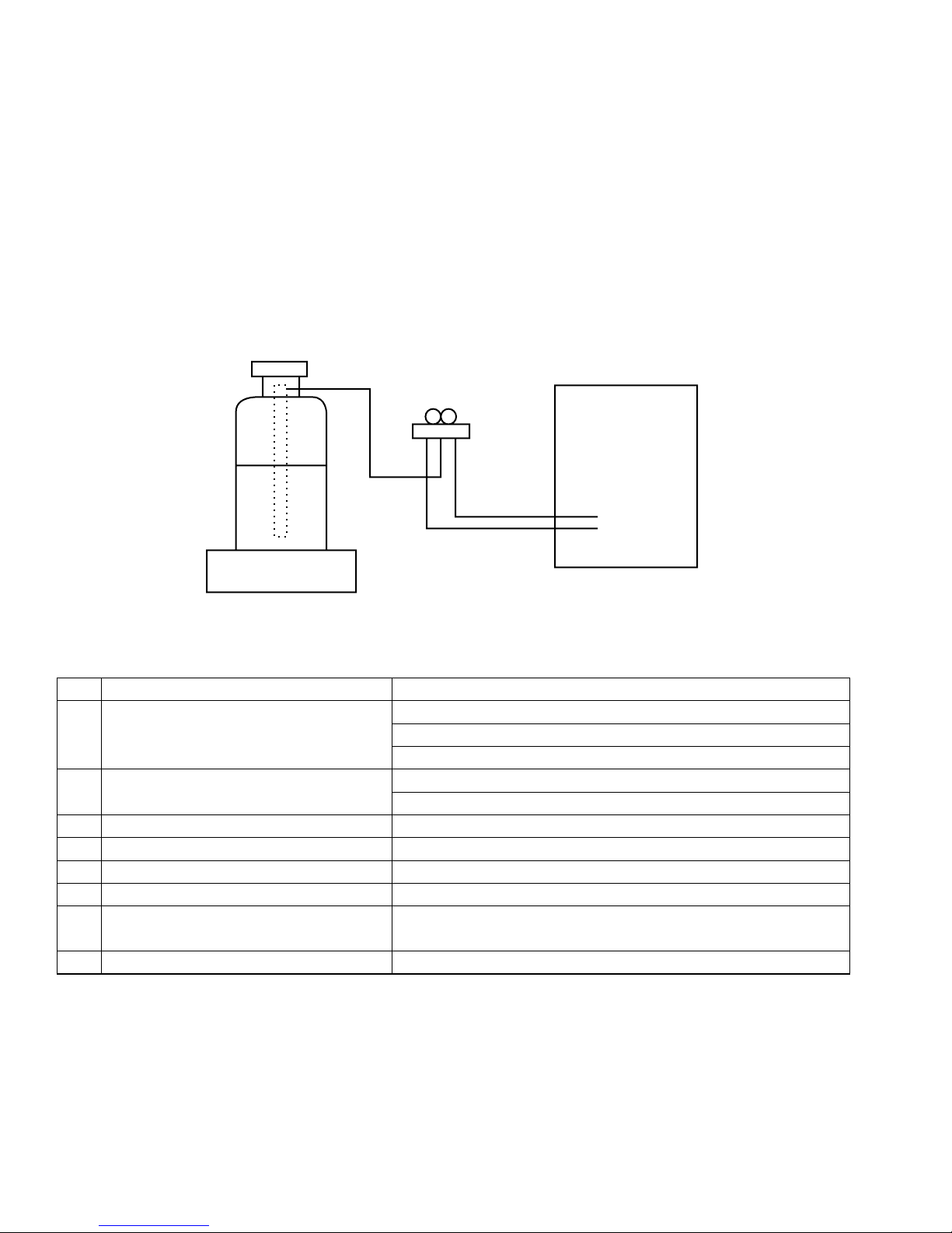
[2] Additional refrigerant charge
When charging directly from cylinder
· Check that cylinder for R410A on the market is syphon type.
· Charging should be performed with the cylinder of syphon stood vertically. (Refrigerant is charged from liquid phase.)
Unit
Gravimeter
[3] Service tools
Use the below service tools as exclusive tools for R410A refrigerant.
No. Tool name Specifications
1
Gauge manifold · Only for R410A
· Use the existing fitting
· Use high-tension side pressure of 5.3MPa·G or over.
2
Charge hose · Only for R410A
· Use pressure performance of 5.09MPa·G or over.
3
Electronic scale
4
Gas leak detector · Use the detector for R134a, R407C or R410A
5
Adaptor for reverse flow check · Attach on vacuum pump.
6
Refrigerant charge base
7
Refrigerant cylinder · Only for R410A ·Top of cylinder (Pink)
· Cylinder with syphon
8
Refrigerant recovery equipment
specifications
—
—
—
.
4
2-3. CAUTIONS FOR REFRIGERANT PIPING WORK
New refrigerant R410A is adopted for replacement inverter series. Although the refrigerant piping work for R410A is
same as for R22, exclusive tools are necessary so as not to mix with different kind of refrigerant. Furthermore as the
working pressure of R410A is 1.6 times higher than that of R22, their sizes of flared sections and flare nuts are different.
1 Thickness of pipes
Because the working pressure of R410A is higher compared to R22, be sure to use refrigerant piping with thickness
shown below. (Never use pipes of 0.7 mm [7/256 inch] or below.)
Diagram below: Piping diameter and thickness
Nominal
dimensions[inch]
1/4
3/8
1/2
5/8
3/4
Outside
diameter
6.35
9.52
12.70
15.88
19.05
(mm)
Thickness
R410A R22
0.8 [1/32]
0.8 [1/32]
0.8 [1/32]
1.0 [5/128]
—
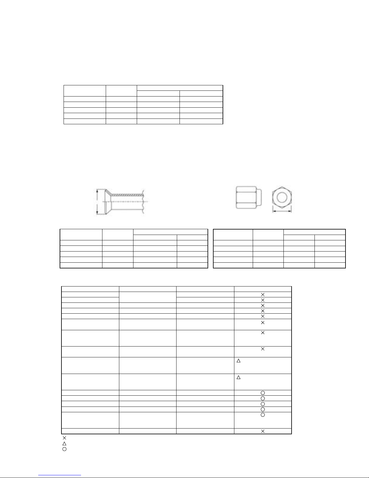
2 Dimensions of flare cutting and flare nut
The component molecules in HFC refrigerant are smaller compared to conventional refrigerants. In addition to that,
R410A is a refrigerant, which has higher risk of leakage because of its working pressure is higher than that of other
refrigerants. Therefore, to enhance air tightness and intensity, flare cutting dimension of copper pipe for R410A has
been specified separately from the dimensions for other refrigerants as shown below. The dimension B of flare nut for
R410A also has partly been changed to increase intensity as shown below. Set copper pipe correctly referring to copper pipe flaring dimensions for R410A below. For 1/2 and 5/8 inch, the dimension B changes.
Use torque wrench corresponding to each dimension.
: mm [inch]
0.8 [1/32]
0.8 [1/32]
0.8 [1/32]
1.0 [5/128]
1.0 [5/128]
Dimension A
Dimension B
Flare cutting dimensions
Nominal
dimensions[inch]
1/4
3/8
1/2
5/8
3/4
Outside
diameter
6.35
9.52
12.70
15.88
19.05
Dimension A
R410A R22
9.1 [11/32-23/64]
13.2 [1/2-33/64]
16.6 [41/64-21/32]
19.7 [49/64-25/32]
—
Unit : mm [inch]
+0
( )
-0.4
9.0
13.0
16.2
19.4
23.3
Flare nut dimensions
Nominal
dimensions[inch]
1/4
3/8
1/2
5/8
3/4
Outside
diameter
6.35
9.52
12.70
15.88
19.05
3 Tools for R410A (The following table shows whether conventional tools can be used or not.)
Tools and materials Use R410A tools Can R22 tools be used?
Gauge manifold
Charge hose
Gas leak detector
Refrigerant recovery equipment
Refrigerant cylinder
Applied oil
Safety charger
Charge valve
Vacuum pump
Flare tool
Bender
Pipe cutter
Welder and nitrogen gas cylinder
Refrigerant charging scale
Vacuum gauge or thermistor vacuum gauge and
vacuum valve
Charging cylinder
: Prepare a new tool. (Use the new tool as the tool exclusive for R410A.)
: Tools for other refrigerants can be used under certain conditions.
: Tools for other refrigerants can be used.
Air purge, refrigerant charge
and operation check
Gas leak check
Collection of refrigerant
Refrigerant charge
Apply to flared section
Prevent compressor malfunction
when charging refrigerant by
spraying liquid refrigerant
Prevent gas from blowing out
when detaching charge hose
Vacuum drying and air
purge
Flaring work of piping
Bend the pipes
Cut the pipes
Weld the pipes
Refrigerant charge
Check the degree of vacuum. (Vacuum
valve prevents back flow of oil and refrigerant to thermistor vacuum gauge)
Refrigerant charge
Tool exclusive for R410A
Tool exclusive for R410A
Tool for HFC refrigerant
Tool exclusive for R410A
Tool exclusive for R410A
Ester oil, ether oil and
alkylbenzene oil(minimum amount)
Tool exclusive for R410A
Tool exclusive for R410A
Tools for other refrigerants can
be used if equipped with adopter for reverse flow check
Tools for other refrigerants
can be used by adjusting
flaring dimension
Tools can be used for other refrigerants
Tools can be used for other refrigerants
Tools can be used for other refrigerants
Tools can be used for other refrigerants
Tools can be used for other
refrigerants
Tool exclusive for R410A
(Usable if equipped
with adopter for rever se flow)
(Usable by adjusting
flaring dimension)
Unit : mm [inch]
Dimension B
R410A R22
17.0 [43/64]
22.0 [7/8]
26.0 [1-3/64]
29.0 [1-9/64]
—
17.0
22.0
24.0
27.0
36.0
5
3 FEATURES
PUZ-A18NHA4
PUZ-A18NHA4-BS
PUY-A12/18NHA4
PUY-A12/18NHA4-BS
PUZ-A24/30/36NHA4
PUZ-A24/30/36NHA4-BS
PUY-A24/30/36NHA4
PUY-A24/30/36NHA4-BS
PUZ-A42NHA4
PUZ-A42NHA4-BS
PUY-A42NHA4
PUY-A42NHA4-BS
CHARGELESS SYSTEM
PRE-CHARGED REFRIGERANT IS SUPPLIED FOR PIPING LENGTH AT SHIPMENT.
(Max. 100ft, 30m (A42) / Max. 70ft, 20m (A12-36))
The refrigerant circuit with LEV(Linear Expansion Valve) and accumulator always control the optimal refrigerant level
regardless of the length (A42: 100ft, 30m max. / A12-36: 70ft, 20m max. and 16ft, 5m min.) of piping. The additional
refrigerant charging work during installation often causes problems.
It is completely eliminated by chargeless system. This unique system improves the quality and reliability of the work done.
It also helps to speed up the installation time.
6
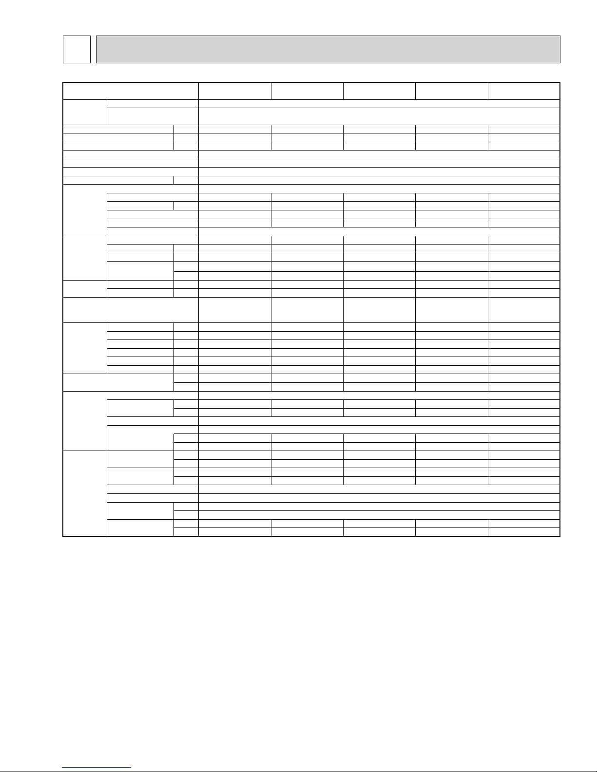
4 SPECIFICATIONS
Service Ref. PUZ-A18NHA4 PUZ-A24NHA4 PUZ-A30NHA4 PUZ-A36NHA4 PUZ-A42NHA4
Power supply Phase Single
Cycle 60Hz
Voltage 208/230V
MCA A 13 18 25 25 26
MOCP A2030404040
Breaker size A 15 25 30 30 30
External finish Munsell 3Y 7.8/1.1
Heat exchanger Plate fin coil
Defrost method Reverse cycle
Crankcase heater
Compressor Hermetic
Model SNB130FQCM1 TNB220FLHM TNB220FLHM TNB220FLHM ANV33FDPMT
Motor output kW 0.9 1.3 1.3 1.3 2.5
R.L.A. 12 12 12 12 20
L.R.A. 14 14 17.5 17.5 27.5
Starter type Inverter
Fan Fan(drive)% No. Propeller fan % 1 Propeller fan % 1 Propeller fan % 1 Propeller fan % 1 Propeller fan % 2
Fan motor output
Fan motor
Airflow m
Sound level Cooling dB 48 48 48 48 51
Heating dB 47 50 50 50 55
Protection devices
Dimension W mm 800 950 950 950 950
D mm 300+23 330+30 330+30 330+30 330+30
H mm 600 943 943 943 1350
W in. 31-1/2 37-12/32 37-12/32 37-12/32 37-12/32
D in. 11-13/16 + 7/8 13 + 1-3/16 13 + 1-3/16 13 + 1-3/16 13 + 1-3/16
H in. 23-5/8 37-1/8 37-1/8 37-1/8 53-5/32
Weight kg 41 75 75 75 118
Refrigerant R410A
Charged kg 1.7 3.0 3.0 3.0 4.5
Control Linear expansion valve
Oil Model
Charged L 0.65 0.87 0.87 0.87 1.4
Refrigerant Pipe size OD mm 6.35 9.52 9.52 9.52 9.52
piping Liquid in. 1/4 3/8 3/8 3/8 3/8
Pipe size OD mm 12.7 15.88 15.88 15.88 15.88
Gas in. 1/2 5/8 5/8 5/8 5/8
Connection method Indoor Flared
Connection method Outdoor Flared
Height difference m Max. 30
IU - OU ft Max. 100
Piping length m Max. 30 Max. 50 Max. 50 Max. 50 Max. 50
PUZ-A18NHA4-BS PUZ-A24NHA4-BS PUZ-A30NHA4-BS PUZ-A36NHA4-BS PUZ-A42NHA4-BS
kW
kW
F. L. A .
3
/min 34 55 55 55 100
CFM 1200 1940 1940 1940 3530
lbs 91 165 165 165 260
lbs 3 + 12/16 6 + 10/16 6 + 10/16 6 + 10/16 10
oz 20 28 28 28 45
ft Max. 100 Max. 165 Max. 165 Max. 165 Max. 165
0.040 0.075 0.075 0.075 0.086 + 0.086
0.35 0.75 0.75 0.75 0.40 + 0.40
HP switch HP switch HP switch HP switch HP switch
Comp.shell thermo Comp.shell thermo Comp.shell thermo Comp.shell thermo Discharge thermo
-
Ether(FV50S
LP switch
)
7
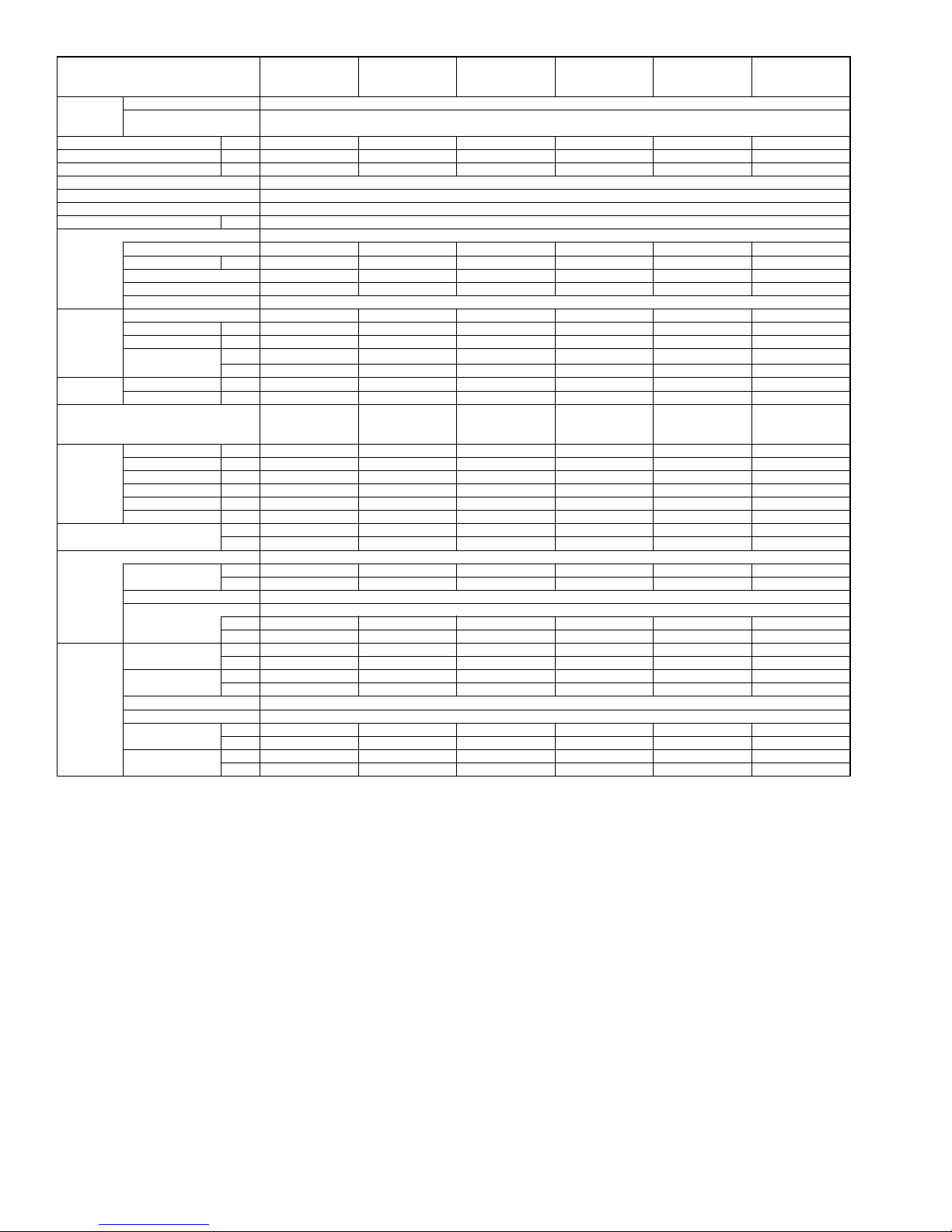
Service Ref.
Power supply
MCA A 13 13 18 25 25 26
MOCP A152030404040
Breaker size A 15 15 25 30 30 30
External finish Munsell 3Y 7.8/1.1
Heat exchanger Plate fin coil
Defrost method Crankcase heater
Compressor Hermetic
Fan
Sound level Cooling dB 46 48 48 48 48 51
Protection devices HP switch HP switch HP switch HP switch HP switch HP switch
Dimension W mm 800 800 950 950 950 950
Weight kg 37 40 74 74 74 117
Refrigerant R410A
Refrigerant Pipe size OD mm 6.35 6.35 9.52 9.52 9.52 9.52
piping Liquid in. 1/4 1/4 3/8 3/8 3/8 3/8
Phase Single
Cycle 60Hz
Voltage 208/230V
Model SNB130FQCM1 SNB130FQCM1 TNB220FLHM TNB220FLHM TNB220FLHM ANV33FDPMT
Motor output kW 0.9 0.9 1.3 1.3 1.3 2.5
R.L.A. 12 12 12 12 12 20
L.R.A. 14 14 14 17.5 17.5 27.5
Starter type Inverter
Fan (drive) % No.
Fan motor output
Fan motor
Airflow m
Heating dB – – – – – –
D mm 300+23 300+23 330+30 330+30 330+30 330+30
H mm 600 600 943 943 943 1350
W in. 31-1/2 31-1/2 37-12/32 37-12/32 37-12/32 37-12/32
D in. 11-13/16 + 7/8 11-13/16 + 7/8 13 + 1-3/16 13 + 1-3/16 13 + 1-3/16 13 + 1-3/16
H in. 23-5/8 23-5/8 37-1/8 37-1/8 37-1/8 53-5/32
Charged kg 1.3 1.7 3.0 3.0 3.0 4.5
Control Linear expansion valve
Oil Model
Charged L 0.65 0.65 0.87 0.87 0.87 1.4
Pipe size OD mm 12.7 12.7 15.88 15.88 15.88 15.88
Gas in. 1/2 1/2 5/8 5/8 5/8 5/8
Connection method Indoor Flared
Connection method Outdoor
Height difference m Max. 30 Max. 30 Max. 30 Max. 30 Max. 30 Max. 30
IU - OU ft Max. 100 Max. 100 Max. 100 Max. 100 Max. 100 Max. 100
Piping length m Max. 30 Max. 30 Max. 50 Max. 50 Max. 50 Max. 50
PUY-A12NHA4 PUY-A18NHA4 PUY-A24NHA4 PUY-A30NHA4 PUY-A36NHA4 PUY-A42NHA4
PUY-A12NHA4-BS PUY-A18NHA4-BS PUY-A24NHA4-BS PUY-A30NHA4-BS PUY-A36NHA4-BS PUY-A42NHA4-BS
kW
Propeller fan
kW
F. L. A .
3
/min 34 34 55 55 55 100
CFM 1200 1200 1940 1940 1940 3530
lbs 82 89 163 163 163 258
lbs 2 +14/16 3 + 12/16 6 + 10/16 6 + 10/16 6 + 10/16 10
oz 20 20 28 28 28 45
ft Max. 100 Max. 100 Max. 165 Max. 165 Max. 165 Max. 165
0.040 0.040 0.075 0.075 0.075 0.086 + 0.086
0.35 0.35 0.75 0.75 0.75 0.40 + 0.40
Comp.shell thermo Comp.shell thermo Comp.shell thermo Comp.shell thermo Comp.shell thermo
% 1
Propeller fan
% 1
Propeller fan
-
Propeller fan
% 1
Ether(FV50S
Flared
Propeller fan
% 1
)
Propeller fan
% 1
Discharge thermo
LP switch
% 2
8
5
DATA
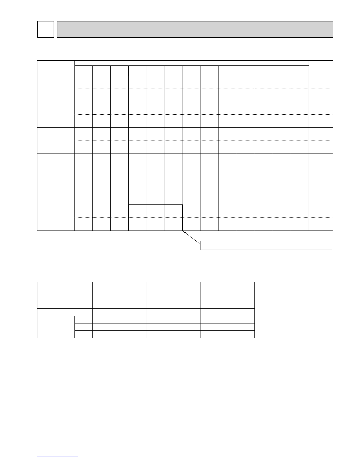
5-1. REFILLING REFRIGERANT CHARGE (R410A : oz, kg)
Service Ref. 50ft 60ft 70ft 80ft 90ft 100ft 110ft 120ft 130ft 140ft 150ft 160ft 165ft
PUY-A12NHA4
PUY-A12NHA4-BS
PUZ-A18NHA4
PUZ-A18NHA4-BS
PUY-A18NHA4
PUY-A18NHA4-BS
PUZ-A24NHA4
PUZ-A24NHA4-BS
PUY-A24NHA4
PUY-A24NHA4-BS
PUZ-A30NHA4
PUZ-A30NHA4-BS
PUY-A30NHA4
PUY-A30NHA4-BS
PUZ-A36NHA4
PUZ-A36NHA4-BS
PUY-A36NHA4
PUY-A36NHA4-BS
PUZ-A42NHA4
PUZ-A42NHA4-BS
PUY-A42NHA4
PUY-A42NHA4-BS
15m 18m 21m 24m 27m 30m 33m 37m 40m 43m 46m 49m 50m
42 oz 44 oz 46 oz 48 oz 50 oz 52 oz - - - - - - - 46 oz
1.2 kg 1.2 kg 1.3 kg 1.4 kg 1.4 kg 1.5 kg - - - - - - - 1.3 kg
56 oz 58 oz 60 oz 62 oz 64 oz 66 oz - - - - - - - 60 oz
1.6 kg 1.6 kg 1.7 kg 1.8 kg 1.8 kg 1.9 kg - - - - - - - 1.7 kg
94 oz 100 oz 106 oz 112 oz 118 oz 124 oz 130 oz 136 oz 142 oz 148 oz 154 oz 160 oz 166 oz 106 oz
2.7 kg 2.8 kg 3.0 kg 3.2 kg 3.3 kg 3.5 kg 3.7 kg 3.9 kg 4.0 kg 4.2 kg 4.4 kg 4.5 kg 4.7 kg 3.0 kg
94 oz 100 oz 106 oz 112 oz 118 oz 124 oz 130 oz 136 oz 142 oz 148 oz 154 oz 160 oz 166 oz 106 oz
2.7 kg 2.8 kg 3.0 kg 3.2 kg 3.3 kg 3.5 kg 3.7 kg 3.9 kg 4.0 kg 4.2 kg 4.4 kg 4.5 kg 4.7 kg 3.0 kg
94 oz 100 oz 106 oz 112 oz 118 oz 124 oz 130 oz 136 oz 142 oz 148 oz 154 oz 160 oz 166 oz 106 oz
2.7 kg 2.8 kg 3.0 kg 3.2 kg 3.3 kg 3.5 kg 3.7 kg 3.9 kg 4.0 kg 4.2 kg 4.4 kg 4.5 kg 4.7 kg 3.0 kg
132 oz 136 oz 142 oz 148 oz 154 oz 160 oz 166 oz 172 oz 178 oz 184 oz 190 oz 196 oz 202 oz 160 oz
3.7 kg 3.9 kg 4.0 kg 4.2 kg 4.4 kg 4.5 kg 4.7 kg 4.9 kg 5.0 kg 5.2 kg 5.4 kg 5.6 kg 5.7 kg 4.5 kg
Piping Length (one way
)
Factory
Charged
Longer pipe than 70 or 100 ft,additional charge is required.
5-2. COMPRESSOR TECHNICAL DATA
PUZ-A18NHA4
Service Ref.
Compressor model SNB130FQCM1 TNB220FLHM ANV33FDPMT
Winding Registance
()
U-V 0.640 0.880 0.266
U-W 0.640 0.880 0.266
W-V 0.640 0.880 0.266
PUZ-A18NHA4-BS
PUY-A12,18NHA4
PUY-A12,18NHA4-BS
PUZ-A24,30,36NHA4
PUZ-A24,30,36NHA4-BS
PUY-A24,30,36NHA4
PUY-A24,30,36NHA4-BS
(
at 20°C,68°F
PUZ-A42NHA4
PUZ-A42NHA4-BS
PUY-A42NHA4
PUY-A42NHA4-BS
)
9
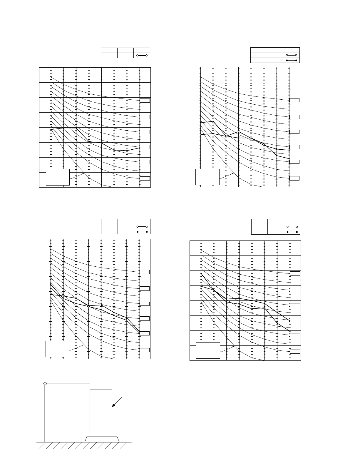
5-3. NOISE CRITERION CURVES
PUY-A12NHA4
PUY-A12NHA4-BS
90
80
70
60
50
40
30
APPROXIMATE
20
THRESHOLD OF
HEARING FOR
CONTINUOUS
NOISE
OCTAVE BAND SOUND PRESSURE LEVEL, dB (0 dB = 0.0002 μbar)
10
63 125 250 500 1000 2000 4000 8000
BAND CENTER FREQUENCIES, Hz
MODE
COOLING
SPL(dB)
46
LINE
NC-70
NC-60
NC-50
NC-40
NC-30
NC-20
PUY-A18NHA4
PUY-A18NHA4-BS
PUZ-A18NHA4
PUZ-A18NHA4-BS
90
80
70
60
50
40
30
APPROXIMATE
20
THRESHOLD OF
HEARING FOR
CONTINUOUS
OCTAVE BAND SOUND PRESSURE LEVEL, dB (0 dB = 0.0002 μbar)
NOISE
10
63 125 250 500 1000 2000 4000 8000
BAND CENTER FREQUENCIES, Hz
MODE
COOLING
HEATING
SPL(dB)
48
47
LINE
NC-70
NC-60
NC-50
NC-40
NC-30
NC-20
PUY-A24/30/36NHA4
PUY-A24/30/36NHA4-BS
PUZ-A24/30/36NHA4
PUZ-A24/30/36NHA4-BS
90
80
70
60
50
40
30
APPROXIMATE
20
THRESHOLD OF
HEARING FOR
CONTINUOUS
NOISE
OCTAVE BAND SOUND PRESSURE LEVEL, dB (0 dB = 0.0002 μbar)
10
63 125 250 500 1000 2000 4000 8000
BAND CENTER FREQUENCIES, Hz
MICROPHONE
3.3ft
MODE
COOLING
HEATING
SPL(dB)
48
50
UNIT
LINE
NC-70
NC-60
NC-50
NC-40
NC-30
NC-20
PUY-A42NHA4
PUY-A42NHA4-BS
PUZ-A42NHA4
PUZ-A42NHA4-BS
90
80
70
60
50
40
30
APPROXIMATE
20
THRESHOLD OF
HEARING FOR
CONTINUOUS
NOISE
OCTAVE BAND SOUND PRESSURE LEVEL, dB (0 dB = 0.0002 μbar)
10
63 125 250 500 1000 2000 4000 8000
BAND CENTER FREQUENCIES, Hz
MODE
COOLING
HEATING
SPL(dB)
51
55
LINE
NC-70
NC-60
NC-50
NC-40
NC-30
NC-20
5ft
GROUND
10
5-4. STANDARD OPERATION DATA
5-4-1. Heat pump
Representative matching
Mode
Total Capacity BTU/h
Input W
Indoor unit model
Phase
Cycle
Voltage
Current
Outdoor unit model
Electrical circuit
Phase
Cycle
Voltage
Current
Discharge pressure MPa
Suction pressure MPa
Discharge temperature
Condensing temperature
Suction temperature
Ref. Pipe length m
Discharge pressure PSIG
Suction pressure PSIG
Refrigerant circuit
Discharge temperature °F
Condensing temperature °F
Suction temperature °F
Ref. Pipe length ft 25 25 25 25 25 25 25 25 25 25
Intake air temperature DB 26.721.126.721.126.721.126.721.126.721.1
Indoor
Intake air temperature WB 19.4
side
Discharge air temperature DB 12.9 41.9
Intake air temperature DB 35 8.3 35 8.3 35 8.3 35 8.3 35 8.3
Outdoor
side
Intake air temperature WB 23.9 6.1 23.9 6.1 23.9 6.1 23.9 6.1 23.9 6.1
Intake air temperature DB °F 80
Indoor
Intake air temperature WB °F 67 60
side
Discharge air temperature DB °F 55 107
Intake air temperature DB °F 95 47 95 47 95 47 95 47 95 47
Outdoor
side
Intake air temperature WB °F 75
SHF
BF
PKA-A18HA4 PKA-A24KA4 PKA-A30KA4 PKA-A36KA4 PLA-A42BA4
COOLING HEATING COOLING HEATING COOLING HEATING COOLING HEATING COOLING HEATING
18,000
2,240
9.8A
3.01
0.77
80.1
49.9
437
112
176
122
11. 3
0.68
0.08
19,000
1,970
PKA-A18HA4 PKA-A24KA4 PKA-A30KA4 PKA-A36KA4 PLA-A42BA4
Single Single Single Single Single
60Hz 60Hz 60Hz 60Hz 60Hz
230V 230V 230V 230V 230V
0.33A 0.36A 0.36A 0.57A 1.00A 0.94A
PUZ-A18NHA4 PUZ-A24NHA4 PUZ-A30NHA4 PUZ-A36NHA4 PUZ-A42NHA4
Single Single Single Single Single
60Hz 60Hz 60Hz 60Hz 60Hz
230V 230V 230V 230V 230V
3.8
7.6
39
67
52
8.8A
3.03
0.64
83.7
50.8
-1.1
7.6
439
93
183
123
34
15.6
45.4
70
60
114
43 75
–
–
24,000
2,270
9.4A
2.78
0.92
73.9
46.9
12.1
7.6
403
133
165
116
54
19.4
14.1
80
67
57
0.77
0.09
26,000
2,330
10.4A
2.89
0.68
77.9
48.5
0.4
7.6
419
99
172
119
33
15.6
39.2
70
60
103
43 75
–
–
30,000
4,130
18.1A
3.08
0.77
81.2
50.8
3.3
7.6
447
117
178
123
38
19.4
12.3
80
67
54
0.70
0.09
32,000
3,150
14.0A
3.04
0.64
81.4
50.8
-1.5
7.6
441
93
179
123
29
15.6
43.4
70
60
110
43 75
–
–
34,200
5,030
21.7A
3.23
0.74
88.1
52.8
2.3
7.6
468
107
191
127
36
19.4
12.3
80
67
54
0.70
0.09
37,000
3,610
15.6A
2.95
0.63
80.7
49.3
-2.0
7.6
428
177
121
15.6
42.9
109
42,000 45,000
4,600 4,450
20.4A
2.83
0.82
73.4
47.5
4.9
7.6
410
91
28
70
60
43 75 43
–
–
120
164
118
40
19.4 15.6
80 70
0.71
21.5A
2.93
0.69
80.3
47.5
0.3
7.6
425
100
177
118
33
–
–0.15
11

5-4-2. Cooling only
Representative matching
Mode
Total Capacity BTU/h
Input W
Indoor unit model
Phase
Cycle
Voltage
Current
Outdoor unit model
Electrical circuit
Phase
Cycle
Voltage
Current
Discharge pressure MPa
Suction pressure MPa
Discharge temperature
Condensing temperature
Suction temperature
Ref. Pipe length m
Discharge pressure PSIG
Suction pressure PSIG
Refrigerant circuit
Discharge temperature °F
Condensing temperature °F
Suction temperature °F
Ref. Pipe length ft 25 25
Indoor
side
Intake air temperature DB 26.7 26.7
Intake air temperature WB 19.4
Discharge air temperature DB
Outdoor
side
Indoor
side
Intake air temperature DB 35 35
Intake air temperature WB 23.9 23.9
Intake air temperature DB °F 80 80
Intake air temperature WB °F 67
Discharge air temperature DB °F
Outdoor
side
Intake air temperature DB °F 95 95
Intake air temperature WB °F 75
SHF 0.71
BF 0.15
PKA-A12HA4 PKA-A18HA4 PKA-A24KA4 PKA-A30KA4 PKA-A36KA4 PLA-A42BA4
COOLING COOLING COOLING COOLING COOLING COOLING
12,000
1,190
18,000
2,240
24,000
2,270
30,000
4,130
34,200
5,030
42,000
4,600
PKA-A12HA4 PKA-A18HA4 PKA-A24KA4 PKA-A30KA4 PKA-A36KA4 PLA-A42BA4
Single Single Single Single Single Single
60Hz 60Hz 60Hz 60Hz 60Hz 60Hz
230V 230V 230V 230V 230V 230V
0.33A 0.33A 0.36A 0.36A 0.57A 1.00A
PUY-A12NHA4 PUY-A18NHA4 PUY-A24NHA4 PUY-A30NHA4 PUY-A36NHA4 PUY-A42NHA4
Single Single Single Single Single Single
60Hz 60Hz 60Hz 60Hz 60Hz 60Hz
230V 230V 230V 230V 230V 230V
5.3A
2.87
1.00
69.0
48.6
12.5
7.6
416
145
156
119
55
14.6
58
0.81
0.08
9.8A
3.01
0.77
80.1
49.9
3.8
7.6
437
112
176
122
39
25
26.7
19.4
11. 3
35
23.9
80
67
52
95
75
0.68
0.08
9.4A
2.78
0.92
73.9
46.9
12.1
7.6
403
133
165
116
54
25
26.7
19.4
14.1
35
23.9
80
67
57
95
75
0.77
0.09
18.1A
3.08
0.77
81.2
50.8
3.3
7.6
447
117
178
123
38
25 25
26.7 26.7
19.4
12.3
35 35
23.9 23.9
80
67
54
95 95
75
0.70
0.09
21.7A
3.23
0.74
88.1
52.8
2.3
7.6
468
107
191
127
36
19.4
12.3
80
67
54
75
0.70
0.09
20.4A
2.83
0.82
73.4
47.5
19.4
12.9
4.9
7.6
410
120
164
118
40
67
55
75
12
6
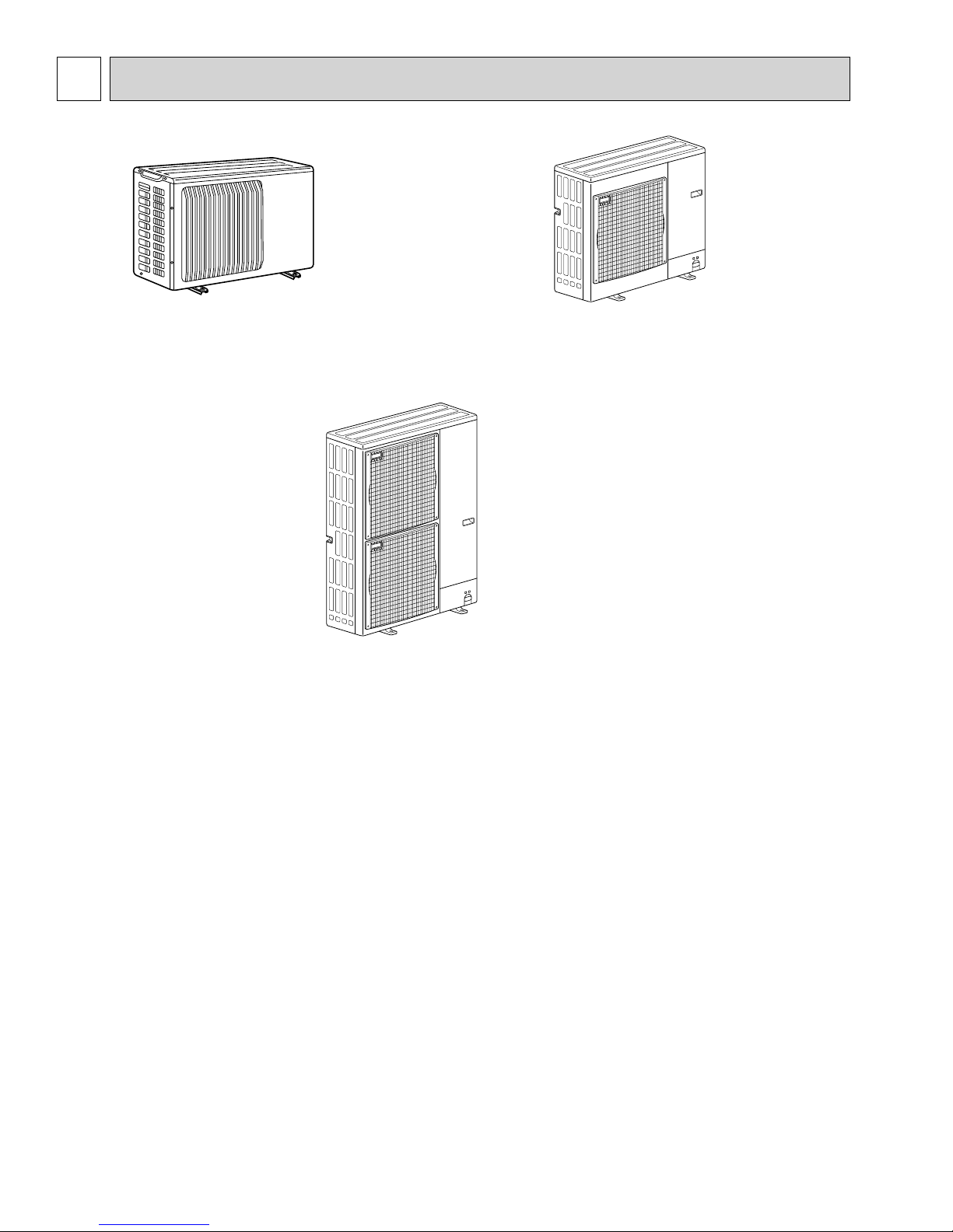
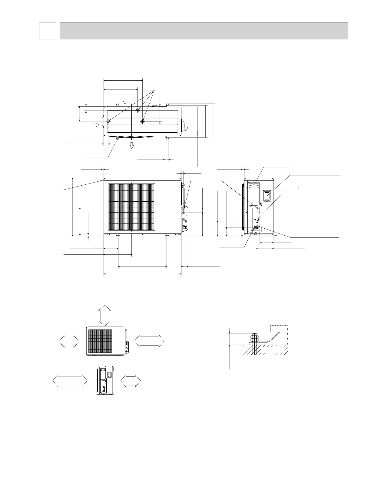
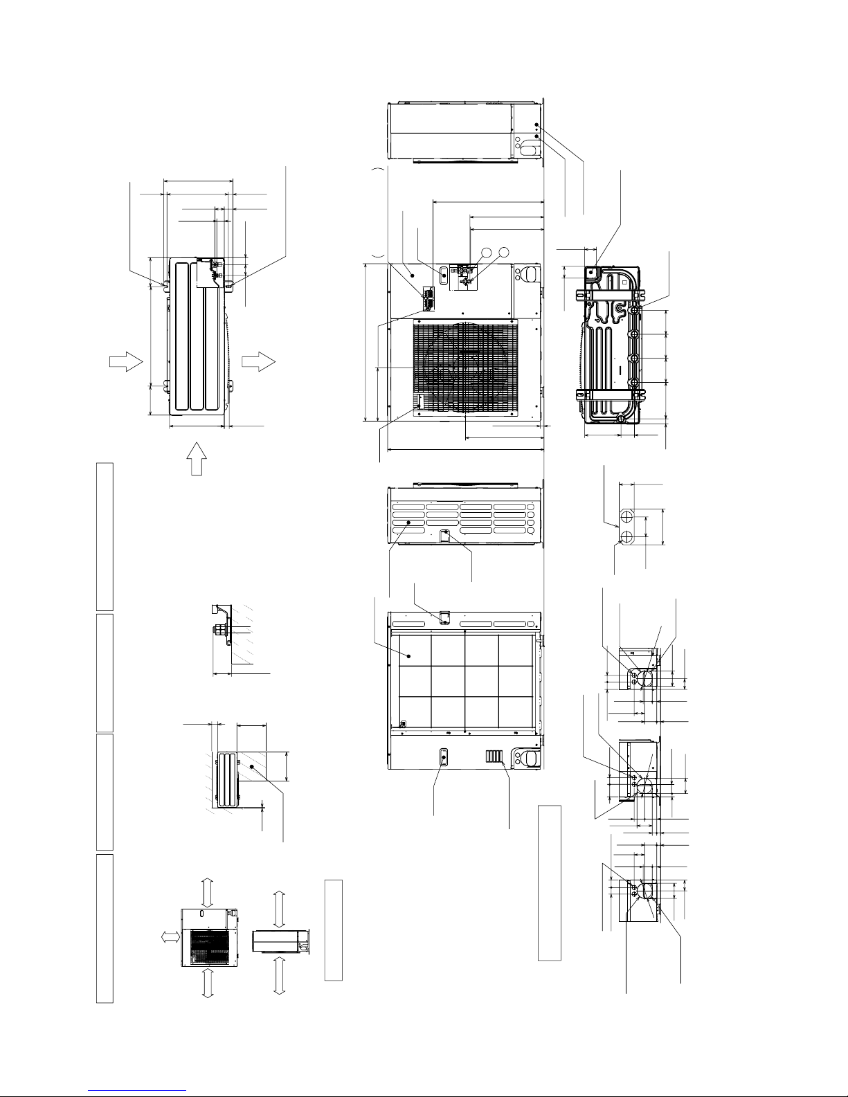
OUTLINES AND DIMENSIONS
OUTDOOR UNIT Unit: mm<inch>
PUZ-A18NHA4 PUZ-A18NHA4-BS PUY-A12/18NHA4 PUY-A12/18NHA4-BS
400<15-25/32>
347.5<13-11/16>
Air intake
43.6<1-23/32>
152<6>
Air intake
45.4<1-25/32>
Air discharge
4-oval hole
18<23/32>
Handle
W33<1-5/16> drain hole
155
40<1-9/16>
330<13>
300<11-13/16>
32.5<1-9/32>
22<7/8>
2-W22.2<7/8>
1/2 conduit hole
38<1-1/2>241<9-1/2>
365<14-3/8>
23<29/32>
Service panel
Service panel for charge plug
Connection for liquid pipe
FLARE W6.35<1/4>
600<23-5/8>
10<3/8>
300<11-13/16>
150<5-29/32>
287.5<11-11/32>
Installation bolt pitch
500<19-11/16>
800<31-1/2>
Free space around the outdoor unit
(basic example)
Min.100mm<3-15/16>
*1
*2
Min.500mm<19-11/16>
2 sides should be open in
the right, left and rear side.
Min.100mm<3-15/16> as long as
no obstacle is placed on the
rear and light-and-left sides
open
of the unit
Basically
Min.350mm<13-25/32>
*1
Min.100mm<3-15/16>
69<2-23/32>
155<6-3/32>
90<3-17/32>
Service port
144<5-21/32>
183<7-7/32>
FOUNDATION BOLTS
Please secure the unit firmly
with 4 foundation M10<W3/8> bolts.
(Bolts, washers and nut must
be purchased locally.)
<Foundation bolt height>
FOUNDATION
18mm<23/32>
Max.
PIPING-WIRING DIRECTION
Piping and wiring connection can
be made from the rear direction only.
Connection for gas pipe
FLARE W12.7<1/2>
Minimum installation space for outdoor unit
*1 In the place where short cycle tends to occur, cooling and heating capacity and power consumption might get lowered 10%.
Air outlet guide (optional PAC-SG58SG-E) will help them improve.
*2 If air discharges to the wall, the surface might get stained.
13
PUZ-A24/30/36NHA4 PUZ-A24/30/36NHA4-BS Unit: mm<inch>
Min. 10mm
<3/8>
Min. 10mm
<3/8>
Min. 100mm
<3-15/16>
Min. 500mm
<19-11/16>
Min.
100mm
<3-15/16>
Min.
500mm
<191/16>
Max.
300mm<1-3/16>
Min.
10mm
<3/8>
Min.
500mm
<19-11/16>
Service space
FOUNDATION
<Foundation bolt height>
FREE
When installing the conduit,
Set the attachment to the
inner side of each panel.
1/2 Conduit attachment
2-:22.2<7/8>
40<1-9/16>
31<1-7/32>
74<2-19/32>
330 <13>
175 <6-7/8>
600 <23-5/8>
175 <6-7/8>
53 <2-3/32>
28 <1-3/32>
370 <14-9/16>
19 <3/4>
56 <2-7/32>
45 <1-25/32>
42 <1-21/32>
66 <2-5/8>
417 <16-13/32>
2-U Shaped notched hole
(Foundfation Bolt M10<W3/8>)
Side Air Intake
Rear Air Intake
Air Discharge
2-12%36 Oval hole
(Foundation Bolt M10<W3/8>)
30 <1-3/16>
Side Air Intake
Handle
Rear piping cover
Front piping cover
81<3-3/16>
219 <8-5/8>
30 <1-3/16>
71 <2-13/16>
71 <2-13/16>
Bottom piping hole
(Knockout)
Drain hole
(5-:33<1-5/16>)
Handle
Handle
Rear Air Intake
Air Intake
670 <26-3/8>
*1 443<17-7/16>
*1 447<17-19/32>
322 <12-11/16>
950 <37-13/32>
473 <18-5/8>
943 <37-1/8>
23<29/32>
2
1
Handle
Handle
Service panel
Earth terminal
Left···Power supply wiring
Right···Indoor/Outdoor wiring
Terminal Block
Conduit hole
(2-
:
27<1-1/16>Knockout)
Right trunking hole
(Knockout)
Right piping hole
(Knockout)
65<2-9/16>
92<3-5/8>
40 <1-9/16> 45 <1-25/32>
19<3/4>
27<1-1/16>
23<29/32>
23<29/32>
73<2-7/8>
Conduit hole
(2-:27<1-1/16>Knockout)
Front trunking hole
(Knockout)
Front piping hole
(Knockout)
:
92
<3-5/8>
Conduit hole
(2-
:
27<1-1/16>Knockout)
Rear trunking hole
(Knockout)
Rear piping hole
(Knockout)
220
<8-21/32>
145
<5-23/32>
145
<5-23/32>
145
<5-23/32>
55<2-3/16>
63<2-1/2>
63<2-1/2>
75
<2-31/32>
40<1-9/16>
45<1-25/32>
40<1-9/16>
23<29/32>
73<2-7/8>
63<2-1/2>
55<2-3/16>
27<1-1/16>
:92<3-5/8>
:
92<3-5/8>
73<2-7/8>
27<1-1/16>
92<3-5/8>
92<3-5/8>
65<2-9/16>
95<3-5/8>
55<2-3/16>
Piping and wiring connections
can be made from 4 directions:
front, right, rear and below.
Dimensions of space needed
for service access are
shown in the below diagram.
Please secure the unit firmly
with 4 foundation (M10<W3/8>)
bolts. (Bolts and washers must
be purchased locally.)
The diagram below shows a
basic example.
Explanation of particular details are
given in the installation manuals etc.
····Refrigerant GAS pipe connection (FLARE):15.88<5/8>
····Refrigerant LIQUID pipe connection (FLARE): 9.52<3/8>
*1 ····Indication of STOP VALVE connection location.
Example of Notes
Piping Knockout Hole Details
1 FREE SPACE (Around the unit)
2 SERVICE SPACE
3 FOUNDATION BOLTS
4 PIPING-WIRING DIRECTIONS
PUY-A24/30/36NHA4 PUY-A24/30/36NHA4-BS
14
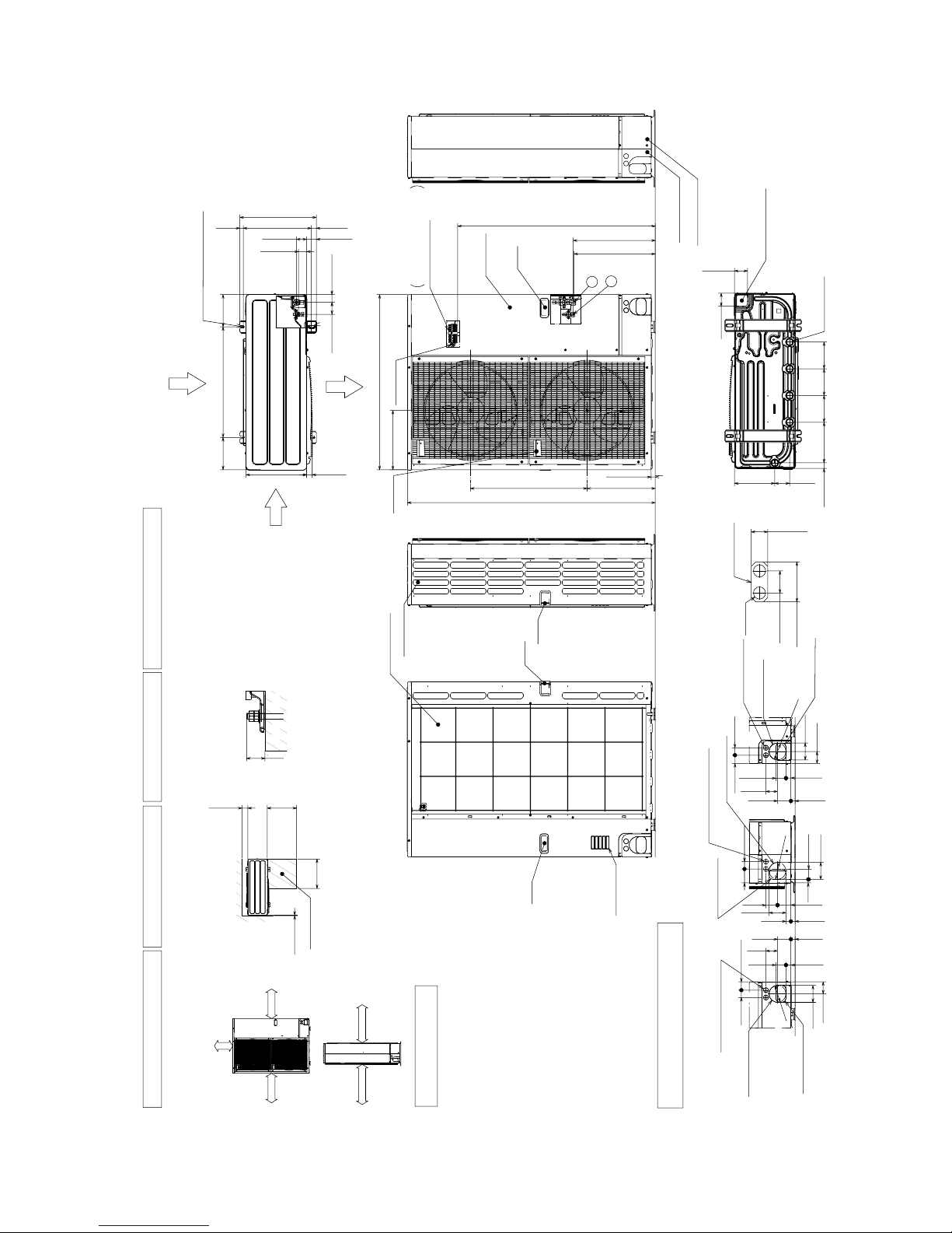
PUZ-A42NHA4 PUZ-A42NHA4-BS Unit: mm<inch>
Min. 1000mm
<39-3/8>
Min. 150mm
<5-29/32>
Min. 10mm
<3/8>
Min. 10mm
<3/8>
FREE
<Foundation bolt height>
FOUNDATION
Service space
Terminal Block
Left···Power supply wiring
Right····Indoor/Outdoor wiring
Earth terminal
Service panel
Handle
1
2
23<29/32>
1076<42-3/8>
* 1 447<17-19/32>
* 1 443<17-7/16>
Handle
Front piping cover
Rear piping cover
Air Discharge
Rear Air Intake
Side Air Intake
31<1-7/32>
145
<5-23/32>
145
<5-23/32>
220
<8-21/32>
30<1-3/16>
145
<5-23/32>
81<3-3/16>
219<8-5/8>
71<2-13/16>
71<2-13/16>
Bottom piping hole
(Knockout)
Drain hole
5-:33<1-5/16>
Handle
Side Air Intake
Air intake
Rear Air Intake
Handle
Handle
40<1-9/16>
74<2-19/32>
When installing the conduit.
Set the attachment to the
inner side of each panel.
2-:22.2<7/8>
1/2 Conduit attachment
45<1-25/32>
40<1-9/16>
65<2-9/16>
92<3-5/8>
27<1-1/16>
55<2-3/16>
23<29/32>
73<2-7/8>
63<2-1/2>
Rear piping hole
(Knockout)
Rear trunking hole
(Knockout)
Conduit hole
(2-:27<1-1/16>Knockout)
:
92
<3-5/8>
19<3/4>
55<2-3/16>
92<3-5/8>
75
<2-31/32>
40<1-9/16>
73<2-7/8>
63<2-1/2>
23<29/32>
27<1-1/16>
92<3-5/8>
Right piping hole
(Knockout)
Right trunking hole
(Knockout)
Conduit hole
(2-:27<1-1/16>Knockout)
:92
<3-5
/8>
92<3-5/8>
65<2-9/16>
45<1-25/32>
40<1-9/16>
27<1-1/16>
55<2-3/16>
23<29/32>
73<2-7/8>
63
<2-1/2>
Front piping hole
(Knockout)
Front trunking hole
(Knockout)
Conduit hole
(2-:27<1-1/16>Knockout)
:92
<3-5
/8>
371<14-19/32>
330<13>30<1-3/16>
175<6-7/8>
600<23-5/8>
175<6-7/8>
42<1-21/32>
66<2-5/8>
950<37-13/32>
322<12-11/16>
1350<53-5/32>
635<25>
19<3/4>
417<16-13/32>
370<14-9/16>
2-U Shaped notched hole
(Foundation Bolt M10<W3/8>)
56<2-7/32>
28<1-3/32>
53<2-3/32>
45<1-25/32>
2-12%36 Oval hole
(Foundation Bolt M10<W3/8>)
····Refrigerant GAS pipe connection (FLARE):15.88<5/8>
····Refrigerant LIQUID pipe connection (FLARE): 9.52<3/8>
*1 ····Indication of STOP VALVE connection location.
Example of Notes
1 FREE SPACE (Around the unit)
2 SERVICE SPACE
3 FOUNDATION BOLTS
4 PIPING-WIRING DIRECTIONS
Piping Knockout Hole Details
The diagram below shows a
basic example.
Explanation of particular details are
given in the installation manuals etc.
Dimensions of space needed
for service access are
shown in the below diagram.
Please secure the unit firmly
with 4 foundation (M10<W3/8>)
bolts. (Bolts and washers must
be purchased locally.)
Piping and wiring connections
can be made from 4 directions:
front, right, rear and below.
Min.
10mm<3/8>
Min.
500mm
<19-11/16>
Min.
500mm
<19-11/16>
Min.
150mm
<5-29/32>
Min.
30mm
<1-3/16>
PUY-A42NHA4 PUY-A42NHA4-BS
15
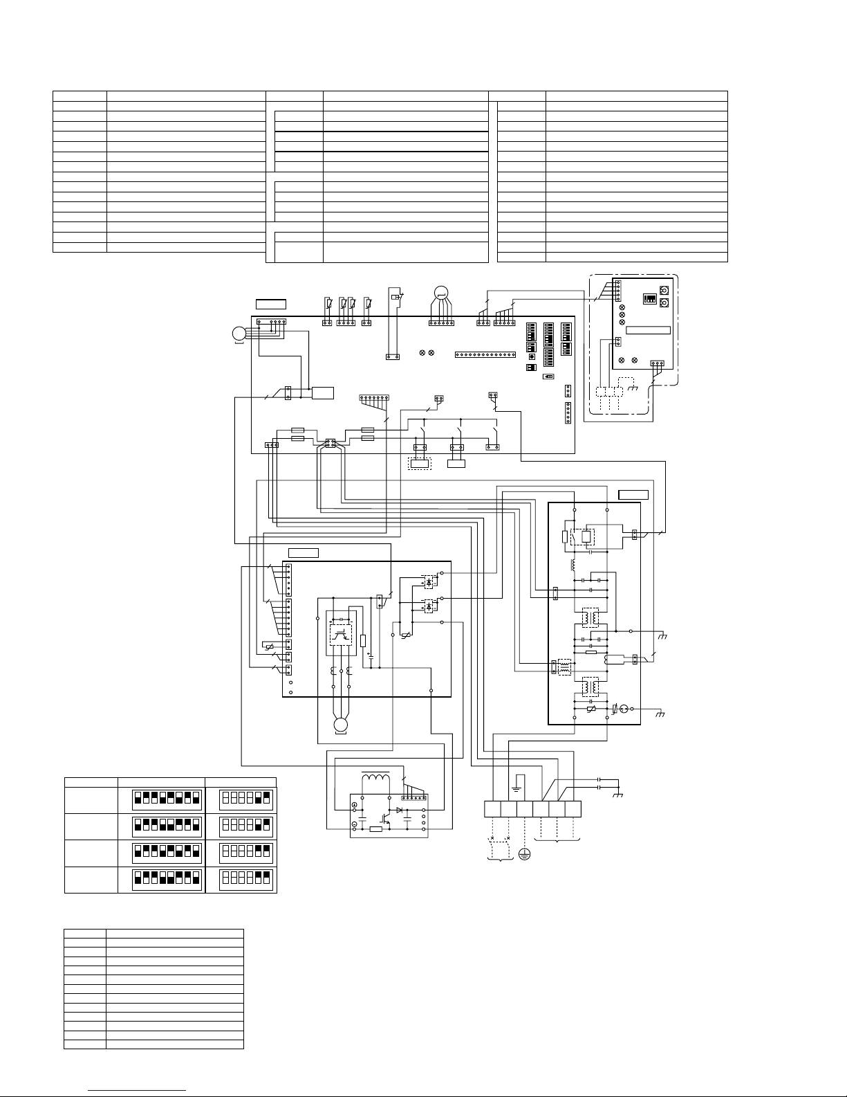
7
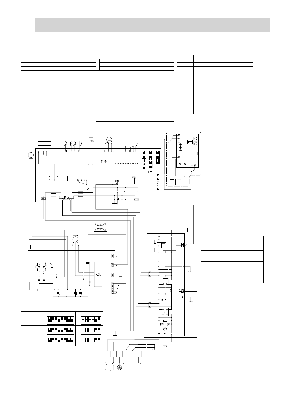
WIRING DIAGRAM
PUZ-A18NHA4 PUZ-A18NHA4-BS PUY-A12/18NHA4 PUY-A12/18NHA4-BS
[LEGEND]
SYMBOL
TB1
MC
MF1
21S4
63H
TH3
TH6
TH7
TH8
TH32
LEV-A
ACL Reactor
CY1,CY2
P. B .
TABR/S
TABU/V/W
Terminal Block<Power Supply, Indoor/Outdoor>
Motor for Compressor
Fan Motor
Solenoid Valve (Four-Way Valve)
High Pressure Switch
Thermistor<Outdoor Pipe>
Thermistor<Outdoor 2-Phase Pipe>
Thermistor<Outdoor>
Thermistor<Heatsink>
Thermistor<Shell>
Electronic Expansion Valve
Capacitor
Power Circuit Board
Connection Terminal<L1/L2-Phase>
Connection Terminal<U/V/W-Phase>
NAME SYMBOL NAME SYMBOL NAME
PFC
N.F.
LI/LO
NI/NO
EI,E2,E3
52C
C.B.
SW1
SW4
SW5
SW6
SW7
SW8
Converter
Power ModuleIPM
Main Smoothing CapacitorCB1~CB3
Noise Filter Circuit Board
Connection Terminal<L1-Phase>
Connection Terminal<L2-Phase>
Connection Terminal<Ground>
52C Relay
Controller Circuit Board
Switch<Forced Defrost, Defect History
Record Reset, Refrigerant Address>
Switch<Test Operation>
Switch<Function Switch>
Switch<Model Select>
Switch<Function Setup>
Switch<Function Setup>
SW9
LED1,LED2
F1~F4
SWP
CN31
SS
CNM
CNMNT
CNVMNT
CNDM
CN51
X51, X52, X55
Switch
LED<Operation Inspection Indicators>
Fuse<T6.3AL250V>
Switch<Pump Down>
Connector<Emergency Operation>
Connector<Connection for Option>
Connector<A-Control Service Inspection Kit>
Connector
<Connected to Optional M-NET Adapter Board>
Connector
<Connected to Optional M-NET Adapter Board>
Connector <Connected for Option (Contact Input)>
Connector <Connected for Option (Signal output)>
Relay
C. B.
CNS
31
7
3
1
CNDC
(PNK)
CNF1
(WHT)
F2
F1
MF1
1
MS
3~
(WHT)
P. B .
PFC
+1 MODEL SELECT
The black square (■) indicates a switch position.
MODEL SW6
PUZ-A18NHA4
PUY-A12NHA4
PUY-A18NHA4
ON
OFF
123456
ON
OFF
123456
ON
OFF
123456
TH7 TH6 TH3TH32
t° t° t°t°
TH7/6
TH32
(RED)
(BLK)
TRANS
CNAC
(WHT)
21
43
BLK
TABR
RED
WHT
TABS
CB1 CB2 CB3
78
78
78
412112
MS
3~
WHT
+2. SW5-1 to 4 : Function switch
TH3
(WHT)
CN2
(WHT)
F3
F4
MC
UVW
RED
TABU
TABV
TABW
SW5-5.6
ON
OFF
123456
ON
OFF
123456
ON
OFF
123456
5
63H
63H
(YLW)
71
RED
WHT
LEV-A
M
LEV-A
(WHT)
LED2
31
21S4
(GRN)
RED
WHT
ACL
CN5
(RED)
IPM
CN4
(WHT)
CN3
(WHT)
CN2
(WHT)
+2
RED
L1 L2 GR S1 S2 S3
LED1
1
2
1
2
1
7
1
2
61
1
CN4
(WHT)
2
21S4
BLU
CNVMNT
(WHT)
(WHT)
12
X52
1313
PUZ only
2
2
t°
TH8
5
GRN
3
CNM
YLW
31
13
X55
SV2
(BLU)
CNMNT
(WHT)
CN52C
(RED)
221
ORN
When M-NET adapter is connected
5
SW11
SW1
CN5
ABS
(WHT)
1
LED2
LED3
LED4
M-NET ADAPTER
2
1
CN2M
(WHT)
LED5
TB7
M-NET
N. F.
1
2
(BLK)
CN52C
E3
CN5
(RED)
1
2
E2
SW12
CND
(WHT)
31
LED1
3
M-NET ADAPTER
SYMBOL
TB7
2
CN5
CND
CN2M
SW1
SW11
SW12
LED1
LED2
LED3
LED4
LED5
2
Terminal Block<M-net connection>
Connector<Transmission>
Connector<Power Supply>
Connector<M-NET communication>
Switch<Status of communication>
Switch<Address setting : 1s digit>
Switch<Address setting : 10s digit>
LED<Power Supply : DC5V>
LED<Connection to Outdoor Unit>
LED<Transmission : Sending>
LED<Transmission : Receiving>
LED<Power Supply : DC12V>
NAME
SW7
SW9
3
1
(WHT)
5
(WHT)
1
LO NO
52C
U
LI EI NI
5
WHT
U
5
+1+1
51
SW5SW8SW4 SWP
SW6SW1
14
CN31
CNDM
CN51
X51
SS
(WHT)
RED
1
3
(RED)
CNAC2
1
3
(WHT)
CNAC1
BRN
CY1
CY2
TB1
POWER SUPPLY
208 / 230V 60Hz
INDOOR
UNIT
+Use copper supply wires.
16
PUZ-A24NHA4 PUZ-A24NHA4-BS PUY-A24NHA4 PUY-A24NHA4-BS
[LEGEND]
SYMBOL
TB1
MC
MF1
21S4
63H
Terminal Block<Power Supply, Indoor/Outdoor>
Motor for Compressor
Fan Motor
Solenoid Valve (Four-Way Valve)
High Pressure Switch
SV Solenoid Valve (Bypass Valve)
TH3
TH6
TH7
TH8
TH32
LEV-A
ACL
CY1,CY2
P.B.
TABR/S
TABU/V/W
Thermistor<Outdoor Pipe>
Thermistor<Outdoor 2-Phase Pipe>
Thermistor<Outdoor>
Thermistor<Heatsink>
Thermistor<Shell>
Electronic Expansion Valve
Reactor
Capacitor
Power Circuit Board
Connection Terminal<L1/L2-Phase>
Connection Terminal<U/V/W-Phase>
NAME SYMBOL NAME SYMBOL NAME
PFC
IPM
CB1~CB3
N.F.
LI/LO
NI/NO
EI,E2,E3
52C
C.B.
SW1
SW4
SW5
SW6
SW7
SW8
SW9
MF1
MS
C. B.
CNS
31
7
3
1
CNDC
(PNK)
CNF1
(WHT)
F2
F1
1
3~
(WHT)
TH32
(BLK)
TRANS
CNAC
(WHT)
TH7 TH6 TH3TH32
21
43
t° t° t°t°
TH7/6
(RED)
412121
TH3
(WHT)
Converter
Power Module
Main Smoothing Capacitor
Noise Filter Circuit Board
Connection Terminal<L1-Phase>
Connection Terminal<L2-Phase>
Connection Terminal<Ground>
52C Relay
Controller Circuit Board
Switch<Forced Defrost, Defect History
Record Reset, Refrigerant Address>
Switch<Test Operation>
Switch<Function Switch>
Switch<Model Select>
Switch<Function Setup>
Switch<Function Setup>
Switch
21S4
(GRN)
PUZ only
LED2
LEV-A
LEV-A
(WHT)
21S4
M
LED1
61
1
CN4
(WHT)
12
2
X52
13
CN2
(WHT)
F3
F4
5
63H
63H
(YLW)
71
31
3
CNVMNT
(WHT)
CNM
(WHT)
13 13
SV
31
X55
SV2
(BLU)
CNMNT
(WHT)
CN52C
(RED)
221
5
51
SW5SW8SW4 SWP
14
X51
SS
(WHT)
+
1
+1
SW6SW1
CN31
CNDM
CN51
LED1,LED2
F1~F4
SWP
CN31
SS
CNM
CNMNT
CNVMNT
CNDM
CN51
X51,X52,X55
When M-NET adapter is connected
5
SW7
SW9
3
1
(WHT)
5
(WHT)
1
ABS
LED<Operation Inspection Indicators>
Fuse<T6.3AL250V>
Switch<Pump Down>
Connector<Emergency Operation>
Connector<Connection for Option>
Connector<A-Control Service Inspection Kit>
Connector
<Connected to Optional M-NET Adapter Board>
Connector
<Connected to Optional M-NET Adapter Board>
Connector <Connected for Option (Contact Input)>
Connector <Connected for Option (Signal output)>
Relay
5
SW1
CN5
(WHT)
1
LED2
LED3
LED4
M-NET ADAPTER
2
1
CN2M
(WHT)
LED1
LED5
TB7
M-NET
CND
(WHT)
31
3
SW11
SW12
P. B.
PFC
TABR
TABS
+1 MODEL SELECT
The black square (■) indicates a switch position.
MODEL SW6
PUZ-A24NHA4
PUY-A24NHA4
ON
OFF
123456
ON
OFF
123456
BLK
RED
WHT
CB1 CB2 CB3
ON
OFF
7878123456
ON
OFF
+2. SW5-1 to 4 : Function switch
M-NET ADAPTER
SYMBOL
TB7
CN5
CND
CN2M
SW1
SW11
SW12
LED1
LED2
LED3
LED4
LED5
Terminal Block<M-net connection>
Connector<Transmission>
Connector<Power Supply>
Connector<M-NET communication>
Switch<Status of communication>
Switch<Address setting : 1s digit>
Switch<Address setting : 10s digit>
LED<Power Supply : DC5V>
LED<Connection to Outdoor Unit>
LED<Transmission : Sending>
LED<Transmission : Receiving>
LED<Power Supply : DC12V>
NAME
MC
MS
3~
UVW
WHT
RED
TABU
TABV
TABW
SW5-5.6
123456
ACL
IPM
CN5
(RED)
CN4
(WHT)
CN3
(WHT)
CN2
(WHT)
RED
WHT
1
2
1
2
1
2
1
7
RED
WHT
+2
RED
BLU
L1 L2 GR
POWER SUPPLY
208 / 230V 60Hz
+Use copper supply wires.
2
2
TH8
t°
5
YLW
GRN
S1 S2 S3
ORN
INDOOR
UNIT
BRN
CY1
CY2
TB1
RED
1
3
(RED)
CNAC2
1
3
(WHT)
CNAC1
WHT
LO NO
52C
U
LI
N. F.
2
1
2
(BLK)
CN52C
E3
CN5
(RED)
1
2
2
E2
U
EI
NI
17
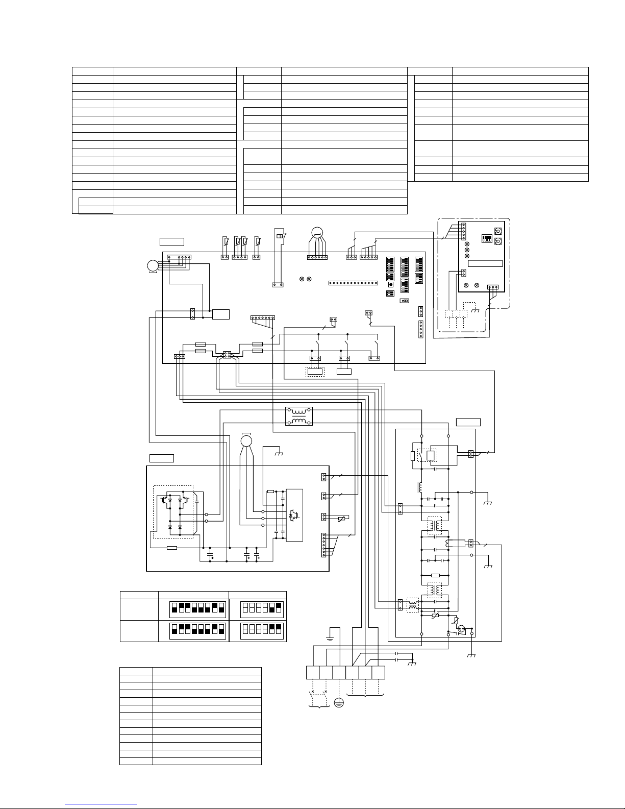
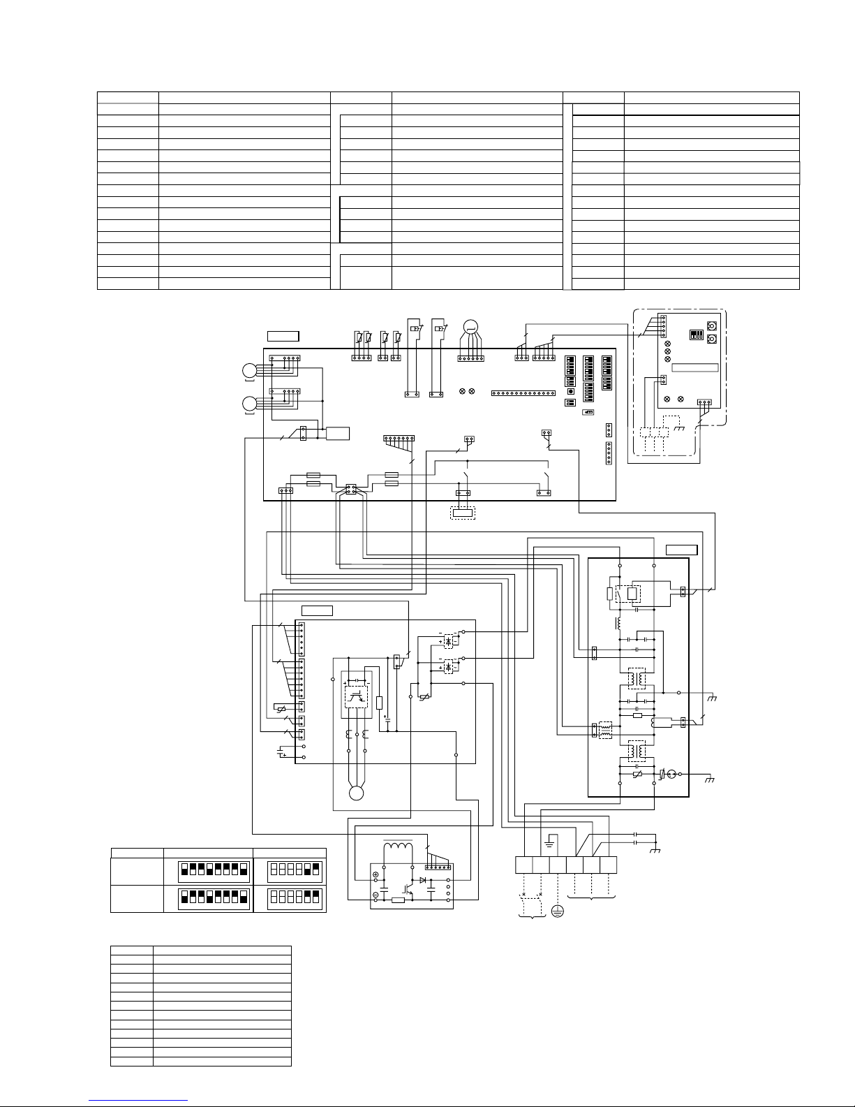
PUZ-A30/36NHA4 PUZ-A30/36NHA4-BS PUY-A30/36NHA4 PUY-A30/36NHA4-BS
[LEGEND]
SYMBOL
TB1
MC
MF1
21S4
SV Solenoid Valve (Bypass Valve)
63H
TH3
TH6
TH7
TH8
TH32
LEV-A
DCL
CY1, CY2
ACTM
Terminal Block<Power Supply, Indoor/Outdoor>
Motor for Compressor
Fan Motor
Solenoid Valve (Four-Way Valve)
High Pressure Switch
Thermistor<Outdoor Pipe>
Thermistor<Outdoor 2-Phase Pipe>
Thermistor<Outdoor>
Thermistor<Heatsink>
Thermistor<Shell>
Electronic Expansion Valve
Reactor
Capacitor
Active Filter Module
NAME SYMBOL NAME SYMBOL NAME
MF1
P.B.
TABU/V/W
TABS/T
TABP1/P2
TABN1/N2
DS2, DS3
N.F.
LI/LO
NI/NO
EI, E2
52C
C.B.
F1~F4
SW1
C. B.
1
2
CNS
(WHT)
31
7
TH8
t°
7
3
1
CNDC
(PNK)
4
2
2
MS
3~
Power Circuit Board
Connection Terminal<U/V/W-Phase>
Connection Terminal<L1/L2-Phase>
Connection Terminal<DC Voltage>
Connection Terminal<DC Voltage>
Diode Bridge
Power ModuleIPM
Noise Filter Circuit Board
Connection Lead<L1-Phase>
Connection Lead<L2-Phase>
Connection Terminal<Ground>
52C Relay
Controller Circuit Board
Fuse<T6.3AL250V>
Switch<
Forced Defrost, Defect History Record
Reset, Refrigerant Address>
TH7TH6 TH3TH32
(BLK)
TRANS
TH32
CNAC
(WHT)
43
t° t° t°t°
TH7/6
(RED)
21
412121
TH3
(WHT)
(WHT)
F3
F4
CN2
CNF1
(WHT)
F2
F1
P. B .
1
CNAF
(WHT)
6
1
CN2
(WHT)
7
1
CN3
2
(WHT)
1
CN5
2
(RED)
1
CN4
2
(WHT)
TABN
TABP
IPM
RED
TABP 2
TABV
TABU
RED
WHT
UVW
MS
3~
BLK
CNDC
(PNK)
1
3
TABW
MC
7
(YLW)
71
2
63H
63H
TABN 1
LEV-A
M
61
LEV-A
(WHT)
LED1
LED2
DS3
DS2
2
13
(GRN)
CN4
(WHT)
12
X52
21S4
TABT
TABS
TABP 1
1
SV
BLU
WHT
RED
TABN 2
WHT
31
21S4
PUZ only
U
BLK
13
(BLU)
CNVMNT
(WHT)
X55
SV2
CNM
(WHT)
3
31
CN52C
(RED)
SW4
SW5
SW6
SW7
SW8
SW9
SWP
CN31
LED1,LED2
SS
CNM
CNMNT
CNVMNT
CNDM
CN51
X51,X52,X55
5
51
CNMNT
(WHT)
14
221
X51
13
SS
(WHT)
Switch<Test Operation>
Switch<Function Switch>
Switch<Model Select>
Switch<Function Setup>
Switch<Function Setup>
Switch
Switch<Pump Down>
Connector<Emergency Operation>
LED<Operation Inspection Indicators>
Connector<Connection for Option>
Connector<A-Control Service Inspection Kit>
Connector<Connected to Optional M-NET Adapter Board>
Connector<Connected to Optional M-NET Adapter Board>
Connector< Connected for Option (Contact Input)>
Connector< Connected for Option (Signal output)>
Relay
When M-NET adapter is connected
5
5
1
+1+1
SW7
SW5SW8SW4SWP
SW6SW1
SW9
CN31
3151
(WHT)
CNDM
CN51
(WHT)
LO
3
1
(RED)
CNAC2
3
1
(WHT)
CNAC1
LI NI
WHT
52C
U
ABS
NO
2
1
TB7
M-NET
BLU
U
SW1
CN5
(WHT)
LED2
LED3
LED4
M-NET ADAPTER
CND
CN2M
(WHT)
(WHT)
31
LED1
LED5
3
N. F.
1
2
(BLK)
CN52C
E2
2
1
2
CN5
(RED)
EI
SW11
SW12
2
+
1 MODEL SELECT
The black square (■) indicates a switch position.
MODEL SW6
PUZ-A30NHA4
PUZ-A36NHA4
PUY-A30NHA4
PUY-A36NHA4
+2. SW5-1 to 4 : Function switch
M-NET ADAPTER
SYMBOL
TB7
CN5
CND
CN2M
SW1
SW11
SW12
LED1
LED2
LED3
LED4
LED5
ON
OFF
123456
ON
OFF
123456
ON
OFF
123456
ON
OFF
123456
Terminal Block<M-net connection>
Connector<Transmission>
Connector<Power Supply>
Connector<M-NET communication>
Switch<Status of communication>
Switch<Address setting : 1s digit>
Switch<Address setting : 10s digit>
LED<Power Supply : DC5V>
LED<Connection to Outdoor Unit>
LED<Transmission : Sending>
LED<Transmission : Receiving>
LED<Power Supply : DC12V>
78
78
78
78
NAME
SW5-5.6
ON
OFF
123456
ON
OFF
123456
ON
OFF
123456
ON
OFF
123456
+
2
BLK
DCL
ACTM
BLK
4
WHT
L1
L2
16
REDRED
P
N1
N2
WHT
Io
BLU
RED
L1 L2 GR
POWER SUPPLY
208 / 230V 60Hz
+
Use copper supply wires.
YLW
GRN
S1 S2 S3
INDOOR
UNIT
ORN
BRN
TB1
CY1
CY2
18
PUZ-A42NHA4 PUZ-A42NHA4-BS PUY-A42NHA4 PUY-A42NHA4-BS
[LEGEND]
SYMBOL
TB1
MC
MF1,MF2
21S4
63H
63L
TH3
TH4
TH6
TH7
TH8
LEV-A
DCL
Terminal Block<Power Supply, Indoor/Outdoor >
Motor for Compressor
Fan Motor
Solenoid Valve (Four-Way Valve)
High Pressure Switch
Low Pressure Switch
Thermistor<Outdoor Pipe>
Thermistor<Discharge>
Thermistor<Outdoor 2-Phase Pipe>
Thermistor<Outdoor>
Thermistor<Heatsink>
Electronic Expansion Valve
Reactor
CY1, CY2 Capacitor
ACTM
CB
Active Filter Module
Main Smoothing Capacitor
NAME SYMBOL NAME SYMBOL NAME
MF1
MF2
P. B .
TABU/V/W
TABS/T
TABP1/P2/P
TABN1/N2/N
DS2, DS3
IPM
N.F.
LI/LO
NI/NO
EI, E2
52C
C.B.
F1~F4
SW1
TRANS
CNAC
(WHT)
TH7TH6 TH3 TH4
TH7/6
(RED)
C. B.
CNF1
1
(WHT)
1
(WHT)
CNS
3
2
1
31
7
CNF2
(WHT)
7
CNDC
(PNK)
F2
F1
MS
3~
MS
3~
Power Circuit Board
Connection Terminal<U/V/W-Phase>
Connection Terminal<L1/L2-Phase>
Connection Terminal<DC Voltage>
Connection Terminal<DC Voltage>
Diode Bridge
Power Module
Noise Filter Circuit Board
Connection Lead<L1-Phase>
Connection Lead<L2-Phase>
Connection Terminal<Ground>
52C Relay
Controller Circuit Board
Fuse<
T6.3AL250V>
Switch<
Forced Defrost, Defect History Record
Reset, Refrigerant Address>
63L
63H
t° t° t° t°
412121
TH3
TH4
(WHT)
(WHT)
31
31
63L
63H
(YLW)
(RED)
CN2
(WHT)
71
7
F3
21
F4
43
2
+2 PUZ only
LEV-A
M
61
LEV-A
(WHT)
LED1
LED2
1
CN4
(WHT)
12
X52
13 13
21S4
(GRN)
21S4
3
31
CNVMNT
(WHT)
CNM
(WHT)
CNMNT
(WHT)
CN52C
(RED)
5
51
14
221
(WHT)
SW5SW8SW4SWP
X51
SS
SW4
SW5
SW6
SW7
SW8
SW9
SWP
CN31
LED1,LED2
SS
CNM
CNMNT
CNVMNT
CNDM
CN51
X51,X52
+1+1
SW7
SW6SW1
SW9
CN31
3151
(WHT)
CNDM
CN51
(WHT)
Switch<Test Operation>
Switch<Function Switch>
Switch<Model Select>
Switch<Function Setup>
Switch<Function Setup>
Switch
Switch<Pump Down>
Connector<Emergency Operation>
LED<Operation Inspection Indicators>
Connector<Connection for Option>
Connector<A-Control Service Inspection Kit>
Connector<Connected to Optional M-NET Adapter Board>
Connector<Connected to Optional M-NET Adapter Board>
Connector< Connected for Option (Contact Input)>
Connector< Connected for Option (Signal output)>
Relay
When M-NET adapter is connected
5
CN5
5
1
LED2
LED3
LED4
2
1
ABS
TB7
M-NET
SW11
SW1
(WHT)
SW12
M-NET ADAPTER
CND
CN2M
(WHT)
(WHT)
31
LED1
LED5
3
4
7
TH8
t°
2
2
WHT
CB
RED
+1 MODEL SELECT
The black square (■) indicates a switch position.
MODEL SW6
PUZ-A42NHA4
PUY-A42NHA4
ON
OFF
123456
ON
OFF
123456
SW5-5.6
ON
OFF
7878123456
ON
OFF
123456
+2. SW5-1 to 4 : Function switch
M-NET ADAPTER
SYMBOL
TB7
CN5
CND
CN2M
SW1
SW11
SW12
LED1
LED2
LED3
LED4
LED5
Terminal Block<M-net connection>
Connector<Transmission>
Connector<Power Supply>
Connector<M-NET communication>
Switch<Status of communication>
Switch<Address setting : 1s digit>
Switch<Address setting : 10s digit>
LED<Power Supply : DC5V>
LED<Connection to Outdoor Unit>
LED<Transmission : Sending>
LED<Transmission : Receiving>
LED<Power Supply : DC12V>
NAME
P. B .
1
CNAF
(WHT)
6
1
CN2
(WHT)
7
1
CN3
2
(WHT)
1
CN5
2
(RED)
1
CN4
2
(WHT)
TABN
TABP
+2
IPM
TABP2
RED
TABV
TABU
WHT
RED
UVW
M
3~
BLK
BLK
MC
TABW
DCL
ACTM
BLK
CNDC
(PNK)
1
3
L1
2
TABN1
L2
DS3
DS2
U
BLK
4
WHT
16
19
N. F.
BLU
WHT
LO
NO
1
2
CN52C
E2
1
2
CN5
EI
2
(BLK)
2
(RED)
52C
TABT
BLU
YLW
GRN
S1 S2 S3
INDOOR
UNIT
3
1
CNAC2
3
1
CNAC1
ORN
(RED)
(WHT)
LI NI
BRN
TB1
CY1
CY2
U
U
TABS
WHT
TABP 1
RED
TABN2
WHT
BLU
RED
REDRED
P
N1
N2
WHT
Io
L1 L2 GR
POWER SUPPLY
208 / 230V 60Hz
+Use copper supply wires.
8
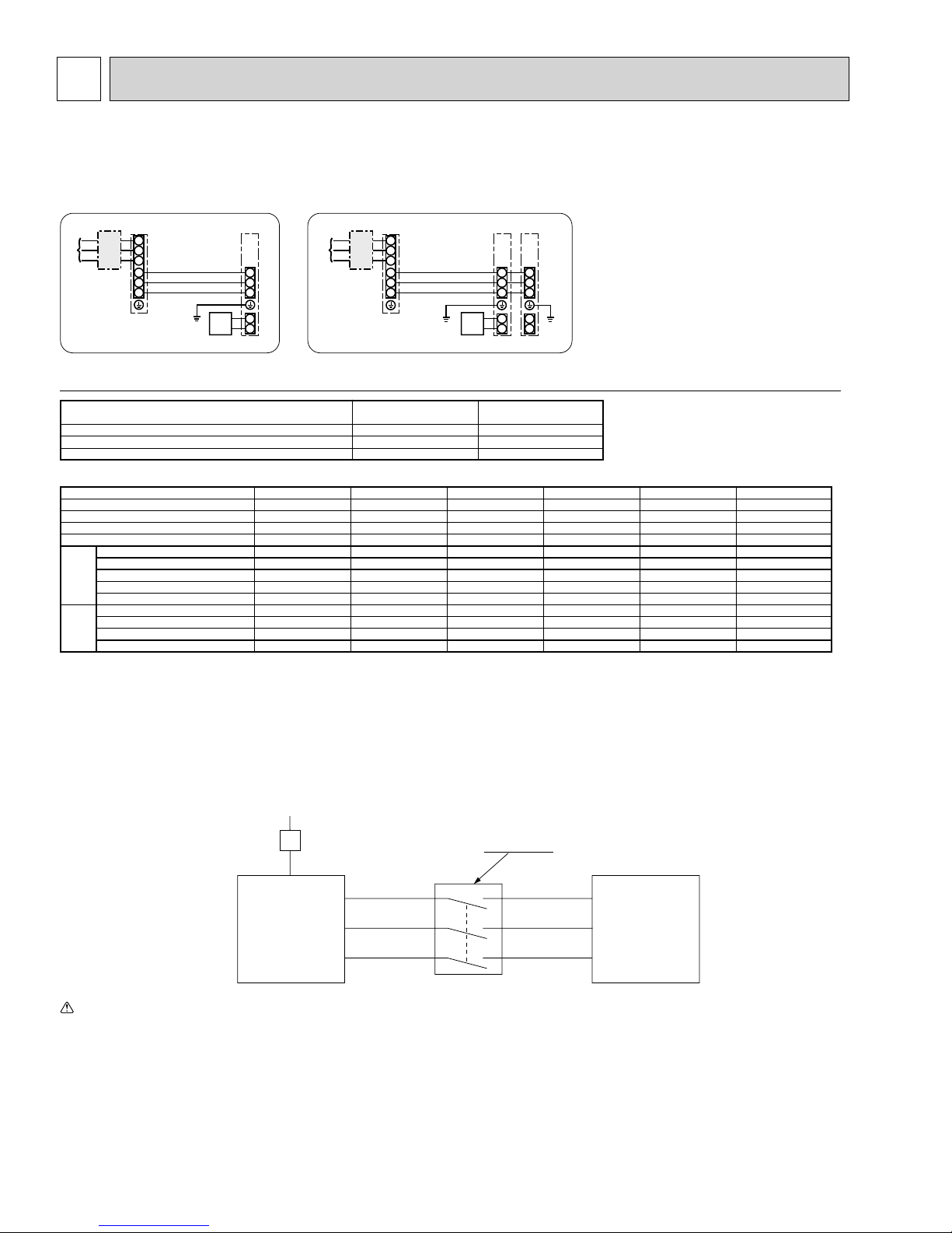
WIRING SPECIFICATIONS
8-1. INDOOR UNIT POWER SUPPLIED FROM OUTDOOR UNIT (A-control application)
The following connection patterns are available.
The outdoor unit power supply patterns vary on models.
1:1 System Simultaneous twin system
L1
L2
GR
S1
S2
S3
S1
S2
S3
1
2
L1
L2
GR
S1
S2
S3
S1
S1
S2
S2
S3
S3
1
1
2
2
* Affix a label A that is included with the manuals near each wiring diagram for the indoor and outdoor units..
Outdoor unit power supply
Wiring circuit breaker or isolating switch
Outdoor unit
Indoor unit/outdoor unit connecting cords
Remote controller
Indoor unit
Indoor unit earth
Indoor unit model
Indoor unit power supply
Minimum circuit ampacity
Maximum rating of overcurrent protective device
Outdoor unit model
Outdoor unit power supply
Breaker size
Minimum circuit ampacity
Maximum rating of overcurrent protective device
Outdoor unit power supply
Outdoor unit power supply earth
Indoor unit-Outdoor unit *1
size
Wiring
Indoor unit earth *1
Wire No. %
Remote controller-Indoor unit *2
Outdoor unit L1-L2 *3
Indoor unit-Outdoor unit S1-S2 *3
Indoor unit-Outdoor unit S2-S3 *3
rating
Circuit
Remote controller-Indoor unit *3
*1. Max. 50 m, 165 ft
*2. The 10 m, 30 ft wire is attached in the remote controller accessory. Max. 1500 ft
*3. The figures are NOT always against the ground.
S3 terminal has DC 24 V against S2 terminal. However between S3 and S1, these terminals are NOT electrically insulated by the transformer or other device.
*4. Use earth leakage breaker (NV).
1.Wiring size must comply with the applicable local and national code.
Notes:
2.Use copper supply wires.
3.Use wires rated 600V or more for the power supply cables and the indoor/outdoor unit connecting cables.
4.Install an earth longer than other cables.
*4
A12 A18 A24 A30 A36 A42
Single, 208/230 V, 60 Hz Single, 208/230 V, 60 Hz Single, 208/230 V, 60 Hz Single, 208/230 V, 60 Hz Single, 208/230 V, 60 Hz Single, 208/230 V, 60 Hz
15A 15A 25A 30A 30A 30A
13A 13A 18A 25A 25A 26A
15A 20A 30A 40A 40A 40A
2 % Min. AWG 14 2 % Min. AWG 14 2 % Min. A WG 12 2 % Min. AWG 10 2 % Min. AWG 10 2 % Min. AWG 10
1 % Min. AWG 14 1 % Min. AWG 14 1 % Min. A WG 12 1 % Min. AWG 10 1 % Min. AWG 10 1 % Min. AWG 10
3 % AWG 16 (polar) 3 % AWG 16 (polar) 3 % AWG 16 (polar) 3 % AWG 16 (polar) 3 % AWG 16 (polar) 3 % AWG 16 (polar)
1 % Min. AWG 16 1 % Min. AWG 16 1 % Min. A WG 16 1 % Min. AWG 16 1 % Min. AWG 16 1 % Min. AWG 16
2% AWG 22 (Non-polar) 2% AWG 22 (Non-polar) 2% AWG 22 (Non-polar) 2% AWG 22 (Non-polar) 2% AWG 22 (Non-polar) 2% AWG 22 (Non-polar)
AC 208/230 V AC 208/230 V AC 208/230 V AC 208/230 V AC 208/230 V AC 208/230 V
AC 208/230 V AC 208/230 V AC 208/230 V AC 208/230 V AC 208/230 V AC 208/230 V
DC 24 V DC 24 V DC 24 V DC 24 V DC 24 V DC 24 V
DC 12 V DC 12 V DC 12 V DC 12 V DC 12 V DC 12 V
230V
Single phase
PLA-A12, 18, 24, 30
PCA-A24, 30, PKA
––
1A 2A
15A 15A
Isolator
PLA-A36, 42
PCA-A36, 42
3 poles isolator
A-Control
Outdoor Unit
Warning:
In case of A-control wiring, there is high voltage potential on the S3 terminal caused by electrical circuit design that has no electrical insulation between power line
and communication signal line. Therefore, please turn off the main power supply when servicing. And do not touch the S1, S2, S3 terminals when the power is
energized. If isolator should be used between indoor unit and outdoor unit, please use 3-pole type .
S1
S2
S3
20
S1
S2
S3
A-Control
Indoor Unit
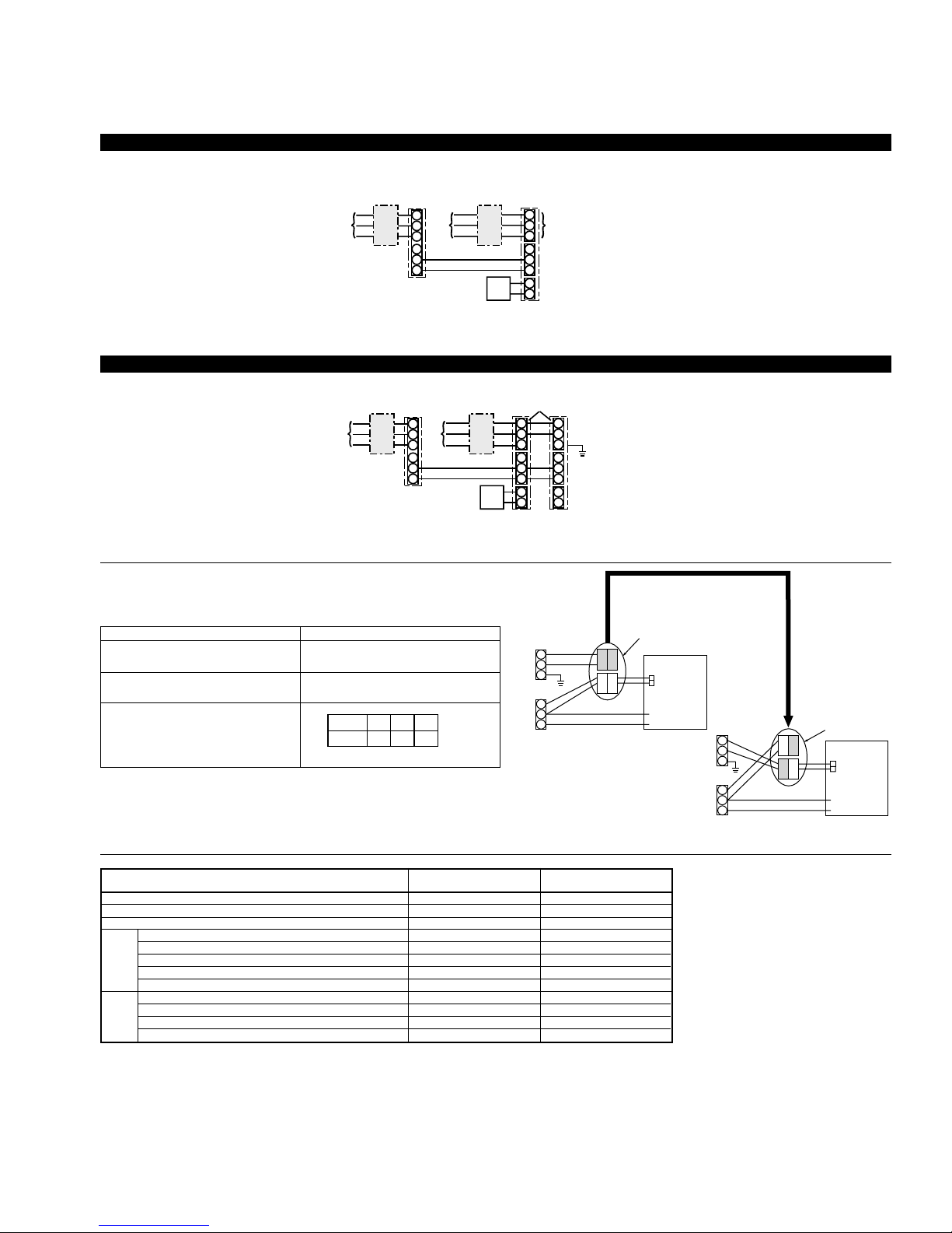
8-2. SEPARATE INDOOR UNIT/OUTDOOR UNIT POWER SUPPLIES
t
The following connection patterns are available.
The outdoor unit power supply patterns vary on models.
1:1 System
* The optional indoor power supply terminal kit is required.
L1
L2
GR GR
S1
S2
S3
1
2
L1
L2
GR
S1
S2
S3
1
2
L1
L2
S1
S2
S3
1
2
L1
L2
GR
S1
S2
S3
* Affix a label B that is included with the manuals near each wiring diagram for the indoor and outdoor units.
Simultaneous twin system
L1
L2
GR
S1
S2
S3
Outdoor unit power supply
Wiring circuit breaker or isolating switch
Outdoor unit
Indoor unit/outdoor unit connecting cords
Remote controller
Indoor unit
Indoor unit power supply
Option
Outdoor unit power supply
Wiring circuit breaker or isolating switch
Outdoor unit
Indoor unit/outdoor unit connecting cords
Remote controller
Indoor unit
Indoor unit power supply
Option
Indoor unit earth
*Affix a label B that is included with the manuals near each wiring diagram for the indoor and outdoor units.
If the indoor and outdoor units have separate power supplies, refer to the table below.
Change the indoor unit electrical box wiring refering to the figure in the right and
he DIP switch settings of the outdoor unit control board.
Indoor unit specifications
Indoor unit electrical box connector connection change
Label affixed near each wiring diagram
for the indoor and outdoor units
Outdoor unit DIP switch settings (when
using separate indoor unit/outdoor unit
power supplies only)
Required
Required
ON
OFF 1 2
3
(SW8)
L1
L2
GR
S1
S2
S3
Indoor unit power supplied
from outdoor unit (Initial
setting)
* There are three types of labels (labels A, B, and C). Affix the appropr iate labels to
the units according to the wiring method.
Indoor unit model
Indoor unit power supply
Minimum circuit ampacity
Maximum rating of overcurrent protective device
Indoor unit power supply
size
Indoor unit power supply earth
%
Indoor unit-Outdoor unit *1
Wiring
Indoor unit earth
Wire No.
Remote controller-Indoor unit *2
Indoor unit L1-L2 *3
Indoor unit-Outdoor unit S1-S2 *3
Indoor unit-Outdoor unit S2-S3 *3
rating
Circuit
Remote controller-Indoor unit *3
*1. Max. 50 m, 165 ft
*2. The 10 m, 30 ft wire is attached in the remote controller accessory. Max. 500 m, 1500 ft
*3. The figures are NOT always against the ground.
PLA-A12, 18, 24, 30
PKA, PCA-24, 30
Single 208/230 V, 60 Hz Single 208/230 V, 60 Hz
1 A 2A
15A 15A
2 % Min. AWG16 2 % Min. AWG16
1 % Min. AWG16 1 % Min. AWG16
2 % AWG22 (polar) 2 % AWG22 (polar)
––
2 % AWG22 (Non-polar) 2 % AWG22 (Non-polar)
AC 208/230 V AC 208/230 V
––
DC24 V DC24 V
DC12 V DC12 V
Connectors (connections when
shipped from the factory are
for indoor unit power supplied
from outdoor unit)
BLUE
BLUE
YELLOW
YELLOW
PLA-A36, 42
PCA-A36,42
CN101
Indoor unit
control board
L1
L2
GR
S1
S2
S3
Separate indoor unit/outdoor unit power
supplies
Notes: 1. Wiring size must comply with the applicable local and national code.
2. Use copper supply wires.
3. Use wires rated 300V or more for the power supply cables.
4. Install an earth longer than other cables.
If the indoor and
outdoor units have
separate power
supplies, change the
connections of the
connectors as shown
in the following
figure.
BLUE
YELLOW
Connectors
CN101
Indoor unit
control board
YELLOW
BLUE
21
8-3. INDOOR - OUTDOOR CONNECTING CABLE
Outdoor power supply
Max. 45m, 147ft
Max. 50m, 164ft
Wire No. % Size
Max. 80m, 262ft
Indoor unit-Outdoor unit
+ The max. cable length may vary depending on the condition of installation, humidity or materials, etc.
Indoor/Outdoor separate
power supply
Indoor unit-Outdoor unit
+ The optional indoor power supply terminal kit is necessary.
Be sure to connect the indoor-outdoor connecting cables directly to the units (no intermediate connections).
Intermediate connections can lead to communication errors if water enters the cables and causes insufficient
insulation to ground or a poor electrical contact at the intermediate connection point.
3 % AWG15(polar)
3 % AWG13(polar)
Wire No. % Size
Max. 120m, 393ft
2 % Min. AWG22
3 % AWG13(polar) and S3 separated
22
8-4. M-NET WIRING METHOD
(Points to note)
(1) Outside the unit, transmission wires should stay away from electric wires in order to prevent electromagnetic noise from
making an influence on the signal communication. Place them at intervals of more than 5 cm. Do not put them in the same
conduit tube.
(2) Terminal block (TB7) for transmission wires should never be connected to 208/230V power supply. If it is connected,
electronic parts on M-NET P.C. board may burn out.
(3) Use 2-core × 1.25mm² [AWG16] shield wire (CVVS, CPEVS) for the transmission wire. Transmission signals may not be
sent or received normally if different types of transmission wires are put together in the same multi-conductor cable. Never
do this because this may cause a malfunction.
Group
remote
controller
Power
supply
unit for
transmission
wire
A-control
remote
controller
It would be ok if M-NET wire (non-polar, 2-cores) is arranged in addition to the wiring for A-control.
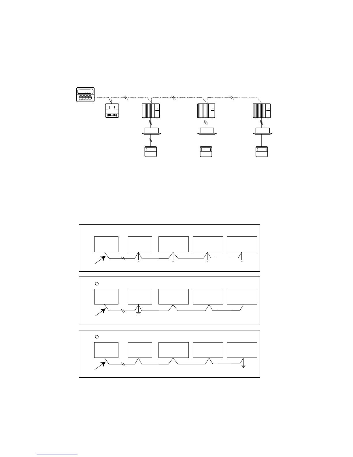
(4) Ground only one of any appliances through M-NET transmission wire (shield wire). Communication error may occur due to
the influence of electromagnetic noise.
“Ed” error will appear on the LED display of outdoor unit.
“0403” error will appear on the central-control remote controller.
Bad example (Multi spot grounding of shield wire)
Central
remote
controller
M-NET transmission wire
Power
supply
appliance
Refrigerant
address 00
M-NET
address 01
M-NET type
outdoor unit
M-NET type
outdoor unit
A-control
remote
controller
Refrigerant
address 00
M-NET
address 02
M-NET type
outdoor unit
A-control
remote
controller
Refrigerant
address 00
M-NET
address 03
Good example 1 (Single spot grounding of shield wire)
Central
remote
controller
M-NET transmission wire
Good example 2 (Single spot grounding of shield wire)
Central
remote
controller
M-NET transmission wire
If there are more than 2 grounding spots on the shield wire, noise may enter into the shield wire because the ground wire
and shield wire form one circuit and the electric potential difference occurs due to the impedance difference among ground-
ing spots. In case of single spot grounding, noise does not enter into the shield wire because the ground wire and shield
wire do not form one circuit.
To avoid communication errors caused by noise, make sure to observe the single spot grounding method described in the
installation manual.
Power
supply
appliance
Power
supply
appliance
M-NET type
outdoor unit
M-NET type
outdoor unit
23
M-NET type
outdoor unit
M-NET type
outdoor unit
M-NET type
outdoor unit
M-NET type
outdoor unit

● M-NET wiring
d
(1) Use 2-core × 1.25mm² [AWG16] shield wire for electric wires.
(Excluding the case connecting to system controller.)
(2) Connect the wire to the M-NET terminal block. Connect one core of the
transmission wire (non-polar) to A terminal and the other to B. Peel the
shield wire, twist the shield part to a string and connect it to S terminal.
(3) In the system which several outdoor units are being connected, the terminal
(A, B, S) on M-NET terminal block should be individually wired to the other
M-NET
terminal
block
ABS
Transmission
wire
Shield
part
Groun
wire
outdoor unit’s terminal, i.e. A to A, B to B and S to S. In this case, choose one of those outdoor units and drive a screw
to fix an ground wire on the plate as shown on the right figure.
8-4-1. M-NET address setting
In A-control models, M-NET address and refrigerant address should be set only for the outdoor unit. Similar to CITY MULTI
series, there is no need to set the address of outdoor unit and remote controller. To construct a central control system, the
setting of M-NET address should be conducted only upon the outdoor unit. The setting range should be 1 to 50 (the same as
that of the indoor unit in CITY MULTI system), and the address number should be consecutively set in a same group.
Address number can be set by using rotary switches
(SW11 for ones digit and SW12 for tens digit), which
is located on the M-NET board of outdoor unit.
(Initial setting: all addresses are set to “0”.)
8-4-2. Refrigerant address setting
<Setting example>
M-NET Address No.
SW11
Switching
setting
ones
digit
SW12
tens
digit
12
3
3
4
4
2
2
5
1
0
2
1
0
5
1
6
6
0
7
7
9
9
8
8
3
3
4
4
2
5
5
1
6
6
0
7
7
9
9
8
8
50
3
4
2
5
1
6
0
7
9
8
~
3
4
2
5
1
6
0
7
9
8
In case of multiple grouping system (multiple refrigerant circuits in one group), indoor units should be connected by remote
controller wiring (TB5) and the refrigerant address needs to be set. Leave the refrigerant addresses to “00” if the group setting is not conducted. Set the refrigerant address by using DIP SW1-3 to -6 on the outdoor controller board. [Initial setting: all
switches are OFF. (All refrigerant addresses are “00”.)]
Refrigerant
address
ON
OFF
1
ON
OFF
1
ON
OFF
1
3
4
5
2
6
0
ON
OFF
1
3
4
5
2
6
8
ON
OFF
1
3
4
5
2
6
1
ON
OFF
1
3
4
5
2
6
9
ON
OFF
1
3
4
5
2
6
2
ON
OFF
1
3
4
5
2
6
10
ON
OFF
1
3
4
5
2
6
3
ON
OFF
1
3
4
5
2
6
11
ON
OFF
1
3
4
5
2
6
4
ON
OFF
1
3
4
5
2
6
12
ON
OFF
1
3
4
5
2
6
5
ON
OFF
1
3
4
5
2
6
13
ON
OFF
1
3
4
2
6
3
4
2
14
3
5
5
4
5
2
6
ON
OFF
6
6
7
1
3
4
5
2
6
15
8-4-3. Regulations in address settings
In case of multiple grouping system, M-NET and refrigerant address settings should be done as explained in the above section. Set the lowest number in the group for the outdoor unit whose refrigerant address is “00” as its M-NET address.
Group A Group B Group C
System
controller
Power
supply
unit for
transmission
wire
Refrigerant
address 00
M-NET
address 01
A-control
remote
controller
Refrigerant
address 00
M-NET
address 02
A-control
remote
controller
Refrigerant
address 01
M-NET
address 03
TB5
Refrigerant
address 00
M-NET
address 04
A-control
remote
controller
w Refrigerant addresses can be overlapped if they are in the different group.
System
controller
Power
supply
unit for
transmission
wire
Refrigerant
address 00
M-NET
address 01
A-control
remote
controller
w In group B, M-NET address of the outdoor unit whose refrigerant address is “00” is not set to the minimum in the group. As
“03” is right for this situation, the setting is wrong. Taking group A as a good sample, set the minimum M-NET address in
the group for the outdoor unit whose refrigerant address is “00”.
Group A Group B
Refrigerant
address 01
M-NET
address 02
Refrigerant
address 00
M-NET
address 04
Refrigerant
address 01
M-NET
address 03
TB5
A-control
remote
controller
24
Refrigerant
address 02
M-NET
address 05
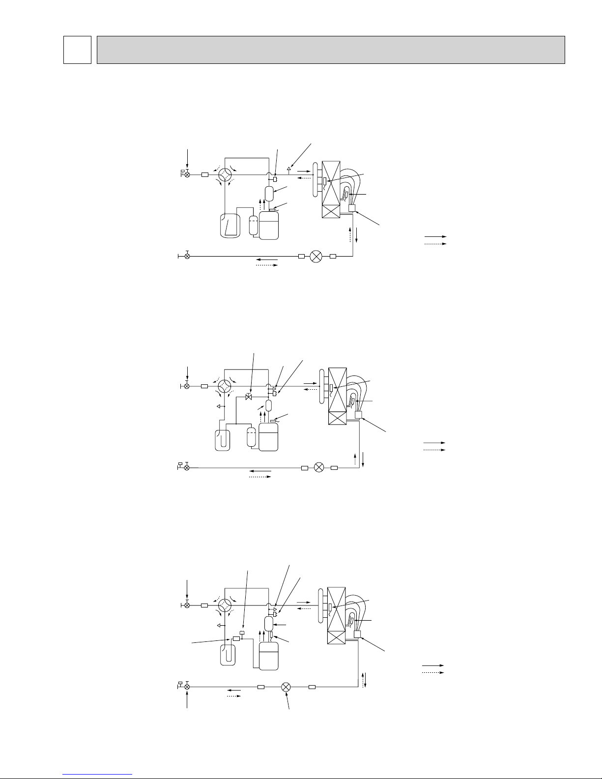
9
REFRIGERANT SYSTEM DIAGRAM
PUZ-A18NHA4(-BS) Unit: mm (inch)
Stop valve
(with service port)
Refrigerant GAS pipe
12.7 (W1/2)
Refrigerant LIQUID pipe
6.35 (W1/4)
(#50)
Strainer
Accumulator
Stop valve
4-way valve
High pressure
protect switch
Compressor
Service
port(check)
Outdoor heat exchanger
Muffler
Thermistor
(TH32)
(#100)
Strainer
(#100)
Strainer
Linear expansion valve
Thermistor
(TH6)
Thermistor
(TH3)
Distributor
PUZ-A24NHA4(-BS) PUZ-A30NHA4(-BS) PUZ-A36NHA4(-BS)
Refrigerant GAS pipe
15.88 (W5/8)
Refrigerant LIQUID pipe
9.52 (W3/8)
Ball valve
(#50)
Strainer
Service
port
(check)
Accumulator
Stop valve
(with service port)
Bypass valve
4-way valve
Muffler
Service
port
(check)
Compressor
High pressure
protect switch
Outdoor heat exchanger
Thermistor
(TH32)
(#100)
Strainer
Linear expansion valve
(#100)
Strainer
Thermistor
(TH6)
Thermistor
(TH3)
Distributor
<4-way valve solenoid coil>
Heating : ON
Cooling : OFF
Refrigerant flow in cooling
Refrigerant flow in heating
Refrigerant flow in cooling
Refrigerant flow in heating
PUZ-A42NHA4(-BS)
Ball valve
(#50)
Strainer
(#100)
Stop valve
Strainer
Service
port
(check)
Refrigerant GAS pipe
15.88 (W5/8)
Refrigerant LIQUID pipe
9.52 (W3/8)
(with service port)
Low pressure protect
switch
4-way
valve
Accumulator
Compressor
Strainer
(#100)
Linear expansion valve
Service port
(check)
High pressure protect switch
Outdoor heat exchanger
Muffler
Thermistor
(TH4)
Strainer
(#100)
25
Thermistor
(TH6)
Thermistor
(TH3)
Distributor
Refrigerant flow in cooling
Refrigerant flow in heating
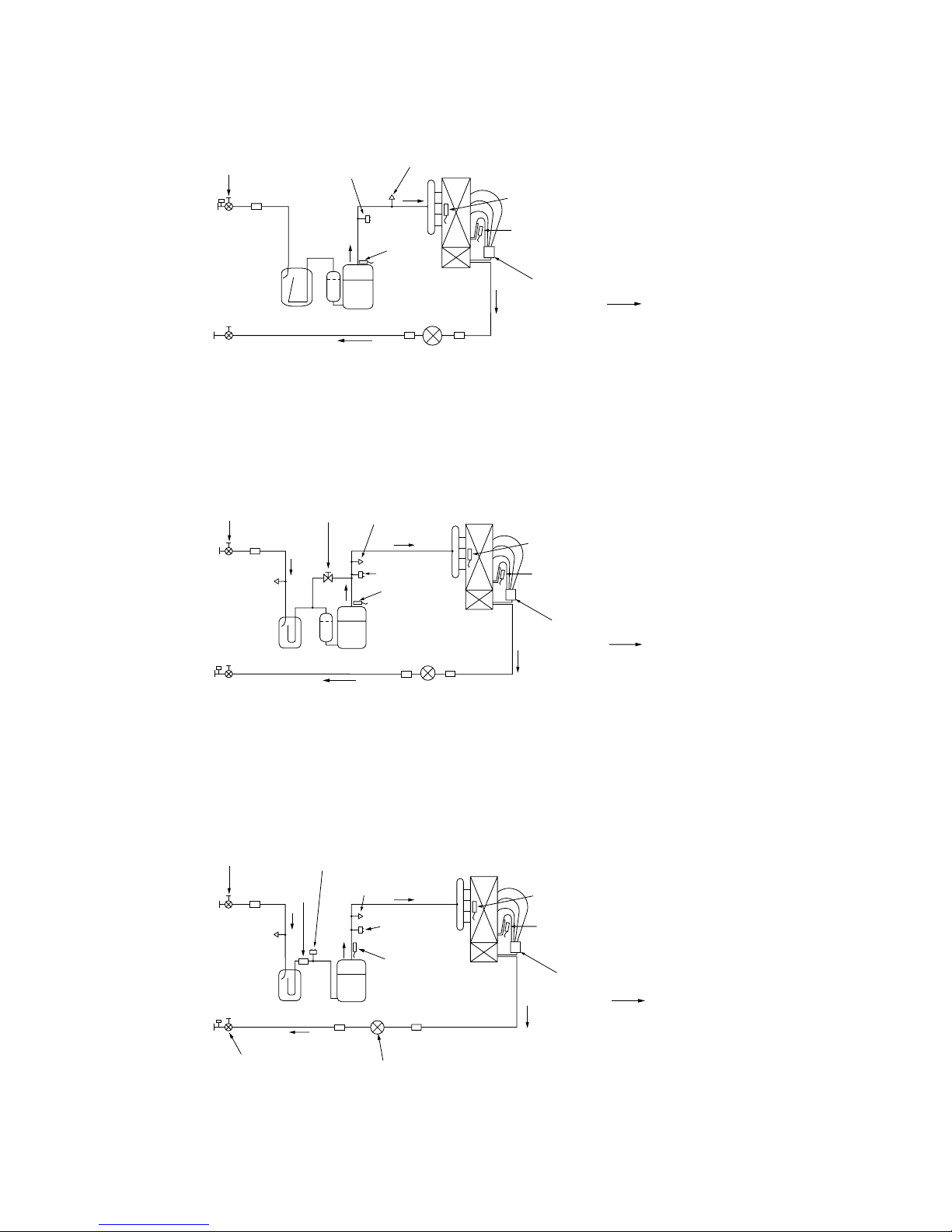
PUY-A12NHA4(-BS) PUY-A18NHA4(-BS)
Unit: mm (inch)
Stop valve
(with service port)
Refrigerant GAS pipe
12.7 (W1/2)
Refrigerant LIQUID pipe
6.35 (W1/4)
(#50)
Strainer
Accumulator
Stop valve
High pressure
protect switch
Compressor
Service port
(Check)
Outdoor heat exchanger
Thermistor
(TH32)
(#100)
Strainer
(#100)
Strainer
Linear expansion valve
Thermistor
(TH6)
Thermistor
(TH3)
Distributor
Refrigerant flow in cooling
PUY-A24NHA4(-BS) PUY-A30NHA4(-BS) PUY-A36NHA4(-BS)
Service
port
(check)
High pressure
protect switch
Thermistor
(TH32)
(#100)
Strainer
Linear expansion valve
Outdoor heat exchanger
(#100)
Strainer
Thermistor
(TH6)
Thermistor
(TH3)
Distributor
Refrigerant flow in cooling
Refrigerant GAS pipe
15.88 (W5/8)
Refrigerant LIQUID pipe
9.52 (W3/8)
Ball valve
(#50)
Strainer
Service
port
(check)
Accumulator
Stop valve
(with service port)
Bypass valve
Compressor
PUY-A42NHA4(-BS)
Ball valve
Refrigerant GAS pipe
15.88 (W5/8)
Accumulator
Refrigerant LIQUID pipe
9.52 (W3/8)
Stop valve
(with service port)
Low pressure protect
switch
(#50)
Strainer
Strainer
(#100)
Service
port
(check)
Service
port
(check)
High pressure
protect switch
Thermistor
(TH4)
Compressor
Strainer
(#100)
Linear expansion valve
Strainer
(#100)
Outdoor heat exchanger
Thermistor
(TH6)
Thermistor
(TH3)
26
Distributor
Refrigerant flow in cooling

1. Refrigerant recovering (pump down)
Perform the following procedures to recover the refrigerant when moving the indoor unit or the outdoor unit.
1 Turn on the power supply (circuit breaker).
wWhen power is supplied, make sure that “CENTRALLY CONTROLLED” is not displayed on the remote controller. If
“CENTRALLY CONTROLLED” is displayed, the refrigerant collecting (pump down) cannot be completed normally.
2 After the liquid stop valve is closed, set the SWP switch on the control board of the outdoor unit to ON. The compressor
(outdoor unit) and ventilators (indoor and outdoor units) start operating and refrigerant recovering operation begins. LED1
and LED2 on the control board of the outdoor unit are lit.
wSet the SWP switch (push-button type) to ON in order to perform refrigerant recovering operation only when the unit is
stopped. However, refrigerant recovering operation cannot be performed until compressor stops even if the unit is stopped.
Wait 3 minutes until compressor stops and set the SWP switch to ON again.
3 Because the unit automatically stops in about 2 to 3 minutes after the refrigerant recovering operation (LED1 is not lit and
LED2 is lit), be sure to quickly close the gas stop valve.
wIn case the outdoor unit is stopped when LED1 is lit and LED2 is not lit, open the liquid stop valve completely, and then
repeat step 2 3 minutes later.
wIf the refrigerant recovering operation has been completed normally (LED1 is not lit and LED2 is lit), the unit will remain
stopped until the power supply is turned off.
4 Turn off the power supply (circuit breaker.)
2. Start and finish of test run
• Operation from the indoor unit
Execute the test run using the installation manual for the indoor unit.
• Operation from the outdoor unit
By using the DIP switch SW4 on the control board of outdoor unit, test run can be started and finished, and its operation
mode (cooling/heating) can be set up.
1 Set the operation mode (cooling/heating) using SW4-2.
2 Turn on SW4-1 to start test run with the operation mode set by SW4-2.
3 Turn off SW4-1 to finish the test run.
• There may be a faint knocking sound around the machine room after power is supplied, but this is
not a problem with the product because the linear expansion valve is just moving to adjust opening pulse.
• There may be a knocking sound around the machine room for several seconds after compressor
starts operating. But this is not a problem with product because the check valve itself generates
the sound because pressure difference is small in the refrigerant circuit.
<SW4>
ON
OFF
12
Stop operation
Cooling Heating
(PUZ only)
Note:
The operation mode cannot be changed by SW4-2 during test run. (To change test run mode, stop the unit by SW4-1,
change the operation mode and restart the test run by SW4-1.)
27
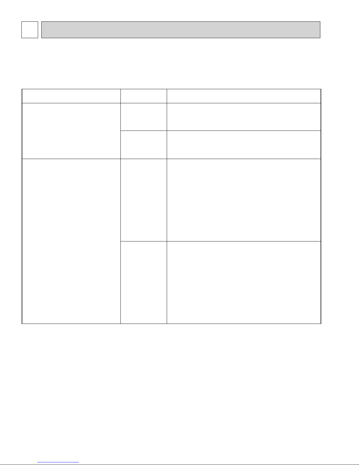
10 TROUBLESHOOTING
10-1. TROUBLESHOOTING
<Error code display by self-diagnosis and actions to be taken for service (summary)>
Present and past error codes are logged and displayed on the wired remote controller and control board of outdoor unit.
Actions to be taken for service, which depends on whether or not the trouble is reoccurring at service, are summarized in the
table below. Check the contents below before investigating details.
Unit conditions at service
The trouble is reoccurring.
The trouble is not reoccurring.
Error code
Displayed
Not displayed
Logged
Not logged
Actions to be taken for service (summary)
Judge what is wrong and take a corrective action according
to “10-4. Self-diagnosis action table”.
Conduct trouble shooting and ascertain the cause of the
trouble according to “10-5. Troubleshooting by inferior
phenomena”.
Consider the temporary defects such as the work of
protection devices in the refrigerant circuit including
compressor, poor connection of wiring, noise and etc.
Re-check the symptom, and check the installation
environment, refrigerant amount, weather when the
trouble occurred, matters related to wiring and etc.
Reset error code logs and restart the unit after finishing
service.
There is no abnormality concerning of parts such as
electrical component, controller board, remote controller
and etc.
Re-check the abnormal symptom.
Conduct trouble shooting and ascertain the cause of the
trouble
according to “10-5. Troubleshooting
by inferior
phenomena”.
Continue to operate unit for the time being if the cause
is not ascertained.
There is no abnormality concerning of parts such as
electrical component, controller board, remote controller
and etc.
10-2. CHECK POINT UNDER TEST RUN
(1) Before test run
• After installation of indoor and outdoor units, piping work and electric wiring work, re-check that there is no refrigerant leak-
age, loosened connections and incorrect polarity.
• Measure impedance between the ground and the power supply terminal block (L1, L2) on the outdoor unit by 500V Megger
and check that it is 1.0M" or over.
w Do not use 500V Megger to indoor/outdoor connecting wire terminal block (S1, S2, S3) and remote controller terminal
block (1, 2). This may cause malfunction.
• Make sure that test run switch (SW4) is set to OFF before turning on power supply.
• Turn on power supply 12 hours before test run in order to protect compressor.
• For specific models which requires higher ceiling settings or auto-recovery feature from power failure, make proper changes
of settings referring to the description of “12. FUNCTION SETTING”.
Make sure to read operation manual before test run. (Especially items to secure safety.)
28
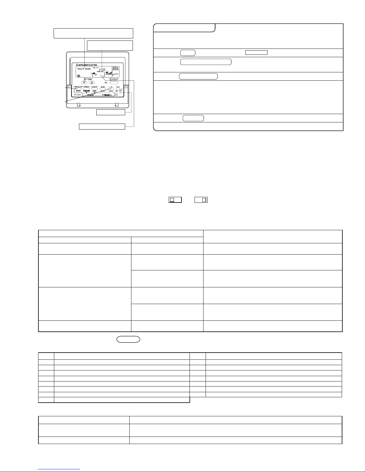
"TEST RUN" and the currently selected
operation mode are displayed alternately.
Displays the remaining
test run time.
F
[TEST] button
Operating procedures
1. Turn on the main power supply.
2. Press TEST button twice.
3. Press OPERATION SWITCH
button.
4. Press AIR DIRECTION button.
5. Check the outdoor unit fan for
correct running.
While the room temperature display on the remote
controller is “PLEASE WAIT”, the remote controller is disabled.
Wait until “PLEASE WAIT” disappears before using remote controller.
“PLEASE WAIT” appears for about 2 minutes after power
supply is turned on. +1
The TEST RUN appears on the screen.
Cooling mode:
Heating mode: Check if warm air blows. (It takes a little
while until warm air blows.)
Check for correct motion of auto-vanes.
The outdoor unit features automatic capacity control to
provide optimum fan speeds. Therefore, the fan keeps
running at a low speed to meet the current outside air
condition unless it exceeds its available maximum power.
Then, in actuality, the fan may stop or run in the reverse
direction depending on the outside air, but this does not
mean malfunction.
Check if cool air blows and water is drained.
6. Press the ON/OFF button to reset the test run in progress.
Pipe (liquid) temperature
7. Register the contact number.
• In case of test run, the OFF timer will be activated, and the test run will automatically stop after 2 hours.
• The room temperature display section shows the pipe temperature of indoor units during the test run.
• Check that all the indoor units are running properly in case of simultaneous twin operation. Malfunctions may not be displayed regardless of incorrect wiring.
w1 After turning on the power supply, the system will go into startup mode, “PLEASE WAIT” will blink on the display section
of the room temperature, and lamp (green) of the remote controller will blink.
As to INDOOR BOARD LED, LED1 will be lit, LED2 will either be lit in case the address is 0 or turned off in case the
address is not 0. LED3 will blink.
As to OUTDOOR BOARD LED, LED1 (green) and LED2 (red) will be lit. (After the startup mode of the system finishes,
LED2 (red) will be turned off.)
In case OUTDOOR BOARD LED is digital display, — and — will be displayed alternately every second.
• If one of the above operations does not function correctly, the causes written below should be considered. Find causes from
the symptoms.
The below symptoms are under test run mode. “startup” in the table means the display status of w1 written above.
Symptoms in test run mode
Remote Controller Display
Remote controller displays “PLEASE
WAIT”, and
cannot be operated.
After power is turned on, “PLEASE WAIT”
is displayed for 3 minutes, then error code
is displayed.
OUTDOOR BOARD LED Display
< > indicates digital display.
After “startup” is displayed, only
green lights up. <00>
After “startup” is displayed,
green (once) and red (once)
blink alternately. <F1>
After “startup” is displayed,
green (once) and red (twice)
• After power is turned on, “PLEASE WAIT” is displayed for 2
minutes during
system startup. (Normal)
• Incorrect connection of outdoor terminal block (L1, L2, and
S1, S2, S3.)
• Outdoor unit’s protection device connector is open.
Cause
blink alternately. <F3, F5, F9>
• Incorrect wiring between the indoor and outdoor unit (Polarity
is wrong for S1, S2, S3.)
• Remote controller transmission wire is short.
• There is no outdoor unit of address 0.
(Address is other than 0.)
• Remote controller transmission wire is open.
• After canceling function selection, operation is not possible for
about 30 seconds. (Normal)
No display appears even when remote
controller operation switch is turned on.
(Operation lamp does not light up.)
Display appears but soon disappears
even when remote controller is operated.
After “startup” is displayed,
green (twice) and red (once)
blink alternately. <EA. Eb>
After “startup” is displayed, only
green lights up. <00>
After “startup” is displayed, only
green lights up. <00>
w Press the remote controller’s CHECK button twice to perform self-diagnosis. See the table below for the contents of LCD
display.
LCD
P1
Abnormality of room temperature thermistor
P2
Abnormality of pipe temperature thermistor/Liquid
Abnormality of drain sensor/Float switch connector open
P4
Drain overflow protection is working.
P5
Freezing/overheating protection is working.
P6
Abnormality of pipe temperature
P8
Abnormality of pipe temperature thermistor/Cond./Eva
P9
Abnormality of indoor controller board
Fb
Contents of inferior phenomena
LCD
U1~UP
Malfunction outdoor unit
F3~F9
Malfunction outdoor unit
E0~E5
Remote controller transmitting error
Indoor/outdoor unit communication error
E6~EF
----
No error history
No applied unit
FFFF
Forced compressor stop(due to water leakage abnormality)
PA
Contents of inferior phenomena
See the table below for details of the LED display (LED 1, 2, 3) on the indoor controller board.
LED1 (microprocessor power supply)
LED2 (remote controller)
LED3 (indoor/outdoor communication)
Lights when power is supplied.
Lights when power is supplied for wired remote controller.
The indoor unit should be connected to the outdoor unit with address “0” setting.
Flashes when indoor and outdoor unit are communicating.
29
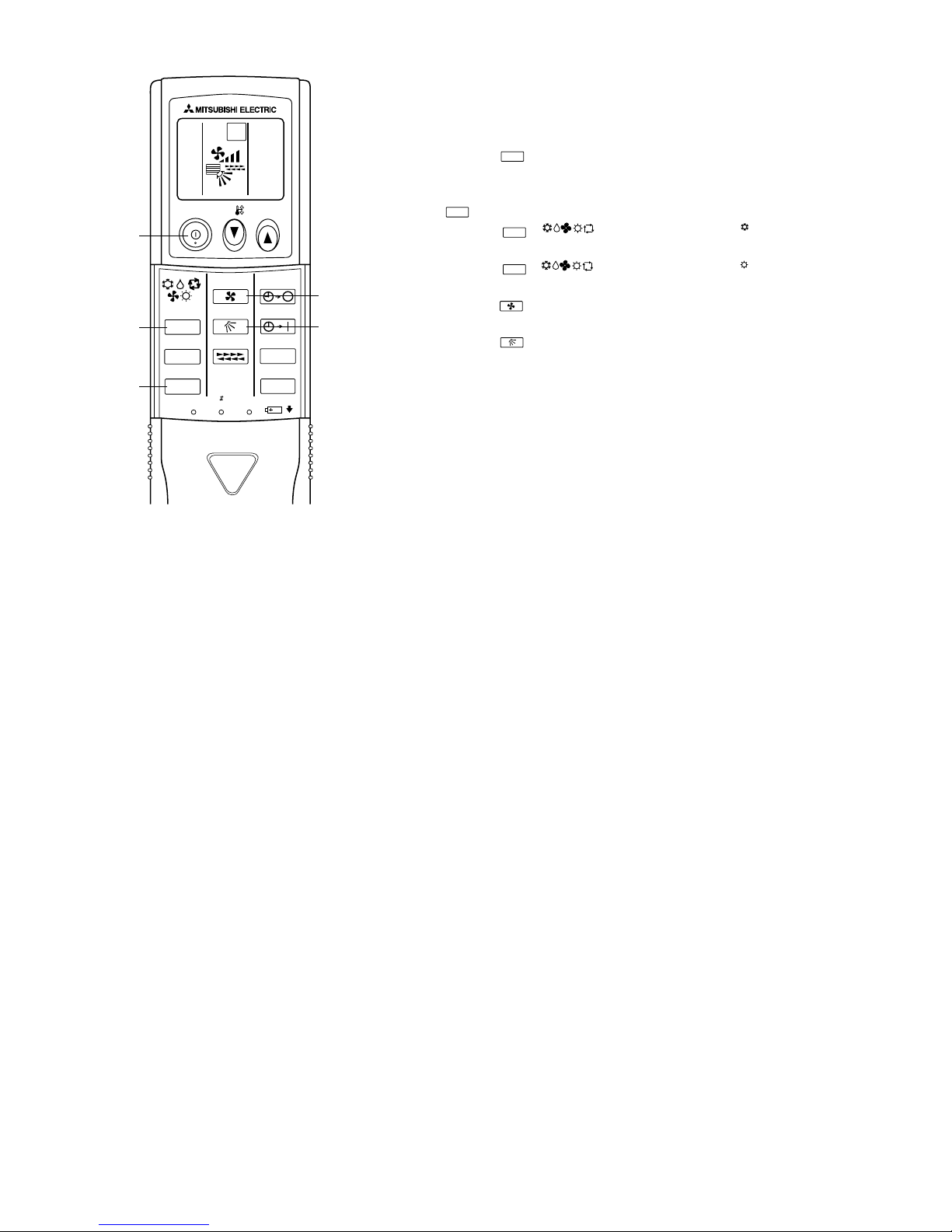
,
COOL
ON/OFF
MODE
CHECK
TEST RUN
SET
TEST
RUN
FAN
VAN E
LOUVER
RESET
CLOCK
TEMP
AUTO STOP
AUTO START
h
min
Test run [for wireless remote controller]
Measure an impedance between the power supply terminal block on
the outdoor unit and ground with a 500V Megger and check that it is
equal to or greater than 1.0M".
1 Turn on the main power to the unit.
2 Press the button twice continuously.
(Start this operation from the turned off status of remote controller
display.)
TEST RUN
and current operation mode are displayed.
3 Press the ( ) button to activate mode, then
check whether cool air is blown out from the unit.
4 Press the ( ) button to activate mode, then
check whether warm air is blown out from the unit.
5 Press the button and check whether strong air is blown out
from the unit.
6 Press the button and check whether the auto vane operates
properly.
7 Press the ON/OFF button to stop the test run.
Note:
• Point the remote controller towards the indoor unit receiver
while following steps 2 to 7.
• It is not possible to run in FAN, DRY or AUTO mode.
TEST RUN
MODE
MODE
FAN
VANE
COOL
HEAT
30
 Loading...