

Mitsubishi Electric PURY-P-YHM-A, PURY-P-YHM-A-BS, PURY-EP-YHM-A, PURY-EP-YHM-A-BS Installation Manual

Air-Conditioners For Building Application
OUTDOOR UNIT
PURY-P-YHM-A (-BS)
PURY-EP-YHM-A (-BS)
For use with R410A
GB
PO
HG
SV
CZ
TR
RU
GR
P
NL
I
E
F
D
SL
INSTALLATION MANUAL
For safe and correct use, please read this installation manual thoroughly before installing the air-conditioner unit.
INSTALLATIONSHANDBUCH
Zum sicheren und ordnungsgemäßen Gebrauch der Klimageräte das Installationshandbuch gründlich durchlesen.
MANUEL D’INSTALLATION
Veuillez lire le manuel d’installation en entier avant d’installer ce climatiseur pour éviter tout accident et vous assurer d’une utilisation correcte.
MANUAL DE INSTALACIÓN
Para un uso seguro y correcto, lea detalladamente este manual de instalación antes de montar la unidad de aire acondicionado.
MANUALE DI INSTALLAZIONE
Per un uso sicuro e corretto, leggere attentamente questo manuale di installazione prima di installare il condizionatore d’aria.
INSTALLATIEHANDLEIDING
Voor een veilig en juist gebruik moet u deze installatiehandleiding grondig doorlezen voordat u de airconditioner installeert.
MANUAL DE INSTALAÇÃO
Para segurança e utilização correctas, leia atentamente este manual de instalação antes de instalar a unidade de ar condicionado.
E°XEIPI¢IO O¢H°IøN E°KATA™TA™H™
°И· ·ЫК¿ПВИ· О·И ЫˆЫЩ‹ ¯Ъ‹ЫЛ, ·Ъ·О·ПВ›ЫЩВ ‰И·‚¿ЫВЩВ ЪФЫВ¯ЩИО¿ ·˘Щfi ЩФ ВБ¯ВИЪ›‰ИФ ВБО·Щ¿ЫЩ·ЫЛ˜ ЪИУ ·Ъ¯›ЫВЩВ ЩЛУ
ВБО·Щ¿ЫЩ·ЫЛ ЩЛ˜ МФУ¿‰·˜ ОПИМ·ЩИЫМФ‡.
РУКОВОДСТВО ПО УСТАНОВКЕ
Для осторожного и правильного использования прибора необходимо тщательно ознакомиться с данным руководством по
установке до выполнения установки кондиционера.
MONTAJ ELKWTABI
Emniyetli ve doqru biçimde naswl kullanwlacaqwnw öqrenmek için lütfen klima cihazwnw monte etmeden önce bu elkitabwnw dikkatle okuyunuz.
2
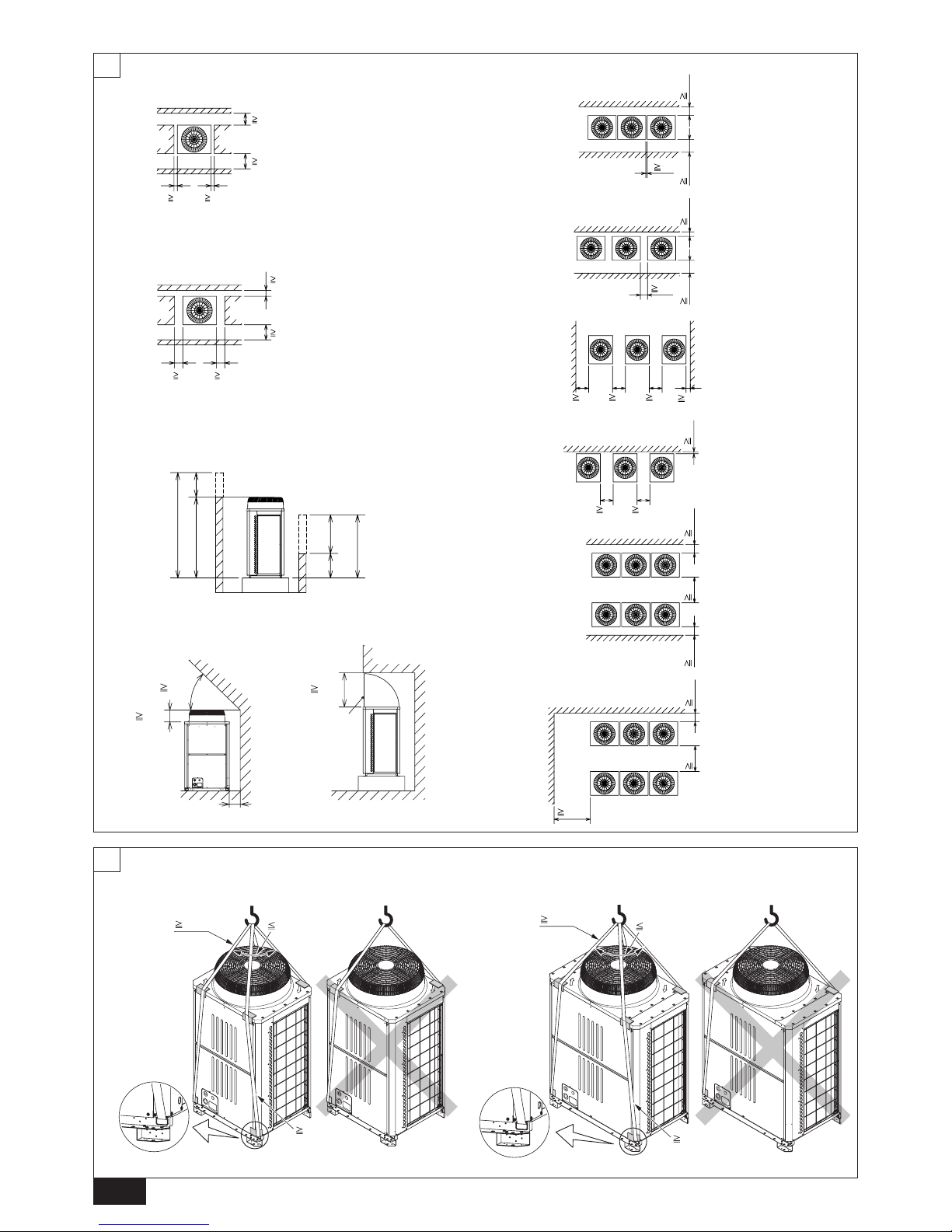
(mm)
6
[Fig. 6.0.1]
(2)
(1)
(3)
(4)
[Fig. 6.0.2]
<A> : Top view
<B> : Side view
<C> : When there is little space up to an obstruction
A : Front
B : Unit height
C : Back
D : Air outlet guide (Procured at the site)
A : Front
B : Must be open
C : Wall height (H)
15
*
15
*
450
*
300
*
<A>
A
100
*
450
*
50
*
50
*
<A>
A
A
B
<B>
500
H
h
h
H
240
45°
A
D
C
50
<C>
1000
30
450
*
300
*
C
B B
C
A
100
450
*
100
*
B B
C
C
A
450
*
100*
C C
B
A
A
A
B
450 450
15
*
C
AAA
450 450
900
300
*
300
*
B B
C
C
A
1000
*
900 300
*
B
B
C
A
(mm)
[Fig. 7.0.1]
1 P200 ~ P300
EP200
7
2 P350 ~ P400
EP250 ~ EP300
8m
8m
40°
8m
40°
8m
3
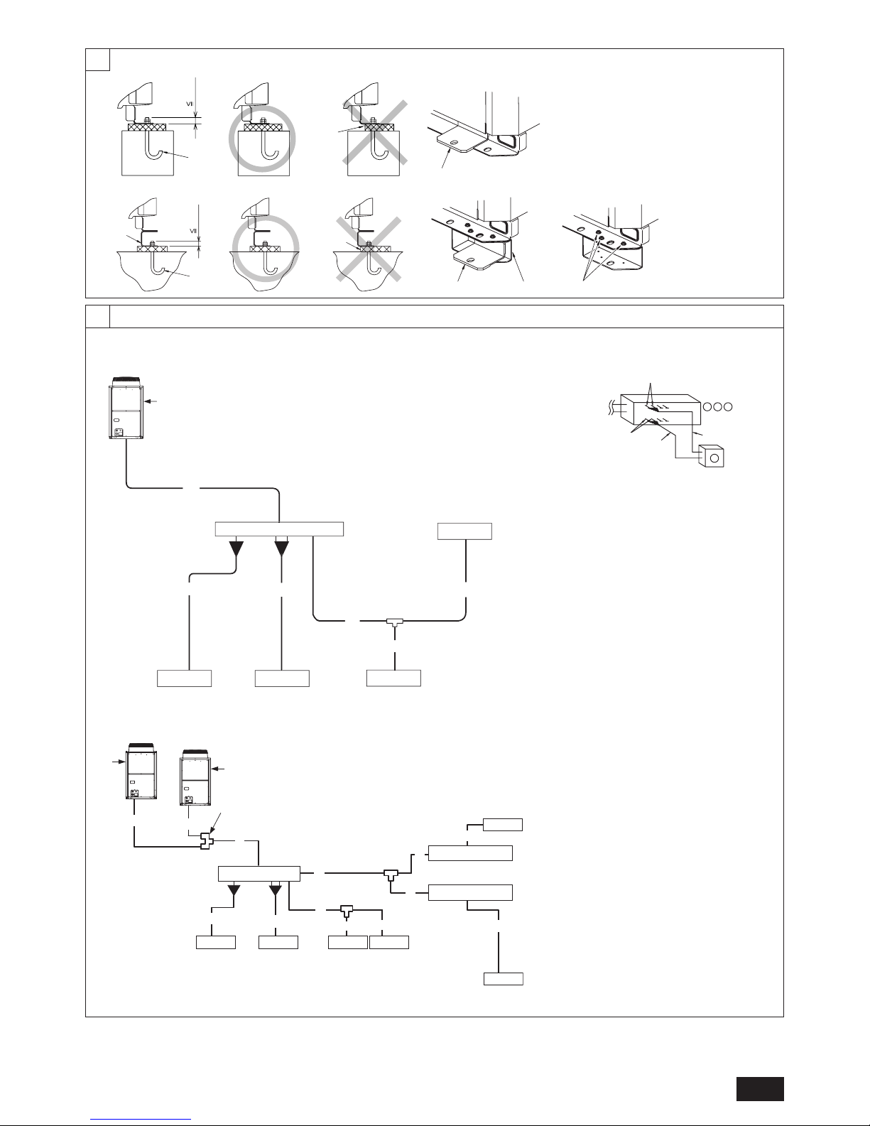
8
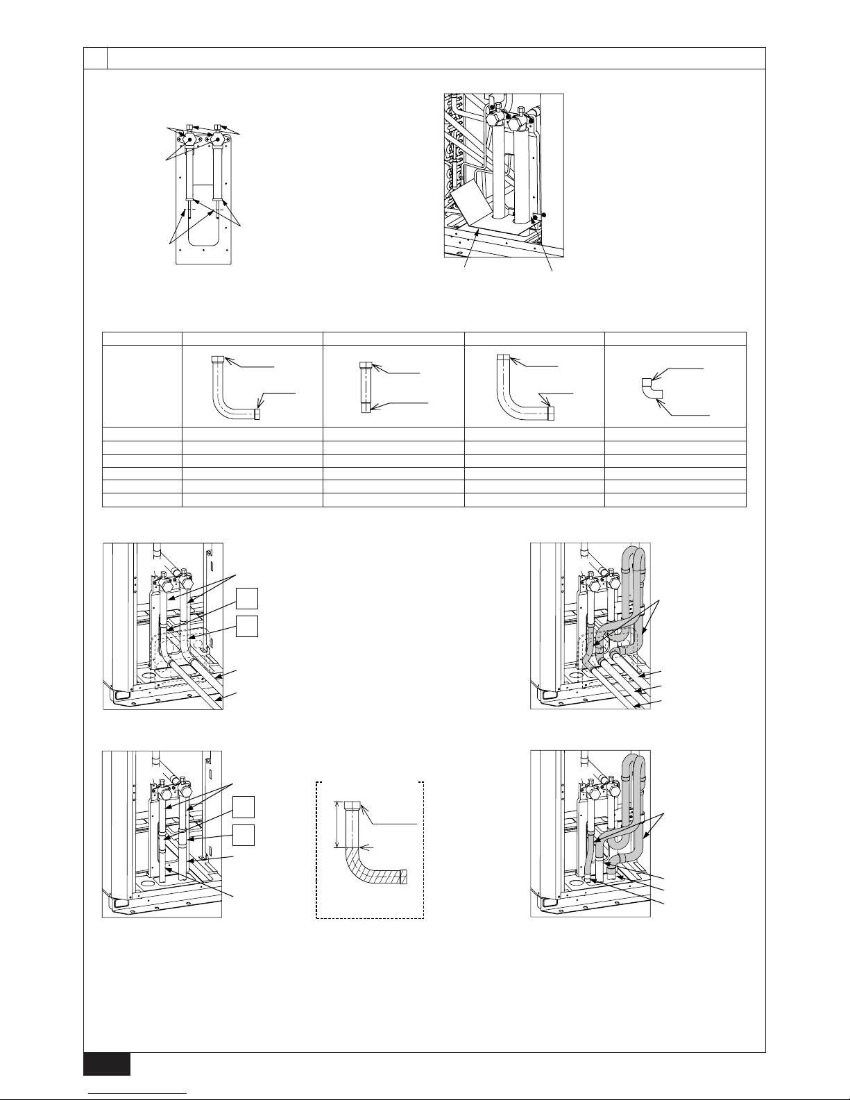
[Fig. 8.1.1]
<A> Without detachable leg A : M10 anchor bolt procured at the site.
B : Corner is not seated.
C : Fixing bracket for hole-in anchor bolt (3 locations to fix
with screws).
D : Detachable leg
30mm
A
B
C
A
[Fig. 8.1.2]
A : Screws
30mm
A
D
B
C D
<B> With detachable leg
9
9.2
[Fig. 9.2.1]
[P200 ~ P400]
[EP200 ~ EP300]
[P450 ~ P800]
[EP400 ~ EP600]
a
C
b
B
c d
f
D
E
A
e
A1
unit1
unit2
A2
A
G
C
E E E
D
E
D
E
F
A
*
NOTE1
a
b
c
d
A
B C
EFE
E
(*Note1)
E
B C D
g
i
j
h
A : Outdoor unit
B : BC controller (standard)
C : BC controller (main)
D : BC controller (sub)
E : Indoor unit (15 ~ 80)
F : Indoor unit (100 ~ 250)
G: Outdoor twinning kit
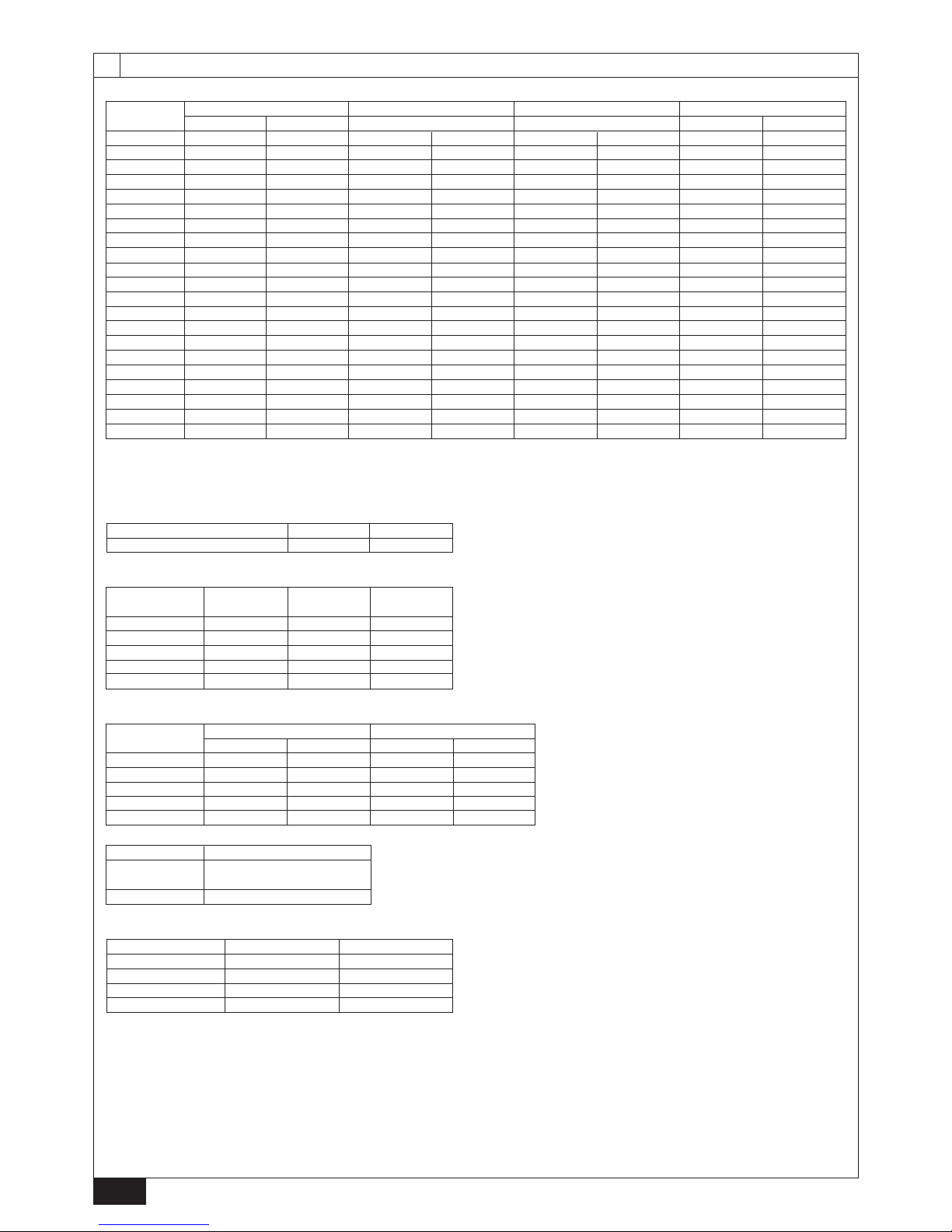
4
*1 The pipe sizes listed in columns A1 to A2 in this table correspond to the
sizes for the models listed in the unit 1 and 2 columns. When the order of
unit 1 and 2 is changed, make sure to use the appropriate pipe size for the
model.
B (mm)
A2 *1
Î Total capacity of indoor units
~ 80
‰ Liquid pipe
ø9.52
Ï Gas pipe
ø15.88
a, b, c, d, e, f (mm)
Ô Model number
15,20,25,32,40,50
63,71,80,100,125,140
200
250
‰ Liquid pipe
ø6.35
ø9.52
ø9.52
ø9.52
Ï Gas pipe
ø12.7
ø15.88
ø19.05
ø22.2
C, D (mm)
Downstream
unit model total
~ 200
201 ~ 300
301 ~ 350
351 ~ 400
401 ~ 450
Ì
High-pressure
gas pipe
ø15.88
ø19.05
ø19.05
ø22.2
ø22.2
Ó
Low-pressure
gas pipe
ø19.05
ø22.2
ø28.58
ø28.58
ø28.58
È Liquid pipe
ø9.52
ø9.52
ø12.7
ø12.7
ø15.88
A [Standard] (mm)
9.2
9
g, h, i, j (mm)
Ô Model number
100
125
140
200
250
g
ø9.52
ø9.52
ø9.52
ø9.52
ø9.52
h
ø9.52
ø9.52
ø9.52
ø9.52
ø9.52
i
ø15.88
ø15.88
ø15.88
ø19.05
ø22.2
j
ø15.88
ø15.88
ø15.88
ø15.88
ø15.88
‰ Liquid pipe Ï Gas pipe
Å Outdoor model
P450 ~ P650
EP400 ~ EP600
P700 ~ P800
Outdoor twinning kit
CMY-R100VBK
CMY-R200VBK
Å Outdoor model
P200
P250
P300
P350
P400
P450
P500
P550
P600
P650
P700
P750
P800
EP200
EP250
EP300
EP400
EP450
EP500
EP550
EP600
ı
High-pressure side
ø15.88
ø19.05
ø19.05
ø19.05
ø22.2
ø22.2
ø22.2
ø28.58
ø28.58
ø28.58
ø28.58
ø28.58
ø28.58
ø15.88
ø19.05
ø19.05
ø22.2
ø22.2
ø22.2
ø28.58
ø28.58
Ç
Low-
pressure side
ø19.05
ø22.2
ø22.2
ø28.58
ø28.58
ø28.58
ø28.58
ø28.58
ø28.58
ø28.58
ø34.93
ø34.93
ø34.93
ø19.05
ø22.2
ø22.2
ø28.58
ø28.58
ø28.58
ø28.58
ø28.58
ı
High-pressure side
-
-
-
-
ø19.05
ø19.05
ø19.05
ø19.05
ø19.05
ø22.2
ø22.2
ø22.2
-
-
ø15.88
ø19.05
ø19.05
ø19.05
ø19.05
Ç
Low-
pressure side
-
-
-
-
ø22.2
ø22.2
ø22.2
ø22.2
ø28.58
ø28.58
ø28.58
ø28.58
-
-
-
ø19.05
ø22.2
ø22.2
ø22.2
ø22.2
ı
High-pressure side
-
-
-
-
ø15.88
ø19.05
ø19.05
ø19.05
ø19.05
ø19.05
ø19.05
ø22.2
-
-
ø15.88
ø15.88
ø15.88
ø19.05
ø19.05
Ç
Low-
pressure side
-
-
-
-
-
ø19.05
ø22.2
ø22.2
ø22.2
ø22.2
ø22.2
ø28.58
ø28.58
-
-
ø19.05
ø19.05
ø19.05
ø22.2
ø22.2
Unit combination A A1 *1
Unit 1
-
-
-
-
P250
P250
P300
P300
P350
P400
P400
P400
-
-
-
EP200
EP250
EP300
EP300
EP300
Unit 2
-
-
-
-
P200
P250
P250
P300
P300
P300
P350
P400
-
-
-
EP200
EP200
EP200
EP250
EP300
5
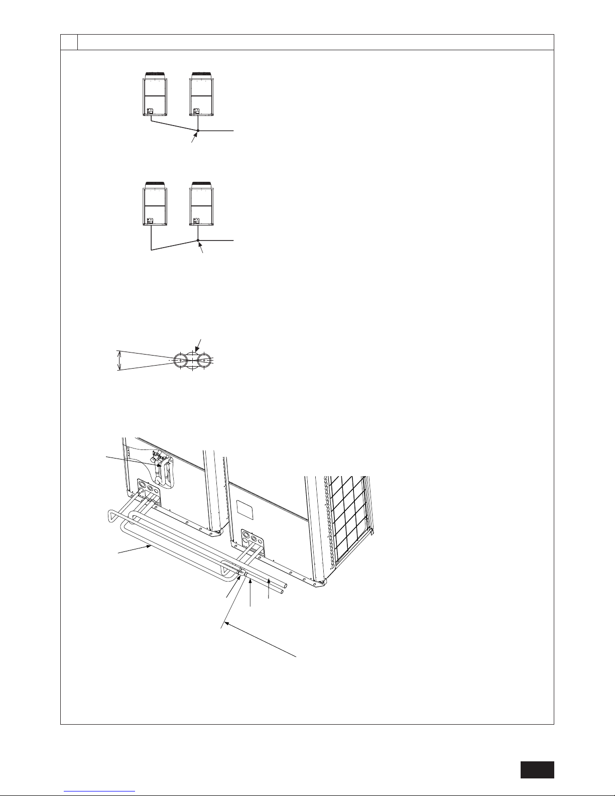
9.2
9
[Fig. 9.2.2]
A
C
D
B
C
D
<A> The piping from the outdoor units to twinning pipe must be made to slope
downwards the twinning pipe. (high-pressure side only)
<B> Slope of twinning pipe (high pressure side only)
±15°
D
E
<C> Pipe connection example
F
H
G
J
K
I
A : Downward slope
B : Upward slope
C : BC controller (standard or main)
D : Twinning pipe
E :
Slope of the
twinning
pipe is at an angle within ±15° to the gro
und
F : Twinning pipe (low-pressure side)
G : Twinning pipe (high-pressure side)
H : On-site piping (low-pressure connecting pipe: between outdoor units)
I : On-site piping (low-pressure main pipe: to BC controller)
J : On-site piping (high-pressure main pipe: to BC controller)
K: Straight run of pipe that is 500 mm or more
6
10.2
10
[Fig. 10.2.1]
A
C
B
E
D
[Fig. 10.2.3]
A
B
A : Example of closure materials (field supply)
B : Fill the gap at the site
No.
A Shape
A : Shaft
B : Service port
C : Cap
D : Pinched connecting pipe severing portion
E : Pinched connecting pipe brazing portion
<A> Front pipe routing <B> Bottom pipe routing <C> Low-pressure side
<D> High-pressure side <E> Severing portion referral figure
A Shape B When not attaching a low-pressure twinning pipe C When attaching a low-pressure twinning pipe
D Refrigerant service valve piping E On-site piping (low-pressure connecting pipe) F On-site piping (high-pressure connecting pipe)
G Twinning kit (sold separately)
H On-site piping (low-pressure connecting pipe: to BC controller)
I On-site piping (low-pressure connecting pipe: to outdoor unit)
J 75 mm (reference measurement) K ID ø25.4 side L Severing portion
*1 For the attachment of the Twinning pipe (sold separately), refer to the instructions included in the kit.
*2 Connection pipe is not used when the Twinning kit is attached.
*3 Use a pipe cutter to sever.
* When not attaching a low-pressure twinning pipe.
[Fig. 10.2.2]
ø22.2
ID ø25.4
ID ø22.2
OD ø19.05
ø22.2
ID ø25.4
ID ø28.58
ø28.58
ID ø25.4
ID ø19.05
OD ø19.05
F
E
<C>
<D>
D
A
B
G
H
I
F
<C>
<D>
<A> Front pipe routing
B When not attaching a low-pressure twinning pipe
C When attaching a low-pressure twinning pipe *1,*2
D
E
F
<C>
<D>
C
D
*3
K
L
J
F
H
I
G
<C>
<D>
B When not attaching a low-pressure twinning pipe C When attaching a low-pressure twinning pipe *1,*2
1 2 3 4
1 <C> Low-pressure side
1 <C> Low-pressure side
1 <C> Low-pressure side
1 <C> Low-pressure side
-
1 <D> High-pressure side
-
1 <D> High-pressure side
1 <D> High-pressure side
1 <D> High-pressure side
-
-
-
-
1 <C> Low-pressure side
1 <C> Low-pressure side
-
1 <D> High-pressure side
1 <D> High-pressure side
1 <D> High-pressure side
-
<E> Severing portion
referral figure
<B> Bottom pipe routing
<B> Refrigerant service valve
(Low-pressure side/brazed type)
<A> Refrigerant service valve
(High-pressure side/brazed type)
P250
EP250
P300
EP300
P350
P400
7
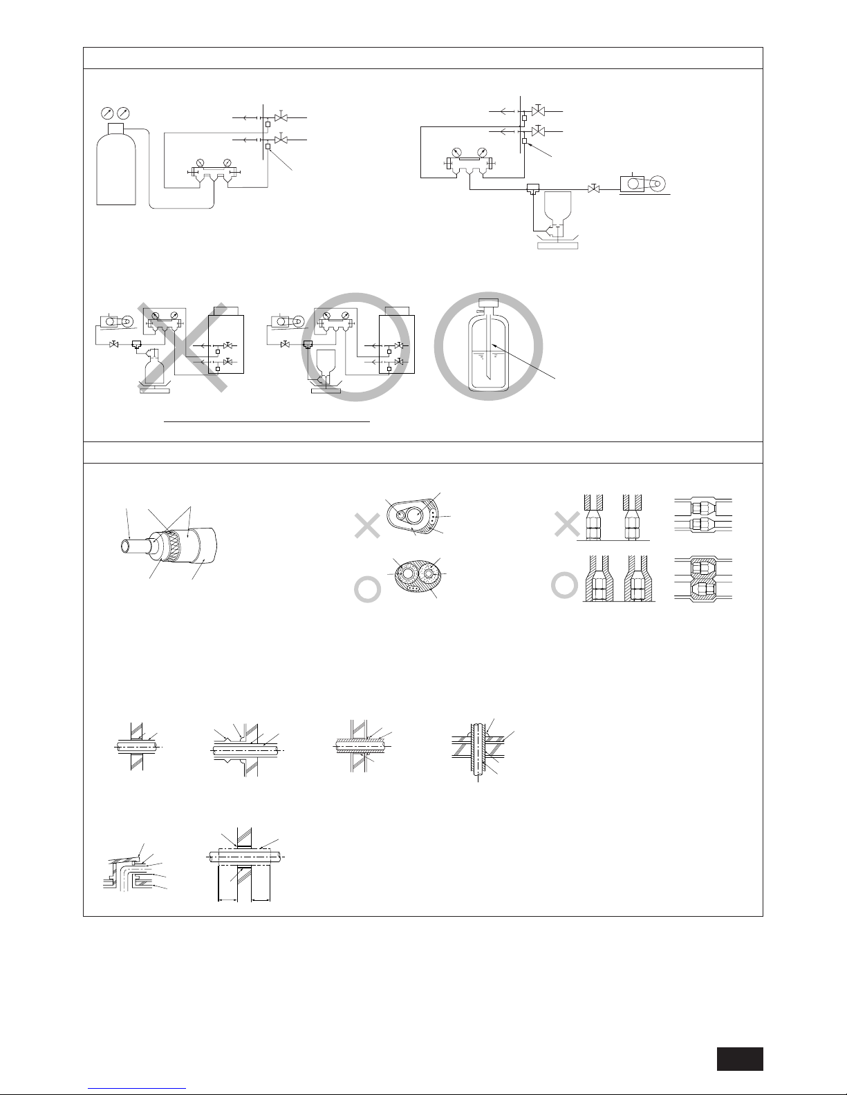
[Fig. 10.3.1]
[Fig. 10.3.3]
10.3
A
A : Nitrogen gas
B : To indoor unit
C : System analyzer
D : Low knob
E : Hi knob
F : Valve
G : Low-pressure pipe
H : High-pressure pipe
I : Outdoor unit
J : Service port
A : System analyzer
B : Low knob
C : Hi knob
D : Valve
E : Low-pressure pipe
F : High-pressure pipe
G : Service port
H : Three-way joint
I : Valve
J : Valve
K : R410A cylinder
L : Scale
M : Vacuum pump
N : To indoor unit
O : Outdoor unit
A : Syphon pipe
D
C
C
B
B
E
F
G
H
I
J
A
LOW
HI
10.4
[Fig. 10.4.4]
[Fig. 10.4.3][Fig. 10.4.2]
C
A
B
D
E
[Fig. 10.4.1]
B
A
D
C
E
E
E
D
A
B
A B
<A> Inner wall (concealed)
A B
D
C
<B> Outer wall
A : Steel wire B : Piping
C : Asphaltic oily mastic or asphalt
D : Heat insulation material A
E : Outer covering B
A : High-pressure pipe B : Low-pressure pipe
C : Electric wire D : Finishing tape
E : Insulator
D
F
G
B
<D> Floor (waterproofing)
E
A
B
<C> Outer wall (exposed)
F
H
D
B
G
<E> Roof pipe shaft
I
A
J
1m1m
<F> Penetrating portion on fire
limit and boundary wall
A : Sleeve B : Heat insulating material
C : Lagging D : Caulking material
E : Band F : Waterproofing layer
G : Sleeve with edge H : Lagging material
I : Mortar or other incombustible caulking
J : Incombustible heat insulation material
B In case of the R410A cylinder having no syphon pipe.
[Fig. 10.3.2]
LOW
HI
B
A
K
J
L
H
M
C
D
EN
N
O
F
G
I
 Loading...