

Page 1

Air-Conditioners For Building Application
OUTDOOR UNIT
PURY-P-YGM-A
For use with R410A
INSTALLATION MANUAL
For safe and correct use, please read this installation manual thoroughly before installing the air-conditioner unit.
INSTALLATIONSHANDBUCH
Zum sicheren und ordnungsgemäßen Gebrauch der Klimageräte das Installationshandbuch gründlich durchlesen.
MANUEL D’INSTALLATION
Veuillez lire le manuel d’installation en entier avant d’installer ce climatiseur pour éviter tout accident et vous assurer d’une utilisation correcte.
MANUAL DE INSTALACIÓN
Para un uso seguro y correcto, lea detalladamente este manual de instalación antes de montar la unidad de aire acondicionado.
MANUALE DI INSTALLAZIONE
Per un uso sicuro e corretto, leggere attentamente questo manuale di installazione prima di installare il condizionatore d’aria.
INSTALLATIEHANDLEIDING
Voor een veilig en juist gebruik moet u deze installatiehandleiding grondig doorlezen voordat u de airconditioner installeert.
MANUAL DE INSTALAÇÃO
Para segurança e utilização correctas, leia atentamente este manual de instalação antes de instalar a unidade de ar condicionado.
GB
D
F
E
I
NL
P
E°XEIPI¢IO O¢H°IøN E°KATA™TA™H™
°И· ·ЫК¿ПВИ· О·И ЫˆЫЩ‹ ¯Ъ‹ЫЛ, ·Ъ·О·ПВ›ЫЩВ ‰И·‚¿ЫВЩВ ЪФЫВ¯ЩИО¿ ·˘Щfi ЩФ ВБ¯ВИЪ›‰ИФ ВБО·Щ¿ЫЩ·ЫЛ˜ ЪИУ ·Ъ¯›ЫВЩВ ЩЛУ
ВБО·Щ¿ЫЩ·ЫЛ ЩЛ˜ МФУ¿‰·˜ ОПИМ·ЩИЫМФ‡.
РУКОВОДСТВО ПО УСТАНОВКЕ
Для осторожного и правильного использования прибора необходимо тщательно ознакомиться с данным руководством по
установке до выполнения установки кондиционера.
MONTAJ ELK‹TABI
Emniyetli ve do¤ru biçimde nas›l kullan›laca¤›n› ö¤renmek için lütfen klima cihaz›n› monte etmeden önce bu elkitab›n› dikkatle okuyunuz.
GR
RU
TR
CZ
SV
SL
HG
PO
Page 2
5
AAFA
L
1
=
>
L
1
=
>
[Fig. 5.0.1]
(1)
<A>
>
L
=
>
L
=
A
<A> : Top view
2
<B> : Side view
<C> : When there is little space up to an obstruction
A : Front
B : No restrictions on wall height (left and right)
1
C : Air outlet guide (Procured at the site)
(5)
E
D
>
1000
=
E
AAAAA
D
>
L2*
=
D
AA
>
E
L1*
=
E
<B>(2)
>
>
>
>
L1*
L1
=
=
>
45°
=
>
1000
>
300
=
=
<C>
L1
=
D
E
>
L1
=
L1
=
>
L2*
=
>
L2
=
C
>
DD
AA
900
=
6
[Fig. 6.0.1]
1 P200 ~ P400
(3)
(4)
>
L2
<A>
<B>
>
L
1
=
>
L
2
=
h
E
>
1000
=
=
E
>
L
2
=
H
A
>
A
L
1
=
B
H’
A
>
=
1000
D
>
=
1000
>
2
L
=
D
>
A
900
=
<A> <B>
>
L
1
=
>
L
2
=
A
>
L
1
=
650
Hh
A
<
40°
=
>
L
2
=
D : Must be open
E : Wall height (H)
h
325
H
F : No restrictions on wall height
(mm)
L1 L2
450 450
2 P450 ~ P650
<
40°
=
7
[Fig. 7.1.1]
2
<
8m
=
<
8m
=
<
8m
=
<
8m
=
B
A : M10 anchor bolt procured at the site.
A
B : Corner is not seated.
Page 3
8
A
B
1
3
[Fig. 8.2.1]
A : BC controller (standard)
B : BC controller (master)
C : BC controller (slave)
D : indoor unit (20 ~ 140)
E : indoor unit (200, 250)
8.2
A (mm)
(*Note1)
A
A
g
A
BC
i
h
f
E
Å Outdoor model
P200
P250
P300
P350
P400
P450
P500
P550
P600
P650
Î Total capacity of indoor units
~ 140
141 ~ 200
D
No.1
a
b
D
No.2
(*Note1)
B
c
D
No.3
d
D
No.4
e
D
No.5
B (mm)
C, D (mm)
C
D
k
j
A
B
C
C
D
D
No.7 No.8
~ 200
201 ~ 300
301 ~ 350
a, b, c, d, e, j, k (mm)
Ô Model number
20,25,32,40,50
a
D
No.1
No.2
b
B
D
c
D
No.3
d
D
No.4
e
D
No.5
f
D
No.6
(*Note1)
63,71,80,100,125,140
200
250
f, g, h, i (mm)
Ô Model number
200
250
ı High press. Side
ø15.88
ø19.05
ø19.05
ø19.05
ø22.2
ø22.2
ø22.2
ø28.58
ø28.58
ø28.58
‰ Liquid line
ø9.52
ø9.52
Ì High press.
gas pipe
ø15.88
ø19.05
ø19.05
Ó Low press.
gas pipe
ø19.05
ø22.2
ø28.58
‰ Liquid line
ø6.35
ø9.52
ø9.52
ø9.52
‰ Liquid line Ï Gas line
f
ø9.52
ø9.52
g
ø9.52
ø9.52
Ç Low press. Side
ø19.05
ø22.2
ø22.2
ø28.58
ø28.58
ø28.58
ø28.58
ø28.58
ø28.58
ø28.58
Ï Gas line
ø15.88
ø19.05
¬ Liquid pipe
ø9.52
ø12.7
ø12.7
Ï Gas line
ø12.7
ø15.88
ø19.05
ø22.2
h
ø19.05
ø22.2
ø15.88
ø15.88
i
9
[Fig. 9.2.1]
[Fig. 9.2.3]
A : Close-packed packing
B : Hollow packing
9.2
[Fig. 9.2.2]
<A> [Ball valve (Low press. side/flanged type)] <B> [Ball valve
<D> This figure shows the valve
in the fully open state.
E E
SO SO
A
C
J
A: Valve stem
B: Stopper pin
C: Packing (Accessory)
D: Connecting pipe (Accessory)
E: Open (Operate slowly)
F: Cap
G: Service port
H: Flare nut
(High press. side/flared type)]
B
OS
D
I
K
E
G
F
D
H
I: ø15.88 (PURY-P200)
ø19.05 (PURY-P250 ~ P350)
J: ø19.05 (PURY-P200)
ø22.2 (PURY-P250, P300)
ø28.58(PURY-P350 ~ P650)
K: Field piping
L: ø22.2 (PURY-P400 ~ P500)
ø28.58 (PURY-P550 ~ P650)
<C> [Ball valve
(High press. side/flanged type)]
C
L
K
B
A
F
3
Page 4
C
A
B
D
E
9.3
[Fig. 9.3.1]
A
C
[Fig. 9.3.3]
F
B
B
C
LO
D
B In case of the cylinder having no syphon pipe.
HI
E
G
H
I
J
A : Nitrogen gas
B : To indoor unit
C : System analyzer
D : Lo knob
E : Hi knob
F : Ball valve
G : Low press. pipe
H : High press. pipe
I : Outdoor unit
J : Service port
[Fig. 9.3.2]
9.4
D
EN
F
A
LO
B
HI
C
O
G
H
I
K
J
L
A
A : Syphon pipe
M
A : System analyzer
B : Lo knob
C : Hi knob
D : Ball valve
E : Low press. pipe
F : High press. pipe
G : Service port
H : Three-way joint
I : Valve
J : Valve
K : R410A cylinder
L : Scale
M : Vacuum pump
N : To indoor unit
O : Outdoor unit
[Fig. 9.4.1]
A : Steel wire B : Piping
C : Asphaltic oily mastic or asphalt
D : Heat insulation material A
E : Outer covering B
[Fig. 9.4.4]
<A> Inner wall (concealed)
A B
A : Sleeve B : Heat insulating material
C : Lagging D : Caulking material
E : Band F : Waterproofing laye
G : Sleeve with edge H : Lagging material
I : Mortar or other incombustible caulking
J : Incombustible heat insulation material
<B> Outer wall
D
C
A B
A
B
C
D
E
E
B
E
A
D
A : High press. pipe B : Low press. pipe
C : Electric wire D : Finishing tape
E : Insulator
<C> Outer wall (exposed)
E
<D> Floor (waterproofing)
B
I
[Fig. 9.4.3][Fig. 9.4.2]
<E> Roof pipe shaft
D
F
G
<F> Penetrating portion on fire
limit and boundary wall
D
I
J
B
G
B
H
F
A
1m1m
10
10.2
[Fig. 10.2.1]
A : Power source
L1 L2 L3 N M1M2 M1M2 S
TB1
TB3 TB7
B : Transmission line
C : Earth screw
ABC
4
Page 5
M1 M2
TB3
RC
N
1
N
2
IC
M1M2 S
TB5
IC
M1M2 S
TB5
RP
AB
ABAB
S
TB2
ABS
TB3
Ground
L
4
r
1
OC
L
7
r
1
BC
M1M2 S
RC
IC
M1M2 S
TB5
IC
M1M2 S
TB5
L
6
L
5
L
3
L
2
L
1
L
8
10.3
[Fig. 10.3.1]
<A> Change the jumper connector
from CN41 to CN40
<B> SW2-1:ON
<C> Keep the jumper connector on
CN41
<B> SW2-1:ON
[Fig. 10.3.2]
<A> Change the jumper connector
from CN41 to CN40
<B> SW2-1:ON
<C> Keep the jumper connector on
CN41
<B> SW2-1:ON
A : Group 1
B : Group 4
C : Group 5
D : Shielded wire
E : Sub remote
controller
( ): Address
L1
M1 M2 S
(105)
RC
M1 M2 S
C
IC
(05)
TB5
r3
IC
(07)
TB5
(155)
IC
(06)
TB5
M1 M2 S
RC
E
OC
CN40
M1 M2 S
(51)
TB3
M1 M2
TB7
(52)
M1 M2 S
BC
r1
D
L2
OC
CN40
(53)
TB3
M1 M2
M1 M2 S
TB7
System
L6
controller
M1M2S
(54)
M1 M2 S
L3
BC
A
IC
(01)
TB5
M1 M2 S
AB AB AB
(101)
RC
IC
(03)
TB5
M1 M2 S
IC
M1 M2 S
(02)
TB5
M1 M2 S
BS
(55)
r2
L4
IC
(04)
TB5
M1 M2 S
L5
r4
AB
(104)
RC
B
L1
M1 M2 S
M1 M2 S
TB5
TB5
IC
(05)
TB15
12
ABABAB
MAMAMA
IC
(07)
TB15
12
C
IC
(06)
TB15
TB5
12
M1 M2 S
c1
c4
c3
E
OC
CN40
(51)
TB3
M1 M2
M1 M2 S
TB7
D
L2
OC
CN40
(53)
TB3
M1 M2
M1 M2 S
TB7
System
L6
controller
M1M2
S
M1 M2 S
(54)
M1 M2 S
BC
(52)
L3
BC
A
(01)
TB5 TB15
M1 M2 1 2S
(03)
TB5
M1 M2 S
IC
c3
MA
IC
TB15
12
IC
c2 c2
(02)
TB15
TB5
12
M1 M2 S
c1
L4
IC
(04)
TB5
TB15
M1 M2 S
12
c1
AB
(55)
M1 M2 S
BS
B
[Fig. 10.3.3]
10.4
F
F
A
3 N~380 - 415 V
1
, L2, L3, N, PE
L
~220 - 240 V
L, N, PE
[Fig. 10.4.1]
A : Switch (breakers for wiring and cur-
rent leakage)
B : Outdoor unit
C : BC controller (master)
'
C
: BC controller (slave)
D : Pull box
E : Indoor unit
F : Breakers for current leakage
A
B
C C
E E
D
E E
'
5
Page 6
Contents
1. Safety precautions ...................................................................................... 6
1.1. Before installation and electric work .......................................... 6
1.2. Precautions for devices that use R410A refrigerant .................. 6
1.3. Before installation ...................................................................... 7
1.4. Before installation - electrical work ............................................ 7
1.5. Before starting the test run ........................................................ 7
2. About the product ....................................................................................... 7
3. Specifications .............................................................................................. 8
4. Confirmation of parts attached ................................................................... 8
5. Space required around unit ........................................................................ 8
6. Lifting method ............................................................................................. 8
7. Installation of unit ........................................................................................ 9
7.1. Installation ................................................................................. 9
8. Refrigerant piping installation ..................................................................... 9
8.1. Caution ...................................................................................... 9
8.2. Refrigerant piping system .......................................................... 9
1. Safety precautions
1.1. Before installation and electric work
GBDFEINLPGRRUTRCZSVSLHGPO
s Before installing the unit, make sure you read all the “Safety
precautions”.
s The “Safety precautions” provide very important points re-
garding safety. Make sure you follow them.
Symbols used in the text
Warning:
Describes precautions that should be observed to prevent danger of injury
or death to the user.
Caution:
Describes precautions that should be observed to prevent damage to the
unit.
Symbols used in the illustrations
: Indicates an action that must be avoided.
: Indicates that important instructions must be followed.
: Indicates a part which must be grounded.
: Beware of electric shock. (This symbol is displayed on the main unit label.)
Warning:
Carefully read the labels affixed to the main unit.
Warning:
• Ask the dealer or an authorized technician to install the air conditioner.
- Improper installation by the user may result in water leakage, electric shock,
or fire.
• Install the unit at a place that can withstand its weight.
- Inadequate strength may cause the unit to fall down, resulting in injuries.
• Use the specified cables for wiring. Make the connections securely so
that the outside force of the cable is not applied to the terminals.
- Inadequate connection and fastening may generate heat and cause a fire.
• Prepare for strong winds and earthquakes and install the unit at the specified place.
- Improper installation may cause the unit to topple and result in injury.
• Always use an filter and other accessories specified by Mitsubishi Electric.
- Ask an authorized technician to install the accessories. Improper installation
by the user may result in water leakage, electric shock, or fire.
• Never repair the unit. If the air conditioner must be repaired, consult the
dealer.
- If the unit is repaired improperly, water leakage, electric shock, or fire may
result.
• Do not touch the heat exchanger fins.
- Improper handling may result in injury.
• If refrigerant gas leaks during installation work, ventilate the room.
- If the refrigerant gas comes into contact with a flame, poisonous gases will
be released.
• Install the air conditioner according to this Installation Manual.
- If the unit is installed improperly, water leakage, electric shock, or fire may
result.
9. Additional refrigerant charge ..................................................................... 10
9.1. Calculation of additional refrigerant charge ............................. 10
9.2. Precautions concerning piping connection and valve
operation ................................................................................. 10
9.3. Airtight test, evacuation, and refrigerant charging ................... 11
9.4. Thermal insulation of refrigerant piping ................................... 12
10. Wiring ........................................................................................................ 12
10.1. Caution .................................................................................... 12
10.2. Control box and connecting position of wiring ......................... 12
10.3. Wiring transmission cables ...................................................... 12
10.4. Wiring of main power supply and equipment capacity ............ 14
11. Test run ..................................................................................................... 14
11.1. The following phenomena do not represent trouble
(emergency) ............................................................................ 14
12. Information on rating plate ........................................................................ 15
• Have all electric work done by a licensed electrician according to “Electric Facility Engineering Standard” and “Interior Wire Regulations”and
the instructions given in this manual and always use a special circuit.
- If the power source capacity is inadequate or electric work is performed im-
properly, electric shock and fire may result.
• Securely install the outdoor unit terminal cover (panel).
- If the terminal cover (panel) is not installed properly, dust or water may enter
the outdoor unit and fire or electric shock may result.
• When installing and moving the air conditioner to another site, do not
charge it with a refrigerant different from the refrigerant specified on the
unit.
- If a different refrigerant or air is mixed with the original refrigerant, the refrig-
erant cycle may malfunction and the unit may be damaged.
• If the air conditioner is installed in a small room, measures must be taken
to prevent the refrigerant concentration from exceeding the safety limit if
the refrigerant should leak.
- Consult the dealer regarding the appropriate measures to prevent the safety
limit from being exceeded. Should the refrigerant leak and cause the safety
limit to be exceeded, hazards due to lack of oxygen in the room could result.
• When moving and reinstalling the air conditioner, consult the dealer or
an authorized technician.
- If the air conditioner is installed improperly, water leakage, electric shock, or
fire may result.
• After completing installation work, make sure that refrigerant gas is not
leaking.
- If the refrigerant gas leaks and is exposed to a fan heater, stove, oven, or
other heat source, it may generate noxious gases.
• Do not reconstruct or change the settings of the protection devices.
- If the pressure switch, thermal switch, or other protection device is shorted
and operated forcibly, or parts other than those specified by Mitsubishi Electric are used, fire or explosion may result.
• To dispose of this product, consult your dealer.
• The installer and system specialist shall secure safety against leakage
according to local regulation or standards.
- Following standards may be applicable if local regulation are not available.
• Pay special attention to the place of installation, such as a basement, etc.
where refrigeration gas can accumulate, since refrigeration is heavier
than the air.
• With Freshair intake type, the installation site must be carefully chosen
because outdoor air can directly blow into the room when the thermostat
is turned off.
- Direct exposure to outdoor air may have harmful effects on people or food.
1.2. Precautions for devices that use R410A
refrigerant
Caution:
• Do not use existing refrigerant piping.
- The old refrigerant and refrigerator oil in the existing piping contains a large
amount of chlorine which may cause the refrigerator oil of the new unit to
deteriorate.
- R410A is a high-pressure refrigerant and can cause the existing piping to
burst.
• Use refrigerant piping made of phosphorus deoxidized copper and copper alloy seamless pipes and tubes. In addition, be sure that the inner
and outer surfaces of the pipes are clean and free of hazardous sulphur,
oxides, dust/dirt, shaving particles, oils, moisture, or any other contaminant.
- Contaminants on the inside of the refrigerant piping may cause the refriger-
ant residual oil to deteriorate.
6
Page 7
• Store the piping to be used during installation indoors and keep both
ends of the piping sealed until just before brazing. (Store elbows and
other joints in a plastic bag.)
- If dust, dirt, or water enters the refrigerant cycle, deterioration of the oil and
compressor trouble may result.
• Use ester oil, ether oil or alkylbenzene (small amount) as the refrigerator
oil to coat flares and flange connections.
- The refrigerator oil will degrade if it is mixed with a large amount of mineral
oil.
• Use liquid refrigerant to fill the system.
- If gas refrigerant is used to seal the system, the composition of the refriger-
ant in the cylinder will change and performance may drop.
• Do not use a refrigerant other than R410A.
- If another refrigerant (R22, etc.) is mixed with R410A, the chlorine in the
refrigerant may cause the refrigerator oil to deteriorate.
• Use a vacuum pump with a reverse flow check valve.
- The vacuum pump oil may flow back into the refrigerant cycle and cause the
refrigerator oil to deteriorate.
• Do not use the following tools that are used with conventional refrigerants.
(Gauge manifold, charge hose, gas leak detector, reverse flow check valve,
refrigerant charge base, refrigerant recovery equipment)
- If the conventional refrigerant and refrigerator oil are mixed in the R410A,
the refrigerant may deteriorated.
- If water is mixed in the R410A, the refrigerator oil may deteriorate.
- Since R410A does not contain any chlorine, gas leak detectors for conven-
tional refrigerants will not react to it.
• Do not use a charging cylinder.
- Using a charging cylinder may cause the refrigerant to deteriorate.
• Be especially careful when managing the tools.
- If dust, dirt, or water gets into the refrigerant cycle, the refrigerant may dete-
riorate.
1.3. Before installation
Caution:
• Do not install the unit where combustible gas may leak.
- If the gas leaks and accumulates around the unit, an explosion may result.
• Do not use the air conditioner where food, pets, plants, precision instruments, or artwork are kept.
- The quality of the food, etc. may deteriorate.
• Do not use the air conditioner in special environments.
- Oil, steam, sulfuric smoke, etc. can significantly reduce the performance of
the air conditioner or damage its parts.
• When installing the unit in a hospital, communication station, or similar
place, provide sufficient protection against noise.
- Inverter equipment, private power generator, high-frequency medical equip-
ment, or radio communication equipment may cause the air conditioner to
operate erroneously, or fail to operate. On the other hand, the air conditioner
may affect such equipment by creating noise that disturbs medical treatment
or image broadcasting.
• Do not install the unit on a structure that may cause leakage.
- When the room humidity exceeds 80 % or when the drain pipe is clogged,
condensation may drip from the indoor unit. Perform collective drainage work
together with the outdoor unit, as required.
1.4. Before installation - electrical work
Caution:
• Ground the unit.
- Do not connect the ground wire to gas or water pipes, lightning rods, or
telephone ground lines. Improper grounding may result in electric shock.
• The reverse phase of L lines (L1, L2, L3) can detected (Error cord: 4103),
but the reverse phase of L lines and N line can not be detected.
- Some electric parts may be damaged when power is supplied during miss
wiring.
• Install the power cable so that tension is not applied to the cable.
- Tension may cause the cable to break and generate heat and cause a fire.
• Install a leak circuit breaker, as required.
- If a leak circuit breaker is not installed, electric shock may result.
• Use power line cables of sufficient current carrying capacity and rating.
- Cables that are too small may leak, generate heat, and cause a fire.
• Use only a circuit breaker and fuse of the specified capacity.
- A fuse or circuit breaker of a larger capacity, a steel or copper wire may result
in a general unit failure or fire.
• Do not wash the air conditioner units.
- Washing them may cause an electric shock.
• Be careful that the installation base is not damaged by long use.
- If the damage is left uncorrected, the unit may fall and cause personal injury
or property damage.
• Install the drain piping according to this Installation Manual to ensure
proper drainage. Wrap thermal insulation around the pipes to prevent
condensation.
- Improper drain piping may cause water leakage causing damage to furniture
and other possessions.
• Be very careful about transporting the product.
- One person should not carry the product as it weighs more than 20 kg.
- Some products use PP bands for packaging. Do not use any PP bands as a
means of transportation. It is dangerous.
- Do not touch the heat exchanger fins. Doing so may cut your fingers.
- When transporting the outdoor unit, support it at the specified positions on
the unit base. Also support the outdoor unit at four points so that it cannot
slip sideways.
• Safely dispose of the packing materials.
- Packing materials, such as nails and other metal or wooden parts, may cause
stabs or other injuries.
- Tear apart and throw away plastic packaging bags so that children will not
play with them. If children play with a plastic bag which was not torn apart,
they face the risk of suffocation.
1.5. Before starting the test run
Caution:
• Turn on the power at least 12 hours before starting operation.
- Starting operation immediately after turning on the main power switch can
result in irreversible damage to internal parts. Keep the power switch turned
on during the operational season.
• Do not touch the switches with wet fingers.
- Touching a switch with wet fingers can cause electric shock.
• Do not touch the refrigerant pipes during and immediately after operation.
- During and immediately after operation, the refrigerant pipes may be hot or
cold, depending on the condition of the refrigerant flowing through the refrigerant piping, compressor, and other refrigerant cycle parts. Your hands may
suffer burns or frostbite if you touch the refrigerant pipes.
• Do not operate the air conditioner with the panels and guards removed.
- Rotating, hot, or high-voltage parts can cause injuries.
• Do not turn off the power immediately after stopping operation.
- Always wait at least five minutes before turning off the power. Otherwise,
water leakage and trouble may occur.
• Do not touch the surface of the compressor during servicing.
- If unit is connected to the supply and not running, crank case heater at com-
pressor base is operating.
GBDFEINLPGRRUTRCZSVSLHGPO
2. About the product
• This unit uses R410A-type refrigerant
• Piping for systems using R410A may be different from that for systems using
conventional refrigerant because the design pressure in systems using R410A
is higher. Refer to Data Book for more information.
• Some of the tools and equipment used for installation with systems that use
other types of refrigerant cannot be used with the systems using R410A. Refer
to Data Book for more information.
• Do not use the existing piping, as it contains chlorine, which is found in conventional refrigerating machine oil and refrigerant. This chlorine will deteriorate
the refrigerant machine oil in the new equipment. The existing piping must not
be used as the design pressure in systems using R410A is higher than that in
the systems using other types of refrigerant and the existing pipes may burst.
7
Page 8
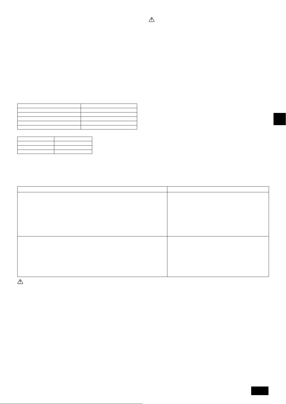
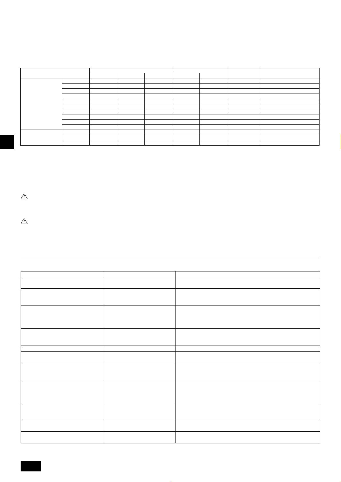
3. Specifications
Model
Noise level (50/60 Hz)
External static pressure
Indoor unit
Operation
temperature
Model
Noise level (50/60 Hz)
External static pressure
Indoor units
Operation
temperature
Total capacity
Model
Quantity
Standard type
Fresh air intake
type
Total capacity
Model
Quantity
Standard type
Fresh air intake
type
PURY-P200
56 dB<A>
1 ~ 15
Cooling mode: – 5 °CDB ~ 43 °CDB (0 °CDB ~ 43 °CDB with outdoor unit at lower position)
Heating mode: – 20 °CWB ~ 15.5 °CWB
Cooling mode: 21 °CDB ~ 43 °CDB
Heating mode: – 12.5 °CWB ~ 20 °CWB
PURY-P450
60/61 dB<A>
1 ~ 24
Cooling mode: – 5 °CDB ~ 43 °CDB (0 °CDB ~ 43 °CDB with outdoor unit at lower position)
Heating mode: – 20 °CWB ~ 15.5 °CWB
Cooling mode: 21 °CDB ~ 43 °CDB
Heating mode: – 12.5 °CWB ~ 20 °CWB
GBDFEINLPGRRUTRCZSVSLHGPO
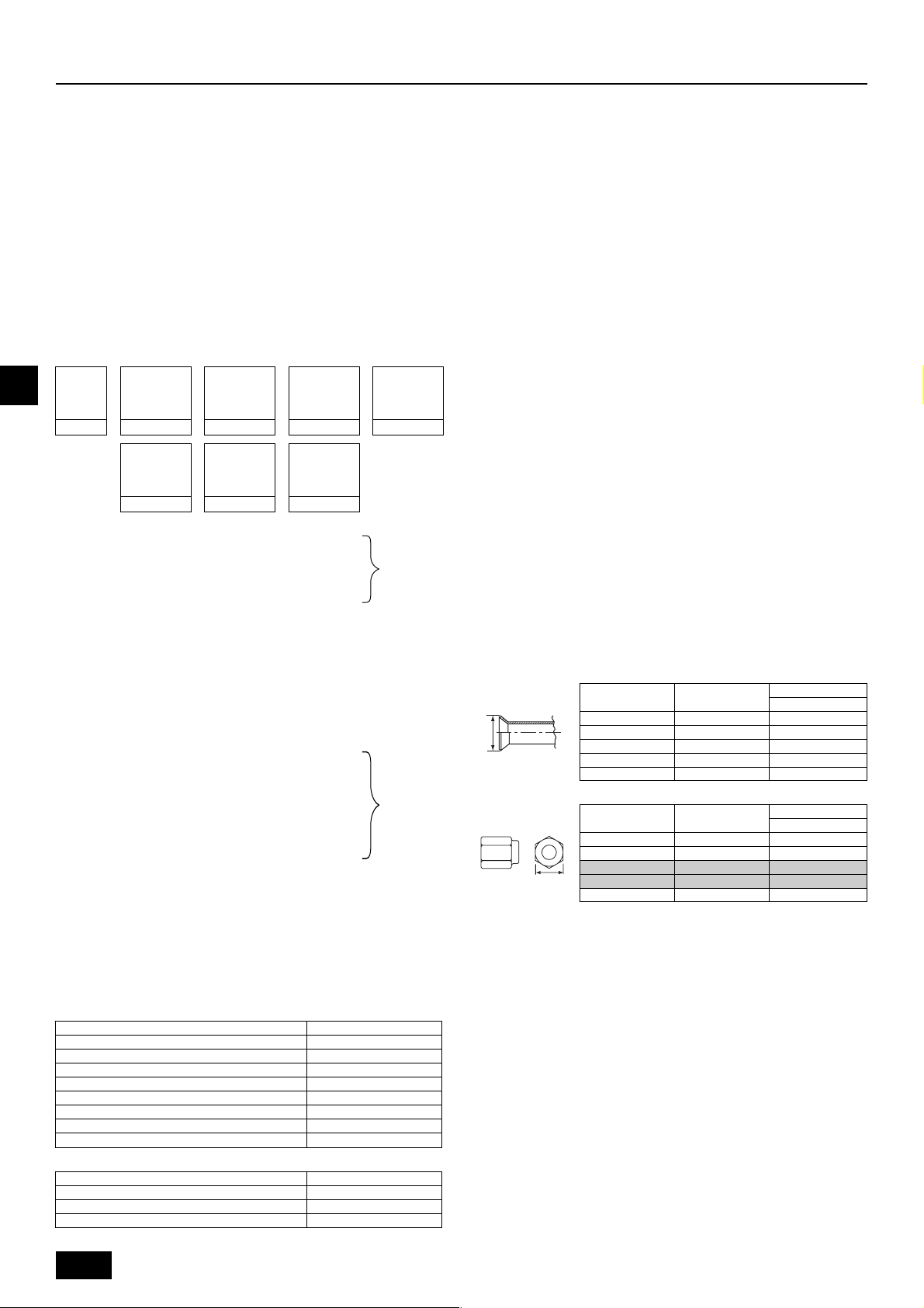
4. Confirmation of parts attached
Model
Model
Model
P200 ~ P350
P400
P450 ~ P650
P200 ~ P350
P400
P450 ~ P650
P200 ~ P350
P400
P450 ~ P650
1 Conduit mounting plate (ø53)
1pc.
1pc.
4 Conduit mounting plate (ø27)
1pc.
-
-
7 Connecting pipe (Low pressure)
1pc.
1pc.
1pc.
PURY-P250
57 dB<A>
1 ~ 16
PURY-P500
60/61 dB<A>
1 ~ 24
2 Conduit mounting plate (ø46)
5 Tappinng screw M4
8 Packing (Low press. pipe)
PURY-P300
59 dB<A>
50 ~150 %
20 ~ 250
PURY-P550
61/62 dB<A>
50 ~150 %
20 ~ 250
1pc.
1pc.
2pcs.
2pcs.
2pcs.
1pc.
1pc.
1pc.
0 Pa
1 ~ 16
0 Pa
1 ~ 24
PURY-P350
60 dB<A>
1 ~ 20
PURY-P600
61/62 dB<A>
1 ~ 32
3 Conduit mounting plate (ø33)
6 Connecting pipe (High pressure)
1pc. (Flare)
2pcs. (Flange)
1pc. (Flange)
9 Packing (High press. pipe)
PURY-P400
61 dB<A>
1 ~ 24
PURY-P650
62/62.5 dB<A>
1 ~ 32
1pc.
-
-
1pc.
1pc.
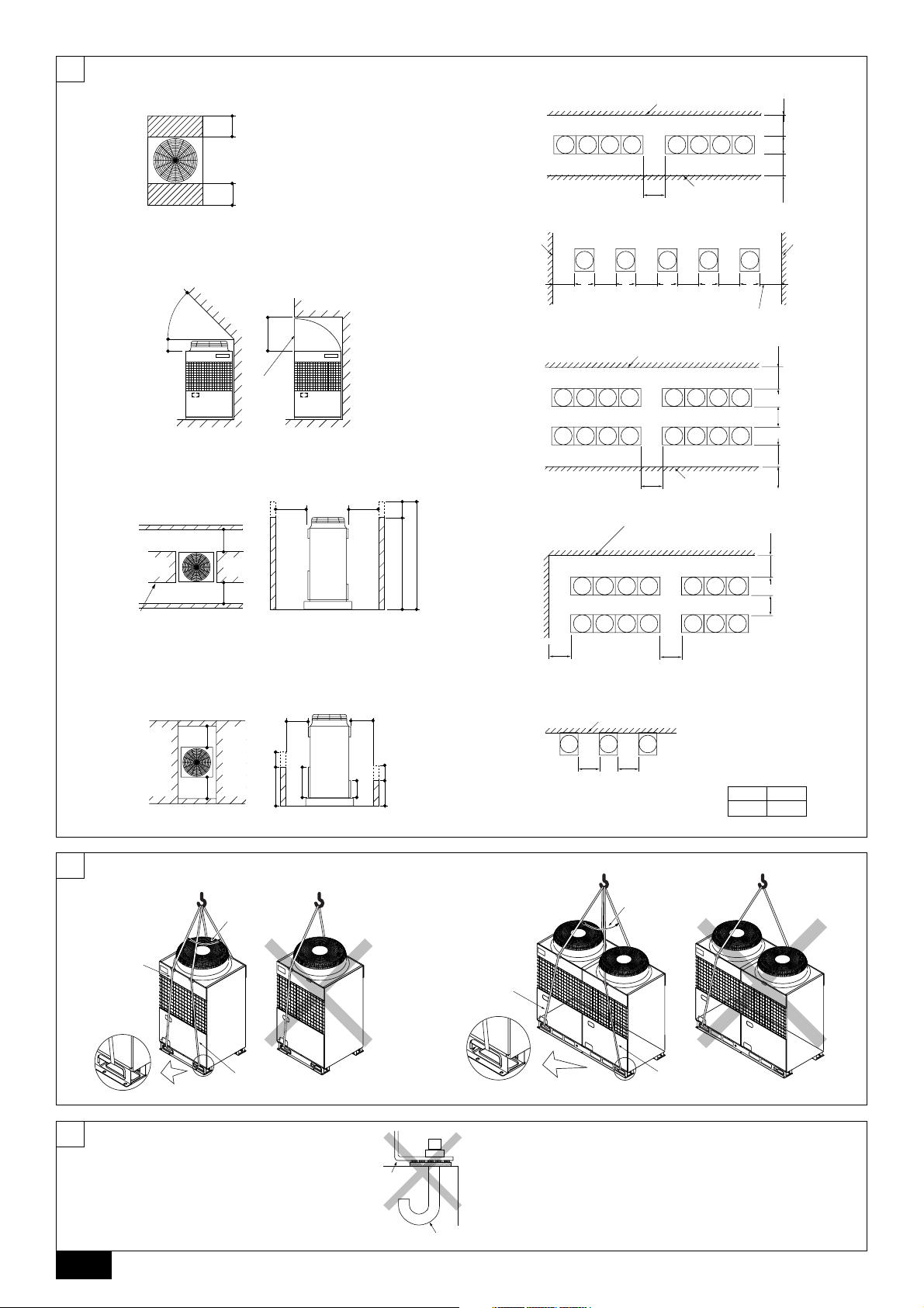
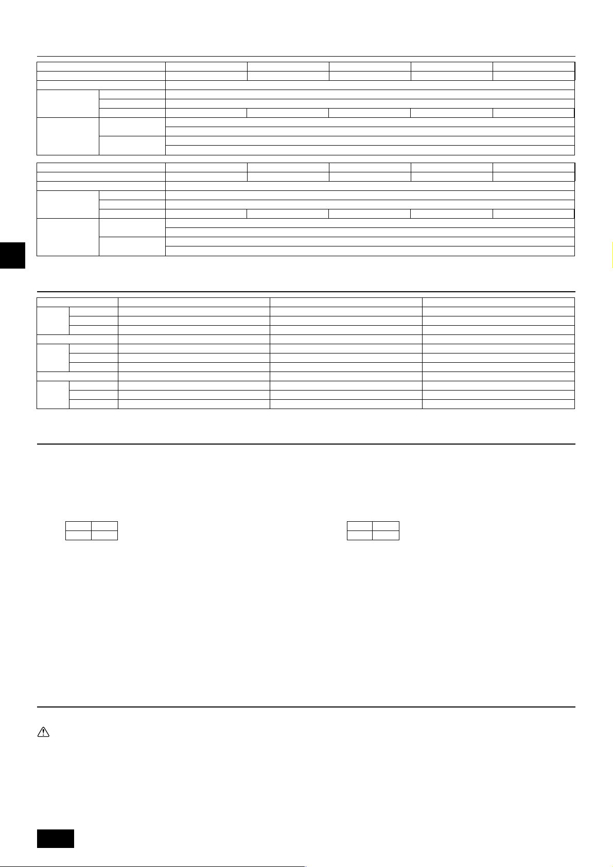
5. Space required around unit
[Fig. 5.0.1] (P.2)
<A> Top view <B> Side view
<C> When there is little space up to an obstruction
A Front B No restrictions on wall height (left and right)
C Air outlet guide (Procured at the site) D Must be open
E Wall height (H) F No restrictions on wall height
(mm)
L1 L2
450 450
(1) Basic space required
(2) When there is an obstruction above the unit
(3) When inlet air enters from right and left sides of unit
• Wall heights “H” of the front and the back sides shall be within total height of
unit.
• When wall height “H” exceeds total height of unit, add “h” dimension to L
L
2 of the Fig. 5.0.1.
“h” = wall height “H'” – total height of unit
1 and
6. Lifting method
[Fig. 6.0.1] (P.2)
(4) When unit is surrounded by walls
Note:
• Wall heights “H” of the front and the back sides shall be lower than either
the front or the back panel.
• If the panel height is exceeded, add the “h” dimension of the Fig. 5.0.1 to
L
1 and L2.
(mm)
L1 L2
450 450
Example: When the “h” dimension is 100 mm,
(5) Collective installation and continuous installation
• Space required for collective installation and continuous installation:
• Open in two directions.
• In case of wall height “H” exceeds total height of unit, add “h” dimension (h =
• If there is a wall at both the front and the rear of the unit, install up to four units
the L
1 dimension becomes 450 + 100 = 550 mm.
When installing several units, provide the space between each block considering passage for air and people.
wall height “H'” – total height of unit) to * marked dimension.
(Every 3 units in the case of P450 ~ P650.) consecutively in the side direction
and provide a space of 1000 mm or more as inlet space/passage space for
each four units (Every 3 units in the case of P450 ~ P650.) .
Caution:
Be very careful to carry product.
- Do not have only one person to carry product if it weighs more than 20 kg.
- PP bands are used to pack some products. Do not use them as a mean for transportation because they are dangerous.
- Do not touch heat exchanger fins with your bare hands. Otherwise you may cut your hands.
- Tear plastic packaging bag and scrap it so that children cannot play with it. Otherwise plastic packaging bag may suffocate children to death.
- When carrying outdoor unit, be sure to support it at four points. Carrying with 3-point support may make outdoor unit unstable, resulting in it falling.
8
Page 9
7. Installation of unit
7.1. Installation
[Fig. 7.1.1] (P.2)
A M10 anchor bolt procured at the site. B Corner is not seated.
• Fix unit tightly with bolts so that unit will not fall down due to earthquake or gust
of wind.
• Use concrete or angle bracket for foundation of unit.
• Vibration may be transmitted to the installation section and noise and vibration
may be generated from the floor and walls, depending on the installation conditions. Therefore, provide ample vibrationproofing (cushion pads, cushion
frame, etc.).
• Be sure that the corners are firmly seated. If the corners are not firmly seated,
the installation feet may be bent.
8. Refrigerant piping installation
City Multi R2 Series is constituted by an end branching system in which the refrigerant piping from outdoor unit is branched at BC controller and connected to each
indoor unit.
The connection method adapted is brazing connection for high pressure pipe and
low pressure pipe between outdoor unit and BC controller, and flare connection
between BC controller and indoor unit. Brazing connection is employed for joint
pipe set and branch pipe set.
Warning:
Always use extreme care to prevent the refrigerant gas from leaking while
using fire or flame. If the refrigerant gas comes into contact with a flame
from any source, such as a gas stove, it breaks down and generates a poisonous gas which can cause gas poisoning. Never weld in an unventilated
room. Always conduct an inspection for gas leakage after installation of the
refrigerant piping has been completed.
8.1. Caution
This unit uses refrigerant R410A. Follow the local regulations on materials and
pipe thickness when selecting pipes.
1 Use the following materials for refrigeration piping.
• Material: Use refrigerant piping made of phosphorus deoxidized copper.
In addition, be sure that the inner and outer surfaces of the pipes are clean
and free of hazardous sulphur, oxides, dust/dirt, shaving particles, oils,
moisture, or any other contaminant.
2 Commercially available piping often contains dust and other materials. Always
blow it clean with a dry inert gas.
3 Use care to prevent dust, water or other contaminants from entering the piping
during installation.
4 Reduce the number of bending portions as much as possible, and make bend-
ing radius as big as possible.
5 Always observe the restrictions on the refrigerant piping (such as rated length,
the difference between high/low pressures, and piping diameter). Failure to do
so can result in equipment failure or a decline in heating/cooling performance.
6 Either a lack or an excess of refrigerant causes the unit to make an emergency
stop. Charge the system with an appropriate amount of refrigerant. At such a
time, always properly charge the unit. When servicing, always check the notes
concerning pipe length and amount of additional refrigerant at both locations,
the refrigerant volume calculation table on the back of the service panel and
the additional refrigerant section on the labels for the combined number of
indoor units.
7 Use liquid refrigerant to fill the system.
8 Never use refrigerant to perform an air purge. Always evacuate using a vacuum
pump.
9 Always insulate the piping properly. Insufficient insulation will result in a de-
cline in heating/cooling performance, water drops from condensation and other
such problems.
0 When connecting the refrigerant piping, make sure the ball valve of the out-
door unit is completely closed (the factory setting) and do not operate it until
the refrigerant piping for the outdoor and indoor units has been connected, a
refrigerant leakage test has been performed and the evacuation process has
been completed.
A Residues in commercially available antioxidants may have adverse effects on
the equipment. Braze only with non-oxide brazing material. The use of other
brazing material may result in compressor damage.
(Refer to item 9.2. for detailed information on pipe connections and valve operations.)
B Never perform outdoor unit piping connection work when it is raining.
Warning:
• Be sure to install unit in a place strong enough to withstand its weight.
Any lack of strength may cause unit to fall down, resulting in a personal
injury.
• Have installation work in order to protect against a strong wind and earthquake.
Any installation deficiency may cause unit to fall down, resulting in a
personal injury.
When building the foundation, give full attention to the floor strength, drain water
disposal <during operation, drain water flows out of the unit>, and piping and wiring routes.
Down piping and down wiring precautions
When down piping and down wiring are performed, be sure that foundation and
base work does not block the base through holes. When down piping is performed,
make the foundation at least 100 mm high so that the piping can pass under the
bottom of the unit.
Warning
When installing and moving the unit, do not charge it with refrigerant other
than the refrigerant specified on the unit.
- Mixing of a different refrigerant, air, etc. may cause the refrigerant cycle to mal-
function and result in severe damage.
Caution:
• Use a vacuum pump with a reverse flow check valve.
- If the vacuum pump does not have a reverse flow check valve, the vacuum
pump oil may flow back into the refrigerant cycle and cause deterioration of
the refrigerator oil and other trouble.
• Do not use the tools shown below used with conventional refrigerant.
(Gauge manifold, charge hose, gas leak detector, check valve, refrigerant
charge base, vacuum gauge, refrigerant recovery equipment)
- Mixing of conventional refrigerant and refrigerator oil may cause the refrig-
erator oil to deteriorate.
- Mixing of water will cause the refrigerator oil to deteriorate.
- R410A refrigerant does not contain any chlorine. Therefore, gas leak detec-
tors for conventional refrigerants will not react to it.
• Manage the tools more carefully than normal.
- If dust, dirt, or water gets in the refrigerant cycle, the refrigerator oil will dete-
riorate.
• Never use existing refrigerant piping.
- The large amount of chlorine in conventional refrigerant and refrigerator oil
in the existing piping will cause the new refrigerant to deteriorate.
• Store the piping to be used during installation indoors and keep both
ends of the piping sealed until just before brazing.
- If dust, dirt, or water gets into the refrigerant cycle, the oil will deteriorate and
the compressor may fail.
• Do not use a charging cylinder.
- Using a charging cylinder may cause the refrigerant to deteriorate.
• Do not use special detergents for washing piping.
8.2. Refrigerant piping system
Connection Example
[Fig. 8.2.1] (P.3)
Å Outdoor model ı High press. side
Ç Low press. side Î Total capacity of indoor units
‰ Liquid line Ï Gas line
Ì High press. gas pipe Ó Low press. gas pipe
¬ Liquid pipe Ô Model number
A BC controller (standard) B BC controller (master)
C BC controller (slave) D Indoor unit (20 ~ 140)
E Indoor unit (200, 250)
GBDFEINLPGRRUTRCZSVSLHGPO
9
Page 10
9. Additional refrigerant charge
B
At the time of shipping, the outdoor unit is charged with the refrigerant. As this
charge does not include the amount needed for extended piping, additional charging for each refrigerant line will be required on site. In order that future servicing
may be properly provided, always keep a record of the size and length of each
refrigerant line and the amount of additional charge by writing it in the space provided on the outdoor unit.
9.1. Calculation of additional refrigerant
charge
• Calculate the amount of additional charge based on the length of the piping
extension and the size of the refrigerant line.
• Use the table to the below as a guide to calculating the amount of additional
charging and charge the system accordingly.
• If the calculation results in a fraction of less than 0.1 kg, round up to the next
0.1 kg. For example, if the result of the calculation was 10.62 kg, round the
result up to 10.7 kg.
<Additional Charge>
Additional
refrigerant
GBDFEINLPGRRUTRCZSVSLHGPO
charge
<Example 1>
Indoor No. 1: 40 A: ø19.05 40 m a: ø6.35 10 m
The total length of each liquid line is as follows:
ø19.05: A = 40 m
ø9.52: B + b + e = 10 + 5 + 10 = 25 m
ø6.35: a + c + d = 10 + 10 + 10 = 30 m
Therefore,
<Calculation example>
Additional refrigerant charge
= 40 × 0.16 + 25 × 0.06 + 30 × 0.024 + 2 = 10.7 kg
<Example 2>
Indoor No. 1: 40 A: ø22.2 40 m a: ø6.35 10 m
The total length of each liquid line is as follows:
ø22.2: A = 40 m
ø12.7: C + D = 10 + 10 = 20 m
ø9.52: B + b + e + f = 10 + 5 + 10 + 10 = 35 m
ø6.35: a + c + d + g + h = 10 + 10 + 10 + 5 + 5 = 40 m
Therefore,
<Calculation example>
Additional refrigerant charge
= 40 × 0.23 + 20 × 0.12 + 35 × 0.06 + 40 × 0.024 + 3.0 + 2.0 = 19.7 kg
Value of α1
Value of α2
High pressure
pipe size
=+++
Total length of
ø28.58 × 0.39
(kg)
(m) × 0.39 (kg/m)
High pressure
pipe size
+++ + α1 + α2
Total length of
ø12.7 × 0.12
(m) × 0.12 (kg/m)
High pressure
pipe size
Total length of
ø22.2 × 0.23
(m) × 0.23 (kg/m)
High pressure
pipe size
Total length of
ø9.52 × 0.06
(m) × 0.06 (kg/m)
High pressure
pipe size
Total length of
ø19.05 × 0.16
(m) × 0.16 (kg/m)
High pressure
pipe size
Total length of
ø6.35 × 0.024
(m) × 0.024 (kg/m)
High pressure
pipe size
Total length of
ø15.88 × 0.11
(m) × 0.11 (kg/m)
No. 2: 200 B: ø9.52 10 m b: ø9.52 5 m
No. 3: 40 c: ø6.35 10 m
No. 4: 32 d: ø6.35 10 m
No. 5: 63 e: ø9.52 10 m
No. 2: 100 B: ø9.52 10 m b: ø9.52 5 m
No. 3: 40 C: ø12.7 10 m c: ø6.35 10 m
No. 4: 32 D: ø12.7 10 m d: ø6.35 10 m
No. 5: 63 e: ø9.52 10 m
No. 6: 200 f: ø9.52 10 m
No. 7: 32 g: ø6.35 5 m
No. 8: 32 h: ø6.35 5 m
Total capacity of connecting indoor units α 1
to Model 80 1.0 kg
Models 81 to 160 1.5 kg
Models 161 to 330 2.0 kg
Models 331 to 480 2.5 kg
Models 481 to 630 3.0 kg
Models 631 to 710 4.0 kg
Models 711 to 890 5.0 kg
Models 891 to 1070 6.0 kg
α 2
BC controller (standard,master only) 0 kg
BC controller (slave) connected (one) 1.0 kg
BC controller (slave) connected (two) 2.0 kg
At the
conditions
below:
At the
conditions
below:
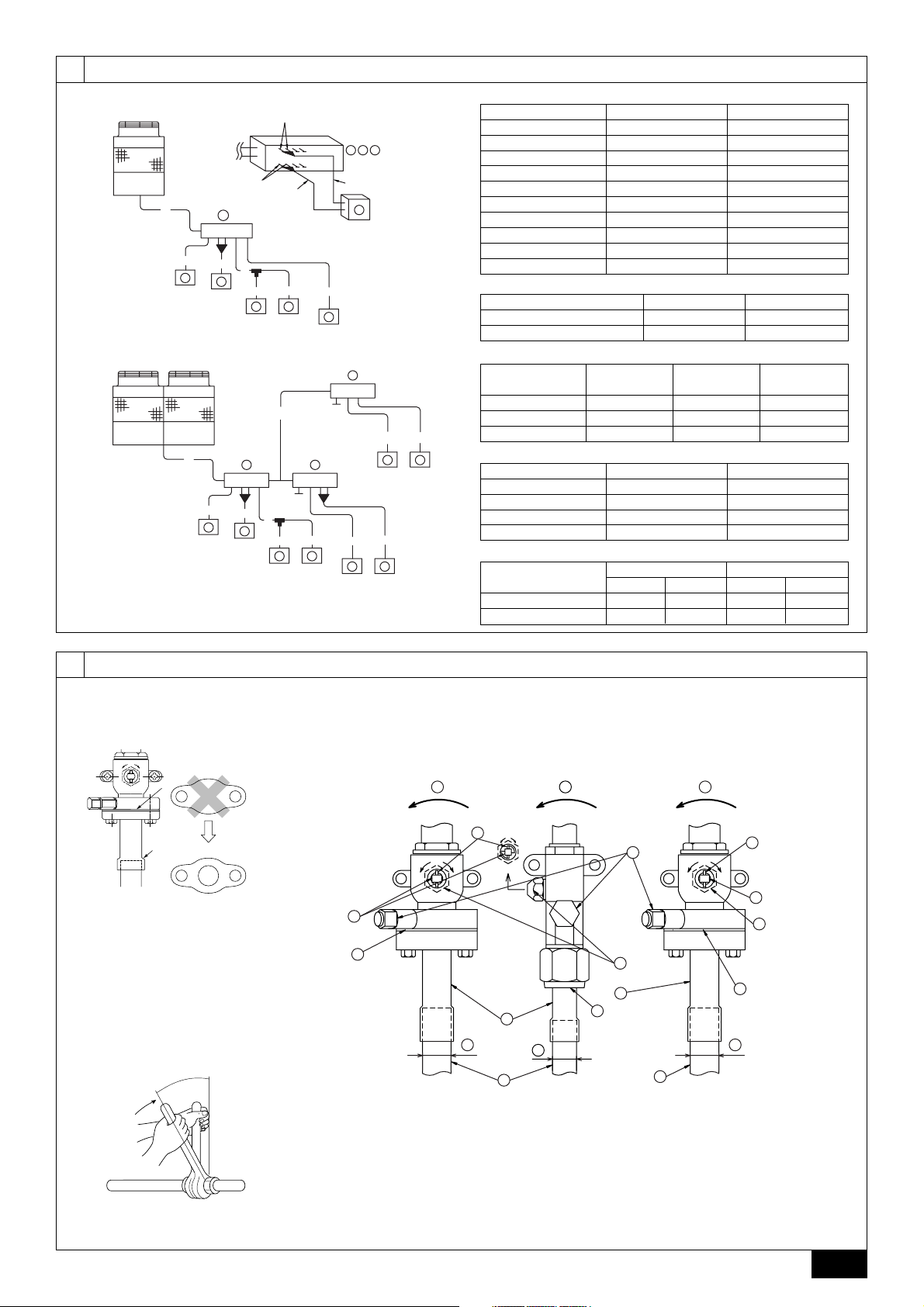
9.2. Precautions concerning piping connection and valve operation
• Conduct piping connection and valve operation accurately.
• Flange type side connecting pipe is assembled in factory before shipment.
1 For brazing to the connecting pipe with flange, remove the connecting pipe
with flange from the ball valve, and braze it outside of the unit.
2 During the time when removing the connecting pipe with flange, remove
the seal attached on the rear side of this sheet and paste it onto the flange
surface of the ball valve to prevent the entry of dust into the valve.
3 The refrigerant circuit is closed with a round, close-packed packing upon
shipment to prevent gas leak between flanges. As no operation can be
done under this state, be sure to replace the packing with the hollow packing attached at the piping connection.
4 At the mounting of the hollow packing, wipe off dust attached on the flange
sheet surface and the packing. Coat refrigerating machine oil (Ester oil,
ether oil or alkylbenzene [small amount]) onto both surfaces of the packing.
[Fig. 9.2.1] (P.3)
A Close-packed packing
B Hollow packing
• After evacuation and refrigerant charge, ensure that the handle is fully open. If
operating with the valve closed, abnormal pressure will be imparted to the
high- or low-pressure side of the refrigerant circuit, giving damage to the compressor, four-way valve, etc.
• Determine the amount of additional refrigerant charge by using the formula,
and charge refrigerant additionally through the service port after completing
piping connection work.
• After completing work, tighten the service port and cap securely not to gener-
ate gas leak.
• Flare machining dimension for systems using R410A is larger than that for
systems using other types of refrigerant in order to increase the air tightness.
• Refer to the table on the below for flare machining dimensions, and follow the
regulations set forth by the local authorities. Seal off the opening of the pipe
with a closure material (not supplied) to keep small animals from entering the
pipe if that is a concern.
flare machining dimension (mm)
outer diameter
size in inches
ø6.35
A
ø9.52
ø12.70
ø15.88
ø19.05
flare nut size (mm)
outer diameter
size in inches
ø6.35
ø9.52
ø12.70
ø15.88
ø19.05
[Fig. 9.2.2] (P.3)
<A> [Ball valve (Low press. side/flanged type)]
<B> [Ball valve (High press. side/flared type)]
<C> [Ball valve (High press. side/flanged type)]
<D>This figure shows the valve in the fully open state.
A Valve stem
[Fully closed at the factory, when connecting the piping, when evacuating, and
when charging additional refrigerant. Open fully after the operations above are
completed.]
B Stopper pin [Prevents the valve stem from turning 90° or more.]
C Packing (Accessory)
[Manufacturer: Nichiasu corporation]
[Type: T/#1991-NF]
D Connecting pipe (Accessory)
[Use packing and securely install this pipe to the valve flange so that gas leakage
will not occur. (Tightening torque:40 N·m) Coat both surfaces of the packing with
refrigerating machine oil. (Ester oil, ether oil or alkylbenzene [small amount])]
E Open (Operate slowly)
F Cap, copper packing
[Remove the cap and operate the valve stem. Always reinstall the cap after operation is completed. (Valve stem cap tightening torque: 23 ~ 27 N·m)]
1/4"
3/8"
1/2"
5/8"
3/4"
1/4"
3/8"
1/2"
5/8"
3/4"
dimension A
R410A
9.1
13.2
16.6
19.7
24.0
dimension B
R410A
17.0
22.0
26.0
29.0
36.0
10
Page 11
G Service port
[Use this port to evacuate the refrigerant piping and add an additional charge at
the site.
Open and close the port using a double-ended wrench.
Always reinstall the cap after operation is completed. (Service port cap tightening
torque: 12 ~ 15 N·m)]
H Flare nut
[Tightening torque: Refer to the following table.
Loosen and tighten this nut using a double-ended wrench.
Coat the flare contact surface with refrigerating machine oil (Ester oil, ether oil or
alkylbenzene [small amount])]
I ø15.88 (PURY-P200)
ø19.05 (PURY-P250 ~ P350)
J ø19.05 (PURY-P200)
ø22.2 (PURY-P250, P300)
ø28.58(PURY-P350 ~ P650)
K Field piping
L ø22.2 (PURY-P400 ~ P500)
ø28.58 (PURY-P550 ~ P650)
Appropriate tightening torque by torque wrench:
• Always remove the connecting pipe from the ball valve and braze it out-
• Use ester oil, ether oil or alkylbenzene (small amount) as the refrigerat-
• Keep the ball valve closed until refrigerant charging to the pipes to be
• Do not use a leak detection additive.
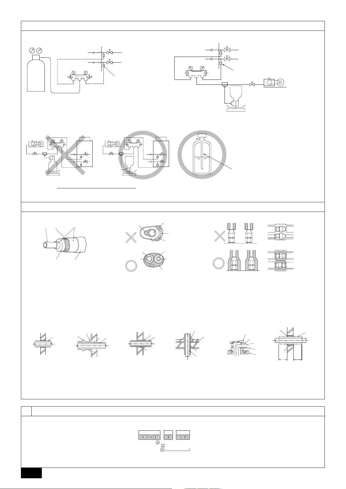
9.3. Airtight test, evacuation, and refrigerant
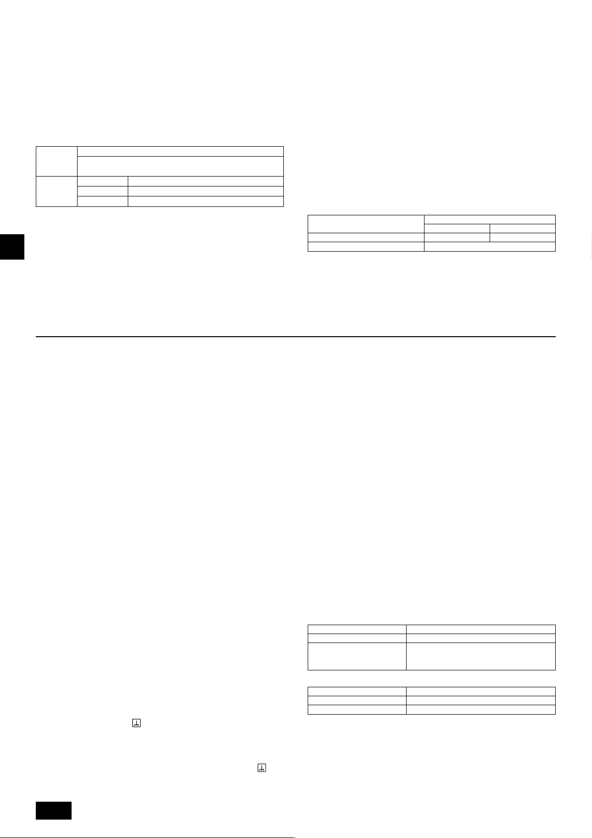
1 Airtight test
Copper pipe external dia. (mm) Tightening torque (N·m)
ø6.35 14 to 18
ø9.52 35 to 42
ø12.7 50 to 57.5
ø15.88 75 to 80
ø19.05 100 to 140
Tightening angle standard:
Pipe diameter (mm) Tightening angle (°)
ø6.35, ø9.52 60 to 90
ø12.7, ø15.88 30 to 60
ø19.05 20 to 35
[Fig. 9.2.3] (P.3)
Observe the following restrictions when conducting an air tightness test to prevent
negative effects on the refrigerating machine oil. Also, with nonazeotropic refrigerant (R410A), gas leakage causes the composition to change and affects performance. Therefore, perform the airtightness test cautiously.
Note:
If a torque wrench is not available, use the following method as a standard:
When you tighten the flare nut with a wrench, you will reach a point where
the tightening torque will abruptly increase. Turn the flare nut beyond this
point by the angle shown in the table above.
Airtight test procedure
1. Nitrogen gas pressurization
(1) After pressurizing to the design pressure (4.15 MPa) using nitrogen gas, allow it to stand for
about one day. If the pressure does not drop, airtightness is good.
However, if the pressure drops, since the leaking point is unknown, the following bubble test
may also be performed.
(2) After the pressurization described above, spray the flare connection parts, brazed parts, flanges,
and other parts that may leak with a bubbling agent (Kyuboflex, etc.) and visually check for
bubbles.
(3) After the airtight test, wipe off the bubbling agent.
2. Pressurization using refrigerant gas and nitrogen gas
(1) Pressurizing to a gas pressure of approximately 0.2 MPa, pressurize to the design pressure
(4.15 MPa) using nitrogen gas.
However, do not pressurize at one time. Stop during pressurization and check that the pressure does not drop.
(2) Check for gas leaks by checking the flare connection parts, brazed parts, flanges, and other
parts which may leak using an R410A compatible electric leak detector.
(3) This test may be used together the with bubble type gas leak test.
Caution:
side the unit.
- Brazing the connecting pipe while it is installed will heat the ball valve and
cause trouble or gas leakage. The piping, etc. inside the unit may also be
burned.
ing machine oil to coat flares and flange connections.
- The refrigerating machine oil will degrade if it is mixed with a large amount of
mineral oil.
added on site has been completed. Opening the valve before charging
the refrigerant may result in unit damage.
charging
Perform with the ball valve of the outdoor unit closed, and pressurize the connection piping and the indoor unit from the service port provided on the ball
valve of the outdoor unit. (Always pressurize from both the high press pipe and
the low press pipe service ports.)
[Fig. 9.3.1] (P.4)
A Nitrogen gas B To indoor unit C System analyzer
D Lo knob E Hi knob F Ball valve
G Low press. pipe H High press. pipe I Outdoor unit
J Service port
Restriction
• If a flammable gas or air (oxygen) is used as the pressurization
gas, it may catch fire or explode.
• Do not use a refrigerant other than that indicated on the unit.
• Sealing with gas from a cylinder will cause the composition of
the refrigerant in the cylinder to change.
• Use a pressure gauge, charging hose, and other parts especially
for R410A.
• An electric leak detector for R22 cannot detect leaks of R410A.
• Do not use a haloid torch. (Leaks cannot be detected.)
GBDFEINLPGRRUTRCZSVSLHGPO
Caution:
Only use refrigerant R410A.
- The use of other refrigerant such as R22 or R407C, which contains chlorine, will
deteriorate the refrigerating machine oil or cause the compressor to malfunction.
2 Evacuation
Evacuate with the ball valve of the outdoor unit closed and evacuate both the
connection piping and the indoor unit from the service port provided on the ball
valve of the outdoor unit using a vacuum pump. (Always evacuate from the
service port of both the high press pipe and the low press pipe.) After the
vacuum reaches 650 Pa [abs], continue evacuation for at least one hour or
more.
* Never perform air purging using refrigerant.
[Fig. 9.3.2] (P.4)
A System analyzer B Lo knob C Hi knob
D Ball valve E Low press. pipe F High press. pipe
G Service port H Three-way joint I Valve
J Valve K R410A cylinder L Scale
M Vacuum pump N To indoor unit O Outdoor unit
Note:
• Always add an appropriate amount of refrigerant. Also always seal the
system with liquid refrigerant. Too much or too little refrigerant will cause
trouble.
• Use a gauge manifold, charging hose, and other parts for the refrigerant
indicated on the unit.
• Use a graviometer. (One that can measure down to 0.1 kg.)
• Use a vacuum pump with a reverse flow check valve.
(Recommended vacuum gauge: ROBINAIR 14830A Thermistor Vacuum
Gauge)
Also use a vacuum gauge that reaches 65 Pa [abs] or below after operating for five minutes.
3 Refrigerant Charging
Since the refrigerant used with the unit is nonazerotropic, it must be charged in
the liquid state. Consequently, when charging the unit with refrigerant from a
cylinder, if the cylinder does not have a syphon pipe, charge the liquid refrigerant by turning the cylinder upside-down as shown in Fig.9.3.3. If the cylinder
has a syphon pipe like that shown in the picture on the right, the liquid refrigerant can be charged with the cylinder standing upright. Therefore, give careful
attention to the cylinder specifications. If the unit should be charged with gas
refrigerant, replace all the refrigerant with new refrigerant. Do not use the refrigerant remaining in the cylinder.
[Fig. 9.3.3] (P.4)
A Syphon pipe B In case of the cylinder having no syphon pipe.
11
Page 12
9.4. Thermal insulation of refrigerant piping
Be sure to give insulation work to refrigerant piping by covering liquid pipe and gas
pipe separately with enough thickness heat-resistant polyethylene, so that no gap
is observed in the joint between indoor unit and insulating material, and insulating
materials themselves. When insulation work is insufficient, there is a possibility of
condensation drip, etc. Pay special attention to insulation work to ceiling plenum.
[Fig. 9.4.1] (P.4)
A Steel wire B Piping
C Asphaltic oily mastic or asphalt D Heat insulation material A
E Outer covering B
Heat
insulation
material A
Outer
covering B
Note:
• When using polyethylene cover as covering material, asphalt roofing shall
not be required.
• No heat insulation must be provided for electric wires.
GBDFEINLPGRRUTRCZSVSLHGPO
[Fig. 9.4.2] (P.4)
[Fig. 9.4.3] (P.4)
Glass fiber + Steel wire
Adhesive + Heat - resistant polyethylene foam + Adhesive tape
Indoor Vinyl tape
Floor exposed Water-proof hemp cloth + Bronze asphalt
Outdoor Water-proof hemp cloth + Zinc plate + Oily paint
A High press. pipe B Low press. pipe C Electric wire
D Finishing tape E Insulator
10. Wiring
Penetrations
[Fig. 9.4.4] (P.4)
<A> Inner wall (concealed) <B> Outer wall
<C> Outer wall (exposed) <D> Floor (waterproofing)
<E> Roof pipe shaft
<F> Penetrating portion on fire limit and boundary wall
A Sleeve B Heat insulating material
C Racking D Caulking material
E Band F Waterproofing laye
G Sleeve with edge H Lagging material
I Mortar or other incombustible caulking
J Incombustible heat insulation material
When filling a gap with mortar, cover the penetration part with steel plate so that
the insulation material will not be caved in. For this part, use incombustible materials for both insulation and covering. (Vinyl covering should not be used.)
• Insulation materials for the pipes to be added on site must meet the following
specifications:
ø6.35 ~ 25.4 mm
Thickness
Temperature Resistance
* Installation of pipes in a high-temperature high-humidity environment, such as
the top floor of a building, may require the use of insulation materials thicker
than the ones specified in the chart above.
* When certain specifications presented by the client must be met, ensure that
they also meet the specifications on the chart above.
10 mm min.
Pipe size
ø28.58 ~ 38.1 mm
15 mm min.
100 °C min.
10.1. Caution
1 Follow ordinance of your governmental organization for technical standard re-
lated to electrical equipment, wiring regulations and guidance of each electric
power company.
2 Wiring for control (hereinafter referred to as transmission line) shall be (5 cm or
more) apart from power source wiring so that it is not influenced by electric
noise from power source wiring. (Do not insert transmission line and power
source wire in the same conduit.)
3 Be sure to provide designated grounding work to outdoor unit.
4 Give some allowance to wiring for electrical part box of indoor and outdoor
units, because the box is sometimes removed at the time of service work.
5 Never connect the main power source to terminal block of transmission line. If
connected, electrical parts will be burnt out.
6 Use 2-core shield cable for transmission line. If transmission lines of different
systems are wired with the same multiplecore cable, the resultant poor transmitting and receiving will cause erroneous operations.
7 Only the transmission line specified should be connected to the terminal block
for outdoor unit transmission.
(Transmission line to be connected with indoor unit : Terminal block TB3 for
transmission line, Other : Terminal block TB7 for centralized control)
Erroneous connection does not allow the system to operate.
8 In the case of connecting with an upper class controller or to conduct group
operation in different refrigerant systems, the control line for transmission is
required between the outdoor units.
Connect this control line between the terminal blocks for centralized control.
(2-wire line with no polarity)
When conducting group operation in different refrigerant systems without connecting to the upper class controller, replace the insertion of the short circuit
connector from CN41 of one outdoor unit to CN40.
9 Group is set by operating the remote controller.
10.2. Control box and connecting position of
wiring
1. Connect the indoor unit transmission line to transmission terminal block (TB3),
or connect the wiring between outdoor units or the wiring with the central control system to the central control terminal block (TB7).
When using shielded wiring, connect shield ground of the indoor unit transmission line to the earth screw (
outdoor units and the central control system transmission line to the shield (S)
terminal of the central control terminal block (TB7) shield (S) terminal. In addition, in the case of outdoor units whose power supply connector CN41 has
been replaced by CN40, the shield terminal (S) of terminal block (TB7) of the
central control system should also be connected to the earth screw (
Fix the wiring securely in place with the cable strap at the bottom of the terminal block so that the external force if not applied to the terminal block. External
) and connect shield ground of the line between
).
force applied to the terminal block may damage the block and short-circuit,
ground fault, or fire may result.
[Fig. 10.2.1] (P.4)
A Power source B Transmission line
C Earth screw
2. Conduit mounting plates (ø27, ø33, ø46, ø53) are being provided. Pass the
power supply and transmission wires through the appropriate knock-out holes,
then remove the knock-out piece from the bottom of the terminal box and connect the wires.
3. Fix power source wiring to terminal box by using buffer bushing for tensile
force (PG connection or the like).
4. Narrow the opening by using a conduit to keep small animals out.
10.3. Wiring transmission cables
1 Types of control cables
1. Wiring transmission cables
• Types of transmission cables: Shielding wire CVVS or CPEVS
• Cable diameter: More than 1.25 mm
• Maximum wiring length: Within 200 m
• Maximum length of transmission lines for centralized control and indoor/out-
door transmission lines (Maximum length via indoor units): 500 m MAX
The maximum length of the wiring between power supply unit for transmission
lines (on the transmission lines for centralized control) and each outdoor unit
and system controller is 200 m.
2. Remote control cables
• M-NET Remote Controller
Kind of remote control cable
Cable diameter
Remarks
• MA Remote Controller
Kind of remote control cable
Cable diameter
Remarks
* Connected with simple remote controller.
2
Sheathed 2-core cable (unshielded)
0.3 to 1.25 mm
When 10 m is exceeded, use cable with the
same specifications as 1. Wiring transmission
cables.
Sheathed 2-core cable (unshielded) CVV
0.3 to 1.25 mm
Within 200 m
2
(0.75 to 1.25 mm2)*
2
(0.75 to 1.25 mm2)*
12
Page 13
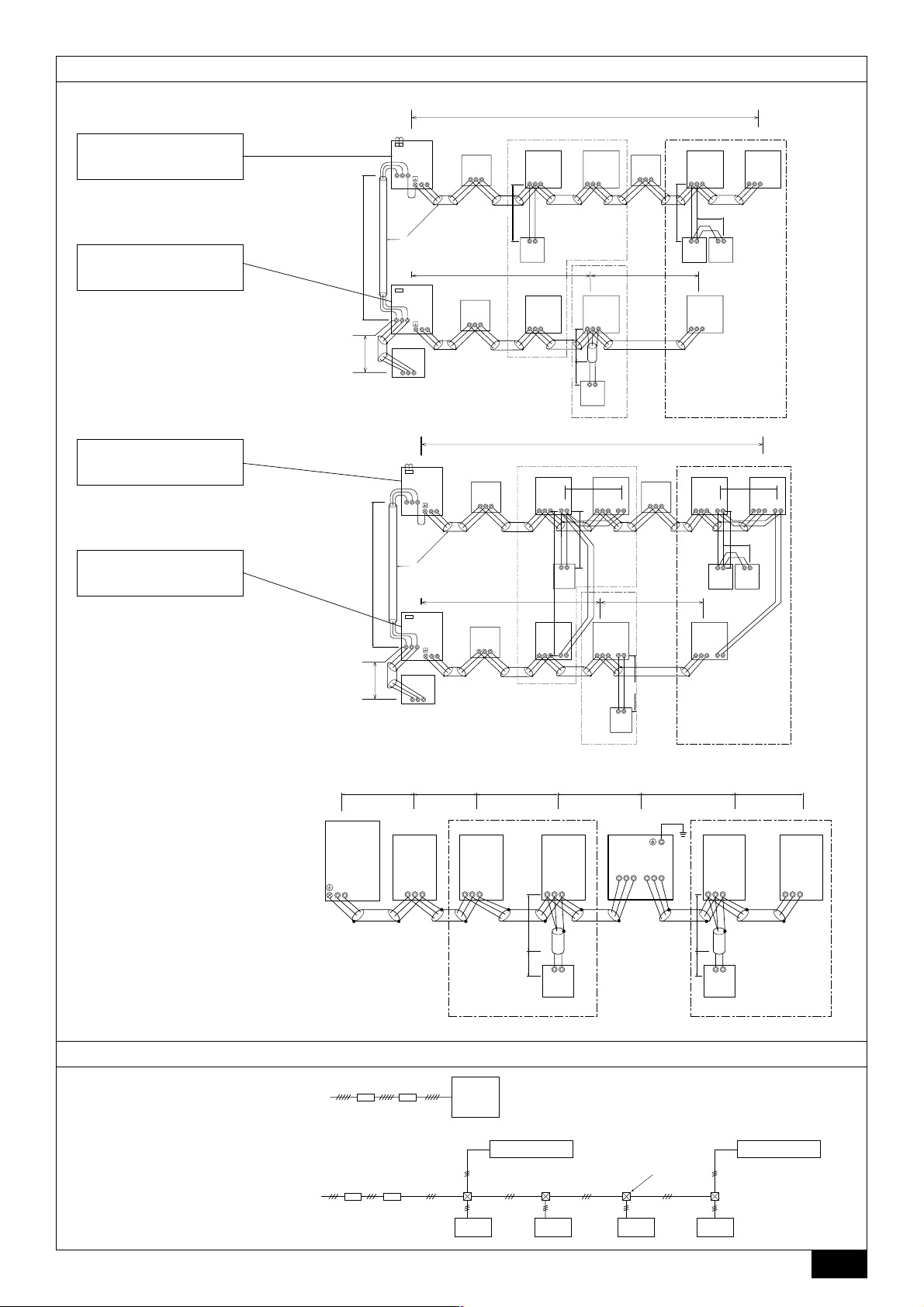
2 Wiring examples
• Controller name, symbol and allowable number of controllers.
Name
Outdoor unit controller
BC Controller (Master)
BC Controller (Slave)
Transmission booster unit
Indoor Unit Controller
Remote Controller
Symbol
OC
BC
BS
RP
IC
RC
Allowable number of controllers
One controller for one OC
Zero, one or two controllers for one OC
Zero or one unit for one OC (*1)
Two to twenty four controllers for one OC (*1)
Maximum of two per group
*1 A transmission booster (RP) may be required depending on the number of connected indoor unit controllers.
Example of a group operation system with multiple outdoor units (Shielding wires and address setting are
necessary.)
<Examples of transmission cable wiring>
[Fig. 10.3.1] M-NET Remote Controller (P.5)
[Fig. 10.3.2] MA Remote Controller (P.5)
[Fig. 10.3.3] Transmission booster unit (P.5)
<A> Change the jumper connector from CN41 to CN40.
<B> SW2-1:ON
<C> Keep the jumper connector on CN41.
A Group 1 B Group 4 C Group 5 D Shielded wire E Sub remote controller
( ) Address
<Wiring Method and Address Settings>
a. Always use shielded wire when making connections between the outdoor unit (OC) and the indoor unit (IC), as well for all OC-OC, and IC-IC wiring intervals.
b. Use feed wiring to connect terminals M1 and M2 and the earth terminal on the transmission cable terminal block (TB3) of each outdoor unit (OC) to terminals M1, M2 and
terminal S on the transmission cable block of the indoor unit (IC).
c. Connect terminals 1 (M1) and 2 (M2) on the transmission cable terminal block of the indoor unit (IC) that has the most recent address within the same group to the
terminal block on the remote controller (RC).
d. Connect together terminals M1, M2 and terminal S on the terminal block for central control (TB7) for the outdoor unit (OC).
e. On one outdoor unit only, change the jumper connector on the control panel from CN41 to CN40.
f. Connect the terminal S on the terminal block for central control (TB7) for the outdoor unit (OC) for the unit into which the jumper connector was inserted into CN40 in Step
above to the earth terminal
g. Set the address setting switch as follows.
* To set the outdoor unit address to 100, the outdoor address setting switch must be set to 50.
Unit Range Setting Method
IC (Main) 01 to 50
IC (Sub) 01 to 50
Outdoor Unit 51 to 100 Use the most recent address of all the indoor units plus 50
BC controller (Master) 51 to 100
BC controller (Slave) 51 to 100 Lowest address within the indoor units connected to the BC controller (slave) plus 50
M-NET R/C (Main) 101 to 150 Set at an IC (Main) address within the same group plus 100
M-NET R/C (Sub) 151 to 200 Set at an IC (Main) address within the same group plus 150
MA R/C – Unnecessary address setting (Necessary main/sub setting)
h. The group setting operations among the multiple indoor units is done by the remote controller (RC) after the electrical power has been turned on.
in the electrical component box.
Use the most recent address within the same group of indoor units. With an R2 system with sub BC controllers, set the
indoor unit address in the following order:
1 Indoor units connected to the main BC controller
2 Indoor units connected to BC sub controller 1
3 Indoor units connected to BC sub controller 2
Set the indoor unit addresses so that all the addresses of 1 are smaller than those of 2, and that all the addresses of 2
are smaller than those of 3.
Use an address, other than that of the IC (Main) from among the units within the same group of indoor units. This must be
in sequence with the IC (Main)
Outdoor unit address plus 1. When the set indoor unit address duplicates the address of another indoor unit, set the new
address to a vacant address within the setting range.
GBDFEINLPGRRUTRCZSVSLHGPO
<Permissible Lengths>
1 M-NET Remote controller
• Max length via outdoor units: L1 + L2 + L3 + L4 and L1 + L2 + L3 + L5 and L1 + L2 + L6 = 500 m (1.25 mm2 or more)
• Max transmission cable length: L
• Remote controller cable length: r
1 and L3 + L4 and L3 + L5 and L6 and L2 + L6
1, r2, r3, r4
If the length exceeds 10 m, use a 1.25 mm
10 m (0.3 to 1.25 mm2)
=
200 m (1.25 mm2 or more)
=
2
shielded wire. The length of this section (L8) should be included in the calculation of the
maximum length and overall length.
2 MA Remote controller
• Max length via outdoor unit (M-NET cable): L
• Max transmission cable length (M-NET cable): L
• Remote controller cable length: c
1 and c1 + c2 + c3 and c1 + c2 + c3 + c4
1 + L2 + L3 + L4 and L1 + L2 + L6
1 and L3 + L4 and L6 and L2 + L6
500 m (1.25 mm2 or more)
=
200 m (1.25 mm2 or more)
=
200 m (0.3 to 1.25 mm2)
=
3 Transmission booster
• Max transmission cable length (M-NET cable): 1 L
2 L
3 L
4 L
1, r2
• Remote controller cable length: r
10 m (0.3 to 1.25 mm2)
=
If the length exceeds 10 m, use 1.25 mm
8 + L1 + L2 + L3 + L5 + L6
8 + L1 + L2 + L3 + L5 + L7
8 + L1 + L2 + L4
6 + L5 + L3 + L4, L4 + L3 + L5 + L7
=
200 m (1.25 mm2)
=
200 m (1.25 mm2)
=
200 m (1.25 mm2)
200 m (1.25 mm2)
=
2
shielded cable and calculate the length of that portion (L4 and L7) as within the total extended
length and the longest remote length.
13
Page 14
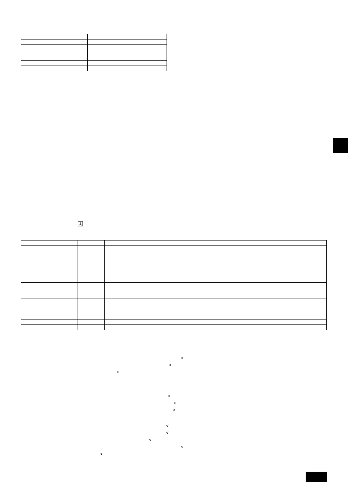
10.4. Wiring of main power supply and equipment capacity
Schematic Drawing of Wiring (Example)
[Fig. 10.4.1] (P.5)
A Switch (breakers for wiring and current leakage) B Outdoor unit C BC controller (master)
D Pull box E Indoor unit F Breakers for current leakage
'
C
BC controller (slave)
Thickness of wire for main power supply and On/Off capacities
Minimum wire thickness (mm
P200
P250
P300
P350
Outdoor unit
Total operating current
of the indoor unit
GBDFEINLPGRRUTRCZSVSLHGPO
1. Use a separate power supply for the outdoor unit and indoor unit.
2. Bear in mind ambient conditions (ambient temperature,direct sunlight, rain water,etc.) when proceeding with the wiring and connections.
3. The wire size is the minimum value for metal conduit wiring. The power cord size should be 1 rank thicker consideration of voltage drops.
Make sure the power-supply voltage does not drop more than 10 %.
4. Specific wiring requirements should adhere to the wiring regulations of the region.
5. Power supply cords of parts of appliances for outdoor use shall not be lighter than polychloroprene sheathed flexible cord (design 245 IEC57). For example,
use wiring such as YZW.
6. A switch with at least 3 mm contact separation in each pole shall be provided by the Air conditioner installation.
P400
P450
P500
P550
P600
P650
16 A or less
25 A or less
32 A or less
Main cable
4.0
4.0
4.0
6.0
10.0
10.0
10.0
16.0
16.0
16.0
1.5
2.5
4.0
Branch Capacity Fuse
4.0
4.0
4.0
6.0
10.0
10.0
10.0
16.0
16.0
16.0
1.5
2.5
4.0
2
)
4.0
4.0
4.0
6.0
10.0
10.0
10.0
16.0
16.0
16.0
1.5
2.5
4.0
25
32
32
40
63
63
63
70
70
70
16
25
32
Switch (A)
Breaker for
25
32
32
40
63
63
63
70
70
70
16
25
32
wiring (NFB)Ground
30
30
30
40
60
60
60
75
75
75
20
30
40
Breaker for current leakage
30 A 100 mA 0.1sec. or less
30 A 100 mA 0.1sec. or less
30 A 100 mA 0.1sec. or less
40 A 100 mA 0.1sec. or less
60 A 100 mA 0.1sec. or less
60 A 100 mA 0.1sec. or less
60 A 100 mA 0.1sec. or less
75 A 100 mA 0.1sec. or less
75 A 100 mA 0.1sec. or less
75 A 100 mA 0.1sec. or less
20 A 30 mA 0.1sec. or less
30 A 30 mA 0.1sec. or less
40 A 30 mA 0.1sec. or less
Warning:
• Be sure to use specified wires to connect so that no external force is imparted to terminal connections. If connections are not fixed firmly, it may cause
heating or fire.
• Be sure to use the appropriate type of overcurrent protection switch. Note that generated overcurrent may include some amount of direct current.
Caution:
• Some installation site may require attachment of an earth leakage breaker. If no earth leakage breaker is installed, it may cause an electric shock.
• Do not use anything other than breaker and fuse with correct capacity. Using fuse and wire or copper wire with too large capacity may cause a malfunction
of unit or fire.
11. Test run
11.1. The following phenomena do not represent trouble (emergency)
Indoor unit and BC controller generate sound
Phenomenon
at the cooling/heating change over sometime.
Indoor unit does not perform cooling (heating) operation.
The auto vane runs freely.
Fan setting changes during heating.
Fan stops during heating operation.
Fan does not stop while operation has been
stopped.
No setting of fan while start SW has been
turned on.
Outdoor unit does not operate by turning
switch on.
Indoor unit remote controller shows “HO” in-
dicator for about two minutes when turning
ON universal power supply.
Drain pump does not stop while unit has been
stopped.
Drain pump continues to operate while unit
has been stopped.
Display of remote controller
Normal display
“Cooling (heating)” flashes
Normal display
Normal display
Defrost display
No lighting
Heat ready
Normal display
“HO” flashes
Light out
This is not a trouble as it is just a selecting sound.
When multiple indoor units (max. 3) are connected to the same branch of the BC
controller, the heating (cooling) operation cannot be performed while another
indoor unit is performing a cooling (heating) operation.
Because of the control operation of auto vane, it may change over to horizontal
blow automatically from the downward blow in cooling in case the downward
blow operation has been continued for 1 hour. At defrosting in heating, hot adjusting and thermostat OFF, it automatically changes over to horizontal blow.
Ultra-low speed operation is commenced at thermostat OFF.
Light air automatically changes over to set value by time or piping temperature at
thermostat ON.
The fan is to stop during defrosting.
Fan is to run for 1 minute after stopping to exhaust residual heat (only in heating).
Ultra low-speed operation for 5 minutes after SW ON or until piping temperature
becomes 35°C, low speed operation for 2 minutes thereafter, and then set notch
is commenced. (Hot adjust control)
When the outdoor unit is being cooled and the refrigerant is resting, warming up
operation is performed for at least 30 minutes to warm the compressor (only
P200).
During this time, only the fan operates.
System is being driven.
Operate remote controller again after “HO” disappear.
After a stop of cooling operation, unit continues to operate drain pump for three
minutes and then stops it.
Unit continues to operate drain pump if drainage is generated, even during a
stop.
Cause
14
Page 15

12. Information on rating plate
Refrigerant (R410A) kg
Model
Allowable pressure (Ps)
Net weight kg
MANUFACTURER: MITSUBISHI ELECTRIC CORPORATION
AIR-CONDITIONING & REFRIGERATION SYSTEMS WORKS 5-66, TEBIRA, 6-CHOME, WAKAYAMA CITY, JAPAN
P200
10.5
236
P250
13.0
251
P300
13.0
251
P350
13.0
251
P400
16.5
HP: 4.15 MPa, LP: 2.21 MPa
291
P450
22.0
481
P500
22.0
481
P550
22.0
481
P600
22.0
481
P650
22.0
481
GBDFEINLPGRRUTRCZSVSLHGPO
15
Page 16
Inhalt
1. Sicherheitsvorkehrungen .......................................................................... 16
1.1. Vor Installations- und Elektroarbeiten...................................... 16
1.2. Vorsichtsmaßnahmen für Vorrichtungen, die das Kältemittel
R410A verwenden ................................................................... 17
1.3. Vor Installationsarbeiten .......................................................... 17
1.4. Vor der Installation - Elektroarbeiten ....................................... 17
1.5. Vor Installationsbeginn ............................................................ 17
2. Informationen zum Gerät .......................................................................... 18
3. Kombination mit Innenaggregaten ............................................................ 18
4. Überprüfung des Lieferumfangs ............................................................... 18
5. Vorgeschriebener Freiraum um das Aggregat .......................................... 18
6. Hebemethode ........................................................................................... 19
7. Einbau der Klimaanlage ............................................................................ 19
7.1. Einbau ..................................................................................... 19
8. Installation der Kältemittelleitungen .......................................................... 19
8.1. Vorsicht.................................................................................... 19
8.2. Das Kältemittel Rohrsystem .................................................... 20
1. Sicherheitsvorkehrungen
1.1. Vor Installations- und Elektroarbeiten
GB
s Vor dem Einbau der Anlage vergewissern, daß Sie alle Infor-
D
mationen über “Sicherheitsvorkehrungen” gelesen haben.
s Die “Sicherheitsvorkehrungen” enthalten sehr wichtige
Sicherheitsgesichtspunkte. Sie sollten sie unbedingt befolgen.
Im Text verwendete Symbole
F
Warnung:
Beschreibt Vorkehrungen, die beachtet werden sollten, um den Benutzer vor
der Gefahr von Verletzungen oder tödlicher Unfälle zu bewahren.
Vorsicht:
Beschreibt Vorkehrungen, die beachtet werden sollten, um die Anlage vor
E
Schäden zu bewahren.
Innerhalb der Abbildungen verwendete Symbole
: Verweist auf eine Handlung, die unterbleiben muß.
INL
PGRRUTR
: Verweist auf wichtige Anweisungen, die befolgt werden müssen.
: Verweist auf ein Teil, das geerdet werden muß.
: Gefahr von elektrischem Schlag. (Dieses Symbol findet sich als Aufkleber
auf der Hauptanlage.)
Warnung:
Die auf der Hauptanlage angebrachten Aufkleber sorgfältig lesen.
Warnung:
• Bitten Sie Ihren Fachhändler oder einen geprüften Fachtechniker, die Installation der Anlage vorzunehmen.
- Unsachgemäße Installation durch den Benutzer kann Wasseraustritt, Strom-
schläge oder Brände verursachen.
• Die Anlage an einem Ort installieren, der genügend Tragkraft für deren
Gewicht besitzt.
- Bei ungenügender Tragkraft kann das Gerät herunterfallen und Verletzun-
gen verursachen.
• Zur Verdrahtung die angegebenen Kabel verwenden. Die Anschlüsse so
sichern, daß Zugspannung von außen nicht auf die Klemmen wirken kann.
- Falscher Anschluß und falsche Befestigung führen zu Wärmebildung und
verursachen Brände.
• Vorsorge gegen heftige Windstöße und Erdbeben treffen, und die Anlage
an dem angegebenen Ort installieren.
- Durch unsachgemäße Installation kann die Anlage herunterfallen und Ver-
letzungen verursachen.
• Stets einen Filter und sonstiges Zubehör gemäß Angaben von Mitsubishi
Electric verwenden.
- Einen geprüften Techniker bitten, die Zusatzeinrichtungen zu installieren.
Unsachgemäße Installation durch den Benutzer kann zu Wasseraustritt,
Stromschlägen oder Bränden führen.
• Die Anlage niemals selbst reparieren. Wenn die Anlage repariert werden
muß, wenden Sie bitte sich an den Fachhändler.
- Wenn die Anlage unsachgemäß repariert wird, kann dies zu Wasseraustritt,
Stromschlägen oder Bränden führen.
• Nicht die Wärmetauscherleitung berühren.
- Unsachgemäße Handhabung kann zu Verletzungen führen.
• Wenn Kältemittelgas während der Installationsarbeiten austritt, den Raum
gründlich lüften.
16
9. Zusätzliches Kühlmittel einfüllen ............................................................... 20
9.1. Kalkulation des zusätzlichen kühlmittels ................................. 20
9.2. Vorsichtsmaßregeln beim Rohrleitungsanschluß und dem
Betrieb der Armatur ................................................................. 20
9.3. Überprüfung der Dichtheit, Evakuieren und Einfüllen von
Kältemitteln .............................................................................. 21
9.4. Kältedämmung und Kältemittelleitung ..................................... 22
10. Verdrahtung ............................................................................................... 23
10.1. Vorsicht .................................................................................... 23
10.2. Reglerkasten und Kabelanschlußpunkte ................................ 23
10.3. Übertragungskabelanschluß ................................................... 23
10.4. Verdrahtung der Hauptspannungsversorgung und Kapazität
der Einheiten ........................................................................... 24
11. Testbetrieb ................................................................................................ 25
11.1. Die folgenden Symptome sind nicht als Betriebsstörungen
(Notfall) anzusehen ................................................................. 25
12. Informationen auf dem Typenschild .......................................................... 25
- Wenn das Kältemittelgas auf offenes Feuer trifft, wird giftiges Gas freigesetzt.
• Die Anlage gemäß Anweisungen in diesem Installations-handbuch installieren.
- Bei unsachgemäßer Installation kann dies zu Wasseraustritt, Stromschlä-
gen oder Bränden führen.
• Elektroarbeiten durch einen zugelassenen Fachelektriker in Übereinstimmung mit dem “Electric Facility Engineering Standard” - (Technische
Normen für Elektroeinrichtungen), den “Interior Wire Regulations” - (Vor-
schriften zur Innenverdrahtung) und den in diesem Handbuch gegebenen Anweisungen vornehmen. Anlage auch immer an einen gesonderten Stromkreis anschließen.
- Wenn die Leistung der Stromquelle ungenügend ist oder die Elektroarbeiten
unsachgemäß ausgeführt wurden, kann dies zu Stromschlägen und zu Bränden führen.
• Die Abdeckung der Elektroanschlüsse der Außenanlage (Abdeckplatte)
fest anbringen.
- Wenn die Abdeckung der Elektroanschlüsse (Abdeckplatte) nicht sachge-
mäß angebracht wurde, kann Staub oder Wasser in die Außenanlage eindringen und Brände oder Stromschläge verursachen.
• Beim Verbringen der Anlage an einen anderen Standort, Anlage nicht mit
einem anderen Kältemittel als dem auf der Anlage angegebenen Kälte-
mittel füllen.
- Wenn das ursprüngliche Kältemittel mit einem anderen Kältemittel oder mit
Luft vermischt wird, kann dies zu Fehlfunktionen des Kältemittelkreislaufs
führen und die Anlage beschädigt werden.
• Wenn die Anlage in einem kleinen Raum installiert wird, müssen Maßnahmen ergriffen werden, damit die Kältemittelkonzentration auch bei
Kältemittelaustritt den Sicherheitsgrenzwert nicht überschreitet.
- Befragen Sie einen Fachhändler bezüglich geeigneter Maßnahmen zur Ver-
hinderung des Überschreitens des Grenzwertes. Sollte durch Austreten von
Kältemittel das Überschreiten des Grenzwertes erfolgen, besteht wegen
möglichem Sauerstoffmangel im Raum Gesundheitsgefahr.
• Beim Verbringen der Anlage an einen anderen Ort einen Fachhändler
oder einen geprüften Techniker zur Neuaufstellung hinzuziehen.
- Bei unsachgemäßer Installation der Anlage kann Wasser austreten, und es
können Stromschlage oder Brände verursacht werden.
• Nach Abschluß der Installationsarbeiten sicherstellen, daß kein
Kältemittelgas austritt.
- Wenn Kältemittelgas austritt und mit einem Heizgebläse, einem Ofen oder
sonstigen Wärmequellen in Berührung kommt, kann giftiges Gas erzeugt
werden.
• Die Einstellungen der Schutzvorrichtungen nicht neu einrichten oder
ändern.
- Wenn Druckschalter, Thermoschalter oder eine andere Schutzvorrichtung
kurzgeschlossen oder mit Gewalt betätigt wird oder wenn andere als die von
Mitsubishi Electric angegebenen Teile verwendet werden, besteht Brandoder Explosionsgefahr.
• Zum Entsorgen dieses Gerätes wenden Sie sich an Ihren Fachhändler.
• Der Installateur und der Systemfachmann müssen für die Sicherung ge-
gen Wasseraustritt gemäß den örtlichen Bestimmungen und Normen
sorgen.
- Falls keine örtlichen Bestimmungen bestehen, sind die nachstehenden Nor-
men anzuwenden.
• Besonders darauf achten, einen Aufstellungsort auszuwählen, wie etwa
ein Untergeschoß etc., von dem aus Kältemittelgas nicht in die Atmosphäre entweichen kann, da Kältemittel schwerer als Luft ist.
• Im Fall eines Modells mit Frischluftzufuhr den Aufstellungsort sorgfältig
auswählen, weil möglicherweise Außenluft direkt in den Raum geblasen
wird, wenn der Thermostat ausgeschaltet ist.
- Wenn Menschen oder Nahrungsmittel unmittelbar der Außenluft ausgesetzt
sind, kann dies negative Auswirkungen haben.
Page 17
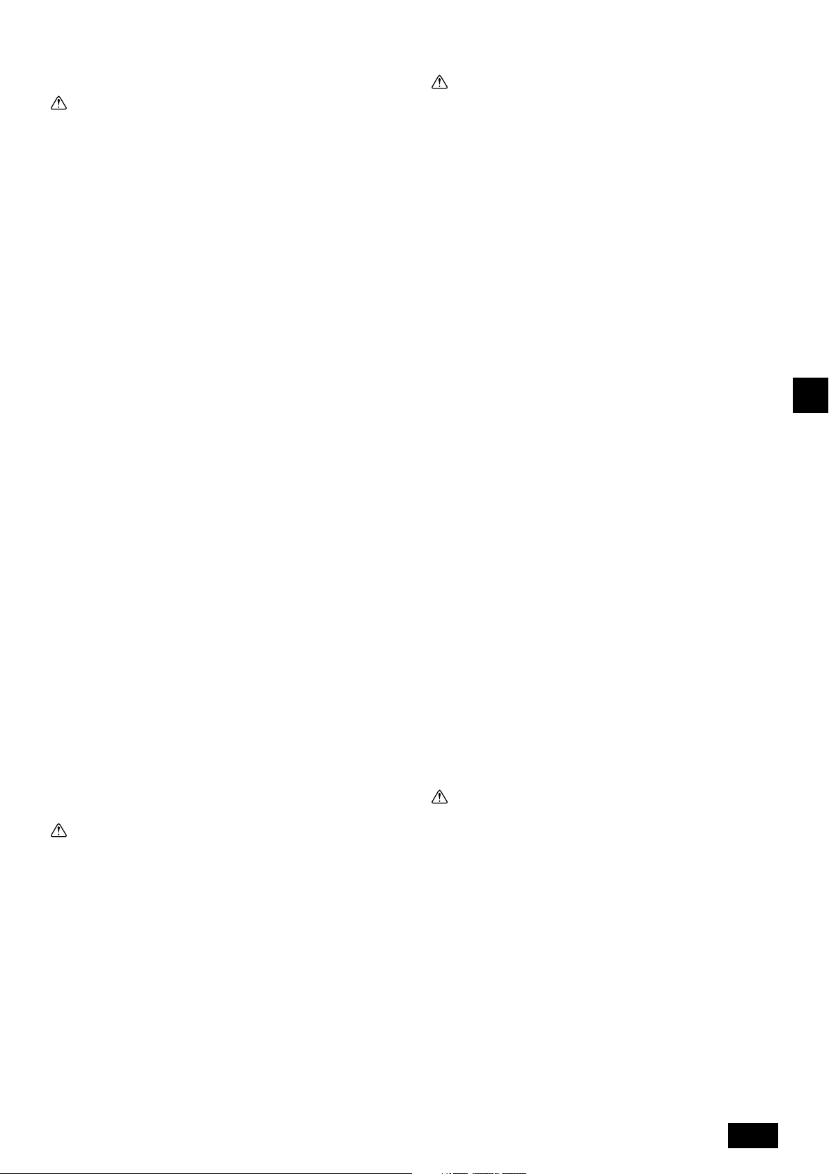
1.2. Vorsichtsmaßnahmen für Vorrichtungen,
die das Kältemittel R410A verwenden
Vorsicht:
• Kältemittel und Öl
- Das alte Kältemittel und das Kältemaschinenöl in der vorhandenen Rohrleitung enthalten große Mengen Chlor, was zur Qualitätsminderung des
Kältemaschinenöls der neuen Anlage führen kann.
- R410A ist ein Hochdruckkältemittel und kann vorhandene Rohrleitungen
bersten lassen.
• Für die Kältemittelrohrleitung nahtlose Rohre und Röhren aus Phosphordesoxidiertem Kupfer und entsprechenden Kupferlegierungen verwenden. Außerdem vergewissern, daß die Innen- und Außenflächen der Rohrleitungen sauber und frei von gefährlichem Kupfer, Oxyden, Staub/
Schmutz, Metallbearbeitungsrückständen, Ölen, Feuchtigkeit oder ande-
ren Verunreinigungen sind.
- Verunreinigungen auf der Innenseite der Kältemittelrohrleitungen können dazu
führen, daß das Kältemittelrestöl verdirbt.
• Die bei der Installation verwendete Rohrleitung in einem geschlossenen
Raum aufbewahren und beide Enden bis unmittelbar vor dem Hartlöten
geschlossen halten. (Krümmer und andere Rohrverbinder in einem
Kunststoffbeutel aufbewahren).
- Wenn Staub, Schmutz oder Wasser in den Kältemittelkreislauf gelangt, kann
dies zu einer Qualitätsminderung des Öls und zu Kompressorstörungen führen.
• Zum Beschichten der Konus- und Flanschanschlüsse Esteröl/Ätheröl oder
Alkylbenzol (kleine Menge) als Kältemaschinenöl verwenden.
- Das Kältemaschinenöl zersetzt sich, wenn es mit größeren Mengen Mine-
ralöl vermischt wird.
• Zur Füllung des Systems flüssiges Kältemittel verwenden.
- Wenn Kältemittelgas zur Füllung des Systems verwendet wird, ändert sich
die Zusammensetzung des Kältemittels im Zylinder, so daß die Leistung
abfallen kann.
• Kein anderes Kältemittel als R410A verwenden.
- Wenn ein anderes Kältemittel (R22 usw.) mit R410A gemischt wird, kann
das im Kältemittel enthaltene Chlor Verschlechterung des Kältemaschinen-
öls verursachen.
• Eine Vakuumpumpe mit einem Reverse Flow (Gegenstrom)- Rückschlag-
ventil verwenden.
- Das Öl der Vakuumpumpe fließt in den Kältemittelkreislauf zurück und führt
zur Qualitätsminderung des Kältemaschinenöls.
• Folgende Vorrichtungen, die bei herkömmlichen Kältemitteln verwendet
werden, nicht einsetzen.
(Meßrohrleitung, Füllschlauch, Gasaustrittsdetektor, Reverse Flow (Gegenstrom)- Rückschlagventil, Kältemittelfüllständer, Kältemittelaufbereitungseinrichtungen)
- Wenn ein herkömmliches Kältemittel und Kältemaschinenöl mit R410A ver-
mischt werden, kann dies zur Qualitätsminderung des Kältemaschinenöls
führen.
- Wenn R410A mit Wasser vermischt wird, kann dies zur Qualitätsminderung
des Kältemaschinenöls führen.
- Da R410A kein Chlor enthält, reagieren Gasaustrittssuchgeräte für herkömm-
liche Kältemittel nicht darauf.
• Keinen Füllzylinder verwenden.
- Bei Verwendung eines Füllzylinders kann das Kältemittel verderben.
• Beim Einsatz der Handhabungsvorrichtungen besondere Sorgfalt walten lassen.
- Wenn Staub, Schmutz oder Wasser in den Kältemittelkreislauf gelangt, kann
dies zur Qualitätsminderung des Kältemittels führen.
1.3. Vor Installationsarbeiten
Vorsicht:
• Anlage nicht an Orten installieren, wo brennbares Gas austreten kann.
- Wenn Gas austritt und sich um die Anlage herum ansammelt, kann dies zu
einer Explosion führen.
• Anlage nicht an Orten verwenden, wo sich Lebensmittel, Tiere, Pflanzen,
Präzisionswerkzeuge oder Kunstgegenstände befinden.
- Die Qualität der Lebensmittel etc. kann sich verschlechtern.
• Anlage nicht unter besonderen Umfeldbedingungen einsetzen.
- Dichter Öldampf, Dampf oder schwefelhaltiger Rauch können die Leistung
der Klimageräte erheblich beeinträchtigen oder Teile der Anlage beschädigen.
• Bei Installation der Anlage in einem Krankenhaus, einer Rundfunkstation oder an ähnlichen Orten für ausreichend Lärmschutz sorgen.
- Der Betrieb der Anlage kann gestört oder unterbrochen werden, wenn sie
durch Aufnahmegeräte, private Stromerzeugungseinrichtungen, medizinische
Hochfrequenzgeräte oder Rundfunkeinrichtungen beeinflußt wird, und umgekehrt kann der Betrieb der Anlage die Funktion dieser Geräte und Einrichtungen beeinträchtigen und Lärm erzeugen, der ärztliche Behandlungen stört
oder Bildübertragungen beeinträchtigt.
• Die Anlage nicht auf Baueinrichtungen installieren, die Wasseraustritt
verursachen können.
- Wenn die Luftfeuchtigkeit 80 % übersteigt oder wenn die Abwasserleitung
verstopft ist, kann Kondenswasser aus der Innenanlage tropfen. Daher die
vorgesehene Sammelabwasserleitung der Außenanlage einrichten.
1.4. Vor der Installation - Elektroarbeiten
Vorsicht:
• Erdung der Anlage.
- Die Erdungsleitung nicht an Gas- oder Wasserrohre, Beleuchtungsstäbe oder
an die Erdleitungen von Telefonen anschließen. Unsachgemäße Erdung kann
zu Stromschlägen führen.
• Die Gegenphase von L-Leitungen (L
(Fehlerkabel: 4103), aber die Gegenphase von L-Leitungen und N-Leitung kann nicht festgestellt werden.
- Wenn bei fehlerhafter Verdrahtung Strom zugeführt wird, können einige
Elektroteile beschädigt werden.
• Netzstromleitungen so anbringen, daß keine Zugspannung auf die Kabel
ausgeübt wird.
- Zugspannung kann Kabelbruch, Wärmebildung und Brände verursachen.
• Einen Fehlerstromschutzschalter wie vorgesehen anbringen.
- Wenn kein Fehlerstromschutzschalter angebracht wird, können Stromschlä-
ge verursacht werden.
• Netzstromkabel mit ausreichender Stromstärke und Nennwertauslegung
verwenden.
- Zu kleine Kabel können Fehlstrom verursachen, Wärme erzeugen und Brand
ausbrechen lassen.
• Nur Stromunterbrecher und Sicherungen der angegebenen Leistung verwenden.
- Eine Sicherung oder ein Stromunterbrecher von größerer Stärke oder Stahl-
oder Kupferdraht können zum Ausfall der Anlage oder zum Ausbruch von
Bränden führen.
• Klimageräte nicht waschen.
- Waschen der Anlage kann Stromschläge verursachen.
• Sorgfältig darauf achten, daß die Installationsplatte durch langen Gebrauch nicht beschädigt wird.
- Wenn der Schaden nicht behoben wird, kann die Anlage herunterfallen und
Personenschäden oder Schäden an der Einrichtung hervorrufen.
• Zur Gewährleistung eines ordnungsgemäßen Wasserablaufs die Abwasserleitung gemäß Anweisungen in diesem Installationshandbuch installieren. Rohrleitungen mit Wärmeisolierung versehen, um
Kondenswasserbildung zu verhindern.
- Unsachgemäß verlegte Abflußrohre können Wasseraustritt verursachen, was
Schäden an Mobiliar und anderen Einrichtungsgegenständen zur Folge haben kann.
• Beim Transport des Produkts äußerste Vorsicht walten lassen.
- Das Gerät wiegt mehr als 20 kg und sollte deshalb nicht von einer Person
allein getragen werden.
- Einige Geräte haben Verpackungsbänder aus PP. PP-Bänder nicht als Trans-
portmittel verwenden. Dies ist gefährlich.
- Nicht die Rippen des Wärmetauschers berühren. Man kann sich dadurch die
Finger verletzen.
- Beim Transport des Außengerätes für Unterstützung an den angegebenen
Stellen am Geräteboden sorgen. Auch die Außenanlage an vier Punkten
unterstützen, damit sie nicht zur Seite wegrutschen kann.
• Verpackungsmaterial sicher entsorgen
- Verpackungsmaterial, wie Nägel und andere Metall- oder Holzteile, können
Stichwunden oder sonstige Verletzungen verursachen.
- Kunststoffbeutel zerreißen und entsorgen, damit Kinder nicht mit ihnen spie-
len. Wenn Kinder mit Kunstoffbeutel spielen, die nicht zerrissen wurden, besteht Erstickungsgefahr.
1, L2, L3) kann festgestellt werden
1.5. Vor Installationsbeginn
Vorsicht:
• Strom mindestens 12 Stunden vor Betriebsbeginn einschalten.
- Betriebsstart unmittelbar nach Einschalten des Netzschalters kann irreversi-
ble Schäden an Innenteilen zur Folge haben. Während der Saison Netzschalter eingeschaltet lassen.
• Schalter nicht mit nassen Fingern berühren.
- Berühren eines Schalters mit nassen Fingern kann einen Stromschlag ver-
ursachen.
• Kältemittelrohrleitung nicht während oder unmittelbar nach Betrieb berühren.
-Während und unmittelbar nach Betrieb sind die Kältemittelrohrleitungen, je
nach Durchfluß des Kältemittels durch die Kältemittelrohrleitung, den Kompressor und andere Teile des Kältemittelkreislaufs, manchmal heiß und
manchmal kalt. Sie können sich die Hände verbrennen oder Frostverletzungen
erleiden, wenn Sie die Kältemittelrohrleitung berühren.
• Klimageräte nicht bei abgenommenen Verkleidungen und Schutzabdeckungen betreiben.
- Drehende, heiße oder unter Hochspannung stehende Teile können Verlet-
zungen verursachen.
• Netzstrom nicht unmittelbar nach Betriebsbeendigung ausschalten.
- Vor Ausschalten des Netzstroms immer mindestens 5 Minuten warten. An-
derenfalls kann es zu Wasseraustritt oder sonstigen Störungen kommen.
• Während der Wartung nicht die Außenfläche des Kompressors berüh-
ren.
- Wenn das Gerät an den Netzstrom angeschlossen ist, aber nicht läuft, ist die
Heizung des Kurbelgehäuses im Kompressor in Betrieb.
GB
D
F
E
INL
PGRRUTR
17
Page 18
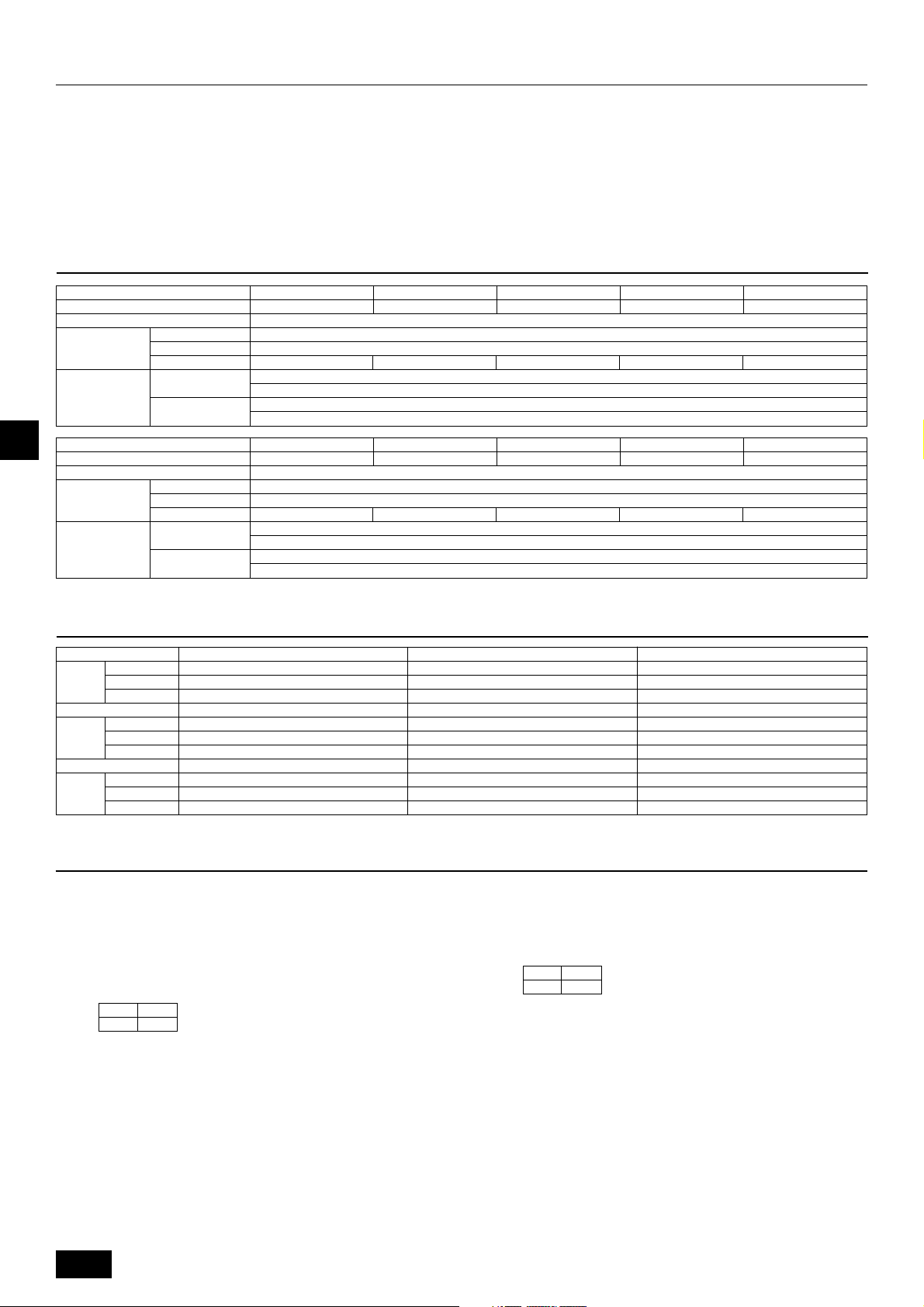
2. Informationen zum Gerät
• In diesem Gerät wird Kältemittel vom Typ R410A verwendet.
• Für R410A-Systeme werden möglicherweise andere Rohrleitungen benötigt
als für Systeme für konventielles Kältemittel, weil der Druck in R410A-Systemen höher ist. Weitere Informationen finden Sie im Datenblatt.
• Nicht alle Werkzeuge und Ausrüstungsgegenstände, die für die Installation
von Systemen mit anderen Kältemitteln verwendet werden, können auch bei
R410A-Systemen benutzt werden. Weitere Informationen finden Sie im Datenblatt.
3. Kombination mit Innenaggregaten
Modell
Geräuschpegel (50/60 Hz)
Statischer Außendruck
Innenanlagen
Betriebstemperatur
GB
D
Modell
Geräuschpegel (50/60 Hz)
Statischer Außendruck
Innenanlagen
Betriebstemperatur
F
Gesamtkapazität
Modell
Menge
Standardtyp
Frischluftzufuhrtyp
Gesamtkapazität
Modell
Menge
Standardtyp
Frischluftzufuhrtyp
PURY-P200
56 dB<A>
1 ~ 15
Betriebsart Kühlen: – 5 °CDB ~ 43 °CDB (0 °C DB ~ 43 °C DB mit der Außeneinheit an einer niedrigeren Position)
Betriebsart Heizen: – 20 °CWB ~ 15,5 °CWB
Betriebsart Kühlen: 21 °CDB ~ 43 °CDB
Betriebsart Heizen: – 12,5 °CWB ~ 20 °CWB
PURY-P450
60/61 dB<A>
1 ~ 24
Betriebsart Kühlen: – 5 °CDB ~ 43 °CDB (0 °C DB ~ 43 °C DB mit der Außeneinheit an einer niedrigeren Position)
Betriebsart Heizen: – 20 °CWB ~ 15,5 °CWB
Betriebsart Kühlen: 21 °CDB ~ 43 °CDB
Betriebsart Heizen: – 12,5 °CWB ~ 20 °CWB
PURY-P250
57 dB<A>
1 ~ 16
PURY-P500
60/61 dB<A>
1 ~ 24
• Verwenden Sie keine vorhandenen Rohrleitungen, da in diesen Chlor verblieben ist, das in konventionellem Kältemaschinenöl und Kältemittel enthalten ist.
Dieses Chlor vermindert die Qualität des Kältemaschinenöls des neuen Geräts. Die vorhandenen Rohrleitungen dürfen auch nicht verwendet werden,
weil der Druck in R410A-Systemen höher ist als in Systemen mit anderen
Kältemittelarten, und vorhandene Rohrleitungen daher möglicherweise bersten.
PURY-P300
59 dB<A>
0 Pa
50 ~150 %
20 ~ 250
1 ~ 16
PURY-P550
61/62 dB<A>
0 Pa
50 ~150 %
20 ~ 250
1 ~ 24
PURY-P350
60 dB<A>
1 ~ 20
PURY-P600
61/62 dB<A>
1 ~ 32
PURY-P400
61 dB<A>
1 ~ 24
PURY-P650
62/62,5 dB<A>
1 ~ 32
E
4. Überprüfung des Lieferumfangs
1 Rohrmontagestück (ø53)
1 Stück
1 Stück
4 Rohrmontagestück (ø27)
1 Stück
-
-
7 Anschlußrohr (Niederdruck)
1 Stück
1 Stück
1 Stück
8 Packung (Niederdruckleitung)
INL
Modell
Modell
Modell
P200 ~ P350
P400
P450 ~ P650
P200 ~ P350
P400
P450 ~ P650
P200 ~ P350
P400
P450 ~ P650
PGRRUTR
5. Vorgeschriebener Freiraum um das Aggregat
[Fig. 5.0.1] (P.2)
<A> Ansicht von oben <B> Seitenansicht
<C> Wenn bis zu einem Hindernis nur wenig Platz vorhanden ist
A Frontseite
B Keine Beschränkung der Wandhöhe (links und rechts)
C Luftauslaßbereich (Vor Ort beschafft) D Muß offen sein
E Wandhöhe (H) F Keine Beschränkung der Wandhöhe
(mm)
L1 L2
450 450
(1) Grundlegender Platzbedarf
(2) Wenn sich oberhalb der Anlage ein Hindernis befindet
(3) Wenn Einlaßluft von der rechten und linken Seite des Aggregats eintritt
• Die Wandhöhe “H” an der Front- und Rückseite sollte der Höhe der Klimaanla-
ge entsprechen.
• Falls die Wandhöhe “H” die Gesamthöhe der Klimaanlage überschreitet, ist die
Dimension “h” zu L
“h” = Wandhöhe “H’” – Gesamthöhe der Klimaanlage
(4) Wenn die Klimaanlage von Wänden umgeben ist
1 und L2 in Fig. 5.0.1 hinzuzufügen.
2 Rohrmontagestück (ø46)
5 Schneidschraube M4
1 Stück
1 Stück
2 Stück
2 Stück
2 Stück
1 Stück
1 Stück
1 Stück
Hinweis:
• Wandhöhen “H” der Vorder- und Rückseiten sollte geringer sein als ent-
weder die Front- oder die Rückplatte.
• Wenn die Höhe der Platte überschritten wird, L
on in Fig. 5.0.1 hinzufügen.
(mm)
L1 L2
450 450
Beispiel: Falls die Dimension “h” 100 mm beträgt,
(5) Einbau mehrerer Klimaanlagen und fortlaufender Einbau
• Für die Gesamtinstallation und die fortlaufende Installation erforderlicher Freiraum:
• In zwei Richtungen offen.
• Falls die Wandhöhe die Gesamthöhe der Klimaanlage überschreitet, ist in der
• Wenn sich sowohl an der Vorder- als auch an der Rückseite der Anlage eine
ist die Dimension L
Beim Installieren mehrerer Anlagen zwischen jedem Block Freiraum für den
Durchgang von Personen und für die Luftzirkulation einräumen.
folgenden Tabelle die oben gezeigte Dimension “h” (h = Wandhöhe “H’” – Gesamthöhe der Klimaanlage) zu der mit * markierten Dimension hinzuzufügen.
Wand befindet, bis zu vier Anlagen (bis zu drei bei den Modellen P450 ~ P650)
seitlich nebeneinander installieren und 1000 mm oder mehr als Einlaß/Durchgangsraum für je vier Anlagen vorsehen (für je drei bei den Modellen P450 ~
P650).
1 450 + 100 = 550 mm.
3 Rohrmontagestück (ø33)
1 Stück
-
-
6 Anschlußrohr (Hochdruck)
1 Stück (Bördel)
2 Stück (Flansch)
1 Stück (Flansch)
9 Packung (Hochdruckleitung)
1 Stück
1 Stück
1 und L2 die “h”-Dimensi-
18
Page 19
6. Hebemethode
[Fig. 6.0.1] (P.2)
Vorsicht:
Vorsicht beim Transport des Aggregats.
- Keine Lasten über 20 kg allein tragen.
- Einige Produkte sind eventuell mit PP-Bändern verschnürt. PP-Bänder sind gefährlich und sollten nicht für den Transport eines Produkts verwendet werden.
- Darauf achten, die Kühlrippen des Wärmetauschers nicht mit den bloßen Händen zu berühren. Eine falsche Handhabung kann Schnitte in den Händen verursachen.
- Plastikverpackungsbeutel nach dem Auspacken zerkleinern und entsorgen, so daß Kinder nicht damit spielen können. Plastikbeutel in Kinderhänden können zum Tod
durch Ersticken führen.
- Das Außenaggregat an vier Punkten aufgehängt tragen. Eine 3-Punkt-Aufhängung ist zum Anheben und Tragen des Aggregats nicht ausreichend und kann dazu führen,
daß das Aggregat fällt.
7. Einbau der Klimaanlage
7.1. Einbau
[Fig. 7.1.1] (P.2)
A Vor Ort beschaffter Ankerbolzen M10. B Ecke hat keinen Sitz.
• Fixieren Sie die Einheit sicher mit Schrauben, so dass sie nicht durch Erdbe-
ben oder Windstöße herunterfällt.
• Verwenden Sie Betonblöcke oder Winkelträger als Fundament für die Einheit.
• Je nach Installationsbedingungen können im Aufstellbereich Schwingungen
entstehen sowie Geräusche und Schwingungen an Boden und Wänden erzeugt werden. Daher reichlich Vibrationsschutz (Polstermaterial etc.) vorsehen.
• Dafür sorgen, daß die Ecken einen festen Sitz haben. Wenn dies nicht der Fall
ist, können sich die Befestigungsfüße verbiegen.
Warnung:
• Die für den Einbau gewählte Aufstellfläche muß dem Gewicht des Aggre-
gats mühelos standhalten.
Eine nicht ausreichend stabile Standfläche kann dazu führen, daß das
Aggregat umfällt und Personen verletzt.
8. Installation der Kältemittelleitungen
Die Serie City Multi R2 ist besteht aus einem Endzweigleitungssystem, bei dem
die Kältemittelleitung vom Außenaggregat am BC-Regler abzweigt und an die einzelnen Innenaggregate angeschlossen ist.
Die verwendeten Verbindungsarten sind: Hartlöten bei Hochdruckleitungen und
Niederdruckleitungen zwischen Außenanlage und BC-Controller sowie Flanschanschlüsse zwischen BC-Controller und Innenanlage. Hartgelöteter Anschluss wird
für den Verbindungsrohrsatz und den Zweigrohrsatz verwendet.
Warnung:
Stets mit äußerster Sorgfalt darauf bedacht sein zu verhindern, daß bei Arbeiten mit Feuer oder offenen Flammen kein Kältemittelgas austreten kann.
Wenn das Kältemittelgas mit Flammen gleich welcher Art, wie etwa aus Gasöfen, in Berührung kommt, zersetzt es sich und erzeugt ein Gas, das Vergiftungen hervorrufen kann. Niemals in einem unbelüfteten Raum Schweißar-
beiten ausführen. Nach Abschluß der Installationsarbeiten an Kältemittel-
rohrleitungen stets eine Inspektion vornehmen.
8.1. Vorsicht
In dieser Anlage wird das Kältemittel R410A verwendet. Bei der Auswahl der Rohrleitungen die geltenden Vorschriften für Material und Wandstärke der Rohrleitungen beachten.
1 Verwenden Sie für die Kältemittelrohre folgende Materialien.
• Material: Kältemittelrohrleitungen müssen aus Phosphor-desoxidiertem
Kupfer bestehen. Darüber hinaus dafür sorgen, daß die Innen- und Außenflächen der Rohre sauber sind und keine gefährlichen Schwefeloxyde, keinen Staub/Schmutz, keine Bearbeitungsrückstände, Öle, Feuchtigkeit oder
sonstige Verunreinigungen aufweisen.
2 Normal verkäufliche Rohre enthalten oft Staub und anderes Material. Blasen
Sie die Rohre immer mit trockener Druckluft sauber.
3 Tragen Sie dafür Sorge, daß kein Staub, Wasser oder andere Verunreinigun-
gen während der Installation in die Rohrleitungen gelangen können.
4 Biegungen in der Leitung sind so weit wie möglich zu vermeiden. Bei notwen-
dige Biegungen sollte der Biegeradius so groß wie möglich sein.
5 Beachten Sie immer die Einschränkungen der Kältemittelrohre (wie z.B. der
vorgegebenen Länge, den Unterschied zwischen hohem / niedrigem Druck
und dem Durchmesser des Rohres). Werden diese Vorgaben nicht beachtet,
ist ein Fehler beim Betrieb der Geräte oder ein Abfall der Heiz- / Kühlleistung
möglich.
• Das Aggregat wie in der Anleitung beschrieben einbauen, um Schäden
durch starken Wind oder Erdebenerschütterungen zu vermeiden.
Fehler beim Einbau können dazu führen, daß das Aggregat umfällt und
Unfälle mit Personenverletzungen verursacht.
Beim Legen des Fundamentes sorgfältig darauf achten, daß der Boden stark genug ausgelegt wird, daß während des Betriebs genügend Wasser zur Verfügung
steht, daß Wasser aus der Anlage abfließen kann und daß Platz für Rohr- und
Elektroleitungen vorhanden ist.
Vorkehrungen beim Verlegen von Rohr- und Elektroleitungen nach unten
Beim Verlegen von Rohr- und Elektroleitungen nach unten darauf achten, daß
Fundamente und Vorrichtungen am Boden die Öffnungen am Boden der Anlage
nicht verdecken. Bei Durchführung der Abwärtsrohrleitungen die Fundamente wenigstens 100 mm hoch auslegen, damit die Rohrleitung unter der Anlage durchgeführt werden kann.
6 Sowohl bei zuwenig als bei zuviel Kältemittel führt die Anlage einen Notstopp
durch. Füllen Sie bei einem solchen Zustand das Gerät entsprechend der Vorschriften. Lassen Sie eine Wartung durchführen, prüfen Sie immer die Hinweise, die sich auf die Länge der Rohre und die Gesamtzahl der Kühlgeräte an
beiden Orten, beziehen. Beachten Sie dabei die Tabelle der Kalkulation der
Kühlflüssigkeit auf der Rückseite des Servicefeldes und die zusätzlichen Kühleinheiten auf den Aufklebern für die kombinierte Anzahl der Innenaggregate.
7 Zur Füllung des Systems flüssiges Kältemittel verwenden.
8 Benutzen Sie niemals ein Kältemittel, um eine Reinigung der Luft durchzufüh-
ren. Benutzen Sie zum Absaugen immer eine Absaugpumpe.
9 Isolieren Sie die Rohrleitung immer einwandfrei. Nicht ausreichende Isolation
kann als Folge ein Nachlassen der Heiz- / Kühlleistung, Kondensieren von
Wassertropfen oder ähnliche Probleme bewirken.
0 Wenn Sie die Kältemittelrohre anschließen, stellen Sie sicher, daß der Kugel-
hahn des Außenaggregats vollständig geschlossen ist (die Werkseinstellung).
Betreiben Sie die Einheit nicht, bevor die Kältemittelrohre an das Außenaggregat
und an die Innenaggregate vollständig angeschlossen sind, ein Kältemittel-
lecktest durchgeführt wurde und die Luft komplett abgepumpt ist.
A Rückstände in den im Handel verfügbaren Oxydationsinhibitoren haben mög-
licherweise nachteilige Auswirkungen auf die Ausrüstung. Benutzen Sie zum
Hartlöten der Rohre immer nicht oxydierendes Material. Bei der Verwendung
von anderem Lötmaterial wird möglicherweise die Kompressoreinheit beschä-
digt.
(Detaillierte Informationen zum Rohrleitungsanschluß und zum Betrieb der
Armatur finden Sie unter Punkt 9.2.)
B Niemals bei Regen Rohrleitungsanschlußarbeiten an der Außenanlage
durchführen.
Warnung:
Beim Installieren und Verlegen der Anlage kein anderes Kältemittel als das
auf der Anlage angegebene Kältemittel einfüllen.
- Vermischung mit einem anderen Kältemittel, mit Luft etc. kann zu Fehlfunktio-
nen des Kältemittelkreislaufs und zu schweren Schäden an der Anlage führen.
Vorsicht:
• Eine Vakuumpumpe mit einem Reverse Flow (Gegenstrom) - Rückschlag-
ventil verwenden.
- Wenn die Vakuumpumpe kein Gegenstromrückschlagventil hat, kann das Öl
der Vakuumpumpe in den Kältemittelkreislauf zurückfließen und eine Qualitätsminderung des Kältemaschinenöls und andere Störungen verursachen.
GB
D
F
E
INL
PGRRUTR
19
Page 20
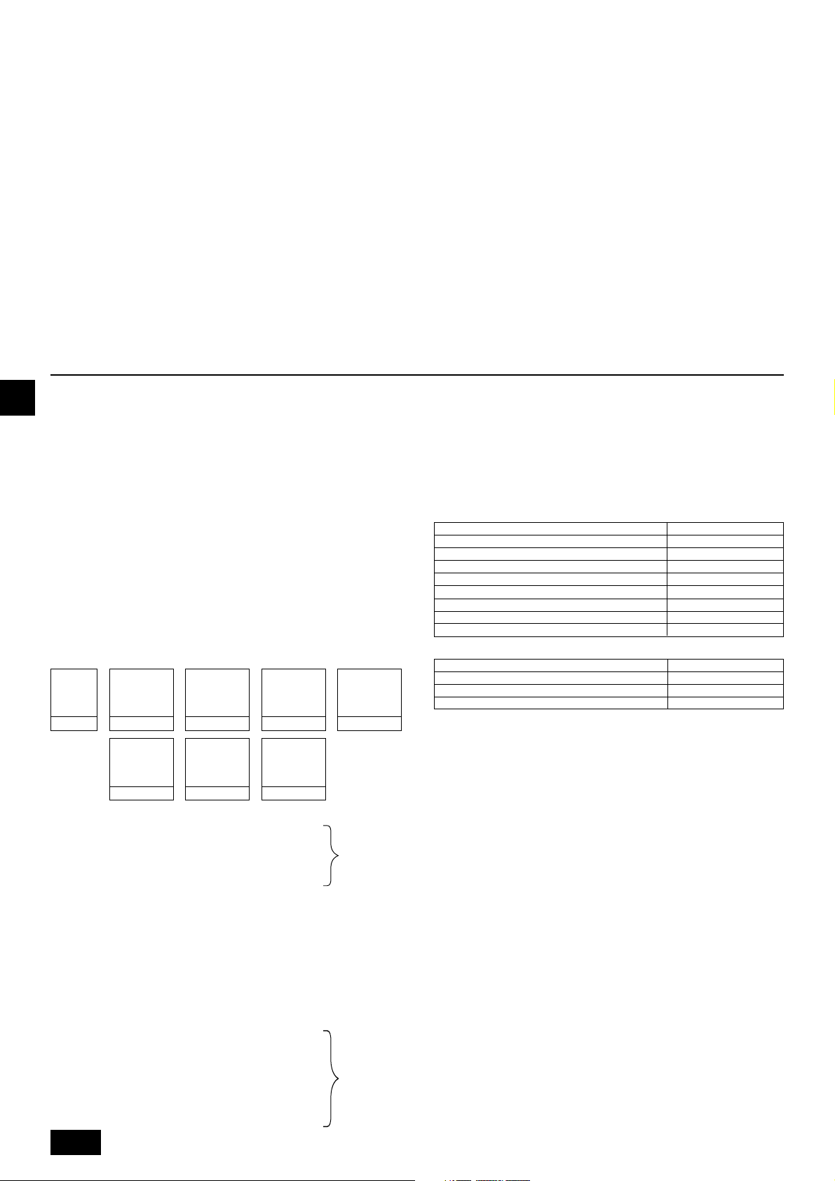
• Die bei herkömmlichen Kältemitteln eingesetzten, nachstehend dargestellten, Hilfsvorrichtungen nicht verwenden.
(Meßrohrleitung, Füllschlauch, Gasaustrittsfühler, Rückschlagventil, Kältemittel-Base, Vakuummeter, Kältemittelauffangvorrichtung)
- Vermischen von herkömmlichem Kältemittel und Kältemaschinenöl kann zur
Qualitätsminderung des Kältemaschinenöls führen.
-
Vermischen mit Wasser führt zur Qualitätsminderung des Kältemaschinenöls.
-Kältemittel R410A enthält kein Chlor. Daher reagieren Gasaustrittsfühler für
herkömmliche Kältemittel nicht darauf.
• Hilfsorrichtungen sorgfältiger handhaben als üblich.
- Wenn Staub, Schmutz oder Wasser in den Kältemittelkreislauf gelangt, wird
die Qualität des Kältemaschinenöls gemindert.
• Niemals vorhandene Kältemittelrohrleitungen einsetzen.
- Die große Menge Chlor in herkömmlichen Kältemitteln und Kältemaschinenöl
in der vorhandenen Rohrleitung führt zu einer Qualitätsminderung des neu-
en Kältemittels.
• Die zu verwendende Rohrleitung während der Installation in einem geschlossenen Raum aufbewahren und beide Enden der Rohrleitung bis
unmittelbar vor dem Hartlöten abgedichtet lassen.
- Wenn Staub, Schmutz oder Wasser in den Kältemittelkreislauf gelangen,
wird die Qualität des Öls gemindert, was zum Ausfall des Kompressors füh-
ren kann.
9. Zusätzliches Kühlmittel einfüllen
GB
• Keinen Füllzylinder verwenden.
- Bei Verwendung eines Füllzylinders kann das Kältemittel verderben.
• Zum Auswaschen der Rohrleitung keine Spezialwaschmittel verwenden.
8.2. Das Kältemittel Rohrsystem
Anschlußbeispiele
[Fig. 8.2.1] (P.3)
Å Typ der Außenanlage ı Hochdruckseite
Ç Niederdruckseite
Î Gesamtkapazität der Innenaggregate ‰ Flüssigkeitsrohr
Ï Gasrohr Ì Hochdruckgasrohr
Ó Niederdruckgasrohr ¬ Flüssigkeitsrohr
Ô Modellnummer
A BC-Controller (Standard) B BC-Controller (Haupt)
C BC-Controller (Untergeordnet) D Innenaggregat (20 ~ 140)
E Innenaggregat (200, 250)
Bei Versand ab Werk ist die Außenanlage mit dem Kältemittel gefüllt. In dieser
D
Menge des Kühlmittels sind die weiteren Mengen nicht enthalten, die je nach Län-
ge der Rohrleitungen notwendig sind. Es muß daher eine weitere Menge Kühl-
mittel für jede weitere Kühlmittellinie in die Anlage eingefüllt werden. Im Hinblick
auf die Durchführung weiterer Wartungsarbeiten zu einem späteren Zeitpunkt, stellen Sie sich eine Liste der Größe und Länge jeder Kühlmittelleitung und der Menge des zusätzlichen eingefüllten Kühlmittels zusammen. Einen Entwurf der Liste
und die entsprechenden Spalten zum Ausfüllen finden Sie im Außenaggregat.
F
9.1. Kalkulation des zusätzlichen kühl-
mittels
• Kalkulieren Sie die Menge des zusätzlich einzufüllenden Kühlmittels auf der
Basis der Länge des Rohrnetzes für das Kühlmittel und dessen Durchmesser.
E
• Benutzen Sie die unten stehende Tabelle dafür, um die Menge des zusätzlich
einzufüllenden Kältemittels zu errechnen, und füllen Sie diese errechnete Menge
in die Anlage.
• Wenn das Ergebnis der Berechnung einen Bruch von weniger als 0,1 kg aus-
INL
macht, auf die nächsten 0,1 kg aufrunden. Wenn das Ergebnis der Berechnung beispielsweise 10,62 lautet, die Menge auf 10,7 aufrunden.
<Zusätzliche Kältemittelmenge>
KältemittelNachfüllmenge
PGRRUTR
<Beispiel 1>
Innenaggregat
Gesamtlänge der einzelnen Kältemittelleitungen:
ø19,05: A = 40 m
ø9,52: B + b + e = 10 + 5 + 10 = 25 m
ø6,35: a + c + d = 10 + 10 + 10 = 30 m
Deshalb,
<Rechenbeispiel>
Kältemittel Nachfüllmenge
= 40 × 0,16 + 25 × 0,06 + 30 × 0,024 + 2,0 = 10,7 kg
<Beispiel 2>
Innenaggregat
Hochdruckrohrdurchmesser
Gesamtlänge von
=+++
ø28,58 × 0,39
(kg)
(m) × 0,39 (kg/m)
Hochdruckrohrdurchmesser
++++ α1 + α2
Gesamtlänge von
ø12,7 × 0,12
(m) × 0,12 (kg/m)
Nr. 1: 40 A: ø19,05 40 m a: ø6,35 10 m
Nr. 2: 200 B: ø9,52 10 m b: ø9,52 5 m
Nr. 3: 40 c: ø6,35 10 m
Nr. 4: 32 d: ø6,35 10 m
Nr. 5: 63 e: ø9,52 10 m
Nr. 1: 40 A: ø22,2 40 m a: ø6,35 10 m
Nr. 2: 100 B: ø9,52 10 m b: ø9,52 5 m
Nr. 3: 40 C: ø12,7 10 m c: ø6,35 10 m
Nr. 4: 32 D: ø12,7 10 m d: ø6,35 10 m
Nr. 5: 63 e: ø9,52 10 m
Nr. 6: 200 f: ø9,52 10 m
Nr. 7: 32 g: ø6,35 5 m
Nr. 8: 32 h: ø6,35 5 m
Hochdruckrohrdurchmesser
Gesamtlänge von
ø22,2 × 0,23
(m) × 0,23 (kg/m)
Hochdruckrohrdurchmesser
Gesamtlänge von
ø9,52 × 0,06
(m) × 0,06 (kg/m)
Hochdruckrohrdurchmesser
Gesamtlänge von
ø19,05 × 0,16
(m) × 0,16 (kg/m)
Hochdruckrohrdurchmesser
Gesamtlänge von
ø6,35 × 0,024
(m) × 0,024 (kg/m)
Hochdruckrohrdurchmesser
Gesamtlänge von
ø15,88 × 0,11
(m) × 0,11 (kg/m)
Gemäß den
untenstehenden
Bedingungen:
Gemäß den
untenstehenden
Bedingungen:
20
Gesamtlänge der einzelnen Kältemittelleitungen:
ø22,2: A = 40 m
ø12,7: C + D = 10 + 10 = 20 m
ø9,52: B + b + e + f = 10 + 5 + 10 + 10 = 35 m
ø6,35: a + c + d + g + h = 10 + 10 + 10 + 5 + 5 = 40 m
Deshalb,
<Rechenbeispiel>
Kältemittel Nachfüllmenge
= 40 × 0,23 + 20 × 0,12 + 35 × 0,06 + 40 × 0,024 + 3,0 + 2,0 = 19,7 kg
Wert von α1
Gesamtkapazität angeschlossener Innenaggregate α1
Wert von α2
BC-Controller (Standard, nur Haupt) 0 kg
BC-Controller (Untergeordnet) angeschlossen (ein) 1,0 kg
BC-Controller (Untergeordnet) angeschlossen (zwei)
bis Modell 80 1,0 kg
Modelle 81 bis 160 1,5 kg
Modelle 161 bis 330 2,0 kg
Modelle 331 bis 480 2,5 kg
Modelle 481 bis 630 3,0 kg
Modelle 631 bis 710 4,0 kg
Modelle 711 bis 890 5,0 kg
Modelle 891 bis 1070 6,0 kg
α2
2,0 kg
9.2. Vorsichtsmaßregeln beim Rohrleitungsanschluß und dem Betrieb der Armatur
• Rohrleitungsanschluß und Armaturbetrieb genauestens ausführen.
• Das Anschlußrohr auf der Gasseite wurde vor dem Transport werksseitig zu-
sammengebaut.
1 Zum Hartlöten des Anschlußrohrs mit Flansch das Rohr vom Schwimmer-
ventil trennen und außerhalb des Aggregats verlöten.
2 Beim Trennen des Flanschanschlußrohrs die an der Rückseite dieses Blattes
befestigte Dichtung entfernen und auf die Flanschoberfläche des Schwimmerventils kleben, um zu vermeiden, daß Staub in das Ventil gelangt.
3 Der Kältemittelumlauf ist werksseitig mit einer runden, dichtgepackten Pak-
kung abgedichtet, um das Austreten von Gas zwischen den Flanschen zu
verhindern. Da ein Betrieb in diesem Zustand nicht möglich ist, muß die
Packung durch eine Hohlpackung am Rohranschluß ausgetauscht werden.
4 Vor dem Anbringen der Hohlpackung jeglichen Staub auf der Flanschoberfläche
und der Packung abwischen und beide Seiten der Packung mit Kühlaggregatöl
(Esteröl, Ätheröl oder Alkylbenzole [kleine Menge]) bestreichen.
[Fig. 9.2.1] (P.3)
A Straff anliegende Verpackung
B Hohlpackung
• Nach dem Entleeren und Einfüllen des Kältemittels stellen Sie sicher, daß der
Hebel des Ventils voll geöffnet ist. Sollten Sie die Anlage mit geschlossenem
Ventil betrieben, kann das zu übermäßig hohem Druck auf der Hochdruckseite oder der Niederdruckseite deKältemittelelkreislaufes führen, wodurch der
Kompressor oder das 4 - Wege Ventil usw. beschädigt werden können.
• Die zusätzliche Kältemitteleinfüllmenge mit Hilfe der erwähnten Rechenformel
bestimmen und das Kältemittel nach Anschluß aller Rohrleitungen durch die
Wartungsöffnung einfüllen.
Page 21
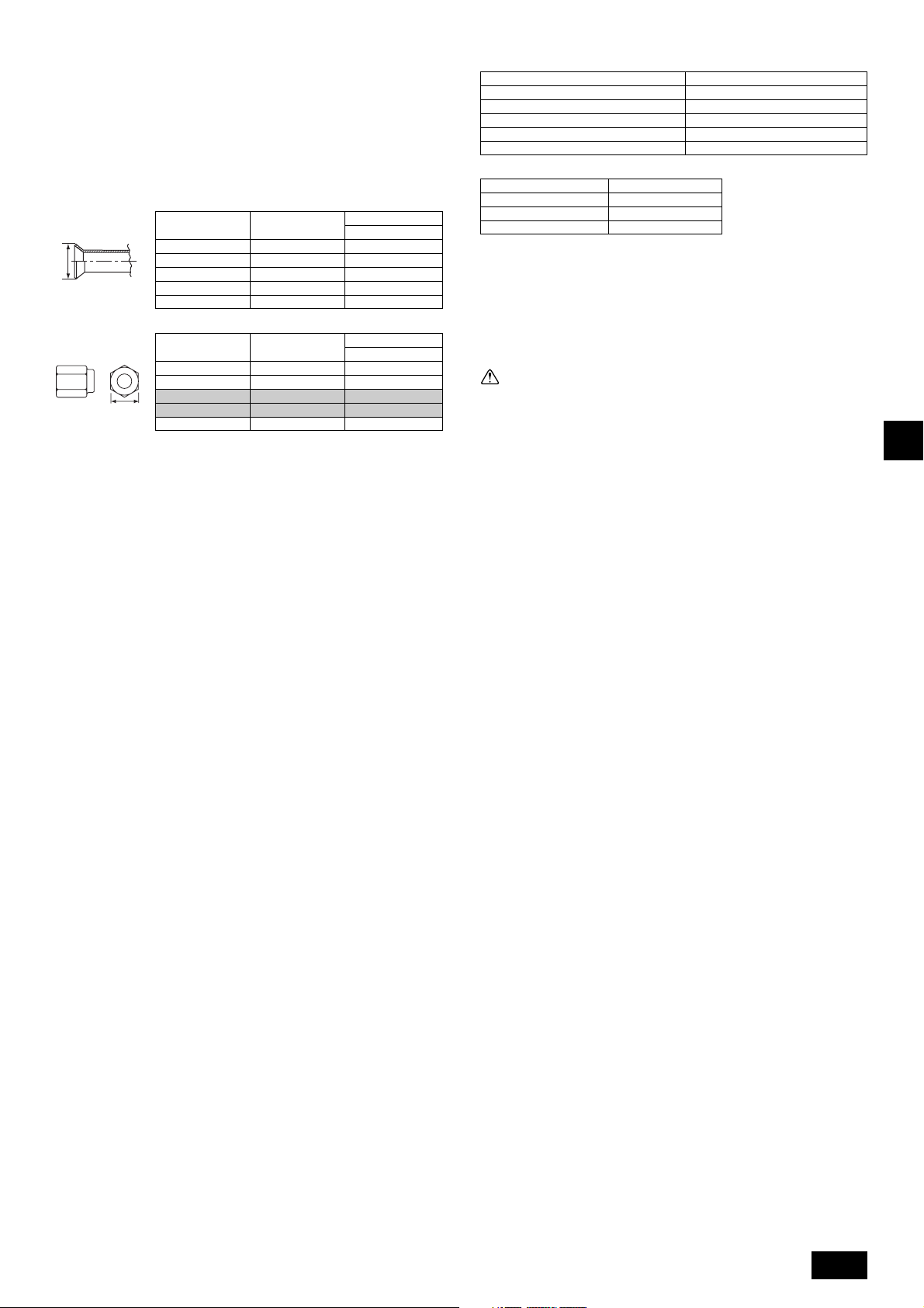
• Nach Abschluß aller Arbeiten die Wartungsöffnung fest schließen und mit dem
Deckel abdecken, um das Austreten von Gas zu vermeiden.
• Der Bördelfertigungsdurchmesser ist bei R410A-System größer als bei Systemen, die mit anderen Kältemitteln arbeiten, um die Luftdichtigkeit zu erhöhen.
• In der unten stehende Tabelle finden Sie Informationen zum
Bördelfertigungsdurchmesser. Befolgen Sie außerdem die jeweiligen gesetzlichen Vorschriften. Verschließen Sie, falls notwendig, die Rohrleitungsöffnung
mit geeignetem Material (nicht mitgeliefert), um zu verhindern, daß Kleingetier
in die Rohrleitung gelangen kann.
Bördelfertigungsdurchmesser (mm)
Außendurch
A
Konusmuttergröße (mm)
Außendurch
B
[Fig. 9.2.2] (P.3)
<A> [Kugelhahn (Niederdruckseite/Flanschtyp)]
<B> [Kugelhahn (Hochdruckseite/Bördeltyp)]
<C> [Kugelhahn (Hochdruckseite/Flanschtyp)]
<D> Diese Abbildung zeigt den Hahn voll geöffnet.
A Armaturspindel
[Ab Werk vollständig geschlossen, beim Anschluß der Rohrleitung, beim Auspumpen und beim Einfüllen von zusätzlichem Kältemittel vollständig schließen.
Nach Abschluß obengenannter Vorgänge vollständig öffnen.]
B Arretierstift [Verhindert, daß sich die Armaturspindel um 90° oder mehr dreht.]
C Packung [Sonderzubehör]
[Hersteller: Nichiasu Corporation]
[Typ: T/#1991-NF]
D Anschlußrohr (Sonderzubehör)
[Mit der Packung dieses Rohr fest am Armaturflansch anbringen, damit kein Gasaustritt erfolgt.(Anzugsdrehmoment: 40 N·m) Beide Flächen der Packung mit Kältemaschinenöl (Esteröl, Etheröl oder Alkylbenzole [kleine Menge]) bestreichen.]
E Öffnen (Langsam laufen lassen)
F Deckel
[Den Deckel abnehmen und die Armaturspindel betätigen. Den Deckel nach Abschluß des Vorgangs stets wieder anbringen. (Anzugsdrehmoment für Armaturspindeldeckel: 23 ~ 27 N·m)]
G Wartungseinheit
[Mit dieser Wartungseinheit die Kältemittelrohrleitung auspumpen und für eine
zusätzliche Füllung vor Ort verwenden.
Wartungseinheit mit einem doppelseitigen Schraubenschlüssel öffnen und schließen.
Nach Abschluß des Vorgangs Deckel stets wieder anbringen. (Anzugsdrehmoment
für den Deckel der Wartungseinheit: 12 ~ 15 N·m)]
H Konusmutter
[Anzugsdrehmoment: Siehe folgende Tabelle.
Diese Mutter mit einem doppelseitigen Schraubenschlüssel lockern.
Die Oberfläche der Aufweitung mit Kältemaschinenöl. (Esteröl, Etheröl oder Alkylbenzole [kleine Menge]) bestreichen.]
I ø15,88 (PURY-P200)
ø19,05 (PURY-P250 ~ P350)
J ø19,05 (PURY-P200)
ø22,2 (PURY-P250, P300)
ø28,58(PURY-P350 ~ P650)
K Hausrohrleitung
L ø22,2 (PURY-P400 ~ P500)
ø28,58 (PURY-P550 ~ P650)
ø6,35
ø9,52
ø12,70
ø15,88
ø19,05
ø6,35
ø9,52
ø12,70
ø15,88
ø19,05
messer
messer
Größe in Zoll
1/4"
3/8"
1/2"
5/8"
3/4"
Größe in Zoll
1/4"
3/8"
1/2"
5/8"
3/4"
Dimension A
R410A
9,1
13,2
16,6
19,7
24,0
Dimension B
R410A
17,0
22,0
26,0
29,0
36,0
Korrektes Anzugsdrehmoment für Drehmomentschlüssel:
Außendurchmesser des Kupferrohrs (mm) Anzugsdrehmoment (N·m)
ø6,35 14 bis 18
ø9,52 35 bis 42
ø12,7 50 bis 57,5
ø15,88 75 bis 80
ø19,05 100 bis 140
Standard-Befestigungswinkel:
Rohrdurchmesser (mm) Anzugswinkel (°)
ø6,35, ø9,52 60 bis 90
ø12,7, ø15,88 30 bis 60
ø19,05 20 bis 35
[Fig. 9.2.3] (P.3)
Hinweis:
Wenn kein Drehmomentschlüssel vorhanden ist, folgendes Standardverfahren verwenden:
Wenn Sie die Konusmutter mit einem Schraubenschlüssel anziehen, kom-
men Sie an einenPunkt, an dem sich das Anzugsdrehmoment abrupt erhöht.
Die Konusmutter in dem in der Tabelle oben dargestellten Winkel über die-
sen Punkt hinaus anziehen.
Vorsicht:
• Das Anschlußrohr stets von der Kugelarmatur abnehmen und es außerhalb der Anlage hartlöten.
- Hartlöten des Anschlußrohrs im installierten Zustand führt zum Erhitzen der
Kugelarmatur und zieht Störungen oder Gasaustritt nach sich. Auch kann
die Rohrleitung etc. innerhalb der Anlage Brandschäden erleiden.
• Zum beschichten der Konus- und Flanschanschlüsse Esteröl, Etheröl oder
Alkylbenzole (kleine Menge) als Kältemittelöl verwenden.
- Das Kältemaschinenöl zersetzt sich, wenn es mit größeren Mengen Mine-
ralöl vermischt wird.
• Halten Sie den Kugelhahn geschlossen, bis die vor Ort installierten Rohrleitungen vollständig mit Kältemittel gefüllt sind. Wenn das Ventil vor der
vollständigen Füllung geöffnet wird, wird die Anlage möglicherweise
beschädigt.
• Verwenden Sie kein Leckdetektoradditiv.
9.3. Überprüfung der Dichtheit, Evakuieren
und Einfüllen von Kältemitteln
1 Luftdichtetest
Führen Sie den Test bei geschlossenem Kugelhahn der Außenanlage durch,
und setzen Sie die Rohrleitungen und die Innenanlage über die Wartungs-
einheit am Kugelhahn der Außenanlage unter Druck. (Stets von den Wartungseinheiten des Hochdruckrohres und des Niederdruckrohres aus unter Druck
setzen.)
[Fig. 9.3.1] (P.4)
A Stickstoffgas B Zum Innenaggregat C Systemanalysegerät
D Lo-knopf E Hi-knopf F Kugelventil
G Niederdruckleitung H Hochdruckleitung I Außenaggregat
J Wartungsöffnung
Beachten Sie die folgenden Einschränkungen bei der Durchführung von Luftdichtigkeitstests, um negative Auswirkungen auf das Kältemaschinenöl zu vermeiden. Auch führt bei einem nicht-azeotropen Kältemittel (R410A usw.) ein Gasaustritt
dazu, daß sich die Zusammensetzung ändert und die Leistung beeinträchtigt wird.
Daher den Test auf Luftdichtigkeit mit größter Sorgfalt und Vorsicht durchführen.
GB
D
F
E
INL
PGRRUTR
21
Page 22
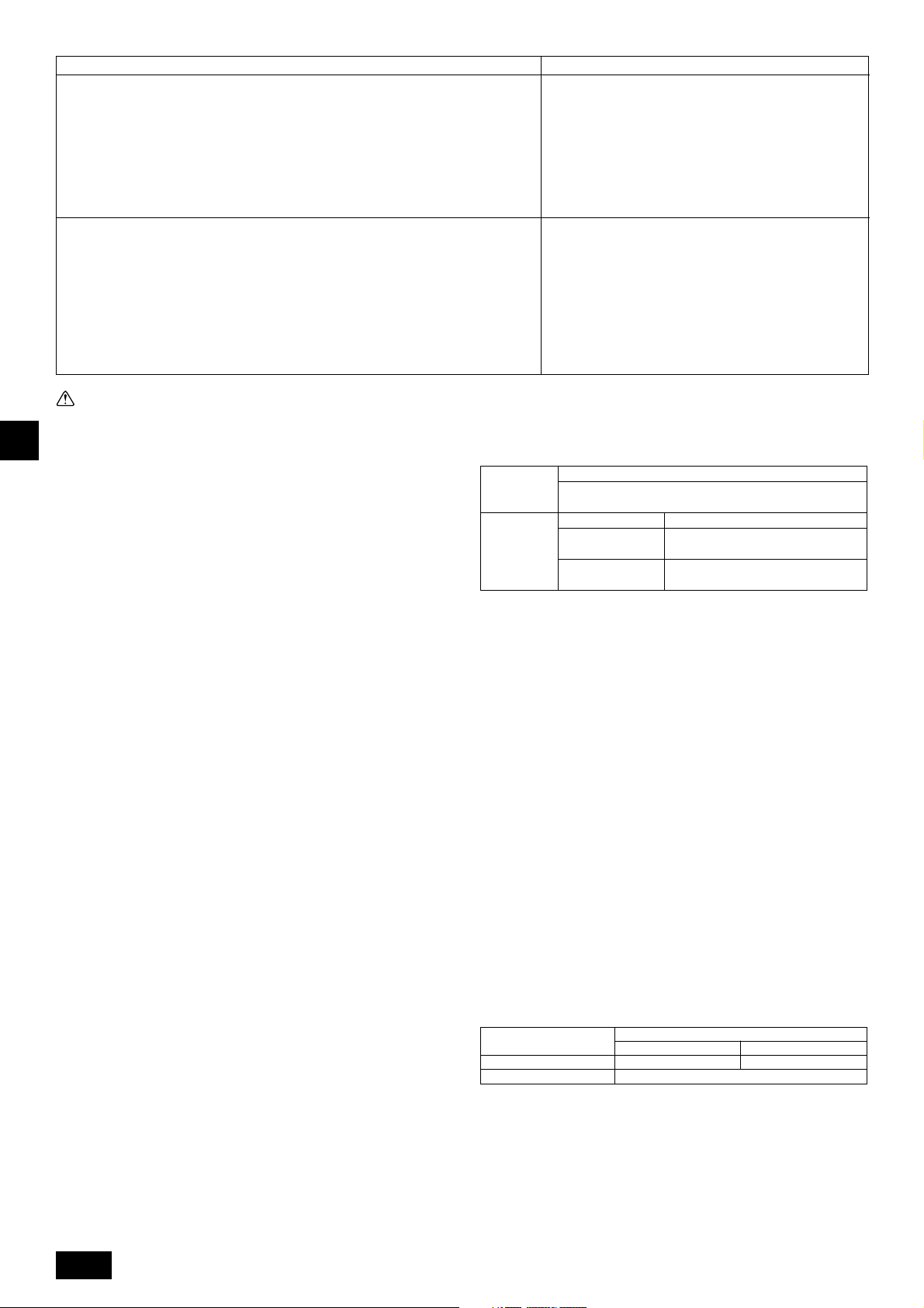
Verfahren des Dichtheitstests
1. Druckaufbau mit Stickstoffgas
(1) Nach dem Aufbau des Drucks auf die vorgegebene Druckstärke (4,15 MPa) mit Stickstoffgas,
diesen Zustand etwa einen Tag lang beibehalten. Wenn der Druck nicht abfällt, ist die Luftdichtigkeit einwandfrei. Wenn der Druck jedoch abfällt und die Gasaustrittsstelle unbekannt
ist, kann auch ein Blasentest durchgeführt werden.
(2) Nach Durchführung des oben beschriebenen Druckaufbaus die aufgeweiteten Anschlußstellen,
die hartgelötetenTeile, Flansche und andere Teile, an denen Gasaustritt erfolgen kann, mit einem
blasenbildenden Mittel (Kyuboffex etc.) besprühen und nachsehen, ob sich Blasen bilden.
(3) Nach Beendigung des Luftdichtigkeitstest das blasenbildende Mittel abwischen.
2. Druckaufbau mit Kältemittelgas und Stickstoffgas
(1) Bei der Druckerzeugung auf einen Gasdruck von etwa 0,2 MPa den Druck mit Stickstoffgas
auf den vorgesehenen Druck (4,15 MPa) bringen.
Druckaufbau aber nicht auf einmal vornehmen. Während des Druckaufbaus anhalten und
vergewissern, daß der Druck nicht abfällt.
(2) Die aufgeweiteten Anschlußstellen, die hartgelöteten Teile, Flansche und andere Teile, an
denen Gas austreten kann, mit einem R410A-kompatiblen, elektrischen Gasaustrittsprüfgerät
überprüfen.
(3) Dieser Test kann in Verbindung mit einem blasenbildenden Test vorgenommen werden.
Beschränkung
• Wenn ein brennbares Gas oder Luft (Sauerstoff) zum Druckaufbau verwendet wird, kann es Feuer fangen oder explodieren.
• Kein anderes Kältemittel als das auf der Anlage angegebene verwenden.
• Durch Abdichten mit Gas aus einer Gasflasche erfolgt eine Veränderung der Zusammensetzung des Kältemittels in der Gasflasche.
• Manometer, Füllschlauch und andere Teile verwenden, die speziell für R410A geeignet sind.
• Ein elektrischer Leckdetektor für R22 kann den Austritt von R410A
nicht feststellen.
• Keinen Halogen-Wasserstoffsäure-Brenner verwenden. (Damit
kann kein Gasaustritt festgestellt werden.)
Vorsicht:
GB
Nur Kältemittel R410A verwenden.
- Die Verwendung von anderen, chlorhaltigen Kältemitteln wie R22 oder R407C
D
vermindert die Qualität des Kältemaschinenöls oder führt zu Fehlfunktionen
des Kompressors.
2 Entleerung Evakuieren
Entlüftung bei geschlossenem Kugelhahn der Außenanlage vornehmen. Die
Entlüftung sowohl der Anschlußrohrleitung als auch der Innenanlage muß mittels einer Vakuumpumpe von der Wartungseinheit des Kugelhahns der Au-
F
ßenanlage aus vorgenommen werden. (Stets von den Wartungseinheiten des
Hochdruckrohres und des Niederdruckrohres aus evakuieren.) Wenn das Vakuum 650 Pa [abs] erreicht, das Auspumpen mindestens noch eine Stunde
lang oder mehr fortsetzen.
* Niemals Luftreinigung mit Kältemittel durchführen.
E
[Fig. 9.3.2] (P.4)
A Systemanalysegerät B Lo-Knopf C Hi-Knopf
D Kugelhahn E Niederdruckleitung F Hochdruckleitung
G Wartungsöffnung H Dreiwege-Anschluß I Ventil
INL
PGRRUTR
J Ventil K R410A-Zylinder L Waage
M Unterdruckpumpe N Zur Innenanlage O Außenanlage
Hinweis:
• Immer eine angemessene Menge Kältemittel nachfüllen. Auch das System stets mit Flüssigkältemittel nachfüllen. Zuviel oder zu wenig Kälte-
mittel verursacht Störungen.
• Eine Meßrohrleitung, einen Füllschlauch oder andere Teile, wie auf der
Anlage angegeben, für das Kältemittel verwenden.
• Mit einem Gravimeter (Das nach unten bis 0,1 kg messen kann.)
• Eine Vakuumpumpe mit einem Reverse Flow (Gegenstrom) - Rückschlag-
ventil verwenden.
(Empfohlenes Vakuummeter: ROBINAIR 14830A Thermistor Vakuummeter)
Auch einen Unterdruckmesser verwenden, der 65 Pa [abs] oder weniger
nach einer Betriebszeit von fünf Minuten erreicht.
3 Einfüllen von Kältemittel
Da das auf der Anlage verwendete Kältemittel nicht-azeotropisch ist, muß es
in flüssigem Zustand eingefüllt werden. Daher beim Befüllen der Anlage mit
einem Kältemittel aus einem Behälter, sofern der Behälter nicht über ein Siphonrohr verfügt, den Behälter, wie in Fig. 9.3.3 dargestellt, beim Einfüllen von Käl-
temittel auf den Kopf stellen. Falls der Behälter eine Siphonrohr hat, wie in der
Abbildung rechts dargestellt, kann das Kältemittel beim aufrecht stehenden
Behälter eingefüllt werden. Daher sorgfältig auf die technische Auslegung des
Behälters achten. Wenn die Anlage mit Kältemittelgas gefüllt werden muß, das
gesamte Kältemittel durch das neue Kältemittel ersetzen. Das in dem Behälter
verbleibende Kältemittel nicht verwenden.
[Fig. 9.3.3] (P.4)
A Siphonrohr B Wenn der Zylinder kein Siphonrohr hat
9.4. Kältedämmung und Kältemittelleitung
Dafür sorgen, daß die Kältemittelrohrleitung ausreichend isoliert ist. Dazu
Flüssigkeitsrohrleitung und Gasrohrleitung getrennt mit hitzebeständigem Polyäthylen von ausreichender Dicke abdecken, so daß an den Anschlußstellen zwi-
schen Innenanlage und Isoliermaterial und den Isoliermaterialien selbst keine Lücke
vorhanden ist. Eine unzureichende Isolierung führt zu Heraustropfen von Kondensat usw. Hierbei sollte ganz besonders auf die sorgfältige Isolierung am Deckenraum geachtet werden.
[Fig. 9.4.1] (P.4)
A Stahldraht B Rohr
C Asphaltmastix oder Asphalt D Wärmeisoliermaterial A
E Äußere Abdeckung B
Wärme-
isoliermaterial
A
Äußere
Abdeckung B
Hinweis:
• Bei einer Isolierung mit Polyäthylen als Abdeckmaterial ist ein mit Asphalt abgedecktes Dach nicht notwendig.
• Die Elektroleitungen dürfen keine Wärmeisolierung haben.
[Fig. 9.4.2] (P.4)
[Fig. 9.4.3] (P.4)
Glasfaser + Stahldraht
Klebstoff + Wärmestabiler Polyäthylenschaum + Klebeband
Innenaggregat Vinylklebeband
Freiliegender Boden
Außenaggregat
A Niederdruckleitung B Hochdruckleitung C Elektrische Drähte
D Deckband E Isolator
Wasserabweisendes Hanftuch + Bronzeasphalt
Wasserabweisendes Hanftuch + Zinkblech + Öliger Lack
Eindringender Abschnitt
[Fig. 9.4.4] (P.4)
<A> Innere Wandung (nicht sichtbar) <B> Äußere Wandung
<C> Äußere Wandung (freiliegend) <D> Boden (Wasserdichtmachen)
<E> Dachrohrschaft
<F> Eindringender Abschnitt in Feuerabgrenzung und Grenzwand
A Manschette B Wärmeisoliermaterial
C Isolierung D Wärmeschutzisolierung
E Klebeband F Wasserfeste Schicht
G Manschette mit Kante H Wärmeschutzisolierung
I Mörtel oder sonstiges, nichtbrennbares Nahtdichtungsmaterial
J Nichtbrennbares Wärmeisoliermaterial
Beim Ausfüllen eines Spalts mit Mörtel muß der eindringende Abschnitt mit Stahlblech abgedeckt werden, damit das Isoliermaterial nicht eingedrückt wird. Im obigen Fall sowohl zum Isolieren als auch zum Abdecken feuerfestes Material verwenden. (Zur Abdeckung kein Vinyl verwenden.)
• Das Isoliermaterial für vor Ort installierte Rohrleitungen muß den folgenden
Spezifikationen entsprechen:
Dicke
ø6,35 bis ø25,4 mm
Temperaturfestigkeit
* Die Installation von Rohrleitungen in einer Umgebung mit hohen Temperatu-
ren und hoher Luftfeuchtigkeit, wie etwa auf dem obersten Stockwerk eines
Gebäudes, erfordert möglicherweise die Verwendung von dickerem Isoliermaterial als in der oben stehenden Tabelle angegeben.
* Falls bestimmte vom Kunden geforderte Spezifikationen erfüllt werden sollen,
stellen Sie sicher, daß auch die Spezifikationen in der oben stehenden Tabelle
erfüllt werden.
Leitungsdurchmesser
min. 10 mm
ø28,58 bis ø38,1 mm
min. 15 mm
min. 100 °C
22
Page 23
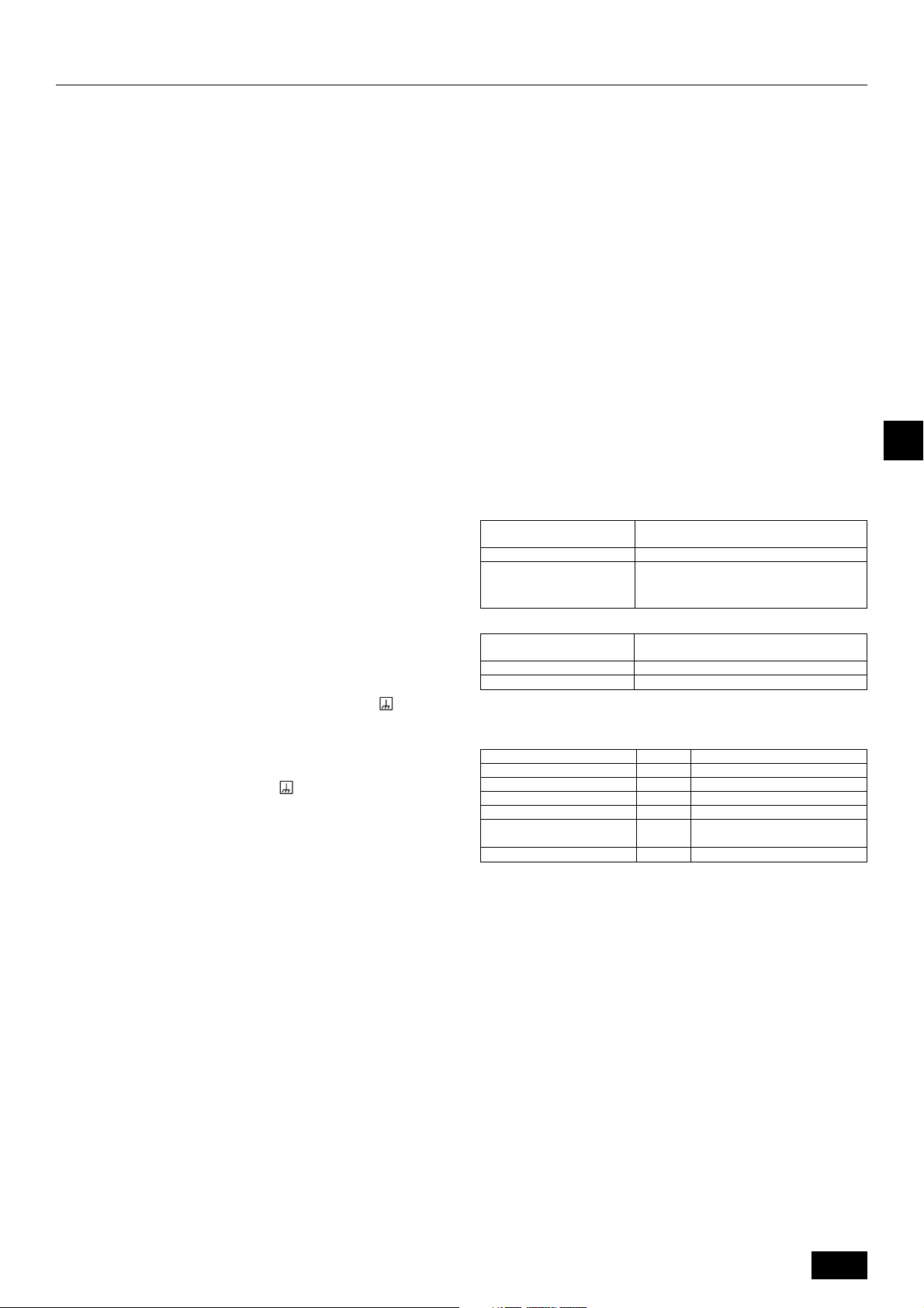
10. Verdrahtung
10.1. Vorsicht
1 Elektrische Arbeiten sind in Übereinstimmung mit den für elektrische Ausrü-
stung, Verkabelung usw. geltenden gesetzlichen Normen und Vorschriften sowie den Richtlinien der Elektrizitätswerke auszuführen.
2 Die Reglerverdrahtung (im nachfolgenden Text Übertragungsleitung genannt)
sollte (5 cm oder mehr) von den Stromquellenkabeln entfernt verlegt werden,
um elektrische Störgeräuschen durch die Stromquellenkabel zu vermeiden.
(Übertragungsleitung und Stromquellenkabel nicht im gleichen Leitungsrohr
verlegen.)
3 Darauf achten, das Außenaggregat vorschriftsmäßig zu erden.
4 Ausreichend Platz für die Verkabelung des Schaltkastens der Innen- und Außen-
aggregate frei lassen, da der Kasten bei der Wartung mitunter ausgebaut wird.
5 Die Hauptstromquelle niemals an die Klemmleiste der Übertragungsleitung
anschließen; andernfalls verschmoren elektrische Teile.
6 Für die Übertragungsleitung zweiadrige Abschirmkabel verwenden. Die
Verdrahtung von Übertragungsleitungen verschiedene Systeme mit dem gleichen mehradrigen Kabel vermindert die Übertragungs- und Empfangsqualität
und führt zu Fehlfunktionen.
7 Es sollte nur die angegebene Übertragungsleitung an die Klemmleiste für die
Signalübertragung vom Außenaggregat angeschlossen werden.
(Mit Außenaggregat anzuschließende Übertragungsleitung: Klemmleiste TB3
für Übertragungsleitung. Sonstige: Klemmleiste TB7 für Zentralregelung)
Bei fehlerhaft ausgeführten Anschlüssen funktioniert das System nicht.
8 Bei Anschluß an einen Regler der oberen Klasse oder Anschluß für Gruppen-
betrieb mit verschiedenen Kältemittelsystemen muß eine übertragende Reglerleitung zwischen den Außenaggregaten installiert werden.
Diese Reglerleitung ist zwischen den Klemmleisten für die Zentralregelung anzuschließen. (Zweiadriges Kabel ohne Polarität)
Für Gruppenbetrieb mit verschiedenen Kältemittelsystemen ohne Anschluß an
den Regler der oberen Klasse ist der an CN41 angeschlossene Kurzschluß-
stecker zu trennen und an CN40 für eines der Außenaggregate anzuschließen.
9 Die Gruppe wird über die Fernbedienung eingestellt.
10.2. Reglerkasten und Kabelanschlußpunkte
1. Die Übertragungsleitung der Innenanlage am Anschlußblock für die Übertra-
gungsleitung (TB3) anschließen oder die Leitungen zwischen den Außenanla-
gen oder die Leitungen zum Hauptsteuersystem an den Klemmblock der
Hauptsteuerung (TB7) anschließen.
Bei Verwendung von abgeschirmten Leitungen die Abschirmungserdung der
Übertragungsleitung der Innenanlage an die Erdungsschraube (
ßen und die Abschirmungserdung der Leitung zwischen den Außenanlagen
und der Übertragungsleitung des Hauptsteuersystems an die Abschirmungsklemme (S) des Klemmblocks der Hauptsteuerung anschließen. Außerdem
muß bei Außenanlagen, deren Netzanschluß CN41 durch einen Anschluß CN40
ersetzt wurde, die abgeschirmte Klemme (S) des Klemmblocks (TB7) der
Zentralsteuerung ebenfalls an die Erdung (
Befestigen Sie das Kabel mit dem Kabelbinder sicher unten am Klemmblock,
so daß externe Kräfte nicht auf den Klemmblock wirken. Andernfalls wird mög-
licherweise der Klemmblock beschädigt, was einen Kurzschluß, Erdungsfehler
oder Brand zur Folge haben kann.
) angeschlossen sein.
) anschlie-
[Fig. 10.2.1] (P.4)
A Stromquelle B Über tragungsleitung
C Erdungsschraube
2. Rohrleitungsbefestigungsplatten (ø27, ø33, ø46, ø53) werden mitgeliefert. Die
Netz- und Übertragungsleitungen durch die zugehörigen Ausbrechöffnungen
führen, dann das Ausbrechteil von der Unterseite des Klemmkastens abnehmen und die Leitungen anschließen.
3. Netzleitung mit Pufferbuchse zum Schutz gegen Zugspannung (PG-Anschluß
o.ä.) am Klemmkasten befestigen.
4. Verkleinern Sie die Öffnung mit einem Leitungsrohr, um Kleingetier den Zu-
gang zu versperren.
10.3. Übertragungskabelanschluß
1 Steuerkabelarten
1. Übertragungskabel für die Verdrahtung
•Übertragungskabelarten: Abgeschirmte Kable CVVS, CPEVS
• Kabeldurchmesser: Mehr als 1,25 mm
• Maximale Elektroleitungslänge: Bis 200 m
• Maximale Länge von Übertragungskabeln für Zentralsteuerung und Außenan-
lagen/Innenanlagen-Übertragungskabeln (maximale Länge über Innenanlagen): maximal 500 m
Die maximale Länge der Übertragungskabel-Verdrahtung (für die Zentralsteuerung und die einzelnen Außenanlagen) zwischen der ÜbertragungskabelSpannungsversorgungseinheit und Systembedienung beträgt 200 m.
2. Fernbedienungskabel
• M-NET-Fernbedienung
Art des Fernbedienungs-
kabel
Kabeldurchmesser
Anmerkungen
• MA-Fernbedienung
Art des Fernbedienungs-
kabel
Kabeldurchmesser
Anmerkungen
* Mit einer einfachen Fernbedienung angeschlossen.
2 Verdrahtungsbeispiele
• Name der Steuereinheit, Symbol und zulässige Anzahl der Steuereinheiten.
Bezeichnung
Außenaggregat Steuereinheit
BC-Steuereinheit (Master/Haupt)
BC-Steuereinheit (Slave/Unter)
Übertragungsverstärkergerät
Innenaggregat Steuereinheit
Fernbedienung
*1 Je nach Anzahl der angeschlossenen Innengerätesteuerungen kann ein
Übertragungsverstärker (RP) erforderlich sein.
2
Armiertes 2-adriges Kabel (nicht abgeschirmt)
0,3 bis 1,25 mm
Bei Überschreitung von 10 m Kabel, mit den
gleichen technischen Daten wie 1.
Übertragungskabel für die Verdrahtung.
Armiertes 2-adriges Kabel (nicht abgeschirmt)
CVV
0,3 bis 1,25 mm
unter 200 m
Symbol
OC
BC
BS
RP
IC
RC
2
(0,75 bis 1,25 mm2)*
2
(0,75 bis 1,25mm2)*
Zulässige Regleranzahl
Ein Regler für OC
Kein, einer oder zwei Controller für ein OC
Null oder eine Steuerung für ein OC (*1)
Zwei bis vierundzwanzig Regler für
ein OC (*1)
Maximal 2 pro Gruppe
GB
D
F
E
INL
PGRRUTR
Beispiel eines Gruppenbetriebssystems mit mehreren Außenaggregaten (Abschirmkabel und Adressenangaben sind notwendig.)
<Beispiel der übertragungskabelverlegung>
[Fig. 10.3.1] M-NET-Fernbedienung (P.5)
[Fig. 10.3.2] MA-Fernbedienung (P.5)
[Fig. 10.3.3] Übertragungsverstärkereinheit (P.5)
<A> Stecken Sie die Kabelbrücke von CN41 auf CN40.
<B> SW2-1:ON
<C> Belassen Sie die Kabelbrücke auf CN41.
A Gruppe 1 B Gruppe 4 C Gruppe 5 D Abgeschirmte Kabel E Unter fernbedienung
( ) Adresse
<Kabelverlegung und Adresseneinstellung>
a. Benutzen Sie für den Anschluß zwischen dem Außenaggregat (OC) und dem Innenaggregat (IC), sowie zwischen allen OC und OC als auch allen IC und IC Verbindun-
gen, unbedingt immer abgeschirmte Kabel.
b. Benutzen Sie Zuleitungskabel für die Verbindungen zwischen den Anschlüssen der Klemmleiste M1 und M2 und dem Erdanschluß am Anschlußkasten der Übertragungs-
kabel (TB3) jedes Außenaggregates (OC) zu den Anschlüssen M1 und M2 und dem Anschluß S am Anschlußkasten der Übertragungskabel des Innenaggregates (IC).
c. Verbinden Sie die Anschlüsse 1 (M1) und 2 (M2) am Anschlußkasten der Übertragungskabel des Innenaggregates (IC), das auf die letzte angegebene Adresse
innerhalb der gleichen Gruppe eingestellt ist, mit der Klemmleiste der Fernbedienung (RC).
d. Schließen Sie die Anschlüsse M1, M2 und den Anschluß S an die Klemmleiste (TB7) der Zentralsteuerung des Außenaggregates (OC) an.
23
Page 24
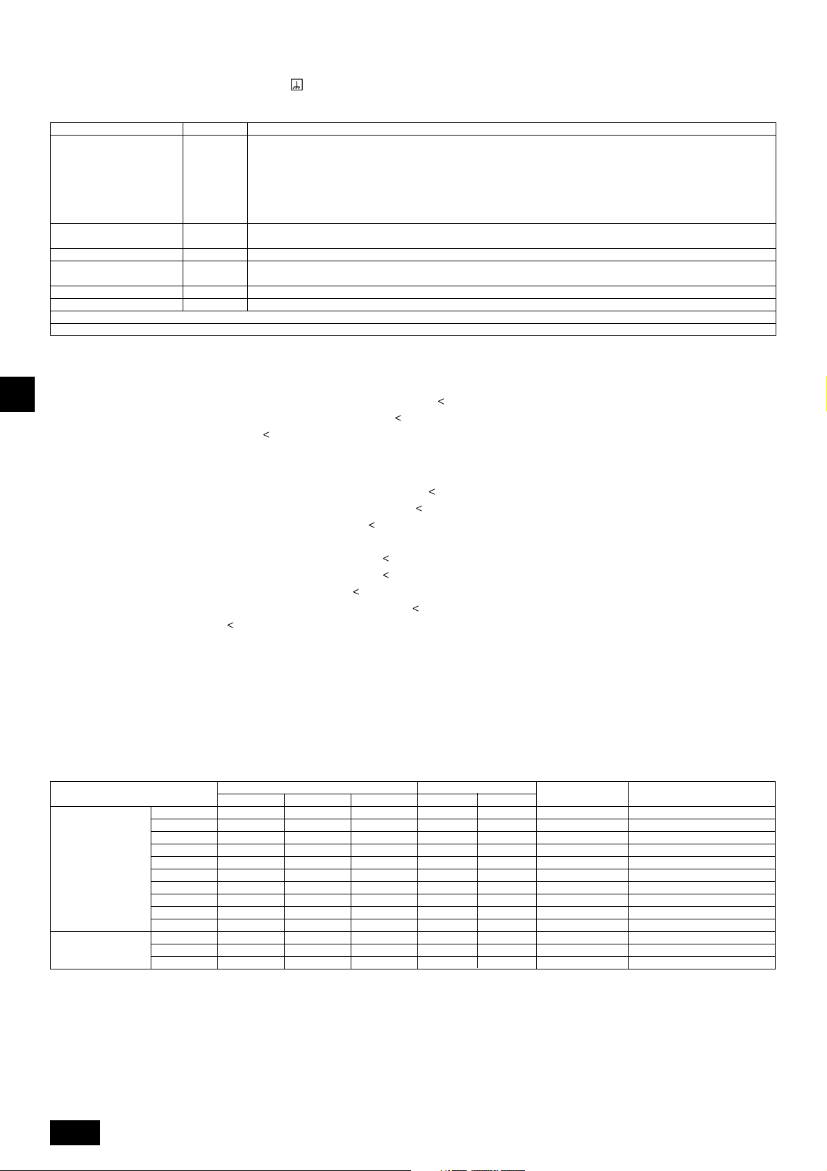
e. Ändern Sie an nur einem Außenaggregat die Kabelbrücke des Bedienungsfeldes von CN41 nach CN40.
f. Schließen Sie den Anschluß S der Klemmleiste der Zentralsteuerung (TB7) des Außenaggregates (OC) des Gerätes, in dem oben in Schritt e die Kabelbrücke in
Position CN40 gesteckt wurde, an den Erdanschluß des Anschlußkastens an.
g. Stellen Sie die Adressen wie folgt ein.
* Zur Einstellung der Adresse der Außenanlage auf 100 muß der Schalter für die Einstellung der Adresse der Außenanlage auf 50 eingestellt sein.
Aggregat Bereich Einstellung
IC (Hauptaggregat) 01 bis 50
IC (Unteraggregat) 01 bis 50
Außenaggregat 51 bis 100 Letzte angegebene Adresse aller Innenaggregate plus 50 einstellen
BC-Controller (Haupt) 51 bis 100
BC-Controller (Untergeordnet) 51 bis 100 Niedrigste Adresse aller an den BC-Controller (Slave) angeschlossenen Innenanlagen plus 50
M-NET R/C (Hauptaggregat) 101 bis 150 IC (Hauptaggregat) Adresse innerhalb der gleichen Adressen der Gruppe der Innenaggregate plus 100 einstellen
M-NET R/C (Unteraggregat) 151 bis 200 IC (Hauptaggregat) Adresse innerhalb der gleichen Adressen der Gruppe der Innenaggregate plus 150 einstellen
MA R/C – Nicht erforderliche Adresseneinstellung (Erforderliche Einstellung Haupt/Sub)
h. Die Einstellung der Gruppenoperation verschiedener Innenaggregate kann, nach dem Einschalten der Netzspannung, durch die Fernbedienung (RC) erfolgen.
Die nächstmögliche Adresse innerhalb der gleichen Innenanlagengruppe verwenden. Legen Sie bei einem R2-System mit
Sub-BC-Controllern die Innenanlagen-Adressen in der folgenden Reihenfolge fest:
1 Innenanlagen, die an den Haupt-BC-Controller angeschlossen sind
2 Innenanlagen, die an den BC-Sub-Controller 1 angeschlossen sind
3 Innenanlagen, die an den BC-Sub-Controller 2 angeschlossen sind
Legen Sie die Innenanlagen-Adressen so fest, daß alle Adressen von 1 niedriger sind als diejenigen von 2 und daß alle
Adressen von 2) niedriger sind als diejenigen von 3.
Stellen Sie eine andere Adresse als die Adresse des IC Hauptaggregates in der gleichen Gruppe der Innenaggregate ein.
Sie muß sich in der gleichen Sequenz mit dem IC (Hauptaggregat) befinden
Außenaggregat-Adresse plus 1 einstellen. Falls die gesetzte Innenanlagen-Adresse identisch ist mit der Adresse einer
anderen Innenanlage, die neue Adresse auf einen nicht belegten Wert innerhalb des Einstellbereichs setzen.
GB
<Zulässige Kabellängen>
1 M-NET-Fernbedienung
D
• Größte Länge über die Außenaggregate: L
• Längste Übertragungskabellänge: L
• Fernbedienungskabellänge: r
2 MA-Fernbedienung
F
• Größte Länge über die Außenaggregate (M-NET-Kabel): L
• Längste Übertragungskabellänge (M-NET-Kabel): L
• Fernbedienungskabellänge: c
3 Übertragungsverstärkergerät
E
• Längste Übertragungskabellänge (M-NET-Kabel): 1 L
INL
• Fernbedienungskabellänge: r
1, r2, r3, r4
Überschreitet die Kabellänge den Wert von 10 m, benutzen Sie abgeschirmte Kabel des Querschnitts 1,25 mm
Abschnitts (L
1 und c1+c2+c3 und c1+c2+c3+c4
1, r2
Wenn die Länge 10 m überschreitet, ein abgeschirmtes Kabel von 1,25 mm
innerhalb der gesamten erweiterten Länge und der längstenFernbedienungslänge berechnen.
1+L2+L3+L4 und L1+L2+L3+L5 und L1+L2+L6
1 und L3+L4 und L3+L5 und L6 und L2+L6
10 m (0,3 bis 1,25 mm2)
=
8) sollte sowohl in die Kalkulation der maximalen Länge als auch in die Berechnung der Gesamtlänge eingerechnet werden.
1+L2+L3+L4 und L1+L2+L6
1 und L3+L4 und L6 und L2+L6
8+L1+L2+L3+L5+L6
8+L1+L2+L3+L5+L7
2 L
8+L1+L2+L4
3 L
6+L5+L3+L4, L4+L3+L5+L7
4 L
10 m (0,3 bis 1,25 mm2)
=
200 m (1,25 mm2)
=
200 m (1,25 mm2 oder mehr)
=
200 m (0,3 bis 1,25 mm2)
=
200 m (1,25 mm2)
=
200 m (1,25 mm2)
=
500 m (1,25 mm2 oder mehr)
=
500 m (1,25 mm2 oder mehr)
=
200 m (1,25 mm
=
200 m (1,25 mm2)
=
2
oder mehr)
2
. Die Länge dieses
2
verwenden und dieLänge dieses Teils (L4 und L7) als
10.4. Verdrahtung der Hauptspannungsversorgung und Kapazität der Einheiten
Schematische Darstellung der Verdrahtung (Beispiel)
[Fig. 10.4.1] (P.5)
A Leitungsunterbrecher (Erdschlußunterbrecher) B Außenaggregat C BC - Steuereinheit (Master/Hauptl) C' BC - Steuereinheit (Slave/Unter)
PGRRUTR
D Einziehdose E Innenaggregat F Unterbrecherkontakte für Stromlecks
Drahtstärke der kabel der hauptspannungsversorgung und der Ein/Aus schalter
Minimum - drahtstärke (mm
Hauptkabel
P200
P250
P300
P350
Außenaggregat
Gesamtstromstärke
der Innenanlage
1. Verwenden Sie eine separate Netzstromversorgung für das Innen- und Außengerät.
2. Berücksichtigen Sie bei der Verkabelung und den Anschlüssen die Umgebungsbedingungen (Umgebungstemperatur, direktes Sonnenlicht, Regenwasser,
usw.)
3. Die Leitungsstärke ist der Minimalwert für die Verkabelung mit Metalleitern. Um Spannungsabfall zu vermeiden, muß die Stärke der Netzanschlußleitung eine
Nummer größer gewählt werden. Die Netzstromspannung sollte auf keinen Fall um mehr als 10 % abfallen.
4. Bestimmte Verkabelungsvorschriften sollten die örtlichen Vorschriften einhalten.
5. Kabel für die Stromversorgung von Außengeräten sollten nicht dünner sein als flexible Leitungen mit Polychloropren-Mantel (Nr. 245 nach IEC-Norm 57).
Verwenden Sie z. B. YZW-Kabel.
6. Ein Schalter mit einem Kontaktabstand von mindestens 3 mm für jeden Pol ist durch die Klimaanlageninstallation vorzusehen.
P400
P450
P500
P550
P600
P650
16 A oder weniger
25 A oder weniger
32 A oder weniger
4,0
4,0
4,0
6,0
10,0
10,0
10,0
16,0
16,0
16,0
1,5
2,5
4,0
Verteilung Kapazität Sicherung
4,0
4,0
4,0
6,0
10,0
10,0
10,0
16,0
16,0
16,0
1,5
2,5
4,0
2
)
Erdung
4,0
4,0
4,0
6,0
10,0
10,0
10,0
16,0
16,0
16,0
1,5
2,5
4,0
Schalter (A)
25
32
32
40
63
63
63
70
70
70
16
25
32
Unterbrecher schutzschalter
25
32
32
40
63
63
63
70
70
70
16
25
32
für verdrahtung (NFB)
30
30
30
40
60
60
60
75
75
75
20
30
40
Unterbrecher Schutzschalter
für Leckstrom
30 A 100 mA 0,1Sek. oder weniger
30 A 100 mA 0,1Sek. oder weniger
30 A 100 mA 0,1Sek. oder weniger
40 A 100 mA 0,1Sek. oder weniger
60 A 100 mA 0,1Sek. oder weniger
60 A 100 mA 0,1Sek. oder weniger
60 A 100 mA 0,1Sek. oder weniger
75 A 100 mA 0,1Sek. oder weniger
75 A 100 mA 0,1Sek. oder weniger
75 A 100 mA 0,1Sek. oder weniger
20 A 30 mA 0,1Sek. oder weniger
30 A 30 mA 0,1Sek. oder weniger
40 A 30 mA 0,1Sek. oder weniger
24
Page 25
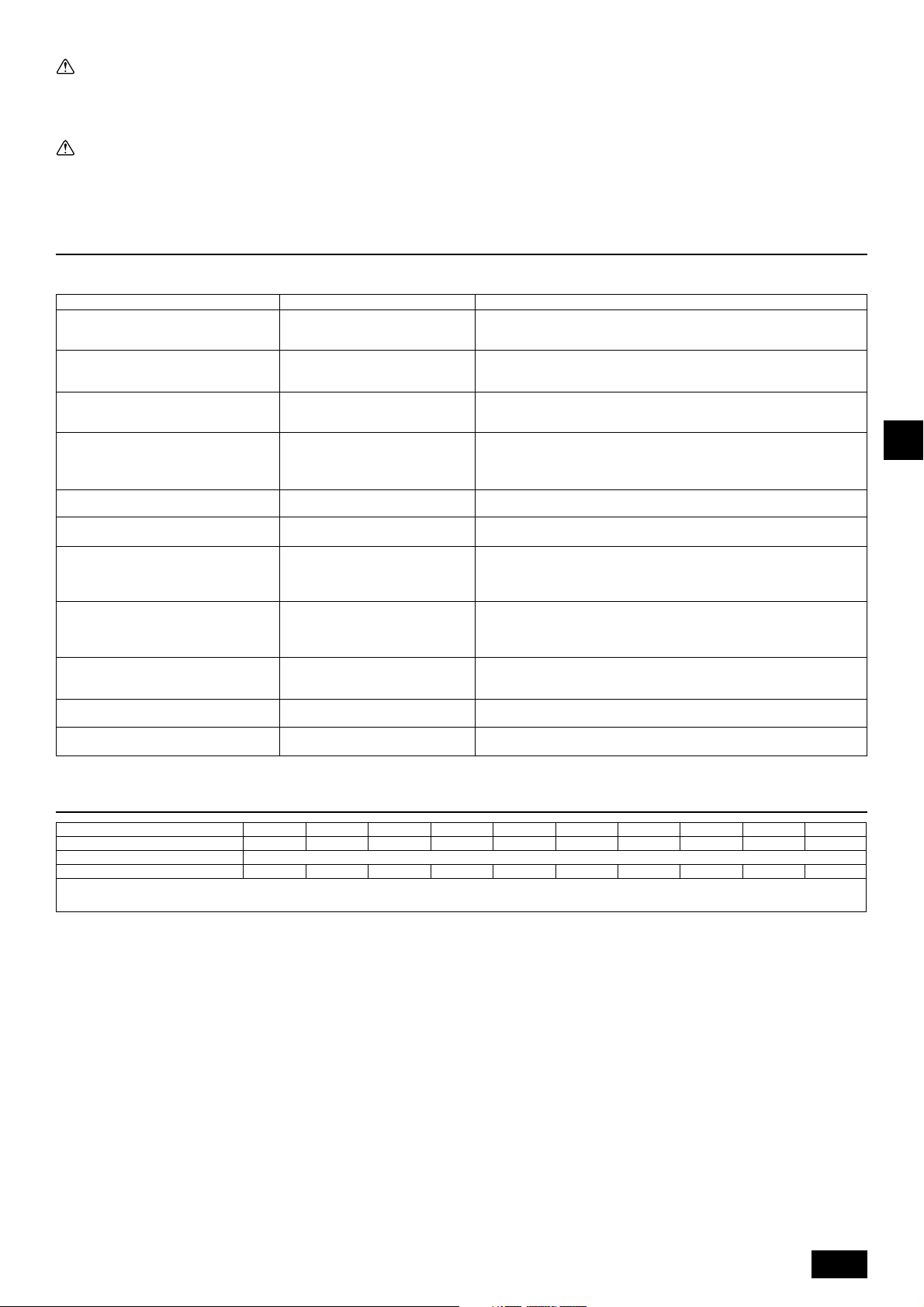
Warnung:
• Immer nur Drähte der vorgeschriebenen Sorte zur Verbindung verwenden und die Verbindung so herstellen, daß keine Kräfte von außen auf die Klemmenan-
schlüsse einwirken. Wenn die Verbindungen nicht richtig hergestellt werden, kann Überhitzung oder Feuer hervorgerufen werden.
• Darauf achten, daß ein Überstromschutzschalter der geeigneten Art verwendet wird.
Bitte beachten, daß evtl. entstehender Überstrom einen gewissen Anteil Gleichstrom aufweisen kann.
Vorsicht:
• An einigen Einbauplätzen muß eventuell ein Erdschlußunterbrecher installiert werden, um elektrische Schläge zu vermeiden.
• Ausschließlich Unterbrecher und Sicherungen mit der korrekten Kapazität verwenden. Sicherungen und Drähte oder Kupferdrähte mit zu hoher Kapazität
können Betriebsstörungen des Aggregats oder Brände verursachen.
11. Testbetrieb
11.1. Die folgenden Symptome sind nicht als Betriebsstörungen (Notfall) anzusehen
Beim Umschalten von Kühl- auf Heizbetrieb
Symptom
erzeugen Innenaggregat und BC-Regler mitunter Betriebsgeräusche.
Innenanlage arbeitet nicht im Kühl-(Heiz-)Betrieb.
Die Luftstromrichtung des automatischen
Gebläses wechselt.
Die Gebläseeinstellung wechselt bei
Heizbetrieb.
Das Gebläse stoppt während des
Heizbetriebs.
Das Gebläse läuft nach Ausschalten der Klimaanlage weiter.
Keine Gebläseeinstellung nach Drücken der
Starttaste.
Das Außenaggregat läuft nach Drücken der
Starttaste nicht.
Die Fernbedienung des Innenaggregats zeigt
beim Einschalten der Allstromversorgung
etwa zwei Minuten lang “HO”.
Die Ablaßpumpe stoppt nach Ausschalten
des Aggregats nicht.
Die Ablaßpumpe läuft nach dem Ausschalten des Aggregats weiter.
Anzeige der Fernbedienung
Normale Anzeige
“Kühlen (Heizen)” blinkt
Normale Anzeige
Normale Anzeige
Anzeige: Entfrosten
Leuchtet nicht
Heizbereit
Normale Anzeige
“HO” blinkt
Die Beleuchtung ist erloschen
Es handelt sich hier lediglich um das Umschaltgeräusch beim Übergang auf eine
Ursache
andere Betriebsart, das durchaus normal ist.
Wenn mehrere Innengeräte (maximal 3) an denselben Zweig der BC Steuereinheit angeschlossen sind, kann der Heiz- bzw. Kühlbetrieb nicht ausgeführt werden, wenn eine andere Innenanlage im Heiz- bzw. Kühlbetrieb arbeitet.
Aufgrund der automatischen Regelung des Gebläses, kann der Abwärtsluftstrom
bei Kühlbetrieb automatisch auf horizontalen Luftstrom wechseln, wenn der Abwärtsluftstrom bereits 1 Stunde in Betrieb war.
Bei ausgeschaltetem Thermostat (OFF) schaltet das Gebläse auf extrem geringe Laufgeschwindigkeit um.
Bei eingeschaltetem Thermostat (ON) wechselt ein leichter Luftstrom je nach
Zeit oder Rohrtemperatur automatisch auf den voreingestellten Wert.
Beim Entfrosten muß das Gebläse ausgeschaltet sein.
Der Lüfter läuft nach dem Ausschalten des Gerätes (nur im Heizungsbetrieb)
noch eine Minute nach, um Restwärme abzuführen.
Sehr geringe Laufgeschwindigkeit für 5 Minuten nach Drücken der Starttaste auf
ON, oder bis die Leitungstemperatur 35 °C erreicht hat. Danach Betrieb mit sehr
geringer Laufgeschwindigkeit für 2 Minuten mit anschließender Einstellung des
Gebläses (Heizbetriebregelung).
Wenn die Außenanlage gekühlt wird und das Kältemittel ruht, erfolgt über einen
Zeitraum von wenigstens 30 Minuten ein Aufwärmvorgang, mit dem der Kom-
pressor erwärmt wird, (nur P200).
Während dieser Zeit arbeitet nur das Gebläse.
System wird angesteuert.
Die Fernbedienung nach Erlöschen von “HO” nochmals betätigen.
Nach dem Ausschalten des Kühlbetriebs läuft die Ablaßpumpe drei Minuten lang
weiter und stoppt anschließend.
Die Ablaßpumpe des Außenaggregats läuft weiter solange Abflußwasser vorhanden ist, auch wenn das Außenaggregat ausgeschaltet wurde.
GB
D
F
E
INL
12. Informationen auf dem Typenschild
Kältemittel (R410A) kg
Modell
Zulässiger Druck (Ps)
Nettogewicht kg
HERSTELLER: MITSUBISHI ELECTRIC CORPORATION
AIR-CONDITIONING & REFRIGERATION SYSTEMS WORKS 5-66, TEBIRA, 6-CHOME, WAKAYAMA CITY, JAPAN
P200
10,5
236
P250
13,0
251
P300
13,0
251
P350
13,0
Hochdruck (HP): 4,15 MPa, Niederdruck (LP): 2,21 MPa
251
P400
16,5
291
P450
22,0
481
P500
22,0
481
P550
22,0
481
P600
22,0
481
P650
22,0
481
PGRRUTR
25
Page 26
Table des matières
1. Consignes de sécurité .............................................................................. 26
1.1. Avant l’installation de l’appareil et l’installation électrique ....... 26
1.2. Précautions à prendre avec les dispositifs utilisant
le réfrigérant R410A ................................................................ 27
1.3. Avant de procéder à l’installation............................................. 27
1.4. Avant l’installation de l’appareil et l’installation électrique ....... 27
1.5. Avant d’effectuer l’essai........................................................... 27
2. Le produit .................................................................................................. 28
3. Association aux appareils intérieurs ......................................................... 28
4. Vérification des pièces livrées .................................................................. 28
5. Espace requis autour de l’appareil ........................................................... 28
6. Comment soulever l’appareil .................................................................... 29
7. Installation de l’appareil ............................................................................ 29
7.1. Installation ............................................................................... 29
8. Installation des tuyaux de réfrigérant ........................................................ 29
8.1. Précaution ............................................................................... 29
8.2. Système de mise en place des tuyaux de réfrigérant ............. 30
1. Consignes de sécurité
GB
1.1. Avant l’installation de l’appareil et l’installation électrique
s Avant d’installer le climatiseur, lire attentivement toutes les
D
F
INLPGRRUTR
“Consignes de sécurité”.
s Les “Consignes de sécurité” reprennent des points très im-
portants concernant la sécurité. Veillez bien à les suivre.
Symboles utilisés dans le texte
Avertissement:
Précautions à suivre pour éviter tout danger de blessure ou de décès de
l’utilisateur.
Précaution:
Précautions à suivre pour éviter tout endommagement de l’appareil.
Symboles utilisés dans les illustrations
: Indique une action qui doit être évitée.
: Indique des instructions importantes à suivre.
: Indique un élément à mettre à la terre.
: Danger d’électrocuition. (Ce symbole se trouve sur l’étiquette de l’appareil
principal.)
Avertissement:
Lisez soigneusement les étiquettes se trouvant sur l’appareil
principal.
Avertissement:
• Demandez à votre revendeur ou à un technicien agréé d’installer le cli-
matiseur.
- En cas de mauvaise installation, il y aurait un risque de fuite d’eau, d’électro-
cution ou d’incendie.
• Installer l’appareil dans un endroit capable de supporter son poids.
- Autrement l’appareil risque de tomber et de blesser quelqu’un.
• Utilisez les câbles mentionnées pour les raccordements. Assurez-vous
que les connexions soient effectués correctement de façon à ce que la
force externe du câble ne s’applique pas aux bornes.
- Un mauvais raccordement pourrait provoquer une surchauffe, voire un in-
cendie.
• Prévoir les vents violents et les tremblements de terre et en tenir compte
pour l’emplacement adéquat de l’appareil.
-L’appareil pourrait tomber et par conséquent blesser quelqu’un si l’installa-
tion n’est pas effectuée correctement.
• Toujours utiliser un filtre et les autres accessoires spécifiés par Mitsubishi
Electric.
- Demandez à un technicien agréé d’installer les accessoires. Une mauvaise
installation par l’utilisateur pourrait provoquer des fuites d’eau, électrocution
ou un incendie.
• Ne réparez jamais vous-même l’appareil. En cas de réparation nécessaire, veuillez consulter le revendeur.
- Toute mauvaise réparation pourrait résulter en des fuites d’eau, chocs élec-
triques ou incendies.
• Ne touchez jamais les ailettes de l’échangeur de chaleur.
- Vous risqueriez de vous blesser.
26
9. Charge supplémentaire de réfrigérant ...................................................... 30
9.1. Calcul de la charge supplémentaire de réfrigérant .................. 30
9.2. Précautions à prendre lors du raccordement des tuyaux/du
fonctionnement de la valve...................................................... 30
9.3. Test d’étanchéité à l’air, évacuation et mise en place du
réfrigérant ................................................................................ 31
9.4. Isolation thermique des tuyaux de réfrigérant ......................... 32
10. Câblage .................................................................................................... 32
10.1. Précaution ............................................................................... 32
10.2. Boîtier de commande et emplacement pour le raccordement
des câbles ............................................................................... 33
10.3. Mise en place des câbles de transmission .............................. 33
10.4. Câblage de l’alimentation principale et capacité
des équipements ..................................................................... 34
11. Essai de fonctionnement........................................................................... 35
11.1. Les phénomènes suivants ne constituent pas des problèmes
(urgence) ................................................................................. 35
12. Informations sur la plaque signalétique .................................................... 35
• En cas de fuite de gaz durant l’installation, aérez la pièce.
- Si le gaz réfrigérant entre en contact avec une flamme, il y aura émission de
gaz toxiques.
• Installez le climatiseur en respectant les instructions du manuel d’installation.
- En cas d’installation incorrecte, il y aura un risque de fuites d’eau, d’électro-
cution ou d’incendie.
• Demandez à un électricien qualifié d’effectuer l’installation électrique
conformément aux “Normes concernant les installations électriques” et
les “Réglementations sur le câblage intérieur” ainsi que les instructions
de ce manuel; utilisez toujours un circuit différent.
- Si la capacité de la source d’alimentation n’est pas adéquate ou si l’installa-
tion électrique n’est pas effectuée correctement, il y aura un risque d’électro-
cution ou d’incendie.
• Mettez fermement en place le couvercle des bornes de l’appareil extérieur (panneau).
- Si le couvercle des bornes (panneau) n’est pas mis en place correctement,
il se peut que de la poussière ou de l’eau s’infiltre dans l’appareil extérieur et
par conséquent il y aura un risque d’incendie ou d’électrocution.
• Lors du déplacement et de l’installation du climatiseur à un endroit différent, ne le remplissez pas d’un réfrigérant différent, utilisez le réfrigérant
spécifié sur l’appareil.
- Lorsqu’un réfrigérant différent est mélangé au réfrigérant d’origine, il se peut
que le cycle du réfrigérant ne fonctionne pas correctement et que l’appareil
soit endommagé.
• Si le climatiseur est installé dans une pièce relativement petite, certaines
mesures doivent être prises pour éviter que la concentration de réfrigé-
rant ne dépasse le seuil de sécurité en tenant compte des possibilités de
fuites de réfrigérant.
- Consultez votre revendeur sur les précautions nécessaires à prendre afin
que la limite admissible ne soit pas dépassée. Si le réfrigérant fuit et que la
limite admissible est dépassée, il pourrait se produire des accidents suite au
manque d’oxygène dans la pièce.
• Veuillez consulter votre revendeur ou un technicien agréé lors du dépla-
cement et de l’installation du climatiseur dans un différent endroit.
- Une mauvaise installation du climatiseur pourrait résulter en fuites d’eau,
électrocution ou un incendie.
• L’installation terminée, assurez-vous qu’il n’y a aucune fuite de gaz.
- Si le gaz réfrigérant fuit et entre en contact avec un radiateur soufflant, un
poêle, un four ou toute autre source de chaleur, il se peut que des gaz toxiques soient relâchés.
• Ne réarrangez pas et ne changez pas les réglages des dispositifs de sécurité.
- Si l’interrupteur de pression, l’interrupteur thermique ou tout autre dispositif
de sécurité sont court-circuités ou utilisés avec trop de force, ou si toutes
autres pièces que celles spécifiées par Mitsubishi Electric sont utilisées, il y
aura un risque d’incendie ou d’explosion.
• Pour vous débarrasser de ce produit, consultez votre concessionnaire.
• Le technicien-installateur prendra toutes les précautions nécessaires pour
éviter toutes fuites conformément aux réglementations ou normes loca-
les.
- Les normes suivantes sont parfois applicables s’il n’existe aucune régle-
mentation locale.
• Faites particulièrement attention aux endroits d’installation comme une
cave, etc. où le gaz réfrigérant ne peut pas se disperser dans l’atmos-
phère étant donné qu’il est plus lourd que l’air.
• Pour ce type de climatiseur à arrivée d’air, le choix de l’emplacement
d’installation est très important car l’air extérieur peut entrer directement
dans la pièce lorsque le thermostat est éteint.
- Une exposition directe à l’air extérieur peut être néfaste aux personnes ou à
la nourriture.
Page 27
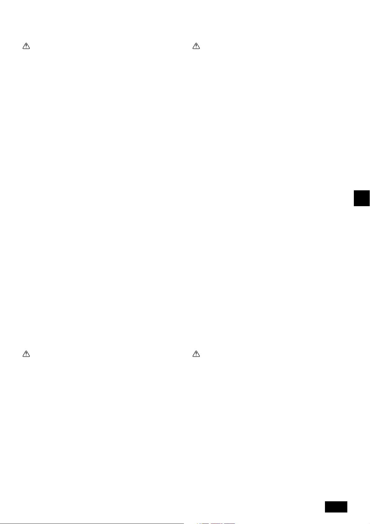
1.2. Précautions à prendre avec les dispo-
sitifs utilisant le réfrigérant R410A
1.4. Avant l’installation de l’appareil et l’installation électrique
Précaution:
• N’utilisez pas les tuyaux de réfrigérant actuels.
- Le vieux réfrigérant et l’huile réfrigérante se trouvant dans les tuyaux contiennent une large quantité de chlore qui pourrait abîmer l’huile réfrigérante
du nouvel appareil.
- Le R410A est un réfrigérant à haute pression et peut engendrer l’éclatement
des tuyaux existants.
• Utiliser des tuyaux de réfrigérant en cuivre désoxydé au phosphore et
des tuyaux et gaines en alliage de cuivre sans soudures. Veillez égale-
ment à ce que les surfaces internes et externes des tuyaux soient propres et sans soufre, oxyde, poussière/impuretés, rognures, huile, con-
densation ou autre particule contaminante.
- Tout contaminant à l’intérieur des tuyaux de réfrigérant pourrait provoquer la
détérioration de l’huile réfrigérante résiduelle.
• Gardez les tuyaux à l’intérieur de l’immeuble et gardez les deux extrémités du tuyau couvertes jusqu’à ce que vous soyez prêt à les braser. (Gar-
dez les joints articulés et autres joints dans des sacs en plastique.)
- Si de la poussière, de la saleté ou de l’eau s’infiltre dans le cycle du réfrigé-
rant, le réfrigérant risque de se détériorer et le compresseur risque de ne
pas fonctionner correctement.
• Appliquez une petite quantité d’huile ester, ether ou alkylbenzène sur les
évasements et les connexions à brides.
-L’huile réfrigérante se détériorera lorsque mélangée à une grande quantité
d’huile minérale.
• Utilisez un réfrigérant liquide pour remplir le système.
- Si l’on utilise du gaz réfrigérant pour rendre le système hermétique, la com-
position du réfrigérant se trouvant dans le cylindre changera et il se peut que
la performance ne soit plus aussi bonne.
• Utilisez uniquement du réfrigérant R410A.
- Si un autre réfrigérant (R22, etc.) est mélangé au R410A, le chlore dans le
réfrigérant peut provoquer la détérioration de l’huile du climatiseur.
• Utilisez une pompe à vide équipée d’une valve de contrôle de flux inverse.
- Il se peut que l’huile de la pompe à vide reparte dans le cycle du réfrigérant
ce qui entraînerait la détérioration de l’huile réfrigérante.
• N’utilisez pas les outils énumérés ci-dessous, destinés aux réfrigérants
traditionnels.
(Jauge collectrice, tuyau de charge, détecteur de fuite de gaz, valve de
contrôle de flux inverse, base de remplissage du réfrigérant, équipements
de récupération de réfrigérant).
- Si l’on mélange un réfrigérant courant à l’huile réfrigérante dans le R410A, il
se peut que le réfrigérant se détériore.
- Si de l’eau se mélange au R410A, il se peut que l’huile réfrigérante se dété-
riore.
- Etant donné que le R410A ne contient pas de chlore, les détecteurs de fuite
de gaz conçus pour les réfrigérants traditionnels ne réagiront pas en cas de
fuite du R410A.
• N’utilisez pas de cylindre de charge.
- Autrement le réfrigérant pourrait se détériorer.
• Faites particulièrement attention lors de l’utilisation des outils.
- Si de la poussière, de la saleté ou de l’eau s’infiltre dans le cycle du réfrigé-
rant, il se peut que le réfrigérant se détériore.
1.3. Avant de procéder à l’installation
Précaution:
• Mettez l’appareil à la terre.
- Ne branchez pas le fil de mise à la terre à un tuyau de gaz ou d’eau, un
paratonnerre ou câble téléphonique de terre. Une mauvaise mise à la terre
peut provoquer des risques d’électrocution.
• L’inversion de phase des lignes L (L
d’erreur: 4103), mais l’inversion de phase des lignes L et de la ligne N ne
peut être détectée.
- En cas de mauvais branchement, certaines éléments électriques peuvent
être endommagés si l’appareil est sous tension.
• Installez le câble d’alimentation de façon à ce qu’il ne soit pas tendu.
- Autrement le fil pourrait se rompre, engendrant un surchauffage et par con-
séquent des risques d’incendie.
• Installez un disjoncteur, comme spécifié.
- Sans disjoncteur, il y aura risque d’électrocution.
• Utilisez des câbles d’alimentation dont la capacité à distribuer le courant
et la valeur nominale sont adéquates.
- Si les câbles sont trop petits, il est possible qu’il y ait des fuites, entraînant un
surchauffage qui en retour pourrait causer un incendie.
• Utilisez uniquement un disjoncteur et un fusible de la valeur indiquée.
-L’utilisation d’un fusible ou d’un disjoncteur de plus grande valeur, d’un fil en
acier ou en cuivre peut provoquer un dysfonctionnement général de l’appa-
reil ou un risque d’incendie.
• Ne lavez pas les différents éléments du climatiseur.
- Autrement il y aurait un risque de choc électrique.
• Assurez-vous que la base d’installation ne soit pas abîmée à cause d’un
usage prolongé.
- Si l’endommagement n’est pas réparé, l’appareil pourrait tomber et par con-
séquent blesser quelqu’un ou abîmer le mobilier ou d’autres biens.
• Installez les tuyaux d’écoulement conformément aux instructions du
manuel d’installation afin d’assurer que l’écoulement se fait correcte-
ment. Enveloppez les tuyaux de matériaux isolants afin d’empêcher la
formation de condensation.
- Une mauvaise mise en place des tuyaux d’écoulement peut provoquer des
fuites d’eau et endommager les meubles ou d’autres biens.
• Soyez très prudent lors du transport de l’appareil.
-L’appareil ne doit jamais être porté par une seule personne étant donné qu’il
pèse plus de 20 kg.
- Certains produits sont emballés avec des courroies en polypropylène (PP).
N’utilisez jamais ces courroies pour le transport car cela pourrait être dangereux.
- Ne touchez pas les ailettes de l’échangeur de chaleur. Vous pourriez vous
couper les doigts.
- Lors du transport de l’appareil extérieur, tenez-le bien aux emplacements
indiqués sur la base de l’appareil. Fournir un support à quatre points à l’appareil extérieur afin de l’empêcher de glisser sur les côtés.
• Jetez les emballages dans un endroit où ils ne présenteront aucun risque pour quiconque.
- Il est possible de se blesser sur les matériaux utilisés pour l’emballage, par
exemple les clous ou autres pièces métalliques ou en bois.
-Déchirez et jetez les sacs d’emballage en plastique de façon à ce qu’ils
soient hors de la portée des enfants pour éviter tout risque de suffocation.
1, L2, L3) peut être détectée (code
1.5. Avant d’effectuer l’essai
GB
D
F
E
INL
PGRRUTR
Précaution:
• N’installez pas l’appareil dans un endroit sujet aux fuites de gas inflam-
mables.
-S’il y a une fuite de gaz et que le gaz s’accumule autour de l’appareil, il y
aura des risques d’explosion.
• N’utilisez pas le climatiseur près d’animaux ou de plantes ou près d’aliments, d’instruments de précision ou d’objets d’art.
- La qualité d’aliments etc. pourrait en souffrir.
• N’utilisez pas le climatiseur dans certains environnements.
-L’huile, la vapeur, la fumée sulfurique, etc. peuvent considérablement ré-
duire la performance du climatiseur ou en endommager les pièces.
• Lors de l’installation de l’appareil dans un hôpital, une station de communications ou tout endroit similaire, veillez à ce qu’il soit correctement
protégé contre le bruit.
- Les équipements onduleurs, générateurs privés, équipements médicaux à
haute fréquence ou de communication radiophonique peuvent empêcher le
climatiseur de fonctionner ou de fonctionner proprement. De plus, il se peut
que le climatiseur ait un effet nuisible sur ce genre d’équipements en faisant
du bruit qui gênerait les traitements médicaux ou l’envoi d’images.
• N’installez pas l’appareil sur une structure qui pourrait causer des fuites.
- Lorsque l’humidité de la pièce dépasse 80 % ou lorsque le tuyau d’écoule-
ment est bouché, il se peut que des gouttes d’eau tombent de l’appareil
intérieur. Veillez à fournir une voie d’écoulement pour l’appareil intérieur et
l’appareil extérieur si nécessaire.
Précaution:
• Mettez l’appareil sous tension au moins 12 heures avant de le faire fonc-
tionner.
- Ne faites jamais fonctionner l’appareil immédiatement après sa mise sous
tension. Les éléments internes risqueraient de subir des dégâts irréversi-
bles. Ne mettez pas l’appareil hors tension pendant la saison de fonctionnement.
• Ne touchez pas les interrupteurs avec les doigts mouillés.
- Vous risqueriez d’être électrocuté.
• Ne touchez pas les tuyaux de réfrigérant pendant ou immédiatement après
le fonctionnement.
- Les tuyaux sont parfois chauds ou froids pendant ou immédiatement après
le fonctionnement de l’appareil, selon la condition du réfrigérant coulant dans
les tuyaux de réfrigérant, le compresseur et les autres parties du cycle du
réfrigérant. En les touchant vous risqueriez de brûler ou geler les mains.
• Ne faites pas fonctionner le climatiseur lorsque les panneaux et dispositifs de sécurité ont été enlevés.
- Les éléments tournants, chauds ou sous haute tension peuvent en effet être
dangereux et vous risqueriez de vous blesser.
• Ne mettez pas l’appareil immédiatement hors tension après son fonctionnement.
- Attendez au moins cinq minutes avant de le mettre hors tension. Autrement,
il y aura un risque de fuite d’eau ou de mauvais fonctionnement.
• Ne touchez jamais la surface du compresseur pendant les interventions
techniques.
- Si l’appareil est sous tension mais ne fonctionne pas, le chauffage du carter
à la base du compresseur est opérationnel.
27
Page 28
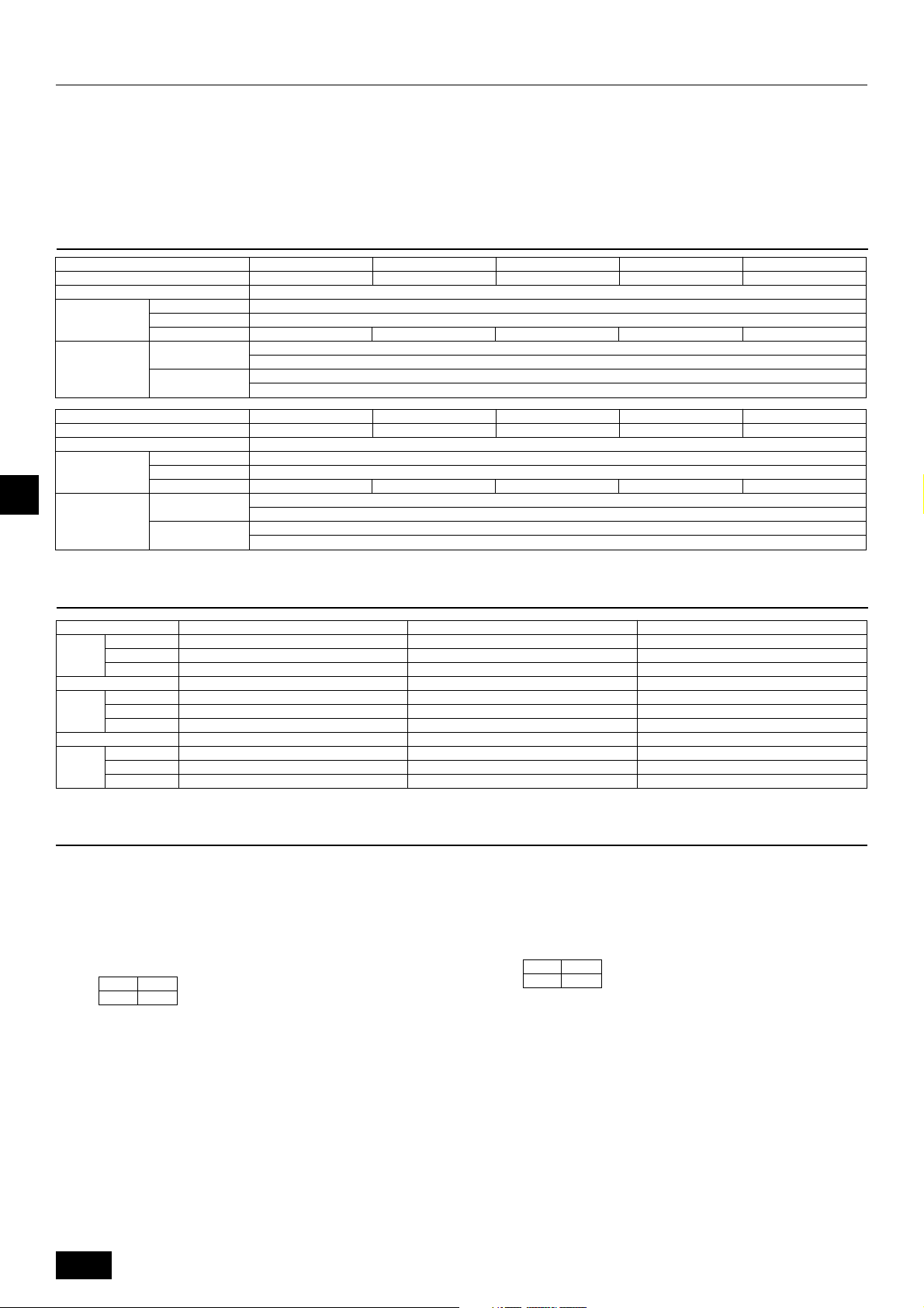
2. Le produit
• Cet appareil utilise le réfrigérant R410A
• La tuyauterie des systèmes utilisant le R410A peut être différente de celle des
systèmes utilisant un réfrigérant ordinaire car leur pressurisation est plus élevée. Pour plus d’informations, se reporter au Livre de données.
• Certains outils et équipements permettant l’installation des systèmes utilisant
d’autres types de réfrigérants ne peuvent pas servir pour les systèmes utilisant le R410A. Pour plus d’informations, se reporter au Livre de données.
3. Association aux appareils intérieurs
Modèle
Niveau sonore (50/60 Hz)
Pression statique externe
Appareils
intérieurs
Température
d’exploitation
GB
Modèle
Niveau sonore (50/60 Hz)
Pression statique externe
Appareils
D
intérieurs
F
Température
d’exploitation
Capacité totale
Modèle
Quantité
Type standard
Type à arrivée
d’air
Capacité totale
Modèle
Quantité
Type standard
Type à arrivée
d’air
PURY-P200
56 dB<A>
1 ~ 15
Mode de refroidissement: – 5 °CDB ~ 43 °CDB (0° CDB ~ 43° CDB avec l’appareil extérieur en position inférieure)
Mode chauffage: – 20 °CWB ~ 15,5 °CWB
Mode de refroidissement: 21 °CDB ~ 43 °CDB
Mode chauffage: – 12,5 °CWB ~ 20 °CWB
PURY-P450
60/61 dB<A>
1 ~ 24
Mode de refroidissement: – 5 °CDB ~ 43 °CDB (0° CDB ~ 43° CDB avec l’appareil extérieur en position inférieure)
Mode chauffage: – 20 °CWB ~ 15,5 °CWB
Mode de refroidissement: 21 °CDB ~ 43 °CDB
Mode chauffage: – 12,5 °CWB ~ 20 °CWB
PURY-P250
57 dB<A>
1 ~ 16
PURY-P500
60/61 dB<A>
1 ~ 24
• Ne pas utiliser la tuyauterie existante car elle contient du chlore, substance
contenue dans l’huile et le réfrigérant des machines réfrigérantes traditionnelles. Le chlore pourrait détériorer l’huile de la machine réfrigérante dans le nouvel équipement. La tuyauterie existante ne doit pas être utilisée car la pressurisation des systèmes utilisant le R410A est supérieure à celle des systèmes
utilisant d’autres types de réfrigérants et les tuyaux risqueraient d’éclater.
PURY-P300
59 dB<A>
0 Pa
50 ~150 %
20 ~ 250
1 ~ 16
PURY-P550
61/62 dB<A>
0 Pa
50 ~150 %
20 ~ 250
1 ~ 24
PURY-P350
60 dB<A>
1 ~ 20
PURY-P600
61/62 dB<A>
1 ~ 32
PURY-P400
61 dB<A>
1 ~ 24
PURY-P650
62/62,5 dB<A>
1 ~ 32
4. Vérification des pièces livrées
1 Plaque de montage du conduit (ø53)
1 pièce
1 pièce
4 Plaque de montage du conduit (ø27)
1 pièce
-
-
7 Raccord (basse pression)
1 pièce
1 pièce
1 pièce
INLPGRRUTR
Modèle
Modèle
Modèle
P200 ~ P350
P400
P450 ~ P650
P200 ~ P350
P400
P450 ~ P650
P200 ~ P350
P400
P450 ~ P650
5. Espace requis autour de l’appareil
[Fig. 5.0.1] (P.2)
<A> Vue du dessus <B> Vue latérale
<C> Lorsqu’il y a un peu d’espace entre l’appareil et l’obstruction
A Avant B Pas de limite de hauteur du mur (gauche et droit)
C Conduit de la sortie d’air (Fourni sur place)
D Doit être ouvert E Hauteur du mur (H)
F Pas de limite de hauteur de mur
(1) Espace minimum requis
(2) Lorsqu’il y a une obstruction au-dessus de l’appareil
(3) Lorsque la prise d’air se fait par les côtés gauche et droit de l’appareil
• La hauteur des murs “H” à l’avant et à l’arrière de l’appareil doit se situer dans
les limites de la hauteur globale de l’appareil.
• Si la hauteur des murs “H” excède la hauteur globale de l’appareil, ajouter la
dimension “h” de la Fig. 5.0.1 à L
“h” = hauteur du mur “H’” = hauteur globale de l’appareil
(mm)
L1 L2
450 450
1 et L2.
2 Plaque de montage du conduit (ø46)
8 Emballage (tuyau à basse pression)
1 pièce
1 pièce
5 Vis à tôle M4
2 pièces
2 pièces
2 pièces
1 pièce
1 pièce
1 pièce
(4) Lorsque l’appareil est entouré de murs
Remarque:
• La hauteur des murs “H” à l’avant et à l’arrière de l’appareil doit être
inférieure à celle du panneau avant ou arrière.
• Si la hauteur du panneau est dépassée, ajouter la dimension “h” de la
Fig. 5.0.1 à L
Exemple: Lorsque “h” est égal à 100 mm,
(5) Installation collective et installation en continu
• Espace requis pour une installation collective et en continu:
Lors de l’installation de plusieurs appareils, laisser l’espace indiqué ci-des-
sous entre chaque bloc pour le passage de l’air et des personnes.
• Ouvert dans les deux sens.
• Si la hauteur du mur “H” dépasse la hauteur globale de l’appareil, ajoutez la
dimension “h” ( h = hauteur du mur “H’” – la hauteur globale de l’appareil) à la
dimension indiquée d’un *.
• Si un mur se trouve à l’avant et à l’arrière de l’appareil, installez un maximum
de quatre appareils (3 s’il s’agit de P450 ~ P650) l’un après l’autre dans le
sens latéral et laisser un espace d’au moins 1000 mm pour chacun des quatre
appareils (3 s’il s’agit de P450 ~ P650).
1 et L2.
(mm)
L1 L2
450 450
la dimension L
3 Plaque de montage du conduit (ø33)
1 pièce
-
-
6 Raccord (haute pression)
1 pièce (évasement)
2 pièces (brides)
1 pièce (brides)
9 Emballage (tuyau à haute pression)
1 pièce
1 pièce
1 est égale à 450 + 100 = 550 mm.
28
Page 29
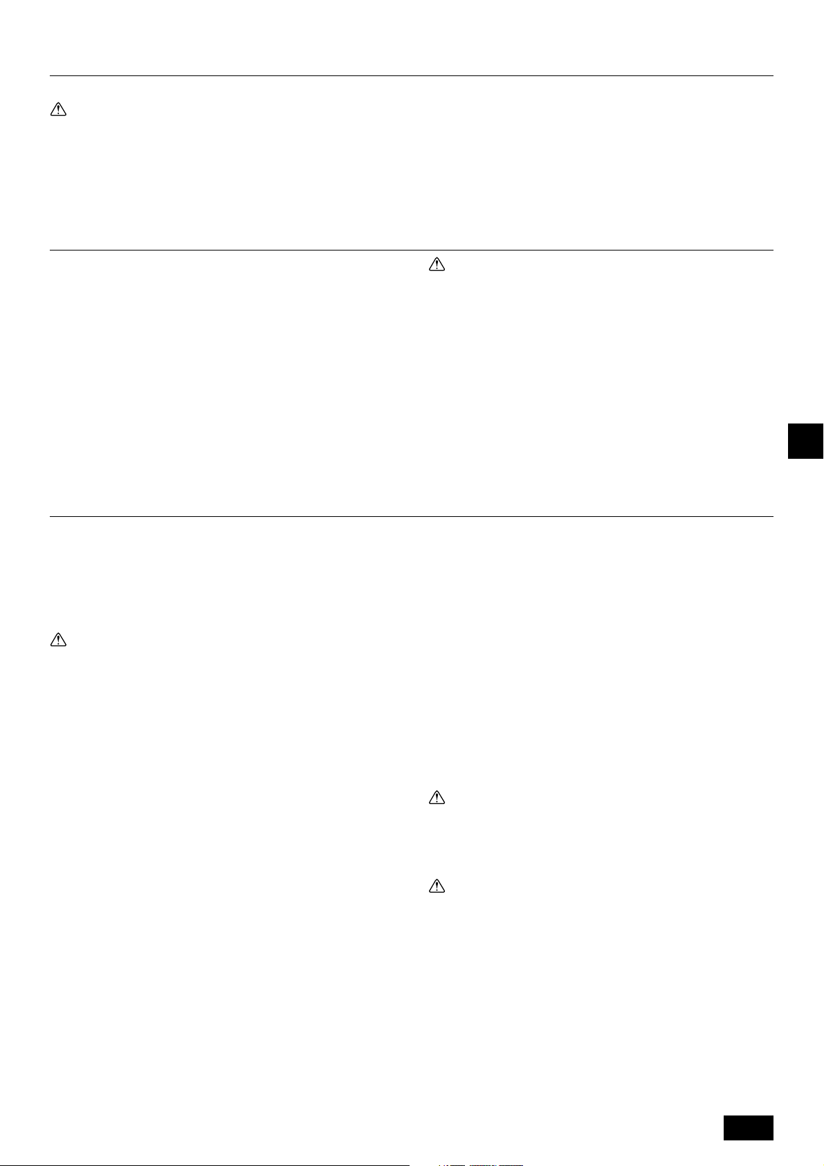
6. Comment soulever l’appareil
[Fig. 6.0.1] (P.2)
Précaution:
Faites très attention pendant le transport de l’appareil.
-L’appareil ne doit pas être porté par une seule personne s’il pèse plus de 20 kg.
- Les courroies PP servent à emballer certains éléments. Ne les utilisez pas pour transporter l’appareil, car elles peuvent se révéler dangereuses.
- Ne touchez pas les ailettes de l’échangeur les mains nues. Vous risqueriez de vous couper.
-Déchirez l’emballage plastique et jetez-le dans un endroit où il sera hors de la portée des enfants. Un enfant pourrait s’étouffer en y jouant avec.
- Lors du transport de l’appareil extérieur, celui-ci doit être soutenu à quatre endroits. Si vous le transportez en le soutenant uniquement sur 3 points, l’appareil extérieur
risque d’être instable et de tomber.
7. Installation de l’appareil
7.1. Installation
[Fig. 7.1.1] (P.2)
A Boulon d’ancrage M10 à se procurer sur place.
B Le coin n’est pas posé fermement.
• Fixez l’appareil fermement avec les boulons de sorte qu’il ne tombe pas en
cas de tremblement de terre ou de rafales de vent.
• Utiliser du béton ou un étrier angulaire pour la fondation de l’appareil.
• Il se peut que des vibrations soient transmises à la section d’installation et que
des bruits ou vibrations proviennent du sol et des murs, selon les conditions
d’installation. Par conséquent, fournir assez de protection anti-vibrations (tampons, bâti d’amortissement, etc.).
• Veillez à ce que les coins soient fermement en place. Autrement les semelles
de l’installation plieraient.
8. Installation des tuyaux de réfrigérant
La série de climatiseurs City Multi R2 se compose d’un système d’embranche-
ment final dans lequel les tuyaux de réfrigérant de l’appareil extérieur sont branchés au contrôleur BC et raccordés à chaque appareil intérieur.
La méthode de raccordement appropriée est le raccordement par brasage pour
les tuyaux à haute et basse pression entre l’appareil extérieur et le boîtier de commande, et le raccordement évasé entre le boîtier de commande et l’appareil inté-
rieur. La connexion par brasage est utilisée pour les tuyaux de raccord et les tuyaux
secondaires.
Avertissement:
Faites toujours très attention que le gaz réfrigérant ne s’échappe pas pendant l’utilisation de feu ou de flammes. Si le gaz réfrigérant entrait en contact
avec une flamme, quelle qu’en soit la source, par exemple une gazinière, il
se désagrégerait et générerait des gaz toxiques susceptibles de provoquer
un empoisonnement au gaz. Ne soudez jamais dans une pièce non aérée.
Vérifiez toujours qu’il n’y a pas de fuite de gaz après l’installation des tuyaux
de réfrigérant.
8.1. Précaution
Cet appareil utilise le réfrigérant R410A. Lors de la sélection des tuyaux, respecter
les réglementations locales concernant les équipements et l’épaisseur des tuyaux.
1 Utilisez les matériaux suivants pour les tuyaux de réfrigérant.
• Matériel: Utiliser des tuyaux de réfrigérant en cuivre désoxydé au phos-
phore. Veillez également à ce que les surfaces internes et externes des
tuyaux soient propres et sans soufre, oxyde, poussières, impuretés, rognures, huile, condensation ou autres particules contaminantes.
2 Les tuyaux disponibles dans le commerce contiennent souvent de la pous-
sière et autres éléments. Toujours les nettoyer en y insufflant un gaz sec et
inerte.
3 Prenez les précautions nécessaires pour éviter que la poussière, l’eau ou tout
autre élément contaminant s’infiltrent dans les tuyaux durant l’installation.
4 Réduisez le nombre de coudes autant que possible, et coudez les tuyaux se-
lon un rayon aussi large que possible.
5 Veuillez toujours respecter les restrictions concernant les tuyaux de réfrigé-
rant (par exemple la longueur nominale, la différence haute/basse pression, et
le diamètre des tuyaux). Autrement l’équipement tombera en panne ou les
modes de chauffage/de refroidissement ne fonctionneront plus correctement.
6 Un manque ou un excès de réfrigérant entraîne l’arrêt d’urgence de l’appareil.
Dans ce cas, veuillez toujours remplir correctement l’appareil. Lors de travaux
d’entretien, repectez-vous toujours les remarques concernant la longueur des
tuyaux et la quantité de réfrigérant supplémentaire nécessaire aux deux emplacements, les informations du tableau de calcul du volume de réfrigérant
situé au dos du panneau de service et la section concernant la quantité supplémentaire de réfrigérant indiquée sur les étiquettes pour le nombre combiné
d’appareils intérieurs.
Avertissement:
• Installez toujours l’appareil dans un endroit pouvant supporter son poids.
Dans le cas contraire, l’appareil pourrait tomber et par conséquent blesser quelqu’un.
• Effectuez les travaux nécessaires afin d’assurer la protection de l’appareil contre les vents violents et les tremblements de terre.
Toute installation défectueuse risquerait de causer la chute de l’appareil
et par conséquent de blesser quelqu’un.
Lors de la construction des fondations, faites particulièrement attention à la résis-
tance du sol, la voie d’écoulement de l’eau <durant le fonctionnement, l’eau sort
de l’appareil>, et l’acheminement des tuyaux et des fils.
Consignes de sécurité pour les tuyaux et les fils descendants
Lors de l’installation des tuyaux et fils descendants, veillez à ce que les fondations
ne bloquent pas les orifices situés en bas de la base. Lors de l’installation des
tuyaux descendants, veillez à ce que les fondations soient surélevées de 100 mm
pour permettre à la tuyauterie de passer sous l’appareil.
7 Utilisez un réfrigérant liquide pour remplir le système.
8 N’utilisez jamais de réfrigérant pour purger l’air. Purgez-le toujours à l’aide
d’une pompe à vide.
9 Isolez toujours les tuyaux correctement. Une isolation insuffisante risque en
effet d’entraîner une diminution de la performance des modes de chauffage/
refroidissement, la formation de gouttes de condensation et autres problèmes
similaires.
0 Lors du raccordement des tuyaux de réfrigérant, veillez à ce que la soupape à
flotteur de l’appareil extérieur soit fermée à fond (réglage d’usine) et veillez à
ne pas l’utiliser avant d’avoir raccordé les appareils extérieurs et intérieurs,
d’avoir vérifié qu’il n’y a aucune fuite de réfrigérant et avant d’avoir terminé la
procédure d’évacuation.
A Les antioxydants disponibles dans le commerce contiennent des résidus qui
peuvent endommager les équipements. Braser uniquement avec du matériel
de brasage non oxydé. L’utilisation d’un autre matériel de brasage peut en-
dommager le compresseur.
(Pour des informations détaillées sur le raccordement des tuyaux et l’utilisa-
tion des vannes, se référer au chapitre 9.2.)
B Ne raccordez jamais les tuyaux de l’appareil extérieur lorsqu’il pleut.
Avertissement:
Lors de l’installation ou du déplacement de l’appareil, ne le remplissez pas
d’un autre réfrigérant que le réfrigérant (R410A) indiqué sur l’appareil.
- En cas d’addition d’un autre réfrigérant, d’air ou de toute autre substance, il y
aura une malfonction du cycle de réfrigération, ce qui risque de provoquer des
dégâts.
Précaution:
• Utilisez une pompe à vide équipée d’une valve de contrôle de flux in-
verse.
- Si la pompe à vide n’est pas équipée d’un tel dispositif, il se peut que l’huile
de la pompe à vide reparte dans le cycle de réfrigérant et par conséquent
entraîne la détérioration de l’huile réfrigérante et provoque des dégâts.
• N’utilisez pas les outils indiqués ci-dessous, destinés aux réfrigérants
traditionnels.
(Jauge collectrice, tuyau flexible de remplissage, détecteur de fuites de
gaz, valve de contrôle, base de remplissage de réfrigérant, jauge à vide,
équipements de récupération de réfrigérant)
- Il se peut que l’huile réfrigérante se détériore à la suite du mélange d’un
réfrigérant traditionnel à l’huile réfrigérante.
- Il se peut que l’huile se détériore si de l’eau y est mélangée.
- Le réfrigérant R410A ne contient pas de chlore. Par conséquent, les détec-
teurs de fuites de gaz conçus pour les réfrigérants traditionnels ne peuvent
pas le détecter.
29
GB
D
F
E
INL
PGRRUTR
Page 30
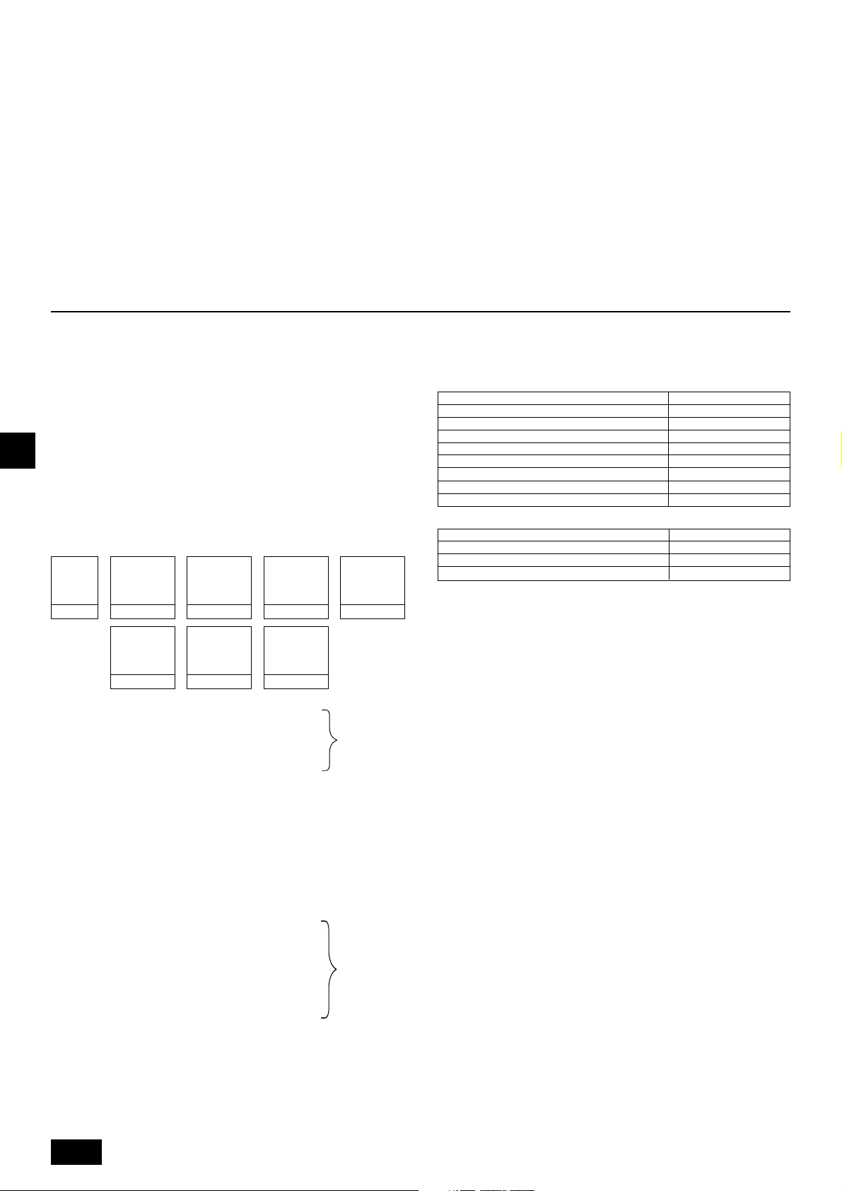
• Faites très attention lors de l’utilisation d’outils.
-L’huile réfrigérante se détériorera si de la poussière, des impuretés ou de
l’eau s’infiltrent dans le cycle réfrigérant.
• N’utilisez jamais les tuyaux de réfrigérant déjà en place.
- La quantité importante de chlore contenue dans les réfrigérants traditionnels et l’huile réfrigérante des tuyaux actuels provoquera la détérioration du
nouveau réfrigérant.
• Gardez les tuyaux d’installation dans l’immeuble et laissez les deux extrémités des tuyaux couvertes jusqu’au moment du brasage.
-L’huile se détériorera et il est possible que le compresseur tombe en panne
si de la poussière, des impuretés ou de l’eau s’infiltrent dans le cycle réfrigé-
rant.
• N’utilisez pas de cylindre de charge.
- Autrement le réfrigérant pourrait se détériorer.
• Ne pas utiliser de détergeants spéciaux pour le nettoyage des tuyaux.
9. Charge supplémentaire de réfrigérant
8.2. Système de mise en place des tuyaux
de réfrigérant
Exemples de raccordements
[Fig. 8.2.1] (P.3)
Å Modèle extérieur ı Côté de haute pression
Ç Côté de basse pression Î Capacité totale des appareils intérieurs
‰ Tuyau de liquide Ï Tuyau de gaz
Ì Tuyau de gaz à haute pression
Ó Tuyau de gaz à basse pression
È Tuyau de liquide
Ô Numéro du modèle
A Boîtier de commande (standard) B Boîtier de commande (maître)
C Boîtier de commande (esclave) D Appareil intérieur (20 ~ 140)
E Appareil intérieur (200, 250)
L’appareil extérieur contient le réfrigérant à la livraison. Etant donné que cette charge
ne comprend pas la quantité nécessaire pour des longs tuyaux, une charge supplémentaire pour chaque ligne de réfrigérant devra être ajoutée sur place. Afin de
pouvoir effectuer correctement les interventions techniques par la suite, toujours
GB
noter la taille et la longueur de chaque tuyau de réfrigérant ainsi que la quantité
supplémentaire ajoutée dans l’espace prévu à cet effet sur l’appareil extérieur.
9.1. Calcul de la charge supplémentaire de
D
F
INLPGRRUTR
réfrigérant
• Calculer la quantité de la charge supplémentaire en se basant sur la longueur
d’extension et la taille des tuyaux de réfrigérant.
• Utiliser le tableau ci-après pour calculer la charge supplémentaire, puis charger le système en conséquence.
• Si le calcul donne une fraction inférieure à 0,1 kg, arrondissez au 0,1 kg suivant. Par exemple, si le résultat du calcul est 10,62 kg, arrondissez à 10,7 kg.
<Charge supplémentaire>
Charge
supplémentaire de
réfrigérant
<Example 1>
Intérieur
La longueur totale de chaque tuyau de liquide est la suivante:
ø19,05: A = 40 m
ø9,52: B + b + e = 10 + 5 + 10 = 25 m
ø6,35: a + c + d = 10 + 10 + 10 = 30 m
Dès lors,
<Exemple de calcul>
Charge de réfrigérant supplémentaire
= 40 × 0,16 + 25 × 0,06 + 30 × 0,024 + 2,0 = 10,7 kg
<Example 2>
Intérieur
La longueur totale de chaque tuyau de liquide est la suivante:
ø22,2: A = 40 m
ø12,7: C + D = 10 + 10 = 20 m
ø9,52: B + b + e + f = 10 + 5 + 10 + 10 = 35 m
ø6,35: a + c + d + g + h = 10 + 10 + 10 + 5 + 5 = 40 m
Taille du tuyau à
haute pression
=+++
Longueur totale de
ø28,58 × 0,39
(kg)
(m) × 0,39 (kg/m)
Taille du tuyau à
haute pression
+++ + α1 + α2
Longueur totale de
ø12,7 × 0,12
(m) × 0,12 (kg/m)
N°1: 40 A: ø19,05 40 m a: ø6,35 10 m
N°2: 200 B: ø9,52 10 m b: ø9,52 5 m
N°3: 40 c: ø6,35 10 m
N°4: 32 d: ø6,35 10 m
N°5: 63 e: ø9,52 10 m
N°1: 40 A: ø22,2 40 m a: ø6,35 10 m
N°2: 100 B: ø9,52 10 m b: ø9,52 5 m
N°3: 40 C: ø12,7 10 m c: ø6,35 10 m
N°4: 32 D: ø12,7 10 m d: ø6,35 10 m
N°5: 63 e: ø9,52 10 m
N°6: 200 f: ø9,52 10 m
N°7: 32 g: ø6,35 5 m
N°8: 32 h: ø6,35 5 m
Taille du tuyau à
haute pression
Longueur totale de
ø22,2 × 0,23
(m) × 0,23 (kg/m)
Taille du tuyau à
haute pression
Longueur totale de
ø9,52 × 0,06
(m) × 0,06 (kg/m)
Taille du tuyau à
haute pression
Longueur totale de
ø19,05 × 0,16
(m) × 0,16 (kg/m)
Taille du tuyau à
haute pression
Longueur totale de
ø6,35 × 0,024
(m) × 0,024 (kg/m)
Taille du tuyau à
haute pression
Longueur totale de
ø15,88 × 0,11
(m) × 0,11 (kg/m)
Dans les
conditions cidessous:
Dans les
conditions cidessous:
Dès lors,
<Exemple de calcul>
Charge de réfrigérant supplémentaire
= 40 × 0,23 + 20 × 0,12 + 35 × 0,06 + 40 × 0,024 + 3,0 + 2,0 = 19,7 kg
Valeur de α1
Capacité totale des appareils intérieurs raccordés α1
Valeur de α2
Boîtier de commande (standard, maître uniquement)
Boîtier de commande (esclave) connecté (un) 1,0 kg
Boîtiers de commandes (esclaves) connectés (deux)
jusqu’au modèle 80 1,0 kg
Modèles 81 à 160 1,5 kg
Modèles 161 à 330 2,0 kg
Modèles 331 à 480 2,5 kg
Modèles 481 à 630 3,0 kg
Modèles 631 à 710 4,0 kg
Modèles 711 à 890 5,0 kg
Modèles 891 à 1070 6,0 kg
α2
0 kg
2,0 kg
9.2. Précautions à prendre lors du raccor-
dement des tuyaux/du fonctionnement
de la valve
• Raccorder correctement les conduits et vérifier le bon fonctionnement des
vannes.
• Le tuyau de connexion côté gaz est assemblé à l’usine avant la livraison.
1 Pour le brasage du tuyau de connexion à collerette, retirer le tuyau de
connexion avec la collerette de la valve à bille et le braser à l’extérieur de
l’appareil.
2 Lors du retrait de la connexion avec collerette, retirez le joint d’étanchéité
attaché au dos de cette feuille et collez-le sur la surface de la collerette de
la valve à bille pour empêcher la poussière d’entrer dans la valve.
3 A la sortie d’usine, le circuit de réfrigérant est obturé par une garniture
d’étanchéité compacte et ronde pour éviter les fuites de gaz entre les collerettes. Etant donné qu’il n’est pas possible d’utiliser l’appareil dans cet
état, remplacer la garniture par la garniture creuse fixée à la connexion
des tuyaux.
4 Avant de mettre en place la garniture creuse, essuyez les poussières dé-
posées sur la surface de la collerette et de la garniture. Mettez de l’huile
(Huile ester, ether ou alkylbenzène [petite quantité]) pour machines sur les
deux surfaces de la garniture.
[Fig. 9.2.1] (P.3)
A Garniture pleine
B Garniture creuse
• Après l’évacuation et le remplissage de réfrigérant, assurez-vous que la ma-
nette est complètement ouverte. Si le système est utilisé alors que la valve est
fermée, une pression anormale sera transmise au côté de haute ou de basse
pression du circuit du réfrigérant, ce qui pourrait endommager le compresseur, la soupape à quatre voies, etc.
• Déterminez la quantité supplémentaire de réfrigérant à l’aide de la formule et
ajoutez du réfrigérant supplémentaire par l’ouverture de service lorsque les
travaux de raccordement des tuyaux sont terminés.
• Les travaux terminés, fermez correctement l’ouverture de service et serrez le
capuchon pour éviter toute fuite de gaz.
• L’évasement est plus important pour les systèmes utilisant le R410A que pour
les systèmes utilisant d’autres types de réfrigérants, et ce afin d’augmenter
l’étanchéité à l’air.
30
Page 31

• Se référer au tableau ci-après pour les dimensions d’évasement et respecter
les réglementations fixées par les autorités locales. Colmater l’ouverture du
tuyau avec un matériel de colmatage (non fourni) pour empêcher les petits
animaux d’y pénétrer, le cas échéant.
dimension de l’évasement (mm)
diamètre extérieur
ø6,35
A
taille de l’écrou évasé (mm)
B
[Fig. 9.2.2] (P.3)
<A> [Soupape à bille (Côté de basse pression/raccordement à brides)]
<B> [Soupape à bille (Côté de haute pression/raccordement évasé)]
<C> [Soupape à bille (Côté de haute pression/raccordement à brides)]
<D> Cette figure montre la soupape complètement ouverte.
A Tige de la valve
[Entièrement fermée à la sortie d’usine, lors du raccordement des tuyaux, de
l’écoulement et du remplissage du réfrigérant supplémentaire. Entièrement ouverte
lorsque les travaux mentionnés ci-avant sont terminés.]
B Clavette d’arrêt [Empêche la tige de la valve de tourner de plus de 90°]
C Garniture (Accessoire)
[Fabricant: Nichiasu corporation]
[Type: T/#1991-NF]
D Raccord (Accessoire)
[Utilisez la garniture et attachez fermement ce tuyau à la bride de la valve pour
empêcher toute fuite de gaz. (Force de torsion : 40 N·m) Appliquez une couche
d’huile pour appareil réfrigérant sur les deux surfaces de la garniture. (huile d’ester, huile d’éther ou alkylbenzène [petite quantité])]
E Ouvert (Lentement)
F Capuchon
[Enlevez le capuchon et faites fonctionner la tige de la valve. Veuillez toujours
remettre en place le capuchon après cette action. (Force de torsion du capuchon
de la tige de la valve: 23 ~ 27 N·m)]
G Ouverture de service
[Pour l’écoulement et le remplissage du réfrigérant supplémentaire sur place.
Ouvrez et fermez l’ouverture de service à l’aide d’une clé à double fonction.
Veuillez toujours remettre en place le capuchon une fois l’opération terminée.
(Force de torsion du capuchon de l’ouverture de service: 12 ~ 15 N·m)]
H Ecrou évasé
[Force de torsion: Se reporter au tableau suivant.
Serrez et desserrez cet écrou à l’aide d’une clé à double fonction.
Appliquez de l’huile réfrigérante sur la surface de contact de l’évasement. (huile
d’ester, huile d’éther ou alkylbenzène [petite quantité])]
I ø15,88 (PURY-P200)
ø19,05 (PURY-P250 ~ P350)
J ø19,05 (PURY-P200)
ø22,2 (PURY-P250, P300)
ø28,58(PURY-P350 ~ P650)
K Tuyaux extérieurs
L ø22,2 (PURY-P400, P500)
ø28,58(PURY-P550 ~ P650)
1. Pressurisation à l’azote
(1) Après avoir effectué la pressurisation au niveau prévu (4,15 MPa) avec de l’azote, ne pas
utiliser l’appareil pendant environ un jour. Si la pression ne diminue pas, l’étanchéité à l’air est
satisfaisante.
Toutefois, si la pression diminue, effectuez une détection de “bulles” afin de localiser la fuite.
(2) Après avoir effectué la pressurisation décrite ci-dessus, vaporisez un agent de barbotage
(Kyuboflex, etc.) sur les connexions évasées, les pièces brasées, les brides et autres pièces
susceptibles de fuir et voyez si des bulles apparaissent.
(3) Le test d’étanchéité à l’air terminé, enlevez l’agent de barbotage.
2. Pressurisation avec un gaz réfrigérant et de l’azote.
(1) Pressurisation à une pression gazeuse d’environ 0,2 MPa. Pressuriser à la pression d’origine
(4,15 MPa) à l’aide d’azote à l’état gazeux.
Toutefois, n’effectuez pas toute la pressurisation d’un seul coup. Arrêtez pendant la pressurisation et vérifiez que la pression ne diminue pas.
(2) Vérifiez que les connexions évasées, les pièces brasées, les brides et autres pièces ne lais-
sent pas échapper de gaz en utilisant un détecteur de fuite électrique compatible avec le
R410A.
(3) Ce test peut être utilisé en même temps que le test de détection de fuites du type “barbotage”.
ø9,52
ø12,70
ø15,88
ø19,05
diamètre extérieur
ø6,35
ø9,52
ø12,70
ø15,88
ø19,05
Procédure pour le test d’étanchéité à l’air
taille en pouces
1/4"
3/8"
1/2"
5/8"
3/4"
taille en pouces
1/4"
3/8"
1/2"
5/8"
3/4"
dimension A
R410A
9,1
13,2
16,6
19,7
24,0
dimension B
R410A
17,0
22,0
26,0
29,0
36,0
Force de torsion appropriée avec clé dynamométrique:
Angles de serrage:
Remarque:
Si vous n’avez pas de clé dynamométrique à votre disposition, utilisez la
méthode suivante:
Lorsque vous serrez un écrou évasé à l’aide d’une clé, à un certain moment
la force de torsion augementera soudainement. Continuez de serrer l’écrou
évasé du nombre de degrés indiqués dans le tableau ci-dessus.
• Veuillez toujous enlever le raccord de la valve à bille et brasez-le à l’exté-
• Utilisez de l’huile d’ester, de l’huile d’éther ou de l’alkylbenzène (petite
• Maintenir la soupape à bille fermée jusqu’à ce que la charge de réfrigé-
• Ne pas utiliser de liquide de détection de fuite.
9.3. Test d’étanchéité à l’air, évacuation et
1 Test d’étanchéité à l’air
Lors de la réalisation d’un test d’étanchéité à l’air, respecter les instructions suivantes pour éviter la détérioration de l’huile réfrigérante. De même, avec le réfrigé-
rant non azéotropique (R410A, etc.), des fuites de gaz pourraient altérer la composition et affecter le rendement. Il est dès lors important d’effectuer soigneusement les tests d’étanchéité.
Diamètre extérieur du tuyau en cuivre (mm)
Diamètre du tuyau (mm)
ø6,35, ø9,52 60 à 90
ø12,7, ø15,88 30 à 60
ø19,05 20 à 35
[Fig. 9.2.3] (P.3)
ø6,35 14 à 18
ø9,52 35 à 42
ø12,7 50 à 57,5
ø15,88 75 à 80
ø19,05 100 à 140
Angle de torsion (°)
Force de torsion (N·m)
Précaution:
rieur de l’appareil.
- Si le raccord est brasé alors qu’il est toujours connecté, il se peut que la
valve à bille se chauffe et par conséquent il y aura des risques de fuites de
gaz ou autres problèmes. De plus, les tuyaux, etc, à l’intérieur de l’appareil
pourraient brûler.
quantité) comme huile d’appareil réfrigérant, pour enduire les évasements
et les connexions à brides.
- Si elle est mélangée avec une grande quantité d’huile minérale, l’huile d’ap-
pareil réfrigérant se dégradera.
rant dans les tuyaux à ajouter sur site soit terminée. L’ouverture de la
soupape avant la charge du réfrigérant peut endommager l’appareil.
mise en place du réfrigérant
La soupape à bille de l’appareil extérieur fermée, pressuriser le tuyau de raccordement et l’appareil intérieur à partir de l’orifice de service situé sur la soupape à bille de l’appareil extérieur. (Toujours pressuriser à partir des orifices
de service du tuyau à haute pression et du tuyau à basse pression.)
[Fig. 9.3.1] (P.3)
A Azote B Vers l’appareil intérieur
C Analyseur de système D Bouton bas
E Bouton haut F Valve à bille
G Tuyau à basse pression H Tuyau à haute pression
I Appareil extérieur J Ouverture de service
Restriction
• Les gaz inflammables et l’air (l’oxygène) peuvent s’enflammer
ou exploser; ne les utilisez donc pas pour effectuer la pressurisation.
• Utilisez uniquement le réfrigérant indiqué sur l’appareil.
• Lorsqu’un gaz provenant d’un cylindre est utilisé pour effectuer
l’étanchéité, celui-ci changera la composition du réfrigérant se
trouvant dans le cylindre.
• Utiliser un manomètre, un tuyau de remplissage, et autres éléments spécialement conçus pour le R410A.
• Un détecteur électrique de fuites pour R22 ne peut pas détecter
les fuites de R410A.
• Ne pas utiliser de torche haloïde. (Ne peut détecter les fuites.)
GB
D
F
E
INL
PGRRUTR
31
Page 32

Précaution:
Utiliser uniquement le réfrigérant R410A.
-L’utilisation d’autres réfrigérants tels que le R22 ou le R407C, qui contiennent
du chlore, endommage l’huile réfrigérante ou engendre un dysfonctionnement
du compresseur.
2 Ecoulement
Procéder à l’évacuation en maintenant la valve à bille de l’appareil extérieur
fermée et, à l’aide d’une pompe à vide, purger les tuyaux de connexion et
l’appareil intérieur par le port de service prévu sur la valve à bille de l’appareil
extérieur. (Toujours évacuer à partir des orifices de service du tuyau à haute
pression et du tuyau à basse pression.) Lorsque le vide atteint les 650 Pa
[abs], continuez l’écoulement pendant au moins une heure.
* Ne purgez jamais l’air à l’aide d’un réfrigérant.
[Fig. 9.3.2] (P.4)
A Analyseur de système B Bouton Bas C Bouton Haut
D Valve à bille E
G Ouverture de service H Joint à trois voies I Valve
J Valve K Cylindre R410A L Balance
M Pompe à vide N Vers l’appareil intérieur
O Appareil extérieur
Remarque:
• Ajoutez toujours la quantité de réfrigérant adéquate. Etanchez toujours
GB
le système en utilisant du réfrigérant liquide. Trop ou trop peu de réfrigé-
rant causera des problèmes.
• Utilisez la jauge collectrice, le tuyau flexible de remplissage et autres
pièces indiqués sur l’appareil.
• Utilisez un gravimètre. (D’une précision de 0,1 kg.)
D
• Utilisez une pompe à vide équipée d’une valve de contrôle de flux inverse.
F
(Jauge à vide recommandée: jauge à vide Thermistor ROBINAIR 14830A)
Utiliser également une jauge à vide pouvant atteindre 65 Pa [valeur absolue] maximum après cinq minutes d’utilisation.
3 Ajout du réfrigérant
Etant donné que le réfrigérant utilisé dans cet appareil est nonazéotropique, il
doit être dans un état liquide lorsqu’ajouté. Par conséquent, lorsque vous chargez l’appareil de réfrigérant à l’aide d’un cylindre, si celui-ci n’est pas équipé
d’un tuyau de purge, chargez le réfrigérant liquide en retournant le cylindre,
comme indiqué à la Fig. 9.3.3. Si le cylindre est doté d’un tuyau de purge comme
le montre l’illustration de droite, le réfrigérant liquide peut être chargé tout en
gardant le cylindre dans sa position verticale. Par conséquent, tenez bien compte
des spécifications du cylindre. S’il s’avérait nécessaire de mettre du gaz réfri-
gérant dans l’appareil, remplacez tout le réfrigérant avec le nouveau réfrigé-
INLPGRRUTR
rant. N’utilisez pas le reste du réfrigérant se trouvant dans le cylindre.
[Fig. 9.3.3] (P.4)
A Tuyau siphon B Cas d’un cylindre sans tuyau siphon
Tuyau à basse pression
F Tuyau à haute pression
9.4. Isolation thermique des tuyaux de ré-
frigérant
Veillez à bien isoler les tuyaux de réfrigérant en recouvrant les tuyaux à liquide et
à gaz séparément avec du polyéthylène thermique suffisamment épais, de façon à
ce qu’il n’y ait aucun joint entre l’appareil intérieur et le matériau isolant et entre les
différents matériaux isolants. Une isolation insuffisante risque de provoquer des
gouttes de condensaiton, etc. Faites particulièrement attention à l’isolation de
l’entièreté du plafond.
[Fig. 9.4.1] (P.4)
A Fil d’acier B Tuyaux
C Mastic huileux à base d’asphalte ou asphalte
D Isolant thermique A E Couche extérieure B
Isolant
thermique
Couche
extérieure
Remarque:
• Lors de l’utilisation d’un revêtement en polyéthylène, une couverture d’as-
phalte n’est pas nécessaire.
• Ne pas envelopper les fils électriques d’isolation thermique.
[Fig. 9.4.2] (P.4)
[Fig. 9.4.3] (P.4)
Fibre de verre + Fil d’acier
Adhésif + Mousse polyéthylène thermique + Ruban adhésif
A
Intérieur Ruban vinyle
Sol exposé Chanvre étanche + Asphalte en bronze
B
Extérieur
A Tuyau à basse pression B Tuyau à haute pression C Fil électrique
D Bande de finition E Isolant
Chanvre étanche + Plaque de zinc + Peinture à l’huile
Pénétrations
[Fig. 9.4.4] (P.4)
<A> Mur interne (caché) <B> Mur externe
<C> Mur externe (exposé) <D> Sol (Etanchéification)
<E> Cheminée des tuyaux du toit
<F> Partie pénétrant dans le coupe-feu et le mur limite
A Manchon B Isolant thermique C Calorifuge
D Matériau de calfeutrage E Bande
F Matériau hydrofuge G Manchon avec bord H Matériau calorifuge
I Mortier ou autre matériau de calfeutrage non combustible
J Matériau thermique non combustible
Lors du remplissage d’un espace avec du mortier, recouvrez la partie encastrée
d’une plaque d’acier de sorte que l’isolant ne s’effondre pas. Pour cette partie,
utilisez des matériaux ignifuges pour l’isolation et le revêtement. (Ne pas utiliser
de revêtement en vinyle.)
• Les matériaux d’isolation pour les tuyaux à ajouter sur site doivent répondre
aux spécifications suivantes :
ø6,35 à ø25,4 mm
Epaisseur
Résistance thermique
*L’installation de tuyaux dans un environnement très chaud et très humide, tels
que le dernier étage d’un immeuble, peut requérir l’utilisation de matériaux
d’isolation plus épais que ceux indiqués dans le tableau ci-dessous.
* Lorsque certaines spécifications indiquées par le client doivent être respec-
tées, s’assurer qu’elles correspondent également à celles figurant dans le tableau ci-dessous.
10 mm minimum
Taille du tuyau
ø28,58 à ø38,1 mm
15 mm minimum
100 °C minimum
10. Câblage
10.1. Précaution
1 Respecter les réglementations gouvernementales pour les normes techniques
concernant les installations électriques et le câblage et suivre les conseils de
la compagnie d’électricité concernée.
2 Les câbles de commandes (ci-après dénommé la ligne de transmission) se-
ront éloignés (de 5 cm ou plus) des câbles de la source d’alimentation de sorte
à ne pas être influencé par les interférences de l’alimentation. (Ne jamais introduire la ligne de transmission et les câbles d’alimentation dans la même gaine.)
3 Toujours effectuer les travaux adéquats de mise à la terre à l’appareil exté-
rieur.
4 Laisser une longueur de câble suffisante dans le boîtier des éléments électri-
ques des appareils intérieurs et des appareils extérieurs car le boîtier doit
parfois être retiré pour les interventions techniques.
5 Ne jamais raccorder la source d’alimentation principale au bloc terminal de la
ligne de transmission car cela brûlerait les composants électriques.
6 Utiliser un câble blindé à deux fils comme ligne de transmission. Si les lignes
de transmission des différents systèmes devaient être reliées par le même
câble à fils multiples, la transmission et la réception seraient mauvaises ce qui
conduirait à un fonctionnement erroné des appareils.
32
7 Seule la ligne de transmission indiquée doit être reliée au bloc terminal pour la
transmission de l’appareil extérieur.
(Ligne de transmission à raccorder à l’appareil intérieur: Bloc terminal TB3
pour la ligne de transmission, Autres: Bloc terminal TB7 pour une commande
centralisée)
Une mauvaise connexion empêchera le fonctionnement du système.
8 En cas de raccordement avec le contrôleur de classe supérieure ou pour obte-
nir un fonctionnement groupé de plusieurs systèmes de réfrigérant, il est né-
cessaire de placer une ligne de contrôle de transmission entre chaque appareil extérieur.
Connecter cette ligne de contrôle entre les blocs terminaux pour une commande centralisée. (Ligne à deux câbles non polarisés.)
En cas de raccordement dans différents systèmes de réfrigérant sans passer
par le contrôleur de classe supérieure, sur un des appareils extérieurs, dépla-
cer le cavalier du connecteur de court-circuit de CN41 à CN40.
9 La définition du groupe se fait par le biais de la commande à distance.
Page 33

10.2. Boîtier de commande et emplacement
pour le raccordement des câbles
1. Connectez la ligne de transmission de l’appareil intérieur au bloc de sorties de
la ligne de transmission (TB3) ou connectez les fils entre les appareils exté-
rieurs ou les fils du système de commande centrale au bloc de sorties de la
commande centrale (TB7).
Lorsqu’un câblage blindé est utilisé, connectez la terre blindée de la ligne de
transmission de l’appareil intérieur à la vis de terre (
blindée de la ligne reliant les appareils extérieurs et la ligne de transmission du
système de commande centrale à la borne de blindage (S) du bloc de sorties
(TB7) de la commande centrale. En outre, si le connecteur d’alimentation CN41
des appareils extérieurs a été remplacé par le CN40, la borne de blindage (S)
du bloc de sorties (TB7) du système de commande centrale doit également
être relié à la terre (
Fixer fermement le câblage à la partie inférieure du bloc de raccordement
avec une bride pour ne pas appliquer la force extérieure au bloc de raccordement. Le cas échéant, le bloc peut être endommagé et des courts-circuits, des
fuites à la terre et des incendies peuvent se produire.
[Fig. 10.2.1] (P.4)
A Alimentation B Ligne de transmission
C Prise de terre
2. Des plaques de montage pour les conduits (ø27, ø33, ø46, ø53) sont fournies.
Faites passer le câble d’alimentation et les câbles de transmission par l’orifice
à dégager approprié, puis enlevez la pièce superflue de l’orifice situé en bas
du bloc de sorties et connectez les fils.
3. Attachez le câble d’alimentation au bloc de sorties en utilisant le manchon
pour la force de tension (Connexion PG ou similaire).
4. Réduire l’ouverture à l’aide d’un conduit pour éviter l’entrée de petits animaux.
).
) et connectez la terre
10.3. Mise en place des câbles de transmis-
sion
1 Types de câbles de commande
1. Mise en place des câbles de transmission
• Types de câbles de transmission: Fil blindé CVVS ou CPEVS
• Diamètre des câbles: Supérieur à 1,25 mm
• Longueur maximum des câbles: 200 m
• Longueur maximale des lignes de transmission pour une commande centrali-
sée et pour les lignes de transmissions intérieures/extérieures (longueur maximale via les appareils extérieurs) : 500 m maximum.
La longueur maximale du câblage entre le bloc d’alimentation pour les lignes
de transmission sur les lignes de transmission (pour la commande centralisée
et chaque appareil extérieur) et le contrôleur de système est de 200 m.
2. Câbles de la télécommande
• Commande à distance M-NET
Type de câble de télécommande
Diamètre du câble
Remarques
• Commande à distance MA
Type de câble de télécommande
Diamètre du câble
Remarques
* Raccordé avec une télécommande simple.
2 Exemples de câblage
• Nom du contrôleur, symbole et nombre de contrôleurs permis.
Nom
Contrôleur de l’appareil extérieur
Contrôleur BC (principal)
Contrôleur BC (secondaire)
Stimulateur de transmission
Contrôleur de l’appareil intérieur
Commande à distance
*1 Un stimulateur de transmission (RP) peut s’avérer nécessaire en fonction du
nombre de contrôleurs d’appareils internes connectés.
Câble à deux âmes gainé (non blindé)
0,3 à 1,25 mm
Pour une longueur supérieure à 10 m, utilisez
un câble similaire au 1. Mise en place des câ-
bles de transmission
Câble à deux âmes gainé (non blindé) CVV
0,3 à 1,25 mm
Dans les 200 m
Symbole
2
2
(0,75 a 1,25 mm2)*
2
(0,75 a 1,25 mm2)*
Nombre de contrôleurs permis
OC
Un contrôleur par OC
BC
Zéro, un ou deux contrôleurs
BS
pour un appareil extérieur (OC)
RP
Zéro ou un contrôleur par OC (*1)
Deux à vingt-quatre contrôleurs
IC
par OC (*1)
RC
Maximum 2 par groupe
GB
D
F
E
INL
Exemple de système de fonctionnement relié à la terre avec plusieurs appareils extérieurs (Il est nécessaire
d’utiliser des câbles blindés et de définir les adresses.)
<Exemple de mise en place des câbles de transmission>
[Fig. 10.3.1] Commande à distance M-NET (P.5)
[Fig. 10.3.2] Commande à distance MA (P.5)
[Fig. 10.3.3] Appareil auxiliaire de transmission (P.5)
<A> Déplacer le cavalier de CN41 sur CN40.
<B> SW2-1 : sous tension
<C> Laisser le cavalier sur CN41.
A Groupe 1 B Groupe 4 C Groupe 5 D Câble blindé E Commande à distance secondaire
Entre ( ): Adresse
<Méthode de câblage et réglage des adresses>
a. Toujours utiliser des câbles blindés pour effectuer les connexions entre l’appareil extérieur (OC) et l’appareil intérieur (IC), ainsi que pour les intervalles de câblage OC-
OC et IC-IC.
b. Utiliser des câbles d’alimentation pour raccorder les terminaux M1 et M2 et la borne de terre du câble de transmission du bloc de sorties (TB3) de chaque appareil
extérieur (OC) aux bornes M1, M2 et S des câbles de transmission du bloc de l’appareil intérieur (IC).
c. Raccorder les bornes 1 (M1) et 2 (M2) du bloc terminal des câbles de transmission de l’appareil intérieur (IC) qui possède l’adresse la plus récente au sein d’un même
groupe au bloc terminal de la commande à distance (RC).
d. Connecter les bornes M1, M2 et S des blocs terminaux (TB7) pour le contrôle central sur les deux appareils extérieurs (OC).
e. Sur un seul appareil extérieur, changer l’emplacement du cavalier sur le panneau de commande de CN41 à CN40.
f. Pour l’appareil extérieur (OC) dans lequel le cavalier est inséré dans la borne CN40, raccorder le terminal S du bloc de sorties pour le contrôle centralisé (TB7) à la borne
de terre
g. Régler les commutateurs d’adresses comme indiqué ci-dessous.
* Pour pouvoir régler l’adresse sur 100, le commutateur d’adresse extérieure doit se trouver sur 50.
dans le boîtier des composants électriques.
PGRRUTR
33
Page 34

Appareil Plage Méthode de réglage
IC (maître) 01 à 50
IC (esclave) 01 à 50
Appareil extérieur 51 à 100 Utiliser l’adresse la plus récente des appareils intérieurs dans le même système réfrigérant plus 50
Boîtier de commande (maître) 51 à 100
Boîtier de commande (esclave)
M-NET R/C (maître) 101 à 150 Régler l’adresse IC (principale) plus 100
M-NET R/C (esclave) 151 à 200 Régler l’adresse adresse IC (principale) plus 150
MA R/C – Réglage d’adresse inutile (Réglage principal/secondaire nécessaire)
h. Les opérations de réglage groupé pour des appareils intérieurs multiples s’effectuent par le biais de la commande à distance (RC) après la mise sous tension.
<Longueurs permises>
1 Commande à distance M-NET
• Longueur maximum via les appareils extérieurs: L
• Longueur maximum des câbles de transmission: L
GB
• Longueur du câble de la commande à distance: r
2 Commande à distance MA
D
• Longueur maximum via les appareils extérieurs (Câble M-NET): L
• Longueur maximum des câbles de transmission (Câble M-NET): L
F
• Longueur du câble de la commande à distance: c
3 Auxiliaire de transmission
• Longueur maximum des câbles de transmission (Câble M-NET): 1 L
• Longueur du câble de la commande à distance: r
51 à 100 Adresse la plus basse des appareils intérieurs connectés au boîtier de commande (esclave) plus 50
Utiliser l’adresse la plus récente au sein du même groupe d’appareils intérieurs. Pour un système R2 avec boîtiers de
commandes secondaires, définir l’adresse de l’appareil intérieur dans l’ordre suivant :
1 Appareils intérieurs connectés au boîtier de commande principal
2 Appareils intérieurs connectés au boîtier de commande secondaire 1
3 Appareils intérieurs connectés au boîtier de commande secondaire 2
Définir les adresses des appareils intérieurs de façon à ce que toutes les adresses du 1 soient plus courtes que celles du
2 et que toutes les adresses du 2 soient plus courtes que celles du 3.
Utiliser une adresse, autre que celle de l’IC maître parmi les unités d’un même groupe d’appareils intérieurs. Celle-ci doit
se trouver en séquence avec celle de l’IC maître
Régler l’adresse de l’appareil extérieur +1. Lorsque l’adresse de l’appareil intérieur défini est identique à celle d’un autre
appareil intérieur, modifiez le réglage de l’appareil pour utiliser une adresse libre dans la plage de réglages.
1+L2+L3+L4 et L1+L2+L3+L5 et L1+L2+L6
1 et L3+L4 et L3+L5 et L6 et L2+L6
1, r2, r3, r4
Si la longueur dépasse 10 m, utiliser un câble blindé de 1,25 mm
alors être prise en considération dans les calculs de longueur maximum et de longueur totale.
1 et c1+c2+c3 et c1+c2+c3+c4
1, r2
=
Si la longueur dépasse 10 m, utiliser un câble blindé de 1,25 mm
(L
4 et L7) au sein de la longueur maximum totale et de la longueur vers l’appareil le plus distant.
10 m (0,3 à 1,25 mm2)
=
1+L2+L3+L4 et L1+L2+L6
1 et L3+L4 et L6 et L2+L6
8+L1+L2+L3+L5+L6
8+L1+L2+L3+L5+L7
2 L
8+L1+L2+L4
3 L
6+L5+L3+L4, L4+L3+L5+L7
4 L
10 m (0,3 à 1,25 mm2)
=
500 m (1,25 mm2 ou plus)
=
200 m (1,25 mm2 ou plus)
=
500 m (1,25 mm2 ou plus)
=
200 m (1,25 mm2 ou plus)
=
200 m (0,3 à 1,25 mm2)
=
200 m (1,25 mm2)
=
200 m (1,25 mm2)
=
200 m (1,25 mm2)
200 m (1,25 mm2)
=
2
de section. La longueur de cette section (L8) doit
2
de section et calculer la longueur de cette section
10.4. Câblage de l’alimentation principale et capacité des équipements
INLPGRRUTR
Schéma du câblage (exemple)
[Fig. 10.4.1] (P.5)
A Coupe-circuit (pour fuites à la terre) B Appareil extérieur C Contrôleur BC (principal) C' Contrôleur BC (secondaire)
D Boîtier de traction E Appareil intérieur F Disjoncteurs pour fuite de courant
Section des câbles pour l’alimentation principale et capacités On/Off
Section minimum des câbles (mm
Câble principal
P200
P250
P300
P350
Appareil extérieur
Courant de fonction-
nement total de
l’appareil intérieur
1. Utiliser une alimentation séparée pour l’appareil extérieur et pour l’appareil intérieur.
2. Tenir compte des conditions climatiques (température ambiante, rayons solaires directs, eau pluviale, etc.) lors du câblage et du raccordement des appa-
reils.
3. Les dimensions des câbles représentent les dimensions minimales pour le câblage de conduits métalliques. Le cordon d’alimentation doit être une unité
plus épais à cause des chutes de tension. Vérifier que la tension de l’alimentation ne diminue pas de plus de 10 %.
4. En cas de câblages spécifiques, ceux-ci doivent respecter les lois en vigueur dans la région concernée.
5. Les cordons d’alimentation électrique des éléments des appareils utilisés à l’extérieur seront au moins aussi lourds que les cordons souples blindés de
polychloroprène (conception 245 IEC57). Vous pouvez notamment utiliser dans ce cas des câbles de type YZW.
6. Un commutateur avec au moins une séparation de contact de 3 mm pour chaque pôle doit être prévu pour l’installation du climatiseur.
P400
P450
P500
P550
P600
P650
16 A maximum
25 A maximum
32 A maximum
4,0
4,0
4,0
6,0
10,0
10,0
10,0
16,0
16,0
16,0
1,5
2,5
4,0
Embranchement
4,0
4,0
4,0
6,0
10,0
10,0
10,0
16,0
16,0
16,0
1,5
2,5
4,0
Terre
4,0
4,0
4,0
6,0
10,0
10,0
10,0
16,0
16,0
16,0
1,5
2,5
4,0
2
)
Capacité Fusible
Commutateur (A)
25
32
32
40
63
63
63
70
70
70
16
25
32
Coupe-circuit pour
25
32
32
40
63
63
63
70
70
70
16
25
32
le câblage (NFB)
30
30
30
40
60
60
60
75
75
75
20
30
40
Coupe-circuit pour les fuites de
courant
30 A 100 mA 0,1 sec ou moins
30 A 100 mA 0,1 sec ou moins
30 A 100 mA 0,1 sec ou moins
40 A 100 mA 0,1 sec ou moins
60 A 100 mA 0,1 sec ou moins
60 A 100 mA 0,1 sec ou moins
60 A 100 mA 0,1 sec ou moins
75 A 100 mA 0,1 sec ou moins
75 A 100 mA 0,1 sec ou moins
75 A 100 mA 0,1 sec ou moins
20 A 30 mA 0,1 sec ou moins
30 A 30 mA 0,1 sec ou moins
40 A 30 mA 0,1 sec ou moins
Avertissement:
• Toujours utiliser les câbles indiqués pour les connexions de sorte qu’aucune force externe ne s’applique aux bornes. Si les connexions ne sont pas
effectuées correctement, il peut se produire une surchauffe, voir un incendie.
• Assurez-vous d’utiliser le correct interrupteur de protection contre la surintensité de courant. Veuillez noter que la surintensité de courant générée peut
comprendre une certaine quantité de courant direct.
34
Page 35

Précaution:
• Certains sites d’installation peuvent demander l’application d’un coupe-circuit de fuite à la terre. Si ce coupe-circuit n’est pas installé, il peut y avoir danger
d’électrocution.
• Ne jamais utiliser de coupe-circuits ou de fusibles autres que ceux possédant la valeur adéquate. L’utilisation de fusibles et de fils/fils en cuivre surdimensionnés
risque de provoquer un mauvais fonctionnement de l’appareil, voir un incendie.
11. Essai de fonctionnement
11.1. Les phénomènes suivants ne constituent pas des problèmes (urgence)
L’appareil intérieur et le contrôleur BC génè-
Phénomène
rent parfois des sons lors du passage refroidissement/chauffage
L’appareil intérieur ne se met pas en mode
refroidissement (chauffage).
L’ailette automatique ne s’arrête pas.
Le réglage du ventilateur change durant le
chauffage.
Le ventilateur s’arrête durant le mode chauffage.
Le ventilateur ne s’arrête pas alors que la
fonction est terminée.
Ventilateur non réglé alors que le SW de mise
en marche est activé.
L’appareil extérieur ne fonctionne pas quand
il est mis sous tension.
La télécommande de l’appareil intérieur affiche l’indicateur “HO” pendant environ deux
minutes après la mise sous tension.
La pompe de drainage ne s’arrête pas alors
que l’appareil s’est arrêté.
La pompe de drainage continue de fonctionner alors que l’appareil s’est arrêté.
Affichage de la télécommande
Affichage normal
“Refroidissement (chauffage)” clignote
Affichage normal
Affichage normal
Affichage de décongélation
Eteint
Chauffage prêt
Affichage normal
“HO” clignote
S’éteint
Il ne s’agit pas d’un problème car il s’agit uniquement du bruit de la sélection.
Lorsque plusieurs appareils intérieurs (max. 3) sont raccordés à la même ramification du contrôleur BC, le chauffage (le refroidissement) ne peut pas se faire si
un autre appareil intérieur fonctionne en mode de refroidissement (de chauffage).
Etant donné la façon dont fonctionne l’ailette automatique, il se peut qu’elle passe
automatiquement de la position vers le bas en position horizontale durant le refroidissement si le ventilateur a soufflé vers le bas pendant une heure. Elle se
met automatiquement en position horizontale pendant la décongélation, le ré-
glage de la chaleur et si le thermostat est désactivé.
Le fonctionnement en vitesse très lente commence lorsque le thermostat est
désactivé. Lorsque le ventilateur souffle doucement, il passe à la valeur temporelle ou à la température des tuyaux lorsque le thermostat est activé.
Le ventilateur doit s’arrêter pendant la décongélation.
Le ventilateur continue de fonctionner pendant 1 minute après l’arrêt de l’appa-
reil afin de se débarrasser de toute chaleur résiduelle (seulement en mode de
chauffage).
Le ventilateur fonctionne à vitesse extrêmement réduite pedant les 5 minutes
après l’activation du SW ou jusqu’à ce que la température des tuyaux atteigne
35 °C, il fonctionne lentement pendant les 2 minutes qui suivent puis il fonctionne
selon le préréglage. (Commande de réglage de la chaleur.)
Lorsque l’appareil extérieur se refroidit et que le réfrigérant ne circule plus, le
mode de réchauffement fonctionne pendant 30 minutes afin de réchauffer le compresseur (seulement en modèle de P200).
Pendant ce temps seul le ventilateur fonctionne.
Le système est en train d’être mis en marche.
Utilisez la télécommande lorsque “HO” a disparu de l’affichage.
Lorsque l’appareil s’arrête après le mode de refroidissement, il continue de faire
fonctionner la pompe de drainage pendant 3 minutes avant de l’arrêter.
La pompe de drainage continue de fonctionner si l’écoulement est nécessaire,
même si l’appareil s’est arrêté.
Cause
GB
D
F
E
INL
12. Informations sur la plaque signalétique
Réfrigérant (R410A) kg
Modèle
Pression autorisée (Ps)
Poids net kg
FABRICANT : MITSUBISHI ELECTRIC CORPORATION
AIR-CONDITIONING & REFRIGERATION SYSTEMS WORKS 5-66, TEBIRA, 6-CHOME, WAKAYAMA CITY, JAPON
P200
10,5
236
P250
13,0
251
P300
13,0
251
P350
13,0
251
P400
16,5
HP 4,15 MPa, LP : 2,21 MPa
291
P450
22,0
481
P500
22,0
481
P550
22,0
481
P600
22,0
481
P650
22,0
481
PGRRUTR
35
Page 36

Contenido
1. Precauciones ............................................................................................ 36
1.1. Antes de la instalación y de las conexiones eléctricas ............ 36
1.2. Precauciones para aparatos que utilizan refrigerante R410A ... 37
1.3. Antes de la instalación ............................................................ 37
1.4. Antes de la instalación – trabajo eléctrico ............................... 37
1.5. Antes de iniciar el funcionamiento de prueba ......................... 37
2. Sobre el producto .................................................................................... 38
3. Combinación con unidades interiores ....................................................... 38
4. Confirmación de las piezas incluidas ........................................................ 38
5. Espacio necesario alrededor de la unidad ................................................ 38
6. Método de levantamiento.......................................................................... 39
7. Instalación de la unidad ............................................................................ 39
7.1. Instalación ............................................................................... 39
8. Instalación de los tubos de refrigerante .................................................... 39
8.1. Cuidado ................................................................................... 39
8.2. Sistema de tubos de refrigerante ............................................ 40
1. Precauciones
1.1. Antes de la instalación y de las conexio-
GB
nes eléctricas
s Antes de instalar la unidad, asegúrese de haber leído el ca-
D
F
E
INLPGRRUTR
pítulo de “Precauciones”.
s Las “Precauciones” señalan aspectos muy importantes so-
bre seguridad. Es importante que se cumplan todos.
Símbolos utilizados en el texto
Advertencia:
Describe precauciones que deben tenerse en cuenta para evitar el riesgo de
lesiones o muerte del usuario.
Precaución:
Describe precauciones que deben tenerse en cuenta para evitar el riesgo de
dañar la unidad.
Símbolos utilizados en las ilustraciones
: Indica una acción que debe impedirse.
: Indica que deben seguirse unas instrucciones importantes.
: Indica una pieza que debe conectarse a tierra.
: Peligro de descarga eléctrica. (Este símbolo aparece en la etiqueta de la
unidad principal.)
Advertencia:
Lea atentamente las etiquetas adheridas a la unidad principal.
Advertencia:
• La instalación del aire acondicionado debe correr a cargo del distribuidor o de un técnico autorizado.
- Una instalación incorrecta realizada por el usuario puede provocar fugas de
agua, descargas eléctricas o fuego.
• Instale la unidad en un lugar resistente que pueda soportar su peso.
- Una resistencia inadecuada podría provocar la caída de la unidad provocan-
do lesiones.
• Utilice los cables especificados para la instalación eléctrica. Realice las
conexiones asegurándose de que cualquier tracción de los cables no
afectará a los terminales.
- La conexión y fijación inadecuadas pueden provocar calor y causar un incendio.
• Prepare la zona contra fuertes rachas de viento y terremotos e instale la
unidad en el lugar especificado.
- La instalación inadecuada puede provocar que la unidad caiga y provoque
lesiones.
• Utilice siempre el filtro y el resto de accesorios especificados por
Mitsubishi Electric.
- Solicite a un técnico autorizado que instale los accesorios. Una instalación
incorrecta realizada por el usuario puede provocar fugas de agua, descargas eléctricas o fuego.
• No repare nunca la unidad. Si la unidad requiere reparación, avise a su
distribuidor.
- Si la unidad se repara incorrectamente, pueden producirse fugas de agua,
descargas eléctricas o fuego.
• No toque las aletas del intercambiador de calor.
- Una manipulación incorrecta podría provocar lesiones.
9. Carga adicional de refrigerante ................................................................ 40
9.1. Cálculo de la carga adicional de refrigerante .......................... 40
9.2. Precauciones relativas a la conexión de las tuberías y el
funcionamiento de las válvulas ............................................... 40
9.3. Prueba de estanqueidad, vaciado y carga de refrigerante ...... 41
9.4. Aislamiento térmico de los tubos de refrigerante .................... 42
10. Cableado .................................................................................................. 42
10.1. Cuidado ................................................................................... 42
10.2. Caja de control y posición de conexión de los cables ............. 43
10.3. Tendido de cables de transmisión ........................................... 43
10.4. Cableado del suministro principal de energía y capacidad
del equipo ................................................................................ 44
11. Cómo realizar el test ................................................................................. 45
11.1. Las incidencias siguientes no suponen problemas
(emergencia) ........................................................................... 45
12. Información en la placa de potencias ....................................................... 45
• Si hubiese alguna pérdida de gas refrigerante durante la instalación, ventile bien la habitación.
- Si el gas refrigerante entra en contacto con una llama se producirán gases
tóxicos.
• Instale el aire acondicionado según se indica en este manual de instalación.
- Si la unidad se instala de forma incorrecta, pueden producirse fugas de agua,
descargas eléctricas o fuego.
• Las conexiones eléctricas deberán ir a cargo de un electricista autorizado según las leyes y disposiciones legales vigentes, según este manual
de instrucciones y siempre con un circuito especial dedicado.
- Si el amperaje de la fuente de alimentación es inadecuada o el tendido eléc-
trico es incorrecto, pueden producirse fugas de agua, descargas eléctricas
o fuego.
• Instale la tapa de terminales (panel) de la unidad exterior de forma segura.
- Si la tapa de terminales (panel) no se instala correctamente, pueden entrar
polvo o agua en la unidad exterior provocando fuego o descargas eléctricas.
• Cuando se instale o desplace el aire acondicionado a otro lugar, no lo
cargue con un refrigerante distinto al especificado en la unidad.
- Si se mezcla un refrigerante distinto o aire con el refrigerante original, el
ciclo de refrigeración funcionará mal y la unidad puede quedar dañada.
• Si el aire acondicionado se instala en una habitación pequeña deberán
tomarse medidas para prevenir que la concentración de refrigerante exceda los límites de seguridad incluso si hubiese fugas.
- Consulte al distribuidor respecto a las medidas adecuadas para evitar exce-
der los límites de seguridad. Si hubiese fuga de refrigerante y se excediese
el límite de seguridad, puede haber peligro por pérdida de oxígeno en la
habitación.
• Cuando mueva o reinstale el acondicionador de aire, consulte con el distribuidor o con un técnico autorizado.
- Si el acondicionador de aire se instala incorrectamente, pueden producirse
fugas de agua, descargas eléctricas o fuego.
• Una vez finalizada la instalación asegúrese de que no hay fugas de gas.
- Si hay fugas de gas refrigerante y se exponen a un calefactor de aire, estufa,
horno u otra fuente de calor, pueden producirse gases tóxicos.
• No reconstruya ni cambie los ajustes de los dispositivos de protección.
- Si se cortocircuitan o manipulan con fuerza los interruptores de presión,
térmico u otro sistema de protección o si se utilizan piezas distintas a las
especificadas por Mitsubishi Electric, puede producirse fuego o explosión.
• Consulte con su proveedor cuando desee deshacerse de este producto.
• Las personas responsables de la instalación y del sistema deberán ga-
rantizar la seguridad frente al riesgo de posibles fugas de acuerdo con la
normativa local.
- Si no existiera una normativa local establecida, entonces deberían aplicarse
los criterios adecuados a tal fin.
• Preste mucha atención al lugar, como por ejemplo la base, donde el gas
refrigerante no pueda dispersarse en la atmósfera, ya que el refrigerante
pesa más que el aire.
• Deberá escogerse cuidadosamente la ubicación de la instalación con el
tipo de entrada Freshair debido a que el aire del exterior puede soplar
directamente en la sala cuando el termostato esta apagado.
- La exposición directa al aire externo puede provocar efectos dañinos a las
personas o comida.
36
Page 37

1.2. Precauciones para aparatos que utilizan refrigerante R410A
1.4. Antes de la instalación – trabajo eléc-
trico
Precaución:
• No utilice los tubos de refrigerante existentes.
- El refrigerante antiguo y el aceite refrigerante en los tubos existentes contienen una gran cantidad de cloro que puede deteriorar el aceite refrigerador
de la unidad nueva.
- El R410A es un refrigerante de alta presión que puede causar que exploten
las tuberías existentes.
• Utilice tubos de refrigerante de cobre fosforoso desoxidado y tubos y
tuberías sin costuras de aleación de cobre. Por otro lado, asegúrese de
que tanto la superficie interna de los tubos como la externa estén limpias y no contengan ninguna substancia que pueda resultar peligrosa
como, por ejemplo, azufre, óxido, suciedad, polvo, restos de metal, acei-
tes, humedad o cualquier otro elemento contaminante.
- Si entran substancias contaminantes en el interior de los tubos de refrige-
rante, el aceite refrigerante residual se deteriorará.
• Guarde las tuberías que va a utilizar durante la instalación interior con
los dos extremos sellados hasta justo antes de la soldadura. (Guarde los
codos y las demás juntas en una bolsa de plástico.)
- Si entra polvo, suciedad o agua en el ciclo del refrigerante, el aceite puede
deteriorarse y pueden producirse problemas en el compresor.
• Utilice aceite de éster, de éter o alquilobenceno (en pequeñas cantida-
des) para recubrir las conexiones abocinadas o bridadas.
- El aceite del refrigerante puede degradarse si se mezcla con una cantidad
excesiva de aceite mineral.
• Utilice líquido refrigerante para llenar el sistema.
- Si se utiliza gas refrigerante para sellar el sistema, cambiará la composición
del refrigerante en el cilindro, disminuyendo así el rendimiento.
• No utilice un refrigerante distinto al R410A.
- Si se mezcla otro refrigerante (R22, etc.) con el R410A, el cloro puede dañar
el aceite refrigerador.
• Utilice una bomba de vacío con una válvula de retención.
- El aceite de la bomba de vacío podría introducirse en el circuito del refrige-
rante y deteriorar el aceite refrigerador.
• No emplee las herramientas siguientes, que se utilizan con los
refrigerantes convencionales.
(Manómetro distribuidor, manguera de carga, detector de fugas, válvula
de retención, base de carga del refrigerante, equipo de recuperación del
refrigerante)
- Si se mezcla refrigerante convencional o aceite refrigerador con el R410A,
éste podría deteriorarse.
- Si se mezcla agua con el R410A, el aceite refrigerador podría deteriorarse.
- Los detectores de fugas de gas de los refrigerantes convencionales no reac-
cionan ante el R410A, porque éste no contiene cloro.
• No utilice cilindros de carga
- El refrigerante podría estropearse.
• Vaya con mucho cuidado al manejar las herramientas.
- Si entra polvo, suciedad o agua en el ciclo del refrigerante, el refrigerante
puede deteriorarse.
1.3. Antes de la instalación
Precaución:
• No instale la unidad en lugares donde puedan producirse fugas de gas.
- Si hay pérdidas de gas y éste se acumula alrededor de la unidad, podría
producirse una explosión.
• No utilice el aire acondicionado en lugares en los que se guarde comida,
animales domésticos, plantas, instrumentos de precisión u obras de arte.
- Podrían deteriorarse.
• No utilice el equipo de aire acondicionado en entornos especiales.
- Aceite, vapor, gas sulfúrico, etc. pueden reducir de forma considerable el
rendimiento del aparato o deteriorar sus piezas.
• Si instala la unidad en un hospital, una central de comunicaciones u otro
lugar de características similares, proteja convenientemente el aparato
para que no produzca ruido.
- El equipo inversor, los generadores, el equipo médico de alta frecuencia o el
de emisión de radio pueden provocar que el aparato funcione de forma erró-
nea o que no funcione. A su vez, el aire acondicionado puede incidir en
dicho equipo creando ruido que distorsione el tratamiento médico o la transmisión de la imagen.
• No instale la unidad sobre una estructura en la que puedan producirse
fugas.
- Cuando la humedad de la habitación supera el 80 % o cuando la tubería de
drenaje está obstruida, puede que la unidad interior gotee a causa de la condensación. En tal caso, drene las dos unidades conjuntamente como se indica.
Precaución:
• Conecte la unidad a tierra.
- No conecte la toma de tierra a tuberías de gas o agua, a un pararrayos o
cables del teléfono que vayan por el suelo. Una toma a tierra incorrecta puede producir descargas eléctricas.
• La fase inversa de las líneas L (L
del error: 4103), pero no puede detectarse la fase inversa de las Líneas L
y la línea N.
- Podrían dañarse algunas piezas eléctricas cuando se suministre la corrien-
te eléctrica en condiciones de tendido eléctrico defectuoso.
• Instale el cable de alimentación de modo que no quede tenso.
- Si está tenso, el cable puede romperse o calentarse hasta producir un in-
cendio.
• Instale un interruptor para el circuito de fugas.
- Si no se instala, pueden producirse descargas eléctricas.
• Utilice cables de alimentación de capacidad y gama de corriente adecuadas.
- Si los cables son demasiado pequeños, pueden producirse fugas o pueden
recalentarse y causar un incendio.
• Utilice un interruptor de circuito y un fusible exclusivamente de la capacidad indicada.
- Un fusible o un interruptor de circuito de mayor capacidad o uno de acero o
cobre podría provocar una avería o un incendio en la unidad.
• No lave las unidades de aire acondicionado con agua.
- Si lo hace, podría producirse una descarga eléctrica.
• Compruebe que la plataforma de instalación no se haya deteriorado a
causa de un uso prolongado.
- Si no se arregla, la unidad podría caerse y producir daños personales o
materiales.
• Instale las tuberías de drenaje como se indica en este Manual de instalación para asegurar un drenaje correcto. Forre las tuberías con un aislante térmico para evitar que se produzca condensación.
- Las tuberías de drenaje inapropiadas pueden provocar pérdidas de agua,
causando daños en los muebles y en otros accesorios.
• Tenga especial cuidado al transportar el producto.
- Una sola persona no debe cargar con el producto, ya que pesa más de 20 kg.
- Algunos productos utilizan bandas de polipropileno (PP) para el empaque-
tado. No utilice estas bandas para transporte porque son peligrosas.
- No toque las láminas del intercambiador térmico, ya que podría cortarse los
dedos.
- Cuando transporte la unidad exterior, sujétela en las posiciones especifica-
das en la base de la unidad. Además, fije la unidad exterior por cuatro puntos para que no resbale por un lado.
• Retire los materiales de embalaje de forma segura.
- Los materiales de embalaje como clavos y otras piezas metálicas o de ma-
dera pueden producir cortes u otras heridas.
- Separe y retire las bolsas de embalaje de plástico para que los niños no
jueguen con ellas y corran el riesgo de ahogarse.
1, L2, L3) puede ser detectada (conductor
1.5. Antes de iniciar el funcionamiento de
prueba
Precaución:
• Conecte la corriente al menos 12 horas antes de que empiece a funcionar el equipo.
- La puesta en funcionamiento inmediatamente después de encender el inte-
rruptor principal puede provocar daños irreversibles a las piezas internas.
Mantenga la unidad conectada a la corriente durante la temporada de funcionamiento.
• No toque los enchufes con los dedos mojados.
- Si lo hace, puede producirse una descarga eléctrica.
• No toque las tuberías de refrigerante durante el funcionamiento e inmediatamente después de éste.
- En esos momentos, las tuberías estarán frías o calientes, según la tempera-
tura del refrigerante que pasa por ellas, el compresor y las demás piezas del
circuito. Si toca las tuberías en tal estado, puede sufrir quemaduras o congelación en las manos.
• No accione el equipo de aire acondicionado cuando se hayan extraído
los paneles y las protecciones.
- Las piezas rotativas, calientes o con un alto voltaje podrían causar daños.
• No desconecte la corriente inmediatamente después de parar el funcionamiento del equipo.
- Espere al menos cinco minutos antes de hacerlo, ya que podría producirse
un escape de gas u otros problemas.
• No toque la superficie del compresor durante el funcionamiento.
- Si la unidad está conectada a la fuente de alimentación y no funciona, el
calentador del cigüeñal del compresor está en funcionamiento.
GB
D
F
E
INLPGRRUTR
37
Page 38

2. Sobre el producto
• Esta unidad usa el refrigerante de tipo R410A
• Los sistemas de tuberías que usen el R410A pueden diferir del que usen los
sistemas que emplean refrigerante convencional ya que la presión de diseño
de los sistemas que usan el R410A es mayor. Consulte el Libro de Datos para
más información.
• Algunas de las herramientas y del equipo usado para la instalación con los
sistemas que usan otros tipos de refrigerante no pueden usarse con los sistemas que usen el R410A. Consulte el Libro de Datos para más información.
3. Combinación con unidades interiores
Modelo
Nivel de ruido (50/60 Hz)
Presión estática externa
Unidades
interiores
Temperatura de
funcionamiento
GB
Modelo
Nivel de ruido (50/60 Hz)
Presión estática externa
D
Unidades
interiores
Temperatura de
funcionamiento
F
E
Capacidad total
Modelo
Cantidad
Tipo estándar
Tipo de entrada
de aire fresco
Capacidad total
Modelo
Cantidad
Tipo estándar
Tipo de entrada
de aire fresco
PURY-P200
56 dB<A>
1 ~ 15
Modo refrigeración: – 5 °CDB ~ 43 °CDB (0 °CDB ~ 43 °con la unidad externa en la posición inferior)
Modo calefacción: – 20 °CWB ~ 15,5 °CWB
Modo refrigeración: 21 °CDB ~ 43 °CDB
Modo calefacción: – 12,5 °CWB ~ 20 °CWB
PURY-P450
60/61 dB<A>
1 ~ 24
Modo refrigeración: – 5 °CDB ~ 43 °CDB (0 °CDB ~ 43 °con la unidad externa en la posición inferior)
Modo calefacción: – 20 °CWB ~ 15,5 °CWB
Modo refrigeración: 21 °CDB ~ 43 °CDB
Modo calefacción: – 12,5 °CWB ~ 20 °CWB
PURY-P250
57 dB<A>
1 ~ 16
PURY-P500
60/61 dB<A>
1 ~ 24
• No utilice las tuberías actuales puesto que contienen cloro del tipo que encontrará en el aceite y refrigerante de las máquinas refrigeradoras convencionales. Este cloro deteriorará el aceite de la máquina refrigerante del equipo nuevo. No deben usarse las tuberías actuales ya que la presión de diseño de los
sistemas que usan el R410A es mayor que la de los sistemas que usan otros
tipos de refrigerante y las tuberías actuales podrían explotar.
PURY-P300
59 dB<A>
0 Pa
50 ~150 %
20 ~ 250
1 ~ 16
PURY-P550
61/62 dB<A>
0 Pa
50 ~150 %
20 ~ 250
1 ~ 24
PURY-P350
60 dB<A>
1 ~ 20
PURY-P600
61/62 dB<A>
1 ~ 32
PURY-P400
61 dB<A>
1 ~ 24
PURY-P650
62/62,5 dB<A>
1 ~ 32
4. Confirmación de las piezas incluidas
1 Placa de montaje de conductos (ø53)
1 pieza
1 pieza
4 Placa de montaje de conductos (ø27)
1 pieza
-
-
7 Tubo de conexión (Baja presión)
1 pieza
1 pieza
1 pieza
INLPGRRUTR
Modelo
Modelo
Modelo
P200 ~ P350
P400
P450 ~ P650
P200 ~ P350
P400
P450 ~ P650
P200 ~ P350
P400
P450 ~ P650
5. Espacio necesario alrededor de la unidad
[Fig. 5.0.1] (P.2)
<A> Vista superior <B> Vista lateral
<C> Cuando haya poco espacio hasta una obstrucción
A Delante
B No restricciones en la altura de la pared (derecha e izquierda)
C Guía de salida de aire (aportado por el usuario)
D Debe estar abierto E Altura de pared (H)
F No limitaciones en la altura de la pared
(mm)
L1 L2
450 450
(1) Espacio básico necesario
(2) Cuando haya una obstrucción sobre la unidad
(3) Cuando el aire entra por los lados derecho e izquierdo de la unidad
• Las alturas de la pared “H” de las partes frontales y posteriores deberán estar
dentro de la altura total de la unidad.
• Si la altura de la pared “H” sobrepasa la altura total de la unidad, añada la
dimensión “h” a la L
“h” = altura de la pared “H’” – altura total de la unidad
1 y L2 de la Fig. 5.0.1.
2 Placa de montaje de conductos (ø46)
8 Juntas (Tubería de baja presión)
1 pieza
1 pieza
5 Tornillos M4
2 pieza
2 pieza
2 pieza
1 pieza
1 pieza
1 pieza
(4) Cuando la unidad está rodeada de paredes
Nota:
• Las alturas de la pared “H” de las partes frontales y posteriores deberán
ser inferiores al panel frontal o posterior.
• Si la altura del panel es excesiva, añada la dimensión “h” de la Fig. 5.0.1
a L
1 y L2.
(mm)
L1 L2
450 450
Ejemplo: Cuando la dimensión “h” sea 100 mm,
(5) Instalación colectiva e instalación continuada
• Espacio necesario para la instalación colectiva y la instalación continuada:
• Abierto en las dos direcciones.
• En el caso de que la altura de la pared “H” exceda a la altura total de la unidad,
• Si hay una pared en la parte frontal y posterior de la unidad, recomendamos la
la dimensión L
Cuando instale varias unidades, deje espacio entre cada bloque para el paso
de personas y de aire.
añada “h” (h = altura de pared “H’” – altura total de la unidad) a la dimensión
señalada con un *.
instalación de hasta 4 unidades (cada 3 unidades en el caso de las P450 ~
P650)
consecutivamente en la dirección lateral y que deje un espacio de 1000 mm
o más como espacio de entrada/pasaje para cada cuatro unidades (cada 3
unidades en el caso de las P450 ~ P650) .
1 será 450 + 100 = 550 mm.
3 Placa de montaje de conductos (ø33)
1 pieza
-
-
6 Tubo de conexión (Alta presión)
1 pieza (Abocinado)
2 pieza (Brida)
1 pieza (Brida)
9 Juntas (Tubería de alta presión)
1 pieza
1 pieza
38
Page 39

6. Método de levantamiento
[Fig. 6.0.1] (P.2)
Precaución:
Tenga mucho cuidado durante el transporte.
- Si la unidad pesa más de 20 kg no puede llevarla una sola persona.
- Para el empaquetado de varios productos juntos se suelen utilizar bandas de polipropileno (PP). No los utilice para transporte ya que son peligrosos.
- No toque las láminas del intercambiador térmico con las manos desnudas, podría cortarse muy fácilmente.
- Rompa las bolsas de plástico y tírelas para que los niños no jueguen con ellas. Las bolsas de plástico pueden causar la muerte por asfixia.
- Cuando transporte la unidad exterior, asegúrese de que la lleva apoyada en cuatro puntos. El transporte o elevación de la unidad apoyada sobre 3 puntos puede ser
demasiado inestable y causar su caída.
7. Instalación de la unidad
7.1. Instalación
[Fig. 7.1.1] (P.2)
A Perno de anclaje M10 adquirido en el emplazamiento.
B No está asentada la esquina.
• Fije la unidad firmemente con pernos para que la misma no se caiga en el
caso de un terremoto o de un viento fuerte.
• Utilice hormigón o soporte angular para la fijación de la unidad.
• La vibración de la unidad puede transmitirse a la zona de instalación produ-
ciendo ruido y vibraciones en suelo y paredes según el tipo de instalación. Por
ello deben incluirse aislamiento contra vibraciones (marcos o topes de caucho, etc.).
• Asegúrese de que las esquinas se asientan bien. Si no están bien asentadas,
los pies de la unidad podrían doblarse.
8. Instalación de los tubos de refrigerante
La serie City Multi R2 esta compuesta por un sistema de bifurcación en los extremos en el que las tuberías de refrigeración de la unidad exterior se bifurcan en el
controlador BC y están conectadas a cada unidad interior.
El método de conexión adoptado para tubería de alta presión y tubería de baja
presión es el de conexión con amarres entre la unidad exterior y el controlador BC
y de conexión de abocinado entre el controlador BC y la unidad interior. La conexión por llama se emplea en el conjunto de tubos de unión y en el conjunto de
tubos de ramificación.
Advertencia:
Tenga mucho cuidado de evitar cualquier pérdida de gas refrigerante durante trabajos con fuego o llama. Si el gas refrigerante entra en contacto con la
llama de cualquier fuente como una estufa de gas, se descompone y genera
un gas tóxico que puede provocar envenenamiento. No realice nunca labores de soldadura en una habitación sin ventilación. Compruebe siempre las
posibles fugas de gas después de la instalación de la tubería de refrigerante.
8.1. Cuidado
Esta unidad usa refrigerante R410A. Siga las regulaciones locales acerca de materiales y grosores de tuberías al seleccionarlas.
1 Utilice el material siguiente para los tubos de refrigeración.
• Material: Utilice tubos de refrigerante de cobre fosforoso desoxidado. Asi-
mismo, asegúrese de que las superficies interior y exterior de los tubos
estén limpias y sin sulfuro, óxidos, polvo/suciedad, partículas de viruta,
aceites, humedad o cualquier otro contaminante.
2 Los tubos que pueden adquirirse en el comercio general contienen polvo y
otros materiales. Límpielos siempre a fondo mediante soplado con gas seco
inerte.
3 Evite que, durante la instalación, entre polvo, agua u otros contaminantes en
los tubos.
4 Reduzca el número de codos al mínimo necesario y deje el radio de giro lo
más grande posible.
5 Respete siempre las limitaciones del tubo de refrigerante (longitud máxima,
diferencia entre alta y baja presión y diámetro del tubo). Si no se respetan el
equipo puede fallar y el rendimiento de calefacción/refrigeración empeoraría.
6 Tanto una falta como un exceso de refrigerante puede causar que la unidad
realice una parada de emergencia. Cuando suceda, cargue adecuadamente
la unidad. En las revisiones o reparaciones, compruebe los datos concernientes a la longitud de tubo y a la carga adicional de refrigerante tanto en la tabla
de cálculo de volumen de refrigerante en la parte trasera del panel de acceso
al servicio técnico como en la sección de refrigerante adicional en las etiquetas para el número de unidades interiores combinadas.
Advertencia:
• Asegúrese de instalar la unidad en un lugar lo suficientemente resistente para aguantar el peso.
Cualquier escasez de resistencia puede provocar la caída de la unidad
con riesgo de lesiones personales.
• Procure que la instalación quede bien protegida contra fuertes vientos o
terremotos.
Cualquier deficiencia de la instalación puede provocar al caída de la unidad con riesgo de lesiones personales.
Cuando construya la base de hormigón, preste atención a la resistencia del suelo,
a la posibilidad de eliminación del agua de drenaje <durante el funcionamiento
sale agua de drenaje de la unidad> y al trazado de los tubos y de los cables.
Tendido de cables y tuberías hacia abajo
Cuando realice los trabajos de tendido de tuberías y cables hacia abajo, asegúre-
se de que la obra de base de la unidad no bloquee los orificios de salida de tubos
debajo de la unidad. Cuando se tienden las tuberías hacia abajo haga la base con
una altura mínima de 100 mm para permitir el paso de las tuberías por debajo de
la unidad.
7 Utilice líquido refrigerante para llenar el sistema.
8 No utilice refrigerante para purgar el aire. Realice la evacuación con una bom-
ba de vacío.
9 Aísle siempre los tubos correctamente. Un aislamiento insuficiente reducirá el
rendimiento de calefacción/refrigeración, provocará el goteo de condensación
y se producirán otros problemas similares.
0 Al conectar el tubo del refrigerante, asegúrese de que la válvula de bola de la
unidad exterior esté totalmente cerrada (ajuste de fábrica) y no la accione
hasta que los tubos del refrigerante de las unidades exterior e interior estén
conectados, se haya efectuado un test de de fugas y se haya finalizado el
proceso de evacuación.
A Los residuos presentes en productos antioxidantes disponibles en los comer-
cios pueden afectar al equipo adversamente. Realice los amarres con
abrazaderas utilizando material no óxido. Usar otro tipo de material de amarre
puede ocasionar daños al compresor.
(Consulte el apartado 9.2. si desea información más detallada sobre las conexiones de las tuberías y las operaciones de la válvula).
B No conecte tubos en la unidad exterior bajo la lluvia.
Advertencia:
Cuando instale y mueva la unidad, no la cargue con un refrigerante distinto
al especificado en la unidad.
- La mezcla con un refrigerante diferente, aire, etc. puede provocar un mal funcio-
namiento del ciclo de refrigeración produciendo graves daños.
Precaución:
• Utilice una bomba de vacío con válvula de retención de flujo inverso.
- Si la bomba de vacío no tiene válvula de retención, el aceite de la válvula de
vacío podría retornar al ciclo refrigerante y deteriorar el aceite refrigerante y
provocar otros daños.
• No utilice las herramientas mostradas abajo, que se utilizan para refrigerante convencional.
(Distribuidor, manguera de carga, detector de fugas, válvula de retención, base de carga de refrigerante, vacuómetro, equipo de recuperación
del refrigerante)
- La mezcla de refrigerante convencional con aceite refrigerante puede pro-
vocar el deterioro del aceite refrigerante.
- La mezcla de agua provocará el deterioro del aceite refrigerante.
- El refrigerante R410A no contiene cloro. Por ello, los detectores de fugas de
gas para refrigerantes convencionales no reaccionarán ante él.
• Manipule las herramientas con más cuidado de lo normal.
- Si entra polvo, suciedad o agua en el ciclo de refrigeración, el aceite refrige-
rante se estropeará.
GB
D
F
E
INLPGRRUTR
39
Page 40

• No utilice tubos de refrigerante existentes.
- La gran cantidad de cloro en los refrigerantes y en el aceite del refrigerador
convencionales que puede haber en los tubos existentes deteriorarían el
nuevo refrigerante.
• Almacene los tubos que vaya a utilizar en la instalación interior manteniendo ambos extremos de los tubos sellados hasta justo antes de soldarlos.
- Si entrase polvo, suciedad o agua en el ciclo de refrigeración, el aceite se
deteriorará y el compresor fallará.
• No utilice cilindros de carga.
- El refrigerante podría estropearse.
• No utilice detergentes especiales para lavar las tuberías.
9. Carga adicional de refrigerante
8.2. Sistema de tubos de refrigerante
Ejemplos de conexión
[Fig. 8.2.1] (P.3)
Å Modelo para exteriores ı Lado de alta presión
Ç Lado de baja presión Î Capacidad total de unidades interiores
‰ Línea de líquido Ï Línea de gas
Ì Tubería de gas de alta presión Ó Tubería de gas de baja presión
¬ Tubo de líquido Ô Número de modelo
A Controlador BC (estándar) B Controlador BC (master)
C Controlador BC (esclavo) D Unidad interior (20 ~ 140)
E Unidad interior (200, 250)
En el momento del envío, la unidad exterior se carga con refrigerante. Puesto que
dicha carga no incluye la cantidad necesaria para tuberías alargadas, una vez
instaladas las unidades, cada conducto de refrigeración recibirá una carga adicio-
nal. Para que en el futuro se puedan recargar correctamente, debe registrarse el
tamaño y la longitud de los conductos de refrigeración y la cantidad de carga
adicional escribiéndolo en el espacio previsto en la unidad exterior.
GB
9.1. Cálculo de la carga adicional de refri-
gerante
• Calcule la cantidad de carga adicional basándose en la longitud de las tube-
rías y el tamaño del conducto de refrigeración.
D
• Use la tabla siguiente como guía para calcular la cantidad de carga adicional
y cargue el sistema según se indica en ella.
• Si el resultado del cálculo corresponde a una fracción inferior a 0,1 kg, redon-
déelo hasta la siguiente fracción de 0,1 kg. Por ejemplo, si el resultado es
10,62 kg, redondee hasta 10,7 kg.
F
E
<Carga adicional>
Carga
adicional
de
refrigerante
INLPGRRUTR
<Ejemplo 1>
Interior Nº1: 40 A: ø19,05 40 m a: ø6,35 10 m
La longitud total de cada conducto de líquido es el siguiente:
ø19,05: A = 40 m
ø9,52: B + b + e = 10 + 5 + 10 = 25 m
ø6,35: a + c + d = 10 + 10 + 10 = 30 m
Por consiguiente,
<Ejemplo de cálculo>
Carga adicional de refrigerante
= 40 × 0,16 + 25 × 0,06 + 30 × 0,024 + 2,0 = 10,7 kg
<Ejemplo 2>
Interior Nº1: 40 A: ø22,2 40 m a: ø6,35 10 m
La longitud total de cada conducto de líquido es el siguiente:
ø22,2: A = 40 m
ø12,7: C + D = 10 + 10 = 20 m
ø9,52: B + b + e + f = 10 + 5 + 10 + 10 = 35 m
ø6,35: a + c + d + g + h = 10 + 10 + 10 + 5 + 5 = 40 m
Por consiguiente,
<Ejemplo de cálculo>
Carga adicional de refrigerante
= 40 × 0,23 + 20 × 0,12 + 35 × 0,06 + 40 × 0,024 + 3,0 + 2,0 = 19,7 kg
Tamaño de tubería de alta presión
=+++
Longitud total de
ø28,58 × 0,39
(kg)
(m) × 0,39 (kg/m)
Tamaño de tubería de alta presión
+++ + α1 + α2
Longitud total de
ø12,7 × 0,12
(m) × 0,12 (kg/m)
Nº2: 200 B: ø9,52 10 m b: ø9,52 5 m
Nº3: 40 c: ø6,35 10 m
Nº4: 32 d: ø6,35 10 m
Nº5: 63 e: ø9,52 10 m
Nº2: 100 B: ø9,52 10 m b: ø9,52 5 m
Nº3: 40 C: ø12,7 10 m c: ø6,35 10 m
Nº4: 32 D: ø12,7 10 m d: ø6,35 10 m
Nº5: 63 e: ø9,52 10 m
Nº6: 200 f: ø9,52 10 m
Nº7: 32 g: ø6,35 5 m
Nº8: 32 h: ø6,35 5 m
Tamaño de tubería de alta presión
Longitud total de
ø22,2 × 0,23
(m) × 0,23 (kg/m)
Tamaño de tubería de alta presión
Longitud total de
ø9,52 × 0,06
(m) × 0,06 (kg/m)
Tamaño de tubería de alta presión
Longitud total de
ø19,05 × 0,16
(m) × 0,16 (kg/m)
Tamaño de tubería de alta presión
Longitud total de
ø6,35 × 0,024
(m) × 0,024 (kg/m)
Tamaño de tubería de alta presión
Longitud total de
ø15,88 × 0,11
(m) × 0,11 (kg/m)
Según las
condiciones
mostradas
más abajo:
Según las
condiciones
mostradas
más abajo:
Valor de α1
Capacidad total de unidades interiores conectables α1
hasta el modelo 80 1,0 kg
Modelos 81 a 160 1,5 kg
Modelos 161 a 330 2,0 kg
Modelos 331 a 480 2,5 kg
Modelos 481 a 630 3,0 kg
Modelos 631 a 710 4,0 kg
Modelos 711 a 890 5,0 kg
Modelos 891 a 1070 6,0 kg
Valor de α2
α2
Controlador BC (estándar, sólo master) 0 kg
Controlador BC (esclavo) conectado (uno) 1,0 kg
Controlador BC (esclavo) conectado (dos) 2,0 kg
9.2. Precauciones relativas a la conexión de
las tuberías y el funcionamiento de las
válvulas
• Guíe la conexión de la tubería y el funcionamiento de la válvula con precisión.
• El tubo de conexión del lado del gas es ensamblado en la fábrica antes de su envío.
1 Para soldar al tubo de conexión con brida, extraiga el tubo con brida de la
válvula de bola y suéldelo fuera de la unidad.
2 Cuando saque el tubo de conexión con brida, extraiga la protección adhe-
rida al dorso de esta hoja y péguelo en la superficie de la brida de la
válvula de bola para evitar que entre polvo en la misma.
3 El circuito refrigerante se cierra con una empaquetadura redonda de cie-
rre en el momento del envío para evitar la fuga de gas entre bridas. Ya que
de esta manera no puede producirse el funcionamiento, asegúrese de
sustituir la empaquetadura de cierre por la empaquetadura hueca que se
adjunta en la conexión del tubo.
4 Cuando se monte la junta hueca, elimine el polvo que pueda haber en la
superficie de la brida y en la junta con un paño. Aplique en ambas superficies de la junta algo de aceite de máquina de refrigeración (Aceite de
éster, de éter o alquilobenceno [en pequeñas proporciones]).
[Fig. 9.2.1] (P.3)
A Embalaje de empaquetamiento cerrado
B Junta hueca de paso
• Tras el vaciado y el llenado con refrigerante, asegúrese de que el grifo está
totalmente abierto. Si se acciona con la válvula cerrada se producirá una presión anormal en el paso de alta o baja presión del circuito de refrigerante
dañando el compresor, la válvula de 4 vías, etc.
• Determine la cantidad de carga refrigerante adicional necesaria mediante la
fórmula y cargue el refrigerante adicional a través del puerto de servicio una
vez realizadas todas las conexiones de tubos.
• Cuando finalice el trabajo, cierre bien el puerto de servicio para evitar cual-
quier fuga de gas.
• La dimensión del abocinado del mecanizado para los sistemas que usen la
R410A es mayor que la de los sistemas que usan otros tipos de refrigerante
para poder incrementar la estanqueidad.
• Use la tabla siguiente como guía para calcular las dimensiones de mecaniza-
do del abocinado y siga las regulaciones establecidas por las autoridades
locales. Selle la abertura de la tubería con un material de cierre (no suministrado) para evitar que los animales de pequeño tamaño entren en la tubería, si
ello fuera una circunstancia de preocupación en su entorno.
40
Page 41

dimensión de mecanizado del abocinado (mm) Pares de apriete adecuados para llave dinamométrica:
diámetro externo
ø6,35
A
ø9,52
ø12,70
ø15,88
ø19,05
tamaño de la tuerca de abocinado (mm)
diámetro externo
ø6,35
ø9,52
B
ø12,70
ø15,88
ø19,05
tamaño en pulgadas
1/4"
3/8"
1/2"
5/8"
3/4"
tamaño en pulgadas
1/4"
3/8"
1/2"
5/8"
3/4"
dimensión A
R410A
9,1
13,2
16,6
19,7
24,0
dimensión B
R410A
17,0
22,0
26,0
29,0
36,0
Diámetro exterior del tubo de cobre (mm) Par de apriete (N·m)
ø6,35 14 a 18
ø9,52 35 a 42
ø12,7 50 a 57,5
ø15,88 75 a 80
ø19,05 100 a 140
Estándar de ángulo de apriete:
Diámetro de tubo (mm) Ángulo de apriete (°)
ø6,35, ø9,52 60 a 90
ø12,7, ø15,88 30 a 60
ø19,05 20 a 35
[Fig. 9.2.3] (P.3)
Nota:
Si no se dispone de una llave dinamométrica, utilice el método siguiente
como norma:
[Fig. 9.2.2] (P.3)
<A> [Válvula de bola (Lado de baja presión /tipo con brida)]
<B> [Válvula de bola (Lado de alta presión /tipo con brida)]
<C> [Válvula de bola (Lado de alta presión /tipo con brida)]
<D> Esta figura muestra la válvula en estado completamente abierto.
A Vástago de válvula
[Totalmente cerrado de fábrica, cuando se conectan los tubos, cuando se vacían
y cuando se carga refrigerante adicional. Ábrase totalmente una vez finalizadas
las operaciones indicadas.]
B Pasador tope [Evita que el vástago de la válvula gire 90° o más.]
C Junta (Accesorio)
[Fabricante: Nichiasu corporation]
[Tipo: T/#1991-NF]
D Tubo de conexión (Accesorio)
[Utilice la junta y fije bien este tubo en la brida de la válvula de forma que no haya
fuga de gas. (Par de apriete: 40 N·m) Unte las dos caras de la junta con aceite
refrigerante. Unte las dos caras de la junta con aceite refrigerante. (Aceite de
éster, de éter o alquilobenceno [en pequeñas proporciones])].
E Abra (Despacio)
F Ta pón
[Extraiga el tapón y accione el vástago de la válvula. Reinstale siempre el tapón una
vez finalizada la operación. (Par de apriete del vástago de la válvula: 23 ~ 27 N·m)]
G Puerto de servicio
[Utilice este puerto para vaciar el tubo de refrigerante y para añadir refrigerante
adicional.
Abra y cierre el puerto con una llave inglesa. Vuelva a colocar el tapón una vez finalizada la operación. (Par de apriete del tapón del puerto de servicio: 12 ~ 15 N·m)]
H Tuerca de mariposa
[Par de apriete: Consulte la tabla siguiente
Afloje y apriete esta tuerca con una llave inglesa.
Unte la cara de contacto de la tuerca con aceite refrigerante. (Aceite de éster, de
éter o alquilobenceno [en pequeñas proporciones])]
I ø15,88 (PURY-P200)
ø19,05 (PURY-P250 ~ P350)
J ø19,05 (PURY-P200)
ø22,2 (PURY-P250, P300)
ø28,58(PURY-P350 ~ P650)
K Tubos del tendido local
L ø22,2 (PURY-P400 ~ P500)
ø28,58(PURY-P550 ~ P650)
Cuando apriete la tuerca de mariposa con una llave, alcanzará un punto en
el que el par de apriete aumenta de forma brusca. Gire entonces la tuerca
más allá de ese punto en el ángulo que muestra la tabla anterior.
Precaución:
• Saque siempre el tubo de conexión de la válvula de bola y suéldela fuera
de la unidad.
- Si se suelda el tubo de conexión instalado, el calor dañará la válvula de bola
y puede provocar pérdidas de gas. También podrían quemarse los tubos,
etc. dentro de la unidad.
• Utilice aceite de éster, de éter o alquilobenceno (en pequeñas cantidades) como aceite de máquina de refrigeración para recubrir las conexiones abocinadas o bridadas.
- El aceite de máquina de refrigeración puede degradarse si se mezcla con
una cantidad excesiva de aceite mineral.
• Mantenga cierra de la válvula de bola hasta que haya terminado la carga
del refrigerante que carga las tuberías in situ. Abrir la válvula antes de
cargar el refrigerante puede ocasionar daños a la unidad.
• No use aditivos de detección de escapes.
9.3. Prueba de estanqueidad, vaciado y car-
ga de refrigerante
1 Prueba de estanqueidad
Opere con la válvula de bola de la unidad exterior cerrada, y presurice la
tubería de conexión y la unidad interior desde el puerto de servicio proporcionado en la válvula de bola de la unidad exterior. (Presurice siempre desde los
puertos de servicio de la tubería de alta presión y de la tubería de baja presión.)
[Fig. 9.3.1] (P.4)
A Nitrógeno B Hacia la unidad interior
C Analizador del sistema D Grifo baja presión
E Grifo alta presión F Válvula esférica
G Tubería de baja presión H Tubería de alta presión
I Unidad exterior J Puerto de servicio
Respete las restricciones siguientes al efectuar una prueba de estanqueidad para
evitar los efectos negativos del aceite de la máquina refrigerante. Además, con
refrigerantes no azeotrópicos, (R410A, etc.) las fugas de gas provocan un cambio
en la composición y afectan al rendimiento. Por ello, realice la prueba de
estanqueidad con mucha precaución. Por ello, realice la prueba de estanqueidad
con mucha precaución.
GB
D
F
E
INLPGRRUTR
Procedimiento de prueba de estanqueidad
1. Presurización del gas nitrógeno
(1) Tras la presurización a la presión nominal (4,15 MPa) con gas nitrógeno, espere un día entero.Si
la presión no baja el sistema es estanco (la estanqueidad es buena).
No obstante, si la presión baja, ya que no se sabe dónde está el punto de fuga se deberá
llevar a cabo el siguiente test de burbuja.
(2) Tras la presurización arriba descrita, rocíe con un agente burbujeante (Kyuboflex, etc.) las
zonas de ensamblaje por abocinado, las piezas soldadas, bridas y otras piezas que puedan
tener pérdidas y compruebe visualmente si se produce un tal burbujeo.
(3) Tras finalizar la prueba de estanqueidad, limpie el agente burbujeante.
2. Presurización con gas refrigerante y gas nitrógeno
(1) Presurice a una presión de gas de aproximadamente 0,2 MPa. Presurice hasta la presión
nominal (4,15 MPa) con gas nitrógeno.
Pero no lo haga de una sola vez. Pare durante la presurización y compruebe que la presión
no baja.
(2) Compruebe las fugas en uniones abocinadas, con brida, soldadas y otros lugares que pue-
dan tener pérdidas, con un detector eléctrico de fugas compatible con R410A.
(3) La prueba puede utilizarse conjuntamente con el test de fugas por medio de agente burbujeante.
Restriction
• Si se utiliza un gas inflamable o aire (oxígeno) como gas de
presurización, puede encenderse o explotar.
• No utilice un refrigerante distinto al indicado en la unidad.
• El sellado con gas de una bombona provocará el cambio de la com-
posición del refrigerante de la bombona.
• Utilice un manómetro, una manguera de carga y otras piezas
especialmente diseñadas para R410A.
• Un detector de fuga eléctrica para R22 no detecta las fugas de R410A .
• No utilice un foco con lámpara de haluro. (No se detectarán las
fugas.)
41
Page 42

Precaución:
Use únicamente refrigerante R410A.
- El uso de otros refrigerantes como el R22 o el R407C deteriorarán la máquina
refrigerante o causarán un mal funcionamiento del compresor porque contienen cloro.
2 Vaciado
El vaciado debe realizarse con la válvula de bola de la unidad exterior cerrada
y evacuar tanto el tubo conector como la unidad interior a través del puerto de
servicio de la válvula de bola de la unidad exterior, usando una bomba de
vacío. (Vacíe siempre desde el puerto de servicio del tubo de alta presión y del
tubo de baja presión). Cuando el vacío alcance 650 Pa [abs], continúe vaciando al menos durante uno hora o más.
* No realice nunca un purgado de aire con refrigerante.
[Fig. 9.3.2] (P.4)
A Analizador del sistema B Grifo baja presión C Grifo alta presión
D Válvula de bola E
G Puerto de servicio H Pieza de unión de 3 vías
I Válvula J Válvula K Cilindro de la R410A
L Balanza M Bomba de vacío N A la unidad interior
O A la unidad exterior
Nota:
• Añada siempre la cantidad correcta de refrigerante. Selle también siem-
GB
pre el sistema con líquido refrigerante. Demasiado o demasiado poco
refrigerante causará problemas.
• Utilice los distribuidores, las mangueras de carga y otras piezas para el
refrigerante que se indican en la unidad.
• Utilice un gravímetro. (Con precisión de hasta 0,1 kg.)
D
• Utilice una bomba de vacío con válvula de retención de flujo invertido.
(Vacuómetro recomendado: Vacuómetro con termistor ROBINAIR 14830A)
Utilice también un vacuómetro que alcance 65 Pa [abs] o menos después de funcionar durante 5 minutos.
3 Carga de refrigerante
F
E
Ya que el refrigerante utilizado con la unidad no es azeotrópico, debe cargarse
en estado líquido. En consecuencia, cuando cargue la unidad con refrigerante
desde un cilindro, si el cilindro no dispone de un tubo sifón, cargue el líquido
refrigerante girando el cilindro hacia abajo tal y como se muestra en la Fig.9.3.3.
Si el cilindro tiene un tubo sifón como el que se muestra en la ilustración de la
derecha, el líquido refrigerante podrá cargarse con el cilindro en posición vertical. Por ello deberá observar bien las especificaciones de la bombona. Si la
unidad debe cargarse con gas refrigerante, sustituya todo el refrigerante por
nuevo. No utilice el refrigerante restante en la bombona.
[Fig. 9.3.3] (P.4)
INLPGRRUTR
A Tubo sifón B En el caso de cilindro sin tubo sifón
Tubería de baja presión
F Tubería de alta presión
9.4. Aislamiento térmico de los tubos de
refrigerante
Aísle bien los tubos de refrigerante cubriendo los tubos de líquido y gas por separado con polietileno termoresistentes de suficiente espesor y sin que quede ningún intersticio abierto en la junta entre unidad interior y material aislante ni entre
los materiales aislantes entre ellos. Cuando el aislamiento es insuficiente puede
haber condensación y goteo. Preste especial atención al aislamiento de los tubos
que pasen por falsos techos.
[Fig. 9.4.1] (P.4)
A Alambre de acero B Tubo
C Tela asfáltica oleaginosa o asfalto D Material de aislamiento A
E Cobertura exterior B
Material de
aislamiento
Cobertura
exterior B
Nota:
• Cuanto utilice un recubrimiento de polietileno no hace falta utilizar tela
asfáltica.
• Los cables eléctricos no deben aislarse térmicamente.
[Fig. 9.4.2] (P.4)
[Fig. 9.4.3] (P.4)
Fibra de vidrio + Malla de acero
Adhesivo + Espuma de polietileno termoresistente + Cinta adhesiva
A
Interior Cinta de vinilo
Sobre suelo Tela de cáñamo estanca + Asfalto bronce
Exterior
A
Tubería de baja presión
D Cinta aislante E Aislador
Tela de cáñamo estanca + Placa de cinc + Pintura
oleaginosa
B Tubería de alta presión C Cable eléctrico
Penetraciones
[Fig. 9.4.4] (P.4)
<A> IPared interior (cerrada) <B> Pared exterior
<C> Pared exterior (expuesta) <D> Suelo (estanca)
<E> Paso de tubo por techo
<F> Porción penetrante en pared anti-incendio y de linde
A Manguito B Material termoaislante
C Revestimiento D Material de calafateado
E Banda F Capa estanca
G Manguito con borde H Material de encofrado
I Mortero u otro encofrado incombustible
J Material termoaislante incombustible
Cuando se rellene un espacio con mortero debe cubrirse la parte de penetración
con plancha metálica para que el material aislante no se destruya. Para ello utilice
materiales incombustibles tanto para el aislamiento como para la cubierta. (No
utilice recubrimiento de vinilo.)
• Los materiales aislantes de la tuberías a añadir in situ deben cumplir las siguientes especificaciones:
Grosor
ø6,35 a ø25,4 mm
Resistencia a la temperatura
* Para la instalación de tuberías en un ambiente de altas temperaturas y alta
humedad, como puede ser en el último piso de un edificio, se pueden necesitar materiales aislantes de un mayor grosor que los especificados en la tabla
anterior.
* Cuando deban satisfacerse ciertas especificaciones presentadas por el clien-
te, asegúrese también de cumplir las especificaciones de la tabla anterior.
Tamaño de la tubería
10 mm mín.
ø28,58 a ø38,1 mm
15 mm mín.
100 °C mín.
10. Cableado
10.1. Cuidado
1 Siga las ordenanzas gubernamentales en cuanto a normas técnicas relacio-
nadas con el equipo eléctrico, las regulaciones sobre cableado y las indicaciones de cada compañia eléctrica.
2 El cableado para control (a partir de ahora denominado línea de transmisión)
debe estar (5 cm o más) aparte del cableado de la fuente de energía de manera que no le afecte el ruido eléctrico del cableado de la fuente de energía (no
intercale la línea de transmisión y el cable de la fuente de energía en el mismo
conducto).
3 Asegúrese de dar el trabajo de tierra previsto para la unidad exterior.
4 Dé un cierto margen al cableado para la caja eléctrica de las unidades interior
y exterior, ya que la caja es retirada a veces cuando se realiza el trabajo de
mantenimiento.
5 No conecte nunca la fuente principal de energía al bloque de terminal de la
línea de transmisión. Si está conectado , las piezas eléctricas se quemarán.
6 Use cable blindado de dos almas para la línea de transmisión. Si las líneas de
transmisión de sistemas diferentes están conectados con los mismos cables
de varias almas, la pobre transmisión y recepción resultante dará lugar a funciones erróneas.
42
7 Únicamente la línea de transmisión especificada debería ser conectada al
bloque de terminal para la transmisión de la unidad exterior.
(La línea de transmisión que debe conectarse con la unidad interior: El bloque
de terminal TB3 para la línea de transmisión, Otro: El bloque de terminal TB7
para un control centralizado)
Una conexión errónea no permite que el sistema funcione.
8 Si se conecta con el controlador de gama alta o se efectúa una manejo en
grupo en diferentes sistemas de refrigeración es necesaria la línea de control
para la transmisión entre cada una de las unidades exteriores.
Conecte esta línea de control entre los bloques de terminal para un control
centralizado (línea de dos cables sin polaridad).
Cuando se lleva a cabo un manejo en grupo en diferentes sistemas de refrigeración sin conectar al controlador de gama alta, cambie el inserto del conector
de cortocircuito de CN41 de una unidad exterior a CN40.
9 El grupo se ajusta con el controlador remoto.
Page 43

10.2. Caja de control y posición de conexión
de los cables
1. Conecte la línea de transmisión de la unidad interior al bloque de terminales
de transmisión (TB3) o conecte el cableado entre las unidades exteriores o el
del sistema de control central al bloque de terminales del control central (TB7).
Al utilizar un cable blindado, conecte la toma a tierra blindada de la línea de
transmisión de la unidad interior al tornillo a tierra (
tierra blindada de la línea entre las unidades interiores y la línea de transmisión del sistema de control central al terminal blindado (S) del bloque de terminales del control central (TB7). Además, y en el caso de las unidad exteriores
cuyo conector de alimentación CN41 haya sido recambiado por el CN40, el
terminal blindado (S) del bloque de terminales (TB7) del sistema de control
central debería conectarse también al tornillo de toma a tierra (
Fije el cableado con seguridad en su lugar con la banda amazadora de cables
en la parte inferior del bloque de terminales de modo que no se aplique la
fuerza externa al bloque de terminales1 . Aplicar fuerza externa al bloque de
terminales puede dañar al bloque y cortocircuitarlo, provocar un fallo de la
toma a tierra u ocasionar un incendio.
[Fig. 10.2.1] (P.4)
A Fuente de alimentación B Línea de transmisión
C Tornillo de toma a tierra
2. Se suministran las cajas de montaje de conducciones (ø27, ø33, ø46, ø53,).
Pase los cables de alimentación y de transmisión por los orificios troquelados
adecuados, retire la pieza troquelada de la parte inferior de la caja de terminales y conecte los cables.
3. Asegure los cables de alimentación a la caja de terminales utilizando un man-
guito separador para la fuerza de tracción (conexión PG o similar).
4. Estreche la abertura usando un conducto para impedir que entren animales
de pequeño tamaño.
) y conecte la toma a
).
10.3. Tendido de cables de transmisión
1 Tipos de cables de control
1. Cables de transmisión del cableado
• Tipos de cables de transmisión: Cable blindado CVVS o CPEVS
• Diámetro del cable: Más de 1,25 mm
2
• Longitud máxima del cable: Entre unos 200 m
• Longitud máxima de líneas de transmisión para el control centralizado y líneas
de transmisión de interior/exterior (longitud máxima a través de las unidades
de interior): 500 m MAX
La longitud máxima del cableado entre la unidad de alimentación de las líneas
de transmisión en líneas de transmisión (para control centralizado y cada uni-
dad exterior) y el controlador del sistema es de 200 m.
2. Cables del controlador remoto
• Controlador remoto M-NET
Tipo de cable para el controlador remoto
Diámetro del cable
Observaciones
• Controlador remoto MA
Tipo de cable para el controlador remoto
Diámetro del cable
Observaciones
* Conectado con un controlador remoto simple.
2 Ejemplos de cables
• Nombre de los controladores, símbolo y número de controladores conectables.
Nombre
Controlador de la unidad
exterior
Controlador BC (principal)
Controlador BC (subordinado)
Unidad impulsora de la transmisión
Controlador de la unidad interior
Controlador remoto
*1 Es posible que se requiera un impulsor de transmisión (RP), dependiendo del
número de controladores conectados a la unidad interior.
Cable de 2 núcleos envainado (no blindado)
0,3 a 1,25 mm2 (0,75 a 1,25 mm2)*
Cuando pase de 10 m, utilice un cable
con las mismas características que el de
la 1. Cables de transmisión del cableado
Cable de 2 núcleos envainado (no blindado) CVV
0,3 a 1,25 mm2 (0,75 a 1,25 mm2)*
Dentro de los 200 m
Símbolo
Número de controladores permitido
OC
Un controlador por cada OC
BC
BS
Ninguno, uno o dos controladotes para un OC
RP
Cero o un controlador para un OC (*1)
De 2 a 24 controladores por
IC
unidad interior cada OC (*1)
RC
Máximo dos por grupo
GB
D
F
E
Ejemplo de un sistema de funcionamiento en tierra con varias unidades exteriores (se requiere cable blindado
y ajustes de dirección)
<Ejemplo de tendido de cables de transmisión>
[Fig. 10.3.1] Controlador remoto M-NET (P.5)
[Fig. 10.3.2] Controlador remoto MA (P.5)
[Fig. 10.3.3] Unidad de superalimentación (P.5)
<A> Cambie el conector de los puentes de CN41 a CN40.
<B> SW2-1:ON
<C> Deje el conector del puente en el CN41.
A Grupo 1 B Grupo 4 C Grupo 5 D Cable blindado E Controlador remoto subordinado
( ) Dirección
<Método de tendido de cables y ajustes de dirección>
a. Asegúrese de usar cables blindados para efectuar la conexión entre la unidad exterior (OC) y la unidad interior (IC), entre OC y OC y entre IC y IC.
b. Pase los cables para conectar a las terminales M1 y M2 y la terminal de toma a tierra del cable de transmisión del bloque de terminales (TB3) de cada unidad exterior
(OC) a las terminales M1, M2 y la terminal S del bloque de cables de transmisión de la unidad interior (IC).
c. Conecte los terminales 1 (M1) y 2 (M2) del bloque de terminal del cable de transmisión de la unidad interior (IC) cuya dirección es la más reciente del mismo grupo, al
bloque de terminal del controlador remoto (RC).
d. Conecte los terminales M1, M2 y S de los bloques de terminal (TB7) para un control centralizado en ambas unidades exteriores (OC).
e. Cambie el conector de puente del tablero de control de CN41 a CN40 sólo para una unidad exterior.
f. Conecte la terminal S del bloque de terminales para el control central (TB7) de la unidad exterior (OC) de la unidad en la que se insertó el conector de puentes en el
CN40 en el paso anterior a la terminal de toma a tierra
g. Active el interruptor de ajuste de la dirección tal como se muestra más abajo.
* Para poner a 100 la dirección de la unidad exterior hay que poner la configuración de dicha dirección a 50.
en la caja de componentes eléctricos2.
INLPGRRUTR
43
Page 44

Unidad Campo Cómo realizar los ajustes
IC (máster) de 01 a 50
IC (subordinada) de 01 a 50
Unidad exterior de 51 a 100 Ajuste la dirección más reciente de las unidades interiores en el mismo sistema de refrigeración + 50
Controlador BC (master) de 51 a 100
Controlador BC (esclavo) de 51 a 100 La dirección más baja de las unidades interiores conectadas al controlador BC (esclavo) más 50
M-NET R/C (máster) de 101 a 150 Ajuste la dirección IC (máster) +100
M-NET R/C (subordinada) de 151 a 200 Ajuste la dirección IC (máster) + 150
MA R/C – Configuración de dirección innecesaria (Imprescindible el ajuste en principal/subordinado)
h. Ajuste diferentes unidades exteriores como un grupo del controlador remoto (RC) después de dar la corriente. Para más información, véase el manual de instalación del
controlador remoto.
<Longitud permitida>
1 Controlador remoto M-NET
• Longitud mayor a través de las unidades exteriores: L
GB
• Longitud mayor del cable de transmisión: L
• Longitud del cable de controlador remoto: r
D
2 Controlador remoto MA
• Longitud mayor a través de las unidades exteriores (Cable M-NET): L
• Longitud mayor del cable de transmisión (Cable M-NET): L
• Longitud del cable de controlador remoto: c
F
3 Unidad de superalimentación
E
• Longitud mayor del cable de transmisión (Cable M-NET): 1 L
• Longitud del cable de controlador remoto: r
INLPGRRUTR
10.4. Cableado del suministro principal de energía y capacidad del equipo
Dibujo esquemático del cableado (ejemplo)
[Fig. 10.4.1] (P.5)
A Disyuntor de cable (disyuntor de fuga de tierra) B Unidad exterior C Controlador BC (principal) C' Controlador BC (subordinado)
D Caja de derivación E Unidad interior F Disyuntores para fugas de corrientes
Grosor del cable para el suministro principal de energía y capacidades on/off
P200
P250
P300
P350
Unidad exterior
Corriente de
operación total de la
unidad interior
1. Utilice una fuente de alimentación principal diferente para la unidad exterior y unidad interior.
2. Tenga en cuenta las condiciones ambientales (temperatura ambiente, luz solar directa, lluvia, etc.) cuando realice el tendido de cables y las conexiones.
3. El tamaño del cable corresponde al valor mínimo para cables de conductos de metal. El cable de alimentación principal debe tener un tamaño más grande
teniendo en cuenta las caídas de tensión. Asegúrese que la tensión de la alimentación principal no baje más del 10 %.
4. Los requisitos específicos sobre el cableado deben adaptarse a las reglamentaciones locales.
5. Los cables de alimentación principal de los componentes de aparatos destinados al uso en la intemperie no deben ser más livianos que el cable flexible con
revestimiento de policioropreno (diseño 245 IEC57). Por ejemplo, utilice cables del tipo YZW.
6. Se debe colocar un interruptor con una separación entre contactos de 3 mm, como mínimo, en cada polo, a través de la instalación del acondicionador de
aire.
P400
P450
P500
P550
P600
P650
16 A o inferior
25 A o inferior
32 A o inferior
Ajuste la dirección más reciente del mismo grupo de unidades interiores.
ajuste la dirección de la unidad interior en el orden siguiente:
1 Unidades interiores conectadas al controlador BC principal
2 Unidades interiores conectadas al subcontrolador BC 1
3 Unidades interiores conectadas al subcontrolador BC 2
Ajuste las direcciones de la unidad interior de modo que todas las direcciones de 1 sean inferiores a las de 2 y al mismo
tiempo, que todas las direcciones de 2 sean inferiores a las de 3.
Ajuste la dirección en el mismo grupo de unidades interiores (IC) que no sea el de IC (máster). IC (máster) debe ser
secuencial
Ajuste la dirección de la unidad exterior + 1. Si la dirección de la unidad interior duplica el valor de otra dirección de una
unidad interior, ajuste la nueva dirección a una dirección libre dentro del margen de ajuste.
1+L2+L3+L4 y L1+L2+L3+L5 y L1+L2+L6
1 y L3+L4 y L3+L5 y L6 y L2+L6
1, r2, r3, r4
Si la longitud es superior a 10 m, use un cable blindado de 1,25 mm
longitud máxima de cálculo y la longitud total.
1 y c1+c2+c3 y c1+c2+c3+c4
1, r2
=
Si la longitud es superior a 10 m, utilice cable apantallado de 1,25 mm
y L7) dentro de la longitud total extendida y la distancia hasta la unidad más alejada.
Grosor mínimo del cable (mm2)
Cable principal
4,0
4,0
4,0
6,0
10,0
10,0
10,0
16,0
16,0
16,0
1,5
2,5
4,0
10 m (0,3 a 1,25 mm2)
=
1 y L3+L4 y L6 y L2+L6
8+L1+L2+L3+L5+L6
8+L1+L2+L3+L5+L7
2 L
8+L1+L2+L4
3 L
6+L5+L3+L4, L4+L3+L5+L7
4 L
10 m (0,3 a 1,25 mm2)
Bifurcación Capacidad Fusibles
4,0
4,0
4,0
6,0
10,0
10,0
10,0
16,0
16,0
16,0
1,5
2,5
4,0
200 m (1,25 mm2 o superior)
=
1+L2+L3+L4 y L1+L2+L6
200 m (1,25 mm2 o superior)
=
200 m (0,3 a 1,25 mm2)
=
200 m (1,25 mm2)
=
200 m (1,25 mm2)
=
200 m (1,25 mm2)
=
4,0
4,0
4,0
6,0
10,0
10,0
10,0
16,0
16,0
16,0
1,5
2,5
4,0
500 m (1,25 mm2 o superior)
=
500 m (1,25 mm2 o superior)
=
200 m (1,25 mm2)
=
Interruptor (A)
25
32
32
40
63
63
63
70
70
70
16
25
32
25
32
32
40
63
63
63
70
70
70
16
25
32
Con un sistema R2 con subcontroladores BC,
2
. La longitud de esta sección (L8) debería incluirse en
2
de sección y considere la longitud de esa parte (L4
Disyuntor para
cableado (NFB)Toma de tierra
30
30
30
40
60
60
60
75
75
75
20
30
40
Disyuntor para fuga de corriente
30 A 100 mA 0,1 segundos o menos
30 A 100 mA 0,1 segundos o menos
30 A 100 mA 0,1 segundos o menos
40 A 100 mA 0,1 segundos o menos
60 A 100 mA 0,1 segundos o menos
60 A 100 mA 0,1 segundos o menos
60 A 100 mA 0,1 segundos o menos
75 A 100 mA 0,1 segundos o menos
75 A 100 mA 0,1 segundos o menos
75 A 100 mA 0,1 segundos o menos
20 A 30 mA 0,1 segundos o menos
30 A 30 mA 0,1 segundos o menos
40 A 30 mA 0,1 segundos o menos
44
Page 45

Advertencia:
• Asegúrese de usar los cables especificados para realizar las conexiones de manera que actúa ninguna fuerza externa sobre las conexiones del terminal. Si
las conexiones no están bien fijadas, se corre el riesgo de que se produzca calentamiento o un incendio.
• Asegúrese de escoger un interruptor de protección de sobrecarga adecuado. No olvide que la sobrecorriente generada puede contener pequeñas cantidades de corriente directa.
Precaución:
• Algunas instalaciones están hechas en sitios que requieren un disyuntor de fuga de tierra. Si no se instala un disyuntor de fuga de tierra, puede producirse
un electroshock.
• Use los fusibles y el disyuntor con la capacidad correcta. Si emplea un fusible o cable con demasiada capacidad puede haber una disfunción de la unidad
o incluso puede producirse un incendio.
11. Cómo realizar el test
11.1. Las incidencias siguientes no suponen problemas (emergencia)
Algunas veces la unidad interior y el contro-
Incidencia
lador BC generan sonido en el cambio refrigeración/calefacción.
La unidad interior no realiza la función de
refrigeración (calefacción).
La lámina automática funciona sola.
La configuración del ventilador cambia durante la calefacción.
El ventilador se detiene durante el funcionamiento de la calefacción.
El ventilador no se para una vez detenido el
funcionamiento.
No se ha activado ninguna configuración del
ventilador al activarse el SW.
Al encender el interruptor, la unidad exterior
no funciona.
Al encender la unidad interior, el controlador
remoto presenta el indicador “HO” durante
unos dos minutos.
La bomba de drenaje no se detiene una vez
detenida la unidad.
La bomba de drenaje sigue funcionando una
vez detenida la unidad.
Pantalla del controlador remoto
Indicador normal
Parpadea el mensaje “refrigeración
(calefacción)”
Pantalla normal
Pantalla normal
Pantalla de descongelación
No se enciende
Calor a punto
Pantalla normal
Parpadea el mensaje “HO”
Luz apagada
Esto no es un problema ya que se trata sólo de un sonido de selección.
Cuando se conecten unidades interiores múltiples (3 como máximo) a la misma
rama del controlador BC, la función de calefacción (refrigeración) no podrá activarse cuando otra unidad interior esté utilizando la función de refrigeración (calefacción).
A causa del funcionamiento de control de la lámina automática, cuando el flujo
de aire lleva una hora funcionando hacia abajo durante el modo de refrigeración,
puede que pase al modo de flujo horizontal. En la función de descongelación en
el modo de calefacción, al ajustar el calor y al apagar el termostato, la lámina
pasa automáticamente al modo de flujo horizontal.
El funcionamiento a velocidad ultrabaja empieza con el termostato apagado.
Con el termostato encendido, el modo de aire leve cambia automáticamente al
valor prefijado por el tiempo o la temperatura de la tubería.
El ventilador tiene que detenerse durante el modo de descongelación.
Después de detenerse, el ventilador funcionará durante 1 minuto para agotar el
calor residual (sólo en el modo de calefacción).
El funcionamiento a velocidad ultrabaja dura 5 minutos, una vez activado el SW,
o bien hasta que la temperatura alcance los 35 ºC; después pasa al funcionamiento a velocidad baja, que dura 2 minutos y finalmente empieza el punto configurado. (Control para regular el calor.)
Cuando se enfría la unidad exterior y el refrigerante está en reposo, se lleva a
cabo el funcionamiento de calentamiento durante al menos 30 minutos para calentar el compresor (sólo en el modelo de P200).
Durante este tiempo sólo funciona el ventilador.
El sistema se está encendiendo.
Vuelva a accionar el controlador remoto cuando desaparezca el mensaje “HO”.
Después de detenerse el funcionamiento de refrigeración, la bomba de drenaje
de la unidad sigue funcionando durante tres minutos y después se para.
Si se genera drenaje, la unidad sigue accionando la bomba de drenaje incluso
cuando está parada.
Causa
GB
D
F
E
INLPGRRUTR
12. Información en la placa de potencias
Refrigerante (R410A) kg
Modelo
Presión permisible (Ps)
Peso neto kg
FABRICANTE: MITSUBISHI ELECTRIC CORPORATION
AIR-CONDITIONING & REFRIGERATION SYSTEMS WORKS 5-66, TEBIRA, 6-CHOME, WAKAYAMA CITY, JAPÓN
P200
10,5
236
P250
13,0
251
P300
13,0
251
P350
13,0
CV: 4,15 MPa, Baja presión: 2,21 MPa
251
P400
16,5
291
P450
22,0
481
P500
22,0
481
P550
22,0
481
P600
22,0
481
P650
22,0
481
45
Page 46

Indice
1. Misure di sicurezza ................................................................................... 46
1.1. Prima dell’installazione e dell’esecuzione dei collegamenti
elettrici ..................................................................................... 46
1.2. Precauzioni per le unità che usano il refrigerante R410A ....... 47
1.3. Prima dell’installazione ............................................................ 47
1.4. Prima dell’installazione – collegamenti elettrici ....................... 47
1.5. Prima di iniziare la prova di funzionamento ............................. 47
2. Informazioni sul prodotto .......................................................................... 48
3. Combinazione con sezioni interne ............................................................ 48
4. Conferma delle parti attaccate .................................................................. 48
5. Spazio necessario attorno all’unità ........................................................... 48
6. Metodo di sollevamento ............................................................................ 49
7. Installazione dell’unità ............................................................................... 49
7.1. Installazione ............................................................................ 49
8. Installazione della tubazione del refrigerante ........................................... 49
8.1. Cautela .................................................................................... 49
8.2. Sistema di tubazione del refrigerante ...................................... 50
1. Misure di sicurezza
1.1. Prima dell’installazione e dell’esecuzio-
GB
ne dei collegamenti elettrici
s Leggere attentamente la sezione “Misure di sicurezza” pri-
D
F
I
E
NL
PGRRUTR
ma di far funzionare l’unità.
s La sezione “Misure di sicurezza” contiene informazioni im-
portanti sulla sicurezza di funzionamento dell’unità. Accertarsi che vengano seguite perfettamente.
Simboli utilizzati nel testo
Avvertenza:
Descrive le precauzioni da prendere per evitare il rischio di lesioni, anche
mortali, per l’utente.
Cautela:
Descrive le precauzioni da prendere per evitare il danneggiamento dell’uni-
tà.
Simboli utilizzati nelle illustrazioni
: Indica un’azione da evitare.
: Indica la necessità di rispettare un’istruzione importante.
: Indica la necessità di collegare un componente a massa.
: Attenzione alle scosse elettriche. (Questo simbolo è visualizzato sull’eti-
chetta dell’unità principale.)
Avvertenza:
Leggere attentamente le etichette attaccate all’unità principale.
Avvertenza:
• Chiedere al distributore o ad una società autorizzata di installare l’unità.
- Se l’unità non è installata correttamente, vi è il rischio di perdite d’acqua, di
scosse elettriche o di incendio.
• Installare l’unità in un punto in grado di reggerne il peso.
- Se l’unità è montata su una struttura non adatta, vi è il rischio che cada con
conseguenze anche gravi.
• Utilizzare solo cavi specifici per i cablaggi. I collegamenti devono essere
eseguiti in modo sicuro ed occorre evitare che i cavi siano troppo tesi
rispetto ai raccordi terminali.
- Collegamenti non corretti ed un’installazione impropria possono creare un
surriscaldamento con rischio di incendio.
• Predisporre l’unità sul punto indicato in modo tale da minimizzare il rischio di venti forti e terremoti.
-Un’installazione eseguita in modo non corretto rischia di cadere e di causare
danni o lesioni.
• Utilizzare soltanto filtri e accessori indicati da Mitsubishi Electric.
- Chiedere al proprio distributore o ad una società autorizzata di installarli. Se
questi non sono installati correttamente, vi è il rischio di perdite d’acqua, di
scosse elettriche o di incendio.
• Non riparare mai l’unità. Qualora debba essere riparata, consultare il proprio distributore.
- In caso di riparazione non effettuata correttamente, vi è il rischio di perdite
d’acqua, di scosse elettriche o di incendio.
• Non toccare le alette dello scambiatore di calore.
- Una manipolazione non corretta può essere alla base di lesioni.
9. Carica addizionale di refrigerante ............................................................. 50
9.1. Calcolo della carica addizionale di refrigerante ....................... 50
9.2. Precauzioni per il collegamento della tubazione e per
il funzionamento delle valvole.................................................. 50
9.3. Prova di tenuta d’aria, evacuazione e carica del refrigerante.. 51
9.4. Isolamento termico della tubazione del refrigerante ............... 52
10. Cablaggio .................................................................................................. 52
10.1. Cautela .................................................................................... 52
10.2. Scatola di comando e posizione di collegamento
dei cablaggi ............................................................................. 53
10.3. Cavi di trasmissione dei cablaggi ............................................ 53
10.4. Cablaggio di alimentazione principale e capacità
dell’apparecchiatura ................................................................ 54
11. Prova di funzionamento ............................................................................. 55
11.1. Le seguenti situazioni non sono rappresentative di
un guasto ................................................................................. 55
12. Informazioni sulla targhetta dei dati .......................................................... 55
• Ventilare la stanza se si verificano delle perdite di refrigerante durante
l’installazione dell’unità.
- In caso di contatto del refrigerante con una fiamma, vi sarà il rilascio di gas
velenosi.
• Installare l’unità conformemente a quanto indicato nel manuale di installazione.
- In caso di installazione non effettuata correttamente, vi è il rischio di perdite
d’acqua, di scosse elettriche o di incendio.
• Tutti i lavori elettrici devono essere eseguiti da un elettricista esperto,
nel pieno rispetto degli standard normativi locali sulle installazioni elettriche e suoi circuiti interni, oltre che delle istruzioni contenute nel presente manuale. Le unità devono essere alimentate da una linea specifica.
- Linee di alimentazione con una capacità insufficiente o raccordate in modo
inadatto possono causare scosse elettriche o un incendio.
• Fissare saldamente il coperchio del blocco terminale della sezione esterna (pannello).
- Se il coperchio del blocco terminale (pannello) non è installato correttamen-
te, può consentire l’entrata di polvere o acqua, con un conseguente rischio
di scosse elettriche o incendio.
• In caso di installazione o di spostamento del condizionatore in un altro
luogo, non utilizzare un refrigerante diverso da quello specificato per
l’unità.
- Qualora venisse mischiato un refrigerante diverso a quello originale, vi è il
rischio di un cattivo funzionamento del circuito, con conseguenti danni all’unità.
• Se il condizionatore d’aria viene installato in una stanza di piccole dimensioni, occorre adottare le misure necessarie per evitare la concentrazione di refrigerante al di là dei limiti di sicurezza, in caso di perdite.
- Per quanto riguarda queste misure, rivolgersi al proprio distributore. Nel caso
in cui si verifichino le perdite di refrigerante e vengano oltrepassati i limiti di
concentrazione, possono verificarsi degli incidenti seri a seguito della mancanza di ossigeno nella stanza.
• In caso di spostamento o di reinstallazione del condizionatore d’aria,
consultare il proprio distributore od una società specializzata.
- In caso di installazione non effettuata correttamente, vi è il rischio di perdite
d’acqua, di scosse elettriche o di incendio.
• Una volta completata l’installazione, accertarsi che non vi siano perdite
di refrigerante.
- In caso di perdite di gas e di contatto di queste con un riscaldatore, uno
scaldino, un forno od un’altra sorgente elettrica, vi è il rischio di generazione
di gas nocivi.
• Non rimodellare o modificare le caratteristiche dei dispositivi di protezione.
- Se il pressostato, l’interruttore termico od un altro dispositivo di protezione
viene messo in corto e fatto funzionare in modo non opportuno, o se vengono utilizzate parti diverse da quelle specificate dalla Mitsubishi Electric, vi è
il rischio di incendio o esplosione.
• Per eliminare questo prodotto, consultare il proprio concessionario.
• L’installatore e lo specialista del sistema adotteranno le misure di sicu-
rezza destinate ad evitare le perdite conformemente ai regolamenti ed
agli standard locali.
- In mancanza di regolamenti locali, saranno applicabili i seguenti standard.
• Fare molta attenzione al luogo d’installazione, come la base di appoggio,
ecc., dove il gas refrigerante non possa disperdersi nell’atmosfera poiché è più pesante dell’aria.
• Per questo tipo con presa d’aria esterna, è necessario scegliere il luogo
di installazione molto attentamente, perché l’aria esterna può entrare direttamente nella stanza quando il termostato è disattivato.
-L’esposizione diretta all’aria esterna può avere effetti dannosi sulle persone
o sugli alimenti.
46
Page 47

1.2. Precauzioni per le unità che usano il
refrigerante R410A
1.4. Prima dell’installazione – collegamenti
elettrici
Cautela:
• Non usare l’esistente tubazione del refrigerante.
- Il vecchio liquido refrigerante e l’olio refrigerante presenti nella tubazione
esistente contengono un’elevata quantità di cloro che può causare un deterioramento dell’olio della nuova unità.
- Il refrigerante R410A è un refrigerante ad alta pressione, che può provocare
l’esplosione della tubazione esistente.
• Utilizzare tubazioni del refrigerante fatte di rame fosforoso disossidato
nonché tubi e condutture in lega di rame senza saldature. Oltre a ciò,
accertarsi che le superfici interne dei tubi siano perfettamente pulite e
prive di tracce di zolfo, ossidi, polvere/sporcizia, trucioli, oli, umidità e
qualsiasi altro agente contaminante.
- Gli agenti contaminanti all’interno della tubazione del refrigerante possono
causare un deterioramento dell’olio refrigerante residuo.
• Conservare la tubazione da usare per l’installazione all’interno e sigillare
entrambe le estremità della tubazione sino al momento della saldatura.
(Conservare i gomiti e gli altri giunti in un sacco di plastica.)
- In caso di ingresso di polvere, sporcizia o acqua nel circuito refrigerante, vi è
il rischio di un deterioramento dell’olio e di un cattivo funzionamento del compressore.
• Usare olio a base di esteri, olio a base di etere o alchilbenzene (in piccole
quantità) per lubrificare i collegamenti a cartella ed a flangia.
-L’olio refrigerante subirà un deterioramento se mescolato con una grande
quantità di olio minerale.
• Riempire il sistema di liquido refrigerante.
- In caso di uso di gas refrigerante per sigillare il sistema, la composizione del
refrigerante nel cilindro subirà una modifica ed il rendimento può diminuire
notevolmente.
• Utilizzare esclusivamente refrigerante di tipo R410A.
- Se all’R410A viene mischiato un altro refrigerante (R22, ecc.), il cloro conte-
nuto nel refrigerante può provocare il deterioramento dell’olio refrigerante.
• Usare una pompa a vuoto con una valvola di controllo dell’inversione di
flusso.
-L’olio della pompa a vuoto può fluire nel circuito refrigerante e causare un
deterioramento dell’olio.
• Non usare i seguenti attrezzi, utilizzati di solito con i refrigeranti convenzionali.
(Raccordo del manometro, tubo flessibile di carica, rivelatore di perdite
di gas, valvola di controllo del flusso invertito, base di carica del refrigerante, equipaggiamento di recupero di refrigerante.)
- Qualora il liquido refrigerante e l’olio refrigerante di tipo convenzionale ve-
nissero mischiati con l’R410A, l’olio refrigerante potrebbe deteriorasi.
- Qualora venisse mischiata dell’acqua all’R410A, l’olio refrigerante potrebbe
deteriorarsi.
- Poiché l’R410A non contiene cloro, i rivelatori di perdite di gas per refrige-
ranti convenzionali non saranno di alcuna utilità.
• Non utilizzare una bombola di carica.
-L’uso di una bombola di carica può causare un deterioramento dell’olio refri-
gerante.
• Usare gli attrezzi con grande precauzione.
- In caso di ingresso di polvere, sporcizia o acqua nel circuito refrigerante, il
refrigerante rischia di deteriorarsi.
1.3. Prima dell’installazione
Cautela:
• Non installare l’unità in un luogo in cui potrebbero esservi perdite di gas.
- In caso di perdite di gas, questo potrebbe accumularsi all’attorno all’unità ed
esplodere.
• Non tenere generi alimentari, animali domestici, piante, strumenti di precisione od opere d’arte nella zona della portata d’aria del condizionatore.
- La qualità dei generi alimentari, ecc... potrebbe deteriorarsi.
• Non usare il condizionatore in ambienti speciali.
- Gli oli, i vapori, i fumi solforici, ecc.., possono ridurre in modo significativo il
rendimento dell’unità e danneggiare le sue parti interne.
• Durante l’installazione dell’unità in un ospedale, in un centro di trasmissione o luogo simile, occorre prevedere una sufficiente protezione acustica.
- Il condizionatore d’aria può funzionare in modo errato o non funzionare del
tutto se disturbato da un’apparecchiatura inverter, da un generatore elettrico
ad uso privato, da un’apparecchiatura medica ad alta frequenza o da un
equipaggiamento di comunicazione radio. Per converso, il condizionatore
d’aria può influenzare negativamente il funzionamento di tali equipaggiamenti
creando rumori in grado di disturbare il trattamento medico o la trasmissione
di immagini.
• Non installare l’unità su una struttura che potrebbe causare una perdita.
- Se l’umidità della stanza supera l’80 % o se il tubo di drenaggio è intasato,
l’acqua può gocciolare dalla sezione interna. Effettuare quindi un drenaggio
sia di questa che della sezione esterna se necessario.
Cautela:
• Messa a terra dell’unità.
- Non collegare mai il filo di massa ad un tubo del gas, ad un tubo dell’acqua,
ad un conduttore di illuminazione o ad un filo di messa a terra del telefono.
Ciò può infatti creare scosse elettriche.
•È possibile rivelare la fase di inversione delle linee L (L
di anomalia: 4103), mentre non è possibile rivelare la fase di inversione
delle linee L e della linea N.
- Alcuni componenti elettrici potrebbero essere danneggiati quando si forni-
sce alimentazione in presenza di un cablaggio errato.
• Installare le linee di alimentazione in modo che i cavi non siano in tensione.
- La tensione potrebbe causare una rottura dei cavi, con la generazione di
calore e il rischio di incendio.
• Installare un interruttore del circuito, se necessario.
- In mancanza di un interruttore del circuito, vi è il rischio di scosse elettriche.
• Utilizzare, per le linee di alimentazione, cavi standard con una capacità
sufficiente.
- In caso contrario, vi è il rischio di perdite, di generazione di calore o di incen-
dio.
• Usare soltanto un interruttore del circuito e fusibili della capacità specificata.
- In presenza di un interruttore del circuito o di fusibili di capacità superiore, un
cavo di acciaio o di rame può causare un guasto generale o un incendio.
• Non lavare un condizionatore d’aria.
-Ciò potrebbe causare una scossa elettrica.
• Accertarsi che la base di installazione non sia danneggiata dal lungo
uso.
- Qualora non si provveda a rimediare a tale inconveniente, l’unità rischia di
cadere e di causare danni o lesioni.
• Installare la tubazione di drenaggio rispettando quanto raccomandato
nel presente manuale di installazione, in modo da assicurare un corretto
drenaggio. Avvolgere nastro isolante termico attorno ai tubi per evitare
la formazione di condensa.
- Un tubo di drenaggio installato male può provocare una fuoriuscita d’acqua,
causando danni ai mobili e agli arredi.
• Usare estrema cautela nel trasportare il prodotto.
- Il prodotto non dovrebbe essere trasportato da una sola persona poiché
pesa più di 20 kg.
- Alcuni prodotti sono imballati con nastri di polipropilene. Questi non vanno
utilizzati come mezzo di trasporto poiché ciò è pericoloso.
- Non toccare le alette degli scambiatori di calore a mani nude, per evitare di
tagliarsi le mani.
- Quando si trasporta la sezione esterna, sostenerla nelle posizioni indicate
sulla base dell’unità. Sostenere inoltre la sezione esterna nei quattro punti in
modo da non farla scivolare sui lati.
• Accertarsi di eliminare in modo sicuro i materiali di imballaggio.
- I materiali di imballaggio, come ganci e parti metalliche o di legno, possono
provocare ferite.
- Rimuovere ed eliminare tutti i sacchetti di plastica in modo che i bambini non
li usino per giocare. I giochi con i sacchetti di plastica sono molto pericolosi
in quanto i bambini corrono il rischio di soffocamento.
1, L2, L3 ) (Codice
1.5. Prima di iniziare la prova di funziona-
mento
Cautela:
• Accendere l’interruttore di alimentazione principale almeno 12 ore prima
dell’avvio dell’unità.
- Avviando l’unità immediatamente dopo l’accensione dell’interruttore di ali-
mentazione principale si rischia di provocare danni irreversibili ai componenti interni. Tenere acceso l’interruttore di alimentazione principale durante la
stagione di funzionamento.
• Non toccare alcun interruttore con le dita bagnate.
- Questo potrebbe causare una scossa elettrica.
• Non toccare i tubi del refrigerante con le mani nude durante ed immediatamente dopo il funzionamento.
- Talvolta, questi tubi sono roventi o ghiacciati, in funzione delle condizioni del
refrigerante, del compressore e degli altri componenti del circuito refrigerante. I tubi potrebbero in questo caso causare scottature o congelamento.
• Prima di iniziare il funzionamento dell’unità, controllare che tutti i pannelli, e le protezioni siano installate correttamente.
- Le parti rotanti, roventi o ad alta tensione possono produrre conseguenze
gravi.
• Dopo aver arrestato l’unità, non spegnere immediatamente l’interruttore
di alimentazione principale.
- Attendere almeno cinque minuti prima di spegnere l’interruttore, per evitare
perdite d’acqua o il rischio di un guasto.
• Non toccare la superficie del compressore durante la manutenzione.
- Se l’unità è collegata all’alimentazione senza essere accesa, il riscaldatore
del carter sulla base del compressore è comunque in funzione.
47
GB
D
F
I
E
NL
PGRRUTR
Page 48

2. Informazioni sul prodotto
• Questa unità utilizza un refrigerante di tipo R410A.
• La tubazione per i sistemi che utilizzano il refrigerante R410A potrebbe essere
differente da quella per i sistemi che utilizzano un refrigerante convenzionale,
perché la pressione dei sistemi con R410A è superiore. Per ulteriori informazioni, consultare la scheda dati.
• Determinati strumenti e attrezzature usati per l’installazione dei sistemi che
utilizzano altri tipi di refrigerante non possono essere usati per i sistemi che
utilizzano il refrigerante R410A. Per ulteriori informazioni, consultare la scheda dati.
3. Combinazione con sezioni interne
Modello
Livello rumorosità (50/60 Hz)
Pressione esterna statica
Sezioni interne
Temperatura di
funzionamento
GB
Modello
Livello rumorosità (50/60 Hz)
Pressione esterna statica
D
Sezioni interne
Temperatura di
funzionamento
F
Capacità complessiva
Modello
Quantità
Tipo standard
Tipo con presa
d’aria esterna
Capacità complessiva
Modello
Quantità
Tipo standard
Tipo con presa
d’aria esterna
PURY-P200
56 dB<A>
1 ~ 15
Modalità di raffreddamento:– 5 °CDB ~ 43 °CDB (0 °CDB ~ 43 °CDB con l’unità esterna in posizione inferiore)
Modalità di riscaldamento: – 20 °CWB ~ 15,5 °CWB
Modalità di raffreddamento:21 °CDB ~ 43 °CDB
Modalità di riscaldamento: – 12,5 °CWB ~ 20 °CWB
PURY-P450
60/61 dB<A>
1 ~ 24
Modalità di raffreddamento:– 5 °CDB ~ 43 °CDB (0 °CDB ~ 43 °CDB con l’unità esterna in posizione inferiore)
Modalità di riscaldamento: – 20 °CWB ~ 15,5 °CWB
Modalità di raffreddamento:21 °CDB ~ 43 °CDB
Modalità di riscaldamento: – 12,5 °CWB ~ 20 °CWB
PURY-P250
57 dB<A>
1 ~ 16
PURY-P500
60/61 dB<A>
1 ~ 24
• Non utilizzare la tubazione esistente, poiché contiene cloro, presente nel liquido refrigerante e nell’olio per macchina refrigerante convenzionale. Il cloro può
causare un deterioramento dell’olio refrigerante della nuova unità. Non usare
la tubazione esistente, poiché la pressione dei sistemi che utilizzano il refrigerante R410A è superiore a quella dei sistemi che utilizzano altri tipi di refrigerante, e di conseguenza i tubi esistenti potrebbero esplodere.
PURY-P300
59 dB<A>
0 Pa
50 ~150 %
20 ~ 250
1 ~ 16
PURY-P550
61/62 dB<A>
0 Pa
50 ~150 %
20 ~ 250
1 ~ 24
PURY-P350
60 dB<A>
1 ~ 20
PURY-P600
61/62 dB<A>
1 ~ 32
PURY-P400
61 dB<A>
1 ~ 24
PURY-P650
62/62.5 dB<A>
1 ~ 32
I
4. Conferma delle parti attaccate
E
Modello
Modello
Modello
NL
PGRRUTR
5. Spazio necessario attorno all’unità
(1) Spazio di base necessario
(2) Se vi è una struttura sopra l’unità
(3) Quando l’ingresso dell’aria avviene dai lati destro e sinistro dell’unità
• L’altezza delle pareti “H” che fronteggiano i lati anteriore e posteriore dell’unità
• Quando l’altezza delle pareti “H” supera l’altezza complessiva dell’unità, ag-
(4) Quando l’unità è circondata da pareti
P200 ~ P350
P400
P450 ~ P650
P200 ~ P350
P400
P450 ~ P650
P200 ~ P350
P400
P450 ~ P650
[Fig. 5.0.1] (P.2)
<A> Veduta dall’alto <B> Veduta laterale
<C> Quando vi è una breve distanza da una struttura
A Parte anteriore
B Nessun limite per l’altezza della parete (sia sul lato destro che sinistro)
C Guida di uscita dell’aria (di fornitura locale)
D Lato aperto E Altezza parete (H)
F Nessuna restrizione per l’altezza della parete
L1 L2
450 450
non deve superare l’altezza complessiva dell’unità stessa.
giungere la dimensione “h” a L
“h” = altezza parete “H’” – altezza complessiva dell’unità
1 Piastra di montaggio del conduttore (ø53)
1 pz.
1 pz.
4 Piastra di montaggio del conduttore (ø27)
1 pz.
-
-
7 Tubo di collegamento (bassa pressione)
1 pz.
1 pz.
1 pz.
(mm)
1 e L2 della Fig. 5.0.1.
2 Piastra di montaggio del conduttore (ø46)
5 Viti di maschiatura M4
8 Guarnizione (tubo a bassa pressione)
1 pz.
1 pz.
2 pz.
2 pz.
2 pz.
1 pz.
1 pz.
1 pz.
Nota:
• L’altezza delle pareti “H” che fronteggiano i lati anteriore e posteriore
deve essere inferiore all’altezza del pannello anteriore o posteriore.
• Qualora l’altezza del pannello venga superata, aggiungere la dimensione
“h” della Fig. 5.0.1 a L
L1 L2
450 450
Esempio: Se la dimensione “h” è 100 mm,
la dimensione L
(5) Installazione collettiva e installazione continua
• Spazio necessario per l’installazione collettiva e continua:
Se si installano varie unità, lasciare uno spazio libero sufficiente tra ciascun
blocco in modo da consentire il passaggio dell’aria e delle persone.
• Aperto nelle due direzioni.
• Qualora l’altezza delle pareti “H” superi l’altezza totale dell’unità, aggiungere
la dimensione “h” (h = altezza parete “H’” – altezza totale dell’unità) alla dimen-
sione marcata con *.
• Se vi è una parete sia davanti che dietro l’unità, installare lateralmente fino a
quattro unità consecutive (ogni 3 unità nel caso di P450 ~ P650) e lasciare uno
spazio di almeno 1000 mm come spazio di entrata aria/passaggio per ciascuna unità (ogni 3 unità nel caso di P450 ~ P650).
1 e L2.
(mm)
1 diventa 450 + 100 = 550 mm.
3 Piastra di montaggio del conduttore (ø33)
1 pz.
-
-
6 Tubo di collegamento (alta pressione)
1 pz. (cartella)
2 pz. (flangia)
1 pz. (flangia)
9 Guarnizione (tubo ad alta pressione)
1 pz.
1 pz.
48
Page 49

6. Metodo di sollevamento
[Fig. 6.0.1] (P.2)
Cautela:
Trasportare il prodotto con molta cautela.
- Non far trasportare il prodotto a più di una persona se pesa più di 20 kg.
- Per l’imballaggio di alcuni prodotti vengono utilizzati dei nastri in polipropilene. Evitare di usarli come mezzo di trasporto in quanto può essere pericoloso.
- Per evitare di tagliarsi non toccare le alette dello scambiatore di calore a mani nude.
- Rimuovere ed eliminare tutti i sacchetti di plastica in modo che i bambini non li usino per giocare. I giochi con i sacchetti di plastica sono infatti molto pericolosi in quanto
i bambini corrono un rischio di soffocamento.
- Nel trasportare la sezione esterna, accertarsi di sostenerla in quattro punti, altrimenti questa potrebbe non essere stabile e rischierebbe di cadere.
7. Installazione dell’unità
7.1. Installazione
[Fig. 7.1.1] (P.2)
A Bullone di fissaggio M10 di fornitura locale. B Angolo mal posizionato.
• Fissare saldamente l’unità con gli appositi bulloni, per evitare che cada in se-
guito a terremoto o forti raffiche di vento.
• Utilizzare calcestruzzo o elementi a squadra per la base di appoggio dell’unità.
• In funzione delle condizioni dell’installazione, è possibile che si assista alla
trasmissione di vibrazioni ed alla generazione di rumori e vibrazioni a partire
dal pavimento e dalle pareti. Si raccomanda pertanto di prevedere un’efficace
protezione contro questi inconvenienti (cuscini ammortizzatori, telai
antivibrazioni, ecc...).
• Accertarsi che gli angoli siano correttamente posizionati, in modo da evitare il
piegamento dei piedi di appoggio.
• Accertarsi di installare l’unità su una superficie abbastanza resistente
• Installare l’unità in modo tale da proteggerla contro forti raffiche di vento
Al momento di eseguire i lavori per la base di appoggio, esaminare con estrema
attenzione le caratteristiche di resistenza della superficie di appoggio, di eliminazione del liquido di drenaggio (tale liquido viene scaricato durante la fase di riscaldamento), nonché il percorso dei tubi e dei collegamenti elettrici.
Precauzioni nell’esecuzione della tubazione e dei collegamenti elettrici verso il basso
Una volta completati i collegamenti elettrici e la tubazione verso il basso, accertarsi che i fori esistenti nella base non siano bloccati. In caso di presenza di una
tubazione sul lato inferiore, la base di appoggio deve essere sollevata di almeno
100 mm per consentirne il passaggio.
8. Installazione della tubazione del refrigerante
I modelli City Multi Serie R2 costituiscono un sistema di diramazioni terminali in
cui la tubazione del refrigerante proveniente dalla sezione esterna è diramata a
livello del controllore BC e collegata a ciascuna sezione interna.
Il metodo di collegamento utilizzato consiste in un collegamento saldato per il tubo
ad alta pressione e il tubo a bassa pressione tra l’unità esterna e il controllore BC,
e in un collegamento a cartella tra il controllore BC e l’unità interna. La connessione mediante saldatura è utilizzata per le tubature lineari e per quelle a diramazione.
Avvertenza:
Usare la massima prudenza in modo da impedire fuoriuscite di gas refrigerante durante l’uso di fuoco o fiamme. Qualora tale gas venga in contatto
con una fiamma emessa da una sorgente qualsiasi, come ad esempio un
forno a gas, si decompone e origina un gas velenoso che può causare un
avvelenamento. Evitare quindi di effettuare operazioni di brasatura o saldatura in locali non ventilati e/o chiusi. Verificare sempre l’eventuale presenza
di perdite di gas dopo aver completato il collegamento della tubazione del
refrigerante.
8.1. Cautela
Questa unità utilizza il refrigerante R410A. Per la scelta dei tubi, osservare le norme locali relative ai materiali e allo spessore dei tubi.
1 Utilizzare i seguenti materiali per la tubazione del refrigerante:
• Materiale: Utilizzare tubazioni del refrigerante fatte di rame fosforoso
disossidato. Inoltre, le superfici interne ed esterne dei tubi devono essere
perfettamente pulite e prive di tracce di zolfo, ossidi, polvere/sporcizia, trucioli, olio, umidità o qualsiasi altro inquinante.
2 I tubi disponibili in commercio contengono spesso polvere e altri materiali estra-
nei. Eliminarli con un gas inerte asciutto.
3 Evitare l’ingresso di polvere, acqua o altri prodotti contaminanti nella tubazio-
ne durante l’installazione.
4 Ridurre al minimo il numero di sezioni curve e fare in modo che esse presen-
tino il più elevato raggio possibile.
5 Osservare sempre le raccomandazioni tecniche relative alla tubazione del re-
frigerante (come, ad esempio, la lunghezza nominale, le differenze fra alte e
basse pressioni, il diametro della tubazione). Il non rispetto di tali raccomandazioni può causare un guasto dell’impianto od una diminuzione della capacità
di riscaldamento/raffreddamento del sistema.
6 Una quantità insufficiente o eccessiva di refrigerante può provocare un arresto
di emergenza dell’unità. In un caso simile, caricare correttamente l’unità. Durante le operazioni di manutenzione, controllare le indicazioni relative alla lunghezza della tubazione ed alla quantità addizionale di refrigerante nel sistema, la tabella relativa al calcolo del volume di refrigerante sul retro del pannello di servizio, nonché la quantità addizionale di refrigerante sulle targhette
delle sezioni interne combinate.
7 Riempire il sistema di liquido refrigerante.
8 Non usare mai liquido refrigerante per spurgare l’aria. Utilizzare sempre una
9 Isolare sempre correttamente la tubazione. Un cattivo isolamento diminuirà la
0 Durante il collegamento della tubazione del refrigerante, accertarsi che la val-
A Le sostanze residue degli antiossidanti disponibili in commercio potrebbero
B Non effettuare il collegamento della tubazione della sezione esterna men-
In caso di installazione o di spostamento del condizionatore in un altro luogo, non utilizzare un refrigerante diverso da quello (R407C) specificato per
l’unità.
- Qualora venisse mischiato un refrigerante diverso a quello originale, aria, ecc...,
vi è il rischio di un cattivo funzionamento del circuito, con conseguenti danni
all’unità.
• Usare una pompa a vuoto con una valvola di controllo dell’inversione di
• Non usare i seguenti attrezzi, utilizzati di solito con i refrigeranti conven-
Avvertenza:
da sostenerne il peso, in modo da evitare che cada, con il rischio di lesioni personali.
e terremoto, in modo da evitare che cada, con il rischio di lesioni personali.
pompa a vuoto.
capacità di riscaldamento e raffreddamento, sarà alla base della formazione di
gocce di condensa e di altri problemi.
vola a sfera della sezione esterna sia completamente chiusa (impostazione di
fabbrica). Attivare l’unità soltanto se è stata completata la tubazione del refrigerante delle sezioni esterne e interne, se è stata effettuata una prova di per-
dita del refrigerante e se è stato completato positivamente il processo di eva-
cuazione del liquido.
avere effetti dannosi sulle unità. Utilizzare solo materiali di saldatura non ossidanti. L’uso di materiali di saldatura diversi potrebbe causare il danneggiamen-
to del compressore.
(Per informazioni dettagliate sul collegamento della tubazione e il funzionamento delle valvole, consultare la sezione 9.2.)
tre sta piovendo.
Avvertenza:
Cautela:
flusso.
-L’olio della pompa a vuoto può fluire nel circuito refrigerante e causare un
deterioramento dell’olio od un cattivo funzionamento del sistema.
zionali.
(Raccordo del manometro, tubo flessibile di carica, rivelatore di perdite di
gas, valvola di controllo del flusso invertito, base di carica del refrigerante, manometro del vuoto, equipaggiamento di recupero di refrigerante)
- Qualora il liquido refrigerante e l’olio refrigerante di tipo convenzionale ve-
nissero mischiati con l’R410A, l’olio refrigerante potrebbe deteriorasi.
- Qualora venisse mischiata dell’acqua all’R410A, l’olio refrigerante potrebbe
deteriorarsi.
- Poiché l’R410A non contiene cloro, i rivelatori di perdite di gas per refrigeranti convenzionali non saranno di alcuna utilità.
49
GB
D
F
I
E
NL
PGRRUTR
Page 50

• Usare gli attrezzi con grande precauzione.
- In caso di ingresso di polvere, sporcizia o acqua nel circuito refrigerante, il
refrigerante rischia di deteriorarsi.
• Non usare l’esistente tubazione del refrigerante.
-L’elevata quantità di cloro presente nel refrigerante convenzionale e nell’olio
refrigerante causerà un deterioramento del nuovo refrigerante.
• Conservare la tubazione da usare per l’installazione all’interno e sigillare
entrambe le estremità della tubazione sino al momento della saldatura.
- In caso di ingresso di polvere, sporcizia o acqua nel circuito refrigerante, vi è
il rischio di un deterioramento dell’olio e di un cattivo funzionamento del compressore.
• Non utilizzare una bombola di carica.
-L’uso di una bombola di carica può causare un deterioramento dell’olio refri-
gerante.
• Non usare detersivi speciali per lavare le tubazioni.
9. Carica addizionale di refrigerante
8.2. Sistema di tubazione del refrigerante
Esempi di collegamenti
[Fig. 8.2.1] (P.3)
Å Modello esterno ı Lato alta pressione
Ç Lato bassa pressione Î Capacità totale delle sezioni interne
‰ Linea del liquido Ï Linea del gas
Ì Tubo del gas ad alta pressione Ó Tubo del gas a bassa pressione
È Tubo del liquido Ô Numero modello
A Controllore BC (standard) B Controllore BC (principale)
C Controllore BC (secondario) D Sezione interna (20 ~ 140)
E Sezione interna (200, 250)
All’atto della spedizione, la sezione esterna viene riempita di refrigerante. Questa
carica non include la quantità necessaria per la tubazione supplementare, dovendosi quindi procedere a caricare delle quantità addizionali di refrigerante per ciascuna tubazione da eseguire localmente. Allo scopo di effettuare correttamente i
futuri interventi di manutenzione, registrare sempre il diametro e la lunghezza di
ciascuna linea del refrigerante, nonché la quantità addizionale di refrigerante cari-
GB
cato, annotandoli nell’apposito spazio sulla sezione esterna.
9.1. Calcolo della carica addizionale di re-
D
F
I
E
NL
PGRRUTR
frigerante
• Calcolare la quantità addizionale di refrigerante sulla base della lunghezza del
prolungamento della tubazione e sul diametro della linea del refrigerante.
• Utilizzare la tabella riportata di seguito come guida per calcolare la quantità di
carica addizionale di refrigerante, quindi caricare il sistema in base al risultato
ottenuto.
• Se il calcolo risulta in una frazione inferiore a 0,1 kg, arrotondare al successivo
0,1 kg. Ad esempio, se il risultato del calcolo fosse 10,62 kg, arrotondarlo a
10,7 kg.
<Carica addizionale>
Carica
addizionale
di
refrigerante
<Esempio 1>
Interna Nr. 1: 40 A: ø19,05 40 m a: ø6,35 10 m
La lunghezza totale di ciascuna linea del liquido è la seguente:
ø19,05: A = 40 m
ø9,52: B + b + e = 10 + 5 + 10 = 25 m
ø6,35: a + c + d = 10 + 10 + 10 = 30 m
Pertanto,
<Esempio di calcolo>
Carica addizionale di refrigerante
= 40 × 0,16 + 25 × 0,06 + 30 × 0,024 + 2,0 = 10,7 kg
<Esempio 2>
Interna Nr. 1: 40 A: ø22,2 40 m a: ø6,35 10 m
La lunghezza totale di ciascuna linea del liquido è la seguente:
ø22,2: A = 40 m
ø12,7: C + D = 10 + 10 = 20 m
ø9,52: B + b + e + f = 10 + 5 + 10 + 10 = 35 m
ø6,35: a + c + d + g + h = 10 + 10 + 10 + 5 + 5 = 40 m
Pertanto,
<Esempio di calcolo>
Carica addizionale di refrigerante
= 40 × 0,23 + 20 × 0,12 + 35 × 0,06 + 40 × 0,024 + 3,0 + 2,0 = 19,7 kg
Dimensione tubo
ad alta pressione
=+++
Lunghezza totale di
ø28,58 × 0,39
(kg)
(m) × 0,39 (kg/m)
Dimensione tubo
ad alta pressione
+++ + α1 + α2
Lunghezza totale di
ø12,7 × 0,12
(m) × 0,12 (kg/m)
Nr. 2: 200 B: ø9,52 10 m b: ø9,52 5 m
Nr. 3: 40 c: ø6,35 10 m
Nr. 4: 32 d: ø6,35 10 m
Nr. 5: 63 e: ø9,52 10 m
Nr. 2: 100 B: ø9,52 10 m b: ø9,52 5 m
Nr. 3: 40 C: ø12,7 10 m c: ø6,35 10 m
Nr. 4: 32 D: ø12,7 10 m d: ø6,35 10 m
Nr. 5: 63 e: ø9,52 10 m
Nr. 6: 200 f: ø9,52 10 m
Nr. 7: 32 g: ø6,35 5 m
Nr. 8: 32 h: ø6,35 5 m
Dimensione tubo
ad alta pressione
Lunghezza totale di
ø22,2 × 0,23
(m) × 0,23 (kg/m)
Dimensione tubo
ad alta pressione
Lunghezza totale di
ø9,52 × 0,06
(m) × 0,06 (kg/m)
Dimensione tubo
ad alta pressione
Lunghezza totale di
ø19,05 × 0,16
(m) × 0,16 (kg/m)
Dimensione tubo ad
alta pressione
Lunghezza totale di
ø6,35 × 0,024
(m) × 0,024 (kg/m)
Dimensione tubo
ad alta pressione
Lunghezza totale di
ø15,88 × 0,11
(m) × 0,11 (kg/m)
Alle
condizioni di
cui sotto:
Alle
condizioni di
cui sotto:
Valore di α1
Capacità totale delle sezioni interne collegate α1
fino al Modello 80 1,0 kg
da 81 a 160 unità 1,5 kg
da 161 a 330 unità 2,0 kg
da 331 a 480 unità 2,5 kg
da 481 a 630 unità 3,0 kg
da 631 a 710 unità 4,0 kg
da 711 a 890 unità 5,0 kg
da 891 a 1070 unità 6,0 kg
Valore di α2
α2
Controllore BC (standard, solo principale) 0 kg
Controllore BC (secondario) collegato (uno) 1,0 kg
Controllore BC (secondario) collegato (due) 2,0 kg
9.2. Precauzioni per il collegamento della
tubazione e per il funzionamento delle
valvole
• Il collegamento delle tubazioni e il funzionamento della valvola vanno eseguiti
accuratamente.
• Il tubo di collegamento lato gas è assemblato in fabbrica prima della spedizio-
ne.
1 Per eseguire la saldatura del tubo di collegamento a flangia, rimuoverlo
dalla valvola a sfera e saldarlo all’esterno dell’unità.
2 Durante l’operazione di rimozione del tubo di collegamento a flangia, ri-
muovere la guarnizione attaccata sul retro e disporla sulla superficie a
flangia della valvola a sfera, in modo da impedire l’ingresso di polvere nella
valvola stessa.
3 Il circuito del refrigerante è protetto da una guarnizione rotonda e ermeti-
ca, montata al momento della spedizione dalla fabbrica, in modo da impedire le fuoriuscite di gas fra le flange. Poiché non è possibile eseguire alcu-
na operazione in questa situazione, accertarsi di sostituire questa guarnizione con la guarnizione cava attaccata alla connessione della tubazione.
4 Al momento di montare la guarnizione cava, eliminare la polvere deposita-
ta sulla superficie a flangia e sulla guarnizione stessa. Stendere olio per
macchina refrigerante (Olio a base di esteri, olio a base di etere o
alchilbenzene [in piccole quantità]) su entrambe le superfici della guarnizione.
[Fig. 9.2.1] (P.3)
A Guarnizione ermetica
B Guarnizione cava
• Dopo aver vuotato e caricato il refrigerante, accertarsi che la manopola sia
completamente aperta. Qualora venga fatta funzionare l’unità con la valvola
chiusa, si farà aumentare anormalmente la pressione sui lati dell’alta o bassa
pressione del circuito del refrigerante, con un conseguente danneggiamento
del compressore, della valvola a 4 vie e così via...
• Determinare la quantità addizionale di refrigerante necessaria usando la for-
mula e caricarla nel sistema attraverso l’apertura di servizio, una volta effet-
tuato il collegamento della tubazione.
• Non appena terminato il collegamento della tubazione, serrare saldamente il
tappo dell’apertura di servizio per evitare fuoriuscite di gas.
• La dimensione del collegamento a cartella per i sistemi che utilizzano il refri-
gerante R410A è superiore a quella usata per i sistemi che utilizzano altri tipi
di refrigerante, per garantire una tenuta d’aria maggiore.
• Per le dimensioni appropriate dei collegamenti a cartella, consultare la tabella
riportata di seguito e attenersi alle norme stabilite dalle autorità locali. Se necessario, sigillare l’apertura del tubo con del materiale di rivestimento (non
fornito) per impedire ai piccoli animali di entrare nel tubo.
50
Page 51

dimensione collegamento a cartella (mm)
diametro esterno
ø6,35
A
dimensione dado a cartella (mm)
B
[Fig. 9.2.2] (P.3)
<A> [Valvola a sfera (Lato bassa pressione/tipo a flangia)]
<B> [Valvola a sfera (Lato alta pressione/tipo a cartella)]
<C> [Valvola a sfera (Lato alta pressione/tipo a flangia)]
<D> Questa figura mostra la valvola completamente aperta.
A Stelo della valvola
[La valvola a sfera è completamente chiusa al momento della spedizione, durante i lavori di collegamento della tubazione, di svuotamento e di riempimento del
refrigerante. Accertarsi di aprirla completamente una volta completato il lavoro di
collegamento della tubazione.]
B Perno di arresto [Lo stelo della valvola non potrà ruotare per più di 90°.]
C Guarnizione (accessorio)
[Fabbricante: Nichiasu corporation]
[Tipo: T/#1991-NF]
D Tubo di collegamento (accessorio)
[Installare la guarnizione (Accessorio) sulla flangia della valvola in modo da impedire qualsiasi fuoriuscita di gas. (Coppia di serraggio 40 N·m.) Ricoprire entrambe le superfici della guarnizione con olio refrigerante per macchine. (olio a
base di esteri, olio a base di etere o alchilbenzene [in piccole quantità])]
E Aprire (Azionare lentamente)
F Ta pp o
[Rimuovere il tappo e far funzionare la valvola. Accertarsi di rimetterlo a posto
una volta completato il collegamento della tubazione. (Coppia di serraggio del
tappo della valvola: 23 ~ 27 N·m)]
G Apertura di servizio
[Da utilizzare per lo svuotamento e il riempimento della tubazione di refrigerante
locale.
Aprire e chiudere utilizzando due chiavi.
Accertarsi di rimettere il tappo una volta che è stato completato il collegamento
della tubazione. (Coppia di serraggio del coperchio dell’apertura di servizio: 12 ~
15 N·m)]
H Dado a cartella
[Coppia di serraggio: Fare riferimento alla tabella riportata di seguito.
Usare due chiavi per aprire e chiudere.
Stendere dell’olio per macchina refrigerante sulle superfici di contatto. (olio a
base di esteri, olio a base di etere o alchilbenzene [in piccole quantità])]
I ø15,88 (PURY-P200)
ø19,05 (PURY-P250 ~ P350)
J ø19,05 (PURY-P200)
ø22,2 (PURY-P250, P300)
ø28,58(PURY-P350 ~ P650)
K Tubazione da eseguire localmente
J ø22,2 (PURY-P400 ~ P500)
ø28,58(PURY-P550 ~ P650)
ø9,52
ø12,70
ø15,88
ø19,05
diametro esterno
ø6,35
ø9,52
ø12,70
ø15,88
ø19,05
dimensione in pollici
1/4"
3/8"
1/2"
5/8"
3/4"
dimensione in pollici
1/4"
3/8"
1/2"
5/8"
3/4"
dimensione A
R410A
9,1
13,2
16,6
19,7
24,0
dimensione B
R410A
17,0
22,0
26,0
29,0
36,0
Coppie di serraggio appropriate mediante una chiave torsiometrica:
Diametro esterno del tubo di rame (mm) Coppia di serraggio (N·m)
ø6,35 da 14 a 18
ø9,52 da 35 a 42
ø12,7 da 50 a 57,5
ø15,88 da 75 a 80
ø19,05 da 100 a 140
alori dell’angolo di serraggio:
Diametro del tubo (mm) Angolo di serraggio (°)
ø6,35, ø9,52 da 60 a 90
ø12,7, ø15,88 da 30 a 60
ø19,05 da 20 a 35
[Fig. 9.2.3] (P.3)
Nota:
Qualora non si disponga di una chiave torsiometrica, è possibile usare il
seguente metodo per effettuare le misurazioni dei valori:
Durante il serraggio di un dado a cartella con una chiave, si avvertirà un
improvviso aumento della resistenza (coppia di serraggio) in un dato punto.
Arrestare di stringere a questo punto e far ruotare il dado dei gradi indicati
nella tabella di cui sopra.
Cautela:
• Accertarsi di rimuovere il tubo di collegamento dalla valvola a sfera e di
saldarlo all’esterno dell’unità.
- Saldando il tubo di collegamento quando è ancora installato, si fa riscaldare
la valvola a sfera, provocandone così un cattivo funzionamento con una fuoriuscita di gas. Ciò potrebbe inoltre bruciare i tubi, i fili, ecc... all’interno dell’unità.
• Utilizzare olio a base di esteri, olio a base di etere o alchilbenzene [in
piccole quantità] per ricoprire i collegamenti a cartella e a flangia.
- L’olio refrigerante subirà un deterioramento se mescolato con una grande
quantità di olio minerale.
• Mantenere la valvola a sfera chiusa fino al completamento della carica
del refrigerante addizionale nei tubi. L’apertura della valvola prima che
sia stato caricato il refrigerante potrebbe provocare danni all’unità.
• Non utilizzare additivi per il rilevamento di perdite.
9.3. Prova di tenuta d’aria, evacuazione e
carica del refrigerante
1 Prova di tenuta d’aria
Effettuare la prova con la valvola a sfera dell’unità esterna chiusa e esercitare
pressione sulla tubazione di collegamento e sull’unità interna attraverso l’apertura di servizio della valvola a sfera dell’unità esterna. (Applicare pressione
sempre dalle aperture di servizio su entrambe le tubazioni di alta e bassa
pressione.)
[Fig. 9.3.1] (P.4)
A Azoto B Verso la sezione interna
C Analizzatore del sistema D Manopola di bassa pressione
E Manopola di alta pressione F Valvola a sfera
G Tubo a bassa pressione H Tubo ad alta pressione
I Sezione esterna J Apertura di servizio
Quando si effettua la prova di tenuta d’aria, osservare le limitazioni indicate di
seguito, al fine di evitare effetti negativi sull’olio per macchina refrigerante. Inoltre,
con refrigeranti non azeotropici (come R410A, ecc.), le perdite di gas ne modificano la composizione con una conseguente diminuzione del rendimento. Pertanto,
eseguire la prova di tenuta d’aria con molta cautela.
GB
D
F
I
E
NL
PGRRUTR
Procedura di prova di tenuta d’aria
1. Pressurizzazione con azoto
(1) Dopo aver pressurizzato sino al valore specificato (4,15 MPa) usando azoto, lasciar riposare
per un giorno. Se la pressione non cala, la tenuta d’aria è buona.
Tuttavia, se la pressione diminuisce, poiché il punto di perdita non è conosciuto, sarà necessario effettuare anche il seguente test della bolla d’aria.
(2) Dopo aver effettuato la pressurizzazione di cui sopra, spruzzare sopra le connessioni a car-
tella, le parti saldate, le flange e le altre parti che potrebbero perdere, un prodotto per la
creazione di bollicine (Kyuboflex, ecc...) e controllare visivamente la presenza di bolle.
(3) Una volta conclusa la prova di tenuta d’aria, eliminare detto prodotto.
2. Pressurizzazione con gas refrigerante e azoto
(1) Dopo aver pressurizzato a una pressione di circa 0,2 MPa, usare azoto per portare la pressio-
ne a 4,15 MPa.
Tuttavia, non pressurizzare a questo valore in una sola volta. Fare delle soste durante la
pressurizzazione e controllare che la pressione non scenda.
(2) Controllare l’eventuale presenza di perdite di gas sulle connessioni a cartella, le parti saldate,
le flange e le altre parti che potrebbero perdere durante l’uso di un rivelatore di perdite elettrico compatibile con R410A.
(3) Questa prova può essere effettuata assieme alla prova di perdita del gas con le bollicine.
Restrizioni
• In caso di uso di un gas infiammabile o aria (ossigeno) come gas
di pressurizzazione, questo può provocare un incendio o esplodere.
Non usare un refrigerante diverso da quello specificato per l’unità.
•
• Durante la sigillatura del sistema con gas da un cilindro, vi sarà
una modifica della composizione del refrigerante presente nella
bombola stessa.
• Utilizzare un manometro, un flessibile di carica e altri componenti specifici per il modello R410A.
• Un rilevatore di perdite elettriche di R22 non può rilevare perdite
di R410A.
• Non usare una lampada a torcia aloide. (Non è possibile scoprire
fessure.)
51
Page 52

Cautela:
Utilizzare solo il refrigerante R410A.
- Altri tipi di refrigerante, quali R22 o R407C, contenenti cloro, possono causare
il danneggiamento dell’olio per macchina refrigerante o il cattivo funzionamento del compressore.
2 Evacuazione
Effettuare l’evacuazione con la valvola a sfera della sezione esterna chiusa.
L’evacuazione sia della tubazione di collegamento che della sezione interna
deve essere eseguita attraverso l’apertura di servizio presente sulla valvola a
sfera della sezione esterna con la pompa a vuoto. (Evacuare sempre dall’apertura di servizio sia della tubazione di alta pressione che di quella di bassa
pressione.) Una volta che il vuoto ha raggiunto il valore di 650 Pa [abs], continuare l’evacuazione per almeno un’ora.
* Non spurgare mai l’aria usando refrigerante.
[Fig. 9.3.2] (P.4)
A Analizzatore del sistema B Manopola di bassa pressione
C Manopola di alta pressione D Valvola a sfera
E Tubo a bassa pressione F Tubo ad alta pressione
G Apertura di servizio H Giunto a 3 vie
I Valvola J Valvola
K Cilindro R410A L Scala
GB
D
F
I
E
NL
M Pompa a vuoto N Unità interna
O Unità esterna
Nota:
• Accertarsi di usare la corretta quantità di refrigerante. Sigillare sempre il
sistema con refrigerante liquido. Una quantità eccessiva o insufficiente
di refrigerante causa dei problemi.
• Usare un raccordo del manometro, un tubo di carica ed altre parti per il
refrigerante indicato sull’unità.
• Utilizzare un gravimetro di alta precisione, capace di misurare fino a 0,1 kg.
• Utilizzare una pompa a vuoto dotata di una valvola di controllo dell’inver-
sione di flusso.
(Manometro del vuoto raccomandato: ROBINAIR 14830 A Manometro del
vuoto con termistore)
Utilizzare inoltre un manometro del vuoto in grado di raggiungere 65 Pa
[abs] o un valore inferiore dopo un funzionamento di cinque minuti.
3 Carica del refrigerante
Poiché il refrigerante usato è non azeotropico, esso deve essere caricato allo
stato liquido. Quindi, durante il caricamento dell’unità mediante refrigerante da
una bombola, se questa non è dotata di un tubo a sifone, il refrigerante liquido
deve essere caricato con la bombola capovolta, come indicato nella Fig. 9.3.3.
Se invece la bombola è dotata di un tubo a sifone, come quello indicato nella
figura a destra, il refrigerante liquido può essere caricato con la bombola in
posizione verticale normale. Qualora l’unità debba essere caricata con gas
refrigerante, sostituire tutto il refrigerante attuale con il nuovo. Non utilizzare il
refrigerante che rimane nella bombola.
[Fig. 9.3.3] (P.4)
A Tubo a sifone B Se il cilindro non dispone di un tubo a sifone
9.4. Isolamento termico della tubazione del
refrigerante
PGRRUTR
Accertarsi di isolare la tubazione del refrigerante coprendo separatamente i tubi
del liquido e del gas con materiale isolante a base di polietilene in quantità tale da
non lasciare alcuno spazio vuoto fra questo e la sezione interna, e fra il materiale
isolante stesso. Se l’isolamento non è stato effettuato correttamente, vi è il rischio
di formazione di condensa, ecc.. Dedicare un’attenzione particolare al lavoro di
isolamento della camera a pressione del soffitto.
[Fig. 9.4.1] (P.4)
A Filo di acciaio B Tubazione
C Mastice oleoso asfaltico o asfalto D Materiale isolante A
E Esterno B
Materiale
isolante A
Materiale
esterno B
Nota:
• Quando viene utilizzata schiuma di polietilene come materiale di copertura, non è necessario creare uno strato di asfalto.
• Non occorre effettuare alcun isolamento termico dei fili elettrici.
[Fig. 9.4.2] (P.4)
[Fig. 9.4.3] (P.4)
Fibra di vetro + Filo d’acciaio
Adesivo + Schiuma di polietilene resistente al calore + Nastro
adesivo
Interno Nastro in vinile
Superficie scoperta
Esterno
A tubo a bassa pressione B tubo ad alta pressione C Filo elettrico
D Nastro di finitura E Materiale isolante
Straccio di canapa impermeabile + Asfalto e bronzo
Straccio di canapa impermeabile + Piastra di zinco + Vernice oleosa
Penetrazione del tubo
[Fig. 9.4.4] (P.4)
<A> Parete interna (nascosto) <B> Parete esterna
<C> Parete esterna (scoperto) <D> Parete esterna (Impermeabilizzazione)
<E> Asse del tubo del soffitto
<F> Sezione penetrante nel materiale incombustibile e nella parete di confine
A Tubetto isolante B Materiale isolante
C Rivestimento D Materiale di stuccatura
E Nastro F Strato impermeabile
G Tubetto isolante con bordo H Materiale di rivestimento
I Stuccatura con materiali incombustibili come malta
J Materiale isolante incombustibile
Per riempire uno spazio vuoto con malta, coprire la sezione che penetra con una
piastra di acciaio in modo che il materiale isolante non venga rimosso. Utilizzare
per questa sezione materiali incombustibili, sia per la parte isolante che per il
rivestimento. (Evitare di usare materiale in vinile per il rivestimento.)
• I materiali isolanti per i tubi da installare localmente devono essere conformi
alle specifiche seguenti:
da ø6,35 a ø25,4 mm
Spessore
Resistenza alla temperatura
*L’installazione di tubi in un ambiente caratterizzato da temperatura e umidità
elevate, come ad esempio l’ultimo piano di un edificio, potrebbe richiedere
l’uso di materiali isolanti aventi uno spessore superiore a quello specificato
nella tabella precedente.
* Qualora sia necessario soddisfare determinate specifiche indicate dal cliente,
accertarsi che siano anch’esse conformi ai dati riportati sopra.
10 mm min.
Dimensione tubo
da ø28,58 a ø38,1 mm
15 mm min.
100 °C min.
10. Cablaggio
10.1. Cautela
1 Seguire le norme nazionali relative agli standard tecnici degli equipaggiamenti
elettrici, nonché i regolamenti sui cablaggi e le norme tecniche di ciascuna
società fornitrice di energia elettrica.
2 I cablaggi di comando (chiamati nel presente contesto linea di trasmissione)
devono essere distanti di almeno 5 cm da qualsiasi sorgente elettrica, in modo
da non essere influenzati dal rumore elettrico prodotto dalla stessa. (Evitare di
inserire la linea di trasmissione e il cavo di alimentazione nello stesso conduttore.)
3 Accertarsi di effettuare la corretta messa a terra della sezione esterna.
4 Lasciare un pò di spazio per i cablaggi della scatola elettrica delle sezioni
interne ed esterne, poiché la scatola stessa deve essere talvolta rimossa al
momento dei lavori di manutenzione.
5 Non collegare mai la sorgente di alimentazione principale al blocco terminale
della linea di trasmissione, per evitare un cortocircuito delle parti elettriche.
52
6 Utilizzare cavi schermati a 2 conduttori per la linea di trasmissione. Qualora
vengano collegati allo stesso cavo a multiconduttori linee di trasmissione aventi
caratteristiche diverse, si avrà come risultato un cattivo funzionamento della
trasmissione e della ricezione dei segnali.
7 Solamente la linea di trasmissione possedente le specifiche indicate può es-
sere collegata al blocco terminale per il comando della sezione esterna.
(Linea di trasmissione da collegare alla sezione interna: Blocco terminale TB3
per la linea di trasmissione. Altre: Blocco terminale TB7 per controllo centralizzato.)
Una connessione non corretta impedisce al sistema di funzionare regolarmente.
8 In caso di collegamento con un controllore della classe superiore o di esecu-
zione di operazioni di gruppo in diversi sistemi refrigeranti, occorre una linea di
trasmissione fra ciascuna sezione esterna.
Collegare questa linea di comando fra i blocchi terminali per il controllo centralizzato (linea a 2 cavi con assenza di polarità).
Per effettuare operazioni di gruppo in diversi sistemi refrigeranti senza collegare un controllore della classe superiore, modificare l’inserimento del
connettore di corto circuito di una sezione esterna da CN41 a CN40.
9 Il gruppo è impostato tramite il comando a distanza.
Page 53

10.2. Scatola di comando e posizione di collegamento dei cablaggi
1. Collegare la linea di trasmissione della sezione interna al blocco terminale
(TB3) apposito oppure collegare le linee di trasmissione fra le sezioni esterne
o le linee con il sistema di controllo centralizzato al blocco terminale del controllo centralizzato (TB7).
Quando vengono usati cavi schermati, collegare lo schermo di massa della
linea di trasmissione della sezione interna alla vite di messa a terra (
trasmissione del sistema di comando centralizzato al terminale schermato (S)
del blocco terminale del controllo centralizzato (TB7). Inoltre, in presenza di
unità esterne il cui connettore di alimentazione CN41 è stato sostituito da CN40,
anche il terminale schermato (S) del blocco terminale (TB7) del sistema di
comando centrale deve essere collegato a massa (
Fissare saldamente i cavi, mediante l’apposita fascetta, alla parte inferiore del
blocco terminale, in modo che non venga esercitata alcuna forza esterna sul
blocco terminale. Qualora venga esercitata una forza esterna sul blocco terminale, quest’ultimo potrebbe subire un danneggiamento con il rischio di
cortocircuito, messa a terra accidentale o incendio.
[Fig. 10.2.1] (P.4)
A Presa energia elettrica B Linea di trasmissione
C Vite di messa a terra
2. Vengono fornite le piastre di montaggio del conduttore (ø27, ø33, ø46, ø53).
Far passare i fili di alimentazione e di trasmissione attraverso gli appositi fori
sagomati, rimuovere quindi il pezzo sagomato dalla parte inferiore della scatola terminale e collegare quindi i fili.
3. Fissare il cavo di alimentazione alla scatola terminale usando la speciale boccola
di separazione per connessioni sotto tensione tipo PG o simile.
4. Restringere l’apertura mediante un conduttore per impedire ai piccoli animali
di entrare.
).
10.3. Cavi di trasmissione dei cablaggi
1 Tipi di cavi di comando
1. Cavi di trasmissione dei cablaggi
• Tipi di cavi di trasmissione: Cavo schermato CVVS o CPEVS
• Diametro del cavo: Superiore a 1,25 mm
• Lunghezza massima ammessa: Non oltre 200 m
• Lunghezza massima dei cavi di trasmissione per il controllo centralizzato e le
unità interna/esterna (lunghezza massima attraverso le unità interne): 500 m
MAX
La lunghezza massima dei cavi tra l’unità di alimentazione per i cavi di trasmissione (per il controllo centralizzato e ogni unità esterna) e il controllore di siste-
) i
ma è 200 m.
2. Cavi del comando a distanza
• Comando a distanza M-NET
Tipo di cavo del comando a distanza
Diametro del cavo
Osservazioni
• Comando a distanza MA
Tipo di cavo del comando a distanza
Diametro del cavo
Osservazioni
* Collegato con il comando a distanza.
2 Esempi di cablaggi
• Nome del controllore, simbolo e numero ammesso di controllori
Nome
Controllore della sezione
esterna
Controllore BC (principale)
Controllore BC (asservito)
Booster di trasmissione
Controllore della sezione
interna
Comando a distanza
*1 Può essere necessario un booster di trasmissione (RP) a seconda del numero
di controllori delle sezioni interne collegate.
Cavo con guaina a 2 conduttori (non schermato)
da 0,3 a 1,25 m2 (da 0,75 a 1,25 mm2)*
Per lunghezze superiori a 10 m, usare cavi
delle stesse specifiche 1. Cavi di trasmissione
dei cablaggi
Cavo con guaina a 2 conduttori (non schermato) CVV
da 0,3 a 1,25 m2 (da 0,75 a 1,25 mm2)*
Non oltre 200 m
Simbolo
OC
BC
BS
RP
IC
RC
2
Numero di controllori ammessi
Un controllore per un OC
Zero, uno o due controllori per un OC
Nessuno o un controllore per un OC (*1)
Fra due e ventiquattro controllori per
un OC (*1)
Massimo di 2 per gruppo
Esempio di funzionamento a terra con più sezioni esterne (Sono necessari l’uso di cavi schermati e l’impostazione
degli indirizzi)
<Esempi di collegamenti di cavi di trasmissione>
[Fig. 10.3.1] Unità del comando a distanza in rete (P.5)
[Fig. 10.3.2] MA Unità del comando a distanza (P.5)
[Fig. 10.3.3] Amplificatore di trasmissione (P.5)
<A> Cambiare il connettore a ponticello da CN41 a CN40.
<B> SW2-1:ON
<C> Mantenere il connettore a ponticello CN41.
A Gruppo 1 B Gruppo 4 C Gruppo 5 D Cavo schermato E Controllore a distanza secondario
( ) Indirizzo
GB
D
F
I
E
NL
<Metodo di collegamento e impostazione di indirizzo>
a. Utilizzare sempre cavi schermati per eseguire le connessioni fra la sezione esterna (OC) e la sezione interna (IC), per tutte le connessioni OC-OC e per gli intervalli dei
cablaggi IC-IC.
b. Collegare elettricamente i terminali M1 e M2 e il terminale di messa a terra del blocco terminale del cavo di trasmissione (TB3) di ciascuna unità esterna (OC) ai terminali
M1, M2 e al terminale S del blocco del cavo di trasmissione dell’unità interna (IC).
c. Collegare i terminali 1 (M1) e 2 (M2) del blocco terminale del cavo di trasmissione della sezione interna (IC), con l’indirizzo più recente per lo stesso gruppo di sezioni
interne, al blocco terminale dell’unità di comando a distanza (RC).
d. Collegare assieme i terminali M1, M2 ed il terminale S del blocco terminale del comando centrale (TB7) di entrambe le sezioni esterne (OC).
e. Su una sola sezione esterna, cambiare l’inserimento del connettore a ponticello del pannello di comando da CN41 a CN40.
f. Collegare il terminale S del blocco terminale del controllo centralizzato (TB7) dell’unità esterna (OC) per l’unità in cui è stato inserito il connettore a ponticello CN40,
secondo quanto visto sopra, al terminale di messa a terra
g. Impostare l’interruttore di indirizzo come indicato sotto.
* Per impostare l’indirizzo della sezione esterna su 100, l’interruttore di impostazione esterna deve essere regolato su 50.
nella scatola dei componenti elettrici.
53
PGRRUTR
Page 54

Unità Campo valori Metodo di impostazione
IC (Principale) da 01 a 50
IC (Secondaria) da 01 a 50
Sezione esterna da 51 a 100 Utilizzare l’indirizzo più recente di tutte le sezioni interne dello stesso sistema refrigerante più 50
Controllore di diramazione
(Lato alta pressione)
Controllore di diramazione
(Lato bassa pressione)
M-NET R/C (Principale) da 101 a 150 Impostare un indirizzo dell’IC principale per lo stesso gruppo più 100
M-NET R/C (Secondaria) da 151 a 200 Impostare un indirizzo dell’IC principale per lo stesso gruppo più 150
MA R/C – Impostazione indirizzo non necessaria (Impostazione principale/secondaria necessaria)
h. Il funzionamento con impostazione di gruppo di sezioni interne multiple è attivato dall’unità di comando a distanza (RC) solo dopo l’avvenuta alimentazione del sistema.
<Lunghezze ammesse>
1 Unità del comando a distanza in rete
• Lunghezza massima attraverso le sezioni esterne: L
GB
• Lunghezza massima del cavo di trasmissione: L
• Lunghezza del cavo del comando a distanza: r
2 MA Unità del comando a distanza
D
• Lunghezza massima attraverso le sezioni esterne (cavo in rete): L
• Lunghezza massima del cavo di trasmissione (cavo M-NET): L
• Lunghezza del cavo del comando a distanza: c
3 Amplificatore
F
• Lunghezza massima del cavo di trasmissione (cavo M-NET): 1 L
da 51 a 100
da 51 a 100 Indirizzo più basso tra le unità interne collegate al controllore BC (secondario) più 50
I
E
• Lunghezza del cavo del comando a distanza: r
Utilizzare l’indirizzo più recente per lo stesso gruppo di unità interne. Per un sistema R2 con controllori BC secondari,
impostare gli indirizzi delle unità interne nell’ordine seguente:
1 Unità interne collegate al controllore BC principale
2 Unità interne collegate al controllore BC secondario 1
3 Unità interne collegate al controllore BC secondario 2
Impostare gli indirizzi delle unità interne in modo che tutti gli indirizzi di 1 siano inferiori a quelli di 2 e che tutti gli indirizzi
di 2 siano inferiori a quelli di 3.
Utilizzare un indirizzo diverso da quello dell’IC principale fra le unità per lo stesso gruppo di sezioni interne. Questo deve
essere in sequenza con l’IC principale stessa
Impostare l’indirizzo della sezione esterna più 1. Se l’indirizzo impostato per l’unità interna è uguale all’indirizzo di un’altra
unità interna, reimpostare il nuovo indirizzo scegliendo un valore disponibile nell’intervallo degli indirizzi.
1+L2+L3+L4 e L1+L2+L3+L5 e L1+L2+L6
1 e L3+L4 e L3+L5 e L6 e L2+L6
1, r2, r3, r4
Qualora la lunghezza superi i 10 m, usare un cavo schermato da 1,25 mm
essere inclusa nel calcolo della massima lunghezza ammessa e della lunghezza generale.
1 e c1+c2+c3 e c1+c2+c3+c4
1, r2
=
Se la lunghezza supera 10 m, utilizzare un cavo schermato da 1,25 mm
come entro la lunghezza prolungata totale e la lunghezza remota più lunga.
10 m (0,3 a 1,25 mm2)
=
1+L2+L3+L4 e L1+L2+L6
1 e L3+L4 e L6 e L2+L6
8+L1+L2+L3+L5+L6
8+L1+L2+L3+L5+L7
2 L
8+L1+L2+L4
3 L
6+L5+L3+L4, L4+L3+L5+L7
4 L
10 m (da 0,3 a 1,25 mm2)
200 m (sezione di 1,25 mm2 o superiore)
=
200 m (1,25 mm2)
=
500 m (sezione di 1,25 mm2 o superiore)
=
500 m (sezione di 1,25 mm2 o superiore)
=
200 m (sezione di 1,25 mm2 o superiore)
=
200 m (da 0,3 a 1,25 mm2)
=
200 m (1,25 mm2)
=
200 m (1,25 mm2)
=
200 m (1,25 mm2)
=
2
e calcolare la lunghezza di quella parte (L4 e L7)
2
. La lunghezza di questa sezione (L8) deve
10.4. Cablaggio di alimentazione principale e capacità dell’apparecchiatura
Tracciato schematico del cablaggio (Esempio)
[Fig. 10.4.1] (P.5)
A Interruttore (Interruttore per dispersione verso terra) B Sezione esterna C Controllore BC (principale) C' Controllore BC (asservito)
NL
PGRRUTR
D Scatola di derivazione E Sezione interna F Interruttori per dispersione di corrente
Spessore dei cavi dell’alimentazione principale e capacità di attivazione/disattivazione
Spessore minimo del cavo (mm
Cavo principale
P200
P250
P300
P350
Sezione esterna
Corrente operativa
totale dell’unità interna
1. Usare una linea di alimentazione separata per la sezione esterna e la sezione interna.
2. Tener conto delle condizioni ambientali (temperatura ambiente, luce solare diretta, acqua piovana, ecc..) durante il cablaggio e le connessioni.
3. Lo spessore del cavo corrisponde al minimo valore per il cablaggio di conduttura metallica. Il cavo di alimentazione deve essere di uno spessore maggiore,
nel caso si presenti un calo di tensione.
Accertarsi che la tensione di alimentazione non cali più del 10 %.
4. Le caratteristiche specifiche dei cablaggi devono essere conformi agli standard normativi locali.
5. I cavi di alimentazione o le parti di apparecchi per uso esterno non devono essere più leggeri di un cavo schermato flessibile in policloroprene (design 245
IEC57). Usare, ad esempio, cavi di specifica YZW.
6. Per l’installazione del condizionatore d’aria, è necessario un interruttore con una separazione contatti di almeno 3 mm per ciascun polo.
P400
P450
P500
P550
P600
P650
16 A o meno
25 A o meno
32 A o meno
4,0
4,0
4,0
6,0
10,0
10,0
10,0
16,0
16,0
16,0
1,5
2,5
4,0
Diramazione Capacità Fusibile
4,0
4,0
4,0
6,0
10,0
10,0
10,0
16,0
16,0
16,0
1,5
2,5
4,0
4,0
4,0
4,0
6,0
10,0
10,0
10,0
16,0
16,0
16,0
1,5
2,5
4,0
2
)
Interruttore (A)
25
32
32
40
63
63
63
70
70
70
16
25
32
Interruttore
25
32
32
40
63
63
63
70
70
70
16
25
32
cablaggio (NFB)Terra
30
30
30
40
60
60
60
75
75
75
20
30
40
Interruttore dispersione corrente
30 A 100 mA 0,1 sec. max
30 A 100 mA 0,1 sec. max
30 A 100 mA 0,1 sec. max
40 A 100 mA 0,1 sec. max
60 A 100 mA 0,1 sec. max
60 A 100 mA 0,1 sec. max
60 A 100 mA 0,1 sec. max
75 A 100 mA 0,1 sec. max
75 A 100 mA 0,1 sec. max
75 A 100 mA 0,1 sec. max
20 A 30 mA 0,1 sec. max
30 A 30 mA 0,1 sec. max
40 A 30 mA 0,1 sec. max
Avvertenza:
• Accertarsi di usare cavi con le specifiche raccomandate in modo che le connessioni dei terminali non siano sottoposte a sforzi particolari. Qualora le
connessioni non siano fissate saldamente, vi è il rischio di surriscaldamento o incendio.
• Accertarsi di utilizzare il corretto interruttore di protezione per sovracorrente. Occorre notare che la sovracorrente generata può includere una certa quantità
di corrente diretta.
54
Page 55

Cautela:
• Alcune installazioni richiedono l’adozione di un interruttore per dispersione verso terra, per evitare la generazione di scosse elettriche.
• Utilizzare esclusivamente interruttori e fusibili della corretta capacità. L’utilizzo di interruttori, cavi o fili di rame di capacità troppo elevata può causare un
cattivo funzionamento dell’unità o un incendio.
11.Prova di funzionamento
11.1. Le seguenti situazioni non sono rappresentative di un guasto
La sezione interna e il controllore BC emet-
Situazione
tono talvolta un rumore al momento della
commutazione fra le modalità di raffreddamento e di riscaldamento.
La sezione interna non esegue la modalità di
raffreddamento (riscaldamento).
Il deflettore automatico si muove liberamente.
L’impostazione del ventilatore viene modifi-
cata durante la fase di riscaldamento.
Il ventilatore si arresta durante la fase di riscaldamento.
Il ventilatore non si arresta con la
disattivazione del funzionamento dell’unità.
Non è possibile effettuare alcuna
impostazione del ventilatore quando è stato
attivato l’interruttore SW.
La sezione esterna non funziona al momento dell’accensione.
Il comando a distanza della sezione interna
visualizza il messaggio “HO” per circa due
minuti quando questa viene accesa.
La pompa di drenaggio non si arresta con la
disattivazione del funzionamento dell’unità.
La pompa di drenaggio continua a funzionare quando l’unità è stata spenta.
Display del comando a distanza
Display normale
“Raffreddamento (riscaldamento)”
lampeggia
Display normale
Display normale
“Sbrinamento” lampeggia
Nessun segnale luminoso
Pronto riscaldamento
Display normale
“HO” lampeggia
Spegnimento segnale luminoso
Questo non è un segnale di anomalia in quanto si tratta semplicemente di un
rumore durante la selezione.
Quando è stato effettuato il collegamento di più sezioni interne (max 3) alla stessa diramazione del controllore BC, non è possibile attivare la modalità di riscaldamento (raffreddamento) di un’unità, quando un’altra sezione interna sta funzionando nella modalità opposta.
A seguito della presenza del sistema di controllo del funzionamento del deflettore automatico, questo può essere commutato automaticamente nella posizione
di soffiaggio orizzontale dalla posizione di soffiaggio verso il basso, qualora il
deflettore si sia trovato in quest’ultima posizione durante un’ora. Durante la fase
di sbrinamento in modalità riscaldamento, con la regolazione della temperatura e
il termostato disattivato, il deflettore viene automaticamente impostato sulla posizione di soffiaggio orizzontale.
Con il termostato disattivato, è stato avviato il funzionamento a velocità ultralenta.
Con il trascorrere del tempo, la temperatura dell’aria raggiunge il valore impostato, al pari della temperatura della tubazione, con il termostato attivato.
Il ventilatore si arresta durante la fase di sbrinamento.
Il ventilatore continua a funzionare per 1 minuto dopo l’arresto dell’unità per scaricare il calore residuo (solo in fase riscaldamento).
Funzionamento a velocità ultralenta durante 5 minuti dopo attivazione di SW o
fino a quando la temperatura della tubazione non raggiungerà i 35 °C, poi funzionamento a bassa velocità per 2 minuti e quindi è possibile impostare. (Comando
di regolazione dell’aria calda.)
Quando la sezione esterna è stata raffreddata e il refrigerante non è attivo, verrà
avviato il funzionamento dell’unità durante 30 minuti per riscaldare il compressore. (solo P200)
Durante questo periodo solo il ventilatore funzionerà.
Il sistema è stato attivato.
Azionare di nuovo il comando a distanza dopo la sparizione del messaggio “HO”.
Dopo l’arresto della fase di raffreddamento, l’unità continua a funzionare in modo
da attivare la pompa di drenaggio durante tre minuti e quindi si arresta.
L’unità continua ad attivare la pompa di drenaggio in caso di formazione di liquido
di drenaggio, anche durante il suo arresto.
Causa
GB
D
F
I
E
12.Informazioni sulla targhetta dei dati
Refrigerante (R410A) kg
Modello
Pressione ammessa (Ps)
Peso netto kg
PRODUTTORE: MITSUBISHI ELECTRIC CORPORATION
AIR-CONDITIONING & REFRIGERATION SYSTEMS WORKS 5-66, TEBIRA, 6-CHOME, WAKAYAMA CITY, GIAPPONE
P200
10,5
236
P250
13,0
251
P300
13,0
251
P350
13,0
251
P400
16,5
AP: 4,15 MPa, BP: 2,21 MPa
291
P450
22,0
481
P500
22,0
481
P550
22,0
481
P600
22,0
481
P650
22,0
481
NL
PGRRUTR
55
Page 56

Inhoud
1. Veiligheidsvoorschriften ............................................................................ 56
1.1. Voordat u gaat installeren en de elektrische aansluitingen
aanbrengt ................................................................................ 56
1.2. Voorzorgsmaatregels voor apparaten die gebruik maken
van de koelstof R410A ............................................................ 57
1.3. Voordat u het apparaat installeert ........................................... 57
1.4. Voordat u het apparaat installeert - elektrische
werkzaamheden ...................................................................... 57
1.5. Voordat u het apparaat laat proefdraaien ................................ 57
2. Productinformatie ...................................................................................... 58
3. Combinatie met binnenapparaten ............................................................. 58
4. Overzicht van meegeleverde onderdelen ................................................. 58
5. Ruimte benodigd rondom het apparaat .................................................... 58
6. Methode van optakelen............................................................................. 59
7. Installatie van het apparaat ....................................................................... 59
7.1. Installatie ................................................................................. 59
8. Installatie van de koelstofpijpen ................................................................ 59
1. Veiligheidsvoorschriften
1.1. Voordat u gaat installeren en de elektri-
GB
sche aansluitingen aanbrengt
s Lees alle “Veiligheidsvoorschriften” voordat u het apparaat
D
F
NL
IE
PGRRUTR
installeert.
s In de “Veiligheidsvoorschriften” staan belangrijke instructies
met betrekking tot de veiligheid. Volg ze zorgvuldig op.
Symbolen die in de tekst worden gebruikt
Waarschuwing:
Beschrijft maatregelen die genomen moeten worden om het risico van verwonding of dood van degebruiker te voorkomen.
Voorzichtig:
Beschrijft maatregelen die genomen moeten worden om schade aan het apparaat te voorkomen.
Symbolen die in de afbeeldingen worden gebruikt
: Geeft een handeling aan die u beslist niet moet uitvoeren.
: Geeft aan dat er belangrijke instructies moeten worden opgevolgd.
: Geeft een onderdeel aan dat moet worden geaard.
: Geeft aan dat er een risico van elektrische schokken bestaat. (Dit symbool
staat op de sticker op het apparaat.)
Waarschuwing:
Lees de stickers die op het apparaat zijn aangebracht aandachtig.
Waarschuwing:
• Vraag de dealer of een erkende installateur om de airconditioner te installeren.
- Onjuiste installatie door de gebruiker kan resulteren in lekkage, een elektri-
sche schok of brand.
• Installeer het apparaat op een plaats die het gewicht ervan kan dragen.
- Onvoldoende draagkracht kan ertoe leiden dat het apparaat valt, hetgeen
lichamelijk letsel kan veroorzaken.
• Gebruik de gespecificeerde verbindingskabels voor de verbindingen. Sluit
de kabels stevig aan om er zeker van te zijn dat er geen externe spankracht wordt uitgeoefend op de aansluitingen.
- Als de aansluitingen niet goed zijn aangebracht, kan dit brand door
oververhitting veroorzaken.
• Houd rekening met sterke wind en aardbevingen en installeer het apparaat op de gespecificeerde plaats.
- Een apparaat dat niet juist is geïnstalleerd kan vallen en schade of verwon-
dingen veroorzaken.
• Gebruik uitsluitend de door Mitsubishi Electric gespecificeerde filters en
andere accessoires.
- Alle toebehoren moeten door een erkende installateur worden geïnstalleerd.
De gebruiker mag niet zelf proberen accessoires te installeren. Verkeerd
geïnstalleerde accessoires kunnen lekkage, elektrische schokken of brand
veroorzaken.
• Probeer nooit zelf het apparaat te repareren. Als de airconditioner moet
worden gerepareerd, dient u contact op te nemen met de dealer.
- Indien een reparatie niet juist wordt uitgevoerd, kan dit lekkage, elektrische
schokken of brand tot gevolg hebben.
8.1. Voorzichtig ............................................................................... 59
8.2. Het systeem van koelstofpijpen ............................................... 60
9. Extra vulling met koelvloeistof................................................................... 60
9.1. Berekening van extra vulling met koelvloeistof........................ 60
9.2. Voorzorgen bij de aansluitingen van de leidingen en
de bediening van de afsluiter .................................................. 60
9.3. Luchtdichtheidsproef, ontluchting en bijvullen van koelstof ..... 61
9.4. Warmte-isolatie van de koelstofpijpen ..................................... 62
10. Bedrading ................................................................................................. 62
10.1. Voorzichtig ............................................................................... 62
10.2. Bedieningsdoos en aansluitpositie van bedrading .................. 63
10.3. Bedrading transmissiekabels .................................................. 63
10.4. Bedrading van netvoeding en capaciteit van apparatuur ........ 64
11. Proefdraaien ............................................................................................. 65
11.1. De volgende verschijnselen vormen geen probleem
(noodsituatie) ........................................................................... 65
12. Gegevens op kenplaatje ........................................................................... 65
• Raak de vinnen van de warmtewisselaar niet aan.
- Een onjuiste behandeling kan lichamelijk letsel veroorzaken.
• Indien er koelgas lekt tijdens de installatie, dient u de ruimte te ventileren.
- Indien het koelgas in contact komt met vuur, zullen er giftige gassen ont-
staan.
• Installeer de airconditioner volgens deze installatiehandleiding.
- Onjuiste installatie kan resulteren in lekkage, een elektrische schok of brand.
• Alle werkzaamheden met betrekking tot elektriciteit moeten worden uitgevoerd door een erkend elektricien, overeenkomstig de plaatselijke
wetgeving en de voorschriften die in deze handleiding worden gegeven
en altijd op een afzonderlijk elektrisch circuit.
- Een spanningsbron die onvoldoende stroom levert of elektrische bedrading
die niet goed is geïnstalleerd kan elektrische schokken of brand veroorzaken.
• De afdekplaat van de aansluitkast van het buitenapparaat moet stevig
zijn bevestigd.
- Als de afdekplaat onjuist is bevestigd, kan er stof en vocht binnendringen,
hetgeen elektrische schokken of brand kan veroorzaken.
• Wanneer u de airconditioner op een andere plaats installeert, dient u deze
alleen te vullen met die koelstof welke vermeld staat op het apparaat.
- Indien een andere koelstof wordt gebruikt of indien er lucht wordt gemengd
met de oorspronkelijke koelstof, kan er een storing optreden in de koelcyclus
en kan het apparaat beschadigd raken.
• Als de airconditioner in een kleine ruimte wordt geïnstalleerd, moeten er
maatregelen worden genomen om te voorkomen dat de concentratie koelstof in de ruimte hoger is dan de veiligheidsgrens bij eventuele lekkage
van koelstof.
- Vraag uw leverancier om hulp voor het uitvoeren van deze maatregelen ter
voorkoming van overschrijding van de toegestane concentratie. Mocht er
koelstof lekken en wordt de concentratiegrens daardoor overschreden, dan
kunnen er ongelukken gebeuren vanwege het zuurstofgebrek dat in de ruimte
kan ontstaan.
• Wanneer u de airconditioner wilt verplaatsen, dient u contact op te nemen met de dealer of een erkende installateur.
- Onjuiste installatie kan resulteren in lekkage, een elektrische schok of brand.
• Zodra de installatie is voltooid, dient u te controleren of er geen koelgas
lekt.
- Als er koelgas weggelekt is en het blootgesteld wordt aan een ventilator-
kachel, fornuis, oven, kunnen er schadelijke gassen ontstaan.
• Breng geen wijzigingen aan in de instellingen van de beveiligingsmechanismen.
- Indien de drukschakelaar, thermische schakelaar of een ander beveiligings-
mechanisme wordt kortgesloten en incorrect wordt bediend, of er andere
onderdelen worden gebruikt dan gespecificeerd door Mitsubishi Electric, kan
er brand ontstaan of een explosie optreden.
• Als u dit product wilt weggooien, neem dan contact op met uw dealer.
• De installateur en de systeemspecialist dienen beveiligingen tegen lek-
kage te verzorgen volgens de plaatselijk geldende regels en normen.
- Als er geen plaatselijk geldende regels zijn, kunnen de volgende richtlijnen
worden aangehouden.
• Besteed extra aandacht aan de plaats van installatie waar gasvormige
koelstof zich niet in de atmosfeer kan verspreiden, bijvoorbeeld in een
kelder (koelstof is zwaarder dan lucht).
• Bij een inlaat met buitenluchttoevoer moet de installatieplaats met zorg
worden gekozen aangezien buitenlucht direct in de kamer kan worden
geblazen wanneer de thermostaat is uitgeschakeld.
- Blootstelling aan buitenlucht kan schadelijke gevolgen hebben voor mensen
en etenswaren.
56
Page 57

1.2. Voorzorgsmaatregels voor apparaten
die gebruik maken van de koelstof
R410A
Voorzichtig:
• Maak geen gebruik van de bestaande koelstofpijpen.
- De oude koelstof en koelmachine-olie in de bestaande buizen bevat een
grote hoeveelheid chloor die ervoor kan zorgen dat de koelmachine-olie van
het nieuwe apparaat verslechtert.
- R410A is een hogedrukkoelstof die de bestaande leidingen zou kunnen laten stukspringen.
• Gebruik fosforhoudende, zuurstofarme, naadloze koelstofpijpen en –bui-
zen van koper of koperlegeringen. Daarnaast dient u ervoor te zorgen dat
de binnen- en buitenoppervlakken van de pijpen schoon zijn en vrij zijn
van gevaarlijk zwavel, oxiden, stof/vuil, deeltjes ten gevolge van nasnijden,
olieresten, vocht of andere verontreinigingen.
- Verontreinigingen aan binnenkant van de koelstofpijpen kunnen ervoor zor-
gen dat de koelmachine-olieresten verslechteren.
• Sla de te gebruiken pijpen binnen op en zorg ervoor dat beide uiteinden
van de pijpen afgesloten zijn, tot vlak voordat deze worden gesoldeerd.
(Sla ellebogen en andere verbindingsstukken op in een plastic zak.)
- Indien er stof, vuil of water in de koelcyclus terecht komt, kan dit verslechte-
ring van de olie of een storing in de compressor als gevolg hebben.
• Gebruik (een kleine hoeveelheid) esterolie, etherolie of alkylbenzeen als
koelmachine-olie voor de coating van optromp- en flensverbindingen.
- De koelmachine-olie zal verslechteren indien deze met een grote hoeveel-
heid mineraalolie wordt gemengd.
• Gebruik vloeibare koelstof om het systeem af te dichten.
- Indien gasvormige koelstof wordt gebruikt om het systeem af te dichten, zal
de samenstelling van de koelstof in de cilinder veranderen en kunnen de
prestaties verslechteren.
• Gebruik geen andere koelstof dan R410A.
- Als u een andere koelstof (R22, enz.) mengt met de R410A, zou de chloor in
die koelstof de olie van de koelmachine kunnen aantasten.
• Gebruik een vacuümpomp met een keerklep voor terugstroming.
- De olie van de vacuümpomp kan terugstromen in de koelcyclus en kan er-
voor zorgen dat de koelmachine-olie verslechtert.
• Maak geen gebruik van het volgende gereedschap, dat wordt gebruikt bij
gangbare koelstoffen. (Gasverdeelventiel, vulslang, gaslekdetector, keerklep voor terugstroming, vulslang voor koelstof, apparatuur voor het terugwinnen van koelstof.)
- Indien de gangbare koelstof en koelmachine-olie worden gemengd met de
R410A, kan de koelstof verslechteren.
- Indien water wordt gemengd met de R410A, kan de koelmachine-olie ver-
slechteren.
- Aangezien de R410A geen chloor bevat, zullen gaslekdetectoren voor gang-
bare koelstoffen niet op deze koelstof reageren.
• U dient geen gebruik te maken van een vulcilinder.
- Door gebruik te maken van een vulcilinder kan de koelstof verslechteren.
• Wees uiterst voorzichtig bij het hanteren van het gereedschap.
- Indien er stof, vuil of water in de koelcyclus terecht komt, kan dit verslechte-
ring van de koelstof als gevolg hebben.
1.3. Voordat u het apparaat installeert
Voorzichtig:
• Installeer dit apparaat niet op een plaats waar het kan worden blootgesteld aan ontvlambare gassen.
- Wanneer er zich een gaslekkage voordoet en dit gas zich rond het apparaat
ophoopt, kan dit een ontploffing veroorzaken.
• Gebruik de airconditioner niet in een ruimte waar zich voedsel, dieren,
planten, precisie-instrumenten of kunstwerken bevinden.
- De kwaliteit van het voedsel enz., kan nadelig worden beïnvloed.
• Gebruik de airconditioner niet in speciale ruimtes.
- Olie, stoom en zwavelhoudende dampen enz., kunnen de prestaties van de
airconditioner aanzienlijk verminderen of schade toebrengen aan de onderdelen.
• Wanneer het apparaat geïnstalleerd wordt in een ziekenhuis,
communicatiestation, enz., dient te worden gezorgd voor afdoende bescherming tegen geluidsoverlast.
- De airconditioner kan foutief werken of in het geheel niet werken omdat het
wordt beïnvloed door omzetapparatuur, een eigen stroomgenerator, hoog-
frequente medische apparatuur of communicatieapparatuur waarbij gebruik
wordt gemaakt van radiogolven. Omgekeerd kan de airconditioner van invloed zijn op zulke apparatuur omdat het apparaat ruis produceert die een
medische behandeling of het uitzenden van beelden kan verstoren.
• Plaats het apparaat niet zo dat er lekkage kan optreden.
- Wanneer de luchtvochtigheid in de ruimte meer dan 80 % wordt of wanneer
de afvoerbuis is verstopt, kan er condensatie van het binnenapparaat aflopen. Zorg, zoals vereist, tegelijk met het buitenapparaat voor afvoering.
1.4. Voordat u het apparaat installeert - elektrische werkzaamheden
Voorzichtig:
• Het apparaat aarden.
- Sluit de aardleiding niet aan op een gasleiding, waterleiding, bliksemafleider
of aardleiding voor de telefoon. Een tekortkoming in de aarding kan elektrische schokken veroorzaken.
• De omgekeerde fase van de L-leidingen (L
gedetecteerd (foutcode: 4103), maar de omgekeerde fase van L-leidingen en de N-leiding kan niet worden gedetecteerd.
- Sommige elektrische onderdelen kunnen beschadigen als bij bedradings-
fouten de spanning wordt aangesloten.
• Sluit het netsnoer zo aan dat er geen spanning op het snoer staat.
- Spanning kan er voor zorgen dat het snoer breekt, kan zorgen voor
oververhitting en kan brand veroorzaken.
• Zorg dat er, zoals vereist, een stroomonderbreker wordt geïnstalleerd.
- Indien er geen stroomonderbreker wordt geïnstalleerd, kan er een elektri-
sche schok optreden.
• Gebruik voor de elektrische aansluitingen kabels met voldoende stroomcapaciteit.
- Kabels met een te lage capaciteit kunnen lekkage, oververhitting en brand
veroorzaken.
• Gebruik alleen een stroomonderbreker en zekeringen met de gespecificeerde capaciteit.
- Een zekering of een stroomonderbreker met een hogere capaciteit, of een
stalen of koperen draad kan een storing in het apparaat of brand veroorzaken.
• De onderdelen van de airconditioner mogen niet worden gewassen.
- Het wassen van de onderdelen kan elektrische schokken tot gevolg hebben.
•
Zorg ervoor dat de installatie plaat niet wordt beschadigd door lang gebruik.
- Wanneer schade niet wordt hersteld, kan het apparaat naar beneden vallen
en persoonlijk letsel of schade aan uw eigendommen veroorzaken.
• Installeer de afvoerpijpen overeenkomstig deze installatiehandleiding,
zodat een goede afvoer is gewaarborgd. Zorg ervoor dat de pijpen
thermisch geïsoleerd zijn, om condensatie te voorkomen.
- Afvoerpijpen die niet goed zijn geïnstalleerd, kunnen waterlekkage en daar-
mee schade aan meubilair en andere eigendommen veroorzaken.
• Wees uiterst voorzichtig bij het transporteren van het product.
- Omdat het product meer dan 20 kg weegt, moet het door meer dan één
persoon worden gedragen.
- Bij sommige producten worden PP-banden voor de verpakking gebruikt.
Gebruik geen PP-banden voor vervoer. Het is gevaarlijk.
- Raak de vinnen van de warmtewisselaar niet aan. Anders zou u zich kunnen
snijden.
- Bij vervoer van het buitenapparaat moet u zorgen voor ondersteuning op de
aangegeven posities aan de onderkant van het apparaat. Ondersteun het
buitenapparaat eveneens op vier punten zodat het niet opzij kan glijden.
• Wees voorzichtig als u het verpakkingsmateriaal wegdoet.
- Verpakkingsmateriaal zoals klemmen en andere metalen of houten onder-
delen kunnen snijwonden of andere verwondingen veroorzaken.
- Verscheur plastic verpakkingszakken en doe ze weg zodat kinderen er niet
mee kunnen spelen. Als kinderen spelen met een plastic zak die niet gescheurd is, kan dit verstikkingsgevaar opleveren.
1, L2, L3 ) kan worden
1.5. Voordat u het apparaat laat proefdraaien
Voorzichtig:
• Zet de netspanningschakelaar ruim 12 uur voordat u de airconditioner
gaat gebruiken aan.
- Het in gebruik nemen van het apparaat direct na het aanzetten van de hoofd-
stroomschakelaar kan leiden tot onherstelbare schade aan interne onderdelen van het apparaat. Gedurende het seizoen waarin u het apparaat gebruikt, moet u de netschakelaar altijd aan laten staan.
• Raak schakelaars nooit met natte vingers aan.
- Het aanraken van een schakelaar met natte vingers kan een elektrische
schok veroorzaken.
• Raak de koelstofpijpen niet met blote handen aan terwijl de airconditioner
werkt of vlak nadat deze heeft gewerkt.
- Terwijl de airconditioner werkt of vlak nadat deze heeft gewerkt, zijn de koel-
stofpijpen soms heet en soms koud, afhankelijk van de toestand van de vloeistof die circuleert in de pijpen, de compressor en de andere onderdelen van
de koelstofcyclus. Uw handen kunnen verbranden of bevriezen als u de koelstofpijpen aanraakt.
• Gebruik de airconditioner niet wanneer de panelen en beveiligingen zijn
verwijderd.
- Roterende onderdelen, hete onderdelen en onderdelen onder hoge span-
ning kunnen lichamelijk letsel veroorzaken.
• Zet de netspanning niet onmiddellijk na gebruik van het apparaat uit.
- Wacht altijd tenminste vijf minuten alvorens u de netspanning uit zet. Anders
kunnen lekkages of storingen ontstaan.
• Raak nooit het oppervlak van de compressor aan terwijl het apparaat aan
staat.
- Als het apparaat op de voeding is aangesloten maar niet draait, is de carter-
verwarming geactiveerd.
57
GB
D
F
NL
IE
PGRRUTR
Page 58

2. Productinformatie
• Deze unit gebruikt koelstof van het type R410A.
• De leidingen voor systemen die gebruik maken van koelstof van het type R410A
kunnen verschillen van de leidingen van systemen die conventionele koelstoffen
gebruiken omdat de ontwerpspanning van systemen met R410A hoger is.
Raadpleeg het Gegevensboek voor meer informatie.
• Niet alle gereedschap en apparatuur die wordt gebruikt voor de installatie van
systemen die andere koelstoffen gebruiken, kunnen worden gebruikt voor systemen met koelstof van het type R410A. Raadpleeg het Gegevensboek voor
meer informatie.
3. Combinatie met binnenapparaten
Model
Geluidsniveau (50/60 Hz)
Externe statische druk
Binnenapparaten
Bedrijfstemperatuur
GB
Model
Geluidsniveau (50/60 Hz)
D
Externe statische druk
Binnenapparaten
Bedrijfstemperatuur
F
Totale capaciteit
Model
Aantal
Standaardtype
Type buitenluchttoevoer
Totale capaciteit
Model
Aantal
Standaardtype
Type buitenluchttoevoer
PURY-P200
56 dB<A>
1 ~ 15
Koelmodus: – 5 °CDB ~ 43 °CDB (0°C DB ~ 43°C DB met de buiteneenheid in de onderste stand)
Verwarmingsmodus: – 20 °CWB ~ 15,5 °CWB
Koelmodus: 21 °CDB ~ 43 °CDB
Verwarmingsmodus: – 12,5 °CWB ~ 20 °CWB
PURY-P450
60/61 dB<A>
1 ~ 24
Koelmodus: – 5 °CDB ~ 43 °CDB (0°C DB ~ 43°C DB met de buiteneenheid in de onderste stand)
Verwarmingsmodus: – 20 °CWB ~ 15,5 °CWB
Koelmodus: 21 °CDB ~ 43 °CDB
Verwarmingsmodus: – 12,5 °CWB ~ 20 °CWB
PURY-P250
57 dB<A>
1 ~ 16
PURY-P500
60/61 dB<A>
1 ~ 24
• Gebruik de bestaande leidingen NIET. Deze leidingen bevatten chloor, een
stof die voorkomt in de koelolie en koelstof van conventionele apparaten. Het
chloor tast de koelolie in de nieuwe apparatuur aan. De bestaande leidingen
moeten niet worden gebruikt omdat de ontwerpspanning van systemen met
de koelstof R410A hoger is dan die van systemen die gebruik maken van andere typen koelstof en de leidingen hierdoor kunnen stukspringen.
PURY-P300
59 dB<A>
0 Pa
50 ~150 %
20 ~ 250
1 ~ 16
PURY-P550
61/62 dB<A>
0 Pa
50 ~150 %
20 ~ 250
1 ~ 24
PURY-P350
60 dB<A>
1 ~ 20
PURY-P600
61/62 dB<A>
1 ~ 32
PURY-P400
61 dB<A>
1 ~ 24
PURY-P650
62/62,5 dB<A>
1 ~ 32
4. Overzicht van meegeleverde onderdelen
Model
NL
IE
Model
Model
PGRRUTR
5. Ruimte benodigd rondom het apparaat
(1) Minimaal benodigde ruimte-
(2) Wanneer er zich een obstakel boven het apparaat bevindt
(3) Wanneer lucht via de rechter- en linkerzijkanten van het apparaat bin
• De hoogte “H” van de wanden aan de voor- en achterkant mag de totale hoogte
• Als de hoogte “H” van een wand de totale hoogte van de unit overschrijdt, telt
(4) Wanneer het apparaat door wanden omringd is
P200 ~ P350
P400
P450 ~ P650
P200 ~ P350
P400
P450 ~ P650
P200 ~ P350
P400
P450 ~ P650
[Fig. 5.0.1] (P.2)
<A> Bovenaanzicht <B> Zijaanzicht
<C> Wanneer er weinig ruimte is tussen het apparaat en het obstakel daarboven
A Voorkant
B Geen beperking op de hoogte van de wand (links en rechts)
C Luchtuitvoergeleider (Plaatselijk aan te schaffen)
D Moet open zijn E Hoogte van de wand (H)
F Geen beperking op de hoogte van de wand
(mm)
L1 L2
450 450
nenkomt
van de unit niet overschrijden.
u de maat “h” in Fig. 5.0.1 op bij L1 en L2.
“h” = hoogte van wand “H’” = totale hoogte van unit
1 Montageplaat leiding (ø53)
1 stuk
1 stuk
4 Montageplaat leiding (ø27)
1 stuk
-
-
7 Verbindingspijp (lage druk)
1 stuk
1 stuk
1 stuk
2 Montageplaat leiding (ø46)
5 Zelftappende schroef M4
8 Pakking (lagedrukleiding)
1 stuk
1 stuk
2 stuks
2 stuks
2 stuks
1 stuk
1 stuk
1 stuk
Opmerking:
• De hoogte “H” van de wanden aan de voor- en achterkant moet kleiner
zijn dan de hoogte van het voor- en het achterpaneel.
• Als de paneelhoogte wordt overschreden, telt u de maat “h” in Fig. 5.0.1
op bij L
1 en L2.
(mm)
L1 L2
450 450
Voorbeeld: Wanneer de maat “h” 100 mm is,
(5) Collectieve installatie en continue installatie
• Benodigde ruimte voor collectieve installatie en continue installatie:
• In de twee richtingen open laten.
• Indien de hoogte “H” van een wand de totale hoogte van het apparaat over-
•
bedraagt de maat L
Als u meerdere units installeert, moet u tussen elk blok units voldoende luchttoevoer-/beweegruimte vrijlaten.
schrijdt, dient u de maat “h” (h = wand hoogte “H’” – totale hoogte van het
apparaat) op te tellen bij de met * aangeduide maat.
Wanneer er zich zowel voor als achter de unit een wand bevindt, kunt u maximaal
vier units (drie units voor type P450 ~ P650) naast elkaar plaatsen en moet u een
ruimte van minimaal 1000 mm open laten als luchttoevoer-/loopruimte voor elke
vier units (elke drie units voor type P450 ~ P650).
1 450 + 100 = 550 mm.
3 Montageplaat leiding (ø33)
1 stuk
-
-
6 Verbindingspijp (hoge druk)
1 stuk (optromp)
2 stuks (flens)
1 stuk (flens)
9 Pakking (hogedrukleiding)
1 stuk
1 stuk
58
Page 59

6. Methode van optakelen
[Fig. 6.0.1] (P.2)
Voorzichtig:
Wees erg voorzichtig bij het dragen van het product.
- Als een product meer dan 20 kg weegt, laat het dan door meer dan één persoon dragen.
- Bij sommige producten wordt gebruik gemaakt van PP-linten voor de verpakking. Gebruik deze niet om er het product mee te vervoeren omdat ze gevaarlijk zijn.
- Raak de vinnen van de warmtewisselaar niet met blote handen aan om snijwonden aan uw handen te voorkomen.
- Verscheur plastic verpakkingszakken en doe ze weg zodat kinderen er niet mee kunnen spelen. Als u dit nalaat, kunnen kinderen stikken in een plastic verpakkingszak die
niet verscheurd is.
- Ondersteun bij verplaatsingen het buitenapparaat op vier punten. Ondersteuning op drie punten geeft instabiliteit en kan vallen tot gevolg hebben.
7. Installatie van het apparaat
7.1. Installatie
[Fig. 7.1.1] (P.2)
A Plaatselijk aangeschafte M10 ankerbout. B Hoek wordt niet ondersteund.
• Zet het apparaat stevig met bouten vast, zodat het niet kan vallen door hevige
windstoten of zelfs aardschokken.
• Gebruik een betonnen onderstel of hoekprofielen voor de ondersteuning van
het apparaat.
• Afhankelijk van de omstandigheden bij de installatie, is het mogelijk dat er
trillingen doorgegeven worden aan de plaats van de installatie of dat er geluid
en trillingen via de wand en vloer worden doorgegeven. Breng daarom voldoende isolatie tegen trillingen aan (kussens of een frame voor schokdemping,
etc.).
• Zorg ervoor dat de hoeken stevig zijn afgedicht. Indien de hoeken niet stevig
worden afgedicht, kunnen de bevestigingspunten verbuigen.
8. Installatie van de koelstofpijpen
De R2-lijn van City Multi is opgebouwd uit een op het einde aftakkend systeem
waarin de koelstofpijpen van het buitenapparaat bij de BC-bedieningseenheid
aftakken en met elk binnenapparaat worden verbonden.
De toegepaste aansluitingsmethode is een hardsoldeerverbinding voor de hogedrukleiding en de lagedrukleiding tussen buiteneenheid en BC-bedieningseenheid
en een optrompverbinding tussen BC-bedieningseenheid en binneneenheid. Een
hardsoldeer verbinding wordt gebruikt voor het stel verbindingspijpen en het stel
vertakkingspijpen.
Waarschuwing:
Wees altijd uiterst voorzichtig om te voorkomen dat er koelstofgas lekt terwijl er vuur of vlammen gebruikt worden. Wanneer het koelstofgas met een
vlam van welke bron dan ook, zoals een gasfornuis, in contact komt, dan
ontbindt het en ontstaat er een giftig gas, hetgeen gasvergiftiging kan veroorzaken. Soldeer of las nooit in een ongeventileerde en/of gesloten ruimte.
Controleer altijd, na de voltooiing van de installatie van de koelstofpijpen, of
er gas lekt.
8.1. Voorzichtig
Deze unit gebruikt koelstof van het type R410A. Houd u aan plaatselijke regels
voor het materiaal en de dikte van de leidingen bij het selecteren van leidingen.
1 Gebruik de volgende materialen voor de koelstofpijpen:
• Materiaal: Gebruik fosforhoudende, zuurstofarme, koperen koelstofpijpen.
Zorg ervoor dat de binnen- en buitenoppervlakken van de pijpen schoon
zijn en vrij zijn van gevaarlijk zwavel, oxiden, stof/vuil, metaaldeeltjes, olieresten, vocht of andere verontreinigingen.
2 In de winkel verkrijgbare pijpen bevatten vaak stof en andere materialen. Blaas
ze altijd schoon met een droog inert gas.
3 Wees voorzichtig om te voorkomen dat stof, water of andere vervuilende stof-
fen in de pijpen terecht komen tijdens de installatie.
4 Beperk het aantal gebogen delen zoveel mogelijk en gebruik altijd een zo groot
mogelijke straal wanneer u de pijpen buigt.
5 Houd altijd rekening met de beperkingen van de koelstofpijpen (zoals nomi-
nale lengte, het verschil tussen hoge/lage druk, en diameter van de pijpen).
Als u dit niet doet, kan dit storingen van de apparaten of een afname in
verwarmings-/koelingsprestaties veroorzaken.
6 Te veel of te weinig koelstof leidt tot een noodstop van de unit. Als dit gebeurt,
dient u het apparaat van de juiste hoeveelheid koelvloeistof te voorzien. Controleer bij onderhoud altijd de opmerking over pijplengte en de hoeveelheid
extra koelstof op beide plaatsen, de berekeningstabel voor het volume van de
koelstof op de achterkant van het onderhoudspaneel en het extra koelstofgedeelte op de labels voor het totale aantal binnenapparaten.
Waarschuwing:
• Installeer het apparaat op een plaats die sterk genoeg is om het gewicht
van het apparaat te dragen.
Onvoldoende draagkracht kan ertoe leiden dat het apparaat naar beneden valt, hetgeen persoonlijk letsel kan veroorzaken.
• Installeer het apparaat zo dat het tegen harde wind en aardbevingen beschermd wordt.
Onvolkomenheden bij de installatie kunnen ertoe leiden dat het apparaat
naar beneden valt, hetgeen persoonlijk letsel kan veroorzaken.
Bij het aanleggen van de fundering dient u volledige aandacht te besteden aan de
draagkracht van de vloer, de afvoer van afvoerwater (afvoerwater stroomt uit het
apparaat bij gebruik), en de paden voor pijpen en bedrading.
Voorzorgsmaatregelen bij aansluiting aan de onderkant
Wanneer de pijpen en de bedrading aan de onderkant worden aangesloten, dient u
ervoor te zorgen dat de fundering en de bevestiging aan de onderkant de openingen in de behuizing aan de onderkant niet blokkeren. Wanneer de pijpen aan de
onderkant worden aangesloten, dient u een fundering van 100 mm of hoger aan te
leggen zodat de pijpen door de onderkant van het apparaat geleid kunnen worden.
7 Gebruik vloeibare koelstof om het systeem af te dichten.
8 Gebruik nooit koelstof om het apparaat te ontluchten. Gebruik hiervoor altijd
een vacuümpomp.
9 Isoleer de pijpen altijd goed. Onvoldoende isolatie leidt tot een afname in
verwarmings- /koelingsprestaties, waterdruppels door condensatie en andere
problemen van die aard.
0 Wanneer u de koelstofpijpen aansluit, moet u er op letten dat de afsluiter van
het buitenapparaat volledig dicht is (fabrieksinstelling). Stel het buitenapparaat
niet in werking voordat de koelstofpijpen van het buitenapparaat en de binnenapparaten op elkaar zijn aangesloten, een test op koelvloeistoflekkage gedaan is en het ontluchtingsproces is afgerond.
A Residuen in commercieel beschikbare antioxidans kunnen de apparatuur na-
delig beïnvloeden. Bij hardsolderen uitsluitend niet-oxiderend hardsoldeermateriaal gebruiken. Gebruik van ander hardsoldeermateriaal kan leiden tot
beschadiging van de compressor.
(Raadpleeg onderdeel 9.2 voor gedetailleerde informatie over de aansluiting
van leidingen en klepgebruik.)
B Sluit nooit pijpen aan op het buitenapparaat terwijl het regent.
Waarschuwing:
Wanneer u de airconditioner op een andere plaats installeert, dient u deze
alleen te vullen met die koelstof welke vermeld staat op het apparaat.
- Indien een andere koelstof wordt gebruikt of indien er lucht wordt gemengd met
de oorspronkelijke koelstof, kan er een storing optreden in de koelcyclus en kan
het apparaat beschadigd raken.
Voorzichtig:
• Gebruik een vacuümpomp met een keerklep voor terugstroming.
- Indien de vacuümpomp geen keepklep voor terugstroming heeft, kan de olie
van de vacuümpomp terugstromen in de koelcyclus en ervoor zorgen dat de
koelmachine-olie verslechtert en zorgen voor andere problemen.
• Maak geen gebruik van het volgende gereedschap, dat wordt gebruikt bij
gangbare koelstoffen.
(Gasverdeelventiel, vulslang, gaslekdetector, keerklep voor terugstroming,
vulslang voor koelstof, vacuümmeter, apparatuur voor het terugwinnen
van koelstof)
- Indien de gangbare koelstof en koelmachine-olie woâten gemengd, kan de
koelmachine-olie verslechteren.
- Indien water wordt gemengd, kan de koelmachine-olie verslechteren.
- Aangezien de R410A geen chloor bevat, zullen gaslekdetectoren voor gang-
bare koelstoffen deze niet op deze koelstof reageren.
GB
D
F
NL
IE
PGRRUTR
59
Page 60

• Beheer het gereedschap met meer zorg dan normaal.
- Indien er stof, vuil of water in de koelcyclus terecht komt, kan dit verslechtering van de koelmachine-olie als gevolg hebben.
• Maak geen gebruik van de bestaande koelstofpijpen.
- De oude koelstof en koelmachine-olie in de bestaande buizen bevat een
grote hoeveelheid chloor die ervoor kan zorgen dat de koelmachine-olie van
het nieuwe apparaat verslechtert.
• Sla de te gebruiken pijpen binnen op en zorg ervoor dat beide uiteinden
van de pijpen afgesloten zijn, tot vlak voordat deze worden gesoldeerd.
- Indien er stof, vuil of water in de koelcyclus terecht komt, kan dit verslechte-
ring van de olie of een storing in de compressor als gevolg hebben.
• U dient geen gebruik te maken van een vulcilinder.
- Door gebruik te maken van een vulcilinder kan de koelstof verslechteren.
• Gebruik geen speciale reinigingsmiddelen voor het reinigen van de pijpen.
9. Extra vulling met koelvloeistof
8.2. Het systeem van koelstofpijpen
Aansluitingsvoorbeeld
[Fig. 8.2.1] (P.3)
Å Buitenmodel ı Hogedrukzijde
Ç Lagedrukzijde
Î Totale capaciteit van de binnenapparaten
‰ Vloeistofleiding Ï Gasleiding
Ì Hogedrukgasleiding Ó Lagedrukgasleiding
È Vloeistofpijp Ô Typenummer
A BC-bedieningseenheid (standaard) B BC-bedieningseenheid (hoofd)
C BC-bedieningseenheid (ondergeschikt)
D Binnenapparaat (20 – 140) E Binnenapparaat (200, 250)
Het buitenapparaat wordt vóór verzending gevuld met de koelstof. Aangezien deze
vulling niet genoeg is in het geval van uitbreidingen aan de pijpen, is ter plekke een
extra vulling voor elke koelleiding nodig. Om toekomstig onderhoud op de juiste
manier te kunnen laten plaatsvinden, dient u altijd de grootte en lengte van elke
koelleiding bij te houden en de hoeveelheid extra koelvloeistof op de daarvoor
GB
bestemde plaats op het buitenapparaat te schrijven.
9.1. Berekening van extra vulling met koel-
D
F
NL
IE
PGRRUTR
vloeistof
• Bereken de hoeveelheid extra vulling gebaseerd op de lengte van de pijpuitbreidingen en de doorsnede van de koelleiding.
• Gebruik de onderstaande tabel bij het uitrekenen van de hoeveelheid toe te
voegen koelstof en vul het systeem daarmee bij.
• Als de berekening resulteert in een gebroken getalswaarde van kleiner dan
0,1 kg, rond deze waarde dan af op de volgende 0,1 kg-waarde. Bijvoorbeeld,
een rekenresultaat van 10,62 kg rondt u af op 10,7 kg.
<Extra vulling>
Extra
vulling
koelvloeistof
<Voorbeeld 1>
Binnen Nr. 1: 40 A: ø19,05 40 m a: ø6,35 10 m
De totale lengte van elke vloeistofleiding is als volgt:
ø19,05: A = 40 m
ø9,52: B + b + e = 10 + 5 + 10 = 25 m
ø6,35: a + c + d = 10 + 10 + 10 = 30 m
Daarom,
<Rekenvoorbeeld>
Extra vulling koelvloeistof
= 40 × 0,16 + 25 × 0,06 + 30 × 0,024 + 2 = 10,7 kg
<Voorbeeld 2>
Binnen Nr. 1: 40 A: ø22,2 40 m a:ø6,35 10 m
De totale lengte van elke vloeistofleiding is als volgt:
ø22,2: A = 40 m
ø12,7: C + D = 10 + 10 = 20 m
ø9,52: B + b + e + f = 10 + 5 + 10 + 10 = 35 m
ø6,35: a + c + d + g + h = 10 + 10 + 10 + 5 + 5 = 40 m
Daarom,
<Rekenvoorbeeld>
Extra vulling koelvloeistof
= 40 × 0,23 + 20 × 0,12 + 35 × 0,06 + 40 × 0,024 + 3,0 + 2,0 = 19,7 kg
Afmeting hogedrukleiding
=+++
Totale lengte van
ø28,58 × 0,39
(kg)
(m) × 0,39 (kg/m)
Afmeting hogedrukleiding
+++ + α1 + α2
Totale lengte van
ø12,7 × 0,12
(m) × 0,12 (kg/m)
Nr. 2: 200 B: ø9,52 10 m b:ø9,52 5 m
Nr. 3: 40 c: ø6,35 10 m
Nr. 4: 32 d: ø6,35 10 m
Nr. 5: 63 e: ø9,52 10 m
Nr. 2: 100 B: ø9,52 10 m b:ø9,52 5 m
Nr. 3: 40 C: ø12,7 10 m c: ø6,35 10 m
Nr. 4: 32 D: ø12,7 10 m d: ø6,35 10 m
Nr. 5: 63 e: ø9,52 10 m
Nr. 6: 200 f: ø9,52 10 m
Nr. 7: 32 g: ø6,35 5 m
Nr. 8: 32 h: ø6,35 5 m
Afmeting hogedrukleiding
Totale lengte van
ø22,2 × 0,23
(m) × 0,23 (kg/m)
Afmeting hogedrukleiding
Totale lengte van
ø9,52 × 0,06
(m) × 0,06 (kg/m)
Afmeting hogedrukleiding
Totale lengte van
ø19,05 × 0,16
(m) × 0,16 (kg/m)
Afmeting hogedrukleiding
Totale lengte van
ø6,35 × 0,024
(m) × 0,024 (kg/m)
Afmeting hogedrukleiding
Totale lengte van
ø15,88 × 0,11
(m) × 0,11 (kg/m)
Voor de
hieronder
genoemde
omstandigheden:
Voor de
hieronder
genoemde
omstandigheden:
Waarde van α1
Totale capaciteit van aangesloten binnenapparaten α1
Waarde van α2
BC-bedieningseenheid (alleen standaard, hoofd) 0 kg
BC-bedieningseenheid (ondergeschikt), aangesloten (één)
BC-bedieningseenheid (ondergeschikt), aangesloten (twee)
t/m type 80 1,0 kg
Typen 81 tot 160 1,5 kg
Typen 161 tot 330 2,0 kg
Typen 331 tot 480 2,5 kg
Typen 481 tot 630 3,0 kg
Typen 631 tot 710 4,0 kg
Typen 711 tot 890 5,0 kg
Typen 891 tot 1070 6,0 kg
α2
1,0 kg
2,0 kg
9.2. Voorzorgen bij de aansluitingen van de
leidingen en de bediening van de
afsluiter
• Werk nauwkeurig bij het aansluiten van de pijpen en de bediening van de
afsluiters.
• De aansluitpijp aan de gaskant wordt vóór verzending in de fabriek gemon-
teerd.
1 Als u de verbindingspijp met flens hard wilt solderen, verwijdert u de
verbindingspijp met flens van de kogelklep en soldeert u de pijp hard aan
de buitenkant van het apparaat.
2 Zodra u de verbindingspijp met flens los maakt, dient u de afdichting die is
bevestigd aan de andere kant van dit blad te verwijderen en op het
flensoppervlak van de kogelklep te plakken om te voorkomen dat er stof in
komt.
3 Het koelcircuit is bij de verzending afgesloten met een ronde, dichte pakking
om te voorkomen dat gas weglekt tussen de flenzen. Omdat in deze toestand het apparaat niet kan functioneren, moet u deze pakking vervangen
door de holle pakking die aan de pijpaansluiting is bevestigd.
4 Veeg, bij het aanbrengen van de holle pakking, het stof van het
flensoppervlak en van de pakking. Breng koelmachine-olie (Esterolie, etherolie of alkylbenzeen [kleine hoeveelheid]) aan op beide kanten van de
pakking.
[Fig. 9.2.1] (P.3)
A Dichte pakking
B Holle pakking
• Zorg ervoor op dat de handgreep volledig open is na het ontluchten en het
vullen met koelvloeistof. Als u het apparaat in werking stelt met gesloten afsluiter,
komt de hoge- of lagedrukkant van het koelcircuit onder een abnormale druk
te staan, hetgeen schade kan veroorzaken aan de compressor, de 4-wegklep,
enz.
• Bepaal, met behulp van de formule, hoeveel extra koelvloeistof bijgevuld moet
worden en vul de extra koelvloeistof bij via de dienstopening na het voltooien
van de pijpaansluitingswerkzaamheden.
• Draai de dienstopening aan na voltooiing van de werkzaamheden en dop de
opening goed af om een gaslek te voorkomen.
• De maat van de optrompverbindingen van systemen die de koelstof R410A
gebruiken is groter dan die van systemen die andere soorten koelstof gebruiken, zodat de luchtdichtheid wordt vergroot.
• Raadpleeg de onderstaande tabel voor de maat van de optrompverbindingen
en volg de bijbehorende lokale regels. Dicht de opening van de leiding af met
afsluitmateriaal (niet meegeleverd) om er desgewenst voor te zorgen dat er
geen dieren in de leidingen kunnen binnendringen.
60
Page 61

Maat van optrompverbinding (mm) Toe te passen torsie bij vastdraaien met momentsleutel:
buitendiameter
ø6,35
A
Maat van optrompmoer (mm)
B
[Fig. 9.2.2] (P.3)
<A> [Kogelklep (Lagedrukzijde/flenstype flens)]
<B> [Kogelklep (Hogedrukzijde/optromptype)]
<C> [Kogelklep (Hogedrukzijde/flenstype flens)]
<D> Deze afbeelding toont de volledig geopende klep.
A Klepstang
[Het kogelventiel is volledig gesloten bij verzending vanaf de fabriek, werkzaamheden aan de pijpen, ontluchting en bijvulling van koelvloeistof. Zorg ervoor op
dat de kogelklep volledig open is na voltooiing van de hier genoemde werkzaamheden.]
B Stopspie [Voorkomt dat de klepstang over 90° of meer wordt gedraaid.]
C Pakking (accessoire)
[Fabrikant: Nichiasu corporation]
[TypeType: T/#1991-NF]
D CoVerbindingspijp (accessoire)
[Plaats de pakking op de klepflens zodat er geen gas kan lekken. (Torsie bij vastdraaien: 40 N·m) Breng op beide zijden van de pakking een laag koelmachineolie
aan. (esterolie, etherolie of alkylbenzeen [kleine hoeveelheid])]
E Open (Langzaam bedienen)
F Dop
[Verwijder de dop en bedien de klepstang. Zorg ervoor dat de dop in de oude
staat wordt teruggebracht na voltooiing van de werkzaamheden. (Torsie bij vastdraaien dop klepstang: 23 ~ 27 N·m)]
G Dienstopening
[Gebruiken voor ontluchting en bijvullen van aangelegde pijpen.
Gebruik een tweezijdige steeksleutel voor het openen en sluiten.
Zorg ervoor dat de dop in de oude staat wordt teruggebracht na voltooiing van de
werkzaamheden. (Torsie bij vastdraaien dop dienstopening: 12 ~ 15 N·m)]
H Optrompmoer
[Torsie bij vastdraaien: Raadpleeg de volgende tabel.
Gebruik een tweezijdige steeksleutel voor het openen en sluiten.
Breng koelmachine-olie. (esterolie, etherolie of alkylbenzeen [kleine hoeveelheid])]
I ø15,88 (PURY-P200)
ø19,05 (PURY-P250 ~ P350)
J ø19,05 (PURY-P200)
ø22,2 (PURY-P250, P300)
ø28,58(PURY-P350 ~ P650)
K Zelf aan te schaffen pijpen
L ø22,2 (PURY-P400 ~ P500)
ø28,58(PURY-P550 ~ P650)
ø9,52
ø12,70
ø15,88
ø19,05
buitendiameter
ø6,35
ø9,52
ø12,70
ø15,88
ø19,05
maat in inch
1/4"
3/8"
1/2"
5/8"
3/4"
maat in inch
1/4"
3/8"
1/2"
5/8"
3/4"
maat A
R410A
9,1
13,2
16,6
19,7
24,0
maat B
R410A
17,0
22,0
26,0
29,0
36,0
Buitendiameter koperen pijp (mm) Torsie bij vastdraaien (N·m)
ø6,35 14 tot 18
ø9,52 35 tot 42
ø12,7 50 tot 57,5
ø15,88 75 tot 80
ø19,05 100 tot 140
Grootte van aandraaihoek:
Pijpdiameter (mm) Aandraaihoek (°)
ø6,35, ø9,52 60 tot 90
ø12,7, ø15,88 30 tot 60
ø19,05 20 tot 35
[Fig. 9.2.3] (P.3)
Opmerking:
Wanneer u geen momentsleutel heeft kunt u de volgende methode gebruiken:
Wanneer u met een steeksleutel een optrompmoer steeds verder aandraait,
kunt u op een gegeven moment een plotselinge toename in de aandraaitorsie
voelen. Draai vanaf dit punt de moer over het aantal graden dat in de bovenstaande tabel staat.
Voorzichtig:
• Zorg ervoor dat u de verbindingspijp losmaakt van de kogelklep en de
pijp buiten het apparaat hardsoldeert.
- Wanneer u de pijp hardsoldeert terwijl hij bevestigd zit kan dit de kogelklep
verhitten, hetgeen schade aan de klep of gaslekkage kan veroorzaken. Het
kan eveneens draden binnen het apparaat verbranden.
• Gebruik als koelmachineolie esterolie, etherolie of alkylbenzeen (kleine
hoeveelheden) voor het aanbrengen van een laag op contactoppervlakken
van uiteinden en flenzen.
- Koelmachineolie degradeert indien deze met een groet hoeveelheid mine-
rale olie wordt gemengd.
• Zorg dat de kogelklep gesloten blijft tot het bijvullen van koelstof op locatie
is voltooid. De unit zou kunnen worden beschadigd als de kogelklep wordt
geopend voordat de koelstof is bijgevuld.
• Gebruik geen toevoegsel voor het opsporen van lekkages.
9.3. Luchtdichtheidsproef, ontluchting en
bijvullen van koelstof
1 Luchtdichtheidsproef
Voer de luchtdichtheidsproef uit met de kogelklep van de buitenunit gesloten
en zet de verbindingsleidingen en de binnenunit onder druk via de dienstopening
op de kogelklep van de buitenunit. (Breng altijd druk aan via het serviceluik
van zowel de lagedruk- als de hogedrukpijp.)
[Fig. 9.3.1] (P.4)
A Stikstofgas B Naar binnenapparaat C Systeemanalysator
D Laag-knop E Hoog-knop F Kogelklep
G Lagedrukleiding H Hogedrukleiding I Buitenapparaat
J Dienstopening
Neem de volgende beperkingen in acht bij het uitvoeren van een luchtdichtheidsproef om te zorgen dat dit geen nadelige invloed heeft op de koelolie. Ook met
niet-azeotropische koelstoffen (R410A, enz.) kunnen gaslekken tot gevolg hebben
dat de samenstelling anders wordt, waardoor de prestaties verminderen. Voer de
luchtdichtheidsproef daarom zorgvuldig uit.
GB
D
F
NL
IE
PGRRUTR
Procedure voor luchtdichtheidsproef
1. Op druk brengen met stikstofgas
(1) Breng het met stikstof tot de ontwerpspanning (4,15 MPa) op druk en laat het ongeveer een
dag staan om tot rust te laten komen. Indien de druk niet zakt, is de luchtdichtheid goed.
Indien de druk echter wel zakt kunt u, aangezien de plaats van het lek niet bekend is, de
volgende bellentest uitvoeren.
(2) Nadat u het systeem op de hierboven beschreven manier op druk heeft gebracht, dient u
optrompaansluitingen, gesoldeerde aansluitingen, flenzen en andere onderdelen die kunnen
lekken te bespuiten met een middel dat bellen kan vormen (Kyuboflex, etc.) en visueel te
controleren of er zich ergens bellen vormen.
(3) Na de luchtdichtheidsproef, dient u het middel dat bellen kan vormen weg te vegen.
2. Op druk brengen met koelstofgas en stikstofgas
(1) Nadat u het systeem op een druk van ongeveer 0,2 MPa heeft gebracht, brengt u het op de
bedrijfsdruk (4,15 MPa) met behulp van stikstofgas.
U dient de druk echter niet in één keer aan te brengen. Tijdens het op druk brengen dient u te
stoppen en te controleren of de druk niet zakt.
(2) U dient op gaslekken te controleren via controle van optrompaansluitingen, gesoldeerde aan-
sluitingen, flenzen en andere onderdelen die kunnen lekken door gebruik te maken van een
elektrische gaslekdetector, compatibel met R410A.
(3) Deze test kan worden gebruikt samen met de bellentest voor gaslekken.
Beperking
• Indien een ontvlambaar gas of lucht (zuurstof) wordt gebruikt
voor het op druk brengen, kan het ontvlammen of exploderen.
• Gebruik geen andere koelstof dan die welke staat aangegeven
op het apparaat.
• Afdichten met gas uit een cilinder zorgt ervoor dat de samenstelling van de koelstof in de cilinder verandert.
• Gebruik een drukmeter, vulslang en andere onderdelen die speciaal zijn bedoeld voor R410A.
• Een elektrische lekdetector voor R22 kan geen R410A-lekkage
detecteren.
• Gebruik geen halogeenlamp. (Hierbij kunnen geen lekken worden gedetecteerd.)
61
Page 62

Voorzichtig:
Gebruik geen andere koelstof dan R410A.
- Het gebruik van een andere koelstof zoals R22 of R407C die chloor bevatten,
zou aantasting van de koelolie of storingen in de compressor tot gevolg kunnen hebben.
2 Ontluchting
Ontlucht het systeem met de kogelklep van het buitenapparaat dicht. Ontlucht
zowel de verbindingspijpen en het binnenapparaat via de onderhoudspoort op
de kogelklep van het buitenapparaat met behulp van een vacuümpomp.
(Ontlucht altijd via het serviceluik van zowel de hogedruk- als de lagedrukpijp.)
Zodra het vacuüm een waarde van 650 Pa [abs] bereikt, dient u nog tenminste
één uur duur te gaan met ontluchten.
* Voer nooit ontluchting uit met behulp van koelstof.
[Fig. 9.3.2] (P.4)
A Systeemanalysator B Laag-knop C Hoog-knop
D Kogelklep E Lagedrukleiding F Hogedrukleiding
G Dienstopening H 3-wegverbindingsstuk
I Klep J Klep K Cilinder met R410A
L Weegschaal M Vacuümpomp N Naar binnenunit
O Buitenunit
Opmerking:
• Zorg ervoor dat u de juiste hoeveelheid koelvloeistof bijvult. Sluit ook
GB
altijd het systeem af met vloeibare koelstof. Teveel of te weinig koelstof
zal problemen veroorzaken.
• U dient een verdeelventiel, vulslang en andere onderdelen voor de koelstof te gebruiken die staat aangegeven op het apparaat.
• Gebruik een gravimeter. (Een exemplaar dat kan meten tot 0,1 kg.)
D
• Gebruik een vacuümpomp met een keerklep voor terugstroming.
(Aangeraden vacuümmeter: ROBINAIR 14830A Thermistor Vacuum
Gauge)
Gebruik ook een vacuümmeter die 5 minuten na inschakeling een druk
bereikt van 65 Pa [abs] of lager.
F
3 Bijvullen van koelstof
Aangezien de gebruikte koelstof bij het apparaat niet-azeotropisch is, dient
deze in vloeibare toestand te worden bijgevuld. Daarom moet u, wanneer u de
unit dus bijvult met koelstof vanuit een cilinder zonder afzuigpijp, de koelvloeistof
bijvullen door de cilinder ondersteboven te houden (zie Fig. 9.3.3). Als de cilinder wel voorzien is van een afzuigpijp (zoals weergegeven in de rechterafbeelding), kan de koelvloeistof worden bijgevuld terwijl de cilinder rechtop
staat. Bestudeer daarom de specificaties van de cilinder nauwkeurig. Indien
NL
het apparaat wordt bijgevuld met koelstofgas, dient u alle koelstof te vervangen door nieuwe koelsotf. Gebruik niet de koelstof die in de cilinder achterblijft.
IE
[Fig. 9.3.3] (P.4)
A Afzuigpijp B In het geval dat de cilinder geen afzuigpijp heeft
9.4. Warmte-isolatie van de koelstofpijpen
Zorg voor warmte-isolatie van de koelstofpijpen door de vloeistof- en gaspijpen
apart met hittebestendig polyethyleen van voldoende dikte te bedekken en wel zo
dat er geen gat zit bij de verbinding tussen het binnenapparaat en het isolatiemateriaal en de isolerende materialen zelf. Wanneer de isolatie niet goed is, ontstaan er mogelijk condensatiedruppels, enz. Geef vooral aandacht aan isolatie
PGRRUTR
van de tussenruimte boven het plafond.
[Fig. 9.4.1] (P.4)
A Staaldraad B Pijp
C Olieachtige asfaltmastiek of asfalt D Isolatiemateriaal A
E Buitenkant B
Isolatie-
materiaal
Buitenkant
Opmerking:
• Wanneer u een overdekking van polyethyleen gebruikt, is dakbedekking
met asfalt niet nodig.
• Er hoeft geen warmte-isolatie te worden aangebracht voor elektrische
bedrading.
[Fig. 9.4.2] (P.4)
[Fig. 9.4.3] (P.4)
Glasvezel + Staaldraad
Kleefmiddel + Hittebestendig polyethyleenschuim + Kleefband
A
Binnen Vinylband
Open vloer Waterdichte hennepstof + Verhard asfalt
B
Buiten
A Lagedrukleiding B Hogedrukleiding C Elektrische draad
D Afplakband E Isolatiemateriaal
Waterdichte hennepstof + Zinken plaat + Olieachtige verf
Pijpen door muren, vloeren en daken
[Fig. 9.4.4] (P.4)
<A> Binnenmuur (verborgen) <B> Buitenmuur
<C> Buitenmuur (blootgesteld) <D> Vloer (Waterdicht maken)
<E> Pijpkoker op het dak
<F> Het doordringende deel op brandgrens en grensmuur
A Mof B Isolatiemateriaal
C Bekleding D Dichtingsmateriaal
E Band F Waterdichte laag
G Mof met rand H Bekledingsmateriaal
I Specie of ander onbrandbaar dichtingsmateriaal
J Onbrandbaar isolatiemateriaal
Wanneer een gat met specie wordt gevuld, bedek het doordringende deel met een
stalen plaat zodat het isolatiemateriaal niet in elkaar geduwd wordt. Gebruik voor
dit deel onbrandbare materialen voor zowel isolatie als bedekking. (Er dient geen
vinyl voor bedekking gebruikt te worden.)
• Isolatiemateriaal voor de leidingen die op locatie moet worden aangebracht,
moet aan de volgende specificaties voldoen:
ø6,35 tot ø25,4 mm
Dikte
Temperatuurbestendigheid
* Wanneer u de leidingen in een omgeving met een hoge temperatuur en/of
vochtigheid installeert, bijvoorbeeld op de bovenste verdieping van een gebouw, moet u mogelijk dikker isolatiemateriaal gebruiken dan in de bovenstaande tabel wordt aangegeven.
* Wanneer u zich moet houden aan bepaalde specificaties afkomstig van de
klant, moet u controleren of deze wel in overeenstemming zijn met de specificaties uit de bovenstaande tabel.
10 mm min.
Afmeting leiding
ø28,58 tot ø38,1 mm
15 mm min.
100 °C min.
10. Bedrading
10.1. Voorzichtig
1 Volg de voorschriften van uw overheidsorgaan voor technische standaards
met betrekking tot elektrische apparaten, bedradingsvoorschriften en aanwijzingen van elk elektriciteitsbedrijf.
2 Bedrading voor de bediening (die vanaf nu transmissieleiding genoemd wordt)
moet apart (5 cm of meer) van de voedingskabel worden aangelegd zodat
deze niet wordt beïnvloed door elektrische ruis van de voedingskabel. (Plaats
de transmissieleiding en de voedingskabel niet in dezelfde elektriciteitsbuis.)
3 Zorg voor de voorgeschreven aarding voor het buitenapparaat.
4 Geef wat ruimte rond de bedrading van de doos met elektrische onderdelen
van de binnen- en buitenapparaten, want deze doos moet soms verwijderd
worden bij onderhoudswerkzaamheden.
5 Verbind de voedingskabel nooit met het aansluitbed van de transmissieleiding.
Wanneer u dit doet, branden de elektrische onderdelen door.
6 Gebruik tweeaderige afschermkabels voor de transmissieleiding. Wanneer
transmissieleidingen van verschillende systemen verbonden worden met dezelfde meeraderige kabel, veroorzaakt de daaruit voortvloeiende slechte verzending en ontvangst foutieve werking.
62
7 Alleen de gespecificeerde transmissieleiding moet aangesloten worden aan
het aansluitblok voor transmissie van het buitenapparaat.
(Transmissieleiding om aangesloten te worden op een binnenapparaat: Aansluitblok TB3 voor een transmissieleiding. Anders: Aansluitblok TB7 voor centrale
bediening)
Bij foutieve aansluiting zal het systeem niet werken.
8 Wanneer een aansluiting moet worden gemaakt met de hoofdbedienings-
eenheid of apparaten van verschillende koelsystemen in groepsverband moeten werken, moet een transmissieleiding voor bediening gelegd worden tussen de buitenapparaten. Sluit deze bedieningsleiding aan tussen de aansluitblokken voor centrale bediening. (2-dradige leiding zonder polariteit)
Wanneer apparaten van verschillende koelsystemen samenwerken zonder de
aansluiting op de hoofdbedieningseenheid, dient u de invoegklem van de kortsluitverbindingsklem van CN41 van één buitenapparaat naar CN40 te verplaatsen.
9 De groep wordt ingesteld met behulp van de afstandsbedieningseenheid.
Page 63

10.2. Bedieningsdoos en aansluitpositie van
bedrading
1. Sluit de transmissieleiding voor binnenapparaten aan op het aansluitblok voor
de transmissielijn (TB3) of sluit de bedrading tussen buitenapparaten of de
bedrading met het centrale besturingssyteem aan op het aansluitblok voor
centrale besturing (TB7).
Wanneer u afgeschermde bedrading gebruikt, dient u de afscherming van de
transmissieleiding van het binnenapparaat aan te aarden via de aardschroef
(
) en de afscherming van de leiding tussen de buitenapparaten en het centrale besturingssysteem te aarden op de aansluitklem (S) voor de afscherming
op het aansluitblok (TB7) van het centrale besturingssysteem. Daarnaast moet,
in het geval van buitenunits waarbij de aansluitklem voor de netspanning CN41
is vervangen door CN40, de aansluitklem voor afscherming (S) van het aansluitblok voor centrale bediening (TB7) ook worden geaard via de aardschroef (
Zorg dat de bedrading goed met de kabelband aan de onderkant van het
aansluitblok is bevestigd, zodat het aansluitblok is beveiligd tegen uitwendige
krachten. Als een uitwendige kracht op het aansluitblok wordt uitgeoefend, kan
dit leiden tot beschadiging van het blok, kortsluiting, een aardfout of brand.
[Fig. 10.2.1] (P.4)
A Netvoeding B Transmissieleiding
C Aardschroef
2. Leidingbevestigingsplaten (ø27, ø33, ø46, ø53) worden meegeleverd.Leid het
netsnoer en de transmissieleidingen door de juiste doordrukopeningen en verwijder vervolgens de afdekking van de doordrukopening aan de onderkant van
de aansluitdoos en sluit de draden aan.
3. Sluit het netsnoer aan op de bedieningsdoos m.b.v. een kabeldoorvoer die
spankrachten kan opvangen (een PG-aansluiting of iets dergelijks).
4. Maak de opening smaller met behulp van een buis om te voorkomen dat kleine
dieren naar binnen dringen.
10.3. Bedrading transmissiekabels
1 Typen bedieningskabels
1. Bedrading transmissiekabels
• Typen van transmissiekabels: Afschermdraad CVVS of CPEVS
• Kabeldoorsnede: Meer dan 1,25 mm
• Maximaal toegestane kabellengte: Minder dan 200 m
• Maximumlengte van de transmissiekabels voor centrale bediening en de
verbindingskabels tussen binnenunit en buitenunit (maximumlengte via binnenunit): 500 m.
De maximumlengte van de bedrading tussen de voedingseenheid voor de
transmissiekabels op de transmissiekabels (voor centrale bediening en elke
).
buitenunit) en systeembediening is 200 m.
2. Afstandsbedieningskabel
• M-NET-afstandsbediening
Type afstandsbedieningskabel
Kabeldoorsnede
Opmerkingen
• MA-afstandsbediening
Type afstandsbedieningskabel
Kabeldoorsnede
Opmerkingen
* Bij verbinding met een eenvoudige afstandsbediening.
2 Voorbeelden van bedrading
• Naam bedieningseenheid, aanduiding en toegestane aantal bedieningseenheden.
Bedieningseenheid buitenapparaat
BC-bedieningseenheid
(master)
BC-bedieningseenheid
(slave)
Transmissiebooster-apparaat
Bedieningseenheid binnenapparaat
Afstandsbedieningseenheid
*1 Afhankelijk van het aantal aangesloten bedieningseenheden voor het binnen-
Naam
apparaat kan een transmissiebooster (RP) nodig zijn.
2
2-aderige (onafgeschermde) kabel met kabelbekleding
0,3 tot 1,25 mm2 (0,75 tot 1,25 mm2)*
Gebruik bij een lengte van meer dan 10 m, een
kabel met dezelfde specificaties als 1. Bedrading transmissiekabels
2-aderige (onafgeschermde) CVV-kabel met kabelbekleding
0,3 tot 1,25 mm2 (0,75 tot 1,25 mm2)*
Maximaal 200 m
Toegestane aantal bedieningseenheden
Code
OC
Eén bedieningseenheid per OC
BC
Geen, één of twee bedieningseenheden
BS
per OC
Geen of één bedieningseenheid per OC
RP
(*1)
Twee tot vierentwintig bedienings-
IC
eenheden per OC (*1)
Maximaal twee per groep
RC
GB
D
F
NL
IE
Voorbeeld van de groepswerking met meerdere buitenapparaten (afschermdraden en adresinstellingen zijn noodzakelijk)
<Voorbeeld van bedrading transmissiekabels>
[Fig. 10.3.1] M-NET-afstandbediening (P.5)
[Fig. 10.3.2] MA-afstandbediening (P.5)
[Fig. 10.3.3] Transmissieversterker (P.5)
<A> Verplaats de draadbrug van CN41 naar CN40.
<B> Schakelaar 2-1: AAN (ingeschakeld)
<C> Laat de draadbrug op CN41.
A Groep 1 B Groep 4 C Groep 5 D Afschermdraad E Subafstandsbedieningseenheid
( ) Adres
<Bedradingsmethode en adresinstellingen>
a. Zorg ervoor dat afschermdraden gebruikt worden voor aansluitingen tussen buitenapparaat (OC) en binnenapparaat (IC), tussen OC en OC, en tussen IC en IC.
b. Gebruik voedingskabels om de aansluitklemmen M1 en M2 en de aansluitklem voor de aarddraad op het aansluitblok van de transmissiekabel (TB3) van elke buitenunit
(OC) aan te sluiten op de aansluitklemmen M1, M2 en S op het aansluitblok voor de transmissiekabel van de binnenunit (IC).
c. Sluit aansluitklemmen 1 (M1) en 2 (M2) van het transmissiekabelblok van binnenapparaat (IC) met het laatste adres in dezelfde groep aan op aansluitblok van de
afstandsbedieningseenheid (RC).
d. Sluit de aansluitklemmen M1, M2 en S op de aansluitblokken (TB7) voor centrale bediening op beide buitenapparaten (OC) op elkaar aan.
e. Verander de jumperklem op het bedieningsbord van CN41 naar CN40 voor slechts een enkel buitenapparaat.
f. Sluit aansluitklem S op het aansluitblok voor centrale bediening (TB7) van de buitenunit (OC), waarbij de draadbrug in de vorige stap is verplaatst naar CN40, aan op de
aardschroef
g. Stel de schakelaar voor de adresinstelling in zoals hieronder wordt getoond.
* Als u het adres van het buitenapparaat op 100 wilt instellen, dient u de schakelaar voor het instellen van het adres in te stellen op 50.
op de schakeldoos.
PGRRUTR
63
Page 64

Apparaat Bereik Instellingsmethode
IC (Hoofd) 01 t/m 50
IC (Ondergeschikt) 01 t/m 50
Buitenapparaat 51 t/m 100 Meest recente adres van binnenapparaten in hetzelfde koelsysteem + 50
BC-bedieningseenheid (Hoofd) 51 t/m 100
BC-bedieningseenheid (Ondergeschikt)
M-NET R/C (Hoofd) 101 t/m 150 Adres IC (Hoofd) + 100
M-NET R/C (Ondergeschikt) 151 t/m 200 Adres IC (Hoofd) + 150
h. Stel meerdere buitenapparaten in als een groep vanaf de afstandsbedieningseenheid (RC) nadat de spanning is ingeschakeld. Zie de installatiehandleiding van de
<Toegestane lengte>
1 M-NET-afstandbediening
• Grootste lengte via buitenapparaten: L
GB
• Grootste lengte transmissiekabel: L
• Lengte kabel afstandsbedieningseenheid: r
D
2 MA-afstandbediening
• Grootste lengte via buitenapparaten (M-NET-kabel): L
• Grootste lengte transmissiekabel (M-NET-kabel): L
• Lengte kabel afstandsbedieningseenheid: c
F
3 Transmissieversterker
• Grootste lengte transmissiekabel (M-NET-kabel): 1 L
• Lengte kabel afstandsbedieningseenheid: r
MA R/C – Niet-vereiste adresinstelling (vereiste Hoofd/Subinstelling)
afstandsbedieningseenheid voor meer informatie.
51 t/m 100 Laagste adres binnen de groep binnenunits die zijn aangesloten op de ondergeschikte BC-bedieningseenheid + 50
NL
IE
Gebruik het meest recente adres binnen dezelfde groep binnenunits. Bij een R2-systeem met ondergeschikte BC-bedieningseenheden stelt u de adressen van binnenunits in de volgende volgorde in:
1 binnenunits die zijn aangesloten op de hoofd-BC-bedieningseenheid
2 binnenunits die zijn aangesloten op ondergeschikte BC-bedieningseenheid 1
3 binnenunits die zijn aangesloten op ondergeschikte BC-bedieningseenheid 2
Stel de adressen van de binnenunits zo in dat alle adressen van 1 lager zijn dan die van 2 en alle adressen van 2 lager
zijn dan die van 3.
Stel de adressen in van elk apparaat, anders dan de IC (Hoofd), in de groep van binnenapparaten. IC (Hoofd) moet
opeenvolgend zijn
Adres buitenapparaat + 1. Wanneer het adres dat u instelt voor een binnenunit al in gebruik is voor een andere binnenunit,
moet u het nieuwe adres wijzigen in een vrij adres binnen het instelbereik.
1+L2+L3+L4 en L1+L2+L3+L5 en L1+L2+L6
1 en L3+L4 en L3+L5 en L6 en L2+L6
1, r2, r3, r4
Wanneer de lengte groter is dan 10 m, gebruik dan afschermbedrading van 1,25 mm
worden meegenomen in de berekening van de maximale lengte en de totale lengte.
1 en L3+L4 en L6 en L2+L6
1 en c1+c2+c3 en c1+c2+c3+c4
2 L
3 L
4 L
1, r2
=
Als de lengte groter is dan 10 m, gebruik dan afgeschermde draad met een doorsnedeoppervlakte van 1,25 mm
bereken de lengte van dat gedeelte (L
bediening.
10 m (0,3 tot 1,25 mm2)
=
1+L2+L3+L4 en L1+L2+L6
8+L1+L2+L3+L5+L6
8+L1+L2+L3+L5+L7
8+L1+L2+L4
6+L5+L3+L4, L4+L3+L5+L7
10 m (0,3 tot 1,25 mm2)
=
200 m (1,25 mm2)
=
500 m (1,25 mm2 of dikker)
=
200 m (1,25 mm2 of dikker)
2
. De lengte van dit gedeelte (L8) moet
500 m (1,25 mm2 of dikker)
=
200 m (1,25 mm2 of dikker)
=
200 m (0,3 tot 1,25 mm2)
=
200 m (1,25 mm2)
=
200 m (1,25 mm2)
=
200 m (1,25 mm2)
=
4 en L7) dan in verhouding tot de totale lengte en de grootste afstand tot de afstands-
10.4. Bedrading van netvoeding en capaciteit van apparatuur
Schematisch diagram voor bedrading (Voorbeeld)
[Fig. 10.4.1] (P.5)
A Draadonderbrekingsschakelaar (Aardlekschakelaar) B Buitenapparaat C BC-bedieningseenheid (master) C' BC-bedieningseenheid (slave)
D Trekdoos E Binnenapparaat F Beveiligingen voor stroomlekken
Draaddikte voor netvoeding en Aan/Uit-capaciteiten
PGRRUTR
Buitenapparaat
Totale bedrijfsstroomsterkte van binnenunit
1. Gebruik voor buiten- en binnenapparaat gescheiden stroomvoorzieningen.
2. Houd bij het aanbrengen van bedrading en verbindingen rekening met de plaatselijke omstandigheden (plaatselijke temperatuur, direct zonlicht, regenwater
enzovoort).
3. De aangegeven draadgrootte is het minimum voor metalen bedrading. Het elektriciteitssnoer moet 1 orde dikker zijn in verband met voltageverlies. Zorg
ervoor dat het voltage van de stroomvoorziening niet meer dan 10 % daalt.
4. De bedrading moet voldoen aan de plaatselijke eisen.
5. De elektriciteitssnoeren voor onderdelen van apparaten die buiten worden gebruikt, mogen niet lichter zijn uitgevoerd dan flexibel snoer met polychloropreen
omhulsel (ontwerp 245 IEC57). U kunt bijvoorbeeld YZW-bedrading gebruiken.
6. Bij het installeren van de airconditioner moet worden voorzien in een schakelaar met tenminste 3 mm afstand tussen de contacten in elk van de polen.
P200
P250
P300
P350
P400
P450
P500
P550
P600
P650
16 A of minder
25 A of minder
32 A of minder
Waarschuwing:
• Zorg ervoor dat de gespecificeerde draden gebruikt worden zodat geen externe kracht uitgeoefend wordt op de klemaansluitingen. Wanneer de aansluitingen niet stevig bevestigd zijn, kan dit verhitting of brand veroorzaken.
• Let er op dat u de juiste soort overstroombeveiligingsschakelaar gebruikt. De geproduceerde overstroom zou namelijk voor een deel uit gelijkstroom kunnen
bestaan.
Minimale draaddikte (mm2)
Hoofdkabel
4,0
4,0
4,0
6,0
10,0
10,0
10,0
16,0
16,0
16,0
1,5
2,5
4,0
Aftakking Capaciteit Zekering
4,0
4,0
4,0
6,0
10,0
10,0
10,0
16,0
16,0
16,0
1,5
2,5
4,0
Aarde
4,0
4,0
4,0
6,0
10,0
10,0
10,0
16,0
16,0
16,0
1,5
2,5
4,0
Schakelaar (A)
25
32
32
40
63
63
63
70
70
70
16
25
32
25
32
32
40
63
63
63
70
70
70
16
25
32
Onderbrekingsschakelaar
voor bedrading (NFB)
30
30
30
40
60
60
60
75
75
75
20
30
40
Aardlekschakelaar
30 A 100 mA 0,1 s of minder
30 A 100 mA 0,1 s of minder
30 A 100 mA 0,1 s of minder
40 A 100 mA 0,1 s of minder
60 A 100 mA 0,1 s of minder
60 A 100 mA 0,1 s of minder
60 A 100 mA 0,1 s of minder
75 A 100 mA 0,1 s of minder
75 A 100 mA 0,1 s of minder
75 A 100 mA 0,1 s of minder
20 A 30 mA 0,1 s of minder
30 A 30 mA 0,1 s of minder
40 A 30 mA 0,1 s of minder
2
en
64
Page 65

Voorzichtig:
• Een installatieruimte kan de bevestiging van een aardlekschakelaar vereisen. Wanneer geen aardlekschakelaar is aangebracht, kan dit elektrische schokken
veroorzaken.
• Gebruik alleen onderbrekingsschakelaars en zekeringen met de juiste capaciteit. Het gebruik van een zekering, draad en koperdraad met een te grote
capaciteit kan storingen van het apparaat of brand veroorzaken.
11. Proefdraaien
11.1. De volgende verschijnselen vormen geen probleem (noodsituatie)
Binnenapparaat en BC-bedieningseenheid
Verschijnsel
maken gedurende enige tijd geluid bij de overgang koeling/verwarming.
Koeling (verwarming) werk niet bij binnenapparaat.
De automatische schoep draait vrij.
Ventilatorinstelling verandert gedurende verwarming.
Ventilator stopt tijdens verwarming.
Ventilator stopt niet terwijl werking stopgezet is.
Ventilator gaat niet aan na inschakelen SW.
Buitenapparaat gaat niet aan door knop in te
schakelen.
“HO”-indicator brandt op afstandsbediening
van binnenapparaat voor ongeveer twee minuten wanneer algemene netvoeding wordt
AAN gezet.
Afwateringspomp stopt niet als het apparaat
wordt uitgeschakeld.
Afwateringspomp houdt niet op terwijl het
apparaat al is uitgeschakeld.
Weergave op afstandsbediening
Normale weergave
“Cooling (heating)” knippert
Normale weergave
Normale weergave
Ontdooiweergave
Niets verlicht
Klaar voor verwarming
Normale weergave
“HO” knippert
Geen licht
Dit is geen probleem aangezien het slechts een selectiegeluid is.
Wanneer meerdere binnenapparaten (maximaal 3) zijn aangesloten op dezelfde
groep van de BC-bedieningseenheid, is verwarmen of koelen niet mogelijk terwijl
een ander binnenapparaat de tegengestelde operatie uitvoert.
Vanwege de bediening van de automatische schoep kan hij, vanuit de benedenwaartse blaasstand, overgaan naar de horizontale stand bij koeling in het geval
dat de benedenwaartse blaasstand gedurende 1 uur plaats heeft gevonden. Bij
ontdooien gedurende verwarming, warmte-aanpassing en met thermostaat UIT,
gaat hij automatisch naar de horizontale blaasstand.
Bediening bij ultralage snelheid begint wanneer de thermostaat UIT staat.
Wanneer de thermostaat AAN staat zorgt lichte lucht er automatisch voor dat er
overgegaan wordt naar de instelling door tijd of pijptemperatuur.
De ventilator moet tijdens ontdooien stoppen.
De ventilator moet gedurende 1 minuut na het uitschakelen blijven lopen om
achtergebleven warmte af te voeren (alleen bij verwarming).
Ultralage snelheid gedurende 5 minuten nadat SW op AAN staat of totdat pijptemperatuur 35 °C wordt, daarna bediening op lage snelheid gedurende 2 minuten, en dan treedt de ingestelde waarde in werking (Warmteaanpassing).
Wanneer buitenapparaat afgekoeld is en koelvloeistof in rust is, dan vindt er gedurende 30 minuten opwarming plaats om de compressor te verwarmen (alleen P200).
Alleen de ventilator loopt gedurende deze periode.
Systeem wordt bestuurd.
Gebruik de afstandsbediening weer zodra “HO” verdwijnt.
Nadat het koelen is gestopt, gaat het apparaat gedurende 3 minuten door met
het gebruik van de afwateringspomp en houdt dan op.
Het apparaat gaat door met het gebruik van de afwateringspomp wanneer
afwatering nodig is, zelfs gedurende een stop.
Oorzaak
12. Gegevens op kenplaatje
GB
D
F
NL
IE
Koelstof (R410A) kg
Model
Toegestane druk (Ps)
Nettogewicht kg
FABRIKANT: MITSUBISHI ELECTRIC CORPORATION
AIR-CONDITIONING & REFRIGERATION SYSTEMS WORKS 5-66, TEBIRA, 6-CHOME, WAKAYAMA CITY, JAPAN
P200
10,5
236
P250
13,0
251
P300
13,0
251
P350
13,0
Hoge druk (HP): 4,15 MPa, lage druk (LP): 2,21 MPa
251
P400
16,5
291
P450
22,0
481
P500
22,0
481
P550
22,0
481
P600
22,0
481
P650
22,0
481
PGRRUTR
65
Page 66

Índice
1. Instruções de segurança .......................................................................... 66
1.1. Antes da instalação e do trabalho eléctrico ............................. 66
1.2. Precauções com dispositivos que utilizem o refrigerante
R410A ..................................................................................... 67
1.3. Antes de instalar ...................................................................... 67
1.4. Antes da instalação – trabalho eléctrico ................................. 67
1.5. Antes de efectuar o primeiro teste de funcionamento ............. 67
2. Acerca do produto .................................................................................... 68
3. Combinação com as unidades interiores .................................................. 68
4. Confirmação das peças fornecidas .......................................................... 68
5. Espaço requerido em torno da unidade ................................................... 68
6. Método de elevação.................................................................................. 69
7. Instalação da unidade ............................................................................... 69
7.1. Instalação ................................................................................ 69
8. Instalação da tubagem de refrigerante ..................................................... 69
8.1. Cuidado ................................................................................... 69
8.2. Sistema de tubagem de refrigerante ....................................... 70
1. Instruções de segurança
1.1.
GB
D
F
E
INL
P
GRRUTR
Antes da instalação e do trabalho eléctrico
s Antes de instalar a unidade, leia atentamente as “Instruções
de segurança”.
s As “Instruções de segurança” referem aspectos de grande
importância relativos à segurança. Observe-os.
Símbolos utilizados no texto
Aviso:
Descreve as precauções a observar para evitar riscos de ferimentos ou morte ao utilizador.
Cuidado:
Descreve as precauções a tomar para evitar danificar a unidade.
Símbolos utilizados nas ilustrações
: Indica uma acção a ser evitada.
: Indica que devem ser observadas instruções importantes.
: Indica uma peça que deve ser ligada à terra.
: Perigo de choques eléctricos. (Este símbolo encontra-se afixado no rótulo
da unidade principal.)
Aviso:
Leia cuidadosamente os rótulos afixados na unidade principal.
Aviso:
• Peça ao seu concessionário ou a um electricista qualificado que instale
o ar condicionado.
- A deficiente instalação levada a cabo pelo utilizador poderá dar origem a
fugas de água, choques eléctricos ou incêndio.
• Instale a unidade num local que possa suportar o seu peso.
- Uma resistência insuficiente poderá fazer com que a unidade caia, provo-
cando ferimentos.
• Utilize os cabos eléctricos indicados e efectue as ligações com seguran-
ça de forma que a força exterior do cabo não seja aplicada nos terminais.
- A ligação e aperto inadequados poderão ocasionar formação de calor e
provocar um incêndio.
• Prepare para ventos fortes e tremores de terra e instale a unidade no
local especificado.
- A instalação imprópria poderá derrubar a unidade e provocar ferimentos.
• Utilize sempre um filtro e outros acessórios especificados pela Mitsubishi
Electric.
-Peça a um electricista qualificado que proceda à instalação dos acessórios.
A sua deficiente instalação poderá dar origem a fugas de água, choques
eléctricos ou incêndio.
• Nunca proceda à reparação da unidade. Caso o ar condicionado tenha
de ser reparado, consulte o seu concessionário.
- Se a unidade for mal reparada, poderão ocorrer fugas de água, choques
eléctricos ou incêndio.
• Não toque nas palhetas de refrigeração do permutador de calor.
- O seu manuseamento inadequado poderá provocar ferimentos.
• Caso se verifiquem fugas de gás de refrigeração durante as operações
de instalação, proceda ao arejamento do compartimento.
- Se o gás refrigerante entrar em contacto com uma chama, liberar-se-ão
gases tóxicos.
9. Carregamento adicional de refrigerante ................................................... 70
9.1. Cálculo do carregamento adicional de refrigerante ................. 70
9.2. Precauções relativas à ligação da tubagem e à operação
da válvula ................................................................................ 70
9.3. Teste de estanquicidade ao ar, evacuação e carga
de refrigerante ......................................................................... 71
9.4. Isolamento térmico da tubagem de refrigerante ..................... 72
10. Cablagem ................................................................................................. 72
10.1. Cuidado ................................................................................... 72
10.2. Caixa de controlo e posição de ligação da cablagem ............. 73
10.3. Cablagem de cabos de transmissão ....................................... 73
10.4. Cablagem da corrente principal e capacidade do
equipamento ............................................................................ 74
11. Teste de funcionamento............................................................................ 75
11.1. Os seguintes fenómenos não constituem avaria
(emergência) ........................................................................... 75
12. Informações apresentadas na placa de valores ....................................... 75
• Instale o ar condicionado de acordo com o presente Manual de instruções.
- Se a unidade for mal instalada, poderão ocorrer fugas de água, choques
eléctricos ou incêndio.
• Peça a um electricista qualificado que proceda a todos os trabalhos de
electricidade, em conformidade com as “Normas de Engenharia de Apa-
relhagem Eléctrica” e as “Regulamentações sobre Cablagem de Interior”
e com as instruções do presente manual, utilizando sempre um circuito
especial.
- Caso a capacidade da fonte de energia seja inadequada ou a instalação eléc-
trica seja mal executada, poderão ocorrer choques eléctricos ou incêndio.
• Instale com segurança a tampa (painel) do terminal da unidade exterior.
- Se a tampa (painel) do terminal ficar mal instalada, poderá deixar passar
poeiras ou água para a unidade exterior e provocar incêndios ou choques
eléctricos.
• Ao instalar e deslocar o ar condicionado para outro local, encha-o unicamente com refrigerante, especificado na unidade.
- Se misturar um refrigerante diferente ou ar com o refrigerante original, po-
derá provocar o mau funcionamento do ciclo de refrigeração, além de se
arriscar a danificar a unidade.
• Se instalar o ar condicionado num compartimento pequeno, deverá tirar
medidas por forma a evitar que a concentração do refrigerante exceda o
limite de segurança, mesmo que ocorram fugas de refrigerante.
- Informe-se junto do seu concessionário acerca das medidas adequadas para
evitar exceder o referido limite. Caso se verifiquem fugas de refrigerante e a
consequente ultrapassagem do limite de segurança, corre o risco de provocar falta de oxigénio no compartimento.
• Sempre que retirar e reinstalar o ar condicionado, consulte o seu concessionário ou um técnico qualificado.
- Se instalar mal o ar condicionado, poderá dar origem a fugas de água, cho-
ques eléctricos ou um incêndio.
• Após a instalação, certifique-se de que não existem fugas de gás refrigerante.
- Se houver fugas de gás refrigerante e estas forem expostas a um aquece-
dor com ventilador, um aquecedor, forno ou outra fonte de calor, poder-seão formar gases tóxicos.
• Não refaça nem altere as programações dos dispositivos de segurança.
- Se o interruptor de pressão, o interruptor térmico ou outro dispositivo de
protecção for eliminado e funcionar à força, ou se utilizar outras peças que
não as indicadas pela Mitsubishi Electric, poderá provocar um incêndio ou
explosão.
• Para se desfazer deste produto, consulte o seu vendedor.
• O técnico do sistema e de instalação deverá assegurar segurança con-
tra fugas de acordo com os regulamentos locais ou normas.
- Seguir as normas pode ser aplicável se os regulamentos locais não estive-
rem disponívee
• Tenha especial atenção com o local, tal como uma cave, etc. onde o gás
de refrigeração não se pode dispersar na atmosfera, visto que o gás refrigeração é mais pesado que o ar.
• Em relação ao tipo de entrada de Ar puro, o local de instalação deve ser
seleccionado cuidadosamente, pois o ar exterior pode entrar directamente
no compartimento quando o termóstato se encontra desligado.
- A exposição directa de ar vindo do exterior pode provocar efeitos nocivos
nas pessoas e alimentos.
66
Page 67

1.2. Precauções com dispositivos que utili-
zem o refrigerante R410A
Cuidado:
• Não utilize a tubagem de refrigeração existente.
- O refrigerante e o óleo de refrigeração precedentes da tubagem já existente
contêm uma grande quantidade de cloro, podendo provocar a deterioração
do óleo de refrigeração da nova unidade.
- O R410A é um refrigerante de alta pressão e pode causar o rebentamento
da tubagem existente.
• Utilize tubagem de refrigerante feita em cobre de fósforo desoxidado e
tubagens de liga em cobre sem costura e tubos. Além disso, é preciso
que as superfícies interna e externa dos tubos estejam limpas e sem
enxofre, óxidos, poeira/sujidade, partículas de raspagem, óleos, humidade
ou quaisquer outros contaminantes perigosos.
- A presença de contaminantes no interior da tubagem de refrigeração pode
causar a deterioração do óleo residual refrigerante.
• Guarde a tubagem a ser utilizada durante a instalação ao abrigo das intempéries e com ambas as extremidades tapadas até ao momento de serem
soldadas. (Guarde os cotovelos e outras juntas num saco de plástico.)
- Se entrar poeira, sujidade ou água para o ciclo do refrigerante, o óleo pode-
rá deteriorar-se e danificar o compressor.
• Utilize óleo de éster, óleo de éter ou alquilbenzeno (pequenas quantida-
des) como óleo de refrigerador para revestir as ligações de aba saliente
e de flange.
-O óleo de refrigerador degrada-se se for misturado com uma grande quan-
tidade de óleo mineral.
• Utilize refrigerante líquido para encher o sistema.
- Se utilizar gás refrigerante para fechar o sistema, a composição do refrige-
rante no cilindro alterar-se-á, podendo levar à diminuição do rendimento.
• Utilize unicamente refrigerante R410A.
- Se um outro refrigerante (R22, etc.) for misturado com o R410A, o cloro do
refrigerante poderá deteriorar o óleo do refrigerante.
• Utilize uma bomba de vácuo com uma válvula de retenção de fluxo inverso.
-O óleo da bomba de vácuo poderá retroceder para o ciclo do refrigerante e
fazer com que o óleo de refrigeração se deteriore.
• Não utilize as seguintes ferramentas normalmente empregues com os
refrigerantes tradicionais.
(Diversos instrumentos de medida, tubo flexível de carga, detector de
fugas de gás, válvula de retenção de fluxo inverso, base de carga do
refrigerante, equipamento de recuperação de refrigerante.)
- Se o refrigerante convencional e o óleo refrigerante forem misturados com o
R410A, poderá deteriorar o refrigerante.
- Se misturar água no R410A, poderá deteriorar o refrigerante.
- Uma vez que o R410A não contém cloro, os detectores de fugas de gás dos
refrigerantes convencionais não apresentarão qualquer reacção na sua pre-
sença.
• Não utilize um cilindro de carga.
- A utilização de um cilindro de carga pode causar a deterioração do refrigerante.
• Seja muito cuidadoso ao utilizar as ferramentas.
- Se deixar entrar poeiras, sujidade ou água para o ciclo do refrigerante, este
poder-se-á deteriorar.
1.3. Antes de instalar
1.4.
Antes da instalação – trabalho eléctrico
Cuidado:
• Ligue a unidade à terra.
- Nunca ligue o fio de terra à tubagem de gás ou de água, haste de pára-raios
ou linhas de terra telefónicas. A deficiente ligação à terra poderá provocar a
ocorrência de choques eléctricos.
• A fase invertida nas linhas L (L
erro: 4103), mas a fase invertida das linhas L e da linha N pode não ser
detectada.
- Algumas partes eléctricas poderão ser danificadas quando a energia é
fornecida através de uma ligação eléctrica errada.
• Instale o cabo eléctrico de forma que este não fique sujeito a tensões.
- A tensão poderá partir o cabo, provocar a formação de calor e
consequentemente um incêndio.
• Se for necessário, instale um disjuntor de fugas de corrente.
- Se não estiver instalado um disjuntor de fugas de corrente poderão ocorrer
choques eléctricos.
• Utilize cabos eléctricos de capacidade e potência nominal suficientes.
- Os cabos muito pequenos poderão ocasionar fugas de corrente, gerar calor
e provocar um incêndio.
• Utilize unicamente um disjuntor ou fusível com a capacidade indicada.
- Um fusível ou um disjuntor com uma capacidade mais elevada, ou um fio
eléctrico de aço ou de cobre poderão provocar uma avaria geral da unidade
ou um incêndio.
• Não lave as unidades do ar condicionado.
- Ao lavá-las poderá apanhar um choque eléctrico.
• Certifique-se de que a base de instalação não está danificada pelo uso
excessivo.
- Se não resolver este problema, a unidade poderá cair e provocar ferimentos
pessoais ou danos graves no equipamento.
• Instale a tubagem de drenagem de acordo com as indicações do presente Manual, a fim de garantir uma drenagem adequada. Proceda ao isolamento térmico da tubagem para evitar formação de condensação.
- Tubagem de drenagem inadequada pode fazer com que caia água podendo
danificar o mobiliário e outros bens.
• Tenha cuidado quando transportar o produto.
- Os produtos que pesam mais de 20 kg não devem ser transportados por
uma pessoa.
- Alguns produtos utilizam fitas PP para embalagem. Não utilize quaisquer
fitas PP como um meio de transporte. É perigoso.
-Não toque nas palhetas de refrigeração do permutador de calor, pois pode-
rá cortar-se.
- Quando transportar a unidade exterior, segure-a pelas posições especificadas
na base da unidade. Além disso, prenda-a em quatro pontos de apoio para
que não deslize para os lados.
• Elimine os materiais de embalagem segundo as normas de segurança.
- Os materiais de embalagem, como por exemplo pregos e outras peças de
metal ou de madeira, poderão provocar golpes ou outros ferimentos.
- Rasgue e deite fora sacos de plástico de embalagem, de forma que as crian-
ças não possam brincar com eles; caso contrário, correm o risco de asfixia.
1, L2, L3) pode ser detectada (Coord. do
1.5. Antes de efectuar o primeiro teste de
funcionamento
GB
D
F
E
INL
P
Cuidado:
• Não instale a unidade em locais onde possam ocorrer fugas de gás combustível.
- Se ocorrerem fugas de gás e este se acumular junto à unidade, poderá
provocar uma explosão.
• Não utilize o ar condicionado em compartimentos onde permaneçam alimentos, animais domésticos, plantas, instrumentos de precisão ou obras
de arte.
- A qualidade dos alimentos, etc. poder-se-á deteriorar.
• Não utilize ar condicionado em ambientes especiais.
-O óleo,ovapor e os fumos sulfúricos, etc. poderão diminuir significativamen-
te o rendimento do ar condicionado ou danificar as suas peças.
• Quando instalar a unidade num hospital, estação de comunicações ou
num local semelhante, tenha o cuidado de instalar protecção suficiente
contra as interferências.
- O equipamento inversor, gerador de energia privado, equipamento médico
de alta frequência ou equipamento de comunicação via rádio poderão provocar perturbações no funcionamento do ar condicionado, ou mesmo uma
avaria. Por seu turno, o ar condicionado poderá afectar esse equipamento
ao criar interferências que perturbem o tratamento médico ou a transmissão
de imagens.
• Não instale a unidade numa estrutura que possa provocar fugas.
- Se a humidade ambiente do compartimento exceder 80 % ou se o tubo de
drenagem estiver obstruído, poderá ocorrer condensação na unidade interior. Se for necessário, proceda a operações de recolha de drenagem juntamente com a unidade exterior.
Cuidado:
• Ligue a electricidade pelo menos 12 horas antes de dar início à operação.
- Iniciar o funcionamento imediatamente após ligar o interruptor de alimenta-
ção principal pode resultar em danos irreversíveis nas partes internas. Man-
tenha o interruptor ligado durante a estação operacional.
• Não toque nos interruptores com os dedos molhados.
- Se tocar num interruptor com os dedos molhados poderá apanhar um choque eléctrico.
• Não toque na tubagem de refrigeração durante e imediatamente após o
seu funcionamento.
- No decorrer e imediatamente após o seu funcionamento, as tubagens de
refrigeração poderão estar quentes ou frias, consoante o local de passagem do respectivo fluxo - através da tubagem de refrigeração, do compressor e outras peças do ciclo de refrigeração. Poderá sofrer queimaduras
provocadas pelo calor ou pelo frio excessivos.
• Não utilize o ar condicionado com os painéis e resguardos retirados.
- As peças rotativas, quentes ou em alta voltagem poderão dar origem a
ferimentos.
• Não desligue imediatamente a electricidade depois de terminar a operação.
- Aguarde sempre pelo menos cinco minutos antes de desligar a electricida-
de. Caso contrário, poderão ocorrer fugas de água e problemas.
• Não toque na superfície do compressor quando efectuar algum serviço.
- Se a unidade estiver ligada à corrente e não estiver em funcionamento, o
aquecimento na base do compressor está em funcionamento.
67
GRRUTR
Page 68

2. Acerca do produto
• Esta unidade utiliza refrigerante do tipo R410A
• A tubagem dos sistemas que utilizam o R410A poderá diferir da de sistemas
que utilizam refrigerante normal, pois a concepção em termos de pressão é
superior em sistemas que utilizam o R410A. Consulte o Manual Técnico para
obter mais informações.
• Algumas das ferramentas e equipamento utilizadas durante a instalação de
sistemas que utilizam outro tipo de refrigerantes não podem ser utilizadas
com os sistemas que utilizam o R410A. Consulte o Manual Técnico para obter
mais informações.
3. Combinação com as unidades interiores
Modelo
Nível de ruído (50/60 Hz)
Pressão estática externa
Unidades
interiores
Temperatura de
operação
GB
Modelo
Nível de ruído (50/60 Hz)
D
Pressão estática externa
Unidades
interiores
Temperatura de
F
operação
Capacidade total
Modelo
Quantidade
Tipo padrão
Tipo de entrada
de ar puro
Capacidade total
Modelo
Quantidade
Tipo padrão
Tipo de entrada
de ar puro
PURY-P200
56 dB<A>
1 ~ 15
Modo de arrefecimento: – 5 °CDB ~ 43 °CDB (0 °CDB ~ 43 °CDB com a unidade externa na posição inferior)
Modo de aquecimento: – 20 °CWB ~ 15,5 °CWB
Modo de arrefecimento: 21 °CDB ~ 43 °CDB
Modo de aquecimento: – 12,5 °CWB ~ 20 °CWB
PURY-P450
60/61 dB<A>
1 ~ 24
Modo de arrefecimento: – 5 °CDB ~ 43 °CDB (0 °CDB ~ 43 °CDB com a unidade externa na posição inferior)
Modo de aquecimento: – 20 °CWB ~ 15,5 °CWB
Modo de arrefecimento: 21 °CDB ~ 43 °CDB
Modo de aquecimento: – 12,5 °CWB ~ 20 °CWB
PURY-P250
57 dB<A>
1 ~ 16
PURY-P500
60/61 dB<A>
1 ~ 24
• Não utilize a tubagem existente, pois contém cloro, o qual se encontra no
refrigerante e no óleo de máquina de refrigeração normais. Este cloro irá dete-
riorar o óleo de máquina de refrigeração existente no novo equipamento. A
tubagem existente não pode ser utilizada, pois a concepção em termos de
pressão em sistemas que utilizam o R410A é superior aos sistemas que utilizam outros tipos de refrigerantes, podendo ocorrer o rebentamento dos tubos
existentes.
PURY-P300
59 dB<A>
0 Pa
50 ~150 %
20 ~ 250
1 ~ 16
PURY-P550
61/62 dB<A>
0 Pa
50 ~150 %
20 ~ 250
1 ~ 24
PURY-P350
60 dB<A>
1 ~ 20
PURY-P600
61/62 dB<A>
1 ~ 32
PURY-P400
61 dB<A>
1 ~ 24
PURY-P650
62/62,5 dB<A>
1 ~ 32
E
4. Confirmação das peças fornecidas
1 Placas de montagem da conduta (ø53)
1 pç.
1 pç.
4 Placas de montagem da conduta (ø27)
1 pç.
-
-
7 Tubo de ligação (Baixa pressão)
1 pç.
1 pç.
1 pç.
INL
P
Modelo
Modelo
Modelo
P200 ~ P350
P400
P450 ~ P650
P200 ~ P350
P400
P450 ~ P650
P200 ~ P350
P400
P450 ~ P650
5. Espaço requerido em torno da unidade
[Fig. 5.0.1] (P.2)
<A> Vista superior <B> Vista lateral
GRRUTR
<C> Quando houver pouco espaço para uma obstrução
A Frente B Sem limite de altura da parede (esquerda e direita)
C Guia de saída de ar (Fornecimento no local) D Deve estar aberto
E Altura da parede (H) F Sem restrições na altura da parede
(mm)
L1 L2
450 450
(1) Base para o espaço requerido
(2) Quando houver obstrução por cima da unidade
(3) Quando o ar entra pelos lados direito e esquerdo da unidade
• A altura “H” da parte frontal e posterior da parede deve ficar dentro dos limites
da altura global da unidade.
• Quando a altura da parede “H” exceder a altura total da unidade, adicione a
dimensão “h” da Fig. 5.0.1 para L
“h” = altura da parede “H’” – altura total da unidade
(4) Quando a unidade é rodeada de paredes
1 e L2.
2 Placas de montagem da conduta (ø46)
5 Parafuso de rosca M4
8 Embalagem (Tubo de baixa pressão)
1 pç.
1 pç.
2 pçs.
2 pçs.
2 pçs.
1 pç.
1 pç.
1 pç.
Nota:
• A altura “H” da par te frontal e posterior da parede deverá ser inferior à do
painel frontal e posterior.
• Se a altura do painel for excedida, adicione a dimensão “h” da Fig. 5.0.1
para L
1 e L2.
(mm)
L1 L2
450 450
Exemplo: Quando a dimensão “h” é de 100 mm,
(5) Instalação colectiva e instalação contínua
• Espaço necessário para a instalação colectiva e para a instalação contínua:
• Aberto em duas direcções.
• Caso a altura “H” da parede exceda a altura global da unidade, aumente a
• Caso haja uma parede na parte dianteira e posterior da unidade, instale con-
a dimensão L
Quando instalar várias unidades, deixe o espaço suficiente entre cada bloco
para a passagem de ar e pessoas.
dimensão “h” (h = altura da parede “H’” – altura global da unidade) até à di-
mensão marcada com *.
secutivamente até quarto unidades (Cada 3 unidades, no caso de P450 ~
P650) na parte lateral e deixe um espaço de 1000 mm ou mais como espaço
de entrada/passagem para cada uma das quarto unidades (Cada 3 unidades
no caso de P450 ~ P650) .
1 é de 450 + 100 = 550 mm.
3 Placas de montagem da conduta (ø33)
1 pç.
-
-
6 Tubo de ligação (Alta pressão)
1 pç. (Aba)
2 pçs. (Flange)
1 pç. (Flange)
9 Embalagem (Tubo de alta pressão)
1 pç.
1 pç.
68
Page 69

6. Método de elevação
[Fig. 6.0.1] (P.2)
Cuidado:
Tenha muito cuidado ao transportar o produto.
- Os produtos que pesam mais de 20 kg não devem ser transportados apenas por uma pessoa.
- Utilizam-se bandas de PP para embalar alguns produtos. Como são perigosas, não as utilize como meio de transporte.
-Não toque com as mãos desprotegidas nas alhetas de comutação de calor do radiador. Caso contrário, pode cortar as mãos.
- Rasgue o saco de plástico da embalagem e elimine-o para que as crianças não brinquem com ele, podendo sufocar-se e morrer.
- Quando transportar a unidade exterior, suporte-a em quatro pontos. Transportar apoiada em três pontos pode tornar a unidade exterior instável e esta pode cair.
7. Instalação da unidade
7.1. Instalação
[Fig. 7.1.1] (P.2)
A O gancho de fixação M10 é obtido localmente. B O canto não está assente.
• Fixe a unidade firmemente com parafusos para que a mesma não caia em
caso de terremoto ou rajada de vento.
• Use concreto ou suporte angular para a fixação da unidade.
• A vibração pode ser transmitida à secção de instalação e ruído e a vibração
pode ser gerada, independentemente das instalações de instalação. Por conseguinte, preveja um amplo amortecimento da vibração (almofadas
amortecedoras, armação amortecedora, etc.).
• Assegure-se de que todos os cantos estão bem assentes. Se os cantos não
estiverem bem assentes, os pés da instalação podem vergar.
8. Instalação da tubagem de refrigerante
A série R2 Multi City é constituída por um sistema de derivação em que a tubagem
de refrigerante da unidade exterior é derivada no controlador BC e ligada a cada
unidade interior.
Os métodos de ligação adaptados são ligações soldadas para o tubo de alta pressão e o tubo de baixa pressão entre a unidade exterior e o controlador BC e
ligações de alargamento entre o controlador BC e a unidade interna. A conexão
por chama é empregada no conjunto de tubos de junção e no conjunto de tubos
de ramificação.
Aviso:
Tenha sempre muito cuidado para evitar fugas de gás refrigerante enquanto
manipula fogo ou chamas. Se o gás refrigerante entrar em contacto com a
chama de qualquer fonte, como a de um forno a gás, apaga-se e gera gás
venenoso que pode envenenar. Nunca solde num lugar não ventilado. Após
a instalação da tubagem de refrigerante, verifique sempre se há fugas de
gás.
8.1. Cuidado
Esta unidade utiliza refrigerante R410A. Siga as normas locais acerca da espessura dos tubos e dos materiais aquando da sua escolha.
1 Utilize os seguintes materiais para instalação da tubagem de refrigerante.
• Material: Utilize tubagem de refrigerante feita em cobre de fósforo
desoxidado. Além disso, certifique-se de que as superfícies interna e externa dos tubos estão limpas e livres de enxofre perigosos, óxidos, pó/
sujidade, partículas de aparas, óleos, humidade, ou quaisquer outros
contaminantes.
2 A tubagem à venda no comércio contém muitas vezes poeira e outras matéri-
as. Limpe-a sempre, insuflando-lhe um gás seco inerte.
3 Tenha cuidado para evitar a entrada de poeira, água ou outros contaminantes
na tubagem durante a instalação.
4 Reduza o mais possível o número de porções de curvas e descreva sempre
um raio o mais largo possível.
5 Observe sempre as restrições inerentes à tubagem de refrigerante (tais como
o comprimento nominal, a diferença entre altas e baixas pressões e o diâme-
tro da tubagem).
Caso contrário, pode haver uma avaria do equipamento ou uma diminuição da
capacidade de aquecimento/arrefecimento.
6 A falta ou excesso de refrigerante provoca uma paragem de emergência da
máquina. Aquando da manutenção, verifique sempre as notas relativas ao
comprimento do tubo e ao volume do refrigerante adicional nos dois locais, a
tabela de cálculo do volume de refrigerante nas traseiras do painel de serviço
e a secção de refrigerante adicional nos rótulos para o número combinado de
unidades interiores.
7 Utilize refrigerante líquido para encher o sistema.
Aviso:
• Instale a unidade num local suficientemente sólido para suportar o respectivo peso.
Qualquer perda de solidez pode provocar a queda da unidade e causar
ferimentos pessoais.
• Execute o trabalho de instalação de modo a proteger a unidade de ventos fortes e terremotos.
Qualquer deficiência de instalação pode provocar a queda da unidade e
causar ferimentos pessoais.
Ao abrir os alicerces, preste-se muita atenção à solidez do piso, à eliminação da
água de drenagem <durante a operação, a água de drenagem sai da unidade> e
aos circuitos da tubagem e da cablagem.
Precauções com a tubagem e a cablagem de descarga
Ao realizar a tubagem e a cablagem de descarga, assegure-se de que os alicerces e o trabalho de apoio não bloqueiam a base pelos furos de passagem. Quando efectuar a tubagem, faça os alicerces a uma altura de pelo menos 100 mm,
para que a tubagem possa passar sob a unidade.
8 Nunca utilize refrigerante para efectuar uma purga de ar. Evacue-o sempre
com uma bomba de vácuo.
9 Isole sempre adequadamente a tubagem. Se a isolação for insuficiente, afec-
tará a capacidade do aquecimento/arrefecimento, goteja água da condensação
e pode haver outros problemas.
0 Quando ligar a tubagem do refrigerante, assegure-se de que a válvula esféri-
ca da unidade exterior está totalmente fechada (regulação de fábrica) e accione-a apenas quando terminar a ligação da tubagem do refrigerante das unidades exterior e interior, efectuar o teste de fuga de refrigerante e concluir o
processo de evacuação.
A Os resíduos existentes nos antioxidantes disponíveis no mercado podem da-
nificar o equipamento. Solde apenas com materiais de soldadura inoxidáveis.
A utilização de outros materiais de soldadura poderá danificar o compressor.
(Consulte o item 9.2. para obter detalhes mais pormenorizados acerca das
ligações dos tubos e do funcionamento das válvulas)
B Nunca proceda a trabalhos de ligação de tubagem da unidade exterior
quando chover.
Aviso:
Quando instalar ou deslocar a unidade, nunca misture nada para além do
refrigerante especificado na unidade.
- A mistura de gás refrigerante, ar, etc. pode conduzir ao mau funcionamento do
ciclo de refrigeração e provocar danos graves.
Cuidado:
• Utilize uma bomba de vácuo com válvula de retenção de fluxo inverso.
- Se a bomba de vácuo não estiver dotada de uma válvula de retenção do
fluxo inverso, o óleo da bomba poderá retroceder para o ciclo do refrigerante
e provocar a deterioração do óleo refrigerante e outros problemas.
• Não utilize as seguintes ferramentas normalmente empregues com os
refrigerantes convencionais.
(Manómetro, tubo flexível de carga, detector de fugas de gás, válvula de
controlo, base de carga do refrigerante, manómetro de vácuo, equipamento de recuperação de refrigerante)
- Se misturar o refrigerante convencional com óleo refrigerante, poderá dete-
riorar o óleo refrigerante.
- Se misturar água poderá deteriorar o óleo refrigerante.
- Uma vez que o R410A não contém cloro, os detectores de fugas de gás dos
refrigerantes convencionais não apresentarão qualquer reacção na sua presença.
• Seja muito cuidadoso ao utilizar as ferramentas.
- Se deixar entrar poeiras, sujidade ou água para o ciclo do refrigerante, este
poderá deteriorar-se.
• Nunca utilize a tubagem de refrigerante existente.
- Uma grande quantidade de cloro no refrigerante convencional e de óleo de
refrigeração na tubagem existente deteriora o novo refrigerante.
GB
D
F
E
INL
P
GRRUTR
69
Page 70

• Guarde a tubagem a utilizar durante a instalação no interior e mantenha
ambas as extremidades da mesma vedadas até à soldadura.
- Se entrar poeira, lixo ou água no ciclo refrigerante, o óleo deteriora-se e o
compressor pode avariar.
• Não utilize um cilindro de carga.
- A utilização de um cilindro de carga pode causar a deterioração do refrige-
rante.
• Não utilize detergentes especiais para lavar a tubagem.
9. Carregamento adicional de refrigerante
8.2. Sistema de tubagem de refrigerante
Exemplos de ligação
[Fig. 8.2.1] (P.3)
Å Modelo exterior ı Lado da alta pressão
Ç Lado da baixa pressão
Î Capacidade total das unidades interiores
‰ Tubagem para fluído Ï Tubagem para gás
Ì Tubo para gás de alta pressão Ó Tubo para gás de baixa pressão
¬ Tubo de líquido Ô Número do modelo
A Controlador BC (padrão) B Controlador BC (principal)
C Controlador BC (secundário) D Unidade interior (20 ~ 140)
E Unidade interior (200, 250)
Quando sai de fábrica, a unidade externa está carregada com o refrigerante. Dado
que este carregamento não contém a quantidade necessária para toda a tubagem,
será necessário um carregamento adicional, a efectuar no local, para cada linha
de refrigerante. Para que no futuro o serviço de manutenção possa ser adequada-
mente efectuado, conserve sempre um registo da dimensão e do comprimento de
cada linha de refrigerante e da quantidade de carregamento adicional, inscreven-
GB
do-o no espaço previsto na unidade exterior.
9.1. Cálculo do carregamento adicional de
refrigerante
D
• Calcule o volume do carregamento adicional segundo o comprimento total da
tubagem e a dimensão da linha de refrigerante.
• Utilize a tabela a seguir apresentada como guia para calcular a quantidade de
carga adicional de modo a carregar o sistema de forma adequada.
F
• Se o resultado do cálculo tiver uma fracção inferior a 0,1 kg, arredonde para o
0,1 kg mais próximo. Por exemplo, o resultado do cálculo for 10,62 kg, arredonde para 10,7 kg.
<Carregamento adicional>
Carrega-
E
mento
adicional de
refrigerante
INL
P
<Exemplo 1>
Interior N.º 1: 40 A: ø19,05 40 m a: ø6,35 10 m
O comprimento total de cada linha de líquido é o seguinte:
ø19,05: A = 40 m
ø9,52: B + b + e = 10 + 5 + 10 = 25 m
ø6,35: a + c + d = 10 + 10 + 10 = 30 m
Por conseguinte,
GRRUTR
<Exemplo de cálculo>
Carregamento adicional de refrigerante
= 40 × 0,16 + 25 × 0,06 + 30 × 0,024 + 2,0 = 10,7 kg
<Exemplo 2>
Interior N.º 1: 40 A: ø22,2 40 m a: ø6,35 10 m
O comprimento total de cada linha de líquido é o seguinte:
ø22,2: A = 40 m
ø12,7: C + D = 10 + 10 = 20 m
ø9,52: B + b + e + f = 10 + 5 + 10 + 10 = 35 m
ø6,35: a + c + d + g + h = 10 + 10 + 10 + 5 + 5 = 40 m
Por conseguinte,
<Exemplo de cálculo>
Carregamento adicional de refrigerante
= 40 × 0,23 + 20 × 0,12 + 35 × 0,06 + 40 × 0,024 + 3,0 + 2,0 = 19,7 kg
Tamanho do tubo de
alta pressão
=+++
Comprimento total de
ø28,58 × 0,39
(kg)
(m) × 0,39 (kg/m)
Tamanho do tubo de
alta pressão
+++ + α1 + α2
Comprimento total de
ø12,7 × 0,12
(m) × 0,12 (kg/m)
N.º 2: 200 B: ø9,52 10 m b: ø9,52 5 m
N.º 3: 40 c: ø6,35 10 m
N.º 4: 32 d: ø6,35 10 m
N.º 5: 63 e: ø9,52 10 m
N.º 2: 100 B: ø9,52 10 m b: ø9,52 5 m
N.º 3: 40 C: ø12,7 10 m c: ø6,35 10 m
N.º 4: 32 D: ø12,7 10 m d: ø6,35 10 m
N.º 5: 63 e: ø9,52 10 m
N.º 6: 200 f: ø9,52 10 m
N.º 7: 32 g: ø6,35 5 m
N.º 8: 32 h: ø6,35 5 m
Tamanho do tubo de
alta pressão
Comprimento total de
ø22,2 × 0,23
(m) × 0,23 (kg/m)
Tamanho do tubo de
alta pressão
Comprimento total de
ø9,52 × 0,06
(m) × 0,06 (kg/m)
Tamanho do tubo de
alta pressão
Comprimento total de
ø19,05 × 0,16
(m) × 0,16 (kg/m)
Tamanho do tubo de
alta pressão
Comprimento total de
ø6,35 × 0,024
(m) × 0,024 (kg/m)
Tamanho do tubo de
alta pressão
Comprimento total de
ø15,88 × 0,11
(m) × 0,11 (kg/m)
Segundo as
condições
infra:
Segundo as
condições
infra:
Valor de α1
Capacidade total de ligação das unidades interiores α1
para Modelo 80 1,0 kg
Modelos 81 a 160 1,5 kg
Modelos 161 a 330 2,0 kg
Modelos 331 a 480 2,5 kg
Modelos 481 a 630 3,0 kg
Modelos 631 a 710 4,0 kg
Modelos 711 a 890 5,0 kg
Modelos 891 a 1070 6,0 kg
Valor de α2
α2
Controlador BC (padrão, apenas principal) 0 kg
Controlador BC (secundário) ligado (um) 1,0 kg
Controlador BC (secundário) ligado (dois) 2,0 kg
9.2. Precauções relativas à ligação da
tubagem e à operação da válvula
• Efectue a ligação da tubagem e da válvula de operação com precisão.
• Otubo de ligação do lado do gás é montado na fábrica antes do transporte.
1 Para soldar o tubo de ligação com flange, retire o tubo de ligação com
flange da válvula esférica e solde-a da parte de fora da unidade.
2 Durante a remoção do tubo de ligação com flange, retire a vedação
fornecida nas costas desta folha. Depois, cole-a na superfície da flange da
válvula esférica para evitar a entrada de poeira na válvula.
3 O circuito de refrigerante é fechado para transporte com uma junta redon-
da e compacta para evitar a fuga de gás entre as flanges. Como não pode
ser executada nenhuma operação nesta fase, não se esqueça de substituir a junta por uma junta oca fixa à ligação da tubagem.
4 Ao montar a embalagem oca, limpe a poeira agarrada à flange na super-
fície da folha da flange e à embalagem. Revista ambos os lados da junta
com óleo de refrigeração (Óleo de éster, óleo de éter ou alquilbenzeno
[pequena quantidade]).
[Fig. 9.2.1] (P.3)
A Feche a junta compacta
B Embalagem oca
• Após evacuação e carregamento de refrigerante, assegure-se de que a pega
está completamente aberta. Em caso de utilização com a válvula fechada,
será aplicada pressão anormal ao lado da alta ou da baixa pressão do circuito
de refrigerante, danificando o compressor, a válvula de 4 vias, etc.
• Utilizando a fórmula, determine a quantidade de carregamento de refrigerante
adicional e, depois de concluir o trabalho de ligação da tubagem, carregue
refrigerante adicional pela porta de serviço.
• Terminado o trabalho, aperte bem a porta de serviço e a tampa para não gerar
fugas de gás.
• As dimensões dos mecanismos de ligamento dos sistemas que utilizam R410A
são superiores às dos sistemas que utilizam outros tipos de refrigerante de
modo a aumentar a estanquicidade do ar.
• Consulte a tabela apresentada em seguida para obter as dimensões dos me-
canismos de ligamento e siga as normas locais. Vede a abertura do tubo com
material vedante (não fornecido) para evitar que pequenos animais se introduzam no tubo, caso haja essa possibilidade.
70
Page 71

dimensões dos mecanismos de ligamento (mm)
diâmetro exterior
ø6,35
A
tamanho da porca de alargamento (mm)
B
[Fig. 9.2.2] (P.3)
<A> [Válvula esférica (Lado da baixa pressão/tipo de flange)]
<B> [Válvula esférica (Lado da alta pressão/tipo de alargamento)]
<C> [Válvula esférica (Lado da alta pressão/tipo de flange)]
<D> Esta figura apresenta a válvula no modo totalmente aberto.
A Haste da válvula
[Completamente fechada à saída da fábrica, aquando da ligação da tubagem,
da evacuação e enchimento adicional de refrigerante. Abra completamente após
a realização das operações supramencionadas.]
B Pino de retenção [Evita que a haste da válvula rode 90° ou mais.]
C Junta de vedação (acessório)
[Fabricante: Nichiasu corporation]
[Tipo: T/#1991-NF]
D Tubo de ligação (acessório)
[Utilize a junta de vedação e instale este tubo com segurança na flange da válvu-
la para evitar eventuais fugas de gás. (Binário de aperto do parafuso: 40 N·m)
Aplique em ambas as superfícies da junta uma camada de óleo de máquina de
refrigeração. (óleo de éster, óleo éter ou alquilo benzeno [pouca quantidade])]
E Aberto (Operar lentamente)
F Tampa
[Remova a tampa e accione a haste da válvula. Reinstale sempre a tampa no fim
da operação. (Binário de aperto da tampa da haste da válvula: 23 ~ 27 N·m)]
G Porta de serviço
[Utilize-a para evacuação da tubagem de refrigerante e acrescente carga adicio-
nal no local.
Abra e feche a porta com uma dupla chave de bocas.
Reinstale sempre a tampa no fim da operação. (Binário de aperto da tampa da
porta de serviço: 12 ~ 15 N·m)]
H Porca de alargamento
[Binário de aperto: Consulte a seguinte tabela.
Desaperte e aperte esta porca com uma dupla chave de bocas.
Revista a superfície de contacto de alargamento com óleo de refrigeração. (óleo
de éster, óleo éter ou alquilo benzeno [pouca quantidade])]
I ø15,88 (PURY-P200)
ø19,05 (PURY-P250 ~ P350)
J ø19,05 (PURY-P200)
ø22,2 (PURY-P250, P300)
ø28,58 (PURY-P350 ~ P650)
K Tubagem fornecida no local
L ø22,2 (PURY-P400 ~ P500)
ø28,58 (PURY-P550 ~ P650)
ø9,52
ø12,70
ø15,88
ø19,05
diâmetro exterior
ø6,35
ø9,52
ø12,70
ø15,88
ø19,05
tamanho em
polegadas
1/4"
3/8"
1/2"
5/8"
3/4"
tamanho em
polegadas
1/4"
3/8"
1/2"
5/8"
3/4"
tamanho A
R410A
9,1
13,2
16,6
19,7
24,0
tamanho B
R410A
17,0
22,0
26,0
29,0
36,0
Binário de aperto apropriado com chave dinamométrica:
Diâm. externo do tubo de cobre (mm) Binário de aperto (N·m)
ø6,35 14 a 18
ø9,52 35 a 42
ø12,7 50 a 57,5
ø15,88 75 a 80
ø19,05 100 a 140
Aperto standard do ângulo:
Diâmetro do tubo (mm) Ângulo de aperto (°)
ø6,35, ø9,52 60 a 90
ø12,7, ø15,88 30 a 60
ø19,05 20 a 35
[Fig. 9.2.3] (P.3)
Nota:
Se não tiver chave dinamométrica, pode utilizar como medida o seguinte
método:
Durante o aperto de uma porca de alargamento com uma chave de bocas,
pode-se sentir, a dada altura, um aumento súbito do binário de aperto. Deixe
imediatamente de apertar e desande então a porca segundo os graus fornecidos na tabela acima referida.
Cuidado:
• Remova sempre o tubo de ligação da válvula esférica e solde-o fora da
unidade.
- Se o tubo for soldado estando instalado, pode aquecer a válvula esférica e
provocar mau funcionamento da mesma ou uma fuga de gás. A tubagem,
etc. pode queimar-se no interior da unidade.
• Use um óleo de éster, óleo éter ou alquilo benzeno (pouca quantidade)
como o óleo de máquina de refrigeração na superfície de união de dilatação ou da flange.
-O óleo de máquina de refrigeração perde a qualidade se for misturado com
uma grande quantidade de óleo mineral.
• Mantenha a válvula esférica fechada até que o abastecimento de refrigerante para os tubos adicionado no local esteja completo. Abrir a válvula
antes de abastecer o refrigerante pode danificar a unidade.
• Não utilize um aditivo de detecção de fugas.
9.3. Teste de estanquicidade ao ar, evacua-
ção e carga de refrigerante
1 Teste de estanquicidade
Efectue-o com a válvula esférica da unidade exterior fechada e pressurize a
tubagem de ligação e a unidade de ligação a partir da porta de ser viço fornecida
na válvula esférica da unidade exterior. (Pressurize sempre a partir das portas
de serviço do tubo de pressão alta e do tubo de pressão baixa.)
[Fig. 9.3.1] (P.4)
A Azoto gasoso B Para a unidade interior
C Analisador do sistema D Botão inf.
E Botão sup. F Válvula esférica
G Tubo de baixa pressão H Tubo de alta pressão
I Unidade exterior J Porta de serviço
Tenha em atenção as seguintes restrições quando efectuar um teste à
estanquicidade do ar de modo a evitar danificar o óleo de máquina de refrigeração. Também com um refrigerante não azeotrópico (R410A, etc.), uma fuga de
gás provoca alteração da composição e afecta o rendimento. Por isso, efectue o
teste de fugas de entrada de ar com muita atenção.
GB
D
F
E
INL
P
Teste de estanquicidade
1. Pressurização do azoto gasoso
(1) Depois de levar a pressão para a pressão estipulada (4,15 MPa) usando gás nitrogénio,
deixe-o repousar um dia. Se a pressão não baixar, a estanquicidade é boa.
Pelo contrário, se a pressão baixar, e uma vez que o local da fuga é desconhecido, é necessário efectuar igualmente o seguinte teste da bolha.
(2) Após a realização da pressurização supramencionada, pulverize as peças de união de alar-
gamento, as peças soldadas, as flanges e outras peças onde se possam localizar as fugas,
com um produto que faça bolhas (Kyuboflex, etc.) e observe visualmente se existe ou não
formação de bolhas.
(3) Uma vez concluído o teste de estanquicidade, limpe o agente de formação de bolhas.
2. Pressurização utilizando gás refrigerante e azoto gasoso
(1) Ao pressurizar para uma pressão de gás de aproximadamente 0,2 MPa, pressuriza para a
pressão de design (4,15 MPa) ao usar gás de nitrogénio.
No entanto, não o faça de uma vez só. Pare durante a pressurização e certifique-se de que a
pressão não baixa.
(2) Verifique se existem fugas de gás, inspeccionando as peças de união de alargamento, as
peças soldadas, as flanges e outras peças que possam ser mais sujeitas a fugas, utilizando
um R410A compatível com o detector eléctrico de fugas.
(3) Este teste poderá ser efectuado concomitantemente com o teste de fuga de gás tipo bolha.
Restrição
• Se utilizar como gás de pressurização um gás ou ar (oxigénio)
inflamável, este poderá incendiar-se ou explodir.
• Utilize unicamente um refrigerante indicado na unidade.
• Se proceder ao enchimento com um gás de botija provocará a
alteração da composição do refrigerante na botija.
• Utilize um manómetro, tubo flexível de abastecimento e outras
peças destinadas ao R410A.
• Um detector de fugas eléctrico para R22 não consegue detectar
fugas de R410A.
• Não utilize lâmpadas halóide. (Não conseguirá detectar as fugas.)
71
GRRUTR
Page 72

Cuidado:
Utilize apenas refrigerante R410A.
- A utilização de outros refrigerantes, tais como R22 ou R407C, os quais contêm cloro, irão deteriorar o óleo de máquina de refrigeração ou provocar a
avaria do compressor.
2 Evacuação
A evacuação deverá ser efectuada com a válvula esférica da unidade exterior
fechada e, tanto para tubagem de conexão como para unidade interior, a partir da porta de serviço existente na válvula esférica da unidade exterior, utilizando uma bomba de vácuo. (Evacue sempre a partir das portas de serviço
do tubo de pressão alta e do tubo de pressão baixa.) Depois do vácuo atingir
650 Pa [abs], prossiga a evacuação pelo menos durante uma hora, ou mais.
* Nunca proceda à purga de ar utilizando refrigerante.
[Fig. 9.3.2] (P.4)
A Analisador do sistema B Botão inf. C Botão sup.
D Válvula esférica E
G Porta de serviço H Junta de 3 vias I Válvula
J Válvula K Cilindro R410A L Balança
M Bomba de vácuo N Para a unidade interior
O Unidade exterior
Nota:
• Acrescente sempre uma quantidade de refrigerante apropriada. Além
GB
disso, encha sempre o sistema com líquido refrigerante. Se o refrigerante estiver em excesso ou em falta, dará origem a problemas.
• Utilize um manómetro, tubo flexível de carga, e outras peças para o refri-
gerante, indicadas na unidade.
• Utilize um gravímetro. (Um aparelho que consiga efectuar medições in-
D
feriores a 0,1 kg.)
• Utilize uma bomba de vácuo com válvula de retenção de fluxo inverso.
(Manómetro de vácuo aconselhado: ROBINAIR 14830A Thermistor
Vacuum Gauge)
Utilize também um indicador de vácuo que atinja um valor de 65 Pa [abs]
F
ou inferior após funcionar durante cinco minutos.
3 Carga do refrigerante
Uma vez que o refrigerante utilizado na unidade é não azeotrópico, deverá ser
carregado no estado líquido. Consequentemente, quando abastecer a unidade com refrigerante de um cilindro, se o cilindro não possuir um tubo rígido
E
sifão, abasteça o líquido refrigerante colocando o cilindro na posição inversa,
conforme indicado na Fig.9.3.3. Se o cilindro possuir um tubo rígido sifão, tal
como apresentado na figura à direita, é possível abastecer o líquido refrige-
rante com o cilindro na sua posição normal. Por conseguinte, preste atenção
às especificações nela inscritas. Se a unidade tiver de ser carregada com
INL
refrigerante gasoso, substitua todo o refrigerante por novo. Não utilize refrigerante remanescente na botija.
P
[Fig. 9.3.3] (P.4)
A Tubo de sifão B No caso de cilindro sem tubo de sifão
Tubo de baixa pressão
F Tubo de alta pressão
9.4. Isolamento térmico da tubagem de re-
frigerante
Proceda ao trabalho de isolamento da tubagem de refrigerante cobrindo separadamente os tubos de líquido e de gás com polietileno suficientemente espesso
para resistir ao calor, de modo que não haja folga na junta entre a unidade interior
e o material isolante e os materiais isolantes entre eles. Se o trabalho de isolamento não for suficiente, podem-se formar gotas de condensação, etc. Preste
especial atenção ao trabalho de isolamento em todo o espaço do tecto.
[Fig. 9.4.1] (P.4)
A Fio de aço B Tubagem
C Mástique oleoso de asfalto ou asfalto
D Material isolante de aquecimento A E Cobertura exterior B
Material
isolante A de
aquecimento
Cobertura
exterior B
Nota:
• Quando utilizar um revestimento de polietileno como material de revestimento, não é necessário roofing de asfalto.
• Os fios eléctricos não devem ser revestidos de isolamento térmico.
[Fig. 9.4.2] (P.4)
[Fig. 9.4.3] (P.4)
Fibra de vidro + Fio de aço
Adesivo + Espuma de polietileno resistente ao calor + Fita adesiva
Interior Fita de vinilo
Exposto no solo
Exterior
A
Tubo de baixa pressão
D Fita de acabamento E Isolador
Pano de cânhamo à prova de água + Asfalto de bronze
Pano de cânhamo à prova de água + Chapa
de zinco + Tinta a óleo
B Tubo de alta pressão C Fio eléctrico
Penetrações
[Fig. 9.4.4] (P.4)
<A> Parede interna (encoberta) <B> Parede externa
<C> Parede externa (exposta) <D> Piso (à prova de água)
<E> Veio do tubo do tecto
<F> Porção de penetração no limite do fogo e na parede limítrofe
A Camisa B Material isolante de aquecimento
C Revestimento D Material de calafetagem
E Banda F Camada à prova de água
G Camisa com rebordo H Material de forro isolador
I Argamassa ou outras calafetagens incombustíveis
J Material isolante de aquecimento incombustível
Quando encher um buraco com argamassa, tape a parte de penetração com uma
chapa de aço para não afectar o material isolante. No que diz respeito a esta
parte, utilize materiais incombustíveis, tanto para o isolamento como para a cobertura. (Não se deve usar cobertura de vinilo.)
• Os materiais de isolamento dos tubos a serem colocados no local deverão
estar de acordo com as seguintes especificações:
ø6,35 a ø25,4 mm
Espessura
Resistência Térmica
* A instalação dos tubos em ambientes com temperatura e humidade elevadas,
tais como o piso superior de um edifício, poderá requerer a utilização de materiais de isolamento mais espessos do que o especificado na tabela apresentada.
* Quando for necessário seguir certas especificações apresentadas pelo clien-
te, certifique-se de que estas estão de acordo com o especificado na tabela.
Tamanho do tubo
10 mm mín.
ø28,58 a ø38,1 mm
15 mm mín.
100 °C mín.
GRRUTR
10. Cablagem
10.1. Cuidado
1 Siga as instruções do seu governo quanto às normas técnicas relativas ao
equipamento eléctrico, às regulamentações de cablagem é às orientações de
cada companhia de electricidade.
2 A cablagem de controlo (a seguir referida como linha de transmissão) deve
estar distante (5 cm ou mais) da cablagem eléctrica para não ser afectada
pelo ruído eléctrico emitido pela cablagem eléctrica (Não introduza a linha de
transmissão nem o fio eléctrico no mesmo conduto).
3 Não se esqueça de efectuar o trabalho previsto de ligação à terra da unidade
exterior.
4 Preveja alguma folga da cablagem para a caixa da parte eléctrica das unida-
des interior e exterior, porque a caixa é, por vezes, removida aquando do
trabalho de manutenção.
5 Nunca ligue a corrente ao bloco terminal da linha de transmissão. Se o fizer,
as peças eléctricas queimam-se.
6 Para linha de transmissão, utilize cabos blindados de 2 condutores. Se as
linhas de transmissão de diferentes sistemas forem de cabos com o mesmo
multicondutor, a fraca transmissão e recepção daí resultante causará operações erradas.
72
7 Só a linha de transmissão específica deve ser ligada ao bloco terminal para
transmissão da unidade exterior.
(Linha de transmissão a ligar à unidade interior: bloco terminal TB3 para linha
de transmissão. Outra: bloco terminal TB7 para controlo centralizado)
A ligação errada impede o sistema de funcionar.
8 Se ligar a um controlador de classe superior ou se efectuar uma operação de
grupo em sistemas de refrigerante diferentes, é necessária uma linha de controlo de transmissão entre todas as unidades exteriores.
Ligue esta linha de controlo entre os blocos terminais para controlo centralizado. (Linha de 2 fios sem polaridade).
Se efectuar uma operação de grupo num sistema de refrigerante diferente
sem a ligar a um controlador de classe superior, substitua a inserção do conector
de curto-circuito a partir do CN41 de uma unidade exterior para o CN40.
9 O grupo é regulado pela operação do controlo remoto.
Page 73

10.2. Caixa de controlo e posição de ligação
da cablagem
1. Ligue a linha de transmissão da unidade interior ao bloco terminal de trans-
missão (TB3), ou ligue a cablagem entre as unidades exteriores ou a cablagem
com o sistema de controlo central ao bloco terminal de controlo central (TB7).
Quando utilizar cablagem blindada, ligue o fio de terra blindado da linha de
transmissão da unidade interior ao parafuso de terra (
do da linha de transmissão entre as unidades exteriores e a linha de transmissão do sistema de controlo central ao terminal blindado (S) do terminal blindado (S) do bloco terminal de controlo central (TB7). Para além disso, no caso da
unidade exterior, cujo conector CN41 de corrente foi substituído pelo CN40, o
terminal blindado (S) do bloco central (TB7) do sistema de controlo central
também deve ser ligado à terra (
Fixe firmemente a cablagem no local adequado com uma braçadeira de cabos na parte inferior do bloco terminal de modo a que a força externa não seja
exercida sobre o bloco terminal. A força externa exercida sobre o bloco terminal pode danificar o bloco e provocar curto-circuito, falta de massa ou incên-
dio.
[Fig. 10.2.1] (P.4)
A Corrente B Linha de transmissão
C Parafuso de terra
2. As placas de montagem da conduta (ø27, ø33, ø46, ø53) são fornecidas.
Passe os fios de corrente e de transmissão pelos furos separadores apropriados, remova a peça do furo de separação a partir do fundo da caixa terminal e
ligue os fios.
3. Fixe a cablagem eléctrica à caixa do terminal utilizando um casquilho amorte-
cedor da força de tracção (Ligação PG ou similar).
4. Diminua o tamanho da abertura utilizando uma conduta para evitar a entrada
de pequenos animais.
).
) o fio de terra blinda-
10.3. Cablagem de cabos de transmissão
1 Tipos de cabos de controlo
1. Cablagem de cabos de transmissão
• Tipos de cabos de transmissão: Cabo blindado CVVS ou CPEVS
• Diâmetro do cabo: Superior a 1,25 mm
2
• Comprimento máximo da cablagem: Dentro de 200 m
• O comprimento máximo das linhas de transmissão para o controlo centraliza-
do e linhas de transmissão interiores/exteriores (Comprimento máximo através das unidades interiores): 500m MÁX.:
O comprimento máximo da cablagem entre a unidade de alimentação para as
linhas de transmissão nas linhas de transmissão (para o controlo centralizado
e cada unidade exterior) e o controlador do sistema é de 200 m.
2. Cabos do controlo remoto
• Controlo Remoto M-NET
Tipo de cabo do controlo remoto
Diâmetro do cabo
Observações
• Controlo Remoto MA
Tipo de cabo do controlo remoto
Diâmetro do cabo
Observações
* Ligado com um controlo remoto normal.
2 Exemplos de cablagem
• Nome do controlador, símbolo e número admissível de controladores.
Nome
Controlador da unidade exterior
Controlador BC (mestre)
Controlador BC (escravo)
Unidade auxiliar de transmissão
Controlador da unidade interior
Controlo remoto
*1 Pode ser necessário um auxiliar de transmissão (RP) dependendo do número
de controladores da unidade interior ligados.
Cabo revestido de dois condutores (sem blindagem)
0,3 a 1,25 mm2 (0,75 a 1,25 mm2)*
Para mais de 10 m, utilize um cabo com as
mesmas especificações que 1. Cablagem de
cabos de transmissão
Cabo revestido de dois condutores (sem blindagem) CVV
0,3 a 1,25 mm2 (0,75 a 1,25 mm2)*
Dentro de 200 m
Símbolo
Número admissível de controladores
OC
BC
Um controlador para um OC
BS
Zero, um ou dois controladores para uma OC
Nenhum ou um controlador para um OC
RP
(*1)
Dois a vinte quatro controladores
IC
para um OC (*1)
RC
Máximo de duas por grupo
GB
D
F
E
Exemplo de um sistema de operação de grupo com unidades exteriores múltiplas (fios blindados e definição de
endereços necessários)
<Exemplos de cablagem de cabos de transmissão>
[Fig. 10.3.1] Controlo Remoto M-NET (P.5)
[Fig. 10.3.2] Controlo Remoto MA (P.5)
[Fig. 10.3.3] Unidade de impulso da transmissão (P.5)
<A> Mude o conector em ponte de CN41 para CN40.
<B> SW2-1: LIGADO
<C> Mantenha o conector em ponte em CN41.
A Grupo 1 B Grupo 4 C Grupo 5 D Fio blindado E Controlo remoto subordinado
( ) Endereço
<Como instalar a cablagem definição de endereços>
a. Utilize fios blindados para efectuar ligações entre a unidade exterior (OC) e a unidade interior (IC), entre OC e OC e entre IC e IC.
b. Utilize cablagem eléctrica para ligar os terminais M1 e M2 e o terminal de terra do bloco terminal do cabo de transmissão (TB3) de cada unidade exterior (OC) aos
terminais M1, M2 e S do bloco do cabo de transmissão da unidade interior (IC).
c. Ligue os terminais 1 (M1) e 2 (M2) do bloco terminal do cabo de transmissão da unidade interior (IC), cujo endereço seja o mais recente do mesmo grupo, ao bloco
terminal do controlo remoto (RC).
d. Ligue os terminais M1, M2 e S aos blocos terminais (TB7) para controlo central de ambas as unidades exteriores (OC).
e. Numa única unidade exterior, mude o conector em ponte do painel de controlo do CN41 para o CN40.
f. Ligue o terminal S do bloco terminal (TB7) para controlo central de cada unidade exterior (OC), onde o conector em ponte tiver sido inserido no CN40, ao parafuso de
g. Coloque o interruptor de definição de endereços como ilustrado abaixo.
* Para regular a unidade exterior no endereço 100, o interruptor de regulação do endereço exterior deve estar regulado em 50.
da caixa do painel eléctrico.
terra
INL
P
GRRUTR
73
Page 74

Unidade Gama Com definir a cablagem
IC (principal) 01 a 50
IC (subordinada) 01 a 50
Unidade exterior 51 a 100 Defina o endereço mais recente das unidades interiores no mesmo sistema de refrigerante + 50
Controlador BC (principal) 51 a 100
Controlador BC (secundário) 51 a 100 Endereço inferior nas unidades interiores ligadas ao controlador BC (secundário) mais 50
M-NET R/C (principal) 101 a 150 Defina o endereço (principal) + 100
M-NET R/C (subordinada) 151 a 200 Defina o endereço (principal) + 150
MA R/C – Programação de endereço desnecessária (Programação de main/sub necessária)
h. Defina as múltiplas unidades exteriores como um grupo do controlo remoto (RC) depois de ligar a corrente. Para mais informações, consulte o manual de instalação do
controlo remoto.
<Comprimento admissível>
1 Controlo Remoto M-NET
• Maior comprimento das unidades exteriores: L
• Maior comprimento do cabo de transmissão: L
GB
• Comprimento do cabo do controlo remoto:r
2 Controlo Remoto MA
D
• Maior comprimento das unidades exteriores (Cabo M-NET): L
• Maior comprimento do cabo de transmissão (Cabo M-NET): L
• Comprimento do cabo do controlo remoto: c
3 Unidade de impulso da transmissão
F
• Maior comprimento do cabo de transmissão (Cabo M-NET): 1 L
E
• Comprimento do cabo do controlo remoto:r
Utilize o endereço mais recente para o mesmo grupo de unidades interiores. Com um sistema R2 com sub-controladores
BC, defina o endereço da unidade interior na seguinte ordem:
1 Unidades interiores ligadas ao controlador BC principal
2 Unidades interiores ligadas ao sub-controlador 1 BC
3 Unidades interiores ligadas ao sub-controlador 2 BC
Defina os endereços da unidade interior de forma a que todos os endereços de 1 sejam menores do que os de 2 e que
todos os endereços de 2 sejam menores do que os de 3.
Defina um endereço, diferente do da IC (principal) no mesmo grupo de unidades interiores (IC). Este deve ser consequente
com o da IC (principal)
Defina o endereço da Unidade exterior + 1. Quando o endereço definido da unidade interior duplicar o endereço de outra
unidade interior, defina o novo endereço para um endereço livre dentro da gama de definições.
1+L2+L3+L4 e L1+L2+L3+L5 e L1+L2+L6
1 e L3+L4 e L3+L5 e L6 e L2+L6
1, r2, r3, r4
Se o comprimento for superior a 10 m, utilize um fio blindado de 1,25 mm
(L
8) deveria estar compreendido no comprimento máximo de cálculo e no comprimento global.
1 e c1+c2+c3 e c1+c2+c3+c4
1, r2
=
Se o comprimento exceder 10 m, use cabo blindado com 1,25 mm
estando dentro do comprimento total prolongado e o comprimento remoto mais comprido.
10 m (0,3 a 1,25 mm2)
=
1+L2+L3+L4 e L1+L2+L6
1 e L3+L4 e L6 e L2+L6
8+L1+L2+L3+L5+L6
8+L1+L2+L3+L5+L7
2 L
8+L1+L2+L4
3 L
6+L5+L3+L4, L4+L3+L5+L7
4 L
10 m (0,3 a 1,25 mm2)
=
500 m (1,25 mm2 ou mais)
=
200 m (1,25 mm2 ou mais)
500 m (1,25 mm2 ou mais)
=
200 m (1,25 mm2 ou mais)
=
200 m (0,3 a 1,25 mm2)
=
200 m (1,25 mm2)
=
200 m (1,25 mm2)
=
200 m (1,25 mm2)
=
200 m (1,25 mm2)
=
2
. Por conseguinte, o comprimento desta secção
2
e calcule o comprimento daquela parte (L4 e L7) como
INL
10.4. Cablagem da corrente principal e capacidade do equipamento
Diagrama esquemático da cablagem (exemplo)
P
[Fig. 10.4.1] (P.5)
A Disjuntor de fio (disjuntor de fuga do fio de terra) B Unidade exterior C Controlador BC (mestre) C' Controlador BC (escravo)
D Caixa de tracção E Unidade interior F Disjuntor de fuga de corrente
Espessura do fio da corrente principal e capacidades de ligar/desligar
2
Espessura mínima do fio (mm
Cabo principal
P200
P250
P300
P350
Unidade exterior
GRRUTR
Corrente total de
funcionamento da
unidade interior
1. Utilize uma fonte de alimentação separada para a unidade exterior e interior.
2. Tenha em consideração as condições ambientais (temperatura ambiente, luz directa do sol, água da chuva, etc.) quando estiver a fazer a instalação e as ligações.
3. O tamanho do fio corresponde ao valor mínimo para a instalação de tubulação metálica. O cabo de alimentação deverá ser 1 grau mais espesso, tendo em
consideração as quedas de tensão.
Certifique-se de que a tensão de alimentação não desce abaixo dos 10 %.
4. Os requisitos específicos da instalação devem estar em conformidade com as normas técnicas aplicáveis na região.
5. O cabos de alimentação para peças de dispositivos de utilização no exterior não deverão ser mais leves do que um cabo flexível blindado em policloropreno
(concepção 245 IEC57). Por exemplo, utilize cablagem tal como YZW.
6. Deve ser colocado um interruptor com uma separação entre contatos de 3 mm, no mínimo, em cada pólo, através da instalação do condicionador de ar.
P400
P450
P500
P550
P600
P650
16 A ou menos
25 A ou menos
32 A ou menos
4,0
4,0
4,0
6,0
10,0
10,0
10,0
16,0
16,0
16,0
1,5
2,5
4,0
Derivação Capacidade Fusível
4,0
4,0
4,0
6,0
10,0
10,0
10,0
16,0
16,0
16,0
1,5
2,5
4,0
)
Ligação à terra
4,0
4,0
4,0
6,0
10,0
10,0
10,0
16,0
16,0
16,0
1,5
2,5
4,0
Interruptor (A)
25
32
32
40
63
63
63
70
70
70
16
25
32
Disjuntor de
25
32
32
40
63
63
63
70
70
70
16
25
32
cablagem (NFB)
30
30
30
40
60
60
60
75
75
75
20
30
40
Disjuntor de fuga de corrente
30 A 100 mA 0,1 seg. ou menos
30 A 100 mA 0,1 seg. ou menos
30 A 100 mA 0,1 seg. ou menos
40 A 100 mA 0,1 seg. ou menos
60 A 100 mA 0,1 seg. ou menos
60 A 100 mA 0,1 seg. ou menos
60 A 100 mA 0,1 seg. ou menos
75 A 100 mA 0,1 seg. ou menos
75 A 100 mA 0,1 seg. ou menos
75 A 100 mA 0,1 seg. ou menos
20 A 30 mA 0,1 seg. ou menos
30 A 30 mA 0,1 seg. ou menos
40 A 30 mA 0,1 seg. ou menos
Aviso:
• Nas ligações, não se esqueça de utilizar fios específicos para que nenhuma força externa seja transmitida às ligações do terminal. Se as ligações não forem
feitas firmementes, podem gerar calor ou originar incêndios.
• Não se esqueça de utilizar o tipo apropriado de interruptor de protecção de sobretensão. Note que a sobretensão gerada pode incluir uma certa quantidade
de corrente contínua.
74
Page 75

Cuidado:
• Alguns locais de instalação podem necessitar de fixação de fio de terra de um disjuntor de fuga de fio de terra. Se não for instalado disjuntor de fugas de fio
de terra, é possível haver choques eléctricos.
• Utilize apenas disjuntores e fusíveis com a capacidade prevista. Utilizando fusíveis e fios ou fios de cobre com capacidade a mais, pode causar malformação
da unidade ou incêndio.
11. Teste de funcionamento
11.1. Os seguintes fenómenos não constituem avaria (emergência)
A unidade interior e o controlador BC produ-
Fenómeno
zem um determinado som na mudança
arrefecimento/aquecimento durante um certo tempo.
A unidade interior não funciona na operação
de arrefecimento (aquecimento).
A válvula automática funciona livremente.
A posição da ventoinha muda durante o aquecimento.
A ventoinha pára durante a operação de
aquecimento.
A ventoinha não pára com a paragem da
operação.
Não houve regulação da ventoinha durante
o arranque do SW.
A unidade exterior não funciona quando se
liga o interruptor.
O controlo remoto da unidade interior
visualiza o indicador “HO” durante cerca de
dois minutos com a corrente ligada.
A bomba de drenagem não pára com a paragem da unidade.
A bomba de drenagem continua a funcionar
quando a unidade pára.
Visualização do controlo remoto.
Visualização normal.
“O arrefecimento (aquecimento) pisca”
Visualização normal
Visualização normal
Visualização do desembaciador
Não há luz
O aquecimento está pronto
Visualização normal
“HO” pisca
Apaga-se
Isto não é uma avaria, mas uma simples selecção sonora.
Causa
Se houver várias unidades interiores (máx. 3) ligadas à mesma derivação do
controlador BC, a operação de aquecimento (arrefecimento) não poderá ser efectuada enquanto uma outra unidade interior estiver a efectuar a operação de
arrefecimento (aquecimento).
Devido à operação de controlo da válvula automática, é possível mudar automa-
ticamente para sopro horizontal a partir do sopro para baixo em modo de
arrefecimento, caso o sopro para baixo tenha continuado durante 1 hora. Ao
desembaciar em modo de aquecimento, o ajustamento a quente e com o
termóstato desligado, muda automaticamente para sopro horizontal.
A operação a velocidade ultra-baixa é iniciada com o termóstato desligado.
O ar leve muda automaticamente para definir o valor em função do tempo ou da
temperatura da tubagem com o termóstato ligado.
A ventoinha deve parar durante o desembaciamento.
A ventoinha deve funcionar durante 1 minuto após paragem para evacuar o aquecimento residual (só no aquecimento).
Operação a velocidade ultra-baixa durante 5 minutos depois de ligado o SW ou
até a temperatura da tubagem atingir 35 °C em funcionamento, e depois a baixa
velocidade durante 2 minutos; em seguida, regule o encaixe que iniciou. (Controlo de ajustamento a quente.)
Quando a unidade exterior tiver arrefecido e o refrigerante está a descansar, a
operação de aquecimento será prosseguida durante 30 minutos,pelo menos,
para aquecer o compressor (só a P200).
Só a ventoinha funciona durante este tempo.
O sistema está activado.
Accione novamente o controlo remoto depois de “HO” desaparecer.
Após a paragem da operação de arrefecimento, a unidade continua a fazer funcionar a bomba de drenagem durante 3 minutos, parando depois.
Se for gerada drenagem, a unidade continua a fazer funcionar a bomba de drenagem, mesmo durante uma paragem.
GB
D
F
E
INL
P
12. Informações apresentadas na placa de valores
Refrigerante (R410A) kg
Modelo
Pressão permitida (Ps)
Peso líquido kg
FABRICANTE: MITSUBISHI ELECTRIC CORPORATION
AIR-CONDITIONING & REFRIGERATION SYSTEMS WORKS 5-66, TEBIRA, 6-CHOME, WAKAYAMA CITY, JAPÃO
P200
10,5
236
P250
13,0
251
P300
13,0
251
P350
13,0
251
P400
16,5
HP: 4,15 MPa, LP: 2,21 MPa
291
P450
22,0
481
P500
22,0
481
P550
22,0
481
P600
22,0
481
P650
22,0
481
GRRUTR
75
Page 76

¶ÂÚȯfiÌÂÓ·
1. ª¤ÙÚ· ·ÛÊ·Ï›·˜ ..................................................................................... 76
1.1. ¶ЪИУ ·fi ЩЛУ ВБО·Щ¿ЫЩ·ЫЛ О·И ЩИ˜ ЛПВОЩЪИО¤˜ ВЪБ·Ы›В˜ ... 76
1.2. ª¤ЩЪ· ·ЫК·ПВ›·˜ БИ· Ы˘ЫОВ˘¤˜ Ф˘ ¯ЪЛЫИМФФИФ‡У
„˘ÎÙÈÎfi ˘ÁÚfi R410A .............................................................. 77
1.3. ¶ÚÈÓ ÙËÓ ÂÁηٿÛÙ·ÛË ........................................................... 77
1.4. ¶ЪИУ ЩЛУ ВБО·Щ¿ЫЩ·ЫЛ – ЛПВОЩЪИО¤˜ ВЪБ·Ы›В˜ .................... 77
1.5. ¶ЪИУ ·Ъ¯›ЫВЩВ ЩЛУ ‰ФОИМ·ЫЩИО‹ ПВИЩФ˘ЪБ›· ........................... 78
2. ™¯ÂÙÈο Ì ÙÔ ÚÔ˚fiÓ .............................................................................. 78
3. ™˘У‰˘·ЫМФ› МВ ВЫˆЩВЪИО¤˜ МФУ¿‰В˜ ...................................................... 78
4. ∂·Ï‹ı¢ÛË ÙˆÓ ÂÍ·ÚÙËÌ¿ÙˆÓ Ô˘ ÚÔÌËı‡ÔÓÙ·È ............................. 78
5. ∞·ÈÙÔ‡ÌÂÓÔ˜ ¯ÒÚÔ˜ Á‡Úˆ ·fi ÙË ÌÔÓ¿‰· .......................................... 79
6. ª¤ıÔ‰Ô˜ ·Ó‡„ˆÛ˘ ................................................................................. 79
7. ∂Á·Î·Ù¿ÛÙ·ÛË Ù˘ ÌÔÓ¿‰·˜ ................................................................... 79
7.1. ∂ÁηٿÛÙ·ÛË ........................................................................... 79
8. ∂БО·Щ¿ЫЩ·ЫЛ ЫˆПЛУТЫВˆУ „˘ОЩИОФ‡ ..................................................... 79
8.1. ¶ÚÔÛÔ¯‹ .................................................................................. 80
8.2. ™‡ЫЩЛМ· ЫˆПЛУТЫВˆУ „˘ОЩИОФ‡ ............................................ 80
1. ª¤ÙÚ· ·ÛÊ·Ï›·˜
1.1. ¶ÚÈÓ ·fi ÙËÓ ÂÁηٿÛÙ·ÛË Î·È ÙȘ
GB
ЛПВОЩЪИО¤˜ ВЪБ·Ы›В˜
s ¶ÚÈÓ ÂÁηٷÛÙ‹ÛÂÙ ÙËÓ ÌÔÓ¿‰·, ‚‚·Èˆı›Ù fiÙÈ ¤¯ÂÙÂ
D
F
E
INL
GR
P
RUTR
‰È·‚¿ÛÂÈ fiÏ· Ù· “ª¤ÙÚ· ∞ÛÊ·Ï›·˜”.
s ∆· “ª¤ÙÚ· ∞ÛÊ·Ï›·˜” ·Ú¤¯Ô˘Ó Ôχ ÛËÌ·ÓÙÈο ÛËÌ›·
Û¯ÂÙÈο Ì ÙËÓ ·ÛÊ¿ÏÂÈ·. µÂ‚·Èˆı›Ù fiÙÈ Ù· ÂÊ·ÚÌfi˙ÂÙÂ.
™‡М‚ФП· Ф˘ ¯ЪЛЫИМФФИФ‡УЩ·И ЫЩФ ОВ›МВУФ
¶ÚÔÂȉÔÔ›ËÛË:
¶ВЪИБЪ¿КВИ Щ· М¤ЩЪ· ·ЫК·ПВ›·˜ Ф˘ Ъ¤ВИ У· ЩЛЪФ‡УЩ·И ТЫЩВ У· ·ФКВ‡БФУЩ·И
О›У‰˘УФ˜ ЩЪ·˘М·ЩИЫМФ‡ ‹ ı¿У·ЩФ˜ ЩФ˘ ¯Ъ‹ЫЩЛ.
¶ÚÔÛÔ¯‹:
¶ВЪИБЪ¿КВИ Щ· М¤ЩЪ· ·ЫК·ПВ›·˜ Ф˘ Ъ¤ВИ У· ЩЛЪФ‡УЩ·И ТЫЩВ У· ·ФКВ‡БВЩ·И
‚П¿‚Л ЫЩЛ МФУ¿‰·.
™‡М‚ФП· Ф˘ ¯ЪЛЫИМФФИФ‡УЩ·И ЫЩИ˜ ВИОФУФБЪ·К‹ЫВИ˜
: ¢Â›¯ÓÂÈ ÙËÓ ÂÓ¤ÚÁÂÈ· Ô˘ Ú¤ÂÈ Ó· ·ÔʇÁÂÙ·È.
: ¢Â›¯ÓÂÈ fiÙÈ Ú¤ÂÈ Ó· ·ÎÔÏÔ˘ıÔ‡ÓÙ·È ÛËÌ·ÓÙÈΤ˜ Ô‰ËÁ›Â˜.
: ¢В›¯УВИ ЩФ М¤ЪФ˜ ЩЛ˜ Ы˘ЫОВ˘‹˜ Ф˘ Ъ¤ВИ У· БВИТУВЩ·И.
: ¶ЪФЫФ¯‹ О›У‰˘УФ˜ ЛПВОЩЪФПЛН›·˜. (∞˘Щfi ЩФ Ы‡М‚ФПФ ВМК·У›˙ВЩ·И
ÛÙËÓ ÂÙÈΤٷ Ù˘ ·ÚÈ·˜ ÌÔÓ¿‰·˜.)
¶ÚÔÂȉÔÔ›ËÛË:
¢И·‚¿ЫЩВ ЪФЫВОЩИО¿ ЩИ˜ ВЩИО¤ЩВ˜ Ф˘ В›У·И ОФППЛМ¤УВ˜ ¿Уˆ
ЫЩЛУ О‡ЪИ· МФУ¿‰·.
¶ÚÔÂȉÔÔ›ËÛË:
• ∑ËÙ‹ÛÙ ·fi ¤Ó·Ó ·ÓÙÈÚfiÛˆÔ ‹ ·fi ¤Ó·Ó ÂÍÔ˘ÛÈÔ‰ÔÙË̤ÓÔ Ù¯ÓÈÎfi Ó·
О¿УФ˘У ЩЛУ ВБО·Щ¿ЫЩ·ЫЛ ЩФ˘ ОПИМ·ЩИЫЩИОФ‡.
- ∞О·Щ¿ППЛПЛ ВБО·Щ¿ЫЩ·ЫЛ ЩЛ˜ Ы˘ЫОВ˘‹˜ ·fi ЩФУ ¯Ъ‹ЫЩЛ МФЪВ› У·
¤¯ВИ Ы·У ·ФЩ¤ПВЫМ· ‰И·ЪЪФ‹ УВЪФ‡, ЛПВОЩЪФПЛН›· ‹ ˘ЪО·БИ¿.
• ∂БО·Щ·ЫЩ‹ЫЩВ ЩЛ МФУ¿‰· ЫВ М¤ЪФ˜ ·ЪОВЩ¿ ·УıВОЩИОfi Ф˘ У· ·УЩ¤¯ВИ ЩФ
‚¿ÚÔ˜ Ù˘.
- ∞Ó·Ú΋˜ ÛÙ·ıÂÚfiÙËÙ· ÌÔÚ› Ó· ¤¯ÂÈ Û·Ó ·ÔÙ¤ÏÂÛÌ· ÙËÓ ÙÒÛË
Ù˘ ÌÔÓ¿‰·˜ ÚÔηÏÒÓÙ·˜ ÙÚ·˘Ì·ÙÈÛÌfi.
• °И· ЩЛУ О·Пˆ‰›ˆЫЛ, ¯ЪЛЫИМФФИВ›ЩВ МfiУФУ Щ· ЪФ‰И·БЪ·КfiМВУ· О·ПТ‰И·.
∫¿УВЩВ ЩИ˜ Ы˘У‰¤ЫВИ˜ ·ЫК·ПТ˜ ¤ЩЫИ ТЫЩВ ФИ ВНˆЩВЪИО¤˜ И¤ЫВИ˜ ЩФ˘
О·Пˆ‰›Ф˘ У· МЛУ ¤Ъ¯ФУЩ·И ЫВ В·К‹ МВ Щ· ЩВЪМ·ЩИО¿.
- ∞Ó·Ú΋˜ Û‡Ó‰ÂÛË Î·È ÛÙÂÚ¤ˆÛË ÌÔÚ› Ó· ÚÔηϤÛÔ˘Ó ˘ÂÚı¤ÚÌ·ÓÛË
Î·È Î·Ù¿ Û˘Ó¤ÂÈ· ˘ÚηÁÈ¿.
• ¶ЪФ‚П¤„ЩВ БИ· ‰˘У·ЩФ‡˜ ·У¤МФ˘˜ О·И ЫВИЫМФ‡˜ О·И ВБО·Щ·ЫЩ‹ЫЩВ ЩЛ МФУ¿‰·
ЫЩФ О·Щ¿ППЛПФ ЫЛМВ›Ф.
- ∞О·Щ¿ППЛПЛ ВБО·Щ¿ЫЩ·ЫЛ МФЪВ› У· ЪФО·П¤ЫВИ ЩЛУ О·Щ¿ЪЪВ˘ЫЛ ЩЛ˜
МФУ¿‰·˜ О·И ЩЛУ ЪФН¤УЛЫЛ ЩЪ·˘М·ЩИЫМФ‡.
• ГЪЛЫИМФФИВ›ЩВ ¿УЩ· К›ПЩЪФ О·И ¿ПП· ·НВЫФ˘¿Ъ Ф˘ Ы˘УИЫЩФ‡УЩ·И ·fi
ÙËÓ Mitsubishi Electric.
- ∑ЛЩ‹ЫЩВ ·fi ¤У·У ВНФ˘ЫИФ‰ФЩЛМ¤УФ ЩВ¯УИОfi У· ВБО·Щ·ЫЩ‹ЫВИ ЩИ˜
ЪФЫ·ЪМfiЫИМВ˜ Ы˘ЫОВ˘¤˜. ∞О·Щ¿ППЛПЛ ВБО·Щ¿ЫЩ·ЫЛ ·fi ЩФУ ¯Ъ‹ЫЩЛ
МФЪВ› У· ¤¯ВИ Ы·У ·ФЩ¤ПВЫМ· ‰И·ЪЪФ‹ УВЪФ‡, ЛПВОЩЪФПЛН›· ‹
˘ЪО·БИ¿.
• ¶ФЩ¤ МЛУ ВИЫОВ˘¿˙ВЩВ МfiУФИ Ы·˜ ЩЛ МФУ¿‰·. ∂¿У ЩФ ОПИМ·ЩИЫЩИОfi Ъ¤ВИ
Ó· ÂÈÛ΢·Ûı›, Û˘Ì‚Ô˘Ï¢ı›Ù ÙÔÓ ·ÓÙÈÚfiÛˆfi Û·˜.
- ∂¿У Б›УВИ ·О·Щ¿ППЛПЛ ВИЫОВ˘‹ ЫЩЛУ МФУ¿‰· МФЪВ› У· ЪФОПЛıВ› ‰И·ЪЪФ‹
УВЪФ‡, ЛПВОЩЪФПЛН›· ‹ ˘ЪО·БИ¿.
9. ™˘ÌÏËڈ̷ÙÈ΋ ¶Ï‹ÚˆÛË Ì æ˘ÎÙÈÎfi .................................................. 80
9.1. АФПФБИЫМfi˜ ™˘МПЛЪˆМ·ЩИО‹˜ ¶ФЫfiЩЛЩ·˜ ж˘ОЩИОФ‡ ....... 80
9.2. ¶ЪФК˘П¿НВИ˜ Ы¯ВЩИО¿ МВ ЩЛ Ы‡У‰ВЫЛ ЩˆУ ЫˆПЛУТЫВˆУ
О·И ЩЛ ПВИЩФ˘ЪБ›· ЩЛ˜ ‚·П‚›‰·˜ ............................................. 81
9.3. ¢ФОИМ‹ ∞ВЪФЫЩВБ·УfiЩЛЩ·˜, ∂ОО¤УˆЫЛ˜ О·И ∞У·У¤ˆЫЛ˜
„˘ОЩИОФ‡ ................................................................................... 82
9.4. £ВЪМИО‹ МfiУˆЫЛ „˘ОЩИОТУ ЫˆП‹УˆУ .................................... 83
10. ∫·Ïˆ‰›ˆÛË ................................................................................................ 83
10.1. ¶ÚÔÛÔ¯‹ .................................................................................. 83
10.2. ∫Ô˘Ù› ÂϤÁ¯Ô˘ Î·È ı¤ÛÂȘ Û˘Ó‰¤ÛÂˆÓ Î·Ïˆ‰›ˆÓ ................. 83
10.3. ∫·ПТ‰И· БИ· О·Пˆ‰ИТЫВИ˜ МВЩ¿‰ФЫЛ˜ ................................... 84
10.4. ™‡У‰ВЫЛ ЛПВОЩЪИО‹˜ ·ЪФ¯‹˜ О·И ИО·УfiЩЛЩ· Ы˘ЫОВ˘ТУ ..... 85
11. ¢ФОИМ·ЫЩИО‹ ПВИЩФ˘ЪБ›· ............................................................................ 86
11.1. ∆· ·Ú·Î¿Ùˆ Ê·ÈÓfiÌÂÓ· ‰ÂÓ ıˆÚÔ‡ÓÙ·È Û·Ó Úfi‚ÏËÌ·
(¤ÎÙ·ÎÙ·) .................................................................................. 86
12. ¶ПЛЪФКФЪ›В˜ БИ· ЩЛУ ИУ·О›‰· ФУФМ·ЫЩИОТУ ЩИМТУ............................. 86
• ªËÓ ·ÁÁ›˙ÂÙ ٷ ÙÂÚ‡ÁÈ· ÂÓ·ÏÏ·Á‹˜ ıÂÚÌfiÙËÙ·˜.
- ∞О·Щ¿ППЛПФ˜ ¯ВИЪИЫМfi˜ МФЪВ› У· ЪФО·П¤ЫВИ ЩЪ·˘М·ЩИЫМfi.
• ∂¿У ˘¿Ъ¯ВИ ‰И·ЪЪФ‹ „˘ОЩИОФ‡ ·ВЪ›Ф˘ О·Щ¿ ЩЛУ ‰И¿ЪОВИ· ЩЛ˜ ‰И·‰ИО·Ы›·˜
ÂÁηٿÛÙ·Û˘, ·ÂÚ›ÛÂÙ ÙÔ ¯ÒÚÔ.
- ™ЩЛУ ВЪ›ЩˆЫЛ Ф˘ ЩФ „˘ОЩИОfi ·¤ЪИФ ¤ЪıВИ ЫВ В·К‹ МВ КПfiБ·, ı·
ВПВ˘ıВЪˆıФ‡У ‰ЛПЛЩЛЪИТ‰Л ·¤ЪИ·.
• ∂БО·Щ·ЫЩ‹ЫВЩВ ЩФ ОПИМ·ЩИЫЩИОfi Ы‡МКˆУ· МВ ЩФУ √‰ЛБfi ∂БО·Щ¿ЫЩ·ЫЛ˜.
- ∂¿У Б›УВИ ·О·Щ¿ППЛПЛ ВБО·Щ¿ЫЩ·ЫЛ ЩЛ˜ МФУ¿‰·˜, МФЪВ› У· ЪФОПЛıВ›
‰И·ЪЪФ‹ УВЪФ‡, ЛПВОЩЪФПЛН›· ‹ ˘ЪО·БИ¿.
• ŸПВ˜ ФИ ЛПВОЩЪИО¤˜ ВЪБ·Ы›В˜ Ъ¤ВИ У· ВОЩВПФ‡УЩ·И ·fi ¤У·У ВВИЪ·М¤УФ
ЛПВОЩЪФПfiБФ, Ф ФФ›Ф˜ ‰И·ı¤ЩВИ Ы¯ВЩИО‹ ¿‰ВИ· О·И У· Б›УФУЩ·И Ы‡МКˆУ· МВ
ЩФ˘˜ ИЫ¯‡Ф˘ЫВ˜ ЩФИО¤˜ ‰И·Щ¿НВИ˜ О·И О·УФУИЫМФ‡˜ О·И ЩИ˜ Ф‰ЛБ›В˜ Ф˘
‰›УФУЩ·И ЫВ ·˘ЩfiУ ЩФУ Ф‰ЛБfi О·ıТ˜ О·И ¿УЩФЩВ У· ¯ЪЛЫИМФФИВ›Щ·И ВИ‰ИОfi
О‡ОПˆМ·.
- ∂¿У Л ¯ˆЪЛЩИОfiЩЛЩ· ЩЛ˜ ЛБ‹˜ ИЫ¯‡Ф˜ В›У·И ·УВ·ЪО‹˜ ‹ ¤¯Ф˘У Б›УВИ
·О·Щ¿ППЛП· ФИ ЛПВОЩЪИО¤˜ ВЪБ·Ы›В˜, МФЪВ› У· ЪФОПЛıФ‡У ЛПВОЩЪФПЛН›·
‹ ˘ЪО·БИ¿.
• ∆ÔÔıÂÙ‹ÛÙ ·ÛÊ·ÏÒ˜ ÙÔ ÚÔÛٷ٢ÙÈÎfi Î¿Ï˘ÌÌ· ÛÙÔ˘˜ ·ÎÚÔ‰¤ÎÙ˜
‰И·УФМ‹˜ ЩЛ˜ ВНˆЩВЪИО‹˜ МФУ¿‰·˜ (МВЩ·ППИОfi К‡ППФ).
- ∂¿У ЩФ МВЩ·ППИОfi К‡ППФ ‰ВУ ¤¯ВИ ЩФФıВЩЛıВ› ЫˆЫЩ¿, МФЪВ› У·
ВИЫ¤ПıФ˘У ЫОfiУЛ ‹ УВЪfi ЫЩЛУ ВЫˆЩВЪИО‹ МФУ¿‰·, О·И ·˘Щfi У· ¤¯ВИ Ы·У
·ФЩ¤ПВЫМ· ЛПВОЩЪФПЛН›· ‹ ˘ЪО·БИ¿.
• ŸЩ·У Б›УВЩ·И ВБО·Щ¿ЫЩ·ЫЛ ‹ МВЩ·О›УЛЫЛ ЩФ˘ ОПИМ·ЩИЫЩИОФ‡ ЫВ ¤У· ¿ППФ
М¤ЪФ˜, МЛУ ·УВКФ‰И¿˙ВЩВ „˘ОЩИОfi ˘БЪfi ‰И·КФЪВЩИОfi ·fi ·˘Щfi Ф˘
ЪФ‰И·БЪ¿КВЩ·И В¿Уˆ ЫЩЛУ МФУ¿‰·.
- ∂¿У ·У·МИ¯ıВ› ¿ППФ В›‰Ф˘˜ „˘ОЩИОfi ˘БЪfi ‹ ·¤Ъ·˜ МВ ЩФ ·˘ıВУЩИОfi
„˘ОЩИОfi, Ф „˘ОЩИОfi˜ О‡ОПФ˜ МФЪВ› У· ¿ıВИ ‚П¿‚Л О·И ·˘Щfi Иı·Уfi У·
ЪФО·П¤ЫВИ ˙ЛМИ¿ ЫЩЛУ МФУ¿‰·.
• ∂¿У ЩФ ОПИМ·ЩИЫЩИОfi ВБО·Щ·ЫЩ·ıВ› ЫВ МИОЪfi ¯ТЪФ, Ъ¤ВИ У· Б›УФУЩ·И ВИ‰ИО¤˜
МВЩЪ‹ЫВИ˜ ТЫЩВ У· ·ЪВМФ‰›˙ВЩ·И Л ˘¤Ъ‚·ЫЛ ЩˆУ ФЪ›ˆУ ·ЫК·ПВ›·˜ Л
Ы˘М‡ОУˆЫЛ ЩФ˘ „˘ОЩИОФ‡ ·ОfiМЛ О·И ·У ˘¿ЪНВИ ‰И·ЪЪФ‹ ЩФ˘.
- ™˘М‚Ф˘ПВ˘ıВ›ЩВ ЩФУ ·УЩИЪfiЫˆfi Ы·˜ БИ· Щ· М¤ЩЪ· Ф˘ Ъ¤ВИ У·
П·М‚¿УФУЩ·И ТЫЩВ У· ·ЪВМФ‰›˙ВЩ·И Л ˘¤Ъ‚·ЫЛ ЩˆУ ФЪ›ˆУ ·ЫК·ПВ›·˜.
™ЩЛУ ВЪ›ЩˆЫЛ Ф˘ ˘¿ЪНВИ ‰И·ЪЪФ‹ „˘ОЩИОФ‡ Ф˘ Щ˘¯fiУ ˘ВЪ‚В› Щ·
fiЪИ· ·ЫК·ПВ›·˜, МФЪВ› У· ЪФОПЛıФ‡У ·Щ˘¯‹М·Щ· ПfiБˆ ЩЛ˜ ¤ППВИ„Л˜
ФН˘БfiУФ˘ ЫЩФ ¯ТЪФ.
• ŸЩ·У ЪfiОВИЩ·И У· МВЩ·ОИУ‹ЫВЩВ ‹ У· ВБО·Щ·ЫЩ‹ЫВЩВ ЩФ ОПИМ·ЩИЫЩИОfi ЫВ
¿ÏÏÔ Ì¤ÚÔ˜, Û˘Ì‚Ô˘Ï¢ı›Ù ÙÔÓ ·ÓÙÈÚfiÛˆfi Û·˜ ‹ ¤Ó·Ó ÂÍÔ˘ÛÈÔ‰ÔÙË̤ÓÔ
Ù¯ÓÈÎfi.
- ∂¿У Б›УВИ ·О·Щ¿ППЛПЛ ВБО·Щ¿ЫЩ·ЫЛ ЩЛ˜ МФУ¿‰·˜, МФЪВ› У· ЪФОПЛıВ›
‰И·ЪЪФ‹ УВЪФ‡, ЛПВОЩЪФПЛН›· ‹ ˘ЪО·БИ¿.
• ŸЩ·У ФПФОПЛЪˆıВ› Л ‰И·‰ИО·Ы›· ВБО·Щ¿ЫЩ·ЫЛ˜, ‚В‚·ИˆıВ›ЩВ fiЩИ ‰ВУ ˘¿Ъ¯ВИ
‰И·ЪЪФ‹ „˘ОЩИОФ‡ ·ВЪ›Ф˘.
- ∂¿У ˘¿Ъ¯ВИ ‰И·ЪЪФ‹ „˘ОЩИОФ‡ ·ВЪ›Ф˘ О·И ЩФ ·¤ЪИФ ¤ЪıВИ ЫВ В·К‹ МВ
ıВЪМФЫ˘ЫЫˆЪВ˘Щ‹, ЫfiМ· ‹ ¿ППЛ ЛБ‹ ıВЪМfiЩЛЩ·˜, МФЪВ› У·
ВПВ˘ıВЪˆıФ‡У ‰ЛПЛЩЛЪИТ‰Л ·¤ЪИ·.
• ªЛУ ·ПП¿˙ВЩВ ‹ ЩЪФФФИВ›ЩВ ЩИ˜ Ъ˘ıМ›ЫВИ˜ ЩˆУ ЪФЫЩ·ЩВ˘ЩИОТУ М¤ЫˆУ
·ÛÊ·Ï›·˜.
- ∂¿Ó Ô ‰È·ÎfiÙ˘ ȤÛˆ˜, Ô ‰È·ÎfiÙ˘ ıÂÚÌfiÙËÙ·˜ ‹ ¿ÏϘ Û˘Û΢¤˜
·ЫК·ПВ›·˜ ВИЩ·¯˘УıФ‡У ‹ ПВИЩФ˘ЪБЛıФ‡У ‚›·И· ‹ ·У ¯ЪЛЫИМФФИЛıФ‡У
ВН·ЪЩ‹М·Щ· ‰И·КФЪВЩИО¿ ·fi ·˘Щ¿ Ф˘ ЪФ‰И·БЪ¿КФУЩ·И ·fi ЩЛУ
ªitsubishi Electric, МФЪВ› У· ЪФОПЛıВ› ¤ОЪЛНЛ ‹ ˘ЪО·БИ¿.
• °И· У· ВЩ¿НВЩВ ЩФ ЪФ˚fiУ fiЩ·У И· ‰ВУ ЩФ ¯ЪЛЫИМФФИВ›ЩВ, Ы˘М‚Ф˘ПВ˘ЩВ›ЩВ
ÙÔ Î·Ù¿ÛÙËÌ· ·fi ÙÔ ÔÔ›Ô ÙÔ ·ÁÔÚ¿Û·ÙÂ.
• √ ВИ‰ИОfi˜ БИ· ЩЛУ ВБО·Щ¿ЫЩ·ЫЛ О·И ЩЛ ПВИЩФ˘ЪБ›· ЩФ˘ Ы˘ЫЩ‹М·ЩФ˜ ı·
КЪФУЩ›ЫВИ БИ· ЩЛУ ЪФЫЩ·Ы›· ·fi ‰И·ЪЪФ‹ Ы‡МКˆУ· МВ ЩФ˘˜ ЩФИОФ‡˜
О·УФУИЫМФ‡˜ ‹ ЩИ˜ ЪФ‰И·БЪ·К¤˜.
- ™В ВЪ›ЩˆЫЛ Ф˘ ‰ВУ В›У·И ‰И·ı¤ЫИМФИ ЩФИОФ› О·УФУИЫМФ›, МФЪФ‡У У·
ВК·ЪМФЫЩФ‡У ФИ ·Ъ·О¿Щˆ ЪФ‰И·БЪ·К¤˜.
76
Page 77

• ¢ÒÛÙ ȉȷ›ÙÂÚË ÚÔÛÔ¯‹ Û ¯ÒÚÔ˘˜, fiˆ˜ ¤Ó· ˘fiÁÂÈÔ Î.Ï., fiÔ˘ ÌÔÚ›
У· ·Ъ·ЩЛЪЛıВ› Ы˘М‡ОУˆЫЛ ЩФ˘ „˘ОЩИОФ‡ ·ВЪ›Ф˘ ЫЩЛУ ·ЩМfiЫК·ИЪ·, ·КФ‡
В›У·И ‚·Ъ‡ЩВЪФ ·fi ЩФУ ·¤Ъ·.
ñ ªÂ ÙÔÓ Ù‡Ô ÂÈÛ·ÁˆÁ‹˜ ηı·ÚÔ‡ ·¤Ú· Ô ÙfiÔ˜ ÂÁηٿÛÙ·Û˘ Ú¤ÂÈ Ó·
ВИП¤БВЩ·И ЪФЫВОЩИО¿, ВВИ‰‹ Ф ВНˆЩВЪИОfi˜ ·¤Ъ·˜ МФЪВ› ·fiЩФМ· У·
ВИЫ¤ПıВИ ·В˘ıВ›·˜ ЫЩФ ‰ˆМ¿ЩИФ, fiЩ·У Ф ıВЪМФЫЩ¿ЩЛ˜ В›У·И
·ВУВЪБФФИЛМ¤УФ˜.
- ∏ ·В˘ıВ›·˜ ¤ОıВЫЛ ЫЩФУ ВНˆЩВЪИОfi ·¤Ъ· МФЪВ› У· ¤¯ВИ ВИ‚П·‚В›˜
Ы˘У¤ВИВ˜ ЫЩФ˘˜ ·УıЪТФ˘˜ ‹ Щ· ЩЪfiКИМ·.
1.2. ª¤ЩЪ· ·ЫК·ПВ›·˜ БИ· Ы˘ЫОВ˘¤˜ Ф˘
¯ЪЛЫИМФФИФ‡У „˘ОЩИОfi ˘БЪfi R410A
¶ÚÔÛÔ¯‹:
• ªЛУ ¯ЪЛЫИМФФИВ›ЩВ ЩЛУ ˘¿Ъ¯Ф˘Ы· ЫˆП‹УˆЫЛ „˘ОЩИОФ‡.
- ∆Ô ·ÏÈfi „˘ÎÙÈÎfi ˘ÁÚfi Î·È ÙÔ „˘ÎÙÈÎfi Ï¿‰È ÛÙËÓ ˘¿Ú¯Ô˘Û· ۈϋӈÛË
ÂÚȤ¯ÂÈ Ì›· ÌÂÁ¿ÏË ÔÛfiÙËÙ· ¯ÏˆÚ›Ô˘ Ô˘ ÌÔÚ› Ó· ÚÔηϤÛÂÈ ÙËÓ
·ППФ›ˆЫЛ ЩФ˘ „˘ОЩИОФ‡ П·‰ИФ‡ ЫЩЛУ О·ИУФ‡ЪИ· МФУ¿‰·.
- ∆Ф R410A В›У·И ¤У· „˘ОЩИОfi ˘„ЛП‹˜ ›ВЫЛ˜ О·И МФЪВ› У· ЪФО·П¤ЫВИ
¤ОЪЛНЛ ЫЩИ˜ ЫˆПЛУТЫВИ˜ Ф˘ ˘¿Ъ¯Ф˘У.
• ГЪЛЫИМФФИВ›ЩВ ЫˆПЛУТЫВИ˜ „˘ОЩИОФ‡ ·fi ·ФНВИ‰ˆМ¤УФ КˆЫКФЪИОfi
¯·ПОfi О·И ЫˆП‹УВ˜ О·И ·БˆБФ‡˜ ¯ˆЪ›˜ Ъ·К¤˜, ·fi ¯·ПОfi О·И ЪfiЫМИНЛ
ОЪ¿М·ЩФ˜ ¯·ПОФ‡. ∂›ЫЛ˜, ‚В‚·ИˆıВ›ЩВ fiЩИ ФИ ВЫˆЩВЪИО¤˜ О·И ВНˆЩВЪИО¤˜
ВИК¿УВИВ˜ ЩˆУ ЫˆП‹УˆУ Ъ¤ВИ У· В›У·И О·ı·Ъ¤˜ О·И У· МЛУ ВЪИ¤¯Ф˘У
ВИО›У‰˘УФ ıВИ¿КИ, ФНВ›‰И·, ЫОfiУЛ/‚ЪˆМИ¿, ОfiООФ˘˜ ЪИУ›ЫМ·ЩФ˜, П¿‰И·,
˘БЪ·Ы›· ‹ ФФИВЫ‰‹ФЩВ ¿ППВ˜ ЪФЫМ›НВИ˜.
- ¶ЪФЫМ›НВИ˜ ЫЩФ ВЫˆЩВЪИОfi ЩˆУ „˘ОЩИОТУ ЫˆПЛУТЫВˆУ ВУ‰¤¯ВЩ·И У·
ЪФО·П¤ЫФ˘У ЩЛУ ·ППФ›ˆЫЛ ЩФ˘ „˘ОЩИОФ‡ И˙ЛМ·ЩИОФ‡ П·‰ИФ‡.
• ∞ФıЛОВ‡ЫВЩВ ЩИ˜ ЫˆПЛУТЫВИ˜ Ф˘ ı· ¯ЪЛЫИМФФИЛıФ‡У БИ· ЩЛУ
ВБО·Щ¿ЫЩ·ЫЛ ЫВ ВЫˆЩВЪИОfi ¯ТЪФ О·И К˘П¿НЩВ О·И Щ· ‰‡Ф ¿ОЪ· ЩˆУ
ЫˆПЛУТЫВˆУ ЫКЪ·БИЫМ¤У· М¤¯ЪИ˜ fiЩФ˘ Б›УВИ Л Ы˘БОfiППЛЫЛ. (º˘П¿НЩВ ЩФ˘˜
Ы˘У‰¤ЫМФ˘˜ О·И ЩИ˜ БˆУИ¤˜ ЫВ МИ¿ П·ЫЩИО‹ Ы·ООФ‡П·).
- ∂¿Ó Ù˘¯fiÓ ÂÈÛ¤ÏıÔ˘Ó ÛÎfiÓË, ‚ÚˆÌÈ¿ ‹ ÓÂÚfi ÛÙÔÓ „˘ÎÙÈÎfi ·ÎÏÔ, ÌÔÚ›
Ó· ·ÏÏÔȈı› Ë ÔÈfiÙËÙ· ÙÔ˘ Ï·‰ÈÔ‡ ‹ Ó· ‰ËÌÈÔ˘ÚÁËıÔ‡Ó ÚÔ‚Ï‹Ì·Ù·
ÛÙËÓ Û˘Ì›ÂÛË.
• ГЪЛЫИМФФИ‹ЫЩВ П¿‰И ВЫЩ¤Ъ·, П¿‰И ·Иı¤Ъ· ‹ ·ПО˘ПИФ‚ВУ˙fiПЛ (МИОЪ‹
ÔÛfiÙËÙ·) Û·Ó „˘ÎÙÈÎfi Ï¿‰È, ÁÈ· ÙËÓ Â›ÛÙÚˆÛË ‰È·Ï¿Ù˘ÓÛ˘ Î·È ÙȘ
Û˘Ó‰¤ÛÂȘ ÊÏ¿ÓÙ˙·˜.
- ∆Ô „˘ÎÙÈÎfi Ï¿‰È ·Ó ·Ó·Ìȯı› Ì ÌÂÁ¿ÏË ÔÛfiÙËÙ· ÔÚ˘Î٤ϷÈÔ˘, ı·
·ÏÏÔȈı›.
• °И· У· БВМ›ЫВЩВ ЩФ Ы‡ЫЩЛМ·, ¯ЪЛЫИМФФИВ›ЫЩВ „˘ОЩИОfi ˘БЪfi.
- ∞У ¯ЪЛЫИМФФИЛıВ› „˘ОЩИОfi ·¤ЪИФ БИ· У· ЫКЪ·БИЫЩВ› ЩФ Ы‡ЫЩЛМ·, ı·
·ПП¿НВИ Л Ы‡УıВЫЛ ЩФ˘ „˘ОЩИОФ‡ ЫЩФУ О‡ПИУ‰ЪФ О·И МФЪВ› У· ‰И·ОФВ›
Л ПВИЩФ˘ЪБ›·.
• ªЛУ ¯ЪЛЫИМФФИВ›ЩВ ¿ППФ „˘ОЩИОfi ·fi ЩФ R410A.
- ∞У ·У·М›НВЩВ ¿ППФ „˘ОЩИОfi (R22 ОЩП.) МВ ЩФ R410A, ЩФ ¯ПТЪИФ Ф˘
ВЪИ¤¯ВИ ЩФ „˘ОЩИОfi МФЪВ› У· ЪФО·П¤ЫВИ ЩЛУ ·ППФ›ˆЫЛ ЩФ˘ „˘ОЩИОФ‡
П·‰ИФ‡.
• ГЪЛЫИМФФИ‹ЫЩВ М›· ·ВЪФЫЩВБ‹ ·УЩП›· МВ Ъ˘ıМИЫЩИО‹ ‚·П‚›‰· ·УЩ›ЫЩЪФКЛ˜
ÚÔ‹˜.
- ∆Ф П¿‰И ЩЛ˜ ·ВЪФЫЩВБФ‡˜ ·УЩП›·˜ МФЪВ› У· ЪВ‡ЫВИ ЪФ˜ Щ· ›Ыˆ М¤Ы·
ЫЩФУ „˘ОЩИОfi О‡ОПФ О·И ¤ЩЫИ У· ·ППФИˆıВ› ЩФ „˘ОЩИОfi П¿‰И.
• ªЛУ ¯ЪЛЫИМФФИВ›ЩВ Щ· ·Ъ·О¿Щˆ ВЪБ·ПВ›· Щ· ФФ›· ¯ЪЛЫИМФФИФ‡УЩ·И МВ
Ы˘УЛıИЫМ¤У· „˘ОЩИО¿.
(¶ФПП·Пfi˜ МВЩЪЛЩ‹˜, ЫˆП‹У·˜ КfiЪЩИЫЛ˜, ·УИ¯УВ˘Щ‹˜ ‰И·ЪЪФ‹˜ ·ВЪ›Ф˘,
Ъ˘ıМИЫЩИО‹ ‚·П‚›‰· ·УЩ›ЫЩЪФКЛ˜ ЪФ‹˜, ‚¿ЫЛ КfiЪЩИЫЛ˜ „˘ОЩИОФ‡,
ВНФПИЫМfi˜ ·У·П‹ЪˆЫЛ˜ „˘ОЩИОФ‡)
- ∞У ЩФ Ы˘УЛıИЫМ¤УФ „˘ОЩИОfi О·И ЩФ „˘ОЩИОfi П¿‰И ·У·МИ¯ıФ‡У МВ ЩФ R410A,
МФЪВ› У· ЪФОПЛıВ› ·ППФ›ˆЫЛ ЩФ˘ „˘ОЩИОФ‡.
- ∞Ó ·Ó·Ìȯı› ÓÂÚfi Ì ÙÔ R410A, ÌÔÚ› Ó· ·ÏÏÔȈı› ÙÔ „˘ÎÙÈÎfi Ï¿‰È.
- ∞fi ЩЛУ ЫЩИБМ‹ Ф˘ ЩФ R410A ‰ВУ ВЪИ¤¯ВИ О·ıfiПФ˘ ¯ПТЪИФ, ФИ ·УИ¯УВ˘Щ¤˜
‰И·ЪЪФ‹˜ ·ВЪ›Ф˘ ЩˆУ Ы˘УЛıИЫМ¤УˆУ „˘ОЩИОТУ ‰ВУ ЪfiОВИЩ·И У·
·ÓÙȉڿÛÔ˘Ó Û’ ·˘Ùfi.
• ªЛУ ¯ЪЛЫИМФФИВ›ЩВ О‡ПИУ‰ЪФ БfiМˆЫЛ˜.
- ГЪЛЫИМФФИТУЩ·˜ О‡ПИУ‰ЪФ БfiМˆЫЛ˜, МФЪВ› У· ·ППФИˆıВ› ЩФ „˘ОЩИОfi
М›БМ·.
• ¡· В›ЫЩВ И‰И·›ЩВЪ· ЪФЫВОЩИОФ› fiЩ·У ¯ВИЪ›˙ВЫЩВ Щ· ВЪБ·ПВ›·.
- ∞Ó ÂÈÛ¤ÏıÔ˘Ó ÓÂÚfi, ÛÎfiÓË ‹ ‚ÚˆÌÈ¿ ÛÙÔÓ „˘ÎÙÈÎfi ·ÎÏÔ, ÌÔÚ› Ó·
·ППФИˆıВ› Л ФИfiЩЛЩ· ЩФ˘ „˘ОЩИОФ‡.
1.3. ¶ÚÈÓ ÙËÓ ÂÁηٿÛÙ·ÛË
¶ÚÔÛÔ¯‹:
• ªËÓ ÂÁηıÈÛٿ٠ÙË ÌÔÓ¿‰· Û ̤ÚË fiÔ˘ ÌÔÚ› Ó· ˘¿Ú¯ÂÈ ‰È·ÚÚÔ‹
В‡КПВОЩФ˘ ·ВЪ›Ф˘.
- ∂¿У ˘¿Ъ¯ВИ ‰И·ЪЪФ‹ ·ВЪ›Ф˘ ЩФ ФФ›Ф Ы˘ЫЫˆЪВ˘ЩВ› Б‡Ъˆ ·fi ЩЛ МФУ¿‰·,
МФЪВ› У· ЪФОПЛıВ› ¤ОЪЛНЛ.
• ªЛУ ¯ЪЛЫИМФФИВ›ЩВ ЩФ ОПИМ·ЩИЫЩИОfi ЫВ М¤ЪЛ fiФ˘ К˘П¿ЫЫФУЩ·И ЩЪfiКИМ·,
ηÙÔÈΛ‰È· ˙Ò·, Ê˘Ù¿, fiÚÁ·Ó· ·ÎÚȂ›·˜ ‹ ¤ÚÁ· Ù¤¯Ó˘.
- ∏ ÔÈfiÙËÙ· ÙˆÓ ÙÚÔʛ̈Ó, ÎÏ. ÌÔÚ› Ó· ·ÏÏÔȈı›.
• ªЛ ¯ЪЛЫИМФФИВ›ЩВ ЩФ ОПИМ·ЩИЫЩИОfi ЫВ ВИ‰ИОfi ВЪИ‚¿ППФУ.
- §¿‰И, ·ЩМfi˜, ıВИ˚Оfi˜ О·Уfi˜, ОП., МФЪВ› У· ВП·ЩЩТЫФ˘У ·ИЫıЛЩ¿ ЩЛУ
·fi‰ФЫЛ ЩЛ˜ ПВИЩФ˘ЪБ›·˜ ЩФ˘ ОПИМ·ЩИЫЩИОФ‡ ‹ У· О·Щ·ЫЩЪ¤„Ф˘У ЩМ‹М·Щ¿
ЩФ˘.
• ŸЩ·У ЪfiОВИЩ·И У· ВБО·Щ·ЫЩ‹ЫВЩВ ЩФ ОПИМ·ЩИЫЩИОfi ЫВ УФЫФОФМВ›·, ЫЩ·ıМФ‡˜
ЩЛПВИОФИУˆУ›·˜ ‹ ·ЪfiМФИ· М¤ЪЛ, ‚В‚·ИˆıВ›ЩВ fiЩИ ВК·ЪМfiЫ·ЩВ ЩЛУ
О·Щ¿ППЛПЛ О·И В·ЪО‹ Л¯ЛЩИО‹ МfiУˆЫЛ.
- √ ВНФПИЫМfi˜ МВЩ·Ы¯ЛМ·ЩИЫЩТУ Ы˘УВ¯Ф‡˜ ЪВ‡М·ЩФ˜, БВУУ‹ЩЪИВ˜ И‰ИˆЩИО‹˜
¯Ъ‹ЫЛ˜, И·ЩЪИО¿ МЛ¯·У‹М·Щ· ˘„ЛП‹˜ Ы˘¯УfiЩЛЩ·˜ О·И ФМФ› Ъ·‰ИФКˆУ›·˜,
МФЪВ› У· ЪФО·П¤ЫФ˘У ЩЛУ ‰И·ОВОФММ¤УЛ ПВИЩФ˘ЪБ›· ЩФ˘ ОПИМ·ЩИЫЩИОФ‡
‹ ЩЛУ ВППВИ‹ ПВИЩФ˘ЪБ›· ЩФ˘. ¶·Ъ¿ППЛП·, ЩФ ОПИМ·ЩИЫЩИОfi МФЪВ› У·
ВВУВЪБ‹ЫВИ ЫВ Щ¤ЩФИФ˘ В›‰Ф˘˜ ВНФПИЫМfi, ‰ЛМИФ˘ЪБТУЩ·˜ ‹¯Ф˘˜ Ф˘
·ЪВМФ‰›˙Ф˘У ЩfiЫФ ЩЛУ ıВЪ·В˘ЩИО‹ ·БˆБ‹ fiЫФ О·И ЩЛУ ВОФМ‹
ЩЛПВФЩИО‹˜ ВИОfiУ·˜.
• ªЛУ ВБО·ıИЫЩ¿ЩВ ЩЛУ МФУ¿‰· О·Щ¿ Щ¤ЩФИФ ЩЪfiФ Ф˘ МФЪВ› У· ЪФОПЛıВ›
‰È·ÚÚÔ‹.
- ŸЩ·У Л ˘БЪ·Ы›· ЫЩФ ¯ТЪФ НВВЪУ¿ ЩФ 80 % ‹ fiЩ·У ¤¯ВИ ‚Ф˘ПТЫВИ Ф
ЫˆП‹У·˜ ·ФЫЩЪ¿ББИЫЛ˜, МФЪВ› У· ЫЩ¿НВИ Л Ы˘М‡ОУˆЫЛ ·fi ЩЛУ
ВЫˆЩВЪИО‹ МФУ¿‰·. ∂ОЩВП¤ЫЩВ ЩИ˜ ВЪБ·Ы›В˜ ВЪИЫ˘ППФБ‹˜ ·ФЫЩЪ¿ББИЫЛ˜
М·˙› МВ ЩЛУ ВНˆЩВЪИО‹ МФУ¿‰·, fiˆ˜ Ы˘УИЫЩ¿Щ·И.
1.4. ¶ЪИУ ЩЛУ ВБО·Щ¿ЫЩ·ЫЛ – ЛПВОЩЪИО¤˜
ВЪБ·Ы›В˜
¶ÚÔÛÔ¯‹:
• °ВИТЫЩВ ЩЛУ МФУ¿‰·.
- ªË Û˘Ó‰¤ÛÂÙ ÙÔ Î·ÏÒ‰ÈÔ Á›ˆÛ˘ Ì ۈϋÓ˜ ·ÂÚ›Ô˘ ‹ ÓÂÚÔ‡,
·ПВНИО¤Ъ·˘У·, ‹ ЩЛПВКˆУИОfi Ы‡ЪМ· БВ›ˆЫЛ˜. ∞УЩИО·УФУИО‹ БВ›ˆЫЛ
ВУ‰¤¯ВЩ·И У· ЪФО·П¤ЫВИ ЛПВОЩЪФПЛН›·.
• ∏ ·У¿ЫЩЪФКЛ К¿ЫЛ ЩˆУ БЪ·ММТУ L (L
(∫ˆ‰ИОfi˜ ‚П¿‚Л˜: 4103), ·ПП¿ Л ·У¿ЫЩЪФКЛ К¿ЫЛ ЩˆУ БЪ·ММТУ L О·И ЩЛ˜
БЪ·ММ‹˜ ¡ ‰ВУ В›У·И ‰˘У·ЩfiУ У· ВУЩФИЫЩВ›.
- √ЪИЫМ¤У· ЛПВОЩОЪИО¿ М¤ЪЛ МФЪВ› У· О·Щ·ЫЩЪ·КФ‡У ·У ЩЪФКФ‰ФЩЛıВ›
ЪВ‡М· М¤Ыˆ П·Уı·ЫМ¤УˆУ О·Пˆ‰ИТЫВˆУ.
• ∂БО·Щ·ЫЩ‹ЫВЩВ ЩФ О·ПТ‰ИФ ЩЪФКФ‰ФЫ›·˜ ¤ЩЫИ ТЫЩВ У· МЛУ В›У·И ˘ВЪ‚ФПИО¿
ÙÂÓو̤ÓÔ.
- ÀÂÚ‚ÔÏÈÎfi Ù¤Óو̷ ÌÔÚ› Ó· οÓÂÈ ÙÔ Î·ÏÒ‰ÈÔ Ó· Û¿ÛÂÈ Î·È Ó·
˘ÂÚıÂÚÌ·Óı› ÚÔηÏÒÓÙ·˜ ˘ÚηÁÈ¿.
• ∂ÁηٷÛÙ‹ÛÂÙ ¤Ó·Ó ‰È·ÎfiÙË Î˘ÎÏÒÌ·ÙÔ˜ ‰È·ÚÚÔ‹˜, fiˆ˜ ··ÈÙ›ٷÈ.
- ∂¿У ‰ВУ ВБО·Щ·ЫЩ·ıВ› ¤У·˜ ‰И·ОfiЩЛ˜ О˘ОПТМ·ЩФ˜ ‰И·ЪЪФ‹˜, МФЪВ›
У· ЪФОПЛıВ› ЛПВОЩЪФПЛН›·.
• ГЪЛЫИМФФИВ›ЫЩВ О·Пˆ‰И·О¤˜ БЪ·ММ¤˜ ЩЪФКФ‰ФЫ›·˜ В·ЪОФ‡˜
¯ˆЪЛЩИОfiЩЛЩ·˜ О·И ‰И·‚¿ıМИЫЛ˜.
- ∫·ПТ‰И·, ФП‡ МИОЪ‹˜ ¯ˆЪЛЩИОfiЩЛЩ·˜ МФЪВ› У· ·ЪФ˘ЫИ¿ЫФ˘У ‰И·ЪЪФ‹,
У· ˘ВЪıВЪМ·УıФ‡У О·И У· ЪФО·П¤ЫФ˘У ˘ЪО·БИ¿.
• ГЪЛЫИМФФИ‹ЫЩВ МfiУФУ ‰И·ОfiЩЛ О˘ОПТМ·ЩФ˜ О·И ·ЫК¿ПВИ· ЩЛ˜
¯ˆЪЛЩИОfiЩЛЩ·˜ Ф˘ ЪФ‰И·БЪ¿КВЩ·И.
- ªИ· ·ЫК¿ПВИ· ‹ ¤У·˜ ‰И·ОfiЩЛ˜ О˘ОПТМ·ЩФ˜ МВБ·П‡ЩВЪЛ˜ ¯ˆЪЛЩИОfiЩЛЩ·˜,
¤У· ·ЩЫ¿ПИУФ ‹ ¯¿ПОИУФ О·ПТ‰ИФ, МФЪВ› У· ЪФО·П¤ЫВИ ЫФ‚·Ъ‹ ‚П¿‚Л
ЫЩЛ МФУ¿‰· ‹ ˘ЪО·БИ¿.
• ªЛУ П¤УВЩВ ЩИ˜ МФУ¿‰В˜ ЩФ˘ ОПИМ·ЩИЫЩИОФ‡.
- ∆Ф П‡ЫИМФ МФЪВ› У· ЪФО·П¤ЫВИ ЛПВОЩЪФПЛН›·.
• µÂ‚·Èˆı›Ù fiÙÈ Ë ‚¿ÛË ÂÁηٿÛÙ·Û˘ Ù˘ ÌÔÓ¿‰·˜ ‰ÂÓ ¤¯ÂÈ ¯·Ï¿ÛÂÈ ·’
ÙËÓ ÔχηÈÚË ¯Ú‹ÛË.
- ∂¿У Л ˙ЛМИ¿ ‰ВУ ¤¯ВИ ‰ИФЪıˆıВ›, Л МФУ¿‰· ВУ‰¤¯ВЩ·И У· ¤ЫВИ О·И У·
ЪФО·П¤ЫВИ ЪФЫˆИОФ‡˜ ЩЪ·˘М·ЩИЫМФ‡˜ ‹ ˘ПИО¤˜ ˙ЛМИ¤˜.
• ∂БО·Щ·ЫЩ‹ЫВЩВ ЩЛ ЫˆП‹УˆЫЛ ·ФЫЩЪ¿ББИЫЛ˜ Ы‡МКˆУ· МВ ЩИ˜ Ф‰ЛБ›В˜
ÂÙÔ‡ÙÔ˘ ÙÔ˘ ∂Á¯ÂÈÚ›‰ÈÔ˘ ∂ÁηٿÛÙ·Û˘, ÒÛÙ ӷ ›ÛÙ ۛÁÔ˘ÚÔÈ ÁÈ· ÛˆÛÙ‹
·ФЫЩЪ¿ББИЫЛ. ∆˘П›НЩВ МВ ЩЛ ıВЪМИО‹ МfiУˆЫЛ ЩФ˘˜ ЫˆП‹УВ˜, ТЫЩВ У·
·ÔÊ¢¯ı› Ë Û˘Ì‡ÎÓˆÛË.
- ∞О·Щ¿ППЛПЛ ЫˆП‹УˆЫЛ ·ФЫЩЪ¿ББИЫЛ˜ ВУ‰¤¯ВЩ·И У· ЪФО·П¤ЫВИ ‰И·ЪЪФ‹
УВЪФ‡, МВ ·ФЩ¤ПВЫМ· ЩЛ КıФЪ¿ В›ПˆУ ‹ ¿ППˆУ ·УЩИОВИМ¤УˆУ.
• ¡· В›ЫЩВ ФП‡ ЪФЫВОЩИОФ› О·Щ¿ ЩЛ МВЩ·КФЪ¿ ЩФ˘ ЪФ˚fiУЩФ˜.
- ∆Ô ÚÔ˚fiÓ ‰ÂÓ Ú¤ÂÈ Ó· ÌÂٷʤÚÂÙ·È ·fi ¤Ó· ÌfiÓÔ ¿ÙÔÌÔ, ηıÒ˜
˙˘Á›˙ÂÈ ¿Óˆ ·fi 20 kg.
- √ЪИЫМ¤У· ЪФ˚fiУЩ· ¯ЪЛЫИМФФИФ‡У ИМ¿УЩВ˜ PP ЫЩЛ Ы˘ЫОВ˘·Ы›· ЩФ˘˜.
ªЛУ ¯ЪЛЫИМФФИВ›ЩВ ФЩ¤ ЩФ˘˜ ИМ¿УЩВ˜ PP БИ· ЩЛ МВЩ·КФЪ¿. ∂›У·И
ВИО›У‰˘УФ.
- ªËÓ ·ÁÁ›˙ÂÙ ٷ ÙÂÚ‡ÁÈ· ıÂÚÌÔ·ÓÙ·ÏÏ·Á‹˜. ∂¿Ó Ù· ·ÁÁ›ÍÂÙÂ, ÂÓ‰¤¯ÂÙ·È
Ó· Îfi„ÂÙ ٷ ¯¤ÚÈ· Û·˜.
- ŸЩ·У МВЩ·К¤ЪВЩВ ЩЛУ ВНˆЩВЪИО‹ МФУ¿‰·, ЫЩЛЪ›НЩВ ЩЛУ ЫЩ· ЫЛМВ›· Ф˘
ЪФЫ‰ИФЪ›˙ФУЩ·И ЫЩЛ ‚¿ЫЛ ЩЛ˜ МФУ¿‰·˜. ∂›ЫЛ˜, ЫЩВЪВТЫЩВ О·П¿ ЩЛ
МФУ¿‰· О·И ЫЩИ˜ Щ¤ЫЫВЪИ˜ ПВ˘Ъ¤˜, ТЫЩВ У· МЛУ МФЪВ› У· БПИЫЩЪ‹ЫВИ
·fi Ù· Ï¿ÁÈ·.
• ∞¯ÚËÛÙ¤„Ù ·ÛÊ·ÏÒ˜ Ù· ˘ÏÈο Û˘Û΢·Û›·˜.
- АПИО¿ Ы˘ЫОВ˘·Ы›·˜ fiˆ˜ О·ЪКИ¿ ОИ ¿ПП· МВЩ·ППИО¿ ‹ Н‡ПИУ· М¤ЪЛ
ВУ‰¤¯ВЩ·И У· ЪФО·П¤ЫФ˘У ‰И·НИКИЫМФ‡˜ ‹ ¿ППФ˘˜ ЩЪ·˘М·ЩИЫМФ‡˜.
- µБ¿ПЩВ О·И ВЩ¿НЩВ ЩЛУ Ы˘ЫОВ˘·Ы›· ·fi П·ЫЩИО¤˜ Ы·ООФ‡ПВ˜, ¤ЩЫИ
ТЫЩВ Щ· ·И‰И¿ У· МЛУ ·›НФ˘У МВ ·˘Щ¤˜. ∞У Щ· ·И‰И¿ ·›˙Ф˘У МВ
П·ЫЩИО¤˜ Ы·ООФ‡ПВ˜ Ф˘ ‰ВУ ¤¯Ф˘У ·¯ЪЛЫЩВ˘ıВ›, ‰И·ЩЪ¤¯Ф˘У ЩФУ О›У‰˘УФ
У· ¿ıФ˘У ·ЫК˘Н›·.
1, L2, L3) ÌÔÚ› Ó· ÂÓÙÔÈÛÙ›
GB
D
F
E
INL
GR
P
RUTR
77
Page 78

1.5. ¶ЪИУ ·Ъ¯›ЫВЩВ ЩЛУ ‰ФОИМ·ЫЩИО‹
ПВИЩФ˘ЪБ›·
¶ÚÔÛÔ¯‹:
• ∞УФ›НЩВ ЩФУ ‰И·ОfiЩЛ ЩЪФКФ‰ФЫ›·˜ ЩФ˘П¿¯ИЫЩФУ 12 ТЪВ˜ ЪИУ ЩЛУ ¤У·ЪНЛ
ПВИЩФ˘ЪБ›·˜.
- £¤ЩФУЩ·˜ ЫВ ПВИЩФ˘ЪБ›· ЩЛ Ы˘ЫОВ˘‹ ·М¤Ыˆ˜ МВЩ¿ ЩФ ¿УФИБМ· ЩФ˘
ОВУЩЪИОФ‡ ‰И·ОfiЩЛ ЩЪФКФ‰ФЫ›·˜, ВУ‰¤¯ВЩ·И У· ЪФОПЛıВ› ЫФ‚·Ъ‹ ‚П¿‚Л
ЫЩ· ВЫˆЩВЪИО¿ ЩЛ˜ М¤ЪЛ. ∫·Щ¿ ЩЛУ ВФ¯‹ ‰И¿ЪОВИ·˜ ПВИЩФ˘ЪБ›·˜ ЩЛ˜
Ы˘ЫОВ˘‹˜, ·К‹ЫЩВ ЩФУ ‰И·ОfiЩЛ ЩЪФКФ‰ФЫ›·˜ ·У·ММ¤УФ.
• ªËÓ ·ÁÁ›˙ÂÙ ÙÔ˘˜ ‰È·ÎfiÙ˜ Ì ‚ÚÂÁ̤ӷ ¯¤ÚÈ·.
- ∞ББ›˙ФУЩ·˜ ¤У·У ‰И·ОfiЩЛ МВ ‚ЪВБМ¤У· ¯¤ЪИ· МФЪВ› У· ЪФОПЛıВ›
ЛПВОЩЪФПЛН›·.
• ªЛУ ·ББ›˙ВЩВ ЩИ˜ „˘ОЩИО¤˜ ЫˆПЛУТЫВИ˜ О·Щ¿ ЩЛУ ‰И¿ЪОВИ· О·И ·М¤Ыˆ˜ МВЩ¿
ЩЛУ ПВИЩФ˘ЪБ›·.
- ∫·Щ¿ЩЛУ ‰И¿ЪОВИ· О·И ·М¤Ыˆ˜ МВЩ¿ ЩЛУ ПВИЩФ˘ЪБ›·, ФИ „˘ОЩИО¤˜ ЫˆПЛУТЫВИ˜
ВУ‰¤¯ВЩ·И У· В›У·И ФП‡ ˙ВЫЩ¤˜ ‹ ФП‡ ОЪ‡В˜, ·У¿ПФБ· МВ ЩЛУ О·Щ¿ЫЩ·ЫЛ
ЩФ˘ „˘ОЩИОФ‡ Ф˘ Ъ¤ВИ М¤Ы· ЫЩИ˜ ЫˆПЛУТЫВИ˜, ЩФ Ы˘МИВЫЩ‹ О·И ¿ПП·
ЩМ‹М·Щ· ЩФ˘ „˘ОЩИОФ‡ О˘ОПТМ·ЩФ˜. ™В ВЪ›ЩˆЫЛ Ф˘ ·ББ›НВЩВ ЩИ˜
ЫˆП‹УВ˜, Щ· ¯¤ЪИ· Ы·˜ ВУ‰¤¯ВЩ·И У· ¿ıФ˘У ВБО·‡М·Щ· ‹ ОЪ˘Ф·Б‹М·Щ·.
2. ™¯ÂÙÈο Ì ÙÔ ÚÔ˚fiÓ
GB
с ∏ МФУ¿‰· ·˘Щ‹ ¯ЪЛЫИМФФИВ› „˘ОЩИОfi Щ‡Ф˘ R410A
с √И ЫˆПЛУТЫВИ˜ БИ· Ы˘ЫЩ‹М·Щ· Ф˘ ¯ЪЛЫИМФФИФ‡У R410A МФЪВ› У·
‰И·К¤ЪФ˘У ·fi ВОВ›УВ˜ БИ· Ы˘ЫЩ‹М·Щ· Ф˘ ¯ЪЛЫИМФФИФ‡У Ы˘М‚·ЩИОfi
„˘ОЩИОfi, ВВИ‰‹ Л ›ВЫЛ Ы¯В‰И·ЫМФ‡ ЫВ Ы˘ЫЩ‹М·Щ· Ф˘ ¯ЪЛЫИМФФИФ‡У
D
R410A В›У·И ˘„ЛПfiЩВЪЛ. °И· ВЪИЫЫfiЩВЪВ˜ ПЛЪФКФЪ›В˜ ·У·ЩЪ¤НЩВ ЫЩФ
µИ‚П›Ф ∆В¯УИОТУ Г·Ъ·ОЩЛЪИЫЩИОТУ.
с ª¤ЪФ˜ ·fi Щ· ВЪБ·ПВ›· О·И ЩФУ ВНФПИЫМfi Ф˘ ¯ЪЛЫИМФФИФ‡УЩ·И БИ· ЩЛУ
ВБО·Щ¿ЫЩ·ЫЛ МВ Ы˘ЫЩ‹М·Щ· Ф˘ ПВИЩФ˘ЪБФ‡У МВ ‰И·КФЪВЩИОФ‡˜ Щ‡Ф˘˜
„˘ОЩИОФ‡ ‰ВУ МФЪФ‡У У· ¯ЪЛЫИМФФИЛıФ‡У ЫВ Ы˘У‰˘·ЫМfi МВ Ы˘ЫЩ‹М·Щ·
Ф˘ ПВИЩФ˘ЪБФ‡У МВ R410A. °И· ВЪИЫЫfiЩВЪВ˜ ПЛЪФКФЪ›В˜ ·У·ЩЪ¤НЩВ
F
ЫЩФ µИ‚П›Ф ∆В¯УИОТУ Г·Ъ·ОЩЛЪИЫЩИОТУ.
• ªЛУ ‚¿˙ВЩВ ЫВ ПВИЩФ˘ЪБ›· ЩФ ОПИМ·ЩИЫЩИОfi ¯ˆЪ›˜ У· В›У·И ЩФФıВЩЛМ¤У· Щ·
П·›ЫИ· О·И Щ· ·ЫК¿ПИЫЩЪ·.
- ¶ВЪИЫЩЪВКfiМВУ·, О·˘Щ¿ ‹ ˘„ЛП‹˜ Щ¿ЫВˆ˜ М¤ЪЛ МФЪВ› У· ЪФО·П¤ЫФ˘У
ЩЪ·˘М·ЩИЫМФ‡˜.
• ªЛУ ОПВ›УВЩВ ЩФУ ‰И·ОfiЩЛ ЩЪФКФ‰ФЫ›·˜ ·М¤Ыˆ˜ МВЩ¿ ЩЛУ ‰И·ОФ‹
ПВИЩФ˘ЪБ›·˜.
- ¶ВЪИМ¤УВЩВ ¿УЩ· ¤УЩВ ПВЩ¿ ЩФ ПИБfiЩВЪФ ЪИУ ОПВ›ЫВЩВ ЩФУ ‰И·ОfiЩЛ
ЩЪФКФ‰ФЫ›·˜. ™ЩЛУ ·УЩ›ıВЩЛ ВЪ›ЩˆЫЛ, ВУ‰¤¯ВЩ·И У· ·ЪФ˘ЫИ·ЫЩВ›
‰И·ОФ‹ УВЪФ‡ ‹ Ъfi‚ПЛМ·.
• ªËÓ ·ÎÔ˘Ì¿Ù ÙËÓ ÂÈÊ¿ÓÂÈ· ÙÔ˘ Û˘ÌÈÂÛÙ‹ ÛÙË ‰È¿ÚÎÂÈ· ÂÈÛ΢‹˜.
- ∂¿У Л МФУ¿‰· В›У·И Ы˘У‰В‰ВМ¤УЛ ЫВ ЛБ‹ ·ЪФ¯‹˜ ЪВ‡М·ЩФ˜ О·И ‰ВУ
ПВИЩФ˘ЪБВ›, ПВИЩФ˘ЪБВ› Ф ıВЪМ·УЩ‹Ъ·˜ ЫЩЪФК·ПФОИ‚ˆЩ›Ф˘ ЫЩЛ ‚¿ЫЛ ЩФ˘
Ы˘МИВЫЩ‹.
с ªЛУ ¯ЪЛЫИМФФИВ›ЩВ ЩИ˜ ЫˆПЛУТЫВИ˜ Ф˘ ˘¿Ъ¯Ф˘У, ВВИ‰‹ ВЪИ¤¯Ф˘У
¯ПТЪИФ Ф˘ ‚Ъ›ЫОВЩ·И ЫВ Ы˘М‚·ЩИО¿ П¿‰И· „˘ОЩИО‹˜ МЛ¯·У‹˜ О·И „˘ОЩИО¿.
∆Ф ¯ПТЪИФ ·˘Щfi ˘ФУФМВ‡ВИ ЩЛУ ФИfiЩЛЩ· ЩФ˘ П·‰ИФ‡ „˘ОЩИО‹˜ МЛ¯·У‹˜
ЫЩФУ О·ИУФ‡ЪИФ ВНФПИЫМfi. √И ЫˆПЛУТЫВИ˜ Ф˘ ˘¿Ъ¯Ф˘У ‰ВУ Ъ¤ВИ У·
¯ЪЛЫИМФФИФ‡УЩ·И, ВВИ‰‹ Л ›ВЫЛ Ы¯В‰И·ЫМФ‡ ЫВ Ы˘ЫЩ‹М·Щ· Ф˘
ПВИЩФ˘ЪБФ‡У МВ R410A В›У·И ˘„ЛПfiЩВЪЛ ·fi ВОВ›УЛ ЫВ Ы˘ЫЩ‹М·Щ· Ф˘
¯ЪЛЫИМФФИФ‡У ¿ППФ˘˜ Щ‡Ф˘˜ „˘ОЩИОФ‡ О·И ЪФО‡ЩВИ О›У‰˘УФ˜ ‰И¿ЪЪЛНЛ˜
ЩˆУ ЫˆП‹УˆУ Ф˘ ˘¿Ъ¯Ф˘У.
3. ™˘У‰˘·ЫМФ› МВ ВЫˆЩВЪИО¤˜ МФУ¿‰В˜
E
MФУЩ¤ПФ
™Щ¿ıМЛ ıФЪ‡‚Ф˘ (50/60 Hz)
EНˆЩВЪИО‹ ЫЩ·ЩИО‹ ›ВЫЛ
∂ЫˆЩВЪИО¤˜
INL
ÌÔÓ¿‰˜
£ВЪМФОЪ·Ы›·
ПВИЩФ˘ЪБ›·˜
GR
MФУЩ¤ПФ
™Щ¿ıМЛ ıФЪ‡‚Ф˘ (50/60 Hz)
EНˆЩВЪИО‹ ЫЩ·ЩИО‹ ›ВЫЛ
∂ЫˆЩВЪИО¤˜
МФУ¿‰˜
P
£ВЪМФОЪ·Ы›·
ПВИЩФ˘ЪБ›·˜
™˘УФПИО‹ ИО·УfiЩЛЩ·
ªФУЩ¤ПФ
¶ФЫfiЩЛЩ·
¶ЪfiЩ˘Ф˜ Щ‡Ф˜
∆‡Ô˜ ÂÈÛ·ÁˆÁ‹˜
ηı·ÚÔ‡ ·¤Ú·
™˘УФПИО‹ ИО·УfiЩЛЩ·
ªФУЩ¤ПФ
¶ФЫfiЩЛЩ·
¶ЪfiЩ˘Ф˜ Щ‡Ф˜
∆‡Ô˜ ÂÈÛ·ÁˆÁ‹˜
ηı·ÚÔ‡ ·¤Ú·
PURY-P200
56 dB<A>
1 ~ 15
§ÂÈÙÔ˘ÚÁ›· „‡Í˘: – 5 °CDB ~ 43 °CDB (0 °CDB ~ 43 °CDB МВ ЩЛУ ВНˆЩВЪИО‹ МФУ¿‰· ЫВ ¯·МЛПfiЩВЪЛ ı¤ЫЛ)
§ÂÈÙÔ˘ÚÁ›· ı¤ÚÌ·ÓÛ˘: – 20 °CWB ~ 15,5 °CWB
§ÂÈÙÔ˘ÚÁ›· „‡Í˘: 21 °CDB ~ 43 °CDB
§ÂÈÙÔ˘ÚÁ›· ı¤ÚÌ·ÓÛ˘: – 12,5 °CWB ~ 20 °CWB
PURY-P450
60/61 dB<A>
1 ~ 24
§ÂÈÙÔ˘ÚÁ›· „‡Í˘: – 5 °CDB ~ 43 °CDB (0 °CDB ~ 43 °CDB МВ ЩЛУ ВНˆЩВЪИО‹ МФУ¿‰· ЫВ ¯·МЛПfiЩВЪЛ ı¤ЫЛ)
§ÂÈÙÔ˘ÚÁ›· ı¤ÚÌ·ÓÛ˘: – 20 °CWB ~ 15,5 °CWB
§ÂÈÙÔ˘ÚÁ›· „‡Í˘: 21 °CDB ~ 43 °CDB
§ÂÈÙÔ˘ÚÁ›· ı¤ÚÌ·ÓÛ˘: – 12,5 °CWB ~ 20 °CWB
PURY-P250
57 dB<A>
1 ~ 16
PURY-P500
60/61 dB<A>
1 ~ 24
4. ∂·Ï‹ı¢ÛË ÙˆÓ ÂÍ·ÚÙËÌ¿ÙˆÓ Ô˘ ÚÔÌËı‡ÔÓÙ·È
RUTR
MÔÓÙ¤ÏÔ
MÔÓÙ¤ÏÔ
MÔÓÙ¤ÏÔ
P200 ~ P350
P400
P450 ~ P650
P200 ~ P350
P400
P450 ~ P650
P200 ~ P350
P400
P450 ~ P650
1 ¶Ï¿Î· ÛÙÂÚ¤ˆÛ˘ ÛˆÏ‹ÓˆÓ (ø53)
1 ÙÂÌ.
1 ÙÂÌ.
4 ¶Ï¿Î· ÛÙÂÚ¤ˆÛ˘ ÛˆÏ‹ÓˆÓ (ø27)
1 ÙÂÌ.
-
-
7 ™ˆÏ‹Ó·˜ Û‡Ó‰ÂÛ˘ (÷ÌËÏ‹ ›ÂÛË)
1 ÙÂÌ.
1 ÙÂÌ.
1 ÙÂÌ.
2 ¶Ï¿Î· ÛÙÂÚ¤ˆÛ˘ ÛˆÏ‹ÓˆÓ (ø46)
5 µ›‰В˜ ВЪЩЫИУТМ·ЩФ˜ M4
8 ∂›ıÂÌ· (™ˆÏ‹Ó·˜ ¯·ÌËÏ‹˜ ›ÂÛ˘)
PURY-P300
59 dB<A>
50 ~150 %
20 ~ 250
PURY-P550
61/62 dB<A>
50 ~150 %
20 ~ 250
1 ÙÂÌ.
1 ÙÂÌ.
2 ÙÂÌ.
2 ÙÂÌ.
2 ÙÂÌ.
1 ÙÂÌ.
1 ÙÂÌ.
1 ÙÂÌ.
0 Pa
1 ~ 16
0 Pa
1 ~ 24
PURY-P350
60 dB<A>
1 ~ 20
PURY-P600
61/62 dB<A>
1 ~ 32
3 ¶Ï¿Î· ÛÙÂÚ¤ˆÛ˘ ÛˆÏ‹ÓˆÓ (ø33)
6 ™ˆÏ‹Ó·˜ Û‡Ó‰ÂÛ˘ (À„ËÏ‹ ›ÂÛË)
1 ÙÂÌ. (¶·ÙÔ‡Ú·)
2 ÙÂÌ. (ºÏ¿ÓÙ˙·)
1 ÙÂÌ. (ºÏ¿ÓÙ˙·)
9 ∂›ıÂÌ· (™ˆÏ‹Ó·˜ ˘„ËÏ‹˜ ›ÂÛ˘)
PURY-P400
61 dB<A>
1 ~ 24
PURY-P650
62/62,5 dB<A>
1 ~ 32
1 ÙÂÌ.
-
-
1 ÙÂÌ.
1 ÙÂÌ.
78
Page 79

5. ∞·ÈÙÔ‡ÌÂÓÔ˜ ¯ÒÚÔ˜ Á‡Úˆ ·fi ÙË ÌÔÓ¿‰·
[Fig. 5.0.1] (P.2)
<A> ∫¿ÙÔ„Ë <B> ¶Ï¢ÚÈ΋ ¿Ô„Ë
<C> ŸÙ·Ó ˘¿Ú¯ÂÈ Ï›ÁÔ˜ ÎÂÓfi˜ ¯ÒÚÔ˜ ˆ˜ ¤Ó· ÂÌfi‰ÈÔ
A ªЪФЫЩИУfi
B ГˆЪ›˜ ВЪИФЪИЫМФ‡˜ БИ· ЩФ ‡„Ф˜ЩФ˘ ЩФ›¯Ф˘ (‰ВНИ¿ О·И ·ЪИЫЩВЪ¿)
C √‰ËÁfi˜ ÂÍfi‰Ô˘ ·¤Ú· (¶ÚÔÌËı‡ÂÙ·È ÙÔÈο)
D ¶Ъ¤ВИ У· В›У·И ·УФИОЩfi E ⁄„Ô˜ ÙÔ›¯Ô˘ (∏)
F ГˆЪ›˜ ВЪИФЪИЫМФ‡˜ БИ· ЩФ ‡„Ф˜ ЩФ˘ ЩФ›¯Ф˘
(mm)
L1 L2
450 450
(1) ∞·ÈÙÔ‡ÌÂÓÔ˜ ‚·ÛÈÎfi˜ ¯ÒÚÔ˜
(2) ŸÙ·Ó ˘¿Ú¯ÂÈ ÂÌfi‰ÈÔ ¿Óˆ ·fi ÙË ÌÔÓ¿‰·
(3) ŸЩ·У Л ВИЫ·БˆБ‹ ЩФ˘ ·¤Ъ· Б›УВЩ·И ·fi ЩЛУ ‰ВНИ¿ О·И ЩЛУ ·ЪИЫЩВЪ‹ ПВ˘Ъ¿
Ù˘ ÌÔÓ¿‰·˜
с ∆· ‡„Л ЩФИ¯ˆМ¿ЩˆУ “∏” ЩˆУ МЪФЫЩИУТУ О·И ›Ыˆ ПВ˘ЪТУ Ъ¤ВИ У·
О˘М·›УФУЩ·И ВУЩfi˜ ЩФ˘ Ы˘УФПИОФ‡ ‡„Ф˘˜ МФУ¿‰·˜.
с ŸЩ·У ЩФ ‡„Ф˜ ЩФИ¯ТМ·ЩФ˜ “∏” ˘ВЪ‚·›УВИ ЩФ Ы˘УФПИОfi ‡„Ф˜ МФУ¿‰·˜
ÚÔÛı¤ÛÙ ÙË ‰È¿ÛÙ·ÛË “h” ÛÙȘ ·Ú·Ì¤ÙÚÔ˘˜ L1 Î·È L2 ÙÔ˘ Fig. 5.0.1.
“h” = ‡„Ф˜ ЩФИ¯ТМ·ЩФ˜ “H’” - Ы˘УФПИОfi ‡„Ф˜ МФУ¿‰·˜
(4) ŸÙ·Ó Ë ÌÔÓ¿‰· ÂÚÈ‚¿ÏÏÂÙ·È ·fi ÙÔ›¯Ô˘˜
6. ª¤ıÔ‰Ô˜ ·Ó‡„ˆÛ˘
[Fig. 6.0.1] (P.2)
™ËÌ›ˆÛË:
• ∆· ‡„Л ЩФИ¯ˆМ¿ЩˆУ “H” ЫЩИ˜ МЪФЫЩИУ¤˜ О·И ›Ыˆ ПВ˘Ъ¤˜ Ъ¤ВИ У· В›У·И
¯·МЛПfiЩВЪ· ·fi ЩФУ МЪФЫЩИУfi ‹ ЩФУ ›Ыˆ ›У·О·.
• ∂¿Ó ÍÂÂÚ·ÛÙÂÈ ÙÔ ‡„Ô˜ ÙÔ˘ Ï·ÈÛ›Ô˘, ÚÔÛı¤ÛÙ ÙË ‰È¿ÛÙ·ÛË “h” Ù˘
Fig.5.0.1 ÛÙ· L
¶·Ú¿‰ÂÈÁÌ·: ŸÙ·Ó Ë ‰È¿ÛÙ·ÛË “h” Â›Ó·È 100 mm,
(5) ™˘ППФБИО‹ ВБО·Щ¿ЫЩ·ЫЛ О·И Ы˘УВ¯‹˜ ВБО·Щ¿ЫЩ·ЫЛ
• ∞·ÈÙÔ‡ÌÂÓÔ˜ ¯ÒÚÔ˜ ÁÈ· ÔÌ·‰È΋ ÂÁηٿÛÙ·ÛË Î·È Û˘Ó¯‹ ÂÁηٿÛÙ·ÛË:
∫·Щ¿ ЩЛУ ВБО·Щ¿ЫЩ·ЫЛ ФППТУ МФУ¿‰ˆУ МВЪИМУ‹ЫЩВ БИ· ЩФ ¯ТЪФ МВЩ·Н‡
О¿ıВ Ы˘БОЪФЩ‹М·ЩФ˜, П·М‚¿УФУЩ·˜ ˘fi„Л ЩФ ¯ТЪФ ‰И¤ПВ˘ЫЛ˜ БИ· ·¤Ъ·
О·И ¿ЩФМ·.
• ∞УФИОЩfi О·И ЫЩИ˜ ‰‡Ф О·ЩВ˘ı‡УЫВИ˜.
• ™В ВЪ›ЩˆЫЛ Ф˘ ЩФ ‡„Ф˜ ЩФ˘ ЩФ›¯Ф˘ “∏” НВВЪУ¿ ЩФ Ы˘УФПИОfi ‡„Ф˜
ЩЛ˜ МФУ¿‰·˜, ЪФЫı¤ЫЩВ ЩЛУ ‰И¿ЫЩ·ЫЛ “h” (h = ‡„Ф˜ ЩФ›¯Ф˘ “∏’” – Ы˘УФПИОfi
‡„Ф˜ ЩЛ˜ МФУ¿‰·˜) ЫЩЛУ ‰И¿ЫЩ·ЫЛ Ф˘ В›У·И ЫЛМВИˆМ¤УЛ *.
• ∞У ˘¿Ъ¯ВИ ¤У·˜ ЩФ›¯Ф˜ ЩfiЫФ ЫЩФ МЪФЫЩИУfi fiЫФ О·И ЩФ ›Ыˆ М¤ЪФ˜ ЩЛ˜
МФУ¿‰·˜, ВБО·Щ·ЫЩ‹ЫЩВ ‰И·‰Ф¯ИО¿ ˆ˜ О·И Щ¤ЫЫВЪИ˜ МФУ¿‰В˜ (О¿ıВ 3 МФУ¿‰В˜
ЫЩЛУ ВЪ›ЩˆЫЛ ЩˆУ P450 ~ P650.) ЪФ˜ ЩЛ ПВ˘ЪИО‹ ‰ИВ‡ı˘УЫЛ О·И
ЪФ‚П¤„ЩВ ¤У· ¯ТЪФ 1000 mm ‹ ВЪИЫЫfiЩВЪФ ˆ˜ ¯ТЪФ ВИЫfi‰Ф˘/¯ТЪФ
‰И¤ПВ˘ЫЛ˜ БИ· О¿ıВ Щ¤ЫЫВЪИ˜ МФУ¿‰В˜ (О¿ıВ 3 МФУ¿‰В˜ ЫЩЛУ ВЪ›ЩˆЫЛ
ЩˆУ P450 ~ P650.) .
1 Î·È L2.
L1 L2
450 450
Ë ‰È¿ÛÙ·ÛË L
(mm)
1 Á›ÓÂÙ·È 450 + 100 = 550 mm.
GB
D
F
¶ÚÔÛÔ¯‹:
¡· ›ÛÙ Ôχ ÚÔÛ¯ÙÈÎÔ› ηٿ ÙË ÌÂÙ·ÊÔÚ¿ ÙÔ˘ ÚÔ˚fiÓÙÔ˜.
- ∂¿У ЩФ ЪФ˚fiУ ˙˘Б›˙ВИ ВЪИЫЫfiЩВЪФ ·fi 20 kg, МЛУ ЩФ МВЩ·К¤ЪВЩВ МВ ¤У· МfiУФ ¿ЩФМФ.
- √И ИМ¿УЩВ˜ ƒƒ ¯ЪЛЫИМФФИФ‡УЩ·И БИ· ЩЛУ Ы˘ЫОВ˘·Ы›· МВЪИОТУ ЪФ˚fiУЩˆУ.
ªЛУ ЩФ˘˜ ¯ЪЛЫИМФФИВ›ЩВ БИ· У· МВЩ·К¤ЪВЩВ ЩФ ЪФ˚fiУ ‰ИfiЩИ В›У·И ВИО›У‰˘УФИ.
- ªËÓ ·ÁÁ›˙ÂÙ Ì Á˘ÌÓ¿ ¯¤ÚÈ· Ù· ÙÂÚ‡ÁÈ· ÙÔ˘ ÂÓ·ÏÏ¿ÎÙË ıÂÚÌfiÙËÙ·˜. À¿Ú¯ÂÈ Î›Ó‰˘ÓÔ˜ Ó· Îfi„ÂÙ ٷ ¯¤ÚÈ· Û·˜.
- µÁ¿ÏÙÂ Î·È ÂÙ¿ÍÙ ÙËÓ Û˘Û΢·Û›· ·fi Ï·ÛÙÈΤ˜ Û·ÎÎԇϘ, ¤ÙÛÈ ÒÛÙ ٷ ·È‰È¿ Ó· ÌËÓ ·›ÍÔ˘Ó Ì ·˘Ù¤˜. ∂ȉ¿Ïψ˜, ÔÈ Ï·ÛÙÈΤ˜ Û·ÎÎԇϘ Û˘Û΢·Û›·˜
ÌÔÚ› Ó· Ô‰ËÁ‹ÛÔ˘Ó Ù· ·È‰È¿ ÛÙÔ ı¿Ó·ÙÔ.
- ŸЩ·У МВЩ·К¤ЪВЩВ ЩЛУ ВНˆЩВЪИО‹ МФУ¿‰·, ‚В‚·ИˆıВ›ЩВ fiЩИ ЩЛУ ¤¯ВЩВ ЫЩВЪВТЫВИ ЫВ Щ¤ЫЫВЪ· ЫЛМВ›·. ∞У МВЩ·К¤ЪВЩВ ЩЛ МФУ¿‰· ¤¯ФУЩ¿˜ ЩЛУ ЫЩВЪВˆМ¤УЛ МfiУФ
ЫВ 3 ЫЛМВ›·, МФЪВ› У· В›У·И ·ЫЩ·ı‹˜ МВ ·ФЩ¤ПВЫМ· У· ¤ЫВИ.
7. ∂Á·Î·Ù¿ÛÙ·ÛË Ù˘ ÌÔÓ¿‰·˜
7.1. ∂ÁηٿÛÙ·ÛË
[Fig. 7.1.1] (P.2)
A ∆Ô ÌÔ˘ÏfiÓÈ ª10 Ú¤ÂÈ Ó· ÙÔ ÚÔÌËı¢Ù›Ù ·fi ÙËÓ ÙÔÈ΋ ·ÁÔÚ¿.
B ∏ ÁˆÓ›· ‰ÂÓ Â›Ó·È ÙÔÔıÂÙË̤ÓË.
• ™ЩВЪВТЫЩВ О·П¿ ЩЛ МФУ¿‰· МВ Щ· МФ˘ПfiУИ· ТЫЩВ У· МЛУ ˘¿Ъ¯ВИ О›У‰˘УФ˜
У· ¤ЫВИ ЫВ ВЪ›ЩˆЫЛ ЫВИЫМФ‡ ‹ ‰˘У·ЩФ‡ ·У¤МФ˘.
• ГЪЛЫИМФФИ‹ЫЩВ МВЩfiУ ‹ ЫИ‰ЛЪФБˆУИ¤˜ БИ· У· ЫЩЛЪ›НВЩВ ЩЛ МФУ¿‰·.
• ∫Ú·‰·ÛÌÔ› ÂÓ‰¤¯ÂÙ·È Ó· ÌÂÙ·‰ÔıÔ‡Ó ÛÙÔ ÙÌ‹Ì· ÂÁηٿÛÙ·Û˘ ηıÒ˜ ηÈ
ıfiЪ˘‚ФИ О·И ОЪ·‰·ЫМФ› МФЪВ› У· ·Ъ·¯ıФ‡У ·fi ЩФ˘˜ ЩФ›¯Ф˘˜ ·У¿ПФБ·
МВ ЩФУ ЩЪfiФ ВБО·Щ¿ЫЩ·ЫЛ˜. °И’ ·˘ЩfiУ ЩФ ПfiБФ Ъ¤ВИ У· ·Ъ¤¯ВЩВ
В·ЪО‹ ·ФЪЪФКЛЩИОfiЩЛЩ· ОЪ·‰·ЫМТУ (·ФЪЪФКЛЩИО¿ М·НИП·Ъ¿ОИ·,
·ФЪЪФКЛЩИОfi ВЪ›‚ПЛМ·, ОП.).
• µÂ‚·Èˆı›Ù fiÙÈ ÔÈ ÁˆÓ›Â˜ Â›Ó·È Î·Ï¿ ÙÔÔıÂÙË̤Ó˜. ∂¿Ó ÔÈ ÁˆÓ›Â˜ ‰ÂÓ
Â›Ó·È Î·Ï¿ ÙÔÔıÂÙË̤Ó˜, Ë ‚¿ÛË ÂÁηٿÛÙ·Û˘ ÌÔÚ› Ó· ÛÙÚ·‚ÒÛÂÈ.
¶ÚÔÂȉÔÔ›ËÛË:
• µÂ‚·Èˆı›Ù fiÙÈ ÙÔ Ì¤ÚÔ˜ Ô˘ ı· ÂÁηٷÛÙ‹ÛÂÙ ÙË ÌÔÓ¿‰· Â›Ó·È ·ÚÎÂÙ¿
ÈÛ¯˘Úfi ÒÛÙ ӷ ·ÓÙ¤¯ÂÈ ÙÔ ‚¿ÚÔ˜ Ù˘.
∂¿Ó ‰ÂÓ Â›Ó·È ·ÚÎÂÙ¿ ÈÛ¯˘Úfi, Ë ÌÔÓ¿‰· ÂÓ‰¤¯ÂÙ·È Ó· ¤ÛÂÈ Ì ·ÔÙ¤ÏÂÛÌ·
ÙÔÓ ÙÚ·˘Ì·ÙÈÛÌfi ·ÙfïÓ.
• √È ÂÚÁ·Û›Â˜ ÂÁηٿÛÙ·Û˘ Ú¤ÂÈ Ó· Á›ÓÔ˘Ó Î·Ù¿ÏÏËÏ· ÒÛÙ ӷ
·ФКВ˘¯ıФ‡У ˙ЛМ И¤˜ ·fi ИЫ¯˘ЪФ‡˜ ·У¤МФ˘˜ О·И ЫВИЫМfi.
√ФИ·‰‹ФЩВ ВЫК·ПМ¤УЛ ВБО·Щ¿ЫЩ·ЫЛ, ВУ‰¤¯ВЩ·И У· ЪФО·П¤ЫВИ ЩЛУ ЩТЫЛ
ЩЛ˜ МФУ¿‰·˜ МВ ·ФЩ¤ПВЫМ· ЩФУ ЩЪ·˘М·ЩИЫМfi ·ЩfiМˆУ.
™ЩЛУ ВЪ›Ф‰Ф Ф˘ Б›УФУЩ·И ФИ ВЪБ·Ы›В˜ ˘Ф‰ФМ‹˜, ‰ТЫЩВ И‰И·›ЩВЪЛ ЪФЫФ¯‹
ЫЩЛУ ВУ›Ы¯˘ЫЛ ЩФ˘ ‰·¤‰Ф˘ ¿Уˆ ЫЩФ ФФ›Ф ı· ВБО·Щ·ЫЩ·ıВ› Л МФУ¿‰·,
ЫЩЛУ ·ЪФ¯¤ЩВ˘ЫЛ ЩФ˘ ·Ф¯ВЩВ˘ЩИОФ‡ УВЪФ‡ <О·Щ¿ ЩЛУ ‰И¿ЪОВИ· ПВИЩФ˘ЪБ›·˜,
УВЪfi ·ФЫЩЪ¿ББИЫЛ˜ ‚Б·›УВИ ·fi ЩЛ МФУ¿‰·> О·И ЩЛУ ‰ЪФМФПfiБЛЫЛ ЩˆУ
ЫˆПЛУТЫВˆУ О·И ЩЛ˜ О·Пˆ‰›ˆЫЛ˜.
¶ЪФК˘П¿НВИ˜ ЩЛ˜ О·Щ¿ М‹ОФ˘˜ ЫˆПЛУТЫВˆУ О·И О·Пˆ‰›ˆЫЛ˜
ŸЩ·У ВОЩВПФ‡УЩ·И ФИ ВЪБ·Ы›В˜ ЩЛ˜ О·Щ¿ М‹ОФ˘˜ ЫˆПЛУТЫВˆУ О·И О·Пˆ‰›ˆЫЛ˜,
‚В‚·ИˆıВ›ЩВ fiЩИ Л ˘Ф‰ФМ‹ О·ıТ˜ О·И ФИ ‚·ЫИО¤˜ ВЪБ·Ы›В˜ ‰ВУ ·ЪВМФ‰›˙Ф˘У
ЩИ˜ ВЫФ¯¤˜. ŸЩ·У О·Щ·ЫОВ˘¿˙ФУЩ·И ФИ ЫˆПЛУТЫВИ˜ КЩИ¿НЩВ ЩЛУ ˘Ф‰ФМ‹
ЩФ˘П¿¯ИЫЩФУ 100 mm „ЛПfiЩВЪ·, ¤ЩЫИ ТЫЩВ ФИ ЫˆПЛУТЫВИ˜ У· МФЪФ‡У У·
ВЪ¿ЫФ˘У О¿Щˆ ·fi ЩЛ ‚¿ЫЛ ЩЛ˜ МФУ¿‰·˜.
E
INL
GR
P
RUTR
8. ∂БО·Щ¿ЫЩ·ЫЛ ЫˆПЛУТЫВˆУ „˘ОЩИОФ‡
∆· МФУЩ¤П· ЩЛ˜ ЫВИЪ¿˜ City Multi R2 Series ··ЪЩ›˙ФУЩ·И ·fi Ы‡ЫЩЛМ·
ЩВЪМ·ЩИОФ‡ ‰И·ОП¿‰ˆЫЛ˜ ЫЩФ ФФ›Ф Л ЫˆП‹УˆЫЛ „˘ОЩИОФ‡ ·fi ЩЛУ ВНˆЩВЪИО‹
МФУ¿‰· ‰И·ОП·‰›˙ВЩ·И ЫВ МЛ¯·УИЫМfi ВП¤Б¯Ф˘ BC МВ ЩФУ ФФ›Ф Ы˘У‰¤ФУЩ·И
fiПВ˜ ФИ ВЫˆЩВЪИО¤˜ МФУ¿‰В˜.
∏ М¤ıФ‰Ф˜ Ы‡У‰ВЫЛ˜ Ф˘ ВК·ЪМfi˙ВЩ·И В›У·И Л ¯·ПОФОfiППЛЫЛ БИ· ЫˆП‹УВ˜
˘„ЛП‹˜ О·И ¯·МЛП‹˜ ›ВЫЛ˜ МВЩ·Н‡ ЩЛ˜ МФУ¿‰·˜ ВНˆЩВЪИОФ‡ ¯ТЪФ˘ О·И ЩЛ˜
МФУ¿‰·˜ ВП¤Б¯Ф˘ BC, ВУТ Л ·ЩФ‡Ъ· (ВП·Щ˘ЫМ¤УЛ Ы‡У‰ВЫЛ) ВК·ЪМfi˙ВЩ·И
МВЩ·Н‡ ЩЛ˜ МФУ¿‰·˜ ВП¤Б¯Ф˘ BC О·И ЩЛ˜ МФУ¿‰·˜ ВЫˆЩВЪИОФ‡ ¯ТЪФ˘. ∏ Ы‡У‰ВЫЛ
МВ ¯·ПОФОfiППЛЫЛ ВУ‰В›ОУ˘Щ·И БИ· Щ· ЩМ‹М·Щ· ВУТЫВˆУ О·И ‰И·ОП·‰ТЫВˆУ.
¶ÚÔÂȉÔÔ›ËÛË:
ŸЩ·У ¯ЪЛЫИМФФИВ›ЩВ КˆЩИ¿ ‹ КПfiБ·, У· В›ЫЩВ ¿УЩ· ¿ОЪˆ˜ И‰И·ИЩ¤Ъˆ˜
ЪФЫВОЩИОФ› ТЫЩВ У· ЪФП·М‚¿УВЩВ Щ˘¯fiУ ‰И·ЪЪФ‹ ЩФ˘ „˘ОЩИОФ‡ ·ВЪ›Ф˘. ∞У
ЩФ „˘ОЩИОfi ·¤ЪИФ ¤ЪıВИ ЫВ В·К‹ МВ КПfiБ· ФФИ·Ы‰‹ФЩВ ЛБ‹˜,fiˆ˜ БИ·
·Ъ¿‰ВИБМ· ¤У· О·МИУ¤ЩФ, ‰ЛМИФ˘ЪБВ› О·И ВПВ˘ıВЪТУВИ ¤У· ‰ЛПЛЩЛЪИТ‰В˜ ·¤ЪИФ
ЩФ ФФ›Ф МФЪВ› У· ЪФО·П¤ЫВИ ‰ЛПЛЩЛЪИ¿ЫВИ˜. ªЛУ О¿УВЩВ ФЩ¤
ФН˘БФУФОФПП‹ЫВИ˜ ЫВ ¯ТЪФ˘˜ Ф˘ ‰ВУ ·ВЪ›˙ФУЩ·И О·П¿. ∂ИıВˆЪВ›ЩВ ¿УЩ·
ЪФЫВ¯ЩИО¿ ЩФ˘˜ ЫˆП‹УВ˜ „˘ОЩИОФ‡ БИ· Щ˘¯fiУ ‰И·ЪЪФ‹ ·ВЪ›Ф˘, МВЩ¿ ЩЛУ
ФПФОП‹ЪˆЫЛ ЩЛ˜ ВБО·Щ¿ЫЩ·Ы‹˜ ЩФ˘˜.
79
Page 80

8.1. ¶ÚÔÛÔ¯‹
∏ МФУ¿‰· ·˘Щ‹ ¯ЪЛЫИМФФИВ› „˘ОЩИОfi Щ‡Ф˘ R410A. ∫·Щ¿ ЩЛУ ВИПФБ‹ ЩˆУ
ЫˆП‹УˆУ ЩЛЪ‹ЫЩВ ЩФ˘˜ ЩФИОФ‡˜ О·УФУИЫМФ‡˜ БИ· Щ· ˘ПИО¿ О·И ЩФ ¿¯Ф˜ ЩˆУ
ЫˆП‹УˆУ.
1 ГЪЛЫИМФФИВ›ЩВ Щ· ·Ъ·О¿Щˆ ˘ПИО¿ БИ· ЩЛ ЫˆП‹УˆЫЛ „˘ОЩИОФ‡
• АПИОfi: ГЪЛЫИМФФИВ›ЩВ ЫˆПЛУТЫВИ˜ „˘ОЩИОФ‡ О·Щ·ЫОВ˘·ЫМ¤УВ˜ ·fi
·ФНВИ‰ˆМ¤УФ КˆЫКФЪИОfi ¯·ПОfi. ∂ИП¤ФУ, ‚В‚·ИˆıВ›ЩВ fiЩИ ФИ
ВЫˆЩВЪИО¤˜ О·И ФИ ВНˆЩВЪИО¤˜ ВИК¿УВИВ˜ ЩˆУ ЫˆП‹УˆУ В›У·И О·ı·Ъ¤˜
О·И ‰ВУ ВЪИ¤¯Ф˘У ВИО›У‰˘УФ ıВИ¿КИ, ФНВ›‰И·, ЫОfiУЛ/‚ЪˆМИ¿, ОfiООФ˘˜
ЪИУ›ЫМ·ЩФ˜, П¿‰И·, ˘БЪ·Ы›· ‹ ¿ППВ˜ ЪФЫМ›НВИ˜.
2 √È ÛˆÏ‹Ó˜ ÙÔ˘ ÂÌÔÚ›Ô˘ Û˘¯Ó¿ ÂÚȤ¯Ô˘Ó Ôχ ÛÎfiÓË Î·È ¿ÏÏ· ˘ÏÈο.
¶¿ÓÙ· Ó· ÙȘ ηı·Ú›˙ÂÙÂ Ê˘ÛÒÓÙ·˜ Ù˜ Ì ÍËÚfi ·‰Ú·Ó¤˜ ·¤ÚÈÔ.
3 ∫·Ù¿ ÙËÓ ‰È¿ÚÎÂÈ· Ù˘ ÂÁηٿÛÙ·Û˘, ÚÔÛ¤¯ÂÙ ÒÛÙ ӷ ÚÔÏ·Ì‚¿ÓÂÙÂ
ЩЛУ ВИЫ¯ТЪЛЫЛ ЫОfiУЛ˜, УВЪФ‡ О·И ¿ППˆУ ВИ‚П·‚ТУ Ф˘ЫИТУ ЫЩФ˘˜ ЫˆП‹УВ˜
„˘ОЩИОФ‡.
4 ∂П·ЩЩТЫЩВ ЩФУ ·ЪИıМfi ЩˆУ П˘БИ˙fiМВУˆУ ЩВМ·¯›ˆУ О·Щ¿ ЩФ ВП¿¯ИЫЩФ ‰˘У·Щfi
О·И КЪФУЩ›˙ВЩВ Л БˆУ›· О¿М„Л˜ У· В›У·И fiЫФ ЩФ ‰˘У·ЩfiУ МВБ·П‡ЩВЪЛ.
5 ∂К·ЪМfi˙ВЩВ ¿УЩ· ЩФ˘˜ ВЪИФЪИЫМФ‡˜ Ф˘ ˘¿Ъ¯Ф˘У Ы¯ВЩИО¿ МВ ЩФ˘˜
ЫˆП‹УВ˜ „˘ОЩИОФ‡ (fiˆ˜ М¤БИЫЩФ М¿ОЪФ˜, ‰И·КФЪ¿ ˘„ЛП‹˜ / ¯·МЛП‹˜
›ВЫЛ˜ О·И ЩЛ ‰И¿МВЩЪФ ЩˆУ ЫˆП‹УˆУ). ∞У ·Ъ·ПВ›„ВЩВ ЩЛУ ‰И·‰ИО·Ы›·
·˘Щ‹ МФЪВ› У· ЪФОПЛıВ› ‚П¿‚Л ЩˆУ Ы˘ЫОВ˘ТУ ‹ ЫЩ·‰И·О‹ МВ›ˆЫЛ ЩЛ˜
·fi‰ФЫЛ˜ ОПИМ·ЩИЫМФ‡ МВ ˙ВЫЩfi ‹ ОЪ‡Ф ·¤Ъ·.
GB
6 ∂ППИ‹˜ ‹ ˘ВЪ‚ФПИО‹ ФЫfiЩЛЩ· „˘ОЩИОФ‡ ЪФО·ПВ› ЩЛ ‰И·ОФ‹ ·ЫК·ПВ›·˜
ЩЛ˜ МФУ¿‰·˜. ™’ ·˘Щ¤˜ ЩИ˜ ВЪИЩТЫВИ˜, КФЪЩ›˙ВЩВ ¿УЩ· ЩЛ МФУ¿‰· МВ
ЩФУ ЩЪfiФ Ф˘ ЪФ‚П¤ВЩ·И. ŸЩ·У О¿УВЩВ Ы˘УЩ‹ЪЛЫЛ, У· Ы˘М‚Ф˘ПВ‡ВЫЩВ
¿УЩ· ЩИ˜ ЫЛМВИТЫВИ˜ Ф˘ ·КФЪФ‡У ЩФ М¿ОЪФ˜ ЩˆУ ЫˆП‹УˆУ „˘ОЩИОФ‡ О·И
ЩЛУ ЪfiЫıВЩЛ ФЫfiЩЛЩ· „˘ОЩИОФ‡ Ф˘ ··ИЩВ›Щ·И О·И ЫЩИ˜ ‰‡Ф ı¤ЫВИ˜, ЩФУ
D
›У·О· ˘ФПФБИЫМФ‡ ЩЛ˜ ФЫfiЩЛЩ·˜ „˘ОЩИОФ‡ Ф˘ ‚Ъ›ЫОВЩ·И Щ˘ˆМ¤УФ
ЫЩФ ›Ыˆ М¤ЪФ˜ ЩФ˘ П·ИЫ›Ф˘ Ы˘УЩ‹ЪЛЫЛ˜ О·И ЩФ ЩМ‹М· ЫЩИ˜ ВЩИО¤ЩВ˜
Ы¯ВЩИО¿ МВ ЩФ ЪfiЫıВЩФ „˘ОЩИОfi БИ· ЩФ Ы˘У‰˘·ЫМ¤УФ ·ЪИıМfi ЩˆУ
ВЫˆЩВЪИОТУ МФУ¿‰ˆУ.
7 °И· У· БВМ›ЫВЩВ ЩФ Ы‡ЫЩЛМ·, ¯ЪЛЫИМФФИВ›ЫЩВ „˘ОЩИОfi ˘БЪfi.
F
8 ªЛУ ¯ЪЛЫИМФФИВ›ЩВ ФЩ¤ „˘ОЩИОfi БИ· ЩФ О·ı¿ЪИЫМ· ЩФ˘ ·¤Ъ·. ∂ООВУТУВЩВ
¿УЩ· ¯ЪЛЫИМФФИТУЩ·˜ М›· ·УЩП›· ОВУФ‡.
9 ªФУТУВЩВ ¿УЩ· ЫˆЫЩ¿ ЩФ˘˜ ЫˆП‹УВ˜. ∞УВ·ЪО‹˜ МfiУˆЫЛ ı· ЪФО·П¤ЫВИ
МВИˆМ¤УЛ ·fi‰ФЫЛ ЩФ˘ ОПИМ·ЩИЫМФ‡ ЩЛ˜ ПВИЩФ˘ЪБ›·˜ ı¤ЪМ·УЫЛ/„‡НЛ, ЫЩ¿НИМФ
УВЪФ‡ ·fi ЩЛ Ы˘М‡ОУˆЫЛ О·И ¿ПП· ·ЪfiМФИ· ЪФ‚П‹М·Щ·.
E
0 ŸЩ·У О¿УВЩВ ЩЛ Ы‡У‰ВЫЛ ЩˆУ ЫˆП‹УˆУ „˘ОЩИОФ‡, ‚В‚·ИˆıВ›ЩВ fiЩИ Л ЫК·ИЪИО‹
‚·П‚›‰· ЩЛ˜ ВНˆЩВЪИО‹˜ МФУ¿‰·˜ В›У·И ЩВПВ›ˆ˜ ОПВИЫЩ‹ (fiˆ˜ ¤¯ВИ Ъ˘ıМИЫЩВ›
·fi ЩФ ВЪБФЫЩ¿ЫИФ) О·И МЛУ ı¤ЫВЩВ ЫВ ПВИЩФ˘ЪБ›· ЩЛУ ВНˆЩВЪИО‹ МФУ¿‰·,
¤ˆ˜ fiЩФ˘ Б›УВИ Л Ы‡У‰ВЫЛ ЩˆУ ЫˆП‹УˆУ „˘ОЩИОФ‡ ЫЩИ˜ ВНˆЩВЪИО¤˜ О·И
INL
ВЫˆЩВЪИО¤˜ МФУ¿‰В˜ О·И ¤ˆ˜ fiЩФ˘ Б›УВИ ‰ФОИМ‹ ‰И·ЪЪФ‹˜ „˘ОЩИОФ‡ О·И
ВКfiЫФУ ¤¯ВИ ФПФОПЛЪˆıВ› Л ‰И·‰ИО·Ы›· ВОО¤УˆЫЛ˜.
A ∆· О·Щ¿ПФИ· ЫЩ· ·УЩИФНВИ‰ˆЩИО¿ Ф˘ ‰И·Щ›ıВУЩ·И ЫЩФ ВМfiЪИФ МФЪВ› У·
¤¯Ф˘У ·ЪУЛЩИО¤˜ ВИЩТЫВИ˜ ЫЩФУ ВНФПИЫМfi. ™˘БОФПП‹ЫЩВ МfiУФ МВ МЛ
ФНВИ‰ˆЩИОfi ˘ПИОfi ¯·ПОФОfiППЛЫЛ˜. ∏ ¯Ъ‹ЫЛ ‰И·КФЪВЩИОТУ ˘ПИОТУ
¯·ПОФОfiППЛЫЛ˜ МФЪВ› У· ЪФО·П¤ЫВИ ‚П¿‚Л ЫЩФ Ы˘МИВЫЩ‹.
(∞У·ЩЪ¤НЩВ ЫЩЛУ ·Ъ¿БЪ·КФ 9.2. БИ· ПВЩФМВЪ‹ ЫЩФИ¯В›· Ы¯ВЩИО¿ МВ ЩИ˜
GR
Ы˘У‰¤ЫВИ˜ ЩˆУ ЫˆП‹УˆУ О·И ЩИ˜ ПВИЩФ˘ЪБ›В˜ ЩˆУ ‚·П‚›‰ˆУ.)
B ¶ФЩ¤ МЛУ ВОЩВПВ›ЩВ ЩИ˜ ВЪБ·Ы›В˜ Ы‡У‰ВЫЛ˜ ЫˆП‹УˆУ ЩЛ˜ ВНˆЩВЪИО‹˜
ÌÔÓ¿‰·˜ fiÙ·Ó ‚Ú¤¯ÂÈ.
P
¶ÚÔÂȉÔÔ›ËÛË:
ŸÙ·Ó οÓÂÙ ÙËÓ ÂÁηٿÛÙ·ÛË Î·È ÌÂÙ·ÎÈÓ›Ù ÙË ÌÔÓ¿‰· Û ¿ÏÏË ı¤ÛË, ÌË
ÊÔÚÙ›˙ÂÙ Ì ¿ÏÏÔ „˘ÎÙÈÎfi Ì›ÁÌ·, ·fi ÙÔ „˘ÎÙÈÎfi (R410A) Ô˘ ÚԉȷÁÚ¿ÊÂÙ·È
¿Óˆ ÛÙË ÌÔÓ¿‰·.
- ∞У·МИБУ‡ФУЩ·˜ ¤У· ‰И·КФЪВЩИОfi „˘ОЩИОfi М›БМ·, ·¤Ъ·, ОП. ВУ‰¤¯ВЩ·И У·
ЪФОПЛıВ› ‚П¿‚Л ЫЩФУ „˘ОЩИОfi О‡ОПФ МВ ·ФЩ¤ПВЫМ· ЫФ‚·Ъ‹ ˙ЛМИ¿.
¶ÚÔÛÔ¯‹:
• ГЪЛЫИМФФИ‹ЫЩВ М›· ·УЩП›· ОВУФ‡ МВ ‚·П‚›‰· ВП¤Б¯Ф˘ ·УЩ›ЫЩЪФКЛ˜ ЪФ‹˜.
- ∂¿У Л ·УПЩ›· ОВУФ‡ ‰ВУ ¤¯ВИ ‚·П‚›‰· ВП¤Б¯Ф˘ ·УЩ›ЫЩЪФКЛ˜ ЪФ‹˜, ЩФ
П¿‰И ЩЛ˜ ·УЩП›·˜ ОВУФ‡ ı· ЩЪ¤НВИ ЪФ˜ Щ· ›Ыˆ ‰ИВИЫ‰‡ФУЩ·˜ ЫЩФУ
„˘ОЩИОfi О‡ОПФ О·И ı· ЪФО·П¤ЫВИ ЩЛУ ·ППФ›ˆЫЛ ЩФ˘ „˘ОЩИОФ‡ П·‰ИФ‡
О·ıТ˜ О·И ¿ПП· ЪФ‚П‹М·Щ·.
• ªЛУ ¯ЪЛЫИМФФИВ›ЩВ Щ· ВЪБ·ПВ›· Ф˘ ·У·К¤ЪФУЩ·И ·Ъ·О¿Щˆ О·И Ф˘
¯ЪЛЫИМФФИФ‡УЩ·И МВ Ы˘УЛıИЫМ¤У· „˘ОЩИО¿.
(¶ФПП·Пfi БУТМФУ·, ЫˆП‹У· КfiЪЩИЫЛ˜, О‡ПИУ‰ЪФ КfiЪЩИЫЛ˜, Ъ˘ıМИЫЩИО‹
‚·П‚›‰·, ‚¿ЫЛ КfiЪЩИЫЛ˜ „˘ОЩИОФ‡, МВЩЪЛЩ‹ ОВУФ‡ ·¤ЪФ˜, ВНФПИЫМfi˜
·У·П‹ЪˆЫЛ˜ „˘ОЩИОФ‡)
- ∞У ·У·МИ¯ıФ‡У ЩФ Ы˘УЛıИЫМ¤УФ „˘ОЩИОfi О·И ЩФ „˘ОЩИОfi П¿‰И МФЪВ› У·
ЪФОПЛıВ› ·ППФ›ˆЫЛ ЩЛ˜ ФИfiЩЛЩ·˜ ЩФ˘ „˘ОЩИОФ‡.
- ∞Ó ·Ó·Ìȯı› ÓÂÚfi, ÌÔÚ› Ó· ·ÏÏÔȈı› ÙÔ „˘ÎÙÈÎfi Ï¿‰È.
- ∞fi ЩЛУ ЫЩИБМ‹ Ф˘ ЩФ R410A ‰ВУ ВЪИ¤¯ВИ О·ıfiПФ˘ ¯ПТЪИФ, ФИ ·УИ¯УВ˘Щ¤˜
‰И·ЪЪФ‹˜ ·ВЪ›Ф˘ ЩˆУ Ы˘УЛıИЫМ¤УˆУ „˘ОЩИОТУ, ‰ВУ ЪfiОВИЩ·И У·
·ÓÙȉڿÛÔ˘Ó Û’ ·˘Ùfi.
• ¡· В›ЫЩВ И‰И·›ЩВЪ· ЪФЫВОЩИОФ› fiЩ·У ¯ВИЪ›˙ВЫЩВ Щ· ВЪБ·ПВ›·.
- ∞Ó ÂÈÛ¤ÏıÔ˘Ó ÓÂÚfi, ÛÎfiÓË ‹ ‚ÚˆÌÈ¿ ÛÙÔÓ „˘ÎÙÈÎfi ·ÎÏÔ, ÌÔÚ› Ó·
·ППФИˆıВ› Л ФИfiЩЛЩ· ЩФ˘ „˘ОЩИОФ‡ М›БМ·ЩФ˜.
• ªЛ ¯ЪЛЫИМФФИВ›ЩВ ФЩ¤ ЩИ˜ ·ПИ¤˜ ЫˆПЛУТЫВИ˜ „˘ОЩИОФ‡.
- ∏ МВБ¿ПЛ ФЫfiЩЛЩ· ¯ПˆЪ›Ф˘ ЫЩФ Ы˘УЛıИЫМ¤УФ „˘ОЩИОfi О·И ЩФ „˘ОЩИОfi
П¿‰И ЫЩЛУ ·ПИ¿ ЫˆП‹УˆЫЛ, ı· ЪФО·П¤ЫФ˘У ЩЛУ ·ППФ›ˆЫЛ ЩФ˘ У¤Ф˘
„˘ОЩИОФ‡.
• ∞ФıЛОВ‡ЫВЩВ ЩИ˜ ЫˆПЛУТЫВИ˜ Ф˘ ı· ¯ЪЛЫИМФФИЛıФ‡У БИ· ЩЛУ
ВБО·Щ¿ЫЩ·ЫЛ ЫВ ВЫˆЩВЪИОfi ¯ТЪФ О·И К˘П¿НЩВ О·И Щ· ‰‡Ф ¿ОЪ· ЩˆУ
ЫˆПЛУТЫВˆУ ЫКЪ·БИЫМ¤У· М¤¯ЪИ˜ fiЩФ˘ Б›УВИ Л Ы˘БОfiППЛЫЛ.
- ∂¿Ó Ù˘¯fiÓ ÂÈÛ¤ÏıÔ˘Ó ÛÎfiÓË, ‚ÚˆÌÈ¿ ‹ ÓÂÚfi ÛÙÔÓ „˘ÎÙÈÎfi ·ÎÏÔ, ÂÓ‰¤¯ÂÙ·È
Ó· ·ÏÏÔȈı› Ë ÔÈfiÙËÙ· ÙÔ˘ Ï·‰ÈÔ‡ ‹ Ó· ‰ËÌÈÔ˘ÚÁËıÔ‡Ó ÚÔ‚Ï‹Ì·Ù·
ÛÙÔ Û˘ÌÈÂÛÙ‹.
• ªЛУ ¯ЪЛЫИМФФИВ›ЩВ О‡ПИУ‰ЪФ БfiМˆЫЛ˜.
- ГЪЛЫИМФФИТУЩ·˜ О‡ПИУ‰ЪФ БfiМˆЫЛ˜, МФЪВ› У· ·ППФИˆıВ› ЩФ „˘ОЩИОfi
М›БМ·.
• ªЛУ ¯ЪЛЫИМФФИВ›ЩВ ВИ‰ИО¿ ·ФЪЪ˘·УЩИО¿ БИ· ЩФ О·ı¿ЪИЫМ· ЩˆУ ЫˆП‹УˆУ.
8.2. ™‡ЫЩЛМ· ЫˆПЛУТЫВˆУ „˘ОЩИОФ‡
¶·Ú·‰Â›ÁÌ·Ù· ™‡Ó‰ÂÛ˘
[Fig. 8.2.1] (P.3)
Å ªФУЩ¤ПФ ВНˆЩВЪИОФ‡ ¯ТЪФ˘ ı ¶ÏÂ˘Ú¿ ˘„ËÏ‹˜ ›ÂÛ˘
Ç ¶ÏÂ˘Ú¿ ¯·ÌËÏ‹˜ ›ÂÛ˘
Î ™˘УФПИО‹ ·fi‰ФЫЛ ВЫˆЩВЪИОТУ МФУ¿‰ˆУ
‰ °Ú·ÌÌ‹ ˘ÁÚÔ‡ Ï °Ú·ÌÌ‹ ·ÂÚ›Ô˘
Ì ™ˆÏ‹Ó·˜ ·ÂÚ›Ô˘ ˘„ËÏ‹˜ ›ÂÛ˘ Ó ™ˆÏ‹Ó·˜ ·ÂÚ›Ô˘ ¯·ÌËÏ‹˜ ›ÂÛ˘
¬ ™ˆÏ‹Ó·˜ ˘ÁÚÔ‡ Ô ∞ÚÈıÌfi˜ ÌÔÓÙ¤ÏÔ˘
A ªÔÓ¿‰· ÂϤÁ¯Ô˘ BC (ÚfiÙ˘Ë) B ªÔÓ¿‰· ÂϤÁ¯Ô˘ BC (·ÚÈ·)
C
ªÔÓ¿‰· ÂϤÁ¯Ô˘ BC (ÂÍ·ÚÙË̤ÓË)
E ∂ЫˆЩВЪИО‹ ªФУ¿‰· (200, 250)
D ∂ЫˆЩВЪИО‹ ªФУ¿‰· (20 ~ 140)
9. ™˘ÌÏËڈ̷ÙÈ΋ ¶Ï‹ÚˆÛË Ì æ˘ÎÙÈÎfi
∫·Щ¿ ЩЛУ ·Ъ¿‰ФЫЛ ·fi ЩФ ВЪБФЫЩ¿ЫИФ, Л ВНˆЩВЪИО‹ МФУ¿‰· ¤¯ВИ ПЛЪˆıВ›
МВ „˘ОЩИОfi. ∂ВИ‰‹ ЫЩЛУ ФЫfiЩЛЩ· ·˘Щ‹ ‰ВУ Ы˘МВЪИП·М‚¿УВЩ·И Л ·УЩ›ЫЩФИ¯Л
ФЫfiЩЛЩ· Ф˘ ··ИЩВ›Щ·И БИ· ЩЛУ В¤ОЩ·ЫЛ ЩˆУ ЫˆП‹УˆУ, ı· ¯ЪВИ·ЫЩВ›
Ы˘МПЛЪˆМ·ЩИО‹ П‹ЪˆЫЛ МВ „˘ОЩИОfi БИ· О¿ıВ „˘ОЩИОfi ЫˆП‹У·. °И· У· Б›УВЩ·И
Л МВППФУЩИО‹ Ы˘УЩ‹ЪЛЫЛ ЩЛ˜ МФУ¿‰·˜ fiˆ˜ ЪФ‚П¤ВЩ·И, Ъ¤ВИ ¿УЩ· У·
ЩЛЪВ›ЩВ ЫЩФИ¯В›· БИ· ЩФ М¤БВıФ˜ О·И ЩФ М¿ОЪФ˜ О¿ıВ ЫˆП‹У· „˘ОЩИОФ‡ О·ıТ˜
О·И БИ· ЩЛУ ФЫfiЩЛЩ· Ы˘МПЛЪˆМ·ЩИОФ‡ „˘ОЩИОФ‡ Ф˘ ··ИЩВ›Щ·И. ∆· ЫЩФИ¯В›·
RUTR
·˘Щ¿ БЪ¿КФУЩ·И ЫВ ВИ‰ИОfi М¤ЪФ˜ Ф˘ ‚Ъ›ЫОВЩ·И ЫЩЛУ ВНˆЩВЪИО‹ МФУ¿‰·.
9.1. АФПФБИЫМfi˜ ™˘МПЛЪˆМ·ЩИО‹˜
¶ФЫfiЩЛЩ·˜ ж˘ОЩИОФ‡
• АФПФБ›ЫЩВ ЩЛУ ФЫfiЩЛЩ· Ы˘МПЛЪˆМ·ЩИОФ‡ „˘ОЩИОФ‡ Ф˘ ··ИЩВ›Щ·И МВ
‚¿ЫЛ ЩФ М¿ОЪФ˜ ЩЛ˜ В¤ОЩ·ЫЛ˜ ЩˆУ ЫˆП‹УˆУ „˘ОЩИОФ‡ О·И ЩФ М¤БВıФ˜
ЩˆУ ЫˆП‹УˆУ „˘ОЩИОФ‡.
• ГЪЛЫИМФФИ‹ЫЩВ ЩФУ ›У·О· ·Ъ·О¿Щˆ ˆ˜ Ф‰ЛБfi БИ· У· ˘ФПФБ›ЫВЩВ ЩЛУ
ФЫfiЩЛЩ· ЪfiЫıВЩЛ˜ КfiЪЩИЫЛ˜ О·И КФЪЩ›ЫЩВ ЩФ Ы‡ЫЩЛМ· ·УЩ›ЫЩФИ¯·.
• ∂¿У ЩФ ·ФЩ¤ПВЫМ· ЩФ˘ ˘ФПФБИЫМФ‡ ‰ТЫВИ ОП¿ЫМ· МИОЪfiЩВЪФ ·fi 0,1 kg,
ЫЩЪФББ˘ПФФИ‹ЫЩВ ЫЩФ ·М¤Ыˆ˜ ВfiМВУФ 0,1 kg. °И· ·Ъ¿‰ВИБМ·, В¿У ЩФ
·ФЩ¤ПВЫМ· ЩФ˘ ˘ФПФБИЫМФ‡ ‹Щ·У 10,62 kg, ЫЩЪФББ˘ПФФИ‹ЫЩВ ЩФ ЫЩ·
10,7 kg.
80
<™˘ÌÏËڈ̷ÙÈ΋ ¶Ï‹ÚˆÛË>
™˘МПЛЪˆМ·ЩИО‹
¶П‹ЪˆЫЛ
ж˘ОЩИОФ‡
<¶·Ъ¿‰ВИБМ· 1>
∂ЫˆЩВЪИО‹ ∞Ъ.1: 40 A: ø19,05 40 m a: ø6,35 10 m
∆Ф Ы˘УФПИОfi М¿ОЪФ˜ О¿ıВ ЫˆП‹У· ˘БЪФ‡ В›У·И:
ø19,05: A = 40 m
ø9,52: B + b + e = 10 + 5 + 10 = 25 m
ø6,35: a + c + d = 10 + 10 + 10 = 30 m
ª¤ÁÂıÔ˜ ۈϋӷ
˘„ËÏ‹˜ ›ÂÛ˘
= +++
™˘УФПИОfi М‹ОФ˜
ø28,58 × 0,39
(kg)
(m) × 0,39 (kg/m)
ª¤ÁÂıÔ˜ ۈϋӷ
˘„ËÏ‹˜ ›ÂÛ˘
+++ + α1 + α2
™˘УФПИОfi М‹ОФ˜
ø12,7 × 0,12
(m) × 0,12 (kg/m)
∞Ú.2: 200 B: ø9,52 10 m b: ø9,52 5 m
∞Ú.3: 40 c: ø6,35 10 m
∞Ú.4: 32 d: ø6,35 10 m
∞Ú.5: 63 e: ø9,52 10 m
ª¤БВıФ˜ ЫˆП‹У·
˘„ЛП‹˜ ›ВЫЛ˜
™˘УФПИОfi М‹ОФ˜
ø22,2 × 0,23
(m) × 0,23 (kg/m)
ª¤БВıФ˜ ЫˆП‹У·
˘„ЛП‹˜ ›ВЫЛ˜
™˘УФПИОfi М‹ОФ˜
ø9,52 × 0,06
(m) × 0,06 (kg/m)
ª¤БВıФ˜ ЫˆП‹У·
˘„ЛП‹˜ ›ВЫЛ˜
™˘УФПИОfi М‹ОФ˜
ø19,05 × 0,16
(m) × 0,16 (kg/m)
ª¤БВıФ˜ ЫˆП‹У·
˘„ЛП‹˜ ›ВЫЛ˜
™˘УФПИОfi М‹ОФ˜
ø6,35 × 0,024
(m) × 0,024 (kg/m)
ª¤БВıФ˜ ЫˆП‹У·
˘„ЛП‹˜ ›ВЫЛ˜
™˘УФПИОfi М‹ОФ˜
ø15,88 × 0,11
(m) × 0,11 (kg/m)
ªÂ ÙȘ
·Ú·Î¿Ùˆ
ÚÔ¸Ôı¤ÛÂȘ:
Page 81

∂Ô̤ӈ˜,
B
<¶·Ъ¿‰ВИБМ· ˘ФПФБИЫМФ‡>
™˘МПЛЪˆМ·ЩИО‹ П‹ЪˆЫЛ „˘ОЩИОФ‡
= 40 × 0,16 + 25 × 0,06 + 30 × 0,024 + 2,0 = 10,7 kg
<¶·Ъ¿‰ВИБМ· 2>
∂ЫˆЩВЪИО‹ ∞Ъ.1: 40 A: ø22,2 40 m a: ø6,35 10 m
∆Ф Ы˘УФПИОfi М¿ОЪФ˜ О¿ıВ ЫˆП‹У· ˘БЪФ‡ В›У·И:
ø22,2: A = 40 m
ø12,7: C + D = 10 + 10 = 20 m
ø9,52: B + b + e + f = 10 + 5 + 10 + 10 = 35 m
ø6,35: a + c + d + g + h = 10 + 10 + 10 + 5 + 5 = 40 m
∂ФМ¤Уˆ˜,
<¶·Ъ¿‰ВИБМ· ˘ФПФБИЫМФ‡>
™˘МПЛЪˆМ·ЩИО‹ П‹ЪˆЫЛ „˘ОЩИОФ‡
= 40 × 0,23 + 20 × 0,12 + 35 × 0,06 + 40 × 0,024 + 3,0 + 2,0 = 19,7 kg
∆ÈÌ‹ ÙÔ˘ α1
™˘УФПИО‹ ·fi‰ФЫЛ Ы‡У‰ВЫЛ˜ ВЫˆЩВЪИОТУ МФУ¿‰ˆУ α1
∆ÈÌ‹ ÙÔ˘ α2
ªÔÓ¿‰· ÂϤÁ¯Ô˘ BC (ÌfiÓÔ ÚfiÙ˘Ë, ·ÚÈ·) 0 kg
™˘Ó‰Â̤ÓË ÌÔÓ¿‰· ÂϤÁ¯Ô˘ BC (ÂÍ·ÚÙË̤ÓË) (Ì›·) 1,0 kg
™˘Ó‰Â̤ÓË ÌÔÓ¿‰· ÂϤÁ¯Ô˘ BC (ÂÍ·ÚÙË̤ÓË) (‰‡Ô) 2,0 kg
∞Ú.2: 100 B: ø9,52 10 m b: ø9,52 5 m
∞Ú.3: 40 C: ø12,7 10 m c: ø6,35 10 m
∞Ú.4: 32 D: ø12,7 10 m d: ø6,35 10 m
∞Ú.5: 63 e: ø9,52 10 m
∞Ú.6: 200 f: ø9,52 10 m
∞Ú.7: 32 g: ø6,35 5 m
∞Ú.8: 32 h: ø6,35 5 m
Û ªÔÓÙ¤ÏÔ 80 1,0 kg
ªÔÓ٤Ϸ 81 ¤ˆ˜ 160 1,5 kg
ªÔÓ٤Ϸ 161 ¤ˆ˜ 330 2,0 kg
MÔÓ٤Ϸ 331 ¤ˆ˜ 480 2,5 kg
ªÔÓ٤Ϸ 481 ¤ˆ˜ 630 3,0 kg
ªÔÓ٤Ϸ 631 ¤ˆ˜ 710 4,0 kg
MÔÓ٤Ϸ 711 ¤ˆ˜ 890 5,0 kg
MÔÓ٤Ϸ 891 ¤ˆ˜ 1070 6,0 kg
ªÂ ÙȘ
·Ú·Î¿Ùˆ
ÚÔ¸Ôı¤ÛÂȘ:
α2
9.2. ¶ЪФК˘П¿НВИ˜ Ы¯ВЩИО¿ МВ ЩЛ Ы‡У‰ВЫЛ ЩˆУ
ЫˆПЛУТЫВˆУ О·И ЩЛ ПВИЩФ˘ЪБ›· ЩЛ˜
‚·П‚›‰·˜
• ∫¿УЩВ ЩЛ Ы‡У‰ВЫЛ ЩˆУ ЫˆПЛУТЫВˆУ О·И ЩЛ ПВИЩФ˘ЪБ›· ЩЛ˜ ‚·П‚›‰·˜ МВ
·ÎÚ›‚ÂÈ·.
• √ ЫˆП‹У·˜ Ы‡У‰ВЫЛ˜ ЩЛ˜ ПВ˘Ъ¿˜ ЩФ˘ ·ВЪ›Ф˘ Ы˘У·ЪМФПФБВ›Щ·И ЫЩФ
ВЪБФЫЩ¿ЫИФ ЪИУ ЩЛУ ·Ъ¿‰ФЫЛ.
1 °И· ЩЛ Ы˘БОfiППЛЫЛ ЩФ˘ ЫˆП‹У· МВ КП¿УЩ˙·, ‚Б¿ПЩВ ЩФ ЫˆП‹У·
Ы‡У‰ВЫЛ˜ МВ ЩЛ КП¿УЩ˙· ·fi ЩЛ ЫК·ИЪИО‹ ‚·П‚›‰· О·И О¿УЩВ ЩЛ
Ы˘БОfiППЛЫЛ М·ОЪИ¿ ·fi ЩЛ МФУ¿‰·.
2 ™ÙÔ ‰È¿ÛÙËÌ· Ô˘ ¤¯ÂÙ ‚Á¿ÏÂÈ ÙÔ ÛˆÏ‹Ó· Û‡Ó‰ÂÛ˘ Ì ÊÏ¿ÓÙ˙·,
‚Б¿ПЩВ ЩФ ЫКЪ¿БИЫМ· Ф˘ В›У·И ОФППЛМ¤УФ ЫЩФ ›Ыˆ М¤ЪФ˜ ·˘ЩФ‡ ЩФ˘
К‡ППФ˘ О·И ЪФЫ·ЪМfiЫЩВ ЩФ ЫЩЛ ЫК·ИЪИО‹ ‚·П‚›‰· ЫЩЛ ı¤ЫЛ Ф˘ ‹Щ·У
Л КП¿УЩ˙·, ТЫЩВ У· ВМФ‰›ЫВЩВ ЩЛ ЫОfiУЛ У· ВИЫ¯ˆЪ‹ЫВИ М¤Ы· ЫЩЛ
‚·П‚›‰·.
3 ∆Ф О‡ОПˆМ· „˘ОЩИОФ‡ В›У·И ЫКЪ·БИЫМ¤УФ ·fi ЩФ ВЪБФЫЩ¿ЫИФ МВ ¤У·
ЫЩЪФББ˘Пfi, ОПВИЫЩfi ·Ъ¤М‚˘ЫМ· БИ· У· ·ФКВ‡БФУЩ·И ФИ ‰И·ЪЪФ¤˜
·ВЪ›Ф˘ МВЩ·Н‡ ЩˆУ КП·УЩ˙ТУ. ∂ВИ‰‹ ЫВ ·˘Щ‹ ЩЛУ О·Щ¿ЫЩ·ЫЛ ‰ВУ
В›У·И ‰˘У·Щ‹ Л ПВИЩФ˘ЪБ›·, ·УЩИО·Щ·ЫЩ‹ЫЩВ ·˘Щfi ЩФ ·Ъ¤М‚˘ЫМ· МВ ЩФ
·Ъ¤М‚˘ЫМ· Ф˘ ¤¯ВИ ¿УФИБМ· ЫЩФ М¤ЫФУ О·И ЩФ ФФ›Ф ı· ‚ЪВ›ЩВ
ЫЩВЪВˆМ¤УФ ЫЩФ ЫЛМВ›Ф Ы‡У‰ВЫЛ˜ ЩФ˘ ЫˆП‹У·.
4 ¶ЪИУ ЩФФıВЩ‹ЫВЩВ ЩФ ЫЩВБ·Уfi ЩФ˘ ОФИПТМ·ЩФ˜, О·ı·Ъ›ЫЩВ ЩЛ ЫОfiУЛ
Ô˘ Ù˘¯fiÓ ¤¯ÂÈ ÂÈηı›ÛÂÈ ÛÙȘ ÂÈÊ¿ÓÂȘ ÙÔ˘ ÛÙÂÁ·ÓÔ‡. ∂›Û˘,
Ï·‰ÒÛÙ Ì „˘ÎÙÈÎfi Ï¿‰È (§¿‰È ÂÛÙ¤Ú·, Ï¿‰È ·Èı¤Ú· ‹ ·Ï΢ÏÈÔ‚ÂÓ˙fiÏË
[ÌÈÎÚ‹ ÔÛfiÙËÙ·]) Ì˯·ÓÒÓ Î·È ÙȘ ‰‡Ô ÂÈÊ¿ÓÂȘ ÙÔ˘ ÛÙÂÁ·ÓÔ‡.
[Fig. 9.2.1] (P.3)
A ∫ПВИЫЩ‹ Ы˘ЫОВ˘·Ы›·
B ™ЩВБ·Уfi ОФИПТМ·ЩФ˜
• ªВЩ¿ ЩЛУ ВОО¤УˆЫЛ О·И ЩЛУ П‹ЪˆЫЛ „˘ОЩИОФ‡, ‚В‚·ИˆıВ›ЩВ fiЩИ ¤¯ВЩВ
·УФ›НВИ ЩВПВ›ˆ˜ ЩФ ¯ВЪФ‡ПИ. µ¿˙ФУЩ·˜ ЫВ ПВИЩФ˘ЪБ›· ЩЛ МФУ¿‰· МВ ЩЛ
‚·П‚›‰· ОПВИЫЩ‹ ı· МВЩ·‰ФıВ› ·О·УfiУИЫЩЛ ›ВЫЛ ЫЩЛУ ПВ˘Ъ¿ ˘„ЛП‹˜ ‹
¯·МЛП‹˜ ›ВЫЛ˜ ЩФ˘ О˘ОПТМ·ЩФ˜ „˘ОЩИОФ‡, ЩФ ФФ›Ф ı· ЪФО·П¤ЫВИ ‚П¿‚Л
ЫЩФ Ы˘МИВЫЩ‹, ЫЩЛ ‚·П‚›‰· ЩВЫЫ¿ЪˆУ ‰ИВ˘ı‡УЫВˆУ, ОП.
• ГЪЛЫИМФФИТУЩ·˜ ЩФУ Щ‡Ф ˘ФПФБИЫМФ‡ ‚ЪВ›ЩВ ЩЛУ ФЫfiЩЛЩ·
Ы˘МПЛЪˆМ·ЩИОФ‡ „˘ОЩИОФ‡ Ф˘ ··ИЩВ›Щ·И О·И Ы˘МПЛЪТЫЩВ „˘ОЩИОfi М¤Ыˆ
ЩЛ˜ ı˘Ъ›‰·˜ Ы˘УЩ‹ЪЛЫЛ˜, ·КФ‡ ЪТЩ· ЩВПВИТЫВЩВ ЩЛ Ы‡У‰ВЫЛ ЩˆУ
ЫˆП‹УˆУ.
• ªВЩ¿ ЩЛУ ФПФОП‹ЪˆЫЛ ЩˆУ ВЪБ·ЫИТУ ЫК›НЩВ О·П¿ ЩЛ ı˘Ъ›‰· Ы˘УЩ‹ЪЛЫЛ˜
Î·È ·ÛÊ·Ï›ÛÙ ηϿ ÙÔ Î·¿ÎÈ ÒÛÙ ӷ Â›Ó·È ‚¤‚·ÈÔ fiÙÈ ‰ÂÓ ı· ˘¿Ú¯ÂÈ
‰È·ÚÚÔ‹ ·ÂÚ›Ô˘.
с ∏ ‰И¿ЫЩ·ЫЛ БИ· ЩЛУ ‰И·МfiЪКˆЫЛ ·ЩФ‡Ъ·˜ ЫВ Ы˘ЫЩ‹М·Щ· Ф˘ ¯ЪЛЫИМФФИФ‡У
R410A В›У·И МВБ·П‡ЩВЪЛ ·fi fi,ЩИ ВОВ›УЛ ЩˆУ Ы˘ЫЩЛМ¿ЩˆУ Ф˘ ¯ЪЛЫИМФФИФ‡У
¿ППФ˘˜ Щ‡Ф˘˜ „˘ОЩИОФ‡, ЪФОВИМ¤УФ˘ У· ·˘Н‹ЫФ˘У ЩЛУ ·ВЪФЫЩВБ·УfiЩЛЩ·.
ñ ∞Ó·ÙÚ¤ÍÙ ÛÙÔÓ ›Ó·Î· ·Ú·Î¿Ùˆ ÁÈ· ÙȘ ‰È·ÛÙ¿ÛÂȘ ‰È·ÌfiÚʈÛ˘
·ЩФ‡Ъ·˜ О·И ЩЛЪ‹ЫЩВ ЩФ˘˜ О·УФУИЫМФ‡˜ Ф˘ ФЪ›˙ФУЩ·И ·fi ЩИ˜ ЩФИО¤˜
·Ъ¯¤˜. ™КЪ·Б›ЫЩВ ЩФ ¿УФИБМ· ЩФ˘ ЫˆП‹У· МВ ¤У· МФУˆЩИОfi ˘ПИОfi (‰ВУ
·Ъ¤¯ВЩ·И) БИ· У· ·ФЩЪ¤„ВЩВ ЩЛУ В›ЫФ‰Ф МИОЪТУ ˙ТˆУ ЫЩФ ЫˆП‹У·,
ВКfiЫФУ ·˘Щfi ·ФЩВПВ› Ъfi‚ПЛМ·.
‰È¿ÛÙ·ÛË ‰È·ÌfiÚʈÛ˘ ·ÙÔ‡Ú·˜ (mm)
ВНˆЩВЪИО‹ ‰И¿МВЩЪФ˜
ø6,35
A
М¤БВıФ˜ ВП·Щ˘ЫМ¤УФ˘ ВЪИОФ¯П›Ф˘ (МВ ·ЩФ‡Ъ·) (mm)
[Fig. 9.2.2] (P.3)
<A> [™Ê·ÈÚÈ΋ ‚·Ï‚›‰· (¶ÏÂ˘Ú¿ ¯·ÌËÏ‹˜ ›ÂÛ˘/ÊÏ·ÓÙ˙ˆÙfi˜ Ù‡Ô˜)]
<B> [™Ê·ÈÚÈ΋ ‚·Ï‚›‰· (¶ÏÂ˘Ú¿ ˘„ËÏ‹˜ ›ÂÛ˘/ÂÏ·Ù˘Ṳ̂ÓÔ˜ Ù‡Ô˜)]
<C> [™Ê·ÈÚÈ΋ ‚·Ï‚›‰· (¶ÏÂ˘Ú¿ ˘„ËÏ‹˜ ›ÂÛ˘/ÊÏ·ÓÙ˙ˆÙfi˜ Ù‡Ô˜)]
<D> ∆Ф Ы¯‹М· ·˘Щfi ·ВИОФУ›˙ВИ ЩЛ ‚·П‚›‰·, fiЩ·У В›У·И П‹Ъˆ˜ ·УФИОЩ‹.
A ¢ÈˆÛÙ‹Ú·˜ µ·Ï‚›‰·˜
[∂УЩВПТ˜ ОПВИЫЩfi ·fi ЩФ ВЪБФЫЩ¿ЫИФ, fiЩ·У Ы˘У‰¤ВЩВ ЩИ˜ ЫˆПЛУТЫВИ˜, fiЩ·У
О¿УВЩВ ВОО¤УˆЫЛ О·И fiЩ·У БВМ›˙ВЩВ Ы˘МПЛЪˆМ·ЩИО‹ ФЫfiЩЛЩ· „˘ОЩИОФ‡.
∞УФ›НЩВ ЩФ ВУЩВПТ˜ fiЩ·У ФПФОПЛЪТЫВЩВ ЩИ˜ ·Ъ·¿Уˆ ВЪБ·Ы›В˜.]
B ∞Ó·ÛÙ·ÏÙÈ΋ ÂÚfiÓË [∂ÌÔ‰›˙ÂÈ ÙÔÓ ‰ÈˆÛÙ‹Ú· ‚·Ï‚›‰·˜ Ó· ÛÙÚ¤ÊÂÙ·È ÛÂ
90Ж МФ›ЪВ˜ ‹ ВЪИЫЫfiЩВЪФ.]
C ™ÙÂÁ·ÓÔÔ›ËÛË (∂Í¿ÚÙËÌ·)
[∫·Ù·Û΢·ÛÙ‹˜: Nichiasu corporation]
[∆‡Ô˜: T/#1991-NF]
D ™ˆÏ‹Ó·˜ Û‡Ó‰ÂÛ˘ (∂Í¿ÚÙËÌ·)
[ГЪЛЫИМФФИ‹ЫЩВ ЩЛ ЫЩВБ·УФФ›ЛЫЛ О·И ЩФФıВЩ‹ЫЩВ ·ЫК·ПТ˜ ·˘ЩfiУ ЩФ
ЫˆП‹У· ЫЩЛ КП¿УЩ˙· ЩЛ˜ ‚·П‚›‰·˜, ¤ЩЫИ ТЫЩВ У· МЛУ ˘¿Ъ¯ВИ ‰И·ЪЪФ‹
·ÂÚ›Ô˘. (ƒÔ‹ ÛÙÚ¤„ˆ˜: 40 N·m) ∫·Ï‡„ÙÂ Î·È ÙȘ ‰‡Ô ÂÈÊ¿ÓÂȘ ÙÔ˘
·ÚÂÌ‚‡ÛÌ·ÙÔ˜ Ì „˘ÎÙÈÎfi Ï¿‰È Ì˯·Ó‹˜. (§¿‰È ÂÛÙ¤Ú·, Ï¿‰È ·Èı¤Ú· ‹
·Ï΢ÏÈÔ‚ÂÓ˙fiÏË [ÌÈÎÚ‹ ÔÛfiÙËÙ·])]
E ХУФИБМ· (§ВИЩФ˘ЪБ‹ЫЩВ ·ЪБ¿)
F ∫¿Ï˘ÌÌ·
[∞К·ИЪ¤ЫЩВ ЩФ О·¿ОИ О·И ‚¿ПЩВ ЫВ ПВИЩФ˘ЪБ›· ЩФУ ‰ИˆЫЩ‹Ъ· ‚·П‚›‰·˜. µ¿˙ВЩВ
¿УЩ· ЩФ О·¿ОИ ЫЩЛ ı¤ЫЛ ЩФ˘ МВЩ¿ ЩЛУ ФПФОП‹ЪˆЫЛ ЩЛ˜ ПВИЩФ˘ЪБ›·˜.
(ƒФ‹ ЫЩЪ¤„Вˆ˜ О··ОИФ‡ ‰ИˆЫЩ‹Ъ· ‚·П‚›‰·˜: 23 ~ 27 N·m)]
G £˘Ú›‰· Û˘ÓÙ‹ÚËÛ˘
[ГЪЛЫИМФФИ‹ЫЩВ ·˘Щ‹ ЩЛ ı˘Ъ›‰· БИ· У· ВООВУТЫВЩВ ЩИ˜ „˘ОЩИО¤˜ ЫˆПЛУТЫВИ˜
О·И У· ·У·УВТЫВЩВ ЩФ „˘ОЩИОfi ЫЩЛ ı¤ЫЛ ВБО·Щ¿ЫЩ·ЫЛ˜.
∞УФ›БВЩВ О·И ОПВ›УВЩВ ЩЛ ı˘Ъ›‰· ¯ЪЛЫИМФФИТУЩ·˜ ¤У· ‰ИПfi ОПВИ‰›.
Aµ¿˙ВЩВ ¿УЩ· ЩФ О·¿ОИ ЫЩЛ ı¤ЫЛ ЩФ˘ fiЩ·У ФПФОПЛЪТУВЩ·И ЩЛУ ВЪБ·Ы›·.
(ƒФ‹ ЫЩЪ¤„Вˆ˜ О··ОИФ‡ ЩЛ˜ ı˘Ъ›‰·˜ Ы˘УЩ‹ЪЛЫЛ˜: 12 ~ 15 N·m)]
H ¶ÂÚÈÎfi¯ÏÈÔ Âί›ψÛ˘
[ƒФ‹ ЫЩЪ¤„Вˆ˜: ∞У·ЩЪ¤НЩВ ЫЩФУ ·ОfiПФ˘ıФ ›У·О·.
Г·П·ЪТУВЩВ О·И ЫК›ББВЩВ ·˘Щfi ЩФ ВЪИОfi¯ПИФ ¯ЪЛЫИМФФИТУЩ·˜ ¤У· ‰ИПfi
ОПВИ‰›.
∂·ПВ›„ЩВ ЩИ˜ ВИК¿УВИВ˜ В·К‹˜ ЩЛ˜ ВО¯В›ПˆЫЛ˜ МВ „˘ОЩИОfi П¿‰И. (§¿‰И
ВЫЩ¤Ъ·, П¿‰И ·Иı¤Ъ· ‹ ·ПО˘ПИФ‚ВУ˙fiПЛ [МИОЪ‹ ФЫfiЩЛЩ·])]
I ø15,88 (PURY-P200)
ø19,05 (PURY-P250 ~ P350)
J ø19,05 (PURY-P200)
ø22,2 (PURY-P250, P300)
ø28,58(PURY-P350 ~ P650)
K ™ˆÏ‹Ó·˜ ÂÌÔÚ›Ô˘
L ø22,2 (PURY-P400 ~ P500)
ø28,58(PURY-P550 ~ P650)
ø9,52
ø12,70
ø15,88
ø19,05
ВНˆЩВЪИО‹ ‰И¿МВЩЪФ˜
ø6,35
ø9,52
ø12,70
ø15,88
ø19,05
̤ÁÂıÔ˜ Û ›ÓÙÛ˜
1/4"
3/8"
1/2"
5/8"
3/4"
̤ÁÂıÔ˜ Û ›ÓÙÛ˜
1/4"
3/8"
1/2"
5/8"
3/4"
‰È¿ÛÙ·ÛË A
R410A
9,1
13,2
16,6
19,7
24,0
‰È¿ÛÙ·ÛË B
R410A
17,0
22,0
26,0
29,0
36,0
GB
D
F
E
INL
GR
P
RUTR
81
Page 82

¶ÚÔ‚ÏÂfiÌÂÓË ÚÔ‹ ÛÙÚ¤„ˆ˜ Ì ÎÏÂȉ› ÛÙÚ¤„ˆ˜:
∂НˆЩВЪИО‹ ‰И¿МВЩЪФ˜ ¯·ПОФЫˆП‹У· (mm) ƒÔ‹ ÛÙÚ¤„ˆ˜ (N·m)
TИМ¤˜ БˆУ›·˜ Ы‡ЫКИНЛ˜:
¢И¿ОВЩЪФ˜ ЫˆП‹У· (mm) °ˆУ›· Ы‡ЫКИНЛ˜ (°)
ø6,35, ø9,52 60 ¤ˆ˜ 90
ø12,7, ø15,88 30 ¤ˆ˜ 60
ø19,05 20 ¤ˆ˜ 35
[Fig. 9.2.3] (P.3)
™ЛМВ›ˆЫЛ:
∂¿У ‰ВУ ‰И·ı¤ЩВЩВ ОПВИ‰› ЫЩЪ¤„Вˆ˜, МФЪВ›ЩВ У· ¯ЪЛЫИМФФИ‹ЫВЩВ ЩЛУ
·Ъ·О¿Щˆ М¤ıФ‰Ф Ы·У М¤ЩЪФ:
∂УТ ЫК›ББВЩВ ЩФ ВЪИОfi¯ПИФ ЩЛ˜ ВО¯В›ПˆЫЛ˜ МВ ОПВИ‰›, ЫВ О¿ФИФ ЫЛМВ›Ф ı·
·ÈÛı·Óı›Ù ̛· Í·ÊÓÈ΋ ·‡ÍËÛË ÛÙË ‰‡Ó·ÌË Ù˘ ÛÙÚ¤„ˆ˜. ™’ ·˘Ùfi ÙÔ ÛËÌ›Ô
ÛÙ·Ì·Ù‹ÛÙ ÙÔ ÛÊ›ÍÈÌÔ Î·È ÌÂÙ¿ ÛÙÚ›„Ù ÙÔ ÂÚÈÎfi¯ÏÈÔ ÛÙÔ˘˜ ‚·ıÌÔ‡˜ Ô˘
‰›ÓÔÓÙ·È ·Ú·Î¿Óˆ ›Ó·Î·.
ø6,35 14 ¤ˆ˜ 18
ø9,52 35 ¤ˆ˜ 42
ø12,7 50 ¤ˆ˜ 57,5
ø15,88 75 ¤ˆ˜ 80
ø19,05 100 ¤ˆ˜ 140
¶ÚÔÛÔ¯‹:
• ∞Ê·ÈÚ›Ù ¿ÓÙ· ÙÔ ÛˆÏ‹Ó· Û‡Ó‰ÂÛ˘ ·fi ÙË ÛÊ·ÈÚÈ΋ ‚·Ï‚›‰· ηÈ
GB
Ы˘БОФППВ›ЫЩВ ЩФ ЫˆП‹У· ВОЩfi˜ ЩЛ˜ МФУ¿‰·˜.
- ∂¿У Ф Ы˘БОФППФ‡МВУФ˜ ЫˆП‹У·˜ ·Ъ·МВ›УВИ ЫЩЛ ‚·П‚›‰· О·Щ¿ ЩЛУ
‰И¿ЪОВИ· ЩЛ˜ Ы˘БОfiППЛЫЛ˜, ı· ЩЛУ ˘ВЪıВЪМ¿УВИ МВ ·ФЩ¤ПВЫМ· ‚П¿‚Л
‹ ‰И·ЪЪФ‹ ·ВЪ›Ф˘.
• ГЪЛЫИМФФИ‹ЫЩВ П¿‰И ВЫЩ¤Ъ·, П¿‰И ·Иı¤Ъ· ‹ ·ПО˘ПИФ‚ВУ˙fiПЛ (МИОЪ‹
D
ФЫfiЩЛЩ·) БИ· ЩЛУ О¿П˘„Л ЩˆУ ВИК·УВИТУ ‰И·П¿Щ˘УЫЛ˜ О·И ЩˆУ
Ы˘У‰¤ЫВˆУ КП¿УЩ˙·˜.
- ∆Ô „˘ÎÙÈÎfi Ï¿‰È Ì˯·Ó‹˜ ı· ·ÏÏÔȈı› Â¿Ó ·Ó·Ìȯı› Ì ÌÂÁ¿ÏË ÔÛfiÙËÙ·
ÔÚ˘Î٤ϷÈÔ˘.
F
1. ∞¤ÚÈÔ ÙÔ˘ ·˙ÒÙÔ˘ ˘fi ›ÂÛË
(1) ∞ÊÔ‡ ‰È·ÙËÚ‹ÛÂÙ ÛÙ·ıÂÚ‹ ÙËÓ ›ÂÛË Û‡Ìʈӷ Ì ÙȘ ÚԉȷÁڷʤ˜ ÙÔ˘ ηٷÛ΢·ÛÙ‹
(4,15 MPa) ¯ЪЛЫИМФФИТУЩ·˜ ·¤ЪИФ ¿˙ˆЩФ, ·К‹ЫЩВ ЩФ У· МВ›УВИ ¤ЩЫИ БИ· М›· М¤Ъ·
E
INL
GR
P
ВЪ›Ф˘. ∂¿У Л ›ВЫЛ ‰ВУ МВИˆıВ›, Л ·ВЪФЫЩВБ·УfiЩЛЩ· В›У·И О·П‹.
∂У ЩФ‡ЩФИ˜, ·У Л ›ВЫЛ ВП·ЩЩˆıВ›, ·fi ЩЛ ЫЩИБМ‹ Ф˘ ‰ВУ В›У·И БУˆЫЩfi ЩФ ЫЛМВ›Ф
‰И·ЪЪФ‹˜, МФЪВ› У· ВК·ЪМФЫЩВ› Л ·ОfiПФ˘ıЛ ‰ФОИМ‹ К˘Ы·ПП›‰ˆУ.
(2) ªВЩ¿ ЩЛУ ‰И·Щ‹ЪЛЫЛ ЫЩ·ıВЪ‹˜ ›ВЫЛ˜ Ф˘ ВЪИБЪ¿КВЩ·И ·Ъ·¿Уˆ, „ВО¿ЫЩВ Щ· ЫЛМВ›·
Ы‡У‰ВЫЛ˜ ВО¯В›ПˆЫЛ˜, Щ· Ы˘БОФППЛМ¤У· М¤ЪЛ, КП¿УЩ˙В˜ О·И ¿ПП· ЫЛМВ›· Ф˘ В›У·И
‰˘У·ЩfiУ У· ·ЪФ˘ЫИ¿ЫФ˘У ‰И·ЪЪФ‹ МВ ¤У· ЪФ˚fiУ К˘Ы·ПП›‰ˆУ (Kyuboflex, ОП.) О·И
ВП¤БНЩВ МВ ЩФ М¿ЩИ БИ· К˘Ы·ПП›‰В˜.
(3) ªВЩ¿ ЩФ Щ¤ПФ˜ ЩЛ˜ ‰ФОИМ‹˜ ·ВЪФЫЩВБ·УfiЩЛЩ·˜, ЫОФ˘›ЫЩВ О·П¿ ЩФ ЪФ˚fiУ К˘Ы·ПП›‰ˆУ.
2. ¢И·Щ‹ЪЛЫЛ ЫЩ·ıВЪ‹˜ ›ВЫЛ˜ ¯ЪЛЫИМФФИТУЩ·˜ „˘ОЩИОfi ·¤ЪИФ О·И ·¤ЪИФ ЩФ˘ ·˙ТЩФ˘
(1) ∞КФ‡ ‰И·ЩЛЪ‹ЫВЩВ ЩЛУ ›ВЫЛ ЩФ˘ ·ВЪ›Ф˘ ЫЩ· 0,2 MPa ВЪ›Ф˘, ·ЫО‹ЫЩВ ›ВЫЛ ЫЩЛ
Ы¯В‰И·ЫМ¤УЛ ЩИМ‹ (4,15 MPa) ¯ЪЛЫИМФФИТУЩ·˜ ·¤ЪИФ ЩФ˘ ·˙ТЩФ˘.
∂У ЩФ‡ЩФИ˜, МЛУ ·ЫОВ›ЩВ Ы˘УВ¯‹ ›ВЫЛ М›· КФЪ¿ Ы˘УВ¯fiМВУ·. ™Щ·М·Щ‹ЫЩВ О·Щ¿ ЩЛУ
‰И¿ЪОВИ· ЩЛ˜ ¿ЫОЛЫЛ˜ ›ВЫЛ˜ О·И ВП¤БНЩВ ·У Л ›ВЫЛ ВП·ЩЩТУВЩ·И.
(2) ∂ϤÁÍÙ ÁÈ· Ù˘¯fiÓ ‰È·ÚÚÔ‹ ·ÂÚ›Ô˘, ÂϤÁ¯ÔÓÙ·˜ Ù· ÙÌ‹Ì·Ù· Û‡Ó‰ÂÛ˘ Âί›ψÛ˘, Ù·
Ы˘БОФППЛМ¤У· М¤ЪЛ, КП¿УЩ˙В˜ О·И ¿ПП· М¤ЪЛ Ф˘ Щ˘¯fiУ ·ЪФ˘ЫИ¿˙Ф˘У ‰И·ЪЪФ‹
¯ЪЛЫИМФФИТУЩ·˜ ¤У·У Ы˘М‚·Щfi ·УИ¯УВ˘Щ‹ ‰И·ЪЪФ‹˜ R410A.
(3) ∞˘Щ‹ Л ‰ФОИМ‹ МФЪВ› У· ВК·ЪМФЫЩВ› М·˙› МВ ЩЛУ ‰ФОИМ‹ ‰И·ЪЪФ‹˜ ·ВЪ›Ф˘ Щ‡Ф˘
Ê˘Û·ÏÏ›‰ˆÓ.
¢И·‰ИО·Ы›· ‰ФОИМ‹˜ ·ВЪФЫЩВБ·УfiЩЛЩ·˜
с ¢И·ЩЛЪ‹ЫЩВ ЩЛ ЫК·ИЪИО‹ ‚·П‚›‰· ОПВИЫЩ‹ М¤¯ЪИ У· ФПФОПЛЪˆıВ› Л КfiЪЩИЫЛ
ЩФ˘ „˘ОЩИОФ‡ ЫЩФ˘˜ ЫˆП‹УВ˜ Ф˘ ЪfiОВИЩ·И У· ЪФЫЩВıФ‡У ЫЩЛУ
ВБО·Щ¿ЫЩ·ЫЛ. ∞У ·УФ›НВЩВ ЩЛ ‚·П‚›‰· ЪИУ ·fi ЩЛУ КfiЪЩИЫЛ ЩФ˘ „˘ОЩИОФ‡,
МФЪВ› У· ЪФОПЛıФ‡У ‚П¿‚В˜ ЫЩЛ МФУ¿‰·.
с ªЛУ ¯ЪЛЫИМФФИВ›ЩВ ЪФЫıВЩИОfi ·У›¯УВ˘ЫЛ˜ ‰И·ЪЪФТУ.
9.3. ¢ФОИМ‹ ∞ВЪФЫЩВБ·УfiЩЛЩ·˜, ∂ОО¤УˆЫЛ˜
О·И ∞У·У¤ˆЫЛ˜ „˘ОЩИОФ‡
1 ¢ФОИМ‹ ·ВЪФЫЩВБ·УfiЩЛЩ·˜
∂ОЩВП¤ЫЩВ ЩЛ ‰И·‰ИО·Ы›·, ¤¯ФУЩ·˜ ЩЛ ЫК·ИЪИО‹ ‚·П‚›‰· ЩЛ˜ МФУ¿‰·˜
ВНˆЩВЪИОФ‡ ¯ТЪФ˘ ОПВИЫЩ‹ О·И ЪФЫ·ЪМfiЫЩВ ЩЛУ ›ВЫЛ ЩЛ˜ ЫˆП‹УˆЫЛ˜
Ы‡У‰ВЫЛ˜ О·И ЩЛ˜ МФУ¿‰·˜ ВЫˆЩВЪИОФ‡ ¯ТЪФ˘ ·fi ЩЛ ı˘Ъ›‰· Ы˘УЩ‹ЪЛЫЛ˜
Ф˘ ЪФ‚П¤ВЩ·И ЫЩЛ ЫК·ИЪИО‹ ‚·П‚›‰· ЩЛ˜ МФУ¿‰·˜ ВНˆЩВЪИОФ‡ ¯ТЪФ˘.
(∂К·ЪМfi˙ВЩВ ¿УЩ· ЫЩ·ıВЪ‹ ›ВЫЛ ЩfiЫФ ЫЩЛ ı˘Ъ›‰· Ы˘УЩ‹ЪЛЫЛ˜ ЩФ˘
ЫˆП‹У· ˘„ЛП‹˜ ›ВЫЛ˜ fiЫФ О·И ЫЩЛ ı˘Ъ›‰· Ы˘УЩ‹ЪЛЫЛ˜ ЩФ˘ ЫˆП‹У·
¯·МЛП‹˜ ›ВЫЛ˜.)
[Fig. 9.3.1] (P.4)
A ∞¤ÚÈÔ ·˙ÒÙÔ˘ B ™ЩЛ ВЫˆЩВЪИО‹ МФУ¿‰·
C ∞Ó·Ï˘Ù‹˜ Û˘ÛÙ‹Ì·ÙÔ˜ D ƒÔ‰¤Ï· ¯·ÌËÏ‹˜ ›ÂÛ˘ (LÔ)
E ƒÔ‰¤Ï· ˘„ËÏ‹˜ ›ÂÛ˘ (∏i) F ™Ê·ÈÚÈ΋ ‚·Ï‚›‰·
G ™ˆÏ‹Ó·˜ ¯·ÌËÏ‹˜ ›ÂÛ˘ H ™ˆÏ‹Ó·˜ ˘„ËÏ‹˜ ›ÂÛ˘
I ∂НˆЩВЪИО‹ МФУ¿‰· J £˘Ú›‰· Û˘ÓÙ‹ÚËÛ˘
∫·Щ¿ ЩЛ ‰ИВН·БˆБ‹ ЩЛ˜ ‰ФОИМ‹˜ ·ВЪФЫЩВБ·УfiЩЛЩ·˜ П¿‚ВЩВ ˘fi„Л Ы·˜ ЩФ˘˜
·ОfiПФ˘ıФ˘˜ ВЪИФЪИЫМФ‡˜ БИ· У· ·ФЩЪ¤„ВЩВ ·ЪУЛЩИО¤˜ ВИЩТЫВИ˜ ЫЩФ П¿‰И
„˘ОЩИО‹˜ МЛ¯·У‹˜. ∂›ЫЛ˜, МВ МЛ ·˙ВФЩЪФИОfi „˘ОЩИОfi, Л ‰И·ЪЪФ‹ ·ВЪ›Ф˘
ЪФО·ПВ› ЩЛУ ·ППФ›ˆЫЛ ЩЛ˜ Ы‡УıВЫЛ˜ О·И ВЛЪВ¿˙ВИ ЩЛУ ·fi‰ФЫЛ. °И’ ·˘Щfi,
ВОЩВП¤ЫЩВ ЪФЫВОЩИО¿ ЩЛ ‰ФОИМ‹ ·ВЪФЫЩВБ·УfiЩЛЩ·˜.
¶ВЪИФЪИЫМfi˜
• ∂¿У ¤У· В‡КПВОЩФ ·¤ЪИФ ‹ ·¤Ъ·˜ (ФН˘БfiУФ) ¯ЪЛЫИМФФИЛıВ›
Ы·У ·¤ЪИФ БИ· ¿ЫОЛЫЛ ЩЛ˜ ›ВЫЛ˜, МФЪВ› У· ·Ъ¿НВИ КˆЩИ¿
‹ У· ВОЪ·БВ›.
• ªЛУ ¯ЪЛЫИМФФИВ›ЩВ ¿ППФ „˘ЩОИОfi ·’ ·˘Щfi Ф˘ ˘Ф‰ВИОУ‡ВЩ·И
ÛÙË ÌÔÓ¿‰·.
• ™КЪ·Б›˙ФУЩ·˜ МВ ·¤ЪИФ ·fi ¤У·У О‡ПИУ‰ЪФ, ı· ЪФОПЛıВ›
·ПП·Б‹ ЫЩЛ Ы‡УıВЫЛ ЩФ˘ „˘ОЩИОФ‡ М›БМ·ЩФ˜ ЫЩФУ О‡ПИУ‰ЪФ.
• ГЪЛЫИМФФИ‹ЫЩВ ¤У· МВЩЪЛЩ‹ ›ВЫЛ˜, ЫˆП‹У· КfiЪЩИЫЛ˜ О·И
¿ÏÏ· ̤ÚË ÂȉÈο ÁÈ· ÙÔ R410A.
• ŒУ·˜ ЛПВОЩЪФУИОfi˜ ·УИ¯УВ˘Щ‹˜ ‰И·ЪЪФ‹˜ БИ· R22 ‰ВУ МФЪВ›
Ó· ·ÓȯÓ‡ÛÂÈ ‰È·ÚÚÔ¤˜ ÙÔ˘ R410A.
• ªЛУ ¯ЪЛЫИМФФИВ›ЩВ ·ПФВИ‰‹ К·Оfi. (¢ВУ МФЪФ‡У У·
·ÓȯÓ¢ıÔ‡Ó ‰È·ÚÚÔ¤˜.)
¶ÚÔÛÔ¯‹:
ГЪЛЫИМФФИ‹ЫЩВ МfiУФ „˘ОЩИОfi Щ‡Ф˘ R410A.
- ∏ ¯Ъ‹ЫЛ ‰И·КФЪВЩИОФ‡ „˘ОЩИОФ‡, fiˆ˜ Щ‡Ф˘ R22 ‹ R407C, Ф˘ ВЪИ¤¯Ф˘У
¯ПТЪИФ, ı· ˘ФУФМВ‡ЫВИ ЩЛУ ФИfiЩЛЩ· ЩФ˘ П·‰ИФ‡ „˘ОЩИО‹˜ МЛ¯·У‹˜ ‹ ı·
ЪФО·П¤ЫВИ ‰˘ЫПВИЩФ˘ЪБ›· ЫЩФ Ы˘МИВЫЩ‹.
RUTR
2 ∂ÎΤӈÛË
K¿УВЩВ ЩЛУ ВОО¤УˆЫЛ ¤¯ФУЩ·˜ ОПВИЫЩ‹ ЩЛУ ЫК·ИЪИО‹ ‚·П‚›‰· ЩЛ˜ ВНˆЩВЪИО‹˜
МФУ¿‰·˜ О·И ВООВУТЫЩВ ¯ЪЛЫИМФФИТУЩ·˜ М›· ·УЩП›· ОВУФ‡, Щ·˘Щfi¯ЪФУ·
О·И ЩИ˜ ЫˆПЛУТЫВИ˜ Ы‡У‰ВЫЛ˜ О·И ЩЛУ ВЫˆЩВЪИО‹ МФУ¿‰·, ·fi ЩЛ ı˘Ъ›‰·
Ы˘УЩ‹ЪЛЫЛ˜ Ф˘ ˘¿Ъ¯ВИ ЫЩЛУ ЫК·ИЪИО‹ ‚·П‚›‰· ЩЛ˜ ВНˆЩВЪИО‹˜ МФУ¿‰·˜.
(∫¿УВЩВ ¿УЩ· ВОО¤УˆЫЛ ЩfiЫФ ЩФ˘ ЫˆП‹У· ˘„ЛП‹˜ ›ВЫЛ˜ fiЫФ О·И ЩФ˘
ЫˆП‹У· ¯·МЛП‹˜ ›ВЫЛ˜ ·fi ЩЛ ı˘Ъ›‰· Ы˘УЩ‹ЪЛЫЛ˜.) ∂К’ fiЫФУ Л ·ВЪ·УЩП›·
ОВУФ‡ КЩ¿ЫВИ Щ· 650 Pa [abs], Ы˘УВ¯›ЫЩВ ЩЛУ ВОО¤УˆЫЛ БИ· ЩФ˘П¿¯ИЫЩФУ
М›· ТЪ· ‹ О·И ВЪИЫЫfiЩВЪФ.
* ªЛУ О¿УВЩВ ФЩ¤ О·ı¿ЪИЫМ· ЩФ˘ ·¤Ъ· ¯ЪЛЫИМФФИТУЩ·˜ „˘ОЩИОfi.
82
[Fig. 9.3.2] (P.4)
A ∞Ó·Ï˘Ù‹˜ Û˘ÛÙ‹Ì·ÙÔ˜ B ƒÔ‰¤Ï· ¯·ÌËÏ‹˜ ›ÂÛ˘ (LÔ)
C ƒÔ‰¤Ï· ˘„ËÏ‹˜ ›ÂÛ˘ D ™Ê·ÈÚÈ΋ ‚·Ï‚›‰·
E ™ˆÏ‹Ó·˜ ¯·ÌËÏ‹˜ ›ÂÛ˘ F ™ˆÏ‹Ó·˜ ˘„ËÏ‹˜ ›ÂÛ˘
G £˘Ú›‰· Û˘ÓÙ‹ÚËÛ˘ H ∂Н¿ЪЩЛМ· ¤УˆЫЛ˜ ЩЪИТУ О·ЩВ˘ı‡УЫВˆУ
I µ·Ï‚›‰· J µ·Ï‚›‰·
K ∫‡ÏÈÓ‰ÚÔ˜ R410A L ∑˘Áfi˜
M ∞ÓÙÏ›· ÎÂÓÔ‡ N ™В МФУ¿‰· ВЫˆЩВЪИОФ‡ ¯ТЪФ˘
O ªФУ¿‰· ВНˆЩВЪИОФ‡ ¯ТЪФ˘
™ËÌ›ˆÛË:
• µВ‚·ИˆıВ›ЩВ ¿УЩ· fiЩИ ·У·УВТУВЩВ ЩЛУ ЪФ‚ПВfiМВУЛ ФЫfiЩЛЩ· „˘ОЩИОФ‡.
∂›ЫЛ˜, ЫКЪ·Б›˙ВЩВ ¿УЩ· ЩФ Ы‡ЫЩЛМ· МВ ˘БЪfi „˘ОЩИОfi. АВЪ‚ФПИО‹
ФЫfiЩЛЩ· ‹ ¤ППВИ„Л ФЫfiЩЛЩ·˜ „˘ОЩИОФ‡, ı· ‰ЛМИФ˘ЪБ‹ЫВИ ЪФ‚П‹М·Щ·.
• ГЪЛЫИМФФИ‹ЫЩВ ¤У·У ФПП·Пfi БУТМФУ·, ¤У·У ЫˆП‹У· Кfi ЪЩИЫЛ˜ О·И ¿ПП·
ÙÌ‹Ì·Ù· ÁÈ· ÙÔ „˘ÎÙÈÎfi Ô˘ ·Ó·ÁÚ¿ÊÂÙ·È ÛÙË ÌÔÓ¿‰·.
• ГЪЛЫИМФФИ‹ЫЩВ ¤У· ‚·Ъ˘ЩfiМВЩЪФ. (ŒУ· ‚·Ъ˘ЩfiМВЩЪФ МВБ¿ПЛ˜ ·ОЪИ‚В›·˜,
Ì ‰È·‚·ıÌ›ÛÂȘ ¤ˆ˜ Î·È 0,1 kg.)
• ГЪЛЫИМФФИ‹ЫЩВ М›· ·УЩП›· ОВУФ‡ МВ ‚·П‚›‰· ВП¤Б¯Ф˘ ·УЩ›ЫЩЪФКЛ˜ ЪФ‹˜
(ªВЩЪЛЩ‹˜ ОВУФ‡ Ф˘ Ы˘УИЫЩ¿Щ·И: ROBINAIR 14830∞ £ВЪМФ·УЩИЫЩ¿ЩЛ˜
ªВЩЪЛЩ‹˜ ∫ВУФ‡)
∂›ЫЛ˜, ¯ЪЛЫИМФФИ‹ЫЩВ ЩФ МВЩЪЛЩ‹ Ф˘ Кı¿УВИ Щ· 65 Pa [abs] ‹ ¯·МЛПfiЩВЪ·
МВЩ¿ ·fi 5 ПВЩ¿ ПВИЩФ˘ЪБ›·˜.
Page 83

3 ∞У·У¤ˆЫЛ ж˘ОЩИОФ‡
∞fi ЩЛ ЫЩИБМ‹ Ф˘ ЩФ „˘ОЩИОfi Ф˘ ¯ЪЛЫИМФФИВ›Щ·И ЫЩЛ МФУ¿‰· В›У·И МЛ
·˙ВФЩЪФИОfi, Ъ¤ВИ У· ·У·ПЛЪˆıВ› ЫВ ˘БЪ‹ МФЪК‹. ∫·Щ¿ Ы˘У¤ВИ·,
fiЩ·У КФЪЩ›˙ВЩВ ЩЛ МФУ¿‰· МВ ЩФ „˘ОЩИОfi ·fi ¤У·У О‡ПИУ‰ЪФ, ·У Ф О‡ПИУ‰ЪФ˜
‰ВУ ‰И·ı¤ЩВИ ЫˆП‹У· ЫИКˆУ›Ф˘, КФЪЩ›ЫЩВ ЩФ ˘БЪfi „˘ОЩИОfi, Б˘Ъ›˙ФУЩ·˜
ЩФУ О‡ПИУ‰ЪФ ·У¿Ф‰·, fiˆ˜ ·ВИОФУ›˙ВЩ·И ЫЩФ Fig. 9.3.3. ∞У Ф О‡ПИУ‰ЪФ˜
‰И·ı¤ЩВИ ЫˆП‹У· ЫИКˆУ›Ф˘, fiˆ˜ ·˘Щfi˜ Ф˘ ·ВИОФУ›˙ВЩ·И ЫЩЛУ ВИОfiУ·
‰ВНИ¿, ЩФ ˘БЪfi „˘ОЩИОfi МФЪВ› У· КФЪЩИЫЩВ›, fiЩ·У Ф О‡ПИУ‰ЪФ˜ В›У·И ЫВ
fiЪıИ· О·Щ·ОfiЪ˘КЛ ı¤ЫЛ. °И’ ·˘ЩfiУ ЩФ ПfiБФ, ‰ТЫЩВ И‰И·›ЩВЪЛ ЪФЫФ¯‹
ЫЩИ˜ ЪФ‰И·БЪ·К¤˜ ЩФ˘ О˘П›У‰ЪФ˘. ∂¿У Л МФУ¿‰· Ъ¤ВИ У· ·У·ПЛЪˆıВ›
МВ „˘ОЩИОfi ·¤ЪИФ, ·УЩИО·Щ·ЫЩ‹ЫВЩВ fiПФ ЩФ „˘ОЩИОfi, МВ У¤Ф „˘ОЩИОfi. ªЛУ
¯ЪЛЫИМФФИ‹ЫВЩВ ЩФ „˘ОЩИОfi Ф˘ ¤¯ВИ ·ФМВ›УВИ ЫЩФУ О‡ПИУ‰ЪФ.
[Fig. 9.3.3] (P.4)
A ™ÈÊfiÓÈ B ™Â ÂÚ›ÙˆÛË Ô˘ Ô Î‡ÏÈÓ‰ÚÔ˜ ‰ÂÓ ¤¯ÂÈ ÛÈÊfiÓÈ
9.4. £ВЪМИО‹ МfiУˆЫЛ „˘ОЩИОТУ ЫˆП‹УˆУ
µВ‚·ИˆıВ›ЩВ fiЩИ О¿УВЩВ МfiУˆЫЛ ЫЩЛ ЫˆП‹УˆЫЛ „˘ОЩИОФ‡, О·П‡ЩФУЩ·˜ ¯ˆЪИЫЩ¿
ЩФ ЫˆП‹У· ˘БЪФ‡ О·И ЩФ ЫˆП‹У· ·ВЪ›Ф˘, МВ ·ЪОВЩ¿ ·¯‡ ıВЪМФМФУˆЩИОfi
˘ПИОfi ФП˘·Иı˘П¤УИФ, ¤ЩЫИ ТЫЩВ У· МЛУ ˘¿Ъ¯ВИ ‰И¿ОВУФ ВУ‰И¿МВЫ· ЫЩЛУ
¤УˆЫЛ МВЩ·Н‡ ЩЛ˜ ВЫˆЩВЪИО‹˜ МФУ¿‰·˜ О·И ЩФ˘ МФУˆЩИОФ‡ ˘ПИОФ‡. ŸЩ·У Л
МfiУˆЫЛ ‰ВУ В›У·И В·ЪО‹˜, ˘¿Ъ¯ВИ Иı·УfiЩЛЩ· У· ЫЩ¿˙ВИ Л ˘БЪФФИЛМ¤УЛ
Ы˘М‡ОУˆЫЛ ˘‰Ъ·ЩМТУ, ОП. ¢ТЫЩВ И‰И·›ЩВЪЛ ЪФЫФ¯‹ ЫЩЛ МfiУˆЫЛ ЩФ˘
Ы˘ЫЩ‹М·ЩФ˜ ОПИМ·ЩИЫМФ‡ ·У¿ЪЩЛЫЛ˜ ЫЩФ Щ·‚¿УИ.
[Fig. 9.4.1] (P.4)
A ∞ÙÛ¿ÏÈÓÔ Û‡ÚÌ· B ™ˆÏ‹Ó·˜
C ∞ÛÊ·ÏÙÈÎfi˜ ÏÈ·Úfi˜ ÛÙfiÎÔ˜ ‹ ¿ÛÊ·ÏÙÔ˜
D ªÔÓˆÙÈÎfi ˘ÏÈÎfi ∞ E ∂НˆЩВЪИОfi О¿П˘ММ· µ
£ВЪМФМФУˆЩИОfi
˘ÏÈÎfi ∞
∂НˆЩВЪИОfi
О¿П˘ММ· µ
А·ПФ‚¿М‚·О·˜ + ∞ЩЫ¿ПИУФ Ы‡ЪМ·
∞˘ЩФОfiППЛЩФ + £ВЪМФМФУˆЩИОfi˜ ·КЪfi˜ ФП˘·Иı˘П¤УИФ˘ +
A˘ЩФОfiППЛЩЛ Щ·ИУ›·
∂ЫˆЩВЪИО‹ МФУ¿‰·
∂ОЩВıВИМ¤УФ ЫЩФ
¿ЩˆМ·
∂НˆЩВЪИО‹
МФУ¿‰·
∆·ÈÓ›· ‚ÈÓ˘Ï›Ô˘
∞‰È¿‚ÚÔ¯Ô ·Ó› ηӷ‚¿ÙÛÔ˘ + ¿ÛÊ·ÏÙÔ˜
ÔÚÂȯ¿ÏÎÔ˘
∞‰È¿‚ÚÔ¯Ô ·Ó› ηӷ‚¿ÙÛÔ˘ + ∂Ï¿ÛÌ·Ù·
ηÛÛ›ÙÂÚÔ˘ + §·‰ÔÌÔÁÈ¿
™ËÌ›ˆÛË:
• ŸЩ·У ¯ЪЛЫИМФФИВ›ЩВ О¿П˘ММ· ФП˘·Иı˘П¤УИФ˘ Ы·У ˘ПИОfi ВИО¿П˘„Л˜, ‰ВУ
Â›Ó·È ··Ú·›ÙËÙÔ Ó· ·ÛÊ·ÏÙˆı› Ë ÔÚÔÊ‹.
• ¢ВУ ¯ЪВИ¿˙ВЩ·И У· Б›УВИ ıВЪМФМfiУˆЫЛ ЫЩ· ЛПВОЩЪИО¿ О·ПТ‰И·.
[Fig. 9.4.2] (P.4)
A ™ˆÏ‹Ó·˜ ¯·ÌËÏ‹˜ ›ÂÛ˘ B ™ˆÏ‹Ó·˜ ˘„ËÏ‹˜ ›ÂÛ˘
C ∏ПВОЩЪИОfi О·ПТ‰ИФ D ∫ФППЛЩИО‹ Щ·ИУ›· ЩВПВИТМ·ЩФ˜
E ªÔÓˆÙÈÎfi ˘ÏÈÎfi
[Fig. 9.4.3] (P.4)
¢ÈÂÈÛ‰‡ÛÂȘ
[Fig. 9.4.4] (P.4)
<A> ∂ЫˆЩВЪИОfi˜ ЩФ›¯Ф˜ (О·П˘ММ¤УФ˜) <B> ∂НˆЩВЪИОfi ЩФ›¯Ф˜
<C> ∂НˆЩВЪИОfi˜ ЩФ›¯Ф˜ (ВОЩВıВИМ¤УФ˜) <D> ¶¿ЩˆМ· (™ЩВБ·УФФ›ЛЫЛ)
<E> ¶¤Ú·ÛÌ· ÛˆÏ‹ÓˆÓ ÔÚÔÊ‹˜
<F> ∆Ì‹Ì· ‰È›ۉ˘Û˘ ÁÈ· ÚÔÛÙ·Û›· ·fi ˘ÚηÁÈ¿ Î·È Û˘ÓÔÚÈ·Îfi ÙÔ›¯Ô
A ¶ÂÚ›‚ÏËÌ· B £ВЪМФМФУˆЩИОfi ˘ПИОfi
C ∂НˆЩВЪИО‹ В¤У‰˘ЫЛ D ¶·Îو̤ÓÔ ˘ÏÈÎfi
E ¢¤ÛÌË F ∞‰И¿‚ЪФ¯Л ЫЩЪТЫЛ
G ¶ÂÚ›‚ÏËÌ· Ì ¿ÎÚË H ∂ÂÓ‰˘ÙÈÎfi ˘ÏÈÎfi
I ¶¿ОЩˆЫЛ МВ МЛ В‡КПВОЩФ ˘ПИОfi fiˆ˜ ОФУ›·М·
J ХКПВОЩФ ıВЪМФМФУˆЩИОfi ˘ПИОfi
ŸЩ·У БВМ›˙ВЩВ ¤У· ‰И¿ОВУФ МВ ОФУ›·М·, О·П‡ЩВЩВ ЩФ М¤ЪФ˜ ВИЫ¯ТЪЛЫЛ˜ МВ
·ЩЫ¿ПИУФ ¤П·ЫМ·, ТЫЩВ ЩФ МФУˆЩИОfi ˘ПИОfi У· МЛУ ВИО¿ıВЩ·И. °И’ ·˘Щfi ЩФ
М¤ЪФ˜ ¯ЪЛЫИМФФИВ›ЩВ МЛ В‡КПВОЩ· ˘ПИО¿, ЩfiЫФ Ы· МФУˆЩИОfi ˘ПИОfi fiЫФ О·И
Ы·У ˘ПИОfi ВИО¿П˘„Л˜. (∂ИО¿П˘„Л ·fi ‚ИУ‡ПИФ ‰ВУ Ъ¤ВИ У· ¯ЪЛЫИМФФИВ›Щ·И.)
• ∆· МФУˆЩИО¿ ˘ПИО¿ БИ· ЩФ˘˜ ЫˆП‹УВ˜ Ф˘ ЪfiОВИЩ·И У· ЪФЫЩВıФ‡У ЫЩЛУ
ÂÁηٿÛÙ·ÛË Ú¤ÂÈ Ó· ÏËÚÔ‡Ó ÙȘ ·ÎfiÏÔ˘ı˜ ÚԉȷÁڷʤ˜:
ø6,35 ¤ˆ˜ ø25,4 mm
¶¿¯Ф˜
∞УЩФ¯‹ ЫВ ıВЪМФОЪ·Ы›·
* ∏ ВБО·Щ¿ЫЩ·ЫЛ ЫˆП‹УˆУ ЫВ ¤У· ВЪИ‚¿ППФУ ˘„ЛП‹˜ ıВЪМФОЪ·Ы›·˜ О·И
˘„ËÏ‹˜ ˘ÁÚ·Û›·˜, fiˆ˜ Ô ÙÂÏÂ˘Ù·›Ô˜ fiÚÔÊÔ˜ ÂÓfi˜ ÎÙÈÚ›Ô˘, ÌÔÚ› Ó·
··ИЩВ› ЩЛ ¯Ъ‹ЫЛ МФУˆЩИОТУ ˘ПИОТУ МВБ·П‡ЩВЪФ˘ ¿¯Ф˘˜ ·fi fi,ЩИ ВОВ›У·
Ф˘ ЪФ‰И·БЪ¿КФУЩ·И ЫЩФ ‰И¿БЪ·ММ· ·Ъ·¿Уˆ.
* ŸЩ·У В›У·И ··Ъ·›ЩЛЩФ У· ПЛЪФ‡УЩ·И ФЪИЫМ¤УВ˜ ЪФ‰И·БЪ·К¤˜ Ф˘ Щ›ıВУЩ·И
·fi ÙÔÓ ÂÏ¿ÙË, ‚‚·Èˆı›Ù fiÙÈ ÏËÚÔ‡Ó Â›Û˘ Î·È ÙȘ ÚԉȷÁڷʤ˜
ÙÔ˘ ‰È·ÁÚ¿ÌÌ·ÙÔ˜ ·Ú·¿Óˆ.
10 mm min.
ª¤ÁÂıÔ˜ ۈϋӷ
ø28,58 ¤ˆ˜ ø38,1 mm
15 mm min.
100 ÆC min.
GB
D
F
E
10. ∫·Ïˆ‰›ˆÛË
10.1. ¶ÚÔÛÔ¯‹
1 °И· Щ· ЩВ¯УИО¿ ЪfiЩ˘· Ф˘ ИЫ¯‡Ф˘У fiЫФУ ·КФЪ¿ ЛПВОЩЪИОfi ВНФПИЫМfi,
‰И·Щ¿НВИ˜ О·Пˆ‰ИТЫВˆУ О·И БИ· Ф‰ЛБ›В˜ ЪФ˜ ЩИ˜ ВИ¯ВИЪ‹ЫВИ˜ ·ЪФ¯‹˜
ЛПВОЩЪИЫМФ‡, ·ОФПФ˘ıВ›ЩВ ЩИ˜ Ы¯ВЩИО¤˜ ‰И·Щ¿НВИ˜ Ф˘ ¤¯Ф˘У ВО‰ФıВ› ·fi
ЩИ˜ ·УЩ›ЫЩФИ¯В˜ ОЪ·ЩИО¤˜ ˘ЛЪВЫ›В˜.
2 ∏ ηψ‰›ˆÛË Ô˘ Á›ÓÂÙ·È ÁÈ· ÙË Û‡Ó‰ÂÛË ÙˆÓ ÔÚÁ¿ÓˆÓ ÂϤÁ¯Ô˘ (ÂÊÂÍ‹˜
ı· ·У·К¤ЪВЩ·И ˆ˜ О·Пˆ‰›ˆЫЛ МВЩ¿‰ФЫЛ˜) Ъ¤ВИ У’·¤¯ВИ 5 cm ‹
ВЪИЫЫfiЩВЪФ ·fi ЩЛУ О·Пˆ‰›ˆЫЛ ЩЛ˜ ЛПВОЩЪИО‹˜ ЛБ‹˜ ТЫЩВ У· МЛУ
ВЛЪВ¿˙ВЩ·И ·fi ЩФУ ЛПВОЩЪИОfi ıfiЪ˘‚Ф Ф˘ ·Ъ¿БВЩ·И ·fi Щ· Ы‡ЪМ·Щ·
ЩЛ˜ ЛПВОЩЪИО‹˜ ЛБ‹˜ (¢ВУ Ъ¤ВИ У· ВЪУ¿ЩВ Щ· О·ПТ‰И· МВЩ¿‰ФЫЛ˜
М¤Ы· ЫЩФУ ›‰ИФ ·БˆБfi ·fi ЩФУ ФФ›Ф ВЪУ¿ЩВ Щ· ЛПВОЩЪИО¿ О·ПТ‰И·).
3 µВ‚·ИˆıВ›ЩВ fiЩИ БИ· ЩЛУ ВНˆЩВЪИО‹ МФУ¿‰· КıИ¿¯УВЩВ ¯ˆЪИЫЩ‹ О·И
·ФОПВИЫЩИО‹ ВЪБ·Ы›· БВ›ˆЫЛ˜.
4 ∆· О·ПТ‰И· Ф˘ Ы˘У‰¤ФУЩ·И МВ Щ· ОФ˘ЩИ¿ ЩˆУ ЛПВОЩЪИОТУ МВЪТУ ЩЛ˜
ВЫˆЩВЪИО‹˜ О·И ВНˆЩВЪИО‹˜ МФУ¿‰·˜ Ъ¤ВИ У· В›У·И ¯·П·Ъ¿ О·И МВ ЪfiЫıВЩФ
М¿ОЪФ˜. ∫·МИ¿ КФЪ¿ Щ· ОФ˘ЩИ¿ ‚Б·›УФ˘У БИ· У· ‰ИВ˘ОФП‡УФУЩ·И ФИ ВЪБ·Ы›В˜
Ы˘УЩ‹ЪЛЫЛ˜.
5 ∆· ЛПВОЩЪИО¿ О·ПТ‰И· ‰ВУ Ъ¤ВИ ФЩ¤ У· Ы˘У‰¤ФУЩ·И ЫЩФУ ›У·О· МВ
ЩФ˘˜ ·ОЪФ‰¤ОЩВ˜ Ф˘ ЪФФЪ›˙ФУЩ·И БИ· ЩЛ Ы‡У‰ВЫЛ ЩˆУ О·Пˆ‰›ˆУ
МВЩ¿‰ФЫЛ˜, Щ· ЛПВОЩЪИО¿ М¤ЪЛ ı· О·Ф‡У.
6 °И· ЩЛУ О·Пˆ‰›ˆЫЛ МВЩ¿‰ФЫЛ˜ ¯ЪЛЫИМФФИВ›ЩВ 2-ОПˆУ· МФУˆМ¤У· О·ПТ‰И·.
∂¿У Щ· О·ПТ‰И· МВЩ¿‰ФЫЛ˜ ‰И·КФЪВЩИОТУ Ы˘ЫЩЛМ¿ЩˆУ Ы˘У‰ВıФ‡У ЫЩФ
›‰ИФ ФП‡ОПˆУФ О·ПТ‰ИФ, ı· ˘¿Ъ¯ВИ ·УВ·ЪО‹˜ МВЩ¿‰ФЫЛ О·И П‹„Л
ЫЩФИ¯В›ˆУ МВ ·ФЩ¤ПВЫМ· ЩЛУ ˘¿Ъ¯Ф˘У П·Уı·ЫМ¤УВ˜ ПВИЩФ˘ЪБ›В˜.
7 °И· ЩЛ МВЩ¿‰ФЫЛ ЪФ˜ О·И ·fi ЩЛУ ВНˆЩВЪИО‹ МФУ¿‰· Ъ¤ВИ У· Ы˘У‰¤ФУЩ·И
ÌfiÓÔ Ù· ηÏ҉ȷ ÌÂÙ¿‰ÔÛ˘ Ô˘ ηıÔÚ›˙ÔÓÙ·È.
(∫·Пˆ‰›ˆЫЛ МВЩ¿‰ФЫЛ˜ БИ· ЩЛ Ы‡У‰ВЫЛ МВ ЩЛУ ВЫˆЩВЪИО‹ МФУ¿‰·: ¶›У·О·˜
ЩВЪМ·ЩИОТУ ∆µ3 БИ· ЩИ˜ Ы˘У‰¤ЫВИ˜ ЩˆУ О·Пˆ‰›ˆУ МВЩ¿‰ФЫЛ˜. ХППВ˜: ¶›У·О·˜
ЩВЪМ·ЩИОТУ ∆µ7 БИ· ОВУЩЪИОfi ¤ПВБ¯Ф).
§·Уı·ЫМ¤УВ˜ Ы˘У‰¤ЫВИ˜ ¤¯Ф˘У Ы·У ·ФЩ¤ПВЫМ· ЩЛ МЛ ПВИЩФ˘ЪБ›· ЩФ˘
Ы˘ЫЩ‹М·ЩФ˜.
8 ™В ВЪ›ЩˆЫЛ Ы‡У‰ВЫЛ˜ МВ МЛ¯·УИЫМfi ВП¤Б¯Ф˘ ЪТЩЛ˜ О·ЩЛБФЪ›·˜ ‹
fiЩ·У ˘¿Ъ¯ВИ Ы˘ППФБИО‹ ПВИЩФ˘ЪБ›· Ы˘ЫЩЛМ¿ЩˆУ МВ ‰И·КФЪВЩИОfi „˘ОЩИОfi
··ИЩВ›Щ·И О·Пˆ‰›ˆЫЛ ВП¤Б¯Ф˘ МВЩ¿‰ФЫЛ˜ МВЩ·Н‡ О¿ıВ М›·˜ ВНˆЩВЪИО‹˜
МФУ¿‰·˜.
™˘У‰¤ЫЩВ ·˘Щ‹ ЩЛУ О·Пˆ‰›ˆЫЛ ВП¤Б¯Ф˘ МВЩ·Н‡ ЩˆУ ИУ¿ОˆУ ЩВЪМ·ЩИОТУ
БИ· ОВУЩЪИОfi ¤ПВБ¯Ф (2-ОПˆУ· О·ПТ‰И· ¯ˆЪ›˜ ФПИОfiЩЛЩ·).
ŸЩ·У ¤¯ВЩВ Ы˘ППФБИО‹ ПВИЩФ˘ЪБ›· Ы˘ЫЩЛМ¿ЩˆУ МВ ‰И·КФЪВЩИОfi „˘ОЩИОfi
¯ˆЪ›˜ Ы‡У‰ВЫЛ ЫВ МЛ¯·УИЫМfi ВП¤Б¯Ф˘ ЪТЩЛ˜ О·ЩЛБФЪ›·˜, ·УЩИО·Щ·ЫЩ‹ЫЩВ
ЩФ Ы˘У‰ВЩИОfi ВИЫ·БˆБ‹˜ ‚Ъ·¯˘О˘ОПТМ·ЩФ˜ ·fi ЩФ CN41 М›·˜ ВНˆЩВЪИО‹˜
МФУ¿‰·˜ ЫЩФ CN40.
9 ∏ ФМ·‰ФФ›ЛЫЛ Ъ˘ıМ›˙ВЩ·И МВ ПВИЩФ˘ЪБ›· ЩФ˘ ЩЛПВ¯ВИЪИЫЩ‹ЪИФ˘.
10.2. ∫Ô˘Ù› ÂϤÁ¯Ô˘ Î·È ı¤ÛÂȘ Û˘Ó‰¤ÛˆÓ
ηψ‰›ˆÓ
1. ™˘У‰¤ЫЩВ ЩФ О·ПТ‰ИФ МВЩ¿‰ФЫЛ˜ ЩЛ˜ ВЫˆЩВЪИО‹˜ МФУ¿‰·˜ ЫЩ· ЩВЪМ·ЩИО¿
О·Пˆ‰›ˆУ МВЩ¿‰ФЫЛ˜ (∆µ3) ‹ Ы˘У‰¤ЫЩВ Щ· О·ПТ‰И· МВЩ·Н‡ ЩˆУ ВНˆЩВЪИОТУ
МФУ¿‰ˆУ ‹ Щ· О·ПТ‰И· МВ ЩФ ОВУЩЪИОfi Ы‡ЫЩЛМ· ВП¤Б¯Ф˘ ЫЩ· ЩВЪМ·ЩИО¿
ЩФ˘ ОВУЩЪИОФ‡ ВП¤Б¯Ф˘ (∆µ7).
ŸЩ·У ¯ЪЛЫИМФФИВ›ЩВ ЪФЫЩ·ЩВ˘ЩИО‹ О·Пˆ‰›ˆЫЛ, Ы˘У‰¤ЫЩВ ЩЛУ О·Пˆ‰›ˆЫЛ
МВЩ¿‰ФЫЛ˜ ЪФЫЩ·ЩВ˘ЩИО‹˜ БВ›ˆЫЛ˜ ЩЛ˜ ВЫˆЩВЪИО‹˜ МФУ¿‰·˜, ЫЩЛ ‚›‰·
БВ›ˆЫЛ˜ (
МВЩ·Н‡ ЩˆУ ВНˆЩВЪИОТУ МФУ¿‰ˆУ О·И ЩЛ˜ О·Пˆ‰›ˆЫЛ˜ Ы˘ЫЩ‹М·ЩФ˜
МВЩ¿‰ФЫЛ˜ ОВУЩЪИОФ‡ ВП¤Б¯Ф˘, ЫЩФ ЪФЫЩ·ЩВ˘ЩИОfi ЩВЪМ·ЩИОfi (S) ЩФ˘
ЩВЪМ·ЩИОФ‡ ЪФЫЩ·Ы›·˜ (S) О·Пˆ‰›ˆУ МВЩ¿‰ФЫЛ˜ ЩФ˘ ОВУЩЪИОФ‡ ВП¤Б¯Ф˘
(∆µ7). ∂ИЪfiЫıВЩ·, ЫЩЛУ ВЪ›ЩˆЫЛ ЩˆУ МФУ¿‰ˆУ ВНˆЩВЪИОФ‡ ¯ТЪФ˘
ЫЩИ˜ ФФ›В˜ Ф Ы‡У‰ВЫМФ˜ ЩЪФКФ‰ФЫ›·˜ ИЫ¯‡Ф˜ CN41 ¤¯ВИ ·УЩИО·Щ·ЫЩ·ıВ›
МВ ЩФУ CN40, Ф ·ОЪФ‰¤ОЩЛ˜ ıˆЪ¿ОИЫЛ˜ (S) ЩФ˘ Ы˘БОЪФЩ‹М·ЩФ˜ ·ОЪФ‰ВОЩТУ
(TB7) ЩФ˘ ОВУЩЪИОФ‡ Ы˘ЫЩ‹М·ЩФ˜ ВП¤Б¯Ф˘ Ъ¤ВИ В›ЫЛ˜ У· Ы˘У‰¤ВЩ·И МВ
¤У·У ОФ¯П›· БВ›ˆЫЛ˜ (
™ЩВЪВТЫЩВ МВ ·ЫК¿ПВИ· ЩЛ Ы˘ЪМ¿ЩˆЫЛ ЫЩЛ ı¤ЫЛ ЩЛ˜ МВ МИ· ПˆЪ›‰·
О·Пˆ‰›ˆУ ЫЩФ О¿Щˆ М¤ЪФ˜ ЩФ˘ Ы˘БОЪФЩ‹М·ЩФ˜ ·ОЪФ‰ВОЩТУ ¤ЩЫИ, ТЫЩВ У·
МЛУ ·ЫОВ›Щ·И ВНˆЩВЪИО‹ ‰‡У·МЛ ЫЩФ Ы˘БОЪfiЩЛМ·. ∏ ¿ЫОЛЫЛ ВНˆЩВЪИО‹˜
‰‡У·МЛ˜ ЫЩФ Ы˘БОЪfiЩЛМ· ·ОЪФ‰ВОЩТУ МФЪВ› У· О·Щ·ЫЩЪ¤„ВИ ЩФ
Ы˘БОЪfiЩЛМ· О·И У· ЪФО·П¤ЫВИ ‚Ъ·¯˘О‡ОПˆМ·, ЫК¿ПМ· ЫЩЛ БВ›ˆЫЛ ‹
˘ЪО·БИ¿.
) ‘hÎ·È Û˘Ó‰¤ÛÙ ÙËÓ Î·Ïˆ‰›ˆÛË ÚÔÛٷ٢ÙÈ΋˜ Á›ˆÛ˘
).
INL
GR
P
RUTR
83
Page 84

[Fig. 10.2.1] (P.4)
A ∏ПВОЩЪИО‹ ЛБ‹ B ∫·Ïˆ‰›ˆÛË ÌÂÙ¿‰ÔÛ˘
C ∫ԯϛ·˜ Á›ˆÛ˘
2. ∆· ВП¿ЫМ·Щ· ЫЩ‹ЪИНЛ˜ ЪФЫЩ·ЩВ˘ЩИОТУ ЫˆП‹УˆУ (‰И·М¤ЩЪФ˘ ø27, ø33,
ø46, ø53) ЪФМЛıВ‡ФУЩ·И. ¶ВЪ¿ЫЩВ ЩФ О·ПТ‰ИФ ·ЪФ¯‹˜ ЛПВОЩЪИЫМФ‡ О·И
Ù· ηÏ҉ȷ ÌÂÙ¿‰ÔÛ˘ ̤۷ ·fi Ù· ÚÔηٷÛ΢·Ṳ̂ӷ ·ÓÔ›ÁÌ·Ù· ηÈ
‡ÛÙÂÚ· ‚Á¿ÏÙ ÙÔ ÂÚ·Ṳ̂ÓÔ ÎÔÌÌ¿ÙÈ ·fi ÙÔ Î¿Ùˆ ̤ÚÔ˜ ÙÔ˘ ÎÔ˘ÙÈÔ‡
ÂϤÁ¯Ô˘ Î·È Û˘Ó‰¤ÛÙ ٷ ηÏ҉ȷ.
3. ™˘У‰¤ЫЩВ ЩФ О·ПТ‰ИФ ЩЛ˜ ЛПВОЩЪИО‹˜ ЛБ‹˜ ЫЩФ ОФ˘Щ› ВП¤Б¯Ф˘
¯ЪЛЫИМФФИТУЩ·˜ ·Ъ¤М‚·ЫМ· ·fiЫ‚ВЫЛ˜ ВКВПОИЫМФ‡ (Ы‡У‰ВЫЛ ƒG ‹
О¿ЩИ ·ЪfiМФИФ).
4. ¶ВЪИФЪ›ЫЩВ ЩФ ¿УФИБМ·, ¯ЪЛЫИМФФИТУЩ·˜ ¤У·У ЪФЫЩ·ЩВ˘ЩИОfi ·БˆБfi,
ЪФОВИМ¤УФ˘ У· ОЪ·Щ‹ЫВЩВ Щ· МИОЪ¿ ˙Т· М·ОЪИ¿.
10.3. ∫·ПТ‰И· БИ· О·Пˆ‰ИТЫВИ˜ МВЩ¿‰ФЫЛ˜
1 ∆‡ÔÈ Î·Ïˆ‰›ˆÓ ÂϤÁ¯Ô˘
1. ∫·ПТ‰И· БИ· О·Пˆ‰ИТЫВИ˜ МВЩ¿‰ФЫЛ˜
• ∆‡ÔÈ Î·Ïˆ‰›ˆÓ ÌÂÙ¿‰ÔÛ˘: ™‡ÚÌ·Ù· Ì ÂÚ›‚ÏËÌ· CVVS ‹ CPEVS
• ¢И¿МВЩЪФ˜ О·Пˆ‰›ˆУ: ªВБ·П‡ЩВЪЛ ·fi 1,25 mm
• ª¤БИЫЩФ М‹ОФ˜ О·Пˆ‰›Ф˘: Œˆ˜ 200 m
• ª¤БИЫЩФ М‹ОФ˜ БЪ·ММТУ МВЩ¿‰ФЫЛ˜ БИ· ОВУЩЪИОfi ¤ПВБ¯Ф О·И ВЫˆЩВЪИО¤˜/
GB
ВНˆЩВЪИО¤˜ БЪ·ММ¤˜ МВЩ¿‰ФЫЛ˜ (ª¤БИЫЩФ М‹ОФ˜ М¤Ыˆ МФУ¿‰ˆУ ВЫˆЩВЪИОФ‡
¯ТЪФ˘): 500 m ME°.
∆Ф М¤БИЫЩФ М‹ОФ˜ ЩЛ˜ Ы˘ЪМ¿ЩˆЫЛ˜ МВЩ·Н‡ ЩЛ˜ МФУ¿‰·˜ ЩЪФКФ‰ФЫ›·˜
ИЫ¯‡Ф˜ БИ· ЩИ˜ БЪ·ММ¤˜ МВЩ¿‰ФЫЛ˜ ЫЩИ˜ БЪ·ММ¤˜ МВЩ¿‰ФЫЛ˜ (БИ· ЩФУ
ОВУЩЪИОfi ¤ПВБ¯Ф О·И О¿ıВ МФУ¿‰· ВНˆЩВЪИОФ‡ ¯ТЪФ˘) О·И ЫЩЛ МФУ¿‰·
D
ÂϤÁ¯Ô˘ Û˘ÛÙ‹Ì·ÙÔ˜ ·Ó¤Ú¯ÂÙ·È Û 200 m.
2
2. ∫·ПТ‰И· ЩЛПВ¯ВИЪИЫЩЛЪ›Ф˘
• ªÔÓ¿‰· ·ÔÌ·ÎÚ˘Ṳ̂ÓÔ˘ ÂϤÁ¯Ô˘ M-NET
∂›‰Ô˜ ηψ‰›Ô˘ ·ÔÌ·ÎÚ˘Ṳ̂ÓÔ˘ ÂϤÁ¯Ô˘
¢И¿МВЩЪФ˜ О·Пˆ‰›Ф˘
¶·Ú·ÙËÚ‹ÛÂȘ
• ªÔÓ¿‰· ·ÔÌ·ÎÚ˘Ṳ̂ÓÔ˘ ÂϤÁ¯Ô˘ MA
∂›‰Ô˜ ηψ‰›Ô˘ ·ÔÌ·ÎÚ˘Ṳ̂ÓÔ˘ ÂϤÁ¯Ô˘
¢И¿МВЩЪФ˜ О·Пˆ‰›Ф˘
¶·Ú·ÙËÚ‹ÛÂȘ
* ™˘Ó‰Â̤ÓÔ Ì ·Ï‹ ÌÔÓ¿‰· ·ÔÌ·ÎÚ˘Ṳ̂ÓÔ˘ ÂϤÁ¯Ô˘.
2 ¶·Ú·‰Â›ÁÌ·Ù· ηψ‰›ˆÛ˘
• √ÓÔ̷ۛ˜, Έ‰ÈÎÔ› Î·È ·ÚÈıÌfi˜ ÙˆÓ Û˘Ó‰ÂfiÌÂÓˆÓ ÌÔÓ¿‰ˆÓ
√ÓÔÌ·Û›·
ªË¯·ÓÈÛÌfi˜ ∂ϤÁ¯Ô˘
∂͈Ù. ªÔÓ¿‰·˜
ªË¯·ÓÈÛÌfi˜ BC (·ÚÈÔ˜)
ªË¯·ÓÈÛÌfi˜ BC
(‰Â˘ÙÂÚ‡ˆÓ)
ªÔÓ¿‰· ÂÈÙ¿¯˘ÓÛ˘
ÌÂÙ¿‰ÔÛ˘
ªË¯·ÓÈÛÌfi˜ ∂ϤÁ¯Ô˘
∆ЛПВ¯ВИЪИЫЩ‹ЪИФ
*1 ªÔÚ› Ó· ··ÈÙÂ›Ù·È ÌÔÓ¿‰· ÂÈÙ¿¯˘ÓÛ˘ ÌÂÙ¿‰ÔÛ˘ (RP) ·Ó¿ÏÔÁ· ÌÂ
ЩФУ ·ЪИıМfi ЩˆУ Ы˘У‰В‰ВМ¤УˆУ МЛ¯·УИЫМТУ ВП¤Б¯Ф˘ ВЫˆЩВЪИО‹˜ МФУ¿‰·˜.
∫·ПТ‰ИФ 2-˘Ъ‹УˆУ МВ ¯ИЩТУИФ (¯ˆЪ›˜ ıˆЪ¿ОИЫЛ)
0,3 ¤ˆ˜ 1,25 mm2 (0,75 ¤ˆ˜ 1,25 mm2)*
ŸЩ·У В›У·И М·ОЪ‡ЩВЪФ ЩˆУ 10 m,
¯ЪЛЫИМФФИ‹ЫЩВ О·ПТ‰ИФ МВ ЩИ˜ ›‰ИВ˜
ЪФ‰И·БЪ·К¤˜ 1. ∫·ПТ‰И· БИ· О·Пˆ‰ИТЫВИ˜
МВЩ¿‰ФЫЛ˜.
∫·ПТ‰ИФ 2-˘Ъ‹УˆУ МВ ¯ИЩТУИФ (¯ˆЪ›˜ ıˆЪ¿ОИЫЛ) CVV
0,3 ¤ˆ˜ 1,25 mm2 (0,75 ¤ˆ˜ 1,25 mm2)*
∂УЩfi˜ 200 m
™‡Ì‚ÔÏÔ
OC
BC
BS
RP
IC
RC
∂ÈÙÚÂfiÌÂÓÔ˜ ·ÚÈıÌfi˜
МЛ¯·УИЫМТУ ВП¤Б¯Ф˘
ŒУ·˜ МЛ¯·УИЫМfi˜ ВП¤Б¯Ф˘ БИ· М›· OC
∫·М›·, М›· ‹ ‰‡Ф МФУ¿‰В˜ ВП¤Б¯Ф˘
БИ· М›· МФУ¿‰· ВНˆЩВЪИОФ‡ ¯ТЪФ˘ OC
∫·У¤У·˜ ‹ ¤У·˜ МЛ¯·УИЫМfi˜ ВП¤Б¯Ф˘
БИ· ¤У· OC (*1)
¢‡Ф ¤ˆ˜ В›ОФЫИ Щ¤ЫЫВЪИ˜, Щ¤ЫЫВЪ·
МЛ¯·УИЫМФ› ВП¤Б¯Ф˘ БИ· М›· OC (*1)
ª¤¯ЪИ ‰‡Ф ЫВ О¿ıВ ФМ¿‰·
F
¶·Ъ¿‰ВИБМ· §ВИЩФ˘ЪБ›·˜ √М·‰ИОФ‡ ™˘ЫЩ‹М·ЩФ˜ МВ ¶ФПП¤˜ ∂НˆЩВЪИО¤˜ ªФУ¿‰В˜ (∞·ИЩФ‡УЩ·И ∫·ПТ‰И· МВ
¶ЪФЫЩ·ЩВ˘ЩИОfi ¶ВЪ›‚ПЛМ· О·И ƒ‡ıМИЫЛ ¢ИВ˘ı‡УЫВˆУ)
<¶·Ú·‰Â›ÁÌ·Ù· Û‡Ó‰ÂÛ˘ ηψ‰›ˆÓ ÌÂÙ¿‰ÔÛ˘>
[Fig. 10.3.1] ∆ЛПВ¯ВИЪИЫЩ‹ЪИФ M-NET (P.5)
E
[Fig. 10.3.2] TЛПВ¯ВИЪИЫЩ‹ЪИФ ª∞ (P.5)
[Fig. 10.3.3] ªÔÓ¿‰· ÂÓÈÛ¯˘Ù‹ ÌÂÙ¿‰ÔÛ˘ (P.5)
<A> ∞ÏÏ¿ÍÙ ÙÔ Û‡Ó‰ÂÛÌÔ Ì ʛÛ˜ Î·È ÛÙ· ‰‡Ô ¿ÎÚ· ·fi ÙÔÓ Ù‡Ô CN41 Û CN40.
INL
GR
P
<B> SW2-1:∂¡∂ƒ°√
<°> ¢È·ÙËÚ‹ÛÙ ÙÔ Û‡Ó‰ÂÛÌÔ Ì ʛÛ˜ Î·È ÛÙ· ‰‡Ô ¿ÎÚ· ÙÔ˘ Ù‡Ô˘ CN41.
A √Ì¿‰· 1 B √Ì¿‰· 4 C √Ì¿‰· 5 D ∫·ÏÒ‰ÈÔ Ì ÚÔÛٷ٢ÙÈÎfi ÂÚ›‚ÏËÌ· E ¢В˘ЩВЪВ‡Ф˘Ы· mФУ¿‰· tЛПВ¯ВИЪИЫЩ‹ЪИФ˘
( ) ¢È‡ı˘ÓÛË
<ª¤ıÔ‰Ô˜ ∫·Ïˆ‰›ˆÛ˘ Î·È ƒ‡ıÌÈÛË ¢È¢ı‡ÓÛˆÓ>
a. ¶¿УЩ· У· ¯ЪЛЫИМФФИВ›ЩВ О·ПТ‰И· МВ ЪФЫЩ·ЩВ˘ЩИОfi ВЪ›‚ПЛМ· fiЩ·У О¿УВЩВ Ы˘У‰¤ЫВИ˜ МВЩ·Н‡ ВНˆЩВЪИО‹˜ МФУ¿‰·˜ (√C) О·И ВЫˆЩВЪИО‹˜ МФУ¿‰·˜ (IC), МВЩ·Н‡
OC Î·È OC, ηıÒ˜ Î·È ÌÂٷ͇ IC Î·È IC.
b. ГЪЛЫИМФФИ‹ЫЩВ Ы˘ЪМ¿ЩˆЫЛ ЩЪФКФ‰ФЫ›·˜ БИ· У· Ы˘У‰¤ЫВЩВ ЩФ˘˜ ·ОЪФ‰¤ОЩВ˜ M1 О·И M2 О·И ЩФУ ·ОЪФ‰¤ОЩЛ БВ›ˆЫЛ˜ ЫЩФ Ы˘БОЪfiЩЛМ· ·ОЪФ‰ВОЩТУ ЩФ˘
О·Пˆ‰›Ф˘ МВЩ¿‰ФЫЛ˜ (TB3) ЩЛ˜ О¿ıВ МФУ¿‰·˜ ВНˆЩВЪИОФ‡ ¯ТЪФ˘ (OC) ЫЩФ˘˜ ·ОЪФ‰¤ОЩВ˜ M1, M2 О·И ЩФУ ·ОЪФ‰¤ОЩЛ S ЫЩФ Ы˘БОЪfiЩЛМ· О·Пˆ‰›ˆУ МВЩ¿‰ФЫЛ˜
ЩЛ˜ МФУ¿‰·˜ ВЫˆЩВЪИОФ‡ ¯ТЪФ˘ (IC).
c. ™˘У‰¤ЫЩВ Щ· ЩВЪМ·ЩИО¿ 1 (M1) О·И 2 (M2) ЩˆУ О·Пˆ‰›ˆУ МВЩ¿‰ФЫЛ˜ ЩЛ˜ ВЫˆЩВЪИО‹˜ МФУ¿‰·˜ (IC) Ф˘ ¤¯ВИ ЩЛУ ИФ ЪfiЫК·ЩЛ ‰ИВ‡ı˘УЫЛ М¤Ы· ЫЩЛУ ›‰И· ФМ¿‰·
‹ Ы‡УФПФ ЫЩ· ЩВЪМ·ЩИО¿ЩЛ˜ МФУ¿‰·˜ ЩЛПВ¯ВИЪИЫЩ‹ЪИФ˘ ‰ИОЩ‡Ф˘ (RC).
d. ™˘У‰¤ЫЩВ М·˙› Щ· ЩВЪМ·ЩИО¿ M1, M2 О·И S ЫЩ· ·УЩ›ЫЩФИ¯· ЩВЪМ·ЩИО¿ ОВУЩЪИОФ‡ ВП¤Б¯Ф˘ (∆µ7) ЩˆУ ‰‡Ф ВНˆЩВЪИОТУ МФУ¿‰ˆУ (OC).
e. ™В М›· МfiУФ ВНˆЩВЪИО‹ МФУ¿‰·, ·ПП¿НЩВ ЩЛ Ы‡У‰ВЫЛ ‰И·ОП·‰ˆЩ‹Ъ· ЩФ˘ ›У·О· ВП¤Б¯Ф˘ ·fi CN41 ЫВ CN40.
f. ™˘У‰¤ЫЩВ ЩФУ ·ОЪФ‰¤ОЩЛ S ЫЩФ Ы˘БОЪfiЩЛМ· ·ОЪФ‰ВОЩТУ БИ· ОВУЩЪИОfi ¤ПВБ¯Ф (TB7) БИ· ЩЛ МФУ¿‰· ВНˆЩВЪИОФ‡ ¯ТЪФ˘ (OC), Ф˘ ·КФЪ¿ ЫЩЛ МФУ¿‰· ЫЩЛУ
ÔÔ›· ›¯Â ÂÈÛ·¯ı› Ô Û‡Ó‰ÂÛÌÔ˜ Ì ʛÛ˜ Î·È ÛÙ· ‰‡Ô ¿ÎÚ· ̤۷ ÛÙÔÓ Ù‡Ô CN40 - ‚Ï. ‚‹Ì· ·Ú·¿Óˆ - ÛÙÔÓ ·ÎÚÔ‰¤ÎÙË Á›ˆÛ˘
ÂÍ·ÚÙËÌ¿ÙˆÓ.
g. ƒ˘ıМ›ЫЩВ ЩФ˘˜ ‰И·ОfiЩВ˜ ‰ИВ˘ı‡УЫВˆУ Ы‡МКˆУ· МВ ЩФУ ·Ъ·О¿Щˆ ›У·О·.
* °И· У· Ъ˘ıМ›ЫВЩВ ЩЛУ ВНˆЩВЪИО‹ МФУ¿‰· ЫЩЪ¤„ЩВ ЫЩФ 100, ВУТ Ф ВНˆЩВЪИОfi˜ ‰И·ОfiЩЛ˜ Ъ‡ıМИЫЛ˜ ‰ИВ‡ı˘УЫЛ˜ Ъ¤ВИ У· В›У·И Ъ˘ıМИЫМ¤УФ˜ ЫЩФ 50.
ЫЩФ ЛПВОЩЪИОfi ОИ‚ТЩИФ
RUTR
84
Page 85

ªÔÓ¿‰· ∫ϛ̷η ª¤ıÔ‰Ô˜ ƒ‡ıÌÈÛ˘
IC (∫‡ÚÈ·) 01 ¤ˆ˜ 50
IC (¢Â˘ÙÂÚÂ‡Ô˘Û·) 01 ¤ˆ˜ 50
∂НˆЩВЪИО‹ ªФУ¿‰· 51 ¤ˆ˜ 100 ГЪЛЫИМФФИ‹ЫЩВ ЩЛУ ИФ ЪfiЫК·ЩЛ ‰ИВ‡ı˘УЫЛ МВЩ·Н‡ ЩˆУ ВЫˆЩВЪИОТУ МФУ¿‰ˆУ ЩФ˘ ›‰ИФ˘ Ы˘ЫЩ‹М·ЩФ˜ „˘ОЩИОФ‡ + 50
ªÔÓ¿‰· ÂϤÁ¯Ô˘ BC (·ÚÈ·) 51 ¤ˆ˜ 100
ªÔÓ¿‰· ÂϤÁ¯Ô˘ BC (ÂÍ·ÚÙË̤ÓË)
M-NET R/C (∫‡ÚÈ·) 101 ¤ˆ˜ 150 ƒ˘ıÌ›ÛÙ ÙËÓ Û ‰È‡ı˘ÓÛË IC (∫‡ÚÈ·) + 100
M-NET R/C (¢Â˘ÙÂÚÂ‡Ô˘Û·) 151 ¤ˆ˜ 200 ƒ˘ıÌ›ÛÙ ÙËÓ Û ‰È‡ı˘ÓÛË IC (∫‡ÚÈ·) + 150
MA R/C – ªË ··Ú·›ÙËÙË Ú‡ıÌÈÛË ‰È‡ı˘ÓÛ˘ (∞·Ú·›ÙËÙË Ú‡ıÌÈÛË Î‡ÚÈ·˜/‰Â˘ÙÂÚÂ‡Ô˘Û·˜)
h. √И ПВИЩФ˘ЪБ›В˜ ФМ·‰ИО‹˜ Ъ‡ıМИЫЛ˜ МВЩ·Н‡ ФППТУ ВЫˆЩВЪИОТУ МФУ¿‰ˆУ Ъ˘ıМ›˙ФУЩ·И МВ ЩЛ МФУ¿‰· ЩЛПВ¯ВИЪИЫЩ‹ЪИФ˘ (RC) ·КФ‡ ·УФ›НВИ Л ЛПВОЩЪИО‹ ·ЪФ¯‹.
<∂ÈÙÚÂfiÌÂÓÔ ª¿ÎÚÔ˜>
1 ∆ЛПВ¯ВИЪИЫЩ‹ЪИФ M-NET
• ª·ОЪ‡ЩВЪФ О·ПТ‰ИФ М¤Ыˆ ВНˆЩВЪИОТУ МФУ¿‰ˆУ: L
• ª·ÎÚ‡ÙÂÚÔ Î·ÏÒ‰ÈÔ ÌÂÙ¿‰ÔÛ˘: L
• ª¿ОЪФ˜ О·Пˆ‰›Ф˘ ЩЛПВ¯ВИЪИЫЩ‹ЪИФ˘: r1, r2, r3, r4 = 10 m (0,3 ¤ˆ˜ 1,25 mm2)
2 TЛПВ¯ВИЪИЫЩ‹ЪИФ ª∞
• ª·ОЪ‡ЩВЪФ О·ПТ‰ИФ М¤Ыˆ ВНˆЩВЪИОТУ МФУ¿‰ˆУ (∫·ПТ‰ИФ ª-¡∂∆): L
• ª·ÎÚ‡ÙÂÚÔ Î·ÏÒ‰ÈÔ ÌÂÙ¿‰ÔÛ˘ (∫·ÏÒ‰ÈÔ ª-¡∂∆): L
• ª¿ОЪФ˜ О·Пˆ‰›Ф˘ ЩЛПВ¯ВИЪИЫЩ‹ЪИФ˘: c
3 ªÔÓ¿‰· ÂÈÙ¿¯˘ÓÛ˘ ÌÂÙ¿‰ÔÛ˘
• ª·ÎÚ‡ÙÂÚÔ Î·ÏÒ‰ÈÔ ÌÂÙ¿‰ÔÛ˘ (∫·ÏÒ‰ÈÔ ª-¡∂∆): 1 L
• ª¿ОЪФ˜ О·Пˆ‰›Ф˘ ЩЛПВ¯ВИЪИЫЩЛЪ›Ф˘: r
51 ¤ˆ˜ 100
ГЪЛЫИМФФИ‹ЫЩВ ЩЛУ ИФ ЪfiЫК·ЩЛ ‰ИВ‡ı˘УЫЛ ЫЩФ П·›ЫИФ ЩЛ˜ ›‰И·˜ ФМ¿‰·˜ МФУ¿‰ˆУ ВЫˆЩВЪИОФ‡ ¯ТЪФ˘. ™В ¤У·
Ы‡ЫЩЛМ· R2 МВ ˘ФМФУ¿‰В˜ МФУ¿‰В˜ ВП¤Б¯Ф˘ BC, Ъ˘ıМ›ЫЩВ ЩЛ ‰ИВ‡ı˘УЫЛ МФУ¿‰·˜ ВЫˆЩВЪИОФ‡ ¯ТЪФ˘ О·Щ¿ ЩЛУ
·ÎfiÏÔ˘ıË ÛÂÈÚ¿:
1 ªФУ¿‰В˜ ВЫˆЩВЪИОФ‡ ¯ТЪФ˘ Ы˘У‰ВМ¤УВ˜ ЫЩЛУ ОВУЩЪИО‹ МФУ¿‰· ВП¤Б¯Ф˘ BC
2 ªФУ¿‰В˜ ВЫˆЩВЪИОФ‡ ¯ТЪФ˘ Ы˘У‰ВМ¤УВ˜ ЫЩЛУ ˘ФМФУ¿‰· ВП¤Б¯Ф˘ BC 1
3 ªФУ¿‰В˜ ВЫˆЩВЪИОФ‡ ¯ТЪФ˘ Ы˘У‰ВМ¤УВ˜ ЫЩЛУ ˘ФМФУ¿‰· ВП¤Б¯Ф˘ BC 2
ƒ˘ıМ›ЫЩВ ЩИ˜ ‰ИВ˘ı‡УЫВИ˜ ЩˆУ МФУ¿‰ˆУ ВЫˆЩВЪИОФ‡ ¯ТЪФ˘ ¤ЩЫИ, ТЫЩВ fiПВ˜ ФИ ‰ИВ˘ı‡УЫВИ˜ 1 Ó· Â›Ó·È ÌÈÎÚfiÙÂÚ˜
·fi ÂΛӘ Ù˘ 2, Î·È fiϘ ÔÈ ‰È¢ı‡ÓÛÂȘ Ù˘ 2 Ó· Â›Ó·È ÌÈÎÚfiÙÂÚ˜ ·fi ÂΛӘ Ù˘ 3.
ГЪЛЫИМФФИ‹ЫЩВ М›· ‰ИВ‡ı˘УЫЛ, ‰И·КФЪВЩИО‹ ·˘Щ‹˜ ЩЛ˜ IC (∫‡ЪИ·) МВЩ·Н‡ ЩˆУ МФУ¿‰ˆУ М¤Ы· ЫЩЛУ ›‰И· ФМ¿‰· ‹
Ы‡УФПФ ВЫˆЩВЪИОТУ МФУ¿‰ˆУ. ∏ ‰ИВ‡ı˘УЫЛ ·˘Щ‹ Ъ¤ВИ У· В›У·И Ы˘У¤¯ВИ· ЩЛ˜ ‰ИВ‡ı˘УЫЛ˜ ЩЛ˜ IC (∫‡ЪИ·)
ƒ˘ıМ›ЫЩВ ЩЛУ ЫВ ‰ИВ‡ı˘УЫЛ ВНˆЩВЪИО‹˜ МФУ¿‰·˜ + 1. ŸЩ·У Л О·ıФЪИЫМ¤УЛ ‰ИВ‡ı˘УЫЛ МФУ¿‰·˜ ВЫˆЩВЪИОФ‡ ¯ТЪФ˘
·УЩИБЪ¿КВИ ЩЛ ‰ИВ‡ı˘УЫЛ МИ·˜ ¿ППЛ˜ ·УЩ›ЫЩФИ¯Л˜ МФУ¿‰·˜, ФЪ›ЫЩВ ЩЛ У¤· ‰ИВ‡ı˘УЫЛ ЫВ МИ· ОВУ‹ ı¤ЫЛ ВУЩfi˜ ЩЛ˜
ВЪИФ¯‹˜ ЩИМТУ Ъ‡ıМИЫЛ˜.
∏ ¯·МЛПfiЩВЪЛ ‰ИВ‡ı˘УЫЛ ВУЩfi˜ ЩˆУ МФУ¿‰ˆУ ВЫˆЩВЪИОФ‡ ¯ТЪФ˘ Ф˘ Ы˘У‰¤ФУЩ·И ЫЩЛ МФУ¿‰· ВП¤Б¯Ф˘ BC (ВН·ЪЩЛМ¤УЛ) Ы˘У 50
1+L2+L3+L4 Î·È L1+L2+L3+L5 Î·È L1+L2+L6
1 Î·È L3+L4 Î·È L3+L5 Î·È L6 Î·È L2+L6
∂¿У ЩФ М¿ОЪФ˜ ˘ВЪ‚·›УВИ Щ· 10 m, ¯ЪЛЫИМФФИ‹ЫЩВ О·ПТ‰ИФ МВ ЪФЫЩ·ЩВ˘ЩОfi ВЪ›‚ПЛМ· 1,25 mm
ЩФ˘ ЩМ‹М·ЩФ˜ (L
1 Î·È c1+c2+c3 Î·È c1+c2+c3+c4
1, r2
∂¿У ЩФ М‹ОФ˜ ˘ВЪ‚·›УВИ Щ· 10m ¯ЪЛЫИМФФИ‹ЫЩВ О·Пˆ‰ИФ МВ ВЪ›‚ПЛМ· 1,25 mm
ЩМ‹М·ЩФ˜ (L
8) Ъ¤ВИ У· Ы˘МВЪИПЛКıВ› ЫЩФУ ˘ФПФБИЫМfi ЩФ˘ М¤БИЫЩФ˘ М¿ОЪФ˘˜ О·И ЩФ˘ Ы˘УФПИОФ‡ М¿ОЪФ˘˜.
1 Î·È L3+L4 Î·È L6 Î·È L2+L6
8+L1+L2+L3+L5+L6
8+L1+L2+L3+L5+L7
2 L
8+L1+L2+L4
3 L
6+L5+L3+L4, L4+L3+L5+L7
4 L
10 m (0,3 ¤ˆ˜ 1,25 mm2)
=
4 Î·È L7) ˆ˜ Ы˘УФПИОfi М‹ОФ˜ О·И ˆ˜ ЩФ МВБ·П‡ЩВЪФ М‹ОФ˜.
200 m (1,25 mm2 ‹ ÌÂÁ·Ï‡ÙÂÚÔ)
=
1+L2+L3+L4 Î·È L1+L2+L6
200 m (1,25 mm2 ‹ ÌÂÁ·Ï‡ÙÂÚÔ)
=
200 m (0,3 ¤ˆ˜ 1,25 mm2)
=
200 m (1,25 mm2)
=
200 m (1,25 mm2)
=
200 m (1,25 mm2)
=
200 m (1,25 mm2)
=
500 m (1,25 mm2 ‹ ÌÂÁ·Ï‡ÙÂÚÔ)
=
500 m (1,25 mm2 ‹ ÌÂÁ·Ï‡ÙÂÚÔ)
=
2
Î·È ˘ÔÏÔÁ›ÛÙ ÙÔ Ì‹ÎÔ˜ ·˘ÙÔ‡ ÙÔ˘
2
. ∆Ô Ì¿ÎÚÔ˜ ·˘ÙÔ‡
10.4. ™‡У‰ВЫЛ ЛПВОЩЪИО‹˜ ·ЪФ¯‹˜ О·И ИО·УfiЩЛЩ· Ы˘ЫОВ˘ТУ
™¯ËÌ·ÙÈ΋ ¶·Ú¿ÛÙ·ÛË ∫·Ïˆ‰›ˆÛ˘ (¶·Ú¿‰ÂÈÁÌ·)
[Fig. 10.4.1] (P.5)
A ¢È·ÎfiÙ˘ (·ÛÊ¿ÏÂÈ·) ∫·Ïˆ‰›Ô˘ (¢È·ÎfiÙ˘ Á›ˆÛ˘ ÁÈ· ‰È·ÚÚÔ‹) B ∂НˆЩВЪИО‹ ªФУ¿‰· C ªË¯·ÓÈÛÌfi˜ ∂ϤÁ¯Ô˘ BC (·ÚÈÔ˜)
'
C
ª¿ОЪФ˜ О·Пˆ‰›Ф˘ ЩЛПВ¯ВИЪИЫЩЛЪ›Ф˘ (‰В˘ЩВЪВ‡ˆУ) D ∫Ô˘Ù› Ô˘ ÙÚ·‚È¤Ù·È E ∂ЫˆЩВЪИО‹ ªФУ¿‰·
F ¢È·ÎfiÙ˜ ÁÈ· ‰È·ÚÚÔ‹ Ú‡̷ÙÔ˜
¶¿¯Ф˜ k·Пˆ‰›ˆУ ЛПВОЩЪИО‹˜ ·ЪФ¯‹˜ О·И ИО·УfiЩЛЩ· ‰И·ОФ‹˜/ ∂·У·Ы‡У‰ВЫЛ˜ ЪВ‡М·ЩФ˜
P200
P250
P300
P350
∂НˆЩВЪИО‹ ªФУ¿‰·
™˘УФПИОfi ЪВ‡М·
ПВИЩФ˘ЪБ›·˜ ЩЛ˜ МФУ¿‰·˜
ВЫˆЩВЪИОФ‡ ¯ТЪФ˘
P400
P450
P500
P550
P600
P650
16 A ‹ ÌÈÎÚfiÙÂÚÔ
25 A ‹ ÌÈÎÚfiÙÂÚÔ
32 A ‹ ÌÈÎÚfiÙÂÚÔ
∂Ï¿¯ÈÛÙÔ ¿¯Ô˜ ηψ‰›Ô˘ (mm
∏ПВОЩЪ. О·ПТ‰ИФ
4,0
4,0
4,0
6,0
10,0
10,0
10,0
16,0
16,0
16,0
1,5
2,5
4,0
¢È·ÎÏ¿‰ˆÛË πηÓfiÙËÙ· ∞ÛÊ¿ÏÂÈ·
4,0
4,0
4,0
6,0
10,0
10,0
10,0
16,0
16,0
16,0
1,5
2,5
4,0
2
°Â›ˆÛË
4,0
4,0
4,0
6,0
10,0
10,0
10,0
16,0
16,0
16,0
1,5
2,5
4,0
)
¢È·ÎfiÙ˘ (A)
25
32
32
40
63
63
63
70
70
70
16
25
32
¢È·ÎfiÙ˘ (·ÛÊ¿ÏÂÈ·)
25
32
32
40
63
63
63
70
70
70
16
25
32
ÁÈ· ηÏ҉ȷ (NFB)
30
30
30
40
60
60
60
75
75
75
20
30
40
¢È·ÎfiÙ˘ (·ÛÊ¿ÏÂÈ·) ÁÈ·
‰È·ÚÚÔ‹ Ú‡̷ÙÔ˜
30 A 100 mA 0,1 ‰Â˘Ù. ‹ ÏÈÁfiÙÂÚÔ
30 A 100 mA 0,1 ‰Â˘Ù. ‹ ÏÈÁfiÙÂÚÔ
30 A 100 mA 0,1 ‰Â˘Ù. ‹ ÏÈÁfiÙÂÚÔ
40 A 100 mA 0,1 ‰Â˘Ù. ‹ ÏÈÁfiÙÂÚÔ
60 A 100 mA 0,1 ‰Â˘Ù. ‹ ÏÈÁfiÙÂÚÔ
60 A 100 mA 0,1 ‰Â˘Ù. ‹ ÏÈÁfiÙÂÚÔ
60 A 100 mA 0,1 ‰Â˘Ù. ‹ ÏÈÁfiÙÂÚÔ
75 A 100 mA 0,1 ‰Â˘Ù. ‹ ÏÈÁfiÙÂÚÔ
75 A 100 mA 0,1 ‰Â˘Ù. ‹ ÏÈÁfiÙÂÚÔ
75 A 100 mA 0,1 ‰Â˘Ù. ‹ ÏÈÁfiÙÂÚÔ
20 A 30 mA 0,1 ‰Â˘Ù. ‹ ÏÈÁfiÙÂÚÔ
30 A 30 mA 0,1 ‰Â˘Ù. ‹ ÏÈÁfiÙÂÚÔ
40 A 30 mA 0,1 ‰Â˘Ù. ‹ ÏÈÁfiÙÂÚÔ
GB
D
F
E
INL
GR
P
RUTR
1. ГЪЛЫИМФФИВ›ЫЩВ НВ¯ˆЪИЫЩ¤˜ Ъ›˙В˜ ·ЪФ¯‹˜ ЪВ‡М·ЩФ˜ БИ· ЩЛУ ВНˆЩВЪИО‹ О·И ЩЛУ ВЫˆЩВЪИО‹ МФУ¿‰·.
2. §¿‚ВЩВ ˘’ fi„ИУ Ы·˜ ЩИ˜ ВЪИ‚·ППФУЩФПФБИО¤˜ Ы˘Уı‹ОВ˜ (ıВЪМФОЪ·Ы›· ВЪИ‚¿ППФУЩФ˜, ¿МВЫЛ ЛПИ·О‹ ·ОЩИУФ‚ФП›·, ‚Ъfi¯ИУ· УВЪ¿, ОП.), fiЩ·У ЪФ¯ˆЪВ›ЩВ ЫЩИ˜
О·Пˆ‰И·О¤˜ ВЪБ·Ы›В˜ О·И ЩИ˜ Ы˘У‰¤ЫВИ˜ ЩФ˘˜.
3. ∆Ф М¤БВıФ˜ ЩФ˘ О·Пˆ‰›Ф˘ В›У·И Л ВП¿¯ИЫЩЛ ЩИМ‹ БИ· ЩФ˘˜ МВЩ·ППИОФ‡˜ ·БˆБФ‡˜ ЩЛ˜ О·Пˆ‰›ˆЫЛ˜. ∆Ф М¤БВıФ˜ ЩФ˘ О·ПТ‰ИФ˘ ·ЪФ¯‹˜ ИЫ¯‡Ф˜ Ъ¤ВИ У· В›У·И ¤У·
‚·ıМfi ·¯‡ЩВЪФ ·У¿ПФБ· МВ ЩЛУ ЩТЫЛ ЩЛ˜ Щ¿ЫЛ˜.
µВ‚·ИˆıВ›ЩВ fiЩИ Л Щ¿ЫЛ ЩЛ˜ ·ЪФ¯‹˜ ЩФ˘ ЪВ‡М·ЩФ˜ ‰ВУ ¤КЩВИ ВЪИЫЫfiЩВЪФ ·fi 10 %.
4. ∂НВИ‰ИОВ˘М¤УВ˜ ··ИЩ‹ЫВИ˜ О·Пˆ‰›ˆЫЛ˜ Ъ¤ВИ У· ЩЛЪФ‡УЩ·И ·У¿ПФБ· МВ ЩФ˘˜ О·УФУИЫМФ‡˜ О·Пˆ‰›ˆЫЛ˜ ЩЛ˜ ВЪИФ¯‹˜.
5. ™В ЫЛМВ›· ВК·ЪМФБТУ БИ· ВНˆЩВЪИО‹ ¯Ъ‹ЫЛ, Щ· О·ПТ‰И· ·ЪФ¯‹˜ ИЫ¯‡Ф˜ ‰ВУ Ъ¤ВИ У· В›У·И ИФ КˆЩВИУ¿ ·fi Щ· ФП‡ОПФУ· В˘П‡БИЫЩ· О·ПТ‰И· МВ В¤У‰˘ЫЛ
(Ы¯¤‰ИФ 245 π∂C57). °И· ·Ъ¿‰ВИБМ·, ¯ЪЛЫИМФФИВ›ЫЩВ О·ПТ‰И· ЩФ˘ Щ‡Ф˘ А∑W.
6. °И· ЩЛУ ВБО·Щ¿ЫЩ·ЫЛ ЩФ˘ ОПИМ·ЩИЫЩИОФ‡ Ъ¤ВИ У· ¯ЪЛЫИМФФИЛıВ› ¤У·˜ ‰И·ОfiЩЛ˜ МВ ЩФ˘П¿¯ИЫЩФУ 3 mm ·fiЫЩ·ЫЛ ЫВ О¿ıВ fiПФ.
85
Page 86

¶ÚÔÂȉÔÔ›ËÛË:
• µВ‚·ИˆıВ›ЩВ fiЩИ ¯ЪЛЫИМФФИФ‡УЩ·И БИ· ЩИ˜ Ы˘У‰¤ЫВИ˜ Щ· О·ПТ‰И· Ф˘ О·ıФЪ›˙ФУЩ·И ТЫЩВ У· МЛУ ·ЫОФ‡УЩ·И ВНˆЩВЪИО¤˜ ‰˘У¿МВИ˜ ЫЩИ˜ Ы˘У‰¤ЫВИ˜ ЩВЪМ·ЩИОТУ. ∂¿У
ФИ Ы˘У‰¤ЫВИ˜ ‰ВУ В›У·И О·П¿ ЪФЫ·ЪМФЫМ¤УВ˜, ВУ‰¤¯ВЩ·И У· ЪФО·П¤ЫФ˘У ˘ВЪı¤ЪМ·УЫЛ ‹ ˘ЪО·БИ¿.
• µВ‚·ИˆıВ›ЩВ fiЩИ ¯ЪЛЫИМФФИВ›ЩВ ЩФУ О·Щ¿ППЛПФ Щ‡Ф ‰И·ОfiЩЛ ЪФЫЩ·Ы›·˜ ·fi ˘ВЪ‚ФПИО‹ ¤УЩ·ЫЛ ЪВ‡М·ЩФ˜. ™ЛМВИТЫЩВ fiЩИ Л ˘ВЪ‚ФПИО‹ ¤УЩ·ЫЛ ЪВ‡М·ЩФ˜
Ф˘ Щ˘¯fiУ У· ·Ъ¿БВЩ·И ВУ‰¤¯ВЩ·И У· Ы˘МВЪИП·М‚¿УВИ Ы˘УВ¯¤˜ ЪВ‡М· ЫВ О¿ФИ· ФЫfiЩЛЩ·.
¶ÚÔÛÔ¯‹:
• ªВЪИО¤˜ ЩФФıВЫ›В˜ ВБО·Щ¿ЫЩ·ЫЛ˜ ВУ‰¤¯ВЩ·И У· ¯ЪВИ¿˙ФУЩ·И ЩЛУ ‡·ЪНЛ ‰И·ОfiЩЛ (·ЫК¿ПВИ·) БВ›ˆЫЛ˜ БИ· ВЪИЩТЫВИ˜ ‰И·ЪЪФ‹˜. ∂¿У ‰ВУ ВБО·Щ·ЫЩ·ıВ›
‰И·ОfiЩЛ˜ (·ЫК¿ПВИ·) БВ›ˆЫЛ˜ ВУ‰¤¯ВЩ·И У· ЪФОПЛıВ› ЛПВОЩЪФПЛН›·.
• ªЛ ¯ЪЛЫИМФФИВ›ЩВ ‰И·ОfiЩВ˜ О·И ·ЫК¿ПВИВ˜ Ф˘ ‰ВУ ¤¯Ф˘У ЩЛУ ЪФ‚ПВfiМВУЛ ИО·УfiЩЛЩ·. ГЪ‹ЫЛ ·ЫК·ПВИТУ О·И О·Пˆ‰›ˆУ ‹ О·Пˆ‰›ˆУ ¯·ПОФ‡ ФП‡ МВБ¿ПЛ˜
ИО·УfiЩЛЩ·˜ ВУ‰¤¯ВЩ·И У· ЪФО·П¤ЫФ˘У ‚П¿‚Л ЫЩЛ ПВИЩФ˘ЪБ›· ЩЛ˜ МФУ¿‰·˜ ‹ ˘ЪО·БИ¿.
11. ¢ФОИМ·ЫЩИО‹ ПВИЩФ˘ЪБ›·
11.1. ∆· ·Ú·Î¿Ùˆ Ê·ÈÓfiÌÂÓ· ‰ÂÓ ıˆÚÔ‡ÓÙ·È Û·Ó Úfi‚ÏËÌ· (¤ÎÙ·ÎÙ·)
∫·ÌÈ¿ ÊÔÚ¿ fiÙ·Ó ·ÏÏ¿˙ÂÈ Ô ÎÏÈÌ·ÙÈÛÌfi˜
·fi ОЪ‡Ф/ıВЪМfi ·¤Ъ· Л ВЫˆЩВЪИО‹ МФУ¿‰·
О·И Ф МЛ¯·УИЫМfi˜ ВП¤Б¯Ф˘ BC О¿УФ˘У
ıfiЪ˘‚Ф.
¢ВУ ПВИЩФ˘ЪБВ› Л „‡НЛ (ı¤ЪМ·УЫЛ) ЩЛ˜
ВЫˆЩВЪИО‹˜ МФУ¿‰·˜.
º·ÈÓfiÌÂÓÔ
GB
∆· ·˘ЩfiМ·Щ· ЩВЪ‡БИ· ПВИЩФ˘ЪБФ‡У
ВПВ‡ıВЪ·.
D
∏ Ъ‡ıМИЫЛ ЩФ˘ ·УВМИЫЩ‹Ъ· ·ПП¿˙ВИ О·Щ¿
ЩЛУ ‰И¿ЪОВИ· ЩЛ˜ ı¤ЪМ·УЫЛ˜.
F
√ ·УВМИЫЩ‹Ъ·˜ ЫЩ·М·Щ¿ О·Щ¿ ЩЛУ ‰И¿ЪОВИ·
ЩЛ˜ ı¤ЪМ·УЫЛ˜.
√ ·УВМИЫЩ‹Ъ·˜ ‰В ЫЩ·М·Щ¿, ВУТ Л
ПВИЩФ˘ЪБ›· ЩЛ˜ МФУ¿‰·˜ ¤¯ВИ ЫЩ·М·Щ‹ЫВИ.
¢ВУ Б›УВЩ·И Ъ‡ıМИЫЛ ЩФ˘ ·УВМИЫЩ‹Ъ·, ВУТ
E
Ô ‰È·ÎfiÙ˘ SW ¤¯ÂÈ ·ÓÔ›ÍÂÈ.
∏ ВНˆЩВЪИО‹ МФУ¿‰· ‰ВУ ПВИЩФ˘ЪБВ› ·Ъ¿
ЩФ˘ fiЩИ ·УФ›БВИ Ф ‰И·ОfiЩЛ˜.
INL
™ЩЛУ ФıfiУЛ ЩФ˘ ЩЛПВ¯ВИЪИЫЩЛЪ›Ф˘ ЩЛ˜
ВЫˆЩВЪИО‹˜ МФУ¿‰·˜ ВМК·У›˙ВЩ·И Л ¤У‰ВИНЛ
“∏√” БИ· ‰‡Ф ВЪ›Ф˘ ПВЩ¿, fiЩ·У ·УФ›БВИ
Ф ОВУЩЪИОfi˜ ЛПВОЩЪИОfi˜ ‰И·ОfiЩЛ˜
ЩЪФКФ‰ФЫ›·˜.
GR
∏ ·УПЩ›· ·ФЫЩЪ¿ББИЫЛ˜ ‰ВУ ЫЩ·М·Щ¿ ЩЛ
ПВИЩФ˘ЪБ›·, ВУТ Л ПВИЩФ˘ЪБ›· ЩЛ˜ МФУ¿‰·˜
¤¯ВИ ЫЩ·М·Щ‹ЫВИ.
∏ ·УПЩ›· ·ФЫЩЪ¿ББИЫЛ˜ ВН·ОФПФ˘ıВ› У·
P
ПВИЩФ˘ЪБВ›, ВУТ Л ПВИЩФ˘ЪБ›· ЩЛ˜ МФУ¿‰·˜
¤¯ВИ ЫЩ·М·Щ‹ЫВИ.
ŒУ‰ВИНЛ ЫЩФ ЩЛПВ¯ВИЪИЫЩ‹ЪИФ
∫·УФУИО‹ ¤У‰ВИНЛ
∏ ¤Ó‰ÂÈÍË “æ‡ÍË (ı¤ÚÌ·ÓÛË)/Cooling
(heating)” ·Ó·‚ÔÛ‚‹ÓÂÈ
∫·УФУИО‹ ¤У‰ВИНЛ
∫·УФУИО‹ ¤У‰ВИНЛ
ŒÓ‰ÂÈÍË ·fi„˘Í˘
¢ÂÓ ·Ó¿‚ÂÈ
£¤ЪМ·УЫЛ ¤ЩФИМЛ
∫·УФУИО‹ ¤У‰ВИНЛ
ŒÓ‰ÂÈÍË “∏√” ·Ó·‚ÔÛ‚‹ÓÂÈ
™‚‹ÓÂÈ
∞˘Щfi ‰ВУ ·ФЩВПВ› Ъfi‚ПЛМ·, В›У·И ·ПТ˜ ıfiЪ˘‚Ф˜ Ф˘ ЪФО·ПВ›Щ·И ВН·ИЩ›·˜
∞ÈÙ›·
Ù˘ ·ÏÏ·Á‹˜.
ŸЩ·У ФПП·П¤˜ ВЫˆЩВЪИО¤˜ МФУ¿‰В˜ (ЩФ ВЪИЫЫfiЩВЪФ 3) Ы˘У‰¤ФУЩ·И ЫЩФУ
›‰ИФ ОП¿‰Ф ЩФ˘ ›У·О· ВП¤Б¯Ф˘ µC, Л ПВИЩФ˘ЪБ›· ЩЛ˜ ı¤ЪМ·УЫЛ˜ („‡НЛ˜)
‰ВУ МФЪВ› У· Ъ·БМ·ЩФФИЛıВ› О·Щ¿ ЩЛУ ‰И¿ЪОВИ· Ф˘ Л ¿ППЛ МФУ¿‰·
ПВИЩФ˘ЪБВ› ЫЩЛУ ПВИЩФ˘ЪБ›· ЩЛ˜ „‡НЛ˜ (ı¤ЪМ·УЫЛ˜).
∂Н·ИЩ›·˜ ЩЛ˜ ВПВБ¯fiМВУЛ˜ ПВИЩФ˘ЪБ›·˜ ЩˆУ ·˘ЩfiМ·ЩˆУ ЩВЪ˘Б›ˆУ, МФЪФ‡У
У· ·ПП¿˙Ф˘У ·˘ЩfiМ·Щ· ·fi ЩЛУ ЪФ˜ Щ· О¿Щˆ ЪФ‹ ЩФ˘ ОЪ‡Ф˘ ·¤Ъ· ЫЩЛУ
ФЪИ˙fiУЩИ·, ЫВ ВЪ›ЩˆЫЛ Ф˘ Л О·ЩВ‡ı˘УЫЛ ЪФ‹˜ ЪФ˜ Щ· О¿Щˆ Ы˘УВ¯›˙ВИ
БИ· 1 ТЪ·. ™В ОПИМ·ЩИЫМfi МВ ıВЪМfi ·¤Ъ· (·fi„˘НЛ), fiЩ·У ЪФЫ·ЪМfi˙ВЩ·И Л
ıВЪМФОЪ·Ы›· О·И fiЩ·У Ф ıВЪМФЫЩ¿ЩЛ˜ В›У·И ОПВИЫЩfi˜, Щ· ЩВЪ‡БИ· ·ПП¿˙Ф˘У
·˘ЩfiМ·Щ· ЫВ ФЪИ˙fiУЩИ· О·ЩВ‡ı˘УЫЛ ЪФ‹˜ ЩФ˘ ·¤Ъ·.
¶¿Ъ· ФП‡ ¯·МЛП‹ Щ·¯‡ЩЛЩ· ПВИЩФ˘ЪБ›·˜ Ы˘УИЫЩ¿Щ·И fiЩ·У Ф ıВЪМФЫЩ¿ЩЛ˜
В›У·И ОПВИЫЩfi˜ √FF. ŸЩ·У Ф ıВЪМФЫЩ¿ЩЛ˜ В›У·И ·УФИ¯Щfi˜ √¡, Ф ВП·КЪfi˜
·¤Ъ·˜ ·ПП¿˙ВИ ·˘ЩfiМ·Щ· ЫЩЛУ О·ıФЪИЫМ¤УЛ ЩИМ‹.
√ ·УВМИЫЩ‹Ъ·˜ ЪfiОВИЩ·И У· ЫЩ·М·Щ‹ЫВИ ЫЩЛУ ‰И¿ЪОВИ· ОПИМ·ЩИЫМФ‡ МВ ıВЪМfi
·¤Ъ· (·fi„˘НЛ).
√ ·УВМИЫЩ‹Ъ·˜ ЪfiОВЩ·И У· ЫЩ·М·Щ‹ЫВИ 1 ПВЩfi МВЩ¿ ЩЛУ ·‡ЫЛ ПВИЩФ˘ЪБ›·˜
ТЫЩВ У· ВН·ЫıВУ‹ЫФ˘У Щ· ˘ФПВ›ММ·Щ· ı¤ЪМ·УЫЛ˜ (МfiУФ ЫЩЛ ı¤ЪМ·УЫЛ).
™˘УИЫЩ¿Щ·И Л ПВИЩФ˘ЪБ›· ЫВ ФП‡ ¯·МЛП‹ Щ·¯‡ЩЛЩ· БИ· 5 ПВЩ¿ МВЩ¿ ЩФ
¿УФИБМ· ЩФ˘ ‰И·ОfiЩЛ SW ‹ ¤ˆ˜ fiЩФ˘ Л ıВЪМФОЪ·Ы›· ЩˆУ ЫˆП‹УˆУ КЩ¿ЫВИ
ЩФ˘˜ 35ЖC, ВУ Ы˘УВ¯В›· ПВИЩФ˘ЪБ›· ЫВ ¯·МЛП‹ Щ·¯‡ЩЛЩ· БИ· 2 ПВЩ¿ О·И
МВЩ¿ ЩФФı¤ЩЛЫЛ ЫЩЛУ ВБОФ‹ (ŸЪБ·УФ ВП¤Б¯Ф˘ ıВЪМФОЪ·Ы›·˜).
ŸЩ·У Л ВНˆЩВЪИО‹ МФУ¿‰· ¤¯ВИ ОЪ˘ТЫВИ О·И ЩФ „˘ОЩИОfi ˘БЪfi ·У·О·ЩВ‡ВЩ·И
М¤Ы· ЫВ УВЪfi, ·Ъ¯›˙ВИ Л ПВИЩФ˘ЪБ›· ЪФı¤ЪМ·УЫЛ˜ ЩФ˘ Ы˘МИВЫЩ‹ Л ФФ›·
‰И·ЪОВ› ЩФ˘П¿¯ИЫЩФУ 30 ПВЩ¿ (∞У·БО·ЫЩИОfi˜ ¤ПВБ¯Ф˜ ИЫ¯‡Ф˜) (МfiУФv P200).
™ЩЛУ ‰И¿ЪОВИ· ·˘Щ‹˜ ЩЛ˜ ВЪИfi‰Ф˘ ПВИЩФ˘ЪБВ› МfiУФУ Ф ·УВМИЫЩ‹Ъ·˜.
∂УВЪБФФ›ЛЫЛ ЩФ˘ Ы˘ЫЩ‹М·ЩФ˜.
£¤ЫЩВ ¿ПИ ЫВ ПВИЩФ˘ЪБ›· ЩФ ЩЛПВ¯ВИЪИЫЩ‹ЪИФ, fiЩ·У Л ¤У‰ВИНЛ “∏√”
ВН·К·УИЫЩВ›.
ªВЩ¿ ЩЛУ ‰И·ОФ‹ ПВИЩФ˘ЪБ›·˜ ЩЛ˜ „‡НЛ˜, Л МФУ¿‰· Ы˘УВ¯›˙ВИ У· ПВИЩФ˘ЪБВ›
ЩЛУ ·УПЩ›· ·ФЫЩЪ¿ББИЫЛ˜ БИ· ЩЪ›· ПВЩ¿, МВЩ¿ ЩЛУ ·Ъ¤ПВ˘ЫЛ ЩˆУ ФФ›ˆУ
ЫЩ·М·Щ¿.
∏ МФУ¿‰· Ы˘УВ¯›˙ВИ У· ПВИЩФ˘ЪБВ› ЩЛУ ·УЩП›· ·ФЫЩЪ¿ББИЫЛ˜, В¿У Ы˘УВ¯›˙ВИ
У· ˘¿Ъ¯ВИ ·У¿БОЛ БИ· ·ФЫЩЪ¿ББИЫЛ ·ОfiМЛ ОИ fiЩ·У ¤¯ВИ ЫЩ·М·Щ‹ЫВИ Л
ПВИЩФ˘ЪБ›· ЩЛ˜ МФУ¿‰·˜.
12.¶ПЛЪФКФЪ›В˜ БИ· ЩЛУ ИУ·О›‰· ФУФМ·ЫЩИОТУ ЩИМТУ
æ˘ÎÙÈÎfi (R410A) kg
∂ÈÙÚÂÙ‹ ›ÂÛË (Ps)
∫·ı·Úfi ‚¿ÚÔ˜ kg
RUTR
∫∞∆∞™∫∂À∞™∆∏™:MITSUBISHI ELECTRIC CORPORATION
ªÔÓÙ¤ÏÔ
AIR-CONDITIONING & REFRIGERATION SYSTEMS WORKS 5-66, TEBIRA, 6-CHOME, WAKAYAMA CITY, JAPAN
P200
10,5
236
P250
13,0
251
P300
13,0
251
P350
13,0
ª¤Á. ›ÂÛË: 4,15 MPa, ∂Ï¿¯. ›ÂÛË: 2,21 MPa
251
86
P400
16,5
291
P450
22,0
481
P500
22,0
481
P550
22,0
481
P600
22,0
481
P650
22,0
481
Page 87

СОДЕРЖАНИЕ
1. Меры предосторожности ....................................................................... 87
1.1. Перед установкой прибора и выполнением
электроработ ......................................................................... 87
1.2. Меры предосторожности для приборов, в которых
используется хладагент R410A ............................................ 88
1.3. Перед установкой .................................................................. 88
1.4. Перед установкой - электроработы .................................... 88
1.5. Перед началом пробной эксплуатации................................ 88
2. Об изделии .............................................................................................. 89
3. Использование в сочетании с внутренними приборами ..................... 89
4. Поставляемые приспособления ............................................................ 89
5. Пространсво вокруг прибора ................................................................. 89
6. Перемещение прибора ........................................................................... 90
7. Установка прибора ................................................................................. 90
7.1. Установка .............................................................................. 90
8. Установка труб хладагента ................................................................... 90
8.1. Осторожно ............................................................................. 90
1. Меры предосторожности
1.1. Перед установкой прибора и
выполнением электроработ
s До установки прибора убедитесь, что Вы прочли все
“Меры предосторожности”.
s “Меры предосторожности” содержат важные указания
по технике безопасности. Убедитесь, что Вы им следуете.
Символика, используемая в тексте
Предупреждение:
Описывает меры предосторожности, необходимые для предотвращения
получения травмы или гибели пользователя.
Внимание:
Описывает меры предосторожности, необходимые для предотвращения
повреждения прибора.
Символика, используемая в иллюстрациях
: Указывает действие, которое следует избегать.
: Указывает на важную инструкцию.
: Указывает, что данная часть должна быть заземлена.
: Опасайтесь электрошока. (Этот символ указан на этикетке основного
прибора.)
Предупреждение:
Внимательно прочтите текст на этикетках главного прибора.
Предупреждение:
• Обратитесь к дилеру или квалифицированному технику для
выполнения установки кондиционера воздуха.
- Неправильная установка, выполненная пользователем, может вызвать
утечку воды, электрошок или пожар.
• Устанавливайте прибор в месте, способном выдержать его вес.
- Недостаточно прочное основание может вызвать падение прибора и
привести к т равме.
• Используйте указанные кабели для электропроводки. Выполняйте
соединения с соблюдением требований безопасности, чтобы кабели
не приводили к повреждению клемм.
- Недостаточно надежные соединения могут вызвать перегрев и стать
причиной пожара.
• Подготовьтесь к сильным ветрам и землетрясениям и установите
прибор в соответствующем месте.
- Неправильная установка может вызвать падение прибора и причинить
травму.
• Используйте фильтры и другие дополнительные принадлежности
только производства компании Mitsubishi Electric.
- Обратитесь к услугам квалифицированногоу техника для установки
дополнительных приспоосблений. Неправильная установка,
выполненная пользователем, может вызвать утечку воды, электрошок
или пожар.
• Никогда не ремонтируйте прибор самостоятельно. Если требуется
ремонт кондиционера воздуха, обратитесь к дилеру.
- Если прибор неправильно отремонтирован, это может вызвать утечку
воды, электрошок или пожар.
• Не прикасайтесь к лопастям теплообменника.
- Неправильное обращение с прибором может привести к травме.
8.2. Система труб хладагента ..................................................... 91
9. Дополнительный заряд хладагента ...................................................... 91
9.1. Расчет дополнительного заряда хладагента...................... 91
9.2. Меры предосторожности, связанные с соединениями
трубопроводов и эксплуатацией клапанов ......................... 91
9.3. Тест на герметичность, продувка и зарядка хладагента... 92
9.4. Термоизоляция труб хладагента .......................................... 93
10. Электропроводка .................................................................................... 94
10.1. Осторожно ............................................................................. 94
10.2. Блок управления и положение проводки ............................ 94
10.3. Прокладка кабелей передачи ............................................. 94
10.4. Электропроводка для сетевого питания
и характеристики оборудования .......................................... 95
11. Контрольный запуск ............................................................................... 96
11.1. Указанные ниже явления не являются
неисправностями ................................................................... 96
12. Информация на табличке с техническими данными ........................... 97
• При утечке газа охлаждения во время установки проветрите
помещение.
- При контакте газа охлаждения с огнем будут выделяться ядовитые
газы.
• Устанавливайте кондиционер согласно инструкциям, приведенным
в данном Руководстве по установке.
- Неправильная установка может вызвать утечку воды, электрошок или
пожар.
• Все электроработы должны выполняться квалифицированным
лицензированным электриком согласно Электротехническим
Станадартам и Нормам проведения внутренней проводки и
инструкциям, приведенным в данном руководстве; всегда
используйте отдельную схему.
- При недостаточной мощности источника питания или неправильном
выполнении электроработ может возникнуть электрошок или пожар.
• Надежно установите крышку (панель) коробки терминала выводов
наружного прибора.
- Если крышка (панель) коробки терминала выводов не установлена
надлежащим образом, то в наружный прибор может попасть пыль или
вода, что, в свою очередь, может привести к пожару или электрошоку.
• При установке и перемещении кондиционера на другой объект не
заряжайте его другим хладагентом, кроме хладагента, указанного
на приборе.
- При смешении другого хладагента или воздуха с первоначальным
хладагентом может произойти сбой цикла охлаждения и прибор может
быть поврежден.
• Если кондиционер установлен в небольшом помещении, необходимо
принять меры для предотвращения концентрации хладагента свыше
безопасных пределов в случае утечки хладагента.
- Проконсультируйтесь с дилером относительно соответствующих мер
по предотвращению превышения допустимой концетрации. В случае
утечки хладагента и превышения допустимых лимитов концентрации
может возникнуть опасносная ситуация в связи с недостатком
кислорода в помещении.
• При перемещении и повторной установке кондиционера
проконсультируйтесь с дилером или квалифицированным
техником.
- Неправильная установка, выполненная пользователем, может вызвать
утечку воды, электрошок или пожар.
• По завершении установки убедитесь в отсутствии утечки газа
охлаждения.
- При утечке газа охлаждения и попадании его под воздействие
обогревателя, печи, духовки или другого источника тепла могут
образоваться ядовитые газы.
• Не переделывайте и не изменяйте предохранительных установок
на защитных устройствах.
- При коротком замыкании и насильственном включении выключателей
давления, термовыключателей или других элементов, кроме тех,
которые указаны Митцубиси Электрик, может возникнуть пожар или
взрыв.
• Для утилизации данного изделия, пожалуйста, обратитесь к Вашему
дилеру.
• Специалист по установке и специалист по системе обеспечат защиту
от утечки в соответствии с местными стандартами и нормативами.
- При отсутствии местных нормативных актов могут примяняться
следующие стандарты.
• Особое внимание следует уделять таким местам, как подвалам и т.
д., где газ хладагента не может свободно рассеиваться в атмосфере
ввиду того, что он тяжелее воздуха.
GB
D
F
E
INL
RU
GR
TR
87
Page 88

• При установке кондиционера с забором свежего воздуха,
необходимо тщательно выбрать место установки, так как наружный
воздух может подаваться непосредственно в помещение, когда
термостат выключен.
- Прямое воздействие наружного воздуха может привести к вредным
последствиям для людей или продуктов питания.
• Не устанавливайте прибор на конструкции, которая может стать
причиной утечки.
- При влажности в помещении свыше 80 % или при засорении дренажной
трубы, с внутреннего прибора может капать конденсирующаяся влага.
Выполняйте дренаж одновременно внутреннего прибора и наружного
прибора, когда это требуется.
1.2. Меры предосторожности для
приборов, в которых используется
хладагент R410A
Внимание:
• Не используйте имеющиеся трубы хладагента.
- Использование старых труб хладагента и старого масла охлажднения,
содержащих большие количества хлорина, может привести к порче
масла охлаждения нового прибора.
- R410A представляет собой хладагент высокого давления, и может
привести к разрыву трубопроводов.
• Для труб хладагента используйте бесшовные трубы из фосфористой
восстановленной меди и медных сплавов. Кроме этого убедитесь,
что внутренняя и внешняя поверхность труб чистая, без частиц серы,
окисей, пыли/грязи, частиц стружки, масел, влаги или других
загрязнений.
GB
- Загрязнение внутренней поверхности труб хладагента может вызвать
ухудшение остаточного масла охлаждения.
• Храните предназначенные для установки трубы в помещении,
герметически закрытыми с обоих концов до припайки. (Углы и
другие соединнеия храните в пластмассовом пакете.)
D
- Попадание в цикл охлаждения пыли, грязи или воды, может ухудшить
масло и вызвать проблемы с компрессором.
• Используйте в качестве масла охлаждения масло сложного или
простого эфира или алкинбензол (небольшое количество) для
покрытия раструбов и фланцевых соединений.
- Масло охлаждения испортится при смешивании с большим количеством
F
E
INL
RU
PGR
минерального масла.
• Используйте для заполнения системы жидкий хладагент.
- При использовании газового хладагента для герметизации системы,
состав хладагента в баллоне изменится, а рабочие показатели прибора
могут ухудшиться.
• Не используйте другие хладагенты, кроме хладагента R410A.
- Если другой хладагент (R22 и т.д.) смешан с R410A, хлорин в хладагенте
может привести к разрушению масла в системе холодильника.
• Используйте вакуумный насос с контрольным клапаном обратного
хода.
- Масло вакуумного насоса может проникнуть обратно в цикл охлаждения
и привести к ухудшению масла охлаждения.
• Не используйте указанные ниже инструменты с обычным
хладагентом.
(Манифольд, зарядный шланг, детектор обнаружения утечки газа,
конт рольный клапан, основу заряда хладагентом, оборудование для
сбора хладагента.)
- Смешивание обычного хладагента и масла охлаждения с R410A может
вызвать ухудшение масла охлаждения.
- Смешивание воды с R410A может вызвать ухудшение масла
охлаждения.
- Хладагент R410A не содержит хлорина. Поэтому детекторы утечек газа,
предназначенные для обычных хладагентов, не обнаруживают его.
• Не используйте зарядный баллон.
- Использовние зарядного баллона может вызвать ухудшение хладагента.
• Обращайтесь с инструментами особенно внимательно.
- Попадание в цикл охлаждения пыли, грязи или воды может вызвать
ухудшение масла охлаждения.
1.3. Перед установкой
Внимание:
• Не устанавливайте прибор там, где возможна утечка горючего газа.
- При утечке газа и его скоплении около прибора может произойти взрыв.
• Не используйте кондиционер воздуха в местах содержания
продуктов, домашних животных, растений, точных приборов или
предметов искусства.
- Качество продуктов и т.д. может ухудшиться.
TR
• Не используйте кондиционер воздуха в особых условиях.
- Наличие масел, пара, сульфурных испарений и т.д. может вызвать
значительное ухудшение рабочих показателей кондиционера или
повредить его элементы.
• При установке прибора в больнице, на станции связи или в
аналогичном помещении обеспечьте достаточную защиту от шума.
- Преобразовательное оборудование, частный электрогенератор,
высоковольтное медицинское оборудование или оборудование для
радиосвязи могут вызвать сбой в работе кондиционера или его
отключение. С другой стороны, кондиционер может мешать работе
такого оборудования создаваемым шумом, который нарушает ход
медицинских процедур или радиовещания.
1.4. Перед установкой - электроработы
Внимание:
• Заземлите прибор.
- Не подсоединяйте провод заземления к газовой трубе, водяной трубе,
громоотводу или линии заземления телефонной проводки. При
неправильном заземлении может возникнуть электрошок.
• Обратная фаза линий L (L
ошибки 4103), но обратную фазу линий L и линии N обнаружить
невозможно.
- При подаче электропитания в неправильно соединенную сеть возможна
поломка некоторых электродеталей.
• Проложите сетевой кабель так, чтобы он не был натянут.
- Натяжение может привести к разрыву кабеля и стать источником
перегрева и пожара.
• Установите прерыватель цепи, если требуется.
- Если прерываетль цепи не установлен, это может приветси к
электрошоку.
• Используйте сетевой кабель достаточной мощности напряжения.
- Кабели слишком малой мощности могут прогореть, вызвать перегрев
и пожар.
• Используйте прерыватель цепи и предохранитель указанной
мощности.
- Предохранитель или прерыватель цепи большей мощности или
использование стального или медного провода могут вызвать общую
поломку прибора или пожар.
• Не мойте детали кондиционера.
- Мытье деталей кондиционера может вызвать электрошок.
• Проявляйте осторожность, следите, чтобы установочное основание
не было повреждено после длительного использования.
- При неустранении повреждения основания прибор может упасть и
причинить травму или повреждение имущества.
• Проложите дренажные трубы в соответствии с инструкциями в
данном Руководстве по установке для обеспечения надлежащего
дренирования. Оберните трубы термоизоляционным материалом
для предотвращения конденсации.
- Неправильная прокладка дренажных труб может вызвать утечку воды
и повредить мебель и другое имущество.
• Будьте очень внимательны при транспортировке прибора.
- Нельзя, чтобы перемещение прибора выполнял один человек, так как
вес прибора превышает 20 кг.
- Для упаковки некоторых изделий используются ленты из
полипропилена. Не применяйте их для транспортировки. Это опасно.
- Не трогайте лопасти теплообменника голыми руками. Вы можете
порезаться.
- При перемещении наружного прибора поддерживайте его в указанных
точках основания прибора. Также поддерживайте его в четырех точках,
чтобы он не соскользнул.
• Утилизируйте упаковочные материалы с соблюдением правил
безопасности.
- Такие упаковочные материалы, как гвозди и другие металлические или
деревянные части, могут причинить порез и другую травму.
- Удалите пластиковый упаковочный пакет и устраните его так, чтобы
он был недоступен детям. Дети могут задохнуться и умереть, если будут
играть с пластиковым упаковочным пакетом.
1, L2, L3) может быть обнаружена (Код
1.5. Перед началом пробной
эксплуатации
Внимание:
• Подключите электропитание прибора не менее чем за 12 часов до
начала работы.
- Запуск прибора сразу после включения главного выключателя питания
может нанести непоправимый ущерб внутренним частям прибора.
Сетевой выключатель должен оставаться во включенном положении
в течение всего периода эксплуатации прибора.
• Не прикасайтесь к выключателям мокрыми руками.
- Прикосновение к выключателю мокрыми руками может вызвать
электрошок.
• Не прикасайтесь к трубам хладагента во время работы и сразу после
выключения прибора.
- В течение и сразу после эксплуатации прибора трубы хладагента могут
быть горячими или холодными, в зависимости от условий протекающего
в трубах, компрессоре и других элементах цикла охлаждения
хладагента. Вы можете обжечь или обморозить руки при прикосновении
к трубам хладагента.
88
Page 89

• Не используйте кондиционер воздуха, если его панели и крышки
сняты.
- Вращающиеся, горячие части или части под напряжением могут
причинить травму.
• Не отключайте питание немедленно после выключения прибора.
- Всегда подождите не менее пяти минут до отключения питания. Иначе
может возникнуть утечка воды и другие проблемы.
2. Об изделии
• Не прикасайтесь к поверхности компрессора во время проведения
техобслуживания.
- Если прибор подключен к электросети, но при этом не работает,
обогреватель картера двигателя, расположенный в основании
компрессора, находится в работе.
• В данном приборе используется хладагент типа R410A
• Трубопроводы для систем, в которых используется R410A, могут
отличаться от трубопроводов для систем с обычным хладагентом, так
как расчетное давление в системах с использованием R410A выше.
Дополнительная информация приводится в техническом журнале.
• Некоторые инструменты и оборудование для установки систем с другими
типами хладагентов нельзя использовать при установке систем, в
которых используется R410A. Дополнительная информация приводится
в техническом журнале.
• Не используйте существующие трубопроводы, так как в них содержится
хлор, который входит в состав обычных хладагентов и машинных масел
охлаждения. Этот хлор приведет к ухудшению свойств машинного масла
охлаждения в новом оборудовании. Существующие трубопроводы
использовать нельзя, так как расчетное давление в системах, в которых
используется R410A, выше, чем давление в системах с использованием
других типов хладагентов, и это может привести к разрыву существующих
труб.
3. Использование в сочетании с внутренними приборами
Mодель
Уровень шума (50/60 Hz)
Внешнее статическое давление
Внутренние блоки
Общая мощность
кондиционера
Рабочая
температура
Mодель
Уровень шума (50/60 Hz)
Внешнее статическое давление
Внутренние блоки
Общая мощность
кондиционера
Рабочая
температура
Общая мощность
Модель
Количество
Стандартного
типа
С забором
свежего воздуха
Общая мощность
Модель
Количество
Стандартного
типа
С забором
свежего воздуха
PURY-P200
56 dB<A>
1 ~ 15
Режим охлаждения: – 5 °CDB ~ 43 °CDB (0 °CDB ~ 43 °CDB с наружным прибором в более низком положении)
Режим обогрева: – 20 °CWB ~ 15,5 °CWB
Режим охлаждения: 21 °CDB ~ 43 °CDB
Режим обогрева: – 12,5 °CWB ~ 20 °CWB
PURY-P450
60/61 dB<A>
1 ~ 24
Режим охлаждения: – 5 °CDB ~ 43 °CDB (0 °CDB ~ 43 °CDB с наружным прибором в более низком положении)
Режим обогрева: – 20 °CWB ~ 15,5 °CWB
Режим охлаждения: 21 °CDB ~ 43 °CDB
Режим обогрева: – 12,5 °CWB ~ 20 °CWB
PURY-P250
57 dB<A>
1 ~ 16
PURY-P500
60/61 dB<A>
1 ~ 24
PURY-P300
59 dB<A>
0 Pa
50 ~150 %
20 ~ 250
1 ~ 16
PURY-P550
61/62 dB<A>
0 Pa
50 ~150 %
20 ~ 250
1 ~ 24
PURY-P350
60 dB<A>
1 ~ 20
PURY-P600
61/62 dB<A>
1 ~ 32
GB
PURY-P400
61 dB<A>
D
1 ~ 24
F
PURY-P650
62/62,5 dB<A>
E
1 ~ 32
INL
4. Поставляемые приспособления
Mодель
Mодель
Mодель
P200 ~ P350
P400
P450 ~ P650
P200 ~ P350
P400
P450 ~ P650
P200 ~ P350
P400
P450 ~ P650
1 Пластина для установки вентиляционной трубы (ø53)
1 шт
1 шт
4 Пластина для установки вентиляционной трубы (ø27)
1 шт
-
-
7 Соединительная труба (Низкое давление)
1 шт
1 шт
1 шт
5. Пространсво вокруг прибора
[Fig. 5.0.1] (P.2)
<A> Вид сверху <B> Вид сбоку
<C> Если расстояние до препятствия малое
A Перед
B Нет ограничений для высоты стен (слева и справа)
C Направляющая выхода воздуха (Поставку требуется организовать на месте)
D Должно быть открыто E Высота стен (Н)
F Нет ограничения для высоты стен
(мм)
L1 L2
450 450
(1) Основное требуемое пространство
(2) Если имеется препятствие над прибором
(3) Если воздух поступает с правой и с левой стороны прибора
2 Пластина для установки вентиляционной трубы (ø46)
8 Уплотнение (Труба низкого давления)
1 шт
1 шт
5 Винт M4
2 шт
2 шт
2 шт
1 шт
1 шт
1 шт
• Высота стен “H” впереди и сзади должна соответствовать общей высоте
прибора.
• В случае если высота стен “H” превышает общую высоту прибора,
добавьте расстояние “h” к L
“h” = высота стен “H’” - общая высота прибора
(4) Если прибор окружают стены
Примечание:
• Высота стен “H” передней и задней сторон должна быть ниже
передней или задней панели.
• В случае превышения высоты панели добавьте расстояние “h” на
Fig. 5.0.1 к L
Пример: Когда размер “h” равен 100 мм,
1 и L2.
(мм)
L1 L2
450 450
размер L1 будет 450 + 100 = 550 мм.
3 Пластина для установки вентиляционной трубы (ø33)
1 шт
-
-
6 Соединительная труба (Высокое давление)
1 шт (Раструб)
2 шт (Фланец)
1 шт (Фланец)
9 Уплотнение (Труба высокого давления)
1 шт
1 шт
1 и L2 на Fig. 5.0.1.
89
RU
GR
TR
Page 90

(5) Установка ряда приборов в последовательности и непрерывная
установка
• Пространство, необходимое для коллективной и непрерывной установки:
При установке нескольких приборов оставьте расстояние между каждым
блоком для доступа людей и воздуха.
• Оставьте открытыми оба направления.
• Если высота стен “Н” превышает общую высоту прибора, добавьте размер
h (h = высота стен “Н’” – общая высота прибора) к размерам, помеченным
звездочкой (*).
• Если перед прибором и позади него имеется стена, установите друг за
другом до четырех приборов (каждые 3 прибора в случае P450 ~ P650) в
боковом направлении и оставьте место в 1000 мм или более между
каждым из четырех приборов (каждым из 3 приборов в случае P450 ~
P650) для прохода впускного воздуха/людей.
6. Перемещение прибора
[Fig. 6.0.1] (P.2)
Внимание:
Будьте очень внимательны при перемещении прибора.
- Если вес прибора превышает 20 kr, выполнять его перемещение в одиночку запрещается.
- Для упаковки некоторых изделий используются пластиковые ленты. Не применяйте их для транспортировки, это опасно.
- Не прикасайтесь к ребрам теплообменника голыми руками. Вы можете порезаться.
- Удалите пластиковый упаковочный пакет и устраните его так, чтобы он был недоступен детям. Дети могут задохнуться и умереть, если будут играть с
пластиковым упаковочным пакетом.
- При перемещении наружного прибора обязательно поддерживайте его в четырех точках. Перемещение или подъем его за три точки может привести к
неустойчивости наружного прибора и его падению. При перемещении с использованием трех точек поддержки наружный прибор может потерять устойчивость
и в результате - упасть.
GB
7. Установка прибора
7.1. Установка
D
[Fig. 7.1.1] (P.2)
A Анкерный болт M10 (приобретается на месте). B Угол “не сел”.
• Установите прибор прочно с помощью болтов, так чтобы он не упал при
землетрясении или сильном порыве ветра.
F
• Используйте бетонные или угловые (металлические) крепления в
основании прибора.
• Вибрация може передаваться в рабочую часть установки, шум и вибрация
могут исходить от пола и стен, в зависисмости от рабочих условий.
Поэтому предусмотрите соответствующую виброзащиту (подушки,
E
прокладки, и т.д.).
• Убедитесь, что углы плотно встали на место. Если углы неплотно встали
на место, могут быть погнуты установочные ножки.
INL
8. Установка труб хладагента
Серия приборов City Multi R2 имеет на конце систему разветвления, в которой
хладагент от внешнего прибора разветвляется на регуляторе ВС и
подводится к каждому внутреннему прибору.
Методом подсоединения является паяное соединение для трубы высокого
давления и трубы низкого давления между внешним прибором и
RU
контроллером ВС и соединение раструбом между контроллером ВС и
PGR
внутренним прибором. Соединение паянием используется для
соединительных труб и ответвленных труб.
Предупреждение:
Всегда проявляйте предельную осторожность для предотвращения
утечки газа хладагента при использовании пламени. Если газ хладагента
войдет в контакт с пламенем из любого источника, например пламенем
газовой плиты, он расщепляется и генерирует ядовитый газ, который
может вызвать отравление. Никогда не проводите сварку в
непроветриваемом помещении. После прокладки труб хладагента
всегда проверьте, что утечки газа нет.
8.1. Осторожно
В данном приборе используется хладагент R410A. При выборе труб
соблюдайте местные постановления в сфере материалов и толщины труб.
1 Используйте для труб хладагента следующие материалы:
TR
• Материал: Используйте трубы хладагента, изготовленные из
фосфористой восстановленной меди. Кроме того, убедитесь в
отсутствии вредных серных и оксидных смесей, пыли/грязи,
металлической стружки, масел, влаги или иных загрязнений на
внутренней и наружной поверхности труб.
2 Покупаемые трубы часто покрыты пылью и другими материалами. Всегда
продуйте их чистым инертным газом.
3 Проявляйте осторожность, чтобы при изолировании труб туда не
проникла пыль, вода или другие загрязняющие вещества.
4 По возможности сокращайте число изгибов и делайте радиус изгиба как
можно большим.
Предупреждение:
• Обязатнельно устанавливайте прибор на достаточно прочном
основании, которое выдержит вес прибора.
Недостаточно прочное основание может вызвать падение прибора,
что причинит личную травму.
• Устанавливайте прибор так, чтобы он был защищен от сильного
ветра и землетрясения.
Любое несоблюдение условий установки может вызвать
падение прибора, что причинит личную травму.
При возведении установочного основания уделяйте большое внимание
прочности пола, утилизации сточной воды (при работе прибора из него
должна стекать вода) и маршруту прокладки труб и электропроводки.
Меры предосторожности при прокладке труб и электропроводки снизу
При прокладке труб и электропроводки снизу убедитесь, что установочное
основание не блокирует отверстия основания прибора. При прокладке труб
снизу возведите установочное основание не менее, чем на 100 мм, чтобы
трубы могли пройти под нижней панелью прибора.
5 Всегда соблюдайте ограничения, обозначенные на трубах хладагента
(например номинальная длина, перепад давления, диаметр трубы).
Несоблюдение этих условий может вызвать падение прибора или
ухудшение показателей обогрева/охлаждения.
6 Недостаточное или чрезмерное количество хладагента приведет к
аварийной остановке прибора. При этом всегда следует правильно
зарядить прибор. При проведении техобслуживания всегда сверяйтесь
с замечаниями, указывающими длину труб и количество дополнительного
хладагента в обеих точках, с таблицей расчета количества хладагента
на задней части сервисной панели и с информацией по дополнительному
хладагенту на этикетах при использовании нескольких внутренних
приборов.
7 Используйте для заполнения системы жидкий хладагент.
8 Никогда не используйте хладагент для продувки, Всегда пользуйтесь
вакуумным насосом.
9 Всегда изолируйте трубы надлежащим образом. Недостаточная изоляция
приведет к ухудшению показателей нагрева/охлаждения, появлению
капель воды в резудьтате конденсации и другим подобным проблемам.
0 При подсоединении труб хладагента убедитесь, что шаровой клапан
наружного прибора полностью закрыт (установка изготовителя) и не
используйте прибор, пока не будут подсоединены трубы хладагента
наружного прибора и внутреннего прибора, не будет выполнен тест на
наличие утечки хладагента и не будет завершен процесс продувки.
A Осадки в имеющихся в продаже антиокислителях могут отрицательно
повлиять на оборудование. Производите пайку только с использованием
материала для пайки на бескислородной основе. Использование любого
другого материала для пайки может привести к неисправности
компрессора.
(Дополнительная информация о соединениях труб и работе клапанов
приводится в п. 9.2).
B Никогда не выполняйте работы по соединению труб наружного
прибора под дождем.
90
Page 91

Предупреждение:
При установке и монтаже прибора заряжайте его только хладагентом,
указанным на приборе.
- Подмешивание другого хладагента, воздуха и т.д. может нарушить цикл
охлаждения и стать причиной серъезного повреждения.
Внимание:
• Используйте вакуумный насос с контрольным клапаном обратного
хода.
- Если вакуумный насос не оснащен контрольным клапаном обратного
хода, масло вакуумного насоса может проникнуть обратно в цикл
охлаждения и привести к ухудшению масла охлаждения и другим
проблемам.
• Не используйте показанные ниже инструменты с обычным
хладагентом.
(Манифольд, зарядный шланг, детектор обнаружения утечки газа,
контрольный клапан, основу заряда хладагентом, вакуумный
датчик, оборудование для сбора хладагента)
- Подмешивание обычного хладагента и масла охлаждения может
вызвать ухудшение масла охлаждения.
- Подмешивание воды может вызвать ухудшение масла охлаждения.
- Хладагент R410A не содержит хлорина. Поэтому детекторы утечек газа,
предназначенные для обычных хладагентов, не обнаруживают его.
• Обращайтесь с инструментами особенно внимательно.
- Попадание в цикл охлаждения пыли, грязи или воды может вызвать
ухудшение масла охлаждения.
• Никогда не пользуйтесь имеющимися трубами хладагента.
- Большое количество хлорина в обычном хладагенте и масле
охлаждения в имеющихся трубах вызовет ухудшение нового хладагента.
9. Дополнительный заряд хладагента
• Храните трубы, предназначенные для установки, в помещении; оба
конца труб должны быть герметически закрыты до
непосредственного момента спайки.
- При попадании пыли, грязи или воды в цикл охлаждения масло
ухудшится и может выйти из строя компрессор.
• Не используйте зарядный баллон.
- Использовние зарядного баллона может вызвать ухудшение хладагента.
• Не пользуйтесь специальными моющими средствами для мойки
труб.
8.2. Система труб хладагента
Примеры подсоединения
[Fig. 8.2.1] (P.4)
Å Наружная модель ı Сторона высокого давления
Ç Сторона низкого давления
Î Общая мощность внутренних приборов
‰ Труба для жидкости Ï Труба для газа
Ì
Труба для газа высокого давления
È Труба для жидкости
Ô Номер модели
A Контроллер BC (стандартный) B Контроллер BC (главный)
C Контроллер BC (подчиненный) D Внутренний прибор (20 ~ 140)
E Внутренний прибор (200, 250)
Ó Труба для газа низкого давления
GB
D
При поставке с завода-изготовителя наружный блок заправляется
хладагентом. Поскольку этот заряд не включает количество, необходимое
для продленных труб, на площадке потребуется провести дополнительную
заправку для каждой линии хладагента. Для правильного обслуживания в
будущем всегда держите записи по размеру и длине каждой линии хладагента
и количеству дополнительно заправленного хладагента в специально
отведенном для этого месте на внешнем приборе.
9.1. Расчет дополнительного заряда
хладагента
• Рассчитайте величину дополнительного заряда на основе длины
удлинительного участка трубы и размера линии хладагента.
• Используйте таблицу ниже в качестве руководства для расчета
количества необходимого хладагента и осуществите зарядку системы
соответствующим образом.
• Если результат подсчета представляет из себя дробное число менее
0,1 кг, округлите его на 0,1 кг в большую сторону. Например, если при
расчете был получен результат 10,62 кг, округлите его до 10,7 кг.
<Дополнительный заряд>
Дополнительный
заряд
хладагента
<Пример 1>
Внутр. No. 1: 40 A: ø19,05 40 м a: ø6,35 10 м
Общая длина каждой линии жидкости следующая:
ø19,05: A = 40 м
ø9,52: B + b + e = 10 + 5 + 10 = 25 м
ø6,35: a + c + d = 10 + 10 + 10 = 30 м
Следовательно,
<Пример расчета>
Дополнительный заряд хладагента
= 40 × 0,16 + 25 × 0,06 + 30 × 0,024 + 2,0 = 10,7 кг
Сторона трубы
высокого давления
= +++
Общая длина
ø28,58 × 0,39
(кг)
(м) × 0,39 (кг/м)
Сторона трубы
высокого давления
+++ + α1 + α2
Общая длина
ø12,7 × 0,12
(м) × 0,12 (кг/м)
No. 2: 200 B: ø9,52 10 м b: ø9,52 5 м
No. 3: 40 c: ø6,35 10 м
No. 4: 32 d: ø6,35 10 м
No. 5: 63 e: ø9,52 10 м
Сторона трубы
высокого давления
Общая длина
ø22,2 × 0,23
(м) × 0,23 (кг/м)
Сторона трубы
высокого давления
Общая длина
ø9,52 × 0,06
(м) × 0,06 (кг/м)
Сторона трубы
высокого давления
Общая длина
ø19,05 × 0,16
(м) × 0,16 (кг/м)
Сторона трубы
высокого давления
Общая длина
ø6,35 × 0,024
(м) × 0,024 (кг/м)
Сторона трубы
высокого давления
Общая длина
ø15,88 × 0,11
(м) × 0,11 (кг/м)
При
указанных
ниже
условиях
<Пример 2>
Внутр. No. 1: 40 A: ø22,2 40 м a: ø6,35 10 м
No. 2: 100 B: ø9,52 10 м b: ø9,52 5 м
No. 3: 40 C: ø12,7 10 м c: ø6,35 10 м
No. 4: 32 D: ø12,7 10 м d: ø6,35 10 м
No. 5: 63 e: ø9,52 10 м
No. 6: 200 f: ø9,52 10 м
No. 7: 32 g: ø6,35 5 м
No. 8: 32 h: ø6,35 5 м
Общая длина каждой линии жидкости следующая:
ø22.2: A = 40 м
ø12.7: C + D = 10 + 10 = 20 м
ø9.52: B + b + e + f = 10 + 5 + 10 + 10 = 35 м
ø6.35: a + c + d + g + h = 10 + 10 + 10 + 5 + 5 = 40 м
Следовательно,
<Пример расчета>
Дополнительный заряд хладагента
= 40 × 0,23 + 20 × 0,12 + 35 × 0,06 + 40 × 0,024 + 3,0 + 2,0 = 19,7 кг
Значение α1
Общая мощность соединяющихся внтуренних приборов
к Модели 80 1,0 кг
Модели 81 до 160 1,5 кг
Модели 161 до 330 2,0 кг
Moдели 331 до 480 2,5 кг
Модели 481 до 630 3,0 кг
Модели 631 до 710 4,0 кг
Moдели 711 до 890 5,0 кг
Moдели 891 до 1070 6,0 кг
Значение α2
Контроллер BC (стандартный, только главный) 1,0 кг
Контроллер BC (подчиненный), подсоединенный (один)
Контроллер BC (подчиненный), подсоединенный (два)
При
указанных
ниже
условиях
α1
α2
1,5 кг
2,0 кг
9.2. Меры предосторожности, связанные
с соединениями трубопроводов и
эксплуатацией клапанов
• Точно выполняйте инструкции по соединению труб и эксплуатации
клапанов.
• Труба подсоединения со стороны поступления газа собирается
изготовителем перед поставкой.
1 При спаивании с соединительной трубой с фланцем удалите
соединительную трубу с фланцем из шарового клапана и проведите
спайку вне прибора.
F
E
INL
RU
GR
TR
91
Page 92

2 При удалении соединительной трубы и шарового клапана удалите
пломбу, прикрепленную на задней стороне этого листа и наклейте
его на поверхность фланца шарового клапана, чтобы в него не попала
пыль.
3 Цикл охлаждения закрыт круглым сплошным уплотнением при
отгрузке, для предотвращения утечки газа между фланцами.
Поскольку в таком состоянии работа невозможна, убедитесь, что Вы
заменили уплотнение другим, не сплошным уплотнением, имеющим
отверстия, и закрепленным у соединения трубы.
4 При укреплении уплотнения с отверстиями сотрите пыль с
поверхности фланца и уплотнения. Нанесите на обе поверхности
уплотнения слой охлаждающего машинного масла (Масло сложного
или простого эфира или алкинбензол [небольшое количество]).
[Fig. 9.2.1] (P.3)
A Плотная упаковка
B Уплотнение с отверстиями
• После продувки и зарядки хладагентом убедитесь, что ручка полностью
в открытом положении. При работе с закрытым клапаном в цикле
охлаждения возникнет нарушение давления, что в свою очередь
повредит компрессор, четырехходовой клапан и т.д.
• Определите количество дополнительного заряда хладагента с помощью
формулы и зарядите дополнительный хладагент через сервисный порт
после того, как работа по соединению труб будет завершена.
GB
• По окончании работы надежно закройте сервисный порт и крышку, чтобы
не было утечки газа.
• Размеры обработки раструбов для систем, в которых используется R410A,
больше, чем для систем с другими типами хладагентов, чтобы повысить
D
герметичность.
• См. таблицу ниже для информации о размерах обработки раструбов и
соблюдайте постановления местных организаций. Закупорьте отверстие
трубы закрывающим материалом (в комплект поставки не входит), чтобы
предотвратить проникновение насекомых в трубу, если они представляют
F
собой причину для беспокойства.
размер обработки раструба (мм)
размер A
R410A
размер B
R410A
E
A
INL
размер гайки с раструбом (мм)
B
[Fig. 9.2.2] (P.3)
RU
PGR
TR
<A> [Шаровой клапан (Сторона низкого давления/фланцевый тип)]
<B> [Шаровой клапан (Сторона высокого давления/раструбный тип)]
<С> [Шаровой клапан (Сторона высокого давления/фланцевый тип)]
<D> На этом рисунке клапан показан в полностью открытом состоянии.
A Стержень клапана
[Полностью закрыт изгогтовителем, при подсоединении труб, при продувке
и при зарядке дополнительным хладагентом. Полностью открыт после
выполнения этих работ.]
B Стопор [Предотвращает поворот стержня клапана на 90° или более]
C Уплотнение (Приспособление)
[Изготовитель: Ничиасу-корпорейшн]
[Тип: Т/#1991-NF]
D Соединительная труба (Приспособление)
[Используя уплотнение надежно подсоедините эту трубу к фланцу клапана,
чтобы не было утечки газа. (Крутящий момент: 40 Нм) Смажьте обе стороны
уплотнения маслом охлаждения. (Сложноэфирное синтетическое масло,
эфирное масло или алкилбензол [в небольшом количестве])]
E Открыть (Выполняйте медленно)
F Загпушка
[Снимите крышку и управляйте стержнем клапана. Всегда снова закрывайте
клапан крышкой по окончании работы. (Крутящий момент крышки стержня
клапана: 23 ~ 27 Нм)]
G Сервисный порт
[Используется для продувки труб хладагента и добавления дополнительного
хладагента на объекте.
Открывайте и закрывайте этот порт с помощью двустороннего гаечного
ключа.
Всегда снова закрывайте его крышкой по окончании работы. (Крутящий
момент крышки сервисного порта: 12 ~ 15 Нм)]
наружный диаметр
ø6,35
ø9,52
ø12,70
ø15,88
ø19,05
наружный диаметр
ø6,35
ø9,52
ø12,70
ø15,88
ø19,05
размер в дюймах
1/4"
3/8"
1/2"
5/8"
3/4"
размер в дюймах
1/4"
3/8"
1/2"
5/8"
3/4"
9,1
13,2
16,6
19,7
24,0
17,0
22,0
26,0
29,0
36,0
H Гайка с раструбом
[Крутящий момент: См. следующую таблицу.
Ослабляйте и закручивайте эту гайку с помощью двустороннего гаечного
ключа.
Смажьте контактную поверхность раструба маслом охлаждения.
(Сложноэфирное синтетическое масло, эфирное масло или алкилбензол
[в небольшом количестве])]
I ø15,88 (PURY-P200)
ø19,05 (PURY-P250 ~ P350)
J ø19,05 (PURY-P200)
ø22,2 (PURY-P250, P300)
ø28,58 (PURY-P350 ~ P650)
K Прокладка труб на объекте
L ø22,2 (PURY-P400 ~ P500)
ø28,58 (PURY-P550 ~ P650)
Соответствующий крутящий момент гаечного ключа с ограничителем
крутящего момента:
Внешний диаметр медной трубы (мм) Крутящий момент (Нм)
Стандарт угла закручвания:
Диаметр трубы (мм) Угол закручивания (°)
ø6,35, ø9,52 60 до 90
ø12,7, ø15,88 30 до 60
ø19,05 20 до 35
[Fig. 9.2.3] (P.3)
Примечание:
Если нет гаечного ключа с ограничителем крутящего момента,
используйте следующий метод:
При закручивании гайки с раструбом с помощью гаечного ключа вы
достигаете точки, где крутящий момент резко увеличивается. Поверните
гайку с раструбом после этой точки на угол, указанный в таблице выше.
ø6,35 14 до 18
ø9,52 35 до 42
ø12,7 50 до 57,5
ø15,88 75 до 80
ø19,05 100 до 140
Внимание:
• Всегда удаляйте соединительную трубу и фланец из шарового
клапана и проводите спайку вне прибора.
- При спайке соединительной трубы в установленном состоянии шаровой
клапан нагреется и вызовет повреждение или утечку газа. Также могут
быть обожжены трубы внутри прибора.
• Для покрытия раструбов и фланцевых соединений используйте в
качестве масла охлаждения сложноэфирное синтетическое масло,
эфирное масло или алкилбензол (в небольшом количестве).
- При смешивании с большим количеством минерального масла масло
охлаждения испортится.
• Держите шаровой клапан в закрытом состоянии до завершения
добавления хладагента в трубы на месте. Открытие клапана до
загрузки хладагента может привести к поломке прибора.
• Не используйте добавку для обнаружения утечки.
9.3. Тест на герметичность, продувка и
зарядка хладагента
1 Тест на герметичность
Запустите прибор с закрытым шаровым клапаном внешнего прибора, и
создайте давление в соединительном трубопроводе и внутреннем
приборе через сервисный порт шарового клапана внешнего прибора.
(Всегда герметизируйте с сервисных портов как трубы высокого
давления, так и трубы низкого давления.)
[Fig. 9.3.1] (P.4)
A Азот B К внутреннему прибору
C Анализатор системы D Рукоятка вниз E Рукоятка вверх
F Шаровой клапан G Труба низкого давления
H Труба высокого давления I Наружный прибор
J Сервисный порт
Соблюдайте следующие ограничения при проведении теста на герметичность
во избежание отрицательных воздействий на машинное масло охлаждения.
Кроме того, при использовании неазеотропного хладагента (R410A и т. д.)
утечка газа вызывает изменение химического состава смеси и
неблагоприятно сказывается на эффективности работы прибора. В связи с
этим необходимо провести тщательное испытание на герметичность.
92
Page 93

Порядок проведения теста на герметичность
1. Герметизация с помощью азота
(1) После герметизации до требуемого уровня давления (4,15 MПа) с помощью азота
оставьте прибор примерно на один день. Если после этого давление не упадет, значит
герметичность в порядке.
Однако если давление упадет, то поскольку точка утечки неизвестна, можно выполнить
следующий тест.
(2) После описанной выше герметизации опрыскайте участки соединения фланцев, участки
спайки, фланцы и другие участки, где может происходить утечка, специальным
пузырящимся агентом (Кьюбофлекс и т.д.) и затем смотрите, где будут возникать
пузырьки.
(3) После окончания теста на герметичность сотрите пузырящийся агент.
2. Герметизация с помощью газа охлаждения и азота
(1) Доведите давление газа приблизительно до 0,2 MПа, доведите до расчетного давления
(4,15 MПa), используя азот.
Однако не герметизируйте сразу. Остановитесь во время герметизации и проверьте,
что давление не падает.
(2) Проверьте, нет ли утечки через участки соединения фланцев, участки спайки, фланцы
и другие участки, где может происходить утечка, с помощью совместимого с R410A
электродетектора утечек.
(3) Этот тест можно проводить вместе с тестом с применением пузырящегося агента.
Внимание:
Используйте только хладагент R410A.
- Использование другого хладагента, такого, как R22 или R407C,
содержащего хлор, ухудшит характеристики машинного масла охлаждения
или приведет к неисправности компрессора.
2 Продувка
Произведите откачку с закрытым шаровым клапаном наружного блока
кондиционера; с помощью вакуумного насоса произведите откачку как
соединительных труб, так и внутреннего блока кондиционера с сервисного
порта, расположенного на шаровом клапане наружного блока
кондиционера. (Всегда продувайте через сервисный порт как трубу
высокого давления, так и трубу низкого давления.) По достижении уровня
вакуума 650 Пa [абс.] продолжайте продувку еще в течение одного часа
или более.
* Никогда не осуществляйте продувку с помощью хладагента.
[Fig. 9.3.2] (P.4)
A Анализатор системы B Рукоятка вниз
C Рукоятка вверх D Шаровой клапан
E Труба низкого давления F Труба высокого давления
G Сервисный порт H Тройное соединение
I Клапан J Клапан
K Цилиндр R410A L Весы
M Вакуммный насос N К внутреннему прибору
O Внешний прибор
Примечание:
• Всегда добавляйте соответствующее количество хладагента. Также
всегда герметизируйте систему жидким хладагентом. Недостаточное
или избыточное количество хладагента приведет к неполадкам.
• Используйте калиброванный манифольд, шланг зарядки и другие
части, предназначенные для хладагента, которые обозначены на
приборе.
• Используйте гравиметрический датчик. (Способный к замерам до
0,1 кг.)
• Используйте вакуумный насос с контрольным клапаном обратного
хода.
(Рекомендуемый вакуумный датчик: РОБИНЭЙР 14830А, Термистор)
Также воспользуйтесь вакуумметром, который обеспечивает 65 Па
[абс.] или ниже после пяти минут работы.
3 Зарядка хладагента
Поскольку в приборе используется неазеотропный хладагент, его следует
заряжать в жидкой фазе. Следовательно, при загрузке хладагента в
устройство из цилиндра, и если цилиндр не имеет сифонной трубы,
загрузите жидкий хладагент, перевернув цилиндр вверх дном, как
показано на Fig. 9.3.3. Если цилиндр имеет сифонную трубу, например,
подобную указанной на рисунке справа, жидкий хладагент можно
загрузить в цилиндр, находящийся в вертикальном положении. Поэтому
внимательно ознакомьтесь с техническими условиями баллона. Если
прибор требуется заряжать газовым хладагентом, замените весь
хладагент новым хладагентом. Не используйте оставшийся в баллоне
хладагент.
[Fig. 9.3.3] (P.4)
A Сифонная труба B В случае, если в цилиндре нет сифонной трубы
9.4. Термоизоляция труб хладагента
Обязательно изолируйте трубы хладагента, обернув отдельно трубы для
жидкости и трубы для газа в термоустойчивый полиэтилен достаточной
толщины, чтобы не было зазора в соединении между внутренним прибором
и изоляционным материалом. При недостаточной изоляции произойдет
конденсация и образование капель воды. Проявляейте особое внимание к
изоляции на потолке.
Термоизоляционный
Примечание:
• При использовании полиэтилена в качестве покрытия не требуется
• Для электропроводов не требуется термоизоляция.
Проникновение в стены и перекрытия
При заполнении пространства бетоном закройте проникающую часть
стальной пластиной так, чтобы изоляционный материал не попадал туда.
Используйте в этом месте негорючие материалы и для изоляции, и для
покрытия. (Виниловое покрытие нельзя использовать.)
• Изоляционные материалы труб, которые необходимо нанести на месте,
Ограничения
• При использовании воспламеняющегося газа или воздуха
(кислорода) в качестве агента герметизации, может
возникнуть пожар или взрыв.
• Не используйте другие хладагенты, кроме того, который
указан на приборе.
• Герметизация газом из баллона вызовет изменение
композиционного состава хладагента в баллоне.
• Используйте манометр, шланг зарядки и другие детали,
предназначенные специально для R410A.
• Электрический детектор утечки газа для хладагента R22
не способен обнаружить утечку газа хладагента R410A.
• Не используйте галлоидный фонарь. (Он не обнаружит
утечек.)
[Fig. 9.4.1] (P.4)
A Стальная проволока B Трубы
C Асфальтовая мастика или асфальт
D Термоизоляционный материал А E Наружный слой В
Стекловолокно + Стальная проволока
материал А
Наружный
слой В
асфальтового покрытия.
[Fig. 9.4.2] (P.4)
[Fig. 9.4.3] (P.4)
[Fig. 9.4.4] (P.4)
должны отвечать следующим спецификациям:
Толщина
Термостойкость
Адгезив + Термоустойчивая полиэтиленовая губка +
Адгезивная лента
Внутренний прибор
Пол
Наружный прибор
A Труба низкого давления B Труба высокого давления
C Электропровод D Лента для заканчивания
E Изолятор
<A> Внутренняя стена (скрытое) <B> Наружная стена
<C> Наружная стена (открытое) <D> Пол (Водонепроницаемая защита)
<E> Желоб труб на крыше
<F> Проникающая часть на пожарозащитном перекрытии и ограничивающей
стене
A Рукав B Термоизоляционный материал
C Обшивка D Негорючий стройматериал
E Лента F Водонепроницаемый слой
G Рукав с кромкой H Обертывающий материал
I Бетон или другой негорючий стройматериал
J Негорючий термоизоляционный материал
Виниловая лента
Водонепроницаемая ткань + Бронзовый асфальт
Водонепроницаемая ткань + Цинковая пластина + Маяляная краска
ø6,35 до ø25,4 мм
мин. 10 мм.
Размер трубы
ø28,58 до ø38,1 мм
мин. 15 мм.
мин. 100 °C.
GB
D
F
E
INL
RU
GR
TR
93
Page 94

* При установке труб в условиях высокой температуры и влажности,
например, на последнем этаже здания, может потребоваться
использовать изоляционные материалы большей толщины, чем указано
в таблице выше.
* Если необходимо соблюсти определенные спецификации,
предъявляемые заказчиком, убедитесь, что они также отвечают
спецификациям в таблице выше.
10. Электропроводка
10.1. Осторожно
1 Cледуйте правилам техники безопасности, официально предписанным
для работы с электрооборудованием, электропроводки и требованиям
организации по электроснабжению.
2 Проводка для управления (называемая ниже “линией передачи”) должна
отстоять на 5 см или более от проводки источника питания с тем, чтобы
на нее не влиял электрический шум от проводки источника питания. (Не
вставляйте линию передачи и кабель источника питания в один и тот же
кабелепровод.)
3 Обеспечьте правильное заземление внешнего прибора.
4 Примите во внимание проводку коробки электродеталей внутреннего и
GB
внешнего приборов, поскольку коробку иногда приходится снимать во
время работ по техобслуживанию.
5 Никогда не подсоединяйте сетевой источник питания к колодке
концевиков линиии передачи. В противном случае произойдет подгорание
D
электрических элементов.
6 Используйте 2-жильный экранированный кабель для линии передачи.
Если линии передачи различных систем включаются в один и тот же
многожильный кабель, это поведет к ухудшению приема и передачи и
неустойчивой работе.
F
7 Только специально обозначенная линия передачи может быть
подсоединена к блоку концевиков для передачи к внешнему прибору.
(Линия передачи, подсоединяемая к внутреннему прибору: Блок
концевиков ТВ3 для линии передачи. Остальное: блок концевиков ТВ7
для централизованного управления.)
E
При неправильном подсоединении система не работает.
8 В случае соединения с регулятором высшего класса или для обеспечения
групповой работы различных систем хладагента необходима линия
управления для передачи между отдельными внешними приборами.
Подсоедините эту линию управления между блоками концевиков для
INL
централизованного управления. (2-жильная линия без полярности.)
При осуществлении групповой работы в различных системах хладагента
без подсоединенного регулятора высшего класса, замените вставку
соединителя закорачивания с CN41 одного внешнего прибора на CN40.
9 Группа устанавливается при помощи дистанционного управления.
10.2. Блок управления и положение
проводки
RU
1. Соедините линию передачи внутреннего прибора с концевыми
PGR
соединениями (ТВ3) или соедините провода между наружными приборами
или провода центральной системы управления с концевыми
соединениями центрального управления (ТВ7).
При использовании экранированного провода подсоедните
экранированный провод заземления линии передачи внутреннего
прибора к винту заземления (
заземления линии между наружным прибором и линией передачи
центральной системой управления с экранированным (S) терминалом
коробки концевых соединений (TB7) центрального управления (S). Кроме
того, в случае внешних приборов, разъем питания CN41 которых был
заменен на CN40, клемма экранирования (S) клеммной колодки (TB7)
центральной системы управления также должна подключаться к винту
заземления (
).
) и соедините экранированный провод
TR
Надежно закрепите проводку на месте с помощью кабельной ленты у
основания клеммной колодки, чтобы к клеммной колодке не прилагалось
внешнее усилие. Внешнее усилие, прилагаемое к клеммной колодке,
может повредить колодку и привести к короткому замыканию, замыканию
на массу или пожару.
[Fig. 10.2.1] (P.4)
A Источник питания B Линия передачи
C Винт заземления
2. Пластины монтажа кабельного желоба поставлены в комплекте (ø27, ø33,
ø46, ø53). Проведите сетевые кабели и провода передачи через
соответствующие пробиваемые отверстия, а затем снимите пробиваемую
пластину с нижней панели коробки концевых соединений и подсоедините
провода.
3. Закрепите провода источника питания на коробке концевых соединений
с помощью буферной втулки для прочности на разрыв (соединитель PG
или тому подобный).
4. Сузьте отверстие с помощью трубы, чтобы предотвратить проникновение
насекомых.
10.3. Прокладка кабелей передачи
1 Типы кабелей управления
1. Прокладка кабелей передачи
• Типы кабелей управления: Экранированные провода CVVS или CPEVS
• Диаметр кабеля: Свыше 1,25 мм
• Максимальная длина проводки: В пределах 200 м
• Максимальная длина линий передачи для централизованного управления
и линий передачи внутреннего/внешнего прибора (Максимальная длина
через внутренние приборы): макс. 500 м
Максимальная длина mпроводки между блоком питания для линий
передачи (для централизованного управления и каждым внешним
прибором) и контроллером системы составляет 200 м.
2. Кабели дистанционного управления
• Контроллер ДУ M-NET
Тип кабеля контроллера
дистанционного управления
Диаметр кабеля
Примечания
• Контроллер ДУ MA
Тип кабеля контроллера
дистанционного управления
Диаметр кабеля
Примечания
* Подключен к простому контроллеру ДУ.
2 Примеры проводки
• Название регулятора, его символ и допускаемое число регуляторов
Название
Регулятор внешнего
прибора
Регулятор BC (главный)
Регулятор BC (подчиненного)
Усилитель несущей
частоты передачи
Регулятор внутренних
приборов
Дистанционный блок
управления
*1 В зависимости от числа подсоединенных регуляторов внутренних
приборов может потребоваться усилитель несущей частоты передачи
(RP).
2
Защищенный 2-жильный кабель
(неэкранированный)
0,3 до 1,25 мм
При превышении длины 10 м используйте кабель
с теми же спецификациями, какие указаны в
пункте 1. Прокладка кабелей передачи
Защищенный 2-жильный кабель
(неэкранированный) CVV
0,3 до 1,25 мм
До 200 м
Символ
OC
BC
BS
RP
IC
RC
2
(0.75 до 1,25 мм2)*
2
(0.75 до 1,25 мм2)*
Допускаемое число регуляторов
Один регулятор на один ОС
Ноль, один или два контроллера
для одного OC
Ноль или один регулятор на один
OC (*1)
2-24 регуляторов на один ОС (*1)
Максимум два на группу
94
Page 95

Пример работы заземленной системы с многочисленными внешними приборами (подсоединения и
провода прикреплены как необходимо)
<Примеры проводки кабелей передачи>
[Fig. 10.3.1] Контроллер ДУ “M-NET” (P.5)
[Fig. 10.3.2] Контроллер ДУ “MA” (P.5)
[Fig. 10.3.3] Устройство усилителя передачи (P.5)
<A> Переставьте перемычку с CN41 на CN40.
<B> SW2-1: ВКЛ
<C> Оставьте перемычку на CN41.
A Группа 1 B Группа 4 C Группа 5 D Экранированный провод E Дополнительный дистанционный блок управления
( ) Адрес
<Метод электропроводки и адресная настройка>
a. Всегда используйте экранированные провода при соединении между внешним прибором (ОС) и внутренним прибором (IC), а также между ОС и ОС и IC и IC.
b. Используйте фидерную проводку для подключения концевиков M1 и M2 и концевика заземления на клеммной колодке кабеля передачи (TB3) каждого
внешнего прибора (OC) с концевиками M1, M2 и S на блоке кабеля передачи внутреннего прибора (IC).
c. Соедините концевики 1 (M1) и 2 (M2) на блоке концевиков кабеля передачи внутреннего прибора (IC), который имеет самый недавний адрес в этой же
группе, к блоку концевиков на дистанционном блоке управления (RC).
d. Соедините между собой концевики M1, M2 и S на блоке концевиков для центрального регулятора (ТВ7) для обоих внешних приборов (ОС).
e. Только на одном внешнем приборе - измените соединительную перемычку на панели управления с CN41 на CN40.
f. Соедините концевик S на клеммной колодке центрального регулятора (TB7) внешнего прибора (OC) для того прибора, в который была вставлена перемычка
CN40 в пункте выше, к концевику заземления
g. Установите выключатель адресной настройки, как показано ниже.
* Чтобы установить адрес наружного прибора на 100, переключатель адреса наружного прибора должен быть установлен на 50.
Прибор Диапазон Метод настройки
IC (Главный) 01 до 50
IC (Дополнительный) 01 до 50
Внешний прибор 51 до 100 Используйте самый недавний адрес из всех внутренних приборов в той же системе хладагента + 50
Контроллер BC (главный) 51 до 100
Контроллер BC (подчиненный)
M-NET R/C (Главный) 101 до 150 Настройте адрес IC (Главного) + 100
M-NET R/C (Дополнительный)
MA R/C – Ненужная настройка адреса (Необходимая настройка - установка “главный/подчиненный”)
h. Операция групповой настройки среди некоторого числа внутренних приборов выполняется дистанционным блоком управления (RC) после включения
электропитания. Более подробная информация приводится в руководстве по установке дистанционного регулятора.
51 до 100 Самый нижний адрес внутренних блоков, подключенных к контроллеру BC (подчиненный) плюс 50
151 до 200 Настройте адрес IC (Главного) + 150
в коробке электрической панели.
Используйте самый последний адрес в той же группе внутренних устройств. При использовании системы R2 с
двумя подчиненными контроллерами BC, установите адрес внутреннего устройства в следующем порядке:
1 Внутренние устройства, подключенные к главному контроллеру BC
2 Внутренние устройства, подключенные к подчиненному контроллеру BC 1
3 Внутренние устройства, подключенные к подчиненному контроллеру BC 2
Установите адреса внутренних устройств так, чтобы все адреса устройств 1 были меньше, чем адреса устройств
2, и чтобы все адреса устройств 2 были меньше, чем адреса устройств 3.
Используйте адрес, помимо адреса IC (Главного) из приборов в одной и той же группе внутренних приборов. Он
должен быть последовательным с IC (Главным)
Настройте адрес выходного прибора + 1. Если установленный адрес внутреннего устройства дублирует адрес
другого внутреннего устройства, установите новый адрес, равный свободному адресу в пределах установки.
GB
D
F
E
INL
<Допускаемая длина>
1 Контроллер ДУ “M-NET”
• Максимальная длина через внешние приборы: L
• Максимальная длина кабеля передачи: L
• Длина провода дистанционного блока управления: r
2 Контроллер ДУ “MA”
• Максимальная длина через внешние приборы (Кабель M-NET): L
• Максимальная длина кабеля передачи (Кабель M-NET): L
• Длина провода дистанционного блока управления: c
3 Устройство усилителя передачи
• Максимальная длина кабеля передачи (кабель M-NET): 1 L
• Длина провода дистанционного блока управления:r
1+L2+L3+L4 и L1+L2+L3+L5 и L1+L2+L6
1 и L3+L4 и L3+L5 и L6 и L2+L6
1, r2, r3, r4
Если длина превышает 10 м, используйте экранированный провод 1,25 мм
должна быть включена в расчет максимальной длины и общей длины.
1 и L3+L4 и L6 и L2+L6
1 и c1+c2+c3 и c1+c2+c3+c4
2 L
3 L
4 L
1, r2
=
Если длина превосходит 10 м, используйте провода с сечением 1,25 мм
и L7), так чтобы не была превышена общая длина проводов и длина провода, ведущего к самому
удаленному блоку дистанционного управления.
10 м (0,3 до 1,25 мм2)
=
1+L2+L3+L4 и L1+L2+L6
8+L1+L2+L3+L5+L6
8+L1+L2+L3+L5+L7
8+L1+L2+L4
6+L5+L3+L4, L4+L3+L5+L7
10 м (0,3 до 1,25 мм2)
500 м (Не менее 1,25 мм2)
=
200 м (Не менее 1,25 мм2)
=
500 м (Не менее 1,25 мм2)
=
200 м (Не менее 1,25 мм2)
=
200 м (0,3 до 1,25 мм2)
=
200 м (1,25 мм2)
=
200 м (1,25 мм2)
=
200 м (1,25 мм2)
=
200 м (1,25 мм2)
=
2
. Длина этого отрезка (L8)
2
и вычислите длину участка (L4
10.4. Электропроводка для сетевого питания и характеристики оборудования
Схема электропроводки (Пример)
[Fig. 10.4.1] (P.5)
A Выключатель (прерывание цепи и утечки тока) B Внешний прибор C Регулятор BC (главный)
D Коробка пенального типа E Внутренний прибор F Прерыватели тока утечки
'
C
Регулятор BC (подчиненного)
RU
GR
TR
95
Page 96

Толщина проводов для главного источника питания и характеристики вкл/выкл.
Минимальная толщина провода (мм
P200
P250
P300
P350
Внешний прибор
Общий рабочий ток
внутреннего прибора
1. Используйте отдельный источник питания для подключения наружного и внутреннего приборов.
2. При проведении проводки и электросоединений имейте в виду окружающие условия (температуру окружающего воздуха, прямые солнечные
лучи, дождевую воду и т. д.).
3. Размер провода является минимальной величиной для электропроводки в металлических трубах. Размер кабеля питания должен быть на 1
порядок толще ввиду падений напряжения. Убедитесь в том, что напряжение в сети питания падает не более, чем на 10 %.
4. Необходимо следовать специфическим требованиям по проведению электропроводки, соответствующим нормативам данного региона.
5. Шнуры питания частей устройств, предназначенных для наружной эксплуатации, не должны быть легче, чем гибкий шнур с оболочкой из
полихлоропрена (дизайн 245 IEC57). К примеру, используйте проводку типа YZW.
GB
6. Переключатель с минимальным контактным разделением в 3 мм на каждом полюсе должен быть предоставлен службой установки кондиционеров.
P400
P450
P500
P550
P600
P650
16 A или меньше
25 A или меньше
32 A или меньше
Mагистр. кабель
4,0
4,0
4,0
6,0
10,0
10,0
10,0
16,0
16,0
16,0
1,5
2,5
4,0
Отвод Характ. Предохр.
4,0
4,0
4,0
6,0
10,0
10,0
10,0
16,0
16,0
16,0
1,5
2,5
4,0
4,0
4,0
4,0
6,0
10,0
10,0
10,0
16,0
16,0
16,0
1,5
2,5
4,0
2
)
Выключатель (А)
25
32
32
40
63
63
63
70
70
70
16
25
32
25
32
32
40
63
63
63
70
70
70
25
32
Прерыватель
цепи (NFB)Заземл.
30
30
30
40
60
60
60
75
75
16
75
20
30
40
Прерыватель против утечки тока
30 A 100 mA 0,1сек. или менее
30 A 100 mA 0,1сек. или менее
30 A 100 mA 0,1сек. или менее
40 A 100 mA 0,1сек. или менее
60 A 100 mA 0,1сек. или менее
60 A 100 mA 0,1сек. или менее
60 A 100 mA 0,1сек. или менее
75 A 100 mA 0,1сек. или менее
75 A 100 mA 0,1сек. или менее
75 A 100 mA 0,1сек. или менее
20 A 30 mA 0,1сек. или менее
30 A 30 mA 0,1сек. или менее
40 A 30 mA 0,1сек. или менее
Предупреждение:
• Обязательно используйте для соединений указанные провода так, чтобы на соединения концевиков не действовала внешняя сила. Ненадежные
соединения могут вызвать перегрев или пожар.
D
• Обязательно убедитесь в том, что Вы используете соответствующий тип переключателя защиты от сверхтока. Заметьте, что генерируемый сверхток
может включать в себя некоторое количество постоянного тока.
Внимание:
• На некоторых площадках может потребоваться установка прерывателя заземления. Отсутствие прерывателя в линии заземления может привести
F
к электрическому удару.
• Используйте только прерыватели и предохранители с правильной характеристикой. Применение предохранителя или медного провода со слишком
высокой характеристикой может вызвать отказ или возгорание прибора.
11. Контрольный запуск
E
11.1. Указанные ниже явления не являются неисправностями
INL
Внутренний прибор и регулятор ВС иногда
генерируют звук при переключении
между охлаждением и обогревом.
Внутренний прибор не выполняет
охлаждения (отопления).
Автовентилятор работает в свободном
режиме.
RU
PGR
При отоплении изменяется настройка
вентилятора.
Во время отапливания вентилятор
останавливается.
Вентилятор не останавливается после
окончания работы прибора.
Вентилятор не настраивается после
включения выключателя.
При включении выключателя не
включается наружный прибор.
Явление
TR
Дистанционное управление внутреннего
прибора показывает индикацию “НО”
примерно в течение двух минут после
включения электропитания.
Дренажный насос не останавливается
после остановки прибора.
Дренажный насос продолжает работать
после остановки прибора.
Дисплей на пульте дистанционного
управления
Нормальный дисплей
Мигает “Охлаждение (отопление)”
Дисплей обычный
Дисплей обычный
Дисплей размораживания
Нет света
Отопление готово к работе
Дисплей обычный
Мигает “НО”
Свет не горит
Это не составляет проблему, так как этот звук сопровождает выбор режима.
Если к одной ветви регулятора ВС подключены несколько внутренних
приборов (макс. 3), работа в режиме отопления (охлажения) невозможна в
момент, когда другой внутренний прибор работает в режиме отопления
(охлажения).
В связи с режимом управления автовентилятора он может изменять
автоматически направление выдува на горизонтальное с выдува вниз при
охлаждении, если выдув вниз выполнялся в течение 1 часа. Во время
размораживания в режиме отопления при выключенном термостате он
автоматически меняет направление выдува на горизонтальное.
Операция на ультра-низкой скорости начинается при выключенном
термостате.
Легкий воздух автоматически настраивается на установленное значение
по времени или на температуру в трубопроводе при включенном термостате.
При размораживании вентилятор должен останавливаться
Вентилятор будет работать примерно 1 час после остановки для выдува
остаточного тепла (только при отоплении)
Работа на ультра-низкой скорости в течение 5 минут после включения
выключателя или до тех пор, пока температура трубопровода не достигнет
35°С; работа на низкой скорости ещё в течение 2-х минут после этого и
затем в установленной скорости. (Управление температурой.)
При охлаждении наружного прибора и отдыхе хладагента нагревание
выполняется в течение не менее 30 минут для прогревания компрессора
(только P200).
В это время работает только вентилятор.
Система приводится в действие приводом.
Снова включите дистанционный контроллер после того, как “НО” исчезнет.
После прекращения охлаждения дренажный насос прибора продолжает
работать в течение трёх минут и затем останавливается.
Прибор продолжает работу дренажого насоса, если генерируется жидкость
для дренажа, даже во время остановки.
Причина
96
Page 97

12. Информация на табличке с техническими данными
Хладагент (R410A) кг
Модель
Допустимое давление (Ps)
Вес нетто кг
ИЗГОТОВИТЕЛЬ: MITSUBISHI ELECTRIC CORPORATION
AIR-CONDITIONING & REFRIGERATION SYSTEMS WORKS 5-66, TEBIRA, 6-CHOME, WAKAYAMA CITY, JAPAN
P200
10,5
236
P250
13,0
251
P300
13,0
251
P350
13,0
Высокое давление: 4,15 МПа, низкое давление: 2,21 МПа
251
P400
16,5
291
P450
22,0
481
P500
22,0
481
P550
22,0
481
P600
22,0
481
P650
22,0
481
GB
D
F
E
INL
RU
GR
97
TR
Page 98

‹çindekiler
1. Güvenlik Önlemleri ................................................................................... 98
1.1. Montaj ve elektrik tesisat› ifllerinden önce ............................... 98
1.2. R410A so¤utucusu kullanacak araçlar için al›nmas›
gereken önlemler..................................................................... 98
1.3. Montajdan önce ....................................................................... 99
1.4. Montajdan önce - elektriksel ifller ............................................ 99
1.5. Çal›flt›rma denemesine bafllamadan önce .............................. 99
2. Ürün hakkında .......................................................................................... 99
3. ‹ç ünitelerle birlefltirme ............................................................................ 100
4. Birlikte verilen parçalar›n teyidi ............................................................... 100
5. Ünitenin etraf›nda b›rak›lmas› gereken boflluk ....................................... 100
6. Kald›rma yöntemi .................................................................................... 100
7. Ünitenin montaj› ...................................................................................... 101
7.1. Montaj .................................................................................... 101
8. So¤utucu borusunun montaj› .................................................................. 101
1. Güvenlik Önlemleri
1.1. Montaj ve elektrik tesisat› ifllerinden
GB
D
F
E
INL
PGRRU
TR
önce
s Cihaz› çal›flt›rmadan önce “Güvenlik Önlemleri”nin hepsini
okumal›s›n›z.
s Güvenlikle ilgili önemli noktalar “Güvenlik Önlemleri”nde
belirtilmifltir. Lütfen bunlara kesinlikle uyunuz.
Metinde kullan›lan simgeler
Uyar›:
Kullan›c›n›n yaralanmas› veya ölümü ile sonuçlanabilecek tehlikeleri önlemek
için al›nmas› gereken önlemleri aç›klar.
Dikkat:
Cihaz›n hasar görmesini önlemek için al›nmas› gereken önlemleri aç›klar.
Resimlerde kullan›lan simgeler
: Kaç›n›lmas› gereken hareketleri gösterir.
: Önemli talimatlara mutlaka uymak gerekti¤ini gösterir.
: Topraklanmas› gereken parçalar› gösterir.
: Elektrik çarpmas›ndan sak›n›n›z. (Bu simge, ana üniteye yap›flt›r›lm›fl etiket
üzerinde kullan›l›r.)
Uyar›:
Ana üniteye yap›flt›r›lm›fl olan etiketleri dikkatle okuyunuz.
Uyar›:
• Sat›c›dan veya yetkili bir teknisyenden kliman›n montaj›n› yapmas›n›
isteyiniz.
- Kullan›c› taraf›ndan yanl›fl monte edilirse su kaçaklar›na, elektrik çarpmalar›na
ve yang›na neden olur.
• Üniteyi a¤›rl›¤›n› çekebilecek bir yere monte edin.
- E¤er cihaz yeterince sa¤lam olmayan bir yap› üzerine monte edilirse afla¤›ya
düflerek yaralanmalara yol açabilir.
• Elektriksel ba¤lant›lar için yaln›z belirtilen nitelikteki kablolar› kullan›n›z.
Kablolar›n terminalleri zorlamamas› için kablo ba¤lant›lar› sa¤lam bir
flekilde yap›lmal›d›r.
- Ba¤lant›lar›n veya montaj iflleminin do¤ru yap›lmamas› ›s›nmaya veya
yang›na yol açabilir.
• Güçlü rüzgarlara ve depremlere karfl› haz›rl›k yap›n ve üniteyi belirtilen
yere monte edin.
- Do¤ru monte edilmeyen cihazlar afla¤›ya düflerek hasara veya yaralanmalara
yol açabilirler.
• Mutlaka Mitsubishi Electric’in belirtti¤i spesifikasyonlara uygun filtre ve
di¤er aksesuarlar› kullan›n.
- Bütün aksesuvarlar yetkili teknisyen taraf›ndan monte edilmelidir. Do¤ru
monte edilmeyen aksesuarlar su kaça¤›na, elektrik çarpmas›na veya yang›na
yol açabilirler.
• Cihaz› asla kendiniz onarmay›n›z. E¤er onar›m gerekliyse sat›c›n›za
baflvurun.
- E¤er onar›m do¤ru yap›lmazsa su kaça¤›, elektrik çarpmas› veya yang›n
söz konusu olabilir.
• Is› eflanjörünün kanatç›klar›na dokunmay›n›z.
- Do¤ru olmayan tutufl yaralanmalara yol açar.
• Montaj ifllemi s›ras›nda so¤utucu gaz› s›zarsa, oday› havaland›r›n.
- So¤utucu gaz alevle temas ederse, zehirli gazlar ortaya ç›kar.
8.1. Dikkat .................................................................................... 101
8.2. So¤utucu boru sistemi ........................................................... 101
9. Ek So¤utucu Doldurma ........................................................................... 102
9.1. Ek so¤utucu dolumunun hesaplanmas› ................................ 102
9.2. Borularin baglanmasinda/vana kullaniminda dikkat edilecek
hususlar ................................................................................. 102
9.3. Hava Geçirmezlik testi, boflaltma ve so¤utucu doldurma ...... 103
9.4. So¤utucu Tesisat›n›n Is› ‹zolasyonu ...................................... 104
10.Elektrik Tesisat› ...................................................................................... 104
10.1. Dikkat .................................................................................... 104
10.2. Kumanda kutusu ve kablo ba¤lant› konumu ......................... 104
10.3. ‹letim kablosu ba¤lant›lar›n›n yap›lmas› ................................ 104
10.4. Ana güç kayna¤› kablo ba¤lant›lar› ve donan›m kapasitesi .. 105
11. ‹flletme testi ............................................................................................. 106
11.1. Afla¤›daki olaylar sorun (acil durum) ifade etmez ................. 106
12. Oranlama plakası bilgileri ....................................................................... 106
• Montaj› montaj elkitab›nda belirtildi¤i gibi gerçeklefltirin.
- Yanl›fl montaj su kaçaklar›na, elektrik çarpmalar›na ve yang›na neden olabilir.
• Tüm elektrik iflleri ruhsatl› bir elektrikçi taraf›ndan “Elektrik Tesisi
Mühendislik Standartlar›na” ve “Dahili Kablo Düzenleme”lerine ve bu
elkitab›ndaki talimatlara uygun olarak yap›lmal›d›r ve her zaman özel bir
elektrik devresi kullan›lmal›d›r.
- Elektrik sa¤lama kapasitesi yeterli de¤ilse ve elektrik iflleri düzgün
gerçeklefltirmezse elektrik çarpmas›na ve yang›na yol açabilir.
• D›fl Ünite terminal kapa¤›n› (panelini) emniyetli bir biçimde monte ediniz.
- D›fl ünitenin terminal kapa¤› usulüne uygun tak›lmazsa, toz ve su d›fl ünite
girebilir ve bu da elektrik çarpmas›na ve yang›na yol açabilir.
• Klima cihaz›n› monte ederken ve baflka bir yere tafl›rken, ünitede belirtilen
so¤utucusundan baflka bir so¤utucuyla doldurmay›n.
- Baflka bir so¤utucu kullan›l›rsa veya orjinal so¤utucuya hava kar›fl›rsa,
so¤utucu devre ar›zalanabilir ve ünite bozulabilir.
• E¤er klima cihaz› küçük bir odaya kurulacaksa, so¤utucu kaça¤› olmas›
halinde bile odadaki so¤utucu yo¤unlu¤unun güvenlik s›n›r›n› aflmas›n›
önlemek üzere önlem al›nmal›d›r.
- Geçerli yo¤unlu¤un afl›lmas›n› önlemeye yönelik önlemler konusunda yetkili
sat›c›n›za dan›fl›n›z. So¤utucunun d›flar› s›zarak yo¤unluk s›n›r›n›n aflmas›
halinde, odadaki oksijen seviyesinin yetersiz kalmas›ndan kaynaklanan
kazalara yol açabilir.
• Klimay› tafl›rken veya tekrar monte ederken, sat›c›n›za veya yetkili bir
teknisyene baflvurun.
- Kliman›n yanl›fl montaj› su kaçaklar›na, elektrik çarpmalar›na ve yang›na
neden olabilir.
• Montaj› tamamland›ktan sonra, so¤utucu gaz kaça¤› olmamas›n›
sa¤lay›n›z.
- So¤utucu gaz kaça¤› olursa ve de bir elektrik ›s›t›c›s›na, f›r›na veya herhangi
›s› kayna¤›yla temas ederse zehirli gaz üretebilir.
• Koruma cihazlar›n›n ayarlar›n› yeniden kurmay›n ya da de¤ifltirmeyin.
- Bas›nç anahtar›, ›s› anahtar› veya di¤er koruma cihazlar› devreden ç›kart›l›rsa,
zorla iflletilirse veya Mitsubishi Elektrik taraf›ndan belirtilen parçalardan baflka
parçalar kullan›l›rsa, patlamaya ve yang›na neden olabilir.
• Bu ürünü uzaklaflt›rmak için yetkili sat›c›n›za dan›fl›n.
• Montajc› ve sistem uzman›, kaçak olas›l›¤›na karfl› güvenlik önlemlerini
yerel yönetmelik veya standartlara uygun olarak al›rlar.
- E¤er yerel yönetmelik yoksa afla¤›daki standartlar uygulanabilir.
• Havadan daha a¤›r olan so¤utucu gaz›n›n atmosferde da¤›lamayaca¤›
bodrum vb gibi yerlere özel olarak dikkat edin.
• Ferah hava girifl tipi ile kurulum alanı dikkatli bir flekilde seçilmelidir,
çünkü termostat kapatıldı¤ında dıfl hava do¤rudan odaya dolabilir.
- Dıfl hava ile do¤rudan temas kurulması insanlar veya hayvanlar için zararlı
olabilir.
1.2. R410A so¤utucusu kullanacak araçlar
için al›nmas› gereken önlemler
Dikkat:
• Varolan so¤utucu borular›n› kullanmay›n.
- Varolan borulardaki eski so¤utucu ve so¤utucu ya¤› çok yüksek miktarda
klorin içerir. Bu da yeni ünitenin so¤utucu ya¤›n›n bozulmas›na neden olabilir.
- R410A yüksek basınca sahip bir so¤utucu olup çıkıfl borusunun yanmasına
sebep olabilir.
• Fosforlu, oksijeni al›nm›fl bak›rdan yap›lm›fl dikiflsiz so¤utucu borular›
kullan›n. Ayr›ca, borunun iç ve d›fl yüzeylerini zararl› sülfür, oksitler, kir/
toz, talafl, ya¤lar, nem ve di¤er kirletici maddelerden koruyun ve temiz
tutun.
- So¤utucu borular›n›n içindeki kirletici maddeler kalan so¤utucu ya¤›n›n
bozumas›na sebep olabilir.
98
Page 99

• Montajda kullan›lacak borular› içerde depolay›n›z ve borular›n iki a¤z›n›
da ba¤lanmadan önceye kadar kapal› tutunuz. (Dirsekleri ve di¤er
ba¤lant›lar› bir plastik torban›n içinde saklay›n.)
- Toz, pislik veya su so¤utucu devresine girerse, so¤utucu ya¤›n›n bozulmas›na
ve kompresör ar›zalar›na yol açabilir.
• Köfle ve flanfl ba¤lant›lar›n› kaplamak için so¤utucu ya¤› olarak ester
ya¤›, eter ya¤› ya da alkilbenzol (az miktarda) kullan›n.
- So¤utucu ya¤›, büyük miktarlarda madeni ya¤la kar›flt›r›ld›¤›nda bozulur.
• Sistemi doldurmak için s›v› so¤utucu kullan›n.
- Sistemin s›zd›rmazl›¤› için gaz so¤utucu kullan›l›rsa, kazandaki so¤utucunun
bileflimi de¤iflecektir ve bu performans kayb›na yol açabilir.
• R410A’den baflka bir so¤utucu kullanmay›n.
- E¤er R410A ile baflka bir so¤utkan kar›flt›r›l›rsa (R22, vs.) , so¤utkandaki
klor so¤utucu ya¤›n›n bozulmas›na sebep olabilir.
• Ters ak›nt› kontrol vanas› olan bir vakum pompas kullan›n.
- Vakum pompas ya¤› so¤utucu devresine geri girebilir ve so¤utucu ya¤›n›n
bozulmas›na neden olabilir.
• Geleneksel so¤utucularda kullan›lan afla¤›daki aletleri kullanamay›n.
(Ölçeme manifoldu, flarz hortumu, gaz kaça¤› detektörü, ters ak›nt› kontrol
vanas›, so¤utucu flarz kaidesi, so¤utucu canland›rma donan›m›)
- Geleneksel so¤utucu ve so¤utucu ya¤ R410A ile kar›fl›rsa, so¤utucu
bozulabilir.
- R410A’ye su kar›fl›rsa so¤utucu ya¤ bozulabilir.
- R410A klorin içermedi¤i için, geleneksel so¤utucu gaz kaça¤› detektörleri
ona karfl› reaksiyon göstermez.
• fiarz silinidiri kullanmay›n.
- fiarz silidirini kullanmak so¤utucunun bozulmas›na yol açabilir.
• Aletleri kullan›rken özellikle dikkatli olun.
- Toz, pislik ve su so¤utucu devresine girerse, so¤utucu bozulabilir.
1.3. Montajdan önce
Dikkat:
• Cihaz, yan›c› gaz kaçaklar›n›n meydana gelebilece¤i yerlerin yak›n›na
monte edilmemelidir.
- E¤er gaz kaça¤› olursa ve cihaz›n çevresinde gaz birikirse patlamaya yol
açabilir.
• Klimay› yiyecek maddeleri, bitki, hayvanlar, sanat eserleri ya da hassas
cihazlar›n bulunduruldu¤u yerlerde kullanmay›n.
- Yiyeceklerin kalitesi vs., bozulabilir.
• Özel ortamlarda klimay› kullanmay›n.
- Buhar, ya¤, kükürtlü duman vb. kliman›n performans›n› önemli ölçüde
düflürebilir ve cihaz›n içindeki parçalara zarar verebilirler.
• Üniteyi hastane, iletiflim merkezi ya da benzeri yerlere monte edece¤iniz
zaman gürültüye karfl› yeterli koruma sa¤lay›n›z.
- Klima cihaz›, inverter donan›ml›, özel elektrik jeneratörü, yüksek frekansl›
t›bb› teçhizat veya telsize dayal› iletiflim donan›m›ndan etkilendi¤i için hatal›
çal›flabilir veya çal›flmayabilir. Di¤er yandan, klima ç›kard›¤› gürültüyle t›bbi
tedavi ya da imaj yay›n› yapan teçhizatlar› etkileyebilir.
• Üniteyi kaçaklara neden olacak bir yerin üstüne monte etmeyin.
- Odadaki nem oran› % 80’i afl›nca veya drenaj borusu t›kan›nca iç üniteden
su s›zabilir. ‹ç üniteyi bu tür su s›zmalar›n›n zarar verebilece¤i bir yere
kurmay›n›z. Toplu drenaj çal›flmas›n› d›fl üniteyle beraber, gerektikçe yap›n.
1.4. Montajdan önce - elektriksel ifller
Dikkat:
• Üniteye topraklay›n.
- Toprak hatt›n› asla gaz veya su borular›na, paratönere veya telefon toprak
hatt›na ba¤lamay›n›z. Cihaz›n do¤ru biçimde topraklanmamas› elektrik
çarpmas›na yol açabilir.
• L hatlar›n›n (L
ama L hatlar›n›n ve N hatt›n›n ters fazda oldu¤u sezilemez.
- Kablo tesisat›nda hatal› ba¤lant›lar oldu¤u s›rada elektrik verilirse baz› elektrik
aksam› hasar görebilir.
1, L2, L3) ters fazda oldu¤u sezilebilir (Hata kodu: 4103),
• Elektrik kablolar›n› döflerken kablolar› fazla germemeye dikkat ediniz.
- Gerginlik, kablolar›n kopmas›na ve ›s›nmas›na yol açar ve yang›na neden
olabilir.
• Gerekti¤inde, devre kesicisi tak›lmas›n› sa¤lay›n›z.
- Devre kesicisi tak›lmad›¤›nda, elektrik çarpmas› meydana gelebilir.
• Elektrik kablolar› için yeterli ak›m kapasitesine sahip standart kablo
kullan›n›z.
- Çok küçük kablolar, kaçak yapabilir, ›s› yaratabilir ve yang›na neden olabi%qr.
• Sadece belirtilen kapasitede sigorta ve devre kesici kullan›n›z.
- Gerekenden daha yüksek kapasiteli bir sigorta ya da devre kesici ya da çelik
veya bak›r tel kullan›lmas› ünitenin ar›zalanmas›na veya yang›na yol açabilir.
• Klima cihaz› ünitelerini y›kamay›n›z.
- Y›kama ifllemi elektrik çarpmas›na yol açabilir.
• Montaj temelinin uzun kullanmadan ötürü hasar görmemifl oldu¤una
dikkat edin.
- Hasar tamir edilmezse, ünitenin düflmesine, yaralanmalara ve mal hasar›na
yol açabilir.
• Drenaj tesisat›n› bu Montaj Elkitab›na uygun olarak döfleyiniz.
Kondansasyonunu önlemek için borular›n üzerine ›s› izolasyonu ile
kaplay›n›z.
- Uygun olmayan drenaj borular› döflemesi su kaçaklar›na neden olabilir ve
ev eflyalar›n›n ve di¤er mallar›n hasar görmesine yol açabilir.
• Ürünü tafl›rken çok dikkatli olunuz.
- Cihaz›n a¤›rl›¤› 20 kg’den fazla oldu¤u için, tek kifli taraf›ndan tafl›nmamal›d›r.
- Baz› mamullerin ambalajlar›nda PP bantlar› kullan›lm›flt›r. PP bantlar›n› tafl›ma
amac›yla kullanmay›n›z. Bu tehlikelidir.
- Is› eflanjörlerinin kanatç›klar›na ç›plak elle dokunmay›n›z. Ellerinizi kesebilirler.
- D›fl üniteyi tafl›rken ünitenin kaidesinde belirtilen noktalardan desteleyin.
Ayr›ca, yanlara kaymas›n› önlemek için d›fl üniteye dört noktadan destek
verin.
• Ambalaj malzemelerinin emniyetli flekilde at›lmas›n› sa¤lay›n.
- Mandal gibi ambalaj malzemeleri ve di¤er metal ya da tahta parçalar
saplanmalara veya di¤er yaralanmalara yol açabilir.
- Çocuklar›n oynamas›n› engellemek için plastik ambalaj torbalar›n› y›rt›p at›n›z.
Y›rt›lmam›fl bir plastik torban›n çocuklar›n eline geçmesi, onunla oynamalar›
s›ras›nda bo¤ulma tehlikesi yaratabilir.
1.5. Çal›flt›rma denemesine bafllamadan
önce
Dikkat:
• Cihaz› çal›flt›rmadan en az 12 saat önce ana elektrik flalterini aç›n›z.
- Ana elektrik flalterini açt›ktan hemen sonra cihaz› çal›flt›rmak iç parçalar›n
ciddi hasar görmesine yol açabilir. Cihaz›n çal›flt›r›laca¤› mevsimde ana
elektrik flalterini aç›k b›rak›n›z.
• Anahtarlara ›slak elle dokunmay›n›z.
- Anahtarlara ›slak elle dokunulmas› elektrik çarpmas›na yol açabilir.
• So¤utucu madde borular›na cihaz çal›fl›rken ve duruduktan hemen sonra,
ç›plak elle dokunmay›n›z.
- Çal›fl›rken ve durduktan hemen sonra so¤utucu borular› So¤utucu borular›,
so¤utucunun so¤utucu borular›nda, kompresörede ve di¤er so¤utucu devre
parçalar›ndaki durumuna göre s›cak bazen de so¤uk olabilir. So¤utucu
borusuna dokunursan›z elleriniz yanabilir veya donabilir.
• Klimay› panel ve mahfazalar ç›kar›lm›fl olarak çal›flt›rmay›n.
- Dönen, s›cak veya yüksek voltajl› parçalar yaralanmalara yol açabilir.
• Cihaz›n çal›flmas›n› durdurduktan hemen sonra ana elektrik flalterini
kapatmay›n.
- Ana elektrik flalterini kapatmadan önce muhakkak en az befl dakika bekleyiniz.
Aksi takdirde su s›zmas› olabilir veya cihaz ar›zalanabilir.
• Bak›m çal›flmas› s›ras›nda kompresörün yüzeyine dokunmay›n.
- Ünite elektrik flebekesine ba¤l›ysa ve çal›flm›yorsa, kompresördeki karter
›s›t›c›s› çal›fl›r.
GB
D
F
E
INL
PGRRU
TR
2. Ürün hakkında
• Bu ünite R410A-tipi so¤utucu kullanmaktadır
• R410A kullanılarak sistemler için boru tesisatı geleneksel so¤utucu kullanan
sistemlerden farklı olabilir, çünkü R410A kullanan sistemlerde bulunan tasarım
basıncı daha yüksektir. Ayrıntılı bilgi için Veri Kitabına bakınız.
• Di¤er so¤utucu tiplerini kullanan sistemlerin kurulumu için di¤er araç ve
ekipmanların kullanımı R410A kullanan sistemler ile kullanılamaz. Ayrıntılı bilgi
için Veri Kitabına bakınız.
• Geleneksel so¤utma makine ya¤ı ve so¤utucusunda bulunan çıkıfl borusunda
klor bulundu¤undan bu boruyu kullanmayın. Klor yeni makinede bulunan
so¤utucu makine ya¤ını bozacaktır. R410A kullanan sistemdeki çıkıfl basıncı
di¤er so¤utucu tipi kullanan sistemlerdeki çıkıfl basıncından yüksek olaca¤ından
ve mevcut borular yanabilece¤inden çıkıfl borusu kullanılmamalıdır.
99
Page 100

3. ‹ç ünitelerle birlefltirme
Model
Gürültü düzeyi (50/60 Hz)
D›fl statik bas›nç
‹ç üniteler
Çal›flma
s›cakl›¤›
Model
Gürültü düzeyi (50/60 Hz)
D›fl statik bas›nç
‹ç üniteler
Çal›flma
s›cakl›¤›
Toplam kapasite
Model
Miktar
Standart tip
Taze hava girifl
tipi
Toplam kapasite
Model
Miktar
Standart tip
Taze hava girifl
tipi
PURY-P200
56 dB<A>
1 ~ 15
So¤utma modu: – 5 °CDB ~ 43 °CDB (0 °CDB ~ 43 °CDB alçak pozisyonda d›fl ünite ile)
Is›tma modu: – 20 °CWB ~ 15,5 °CWB
So¤utma modu: 21 °CDB ~ 43 °CDB
Is›tma modu: – 12.5 °CWB ~ 20 °CWB
PURY-P450
60/61 dB<A>
1 ~ 24
So¤utma modu: – 5 °CDB ~ 43 °CDB (0 °CDB ~ 43 °CDB alçak pozisyonda d›fl ünite ile)
Is›tma modu: – 20 °CWB ~ 15,5 °CWB
So¤utma modu: 21 °CDB ~ 43 °CDB
Is›tma modu: – 12.5 °CWB ~ 20 °CWB
GB
4. Birlikte verilen parçalar›n teyidi
D
F
E
Model
Model
Model
P200 ~ P350
P400
P450 ~ P650
P200 ~ P350
P400
P450 ~ P650
P200 ~ P350
P400
P450 ~ P650
1 Kablo borusu montaj levhas› (ø53)
1 adet
1 adet
4 Kablo borusu montaj levhas› (ø27)
1 adet
-
-
7 Ba¤lant› borusu (Düflük basınç)
1 adet
1 adet
1 adet
PURY-P250
57 dB<A>
1 ~ 16
PURY-P500
60/61 dB<A>
1 ~ 24
2 Kablo borusu montaj levhas› (ø46)
5 K›lavuz vida M4
8 Paket (Düflük basınç borusu)
PURY-P300
59 dB<A>
50 ~ 150 %
20 ~ 250
1 ~ 16
PURY-P550
61/62 dB<A>
50 ~150 %
20 ~ 250
1 ~ 24
1 adet
1 adet
2 adet
2 adet
2 adet
1 adet
1 adet
1 adet
0 Pa
0 Pa
PURY-P350
60 dB<A>
1 ~ 20
PURY-P600
61/62 dB<A>
1 ~ 32
3 Kablo borusu montaj levhas› (ø33)
6 Ba¤lant› borusu (Yüksek basınç)
1 adet (Parıltılı)
2 adet (Flanfl)
1 adet (Flanfl)
9 Paket (Yüksek basınç borusu)
PURY-P400
61 dB<A>
1 ~ 24
PURY-P650
62/62,5 dB<A>
1 ~ 32
1 adet
-
-
1 adet
1 adet
5. Ünitenin etraf›nda b›rak›lmas› gereken boflluk
[Fig. 5.0.1] (P.2)
INL
PGRRU
TR
<A> Tepeden görünüfl <B> Yandan görünüfl
<C> Engelle aras›nda çok az bir yer oldu¤unda
A Ön
B Duvar yüksekli¤ine (solda ya da sa¤da) bir s›n›rlama yoktur
C Hava ç›k›fl k›lavuzu (yerinde tedarik)
D Mutlaka aç›k olmad›r E Duvar yüksekli¤i (H)
F Duvar yüksekli¤ine herhangi bir s›n›rlama yoktur
(1) Gerekli bofl yer baz›
(2) Ünitenin üstünde bir engel varsa
(3) Girifl havas› ünitenin sa¤ ve sol taraflar›ndan girdi¤inde
• Ön ve arka taraflardaki duvar yükseklikleri “H” ünitenin toplam yüksekli¤i
dahilinde olacaktır.
• Duvar yüksekli¤i “H” ünitenin toplam uzunlu¤unu geçerse, Fig 5.0.1’deki L
L
2 ye “h” boyutunu ekleyin.
“h” = duvar yüksekli¤i “H’” – Ünitenin toplam yüksekli¤i
(mm)
L1 L2
450 450
1 ve
(4) Ünite duvarla çevrili oldu¤unda
Not:
• Ön ve arka tarafların duvar yüksekli¤i “H” hem ön hem de arka panelin
yüksekli¤inden düflük olmalıdır.
• Panel yüksekli¤i afl›l›rsa, Fig. 5.0.1’deki “h” boyutunu L
(mm)
L1 L2
450 450
Örnek: “h” boyutu 100 mm oldu¤unda L1 boyutu 450 + 100 = 500 mm olur.
(5) Toplu montaj ve sürekli montaj
• Toplu montaj ve sürekli montaj için gerekli yer:
Birden fazla ünite kurarken, hava ve insan geçifli için gerekli olan alanı göz
önünde bulundurarak her bir blok arasına boflluk bırakın.
• ‹ki yönde aç›k.
• Duvar yüksekli¤i nin “H” ünitenin toplam yüksekli¤ini aflmas› halinde * iflaretli
boyuta “h” boyutunu (h = duvar yüksekli¤i “H’” ünitenin toplam yüksekli¤i) ekleyin.
• Ünitenin hem ön hem arka tarafında duvar varsa, dört üniteyi yan yönde art
arda monte edin (P450 ~ P650 durumunda her 3 ünite için) ve her bir ünite için
(P450 ~ P650 durumunda her 3 ünite için) girifl alanı/yolu olarak 1000 mm ya
da daha fazla bir alan sa¤layın.
1 ve L2’ye ekleyin.
6. Kald›rma yöntemi
[Fig. 6.0.1] (P.2)
Dikkat:
Ürünü tafl›rken çok dikkatli olun.
- 20 kg’den a¤›rsa ürünü tek kifliye tafl›tmay›n›z.
- Baz› ürünlerin ambalaj›nda PP bantlar› kullan›lm›flt›r. Bunlar› tafl›ma arac› olarak kullanmay›n; tehlikelidir.
- Is› eflanjörlerinin kanatç›klar›na ç›plak elle dokunmay›n›z. Ellerinizi kesebilir.
- Çocuklar›n oynamas›n› engellemek için plastik ambalaj torbalar›n› y›rt›p at›n. Aksi takdirde plastik torbalar çocuklar›n bo¤ulmas›na yol açabilir.
- D›fl üniteyi tafl›rken dört noktadan desteklemeyi ihmal etmeyiniz. Ünitenin sadece 3 noktadan destelenerek tafl›nmas› dengesiz olmas›na ve düflmesine neden olabilir.
100
 Loading...