

Page 1
Outdoor Unit: 18-TON PURY-P216TSKMU-A (-BS)
(Consists of One PURY-P120TKMU-A (-BS), One PURY-P96TKMU-A (-BS), and One CMY-R100XLCBK Twinning Kit)
Job Name:
Schedule Reference: Date:
OUTDOOR VRF HEAT PUMP WITH HEAT RECOVERY
SYSTEM FEATURES
• INVERTER-driven compressor
• Air-source, simultaneous cooling and heating
• Long line lengths - for details see Engineering Manual
• Connects to CITY MULTI indoor units
• Controlled via CITY MULTI Controls Network
UNIT OPTION
□ Standard Model………...…………......………PURY-P216TSKMU-A
□ Sea Coast (BS) Model……………......….PURY-P216TSKMU-A-BS
OPTIONAL PARTS
□ Twinning Kit (required)............................................…CMY-R100XLCBK
□ Joint Kit.............................…for details see Pipe Accesories Submittal
□ BC Controller.................…..............for details see BC Controller Submittals
□ Low Ambient Kit ....... ... .....…..for details see Low Ambient Kit Submittal
□ Snow/Hail Guards K it.... ..…for details see Snow/Hail Guards Kit Submittal
□ Base Pan Heater Kit. ......... ...for details see Base Pan Heater Kit Submittal
Specications System Module 1 Module 2
Unit Type PURY-P216TSKMU-A (-BS) PURY-P120TKMU-A (-BS) PURY-P96TKMU-A (-BS)
Nominal Cooling Capacity
(208/230V)
Nominal Heating Capacity
(208/230V)
Operating Temperature Range *1
External Dimensions (H x W x D)
Net Weight Lbs. / kg 1,253 (568) 715 (324) 538 (244)
External Finish
Electrical Power Requirements Voltage, Phase, Hertz Refer to Module Data** 208 / 230V, 3-Phase, 60Hz
Minimum Circuit Ampacity (MCA) A Refer to Module Data** 45 / 42 34 / 31
Maximum Fuse Size A Refer to Module Data** 50 40
Piping Diameter
F r o m T w i n n i n g K i t t o I n d o o r U n i t s
(Brazed) (In. / mm)
Max. Total Refrigerant Line Length Ft. 2,625
Max. Refrigerant Line Length
(Between ODU & IDU)
Max. Control Wiring Length Ft. 1,650
Indoor Unit
Sound Pressure Level dB(A) 62.5 Refer to System Data
Fan
Type x Quantity
Airow Rate CFM 11,300 6,200
External Static Pressure In. WG (Pa) Refer to Module Data Selectable; 0, 0.12 or 0.24”WG; factory set to 0”W.G.
Compressor Operating Range 8% to 100% 15% to 100% 16% to 100%
Compressor Type x Quantity Refer to Module Data
Refrigerant Refer to Module Data
Protection Devices
AHRI Ratings
(Ducted/Non-Ducted)
Simultaneous Rating
(Ducted/Non-Ducted)
Blue Fin Anti-corrosion Protection: Cellulose- and polyurethane-resin coating treatment applied to condenser coil that protects it from air contaminants
Standard: ≥1μm thick; Salt Spray Test Method - no unusual rust development to 480 hours.
Sea Coast (BS): ≥1μm thick; Salt Spray Test Method - no unusual rust development to 960 hours.
Btu/h 216,000 120,000 96,000
Btu/h 243,000 135,000 108,000
Cooling (Outdoor) *2
Heating (Outdoor) -4~60° F (-20~15.5° C) WB
In.
mm
Liquid (High Pressure) 1-1/8 (28.58) Brazed
Gas (Low Pressure) 1-1/8 (28.58) Brazed
Ft. 541
Total Capacity 50~150% of ODUs Refer to System Data
Model / Quantity
High Pressure
Inverter Circuit
(Comp. / Fan)
Fan Motor
EER 11.4 / 11.3
COP 3.54 / 3.43
SCHE *3 17.10 / 20.11 Refer to System Data
Refer to Module Data
Refer to Module Data
Refer to Module Data Pre-coated galvanized steel sheet
P06~P96/2~50 (Max. No.
Connectable Branches: 48)
Refer to Module Data
Refer to Module Data
64-31/32 x 68-29/32 x 29-5/32
1,650 x 1,750 x 740
Propeller fan x 2 Propeller fan x 1
Inverter-driven Scroll
Hermetic x 1
R410A x 26 lbs + 1 oz
High pressure sensor, High
pressure switch at 4.15 MPa
Over-current protection Over-current protection
Thermal switch Thermal switch
23~115° F (-5~46° C) DB
Refer to System Data
Refer to System Data
Refer to System Data
(11.8 kg)
(601 psi)
Refer to System DataIEER 18.7 / 18.3
64-31/32 x 48-1/16 x 29-5/32
1,650 x 1,220 x 740
Inverter-driven Scroll
Hermetic x 1
R410A x 26 lbs + 1 oz
(11.8 kg)
High pressure sensor, High
pressure switch at 4.15 MPa
(601 psi)
NOTES:
*1. Harsh weather environments may demand performance enhancing equipment.
Ask your Mitsubishi Electric representative for more details about your region.
*2. For details on extended cooling operation range down to -10° F DB, see Low Ambient Kit Submittal.
Specications are subject to change without notice.
© 2014 Mitsubishi Electric US, Inc.
*3. Simultaneous Cooling and Heating Efciency
** Each individual module requires a separate electrical connection.
Refer to electrical data for each individual module.
Page 2
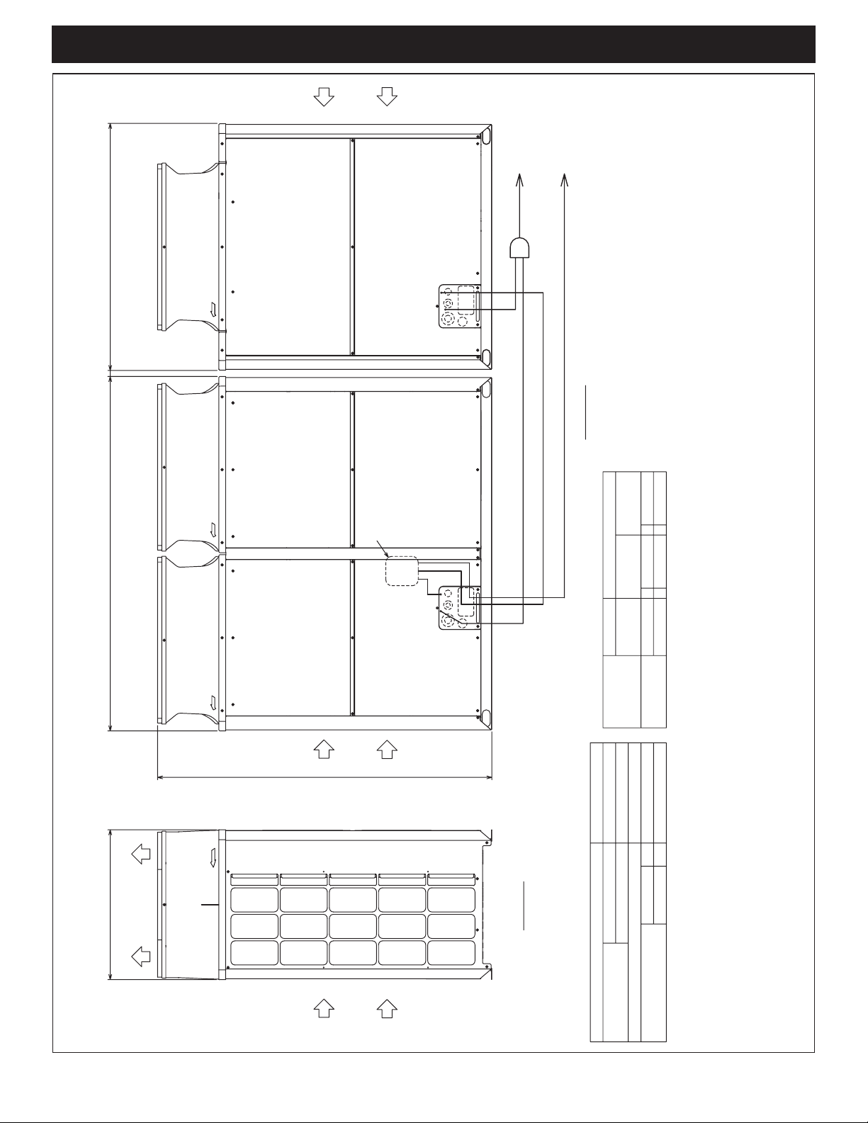
Outdoor Unit: PURY-P216TSKMU-A (-BS) – DIMENSIONS
PURY-P216TSKMU-A(-BS)
Unit : mm(in.)
Intake
air
Outdoor unit 2
1220(48-1/16)
30(1-3/16)740(29-5/32)
Outdoor unit 1
1750(68-29/32)
Twinning pipe(Low pressure)
<optional parts>
d
To BC controller
a
To BC controller
b
Twinning pipe(High pressure)
<optional parts>
e
c
f
Front view
P216
P96
ø22.2(7/8)
ø19.05(3/4)
fd
ecø19.05(3/4)
(Note 5)
-
P120
Discharge air
Intake
air
1650(64-31/32)
Intake
air
Left view
High pressure
Low pressure
Component
unit model
Unit model
Twinning Kit
~Outdoor unit
ø28.58(1-1/8)
ø28.58(1-1/8)
CMY-R100XLCBK
PURY-P216TSKMU-A(-BS)
PURY-P120TKMU-A(-BS)
PURY-P96TKMU-A(-BS)
b
a
Low pressure
High pressure
Outdoor unit 2
Outdoor unit 1
Package unit name
Outdoor Twinning Kit(optional parts)
BC controller~Twinning pipe
Component unit name
Twinning pipe connection size
Note 1.Connect the pipes as shown in the figure above. Refer to the table above for the pipe size.
2.Twinning pipe (High pressure) should not be tilted more than 15 degrees from the horizontal plane.
Be sure to see the Installation Manual for details of Twinning pipe installation.
3.The pipe section before the Twinning pipe (section "a" in the figure) must have at least 500mm(19-11/16) of straight section
4.Only use the Twinning pipe by Mitsubishi (optional parts).
5.Connect the outdoor unit 1 with the Twinning pipe (Low pressure) (section "d" in the figure).
(*including the straight pipe that is supplied with the Twinning pipe).
Specications are subject to change without notice.
© 2014 Mitsubishi Electric US, Inc.
Page 3

Model: PURY-P120TKMU-A (-BS) – DIMENSIONS
)(
PURY-P120,144TKMU-A(-BS)
Unit : mm(in.)
1-1/8)
(1-1/8)
Low
pressure
ø28.58
ø28.58
Service valve
ø25.4
High
pressure
Specifications
(1)
(1)
ø25.4
140 × 77 Knockout hole
(5-17/32)(3-1/16)
150 × 94 Knockout hole
ø45 Knockout hole
(1-25/32)
(7/8)
(1-3/8)
ø65 Knockout hole
ø62.7 or ø34.5 Knockout hole
(2-15/32)
(5-29/32)(3-23/32)
ø52 Knockout hole
ø43.7 or ø22.2 Knockout hole
(1-3/4)
(2-9/16)
(2-1/16)
ø34 Knockout hole
(1-11/32)
Note 1.Please refer to the engineering manual for information
regarding necessary spacing around the unit and
foundation work. Outdoor unit must be mounted
at least 12" off the ground or 12" above the highest
average snow depth, whichever is greater.
2.At brazing of pipes,wrap the refrigerant service valve
with wet cloth and keep the temperature of
refrigerant service valve under 120°C(248°F).
740(29-5/32)
49(1-15/16)
60070
(23-5/8)
(2-25/32)
Diameter
Connecting pipe specifications
19.5
(25/32)
831(32-23/32)
*1
Low
pressure
(1-1/8)
ø28.58 Brazed
ø28.58 Brazed
Refrigerant pipe
*2
High
pressure
(3/4)
ø22.2 Brazed
ø19.05 Brazed
Model
PURY-P144TKMU
PURY-P120TKMU
(11-15/16)
303
Top view
1750(68-29/32)
831(32-23/32)
19.5
(25/32)
Control box
*1
(1-1/8
*2
(7/8)
*1 Expand the on-site piping and connect to the refrigerant service valve piping.ࠉ
Intake
air
Intake
*2 Use the pipe joint(field supply) and connect to the refrigerant service valve piping.ࠉ
air
Front through hole
Usage
1
NO.
1650(64-31/32)
1347(53-1/16)
Service
panel
Fan box
1
8
5
4
2
Service panel
Refrigerant service valve
<High pressure>
Refrigerant service valve
<Low pressure>
Front through hole
(Uses when twinning
kit (optional parts)
is mounted.)
For pipes
2
2X2-80(3-5/32)X35(1-13/32) Oval hole
7789
75(2-31/32)
58(2-5/16)
541(21-5/16)
526(20-23/32)
145
217
(10-11/32)
262
Bottom through hole
Front through hole
Front through hole
Bottom through hole
For wires
4
5
2X3-14(9/16)X20(13/16) Oval hole
(3-17/32) (3-1/16)
Front view
150(5-29/32)
561(22-3/32)
6
83
(3-9/32)
590(23-1/4)
516(20-11/32)
3
<Sling hole>
140(5-17/32)
562(22-5/32)
(5-23/32)
(8-9/16)
57
(2-1/4)
Front through hole
Bottom through hole
For transmission cables
7
8
(1-3/16)
(3-5/16)
8494
(5-23/32)
145
7
6
(4-25/32)
121
(5-3/4)
146
(7-23/32)
196
(740)(29-5/32)
(Mounting pitch)
681
(26-13/16)
(3-23/32)
Refrigerant service valve
<Low pressure>
3
Refrigerant service valve
<High pressure>
(1-3/16)
29.529.5
80
(3-5/32)
795(31-5/16)
(Mounting pitch)(Mounting pitch)
Bottom view
795(31-5/16)
80
(3-5/32)
<Snow hood attachment hole>
2X7-ø4.6(3/16) Hole
(Make hole at the plastic fan guard
for snow hood attachment)
Discharge air
Specications are subject to change without notice.
© 2014 Mitsubishi Electric US, Inc.
Intake
air
20
(13/16)
(13/16)
20
54(2-5/32)
586(23-3/32)
Left side view
57
(2-1/4)
Page 4

Model: PURY-P96TKMU-A (-BS) – DIMENSIONS
PURY-P72,96TKMU-A(-BS)
Unit : mm(in.)
engineering manual for information
the
regarding necessary spacing around the unit and
foundation work. Outdoor unit must be mounted
at least 12" off the ground or 12" above the highest
average snow depth, whichever is greater.
2.At brazing of pipes,wrap the refrigerant service valve
with wet cloth and keep the temperature of
Note 1.Please refer to
refrigerant service valve under 120°C(248°F).
Connecting pipe specifications
Service valveRefrigerant pipe
Diameter
Model
Low
High
Low
High
pressure
pressure
pressure
pressure
(1)
(1)
ø25.4
ø25.4
(3-1/16)(5-17/32)
(1)
(1)
ø25.4
ø25.4
*1
*1
(3/4)
(7/8)
ø19.05 Brazed
ø22.2 Brazed
*1
*1
(5/8)
(3/4)
ø15.88 Brazed
ø19.05 Brazed
PURY-P96TKMU
PURY-P72TKMU
*1 Use the pipe joint(field supply) and connect to the refrigerant service valve piping.
Specifications
140 × 77 Knockout hole
Front through hole
Front through hole
Usage
1
NO.
(3-23/32)(5-29/32)
150 × 94 Knockout hole
ø45 Knockout hole
(Uses when twinning
For pipes
2
ø62.7 or ø34.5 Knockout hole
(1-25/32)
Front through hole
Bottom through hole
kit (optional
parts) is mounted.)
4
3
(7/8)
(1-3/8)
ø34 Knockout hole
ø52 Knockout hole
ø65 Knockout hole
ø43.7 or ø22.2 Knockout hole
(1-3/4)
(2-15/32)
Front through hole
For wires
5
(2-9/16)
(2-1/16)
Bottom through hole
Bottom through hole
6
7
(1-11/32)
Front through hole
For transmission cables
8
600
(23-5/8)
740(29-5/32)
19.5
(25/32)
Top view
1181(46-1/2)
1220(48-1/16)
19.5
150(5-29/32)
(25/32)
70
(2-25/32)
<Snow hood attachment hole>
4X5-ø4.6(3/16) Hole
(Make hole at the plastic fan guard
for snow hood attachment)
Discharge air
(11-15/16)
303
Control box
Intake
air
Intake
air
1650(64-31/32)
1347(53-1/16)
Service
panel
77
1
8
5
4
2
Refrigerant service valve
<High pressure>
Refrigerant service valve
<Low pressure>
217
262
89
75(2-31/32)
236
(9-5/16)
145
(10-11/32)
20
20
<Sling hole>
2X2-80(3-5/32)X35(1-13/32) Oval hole
(3-17/32) (3-1/16)
58(2-5/16)
140(5-17/32)
272
251
(9-29/32)
(10-23/32)
(5-23/32)
(8-9/16)
57
(2-1/4)
(13/16)(13/16)
586(23-3/32)
29.5
2X2-14(9/16)X20(13/16) Oval hole
Front view
83(3-9/32)
150(5-29/32)
301
272
227
(8-15/16)
(10-23/32)
(11-7/8)
Left side view
(1-3/16)
(3-5/16)
(5-3/4)
146
(4-25/32)
121
(5-3/4)
146
(7-23/32)
94 84
6
196
(740)(29-5/32)
(Mounting pitch)
(26-13/16)
681
80
(3-23/32)
Refrigerant service
valve <Low pressure>
1060(41-3/4)
3
80
7
Refrigerant service
valve <High pressure>
(1-3/16)
29.5
(3-5/32)
Bottom view
(Mounting pitch)
(3-5/32)
Specications are subject to change without notice.
© 2014 Mitsubishi Electric US, Inc.
Intake
air
(2-5/32)
54
57
(2-1/4)
Page 5

Twinning Kit: CMY-R100XLCBK
CMY-R100XLCBK
Low-pressure pipe twinning kit
High-pressure twinning pipe
ID 1-5/32”
OD 3/4”
OD 1-1/4”
6-15/16”
1-1/32”
2-3/32”1-31/32”
1-9/32”
2-15/32”
ID 3/4”
3-5/32”
8-7/16”
4-9/32”
OD 1-5/32”
ID 1-1/4”
ID 1-1/4”
2-3/32”
ID 1-5/32”
ID 1-5/32”
1-31/32”
1-31/32”
ID 3/4”
ID 1-5/32”
16-13/16”
OD 1-1/4”
ID 1”
21/32”
<Deformed pipe(Accessory)><Elbow pipe(Accessory)>
OD 1-1/4”
<Deformed pipe (Accessory)>
OD 3/4”
ID 1-13/32”
6-5/16”
ID 1-5/32”
2-23/32”
ID 7/8”
(3Pcs.)
2-15/32”
<Pipe for routing through the front (Accessory)><Pipe for routing through the bottom (Accessory)>
4-17/32”
ID 1”
1”
OD 1-5/32”
OD 7/8”
5-3/8”
OD 7/8”
7-17/32”
unit : inch
1-13/32”
ID 7/8”
2-15/32”
ID 1-5/32”
2-15/32”
ID 3/4”
2-15/32”
ID 3/4”
2-5/16”
Notes:
FORM# PURY-P216TSKMU-A (-BS) - 201407
Specications are subject to change without notice.
© 2014 Mitsubishi Electric US, Inc.
1340 Satellite Boulevard
Suwanee, GA 30024
Toll Free: 800-433-4822
www.mehvac.com
 Loading...