

Mitsubishi PURY-M400YNW-A1, PURY-M250YNW-A1, PURY-M200YNW-A1, PURY-M500YNW-A1, PURY-M450YNW-A1 Data Book
...
AIR CONDITIONING SYSTEMS
MODEL
PURY-M200-500YNW-A1 (-BS)
PURY-EM200-500YNW-A1 (-BS)
GENERAL LINE-UP
I.GENERAL LINE-UP
GENERAL LINE-UP
Heat Recovery R2-Series
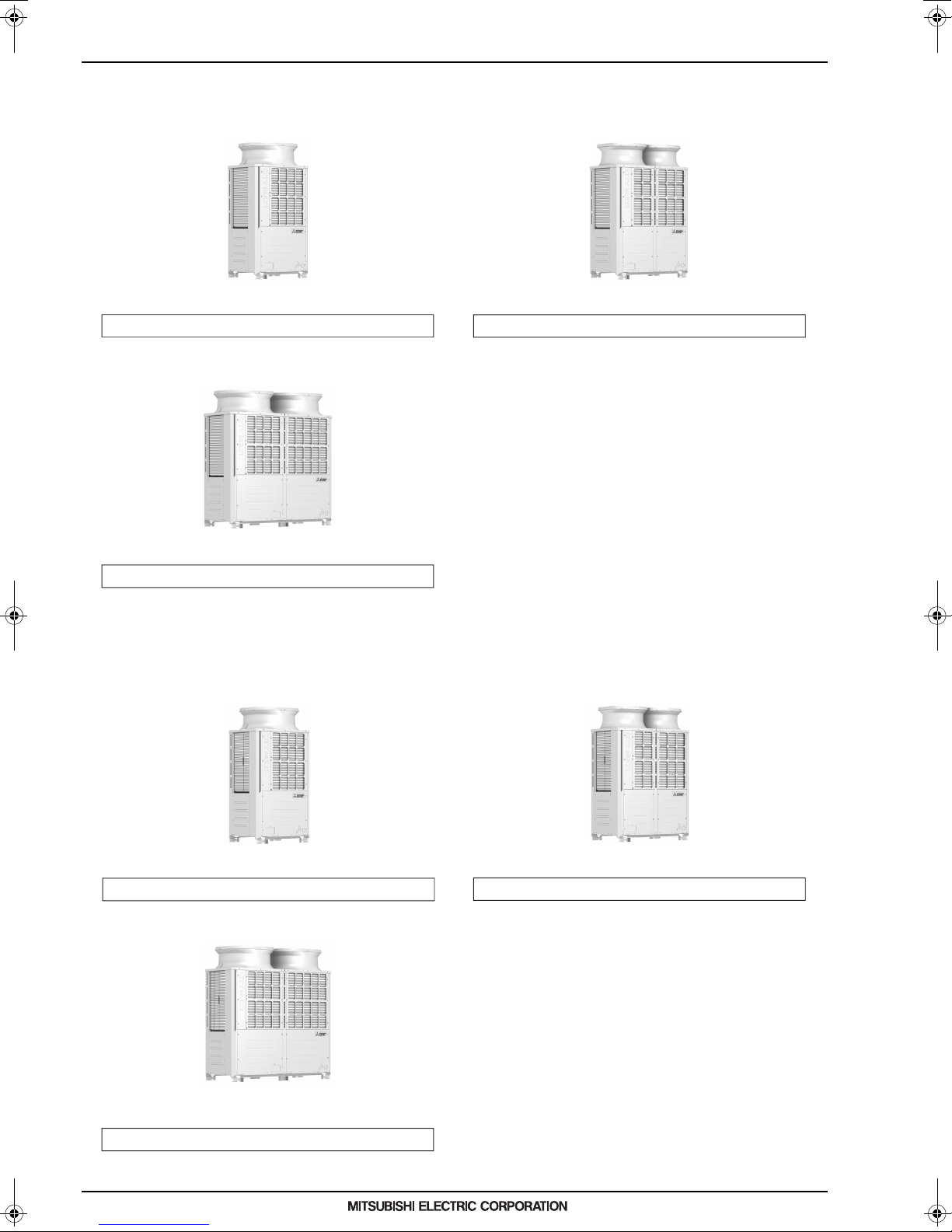
PURY-M300YNW-A1(-BS)
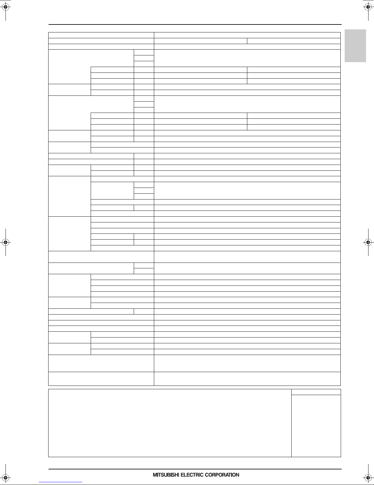
PURY-M500YNW-A1(-BS)
PURY-M250YNW-A1(-BS)PURY-M200YNW-A1(-BS)
8, 10, 12HP
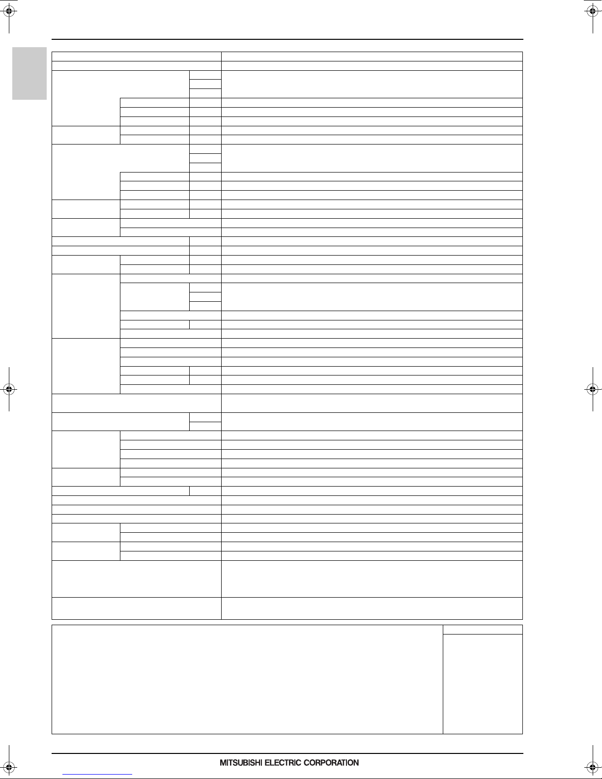
PURY-M450YNW-A1(-BS)
PURY-M400YNW-A1(-BS)PURY-M350YNW-A1(-BS)
14, 16, 18HP
20HP
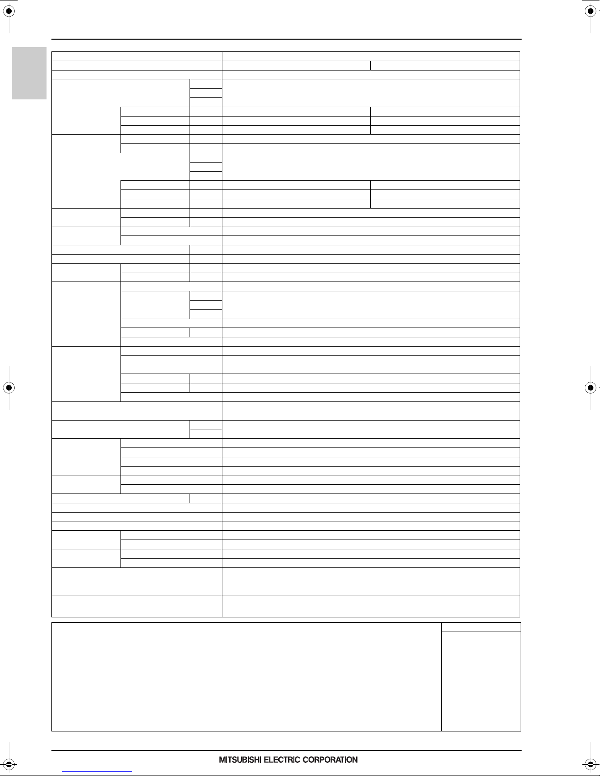
Heat Recovery High efficiency R2-Series
PURY-EM250YNW-A1(-BS)PURY-EM200YNW-A1(-BS)
PURY-EM300YNW-A1(-BS)
8, 10, 12HP
PURY-EM450YNW-A1(-BS)
PURY-EM400YNW-A1(-BS)PURY-EM350YNW-A1(-BS)
14, 16, 18HP
PURY-EM500YNW-A1(-BS)
20HP
MEES18K068

CONTENTS
PURY-M-YNW-A1, PURY-EM-YNW-A1
I.R2-Series
1. SPECIFICATIONS .................................................................................................................................... 2
2. EXTERNAL DIMENSIONS ....................................................................................................................... 16
3. CENTER OF GRAVITY ............................................................................................................................ 28
4. ELECTRICAL WIRING DIAGRAMS ......................................................................................................... 30
5. SOUND LEVELS ...................................................................................................................................... 33
5-1. Sound levels in cooling mode .......................................................................................................... 33
5-2. Sound levels in heating mode.......................................................................................................... 39
6. VIBRATION LEVEL .................................................................................................................................. 45
7. OPERATION TEMPERATURE RANGE...................................................................................................46
8. CAPACITY TABLES ................................................................................................................................. 47
8-1. Correction by temperature ............................................................................................................... 48
8-2. Correction by total indoor................................................................................................................. 60
8-3. Correction by piping length.............................................................................................................. 64
8-4. Correction at frost and defrost ......................................................................................................... 67
8-5. Correction by antifreeze solution concentration............................................................................... 68
9. ELECTRICAL WORK................................................................................................................................ 69
9-1. Power supply for Outdoor unit ......................................................................................................... 69
9-2. Power cable specifications .............................................................................................................. 70
9-3. Power supply examples ................................................................................................................... 71
10.M-NET CONTROL ................................................................................................................................... 72
10-1.Address setting................................................................................................................................ 72
11.PIPING DESIGN ...................................................................................................................................... 73
11-1.R32 Piping material ......................................................................................................................... 73
11-2.Piping Design .................................................................................................................................. 74
11-3.Refrigerant charging calculation ...................................................................................................... 83
11-4.Water piping .................................................................................................................................... 84
R2-Series
MEES18K068
1

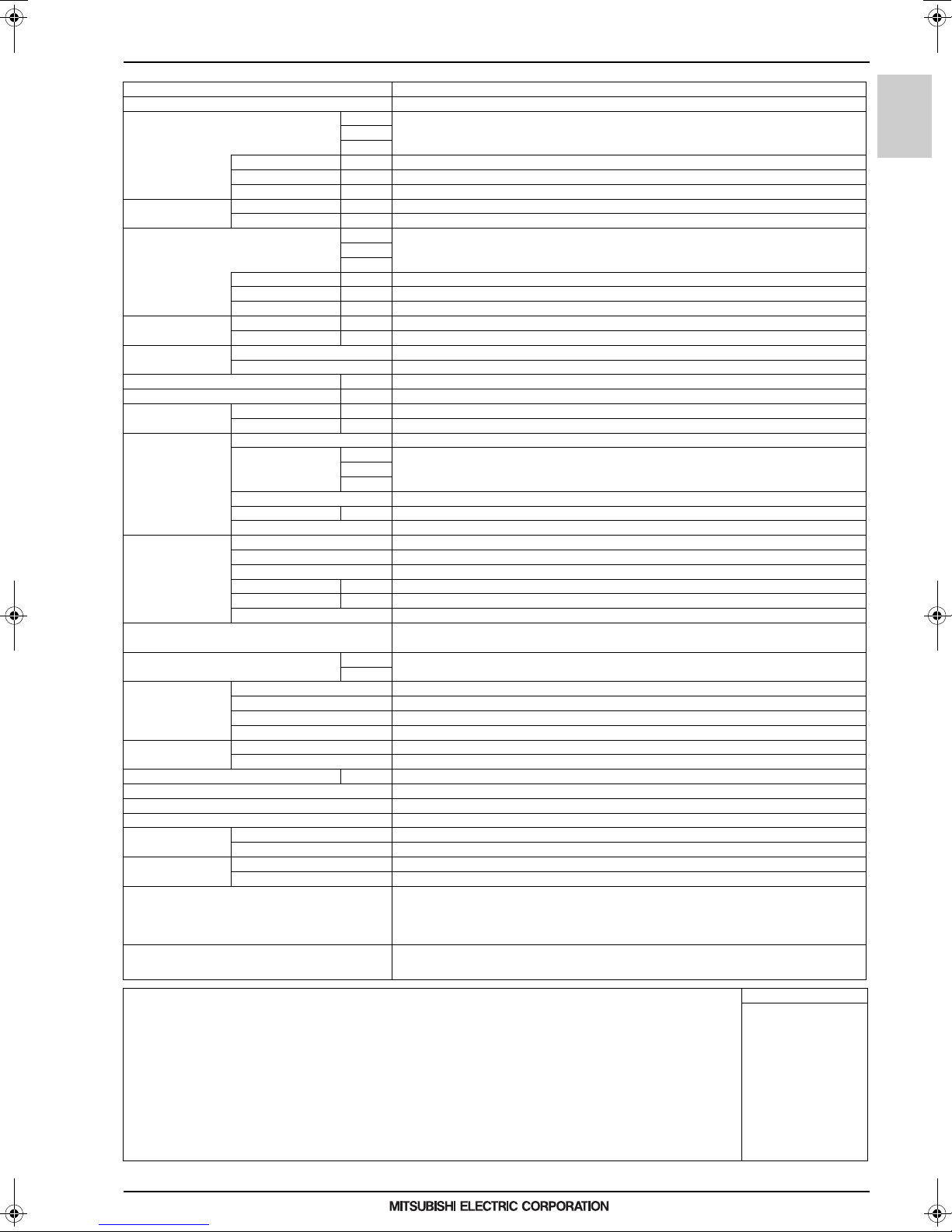
1. SPECIFICATIONS
I.R2-Series1. SPECIFICATIONS
Model PURY-M200YNW-A1 (-BS)
Power source 3-phase 4-wire 380-400-415 V 50/60 Hz
Cooling capacity *1 kW 22.4
(Nominal) kcal/h 20,000
Power input kW 5.53
Current input A 9.3-8.8-8.5
Temp. range of Indoor W.B. 15.0~24.0°C (59~75°F)
cooling *3 Outdoor D.B. -5.0~52.0°C (23~126°F)
Heating capacity *2 kW 25.0
(Nominal) kcal/h 21,500
Temp. range of Indoor D.B. 15.0~27.0°C (59~81°F)
PURY-M-YNW-A1, EM-YNW-A1
heating *3 Outdoor W.B. -20.0~15.5°C (-4~60°F)
Indoor unit Total capacity 50~150% of outdoor unit capacity
connectable Model/Quantity WP10~125, W10~125/1~30
Sound pressure level (measured in anechoic room) *4 dB <A> 59.0/59.0
Sound power level (measured in anechoic room) *4 dB <A> 76.0/78.0
Refrigerant High pressure mm (in.) 15.88 (5/8) Brazed
piping diameter Low pressure mm (in.) 19.05 (3/4) Brazed
FAN Type x Quantity Propeller fan x 1
Compressor Type Inverter scroll hermetic compressor
External finish Pre-coated galvanized steel sh eets (+powder coating for -BS type)
External dimension H x W x D mm 1,858 (1,798 without legs) x 920 x 740
Protection devices High pressure protection High pressure sensor, High pressure switch at 4.15 MPa (601 psi)
Refrigerant Type x original charge R32 x 5.2 kg (12 lbs)
Net weight kg (lbs) 227 (501)
Heat exchanger Salt-resistant cross fin & copper tube
HIC circuit (HIC: Heat Inter-Changer) -
Defrosting method Auto-defrost mode (Reversed refrigerant cycle, Hot gas)
Drawing External WKL94T598
Standard attachment Document Installation Manual
Optional parts
EER kW/kW 4.05
Power input kW 6.39
Current input A 10.7-10.2-9.8
COP kW/kW 3.91
Air flow rate m3/min 170
Control, Driving mechanism Inverter-control, Direct-driven by motor
Motor output kW 0.92 x 1
*5 External static press. 0 Pa (0 mmH2O)
Manufacture AC&R Works, MITSUBISHI ELECTRIC CORPORATION
Starting method Inverter
Motor output kW 4.6
Case heater kW - (- V)
Lubricant MEL46EH
Inverter circuit (COMP./FAN) Over-heat protection, Over-current protection
Compressor -
Fan motor -
Control HBC controller
Wiring WKE94G769
Accessory -
BTU/h 76,400
BTU/h 85,300
L/s 2,833
cfm 6,003
<MUNSELL 5Y 8/1 or similar>
in. 73-3/16 (70-13/16 without legs) x 36-1/4 x 29-3/16
Main HBC controller: CMB-WM108,1016V-AA
Sub HBC controller: CMB-WM108,1016V-AB
R2-Series
Remarks Details on foundation work, duct work, insulation work, electrical wiring, power source switch, and other items shall be
Notes: Unit converter
1.Nominal cooling conditions (subject to JIS B8615-2)
Indoor: 27°CD.B./19°CW.B. (81°FD.B./66°FW.B.), Outdoor: 35°CD.B./24°CW.B. (95°FD.B./75°FW.B.)
Pipe length: 7.5 m (24-9/16 ft.), Level difference: 0 m (0 ft.)
2.Nominal heating conditions (subject to JIS B8615-2)
Indoor: 20°CD.B. (68°FD.B.), Outdoor: 7°CD.B./6°CW.B. (45°FD.B./43°FW.B.)
Pipe length: 7.5 m (24-9/16 ft.), Level difference: 0 m (0 ft.)
3.-5°CD.B. (23°FD.B.)/-6°CW.B. (21°FW.B.) to 21°CD.B. (70°FD.B.)/15.5°CW.B. (60°FW.B.)
with cooling/heating mixed operat ion.
4.Cooling mode/Heating mode
5.External static pressure option is available (30 Pa, 60 Pa, 80 Pa/3.1 mmH2O, 6.1 mmH2O, 8.2 mmH2O).
Consult your dealer about the specification when setting External static pressure option.
6.R32 is flammable, and certain restrictions apply to the installation of units.
When installing new units, moving the existing units, or changing the layout of the room,
ensure that installation restrictions are observed.
For detail, refer to the section in the Databook on installation restrictions.
MEES18K068
referred to the Installation Manual.
Due to continuing improvement, above specifications may be subje ct to change without notice.
BTU/h =kW x 3,412
cfm =m3/min x 35.31
lbs =kg/0.4536
*Above specification data is
subject to rounding variatio n.
2

1. SPECIFICATIONS
Model PURY-M250YNW-A1 (-BS)
Power source 3-phase 4-wire 380-400-415 V 50/60 Hz
Cooling capacity *1 kW 28.0
(Nominal) kcal/h 25,000
BTU/h 95,500
Power input kW 8.40
Current input A 14.1-13.4-12.9
EER kW/kW 3.33
Temp. range of Indoor W.B. 15.0~24.0°C (59~75°F)
cooling *3 Outdoor D.B. -5.0~52.0°C (23~126°F)
Heating capacity *2 kW 31.5
(Nominal) kcal/h 27,100
BTU/h 107,500
Power input kW 9.15
Current input A 15.4-14.6-14.1
COP kW/kW 3.44
Temp. range of Indoor D.B. 15.0~27.0°C (59~81°F)
heating *3 Outdoor W.B. -20.0~15.5°C (-4~60°F)
Indoor unit Total capacity 50~150% of outdoor unit capacity
connectable Model/Quantity WP10~125, W10~125/1~37
Sound pressure level (meas ured in anechoic room) *4 dB <A> 60.5/61.0
Sound power level (measured in anechoic room) *4 dB <A> 78.5/80.0
Refrigerant High pressure mm (in.) 15.88 (5/8) Brazed
piping diameter Low pressure mm (in.) 22.2 (7/8) Brazed
FAN Type x Quantity Propeller fan x 1
Air flow rate m3/min 185
L/s 3,083
cfm 6,532
Control, Driving mechanism Inverter-control, Direct-driven by motor
Motor output kW 0.92 x 1
*5 External static press. 0 Pa (0 mmH2O)
Compressor Type Inverter scroll hermetic compressor
Manufacture AC&R Works, MITSUBISHI ELECTRIC CORPORATION
Starting method Inverter
Motor output kW 7 .0
Case heater kW - (- V)
Lubricant MEL46EH
External finish Pre-coated galvanized steel sheets (+powder coating for -BS type)
<MUNSELL 5Y 8/1 or similar>
External dimension H x W x D mm 1,858 (1,798 without legs) x 920 x 740
in. 73-3/16 (70-13/16 without legs) x 36-1/4 x 29-3/16
Protection devices High pressure protection High pressure sensor, High pressure switc h at 4.15 MPa (601 psi)
Inverter circuit (COMP./FA N) Ove r-heat protection, Over-cur rent protection
Compressor -
Fan motor -
Refrigerant Type x original charge R32 x 5.2 kg (12 lbs)
Control HBC controller
Net weight kg (lbs) 227 (501)
Heat exchanger Salt-resistant cross fin & copper tube
HIC circuit (HIC: Heat Inter-Changer) -
Defrosting method Auto-defrost mode (Reversed refrigerant cycle, Hot gas)
Drawing External WKL94T598
Wiring WKE94G769
Standard attachment Document Installation Manual
Accessory -
Optional parts
Main HBC controller: CMB-WM108,1016V-AA
Sub HBC controller: CMB-WM108,1016V-AB
R2-Series
PURY-M-YNW-A1, EM-YNW-A1
Remarks Details on foundation work, duct work, insulation work, electrical wiring, power source switch, and other items shall be
Notes: Unit converter
1.Nominal cooling conditions (subject to JIS B8615-2)
Indoor: 27°CD.B./19°CW.B. (81°FD.B./66°FW.B.), Outdoor: 35°CD.B./24°CW.B. (95°FD.B./75°FW.B.)
Pipe length: 7.5 m (24-9/16 ft.), Level difference: 0 m (0 ft.)
2.Nominal heating conditions (subj ect to JIS B8615-2)
Indoor: 20°CD.B. (68°FD.B.), Outdoor: 7°CD.B./6°CW.B. (45°FD.B./43°FW.B.)
Pipe length: 7.5 m (24-9/16 ft.), Level difference: 0 m (0 ft.)
3.-5°CD.B. (23°FD.B.)/-6°CW.B. (21°FW.B.) to 21°CD.B. (70°FD.B.)/15.5°CW.B. (60°FW.B.)
with cooling/heating mixed operation.
4.Cooling mode/Heating mode
5.External static pressure option is available (30 Pa, 60 Pa, 80 Pa/3.1 mmH2O, 6.1 mmH2O, 8.2 mmH2O).
Consult your dealer about the specification when setting External static pressure option.
6.R32 is flammable, and certain rest rictions apply to the installation of units.
When installing new units, moving the existing units, or changing the layout of the room,
ensure that installation restrictions are observed.
For detail, refer to the section in the Databook on installation restrictions.
MEES18K068
referred to the Installation Manual.
Due to continuing improvement, a bove specifications may be subject to change without notice.
BTU/h =kW x 3,412
cfm =m3/min x 35.31
lbs =kg/0.4536
*Above specification data is
subject to rounding variation.
3

1. SPECIFICATIONS
Model PURY-M300YNW-A1 (-BS)
Number of HBC controller Single HBC Double HBC
Power source 3-phase 4-wire 380-400-415 V 50/60 Hz
Cooling capacity *1 kW 33.5
(Nominal) kcal/h 30,000
Power input kW 11.65 9.88
Current input A 19.6-18.6-18.0 16.6-15.8-15.2
Temp. range of Indoor W.B. 15.0~24.0°C (59~75°F)
cooling *3 Outdoor D.B. -5.0~52.0°C (23~126°F)
Heating capacity *2 kW 37.5
(Nominal) kcal/h 32,300
PURY-M-YNW-A1, EM-YNW-A1
Temp. range of Indoor D.B. 15.0~27.0°C (59~81°F)
heating *3 Outdoor W.B. -20.0~15.5°C (-4~60°F)
Indoor unit Total capacity 50~150% of outdoor unit capacity
connectable Model/Quantity WP10~125, W10 ~125/2~45
Sound pressure level (measured in anechoic room) *4 dB <A> 61.0/67.0
Sound power level (measured in anechoic room) *4 dB <A> 80.0/86.5
Refrigerant High pressure mm (in.) 15.88 (5/ 8) Brazed
piping diameter L ow pressure mm (in.) 22.2 (7/8) Brazed
FAN Type x Quantity Propeller fan x 1
Compressor Type Inverter scroll hermetic compressor
External finish Pre-coated galvanized steel sh eets (+powder coating for -BS type)
External dimension H x W x D mm 1,858 (1,798 without legs) x 920 x 740
Protection devices High pressure protection High pressure sensor, High pressure switch at 4.15 MPa (601 psi)
Refrigerant Type x original charge R32 x 5.2 kg (12 lbs)
Net weight kg (lbs) 227 (501)
Heat exchanger Salt-resistant cross fin & copper tube
HIC circuit (HIC: Heat Inter-Changer) -
Defrosting method Auto-defrost mode (Reversed refrigerant cycle, Hot gas)
Drawing External WKL94T598
Standard attachment Document Installation Manual
Optional parts Main HBC controller: CMB-WM108,1016V-AA
EER kW/kW 2.87 3.39
Power input kW 11.00 10.33
Current input A 18.5-17.6-17.0 17.4-16.5-15.9
COP kW/kW 3.40 3.63
Air flow rate m
Control, Driving mechanism Inverter-control, Direct-driven by motor
Motor output kW 0.92 x 1
*5 External static press. 0 Pa (0 mmH
Manufacture AC&R Works, MITSUBISHI ELECTRIC CORPORATION
Starting method Inverter
Motor output kW 8.0
Case heater kW - (- V)
Lubricant MEL46EH
Inverter circuit (COMP./FAN) Over-heat protection, Over-current protection
Compressor -
Fan motor -
Control HBC controller
Wiring WKE94G769
Accessory -
BTU/h 114,300
BTU/h 128,000
3
/min 240
L/s 4,000
cfm 8,474
O)
2
<MUNSELL 5Y 8/1 or similar>
in. 73-3/16 (70-13/16 without legs) x 36-1/4 x 29-3/16
Sub HBC controller: CMB-WM108,1016V-AB
R2-Series
Remarks Details on foundation work, duct work, insulation work, electrical wiring, power source switch, and other items shall be
Notes: Unit converter
1.Nominal cooling conditions (subject to JIS B8615-2)
Indoor: 27°CD.B./19°CW.B. (81°FD.B./66°FW.B.), Outdoor: 35°CD.B./24°CW.B. (95°FD.B./75°FW.B.)
Pipe length: 7.5 m (24-9/16 ft.), Level difference: 0 m (0 ft.)
2.Nominal heating conditions (subject to JIS B8615-2)
Indoor: 20°CD.B. (68°FD.B.), Outdoor: 7°CD.B./6°CW.B. (45°FD.B./43°FW.B.)
Pipe length: 7.5 m (24-9/16 ft.), Level difference: 0 m (0 ft.)
3.-5°CD.B. (23°FD.B.)/-6°CW.B. (21°FW.B.) to 21°CD.B. (70°FD.B.)/15.5°CW.B. (60°FW.B.)
with cooling/heating mixed operat ion.
4.Cooling mode/Heating mode
5.External static pressure option is available (30 Pa, 60 Pa, 80 Pa/3.1 mmH2O, 6.1 mmH2O, 8.2 mmH2O).
Consult your dealer about the specification when setting External static pressure option.
6.R32 is flammable, and certain restrictions apply to the installation of units.
When installing new units, moving the existing units, or changing the layout of the room,
ensure that installation restrictions are observed.
For detail, refer to the section in the Databook on installation restrictions.
MEES18K068
referred to the Installation Manual.
Due to continuing improvement, above specifications may be subje ct to change without notice.
BTU/h =kW x 3,412
cfm =m3/min x 35.31
lbs =kg/0.4536
*Above specification data is
subject to rounding variatio n.
4
1. SPECIFICATIONS
Model PURY-M350YNW-A1 (-BS)
Number of HBC controller Single HBC Double HBC
Power source 3-phase 4-wire 380-400-415 V 50/60 Hz
Cooling capacity *1 kW 40.0
(Nominal) kcal/h 35,000
Power input kW 14.93 12.15
Current input A 25.2-2 3.9-23.0 20.5-19.4-18.7
EER kW/kW 2.67 3.29
Temp. range of Indoor W.B. 15.0~24.0°C (59~75°F)
cooling *3 Outdoor D.B. -5.0~52.0°C (23~126°F)
Heating capacity *2 kW 45.0
(Nominal) kcal/h 38,700
Power input kW 13.14 12.16
Current input A 22.1-2 1.0-20.3 20.5-19.5-18.7
COP kW/kW 3.42 3.70
Temp. range of Indoor D.B. 15.0~27.0°C (59~81°F)
heating *3 Outdoor W.B. -20.0~15.5°C (-4~60°F)
Indoor unit Total capacity 50~150% of outdoor unit capacity
connectable Model/Quantity WP10~125, W10~125/1~35
Sound pressure level (meas ured in anechoic room) *4 dB <A> 62 .5/64.0
Sound power level (measured in anechoic room) *4 dB <A> 81.0/83.0
Refrigerant High pressure mm (in.) 15.88 (5/8) Brazed
piping diameter Low pressure mm (in.) 28.58 (1-1/8) Brazed
FAN Type x Quantity Propeller fan x 2
Air flow rate m
Control, Driving mechanism Inverter-control, Direct-driven by motor
Motor output kW 0.46 x 2
*5 External static press. 0 Pa (0 mmH
Compressor Type Inverter scroll hermetic compressor
Manufacture AC&R Works, MITSUBISHI ELECTRIC CORPORATION
Starting method Inverter
Motor output kW 9.6
Case heater kW - (- V)
Lubricant MEL46EH
External finish Pre-coated galvanized steel sheets (+powder coating for -BS type)
External dimension H x W x D mm 1,858 (1,798 without legs) x 1,240 x 740
Protection devices High pressure protection High pressure sensor, High pressure switch at 4.15 MPa (601 psi)
Inverter circuit (COMP./FAN) Over-heat protection, Over-current protection
Compressor -
Fan motor -
Refrigerant Type x original charge R32 x 8.0 kg (18 lbs)
Control HBC controller
Net weight kg (lbs) 270 (596)
Heat exchanger Salt-resistant cross fin & copper tube
HIC circuit (HIC: Heat Inter-Changer) -
Defrosting method Auto-defrost mode (Reversed refrigerant cycle)
Drawing External WKL94T599
Wiring WKE94G770
Standard attachment Document Installation Manual
Accessory -
Optional parts Main HBC controller: CMB-WM108,1016V-AA
BTU/h 136,500
BTU/h 153,500
3
/min 250
L/s 4,167
cfm 8,828
O)
2
<MUNSELL 5Y 8/1 or similar>
in. 73-3/16 (70-13/16 without legs) x 48-7/8 x 29-3/16
Sub HBC controller: CMB-WM108,1016V-AB
R2-Series
PURY-M-YNW-A1, EM-YNW-A1
Remarks Details on foundation work, duct work, insulation work, electrical wiring, power source switch, and other items shall be
Notes: Unit converter
1.Nominal cooling conditions (subject to JIS B8615-2)
Indoor: 27°CD.B./19°CW.B. (81°FD.B./66°FW.B.), Outdoor: 35°CD.B./24°CW.B. (95°FD.B./75°FW.B.)
Pipe length: 7.5 m (24-9/16 ft.), Level difference: 0 m (0 ft.)
2.Nominal heating conditions (subj ect to JIS B8615-2)
Indoor: 20°CD.B. (68°FD.B.), Outdoor: 7°CD.B./6°CW.B. (45°FD.B./43°FW.B.)
Pipe length: 7.5 m (24-9/16 ft.), Level difference: 0 m (0 ft.)
3.-5°CD.B. (23°FD.B.)/-6°CW.B. (21°FW.B.) to 21°CD.B. (70°FD.B.)/15.5°CW.B. (60°FW.B.)
with cooling/heating mixed operation.
4.Cooling mode/Heating mode
5.External static pressure option is available (30 Pa, 60 Pa, 80 Pa/3.1 mmH2O, 6.1 mmH2O, 8.2 mmH2O).
Consult your dealer about the specification when setting External static pressure option.
6.R32 is flammable, and certain rest rictions apply to the installation of units.
When installing new units, moving the existing units, or changing the layout of the room,
ensure that installation restrictions are observed.
For detail, refer to the section in the Databook on installation restrictions.
MEES18K068
referred to the Installation Manual.
Due to continuing improvement, a bove specifications may be subject to change without notice.
BTU/h =kW x 3,412
cfm =m3/min x 35.31
lbs =kg/0.4536
*Above specification data is
subject to rounding variation.
5
1. SPECIFICATIONS
Model PURY-M400YNW-A1 (-BS)
Power source 3-phase 4-wire 380-400-415 V 50/60 Hz
Cooling capacity *1 kW 45.0
(Nominal) kcal/h 40,000
Power input kW 15.15
Current input A 25.5-24.2-23.4
Temp. range of Indoor W.B. 15.0~24.0°C (59~75°F)
cooling *3 Outdoor D.B. -5.0~52.0°C (23~126°F)
Heating capacity *2 kW 50.0
(Nominal) kcal/h 45,000
Temp. range of Indoor D.B. 15.0~27.0°C (59~81°F)
PURY-M-YNW-A1, EM-YNW-A1
heating *3 Outdoor W.B. -20.0~15.5°C (-4~60°F)
Indoor unit Total capacity 50~150% of outdoor unit capacity
connectable Model/Quantity WP10~125, W10~125/1~40
Sound pressure level (measured in anechoic room) *4 dB <A> 65.0/69.0
Sound power level (measured in anechoic room) *4 dB <A> 83.0/88.0
Refrigerant High pressure mm (in.) 19.05 (3/4) Brazed
piping diameter L ow pressure mm (in.) 28.58 (1-1/8) Brazed
FAN Type x Quantity Propeller fan x 2
Compressor Type Inverter scroll hermetic compressor
External finish Pre-coated galvanized steel sheets (+powder coating for -BS type)
External dimension H x W x D mm 1,858 (1,798 without legs) x 1,240 x 740
Protection devices High pressure protection High pressure sensor, High pressure switch at 4.15 MPa (601 psi)
Refrigerant Type x original charge R32 x 8.0 kg (18 lbs)
Net weight kg (lbs) 273 (602)
Heat exchanger Salt-resistant cross fin & copper tube
HIC circuit (HIC: Heat Inter-Changer) -
Defrosting method Auto-defrost mode (Reversed refrigerant cycle)
Drawing External WKL94T599
Standard attachment Document Installation Manual
Optional parts
EER kW/kW 2.97
Power input kW 14.08
Current input A 23.7-22.5-21.7
COP kW/kW 3.55
Air flow rate m3/min 315
Control, Driving mechanism Inverter-control, Direct-dri ven by motor
Motor output kW 0.46 x 2
*5 External static press. 0 Pa (0 mmH2O)
Manufacture AC&R Works, MITSUBISHI ELECTRIC CORPORATION
Starting method Inverter
Motor output kW 12.2
Case heater kW - (- V)
Lubricant MEL46EH
Inverter circuit (COMP./FAN) Over-heat protection, Over-current protection
Compressor -
Fan motor -
Control HBC controller
Wiring WKE94G770
Accessory -
BTU/h 153,500
BTU/h 170,600
L/s 5,250
cfm 11,123
<MUNSELL 5Y 8/1 or similar>
in. 73-3/16 (70-13/16 without legs) x 48-7/8 x 29-3/16
Main HBC controller: CMB-WM108,1016V-AA
Sub HBC controller: CMB-WM108,1016V-AB
R2-Series
Remarks Details on foundation work, duct work, insulation work, electrical wiring, power source switch, and other items shall be
Notes: Unit converter
1.Nominal cooling conditions (subject to JIS B8615-2)
Indoor: 27°CD.B./19°CW.B. (81°FD.B./66°FW.B.), Outdoor: 35°CD.B./24°CW.B. (95°FD.B./75°FW.B.)
Pipe length: 7.5 m (24-9/16 ft.), Level difference: 0 m (0 ft.)
2.Nominal heating conditions (subject to JIS B8615-2)
Indoor: 20°CD.B. (68°FD.B.), Outdoor: 7°CD.B./6°CW.B. (45°FD.B./43°FW.B.)
Pipe length: 7.5 m (24-9/16 ft.), Level difference: 0 m (0 ft.)
3.-5°CD.B. (23°FD.B.)/-6°CW.B. (21°FW.B.) to 21°CD.B. (70°FD.B.)/15.5°CW.B. (60°FW.B.)
with cooling/heating mixed operat ion.
4.Cooling mode/Heating mode
5.External static pressure option is available (30 Pa, 60 Pa, 80 Pa/3.1 mmH2O, 6.1 mmH2O, 8.2 mmH2O).
Consult your dealer about the specification when setting External static pressure option.
6.R32 is flammable, and certain restrictions apply to the installation of units.
When installing new units, moving the existing units, or changing the layout of the room,
ensure that installation restrictions are observed.
For detail, refer to the section in the Databook on installation restrictions.
MEES18K068
referred to the Installation Manual.
Due to continuing improvement, above specifications may be subje ct to change without notice.
BTU/h =kW x 3,412
cfm =m3/min x 35.31
lbs =kg/0.4536
*Above specification data is
subject to rounding variatio n.
6

1. SPECIFICATIONS
Model PURY-M450YNW-A1 (-BS)
Power source 3-phase 4-wire 380-400-415 V 50/60 Hz
Cooling capacity *1 kW 50.0
(Nominal) kcal/h 45,000
BTU/h 170,600
Power input kW 15.47
Current input A 26.1-24.8-23.9
EER kW/kW 3.23
Temp. range of Indoor W.B. 15.0~24.0°C (59~75°F)
cooling *3 Outdoor D.B. -5.0~52.0°C (23~126°F)
Heating capacity *2 kW 56.0
(Nominal) kcal/h 50,000
BTU/h 191,100
Power input kW 16.18
Current input A 27.3-25.9-25.0
COP kW/kW 3.46
Temp. range of Indoor D.B. 15.0~27.0°C (59~81°F)
heating *3 Outdoor W.B. -20.0~15.5°C (-4~60°F)
Indoor unit Total capacity 50~150% of outdoor unit capacity
connectable Model/Quantity WP10~125, W10~125/1~45
Sound pressure level (meas ured in anechoic room) *4 dB <A> 65.5/70.0
Sound power level (measured in anechoic room) *4 dB <A> 83.0/89.0
Refrigerant High pressure mm (in.) 19.05 (3/4) Brazed
piping diameter Low pressure mm (in.) 28.58 (1-1/8) Brazed
FAN Type x Quantity Propeller fan x 2
Air flow rate m3/min 317
L/s 5,283
cfm 11,193
Control, Driving mechanism Inverter-control, Direct-driven by motor
Motor output kW 0.46 x 2
*5 External static press. 0 Pa (0 mmH2O)
Compressor Type Inverter scroll hermetic compressor
Manufacture AC&R Works, MITSUBISHI ELECTRIC CORPORATION
Starting method Inverter
Motor output kW 13.1
Case heater kW - (- V)
Lubricant MEL46EH
External finish Pre-coated galvanized steel sheets (+powder coating for -BS type)
<MUNSELL 5Y 8/1 or similar>
External dimension H x W x D mm 1,858 (1,798 without le gs) x 1,240 x 740
in. 73-3/16 (70-13/16 without legs) x 48-7/8 x 29-3/16
Protection devices High pressure protection High pressure sensor, High pressure switc h at 4.15 MPa (601 psi)
Inverter circuit (COMP./FA N) Ove r-heat protection, Over-cur rent protection
Compressor -
Fan motor -
Refrigerant Type x original charge R32 x 10.8 kg (24 lbs)
Control HBC controller
Net weight kg (lbs) 293 (646)
Heat exchanger Salt-resistant cross fin & copper tube
HIC circuit (HIC: Heat Inter-Changer) -
Defrosting method Auto-defrost mode (Reversed refrigerant cycle)
Drawing External WKL94T599
Wiring WKE94G770
Standard attachment Document Installation Manual
Accessory -
Optional parts
Main HBC controller: CMB-WM108,1016V-AA
Sub HBC controller: CMB-WM108,1016V-AB
R2-Series
PURY-M-YNW-A1, EM-YNW-A1
Remarks Details on foundation work, duct work, insulation work, electrical wiring, power source switch, and other items shall be
Notes: Unit converter
1.Nominal cooling conditions (subject to JIS B8615-2)
Indoor: 27°CD.B./19°CW.B. (81°FD.B./66°FW.B.), Outdoor: 35°CD.B./24°CW.B. (95°FD.B./75°FW.B.)
Pipe length: 7.5 m (24-9/16 ft.), Level difference: 0 m (0 ft.)
2.Nominal heating conditions (subj ect to JIS B8615-2)
Indoor: 20°CD.B. (68°FD.B.), Outdoor: 7°CD.B./6°CW.B. (45°FD.B./43°FW.B.)
Pipe length: 7.5 m (24-9/16 ft.), Level difference: 0 m (0 ft.)
3.-5°CD.B. (23°FD.B.)/-6°CW.B. (21°FW.B.) to 21°CD.B. (70°FD.B.)/15.5°CW.B. (60°FW.B.)
with cooling/heating mixed operation.
4.Cooling mode/Heating mode
5.External static pressure option is available (30 Pa, 60 Pa, 80 Pa/3.1 mmH2O, 6.1 mmH2O, 8.2 mmH2O).
Consult your dealer about the specification when setting External static pressure option.
6.R32 is flammable, and certain rest rictions apply to the installation of units.
When installing new units, moving the existing units, or changing the layout of the room,
ensure that installation restrictions are observed.
For detail, refer to the section in the Databook on installation restrictions.
MEES18K068
referred to the Installation Manual.
Due to continuing improvement, a bove specifications may be subject to change without notice.
BTU/h =kW x 3,412
cfm =m3/min x 35.31
lbs =kg/0.4536
*Above specification data is
subject to rounding variation.
7

1. SPECIFICATIONS
Model PURY-M500YNW-A1 (-BS)
Power source 3-phase 4-wire 380-400-415 V 50/60 Hz
Cooling capacity *1 kW 56.0
(Nominal) kcal/h 50,000
Power input kW 22.25
Current input A 37.5-35.6-34.3
Temp. range of Indoor W.B. 15.0~24.0°C (59~75°F)
cooling *3 Outdoor D.B. -5.0~52.0°C (23~126°F)
Heating capacity *2 kW 63.0
(Nominal) kcal/h 54,200
Temp. range of Indoor D.B. 15.0~27.0°C (59~81°F)
PURY-M-YNW-A1, EM-YNW-A1
heating *3 Outdoor W.B. -20.0~15.5°C (-4~60°F)
Indoor unit Total capacity 50~150% of outdoor unit capacity
connectable Model/Quantity WP10~125, W10~125/1~50
Sound pressure level (measured in anechoic room) *4 dB <A> 63.5/64.5
Sound power level (measured in anechoic room) *4 dB <A> 82.0/84.0
Refrigerant High pressure mm (in.) 19.05 (3/4) Brazed
piping diameter L ow pressure mm (in.) 28.58 (1-1/8) Brazed
FAN Type x Quantity Propeller fan x 2
Compressor Type Inverter scroll hermetic compressor
External finish Pre-coated galvanized steel sheets (+powder coating for -BS type)
External dimension H x W x D mm 1,858 (1,798 without legs) x 1,750 x 740
Protection devices High pressure protection High pressure sensor, High pressure switch at 4.15 MPa (601 psi)
Refrigerant Type x original charge R32 x 10.8 kg (24 lbs)
Net weight kg (lbs) 337 (743)
Heat exchanger Salt-resistant cross fin & copper tube
HIC circuit (HIC: Heat Inter-Changer) -
Defrosting method Auto-defrost mode (Reversed refrigerant cycle)
Drawing External WKL94T600
Standard attachment Document Installation Manual
Optional parts
EER kW/kW 2.51
Power input kW 18.26
Current input A 30.8-29.2-28.2
COP kW/kW 3.45
Air flow rate m3/min 295
Control, Driving mechanism Inverter-control, Direct-dri ven by motor
Motor output kW 0.92 x 2
*5 External static press. 0 Pa (0 mmH2O)
Manufacture AC&R Works, MITSUBISHI ELECTRIC CORPORATION
Starting method Inverter
Motor output kW 17.4
Case heater kW - (- V)
Lubricant MEL46EH
Inverter circuit (COMP./FAN) Over-heat protection, Over-current protection
Compressor -
Fan motor -
Control HBC controller
Wiring WKE94G771
Accessory -
BTU/h 191,100
BTU/h 215,000
L/s 4,917
cfm 10,416
<MUNSELL 5Y 8/1 or similar>
in. 73-3/16 (70-13/16 without legs) x 68-15/16 x 29-3/16
Main HBC controller: CMB-WM108,1016V-AA
Sub HBC controller: CMB-WM108,1016V-AB
R2-Series
Remarks Details on foundation work, duct work, insulation work, electrical wiring, power source switch, and other items shall be
Notes: Unit converter
1.Nominal cooling conditions (subject to JIS B8615-2)
Indoor: 27°CD.B./19°CW.B. (81°FD.B./66°FW.B.), Outdoor: 35°CD.B./24°CW.B. (95°FD.B./75°FW.B.)
Pipe length: 7.5 m (24-9/16 ft.), Level difference: 0 m (0 ft.)
2.Nominal heating conditions (subject to JIS B8615-2)
Indoor: 20°CD.B. (68°FD.B.), Outdoor: 7°CD.B./6°CW.B. (45°FD.B./43°FW.B.)
Pipe length: 7.5 m (24-9/16 ft.), Level difference: 0 m (0 ft.)
3.-5°CD.B. (23°FD.B.)/-6°CW.B. (21°FW.B.) to 21°CD.B. (70°FD.B.)/15.5°CW.B. (60°FW.B.)
with cooling/heating mixed operat ion.
4.Cooling mode/Heating mode
5.External static pressure option is available (30 Pa, 60 Pa, 80 Pa/3.1 mmH2O, 6.1 mmH2O, 8.2 mmH2O).
Consult your dealer about the specification when setting External static pressure option.
6.R32 is flammable, and certain restrictions apply to the installation of units.
When installing new units, moving the existing units, or changing the layout of the room,
ensure that installation restrictions are observed.
For detail, refer to the section in the Databook on installation restrictions.
MEES18K068
referred to the Installation Manual.
Due to continuing improvement, above specifications may be subje ct to change without notice.
BTU/h =kW x 3,412
cfm =m3/min x 35.31
lbs =kg/0.4536
*Above specification data is
subject to rounding variatio n.
8

1. SPECIFICATIONS
Model PURY-EM200YNW-A1 (-BS)
Power source 3-phase 4-wire 380-400-415 V 50/60 Hz
Cooling capacity *1 kW 22.4
(Nominal) kcal/h 20,000
BTU/h 76,400
Power input kW 5.13
Current input A 8.6-8.2-7.9
EER kW/kW 4.36
Temp. range of Indoor W.B. 15.0~24.0°C (59~75°F)
cooling *3 Outdoor D.B. -5.0~52.0°C (23~126°F)
Heating capacity *2 kW 25.0
(Nominal) kcal/h 21,500
BTU/h 85,300
Power input kW 6.23
Current input A 10.5-9.9-9.6
COP kW/kW 4.01
Temp. range of Indoor D.B. 15.0~27.0°C (59~81°F)
heating *3 Outdoor W.B. -20.0~15.5°C (-4~60°F)
Indoor unit Total capacity 50~150% of outdoor unit capacity
connectable Model/Quantity WP10~125, W10~125/1~30
Sound pressure level (meas ured in anechoic room) *4 dB <A> 59.0/59.0
Sound power level (measured in anechoic room) *4 dB <A> 76.0/78.0
Refrigerant High pressure mm (in.) 15.88 (5/8) Brazed
piping diameter Low pressure mm (in.) 19.05 (3/4) Brazed
FAN Type x Quantity Propeller fan x 1
Air flow rate m3/min 170
L/s 2,833
cfm 6,003
Control, Driving mechanism Inverter-control, Direct-driven by motor
Motor output kW 0.92 x 1
*5 External static press. 0 Pa (0 mmH2O)
Compressor Type Inverter scroll hermetic compressor
Manufacture AC&R Works, MITSUBISHI ELECTRIC CORPORATION
Starting method Inverter
Motor output kW 4 .5
Case heater kW - (- V)
Lubricant MEL46EH
External finish Pre-coated galvanized steel sheets (+powder coating for -BS type)
<MUNSELL 5Y 8/1 or similar>
External dimension H x W x D mm 1,858 (1,798 without legs) x 920 x 740
in. 73-3/16 (70-13/16 without legs) x 36-1/4 x 29-3/16
Protection devices High pressure protection High pressure sensor, High pressure switc h at 4.15 MPa (601 psi)
Inverter circuit (COMP./FA N) Ove r-heat protection, Over-cur rent protection
Compressor -
Fan motor -
Refrigerant Type x original charge R32 x 5.2 kg (12 lbs)
Control HBC controller
Net weight kg (lbs) 231 (510)
Heat exchanger Salt-resistant cross fin & aluminium tube
HIC circuit (HIC: Heat Inter-Changer) -
Defrosting method Auto-defrost mode (Reversed refrigerant cycle, Hot gas)
Drawing External WKL94T601
Wiring WKE94G769
Standard attachment Document Installation Manual
Accessory -
Optional parts
Main HBC controller: CMB-WM108,1016V-AA
Sub HBC controller: CMB-WM108,1016V-AB
R2-Series
PURY-M-YNW-A1, EM-YNW-A1
Remarks Details on foundation work, duct work, insulation work, electrical wiring, power source switch, and other items shall be
Notes: Unit converter
1.Nominal cooling conditions (subject to JIS B8615-2)
Indoor: 27°CD.B./19°CW.B. (81°FD.B./66°FW.B.), Outdoor: 35°CD.B./24°CW.B. (95°FD.B./75°FW.B.)
Pipe length: 7.5 m (24-9/16 ft.), Level difference: 0 m (0 ft.)
2.Nominal heating conditions (subj ect to JIS B8615-2)
Indoor: 20°CD.B. (68°FD.B.), Outdoor: 7°CD.B./6°CW.B. (45°FD.B./43°FW.B.)
Pipe length: 7.5 m (24-9/16 ft.), Level difference: 0 m (0 ft.)
3.-5°CD.B. (23°FD.B.)/-6°CW.B. (21°FW.B.) to 21°CD.B. (70°FD.B.)/15.5°CW.B. (60°FW.B.)
with cooling/heating mixed operation.
4.Cooling mode/Heating mode
5.External static pressure option is available (30 Pa, 60 Pa, 80 Pa/3.1 mmH2O, 6.1 mmH2O, 8.2 mmH2O).
Consult your dealer about the specification when setting External static pressure option.
6.R32 is flammable, and certain rest rictions apply to the installation of units.
When installing new units, moving the existing units, or changing the layout of the room,
ensure that installation restrictions are observed.
For detail, refer to the section in the Databook on installation restrictions.
MEES18K068
referred to the Installation Manual.
Due to continuing improvement, a bove specifications may be subject to change without notice.
BTU/h =kW x 3,412
cfm =m3/min x 35.31
lbs =kg/0.4536
*Above specification data is
subject to rounding variation.
9

1. SPECIFICATIONS
Model PURY-EM250YNW-A1 (-BS)
Power source 3-phase 4-wire 380-400-415 V 50/60 Hz
Cooling capacity *1 kW 28.0
(Nominal) kcal/h 25,000
Power input kW 7.69
Current input A 12.9-12.3-11.8
Temp. range of Indoor W.B. 15.0~24.0°C (59~75°F)
cooling *3 Outdoor D.B. -5.0~52.0°C (23~126°F)
Heating capacity *2 kW 31.5
(Nominal) kcal/h 27,100
Temp. range of Indoor D.B. 15.0~27.0°C (59~81°F)
PURY-M-YNW-A1, EM-YNW-A1
heating *3 Outdoor W.B. -20.0~15.5°C (-4~60°F)
Indoor unit Total capacity 50~150% of outdoor unit capacity
connectable Model/Quantity WP10~125, W10~125/1~37
Sound pressure level (measured in anechoic room) *4 dB <A> 60.5/61.0
Sound power level (measured in anechoic room) *4 dB <A> 78.5/80.0
Refrigerant High pressure mm (in.) 15.88 (5/8) Brazed
piping diameter Low pressure mm (in.) 22.2 (7/8) Brazed
FAN Type x Quantity Propeller fan x 1
Compressor Type Inverter scroll hermetic compressor
External finish Pre-coated galvanized steel sheets (+po wder coating for -BS type)
External dimension H x W x D mm 1,858 (1,798 without legs) x 920 x 740
Protection devices High pressure protection High pressure sensor, High pressure switch at 4.15 MPa (601 psi)
Refrigerant Type x original charge R32 x 5.2 kg (12 lbs)
Net weight kg (lbs) 231 (510)
Heat exchanger Salt-resistant cross fin & aluminium tube
HIC circuit (HIC: Heat Inter-Changer) -
Defrosting method Auto-defrost mode (Reversed refrigerant cycle, Hot gas)
Drawing External WKL94T601
Standard attachment Document Installation Manual
Optional parts
EER kW/kW 3.64
Power input kW 8.84
Current input A 14.9-14.1-13.6
COP kW/kW 3.56
Air flow rate m3/min 185
Control, Driving mechanism Inverter-control, Direct-driven by motor
Motor output kW 0.92 x 1
*5 External static press. 0 Pa (0 mmH2O)
Manufacture AC&R Works, MITSUBISHI ELECTRIC CORPORATION
Starting method Inverter
Motor output kW 6.7
Case heater kW - (- V)
Lubricant MEL46EH
Inverter circuit (COMP./FAN) Over-heat protection, Over-current protection
Compressor -
Fan motor -
Control HBC controller
Wiring WKE94G769
Accessory -
BTU/h 95,500
BTU/h 107,500
L/s 3,083
cfm 6,532
<MUNSELL 5Y 8/1 or similar>
in. 73-3/16 (70-13/16 without legs) x 36-1/4 x 29-3 /16
Main HBC controller: CMB-WM108,1016V-AA
Sub HBC controller: CMB-WM108,1016V-AB
R2-Series
Remarks Details on foundation work, duct work, insulation work, electrical wiring, power source switch, and other items shall be
Notes: Unit converter
1.Nominal cooling conditions (subject to JIS B8615-2)
Indoor: 27°CD.B./19°CW.B. (81°FD.B./66°FW.B.), Outdoor: 35°CD.B./24°CW.B. (95°FD.B./75°FW.B.)
Pipe length: 7.5 m (24-9/16 ft.), Level difference: 0 m (0 ft.)
2.Nominal heating conditions (subject to JIS B8615-2)
Indoor: 20°CD.B. (68°FD.B.), Outdoor: 7°CD.B./6°CW.B. (45°FD.B./43°FW.B.)
Pipe length: 7.5 m (24-9/16 ft.), Level difference: 0 m (0 ft.)
3.-5°CD.B. (23°FD.B.)/-6°CW.B. (21°FW.B.) to 21°CD.B. (70°FD.B.)/15.5°CW.B. (60°FW.B.)
with cooling/heating mixed operat ion.
4.Cooling mode/Heating mode
5.External static pressure option is available (30 Pa, 60 Pa, 80 Pa/3.1 mmH2O, 6.1 mmH2O, 8.2 mmH2O).
Consult your dealer about the specification when setting External static pressure option.
6.R32 is flammable, and certain restrictions apply to the installation of units.
When installing new units, moving the existing units, or changing the layout of the room,
ensure that installation restrictions are observed.
For detail, refer to the section in the Databook on installation restrictions.
MEES18K068
referred to the Installation Manual.
Due to continuing improvement, above specifications may be subje ct to change without notice.
BTU/h =kW x 3,412
cfm =m3/min x 35.31
lbs =kg/0.4536
*Above specification data is
subject to rounding variatio n.
10

1. SPECIFICATIONS
Model PURY-EM300YNW-A1 (- BS)
Number of HBC controller Single HBC Double HBC
Power source 3-ph ase 4-wire 380-400-415 V 50/60 Hz
Cooling capacity *1 kW 33.5
(Nominal) kcal/h 30,000
Power input kW 10.03 8.52
Current input A 16.9-16.0-15.5 14.3-13.6-13.1
EER kW/kW 3.33 3.93
Temp. range of Indoor W.B. 15.0~24 .0°C (59~75°F)
cooling *3 Outdoor D.B. -5.0~52.0°C (23~126°F)
Heating capacity *2 kW 37.5
(Nominal) kcal/h 32,300
Power input kW 10.46 9.93
Current input A 17.6-16.7-16.1 16.7-15.9-15.3
COP kW/kW 3.58 3.77
Temp. range of Indoor D.B. 15.0~27.0° C (59~81°F)
heating *3 Outdoor W.B. -20.0~15.5°C (-4~60°F)
Indoor unit Total capacity 50~150% of outdoor unit capacity
connectable Model/Quantity WP10~125, W10~125/2~45
Sound pressure level (measured in anechoic room) *4 dB <A> 61.0/67.0
Sound power level (measured in anechoic room) *4 dB <A> 80.0/86.5
Refrigerant High pressure mm (in.) 15.88 (5/8) Brazed
piping diameter Low pressure mm (in.) 22.2 (7/8) Brazed
FAN Type x Quantity Propeller fan x 1
Air flow rate m
Control, Driving mechanism Inverter-control, Direct-driven by motor
Motor output kW 0.92 x 1
*5 External static press. 0 Pa (0 mmH
Compressor Type Inverter scroll hermetic compressor
Manufacture AC&R Works, MITSUBISHI ELECTRIC CORPORATION
Starting method Inverter
Motor output kW 7.7
Case heater kW - (- V)
Lubricant MEL46EH
External finish Pre-coate d galvanized steel sheets (+powder co ating for -BS type)
External dimension H x W x D mm 1,858 (1,798 without legs) x 920 x 740
Protection devices High pressure protection High pressure sensor, High pre ssure switch at 4.15 MPa (601 psi)
Inverter circuit (COMP./FA N) Over-heat protection, Over-current protectio n
Compressor -
Fan motor -
Refrigerant Type x original charge R32 x 5.2 kg (12 lbs)
Control HBC controller
Net weight kg (lbs) 23 1 (510)
Heat exchanger Salt-resistant cross fin & aluminium tube
HIC circuit (HIC: Heat Inter-Changer) -
Defrosting method Auto-defrost mode (Reversed refrigerant cycle, Hot gas)
Drawing External WKL94T601
Wiring WKE94G769
Standard attachment Document Installation Manual
Accessory -
Optional parts Main HBC controller: CMB -WM108,1016V-AA
BTU/h 114,300
BTU/h 128,000
3
/min 240
L/s 4,000
cfm 8,474
O)
2
<MUNSELL 5Y 8/1 or similar>
in. 73-3/16 (70-13/16 without legs) x 36-1/4 x 29-3/16
Sub HBC controller: CMB-WM108,1016V-AB
R2-Series
PURY-M-YNW-A1, EM-YNW-A1
Remarks Details on foundation work, duct work, insulation work, electrical wiring, power source switch, and other items shall be
Notes: Unit converter
1.Nominal cooling conditions (subject to JIS B8615-2)
Indoor: 27°CD.B./19°CW.B. (81°FD.B./66°FW.B.), Outdoor: 35°CD.B./24°CW.B. (95°FD.B./75°FW.B.)
Pipe length: 7.5 m (24-9/16 ft.), Level difference: 0 m (0 ft.)
2.Nominal heating conditions (subj ect to JIS B8615-2)
Indoor: 20°CD.B. (68°FD.B.), Outdoor: 7°CD.B./6°CW.B. (45°FD.B./43°FW.B.)
Pipe length: 7.5 m (24-9/16 ft.), Level difference: 0 m (0 ft.)
3.-5°CD.B. (23°FD.B.)/-6°CW.B. (21°FW.B.) to 21°CD.B. (70°FD.B.)/15.5°CW.B. (60°FW.B.)
with cooling/heating mixed operation.
4.Cooling mode/Heating mode
5.External static pressure option is available (30 Pa, 60 Pa, 80 Pa/3.1 mmH2O, 6.1 mmH2O, 8.2 mmH2O).
Consult your dealer about the specification when setting External static pressure option.
6.R32 is flammable, and certain rest rictions apply to the installation of units.
When installing new units, moving the existing units, or changing the layout of the room,
ensure that installation restrictions are observed.
For detail, refer to the section in the Databook on installation restrictions.
MEES18K068
referred to the Installation Manual.
Due to continuing improvement, above specifications may be subject to change without notice.
BTU/h =kW x 3,412
cfm =m3/min x 35.31
lbs =kg/0.4536
*Above specification data is
subject to rounding variation.
11
1. SPECIFICATIONS
Model PURY-EM350YNW-A1 (-BS)
Number of HBC controller Single HBC Double HBC
Power source 3-phase 4-wire 380-400-415 V 50/60 Hz
Cooling capacity *1 kW 40.0
(Nominal) kcal/h 35,000
Power input kW 13.91 11.33
Current input A 23.4-22.3-21.5 19.1-18.1-17.5
Temp. range of Indoor W.B. 15.0 ~24.0°C (59~75°F)
cooling *3 Outdoor D.B. -5.0~52.0°C (23~126°F)
Heating capacity *2 kW 45.0
(Nominal) kcal/h 38,700
PURY-M-YNW-A1, EM-YNW-A1
Temp. range of Indoor D.B. 15.0~27. 0°C (59~81°F)
heating *3 Outdoor W.B. -20.0~15.5°C (-4~60°F)
Indoor unit Total capacity 50~150% of outdoor unit capacity
connectable Model/Quantity WP10~125, W10~125/1~35
Sound pressure level (measured in anechoic room) *4 dB <A> 62.5/64.0
Sound power level (measured in anechoic room) *4 dB <A> 81.0/83.0
Refrigerant High pressure mm (in.) 1 5.88 (5/8) Brazed
piping diameter Low pressure mm (in.) 28.58 (1-1/8) Brazed
FAN Type x Quantity Propeller fan x 2
Compressor Type Inverter scroll hermetic compressor
External finish Pre-coated galvanized steel sheets (+powder coating for -BS type)
External dimension H x W x D mm 1,858 (1,798 without legs) x 1,240 x 740
Protection devices High pressure protection High pressure sensor, High pressure switch at 4.15 MPa (601 psi)
Refrigerant Type x original charge R32 x 8.0 kg (18 lbs)
Net weight kg (lbs) 276 (609)
Heat exchanger Salt-resistant cross fin & aluminium tube
HIC circuit (HIC: Heat Inter-Changer) -
Defrosting method Auto-defrost mode (Reversed refrigerant cycle, Hot gas)
Drawing External WKL94T602
Standard attachment Document Installation Manual
Optional parts Main HBC contro ller: CMB-WM108,1016V-AA
EER kW/kW 2.87 3.53
Power input kW 13.10 12.16
Current input A 22.1-21.0-20.2 20.5-19.5-18.7
COP kW/kW 3.43 3.70
Air flow rate m
Control, Driving mechanism Inverter-control, Direct-driven by motor
Motor output kW 0.46 x 2
*5 External static press. 0 Pa (0 mmH
Manufacture AC&R Works, MITSUBISHI ELECTRIC CORPORATION
Starting method Inverter
Motor output kW 9.6
Case heater kW - (- V)
Lubricant MEL46EH
Inverter circuit (COMP./FAN) Over-heat protection, Over-current protection
Compressor -
Fan motor -
Control HBC controller
Wiring WKE94G770
Accessory -
BTU/h 136,500
BTU/h 153,500
3
/min 250
L/s 4,167
cfm 8,828
O)
2
<MUNSELL 5Y 8/1 or similar>
in. 73-3/16 (70-13/16 without legs) x 48-7/8 x 29-3/16
Sub HBC controller: CMB-WM108,1016V-AB
R2-Series
Remarks Details on foundation work, duct work, insulation work, electrical wiring, power source switch, and other items shall be
Notes: Unit converter
1.Nominal cooling conditions (subject to JIS B8615-2)
Indoor: 27°CD.B./19°CW.B. (81°FD.B./66°FW.B.), Outdoor: 35°CD.B./24°CW.B. (95°FD.B./75°FW.B.)
Pipe length: 7.5 m (24-9/16 ft.), Level difference: 0 m (0 ft.)
2.Nominal heating conditions (subject to JIS B8615-2)
Indoor: 20°CD.B. (68°FD.B.), Outdoor: 7°CD.B./6°CW.B. (45°FD.B./43°FW.B.)
Pipe length: 7.5 m (24-9/16 ft.), Level difference: 0 m (0 ft.)
3.-5°CD.B. (23°FD.B.)/-6°CW.B. (21°FW.B.) to 21°CD.B. (70°FD.B.)/15.5°CW.B. (60°FW.B.)
with cooling/heating mixed operat ion.
4.Cooling mode/Heating mode
5.External static pressure option is available (30 Pa, 60 Pa, 80 Pa/3.1 mmH2O, 6.1 mmH2O, 8.2 mmH2O).
Consult your dealer about the specification when setting External static pressure option.
6.R32 is flammable, and certain restrictions apply to the installation of units.
When installing new units, moving the existing units, or changing the layout of the room,
ensure that installation restrictions are observed.
For detail, refer to the section in the Databook on installation restrictions.
MEES18K068
referred to the Installation Manual.
Due to continuing improvement, above specifications may be subject to change without notice.
BTU/h =kW x 3,412
cfm =m3/min x 35.31
lbs =kg/0.4536
*Above specification data is
subject to rounding variatio n.
12

1. SPECIFICATIONS
Model PURY-EM400YNW-A1 (-BS)
Power source 3-phase 4-wire 380-400-415 V 50/60 Hz
Cooling capacity *1 kW 45.0
(Nominal) kcal/h 40,000
BTU/h 153,500
Power input kW 13.84
Current input A 23.3-22.1-21.3
EER kW/kW 3.25
Temp. range of Indoor W.B. 15.0~24.0°C (59~75°F)
cooling *3 Outdoor D.B. -5.0~52.0°C (23~126°F)
Heating capacity *2 kW 50.0
(Nominal) kcal/h 45,000
BTU/h 170,600
Power input kW 13.88
Current input A 23.4-22.2-21.4
COP kW/kW 3.60
Temp. range of Indoor D.B. 15.0~27.0°C (59~81°F)
heating *3 Outdoor W.B. -20.0~15.5°C (-4~60°F)
Indoor unit Total capacity 50~150% of outdoor unit capacity
connectable Model/Quantity WP10~125, W10~1 25/1~40
Sound pressure level (meas ured in anechoic room) *4 dB <A> 65.0/69.0
Sound power level (measured in anechoic room) *4 dB <A> 83.0/88.0
Refrigerant High pressure mm (in.) 19.05 (3/4) Brazed
piping diameter Low pressure mm (in.) 28.58 (1-1/8) Brazed
FAN Type x Quantity Propeller fan x 2
Air flow rate m3/min 315
L/s 5,250
cfm 11,123
Control, Driving mechanism Inverter-control, Direct-driven by motor
Motor output kW 0.46 x 2
*5 External static press. 0 Pa (0 mmH2O)
Compressor Type Inverter scroll hermetic compressor
Manufacture AC&R Works, MITSUBISHI ELECTRIC CORPORATION
Starting method Inverter
Motor output kW 11.1
Case heater kW - (- V)
Lubricant MEL46EH
External finish Pre-coated galvanized steel sheets (+powder coating for -BS type)
<MUNSELL 5Y 8/1 or similar>
External dimension H x W x D mm 1,858 (1,798 without legs) x 1,240 x 740
in. 73-3/16 (70-13/16 without legs) x 48-7/8 x 29-3/16
Protection devices High pressure protection High pressure sensor, High pressure switch at 4.15 MPa (601 psi)
Inverter circuit (COMP./FAN) Over-heat protection, Over-current protection
Compressor -
Fan motor -
Refrigerant Type x original charge R32 x 8.0 kg (18 lbs)
Control HBC con troller
Net weight kg (lbs) 280 (618)
Heat exchanger Salt-resistant cross fin & aluminium tube
HIC circuit (HIC: Heat Inter-Changer) -
Defrosting method Auto-defrost mode (Reversed refrigerant cycle)
Drawing External WKL94T602
Wiring WKE94G770
Standard attachment Document Installation Manual
Accessory -
Optional parts
Main HBC controller: CMB-WM108,1016V-A A
Sub HBC controller: CMB-WM108,1016V-AB
R2-Series
PURY-M-YNW-A1, EM-YNW-A1
Remarks Details on foundation work, duct work, insulation work, electrical wiring, power source switch, and other items shall be
Notes: Unit converter
1.Nominal cooling conditions (subject to JIS B8615-2)
Indoor: 27°CD.B./19°CW.B. (81°FD.B./66°FW.B.), Outdoor: 35°CD.B./24°CW.B. (95°FD.B./75°FW.B.)
Pipe length: 7.5 m (24-9/16 ft.), Level difference: 0 m (0 ft.)
2.Nominal heating conditions (subj ect to JIS B8615-2)
Indoor: 20°CD.B. (68°FD.B.), Outdoor: 7°CD.B./6°CW.B. (45°FD.B./43°FW.B.)
Pipe length: 7.5 m (24-9/16 ft.), Level difference: 0 m (0 ft.)
3.-5°CD.B. (23°FD.B.)/-6°CW.B. (21°FW.B.) to 21°CD.B. (70°FD.B.)/15.5°CW.B. (60°FW.B.)
with cooling/heating mixed operation.
4.Cooling mode/Heating mode
5.External static pressure option is available (30 Pa, 60 Pa, 80 Pa/3.1 mmH2O, 6.1 mmH2O, 8.2 mmH2O).
Consult your dealer about the specification when setting External static pressure option.
6.R32 is flammable, and certain rest rictions apply to the installation of units.
When installing new units, moving the existing units, or changing the layout of the room,
ensure that installation restrictions are observed.
For detail, refer to the section in the Databook on installation restrictions.
MEES18K068
referred to the Installation Manual.
Due to continuing improvement, a bove specifications may be subject to change without notice.
BTU/h =kW x 3,412
cfm =m3/min x 35.31
lbs =kg/0.4536
*Above specification data is
subject to rounding variation.
13

1. SPECIFICATIONS
Model PURY-EM450YNW-A1 (-BS)
Power source 3-phase 4-wire 380-400-415 V 50/60 Hz
Cooling capacity *1 kW 50.0
(Nominal) kcal/h 45,000
Power input kW 15.24
Current input A 25.7-24.4-23.5
Temp. range of Indoor W.B. 15.0~24.0°C (59~75°F)
cooling *3 Outdoor D.B. -5.0~52.0°C (23~126°F)
Heating capacity *2 kW 56.0
(Nominal) kcal/h 50,000
Temp. range of Indoor D.B. 15.0~27.0°C (59~81°F)
PURY-M-YNW-A1, EM-YNW-A1
heating *3 Outdoor W.B. -20.0~15.5°C (-4~60°F)
Indoor unit Total capacity 50~150% of outdoor unit capacity
connectable Model/Quantity WP10~125, W10~125/1~45
Sound pressure level (measured in anechoic room) *4 dB <A> 65.5/70.0
Sound power level (measured in anechoic room) *4 dB <A> 83.0/89.0
Refrigerant High pressure mm (in.) 19.05 (3/4) Brazed
piping diameter L ow pressure mm (in.) 28.58 (1-1/8) Bra zed
FAN Type x Quantity Propeller f an x 2
Compressor Type Inverter scroll hermetic compressor
External finish Pre-coated galvanized steel sheets (+po wder coating for -BS type)
External dimension H x W x D mm 1,858 (1,798 without legs) x 1,240 x 740
Protection devices High pressure protection High pressure sensor, High pressure switch at 4.15 MPa (601 psi)
Refrigerant Type x original charge R32 x 10.8 kg (24 lbs)
Net weight kg (lbs) 305 (673)
Heat exchanger Salt-resistant cross fin & aluminium tube
HIC circuit (HIC: Heat Inter-Changer) -
Defrosting method Auto-defrost mode (Reversed refrigerant cycle)
Drawing External WKL94T602
Standard attachment Document Installation Manual
Optional parts
EER kW/kW 3.28
Power input kW 15.77
Current input A 26.6-25.2-24.3
COP kW/kW 3.55
Air flow rate m3/min 315
Control, Driving mechanism Inverter-control, Direct-driven by motor
Motor output kW 0.46 x 2
*5 External static press. 0 Pa (0 mmH2O)
Manufacture AC&R Works, MITSUBISHI ELECTRIC CORPORATION
Starting method Inverter
Motor output kW 12.7
Case heater kW - (- V)
Lubricant MEL46EH
Inverter circuit (COMP./FAN) Over-heat protection, Over-current protection
Compressor -
Fan motor -
Control HBC controller
Wiring WKE94G770
Accessory -
BTU/h 170,600
BTU/h 191,100
L/s 5,250
cfm 11,123
<MUNSELL 5Y 8/1 or similar>
in. 73-3/16 (70-13/16 without legs) x 48-7/8 x 29-3 /16
Main HBC controller: CMB-WM108,1016V-AA
Sub HBC controller: CMB-WM108,1016V-AB
R2-Series
Remarks Details on foundation work, duct work, insulation work, electrical wiring, power source switch, and other items shall be
Notes: Unit converter
1.Nominal cooling conditions (subject to JIS B8615-2)
Indoor: 27°CD.B./19°CW.B. (81°FD.B./66°FW.B.), Outdoor: 35°CD.B./24°CW.B. (95°FD.B./75°FW.B.)
Pipe length: 7.5 m (24-9/16 ft.), Level difference: 0 m (0 ft.)
2.Nominal heating conditions (subject to JIS B8615-2)
Indoor: 20°CD.B. (68°FD.B.), Outdoor: 7°CD.B./6°CW.B. (45°FD.B./43°FW.B.)
Pipe length: 7.5 m (24-9/16 ft.), Level difference: 0 m (0 ft.)
3.-5°CD.B. (23°FD.B.)/-6°CW.B. (21°FW.B.) to 21°CD.B. (70°FD.B.)/15.5°CW.B. (60°FW.B.)
with cooling/heating mixed operat ion.
4.Cooling mode/Heating mode
5.External static pressure option is available (30 Pa, 60 Pa, 80 Pa/3.1 mmH2O, 6.1 mmH2O, 8.2 mmH2O).
Consult your dealer about the specification when setting External static pressure option.
6.R32 is flammable, and certain restrictions apply to the installation of units.
When installing new units, moving the existing units, or changing the layout of the room,
ensure that installation restrictions are observed.
For detail, refer to the section in the Databook on installation restrictions.
MEES18K068
referred to the Installation Manual.
Due to continuing improvement, above specifications may be subje ct to change without notice.
BTU/h =kW x 3,412
cfm =m3/min x 35.31
lbs =kg/0.4536
*Above specification data is
subject to rounding variatio n.
14
1. SPECIFICATIONS
Model PURY-EM500YNW-A1 (-BS)
Power source 3-phase 4-wire 380-400-415 V 50/60 Hz
Cooling capacity *1 kW 56.0
(Nominal) kcal/h 50,000
BTU/h 191,100
Power input kW 18.06
Current input A 30.4-28.9-27.9
EER kW/kW 3.10
Temp. range of Indoor W.B. 15.0~24.0°C (59~75°F)
cooling *3 Outdoor D.B. -5.0~52.0°C (23~126°F)
Heating capacity *2 kW 63.0
(Nominal) kcal/h 54,200
BTU/h 215,000
Power input kW 17.45
Current input A 29.4-27.9-26.9
COP kW/kW 3.61
Temp. range of Indoor D.B. 15.0~27.0°C (59~81°F)
heating *3 Outdoor W.B. -20.0~15.5°C (-4~60°F)
Indoor unit Total capacity 50~150% of outdoor unit capacity
connectable Model/Quantity WP10~125, W10~1 25/1~50
Sound pressure level (meas ured in anechoic room) *4 dB <A> 63.5/64.5
Sound power level (measured in anechoic room) *4 dB <A> 82.0/84.0
Refrigerant High pressure mm (in.) 19.05 (3/4) Brazed
piping diameter Low pressure mm (in.) 28.58 (1-1/8) Brazed
FAN Type x Quantity Propeller fan x 2
Air flow rate m3/min 295
L/s 4,917
cfm 10,416
Control, Driving mechanism Inverter-control, Direct-driven by motor
Motor output kW 0.92 x 2
*5 External static press. 0 Pa (0 mmH2O)
Compressor Type Inverter scroll hermetic compressor
Manufacture AC&R Works, MITSUBISHI ELECTRIC CORPORATION
Starting method Inverter
Motor output kW 13.8
Case heater kW - (- V)
Lubricant MEL46EH
External finish Pre-coated galvanized steel sheets (+powder coating for -BS type)
<MUNSELL 5Y 8/1 or similar>
External dimension H x W x D mm 1,858 (1,798 without legs) x 1,750 x 740
in. 73-3/16 (70-13/16 without legs) x 68-15/16 x 29-3/16
Protection devices High pressure protection High pressure sensor, High pressure switch at 4.15 MPa (601 psi)
Inverter circuit (COMP./FAN) Over-heat protection, Over-current protection
Compressor -
Fan motor -
Refrigerant Type x original charge R32 x 10.8 kg (24 lbs)
Control HBC con troller
Net weight kg (lbs) 348 (768)
Heat exchanger Salt-resistant cross fin & aluminium tube
HIC circuit (HIC: Heat Inter-Changer) -
Defrosting method Auto-defrost mode (Reversed refrigerant cycle)
Drawing External WKL94T603
Wiring WKE94G771
Standard attachment Document Installation Manual
Accessory -
Optional parts
Main HBC controller: CMB-WM108,1016V-A A
Sub HBC controller: CMB-WM108,1016V-AB
R2-Series
PURY-M-YNW-A1, EM-YNW-A1
Remarks Details on foundation work, duct work, insulation work, electrical wiring, power source switch, and other items shall be
Notes: Unit converter
1.Nominal cooling conditions (subject to JIS B8615-2)
Indoor: 27°CD.B./19°CW.B. (81°FD.B./66°FW.B.), Outdoor: 35°CD.B./24°CW.B. (95°FD.B./75°FW.B.)
Pipe length: 7.5 m (24-9/16 ft.), Level difference: 0 m (0 ft.)
2.Nominal heating conditions (subj ect to JIS B8615-2)
Indoor: 20°CD.B. (68°FD.B.), Outdoor: 7°CD.B./6°CW.B. (45°FD.B./43°FW.B.)
Pipe length: 7.5 m (24-9/16 ft.), Level difference: 0 m (0 ft.)
3.-5°CD.B. (23°FD.B.)/-6°CW.B. (21°FW.B.) to 21°CD.B. (70°FD.B.)/15.5°CW.B. (60°FW.B.)
with cooling/heating mixed operation.
4.Cooling mode/Heating mode
5.External static pressure option is available (30 Pa, 60 Pa, 80 Pa/3.1 mmH2O, 6.1 mmH2O, 8.2 mmH2O).
Consult your dealer about the specification when setting External static pressure option.
6.R32 is flammable, and certain rest rictions apply to the installation of units.
When installing new units, moving the existing units, or changing the layout of the room,
ensure that installation restrictions are observed.
For detail, refer to the section in the Databook on installation restrictions.
MEES18K068
referred to the Installation Manual.
Due to continuing improvement, a bove specifications may be subject to change without notice.
BTU/h =kW x 3,412
cfm =m3/min x 35.31
lbs =kg/0.4536
*Above specification data is
subject to rounding variation.
15

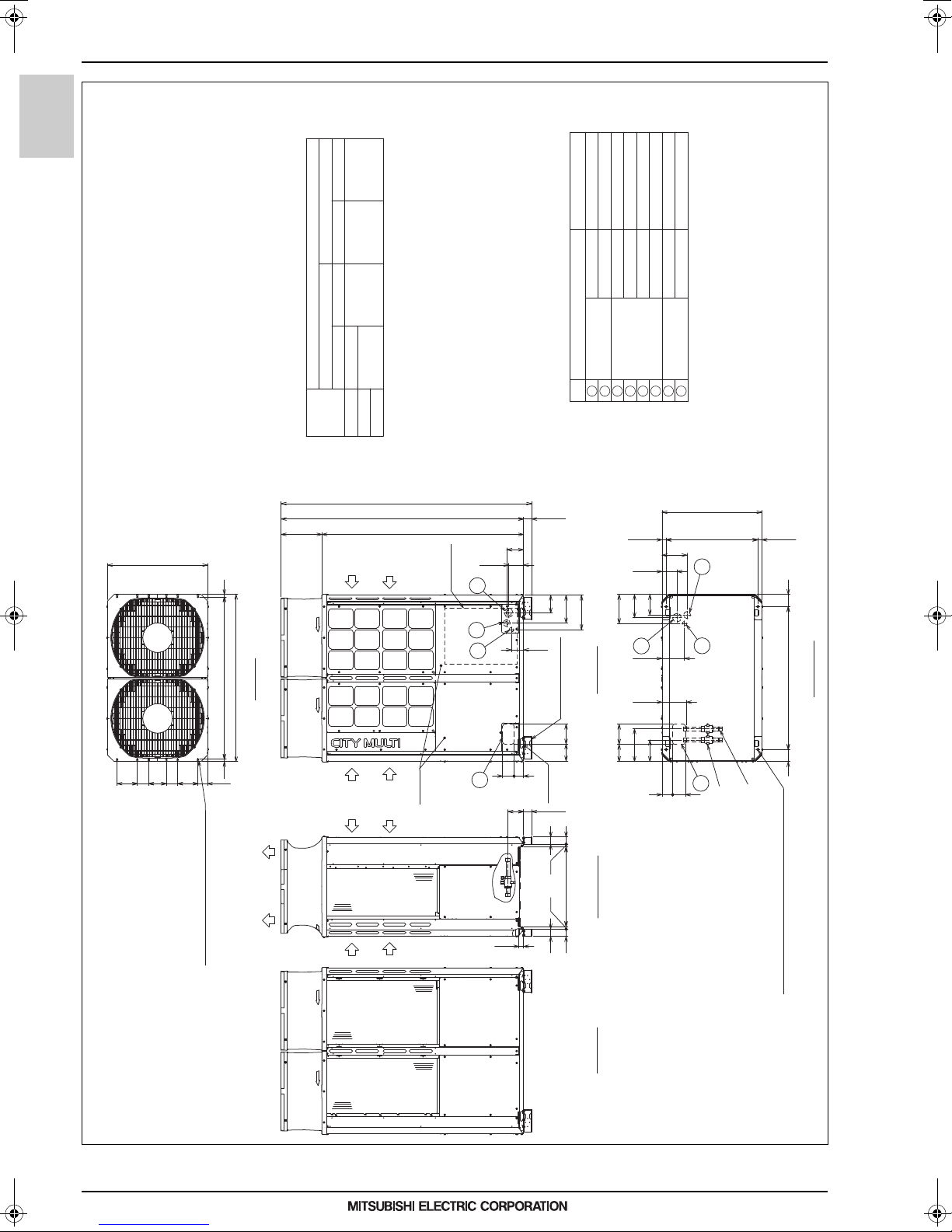
2. EXTERNAL DIMENSIONS
PURY-M200, 250, 300YNW-A1(-BS)
Unit: mm
1
3
4
7
Intake
air
Front view
Intake
air
Intake
air
Discharge air
Left side view
Rear view
2
5
6
8
(Mounting pitch)
Bottom view
(Mounting pitch)
2×5-ø4.6 Hole
(Make hole at the plastic fan guard
for snow hood attachment)
<Snow hood attachment hole>
Top view
Sling hole
Detachable leg
(front and back, 2 points)
Note 2*
2×2-14×31 Oval hole
2×2-14×20 Oval hole(without detachable leg)
Intake
air
Refrigerant
service valve
<High pressure>
Refrigerant
service valve
<Low pressure>
Service
panel
Control box
(INV Box)
Control box
(MAIN Box)
For transmission cables
For wires
For pipes
NO.
Usage Specifications
Front through hole
Bottom through hole
Front through hole
Front through hole
Bottom through hole
Bottom through hole
Front through hole
148 × 84 Knockout hole
ø65 or ø40 Knockout hole
ø52 or ø27 Knockout hole
ø65 Knockout hole
ø52 Knockout hole
ø34 Knockout hole
150 × 94 Knockout hole
Connecting pipe specifications
ø34 Knockout hole
Note 1.Please refer to the next page for information regarding necessary
spacing around the unit and foundation work.
2.The detachable leg can be removed at site.
3.At brazing of pipes, wrap the refrigerant service valve
with wet cloth and keep the temperature of refrigerant
service valve under 120°C.
4.This unit has restrictions for the safety, so refer to
SAFETY HANDLING FOR R32 or the Installation Manual.
*1 Connect the refrigerant pipe to the service valve
according to the Installation Manual.
Bottom through hole
Model
Diameter
Refrigerant pipe
Service valve
M250
ø22.2
ø22.2 Brazed *1
ø15.88 Brazed *1
ø28.58
M200
High pressure Low pressure
M300
High pressure Low pressure
ø19.05 Brazed *1
132
207
256
148125
90
110
125
1495 303
1798
(60)
1858
5656
20
54
592
110
185
681(678~684)
29.5
(740)
80760
80
166
181
152
172
216
160
243
150128
94 79
181
29.5
84
71
35
920
19.519.5 881
740
150
600=150×470
54
20
116
(60)
1
243
567
8
2. EXTERNAL DIMENSIONS
R2-Series
PURY-M-YNW-A1, EM-YNW-A1
MEES18K068
16

2. EXTERNAL DIMENSIONS
Unit: mm
PURY-M200, 250, 300YNW-A1(-BS)
Front
Front
<Top view>
*
<Unit:mm>
<Top view>
M10 anchor bolt
<field supply required>
Fixing plate
<field supply required>
<To be left open>
Front
Wall <H>
<To be left open>
Front
<Unit:mm>
Fixing plate
<field supply required>
M10 anchor bolt
<field supply required>
Wall <H>
<To be left open>
<To be left open>
<To be left open>
Front
Wall <H>
Wall <H>
Wall <H>
Wall <H>
Front
Front
<To be left open>
Wall <H>
Front
Wall <H>
<To be left open>
<To be left open>
Front
Front
Front
Wall <H>
Wall <H>
Front
<To be left open>
<To be left open>
Detachable leg
Fig.A (without detachable legs)
Fig.B (with detachable legs)
Fig.C (without detachable legs) Fig.D (with detachable legs)
Detachable leg
<Wall height limit> Front :Up to the unit height
Back :Up to the unit height
Side :Up to the unit height
<Side view>
Front
1. Required space around the unit
●In case of single installation
1 Secure enough space around the unit as shown in the figure below.
· With a space of at least
300mm to the wall on
the back of the unit
2 When the height of the walls on the front, back or on the sides<H>
exceeds the wall height limit as defined below
add the height that exceeds the height limit <h> to the figures that
are marked with an asterisk.
2. Foundation work
1 Take into consideration the surface strength, water drainage route,
piping route, and wiring route when preparing the installation site.
<Note that the drain water comes out of the unit during operation.>
2 Build the foundation in such way that the corner of the installation leg is
securely supported as shown in the right figure.(Fig.A,B)
When using a rubber isolating cushion, please ensure it is large enough
to cover the entire width of each of the unit's legs.
3 The protrusion length of the anchor bolt must not exceed 30mm.(Fig.A,B)
4 Use four fixing plates as shown in the right figure <field supply required>
when using post-installed anchor bolts.(Fig.C,D)
5
To prevent small animals and water and snow from entering the unit and damaging its parts,
close the gap around the edges of through holes for pipes and wires with
filler plates <field supply required>.
6 When the pipes or cables are routed at the bottom of the unit,
make sure that the through hole at the base of the unit does not get blocked
with the installation base.
7 Refer to the Installation Manual when installing units on an installation base.
●In case of collective installation
· With a space of at least
100mm to the wall on
the back of the unit
15 min.
50 min.* 50 min.*
100 min.*
450 min.*
300 min.*
100 min.30 min.
450 min.450 min.* 450 min. 100 min.*
450 min.* 100 min.*
450 min.*
1000 min.*
900 min.
300 min.*
900 min.
300 min.*300 min.*
15 min.*
450 min.450 min.
450 min.* 300 min.*
15 min.*
30mm max.30mm max.
Unit height
h
H
Unit height
h
H
1 When multiple units are installed adjacent to each other, secure enough space to allow
for air circulation and walkway between groups of units as shown in the figures below.
2 At least two sides must be left open.
3 As with the single installation, add the height that exceeds the height limit<h>
to the figures that are marked with an asterisk.
4 If there is a wall at both the front and the rear of the unit, install up to six units
consecutively in the side direction and provide a space of 1000mm or more as inlet space/
passage space for each six units.
R2-Series
PURY-M-YNW-A1, EM-YNW-A1
MEES18K068
17
2. EXTERNAL DIMENSIONS
PURY-M350,400,450YNW-A1(-BS)
Unit: mm
Note 1.Please refer to the next page for information regarding necessary
spacing around the unit and foundation work.
2.The detachable leg can be removed at site.
3.At brazing of pipes, wrap the refrigerant service valve
with wet cloth and keep the temperature of refrigerant
service valve under 120°C.
4.This unit has restrictions for the safety, so refer to
SAFETY HANDLING FOR R32 or the Installation Manual.
NO.
1
243
567
8
740
70
150 85 85130 150
18
1204181240
110
(740)
185
29.5
681(678~684)
29.5
94
79
181
160
243
150
128
125
132
207
256
90
110
8471
35
56
116
(60)
20
54
592
54
20
56
148
152
216
166
125
(60)
3031495
1798
1858
90
1060
90
172
2
5
68
(Mounting pitch)
Bottom view
(Mounting pitch)
2×2-14×31 Oval hole
2×2-14×20 Oval hole(without detachable leg)
1
Sling hole
Detachable leg
(front and back, 2 points)
Note 2*
Control box
3
4
7
Service
panel
Intake
air
Intake
air
Discharge air
Intake
air
Intake
air
2×6-ø4.6 Hole
(Make hole at the plastic fan guard
for snow hood attachment)
<Snow hood attachment hole>
Top view
Front view
Left side view
Rear view
Refrigerant
service valve
<High pressure>
Refrigerant
service valve
<Low pressure>
For transmission cables
For wires
For pipes
Usage
Specifications
Front through hole
Bottom through hole
Front through hole
Front through hole
Bottom through hole
Bottom through hole
Front through hole
148 × 84 Knockout hole
ø65 or ø40 Knockout hole
ø52 or ø27 Knockout hole
ø65 Knockout hole
ø52 Knockout hole
ø34 Knockout hole
150 × 94 Knockout hole
Connecting pipe specifications
ø34 Knockout hole
*1 Connect the refrigerant pipe to the service valve
according to the Installation Manual.
Bottom through hole
Model
Diameter
Refrigerant pipe
Service valve
M400
ø28.58
ø15.88 Brazed *1
ø28.58
M350
High pressure Low pressure
ø28.58 Brazed
ø19.05 Brazed *1
M450
High pressure Low pressure
R2-Series
PURY-M-YNW-A1, EM-YNW-A1
MEES18K068
18

2. EXTERNAL DIMENSIONS
Unit: mm
PURY-M350,400,450YNW-A1(-BS)
<Wall height limit> Front :Up to the unit height
Back :Up to the unit height
Side :Up to the unit height
1. Required space around the unit
●In case of single installation
1 Secure enough space around the unit as shown in the figure below.
· With a space of at least
300mm to the wall on
the back of the unit
2 When the height of the walls on the front, back or on the sides<H>
exceeds the wall height limit as defined below
add the height that exceeds the height limit <h> to the figures that
are marked with an asterisk.
2. Foundation work
1 Take into consideration the surface strength, water drainage route,
piping route, and wiring route when preparing the installation site.
<Note that the drain water comes out of the unit during operation.>
2 Build the foundation in such way that the corner of the installation leg is
securely supported as shown in the right figure.(Fig.A,B)
When using a rubber isolating cushion, please ensure it is large enough
to cover the entire width of each of the unit's legs.
3 The protrusion length of the anchor bolt must not exceed 30mm.(Fig.A,B)
4 Use four fixing plates as shown in the right figure <field supply required>
when using post-installed anchor bolts.(Fig.C,D)
5
To prevent small animals and water and snow from entering the unit and damaging its parts,
close the gap around the edges of through holes for pipes and wires with
filler plates <field supply required>.
6 When the pipes or cables are routed at the bottom of the unit,
make sure that the through hole at the base of the unit does not get blocked
with the installation base.
7 Refer to the Installation Manual when installing units on an installation base.
●In case of collective installation
· With a space of at least
100mm to the wall on
the back of the unit
1 When multiple units are installed adjacent to each other, secure enough space to allow
for air circulation and walkway between groups of units as shown in the figures below.
2 At least two sides must be left open.
3 As with the single installation, add the height that exceeds the height limit<h>
to the figures that are marked with an asterisk.
4 If there is a wall at both the front and the rear of the unit, install up to six units
consecutively in the side direction and provide a space of 1000mm or more as inlet space/
passage space for each six units.
Front
Front
<Top view>
<Unit:mm>
<Top view>
M10 anchor bolt
<field supply required>
Fixing plate
<field supply required>
<To be left open>
Front
Wall <H>
<To be left open>
Front
<Unit:mm>
Fixing plate
<field supply required>
M10 anchor bolt
<field supply required>
Wall <H>
<To be left open>
<To be left open>
<To be left open>
Front
Wall <H>
Wall <H>
Wall <H>
Wall <H>
Front
Front
<To be left open>
Wall <H>
Front
Wall <H>
<To be left open>
<To be left open>
Front
Front
Front
Wall <H>
Wall <H>
Front
<To be left open>
<To be left open>
Detachable leg
Fig.A (without detachable legs)
Fig.B (with detachable legs)
Fig.C (without detachable legs) Fig.D (with detachable legs)
Detachable leg
<Side view>
Front
15 min.*
50 min.* 50 min.*
100 min.*450 min.*
300 min.*
100 min.
30 min.
450 min.450 min.* 450 min.
100 min.*
450 min.* 100 min.*
450 min.*
1000 min.*
900 min.
300 min.*
900 min.
300 min.*300 min.*
15 min.*
450 min.450 min.
450 min.* 300 min.*
15 min.*
30mm max.
30mm max.
Unit height
h
H
Unit height
h
H
R2-Series
PURY-M-YNW-A1, EM-YNW-A1
MEES18K068
19
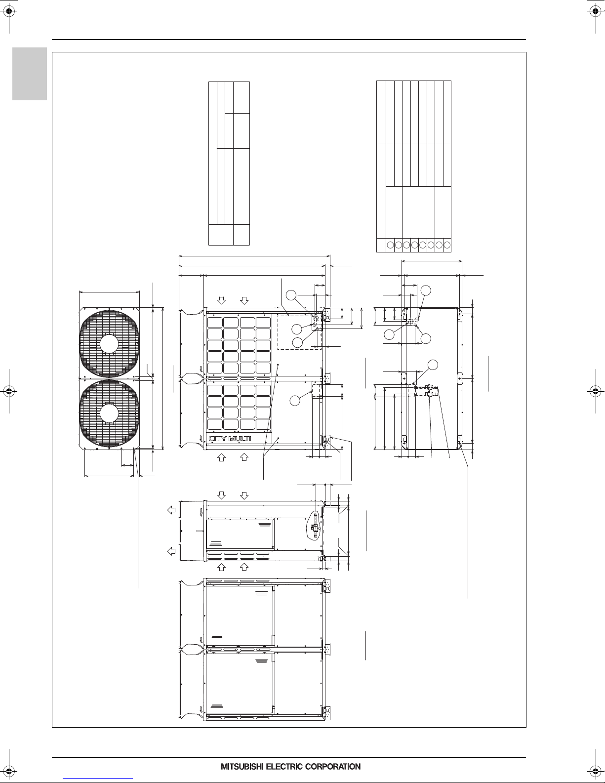
2. EXTERNAL DIMENSIONS
PURY-M500YNW-A1(-BS)
Unit: mm
Note 1.Please refer to the next page for information regarding necessary
spacing around the unit and foundation work.
2.The detachable leg can be removed at site.
3.At brazing of pipes, wrap the refrigerant service valve
with wet cloth and keep the temperature of refrigerant
service valve under 120°C.
4.This unit has restrictions for the safety, so refer to
SAFETY HANDLING FOR R32 or the Installation Manual.
NO.
1
243
567
8
(740)
132
650
148
8471
110
125
90
207
256
(60)
116
35
740
831831
19.5
19.5
70
150
600=150×4
1750
49
185
152
1495 303
1798
(60)
1858
172
216
166
110
29.5
681(678~684)
29.5
80
685
768
653 150
94 79
181
795795
80
20
54
59254
20
60
60
Control box
3
4
7
Intake
air
Intake
air
Discharge air
5
6
8
Intake
air
Intake
air
Detachable leg
(front and back, 3 points)
Note 2*
2×7-ø4.6 Hole
(Make hole at the plastic fan guard
for snow hood attachment)
<Snow hood attachment hole>
Top v i e w
1
Service
panel
2
(Mounting pitch)
Bottom view
(Mounting pitch)
Front view
Left side view
Rear view
Sling hole
(Mounting pitch)
2×3-14×31 Oval hole
2×3-14×20 Oval hole(without detachable leg)
Refrigerant
service valve
<High pressure>
Refrigerant
service valve
<Low pressure>
For transmission cables
For wires
For pipes
Usage Specifications
Front through hole
Bottom through hole
Front through hole
Front through hole
Bottom through hole
Bottom through hole
Front through hole
148 × 84 Knockout hole
ø65 or ø40 Knockout hole
ø52 or ø27 Knockout hole
ø65 Knockout hole
ø52 Knockout hole
ø34 Knockout hole
150 × 94 Knockout hole
Connecting pipe specifications
ø34 Knockout hole
Bottom through hole
Model
Diameter
Refrigerant pipe
Service valve
ø28.58
ø19.05 Brazed *1
ø28.58
M500
High pressure Low pressure
ø28.58 Brazed
High pressure Low pressure
*1 Connect the refrigerant pipe to the service valve
according to the Installation Manual.
R2-Series
PURY-M-YNW-A1, EM-YNW-A1
MEES18K068
20
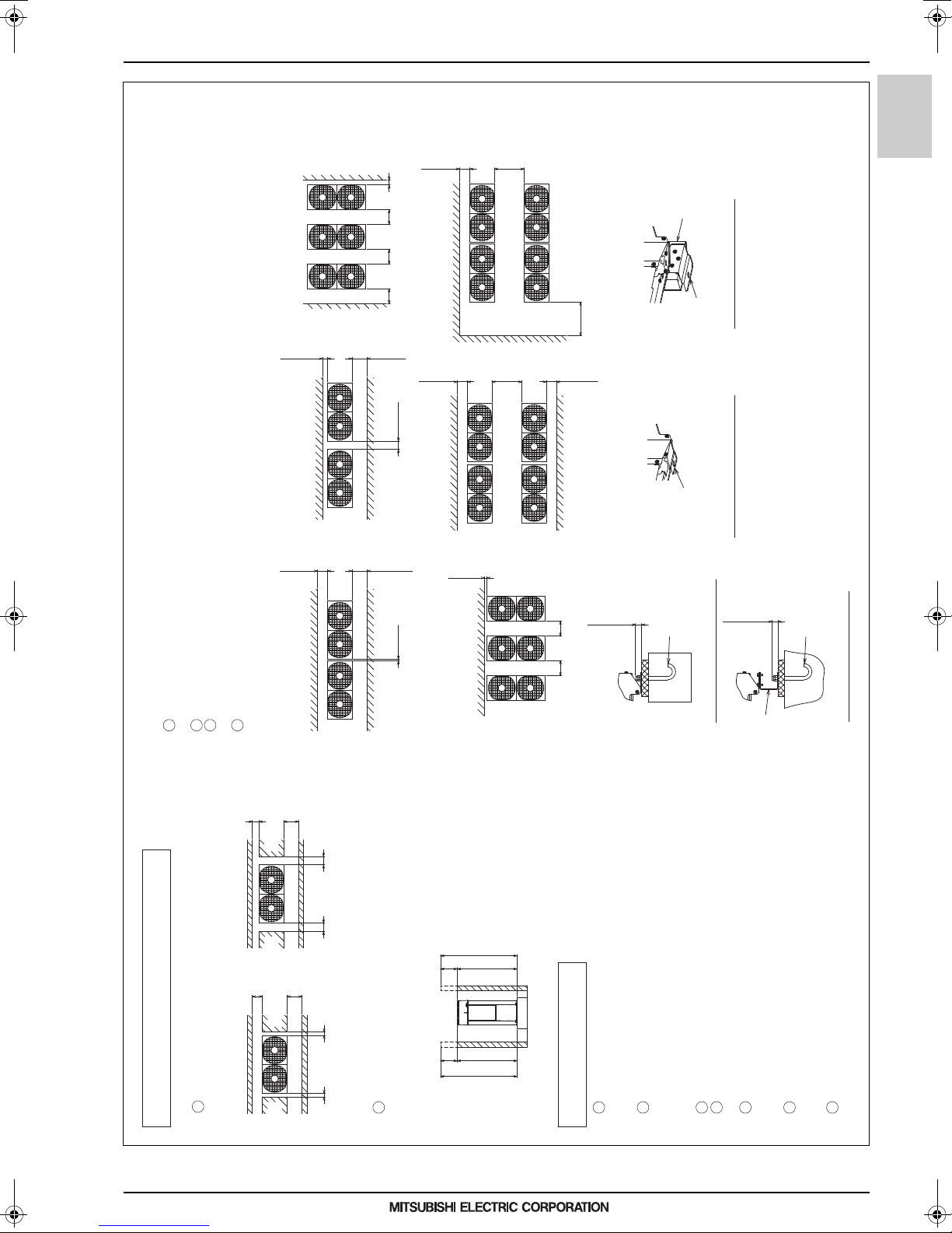
2. EXTERNAL DIMENSIONS
PURY-M500YNW-A1(-BS)
<Wall height limit> Front :Up to the unit height
Back :Up to the unit height
Side :Up to the unit height
1. Required space around the unit
●In case of single installation
1 Secure enough space around the unit as shown in the figure below.
· With a space of at least
300mm to the wall on
the back of the unit
2 When the height of the walls on the front, back or on the sides<H>
exceeds the wall height limit as defined below
add the height that exceeds the height limit <h> to the figures that
are marked with an asterisk.
2. Foundation work
1 Take into consideration the surface strength, water drainage route,
piping route, and wiring route when preparing the installation site.
<Note that the drain water comes out of the unit during operation.>
2 Build the foundation in such way that the corner of the installation leg is
securely supported as shown in the right figure.(Fig.A,B)
When using a rubber isolating cushion, please ensure it is large enough
to cover the entire width of each of the unit's legs.
3 The protrusion length of the anchor bolt must not exceed 30mm.(Fig.A,B)
4 Use four fixing plates as shown in the right figure <field supply required>
when using post-installed anchor bolts.(Fig.C,D)
5
To prevent small animals and water and snow from entering the unit and damaging its parts,
close the gap around the edges of through holes for pipes and wires with
filler plates <field supply required>.
6 When the pipes or cables are routed at the bottom of the unit,
make sure that the through hole at the base of the unit does not get blocked
with the installation base.
7 Refer to the Installation Manual when installing units on an installation base.
●In case of collective installation
· With a space of at least
100mm to the wall on
the back of the unit
1 When multiple units are installed adjacent to each other, secure enough space to allow
for air circulation and walkway between groups of units as shown in the figures below.
2 At least two sides must be left open.
3 As with the single installation, add the height that exceeds the height limit<h>
to the figures that are marked with an asterisk.
4 If there is a wall at both the front and the rear of the unit, install up to three units
consecutively in the side direction and provide a space of 1000mm or more as inlet space/
passage space for each three units.
<Top view>
<Unit:mm>
<Top view>
M10 anchor bolt
<field supply required>
Fixing plate
<field supply required>
<Unit:mm>
Fixing plate
<field supply required>
M10 anchor bolt
<field supply required>
Detachable leg
Fig.A (without detachable legs)
Fig.B (with detachable legs)
Fig.C (without detachable legs) Fig.D (with detachable legs)
Detachable leg
Front
Front
<To be left open>
Front
Wall <H>
Wall <H>
<To be left open>
<To be left open>
Front
Wall <H>
Wall <H>
<To be left open>
<To be left open>
Front
Wall <H>
Wall <H>
Front
Front
<To be left open>
Front
Front
Front
Wall <H>
Wall <H>
Front
Wall <H>
<To be left open>
<To be left open>
Wall <H>
Front
<To be left open>
<To be left open>
<Side view>
Front
30mm max.
30mm max.
450 min.*
300 min.*
15 min.*15 min.*
50 min.*
50 min.*
450 min.*
100 min.*
30 min.
100 min.
450 min.* 450 min. 450 min. 100 min.*
15 min.*
450 min. 450 min.
900 min.
300 min.*300 min.*
1000 min.*
300 min.*
900 min.
300 min.*
450 min.*
100 min.*450 min.*
Unit height
h
H
Unit height
h
H
R2-Series
PURY-M-YNW-A1, EM-YNW-A1
MEES18K068
21
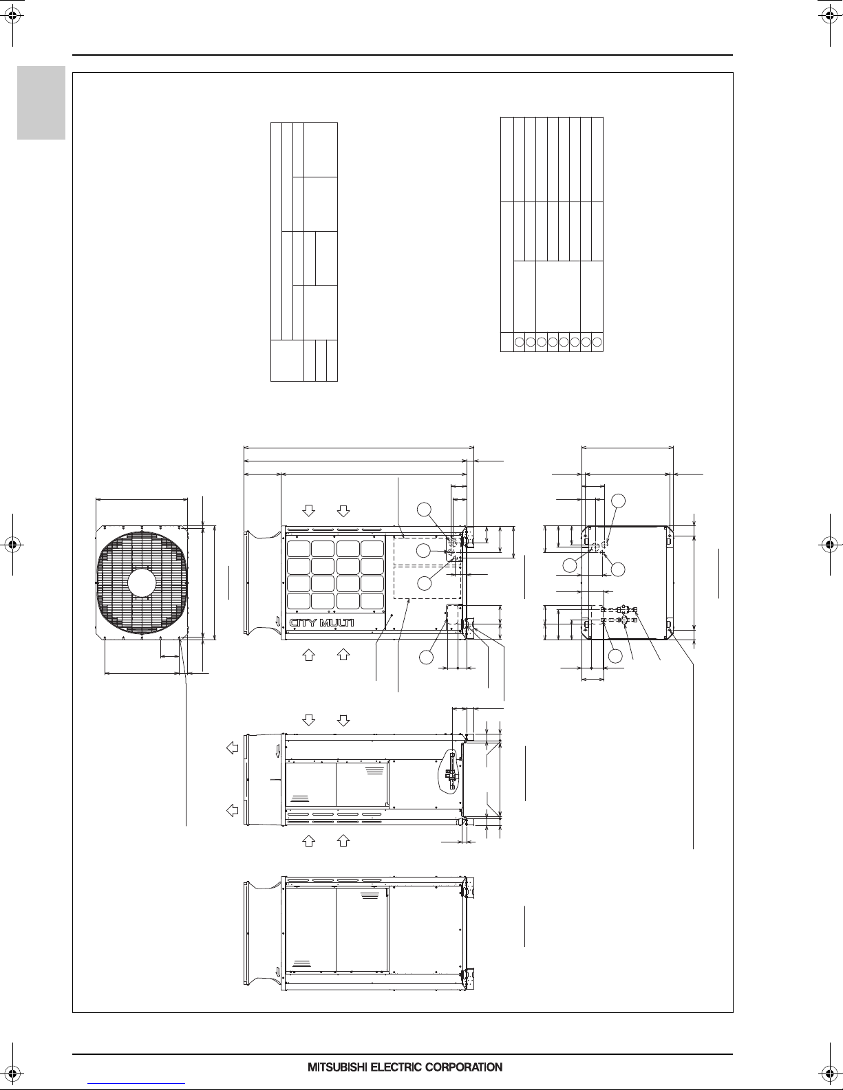
2. EXTERNAL DIMENSIONS
PURY-EM200, 250, 300YNW-A1(-BS)
Unit: mm
1
3
4
7
Intake
air
Front view
Intake
air
Intake
air
Discharge air
Left side view
Rear view
2
5
6
8
(Mounting pitch)
Bottom view
(Mounting pitch)
2×5-ø4.6 Hole
(Make hole at the plastic fan guard
for snow hood attachment)
<Snow hood attachment hole>
Top view
Sling hole
Detachable leg
(front and back, 2 points)
Note 2*
2×2-14×31 Oval hole
2×2-14×20 Oval hole(without detachable leg)
Intake
air
Refrigerant
service valve
<High pressure>
Refrigerant
service valve
<Low pressure>
Service
panel
Control box
(INV Box)
Control box
(MAIN Box)
For transmission cables
For wires
For pipes
NO.
Usage Specifications
Front through hole
Bottom through hole
Front through hole
Front through hole
Bottom through hole
Bottom through hole
Front through hole
148 × 84 Knockout hole
ø65 or ø40 Knockout hole
ø52 or ø27 Knockout hole
ø65 Knockout hole
ø52 Knockout hole
ø34 Knockout hole
150 × 94 Knockout hole
Connecting pipe specifications
ø34 Knockout hole
Note 1.Please refer to the next page for information regarding necessary
spacing around the unit and foundation work.
2.The detachable leg can be removed at site.
3.At brazing of pipes, wrap the refrigerant service valve
with wet cloth and keep the temperature of refrigerant
service valve under 120°C.
4.This unit has restrictions for the safety, so refer to
SAFETY HANDLING FOR R32 or the Installation Manual.
*1 Connect the refrigerant pipe to the service valve
according to the Installation Manual.
Bottom through hole
Model
Diameter
Refrigerant pipe
Service valve
EM250
ø22.2
ø22.2 Brazed *1
ø15.88 Brazed *1
ø28.58
EM200
High pressure Low pressure
EM300
High pressure Low pressure
ø19.05 Brazed *1
132
207
256
148125
90
110
125
1495 303
1798
(60)
1858
5656
20
54
592
110
185
681(678~684)
29.5
(740)
80760
80
166
181
152
172
216
160
243
150128
94 79
181
29.5
84
71
35
920
19.519.5 881
740
150
600=150×470
54
20
116
(60)
1
243
567
8
R2-Series
PURY-M-YNW-A1, EM-YNW-A1
MEES18K068
22
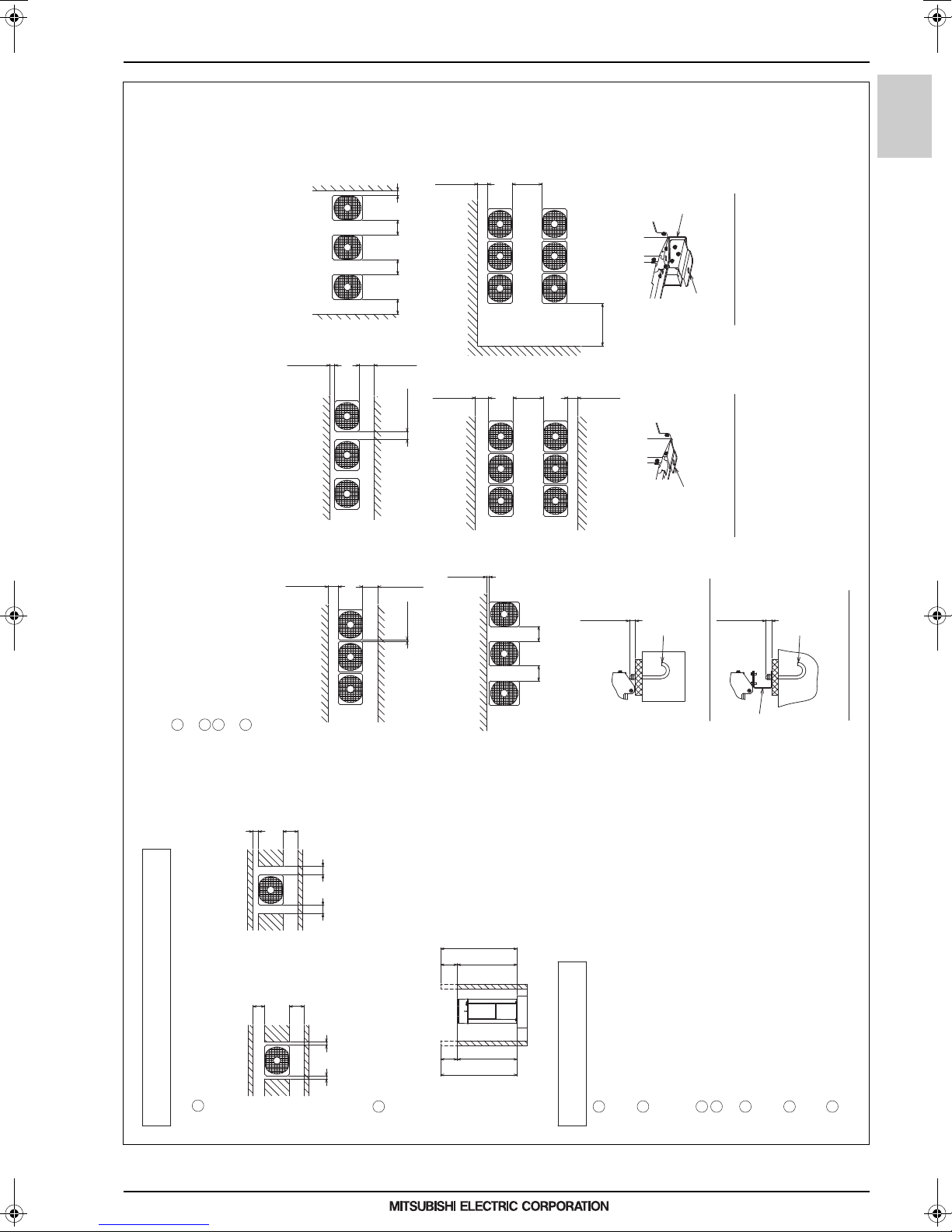
2. EXTERNAL DIMENSIONS
Unit: mm
PURY-EM200, 250, 300YNW-A1(-BS)
Front
Front
<Top view>
*
<Unit:mm>
<Top view>
M10 anchor bolt
<field supply required>
Fixing plate
<field supply required>
<To be left open>
Front
Wall <H>
<To be left open>
Front
<Unit:mm>
Fixing plate
<field supply required>
M10 anchor bolt
<field supply required>
Wall <H>
<To be left open>
<To be left open>
<To be left open>
Front
Wall <H>
Wall <H>
Wall <H>
Wall <H>
Front
Front
<To be left open>
Wall <H>
Front
Wall <H>
<To be left open>
<To be left open>
Front
Front
Front
Wall <H>
Wall <H>
Front
<To be left open>
<To be left open>
Detachable leg
Fig.A (without detachable legs)
Fig.B (with detachable legs)
Fig.C (without detachable legs) Fig.D (with detachable legs)
Detachable leg
<Wall height limit> Front :Up to the unit height
Back :Up to the unit height
Side :Up to the unit height
<Side view>
Front
1. Required space around the unit
●In case of single installation
1 Secure enough space around the unit as shown in the figure below.
· With a space of at least
300mm to the wall on
the back of the unit
2 When the height of the walls on the front, back or on the sides<H>
exceeds the wall height limit as defined below
add the height that exceeds the height limit <h> to the figures that
are marked with an asterisk.
2. Foundation work
1 Take into consideration the surface strength, water drainage route,
piping route, and wiring route when preparing the installation site.
<Note that the drain water comes out of the unit during operation.>
2 Build the foundation in such way that the corner of the installation leg is
securely supported as shown in the right figure.(Fig.A,B)
When using a rubber isolating cushion, please ensure it is large enough
to cover the entire width of each of the unit's legs.
3 The protrusion length of the anchor bolt must not exceed 30mm.(Fig.A,B)
4 Use four fixing plates as shown in the right figure <field supply required>
when using post-installed anchor bolts.(Fig.C,D)
5
To prevent small animals and water and snow from entering the unit and damaging its parts,
close the gap around the edges of through holes for pipes and wires with
filler plates <field supply required>.
6 When the pipes or cables are routed at the bottom of the unit,
make sure that the through hole at the base of the unit does not get blocked
with the installation base.
7 Refer to the Installation Manual when installing units on an installation base.
●In case of collective installation
· With a space of at least
100mm to the wall on
the back of the unit
15 min.
50 min.* 50 min.*
100 min.*
450 min.*
300 min.*
100 min.30 min.
450 min.450 min.* 450 min. 100 min.*
450 min.* 100 min.*
450 min.*
1000 min.*
900 min.
300 min.*
900 min.
300 min.*300 min.*
15 min.*
450 min.450 min.
450 min.* 300 min.*
15 min.*
30mm max.30mm max.
Unit height
h
H
Unit height
h
H
1 When multiple units are installed adjacent to each other, secure enough space to allow
for air circulation and walkway between groups of units as shown in the figures below.
2 At least two sides must be left open.
3 As with the single installation, add the height that exceeds the height limit<h>
to the figures that are marked with an asterisk.
4 If there is a wall at both the front and the rear of the unit, install up to six units
consecutively in the side direction and provide a space of 1000mm or more as inlet space/
passage space for each six units.
R2-Series
PURY-M-YNW-A1, EM-YNW-A1
MEES18K068
23
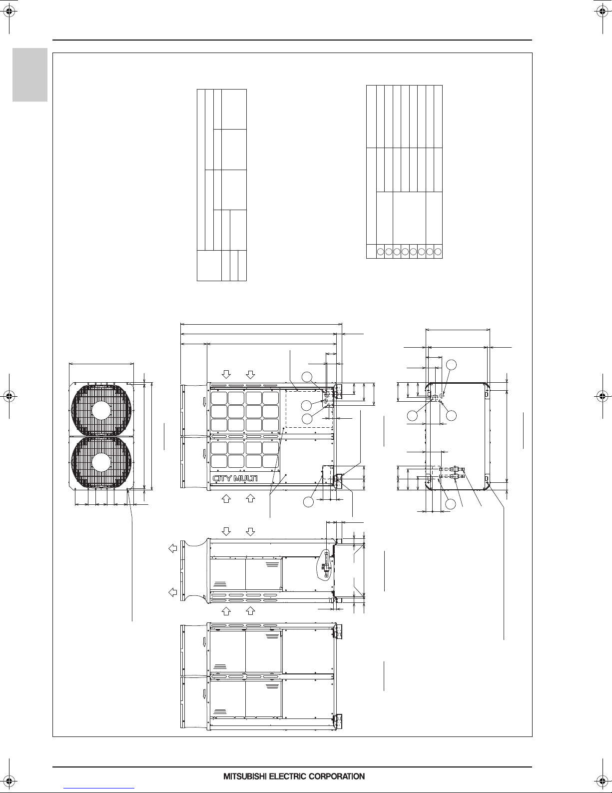
2. EXTERNAL DIMENSIONS
PURY-EM350,400,450YNW-A1(-BS)
Unit: mm
Note 1.Please refer to the next page for information regarding necessary
spacing around the unit and foundation work.
2.The detachable leg can be removed at site.
3.At brazing of pipes, wrap the refrigerant service valve
with wet cloth and keep the temperature of refrigerant
service valve under 120°C.
4.This unit has restrictions for the safety, so refer to
SAFETY HANDLING FOR R32 or the Installation Manual.
NO.
1
243
567
8
740
70
150 8585130 150
18
1204
18
1240
110
(740)
185
29.5
681(678~684)
29.5
94
79
181
160
243
150
128
125
132
207
256
90
110
8471
35
56
116
(60)
20
54
592
54
20
56
148
152
216
166
125
(60)
3031495
1798
1858
90
1060
90
172
2
5
68
(Mounting pitch)
Bottom view
(Mounting pitch)
2×2-14×31 Oval hole
2×2-14×20 Oval hole(without detachable leg)
1
Sling hole
Detachable leg
(front and back, 2 points)
Note 2*
Control box
3
4
7
Service
panel
Intake
air
Intake
air
Discharge air
Intake
air
Intake
air
2×6-ø4.6 Hole
(Make hole at the plastic fan guard
for snow hood attachment)
<Snow hood attachment hole>
Top view
Front view
Left side view
Rear view
Refrigerant
service valve
<High pressure>
Refrigerant
service valve
<Low pressure>
For transmission cables
For wires
For pipes
Usage
Specifications
Front through hole
Bottom through hole
Front through hole
Front through hole
Bottom through hole
Bottom through hole
Front through hole
148 × 84 Knockout hole
ø65 or ø40 Knockout hole
ø52 or ø27 Knockout hole
ø65 Knockout hole
ø52 Knockout hole
ø34 Knockout hole
150 × 94 Knockout hole
Connecting pipe specifications
ø34 Knockout hole
*1 Connect the refrigerant pipe to the service valve
according to the Installation Manual.
Bottom through hole
Model
Diameter
Refrigerant pipe
Service valve
EM400
ø28.58
ø15.88 Brazed *1
ø28.58
EM350
High pressure Low pressure
ø28.58 Brazed
ø19.05 Brazed *1
EM450
High pressure Low pressure
R2-Series
PURY-M-YNW-A1, EM-YNW-A1
MEES18K068
24
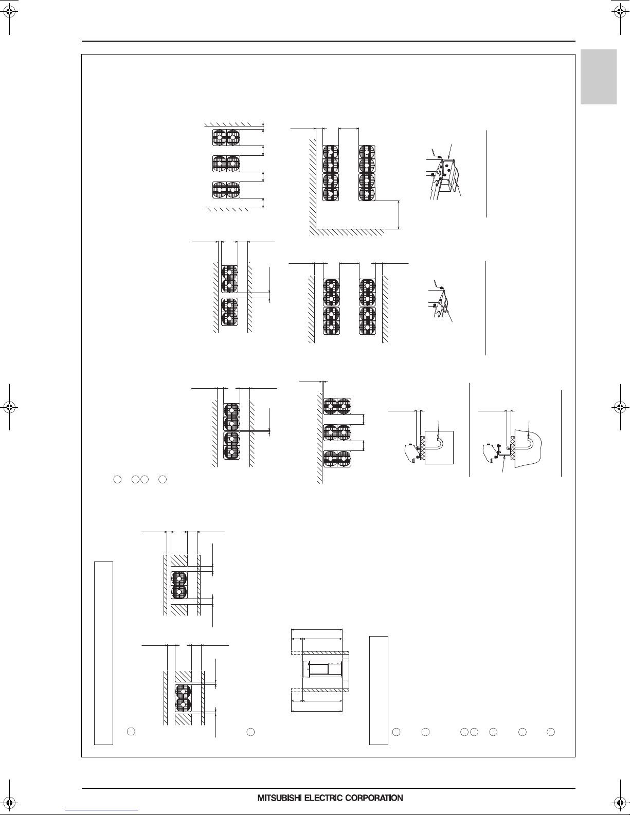
2. EXTERNAL DIMENSIONS
Unit: mm
PURY-EM350,400,450YNW-A1(-BS)
<Wall height limit> Front :Up to the unit height
Back :Up to the unit height
Side :Up to the unit height
1. Required space around the unit
●In case of single installation
1 Secure enough space around the unit as shown in the figure below.
· With a space of at least
300mm to the wall on
the back of the unit
2 When the height of the walls on the front, back or on the sides<H>
exceeds the wall height limit as defined below
add the height that exceeds the height limit <h> to the figures that
are marked with an asterisk.
2. Foundation work
1 Take into consideration the surface strength, water drainage route,
piping route, and wiring route when preparing the installation site.
<Note that the drain water comes out of the unit during operation.>
2 Build the foundation in such way that the corner of the installation leg is
securely supported as shown in the right figure.(Fig.A,B)
When using a rubber isolating cushion, please ensure it is large enough
to cover the entire width of each of the unit's legs.
3 The protrusion length of the anchor bolt must not exceed 30mm.(Fig.A,B)
4 Use four fixing plates as shown in the right figure <field supply required>
when using post-installed anchor bolts.(Fig.C,D)
5
To prevent small animals and water and snow from entering the unit and damaging its parts,
close the gap around the edges of through holes for pipes and wires with
filler plates <field supply required>.
6 When the pipes or cables are routed at the bottom of the unit,
make sure that the through hole at the base of the unit does not get blocked
with the installation base.
7 Refer to the Installation Manual when installing units on an installation base.
●In case of collective installation
· With a space of at least
100mm to the wall on
the back of the unit
1 When multiple units are installed adjacent to each other, secure enough space to allow
for air circulation and walkway between groups of units as shown in the figures below.
2 At least two sides must be left open.
3 As with the single installation, add the height that exceeds the height limit<h>
to the figures that are marked with an asterisk.
4 If there is a wall at both the front and the rear of the unit, install up to six units
consecutively in the side direction and provide a space of 1000mm or more as inlet space/
passage space for each six units.
Front
Front
<Top view>
<Unit:mm>
<Top view>
M10 anchor bolt
<field supply required>
Fixing plate
<field supply required>
<To be left open>
Front
Wall <H>
<To be left open>
Front
<Unit:mm>
M10 anchor bolt
<field supply required>
Wall <H>
<To be left open>
<To be left open>
<To be left open>
Front
Wall <H>
Wall <H>
Wall <H>
Wall <H>
Front
Front
<To be left open>
Wall <H>
Front
Wall <H>
<To be left open>
<To be left open>
Front
Front
Front
Wall <H>
Wall <H>
Front
<To be left open>
<To be left open>
Fig.A (without detachable legs)
Fig.B (with detachable legs)
Fig.C (without detachable legs)
Detachable leg
<Side view>
Front
15 min.*
50 min.* 50 min.*
100 min.*450 min.*
300 min.*
100 min.
30 min.
450 min.450 min.* 450 min.
100 min.*
450 min.* 100 min.*
450 min.*
1000 min.*
900 min.
300 min.*
900 min.
300 min.*300 min.*
15 min.*
450 min.450 min.
450 min.* 300 min.*
15 min.*
30mm max.
30mm max.
Unit height
h
H
Unit height
h
H
Fixing plate
<field supply required>
Detachable leg
Fig.D (with detachable legs)
R2-Series
PURY-M-YNW-A1, EM-YNW-A1
MEES18K068
25

2. EXTERNAL DIMENSIONS
PURY-EM500YNW-A1(-BS)
Unit: mm
Note 1.Please refer to the next page for information regarding necessary
spacing around the unit and foundation work.
2.The detachable leg can be removed at site.
3.At brazing of pipes, wrap the refrigerant service valve
with wet cloth and keep the temperature of refrigerant
service valve under 120°C.
4.This unit has restrictions for the safety, so refer to
SAFETY HANDLING FOR R32 or the Installation Manual.
NO.
1
243
567
8
(740)
132
650
148
8471
110
125
90
207
256
(60)
116
35
740
831831
19.5
19.5
70
150
600=150×4
1750
49
185
152
1495 303
1798
(60)
1858
172
216
166
110
29.5
681(678~684)
29.5
80
685
768
653 150
94 79
181
795795
80
20
54
59254
20
60
60
Control box
3
4
7
Intake
air
Intake
air
Discharge air
5
6
8
Intake
air
Intake
air
Detachable leg
(front and back, 3 points)
Note 2*
2×7-ø4.6 Hole
(Make hole at the plastic fan guard
for snow hood attachment)
<Snow hood attachment hole>
Top view
1
Service
panel
2
(Mounting pitch)
Bottom view
(Mounting pitch)
Front view
Left side view
Rear view
Sling hole
(Mounting pitch)
2×3-14×31 Oval hole
2×3-14×20 Oval hole(without detachable leg)
Refrigerant
service valve
<High pressure>
Refrigerant
service valve
<Low pressure>
For transmission cables
For wires
For pipes
Usage Specifications
Front through hole
Bottom through hole
Front through hole
Front through hole
Bottom through hole
Bottom through hole
Front through hole
148 × 84 Knockout hole
ø65 or ø40 Knockout hole
ø52 or ø27 Knockout hole
ø65 Knockout hole
ø52 Knockout hole
ø34 Knockout hole
150 × 94 Knockout hole
Connecting pipe specifications
ø34 Knockout hole
Bottom through hole
Model
Diameter
Refrigerant pipe
Service valve
ø28.58
ø19.05 Brazed *1
ø28.58
EM500
High pressure Low pressure
ø28.58 Brazed
High pressure Low pressure
*1 Connect the refrigerant pipe to the service valve
according to the Installation Manual.
R2-Series
PURY-M-YNW-A1, EM-YNW-A1
MEES18K068
26

2. EXTERNAL DIMENSIONS
PURY-EM500YNW-A1(-BS)
<Wall height limit> Front :Up to the unit height
Back :Up to the unit height
Side :Up to the unit height
1. Required space around the unit
●In case of single installation
1 Secure enough space around the unit as shown in the figure below.
· With a space of at least
300mm to the wall on
the back of the unit
2 When the height of the walls on the front, back or on the sides<H>
exceeds the wall height limit as defined below
add the height that exceeds the height limit <h> to the figures that
are marked with an asterisk.
2. Foundation work
1 Take into consideration the surface strength, water drainage route,
piping route, and wiring route when preparing the installation site.
<Note that the drain water comes out of the unit during operation.>
2 Build the foundation in such way that the corner of the installation leg is
securely supported as shown in the right figure.(Fig.A,B)
When using a rubber isolating cushion, please ensure it is large enough
to cover the entire width of each of the unit's legs.
3 The protrusion length of the anchor bolt must not exceed 30mm.(Fig.A,B)
4 Use four fixing plates as shown in the right figure <field supply required>
when using post-installed anchor bolts.(Fig.C,D)
5
To prevent small animals and water and snow from entering the unit and damaging its parts,
close the gap around the edges of through holes for pipes and wires with
filler plates <field supply required>.
6 When the pipes or cables are routed at the bottom of the unit,
make sure that the through hole at the base of the unit does not get blocked
with the installation base.
7 Refer to the Installation Manual when installing units on an installation base.
●In case of collective installation
· With a space of at least
100mm to the wall on
the back of the unit
1 When multiple units are installed adjacent to each other, secure enough space to allow
for air circulation and walkway between groups of units as shown in the figures below.
2 At least two sides must be left open.
3 As with the single installation, add the height that exceeds the height limit<h>
to the figures that are marked with an asterisk.
4 If there is a wall at both the front and the rear of the unit, install up to three units
consecutively in the side direction and provide a space of 1000mm or more as inlet space/
passage space for each three units.
<Top view>
<Unit:mm>
<Top view>
M10 anchor bolt
<field supply required>
Fixing plate
<field supply required>
<Unit:mm>
Fixing plate
<field supply required>
M10 anchor bolt
<field supply required>
Detachable leg
Fig.A (without detachable legs)
Fig.B (with detachable legs)
Fig.C (without detachable legs) Fig.D (with detachable legs)
Detachable leg
Front
Front
<To be left open>
Front
Wall <H>
Wall <H>
<To be left open>
<To be left open>
Front
Wall <H>
Wall <H>
<To be left open>
<To be left open>
Front
Wall <H>
Wall <H>
Front
Front
<To be left open>
Front
Front
Front
Wall <H>
Wall <H>
Front
Wall <H>
<To be left open>
<To be left open>
Wall <H>
Front
<To be left open>
<To be left open>
<Side view>
Front
30mm max.
30mm max.
450 min.* 300 min.*
15 min.*15 min.*
50 min.*
50 min.*
450 min.*
100 min.*
30 min.
100 min.
450 min.* 450 min. 450 min. 100 min.*
15 min.*
450 min. 450 min.
900 min.
300 min.*300 min.*
1000 min.*
300 min.*
900 min.
300 min.*
450 min.*
100 min.*450 min.*
Unit height
h
H
Unit height
h
H
R2-Series
PURY-M-YNW-A1, EM-YNW-A1
MEES18K068
27

3. CENTER OF GRAVITY
3. CENTER OF GRAVITY
R2-Series
PURY-M200, 250, 300YNW-A1 (-BS)
920
1858
PURY-M-YNW-A1, EM-YNW-A1
X
760
80
PURY-M350, 400, 450YNW-A1 (-BS)
1240
1555
740
Unit: mm
Model X Y Z
PURY-M200YNW-A1(-BS)
PURY-M250YNW-A1(-BS)
PURY-M300YNW-A1(-BS)
357 338 664
357 338 664
357 338 664
Z
Y
60
681
740
X
1060
90
PURY-M500YNW-A1 (-BS)
1750
1858
1858
1555
1555
Unit: mm
Model X Y Z
PURY-M350YNW-A1(-BS)
PURY-M400YNW-A1(-BS)
PURY-M450YNW-A1(-BS)
502 344 714
502 344 714
501 345 741
Z
Y
60
681
740
Unit: mm
Model X Y Z
PURY-M500YNW-A1(-BS)
871 305 720
X
80
MEES18K068
795
795
Z
Y
60
681
28

3. CENTER OF GRAVITY
R2-Series
PURY-EM200, 250, 300YNW-A1 (-BS)
920
1858
1555
Z
X
760
80
PURY-EM350, 400, 450YNW-A1 (-BS)
1240
60
740
PURY-M-YNW-A1, EM-YNW-A1
Unit: mm
Model X Y Z
PURY-EM200YNW-A1(-BS)
PURY-EM250YNW-A1(-BS)
PURY-EM300YNW-A1(-BS)
355 339 678
355 339 678
355 339 678
Y
681
740
X
1060
90
PURY-EM500YNW-A1 (-BS)
1750
1858
1858
1555
1555
Unit: mm
Model X Y Z
PURY-EM350YNW-A1(-BS)
PURY-EM400YNW-A1(-BS)
PURY-EM450YNW-A1(-BS)
501 344 729
502 346 727
503 346 755
Z
Y
60
681
740
Unit: mm
Model X Y Z
PURY-EM500YNW-A1(-BS)
867 307 730
X
795
MEES18K068
795
80
Z
Y
60
681
29

4. ELECTRICAL WIRING DIAGRAMS
PURY-(E)M200, 250, 300YNW-A1(-BS)
RSH01/02/03
For current detection
Central control transmission line
Indoor/Outdoor transmission line
L
Choke coil (for high frequency noise reduction)
For inrush current prevention
Resistor
R1,5
HIC bypass,Controls refrigerant
flow in HIC circuit
For opening/closing the discharge
suction bypass
SV2
Pipe temperature
SV1a
LEV2a,b
21S4a
Symbol
<Symbol explanation>
63H1
63HS1
63LS
C700,C701,
21S4b
LEV1 *10
DCL
Pressure control,Refrigerant flow
rate control
Solenoid
valve
For opening/closing the bypass
circuit under the O/S
Heat exchanger capacity control(only
4-way valve
Explanation
Pressure
sensor
Cooling/Heating switching
Pressure
switch
High pressure protection for the
outdoor unit
Discharge pressure
Low pressure
Capacitor(inverter main circuit)
Linear
expansion
valve
DC reactor
TH5
TH4
TH3
TB7
TB3
TB1
SV9 *8
Thermistor
Discharge pipe temperature
ACC inlet pipe temperature
Power supply
Terminal
block
*1.Single-dotted lines indicate wiring not supplied with the unit.
*2.Dot-dash lines indicate the control box boundaries.
*3.Refer to the Data book for connecting input/output
signal connectors.
*4.Daisy-chain terminals (TB3) on the outdoor units in the
same refrigerant system together.
*5.Faston terminals have a locking function.
Make sure the terminals are securely locked in place
after insertion. Press the tab on the terminals to
removed them.
*6.Control box houses high-voltage parts.
Before inspecting the inside of the MAIN BOX or INV BOX,
turn off the power,keep the unit off for at least 10
minutes, and confirm that the voltage of the connector
RYPN on INV BOX has dropped to DC20V or less.
SV14,15 *11
For changing refrigerant flow
(cooling/heating)
INV Board
IPM
THHS
SC-U
SC-V SC-W
41
CNCT2
yellow
SC-P1
SC-P1L
DCL
FT-P2
FT-P1
X901
X902
R1,R5
2
1
green
++
C705, R705,
C706 R706
C700, R700,
C701 R701
1
CNFAN1
4
NR001
SC-L1
SC-L2SC-L3
SC-PL
CN-N
red
IPM
CNDCP
red
CNINV
31
CNDCN
black
FAN Board
F001
DC 400V
10AT
RSH01/02/03
14
CN80
LED4:CPU in operation
LED1:Normal operation(Lit)
/ Error(Blink)
2
1
CN81
green
Noise Filter
Noise filter
L3 NL2L1
L
L3 NL2L1
Surge absorber
CN2
Power failure
Detection circuit
Noise filter
121
2
147
1
2
CN3
black
2
1
631
Control Board
312
123
312
123
CN202CN201
red
63LS
63HS1
12
CNPOW
yellow
13
CN3K
yellow
13
CN3S
red
*3
13
CN3D
13
CN3N
blue
41
CN41
23
41
CN40
23
TP1 TP2
TB3
TB7
M1 M2 M1 M2 S
Indoor/Outdoor
transmission
cable
Central control
transmission
cable
*4
LED2 LED101
CNAC
3
1
SWU2
LED301
Compressor ON/OFF output
Error detection output
DC12V
CN51
1's
digit
10's
digit
*3
SWU1
SWP3
LED301
Display
setting/
Function
setting
CN4A
black
2314
CN4
black
2314
CNPS
red
214
CN604
green
21
CN600
4521
PS Board
13
CNINV
yellow
21
CNFAN1
yellow
1
2
CNDC
451
CN1014blue
CN304
2
1
blue
CN303
2
1
432
1
CN202
CN100
red
13
DB2
IPM power
supply circuit
M-NET power
supply circuit
CPU power
supply circuit
32
CN110
black
21
2
22 2
ON
OFF
USB TYPEA
CNUSB
X10
X07
X09
551
1
CN506
red
21S4b
Power failure
detection circuit
CN507
black
3
6
SV9
SV2
X05
X06
351
6
CN505
SV1a
21S4a
X04
3
1
CN504
SV14
X03
3
1
CN503
SV10
green
yellow
6
F001
AC250V
3.15A T
CN-P
blue
CN19V
CNRY
U
V
W
MS
3~
SW001
LED4:CPU in operation
LED1:Normal operation(Lit)
/ Error(Blink)
LED900:Relay power supply
L3
N
L1
L2
TB1
L1 L2 L3
N
Power Source
3N~
50/60Hz
380/400/415V
ACCT1
ACCT2
TB7 Power selecting connector
DB1
12
CNINT4red
P
63H1
RY63H
black
2
1
CNAC2
2
1
CNFG
blue
TH2
TH5
CN211
green
123
4
CN213
green
TH6
1
2
TH3
TH7
CN212
red
123
4
Z25
3
CNTYP5
green1CNTYP4
1
2
Z24
TH15
TH4
CN192
green
123
4
LEV2a
M
12346
CNLVB
red
LEV1/LEV9
M
12346
CNLVA
5
LEV2b
M
12346
CNLVC
blue
LEV9/LEV2d
M
12346
CNLVE
green
CNPW
2314
2
1
13
RYPS1
23
U
1
black
X02
3
1
CN502
SV15
black
*8
*11
*8
*8
P
N
CNRYA
red
21
*10
LED3
*7
U
V
W
MS
741
8
Motor
(Compressor)
Fan motor
(Heat exchanger)
*7.Control board LED display.
124
RYPS2
*5
*5
*5
121
4
CN2
2
3
PUHY model).
Cooling/Heating switching
C705,C706
ACCT1,ACCT2
Current sensor(AC)
LEV2d *9
Pressure control,Refrigerant flow
rate control
LEV4
For opening/closing the injection circuit
For opening/closing the bypass circuit
SV10 *8
For continuous heating
Subcool bypass outlet temperature
TH2 *8
*8
*11
RYFAN1
CN5
green
3
1
CN1
3
1
F4
AC 250V
6.3A T
Function
setting
5
X800
X901,
X902
LED2
Normal operation(Lit)/Error(Blink)
In operation(Lit)/In stop(Unlit)
LED3
SW6-10 is OFF and
SW4-1~10 are OFF
Function setting by SW4
enable(Lit)/disable(Unlit)
SW6-10 is ON
LED101
Normal operation(Lit)/IC Error(Unlit)
*8.Difference of appliance.
Model name Appliance
PUHY *8 exist
PURY *8 do not exist
*9.Difference of appliance.
*10.Difference of appliance.
Model name Appliance
PUHY LEV1
PURY LEV9
*11.Difference of appliance.
Model name Appliance
PUHY-M,PURY
*11 do not exist
PUHY-EM *11 exist
<INV BOX>
<MAIN BOX>
*6
THHS
134
5
Z22
3
CNTYP2
black
1
Z2
U
7
F1~F3
AC 250V
6.3A T
Z22,24,25
X901,902
Function setting connector
Magnetic relay(inverter main circuit)
5
Z1
U
Model name Appliance
PUHY LEV9
PURY LEV2d
Compressor shell bottom temperature
OA temperature
TH15
TH7
TH6 *8
Subcooled liquid refrigerant temperature
IPM temperature
THHS
*9
LEV4
M
12346
CNLVF
black
SW4
ON
1
10
SW5
ON
1
10
SW6
ON
1
10
SW7
ON
1
10
ON
12
SW001
ON
1
4
LEV9 *9,10
Heat exchanger for inverter
SWS2
SW101
ON
1
4
RYPN
3
CN605
12
2
CN603
blue
123
3~
+
-
+
-
t°
t°
t°t°t°t°t°
4. ELECTRICAL WIRING DIAGRAMS
R2-Series
PURY-M-YNW-A1, EM-YNW-A1
MEES18K068
30

4. ELECTRICAL WIRING DIAGRAMS
PURY-(E)M350, 400, 450YNW-A1(-BS)
RSH01/02/03
For current detection
Central control transmission line
Indoor/Outdoor transmission line
L
Choke coil (for high frequency noise reduction)
For inrush current prevention
Resistor
R1,5
HIC bypass,Controls refrigerant
flow in HIC circuit
For opening/closing the discharge
suction bypass
SV2
SV1a
LEV2a,b
21S4a
Symbol
<Symbol explanation>
63H1
63HS1
63LS
21S4b
705,706
LEV1 *10
DCL
Pressure control,Refrigerant flow
rate control
Solenoid
valve
For opening/closing the bypass
circuit under the O/S
Heat exchanger capacity control(only
4-way valve
Explanation
Pressure
sensor
Cooling/Heating switching
Pressure
switch
High pressure protection for the
outdoor unit
Discharge pressure
Low pressure
Capacitor (inverter main circuit)
Linear
expansion
valve
DC reactor
THHS
TH5
TH4
TB7
TB3
TB1
Thermistor
Discharge pipe temperature
ACC inlet pipe temperature
IPM temperature
Power supply
Terminal
block
*1.Single-dotted lines indicate wiring not supplied with the unit.
*2.Dot-dash lines indicate the control box boundaries.
*3.Refer to the Data book for connecting input/output
signal connectors.
*4.Daisy-chain terminals (TB3) on the outdoor units in the
same refrigerant system together.
*5.Faston terminals have a locking function.
Make sure the terminals are securely locked in place
after insertion. Press the tab on the terminals to
removed them.
*6.Control box houses high-voltage parts.
Before inspecting the inside of the control box,turn off
the power,keep the unit off for at least 10 minutes, and
confirm that the voltage of the connector RYPN
has dropped to DC20V or less.
RYFAN1
Noise Filter
Noise filter
L3 NL2L1
L
L3 NL2L1
Surge absorber
CN2
Power failure
Detection circuit
Noise filter
CN3
black
2
1
6
3
1
IPM
CNINV
31
CNDCN
black
FAN Board
F001
DC 400V
10AT
RSH01/02/03
14
CN80
LED4:CPU in operation
LED1:Normal operation(Lit)
/ Error(Blink)
2
1
CN81
green
32
IPM
CNDCP
red
CNINV
31
CNDCN
black
FAN Board
F001
DC 400V
10AT
RSH01/02/03
14
CN80
LED4:CPU in operation
LED1:Normal operation(Lit)
/ Error(Blink)
2
1
CN81
green
147
1
2
32
LED2 LED101
SWU2
LED301
Compressor ON/OFF output
Error detection output
DC12V CN51
1's
digit
10's
digit
*3
SWU1
SWP3
CN4A
black
2314
CN4
black
2314
CNPS
red
214
CN604
green
21
CN603
blue
213
CN600
4521
PS Board
blue
CNFG5
12
DB2
IPM power
supply circuit
CN110
black
21
P
63H1
RY63H
DCL
INV Board
IPM
THHS
41
blue
SC-L1
X901 X902
NR001
green
SC-L2
SC-L3
SC-U
SC-P
SC-WSC-V
CNRY
2
1
LED4:CPU in operation
LED1:Normal operation(Lit)
/ Error(Blink)
LED900:Relay power supply
L3
N
L1
L2
TB1
L1 L2 L3
N
Power Source
3N~
50/60Hz
380/400/415V
U
V
W
MS
3~
CN4B
black
2314
32
CN100
red
13
CN304
blue
CN303
2
1
2
1
2
1
13
21
2
CNINV
yellow
CNFAN1
yellow
1245124
432
1
CN202
M-NET power
supply circuit
CPU power
supply circuit
DB1
12
CNINT4red
CNDC
CN101
blue
Control Board
312
123
312
123
CN202CN201
red
63LS63HS1
12
CNPOW
yellow
13
CN3K
yellow
13
CN3S
red
*3
13
CN3D
13
CN3N
blue
41
CN41
23
41
CN40
23
TP1TP2
TB3 TB7
M1M2 M1M2 S
Indoor/Outdoor
transmission
cable
Central control
transmission
cable
*4
CNAC
3
1
22 2
ON
OFF
X10
X07
X09
551
1
CN506
red
21S4b
Power failure
detection circuit
CN507
black
3
6
SV9
SV2
X05
X06
351
6
CN505
SV1a
21S4a
X04
3
1
CN504
SV14
X03
3
1
CN503
SV10
green
yellow
6
F001
AC250V
3.15A T
TB7 Power selecting connector
black
2
1
X02
3
1
CN502
SV15
black
*11
*8
2
1
CNFG
blue
LED301
Display
setting/
Function
setting
USB TYPEA
CNUSB
CNPW
2314
TH2
TH5
CN211
green
123
4
CN213
green
TH6
1
2
TH3
TH7
CN212
red
123
4
Z25
3
CNTYP5
green1CNTYP4
1
2
Z24
TH15
TH4
CN192
green
123
4
LEV2a
M
12346
CNLVB
red
LEV1/LEV9
M
12346
CNLVA
5
LEV2b
M
12346
CNLVC
blue
LEV9/LEV2d
M
12346
CNLVE
green
*8
*8
*9
*7.Control board LED display.
U
*8
*11
*10
CNRYA
red
21
LED3
*7
CN19V
yellow
1
2
CN2
123
4
Motor
(Compressor)
ACCT1
ACCT2
5
RYPN
U
V
W
MS
3
~
Fan motor2(Right)
(Heat exchanger)
841
7
Fan motor1(Left)
(Heat exchanger)
8
1
green
2
1
CNFAN2
RYFAN2
PUHY model).
Cooling/Heating switching
ACCT1,ACCT2
Current sensor(AC)
LEV2d *9
Pressure control,Refrigerant flow
rate control
Heat exchanger for inverter
LEV9 *9,10
For opening/closing the bypass circuit
SV9 *8
For continuous heating
SV10 *8
For changing refrigerant flow
(cooling/heating)
SV14,15 *11
Subcool bypass outlet temperature
TH2 *8
TH3
Pipe temperature
TH6 *8
Subcooled liquid refrigerant temperature
TH7
OA temperature
TH15
Compressor shell bottom temperature
X901,X902
Magnetic relay(inverter main circuit)
Z22,24,25
Function setting connector
CNAC2
CNDCP
red
147
1
2
CN1
3
1
CN5
green
3
1
Function
setting
F4
AC 250V
6.3AT
X800
X901,
X902
LED2 Normal operation(Lit)/Error(Blink)
LED3
SW6-10 is OFF and
SW4-1~10 are OFF
In operation(Lit)/In stop(Unlit)
SW6-10 is ON
Function setting by SW4
enable(Lit)/disable(Unlit)
LED101
Normal operation(Lit)/IC Error(Unlit)
*10.Difference of appliance.
Model name Appliance
PUHY LEV1
PURY LEV9
*11.Difference of appliance.
Model name Appliance
PUHY-M,PURY
*11 do not exist
PUHY-EM *11 exist
*8.Difference of appliance.
Model name Appliance
PUHY *8 exist
PURY *8 do not exist
*9.Difference of appliance.
Model name Appliance
PUHY LEV9
PURY LEV2d
THHS
THHS
*6
543
1
MF1
Fan motor(for cooling in control box)
Z22
3
CNTYP2
black
1
M
1~
MF1
CN24VA
black
214
C3 C1
R5~R8 R1~R4
FT-P1C
CN-CAP
21
CAP Board
CN63PW
blue
213
*5
3
3
Z2
U
7
F1
~
F3
AC 250V
6.3AT
213
RY24VA
black
8
RYNF
4
1
1
Z1
U
4
7
U
V
W
MS
3
~
CN-P
1
2
red
CN-N
1
2
blue
2
1
4141
CNFAN2
SC-P1
CNFAN1
SW4
ON
1
10
SW5
ON
1
10
SW6
ON
1
10
SW7
ON
1
10
SW001
ON
12
SW001
ON
1
4
SW001
ON
1
4
FT-P2
FT-P1
R1,R5
*5
*5
*5
R700,
R701
R705,
R706
C705,
C706
C700,
C701
FT-P1C
*5
For opening/closing the injection circuit
LEV4
LEV4
M
12346
CNLVF
black
SW101
ON
1
4
SWS2
CNCT2
CN-CAP
blue
C1,3,700,701,
black
+
-
+
-
++
+
+
t°
t°
t°t°t°t°t°
R2-Series
PURY-M-YNW-A1, EM-YNW-A1
MEES18K068
31

4. ELECTRICAL WIRING DIAGRAMS
PURY-(E)M500YNW-A1(-BS)
+
-
+
-
t°
t°
t°
t°
t°t°t°
+
+
t°
RSH01/02/03
For current detection
Central control transmission line
Indoor/Outdoor transmission line
C100~C109
Capacitor (inverter main circuit)
L Choke coil (for high frequency noise reduction)
For inrush current prevention
Resistor
R1,5
HIC bypass,Controls refrigerant
flow in HIC circuit
For opening/closing the discharge
suction bypass
SV2
Pipe temperature
SV1a
LEV2a,b,c
21S4a
Symbol
<Symbol explanation>
63H1
63HS1
63LS
ACCT1,ACCT2
21S4b,c
DCL
LEV1 *10
Pressure control,Refrigerant flow
rate control
Solenoid
valve
For opening/closing the bypass
circuit under the O/S
Heat exchanger capacity control(only
4-way valve
Explanation
Pressure
sensor
Cooling/Heating switching
Pressure
switch
High pressure protection for the
outdoor unit
Discharge pressure
Low pressure
Current sensor(AC)
DC reactor
Linear
expansion
valve
TH5
TH4
TH3
TB7
TB3
TB1
Discharge pipe temperature
ACC inlet pipe temperature
Power supply
Terminal
block
*1.Single-dotted lines indicate wiring not supplied with the unit.
*2.Dot-dash lines indicate the control box boundaries.
*3.Refer to the Data book for connecting input/output
signal connectors.
*4.Daisy-chain terminals (TB3) on the outdoor units in the
same refrigerant system together.
*5.Faston terminals have a locking function.
Make sure the terminals are securely locked in place
after insertion. Press the tab on the terminals to
removed them.
*6.Control box houses high-voltage parts.
Before inspecting the inside of the control box,turn off
the power,keep the unit off for at least 10 minutes, and
confirm that the voltage of the connector RYPN has
dropped to DC20V or less.
INV Board
THHS
IPM
DCL
SC-L
SC-L1 SC-L2 SC-L3
CNCT1A
green
SC-B
SC-U
SC-V
SC-W
1
3
black
CN200
4
1
blue
CNCT2
2
1
red
CNTH
LED4:CPU in operation
LED1:Normal operation(Lit)
/ Error(Blink)
LED1 LED4
C100,C102,
C104,C106,
R100~R107
C101,C103,
C105,C107,
CN-P
red
CN-N
1
4
CNFAN1
1
4
CNFAN2
12
green
CNRY
51
green
CNCT1B
41
CN2
FT-101
X101~X103
FT-100
C108
C109
Noise Filter
Noise filter
L3 NL2L1
L
L3 NL2L1
Surge absorber
CN2
Power failure
Detection circuit
Noise filter
CN3
black
21631
CN5
green
3
1
Noise filter
L
L3 NL2L1
IPM
CNDCP
red
CNINV
31
CNDCN
black
FAN Board
F001
DC 400V
10AT
RSH01/02/03
14
CN80
LED4:CPU in operation
LED1:Normal operation(Lit)
/ Error(Blink)
2
1
CN81
green
147
1
2
32
IPM
CNDCP
red
CNINV
31
CNDCN
black
FAN Board
F001
DC 400V
10AT
RSH01/02/03
14
CN80
LED4:CPU in operation
LED1:Normal operation(Lit)
/ Error(Blink)
2
1
CN81
green
147
32
Control Board
312
123
312
123
CN202CN201
red
63LS63HS1
12
CNPOW
yellow
13
CN3K
yellow
13
CN3S
red
*3
13
CN3D
13
CN3N
blue
41
CN41
23
41
CN40
23
TP1 TP2
TB3 TB7
M1 M2
M1 M2 S
Indoor/Outdoor
transmission
cable
Central control
transmission
cable
*4
LED2 LED101
CNAC
3
1
SWU2
LED301
Compressor ON/OFF output
Error detection output
DC12V
CN51
1's
digit
10's
digit
*3
SWU1
SWP3
LED301
Display
setting/
Function
setting
CN4A
black
2314
CN4
black
2314
CNPS
red
214
CN604
green
21
CN603
blue
213
CN600
4521
PS Board
13
CNINV
yellow
12
CNFAN1
yellow
12
CNDC
4512
CN101
4
blue
CN304
2
1
blue
432
1
CN202
CNFG5
blue
12
CN100
red
3
DB2
IPM power
supply circuit
M-NET power
supply circuit
CPU power
supply circuit
CN110
black
21
2
2222
ON
OFF
USB TYPEA
CNUSB
X10
X07
X09
551
1
CN506
red
21S4b
Power failure
detection circuit
CN507
black
3
6
SV9
SV2
X05
X06
351
6
CN505
SV1a
21S4a
X03
3
1
CN503
SV10
green
6
F001
AC250V
3.15A T
TB7 Power selecting connector
DB1
12
CNINT4red
P
63H1
black
2
1
CNAC2
L3
N
L1
L2
TB1
L1 L2 L3
N
Power Source
3N~
50/60Hz
380/400/415V
U
V
W
MS
3~
NR100
R1,5
*5
CPU power
supply circuit
2
1
yellow
CN19V
THL
LED102:Relay
power supply
2
1
CNFG
blue
TH2
TH5
CN211
green
123
4
CN213
green
TH6
1
2
TH3
TH7
CN212
red
123
4
Z25
3
CNTYP5
green1CNTYP4
1
2
Z24
TH15
TH4
CN192
green
123
4
LEV2a
M
12346
CNLVB
red
LEV1/LEV9
M
12346
CNLVA
5
LEV2b
M
12346
CNLVC
blue
M
12346
CNLVD
yellow
LEV9/LEV2d
M
12346
CNLVE
green
*8
CN303
2
1
2
1
*7.Control board LED display.
PUHY model).
Cooling/heating switching
LEV2d *9
Pressure control,Refrigerant flow
rate control
Heat exchanger for inverter
LEV9 *9,10
For opening/closing the bypass circuit
SV9 *8
For continuous heating
SV10,11 *8
TH2 *8
Subcool bypass outlet temperature
Thermistor
TH6 *8
Subcooled liquid refrigerant temperature
CNRYA
red
21
CN4B
black
2314
CNPW
2314
LED3
*7
*10
X12
X11
5
1
CN508
blue
3
6
SV11
21S4C
U
*8
*8
*9
*8
*8
1
RY63H
CN300
3
1
green
2
1
CNFAN2
RYFAN1
32
51234
432
RYFAN2
U
V
W
MS
3~
Motor
(Compressor)
Fan motor2(Right)
(Heat exchanger)
U
V
W
MS
3~
Fan motor1(Left)
(Heat exchanger)
ACCT2
ACCT1
3
2
LEV2c
R108~R115
*5
*5
1
black
1
2
8315841
7
121
2
P
N
3
1
CN1
Function
setting
F4
AC 250V
6.3AT
LED2 Normal operation(Lit)/Error(Blink)
LED3 SW6-10 is OFF and
SW4-1~10 are OFF
In operation(Lit)/In stop(Unlit)
SW6-10 is ON Function setting by SW4
enable(Lit)/disable(Unlit)
LED101 Normal operation(Lit)/IC Error(Unlit)
*8.Difference of appliance.
Model name Appliance
PUHY *8 exist
PURY *8 do not exist
*9.Difference of appliance.
Model name Appliance
PUHY LEV9
PURY LEV2d
*10.Difference of appliance.
Model name Appliance
PUHY LEV1
PURY LEV9
X105
*6
THHS
THHS
543
1
MF1,2 Fan motor(for cooling in control box)
Z22
3
CNTYP2
black
1
M
1~
MF1
CN24VA
black
124
CN63PW
blue
213
3
3
Z2
U
F001
AC 250V
3.15A T
7
F1~F3
AC 250V
6.3A T
TH7
OA temperature
IPM temperature
Compressor shell bottom temperature
THHS
TH15
X101~X103
Z22,24,25
Magnetic relay(inverter main circuit)
Function setting connector
123
RY24VA
black
5
1
RYNF
48
Noise filter
Filter Board
Z1
U
13
CN1A
41
CN1B
X101
X102
X103
M
1~
MF2
CN24VB
black
124
123
RY24VB
LEV4
M
12346
CNLVF
black
SW4
ON
1
10
SW5
ON
1
10
SW6
ON
1
10
SW7
ON
1
10
SW001
ON
2
1
SW001
ON
1
4
SW001
ON
1
4
For opening/closing the injection circuit
LEV4
SWS2
SW101
ON
1
4
R
YPN
PURY-M-YNW-A1, EM-YNW-A1
R2-Series
MEES18K068
32

5. SOUND LEVELS
5. SOUND LEVELS
5-1. Sound levels in cooling mode
R2-Series
Measurement condition
PURY-M200, 250, 300YNW-A1(-BS)
1m
Measurement
location
Sound level of PURY-M200YNW-A1(-BS)
90
80
70
60
50
40
Octave band sound level (dB)
30
Approximate minimum
20
audible limit on
continuous noise
10
63 125 250 500 1k 2k 4k 8k
Octave band central frequency (Hz)
Standard Cooling 50/60Hz
Low noise mode 50/60Hz
When Low noise mode is set,the A/C system's capacity is limited. The system could return to normal operation
from Low noise mode automatically in the case that the operation condition is severe.
Sound level of PURY-M250YNW-A1(-BS)
90
80
63 125 250 500 1k 2k 4k 8k dB(A)
77.0 61.0 60.5 57.5 51.0 46.5 44.0 41.5 59.0
51.0 49.5 43.0 39.5 37.5 29.0 33.0 39.0 44.0
50/60Hz
Stand
Low 50/60Hz
50/60Hz
Stand
Low 50/60Hz
1m
NC-70
NC-60
NC-50
NC-40
NC-30
NC-20
Sound level of PURY-M300YNW-A1(-BS)
90
80
70
60
50
40
Octave band sound level (dB)
30
Approximate minimum
20
audible limit on
continuous noise
10
63 125 250 500 1k 2k 4k 8k
Octave band central frequency (Hz)
Standard 50/60Hz
Low noise mode 50/60Hz
When Low noise mode is set,the A/C system's capacity is limited. The system could return to normal operation
from Low noise mode automatically in the case that the operation condition is severe.
63 125 250 500 1k 2k 4k 8k dB(A)
75.5 62.5 62.5 60.0 54.0 49.5 44.5 40.0 61.0
54.5 53.0 47.0 46.0 40.0 35.0 33.0 33.5 47.0
50/60Hz
Stand
Low 50/60Hz
NC-70
NC-60
NC-50
NC-40
NC-30
NC-20
PURY-M-YNW-A1, EM-YNW-A1
70
60
50
40
Octave band sound level (dB)
30
Approximate minimum
20
audible limit on
continuous noise
10
63 125 250 500 1k 2k 4k 8k
Octave band central frequency (Hz)
Standard Cooling 50/60Hz
Low noise mode 50/60Hz
When Low noise mode is set,the A/C system's capacity is limited. The system could return to normal operation
from Low noise mode automatically in the case that the operation condition is severe.
63 125 250 500 1k 2k 4k 8k dB(A)
78.0 62.5 61.5 59.0 52.0 48.5 48.5 43.0 60.5
53.0 51.5 41.5 42.0 35.0 31.5 38.0 38.5 45.0
Depending on the operation conditions, the unit generates noise caused by valve actuation, refrigerant flow, and
pressure changes when operating normally. Please consider to avoid location where quietness is required.
For HBC controller, it is recommended to be installed in places such as ceilings of corridor, rest rooms and plant rooms.
MEES18K068
NC-70
NC-60
NC-50
NC-40
NC-30
NC-20
33

5. SOUND LEVELS
R2-Series
Measurement condition
PURY-M350, 400, 450YNW-A1(-BS)
1m
Measurement
location
1m
PURY-M-YNW-A1, EM-YNW-A1
Sound level of PURY-M350YNW-A1(-BS)
90
80
70
60
50
40
Octave band sound level (dB)
30
Approximate minimum
20
audible limit on
continuous noise
10
63 125 250 500 1k 2k 4k 8k
Octave band central frequency (Hz)
Standard 50/60Hz
Low noise mode 50/60Hz
When Low noise mode is set,the A/C system's capacity is limited. The system could return to normal operation
from Low noise mode automatically in the case that the operation condition is severe.
Sound level of PURY-M400YNW-A1(-BS)
90
80
63 125 250 500 1k 2k 4k 8k dB(A)
69.0 63.5 64.0 61.5 56.5 51.5 46.5 40.0 62.5
55.0 55.0 50.5 47.0 42.5 37.0 35.5 34.5 49.0
50/60Hz
Stand
Low 50/60Hz
50/60Hz
Stand
Low 50/60Hz
NC-70
NC-60
NC-50
NC-40
NC-30
NC-20
Sound level of PURY-M450YNW-A1(-BS)
90
80
70
60
50
40
Octave band sound level (dB)
30
Approximate minimum
20
audible limit on
continuous noise
10
63 125 250 500 1k 2k 4k 8k
Octave band central frequency (Hz)
Standard 50/60Hz
Low noise mode 50/60Hz
When Low noise mode is set,the A/C system's capacity is limited. The system could return to normal operation
from Low noise mode automatically in the case that the operation condition is severe.
63 125 250 500 1k 2k 4k 8k dB(A)
73.5 64.0 66.5 64.5 59.5 55.0 49.5 45.5 65.5
64.5 57.0 52.0 49.5 47.5 44.0 39.5 43.5 53.0
50/60Hz
Stand
Low 50/60Hz
NC-70
NC-60
NC-50
NC-40
NC-30
NC-20
70
60
50
40
Octave band sound level (dB)
30
Approximate minimum
20
audible limit on
continuous noise
10
63 125 250 500 1k 2k 4k 8k
Octave band central frequency (Hz)
Standard 50/60Hz
Low noise mode 50/60Hz
When Low noise mode is set,the A/C system's capacity is limited. The system could return to normal operation
from Low noise mode automatically in the case that the operation condition is severe.
63 125 250 500 1k 2k 4k 8k dB(A)
73.5 63.5 66.0 64.0 59.0 54.5 48.5 45.0 65.0
64.0 57.0 51.0 48.0 46.5 42.5 38.0 43.5 52.0
Depending on the operation conditions, the unit generates noise caused by valve actuation, refrigerant flow, and
pressure changes when operating normally. Please consider to avoid location where quietness is required.
For HBC controller, it is recommended to be installed in places such as ceilings of corridor, rest rooms and plant rooms.
MEES18K068
NC-70
NC-60
NC-50
NC-40
NC-30
NC-20
34

5. SOUND LEVELS
Measurement condition
PURY-M500YNW-A1(-BS)
R2-Series
1m
Measurement
location
Sound level of PURY-M500YNW-A1(-BS)
90
80
70
60
50
40
Octave band sound level (dB)
30
Approximate minimum
20
audible limit on
continuous noise
10
63 125 250 500 1k 2k 4k 8k
Octave band central frequency (Hz)
Standard 50/60Hz
Low noise mode 50/60Hz
When Low noise mode is set,the A/C system's capacity is limited. The system could return to normal operation
from Low noise mode automatically in the case that the operation condition is severe.
63 125 250 500 1k 2k 4k 8k dB(A)
77.0 67.5 66.0 61.0 55.5 53.5 50.5 44.0 63.5
67.5 60.0 56.5 47.5 45.5 42.5 39.5 34.0 53.0
50/60Hz
Stand
Low 50/60Hz
1m
NC-70
NC-60
NC-50
NC-40
NC-30
NC-20
Depending on the operation conditions, the unit generates noise caused by valve actuation, refrigerant flow, and
pressure changes when operating normally. Please consider to avoid location where quietness is required.
For HBC controller, it is recommended to be installed in places such as ceilings of corridor, rest rooms and plant rooms.
PURY-M-YNW-A1, EM-YNW-A1
MEES18K068
35

5. SOUND LEVELS
R2-Series
Measurement condition
PURY-EM200, 250, 300YNW-A1(-BS)
1m
Measurement
location
1m
PURY-M-YNW-A1, EM-YNW-A1
Sound level of PURY-EM200YNW-A1(-BS)
90
80
70
60
50
40
Octave band sound level (dB)
30
Approximate minimum
20
audible limit on
continuous noise
10
63 125 250 500 1k 2k 4k 8k
Octave band central frequency (Hz)
Standard 50/60Hz
Low noise mode 50/60Hz
When Low noise mode is set,the A/C system's capacity is limited. The system could return to normal operation
from Low noise mode automatically in the case that the operation condition is severe.
Sound level of PURY-EM250YNW-A1(-BS)
90
80
63 125 250 500 1k 2k 4k 8k dB(A)
77.0 61.0 60.5 57.5 51.0 46.5 44.0 41.5 59.0
51.0 49.5 43.0 39.5 37.5 29.0 33.0 39.0 44.0
50/60Hz
Stand
Low 50/60Hz
50/60Hz
Stand
Low 50/60Hz
NC-70
NC-60
NC-50
NC-40
NC-30
NC-20
Sound level of PURY-EM300YNW-A1(-BS)
90
80
70
60
50
40
Octave band sound level (dB)
30
Approximate minimum
20
audible limit on
continuous noise
10
63 125 250 500 1k 2k 4k 8k
Octave band central frequency (Hz)
Standard Cooling 50/60Hz
Low noise mode 50/60Hz
When Low noise mode is set,the A/C system's capacity is limited. The system could return to normal operation
from Low noise mode automatically in the case that the operation condition is severe.
63 125 250 500 1k 2k 4k 8k dB(A)
75.5 62.5 62.5 60.0 54.0 49.5 44.5 40.0 61.0
54.5 53.0 47.0 46.0 40.0 35.0 33.0 33.5 47.0
50/60Hz
Stand
Low 50/60Hz
NC-70
NC-60
NC-50
NC-40
NC-30
NC-20
70
60
50
40
Octave band sound level (dB)
30
Approximate minimum
20
audible limit on
continuous noise
10
63 125 250 500 1k 2k 4k 8k
Octave band central frequency (Hz)
Standard 50/60Hz
Low noise mode 50/60Hz
When Low noise mode is set,the A/C system's capacity is limited. The system could return to normal operation
from Low noise mode automatically in the case that the operation condition is severe.
63 125 250 500 1k 2k 4k 8k dB(A)
78.0 62.5 61.5 59.0 52.0 48.5 48.5 43.0 60.5
53.0 51.5 41.5 42.0 35.0 31.5 38.0 38.5 45.0
Depending on the operation conditions, the unit generates noise caused by valve actuation, refrigerant flow, and
pressure changes when operating normally. Please consider to avoid location where quietness is required.
For HBC controller, it is recommended to be installed in places such as ceilings of corridor, rest rooms and plant rooms.
MEES18K068
NC-70
NC-60
NC-50
NC-40
NC-30
NC-20
36

5. SOUND LEVELS
R2-Series
Measurement condition
PURY-EM350, 400, 450YNW-A1(-BS)
1m
Measurement
location
Sound level of PURY-EM350YNW-A1(-BS)
90
80
70
60
50
40
Octave band sound level (dB)
30
Approximate minimum
20
audible limit on
continuous noise
10
63 125 250 500 1k 2k 4k 8k
Octave band central frequency (Hz)
Standard Cooling 50/60Hz
Low noise mode 50/60Hz
When Low noise mode is set,the A/C system's capacity is limited. The system could return to normal operation
from Low noise mode automatically in the case that the operation condition is severe.
Sound level of PURY-EM400YNW-A1(-BS)
90
80
63 125 250 500 1k 2k 4k 8k dB(A)
69.0 63.5 64.0 61.5 56.5 51.5 46.5 40.0 62.5
55.0 55.0 50.5 47.0 42.5 37.0 35.5 34.5 49.0
50/60Hz
Stand
Low 50/60Hz
50/60Hz
Stand
Low 50/60Hz
1m
NC-70
NC-60
NC-50
NC-40
NC-30
NC-20
Sound level of PURY-EM450YNW-A1(-BS)
90
80
70
60
50
40
Octave band sound level (dB)
30
Approximate minimum
20
audible limit on
continuous noise
10
63 125 250 500 1k 2k 4k 8k
Octave band central frequency (Hz)
Standard Cooling 50/60Hz
Low noise mode 50/60Hz
When Low noise mode is set,the A/C system's capacity is limited. The system could return to normal operation
from Low noise mode automatically in the case that the operation condition is severe.
63 125 250 500 1k 2k 4k 8k dB(A)
73.5 64.0 66.5 64.5 59.5 55.0 49.5 45.5 65.5
64.5 57.0 52.0 49.5 47.5 44.0 39.5 43.5 53.0
50/60Hz
Stand
Low 50/60Hz
NC-70
NC-60
NC-50
NC-40
NC-30
NC-20
PURY-M-YNW-A1, EM-YNW-A1
70
60
50
40
Octave band sound level (dB)
30
Approximate minimum
20
audible limit on
continuous noise
10
63 125 250 500 1k 2k 4k 8k
Octave band central frequency (Hz)
Standard Cooling 50/60Hz
Low noise mode 50/60Hz
When Low noise mode is set,the A/C system's capacity is limited. The system could return to normal operation
from Low noise mode automatically in the case that the operation condition is severe.
63 125 250 500 1k 2k 4k 8k dB(A)
73.5 63.5 66.0 64.0 59.0 54.5 48.5 45.0 65.0
64.0 57.0 51.0 48.0 46.5 42.5 38.0 43.5 52.0
Depending on the operation conditions, the unit generates noise caused by valve actuation, refrigerant flow, and
pressure changes when operating normally. Please consider to avoid location where quietness is required.
For HBC controller, it is recommended to be installed in places such as ceilings of corridor, rest rooms and plant rooms.
MEES18K068
NC-70
NC-60
NC-50
NC-40
NC-30
NC-20
37

5. SOUND LEVELS
Measurement condition
PURY-EM500YNW-A1(-BS)
PURY-M-YNW-A1, EM-YNW-A1
Sound level of PURY-EM500YNW-A1(-BS)
90
80
Measurement
location
50/60Hz
Stand
Low 50/60Hz
R2-Series
1m
1m
70
60
50
40
Octave band sound level (dB)
30
Approximate minimum
20
audible limit on
continuous noise
10
63 125 250 500 1k 2k 4k 8k
Octave band central frequency (Hz)
Standard Cooling 50/60Hz
Low noise mode 50/60Hz
When Low noise mode is set,the A/C system's capacity is limited. The system could return to normal operation
from Low noise mode automatically in the case that the operation condition is severe.
63 125 250 500 1k 2k 4k 8k dB(A)
77.0 67.5 66.0 61.0 55.5 53.5 50.5 44.0 63.5
67.5 60.0 56.5 47.5 45.5 42.5 39.5 34.0 53.0
NC-70
NC-60
NC-50
NC-40
NC-30
NC-20
Depending on the operation conditions, the unit generates noise caused by valve actuation, refrigerant flow, and
pressure changes when operating normally. Please consider to avoid location where quietness is required.
For HBC controller, it is recommended to be installed in places such as ceilings of corridor, rest rooms and plant rooms.
MEES18K068
38

5. SOUND LEVELS
5-2. Sound levels in heating mode
R2-Series
Measurement condition
PURY-M200, 250, 300YNW-A1(-BS)
1m
Measurement
location
Sound level of PURY-M200YNW-A1(-BS)
90
80
70
60
50
40
Octave band sound level (dB)
30
Approximate minimum
20
audible limit on
continuous noise
10
63 125 250 500 1k 2k 4k 8k
Octave band central frequency (Hz)
Standard Heating 50/60Hz
Low noise mode 50/60Hz
When Low noise mode is set,the A/C system's capacity is limited. The system could return to normal operation
from Low noise mode automatically in the case that the operation condition is severe.
Sound level of PURY-M250YNW-A1(-BS)
90
80
63 125 250 500 1k 2k 4k 8k dB(A)
69.0 61.0 60.5 58.0 52.0 47.5 48.0 42.5 59.0
43.0 49.0 42.0 40.0 36.0 33.5 37.0 35.5 44.0
50/60Hz
Stand
Low 50/60Hz
50/60Hz
Stand
Low 50/60Hz
1m
NC-70
NC-60
NC-50
NC-40
NC-30
NC-20
Sound level of PURY-M300YNW-A1(-BS)
90
80
70
60
50
40
Octave band sound level (dB)
30
Approximate minimum
20
audible limit on
continuous noise
10
63 125 250 500 1k 2k 4k 8k
Octave band central frequency (Hz)
Standard Heating 50/60Hz
Low noise mode 50/60Hz
When Low noise mode is set,the A/C system's capacity is limited. The system could return to normal operation
from Low noise mode automatically in the case that the operation condition is severe.
63 125 250 500 1k 2k 4k 8k dB(A)
74.5 70.0 68.5 65.5 60.5 56.5 52.0 48.0 67.0
60.5 58.0 50.0 47.5 43.0 39.5 38.5 41.5 50.5
50/60Hz
Stand
Low 50/60Hz
NC-70
NC-60
NC-50
NC-40
NC-30
NC-20
PURY-M-YNW-A1, EM-YNW-A1
70
60
50
40
Octave band sound level (dB)
30
Approximate minimum
20
audible limit on
continuous noise
10
63 125 250 500 1k 2k 4k 8k
Octave band central frequency (Hz)
Standard Heating 50/60Hz
Low noise mode 50/60Hz
When Low noise mode is set,the A/C system's capacity is limited. The system could return to normal operation
from Low noise mode automatically in the case that the operation condition is severe.
63 125 250 500 1k 2k 4k 8k dB(A)
69.0 62.5 62.0 60.0 54.0 49.5 50.5 44.0 61.0
47.5 51.5 46.0 44.5 40.5 37.0 41.0 37.5 48.0
Depending on the operation conditions, the unit generates noise caused by valve actuation, refrigerant flow, and
pressure changes when operating normally. Please consider to avoid location where quietness is required.
For HBC controller, it is recommended to be installed in places such as ceilings of corridor, rest rooms and plant rooms.
MEES18K068
NC-70
NC-60
NC-50
NC-40
NC-30
NC-20
39

5. SOUND LEVELS
R2-Series
Measurement condition
PURY-M350, 400, 450YNW-A1(-BS)
1m
Measurement
location
1m
PURY-M-YNW-A1, EM-YNW-A1
Sound level of PURY-M350YNW-A1(-BS)
90
80
70
60
50
40
Octave band sound level (dB)
30
Approximate minimum
20
audible limit on
continuous noise
10
63 125 250 500 1k 2k 4k 8k
Octave band central frequency (Hz)
Standard Heating 50/60Hz
Low noise mode 50/60Hz
When Low noise mode is set,the A/C system's capacity is limited. The system could return to normal operation
from Low noise mode automatically in the case that the operation condition is severe.
Sound level of PURY-M400YNW-A1(-BS)
90
80
63 125 250 500 1k 2k 4k 8k dB(A)
72.0 70.5 64.0 62.0 57.0 54.0 51.5 48.0 64.0
61.5 59.5 51.5 48.5 45.0 41.5 40.5 42.0 52.0
50/60Hz
Stand
Low 50/60Hz
50/60Hz
Stand
Low 50/60Hz
NC-70
NC-60
NC-50
NC-40
NC-30
NC-20
Sound level of PURY-M450YNW-A1(-BS)
90
80
70
60
50
40
Octave band sound level (dB)
30
Approximate minimum
20
audible limit on
continuous noise
10
63 125 250 500 1k 2k 4k 8k
Octave band central frequency (Hz)
Standard Heating 50/60Hz
Low noise mode 50/60Hz
When Low noise mode is set,the A/C system's capacity is limited. The system could return to normal operation
from Low noise mode automatically in the case that the operation condition is severe.
63 125 250 500 1k 2k 4k 8k dB(A)
83.5 71.0 70.5 69.0 63.0 60.5 56.0 50.5 70.0
60.5 59.0 56.0 49.0 44.5 44.0 40.0 35.5 53.0
50/60Hz
Stand
Low 50/60Hz
NC-70
NC-60
NC-50
NC-40
NC-30
NC-20
70
60
50
40
Octave band sound level (dB)
30
Approximate minimum
20
audible limit on
continuous noise
10
63 125 250 500 1k 2k 4k 8k
Octave band central frequency (Hz)
Standard Heating 50/60Hz
Low noise mode 50/60Hz
When Low noise mode is set,the A/C system's capacity is limited. The system could return to normal operation
from Low noise mode automatically in the case that the operation condition is severe.
63 125 250 500 1k 2k 4k 8k dB(A)
81.0 69.5 69.5 68.0 62.0 59.0 54.0 48.5 69.0
60.0 58.5 55.0 48.0 43.5 43.5 39.0 34.5 52.0
Depending on the operation conditions, the unit generates noise caused by valve actuation, refrigerant flow, and
pressure changes when operating normally. Please consider to avoid location where quietness is required.
For HBC controller, it is recommended to be installed in places such as ceilings of corridor, rest rooms and plant rooms.
MEES18K068
NC-70
NC-60
NC-50
NC-40
NC-30
NC-20
40

5. SOUND LEVELS
Measurement condition
PURY-M500YNW-A1(-BS)
R2-Series
1m
Measurement
location
Sound level of PURY-M500YNW-A1(-BS)
90
80
70
60
50
40
Octave band sound level (dB)
30
Approximate minimum
20
audible limit on
continuous noise
10
63 125 250 500 1k 2k 4k 8k
Octave band central frequency (Hz)
Standard Heating 50/60Hz
Low noise mode 50/60Hz
When Low noise mode is set,the A/C system's capacity is limited. The system could return to normal operation
from Low noise mode automatically in the case that the operation condition is severe.
63 125 250 500 1k 2k 4k 8k dB(A)
66.0 64.0 65.5 62.5 57.0 56.5 53.0 48.5 64.5
62.5 60.5 51.5 49.5 48.0 42.0 44.5 41.0 53.5
50/60Hz
Stand
Low 50/60Hz
1m
NC-70
NC-60
NC-50
NC-40
NC-30
NC-20
Depending on the operation conditions, the unit generates noise caused by valve actuation, refrigerant flow, and
pressure changes when operating normally. Please consider to avoid location where quietness is required.
For HBC controller, it is recommended to be installed in places such as ceilings of corridor, rest rooms and plant rooms.
PURY-M-YNW-A1, EM-YNW-A1
MEES18K068
41

5. SOUND LEVELS
R2-Series
Measurement condition
PURY-EM200, 250, 300YNW-A1(-BS)
1m
Measurement
location
1m
PURY-M-YNW-A1, EM-YNW-A1
Sound level of PURY-EM200YNW-A1(-BS)
90
80
70
60
50
40
Octave band sound level (dB)
30
Approximate minimum
20
audible limit on
continuous noise
10
63 125 250 500 1k 2k 4k 8k
Octave band central frequency (Hz)
Standard Heating 50/60Hz
Low noise mode 50/60Hz
When Low noise mode is set,the A/C system's capacity is limited. The system could return to normal operation
from Low noise mode automatically in the case that the operation condition is severe.
Sound level of PURY-EM250YNW-A1(-BS)
90
80
63 125 250 500 1k 2k 4k 8k dB(A)
69.0 61.0 60.5 58.0 52.0 47.5 48.0 42.5 59.0
43.0 49.0 42.0 40.0 36.0 33.5 37.0 35.5 44.0
50/60Hz
Stand
Low 50/60Hz
50/60Hz
Stand
Low 50/60Hz
NC-70
NC-60
NC-50
NC-40
NC-30
NC-20
Sound level of PURY-EM300YNW-A1(-BS)
90
80
70
60
50
40
Octave band sound level (dB)
30
Approximate minimum
20
audible limit on
continuous noise
10
63 125 250 500 1k 2k 4k 8k
Octave band central frequency (Hz)
Standard Heating 50/60Hz
Low noise mode 50/60Hz
When Low noise mode is set,the A/C system's capacity is limited. The system could return to normal operation
from Low noise mode automatically in the case that the operation condition is severe.
63 125 250 500 1k 2k 4k 8k dB(A)
74.5 70.0 68.5 65.5 60.5 56.5 52.0 48.0 67.0
60.5 58.0 50.0 47.5 43.0 39.5 38.5 41.5 50.5
50/60Hz
Stand
Low 50/60Hz
NC-70
NC-60
NC-50
NC-40
NC-30
NC-20
70
60
50
40
Octave band sound level (dB)
30
Approximate minimum
20
audible limit on
continuous noise
10
63 125 250 500 1k 2k 4k 8k
Octave band central frequency (Hz)
Standard Heating 50/60Hz
Low noise mode 50/60Hz
When Low noise mode is set,the A/C system's capacity is limited. The system could return to normal operation
from Low noise mode automatically in the case that the operation condition is severe.
63 125 250 500 1k 2k 4k 8k dB(A)
69.0 62.5 62.0 60.0 54.0 49.5 50.5 44.0 61.0
47.5 51.5 46.0 44.5 40.5 37.0 41.0 37.5 48.0
Depending on the operation conditions, the unit generates noise caused by valve actuation, refrigerant flow, and
pressure changes when operating normally. Please consider to avoid location where quietness is required.
For HBC controller, it is recommended to be installed in places such as ceilings of corridor, rest rooms and plant rooms.
MEES18K068
NC-70
NC-60
NC-50
NC-40
NC-30
NC-20
42

5. SOUND LEVELS
R2-Series
Measurement condition
PURY-EM350, 400, 450YNW-A1(-BS)
1m
Measurement
location
Sound level of PURY-EM350YNW-A1(-BS)
90
80
70
60
50
40
Octave band sound level (dB)
30
Approximate minimum
20
audible limit on
continuous noise
10
63 125 250 500 1k 2k 4k 8k
Octave band central frequency (Hz)
Standard Heating 50/60Hz
Low noise mode 50/60Hz
When Low noise mode is set,the A/C system's capacity is limited. The system could return to normal operation
from Low noise mode automatically in the case that the operation condition is severe.
Sound level of PURY-EM400YNW-A1(-BS)
90
80
63 125 250 500 1k 2k 4k 8k dB(A)
72.0 70.5 64.0 62.0 57.0 54.0 51.5 48.0 64.0
61.5 59.5 51.5 48.5 45.0 41.5 40.5 42.0 52.0
50/60Hz
Stand
Low 50/60Hz
50/60Hz
Stand
Low 50/60Hz
1m
NC-70
NC-60
NC-50
NC-40
NC-30
NC-20
Sound level of PURY-EM450YNW-A1(-BS)
90
80
70
60
50
40
Octave band sound level (dB)
30
Approximate minimum
20
audible limit on
continuous noise
10
63 125 250 500 1k 2k 4k 8k
Octave band central frequency (Hz)
Standard Heating 50/60Hz
Low noise mode 50/60Hz
When Low noise mode is set,the A/C system's capacity is limited. The system could return to normal operation
from Low noise mode automatically in the case that the operation condition is severe.
63 125 250 500 1k 2k 4k 8k dB(A)
83.5 71.0 70.5 69.0 63.0 60.5 56.0 50.5 70.0
60.5 59.0 56.0 49.0 44.5 44.0 40.0 35.5 53.0
50/60Hz
Stand
Low 50/60Hz
NC-70
NC-60
NC-50
NC-40
NC-30
NC-20
PURY-M-YNW-A1, EM-YNW-A1
70
60
50
40
Octave band sound level (dB)
30
Approximate minimum
20
audible limit on
continuous noise
10
63 125 250 500 1k 2k 4k 8k
Octave band central frequency (Hz)
Standard Heating 50/60Hz
Low noise mode 50/60Hz
When Low noise mode is set,the A/C system's capacity is limited. The system could return to normal operation
from Low noise mode automatically in the case that the operation condition is severe.
63 125 250 500 1k 2k 4k 8k dB(A)
81.0 69.5 69.5 68.0 62.0 59.0 54.0 48.5 69.0
60.0 58.5 55.0 48.0 43.5 43.5 39.0 34.5 52.0
Depending on the operation conditions, the unit generates noise caused by valve actuation, refrigerant flow, and
pressure changes when operating normally. Please consider to avoid location where quietness is required.
For HBC controller, it is recommended to be installed in places such as ceilings of corridor, rest rooms and plant rooms.
MEES18K068
NC-70
NC-60
NC-50
NC-40
NC-30
NC-20
43

5. SOUND LEVELS
Measurement condition
PURY-EM500YNW-A1(-BS)
PURY-M-YNW-A1, EM-YNW-A1
Sound level of PURY-EM500YNW-A1(-BS)
90
80
Measurement
location
50/60Hz
Stand
Low 50/60Hz
R2-Series
1m
1m
70
60
50
40
Octave band sound level (dB)
30
Approximate minimum
20
audible limit on
continuous noise
10
63 125 250 500 1k 2k 4k 8k
Octave band central frequency (Hz)
Standard Heating 50/60Hz
Low noise mode 50/60Hz
When Low noise mode is set,the A/C system's capacity is limited. The system could return to normal operation
from Low noise mode automatically in the case that the operation condition is severe.
63 125 250 500 1k 2k 4k 8k dB(A)
66.0 64.0 65.5 62.5 57.0 56.5 53.0 48.5 64.5
62.5 60.5 51.5 49.5 48.0 42.0 44.5 41.0 53.5
NC-70
NC-60
NC-50
NC-40
NC-30
NC-20
Depending on the operation conditions, the unit generates noise caused by valve actuation, refrigerant flow, and
pressure changes when operating normally. Please consider to avoid location where quietness is required.
For HBC controller, it is recommended to be installed in places such as ceilings of corridor, rest rooms and plant rooms.
MEES18K068
44

6. VIBRATION LEVEL
6. VIBRATION LEVEL
[PURY-M200-500YNW, PURY-EM200-500YNW]
Measurement condition
Measurement frequency: 1 Hz-80 Hz
Measurement point: Ground surface 20 cm away from the unit leg
Installation condition: Direct installation on the concrete floor
Power source: 3-phase 4-wire 380 -400-415 V 50/60 Hz
Operation condition: JIS condition (cooling, heating)
Measurement device: Vibration level meter for vibration pollution VM-1220C (JIS-compliant product)
Service panel side
Concrete
Measurement point
R2-Series
PURY-M-YNW-A1, EM-YNW-A1
10cm
20cm
Vibration level
Model Vibration level (dB)
PURY-M200YNW-A1 (-BS) 45
PURY-M250YNW-A1 (-BS) 46
PURY-M300YNW-A1 (-BS) 47
PURY-M350YNW-A1 (-BS) 47
PURY-M400YNW-A1 (-BS) 47
PURY-M450YNW-A1 (-BS) 47
PURY-M500YNW-A1 (-BS) 48
PURY-EM200YNW-A1 (-BS) 45
PURY-EM250YNW-A1 (-BS) 46
PURY-EM300YNW-A1 (-BS) 47
PURY-EM350YNW-A1 (-BS) 47
PURY-EM400YNW-A1 (-BS) 47
PURY-EM450YNW-A1 (-BS) 47
PURY-EM500YNW-A1 (-BS) 48
* Vibration level varies depending on the conditions of actual installation site.
MEES18K068
45

7. OPERATION TEMPERATURE RANGE
7. OPERATION TEMPERATURE RANGE
Cooling only
30
86
25
77
20
68
15
59
Indoor temperature
1050
5
41
R2-Series
Range for continuous operation
Continuous operation not recommended
PURY-M-YNW-A1, EM-YNW-A1
Heating only
104
Indoor temperature
0
32
-20 -15 -10 -5 0 5 10 15 20 25 30 35 40 45 60
-4 5 14233241505968778695104113 140
Outdoor temperature
40
95
35
86
77
68
59
50
41
32
Continuous operation not recommended
30
25
Range for continuous operation
20
15
10
Continuous operation not recommended
5
0
-20 -15 -10 -5 0 5 10 15 20 25 30 35 40 45 50
-4 5 14233241505968778695104113122
Outdoor temperature
50
122
Combination of cooling/heating operation (Cooling main or Heating main)
Outdoor temperature
-10 to 21 CDB (14 to 70 FDB)
-11 to 15.5 CWB (12.2 to 60 FWB)
MEES18K068
Indoor temperature
Cooling Heating
15 to 27 CDB (59 to 81 FDB)
15 to 24 CWB (59 to 75 FWB)
46

8. CAPACITY TABLES
8. CAPACITY TABLES
Section 8-1.
Shows an example of how to select the indoor and outdoor units according to the required heating/cooling load.
R2-Series
Section 8-2. through 8-5.
Show the actual correction data of indoor and outdoor units.
PURY-M-YNW-A1, EM-YNW-A1
MEES18K068
47

8. CAPACITY TABLES
M200YNW-A1
22.4
76,400
5.53
M250YNW-A1
28.0
95,500
8.40
PURY-
EM200YNW-A1
22.4
76,400
5.13
EM250YNW-A1
28.0
95,500
7.69
PURY-
Indoor unit temperature correction
Nominal
Cooling
Capacity
Input
kW
BTU/h
kW
Nominal
Cooling
Capacity
Input
kW
BTU/h
kW
Indoor Temperature [°CW.B.]
Ratio of cooling capacity
To be used to correct indoor unit capacity only
15 16 17 18 19 20 21 22 23 24
0.8
0.9
1.0
1.1
1.2
Outdoor unit temperature correction
To be used to correct outdoor unit only
Outdoor unit capacity is NOT affected by the indoor temperature.
Outdoor unit power input is affected by the indoor and outdoor temperatures. Please consult the sales office for details.
1.1
0.9
0.8
0.7
0.6
0.5
0.4
0.3
1.0
1.2
Ratio of cooling capacity
°CD.B.
°FD.B.
0.8
0.9
1.0
1.2
1.1
1.3
0.7
0.6
0.5
0.0
0.3
0.2
0.1
0.4
Ratio of power input
-5
23
0
32
5
41
10
50
15
59
20
68
25
77
30
86
35
95
40
104
45
113
50
122
-5
23
0
32
5
41
10
50
15
59
20
68
25
77
30
86
35
95
40
104
45
113
50
122
°CD.B.
°FD.B.
Indoor Temperature
Outdoor Temperature
Outdoor Temperature
24°CW.B.
75°FW.B.
22°CW.B.
72°FW.B.
20°CW.B.
68°FW.B.
18°CW.B.
64°FW.B.
19°CW.B.
66°FW.B.
16°CW.B.
61°FW.B.
15°CW.B.
59°FW.B.
R2-Series
8-1. Correction by temperature
HYBRID CITY MULTI could have varied capacity at different designing temperature. Using the nominal cooling/heating capacity
value and the ratio below, the capacity can be observed at various temperature.
PURY-M-YNW-A1, EM-YNW-A1
MEES18K068
48

8. CAPACITY TABLES
R2-Series
PURY-
Nominal
Heating
Capacity
Input
PURY-
Nominal
Heating
Capacity
Input
kW
BTU/h
kW
kW
BTU/h
kW
M200YNW-A1
25.0
85,300
6.39
EM200YNW-A1
25.0
85,300
6.23
M250YNW-A1
31.5
107,500
9.15
EM250YNW-A1
31.5
107,500
8.84
Indoor unit temperature correction
To be used to correct indoor unit capacity only
1.1
1.0
0.9
0.8
0.7
Ratio of heating capacity
0.6
15 16 17 18 19 20 21 22 23 27262524
Indoor Temperature [°CD.B.]
Outdoor unit temperature correction
To be used to correct outdoor unit only
Outdoor unit capacity is NOT affected by the indoor temperature.
Outdoor unit power input is affected by the indoor and outdoor temperatures. Please consult the sales office for details.
1.2
1.1
1.0
PURY-M-YNW-A1, EM-YNW-A1
0.9
0.8
0.7
Ratio of heating capacity
0.6
0.5
-20
-4
1.4
1.3
1.2
1.1
1.0
0.9
0.8
Ratio of power input
0.7
0.6
0.5
-15
5
-10
14
-5
23
Outdoor Temperature
32
0
5
41
10
50
15
°CW.B.
°FW.B.
59
Indoor Temperature
15°CD.B.
59°FD.B.
20°CD.B.
68°FD.B.
25°CD.B.
77°FD.B.
27°CD.B.
81°FD.B.
0.4
-20
-4
MEES18K068
-15
5
-10
14
-5
23
Outdoor Temperature
32
0
5
41
10
50
15
°CW.B.
°FW.B.
59
49

8. CAPACITY TABLES
R2-Series
Indoor unit temperature correction
To be used to correct indoor unit capacity only
1.2
1.1
1.0
0.9
Ratio of cooling capacity
0.8
15 16 17 18 19 20 21 22 23 24
Indoor Temperature [°CW.B.]
PURY-M-YNW-A1, EM-YNW-A1
PURY-
Nominal
Cooling
Capacity
Input
PURY-
Nominal
Cooling
Capacity
Input
kW
BTU/h
kW
kW
BTU/h
kW
M300YNW-A1
33.5
114,300
9.88
EM300YNW-A1
33.5
114,300
8.52
M350YNW-A1
40.0
136,500
12.15
EM350YNW-A1
40.0
136,500
11. 33
Outdoor unit temperature correction
To be used to correct outdoor unit only
Outdoor unit capacity is NOT affected by the indoor temperature.
Outdoor unit power input is affected by the indoor and outdoor temperatures. Please consult the sales office for details.
1.2
1.1
1.0
0.9
0.8
0.7
0.6
Ratio of cooling capacity
0.5
0.4
0.3
-5
23
1.3
1.2
1.1
1.0
0.9
0.8
0.7
0.6
0.5
Ratio of power input
0.4
0.3
0.2
0.1
0.0
-5
23
0
32
0
32
5
41
41
10
50
5
10
50
15
59
Outdoor Temperature
15
59
Outdoor Temperature
20
68
20
68
25
77
25
77
30
86
30
86
35
95
35
95
40
104
40
104
45
113
45
113
50
122
50
122
°CD.B.
°FD.B.
Indoor Temperature
24°CW.B.
75°FW.B.
22°CW.B.
72°FW.B.
20°CW.B.
68°FW.B.
19°CW.B.
66°FW.B.
18°CW.B.
64°FW.B.
16°CW.B.
61°FW.B.
15°CW.B.
59°FW.B.
°CD.B.
°FD.B.
MEES18K068
50

8. CAPACITY TABLES
R2-Series
PURY-
Nominal
Heating
Capacity
Input
PURY-
Nominal
Heating
Capacity
Input
kW
BTU/h
kW
kW
BTU/h
kW
M300YNW-A1
37.5
128,000
10.33
EM300YNW-A1
37.5
128,000
9.93
M350YNW-A1
45.0
153,500
12.16
EM350YNW-A1
45.0
153,500
12.16
Indoor unit temperature correction
To be used to correct indoor unit capacity only
1.1
1.0
0.9
0.8
0.7
Ratio of heating capacity
0.6
15 16 17 18 19 20 21 22 23 27262524
Indoor Temperature [°CD.B.]
Outdoor unit temperature correction
To be used to correct outdoor unit only
Outdoor unit capacity is NOT affected by the indoor temperature.
Outdoor unit power input is affected by the indoor and outdoor temperatures. Please consult the sales office for details.
1.2
1.1
1.0
PURY-M-YNW-A1, EM-YNW-A1
0.9
0.8
0.7
Ratio of heating capacity
0.6
0.5
-20
-4
1.4
1.3
1.2
1.1
1.0
0.9
0.8
Ratio of power input
0.7
0.6
0.5
0.4
-20
-4
-15
-15
5
5
-10
14
-10
14
-5
23
Outdoor Temperature
-5
23
Outdoor Temperature
32
32
0
0
5
41
5
41
10
50
10
50
15
°CW.B.
°FW.B.
59
Indoor Temperature
15°CD.B.
59°FD.B.
20°CD.B.
68°FD.B.
25°CD.B.
77°FD.B.
27°CD.B.
81°FD.B.
15
°CW.B.
°FW.B.
59
MEES18K068
51

8. CAPACITY TABLES
R2-Series
Indoor unit temperature correction
To be used to correct indoor unit capacity only
1.2
1.1
1.0
0.9
Ratio of cooling capacity
0.8
15 16 17 18 19 20 21 22 23 24
Indoor Temperature [°CW.B.]
PURY-M-YNW-A1, EM-YNW-A1
PURY-
Nominal
Cooling
Capacity
Input
PURY-
Nominal
Cooling
Capacity
Input
kW
BTU/h
kW
kW
BTU/h
kW
M400YNW-A1
45.0
153,500
15.15
EM400YNW-A1
45.0
153,500
13.84
M450YNW-A1
50.0
170,600
15.47
EM450YNW-A1
50.0
170,600
15.24
M500YNW-A1
56.0
191,100
22.25
EM500YNW-A1
56.0
191,100
18.06
Outdoor unit temperature correction
To be used to correct outdoor unit only
Outdoor unit capacity is NOT affected by the indoor temperature.
Outdoor unit power input is affected by the indoor and outdoor temperatures. Please consult the sales office for details.
1.2
1.1
1.0
0.9
0.8
0.7
0.6
Ratio of cooling capacity
0.5
0.4
0.3
-5
23
1.3
1.2
1.1
1.0
0.9
0.8
0.7
0.6
0.5
Ratio of power input
0.4
0.3
0.2
0.1
0.0
-5
23
0
32
0
32
5
41
41
10
50
5
10
50
15
59
Outdoor Temperature
15
59
Outdoor Temperature
20
68
20
68
25
77
25
77
30
86
30
86
35
95
35
95
40
104
40
104
45
113
45
113
50
122
50
122
°CD.B.
°FD.B.
Indoor Temperature
24°CW.B.
75°FW.B.
22°CW.B.
72°FW.B.
20°CW.B.
68°FW.B.
19°CW.B.
66°FW.B.
18°CW.B.
64°FW.B.
16°CW.B.
61°FW.B.
15°CW.B.
59°FW.B.
°CD.B.
°FD.B.
MEES18K068
52

8. CAPACITY TABLES
R2-Series
PURY-
Nominal
Heating
Capacity
Input
PURY-
Nominal
Heating
Capacity
Input
kW
BTU/h
kW
kW
BTU/h
kW
M400YNW-A1
50.0
170,600
14.08
EM400YNW-A1
50.0
170,600
13.88
M450YNW-A1
56.0
191,100
16.18
EM450YNW-A1
56.0
191,100
15.77
M500YNW-A1
63.0
215,000
18.26
EM500YNW-A1
63.0
215,000
17.45
Indoor unit temperature correction
To be used to correct indoor unit capacity only
1.1
1.0
0.9
0.8
0.7
Ratio of heating capacity
0.6
15 16 17 18 19 20 21 22 23 27262524
Indoor Temperature [°CD.B.]
Outdoor unit temperature correction
To be used to correct outdoor unit only
Outdoor unit capacity is NOT affected by the indoor temperature.
Outdoor unit power input is affected by the indoor and outdoor temperatures. Please consult the sales office for details.
1.2
1.1
1.0
PURY-M-YNW-A1, EM-YNW-A1
0.9
0.8
0.7
Ratio of heating capacity
0.6
0.5
-20
-4
1.4
1.3
1.2
1.1
1.0
0.9
0.8
Ratio of power input
0.7
0.6
0.5
-15
5
-10
14
-5
23
Outdoor Temperature
32
0
5
41
10
50
15
°CW.B.
°FW.B.
59
Indoor Temperature
15°CD.B.
59°FD.B.
20°CD.B.
68°FD.B.
25°CD.B.
77°FD.B.
27°CD.B.
81°FD.B.
0.4
-20
-4
MEES18K068
-15
5
-10
14
-5
23
Outdoor Temperature
32
0
5
41
10
50
15
°CW.B.
°FW.B.
59
53

8. CAPACITY TABLES
Correction by temperature (COP Priority Mode)
HYBRID CITY MULTI could have various capacities at different designing temperatures. Using the nominal cooling/heating
capacity values and the ratios below, the capacity can be found for various temperatures.
To select COP priority mode, SW4 (935) must be set to ON.
R2-Series
Indoor unit temperature correction
To be used to correct indoor unit capacity only
1.2
1.1
1.0
0.9
Ratio of cooling capacity
0.8
15 16 17 18 19 20 21 22 23 24
Indoor Temperature [°CW.B.]
PURY-M-YNW-A1, EM-YNW-A1
PURY-
Nominal
Cooling
Capacity
Input
PURY-
Nominal
Cooling
Capacity
Input
kW
BTU/h
kW
kW
BTU/h
kW
M200YNW-A1
22.4
76,400
5.53
EM200YNW-A1
22.4
76,400
5.13
M250YNW-A1
28.0
95,500
8.40
EM250YNW-A1
28.0
95,500
7.69
Outdoor unit temperature correction
To be used to correct outdoor unit only
Outdoor unit capacity is NOT affected by the indoor temperature.
Outdoor unit power input is affected by the indoor and outdoor temperatures. Please consult the sales office for details.
1.2
1.1
1.0
0.9
0.8
0.7
0.6
Ratio of cooling capacity
0.5
0.4
0.3
-5
23
1.3
1.2
1.1
1.0
0.9
0.8
0.7
0.6
0.5
Ratio of power input
0.4
0.3
0.2
0.1
0.0
-5
23
0
32
0
32
5
41
41
10
50
5
10
50
15
59
Outdoor Temperature
15
59
Outdoor Temperature
20
68
20
68
25
77
25
77
30
86
30
86
35
95
35
95
40
104
40
104
45
113
45
113
50
122
50
122
°CD.B.
°FD.B.
Indoor Temperature
24°CW.B.
75°FW.B.
22°CW.B.
72°FW.B.
20°CW.B.
68°FW.B.
19°CW.B.
66°FW.B.
18°CW.B.
64°FW.B.
16°CW.B.
61°FW.B.
15°CW.B.
59°FW.B.
°CD.B.
°FD.B.
MEES18K068
54

8. CAPACITY TABLES
R2-Series
COP Priority Mode
PURY-
Nominal
Heating
Capacity
Input
PURY-
Nominal
Heating
Capacity
Input
M200YNW-A1
kW
BTU/h
kW
EM200YNW-A1
kW
BTU/h
kW
25.0
85,300
6.39
25.0
85,300
6.23
M250YNW-A1
31.5
107,500
9.15
EM250YNW-A1
31.5
107,500
8.84
Indoor unit temperature correction
To be used to correct indoor unit capacity only
1.1
1.0
0.9
0.8
0.7
Ratio of heating capacity
0.6
15 16 17 18 19 20 21 22 23 27262524
Indoor Temperature [°CD.B.]
Outdoor unit temperature correction
To be used to correct outdoor unit only
Outdoor unit capacity is NOT affected by the indoor temperature.
Outdoor unit power input is affected by the indoor and outdoor temperatures. Please consult the sales office for details.
1.2
1.1
1.0
PURY-M-YNW-A1, EM-YNW-A1
0.9
0.8
0.7
Ratio of heating capacity
0.6
0.5
-20
-4
1.4
1.3
1.2
1.1
1.0
0.9
0.8
Ratio of power input
0.7
0.6
0.5
-15
5
-10
14
-5
23
Outdoor Temperature
32
0
5
41
10
50
15
°CW.B.
°FW.B.
59
Indoor Temperature
15°CD.B.
59°FD.B.
20°CD.B.
68°FD.B.
25°CD.B.
77°FD.B.
27°CD.B.
81°FD.B.
0.4
-20
-4
MEES18K068
-15
5
-10
14
-5
23
Outdoor Temperature
32
0
5
41
10
50
15
°CW.B.
°FW.B.
59
55

8. CAPACITY TABLES
R2-Series
Indoor unit temperature correction
To be used to correct indoor unit capacity only
1.2
1.1
1.0
0.9
Ratio of cooling capacity
0.8
15 16 17 18 19 20 21 22 23 24
Indoor Temperature [°CW.B.]
PURY-M-YNW-A1, EM-YNW-A1
PURY-
Nominal
Cooling
Capacity
Input
PURY-
Nominal
Cooling
Capacity
Input
kW
BTU/h
kW
kW
BTU/h
kW
M300YNW-A1
33.5
114,300
9.88
EM300YNW-A1
33.5
114,300
8.52
M350YNW-A1
40.0
136,500
12.15
EM350YNW-A1
40.0
136,500
11. 33
Outdoor unit temperature correction
To be used to correct outdoor unit only
Outdoor unit capacity is NOT affected by the indoor temperature.
Outdoor unit power input is affected by the indoor and outdoor temperatures. Please consult the sales office for details.
1.2
1.1
1.0
0.9
0.8
0.7
0.6
Ratio of cooling capacity
0.5
0.4
0.3
-5
23
1.3
1.2
1.1
1.0
0.9
0.8
0.7
0.6
0.5
Ratio of power input
0.4
0.3
0.2
0.1
0.0
-5
23
0
32
0
32
5
41
41
10
50
5
10
50
15
59
Outdoor Temperature
15
59
Outdoor Temperature
20
68
20
68
25
77
25
77
30
86
30
86
35
95
35
95
40
104
40
104
45
113
45
113
50
122
50
122
°CD.B.
°FD.B.
Indoor Temperature
24°CW.B.
75°FW.B.
22°CW.B.
72°FW.B.
20°CW.B.
68°FW.B.
19°CW.B.
66°FW.B.
18°CW.B.
64°FW.B.
16°CW.B.
61°FW.B.
15°CW.B.
59°FW.B.
°CD.B.
°FD.B.
MEES18K068
56

8. CAPACITY TABLES
R2-Series
COP Priority Mode
PURY-
Nominal
Heating
Capacity
Input
PURY-
Nominal
Heating
Capacity
Input
M300YNW-A1
kW
BTU/h
kW
EM300YNW-A1
kW
BTU/h
kW
37.5
128,000
10.33
37.5
128,000
9.93
M350YNW-A1
45.0
153,500
12.16
EM350YNW-A1
45.0
153,500
12.16
Indoor unit temperature correction
To be used to correct indoor unit capacity only
1.1
1.0
0.9
0.8
0.7
Ratio of heating capacity
0.6
15 16 17 18 19 20 21 22 23 27262524
Indoor Temperature [°CD.B.]
Outdoor unit temperature correction
To be used to correct outdoor unit only
Outdoor unit capacity is NOT affected by the indoor temperature.
Outdoor unit power input is affected by the indoor and outdoor temperatures. Please consult the sales office for details.
1.2
1.1
1.0
PURY-M-YNW-A1, EM-YNW-A1
0.9
0.8
0.7
Ratio of heating capacity
0.6
0.5
-20
-4
1.4
1.3
1.2
1.1
1.0
0.9
0.8
Ratio of power input
0.7
0.6
0.5
0.4
-20
-4
-15
-15
5
5
-10
14
-10
14
-5
23
Outdoor Temperature
-5
23
Outdoor Temperature
32
32
0
0
5
41
5
41
10
50
10
50
15
°CW.B.
°FW.B.
59
Indoor Temperature
15°CD.B.
59°FD.B.
20°CD.B.
68°FD.B.
25°CD.B.
77°FD.B.
27°CD.B.
81°FD.B.
15
°CW.B.
°FW.B.
59
MEES18K068
57

8. CAPACITY TABLES
R2-Series
Indoor unit temperature correction
To be used to correct indoor unit capacity only
1.2
1.1
1.0
0.9
Ratio of cooling capacity
0.8
15 16 17 18 19 20 21 22 23 24
Indoor Temperature [°CW.B.]
PURY-M-YNW-A1, EM-YNW-A1
PURY-
Nominal
Cooling
Capacity
Input
PURY-
Nominal
Cooling
Capacity
Input
kW
BTU/h
kW
kW
BTU/h
kW
M400YNW-A1
45.0
153,500
15.15
EM400YNW-A1
45.0
153,500
13.84
M450YNW-A1
50.0
170,600
15.47
EM450YNW-A1
50.0
170,600
15.24
M500YNW-A1
56.0
191,100
22.25
EM500YNW-A1
56.0
191,100
18.06
Outdoor unit temperature correction
To be used to correct outdoor unit only
Outdoor unit capacity is NOT affected by the indoor temperature.
Outdoor unit power input is affected by the indoor and outdoor temperatures. Please consult the sales office for details.
1.2
1.1
1.0
0.9
0.8
0.7
0.6
Ratio of cooling capacity
0.5
0.4
0.3
-5
23
1.3
1.2
1.1
1.0
0.9
0.8
0.7
0.6
0.5
Ratio of power input
0.4
0.3
0.2
0.1
0.0
-5
23
0
32
0
32
5
41
41
10
50
5
10
50
15
59
Outdoor Temperature
15
59
Outdoor Temperature
20
68
20
68
25
77
25
77
30
86
30
86
35
95
35
95
40
104
40
104
45
113
45
113
50
122
50
122
°CD.B.
°FD.B.
Indoor Temperature
24°CW.B.
75°FW.B.
22°CW.B.
72°FW.B.
20°CW.B.
68°FW.B.
19°CW.B.
66°FW.B.
18°CW.B.
64°FW.B.
16°CW.B.
61°FW.B.
15°CW.B.
59°FW.B.
°CD.B.
°FD.B.
MEES18K068
58

8. CAPACITY TABLES
R2-Series
COP Priority Mode
PURY-
Nominal
Heating
Capacity
Input
PURY-
Nominal
Heating
Capacity
Input
Outdoor unit temperature correction
To be used to correct outdoor unit only
Outdoor unit capacity is NOT affected by the indoor temperature.
Outdoor unit power input is affected by the indoor and outdoor temperatures. Please consult the sales office for details.
1.1
1.0
0.9
0.8
0.7
kW
BTU/h
kW
kW
BTU/h
kW
M400YNW-A1
50.0
170,600
14.08
EM400YNW-A1
50.0
170,600
13.88
M450YNW-A1
56.0
191,100
16.18
EM450YNW-A1
56.0
191,100
15.77
M500YNW-A1
63.0
215,000
18.26
EM500YNW-A1
63.0
215,000
17.45
Indoor unit temperature correction
To be used to correct indoor unit capacity only
1.1
1.0
0.9
0.8
0.7
Ratio of heating capacity
0.6
15 16 17 18 19 20 21 22 23 27262524
Indoor Temperature [°CD.B.]
PURY-M-YNW-A1, EM-YNW-A1
0.6
Ratio of heating capacity
0.5
0.4
0.3
-20
-4
1.4
1.3
1.2
1.1
1.0
0.9
0.8
Ratio of power input
0.7
0.6
0.5
0.4
-20
-4
-15
-15
5
5
-10
14
-10
14
-5
23
Outdoor Temperature
-5
23
Outdoor Temperature
32
32
0
0
5
41
5
41
10
50
10
50
15
°CW.B.
°FW.B.
59
Indoor Temperature
15°CD.B.
59°FD.B.
20°CD.B.
68°FD.B.
25°CD.B.
77°FD.B.
27°CD.B.
81°FD.B.
15
°CW.B.
°FW.B.
59
MEES18K068
59

8. CAPACITY TABLES
Total capacity of indoor units
Ratio of capacity
Ratio of power input
Total capacity of indoor units
Ratio of capacity
Ratio of power input
PURY-(E)M250YNW-A1
PURY-(E)M200YNW-A1
Cooling
Heating
50 100 200 300150 250 350
0.2
1.2
1.0
0.8
0.6
0.4
1.0
0.8
0.6
0.4
0.2
1.2
Cooling
Heating
100 150 250 350200 300 400
0.2
1.2
1.0
0.8
0.6
0.4
1.0
0.8
0.6
0.4
0.2
1.2
Nominal
Cooling
Capacity
Input
kW
BTU/h
kW
PURY-M250YNW-A1
28.0
95,500
8.40
Nominal
Heating
Capacity
Input
kW
BTU/h
kW
PURY-M250YNW-A1
31.5
107,500
9.15
Nominal
Cooling
Capacity
Input
kW
BTU/h
kW
PURY-M200YNW-A1
22.4
76,400
5.53
Nominal
Heating
Capacity
Input
kW
BTU/h
kW
PURY-M200YNW-A1
25.0
85,300
6.39
Nominal
Cooling
Capacity
Input
kW
BTU/h
kW
PURY-EM250YNW-A1
28.0
95,500
7.69
Nominal
Heating
Capacity
Input
kW
BTU/h
kW
PURY-EM250YNW-A1
31.5
107,500
8.84
Nominal
Cooling
Capacity
Input
kW
BTU/h
kW
PURY-EM200YNW-A1
22.4
76,400
5.13
Nominal
Heating
Capacity
Input
kW
BTU/h
kW
PURY-EM200YNW-A1
25.0
85,300
6.23
R2-Series
8-2. Correction by total indoor
HYBRID CITY MULTI system has different capacities and inputs when many combinations of indoor units with different total capacities are connected. Using following tables, the maximum capacity can be found to ensure the system is installed with enough
capacity for a particular application.
PURY-M-YNW-A1, EM-YNW-A1
MEES18K068
60

8. CAPACITY TABLES
R2-Series
Nominal
Cooling
Capacity
Input
kW
BTU/h
kW
PURY-M300YNW-A1
PURY-M300YNW-A1
Nominal
Heating
Capacity
Input
kW
BTU/h
kW
PURY-EM300YNW-A1
Nominal
Cooling
Capacity
Input
kW
BTU/h
kW
PURY-EM300YNW-A1
Nominal
Heating
Capacity
Input
kW
BTU/h
kW
33.5
114,300
9.88
37.5
128,000
10.33
33.5
114 ,30 0
8.52
37.5
128,000
9.93
PURY-(E)M300YNW-A1
1.2
1.0
0.8
0.6
Ratio of capacity
0.4
0.2
1.2
1.0
0.8
0.6
Ratio of power input
0.4
0.2
100 200 300 400 500
Total capacity of indoor units
Cooling
Heating
PURY-M-YNW-A1, EM-YNW-A1
Nominal
Cooling
Capacity
Input
kW
BTU/h
kW
PURY-M350YNW-A1
PURY-M350YNW-A1
Nominal
Heating
Capacity
Input
kW
BTU/h
kW
PURY-EM350YNW-A1
Nominal
Cooling
Capacity
Input
kW
BTU/h
kW
PURY-EM350YNW-A1
Nominal
Heating
Capacity
Input
kW
BTU/h
kW
40.0
136,500
12.15
45.0
153,500
12.16
40.0
136,500
11. 33
45.0
153,500
12.16
PURY-(E)M350YNW-A1
1.2
1.0
0.8
0.6
Ratio of capacity
0.4
0.2
1.2
1.0
0.8
0.6
Ratio of power input
0.4
0.2
100
200 400300 500 600
Total capacity of indoor units
Cooling
Heating
MEES18K068
61

8. CAPACITY TABLES
R2-Series
PURY-M-YNW-A1, EM-YNW-A1
Nominal
Cooling
Capacity
Input
kW
BTU/h
kW
PURY-M400YNW-A1
PURY-M400YNW-A1
Nominal
Heating
Capacity
Input
kW
BTU/h
kW
PURY-EM400YNW-A1
Nominal
Cooling
Capacity
Input
kW
BTU/h
kW
PURY-EM400YNW-A1
Nominal
Heating
Capacity
Input
kW
BTU/h
kW
45.0
153,500
15.15
50.0
170,600
14.08
45.0
153,500
13.84
50.0
170,600
13.88
PURY-(E)M400YNW-A1
1.2
1.0
0.8
0.6
Ratio of capacity
0.4
0.2
1.2
1.0
0.8
0.6
Ratio of power input
0.4
0.2
100 200 400 600300 500 700
Total capacity of indoor units
Cooling
Heating
Nominal
Cooling
Capacity
Input
kW
BTU/h
kW
PURY-M450YNW-A1
PURY-M450YNW-A1
Nominal
Heating
Capacity
Input
kW
BTU/h
kW
PURY-EM450YNW-A1
Nominal
Cooling
Capacity
Input
kW
BTU/h
kW
PURY-EM450YNW-A1
Nominal
Heating
Capacity
Input
kW
BTU/h
kW
50.0
170,600
15.47
56.0
191,100
16.18
50.0
170,600
15.24
56.0
191,100
15.77
PURY-(E)M450YNW-A1
1.2
1.0
0.8
0.6
Ratio of capacity
0.4
0.2
1.2
1.0
0.8
0.6
Ratio of power input
0.4
0.2
200 300 500 700400 600 800
Total capacity of indoor units
Cooling
Heating
MEES18K068
62

8. CAPACITY TABLES
R2-Series
Nominal
Cooling
Capacity
Input
kW
BTU/h
kW
PURY-M500YNW-A1
PURY-M500YNW-A1
Nominal
Heating
Capacity
Input
kW
BTU/h
kW
PURY-EM500YNW-A1
Nominal
Cooling
Capacity
Input
kW
BTU/h
kW
PURY-EM500YNW-A1
Nominal
Heating
Capacity
Input
kW
BTU/h
kW
56.0
191,100
22.25
63.0
215,000
18.26
56.0
191,100
18.06
63.0
215,000
17.45
PURY-(E)M500YNW-A1
1.2
1.0
0.8
0.6
Ratio of capacity
0.4
0.2
1.2
1.0
0.8
0.6
Ratio of power input
0.4
0.2
200 300 500 700400 600 800
Total capacity of indoor units
Cooling
Heating
PURY-M-YNW-A1, EM-YNW-A1
MEES18K068
63

8. CAPACITY TABLES
R2-Series
8-3. Correction by piping length
A decrease in cooling/heating capacity will occur due to piping length increase. Using the following correction factors according to
the equivalent length of the piping shown at 8-3-1 and 8-3-2 the capacity can be calculated. 8-3-3 shows how to obtain the equivalent length of piping. Refrigerant piping and water piping have separate correction factors.
8-3-1. Cooling capacity correction
PURY-(E)M200YNW-A1(-BS)
1
0.95
0.90
0.85
0.80
0.75
PURY-M-YNW-A1, EM-YNW-A1
0.70
Cooling capacity correction factor
0.65
0 20406080100
HBC to outdoor unit refrigerant piping equivalent length (m)
PURY-(E)M250YNW-A1(-BS)
1
0.95
0.90
0.85
0.80
0.75
0.70
Cooling capacity correction factor
0.65
0 20406080100
HBC to outdoor unit refrigerant piping equivalent length (m)
Total capacity of indoor unit
Total capacity of indoor unit
100
150
200
300
125
188
250
375
PURY-(E)M200YNW-A1(-BS)
1
0.99
0.98
0.97
0.96
0.95
0.94
0.93
0.92
Cooling capacity correction factor
0.91
010
Water piping equivalent length to farthest indoor unit (m)
20
PURY-(E)M250YNW-A1(-BS)
1
0.99
0.98
0.97
0.96
0.95
0.94
0.93
0.92
Cooling capacity correction factor
0.91
010
Water piping equivalent length to farthest indoor unit (m)
20
30 40 50 60 70
30 40 50 60 70
PURY-(E)M300YNW-A1(-BS)
1
0.95
0.90
0.85
0.80
0.75
0.70
Cooling capacity correction factor
0.65
0 20406080100
HBC to outdoor unit refrigerant piping equivalent length (m)
PURY-(E)M350YNW-A1(-BS)
1
0.95
0.90
0.85
0.80
0.75
0.70
Cooling capacity correction factor
0.65
0 20406080100
HBC to outdoor unit refrigerant piping equivalent length (m)
Total capacity of indoor unit
Total capacity of indoor unit
150
225
300
450
175
263
350
525
PURY-(E)M300YNW-A1(-BS)
1
0.99
0.98
0.97
0.96
0.95
0.94
0.93
0.92
Cooling capacity correction factor
0.91
010
Water piping equivalent length to farthest indoor unit (m)
20
PURY-(E)M350YNW-A1(-BS)
1
0.99
0.98
0.97
0.96
0.95
0.94
0.93
0.92
Cooling capacity correction factor
0.91
010
Water piping equivalent length to farthest indoor unit (m)
20
30 40 50 60 70
30 40 50 60 70
MEES18K068
64

8. CAPACITY TABLES
R2-Series
PURY-(E)M400YNW-A1(-BS)
1
0.95
0.90
0.85
0.80
0.75
0.70
Cooling capacity correction factor
0.65
0 20406080100
HBC to outdoor unit refrigerant piping equivalent length (m)
PURY-(E)M450YNW-A1(-BS)
1
0.95
0.90
0.85
0.80
0.75
0.70
Cooling capacity correction factor
0.65
0 20406080100
HBC to outdoor unit refrigerant piping equivalent length (m)
Total capacity of indoor unit
Total capacity of indoor unit
PURY-(E)M400YNW-A1(-BS)
200
300
400
600
1
0.99
0.98
0.97
0.96
0.95
0.94
0.93
0.92
Cooling capacity correction factor
0.91
010
Water piping equivalent length to farthest indoor unit (m)
PURY-(E)M450YNW-A1(-BS)
225
338
450
675
1
0.99
0.98
0.97
0.96
0.95
0.94
0.93
0.92
Cooling capacity correction factor
0.91
010
Water piping equivalent length to farthest indoor unit (m)
30 40 50 60 70
20
30 40 50 60 70
20
PURY-M-YNW-A1, EM-YNW-A1
PURY-(E)M500YNW-A1(-BS)
1
0.95
0.90
0.85
0.80
0.75
0.70
Cooling capacity correction factor
0.65
0 20406080100
HBC to outdoor unit refrigerant piping equivalent length (m)
Total capacity of indoor unit
PURY-(E)M500YNW-A1(-BS)
250
375
500
750
1
0.99
0.98
0.97
0.96
0.95
0.94
0.93
0.92
Cooling capacity correction factor
0.91
010
Water piping equivalent length to farthest indoor unit (m)
30 40 50 60 70
20
MEES18K068
65

8. CAPACITY TABLES
8-3-2. Heating capacity correction
R2-Series
PURY-(E)M200YNW-A1(-BS)
1.00
0.90
Heating capacity correction factor
0.80
0 20406080100
PURY-M-YNW-A1, EM-YNW-A1
HBC to outdoor unit refrigerant piping equivalent length (m)
PURY-(E)M250, 300YNW-A1(-BS)
1.00
0.90
Heating capacity correction factor
0.80
0 20406080100
HBC to outdoor unit refrigerant piping equivalent length (m)
PURY-(E)M200YNW-A1(-BS)
1
0.99
0.98
0.97
0.96
0.95
0.94
0.93
0.92
Heating capacity correction factor
0.91
010
Water piping equivalent length to farthest indoor unit (m)
30 40 50 60 70
20
PURY-(E)M250, 300YNW-A1(-BS)
1
0.99
0.98
0.97
0.96
0.95
0.94
0.93
0.92
Heating capacity correction factor
0.91
010
Water piping equivalent length to farthest indoor unit (m)
30 40 50 60 70
20
PURY-(E)M350YNW-A1(-BS)
1.00
0.90
Heating capacity correction factor
0.80
0 20406080100
HBC to outdoor unit refrigerant piping equivalent length (m)
PURY-(E)M400,450,500YNW-A1(-BS)
1.00
0.90
Heating capacity correction factor
0.80
0 20406080100
HBC to outdoor unit refrigerant piping equivalent length (m)
PURY-(E)M350YNW-A1(-BS)
1
0.99
0.98
0.97
0.96
0.95
0.94
0.93
0.92
Heating capacity correction factor
0.91
010
Water piping equivalent length to farthest indoor unit (m)
30 40 50 60 70
20
PURY-(E)M400,450,500YNW-A1(-BS)
1
0.99
0.98
0.97
0.96
0.95
0.94
0.93
0.92
Heating capacity correction factor
0.91
010
Water piping equivalent length to farthest indoor unit (m)
30 40 50 60 70
20
MEES18K068
66

8. CAPACITY TABLES
R2-Series
8-3-3. How to obtain the equivalent piping length
Refrigerant pipe
1. PURY-(E)M200YNW-A1(-BS)
Equivalent length = (Actual piping length to the farthest indoor unit) + (0.35 × number of bends in the piping) [m]
2. PURY-(E)M250, 300YNW-A1(-BS)
Equivalent length = (Actual piping length to the farthest indoor unit) + (0.42 × number of bends in the piping) [m]
3. PURY-(E)M350YNW-A1(-BS)
Equivalent length = (Actual piping length to the farthest indoor unit) + (0.47 × number of bends in the piping) [m]
4. PURY-(E)M400, 450, 500YNW-A1(-BS)
Equivalent length = (Actual piping length to the farthest indoor unit) + (0.50 × number of bends in the piping) [m]
Water pipe
Equivalent length = (Actual piping length to the farthest indoor unit) + (0.55 × number of bends in the piping) [m]
8-4. Correction at frost and defrost
Due to frost at the outdoor heat exchanger and the automatic defrost operation, the heating capacity of the outdoor unit can be
calculated by multiplying the correction factor shown in the table below.
Table of correction factor at frost and defrost
Outdoor inlet air temp. °CWB 64210-2-4-6-8-10-20
Outdoor inlet air temp. °FWB 43 39 36 34 32 28 25 21 18 14 -4
PURY-(E)M200YNW-A1(-BS) 1.00 0.95 0.84 0.83 0.83 0.87 0.90 0.95 0.95 0.95 0.95
PURY-(E)M250YNW-A1(-BS) 1.00 0.95 0.84 0.83 0.83 0.87 0.90 0.95 0.95 0.95 0.95
PURY-(E)M300YNW-A1(-BS) 1.00 0.93 0.82 0.80 0.82 0.86 0.90 0.90 0.95 0.95 0.95
PURY-(E)M350YNW-A1(-BS) 1.00 0.93 0.85 0.83 0.84 0.86 0.90 0.90 0.95 0.95 0.95
PURY-(E)M400YNW-A1(-BS) 1.00 0.95 0.90 0.87 0.88 0.89 0.90 0.95 0.95 0.95 0.95
PURY-(E)M450YNW-A1(-BS) 1.00 0.98 0.89 0.87 0.89 0.90 0.92 0.95 0.95 0.95 0.95
PURY-(E)M500YNW-A1(-BS) 1.00 0.98 0.89 0.86 0.89 0.90 0.92 0.95 0.95 0.95 0.95
PURY-M-YNW-A1, EM-YNW-A1
MEES18K068
67

8. CAPACITY TABLES
R2-Series
8-5. Correction by antifreeze solution concentration
In HYBRID CITY MULTI system, antifreeze solution should be used to prevent the system from freezing. Refer to the following
graphs for the capacity correction by antifreeze solution. Refer to 8-5-1 for antifreeze solution concentration, 8-5-2 and 8-5-3 for
capacity correction by antifreeze solution concentration.
8-5-1. Antifreeze solution concentration
Use propylene glycol solution for antifreeze.
Refer to the following graph to estimate the antifreeze solution concentration required for freeze protection.
DipSW setting (SW5-4 and 5-5) is required in HBC unit depending on the antifreeze solution concentration.
Refer the table A for the setting.
PURY-M-YNW-A1, EM-YNW-A1
0
-5
]
°C
-10
-15
-20
-25
Freezing Temperature [
-30
010203040506070
Antifreeze solution concentration [wt%]
Table A
Brine concentration [%]
DipSW5-4
DipSW5-5
7seg LED
LD2
LD3
8-5-2. Capacity correction by antifreeze solution concentration (cooling)
1
0.99
0.98
0.97
0.96
0.95
0.94
0.93
Ratio of cooling capacit y
0.92
0.91
0.9
01020304050
Antifreeze solution concentration [wt%]
1
0.99
0.98
0.97
0.96
0.95
0.94
0.93
Ratio of cooling input
0.92
0.91
0.9
01020304050
Antifreeze solution concentration [wt%]
0 to 29% 30 to 49% 50 to 59% 60 to 70%
OFF OFF ON ON
OFF ON OFF ON
OFF OFF 1 1
OFF 1 OFF 1
8-5-3. Capacity correction by antifreeze solution concentration (heating)
1
0.99
0.98
0.97
0.96
0.95
0.94
0.93
Ratio of heating capacity
0.92
0.91
0.9
01020304050
MEES18K068
Antifreeze solution concentration [wt%]
1.2
1.18
1.16
1.14
1.12
1.1
1.08
1.06
Ratio of heating input
1.04
1.02
1
01020304050
Antifreeze solution concentration [wt%]
68

9. ELECTRICAL WORK
9. ELECTRICAL WORK
9-1. Power supply for Outdoor unit
R2-Series
9-1-1. Electrical characteristics of the outdoor unit in cooling mode
Symbols: MCA: Max Circuit Amps
RLA: Rated Load Amps SC: Starting Current
PURY-M-YNW-A1 Unit Combination
Units
Hz Volts
Voltage
range
PURY-M200YNW-A1(-BS) PURY-M250YNW-A1(-BS) - 22.5 7.0 8 0.92 14.1/13.4/12.9 15.4/14.6/14.1
PURY-M300YNW-A1(-BS) - 25.6 8.0 8 0.92 16.6/15.8/15.2 17.4/16.5/15.9
PURY-M350YNW-A1(-BS) - 31.6 9.6 8 0.46+0.46 20.5/19.4/18.7 20.5/19.5/18.7
PURY-M400YNW-A1(-BS) - 39.3 12.2 8 0.46+0.46 25.5/24.2/23.4 23.7/22.5/21.7
50/60
380
400
415
Max:456V
Min:342V
PURY-M450YNW-A1(-BS) - 40.2 13.1 8 0.46+0.46 26.1/24.8/23.9 27.3/25.9/25.0
PURY-M500YNW-A1(-BS) - 56.6 17.4 8 0.92+0.92 37.5/35.6/34.3 30.8/29.2/28.2
Power
Compressor FAN RLA (A) (50/60Hz)
supply
MCA
(A)
Output
(kW)
SC
Output (kW) Cooling Heating
(A)
16.1 4.6 8 0.92 9.3/8.8/8.5 10.7/10.2/9.8
PURY-M-YNW-A1, EM-YNW-A1
Power
Compressor FAN RLA (A) (50/60Hz)
supply
MCA
(A)
Output
(kW)
SC
Output (kW) Cooling Heating
(A)
16.1 4.5 8 0.92 8.6/8.2/7.9 10.5/9.9/9.6
PURY-EM-YNW-A1 Unit Combination
PURY-EM200YNW-A1(-BS) -
Units
Hz Volts
Voltage
range
PURY-EM250YNW-A1(-BS) - 21.8 6.7 8 0.92 12.9/12.3/11.8 14.9/14.1/13.6
PURY-EM300YNW-A1(-BS) - 23.9 7.7 8 0.92 14.3/13.6/13.1 16.7/15.9/15.3
PURY-EM350YNW-A1(-BS) - 30.0 9.6 8 0.46+0.46 19.1/18.1/17.5 20.5/19.5/18.7
PURY-EM400YNW-A1(-BS) - 35.9 11.1 8 0.46+0.46 23.3/22.1/21.3 23.4/22.2/21.4
50/60
380
400
415
Max:456V
Min:342V
PURY-EM450YNW-A1(-BS) - 36.9 12.7 8 0.46+0.46 25.7/24.4/23.5 26.6/25.2/24.3
PURY-EM500YNW-A1(-BS) - 46.9 13.8 8 0.92+0.92 30.4/28.9/27.9 29.4/27.9/26.9
MEES18K068
69

9. ELECTRICAL WORK
9-2. Power cable specifications
R2-Series
Thickness of wire for main power supply, capacities of the switch and system impedance
Model
Outdoor unit PURY-(E)M200YNW-A1 4.0 - 4.0 30A 100mA 0.1sec. or less 25 25 30 *2
Total operating current of
the indoor unit
*1 The Ground-fault interrupter should support Inverter circuit. The Ground-fault interrupter should combine using of local switch or wiring breaker.
*2 Meet technical requirements of IEC61000-3-3
*3 Please take the larger of F1 or F2 as the value for F0.
PURY-M-YNW-A1, EM-YNW-A1
F1 = Total operating maximum current of the indoor units × 1.2
F2 = {V1 × (Quantity of Type1)/C} + {V1 × (Quantit y of Type2)/C} + {V1 × (Quantity of Type3)/C} + {V1 × (Q uantity of Type4)/C}
Type1 PEFY-VMS , PFFY-VLRMM 18.6 2.4
Type2 PEFY-VMA 38 1.6
Type3 PLFY-VBM 19.8 2.4
Type4 PLFY-VFM 17.1 2.4
C: Multiple of tripping current at tripping time 0.01s
<Example of "F2" calculation>
*4 Current sensitivity is calculated using the following formula.
G1 = (V2 × Quantity of Type1) + (V2 × Quantity of Type2) + (V2 × Quantity of Type3) + (V2 × Quantity of Type4)
G1 Current sensitivity Wire thickness V3
30 or less 30 mA 0.1sec or less 1.5 mm
100 or less 100 mA 0.1sec or less 2.5 mm
1. Use dedicated power supplies for the outdoor unit and indoor unit. Ensure OC and OS are wired individually.
2. Bear in mind ambient conditions (ambient temperature, direct sunlight, rain water, etc.) when proceeding with the wiring and connections.
3. The wire size is the minimum value for metal conduit wiring. If the voltage drops, use a wire that is one rank thicker in diameter. Make sure the power-supply voltage does not drop more
than 10%. Make sure that the voltage imbalance between the phases is 2% or less.
4. Specific wiring requirements should adhere to the wiring regulations of the region.
5. Power supply cords of parts of appliances for outdoor use shall not be lighter than polychloroprene sheathed flexible cord (design 60245 IEC57). For exampl e, use wiring such as YZW.
6. A switch with at least 3 mm contact separation in each pole shall be provided when the Air Conditioner is installed.
PURY-(E)M250YNW-A1 4.0 - 4.0 30A 100mA 0.1sec. or less 32 32 30 * 2
PURY-(E)M300YNW-A1 4.0 - 4.0 30A 100mA 0.1sec. or less 32 32 30 * 2
PURY-(E)M350YNW-A1 6.0 - 6.0 40A 100mA 0.1sec. or less 40 40 40 0.26Ω
PURY-(E)M400YNW-A1 10.0 - 10.0 60A 100mA 0.1sec. or less 63 63 60 0.20Ω
PURY-(E)M450YNW-A1 10.0 - 10.0 60A 100mA 0.1sec. or less 63 63 60 0.19Ω
PURY-(E)M500YNW-A1 10.0 - 10.0 60A 100mA 0.1sec. or less 63 63 60 0.16Ω
F0 = 20A or less *3 1.5 1.5 1.5 Current sensitivity *4 16 16 20 (apply to IEC61000-3-3)
F0 = 30A or less *3 2.5 2.5 2.5 Current sensitivity *4 25 25 30 (apply to IEC61000-3-3)
F0 = 40A or less *3 4.0 4.0 4.0 Current sensitivity *4 32 32 40 (apply to IEC61000-3-3)
Indoor unit V1 V2
Please pick up "C" from the trip ping characteristic of the breaker.
*Condition PEFY-VMS × 4 + PEFY-VM A × 1, C = 8 (refer to right sample chart)
F2 = 18.6 × 4/8 + 38 × 1/8
= 14.05
→16 A breaker (Tripping current = 8 × 16 A at 0.01s)
Minimum wire thickness (mm2)
Main cable Branch Ground Capacity Fuse
4.0 mm
2
2
2
Ground-fault interrupter *1
48
56
66
Local switch (A) Breaker for wiring (A)
(Non-fuse breaker)
6000
600
60
10
Tripping Time [s]
1
0.1
0.01
1
Rated Tripping current (x)
Max. Permissive
System Impedance
SAMPLE
Sample chart
20
1086432
C
Be sure to use specified wires for connections and ensure no external force is imparted to terminal connections. If connections are not fixed firmly, heating or fire may result.
Be sure to use the appropriate type of overcurrent protection switch. Note that generated overcurrent may include some amount of direct current.
The breakers for current leakage should support Inverter circuit. (e.g. Mitsubishi Electric's NV-S-Series or equivalent). If no earth leakage breaker is installed, it may cause an electric shock.
Breakers for current leakage should combine using of switch.
Do not use anything other than a breaker with the correct capacity. Using a breaker of too large capacity may cause malfunction or fire.
If a large electric current flows due to malfunction or faulty wiring, earth-leakage breakers on the unit side and on the upstream side of the power supply system may both operate.
Depending on the importance of the system, separate the power supply system or take protective coordination of breakers.
This device is intended for the connection to a power supply system with a maximum permissible system impedance shown in the above table at the interface point (power service box) of
the user's supply.
The user must ensure that this device is connected only to a power supply system which fulfils the requirement above.
If necessary, the user can ask the public power supply company for the system impedance at the interface point.
This equipment complies with IEC 61000-3-12 provided that the short-circuit power Ssc is greater than or equal to Ssc (*2) at the interface point between the user's supply and the public
system. It is the responsibility of the installer or user of the equipment to ensure, by consultation with the distribution network operator if necessary, that the equipment is connected only to
a supply with a short-circuit power Ssc greater than or equal to Ssc (*2).
Ssc(*2)
PURY-M200YNW-A1 1.25 PURY-EM200YNW-A1 1.25
PURY-M250YNW-A1 1.38 PURY-EM250YNW-A1 1.32
PURY-M300YNW-A1 1.76 PURY-EM300YNW-A1 1.58
PURY-M350YNW-A1 2.14 PURY-EM350YNW-A1 1.89
PURY-M400YNW-A1 2.72 PURY-EM400YNW-A1 2.38
PURY-M450YNW-A1 2.88 PURY-EM450YNW-A1 2.69
PURY-M500YNW-A1 3.35 PURY-EM500YNW-A1 3.13
MEES18K068
Model Ssc (MVA) Model Ssc (MVA)
70

9. ELECTRICAL WORK
9-3. Power supply examples
The local standards and/or regulations is applicable at a higher priority.
PURY-(E)M200, 250, 300, 350, 400, 450, 500YNW-A1
<In the case a system controller is connected.>
Power supply
3-phase 4-wire
380-400-415V 50/60Hz
Note10, 12
GFILWWB
Note11
SC
Connector
CN41 CN40
Note4
TB1
(L1,L2,L3)
(M1,M2)
To *1 or *2
(Using MA remote controller)
Connecting TB5 terminal.
OU
TB3
TB7
(M1,M2)
Note3
*1
Central control
transmission cable
>=1.25mm
Shield cable
(CVVS, CPEVS
MVVS)
Note4
To other OU
TB7
(S)
HBC controller
TB02
(M1,M2)
TB01
S
L,N
(Shield)
2
R2-Series
Note:
1 The transmission cable is not-polarity double-wire.
2 Symbol means a screw terminal for wiring.
3 The shield wire of transmission cable should be connected to the grounding terminal at
Outdoor unit. All shield wire of M-Net transmission cable among Indoor units should be
connected to the S terminal at Indoor unit or all shield wire should be connected together.
The broken line at the scheme means shield wire.
4 When the Outdoor unit connected with system controller, power-supply to TB7 of the
outdoor unit(s) is needed. The connector change from CN41 to CN40 at one of the
outdoor units will enable the outdoor unit to supply power to TB7, or an extra power
supplying unit PAC-SC51KUA should be used. The transmission cable (above 1.25mm
shielded, CVVS/CPEVS/MVVS) among Outdoor units and system controllers is called
central control transmission cable. The shield wire of the central control transmission
cable must be grounded at the Outdoor unit whose CN41 is changed to CN40. When the
power supplying unit PAC-SC51KUA is used, connect the shielded cable to the ground
terminal on the PAC-SC51KUA.
5 MA R/C transmission cable (0.3-1.25mm
R/C transmission cable (0.3-1.25mm
cable to the ME R/C can be extend using a M-NET cable (>=1.25mm
is counted in the M-Net length.
MA remote controller and ME remote controller should not be grouped together.
6
When a PAR-CT01MA or PAR-3X MA-Series (X indicates 1, 2…) is connected to a
group, no other MA remote controllers can be connected to the same group.
7 If using 1 or 2 (main/sub) MA remote controller to control more than 1 Indoor unit, use MA
transmission cable to connect all the TB15 terminals of the Indoor units. It is called
"Grouping".
If using 1 or 2 (main/sub) ME remote controller control more than 1 indoor unit, set
address to Indoor unit and ME remote controller. For the method, refer to 10-1. "Address
setting".
8 Indoor board consumes power from TB3.
9 If Transmission booster is needed, be sure to connect the shield wires to the both sides
to the booster.
10 The critical current for choosing power source equipment is approximate
1.4 times of total rated current of the Outdoor unit(s) or Indoor unit(s).
11 When System controller (SC) is connected to the system, turn the SW5-1 on.
12 The phases of electricity power must be confirmed to be right used. Phase-reverse, or
phase-missing could break the controllers.
2
) must be less than 200m in length, while ME
2
) must be less than 10m in length. But transmission
2
) when the length
2
,
PURY-M-YNW-A1, EM-YNW-A1
Power supply
1-phase
220-240V 50/60Hz
Note10
* Power supply specifications
vary with the model of
connected indoor units or
HBC controller
Power supply
1-phase
220-240V 50/60Hz
Note10
* Power supply specifications
vary with the model of
connected indoor units or
HBC controller
GFI
LW
BKC
OCP
WB
NFB
OU
IU
SC
MA R/C
ME R/C
GFI
Indoor-outdoor
transmission cable
>=1.25mm
Shield cable
(Using ME remote controller)
Connecting TB5 terminal.
GFILWWB
Indoor-outdoor
transmission cable
>=1.25mm
Shield cable
Ground-fault interrupter
Local switch
Breaker capacity
Over-current protector
Wiring breaker
Non-fuse breaker
Outdoor unit
Indoor unit
System controller
MA remote controller
ME remote controller
LW
WB
TB2
TB5
TB15
(L,N)
(M1,M2)
(1,2)
S
(Shield)
IU
2
TB2
TB5
TB15
(L,N)
(M1,M2)
(1,2)
S
(Shield) (Shield)
MA R/C MA R/C MA R/C
TB5
(M1,M2)
Note6
Note7
Pull box
Note7
TB2
(L,N)
S
TB15
(1,2)
Power supply
1-phase
220-240V 50/60Hz
GFILWWB
TB1
(R,S)
TB2 TB3
SS
(Shield) (Shield)
Transmission
booster
Note8
Note9
TB2
TB5
TB15
(L,N)
(M1,M2)
(1,2)
E
S
(Shield)
MA R/C cable
0.3-1.25mm
<=200m
Note5
2
HBC controller
TB02
*2
(M1,M2)
TB01
S
L,N
(Shield)
Pull box
Note7
TB2
TB15
TB5
(L,N)
(1,2)
(M1,M2)
S
(Shield)
IU
2
ME R/C ME R/C ME R/C
Model Symbol
Ground-fault interrupter
TB2
TB15
TB5
(L,N)
(1,2)
(M1,M2)
S
(Shield) (Shield)
Note6
Note7
TB5
(M1,M2)
TB2
(L,N)
S
*1, *2, *4
PURY-(E)M200YNW-A1 30A 100mA 0.1sec. or less 25 25 30 4 4
PURY-(E)M250YNW-A1 30A 100mA 0.1sec. or less 32 32 30 4 4
PURY-(E)M300YNW-A1 30A 100mA 0.1sec. or less 32 32 30 4 4
PURY-(E)M350YNW-A1 40A 100mA 0.1sec. or less 40 40 40 6 6
PURY-(E)M400YNW-A1 60A 100mA 0.1sec. or less 63 63 60 10 10
PURY-(E)M450YNW-A1 60A 100mA 0.1sec. or less 63 63 60 10 10
PURY-(E)M500YNW-A1 60A 100mA 0.1sec. or less 63 63 60 10 10
*1 The Ground-fault interrupter should support Inverter circuit. (e.g. Mitsubishi Electric's NV-S-Series or equivalent).
*2 Ground-fault interrupter should combine using of local switch or wiring breaker.
*3 It shows data for B-type fuse of the breaker for current leakage.
*4 If a large electric current flows due to malfunction or faulty wiring, earth-leakage breakers on the unit side and on the centralized controller side
may both operate.
Depending on the importance of the system, separate the power supply system or take protective coordination of breakers.
Power supply
TB15
1-phase
(1,2)
220-240V 50/60Hz
Local switch Minimum Wire thickness
OCP*3, *4
BKC
<A>
<A>
GFILWWB
(Shield) (Shield)
Transmission
booster
Note8
Note9
Wiring breaker *4
(NFB)
<A>
TB1
(R,S)
E
TB2 TB3
SS
TB2
TB5
TB15
(L,N)
(M1,M2)
(1,2)
S
(Shield)
ME R/C cable
0.3~1.25mm
<=10m
Note5
Earth wirePower wire
2
<mm
><mm
2
2
>
MEES18K068
71

10. M-NET CONTROL
10. M-NET CONTROL
10-1. Address setting
10-1-1. Rule of setting address
R2-Series
PURY-M-YNW-A1, EM-YNW-A1
Unit
Indoor unit
Outdoor unit
Hydro unit
HBC controller
ME Remote
controller
(Main)
ME Remote
controller
(Sub)
Local remote controller
ON/OFF remote
controller
AE-200E/AE-50E
AG-150A
EW-50E
AT-50B
Address setting
01 ~ 50
51 ~ 99, 100
(Note1)
52 ~ 99, 100
52 ~ 99, 100
101 ~ 150
151 ~ 199, 200
201 ~ 250
000, 201 ~ 250
0
1
9
2
8
3
7
4
6
5
10 1
0
1
9
2
8
3
7
4
6
5
10 1
0
1
9
2
8
3
7
4
6
5
10 1
0
1
9
2
8
3
7
4
6
5
10 1
0
1
9
2
8
3
7
1
Fixed
1
Fixed
0
9
8
7
6
5
1
2
3
4
4
6
5
10 1
0
1
9
2
8
3
7
4
6
5
10 1
0
1
9
2
8
3
7
4
6
5
10 1100
0,2 0~5 0~9
10 1100
NoteExample
Use the most recent address within the same group of
0
1
9
2
indoor units.
8
3
7
4
6
5
The smallest address of indoor unit in same refrigerant
system + 50
Assign sequential address numbers to the outdoor
0
1
9
units in one refrigerant circuit system. OC, OS1 and
2
8
3
7
OS2 are automatically detected. (Note 2)
4
6
5
Please reset one of them to an address between 51
and 99 when two addresses overlap.
The address automatically becomes "100" if it is set
as "01~ 50"
The address of the smallest address of outdoor unit
0
1
connected to the hydro unit +50
9
2
8
3
7
8
7
8
9
8
7
Please reset one of them to an address between 52
4
6
5
and 99 when two addresses overlap.
The address automatically becomes "100" if it is set
as "01~ 50"
The address of the smallest address of indoor unit
0
1
connected to the HBC controller +50
9
2
3
Please reset one of them to an address between 52
4
6
5
and 99 when two addresses overlap.
The address automatically becomes "100" if it is set
as "01~ 50"
0
1
9
2
The smallest address of indoor unit in the group + 100
3
7
4
6
5
The place of "100" is fixed to "1"
0
1
The address of main remote controller + 50
2
3
4
6
5
The address automatically becomes "200" if it is set
as "00"
0
1
9
2
The smallest group No. to be managed + 200
8
3
7
4
6
5
The smallest group No. to be managed is changeable.
AT-50B cannot be set to "000".
PAC-YG50ECA
System controller
BAC-HD150
000, 201 ~ 250
000, 201 ~ 250
0,2 0~5 0~9
10 1100
0,2 0~5 0~9
Settings are made on the initial screen of AG-150A.
Settings are made with setting tool of BM ADAPTER.
10 1100
0
0
1
9
8
7
LMAP04-E
PAC-YG60MCA
PAC-YG63MCA
201 ~ 250
01 ~ 50
01 ~ 50
Fixed
PI, AI, DIDO
PAC-YG66DCA
Lossnay, OA
processing unit
PAC-IF01AHC
Note1: To set the address to "100", set it to "50"
Note2: Outdoor units OC, OS1 and OS2 in one refrigerant circuit system are automatically detected.OC, OS1 and OS2 are ranked in
descending order of capacity. If units are the same capacity, they are ranked in ascending order of their address.
01 ~ 50
01 ~ 50
201 ~ 250
2
2
Fixed
6
10 1
9
8
7
6
10 1
0
9
8
7
6
10 1
0
9
8
7
6
10 1
0
9
8
7
6
10 1
0
9
8
7
6
10 1
1
9
2
2
8
3
3
7
4
4
6
5
5
0
0
1
1
9
2
2
8
3
3
7
4
4
6
5
5
0
1
1
9
2
2
8
3
3
7
4
4
6
5
5
0
1
1
9
2
2
8
3
3
7
4
4
6
5
5
0
1
1
9
2
2
8
3
3
After setting the addresses of all the indoor units,
7
4
4
6
5
5
assign an arbitrary address.
0
1
1
9
2
2
8
3
3
7
4
4
6
5
5
MEES18K068
72

11. PIPING DESIGN
11. PIPING DESIGN
11-1. R32 Piping material
R2-Series
Refrigerant pipe for HYBRID CITY MULTI shall be made of phosphorus deoxidized copper, and has two types.
A. Type-O: Soft copper pipe (annealed copper pipe), can be easily bent with human's hand.
B. Type-1/2H pipe: Hard copper pipe (Straight pipe), being stronger than Type-O pipe of the same radical thickness.
The maximum operation pressure of R32 air conditioner is 4.30 MPa [623psi]. The refrigerant piping should ensure the safety
under the maximum operation pressure. MITSUBISHI ELECTRIC recommends pipe size as Table 1, or You shall follow the local
industrial standard. Pipes of radical thickness 0.7mm or less shall not be used.
Table 1. Copper pipe size and radial thickness for R32 HYBRID CITY MULTI.
Size (mm) Size (inch) Radial thickness (mm) Pipe type
ø6.35 ø1/4" 0.8 Type-O
ø9.52 ø3/8" 0.8 Type-O
ø12.7 ø1/2" 0.8 Type-O
ø15.88 ø5/8" 1.0 Type-O
ø19.05 ø3/4" 1.2 Type-O
ø19.05 ø3/4" 1.0 Type-1/2H or H
ø22.2 ø7/8" 1.0 Type-1/2H or H
ø25.4 ø1" 1.0 Type-1/2H or H
ø28.58 ø1-1/8" 1.0 Type-1/2H or H
ø31.75 ø1-1/4" 1.1 Type-1/2H or H
ø34.93 ø1-3/8" 1.2 Type-1/2H or H
ø41.28 ø1-5/8" 1.4
* For pipe sized ø19.05 (3/4") for R32 air conditioner, choice of pipe type is up to you.
* The figures in the radial thickness column are based on the Japanese standards and provided only as a reference. Use pipes that meet the
local standards.
Radial thickness (mil)
[32]
[32]
[32]
[40]
[48]
[40]
[40]
[40]
[40]
[44]
[48]
[56] Type-1/2H or H
PURY-M-YNW-A1, EM-YNW-A1
MEES18K068
73

11. PIPING DESIGN
OU: Outdoor unit, IU: Indoor unit
(~(E)M350)
h1
h2
g
f
HBC controller (Sub HBC)
H H'
h1
A
OU
e
dc
IU
IU
IU
IU
HBC controller (Main HBC)
Max. 3 sets for 1 port.
Total capacity < = W(P)80
(W(P)10-W(P)80)
(W(P)100, W(P)125)
Junction pipe (field supply)
Branch joint (field supply)
b'
IU
a
b
IU
CMB-WM108V-AA + CMB-WM108V-AB
(CMB-WM1016V-AA) (CMB-WM1016V-AB)
(Unit: m)
Item
Between outdoor unit and
HBC controller (refrigerant pipework)
A1 + A2 + A3
Piping portion
Water pipework between indoor units
and HBC controller
f + g
H
50 or less*1
110 or less
Allowable value
60 or less
40 or less*2
40 or less
Between
HBC and
outdoor units
Outdoor unit above HBC
Outdoor unit below HBC H'
Between indoor units and HBC controller
h3
h1
B
Between HBC controllers
Between HBC controllers
Pipe Lengths
Difference of elevation
15(10) or less*3
*1. 90 m is available depending on the model and installation conditions. For more detailed
information, contact your local distributor.
*2. 60 m is available depending on the model and installation conditions. For more detailed
information, contact your local distributor.
*3. Values in ( ) are applied when indoor total capacity exceeds 130% of outdoor unit capacity
h2Between indoor units 15(10) or less*3
15(10) or less*3
11-2. Piping Design
11-2-1. Restrictions on pipe length
PURY-M-YNW-A1, EM-YNW-A1
R2-Series
Fig. 11-2-1A
H H'
HBC controller
Junction pipe
(field supply)
OU
h1
Increaser
(20A-to-32A)
(field supply)
(W(P)100, W(P)125 models)
CMB-WM108V-AA + CMB-WM108V-AB
(CMB-WM1016V-AA) (CMB-WM1016V-AB)
((E)M300~(E)M500)
(A)
HBC controller (Main HBC)
A2
A1
A3
HBC controller (Main HBC)
a
IU
(W(P)10-W(P)80)
(W(P)100, W(P)125)
Junction pipe (field supply)
Between outdoor unit and
HBC controller (refrigerant pipework)
Water pipework between indoor units
Pipe Lengths
and HBC controller
Between
HBC and
outdoor units
Between indoor units and HBC controller
Between indoor units
Difference of elevation
*1. 90 m is available depending on the model and installation conditions. For more detailed
information, contact your local distributor.
*2. 60 m is available depending on the model and installation conditions. For more detailed
information, contact your local distributor.
*3. Values in ( ) are applied when indoor total capacity exceeds 130% of outdoor unit capacity
B
IU
Item
Outdoor unit above HBC
Outdoor unit below HBC H'
(A), (B) Main-HBC controller
Total indoor units capacity: W(P)525 or less
(C) Sub-HBC controller
Total indoor units capacity (B)+(C): W(P)525 or less
h3
(C)
f
HBC controller (Sub HBC)
g
Piping portion
A
f + g
H
h1
h2
IU
(B)
Branch joint (field supply)
b
IU
b'
dc
IU
IU
Max. 3 sets for 1 port.
Total capacity < = W(P)80
e
IU
OU: Outdoor unit, IU: Indoor unit
(Unit: m)
Allowable value
110 or less
60 or less
50 or less*1
40 or less*2
15(10) or less*3
15(10) or less*3
h1
h2
Indoor units with valves (W-type) and indoor units without valves (WP-type) may not coexist in the same system.
MEES18K068
74

11. PIPING DESIGN
Fig. 11-2-1B
Note: 1
To connect multiple indoor units to a port
Maximum total capacity of connected indoor units: W(P)80 or below
Maximum number of connectable indoor units: 3 units
Branch joints are field-supplied.
All the indoor units that are connected to the same port must be in the same group and Thermo-ON/OFF operation
simultaneously. For all the indoor units in the group, the room temperature needs to be monitored via the connected
remote controller.
When connecting a W(P)71 through 125 model of indoor unit to an HBC controller, the pipes connecting the unit to
the same set of HBC controller ports cannot be branched out to connect additional units.
When connecting multiple indoor units including a W(P)63 unit to the same set of HBC ports, use a size 32A pipe
in the section indicated as "b’ and c" and connect the W(P)63 unit to the pipe indicated as "c" in the figure.
To the branch joint to which a W(P)63 is connected, either a W(P)10 or a W(P)15 unit is connectable.
R2-Series
Pump 1 circuit Pump 2 circuit Pump 1 circuit Pump 2 circuit
PURY-M-YNW-A1, EM-YNW-A1
12345678910111213141516
Note: 2
Connecting W(P)100 or 125 indoor units to an HBC controller
When connecting W(P)100 or 125 indoor units to an HBC controller, connect each unit to two sets of two ports on
the HBC controller, using two Junction pipes (Y-joints). (See Fig. 11-2-1A.)
Connect an increaser (20A-to-32A) to the merged side of each junction pipe. (See Fig. 11-2-1A.)
When connecting junction pipes to HBC ports, the branched sides of the junction pipes cannot be connected to
combinations of ports "4 and 5," "8 and 9," or "12 and 13." (See Fig. 11-2-1B.)
When connecting a W(P)100 or a 125 model of indoor unit to an HBC controller, the pipes connecting the unit to the
same set of HBC controller ports cannot be branched out to connect additional units.
Note: 3
Maximum connectable capacity of indoor units to HBC
HBC has two pumps. Each pump can accommodate the capacity of indoor units equivalent to W(P)175.
Make sure that the total capacity of the indoor units connected to "ports 1 through 4 and 9 through 12" or "5 through
8 and 13 through 16" will not exceed W(P)175. (See Fig. 11-2-1B.)
MEES18K068
75

11. PIPING DESIGN
1. Refrigerant and water pipe size
(1) Refrigerant pipe between outdoor unit and HBC controller (Part A, A1, A2, and A3)
Use of one HBC controller
Unit model
PURY-(E)M200
PURY-(E)M250
PURY-(E)M300
PURY-(E)M350
Outdoor unit side
Model name
CMB-WM108V-AA
CMB-WM1016V-AA
Use of two HBC controllers
Unit model
Model name
PURY-M-YNW-A1, EM-YNW-A1
PURY-(E)M350
PURY-(E)M400
PURY-(E)M450
Outdoor unit side
PURY-(E)M500
CMB-WM108V-AA
CMB-WM1016V-AA
(2) Water pipe between HBC controller and indoor units (Sections a, b, c, d, e, and g)
Indoor unit Inlet pipe size Outlet pipe size
W(P)10 - W(P)50 20A 20A
W(P)63 - W(P)125 32A 32A
HBC controller
High pressure side Low pressure side
ø19.05 (Brazed)
ø15.88 (Brazed)
Between outdoor unit and twinning pipe Between twinning pipe and HBC
High pressure side
ø15.88 (Brazed)
ø19.05 (Brazed)
ø22.2 (Brazed)
ø28.58 (Brazed)
HBC controller
Low pressure side
ø22.2 (Brazed)PURY-(E)M300
ø28.58 (Brazed)
High pressure side
ø15.88 (Brazed) for
each HBC controller
Low pressure side
ø19.05 (Brazed) for
each HBC controller
ø22.2 (Brazed) for
each HBC controller
R2-Series
*The diameter of HBC ports is 20A.
20A-to-32A increasers are required to connect the models of indoor units between W(P)63 and W(P)125 to HBC controller ports.
(3) Water pipe between HBC controller and Sub-HBC
Inlet pipe size Outlet pipe size
Cold-water side 20A 20A
Hot-water side 20A 20A
(4) Refrigerant pipe between HBC controller and HBC controller
Unit: mm [inch]
ø15.88 [5/8" ] (Brazed connection)
2. Connecting the HBC controller
(1) Size of the pipe that fits the standard HBC controller ports
(A)
(C) (D)
(B)
(F)
(E) (E) (E) (E) (E) (E) (E)(E)
(G)
*1
(A) To outdoor unit
(B) End connection (brazing)
(C) Main-HBC controller
(D) Sub-HBC controller
(E) Indoor unit
(F) Twinning pipe (field supply)
(G) Up to three units for 1 branch hole; total capacity: below 80 (but same in cooling/heating mode)
MEES18K068
76

11. PIPING DESIGN
Note: 1
To connect multiple indoor units to a port
Maximum total capacity of connected indoor units: W(P)80 or below
Maximum number of connectable indoor units: 3 units
Branch joints are field-supplied.
All the indoor units that are connected to the same port must be in the same group and Thermo-ON/OFF operation
simultaneously. For all the indoor units in the group, the room temperature needs to be monitored via the connected
remote controller.
When connecting a W(P)71 through 125 model of indoor unit to an HBC controller, the pipes connecting the unit to
the same set of HBC controller ports cannot be branched out to connect additional units.
When connecting multiple indoor units including a W(P)63 unit to the same set of HBC ports, use a size 32A pipe
in the section indicated as "b’ and c" and connect the W(P)63 unit to the pipe indicated as "c" in the figure.
(See page 74.)
Note: 2
Connecting W(P)100 or 125 indoor units to an HBC controller
When connecting W(P)100 or 125 indoor units to an HBC controller, connect each unit to two sets of two ports on
the HBC controller, using two Junction pipes (Y-joints). (See Fig. 11-2-1A.)
Connect an increaser (20A-to-32A) to the merged side of each junction pipe. (See Fig. 11-2-1A.)
When connecting junction pipes to HBC ports, the branched sides of the junction pipes cannot be connected to
combinations of ports "4 and 5," "8 and 9," or "12 and 13." (See Fig. 11-2-1B.)
When connecting a W(P)100 or a 125 model of indoor unit to an HBC controller, the pipes connecting the unit to the
same set of HBC controller ports cannot be branched out to connect additional units.
Note: 3
Maximum connectable capacity of indoor units to HBC
HBC has two pumps. Each pump can accommodate the capacity of indoor units equivalent to W(P)175.
Make sure that the total capacity of the indoor units connected to "ports 1 through 4 and 9 through 12" or "5 through
8 and 13 through 16" will not exceed W(P)175. (See Fig. 11-2-1B.)
R2-Series
PURY-M-YNW-A1, EM-YNW-A1
MEES18K068
77

11. PIPING DESIGN
11-2-2. Drain piping work
1. Drain piping work
• Ensure that the drain piping is sloped downward (sloped gradient of more than 1/100) toward the discharge side.
If it is impossible to take any downward pitch, use an optionally available drain pump to obtain a downward pitch of more
than 1/100.
• Ensure that any horizontal drain piping sections that are longer than 20 m are supported with metal brackets to prevent it
from bending, warping, or vibrating.
• Connect the supplied drain hose to the discharge port on the unit. Use hardvinyl chloride pipes VP-25 (ø32) for drain piping
(2). Tighten the supplied drain hose onto the discharge port using the supplied hose band. (For this, do not use any adhesive
because the drain hose will need to be removed for servicing at a later date.)
• Do not use any odor trap around the discharge port.
R2-Series
PURY-M-YNW-A1, EM-YNW-A1
1
25cm
Downward gradient
of more than 1/100
Supporting bracket
1.5 – 2m
Insulating material
2
Drain discharge port
Hose band (accessory)
Drain hose (200 mm long, accessory)
Cable tie (accessory)
VP-25
• As shown in 3, install a collecting pipe about 10 cm below the drain ports and give it a downward pitch of more than 1/100.
This collecting pipe should be of VP-30.
• Set the end of drain piping in a place without any risk of odor generation.
• Do not put the end of the drain piping into any drain where ionic gases are generated.
• Drain piping may be installed in any direction. However, please be sure to observe the above instructions.
3
HBC controller
Please ensure this
length is at least 10cm.
VP-30
Indoor unitIndoor unit
Collecting pipe
2. Discharge test
After completing drain piping work, open the HBC controller panel, and test drain discharge using a small amount of water. Also,
check to see that there is no water leakage from the connections.
3. Insulating drain pipes
Provide sufficient insulation to the drain pipes just as for refrigerant pipes.
Be sure to provide drain piping with heat insulation in order to prevent excess condensation. Without drain piping, water may leak from
the unit causing damage to your property.
MEES18K068
78

11. PIPING DESIGN
11-2-3. Connecting water pipe work
Please observe the following precautions during installation.
11-2-3-1 Important notes on water pipework installation
• The design pressure of the HBC water system is 0.6MPa.
• Use water pipe-work with a design pressure of at least 1.0MPa.
• When performing a water leak check, please do not allow the water pressure to go above 0.3MPa.
• Please connect the water pipework of each indoor unit to the correct port on the HBC. Failure to do so will result in incorrect
running.
• Please list the indoor units on the naming plate in the HBC unit with addresses and end connection numbers.
• If the number of indoor units are less than the number of ports on the HBC, the unused ports must be capped. Without a cap,
water will leak.
• Use the reverse-return method to insure proper pipe resistance to each unit.
• Provide some joints and valves around inlet/outlet of each unit for easy maintenance, checkup, and replacement.
• Install a suitable air vent on the water pipe. After flowing water through the pipe, vent any excess air.
• Secure the pipes with metal fittings, positioning them in locations to protect pipes against breakage and bending.
• Do not confuse the water intake and outlet piping. (Error code 5102 will appear on the remote controller if a test run is
performed with the pipe-work installed incorrectly (inlet connected to outlet and vice versa).)
• This unit doesn’t include a heater to prevent freezing within the pipe work. If the system is stopped for an extended period
during low ambient conditions, drain the water out.
• The unused knockout holes should be closed and the refrigerant pipes, water pipes, power source and transmission wires
access holes should be filled with putty.
• Install water pipe so that the water flow rate will be maintained.
• Wrap sealing tape as follows.
1. Wrap the joint with sealing tape following the direction of the threads (clockwise), do not wrap the tape over the edge.
2. Overlap the sealing tape by two-thirds to three-fourths of its width on each turn. Press the tape with your fingers so that it
is tight against each thread.
3. Do not wrap the 1.5th through 2nd farthest threads away from the pipe end.
• Hold the pipe on the unit side in place with a spanner when installing the pipes or strainer. Tighten screws to a torque of 40 N·m.
• If there is a risk of freezing, take precautions to prevent this happening.
• When connecting the HBC unit water piping and on site water piping, apply liquid sealing material for water piping over the
sealing tape before connection.
• Please use copper or plastic pipes for the water circuit. Do not use steel or stainless steel pipework. Furthermore, when using
copper pipe-work, use a non-oxidative brazing method. Oxidation of the pipe-work will reduce the pump life.
Example of heat source unit installation (using left piping)
R2-Series
PURY-M-YNW-A1, EM-YNW-A1
Refrigerant pipes
Drain pipe
To expansion vessel
(field supply)
HBC controller sample installation
Water inlet
Pressure gauge
(field supply)
• The HBC system must be serviced at least once a year.
Shutoff valve (field supply)
Pressure reducing valve (field supply)
Strainer (field supply)
Check valve
(field supply)
(*1)
*1. Connect the pipes to the water pipes according to the local regulations.
MEES18K068
79

11. PIPING DESIGN
11-2-3-2 Water pipe insulation
1. Connect the water pipes of each indoor unit to the same (correct) end connection numbers as indicated on the indoor unit
connection section of each HBC controller. If connected to wrong end connection numbers, there will be no normal operation.
2. List indoor unit model names in the name plate on the HBC controller control box (for identification purposes), and HBC
controller end connection numbers and address numbers in the name plate on the indoor unit side.
Seal unused end connections using cover caps (field supply, dezincification resistant brass (DZR) or bronze only). Not replacing
the rubber end caps will lead to water leakage.
3. Be sure to add insulation work to water piping by covering water pipework separately with enough thickness heat-resistant
polyethylene, so that no gap is observed in the joint between indoor unit and insulating material, and insulating materials
themselves. When insulation work is insufficient, there is a possibility of condensation, etc. Pay special attention to insulation
work in the ceiling plenum.
Bind here using band or tape.
Locally procured insulating
material for pipes
PURY-M-YNW-A1, EM-YNW-A1
Do not leave any opening.
R2-Series
Lap margin:
more than 40 mm
Unit side insulating material
Insulating material
(field supply)
• Insulation materials for the pipes to be added on site must meet the following specifications:
HBC controller
-indoor unit
20 mm or more
• This specification is based on copper for water piping. When using plastic pipework, choose a thickness based on the plastic
pipe performance.
• Installation of pipes in a high-temperature high-humidity environment, such as the top floor of a building, may require the use of
insulation materials thicker than the ones specified in the chart above.
• When certain specifications presented by the client must be met, ensure that they also meet the specifications on the chart
above.
4. Expansion vessel
• Install an expansion tank to accommodate expanded water.
Expansion vessel selection criteria:
• The water containment volume of the HBC, the indoor units, and pipe work.
System configuration example
(Refer to the DATA BOOK of the relevant unit for details.)
Unit model Water volume
CMB-WM108V-AA
CMB-WM1016V-AA
CMB-WM108V-AB
CMB-WM1016V-AB
PEFY-WP10VMS1-E
PEFY-WP15VMS1-E
PEFY-WP20VMS1-E
PEFY-WP25VMS1-E
PEFY-WP32VMS1-E
PEFY-WP40VMS1-E
PEFY-WP50VMS1-E
PEFY-WP20VMA-E
PEFY-WP25VMA-E
PEFY-WP32VMA-E
PEFY-WP40VMA-E
PEFY-WP50VMA-E
PEFY-WP63VMA-E
(Unit: L)
10
13
5
9
0.4
0.7
0.9
1.0
1.7
0.7
1.0
1.8
2.0
Unit model Water volume
PFFY-WP20VLRMM-E 0.9
PFFY-WP25VLRMM-E
PFFY-WP32VLRMM-E
PFFY-WP40VLRMM-E
PFFY-WP50VLRMM-E
(Unit: L)
1.3
1.5
PEFY-WP71VMA-E
PEFY-WP80VMA-E
2.6
PEFY-WP100VMA-E
PEFY-WP125VMA-E
3.0
PLFY-WP32VBM-E
PLFY-WP40VBM-E
1.5
PLFY-WP50VBM-E
PLFY-WP10VFM-E
PLFY-WP15VFM-E
PLFY-WP20VFM-E
PLFY-WP25VFM-E 0.9
PLFY-WP32VFM-E
0.5
• The maximum water temperature is 60°C.
• The minimum water temperature is 5°C.
• The circuit protection valve set pressure is 370-490kPa.
• The circulation pump head pressure is 0.24MPa.
MEES18K068
80

11. PIPING DESIGN
5. Leakproof the water pipework, valves and drain pipework. Leakproof all the way to, and include pipe ends so that condensation
cannot enter the insulated pipework.
6. Apply caulking around the ends of the insulation to prevent condensation getting between the pipework and insulation.
7. Add a drain valve so that the unit and pipework can be drained.
8. Ensure there are no gaps in the pipework insulation. Insulate the pipework right up to the unit.
9. Ensure that the gradient of the drain pan pipework is such that discharge can only flow out.
10. HBC water pipe connection sizes and pipe sizes.
Connection size Pipe size
Water out Water return
I.D. 20 mm I.D. 20 mm
I.D. 35 mm I.D. 35 mm
Indoor unit
(W(P)10-W(P)50)
Indoor unit
(W(P)63-W(P)125)
Water inlet Water outlet
Rc 3/4
screw
Rc 1-1/4
screw
Rc 3/4
screw
Rc 1-1/4
screw
R2-Series
PURY-M-YNW-A1, EM-YNW-A1
To outdoor/heat source unit
Auto air vent valve
(Highest point on the water pipe for each branch)
(field supply)
Shutoff valve (field supply)
End connection (brazing)
Indoor
unit
Note: 1
To connect multiple indoor units to a port
Maximum total capacity of connected indoor units: W(P)80 or below
Maximum number of connectable indoor units: 3 units
Branch joints are field-supplied.
All the indoor units that are connected to the same port must be in the same group and Thermo-ON/OFF operation
simultaneously. For all the indoor units in the group, the room temperature needs to be monitored via the connected
remote controller.
When connecting a W(P)71 through 125 model of indoor unit to an HBC controller, the pipes connecting the unit to
the same set of HBC controller ports cannot be branched out to connect additional units.
When connecting multiple indoor units including a W(P)63 unit to the same set of HBC ports, use a size 32A pipe
in the section indicated as "b’ and c" and connect the W(P)63 unit to the pipe indicated as "c" in the figure.
(See page 74.)
Pressure control valves are required for the WP-type indoor units only, and not for the W-type indoor units.
Main-HBC controller
Indoor
unit
Sub-HBC controller
Water pipework
Indoor
unit
Twinning pipe (field supply)
Pressure control valve
(field supply) *1
Indoor
unit
Up to three units for 1 branch hole;
total capacity: below 80
(but in same mode, cooling/heating)
Indoor
unit
Indoor
unit
*1
Note: 2
Connecting W(P)100 or 125 indoor units to an HBC controller
When connecting W(P)100 or 125 indoor units to an HBC controller, connect each unit to two sets of two ports on
the HBC controller, using two Junction pipes (Y-joints). (See Fig. 11-2-1A.)
Connect an increaser (20A-to-32A) to the merged side of each junction pipe. (See Fig. 11-2-1A.)
When connecting junction pipes to HBC ports, the branched sides of the junction pipes cannot be connected to
combinations of ports "4 and 5," "8 and 9," or "12 and 13." (See Fig. 11-2-1B.)
When connecting a W(P)100 or a 125 model of indoor unit to an HBC controller, the pipes connecting the unit to the
same set of HBC controller ports cannot be branched out to connect additional units.
Note: 3
Maximum connectable capacity of indoor units to HBC
HBC has two pumps. Each pump can accommodate the capacity of indoor units equivalent to W(P)175.
Make sure that the total capacity of the indoor units connected to "ports 1 through 4 and 9 through 12" or "5 through
8 and 13 through 16" will not exceed W(P)175. (See Fig. 11-2-1B.)
MEES18K068
81

11. PIPING DESIGN
11. Please refer to the figure below when connecting the water supply.
12. Use formula 0.1 ≤ 0.01 + 0.01 × A ≤ 0.16 for the supply pressure range to be used.
(A: Head pressure (m) between the HBC and the highest indoor unit)
If the supply pressure is greater than 0.16 MPa, use a pressure reducing valve to keep the pressure within the range.
If the head pressure is unknown, set it to 0.16 MPa.
13. Install a shut off valve and strainer in a place that is easy to operate and makes maintenance work easy.
14. Apply insulation to the indoor unit pipework, strainer, shut off valve, and pressure reducing valve.
15. Please do not use a corrosion inhibitor in the water system.
16. When installing the HBC unit in an environment which may drop below 0°C, please add antifreeze (Propylene Glycol only) to
the circulating water. For the brine selection, refer to 8-5. "Correction by antifreeze solution concentration".
11-2-3-3 Water treatment and quality control
To preserve water quality, use the closed type of water circuit. When the circulating water quality is poor, the water heat
exchanger can develop scale, leading to a reduction in heat-exchange power and possible corrosion. Pay careful attention to
water processing and water quality control when installing the water circulation system.
• Removing of foreign objects or impurities within the pipes.
During installation, make sure that foreign objects, such as welding fragments, sealant particles, or rust, do not enter the pipes.
• Water Quality Processing
Depending on the quality of the cold-temperature water used in the airconditioner, the copper piping of the heat exchanger may
corrode. Regular water quality processing is recommended. If a water supply tank is installed, keep air contact to a minimum,
and keep the level of dissolved oxygen in the water no higher than 1mg/ℓ.
Water
pipe
Pressure gauge
(field supply)
Check valve
(field supply)
Shutoff valve
(field supply)
Strainer
(field supply)
Pressure reducing
valve (field supply)
HBC controller
PURY-M-YNW-A1, EM-YNW-A1
R2-Series
MEES18K068
82

<Amount of refrigerant to be added>
The amount of refrigerant that is shown in the table below is factory-charged to the outdoor units.
The amount necessary for extended pipe (field piping) is not included and must be added on site.
Outdoor unit model Amount of pre-charged refri gerant
in the outdoor unit (kg)
M200YNW
M250YNW
M500YNW
5.2
5.2
10.8
M450YNW
10.8
M400YNW
8.0
M350YNW
8.0
EM500YNW
10.8
EM450YNW
10.8
EM400YNW
8.0
EM350YNW
8.0
M300YNW
5.2
Outdoor unit model Amount of pre-charged refri gerant
in the outdoor unit (kg)
EM200YNW
EM250YNW
EM300YNW
5.2
5.2
5.2
* Amount of refrigerant to be charged
for single-module units
■ Calculation formula
・The amount of refrigerant to be added depends on the size and the total length of the high-pressure piping and liquid piping.
・Calculate the amount of refrigerant to be charged according to the formula below.
・Round up the calculation result to the nearest 0.1 kg (Example: 18.04 kg to 18.1 kg).
・The refrigerant does not need to be added for the indoor units in a Hybrid City Multi system.
・When the piping length from the outdoor unit to the farthest HBC controller is 10 m or shorter
<Formula>
Example
■ Sample calculation
A
Outdoor unit
((E)M300)
HBC controller
Indoor unit
Indoor unit Indoor unit Indoor unit
A
B
C
D
Outdoor unit
((E)M300)
HBC controller
HBC controller
Indoor unit
Indoor unit
Indoor unit Indoor unit
Indoor 1: 50 A: ø15.88 42 m
2: 50
3: 50
4: 40
Outdoor M250
The total length of each liquid line is as follows:
ø15.88: A = 42 m,
α
1 = 2.8
Therefore,
<Calculation example>
Additional refrigerant charge
= 42 × 0.09 + 2.8
= 6.58 kg
* All pipe work except A is water pipe work.
Indoor 1: 50 A:ø15.88 18 m
2: 50 B:ø15.88 5 m
3: 50 C:ø15.88 10 m
4: 50 D:ø15.88 8 m
Outdoor M300
The total length of each liquid line is as follows:
ø15.88: A = 18 m, ø15.88: B + C + D = 23m,
α
1 = 2.8 × 2
Therefore,
<Calculation example>
Additional refrigerant charge
= 18 × 0.09 + (5 + 10 + 8) × 0.09 + 2.8 × 2
= 9.29 kg
* All pipe work except A, B, C, D is water pipe work.
= 6.6 kg
= 9.3 kg
Amount of
additional charge (kg)
=
High-pressure pipe
ø22.2 total length
× 0.23 (kg/m)
+
High-pressure pipe
ø19.05 total length
× 0.16 (kg/m)
+
High-pressure pipe
ø15.88 total length
× 0.11 (kg/m)
+
Amount
(kg/HBC controller)
2.8
+
Outdoor unit model Amount (kg)
(E)M200 1.0
(E)M250 1.0
(E)M300 0
(E)M350 0
(E)M400 0
(E)M450 0
(E)M500 0
11. PIPING DESIGN
11-3. Refrigerant charging calculation
R2-Series
PURY-M-YNW-A1, EM-YNW-A1
MEES18K068
83

11. PIPING DESIGN
・When the piping length from the outdoor unit to the farthest HBC controller is longer than 10 m
R2-Series
High-pressure pipe
=
ø22.2 total length
× 0.19 (kg/m)
Outdoor unit model Amount (kg)
(E)M200 1.0
(E)M250 1.0
(E)M300 0
+
(E)M350 0
(E)M400 0
(E)M450 0
(E)M500 0
* Amount of refrigerant to be charged
for single-module units
PURY-M-YNW-A1, EM-YNW-A1
Amount of
additional charge (kg)
■ Limitation of the amount of refrigerant to be charged
The above calculation result of the amount of refrigerant to be charged must become below the value in the table below.
Total index of the outdoor units
Maximum refrigerant charge
Factory charged kg
Charged on site kg
Total for system kg
5.2
13.5
18.7 27.5 30.3
High-pressure pipe
+
ø19.05 total length
× 0.13 (kg/m)
M300
M250M200
5.2
5.2
15.5
13.5
20.7
18.7
High-pressure pipe
+
ø15.88 total length
× 0.09 (kg/m)
Amount
(kg/HBC controller)
+
2.8
M350 M400 M450 M500 EM200
8.0 8.0 10.8
15.5 19.5 19.5
23.5
10.8
19.5
30.3
5.2
13.5
18.7
EM250 EM300 M350 EM400 EM450 EM500
YNW YNW YNW YNW YNW YNWYNWYNWYNWYNW YNW YNW YNW YNW
5.2 5.2 8.0
13.5 15.5 15.5
18.7 20.7 23.5
8.0
19.5
27.5
10.8 10.8
19.5 19.5
30.3 30.3
11-4. Water piping
11-4-1. Precautions for water piping
Consider the following when installing a water piping system.
1. Design pressure of the water piping
Use a water pipe that is strong enough to withstand the design pressure (1.0 MPa).
2. Water pipe type
Use of plastic pipe is recommended.
When using copper pipes, be sure to braze the pipes under a nitrogen purge. (Oxidation during may shorten the
life of the pump.)
3. Expansion vessel
Install an expansion vessel to accommodate expanded water.
4. Drain piping
Install the drain pipe with a downward inclination of between 1/100 and 1/200. To prevent drain water from freezing in winter, install the drain pipe as steep an angle as practically possible and minimize the straight line. For
cold climate installation, take an appropriate measure (e.g., drain heater) to prevent the drain water from freezing.
5. Insulation
Cover the water pipe with insulating materials with the specified thickness or more to prevent thermal loss or condensation from collecting.
6. Air vent valve
Install air vent valves to the highest places where air can accumulate.
7. Maintenance valve
It is recommended to install valves on the inlet/outlet for each HBC controller branch for maintenance.
8. Water pressure gauge
Install a water pressure gauge to check the charged pressure.
MEES18K068
84

11. PIPING DESIGN
11-4-2. Notes on corrosion
1. Water quality
It is important to check the water quality beforehand. See table below (Circulating water/Makeup Water Quality
Standards).
pH (25°C[77°F])
Electric conductivity
Chloride ion
Standard items
Reference items
Reference : Guideline of Water Quality for Refrigeration and Air Conditioning
Equipment. (JRA GL02E-1994)
2. Debris in the water
Sand, pebbles, suspended solids, and corrosion products in water can damage the metal pipe and heat exchanger on the HBC controller and may cause corrosion. When installing, prevent debris from entering the water. If
there is debris in the water, perform debris removal operation after test run by cleaning the strainers inside the
HBC controller. (Refer to other sections for how to perform a test run.)
3. Connecting pipes made of different materials
Connecting pipes used for HBC controller and indoor unit are copper alloy pipes. If steel pipes are connected to
the pipes, the contact surface will corrode. Do not use steel pipes to avoid corrosion.
4. Residual air
Residual air in the pipe results in water pump malfunction, noise, or water pipe corrosion in the water circuit. Ensure air is purged before use. (Refer to other sections for how to perform air vent operation.)
Sulfate ion
Acid consumption (pH4.8)
Total hardness
Calcium hardness
Ionic silica
Iron
Copper
Sulfide ion
Ammonium ion
Residual chlorine
Free carbon dioxide
Ryzner stability index
Items
(mS/m) (25°C[77°F])
(μS/cm) (25°C[77°F])
(mg CaCO3/)
(mg CaCO3/)
(mg CaCO3/)
-
(mg Cl
/)
2-
(mg SO
4
/)
(mg SiO2/)
(mg Fe/ )
(mg Cu/ )
2-
/)
(mg S
+
(mg NH
/)
4
(mg Cl/ )
(mg CO2/ )
Lower mid-range
temperature water system
Recirculating
water
[20<T<60°C]
[68<T<140°F]
7.0 ~ 8.0
30 or less
[300 or less]
50 or less
50 or less
50 or less
70 or less
50 or less
30 or less
1.0 or less
1.0 or less
not to be
detected
0.3 or less
0.25 or less
0.4 or less
–
Make-up
water
7.0 ~ 8.0
30 or less
[300 or less]
50 or less
50 or less
50 or less
70 or less
50 or less
30 or less
0.3 or less
0.1 or less
not to be
detected
0.1 or less
0.3 or less
4.0 or less
–
Tendency
Corrosive
R2-Series
PURY-M-YNW-A1, EM-YNW-A1
Scale-
forming
MEES18K068
85

R2-Series
MEES18K068
86

Warning
■
Do not use refrigerant other than the type indicated in the manuals provided with the unit and on the nameplate.
- Doing so may cause the unit or pipes to burst, or result in explosion or fire during use, repair, or at the time of disposal of the unit.
- It may also be in violation of applicable laws.
- MITSUBISHI ELECTRIC CORPORATION cannot be held responsible for malfunctions or accidents resulting from the use of the wrong
type of refrigerant.
■
Our air conditioning equipment and heat pumps contain a fluorinated greenhouse gas, R32.
MEES18K068
New publication effective Nov. 2018
Specifications subject to change without notice
 Loading...