

Mitsubishi PURY-HP72TKMU-A, PURY-HP192T, PURY-HP72TKMU-A-H, PURY-HP72YKMU-A, PURY-HP72YKMU-A-H Service Handbook
...
Safety Precautions
Please read the following safety precautions carefully before installing the unit to ensure safety.
Indicates a risk of death or serious injury.
Indicates a risk of serious injury or structural damage.
Make sure that this manual is passed on to the end user to retain for future reference.
Retain this manual for future reference. When the unit is reinstalled or repaired, have this manual available to those who pro-
vide these services. Make sure that this manual is passed on to any future users.
All electric work must be performed by qualified personnel.
Air tightness test must be performed by qualified personnel.
[1] General Precautions
General Precautions
Do not use refrigerant other than the type indicated in the manuals provided with the
unit and on the nameplate. Doing so may
cause the unit or pipes to burst, or result in
explosion or fire during use, during repair,
or at the time of disposal of the unit. It may
also be in violation of applicable laws. MITSUBISHI ELECTRIC CORPORATION cannot
be held responsible for malfunctions or accidents resulting from the use of the wrong
type of refrigerant.
Do not install the unit in a place where large
amounts of oil, steam, organic solvents, or
corrosive gases, such as sulfuric gas, are
present or where acidic/alkaline solutions
or sprays containing sulfur are used frequently. These substances can compromise the performance of the unit or cause
certain components of the unit to corrode,
which can result in refrigerant leakage, water leakage, injury, electric shock, malfunctions, smoke, or fire.
Do not try to defeat the safety features of the
unit or make unauthorized setting changes.
Forcing the unit to operate the unit by defeating the safety features of the devices
such as the pressure switch or the temperature switch, making unauthorized changes
to the switch settings, or using accessories
other than the ones recommended by Mitsubishi Electric may result in smoke, fire, or
explosion.
To reduce the risk of shorting, current leakage, electric shock, malfunctions, smoke, or
fire, do not splash water on electric parts.
To reduce the risk of electric shock, malfunctions, smoke or fire, do not operate the
switches/buttons or touch other electrical
parts with wet hands.
To reduce the risk of pipe burst and explosion, do not allow gas refrigerant and refrigerant oil to be trapped in the refrigerant
circuit.
To reduce the risk of burns or frost bites, do
not touch the refrigerant pipes or refrigerant
circuit components with bare hands during
and immediately after operation.
To reduce the risk of burns, do not touch
any electrical parts with bare hands during
or immediately after stopping operation.
To reduce the risk of injury from falling
tools, keep children away while installing,
inspecting, or repairing the unit.
Keep the space well ventilated. Refrigerant
can displace air and cause oxygen starvation. If leaked refrigerant comes in contact
with a heat source, toxic gas may be generated.
i

Always replace a fuse with one with the correct current rating. The use of improperly
rated fuses or a substitution of fuses with
steel or copper wire may result in bursting,
fire or explosion.
To reduce the risk of electric shock, smoke,
and fire due to infiltration of dust and water,
properly install all required covers.
To reduce the risk of electric shock, smoke,
and fire due to infiltration of dust and water,
properly install all required terminal block
covers and insulation sheets.
To reduce the risk of electric shock, smoke,
and fire due to infiltration of dust and water,
properly install all required covers and panels on the terminal box and control box.
To reduce the risk of injury from units falling
or falling over, periodically check the installation base for damage.
Consult an authorized agency for the proper
disposal of the unit. Refrigerant oil and refrigerant that may be left in the unit pose a
risk of fire, explosion, or environmental pollution.
To reduce the risk of fire or explosion, do
not place flammable materials or use flammable sprays around the unit.
To reduce the risk of being caught in rotating parts, electric shock, and burns, do not
operate the unit without all required panels
and guards being installed.
To reduce the risk of injury, do not sit,
stand, or place objects on the unit.
The unit described in this manual is not intended for use with food, animals, plants,
precision instruments, or art work.
To reduce the risk of water leakage and malfunctions, do not turn off the power immediately after stopping operation. Leave the
unit turned on for at least 5 minutes before
turning off the power.
Do not install the unit over things that are
vulnerable to water damage from condensation dripping.
To reduce the risk of injury, electric shock,
and malfunctions, do not touch or allow cables to come in contact with the edges of
components.
[2] Transportation and Installa tion
To reduce the risk of injury, do not touch the
heat exchanger fins or sharp edges of components with bare hands.
Always wear protective gears when touching electrical components on the unit. Several minutes after the power is switched off,
residual voltage may still cause electric
shock.
To reduce the risk of electric shock and
burns, always wear protective gear when
working on units.
To reduce the risk of injury, do not insert fingers or foreign objects into air inlet/outlet
grills. If the unit is left on a damaged base, it
may fall and cause injury.
To reduce the risk of injury, always wear
protective gear when working on units.
Do not release refrigerant into the atmosphere. Collect and reuse the refrigerant, or
have it properly disposed of by an authorized agency. Refrigerant poses environmental hazards if released into the air.
Transportation and Installation
Lift the unit by placing the slings at designated locations. Support the outdoor unit
securely at four points to keep it from slipping and sliding. If the unit is not properly
supported, it may fall and cause personal
injury.
ii
To reduce the risk of injury, do not carry the
product by the PP bands that are used on
some packages.
[3] Installation
Installation
To reduce the risk of injury, products weighing 20 kg or more should be carried by two
or more people.
Do not install the unit where there is a risk
of leaking flammable gas.
If flammable gas accumulates around the
unit, it may ignite and cause a fire or explosion.
To reduce the risk of injury from coming in
contact with units, install units where they
are not accessible to people other than
maintenance personnel.
To reduce the risk of injury, properly dispose of the packing materials so that children will not play with them.
Properly dispose of the packing materials.
Plastic bags pose suffocation hazard to
children.
All drainage work should be performed by
the dealer or qualified personnel according
to the instructions detailed in the Installation Manual. Improper drainage work may
cause water leakage and resultant damage
to the furnishings.
Consult your dealer and take appropriate
measures to safeguard against refrigerant
leakage and resultant oxygen starvation. An
installation of a refrigerant gas detector is
recommended.
Any additional parts must be installed by
the dealer or qualified personnel. Only use
the parts specified by Mitsubishi Electric.
Installation by unauthorized personnel or
use of unauthorized parts or accessories
may result in water leakage, electric shock,
or fire.
Take appropriate safety measures against
wind gusts and earthquakes to prevent the
unit from toppling over and causing injury.
To reduce the risk of injury from units falling
or falling over, install the unit on a surface
that is strong enough to support its weight.
To reduce the risk of injury from units falling
or falling over, periodically check the installation base for damage.
Remove packing materials from the unit before operating the unit. Note that some accessories may be taped to the unit. Properly
install all accessories that are required. Failing to remove the packing materials or failing to install required accessories may
result in refrigerant leakage, oxygen deprivation, smoke, or fire.
Do not install the unit over things that are
vulnerable to water damage. Provide an adequate collective drainage system for the
drain water from unit as necessary.
Do not install the unit over things that are
vulnerable to water damage. When the indoor humidity exceeds 80% or if the drain
water outlet becomes clogged, condensation may drip from the indoor unit onto the
ceiling or floor.
To reduce the risk of damage to the unit and
resultant electric leak and electric shock,
keep small animals, snow, and rain water
from entering the unit by closing the gap in
the pipe and wire access holes.
To reduce the risk of rain water or drain water from entering the room and damaging
the interior, drainage work must be performed by your dealer or qualified personnel according to the instructions detailed in
the Installation Manual.
iii
To reduce the risk of drain water overflow,
install the unit horizontally, using a level.
[4] Piping Work
Piping Work
To reduce the risk of injury, including frost
bites, that may result from being blasted
with refrigerant, use caution when operating the refrigerant service valve. If refrigerant leaks out and comes in contact with an
open flame, toxic gases may be generated.
To reduce the risk of refrigerant catching
fire and causing burns, remove the refrigerant gas and the residual refrigerant oil in the
pipes before heating them.
To reduce the risk of pipe damage, refrigerant leakage, and oxygen deprivation, use
pipes that meet the pipe thickness specifications, which vary by the type of refrigerant used, pipe diameter, and pipe material.
To reduce the risk of pipe burst or explosion, evacuate the refrigerant circuit using a
vacuum pump, and do not purge the system
with refrigerant.
To reduce the risk of explosion and deterioration of refrigerant oil caused by chloride,
do not use oxygen, flammable gas, or refrigerant that contains chloride as a pressurizing gas.
To prevent explosion, do not heat the unit
with refrigerant gas in the refrigerant circuit.
To reduce the risk of refrigerant leakage and
resultant oxygen deprivation, use the flare
nut with holes that is supplied with the refrigerant service valve.
To reduce the risk of refrigerant leakage and
resultant oxygen deprivation, use the flare
nut that is supplied with the unit or its equivalent that meets applicable standards.
To reduce the risk of damage to the unit,
and resultant refrigerant leakage and oxygen deprivation, tighten flare nuts to a specified torque.
To reduce the risk of oxygen deprivation
and gas poisoning, check for gas leakage
and keep fire sources away.
Insulate pipe connections after completing
the air tightness test. Performing an air
tightness test with the pipe being insulated
may lead to failure to detect refrigerant leakage and cause oxygen deprivation.
To reduce the risk of pipe damage and resultant refrigerant leakage and oxygen deprivation, keep the field-installed pipes out
of contact with the edges of components.
To reduce the risk of pipe bursting and explosion due to abnormal pressure rise, do
not allow any substances other than R410A
(such as air) to enter the refrigerant circuit.
[5] Wiring Work
Wiring Work
To reduce the risk of wire breakage, overheating, smoke, and fire, keep undue force
from being applied to the wires.
To reduce the risk of water leakage and resultant damage to the furnishings, drain
piping work must be performed by your
dealer or qualified personnel according to
the instructions detailed in the Installation
Manual.
To keep the ceiling and floor from getting
wet due to condensation, properly insulate
the pipes.
To reduce the risk of wire breakage, overheating, smoke, or fire, properly secure the
cables in place and provide adequate slack
in the cables so as not to stress the terminals.
iv
To reduce the risk of injury or electric
shock, switch off the main power before
performing electrical work.
All electric work must be performed by a
qualified electrician according to the local
regulations, standards, and the instructions
detailed in the Installation Manual. Capacity
shortage to the power supply circuit or improper installation may result in malfunction, electric shock, smoke, or fire.
To reduce the risk of electric shock, smoke,
or fire, install an earth leakage breaker on
the power supply to each unit.
To reduce the risk of electric shock, smoke,
or fire, install an inverter circuit breaker on
the power supply to each unit. (Applicable
to inverter units only)
Use properly rated breakers and fuses
(earth leakage breaker, local switch <switch
+ fuse>, no-fuse breaker). The use of a
breaker with a breaking capacity greater
than the specified capacity may cause electric shock, malfunctions, smoke, or fire.
Use properly rated breakers and fuses (inverter circuit breaker, local switch <switch +
fuse>, no-fuse breaker). The use of a breaker with a breaking capacity greater than the
specified capacity may cause electric
shock, malfunctions, smoke, or fire. (Applicable to inverter units only)
To reduce the risk of current leakage, overheating, smoke, or fire, use properly rated
cables with adequate current carrying capacity.
Proper grounding must be provided by a licensed electrician.
Do not connect the grounding wire to a gas
pipe, water pipe, lightning rod, or telephone
wire. Improper grounding may result in
electric shock, smoke, fire, or malfunction
due to electrical noise interference.
To reduce the risk of current leakage, wire
breakage, smoke, or fire, keep the wiring
out of contact with the refrigerant pipes and
other parts, especially sharp edges.
[6] Relocation and Repairs
Relocation and Repairs
To reduce the risk of refrigerant leakage,
water leakage, injury, electric shock, and
fire, units should only be moved or repaired
by your dealer or qualified personnel.
To reduce the risk of wire shorting, electric
shock, malfunctions, or fire, keep circuit
boards dust free, and do not touch them
with your hands or tools.
[7] Additional Precautions
To reduce the risk of wire shorting, electric
leak, electric shock, smoke, or fire, do not
perform maintenance work in the rain.
To reduce the risk of injury, electric shock,
and fire, properly reinstall all removed components after completing repair work.
To reduce the risk of refrigerant and water
leakage, check the pipe supports and insulation for damage during inspection or repair, and replace or repair the ones that are
found to be deteriorated.
Additional Precautions
To avoid damage to the unit, use appropriate tools to install, inspect, or repair the
unit.
v
To reduce the risk or malfunction, turn on
the power at least 12 hours before starting
operation, and leave the power turned on
throughout the operating season.
To reduce the risk of the vacuum pump oil
backflowing into the refrigerant cycle and
causing the refrigerant oil to deteriorate,
use a vacuum pump with a check valve.
Recover all refrigerant in the units, and dispose of it properly according to any applicable laws and regulations.
To reduce the risk of deterioration of refrigerant oil and compressor malfunctions
caused by a refrigerant that contains chloride, such as R22, only use R410A.
Provide a maintenance access to allow for
the inspection of pipes above the ceiling or
the buried pipes.
Take appropriate measures against electrical noise interference when installing the air
conditioners in hospitals or facilities with
radio communication capabilities. Inverter,
high-frequency medical, or wireless communication equipment as well as power
generators may cause the air conditioning
system to malfunction. Air conditioning
system may also adversely affect the operation of these types of equipment by creating
electrical noise.
To reduce the risk of damage to the unit,
leave the valves on the unit closed until refrigerant charging is completed.
Have a set of tools for exclusive use with
R410A. Consult your nearest Mitsubishi
Electric Dealer.
Keep dust, dirt, and water off charging hose
and flare tool. Infiltration of dust, dirt, or water into the refrigerant circuit may cause the
refrigerant oil to deteriorate or damage the
compressor.
Use refrigerant piping and couplings that
meet the applicable standards. For refrigerant pipes, use pipes made of phosphorus
deoxidized copper. Keep the inner and outer surfaces of pipes and couplings clean
and free of such contaminants as sulfur, oxides, dust, dirt, shaving particles, oil, and
moisture. Failure to follow these directions
may result in the deterioration of refrigerant
oil or compressor damage.
Store the piping materials indoors, and
keep both ends of the pipes sealed until immediately before brazing. Keep elbows and
other joints in plastic bags. Infiltration of
dust, dirt, or water into the refrigerant circuit may cause the refrigerant oil to deteriorate or damage the compressor.
Place a wet towel on the refrigerant service
valve before brazing the pipes to keep its
temperature from rising above 120ºC and
damaging the surrounding equipment.
Direct the blazing torch flame away from the
adjacent cables and sheet metal to keep
them from being overheated and damaged.
Prepare tools for exclusive use with R410A.
Do not use the following tools if they have
been used with the conventional refrigerant
(R22): gauge manifold, charging hose, refrigerant leak detector, check valve, refrigerant charge spout, vacuum gauge, and
refrigerant recovery equipment. R410A
does not contain chloride, so leak detectors
for use with older types of refrigerants will
not detect an R410A leak. Infiltration of the
residual refrigerant, refrigerant oil, or water
on these tools may cause the refrigerant oil
in the new system to deteriorate or damage
the compressor.
Apply ester oil, ether oil, or a small amount
of alkyl benzene to flares and flanges. The
use and accidental infiltration of mineral oil
into the system may cause the refrigerant
oil to deteriorate or damage the compressor.
To reduce the risk of oxidized film from entering the refrigerant pipe and causing the
refrigerant oil to deteriorate or damaging
the compressor, braze pipes under nitrogen
purge.
Do not use the existing refrigerant piping. A
large amount of chloride that is contained in
the residual refrigerant and refrigerant oil in
the existing piping may cause the refrigerant oil in the new unit to deteriorate or damage the compressor.
Charge refrigerant in the liquid state. If refrigerant is charged in the gas phase, the
composition of the refrigerant in the cylinder will change, compromising the unit's
performance.
vi
Do not use a charging cylinder. The use of a
charging cylinder will change the composition of the refrigerant, compromising the
unit's performance.
Charge the system with an appropriate
amount of refrigerant in the liquid phase.
Refer to the relevant sections in the manuals to calculate the appropriate amount of
refrigerant to be charged. Refrigerant overcharge or undercharge may result in performance drop or abnormal stop of operation.
To reduce the risk of power capacity shortage, always use a dedicated power supply
circuit.
To reduce the risk of both the breaker on the
product side and the upstream breaker from
tripping and causing problems, split the
power supply system or provide protection
coordination between the earth leakage
breaker and no-fuse breaker.
Have a backup system, if failure of the unit
has a potential for causing significant problems or damages.
vii

viii

CONTENTS
Chapter 1 Check Before Servicing
1-1 Preparation for Piping Work..................................................................................................................3
1-2 Handling and Characteristics of Piping Materials, Refrigerant, and Refrigerant Oil ....................... 5
1-3 Working with Refrigerant Piping.........................................................................................................10
1-4 Precautions for Wiring......................................................................................................................... 15
Chapter 2 Restrictions
2-1 System Configurations ........................................................................................................................ 19
2-2 Types and Maximum Allowable Length of Cables............................................................................ 20
2-3 Switch Settings.....................................................................................................................................21
2-4 M-NET Address Settings .....................................................................................................................22
2-5 Demand Control Overview ..................................................................................................................29
2-6 System Connection Example ..............................................................................................................30
2-7 Example System with an MA Remote Controller .............................................................................. 32
2-8 Example System with an ME Remote Controller...............................................................................46
2-9 Example System with an MA and an ME Remote Controller............................................................48
2-10 Restrictions on Refrigerant Pipes ......................................................................................................51
Chapter 3 Major Components, Their Functions and Refrigerant Circuits
3-1 External Appearance and Refrigerant Circuit Components of Outdoor Unit ................................. 65
3-2 Outdoor Unit Refrigerant Circuit Diagrams ....................................................................................... 67
3-3 Functions of the Major Components of Outdoor Unit ...................................................................... 69
3-4 Functions of the Major Components of Indoor Unit .........................................................................72
3-5 External Appearance and Refrigerant Circuit Components of BC Controller ................................ 73
3-6 BC Controller Refrigerant Circuit Diagrams ......................................................................................76
3-7 Functions of the Major Components of BC Controller ..................................................................... 79
Chapter 4 Electrical Components and Wiring Diagrams
4-1 Outdoor Unit Circuit Board Arrangement ..........................................................................................87
4-2 Outdoor Unit Circuit Board Components .......................................................................................... 90
4-3 Outdoor Unit Electrical Wiring Diagrams........................................................................................... 98
4-4 Transmission Booster Electrical Wiring Diagrams......................................................................... 100
4-5 BC Controller Circuit Board Arrangement....................................................................................... 101
4-6 BC Controller Circuit Board Components .......................................................................................102
4-7 BC Controller Electrical Wiring Diagrams ....................................................................................... 104
Chapter 5 Control
5-1 Dipswitch Functions and Factory Settings...................................................................................... 117
5-2 Outdoor Unit Control ......................................................................................................................... 124
5-3 BC Controller Control ........................................................................................................................139
5-4 Operation Flowcharts ........................................................................................................................ 140
Chapter 6 Test Run
6-1 Read before Test Run ........................................................................................................................149
6-2 MA and ME Remote Controller Functions and Specifications....................................................... 150
6-3 Making the Group and Interlock Settings from an ME Remote Controller ...................................151
6-4 Selecting Remote Controller Functions from an ME Remote Controller...................................... 155
6-5 Making Interlock Settings from an MA Remote Controller............................................................. 157
6-6 Changing the Room Temperature Detection Position.................................................................... 159
6-7 Test Run Method ................................................................................................................................ 160
6-8 Operation Characteristics and Refrigerant Charge ........................................................................161
6-9 Evaluating and Adjusting Refrigerant Charge................................................................................. 161
6-10 The Following Symptoms Are Normal ............................................................................................. 166
6-11 Standard Operation Data (Reference Data) .....................................................................................167
Chapter 7 Troubleshooting Using Error Codes
7-1 Error Code and Preliminary Error Code Lists .................................................................................175
7-2 Error Code Definitions and Solutions: Codes [0 - 999]...................................................................179
HWE13080 GB

CONTENTS
7-3 Error Code Definitions and Solutions: Codes [1000 - 1999]........................................................... 180
7-4 Error Code Definitions and Solutions: Codes [2000 - 2999]........................................................... 184
7-5 Error Code Definitions and Solutions: Codes [3000 - 3999]........................................................... 191
7-6 Error Code Definitions and Solutions: Codes [4000 - 4999]........................................................... 192
7-7 Error Code Definitions and Solutions: Codes [5000 - 5999]........................................................... 210
7-8 Error Code Definitions and Solutions: Codes [6000 - 6999]........................................................... 223
7-9 Error Code Definitions and Solutions: Codes [7000 - 7999]........................................................... 239
Chapter 8 Troubleshooting Based on Observed Symptoms
8-1 MA Remote Controller Problems......................................................................................................251
8-2 ME remote Controller Problems .......................................................................................................255
8-3 Refrigerant Control Problems ...........................................................................................................259
8-4 Checking Transmission Waveform and for Electrical Noise Interference .................................... 264
8-5 Pressure Sensor Circuit Configuration and Troubleshooting Pressure Sensor Problems ........ 267
8-6 Troubleshooting Solenoid Valve Problems .....................................................................................269
8-7 Troubleshooting Outdoor Unit Fan Problems ................................................................................. 272
8-8 Troubleshooting LEV Problems........................................................................................................273
8-9 Troubleshooting Problems with Major Components on BC Controller ........................................ 277
8-10 Troubleshooting Inverter Problems (TKMU).................................................................................... 288
8-11 Troubleshooting Inverter Problems (YKMU) ...................................................................................298
8-12 Control Circuit (TKMU) ...................................................................................................................... 307
8-13 Control Circuit (YKMU) ......................................................................................................................309
8-14 Measures for Refrigerant Leakage ................................................................................................... 311
8-15 Compressor Replacement Instructions ........................................................................................... 313
8-16 Solenoid Valve Block and Check Valve Replacement Instructions .............................................. 315
8-17 BC Controller Maintenance Instructions..........................................................................................319
8-18 Troubleshooting Problems Using the LED Status Indicators on the Outdoor Unit..................... 322
Chapter 9 LED Status Indicators on the Outdoor Unit Circuit Board
9-1 LED Status Indicators ........................................................................................................................ 325
9-2 LED Status Indicators Table .............................................................................................................328
HWE13080 GB

Chapter 1 Check Before Servicing
1-1 Preparation for Piping Work ................................................................................................................ 3
1-1-1 Read before Servicing ............................................................................................................................ 3
1-1-2 Tool Preparation ..................................................................................................................................... 4
1-2 Handling and Characteristics of Piping Materials, Refrigerant, and Refrigerant Oil...................... 5
1-2-1 Piping Materials ...................................................................................................................................... 5
1-2-2 Storage of Piping Materials..................................................................................................................... 7
1-2-3 Pipe Processing ...................................................................................................................................... 7
1-2-4 Characteristics of the New and Conventional Refrigerants .................................................................... 8
1-2-5 Refrigerant Oil......................................................................................................................................... 9
1-3 Working with Refrigerant Piping ....................................................................................................... 10
1-3-1 Pipe Brazing.......................................................................................................................................... 10
1-3-2 Air Tightness Test ................................................................................................................................. 11
1-3-3 Vacuum Drying ..................................................................................................................................... 12
1-3-4 Refrigerant Charging............................................................................................................................. 14
1-4 Precautions for Wiring ....................................................................................................................... 15
HWE13080 GB
- 1 -

HWE13080 GB
- 2 -
[1-1 Preparation for Piping Work ]
CAUTION
1 Check Before Servicing
1-1 Preparation for Piping Work
1-1-1 Read before Servicing
1. Check the type of refrigerant used in the system to be serviced.
Refrigerant Type
Multi air conditioner for building application CITY MULTI H2i (Hyper Heating Inverter) R2 TKMU-A-H, YKMU-A series : R410A
2. Check the symptoms exhibited by the unit to be serviced.
Refer to this service handbook for symptoms relating to the refrigerant cycle.
3. Thoroughly read the safety precautions at the beginning of this manual.
4. Preparing necessary tools: Prepare a set of tools to be used exclusively with each type of refrigerant.
For information about the correct use of tools, refer to the following page(s). [1-1-2 Tool Preparation](page 4)
5. Verification of the connecting pipes: Verify the type of refrigerant used for the unit to be moved or replaced.
Use refrigerant pipes made of phosphorus deoxidized copper. Keep the inner and outer surfaces of the pipes clean and free
of such contaminants as sulfur, oxides, dust, dirt, shaving particles, oil, and water.
These types of contaminants inside the refrigerant pipes may cause the refrigerant oil to deteriorate.
6. If there is a leak of gaseous refrigerant and the remaining refrigerant is exposed to an open flame, a poisonous gas
hydrofluoric acid may form. Keep workplace well ventilated.
1 Check Before Servicing
Install new pipes immediately after removing old ones to keep moisture out of the refrigerant circuit.
The use of refrigerant that contains chloride, such as R22, will cause the refrigerating machine oil to deteriorate.
HWE13080 GB
- 3 -
[1-1 Preparation for Piping Work ]
1-1-2 Tool Preparation
Prepare the following tools and materials necessary for installing and servicing the unit.
Tools for use with R410A (Adaptability of tools that are for use with R22 or R407C)
1. To be used exclusively with R410A (not to be used if used with R22 or R407C)
Tools/Materials Use Notes
Gauge Manifold Evacuation and refrigerant charging Higher than 5.09MPa[738psi] on the
Charging Hose Evacuation and refrigerant charging The hose diameter is larger than the
Refrigerant Recovery Cylinder Refrigerant recovery
Refrigerant Cylinder Refrigerant charging The refrigerant type is indicated. The
Charging Port on the Refrigerant Cylinder Refrigerant charging The charge port diameter is larger
Flare Nut Connection of the unit with the pipes Use Type-2 Flare nuts.
2. Tools and materials that may be used with R410A with some restrictions
high-pressure side
conventional model.
cylinder is pink.
than that of the current port.
Tools/Materials Use Notes
Gas Leak Detector Gas leak detection The ones for use with HFC refrigerant
may be used.
Vacuum Pump Vacuum drying May be used if a check valve adapter
is attached.
Flare Tool Flare processing Flare processing dimensions for the
piping in the system using the new refrigerant differ from those of R22. Refer to the following page(s). [1-2-1
Piping Materials](page 5)
Refrigerant Recovery Equipment Refrigerant recovery May be used if compatible with
R410A.
3. Tools and materials that are used with R22 or R407C that may also be used with R410A
Tools/Materials Use Notes
Vacuum Pump with a Check Valve Vacuum drying
Bender Bending pipes
Torque Wrench Tightening flare nuts Only the flare processing dimensions
for pipes that have a diameter of
ø12.7 (1/2") and ø15.88 (5/8") have
been changed.
Pipe Cutter Cutting pipes
Welder and Nitrogen Cylinder Welding pipes
Refrigerant Charging Meter Refrigerant charging
Vacuum Gauge Vacuum level check
4. Tools and materials that must not be used with R410A
Tools/Materials Use Notes
Charging Cylinder Refrigerant charging Prohibited to use
Tools for R410A must be handled with special care to keep moisture and dust from infiltrating the cycle.
HWE13080 GB
- 4 -
[1-2 Handling and Characteristics of Piping Materials, Refrigerant, and Refrigerant Oil ]
1-2 Handling and Characteristics of Piping Materials,
Refrigerant, and Refrigerant Oil
1-2-1 Piping Materials
Do not use the existing piping!
1. Copper pipe materials
O-material (Annealed) Soft copper pipes (annealed copper pipes). They can easily be bent with hands.
1/2H-material (Drawn) Hard copper pipes (straight pipes). They are stronger than the O-material (Annealed)
at the same radial thickness.
The distinction between O-materials (Annealed) and 1/2H-materials (Drawn) is made based on the strength of the pipes them-
selves.
O-materials (Annealed) can easily be bent with hands.
1/2H-materials (Drawn) are considerably stronger than O-material (Annealed) at the same thickness.
2. Types of copper pipes
Maximum working pressure Refrigerant type
3.45 MPa [500psi] R22, R407C etc.
4.30 MPa [624psi] R410A etc.
1 Check Before Servicing
3. Piping materials/Radial thickness
Use refrigerant pipes made of phosphorus deoxidized copper.
The operation pressure of the units that use R410A is higher than that of the units that use R22.
Use pipes that have at least the radial thickness specified in the chart below.
(Pipes with a radial thickness of 0.7 mm or less may not be used.)
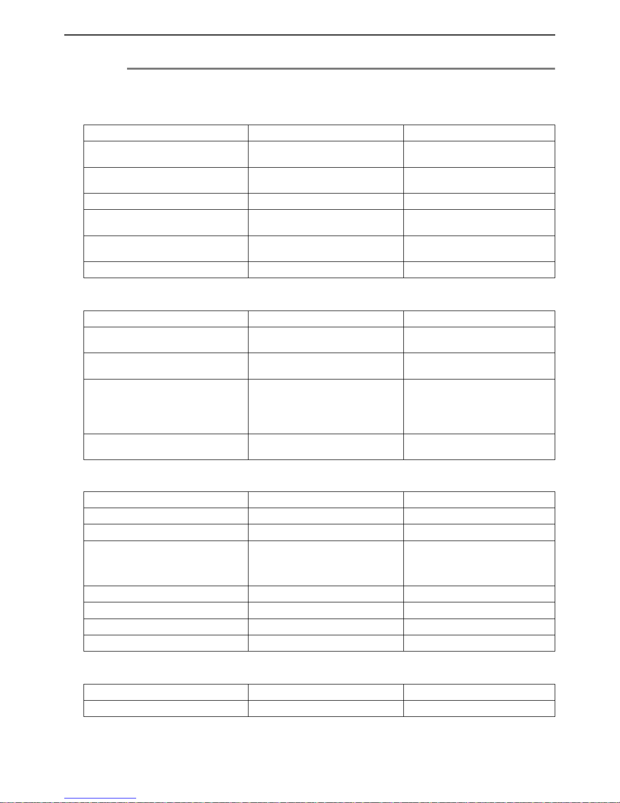
Pipe size (mm[in]) Radial thickness (mm) Type
ø6.35 [1/4"] 0.8t
ø9.52 [3/8"] 0.8t
ø12.7 [1/2"] 0.8t
ø15.88 [5/8"] 1.0t
ø19.05 [3/4"] 1.0t
ø22.2 [7/8"] 1.0t
ø25.4 [1"] 1.0t
ø28.58 [1-1/8"] 1.0t
ø31.75 [1-1/4"] 1.1t
ø34.93 [1-3/8"] 1.1t
ø41.28 [1-5/8"] 1.2t
The pipes in the system that uses the refrigerant currently on the market are made with O-material (Annealed), even if the
pipe diameter is less than ø19.05 (3/4"). For a system that uses R410A, use pipes that are made with 1/2H-material (Drawn)
unless the pipe diameter is at least ø19.05 (3/4") and the radial thickness is at least 1.2t.
The figures in the radial thickness column are based on the Japanese standards and provided only as a reference. Use pipes
that meet the local standards.
O-material (Annealed)
1/2H-material,
H-material (Drawn)
HWE13080 GB
- 5 -
[1-2 Handling and Characteristics of Piping Materials, Refrigerant, and Refrigerant Oil ]
4. Thickness and refrigerant type indicated on the piping materials
Ask the pipe manufacturer for the symbols indicated on the piping material for new refrigerant.
5. Flare processing (O-material (Annealed) and OL-material only)
The flare processing dimensions for the pipes that are used in the R410A system are larger than those in the R22 system.
Flare processing dimensions (mm[in])
A dimension (mm)
Pipe size (mm[in])
R410A R22, R407C
ø6.35 [1/4"] 9.1 9.0
ø9.52 [3/8"] 13.2 13.0
ø12.7 [1/2"] 16.6 16.2
Dimension A
ø15.88 [5/8"] 19.7 19.4
ø19.05 [3/4"] 24.0 23.3
If a clutch-type flare tool is used to flare the pipes in the system using R410A, the length of the pipes must be between 1.0
and 1.5 mm. For margin adjustment, a copper pipe gauge is necessary.
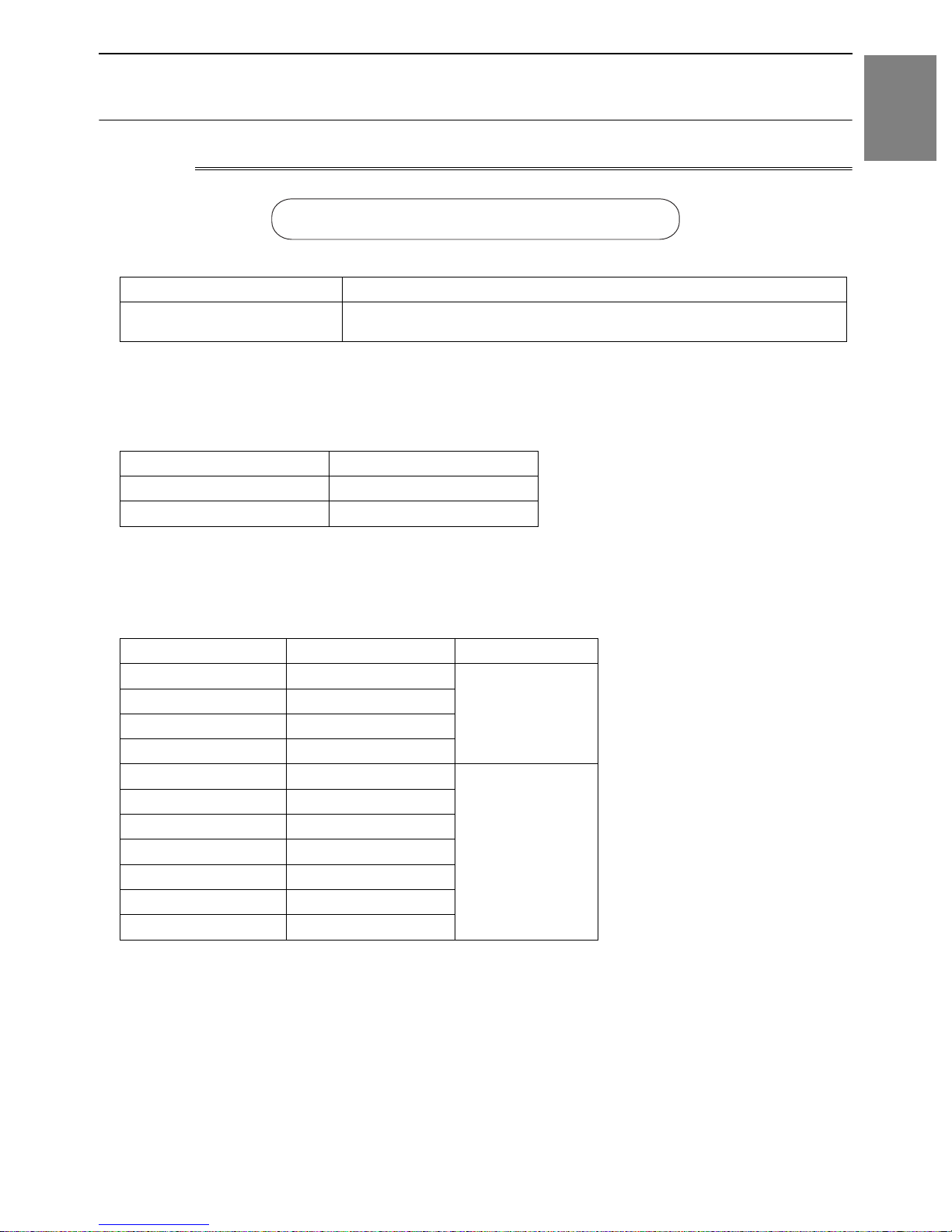
6. Flare nut
The flare nut type has been changed to increase the strength. The size of some of the flare nuts have also been changed.
Flare nut dimensions (mm[in])
B dimension (mm)
Pipe size (mm[in])
R410A R22, R407C
ø6.35 [1/4"] 17.0 17.0
ø9.52 [3/8"] 22.0 22.0
ø12.7 [1/2"] 26.0 24.0
Dimension B
ø15.88 [5/8"] 29.0 27.0
ø19.05 [3/4"] 36.0 36.0
The figures in the radial thickness column are based on the Japanese standards and provided only as a reference. Use pipes
that meet the local standards.
HWE13080 GB
- 6 -
[1-2 Handling and Characteristics of Piping Materials, Refrigerant, and Refrigerant Oil ]
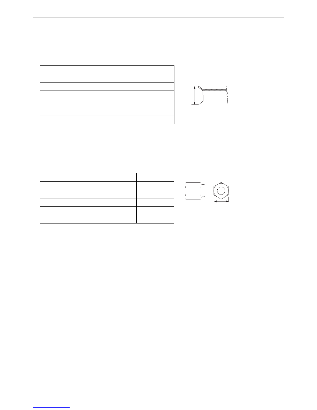
1-2-2 Storage of Piping Materials
1. Storage location
Store the pipes to be used indoors. (Warehouse at site or owner's warehouse)
If they are left outdoors, dust, dirt, or moisture may infiltrate and contaminate the pipe.
2. Sealing the pipe ends
1 Check Before Servicing
Both ends of the pipes should be sealed until just before brazing.
Keep elbow pipes and T-joints in plastic bags.
The new refrigerator oil is 10 times as hygroscopic as the conventional refrigerating machine oil (such as Suniso) and, if not
handled with care, could easily introduce moisture into the system. Keep moisture out of the pipes, for it will cause the oil to
deteriorate and cause a compressor failure.
1-2-3 Pipe Processing
Use a small amount of ester oil, ether oil, or alkylbenzene to coat flares and flanges.
Use a minimum amount of oil.
Use only ester oil, ether oil, and alkylbenzene.
HWE13080 GB
- 7 -
[1-2 Handling and Characteristics of Piping Materials, Refrigerant, and Refrigerant Oil ]
1-2-4 Characteristics of the New and Conventional Refrigerants
1. Chemical property
As with R22, the new refrigerant (R410A) is low in toxicity and chemically stable nonflammable refrigerant.
However, because the specific gravity of vapor refrigerant is greater than that of air, leaked refrigerant in a closed room will
accumulate at the bottom of the room and may cause hypoxia.
If exposed to an open flame, refrigerant will generate poisonous gases. Do not perform installation or service work in a confined area.
New Refrigerant (HFC type) Conventional Refriger-
ant (HCFC type)
R410A R407C R22
R32/R125 R32/R125/R134a R22
Composition (wt%) (50/50) (23/25/52) (100)
Type of Refrigerant Pseudo-azeotropic
Refrigerant
Non-azeotropic
Refrigerant
Single Refrigerant
Chloride Not included Not included Included
Safety Class A1/A1 A1/A1 A1
Molecular Weight 72.6 86.2 86.5
Boiling Point (°C/°F) -51.4/-60.5 -43.6/-46.4 -40.8/-41.4
Steam Pressure
1.557/226 0.9177/133 0.94/136
(25°C,MPa/77°F,psi) (gauge)
Saturated Steam Density
(25°C,kg/m
3
/77°F,psi)
64.0 42.5 44.4
Flammability Nonflammable Nonflammable Nonflammable
Ozone Depletion Coefficient (ODP)
Global Warming Coefficient (GWP)
*1
*2
Refrigerant Charging Method Refrigerant charging in
Replenishment of Refrigerant after a Refrigerant
0 0 0.055
1730 1530 1700
the liquid state
Refrigerant charging in
the liquid state
Refrigerant charging in
the gaseous state
Available Available Available
Leak
*1 When CFC11 is used as a reference
*2 When CO
is used as a reference
2
2. Refrigerant composition
R410A is a pseudo-azeotropic HFC blend and can almost be handled the same way as a single refrigerant, such as R22. To
be safe, however, draw out the refrigerant from the cylinder in the liquid phase. If the refrigerant in the gaseous phase is drawn
out, the composition of the remaining refrigerant will change and become unsuitable for use.
If the refrigerant leaks out, it may be replenished. The entire refrigerant does not need to be replaced.
3. Pressure characteristics
The pressure in the system using R410A is 1.6 times as great as that in the system using R22.
Pressure (gauge)
Temperature (°C/°F)
R410A R407C R22
MPa/psi MPa/psi MPa/psi
-20/-4 0.30/44 0.18/26 0.14/20
0/32 0.70/102 0.47/68 0.40/58
20/68 1.34/194 0.94/136 0.81/117
40/104 2.31/335 1.44/209 1.44/209
60/140 3.73/541 2.44/354 2.33/338
65/149 4.17/605 2.75/399 2.60/377
HWE13080 GB
- 8 -

[1-2 Handling and Characteristics of Piping Materials, Refrigerant, and Refrigerant Oil ]
1-2-5 Refrigerant Oil
1. Refrigerating machine oil in the HFC refrigerant system
HFC type refrigerants use a refrigerating machine oil different from that used in the R22 system.
Note that the ester oil used in the system has properties that are different from commercially available ester oil.
Refrigerant Refrigerating machine oil
R22 Mineral oil
R407C Ester oil
R410A Ester oil
2. Effects of contaminants
*1
Refrigerating machine oil used in the HFC system must be handled with special care to keep contaminants out.
The table below shows the effect of contaminants in the refrigerating machine oil on the refrigeration cycle.
3. The effects of contaminants in the refrigerating machine oil on the refrigeration cycle.
Cause Symptoms Effects on the refrigerant cycle
Water infiltration Frozen expansion valve
and capillary tubes
Clogged expansion valve and capillary tubes
Poor cooling performance
Compressor overheat
Motor insulation failure
Burnt motor
Coppering of the orbiting scroll
Lock
Burn-in on the orbiting scroll
Clogged expansion valve, capillary tubes, and
drier
Hydrolysis
Air infiltration Oxidization
Adhesion to expansion valve and capillary
tubes
Sludge formation and adhesion
Acid generation
Oxidization
Oil degradation
Poor cooling performance
Infiltration of
contaminants
Dust, dirt
Infiltration of contaminants into the compressor
Compressor overheat
Burn-in on the orbiting scroll
Sludge formation and adhesion Clogged expansion valve and capillary tubes
Mineral oil
etc.
Poor cooling performance
Compressor overheat
Oil degradation Burn-in on the orbiting scroll
1 Check Before Servicing
*1. Contaminants is defined as moisture, air, processing oil, dust/dirt, wrong types of refrigerant, and refrigerating machine oil.
HWE13080 GB
- 9 -
[1-3 Working with Refrigerant Piping ]
1-3 Working with Refrigerant Piping
1-3-1 Pipe Brazing
No changes have been made in the brazing procedures. Perform brazing with special care to keep foreign objects (such as oxide
scale, water, and dust) out of the refrigerant system.
Example: Inside the brazed connection
Use of no inert gas during brazing Use of inert gas during brazing
1. Items to be strictly observed
Do not conduct refrigerant piping work outdoors if raining.
Use inert gas during brazing.
Use a brazing material (BCuP-3) that requires no flux when brazing between copper pipes or between a copper pipe and
copper coupling.
If installed refrigerant pipes are not immediately connected to the equipment, then braze and seal both ends.
2. Reasons
The new refrigerating machine oil is 10 times as hygroscopic as the conventional oil and is more likely to cause unit failure if
water infiltrates into the system.
Flux generally contains chloride. Residual flux in the refrigerant circuit will cause sludge to form.
3. Notes
Do not use commercially available antioxidants because they may cause the pipes to corrode or refrigerating machine oil to
deteriorate.
HWE13080 GB
- 10 -
[1-3 Working with Refrigerant Piping ]
1-3-2 Air Tightness Test
No changes have been made in the detection method. Note that a refrigerant leak detector for R22 will not detect an R410A leak.
Halide torch R22 leakage detector
1 Check Before Servicing
1. Items to be strictly observed
Pressurize the equipment with nitrogen up to the design pressure (4.15MPa[601psi]), and then judge the equipment's air tight-
ness, taking temperature variations into account.
Refrigerant R410A must be charged in its liquid state (vs. gaseous state).
2. Reasons
Oxygen, if used for an air tightness test, poses a risk of explosion. (Only use nitrogen to check air tightness.)
Refrigerant R410A must be charged in its liquid state. If gaseous refrigerant in the cylinder is drawn out first, the composition
of the remaining refrigerant in the cylinder will change and become unsuitable for use.
3. Notes
Procure a leak detector that is specifically designed to detect an HFC leak. A leak detector for R22 will not detect an
HFC(R410A) leak.
HWE13080 GB
- 11 -
[1-3 Working with Refrigerant Piping ]
1-3-3 Vacuum Drying
(Photo1) 15010H (Photo2) 14010
Recommended vacuum gauge:
ROBINAIR 14010 Thermistor Vacuum Gauge
1. Vacuum pump with a reverse-flow check valve (Photo1)
To prevent the vacuum pump oil from flowing into the refrigerant circuit during power OFF or power failure, use a vacuum
pump with a reverse-flow check valve.
A reverse-flow check valve may also be added to the vacuum pump currently in use.
2. Standard of vacuum degree (Photo 2)
Use a vacuum pump that attains 0.5Torr(65Pa) or lower degree of vacuum after 5 minutes of operation, and connect it directly
to the vacuum gauge. Use a pump well-maintained with an appropriate lubricant. A poorly maintained vacuum pump may not
be able to attain the desired degree of vacuum.
3. Required precision of vacuum gauge
Use a vacuum gauge that registers a vacuum degree of 5Torr(650Pa) and measures at intervals of 1Torr(130Pa). (A recommended vacuum gauge is shown in Photo2.)
Do not use a commonly used gauge manifold because it cannot register a vacuum degree of 5Torr(650Pa).
4. Evacuation time
After the degree of vacuum has reached 5Torr(650Pa), evacuate for an additional 1 hour. (A thorough vacuum drying re-
moves moisture in the pipes.)
Verify that the vacuum degree has not risen by more than 1Torr(130Pa) 1hour after evacuation. A rise by less than
1Torr(130Pa) is acceptable.
If the vacuum is lost by more than 1Torr(130Pa), conduct evacuation, following the instructions in section 6. Special vacuum
drying.
5. Procedures for stopping vacuum pump
To prevent the reverse flow of vacuum pump oil, open the relief valve on the vacuum pump side, or draw in air by loosening
the charge hose, and then stop the operation.
The same procedures should be followed when stopping a vacuum pump with a reverse-flow check valve.
6. Special vacuum drying
When 5Torr(650Pa) or lower degree of vacuum cannot be attained after 3 hours of evacuation, it is likely that water has pen-
etrated the system or that there is a leak.
If water infiltrates the system, break the vacuum with nitrogen. Pressurize the system with nitrogen gas to
0.5kgf/cm
2
G(0.05MPa) and evacuate again. Repeat this cycle of pressurizing and evacuation either until the degree of vac-
uum below 5Torr(650Pa) is attained or until the pressure stops rising.
Only use nitrogen gas for vacuum breaking. (The use of oxygen may result in an explosion.)
HWE13080 GB
- 12 -

[1-3 Working with Refrigerant Piping ]
7. Triple Evacuation
The method below can also be used to evacuate the system.
Evacuate the system to 4,000 microns from both service valves. System manifold gauges must not be used to measure vac-
uum. A micron gauge must be used at all times. Break the vacuum with Nitrogen (N2) into the discharge service valve to 0
PSIG.
Evacuate the system to 1,500 microns from the suction service valve. Break the vacuum with Nitrogen (N2) into the discharge
service valve to 0 PSIG.
Evacuate the system to 500 microns. System must hold the vacuum at 500 microns for a minimum of 1 hour.
Conduct a rise test for a minimum of 30 minutes
8. Notes
To evacuate air from the entire system
Applying a vacuum through the check joints at the refrigerant service valve on the high and low pressure sides (BV1
and 2) is not enough to attain the desired vacuum pressure.
Be sure to apply a vacuum through the check joints at the refrigerant service valve on the high and low pressure
sides (BV1 and 2) and also through the check joints on the high and low pressure sides (CJ1 and 2).
To evacuate air only from the outdoor units
Apply a vacuum through the check joints on the high and low pressure sides (CJ1, and 2).
To evacuate air from the indoor units and extension pipes
Apply a vacuum through the check joints at the refrigerant service valve on the high and low pressure sides (BV1
and 2).
1 Check Before Servicing
HWE13080 GB
- 13 -
[1-3 Working with Refrigerant Piping ]
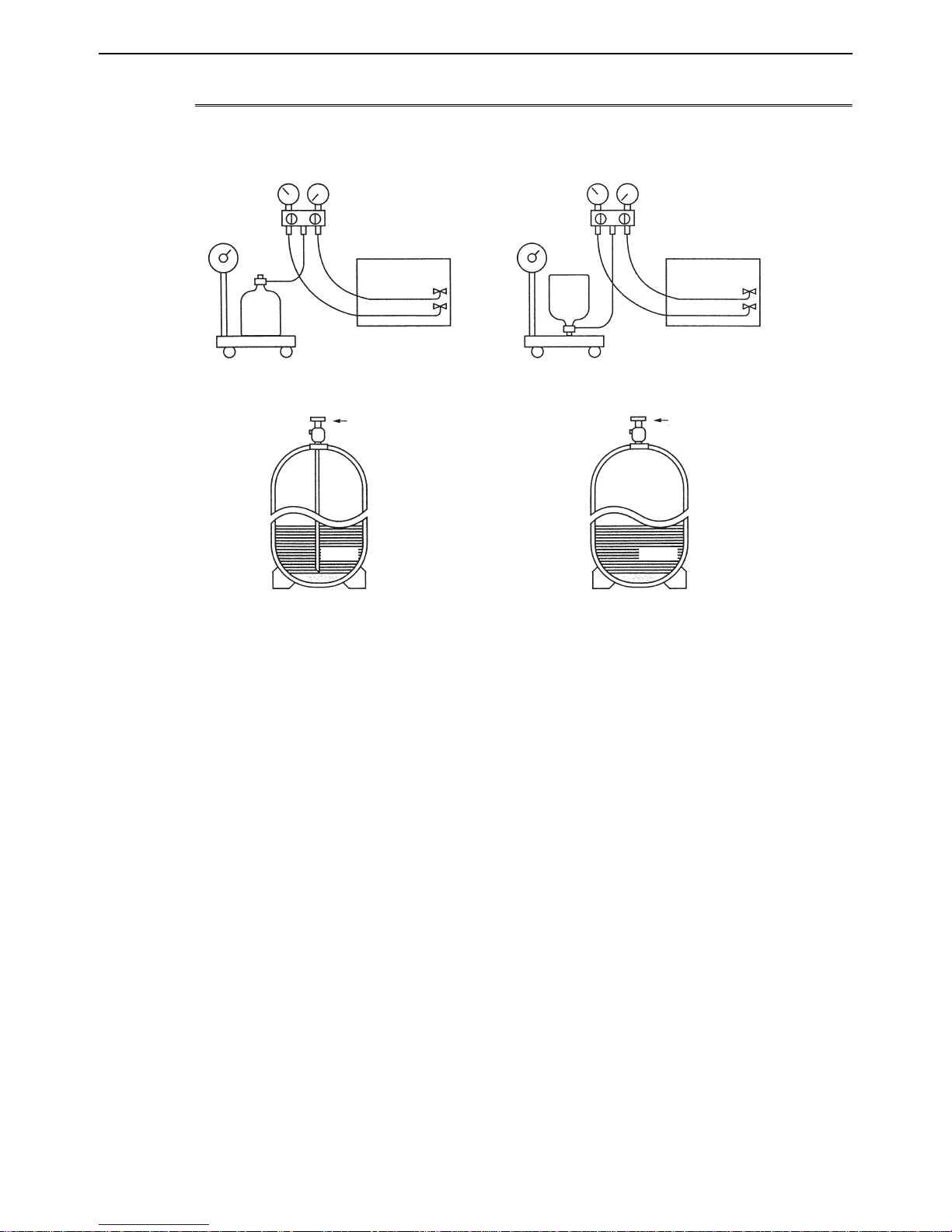
1-3-4 Refrigerant Charging
Cylinder with a siphon
Cylinder without a siphon
Cylin-
Cylin-
der
der
Cylinder color R410A is pink. Refrigerant charging in the liquid state
Valve Valve
liquid
liquid
1. Reasons
R410A is a pseudo-azeotropic HFC blend (boiling point R32=-52°C[-62°F], R125=-49°C[-52°F]) and can almost be handled
the same way as a single refrigerant, such as R22. To be safe, however, draw out the refrigerant from the cylinder in the liquid
phase. If the refrigerant in the gaseous phase is drawn out, the composition of the remaining refrigerant will change and become unsuitable for use.
2. Notes
When using a cylinder with a siphon, refrigerant is charged in the liquid state without the need for turning it upside down. Check
the type of the cylinder on the label before use.
If the refrigerant leaks out, it may be replenished. The entire refrigerant does not need to be replaced. (Charge refrigerant in
the liquid state.)
Refer to the following page(s).[8-14 Measures for Refrigerant Leakage](page 311)
HWE13080 GB
- 14 -
[1-4 Precautions for Wiring ]
1-4 Precautions for Wiring
Control boxes house high-voltage and high-temperature electrical parts.
They may still remain energized or hot after the power is turned off.
When opening or closing the front cover of the control box, keep out of contact with the internal parts.
Before inspecting the inside of the control box, turn off the power, leave the unit turned off for at least 10 minutes, and check
that the voltage of the electrolytic capacitor (inverter main circuit) has dropped to 20 VDC or less.
It will take approximately 10 minutes until the voltage is discharged after power off.
Disconnect the outdoor unit fan board connector (CNINV) before performing maintenance work.
Before connecting or disconnecting the connector, check that the outdoor unit fan is stopped and that the voltage of the main
circuit capacitor has dropped to 20 VDC or below.
If the outdoor unit fan is rotated by external forces such as strong winds, the main circuit capacitor can be charged and cause
an electric shock.
Refer to the wiring nameplate for details.
Reconnect the connector (CNINV) to the fan board after completion of maintenance work.
When the unit is turned on, the compressor will remain energized even when it is stopped to vaporize the liquid refrigerant
that accumulates in the compressor.
Before connecting wiring to TB7, check that the voltage has dropped below 20 VDC.
When a system controller is connected to the centralized control transmission cable to which power is supplied from the out-
door unit (power jumper on the outdoor unit is connected to CN40), be aware that power can be supplied to the centralized
control transmission and the system controller may detect an error and send an error notice if the outdoor unit fan is rotated
by external forces, such as strong winds, even when power to the outdoor unit is turned off.
When replacing the internal electrical components of the control box, tighten the screws to the recommended tightening
torque as specified below.
Recommended tightening torque for the internal electrical components of the control box
1 Check Before Servicing
Screw Recommended tightening torque (N·m)
M3 0.69
M4 1.47
M5 2.55
M6 2.75
M8 6.20
∗1 When replacing semiconductor modules (e.g., diode stack, IPM, INV board (with IPM), fan board (with IPM)), apply heat-
sink silicone evenly to the mounting surface of the semiconductor module (or the semiconductor module on the back of
the circuit board). Next, tighten the screws holding the semiconductor module to one-third of the specified torque, and then
tighten the screws to the specified torque.
∗2 Deviating from the recommended tightening torque may cause damage to the unit or its parts.
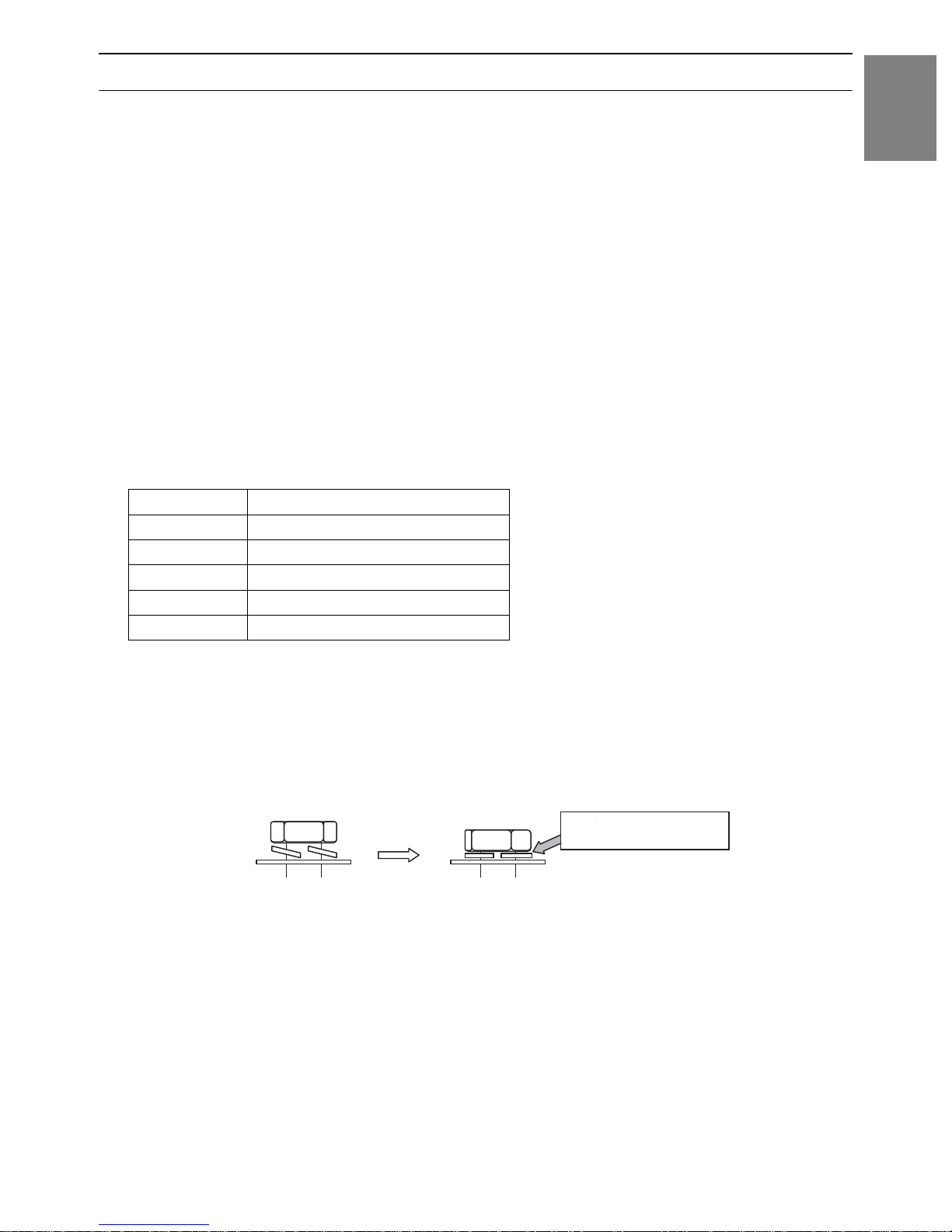
Take the following steps to ensure that the screws are properly tightened.
1) Ensure that the spring washers are parallel to the terminal block.
Even if the tightening torque is observed, if the washers are not parallel to the terminal block, then the semiconductor module
is not installed properly.
Loose screws
Proper installation
Spring washers are parallel to
the terminal block
HWE13080 GB
- 15 -
[1-4 Precautions for Wiring ]
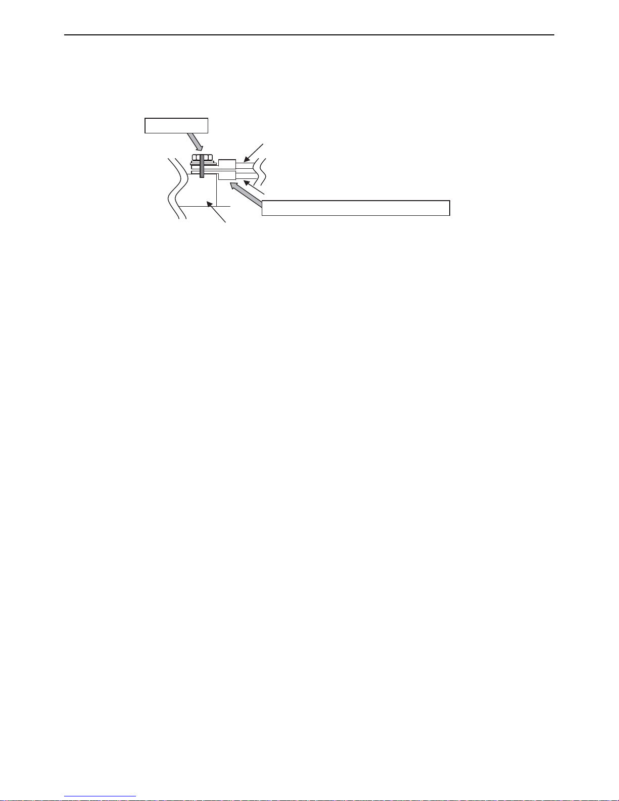
2) Check the wires are securely fastened to the screw terminals.
Screw the screws straight down so as not to damage the screw threads.
Hold the two round terminals back to back to ensure that the screw will screw down straight.
After tightening the screw, mark a line through the screw head, washer, and terminals with a permanent marker.
Example
Mark a line.
Daisy-chain
Power wires, transmission lines, centralized transmission lines
Place the round terminals back to back.
Power supply terminal block, indoor-outdoor transmission line terminal block,
and centralized controller transmission line
Poor contact caused by loose screws may result in overheating and fire.
Continued use of the damaged circuit board may cause overheating and fire.
HWE13080 GB
- 16 -

Chapter 2 Restrictions
2-1 System Configurations....................................................................................................................... 19
2-2 Types and Maximum Allowable Length of Cables........................................................................... 20
2-3 Switch Settings ................................................................................................................................... 21
2-4 M-NET Address Settings .................................................................................................................... 22
2-4-1 Address Settings List ............................................................................................................................ 22
2-4-2 Outdoor Unit Power Jumper Connector Connection.............................................................................24
2-4-3 Outdoor Unit Centralized Controller Switch Setting .............................................................................. 24
2-4-4 Room Temperature Detection Position Selection ................................................................................. 24
2-4-5 Start/Stop Control of Indoor Units ......................................................................................................... 25
2-4-6 Miscellaneous Settings ......................................................................................................................... 25
2-4-7 Various Control Methods Using the Signal Input/Output Connector on Outdoor Unit .......................... 26
2-5 Demand Control Overview ................................................................................................................. 29
2-6 System Connection Example............................................................................................................. 30
2-7 Example System with an MA Remote Controller ............................................................................. 32
2-7-1 Single Refrigerant System (Automatic Indoor/Outdoor Address Startup)............................................. 32
2-7-2 Single Refrigerant System with Two or More LOSSNAY Units ............................................................ 34
2-7-3 Grouped Operation of Units in Separate Refrigerant Circuits ............................................................... 36
2-7-4 System with a Connection of System Controller to Centralized Control Transmission Line................. 38
2-7-5 System with a Connection of System Controller to Indoor-Outdoor Transmission Line ....................... 40
2-7-6 System with Multiple BC Controllers..................................................................................................... 42
2-8 Example System with an ME Remote Controller ............................................................................. 46
2-8-1 System with a Connection of System Controller to Centralized Control Transmission Line................. 46
2-9 Example System with an MA and an ME Remote Controller .......................................................... 48
2-9-1 System with a Connection of System Controller to Centralized Control Transmission Line................. 48
2-10 Restrictions on Refrigerant Pipes ..................................................................................................... 51
2-10-1 Restrictions on Refrigerant Pipe Length ............................................................................................... 51
2-10-2 Restrictions on Refrigerant Pipe Size ................................................................................................... 57
2-10-3 BC Controller Connection Method ........................................................................................................ 58
HWE13080 GB
- 17 -

HWE13080 GB
- 18 -

[2-1 System Configurations ]
2 Restrictions
2-1 System Configurations
1. Table of compatible indoor units
The table below summarizes the types of indoor units that are compatible with different types of outdoor units.
Outdoor
units
Composing units Maximum total capacity
of connectable indoor
units
Maximum number
of connectable in-
door units
Types of connectable in-
door units
72 - - 36 - 108 18 P06 - P96 models
96 - - 48 - 144 24
R410A series indoor units
144 72 72 72 - 216 36
192 96 96 96 - 288 48
1) "Maximum total capacity of connectable indoor units" refers to the sum of the numeric values in the indoor unit model names.
2) If the total capacity of the indoor units that are connected to a given outdoor unit exceeds the capacity of the outdoor unit, the
indoor units will not be able to perform at the rated capacity when they are operated simultaneously. Select a combination of
units so that the total capacity of the connected indoor units is at or below the capacity of the outdoor unit whenever possible.
2 Restrictions
HWE13080 GB
- 19 -
[2-2 Types and Maximum Allowable Length of Cables ]
2-2 Types and Maximum Allowable Length of Cables
1. Wiring work
(1) Notes
1) Have all electrical work performed by an authorized electrician according to the local regulations and instructions in this manual.
2) Install external transmission cables at least 5cm [1-31/32"] away from the power supply cable to avoid noise interference.
(Do not put the control cable and power supply cable in the same conduit tube.)
3) Provide grounding for the outdoor unit as required.
4) Run the cable from the electric box of the indoor or outdoor unit in such way that the box is accessible for servicing.
5) Do not connect power supply wiring to the terminal block for transmission line. Doing so will damage the electronic components on the terminal block.
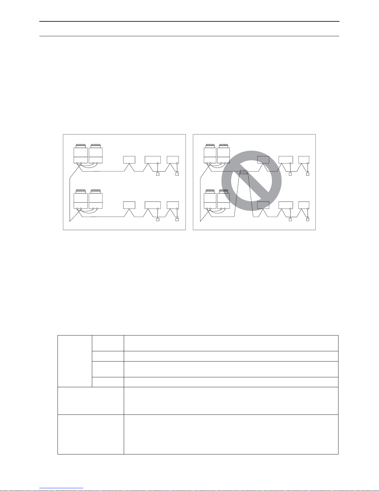
6) Use 2-core shielded cables as transmission cables.
Use a separate 2-core control cable for each refrigerant system. Do not use a single multiple-core cable to connect indoor
units that belong to different refrigerant systems. The use of a multiple-core cable may result in signal transmission errors and
malfunctions.
Outdoor unit
TB3TB7TB3TB
2-core shielded cable
TB3TB7TB3TB
2-core shielded cable
7
7
BC Controller
Indoor unit
Remote Controller
Outdoor unit
TB3TB7TB3TB
TB3TB7TB3TB
BC Controller
7
multiple-core cable
7
Indoor unit
Remote Controller
TB3: Terminal block for indoor-outdoor transmission line TB7: Terminal block for centralized control
7) When extending the transmission cable, be sure to extend the shield wire.
(2) Control wiring
Different types of control wiring are used for different systems. Before performing wiring work, refer to the following page(s).
[2-7 Example System with an MA Remote Controller](page 32)
[2-8 Example System with an ME Remote Controller](page 46)
[2-9 Example System with an MA and an ME Remote Controller](page 48)
Types and maximum allowable length of cables
Control lines are categorized into 2 types: transmission line and remote controller line.
Use the appropriate type of cables and observe the maximum allowable length specified for a given system. If a given system
has a long transmission line or if a noise source is located near the unit, place the unit away from the noise source to reduce
noise interference.
1) M-NET transmission line
Facility
type
Type Shielded cable CVVS, CPEVS, MVVS
Cable type
Number of
cores
Cable size Larger than 1.25mm
Maximum transmission
line distance between the
outdoor unit and the farthest indoor unit
Maximum transmission
line distance for centralized control and Indoor/
outdoor transmission line
(Maximum line distance
500 m [1640ft] max.
*The maximum overall line length from the power supply unit on the transmission lines for
centralized control to each outdoor unit or to the system controller is 200m [656ft] max.
via outdoor unit)
HWE13080 GB
- 20 -
All facility types
2-core cable
2
[AWG16]
200 m [656ft] max.

[2-3 Switch Settings ]
2) Remote controller wiring
Type CVV CVV
Number of
cores
Cable type
Cable size
2-core cable 2-core cable
0.3 to 1.25mm
[AWG22 to 16]
(0.75 to 1.25mm
[AWG18 to 16]
Maximum overall line
length
200 m [656ft] max.
*1 MA remote controller refers to MA remote controller (PAR-20MAU, PAR-21MAAU, PAR-30MAAU), Simple MA Re-
mote Controller, and wireless remote controller.
*2 The use of cables that are smaller than 0.75mm
*3 When connected to the terminal block on the Simple remote controller, use cables that meet the cable size specifi-
cations shown in the parenthesis.
*4 When connecting PAR-30MAAU, use a 0.3mm
*5 ME remote controller refers to ME remote controller and Simple ME Remote Controller.
2-3 Switch Settings
MA remote controller
2 *2 *4
2 ) *3
2
(AWG18) is recommended for easy handling.
2
sheathed cable.
*1
0.3 to 1.25mm
[AWG22 to 16]
(0.75 to 1.25mm
ME remote controller
2 *2
2 ) *3
*5
[AWG18 to 16]
The section of the cable that exceeds 10m
[32ft] must be included in the maximum indoor-outdoor transmission line distance.
2 Restrictions
1. Switch setting
The necessary switch settings depend on system configuration. Before performing wiring work, refer to the following page(s).
[2-7 Example System with an MA Remote Controller](page 32)
[2-8 Example System with an ME Remote Controller](page 46)
[2-9 Example System with an MA and an ME Remote Controller](page 48)
If the switch settings are changed while the unit is being powered, those changes will not take effect, and the unit will not
function properly.
Units on which to set the switches Symbol Units to which the power must be shut off
*3
CITY MULTI indoor unit Main/sub unit IC Outdoor units
LOSSNAY, OA processing unit
ME remote controller Main/sub remote
*1
LC Outdoor units
RC Outdoor units
and Indoor units
*3
and LOSSNAY
*3
controller
MA remote controller
*4
Main/sub remote
MA Indoor units
controller
CITY MULTI outdoor unit
*2
OC,OS Outdoor units
BC controller Main BC Outdoor units
Sub1, 2 BS1, BS2 Outdoor units
*3
*3
and BC controller
*3 *5
and BC controller
*1. Applicable when LOSSNAY units are connected to the indoor-outdoor transmission line.
*2. The outdoor units in the same refrigerant circuit are automatically designated as OC and OS in the order of capacity
from large to small (if two or more units have the same capacity, in the order of address from small to large).
*3. Turn off the power to all the outdoor units in the same refrigerant circuit.
*4. When a PAR-30MAAU is connected to a group, no other MA remote controllers can be connected to the same group.
*5. When setting the switch SW4 of the control board, set it with the outdoor unit power on. Refer to the following page(s).
[5-1-1 Outdoor Unit Switch Functions and Factory Settings](page 117)
HWE13080 GB
- 21 -
[2-4 M-NET Address Settings ]
2-4 M-NET Address Settings
2-4-1 Address Settings List
1. M-NET Address settings
(1) Address settings table
The need for address settings and the range of address setting depend on the configuration of the system.
Unit or controller Sym-
bol
Address
setting
Setting method Factory
range
CITY MULTI
indoor unit
Main/sub unit IC 0, 01 to
50
*1 *4 *6
M-NET
adapter
M-NET control interface
Free Plan
adapter
LOSSNAY, OA processing unit LC 0, 01 to
ME remote
controller
Main remote
controller
Sub remote
RC 101 to
RC 151 to
controller
50
150
200
*1 *4 *6
MA remote controller MA No address settings required. (The main/sub setting must be made if
2 remote controllers are connected to the system.)
CITY MULTI outdoor unit OCOS0, 51 to
100
*6
Auxiliary
outdoor unit
BC controller
(main)
BC 0, 51 to
100
*6
Assign the smallest address to the main indoor unit in the
group, and assign sequential address numbers to the rest
of the indoor units in the same group.
In an R2 system with a sub BC controller, make the settings for the indoor units in the following order.
(i) Indoor unit to be connected to the main BC controller
(ii) Indoor unit to be connected to sub BC controller 1
(iii) Indoor unit to be connected to sub BC controller 2
Make the settings for the indoor units in the way that the
formula "(i) < (ii) < (iii)" is true.
Assign an arbitrary but unique address to each of these
units after assigning an address to all indoor units.
Add 100 to the smallest address of all the indoor units in
the same group.
Add 150 to the smallest address of all the indoor units in
*3
the same group.
*7
Assign an address that equals the lowest address of the indoor
*1 *2
*1 *2
units in the same refrigerant circuit plus 50.
Assign sequential addresses to the outdoor units in the same re-
frigerant circuit. The outdoor units in the same refrigerant circuit
are automatically designated as OC and OS.
Assign an address that equals the address of the outdoor
unit in the same refrigerant system plus 1.
If a given address overlaps any of the addresses that are
*5
assigned to the outdoor units or to the sub BC controller,
use a different, unused address within the setting range.
BC controller
(sub1, 2)
BS1
BS2
51 to
100
Assign an address to both the sub BC controller 1 and 2
*2
that equals the lowest address of the indoor units that
are connected to each of them plus 50.
If a sub BC controller is connected, the automatic startup
function is not available.
address
setting
00
00
101
Main
00
00
*1. If a given address overlaps any of the addresses that are assigned to other units, use a different, unused address within the
setting range.
*2. To set the outdoor unit address or the auxiliary outdoor unit address to "100," set the rotary switches to "50."
*3. To set the ME remote controller address to "200," set the rotary switches to "00."
*4. Some models of indoor units have two or three control boards.
Assign an address to the No.1, No. 2, and No. 3 control boards so that the No. 2 control board address equals the No. 1 control board
address plus 1, and that the No. 3 control board address equals the No. 1 control board address plus 2.
*5. The outdoor units in the same refrigerant circuit are automatically designated as OC, and OS. They are designated as OC, and OS in
the descending order of capacity (ascending order of address if the capacities are the same).
*6. No address settings are required for units in a system with a single outdoor unit (with some exceptions).
Address setting is required if a sub BC controller is connected.
*7. When a PAR-30MAAU is connected to a group, no other MA remote controllers can be connected to the same group.
HWE13080 GB
- 22 -

[2-4 M-NET Address Settings ]
System
controller
Unit or controller Sym-
bol
Group remote con-
GRSC201 to
troller
System remote controller
ON/OFF remote controller
SR
SC
AN
SC
Schedule timer (compatible with M-NET)STSC
Central controller
TRSC000
AG-150A
G(B)-50A
GB-24A
Expansion controller
TR 000
PAC-YG50ECA
BM adapter
SC 000
BAC-HD150
LM adapter
SC 201 to
LMAP03U
Address
setting
range
250
201 to
250
201 to
250
201 to
250
250
Setting method Factory
Assign an address that equals the sum of the smallest
group number of the group to be controlled and 200.
Assign an arbitrary but unique address within the range
listed on the left to each unit.
Assign an address that equals the sum of the smallest
group number of the group to be controlled and 200.
Assign an arbitrary but unique address within the range
listed on the left to each unit.
Assign an arbitrary but unique address within the range
listed on the left to each unit. The address must be set to
"000" to control the K-control unit.
Assign an arbitrary but unique address within the range
listed on the left to each unit. The address must be set to
"000" to control the K-control unit.
Assign an arbitrary but unique address within the range
listed on the left to each unit. The address must be set to
"000" to control the K-control unit.
Assign an arbitrary but unique address within the range
listed on the left to each unit.
address
setting
201
202
000
000
000
247
2 Restrictions
HWE13080 GB
- 23 -

[2-4 M-NET Address Settings ]
2-4-2 Outdoor Unit Power Jumper Connector Connection
There are limitations on the total number of units that are connectable to each refrigerant system. Refer to the DATABOOK
for details.
System configuration
Connection to
the system controller
Power supply unit
for transmission
lines
Group operation
of units in a system with multiple
Power supply switch connector connection
outdoor units
System with one
outdoor unit
System with multiple outdoor units
_ _ _ Leave CN41 as it is
(Factory setting)
Not connected _ Not grouped
Grouped Disconnect the male connector from the fe-
With connection
to the indoor
unit system
With connection
to the centralized control system
Not required Grouped/not
grouped
*1
Not required
(Powered from
Grouped/not
grouped
the outdoor unit)
Required *1 Grouped/not
grouped
male power supply switch connector (CN41)
and connect it to the female power supply
switch connector (CN40) on only one of the
outdoor units.
*Connect the S (shielded) terminal on the
terminal block (TB7) on the outdoor unit
whose CN41 was replaced with CN40 to
the ground terminal ( ) on the electric box.
Leave CN41 as it is
(Factory setting)
*2
*1 The need for a power supply unit for transmission lines depends on the system configuration.
*2 The replacement of the power jumper connector from CN41 to CN40 must be performed on only one outdoor unit in the
system.
2-4-3 Outdoor Unit Centralized Controller Switch Setting
System configuration Centralized control switch (SW5-1) settings *
Connection to the system controller Not connected Leave it to OFF. (Factory setting)
Connection to the system controller Connected *
2
*1 Set SW5-1 on all outdoor units in the same refrigerant circuit to the same setting.
*2 When only the LM adapter is connected, leave SW5-1 to OFF (as it is).
ON
1
2-4-4 Room Temperature Detection Position Selection
To stop the fan during heating Thermo-OFF (SW1-7 and 1-8 on the indoor units to be set to ON), use the built-in thermistor
on the remote controller or an optional thermistor.
1) To use the built-in sensor on the remote controller, set the SW1-1 to ON.
(Factory setting: SW1-1 set to "OFF".)
Some models of remote controllers are not equipped with a built-in temperature sensor.
Use the built-in temperature sensor on the indoor unit instead.
When using the built-in sensor on the remote controller, install the remote controller where room temperature can be detected.
(Note) Factory setting for SW1-1 on the indoor unit of the All-Fresh Models is ON.
2) When an optional temperature sensor is used, set SW1-1 to OFF, and set SW3-8 to ON.
When using an optional temperature sensor, install it where room temperature can be detected.
HWE13080 GB
- 24 -

[2-4 M-NET Address Settings ]
2-4-5 Start/Stop Control of Indoor Units
Each indoor unit (or group of indoor units) can be controlled individually by setting SW 1-9 and 1-10.
Function
Power ON/OFF by the
*1,*2,*3
plug
Automatic restoration
after power failure
*1. Do not cut off power to the outdoor unit. Cutting off the power supply to the outdoor unit will cut off the power supply to the
belt heater and may cause the compressor to malfunction when the unit is put back into operation.
*2. Not applicable to units with a built-in drain pump or humidifier.
*3. Models with a built-in drain pump cannot be turned on/off by the plug individually. All the units in the same refrigerant cir-
cuits will be turned on or off by the plug.
*4. Requires that the dipswitch settings for all the units in the group be made.
*5. To control the external input to and output from the air conditioners with the PLC software for general equipment via the
G(B)-50A, set SW1-9 and SW1-10 to ON. With these settings made, the power start-stop function becomes disabled. To
use the auto recovery function after power failure while these settings are made, set SW1-5 to ON.
Operation of the indoor unit when the operation is resumed after the unit
was stopped
Indoor unit will go into operation regardless of its operation status before
power off (power failure). (In approx. 5 minutes)
Indoor unit will go into operation if it was in operation when the power was
turned off (or cut off due to power failure). (In approx. 5 minutes)
Indoor unit will remain stopped regardless of its operation status before
power off (power failure).
Setting (SW1)
910
OFF ON
ON OFF
OFF OFF
2-4-6 Miscellaneous Settings
*4 *5
2 Restrictions
Cooling-only setting for the indoor unit: Cooling only model (Factory setting: SW3-1 "OFF.")
When using indoor unit as a cooling-only unit, set SW3-1 to ON.
HWE13080 GB
- 25 -

[2-4 M-NET Address Settings ]
2-4-7 Various Control Methods Using the Signal Input/Output Connector on Outdoor
Unit
(1) Various connection options
Terminal
Type Usage Function
Input Prohibiting cooling/heating operation (thermo OFF) by an external
DEMAND (level) CN3D*2Adapter for
input to the outdoor unit.
*It can be used as the DEMAND control device for each system.
Performs a low level noise operation of the outdoor unit by an external input to the outdoor unit.
Low-noise mode
*3*4
(level)
* It can be used as the silent operation device for each refrigerant
system.
Forces the outdoor unit to perform a fan operation by receiving signals from the snow sensor.
*5*7
Cooling/heating operation can be changed by an external input to
Snow sensor signal
input (level)
Auto-changeover CN3N
the outdoor unit.
The operation mode of the unit can be changed from normal cooling operation (performance priority) to energy-saving cooling mode
Energy-saving
mode
by an external signal input.
Out-
How to extract signals from the outdoor unit
put
*It can be used as an operation status display device.
*It can be used for an interlock operation with external devices.
Operation status of
the compressor
Error status
*6 *8
to be
*1
used
CN3S
CN3K
CN51 Adapter for
*5
Option
external input
(PACSC36NA-E)
external output
(PACSC37SA-E)
*1 For details, refer to section (2) Example of wiring connection.
*2 For details, refer to section (2) Example of wiring connection and other relevant sections in the manual. [2-5 Demand Control
Overview](page 29)
*3 Low-noise mode is valid when Dip SW6-8 on the outdoor unit is set to OFF. When DIP SW6-8 is set to ON, 4 levels of on-
DEMAND are possible, using different configurations of low-noise mode input and DEMAND input settings.When 2 or more
outdoor units exist in one refrigerant circuit system, 8 levels of on-DEMAND are possible.
*4. By setting Dip SW6-7, the Low-noise mode can be switched between the Capacity priority mode and the Low-noise priority
mode.
When SW6-7 is set to ON: The low-noise mode always remains effective.
When SW6-7 is set to OFF: The low noise mode is cancelled when certain outside temperature or pressure criteria are met,
and the unit goes into normal operation (capacity priority mode).
Low-noise mod is effective. Capacity priority mode becomes effective.
Cooling Heating Cooling Heating
TH7<30°C[86°F] and
63HS1<32kg/cm
2
TH7>3°C[37°F] and
63LS>4.6kg/cm
2
TH7>35°C[95°F] or
63HS1>35kg/cm
2
TH7<0°C[32°F] or
63LS<3.9kg/cm
2
*5 If multiple outdoor units are connected to the same refrigerant circuit, signal input/output settings need to be made for each
outdoor unit.
*6 Take out signals from the outdoor unit that is designated as OC if multiple outdoor units in the same system.
*7 If the formula TH7>5 holds true, the fan will not go into operation when the contact receives signal input.
*8 On the TKMU-A-H models, the error signal output function is disabled at default settings. Change the DipSW4 (No. 974) setting
to use the error signal output function. When the setting is changed, base heaters cannot be used.
HWE13080 GB
- 26 -

[2-4 M-NET Address Settings ]
CAUTION
(2) Example of wiring connection
1) Wiring should be covered by insulation tube with supplementary insulation.
2) Use relays or switches with IEC or equivalent standard.
3) The electric strength between accessible parts and control circuit should have 2750V or more.
(1) CN51
HP-TKMU-A-H model
Y
External input
adapter
Distant control
board
ecruos rewop pmaL
1
L
L
2
Relay circuit
X
Y
X
External input
adapter
Y
1
5
4
3
Outdoor unit
control board
CN51
Distant control
board
e
L
2
cruo
s
rewop pmaL
Relay circuit
Y
1
4
3
Outdoor unit
control board
CN51
Preparations
in the field
L1 : Outdoor unit error display lamp
L2 : Compressor operation lamp (compressor running state)
X, Y : Relay (coil =<0.9W : DC12V)
1. Optional part : PAC-SC37SA-E or field supply.
(2) CN3S
Relay circuit
Preparations
in the field
X : Relay
Snow sensor : The outdoor fan runs when X is closed
2. Optional part : PAC-SC36NA-E or field supply.
(4) CN3D
Relay circuit
External input
adapter
X
Contact rating voltage >= DC15V
Contact rating current >= 0.1A
Minimum applicable load =< 1mA at DC
in stop mode or thermostat mode.
1
2
3
Maximum cable
length is 10m
External input
adapter
X
Y
Maximum cable
length is 10m
Outdoor unit
2
control board
CN3S
2
1
2
3
Outdoor unit
control board
CN3D
L2 : Compressor operation lamp (compressor running state)
Y : Relay (coil =<0.9W : DC12V)
1. Optional part : PAC-SC37SA-E or field supply.
3. On the TKMU-A-H models, the error signal output function is disabled
at default settings. Change the DipSW4 (No. 974) setting to use the error
signal output function. When the setting is changed, base heaters cannot
be used.
(3) CN3N
X
Y
External input
adapter
Maximum cable
length is 10m
Relay circuit
Relay circuit
Preparations
in the field
2. Optional part :
PAC-SC36NA-E or field supply.
Preparations
in the field
2
Outdoor unit
control board
CN3N
1
2
3
X
Maximum cable
length is 10m
OFF
Y
X : Cooling / Heating
Y : Validity / Invalidity of X
X,Y : Relay
Contact rating voltage >= DC15V
Contact rating current >= 0.1A
Minimum applicable load =< 1mA at DC
External input
adapter
1
2
3
Outdoor unit
2
control board
CN3D
CoolingONHeating
ON
2 Restrictions
X
OFF
Normal
Preparations
in the field
Maximum cable
X : Low-noise mode
Y : Compressor ON/OFF
X,Y : Relay
2. Optional part : PAC-SC36NA-E or field supply.
HWE13080 GB
length is 10m
Contact rating voltage >= DC15V
Contact rating current >= 0.1A
Minimum appicable load =< 1mA at DC
Preparations
in the field
X : Low-noise mode
X : Relay
2. Optional part : PAC-SC36NA-E or field supply.
Low-noise mode : The noise level is reduced by controlling the maximum
Maximum cable
length is 10m
Contact rating voltage >= DC15V
Contact rating current >= 0.1A
Minimum applicable load =< 1mA at DC
fan frequency and maximum compressor frequency.
- 27 -

[2-4 M-NET Address Settings ]
(5) CN3K
Relay circuit
Preparations
in the field
X : Energy-saving mode command
X : Relay
2. Optional part : PAC-SC36NA-E or field supply.
External input
adapter
X
Maximum cable
length is 10m
Contact rating voltage >= DC15V
Contact rating current >= 0.1A
Minimum appicable load =< 1mA at DC
1
2
3
Outdoor unit
2
control board
CN3K
HWE13080 GB
- 28 -

[2-5 Demand Control Overview ]
2-5 Demand Control Overview
(1) General outline of control
Demand control is performed by using the external signal input to the 1-2 and 1-3 pins of CN3D on the outdoor units (OC and OS).
Between 2 and 8 steps of demand control is possible by setting Dip SW6-8 on the outdoor units (OC and OS).
No Demand control switch
Dip SW6-8
Input to CN3D*
2
OC OS
1 2 steps (0-100%) OFF OFF OC
2
ON OFF OC
4 steps (0-50-75-100%)
3 OFF ON OS
8 steps
4
(0-25-38-50-63-75-88-100%)
*1 Available demand functions
HP72 - HP96T(Y)KMU-A(-H) models (single-outdoor-unit system) : 2 and 4 steps shown in the rows 1 and 2 in the table above
only.
HP144 - HP192T(Y)KMU-A(-H) models (two-outdoor-unit system OC+OS) : 2-8 steps shown in the rows 1, 2, 3, and 4 in the
table above only.
*2 Signal is input to CN3D on the outdoor unit whose SW6-8 is set to ON. When SW6-8 is set to OFF on all outdoor units, the
signal is input to the CN3D on the OC.
Outdoor units whose SW6-8 is set to ON are selectable in a single refrigerant system.
*3 If wrong sequence of steps are taken, the units may go into the Thermo-OFF (compressor stop) mode.
Ex) When switching from 100% to 50%
(Incorrect) 100%0%50% The units may go into the Thermo-OFF mode.
(Correct) 100%75%50%
*4 The percentage of the demand listed in the table above is an approximate value based on the compressor volume and does
not necessarily correspond with the actual capacity.
*5 Notes on using demand control in combination with the low-noise mode
To enable the low-noise mode, it is necessary to short-circuit 1-2 pin of CN3D on the outdoor unit whose SW6-8 is set to OFF.
When SW6-8 is set to ON on all outdoor units, the following operations cannot be performed.
Performing 4-step demand in combination with the low-noise operation in a single-outdoor-unit system.
Performing 8-step demand in combination with the low-noise operation in a two-outdoor-unit system.
ON ON OC and OS
1) Contact input and control content
2-step demand control
The same control as the Thermo-OFF is performed by closing 1-3 pin of CN3D.
2 Restrictions
CN3D
1-3
Open 100%
Close 0%
4-step demand control (When SW6-8 is set to ON on an outdoor unit)
Demand capacity is shown below.
CN3D 1-2P
1-3P Open Close
Open 100% 75%
Close 0% 50%
8-step demand control (When SW6-8 is set to ON on two outdoor units)
Demand capacity is shown below.
8-step demand No.2 CN3D
1-2P Open Close
No.1 CN3D 1-2P 1-3P Open Close Open Close
Open Open 100% 50% 88% 75%
Close 50% 0% 38% 25%
Close Open 88% 38% 75% 63%
Close 75% 25% 63% 50%
*1. The outdoor units whose SW6-8 is set to ON are designated as No. 1 and No. 2 in the order of address from small to large.
Ex) When outdoor units whose SW6-8 is set to ON are designated as OC and OS, OC=No. 1 and OS=No. 2.
HWE13080 GB
- 29 -

[2-6 System Connection Example ]
2-6 System Connection Example
Examples of typical system connection are shown below.
Refer to the Installation Manual that came with each device or controller for details.
(1) An example of a system to which an MA remote controller is connected
System
configuration
System with one out-
1
2
3
4
5
6
(2) An example of a system to which an ME remote controller is connected
1
door unit
System with one out-
door unit
Grouping of units in a
system with multiple
outdoor units
System with one out-
door unit
System with one out-
door unit
System with one out-
door unit
System
configuration
System with one out-
door unit
Connection to the system controller
NO
NO
NO
With connection to transmission line
for centralized control
With connection to indoor-outdoor
transmission line
With connection to transmission line
for centralized control
Connection to the system controller
With connection to transmission line
for centralized control
Address start up for in-
door and outdoor units
Address start up for indoor
Automatic
address setup
Manual
address setup
Manual
address setup
Manual
address setup
Manual
address setup
Manual
address setup
and outdoor units
Manual
address setup
Notes
Connection of
multiple LOSSNAY units
Connection of
multiple LOSSNAY units
Notes
(3) An example of a system to which both MA remote controller and ME remote controller are connected
System
configuration
System with one out-
1
*MA remote controller and ME remote controller cannot both be connected to the same group.
door unit
Connection to the system controller
With connection to transmission
line for centralized control
Address start up for indoor and outdoor units
Manual
address setup
Notes
HWE13080 GB
- 30 -

[2-6 System Connection Example ]
2 Restrictions
HWE13080 GB
- 31 -
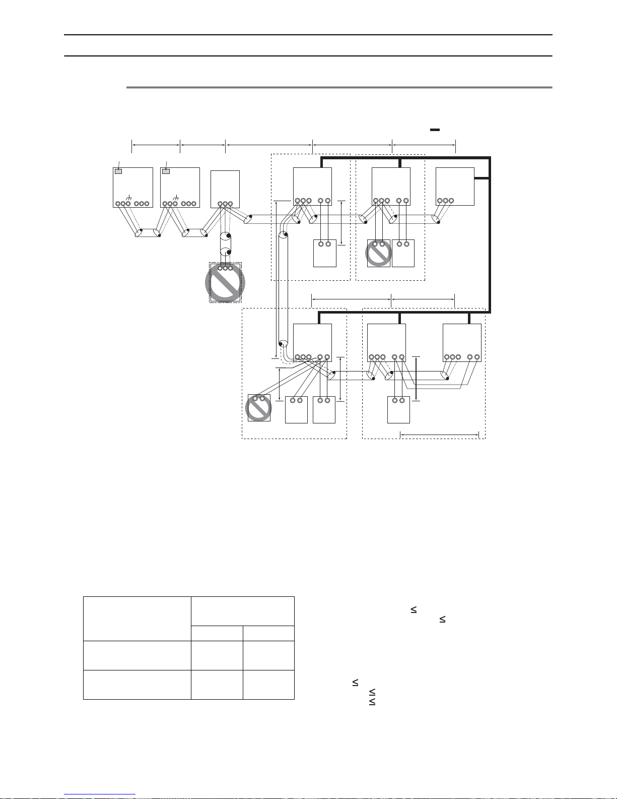
[2-7 Example System with an MA Remote Controller ]
2-7 Example System with an MA Remote Controller
2-7-1 Single Refrigerant System (Automatic Indoor/Outdoor Address Startup)
(1) Sample control wiring
Interlock operation with
the ventilation unit
LC
00
TB5
M1
M2
S
Leave the male
connector on
CN41 as it is.
SW5-1 OFF
TB3
M1 M2 M1 M2 M1 M2
Leave the male
connector on
CN41 as it is.
SW5-1 OFF
OS
00
TB7
OC
00
TB3
M1 M2
S
TB7
L3L1 L2
BC
00
TB02
S
M1 M2
S
IC
00
TB5
M1
M2
S
L4 L5
TB
15
12
m1
GroupGroup
TB5STB
M1
M2
IC
00
15
12
*1
S
M1M2
TB02
00
BS
*1. When BS is connected to the system,
automatic address setup is not available.
L11
m4
A1 B2
MA
(2) Cautions
1) ME remote controller and MA remote controller cannot both
be connected to the same group of indoor units.
2) No more than 2 MA remote controllers can be connected to
a group of indoor units. It is not possible to connect a pair of
PAR-30MAAU.
3) When the number of the connected indoor units is as shown
in the table below, one or more transmission boosters (sold
separately) are required.
To connect two transmission boosters, connect them in parallel. (Observe the maximum number of connectable indoor
units that are listed in the specifications for each outdoor
unit.)
Number of transmission
booster (sold separately) required
1 unit 2 units
When the P72 and P96 models
are not included in the connected indoor units
When the P72 and P96 models
are included in the connected
indoor units
27 - 50 units -
21 - 39 units 40 - 50 units
The table above shows the number of transmission boost-
ers that is required by the system with three BC controllers.
For each BC controller that is subtracted from the abovementioned system, two additional indoor units can be connected.
M1
A1 B2
MA
TB5
A1 B2
MA
L12 L13
IC
TB
15
M2
12
S
m5
A1 B2
MA
A1 B2
RC
GroupGroup
TB5STB
M1
M2
A1 B2
MA
IC
0000
15
12
m2
A1 B2
MA
TB5STB
M1
m3
IC
00
15
M2
12
4) Automatic address setup is not available if start-stop input
(CN32, CN51, CN41) is used for a group operation of indoor
units or when multiple indoor units with different functions
are grouped in the same group. Refer to the following
page(s). [2-7-2 Single Refrigerant System with Two or More
LOSSNAY Units](page 34)
5) For information about connecting two or more LOSSNAY
units to a system, refer to the following page(s). [2-7-2 Single Refrigerant System with Two or More LOSSNAY
Units](page 34)
(3) Maximum allowable length
1) Indoor/outdoor transmission line
Maximum distance (1.25mm
2
[AWG16] or larger)
L1 +L2+L3+L4+L5 200m[656ft]
L1 +L2+L3+L11+L12+L13 200m[656ft]
2) Transmission line for centralized control
No connection is required.
3) MA remote controller wiring
Maximum overall line length
(0.3 to 1.25mm
2
[AWG22 to 16])
m1 200m [656ft]
m2+m3 200m [656ft]
m4+m5 200m [656ft]
*When connected to the terminal block on the Simple remote controller, use cables that meet the following cable
size specifications: 0.75 - 1.25 mm
2
[AWG18-14].
*When connecting PAR-30MAAU, use a 0.3 mm
sheathed cable.
- 32 -
2
GBHWE13080
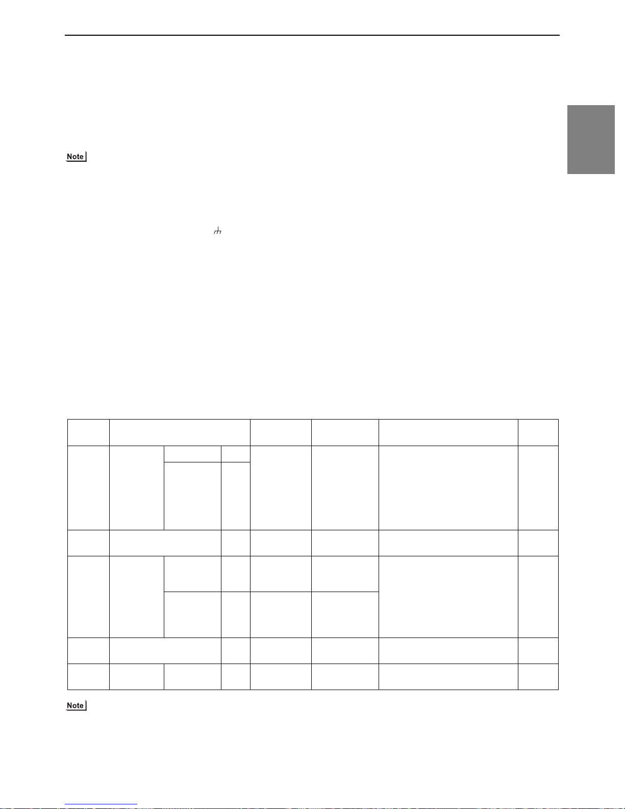
[2-7 Example System with an MA Remote Controller ]
(4) Wiring method
1) Indoor/outdoor transmission line
Daisy-chain terminals M1 and M2 of the terminal block
for indoor-outdoor transmission line (TB3) on the outdoor
units (OC and OS), of the terminal block for indoor-outdoor transmission line (TB02) on the main BC controller
(BC), and of the terminal block for indoor-outdoor transmission line (TB5) on each indoor unit (IC). (Non-polarized two-wire)
Only use shielded cables.
The outdoor units in the same refrigerant circuit are automatically designated as OC and OS in the order of capacity from large to small (if two or more units have the
same capacity, in the order of address from small to
large).
Shielded cable connection
Daisy-chain the ground terminal ( ) on the outdoor
units (OC and OS), the S terminal of the terminal block
(TB02) on the BC controller (BC), and the S terminal of
the terminal block (TB5) on the indoor unit (IC) with the
shield of the shielded cable.
2) Transmission line for centralized control
No connection is required.
3) MA remote controller wiring
Connect terminals 1 and 2 on the terminal block for MA
remote controller line (TB15) on the indoor unit (IC) to the
terminal block on the MA remote controller (MA).
(Non-polarized two-wire)
When 2 remote controllers are connected to the system
When 2 remote controllers are connected to the system,
connect terminals 1 and 2 of the terminal block (TB15) on
the indoor unit (IC) to the terminal block on the two MA
(5) Address setting method
remote controllers.
Set one of the MA remote controllers as a sub controller.
(Refer to the Instruction Manual for the MA remote controller for the setting method.)
Group operation of indoor units
To perform a group operation of indoor units (IC), daisychain terminals 1 and 2 on the terminal block (TB15) on
all indoor units (IC) in the same group, and then connect
terminals 1 and 2 on the terminal block (TB15) on the indoor unit on one end to the terminal block on the MA remotecontroller. (Non-polarized two-wire)
When performing a group operation of indoor units that
have different functions, "Automatic indoor/outdoor addresssetup" is not available.
4) LOSSNAY connection
Connect terminals M1 and M2 on the terminal
block(TB5) on the indoor unit (IC) to the appropriate terminals on the terminal block (TB5) on LOSSNAY (LC).
(Non-polarized two-wire)
Interlock operation setting with all the indoor units in the
same system will automatically be made. (It is required
that the Lossnay unit be turned on before the outdoorunit.)
For information about certain types of systems (1. Sys-
tems in which the LOSSNAY unit is interlocked with only
part of the indoor units, 2. Systems in which the LOSSNAY unit is operated independently from the indoor
units, 3. Systems in which more than 16 indoor units are
interlocked with the LOSSNAY unit, and 4. Systems to
which two ore more LOSSNAY units are connected), refer to the following page(s). [2-7-2 Single Refrigerant
System with Two or More LOSSNAY Units](page 34)
5) Switch setting
Address setting is required as follows.
2 Restrictions
Proce-
dures
Unit or controller
1 Indoor unit Main unit IC No settings
Sub unit IC
Address set-
ting range
required.
Setting method Notes
- Port number setting is required
For information about how to perform a group operation of indoor
Factory
setting
00
units that feature different functions, refer to the following
page(s). [2-7-2 Single Refrigerant
System with Two or More LOSSNAY Units](page 34)
2 LOSSNAY LC No settings
-00
required.
3MA
remote controller
Main
remote controller
Sub
remote controller
MA No settings
required.
MA Sub
remote controller
- It is not possible to connect a pair
of PAR-30MAAU.
Settings to be
made with the
Sub/Main
Main
switch
4 Outdoor unit OCOSNo settings
-00
required.
5 Auxiliary
outdoor unit
BC
controller
BC No settings
required.
-00
The outdoor units in the same refrigerant circuit are automatically designated as OC and OS.
They are designated as OC and OS in the descending order of capacity (ascending order of address if the capacities are the
same).
HWE13080 GB
33- 33 -

[2-7 Example System with an MA Remote Controller ]
2-7-2 Single Refrigerant System with Two or More LOSSNAY Units
(1) Sample control wiring
Interlock operation with the ventilation unit
Leave the male
connector on
CN41 as it is.
SW5-1 OFF
OS
52
TB3
M1 M2
L1 L2
Leave the male
connector on
CN41 as it is.
SW5-1 OFF
TB7
M1 M2
S
TB3
M1 M2
L3
OC
51
TB7
M1 M2
BC
53
TB02
S
M1 M2
S
IC
01
TB5STB
M1M2 M1M2 M1M2
L4 L5
GroupGroup
15
12
m1
IC
02
TB5STB
15
12
TB5
LC
05
S
M1 M2
S
TB02
57
BS
* If the BC address overlaps any of the addresses that are assigned to either the OC, OS, or BS, use a different, unused address.
OC, OS, and BS addresses (lowest indoor unit address in the group plus +50) have higher priority than the BS address.
(2) Cautions
1) ME remote controller and MA remote controller cannot both be
connected to the same group of indoor units.
2) No more than 2 MA remote controllers can be connected to a
group of indoor units. It is not possible to connect a pair of PAR30MAAU.
3) When the number of the connected indoor units is as shown in
the table below, one or more transmission boosters (sold separately) are required.
To connect two transmission boosters, connect them in parallel.
(Observe the maximum number of connectable indoor units that
are listed in the specifications for each outdoor unit.)
Number of transmission
booster (sold separately)
required
1 unit 2 units
When the P72 and P96 models are not included in the connected indoor units
When the P72 and P96 models are included in the connected indoor units
27 - 50
units
21 - 39
units
40 - 50
units
-
L11
Group
A1 B2
MA
L12 L13
IC
A1 B2
MA
IC
0403
TB5
15
TB
S
12
m2
A1 B2
MA
IC
m3
TB5STB
IC
15
12
0807
TB5
15
TB
S
12
A1 B2
MA
TB5STB
M1M2M1M2
15
12
A1 B2
MA
The table above shows the number of transmission boost-
ers that is required by the system with three BC controllers.
For each BC controller that is subtracted from the abovementioned system, two additional indoor units can be connected.
Refer to the DATABOOK for further information about how
many booster units are required for a given system.
(3) Maximum allowable length
1) Indoor/outdoor transmission line
Same as 2-7-1
2) Transmission line for centralized control
No connection is required.
3) MA remote controller wiring
Same as 2-7-1
LC
06
TB5
M1M2M1M2M1M2
S
- 34 -
GBHWE13080

[2-7 Example System with an MA Remote Controller ]
(4) Wiring method
1) Indoor/outdoor transmission line
Daisy-chain terminals M1 and M2 of the terminal block
for indoor-outdoor transmission line (TB3) on the outdoor
units (OC and OS), of the terminal block for indoor-outdoor transmission line (TB02) on the main and sub BC
controllers (BC and BS), and of the terminal block for indoor-outdoor transmission line (TB5) on each indoor unit
(IC). (Non-polarized two-wire)
Only use shielded cables.
The outdoor units in the same refrigerant circuit are automatically designated as OC and OS in the order of capacity from large to small (if two or more units have the
same capacity, in the order of address from small to
large).
Shielded cable connection
Daisy-chain the ground terminal ( ) on the outdoor
units (OC and OS), the S terminal of the terminal block
(TB02) on BC and BS, and the S terminal of the terminal
block (TB5) on the indoor unit (IC) with the shield of the
shielded cable.
2) Transmission line for centralized control
(5) Address setting method
Proce-
dures
1 Indoor
Unit or controller
Main unit IC 01 to 50
Address
setting
range
unit
Sub unit
2 LOSSNAY LC 01 to 50
3MA
remote
controller
Main
remote
controller
Sub
remote
controller
MA No set-
tings required.
MA Sub
remote
controller
4 Outdoor unit OCOS51 to 100
5 Auxiliary
outdoor
BCcontroller (Sub)
BS 51 to 100
unit
BC controller (Main)
BC OC (or OS if it exists) +1
No connection is required.
3) MA remote controller wiring
Same as 2-7-1
When 2 remote controllers are connected to the system
Same as 2-7-1
Group operation of indoor units
Same as 2-7-1
4) LOSSNAY connection
Connect terminals M1 and M2 on the terminal block
(TB5) on the indoor unit (IC) to the appropriate terminals
on the terminal block (TB5) on LOSSNAY (LC). (Non-polarized two-wire)
Interlock setting between the indoor units and LOSS-
NAY units must be entered on the remote controller. For
information about how to interlock the operation of indoor
and LOSSNAY units, refer to the following page(s) in this
Service Handbook.
[6-5 Making Interlock Settings from an MA Remote Controller](page 157)
5) Switch setting
Address setting is required as follows.
Setting method Notes
Assign the smallest address to the main
unit in the group.
In a system with a sub BC controller,
make the settings for the indoor units in
the following order.
(i) Indoor unit to be connected to the main
BC controller
(ii) Indoor unit to be connected to sub BC
controller 1
(iii) Indoor unit to be connected to sub BC
controller 2
Make the settings for the indoor units in
the way that the formula "(i) < (ii) < (iii)"
is true.
Assign sequential numbers starting with
the address of the main unit in the same
group +1. (Main unit address +1, main unit
address +2, main unit address +3, etc.)
Assign an arbitrary but unique address to
each of these units after assigning an address to all indoor units.
- It is not possible to con-
Settings to be made with the Sub/
Main switch
Assign sequential address to the outdoor
units in the same refrigerant circuit.
The outdoor units are automatically des-
ignated as OC and OS.(Note)
Assign an address that equals the sum of
the smallest address of the indoor units
that are connected to the sub BC controller
and 50.
Port number setting is
required
To perform a group op-
eration of indoor units
that feature different
functions, designate
the indoor unit in the
group with the greatest
number of functions as
the main unit.
None of these addresses may
overlap any of the indoor unit
addresses.
nect a pair of PAR30MAAU.
To set the address to 100,
set the rotary switches to 50.
If the addresses that is as-
signed to the main BC controller overlaps any of the
addresses that are assigned
to the outdoor units or to the
sub BC controller, use a different, unused address within the setting range.
The use of a sub BC control-
ler requires the connection
of a main BC controller.
2 Restrictions
Fac-
tory
setting
00
00
Main
00
The outdoor units in the same refrigerant circuit are automatically designated as OC and OS.
They are designated as OC and OS in the descending order of capacity (ascending order of address if the capacities are the
same).
HWE13080 GB
35- 35 -

[2-7 Example System with an MA Remote Controller ]
2-7-3 Grouped Operation of Units in Separate Refrigerant Circuits
(1) Sample control wiring
Interlock operation with
m1
the ventilation unit
GroupGroup
IC
06
TB5STB
M1 M2
12
A1 B2
Leave the male
connector on
CN41 as it is.
SW5-1 OFF
OS
52
TB3
M1 M2
TB7
M1 M2
S
L11
Move the male connector
from CN41 to CN40.
SW5-1 OFF
To be left
unconnected
TB3
M1 M2
TB7
M1 M2
51
OC
S
To be connected
TB02
M1 M2
L12
Group
BC
53
S
IC
01
15
TB5STB
M1 M2 M1M2
12
A1 B2
TB5STB
m2
IC
03
15
12
A1 B2
LC
07
15
TB5
S
M1 M2
L31
Leave the male
connector on
CN41 as it is.
SW5-1 OFF
TB3
M1 M2
TB7
M1 M2
L21
Leave the male
connector on
CN41 as it is.
SW5-1 OFF
To be left
unconnected
TB3
TB7
M1 M2
OC
55
S
To be left
unconnected
BC
57
TB02
M1 M2M1 M2
S
TB5
M1 M2
OS
56
S
(2) Cautions
1) ME remote controller and MA remote controller cannot both
be connected to the same group of indoor units.
2) No more than 2 MA remote controllers can be connected to
a group of indoor units. It is not possible to connect a pair of
PAR-30MAAU.
3) Do not connect the terminal blocks (TB5) on the indoor units
that are connected to different outdoor units with each other.
4) Replacement of male power jumper connector (CN41) must
be performed only on one of the outdoor units.
5) Provide grounding to S terminal on the terminal block for
transmission line for centralized control (TB7) on only one of
the outdoor units.
6) When the number of the connected indoor units is as shown
in the table below, one or more transmission boosters (sold
separately) are required.
To connect two transmission boosters, connect them in parallel. (Observe the maximum number of connectable indoor
units that are listed in the specifications for each outdoor
unit.)
Number of transmission booster (sold separately) required
1 unit 2 units
When the P72 and P96 models are not included in the connected indoor units
When the P72 and P96 models are included in the connected indoor units
27 - 50 units -
21 - 39 units 40 - 50 units
MA
m3
L22
IC
MA
Group
IC
0402
15
15
TB
S
12
TB5STB
M1 M2
12 12
A1 B2
MA
TB5 TB15
M1 M2
m4
m5
The left table shows the number of transmission boost-
ers that is required by the system with three BC controllers. For each BC controller that is subtracted from the
above-mentioned system, two additional indoor units
can be connected.
Refer to the DATABOOK for further information about
how many booster units are required for a given system.
(3) Maximum allowable length
1) Indoor/outdoor transmission line
Maximum distance (1.25mm
L11+L12 200m [656ft]
L21+L22 200m [656ft]
2) Transmission line for centralized control
L31+L21 200m [656ft]
3) MA remote controller wiring
Same as 2-7-1
4) Maximum line distance via outdoor unit
(1.25mm
2
[AWG16] or larger)
L12(L11)+L31+L22(L21) 500m [1640ft]
MA
IC
05
S
2
[AWG16] or larger)
- 36 -
GBHWE13080

[2-7 Example System with an MA Remote Controller ]
(4) Wiring method
1) Indoor/outdoor transmission line
Same as 2-7-2
Shielded cable connection
Same as 2-7-2
2) Transmission line for centralized control
Daisy-chain terminals M1 and M2 on the terminal block for
transmission line for centralized control (TB7) on the outdoor units (OC) in different refrigerant circuits and on the OC
and OS (Note a) in the same refrigerant circuit.
If a power supply unit is not connected to the transmission
line for centralized control, replace the power jumper connector on the control board from CN41 to CN40 on only one
of the outdoor units.
a) The outdoor units in the same refrigerant circuit are automat-
ically designated as OC and OS in the order of capacity from
large to small (if two or more units have the same capacity,
in the order of address from small to large).
b) If TB7's on the outdoor units in the same refrigerant circuit
are not daisy-chained, connect the transmission line for the
central control system to TB7 of the OC. (Note a).To maintain the central control even during an OC failure or a power
failure, connect TB7 on OC and OS together. (If there is a
(5) Address setting method
Proce-
dures
1 Indoor
Unit or controller
Main unit IC 01 to 50
Address
setting
range
unit
Sub unit
2 LOSSNAY LC 01 to 50
3MA
remote
controller
Main
remote
controller
Sub
remote
controller
MA No set-
tings required.
MA Sub
remote
controller
4 Outdoor unit OCOS51 to 100
5 Auxiliary
outdoor
BCcontroller (Sub)
BS 51 to 100
unit
BC controller (Main)
BC OC (or OS if it exists) +1
problem with the outdoor unit whose power jumper was
moved from CN41 to CN40, central control is not possible,
even if TB7's are daisy-chained.)
c) When connecting TB7, only commence after checking that
the voltage is below 20 VDC.
Only use shielded cables.
Shielded cable connection
Daisy-chain the S terminal on the terminal block (TB7) on
the outdoor units (OC, OS) with the shield wire of the shielded cable. Short-circuit the earth terminal ( ) and the S terminal on the terminal block (TB7) on the outdoor unit whose
power jumper connector is mated with CN40.
3) MA remote controller wiring
Same as 2-7-1
When 2 remote controllers are connected to the system
Same as 2-7-1
Group operation of indoor units
Same as 2-7-1
4) LOSSNAY connection
Same as 2-7-2
5) Switch setting
Address setting is required as follows.
Setting method Notes
Assign the smallest address to the main
unit in the group.
In a system with a sub BC controller,
make the settings for the indoor units in
the following order.
(i) Indoor unit to be connected to the main
BC controller
(ii) Indoor unit to be connected to sub BC
controller 1
(iii) Indoor unit to be connected to sub BC
controller 2
Make the settings for the indoor units in
the way that the formula "(i) < (ii) < (iii)"
is true.
Assign sequential numbers starting with
the address of the main unit in the same
group +1. (Main unit address +1, main unit
address +2, main unit address +3, etc.)
Assign an arbitrary but unique address to
each of these units after assigning an address to all indoor units.
- It is not possible to con-
Settings to be made with the Sub/
Main switch
Assign sequential address to the outdoor
units in the same refrigerant circuit.
The outdoor units are automatically des-
ignated as OC and OS.(Note)
Assign an address that equals the sum of
the smallest address of the indoor units
that are connected to the sub BC controller
and 50.
Port number setting is
required
To perform a group op-
eration of indoor units
that feature different
functions, designate
the indoor unit in the
group with the greatest
number of functions as
the main unit.
None of these addresses may
overlap any of the indoor unit
addresses.
nect a pair of PAR30MAAU.
To set the address to 100,
set the rotary switches to 50.
If the addresses that is as-
signed to the main BC controller overlaps any of the
addresses that are assigned
to the outdoor units or to the
sub BC controller, use a different, unused address within the setting range.
The use of a sub BC control-
ler requires the connection
of a main BC controller.
2 Restrictions
Fac-
tory
setting
00
00
Main
00
The outdoor units in the same refrigerant circuit are automatically designated as OC and OS.
They are designated as OC and OS in the descending order of capacity (ascending order of address if the capacities are the
same).
HWE13080 GB
37- 37 -

[2-7 Example System with an MA Remote Controller ]
2-7-4 System with a Connection of System Controller to Centralized Control
Transmission Line
(1) Sample control wiring
An example of a system in which a system controller is connected to the transmission cable for the centralized control system
and the power is supplied from the outdoor unit
Interlock operation with
IC
02
12
15
the ventilation unit
IC
03
TB5STB
15
12
M1M2
LC
07
TB5
S
L11
Leave the male
connector on
CN41 as it is.
SW5-1 OFF
OS
52
TB3
M1M2 M1M2
Move the male connector
from CN41 to CN40.
SW5-1 OFF
OC
51
TB3
TB02
M1M2
L12
BC
53
Group
IC
01
S
TB5STB
M1M2
12
15
Group Group
TB5STB
M1M2 M1M2
To be left
unconnected
L21
To be left
unconnected
TB7
M1M2
Leave the male
connector on
CN41 as it is.
SW5-1 OFF
OC
55
TB3
M1M2M1M2
TB7
S
To be connected
To be left
S
unconnected
L32
System controller
ABS
Note1
TB02
M1M2
BC
57
S
TB7
M1M2
S
Leave the male
connector on
CN41 as it is.
SW5-1 OFF
L31
OS
56
TB3
TB7
M1M2 M1M2
S
(2) Cautions
1) ME remote controller and MA remote controller cannot both be connected to the same group of indoor units.
2) No more than 2 MA remote controllers can be connected to a group of
indoor units. It is not possible to connect a pair of PAR-30MAAU.
3) Do not connect the terminal blocks (TB5) on the indoor units that are connected to different outdoor units with each other.
4) Replacement of male power jumper connector (CN41) must be performed only on one of the outdoor units.
5) When the System controller is connected TB7 side and TKMU outdoor
unit model is used, connect a PAC-SC51KUA to TB7 side. If a PACSC51KUA cannnot be used, connect the System controller to TB3 side.
When YKMU outdoor unit model is used, the male power supply connector can be connected to CN40, and the System controller can be connected to TB7 side.
6) Short-circuit the shield terminal (S terminal) and the earth terminal ( )
on the terminal block for transmission line for centralized control (TB7) on
the outdoor unit whose power jumper connector is mated with CN40.
7) When the number of the connected indoor units is as shown in the
table below, one or more transmission boosters (sold separately)
are required.
To connect two transmission boosters, connect them in parallel.
(Observe the maximum number of connectable indoor units that are
listed in the specifications for each outdoor unit.)
Number of transmission booster
(sold separately) required
1 unit 2 units
When the P72 and P96 models are
not included in the connected indoor units
When the P72 and P96 models are
included in the connected indoor
units
27 - 50 units -
21 - 39 units 40 - 50 units
Group
M1M2
A1B
2
MA
L22
IC
TB5
S
TB
12
A1B
MA
TB5STB
15
m2 m1
2
m3
A1B
2
MA
IC
0504
15
12
Note1 When only the LM adapter is connected,
leave SW5-1 to OFF (as it is).
Note2 LM adapters require the power supply
capacity of single-phase AC 208 - 230V.
Group
IC
06
TB5STB
12
A1B
MA
A1B
2
MA
15
2
LC
08
TB5
S
M1M2M1M2M1M2
The left table shows the number of transmission boosters
that is required by the system with three BC controllers. For
each BC controller that is subtracted from the above-mentioned system, two additional indoor units can be connected.
Refer to the DATABOOK for further information about
how many booster units are required for a given system.
8) When a power supply unit is connected to the transmission
line for centralized control, leave the power jumper connector on CN41 as it is (factory setting).
(3) Maximum allowable length
1) Indoor/outdoor transmission line
Same as 2-7-3
2) Transmission line for centralized control
L31+L32(L21) 200m [656ft]
3) MA remote controller wiring
Same as 2-7-1
4) Maximum line distance via outdoor unit
(1.25mm
2
[AWG16] or larger)
L32+L31+L12(L11) 500m [1640ft]
L32+L22(L21) 500m [1640ft]
L12(L11)+L31+L22(L21) 500m[1640ft]
- 38 -
GBHWE13080

[2-7 Example System with an MA Remote Controller ]
(4) Wiring method
1) Indoor/outdoor transmission line
Same as 2-7-2
Only use shielded cables.
Shielded cable connection
Same as 2-7-2
2) Transmission line for centralized control
Daisy-chain terminals A and B on the system controller, terminals M1 and M2 on the terminal block for transmission line
for centralized control (TB7) on the outdoor units (OC) in different refrigerant circuits and on the outdoor units (OC and
OS) in the same refrigerant circuit. (Note b)
If a power supply unit is not connected to the transmission
line for centralized control, replace the power jumper connector on the control board from CN41 to CN40 on only one
of the outdoor units.
If a system controller is connected, set the central control
switch (SW5-1) on the control board of all outdoor units to
"ON."
a) The outdoor units in the same refrigerant circuit are automat-
ically designated as OC and OS in the order of capacity from
large to small (if two or more units have the same capacity,
in the order of address from small to large).
b) If TB7's on the outdoor units in the same refrigerant circuit
are not daisy-chained, connect the transmission line for the
central control system to TB7 of the OC. (Note a).To maintain the central control even during an OC failure or a power
failure, connect TB7 on OC and OS together. (If there is a
problem with the outdoor unit whose power jumper was
(5) Address setting method
moved from CN41 to CN40, central control is not possible,
even if TB7's are daisy-chained.)
c) When connecting TB7, only commence after checking that
the voltage is below 20 VDC.
Only use shielded cables.
Shielded cable connection
Daisy-chain the S terminal of the terminal block (TB7) on the
system controller, OC, and OS with the shield of the shielded cable. Short-circuit the earth terminal ( ) and the S terminal on the terminal block (TB7) on the outdoor unit whose
power jumper connector is mated with CN40.
3) MA remote controller wiring
Same as 2-7-1
When 2 remote controllers are connected to the system
Same as 2-7-1
Group operation of indoor units
Same as 2-7-1
4) LOSSNAY connection
Connect terminals M1 and M2 on the terminal block (TB5)
on the indoor unit (IC) to the appropriate terminals on the
terminal block for indoor-outdoor transmission line (TB5) on
LOSSNAY (LC). (Non-polarized two-wire)
Indoor units must be interlocked with the LOSSNAY unit us-
ing the system controller. (Refer to the operation manual for
the system controller for the setting method.) Interlock setting from the remote controller is required if the ON/OFF remote controller alone or the LM adapter alone is connected.
5) Switch setting
Address setting is required as follows.
2 Restrictions
Proce-
dures
1 Indoor
Unit or controller
Main unit IC 01 to
unit
Sub unit
2 LOSSNAY LC 01 to
3MA
remote
controller
Main
remote controller
Sub
remote controller
MA
MA
4 Outdoor unit (Note) OC
OS
5 Auxiliary
outdoor
BCcontroller (Sub)
BS
unit
BC controller (Main)
BC OC (or OS if it exists) +1
Ad-
dress
setting
Setting method Notes
range
Assign the smallest address to the main unit
50
50
No settings required.
Sub
remote
controller
51 to 100 Assign sequential address to the outdoor
51 to 100 Assign an address that equals the sum of the
in the group.
In a system with a sub BC controller, make
the settings for the indoor units in the following order.
(i) Indoor unit to be connected to the main BC
controller
(ii) Indoor unit to be connected to sub BC
controller 1
(iii) Indoor unit to be connected to sub BC
controller 2
Make the settings for the indoor units in the
way that the formula "(i) < (ii) < (iii)" is true.
Assign sequential numbers starting with the
address of the main unit in the same group
+1. (Main unit address +1, main unit address
+2, main unit address +3, etc.)
Assign an arbitrary but unique address to
each of these units after assigning an address
to all indoor units.
-
Settings to be made with the Sub/
Main switch
units in the same refrigerant circuit.
The outdoor units are automatically desig-
nated as OC and OS.(Note)
smallest address of the indoor units that are
connected to the sub BC controller and 50.
Port number setting is re-
quired
To perform a group opera-
tion of indoor units that feature different functions,
designate the indoor unit in
the group with the greatest
number of functions as the
main unit.
None of these addresses may overlap any of the indoor unit addresses.
Make the same indoor unit group
settings with the system controller
as the ones that were made with the
MA remote controller. It is not possible to connect a pair of PAR30MAAU.
To set the address to 100, set the
rotary switches to 50.
If the addresses that is assigned to
the main BC controller overlaps
any of the addresses that are assigned to the outdoor units or to
the sub BC controller, use a different, unused address within the
setting range.
The use of a sub BC controller re-
quires the connection of a main
BC controller.
Fac-
tory
setting
00
00
Main
00
The outdoor units in the same refrigerant circuit are automatically designated as OC and OS.
They are designated as OC and OS in the descending order of capacity (ascending order of address if the capacities are the same).
HWE13080 GB
39- 39 -

[2-7 Example System with an MA Remote Controller ]
IC
TB5STB
15
12
01
IC
TB5STB
15
12
02
A1B
2
MA
A1B
2
MA
LC
TB5
S
07
IC
TB5
S
12
TB
15
IC
TB5STB
15
12
0504
LC
TB5
S
08
IC
TB5STB
15
12
03
A1B
2
MA
IC
TB5STB
15
12
06
A1B
2
MA
A1B
2
MA
GroupGroupGroup
Group Group
m3
Interlock operation with
the ventilation unit
OC
Connect
m2 m1
Note1 LM adapters cannot be connected to the
indoor-outdoor transmission line.
TB3
TB7
S
51
OS
TB3
TB7
S
52
OC
TB3
TB7
S
55
OS
TB3
TB7
S
56
L31
ABS
L25
M2M1 M2M1
M2M1
M2M1
M2M1
M2M1 M2M1
M2M1 M2M1
M2M1
M2M1
M2M1M2M1
M2M1
M2M1
M2M1
M2M1
M2M1
Not
Connect
Not
Connect
Not
Connect
CN41 CN40 Replace
SW5-1 OFF ON
SW5-1 OFF ON
Leave the male
connector on
CN41 as it is.
SW5-1 OFF ON
Leave the male
connector on
CN41 as it is.
SW5-1 OFF ON
Leave the male
connector on
CN41 as it is.
System controller
Note1
S
BC
TB02
53
S
BC
TB02
57
L22
L21
L12
L11
2-7-5 System with a Connection of System Controller to Indoor-Outdoor
Transmission Line
(1) Sample control wiring
(2) Cautions
1) ME remote controller and MA remote controller cannot both be con-
2) No more than 2 MA remote controllers can be connected to a group
3) Do not connect the terminal blocks (TB5) on the indoor units that are
nected to the same group of indoor units.
of indoor units. It is not possible to connect a pair of PAR-30MAAU.
connected to different outdoor units with each other.
4) Replacement of male power jumper connector (CN41) must be performed only on one of the outdoor units.
5) Provide grounding to S terminal on the terminal block for transmission line for centralized control (TB7) on only one of the outdoor
units.
6) A maximum of 3 system controllers can be connected to the indooroutdoor transmission line, with the exception that only one G(B)-50A
may be connected.
7) When the total number of indoor units exceeds 20 (12 if one or more
indoor units of the 72 model or above is connected), it may not be
possible to connect a system controller to the indoor-outdoor transmission line.
8) When the number of the connected indoor units is as shown in the
table below, one or more transmission boosters (sold separately)
are required.
To connect two transmission boosters, connect them in parallel.
(Observe the maximum number of connectable indoor units that are
listed in the specifications for each outdoor unit.)
- 40 -
Number of transmission boost-
When the P72 and P96 models are not
included in the connected indoor units
When the P72 and P96 models are included in the connected indoor units
The table above shows the number of transmission boosters that is
Refer to the DATABOOK for further information about how many
required by the system with three BC controllers. For each BC controller that is subtracted from the above-mentioned system, two additional indoor units can be connected.
booster units are required for a given system.
er (sold separately) required
1 unit 2 units
27 - 50 units -
21 - 39 units 40 - 50 units
(3) Maximum allowable length
1) Indoor/outdoor transmission line
Maximum distance (1.25mm
2
[AWG16] or larger)
L11+L12 200m [656ft]
L21+L22 200m [656ft]
2) Transmission line for centralized control
3) MA remote controller wiring
L25 200m [656ft]
L31+L21 200m [656ft]
Same as 2-7-1
4) Maximum line distance via outdoor unit
(1.25mm
L25+L31+L12(L11) 500m [1640ft]
L12(L11)+L31+L22(L21) 500m [1640ft]
2
[AWG16] or larger)
GBHWE13080

[2-7 Example System with an MA Remote Controller ]
(4) Wiring method
1) Indoor/outdoor transmission line
Daisy-chain terminals M1 and M2 of the terminal block for indooroutdoor transmission line (TB3) on the outdoor units (OC and OS)
(Note a), of the terminal block for indoor-outdoor transmission line
(TB02) on the main and sub BC controllers (BC and BS), of the terminal block for indoor-outdoor transmission line (TB5) on each indoor unit (IC), and the S terminal of the system controller.(Nonpolarized two-wire)
Only use shielded cables.
a) The outdoor units in the same refrigerant circuit are automatically
designated as OC and OS in the order of capacity from large to small
(if two or more units have the same capacity, in the order of address
from small to large).
Shielded cable connection
Daisy-chain the ground terminal ( ) on the outdoor units (OC and
OS), the S terminal of the terminal block (TB02) on the BC and BS,
and the S terminal of the terminal block (TB5) on the indoor unit (IC)
with the shield of the shielded cable.
2) Transmission line for centralized control
Daisy-chain terminals M1 and M2 on the terminal block for transmission line for centralized control (TB7) on the outdoor units (OC) in
different refrigerant circuits and on the OC and OS in the same refrigerant circuit. (Note b)
If a power supply unit is not connected to the transmission line for
centralized control, replace the power jumper connector on the control board from CN41 to CN40 on only one of the outdoor units.
Set the central control switch (SW5-1) on the control board of all outdoor units to "ON."
b) If TB7's on the outdoor units in the same refrigerant circuit are not
(5) Address setting method
daisy-chained, connect the transmission line for the central control
system to TB7 of the OC. (Note a).To maintain the central control
even during an OC failure or a power failure, connect TB7 on OC
and OS together. (If there is a problem with the outdoor unit whose
power jumper was moved from CN41 to CN40, central control is not
possible, even if TB7's are daisy-chained.)
c) When connecting TB7, only commence after checking that the volt-
age is below 20 VDC.
Only use shielded cables.
Shielded cable connection
Daisy-chain the S terminal on the terminal block (TB7) on the outdoor units (OC, OS) with the shield wire of the shielded cable. Shortcircuit the earth terminal ( ) and the S terminal on the terminal
block (TB7) on the outdoor unit whose power jumper connector is
mated with CN40.
3) MA remote controller wiring
Same as 2-7-1
When 2 remote controllers are connected to the system
Same as 2-7-1
Group operation of indoor units
Same as 2-7-1
4) LOSSNAY connection
Connect terminals M1 and M2 on the terminal block (TB5) on the indoor units (IC) to the appropriate terminals on the terminal block for
indoor-outdoor transmission line (TB5) on LOSSNAY (LC). (Non-polarized two-wire)
Indoor units must be interlocked with the LOSSNAY unit using the
system controller. (Refer to the operation manual for the system
controller for the setting method.) Interlock setting from the remote
controller is required if the ON/OFF remote controller alone is connected.
5) Switch setting
Address setting is required as follows.
2 Restrictions
Proce-
dures
1 Indoor
Unit or controller
Main unit IC 01 to
unit
Sub unit
2 LOSSNAY LC 01 to
3MA
remote
controller
Main
remote controller
Sub
remote controller
MA
MA
4 Outdoor unit OC
OS
5 Auxiliary
outdoor
BCcontroller (Sub)
BS
unit
BC controller (Main)
BC OC (or OS if it exists) +1
Address
setting
range
Assign the smallest address to the main unit
50
50
No settings required.
Sub
remote
controller
51 to 100 Assign sequential address to the outdoor
51 to 100 Assign an address that equals the sum of the
in the group.
In a system with a sub BC controller, make
the settings for the indoor units in the following order.
(i) Indoor unit to be connected to the main BC
controller
(ii) Indoor unit to be connected to sub BC
controller 1
(iii) Indoor unit to be connected to sub BC
controller 2
Make the settings for the indoor units in the
way that the formula "(i) < (ii) < (iii)" is true.
Assign sequential numbers starting with the
address of the main unit in the same group
+1. (Main unit address +1, main unit address
+2, main unit address +3, etc.)
Assign an arbitrary but unique address to
each of these units after assigning an address
to all indoor units.
Settings to be made with the Sub/
Main switch
units in the same refrigerant circuit.
The outdoor units are automatically desig-
nated as OC and OS.(Note)
smallest address of the indoor units that are
connected to the sub BC controller and 50.
Setting method Notes
-
Port number setting is
required
To perform a group op-
eration of indoor units
that feature different
functions, designate
the indoor unit in the
group with the greatest
number of functions as
the main unit.
None of these addresses may
overlap any of the indoor unit
addresses.
Make the same indoor unit
group settings with the system
controller as the ones that
were made with the MA remote
controller.
It is not possible to connect a
pair of PAR-30MAAU.
To set the address to 100,
set the rotary switches to 50.
If the addresses that is as-
signed to the main BC controller overlaps any of the
addresses that are assigned
to the outdoor units or to the
sub BC controller, use a different, unused address within the setting range.
The use of a sub BC control-
ler requires the connection
of a main BC controller.
Factory set-
ting
00
00
Main
00
The outdoor units in the same refrigerant circuit are automatically designated as OC and OS.
They are designated as OC and OS in the descending order of capacity (ascending order of address if the capacities are the same).
HWE13080 GB
41- 41 -

[2-7 Example System with an MA Remote Controller ]
2-7-6 System with Multiple BC Controllers
(1) Sample control wiring
L31
L11
Leave the male
connector on
CN41 as it is.
SW5-1 OFF ON
M1M2
M1M2
Leave the male
connector on
CN41 as it is.
SW5-1 OFF ON
M1M2
M1M2 M1M2
OS1
52
TB3
TB7
S
OS1
55
TB3
TB7
S
Move the male connector
from CN41 to CN40
SW5-1 OFF ON
To be left
unconnected
L21
To be left
unconnected
L32
OC
51
TB3
M1M2 M1M2
TB7
S
M1M2
To be connected
Leave the male
connector on
CN41 as it is.
SW5-1 OFF ON
OC
54
TB3
M1M2
TB7
S
L12
Group
BC
53 57
TB02
IC
1 1 2 1 222 12
01
15
TB5STB
S
M1M2
12
M1M2 M1M2 M1M2 M1M2 M1M2 M1M2 M1M2 M1M2 M1M2
m2
A1 B2
MA
m3
Group Group Group
IC
02
TB5STB
12
15
TB5STB
BS
IC
04
57
15
12
A1 B2
MA
L22
TB02
TB5STB
S
Group Group Group
BC
56 59
TB02
M1M2
To be left
unconnected
System
controller
ABS
IC
1 1 2 1 1
TB5
15
TB
S
12
M1M2 M1M2
S
A1 B2
MA
Note1
*1 When only the LM adapter is connected, leave SW5-1 to OFF (as it is).
*2 LM adapters require the power supply capacity of single-phase AC 208 - 230V.
m1
IC
0503
TB5STB
12
A1 B2
IC
06
15
TB5STB
M1M2
MA
323 1
15
12
M1M2
TB02
BS
TB5STB
S
M1M2
IC
07
15
12
A1 B2
MA
IC
09
15
12
A1 B2
MA
Numbers in the square indicate port numbers.
Connection to BC controllers
Interlock operation with the ventilation unit
TB5STB
TB5STB
M1M2
IC
08
15
12
IC
10
15
12
BS
M1M2
12
LC
13
TB5
15
S
IC
12
61
TB02
TB5
11
TB5STB
S
LC
14
S
12
A1 B2
MA
15
IC
1 2
12
TB5STB
(2) Cautions
1) ME remote controller and MA remote controller cannot both be connected to the same group of indoor units.
2) No more than 2 MA remote controllers can be connected to a group
of indoor units. It is not possible to connect a pair of PAR-30MAAU.
3) Do not connect the terminal blocks (TB5) on the indoor units that are
connected to different outdoor units with each other.
4) Replacement of male power jumper connector (CN41) must be performed only on one of the outdoor units.
5) Short-circuit the S (shield) terminal of the terminal block for the central control unit (TB7) and the ground terminal ( ) on the outdoor
unit whose power jumper was moved from CN41 to CN40.
6) When the number of the connected indoor units is as shown in the
table below, one or more transmission boosters (sold separately)
are required.
To connect two transmission boosters, connect them in parallel.
(Observe the maximum number of connectable indoor units that are
listed in the specifications for each outdoor unit.)
Number of transmission
booster (sold separately)
required
1 unit 2 units
When the P72 and P96 models are not included in the connected indoor units
When the P72 and P96 models are included in the connected indoor units
27 - 50
units
21 - 39
units
40 - 50
units
-
The table above shows the number of transmission boost-
ers that is required by the system with three BC controllers.
For each BC controller that is subtracted from the abovementioned system, two additional indoor units can be connected.
Refer to the DATABOOK for further information about how
many booster units are required for a given system.
7) When a power supply unit is connected to the transmission
line for centralized control, leave the power jumper connec-
tor on CN41 as it is (factory setting).
(3) Maximum allowable length
1) Indoor/outdoor transmission line
Maximum distance (1.25mm
2
[AWG16] or larger)
L11+L12 200m [656ft]
L21+L22 200m [656ft]
2) Transmission line for centralized control
L31+L32(L21) 200m [656ft]
3) MA remote controller wiring
Maximum overall line length
(0.3 to 1.25mm
2
[AWG22 to 16])
m1 200m [656ft]
m2+m3 200m [656ft]
4) Maximum line distance via outdoor unit
(1.25mm
2
[AWG16] or larger)
L32+L31+L12(L11) 500m [1640ft]
L32+L22(L21) 500m [1640ft]
L12(L11)+L31+L22(L21) 500m[1640ft]
- 42 -
GBHWE13080

[2-7 Example System with an MA Remote Controller ]
(4) Wiring method
1) Indoor/outdoor transmission line
Daisy-chain terminals M1 and M2 of the terminal block
for indoor-outdoor transmission line (TB3) on the outdoor
units (OC and OS) (Note a), of the terminal block for indoor-outdoor transmission line (TB02) on the main and
sub BC controllers (BC and BS), and of the terminal
block for indoor-outdoor transmission line (TB5) on each
indoor unit (IC). (Non-polarized two-wire)
Only use shielded cables.
a) The outdoor units in the same refrigerant circuit are auto-
matically designated as OC and OS in the order of capacity from large to small (if two or more units have the
same capacity, in the order of address from small to
large).
Shielded cable connection
Daisy-chain the ground terminal ( ) on the outdoor units
(OC and OS), the S terminal of the terminal block (TB02)
on the BC and BS, and the S terminal of the terminal
block (TB5) on the indoor unit (IC) with the shield of the
shielded cable.
2) Transmission line for centralized control
Daisy-chain terminals A and B of the system controller,
M1 and M2 terminals of TB7 (terminal block for centralized control system connection) on the outdoor units
(OC) in different refrigerant systems, and M1 and M2 terminals of TB7 (terminal block for centralized control system connection) on the outdoor units (OC and OS ) in the
same refrigerant circuit. (Note b)
If a power supply unit is not connected to the transmission line for centralized control, replace the power jumper connector on the control board from CN41 to CN40 on
only one of the outdoor units.
When connecting a system controller, set the centralized
control switch (SW5-1) on the control board of all indoor
units to "ON."
cuit are not daisy-chained, connect the transmission line
for the central control system to TB7 of the OC. (Note
a).To maintain the central control even during an OC failure or a power failure, connect TB7 on OC and OS together. (If there is a problem with the outdoor unit whose
power jumper was moved from CN41 to CN40, central
control is not possible, even if TB7's are daisy-chained.)
c) When connecting TB7, only commence after checking
that the voltage is below 20 VDC.
Only use shielded cables.
Shielded cable connection
Daisy-chain the S terminal of the terminal block (TB7) on
the system controller, OC, and OS with the shield of the
shielded cable. Short-circuit the earth terminal ( ) and
the S terminal on the terminal block (TB7) on the outdoor
unit whose power jumper connector is mated with CN40.
3) MA remote controller wiring
Same as 2-7-1
When 2 remote controllers are connected to the system
Same as 2-7-1
Group operation of indoor units
Same as 2-7-1
4) LOSSNAY connection
Connect terminals M1 and M2 on the terminal block
(TB5) on the indoor unit (IC) to the appropriate terminals
on the terminal block for indoor-outdoor transmission line
(TB5) on LOSSNAY (LC). (Non-polarized two-wire)
Indoor units must be interlocked with the LOSSNAY unit
using the system controller. (Refer to the operation manual for the system controller for the setting method.) Interlock setting from the remote controller is required if the
ON/OFF remote controller alone or the LM adapter alone
is connected.
5) Switch setting
Address setting is required as follows.
2 Restrictions
b) If TB7's on the outdoor units in the same refrigerant cir-
HWE13080 GB
43- 43 -

[2-7 Example System with an MA Remote Controller ]
(5) Address setting method
Pro-
cedur
es
1 Indoor
Unit or controller
Main unit IC 01 to 50
Address
setting
range
unit
Sub unit
2 LOSSNAY LC 01 to 50
3MA
remote
controller
Main remote
controller
Sub remote controller
4 Outdoor unit OC
No set-
MA
tings required.
Sub re-
MA
mote
controller
51 to 100 The sum of the smallest address of the indoor units in
OS
5 Auxilia-
ry outdoor
unit
BC
controller
(Sub)
BC controller
(Main)
51 to 100 Assign an address that equals the sum of the smallest
BS
BC 51 to
100
Setting method Notes
Assign the smallest address to the main unit in the
group.
In a system with a sub BC controller, make the set-
tings for the indoor units in the following order.
(i) Indoor unit to be connected to the main BC control-
ler
(ii) Indoor unit to be connected to sub BC controller 1
(iii) Indoor unit to be connected to sub BC controller 2
Make the settings for the indoor units in the way that
the formula "(i) < (ii) < (iii)" is true.
Assign sequential numbers starting with the address of
the main unit in the same group +1. (Main unit address
+1, main unit address +2, main unit address +3, etc.)
Assign an arbitrary but unique address to each of these
units after assigning an address to all indoor units.
-
Settings to be made with the Sub/Main switch
the same system and 50.
Assign sequential address to the outdoor units in the
same refrigerant circuit.
The outdoor units are automatically designated as
OC and OS.(Note)
address of the indoor units that are connected to the
sub BC controller and 50.
OC (or OS if it exists) +1
Port number setting is re-
quired
To perform a group opera-
tion of indoor units that
feature different functions,
designate the indoor unit
in the group with the
greatest number of functions as the main unit.
None of these addresses may
overlap any of the indoor unit addresses.
Make the same indoor unit group
settings with the system controller
as the ones that were made with
the MA remote controller.
It is not possible to connect a pair
of PAR-30MAAU.
To set the address to 100, set
the rotary switches to 50.
To set the address to 100, set
the rotary switches to 50.
If the addresses that is assigned
to the main BC controller overlaps any of the addresses that
are assigned to the outdoor
units or to the sub BC controller, use a different, unused address within the setting range.
The use of a sub BC controller
requires the connection of a
main BC controller.
Fac-
tory
setting
00
00
Main
00
00
The outdoor units in the same refrigerant circuit are automatically designated as OC and OS.
They are designated as OC and OS in the descending order of capacity (ascending order of address if the capacities are the same).
- 44 -
GBHWE13080

[2-7 Example System with an MA Remote Controller ]
2 Restrictions
HWE13080 GB
45- 45 -

[2-8 Example System with an ME Remote Controller ]
2-8 Example System with an ME Remote Controller
2-8-1 System with a Connection of System Controller to Centralized Control
Transmission Line
(1) Sample control wiring
L31
Leave the male
connector on
CN41 as it is.
SW5-1 OFF ON
Leave the male
connector on
CN41 as it is.
SW5-1 OFF ON
L11
OS
52
TB3
M1M2 M1M2
TB7
M1M2
S
To be left
unconnected
L21
OS
56
TB3
M1M2 M1 M2
TB7
M1M2 M1 M2
S
To be left
unconnected
Move the male connector
from CN41 to CN40.
SW5-1 OFF ON
OC
51
TB3
TB7
M1 M2
S
Leave the male
connector on
CN41 as it is.
SW5-1 OFF ON
OC
55
TB3
TB7
S
System controller
ABS
To be connected
To be left
unconnected
L32
Note1
L12
Group
BC
53
TB02
S
M1M2
BC
57
TB02
M1M2
S
*1 When only the LM adapter is connected, leave SW5-1 to OFF (as it is).
*2 LM adapters require the power supply capacity of single-phase AC 208 - 230V.
Group
m3
TB5STB
M1M2
A1 B2
101
RC
A1 B2
154
RC
IC
01
m1
Group Group
15
12
L22
TB5
M1M2 M1M2 M1M2 M1M2
A1 B2
104
RC
TB5STB
M1M2
A1 B2
102
RC
IC
TB5STB
15
TB
12
S
m2
Interlock operation with the ventilation unit
IC
02
15
12
A1 B2
Group
IC
0504
15
TB5STB
12
A1 B2
106
RC
TB5STB
103
RC
IC
06
03
IC
12
15
12
LC
07
15
TB5
S
M1M2M1M2
LC
08
TB5
S
(2) Cautions
1) ME remote controller and MA remote controller cannot both
be connected to the same group of indoor units.
2) No more than 2 ME remote controllers can be connected to
a group of indoor units.
3) Do not connect the terminal blocks (TB5) on the indoor units
that are connected to different outdoor units with each other.
4) Replace the power jumper connector of the control board
from CN41 to CN40 on only one of the outdoor units.
5) Provide an electrical path to ground for the S terminal on the
terminal block for centralized control on only one of the outdoor units.
6) When the number of the connected indoor units is as shown
in the table below, one or more transmission boosters (sold
separately) are required.
To connect two transmission boosters, connect them in parallel. (Observe the maximum number of connectable indoor
units that are listed in the specifications for each outdoor
unit.)
Number of transmission booster
(sold separately) required
1 unit 2 units 3 units
When the P72 and P96 models are not
included in the connected indoor units
When the P72 and P96 models are included in the connected indoor units
15 - 34
units
11 - 26
units
35 - 50
units
27 - 42
units
-
43 - 50
units
The left table shows the number of transmission boosters
that is required by the system with three BC controllers. For
each BC controller that is subtracted from the above-mentioned system, two additional indoor units can be connected.
Refer to the DATABOOK for further information about how
many booster units are required for a given system.
7) When a power supply unit is connected to the transmission
line for centralized control, leave the power jumper connector on CN41 as it is (factory setting).
(3) Maximum allowable length
1) Indoor/outdoor transmission line
Same as 2-7-3
2) Transmission line for centralized control
Same as 2-7-4
3) ME remote controller wiring
Maximum overall line length
(0.3 to 1.25mm
2
[AWG22 to 16])
m1 10m [32ft]
m2+m3 10m [32ft]
If the standard-supplied cable must be extended, use a
cable with a diameter of 1.25mm
2
[AWG16]. The section
of the cable that exceeds 10m [32ft] must be included in
the maximum indoor-outdoor transmission line distance
described in (1).
When connected to the terminal block on the Simple remote controller, use cables that meet the following cable
size specifications: 0.75 - 1.25 mm
4) Maximum line distance via outdoor unit
(1.25 mm
2
[AWG16] or large)
2
[AWG18-16].
Same as 2-7-4
- 46 -
GBHWE13080
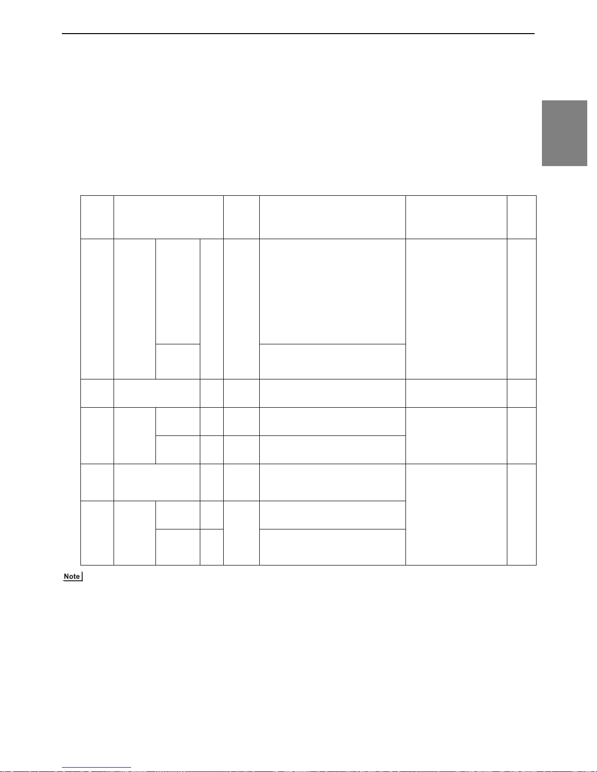
[2-8 Example System with an ME Remote Controller ]
(4) Wiring method
1) Indoor/outdoor transmission line
Same as 2-7-2
Shielded cable connection
Same as 2-7-2
2) Transmission line for centralized control
Same as 2-7-4
Shielded cable connection
Same as 2-7-4
3) ME remote controller wiring
ME remote controller is connectable anywhere on the in-
door-outdoor transmission line.
(5) Address setting method
Ad-
Proce-
dures
Unit or controller
dress
setting
range
1 Indoor
unit
Main unit IC 01 to
50
Sub unit
2 LOSSNAY LC 01 to
50
3ME
remote
controller
4 Outdoor unit OC
Main
remote controller
Sub
remote controller
RC 101 to
150
RC 151 to
200
51 to 100 Assign sequential address to the outdoor
OS
5 Auxiliary
outdoor
BCcontroller (Sub)
51 to 100 Assign an address that equals the sum of the
BS
unit
BC controller (Main)
BC OC (or OS if it exists) +1
When 2 remote controllers are connected to the system
Refer to the section on Switch Setting.
Performing a group operation (including the group
operation of units in different refrigerant circuits).
Refer to the section on Switch Setting.
4) LOSSNAY connection
Same as 2-7-4
5) Switch setting
Address setting is required as follows.
Setting method Notes
Assign the smallest address to the main unit
in the group.
In a system with a sub BC controller, make
the settings for the indoor units in the following order.
(i) Indoor unit to be connected to the main BC
controller
(ii) Indoor unit to be connected to sub BC
controller 1
(iii) Indoor unit to be connected to sub BC
controller 2
Make the settings for the indoor units in the
way that the formula "(i) < (ii) < (iii)" is true.
Assign sequential numbers starting with the
address of the main unit in the same group
+1. (Main unit address +1, main unit address
+2, main unit address +3, etc.)
Assign an arbitrary but unique address to
each of these units after assigning an address
to all indoor units.
Add 100 to the main unit address in
the group
Add 150 to the main unit address in
the group
units in the same refrigerant circuit.
The outdoor units are automatically desig-
nated as OC and OS.(Note)
smallest address of the indoor units that are
connected to the sub BC controller and 50.
Port number setting is
required
To perform a group op-
eration of indoor units
that have different functions, set the indoor unit
in the group with the
greatest number of
functions as the main
unit.
None of these addresses may
overlap any of the indoor unit
addresses.
It is not necessary to set the
100s digit.
To set the address to 200,
set the rotary switches to 00.
To set the address to 100,
set the rotary switches to 50.
If the addresses that is as-
signed to the main BC controller overlaps any of the
addresses that are assigned
to the outdoor units or to the
sub BC controller, use a different, unused address within the setting range.
The use of a sub BC control-
ler requires the connection
of a main BC controller.
Fac-
tory
setting
00
00
101
00
2 Restrictions
The outdoor units in the same refrigerant circuit are automatically designated as OC and OS.
They are designated as OC and OS in the descending order of capacity (ascending order of address if the capacities are the
same).
HWE13080 GB
47- 47 -

[2-9 Example System with an MA and an ME Remote Controller ]
2-9 Example System with an MA and an ME Remote Controller
2-9-1 System with a Connection of System Controller to Centralized Control
Transmission Line
(1) Sample control wiring
L12
Group Group
IC
01
15
TB5STB
M1M2 M1M2 M1M2
12
IC
02
TB5STB
15
12
IC
06
TB5STB
15
12
Leave the male
connector on
CN41 as it is.
SW5-1 OFF ON
OS
52
TB3
M1M2
L11
Move the male connector
from CN41 to CN40.
SW5-1 OFF ON
TB3
M1M2
OC
51
TB02
M1M2
BC
53
S
TB7
M1M2
S
Leave the male
connector on
CN41 as it is.
L31
SW5-1 OFF ON
OS
55
TB3
TB7
S
To be left
unconnected
L21
To be left
unconnected
TB7
M1M2
S
Leave the male
connector on
CN41 as it is.
SW5-1 OFF ON
OC
54
TB3
TB7
S
M1 M2M1 M2
To be connected
To be left
unconnected
L32
Note1
System controller
ABS
M1 M2M1 M2M1 M2
BC
56
TB02
S
(2) Cautions
1) Be sure to connect a system controller.
2) ME remote controller and MA remote controller cannot both be connected to the same group of indoor units.
3) Assign to the indoor units connected to the MA remote controller addresses that are smaller than those of the indoor units that are connected to the ME remote controller.
4) No more than 2 ME remote controllers can be connected to a group
of indoor units.
5) No more than 2 MA remote controllers can be connected to a group
of indoor units. It is not possible to connect a pair of PAR-30MAAU.
6) Do not connect the terminal blocks (TB5) on the indoor units that are
connected to different outdoor units with each other.
7) Replace the power jumper connector of the control board from CN41
to CN40 on only one of the outdoor units.
8) Provide an electrical path to ground for the S terminal on the terminal
block for centralized control on only one of the outdoor units.
9) When the number of the connected indoor units is as shown in the
table below, one or more transmission boosters (sold separately)
are required.
To connect two transmission boosters, connect them in parallel.
(Observe the maximum number of connectable indoor units that are
A1 B2
A1 B2
106
MA
L22
IC
GroupGroup
IC
0403
TB5
TB
15
12
S
A1 B2
MA
*1 When only the LM adapter is connected, leave SW5-1 to OFF (as it is).
*2 LM adapters require the power supply capacity of single-phase AC 208 - 230V.
TB5STB
A1 B2
104
RC
15
12
TB5STB
M1M2M1M2M1M2
RC
IC
05
15
12
listed in the specifications for each outdoor unit.)
Number of transmission booster
(sold separately) required
1 unit 2 units 3 units
When the P72 and P96 models
are not included in the connected
indoor units
When the P72and P96 models
are included in the connected indoor units
15 - 34
units
11 - 26
units
The left table shows the number of transmission boost-
ers that is required by the system with three BC controllers. For each BC controller that is subtracted from the
above-mentioned system, two additional indoor units
can be connected.
Refer to the DATABOOK for further information about
how many booster units are required for a given system.
10) When a power supply unit is connected to the transmission line for centralized control, leave the power jumper
connector on CN41 as it is (factory setting).
35 - 50
units
27 - 42
units
-
43 - 50
units
- 48 -
GBHWE13080

[2-9 Example System with an MA and an ME Remote Controller ]
(3) Maximum allowable length
1) Indoor/outdoor transmission line
Same as 2-7-3
2) Transmission line for centralized control
Same as 2-7-4
3) MA remote controller wiring
Same as 2-7-1
4) ME remote controller wiring
Same as 2-8
5) Maximum line distance via outdoor unit
(1.25 mm
2
[AWG16] or larger)
Same as 2-7-4
(4) Wiring method
1) Indoor/outdoor transmission line
Same as 2-7-2
Shielded cable connection
Same as 2-7-2
2) Transmission line for centralized control
Same as 2-7-4
Shielded cable connection
Same as 2-7-4
3) MA remote controller wiring
(When 2 remote controllers are connected to the system)
(Group operation of indoor units)
Same as 2-7-1
4) ME remote controller wiring
(When 2 remote controllers are connected to the system)
(Group operation of indoor units)
Same as 2-8
5) LOSSNAY connection
Same as 2-7-4
6) Switch setting
Address setting is required as follows.
2 Restrictions
HWE13080 GB
49- 49 -

[2-9 Example System with an MA and an ME Remote Controller ]
(5) Address setting method
Pro-
ce-
dure
Unit or controller
s
1Opera-
tion with
the
Indoor
unit
Main
unit
IC 01 to
50
MA remote
controller
2Opera-
tion with
the
ME remote
MA
remote
controller
Indoor
unit
Sub
unit
Main remote
controller
Sub
remote
controller
Main
unit
Sub
unit
IC 01 to
50
No
MA
settings required.
Sub
MA
remote
controller
IC 01 to 50Assign the smallest address
IC 01 to
50
controller
ME
remote
controller
Main remote
controller
Sub
remote
controller
RC 101 to
150
RC 151 to
200
3 LOSSNAY LC 01 to
50
4 Outdoor unit OCOS51 to
100
5 Auxiliary
outdoor
BCcontroller (Sub)
BS 51 to
100
unit
BC controller
(Main)
BC OC (or OS if it exists) +1
Ad-
dress
setting
range
Setting method Notes
Assign the smallest address to
the main unit in the group.
In a system with a sub BC con-
troller, make the settings for the
indoor units in the following order.
(i) Indoor unit to be connected to
the main BC controller
(ii) Indoor unit to be connected to
sub BC controller 1
(iii) Indoor unit to be connected to
sub BC controller 2
Make the settings for the indoor
units in the way that the formula "(i)
< (ii) < (iii)" is true.
Assign sequential numbers starting with the address of the main
unit in the same group +1. (Main
unit address +1, main unit address
+2, main unit address +3, etc.)
-
Assign an address smaller than that of
the indoor unit that is connected to the
ME remote controller.
Enter the same indoor unit group set-
tings on the system controller as the
ones that were entered on the MA remote controller.
To perform a group operation of indoor
units that have different functions, designate the indoor unit in the group with
the greatest number of functions as the
main unit.
Port number setting is required.
It is not possible to connect a pair
of PAR-30MAAU.
Settings to be made according
to the remote controller function selection
Assign an address higher than those of
to the main unit in the group.
Assign sequential numbers
starting with the address of the
main unit in the same group
+1. (Main unit address +1,
main unit address +2, main
unit address +3, etc.)
Add 100 to the main unit address in the group.
the indoor units that are connected to
the MA remote controller.
Make the initial settings for the indoor
unit group settings via the system controller.
To perform a group operation of indoor
units that have different functions, designate the indoor unit in the group with
the greatest number of functions as the
main unit.
Port number setting is required.
Addresses that are assigned to the in-
door units that are connected to the sub
BC controller should be higher than the
addresses that are assigned to the indoor units that are connected to the
main BC controller.
It is not necessary to set the 100s
digit.
To set the address to 200, set it to
00.
Add 150 to the main unit address in the group.
Assign an arbitrary but unique
address to each of these units
None of these addresses may over-
lap any of the indoor unit addresses.
after assigning an address to
all indoor units.
Assign sequential address to the
outdoor units in the same refrigerant circuit.
The outdoor units are automati-
cally designated as OC and
OS.(Note)
Assign an address that equals the
sum of the smallest address of the
indoor units that are connected to
the sub BC controller and 50.
To set the address to 100, set it to 50.
If the addresses that is assigned to the
main BC controller overlaps any of the
addresses that are assigned to the outdoor units or to the sub BC controller,
use a different, unused address within
the setting range.
The use of a sub BC controller requires
the connection of a main BC controller.
Factory set-
ting
00
Main
00
101
00
00
The outdoor units in the same refrigerant circuit are automatically designated as OC and OS.
They are designated as OC and OS in the descending order of capacity (ascending order of address if the capacities are the same).
- 50 -
GBHWE13080

[2-10 Restrictions on Refrigerant Pipes ]
2-10 Restrictions on Refrigerant Pipes
2-10-1 Restrictions on Refrigerant Pipe Length
(1) System that requires 16 BC controller ports or fewer <System with only the main BC controller or standard BC con-
troller>
Outdoor unit
*Use a main BC controller when connecting the outdoor units of
P144 model or above.
Branch joint
(CMY-Y102S-G2)
b
B
c
Maximum of 3 units per port
Total capacity of P54 or below
Indoor
d
h2
HH'
h1
Reducer (P06 - P18 models)
(Supplied with the BC Controller)
a
Indoor Indoor Indoor
(P06 - P54 models) (P72 - P96 models)
A
BC controller
Junction pipe
(CMY-R160-J)
Unit: m [ft]
Operation Pipe sections Allowable length of pipes
Length Total pipe length A+B+a+b+c+d Refer to the restrictions on the total piping
length in the graph on the next page.
Total pipe length from the outdoor unit
to the farthest indoor unit
Between outdoor unit and BC control-
A+B+d 165 [541] or less
(Equivalent length 190 [623] or less)
A 110 [360] or less
ler
*1
Height
difference
Between BC controller and indoor unit B+d 40 [131] or less
Between indoor
and outdoor units
Outdoor unit
above indoor unit
Outdoor unit be-
H 50 [164] or less
H' 40 [131] or less
low indoor unit
Between indoor unit and BC controller h1 15[49](10[32]) or less
Between indoor units h2 15[49](10[32]) or less
*2
*2
2 Restrictions
*1. When the overall pipe length between the BC controller and the farthest indoor unit exceeds 40m [131ft], observe the
restrictions in the figure titled "Restrictions on pipe length" below. (Except the P96 models)
*2. When the capacity of the connected indoor units is P72 or above, use the figures in the parentheses as a reference.
1) To connect the P72 through P96 models of indoor units, use an optional twinning pipe kit (Model: CMY-R160-J) and merge
the two ports before connecting them.
2) Do not connect the P72 or P96 models of indoor units and other models of indoor units at the same port.
3) Note the following when connecting multiple indoor units to a single port.
Those indoor units connected to the same port must be installed in the same room.
Set the indoor temperature via the connected remote controller, and when connecting multiple remote controllers, configure
these controllers as a group by making appropriate settings. These indoor units can only be operated in the same mode.
HWE13080 GB
- 51 -

[2-10 Restrictions on Refrigerant Pipes ]
The height difference and the pipe length between BC controller and indoor units
70
[229]
60
[196]
50
[164]
40
[131]
30
[98]
20
[64]
Pipe length between main BC
10
controller and farthest indoor unit (m[ft])
[32]
0
0 5 10 15
Height difference between main BC controller and farthest indoor unit (m[ft])
[16] [32] [49]
HWE13080 GB
- 52 -

[2-10 Restrictions on Refrigerant Pipes ]
(2) System that requires more than 16 BC controller ports or with multiple BC controllers <Outdoor unit HP96 model or
below>
Outdoor unit
HH'
h1
BC controller (main)
Reducer (P06 - P18 models)
(Supplied with the BC Controller)
Junction pipe
a
(CMY-R160-J)
Indoor Indoor Indoor Indoor
(P06 - P54 models) (P72 - P96 models)
Branch joint
(CMY-Y202-G2)
A
b
(CMY-Y102L-G2)
(CMY-Y102S-G2)
C
Branch joint
(
CMY-Y102S-G2)
B
c
Maximum of 3 units per port
Total capacity of P54 or below
d
BC controller (sub)
D
BC controller (sub)
E
Indoor
e
Indoor
h1
h3
h2
h1
f
Unit: m [ft]
Operation Pipe sections Allowable length of pipes
Length Total pipe length A+B+C+D+E+a+b+c+d+e+f Refer to the restrictions on the total pip-
ing length in the graphon the next page.
Total pipe length from the outdoor unit to the farthest indoor
A+C+E+f 165 [541] or less
(Equivalent length 190 [623] or less)
unit
Between outdoor unit and BC
A 110 [360] or less
controller
*1
Height
difference
Between BC controller and indoor unit
Outdoor unit
above in-
Between indoor
door unit
B+d or C+D+e
40 [131] or less
or C+E+f
H 50 [164] or less
and outdoor
units
Outdoor unit
H' 40 [131] or less
below indoor unit
Between indoor unit and BC
h1 15 [49](10[32]) or less
*2
controller
Between indoor units h2 15 [49](10[32]) or less
*2
Between the BC controller
(main or sub) and the sub BC
h3 15 [49] or less
controller
2 Restrictions
*1. When the overall pipe length between the BC controller and the farthest indoor unit exceeds 40m [131ft], observe the
restrictions in the figure titled "Restrictions on pipe length" below. (Except the P96 models)
*2. When the capacity of the connected indoor units is P72 or above, use the figures in the parentheses as a reference.
HWE13080 GB
- 53 -

[2-10 Restrictions on Refrigerant Pipes ]
1) A system that requires more than 16 BC controller ports requires two or three BC controllers (main and sub), and three pipes
will be used between the main and the sub BC controllers.
2) When connecting two sub BC controllers, observe the maximum allowable length in the table above.
3) When connecting two sub BC controllers, install them in parallel.
4) To connect the P72 through P96 models of indoor units, use an optional twinning pipe kit (Model: CMY-R160-J) and merge
the two ports before connecting them.
5) Do not connect the P72 or P96 models of indoor units and other models of indoor units at the same port.
6) Note the following when connecting multiple indoor units to a single port.
Those indoor units connected to the same port must be installed in the same room.
Set the indoor temperature via the connected remote controller, and when connecting multiple remote controllers, configure
these controllers as a group by making appropriate settings. These indoor units can only be operated in the same mode.
7) The maximum capacity of the indoor units that is connectable to the CMB-P-NU-GB types of sub BC controllers is P126 or
below (when two GB type controllers are connected P126 or below for both combined).
The maximum total capacity of indoor units that is connectable to the sub BC controller CMB-P1016NU-HB is P126 or below.
If at least one CMB-P1016NU-HB unit is connected, the maximum total capacity of connectable indoor units to a system with
two sub controllers is P168 or below.
The height difference and the pipe length between BC controller and indoor units
70
[229]
60
[196]
50
[164]
40
[131]
30
[98]
20
[64]
Pipe length between main BC
10
controller and farthest indoor unit (m[ft])
[32]
0
0 5 10 15
Height difference between main BC controller and farthest indoor unit (m[ft])
[16] [32] [49]
HWE13080 GB
- 54 -

[2-10 Restrictions on Refrigerant Pipes ]
(3) System that requires more than 16 BC controller ports or with multiple BC controllers <Two-outdoor-unit system>
Branch joint (CMY-R100CBK2)
The distributor on the low-pressure side must be placed in the outdoor unit that has a larger capacity
2
index of the two, regardless of the relative positions of the outdoor units or their addresses.
If the distributor is placed in the outdoor unit that has a smaller capacity, refrigerant will not be properly
distributed and compressor failure may result.
(If outdoor units that have the same capacity are used in combination, the distributor can be placed in
either outdoor unit.)
Branch joint
(CMY-Y202-G2)
(CMY-Y102L-G2)
A
BC controller (main)
Junction pipe
a
(CMY-R160-J)
Indoor Indoor Indoor Indoor
b
C
B
(CMY-Y102S-G2)
Branch joint
(
CMY-Y102S-G2)
cd
Maximum of 3 units per port
Total capacity of P54 or below
D
E
BC controller (sub)
BC controller (sub)
Indoor
e
Indoor
h1
h3
h2
f
h1
h4
HH'
Outdoor unit
h1
1
Outdoor unit
F
Reducer (P06 - P18 models)
(Supplied with the BC Controller)
G
(P06 - P54 models) (P72 - P96 models)
Unit: m [ft]
Operation Pipe sections Allowable length of pipes
Length Total pipe length F+G+A+B+C+D+E+a+b+c+d+e+fRefer to the restrictions on the total pip-
ing length in the graph on the next page.
Total pipe length from the outdoor unit to the farthest indoor
F(G)+A+C+E+f 165 [541] or less
(Equivalent length 190 [623] or less)
unit
Between outdoor unit and BC
F(G)+A 110 [360] or less
controller
Between BC controller and indoor unit
B+d or C+D+e
or C+E+f
40 [131] or less
*1
Between indoor units F+G 5 [16] or less
Height
difference
Between indoor
Outdoor unit
above indoor unit
H 50 [164] or less
and outdoor
units
Outdoor unit
H' 40 [131] or less
below indoor unit
Between indoor unit and BC
h1 15 [49](10[32]) or less
*2
controller
Between indoor units h2 15 [49](10[32]) or less
*2
Between the BC controller
(main or sub) and the sub BC
h3 15 [49] or less
controller
Between outdoor units h4 0.1 [0.3] or less
2 Restrictions
*1. When the overall pipe length between the BC controller and the farthest indoor unit exceeds 40m [131ft], observe
the restrictions in the figure titled "Restrictions on pipe length" below. (Except the P96 models)
*2. When the capacity of the connected indoor units is P72 or above, use the figures in the parentheses as a reference.
HWE13080 GB
- 55 -

[2-10 Restrictions on Refrigerant Pipes ]
1) A system that requires more than 16 BC controller ports requires two or three BC controllers (main and sub), and three pipes
will be used between the main and the sub BC controllers.
2) When connecting two sub BC controllers, observe the maximum allowable length in the table above.
3) When connecting two sub BC controllers, install them in parallel.
4) To connect the P72 through P96 models of indoor units, use an optional twinning pipe kit (Model: CMY-R160-J) and merge
the two ports before connecting them.
5) Do not connect the P72 or P96 models of indoor units and other models of indoor units at the same port.
6) Note the following when connecting multiple indoor units to a single port.
Those indoor units connected to the same port must be installed in the same room.
Set the indoor temperature via the connected remote controller, and when connecting multiple remote controllers, configure
these controllers as a group by making appropriate settings. These indoor units can only be operated in the same mode.
7) The maximum capacity of the indoor units that is connectable to the CMB-P-NU-GB types of sub BC controllers is P126 or
below (when two GB type controllers are connected P126 or below for both combined) .
The maximum total capacity of indoor units that is connectable to the sub BC controller CMB-P1016NU-HB is P126 or below.
If at least one CMB-P1016NU-HB unit is connected, the maximum total capacity of connectable indoor units to a system with
two sub controllers is P168 or below.
Restrictions on pipe length
PURY-HP144TSKMU-A-H
[PURY-HP72, P96TKMU-A-H]
[PURY-HP72, P96YKMU-A]
1000
[3280]
900
[2952]
800
[2624]
700
[2296]
600
[1968]
500
[1640]
400
[1312]
300
[984]
Aggregate length of all pipes(m[ft])
200
[656]
10 20 30 40 50 60 70 80 90
[32] [64] [98] [131] [164] [196] [229] [262] [295] [328] [360]
Pipe length between outdoor unit and BC controller (m[ft])
[PURY-HP192TSKMU-A-H]
[PURY-HP192YSKMU-A]
1000
[3280]
900
[2952]
800
[2624]
700
[2296]
600
[1968]
500
[1640]
400
[1312]
300
[984]
Aggregate length of all pipes(m[ft])
200
[656]
10 20 30 40 50 60 70 80 90
[32] [64] [98] [131] [164] [196] [229] [262] [295] [328] [360]
100 110
100
[
PURY-HP144YSKMU-A
[
Aggregate length of all pipes(m[ft])
110
1000
[3280]
900
[2952]
800
[2624]
700
[2296]
600
[1968]
500
[1640]
400
[1312]
300
[984]
200
[656]
10 20 30 40 50 60 70 80 90
[32] [64] [98] [131] [164] [196] [229] [262] [295] [328] [360]
Pipe length between outdoor unit and BC controller (m[ft])
Pipe length between outdoor unit and BC controller (m[ft])
The height difference and the pipe length between BC controller and indoor units
70
[229]
60
[196]
50
[164]
40
[131]
30
[98]
20
[64]
Pipe length between main BC
10
controller and farthest indoor unit (m[ft])
[32]
0
0 5 10 15
Height difference between main BC controller and farthest indoor unit (m[ft])
[16] [32] [49]
]
]
100 110
HWE13080 GB
- 56 -

[2-10 Restrictions on Refrigerant Pipes ]
2-10-2 Restrictions on Refrigerant Pipe Size
(1) Between outdoor unit and the first twinning pipe (Part A)
Refrigerant pipe size Connection to outdoor unit and BC controller
Outdoor units
Low-pressure pipe High-pressure pipe Low-pressure pipe High-pressure pipe
72 ø19.05 [3/4"] ø15.88 [5/8"] ø19.05 [3/4"] ø15.88 [5/8"]
96 ø22.2 [7/8"] ø19.05 [3/4"] ø22.2 [7/8"] ø19.05 [3/4"]
144
ø28.58 [1-1/8"] ø22.2[7/8"] ø28.58 [1-1/8"] ø22.2 [7/8"]
192
Unit : mm [inch]
(2) Between BC controller and indoor unit (Sections a, b, c, d, e, and f )
Refrigerant pipe size Indoor unit connection
Indoor unit
Liquid pipe Gas pipe Liquid pipe Gas pipe
P06, P08, P12, P15, P18 ø6.35 [1/4"] ø12.7 [1/2"] ø6.35 [1/4"] ø12.7 [1/2"]
P24, P27, P30
P36, P48, P54
P72
P96 ø22.2
(3) Between the main and sub BC controllers (Section C)
Indoor unit
- P72
P73 - P108
P109 - P126
P145 - P168 ø15.88 [5/8"]
ø9.52 [3/8"] ø15.88 [5/8"] ø9.52 [3/8"] ø15.88 [5/8"]
ø19.05 [3/4"]
ø12.7 [1/2"]
[7/8"]
Refrigerant pipe size (Brazed connection on all models )
Liquid pipe High-pressure gas pipe Low-pressure gas pipe
ø9.52 [3/8"]
ø12.7 [1/2"]
Unit : mm [inch]
(Flare connection for all models)
ø19.05 [3/4"]
ø12.7 [1/2"]
ø15.88 [5/8"] ø19.05 [3/4"]
ø19.05 [3/4"]
ø28.58 [1-1/8"]P127 - P144
ø22.2 [7/8"]
ø22.2
[7/8"]
Unit : mm [inch]
ø22.2 [7/8"]
2 Restrictions
Select the proper size pipes for the main unit based on the total capacity of the indoor units that are connected to both sub
BC controllers. Select the proper size pipes for the sub controller side based on the total capacity of the indoor units that are
connected to the sub controller.
HWE13080 GB
- 57 -

[2-10 Restrictions on Refrigerant Pipes ]
2-10-3 BC Controller Connection Method
(1) Size of the pipe that fits the standard BC controller ports
HP72 - HP96 models
Connection: Brazed connection
To outdoor unit
*1
Reducer
(Standard
supplied parts)
P18 model or below
P24 - P54 models P72 - P96 models
The ports of the BC controller accommodates the pipes on P24 - P54 models of indoor units.
To connect other types of indoor units, follow the procedure below.
BC controller
IndoorIndoor
*2
Junction pipe kit
(Model name:
CMY-R160-J)
(Optional accessory)
Indoor
Operation
Outdoor unit side PURY-HP72TKMU-A-H
PURY-HP72YKMU-A
PURY-HP96TKMU-A-H
PURY-HP96YKMU-A
Indoor unit side ø9.52 [3/8"] (Flare connection)
Branch joint (Model name:CMY-Y102S-G2)
(Optional accessory)
A
B
IndoorIndoorIndoor
3*
Maximum of 3 units per port
Total capacity of P54 or below
(All units connected to the same port
must be in the same operating mode.)
Unit : mm [inch]
Pipe sections
High-pressure side (gas) Low-pressure side (gas)
ø15.88 [5/8"]
(Brazed connection)
ø19.05 [3/4"]
(Brazed connection)
ø19.05 [3/4"]
(Brazed connection)
ø22.2 [7/8"]
(Brazed connection)
ø15.88 [5/8"]
(Flare connection)
* BC controllers can only be connected to HP72 - HP96 models of outdoor units.
HWE13080 GB
- 58 -

[2-10 Restrictions on Refrigerant Pipes ]
1) To connect P06 - P18 models of indoor units use
the reducer that is supplied with the BC controller.
2) To connect P72 - P96 models of indoor units (or when the
total capacity of indoor units exceeds P55), use a junction
pipe kit and merge the two nozzles.
50 [1-31/32"]
Liquid pipe side:3/8F
(Flare connection)
Gas pipe side:5/8F
Liquid pipe side: 6.35[1/4"]ID
Gas pipe side: 12.7[1/2"]ID
(Flare connection)
Liquid pipe side:3/8F
(Flare connection)
Gas pipe side:5/8F
(Flare connection)
234 [9-7/32"]
Liquid pipe side: 9.52[3/8”]ID
Gas pipe side: 19.05[3/4”]ID(*1)
Supplied with a thermal insulation cover
Note) Use the flare nut that is supplied with the BC controller.
3) To connect multiple indoor units to a port (or to a junction pipe)
Maximum total capacity of connected indoor units: P54 or below (in a system with a junction pipe: P96 or below)
Maximum number of connectable indoor units: 3 units
Branch joint: Use CMY-Y102S-G2 (optional accessory).
Refrigerant pipe selection (size of the pipes A and B in the previous page) : Select the proper size pipes based
on the total capacity of the downstream indoor units, using the table below as a reference.
2 Restrictions
Total capacity of indoor units Liquid pipe Gas pipe
P54 or below ø9.52 [3/8"] ø15.88 [5/8"]
P55 - P72 ø9.52 [3/8"] ø19.05 [3/4"]
P73 - P96 ø9.52 [3/8"] ø22.2 [7/8"]
Unit : mm [inch]
HWE13080 GB
- 59 -

[2-10 Restrictions on Refrigerant Pipes ]
(2) Size of the pipe that fits the main BC controller ports
HP72 - HP192 models
Branch joint (Model name:CMY-Y102S-G2)
(Optional accessory)
To outdoor unit
Connection: Brazed connection
BC controller (main)
*1
Reducer
(Standard supplied parts)
Indoor Indoor Indoor
P18 model or below
P24 - P54 models P72 - P96 models
*2
Junction pipe kit
(Model name:CMY-R160-J)
(Optional accessory)
A B
Indoor Indoor Indoor
3*
Maximum of 3 units per port
Total capacity of P54 or below
(All units connected to the same port
must be in the same operating mode.)
The ports of the BC controller accommodates the pipes on P24 - P54 models of indoor units. To connect other types of indoor
units, follow the procedure below.
1) To connect P06 - P18 models of indoor units use the reducer that is supplied with the BC controller.
2) To connect the P72 through P96 models of indoor units (or when the total capacity of indoor units is P55 or above), use
an optional twinning pipe kit (Model: CMY-R160-J) to merge two ports before connecting them.
3) To connect multiple indoor units to a port (or to a junction pipe)
Maximum total capacity of connected indoor units: P54 or below (in a system with a junction pipe: P96 or below)
Maximum number of connectable indoor units: 3 units
Branch joint: Use CMY-Y102S-G2 (optional accessory).
Refrigerant pipe selection (size of the pipes in sections A and B in the figure above): Select the proper based on the total
capacity of the downstream indoor units, using the table below as a reference.
Total capacity of indoor units Liquid pipe Gas pipe
P54 or below ø9.52 [3/8"] ø15.88 [5/8"]
P55 - P72 ø9.52 [3/8"] ø19.05 [3/4"]
P73 - P96 ø9.52 [3/8"] ø22.2 [7/8"]
Pipe sections
Operation
High pressure side (Liquid) Low-pressure side (Gas)
Outdoor unit
side
PURY-HP72TKMU-A-H
PURY-HP72YKMU-A
PURY-HP96TKMU-A-H
PURY-HP96YKMU-A
ø15.88 [5/8"]
(Brazed connection)
ø19.05 [3/4"]
(Brazed connection)
PURY-HP144TSKMU-A-H
PURY-HP144YSKMU-A
PURY-HP192TSKMU-A-H
ø22.2 [7/8"]
(Brazed connection)
PURY-HP192YSKMU-A
Indoor unit side ø9.52 [3/8"] (Flare connection) ø15.88 [5/8"] (Flare connection)
Unit : mm [inch]
Unit : mm [inch]
ø19.05 [3/4"]
(Brazed connection)
ø22.2 [7/8"]
(Brazed connection)
ø28.58 [1-1/8"]
(Brazed connection)
HWE13080 GB
- 60 -

[2-10 Restrictions on Refrigerant Pipes ]
(3) Size of the pipe that fits the sub BC controller ports
Branch joint (Model name:CMY-Y102S-G2)
(Optional accessory)
A B
Indoor Indoor Indoor
3*
Maximum of 3 units per port
To Main BC controller
*1
Reducer
(Standard supplied parts)
Indoor Indoor Indoor
P18 model or below
Connection: Brazed connection
*2
BC controller (sub)
Junction pipe kit
(Model name:
CMY-R160-J)
(Optional accessory)
P24 - P54 models P72 - P96 models
Total capacity of P54 or below
(All units connected to the same port
must be in the same operating mode.)
The ports of the BC controller accommodates the pipes on P24 - P54 models of indoor units. To connect other types of indoor
units, follow the procedure below.
1) To connect P06 - P18 models of indoor units use the reducer that is supplied with the BC controller.
2) To connect the P72 through P96 models of indoor units (or when the total capacity of indoor units is P55 or above), use
an optional twinning pipe kit (Model: CMY-R160-J) to merge two ports before connecting them.
3) To connect multiple indoor units to a port (or to a junction pipe)
Maximum total capacity of connected indoor units: P54 or below (in a system with a junction pipe: P96 or below)
Maximum number of connectable indoor units: 3 units
Branch joint: Use CMY-Y102S-G2 (optional accessory).
Refrigerant pipe selection (size of the pipes in sections A and B in the figure above): Select the proper based on the total
capacity of the downstream indoor units, using the table below as a reference.
2 Restrictions
Total capacity of indoor units Liquid pipe Gas pipe
P54 or below ø9.52 [3/8"] ø15.88 [5/8"]
P55 - P72 ø9.52 [3/8"] ø19.05 [3/4"]
P73 - P96 ø9.52 [3/8"] ø22.2 [7/8"]
Operation Pipe sections
Total capacity of the indoor units that are connected to the BC
High-pressure side
(liquid)
Low-pressure side
(gas)
controller
On the BC controller
side
P72 model or below
P73 - P108
ø15.88 [5/8"]
(Brazed connection)
ø19.05 [3/4"]
ø19.05 [3/4"]
(Brazed connection)
ø22.2 [7/8"]
(Brazed connection)
(Brazed connection)
P109 - P126
P127 - P144
P145 - P168
ø22.2 [7/8"]
(Brazed connection)
ø28.58 [1-1/8"]
(Brazed connection)
Unit : mm [inch]
Unit : mm [inch]
Liquid pipe side
ø9.52 [3/8"]
(Brazed connection)
ø12.7 [1/2"]
(Brazed connection)
ø15.88 [5/8"]
(Brazed connection)
HWE13080 GB
- 61 -

[2-10 Restrictions on Refrigerant Pipes ]
HWE13080 GB
- 62 -

Chapter 3 Major Components, Their Functions and Refrigerant Circuits
3-1 External Appearance and Refrigerant Circuit Components of Outdoor Unit................................ 65
3-1-1 External Appearance of Outdoor Unit ................................................................................................... 65
3-1-2 Outdoor Unit Refrigerant Circuits.......................................................................................................... 66
3-2 Outdoor Unit Refrigerant Circuit Diagrams ...................................................................................... 67
3-3 Functions of the Major Components of Outdoor Unit ..................................................................... 69
3-4 Functions of the Major Components of Indoor Unit ........................................................................ 72
3-5 External Appearance and Refrigerant Circuit Components of BC Controller .............................. 73
3-6 BC Controller Refrigerant Circuit Diagrams..................................................................................... 76
3-7 Functions of the Major Components of BC Controller.................................................................... 79
HWE13080 GB
- 63 -

HWE13080 GB
- 64 -

[3-1 External Appearance and Refrigerant Circuit Components of Outdoor Unit ]
3 Major Components, Their Functions and Refrigerant Circuits
3-1 External Appearance and Refrigerant Circuit Components of
Outdoor Unit
3-1-1 External Appearance of Outdoor Unit
(1) PURY-HP72, HP96TKMU-A-H
PURY-HP72, HP96YKMU-A
Fan guardFan guard
FanFan
Fin guardFin guard
Control boxControl box
Side panelsSide panels
3 Major Components, Their Functions and Refrigerant Circuits
Side panelsSide panels
Heat exchangerHeat exchanger
HWE13080 GB
Relay box
Relay box
(TKMU-A-H only)
(TKMU-A-H only)
Front panelsFront panels
- 65 -

[3-1 External Appearance and Refrigerant Circuit Components of Outdoor Unit ]
3-1-2 Outdoor Unit Refrigerant Circuits
(1) PURY-HP72, HP96TKMU-A-H
PURY-HP72, HP96YKMU-A
4-way valve (21S4a)
Check valve
(CV7a)
Check valve
(CV5a)
Solenoid valve
(SV5b)
Low-pressure sensor (63LS)
Solenoid valve (SV9)
Solenoid valve (SV10)
Accumulator
High-pressure switch
(63H1)
High-pressure sensor
(63HS1)
Transformer box
(YKMU-A only)
Solenoid valve
(SV1a)
Compressor
cover
Compressor
Low-pressure
check joint
Base heater
(TKMU-A-H only)
Check valve
(CV3a)
Check valve
(CV9a)
Check valve
(CV8a)
Solenoid valve (SV11)
LEV5a
LEV4
High-pressure check joint
Refrigerant service valve on the low pressure side
Refrigerant service valve on the high pressure side
Check valve
(CV6a)
Check valve
(CV4a)
Check valve
(CV2a)
Oil separator
HWE13080 GB
- 66 -

[3-2 Outdoor Unit Refrigerant Circuit Diagrams ]
3-2 Outdoor Unit Refrigerant Circuit Diagrams
(1) PURY-HP72, HP96TKMU-A-H(-BS)
PURY-HP72, HP96YKMU-A(-BS)
21S4a
63H1
63HS1
O/S
TH4
COMP
ST17
ST3
CJ1
SV11
SV9
SV10
CP1
SV1a
CP5
CP2
CP4
ST7
CJ2
*1
ACC
ST6
TH5
63LS
TH9 TH11
CV8a
Solenoid valve block
SV4a
LEV5a
TH7
ST18
CV9a
SV5b
*1
CV6a
CV4a
HEX
SV4b
TH6
LEV4
CP3
SV4d
CV7a
CV3a
CV2a
CV5a
ST1
BV1
BV2
HWE13080 GB
3 Major Components, Their Functions and Refrigerant Circuits
- 67 -

[3-2 Outdoor Unit Refrigerant Circuit Diagrams ]
(2) PURY-HP144, HP192TSKMU-A-H(-BS)
PURY-HP144, HP192YSKMU-A(-BS)
21S4a
63H1
63HS1
21S4a
63H1
63HS1
O/S
TH4
COMP
O/S
TH4
COMP
ST17
ST17
ST3
ST3
CJ1
CJ1
SV11
SV9
SV10
SV11
SV9
SV10
CP1
SV1a
CP1
SV1a
CP5
CP2
CP4
CP5
CP2
CP4
ST7
ST7
CJ2
CJ2
*1
ACC
ST6
*1
ACC
ST6
TH5
TH5
63LS
63LS
TH9 TH11
CV8a
TH9 TH11
CV8a
Solenoid valve block
SV4a
LEV5a
TH7
HEX
ST18
CV9a
Solenoid valve block
LEV5a
CV9a
TH7
*1
*1
SV5b
CV6a
CV4a
SV4a
HEX
ST18
SV5b
CV6a
SV4b
TH6
LEV4
SV4b
TH6
CP3
CP3
SV4d
SV4d
CV7a
CV7a
CV3a
CV3a
CV2a
CV2a
CV5a
BV1
ST1
BV2
High-pressure
side junction pipe
CV5a
BV1
ST1
BV2
Low-pressure
side distributor
HWE13080 GB
CV4a
LEV4
- 68 -

[3-3 Functions of the Major Components of Outdoor Unit ]
3-3 Functions of the Major Components of Outdoor Unit
Part
name
Compressor
High
pressure
sensor
Low
pressure
sensor
Pressure
switch
Power
supply
transformer
Thermistor
Symbols
(functions)
MC1
(Comp1)
Notes Usage Specifications Check method
Adjusts the amount of circulating
refrigerant by adjusting the operating frequency based on the operating pressure data
63HS1 1) Detects high pressure
2) Regulates frequency and provides high-pressure protection
63LS 1) Detects low pressure
2) Provides low-pressure protection
63H1 1) Detects high pressure
2) Provides high-pressure protection
Trans former YKMU
only
Decreases the power supply voltage (460V) supplied to the circuit
board
TH4
(Discharge)
1) Detects discharge air temperature
2) Provides high-pressure protection
0°C[32°F] :698kohm
10°C[50°F] :413kohm
20°C[68°F] :250kohm
30°C[86°F] :160kohm
40°C[104°F] :104kohm
50°C[122°F] : 70kohm
60°C[140°F] : 48kohm
70°C[158°F] : 34kohm
80°C[176°F] : 24kohm
90°C[194°F] :17.5kohm
100°C[212°F] :13.0kohm
110°C[230°F] : 9.8kohm
HP72, HP96 models
Low-pressure shell scroll
compressor
Wirewound resistance
20°C[68°F] :
0.092ohm (TKMU)
0.323ohm (YKMU)
Pressure
0~4.15 MPa [601psi]
63HS1
Vout 0.5~3.5V
123
0.071V/0.098 MPa [14psi]
Connector
Connector
Pressure [MPa]
=1.38 x Vout [V]-0.69
Pressure [psi]
=(1.38 x Vout [V] - 0.69) x 145
1
GND (Black)
2
Vout (White)
3
Vcc (DC5V) (Red)
Pressure
63LS
0~1.7 MPa [247psi]
Vout 0.5~3.5V
123
0.173V/0.098 MPa [14psi]
Pressure [MPa]
=0.566 x Vout [V] - 0.283
Pressure [psi]
=(0.566 x Vout [V] - 0.283) x 145
1
GND (Black)
2
Vout (White)
3
Vcc (DC5V) (Red)
4.15MPa[601psi] OFF setting
Primary rated voltage:
460V, 50/60Hz
Secondary rated voltage:
229V
(No-load voltage)
Degrees Celsius Resistance check
R = 7.465k
120
R = 4057
25/120
R =
t
7.465
exp
4057
1
273 t
1
393
3 Major Components, Their Functions and Refrigerant Circuits
HWE13080 GB
- 69 -

[3-3 Functions of the Major Components of Outdoor Unit ]
R = 15k
0
R = 3460
R = 15
0/80
t
3460
273 t
1
273
1
exp
Part
name
Thermistor
Symbols
(functions)
TH7
(Outdoor temperature)
Notes Usage Specifications Check method
1) Detects outdoor air tempera-
Degrees Celsius
ture
2) Controls fan operation
TH5 Fan operated on the 63LS and
TH5 values.
TH6 Controls defrosting during heating
TH9
operation
(Pipe
temperature)
TH11
0°C[32°F] :15kohm
10°C[50°F] :9.7kohm
20°C[68°F] :6.4kohm
25°C[77°F] :5.3kohm
30°C[86°F] :4.3kohm
40°C[104°F] :3.1kohm
(Pipe
temperature)
THHS
Inverter
heat sink temperature
Controls inverter cooling fan
based on THHS temperature
Degrees Celsius
R = 17k
50
R = 4016
25/120
R = 17
t
THBOX
Control box
internal temperature detection
0°C[32°F] :161kohm
10°C[50°F] :97kohm
20°C[68°F] :60kohm
25°C[77°F] :48kohm
30°C[86°F] :39kohm
40°C[104°F] :25kohm
Solenoid
valve
SV1a
Dischargesuction
bypass
1) High/low pressure bypass at
start-up and stopping, and
capacity control during lowload operation
AC208 - 230V
Open while being powered/
closed while not being powered
2) High-pressure-rise prevention
SV4a - SV4d
Heat
Controls outdoor unit heat ex-
changer capacity
exchanger
capacity control
SV5b
Heat
exchanger
capacity con-
Prevents high-pressure-rise
Controls defrost cycle
AC208 - 230V
Closed while being powered/
open while not being powered
trol
SV9 High-pressure-rise prevention AC208 - 230V
Open while being powered/
closed while not being powered
SV10 ON-defrost control AC208 - 230V
SV11
Open while being powered/
closed while not being powered
LEV LEV4 Injection amount control DC12V
LEV5a Evaporating temperature control
Opening of stepping motor
driving valve 0-3000 pulses
exp
4016
1
273 t
Resistance check
1
323
Continuity check
with a tester
Refer to the section
"Continuity Test
with a Tester".
Continuity between
white and orange.
Continuity between
yellow, brown, and
blue.
White
Orange
Yellow
M
Brown Blue
HWE13080 GB
- 70 -

[3-3 Functions of the Major Components of Outdoor Unit ]
Part
name
4-way
valve
Fan motor
Symbols
(functions)
Notes Usage Specifications Check method
21S4a Changeover between heating and
cooling
FAN motor Regulates the heat exchanger ca-
pacity by adjusting the operating
frequency and operating the pro-
peller fan based on the operating
pressure.
AC208-230V
Dead: cooling cycle
Live: heating cycle
(TKMU)
AC200-230V, 920W
(YKMU)
AC380-460V, 920W
Continuity check
with a tester
HWE13080 GB
3 Major Components, Their Functions and Refrigerant Circuits
- 71 -

[3-4 Functions of the Major Components of Indoor Unit ]
3-4 Functions of the Major Components of Indoor Unit
Part
Name
Linear
expansion valve
Thermistor
Symbol
(functions)
Notes Usage Specification Check method
LEV 1) Adjusts superheat at the
indoor heat exchanger
outlet during cooling
2) Adjusts subcool at the
heat exchanger outlet of
the indoor unit during
cooling
TH1
Indoor unit control (Thermo)
(Suction air temperature)
TH2
(Pipe temperature)
1) Indoor unit control (Frost
prevention, Hot adjust)
2) LEV control during heating operation (subcool
detection).
TH3
(Gas pipe tem-
LEV control during cooling operation (superheat detection)
perature)
TH4
Indoor unit control (Thermo)
(Outdoor air
temperature)
Temperature
Indoor unit control (Thermo)
sensor (Indoor
air temperature)
DC12V
Opening of stepping motor
driving valve 0-(1800) pulses
R0=15k
R
0/80
=3460
Rt =
15exp{3460( - )}
1
273+t
1
273
0°C [32°F]:15 k
10°C [50°F] :9.7 k
20°C [68°F]:6.4 k
25°C [77°F] :5.3 k
30°C [86°F] :4.3 k
40°C [104°F] :3.1 k
Refer to the section
"Continuity Test with a
Tester".
Continuity between
white, red, and orange.
Continuity between
yellow, brown, and
blue.
White
Red
Orange
Yellow
M
Brown Blue
Resistance check
HWE13080 GB
- 72 -

[3-5 External Appearance and Refrigerant Circuit Components of BC Controller ]
3-5 External Appearance and Refrigerant Circuit Components of
BC Controller
1. CMB-P NU-G, GA, HA
(1) Front
Liquid pipe (Indoor unit side)
Gas pipe (Indoor unit side)
(2) Rear view <G type>
Gas/Liquid separator
Tube in tube heat exchanger
TH12
PS1
TH11
SVM1
LEV3
LEV1
PS3
TH16
3 Major Components, Their Functions and Refrigerant Circuits
TH15
HWE13080 GB
- 73 -

[3-5 External Appearance and Refrigerant Circuit Components of BC Controller ]
(3) Rear view <GA type>
Gas/Liquid separator
Tube in tube heat exchanger
(4) Rear view <HA type>
TH11
TH12
LEV2
TH16
PS3
TH15
PS1
LEV3
LEV1
SVM2
SVM1
PS3
Tube in tube
heat exchanger
Gas/Liquid separator
TH12
TH11
PS1
TH15
LEV3
LEV1
LEV2
SVM2
SVM2b
SVM1b
SVM1
TH16
HWE13080 GB
- 74 -

[3-5 External Appearance and Refrigerant Circuit Components of BC Controller ]
2. CMB-P NU-GB, HB
(1) Front
(2) Rear view
Liquid pipe (Indoor unit side)
Gas pipe (Indoor unit side)
TH12
LEV3
TH15
3 Major Components, Their Functions and Refrigerant Circuits
HWE13080 GB
- 75 -

[3-6 BC Controller Refrigerant Circuit Diagrams ]
3-6 BC Controller Refrigerant Circuit Diagrams
(1) CMB-P104 - P1016NU-G
Solenoid valve block
SVC/SVA/SVB
Gas/Liquid
separator
TH12
HIC-A
TH11
LEV1
SVM1
TH15
LEV3
HIC-B
PS3PS1
TH16
Check valve block
HWE13080 GB
- 76 -

[3-6 BC Controller Refrigerant Circuit Diagrams ]
(2) CMB-P108, P1010, P1013, P1016NU-GA (main)
SVC/SVA/SVB
Solenoid valve block
Gas/Liquid
separator
TH12
HIC-A
(3) CMB-P104, P108NU-GB (sub)
Solenoid valve block
CP
TH11
LEV2
TH12
HIC-C
LEV1
SVM1
TH15
LEV3
HIC-B
PS3PS1
TH16
Check valve block
SVM2
SVC/SVA/SVB
TH15
LEV3
HWE13080 GB
3 Major Components, Their Functions and Refrigerant Circuits
Check valve block
- 77 -

[3-6 BC Controller Refrigerant Circuit Diagrams ]
(4) CMB-P1016V-HA (main)
SVA,SVB,SVC
Gas/Liquid
separator
TH12
HIC-A
(5) CMB-P1016NU-HB (sub)
PS3
PS1
TH11
LEV1
LEV2
SVM1
SVM1b
Solenoid valve block
HIC-B
TH15
LEV3
TH16
SVM2
SVM2b
SVC/SVA/SVB
TH12
CP
HIC-C
TH15
LEV3
Check valve block
HWE13080 GB
- 78 -

[3-7 Functions of the Major Components of BC Controller ]
3-7 Functions of the Major Components of BC Controller
(1) G type
Part name
Pressure
sensor
Symbols
(functions)
PS1
(High pres-
Part
code
Usage Specifications Check method
1) Detects high pressure
2) LEV control
sure side)
PS3
(Intermediate pressure)
Thermistor TH11
(Liquid inlet
1) Detects intermediate
pressure
2) LEV control
LEV control
(Liquid level control)
temperature)
TH12
LEV control (Superheat)
(Bypass
outlet temperature)
TH15
LEV control (Superheat)
(Bypass inlet temperature)
TH16
LEV control (Subcool)
(Liquid refrigerant
temperature)
Solenoid
valve
SVM1 Opens during cooling and de-
frost modes
SV A Provides refrigerant to indoor
unit in cooling operation
SV B Provides refrigerant to indoor
unit in heating operation
SV C Provides refrigerant to indoor
unit in cooling operation
LEV LEV1 1) Liquid level control
LEV3
2) Pressure differential control
Pressure
0~4.15 MPa [601psi]
PS1
Vout 0.5~3.5V
123
0.071V/0.098 MPa [14psi]
Connector
R = 15k
0
R = 3460
0/80
R = 15
t
Pressure [MPa]
=1.38 x Vout [V]-0.69
Pressure [psi]
=(1.38 x Vout [V] - 0.69) x 145
1
GND (Black)
2
Vout (White)
3
Vcc (DC5V) (Red)
exp
3460
1
273 t
273
1
0°C[32°F] : 15kohm
10°C[50°F] :9.7kohm
20°C[68°F] :6.4kohm
25°C[77°F] :5.3kohm
30°C[86°F] :4.3kohm
40°C[104°F] :3.1kohm
AC208-230V
Open while being powered/
closed while not being powered
DC12V
Opening of a valve driven by a
stepping motor
0-2000 pulses
Continuity
check with a
tester
Same as
indoor LEV
3 Major Components, Their Functions and Refrigerant Circuits
HWE13080 GB
- 79 -

[3-7 Functions of the Major Components of BC Controller ]
(2) GA type
Part name
Pressure
sensor
Symbols
(functions)
PS1
(High pressure side)
PS3
(Intermediate pressure)
Thermistor TH11
(Liquid inlet
temperature)
TH12
(Bypass
outlet temperature)
TH15
(Bypass inlet temperature)
TH16
(Liquid refrigerant
temperature)
Solenoid
SVM1 Opens during cooling and de-
valve
SVM2 Pressure differential control
SV A Provides refrigerant to indoor
SV B Provides refrigerant to indoor
SV C Provides refrigerant to indoor
LEV LEV1
LEV2
LEV3 Subcool control
Part
code
Usage Specifications Check method
1) Detects high pressure
2) LEV control
1) Detects intermediate
pressure
2) LEV control
LEV control
(Liquid level control)
LEV control (Superheat)
LEV control (Superheat)
LEV control (Subcool)
frost modes
unit in cooling operation
unit in heating operation
unit in cooling operation
1) Liquid level control
2) Pressure differential control
Pressure
0~4.15 MPa [601psi]
PS1
Vout 0.5~3.5V
123
0.071V/0.098 MPa [14psi]
Connector
R = 15k
0
R = 3460
0/80
R = 15
t
Pressure [MPa]
=1.38 x Vout [V]-0.69
Pressure [psi]
=(1.38 x Vout [V] - 0.69) x 145
1
GND (Black)
2
Vout (White)
3
Vcc (DC5V) (Red)
exp
3460
1
273 t
273
1
0°C[32°F] : 15kohm
10°C[50°F] :9.7kohm
20°C[68°F] :6.4kohm
25°C[77°F] :5.3kohm
30°C[86°F] :4.3kohm
40°C[104°F] :3.1kohm
AC208-230V
Open while being powered/
closed while not being powered
DC12V
Opening of a valve driven by a
stepping motor
0-2000 pulses
Continuity
check with a
tester
Same as
indoor LEV
HWE13080 GB
- 80 -

[3-7 Functions of the Major Components of BC Controller ]
(3) GB type
Part name
Symbols
(functions)
Thermistor TH12
(Bypass
outlet temperature)
TH15
(Bypass inlet temperature)
Part
code
Usage Specifications Check method
LEV control (Superheat)
LEV control (Superheat)
R = 15k
0
R = 3460
0/80
R = 15
t
0°C[32°F] : 15kohm
10°C[50°F] :9.7kohm
20°C[68°F] :6.4kohm
25°C[77°F] :5.3kohm
30°C[86°F] :4.3kohm
40°C[104°F] :3.1kohm
Solenoid
valve
SV A Provides refrigerant to indoor
unit in cooling operation
SV B Provides refrigerant to indoor
unit in heating operation
AC208-230V
Open while being powered/
closed while not being powered
SV C Provides refrigerant to indoor
unit in cooling operation
LEV LEV3 Pressure differential control DC12V
Opening of a valve driven by a
stepping motor
0-2000 pulses
exp
3460
1
273 t
273
1
Continuity
check with a
tester
Same as
indoor LEV
HWE13080 GB
3 Major Components, Their Functions and Refrigerant Circuits
- 81 -

[3-7 Functions of the Major Components of BC Controller ]
(4) HA type
Part name
Pressure
sensor
Symbols
(functions)
PS1
(High pressure side)
PS3
(Intermediate pressure)
Thermistor TH11
(Liquid inlet
temperature)
TH12
(Bypass
outlet temperature)
TH15
(Bypass inlet temperature)
TH16
(Liquid refrigerant
temperature)
Solenoid
SVM1 Opens during cooling and de-
valve
SVM1b Opens during cooling and de-
SVM2 Pressure differential control
SVM2b Pressure differential control
SV A Provides refrigerant to indoor
SV B Provides refrigerant to indoor
SV C Provides refrigerant to indoor
LEV LEV1
LEV2
LEV3 Subcool control
Part
code
Usage Specifications Check method
1) Detects high pressure
2) LEV control
1) Detects intermediate
pressure
2) LEV control
LEV control
(Liquid level control)
LEV control (Superheat)
LEV control (Superheat)
LEV control (Subcool)
frost modes
frost modes
unit in cooling operation
unit in heating operation
unit in cooling operation
1) Liquid level control
2) Pressure differential control
Pressure
0~4.15 MPa [601psi]
PS1
Vout 0.5~3.5V
123
0.071V/0.098 MPa [14psi]
Connector
R = 15k
0
R = 3460
0/80
R = 15
t
Pressure [MPa]
=1.38 x Vout [V]-0.69
Pressure [psi]
=(1.38 x Vout [V] - 0.69) x 145
1
GND (Black)
2
Vout (White)
3
Vcc (DC5V) (Red)
exp
3460
1
273 t
273
1
0°C[32°F] : 15kohm
10°C[50°F] :9.7kohm
20°C[68°F] :6.4kohm
25°C[77°F] :5.3kohm
30°C[86°F] :4.3kohm
40°C[104°F] :3.1kohm
AC208-230V
Open while being powered/
closed while not being powered
DC12V
Opening of a valve driven by a
stepping motor
0-2000 pulses
Continuity
check with a
tester
Same as
indoor LEV
HWE13080 GB
- 82 -

[3-7 Functions of the Major Components of BC Controller ]
(5) HB type
Part name
Symbols
(functions)
Thermistor TH12
(Bypass
outlet temperature)
TH15
(Bypass inlet temperature)
Part
code
Usage Specifications Check method
LEV control (Superheat)
LEV control (Superheat)
R = 15k
0
R = 3460
0/80
R = 15
t
0°C[32°F] : 15kohm
10°C[50°F] :9.7kohm
20°C[68°F] :6.4kohm
25°C[77°F] :5.3kohm
30°C[86°F] :4.3kohm
40°C[104°F] :3.1kohm
Solenoid
valve
SV A Provides refrigerant to indoor
unit in cooling operation
SV B Provides refrigerant to indoor
unit in heating operation
AC208-230V
Open while being powered/
closed while not being powered
SV C Provides refrigerant to indoor
unit in cooling operation
LEV LEV3 Pressure differential control DC12V
Opening of a valve driven by a
stepping motor
0-2000 pulses
exp
3460
1
273 t
273
1
Continuity
check with a
tester
Same as
indoor LEV
HWE13080 GB
3 Major Components, Their Functions and Refrigerant Circuits
- 83 -

[3-7 Functions of the Major Components of BC Controller ]
HWE13080 GB
- 84 -

Chapter 4 Electrical Components and Wiring Diagrams
4-1 Outdoor Unit Circuit Board Arrangement......................................................................................... 87
4-1-1 Outdoor Unit Control Box ...................................................................................................................... 87
4-1-2 Transformer Box ................................................................................................................................... 89
4-2 Outdoor Unit Circuit Board Components ......................................................................................... 90
4-2-1 Control Board ........................................................................................................................................ 90
4-2-2 M-NET Board (Transmission Power Supply Board) ............................................................................. 91
4-2-3 INV Board ............................................................................................................................................. 92
4-2-4 Fan Board ............................................................................................................................................. 94
4-2-5 Noise Filter ............................................................................................................................................ 96
4-3 Outdoor Unit Electrical Wiring Diagrams ......................................................................................... 98
4-4 Transmission Booster Electrical Wiring Diagrams ....................................................................... 100
4-5 BC Controller Circuit Board Arrangement ..................................................................................... 101
4-5-1 BC Controller Control Box................................................................................................................... 101
4-6 BC Controller Circuit Board Components...................................................................................... 102
4-6-1 BC Board ............................................................................................................................................ 102
4-6-2 Four-Relay Board................................................................................................................................ 103
4-6-3 Ten-Relay Board ................................................................................................................................. 103
4-7 BC Controller Electrical Wiring Diagrams...................................................................................... 104
HWE13080 GB
- 85 -

HWE13080 GB
- 86 -

[4-1 Outdoor Unit Circuit Board Arrangement ]
FAN INV board
Control board
M-NET board
IPM
Note 2
Noise filter
Rush current
protection resistor
(R1) Note 2
DC reactor
(DCL)
INV board
Current sensor
(ACCT1)
Current sensor
(DCCT1)
Current sensor
(ACCT2)
Diode stack
Electromagnetic
contactor (72C)
4 Electrical Components and Wiring Diagrams
4-1 Outdoor Unit Circuit Board Arrangement
4-1-1 Outdoor Unit Control Box
<HIGH VOLTAGE WARNING>
Control box houses high-voltage parts.
When opening or closing the front panel of the control box, do not let it come into contact with any of
the internal components.
Before inspecting the inside of the control box, turn off the power, keep the unit off for at least 10 minutes,
and check that the the voltage of the electrolytic capacitor (Inverter main circuit) is 20VDC or below.
(It takes about 10 minutes to discharge electricity after the power supply is turned off.)
1. PURY-HP72, HP96TKMU-A-H
Terminal block
for power supply
(TB1)
Ground
terminal
Note 1
Smoothing
capacitor (C1)
1) Exercise caution not to damage the bottom and the front panel of the control box. Damage to these parts affect the waterproof and dust proof properties of the control box and may result in damage to its internal components.
2) Faston terminals have a locking function. Make sure the cable heads are securely locked in place. Press the tab on the terminals to remove them.
3) Control box houses high temperature parts. Be well careful even after turning off the power source.
4) Disconnect the outdoor unit fan board connector (CNINV) before performing maintenance work. To plug or unplug-
connectors, check that the outdoor unit fan is not rotating and that the voltage of capacitor in the main circuit is 20
VDC or below. The capacitor may collect a charge and cause an electric shock when the outdoor unit fan rotates in
windy conditions. Refer to the wiring nameplate for details.
5) To connect wiring to TB7, check that the voltage is 20 VDC or below.
6) Reconnect the connector (CNINV) to the fan board after completion of maintenance work.
7) When opening or closing the front panel of the control box, do not let it come into contact with any of the internal components.
Before inspecting the inside of the control box, turn off the power, keep the unit off for at least 10 minutes, and confirm that
the capacitor voltage (inverter main circuit) has dropped to 20 VDC or less. It takes about 10 minutes to discharge electricity
after the power supply is turned off.
8) When the power is turned on, the compressor is energized even while it is not operating. Before turning on the power, disconnect all power supply wires from the compressor terminal block, and measure the insulation resistance of the compressor.
Check the compressor for a graound fault. If the insulation resistance is 1.0 M or below, connect all power supply wires to
the compressor and turn on the power to the outdoor unit. The liquid refrigerant in the compressor will evaporate by energizing
the compressor.
HWE13080 GB
- 87 -
Terminal block for
transmission line
(TB3, TB7)
4 Electrical Components and Wiring Diagrams

[4-1 Outdoor Unit Circuit Board Arrangement ]
INV board
Noise filter
DC reactor
(DCL)
(72C)
Capacitor
(C100)
2. PURY-HP72, HP96YKMU-A
Electromagnetic relay
Note 2
Terminal block
for power supply
(TB1)
Fuse (F4)
Fuse (F5)
Ground terminal
Rush current protection resistor
(R1, R5) Note 2
FAN INV board
Note 1
Control board
M-NET board
Terminal block for transmission line
(TB3, TB7)
1) Exercise caution not to damage the bottom and the front panel of the control box. Damage to these parts affect the waterproof and dust proof properties of the control box and may result in damage to its internal components.
2) Faston terminals have a locking function. Make sure the cable heads are securely locked in place. Press the tab on the terminals to remove them.
3) Control box houses high temperature parts. Be well careful even after turning off the power source.
4) Disconnect the outdoor unit fan board connector (CNINV) before performing maintenance work. To plug or unplug-
connectors, check that the outdoor unit fan is not rotating and that the voltage of capacitor in the main circuit is 20
VDC or below. The capacitor may collect a charge and cause an electric shock when the outdoor unit fan rotates in
windy conditions. Refer to the wiring nameplate for details.
5) To connect wiring to TB7, check that the voltage is 20VDC or below.
6) Reconnect the connector (CNINV) to the fan board after completion of maintenance work.
7) When opening or closing the front panel of the control box, do not let it come into contact with any of the internal components.
Before inspecting the inside of the control box, turn off the power, keep the unit off for at least 10 minutes, and confirm that
the capacitor voltage (inverter main circuit) has dropped to 20 V DC or less. It takes about 10 minutes to discharge electricity
after the power supply is turned off.
8) When the power is turned on, the compressor is energized even while it is not operating. Before turning on the power, disconnect all power supply wires from the compressor terminal block, and measure the insulation resistance of the compressor.
Check the compressor for a graound fault. If the insulation resistance is 1.0 M or below, connect all power supply wires to
the compressor and turn on the power to the outdoor unit. The liquid refrigerant in the compressor will evaporate by energizing
the compressor.
HWE13080 GB
- 88 -

[4-1 Outdoor Unit Circuit Board Arrangement ]
Transformer
(T03)
Transformer
(T02)
4-1-2 Transformer Box
(1) PURY-HP72, HP96YKMU-A
HWE13080 GB
4 Electrical Components and Wiring Diagrams
- 89 -
 Loading...