

Mitsubishi Electric PURY-(E)P-YLM-A (-BS) Installation Manual

Air-Conditioners For Building Application
OUTDOOR UNIT
<ORIGINAL>
PURY-(E)P-YLM-A (-BS)
For use with R410A
INSTALLATION MANUAL
For safe and correct use, please read this installation manual thoroughly before installing the air-conditioner unit.
INSTALLATIONSHANDBUCH
Zum sicheren und ordnungsgemäßen Gebrauch der Klimageräte das Installationshandbuch gründlich durchlesen.
MANUEL D’INSTALLATION
Veuillez lire le manuel d’installation en entier avant d’installer ce climatiseur pour éviter tout accident et vous assurer d’une utilisation correcte.
MANUAL DE INSTALACIÓN
Para un uso seguro y correcto, lea detalladamente este manual de instalación antes de montar la unidad de aire acondicionado.
MANUALE DI INSTALLAZIONE
Per un uso sicuro e corretto, leggere attentamente questo manuale di installazione prima di installare il condizionatore d’aria.
INSTALLATIEHANDLEIDING
Voor een veilig en juist gebruik moet u deze installatiehandleiding grondig doorlezen voordat u de airconditioner installeert.
MANUAL DE INSTALAÇÃO
Para segurança e utilização correctas, leia atentamente este manual de instalação antes de instalar a unidade de ar condicionado.
ΕΓΧΕΙΡΙΔΙΟ ΟΔΗΓΙΩΝ ΕΓΚΑΤΑΣΤΑΣΗΣ
Για ασφάλεια και σωστή χρήση, παρακαλείστε διαβάσετε προσεχτικά αυτό το εγχειρίδιο εγκατάστασης πριν αρχίσετε την εγκατάσταση της μονάδας κλιματισμού.
РУКОВОДСТВО ПО УСТАНОВКЕ
Для осторожного и правильного использования прибора необходимо тщательно ознакомиться с данным руководством по установке до выполнения установки кондиционера.
GBDFEINLPGRRUTR
MONTAJ ELKİTABI
Emniyetli ve doğru biçimde nasıl kullanılacağını öğrenmek için lütfen klima cihazını monte etmeden önce bu elkitabını dikkatle okuyunuz.
安装手册
为了安全和正确地使用本空调器,请在安装前仔细阅读本安装手册。
PŘÍRUČKA K INSTALACI
V zájmu bezpečného a správného používání si před instalací klimatizační jednotky důkladně pročtěte tuto příručku k instalaci.
NÁVOD NA INŠTALÁCIU
Pre bezpečné a správne použitie si pred inštalovaním klimatizačnej jednotky, prosím, starostlivo prečítajte tento návod na inštaláciu.
TELEPÍTÉSI KÉZIKÖNYV
A biztonságos és helyes használathoz, kérjük, olvassa el alaposan ezt a telepítési kézikönyvet, mielőtt telepítené a légkondicionáló egységet.
PODRĘCZNIK INSTALACJI
W celu bezpiecznego i poprawnego korzystania należy przed zainstalowaniem klimatyzatora dokładnie zapoznać się z niniejszym podręcznikiem instalacji.
PRIROČNIK ZA NAMESTITEV
Za varno in pravilno uporabo pred namestitvijo klimatske naprave skrbno preberite priročnik za namestitev.
INSTALLATIONSHANDBOK
Läs den här installationshandboken noga innan luftkonditioneringsenheten installeras, för säker och korrekt användning.
PRIRUČNIK ZA UGRADNJU
Radi sigurne i ispravne uporabe, temeljito pročitajte ovaj priručnik prije ugradnje klimatizacijskog uređaja.
РЪКОВОДСТВО ЗА МОНТАЖ
За безопасна и правилна употреба, моля, прочетете внимателно това ръководство преди монтажа на климатизатора.
中
CZSVHGPOSLSWHRBGRODK
MANUAL CU INSTRUCŢIUNI DE INSTALARE
Pentru o utilizare corectă şi sigură, vă rugăm să citiţi cu atenţie acest manual înainte de a instala unitatea de aer condiţionat.
INSTALLATIONSMANUAL
Læs venligst denne installationsmanual grundigt, før De installerer airconditionanlægget, af hensyn til sikker og korrekt anvendelse.


CONTENTS
1. Safety precautions ················································································ 2
1-1. General precautions...............................................................................................................2
1-2. Precautions for transporting the unit ...................................................................................... 3
1-3. Precautions for unit installation .............................................................................................. 4
1-4. Precautions for piping work....................................................................................................4
1-5. Precautions for electrical wiring ............................................................................................. 5
1-6. Precautions for relocating or repairing the unit ...................................................................... 5
1-7. Additional precautions ............................................................................................................ 6
2. About the product ················································································· 8
3. Combination of outdoor units ································································· 8
4. Specifications ······················································································· 9
5. Package contents ·················································································11
6. Transporting the unit ············································································13
7. Installation location ·············································································· 14
7-1. Single unit installation .......................................................................................................... 14
7-2. Multiple unit installation ........................................................................................................ 15
8. Foundation work ·················································································· 17
9. Refrigerant piping work ········································································19
9-1. Restrictions .......................................................................................................................... 19
9-2. Pipe selection.......................................................................................................................21
9-3. Twinning kit selection ........................................................................................................... 21
9-4. Pipe connection example ..................................................................................................... 22
9-5. Piping connections and valve operations ............................................................................26
9-6. Air-tightness test .................................................................................................................. 30
9-7. Thermal insulation for pipes ................................................................................................. 31
9-8. Evacuation of the system ..................................................................................................... 33
9-9. Additional refrigerant charge ................................................................................................ 34
GB
10. Electrical work ···················································································41
10-1. Before electrical work.........................................................................................................41
10-2. Power cables and device capacity ..................................................................................... 41
10-3. Control cable specifications ............................................................................................... 44
10-4. System configuration .........................................................................................................44
10-5. Wiring connections in the control box ................................................................................ 48
10-6. Address setting .................................................................................................................. 51
11. Test run ····························································································· 52
11-1. Before a test run .................................................................................................................52
11-2. Function setting .................................................................................................................. 53
11-3. Operation characteristics in relation to the refrigerant charge ........................................... 53
11-4. Operation check ................................................................................................................. 54
12. Inspection and maintenance ································································55
13. Rating plate information ······································································ 57
WT07282X01
GB-1
1. Safety precautions
►Read and observe the safety precautions below and the instructions provided on the
labels affixed to the unit.
►Retain this manual for future reference. Make sure that this manual is passed on to the
end users.
►All refrigerant piping work, electrical work, air-tightness test, and brazing work must be
performed by qualified personnel.
►Incorrect use may result in serious injury.
: indicates a hazardous situation which, if not avoided, could result in
death or serious injury.
: indicates a hazardous situation which, if not avoided, could result in
minor or moderate injury.
: addresses practices not related to personal injury, such as product
and/or property damage.
1-1. General precautions
Do not use any refrigerant other than the type indicated in the manuals for the unit and on
the nameplate.
- Doing so will cause the unit or pipes to burst, or result in an explosion or fire during use, during
repairs, or at the time of disposal of the unit.
- It may also be in violation of applicable laws.
- MITSUBISHI ELECTRIC CORPORATION cannot be held responsible for malfunctions or
accidents resulting from the use of the wrong type of refrigerant.
Do not use the unit in an unusual environment.
- If the unit is used in areas exposed to large amounts of oil, steam, organic solvents, or corrosive
gases (such as ammonia, sulfuric compounds, or acids), or areas where acidic/alkaline solutions
or special chemical sprays are used frequently, it may significantly reduce the performance and
corrode the internal parts, resulting in refrigerant leakage, water leakage, injury, electric shock,
malfunction, smoke, or fire.
Do not change the settings of the safety or protection devices.
- Forcing the unit to operate by disabling the safety devices, such as the pressure switch or the
thermal switch, may result in bursting, fire, or explosion.
- Operating the unit with a safety device whose settings have been changed may result in
bursting, fire, or explosion.
- Using safety devices other than those specified by Mitsubishi Electric may result in bursting, fire,
or explosion.
Do not alter or modify the unit.
- Doing so will result in refrigerant leakage, water leakage, serious injury, electric shock, or fire.
Do not wet the electrical parts.
- Doing so may result in current leakage, electric shock, malfunction, or fire.
Do not touch the electrical parts, switches, or buttons with wet fingers.
- Doing so may result in electric shock, malfunction, or fire.
WT07282X01
GB-2
Do not touch the refrigerant pipes and refrigerant line components with bare hands during
and immediately after operation.
- The refrigerant in the pipes will be very hot or very cold, resulting in frostbite or burns.
Do not touch the electrical parts with bare hands during and immediately after operation.
- Doing so may result in burns.
Ventilate the room while servicing the unit.
- If the refrigerant leaks, oxygen deficiency may result. If the leaked refrigerant comes in contact
with a heat source, toxic gas will be generated.
If you notice any abnormality (e.g., a burning smell), stop the operation, turn off the power
switch, and consult your dealer.
- Continuing the operation may result in electric shock, malfunction, or fire.
Properly install all required covers and panels on the terminal box and the control box.
- If dust or water enters the unit, this may result in electric shock or fire.
Periodically check the unit base for damage.
- If the damage is left uncorrected, the unit will fall and cause serious injury.
Consult your dealer for the proper disposal of the unit.
- The refrigerant oil and the refrigerant in the unit will pose a risk of environmental pollution, fire,
or explosion.
GB
Children should be supervised to ensure that they do not play with the appliance.
Do not operate the unit with the panels and guards removed.
- Rotating, hot, or high-voltage parts may cause injury, electric shock, or fire.
Do not touch fans, heat exchanger fins, or the sharp edges of components with bare
hands.
- Doing so may result in injury.
Wear protective gloves when working on the unit.
- Failure to do so may result in injury.
1-2. Precautions for transporting the unit
When lifting the unit, pass the slings through the four designated sling holes.
- Improper lifting will cause the unit to topple or fall, resulting in serious injury.
Do not lift the unit with the PP bands that are used on some products.
- Doing so may result in injury.
Observe the restrictions on the maximum weight that a person can lift, which is specified
in local regulations.
- Failure to do so may result in injury.
WT07282X01
GB-3
1-3. Precautions for unit installation
Do not install the unit where combustible gas may leak.
- If combustible gas accumulates around the unit, fire or explosion may result.
Do not allow children to play with the packing materials.
- Suffocation or serious injury may result.
Cut up the packing materials before disposal.
All installation work must be performed by qualified personnel in accordance with this
manual.
- Improper installation may result in refrigerant leakage, water leakage, serious injury, electric
shock, or fire.
If the air conditioner is installed in a small room, take measures to prevent the refrigerant
concentration from exceeding the safety limit in the event of refrigerant leakage.
- Consult your dealer regarding the appropriate measures to prevent the allowable concentration
from being exceeded. If the refrigerant leaks and the allowable concentration is exceeded,
hazards due to a lack of oxygen in the room will result.
Install the unit in accordance with the instructions to minimize the risk of damage from
earthquakes and strong winds.
- Improper installation will cause the unit to topple, resulting in serious injury.
The unit must be securely installed on a structure that can sustain its weight.
- Failure to do so will cause the unit to fall, resulting in serious injury.
Seal all openings around pipes and wires to keep out small animals, rainwater, or snow.
- Failure to do so may result in current leakage, electric shock, or damage to the unit.
1-4. Precautions for piping work
Before heating the brazed sections, remove the gas and oil that are trapped in the pipes.
- Failure to do so may generate fire, resulting in serious injury.
Do not purge the air using refrigerant. Use a vacuum pump to evacuate the system.
- Residual gas in the refrigerant lines will cause bursting of the pipes or an explosion.
Do not use oxygen, flammable gas, or a refrigerant containing chlorine for air-tightness
testing.
- Doing so may result in an explosion. Chlorine will deteriorate the refrigerant oil.
When installing or relocating the unit, do not allow air or any substance other than the
specified refrigerant to enter the refrigerant lines.
- Any substance other than the specified refrigerant may cause abnormally high pressure in the
refrigerant lines, resulting in bursting of the pipes or an explosion.
After the installation has been completed, check for refrigerant leaks.
- If the refrigerant leaks, oxygen starvation may result. If the leaked refrigerant comes in contact
with a heat source, toxic gas will be generated.
WT07282X01
GB-4
1-5. Precautions for electrical wiring
Include some slack in the power cables.
- Failure to do so may break or overheat the cables, resulting in smoke or fire.
Connections must be made securely and without tension on the terminals.
- Improperly connected cables may break, overheat, or cause smoke or fire.
Tighten all terminal screws to the specified torque.
- Loose screws and contact failure may result in smoke or fire.
Electrical work must be performed by qualified personnel in accordance with local
regulations and the instructions provided in this manual. Only use the specified cables and
dedicated circuits.
- Inadequate power source capacity or improper electrical work will result in electric shock,
malfunction, or fire.
Install an inverter circuit breaker on the power supply of each unit.
- Failure to do so may result in electric shock or fire.
Only use properly rated breakers (an earth leakage breaker, local switch <a switch + fuse
that meets local electrical codes>, or overcurrent breaker).
- Failure to do so may result in electric shock, malfunction, smoke, or fire.
Only use standard power cables of sufficient capacity.
- Failure to do so may result in current leakage, overheating, smoke, or fire.
Proper grounding must be provided by qualified personnel.
- Improper grounding may result in electric shock, fire, explosion, or malfunction due to electrical
noise. Do not connect the ground wire to gas or water pipes, lightning rods, or telephone ground
wires.
GB
After the wiring work has been completed, measure the insulation resistance, and make
sure that it reads at least 1 MΩ.
- Failure to do so may result in electric leakage, malfunction, or fire.
1-6. Precautions for relocating or repairing the unit
Only qualified personnel must relocate or repair the unit. Do not attempt to disassemble or
alter the unit.
- Failure to do so will result in refrigerant leakage, water leakage, serious injury, electric shock, or
fire.
Do not service the unit in the rain.
- Doing so may result in electric leakage, electric shock, wire shorting, malfunction, smoke, or fire.
WT07282X01
GB-5

1-7. Additional precautions
Do not turn off the power immediately after stopping operation.
- Wait for at least five minutes after the unit has stopped before turning off the power. Failure to do
so may result in drain water leakage or the mechanical failure of sensitive parts.
The unit must be periodically inspected by a dealer or qualified personnel.
- If dust or dirt accumulates inside the unit, the drain pipes may become clogged, and water
leakage from the pipes may wet the surroundings and generate odours.
Turn on the power at least 12 hours before starting operation. Keep the power turned on
throughout the operating season.
- Insufficient energizing will result in malfunction.
Do not use the air conditioner for special purposes (e.g. keeping food, animals, plants,
precision devices, or art objects in a room).
- Such items could be damaged or deteriorated.
Collect the refrigerant and properly dispose of it in accordance with local regulations.
Do not install the unit on or over items that are subject to water damage.
- When the room humidity exceeds 80% or if the drain pipe is clogged, condensation may collect
and drip from the indoor unit onto the ceiling or floor.
Drain piping must be installed by a dealer or qualified personnel to ensure proper
drainage.
- Improper drain piping may cause water leakage, resulting in damage to furniture and other
surroundings.
Take appropriate measures against electrical noise interference when installing the unit in
hospitals or radio communication facilities.
- Inverter, high-frequency medical, or wireless communication equipment as well as power
generators may cause the air conditioning system to malfunction. The air conditioning system
may also adversely affect the operation of these types of equipment by creating electrical noise.
Insulate pipes to prevent condensation.
- Condensation may collect and drip from the unit onto the ceiling or floor.
Keep the service valves closed until refrigerant charging is completed.
- Failure to do so will damage the unit.
Place a wet towel on the service valves before brazing the pipes to keep the temperature of
the valves from rising above 120ºC (248ºF).
- Failure to do so may result in equipment damage.
Keep the flame out of contact with the cables and metal sheet when brazing the pipes.
- Failure to do so may result in burnout or malfunction.
Use the following tools specifically designed for use with the specified refrigerant: Gauge
manifold, charge hose, gas leak detector, check valve, refrigerant charge base, vacuum
gauge, and refrigerant recovery equipment.
- Gas leak detectors for conventional refrigerants will not react to a refrigerant that does not
contain chlorine.
- If the specified refrigerant is mixed with water, refrigerant oil, or another refrigerant, the
refrigerant oil will deteriorate and the compressor will malfunction.
WT07282X01
GB-6

Use a vacuum pump with a check valve.
- If the vacuum pump oil flows back into the refrigerant lines, the refrigerant oil may deteriorate
and the compressor may malfunction.
Keep tools clean.
- If dust, dirt, or water accumulates on the charging hose or the flare processing tool, the
refrigerant will deteriorate and the compressor will malfunction.
Use refrigerant piping made of phosphorus deoxidized copper (copper and copper alloy
seamless pipes) that meets local requirements. Pipe joints should also meet local
requirements. Keep the inner and outer surfaces of the pipes clean and free of sulphur,
oxides, dust/dirt, shaving particles, oils, moisture, or any other contaminants.
- Contaminants on the inside of the refrigerant piping will cause the refrigerant oil to deteriorate
and cause the compressor to malfunction.
Store pipes indoors, and keep both ends of the pipes sealed until just before making a
flare connection or brazing. (Store elbows and other joints in plastic bags.)
- If dust, dirt, or water enters the refrigerant lines, the refrigerant oil will deteriorate and the
compressor will malfunction.
Braze the pipes with a nitrogen purge to avoid oxidation.
- Oxidized flux inside the refrigerant pipes will cause the refrigerant oil to deteriorate and cause
the compressor to malfunction.
GB
Do not use existing refrigerant piping.
- The old refrigerant and refrigerant oil in the existing piping contain a large amount of chlorine,
which will cause the refrigerant oil in the new unit to deteriorate and cause the compressor to
malfunction.
Charge refrigerant in a liquid state.
- Charging refrigerant in the gaseous state will change the composition of the refrigerant and lead
to a performance drop.
Do not use a charging cylinder when charging refrigerant.
- The use of a charging cylinder may change the composition of the refrigerant and lead to a
performance drop.
If a large electric current flows due to a malfunction or faulty wiring, earth-leakage breakers
on the unit side and on the upstream side of the power supply system could both operate.
Depending on the importance of the system, separate the power supply system or take
protective coordination of breakers.
This appliance is intended to be used by expert or trained users in shops, in light industry
and on farms, or for commercial use by lay persons.
This appliance is not intended for use by persons (including children) with reduced
physical, sensory or mental capabilities, or lack of experience and knowledge, unless they
have been given supervision or instruction concerning use of the appliance by a person
responsible for their safety.
WT07282X01
GB-7
2. About the product
・The outdoor unit described in this manual is air-conditioning equipment that is designed only for human comfort.
・The numeric values in the unit model name (e.g., PURY-P***YLM-A, PURY-EP***YLM-A) indicate the capacity
index of the unit.
・This unit uses R410A refrigerant.
・In this manual, the following terms are used, depending on the systems as shown in the table below.
R2 system Hybrid City Multi system
Controllers that are connected to indoor units BC controller HBC controller
Heating medium on the indoor unit side Refrigerant Water or antifreeze liquid
・CMB-WP108V-G can be connected to PURY-WP200YJM-A and PURY-WP250YJM-A, but not to PURY-(E)P-YLM-A
models of units.
・PURY-P200YLM-A, PURY-P250YLM-A, PURY-EP200YLM-A and PURY-EP250YLM-A can be used in a
Hybrid City Multi system. Contact your dealer when connecting the larger capacity units in a Hybrid City Multi
system.
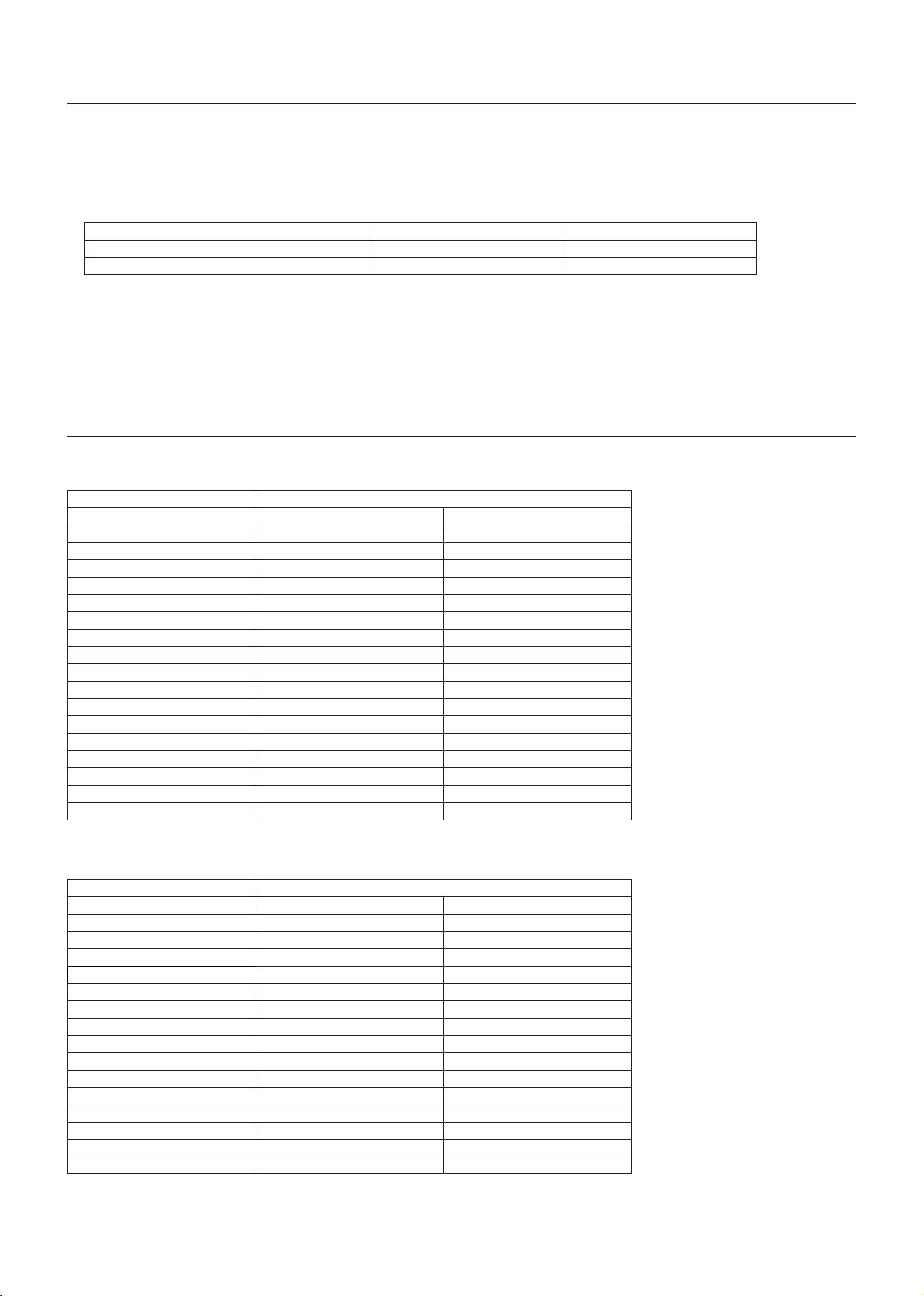
3. Combination of outdoor units
(1) P models
Outdoor unit model Combination of outdoor units
PURY-P200YLM-A(-BS) - PURY-P250YLM-A(-BS) - PURY-P300YLM-A(-BS) - PURY-P350YLM-A(-BS) - PURY-P400YLM-A(-BS) - PURY-P400YSLM-A(-BS) PURY-P200YLM-A(-BS) PURY-P200YLM-A(-BS)
PURY-P450YLM-A(-BS) - PURY-P450YSLM-A(-BS) PURY-P200YLM-A(-BS) PURY-P250YLM-A(-BS)
PURY-P500YLM-A(-BS) - PURY-P500YSLM-A(-BS) PURY-P250YLM-A(-BS) PURY-P250YLM-A(-BS)
PURY-P550YSLM-A(-BS) PURY-P250YLM-A(-BS) PURY-P300YLM-A(-BS)
PURY-P600YSLM-A(-BS) PURY-P300YLM-A(-BS) PURY-P300YLM-A(-BS)
PURY-P650YSLM-A(-BS) PURY-P300YLM-A(-BS) PURY-P350YLM-A(-BS)
PURY-P700YSLM-A(-BS) PURY-P350YLM-A(-BS) PURY-P350YLM-A(-BS)
PURY-P750YSLM-A(-BS) PURY-P350YLM-A(-BS) PURY-P400YLM-A(-BS)
PURY-P800YSLM-A(-BS) PURY-P400YLM-A(-BS) PURY-P400YLM-A(-BS)
PURY-P850YSLM-A(-BS) PURY-P400YLM-A(-BS) PURY-P450YLM-A(-BS)
PURY-P900YSLM-A(-BS) PURY-P450YLM-A(-BS) PURY-P450YLM-A(-BS)
* "Twinning Kit" is required to connect combination units on site.
(2) EP models
Outdoor unit model Combination of outdoor units
PURY-EP200YLM-A(-BS) - PURY-EP250YLM-A(-BS) - PURY-EP300YLM-A(-BS) - PURY-EP350YLM-A(-BS) - PURY-EP400YLM-A(-BS) - PURY-EP450YLM-A(-BS) - PURY-EP500YLM-A(-BS) - PURY-EP500YSLM-A(-BS) PURY-EP250YLM-A(-BS) PURY-EP250YLM-A(-BS)
PURY-EP550YSLM-A(-BS) PURY-EP250YLM-A(-BS) PURY-EP300YLM-A(-BS)
PURY-EP600YSLM-A(-BS) PURY-EP300YLM-A(-BS) PURY-EP300YLM-A(-BS)
PURY-EP650YSLM-A(-BS) PURY-EP300YLM-A(-BS) PURY-EP350YLM-A(-BS)
PURY-EP700YSLM-A(-BS) PURY-EP350YLM-A(-BS) PURY-EP350YLM-A(-BS)
PURY-EP750YSLM-A(-BS) PURY-EP350YLM-A(-BS) PURY-EP400YLM-A(-BS)
PURY-EP800YSLM-A(-BS) PURY-EP400YLM-A(-BS) PURY-EP400YLM-A(-BS)
PURY-EP850YSLM-A(-BS) PURY-EP400YLM-A(-BS) PURY-EP450YLM-A(-BS)
PURY-EP900YSLM-A(-BS) PURY-EP450YLM-A(-BS) PURY-EP450YLM-A(-BS)
* "Twinning Kit" is required to connect combination units on site.
WT07282X01
GB-8
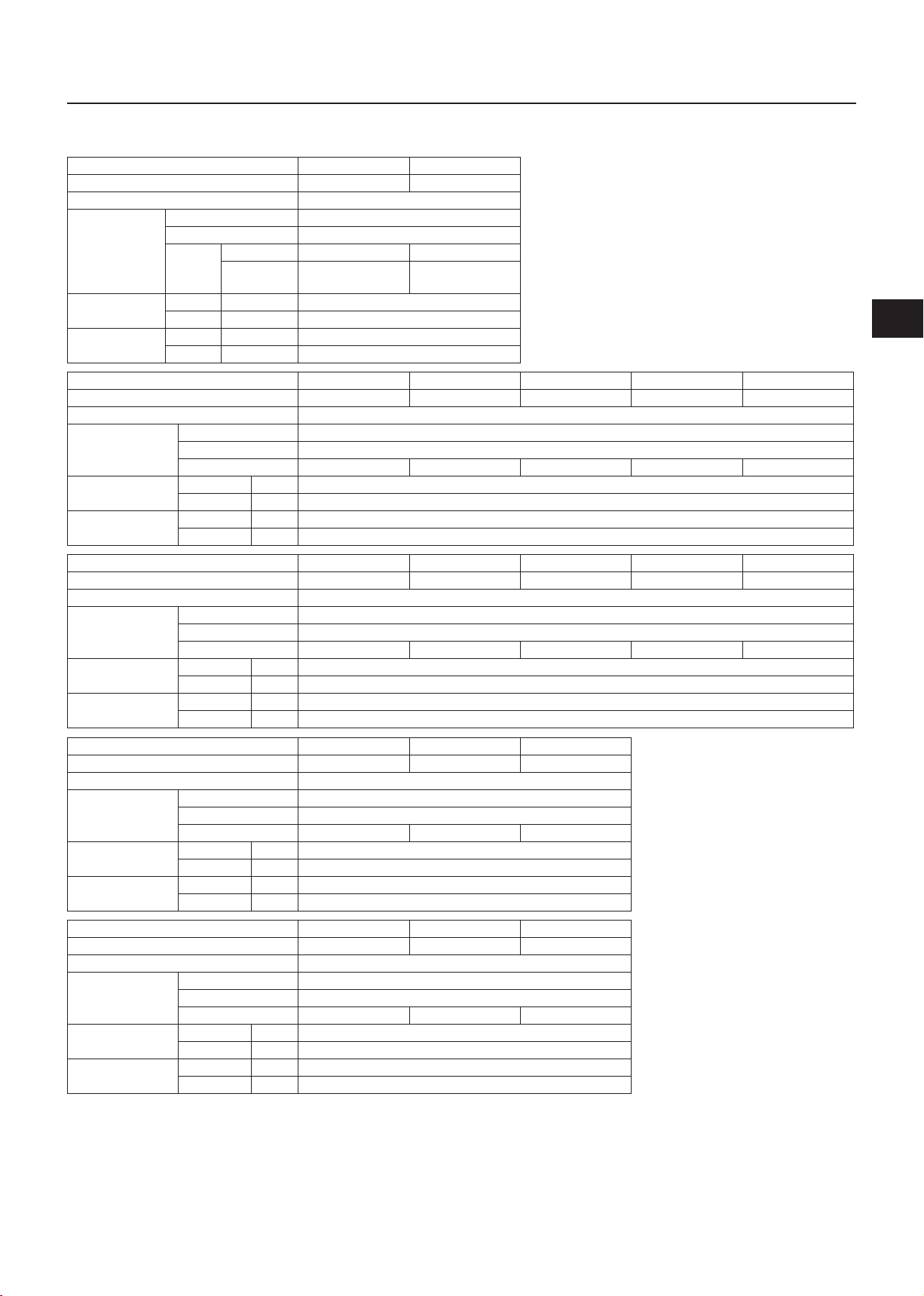
4. Specifications
(1) P models
Model
Sound level (50/60 Hz) 59 dB <A> 60 dB <A>
External static pressure 0 Pa*
Total capacity 50% to 150%*
Model 15 to 250
Indoor unit
Quantity
R2 system 1 to 20 1 to 25
Hybrid City
Multi system
Temperature
range (Cooling)
Temperature
range (Heating)
Indoor W.B.
Outdoor D.B.
Indoor D.B.
Outdoor W.B.
PURY-P200YLM-A
*3PURY-P250YLM-A
2
1
1 to 20 1 to 25
+15.0°C to +24.0°C (+59.0°F to +75.0°F)
-5.0°C to +46.0°C (+23.0°F to +115.0°F)
+15.0°C to +27.0°C (+59.0°F to +81.0°F)
-20.0°C to +15.5°C (-4.0°F to +60.0°F)
3
*
GB
Model
PURY-P300YLM-A PURY-P350YLM-A PURY-P400YLM-A PURY-P450YLM-A PURY-P500YLM-A
Sound level (50/60 Hz) 62.5 dB <A> 62.5 dB <A> 62.5 dB <A> 62.5 dB <A> 63.5 dB <A>
External static pressure 0 Pa*
Total capacity 50% to 150%*
Indoor unit
Model 15 to 250
2
1
Quantity 1 to 30 1 to 35 1 to 40 1 to 45 1 to 50
Temperature range
(Cooling)
Temperature range
(Heating)
Model
Indoor W.B. +15.0°C to +24.0°C (+59.0°F to +75.0°F)
Outdoor D.B. -5.0°C to +46.0°C (+23.0°F to +115.0°F)
Indoor D.B. +15.0°C to +27.0°C (+59.0°F to +81.0°F)
Outdoor W.B. -20.0°C to +15.5°C (-4.0°F to +60.0°F)
PURY-P400YSLM-A PURY-P450YSLM-A PURY-P500YSLM-A PURY-P550YSLM-A PURY-P600YSLM-A
Sound level (50/60 Hz) 62 dB <A> 62.5 dB <A> 63 dB <A> 64.5 dB <A> 65.5 dB <A>
External static pressure 0 Pa*
Total capacity 50% to 150%*
Indoor unit
Model 15 to 250
2
1
Quantity 1 to 40 1 to 45 1 to 50 2 to 50 2 to 50
Temperature range
(Cooling)
Temperature range
(Heating)
Model
Indoor W.B. +15.0°C to +24.0°C (+59.0°F to +75.0°F)
Outdoor D.B. -5.0°C to +46.0°C (+23.0°F to +115.0°F)
Indoor D.B. +15.0°C to +27.0°C (+59.0°F to +81.0°F)
Outdoor W.B. -20.0°C to +15.5°C (-4.0°F to +60.0°F)
PURY-P650YSLM-A PURY-P700YSLM-A PURY-P750YSLM-A
Sound level (50/60 Hz) 65.5 dB <A> 65.5 dB <A> 65.5 dB <A>
External static pressure 0 Pa*
Total capacity 50% to 150%*
Indoor unit
Model 15 to 250
2
1
Quantity 2 to 50 2 to 50 2 to 50
Temperature range
(Cooling)
Temperature range
(Heating)
Indoor W.B. +15.0°C to +24.0°C (+59.0°F to +75.0°F)
Outdoor D.B. -5.0°C to +46.0°C (+23.0°F to +115.0°F)
Indoor D.B. +15.0°C to +27.0°C (+59.0°F to +81.0°F)
Outdoor W.B. -20.0°C to +15.5°C (-4.0°F to +60.0°F)
Model
PURY-P800YSLM-A PURY-P850YSLM-A PURY-P900YSLM-A
Sound level (50/60 Hz) 65.5 dB <A> 65.5 dB <A> 65.5 dB <A>
External static pressure 0 Pa*
Total capacity 50% to 150%*
Indoor unit
Model 15 to 250
2
1
Quantity 2 to 50 2 to 50 2 to 50
Temperature range
(Cooling)
Temperature range
(Heating)
Indoor W.B. +15.0°C to +24.0°C (+59.0°F to +75.0°F)
Outdoor D.B. -5.0°C to +46.0°C (+23.0°F to +115.0°F)
Indoor D.B. +15.0°C to +27.0°C (+59.0°F to +81.0°F)
Outdoor W.B. -20.0°C to +15.5°C (-4.0°F to +60.0°F)
*1 The maximum total capacity of indoor units operating simultaneously is 150%.
*2 To enable the high static pressure setting, set the dipswitch on the main board as follows.
SW6-4: ON
SW6-5: OFF (60 Pa) or ON (30 Pa)
*3 These models can be used for a Hybrid City Multi system.
WT07282X01
GB-9
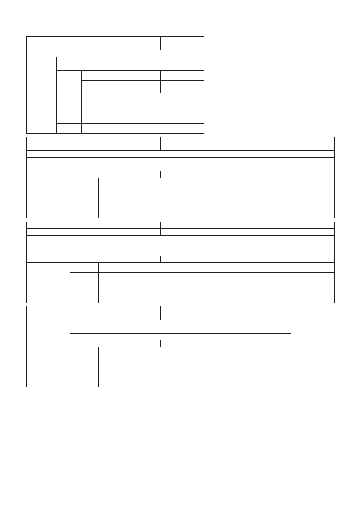
(2) EP models
Model
Sound level (50/60 Hz) 59 dB <A> 60 dB <A>
External static pressure 0 Pa*
Total capacity 50% to 150%*
Model 15 to 250
Indoor unit
Quantity
R2 system 1 to 20 1 to 25
Hybrid City
Multi system
Temperature
Indoor W.B.
range
(Cooling)
Temperature
Outdoor D.B.
Indoor D.B.
range
(Heating)
Outdoor W.B.
PURY-EP200YLM-A
*3PURY-EP250YLM-A
2
1
1 to 20 1 to 25
+15.0°C to +24.0°C (+59.0°F to +75.0°F)
-5.0°C to +46.0°C (+23.0°F to +115.0°F)
+15.0°C to +27.0°C (+59.0°F to +81.0°F)
-20.0°C to +15.5°C (-4.0°F to +60.0°F)
3
*
Model
PURY-EP300YLM-A PURY-EP350YLM-A PURY-EP400YLM-A PURY-EP450YLM-A PURY-EP500YLM-A
Sound level (50/60 Hz) 62.5 dB <A> 62.5 dB <A> 62.5 dB <A> 62.5 dB <A> 63.5 dB <A>
External static pressure 0 Pa*
Total capacity 50% to 150%*
Indoor unit
Model 15 to 250
2
1
Quantity 1 to 30 1 to 35 1 to 40 1 to 45 1 to 50
Temperature range
(Cooling)
Temperature range
(Heating)
Model
Indoor W.B. +15.0°C to +24.0°C (+59.0°F to +75.0°F)
Outdoor D.B. -5.0°C to +46.0°C (+23.0°F to +115.0°F)
Indoor D.B. +15.0°C to +27.0°C (+59.0°F to +81.0°F)
Outdoor W.B. -20.0°C to +15.5°C (-4.0°F to +60.0°F)
PURY-EP500YSLM-A PURY-EP550YSLM-A PURY-EP600YSLM-A PURY-EP650YSLM-A PURY-EP700YSLM-A
Sound level (50/60 Hz) 63 dB <A> 64.5 dB <A> 65.5 dB <A> 65.5 dB <A> 65.5 dB <A>
External static pressure 0 Pa*
Total capacity 50% to 150%*
Indoor unit
Model 15 to 250
2
1
Quantity 1 to 50 2 to 50 2 to 50 2 to 50 2 to 50
Temperature range
(Cooling)
Temperature range
(Heating)
Model
Indoor W.B. +15.0°C to +24.0°C (+59.0°F to +75.0°F)
Outdoor D.B. -5.0°C to +46.0°C (+23.0°F to +115.0°F)
Indoor D.B. +15.0°C to +27.0°C (+59.0°F to +81.0°F)
Outdoor W.B. -20.0°C to +15.5°C (-4.0°F to +60.0°F)
PURY-EP750YSLM-A PURY-PE800YSLM-A PURY-EP850YSLM-A PURY-EP900YSLM-A
Sound level (50/60 Hz) 65.5 dB <A> 65.5 dB <A> 65.5 dB <A> 65.5 dB <A>
External static pressure 0 Pa*
Total capacity 50% to 150%*
Indoor unit
Model 15 to 250
2
1
Quantity 2 to 50 2 to 50 2 to 50 2 to 50
Temperature range
(Cooling)
Indoor W.B. +15.0°C to +24.0°C (+59.0°F to +75.0°F)
Outdoor D.B. -5.0°C to +46.0°C (+23.0°F to +115.0°F)
Temperature range
(Heating)
Indoor D.B. +15.0°C to +27.0°C (+59.0°F to +81.0°F)
Outdoor W.B. -20.0°C to +15.5°C (-4.0°F to +60.0°F)
*1 The maximum total capacity of indoor units operating simultaneously is 150%.
*2 To enable the high static pressure setting, set the dipswitch on the main board as follows.
SW6-4: ON
SW6-5: OFF (60 Pa) or ON (30 Pa)
*3 These models can be used for a Hybrid City Multi system.
WT07282X01
GB-10
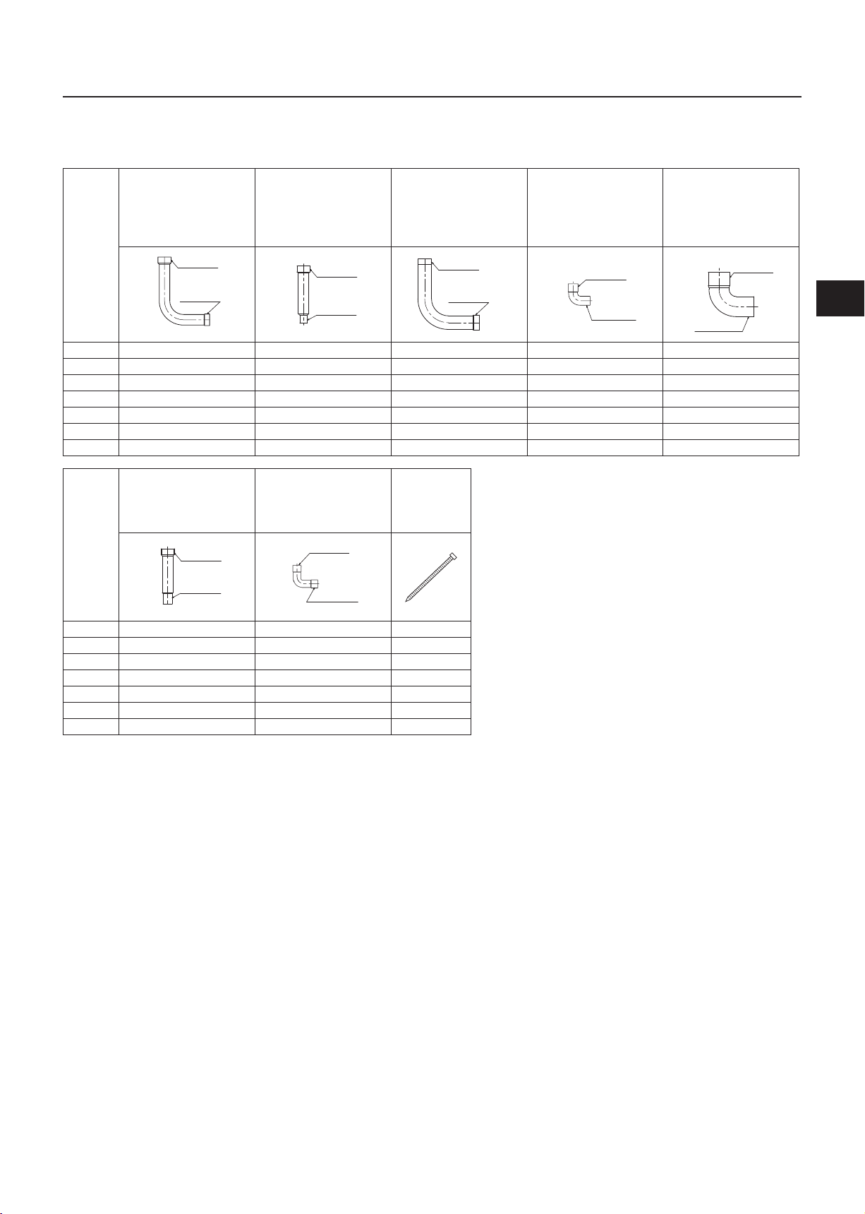
5. Package contents
The table below lists all the parts and their quantities included in the package.
(1) P models
① ② ③ ④ ⑤
Connecting pipe Connecting pipe Connecting pipe Connecting elbow Connecting elbow
ID ø25.4 mm (ø1 in)
ID ø22.2 mm (ø7/8 in)
ID ø25.4
ø22.2
ID ø22.2
P200 - 1 (low-pressure side) - 1 (low-pressure side) P250 1 (low-pressure side) 1 (high-pressure side) - 1 (high-pressure side) P300 1 (low-pressure side) 1 (high-pressure side) - 1 (high-pressure side) P350 - 1 (high-pressure side) 1 (low-pressure side) 1 (high-pressure side) P400 1 (high-pressure side) - 1 (low-pressure side) - P450 1 (high-pressure side) - - - 1 (low-pressure side)
P500 1 (high-pressure side) - - - 1 (low-pressure side)
⑥ ⑦ ⑧
Connecting pipe Connecting pipe
ID ø25.4 mm (ø1 in)
OD ø15.88 mm (ø5/8 in)
ID ø25.4
ø22.2
OD ø15.88
ID ø25.4 mm (ø1 in)
OD ø19.05 mm (ø3/4 in)
ID ø25.4
ø22.2
OD ø19.05
ID ø15.88 mm (ø5/8 in)
ID ø15.88 mm (ø5/8 in)
ID ø15.88
ID ø15.88
ID ø25.4 mm (ø1 in)
ID ø28.58 mm (ø1-1/8 in)
ID ø25.4
ø28.58
ID ø28.58
Tie band
ID ø19.05 mm (ø3/4 in)
OD ø19.05 mm (ø3/4 in)
ID ø19.05
OD ø19.05
ID ø28.58 mm (ø1-1/8 in)
OD ø28.58 mm (ø1-1/8 in)
ID ø28.58
OD ø28.58
GB
P200 1 (high-pressure side) 1 (high-pressure side) 2
P250 - - 2
P300 - - 2
P350 - - 2
P400 - - 2
P450 - - 2
P500 - - 2
WT07282X01
GB-11
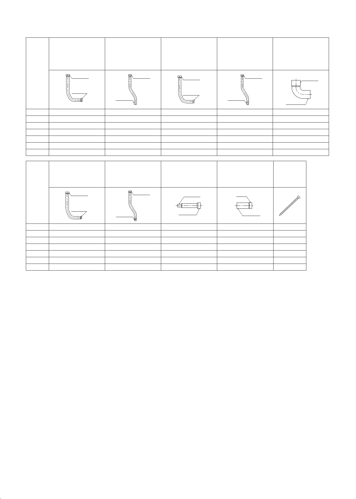
(2) EP models
Connecting pipe Connecting pipe Connecting pipe Connecting pipe Connecting elbow
ID ø25.4 mm (ø1 in)
ID ø22.2 mm (ø7/8 in)
① ② ③ ④ ⑤
ID ø25.4
ID ø25.4 mm (ø1 in)
OD ø22.2 mm (ø7/8 in)
ID ø25.4
ID ø25.4 mm (ø1 in)
ID ø19.05 mm (ø3/4 in)
ID ø25.4
ID ø25.4 mm (ø1 in)
OD ø19.05 mm (ø3/4 in)
ID ø25.4
ID ø28.58 mm (ø1-1/8 in)
OD ø28.58 mm (ø1-1/8 in)
ID ø28.58
ID ø22.2
OD ø22.2
ID ø19.05
OD ø19.05
OD ø28.58
EP200 - - - - 1 (low-pressure side)
EP250 - - 1 (high-pressure side) 1 (high-pressure side) 1 (low-pressure side)
EP300 - - 1 (high-pressure side) 1 (high-pressure side) 1 (low-pressure side)
EP350 - - 1 (high-pressure side) 1 (high-pressure side) 1 (low-pressure side)
EP400 1 (high-pressure side) 1 (high-pressure side) - - 1 (low-pressure side)
EP450 1 (high-pressure side) 1 (high-pressure side) - - 1 (low-pressure side)
EP500 1 (high-pressure side) 1 (high-pressure side) - - 1 (low-pressure side)
⑥ ⑦ ⑧ ⑨ ⑩
Connecting pipe Connecting pipe Connecting pipe Connecting pipe
ID ø25.4 mm (ø1 in)
ID ø15.88 mm (ø5/8 in)
ID ø25.4
ID ø15.88
ID ø25.4 mm (ø1 in)
OD ø15.88 mm (ø5/8 in)
ID ø25.4
OD ø15.88
OD ø22.2 mm (ø7/8 in)
ID ø28.58 mm (ø1-1/8 in)
OD ø22.2
ID ø28.58
ID ø22.2 mm (ø7/8 in)
OD ø19.05 mm (ø3/4 in)
ø22.2
OD ø19.05
Tie band
EP200 1 (high-pressure side) 1 (high-pressure side) 1 (low-pressure side) 1 (low-pressure side) 2
EP250 - - 1 (low-pressure side) - 2
EP300 - - 1 (low-pressure side) - 2
EP350 - - - - 2
EP400 - - - - 2
EP450 - - - - 2
EP500 - - - - 2
WT07282X01
GB-12
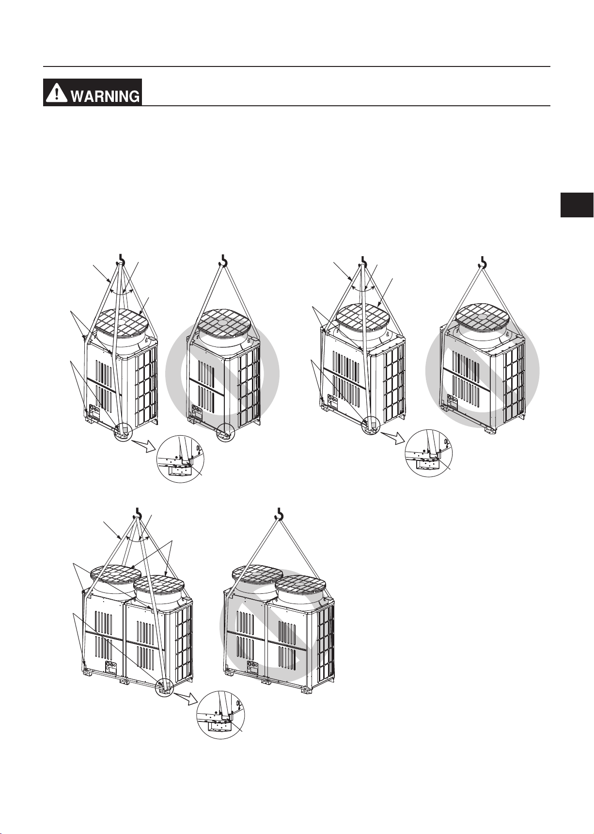
6. Transporting the unit
When lifting the unit, pass the slings through the four designated sling holes.
- Improper lifting will cause the unit to topple or fall, resulting in serious injury.
・Always use two slings to lift up the unit. Each sling must be at least 8 m (26 ft) long and must be able to support the
weight of the unit.
・Put protective pads between slings and the unit where the slings touch the unit at the base to protect the unit from
being scratched.
・Put 50 mm (2 in) or thicker protective pads between slings and the unit where the slings touch the unit at the top of
the unit to protect the unit from being scratched and to avoid contact with the slings and the fan guard.
・Make sure that the angles between slings at the top are less than 40 degrees.
P200, P250, EP200, EP250 P300, P350, P400, EP300, EP350
Ⓐ
≤ 40°
Ⓐ
≤ 40°
Ⓔ
GB
Ⓔ
Ⓑ
Ⓒ
P450, P500, EP400, EP450, EP500
≤ 40°
Ⓐ
Ⓔ
Ⓑ
Ⓑ
Ⓒ
Ⓓ
Ⓐ Slings (Min. 8 m (26 ft) x 2)
Ⓑ Protective pads (Minimum thickness: 50 mm
(2 in))
(two each in the front and back)
Ⓒ Protective pads
(two each in the front and back)
Ⓓ Sling holes
(two each in the front and back)
Ⓔ Fan guard
Ⓓ
Ⓒ
WT07282X01
Ⓓ
GB-13
7. Installation location
Do not install the unit where combustible gas may leak.
- If combustible gas accumulates around the unit, fire or explosion may result.
・Provide sufficient space around the unit for effective operation, efficient air movement, and ease of access for
maintenance.
・Note that refrigerant gas is heavier than air and will therefore tend to collect in low spots such as basements.
・When an indoor unit that draws in outside air exits near the outdoor unit, be careful not to affect the normal
operation of the indoor unit.
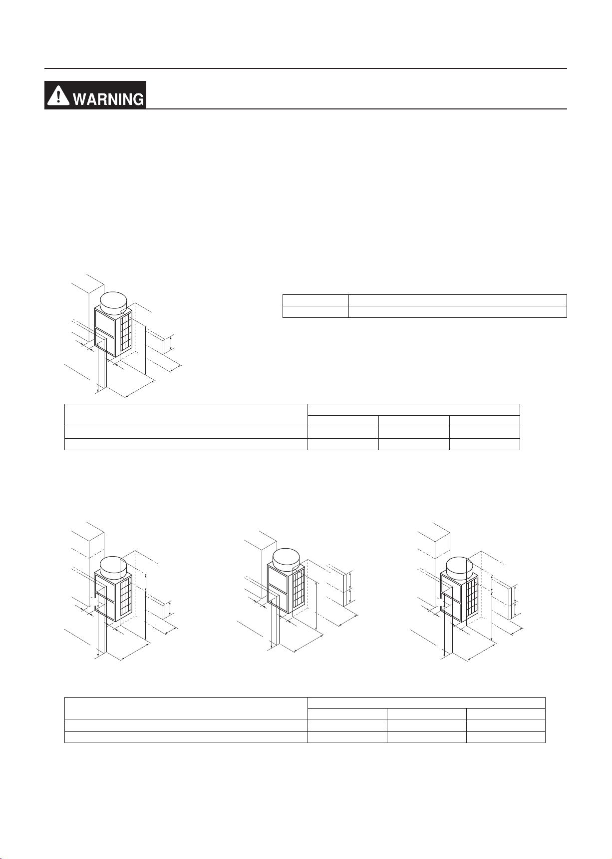
7-1. Single unit installation
(1) When all walls are within their height limits*.
* Height limit
Front/Right/Left Same height or lower than the overall height of the unit
Rear 500 mm (19-11/16 in) or lower from the unit bottom
[mm (in)]
L3
≤ Unit height
L3
≤ Unit height
When the distance behind the unit (L2) needs to be small 450 (17-3/4) 100 (3-15/16) 50 (2)
When the distance to the right or left (L3) needs to be small 450 (17-3/4) 300 (11-13/16) 15 (5/8)
L1
≤ 500 (19-11/16)
L2
Required minimum distance [mm (in)]
L1 (Front) L2 (Rear) L3 (Right/Left)
(2) When one or more walls exceed their height limits*.
When the wall(s) at the front and/
or the right/left exceed(s) their
When the wall at the rear exceeds
its height limit
When all walls exceed their height
limits
height limits
h3
h1
L3
Unit height
L3
Unit height
L1
≤ 500
(19-11/16)
L2
L3
L3
≤ Unit height
≤ Unit height
L1
h2
500
(19-11/16)
L2
h1
L3
Unit height
h3
h2
500
(19-11/16)
Unit height
L3
L1
L2
Add the dimension that exceeds the height limit (shown as "h1" through "h3" in the figures) to L1, L2, and L3 as
shown in the table below.
Required minimum distance [mm (in)]
L1 (Front) L2 (Rear) L3 (Right/Left)
When the distance behind the unit (L2) needs to be small 450 (17-3/4) + h1 100 (3-15/16) + h2 50 (2) + h3
When the distance to the right or left (L3) needs to be small 450 (17-3/4) + h1 300 (11-13/16) + h2 15 (5/8) + h3
WT07282X01
GB-14
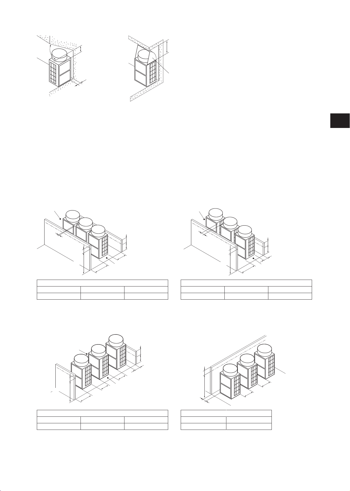
(3) When there are overhead obstacles
≥ 45°
≥ 240 (9-1/2)
≥ 50 (2)
≥ 1000 (39-3/8)
Air outlet guide
(not supplied)
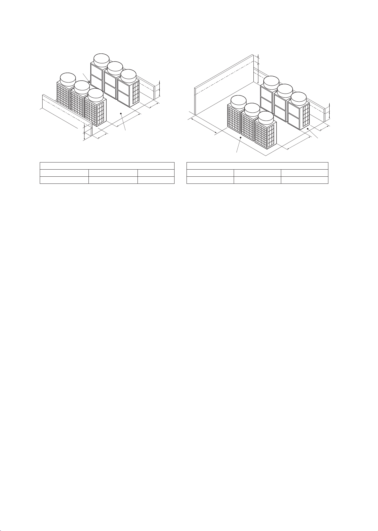
7-2. Multiple unit installation
・When installing multiple units, make sure to take into consideration factors such as providing enough space for
people to pass through, ample space between blocks of units, and sufficient space for airflow. (The areas marked
with Ⓐ in the figures below must be left open.)
・In the same way as with the single unit installation, add the dimension that exceeds the height limit (shown as "h1"
through "h3" in the figures) to L1, L2, and L3 as shown in the tables below.
・If there are walls in the front and rear of the block of units, up to six units (three units for units P450, P500, EP400
through EP500) can be installed consecutively side by side, and a space of 1000 mm (39-3/8 in) or more must be
left between each block of six units.
(1) Side-by-side installation
When the distances between the units (L4) need to
be small
Ⓐ
When the distance behind the block of units (L2) needs
to be small
Ⓐ
GB
L4
h1
Unit height
L1
h2
500 (19-11/16)
L2
Ⓐ
Required minimum distance [mm (in)]
L1 (Front) L2 (Rear) L4 (Between)
450 (17-3/4) + h1 300 (11-13/16) + h2 30 (1-3/16)
(2) Face-to-face installation
When there are walls in the front and rear of the
block of units
Ⓐ
L4
Ⓐ
Unit height
h1
L4
L1
h2
500 (19-11/16)
L2
L4
h2
L2
Ⓐ
500 (19-11/16)
h1
Unit height
L1
Required minimum distance [mm (in)]
L1 (Front) L2 (Rear) L4 (Between)
450 (17-3/4) + h1 100 (3-15/16) + h2 100 (3-15/16)
When there is a wall on either the right or left side of the
block of units
h3
Unit height
L4
L3
L4
Required minimum distance [mm (in)]
L1 (Front) L2 (Rear) L4 (Between)
450 (17-3/4) + h1 100 (3-15/16) + h2 450 (17-3/4)
WT07282X01
Required minimum distance [mm (in)]
L3 (Right/Left) L4 (Between)
15 (5/8) + h3 450 (17-3/4)
GB-15
(3) Combination of face-to-face and side-by-side installations
When there are walls in the front and rear of the
When there are two walls in an L-shape
block of units
Ⓐ
h2
500
(19-11/16)
h3
Unit height
L2
L4
500 (19-11/16)
h2’
L2’
Ⓐ
Required minimum distance [mm (in)]
L2 (Right) L2' (Left) L4 (Between)
300 (11-13/16) + h2 300 (11-13/16) + h2' 900 (35-7/16)
Ⓐ Leave open in two directions.
L3
L4
Ⓐ
Required minimum distance [mm (in)]
L2 (Right) L3 (Right/Left) L4 (Between)
300 (11-13/16) + h2 1000 (39-3/8) + h3 900 (35-7/16)
h2
500
(19-11/16)
L2
Ⓐ
WT07282X01
GB-16
8. Foundation work
Install the unit in accordance with the instructions to minimize the risk of damage from
earthquakes and strong winds.
- Improper installation will cause the unit to topple, resulting in serious injury.
The unit must be securely installed on a structure that can sustain its weight.
- Failure to do so will cause the unit to fall, resulting in serious injury.
・When performing the foundation work, make sure that the floor surface has sufficient strength and carefully route
pipes and wires in consideration of the water drainage that will be required when the unit is operated.
・If considering routing the pipes and wires across the bottom of the unit, make sure that the base is at least 100 mm
(3-15/16 in) high so that the through-holes will not be blocked.
・Provide a strong base of concrete or angle iron. If a stainless steel base is used, insulate the area between the
base and the outdoor unit by putting a rubber cushion or by applying an electrically insulated coating to prevent the
base from rusting.
・Install the unit on a level surface.
・With some types of installation, unit vibration and sound will be transmitted to the floors and walls. In such locations,
take measures to prevent vibration (such as using anti-vibration rubber pads).
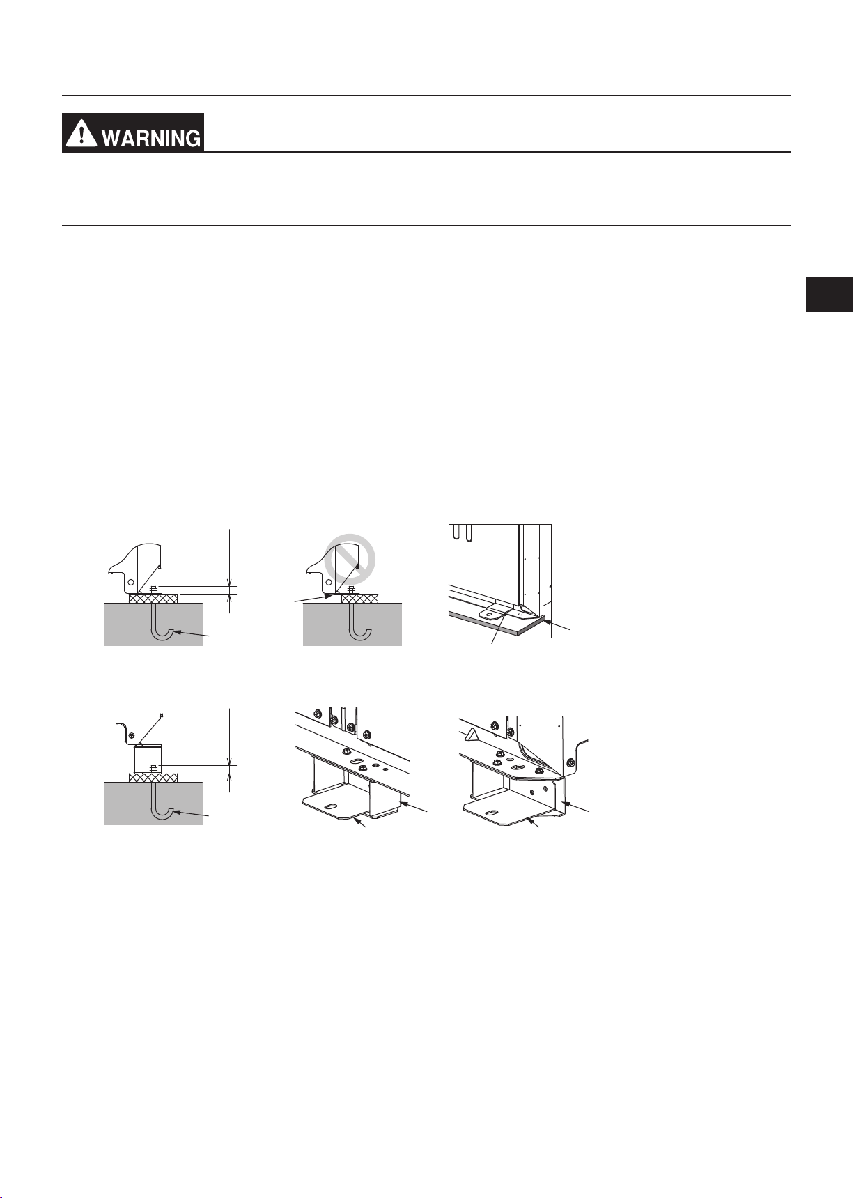
[mm (in)]
(1) Without a detachable leg
≤ 30 (1-3/16)≤ 30 (1-3/16)
Ⓑ
Ⓐ
Ⓒ
Ⓓ
(2) With a detachable leg
GB
Ⓐ
Ⓒ Ⓒ
Ⓐ M10 anchor bolt (not supplied)
Ⓑ (Incorrect installation) The corner section is not securely received.
Ⓒ Fixing bracket for post-installed anchor bolts (not supplied) (To be fixed with three screws)
Ⓓ Anti-vibration rubber pad
(The pad needs to be large enough to cover the entire width of each unit leg.)
Ⓔ Detachable leg
Ⓔ Ⓔ
・Make sure that the corner section is securely received. If not, the unit legs could bend.
・The length of the projecting part of the anchor bolt should be 30 mm (1-3/16 in) or less.
・This unit is not designed to be anchored with post-installed anchor bolts unless fixing brackets are installed at
the bottom four locations (six locations for units P450, P500, EP400 through EP500).
WT07282X01
GB-17
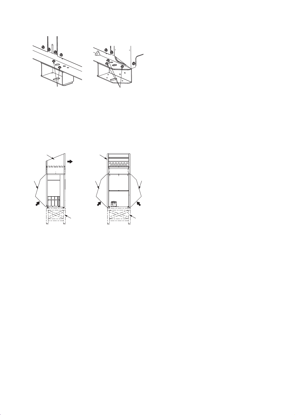
・To remove the detachable legs on site, unscrew the screws shown in the figure below. If the unit leg coating is
damaged when the detachable leg is removed, repair the coating on site.
Ⓐ Screws
Ⓐ
Ⓐ
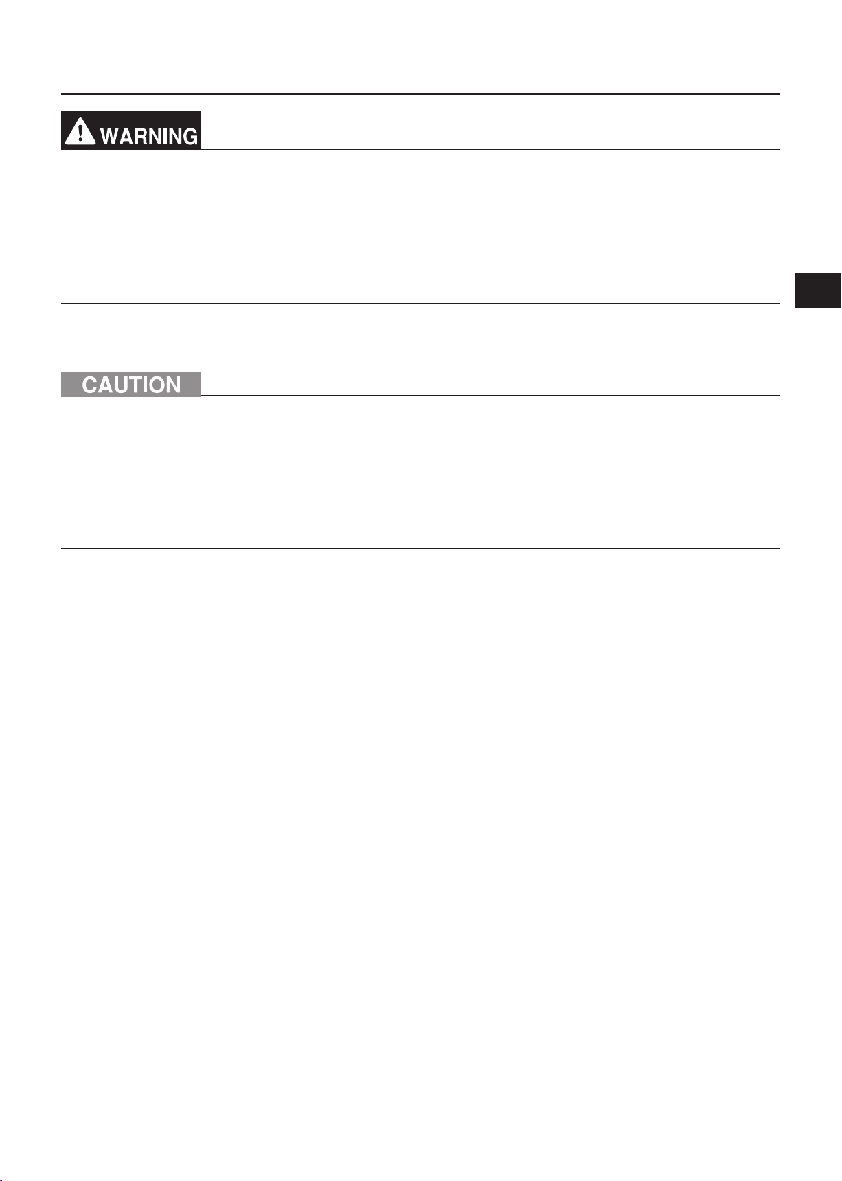
・In abnormally harsh environments such as cold and/or windy areas, sufficient countermeasures to guard against
excessive wind and snow should be taken to ensure the unit’s correct operation. When the unit is expected to
operate in cooling mode in conditions under 10°C (50°F), in snowy areas, in environments subject to strong
winds or rain, install snow hoods of the following specifications (not supplied) as shown in the figure below.
Material: Galvanized steel plate 1.2T
Painting: Overall painting with polyester powder
Color: Munsell 5Y8/1 (same as the unit color)
Size: Refer to the Data Book.
Ⓐ Outlet
Ⓑ Inlet
Ⓒ Snow hood
Ⓓ Raised base
Ⓒ
Ⓑ
Ⓐ
Ⓒ
Ⓑ Ⓑ
Ⓓ Ⓓ
ⒸⒸ
Ⓒ
・Install the unit so that the wind will not blow directly against the inlet and outlet.
・If necessary, install the unit on a raised base of the following specifications (not supplied) to prevent damage
from snow.
Material: Angle iron (Build a structure that snow and wind can pass through.)
Height: Expected maximum snowfall plus 200 mm (7-7/8 in)
Width: Within the unit width (If the raised base is too wide, snow will accumulate on the raised base.)
・When the unit is used in a cold region and the heating operation is continuously performed for a long time when
the outside air temperature is below freezing, install a heater on the raised base or take other appropriate
measures to prevent water from freezing on the raised base.
WT07282X01
GB-18
9. Refrigerant piping work
Do not use any refrigerant other than the type indicated in the manuals for the unit and on
the nameplate.
- Doing so will cause the unit or pipes to burst, or result in an explosion or fire during use, during
repairs, or at the time of disposal of the unit.
- It may also be in violation of applicable laws.
- MITSUBISHI ELECTRIC CORPORATION cannot be held responsible for malfunctions or
accidents resulting from the use of the wrong type of refrigerant.
After the installation has been completed, check for refrigerant leaks.
- If the refrigerant leaks, oxygen starvation may result. If the leaked refrigerant comes in contact
with a heat source, toxic gas will be generated.
Use the following tools specifically designed for use with the specified refrigerant: Gauge
manifold, charge hose, gas leak detector, check valve, refrigerant charge base, vacuum
gauge, and refrigerant recovery equipment.
- Gas leak detectors for conventional refrigerants will not react to a refrigerant that does not
contain chlorine.
- If the specified refrigerant is mixed with water, refrigerant oil, or another refrigerant, the
refrigerant oil will deteriorate and the compressor will malfunction.
GB
Do not use existing refrigerant piping.
- The old refrigerant and refrigerant oil in the existing piping contain a large amount of chlorine,
which will cause the refrigerant oil in the new unit to deteriorate and cause the compressor to
malfunction.
9-1. Restrictions
・Existing refrigerant piping must not be used because the design pressure for systems using R410A is higher than
that for systems using other types of refrigerants.
・Do not install outdoor unit piping when it is raining.
・Do not use special detergents for washing piping.
・Always observe the restrictions on refrigerant piping (such as pipe size, pipe length, and vertical separation
distance) to prevent equipment failure or a decline in heating/cooling performance.
・Do not install solenoid valves to prevent oil backflow and compressor start-up failure.
・Do not install a sight glass because it may show improper refrigerant flow. If a sight glass is installed, inexperienced
technicians that use the glass may overcharge the refrigerant.
WT07282X01
GB-19
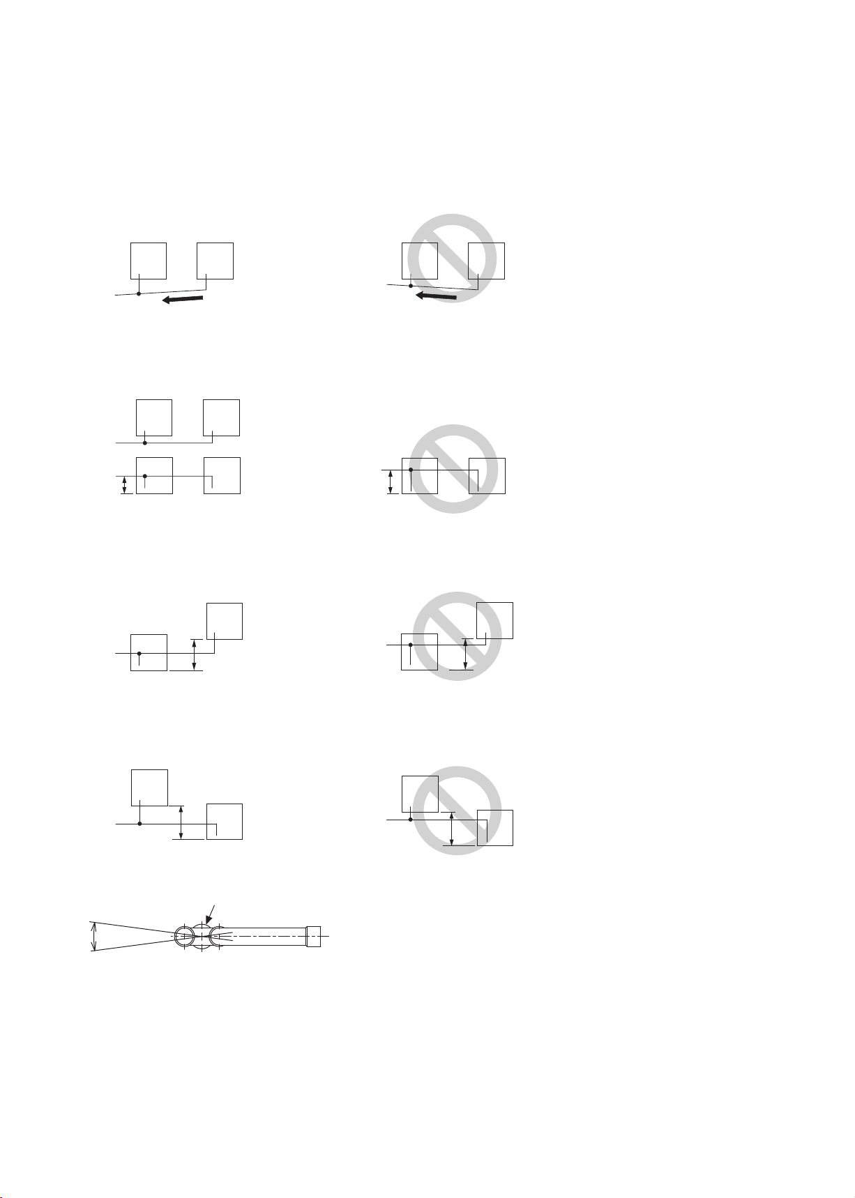
・The pipe from multiple outdoor units must be installed so that oil will not accumulate in the pipe under certain
±15°
Ⓐ
conditions. Refer to the figures below for details.
* Small dots in the figures indicate branching points.
Ⓐ In an R2 system: To a BC controller
In a Hybrid City Multi system: To an HBC controller
(1) The pipe from the outdoor units must be inclined downward to the indoor unit side. In the figure on the right,
because the pipe is inclined upward, the oil in the pipe accumulates when Unit 1 is in operation and Unit 2 is
stopped.
Unit 1 Unit 2Unit 1
Ⓐ
Unit 2
Ⓐ
(2) The distance between the unit bottom and the pipe (H) must be 0.2 m (7-7/8 in) or below. In the figure on the
right, because the distance is more than 0.2 m (7-7/8 in), the oil accumulates in Unit 1 when Unit 2 is in
operation and Unit 1 is stopped.
Unit 1
Ⓐ
Unit 1
Ⓐ
H
H ≤ 0.2 m (7-7/8 in)
Unit 2
Unit 2
Ⓐ
H
H > 0.2 m (7-7/8 in)
Unit 2Unit 1
(3) The vertical separation between units (H) must be 0.1 m (3-15/16 in) or below. In the figure on the right,
because the distance is more than 0.1 m (3-15/16 in), the oil accumulates in Unit 1 when Unit 2 is in operation
and Unit 1 is stopped.
Unit 2
Unit 1
Unit 1
Ⓐ
H
H ≤ 0.1 m (3-15/16 in)
Unit 1
Ⓐ
Unit 2
H
H > 0.1 m (3-15/16 in)
(4) The vertical separation between units (H) must be 0.1 m (3-15/16 in) or below. In the figure on the right,
because the distance is more than 0.1 m (3-15/16 in), the oil accumulates in Unit 2 when Unit 1 is in operation
and Unit 2 is stopped.
Unit 1
Unit 1
Ⓐ
H
Unit 2
H ≤ 0.1 m (3-15/16 in)
Unit 1
Ⓐ
H
Unit 2
H > 0.1 m (3-15/16 in)
・Make sure that the inclination tolerance of the Twinning Kit is ±15˚ to the ground to avoid unit damage.
Ⓐ Twinning Kit
・Do not install traps to prevent oil backflow and compressor start-up failure.
WT07282X01
GB-20
9-2. Pipe selection
Use refrigerant piping made of phosphorus deoxidized copper (copper and copper alloy
seamless pipes) that meets local requirements. Pipe joints should also meet local
requirements. Keep the inner and outer surfaces of the pipes clean and free of sulphur,
oxides, dust/dirt, shaving particles, oils, moisture, or any other contaminants.
- Contaminants on the inside of the refrigerant piping will cause the refrigerant oil to deteriorate
and cause the compressor to malfunction.
Use refrigerant pipes for use with R410A refrigerant system. Piping for systems for use with other types of refrigerants
may not be able to be used.
Use refrigerant pipes with the thicknesses specified in the table below.
Size [mm (in)] Radial thickness [mm (mil)] Type
ø6.35 (ø1/4) 0.8 (32) Type-O
ø9.52 (ø3/8) 0.8 (32) Type-O
ø12.7 (ø1/2) 0.8 (32) Type-O
ø15.88 (ø5/8) 1.0 (40) Type-O
ø19.05 (ø3/4)
ø22.2 (ø7/8) 1.0 (40) Type-1/2H or H
ø25.4 (ø1) 1.0 (40) Type-1/2H or H
ø28.58 (ø1-1/8) 1.0 (40) Type-1/2H or H
ø31.75 (ø1-1/4) 1.1 (44) Type-1/2H or H
ø34.93 (ø1-3/8) 1.2 (48) Type-1/2H or H
ø41.28 (ø1-5/8) 1.4 (56) Type-1/2H or H
1.2 (48) Type-O
1.0 (40) Type-1/2H or H
GB
9-3. Twinning kit selection
Select appropriate twinning kits (sold separately), referring to the sections below.
* Use an adapter, if necessary, to connect a refrigerant pipe to a twinning pipe of a different diameter.
* The maximum number of connectable ports is 48.
9-3-1. 2-Branch Joint Pipe
A 2-Branch Joint Pipe is used to connect multiple indoor units to a port, or to connect two sub BC controllers.
(1) R2 system
Total capacity of downstream indoor units Kit model
80 or below CMY-Y102SS-G2
(2) Hybrid City Multi system
・Connect the pipes on site, referring to the HBC controller Installation Manual.
・CMY-Y102SS-G2 is used in an R2 system, and cannot be used in a Hybrid City Multi system.
9-3-2. Joint Pipe Kit
A Joint Pipe Kit is used to connect an indoor unit of P100 model or above.
(1) R2 system
Indoor unit model Kit model
P100 to P250 CMY-R160-J1
(2) Hybrid City Multi system
・Connect the pipes on site, referring to the HBC controller Installation Manual.
・CMY-R160-J1 is used in an R2 system, and cannot be used in a Hybrid City Multi system.
WT07282X01
GB-21
9-3-3. Outdoor unit twinning kit
Outdoor unit twinning kit is used to combine multiple outdoor units.
Total capacity of outdoor units Kit model
P400 to P500YSLM CMY-R100VBK-A
P550 to P650YSLM CMY-R100VBK2
P700 to P800YSLM CMY-R200VBK2
P850 to P900YSLM CMY-R200XLVBK
EP500YSLM CMY-ER100VBK-A
EP550 to EP900YSLM CMY-ER200VBK
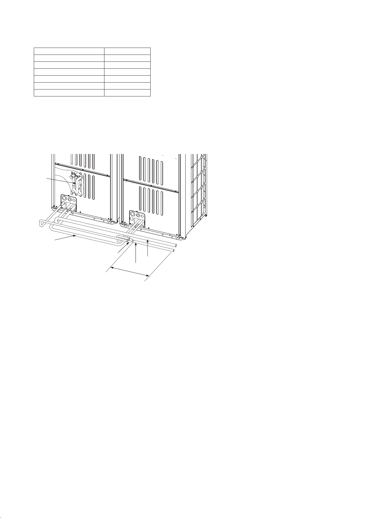
9-4. Pipe connection example
9-4-1. Example of pipe connection between outdoor units, and between an outdoor
unit and BC controller (R2 system) or HBC controller (Hybrid City Multi
system)
Ⓐ Outdoor unit twinning kit (low-pressure side)
Ⓑ Outdoor unit twinning kit (High-pressure side)
Ⓒ On-site piping between outdoor units (low-
Ⓐ
Ⓒ
Ⓑ
Ⓕ
Ⓓ
Ⓔ
pressure side)
Ⓓ In an R2 system: On-site piping to a BC
controller (low-pressure side)
In a Hybrid City Multi system: On-site piping to
an HBC controller (low-pressure side)
Ⓔ In an R2 system: On-site piping to a BC
controller (High-pressure side)
In a Hybrid City Multi system: On-site piping to
an HBC controller (High-pressure side)
Ⓕ The pipe section before the twinning pipe must
have at least 500 mm (19-11/16 in) of straight
section.
・The outdoor unit twinning kit on the low-pressure side must be placed in the outdoor unit that has the larger
capacity index of the two, regardless of the relative positions of the outdoor units or their addresses. (If outdoor
units that have the same capacity are used in combination, the twinning kit can be placed in either outdoor unit.)
If the twinning kit is placed in the outdoor unit that has the smaller capacity, refrigerant will not be properly
distributed and compressor failure may result.
・PURY-P200YLM-A, PURY-P250YLM-A, PURY-EP200YLM-A and PURY-EP250YLM-A can be used in a
Hybrid City Multi system. Contact your dealer when connecting the larger capacity units in a Hybrid City Multi
system.
WT07282X01
GB-22
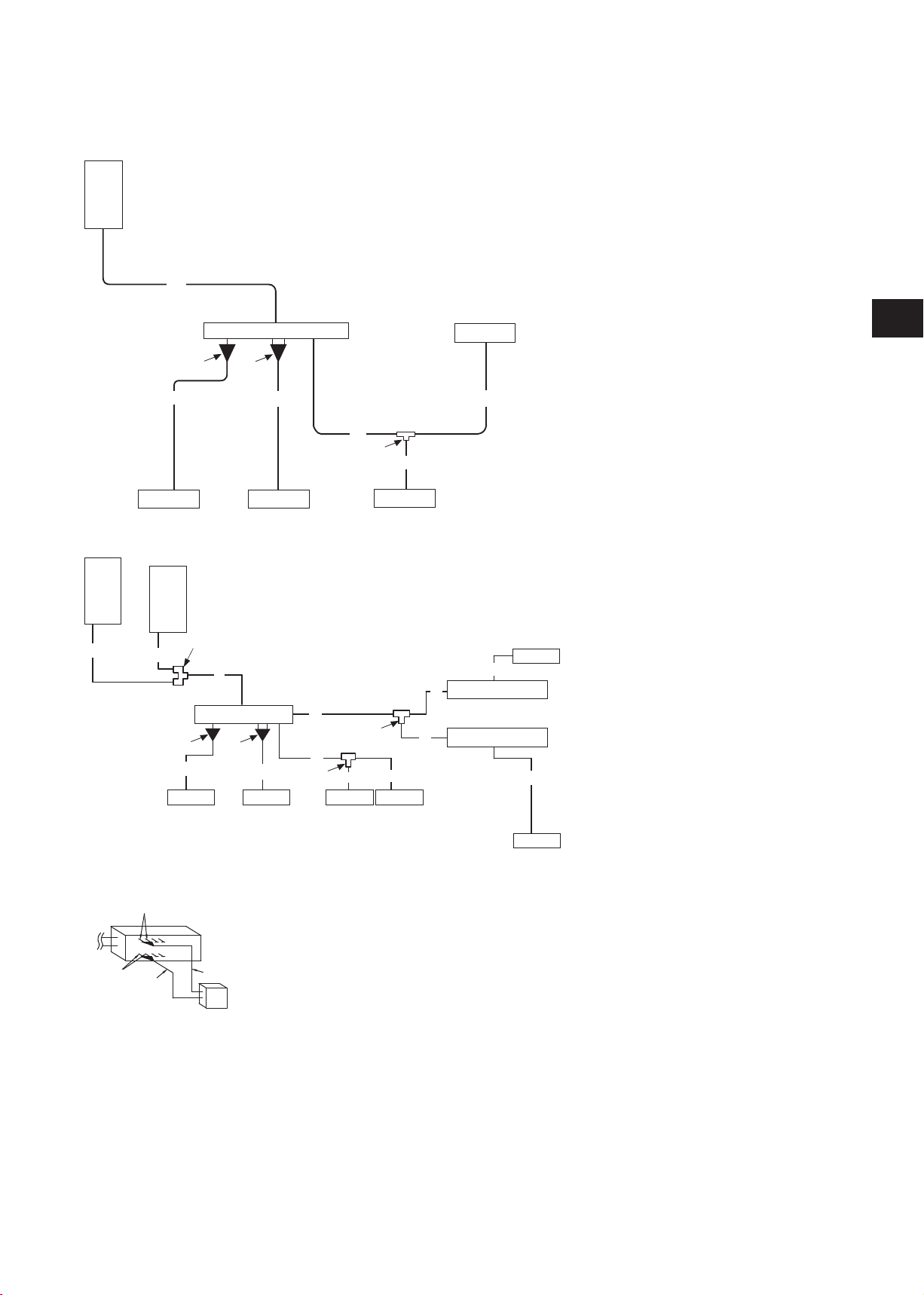
9-4-2. Example of pipe connection between an outdoor unit and BC controller, and
between a BC controller and indoor unit (R2 system)
P200 to P500YLM-A
EP200 to EP500YLM-A
Unit 1
Ⓐ
A
ⒷⒸ
Ⓖ
Ⓗ
Ⓔ
Ⓐ Outdoor unit
Ⓑ BC controller (Standard)
Ⓒ BC controller (Main)
Ⓓ BC controller (Sub)
Ⓔ Indoor unit (Total capacity of downstream indoor
units: 15 to 80)
Ⓕ Indoor unit (Total capacity of downstream indoor
units: 100 to 250)
Ⓖ Reducer
Ⓗ Joint Pipe Kit
Ⓘ 2-Branch Joint Pipe
Ⓙ Outdoor unit twinning kit
GB
a
Ⓔ ⒺⒻ
P400 to P900YSLM
EP500 to EP900YSLM
Unit 1
Ⓐ
A1
Unit 2
Ⓐ
Ⓙ
A2
Ⓖ
a
Ⓔ ⒺⒻ Ⓔ
b
d
B
Ⓘ
c
Ⓔ
A
D
Ⓒ
Ⓗ
b
C
B
Ⓘ
*1
Ⓘ
c d
E
e
Ⓓ
Ⓓ
f
*1
WT07282X01
Ⓔ
h
ⒷⒸⒹ
j
i
g
Ⓕ
GB-23

(1) P models
Pipes A, A1, A2 [mm]
Unit model
1
Combination unit Pipe A Pipe A
1*
Unit 1 Unit 2 High-pressure Low-pressure High-pressure Low-pressure High-pressure Low-pressure
Pipe A2*
1
P200YLM-A - - ø15.88 ø19.05 - - - P250YLM-A - - ø19.05 ø22.2 - - - P300YLM-A - - ø19.05 ø22.2 - - - P350YLM-A - - ø19.05 ø28.58 - - - P400YLM-A - - ø22.2 ø28.58 - - - P400YSLM-A P200 P200 ø22.2 ø28.58 ø15.88 ø19.05 ø15.88 ø19.05
P450YLM-A - - ø22.2 ø28.58 - - - P450YSLM-A P250 P200 ø22.2 ø28.58 ø19.05 ø22.2 ø15.88 ø19.05
P500YLM-A - - ø22.2 ø28.58 - - - P500YSLM-A P250 P250 ø22.2 ø28.58 ø19.05 ø22.2 ø19.05 ø22.2
P550YSLM-A P300 P250 ø28.58 ø28.58 ø19.05 ø22.2 ø19.05 ø22.2
P600YSLM-A P300 P300 ø28.58 ø28.58 ø19.05 ø22.2 ø19.05 ø22.2
P650YSLM-A P350 P300 ø28.58 ø28.58 ø19.05 ø28.58 ø19.05 ø22.2
P700YSLM-A P350 P350 ø28.58 ø34.93 ø19.05 ø28.58 ø19.05 ø28.58
P750YSLM-A P400 P350 ø28.58 ø34.93 ø22.2 ø28.58 ø19.05 ø28.58
P800YSLM-A P400 P400 ø28.58 ø34.93 ø22.2 ø28.58 ø22.2 ø28.58
P850YSLM-A P450 P400 ø28.58 ø41.28 ø22.2 ø28.58 ø22.2 ø28.58
P900YSLM-A P450 P450 ø28.58 ø41.28 ø22.2 ø28.58 ø22.2 ø28.58
Pipes A, A1, A2 [in]
Unit model
1
Combination unit Pipe A Pipe A
1*
Unit 1 Unit 2 High-pressure Low-pressure High-pressure Low-pressure High-pressure Low-pressure
Pipe A2*
1
P200YLM-A - - ø5/8 ø3/4 - - - P250YLM-A - - ø3/4 ø7/8 - - - P300YLM-A - - ø3/4 ø7/8 - - - P350YLM-A - - ø3/4 ø1-1/8 - - - P400YLM-A - - ø7/8 ø1-1/8 - - - P400YSLM-A P200 P200 ø7/8 ø1-1/8 ø5/8 ø3/4 ø5/8 ø3/4
P450YLM-A - - ø7/8 ø1-1/8 - - - P450YSLM-A P250 P200 ø7/8 ø1-1/8 ø3/4 ø7/8 ø5/8 ø3/4
P500YLM-A - - ø7/8 ø1-1/8 - - - P500YSLM-A P250 P250 ø7/8 ø1-1/8 ø3/4 ø7/8 ø3/4 ø7/8
P550YSLM-A P300 P250 ø1-1/8 ø1-1/8 ø3/4 ø7/8 ø3/4 ø7/8
P600YSLM-A P300 P300 ø1-1/8 ø1-1/8 ø3/4 ø7/8 ø3/4 ø7/8
P650YSLM-A P350 P300 ø1-1/8 ø1-1/8 ø3/4 ø1-1/8 ø3/4 ø7/8
P700YSLM-A P350 P350 ø1-1/8 ø1-3/8 ø3/4 ø1-1/8 ø3/4 ø1-1/8
P750YSLM-A P400 P350 ø1-1/8 ø1-3/8 ø7/8 ø1-1/8 ø3/4 ø1-1/8
P800YSLM-A P400 P400 ø1-1/8 ø1-3/8 ø7/8 ø1-1/8 ø7/8 ø1-1/8
P850YSLM-A P450 P400 ø1-1/8 ø1-5/8 ø7/8 ø1-1/8 ø7/8 ø1-1/8
P900YSLM-A P450 P450 ø1-1/8 ø1-5/8 ø7/8 ø1-1/8 ø7/8 ø1-1/8
*1 If the combination units 1 and 2 are in a different order as listed in the table, make sure to use the pipes of appropriate size for the situation.
(2) EP models
Pipes A, A1, A2 [mm]
Unit model
Combination unit Pipe A Pipe A
Unit 1 Unit 2 High-pressure Low-pressure High-pressure Low-pressure High-pressure Low-pressure
EP200YLM-A - - ø15.88 ø19.05 - - - EP250YLM-A - - ø19.05 ø22.2 - - - EP300YLM-A - - ø19.05 ø22.2 - - - EP350YLM-A - - ø19.05 ø28.58 - - - EP400YLM-A - - ø22.2 ø28.58 - - - EP450YLM-A - - ø22.2 ø28.58 - - - EP500YLM-A - - ø22.2 ø28.58 - - - EP500YSLM-A EP250 EP250 ø22.2 ø28.58 ø19.05 ø22.2 ø19.05 ø22.2
EP550YSLM-A EP300 EP250 ø28.58 ø28.58 ø19.05 ø22.2 ø19.05 ø22.2
EP600YSLM-A EP300 EP300 ø28.58 ø28.58 ø19.05 ø22.2 ø19.05 ø22.2
EP650YSLM-A EP350 EP300 ø28.58 ø28.58 ø19.05 ø28.58 ø19.05 ø22.2
EP700YSLM-A EP350 EP350 ø28.58 ø34.93 ø19.05 ø28.58 ø19.05 ø28.58
EP750YSLM-A EP400 EP350 ø28.58 ø34.93 ø22.2 ø28.58 ø19.05 ø28.58
EP800YSLM-A EP400 EP400 ø28.58 ø34.93 ø22.2 ø28.58 ø22.2 ø28.58
EP850YSLM-A EP450 EP400 ø28.58 ø41.28 ø22.2 ø28.58 ø22.2 ø28.58
EP900YSLM-A EP450 EP450 ø28.58 ø41.28 ø22.2 ø28.58 ø22.2 ø28.58
WT07282X01
GB-24
1
1*
Pipe A2*
1
Pipes A, A1, A2 [in]
Unit model
EP200YLM-A - - ø5/8 ø3/4 - - - EP250YLM-A - - ø3/4 ø7/8 - - - EP300YLM-A - - ø3/4 ø7/8 - - - EP350YLM-A - - ø3/4 ø1-1/8 - - - EP400YLM-A - - ø7/8 ø1-1/8 - - - EP450YLM-A - - ø7/8 ø1-1/8 - - - EP500YLM-A - - ø7/8 ø1-1/8 - - - EP500YSLM-A EP250 EP250 ø7/8 ø1-1/8 ø3/4 ø7/8 ø3/4 ø7/8
EP550YSLM-A EP300 EP250 ø1-1/8 ø1-1/8 ø3/4 ø7/8 ø3/4 ø7/8
EP600YSLM-A EP300 EP300 ø1-1/8 ø1-1/8 ø3/4 ø7/8 ø3/4 ø7/8
EP650YSLM-A EP350 EP300 ø1-1/8 ø1-1/8 ø3/4 ø1-1/8 ø3/4 ø7/8
EP700YSLM-A EP350 EP350 ø1-1/8 ø1-3/8 ø3/4 ø1-1/8 ø3/4 ø1-1/8
EP750YSLM-A EP400 EP350 ø1-1/8 ø1-3/8 ø7/8 ø1-1/8 ø3/4 ø1-1/8
EP800YSLM-A EP400 EP400 ø1-1/8 ø1-3/8 ø7/8 ø1-1/8 ø7/8 ø1-1/8
EP850YSLM-A EP450 EP400 ø1-1/8 ø1-5/8 ø7/8 ø1-1/8 ø7/8 ø1-1/8
EP900YSLM-A EP450 EP450 ø1-1/8 ø1-5/8 ø7/8 ø1-1/8 ø7/8 ø1-1/8
*1 If the combination units 1 and 2 are in a different order as listed in the table, make sure to use the pipes of appropriate size for the situation.
Combination unit Pipe A Pipe A
Unit 1 Unit 2 High-pressure Low-pressure High-pressure Low-pressure High-pressure Low-pressure
1
1*
Pipe A2*
1
(3) P and EP models
Pipe B [mm (in)]
Total capacity of indoor units
80 or below ø9.52 (ø3/8) ø15.88 (ø5/8)
Liquid Gas
Pipe
GB
Pipes C, D, E [mm (in)]
Total model number of
downstream indoor units
200 or below ø15.88 (ø5/8) ø19.05 (ø3/4) ø9.52 (ø3/8)
201 to 300 ø19.05 (ø3/4) ø22.2 (ø7/8) ø9.52 (ø3/8)
301 to 350 ø19.05 (ø3/4) ø28.58 (ø1-1/8) ø12.7 (ø1/2)
351 to 400 ø22.2 (ø7/8) ø28.58 (ø1-1/8) ø12.7 (ø1/2)
401 to 450 ø22.2 (ø7/8) ø28.58 (ø1-1/8) ø15.88 (ø5/8)
Pipes a,b,c,d,e,f [mm (in)]
Capacity index of indoor unit
15, 20, 25, 32, 40, 50 ø6.35 (ø1/4) ø12.7 (ø1/2)
63, 71, 80, 100, 125, 140 ø9.52 (ø3/8) ø15.88 (ø5/8)
200 ø9.52 (ø3/8) ø19.05 (ø3/4)
250 ø9.52 (ø3/8) ø22.2 (ø7/8)
Pipes g, h, i, j [mm (in)]
Capacity index of indoor unit
100 ø9.52 (ø3/8) ø9.52 (ø3/8) ø15.88 (ø5/8) ø15.88 (ø5/8)
125 ø9.52 (ø3/8) ø9.52 (ø3/8) ø15.88 (ø5/8) ø15.88 (ø5/8)
140 ø9.52 (ø3/8) ø9.52 (ø3/8) ø15.88 (ø5/8) ø15.88 (ø5/8)
200 ø9.52 (ø3/8) ø9.52 (ø3/8) ø19.05 (ø3/4) ø15.88 (ø5/8)
250 ø9.52 (ø3/8) ø9.52 (ø3/8) ø22.2 (ø7/8) ø15.88 (ø5/8)
High-pressure Low-pressure Liquid
Liquid Gas
Liquid pipe Gas pipe
g h i j
Pipe
Pipe
9-4-3. Example of pipe connection between an outdoor unit and HBC controller, and
between an HBC controller and indoor unit (Hybrid City Multi system)
Refer to the HBC controller Installation Manual for details.
WT07282X01
GB-25
9-5. Piping connections and valve operations
Before heating the brazed sections, remove the gas and oil that are trapped in the pipes.
- Failure to do so may generate fire, resulting in serious injury.
Ventilate the room while servicing the unit.
- If the refrigerant leaks, oxygen deficiency may result. If the leaked refrigerant comes in contact
with a heat source, toxic gas will be generated.
Store pipes indoors, and keep both ends of the pipes sealed until just before making a
flare connection or brazing. (Store elbows and other joints in plastic bags.)
- If dust, dirt, or water enters the refrigerant lines, the refrigerant oil will deteriorate and the
compressor will malfunction.
Keep the service valves closed until refrigerant charging is completed.
- Failure to do so will damage the unit.
Place a wet towel on the service valves before brazing the pipes to keep the temperature of
the valves from rising above 120ºC (248ºF).
- Failure to do so may result in equipment damage.
Keep the flame out of contact with the cables and metal sheet when brazing the pipes.
- Failure to do so may result in burnout or malfunction.
Braze the pipes with a nitrogen purge to avoid oxidation.
- Oxidized flux inside the refrigerant pipes will cause the refrigerant oil to deteriorate and cause
the compressor to malfunction.
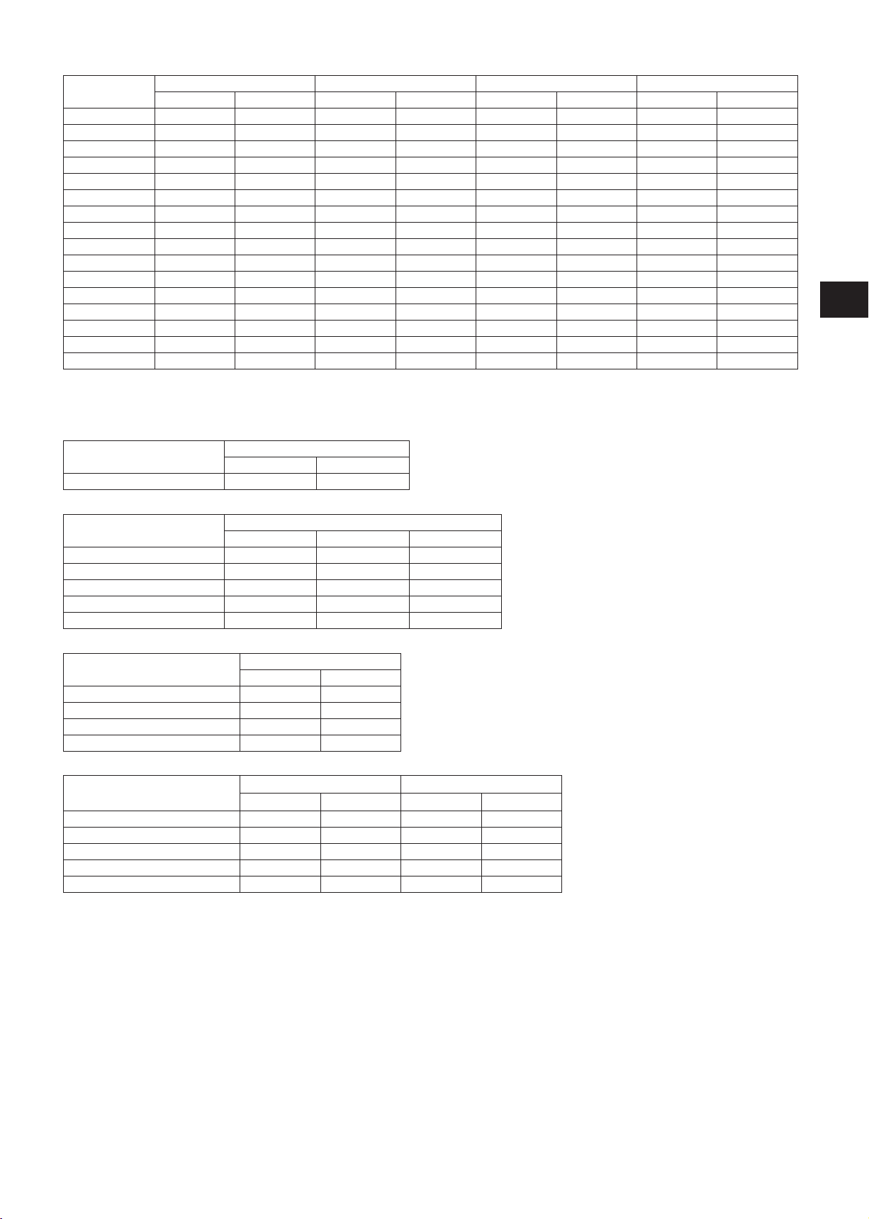
9-5-1. Removing the pinched connecting pipes
The unit is shipped with the pinched connecting pipes attached to the high- and low-pressure side service valves to
prevent gas leakage.
Take the following steps ① through ③ to remove the pinched connecting pipes before connecting refrigerant pipes to
the outdoor unit.
① Check that the service valves are fully closed (turned clockwise all the way).
② Remove the gas in the pinched connecting pipes, and drain out all the refrigerant oil. (See Ⓔ below.)
③ Remove the pinched connecting pipes. (See Ⓕ below.)
P models EP models
Ⓒ
<A>
<B>
<C>
Ⓓ
Ⓐ
Ⓑ
Ⓒ
Ⓕ
<A> <B> <A> <B>
Ⓓ
Ⓐ
Ⓒ
Ⓕ
Ⓒ
Ⓐ
Ⓓ
Ⓐ
Ⓐ
Ⓑ
Ⓒ
Ⓕ
Ⓔ
WT07282X01
Ⓔ
P200 to P400 P450, P500 EP200 to EP500
Ⓔ
GB-26
<A> Refrigerant service valve (high-pressure/brazed)
<B> Refrigerant service valve (low-pressure/brazed)
<C> (EP models only)
Refrigerant service valve (low-pressure gas/brazed)
Used only when a separately-sold unit is attached. Refer to the Installation Manual of the unit for details.
Ⓐ Valve shaft
The unit is shipped with the valve closed. Keep the valve closed while connecting pipes or evacuating the system. Open the valve upon
completion of this work.
Turn the shaft counterclockwise as far as it will go (90˚) to open the valve, and clockwise to close it.
Ⓑ Stopper pin
Prevents the shaft from turning 90˚ or more.
Ⓒ Service port
Through the service ports, you can charge refrigerant, remove the gas in the pinched connecting pipes, or evacuate the system.
Ⓓ Cap
Remove the cap before turning the shaft. Put the cap back on upon completion of all work.
Ⓔ Severed section of the pinched connecting pipe
Ⓕ Brazed section of the pinched connecting pipe
9-5-2. Connecting pipes
・The refrigerant pipe from the outdoor unit is branched at the pipe end, and each branch is then connected to an
indoor unit.
Connecting method
Indoor unit Brazed or flared
Outdoor unit
・Refer to section 5 "Package contents" for details about the supplied connecting pipes.
・When connecting pipes, make sure the service valves are completely closed.
・Commercially available pipes often contain dust or debris. Always blow them clean with a dry inert gas.
・Take care to prevent dust, water or other contaminants from entering the pipes during installation.
・Reduce the number of bending portions as much as possible, and make the bending radius as big as possible.
・Do not use any commercially available anti-oxidizing agents since they may cause pipe corrosion and degrading of
the refrigerant oil. Please contact Mitsubishi Electric for more details.
・Make sure that the pipes are not in contact with each other, unit panels, or base plates.
・Refer to the twinning kit Installation Manual for how to install the twinning kit.
High-pressure pipe Brazed
Low-pressure pipe Brazed
Branched section Brazed
GB
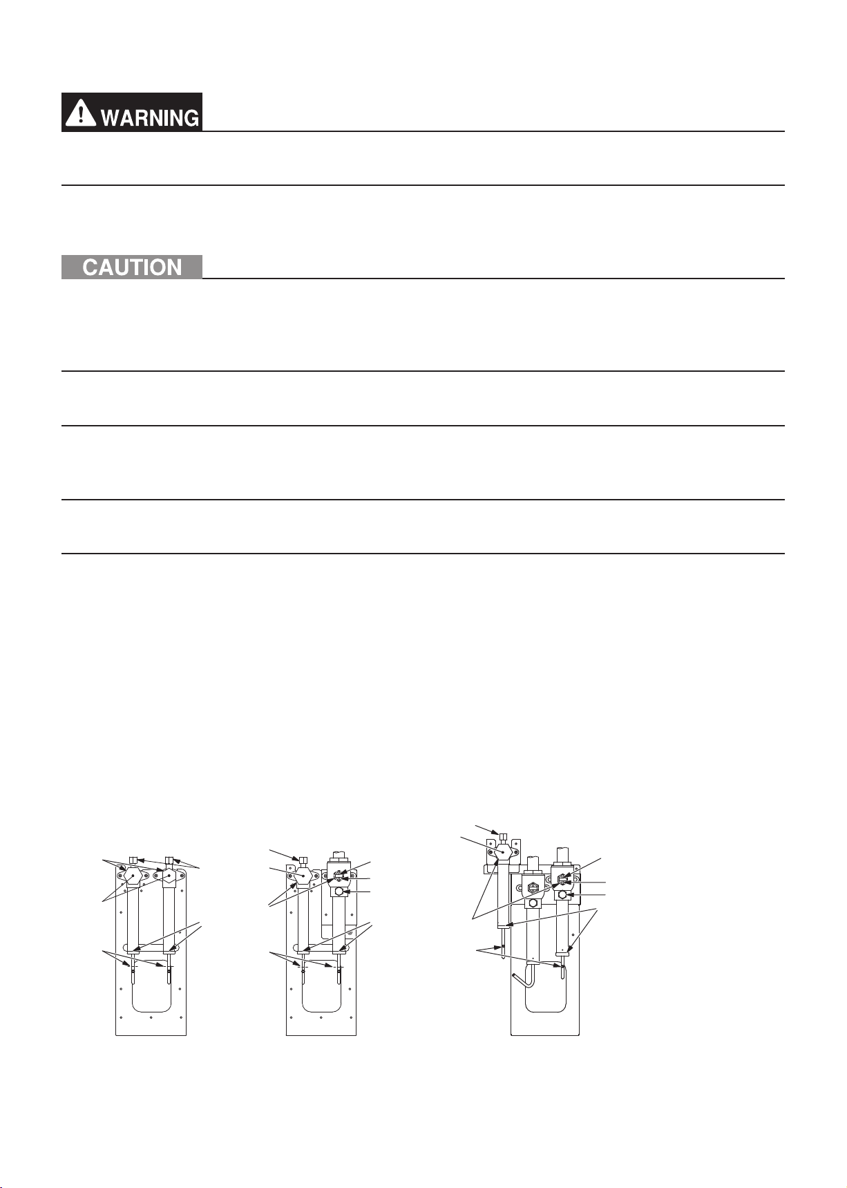
(1) P models
When routing the pipes through the front of the unit
Ⓐ
* The figure shows a unit on which an outdoor unit twinning kit
(low-pressure side) is not installed.
Ⓑ
Ⓒ
Ⓓ
Ⓔ
Ⓕ
Ⓖ
Ⓗ
Ⓐ
* The figure shows a unit on which an outdoor unit twinning kit
(low-pressure side) is installed.
Ⓑ
Ⓘ
Ⓙ
Ⓚ
Ⓗ
WT07282X01
GB-27
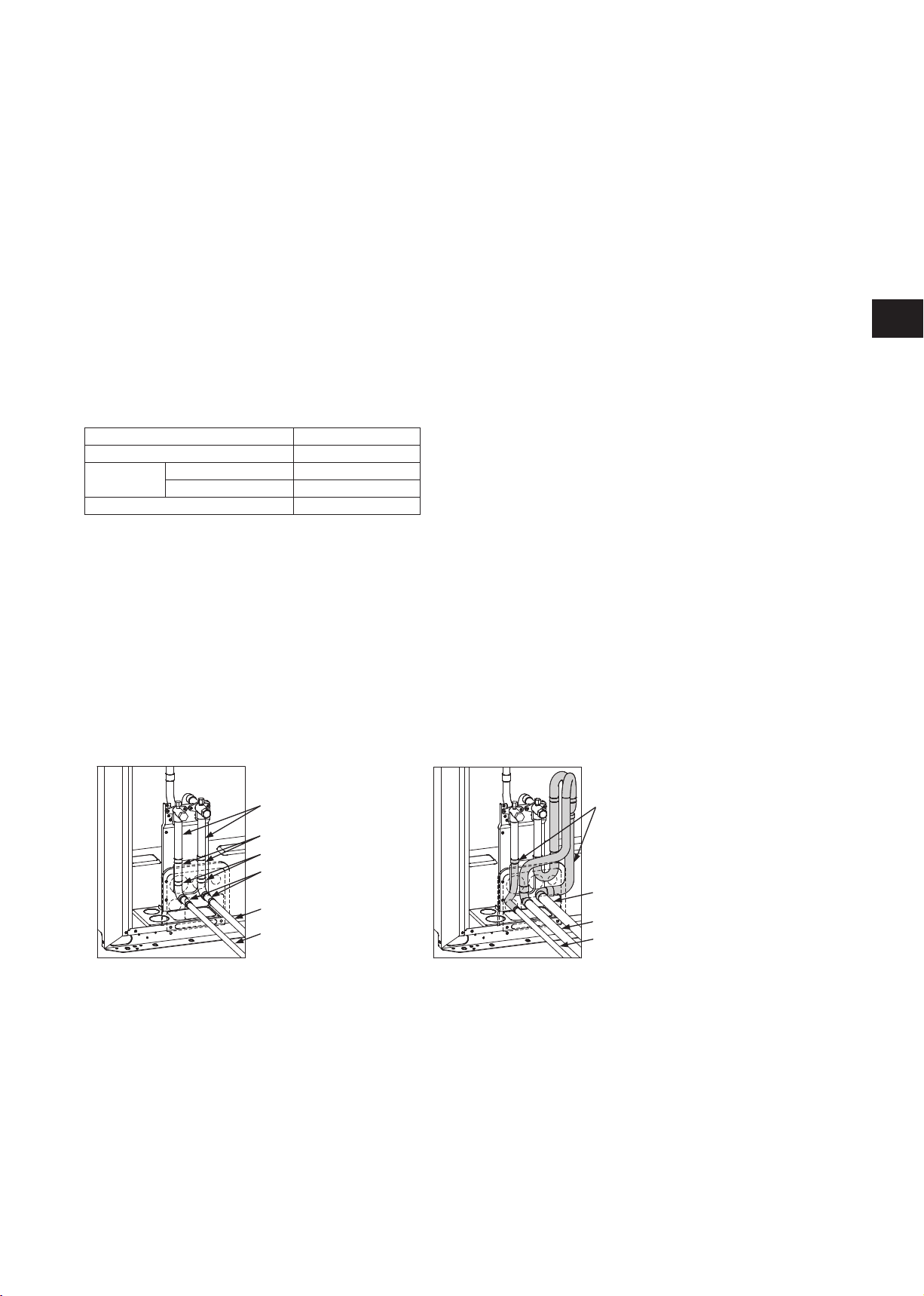
When routing the pipes through the bottom of the unit
Ⓐ
* The figure shows a unit on which an outdoor unit twinning kit
(low-pressure side) is not installed.
Ⓑ
Ⓒ
Ⓕ
Ⓖ
Ⓗ
* The figure shows a unit on which an outdoor unit twinning kit
(low-pressure side) is installed.
Ⓐ
Ⓐ Refrigerant service valve (high-pressure)
Ⓑ Refrigerant service valve (low-pressure)
Ⓒ Service valve piping
Ⓓ On-site piping (Adjust the piping position to the knockout hole.)
Ⓔ Supplied connecting elbow
Ⓕ Reducer etc.
Ⓖ On-site piping (low-pressure side)
Ⓗ On-site piping (high-pressure side)
Ⓘ Outdoor unit twinning kit
Ⓙ On-site piping to an outdoor unit (low-pressure side)
Ⓚ In an R2 system: On-site piping to a BC controller (low-pressure side)
In a Hybrid City Multi system: On-site piping to an HBC controller (low-pressure side)
Ⓑ
Ⓘ
Ⓚ
Ⓙ
Ⓗ
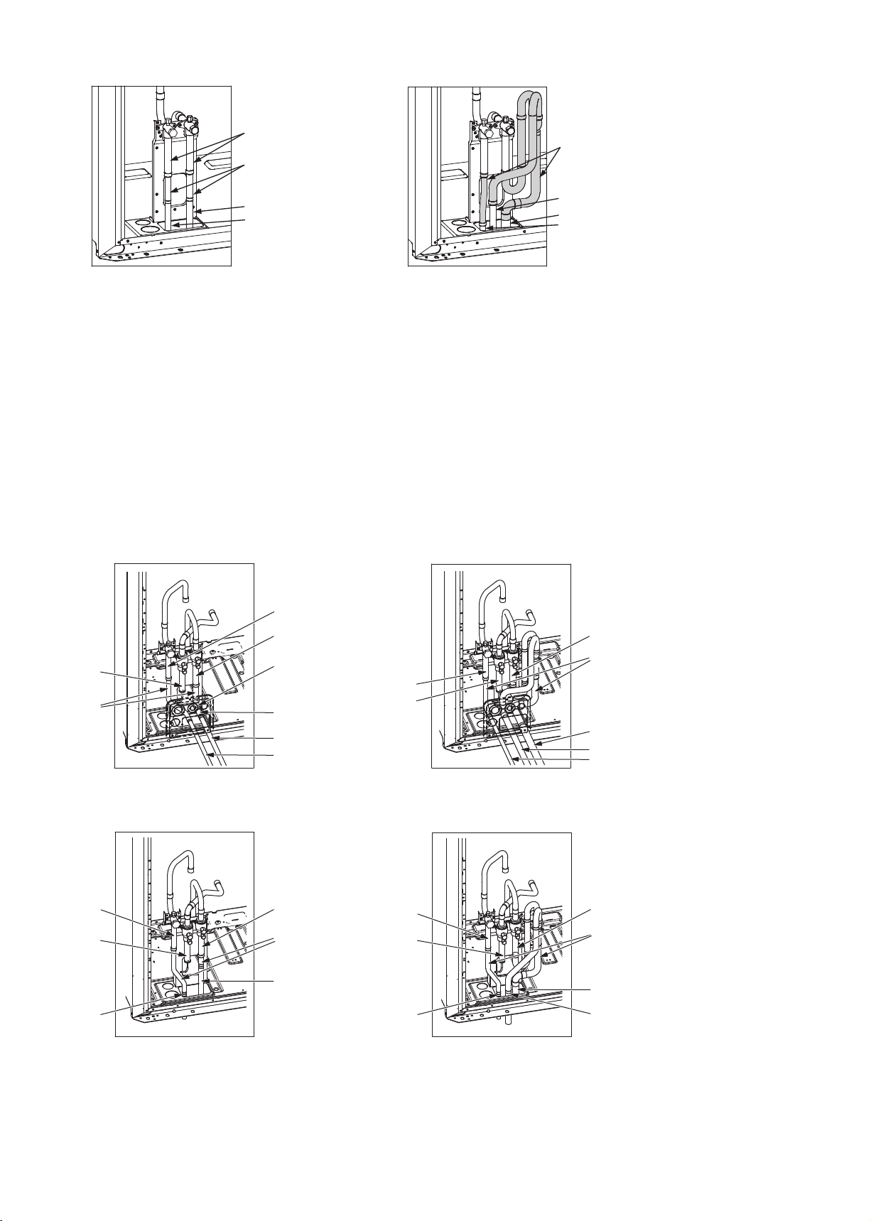
(2) EP models
When routing the pipes through the front of the unit
Ⓐ
Ⓑ
Ⓒ
Ⓓ
* The figure shows a unit on which an outdoor unit twinning kit
(low-pressure side) is not installed.
Ⓔ
Ⓕ
Ⓖ
Ⓗ
When routing the pipes through the bottom of the unit
Ⓐ
Ⓒ
Ⓑ
Ⓕ
Ⓑ
Ⓘ
Ⓐ
Ⓒ
Ⓚ
Ⓙ
Ⓗ
* The figure shows a unit on which an outdoor unit twinning kit
(low-pressure side) is installed.
Ⓐ
Ⓒ
Ⓑ
Ⓘ
Ⓖ
Ⓗ
* The figure shows a unit on which an outdoor unit twinning kit
(low-pressure side) is not installed.
Ⓐ Refrigerant service valve (high-pressure)
Ⓑ Refrigerant service valve (low-pressure)
Ⓒ Refrigerant service valve (low-pressure gas)
Ⓓ On-site piping (Adjust the piping position to the knockout hole.)
Ⓔ Supplied connecting elbow
WT07282X01
Ⓚ
Ⓗ
* The figure shows a unit on which an outdoor unit twinning kit
(low-pressure side) is installed.
Ⓙ
GB-28
 Loading...