

Mitsubishi Electric PURY-80TMU, PURY-100TMU-A, CMB-104, CMB-105, CMB-106 Service Manual
...
AIR CONDITIONERS CITY MULTI
Models PURY-80TMU, 100TMU
PURY-80TMU-A, 100TMU-A
CMB-104, 105, 106, 108, 1010, 1013, 1016NU-F
Service Handbook

–1–
Contents
1 PRECAUTIONS FOR DEVICES .............................................................. 3
[1] Storage of Piping Material ................................................................. 3
[2] Brazing .............................................................................................. 4
[3] Airtightness Test ................................................................................ 5
[4] Vacuuming ........................................................................................ 5
2 COMPONENT OF EQUIPMENT ............................................................. 6
[1] Appearance of Components ............................................................. 6
[2] Refrigerant Circuit Diagram and Thermal Sensor ........................... 13
[3] Electrical Wiring Diagram ................................................................ 14
[4] Standard Operation Data ................................................................ 18
[5] Function of Dip SW and Rotary SW ................................................ 20
3 TEST RUN ............................................................................................. 23
[1] Before Test Run .............................................................................. 23
[2] Test Run Method ............................................................................. 27
4 GROUPING REGISTRATION OF INDOOR UNITS WITH REMOTE
CONTROLLER ....................................................................................... 28
5 CONTROL .............................................................................................. 34
[1] Control of Outdoor Unit ................................................................... 34
[2] Control of BC Controller .................................................................. 37
[3] Operation Flow Chart ...................................................................... 38
[4] List of Major Component Functions ................................................ 44
[5] Resistance of Temperature Sensor ................................................. 47
6 REFRIGERANT AMOUNT ADJUSTMENT ............................................ 48
[1] Refrigerant Amount and Operating Characteristics ........................ 48
[2] Adjustment and Judgement of Refrigerant Amount ........................ 48
7 TROUBLESHOOTING ........................................................................... 54
[1] Principal Parts ................................................................................. 54
[2] BC Controller Disassembly Procedure ........................................... 80
[3] Self-diagnosis and Countermeasures Depending on the Check
Code Displayed ............................................................................... 86
[4] LED Monitor Display ..................................................................... 108
8 PREPARATION, REPAIRS AND REFRIGERANT REFILLING WHEN
REPAIRING LEAKS ............................................................................. 118
[1] Location of leaks: Extension piping or indoor units (when cooling) 118
[2] Location of leaks: Outdoor unit (Cooling mode) ............................. 118
[3] Location of leaks:
Extension piping or indoor units (Heating mode)
119
[4] Location of leaks: Outdoor unit (when heating) ............................. 119

–2–
Safety precautions
Before installation and electric work
Before installing the unit, make sure you read all
the “Safety precautions”.
The “Safety precautions” provide very important
points regarding safety. Make sure you follow
them.
This equipment may not be applicable to
EN61000-3-2: 1995 and EN61000-3-3: 1995.
This equipment may have an adverse effect on
equipment on the same electrical supply system.
Please report to or take consent by the supply.
authority before connection to the system.
Symbols used in the text
Warning:
Describes precautions that should be observed to
prevent danger of injury or death to the user.
Caution:
Describes precautions that should be observed to
prevent damage to the unit.
Symbols used in the illustrations
: Indicates an action that must be avoided.
: Indicates that important instructions must be followed.
: Indicates a part which must be grounded.
: Beware of electric shock (This symbol is displayed on the
main unit label.) <Color: Yellow>
Warning:
Carefully read the labels affixed to the main unit.
Warning:
• Use the specified cables for wiring. Make the connections
securely so that the outside force of the cable is not
applied to the terminals.
- Inadequate connection and fastening may generate heat and
cause a fire.
• Have all electric work done by a licensed electrician
according to “Electric Facility Engineering Standard” and
“Interior Wire Regulations”and the instructions given in
this manual and always use a special circuit.
- If the power source capacity is inadequate or electric work is
performed improperly, electric shock and fire may result.
• Securely install the cover of control box and the panel.
- If the cover and panel are not installed properly, dust or water
may enter the outdoor unit and fire or electric shock may
result.
• After completing service work, make sure that refrigerant
gas is not leaking.
- If the refrigerant gas leaks and is exposed to a fan heater,
stove, oven, or other heat source, it may generate noxious
gases.
• Do not reconstruct or change the settings of the protection
devices.
- If the pressure switch, thermal switch, or other protection
device is shorted and operated forcibly, or parts other than
those specified by Mitsubishi Electric are used, fire or
explosion may result.
*
▲
▲
▲
▲
▲
–3–
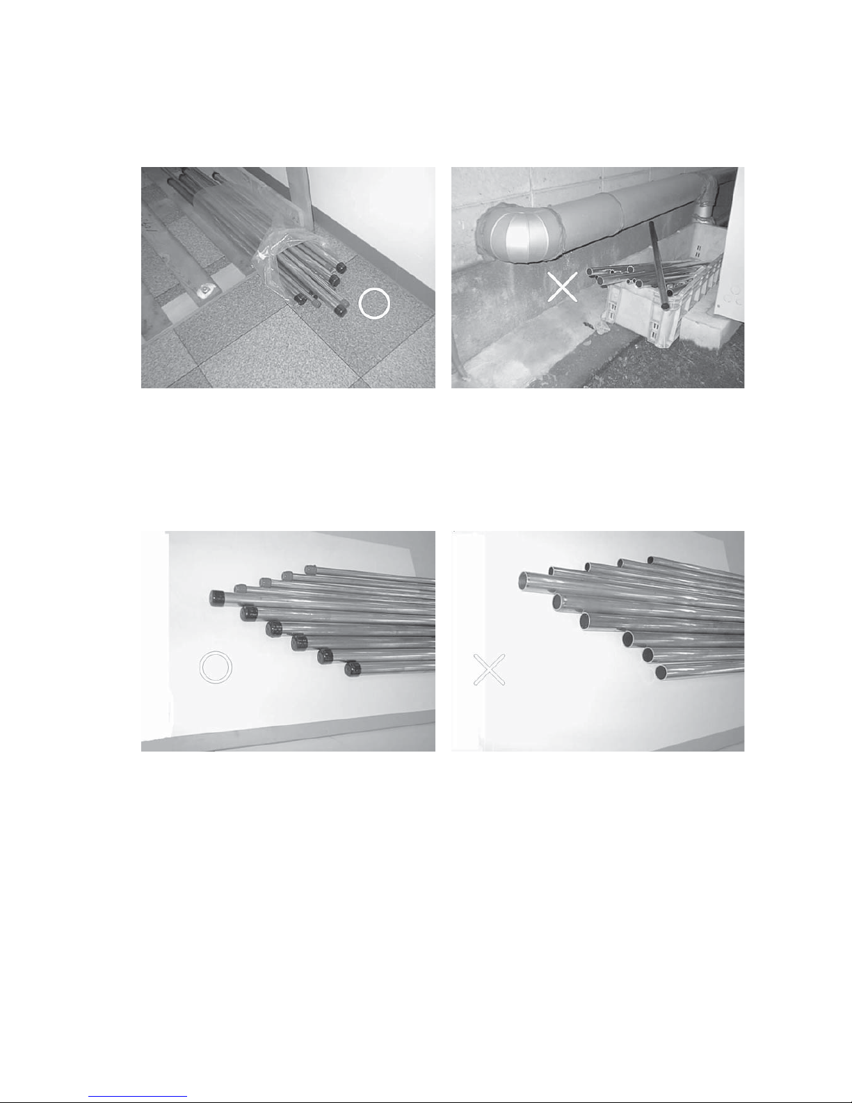
[1] Storage of Piping Material
(1) Storage location
Store the pipes to be used indoors. (Warehouse at site or owner’s warehouse)
Storing them outdoors may cause dirt, waste, or water to infiltrate.
(2) Pipe sealing before storage
Both ends of the pipes should be sealed until immediately before brazing.
Wrap elbows and T’s in plastic bags for storage.
11
11
1 PRECAUTIONS FOR DEVICES

–4–
[2] Brazing
No changes from the conventional method, but special care is required so that foreign matter (ie. oxide scale, water, dirt,
etc.) does not enter the refrigerant circuit.
Example : Inner state of brazed section
When non-oxide brazing was not used When non-oxide brazing was used
Items to be strictly observed :
1. Do not conduct refrigerant piping work outdoors on a rainy day.
2. Apply non-oxide brazing.
3. Use a brazing material (Bcup-3) which requires no flux when brazing between copper pipes or between a copper pipe
and copper coupling.
4. If installed refrigerant pipes are not immediately connected to the equipment, then braze and seal both ends of them.
Reasons :
1. A flux generally contains chlorine. A residual flux in the refrigerant circuit may generate sludge.
Note :
• Commercially available antioxidants may have adverse effects on the equipment due to its residue, etc. When
applying non-oxide brazing, use oxygen free nitrogen (OFN).

–5–
[3] Airtightness Test
Items to be strictly observed :
1. Pressurize the equipment with nitrogen up to the design pressure and then judge the equipment’s airtightness, taking
temperature variations into account.
Reasons :
1. Use of oxygen as the pressurized gas may cause an explosion.
[4] Vacuuming
1. Standard degree of vacuum for the vacuum pump
Use a pump which reaches 65 Pa (0.0094 psi) or below after 5 minutes of operation.
In addition, be sure to use a vacuum pump that has been properly maintained and oiled using the specified oil. If the
vacuum pump is not properly maintained, the degree of vacuum may be too low.
2. Required accuracy of the vacuum gauge
Use a vacuum gauge that can measure up to 650 Pa (0.094 psi). Do not use a general gauge manifold since it cannot
measure a vacuum of 650 Pa (0.094 psi).
3. Evacuating time
• Evacuate the equipment for 1 hour after 650 Pa (0.094 psi) has been reached.
• After envacuating, leave the equipment for 1 hour and make sure that the vacuum is not lost.
4. Operating procedure when the vacuum pump is stopped
In order to prevent a backflow of the vacuum pump oil, open the relief valve on the vacuum pump side or loosen the
charge hose to drawn in air before stopping operation.
The same operating procedure should be used when using a vacuum pump with a check valve.
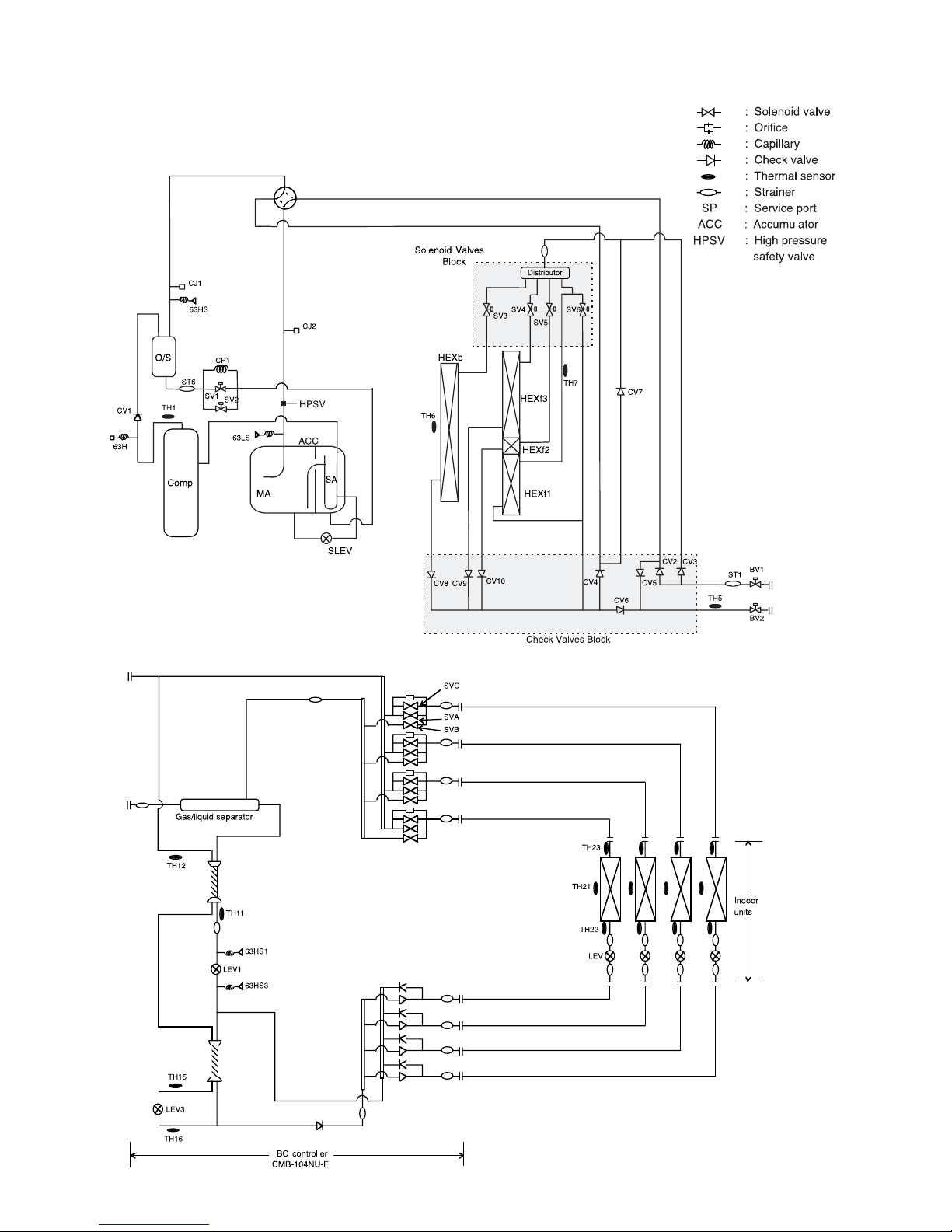
–6–
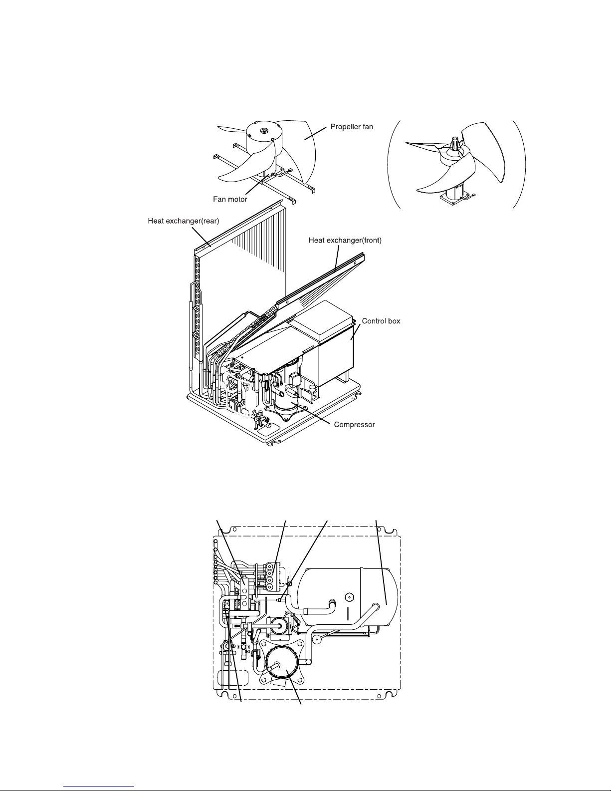
SV block Fusible plug
Accumulator
CV block
Compressor
4-way valve
22
22
2 COMPONENT OF EQUIPMENT
[1] Appearance of Components
In case of -A type.
–7–
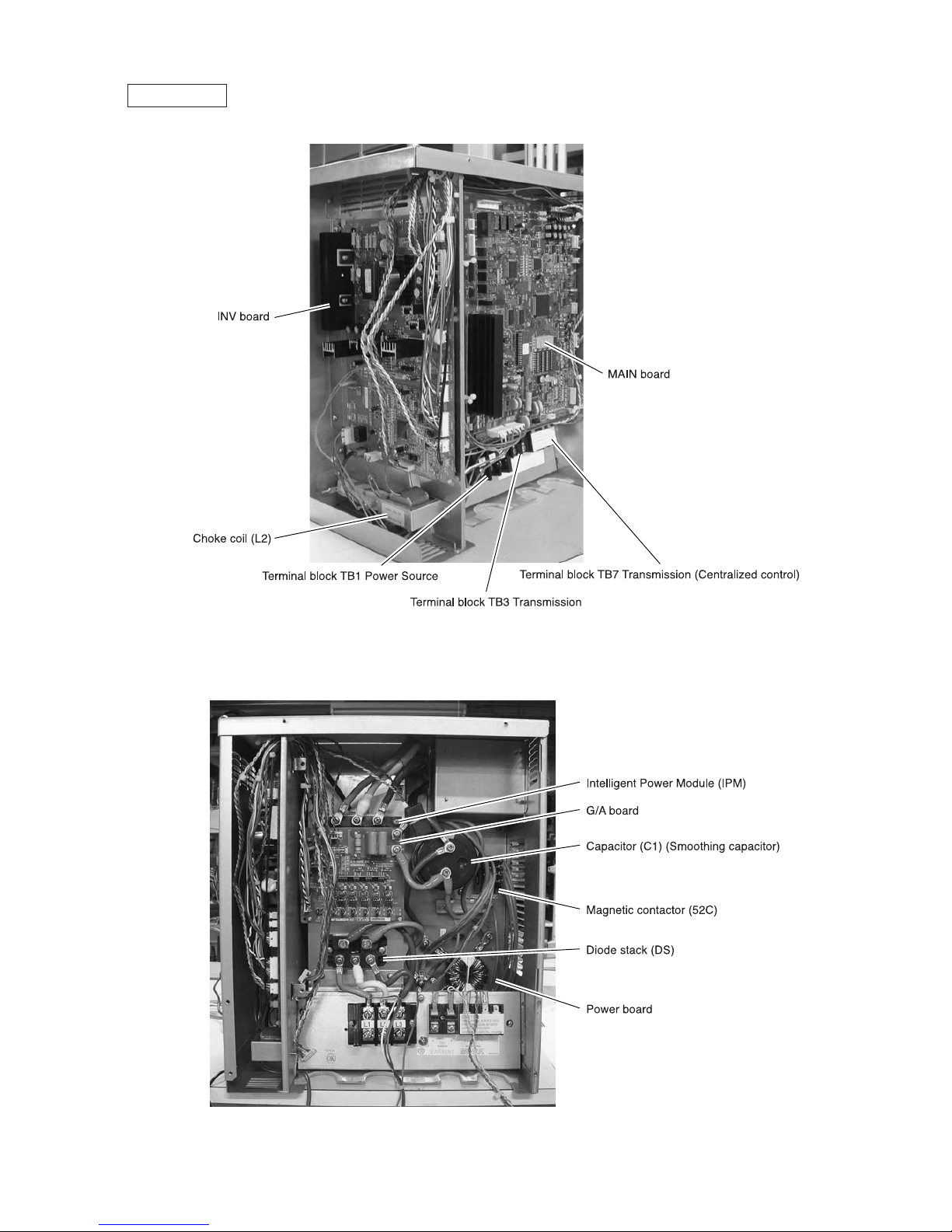
Controller Box
–8–
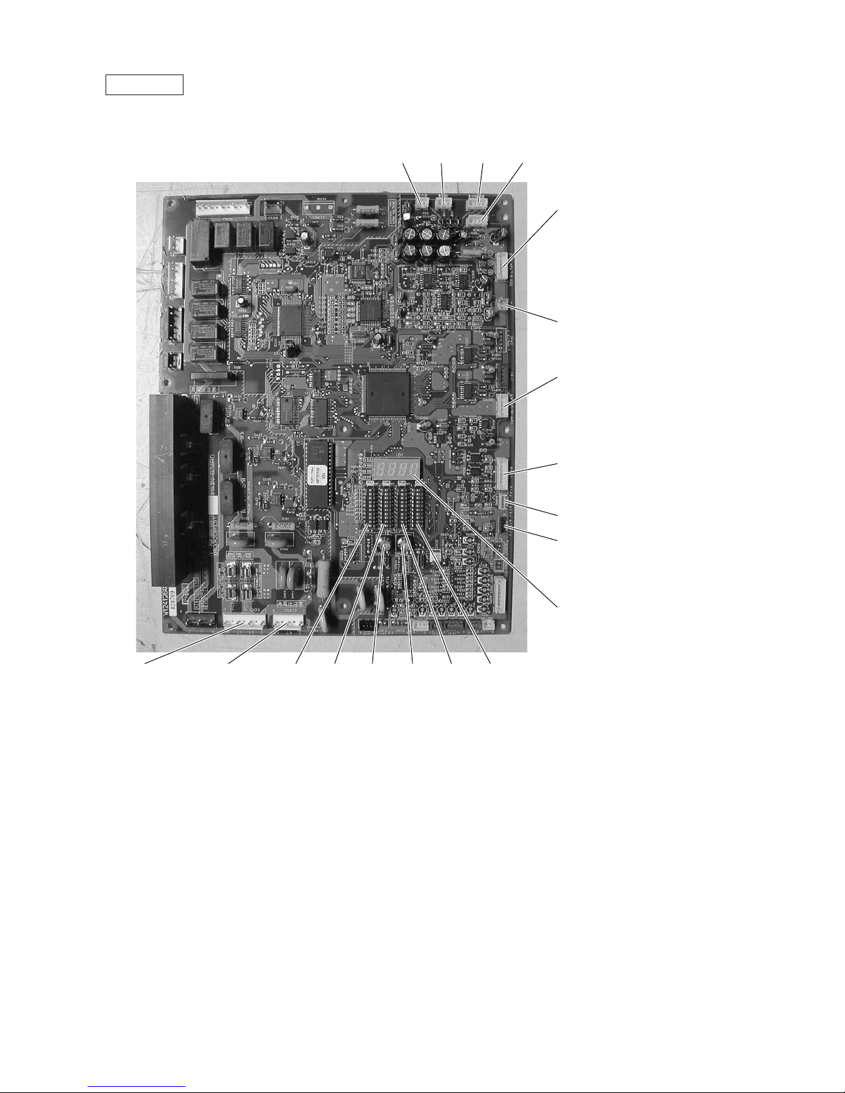
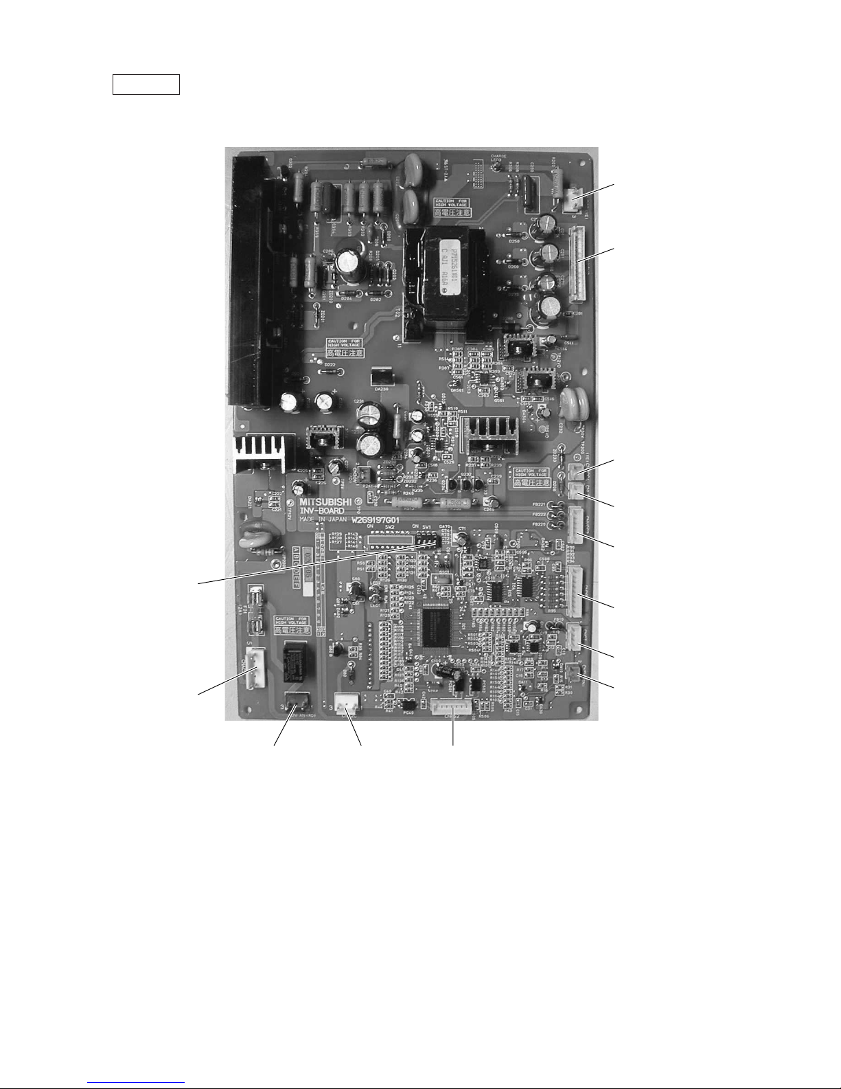
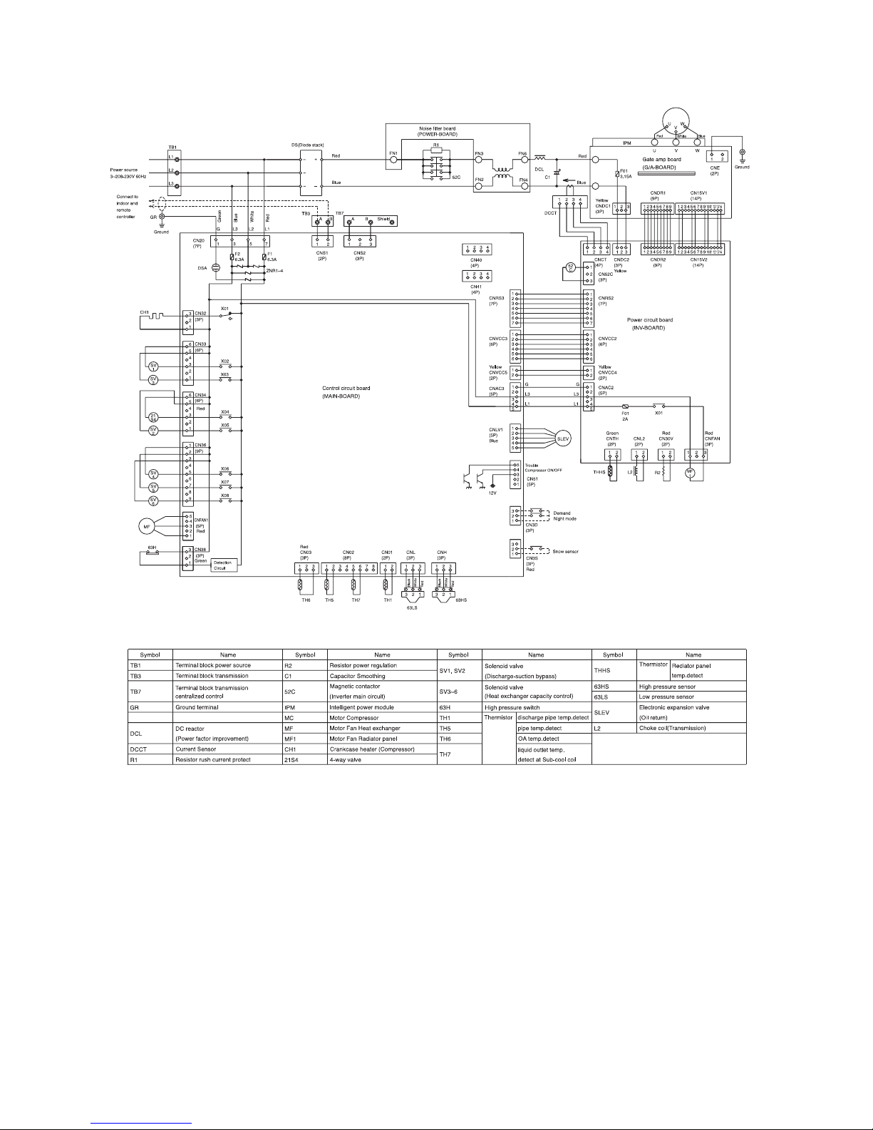
MAIN board
CNS1 CNS2 CN40 CN41
CNVCC3
Power Source
for control
1-2 30V
1-3 30V
4-6 12V
5-6 5V
CN51
Indication distance
3-4 Compressor ON/OFF
3-5 Trouble
CNRS3
Serial transmission to
INV board
CN3D
CN3S
LD1
Service LED
SW1
SW2SWU1SWU2SW3SW4CNAC3
Power Output
5 L1
3 L3
1 G
CN20
Power Input
7 L1
5 L2
3 L3
1 G
CNVCC5
Power Source for control(5V)
–9–
INV board
CNDC2
1-3 DC-325V
CN15V2
Power Output
for IPM control
CNVCC4
Power Output (5V)
CNL2
Choke coil
CNVCC2
Power Output
1-2 30V, 1-3 30V
4-6 12V, 5-6 5V
CNDR2
Output to
G/A board
CNCT
CNTH
CNRS2
Serial transmission
to MAIN board
CN52C
Control for 52C
CNFAN
Control for MF1
CNAC2
Power Input
5 L1
3 L3
1 G
SW1
–10–
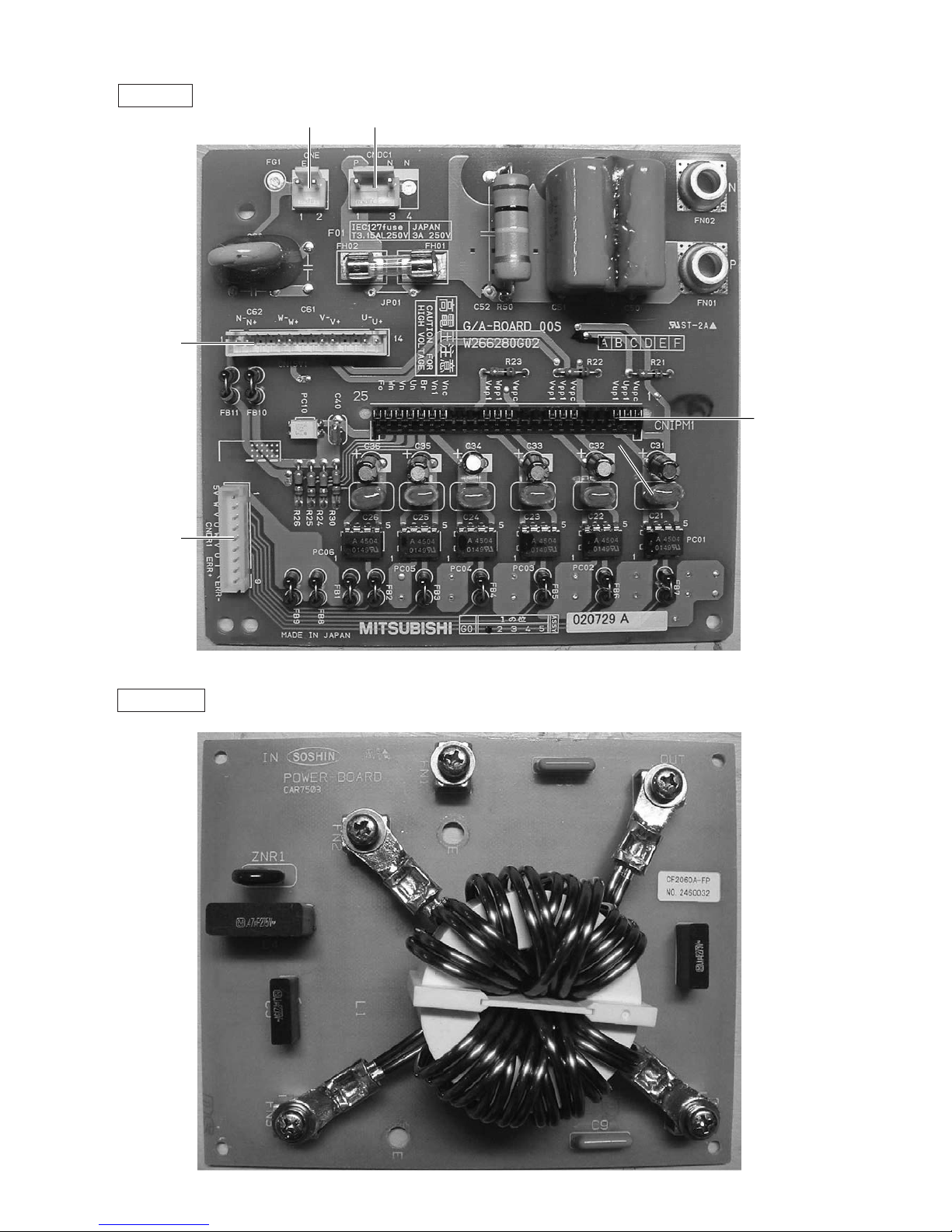
G/A board
CNIPM1
CN15V1
CNDR1
CNE CNDC1
Power board
–11–
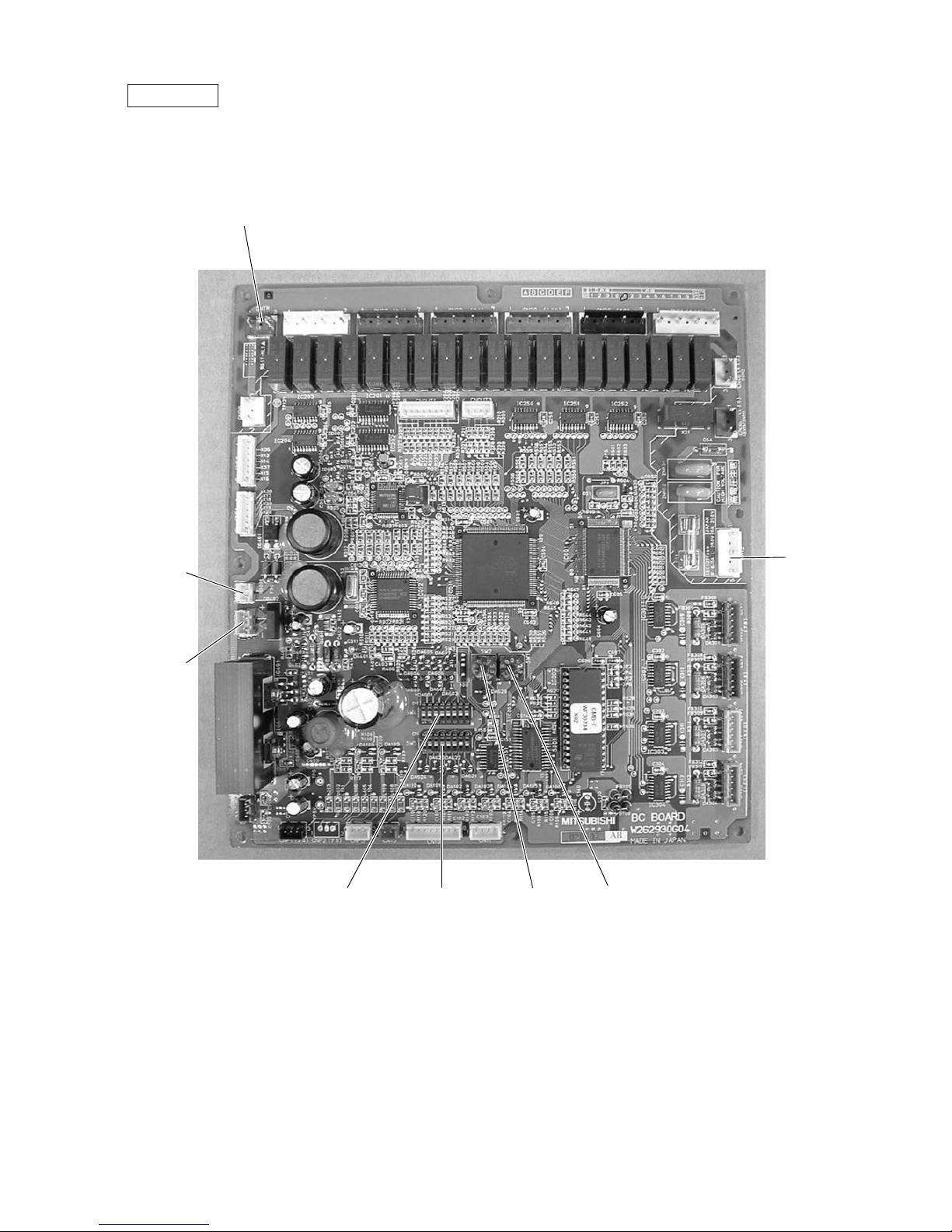
BC controller
CNTR
CN02
M-NET
transmission
CN03
CN12
Power
supply
1 EARTH
3 N
5 L
SW4 SW2 SW1SW5
–12–
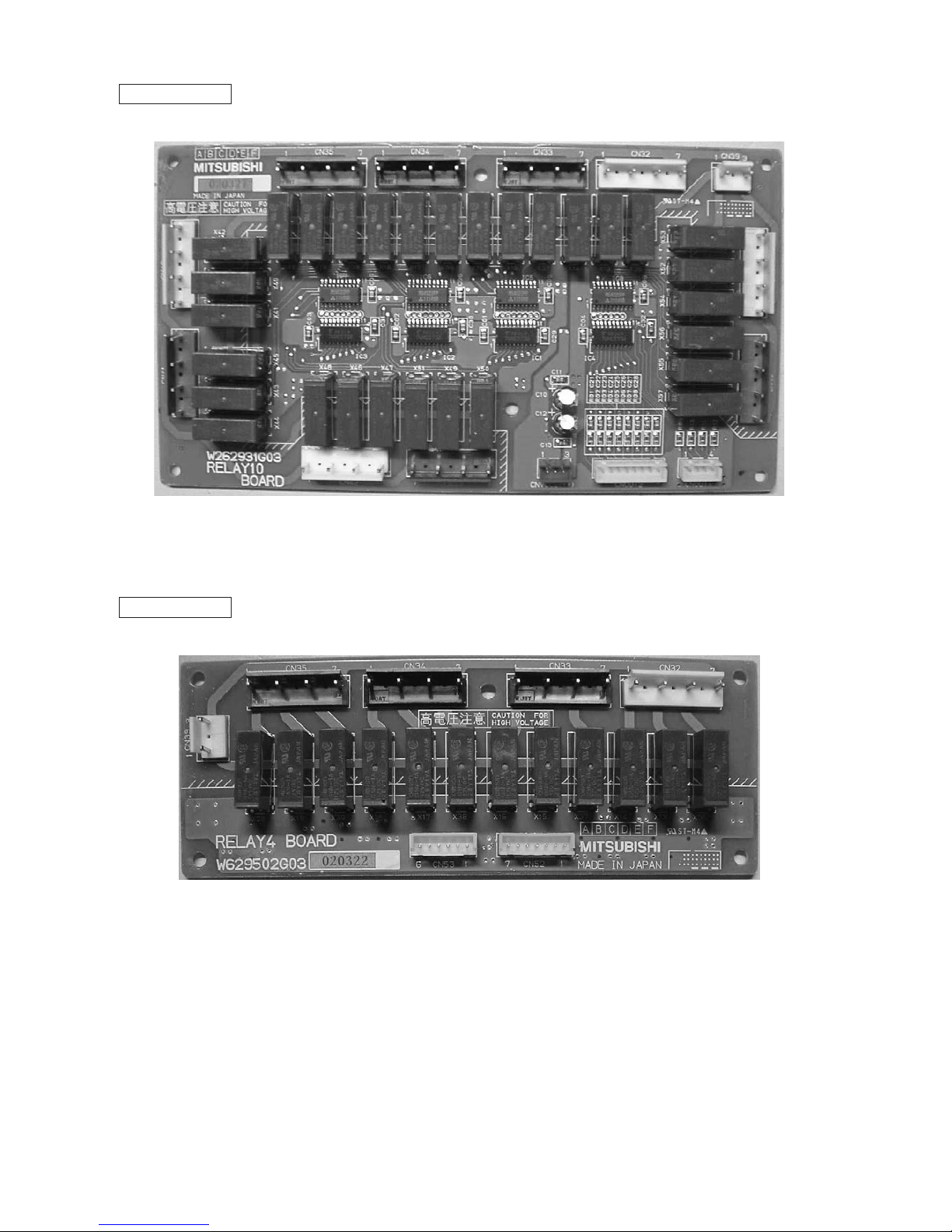
RELAY 10 board
RELAY 4 board
–13–
[2] Refrigerant Circuit Diagram and Thermal Sensor
–14–
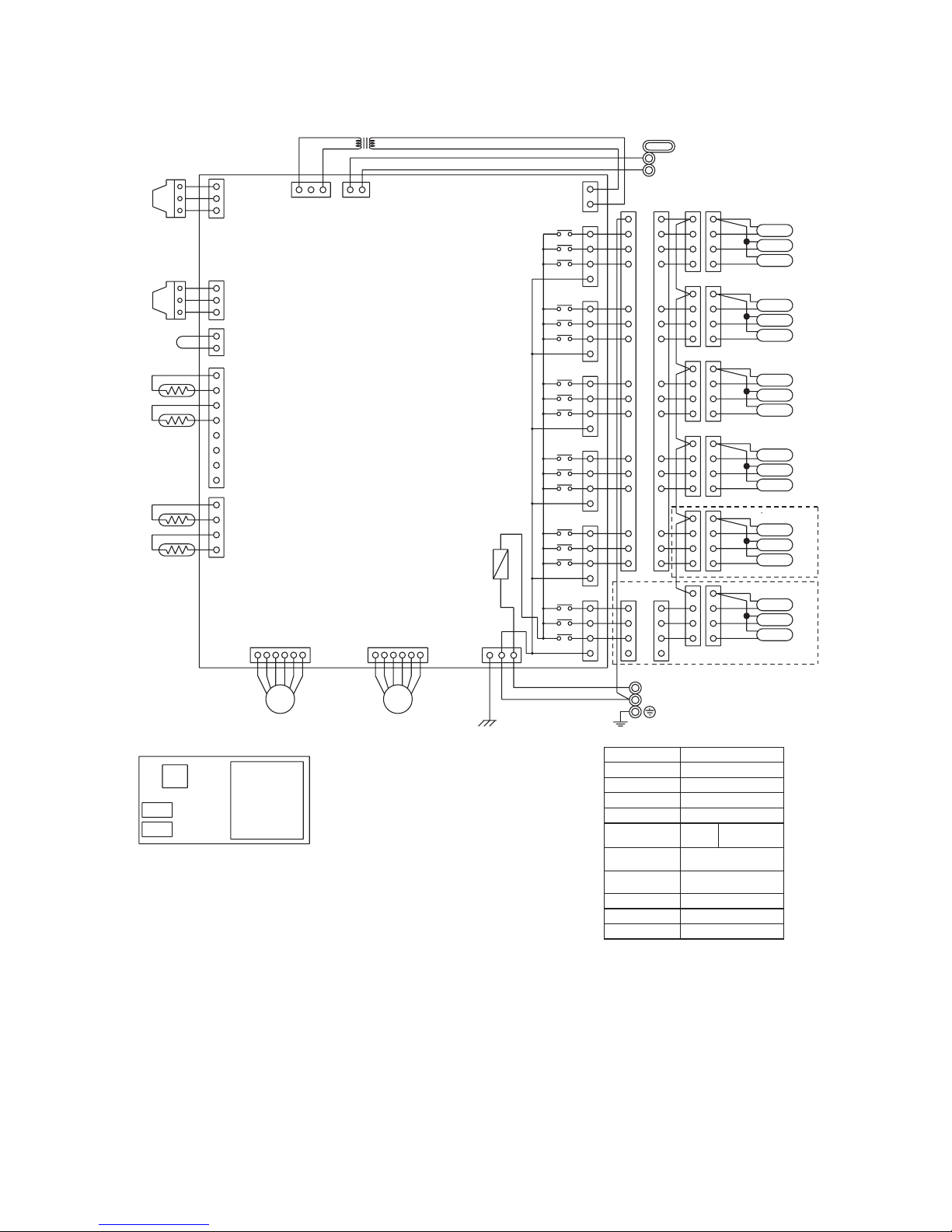
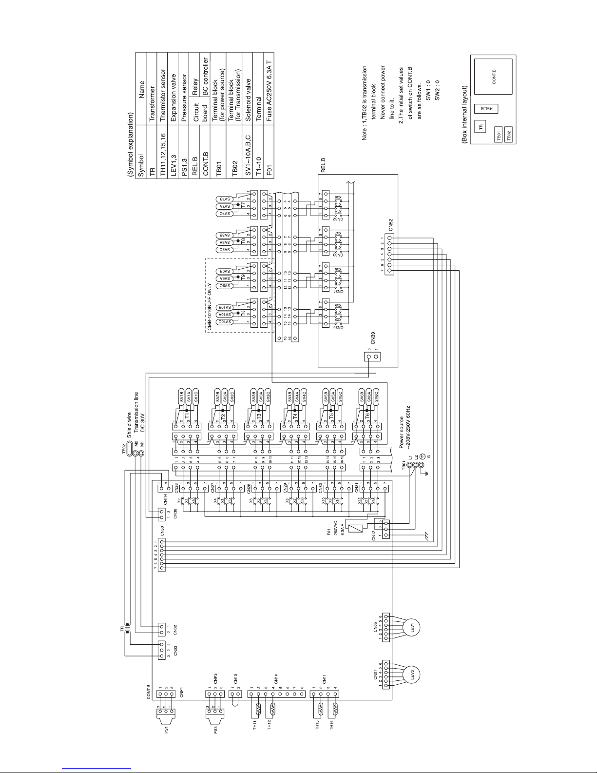
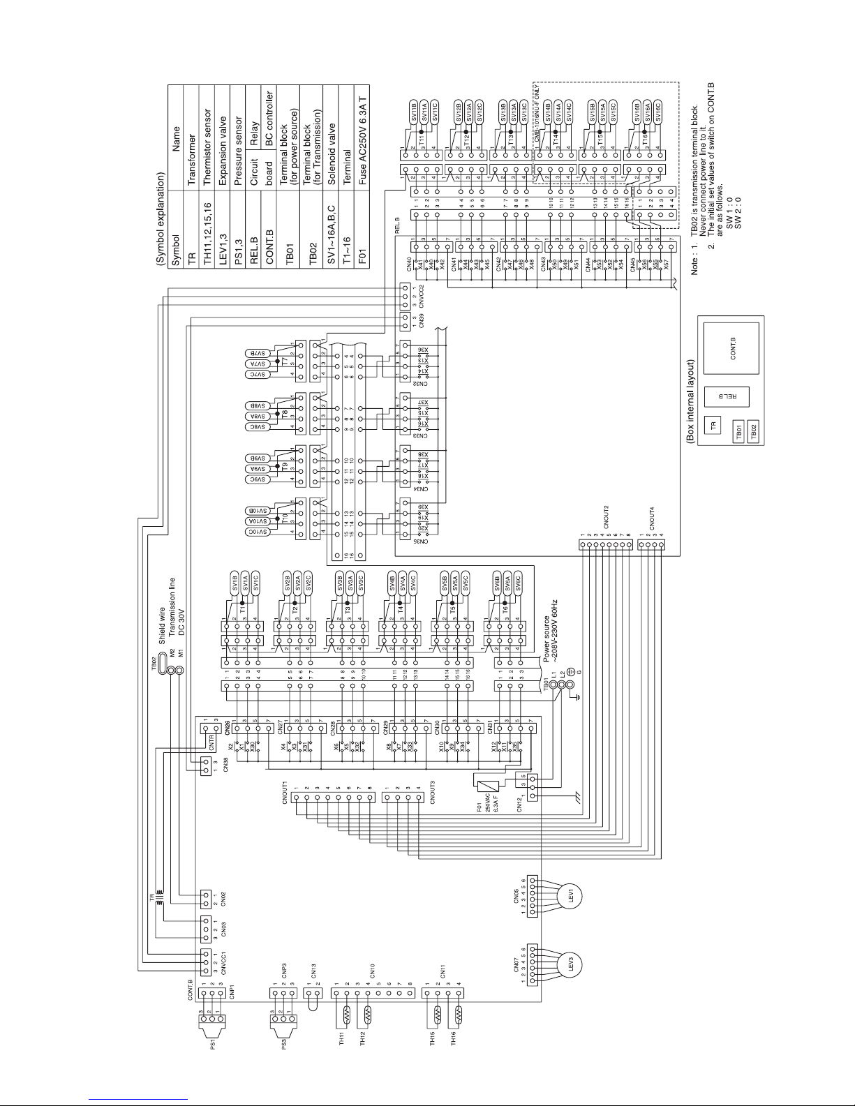
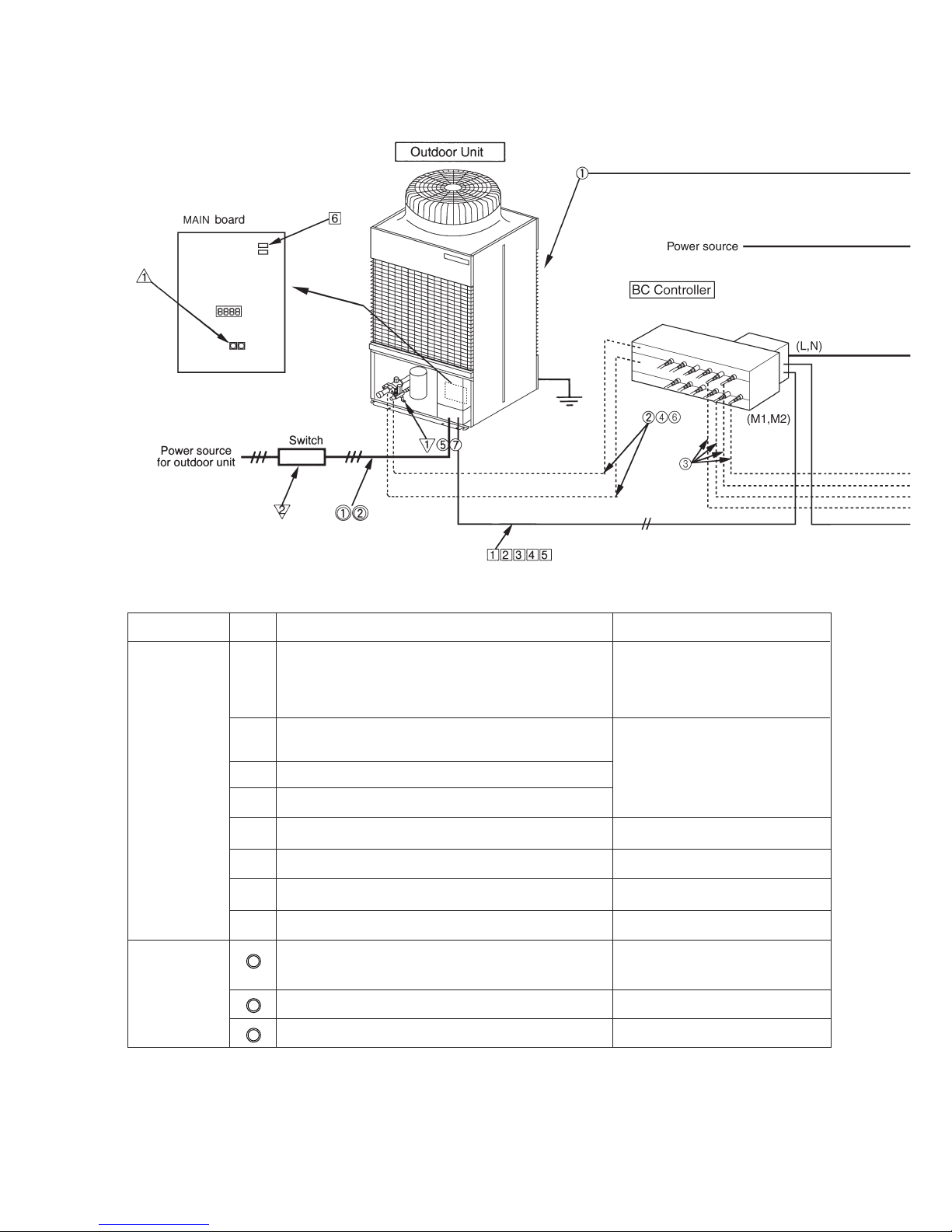
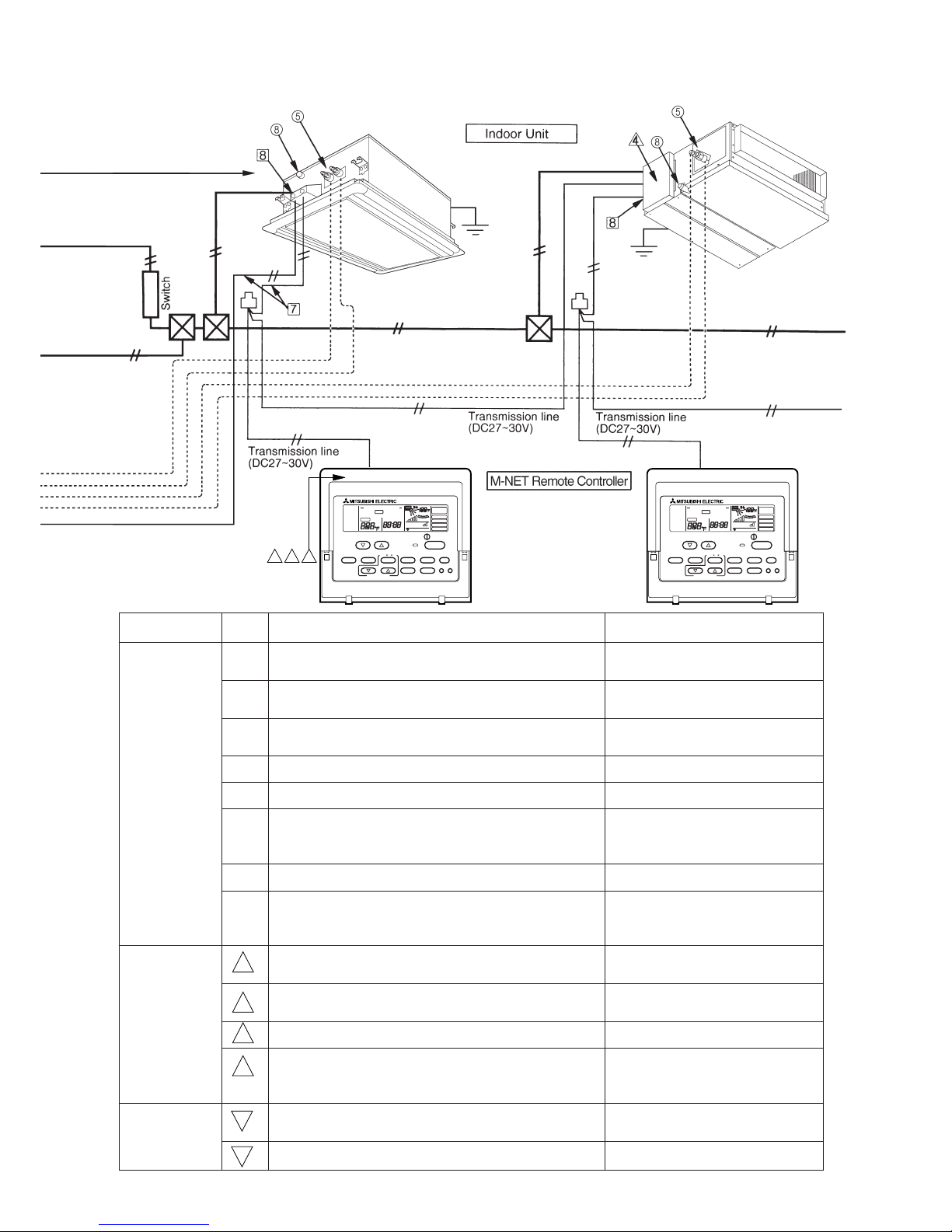
[3] Electrical Wiring Diagram
1
MC
P
N
–15–
2 CMB-104·105·106NU-F
F01
250VAC
6.3A F
CMB-106NU-F ONLY
Circuit
board
(Symbol explanation)
BC controller
(Box internal layout)
T5
T4
T6
T1
T3
T2
1
3
1
1
2
3
1
2
1
2
1
2
3
4
1
123456 123456 1 3 5
2
3
4
5
6
7
8
3
321 21
1
1
1
2
3
4
5
6
7
8
9
10
11
12
13
14
15
16
1
2
3
4
1
2
3
4
1
2
3
4
1
2
3
4
1
2
3
4
1
2
3
4
1
2
3
4
1
2
3
4
1
2
3
4
1
2
3
4
1
2
3
4
1
2
3
4
1
2
3
4
1
2
3
4
1
2
3
4
5
6
7
8
9
10
11
12
13
14
15
16
3
3
5
7
1
3
5
7
1
3
5
7
1
3
5
7
1
3
5
7
1
3
5
7
X2
X1
X30
X4
X3
X31
X6
X5
X32
X8
X7
X33
X10
X9
X34
X12
X11
X35
3
G
2
2
Fuse AC250V 6.3A T
F01
Terminal
T1~6
CN31
CN30
CN29
SV6B
SV6A
SV6C
SV4A
SV4C
SV5B
SV4B
SV5C
SV5A
CN28
CN27
SV1B
SV1A
SV1C
SV2A
SV2C
SV3C
SV2B
SV3B
SV3A
CONT.B
TR
Terminal block
(for Transmission)
TB02
Terminal block
(for power source)
TB01
Solenoid valve
SV1~6A,B,C
Expansion valve
Thermistor sensor
Transformer
Name
Symbol
TR
TH11,12,15,16
LEV1,3
PS1,3
Pressure sensor
CONT.B
Note : 1.TB02 is transmission
terminal block.
Never connect power
line to it.
2.The initial set values
of switch on CONT.B
are as follows.
SW1 : 0
SW2 : 0
TB01
TB02
L1
L2
~208V-230V 60Hz
⎫
⎬
⎭
⎫
⎬
⎭
Power source
M1
M2
Shield wire
Transmission line
DC 30V
LEV1LEV3
TB01
LEV1
PS3
PS1
TH16
TH15
TH12
TH11
CN07
CN11
CN10
CN13
CN03
CNP3
CNP1
CN02
CONT.B
CN05
CN12
CNTR
CN26
TB02
TR
CMB-105 106NU-F ONLY
–16–
3 CMB-108·1010NU-F
⎫
⎬
⎭
⎫
⎬
⎭
–17–
4 CMB-1013·1016NU-F
⎫
⎬
⎭
⎫
⎬
⎭
–18–
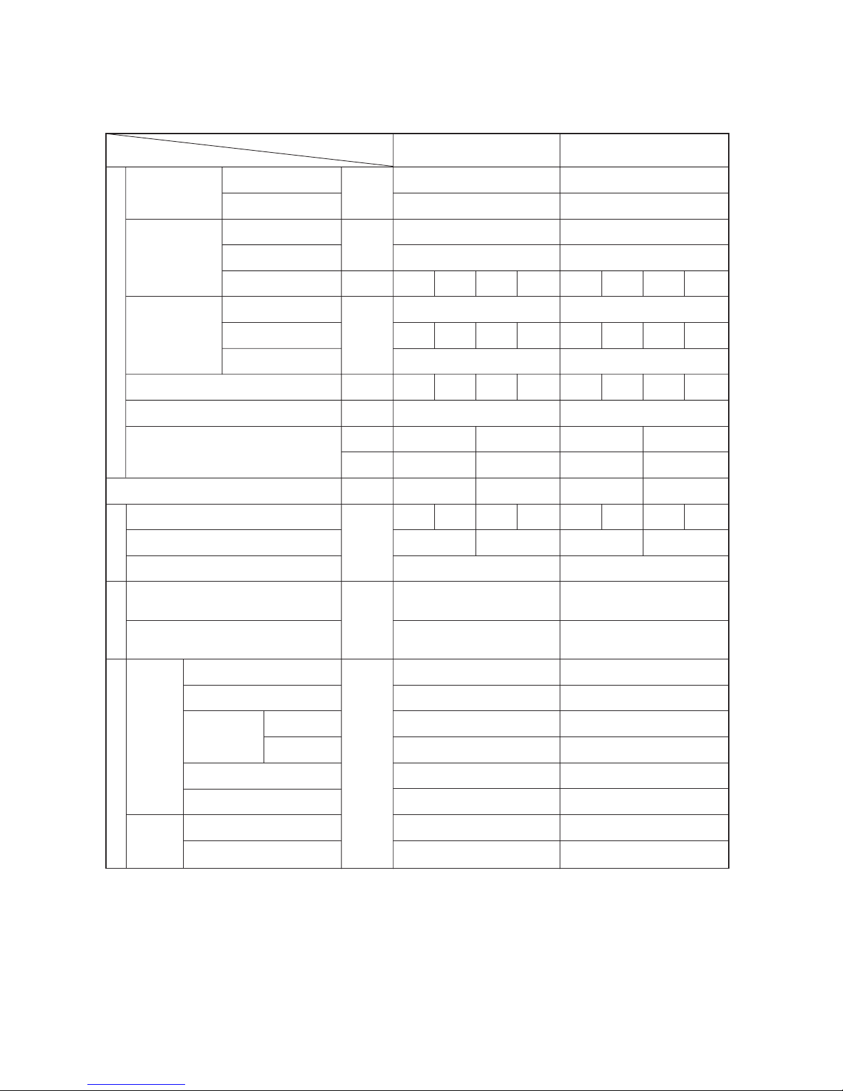
[4] Standard Operation Data
1 Cooling
Outdoor unit
Items
PURY-80TMU(-A) PURY-100TMU(-A)
Indoor
Outdoor
Quantity
Quantity in operation
Model
Main pipe
Branch pipe
Total piping length
26.7˚C(80˚F)/19.4˚C(67˚F) 26.7˚C(80˚F)/19.4˚C(67˚F)
35˚C(95˚F) 35˚C(95˚F)
44
44
24 24 20 10 48 16 24 10
5(16.4) 5(16.4)
5(16.4) 5(16.4) 5(16.4) 5(16.4) 5(16.4) 5(16.4) 5(16.4) 5(16.4)
25(82) 25(82)
Hi Hi Hi Hi Hi Hi Hi Hi
10 kg(67 oz) 12 kg(86 oz)
330 460 430 300 410 330 460 300
2000 140 2000 150
235 235
2.03/0.49 1.90/0.39
(294/71) (276/57)
1.92/1.92 1.79/1.79
(279/279) (25/25)
107(225) 110(230)
50(122) 47(117)
7(45) 7(45)
10(50) 10(50)
12(54) 12(54)
75(167) 70(158)
26(79) 30(86)
15(59) 15(59)
Indoor unit fan notch
Refrigerant volume
Compressor volts / Frequency
Outdoor unit
Indoor unit
BC controller (1, 3)
Oil return
High pressure/Low pressure
BC controller liquid/Intermediate
Pressure
DB/WB
Q’ty
–
m
(Ft)
–
kg(oz)
V
V/Hz
A
Pulse
MPa
(psi)
˚C
(˚F)
Condition
Sectional temperature
LEV opening
Discharge (TH1)
Heat exchanger outlet (TH5)
Accumulator
Suction (Comp)
Shell bottom (Comp)
LEV inlet
Heat exchanger outlet
Inlet
Outlet
Outdoor
unit
Indoor
unit
Ambient temp.
Indoor unit
Piping
208 230 208 230
134/76 134/76 171/98 171/98
27.4 24.8 35.2 31.8
–19–
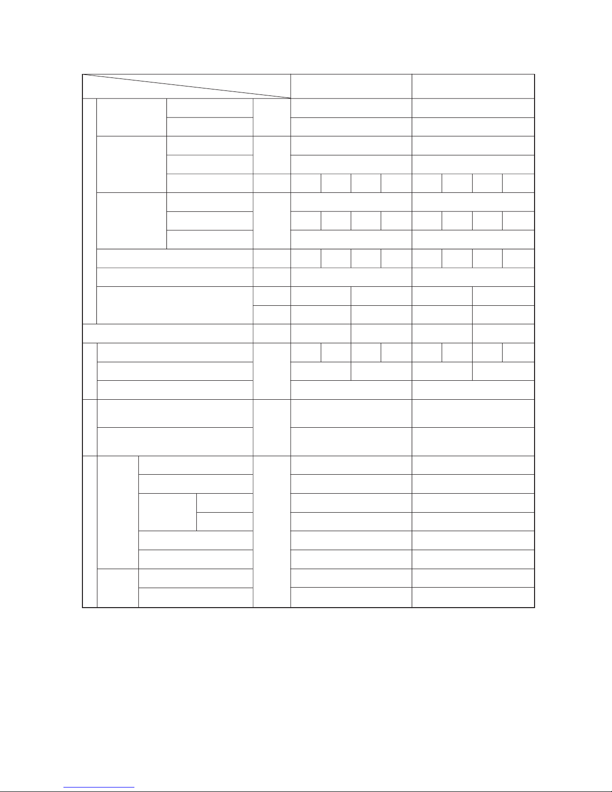
2 Heating
Outdoor unit
Items
PURY-80TMU(-A) PURY-100TMU(-A)
Indoor
Outdoor
Quantity
Quantity in operation
Model
Main pipe
Branch pipe
Total piping length
21.1˚C(70˚F) 21.1˚C(70˚F)
8.3˚C(47˚F)/6.1˚C(43˚F) 8.3˚C(47˚F)/6.1˚C(43˚F)
44
44
24 24 20 10 48 16 24 10
5(16.4) 5(16.4)
5(16.4) 5(16.4) 5(16.4) 5(16.4) 5(16.4) 5(16.4) 5(16.4) 5(16.4)
25(82) 25(82)
Hi Hi Hi Hi Hi Hi Hi Hi
10 kg(67 oz) 12 kg(86 oz)
600 950 750 400 750 600 950 400
60 700 60 800
150 235
1.81/0.35 1.76/0.36
(263/51) (256/53)
1.72/1.37 1.67/1.37
(249/199) (242/199)
100(212) 95(203)
–2(28) –1(30)
–1(30) –1(30)
–4(25) –2(28)
–1(30) –1(30)
45(113) 40(104)
38(100) 40(104)
80(176) 85(185)
208 230 208 230
149/85 149/85 174/100 174/100
27.5 24.9 35.6 32.2
Indoor unit fan notch
Refrigerant volume
Compressor volts / Frequency
Outdoor unit total current
Indoor unit
BC controller (1, 3)
Oil return
High pressure/Low pressure
BC controller liquid/Intermediate
Pressure
DB/WB
Q’ty
–
m
(Ft)
–
kg(oz)
V
V/Hz
A
Pulse
MPa
(psi)
˚C
(˚F)
Condition
Sectional temperature
LEV opening
Discharge (TH1)
Heat exchanger outlet (TH5)
Accumulator
Suction (Comp)
Shell bottom (Comp)
LEV inlet
Heat exchanger outlet
Inlet
Outlet
Outdoor
unit
Indoor
unit
Ambient temp.
Indoor unit
Piping
–20–
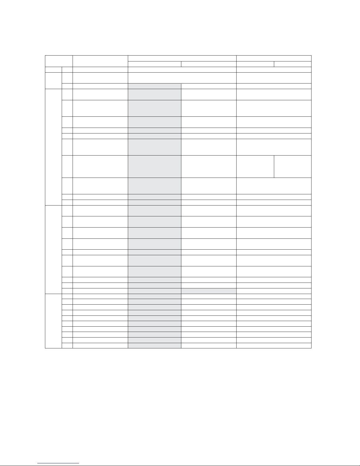
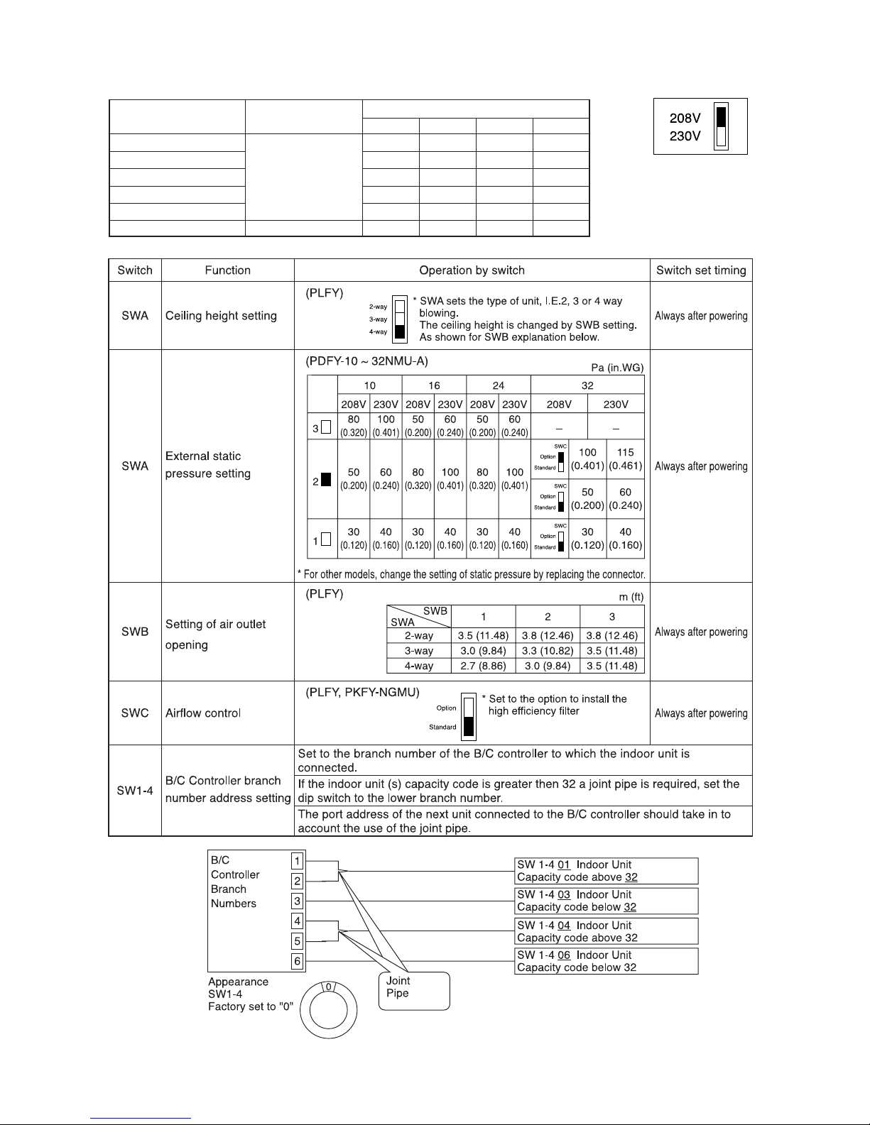
[5] Function of Dip SW and Rotary SW
(1) Outdoor unit
SWU
SW1
SW2
SW3
SW4
1~2
1~8
9~10
1
2
3
4
5
6
7
8
9
10
1
2
3
4
5
6
7
8
9
10
1
2
3
4
5
6
7
8
9
10
Unit address setting
For self diagnosis/
operation monitoring
–
Centralized control switch
Deletion of connection
information.
Deletion of error history.
–
–
Disregard ambient air
sensor errors, liquid
overflow errors.
Forced defrosting
Defrost prohibited timer
–
–
SW3-2 Function valid/
invalid
Indoor unit test operation
Defrosting start temperature of TH7.
Defrosting end temperature of TH5.
–
Pump down operation
Target Td (High pressure)
at Heating
–
–
Models
–
–
–
–
LED Display
–
–
–
–
–
Set on 51~100 with the dial switch.
LED monitering display
–
Centralized control not
connected.
Storing of refrigeration
system connection
information.
–
–
–
Errors valid.
Ordinary control
50 min.
–
–
SW3-2 Function invalid
Stop all indoor units.
–6°C
(21˚F)
8°C
(46˚F)
–
Invalid
49˚C
(120˚F)
–
–
Model 80
–
–
–
–
“˚F” “psig” Display
–
–
–
–
–
–
Centralized control
connected.
Deletion of refrigeration
system connection
information.
Deletion
–
–
Disregard errors.
Start forced defrosting.
90 min.
–
–
SW3-2 Function valid
All indoor units test
operation ON.
–3°C
(27˚F)
15°C
(59˚F)
–
Valid
53˚C
(127˚F)
–
–
Model 100
–
–
–
–
“˚C” “kgf/amG” Display
–
–
–
–
–
Before power is turned on.
During normal operation when power
is on.
Should be set on OFF.
Before power is turned on.
Before power is turned on.
During normal operation when power
is on.
–
–
During normal operation when power
is on.
During normal operation when power
is on. (Except during defrosting)
–
–
During normal operation when power
is on.
When SW3-1 is ON after power is
turned on.
During normal operation when power
is on.
During normal operation when power
is on. (Except during defrosting)
–
During compressor stop when power
is on.
During normal operation when power
is on.
–
–
When switching on the power.
–
–
–
–
When switching on the power
–
–
–
–
–
During normal
operation when
power is on.
10 minutes or
more after
compressor
starts.
Switch Function
Function according to switch operation Switch set timing
When off When on When off When on
Note:
• SWU1~2=00 when shipped from the factory. Other factory settings are indicated by shaded portions.
• If the address is set from 01 to 50, it automatically becomes 100.
–21–
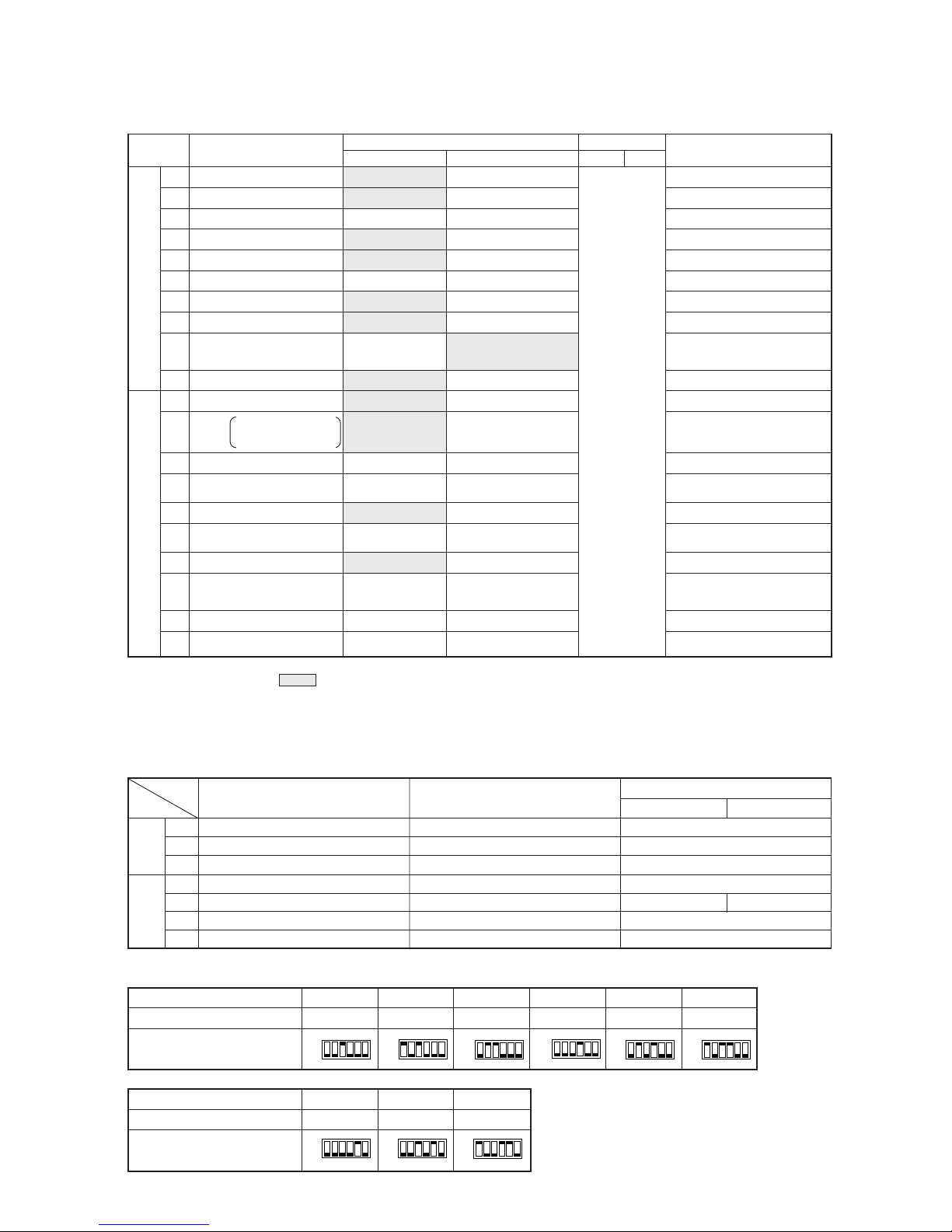
(2) Indoor unit
DIP SW1, 3
Model 32 40 48
Capacity (model name) code
16 20 25
SW2 setting
Model 08 10 12 16 20 24
Capacity (model name) code
45 681013
SW2 setting
ON
OFF
ON
OFF
ON
OFF
ON
OFF
ON
OFF
ON
OFF
ON
OFF
ON
OFF
ON
OFF
Note 1: The shaded part indicates the setting at factory shipment. (For the SW not being shaded, refer to the
table below.)
2: The DipSW setting is only effective during unit stopping (remote controller OFF) for SW1, 2, 3 and 4 commonly
and the power source is not required to reset.)
3: When both SW1-7 and SW1-8 are being set to ON, the fan stops at the heating thermostat of OFF.
Setting of DIP SW2
Model
Switch
SW1
SW3
3
6
7
3
4
6
8
PLFY-NAMU-A
ON
ON
OFF
ON
ON
OFF
OFF
Indoor unit inlet
None
100h
Ineffective
Fan output display
At stationary heating
Very low speed
SW1-7 setting
Ineffective
–
Heat pump
None
None
None
1st setting
Down blow B, C
–
Effective
–
–
Built in remote controller
Provided
2500h
Effective
Thermo. ON signal display
Always at heat.
Low speed
Set airflow
Effective
–
Cool.only
Provided
Provided
Provided
2nd setting
Horizontal
–
Ineffective
–
–
Room temp. sensor position
Clogged filter detect.
Filter duration
OA intake
Remote display select.
Humidifier control
Heating thermo. OFF airflow
Heating thermo. OFF airflow
Power failure automatic
return
–
Model selection
Louver
Vane
Vane swing function
Vane horizontal angle
Vane angle set for cooling
–
Heating 4deg (7.2 deg) up
Note : °C scale (°F scale)
–
–
Always ineffective for PKFY-NAMU
Not provided for PKFY-NAMU
Provided for PLFY-NGMU (ON) setting
Always down blow B,C for
PKFY-NAMU
SW1
SW3
1
2
3
4
5
6
7
8
9
10
1
2
3
4
5
6
7
8
9
10
Switch SW name
Operation by SW
Switch set timing
OFF ON OFF ON
Remarks
At unit stopping
(at remote
controller OFF)
Cooling capacity saving
for PKFY-NAMU,
effective/ineffective
PDFY-NMU-A
ON
ON
OFF
OFF
OFF
OFF
OFF
PKFY
OFF
OFF
OFF
ON
OFF
OFF
NAMU-A NGMU-A
OFF ON
–22–
Setting of DIP SW4 Setting of DIP SW5
1234
ON OFF ON OFF
OFF OFF OFF ON
ON OFF OFF ON
OFF OFF ON ON
––––
OFF OFF ON –
PDFY-10 ~ 32
PLFY-12 ~ 24
PLFY-32 ~ 48
PKFY-P-8
PKFY-P-12
PDFY-40, 48
Model Circuit board used
SW4
Phase control
Relay selection
–23–
33
33
3 TEST RUN
[1] Before Test Run
(1) Check points before test run
1 Neither refrigerant leak nor loose power source/ transmission lines should be found, if found correct immediately.
2 Confirm that the resistance between the power source terminal block and the ground exceeds 2MΩ by measur-
ing it with a DC500V megger. Do not run if it is lower than 2MΩ.
Note : Never apply the megger to the MAIN board. If applied, the MAIN board will be broken.
3 Confirm that the Ball valve at both gas and liquid sides are fully opened.
Note : Close the cap.
4 Be sure that the crankcase heater has been powered by turning the main power source on at least 12 hours
before starting the test run. The shorter powering time causes compressor trouble.
(2) Caution at inverter check
Because the inverter power portion in outdoor unit electrical part box have a lot of high voltage portion, be sure to follow
the instructions shown below.
During energizing power source, never touch inverter power portion because high voltage (approx. 580V) is
applied to inverter power portion.
When checking,
Shut off main power source, and check it with tester, etc.
Allow 10 minutes after shutting off main power source.
Open the MAIN board mounting panel, and check whether voltage of both ends of electrolytic capacitor is
20V or less.
1
2
1
2
3
–24–
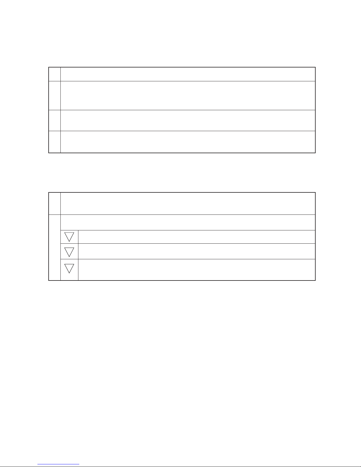
(3) Check points for test run when mounting options
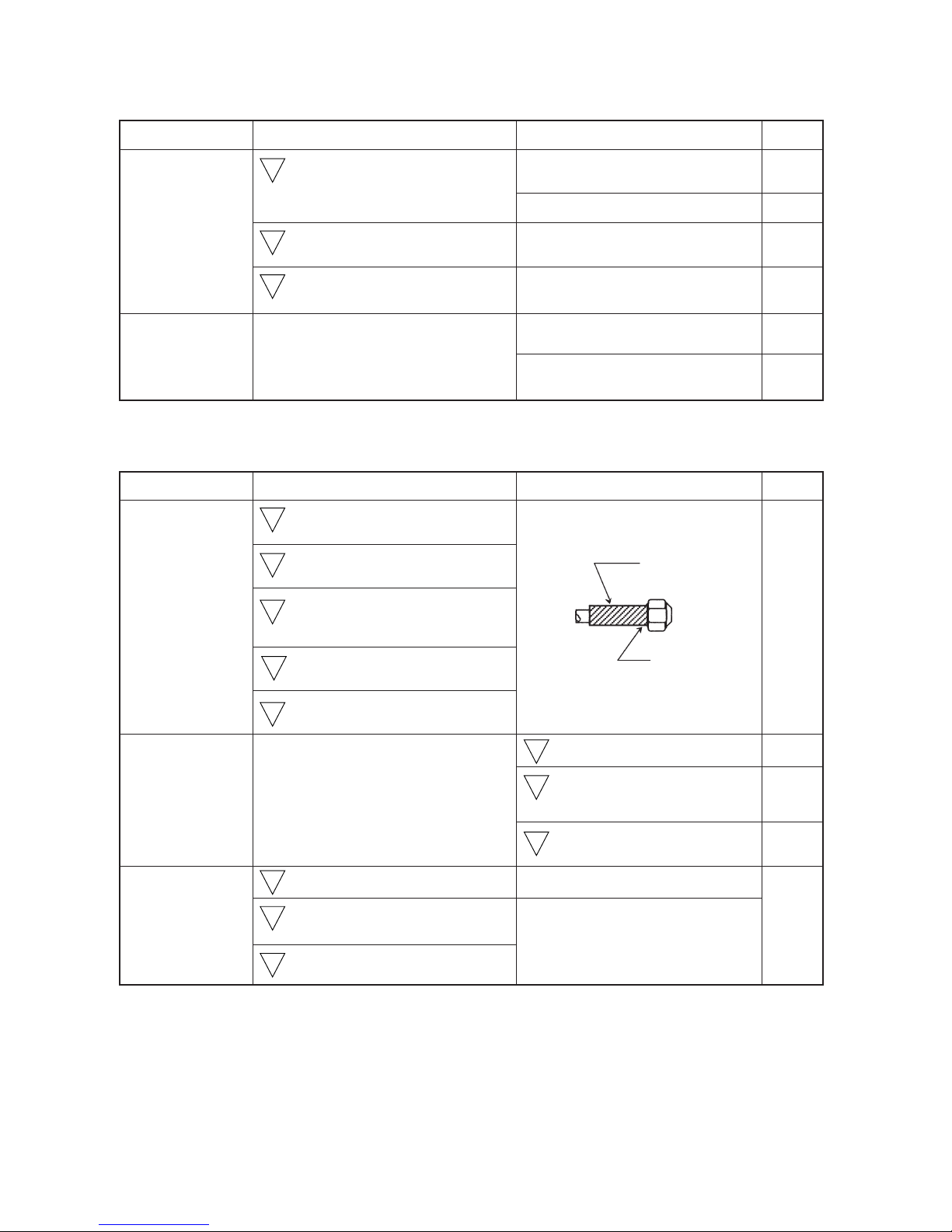
(4) Attention for mounting drain water lifting-up mechanism
Check point
Local remote controller displays code
No. “2503”, and the mechanism stops.
No overflow from drain pan.
Drain water comes out by operation of
drain pump.
Sound of pump operations is heard, and
drain water comes out.
No water leak from connecting portions
of each water piping.
Water is supplied to water supply tank,
and float switch is operating.
Built-in optional parts
Mounting of drain
water lifting-up
mechanism
Mounting of permeable film humidifier
Content of test run
Release connector of pump circuit,
check error detection by pouring
water into drain pan water inlet.
After that, connect connector of
circuit.
Check pump operations and drainage status in cooling (test run) mode.
Check humidifier operations and water
supply status in heating (test run) mode.
1
2
3
4
5
Result
1
2
3
Work
Disassembling and
assembling of drain
water lifting-up
mechanism
Mounting of float
switch
Electric wiring
Float switch moves smoothly.
Float switch is mounted on
mounting board straight without
deformation.
Float switch does not contact the
copper pipe.
Wiring procedure is exactly followed.
Connector portion is tightly hooked.
Content of test run
Lead wire from control box not
damaged.
Rubber cap properly inserted in to
drain water outlet of drain pan?
Insulation pipe of gas and liquid
pipes dealt with as shown in the right
figure?
Drain pan and piping cover mounted
without gap?
Drain pan hooked on cut projection
of the mechanism?
Float switch installed without contacting the
drain pan?
No mistakes in wiring?
Connectors connected securely and
tightly?
No tension on lead wire when sliding
control box?
1
2
3
1
2
3
Check point Result
Insulation pipe
No gap
–25–
(5) Check points for system structure
Check points from installation work to test run.
Trouble
Not operate.
Not cool (at cooling).
Not heat (at heating).
Not cool, not heat, error stop.
Condensation drip in piping.
Not cool, not heat, error stop.
Water leak, condensation drip in drain piping.
Error stop, not operate.
Electric shock.
Error stop, not operate.
Classification
Installation and
piping
Power source
wiring
Portion
1
2
3
4
5
6
7
8
1
2
3
Check item
Instruction for selecting combination of outdoor unit,
and indoor unit followed? (Maximum number of indoor
units which can be connected, connecting model name,
and total capacity.)
Follow limitation of refrigerant piping length? For example,
70m (229ft) or less (total length : 220m (721ft)) at the farthest.
Connecting piping size of branch piping correct?
Refrigerant piping diameter correct?
Refrigerant leak generated at connection?
Insulation work for piping properly done?
Specified amount of refrigerant replenished?
Pitch and insulation work for drain piping properly done?
Specified switch capacity and wiring diameter of main
power source used?
Proper grounding work done on outdoor unit?
The phases of the L line (L1, L2, L3) correct?
–26–
Classification
Transmission
line
Portion Check item
1
Limitation of transmission line length followed? For example,
200m (656ft) or less (total length : 500m (1640ft)) at the farthest.
2 1.25mm2 (AWG16) or more transmission line used?
(Remote controller 10m (32ft) or less 1.25mm2 (AWG16))
3 2-core cable used for transmission line?
4
Transmission line apart from power source line by 5cm (2in) or more?
5 One refrigerant system per transmission line?
6
The short circuit connector is changed form CN41 to
CN40 on the MAIN board when the system is centralized
control? (Just one outdoor unit. Not all outdoor units.)
7 • No connection trouble in transmission line?
8 Connection of wrong remote controller line terminals?
• MA Remote controller : TB15
• M-NET Remote controller : TB5
Trouble
Erroneous operation, error stop.
Erroneous operation, error stop.
Error stop in case multiple-core
cable is used.
Erroneous operation, error stop.
Not operate.
Not operate.
Error stop or not operate.
Never finish the initial mode.
System set
Before starting
Error stop or not operate.
Can not be properly set with power
source turned on.
Not operate.
Set temperature not obtained at
heating operations (Thermostat
stop is difficult)
Error stop.
Error stop, compressor trouble.
1
2
1
2
3
4
Address setting properly done? (M-NET Remote
controller, indoor unit and outdoor unit.)
Setting of address No. done when shutting off power
source?
Address numbers not duplicated?
Turned on SW3-8 on indoor unit circuit board when
mounting room thermistor sensor?
Refrigerant piping ball valve (Liquid pressure pipe, gas
pressure pipe) opened?
Turn on power source 12 hours before starting operations?
2 31
SET TEMP. ON/OFF
PAR-F27MEA-US
FILTER
CHECKTEST
CLOCK ON OFF
MODE
DRY COOL
DAILY
TIMER
CHECK
AUTO
ONCLOCK
SET TEMP.
REMAINDER
NOT AVAILABLE
SENSOR
INSIDE
FILTER
TEST RUN
VENTILATION
EROR CODE
AUTO
OFF
CENTRALLY CONTROLLED
AUTO FAN
HEAT
STAND BY
DEFROST
FAN
SPEED
TIMER FAN SPEED
LOUVER VENTILATION
AIR DIRECTION
TIMER SET
–27–
[2] Test Run Method
Operation procedure
1
Turn on universal power supply at least 12 hours before starting → Displaying “HO” on display panel for about two
minutes
2 Press
TEST
button twice → Displaying “TEST RUN’’ on display panel
3 Press
MODE
button → Make sure that air is blowing out
4
Press
MODE
button to change from cooling to heating operation, and vice versa → Make sure that warm or cold
air is blowing out
5 Press
FAN SPEED
adjust button → Make sure that air blow is changed
6
Press
AIR DIRECTION
or
LOUVER
button to change direction of air blowing make sure that horizontal or
downward blow is adjustable.
7 Make sure that indoor unit fans operate normally
8 Make sure that interlocking devices such as ventilator operate normally if any
9 Press button to cancel test run → Stop operation
Note 1: If check code is displayed on remote controller or remote controller does not operate normally.
2: Test run automatically stops operating after two hours by activation of timer set to two hours.
3: During test run, test run remaining time is displayed on time display section.
4: During test run, temperature of liquid pipe in indoor unit is displayed on remote controller room temperature
display section.
5: When pressing
FAN SPEED
adjust button, depending on the model, “NOT AVAILABLE” may be displayed on
remote controller. However, it is not a malfunction.
6: When pressing
AIR DIRECTION
or
LOUVER
button, depending on the model, “NOT AVAILABLE” may be
displayed on remote controller. However, it is not a malfunction.
–28–
4
GROUPING REGISTRATION OF INDOOR UNITS WITH M-NET REMOTE CONTROLLER
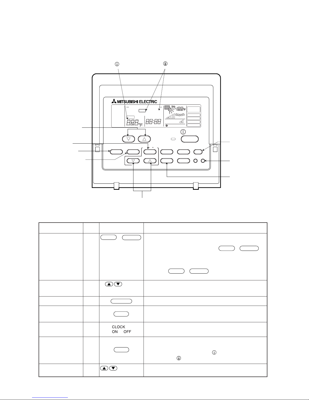
(1) Switch function
• The switch operation to register with the remote controller is shown below:
Registration/
ordinary mode
selector switch
Registration/ordinary
mode selection switch
Switch to assign indoor
unit address
Registration switch
Confirmation switch
Delete switch
Registered mode
selector switch
Switch to assign
interlocked unit address
A + B
C
D
E
F
G
H
This switch selects the ordinary mode or registered mode (ordinary
mode represents that to operate indoor units).
* To select the registered mode, press the
FILTER
+
LOUVER
button continuously for over 2 seconds under stopping state.
[Note] The registered mode can not be obtained for a while after
powering.
Pressing the
FILTER
+
LOUVER
button displays “CENTRALLY
CONTROLLED”.
This button assigns the unit address for “INDOOR UNIT ADDRESS
NO.”
This button is used for group/interlocked registration.
This button is used to retrieve/identify the content of group and
interlocked (connection information) registered.
This button is used to retrieve/identify the content of group and
interlocked (connection information) registered.
This button selects the case to register indoor units as group (group
setting mode) or that as interlocked (interlocked setting mode).
*The unit address is shown at one spot for the group setting mode
while at two spots for the interlocked setting mode.
This button assigns the unit address of “OA UNIT ADDRESS NO.”
Symbol
of switch
G Registered mode
selector switch
E Confirmation switch
C Switch to assign
indoor unit address
H Switch to assign inter-
locked unit address
D Registration switch
A
+
FILTER
TEST RUN
Name Name of actual switch Description
of TEMP
of TIMER SET
B
Registration/
ordinary mode
selector switch
SET TEMP. ON/OFF
PAR-F27MEA-US
FILTER
CHECK TEST
CLOCK ON OFF
MODE
DRY COOL
DAILY
TIMER
CHECK
AUTO
ONCLOCK
SET TEMP.
REMAINDER
NOT AVAILABLE
SENSOR
INSIDE
FILTER
TEST RUN
VENTILATION
EROR CODE
AUTO
OFF
CENTRALLY CONTROLLED
AUTO FAN
HEAT
STAND BY
DEFROST
FAN
SPEED
TIMER FAN SPEED
LOUVER VENTILATION
AIR DIRECTION
TIMER SET
F Delete switch
LOUVER
TIMER
MODE
→
→
–29–
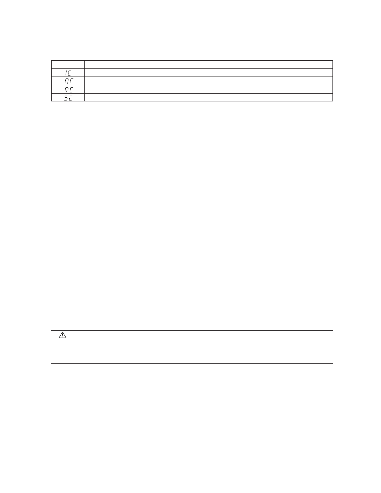
(2) Attribute display of unit
• At the group registration and the confirmation/deletion of registration/connection information, the type (attribute) of the
unit is displayed with two English characters.
Display Type (Attribute) of unit/controller
Indoor unit connectable to remote controller
Outdoor unit
Local remote controller
System controller (MJ)
[Description of registration/deletion/retrieval]
• The items of operation to be performed by the remote controller are given below. Please see the relating paragraph for
detail.
1 Group registration of indoor unit
• The group of the indoor units and operating remote controller is registered.
• It is usually used for the group operation of indoor units with different refrigerant system.
2 Retrieval/identification of group registration information of indoor units
• The address of the registered indoor units in group is retrieved (identified).
3 Retrieval/identification of registration information
• The connection information of any unit (indoor/outdoor units, remote controller or the like) is retrieved (identified).
4 Deletion of group registration information of indoor units
• The registration of the indoor units under group registration is released (deleted).
5 Deletion of the address not existing
• This operation is to be conducted when “6607” error (No ACK error) is displayed on the remote controller caused by
the miss setting at test run, or due to the old memory remained at the alteration/modification of the group composition.
Caution:
When MELANS (MJ-103MTRA for example) is being connected, do not conduct the group/pair registration using
the remote controller. The group/pair registration should be conducted by MELANS. (For detail, refer to the instruction exclusively prepared for MELANS.)
 Loading...