

Mitsubishi PUMY-P48NHMU, PUMY-P36NHMU, PUMY-P36NHMU-BS, PUMY-P48NHMU1, PUMY-P48NHMU2 Technical & Service Manual
...
SPLIT-TYPE, HEAT PUMP AIR CONDITIONERS
TECHNICAL & SERVICE MANUAL
July 2008
No. OC366
REVISED EDITION-C
HFC
utilized
R410A
[Model name]
(Standard type)
PUMY-P36NHMU
PUMY-P48NHMU
[Service Ref.]
PUMY-P36NHMU
PUMY-P48NHMU
PUMY-P48NHMU1
(Salt proof type)
PUMY-P36NHMU-BS
PUMY-P48NHMU-BS
PUMY-P48NHMU2
PUMY-P36NHMU-BS
PUMY-P48NHMU-BS
PUMY-P48NHMU1-BS
PUMY-P48NHMU2-BS
Model name
indication
OUTDOOR UNIT
NOTE :
· This service manual describes technical data of outdoor unit.
As for indoor units, refer to its service manual.
RoHS compliant products have <G> mark on the spec
·
name plate.
Revision:
• 9. TROUBLESHOOING
has been modified.
• Tester check point is added
(PCB, FAN MOTOR).
• Please void OC366
REVISED EDITION-B.
CONTENTS
1. TECHNICAL CHANGES
2. SAFETY PRECAUTION
3. OVERVIEW OF UNITS
4. SPECIFICATIONS
5. DATA
6. OUTLINES AND DIMENSIONS
7. WIRING DIAGRAM
8.
9. TROUBLESHOOTING
10. ELECTRICAL WIRING
11. REFRIGERANT PIPING TASKS
12. DISASSEMBLY PROCEDURE
13. PARTS LIST
14. RoHS PARTS LIST
15. OPTIONAL PARTS
................................................................
NECESSARY CONDITIONS FOR SYSTEM CONSTRUCTION
.....................................................
...................................
....................................
......................................
...........................................
......................
.........................................
.....
....................................
....................................
.....................
........................
..........................................
..........................................
2
5
8
10
12
18
20
24
34
81
84
88
93
96
99
1
TECHNICAL CHANGES
PUMY-P48NHMU1 PUMY-P48NHMU2
PUMY-P48NHMU1-BS PUMY-P48NHMU2-BS
· Compressor (MC) and oil have been changed.
ANB33FDCMT (Ester oil: MEL56) ANB33FDHMT(Ether oil: FV50S)
· Electrical parts have been changed.
Multi controller board (MULTI. C.B.) Noise filter circuit board (N.F.)
Active filter module (ACTM) Relay (52C) , Resister (RS) (including N.F.)
PUMY-P48NHMU PUMY-P48NHMU1
PUMY-P48NHMU-BS PUMY-P48NHMU1-BS
• Primary heating ON/OFF control has been added.
1-1. PRIMARY HEATING ON/OFF CONTROL SET-UP
(1) Primary heating operation controls another heat source that depends on the main system's operations,
which means the interlock operation shown in "c)" will be possible.
a)
Service ref. PUMY-P48NHMU(-BS)
b)
Indoor unit must be R410A UL model for this function to operate.
Note: Following Indoor models DO NOT HAVE this feature available:
PMFY-P06NBMU
PMFY-P08NBMU
c) Different Indoor unit applications that can be applied:
does not have this function.
PMFY-P12NBMU PKFY-P06NAMU
PMFY-P15NBMU PKFY-P08NAMU
(2) Outdoor unit DIPSW4-4 for Primary Heating Control:
Set DIPSW4-4 when power is turned off at unit.
OFF:
Disable Primary Heating Function (Initial setting)
ON :
Enable Primary Heating Function
(3) Determine required Indoor Fans Speed during defrost mode:
a) With no Primary heating output the Indoor fan normally goes off to prevent cold drafts during the defrost cycles.
b) With Primary heating control the auxiliary heat will be on during defrost mode, thus cold drafts will not be present.
(Ducted units only)
c) For models PEFY and PDFY (Ducted) recommended to use "Black" (20K) connector.
d) For models PLFY, PCFY, PKFY and PFFY (Ductless) recommended "None", no connector required.
e) To set the fan airflow rate to be used during defrost operation, insert the resistance that is packed within the
optional adaptor cable kit (PAC-YU24HT-F) into the CN22 sensor input.
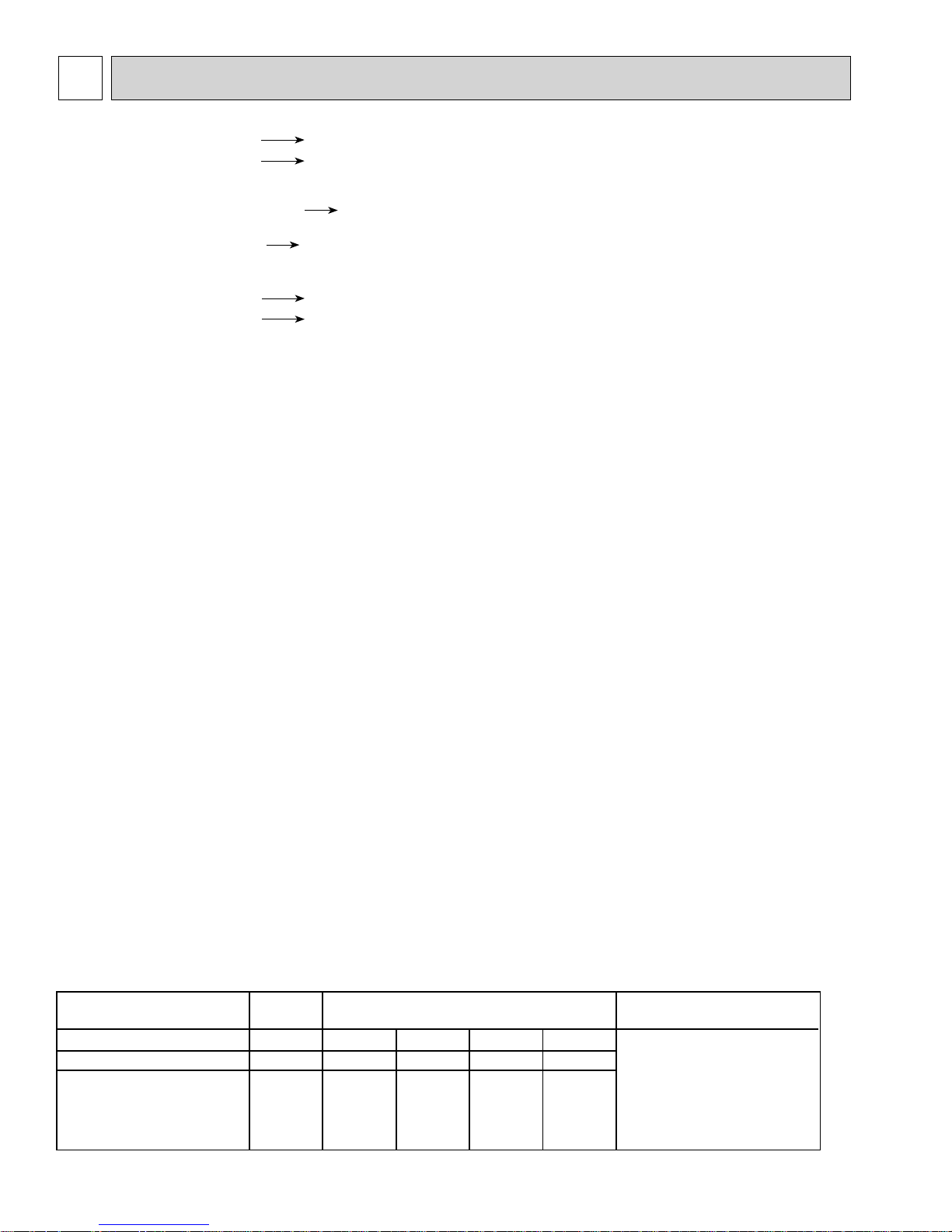
You can choose at what speed the indoor fan operates during defrost cycles bases on chart below.
Fan airflow rate setting
During defrost operation
CN22 input resistance ()
CN22 input (cable color)
FAN SPEED SETTING
Note: The setting will be disabled "when Heater contact signal is OFF".
OFF
0 20k 27k 39k 62K
None Black Blue White Red
Stopped
Setting on
remote
controller
ON Wiring
Very Low Low High
CN22
2
(4) Determine Fan Airflow setting during Indoor Thermo OFF conditions:
A
a) These settings are done within Indoor DIPSW1-7 and DIPSW1-8, see chart below for options.
b) Recommended SW1-7 OFF and SW1-8 ON will determine airflow based on "Setting on the remote controller".
Auxiliary Heating
Signal
Thermo Condition
SW1-7 SW1-8
OFF OFF Very low
ON OFF Low
OFF ON
ON
ON
Fan speed
setting
OFF ON
Setting on
remote
controller
Stopped
Fan speed
setting
Setting on
remote controller
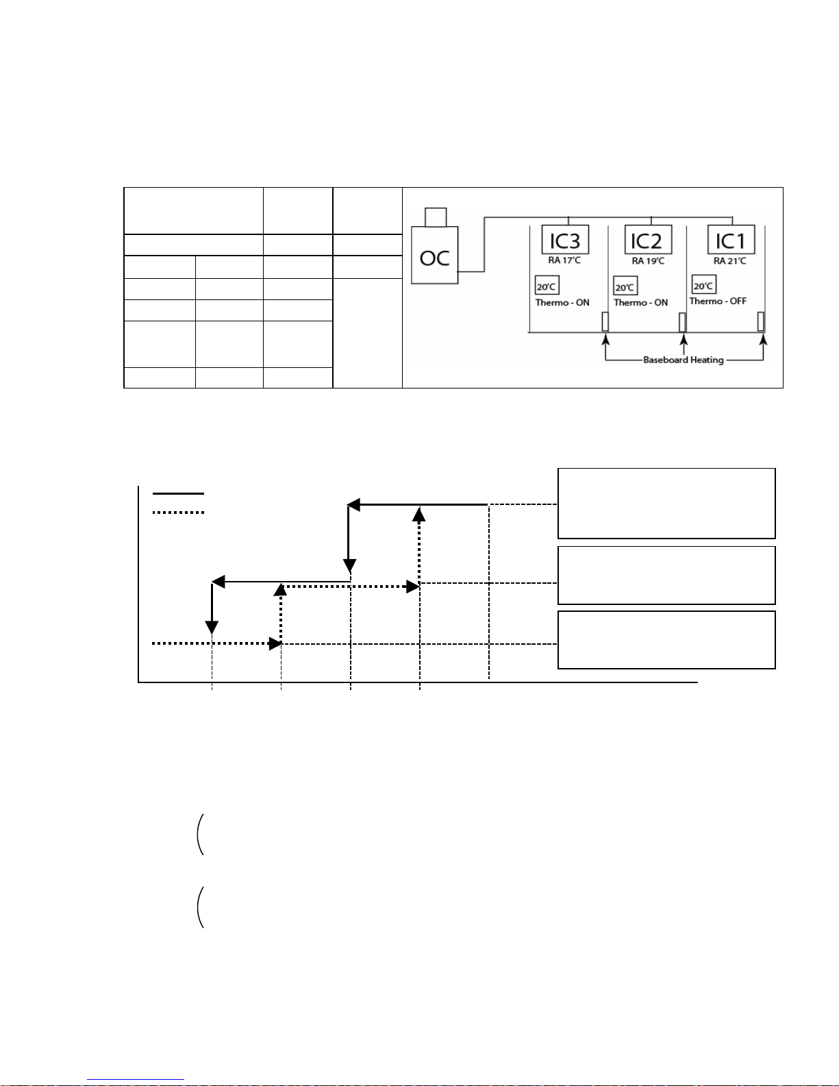
(5) Setting Outdoor unit and Auxiliary heat switch over temperatures.
When the DIPSW 4-4 is set to "ON", the outdoor unit and the contact output operates as shown below.
a) Outdoor default setting and operations are shown below:
Stage 1
mb. Decreasing - Outdoor unit HP operation
Amb. Incareasing - Defrost : Heater contact ON signal
- Other than defrost : Contact OFF
Stage 2
- Outdoor unit HP operation
- Heater contact ON signal
Stage 3
- Outdoor unit OFF (Standby)
a
-12:
[10F]
When the set temperature ranges overlap, the previously set pattern (1,2 or 3) has a priority.
The stage 1 has the highest priority, 2 the second and then 3.
b) Based on above chart listed the sequence of operation on "On Ambient Decrease"
Stage 1 :(TH7 = > 10
Stage 2 :(TH7 = 10
Stage 3 :(TH7 = < -12
c) Based on above chart listed the sequence of operation on " On Ambient Increase"
Stage 3 :(TH7 = < 0
Stage 2 :(TH7 = > 0
Stage 1 :(TH7 = > 20
b
0:
[32F]
c
10:
[50F]
:
) : the Outdoor unit runs in HP mode.
:
to -12:) : the Outdoor unit runs in HP mode with Auxiliary heating.
:
) : Auxiliary heating only (Outdoor unit is OFF).
:
) : Auxiliary heating only (Outdoor unit is OFF).
:
to 20:) : Auxiliary heating with Outdoor unit in HP mode.
:
) : Outdoor unit in HP mode only.
d
20:
[68F]
TH7 = Outdoor Temperature
- Heater contact ON signal
3
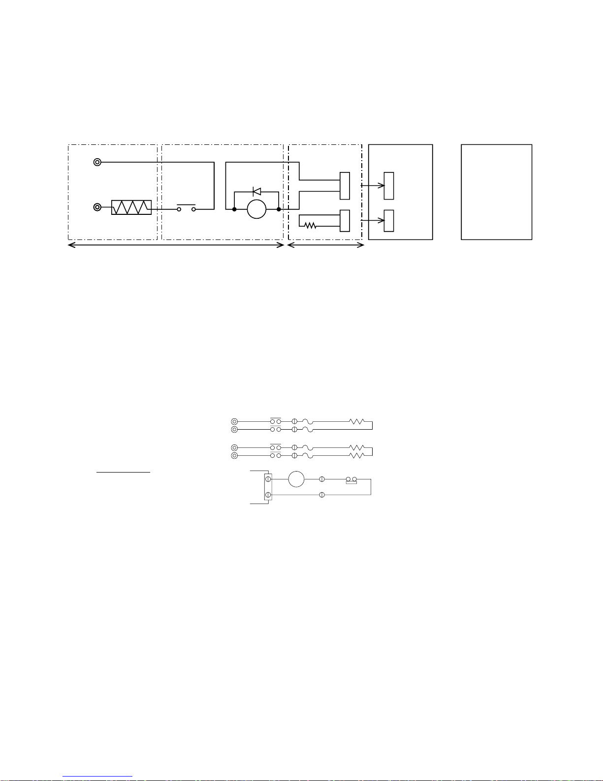
(6) Locally procured wiring
A basic connection method is shown.
(i.e. interlocked operation with the electric heater with the fan speed setting on high
Remote control Board Relay circuit
Adapter
Red 1
control board
CN24
Indoor unit
control board
Dip switch
SW4-4 "ON"
Outdoor unit
YellowGreen
CN22
Electric Heater
power source
Electric
Heater
Preparations in the field
X
X
+
White 2
Red 1
Red 2
Maximum cable length
is 10 m (32ft)
For relay X use the specifications given below Operation coil
Rated voltage : 12VDC
Power consumption : 0.9W or less
*Use the diode that is recommended by the relay manufacturer at both ends of the relay coil.
The length of the electrical wiring for the PAC-YU24HT is 2 meters (6-1/2 ft)
To extend this length, use sheathed 2-core cable.
Control cable type : CVV, CVS, CPEV or equivalent.
Cable size : 0.5 mm
2
~ 1.25 mm2 (AWG22 to AWG16)
Don`t extend the cable more than 10 meters (32ft).
Recommended circuit
Wiring digram
1-phase power
supply
208V, 230V/60Hz
R
S
R
S
Control board
88H
88H
CN24
88H
FS1
FS2
FS1
FS2
26H
H1
H2
FS1, 2 ----- Thermal fuse
H1, H2----- Heater
26H--------- Overheat protection
88H--------- Electromagnetic contactor
thermostat
4
2 SAFETY PRECAUTION
2-1. CAUTIONS RELATED TO NEW REFRIGERANT
Cautions for units utilizing refrigerant R410A
Use new refrigerant pipes.
Avoid using thin pipes.
Make sure that the inside and outside of refrigerant piping is clean and it has no contamination
such as sulfur hazardous for use, oxides, dirt,
shaving particles, etc.
In addition, use pipes with specified thickness.
Contamination inside refrigerant piping can cause deterioration of refrigerant oil etc.
Store the piping to be used during installation
indoors and keep both ends of the piping sealed
until just before brazing. (Leave elbow joints, etc.
in their packaging.)
If dirt, dust or moisture enters into refrigerant cycle, that can
cause deterioration of refrigerant oil or malfunction of compressor.
Use ester oil, ether oil or alkylbenzene oil (small
amount) as the refrigerant oil applied to flares
and flange connections.
If large amount of mineral oil enters, that can cause deterioration of refrigerant oil etc.
Charge refrigerant from liquid phase of gas
cylinder.
If the refrigerant is charged from gas phase, composition
change may occur in refrigerant and the efficiency will be
lowered.
Do not use refrigerant other than R410A.
If other refrigerant (R22 etc.) is used, chlorine in refrigerant can cause deterioration of refrigerant oil etc.
Use a vacuum pump with a reverse flow check
valve.
Vacuum pump oil may flow back into refrigerant cycle and
that can cause deterioration of refrigerant oil etc.
Use the following tools specifically designed for
use with R410A refrigerant.
The following tools are necessary to use R410A refrigerant.
Tools for R410A
Gauge manifold
Charge hose
Gas leak detector
Torque wrench
Flare tool
Size adjustment gauge
Vacuum pump adaptor
Electronic refrigerant
charging scale
Keep the tools with care.
If dirt, dust or moisture enters into refrigerant cycle, that can
cause deterioration of refrigerant oil or malfunction of compressor.
Do not use a charging cylinder.
If a charging cylinder is used, the composition of refrigerant will change and the efficiency will be lowered.
Ventilate the room if refrigerant leaks during
operation. If refrigerant comes into contact with
a flame, poisonous gases will be released.
[1] Cautions for service
(1) Perform service after recovering the refrigerant left in unit completely.
(2) Do not release refrigerant in the air.
(3) After completing service, charge the cycle with specified amount of refrigerant.
(4) When performing service, install a filter drier simultaneously.
Be sure to use a filter drier for new refrigerant.
[2] Additional refrigerant charge
When charging directly from cylinder
· Check that cylinder for R410A on the market is syphon type.
· Charging should be performed with the cylinder of syphon stood vertically. (Refrigerant is charged from liquid phase.)
5

Unit
Gravimeter
[3] Service tools
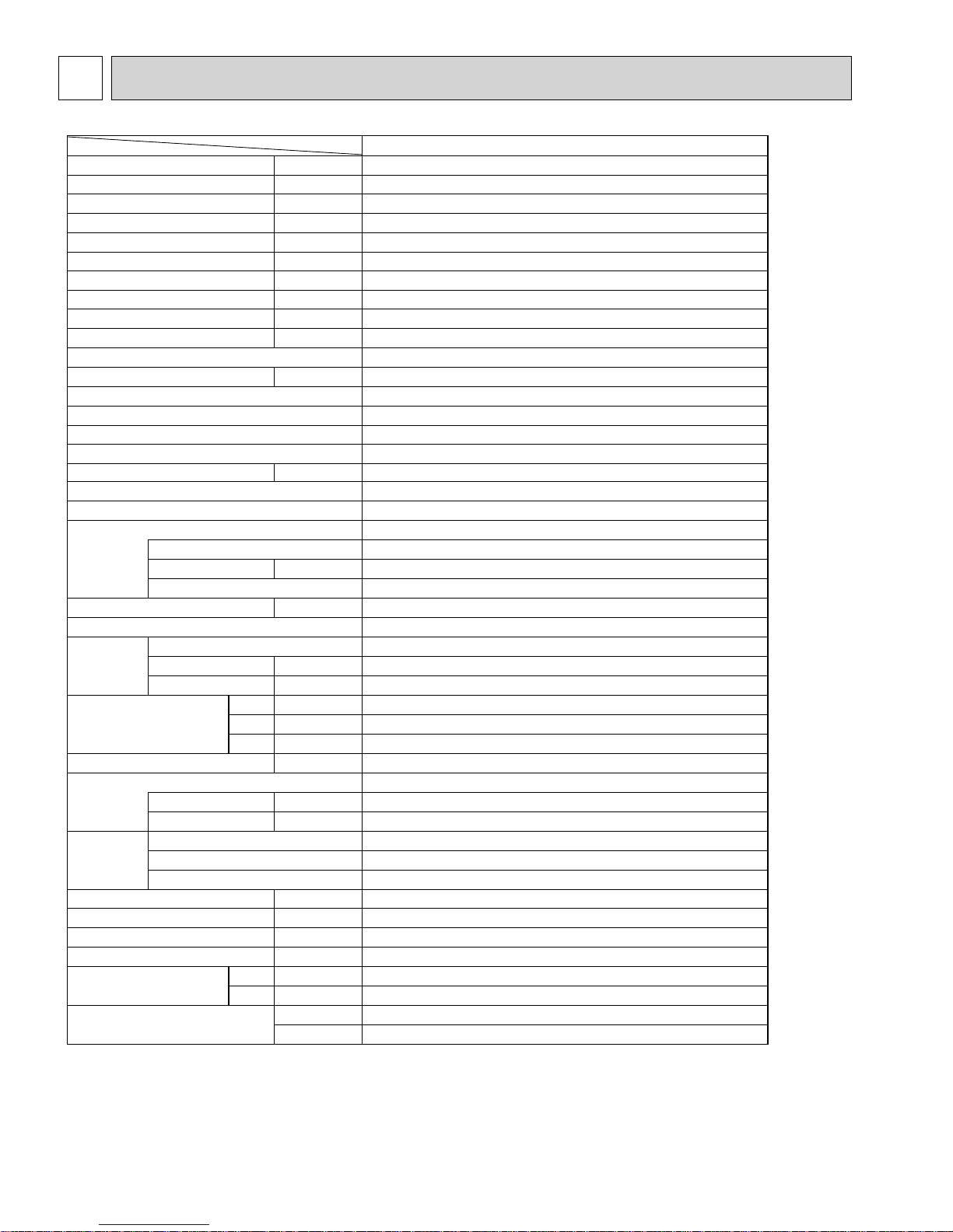
Use the below service tools as exclusive tools for R410A refrigerant.
No. Tool name Specifications
1 Gauge manifold ·Only for R410A
·Use the existing fitting
·Use high-tension side pressure of 5.3MPa·G or over.
2 Charge hose ·Only for R410A
·Use pressure performance of 5.09MPa·G or over.
3 Electronic scale
4 Gas leak detector ·Use the detector for R134a, R407C or R410A.
5 Adaptor for reverse flow check ·Attach on vacuum pump.
6 Refrigerant charge base
7 Refrigerant cylinder ·Only for R410A ·Top of cylinder (Pink)
·Cylinder with syphon
8 Refrigerant recovery equipment
specifications
.
2-2. PRECAUTIONS FOR SALT PROOF TYPE "-BS" MODEL
Although "-BS" model has been designed to be resistant to salt damage, observe the following precautions to maintain the
performance of the unit.
1. Avoid installing the unit in a location where it will be exposed directly to seawater or sea breeze.
2. If the cover panel may become covered with salt, be sure to install the unit in a location where the salt will be washed away
by rainwater. (If a sunshade is installed, rainwater may not clean the panel.)
3. To ensure that water does not collect in the base of the outdoor unit, make sure that the base is level, not at angle. Water
collecting in the base of the outdoor unit could cause rust.
4. If the unit is installed in a coastal area, clean the unit with water regularly to remove any salt build-up.
5. If the unit is damaged during installation or maintenance, be sure to repair it.
6. Be sure to check the condition of the unit regularly.
7. Be sure to install the unit in a location with good drainage.
6

2-3. Cautions for refrigerant piping work
New refrigerant R410A is adopted for replacement inverter series. Although the refrigerant piping work for R410A is
same as for R22, exclusive tools are necessary so as not to mix with different kind of refrigerant. Furthermore as the
working pressure of R410A is 1.6 time higher than that of R22, their sizes of flared sections and flare nuts are different.
1Thickness of pipes
Because the working pressure of R410A is higher compared to R22, be sure to use refrigerant piping with thickness
shown below. (Never use pipes of 0.7mm [7/256 inch] or below.)
Diagram below: Piping diameter and thickness
Nominal
dimensions[inch]
1/4
3/8
1/2
5/8
3/4
Outside
diameter
6.35
9.52
12.70
15.88
19.05
(mm)
Thickness
R410A R22
0.8 [1/32]
0.8 [1/32]
0.8 [1/32]
1.0 [5/128]
—
2Dimensions of flare cutting and flare nut
The component molecules in HFC refrigerant are smaller compared to conventional refrigerants. In addition to that,
R410A is a refrigerant, which has higher risk of leakage because its working pressure is higher than that of other
refrigerants. Therefore, to enhance airtightness and intensity, flare cutting dimension of copper pipe for R410A have
been specified separately from the dimensions for other refrigerants as shown below. The dimension B of flare nut for
R410A also have partly been changed to increase intensity as shown below. Set copper pipe correctly referring to
copper pipe flaring dimensions for R410A below. For 1/2 and 5/8 inch, the dimension B changes.
Use torque wrench corresponding to each dimension.
(mm) [inch]
0.8 [1/32]
0.8 [1/32]
0.8 [1/32]
1.0 [5/128]
1.0 [5/128]
Dimension A
Dimension B
Flare cutting dimensions
Nominal
dimensions[inch]
Outside
diameter
1/4
3/8
1/2
5/8
3/4
12.70
15.88
19.05
6.35
9.52
Dimension A
R410A R22
9.1 [11/32-23/64]
13.2 [1/2-33/64]
16.6 [41/64-21/32]
19.7 [49/64-25/32]
—
(mm) [inch]
+0
( )
-0.4
9.0
13.0
16.2
19.4
23.3
Flare nut dimensions
Nominal
dimensions[inch]
diameter[inch]
1/4
3/8
1/2
5/8
3/4
Outside
6.35
9.52
12.70
15.88
19.05
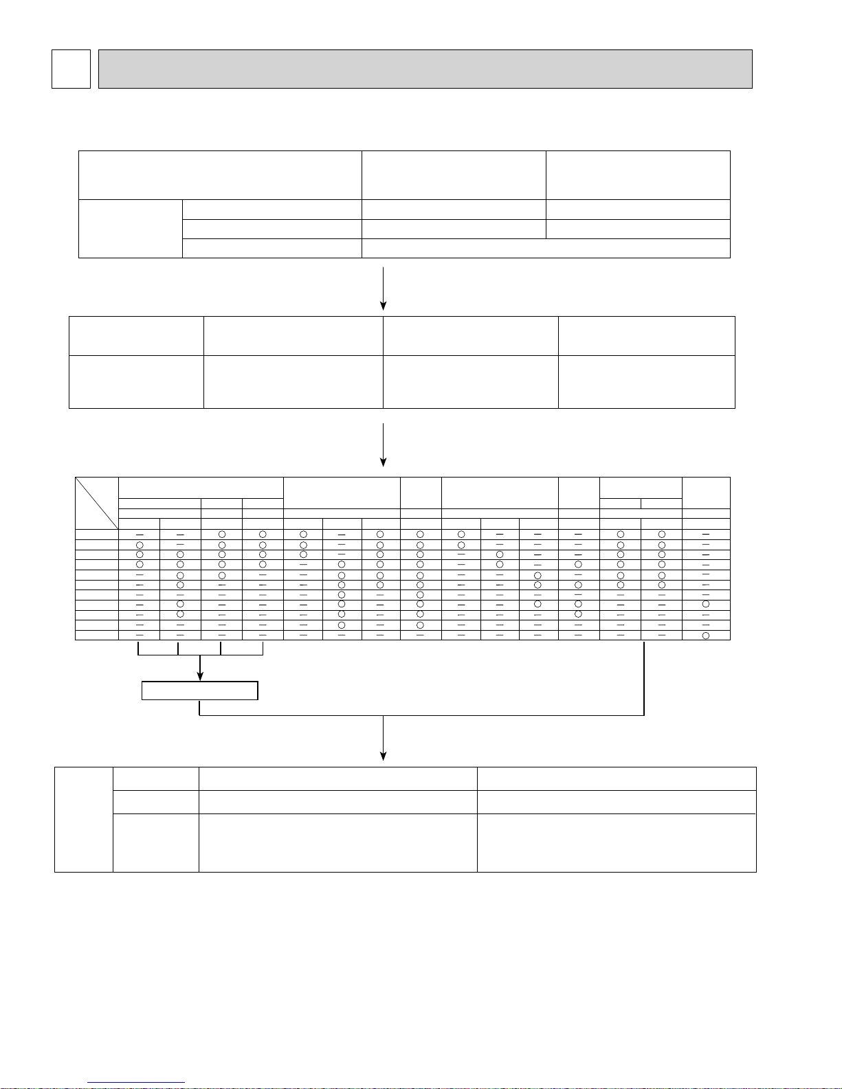
3Tools for R410A (The following table shows whether conventional tools can be used or not.)
Tools and materials Use R410A tools Can R22 tools be used?
Gauge manifold
Charge hose
Gas leak detector
Refrigerant recovery equipment
Refrigerant cylinder
Applied oil
Safety charger
Charge valve
Vacuum pump
Flare tool
Bender
Pipe cutter
Welder and nitrogen gas cylinder
Refrigerant charging scale
Vacuum gauge or thermistor vacuum gauge and
vacuum valve
Charging cylinder
: Prepare a new tool. (Use the new tool as the tool exclusive for R410A.)
: Tools for other refrigerants can be used under certain conditions.
: Tools for other refrigerants can be used.
Air purge, refrigerant charge
and operation check
Gas leak check
Refrigerant recovery
Refrigerant charge
Apply to flared section
Prevent compressor malfunction
when charging refrigerant by
spraying liquid refrigerant
Prevent gas from blowing out
when detaching charge hose
Vacuum drying and air
purge
Flaring work of piping
Bend the pipes
Cut the pipes
Weld the pipes
Refrigerant charge
Check the degree of vacuum. (Vacuum
valve prevents back flow of oil and refrigerant to thermistor vacuum gauge)
Refrigerant charge
Tool exclusive for R410A
Tool exclusive for R410A
Tool for HFC refrigerant
Tool exclusive for R410A
Tool exclusive for R410A
Ester oil, ether oil and
alkylbenzene oil (minimum amount)
Tool exclusive for R410A
Tool exclusive for R410A
Tools for other refrigerants can
be used if equipped with adopter for reverse flow check
Tools for other refrigerants
can be used by adjusting
flaring dimension
Tools for other refrigerants can be used
Tools for other refrigerants can be used
Tools for other refrigerants can be used
Tools for other refrigerants can be used
Tools for other refrigerants
can be used
Tool exclusive for R410A
(Usable if equipped
with adopter for rever se flow)
(Usable by adjusting
flaring dimension)
(mm) [inch]
Dimension B
R410A R22
17.0 [43/64]
22.0 [7/8]
26.0 [1-3/64]
29.0 [1-9/64]
—
Can R407C tools be used?
Ester oil, ether oil:
Alkylbenzene oil: minimum amount
(Usable if equipped
with adopter for rever se flow)
(Usable by adjusting
flaring dimension)
17.0
22.0
24.0
27.0
36.0
7
3 OVERVIEW OF UNITS
3-1. UNIT CONSTRUCTION
Outdoor unit
Indoor unit that
can be connected
Branching pipe
components
Model
4-way flow
Capacity
06
08
12
15
18
24
27
30
36
48
54
PLFY-P PLFY-P PMFY-P PEFY-P PDFY-P PKFY-P PCFY-P PFFY-P PEFY-P
NCMU-E NBMU-E NLMU-E NBMU-E NMLU-E NMHU-E NMSU-E NMU-E NAMU-E NGMU-E NFMU-E NGMU-E NEMU-E NRMU-E NMHU-E-F
Capacity
Number of units
Total system wide capacity
CMY-Y62-G-E CMY-Y64-G-E CMY-Y68-G-E
Branch header
(2 branches)
Ceiling Casette
2-way flow
1-way flow
P36
Type 06 ~ Type 36
1~ 6 unit
50% ~130% of outdoor unit capacity
Branch header
(4 branches)
Ceiling Conceald mounted Wall Mounted
Ceiling
built-in Exposed Cocealed
P48
Type 06 ~ Type 54
1~ 8 unit
Branch header
(8 branches)
Ceiling
Supended
Floor Standing
Ceiling
Concealed
(Fresh Air)*1
Decorative panel
Remote
controller
Name
Model number
Functions
• A handy remote controller for use in conjunction
with the Melans centralized management system.
M-NET remote controller
• Addresses must be set.
*1. It is possible only by 1: 1 system.
(1 indoor unit of Fresh Air type is connected with 1 outdoor unit.)
Operating temperature range (outdoor temperature) for fresh air type indoor units differ from other indoor units.
Refer to 3-2(2).
PAR-F27MEA-US
MA remote controller
PAR-21MAA
• Address setting is not necessary.
8
3-2. UNIT SPECIFICATIONS
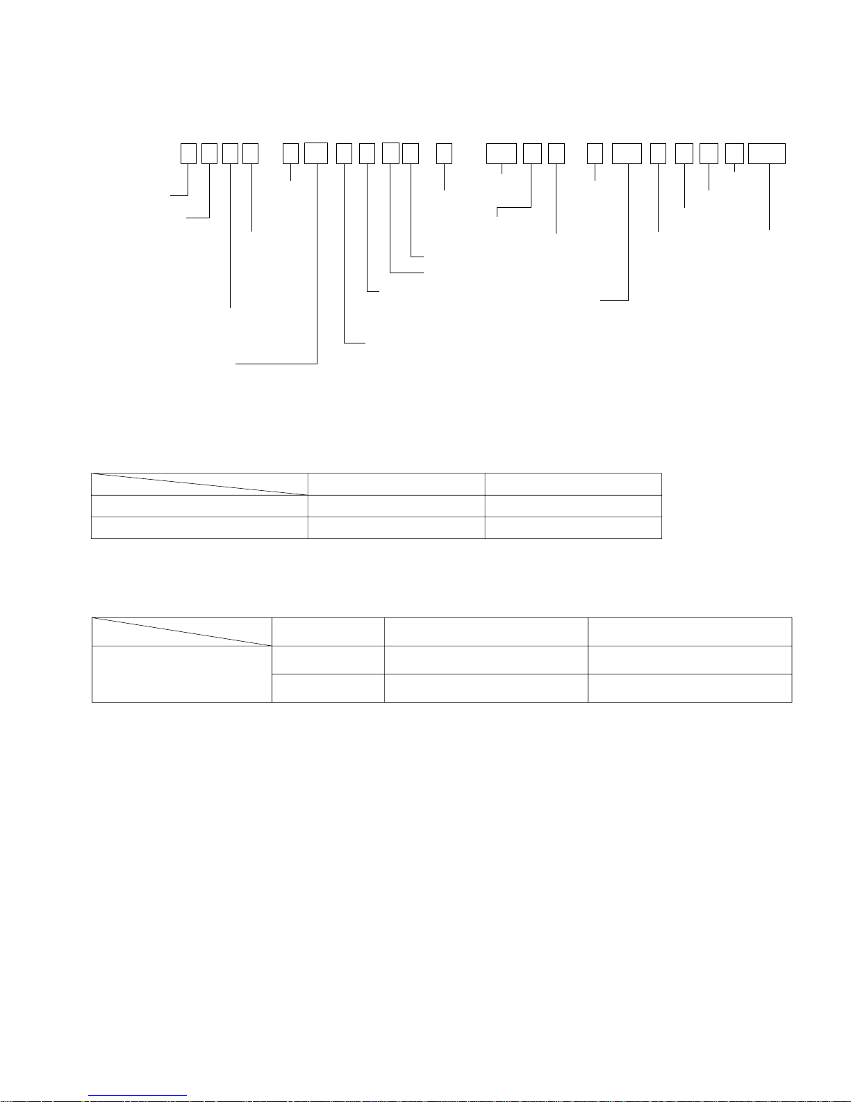
(1) Method for identifying MULTI-S model
■
Indoor unit < When using Model 30 >
P L F Y - P 30 N B M U - E PU M Y - P 48 N H M U -BS
PAC type
L : Ceiling cassette
K : Wall-mounted type
E : Hidden skylight type
C : Ceiling suspended type
M : Ceiling cassette type
F : Floor standing type
NEW frequency converter
one-to-many air conditioners
(flexible design type)
Indicates equivalent
to Cooling capacity
Refrigerant
R410A/R22
commonness
Frequency
conversion
controller
Sub-number
UL model
M-NET control
Unit model type
Power supply
N: Single phase
208/230V 60Hz
Outdoor unit
MULTI-S
Indicates equivalent
to Cooling capacity
■
Outdoor unit <When using model 48 >
Refrigerant
R410A
Frequency
conversion
controller
Power supply
N: Single phase
208/230V 60Hz
UL model
M-NET control
Outdoor unit
model type
Salt proof
type
(2) Operating temperature range
Cooling
Indoor-side intake air temperature
Outdoor-side intake air temperature
W.B. 15~24°C [59~75°F]
D.B. -5~46°C [23~115°F]*1
D.B. 15~27°C [59~81°F]
W.B. -18~15°C [0~60°F]
Notes D.B. : Dry Bulb Temperature
W.B. : Wet Bulb Temperature
*1. 10~46°C DB[50~115°FDB] : In case of connecting PKFY-P06/P08 type indoor unit.
Heating
■ In case of connecting fresh air type indoor unit
Indoor-side and Outdoor-side
intake air temperature
Capacity of Fresh
air type indoor
P30
P54
Cooling
D.B.21~43[70~109°F] *2
W.B.15.5~35[60~95°F]
D.B.21~43[70~109°F] *2
W.B.15.5~35[60~95°F]
*2.Thermo-off(FAN-mode) automatically starts if the outdoor temp. is lower than 21D.B.[70°FD.B.].
*3.Thermo-off(FAN-mode) automatically starts if the outdoor temp. is higher than 20D.B.[68°FD.B.].
(3) Guaranteed voltage
198~253V, 60Hz
Heating
D.B.-10~20[14~68°F] *3
D.B.-5~20[23~68°F] *3
9
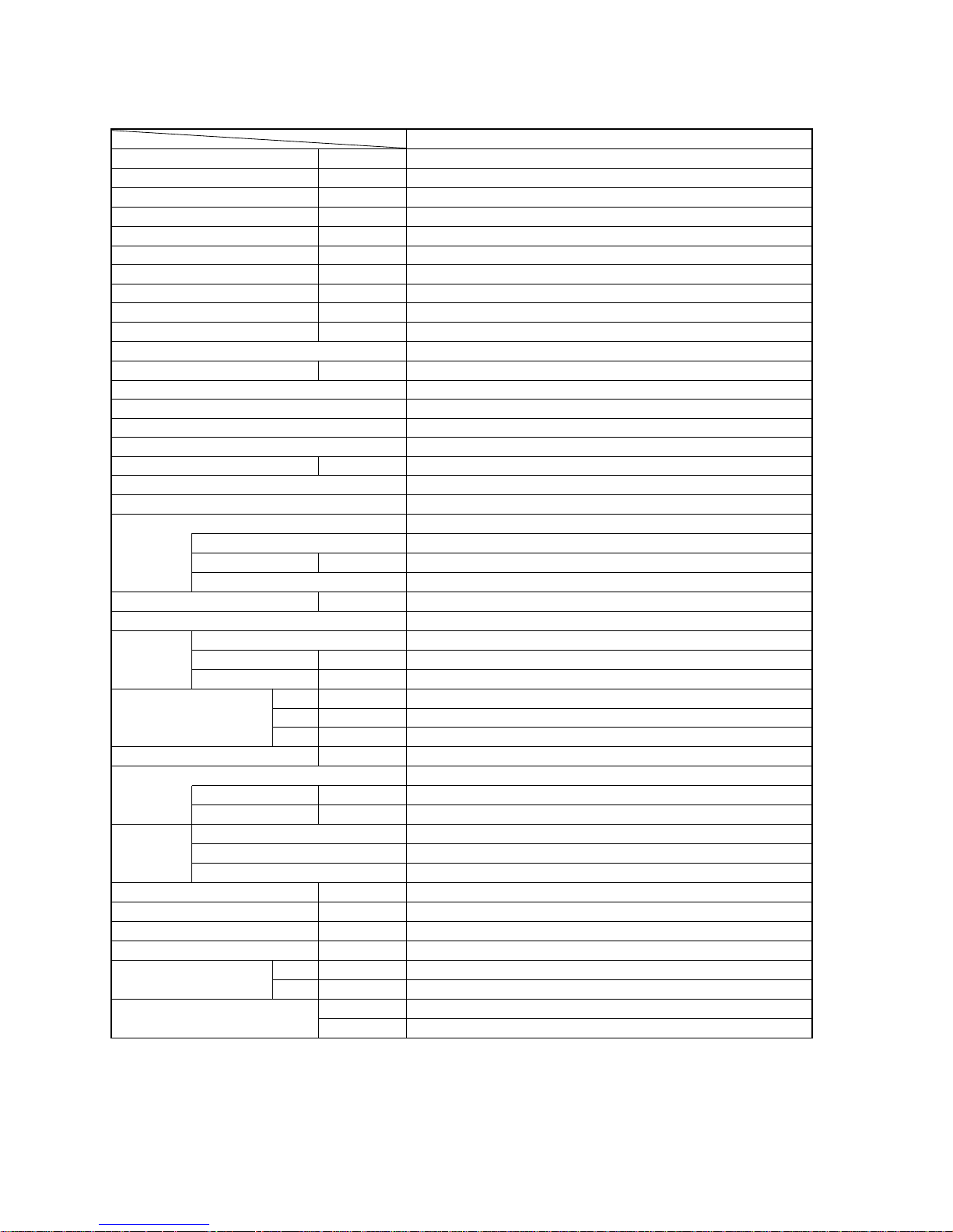
4 SPECIFICATIONS
Item
Cooling Capacity Btu/h
Heating Capacity Btu/h
Input(Cool
Input Current (Cool
Power factor (Cool)
Input(Heat
Input Current (Heat
Power factor (Heat)
EER(Cool
COP (Heat
Connectable indoor units (Max.
Max. Connectable Capacity Btu/h 46,800(130%
Power Supply Single phase ,60Hz,208/230V
Breaker Size
Max. fuse size
Min.Circuit.Ampacity
Sound level (Cool/Heat
External finish Munsell 3Y 7.8/1.1
Refrigerant control Linear Expansion Valve
Compressor Hermetic
Crankcase heater W —
Heat exchanger Plate fin coil (Anti corrosion fin treatment
Fan Fan(drive
Dimensions(HxWxD
Weight kg[lbs
Refrigerant R410A
Protection High pressure protection HP switch
devices Compressor protection Discharge thermo,Over current detection
Total Piping length (Max.
Farthest m [ft] 80 [262]
Max Height difference m [ft] 30 [100]*1
Chargeless length m [ft] 50 [165]
Guranteed operation range
)
)
)
)
Model
Motor output kW 2.2
Starting method Inverter
Fan motor output kW 0.086 + 0.086
Airflow m
Charge kg[lbs
Oil(Model
Fan motor protection Overheating/Voltage protection
Piping diameter
*3
)
*3
*3
*3
)
*3
*3
*3
*3
)
) %
No. Propeller fan % 2
)
)
)
Liquid :mm[inch] 9.52[3/8
Gas :mm[inch] 15.88[5/8
Rating conditions
Cooling Indoor : D.B. 26.7°C / W.B. 19.4°C
[D.B. 80°F / W.B. 67°F]
Outdoor : D.B. 35°C[D.B. 95°F]
Heating Indoor : D.B. 21.1°C[D.B. 70°F]
Outdoor : D.B. 8.3°C / W.B. 6.1°C
Service Ref.
kW
A
%
kW
A
%
Btu/h/W
W/W
)
dB 49 / 51
3
/min[CFM] 100 [3,530]
Wmm[in.
Dmm[in.
Hmm[in.
L [oz]
m [ft]
(
cool
(
heat
]
]
]
]
]
)
)
Note.*1. 20m[70ft] : In case of installing outdoor unit lower than indoor unit.
*2. 10~46°C[50~115°F]DB : In case of connecting PKFY-P06/P08 type indoor unit.
*3. Electrical data is for only outdoor unit.
(In case of connecting 2 indoor units of PLFY-P18BM type)
Btu/h=kW × 3,412 CFM=K/min × 35.31 lbs=kg/ 0.4536
*Above specification data is subject to rounding variation.
PUMY-P36NHMU(-BS)
36,000
40,000
3.22
14.23/15.74
98.4
2.93
12.88/14.24
98.9
11.18
4.00
6
30A
40A
26A
ANB33FDHMT
950 [37-13/32]
330+30 [13+1-3/16
1,350 [53-5/32
130 [287]
8.5[18.7
2.3 [73] (FV50S
120 [394]
-5~ 46 DB [23~115
-18~ 15 WB [0~60
]
]
)
]
)
]
F DB]*2
°
F WB]
°
)
[D.B. 47°F / W.B. 43°F]
)
10
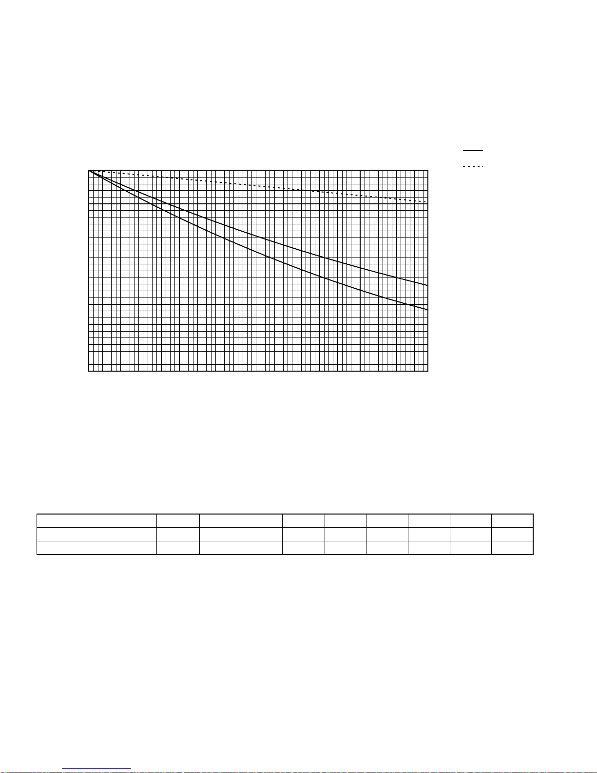
Item
Service Ref.
Cooling Capacity Btu/h
Heating Capacity Btu/h
Input(Cool
Input Current (Cool
Power factor (Cool)
Input(Heat
Input Current (Heat
Power factor (Heat)
EER(Cool
COP (Heat
Connectable indoor units (Max.
)
*3
)
*3
*3
)
*3
)
*3
*3
)
)
*3
*3
kW 4.97
A
%
kW 4.88
A 23.6/21.3
%
Btu/h/W
W/W
)
Max. Connectable Capacity Btu/h 62,400(130%
PUMY-P48NHMU/NHMU1/NHMU2(-BS)
48,000
54,000
24.0/21.7
99.5
99.5
9.66
3.24
8
)
Power Supply Single phase ,60Hz,208/230V
Breaker Size
Max. fuse size
Min.Circuit.Ampacity
Sound level (Cool/Heat
)
dB 50 / 52
30A
40A
26A
External finish Munsell 3Y 7.8/1.1
Refrigerant control Linear Expansion Valve
Compressor Hermetic
Model
ANB33FDCMT(NHMU
(1)), ANB33FDHMT(NHMU2)
Motor output kW 2.4
Starting method Inverter
Crankcase heater W —
Heat exchanger Plate fin coil (Anti corrosion fin treatment
Fan Fan(drive
) %
No. Propeller fan % 2
Fan motor output kW 0.086 + 0.086
Airflow m
Dimensions(HxWxD
)
Weight kg[lbs
3
/min[CFM] 100 [3,530]
Wmm[in.
Dmm[in.
Hmm[in.
]
]
]
]
950 [37-13/32]
330+30 [13+1-3/16
1,350 [53-5/32
]
130 [287]
)
Refrigerant R410A
Charge kg[lbs
Oil(Model
)
L [oz]
]
8.5[18.7
2.3 [73] (MEL56/NHMU
]
(1), FV50S/NHMU2)
Protection High pressure protection HP switch
devices Compressor protection Discharge thermo,Over current detection
Fan motor protection Overheating/Voltage protection
Total Piping length (Max.
)
m [ft]
120 [394]
Farthest m [ft] 80 [262]
Max Height difference m [ft] 30 [100]*1
Chargeless length m [ft] 50 [165]
Piping diameter
Guranteed operation range
Liquid :mm[inch] 9.52[3/8
Gas :mm[inch] 15.88[5/8
(
cool
(
heat
Rating conditions
Cooling Indoor : D.B. 26.7°C / W.B. 19.4°C
[D.B. 80°F / W.B. 67°F]
Outdoor : D.B. 35°C[D.B. 95°F]
Heating Indoor : D.B. 21.1°C[D.B. 70°F]
Outdoor : D.B. 8.3°C / W.B. 6.1°C
)
)
-5~ 46 DB [23~115°F DB]*2
-18~ 15 WB [0~60°F WB]
Note.*1. 20m[70ft] : In case of installing outdoor unit lower than indoor unit.
*2. 10~46°C[50~115°F]DB : In case of connecting PKFY -P06/P08 type indoor unit.
*3. Electrical data is for only outdoor unit.
(In case of connecting 2 indoor units of PLFY-P24BM type)
Btu/h=kW × 3,412 CFM=K/min × 35.31 lbs=kg/ 0.4536
*Above specification data is subject to rounding variation.
]
]
[D.B. 47°F / W.B. 43°F]
)
11
5 DATA
5-1. COOLING AND HEATING CAPACITY AND CHARACTERISTICS
5-1-1. Method for obtaining system cooling and heating capacity:
To obtain the system cooling and heating capacity and the electrical characteristics of the outdoor unit, first add up the ratings
of all the indoor units connected to the outdoor unit (see table below), and then use this total to find the standard capacity with
the help of the tables on 5-2.STANDARD CAPACITY DIAGRAM.
(1) Capacity of indoor unit
Model Number for indoor unit
Model Capacity
(2) Sample calculation
Model 06
Model 088Model1212Model 1515Model 1818Model 2424Model 2727Model 3030Model 3636Model 4848Model 54
6
54
1System assembled from indoor and outdoor unit (in this example the total capacity of the indoor units is greater than that of
the outdoor unit)
• Outdoor unit PUMY-P48NHMU
• Indoor unit PKFY-P08NAMU-E o 2 , PLFY-P18NLMU-E o 2
2According to the conditions in 1, the total capacity of the indoor unit will be: 8 o 2 + 18 o 2 = 52
3The following figures are obtained from the 52 total capacity row of the standard capacity table (5-2.):
Capacity (Btu/h)
Cooling
48,900
A
Heating
54,500
B
Outdoor unit power consumption (kW)
Cooling
5.01
Heating
4.71
Outdoor unit current (A)/230V
Cooling
21.9
Heating
20.6
5-1-2. Method for obtaining the heating and cooling capacity of an indoor unit:
(1) The capacity of each indoor unit (Btu/h) = the capacity A(or B) o
(2) Sample calculation (using the system described above in 5-1-1. (2) ):
During cooling: During heating:
total model capacity of all indoor units
model capacity
• The total model capacity of the indoor unit is:
8000 o 2 + 18000 o 2=52000Btu/h
Therefore, the capacity of PKFY-P08NAMU-E and
PLFY-P18NLMU-E will be calculated as follows by
using the formula in 5-1-2. (1):
Model 08= 48,900o = 7,520 Btu/h
Model 18= 48,900o = 16,930 Btu/h
8000
52000
18000
52000
• The total model capacity of indoor unit is:
9000 o 2 + 20000 o 2=58000 Btu/h
Therefore, the capacity of PKFY-P08NAMU-E and
PLFY-P18NLMU-E will be calculated as follows by
using the formula in 5-1-2. (1):
Model 08=54,500 o = 8,460 Btu/h
Model 18= 54,500 o = 18,790 Btu/h
9000
58000
20000
58000
12

5-2. STANDARD CAPACITY DIAGRAM
* Before calculating the sum of total capacity of indoor units, please convert the value following the formula on 5-1-1.
5-2-1. PUMY-P36NHMU(-BS)
Total capacity
of Indoor units*
18 18,000 20,200 1.38 1.45 6.1 6.4 6.8 7.1
19 19,000 21,300 1.45 1.52 6.4 6.7 7.1 7.4
20 20,000 22,400 1.52 1.60 6.7 7.0 7.4 7.8
21 21,000 23,500 1.60 1.67 7.1 7.4 7.8 8.1
22 22,000 24,700 1.68 1.75 7.4 7.7 8.2 8.5
23 23,000 25,800 1.76 1.83 7.8 8.0 8.6 8.9
24 24,000 26,900 1.85 1.91 8.2 8.4 9.0 9.3
25 25,000 28,000 1.94 1.98 8.6 8.7 9.5 9.6
26 26,000 29,200 2.04 2.06 9.0 9.1 9.9 10.0
27 27,000 30,300 2.14 2.15 9.4 9.4 10.4 10.4
28 28,000 31,400 2.24 2.23 9.9 9.8 10.9 10.8
29 29,000 32,500 2.35 2.31 10.4 10.2 11.5 11.2
30 30,000 33,700 2.46 2.40 10.9 10.5 12.0 11.7
31 31,000 34,800 2.58 2.48 11.4 10.9 12.6 12.1
32 32,000 35,900 2.70 2.57 11.9 11.3 13.2 12.5
33 33,000 37,000 2.82 2.66 12.5 11.7 13.8 12.9
34 34,000 38,200 2.95 2.75 13.0 12.1 14.4 13.4
35 35,000 39,300 3.08 2.84 13.6 12.5 15.1 13.8
36 36,000 40,000 3.22 2.93 14.2 12.9 15.7 14.2
37 36,200 40,200 3.23 2.92 14.3 12.9 15.8 14.2
38 36,400 40,400 3.25 2.89 14.3 12.7 15.9 14.1
39 36,600 40,700 3.26 2.86 14.4 12.6 15.9 13.9
40 36,900 40,900 3.27 2.84 14.5 12.5 16.0 13.8
41 37,100 41,100 3.28 2.81 14.5 12.3 16.0 13.6
42 37,300 41,300 3.30 2.78 14.6 12.2 16.1 13.5
43 37,500 41,600 3.31 2.75 14.6 12.1 16.2 13.4
44 37,700 41,800 3.32 2.72 14.7 11.9 16.2 13.2
45 37,900 42,000 3.34 2.69 14.7 11.8 16.3 13.1
46 38,100 42,200 3.35 2.66 14.8 11.7 16.4 12.9
Note) In some combination patterns, numerical value of the heating data may differ slightly (CAPACITY : about several hun-
dred Btu/h)
Capacity(Btu/h)
Cooling Heating Cooling Heating Cooling Heating Cooling Heating
Power Consumption(kW)
Current(A)/230V Current(A)/208V
13

5-2-2. PUMY-P48NHMU/NHMU1/NHMU2(-BS)
Total capacity
of Indoor units*
24 24,000 26,900 2.11 2.32 9.2 10.2 10.2 11.2
25 25,000 28,000 2.20 2.41 9.6 10.5 10.6 11.6
26 26,000 29,200 2.29 2.50 10.0 10.9 11.1 12.1
27 27,000 30,300 2.38 2.59 10.4 11.3 11.5 12.5
28 28,000 31,400 2.48 2.68 10.8 11.7 12.0 13.0
29 29,000 32,500 2.58 2.78 11.3 12.1 12.4 13.4
30 30,000 33,700 2.68 2.87 11.7 12.6 12.9 13.9
31 31,000 34,800 2.78 2.97 12.2 13.0 13.4 14.4
32 32,000 35,900 2.89 3.07 12.6 13.4 14.0 14.8
33 33,000 37,000 3.00 3.17 13.1 13.9 14.5 15.3
34 34,000 38,200 3.11 3.28 13.6 14.3 15.0 15.8
35 35,000 39,300 3.23 3.38 14.1 14.8 15.6 16.3
36 36,000 40,400 3.35 3.49 14.6 15.2 16.2 16.9
37 37,000 41,500 3.47 3.60 15.2 15.7 16.8 17.4
38 38,000 42,700 3.60 3.71 15.7 16.2 17.4 17.9
39 39,000 43,800 3.72 3.82 16.3 16.7 18.0 18.5
40 40,000 44,900 3.85 3.93 16.8 17.2 18.6 19.0
41 41,000 46,000 3.99 4.05 17.4 17.7 19.3 19.6
42 42,000 47,200 4.12 4.17 18.0 18.2 19.9 20.1
43 43,000 48,300 4.26 4.28 18.6 18.7 20.6 20.7
44 44,000 49,400 4.41 4.41 19.3 19.3 21.3 21.3
45 45,000 50,500 4.55 4.53 19.9 19.8 22.0 21.9
46 46,000 51,700 4.70 4.65 20.5 20.3 22.7 22.5
47 47,000 52,800 4.85 4.78 21.2 20.9 23.4 23.1
48 48,000 54,000 4.97 4.88 21.7 21.3 24.0 23.6
49 48,300 54,200 4.98 4.83 21.8 21.1 24.1 23.3
50 48,500 54,300 4.99 4.79 21.8 20.9 24.1 23.2
51 48,700 54,400 5.00 4.75 21.8 20.8 24.1 23.0
52 48,900 54,500 5.01 4.71 21.9 20.6 24.2 22.8
53 49,100 54,600 5.01 4.67 21.9 20.4 24.2 22.6
54 49,300 54,800 5.02 4.63 21.9 20.2 24.3 22.4
55 49,600 54,900 5.03 4.59 22.0 20.1 24.3 22.2
56 49,800 55,000 5.04 4.55 22.0 19.9 24.3 22.0
57 50,000 55,100 5.04 4.51 22.0 19.7 24.4 21.8
58 50,200 55,200 5.05 4.47 22.1 19.5 24.4 21.6
59 50,400 55,300 5.06 4.43 22.1 19.4 24.4 21.4
60 50,600 55,500 5.07 4.39 22.1 19.2 24.5 21.2
61 50,800 55,600 5.07 4.35 22.2 19.0 24.5 21.0
62 51,100 55,700 5.08 4.31 22.2 18.8 24.6 20.8
Note) In some combination patterns, numerical value of the heating data may differ slightly (CAPACITY : about several hun-
dred Btu/h)
Capacity(Btu/h)
Cooling Heating Cooling Heating Cooling Heating Cooling Heating
Power Consumption(kW)
Current(A)/230V Current(A)/208V
14
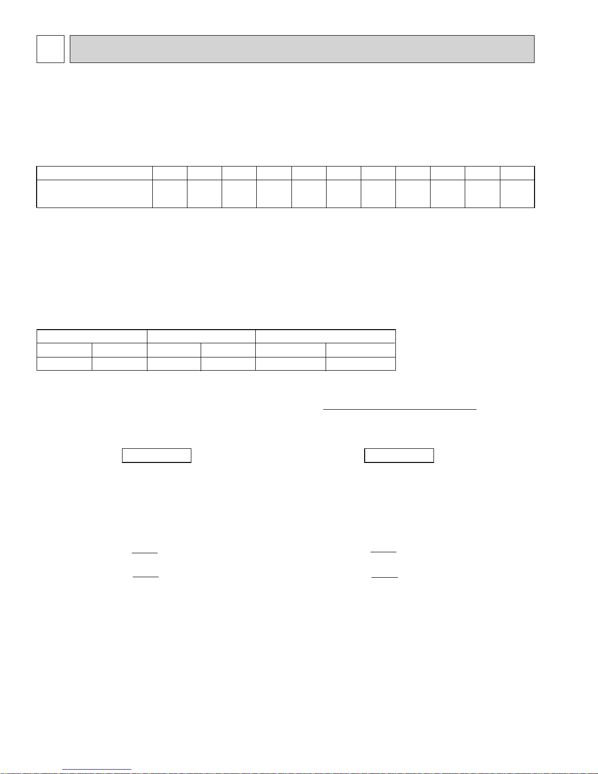
5-3. CORRECTING COOLING AND HEATING CAPACITY
5-3-1. Correcting Changes in Air Conditions
(1)The performance curve charts (Figure 1, 2) show the ratio by the temperature condition change when the rated capacity (total
capacity) and the rated input are presumed 1, under standard length (7.6m [25ft]) and standerd temperature condition.
• Standard conditions:
Rated cooling capacity
Rated heating capacity
• Use the rated input and rated power values given in the characteristics table for each indoor unit.
• The input is the single value of the outdoor unit; the input of each indoor unit must be added to obtain the total input.
(2)The capacity of each indoor unit may be obtained by multiplying the total capacity obtained in (1) by the ratio between the
individual capacity at the rated time and the total capacity at the rated time.
Indoor D.B. 26.7°C / W.B. 19.4°C [D.B.80°F / W.B.67°F]
Outdoor D.B. 35°C [D.B.95°F]
Indoor D.B. 21.1°C [D.B.70°F]
Outdoor D.B. 8.3°C / W.B. 6.1°C [D.B.47°F / W.B.43°F]
Individual capacity under stated conditions = total capacity under the stated conditions o
(3)Capacity correction factor curve
Figure 1. Cooling performance curve
1.4
Cooling capacity (ratio)
1.2
1.0
0.8
0.6
1.4
1.2
Cooling power consumption
(ratio)
1.0
0.8
:WB(°FWB)
22 (71.6)
20 (68)
18 (64.4)
16 (60.8)
INDOOR
:WB(°FWB)
22 (71.6)
20 (68)
18 (64.4)
16 (60.8)
INDOOR
Figure 2. Heating performance curve
1.4
Heating capacity (ratio)
1.2
1.0
0.8
0.6
0.4
1.4
Heating power consumption
1.2
(ratio)
1.0
0.8
individual capacity at the rated time
total capacity at the rated time
:DB(°FDB)
15 (59)
21.1 (70)
25 (77)
INDOOR
:DB(°FDB)
21.1 (70)
15 (59)
25 (77)
INDOOR
0.6
0.4
-5 0 10 20 30 40 46
23 32 50 68 86 104 115
Outdoor Outdoor
°C DB
°F DB
15
0.6
0.4
-18
0
-12
-1014-523032541105015
10
59
°C WB
°F WB
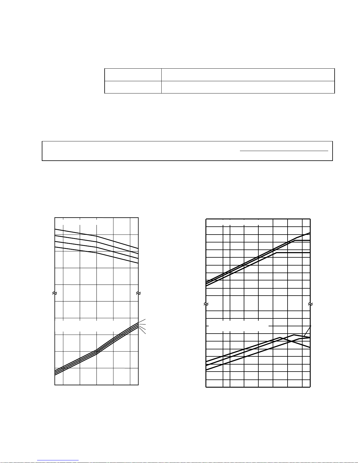
5-3-2. Correcting Capacity for Changes in the Length of Refrigerant Piping
• During cooling, to obtain the ratio (and the equivalent piping length) of the outdoor units rated capacity and the total
in-use indoor capacity, first find the capacity ratio corresponding to the standard piping length from Figure 3
at first, and then multiply by the cooling capacity from Figure 1 to obtain the actual capacity.
• During heating, to find the equivalent piping length, first find the capacity ratio corresponding to standard piping length
from Figure 3, and then multiply by the heating capacity from Figure 2 to obtain the actual capacity.
(1) Capacity CORRECTION CURVE (Figure 3)
Cooling
100
Heating
95
Heating P36, 48 models
90
85
Cooling P36 model
80
Capacity ratio [%]
Cooling P48 model
75
70
5 101520253035404550556065707580[m]
[16] [33] [50] [70] [80] [100] [115] [130] [150] [165] [180] [195] [215] [230] [245] [260][ft]
Corrected pipe length
(2) Method for Obtaining the Equivalent Piping Length
Equivalent length for type P48 = (length of piping to farthest indoor unit) + (0.3 o number of bends in the piping) (m)
Length of piping to farthest indoor unit: 80m [262ft]
5-3-3. Correction of Heating Capacity for Frost and Defrosting
If heating capacity has been reduced due to frost formation or defrosting, multiply the capacity by the appropriate correction
factor from the following table to obtain the actual heating capacity.
Correction factor diagram
Outdoor Intake temperature (W.B.°F)
Outdoor Intake temperature (W.B.°C)
Correction factor
43
6
1.0
39
4
0.98
36
2
0.89
32
0
0.88
28
-2
0.89
25
-4
0.9
21
-6
0.95
18
-8
0.95
14
-10
0.95
16
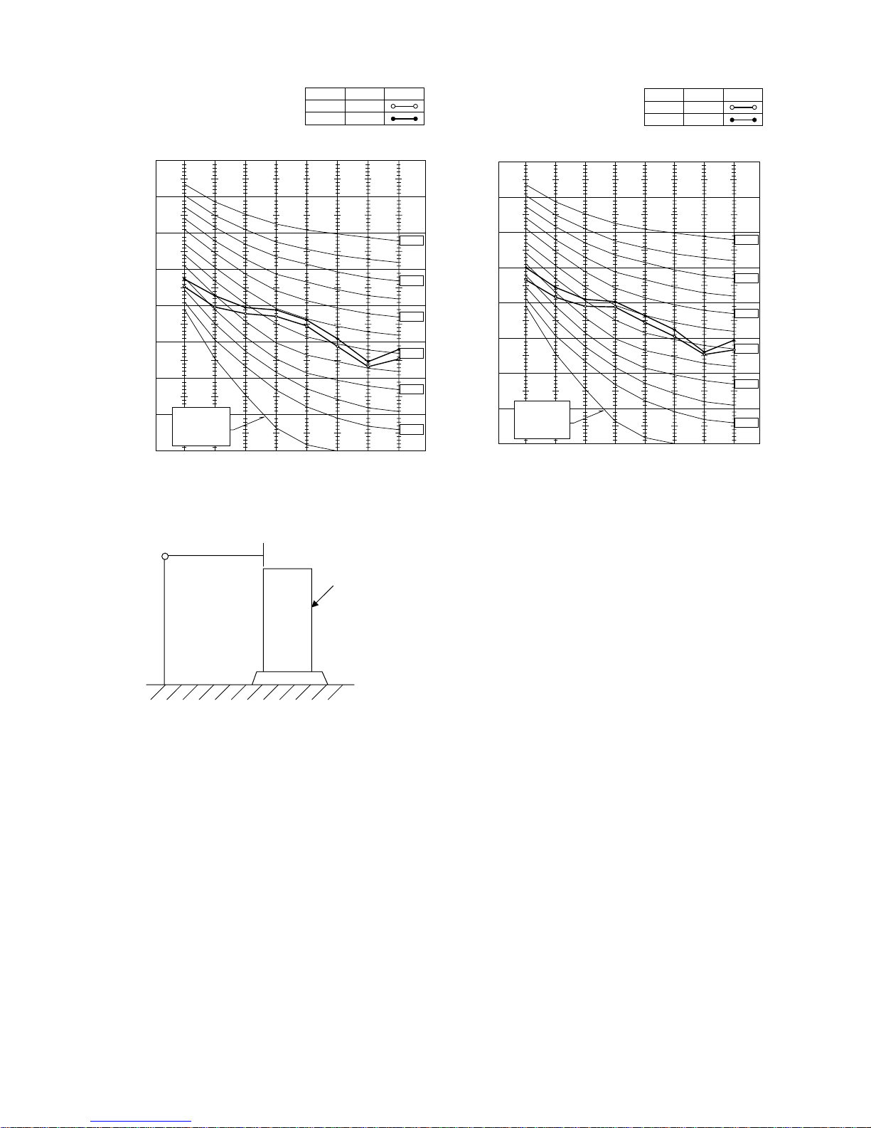
5-4. NOISE CRITERION CURVES
PUMY-P36NHMU(-BS)
MODE
COOLING
HEATING
SPL(dB)
49
51
LINE
PUMY-P48NHMU(-BS)
PUMY-P48NHMU
PUMY-P48NHMU
1(-BS)
2(-BS)
MODE
COOLING
HEATING
SPL(dB)
50
52
LINE
90
80
70
60
50
40
30
APPROXIMATE
20
THRESHOLD OF
HEARING FOR
CONTINUOUS
OCTAVE BAND SOUND PRESSURE LEVEL, dB (0 dB = 0.0002 μbar)
NOISE
10
63 125 250 500 1000 2000 4000 8000
MICROPHONE
BAND CENTER FREQUENCIES, Hz
1m [3.3ft]
UNIT
NC-70
NC-60
NC-50
NC-40
NC-30
NC-20
OCTAVE BAND SOUND PRESSURE LEVEL, dB (0 dB = 0.0002 μbar)
90
80
70
60
50
40
30
APPROXIMATE
20
THRESHOLD OF
HEARING FOR
CONTINUOUS
NOISE
10
63 125 250 500 1000 2000 4000 8000
BAND CENTER FREQUENCIES, Hz
NC-70
NC-60
NC-50
NC-40
NC-30
NC-20
1.5m
[4.9ft]
GROUND
17
6
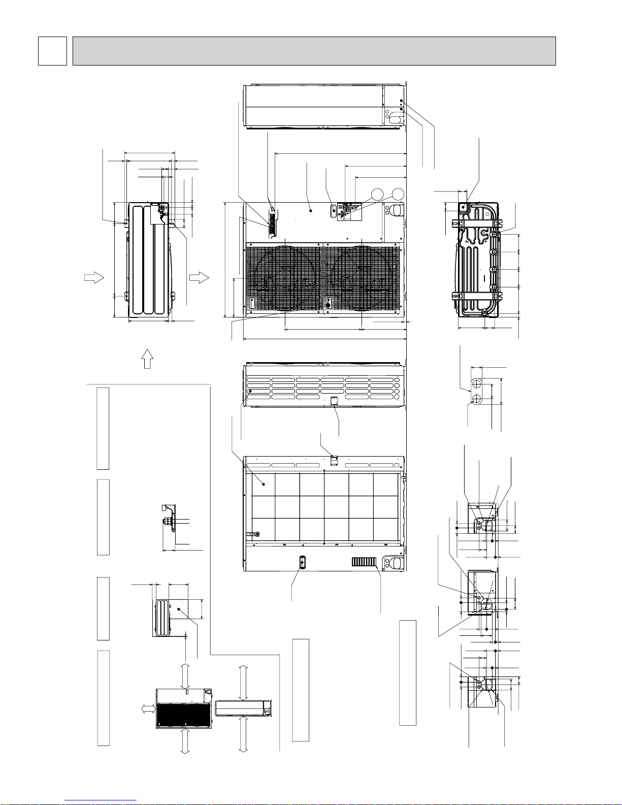
OUTLINES AND DIMENSIONS
PUMY-P48NHMU
PUMY-P48NHMU-BS
PUMY-P48NHMU
1
PUMY-P48NHMU1-BS
19<3/4>
2-U Shaped notched hole
(Foundation Bolt M10<W3/8>)
175
<6-7/8>
Rear Air Intake
600<23-5/8>
175
<6-7/8>
Side Air Intake
4 PIPING-WIRING DIRECTIONS
Piping and wiring connections
can be made from 4 directions:
front, right, rear and below.
417<16-13/32>
56<2-7/32>
37<1-15/32>
330<13>
70<2-3/4>
2-12%36 Oval hole
28<1-3/32> 370<14-9/16>
53<2-3/32>
Left …… For the power supply
Center … For the transmission line
Right…… For concentration control
Terminal block
42<1-21/32>
56<2-7/32>
Air Discharge
(Foundation Bolt M10<W3/8>)
30<1-3/16>
( )
Ground for the power supply
("GR"marking position)
950<37-13/32>
322<12-11/16>
Handle
Side Air Intake
Rear Air Intake
Ground for the transmission line
Ground for concentration control
Service panel
Handle
1088<42-27/32>
+1 507<19-31/32>
Handle
635<25>371<14-19/32>
1350<53-5/32>
Handle
+1 423<16-21/32>
2
1
23<29/32>
Front piping cover
Rear piping cover
71<2-13/16>
When installing the conduit.
Set the attachment to the
inner side of each panel.
Unit : mm <inch>
Bottom piping hole
(Knockout)
71<2-13/16>
219<8-5/8>
1/2 Conduit attachment
2-W22<7/8>
40<1-9/16>
Conduit hole
(2-W27<1-1/16>Knockout)
Rear trunking hole
(Knockout)
W92
74<2-19/32>
<3-5/8>
W33<1-5/16>
Drain hole
5-
145
<5-23/32>
145
<5-23/32>
145
<5-23/32>
220
<8-21/32>
81<3-3/16>
30<1-3/16>
31<1-7/32>
mm<inch>
Rear piping hole
(Knockout)
FOUNDATION
Please secure the unit firmly
with 4 foundation (M10<W3/8>)
2 SERVICE SPACE 3 FOUNDATION BOLTS
Dimensions of space needed
for service access are
1 FREE SPACE (Around the unit)
The diagram below shows a
basic example.
<Foundation bolt height>
bolts.(Bolts and washers must
be purchased locally.)
<5-29/32>
Min.150mm
shown in the below diagram.
FREE
Explantion of particular details is
given in the installation manuals etc.
<19-11/16>
Min.500mm
Min.500mm
Service space
Min.10mm<3/8>
Min.10mm<3/8>
Min.10mm<3/8>
30mm<1-3/16>
Max.
<19-11/16>
Min.150mm<5-29/32>
Min.1000mm<39-3/8>
Handle
Example of Notes
……Refrigerant GAS pipe connction (FLARE):15.88 (5/8 inch)
……Refrigerant LIQUID pipe connection (FLARE): 9.52 (3/8 inch)
+1…..Indication of STOP VALVE connection location.
18
Air intake
55<2-3/16>
63<2-1/2>
73<2-7/8>
W92
63<2-1/2>
92<3-5/8>
73<2-7/8>
<2-1/2>
63
55<2-3/16>
W92
<3-5/8>
27<1-1/16>
<3-5/8>
92<3-5/8>
65<2-9/16>
27<1-1/16>
92<3-5/8>
55<2-3/16>
19<3/4>
73<2-7/8>
27<1-1/16>
65<2-9/16>
92<3-5/8>
23<29/32>
23<29/32>
23<29/32>
40<1-9/16>
Right trunking hole
(Knockout)
45<1-25/32>
Conduit hole
(2-W27<1-1/16>Knockout)
75
Right piping hole
(Knockout)
Conduit hole
(2-W27<1-1/16>Knockout)
40<1-9/16>
<2-31/32>
45<1-25/32>
40<1-9/16>
Piping Knockout Hole Details
Front piping hole
Front trunking hole
(Knockout)
(Knockout)
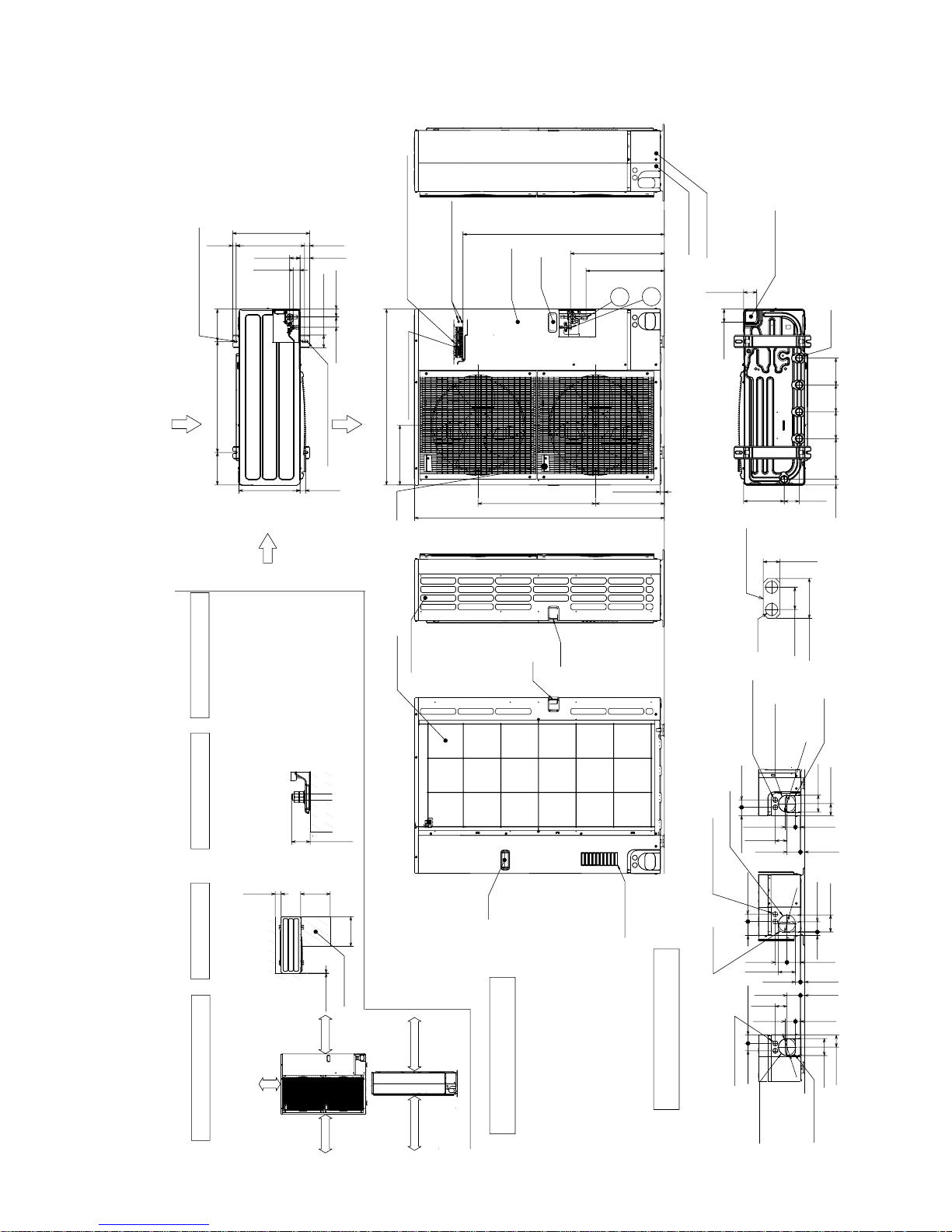
PUMY-P36NHMU
Min.500mm
<19-11/16>
Min.500mm
<19-11/16>
Min.150mm
<5-29/32>
Min.10mm<3/8>
Handle
Side Air Intake
Front piping cover
Rear piping cover
Air intake
Rear Air Intake
Handle
Service panel
Handle
31<1-7/32>
74<2-19/32>
40<1-9/16>
Max.
30mm<1-3/16>
The diagram below shows a
basic example.
Explantion of particular details is
given in the installation manuals etc.
Dimensions of space needed
for service access are
shown in the below diagram.
<Foundation bolt height>
Please secure the unit firmly
with 4 foundation (M10<W3/8>)
bolts.(Bolts and washers must
be purchased locally.)
Air Discharge
Rear Air Intake
Side Air Intake
……Refrigerant GAS pipe connction (FLARE):15.88 (5/8 inch)
……Refrigerant LIQUID pipe connection (FLARE):9.52 (3/8 inch)
+1…..Indication of STOP VALVE connection location.
Example of Notes
Piping Knockout Hole Details
1 FREE SPACE (Around the unit)
2 SERVICE SPACE 3 FOUNDATION BOLTS
4 PIPING-WIRING DIRECTIONS
Piping and wiring connections
can be made from 4 directions:
front,right,rear and below.
1/2 Conduit attachment
2-W22<7/8>
When installing the conduit.
Set the attachment to the
inner side of each panel.
mm<inch>
FOUNDATION
Service space
Min.1000mm<39-3/8>
Min.10mm<3/8>
Min.10mm<3/8>
FREE
Min.150mm<5-29/32>
2-U Shaped notched hole
(Foundation Bolt M10<W3/8>)
Conduit hole
(2-W27<1-1/16>Knockout)
45<1-25/32>
Right trunking hole
(Knockout)
45<1-25/32> 40<1-9/16>
65<2-9/16>
92<3-5/8>
27<1-1/16>
55<2-3/16>
23<29/32>
73<2-7/8>
63<2-1/2>
Rear piping hole
(Knockout)
Rear trunking hole
(Knockout)
Conduit hole
(2-W27<1-1/16>Knockout)
W92
<3-5/8>
W92
<3-5/8>
19<3/4> 55<2-3/16>
92<3-5/8>
40<1-9/16>
73<2-7/8> 63<2-1/2>
23<29/32>
27<1-1/16>
92<3-5/8>
Conduit hole
(2-W27<1-1/16>Knockout)
75
<2-31/32>
Right piping hole
(Knockout)
40<1-9/16>
55<2-3/16>
73<2-7/8>
27<1-1/16>
23<29/32>
65<2-9/16>
92<3-5/8>
Front trunking hole
(Knockout)
Front piping hole
(Knockout)
63
<2-1/2>
W92
<3-5/8>
30<1-3/16>
81<3-3/16>
219<8-5/8>
71<2-13/16>
71<2-13/16>
Bottom piping hole
(Knockout)
Drain hole
5-
W33<1-5/16>
220
<8-21/32>
145
<5-23/32>
145
<5-23/32>
145
<5-23/32>
Handle
600<23-5/8>
28<1-3/32>
370<14-9/16>
70<2-3/4>
56<2-7/32>
42<1-21/32>
56<2-7/32>
37<1-15/32>
19<3/4>
53<2-3/32>
417<16-13/32>
330<13>
175
<6-7/8>
175
<6-7/8>
2-12%36 Oval hole
(Foundation Bolt M10<W3/8>)
30<1-3/16>
1088<42-27/32>
322<12-11/16>
635<25>371<14-19/32>
950<37-13/32>
23<29/32>
1350<53-5/32>
+1 423<16-21/32>
+1 507<19-31/32>
Handle
1
2
( )
Left …… For the power supply
Center … For the transmission line
Right…… For concentration control
Terminal block
Ground for the transmission line
Ground for concentration control
Ground for the power supply
("GR"marking position)
PUMY-P36NHMU-BS
PUMY-P48NHMU
2
PUMY-P48NHMU2-BS
Unit : mm <inch>
19
7
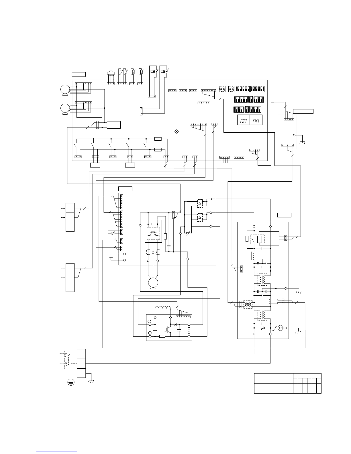
WIRING DIAGRAM
PUMY-P48NHMU PUMY-P48NHMU-BS PUMY-P48NHMU1 PUMY-P48NHMU1-BS
SYMBOL NAME SYMBOL NAMESYMBOL NAME
TB1 Terminal Block <Power Supply>
TB3 Terminal Block <Transmission>
TB7 Terminal Block <Contralized Control>
MC Motor for Compressor
MF1,MF2 Fan Motor
21S4 Solenoid Valve<Four way valve>
SV1 Solenoid Valve<Bypass valve>
TH3
TH4 Thermistor<Discharge Temperature>
TH6
TH7 Thermistor<Outdoor Temperature>
TH8 Thermistor<Heatsink>
63HS
63H High Pressure Switch
63L Low Pressure Switch
CB Main Smoothing Capacitor
ACTM
RS Rush Current Protect Resistor
DCL
P.B. Power Circuit Board
U/V/W
TAB-S/T
TAB-P/P1/P2
TAB-N/N1/N2
CN2~5
CNDC
CNAF
IPM
LED1
Thermistor<Outdoor Pipe Temperature>
Thermistor<Low Pressure Saturated Temperature>
High Pressure Sensor<Discharge Pressure>
Active filter Module
Reactor
Connection Terminal<U/V/W-Phase>
Terminal<L/N-Phase>
Terminal<DCVoltage>
Terminal<DCVoltage>
Connector
Connector
Connector
Inverter
Light Emitting Diodes <Inverter Control Status>
MULTI.B.
F1,F2
F500
SW1
SW2
SW3
SW4
SW5
SW6
SW7
SW8
SWU1
SWU2
TRANS
LED1,2
LED3
CNS1
CNS2
CNAC
CNDC
CN2
CN4
CN40
CN41
TH3
TH4
TH7/6
63HS
63H
63L
CNF1,CNF2
21S4
SV1
SS
CN3D
CN3S
CN3N
CN51
X501~505
Multi Controller Board
Fuse<6.3A>
Fuse<3A>
Switch<Display Selection>
Switch<Function Selection>
Switch<Test Run>
Switch<Model Selection>
Switch<Function Selection>
Switch<Function Selection>
Switch<Function Selection>
Switch<Function Selection>
Switch<Unit Address Selection, 1s digit>
Switch<Unit Address Selection, 10ths digit>
Transfomer
Digital Indicator<Operation Inspection Display>
LED<Power Supply to Main Microcomputer>
Connector<Multi System>
Connector<Centralized Cotrol>
Connector<To Noise Filter Circuit Board>
Connector<Power circuit board>
Connector<To Power Circuit Board>
Connector<To Power Circuit Board>
Connector<Centralized Cotrol Power Supply>
Connector<For storing Jumper Connector>
Connector<Thermistor>
Connector<Thermistor>
Connector<Thermistor>
Connector<High Pressure Sensor>
Connector<High Pressure Switch>
Connector<Low Pressure Switch>
Connector<Fan Motor>
Connector<Four-way Valve>
Connector<Bypass Valve>
Connector<For Option>
Connector<For Option>
Connector<For Option>
Connector<For Option>
Connector<For Option>
Relay
N.F. Noise Filter Circuit Board
LI/LO
NI/NO
EI
CNAC1/2
CN5
M-P.B.
CN1
CN2
Connection Lead<L-Phase>
Connection Lead<N-Phase>
Connection Terminal<Ground>
Connector
Connector
Transmission Power Board
Connector<To Noise Filter Circuit Board>
Connector<To Multi Controller Board>
Caution for electrical work
Use copper supply wires.
Cautions when Servicing
!
WARNING: When the main supply is turned off, the voltage [340 V] in the main capacitor will drop to 20 V in approx. 2
minutes (input voltage: 240 V). When servicing, make sure that LED1, LED2 on the outdoor circuit board goes out, and then
wait for at least 1 minute.
Components other than the outdoor board may be faulty: Check and take corrective action, referring to the service manual.
Do not replace the outdoor board without checking.
NOTES:
1.Refer to the wiring diagrams of the indoor units for details on wiring of each indoor unit.
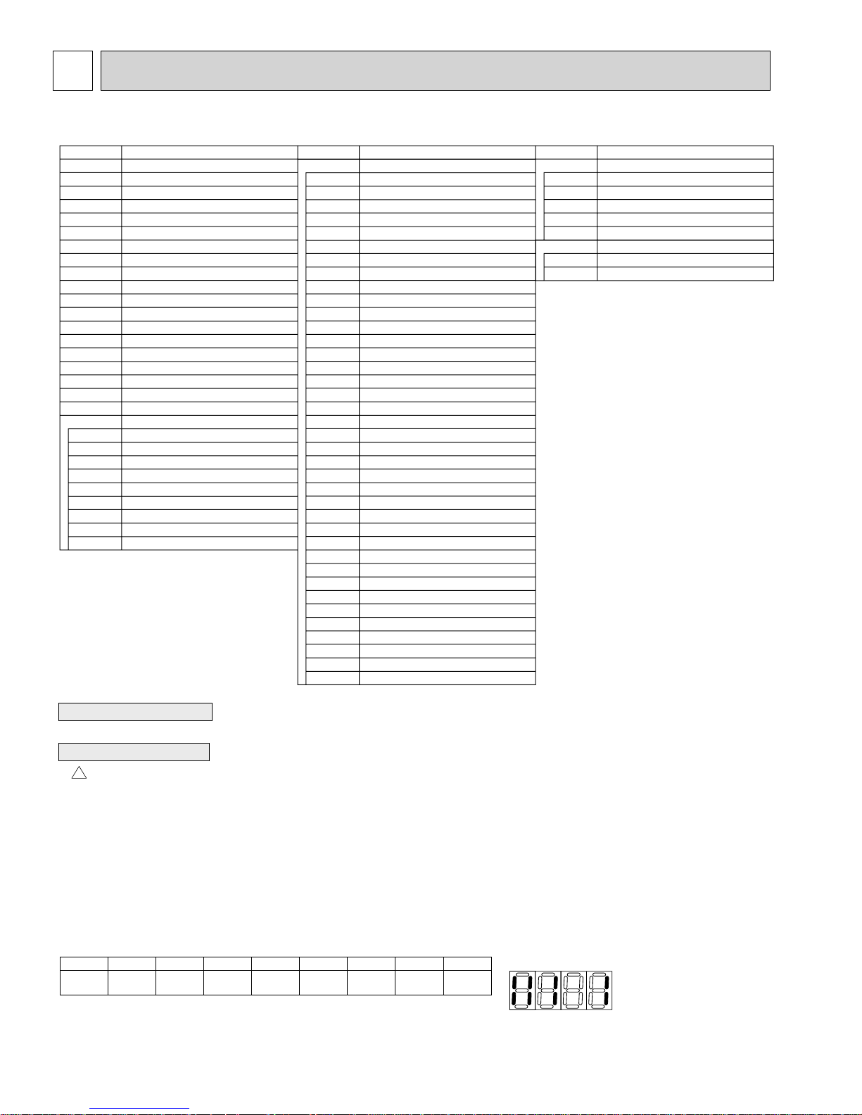
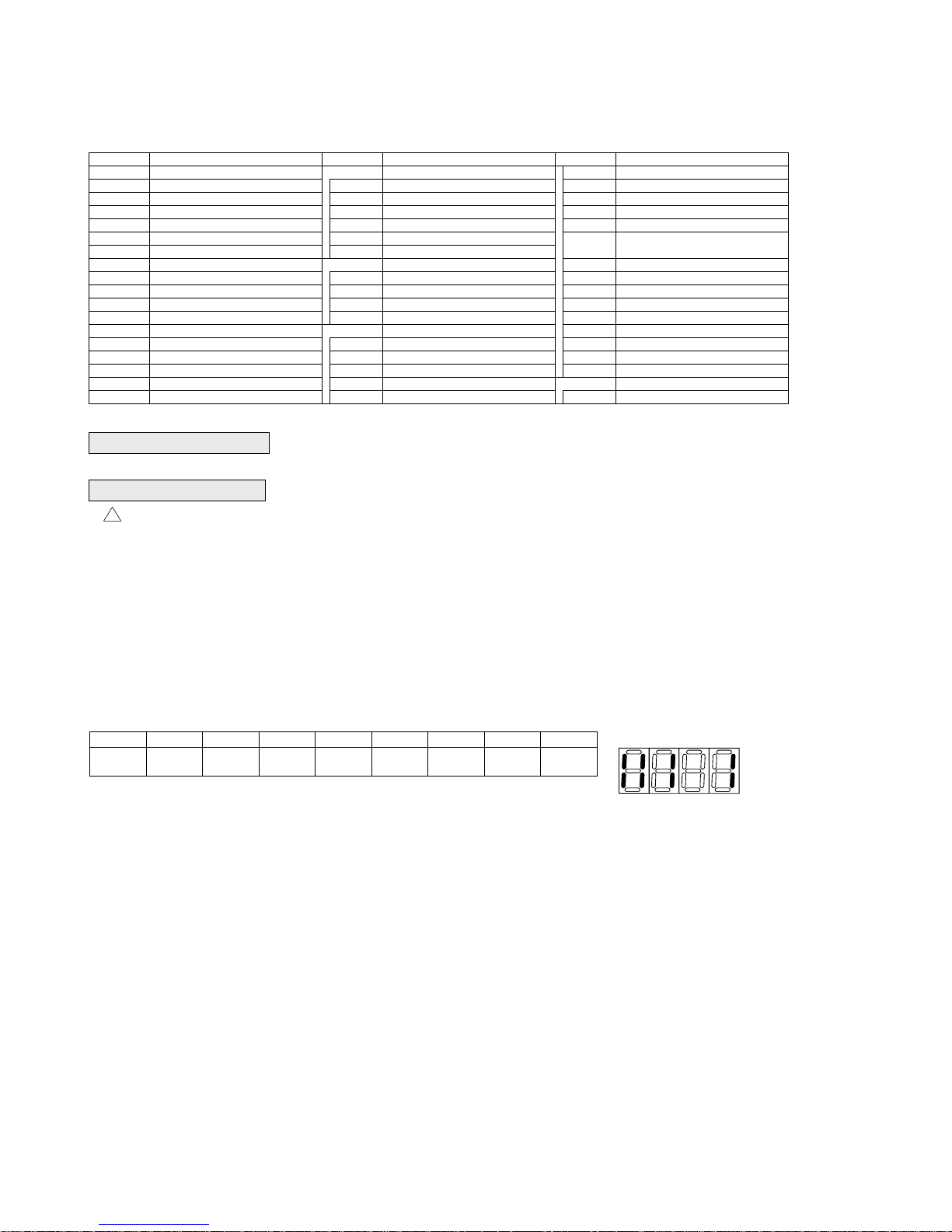
Self-diagnosis function
The indoor and outdoor units can be diagnosed automatically using the self-diagnosis switch
(SW1) and LED1, LED2 (LED indication) found on the multi-controller of the outdoor unit.
LED indication : Set all contacts of SW1 to OFF.
During normal operation
The LED indicates the drive state of the controller in the outdoor unit.
Bit
Indication
When fault requiring inspection has occurred
The LED alternately indicates the inspection code and the location of the unit in which
the fault has occurred.
1
Compressor
operated
52C
2
3
21S44SV15(SV2)
[Example]
When the compressor and
SV1 are turned during cooling
6
–
7
–
8
Always lit
operation.
12345678
20

MF1
MF2
TB3
M1
M2
S
TO INDOOR UNIT
CONNECTING WIRES
DC 30V(Non-polar)
TB7
(ORN)
M1
M2
(ORN)
S
FOR CENTRALIZED
CONTROL
DC 30V(Non-polar)
POWER SUPPLY
~/N
NO FUSE
BREAKER
AC208V/230V
60Hz
L1
L2
GR
(BRN)
(BRN)
MULTI. B.
1
4567
1
4 567
F500
X505
52C
(BLK)
3
1
CNDC
(PNK)
X504
21S4
(GRN)
31
21S4
CB
CNF1
(WHT)
CNF2
(WHT)
31
(BLU)
3 1
+
SV2
TH8
X503
TH7TH6 TH3 TH463HS 63H63L
12 12 123 4
123
TH7/6
63HS
(RED)
(WHT)
63H
(YLW)
TRANS
X502
SS
SV1
(WHT)
(WHT)
3
21
SV1
52C
RS
P. B.
123
CNAF
4
5 6
(WHT)
12 12 12 123 4 567
CN2
(WHT)
CN3
(WHT)
CN5
(RED)
CN4
(WHT)
TABN
TABP
31
X501
1
TABP2
RED
TH3
(WHT)
F1
F2
+
V
U
WHT
MC
(WHT)
31
-
W
BLK
TH4
63L
(RED)
2
1
CNDC
+
CNAC
(RED)
DCL
ACTM
(PIN)
13
TABN1
LED3
+
-
TABN2
CNS1
(RED)
2
L1
CN3D
(WHT)
123
CN2
(WHT)
765
CNS2
(YLW)
121
L2
+
+
CN3S
(RED)
1 23
4 321
123456
TABT
~
~
TABS
~
~
TABP1
CN3N
P
N1
N2
I
(BLU)
123
(WHT)
CN4
21
CN51
(WHT)
SWU2 SWU1
4321
5
+1
CN41
(WHT)
31 3
CNAC2
(RED)
1
CNAC1
(WHT)
SW1
SW4
LED1
CN40
(WHT)
43214321
E I
SW5
SW3
88
LO
NO
CN5
(RED)
SW8
SW7
LED2
CN102
(WHT)
4 321
M-P.B.
N. F.
12
NILI
SW6
SW2
88
TP1
1 234
CN2
(WHT)
CN1
(WHT)
3 1
<+1 MODEL SELECT>
OFF
ON
SW4
123456
MODELS
PUMY-P48NHMU
(Note : Only PUMY-P48NHMU1 and PUMY-P48NHMU1-BS)
DIP SW4-4 for primary heating control : Set DIP SW4-4 when power is turned off at unit.
DIP SW4-4 OFF : Disable primary heating function (Initial setting)
DIP SW4-4 ON : Enable primary heating function
21
PUMY-P36NHMU PUMY-P36NHMU-BS PUMY-P48NHMU2 PUMY-P48NHMU2-BS
SYMBOL NAME SYMBOL NAME SYMBOL NAME
TB1 Terminal Block <Power Supply>
TB3 Terminal Block <Comunication Line>
TB7 Terminal Block <
MC Motor For Compressor
MF1,MF2 Fan Motor
21S4 Solenoid Valve<Four-Way Valve>
63H High Pressure Switch
63L Low Pressure Switch
63HS High Pressure Sensor
SV1 Solenoid Valve<Bypass valve>
TH3
TH4 Thermistor<Discharge>
TH6 Thermistor<Low Pressure Saturated>
TH7
TH8
DCL
ACTM
CE Main Smoothing Capacitor
Thermistor<Outdoor Pipe>
Thermistor<Outdoor>
Thermistor<Heatsink>
Reactor
Active Filter Module
Centralized Control Line>
Caution for electrical work
Use copper supply wires.
Cautions when Servicing
!
• WARNING: When the main supply is turned off, the voltage [340 V] in the main capacitor will drop to 20 V in approx. 2
minutes (input voltage: 240 V). When servicing, make sure that LED1, LED2 on the outdoor circuit board goes out, and then
wait for at least 1 minute.
• Components other than the outdoor board may be faulty: Check and take corrective action, referring to the service manual.
Do not replace the outdoor board without checking.
NOTES:
1.Refer to the wiring diagrams of the indoor units for details on wiring of each indoor unit.
Self-diagnosis function
The indoor and outdoor units can be diagnosed automatically using the self-diagnosis switch
(SW1) and LED1, LED2 (LED indication) found on the multi-controller of the outdoor unit.
LED indication : Set all contacts of SW1 to OFF.
• During normal operation
• The LED indicates the drive state of the controller in the outdoor unit.
Bit
Indication
• When fault requiring inspection has occurred
The LED alternately indicates the inspection code and the location of the unit in which
the fault has occurred.
1
Compressor
operated
52C
2
21S4
P.B. Power Circuit Board
TABU/V/W
TABS/T
TABP1/P2/P
TABN1/N2/N
DS2,DS3
IPM
N.F. Noise Filter Circuit Board
LI/LO
NI/NO
EI,E2
52C
C.B.
SW1
SW2
SW3
SW4
SW5
3
SV1
Connection Terminal<U/V/W-Phase>
Connection Terminal<L/N-Phase>
Connection Terminal<DC Voltage>
Connection Terminal<DC Voltage>
Diode Bridge
Power Module
Connection Terminal<L-Phase>
Connection Terminal<N-Phase>
Connection Terminal<Ground>
52C Relay
Controller Circuit Board
Switch<Display Selection>
Switch<Function Selection>
Switch<Test Run>
Switch<Model Selection>
Switch<Function Selection>
4
5
(SV2)
SW6
SW7
SW8
SWU1
SWU2
CNLVB
SS
CN3D
CN3S
CN3N
CN51
LED1,LED2
LED3
F1,F2
X501~505
M-NET P.B.
TP1
6
-
7
-
8
Always lit
Switch<Function Selection>
Switch<Function Selection>
Switch<Function Selection>
Switch<Unit Address Selection, 1s digit>
Switch<Unit Address Selection, 10ths digit>
Connector<To N.F. Board CN52C>
(Symbol of Board is CNLVB)
Connector<Connection For Option>
Connector<Connection For Option>
Connector<Connection For Option>
Connector<Connection For Option>
Connector<Connection For Option>
LED<Operation Inspection Display>
LED<Power Supply to Main Microcomputer>
Fuse<T6,3AL250V>
Relay
M-NET Power Circuit Board
ConnectionTerminal<Ground>
[Example]
When the compressor and
SV1 are turned during cooling
operation.
12345678
22
C. B.
MF1
1
MS
3~
MF2
1
MS
3~
2
X505
52C
13
(BLK)
TB3
2
RED
M1
M2
RED
S
TO INDOOR UNIT
CONNECTING WIRES
DC 30V(Non-polar)
TB7
2
YLW
M1
M2
YLW
S
FOR CENTRALIZED
CONTROL
DC 30V(Non-polar)
POWER SUPPLY
~/N 208/230V 60Hz
TB1
RED
L1
BLU
L2
GRN
GR
CNF1
(WHT)
7
CNF2
(WHT)
7
3
1
3
21S4
CNDC
(PNK)
X504
21S4
1
(GRN)
TH8
TH7 TH6 TH3 TH4
63HS
3
63HS
(WHT)
TRANS
X503
3
1
4
7
2
2
WHT
CE
+
RED
141
TH7/6
(RED)
SV2
(BLU)
P. B.
1
CNAF
(WHT)
6
1
(WHT)
7
1
2
1
2
1
(WHT)
2
TH3
(WHT)
SV1
CN2
CN3
(WHT)
CN5
(RED)
CN4
TABN
TABP
63H
63L
t t t t t
2112
TH4
(WHT)
113
63L
(RED)
3
63H
(YLW)
F1
F2
X501
X502
SV1
1
3
12 12
(WHT)
IPM
TABP2
RED
RED
BLK
+
TABU
RED
V
U
MS
3~
DCL
+
-
ACTM
SS
(WHT)
TABV
BLK
WHT
W
L1 L2
-
MC
CN3D
CN3S
(WHT)
(RED)
131313
LED3
CNS1
(RED)
1
CNAC
(RED)
2
CNDC
(PIN)
2
1
3
TABN1
BLK
+
TABW
4
16
N1
N2
2
U
P
Io
CN3N
(BLU)
(WHT)
1
CNS2
(YLW)
1
22
TABN2
WHT
RED
WHT
CN2
DS3
+
DS2
+
1
2
CNLVB
SWU2SWU1
(RED)
16
CN51
(WHT)
7
7
TABT
TABS
TABP1
5
CN4
(WHT)
1
2
2
2
4
BLU
WHT
RED
CN41
(WHT)
SW6
SW5
SW2SW8SW1
CN40
LED1
1
3
1
CNAC2
3
1
CNAC1
CN102
(WHT)
4
(RED)
(WHT)
SW7SW3SW4
LED2
4
LO
L I
RED
1
WHT
52C
U
+1
(WHT)
1
4
2
2
NO
N I
BLU
BLU
U
5
N. F.
1
2
4
1
CN2
(WHT)
CN1
(WHT)
1
2
(BLK)
CN52C
E2
CN5
(RED)
E I
M-NET P.B.
4
TP1
1
2
2
BLK
2
BLK
BLK
+1 MODEL SELECT 1:ON 0:OFF
MODELS
PUMY-P36NHMU
PUMY-P48NHMU
SW4
123456
011010
011001
23
8
NECESSARY CONDITIONS FOR SYSTEM CONSTRUCTION
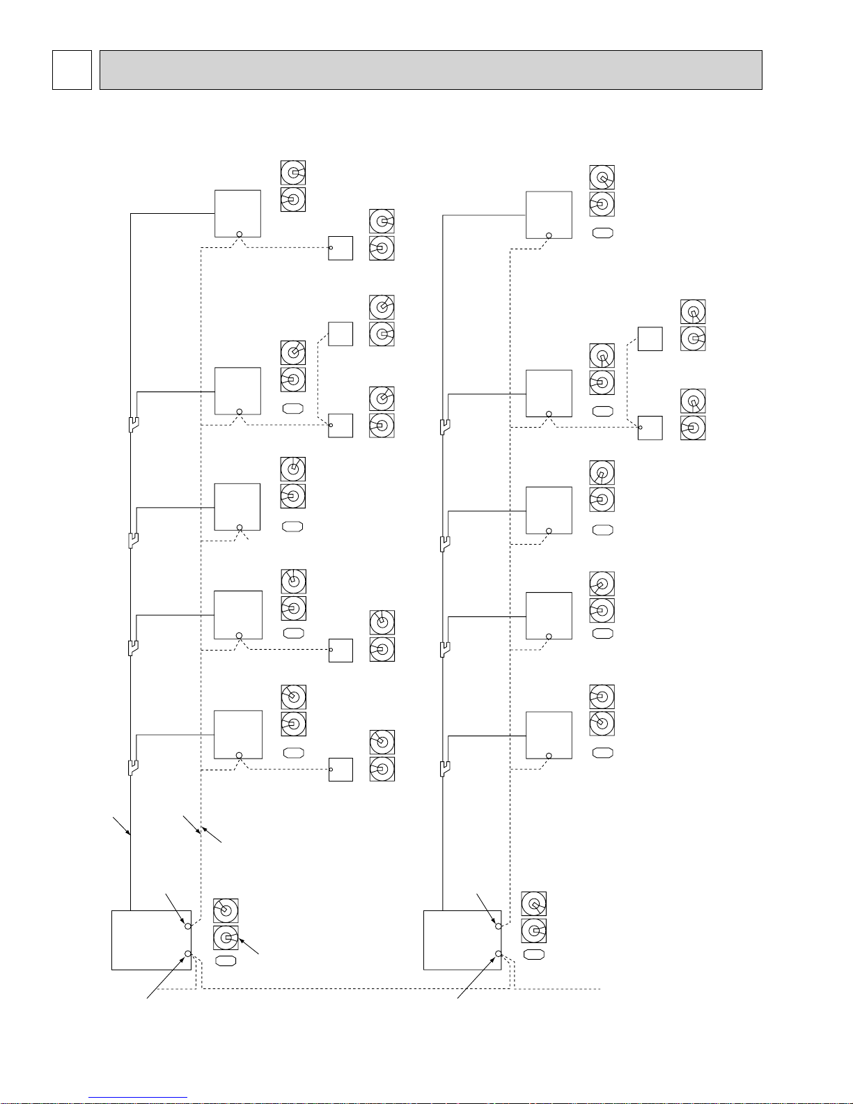
8-1. TRANSMISSION SYSTEM SETUP
3
2
4
1
5
0
6
9
7
8
3
2
4
1
5
0
6
9
7
8
005
3
2
4
1
5
0
6
9
7
8
3
2
4
1
5
0
6
9
7
004
003
8
3
2
4
1
5
0
6
9
7
8
3
2
4
1
5
0
6
9
7
8
105
Remote
controller
Remote
controller
Remote
controller
3
2
4
1
5
0
6
9
7
8
3
2
4
1
5
0
6
9
7
8
3
2
4
1
5
0
6
9
7
8
3
2
4
1
5
0
6
9
7
8
3
2
4
1
5
0
6
9
7
8
3
2
4
1
5
0
6
9
7
8
3
2
4
1
5
0
6
9
7
8
3
2
4
1
5
0
6
9
7
8
Indoor unitIndoor unitIndoor unitIndoor unitIndoor unit
006
007
Address SWAddress SWAddress SWAddress SWAddress SW
3
2
4
1
5
0
6
9
7
8
3
2
4
1
5
0
6
9
7
8
3
2
4
1
5
0
6
9
7
8
3
2
4
1
5
0
6
9
7
8
157
Remote
controller
107
Remote
controller
3
2
4
1
5
0
6
9
7
8
3
2
4
1
5
0
6
9
7
8
Address SWAddress SW
11
3
2
4
1
5
0
6
9
7
8
3
2
4
1
5
0
6
9
7
8
008
Piping
For remote
051
Outdoor unit
Transmission wire
controller
Indoor unit Indoor unit Indoor unit Indoor unit Indoor unit
3
2
4
1
5
0
6
9
7
8
3
2
4
1
5
0
6
9
7
8
002
001
3
2
4
1
5
0
6
9
7
8
3
2
4
1
5
0
6
9
7
8
3
2
4
1
5
0
6
9
7
8
3
2
4
1
5
0
6
9
7
8
Address SW Address SW Address SW Address SW Address SW
connected to each refrigerant
system (outdoor and indoor).
A transmission wire must be
Set addresses:
3
2
4
1
5
0
6
9
7
8
3
2
4
1
5
0
6
9
7
8
102 104 154
Remote
controller
101
1111
3
2
4
1
5
0
6
9
7
8
3
2
4
1
5
0
6
9
7
8
Address SW Address SW Address SW Address SW Address SW
1
Remote
controller
Outdoor unit ..............051-100
Indoor unit .................001-050
Remote controller .....101-200
The address automatically become
"100" if it is set as "01~50".
PUMY has no 100ths digit switch.
For remote
056
Outdoor unit
controller
3
2
4
1
5
0
6
9
7
8
3
2
4
1
5
0
6
9
7
009
8
3
2
4
1
5
0
6
9
7
8
3
2
4
1
5
0
6
9
7
8
010
3
2
4
1
5
0
6
9
7
8
3
2
4
1
5
0
6
9
7
8
For centralized
management
24
For centralized
management
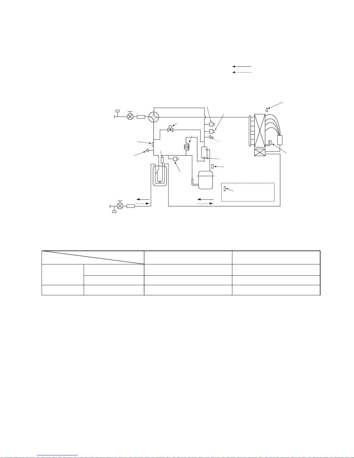
8-2. REFRIGERANT SYSTEM DIAGRAM
PUMY-P48NHMU PUMY-P48NHMU1 PUMY-P48NHMU2
PUMY-P48NHMU-BS PUMY-P48NHMU1-BS PUMY-P48NHMU2-BS
PUMY-P36NHMU PUMY-P36NHMU-BS
Refrigerant flow in cooling
Refrigerant flow in heating
Service
port
Refrigerant Gas pipe
<5/8 inch>
Thermistor<Saturation temperature
of suction pressure>(TH6)
Check valve<Low pressure>
Refrigerant Liquid pipe
<3/8 inch>
Service port
Stop valve
Strainer
Accumulator
Stop valve
Strainer
4-way valve
Capillary tube
Strainer
Low pressure
switch(63L)
Pressure sensor
(63HS)
Solenoid
valve(SV1)
High pressure
switch(63H)
Check valve
<High pressure>
Oil separator
Strainer
Discharge
thermistor(TH4)
Compressor
Heatsink
thermistor(TH8)
Capillary tube (for oil separator) : :2.5 % :0.8 % L1000(mm) [:(3/32) % :(1/32) % L(39-1/2)] inch
Refrigerant pipng specifications <dimensions of flared connector>
Capacity
Item
Liquid piping Gas pipng
Thermistor(TH7)
(Outdoor temperature)
Distributor
Thermistor(TH3)
(Pipe temperature)
Unit:mm<inch>
Indoor unit
Outdoor unit
P06, P08, P12, P15, P18
P24, P30, P36, P48, P54
P36, P48
:6.35<1/4>
:9.52<3/8>
:9.52<3/8>
:12.7<1/2>
:15.88<5/8>
:15.88<5/8>
25
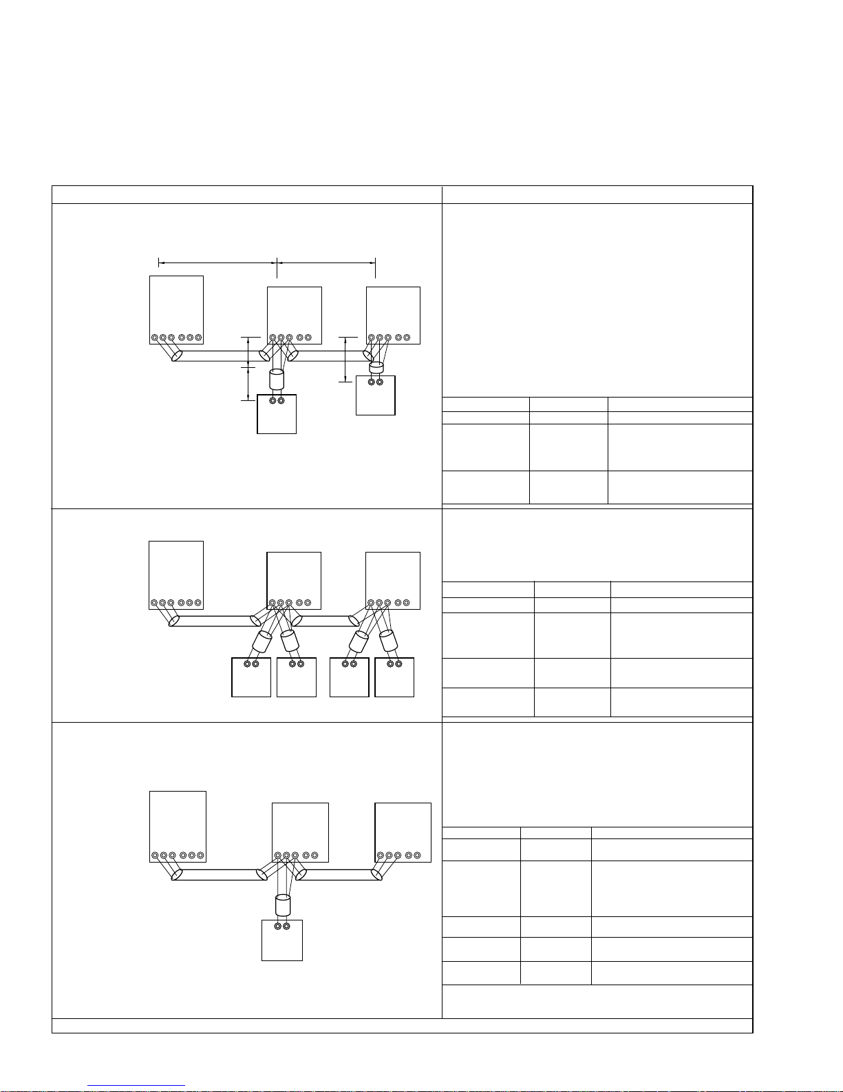
8-3. SYSTEM CONTROL
8-3-1. Example for the System
• Example for wiring control cables, wiring method and address setting, permissible lengths, and the prohibited items are listed
in the standard system with detailed explanation.
The explanation for the system in this section : Use one single outdoor unit and multiple outdoor units for M-NET remote
control system.
Use one single outdoor unit and multiple indoor units in the multiple outdoor
units for the M-NET remote control system.
A. Example of a M-NET remote controller system (address setting is necessary.)
Example of wiring control cables Wiring Method and Address Setting
1. Standard operation
L
TB7
1
IC
01
TB5
TB15
M1M2
S
L3
l1
S12
AB
101
RC
OC
51
TB3
M1M2
SAB
• 1 remote controller for each
indoor unit.
• There is no need for setting the 100
position on the remote controller.
2. Operation using 2 remote controllers
OC
51
TB3
TB7
M1M2
SAB
•
Using 2 remote controllers
for each indoor unit.
S
AB AB AB AB
101
RC
(Main)
TB5
M1M2
IC
01
TB15
S12
151
RC
(Sub)
3. Group operation
OC
51
TB3
TB7
M1M2
SAB
S
• Multiple indoor units operated
TB5
M1M2
AB
101
RC
IC(Main)
01
S12
TB15
together by 1 remote
controller
Combinations of 1through 3 above are possible.
L2
IC
02
TB5
TB15
M1M2
S12
l2
AB
102
RC
IC
02
TB5
TB15
M1M2
S12
102
RC
(Main)
TB5
M1M2
152
RC
(Sub)
IC(Sub)
S122
02
a. Use feed wiring to connect terminals M1 and M2 on
transmission cable block (TB3) for the outdoor unit
(OC) to terminals M1 and M2 on the transmission
cable block (TB5) of each indoor unit (IC). Use
non-polarized 2 wire.
b. Connect terminals M1 and M2 on transmission
cable terminal block (TB5) for each indoor unit with
the terminal block (TB6) for the remote controller
(RC).
c. Set the address setting switch (on outdoor unit
P.C.B) as shown below.
Unit
Indoor unit (IC)
Outdoor unit
(OC)
Range
001 to 050
051 to 100
Setting Method
Use the smallest
address of all the indoor
unit plus 50.
Remote
controller (RC)
101 to 150
Indoor unit address plus
100.
a. Same as above.
b. Same as above.
c. Set address switch (on outdoor unit P.C.B) as
shown below.
Unit
Indoor Unit (IC)
Outdoor unit
(OC)
Main Remote
Controller (RC)
Sub Remote
Controller (RC)
Range
001 to 050
051 to 100
101 to 150
151 to 200
Setting Method
Use the smallest
address of all the indoor
units plus 50.
Indoor unit address plus
100.
Indoor unit address plus
150.
a. Same as above.
b. Connect terminals M1 and M2 on transmission cable
terminal block (TB5) of the IC main unit with the most
recent address within the same indoor unit (IC)
group to terminal block (TB6) on the remote controller.
c. Set the address setting switch (on outdoor unit P.C.B)
as shown below.
TB15
Unit
IC (Main)
IC (Sub)
Outdoor Unit
Main Remote
Controller
Sub Remote
Controller
Range
001 to 050
001 to 050
051 to 100
101 to 150
151 to 200
Use the smallest address within the
same group of indoor units.
Use an address, other than that of
the IC (Main) in the same group
of indoor units. This must be in
sequence with the IC (Main).
Use the smallest address of all the
indoor units plus 50.
Set at an IC (Main) address within
the same group plus 100.
Set at an IC (Main) address within
the same group plus 150.
Setting Method
d. Use the indoor unit (IC) within the group with the
most functions as the IC (Main) unit.
—
—
26
• Name, Symbol and the Maximum Remote controller Units for Connection
Name
Outdoor unit
Indoor unit
M-NET remote
controller
Symbol
OC
IC
RC
Maximum units for connection
—
One OC unit can be connected to 1-6(P36)/1-8(P48) IC units
Maximum 2 RC for 1 indoor unit, Maximum 16 RC for 1 OC
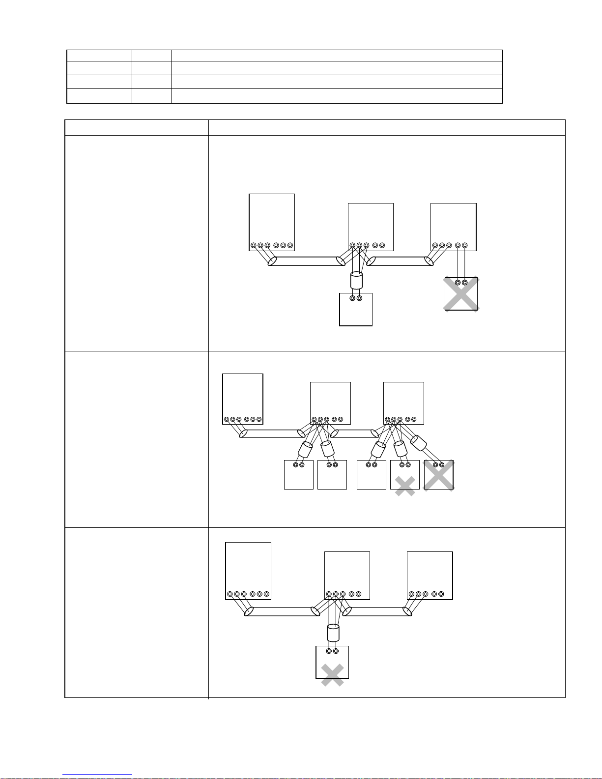
Permissible Lengths Prohibited items
Longest transmission cable length
2
(1.25 mm
1 + L2, L2 + L3, L3 + L1 [ 200m
L
[AWG16])
[656ft]
Remote controller cable length
1. If 0.5 to 1.25 mm
2
[AWG20 to AWG16]
1, R2 [10m [33ft]
R
2. If the length exceeds 10 meters
[33ft], the exceeding section
2
should be 1.25 mm
[AWG16]
and that section should be a
value within the total extension
length of the transmission cable
and maximum transmission
cable length. (L
3)
Same as above
• M-NET remote controller(RC) and MA remote controller(MA) cannot be used together.
• Do not connect anything with TB15 of indoor unit(IC).
TB3
M1M2
M1M2
OC
51
TB7
SAB
TB3
S
OC
51
TB7
SAB
S
IC
01
TB5
TB15
M1M2
S12
TB5
M1M2
AB
101
RC
IC
01
TB15
S12
TB5
M1M2
IC
02
TB15
S12
TB5
M1M2
IC
02
TB15
S12
AB
TB15
MA
• Use the indoor unit(IC)
address plus 150 as
the sub remote controller
address. In this case, it
should be 152.
• Three or more remote
AB AB AB AB AB
101
RC
(Main)
151
RC
(Sub)
102
RC
(Main)
103
RC
(Sub)
104
controller (RC) cannot
be connected to 1
indoor unit.
RC
Same as above
TB3
M1M2
OC
51
TB7
SAB
IC(Main)
01
TB5
TB15
S12
S
M1M2
TB5
M1M2
IC(Sub)
02
S122
TB15
• The remote controller
address is the indoor
unit main address plus
AB
100. In this case, it
should be 101.
102
RC
27
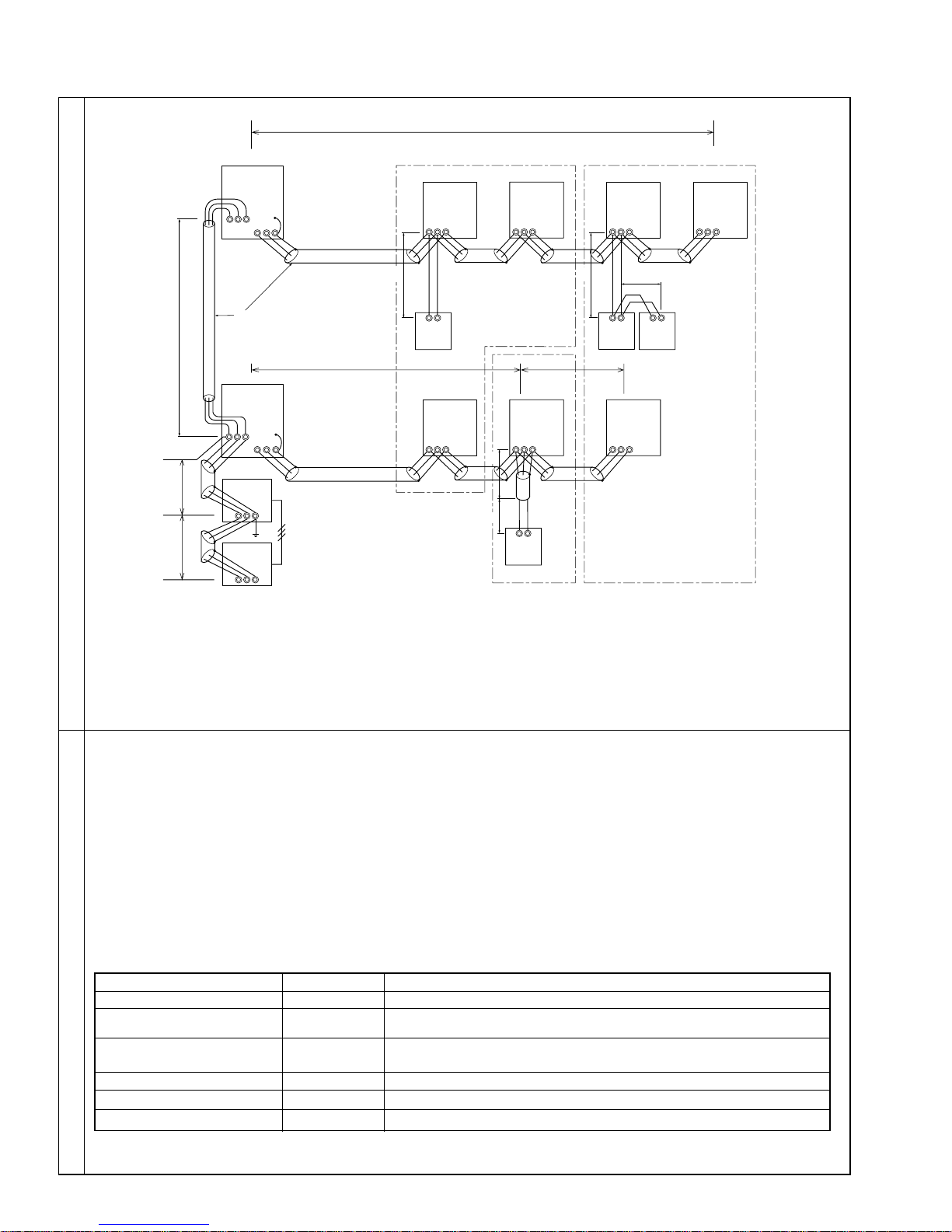
B. Example of a group operation system with 2 or more outdoor units and a M-NET remote controller.
(Shielding wires and address settings are necessary.)
L1
L2
Examples of Transmission Cable Wiring
L6L7
OC
(51)
TB3
M1M2S
M1 M2 S
TB7
OC
(53)
TB3
M1M2 S
M1 M2 S
TB7
Power Supply
Unit
M1M2S
G-50A
M1M2S
DV 12V
IC
(01)
TB5
M1 M2 S
1
N
AB AB AB
(101)
RC
L3
IC
(03)
TB5
M1 M2 S
IC
(02)
TB5
M1 M2 S
L4
IC
(04)
TB5
M1 M2 S
L5
4
N
AB
(104)
RC
TB5
M1 M2 S
2
N
(105)
RC
TB5
M1 M2 S
IC
(05)
N
IC
(07)
3
(155)
RC
IC
(06)
TB5
M1 M2 S
: Group 1
: Group 3
: Group 5
: Shielded Wire
: Sub Remote Controller
( ): Address
a. Always use shielded wire when making connections between the outdoor unit (OC) and the indoor unit (IC), as well
for all OC-OC, and IC-IC wiring intervals.
b. Use feed wiring to connect terminals M1 and M2 and the ground terminal on the transmission cable terminal block
(TB3) of each outdoor unit (OC) to terminals M1 and M2 on the terminal S on the transmission cable block of the
indoor unit (IC).
c. Connect terminals M1 and M2 on the transmission cable terminal block of the indoor unit (IC) that has the most
recent address within the same group to the terminal block on the remote controller (RC).
d. Connect together terminals M1, M2 and terminal S on the terminal block for central control (TB7) for the outdoor
unit (OC).
e. DO NOT change the jumper connector CN41 on MULTI controller board.
f. The earth processing of S terminal for the centralized control terminal block(TB7) is unnecessary.
Connect the terminal S on the power supply unit with the earth.
g. Set the address setting switch as follows.
IC (Main)
IC (Sub)
Wiring Method Address Settings
Outdoor Unit
Main Remote Controller
Sub Remote Controller
Unit
Range
01 to 00
01 to 50
51 to 100
101 to 150
151 to 200
MA Remote Controller
h. The group setting operations among the multiple indoor units is done by the remote controller (RC) after the electrical
power has been turned on.
—
Setting Method
Use the smallest address within the same group of indoor units.
Use an address, other than that of the IC (Main) in the same group of indoor
units. This must be in sequence with the IC (Main).
Use the smallest address of all the indoor units plus 50.
*The address automatically becomes “100” if it is set as “01 - 50”.
Set at an IC (Main) address within the same group plus 100.
Set at an IC (Main) address within the same group plus 150.
Unnecessary address setting (Necessary main/ sub setting)
28
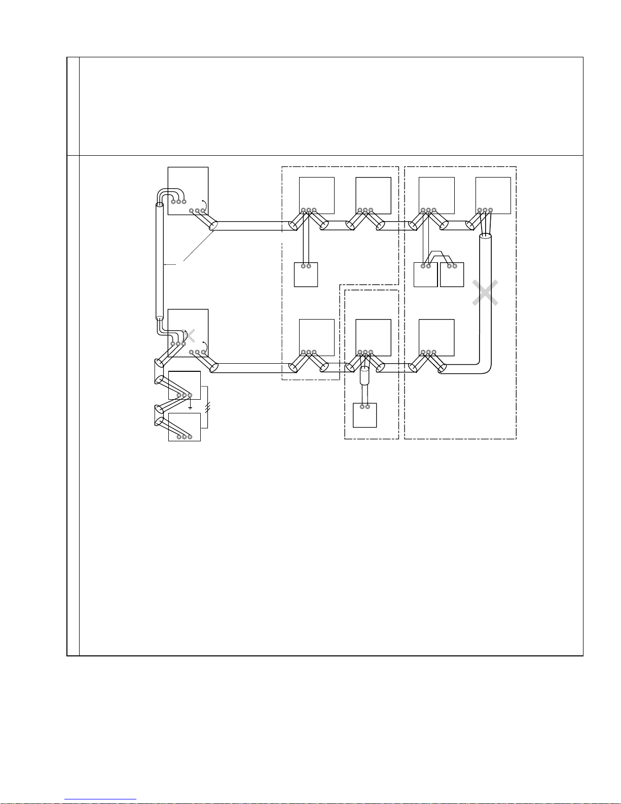
• Name, Symbol, and the Maximum Units for Connection
OC
• Longest length via outdoor units : L1+L2+L3+L4, L1+L2+L3+L5, L1+L2+L6+L7 [ 500 meters [1640ft] (1.25mm2 [AWG16])
• Longest transmission cable length : L
• Remote controller cable length : R
1, L3+L4, L3+L5, L6, L2+L6, L7 [ 200 meters (1.25mm
1,R2, R2+R3, R4 [ 10 meters [33ft] (0.5 to 1.25mm
If the length exceeds 10 meters [33ft], use a 1.25 mm
Permissible Length
length of this section (L
and overall length.
8) should be included in the calculation of the maximum length
2
[AWG16])
2
[AWG20 to AWG16])
2
[AWG16] shielded wire. The
Prohibited items
(51)
TB3
M1M2S
M1 M2 S
TB7
OC
(53)
TB3
M1M2 S
M1 M2 S
TB7
Power Supply
Unit
M1M2S
DV 12V
G-50A
M1M2S
: Group 1
: Group 3
: Group 5
: Shielded Wire
: Sub Remote Controller
( ): Address
TB5
M1 M2 S
TB5
M1 M2 S
AB
(104)
RC
(02)
(04)
IC
IC
TB5
M1 M2 S
(105)
RC
TB5
M1 M2 S
IC
(05)
IC
(07)
IC
(01)
TB5
M1 M2 S
AB AB AB
(101)
RC
IC
(03)
TB5
M1 M2 S
(155)
RC
TB5
M1 M2 S
IC
(06)
• Never connect together the terminal blocks (TB5) for transmission wires for indoor units (IC) that have been connected to
different outdoor units (OC).
• Set all addresses to ensure that they are not overlapped.
• M-NET remote controller and MA remote controller cannot be connected with the indoor unit of the same group wiring
together.
29
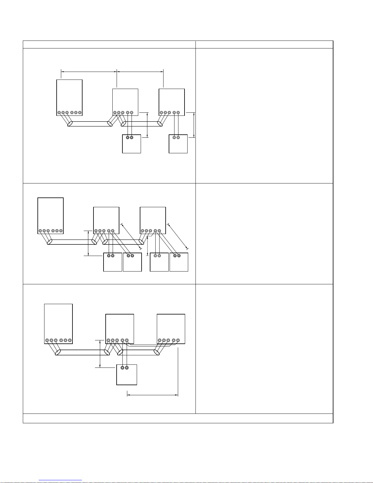
C. Example of a MA remote controller system (address setting is not necessary.)
NOTE : In the case of same group operation, need to set the address that is only main indoor unit.
Example of wiring control cables Wiring Method and Address Setting
1. Standard operation
a. Use feed wiring to connect terminals M1 and M2 on
transmission cable block (TB3) for the outdoor unit
L
TB3
M1M2
1 L2
OC
TB5
M1M2
IC
00
TB15
S12
TB5
M1M2
IC
00
TB15
S12
00
TB7
S
M1M2
S
(OC) to terminals M1 and M2 on the transmission
cable block (TB5) of each indoor unit (IC). Use
non-polarized 2 wire.
b. Connect terminals 1 and 2 on transmission cable
terminal block (TB15) for each indoor unit with the
terminal block for the MA remote controller (MA).
• 1 remote controller for each
indoor unit.
2. Operation using 2 remote controllers
OC
00
IC
00
TB3
TB7
M1M2
SM1M2
S
• Using 2 remote controllers
TB5
TB15
M1M2
S12
N3
AB
MA
for each indoor unit.
3. Group operation
OC
00
TB3
M1M2
S
TB7
M1M2
S
TB5
M1M2
N7
AB
N4
AB AB
MA
IC
00
TB15
S12
TB5
M1M2
N1
IC
00
S12
N5
TB15
AB
MAMA
AB
MA MA
IC
00
TB5
TB15
M1M2
S12
N2
a. The same as above.
b. The same as above.
c. In the case of using 2 remote controllers, connect
terminals 1 and 2 on transmission cable terminal
block (TB15) for each indoor unit with the terminal
block for 2 remote controllers.
N6
· Set the sub remote controller position for one of
MA remote controller’s main switch.
Refer to the installation manual of MA remote con-
troller
a. The same as above.
b. The same as above.
c. Connect terminals 1 and 2 on transmission cable ter-
minal block (TB15) of each indoor unit, which is doing
group operation with the terminal block the MA remote
controller. Use non-polarized tow wire.
d. In the case of same group operation, need to set the
address that is only main indoor unit. Please set the
address of the indoor unit with the most functions in
the same group in the number that 01-50 is young.
AB
• Multiple indoor units operated
MA
together by 1 remote
controller
Combinations of 1through 3 above are possible.
N8
30
 Loading...