

Mitsubishi PUMY-P125VKM3-BS, PUMY-P140YKM3, PUMY-P112YKM3-BS, PUMY-P140VKM3-BS, PUMY-P140YKM3-BS Technical & Service Manual
...
TECHNICAL & SERVICE MANUAL
OUTDOOR UNIT
HFC
utilized
R410A
March 2017
Note:
•
This service manual
describes technical data of
the outdoor units only.
<Outdoor unit>
[Model Name]
Model name
indication
PARTS CATALOG (OCB632)
PUMY-P112VKM3
PUMY-P125VKM3
PUMY-P140VKM3
PUMY-P112YKM3
PUMY-P125YKM3
PUMY-P140YKM3
PUMY-P112VKM3-BS
PUMY-P125VKM3-BS
PUMY-P140VKM3-BS
PUMY-P112YKM3-BS
PUMY-P125YKM3-BS
PUMY-P140YKM3-BS
Salt proof model
PUMY-P112VKM3
PUMY-P125VKM3
PUMY-P140VKM3
PUMY-P112YKM3 PUMY-P112YKME3
PUMY-P125YKM3 PUMY-P125YKME3
PUMY-P140YKM3 PUMY-P140YKME3
PUMY-P112VKM3-BS
PUMY-P125VKM3-BS
PUMY-P140VKM3-BS
PUMY-P112YKM3-BS PUMY-P112YKME3-BS
PUMY-P125YKM3-BS PUMY-P125YKME3-BS
PUMY-P140YKM3-BS PUMY-P140YKME3-BS
[Service Ref.]
CONTENTS
1. SAFETY PRECAUTION
.....................................
2
2. OVERVIEW OF UNITS
.......................................
5
3. SPECIFICATIONS
............................................
10
4. DATA
.................................................................
13
5. OUTLINES AND DIMENSIONS
.......................
27
6. WIRING DIAGRAM
...........................................
29
7.
NECESSARY CONDITIONS FOR SYSTEM CONSTRUCTION
.......
32
8. TROUBLESHOOTING
......................................
50
9. ELECTRICAL WIRING
...................................
132
10. REFRIGERANT PIPING TASKS
....................
139
11. DISASSEMBLY PROCEDURE
.......................
146
SPLIT-TYPE, HEAT PUMP AIR CONDITIONERS
No. OCH632
REVISED EDITION-A
Revision:
•
Modified the "Ratio of
power input" graph for cooling in "4-2. CORRECTION
BY TEMPERATURE" in
REVISED EDITION-A.
•
Some other descriptions
have been also modified.
OCH632 is void.
2
Cautions for units utilizing refrigerant R410A
1-1. CAUTIONS RELATED TO NEW REFRIGERANT
Use new refrigerant pipes.
Store the piping indoors, and both ends of the
piping sealed until just before brazing.
(Leave elbow joints, etc. in their packaging.)
Avoid using thin pipes.
Charge refrigerant from liquid phase of gas
cylinder.
If the refrigerant is charged from gas phase, composition
change may occur in refrigerant and the efficiency will be
lowered.
Do not use refrigerant other than R410A.
If other refrigerant (R22, etc.) is used, chlorine in refrigerant can cause deterioration of refrigerant oil, etc.
Use a vacuum pump with a reverse flow check
valve.
Vacuum pump oil may flow back into refrigerant cycle and
that can cause deterioration of refrigerant oil, etc.
Use the following tools specifically designed for
use with R410A refrigerant.
The following tools are necessary to use R410A refrigerant.
Handle tools with care.
If dirt, dust or moisture enters into refrigerant cycle, that can
cause deterioration of refrigerant oil or malfunction of compressor.
Do not use a charging cylinder.
If a charging cylinder is used, the composition of refrigerant will change and the efficiency will be lowered.
Flare tool
Electronic refrigerant
charging scale
Vacuum pump adaptor
Size adjustment gauge
Gauge manifold
Torque wrench
Gas leak detector
Charge hose
Tools for R410A
Contamination inside refrigerant piping can cause deterioration of refrigerant oil, etc.
If dirt, dust or moisture enters into refrigerant cycle, that can
cause deterioration of refrigerant oil or malfunction of compressor.
If large amount of mineral oil enters, that can cause deterioration of refrigerant oil, etc.
Make sure that the inside and outside of refrigerant piping is clean and it has no contaminants
such as sulfur, oxides, dirt, shaving particles, etc,
which are hazard to refrigerant cycle.
In addition, use pipes with specified thickness.
The refrigerant oil applied to flare and flange
connections must be ester oil, ether oil or
alkylbenzene oil in a small amount.
Ventilate the room if refrigerant leaks during
operation. If refrigerant comes into contact with
a flame, poisonous gases will be released.
Use the specified refrigerant only.
Never use any refrigerant other than that specified.
Doing so may cause a burst, an explosion, or fire when the
unit is being used, serviced, or disposed of.
Correct refrigerant is specified in the manuals and on the
spec labels provided with our products.
We will not be held responsible for mechanical failure,
system malfunction, unit breakdown or accidents caused
by failure to follow the instructions.
1 SAFETY PRECAUTION
OCH632A
3
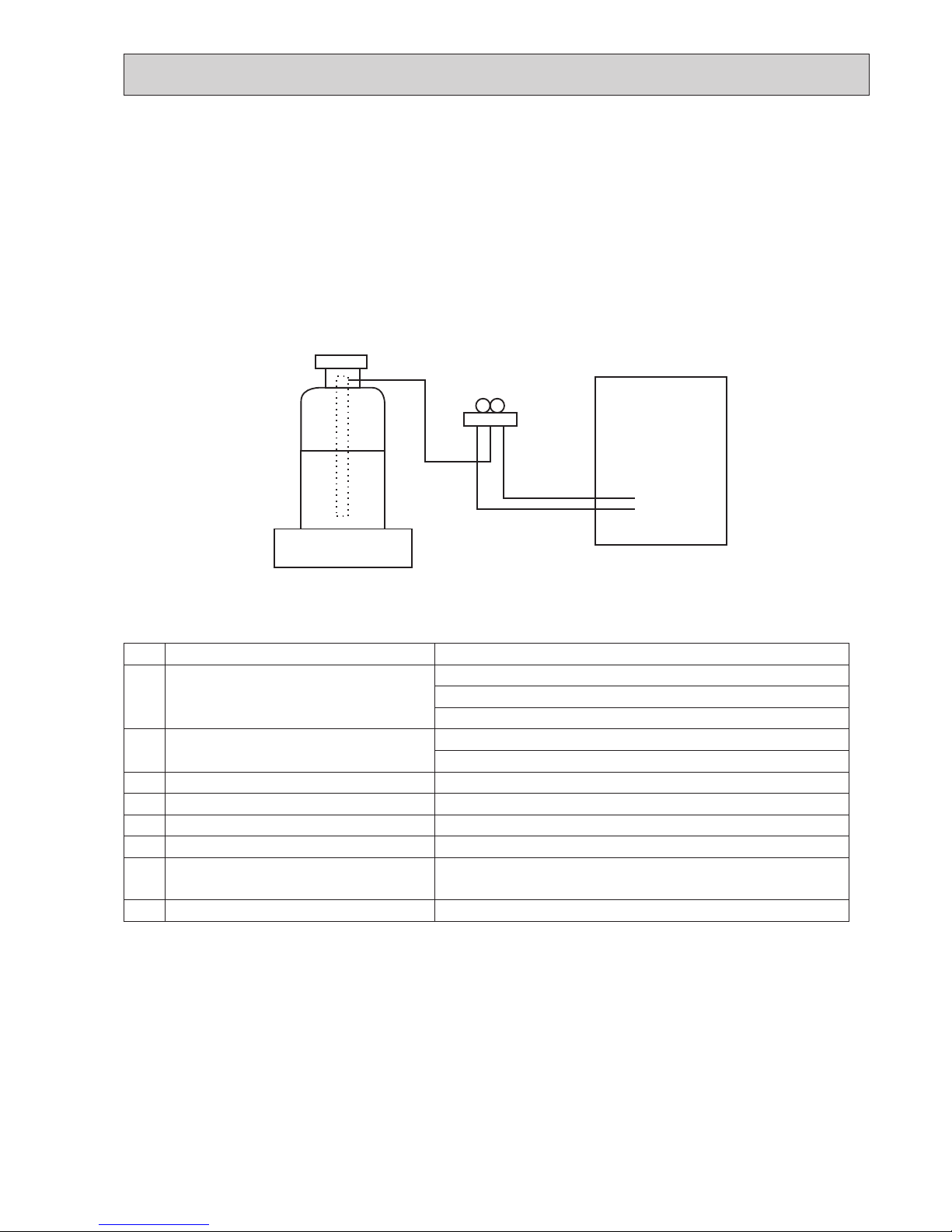
Unit
Electronic weighing scale
[3] Service tools
Use the below service tools as exclusive tools for R410A refrigerant.
[1] Cautions for service
(1) Perform service after recovering the refrigerant left in unit completely.
(2) Do not release refrigerant in the air.
(3) After completing service, charge the cycle with specified amount of refrigerant.
(4) If moisture or foreign matter might have entered the refrigerant piping during service, ensure to remove them.
[2] Additional refrigerant charge
When charging directly from cylinder
(1) Check that cylinder for R410A on the market is a syphon type.
(2) Charging should be performed with the cylinder of syphon stood vertically. (Refrigerant is charged from liquid phase.)
Although "-BS" model has been designed to be resistant to salt damage, observe the following precautions to maintain the
performance of the unit.
(1) Avoid installing the unit in a location where it will be exposed directly to seawater or sea breeze.
(2) If the cover panel may become covered with salt, be sure to install the unit in a location where the salt will be washed away
by rainwater. (If a sunshade is installed, rainwater may not clean the panel.)
(3) To ensure that water does not collect in the base of the outdoor unit, make sure that the base is level, not at angle. Water
collecting in the base of the outdoor unit could cause rust.
(4) If the unit is installed in a coastal area, clean the unit with water regularly to remove any salt build-up.
(5) If the unit is damaged during installation or maintenance, be sure to repair it.
(6) Be sure to check the condition of the unit regularly.
(7) Be sure to install the unit in a location with good drainage.
1-2. PRECAUTIONS FOR SALT PROOF TYPE "-BS" MODEL
No.
Tool name Specifications
1
Gauge manifold · Only for R410A
· Use the existing fitting
specifications
. (UNF1/2)
· Use high-tension side pressure of 5.3MPa·G or over.
2
Charge hose · Only for R410A
· Use pressure performance of 5.09MPa·G or over.
3
Electronic weighing scale
—
4
Gas leak detector · Use the detector for R134a, R407C or R410A.
5
Adaptor for reverse flow check · Attach on vacuum pump.
6
Refrigerant charge base
—
7
Refrigerant cylinder · Only for R410A · Top of cylinder (Pink)
· Cylinder with syphon
8
Refrigerant recovery equipment
—
OCH632A
4
Cautions for refrigerant piping work
New refrigerant R410A is adopted for replacement inverter series. Although the refrigerant piping work for R410A is same
as for R22, exclusive tools are necessary so as not to mix with different kind of refrigerant. Furthermore as the working
pressure of R410A is 1.6 times higher than that of R22, their sizes of flared sections and flare nuts are different.
1 Thickness of pipes
Because the working pressure of R410A is higher compared to R22, be sure to use refrigerant piping with thickness
shown below. (Never use pipes of 0.7 mm or below.)
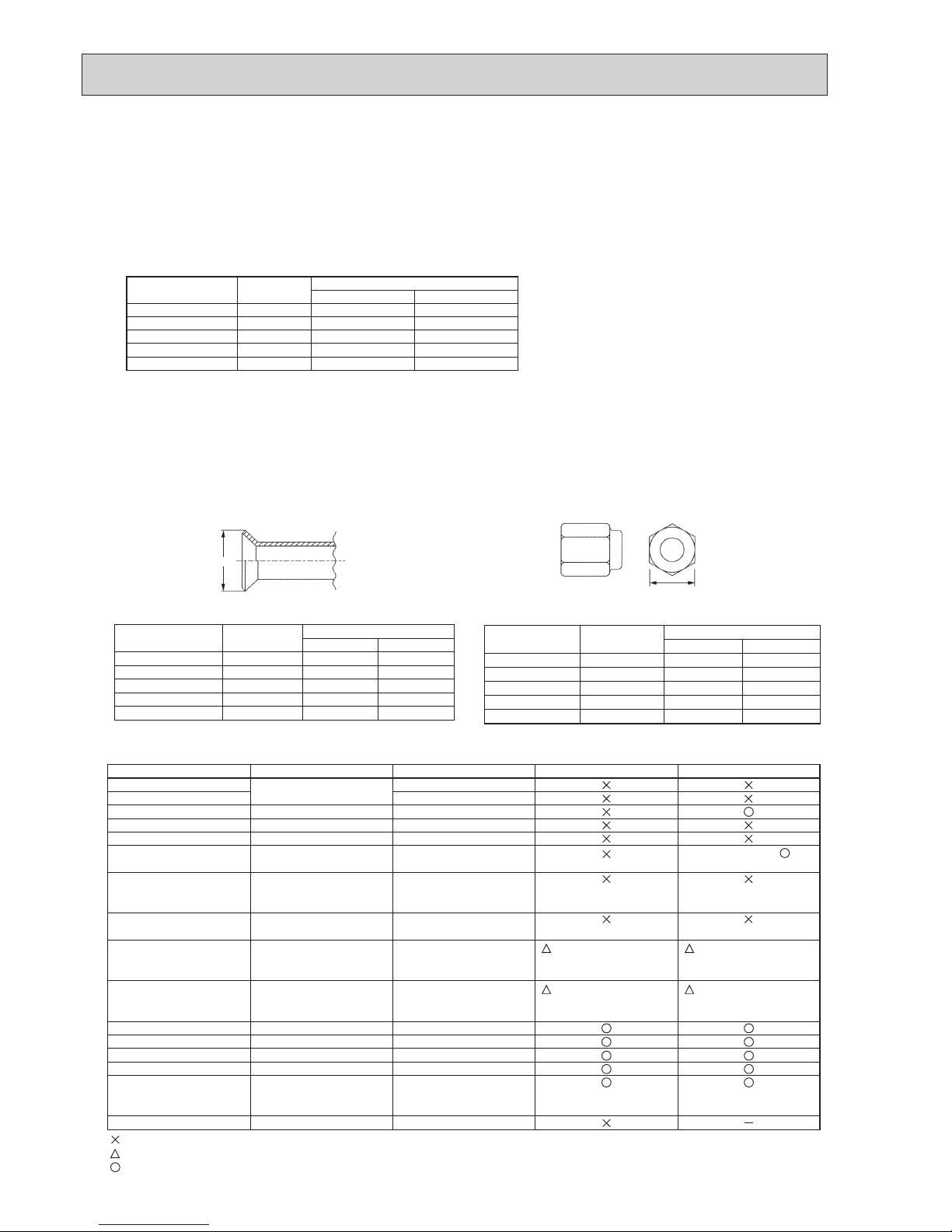
2 Dimensions of flare cutting and flare nut
The component molecules in HFC refrigerant are smaller compared to conventional refrigerants. In addition to that,
R410A is a refrigerant, which has higher risk of leakage because its working pressure is higher than that of other refrigerants. Therefore, to enhance airtightness and strength, flare cutting dimension of copper pipe for R410A has been
specified separately from the dimensions for other refrigerants as shown below. The dimension B of flare nut for R410A
also has partly been changed to increase strength as shown below. Set copper pipe correctly referring to copper pipe
flaring dimensions for R410A below. For 1/2 and 5/8 inch pipes, the dimension B changes.
Use torque wrench corresponding to each dimension.
3 Tools for R410A (The following table shows whether conventional tools can be used or not.)
1/4
3/8
1/2
5/8
3/4
6.35
9.52
12.70
15.88
19.05
0.8
0.8
0.8
1.0
—
0.8
0.8
0.8
1.0
1.0
Nominal
dimensions (in)
Diagram below: Piping diameter and thickness
Outside
diameter
(mm)
Thickness
(mm)
R410A R22
1/4
3/8
1/2
5/8
3/4
6.35
9.52
12.70
15.88
19.05
9.1
13.2
16.6
19.7
—
9.0
13.0
16.2
19.4
23.3
Nominal
dimensions (in)
Flare cutting dimensions
Outside
diameter
Dimension A
( )
+0
-0.4
(mm)
R410A R22
(mm)
1/4
3/8
1/2
5/8
3/4
6.35
9.52
12.70
15.88
19.05
17.0
22.0
26.0
29.0
—
17.0
22.0
24.0
27.0
36.0
Nominal
dimensions (in)
Flare nut dimensions
Outside
diameter
Dimension B
(mm)
R410A R22
(mm)
Gauge manifold
Charge hose
Gas leak detector
Refrigerant recovery equipment
Refrigerant cylinder
Applied oil
Safety charger
Charge valve
Vacuum pump
Flare tool
Bender
Pipe cutter
Welder and nitrogen gas cylinder
Refrigerant charging scale
Vacuum gauge or thermistor vacuum gauge and
vacuum valve
Charging cylinder
Air purge, refrigerant charge
and operation check
Gas leak check
Refrigerant recovery
Refrigerant charge
Apply to flared section
Prevent compressor malfunction
when charging refrigerant by
spraying liquid refrigerant
Prevent gas from blowing out
when detaching charge hose
Vacuum drying and air
purge
Flaring work of piping
Bend the pipes
Cut the pipes
Weld the pipes
Refrigerant charge
Check the degree of vacuum. (Vacuum
valve prevents back flow of oil and refrigerant to thermistor vacuum gauge)
Refrigerant charge
Tool exclusive for R410A
Tool exclusive for R410A
Tool for HFC refrigerant
Tool exclusive for R410A
Tool exclusive for R410A
Ester oil, ether oil and
alkylbenzene oil (minimum amount)
Tool exclusive for R410A
Tool exclusive for R410A
Tools for other refrigerants can
be used if equipped with adopter for reverse flow check
Tools for other refrigerants
can be used by adjusting
flaring dimension
Tools for other refrigerants can be used
Tools for other refrigerants can be used
Tools for other refrigerants can be used
Tools for other refrigerants can be used
Tools for other refrigerants
can be used
Tool exclusive for R410A
Tools and materials Use R410A tools Can R22 tools be used?
(Usable if equipped
with adopter for rever se flow)
(Usable by adjusting
flaring dimension)
Can R407C tools be used?
Ester oil, ether oil:
Alkylbenzene oil: minimum amount
(Usable if equipped
with adopter for rever se flow)
(Usable by adjusting
flaring dimension)
: Prepare a new tool. (Use the new tool as the tool exclusive for R410A.)
: Tools for other refrigerants can be used under certain conditions.
: Tools for other refrigerants can be used.
Dimension A
Dimension B
OCH632A
5
2
2-1. UNIT CONSTRUCTION
Remote
controller
Name
Model number
Functions
M-NET remote controller
PAR-F27MEA-E,
PAR-U02MEDA
• A handy remote controller for use in
conjunction
with the Melans centralized
management system.
• Addresses must be set.
• Addresses setting is not
necessary.
MA remote controller
PAR-21MAA, PAR-31/32MAA
PAR-W21MAA(when using PWFY)
Outdoor unit
Capacity
1 to 9 unit
50 to 130% of outdoor unit capacity
*2 *3
Type 15 to Type 140
1 to 10 unit
Applicable
indoor unit
Number of units
Total system wide capacity
4HP 5HP 6HP
PUMY-P112VKM3(-BS)
PUMY-P112YKM(E)3(-BS)
PUMY-P125VKM3(-BS)
PUMY-P125YKM(E)3(-BS)
1 to 12 unit
PUMY-P140VKM3(-BS)
PUMY-P140YKM(E)3(-BS)
Branching pipe
components
Branch header
(2 branches)
Branch header
(4 branches)
Branch header
(8 branches)
CMY-Y62-G-E CMY-Y64-G-E CMY-Y68-G-E
*1. PUMY is connectable to Fresh Air type indoor unit.
It is possible to connect 1 Fresh Air type indoor unit to 1 outdoor unit. (1:1 system)
Operating temperature range (outdoor temperature) for fresh air type indoor units differ from other indoor units.
Refer to "2-4-(3). Operating temperature range".
*2. When the indoor unit of Fresh Air type is connected with the outdoor unit, the maximum connectable total indoor unit capacity is 110% (100%
incaseofheatingbelow−5:.
*3. When connecting PWFY series (Note that the connection is not allowed inside EU countries.)
•Only1PWFY-P100VM-E-AUcanbeconnected.PWFY-P200VM-E-AUandPWFY-P100VM-E-BUcannotbeconnected.
•ThePWFYunitcannotbetheonlyunitconnectedtoanoutdoorunit.Selectanindoorunitsothatthetotalratedcapacityoftheindoor
units, excluding the PWFY unit, is 50 to 100% of the outdoor unit capacity.
*4.
When connecting the CONNECTION KIT (PAC-LV11M-J) and an M-series indoor unit, refer to the installation manual for the CONNECTION KIT.
*5. Authorized connectable indoor units are as follows;
PUMY-P112: PEFY-P25VMA3-E × 2 + PEFY-P32VMA3-E × 2
PUMY-P125: PEFY-P32VMA3-E × 4
PUMY-P140: PEFY-P32VMA3-E × 3 + PEFY-P40VMA3-E × 1
*6. Do not connect Lossnay remote controller(s). (PZ-61DR-E, PZ-60DR-E, PZ-52SF-E, PZ-43SMF-E)
Decorative panel
OVERVIEW OF UNITS
M series remote
controller
Model
Capacity
Cassette Ceiling
Ceiling
Concealed
Wall
Mounted
Ceiling
Suspended
Floor standing Ceiling concealed
Lossnay
Air to Water
unit
*
3
CONNECTION KIT
2 by 2 4-way ow 2-way ow
1-way ow
Exposed
Concealed Fresh air
*
1
Built-in
PAC-LV11M-J
PLFY-P PLFY-P PLFY-P
PMFY-P
PEFY-P
PKFY-P
PCFY-P PFFY-P PFFY-P PEFY-P PDFY GUF*6PWFY-P
15
15VFM-E1
– – –
15VMS1(L)-E
15VBM-E
– – – – – – –
20
20VFM-E1
20VBM-E 20VLMD-E 20VBM-E
20VMS1(L)-E
20VMA(L)-E
20VMR-E-L/R
20VBM-E
–
20VLEM-E
20VKM-E2
20VLRM-E
20VLRMM-E
– 20VM-E – –
25
25VFM-E1
25VBM-E 25VLMD-E 25VBM-E
25VMS1(L)-E
25VMA(L)-E
25VMR-E-L/R
25VMA3-E
*
5
25VBM-E
–
25VLEM-E
25VKM-E2
25VLRM-E
25VLRMM-E
– 25VM-E – –
32
32VFM-E1
32VBM-E 32VLMD-E 32VBM-E
32VMS1(L)-E
32VMA(L)-E
32VMR-E-L/R
32VMA3-E
*
5
32VHM-E
–
32VLEM-E
32VKM-E2
32VLRM-E
32VLRMM-E
– 32VM-E – –
40
40VFM-E1
40VBM-E 40VLMD-E 40VBM-E
40VMS1(L)-E
40VMA(L)-E
40VMH-E
40VMA3-E
*
5
40VHM-E 40VKM-E
40VLEM-E
40VKM-E2
40VLRM-E
40VLRMM-E
– 40VM-E – –
M series indoor unit
*
4
MSZ-GE Series
MSZ-SF Series
MSZ-EF Series
MSZ-FH Series
MFZ-KJ Series
50
50VFM-E1
50VBM-E 50VLMD-E
–
50VMS1(L)-E
50VMA(L)-E
50VMH-E
50VHM-E
–
50VLEM-E
50VLRM-E
50VLRMM-E
– 50VM-E
50RD(H)4
–
63
–
63VBM-E 63VLMD-E
–
63VMS1(L)-E
63VMA(L)-E
63VMH-E
63VKM-E 63VKM-E
63VLEM-E
63VLRM-E
63VLRMM-E
– 63VM-E – –
71
– –
– –
71VMA(L)-E
71VMH-E
– – – – – 71VM-E – –
80
–
80VBM-E 80VLMD-E
–
80VMA(L)-E
80VMH-E
– – – –
80VMH-E-F
80VM-E –
100
–
100VBM-E
100VLMD-E
–
100VMA(L)-E
100VMH-E
100VKM-E 100VKM-E
–
–
– 100VM-E
100RD(H)4
100VM-E1-AU
100VM-E2-AU
125
–
125VBM-E
125VLMD-E
–
125VMA(L)-E
125VMH-E
–
125VKM-E
–
–
– 125VM-E
–
140
– – –
–
140VMA(L)-E
140VMH-E
– – –
– 140VMH-E-F
– –
OCH632A
6
PUMY-P125VKM3(-BS)
PUMY-P125YKM(E)3(-BS)
PUMY-P140VKM3(-BS)
PUMY-P140YKM(E)3(-BS)
6HP
PUMY-P112VKM3(-BS)
PUMY-P112YKM(E)3(-BS)
4HP
Applicable
indoor unit
Branch box
that can be
connected
Capacity
Number of units
Total system wide capacity*
1
Type 15 to Type 100
2 to 8 units
1 to 2 units
24 to 130 % of outdoor unit capacity
(3.0 to 16.2 kW)
Number of units
*
1
Outdoor unit
Ceiling
concealed
4-way
ceiling cassette
Wall
mounted
Model type
Model name
Deluxe
Standard
Compact
Low static pressure
Middle static pressure
2 by 2 type
Standard
MSZ-FH25/35/50VE2
MSZ-SF25/35/42/50VE3
MSZ-GF60/71VE
MSZ-EF18/22/25/35/42/50VE3
MSZ-SF15/20VA
SEZ-KD25/35/50/60/71VAQ(L)
PEAD-RP50/60/71/100JA(L)Q
SLZ-KF25/35/50VA2
PLA-ZRP35/50/60/71/100BA
PLA-RP35/50/60/71/100EA
PCA-RP35/50/60/71/100KAQ
MFZ-KJ25/35/50VE2
MLZ-KA25/35/50VA
Floor standing
Capacity class (kW)
2.2 2.5 3.5 5.0 6.0 7.1 8.0
10.0
Connectable indoor unit lineup (Heat pump inverter type)
Note: The lineup of a connectable indoor unit depends on a district/areas/country.
Branch box
PAC-MK51/52BC(B)
5 branches
(MAX. 5 units)
PAC-MK31/32BC(B)
3 branches
(MAX. 3 units)
Number of branches
Indoor unit that
can be connected
( )
Notes: 1. A maximum of 2 branch boxes can be connected to 1 outdoor unit.
2. When connecting a Cylinder unit or a Hydrobox, use a PAC-MK32/52BC(B) branch box.
Select a model according to the connection method.
2- branch pipe (joint): Optional parts
In case of using 1- branch box
In case of using 2- branch boxes
No need
Model name
Connection method
flare
brazing
MSDD-50AR-E
MSDD-50BR-E
Option
Optional accessories of indoor units and outdoor units are available.
2.01.5
1.8
4.2
1-way ceiling cassette
5HP
21 to 130 % of outdoor unit capacity
(3.0 to 18.2 kW)
19 to 130 % of outdoor unit capacity
(3.0 to 20.2 kW)
Ceiling suspended
Model type
Cylinder unit
Hydrobox
Connectable ecodan unit
Model name
EHST20C series (except EHST20C-MEC)
EHSC series (except EHSC-MEC)
Note: Only 1 Cylinder unit or Hydrobox can be connected.
*
1
When connecting ecodan unit(s), the total capacity of connected
Air to Air indoor units is up to 130% of the outdoor unit. (Air to Air
130% + ecodan). However, when operating Air to Air indoor
unit(s) in heating mode and ecodan unit(s) in DHW or heating
mode at the same time, the total capacity of connected Air to Air
units is below:
· PUMY-P112: 1.3 kW
· PUMY-P125: 2.8 kW
· PUMY-P140: 4.3 kW
However, the following combinations can be connected:
· PUMY-P112: MSZ-SF15VA × 1
· PUMY-P125: MSZ-SF15VA × 2
· PUMY-P140: MSZ-SF15VA × 3
2-2. UNIT CONSTRUCTION (BRANCH BOX SYSTEM)
OCH632A
7
PUMY-P125VKM3(-BS)
PUMY-P125YKM(E)3(-BS)
PUMY-P140VKM3(-BS)
PUMY-P140YKM(E)3(-BS)
Via branch box Citymulti indoor
PUMY-P112VKM3(-BS)
PUMY-P112YKM(E)3(-BS)
Applicable
indoor unit
Capacity
Number
of units*
1
Via branch box Citymulti indoor
5
7 or 8*
2
Outdoor unit
PAC-MK51/52BC(B)
5 branches
(MAX. 5 units)
PAC-MK31/32BC(B)
3 branches
(MAX. 3 units)
Branch box
Number of branches
City multi indoor unit
Via branch box
Type 15 to Type 140
Type 15 to Type 100
1-branch box
2-branch box
Via branch box Citymulti indoor
5
3 or 2*
2
5
8
5
3
5
8
5
3
Total system wide capacity*
1
6.3 to 16.2 kW 7.1 to 18.2 kW 8.0 to 20.2 kW
50 to 130% of outdoor unit capacity
Branching pipe
components
CMY-Y62-G-E
Branch header
(2 branches)
CMY-Y64-G-E
Branch header
(4 branches)
CMY-Y68-G-E
Branch header
(8 branches)
Citymulti indoor units*
3
CONNECTION KIT
PAC-LV11M-J
M series indoor unit
MA
remote
controller
M series
remote
controller
M series
S series
P series
indoor units*
3
Cylinder unit
Hydrobox
MA
remote
controller
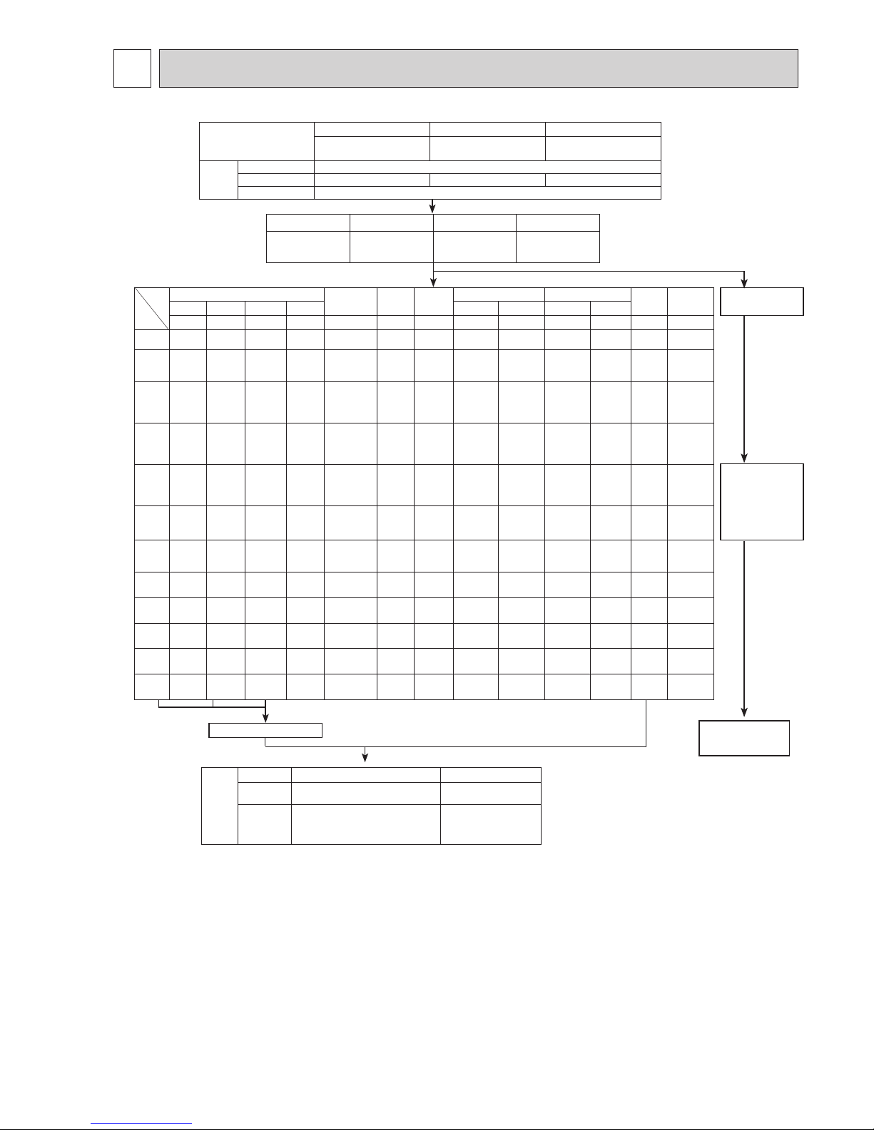
*2 When connecting 7 indoor units via branch box, connectable citymulti indoor units are 3; connecting 8 indoor units
via branch box, connectable citymulti indoor units are 2.
*
3
Refer to “2-1. UNIT CONSTRUCTION” or “2-2. UNIT CONSTRUCTION (BRANCH BOX SYSTEM)”, for more detail.
*
1
When connecting ecodan unit, the total capacity of connected Air to Air indoor units is up to 130% of the outdoor
unit. (Air to Air 130% + ecodan). However, when operating Air to Air indoor unit(s) in heating mode and ecodan unit
in DHW or heating mode at the same time, the maximum connectable Air to Air indoor unit is below.
2-3. UNIT CONSTRUCTION (MIXED SYSTEM)
Model ATA total capacity
Can be exceptionally
connected
PUMY-P112 1.3 kW MSZ-SF15VE × 1
PUMY-P125 2.8 kW MSZ-SF15VE × 2
PUMY-P140 4.3 kW MSZ-SF15VE × 3
OCH632A
8
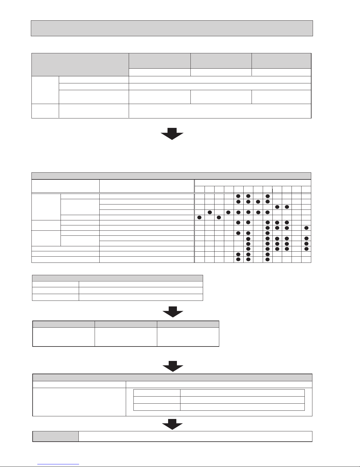
2-4. UNIT SPECIFICATIONS
(2) Method for identifying MULTI-S model
(1) Outdoor Unit
Outdoor unit <When using model 125 >
PU M Y - P 125 Y K M E 3 - BS
Refrigerant
R410A
Indicates equivalent
to Cooling capacity
Power supply
V: Single phase
220/230/240 V, 50 Hz
Y: 3-phase
380/400/415 V, 50 Hz
380 V, 60 Hz (YKM3 only)
Outdoor unit
model type
M-NET
control
Frequency
conversion
controller
Outdoor unit
MULTI-S
(kcal/ h)
Salt proof
type
sub
number
Electrical
box
Service Ref.
Capacity
Cooling (kW)
Heating (kW)
12.5
14.0
2.9
14.0
16.0
3.5
15.5
18.0
3.9
Compressor (kW)
PUMY-P112VKM3(-BS)
PUMY-P112YKM(E)3(-BS)
PUMY-P125VKM3(-BS)
PUMY-P125YKM(E)3(-BS)
PUMY-P140VKM3(-BS)
PUMY-P140YKM(E)3(-BS)
Cooling/Heating capacity indicates the maximum value at operation under the following condition.
*Cooling Indoor : D.B. 27°C/W.B. 19.0°C
Outdoor : D.B. 35°C
Heating Indoor : D.B. 20°C
Outdoor : D.B. 7°C/W.B. 6°C
(3) Operating temperature range
Notes: D.B. : Dry Bulb Temperature
W.B. : Wet Bulb Temperature
*
1
10 to 52°C D.B. : When connecting PKFY-P15/P20/P25VBM, PFFY-P20/25/32VKM, PFFY-P20/25/32VLE(R)M, PEFY-P25/32/40VMA3-E;
and M series, S series, and P series type indoor unit.
Cooling
W.B. 15 to 24°C
D.B. −5 to 52°C
*
1
Heating
D.B. 15 to 27°C
W.B. −20 to 15°C
Indoor-side intake air temperature
Outdoor-side intake air temperature
■
When connecting fresh air type indoor unit
air type indoor
Capacity of Fresh
Cooling
Heating
Indoor-side and Outdoor-side
P80
D.B. 21 to 43:
*
2
W.B. 15.5 to 35:
D.B.−10 to 20:
*
3
intake air temperature
P140
D.B. 21 to 43:
*
2
W.B. 15.5 to 35:
D.B. −5 to 20:
*
3
*2 Thermo-OFF (FAN-mode) automatically starts if the outdoor temp. is lower than 21 : D.B..
*
3
Thermo-OFF (FAN-mode) automatically starts if the outdoor temp. is higher than 20 : D.B..
■ When connecting PWFY unit
Cooling
Heating
Indoor-side intake water temperature
Outdoor-side intake air temperature
• PWFY series can operate in Heating mode but not in Cooling mode. An indoor unit other than that of PWFY series can
operate in Cooling mode.
• A PWFY series and other series cannot operate simultaneously.
• The operation of PWFY series takes precedence over other series. While a PWFY series is operating, other series do not operate.
• The set temperature on the remote controller represents the target temperature of the outlet water.
*
4
*
4
D.B. 10 to 45:
*
4
W.B. −20 to 15:
OCH632A
9
■ When connecting Cylinder unit or Hydrobox
*5 ATA unit: Air to Air unit (other than PWFY, Cylinder unit or Hydrobox)
*
6
Cylinder unit and Hydrobox can not operate Cooling mode in connecting PUMY.
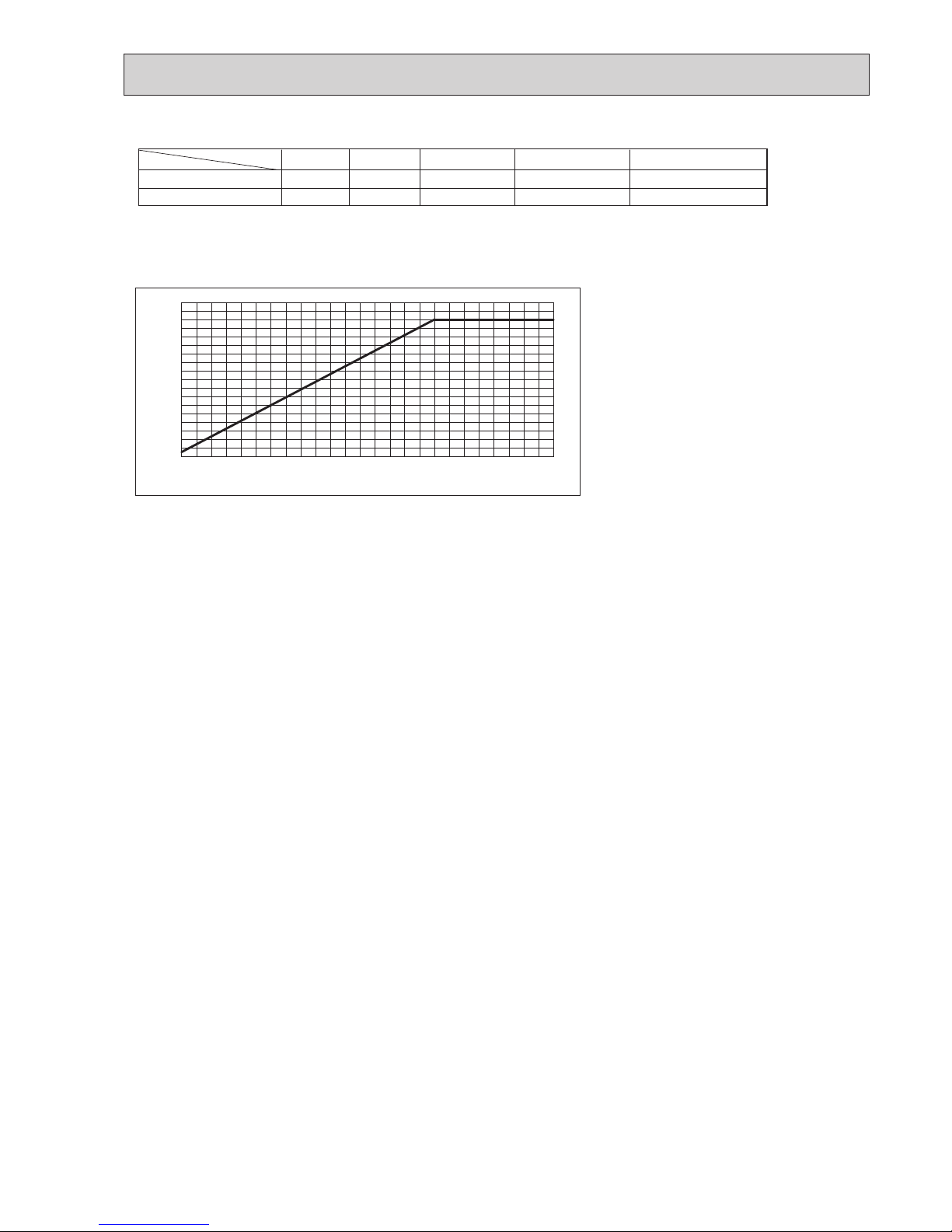
*7 When outdoor temp. is less than 7:, outlet water temp. is lowered (Refer to Figure 1).
Furthermore, outlet air temperature is lowered.
Cooling
—
*
6
—
*
6
Outlet water temperature
Outdoor temperature
DHW only
ATW Heating only
DHW + ATA Heating
*
5
ATW Heating + ATA Heating
*
5
−20 to 35:
−20 to 21:
7 to 35:
−10 to 35:
*
7
55: Max. 55: Max. 55: Max. 45 to 55: Max.
-10 -5 0 5 10 15
39
41
43
45
47
49
51
53
55
57
Outdoor temp. [°CDB]
Max. outlet water temp. [°C]
Figure 1 Temperature change of max. outlet water temp. according to outdoor temperature
OCH632A
10
3
SPECIFICATIONS
Model PUMY-P112VKM3(-BS) PUMY-P125VKM3(-BS) PUMY-P140VKM3(-BS)
Power source
1-phase 220/230/240 V, 50 Hz; 1-phase 220 V, 60 Hz
Cooling capacity
(Nominal)
kW*
1
12.5 14.0 15.5
kcal/h*
1
10,750 12,040 13,330
BTU/h*
1
42,650 47,768 52,886
Power input kW 2.79 3.46 4.52
Current input A 12.87/12.32/11.80, 12.87 15.97/15.27/14.64, 15.97 20.86/19.95/19.12, 20.86
COP kW/kW 4.48 4.05 3.43
Temp. range of
cooling
Indoor temp. W.B. 15 to 24°C
Outdoor temp. D.B. −5to52°C
*3, *4
Heating capacity
(Nominal)
kW*
2
14.0 16.0 18.0
kcal/h*
2
12,040 13,760 15,480
BTU/h*
2
47,768 54,592 61,416
Power input kW 3.04 3.74 4.47
Current input A 14.03/13.42/12.86, 14.03 17.26/16.51/15.82, 17.26 20.63/19.73/18.91, 20.63
COP kW/kW 4.61 4.28 4.03
Temp. range of
heating
Indoor temp. D.B. 15 to 27°C
Outdoor temp. W.B. −20to15°C
Indoor unit
connectable
Total capacity 50 to 130% of outdoor unit capacity
Model/ Quantity Citymulti 15 - 140/9 15 - 140/10 15 - 140/12
Branch box 15 - 100/8 15 - 100/8 15 - 100/8
Mixed system
15 - 140*5/10 15 - 140*5/10*
6
15 - 140*5/10*
6
Sound pressure level
(measured in anechoic room)
dB <A>
49/51 50/52 51/53
Power pressure level
(measured in anechoic room)
dB <A>
69/71 70/72 71/73
Refrigerant
piping diameter
Liquid pipe mm (inch) 9.52 (3/8)
Gas pipe mm (inch) 15.88 (5/8)
FAN *2 Type × Quantity Propeller Fan x 2
Airowrate m³/min 110
L/s 1,833
cfm 3,884
Control, Driving mechanism DC control
Motor output kW 0.06+0.06
External static press. 0
Compressor Type × Quantity Scroll hermetic compressor x 1
Manufacture Mitsubishi Electric Corporation
Starting method Inverter
Capacity control % Cooling 26 to 100
Heating 20 to 100
Cooling 24 to 100
Heating 18 to 100
Cooling 21 to 100
Heating 17 to 100
Motor output kW 2.9 3.5 3.9
Case heater kW 0
Lubricant FV50S (2.3litter)
Externalnish Galvanized Steel Sheet Munsell No. 3Y 7.8/1.1
External dimension H × W × D mm 1,338 × 1,050 × 330(+25)
inch 52-11/16 × 41-11/ 32 × 13 (+1)
Protection
devices
High pressure protection High pressure Switch
Inverter circuit (COMP./FAN)
Overcurrent detection, Overheat detection(Heat sink thermistor)
Compressor Compressor thermistor, Overcurrent detection
Fan motor Overheating, Voltage protection
Refrigerant Type × original charge R410A 4.8 kg
Control Electronic expansion valve
Net weight kg (lb) 122 (269)
Heat exchanger Cross Fin and Copper tube
HIC circuit (HIC: Heat Inter-Changer) HIC circuit
Defrosting method Reversed refrigerant circuit
Drawing External BK01N346
Wiring BH78B813
Standard
attachment
Document Installation Manual
Accessory Grounded lead wire x2
Optional parts Joint: CMY-Y62-G-E, Header: CMY-Y64/68-G-E, Branch box: PAC-MK31/32/51/52BC(B)
Remarks
Unit converter
kcal/h = kW × 860
BTU/h = kW × 3,412
cfm = m³/min × 35.31
lb = kg/0.4536
Abovespecicationdatais
subject to rounding
variation.
*1 Nominal cooling conditions *2 Nominal heating conditions
Indoor :
27°C D.B./19°C W.B. [81°F D.B/66°F W.B.]
20°C D.B. [68°F D.B.]
Outdoor : 35°C D.B. [95°F D.B.]
7°C DB/6°C W.B. [45°F D.B./43°F W.B.]
Pipe length : 7.5 m [24-9/16 ft] 7.5 m [24-9/16 ft]
Level difference : 0 m [0 ft] 0 m [0 ft]
Notes : 1. Nominal conditions *
1
, *2 are subject to ISO 15042.
2.Duetocontinuingimprovement,abovespecicationsmaybesubjecttochangewithoutnotice.
*3 10 to 52:D.B. [50 to 126_F D.B.], when connecting following models: PKFY-P15/20/25VBM, PFFY-P20/25/32VLE(R)M, PFFY-
P20/25/32VKM, PEFY-P25/32/40VMA3; and M series, S series, and P series type indoor unit.
*4−15to52:D.B. [50 to 126_F D.B.], when using an optional air protect guide [PAC-SH95AG-E]. However, this condition does not
apply to the indoor unit listed in *3.
*5
Up to P100 when connecting via branch box.
*6
Up to 11 units when connecting via 2 branch boxes.
OCH632A
11
Model PUMY-P112YKM3(-BS) PUMY-P125YKM3(-BS) PUMY-P140YKM3(-BS)
Power source 3-phase 380/400/415 V, 50 Hz; 3-phase 380 V, 60 Hz
Cooling capacity
(Nominal)
kW *
1
12.5 14.0 15.5
kcal/h *
1
10,750 12,040 13,330
BTU/h *
1
42,650 47,768 52,886
Power input kW 2.79 3.46 4.52
Current input A 4.99/4.74/4.57, 4.99 5.84/5.55/5.35, 5.84 7.23/6.87/6.62, 7.23
COP kW/kW 4.48 4.05 3.43
Temp. range of
cooling
Indoor temp. W.B.
15 to 24°C
Outdoor temp. D.B. −5to52°C
*3, *4
Heating capacity
(Nominal)
kW *
2
14.0 16.0 18.0
kcal/h *
2
12,040 13,760 15,480
BTU/h *
2
47,768 54,592 61,416
Power input kW 3.04 3.74 4.47
Current input A 5.43/5.16/4.98, 5.43 6.31/6.00/5.78, 6.31 7.15/6.79/6.55, 7.15
COP kW/kW 4.61 4.28 4.03
Temp. range of
heating
Indoor temp. D.B. 15 to 27°C
Outdoor temp. W.B. −20to15°C
Indoor unit
connectable
Total capacity 50 to 130% of outdoor unit capacity
Model/Quantity Citymulti 15 - 140/9 15 - 140/10 15 - 140/12
Branch box 15 - 100/8 15 - 100/8 15 - 100/8
Mixed system
15 - 140*5/10 15 - 140*5/10*
6
15 - 140*5/10*
6
Sound pressure level
(measured in anechoic room)
dB <A>
49/51 50/52 51/53
Power pressure level
(measured in anechoic room)
dB <A>
69/71 70/72 71/73
Refrigerant
piping diameter
Liquid pipe mm (inch) 9.52 (3/8)
Gas pipe mm (inch) 15.88 (5/8)
FAN *2 Type × Quantity Propeller Fan × 2
Airowrate K/min 110
L/s 1,833
cfm 3,884
Control, Driving mechanism DC control
Motor output kW 0.06+0.06
External static press. 0
Compressor Type x Quantity Scroll hermetic compressor × 1
Manufacture Mitsubishi Electric Corporation
Starting method Inverter
Capacity control % Cooling 26 to 100
Heating 20 to 100
Cooling 24 to100
Heating 18 to 100
Cooling 21 to 100
Heating 17 to 100
Motor output kW 2.9 3.5 3.9
Case heater kW 0
Lubricant FV50S(2.3litter)
Externalnish Galvanized Steel Sheet Munsell No. 3Y 7.8/1.1
External dimension H × W × D mm 1338 × 1050 × 330(+25)
inch 52-11/16 × 41-11/32 × 13 (+1)
Protection
devices
High pressure protection High pressure Switch
Inverter circuit (COMP./FAN) Overcurrent detection, Overheat detection(Heat sink thermistor)
Compressor Compressor thermistor, Over current detection
Fan motor Overheating, Voltage protection
Refrigerant Type × original charge R410A 4.8 kg
Control
Electronic expansion valve
Net weight kg (lb) 125 (276)
Heat exchanger Cross Fin and Copper tube
HIC circuit (HIC: Heat Inter-Changer) HIC circuit
Defrosting method Reversed refrigerant circuit
Drawing External BK01N339
Wiring BH78B814
Standard
attachment
Document Installation Manual
Accessory Grounded lead wire x2
Optional parts
Joint: CMY-Y62-G-E, Header: CMY-Y64/68-G-E, Branch box: PAC-MK31/32/51/52BC(B)
Unit converter
kcal/h = kW × 860
BTU/h = kW × 3,412
cfm = m³/min × 35.31
lb = kg/0.4536
Abovespecicationdatais
subject to rounding
variation
.
*1 Nominal cooling conditions *2 Nominal heating conditions
Indoor :
27°C D.B./19°C W.B. [81°F D.B/66°F W.B.]
20°C D.B. [68°F D.B.]
Outdoor : 35°C D.B. [95°F D.B.]
7°C DB/6°C W.B. [45°F D.B./43°F W.B.]
Pipe length : 7.5 m [24-9/16 ft] 7.5 m [24-9/16 ft]
Level difference : 0 m [0 ft] 0 m [0 ft]
Remarks:
Notes : 1. Nominal conditions *
1
, *2 are subject to ISO 15042.
2.Duetocontinuingimprovement,abovespecicationsmaybesubjecttochangewithoutnotice.
*3 10 to 52:D.B. [50 to 126_F D.B.], when connecting following models: PKFY-P15/20/25VBM, PFFY-P20/25/32VLE(R)M, PFFY-
P20/25/32VKM, PEFY-P25/32/40VMA3; and M series, S series, and P series type indoor unit.
*4−15to52:D.B. [50 to 126_F D.B.], when using an optional air protect guide [PAC-SH95AG-E]. However, this condition does not
apply to the indoor unit listed in *3.
*5
Up to P100 when connecting via branch box.
*6
Up to 11 units when connecting via 2 branch boxes.
OCH632A
12
Model PUMY-P112YKME3(-BS) PUMY-P125YKME3(-BS) PUMY-P140YKME3(-BS)
Power source 3-phase 380/400/415 V, 50 Hz
Cooling capacity
(Nominal)
kW*
1
12.5 14.0 15.5
kcal/h*
1
10,750 12,040 13,330
BTU/h*
1
42,650 47,768 52,886
Power input kW 2.79 3.46 4.52
Current input A 4.46/4.24/4.09 5.53/5.26/5.07 7.23/6.87/6.62
COP kW/kW 4.48 4.05 3.43
Temp. range of
cooling
Indoor temp. W.B. 15 to 24°C
Outdoor temp. D.B. −5to52°C
*3, *4
Heating capacity
(Nominal)
kW*
2
14.0 16.0 18.0
kcal/h*
2
12,040 13,760 15,480
BTU/h*
2
47,768 54,592 61,416
Power input kW 3.04 3.74 4.47
Current input A 4.86/4.62/4.45 5.98/5.68/5.48 7.15/6.79/6.55
COP kW/kW 4.61 4.28 4.03
Temp. range of
heating
Indoor temp. D.B. 15 to 27°C
Outdoor temp. W.B. −20to15°C
Indoor unit
connectable
Total capacity 50 to 130% of outdoor unit capacity
Model/Quantity Citymulti 15 - 140/9 15 - 140/10 15 - 140/12
Branch box 15 - 100/8 15 - 100/8 15 - 100/ 8
Mixed system
15 - 140*
5
/10 15 - 140*5/10*
6
15 - 140*5/10*
6
Sound pressure level
(measured in anechoic room)
dB <A>
49/51 50/52 51/ 53
Power pressure level
(measured in anechoic room)
dB <A>
69/71 70/72 71/73
Refrigerant
piping diameter
Liquid pipe mm (inch) 9.52 (3/8)
Gas pipe mm (inch) 15.88 (5/8)
FAN *2 Type × Quantity Propeller Fan × 2
Airowrate K/min 110
L/s 1,833
cfm 3,884
Control, Driving mechanism DC control
Motor output kW 0.06+0.06
External static press. 0
Compressor Type × Quantity Scroll hermetic compressor × 1
Manufacture Mitsubishi Electric Corporation
Starting method Inverter
Capacity control % Cooling 26 to 100
Heating 20 to 100
Cooling 24 to 100
Heating 18 to 100
Cooling 21 to 100
Heating 17 to 100
Motor output kW 2.9 3.5 3.9
Case heater kW 0
Lubricant FV50S(2.3litter)
Externalnish Galvanized Steel Sheet Munsell No. 3Y 7.8/1.1
External dimension HxWxD mm 1,338 × 1,050 × 330(+25)
inch 52-11/16 × 41-11/32 × 13 (+1)
Protection
devices
High pressure protection High pressure Switch
Inverter circuit (COMP./FAN)
Overcurrent detection, Overheat detection(Heat sink thermistor)
Compressor Compressor thermistor, Over current detection
Fan motor Overheating, Voltage protection
Refrigerant Type × original charge R410A 4.8kg
Control Electronic expansion valve
Net weight kg (lb) 136 (300)
Heat exchanger Cross Fin and Copper tube
HIC circuit (HIC: Heat Inter-Changer) HIC circuit
Defrosting method Reversed refrigerant circuit
Drawing External BK01N339
Wiring BH78J358
Standard
attachment
Document Installation Manual
Accessory Grounded lead wire x2
Optional parts Joint: CMY-Y62-G-E, Header: CMY-Y64/68-G-E, Branch box: PAC-MK31/32/51/52BC(B)
Remarks
Unit converter
kcal/h = kW × 860
BTU/h = kW × 3,412
cfm = m³/min × 35.31
lb = kg/0.4536
Abovespecicationdatais
subject to rounding
variation.
*1 Nominal cooling conditions *2 Nominal heating conditions
Indoor :
27°C D.B./19°C W.B. [81°F D.B/66°F W.B.]
20°C D.B. [68°F D.B.]
Outdoor : 35°C D.B. [95°F D.B.]
7°C DB/6°C W.B. [45°F D.B./43°F W.B.]
Pipe length : 7.5 m [24-9/16 ft] 7.5 m [24-9/16 ft]
Level difference : 0 m [0 ft] 0 m [0 ft]
Notes : 1. Nominal conditions *
1
, *2 are subject to ISO 15042.
2.Duetocontinuingimprovement,abovespecicationsmaybesubjecttochangewithoutnotice.
*3 10 to 52:D.B. [50 to 126_F D.B.], when connecting following models: PKFY-P15/20/25VBM, PFFY-P20/25/32VLE(R)M, PFFY-
P20/25/32VKM, PEFY-P25/32/40VMA3; and M series, S series, and P series type indoor unit.
*4−15to52:D.B. [50 to 126_F D.B.], when using an optional air protect guide [PAC-SH95AG-E]. However, this condition does not
apply to the indoor unit listed in *3.
*5
Up to P100 when connecting via branch box.
*6
Up to 11 units when connecting via 2 branch boxes.
OCH632A
13
4
Capacity of indoor unit
Model 20
Model Number
for indoor unit
Model
Capacity
2.2
Model 15
1.7
Model 25
2.8
Model 32
3.6
Model 40
4.5
Model 50
5.6
Model 63
7.1
Model 71
8.0
Model 80
9.0
Model 100
11.2
Model 125
14.0
Model 140
16.0
Model
Capacity
2.01.5 2.2 2.5 3.5 4.2 5.0 6.0 7.1
P•FY Series
M Series
S Series
P Series
Model 20
Model Number
for indoor unit
Model 15 Model 22 Model 25 Model 35 Model 42 Model 50 Model 60 Model 71
1.8
Model 18
8.0
Model 80
10.0
Model 100
DATA
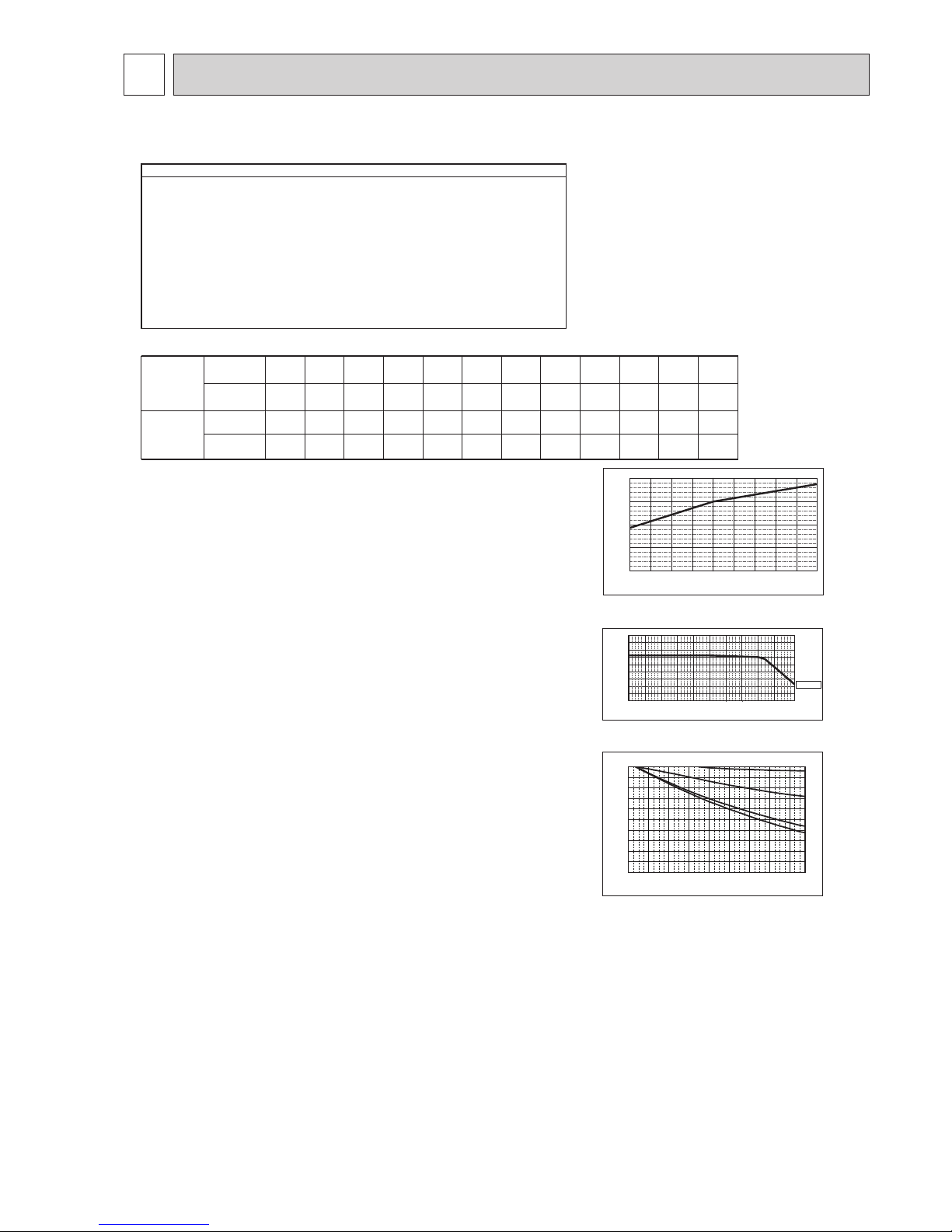
Indoor Temperature [°CW.B.]
Ratio of cooling capacity
15 16 17 18 19 20 21 22 23 24
0.4
0.6
0.8
1.0
1.2
<Cooling>
Design Condition
Outdoor Design Dry Bulb Temperature 40ºC
Total Cooling Load 9.0 kW
Room1
Indoor Design Dry Bulb Temperature 27ºC
Indoor Design Wet Bulb Temperature 20ºC
Cooling Load 4.0 kW
Room2
Indoor Design Dry Bulb Temperature 24ºC
Indoor Design Wet Bulb Temperature 18ºC
Cooling Load 4.5 kW
<Other>
Indoor/Outdoor Equivalent Piping Length 100 m
1. Cooling Calculation
(1) Temporary Selection of Indoor Units
Room1
PEFY-P40 4.5 kW (Rated)
Room2
PEFY-P50 5.6 kW (Rated)
(2) Total Indoor Units Capacity
P40 + P50 = P90
(3) Selection of Outdoor Unit
The P112 outdoor unit is selected as total indoor units capacity is P90
PUMY-P112 12.5 kW
(4) Total Indoor Units Capacity Correction Calculation
Room1
Indoor Design Wet Bulb Temperature Correction (20ºC)
1.04 (Refer to Figure 1)
Figure 1
Indoor unit temperature correction
To be used to correct indoor unit only
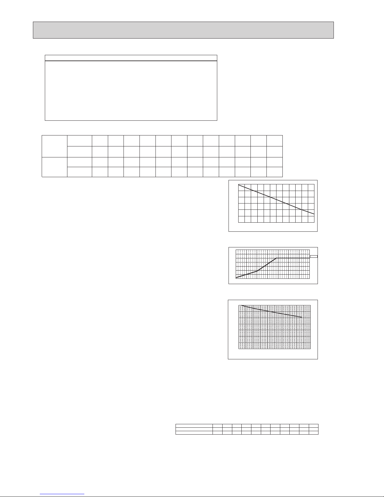
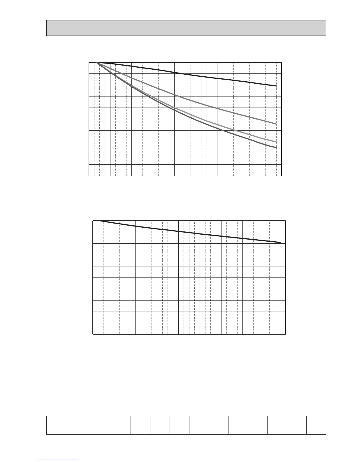
Figure 2 Outdoor unit temperature correction
To be used to correct outdoor unit only
Figure 3
Correction of refrigerant piping length
Room2
Indoor Design Wet Bulb Temperature Correction (18ºC)
0.90 (Refer to Figure 1)
CTi = Σ (Indoor Unit Rating × Indoor Design Temperature Correction)
= 4.5 × 1.04 + 5.6 × 0.90
= 9.7 kW
(5) Outdoor Unit Correction Calculation
Outdoor Design Dry Bulb Temperature Correction (40ºC)
0.86 (Refer to Figure 2)
Piping Length Correction (160 m)
0.85 (Refer to Figure 3)
Total Outdoor Unit Capacity (CTo)
Total Indoor Units Capacity (CTi)
CTo = Outdoor Rating × Outdoor Design Temperature Correction × Piping Length Correction
= 12.5 × 0.86 × 0.85
= 9.14 kW
(6) Determination of Maximum System Capacity
Comparison of Capacity between Total Indoor Units Capacity (CTi) and Total Outdoor Unit Capacity (CTo)
CTi = 9.7 > CTo = 9.14, thus, select CTo.
CTx = CTo = 9.14 kW
(7) Comparison with Essential Load
Against the essential load 9.0kW, the maximum system capacity is 9.14 kW: Proper outdoor units have been selected.
(8) Calculation of Maximum Indoor Unit Capacity of Each Room
CTx = CTo, thus, calculate by the calculation below
Room1
Maximum Capacity × Room1 Capacity after the Temperature Correction/(Room1,2 Total Capacity after the Temperature Correction
= 9.14 × (4.5 × 1.04)/(4.5 × 1.04 + 5.6 × 0.90)
= 4.4 kW
OK: fulfills the load 4.0 kW
Room2
Maximum Capacity × Room2 Capacity after the Temperature Correction/(Room1,2 Total Capacity after the Temperature Correction)
= 9.14 × (5.60 × 0.90)/(4.5 × 1.04 + 5.6 × 0.90)
= 4.7 kW OK: fulfills the load 4.5 kW
Go on to the heating trial calculation since the selected units fulfill the cooling loads of Room 1, 2.
Ratio of cooling capacity
°CD.B.
19°C W.B.
Indoor
Temperature
Total capacity of indoor unit
Outdoor Temperature
0.4
0.5
0.6
0.7
0.8
0.9
1.0
1.1
1.2
1.3
−5 0 5 10 15 20 25 3 0 35
40
45
Cooling capacity correction factor
0.50
0.55
0.60
0.65
0.70
0.75
0.80
0.85
0.90
0.95
1.00
0 20 40 60 80 1 00 120 140 160
Piping equivalent length (m)
6.3
12.5
9.4
16.2
Note: If CTx = CTi, please refer to the <Heating> section to calculate the Maximum Indoor Unit Capacity of Each Room.
4-1. SELECTION OF COOLING/HEATING UNITS
OCH632A
14
Capacity of indoor unit
Model 20
Model Number
for indoor unit
Model
Capacity
2.5
Model 15
1.9
Model 25
3.2
Model 32
4.0
Model 40
5.0
Model 50
6.3
Model 63
8.0
Model 71
9.0
Model 80
10.0
Model 100
12.5
Model 125
16.0
Model 140
18.0
Model
Capacity
2.31.7 2.5 2.9 4.0 4.8 5.7 6.9 8.1
P•FY Series
M Series
S Series
P Series
Model 20
Model Number
for indoor unit
Model 15 Model 22 Model 25
Model 35
Model 42 Model 50 Model 60 Model 71
2.1
Model 18
9.3
Model 80
11.2
Model 100
<Hea ting>
Design Condition
Outdoor Design Wet Bulb Temperature 2ºC
Total Heating Load 10.3 kW
Room1
Indoor Design Dry Bulb Temperature 21ºC
Heating Load
4.8 kW
Room2
Indoor Design Dry Bulb Temperature 23ºC
Heating Load
5.5 kW
<Other>
Indoor/Outdoor Equivalent Piping Length 100 m
2. Hea ting Calcula tion
(1) Temporary Selection of Indoor Units
Room1
PEFY-P40 5.0 kW (Rated)
Room2
PEFY-P50 6.3 kW (Rated)
(2) Total Indoor Units Capacity
P40 + P50 = P90
(3) Selection of Outdoor Unit
The P112 outdoor unit is selected as total indoor units capacity is P90
PUMY-P112 14.0 kW
(4) Total Indoor Units Capacity Correction Calculation
Room1
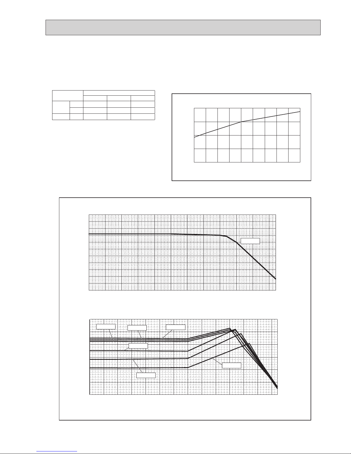
Indoor Design Dry Bulb Temperature Correction (21ºC)
0.96 (Refer to Figure 4)
Table 1 Table of correction factor at frost and defrost
Room2
Indoor Design Dry Bulb Temperature Correction (23ºC)
0.88 (Refer to Figure 4)
CTi = Σ (Indoor Unit Rating × Indoor Design Temperature Correction)
= 5.0 × 0.96 + 6.3 × 0.88
= 10.3 kW
(5) Outdoor Unit Correction Calculation
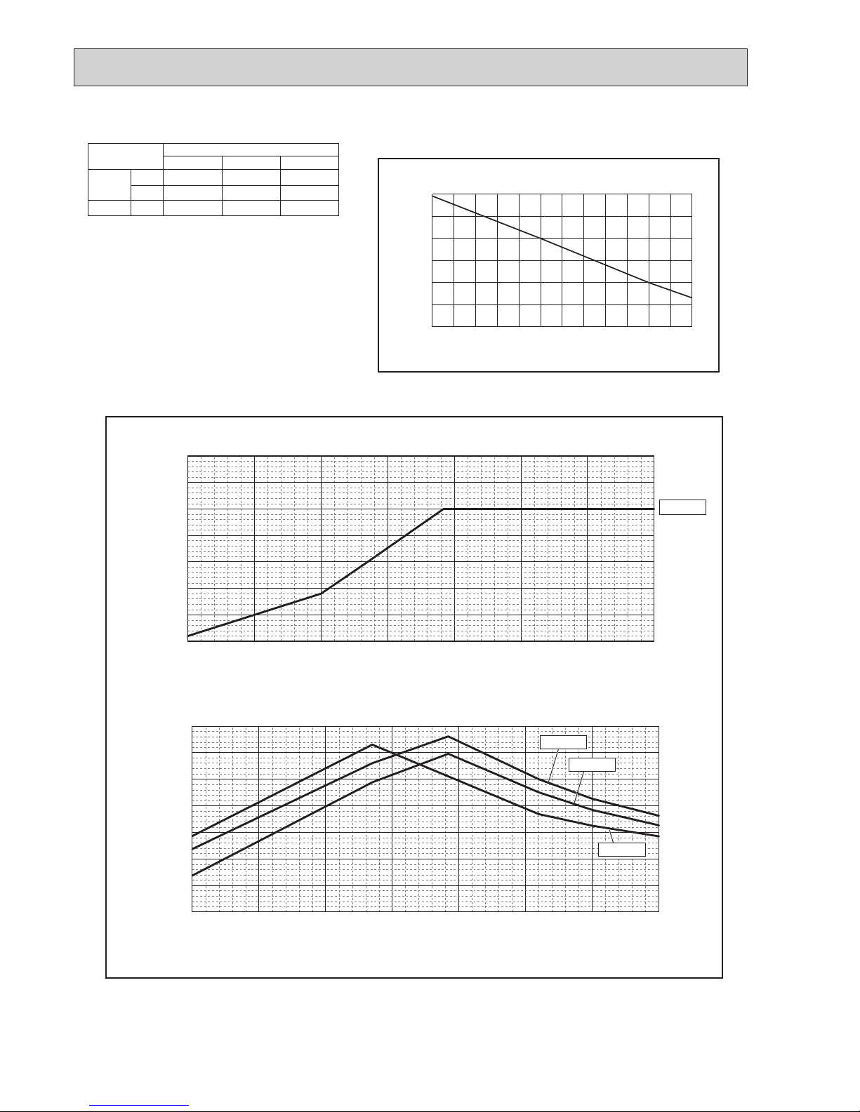
Outdoor Design Wet Bulb Temperature Correction (2ºC)
1.0 (Refer to Figure 5)
Piping Length Correction (100 m)
Defrost Correction
0.94 (Refer to Figure 6)
0.89 (Refer to Table 1)
Total Outdoor Unit Capacity (CTo)
Total Indoor Units Capacity (CTi)
CTo = Outdoor Unit Rating × Outdoor Design Temperature Correction × Piping Length
Correction × Defrost Correction
= 14.0 × 1.0 × 0.94 × 0.89
= 11.7 kW
(6) Determination of Maximum System Capacity
Comparison of Capacity between Total Indoor Units Capacity (CTi) and Total Outdoor Unit Capacity (CTo)
CTi = 10.3 < CTo = 11.7, thus, select CTi.
CTx = CTi = 10.3 kW
(7) Comparison with Essential Load
Against the essential load 10.3kW, the maximum system capacity is 10.3 kW: Proper indoor units have been selected.
(8) Calculation of Maximum Indoor Unit Capacity of Each Room
CTx = CTo, thus, calculate by the calculation below
Room1
Indoor Unit Rating × Indoor Design Temperature Correction
= 5.0 × 0.96
= 4.8 kW OK: fulfills the load 4.8 kW
Room2
Indoor Unit Rating
× Indoor Design Temperature Correction
= 6.3× 0.88
= 5.5 kW OK: fulfills the load 5.5 kW
Completed selecting units since the selected units fulfill the heating loads of Room 1, 2.
Figure 4 Indoor unit temperature correction
To be used to correct indoor unit only
Figure 5 Outdoor unit temperature correction
To be used to correct outdoor unit only
Figure 6 Correction of refrigerant piping length
1
0.90
0.80
0.95
0.85
0.75
0.65
0.70
200 40 60 80 100 120 140 160 180 200
Heating capacity correction factor
Piping equivalent length (m)
15 16 17 18 19 20 21 22 23 24 25 26 27
0.6
0.7
0.8
0.9
1.0
1.1
1.2
Ratio of heating capacity
Indoor Temperature [°CD.B.]
−20 −15 −10 −5 0 5 10 15
0.5
0.6
0.7
0.8
0.9
1.0
1.1
1.2
Ratio of heating capacity
Outdoor Temperature [°C W.B.]
20°C D.B
Note: If CTx = CTo, please refer to the <Cooling> section to calculate the Maximum Indoor Unit Capacity of Each Room.
Outdoor inlet air temp. °C 6 4 2 0
−2 −4 −6 −8 −10 −15 −20
PUMY-P112,125,140VKM3 1.0 0.98 0.89 0.88 0.89 0.90 0.95 0.95 0.95 0.95 0.95
PUMY-P112,125,140YKM(E)3 1.0 0.98 0.89 0.88 0.89 0.90 0.95 0.95 0.95 0.95 0.95
OCH632A
15
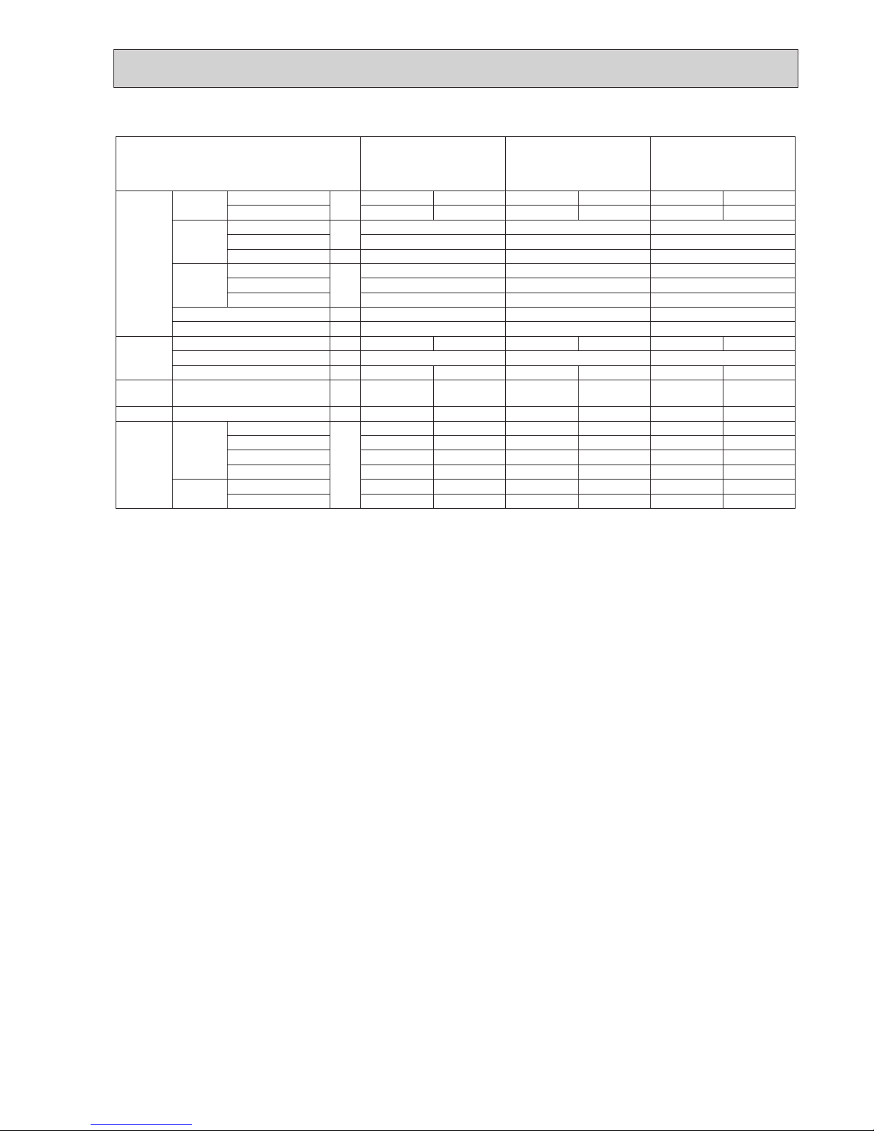
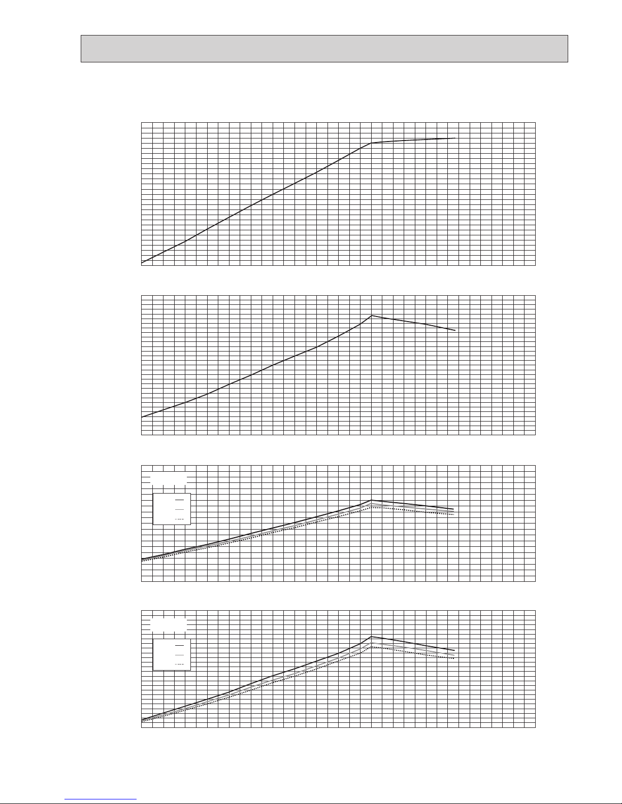
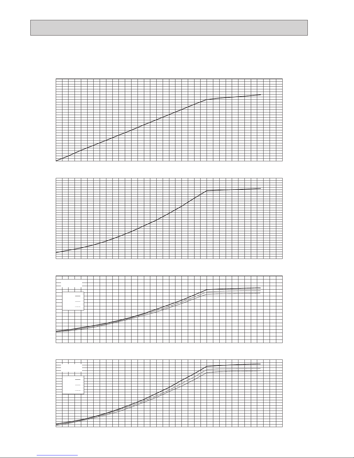
4-2. CORRECTING BY TEMPERATURE
15 16 17 18 19 20 21 22 23 24
0.4
0.6
0.8
1.0
1.2
Ratio of cooling capacity
Indoor Temperature [°CW.B.]
Ratio of cooling capacity
Outdoor Temperature [°C D.B.]
Indoor Temperature
-5.0 0.0 5.0 10.0 15.0 20.0 25.0 30.0 35.0 40.0 45.0
50.0 52.0
0.2
0.3
0.4
0.5
0.6
0.7
0.8
0.9
1.0
1.1
1.2
1.3
19°C W.B
Ratio of power input
Outdoor Temperature [°C D.B.]
Indoor Temperature
-15.0 -10.0 -5.0 0.0 5.0 10.0 15.0 20.0 25.0 30.0 35.0 40.0 45.0
50.0 52.0
0.0
0.2
0.4
0.6
0.8
1.0
1.2
16°C W.B
18°C W.B
19°C W.B
20°C W.B
22°C W.B
24°C W.B
CITY MULTI could have varied capacity at different designing temperature. Using the nominal cooling/heating capacity value
and the ratio below, the capacity can be observed at various temperature.
PUMY
P112 P125 P140
Nominal
cooling
capacity
kW
12.5 14.0 15.5
BTU/h
42,650 47,768 52,886
Input kW
2.79 3.46 4.52
Figure 7 Indoor unit temperature correction
To be used to correct indoor unit capacity only
Figure 8 Outdoor unit temperature correction
To be used to correct outdoor unit capacity only
<Cooling>
OCH632A
16
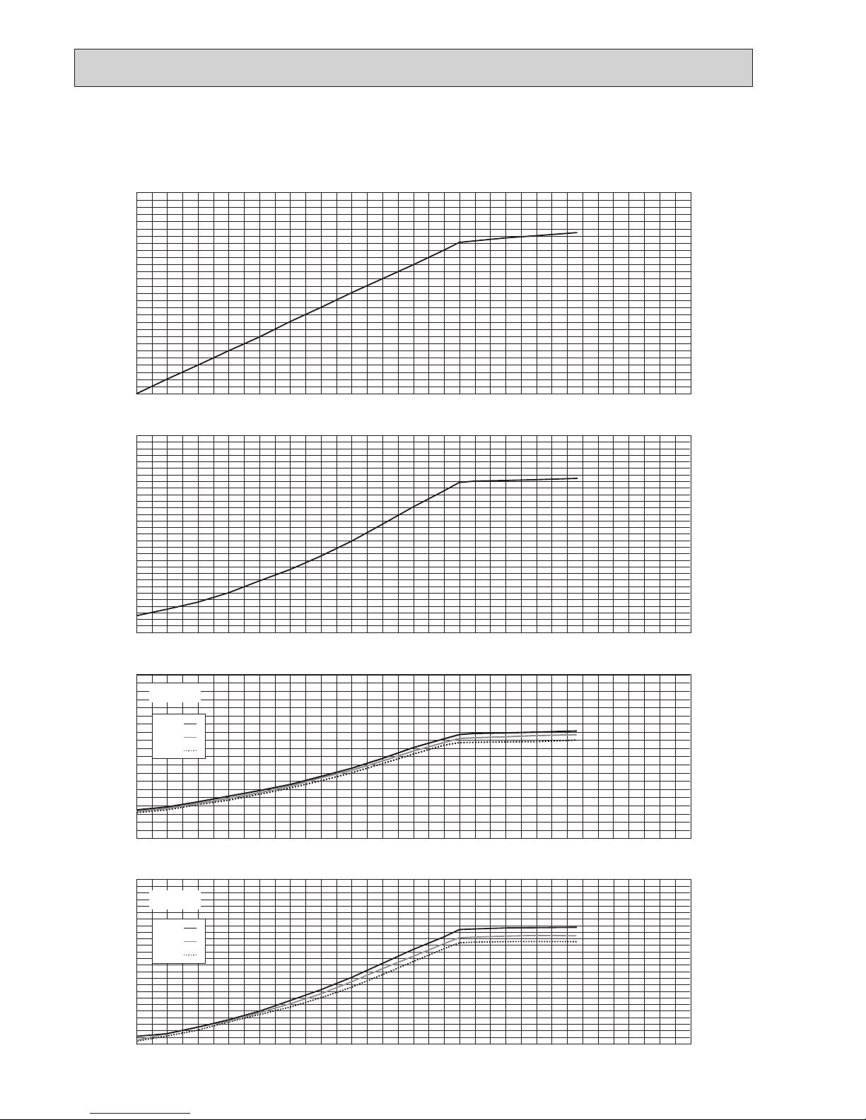
<Heating>
15 16 17 18 19 20 21 22 23 24 25 26 27
0.6
0.7
0.8
0.9
1.0
1.1
1.2
Ratio of heating capacity
Indoor Temperature [°CD.B.]
Ratio of heating capacity
Outdoor Temperature [°C W.B.]
20°C D.B
-20.0 -15.0 -10.0
-5.0 0.0 5.0 10.0 15.0
0.5
0.6
0.7
0.8
0.9
1.0
1.1
1.2
Ratio of power input
Outdoor Temperature [°C W.B.]
Indoor Temperature
-20.0 -15.0 -10.0 -5.0 0.0 5.0 10.0 15.0
0.2
0.4
0.6
0.8
1.0
1.2
1.4
25°C D.B
15°C D.B
20°C D.B
Figure 9 Indoor unit temperature correction
To be used to correct indoor unit capacity only
Figure 10 Outdoor unit temperature correction
To be used to correct outdoor unit capacity only
PUMY
P112 P125 P140
Nominal
heating
capacity
kW
14.0 16.0 18.0
BTU/h
47,768 54,592 61,416
Input kW
3.04 3.74 4.47
OCH632A
17
Operation
PUMY-P112VKM3(-BS)
PUMY-P112YKM3(-BS)
PUMY-P112YKME3(-BS)
PUMY-P125VKM3(-BS)
PUMY-P125YKM3(-BS)
PUMY-P125YKME3(-BS)
PUMY-P140VKM3(-BS)
PUMY-P140YKM3(-BS)
PUMY-P140YKME3(-BS)
Operating
conditions
Ambient
temperature
Indoor
DB/
WB
27°C/19°C 20°C/— 27°C/19°C 20°C/— 27°C/19°C 20°C/—
Outdoor 35°C 7°C/6°C 35°C 7°C/6°C 35°C 7°C/6°C
Indoor unit
No. of connected units
Unit
2 2 2
No. of units in operation 2 2 2
Model — 50 x 1/63 x 1 63 × 2 63 x 1/80×1
Piping
Main pipe
m
5 5 5
Branch pipe 2.5 2.5 2.5
Total pipe length 10 10 10
Fan speed — Hi Hi Hi
Amount of refrigerant kg 7.2 7.2 7.2
Outdoor unit
Electric current A 16.17/5.26 17.38/5.67 21.67/7.12 21.91/7.22 25.84/8.58 25.54/8.48
Voltage V 230/400 230/400 230/400
Compressor frequency Hz 67 69 84 86 96 96
LEV
opening
Indoor unit Pulse 357 421 447 525 511 586
Pressure High pressure/Low pressure
MPa G
2.70/0.94 2.86/0.70 2.86/0.88 2.87/0.67 2.95/0.85 2.95/0.65
Temp. of
each section
Outdoor
unit
Discharge
°C
67.0 71.9 69.7 72.1 70.7 73.2
Heat exchanger outlet 40.2 2.0 40.8 1.3 43.7 0.9
Accumulator inlet 8.7 1.0 8.0 0.2 5.6 −0.6
Compressor inlet 10.7 1.3 9.1 0.1 7.8 −0.7
Indoor unit
LEV inlet 18.9 32.4 17.7 33.0 17.0 33.4
Heat exchanger inlet 12.3 55.5 11.1 55.7 10.4 56.8
4-3. STANDARD OPERATION DATA (REFERENCE DATA)
OCH632A
18
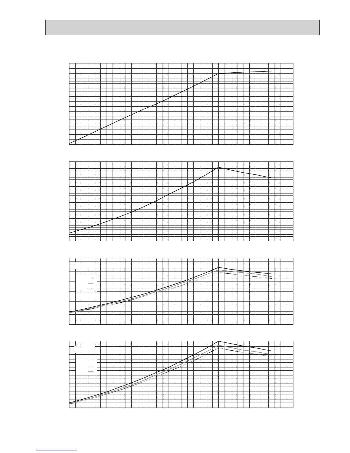
4-4. STANDARD CAPACITY DIAGRAM
Before calculating the sum of total capacity of indoor units, please convert the value into the kW model capacity following the formula on
"4-1-1. Method for obtaining system cooling and heating capacity".
Y-Type
V-Type
1.0
2.0
3.0
4.0
5.0
6.0
Current(A)
2.0
2.0
4.0
6.0
8.0
12.0
10.0
16.0
14.0
4.0 6.0 8.0 10.0 12.0 14.0 16.0 18.0 20.0
Capacity(kW)
Total capacity of indoor units(kW)
2.0 4.0 6.0 8.0 10.0 12.0 14.0 16.0 18.0 20.0
Total capacity of indoor units(kW)
2.0 4.0 6.0 8.0 10.0 12.0 14.0 16.0 18.0 20.0
Total capacity of indoor units(kW)
2.0 4.0 6.0 8.0 10.0 12.0 14.0 16.0 18.0 20.0
Total capacity of indoor units(kW)
0.0
5.0
10.0
15.0
20.0
Current(A)
0.5
1.0
1.5
2.0
2.5
3.0
3.5
Input(kW)
220V
230V
240V
380V
400V
415V
4-4-1. PUMY-P112VKM3(-BS) PUMY-P112YKM(E)3(-BS) <cooling>
OCH632A
19
Y-Type
V-Type
1.0
2.0
3.0
4.0
5.0
6.0
Current(A)
2.0
2.0
4.0
6.0
8.0
12.0
10.0
16.0
14.0
4.0 6.0 8.0 10.0 12.0 14.0 16.0 18.0 200.
Capacity(kW)
Total capacity of indoor units(kW)
2.0 4.0 6.0 8.0 10.0 12.0 14.0 16.0 18.0 20.0
Total capacity of indoor units(kW)
2.0 4.0 6.0 8.0 10.0 12.0 14.0 16.0 18.0 20.0
Total capacity of indoor units(kW)
Current(A)
0.5
1.0
1.5
2.0
2.5
3.0
3.5
Input(kW)
2.0 4.0 6.0 8.0 10.0 12.0 14.0 16.0 18.0 20.0
0.0
5.0
10.0
15.0
20.0
Total capacity of indoor units(kW)
PUMY-P112VKM
220V
230V
240V
380V
400V
415V
4-4-2. PUMY-P112VKM3(-BS) PUMY-P112YKM(E)3(-BS) <heating>
OCH632A
20
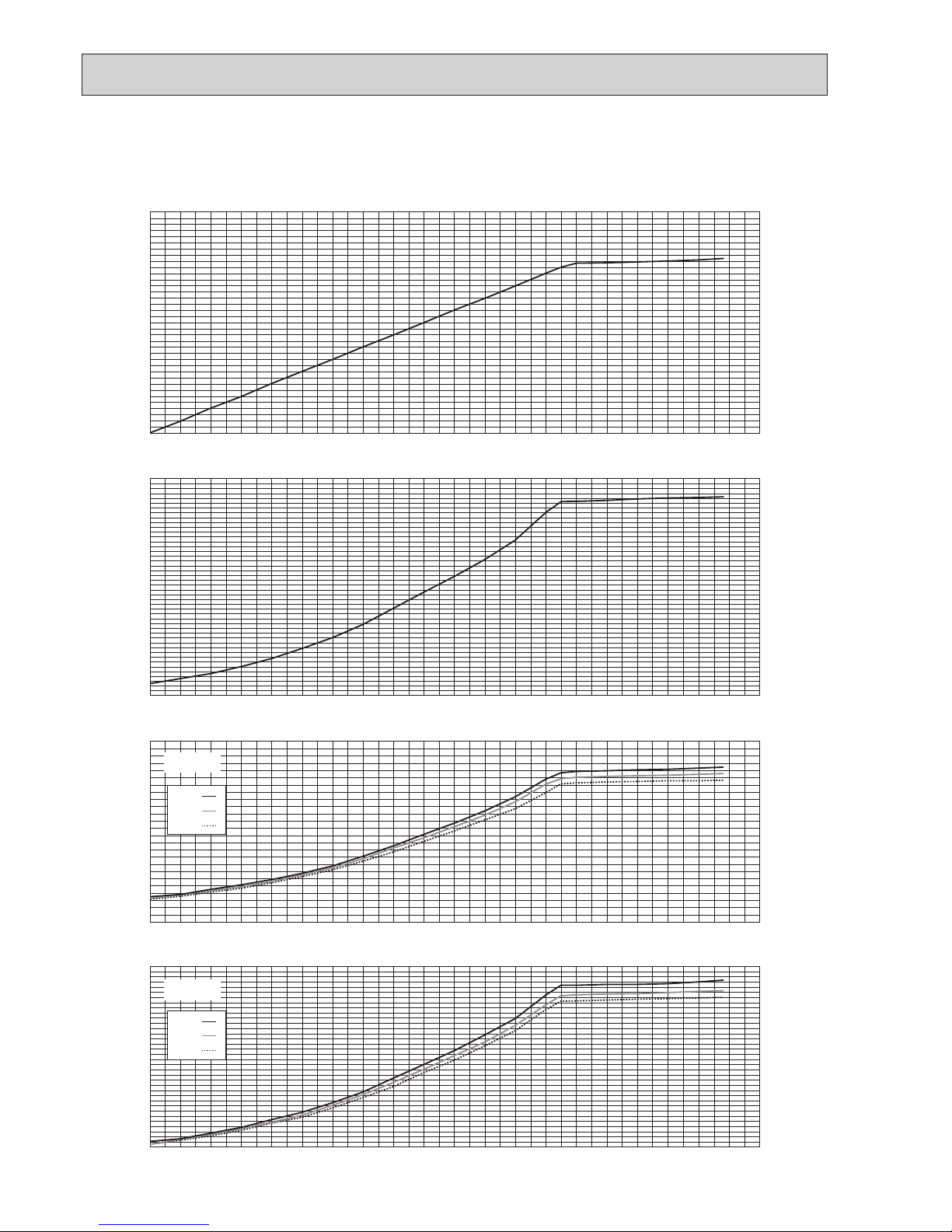
4-4-3. PUMY-P125VKM3(-BS) PUMY-P125YKM(E)3(-BS) <cooling>
Before calculating the sum of total capacity of indoor units, please convert the value into the kW model capacity following the formula on
"4-1-1. Method for obtaining system cooling and heating capacity".
Y-Type
1.0
2.0
3.0
4.0
5.0
6.0
Current(A)
2.0 4.0 6.0 8.0 10.0 12.0 14.0 16.0 18.0 20.0
Total capacity of indoor units(kW)
Current(A) Input(kW)
2.0 4.0 6.0 8.0 10.0 12.0 14.0 16.0 18.0 20.0
Total capacity of indoor units(kW)
0.5
1.0
1.5
2.0
2.5
3.0
3.5
4.0
2.0
2.0
4.0
6.0
8.0
12.0
10.0
16.0
18.0
14.0
4.0 6.0 8.0 10.0 12.0 14.0 16.0 18.0 20.0
Capacity(kW)
Total capacity of indoor units(kW)
V-Type
Total capacity of indoor units(kW)
2.0 4.0 6.0 8.0 10.0 12.0 14.0 16.0 18.0 20.0
0.0
5.0
10.0
15.0
20.0
220V
230V
240V
380V
400V
415V
OCH632A
21
Y-Type
1.0
2.0
3.0
4.0
5.0
6.0
Current(A)
2.0 4.0 6.0 8.0 10.0 12.0 14.0 16.0 18.0 20.0
Total capacity of indoor units(kW)
Current(A) Input(kW)
2.0 4.0 6.0 8.0 10.0 12.0 14.0 16.0 18.0 20.0
Total capacity of indoor units(kW)
0.5
1.0
1.5
2.0
2.5
3.0
3.5
4.0
2.0
2.0
4.0
6.0
8.0
12.0
10.0
16.0
18.0
14.0
4.0 6.0 8.0 10.0 12.0 14.0 16.0 18.0 20.0
Capacity(kW)
Total capacity of indoor units(kW)
V-Type
Total capacity of indoor units(kW)
2.0 4.0 6.0 8.0 10.0 12.0 14.0 16.0 18.0 20.0
0.0
5.0
10.0
15.0
20.0
220V
230V
240V
380V
400V
415V
4-4-4. PUMY-P125VKM3(-BS) PUMY-P125YKM(E)3(-BS) <heating>
OCH632A
22
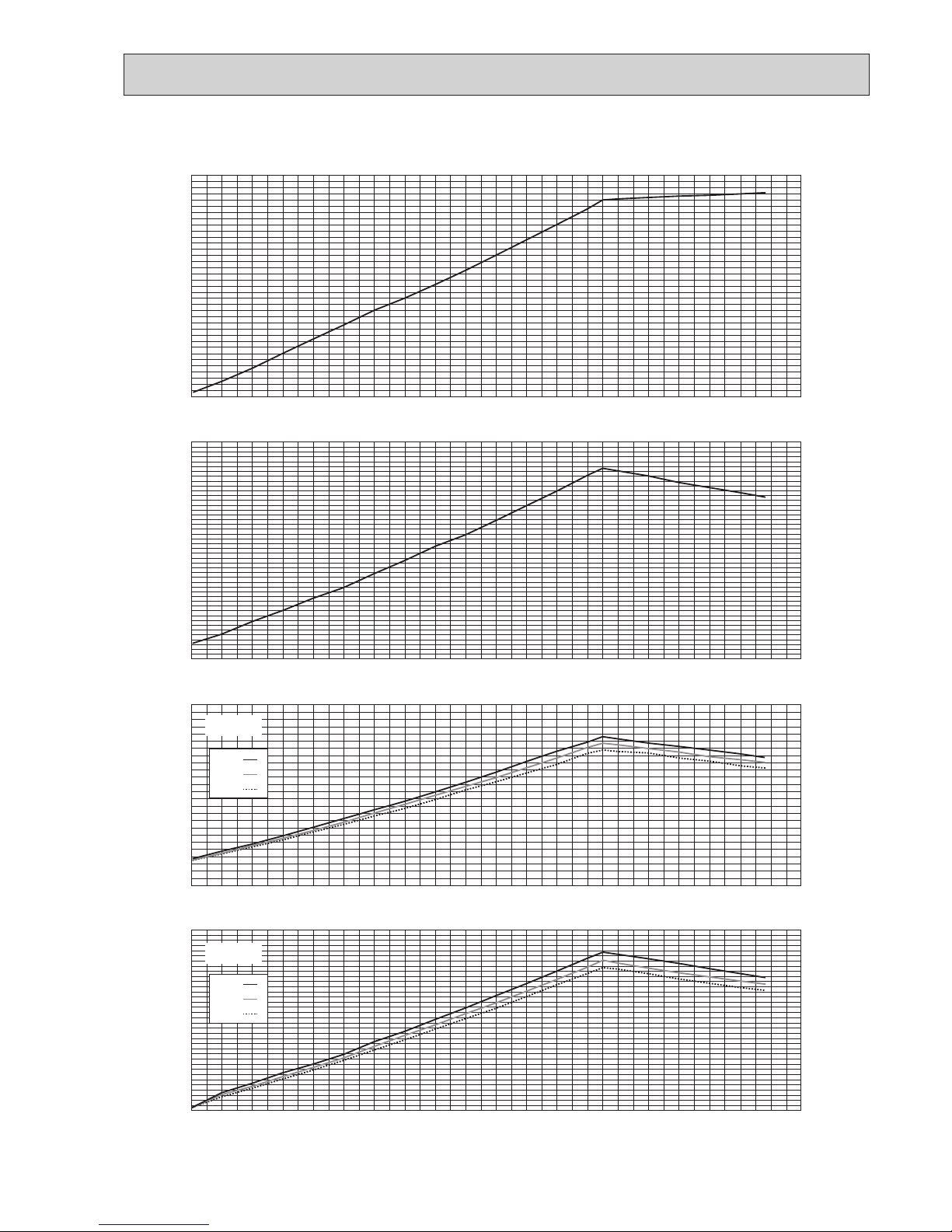
4-4-5. PUMY-P140VKM3(-BS) PUMY-P140YKM(E)3(-BS) <cooling>
Before calculating the sum of total capacity of indoor units, please convert the value into the kW model capacity following the formula on
"4-1-1. Method for obtaining system cooling and heating capacity".
Y-Type
Current(A)
Total capacity of indoor units(kW)
Current(A) Input(kW)
Total capacity of indoor units(kW)
V-Type
2.0
2.0
4.0
6.0
8.0
12.0
10.0
16.0
18.0
20.0
14.0
4.0 6.0 8.0 10.0 12.0 14.0 16.0 18.0 20.0 22.0
2.0
0.5
1.0
1.5
2.0
2.5
3.0
3.5
4.0
4.5
5.0
4.0 6.0 8.0 10.0 12.0 14.0 16.0 18.0 20.0 22.0
2.0
5.0
0.0
10.0
15.0
20.0
25.0
4.0 6.0 8.0 10.0 12.0 14.0 16.0 18.0 20.0 22.0
2.0
2.0
1.0
3.0
4.0
5.0
6.0
7.0
8.0
4.0 6.0 8.0 10.0 12.0 14.0 16.0 18.0 20.0 22.0
Total capacity of indoor units(kW)
Capacity(kW)
Total capacity of indoor units(kW)
220V
230V
240V
380V
400V
415V
OCH632A
23
Y-Type
Current(A)
Total capacity of indoor units(kW)
Current(A) Input(kW)
Total capacity of indoor units(kW)
2.0
2.0
4.0
6.0
8.0
12.0
10.0
16.0
18.0
20.0
14.0
4.0 6.0 8.0 10.0 12.0 14.0 16.0 18.0 20.0 22.0
2.0
0.5
1.0
1.5
2.0
2.5
3.0
3.5
4.0
4.5
5.0
4.0 6.0 8.0 10.0 12.0 14.0 16.0 18.0 20.0 22.0
2.0
2.0
1.0
3.0
4.0
5.0
6.0
7.0
8.0
4.0 6.0 8.0 10.0 12.0 14.0 16.0 18.0 20.0 22.0
Total capacity of indoor units(kW)
Capacity(kW)
Total capacity of indoor units(kW)
Current(A)
V-Type
2.0
5.0
0.0
10.0
15.0
20.0
25.0
4.0 6.0 8.0 10.0 12.0 14.0 16.0 18.0 20.0 22.0
220V
230V
240V
380V
400V
415V
4-4-6. PUMY-P140VKM3(-BS) PUMY-P140YKM(E)3(-BS) <heating>
OCH632A
24
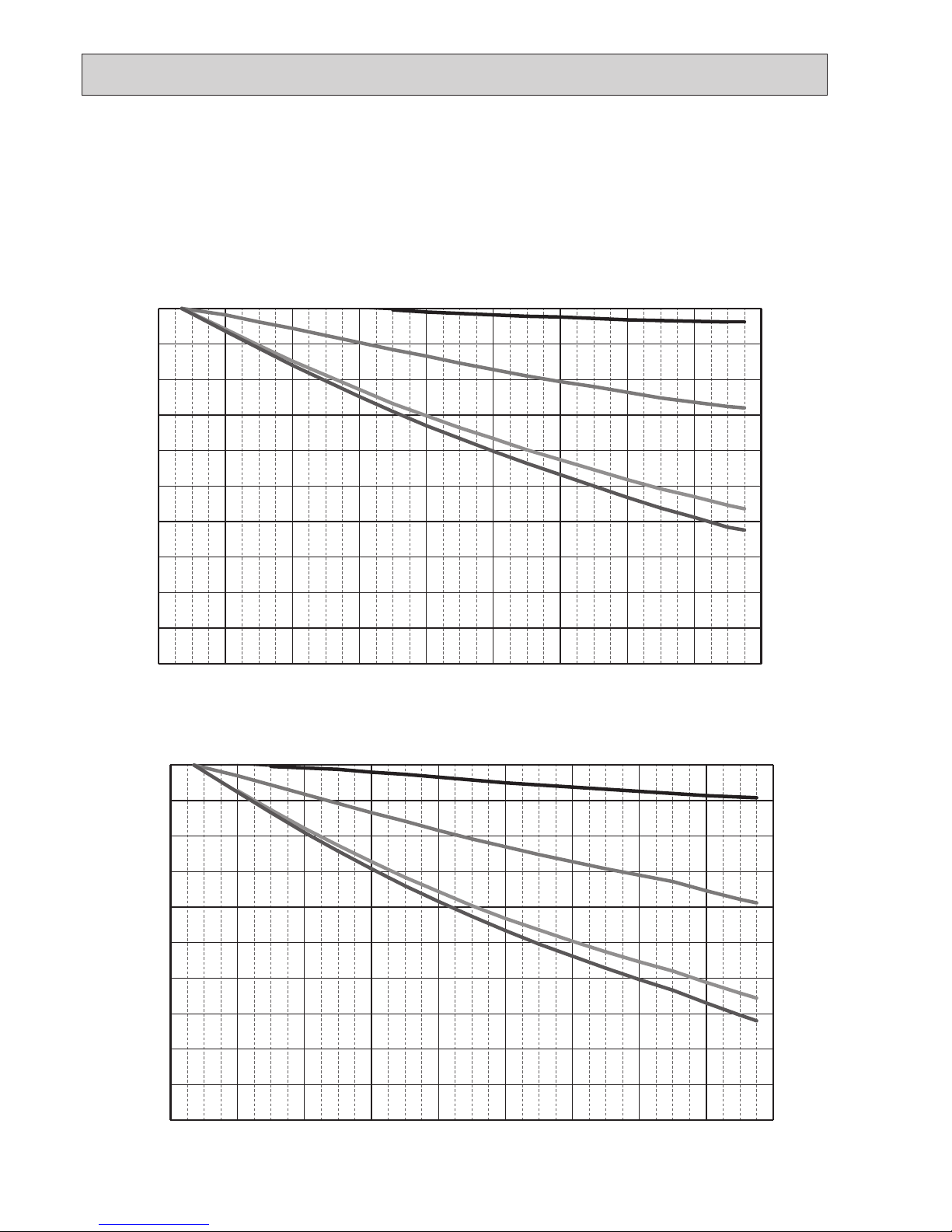
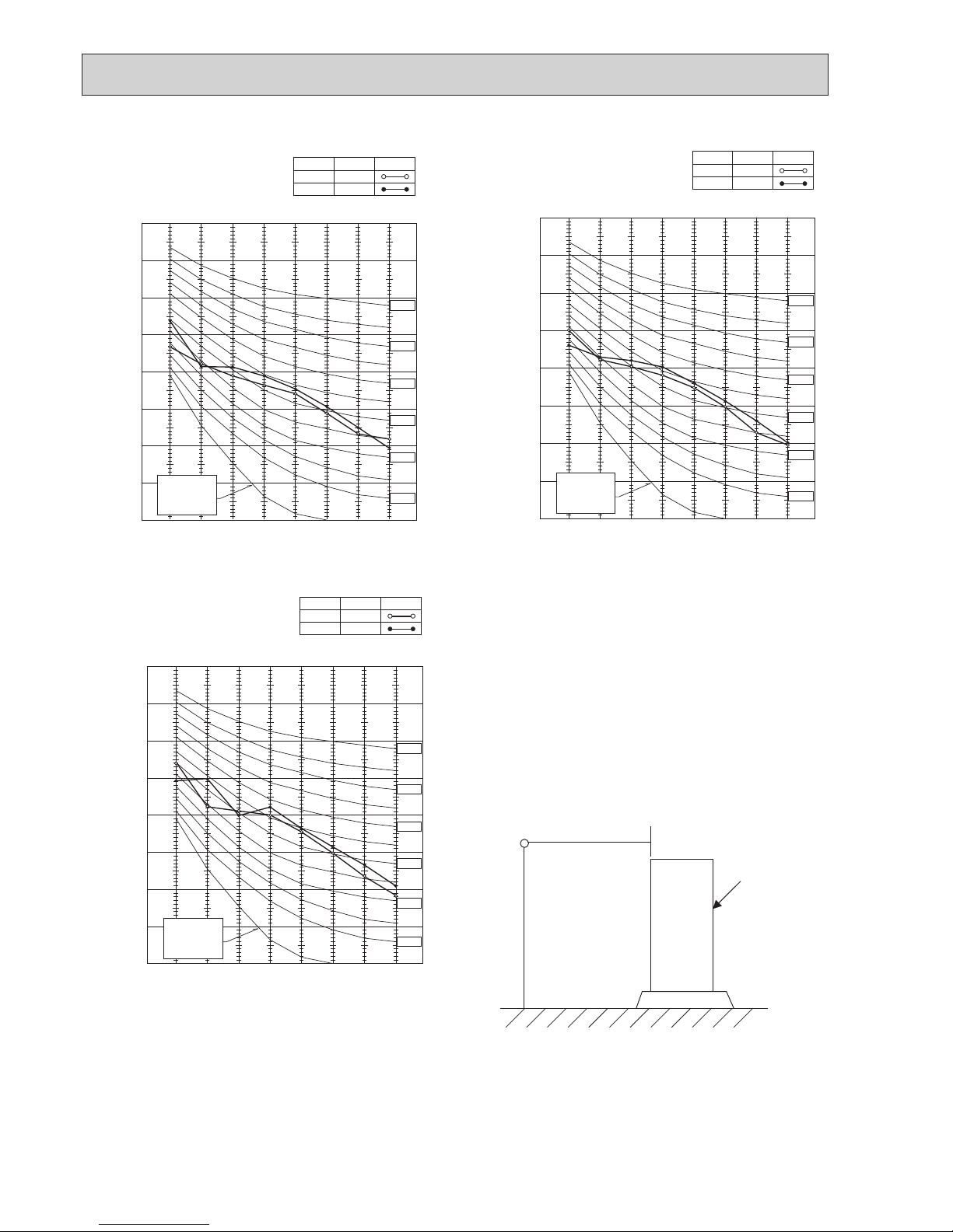
4-5.
CORRECTING CAPACITY FOR CHANGES IN THE LENGTH OF REFRIGERANT PIPING
(1) During cooling, obtain the ratio (and the equivalent piping length) of the outdoor units rated capacity and the total in-use
indoor capacity, and find the capacity ratio corresponding to the standard piping length from Figure 11 to 13. Then multiply
by the cooling capacity from Figure 7 and 8 in "4-2. CORRECTION BY TEMPERATURE" to obtain the actual capacity.
(2) During heating, find the equivalent piping length, and find the capacity ratio corresponding to standard piping length from
Figure 14. Then multiply by the heating capacity from Figure 9 and 10 in "4-2. CORRECTION BY TEMPERATURE" to
obtain the actual capacity.
(1) Capacity Correction Curve
0 20 40 60 80 100 120 140 160 180
0.50
0.55
0.60
0.65
0.70
0.75
0.80
0.85
0.90
0.95
1.00
9.4
6.3
12.5
16.2
Capacity ratio
Piping equivalent length (m)
Total capacity of indoor unit
Total capacity of indoor unit
0 20 40 60 80 100 120 140 160 180
0.50
0.55
0.60
0.65
0.70
0.75
0.80
0.85
0.90
0.95
1.00
10.5
7.0
14.0
18.2
Capacity ratio
Piping equivalent length (m)
Figure 11 PUMY-P112VKM3(-BS) PUMY-P112YKM(E)3(-BS) <Cooling>
Figure 12 PUMY-P125VKM3(-BS) PUMY-P125YKM(E)3(-BS) <Cooling>
OCH632A
25
(2) Method for Obtaining the Equivalent Piping Length
Equivalent length for type P112·125·140 = (length of piping to farthest indoor unit) + (0.3 o number of bends in the piping) (m)
Length of piping to farthest indoor unit: type P112–P140.....150 m
4-5-1. Correction of Heating Capacity for Frost and Defrosting
If heating capacity has been reduced due to frost formation or defrosting, multiply the capacity by the appropriate correction
factor from the following table to obtain the actual heating capacity.
Correction factor diagram
Outdoor Intake temperature (W.B.°C)
6 4 2 0 −2 −4 −6 −8 −10 −15 −20
Correction factor
1.0 0.98 0.89 0.88 0.89 0.9 0.95 0.95 0.95 0.95 0.95
0 20 40 60 80 100 120 140 160 180
0.50
0.55
0.60
0.65
0.70
0.75
0.80
0.85
0.90
0.95
1.00
11.6
7.8
15.5
20.2
Capacity ratio
Piping equivalent length (m)
0 20 40 60 80 100 120 140 160 180
0.50
0.55
0.60
0.65
0.70
0.75
0.80
0.85
0.90
0.95
1.00
Capacity ratio
Piping equivalent length (m)
Total capacity of indoor unit
Figure 13 PUMY-P140VKM3(-BS) PUMY-P140YKM(E)3(-BS) <Cooling>
Figure 14 PUMY-P112/125/140VKM3(-BS) <Heating>
PUMY-P112/125/140YKM3(-BS) <Heating>
PUMY-P112/125/140YKME3(-BS) <Heating>
OCH632A
26
1.5 m
1 m
MICROPHONE
UNIT
GROUND
4-6. NOISE CRITERION CURVES
90
80
70
60
50
40
30
20
10
63 125 250 500 1000 2000 4000 8000
APPROXIMATE
THRESHOLD OF
HEARING FOR
CONTINUOUS
NOISE
OCTAVE BAND SOUND PRESSURE LEVEL, dB (0 dB = 0.0002 µbar)
BAND CENTER FREQUENCIES, Hz
NC-60
NC-50
NC-40
NC-30
NC-20
NC-70
PUMY-P112VKM3(-BS)
PUMY-P112YKM3(-BS)
PUMY-P112YKME3(-BS)
COOLING
MODE
HEATING
49
SPL(dB)
51
LINE
90
80
70
60
50
40
30
20
10
63 125 250 500 1000 2000 4000 8000
APPROXIMATE
THRESHOLD OF
HEARING FOR
CONTINUOUS
NOISE
OCTAVE BAND SOUND PRESSURE LEVEL, dB (0 dB = 0.0002 µbar)
BAND CENTER FREQUENCIES, Hz
NC-60
NC-50
NC-40
NC-30
NC-20
NC-70
PUMY-P125VKM3(-BS)
PUMY-P125YKM3(-BS)
PUMY-P125YKME3(-BS)
COOLING
MODE
HEATING
50
SPL(dB)
52
LINE
90
80
70
60
50
40
30
20
10
63 125 250 500 1000 2000 4000 8000
APPROXIMATE
THRESHOLD OF
HEARING FOR
CONTINUOUS
NOISE
OCTAVE BAND SOUND PRESSURE LEVEL, dB (0 dB = 0.0002 µbar)
BAND CENTER FREQUENCIES, Hz
NC-60
NC-50
NC-40
NC-30
NC-20
NC-70
PUMY-P140VKM3(-BS)
PUMY-P140YKM3(-BS)
PUMY-P140YKME3(-BS)
COOLING
MODE
HEATING
51
SPL(dB)
53
LINE
OCH632A
27
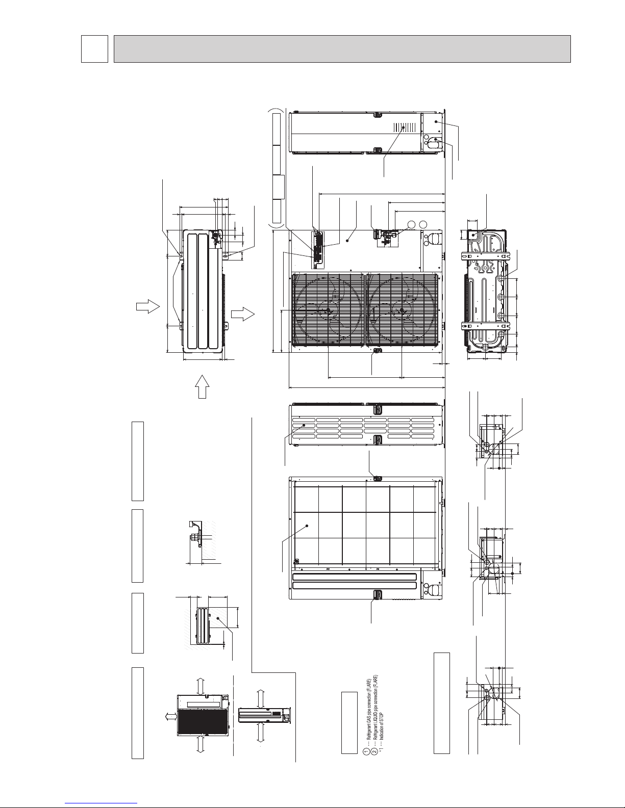
5
OUTLINES AND DIMENSIONS
PUMY-P112VKM3 PUMY-P125VKM3 PUMY-P140VKM3
PUMY-P112VKM3-BS PUMY-P125VKM3-BS PUMY-P140VKM3-BS
Unit: mm
For the
power supply
Terminal connection
For the
branch box
power supply
For the
transmission line
For concentration
control
From left to right
2
1
*1
*1
Service panel
Ground for the power supply
Ground for the transmission line
Ground for concentration control
Handle for
moving
Handle for
moving
Ground for
the branch box
power supply
483
426
1338
26
1050
362
1078
369
632
Bottom piping hole
(Knock-Out)
Drain hole
(5-{33)
81
86
154136
45 160160160110
Handle for
moving
Handle for
moving
Rear Air Intake
Side Air Intake
Rear trunking hole
(Knock-Out)
Power supply wiring hole
({ 40 Knock-Out)
Rear piping hole
(Knock-Out)
Power supply wiring hole
({ 27 Knock-Out)
75
92
55 60
326 73 60
27
55
{
92
Power supply wiring hole
({ 40 Knock-Out)
Front piping hole
(Knock-Out)
Power supply wiring hole
({ 27 Knock-Out)
Front trunking hole
(Knock-Out)
92
75
60 55
27 55
32673
60
{
92
Power supply wiring hole
({ 27 Knock-Out)
Power supply wiring hole
({ 40 Knock-Out)
Right piping hole
(Knock-Out)
Right trunking hole
(Knock-Out)
92
32673
60
75 50
29 55
27
92
{
92
Air Intake
Front piping cover
Rear piping cover
Air Discharge
Rear Air Intake
Side Air Intake
2-12×36 Oval holes
(Foundation Bolt M10)
2-U Shaped notched holes
(Foundation Bolt M10)
Installation Feet
225
417
42
70
61
28
19
370
600 225
25 330
53
56
40
0
Min.15
Min.500
Min.500
Min.150
Min. 15mm
Min. 1000mm Min. 150mm
Min. 15mm
FREE
Piping and wiring connections
can be made from 4 directions:
FRONT, Right, Rear and Below.
4 PIPING-WIRING DIRECTIONS
2 SERVICE SPACE
1 FREE SPACE (Around the unit)
Please secure the unit firmly
with 4 foundation (M10<W3/8>) bolts.
(Bolts and washers must be
purchased locally.)
Dimensions of space needed
for service access are
shown in the below diagram.
The diagram below shows a basic example.
Explantion of particular details are
given in the installation manuals etc.
<Foundation bolt height>
FOUNDATION
Service space
Max.30
Example of Notes
VALVE connection location.
Piping Knock-Out Hole Details
3 FOUNDATION BOL TS
{
15.88(5/8F)
{
9.52(3/8F)
OCH632A
28
Power supply wiring hole
({27Knock-Out)
Power supply wiring hole
({40Knock-Out)
Right trunking hole
(Knock-Out)
Right piping hole
(Knock-Out)
92
2726
92
29 55
373 60
75 50
{
92
Power supply wiring hole
({27Knock-Out)
Power supply wiring hole
({40Knock-Out)
Front piping hole
(Knock-Out)
Front trunking hole
(Knock-Out)
5527
75
92
26
73
60 3
5560
{
92
Power supply wiring hole
({40Knock-Out)
Power supply wiring hole
({27Knock-Out)
Rear trunking hole
(Knock-Out)
Rear piping hole
(Knock-Out)
92
75
55 60
5527
326
73
60
{
92
Side Air Intake
Handle for
moving
Handle for
moving
Rear Air Intake
Air Discharge
Side Air Intake
Rear Air Intake
2-12×36 Oval holes
(Foundation Bolt M10)
2-U Shaped notched holes
(Foundation Bolt M10)
Installation Feet
70 61
42
25 330
417
225 225600
370
28
19
40
53
56
0
From left to right
For concentration
control
For the
transmission line
For the
branch box
power supply
For the
power supply
Terminal connection
1
2
Ground for
the branch box
power supply
Ground for the transmission line
Ground for concentration control
Ground for the power supply
*1
Handle for
moving
Handle for
moving
Service panel
*1
1338
26
1050
362
909
426
483
369
632
Air Intake
Drain hole(5-{33)
Bottom piping hole
(Knock-Out)
81
86
154136
45 160160160110
Min. 15mm
Min. 1000mm Min. 150mm
Min. 15mm
FREE
Service space
FOUNDATION
<Foundation bolt height>
The diagram below shows a basic example.
Explanation of particular details are
given in the installation manuals etc.
Dimensions of space needed
for service access are
shown in the below diagram.
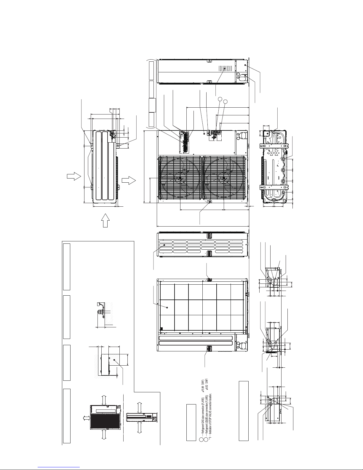
Please secure the unit firmly
with 4 foundation (M10<W3/8>) bolts.
(Bolts and washers must be
purchased locally.)
1 FREE SPACE (Around the unit)
2 SERVICE SPACE
3 FOUNDATION BOLTS
4 PIPING-WIRING DIRECTIONS
Piping and wiring connections
can be made from 4 directions:
FRONT, Right, Rear and Below.
Min.15
Max.30
Min.150Min.500
Min.500
2
1
Example of Notes
Piping Knock-Out Hole Details
Front piping cover
Rear piping cover
Unit: mm
PUMY-P112YKM3 PUMY-P125YKM3 PUMY-P140YKM3
PUMY-P112YKM3-BS PUMY-P125YKM3-BS PUMY-P140YKM3-BS
PUMY-P112YKME3 PUMY-P125YKME3 PUMY-P140YKME3
PUMY-P112YKME3-BS PUMY-P125YKME3-BS PUMY-P140YKME3-BS
OCH632A
29
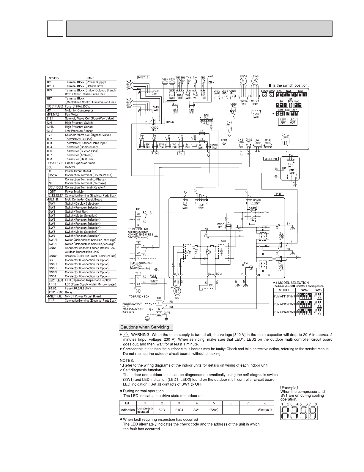
6
WIRING DIAGRAM
PUMY-P112VKM3 PUMY-P125VKM3 PUMY-P140VKM3
PUMY-P112VKM3-BS PUMY-P125VKM3-BS PUMY-P140VKM3-BS
OCH632A
30
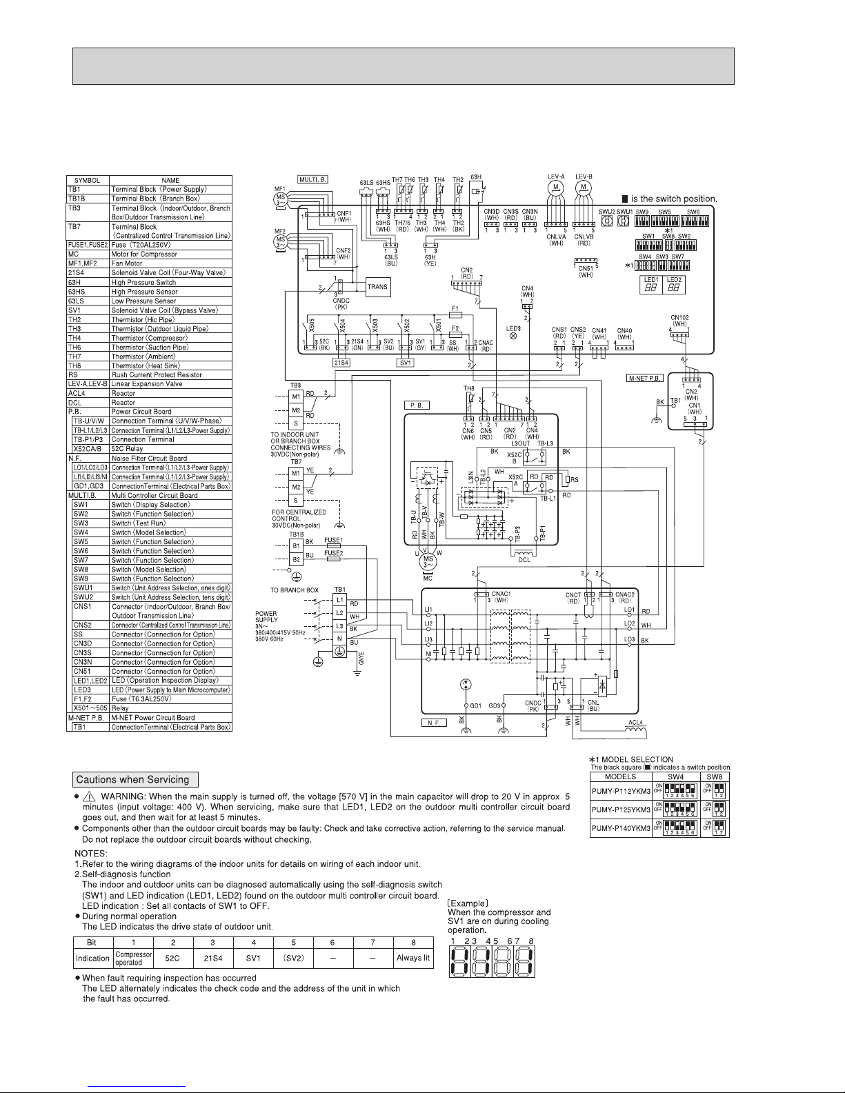
PUMY-P112YKM3 PUMY-P125YKM3 PUMY-P140YKM3
PUMY-P112YKM3-BS PUMY-P125YKM3-BS PUMY-P140YKM3-BS
OCH632A
31
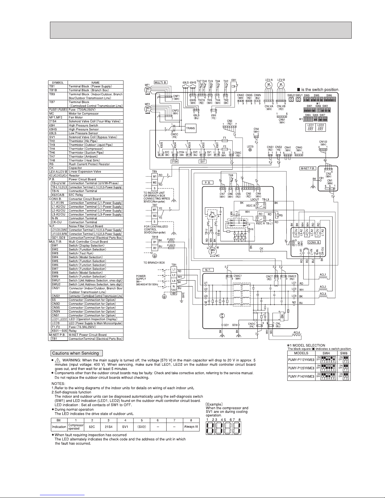
PUMY-P112YKME3 PUMY-P125YKME3 PUMY-P140YKME3
PUMY-P112YKME3-BS PUMY-P125YKME3-BS PUMY-P140YKME3-BS
OCH632A
32
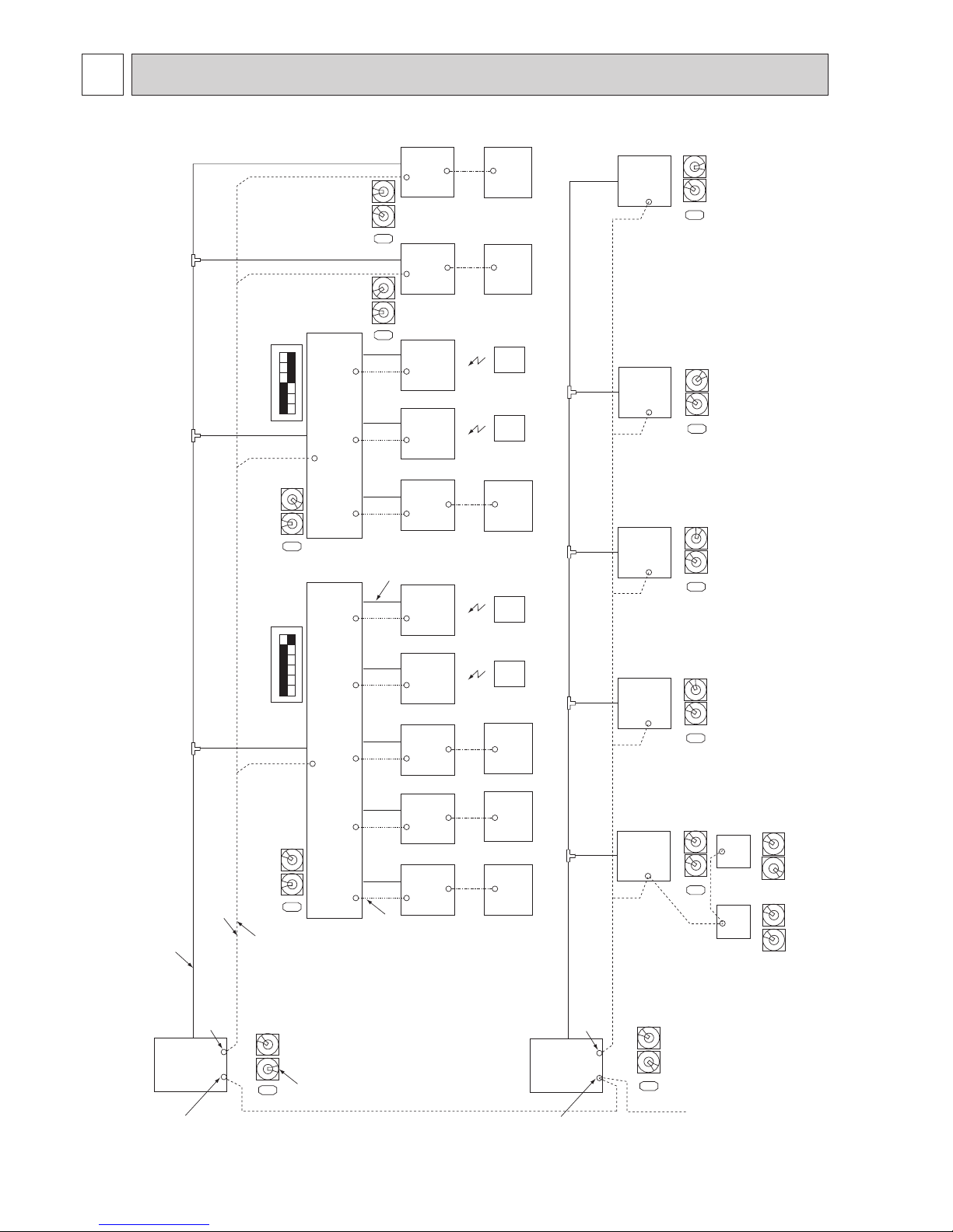
7
NECESSARY CONDITIONS FOR SYSTEM CONSTRUCTION
7-1. TRANSMISSION SYSTEM SETUP
0
1
2
3
4
5
6
7
8
9
0
1
2
3
4
5
6
7
8
9
23
Branch box
001
Branch box
006
Indoor unit
A
(001)
Indoor unit
B
(002)
Indoor unit
C
(003)
Indoor unit
A
(006)
Indoor unit
B
(007)
Indoor unit
C
(008)
Indoor unit
D
(004)
Indoor unit
E
(005)
M-NET cable
① M-NET cable shielding wire must
be connected to each refrigerant
system (outdoor and branch box).
② Set addresses :
Outdoor unit ............ 051–100
Branch box ............... 001–046
③ Outdoor unit has no 100s digit switch.
The address automatically become "100"
if it is set as "01–50".
Piping
Signal line
④ Make sure that the wiring between the
branch box and indoor unit is properly
done, matching with the piping connection.
A B C D E A B C
MA remote
controller
MA remote
controller
MA remote
controller
MA remote
controller
WL-RC WL-RC
WL-RC
WL-RC
For centralized
management
051
Outdoor unit
Piping
For Branch box/ City Multi indoor unit
1
4
0
1
2
3
4
5
6
7
8
9
0
1
2
3
4
5
6
7
8
9
Address SW
0
1
2
3
4
5
6
7
8
9
0
1
2
3
4
5
6
7
8
9
Address SW
0
1
2
3
4
5
6
7
8
9
0
1
2
3
4
5
6
7
8
9
Address SW
0
1
2
3
4
5
6
7
8
9
0
1
2
3
4
5
6
7
8
9
Address SW
SW1
ON
1 2 3 4 5 6
SW1
ON
1 2 3 4 5 6
City Multi
Indoor unit
009
City Multi
Indoor unit
010
MA remote
controller
City Multi .................. 001–050
For centralized
management
061
Outdoor unit
For Branch box/City Multi indoor unit
0
1
2
3
4
5
6
7
8
9
Address SW
City Multi
Indoor unit
011
City Multi
Indoor unit
012
City Multi
Indoor unit
013
City Multi
Indoor unit
014
City Multi
Indoor unit
015
111 161
MA remote
controller
M-NET
remote
controller
M-NET
remote
controller
0
1
2
3
4
5
6
7
8
9
Address SW
0
1
2
3
4
5
6
7
8
9
0
1
2
3
4
5
6
7
8
9
Address SW
0
1
2
3
4
5
6
7
8
9
0
1
2
3
4
5
6
7
8
9
Address SW
0
1
2
3
4
5
6
7
8
9
0
1
2
3
4
5
6
7
8
9
Address SW
0
1
2
3
4
5
6
7
8
9
0
1
2
3
4
5
6
7
8
9
Address SW
0
1
2
3
4
5
6
7
8
9
Address SW
0
1
2
3
4
5
6
7
8
9
Address SW
0
1
2
3
4
5
6
7
8
9
0
1
2
3
4
5
6
7
8
9
1 1
0
1
2
3
4
5
6
7
8
9
0
1
2
3
4
5
6
7
8
9
■ Applicable outdoor units for this service manual
■ Other City Multi outdoor unit
Note: The refrigerant system which includes branch box cannot be operated as a group.
⑤ M-NET remote controller cannot be connected
with refrigerant system including branch box.
⑥ Refrigerant systems including branch box cannot
be grouped with using M-NET remote controller
or system controller.
OCH632A

33
7-2. Special Function Operation and Settings for M-NET Remote Controller
(M-NET remote controller cannot be connected with a refrigerant system which includes branch box.)
• It is necessary to perform “group settings” and “paired settings” at making group settings of different refrigerant systems
(multiple outdoor unit).
(A) Group settings: Enter the indoor unit controlled by the remote controller, check the content of entries, and clear entries,
etc.
(B) Paired settings: Used to set the linked operation of a Lossnay unit.
(1) Entering address: Follow the steps below to enter the addresses of the indoor unit using the remote controller.
a) Group settings
•Turningofftheremotecontroller:PresstheON/OFFbuttontostopoperation(theindicatorlightwillgooff).
•Changingtoindoorunitaddressdisplaymode:IftheFILTERandk buttons on the remote controller are pressed simul-
taneously and held for 2 seconds, the display shown in Figure 1 will appear.
•Changing address:Pressthetemperatureadjustment
buttons to change the displayed address to the address to
be entered.
•Enteringthedisplayedaddress:PresstheTESTRUNbuttontoentertheindoorunitwiththedisplayedaddress.
The type of the unit will be displayed as shown in Figure 2 if entry is completed normally.
If a selected indoor unit does not exist, an error signal will be displayed as shown in Figure 3. When this happens, check
whether the indoor unit actually exists and perform entry again.
• Returning tothe normal mode after completingentry: Press the FILTERand k buttons simultaneously and hold for 2
seconds to return to the normal mode.
b) Paired Settings
•Turnofftheremotecontroller:Presstheremotecontroller’sON/OFFbuttontoturnitoff(theindicatorlightwillgooff).
•Putinindoorunitaddressdisplaymode:PresstheFILTERand k buttons on the remote controller simultaneously and
hold for 2 seconds.
Note: The above steps are the same as when making group settings (A).
• Changing tothe linked operation unit addressdisplay state: The display shownin Figure 4 will appearwhen the
a
button on the remote control is pressed.
•Displaying the addressoftheLossnayunitand linked indoorunit:Inthissituation,the indoor unitnumberwillbethelowest
address of the group. The Lossnay unit will not operate if this setting is incorrect.
Notes:
1.
If the temperature adjustment
buttons are pressed, the address may be changed to the indoor unit that is to be
linked.
2.
If the time setting
buttons are pressed, the address of the linked units may be changed to the address where it
is desired to enter the Lossnay.
•Linking the Lossnay and the indoor unit:ThedisplayshowninFigure5willappearwhentheTESTRUNbuttonispressed.
The indoor unit whose address is displayed and the Lossnay unit with a linked address will operate in a linked manner.
Notes:
1.
If it is desired to display the address of the Lossnay in the indoor unit address, display the indoor unit address in the
linked unit address, and the above content will also be recorded.
2.
Apart from the indoor unit with the lowest address in the group, display and enter the addresses of the other indoor unit
that are to be linked with the Lossnay unit.
•Returningtothenormalmodeaftercompletingentry:PresstheFILTERandk buttons on the remote controller simulta-
neously and hold for 2 seconds to return to the normal mode.
Figure 1. (A) Group setting display
Figure 2. Normal completion of entry
Figure 3. Entry error signal
Figure 4. (B) Making paired settings
Figure 5. Completing normal entry
Flashing“88”indicatesentryerror.Type of unit is displayed.
The addresses of indoor
unit and linked units are
displayed simultaneously.
(alternating
display)
These alternating IC or LC displays will appear
when entry is completed normally.
A flashing “88” will appear if there is a
problem with the entry (indicating that the
unit does not exist).
OCH632A
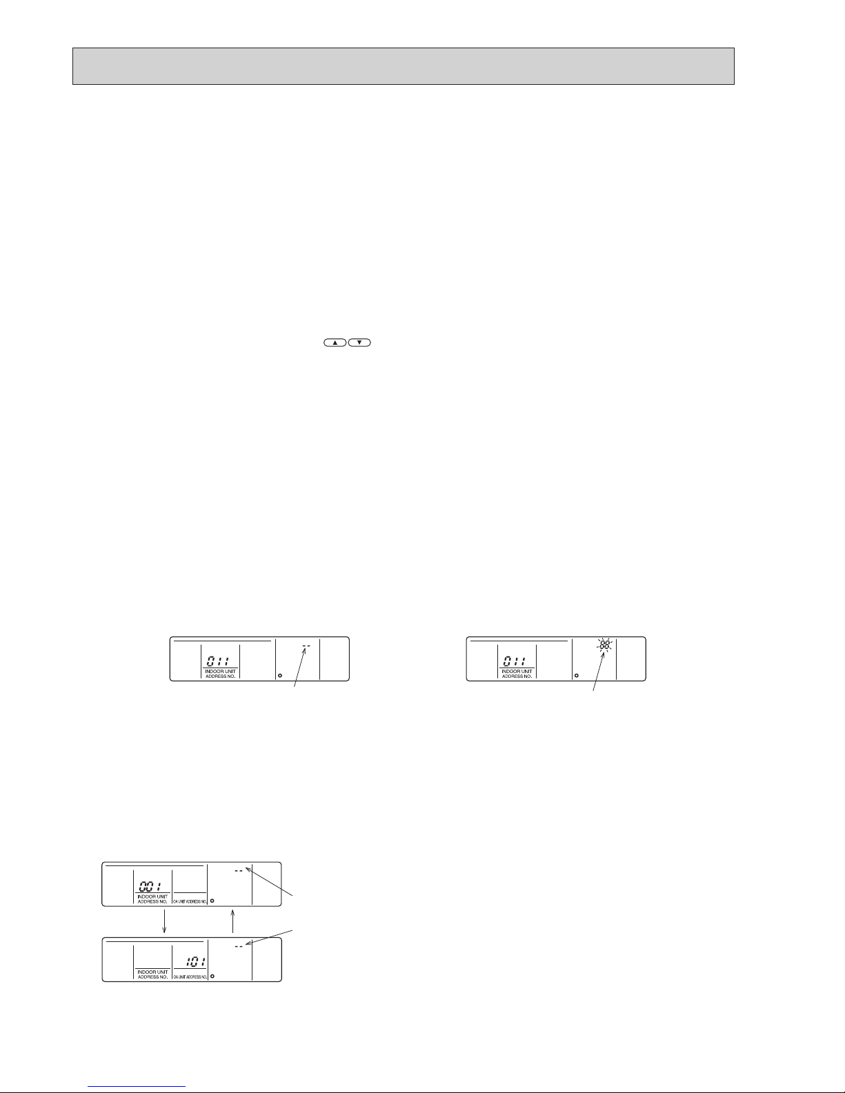
34
(alternating
display)
"--" will appear in the unit type display location when an address has
been cleared normally.
"88" will appear in the unit type display location when an abnormality
has occurred during clearing.
(2) Address check: Refer to section (1) regarding address entry.
a) In making group settings:
•Turnofftheremotecontroller:Presstheremotecontroller'sON/OFFbuttontostopoperation(theindicatorlightwillgooff).
•Locate theindoorunitaddress display mode:Pressthe FILTERandk buttons on the remote controller simultaneously
and hold for 2 seconds.
•Displayindoorunitaddress:Theenteredindoorunitsaddressandtypewillbedisplayedeachtimethebuttonispressed.
* When 1 entry is made, only 1 address will be displayed no matter how many times the w button is pressed.
•Returning to thenormal modeafter completing check: Simultaneouslypress the FILTERand k buttons on the remote
controller and hold for 2 seconds to return to the normal mode.
b) In making paired settings:
•Turnofftheremotecontroller:Presstheremotecontroller'sON/OFFbuttontostopoperation(theindicatorlightwillgooff).
•Putinindoorunitaddressdisplay mode: Press the FILTERand k buttons on the remote controller simultaneously and
hold for 2 seconds.
•Changingtothelinkedoperationunitaddressdisplaystate:Pressthea button on the remote control.
• Displaying the address of the indoor unit to be checked: Change theaddress to that of the indoor unit to bechecked by
pressing the temperature adjustment buttons
.
•Displaying the address of thelinked Lossnay unit:Press the w button to display the addresses of the linked Lossnay and
indoor unit in alternation.
• Displaying the addresses of other entered units: The addresses of the other entered units will be displayed in alternating
fashion after resting the w button again.
• Returning to the normal mode after completing the check: Simultaneously press the FILTER and k buttons on the
remote controller and hold for 2 seconds to return to the normal mode.
(3) Clearing an address: Refer to section (1) regarding the address entry and section (2) regarding checking addresses.
a) In making group settings:
•Turnofftheremotecontroller:Theprocedureisthesameasdescribedina) under (2) Address check.
•Putintheindoorunitaddressdisplaymode:Theprocedureisthesameasdescribedina) under (2) Address check.
•Displayingtheindoorunitaddresstobecleared:Theprocedureisthesameasdescribedina) under (2) Address check.
•Clearingindoorunitaddress:Pressingtheq button on the remote controller twice will clear the address entry of the dis-
played indoor unit, resulting in the display shown in Figure 6.
The display shown in Figure 7 will appear if an abnormality occurs and the entry is not cleared.
Please repeat the clearing procedure.
•
Returning to the normal mode after clearing an address: The procedure is the same as described in a) under (2) Address check.
b) In making paired settings:
•Turnofftheremotecontroller:Theprocedureisthesameasdescribedinb) under (2) Address check.
•Putintotheindoorunitaddressdisplaymode:Theprocedureisthesameasdescribedinb) under (2) Address check.
•Putintothelinkedunitaddressdisplaymode:Theprocedureisthesameasdescribedinb) under (2) Address check.
•DisplaytheaddressoftheLossnayunitortheindoorunittobecleared.
•Deletingtheaddressofa linked indoor unit: Pressing the q button on the remote controller twice will clear the address
entry of the displayed indoor unit, resulting in the display shown in Figure 8.
•Returningtothenormalmodeafterclearinganaddress:Theprocedureissameasb) in (2) Address check.
Figure 7. Display when an abnormality has
occurred during clearing
Figure 6. Display after address has been
cleared normally
Figure 8. Display after address has been cleared normally
"88" will appear in the room temperature display location.
"--" will appear in the room temperature
display location.
OCH632A

35
7-3. REFRIGERANT SYSTEM DIAGRAM
PUMY-P112VKM3(-BS) PUMY-P125VKM3(-BS) PUMY-P140VKM3(-BS)
PUMY-P112YKM3(-BS) PUMY-P125YKM3(-BS) PUMY-P140YKM3(-BS)
PUMY-P112YKME3(-BS) PUMY-P125YKME3(-BS) PUMY-P140YKME3(-BS)
LEV-A
LEV-B
HIC
Solenoid
valve (SV1)
High pressure
sensor
(63HS)
High pressure
switch (63H)
Low pressure
sensor(63LS)
Oil separator
Service port
Strainer
Distributor
Compressor
Refrigerant piping specifications <dimensions of flared connector>
Capillary tube for oil separator : [2.5 o [0.8 o L1000
Capacity
Item
Liquid piping
Gas piping
P15, P20, P25, P32, P40, P50
P63, P80, P100,
P125, P140
P112, P125, P140
Indoor unit
Outdoor unit
[6.35 <1/4>
[9.52 <3/8>
[9.52 <3/8>
[12.7 <1/2>
[15.88 <5/8>
[15.88 <5/8>
Thermistor (TH4)
<
Compressor
>
Thermistor (TH7)
<Ambient>
<Outdoor liquid pipe>
Thermistor (TH3)
Unit: mm <in>
Ball valve
Strainer
Refrigerant Gas pipe
4-way valve
Check valve
<Low pressure>
Thermistor (TH6)
<Suction pipe>
Check valve
<High pressure>
Strainer
Strainer
Strainer
Strainer
Thermistor (TH2)
<HIC pipe>
Refrigerant
Liquid pipe
Stop valve
Service port
Capillary
tube
Accumulator
Strainer
Refrigerant flow in cooling
Refrigerant flow in heating
Note:
When connecting the CONNECTION KIT (PAC-LV11M-J) and an M-series indoor unit, refer to the installation manual for
the CONNECTION KIT.
OCH632A
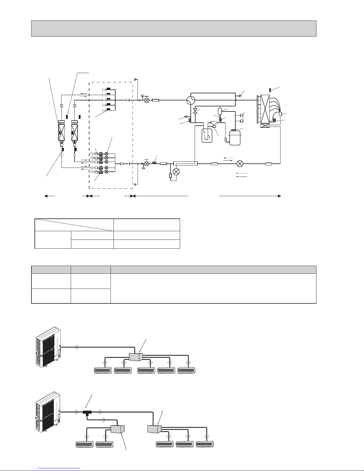
36
Capillary
tube
E
D
C
B
A
Strainer
#100
Condenser / evaporator
temperature thermistor
(TH5 or RT12)
Pipe temperature
thermistor / liquid
(TH2 or RT13)
Strainer
#100
Indoor units Branch box
Outdoor unit
Thermistor (TH-A–E)
(Gas pipe temperature)
LEV A–E
(Linear expansion valve)
Room temperature
thermistor (TH1 or RT11)
PAC-MK51/52BC(B)
PAC-MK31/32BC(B)
Branch box
Capillary tube behind LEV
(in cooling mode)
([4 o [3.0 o L130) o 5
([4 o [3.0 o L130) o 3
Unit: mm
LEV-A
LEV- B
HIC
Solenoid
valve (SV1)
High pressure
sensor (63HS)
High pressure
switch (63H)
Low pressure
sensor(63LS)
Oil separator
Service port
Strainer
Distributor
Compressor
Thermistor (TH4)
<Compressor>
Thermistor (TH7)
<Ambient>
<Outdoor liquid pipe>
Thermistor (TH3)
Ball valve
Strainer
4-way valve
Check valve
<Low pressure>
Thermistor (TH6)
<Suction pipe>
Check valve
<High pressure>
Strainer
Strainer
Strainer
Strainer
Thermistor (TH2)
<HIC pipe>
Stop valve
Service port
Capillary
tube
Accumulator
Strainer
Refrigerant flow in cooling
Refrigerant flow in heating
7-4. REFRIGERANT SYSTEM DIAGRAM (WHEN USING BRANCH BOX)
Piping connection size
■Incaseofusing2-branchboxes
A
B B B B B
Branch box
A
A
A
B B
B B B
2 branches pipe (joint)
: optional parts
Branch box #1
Branch box #2
■Incaseofusing1-branchbox
Flare connection employed (No brazing)
A
B
Liquid (mm) {9.52
Gas (mm) {15.88
The pipe connection size differs according to the type and capacity of indoor units.
Match the piping connection size of branch box with indoor unit.
If the piping connection size of branch box does not match the piping connection size
of indoor unit, use optional different-diameter (deformed) joints to the branch box side.
(Connect deformed joint directly to the branch box side.)
■Installationprocedure(2branchpipe(joint))
Refer to the installation manuals of
MSDD-50AR-E and MSDD-50BR-E.
OCH632A

37
Indoor unit type
Pipe size (mm)
(kW)
Liquid
Gas
22
[6.35
[9.52
25
[6.35
[9.52
35
[6.35
[9.52
50
[6.35
[12.7
60
[6.35
[15.88
71
[9.52
[15.88
15
[6.35
[9.52
18
[6.35
[9.52
20
[6.35
[9.52
42
[6.35
[9.52
■Pipesize(Branchbox-Indoorunit)ForMorSseriesIndoorunit
Indoor unit type
Pipe size
(mm)
(kW)
Liquid
Gas
35
[6.35
[12.7
50
[6.35
[12.7
60
[9.52
[15.88
71
[9.52
[15.88
100
[9.52
[15.88
■ Pipe size (Branch box-Indoor unit) For P series Indoor unit
Pipe size
(mm)
Liquid
Gas
[9.52
[15.88
■ Pipe size (Branch box-Indoor unit) For Cylinder unit and Hydrobox
When using 35, 50 type indoor unit of P series, use the flare nut (for R410A) attached to the indoor unit.
Do not use the flare nut (for R407C) in the indoor unit accessory. If it is used, a gas leakage or even a pipe extraction may occur.
For liquid
For gas
[9.52 mm
[15.88 mm
A UNIT
B UNIT
C UNIT
D UNIT
E UNIT
Liquid pipe
Gas pipe
Liquid pipe
Gas pipe
Liquid pipe
Gas pipe
Liquid pipe
Gas pipe
Liquid pipe
Gas pipe
[6.35 mm
[9.52 mm
[6.35 mm
[9.52 mm
[6.35 mm
[9.52 mm
[6.35 mm
[9.52 mm
[6.35 mm
[12.7 mm
* 3- branch type is only for A, B, and C unit.
*
*
*
[6.35mm
[9.52mm
[12.7mm
[15.88mm
[19.05mm
Conversion formula
1/4 inch
3/8 inch
1/2 inch
5/8 inch
3/4 inch
(1) Valve size for outdoor unit
(2) Valve size for branch unit
Different-diameter joint (optional parts)
Fig.7-1
Fig.7-2
MAC-A454JP
MAC-A455JP
MAC-A456JP
PAC-493PI
PAC-SG76RJ-E
PAC-SG78RJB-E
PAC-SG79RJB-E
PAC-SG80RJB-E
PAC-SG77RJB-E
PAC-SG76RJB-E
{9.52 → {12.7
{12.7 → {9.52
{12.7 → {15.88
{6.35 → {9.52
{9.52 → {15.88
{9.52 → {12.7
{12.7 → {9.52
{12.7 → {15.88
{6.35 → {9.52
{9.52 → {15.88
{9.52
{12.7
{12.7
{6.35
{9.52
{9.52
{12.7
{12.7
{6.35
{9.52
{12.7
{9.52
{15.88
{9.52
{15.88
{12.7
{9.52
{15.88
{9.52
{15.88
Connected pipes diameter
mm
Diameter AmmDiameter B
mm
Model name
A B
Type
Flare
(Fig.7-1)
Braze
(Fig.7-2)
A (Outside)
B (Inside)
OCH632A

38
7-5. SYSTEM CONTROL
7-5-1. Example for the System
•Exampleforwiringcontrolcables,wiringmethodandaddresssetting,permissiblelengths, andtheprohibiteditemsarelisted
in the standard system with detailed explanation.
A. Example of a M-NET remote controller system (address setting is necessary.)
Example of wiring control cables Wiring Method and Address Setting
•1
M-NET
remote controller for
each
M-NET control
indoor unit.
•Thereisnoneedforsetting
the 100 position on the M-NET
remote controller.
1. Standard operation
2. Operation using 2 M-NET remote controllers
•Using2M-NETremote
controllers for each M-NET
control indoor unit.
a. Use feed wiring to connect terminals M1 and M2 on
transmission cable block (TB3) for the outdoor unit
(OC) to terminals M1 and M2 on the transmission
cable block (TB5) of each M-NET control indoor unit
(M-IC). Use non-polarized 2-core wire.
b.
Connect terminals M1 and M2 on transmission cable
terminal block (TB5) for each indoor unit with the terminal block (TB6) for M-NET the remote controller (M-NET
RC).
c. Set the address setting switch (on outdoor unit P.C.B)
as shown below.
3. Group operation
•MultipleM-NETcontrolindoor
units operated together by 1
M-NET remote controller
a. Same as above a
b. Same as above b
c. Set address switch (on outdoor unit P.C.B) as
shown below.
a. Same as above a
b. Connect terminals M1 and M2 on transmission cable termi-
nal block (TB5) of the M-IC main unit with the most recent
address within the same M-NET control indoor unit (M-IC)
group to terminal block (TB6) on the M-NET remote controller.
c. Set the address setting switch (on outdoor unit P.C.B) as
shown below.
d. Use the M-NET control indoor unit (M-IC) within the
group with the most functions as the M-IC (Main) unit
.
Combinations of 1 through 3 above are possible.
TB5
TB15
(01)
(101)
M-IC(Main)
TB3
TB7
(51)
OC
TB5
TB15
(02)
M-IC(Sub)
M-NET RC
1 2
A B
M1M2
S
M1M2
S
M1M2
S
1 2
M1M2
S
Group A
TB5
TB15
(01)
(101)
M-NET RC
(Main)
(151)
M-IC
TB3
TB7
(51)
OC
TB5
TB15
(02)
M-IC
M-NET RC
(Sub)
(102)
M-NET RC
(Main)
(152)
M-NET RC
(Sub)
1 2
M1M2
S
M1M2
S
M1M2
S
1 2
M1M2
S
A B A B A B A B
TB5
1 2
TB15
(01)
(101)
M-IC
A B
M1M2
TB3
S
TB7
(51)
OC
L
1
L3
L2
TB5
TB15
(02)
M-IC
M-NET RC
(102)
M-NET RC
l1
l2
M1M2
S
M1M2
S
1 2
M1M2
S
A B
Unit Range Setting Method
M-NET control
indoor unit (M-IC)
001 to 050 —
Outdoor unit (OC) 051 to 100
Use the smallest address of all
the indoor unit plus 50.
M-NET Remote
controller (M-NET RC)
101 to 150 Indoor unit address plus 100
Unit Range Setting Method
M-NET control
indoor unit (M-IC)
001 to 050 —
Outdoor unit (OC)
051 to 100
Use the smallest address of all
the indoor units plus 50.
Main M-NET
Remote Controller
(M-NET RC)
101 to 150
Indoor unit address plus 100
Sub M-NET
Remote Controller
(M-NET RC)
151 to 200
Indoor unit address plus 150
Unit Range Setting Method
M-
IC (Main) 001 to 050
Use the smallest address within
the same group of M-NET control
indoor units.
M-
IC (Sub) 001 to 050
Use an address, other than that of
the M-IC (Main) from among the units
within the same group of indoor units.
This must be in sequence with the
M-IC (Main).
Outdoor unit
051 to 100
Use the smallest address of all the
M-NET control indoor units plus 50.
Main M-NET
Remote Controller
(M-NET RC)
101 to 150
Set at an M-IC (Main) address
within the same group plus 100.
OCH632A

39
• Name, Symbol and the Maximum Remote controller Units for Connection
Permissible Lengths Prohibited items
Longest transmission cable length
(1.25 mm²)
L
1 + L2, L3 + L1 [ 200 m
M-NET Remote controller cable length
1. If 0.5 to 1.25 mm²
R
1, R2 [10 m
2. If the length exceeds 10 m, the
exceeding section should be 1.25
mm² and that section should be
a value within the total extension length of the transmission
cable and maximum transmission cable length. (L
3)
Same as above
Same as above
1 Use the
M-NET control
indoor unit (M-IC)
address plus 150 as
the sub
M-NET
remote
controller address. In
this case, it should be
152.
2 3 or more
M-NET
remote controllers
(
M-NET
RC) cannot be
connected to 1 M-NET
control indoor unit.
1 The
M-NET
remote
controller address is
the M-NET control
indoor unit main
address plus 100. In
this case, it should be
101.
•
M-NET remote controller (M-NET RC) and MA remote controller (MA RC) cannot be
used together.
•DonotconnectanythingwithTB15ofM-NET control indoor unit (M-IC).
Name Symbol Maximum units for connection
Outdoor unit OC —
M-NET control
Indoor unit
M-IC
1 OC unit can be connected to 1 to 9 (P112)/1 to 10 (P125)/1 to 12 (P140) M-IC units
M-NET remote
controller
M-NET RC
Maximum 2
M-NET
RC for 1 indoor unit, Maximum 12
M-NET
RC for 1 OC
NO
TB5
TB15
(01)
(101)
M-IC
TB3
TB7
(51)
OC
TB5
TB15
(02)
M-NET RC
TB15
MA-RC
1 2
A B
M1M2
S
M1M2
S
M1M2
S
1 2
M1M2
S
A B
M-IC
NO
NO
TB5
TB15
(01)
(101)
M-NET RC
(Main)
(151)
M-IC
TB3
TB7
(51)
OC
TB5
TB15
(02)
M-IC
M-NET RC
(Sub)
(102)
M-NET RC
(Main)
(104)
2M-NET RC
1 2
A B
M1M2
S
M1M2
S
M1M2
S
1 2
M1M2
S
A B A B A BA B
(103)
1M-NET RC
(Sub)
NO
TB5
TB15
(01)
(102)
M-IC(Main)
TB3
TB7
(51)
OC
TB5
TB15
(02)
M-IC(Sub)
1M-NET RC
1 2
A B
M1M2
S
M1M2
S
M1M2
S
1 2
M1M2
S
OCH632A

40
B. Example of a group operation system with 2 or more outdoor units and a M-NET remote controller.
(Address settings are necessary.)
Examples of Transmission Cable WiringWiring Method Address Settings
a. Always use shielded wire when making connections between the outdoor unit (OC) and the M-NET control indoor unit
(M-IC), as well for all OC-OC, and IC-IC wiring intervals.
b. Use feed wiring to connect terminals M1 and M2 and the ground terminal on the transmission cable terminal block (TB3)
of each outdoor unit (OC) to terminals M1 and M2 on the terminal S on the transmission cable terminal block of the
M-NET control indoor unit (M-IC).
c.
Connect terminals M1 and M2 on the transmission cable terminal block of the M-NET control indoor unit (M-IC) that
has the most recent address within the same group to the terminal block on the M-NET remote controller (M-NET RC).
d. Connect together terminals M1, M2 and terminal S on the terminal block for centralized control (TB7) for the outdoor
unit (OC).
e. DO NOT change the jumper connector CN41 on outdoor multi controller circuit board.
f. The earth processing of S terminal for the centralized control terminal block (TB7) is unnecessary. Connect the termi-
nal S on the power supply unit with the earth.
g. Set the address setting switch as follows.
h. The group setting operations among the multiple M-NET control indoor units is done by the M-NET remote controller
(M-NET RC) after the electrical power has been turned on.
Unit Range Setting Method
M-IC (Main) 01 to 50
Use the smallest address within the same group of M-NET control indoor units.
M-IC (Sub) 01 to 50
Use an address, other than the M-IC (Main) in the same group of M-NET control
indoor units. This must be in sequence with the M-IC (Main).
Outdoor Unit 51 to 100
Use the smallest address of all the M-NET control indoor units plus 50.
Theaddressautomaticallybecomes“100”ifitissetas“01–50”.
Main M-NET Remote Controller
101 to 150
Set at an M-IC (Main) address within the same group plus 100.
Sub M-NET Remote Controller
151 to 200
Set at an M-IC (Main) address within the same group plus 150.
MA Remote Controller —
Address setting is not necessary. (Main/sub setting is necessary.)
A
B
C
E
D
TB7
TB3
M-IC
(51)
TB5
M-NET RC
(01)
M-IC
TB5
(03)
M-IC
TB5
(02)
M-IC
TB5
(04)
M-IC
TB5
(05)
TB5
(07)
IC
TB5
(06)
L2
L1
(101)
(105)
(104)
(155)
OC
TB7
(53)
OC
3
Power Supply
Unit
System
controller
L3
L6
L7
L4
L5
2
4
1
A : Group
B : Group
C : Group
D : Shielded Wire
E : Sub M-NET Remote Controller
( ): Address example
r
r
r
r
M1M2
S
M1M2
S
M1M2
S
M1M2
S
A BA BA B
M1M2
S
M1M2
S
M1M2
S
S
M1M2
S
TB3
M1M2
S
M1M2
S
A B
M1M2
M1M2
S
M1M2
S
NO
M-IC
M-NET RC
M-NET RC
M-NET RC
OCH632A
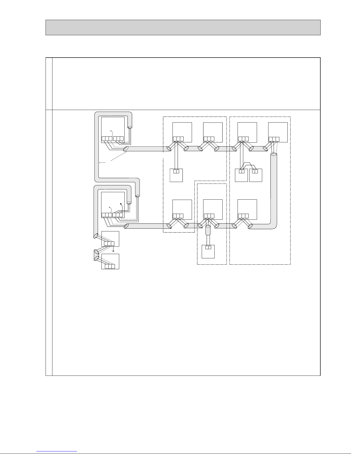
41
• Name, Symbol, and the Maximum Units for Connection
Permissible Length
Prohibited items
•Longestlengthviaoutdoorunits:L1+L2+L3+L4, L1+L2+L3+L5, L1+L2+L6+L7 [ 500 meters (1.25 mm²)
•Longesttransmissioncablelength:L
1, L3+L4, L3+L5, L2+L6, L7 [ 200 meters (1.25 mm²)
•M-NET Remote controller cable length : R
1,R2, R2+R3, R4 [ 10 m (0.5 to 1.25 mm²)
If the length exceeds 10 m, use a 1.25 mm² shielded wire. The length of this section (L
8)
should be included in the calculation of the maximum length and overall length.
•Neverconnecttogethertheterminalblocks(TB5)fortransmissionwiresforM-NETcontrolindoorunits(M-IC)thathave
been connected to different outdoor units (OC).
•Setalladdressestoensurethattheyarenotoverlapped.
•M-NETremotecontrollerandMAremotecontroller cannot be connectedwiththeM-NETcontrol indoorunitofthesame
group wiring together.
A
B
C
E
D
M-IC
(51)
TB5
M-NET RC
(01)
TB5
(03)
M-IC
TB5
(02)
TB5
(04)
M-IC
TB5
(05)
TB5
(07)
M-IC
TB5
(06)
(101)
(105)
(104)
(155)
OC
(53)
OC
Power Supply
Unit
A : Group
B : Group
C : Group
D : Shielded Wire
E : Sub M-NET Remote Controller
( ): Address example
TB7TB3
M1M2
S
TB7
M1M2
S
M1M2
S
TB3
M1M2
S
M1M2
S
M1M2
S
M1M2
S
M1M2
S
M1M2
S
M1M2
S
M1M2
S
M1M2
S
A B A B A B
A B
M1M2
S
System
controller
NO
NO
M-IC
M-IC
M-IC
M-NET RC
M-NET RC
M-NET RC
OCH632A

42
C. Example of a MA remote controller system (address setting is not necessary.)
NOTE : In the case of same group operation, need to set the address that is only main M-NET control indoor unit.
Example of wiring control cables Wiring Method and Address Setting
•1MAremotecontrollerfor
each indoor unit.
1. Standard operation
2. Operation using 2 remote controllers
•Using2MAremotecontrollers for each M-NET control
indoor unit.
a. Use feed wiring to connect terminals M1 and M2
on transmission cable block (TB3) for the outdoor
unit (OC) to terminals M1 and M2 on the transmission cable block (TB5) of each M-NET control
indoor unit (M-IC). Use non-polarized 2-core wire.
b. Connect terminals 1 and 2 on transmission cable
terminal block (TB15) for each M-NET control
indoor unit with the terminal block for the MA
remote controller (MA-RC).
3. Group operation
•Multipleindoorunitsoperated
together by 1 MA remote controller.
a. The same as above a
b. The same as above b
c. In the case of using 2 remote controllers, connect
terminals 1 and 2 on transmission cable terminal
block (TB15) for each indoor unit with the terminal
block for 2 MA remote controllers.
· Set either one of the MA remote controllers to
"sub remote controller".
Refer to the installation manual of MA remote con-
troller.
a. The same as above a
b. The same as above b
c. In the case of group operation using MA remote con-
troller (MA-RC), connect terminals 1 and 2 on transmission cable terminal block (TB15) of each M-NET
control indoor unit. Use non-polarized 2-core wire.
d. In the case of same group operation, need to set
the address that is only main M-NET control indoor
unit. Please set the smallest address within number
01–50 of the M-NET control indoor unit with the
most functions in the same group.
Combinations of 1 through 3 above are possible.
MA-RC
TB5
TB15
(00)
M-IC
TB3
TB7
(00)
OC
TB5
TB15
(00)
M-IC
r7
r8
M1 M2SM1 M2
S
M1 M2
S
A B
1 2
M1 M2
S
1 2
MA-RC
(Main)
TB5
TB15
(00)
M-IC
TB3
TB7
(00)
OC
TB5
TB15
(00)
M-IC
MA-RC
(Sub)
MA-RC
r3
r4
r5
M1M2SM1M2
S
1 2
M1M2
S
1 2
M1M2
S
A B
A B
A B
TB5
TB15
(00)
M-IC
TB3
TB7
(00)
OC
L
1 L2
TB5
TB15
(00)
M-IC
MA-RCMA-RC
r1
r2
M1 M2SM1 M2
S
1 2
M1 M2
S
1 2
M1 M2
S
A B
A B
OCH632A

43
Permissible Lengths Prohibited items
Longest transmission cable length:
L
1 + L2 [ 200 m (1.25 mm²)
MA remote controller cable length:
R
1, R2 [ 200 m (0.3 to 1.25 mm²)
Longest transmission cable length:
L
1 + L2 [ 200 m (1.25 mm²)
MA remote controller cable length:
R
3 +R4, R5 [ 200 m
(0.3 to 1.25 mm²)
Longest transmission cable length:
L
1 + L2 [ 200 m (1.25 mm²)
MA remote controller cable length:
R
7 +R8 [ 200 m (0.3 to 1.25 mm²)
The MA remote controller and the
M-NET remote controller cannot be
used together with the M-NET control indoor unit of the same group.
3 MA remote controllers or more
cannot be connected with the
M-NET control indoor unit of the
same group.
The second MA remote controller is connected with the terminal block (TB15)
for the MA remote controller of the same
M-NET control indoor unit (M-IC) as the
first MA remote control.
NO
MA-RC
(00)
M-IC(00)
OC
MA-RC
(00)
M-IC
TB5
1 2
TB15
A B
M1 M2
TB3
S
TB7
TB5
TB15
M1 M2
S
M1 M2
S
1 2
M1 M2
S
A B
MA-RC
(Main)
TB5
TB15
(00)
M-IC
TB3
TB7
(00)
OC
TB5
TB15
(00)
M-IC
MA-RC
(Sub)
MA-RC
(Main)
MA-RC
(Sub)
MA-RC
(Main)
1 2
M1 M2
S
M1 M2
S
M1 M2
S
A B A B A B A B A B
1 2
M1 M2
S
NO
NO
TB5
TB15
TB3
TB7
(00)
OC
TB5
TB15
(00)
M-IC
MA-RCMA-RCM-NET RC
1 2
A B
M1 M2
S
M1 M2
S
M1 M2
S
1 2
M1 M2
S
A BA B
(00)
M-IC
(00)
OCH632A

44
D. Example of a group operation with 2 or more outdoor units and a MA remote controller.
(Address settings are necessary.)
Examples of Transmission Cable Wiring
Wiring Method Address Settings
a. Always use shielded wire when making connections between the outdoor unit (OC) and the M-NET control indoor unit
(M-IC), as well for all OC-OC, and IC-IC wiring intervals.
b.
Use feed wiring to connect terminals M1 and M2 and the ground terminal on the transmission cable terminal block (TB3)
of each outdoor unit (OC) to terminals M1 and M2 on the terminal S on the transmission cable terminal block of the
M-NET control
indoor unit (M-IC).
c.
Connect terminals M1 and M2 on the transmission cable terminal block of the M-NET control indoor unit (M-IC) that
has the most recent address within the same group to the terminal block on the M-NET remote controller (M-NET RC).
d.
Connect together terminals M1, M2 and terminal S on the terminal block for centralized control (TB7) for the outdoor unit (OC).
e. DO NOT change the jumper connector CN41 on outdoor multi controller circuit board.
f. The earth processing of S terminal for the centralized control terminal block (TB7) is unnecessary. Connect the termi-
nal S on the power supply unit with the earth.
g. Set the address setting switch as follows.
h. The group setting operations among the multiple M-NET control indoor units is done by the M-NET remote controller
(M-NET RC) after the electrical power has been turned on.
i. When connecting PWFY unit
•ForPWFYseries,donotsetupgroupconnectionwithotherindoorunits.
•LOSSNAYisnotavailableforusewithPWFYseries.
•UseaWMAremotecontrollerforoperationofPWFYseries.
For more details, refer to the service manual for PWFY series.
Unit Range Setting Method
M-IC (Main) 01 to 50
Use the smallest address within the same group of indoor units.
M-IC (Sub) 01 to 50
Use an address, other than the M-IC (Main) in the same group of M-NET
indoor units. This must be in sequence with the M-IC (Main).
Outdoor Unit 51 to 100
Use the smallest address of all the indoor units plus 50.
Theaddressautomaticallybecomes“100”ifitissetas“01–50”.
Main M-NET Remote Controller
101 to 150
Set at an M-IC (Main) address within the same group plus 100.
Sub M-NET Remote Controller
151 to 200
Set at an M-IC (Main) address within the same group plus 150.
MA Remote Controller —
Address setting is not necessary. (Main/sub setting is necessary.)
A
B
C
E
D
TB7
M-IC
(51)
TB15 TB15
TB15
MA-RC
(01)
M-IC
TB5
(03)
M-IC
TB5TB5
(02)
M-IC
TB5
(04)
M-IC
(05)
M-IC
(07)
M-IC
(06)
L1
MA-RC
MA-RC
MA-RC
OC
(53)
OC
1
m4
3
Power Supply
Unit
L3
L7
L4
m3
1
1
2
2
TB3
A : Group
B : Group
C : Group
D : Shielded Wire
E : Sub MA Remote Controller
( ): Address example
m
m
m
m
m
m
M1M2SM1M2
S
TB7
M1M2
S
M1M2
S
TB3
M1M2
S
M1M2
S
M1M2
S
M1M2
S
M1M2
S
A B
1 2
1 2
M1M2
S
1 2
1 2
TB15
TB5
M1M2
S
1 2
TB15
TB5
M1M2
S
1 2
A B A B
TB15
TB5
M1M2
S
1 2
TB15
A B
L2
L6
System
controller
NO
OCH632A
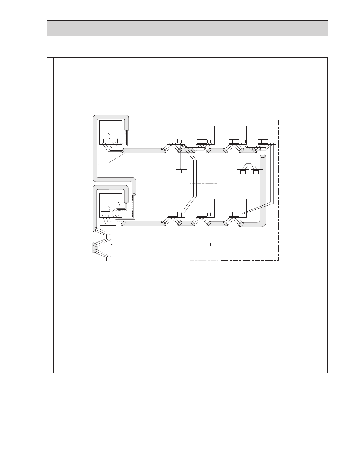
45
• Name, Symbol, and the Maximum Units for Connection
Permissible LengthProhibited items
•Neverconnecttogethertheterminalblocks(TB5)fortransmissionwiresforM-NETcontrolindoorunits(M-IC)thathave
been connected to different outdoor units (OC).
•M-NETremotecontrollerandMAremotecontrollercannotbeconnectedwiththeM-NETcontrolindoorunitofthesame
group wiring together.
Longest length via outdoor unit (M-NET cable): L1+L2+L3+L4 and L1+L2+L6+L7 [ 500 m (1.25 E more)
Longest transmission cable length (M-NET cable): L1 and L3+L4 and L2+L6 and L7 [ 200 m (1.25 E or more)
MA Remote controller cable length: m1 and m1+m2+m3 and m1+m2+m3+m4
[ 200 m (0.3 to 1.25 E)
A : Group
B : Group
C : Group
D : Shielded Wire
E : Sub MA Remote Controller
( ): Address example
A
B
C
E
M-IC
(51)
TB5 TB15 TB15
TB15 TB15
MA-RC
(01)
M-IC
TB5
(03)
M-IC
TB5
(02)
M-IC
TB5
(04)
M-IC
(05)
M-IC
TB5
(07)
M-IC
(06)
MA-RC
MA-RC
MA-RC
OC
(53)
OC
Power Supply
Unit
TB7TB3
M1M2
S
M1M2
S
TB7
M1M2
S
M1M2
S
TB3
M1M2
S
M1M2
S
M1M2
S
M1M2
S
M1M2
S
M1M2
S
M1M2
S
A B
A B
A B A B
1 2
1 2
1 2
1 2
1 2
TB15TB5
M1M2
S
1 2
TB15TB5
M1M2
S
1 2
TB15
D
System
controller
NO
NO
OCH632A

46
E. Example of a system using Branch Box and A-Control indoor unit
Examples of Transmission Cable WiringWiring Method Address Settings
a. Always use shielded wire when making connections between the outdoor unit (OC) and the Branch Box, as well for
all OC-OC wiring intervals.
b. Use feed wiring to connect terminals M1 and M2 and the ground terminal on the transmission cable terminal block (TB3)
of each outdoor unit (OC) to terminals M1 and M2 on the terminal S on the transmission cable terminal block (TB5)
of the Branch Box.
c. Connect terminals 1 and 2 on the transmission cable terminal block (TB5/TB15) of the A-control indoor unit (A-IC), to
the terminal block on the MA remote controller (MA-RC).
d. Connect together terminals M1, M2 and terminal S on the terminal block for centralized control (TB7) for the outdoor
unit (OC).
e. DO NOT change the jumper connector CN41 on outdoor multi controller circuit board.
f. The earth processing of S terminal for the centralized control terminal block (TB7) is unnecessary. Connect the termi-
nal S on the power supply unit to the earth.
g. Set the address setting switch as follows.
Unit Range Setting Method
A-IC 01 to 50
According to the set address of connected Branch Box, set the A-IC addresses
sequentially by SW1 on Branch Box.
(For example, when setting the Branch Box address to 01, A-IC addresses set
02,03,04, and 05. )
Branch Box 01 to 50
Use a number within the range 1–50, but it should not make the highest
address of connected A-IC exceed 50.
Outdoor Unit 51 to 100
Use the smallest address of all the Branch Box plus 50.
Theaddressautomaticallybecomes“100”ifitissetas“01–50”.
MA Remote Controller
-
Address setting is not necessary.
A : Shielded wire
( ): Address example
TB7
TB3
(51)
L
3
L1
OC
TB7
(53)
OC
Power Supply
Unit
System
controller
L
4
L5
M1M2
S
M1M2
S
S
M1M2
S
TB3
M1M2
S
M1M2
S
M1M2
TB3A
A-IC
(01)
(02)
(03)
(04)
MA-RC
WL-RC
WL-RC
WL-RC
(05)
(06)
(07)
(08)
S1
S2
S3
TB
S1
S2
TB5/TB15
12A
B
A
B
A
B
A
B
1
2
1
2
1
2
S3
S1
S2
S3
S1
S2
S3
S1
S2
S3
S1
S2
S3
TB
S1
S2
S3
TB
S1
S2
S3
TB
S1
S2
S3
TB3B
S1
S2
S3
TB3C
S1
S2
S3
TB3D
S1
S2
S3
TB3E
S1
S2
S3
TB3A
S1
S2
S3
TB3B
S1
S2
S3
TB3C
S1
S2
S3
M1
M2
S
TB5
M1
M2
S
TB5
L
(01)
(06)
2
Branch Box
A
A
Branch Box
A
A-IC
A-IC
A-IC
A-IC
A-IC
A-IC
A-IC
MA-RC
MA-RC
MA-RC
WL-RC
TB5/TB15
TB5/TB15
TB5/TB15
TB
TB
TB
TB
L
6
m
1
OCH632A
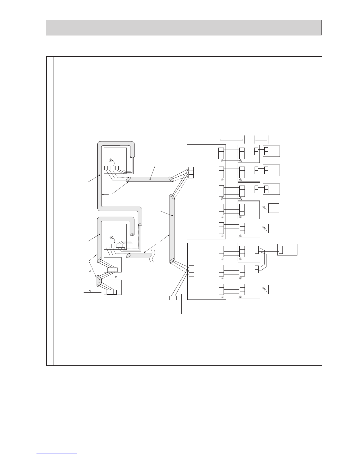
47
• Name, Symbol, and the Maximum Units for Connection
Permissible LengthProhibited items
Longest length via outdoor unit (M-NET cable): L1+L2+L3+L4+L5 [ 500 m (1.25 E
or more)]
Longest transmission cable length (M-NET cable): L1+L2, L3+L4, L5 [ 200 m (1.25 E
or more) ]
Longest transmission cable length (A-Control cable): L6 [ 25 m (1.5 E
) ]
Remote controller cable length: m1 [ 200 m (0.3 to 1.25 E
) ]
TB7
TB3
(51)
L
3
L1
OC
TB7
(53)
OC
Power Supply
Unit
System
controller
L
4
L5
M1M2
S
M1M2
S
S
M1M2
S
TB3
M1M2
S
M1M2
S
M1M2
TB3A
A-IC
(01)
(02)
(03)
(04)
MA-RC
WL-RC
WL-RC
WL-RC
M-NET
RC
(101)
(05)
(06)
(07)
(08)
S1
S2
S3
TB
S1
S2
TB5/TB15
12A
B
A
B
A
B
A
A B
B
1
2
1
2
1
2
1
2
S3
TB
S1
S2
S3
TB
S1
S2
S3
TB
S1
S2
S3
TB
S1
S2
S3
TB
S1
S2
S3
TB
S1
S2
S3
TB
S1
S2
S3
TB3B
S1
S2
S3
TB3C
S1
S2
S3
TB3D
S1
S2
S3
TB3E
S1
S2
S3
TB3A
S1
S2
S3
TB3B
S1
S2
S3
TB3C
S1
S2
S3
M1
M2
S
TB5
M1
M2
S
TB5
L
(01)
(06)
2
Branch Box
A
A
Branch Box
A
MA-RC
MA-RC
A-IC
A-IC
A-IC
A-IC
A-IC
A-IC
A-IC
TB5/TB15
TB5/TB15
TB5/TB15
TB5/TB15
m
1
NO
NO
MA-RC
L6
•Pluralindoorunitscannotbeoperatedbyasingleremotecontroller
•Differentrefrigerantsystemscannotbeconnectedtogether.
•M-NETremotecontrollercannotbeconnected.
OCH632A

48
F. Example of a system using Branch Box, A-Control indoor unit, and M-NET Control indoor unit.
Examples of Transmission Cable WiringWiring Method Address Settings
a. Always use shielded wire when making connections between the outdoor unit (OC) and the Branch Box or M-NET
control indoor unit (M-IC), as well for all OC-OC wiring intervals.
b. Use feed wiring to connect terminals M1 and M2 and the ground terminal on the transmission cable terminal block (TB3)
of each outdoor unit (OC) to terminals M1 and M2 on the terminal S on the transmission cable terminal block (TB5)
of the Branch Box or M-NET control indoor unit (M-IC).
c. Connect terminals 1 and 2 on the transmission cable terminal block (TB5/TB15) of the A-control indoor unit (A-IC) or
M-NET control indoor unit (M-IC), to the terminal block on the MA remote controller (MA-RC).
d. Connect together terminals M1, M2 and terminal S on the terminal block for centralized control (TB7) for the outdoor
unit (OC).
e. DO NOT change the jumper connector CN41 on MULTI controller board.
f. The earth processing of S terminal for the centralized control terminal block (TB7) is unnecessary. Connect the termi-
nal S on the power supply unit to the earth.
g. Set the address setting switch as follows.
Unit Range Setting Method
M-IC 01 to 50
-
A-IC 01 to 50
According to the set address of connected Branch Box, set the A-IC addresses
sequentially by SW1, SW11, SW12 on Branch Box.
(For example, when the Branch Box address is set to 01, set the A-IC
addresses to 01, 02, 03, 04 and 05.)
Branch Box 01 to 50
Use a number within the range 1-50, but it should not make the highest
address of connected A-IC exceed 50.
Outdoor Unit 51 to 100
Use the smallest address of all the Branch Box plus 50.
Theaddressautomaticallybecomes“100”ifitissetas“01–50”.
MA Remote Controller
-
Address setting is not necessary.
TB7
TB3
(51)
L5
L
1
OC
TB7
(53)
OC
L
6
L
7
M1M2
S
M1M2
S
S
M1M2
S
TB3
M1M2
S
M1M2
S
M1M2
TB3A
A-IC
(01)
A-IC
(02)
A-IC
(03)
A-IC
(04)
A-IC
MA-RC
MA-RC
MA-RC
MA-RC
WL-RC
WL-RC
WL-RC
WL-RC
(05)
A-IC
(06)
A-IC
(07)
A-IC
(08)
S1
S2
S3
TB
S1
S2
TB5/TB15
12A
B
A
B
A
B
A
B
1
2
1
2
1
2
S3
TB
S1
S2
S3
TB
S1
S2
S3
TB
S1
S2
S3
TB
S1
S2
S3
TB
S1
S2
S3
TB
S1
S2
S3
TB
S1
S2
S3
TB3B
S1
S2
S3
TB3C
S1
S2
S3
TB3D
S1
S2
S3
TB3E
S1
S2
S3
TB3A
S1
S2
S3
TB3B
S1
S2
S3
TB3C
S1
S2
S3
M1
M2
S
TB5
M1
M2
S
TB5
L
2
A
A
A
M-IC
(09)
M-IC
(10)
MA-RC
MA-RC
TB5
M1
M2
12A
B
A
B
1
2
S
TB5
M1
M2
S
L
3
L
4
Power
Supply
Unit
System
controller
Branch Box
Branch Box
A: Shielded wire
( ): Address example
m
1
TB5/TB15
TB5/TB15
TB15
TB15
TB5/TB15
L
8
OCH632A

49
• Name, Symbol, and the Maximum Units for Connection
Permissible LengthProhibited items
Longest length via outdoor unit (M-NET cable): L1+L2+L3+L4+L5+L6+L7 [500 m (1.25 E
or more)]
Longest transmission cable length (M-NET cable): L1+L2+L3+L4, L5 +L6 and L7 [200 m (1.25 E
or more) ]
Longest transmission cable length (A-Control cable): L8 [25 m (1.5 E
) ]
Remote controller cable length: m1 [200 m (0.3 to 1.25 E
) ]
TB7
TB3
(51)
L5
L
1
OC
TB7
(53)
OC
L
6
L
7
M1M2
S
M1M2
S
S
M1M2
S
TB3
M1M2
S
M1M2
S
M1M2
TB3A
A-IC
(01)
A-IC
(02)
A-IC
(03)
A-IC
(04)
A-IC
MA-RC
MA-RC
MA-RC
MA-RC
WL-RC
WL-RC
(05)
A-IC
(06)
A-IC
(07)
A-IC
(08)
S1
S2
S3
TB
S1
S2
TB5/TB15
12A
B
A
B
A
B
A
B
1
2
1
2
1
2
1
2
MA-RC
A
B
1
2
S3
TB
S1
S2
S3
TB
S1
S2
S3
TB
S1
S2
S3
TB
S1
S2
S3
TB
S1
S2
S3
TB
S1
S2
S3
TB
S1
S2
S3
TB3B
S1
S2
S3
TB3C
S1
S2
S3
TB3D
S1
S2
S3
TB3E
S1
S2
S3
TB3A
S1
S2
S3
TB3B
S1
S2
S3
TB3C
S1
S2
S3
M1
M2
S
TB5
M1
M2
S
TB5
L
2
A
A
A
M-IC
(09)
M-IC
(10)
TB5
M1
M2
1
2
1
2
S
TB5
M1
M2
S
L
3
L
4
Power
Supply
Unit
System
controller
Branch Box
Branch Box
A: Shielded wire
( ): Address example
M-NET
RC
(101)
A B
TB5/TB15
TB5/TB15
TB5/TB15
TB5/TB15
TB5/TB15
TB15
TB15
L
8
NO
NO
NO
m
1
•Pluralindoorunitscannotbeoperatedbyasingleremotecontroller
•Differentrefrigerantsystemscannotbeconnectedtogether.
•M-NETremotecontrollercannotbeconnected.
OCH632A
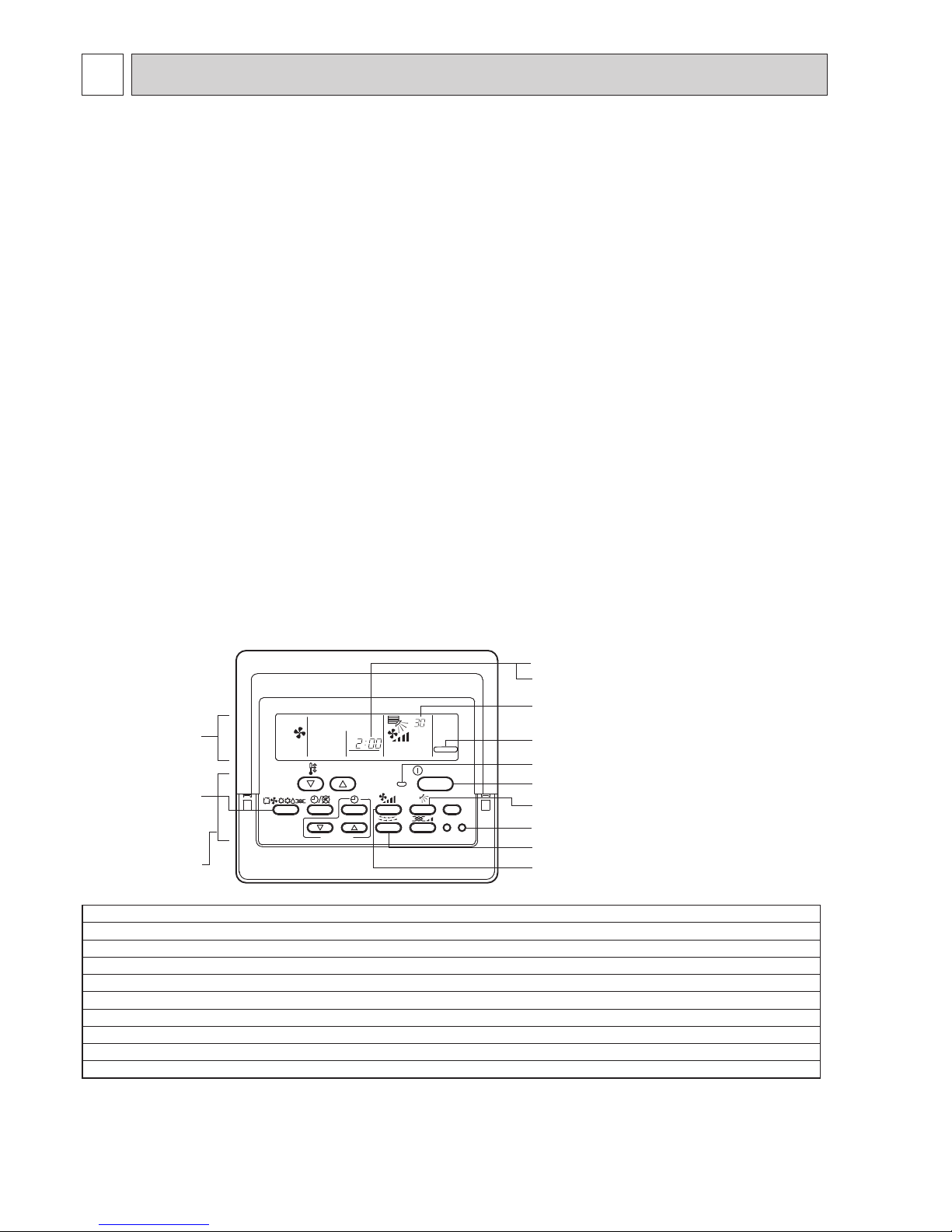
50
8 TROUBLESHOOTING
Notes:
1.Ifcheckcodeappearsonremotecontrollerorremotecontrollermalfunctions,referto“8-1-2.CountermeasuresforErrorDuringRun”.
2.
During test run operation, 2-hour off timer activates automatically and remaining time is on remote controller and test run stops 2 hours later.
3. During test run, the indoor liquid pipe temperature is displayed on remote controller instead of room temperature.
4.
Dependingonamodel,“Thisfunctionisnotavailable”appearswhenairdirectionbuttonispressed.However,thisisnotmalfunction
.
8-1. CHECK POINTS FOR TEST RUN
8-1-1. Procedures before test run
(1) Before a test run, make sure that the following work is completed.
•Installationrelated:
Make sure that the panel of cassette type and electrical wiring are done.
Otherwise electrical functions like auto vane will not operate normally.
•Pipingrelated:
Perform leakage test of refrigerant and drain piping.
Make sure that all joints are perfectly insulated.
Check stop valves on both liquid and gas side for full open.
•Electricalwiringrelated:
Check ground wire, transmission cable, remote controller cable, and power supply cable for secure connection.
Make sure that all switch settings of address or adjustments for special specification systems are correctly settled.
(2) Safety check :
With the insulation tester of 500 V, inspect the insulation resistance.
Do not touch the transmission cable and remote controller cable with the tester.
The resistance should be over 1.0 M". Do not proceed inspection if the resistance is under 1.0 M".
Inspect between the outdoor unit power supply terminal block and ground first, metallic parts like refrigerant pipes or the
electrical box next, then inspect all electrical wiring of outdoor unit, indoor unit, and all linked equipment .
(3) Before operation :
a) Turn the power supply switch of the outdoor unit to on for compressor protection. For a test run, wait at least 12 hours
from this point.
b)Registercontrolsystemsintoremotecontroller(s).NevertouchtheON/OFFswitchoftheremotecontroller(s).Referto“7-2.
SpecialFunctionOperationandSettingsforM-NETRemoteController”asforsettings.InMAremotecontroller(s),this
registration is unnecessary.
(4) More than 12 hours later from power supply to the outdoor unit, turn all power switch to on for the test run. Perform test run
accordingtothe“Operationprocedure”tableofthebottomofthispage.Whiletestrunning,maketestrunreports.
8-1-1-1. Test run for M-NET Remote controller
(M-NET remote controller cannot be connected with a refrigerant system which includes branch box.
)
Whenyoudelivertheunitafterthetestrun,instructtheenduserforproperusageofthesystemusingowners’manual
and the
t
estrunreportyoumadetocertificatenormaloperation.Ifabnormalitiesaredetectedduringtestrun,referto“8-1-2.
CountermeasuresforErrorDuringTestRun”.AsforDIPswitchsettingofoutdoorunit,referto“8-5.INTERNALSWITCH
FUNCTIONTABLE”.
ON/OFF
TEST RUN
°C
1Hr.
FILTER
CHECK TEST
TEMP.
TIMER SET
Check code indicator (see Note 1)
Test run remaining time indicator (see Note 3)
Display panel
(M-NET Remote controller)
ON/OFF button 9
ON/OFF LED (Lights up in operation)
LOUVER button 6
TEST RUN button 2
AIR DIRECTION button 6
FAN SPEED button 5
TEST RUN indicator
Indoor unit liquid pipe temperature indicator
(see Note 4)
(Cooling/Heating)
OPERATION
SWITCH button
3,4
Control panel
Operation procedure
1
Turnonthemainpowersupplyofallunitsatleast12hoursbeforetestrun.”HO”appearsondisplaypanelfor3minutes.
2
12hourslater,pressTESTRUNbuttontwicetoperformtestrun.“TESTRUN“appearsondisplaypanel.
3
Press OPERATION SWITCH button to make sure that air blows out.
4
Select Cooling (or Heating) by OPERATION SWITCH button to make sure that cool (or warm) air blows out.
5
Press Fan speed button to make sure that fan speed is changed by the button.
6
Press AIR DIRECTION button or LOUVER button to make sure that air direction is adjustable (horizontal, downward, upward, and each angle).
7
Check outdoor fans for normal operation.
8
Check interlocked devices (like ventilator) for normal operation, if any. This is the end of test run operation.
9
Press ON/OFF button to stop and cancel test run.
OCH632A

51
F1 F2 F3 F4
unem ecivreS
rosruC
:unem niaM
Test run
Input maintenance info.
Function setting
Check
Self check
F1 F2 F3 F4
Test run menu
Cursor
Service menu:
Test run
Drain pump test run
1
Select "Service" from the Main menu, and press the button.
2
Select "Test run" with the F1 or F2 button, and press the button.
Select "Test run" with the F1
or F2 button, and press the button.
F1 F2 F3 F4
Cool
Pipe
Auto
Switch disp.
Mode Fan
RemainTest run
F1 F2 F3 F4
Remain
Vane
Cool mode: Check the cold air blows out.
Heat mode: Check the heat blows out.
Press the F1
button to go through the operation modes in the order of
"Cool and Heat".
Check the auto vane with the F1
F2 buttons.
Check the operation of the outdoor unit fan, also.
Press the
button to return to “Test run operation”.
Press the
button.
Whenthetestruniscompleted,the“Testrunmenu”screenwillappear.
The test run will automatically stop after 2 hours.
*The function is available only for the model with vanes.
Test run operation
Auto vane check*
Press the button and open the Vane setting screen.
Function buttons
F1 F2 F3 F4
MENU RETURN SELECT ON/OFF
8-1-1-2. Test run for wired remote controller <PAR-31MAA> <PAR-32MAA>
OCH632A

52
8-1-2. Countermeasures for Error During Test Run
•Ifaproblemoccursduringtestrun,acodenumberwillappearontheremotecontroller(orLEDontheoutdoorunit),andthe
air conditioning system will automatically cease operating.
Determine the nature of the abnormality and apply corrective measures.
1 2 3 4 5 6 7 8
[Example]
When the compressor and
SV1 are turned during cooling
operation.
Bit
Indication
1
Compressor
operated
2
52C321S44SV15(SV2)6—
7
—8Always lit
• Self-diagnosis function
The indoor and outdoor units can be diagnosed automatically using the self-diagnosis switch
(SW1) and LED1, LED2 (LED indication) found on the multi-controller of the outdoor unit.
LED indication : Set all contacts of SW1 to OFF.
• During normal operation
The LED indicates the drive state of the controller in the outdoor unit.
Check
code
(2 digits)
Check
code
(4 digits)
Trouble
Detected Unit
Remarks
Indoor Outdoor
Remote
Controller
Ed 0403 Serial communication error
Outdoor unit outdoor multi controller circuit board
– Power circuit board communication trouble
U2 1102 Compressor temperature trouble
Check delay code 1202
UE 1302 High pressure trouble
Check delay code 1402
U7 1500 Superheat due to low discharge temperature trouble
Check delay code 1600
U2 1501
Refrigerant shortage trouble
Check delay code 1601
Closed valve in cooling mode
Check delay code 1501
P6 1503 Indoor HEX freezing protection
EF 1508 4-way valve trouble in heating mode Check delay code 1608
L6 2135 Circulation water freeze protection
PA 2500 Water leakage
P5 2502 Drainoverowprotection
P4 2503 Drain sensor abnormality
UF 4100 Compressor current interruption (locked compressor) Check delay code 4350
Pb 4114 Fan trouble (Indoor unit)
UP 4210 Compressor overcurrent interruption
U9 4220
Voltage shortage/overvoltage/PAM error/L1open phase/primary
current sensor error/power synchronization signal error
Check delay code 4320
U5 4230 Heat sink temperature trouble
Check delay code 4330
U6 4250 Power module trouble
Check delay code 4350
U8 4400 Fan trouble (Outdoor unit)
Check delay code 4500
U3 5101
Air inlet thermistor (TH21) open/short or
Compressor temperature thermistor (TH4) open/short
Check delay code 1202
U4 5102
Liquid pipe temperature thermistor (TH22) open/short
Suction pipe temperature thermistor (TH6) open/short Check delay code 1211
U4 5103 Gas pipe temperature thermistor (TH23) open/short
U4 5105 Outdoor liquid pipe temperature thermistor (TH3) open/short Check delay code 1205
U4 5106 Ambient temperature thermistor (TH7) open/short
Check delay code 1221
U4 5109 HIC pipe temperature thermistor (TH2) open/short
Check delay code 1222
U4 5110 Heat sink temperature thermistor (TH8) open/short
Check delay code 1214
F5 5201 High pressure sensor (63HS) trouble
Check delay code 1402
F3 5202 Low pressure sensor (63LS) trouble
Check delay code 1400
UH 5300 Primary current error
Check delay code 4310
P4 5701 Contactfailureofdrainoatswitch
A0 6600 Duplex address error Only M-NET Remote controller is detected.
A2 6602 Transmission processor hardware error
Only M-NET Remote controller is detected.
A3 6603 Transmission bus BUSY error
Only M-NET Remote controller is detected.
A6 6606 Signal communication error with transmission processor
Only M-NET Remote controller is detected.
A7 6607 No ACK error
Only M-NET Remote controller is detected.
A8 6608 No response frame error
Only M-NET Remote controller is detected.
E0/E4 6831 MA communication receive error
Only MA Remote controller is detected.
E3/E5 6832
MA communication send error
Only MA Remote controller is detected.
E3/E5 6833 MA communication send error
Only MA Remote controller is detected.
E0/E4 6834
MA communication receive error
Only MA Remote controller is detected.
EF 7100 Total capacity error
EF 7101 Capacity code error
EF 7102 Connecting excessive number of units and branch boxes
EF 7105
Address setting error
EF 7130
Incompatible unit combination
Notes:
1. When the outdoor unit detects No ACK error/No response error, an object indoor unit is treated as a stop, and not assumed to be abnormal.
2. The check codes displayed on the units may be different between the error source and others. In that case, please refer to the check
code of error source by displayed attribute and address.
3. Refer to the service manual of indoor unit or remote controller for the detail of error detected in indoor unit or remote controller.
OCH632A

Check code
Abnormal points and detection methods Causes and check points
Abnormal if serial communication between the outdoor multi controller
circuit board and outdoor power circuit board is defective.
Wire breakage or contact failure of connector CN2 or
CN4
Malfunction of communication circuit to power circuit
board on outdoor multi controller circuit board
Malfunction of communication circuit on outdoor
power circuit board
●Diagnosisofdefectives
Make sure to turn the power OFF before connecting/disconnecting any connectors, or replacing boards.
Diagnosis Remedy
0403
(Ed)
Serial communication error
No
Yes
Are they connected normally?
Check the connection of the communication
line (CN2 and CN4) between the outdoor multi
controller circuit board and power circuit
board.
Connect the CN2 and CN4 properly.
Replace them in case of a breakage.
The communication circuit of either the
outdoor multi controller circuit board or
power circuit board is defective.
If unable to identify the defective circuit;
Replace the outdoor multi controller
circuit board if it does not recover.
Replace the outdoor power circuit board.
53
OCH632A
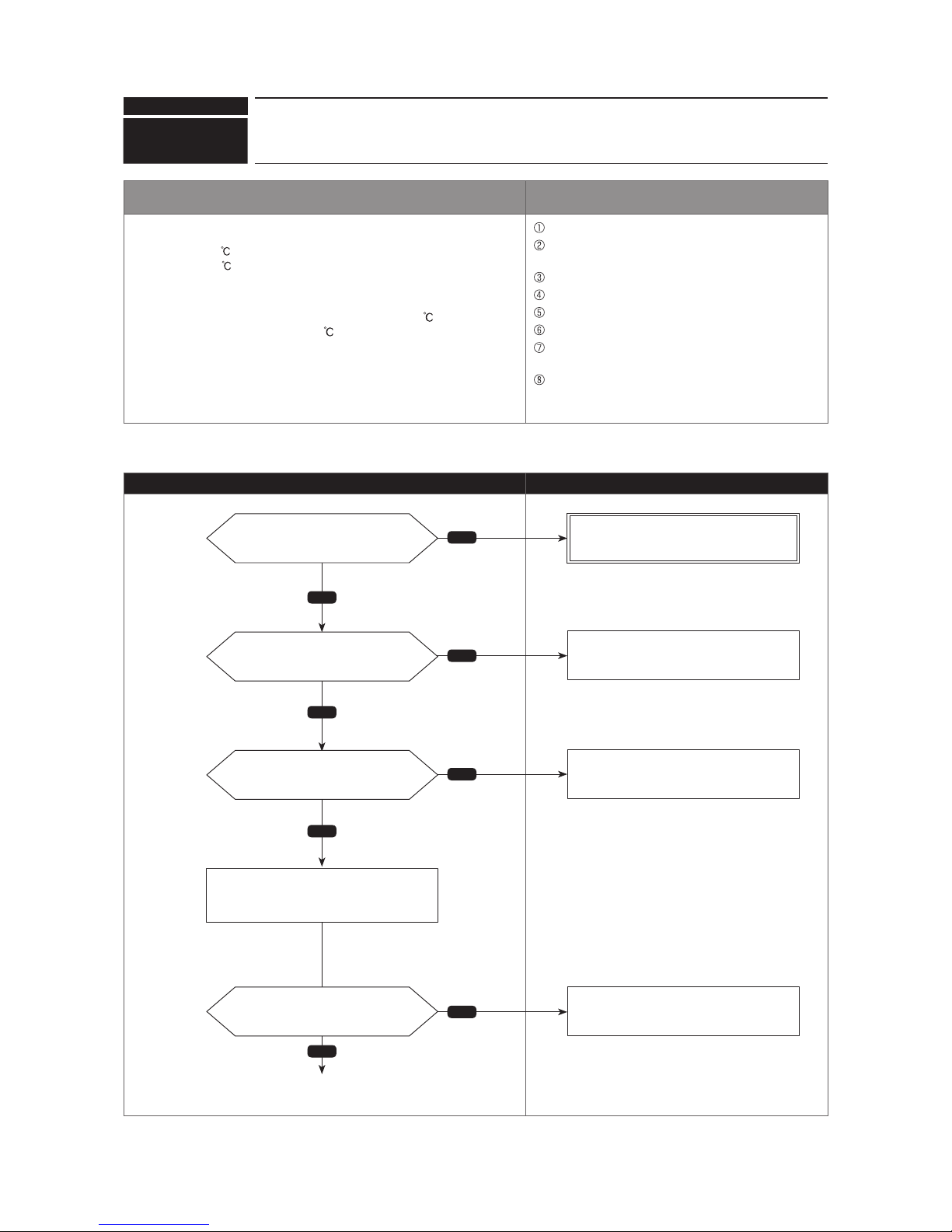
Check code
Abnormal points and detection methods Causes and check points
(1) Abnormal if TH4 falls into following temperature conditions;
●exceeds110
[230°F] continuously for 5 minutes
●exceeds125 [257°F]
(2) Abnormal if a pressure detected by the high pressure sensor and
converted to saturation temperature exceeds 40
[104°F] during
defrosting, and TH4 exceeds 110 [230°F].
TH4: Thermistor <Compressor>
LEV: Electronic expansion valve
Malfunction of stop valve
Over-heated compressor operation caused by
shortage of refrigerant
Defective thermistor
Defective outdoor multi controller circuit board
LEV performance failure
Defective indoor controller board
Clogged refrigerant system caused by foreign
object
Refrigerant shortage
(Refrigerant liquid accumulation in compressor while
indoor unit is OFF/thermo-OFF.)
●Diagnosisofdefectives
Make sure to turn the power OFF before connecting/disconnecting any connectors, or replacing boards.
Diagnosis Remedy
1102
(U2)
Compressor temperature trouble
Yes
Yes
No
Yes
Yes
No
No
No
Is 5101 displayed when restarted?
Is the outdoor stop valve (liquid/gas)
fully open?
Is there a refrigerant leak?
Is there any abnormality on
connectors/wires such as a disconnection,
half-disconnection or breakage?
Check the connection for thermistor wiring
and indoor controller board connector.
Refer to the diagnosis of check code 5101.
Open the stop valve (liquid/gas) fully.
Repair the refrigerant leakage.
Connect the connector properly
(Repair or replace it in case of a breakage).
(5101)
(1102)
(no leak)
Continue to the next page
Chart 1 of 2
54
OCH632A

Check code
1102
(U2)
Compressor temperature trouble
●Diagnosisofdefectives
Make sure to turn the power OFF before connecting/disconnecting any connectors, or replacing boards.
Diagnosis Remedy
Yes
Yes
Yes
No
No
No
Continued from the previous page
Is the voltage normal value?
Is it free from any trace of over-
heating or burning?
Is there a resistance detected?
Is there a resistance detected?
Check the voltage and appearance of the
outdoor multi controller circuit board.
Disconnect the thermistor wiring to check
the resistance.
Disconnect the indoor LEV wiring and
check the resistance.
Replace the outdoor multi controller circuit
board.
Replace the thermistor.
Replace the indoor LEV.
Replace the indoor controller board.
Chart 2 of 2
55
OCH632A
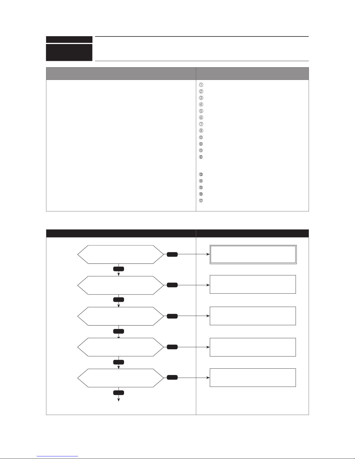
Check code
1302
(UE)
High pressure trouble
Abnormal points and detection methods Causes and check points
(1) High pressure abnormality (63H operation)
Abnormal if 63H operates(*) during compressor operation. (*
4.15 MPaG
[602 PSIG])
(2) High pressure abnormality (63HS detected)
1. Abnormal if a pressure detected by 63HS is 4.31 MPaG [625 PSIG]
or more during compressor operation.
2. Abnormal if a pressure detected by 63HS is 4.14 MPaG [600 PSIG]
or more for 3 minutes during compressor operation.
63H : High pressure switch
63HS : High pressure sensor
LEV : Electronic expansion valve
SV1 : Solenoid valve
TH7 : Thermistor <Ambient>
Defective operation of stop valve (not fully open)
Clogged or broken pipe
Malfunction or locked outdoor fan motor
Short-cycle of outdoor unit
Dirt of outdoor heat exchanger
Remote controller transmitting error caused by noise interference
Contact failure of the outdoor multi controller circuit board connector
Defective outdoor multi controller circuit board
Short-cycle of indoor unit
Decreasedairow,cloggedlter,ordirtonindoorunit.
Malfunction or locked indoor fan motor
Decreasedairowcausedbydefectiveinspection
of outdoor temperature thermistor (It detects lower
temperature than actual temperature.)
Indoor LEV performance failure
Malfunction of fan driving circuit
SV1 performance failure
Defective High pressure sensor
Defective High pressure sensor input circuit on
outdoor multi controller circuit board
●Diagnosisofdefectives
Make sure to turn the power OFF before connecting/disconnecting any connectors, or replacing boards.
Diagnosis Remedy
Chart 1 of 4
No
Yes
Yes
Yes
No
No
Yes
Yes
No
No
Is 5201 displayed when restarted?
Is the outdoor stop valve (liquid/
gas) fully open?
Does the outdoor fan rotate while
the operation?
Is the indoor unit short-cycled?
Does the indoor fan rotate while
the operation?
Refer to the diagnosis of check code 5201.
Open the stop valve (liquid/gas) fully.
Check the outdoor fan motor.
Refer to "How to check the parts" on the
outdoor unit service manual.
Solve the short-cycle.
Check the indoor fan motor.
Refer to "How to check the parts" on the
indoor unit service manual.
(5201)
(short-cycled)
(no short-cycle)
(1302)
Continue to the next page
56
OCH632A
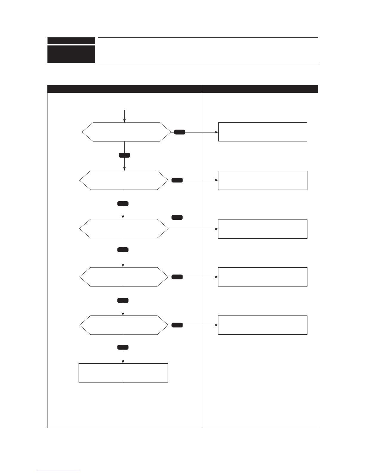
Check code
1302
(UE)
High pressure trouble
●Diagnosisofdefectives
Make sure to turn the power OFF before connecting/disconnecting any connectors, or replacing boards.
Diagnosis Remedy
Chart 2 of 4
No
Yes
Yes
Yes
Yes
Yes
No
No
No
No
Istheindoorunitlterclogged? Cleanthelter.
(Cloggedlter)
(No clog)
Continued from the previous page
Is there dirt on the indoor heat
exchanger?
Is the outdoor unit short-cycled?
Is there dirt on the outdoor heat
exchanger?
Are the pipes clogged or broken?
Wash the indoor heat exchanger.
Solve the short cycle.
Wash the outdoor heat exchanger.
Defective pipes
(dirty)
(dirty)
(short-cycled)
(no dirt)
(no dirt)
(no short-cycle)
Continue to the next page
Disconnect the TH7 wiring and check the
resistance.
57
OCH632A

Check code
1302
(UE)
High pressure trouble
●Diagnosisofdefectives
Make sure to turn the power OFF before connecting/disconnecting any connectors, or replacing boards.
Diagnosis Remedy
No
Is the voltage normal?
Is it free from any trace of overheating or burning?
Replace the indoor controller board.
Check the voltage and appearance of the
indoor controller board.
Check the resistance of SV1.
Chart 3 of 4
No
No
Yes
Yes
Yes
Continued from the previous page
Is there a resistance detected?
Is there a resistance detected?
Replace the TH7.
Replace the indoor LEV.
Disconnect the indoor LEV wiring to check
the resistance.
Continue to the next page
58
OCH632A
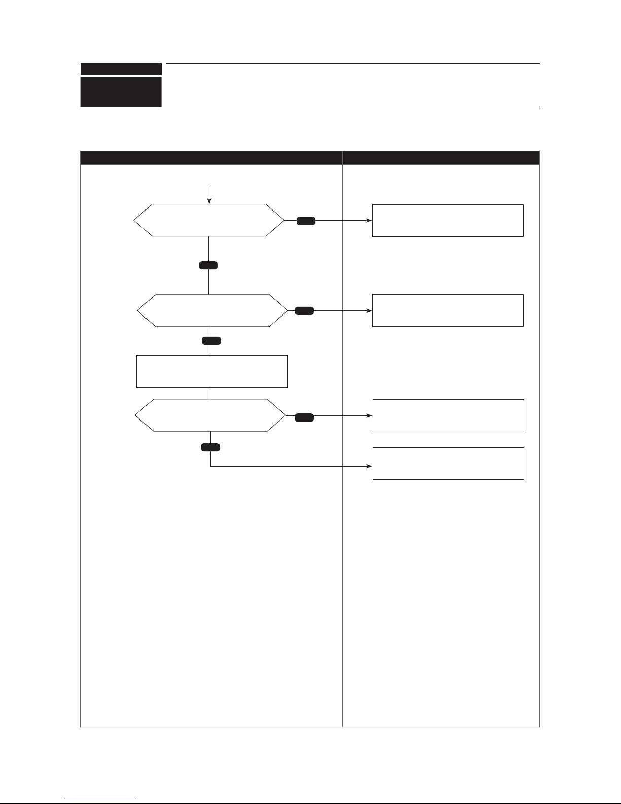
Check code
1302
(UE)
High pressure trouble
●Diagnosisofdefectives
Make sure to turn the power OFF before connecting/disconnecting any connectors, or replacing boards.
Diagnosis Remedy
Chart 4 of 4
No
No
Yes
Continued from the previous page
Is there a voltage(*) detected?
Replace the SV1.
Replace the 63HS.
Replace the outdoor multi controller circuit
board.
Yes
Is the connector for outdoor
multi controller circuit board 63H
disconnected or loose?
Reconnect the connector or connect it tightly.
Check the 63HS voltage.
Is there a resistance detected?
Yes
No
59
*For the voltage, refer to "8-8. HOW
TO CHECK THE COMPONENTS".
OCH632A

Check code
1500
(U7)
Superheat due to low discharge temperature trouble
Abnormal points and detection methods Causes and check points
Abnormalifthedischargesuperheatiscontinuouslydetected−15 [−27°F](*)
or
less for 5 minutes even though the indoor LEV has minimum open pulse
after the compressor starts operating for 10 minutes.
LEV : Electronic expansion valve
TH4 : Thermistor <Compressor>
63HS : High pressure sensor
*At this temperature, conditions for the abnormality detection will not be
satisedifnoabnormalityisdetectedoneitherTH4or63HS.
Disconnection or loose connection of TH4
Defective holder of TH4
Disconnection of LEV coil
Disconnection of LEV connector
LEV performance failure
●Diagnosisofdefectives
Make sure to turn the power OFF before connecting/disconnecting any connectors, or replacing boards.
Diagnosis Remedy
Chart 1 of 2
0 700 k"
10
· 410 k"
20
250 k"
30
160 k"
40
104 k"
No
Yes
No
Yes
No
Yes
Is the TH4 wiring disconnected?
Is the resistance normal?
Is there any abnormality
such as a half-disconnection or
breakage?
Connect the wiring properly.
Replace the
TH4.
Connect the connector properly,
or replace the LEV.
Check the resistance of TH4.
Check the connector contact and wiring of
the indoor LEV.
Disconnect the indoor LEV wiring to check
the resistance.
(disconnected)
(connected properly)
Continue to the next page
60
OCH632A

Check code
1500
(U7)
Superheat due to low discharge temperature trouble
●Diagnosisofdefectives
Make sure to turn the power OFF before connecting/disconnecting any connectors, or replacing boards.
Diagnosis Remedy
Chart 2 of 2
*For the voltage, refer to "8-8. HOW
TO CHECK THE COMPONENTS".
Is there a resistance detected?
Replace the indoor LEV.
No
No
Yes
Yes
No
Yes
Continued from the previous page
Is the voltage normal?
Is it free from any trace of overheating or burning?
Is there a voltage(*) detected?
Replace the indoor controller board.
Replace the 63HS.
Replace the outdoor multi controller circuit
board.
Check the voltage and appearance of the
indoor controller board.
Check the 63HS voltage.
61
OCH632A

Check code
1501
(U2)
Refrigerant shortage trouble
Abnormal points and detection methods Causes and check points
(1)Abnormalwhenallofthefollowingconditionsaresatisedfor15
consecutive minutes:
1. The compressor is operating in HEAT mode.
2. Discharge superheat is 80: [144_F] or more.
3. Difference between TH7 and TH3 applies to the formula of
(TH7−TH3<5:[9_F])
4. The saturation temperature converted from a high pressure sensor
detects below 35: [95_F].
(2)Abnormalwhenallofthefollowingconditionsaresatised:
1. The compressor is in operation.
2. When cooling, discharge superheat is 80: [144_F] or more, and
the saturation temperature converted from a high pressure sensor is
over−40:[−40_F].
3. When heating, discharge superheat is 90:[162_F] or more.
Defective operation of stop valve (not fully open)
Defective thermistor
Defective outdoor multi controller circuit board
Indoor LEV performance failure
Gas leakage or shortage
Defective 63HS
TH3 : Thermistor <Outdoor liquid pipe>
TH7 : Thermistor <Ambient>
LEV : Electronic expansion valve
63HS : High pressure sensor
●Diagnosisofdefectives
Make sure to turn the power OFF before connecting/disconnecting any connectors, or replacing boards.
Diagnosis Remedy
Chart 1 of 2
Yes
No
No
No
No
Yes
Yes
Yes
Is the outdoor stop valve (ball
valve) fully open?
Is there a refrigerant leak?
Is 5104 displayed when restarted?
Is there any abnormality on
connectors such as a disconnection,
half-disconnection or breakage?
Refer to the diagnosis of check code 5104.
Check relevant thermistor wirings and
connector contacts of the outdoor multi
controller circuit board.
Disconnect the thermistor wiring and check
the resistance.
Open the stop valve (ball valve) fully.
Repair the refrigerant leak.
Connect the connector properly
(Repair or replace it in case of a breakage).
(leaking)
(5104)
(no leaking)
(1501)
Continue to the next page
62
OCH632A

Check code
1501
(U2)
Refrigerant shortage trouble
●Diagnosisofdefectives
Make sure to turn the power OFF before connecting/disconnecting any connectors, or replacing boards.
Diagnosis Remedy
Chart 2 of 2
*For the voltage, refer to "8-8. HOW
TO CHECK THE COMPONENTS".
No
No
No
Yes
Yes
Yes
Yes
Yes
No
Continued from the previous page
Is there a voltage(*) detected?
Is the voltage normal value?
Is it free from any trace of over-
heating or burning?
Is there a resistance detected?
Replace the outdoor multi controller circuit
board.
Replace the 63HS.
Replace the indoor LEV.
Replace the indoor controller board.
Check the 63HS voltage.
Check the voltage and appearance of the
outdoor multi controller circuit board.
Disconnect the indoor LEV wiring and
check the resistance.
Is there a resistance detected? Replace the thermistor.
63
OCH632A

Check code
1501
(U2)
Closed valve in cooling mode
Abnormal points and detection methods Causes and check points
Abnormal if stop valve is closed during cooling operation.
Abnormalwhen both of the following temperatureconditionsaresatised
for 20 minutes or more during cooling operation.
1.TH22j−TH21j]−2°C[−3.6_F]
2.TH23j−TH21j]−2°C[−3.6_F]
Note:
Forindoorunit,theabnormalityisdetectedifanoperatingunitsatisesthe
condition.
Outdoor liquid/gas valve is closed.
Malfunction of outdoor LEV (LEV1)(blockage)
TH21: Indoor intake temperature thermistor (RT11 or TH1)
TH22: Indoor liquid pipe temperature thermistor (RT13 or TH2)
TH23: Indoor gas pipe temperature thermistor (TH-A to E)
LEV: Electronic expansion valve
●Diagnosisofdefectives
Make sure to turn the power OFF before connecting/disconnecting any connectors, or replacing boards.
Diagnosis Remedy
v
Is the
outdoor stop valve
(liquid/gas)
fully open?
Open the
outdoor stop valve (liquid/gas)
fully
.
No
Yes
Disconnect the outdoor LEV wiring to
check the resistance.
No
Yes
Replace the outdoor LEV.
Replace the outdoor multi controller circuit
board.
Is there a resistance detected?
64
OCH632A

Check code
Abnormal points and detection methods Causes and check points
The purpose of the check code is to prevent indoor unit from freezing or
dewcondensationwhichiscausedwhenarefrigerantkeepsowinginto
the unit in STOP.
Abnormalwhenallofthefollowingconditionsaresatised:
1. The compressor is operating in COOL mode.
2. 15 minutes have passed after the startup of the compressor, or the
change in the number of operating indoor units is made (including a
change by turning thermo-ON/OFF).
3.Afterthecondition2aboveissatised,thethermistorofindoorunit
in STOP detects TH22j [−5 [23°F] for 5 consecutive minutes.
Wrong piping connection between indoor unit and
branch box
Miswiring between indoor unit and branch box
Miswiring of LEV in branch box
Malfunction of LEV in branch box
●Diagnosisofdefectives
Make sure to turn the power OFF before connecting/disconnecting any connectors, or replacing boards.
Diagnosis Remedy
1503
(P6)
Indoor HEX freezing protection
No
Yes
Connect the piping and wiring to the same
port.
No
Is there a resistance detected?
Connect the LEV wiring to the intended
port properly.
Disconnect the LEV wiring of branch box
to check the resistance.
Replace the LEV coil.
Check the port which the piping and
wiring between the indoor unit and
branch box is connected.
Is the piping and wiring connected
to the same port?
Check the port which the LEV wiring
of branch box is connected.
Is the wiring connected to the same
port as the corresponding branch
box?
Yes
No
Replace the LEV assy in branch box.
Yes
65
OCH632A

Check code
66
4-way valve trouble in heating mode
Abnormal points and detection methods Causes and check points
Abnormal if 4-way valve does not operate during heating operation.
Abnormalwhenanyofthefollowingtemperatureconditionsissatisedfor
3 min. or more during heating operation
1.TH22j−TH21j[−10°C[−18°F]
2.TH23j−TH21j[−10°C[−18°F]
3. TH22j [ 3: [37.4°F]
4. TH23j [ 3: [37.4°F]
Note:
Forindoorunit,theabnormalityisdetectedifanoperatingunitsatisesthe
condition.
4-way valve failure
Disconnection or failure of 4-way valve coil
Clogged drain pipe
Disconnection or loose connection of connectors
Malfunction of input circuit on outdoor multi controller circuit board
Defective outdoor power circuit board
●Diagnosisofdefectives
Make sure to turn the power OFF before connecting/disconnecting any connectors, or replacing boards.
Diagnosis Remedy
Is the connector for outdoor multi
controller circuit board or 4-way valve
coil disconnected or loose?
Reconnect the connector or connect it
tightly.
Yes
Disconnect the connector for outdoor multi
controller circuit board or 4-way valve coil
to check the resistance.
No
Replace the 4-way valve.
Replace the outdoor multi controller circuit
board.
Is the detected voltage normal?
Is it free from any trace of over-heating
or burning?
Is there a resistance detected?
Check the voltage and appearance of the
outdoor multi controller circuit board.
No
No
Yes
1508
(EF)
Yes
Replace the outdoor multi controller circuit
board.
OCH632A

Check code
Abnormal points and detection methods Causes and check points
Abnormal if overcurrent of DC bus or compressor is detected before 30
seconds after the compressor starts operating.
Closed stop valve
Decrease of power supply voltage
Looseness, disconnection, or wrong phase of
compressor wiring connection
Model selection error on indoor controller board or
outdoor multi controller circuit board
Defective compressor
Defective outdoor power circuit board
●Diagnosisofdefectives
Make sure to turn the power OFF before connecting/disconnecting any connectors, or replacing boards.
Diagnosis Remedy
4100
(UF)
Compressor current interruption (Locked compressor)
Chart 1 of 2
Yes
Yes
Yes
No
No
No
Is the stop valve
(liquid/gas)
fully
open?
Is the power supply voltage normal?
Are they set properly?
Open the stop valve
(liquid/gas) fully
.
•
Check the looseness, disconnection, or
breakage of compressor wiring.
•Ensurepowersupplyfromthefacility.
(Check for power supply open phase.)
Set the model selection switch correctly,
then restart.
Check the stop valve.
Check the power supply voltage.
Check if the model selection switch is set
correctly on the indoor controller board or
outdoor multi controller circuit board.
Turn the power OFF to check for
looseness, disconnection, or wrong phase
of compressor wiring connection.
Continue to the next page
67
OCH632A

Check code
4100
(UF)
Compressor current interruption (Locked compressor)
●Diagnosisofdefectives
Make sure to turn the power OFF before connecting/disconnecting any connectors, or replacing boards.
Diagnosis Remedy
Chart 2 of 2
Yes
Yes
No
No
Are they connected properly?
Is the compressor faulty grounded?
Connect the compressor wiring (U, V and
W phase) properly, then turn the power
back ON.
Replace the outdoor power circuit board
(Defective outdoor power circuit board).
Replace the compressor (Defective compressor).
Check whether the compressor is faulty
grounded or not.
Continued from the previous page
68
OCH632A

Check code
Abnormal points and detection methods Causes and check points
Abnormal if overcurrent of DC bus or compressor is detected after 30
seconds since the compressor starts operating.
Closed outdoor stop valve
Decrease of power supply voltage
Looseness, disconnection, or wrong phase of
compressor wiring connection
Model selection error on indoor controller board or
outdoor multi controller circuit board
Defective compressor
Defective outdoor power circuit board
Defective outdoor multi controller circuit board
Malfunction of indoor/outdoor unit fan
Short-cycle of indoor/outdoor unit
●Diagnosisofdefectives
Make sure to turn the power OFF before connecting/disconnecting any connectors, or replacing boards.
Diagnosis Remedy
4210
(UP)
Compressor overcurrent interruption
Chart 1 of 2
Yes
Yes
Yes
No
No
No
Is the stop valve
(liquid/gas)
fully
open?
Is the power supply voltage normal?
Are they set properly?
Open the stop valve
(liquid/gas)
fully.
•
Check the looseness, disconnection, or
breakage of compressor wiring.
•Ensurepowersupplyfromthefacility.
(Check for power supply open phase.)
Set the model selection correctly.
Check the outdoor stop valve.
Check whether the power supply voltage is
normal or not.
Check if the model selection switch is set
correctly on the indoor controller board or
outdoor multi controller circuit board.
Turn the power OFF to check for
looseness, disconnection, or wrong phases
of the compressor wiring.
Continue to the next page
69
OCH632A
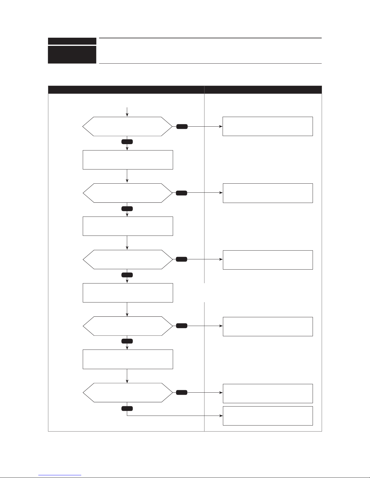
Check code
4210
(UP)
Compressor overcurrent interruption
●Diagnosisofdefectives
Make sure to turn the power OFF before connecting/disconnecting any connectors, or replacing boards.
Diagnosis Remedy
Chart 2 of 2
No
Yes
Yes
No
Yes
Yes
No
Yes
No
No
Are they connected properly?
Connect the compressor wiring (U, V and
W phase) properly, then turn the power
back ON.
Continued from the previous page
Does it operate normally?
Are those units short-cycled?
Are the voltage among the phases
U-V, V-W and W-U different?
Does it operate normally?
Check the DC fan motor.
Remove factor(s) causing the short-cycle.
Replace the compressor.
Replace the outdoor power circuit board.
Replace the outdoor multi controller circuit
board.
Check the operation of indoor/outdoor fan
motors.
Check for indoor/outdoor short-cycle.
Disconnect the compressor wiring from the outdoor
power circuit board, then check the voltage among
each phases U, V and W during test run (SW7-1 ON).
Make sure to perform a voltage
check with the same performing
frequencies.
Replace the outdoor multi controller circuit
board.
(short-cycled)
(no short-cycled)
70
OCH632A

Check code
Abnormal points and detection methods Causes and check points
Abnormal if any of following symptoms are detected;
●DecreaseofDCbusvoltageto200V(Vmodel),350V(Ymodel)
●IncreaseofDCbusvoltageto400V(Vmodel),760V(Ymodel)
●DC bus voltage stays at 310 V or less for consecutive 30 seconds when
the operational frequency is over 20 Hz.
●Whenanyofthefollowingconditionsissatisfiedwhilethedetectionvalue
of primary current is 0.1 A or less.
1. The operational frequency is 40 Hz or more.
2. The compressor current is 6 A or more.
Decrease/increase of power supply voltage
2
LI open-phase (Y model only)
Primary current sensor failure
Disconnection of compressor wiring
Malfunction of 52C
Disconnection or contact failure of CN52C
Defective outdoor power circuit board
Malfunction of 52C driving circuit on outdoor multi
controller circuit board
Disconnection of CN5
0
Disconnection of CN2
1
Malfunction of primary current detecting circuit on
outdoor power circuit board
●Diagnosisofdefectives
Make sure to turn the power OFF before connecting/disconnecting
any connectors, or replacing boards.
Diagnosis Remedy
4220
(U9)
Voltage shortage/overvoltage/PAM error/L1open phase/primary
current sensor error/power synchronization signal error
Theblacksquare(■)indicatesaswitchposition.
Chart 1 of 2
No
No
No
No
No
Yes
Yes
Yes
Yes
Yes
6
3
7,8
Is there any abnormality on wirings?
Which sub code is displayed?
Does a DC bus voltage raise to
approx. 350 V at PAM driving?
Is there any abnormality on
PAM wirings?
Is there any abnormality at the
PAM circuit on the outdoor power
circuit board?
Is there any abnormality at
the PAM power supply circuit on the
outdoor multi controller circuit board?
a. LI open-phase (Y model only)
b. Disconnection of compressor wiring
c. Disconnection of CN52C (V model only)
d. Disconnection of CN5
e. Disconnection of CN2
The sub codes are displayed
by an operation of SW1 on
the outdoor multi controller
circuit board.
The sub codes are displayed by an
operation of SW1 on the outdoor multi
controller circuit board.
Check the power supply facility.
Correct the wiring.
Replace the outdoor power circuit board
(Defective outdoor power circuit board).
Replace the outdoor multi controller circuit
board. Breakage of wiring for PAM controlling
power supply, and such.
Replace the outdoor power circuit board
(Defective outdoor power circuit board).
ON
OFF
1 2 3 4 5 6 7 8
SW1 Setting
Display on LED1,2
1
2 3 4 5 6 7 8
3: PAM error
6: Input sensor trouble
7: Shortage voltage trouble
8: Overvoltage trouble
3: PAM error (V model only)
6: Primary current sensor trouble
7: Undervoltage trouble
8: Overvoltage trouble
Continue to the next page
71
OCH632A

Check code
4220
(U9)
Voltage shortage/overvoltage/PAM error/L1open phase/primary
current sensor error/power synchronization signal error
●Diagnosisofdefectives
Make sure to turn the power OFF before connecting/disconnecting
any connectors, or replacing boards.
Diagnosis Remedy
Theblacksquare(■)indicatesaswitchposition.
Chart 2 of 2
Replace the outdoor power circuit board
(Defective outdoor power circuit board).
Yes
No
No
Yes
Yes
No
Yes
Yes
No
No
Yes
7,8 6
Y model
V model
Is CN5 connected properly
without any contact failure?
The bus voltage can be displayed by an
operation of SW1 on the outdoor multi
controller circuit board.
Correct the CN5 wiring.
Continued from the previous page
Is there any breakage of ACCT
onthenoiseltercircuitboard?
Is the power supply normal?
Is the bus voltage normal?
The difference of the voltage between the
one read by the LED1 and 2, and the one at
the test points listed above is large.
Replacethenoiseltercircuitboard.
Replace the outdoor power circuit board
(Defective outdoor power circuit board).
•Decreaseofpowersupplyvoltage
•L1open-phase
Replace the outdoor power circuit board
(Defective outdoor power circuit board).
Replace the outdoor power circuit board
(Trouble of an input current detection
circuit is suspected).
Check the power supply facility
(Check if a receiving electricity is lowered).
Check the bus voltage read by the microprocessor
with an operation of SW1 on the outdoor multi
controller circuit board.
Check the bus voltage at the test points
listed below on the outdoor power circuit
board using a tester.
V model: CNDC 1-2pin
Y model: N2-P2
ON
OFF
1 2 3 4 5 6 7 8
SW1 Setting
Display on LED1,2
Unit
0–999.9 V
Is the outdoor unit
V model or Y model?
72
OCH632A

Check code
Abnormal points and detection methods Causes and check points
AbnormalifTH8 detectsa temperatureoutside thespecied rangeduring
compressor operation.
TH8:
Thermistor <Heat sink>
Blocked outdoor fan
Malfunction of outdoor fan motor
Blockedairowpath
Rise of ambient temperature
Characteristic defect of thermistor
Malfunction of input circuit on outdoor power circuit board
Malfunction of outdoor fan driving circuit
●Diagnosisofdefectives
Make sure to turn the power OFF before connecting/disconnecting any connectors, or replacing boards.
Diagnosis Remedy
Is 5110 displayed when restart?
4230
(U5)
Heat sink temperature trouble
0 180kΩ
25
50kΩ
50
17kΩ
70
8kΩ
90
4kΩ
TH8 temp. - resistance characteristic
No
Yes
No
No
Yes
Yes
No
No
Yes
Yes
Is 5110 displayed when restarted?
Does the fan rotate during
compressor operation?
Is there any obstacle which
blocksanairowaroundthe
heat
sink
?
Is there any abnormality such
as a disconnection, looseness or
breakage?
Is the resistance normal?
Refer to the diagnosis of check code 5110.
Refer to the diagnosis of check code 4400.
Replace the thermistor
(Defective thermistor).
Replace the outdoor power circuit board
(Defective outdoor power circuit board).
Improvetheairowpath.
Connect the wiring/connector properly.
Replace it in case of a breakage.
Check the wiring and connector connection TH8.
Check the resistance of TH8.
(air path blocked)
(no obstacle)
73
OCH632A

Check code
Abnormal points and detection methods Causes and check points
Abnormalifbothofthefollowingconditionsaresatised:
1. Overcurrent of DC bus or compressor is detected during compressor
operation.
2. Inverter power module is determined to be defected.
Short-circuit caused by looseness or disconnection
of compressor wiring
Defective compressor
Defective outdoor power circuit board
●Diagnosisofdefectives
Make sure to turn the power OFF before connecting/disconnecting any connectors, or replacing boards.
Diagnosis Remedy
4250
(U6)
Power module trouble
Yes
Yes
No
No
Are they connected properly?
Is the check code <4250> still
displayed?
Connect the compressor wiring (U, V and
W phase) properly, then turn the power
back ON.
Replace the outdoor power circuit board or
the outdoor multi controller circuit board
(Defective outdoor power circuit board).
Replace the compressor
(Defective compressor).
Turn the power OFF to check for looseness
or disconnection of the compressor wiring.
1
Disconnect the compressor wiring
(U-V-W phase).
2
Turn ON the SW7-1(*) on the outdoor
multi controller circuit board.
3
Operate the unit.
* SW7-1 ON: Ignore 5300(UH) error.
74
OCH632A

Check code
Abnormal points and detection methods Causes and check points
Abnormal if no rotational frequency is detected, or detected a value
outsidethespeciedrangeduringfanmotoroperation.
Malfunction of fan motor
Disconnection of CNF connector
Defective outdoor multi controller circuit board
●Diagnosisofdefectives
Make sure to turn the power OFF before connecting/disconnecting any connectors, or replacing boards.
Diagnosis Remedy
4400
(U8)
Fan trouble (Outdoor unit)
*For the detail, refer to "Check method of DC
fan motor (fan motor/outdoor multi controller
circuit board)" in chapter 8-7.
No
No
Yes
Yes
Yes
No
Is the fuse melting?
Is there any abnormality such
as a disconnection, looseness or
breakage?
Is the voltage normal?
•
Replace the outdoor multi controller circuit board.
•Replacethedefectivefanmotor.*
Connect the wiring/connector properly.
Replace it in case of a breakage.
Replace the outdoor multi controller circuit
board.
Replace the fan motor.
Check the fuse on the outdoor multi
controller circuit board.
Check the fan motor connector (CNF1 and
CNF2) for a disconnection or looseness.
1
While the breaker is OFF, disconnect the compressor
wirings (U/V/W) from the outdoor power circuit board
.
2
While the breaker is OFF, disconnect the fan motor
connector CNF1 and CNF2.
3
When 5 minutes have passed since turning ON the
breaker, turn SW7-1 ON.
4
Check the voltage of the outdoor multi controller circuit board.
Test points are;
· VDC approx. 310 to 350 V DC (fan connector 1–4)
· VCC approx. 15 V DC (fan connector 5–4)
· VCC approx. 0–6.5 V DC (fan connector 6–4)
(melting)
(Not melting)
Note: Set SW7-1 OFF after the troubleshooting completes.
75
OCH632A

Check code
Abnormal points and detection methods Causes and check points
Abnormal if TH4 detects to be open/short.
(The open/short detection is disabled for 10 minutes after compressor
starts, during defrosting operation, or for 10 minutes after returning from
the defrosting operation.)
Open: 3 [37°F] or less
Short: 217 [423°F] or more TH4: Thermistor <Compressor>
Disconnection or contact failure of connectors
Characteristic defect of thermistor
Defective outdoor multi controller circuit board
●Diagnosisofdefectives
Make sure to turn the power OFF before connecting/disconnecting
any connectors, or replacing boards.
Diagnosis Remedy
−99.9–999.9
5101
(U3)
Compressor temperature thermistor (TH4) open/short
Theblacksquare(■)indicatesaswitchposition.
<Detected in outdoor unit>
No
Yes
Yes
Yes
No
No
Is there any abnormality such
as a disconnection, looseness or
breakage?
Is the detected resistance normal?
Is the detected temperature normal?
Connect the wiring/connector properly.
Replace the connector in case of a
breakage.
Replace the thermistor.
Replace the outdoor multi controller circuit
board
(Malfunction of thermistor circuit).
No abnormality
(A connector contact failure is suspected.)
Check the wiring and connector connection of TH4.
Disconnect the connector to check the
resistance of TH4 using a tester.
Check a temperature of TH4.
The detected temperature of TH4 can be displayed
by an operation of SW1 on the outdoor multi
controller circuit board.
SW1 Setting
ON
OFF
Display on LED1, 2
Unit
−99.9–999.9
:
41 2 5 6 7 83
76
OCH632A

Check code
Abnormal points and detection methods Causes and check points
Abnormal if TH6 detects to be open/short.
(The open/short detection is disabled during 10 seconds to 10 minutes
after compressor starts, during defrosting operation, or for 10 minutes after
returning from the defrosting operation.)
Open:−40 [−40°F]orless
Short: 90 [162°F] or more TH6: Thermistor <Suction pipe>
Disconnection or contact failure of connectors
Characteristic defect of thermistor
Defective outdoor multi controller circuit board
●Diagnosisofdefectives
Make sure to turn the power OFF before connecting/disconnecting
any connectors, or replacing boards.
Diagnosis Remedy
5102
(U4)
Suction pipe temperature thermistor (TH6) open/short
Theblacksquare(■)indicatesaswitchposition.
<Detected in outdoor unit>
No
Yes
Yes
Yes
No
No
Is there any abnormality such
as a disconnection, looseness or
breakage?
Is the detected resistance normal?
Is the detected temperature normal?
Connect the wiring/connector properly.
Replace it in case of a breakage.
Replace the thermistor.
Replace the outdoor multi controller circuit
board (Malfunction of thermistor circuit).
No abnormality
( A connector contact failure is suspected.)
Check the wiring and connector connection of TH6.
Disconnect the connector to check the
resistance of TH6 using a tester.
Check a temperature of TH6.
ON
OFF
1 2 3 4 5 6 7 8
SW1 Setting
Display on LED1,2
Unit
:
−99.9–999.9
The detected temperature of TH6 can be displayed
by an operation of SW1 on the outdoor multi
controller circuit board.
77
OCH632A

Check code
Abnormal points and detection methods Causes and check points
Abnormal if TH3 detects to be open/short.
(The open/short detection is disabled during 10 seconds to 10 minutes
after compressor starts, during defrosting operation, or for 10 minutes after
returning from the defrosting operation.)
Open:−40 [−40°F]orless
Short: 90 [162°F] or more TH3: Thermistor <Outdoor liquid pipe>
Disconnection or contact failure of connectors
Characteristic defect of thermistor
Defective outdoor multi controller circuit board
●Diagnosisofdefectives
Make sure to turn the power OFF before connecting/disconnecting
any connectors, or replacing boards.
Diagnosis Remedy
5105
(U4)
Outdoor liquid pipe temperature thermistor (TH3) open/short
Theblacksquare(■)indicatesaswitchposition.
SW1 Setting
ON
OFF
Display on LED1, 2
Unit
−99.9–999.9
:
41 2 5 6 7 83
No
Yes
Yes
Yes
No
No
Is there any abnormality such
as a disconnection, looseness or
breakage?
Is the detected resistance normal?
Is the detected temperature normal?
Connect the wiring/connector properly
Replace it in case of a breakage.
Replace the thermistor.
Replace the outdoor multi controller circuit
board (Malfunction of thermistor circuit).
No abnormality
(A connector contact failure is suspected.)
Check the wiring and connector connection of TH3.
Disconnect the connector to check the
resistance of TH3 using a tester.
Check a temperature of TH3.
The detected temperature of TH3 can be displayed by an
operation of SW1 on the outdoor multi controller circuit board
78
OCH632A

Check code
5106
(U4)
Ambient temperature thermistor (TH7) open/short
Abnormal points and detection methods Causes and check points
Abnormal if TH7 detects to be open/short
Open:−40 [−40°F]orless
Short: 90 [162°F] or more TH7: Thermistor <Ambient>
Disconnection or contact failure of connectors
Characteristic defect of thermistor
Defective outdoor multi controller circuit board
●Diagnosisofdefectives
Make sure to turn the power OFF before connecting/disconnecting
any connectors, or replacing boards.
Diagnosis Remedy
Theblacksquare(■)indicatesaswitchposition.
SW1 Setting
ON
OFF
Display on LED1, 2
Unit
−99.9–999.9
:
41 2 5 6 7 83
No
Yes
Yes
Yes
No
No
Is there any abnormality such
as a disconnection, looseness or
breakage?
Is the detected resistance normal?
Is the detected temperature normal?
Connect the wiring/connector properly.
Replace it in case of a breakage.
Replace the thermistor.
Replace the outdoor multi controller circuit
board (Malfunction of thermistor circuit).
No abnormality
(A connector contact failure is suspected.)
Check the wiring and connector connection of TH7.
Disconnect the connector to check the
resistance of TH7 using a tester.
Check a temperature of TH7.
The detected temperature of thermistor (TH7)
can be displayed by an operation of SW1 on the
outdoor multi controller circuit board.
The detected temperature of TH7 can be displayed by an
operation of SW1 on the outdoor multi controller circuit board.
79
OCH632A

Check code
5109
(U4)
HIC pipe temperature thermistor (TH2) open/short
Abnormal points and detection methods Causes and check points
Abnormal if TH2 detects to be open/short.
Open:−40 [−40°F]orless
Short: 90 [162°F] or more TH2: Thermistor <
HIC pipe>
Disconnection or contact failure of connectors
Characteristic defect of thermistor
Defective outdoor multi controller circuit board
●Diagnosisofdefectives
Make sure to turn the power OFF before connecting/disconnecting
any connectors, or replacing boards.
Diagnosis Remedy
Theblacksquare(■)indicatesaswitchposition.
No
Yes
Yes
Yes
No
No
Is there any abnormality such
as a disconnection, looseness or
breakage?
Is the detected resistance normal?
Is the detected temperature normal?
Connect the wiring/connector properly.
Replace it in case of a breakage.
Replace the thermistor.
Replace the outdoor multi controller circuit
board
(Malfunction of thermistor circuit).
No abnormality
(A connector contact failure is suspected.)
Check the wiring and connector connection of TH2.
Disconnect the connector to check the
resistance of TH2 using a tester.
Check a temperature of TH2.
ON
OFF
1 2 3 4 5 6 7 8
SW1 Setting
Display on LED1,2
Unit
−99.9–999.9 °C
The detected temperature of TH2 can be displayed by an
operation of SW1 on the outdoor multi controller circuit board.
80
OCH632A

Check code
5110
(U4)
Heat sink temperature thermistor(TH8) open/
short
Abnormal points and detection methods Causes and check points
Abnormal if TH8 (Internal thermistor) detects to be open/short.
P112/125/140V model <Internal thermistor>
Open: 170.3 [338.5°F] or more
Short:−35.1 [−31.2°F]orless
2
P112/125/140Y model
Open: 102 [215.6°F] or more
Short:−34.8 [−30.6°F]orless
TH8: Thermistor <Heat sink>
Disconnection or contact failure of connectors
Characteristic defect of thermistor
Defective outdoor multi controller circuit board
●Diagnosisofdefectives
Make sure to turn the power OFF before connecting/disconnecting
any connectors, or replacing boards.
Diagnosis Remedy
outdoor
Theblacksquare(■)indicatesaswitchposition.
SW1 Setting
ON
OFF
Display on LED1, 2
Unit
−99.9–999.9
:
41 2 5 6 7 83
No
Yes
Yes
Yes
No
No
Yes
No
Is there any abnormality such
as a disconnection, looseness or
breakage?
Is the detected resistance normal?
Is the detected temperature normal?
Connect the wiring/connector properly.
Replace it in case of a breakage.
Replace the thermistor.
Replace the outdoor multi controller circuit
board (Malfunction of thermistor circuit).
No abnormality
(A connector contact failure is suspected.)
Check the wiring and connector connection of TH8.
Disconnect the connector to check the
resistance of TH8 using a tester.
Check a temperature of TH8.
The detected temperature of thermistor (TH8)
can be displayed by an operation of SW1 on the
outdoor multi controller circuit board.
The detected temperature of TH8 can be displayed by an
operation of SW1 on the outdoor multi controller circuit board.
Is it a model with internal
thermistor?
81
OCH632A

Check code
5201
(F5)
High pressure sensor (63HS) trouble
Abnormal points and detection methods Causes and check points
When the detected pressure in the high pressure sensor is 1kgf/F or
less during operation, the compressor stops operation and enters into
an anti-restart mode for 3 minutes.
When the detected pressure is 1kgf/F or less immediately before
restarting, the compressor falls into an abnormal stop with a check code
<5201>.
For 3 minutes after compressor restarting, during defrosting operation,
and for 3 minutes after returning from defrosting operation, above
mentioned symptoms are not determined as abnormal.
Defective high pressure sensor
Decrease of internal pressure caused by gas
leakage
Disconnection or contact failure of connector
Malfunction of input circuit on outdoor multi controller
circuit board
●Diagnosisofdefectives
Make sure to turn the power OFF before connecting/disconnecting
any connectors, or replacing boards.
Diagnosis Remedy
Theblacksquare(■)indicatesaswitchposition.
63HS: High pressure sensor
SW1 Setting
ON
OFF
Display on LED1, 2
Unit
−99.9–999.9
kgf/F
41 2 5 6 7 83
No
Yes
Yes
No
No
Is there any abnormality such
as a disconnection, looseness or
breakage?
Is the detected internal pressure
normal?
Is the detected pressure normal?
Connect the wiring/connector properly.
Replace it in case of a breakage.
Checktherefrigerantcircuit,andrell
refrigerant after repairing the leakage.
Replace the 63HS.
Replace the outdoor multi controller circuit
board.
Check the wiring and connector connection.
Check an internal pressure of the
refrigerant circuit.
Check the detected pressure in 63HS,
then compare it with the internal pressure.
The detected pressure in 63HS can be displayed by an
operation of SW1 on the outdoor multi controller circuit board.
82
OCH632A
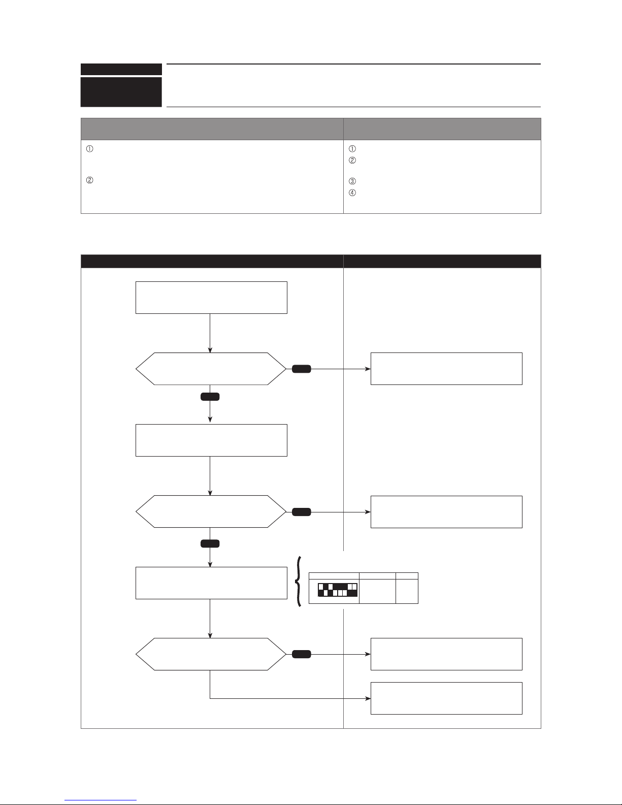
Check code
5202
(F3)
Low pressure sensor (63LS) trouble
Abnormal points and detection methods Causes and check points
Whenthedetectedpressureinthelowpressuresensoris−2.3kgf/F
or less, or 23.1kgf/F or more during operation, the compressor stops
operation with a check code <5202>.
For 3 minutes after compressor restarting, during defrosting operation,
and for 3 minutes after returning from defrosting operation, above
mentioned symptoms are not determined as abnormal.
Defective low pressure sensor
Decrease of internal pressure caused by gas
leakage
Disconnection or contact failure of connector
Malfunction of input circuit on outdoor multi controller
circuit board
●Diagnosisofdefectives
Make sure to turn the power OFF before connecting/disconnecting
any connectors, or replacing boards.
Diagnosis Remedy
Theblacksquare(■)indicatesaswitchposition.
63LS: Low pressure sensor
No
Yes
Yes
No
No
Is there any abnormality such
as a disconnection, looseness or
breakage?
Is the detected internal pressure
normal?
Is the detected pressure normal?
Connect the wiring/connector properly.
Replace it in case of a breakage.
Checktherefrigerantcircuit,andrell
refrigerant after repairing the leakage.
Replace the 63LS.
Replace the outdoor multi controller circuit
board.
Check the wiring and connector
connection.
Check an internal pressure of the
refrigerant circuit.
Check the detected pressure in 63LS, then
compare it with the internal pressure.
ON
OFF
1 2 3 4 5 6 7 8
SW1 Setting
Display on LED1,2
Unit
−99.9–999.9 kgf/cm²
The detected pressure in 63LS can be displayed by an
operation of SW1 on the outdoor multi controller circuit
board.
83
OCH632A

Check code
5300
(UH)
Primary current error
Abnormal points and detection methods Causes and check points
Abnormal if any of the following conditions is detected:
1
Primary current sensor detects any of the following conditions (single
phase unit only):
2
Secondary current sensor detects 25 A or more.
3
Secondary current sensor detects 1.0 A or less.
Decrease/trouble of power supply voltage
Disconnection of compressor wiring
Current sensor trouble on outdoor power circuit
board
Wiring through current sensor (penetration type) is
not done.
●Diagnosisofdefectives
Make sure to turn the power OFF before connecting/disconnecting
any connectors, or replacing boards.
Diagnosis Remedy
Ambient
temperature
10 consecutive-
second detection
One-time detection
TH7 > 3: 37 A 40 A
TH7 [ 3: 40 A 43A
(Three-phase)
Yes
Yes
No
No
Yes
No
Is the power supply single phase?
Is there any abnormality
such as a disconnection,
looseness, or breakage?
The power supply voltage might be
decreased or abnormal.
Check the power supply facility.
Connect the compressor wiring properly.
Replace the outdoor power circuit board
(Malfunction of current sensor circuit).
Checkthepowerspecicationofthe
outdoor unit.
Check the value on the secondary current
sensor during the error.
(Single-phase)
Does it satisfy the condition 1?
No
SW1 Setting
ON
OFF
Display on LED1, 2
Unit
0–999.9
Arms
41 2 5 6 7 83
The secondary current sensor value during the error can be displayed
by an operation of SW1 on the outdoor multi controller circuit board.
Does it satisfy the
condition 2 or 3?
Check the compressor
wiring.
84
OCH632A

Check code
Abnormal points and detection methods Causes and check points
Abnormal if 2 or more units with the same address are existing. There are 2 units or more with the same address
in their controller among outdoor unit, indoor unit,
Fresh Master, Lossnay or remote controller
Noise interference on indoor/outdoor connectors
●Diagnosisofdefectives
Make sure to turn the power OFF before connecting/disconnecting any connectors, or replacing boards.
Diagnosis Remedy
6600
(A0)
Duplex address error
No
Yes
Yes
No
Is there any unit with the same
address?
Does it operate normally?
Correct the address, and turn the power
OFF of indoor/outdoor unit, Fresh Master
or Lossnay simultaneously for 2 minutes or
more, then turn the power back ON.
Malfunction of sending/receiving circuit on
indoor/outdoor unit is suspected.
There is no abnormality on the AC unit.
It might be caused by an external noise, so
check the transmission line to remove the
factor(s).
Search for a unit with the same address as
the source of abnormality.
Turn the power back ON.
85
OCH632A

Check code
Abnormal points and detection methods Causes and check points
Abnormal if the transmission line shows "1" although the transmission
processor transmitted "0".
A transmitting data collision occurred because of a
wiring work or polarity change has performed while
the power is ON on either of the indoor/outdoor unit,
Fresh Master or Lossnay
Malfunction of transmitting circuit on transmission
processor
Noise interference on indoor/outdoor connectors
●Diagnosisofdefectives
Make sure to turn the power OFF before connecting/disconnecting any connectors, or replacing boards.
Diagnosis Remedy
6602
(A2)
Transmission processor hardware error
Yes
Yes
No
No
A wiring work was performed
while the power OFF.
Does it operate normally?
If the wiring work was performed while the
power ON, turn the power OFF of indoor/
outdoor unit, Fresh Master or Lossnay
simultaneously for 2 minutes or more, then
turn the power back ON.
Replace the indoor/outdoor controller board.
There is no abnormality on the AC unit.
It might be caused by an external noise, so
check the transmission line to remove the
factor(s).
Turn the power back ON.
86
OCH632A

Check code
Abnormal points and detection methods Causes and check points
Over error by collision
Abnormal if no-transmission status caused by a transmitting data
collision is consecutive for 8 to 10 minutes.
Abnormal if a status, that data is not allowed on the transmission line
because of noise and such, is consecutive for 8 to 10 minutes.
The transmission processor is unable to transmit due
to a short-cycle voltage such as noise is mixed on
the transmission line
.
The transmission processor is unable to transmit due
to an increase of transmission data amount caused
by a miswiring of the terminal block (transmission
line) (TB3) and the terminal block (centralized control
line) (TB7) on the outdoor unit.
The share on transmission line becomes high due
to a mixed transmission caused by a malfunction
of repeater on the outdoor unit, which is a function
to connect/disconnect transmission from/to control
system and centralized control system.
●Diagnosisofdefectives
Make sure to turn the power OFF before connecting/disconnecting any connectors, or replacing boards.
Diagnosis Remedy
6603
(A3)
Transmission bus BUSY error
No
Yes
Yes
Yes
No
No
Is the transmission line miswired?
Is the transmission line miswired?
Does it operate normally?
Correct the wiring, then turn the power
back ON.
Correct the wiring, then turn the power
back ON.
Replace the indoor/outdoor controller
board.
There is no abnormality on the AC unit.
It might be caused by an external noise, so check
the transmission line to remove the factor(s).
Check whether the transmission line to the indoor unit,
Fresh Master, Lossnay or remote controller is miswired
to the terminal block (TB7) on outdoor unit or not.
Check whether the transmission line with the other refrigerant
system of the indoor unit, Fresh Master or Lossnay is miswired
to the terminal block (TB3) on outdoor unit or not.
Turn the power back ON.
(miswired)
(miswired)
(Not miswired)
(Not miswired)
87
OCH632A

Check code
Abnormal points and detection methods Causes and check points
Abnormal if the data of unit/transmission processor were not normally
transmitted.
Abnormal if the address transmission from the unit processor was not
normally transmitted.
Accidental disturbance such as noise or lightning
surge
Hardware malfunction of transmission processor
●Diagnosisofdefectives
Make sure to turn the power OFF before connecting/disconnecting any connectors, or replacing boards.
Diagnosis Remedy
6606
(A6)
Signal communication error with transmission processor
Yes
No
Does it operate normally?
Replace the controller.
(Defect of error source controller).
There is no abnormality on the AC unit.
It might be caused by an external noise, so check
the transmission line to remove the factor(s).
Turn the power OFF of indoor/outdoor unit, Fresh
Master, Lossnay and remote controller simultaneously
for 2 minutes or more, then turn the power back ON.
88
OCH632A
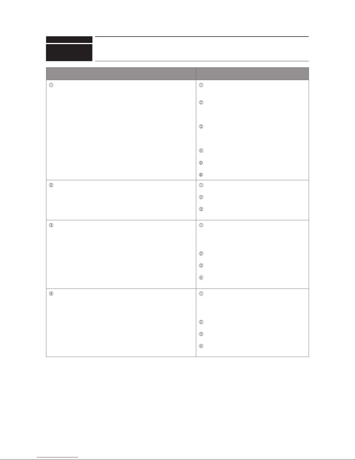
Check code
Abnormal points and detection methods Causes and check points
Represents a common error detection
An abnormality detected by the sending side controller when receiving
no ACK from the receiving side, though signal was once sent. The
sending side searches the error in 30 seconds interval for 6 times
continuously.
The previous address unit does not exist since
the address switch was changed while in electric
continuity status.
Decline of transmission voltage/signal caused by
tolerance over on transmission line
·At the furthest end: 200 m
·On remote controller line: (12 m)
Decline of transmission voltage/signal due to
unmatched transmission line types
·Types for shield line: CVVS, CPEVS, or MVVS
·Line diameter: 1.25 E or more
Decline of transmission voltage/signal due to
excessive number of connected units
Malfunction due to accidental disturbance such as
noise or lightning surge
Defect of error source controller
The cause of displayed address and attribute is on the outdoor unit side
An abnormality detected by the indoor unit if receiving no ACK when
transmitting signal from the indoor unit to the outdoor unit.
Contact failure of indoor/outdoor unit transmission
line.
Disconnection of transmission connector (CN2M) on
indoor unit.
Malfunction of sending/receiving circuit on indoor/
outdoor unit.
The cause of displayed address and attribute is on the indoor unit side
An abnormality detected by the remote controller if receiving no ACK
when sending data from the remote controller to the indoor unit.
While operating with multi refrigerant system indoor
units, an abnormality is detected when the indoor
unit transmit signal to the remote controller during
the other refrigerant-system outdoor unit is turned
OFF, or within 2 minutes after it turned back ON.
Contact failure of indoor unit or remote controller
transmission line
Disconnection of transmission connector (CN2M) on
indoor unit
Malfunction of sending/receiving circuit on indoor
unit or remote controller
The cause of the displayed address and attribute is on the remote
controller side
An abnormality detected by the indoor unit if receiving no ACK when
transmitting signal from the indoor unit to the remote controller.
While operating with multi refrigerant system indoor
units, an abnormality is detected when the indoor
unit transmit signal to the remote controller during
the other refrigerant-system outdoor unit is turned
OFF, or within 2 minutes after it turned back ON.
Contact failure of indoor unit or remote controller
transmission line
Disconnection of transmission connector (CN2M) on
indoor unit
Malfunction of sending/receiving circuit on indoor
unit or remote controller
6607
(A7)
No ACK error
Chart 1 of 4
89
OCH632A

Check code
6607
(A7)
No ACK error
Abnormal points and detection methods Causes and check points
The cause of displayed address and attribute is on the Fresh Master
side
An abnormality detected by the indoor unit if receiving no ACK when
transmitting signal from the indoor unit to the Fresh Master.
While the indoor unit is operating with multi
refrigerant system Fresh Master, an abnormality
is detected when the indoor unit transmits signal
to the remote controller while the outdoor unit with
the same refrigerant system as the Fresh Master is
turned OFF, or within 2 minutes after it turned back
ON.
Contact failure of indoor unit or Fresh Master
transmission line
Disconnection of transmission connector (CN2M) on
indoor unit or Fresh Master
Malfunction of sending/receiving circuit on indoor
unit or Fresh Master
The cause of displayed address and attribute is on Lossnay side
An abnormality detected by the indoor unit if receiving no ACK when the
indoor unit transmit signal to the Lossnay.
An abnormality is detected when the indoor unit
transmits signal to Lossnay while the Lossnay is
turned OFF.
While the indoor unit is operating with the other
refrigerant Lossnay, an abnormality is detected when
the indoor unit transmits signal to the Lossnay while
the outdoor unit with the same refrigerant system as
the Lossnay is turned OFF, or within 2 minutes after
it turned back ON.
Contact failure of indoor unit or Lossnay transmission
line
Disconnection of transmission connector (CN2M) on
indoor unit
Malfunction of sending/receiving circuit on indoor
unit or Lossnay
The controller of displayed address and attribute is not recognized The previous address unit does not exist since
the address switch was changed while in electric
continuity status.
An abnormality detected at transmitting from the
indoor unit since the Fresh Master/Lossnay address
are changed after synchronized setting of Fresh
Master/Lossnay by the remote controller.
Chart 2 of 4
90
OCH632A

Check code
6607
(A7)
No ACK error
Chart 3 of 4
●Diagnosisofdefectives
Make sure to turn the power OFF before connecting/disconnecting any connectors, or replacing boards.
Diagnosis Remedy
Yes
Yes
No
No
No
Yes
Yes
No
The transmission line is connected
properly.
It is not exceeding the tolerance.
Check the transmission line whether it
exceeds the tolerance or not.
Check whether the correct kind of
transmission line is used or not.
Correct it within the tolerance, then perform
the procedure 1.
Connect the transmission line properly,
then perform the procedure 1.
Is the abnormality reproduced?
Is it set properly?
There is no abnormality on the AC unit.
It might be caused by an external noise, so check the
transmission line to remove the factor(s).
Set the address properly, then perform the
procedure 1.
Check the address switch on the source of
abnormality.
Check the transmission line for a
disconnection and looseness
(on the terminal board and connector).
Turn the power OFF of indoor/outdoor unit, Fresh
Master, Lossnay and remote controller simultaneously
for 2 minutes or more, then turn the power back ON.
Procedure 1:
Continue to the next page
91
OCH632A

Check code
6607
(A7)
No ACK error
Chart 4 of 4
●Diagnosisofdefectives
Make sure to turn the power OFF before connecting/disconnecting any connectors, or replacing boards.
Diagnosis Remedy
Yes
Yes
Yes
Yes
No
No
No
No
Is the correct kind of transmission
line used?
Is it operating in multi refrigerant
system?
Is the address information correct?
Does it operate normally?
When operating in a multi refrigerant system (2 or
more outdoor units), check if any of the indoor unit
stores non-existing address information.
Replace the controller board which the
displayed address/attribute belongs to.
Continued from the previous page
Defective outdoor multi controller circuit board
(repeater circuit) on the outdoor unit is suspected.
Replace the outdoor multi controller circuit board one
by one, then check for normal operation.
Delete the unnecessary address using
a manual setting function on the remote
controller
(Only for operating in a system with the
Fresh Master/Lossnay is connected, or in a
multi refrigerant system with group setting
is set).
When operating in a single refrigerant
system (single indoor unit), the controller of
the displayed address/attribute is defective.
Apply the correct kind of transmission line,
then perform the procedure 1.
Complete
92
OCH632A

Check code
6608
(A8)
Abnormal points and detection methods Causes and check points
Abnormal if receiving no response command while already received ACK.
The sending side searches the error in 30 seconds interval for 6 times
continuously.
Continuous failure of transmission due to noise, etc
Decline of transmission voltage/signal caused by
tolerance over on transmission line
·At the furthest end: 200 m
·On remote controller line: (12 m)
Decline of transmission voltage/signal due to
unmatched transmission line types
·Types for shield line: CVVS, CPEVS, or MVVS
·Line diameter: 1.25 E or more
Accidental malfunction of error source controller
●Diagnosisofdefectives
Make sure to turn the power OFF before connecting/disconnecting any connectors, or replacing boards.
Diagnosis Remedy
No response frame error
Yes
Yes
Yes
Yes
No
No
No
No
Does it operate normally?
The transmission line is connected
properly.
It is not exceeding the tolerance.
Is correct kind of transmission line
used?
Replace the controller board
(Defect of the controller which the
displayed address/attribute belong to).
Connect the transmission line properly.
Correct it within the tolerance.
Replace it with the correct kind of
transmission line.
There is no abnormality on the AC unit.
Check the transmission line for
transmission wave and noise.
Turn the power OFF of indoor/outdoor unit, Fresh
Master, Lossnay and remote controller simultaneously
for 2 minutes or more, then turn the power back ON.
Check the transmission line for a
disconnection and looseness
(on the terminal board and connector).
Check the transmission line whether it
exceeds the tolerance or not.
Check whether the correct kind of
transmission line is used or not.
93
OCH632A

Check code
6831, 6834
(E0/E4)
MA communication receive error
Abnormal points and detection methods Causes and check points
Detected in remote controller or indoor unit:
When the main or sub remote controller cannot receive signal from
indoor unit which has the "0" address.
When the sub remote controller cannot receive signal.
When the indoor controller board cannot receive signal from remote
controller or another indoor unit.
When the indoor controller board cannot receive signal.
Contact failure of remote controller wirings
Irregular Wiring
(A wiring length, number of connecting remote
controllers or indoor units, or a wiring thickness does
notmeettheconditionsspeciedinthechapter
"Electrical Work" in the indoor unit Installation
Manual.)
Malfunction of the remote controller sending/
receiving circuit on indoor unit with the LED2 is
blinking.
Malfunction of the remote controller sending/
receiving circuit
Remote controller transmitting error caused by noise
interference
●Diagnosisofdefectives
Make sure to turn the power OFF before connecting/disconnecting any connectors, or replacing boards
Diagnosis Remedy
Check the remote controller for
main-sub setting.
Conduct the Remote Controller
Diagnosis 2 or more times.
Is "RC NG"
displayed?
Turn the power back ON.
No
Is "RC 6832" or
"ERC01" to "ERC66"
displayed?
No abnormality
It might be caused by an external noise, so
check the transmission line.
Yes
No
Yes
Chart 1 of 2
No
No
No
Yes
Yes
No
Yes
Yes
Is the check code
<6831> or <6834>still
displayed?
Is there only 1 remote controller
set as the main controller?
Does "HO"or "Please
wait" disappear within
6 minutes?
Is "RC OK" displayed on
all remote controllers?
Set one remote controller to main remote
controller, and the other to sub.
Disconnect and reconnect the
connector CN3A, then turn the
power back ON.
Note:
It takes 6 seconds at maximum
until the result is displayed.
Continue to the next page
No abnormality
A connector or wiring contact failure is
suspected.
Replace the remote controller.
Replace the indoor controller board with
the LED2 is blinking.
94
OCH632A

Check code
●Diagnosisofdefectives
Make sure to turn the power OFF before connecting/disconnecting any connectors, or replacing boards
Diagnosis Remedy
6831, 6834
(E3/E5)
MA communication receive error
Chart 2 of 2
No abnormality
It might be caused by an external noise, so
check the transmission line to remove the
factor(s).
No
Yes
Is the wiring connected
properly, meeting the condition?
Connectthewiringproperlyasspeciedin
the chapter "Electrical Work" in the indoor
unit Installation Manual.
Refer to the chapter "Electrical
Work".
Continued from the previous page
95
OCH632A
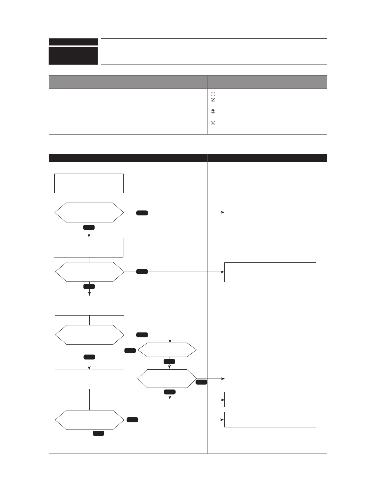
Check code
Chart 1 of 2
6832, 6833
(EF)
MA communication send error
Abnormal points and detection methods Causes and check points
Detected in remote controller or indoor unit. There are 2 remote controllers set as main.
Malfunction of remote controller sending/receiving
circuit
Malfunction of sending/receiving circuit on indoor
controller board
Remote controller transmitting error caused by noise
interference
●Diagnosisofdefectives
Make sure to turn the power OFF before connecting/disconnecting any connectors, or replacing boards
Diagnosis Remedy
Check the remote controller for
main-sub setting.
Conduct the Remote Controller
Diagnosis more than 2 times.
No
No
Is the check code
<6832> or <6833> still
displayed?
Is there only 1 remote controller
set as the main controller?
Set one remote controller to main remote
controller, and the other to sub.
Disconnect and reconnect the
connector CN3A, then turn the
power back ON.
Note:
It takes 6 seconds at maximum
until the result is displayed.
No abnormality
A connector or wiring contact failure is
suspected.
Yes
Continue to the next page
Is "RC NG"
displayed?
Turn the power back ON
No
Is "RC 6832" or
"ERC01" to "ERC66"
displayed?
No abnormality
It might be caused by an external noise, so
check the transmission line.
Yes
No
Yes
No
Yes
Yes
No
Does "HO"or "Please
wait" disappear within
6 minutes?
Is "RC OK" displayed on
all remote controllers?
Replace the remote controller.
Replace the indoor controller board with
the LED2 is blinking.
Yes
96
OCH632A

Check code
●Diagnosisofdefectives
Make sure to turn the power OFF before connecting/disconnecting any connectors, or replacing boards
Diagnosis Remedy
6832, 6833
(EF)
MA communication send error
Chart 2 of 2
No abnormality
It might be caused by an external noise, so
check the transmission line to remove the
factor(s).
No
Yes
Is the wiring connected
properly, meeting the condition?
Connectthewiringproperlyasspeciedin
the chapter "Electrical Work" in the indoor
unit Installation Manual.
Refer to the chapter "Electrical
Work".
Continued from the previous page
97
OCH632A
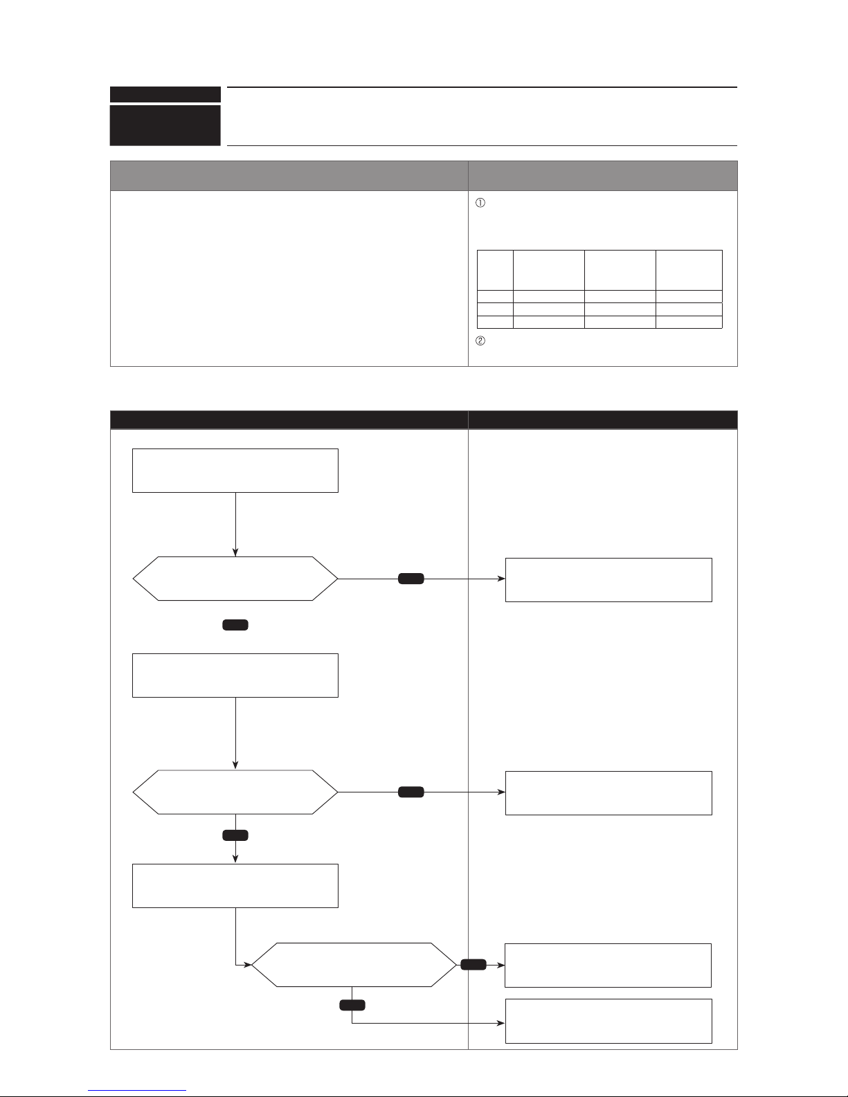
Check code
Abnormal points and detection methods Causes and check points
Whenthetotalcapacityofconnectedindoorunitsexceedsthespecied
capacity (130% of the outdoor unit capacity), a check code <7100> is
displayed.
The total capacity of connected indoor units
exceedsthespeciedcapacity.(Thetotalcodesof
indoor units excluding PWFY unit, Cylinder unit, and
Hydrobox. )
PUMY
WITHOUT PWFY
unit, Cylinder
unit, or Hydrobox
connection
WITH PWFY
unit, Cylinder
unit, or Hydrobox
connection
ecodan unit,
Cylinder unit,
or Hydrobox
connection
P112 35 28 20
P125 41 31 20
P140 47 38 20
The model name code of the outdoor unit is
registered wrongly.
●Diagnosisofdefectives
Make sure to turn the power OFF before connecting/disconnecting any connectors, or replacing boards.
Diagnosis Remedy
7100
(EF)
Total capacity error
No
Yes
Yes
No
No
Yes
Is it set properly?
Is it set properly?
Is the total under 130% of outdoor
unit capacity?
Check the capacity code switch (SW2
on the indoor controller board) on the
connected indoor unit.
Check the model selection switch (SW4 on
the outdoor multi controller circuit board) of
the outdoor unit.
Check the total capacity of connected
indoor units.
Correct it so that the total capacity of
connected indoor units is under 130% of
the outdoor unit capacity.
Set the switch properly.
Set the switch properly.
Complete
98
OCH632A

Check code
Abnormal points and detection methods Causes and check points
When a connected indoor unit is incompatible, a check code <7101> is
displayed.
The model name of connected indoor unit (model code)
is read as incompatible.
The connectable indoor units are:
·
P112 to P140 model: P15 to P140 model (code 3 to 28)
·
When connecting via branch box: P15 to P100 model
(code 3 to 20)
·
PWFY unit: P100 model (code 20)
●Diagnosisofdefectives
Make sure to turn the power OFF before connecting/disconnecting any connectors, or replacing boards.
Diagnosis Remedy
7101
(EF)
Capacity code error
Yes
No
Is it set properly? Set the switch properly.
The model code of the connected indoor
unit can be displayed by an operation of
SW1 on the outdoor unit.
Check the model selection switch (SW4
on the indoor controller board) of the
connected indoor unit.
99
OCH632A

Check code
Abnormal points and detection methods Causes and check points
When the connected indoor unit exceeds the limit, a check code <7102> is
displayed.
Connecting more indoor units and branch boxes than
the limit.
Abnormal if connecting status does not comply with the
following limit;
1
Connectable up to 12 indoor units
2
Connect at least 1 indoor unit (Abnormal if
connected none).
3
Connectable up to 2 branch boxes
4
Connectable up to 1 Air to Water unit (PWFY unit,
Cylinder unit, or Hydrobox)
5
When connecting PWFY unit, Cylinder unit, or
Hydrobox, connect at least 1 indoor unit (other than
Air to Water unit).
6
Connectable up to 1 PEFY-P·VMH-E-F
●Diagnosisofdefectives
Make sure to turn the power OFF before connecting/disconnecting any connectors, or replacing boards.
Diagnosis Remedy
7102
(EF)
Connecting excessive number of units
and branch boxes
Yes
No
No
Yes
Is an indoor unit connected?
Does it exceed the limit?
Connect indoor unit.
Connect less number of units than the
limit.
The model code of the connected indoor
unit can be displayed by an operation of
SW1 on the outdoor unit.
Check whether the M-NET line to the
indoor unit is connected or not.
Check if at least 1 indoor unit is connected.
Check whether the connecting unit
exceeds the limit or not.
100
OCH632A
 Loading...