

Mitsubishi Electric PUMY-P112, PUMY-P125, PUMY-P140VKM, PUMY-P140YKM, PUMY-P112YKM Installation Manual
...
MONTÖR İÇİN
ДЛЯ УСТАНОВИТЕЛЯ
TIL INSTALLATØREN
FÖR INSTALLATÖREN
PARA O INSTALADOR
ΓΙΑ ΑΥΤΟΝ ΠΟΥ ΚΑΝΕΙ ΤΗΝ ΕΓΚΑΤΑΣΤΑΣΗ
PER L’INSTALLATORE
PARA EL INSTALADOR
VOOR DE INSTALLATEUR
POUR L’INSTALLATEUR
FÜR INSTALLATEURE
FOR INSTALLER
Air-Conditioners
PUMY-P112, P125, P140VKM
PUMY-P112, P125, P140YKM
For use with R410A
Eλληνικά (GR)
INSTALLATION MANUAL
For safe and correct use, read this manual and the indoor unit installation manual thoroughly before installing
the air-conditioner unit.
РУКОВОДСТВО ПО УСТАНОВКЕ
Для обеспечения безопасной и надлежащей эксплуатации внимательно прочтите данное руководство
и руководство по установке внутреннего прибора перед установкой кондиционера.
INSTALLATIONSHANDBUCH
Aus Sicherheitsgründen und zur richtigen Verwendung vor der Installation die vorliegende Bedienungsanleitung
und die Installationsanleitung der Innenanlage gründlich durchlesen die Klimaanlage.
MANUEL D’INSTALLATION
Avant d’installer le climatiseur, lire attentivement ce manuel, ainsi que le manuel d’installation de l’appareil
intérieur pour une utilisation sûre et correcte.
INSTALLATIEHANDLEIDING
Lees deze handleiding en de installatiehandleiding van het binnenapparaat zorgvuldig door voordat u met het
installeren van de airconditioner begint.
MANUAL DE INSTALACIÓN
Para un uso correcto y seguro, lea detalladamente este manual y el manual de instalación de la unidad interior
antes de instalar la unidad de aire acondicionado.
MANUALE DI INSTALLAZIONE
Per un uso sicuro e corretto, leggere attentamente il presente manuale ed il manuale d’installazione dell’unità
interna prima di installare il condizionatore d’aria.
EΓΧEIPIΔIO OΔHΓIΩN EΓKATAΣTAΣHΣ
Για σωστή και ασφαλή χρήση, διαβάστε προσεκτικά αυτό το εγχειρίδιο καθώς και το εγχειρίδιο εγκατάστασης
της εσωτερικής μονάδας, προτού εγκαταστήσετε τη μονάδα του κλιματιστικού.
MANUAL DE INSTALAÇÃO
Para uma utilização segura e correcta, leia atentamente este manual e o manual de instalação da unidade
interior antes de instalar o aparelho de ar condicionado.
INSTALLATIONSMANUAL
Læs af sikkerhedshensyn denne manual samt manualen til installation af indendørsenheden grundigt, før du
installerer klimaanlægget.
INSTALLATIONSMANUAL
Läs bruksanvisningen och inomhusenhetens installationshandbok noga innan luftkonditioneringen installeras
så att den används på ett säkert och korrekt sätt.
MONTAJ ELKİTABI
Emniyetli ve doğru kullanım için, klima cihazını monte etmeden önce bu kılavuzu ve iç ünite montaj kılavuzunu
tamamıyla okuyun.
Türkçe (TR)
Русский (RU)
English (GB)
Deutsch (D)
Français (F)
Nederlands (NL)
Español (E)
Italiano (I)
Português (P)
Dansk (DA)
Svenska (SW)
2
Warning:
• The unit must not be installed by the user. Ask a dealer or an authorized
technician to install the unit. If the unit is installed incorrectly, water leakage,
electric shock, or re may result.
• This
appliance is intended to be used by expert or trained users in shops, in
light industry and on farms, or for commercial use by lay persons.
• F
or installation work, follow the instructions in the Installation Manual and use
tools and pipe components specically made for use with R410A refrigerant.
The R410A refrigerant in the HFC system is pressurized 1.6 times the pressure
of usual refrigerants. If pipe components not designed for R410A refrigerant are
used and the unit is not installed correctly, the pipes may burst and cause dam-
age or injuries. In addition, water leakage, electric shock, or re may result.
•
The
unit must be installed according to the instructions in order to minimize
the risk of damage from earthquakes, typhoons, or strong winds. An incorrectly installed unit may fall down and cause damage or injuries.
• The
unit must be securely installed on a structure that can sustain its weight.
If the unit is mounted on an unstable structure, it may fall down and cause
damage or injuries.
• If
the air conditioner is installed in a small room, measures must be taken to
prevent the refrigerant concentration in the room from exceeding the safety
limit in the event of refrigerant leakage. Consult a dealer regarding the appropriate measures to prevent the allowable concentration from being exceeded.
Should the refrigerant leak and cause the concentration limit to be exceeded,
hazards due to lack of oxygen in the room may result.
•
V
entilate the room if refrigerant leaks during operation. If refrigerant comes
into contact with a ame, poisonous gases will be released.
• All
electric work must be performed by a qualied technician according to
local regulations and the instructions given in this manual. The units must be
powered by dedicated power lines and the correct voltage and circuit breakers
must be used. Power lines with insufcient capacity or incorrect electrical
work may result in electric shock or re.
• Use
C1220 copper phosphorus, for copper and copper alloy seamless pipes,
to connect the refrigerant pipes. If the pipes are not connected correctly, the
unit will not be properly grounded and electric shock may result.
• Use only specied cables for wiring. The wiring connections must be made
securely with no tension applied on the terminal connections. Also, never
splice the cables for wiring (unless otherwise indicated in this document).
Failure to observe these instructions may result in overheating or a re.
•
The
terminal block cover panel of the outdoor unit must be rmly attached. If
the cover panel is mounted incorrectly and dust and moisture enter the unit,
electric shock or re may result.
• When
installing or relocating, or servicing the air conditioner, use only the
specied refrigerant (R410A) to charge the refrigerant lines. Do not mix it with
any other refrigerant and do not allow air to remain in the lines.
If
air
is mixed with the refrigerant, then it can be the cause of abnormal high
pressure in the refrigerant line, and may result in an explosion and other
hazards.
The use of any refrigerant other than that specied for the system will cause
mechanical failure or system malfunction or unit breakdown. In the worst case,
this could lead to a serious impediment to securing product safety.
• Use only accessories authorized by Mitsubishi Electric and ask a dealer or an
authorized technician to install them. If accessories are incorrectly installed,
water leakage, electric shock, or re may result.
•
Do
not alter the unit. Consult a dealer for repairs. If alterations or repairs are
not performed correctly, water leakage, electric shock, or re may result.
• The
user should never attempt to repair the unit or transfer it to another loca-
tion. If the unit is installed incorrectly, water leakage, electric shock, or re
may result. If the air conditioner must be repaired or moved, ask a dealer or
an authorized technician.
•
After
installation has been completed, check for refrigerant leaks. If refriger-
ant leaks into the room and comes into contact with the ame of a heater or
portable cooking range, poisonous gases will be released.
1. Safety precautions
► Before installing the unit, make sure you read all the “Safety precau-
tions”.
► Please report to or take consent by the supply authority before connec-
tion to the system.
►
Equipment complying with IEC/EN 61000-3-12
► PUMY
-P·VKM series is designed for use in the residential, commercial
and light-industrial environment.
►
PUMY-P·YKM series is designed as professional equipment.
Warning:
Describes precautions that must be observed to prevent danger of injury or
death to the user.
Caution:
Describes precautions that must be observed to prevent damage to the unit.
After installation work has been completed, explain the “Safety Precautions,” use, and
maintenance of the unit to the customer according to the information in the Operation
Manual and perform the test run to ensure normal operation. Both the Installation
Manual and Operation Manual must be given to the user for keeping. These manuals
must be passed on to subsequent users.
: Indicates a part which must be grounded.
Warning:
Carefully read the labels afxed to the main unit.
Conrmation of parts attached
In addition to this manual, the following parts are supplied with the outdoor unit.
They are used for grounding the S terminals of transmission terminal blocks TB3,
TB7. For details refer to “6. Electrical work”.
Grounding lead wire with a ferrite core for TB3
Note: This symbol mark is for EU countries only.
This symbol mark is according to the directive 2002/96/EC Article 10 Information for users and Annex IV.
Your MITSUBISHI ELECTRIC product is designed and manufactured with high quality materials and components which can be recycled and reused.
This symbol means that electrical and electronic equipment, at their end-of-life, should be disposed of separately from your household waste.
Please, dispose of this equipment at your local community waste collection/recycling centre.
In the European Union there are separate collection systems for used electrical and electronic product.
Please, help us to conserve the environment we live in!
Caution:
• Do not vent R410A into the Atmosphere:
• R410A is a Fluorinated Greenhouse gas, covered by the Kyoto Protocol, with a Global Warming Potential (GWP)=1975.
Contents
1. Safety precautions .....................................................................................2
2. Installation location ....................................................................................4
3. Installing the outdoor unit ..........................................................................6
4. Installing the refrigerant piping ..................................................................6
5. Drainage piping work .................................................................................9
6. Electrical work ...........................................................................................9
7. T
est run ....................................................................................................13
<PUMY-P112-140YKM>
<PUMY-P112-140VKM>
Grounding lead wire (× 2)
Grounding lead wire without a ferrite core for TB7
3
1. Safety precautions
1.3. Before electric work
Caution:
• Be sure to install circuit breakers. If not installed, electric shock may result.
• For the power lines, use standard cables of sufcient capacity. Otherwise, a
short circuit, overheating, or re may result.
• When
installing the power lines, do not apply tension to the cables. If the
connections are loosened, the cables can snap or break and overheating or
re may result.
1.4. Before starting the test run
Caution:
• Turn on the main power switch more than 12 hours before starting operation.
Starting operation just after turning on the power switch can severely damage
the internal parts. Keep the main power switch turned on during the operation
season.
• Before
starting operation, check that all panels, guards and other protective
parts are correctly installed. Rotating, hot, or high voltage parts can cause
injuries.
• Do not touch any switch with wet hands. Electric shock may result.
•
Be sure to ground the unit. Do not connect the ground wire to gas or water
pipes, lighting rods, or telephone grounding lines. If the unit is not properly
grounded, electric shock may result.
• Use
circuit breakers (ground fault interrupter, isolating switch (+B fuse), and
molded case circuit breaker) with the specied capacity. If the circuit breaker
capacity is larger than the specied capacity, breakdown or re may result.
• Do not touch the refrigerant pipes with bare hands during operation. The
refrigerant pipes are hot or cold depending on the condition of the owing
refrigerant. If you touch the pipes, burns or frostbite may result.
•
A
fter stopping operation, be sure to wait at least ve minutes before turning off
the main power switch. Otherwise, water leakage or breakdown may result.
1.5. Using R410A refrigerant air conditioners
Caution:
• Use C1220 copper phosphorus, for copper and copper alloy seamless pipes,
to connect the refrigerant pipes. Make sure the insides of the pipes are clean
and do not contain any harmful contaminants such as sulfuric compounds,
oxidants, debris, or dust. Use pipes with the specied thickness. (Refer to
page 6) Note the following if reusing existing pipes that carried R22 refriger-
ant.
-
Replace
theexistingarenutsandarethearedsectionsagain.
- Do not use thin pipes. (Refer to page 6)
• Store the pipes to be used during installation indoors and keep both ends of
the pipes sealed until just before brazing. (Leave elbow joints, etc. in their
packaging.) If dust, debris, or moisture enters the refrigerant lines, oil deterioration or compressor breakdown may result.
•
Use
ester oil, ether oil, alkylbenzene oil (small amount) as the refrigeration
oil applied to the ared sections. If mineral oil is mixed in the refrigeration
oil, oil deterioration may result.
• Do
not use refrigerant other than R410A refrigerant. If another refrigerant is
used, the chlorine will cause the oil to deteriorate.
• Use
the following tools specically designed for use with R410A refrigerant.
The following tools are necessary to use R410A refrigerant. Contact your
nearest dealer for any questions.
Tools (for R410A)
Gauge manifold Flare tool
Charge hose Size adjustment gauge
Gas leak detector Vacuum pump adapter
Torque wrench Electronic refrigerant charging scale
• B
e sure to use the correct tools. If dust, debris, or moisture enters the refriger-
ant lines, refrigeration oil deterioration may result.
• D
o not use a charging cylinder. If a charging cylinder is used, the composition
of the refrigerant will change and the efciency will be lowered.
1.2. Before installation (relocation)
Caution:
• Be extremely careful when transporting the units. Two or more persons are
needed to handle the unit, as it weighs 20 kg or more. Do not grasp the packaging bands. Wear protective gloves to remove the unit from the packaging
and to move it, as you can injure your hands on the ns or other parts.
• Be
sure to safely dispose of the packaging materials. Packaging materials, such
as nails and other metal or wooden parts may cause stabs or other injuries.
• The
base and attachments of the outdoor unit must be periodically checked
for looseness, cracks or other damage. If such defects are left uncorrected,
the unit may fall down and cause damage or injuries.
• Do not clean the air conditioner unit with water
. Electric shock may result.
• Tighten all are nuts to specication using a torque wrench. If tightened too
much, the are nut can break after an extended period and refrigerant can
leak out.
1.1. Before installation
Caution:
• Do not use the unit in an unusual environment. If the air conditioner is installed
in areas exposed to steam, volatile oil (including machine oil), or sulfuric gas,
areas exposed to high salt content such as the seaside, or areas where the
unit will be covered by snow, the performance can be signicantly reduced
and the internal parts can be damaged.
• Do
not install the unit where combustible gases may leak, be produced, ow,
or accumulate. If combustible gas accumulates around the unit, re or explo-
sion may result.
• The
outdoor unit produces condensation during the heating operation. Make
sure to provide drainage around the outdoor unit if such condensation is likely
to cause damage.
• When installing the unit in a hospital or communications ofce, be prepared for
noise and electronic interference. Inverters, home appliances, high-frequency
medical equipment, and radio communications equipment can cause the air
conditioner to malfunction or breakdown. The air conditioner may also affect
medical equipment, disturbing medical care, and communications equipment,
harming the screen display quality.
4
2. Installation location
2.1. Refrigerant pipe
Refer to Fig. 4-1.
2.2. Choosing the outdoor unit installation location
• Avoid locations exposed to direct sunlight or other sources of heat.
• Select a location from which noise emitted by the unit will not inconvenience neighbors.
• Select
a location permitting easy wiring and pipe access to the power source and
indoor unit.
• A
voidlocationswherecombustiblegasesmayleak,beproduced,ow,oraccumu-
late.
• Note that water may drain from the unit during operation.
•
Select a level location that can bear the weight and vibration of the unit.
• Avoid locations where the unit can be covered by snow. In areas where heavy snow
fall is anticipated, special precautions such as raising the installation location or
installing a hood on the air intake must be taken to prevent the snow from block-
ingthe
airintakeorblowingdirectlyagainstit.Thiscanreducetheairowanda
malfunction may result.
• A
void locations exposed to oil, steam, or sulfuric gas.
• Use the transportation handles of the outdoor unit to transport the unit. If the unit
iscarriedfromthebottom,handsorngersmaybepinched.
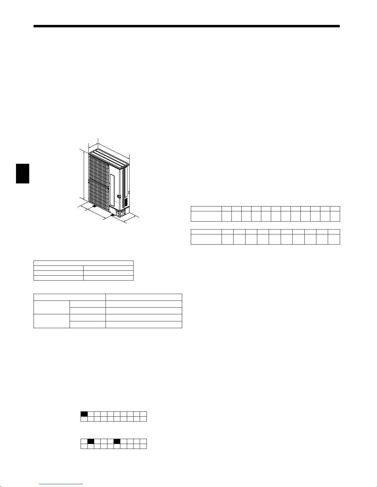
2.3. Outline dimensions (Outdoor unit) (Fig. 2-1)
Constraints on indoor unit installation
You should note that indoor units that can be connected to this outdoor unit are the
following models.
• Indoor
units with model numbers 15-140 (PUMY-P112:15-125) can be connected.
Refer to the table 1 below for possible room, indoor unit combinations.
Verication
The rated capacity should be determined by observing the table below. The unit’s
quantities are limited as shown in the following table 2. For the next step, make
sure that the total rated capacity selected will stay in a range of 50% - 130% of the
outdoor unit capacity.
•
PUMY-P112 6.3 - 16.2 kW
• PUMY-P125 7.1 - 18.2 kW
• PUMY-P140 8.0 - 20.2 kW
Table 1-1 (P*FY series (For Building Application indoor unit))
Indoor unit type
P15 P20 P25 P32 P40 P50 P63 P71 P80 P100 P125 P140
Rated capacity
(Cooling) (kW)
1.7 2.2 2.8 3.6 4.5 5.6 7.1 8.0 9.0 11.2 14.0 16.0
Table 1-2 (M*Z series)
Indoor unit type
15 20 22 25 35 42 50 60 71 80
Rated capacity
(Cooling) (kW)
1.5 2.0 2.2 2.5 3.5 4.2 5.0 6.0 7.1 8.0
Combinations in which the total capacity of indoor units exceeds the capacity of the
outdoor unit will reduce the cooling capacity of each indoor unit below their rated
cooling capacity. Thus, combine indoor units with an outdoor unit within the outdoor
unit’s capacity, if possible.
* Only
when all the indoor units are 1.7 kW models, 12 indoor units can be connected
to 1 outdoor unit.
2.4. Connecting a PWFY Unit
When using a PWFY unit as an indoor unit, be aware of the following points
because the PWFY unit is different from other indoor units.
2.4.1. Connection restrictions
• Only 1 PWFY-P100VM-E-AU can be connected. PWFY-P200VM-E-AU and PWFYP100VM-E-BU cannot be connected.
• The
PWFY unit cannot be the only unit connected to an outdoor unit. Select an
outdoor unit so that the total rated capacity of the indoor units, excluding the PWFY
unit, is 50–100% of the outdoor unit capacity.
Limits for the total rated capacity of the indoor units when connecting a PWFY unit
• PUMY
-P112 (1 PWFY unit + Non-PWFY units [6.3–12.5 kW])
• PUMY-P125 (1 PWFY unit + Non-PWFY units [7.1–14.0 kW])
• PUMY-P140 (1 PWFY unit + Non-PWFY units [8.0–15.5 kW])
2.4.2. Indoor unit specications
When connecting a PWFY unit to a PUMY unit, the following specications will
change.
• The
PWFY unit can operate only in heating mode. The PWFY unit cannot operate
in cooling mode. However, the indoor units other than the PWFY unit can operate
in cooling mode.
• The other indoor units cannot operate at the same time as the PWFY
unit.
• The operation of the PWFY unit has priority. When the PWFY unit is in the operation
mode, the other indoor units will stop.
• The
temperature setting of the remote controller is the target value for the outlet
water temperature.
2.4.3. Switch settings (Fig. 2-2)
When connecting a PWFY unit to a PUMY unit, set DIP switches SW1-1, SW4-2, and
SW4-6 of the PWFY unit to ON.
2.4.4. Test run
If the test run is carried out using the outdoor unit switches, the PWFY unit will
not operate. Carry out the test run using the PWFY unit switches or the remote
controller.
For information about carrying out the test run, refer to the data book or the service
manual for the PWFY unit.
2.4.5. Refrigerant collecting (Pump down)
Step 1 in the pump down procedure instructs the user to “operate all indoor units
in cooling mode”. However, the PWFY unit will not operate in cooling mode.
Operate all of the indoor units, excluding the PWFY unit, in cooling mode.
Fig. 2-1
Table 3 PWFYunitspecications
Model PWFY-P100VM-E-AU
Temp. range of
Heating
Outdoor temp. –15 to 21°C (DB), –15 to 15°C (WB)
Inlet Water temp. 10 to 45°C
Temp. range of
Cooling
Outdoor temp. –
Inlet Water temp. –
SW1
1 2 3 4 5 6 7 8 9 10
ON
SW4
1 2 3 4 5 6 7 8 9 10
ON
Fig. 2-2
(mm)
330+30
370
1050
225
600
1338
Table 2
Connectable indoor units quantities
PUMY-P112 1-9
PUMY-P125 1-10
PUMY-P140 1-12*
5
2. Installation location
Fig. 2-4
Fig. 2-8
Fig. 2-9
Fig. 2-10
Fig. 2-11 Fig. 2-12
Fig. 2-13 Fig. 2-14 Fig. 2-15
Fig. 2-7
Fig. 2-6Fig. 2-5Fig. 2-3
150
200
300
200
1000
150
1000
300
1500
1500
500
1000
600
2000
150
1500
600
3000
500
1500
800
150
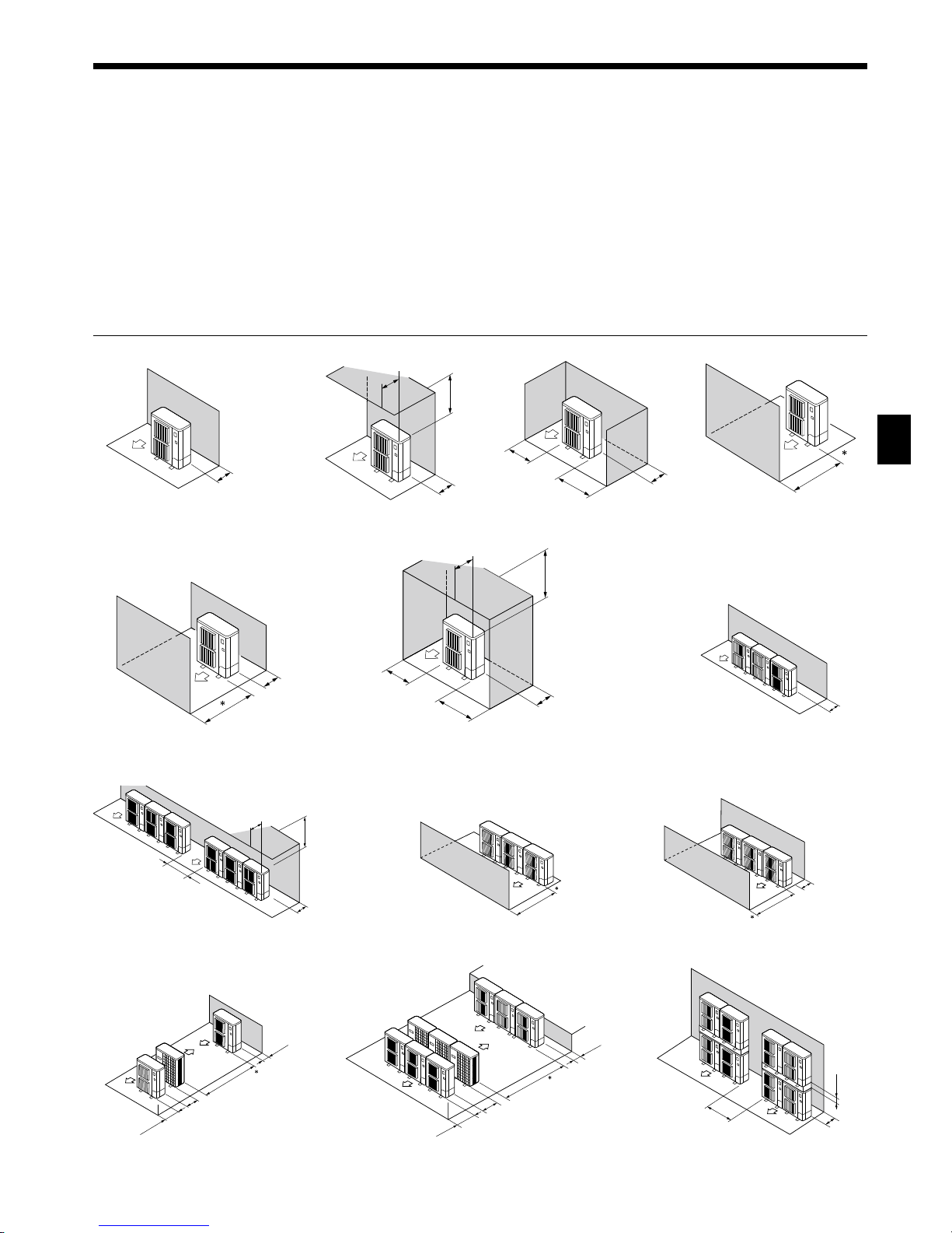
2.5. Ventilation and service space
2.5.1. When installing a single outdoor unit
Minimum dimensions are as follows, except for Max., meaning Maximum dimensions, indicated.
Refer
totheguresforeachcase.
1 Obstacles at rear only (Fig. 2-3)
2 Obstacles at rear and above only (Fig. 2-4)
• Donotinstalltheoptionalairoutletguidesforupwardairow.
3 Obstacles at rear and sides only (Fig. 2-5)
4 Obstacles at front only (Fig. 2-6)
∗ When using an optional air outlet guide, the clearance is 500 mm or more.
5 Obstacles at front and rear only (Fig. 2-7)
∗ When using an optional air outlet guide, the clearance is 500 mm or more.
6 Obstacles at rear, sides, and above only (Fig. 2-8)
• Donotinstalltheoptionalairoutletguidesforupwardairow.
2.5.2. When installing multiple outdoor units
Leave 25 mm space or more between the units.
1 Obstacles at rear only (Fig. 2-9)
2 Obstacles at rear and above only (Fig. 2-10)
• No more than three units must be installed side by side. In addition, leave space as shown.
• Donotinstalltheoptionalairoutletguidesforupwardairow.
3 Obstacles at front only (Fig. 2-11)
∗ When using an optional air outlet guide, the clearance is 1000 mm or more.
4 Obstacles at front and rear only (Fig. 2-12)
∗ When using an optional air outlet guide, the clearance is 1000 mm or more.
5 Single parallel unit arrangement (Fig. 2-13)
∗ Whenusinganoptionalairoutletguideinstalled forupwardairow,theclearance is1000
mm or more.
6 Multiple parallel unit arrangement (Fig. 2-14)
∗ Whenusinganoptionalairoutletguideinstalled forupwardairow,theclearance is1500
mm or more.
7 Stacked unit arrangement (Fig. 2-15)
• The units can be stacked up to two units high.
• No more than two stacked units must be installed side by side. In addition, leave space as shown.
Max.500
500
1000
Max.500
250
250
300
1500
Max.300
1500
500
1500
6
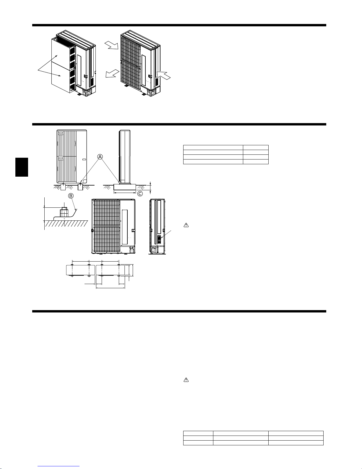
2.5.3. Windy location installation
When installing the outdoor unit on a rooftop or other location unprotected from the
wind, situate the air outlet of the unit so that it is not directly exposed to strong winds.
Strongwind
enteringtheairoutletmayimpedethenormalairowandamalfunction
may result.
The following shows two examples of precautions against strong winds.
1 Install an optional air guide if the unit is installed in a location where strong winds
f
rom a typhoon, etc. may directly enter the air outlet. (Fig. 2-16)
A Air guide
2 Position the unit so that the air outlet blows perpendicularly to the seasonal wind
direction, if possible. (Fig. 2-17)
B Wind direction
Fig. 2-16 Fig. 2-17
2. Installation location
3. Installing the outdoor unit
(mm)
• Be sure to install the unit in a sturdy, level surface to prevent rattling noises during
operation. (Fig. 3-1)
<Foundation
specications>
Foundation bolt M10(3/8″)
Thickness of concrete 120 mm
Length of bolt 70 mm
Weight-bearing capacity 320 kg
• Make
sure that the length of the foundation bolt is within 30 mm of the bottom
surface of the base.
• Secure
the base of theunitrmlywith four-M10 foundation boltsinsturdyloca-
tions.
Installing the outdoor unit
•
Do
not block the vent. If the vent is blocked, operation will be hindered and break-
down may result.
•
In
addition to the unit base, use the installation holes on the back of the unit to
attach wires, etc., if necessary to install the unit. Use self-tapping screws (ø5 × 15
mm or less) and install on site.
Warning:
• The unit must be securely installed on a structure that can sustain its weight.
If the unit is mounted on an unstable structure, it may fall down and cause
damage or injuries.
• The
unit must be installed according to the instructions in order to minimize
the risk of damage from earthquakes, typhoons, or strong winds. An incorrectly installed unit may fall down and cause damage or injuries.
Fig. 3-1
A M10 (3/8") bolt
B Base
C As long as possible.
D Vent
4. Installing the refrigerant piping
4.1. Precautions for devices that use R410A refriger-
ant
• Refer to page 3 for precautions not included below on using air conditioners
with R410A refrigerant.
• Use
ester oil, ether oil, alkylbenzene oil (small amount) as the refrigeration
oil applied to the ared sections.
• Use
C1220 copper phosphorus, for copper and copper alloy seamless pipes,
to connect the refrigerant pipes. Use refrigerant pipes with the thicknesses
specied in the table to the below. Make sure the insides of the pipes are clean
and do not contain any harmful contaminants such as sulfuric compounds,
oxidants, debris, or dust.
Warning:
When installing or relocating, or servicing the air conditioner, use only the
specied refrigerant (R410A) to charge the refrigerant lines. Do not mix it with
any other refrigerant and do not allow air to remain in the lines.
If air is mixed with the refrigerant, then it can be the cause of abnormal high pressure in the refrigerant line, and may result in an explosion and other hazards.
The use of any refrigerant other than that specied for the system will cause
mechanical failure or system malfunction or unit breakdown. In the worst case,
this could lead to a serious impediment to securing product safety.
Indoor unit type 15-50 63-140
Liquid pipe ø6.35 thickness 0.8 mm ø9.52 thickness 0.8 mm
Gas pipe ø12.7 thickness 0.8 mm ø15.88 thickness 1.0 mm
• Do not use pipes thinner than those specied above.
Max.30
600 600Min.475
Min.25
1050
225 225
25
370
330
B
A
D
 Loading...