

Mitsubishi PUMY-P100YHM, PUMY-P140YHMA, PUMY-P100YHMA-BS, PUMY-P125YHMA-BS, PUMY-P140YHMA-BS Service Manual
...
TECHNICAL & SERVICE MANUAL
SPLIT-TYPE, HEAT PUMP AIR CONDITIONERS
CONTENTS
1. TECHNICAL CHANGES
...................................
2
2. SAFETY PRECAUTION
....................................
2
3. OVERVIEW OF UNITS
......................................
5
4. SPECIFICATIONS
.............................................
7
5. DATA
.................................................................
8
6. OUTLINES AND DIMENSIONS
......................
18
7. WIRING DIAGRAM
.........................................
20
8.
NECESSARY CONDITIONS FOR SYSTEM CONSTRUCTION
.....
22
9. TROUBLESHOOTING
....................................
32
10. ELECTRICAL WIRING
....................................
74
11. REFRIGERANT PIPING TASKS
.....................
77
12. DISASSEMBLY PROCEDURE
.......................
81
13. PARTS LIST
.....................................................
87
14. RoHS PARTS LIST
..........................................
90
15. OPTIONAL PARTS
..........................................
93
OUTDOOR UNIT
No. OC355
REVISED EDITION-D
[Service Ref.]
PUMY-P100YHM
PUMY-P100YHM1
PUMY-P100YHMA
PUMY-P125YHM
PUMY-P125YHM1
PUMY-P125YHMA
PUMY-P140YHM
PUMY-P140YHM1
PUMY-P140YHMA
PUMY-P100YHMA-BS
PUMY-P125YHMA-BS
PUMY-P140YHMA-BS
HFC
utilized
R410A
June 2008
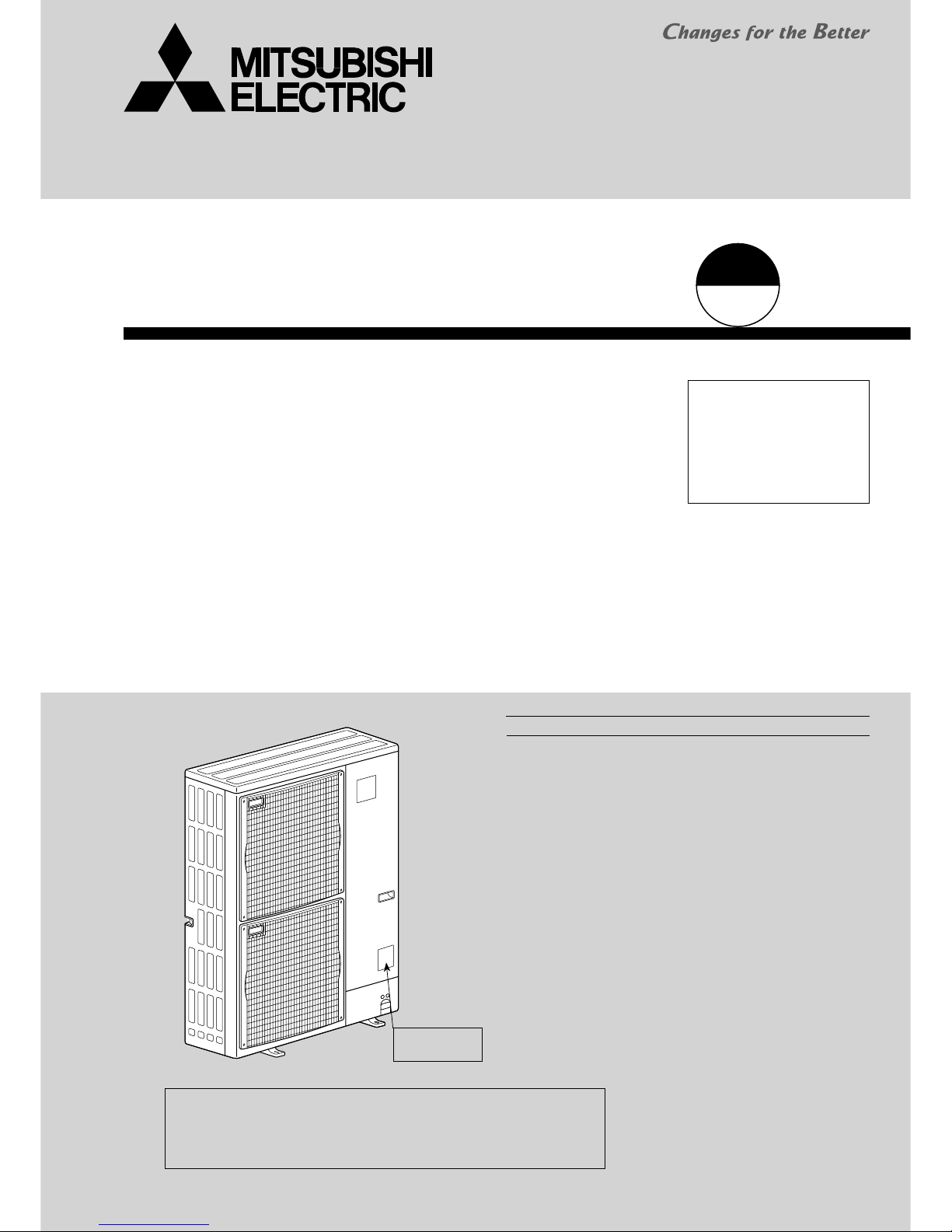
NOTE :
· This service manual describes technical data of outdoor unit.
As for indoor units, refer to its service manual.
· RoHS compliant products have <G> mark on spec name plate.
· For servicing of RoHS compliant products, refer to RoHS PARTS LIST.
[Model name]
<Outdoor unit>
PUMY-P100YHM
PUMY-P100YHMA
PUMY-P125YHM
PUMY-P125YHMA
PUMY-P140YHM
PUMY-P140YHMA
PUMY-P100YHMA-BS
PUMY-P125YHMA-BS
PUMY-P140YHMA-BS
• Please void OC355
REVISED EDITION-C.
Model name
indication
Revision:
• PUMY-P100/125/140YHMA-BS
are added in
REVISED EDITION-D.
• Some descriptions have
been modified.
2
2 SAFETY PRECAUTION
Cautions for units utilizing refrigerant R410A
2-1. CAUTIONS RELATED TO NEW REFRIGERANT
Use new refrigerant pipes.
Make sure that the inside and outside of refrigerant piping is clean and it has no contamination
such as sulfur hazardous for use, oxides, dirt,
shaving particles, etc.
In addition, use pipes with specified thickness.
Store the piping to be used during installation
indoors and keep both ends of the piping sealed
until just before brazing. (Leave elbow joints, etc.
in their packaging.)
Use ester oil, ether oil or alkylbenzene oil (small
amount) as the refrigerant oil applied to flares
and flange connections.
Avoid using thin pipes.
Charge refrigerant from liquid phase of gas
cylinder.
If the refrigerant is charged from gas phase, composition
change may occur in refrigerant and the efficiency will be
lowered.
Do not use refrigerant other than R410A.
If other refrigerant (R22 etc.) is used, chlorine in refrigerant can cause deterioration of refrigerant oil etc.
Use a vacuum pump with a reverse flow check
valve.
Vacuum pump oil may flow back into refrigerant cycle and
that can cause deterioration of refrigerant oil etc.
Use the following tools specifically designed for
use with R410A refrigerant.
The following tools are necessary to use R410A refrigerant.
Keep the tools with care.
If dirt, dust or moisture enters into refrigerant cycle, that can
cause deterioration of refrigerant oil or malfunction of compressor.
Do not use a charging cylinder.
If a charging cylinder is used, the composition of refrigerant will change and the efficiency will be lowered.
Flare tool
Electronic refrigerant
charging scale
Vacuum pump adaptor
Size adjustment gauge
Gauge manifold
Torque wrench
Gas leak detector
Charge hose
Tools for R410A
Contamination inside refrigerant piping can cause deterioration of refrigerant oil etc.
If dirt, dust or moisture enters into refrigerant cycle, that can
cause deterioration of refrigerant oil or malfunction of compressor.
If large amount of mineral oil enters, that can cause deterioration of refrigerant oil etc.
Ventilate the room if refrigerant leaks during
operation. If refrigerant comes into contact with
a flame, poisonous gases will be released.
PUMY-P100YHM1 PUMY-P100YHMA
PUMY-P125YHM
1 PUMY-P125YHMA
PUMY-P140YHM1 PUMY-P140YHMA
• Compressor and oil have been changed.
ANB33FDEMT ANB33FDKMT
Ester oil Ether oil
• Electrical parts below have been changed.
1Controller board (MULTI.B.) 2Noise filter (N.F.)
• PEFY-P15 can be connected.
1 TECHNICAL CHANGES
PUMY-P100YHM PUMY-P100YHM1
PUMY-P125YHM PUMY-P125YHM1
PUMY-P140YHM PUMY-P140YHM1
• The parts below have been changed.
14-way valve and coil (21S4) 2Fan motor (MF1,MF2)
3Noise filter circuit board (N.F.) 4Multi controller circuit board (MULTI.B.)
3
Gravimeter
Unit
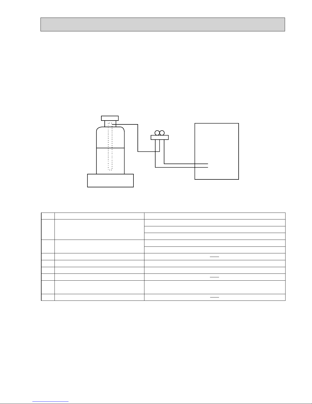
[3] Service tools
Use the below service tools as exclusive tools for R410A refrigerant.
No. Tool name Specifications
1 Gauge manifold ·Only for R410A
·Use the existing fitting
specifications
. (UNF1/2)
·Use high-tension side pressure of 5.3MPa·G or over.
2 Charge hose ·Only for R410A
·Use pressure performance of 5.09MPa·G or over.
3 Electronic scale
4 Gas leak detector ·Use the detector for R134a, R407C or R410A.
5 Adaptor for reverse flow check ·Attach on vacuum pump.
6 Refrigerant charge base
7 Refrigerant cylinder ·Only for R410A ·Top of cylinder (Pink)
·Cylinder with syphon
8 Refrigerant recovery equipment
[1] Cautions for service
(1) Perform service after recovering the refrigerant left in unit completely.
(2) Do not release refrigerant in the air.
(3) After completing service, charge the cycle with specified amount of refrigerant.
(4) When performing service, install a filter drier simultaneously.
Be sure to use a filter drier for new refrigerant.
[2] Additional refrigerant charge
When charging directly from cylinder
· Check that cylinder for R410A on the market is syphon type.
· Charging should be performed with the cylinder of syphon stood vertically. (Refrigerant is charged from liquid phase.)
Although "-BS" model has been designed to be resistant to salt damage, observe the following precautions to maintain the
performance of the unit.
1. Avoid installing the uint in a location where it will be exposed directly to seawater or sea breeze.
2. If the cover panel may become covered with salt, be sure to install the unit in a location where the salt will be washed away by
rainwater. (If a sunshade is installed, rainwater may not clean the panel.)
3. To ensure that water does not collect in the base of the outdoor unit, make sure that the base is level, not at angle. Water
collecting in the base of the outdoor unit could cause rust.
4. If the unit is installed in a coastal area, clean the unit with water regularly to remove any salt build-up.
5. If the unit is damaged during installation or maintenance, be sure to repair it.
6. Be sure to check the condition of the unit regularly.
7. Be sure to install the unit in a location with good drainage.
2-2. PRECAUTIONS FOR SALT PROOF TYPE "-BS" MODEL
4
Cautions for refrigerant piping work
New refrigerant R410A is adopted for replacement inverter series. Although the refrigerant piping work for R410A is same
as for R22, exclusive tools are necessary so as not to mix with different kind of refrigerant. Furthermore as the working
pressure of R410A is 1.6 time higher than that of R22, their sizes of flared sections and flare nuts are different.
1Thickness of pipes
Because the working pressure of R410A is higher compared to R22, be sure to use refrigerant piping with thickness
shown below. (Never use pipes of 0.7mm or below.)
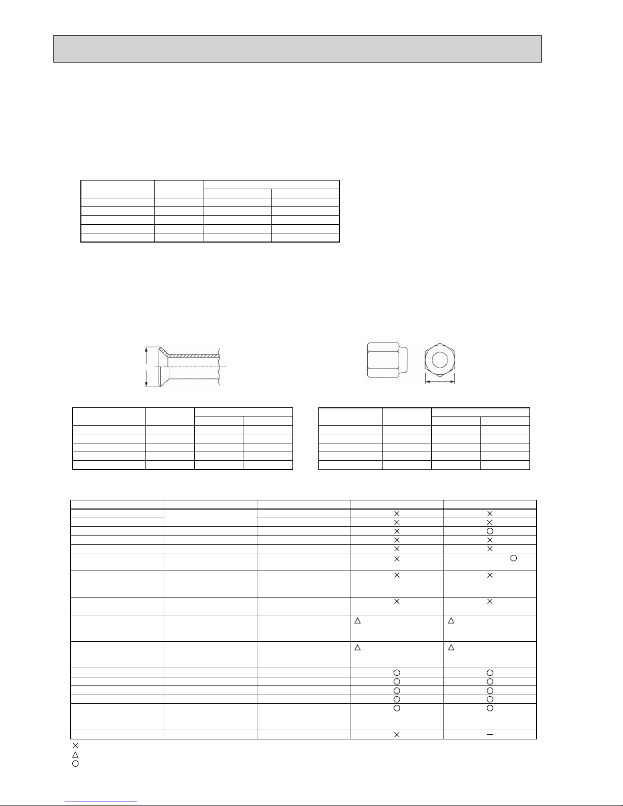
2Dimensions of flare cutting and flare nut
The component molecules in HFC refrigerant are smaller compared to conventional refrigerants. In addition to that,
R410A is a refrigerant, which has higher risk of leakage because its working pressure is higher than that of other refriger ants. Therefore, to enhance airtightness and intensity, flare cutting dimension of copper pipe for R410A have been speci fied separately from the dimensions for other refrigerants as shown below. The dimension B of flare nut for R410A also
have partly been changed to increase intensity as shown below. Set copper pipe correctly referring to copper pipe flaring
dimensions for R410A below. For 1/2 and 5/8 inch, the dimension B changes.
Use torque wrench corresponding to each dimension.
3Tools for R410A (The following table shows whether conventional tools can be used or not.)
1/4
3/8
1/2
5/8
3/4
6.35
9.52
12.70
15.88
19.05
0.8
0.8
0.8
1.0
—
0.8
0.8
0.8
1.0
1.0
Nominal
dimensions(inch)
Diagram below: Piping diameter and thickness
Outside
diameter
(mm)
Thickness
(mm)
R410A R22
1/4
3/8
1/2
5/8
3/4
6.35
9.52
12.70
15.88
19.05
9.1
13.2
16.6
19.7
—
9.0
13.0
16.2
19.4
23.3
Nominal
dimensions(inch)
Flare cutting dimensions
Outside
diameter
Dimension A
( )
+0
-0.4
(mm)
R410A R22
1/4
3/8
1/2
5/8
3/4
6.35
9.52
12.70
15.88
19.05
17.0
22.0
26.0
29.0
—
17.0
22.0
24.0
27.0
36.0
Nominal
dimensions(inch)
Flare nut dimensions
Outside
diameter
Dimension B
(mm)
R410A R22
Gauge manifold
Charge hose
Gas leak detector
Refrigerant recovery equipment
Refrigerant cylinder
Applied oil
Safety charger
Charge valve
Vacuum pump
Flare tool
Bender
Pipe cutter
Welder and nitrogen gas cylinder
Refrigerant charging scale
Vacuum gauge or thermistor vacuum gauge and
vacuum valve
Charging cylinder
Air purge, refrigerant charge
and operation check
Gas leak check
Refrigerant recovery
Refrigerant charge
Apply to flared section
Prevent compressor malfunction
when charging refrigerant by
spraying liquid refrigerant
Prevent gas from blowing out
when detaching charge hose
Vacuum drying and air
purge
Flaring work of piping
Bend the pipes
Cut the pipes
Weld the pipes
Refrigerant charge
Check the degree of vacuum. (Vacuum
valve prevents back flow of oil and refrigerant to thermistor vacuum gauge)
Refrigerant charge
Tool exclusive for R410A
Tool exclusive for R410A
Tool for HFC refrigerant
Tool exclusive for R410A
Tool exclusive for R410A
Ester oil, ether oil and
alkylbenzene oil (minimum amount)
Tool exclusive for R410A
Tool exclusive for R410A
Tools for other refrigerants can
be used if equipped with adopter for reverse flow check
Tools for other refrigerants
can be used by adjusting
flaring dimension
Tools for other refrigerants can be used
Tools for other refrigerants can be used
Tools for other refrigerants can be used
Tools for other refrigerants can be used
Tools for other refrigerants
can be used
Tool exclusive for R410A
Tools and materials Use R410A tools Can R22 tools be used?
(Usable if equipped
with adopter for rever se flow)
(Usable by adjusting
flaring dimension)
Can R407C tools be used?
Ester oil, ether oil:
Alkylbenzene oil: minimum amount
(Usable if equipped
with adopter for rever se flow)
(Usable by adjusting
flaring dimension)
: Prepare a new tool. (Use the new tool as the tool exclusive for R410A.)
: Tools for other refrigerants can be used under certain conditions.
: Tools for other refrigerants can be used.
Dimension A
Dimension B
5
3
OVERVIEW OF UNITS
3-1. UNIT CONSTRUCTION
15
20
25
32
40
50
63
71
80
100
125
140
–
20VCM-E
25VCM-E
32VCM-E/32VBM-E
40VCM-E/40VBM-E
50VBM-E
63VBM-E
–
80VBM-E
100VBM-E
125VBM-E
–
–
20VLMD-E
25VLMD-E
32VLMD-E
40VLMD-E
50VLMD-E
63VLMD-E
–
80VLMD-E
100VLMD-E
125VLMD-E
–
15VMS/(L)-E
20VML-E / VMM-E
25VML-E / VMM-E
32VML-E / VMM-E
40VMH-E / VMM-E
50VMH-E / VMM-E
63VMH-E / VMM-E
71VMH-E / VMM-E
80VMH-E / VMM-E
100VMH-E / VMM-E
125VMH-E / VMM-E
140VMM-E
–
20VM-E
25VM-E
32VM-E
40VM-E
50VM-E
63VM-E
71VM-E
80VM-E
100VM-E
125VM-E
–
–
20VBM-E
25VBM-E
32VGM-E
40VGM-E
50VGM-E
–
–
–
–
–
–
–
20VLEM-E
25VLEM-E
32VLEM-E
40VLEM-E
50VLEM-E
63VLEM-E
–
–
–
–
–
–
20VLRM-E
25VLRM-E
32VLRM-E
40VLRM-E
50VLRM-E
63VLRM-E
–
–
–
–
–
–
–
–
–
40VGM-E
–
63VGM-E
–
–
100VGM-E
125VGM-E
–
PLFY-P PLFY-P PEFY-P PDFY-P PKFY-P PCFY-P PFFY-P PFFY-P
–
–
–
–
–
–
–
–
80VMH-E-F
–
–
140VMH-E-F
PEFY-P
Capacity
Model
Cassette Ceiling
4-way flow 2-way flow
–
20VBM-E
25VBM-E
32VBM-E
40VBM-E
–
–
–
–
–
–
–
PMFY-P
1-way flow
Ceiling
Concealed
Ceiling
mounted
built-in
Ceiling
Suspended
Ceiling
Concealed
(Fresh Air)
*1
Wall
Mounted
Floor standing
Exposed Concealed
Remote
controller
Name
Model number
Functions
M-NET remote controller
PAR-F27MEA-E
• A handy remote controller for use in conjunction
with the Melans centralized management system.
• Addresses must be set.
• Addresses setting is not necessary.
MA remote controller
PAR-21MAA
Outdoor unit
Capacity
Type 15(YHMA) / 20(YHM(1))~Type 125
1~ 6 unit
50% ~130% of outdoor unit capacity
*2
Type 15(YHMA) / 20(YHM
(1))~Type 140
1~ 8 unit
Indoor
unit that
can be
connected
Number of units
Total system wide capacity
4HP 5HP 6HP
PUMY-P100YHM
PUMY-P100YHM1
PUMY-P100YHMA (-BS)
PUMY-P125YHM
PUMY-P125YHM1
PUMY-P125YHMA (-BS)
PUMY-P140YHM
PUMY-P140YHM1
PUMY-P140YHMA (-BS)
Branching pipe
components
Branch header
(2 branches)
Branch header
(4 branches)
Branch header
(8 branches)
CMY-Y62-G-E CMY-Y64-G-E CMY-Y68-G-E
*1. PUMY-P·YHM1/YHMA can connect Fresh Air type indoor unit. (PUMY-P·YHM can NOT connect.)
It is possible only by 1: 1 system.
(1 indoor unit of Fresh Air type is connected with 1 outdoor unit.)
Operating temperature range(outdoor temperature) for fresh air type indoor units differ from other indoor units.
Refer to 3-2(3).
*2. When the indoor unit of Fresh Air type is connected with the outdoor unit, the maximum connectable total indoor unit
capacity is 110% (100% in case of heating below -5:[23˚F]).
Decorative panel
6
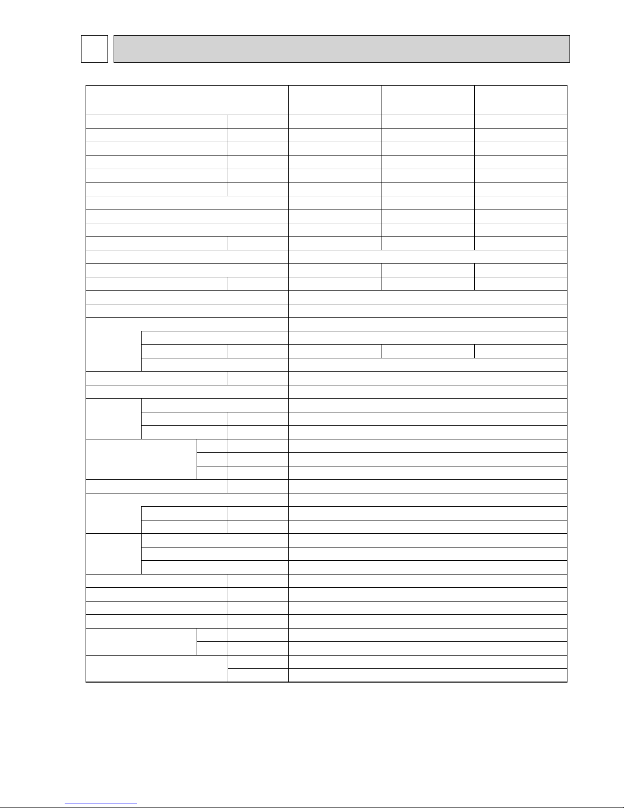
3-2. UNIT SPECIFICATIONS
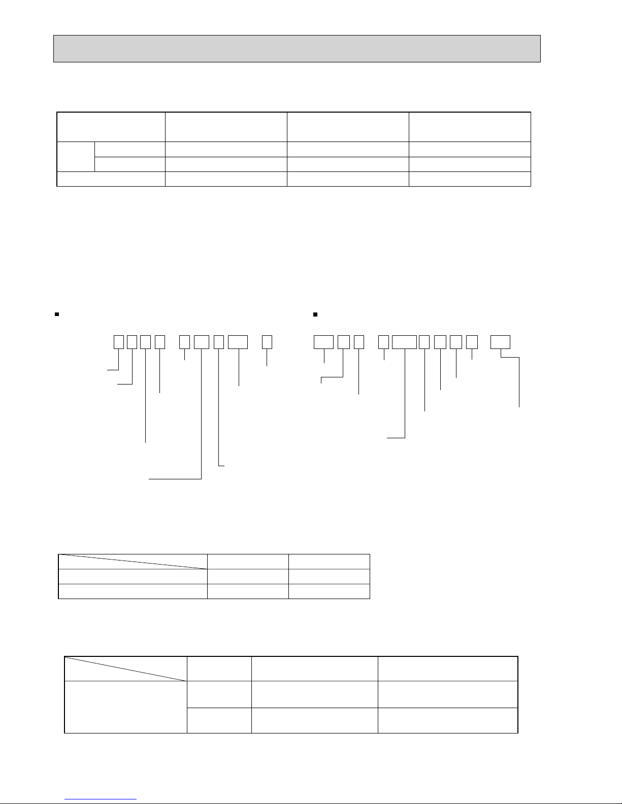
(2) Method for identifying MULTI-S model
(1) Outdoor Unit
Indoor unit < When using Model 80 >
Outdoor unit <When using model 125 >
P L F Y - P 80 V AM - E PU M Y - P 125 Y H M A - BS
PAC type
AM
BM
CM
KM
M
KM
LMD
Frequency
conversion
controller
Refrigerant
R407C/R22
R410A
commonness
Refrigerant
R410A
NEW frequency converter
one-to-many air conditioners
(flexible design type)
Indicates equivalent
to Cooling capacity
Indicates equivalent
to Cooling capacity
Power supply
V: Single phase
220-230-240V 50Hz
220V 60Hz
Power supply
Y: 3-phase
380-400-415V 50Hz
L : Ceiling cassette
K : Wall-mounted type
E : Hidden skylight type
C : Ceiling suspended type
M : Ceiling cassette type
F : Floor standing type
}
M-NET
control
Outdoor unit
model type
Sub-number
M-NET control
Sub-number
Frequency
conversion
controller
Outdoor unit
MULTI-S
(k cal / h)
(k cal / h)
Salt proof type
Service Ref.
PUMY-P100YHM
PUMY-P100YHM
1
PUMY-P100YHMA(-BS)
Capacity
Cooling (kW)
Heating (kW)
11.2
12.5
1.9
PUMY-P125YHM
PUMY-P125YHM1
PUMY-P125YHMA (-BS)
14.0
16.0
2.4
PUMY-P140YHM
PUMY-P140YHM1
PUMY-P140YHMA (-BS)
16.0
18.0
2.9Motor for compressor (kW)
Cooling / Heating capacity indicates the maximum value at operation under the following condition.
w. Cooling Indoor : D.B. 27°C / W.B. 19.0°C
Outdoor : D.B. 35°C
Heating Indoor : D.B. 20°C
Outdoor : D.B. 7°C / W.B. 6°C
(3) Operating temperature range
Notes D.B. : Dry Bulb Temperature
W.B. : Wet Bulb Temperature
w1. 10~46°C DB : In case of connecting PKFY-P20/P25 type indoor unit.
Cooling
W
.B. 15~24C
D.B. -5~46C
+1
Heating
D.B. 15~27C
W.B. -15~15C
Indoor-side intake air temperature
Outdoor-side intake air temperature
■ In case of connecting fresh air type indoor unit (Only PUMY-P·YHM1/YHMA can connect Fresh air type indoor unit.)
air type indoor
Capacity of Fresh
Cooling
Heating
Indoor-side and Outdoor-side
P80
D.B.21~43
+
2
W.B.15.5~35
D.B.-10~20
+
3
intake air temperature
P140
D.B.21~43
+
2
W.B.15.5~35
D.B.-5~20
+
3
+
2.Thermo-off (FAN-mode) automatically starts if the outdoor temp. is lower than 21D.B..
+
3.Thermo-off (FAN-mode) automatically starts if the outdoor temp. is higher than 20D.B..
7
4
SPECIFICATIONS
PUMY-P100YHM
(1)
PUMY-P100YHMA
PUMY-P100YHMA-BS
PUMY-P125YHM
(1)
PUMY-P125YHMA
PUMY-P125YHMA-BS
PUMY-P140YHM
(1)
PUMY-P140YHMA
PUMY-P140YHMA-BS
Cooling Capacity
Service Ref.
kW 11.2 14.0 15.5
Heating Capacity kW 12.5 16.0 18.0
Input(Cool
)
kW 3.3 4.27 5.32
Input Current (Cool
)
A 5.28/5.02/4.84 6.83/6.49/6.26 8.51/8.09/7.80
Input(Heat
)
kW 3.63 4.29 5.32
Input Current (Heat
)
A 5.81/5.52/5.32 6.87/6.52/6.29 8.51/8.09/7.80
EER(Cool
)
3.39 3.28 2.91
COP (Heat
)
3.44 3.73 3.38
Connectable indoor units (Max.
)
688
Max. Connectable Capacity kW 14.5(130%
)
18.2(130%
)
20.2(130%
)
Power Supply 3 phase ,50Hz,380/400/415V
Breaker Size 16A 16A 16A
Sound level (Cool/Heat
)
dB 49 / 51 50 / 52 51 / 53
External finish Munsell 3Y 7.8/1.1
Refrigerant control Linear Expansion Valve
Compressor Hermetic
YHM
(1)
:ANB33FDEMT, YHMA:ANB33FDKMT
Model
Motor output kW 1.9 2.4 2.9
Starting method Inverter
Crankcase heater W —
Heat exchanger Plate fin coil (Anti corrosion fin treatment
)
Fan Fan(drive
) %
No. Propeller fan % 2
Fa motor output kW 0.060 + 0.060
Airflow m
3
/min(CFM
)
100(3,530
)
Dimensions(HxWxD
)
Wmm
(
in.
)
950(37-3/8
)
Dmm
(
in.
)
330+30(13+1-3/16
)
Hmm
(
in.
)
1,350(53-1/8
)
Weight kg(lbs
)
140(309
)
Refrigerant R410A
Charge kg(lbs
)
8.5(18.7
)
Protection High pressure protection HP switch
devices Compressor protection Discharge thermo,Over current detection
Fan motor protection Overheating/Voltage protection
Oil(Model
)
2.3(YHM
(1)
: MEL56, YHMA:FV50S
)
Total Piping length (Max.
)
m
L
120
Farthest m 80
Max. Height difference m 30
Chargeless length m 50
Piping diameter
Gas :mm(in.) 15.88(5/8
)
Liquid :mm(in.) 9.52(3/8
)
Guranteed operation range
(
cool
)
-5~ 46 DB
(
heat
)
-15~ 15 WB
+3
+3
+3
+3
+3
+3
+1
+2
Rating conditions (JIS B 8616)
Cooling Indoor : D.B. 27: / W.B. 19:
Outdoor : D.B. 35: / W.B. 20:
Heating Indoor : D.B. 20:
Outdoor : D.B. 7: / W.B. 6:
Note.w1. 20m : In case of installing outdoor unit lower than
indoor unit.
w2. 10~46:DB : In case of connecting PKFY-P20/P25 type
indoor unit.
w3. Electrical data is for only outdoor unit.
8
5
DATA
5-1. COOLING AND HEATING CAPACITY AND CHARACTERISTICS
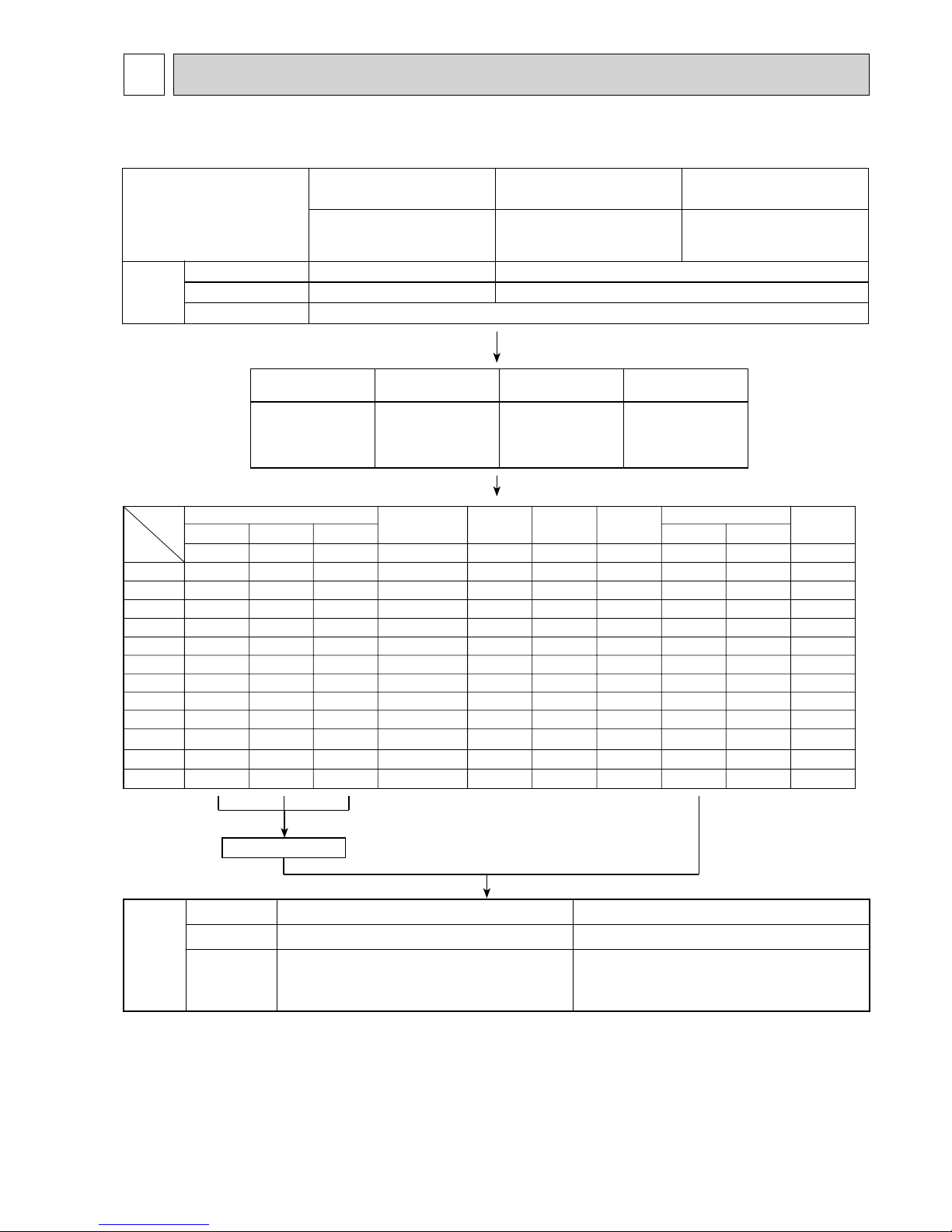
5-1-1. Method for obtaining system cooling and heating capacity:
To obtain the system cooling and heating capacity and the electrical characteristics of the outdoor unit, first add up the rati ngs
of all the indoor units connected to the outdoor unit (see table below), and then use this total to find the standard capacity with
the help of the tables on 5-2.STANDARD CAPACITY DIAGRAM.
(1) Capacity of indoor unit
5-1-2. Method for obtaining the heating and cooling capacity of an indoor unit:
(1) The capacity of each indoor unit (kW) = the capacity A (or B)
o
(2) Sample calculation (using the system described above in 5-1-1. (2) ):
model capacity
total model capacity of all indoor units
During cooling: During heating:
• The total model capacity of the indoor unit is:
2.8 o 2 + 5.6 o 2=16.8kW
Therefore, the capacity of PKFY-P25VAM-E and
PLFY-P50VLMD-E will be calculated as follows by
using the formula in 5-1-2. (1):
Model 25=14.6 o = 2.43kW
Model 50=14.6 o = 4.87kW
• The total model capacity of indoor unit is:
3.2 o 2 + 6.3 o 2=19.0
Therefore, the capacity of PKFY-P25VAM-E and PLFYP50VLMD-E will be calculated as follows by using the
formula in 5-1-2. (1):
Model 25=16.33 o = 2.75kW
Model 50=16.33 o = 5.41kW
2.8
16.8
5.6
16.8
6.3
19.0
3.2
19.0
(2) Sample calculation
1System assembled from indoor and outdoor unit (in this example the total capacity of the indoor units is greater than that of
the outdoor unit)
• Outdoor unit PUMY-P125YHM PUMY-P125YHM
1
• Indoor unit PKFY-P25VAM-E o 2 , PLFY-P50VLMD-E o 2
2According to the conditions in 1, the total capacity of the indoor unit will be: 28 o 2 + 56 o 2 = 168
3The following figures are obtained from the 168 total capacity row of the standard capacity diagram (5-2.):
Model 20
Model Number for indoor unit
Model Capacity
22
Model 15
17
Model 2528Model 3236Model 4045Model 5056Model 6371Model 7180Model 8090Model 100
112
Model 125
140
Model 140
160
Cooling
A 14.60
Heating
6.01
Cooling
6.59
Heating
3.95
Cooling
4.34
Heating
B 16.33
Capacity (kW)
Outdoor unit power consumption (kW)
Outdoor unit current (A)/400V

9
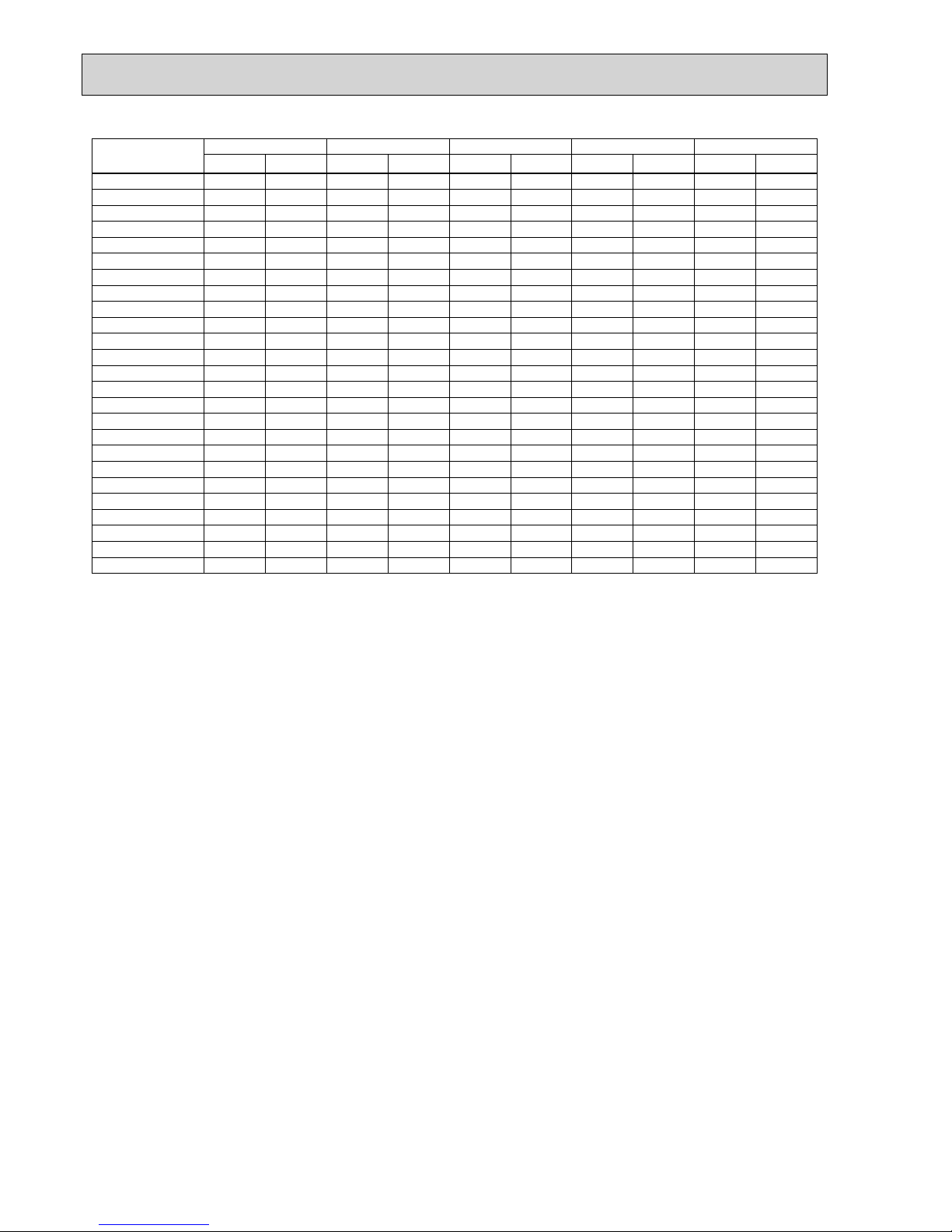
Total capacity of
Capacity(kW)
Power Consumption(kW)
Current(A)/380V Current(A)/400V Current(A)/415V
indoor units
*
Cooling Heating Cooling Heating Cooling Heating Cooling Heating Cooling Heating
56 5.60 6.30 1.57 1.87 2.52 3.00 2.39 2.85 2.31 2.75
57 5.70 6.41 1.59 1.90 2.55 3.05 2.42 2.89 2.34 2.79
58 5.80 6.53 1.62 1.92 2.60 3.08 2.47 2.93 2.38 2.82
59 5.90 6.64 1.64 1.95 2.63 3.13 2.50 2.97 2.41 2.86
60 6.00 6.75 1.66 1.98 2.66 3.17 2.53 3.02 2.44 2.91
61 6.10 6.87 1.69 2.00 2.71 3.21 2.58 3.05 2.48 2.94
62 6.20 6.98 1.71 2.03 2.74 3.26 2.61 3.09 2.51 2.98
63 6.30 7.09 1.74 2.06 2.79 3.30 2.65 3.14 2.56 3.02
64 6.40 7.20 1.76 2.08 2.82 3.34 2.68 3.17 2.59 3.05
65 6.50 7.32 1.78 2.11 2.85 3.38 2.71 3.21 2.61 3.10
66 6.60 7.43 1.81 2.14 2.90 3.43 2.76 3.26 2.66 3.14
67 6.70 7.54 1.83 2.17 2.93 3.48 2.79 3.31 2.69 3.19
68 6.80 7.66 1.86 2.20 2.98 3.53 2.83 3.35 2.73 3.23
69 6.90 7.77 1.89 2.22 3.03 3.56 2.88 3.38 2.78 3.26
70 7.00 7.88 1.91 2.25 3.06 3.61 2.91 3.43 2.81 3.30
71 7.10 8.00 1.94 2.28 3.11 3.66 2.96 3.47 2.85 3.35
72 7.20 8.11 1.97 2.31 3.16 3.70 3.00 3.52 2.89 3.39
73 7.30 8.22 1.99 2.34 3.19 3.75 3.03 3.56 2.92 3.44
74 7.40 8.33 2.02 2.37 3.24 3.80 3.08 3.61 2.97 3.48
75 7.50 8.44 2.05 2.40 3.28 3.85 3.12 3.66 3.01 3.52
76 7.60 8.56 2.08 2.43 3.33 3.90 3.17 3.70 3.05 3.57
77 7.70 8.67 2.11 2.46 3.38 3.94 3.21 3.75 3.10 3.61
78 7.80 8.78 2.13 2.49 3.41 3.99 3.24 3.79 3.13 3.66
79 7.90 8.89 2.16 2.52 3.46 4.04 3.29 3.84 3.17 3.70
80 8.00 9.00 2.19 2.55 3.51 4.09 3.34 3.88 3.22 3.74
81 8.10 9.10 2.22 2.58 3.56 4.14 3.38 3.93 3.26 3.79
82 8.20 9.20 2.25 2.61 3.60 4.18 3.43 3.97 3.30 3.83
83 8.30 9.30 2.28 2.64 3.65 4.23 3.47 4.02 3.35 3.88
84 8.40 9.40 2.31 2.67 3.70 4.28 3.52 4.07 3.39 3.92
85 8.50 9.50 2.35 2.70 3.76 4.33 3.58 4.11 3.45 3.96
86 8.60 9.60 2.38 2.74 3.81 4.39 3.62 4.17 3.49 4.02
87 8.70 9.70 2.41 2.77 3.86 4.44 3.67 4.22 3.54 4.07
88 8.80 9.80 2.44 2.80 3.91 4.49 3.72 4.26 3.58 4.11
89 8.90 9.90 2.47 2.83 3.96 4.54 3.76 4.31 3.63 4.15
90 9.00 10.00 2.51 2.86 4.02 4.58 3.82 4.35 3.68 4.20
91 9.10 10.10 2.54 2.90 4.07 4.65 3.87 4.42 3.73 4.26
92 9.20 10.22 2.57 2.93 4.12 4.70 3.91 4.46 3.77 4.30
93 9.30 10.33 2.60 2.96 4.16 4.74 3.96 4.51 3.82 4.34
94 9.40 10.45 2.64 3.00 4.23 4.81 4.02 4.57 3.88 4.40
95 9.50 10.56 2.67 3.03 4.28 4.86 4.07 4.61 3.92 4.45
96 9.60 10.67 2.71 3.06 4.34 4.90 4.13 4.66 3.98 4.49
97 9.70 10.79 2.74 3.10 4.39 4.97 4.17 4.72 4.02 4.55
98 9.80 10.90 2.78 3.13 4.45 5.02 4.23 4.77 4.08 4.59
99 9.90 11.02 2.81 3.17 4.50 5.08 4.28 4.83 4.12 4.65
100 10.00 11.13 2.85 3.20 4.56 5.13 4.34 4.87 4.18 4.70
101 10.10 11.24 2.88 3.24 4.61 5.19 4.39 4.93 4.23 4.75
102 10.20 11.36 2.92 3.27 4.67 5.24 4.45 4.98 4.29 4.80
103 10.30 11.47 2.96 3.31 4.74 5.30 4.51 5.04 4.34 4.86
104 10.40 11.59 2.99 3.34 4.79 5.35 4.55 5.08 4.39 4.90
105 10.50 11.70 3.03 3.38 4.85 5.42 4.61 5.15 4.45 4.96
106 10.60 11.81 3.07 3.41 4.91 5.46 4.67 5.19 4.51 5.00
107 10.70 11.93 3.11 3.45 4.98 5.53 4.74 5.25 4.56 5.06
108 10.80 12.04 3.14 3.48 5.03 5.58 4.78 5.30 4.61 5.11
109 10.90 12.16 3.18 3.52 5.09 5.64 4.84 5.36 4.67 5.17
110 11.00 12.27 3.22 3.56 5.15 5.70 4.90 5.42 4.73 5.22
111 11.10 12.38 3.26 3.59 5.22 5.75 4.96 5.47 4.78 5.27
112 11.20 12.50 3.30 3.63 5.28 5.81 5.02 5.52 4.84 5.32
113 11.22 12.51 3.31 3.62 5.30 5.80 5.04 5.51 4.86 5.31
114 11.24 12.53 3.31 3.61 5.30 5.78 5.04 5.50 4.86 5.30
115 11.26 12.54 3.32 3.60 5.31 5.77 5.05 5.48 4.87 5.28
116 11.28 12.55 3.32 3.59 5.31 5.75 5.05 5.47 4.87 5.27
117 11.30 12.56 3.32 3.58 5.31 5.74 5.05 5.45 4.87 5.25
118 11.32 12.57 3.33 3.56 5.33 5.70 5.07 5.42 4.89 5.22
119 11.34 12.58 3.33 3.55 5.33 5.69 5.07 5.40 4.89 5.21
120 11.36 12.60 3.34 3.54 5.35 5.67 5.08 5.39 4.90 5.19
5-2. STANDARD CAPACITY DIAGRAM
5-2-1.PUMY-P100YHM PUMY-P100YHM1 PUMY-P100YHMA (-BS)
*Before calculating the sum of total capacity of indoor units, please convert the value into the kW model capacity
following the formula on 5-1-1.
10
Total capacity of Capacity(kW)
Power Consumption(kW)
Current(A)/380V Current(A)/400V Current(A)/415V
indoor units
*
Cooling Heating Cooling Heating Cooling Heating Cooling Heating Cooling Heating
121 11.38 12.61 3.34 3.53 5.35 5.66 5.08 5.37 4.90 5.18
122 11.40 12.62 3.34 3.52 5.35 5.64 5.08 5.36 4.90 5.17
123 11.42 12.63 3.35 3.51 5.36 5.62 5.10 5.34 4.92 5.15
124 11.44 12.64 3.35 3.50 5.36 5.61 5.10 5.33 4.92 5.14
125 11.47 12.66 3.36 3.48 5.38 5.58 5.12 5.30 4.93 5.11
126 11.49 12.67 3.36 3.47 5.38 5.56 5.12 5.28 4.93 5.09
127 11.51 12.68 3.36 3.46 5.38 5.54 5.12 5.27 4.93 5.08
128 11.53 12.69 3.37 3.45 5.39 5.53 5.13 5.25 4.95 5.06
129 11.55 12.70 3.37 3.44 5.39 5.51 5.13 5.24 4.95 5.05
130 11.57 12.71 3.38 3.43 5.41 5.50 5.15 5.22 4.96 5.03
131 11.59 12.73 3.38 3.41 5.41 5.46 5.15 5.19 4.96 5.00
132 11.61 12.74 3.38 3.40 5.41 5.45 5.15 5.18 4.96 4.99
133 11.63 12.75 3.39 3.39 5.43 5.43 5.16 5.16 4.97 4.97
134 11.65 12.76 3.39 3.38 5.43 5.42 5.16 5.15 4.97 4.96
135 11.67 12.77 3.40 3.37 5.44 5.40 5.18 5.13 4.99 4.95
136 11.69 12.78 3.40 3.36 5.44 5.38 5.18 5.12 4.99 4.93
137 11.71 12.80 3.40 3.34 5.44 5.35 5.18 5.08 4.99 4.90
138 11.73 12.81 3.41 3.33 5.46 5.34 5.19 5.07 5.00 4.89
139 11.75 12.82 3.41 3.32 5.46 5.32 5.19 5.05 5.00 4.87
140 11.77 12.83 3.42 3.31 5.47 5.30 5.21 5.04 5.02 4.86
141 11.79 12.84 3.42 3.30 5.47 5.29 5.21 5.02 5.02 4.84
142 11.82 12.86 3.42 3.29 5.47 5.27 5.21 5.01 5.02 4.83
143 11.84 12.87 3.43 3.27 5.49 5.24 5.22 4.98 5.03 4.80
144 11.86 12.88 3.43 3.26 5.49 5.22 5.22 4.96 5.03 4.78
145 11.88 12.89 3.44 3.25 5.51 5.21 5.24 4.95 5.05 4.77

11
Total capacity of
Capacity(kW)
Power Consumption(kW)
Current(A)/380V Current(A)/400V Current(A)/415V
indoor units
*
Cooling Heating Cooling Heating Cooling Heating Cooling Heating Cooling Heating
70 7.00 7.88 1.80 2.04 2.88 3.27 2.74 3.10 2.64 3.00
71 7.10 8.00 1.83 2.06 2.93 3.30 2.79 3.13 2.69 3.02
72 7.20 8.11 1.85 2.09 2.96 3.35 2.82 3.18 2.72 3.07
73 7.30 8.22 1.88 2.11 3.01 3.38 2.86 3.21 2.76 3.10
74 7.40 8.33 1.91 2.14 3.06 3.43 2.91 3.26 2.81 3.14
75 7.50 8.44 1.93 2.17 3.09 3.48 2.94 3.30 2.83 3.19
76 7.60 8.56 1.96 2.19 3.14 3.51 2.98 3.33 2.88 3.22
77 7.70 8.67 1.99 2.22 3.19 3.56 3.03 3.38 2.92 3.26
78 7.80 8.78 2.01 2.25 3.22 3.61 3.06 3.42 2.95 3.30
79 7.90 8.89 2.04 2.28 3.27 3.66 3.10 3.47 3.00 3.35
80 8.00 9.00 2.07 2.30 3.32 3.69 3.15 3.50 3.04 3.38
81 8.10 9.10 2.10 2.33 3.36 3.74 3.20 3.55 3.08 3.42
82 8.20 9.20 2.12 2.36 3.40 3.78 3.23 3.59 3.11 3.46
83 8.30 9.30 2.15 2.39 3.44 3.83 3.27 3.64 3.16 3.51
84 8.40 9.40 2.18 2.42 3.49 3.88 3.32 3.68 3.20 3.55
85 8.50 9.50 2.21 2.44 3.54 3.91 3.36 3.71 3.24 3.58
86 8.60 9.60 2.24 2.47 3.59 3.96 3.41 3.76 3.29 3.63
87 8.70 9.70 2.27 2.50 3.64 4.01 3.45 3.80 3.33 3.67
88 8.80 9.80 2.30 2.53 3.68 4.06 3.50 3.85 3.38 3.71
89 8.90 9.90 2.33 2.56 3.73 4.10 3.55 3.89 3.42 3.76
90 9.00 10.00 2.36 2.59 3.78 4.15 3.59 3.94 3.46 3.80
91 9.10 10.10 2.39 2.62 3.83 4.20 3.64 3.99 3.51 3.85
92 9.20 10.22 2.42 2.65 3.88 4.25 3.68 4.03 3.55 3.89
93 9.30 10.33 2.45 2.68 3.92 4.30 3.73 4.08 3.60 3.93
94 9.40 10.45 2.49 2.71 3.99 4.34 3.79 4.12 3.66 3.98
95 9.50 10.56 2.52 2.74 4.04 4.39 3.83 4.17 3.70 4.02
96 9.60 10.67 2.55 2.77 4.08 4.44 3.88 4.21 3.74 4.07
97 9.70 10.79 2.58 2.80 4.13 4.49 3.92 4.26 3.79 4.11
98 9.80 10.90 2.62 2.83 4.20 4.54 3.99 4.30 3.85 4.15
99 9.90 11.02 2.65 2.86 4.24 4.58 4.03 4.35 3.89 4.20
100 10.00 11.13 2.68 2.89 4.29 4.63 4.08 4.40 3.93 4.24
101 10.10 11.24 2.72 2.92 4.36 4.68 4.14 4.44 3.99 4.29
102 10.20 11.36 2.75 2.96 4.40 4.74 4.18 4.50 4.04 4.34
103 10.30 11.47 2.79 2.99 4.47 4.79 4.24 4.55 4.10 4.39
104 10.40 11.59 2.82 3.02 4.52 4.84 4.29 4.59 4.14 4.43
105 10.50 11.70 2.86 3.05 4.58 4.89 4.35 4.64 4.20 4.48
106 10.60 11.81 2.89 3.08 4.63 4.94 4.40 4.68 4.24 4.52
107 10.70 11.93 2.93 3.12 4.69 5.00 4.46 4.75 4.30 4.58
108 10.80 12.04 2.96 3.15 4.74 5.05 4.50 4.79 4.34 4.62
109 10.90 12.16 3.00 3.18 4.80 5.10 4.56 4.84 4.40 4.67
110 11.00 12.27 3.04 3.21 4.87 5.14 4.62 4.88 4.46 4.71
111 11.10 12.38 3.07 3.25 4.91 5.21 4.67 4.94 4.51 4.77
112 11.20 12.50 3.11 3.28 4.98 5.26 4.73 4.99 4.56 4.81
113 11.30 12.63 3.15 3.31 5.04 5.30 4.79 5.03 4.62 4.86
114 11.40 12.75 3.19 3.35 5.11 5.37 4.85 5.09 4.68 4.92
115 11.50 12.88 3.22 3.38 5.15 5.42 4.90 5.14 4.73 4.96
116 11.60 13.00 3.26 3.42 5.22 5.48 4.96 5.20 4.78 5.02
117 11.70 13.13 3.30 3.45 5.28 5.53 5.02 5.25 4.84 5.06
118 11.80 13.25 3.34 3.49 5.35 5.59 5.08 5.31 4.90 5.12
119 11.90 13.38 3.38 3.52 5.41 5.64 5.14 5.35 4.96 5.17
120 12.00 13.50 3.42 3.55 5.47 5.69 5.20 5.40 5.02 5.21
121 12.10 13.63 3.46 3.59 5.54 5.75 5.26 5.46 5.08 5.27
122 12.20 13.75 3.50 3.62 5.60 5.80 5.32 5.51 5.14 5.31
123 12.30 13.88 3.54 3.66 5.67 5.86 5.38 5.57 5.19 5.37
124 12.40 14.00 3.58 3.70 5.73 5.93 5.44 5.63 5.25 5.43
125 12.50 14.13 3.62 3.73 5.79 5.98 5.51 5.67 5.31 5.47
126 12.60 14.25 3.66 3.77 5.86 6.04 5.57 5.73 5.37 5.53
127 12.70 14.38 3.70 3.80 5.92 6.09 5.63 5.78 5.43 5.58
128 12.80 14.50 3.74 3.84 5.99 6.15 5.69 5.84 5.49 5.63
129 12.90 14.63 3.79 3.88 6.07 6.22 5.76 5.90 5.56 5.69
130 13.00 14.75 3.83 3.91 6.13 6.26 5.82 5.95 5.62 5.74
5-2-2.PUMY-P125YHM PUMY-P125YHM1 PUMY-P125YHMA (-BS)
*Before calculating the sum of total capacity of indoor units, please convert the value into the kW model capacity
following the formula on 5-1-1.

12
Total capacity of
Capacity(kW)
Power Consumption(kW)
Current(A)/380V Current(A)/400V Current(A)/415V
indoor units
*
Cooling Heating Cooling Heating Cooling Heating Cooling Heating Cooling Heating
131 13.10 14.88 3.87 3.95 6.19 6.33 5.88 6.01 5.68 5.80
132 13.20 15.00 3.91 3.99 6.26 6.39 5.95 6.07 5.74 5.85
133 13.30 15.13 3.96 4.02 6.34 6.44 6.02 6.11 5.81 5.90
134 13.40 15.25 4.00 4.06 6.40 6.51 6.08 6.17 5.87 5.96
135 13.50 15.38 4.04 4.10 6.47 6.57 6.14 6.23 5.93 6.02
136 13.60 15.50 4.09 4.14 6.55 6.63 6.22 6.30 6.00 6.07
137 13.70 15.63 4.13 4.17 6.61 6.68 6.28 6.34 6.06 6.12
138 13.80 15.75 4.18 4.21 6.69 6.75 6.36 6.40 6.13 6.18
139 13.90 15.88 4.22 4.25 6.75 6.81 6.42 6.46 6.19 6.24
140 14.00 16.00 4.27 4.29 6.83 6.87 6.49 6.52 6.26 6.29
141 14.02 16.01 4.28 4.28 6.84 6.86 6.50 6.51 6.27 6.28
142 14.04 16.02 4.28 4.27 6.85 6.84 6.50 6.49 6.28 6.26
143 14.06 16.03 4.28 4.26 6.85 6.82 6.51 6.47 6.28 6.24
144 14.08 16.04 4.28 4.24 6.85 6.80 6.51 6.45 6.28 6.23
145 14.10 16.06 4.28 4.23 6.86 6.78 6.51 6.43 6.29 6.21
146 14.12 16.07 4.29 4.22 6.86 6.76 6.52 6.42 6.29 6.19
147 14.15 16.08 4.29 4.21 6.86 6.74 6.52 6.40 6.29 6.17
148 14.17 16.09 4.29 4.19 6.87 6.72 6.52 6.38 6.29 6.15
149 14.19 16.10 4.29 4.18 6.87 6.70 6.53 6.36 6.30 6.14
150 14.21 16.12 4.30 4.17 6.87 6.68 6.53 6.34 6.30 6.12
151 14.23 16.13 4.30 4.16 6.88 6.66 6.53 6.32 6.30 6.10
152 14.25 16.14 4.30 4.15 6.88 6.64 6.54 6.31 6.31 6.08
153 14.27 16.15 4.30 4.13 6.88 6.62 6.54 6.29 6.31 6.07
154 14.30 16.16 4.30 4.12 6.89 6.61 6.54 6.27 6.31 6.05
155 14.32 16.17 4.31 4.11 6.89 6.59 6.55 6.25 6.32 6.03
156 14.34 16.19 4.31 4.10 6.90 6.57 6.55 6.23 6.32 6.01
157 14.36 16.20 4.31 4.09 6.90 6.55 6.55 6.21 6.32 6.00
158 14.38 16.21 4.31 4.07 6.90 6.53 6.56 6.20 6.33 5.98
159 14.40 16.22 4.32 4.06 6.91 6.51 6.56 6.18 6.33 5.96
160 14.42 16.23 4.32 4.05 6.91 6.49 6.56 6.16 6.33 5.94
161 14.45 16.25 4.32 4.04 6.91 6.47 6.57 6.14 6.34 5.92
162 14.47 16.26 4.32 4.03 6.92 6.45 6.57 6.12 6.34 5.91
163 14.49 16.27 4.32 4.01 6.92 6.43 6.57 6.10 6.34 5.89
164 14.51 16.28 4.33 4.00 6.92 6.41 6.58 6.09 6.35 5.87
165 14.53 16.29 4.33 3.99 6.93 6.39 6.58 6.07 6.35 5.85
166 14.55 16.31 4.33 3.98 6.93 6.37 6.58 6.05 6.35 5.84
167 14.57 16.32 4.33 3.97 6.93 6.35 6.59 6.03 6.36 5.82
168 14.60 16.33 4.34 3.95 6.94 6.33 6.59 6.01 6.36 5.80
169 14.62 16.34 4.34 3.94 6.94 6.32 6.59 5.99 6.36 5.78
170 14.64 16.35 4.34 3.93 6.95 6.30 6.60 5.98 6.37 5.77
171 14.66 16.36 4.34 3.92 6.95 6.28 6.60 5.96 6.37 5.75
172 14.68 16.38 4.34 3.91 6.95 6.26 6.61 5.94 6.37 5.73
173 14.70 16.39 4.35 3.89 6.96 6.24 6.61 5.92 6.38 5.71
174 14.72 16.40 4.35 3.88 6.96 6.22 6.61 5.90 6.38 5.69
175 14.75 16.41 4.35 3.87 6.96 6.20 6.62 5.88 6.38 5.68
176 14.77 16.42 4.35 3.86 6.97 6.18 6.62 5.87 6.39 5.66
177 14.79 16.44 4.36 3.84 6.97 6.16 6.62 5.85 6.39 5.64
178 14.81 16.45 4.36 3.83 6.97 6.14 6.63 5.83 6.39 5.62
179 14.83 16.46 4.36 3.82 6.98 6.12 6.63 5.81 6.40 5.61
180 14.85 16.47 4.36 3.81 6.98 6.10 6.63 5.79 6.40 5.59
181 14.87 16.48 4.36 3.80 6.98 6.08 6.64 5.77 6.40 5.57
182 14.89 16.50 4.37 3.78 6.99 6.06 6.64 5.76 6.41 5.55

13
Total capacity of
Capacity(kW)
Power Consumption(kW)
Current(A)/380V Current(A)/400V Current(A)/415V
indoor units
*
Cooling Heating Cooling Heating Cooling Heating Cooling Heating Cooling Heating
80 8.00 9.00 2.34 2.73 3.75 4.37 3.56 4.16 3.44 4.01
81 8.10 9.10 2.37 2.76 3.80 4.42 3.61 4.20 3.48 4.05
82 8.20 9.20 2.40 2.79 3.84 4.47 3.66 4.25 3.52 4.10
83 8.30 9.30 2.43 2.82 3.89 4.52 3.70 4.29 3.57 4.14
84 8.40 9.40 2.46 2.86 3.94 4.58 3.75 4.35 3.61 4.20
85 8.50 9.50 2.49 2.89 3.99 4.63 3.79 4.40 3.66 4.24
86 8.60 9.60 2.53 2.92 4.05 4.67 3.85 4.45 3.71 4.29
87 8.70 9.70 2.56 2.95 4.10 4.72 3.90 4.49 3.76 4.33
88 8.80 9.80 2.59 2.98 4.15 4.77 3.94 4.54 3.80 4.37
89 8.90 9.90 2.62 3.01 4.20 4.82 3.99 4.58 3.85 4.42
90 9.00 10.00 2.66 3.04 4.26 4.87 4.05 4.63 3.90 4.46
91 9.10 10.11 2.69 3.08 4.31 4.93 4.10 4.69 3.95 4.52
92 9.20 10.23 2.72 3.11 4.36 4.98 4.14 4.74 3.99 4.56
93 9.30 10.34 2.76 3.14 4.42 5.03 4.20 4.78 4.05 4.61
94 9.40 10.46 2.79 3.17 4.47 5.07 4.25 4.83 4.10 4.65
95 9.50 10.57 2.83 3.21 4.53 5.14 4.31 4.89 4.15 4.71
96 9.60 10.68 2.86 3.24 4.58 5.19 4.35 4.93 4.20 4.75
97 9.70 10.80 2.89 3.27 4.63 5.23 4.40 4.98 4.24 4.80
98 9.80 10.91 2.93 3.30 4.69 5.28 4.46 5.02 4.30 4.84
99 9.90 11.03 2.97 3.34 4.75 5.35 4.52 5.08 4.36 4.90
100 10.00 11.14 3.00 3.37 4.80 5.39 4.57 5.13 4.40 4.95
101 10.10 11.25 3.04 3.40 4.87 5.44 4.63 5.18 4.46 4.99
102 10.20 11.37 3.07 3.43 4.91 5.49 4.67 5.22 4.51 5.03
103 10.30 11.48 3.11 3.47 4.98 5.55 4.74 5.28 4.56 5.09
104 10.40 11.60 3.14 3.50 5.03 5.60 4.78 5.33 4.61 5.14
105 10.50 11.71 3.18 3.53 5.09 5.65 4.84 5.37 4.67 5.18
106 10.60 11.82 3.22 3.57 5.15 5.71 4.90 5.43 4.73 5.24
107 10.70 11.94 3.26 3.60 5.22 5.76 4.96 5.48 4.78 5.28
108 10.80 12.05 3.29 3.63 5.27 5.81 5.01 5.53 4.83 5.33
109 10.90 12.17 3.33 3.67 5.33 5.87 5.07 5.59 4.89 5.39
110 11.00 12.28 3.37 3.70 5.39 5.92 5.13 5.63 4.95 5.43
111 11.10 12.39 3.41 3.74 5.46 5.99 5.19 5.69 5.00 5.49
112 11.20 12.51 3.45 3.77 5.52 6.03 5.25 5.74 5.06 5.53
113 11.30 12.63 3.48 3.80 5.57 6.08 5.30 5.78 5.11 5.58
114 11.40 12.75 3.52 3.84 5.63 6.15 5.36 5.85 5.17 5.63
115 11.50 12.88 3.56 3.87 5.70 6.19 5.42 5.89 5.22 5.68
116 11.60 13.00 3.60 3.91 5.76 6.26 5.48 5.95 5.28 5.74
117 11.70 13.13 3.64 3.94 5.83 6.31 5.54 6.00 5.34 5.78
118 11.80 13.25 3.68 3.98 5.89 6.37 5.60 6.06 5.40 5.84
119 11.90 13.38 3.72 4.01 5.95 6.42 5.66 6.10 5.46 5.88
120 12.00 13.50 3.76 4.05 6.02 6.48 5.72 6.16 5.52 5.94
121 12.10 13.63 3.80 4.08 6.08 6.53 5.78 6.21 5.58 5.99
122 12.20 13.75 3.84 4.12 6.15 6.59 5.85 6.27 5.63 6.04
123 12.30 13.88 3.88 4.15 6.21 6.64 5.91 6.32 5.69 6.09
124 12.40 14.00 3.92 4.19 6.27 6.71 5.97 6.38 5.75 6.15
125 12.50 14.13 3.97 4.22 6.35 6.75 6.04 6.42 5.82 6.19
126 12.60 14.25 4.01 4.26 6.42 6.82 6.10 6.48 5.88 6.25
127 12.70 14.38 4.05 4.29 6.48 6.87 6.16 6.53 5.94 6.29
128 12.80 14.50 4.09 4.33 6.55 6.93 6.23 6.59 6.00 6.35
129 12.90 14.63 4.13 4.36 6.61 6.98 6.29 6.64 6.06 6.40
130 13.00 14.75 4.18 4.40 6.69 7.04 6.36 6.70 6.13 6.46
131 13.10 14.88 4.22 4.44 6.75 7.11 6.42 6.76 6.19 6.51
132 13.20 15.00 4.26 4.47 6.82 7.15 6.48 6.80 6.25 6.56
133 13.30 15.13 4.31 4.51 6.90 7.22 6.56 6.86 6.32 6.62
134 13.40 15.25 4.35 4.54 6.96 7.27 6.62 6.91 6.38 6.66
135 13.50 15.38 4.39 4.58 7.03 7.33 6.68 6.97 6.44 6.72
136 13.60 15.50 4.44 4.62 7.11 7.39 6.76 7.03 6.51 6.78
137 13.70 15.63 4.48 4.65 7.17 7.44 6.82 7.08 6.57 6.82
138 13.80 15.75 4.53 4.69 7.25 7.51 6.89 7.14 6.65 6.88
139 13.90 15.88 4.57 4.73 7.31 7.57 6.96 7.20 6.70 6.94
140 14.00 16.00 4.62 4.76 7.39 7.62 7.03 7.24 6.78 6.98
141 14.10 16.13 4.66 4.80 7.46 7.68 7.09 7.31 6.84 7.04
142 14.20 16.26 4.71 4.84 7.54 7.75 7.17 7.37 6.91 7.10
143 14.30 16.40 4.76 4.87 7.62 7.79 7.24 7.41 6.98 7.14
5-2-3.PUMY-P140YHM PUMY-P140YHM1 PUMY-P140YHMA (-BS)
*Before calculating the sum of total capacity of indoor units, please convert the value into the kW model capacity
following the formula on 5-1-1.

14
Total capacity of
Capacity(kW)
Power Consumption(kW)
Current(A)/380V Current(A)/400V Current(A)/415V
indoor units
*
Cooling Heating Cooling Heating Cooling Heating Cooling Heating Cooling Heating
144 14.40 16.53 4.80 4.91 7.68 7.86 7.31 7.47 7.04 7.20
145 14.50 16.66 4.85 4.95 7.76 7.92 7.38 7.53 7.11 7.26
146 14.60 16.80 4.89 4.99 7.83 7.99 7.44 7.59 7.17 7.32
147 14.70 16.93 4.94 5.02 7.91 8.03 7.52 7.64 7.25 7.36
148 14.80 17.06 4.99 5.06 7.99 8.10 7.59 7.70 7.32 7.42
149 14.90 17.20 5.04 5.10 8.07 8.16 7.67 7.76 7.39 7.48
150 15.00 17.33 5.08 5.14 8.13 8.23 7.73 7.82 7.45 7.54
151 15.10 17.46 5.13 5.17 8.21 8.27 7.81 7.87 7.53 7.58
152 15.20 17.60 5.18 5.21 8.29 8.34 7.88 7.93 7.60 7.64
153 15.30 17.73 5.23 5.25 8.37 8.40 7.96 7.99 7.67 7.70
154 15.40 17.86 5.28 5.29 8.45 8.47 8.04 8.05 7.75 7.76
155 15.50 18.00 5.32 5.32 8.51 8.51 8.09 8.09 7.80 7.80
156 15.51 18.01 5.32 5.31 8.52 8.49 8.10 8.08 7.81 7.79
157 15.52 18.02 5.32 5.29 8.52 8.47 8.10 8.06 7.81 7.77
158 15.54 18.04 5.33 5.28 8.52 8.45 8.11 8.04 7.81 7.74
159 15.55 18.05 5.33 5.27 8.53 8.43 8.11 8.01 7.82 7.72
160 15.57 18.06 5.33 5.25 8.53 8.40 8.12 7.99 7.82 7.70
161 15.58 18.07 5.34 5.24 8.54 8.38 8.12 7.97 7.83 7.68
162 15.60 18.09 5.34 5.22 8.54 8.36 8.12 7.95 7.83 7.66
163 15.61 18.10 5.34 5.21 8.55 8.34 8.13 7.93 7.83 7.64
164 15.62 18.11 5.34 5.20 8.55 8.32 8.13 7.91 7.84 7.62
165 15.64 18.12 5.35 5.18 8.56 8.29 8.14 7.89 7.84 7.60
166 15.65 18.14 5.35 5.17 8.56 8.27 8.14 7.87 7.85 7.58
167 15.67 18.15 5.35 5.16 8.56 8.25 8.14 7.85 7.85 7.56
168 15.68 18.16 5.35 5.14 8.57 8.23 8.15 7.83 7.85 7.54
169 15.70 18.17 5.36 5.13 8.57 8.21 8.15 7.80 7.86 7.52
170 15.71 18.19 5.36 5.11 8.58 8.18 8.16 7.78 7.86 7.50
171 15.73 18.20 5.36 5.10 8.58 8.16 8.16 7.76 7.87 7.48
172 15.74 18.21 5.37 5.09 8.59 8.14 8.17 7.74 7.87 7.46
173 15.76 18.22 5.37 5.07 8.59 8.12 8.17 7.72 7.87 7.44
174 15.77 18.24 5.37 5.06 8.59 8.10 8.17 7.70 7.88 7.42
175 15.79 18.25 5.37 5.05 8.60 8.07 8.18 7.68 7.88 7.40
176 15.80 18.26 5.38 5.03 8.60 8.05 8.18 7.66 7.89 7.38
177 15.81 18.27 5.38 5.02 8.61 8.03 8.19 7.64 7.89 7.36
178 15.83 18.29 5.38 5.00 8.61 8.01 8.19 7.62 7.89 7.34
179 15.84 18.30 5.38 4.99 8.62 7.99 8.19 7.59 7.90 7.32
180 15.86 18.31 5.39 4.98 8.62 7.96 8.20 7.57 7.90 7.30
181 15.87 18.32 5.39 4.96 8.63 7.94 8.20 7.55 7.91 7.28
182 15.89 18.34 5.39 4.95 8.63 7.92 8.21 7.53 7.91 7.26
183 15.90 18.35 5.40 4.94 8.63 7.90 8.21 7.51 7.91 7.24
184 15.92 18.36 5.40 4.92 8.64 7.88 8.22 7.49 7.92 7.22
185 15.93 18.37 5.40 4.91 8.64 7.85 8.22 7.47 7.92 7.20
186 15.95 18.39 5.40 4.89 8.65 7.83 8.22 7.45 7.93 7.18
187 15.96 18.40 5.41 4.88 8.65 7.81 8.23 7.43 7.93 7.16
188 15.97 18.41 5.41 4.87 8.66 7.79 8.23 7.41 7.93 7.14
189 15.99 18.42 5.41 4.85 8.66 7.77 8.24 7.39 7.94 7.12
190 16.00 18.44 5.41 4.84 8.66 7.74 8.24 7.36 7.94 7.10
191 16.02 18.45 5.42 4.82 8.67 7.72 8.24 7.34 7.95 7.08
192 16.03 18.46 5.42 4.81 8.67 7.70 8.25 7.32 7.95 7.06
193 16.05 18.47 5.42 4.80 8.68 7.68 8.25 7.30 7.95 7.04
194 16.06 18.49 5.43 4.78 8.68 7.66 8.26 7.28 7.96 7.02
195 16.08 18.50 5.43 4.77 8.69 7.63 8.26 7.26 7.96 7.00
196 16.09 18.51 5.43 4.76 8.69 7.61 8.27 7.24 7.97 6.98
197 16.11 18.52 5.43 4.74 8.70 7.59 8.27 7.22 7.97 6.96
198 16.12 18.54 5.44 4.73 8.70 7.57 8.27 7.20 7.97 6.94
199 16.14 18.55 5.44 4.71 8.70 7.54 8.28 7.18 7.98 6.92
200 16.15 18.56 5.44 4.70 8.71 7.52 8.28 7.15 7.98 6.90
201 16.16 18.57 5.44 4.69 8.71 7.50 8.29 7.13 7.99 6.88
202 16.18 18.59 5.45 4.67 8.72 7.48 8.29 7.11 7.99 6.86
203 16.19 18.60 5.45 4.66 8.72 7.46 8.29 7.09 7.99 6.84
204 16.21 18.61 5.45 4.65 8.73 7.43 8.30 7.07 8.00 6.82
205 16.22 18.62 5.46 4.63 8.73 7.41 8.30 7.05 8.00 6.79
206 16.24 18.64 5.46 4.62 8.73 7.39 8.31 7.03 8.01 6.77
207 16.25 18.65 5.46 4.60 8.74 7.37 8.31 7.01 8.01 6.75
208 16.27 18.66 5.46 4.59 8.74 7.35 8.31 6.99 8.01 6.73
15
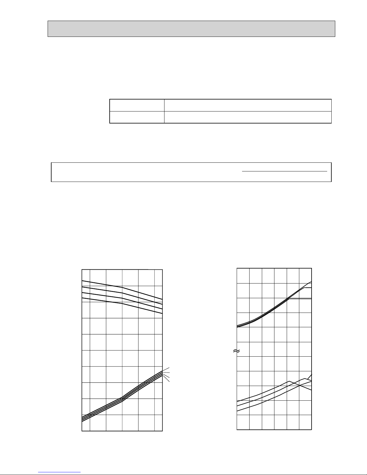
5-3. CORRECTING COOLING AND HEATING CAPACITY
5-3-1. Correcting Changes in Air Conditions
(1)The performance curve charts (Figure 1, 2) show the change ratio of capacity and input (power consumption) according to the
indoor and outdoor temperature condition when defining the rated capacity (total capacity) and rated input under the standard
condition in standard piping length (5m) as “1.0”.
• Standard conditions:
• Use the rated capacity and rated input given in “5-2.”.
• The input is the single value on the side of the outdoor unit; the input on the sides of each indoor unit must be
added to obtain the total input.
(2)The capacity of each indoor unit may be obtained by multiplying the total capacity obtained in (1) by the ratio between the
individual capacity at the rated time and the total capacity at the rated time.
individual capacity at the rated time
Individual capacity under stated conditions = total capacity under the stated conditions o
total capacity at the rated time
Rated cooling capacity
Rated heating capacity
Indoor D.B. 27˚C / W.B. 19˚C
Outdoor D.B. 35˚C
Indoor D.B. 20˚C
Outdoor D.B. 7˚C / W.B. 6˚C
0.4
-5 0 10 20 30 40 46
0.6
0.8
1.0
1.2
1.4
0.6
0.8
1.0
1.2
1.4
22
20
18
16
22
20
18
16
Cooling performance curve
0.6
0.4
0.8
1.0
1.2
1.4
0.4
0.6
0.8
1.0
1.2
1.4
-10-15 -5 0 5 10 15
20
25
15
20
25
15
Heating performance curve
Cooling
Capacity
(ratio)
Cooling
Power
consumption
(ratio)
Heating
Power
consumption
(ratio)
Heating
Capacity
(ratio)
INDOOR
<D.B. :>
INDOOR
<W.B. :>
INDOOR
<W.B. :>
INDOOR
<D.B. :>
Outdoor <D.B. :>
Outdoor <W.B. :>
Figure 2.
PUMY-P100YHM PUMY-P100YHM1 PUMY-P100YHMA(-BS)
PUMY-P125YHM PUMY-P125YHM
1 PUMY-P125YHMA(-BS)
PUMY-P140YHM PUMY-P140YHM
1 PUMY-P140YHMA(-BS)
(3)Capacity correction factor curve
Figure 1.
PUMY-P100YHM PUMY-P100YHM1 PUMY-P100YHMA(-BS)
PUMY-P125YHM PUMY-P125YHM
1 PUMY-P125YHMA(-BS)
PUMY-P140YHM PUMY-P140YHM
1 PUMY-P140YHMA(-BS)
16
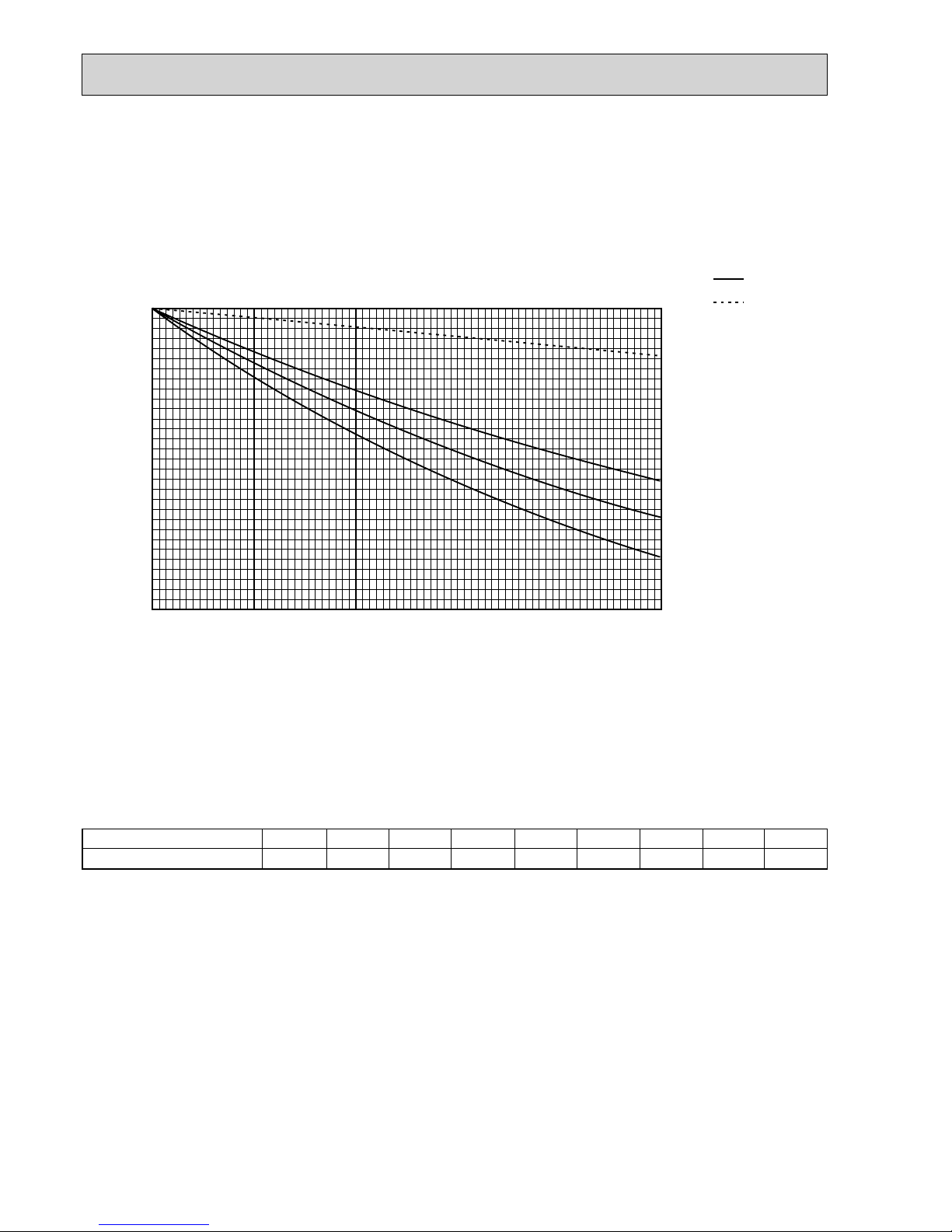
5-3-2. Correcting Capacity for Changes in the Length of Refrigerant Piping
(1) During cooling, obtain the ratio (and the equivalent piping length) of the outdoor units rated capacity and the total in-use
indoor capacity, and find the capacity ratio corresponding to the standard piping length from Figure 3. Then multiply by
the cooling capacity from Figure 1 to obtain the actual capacity.
(2) During heating, find the equivalent piping length, and find the capacity ratio corresponding to standard piping length from
Figure 3. Then multiply by the heating capacity from Figure 2 to obtain the actual capacity.
(2) Method for Obtaining the Equivalent Piping Length
Equivalent length for type P100·125·140 = (length of piping to farthest indoor unit) + (0.3 o number of bends in the piping) (m)
Length of piping to farthest indoor unit: type P100~P140.....80m
5-3-3. Correction of Heating Capacity for Frost and Defrosting
If heating capacity has been reduced due to frost formation or defrosting, multiply the capacity by the appropriate correction
factor from the following table to obtain the actual heating capacity.
Correction factor diagram
6
1.0
-10
0.95
-8
0.95
-6
0.95
-4
0.9
-2
0.89
0
0.88
2
0.89
4
0.98
Outdoor Intake temperature (W.B.°C)
Correction factor
(1) Capacity CORRECTION CURVE (Figure.3)
Cooling
Heating
100
95
90
85
80
75
70
5 101520253035404550556065707580
Cooling P100 model
Heating P100, 125, 140
models
Cooling P125 model
Cooling P140 model
Capacity ratio [%]
Corrected pipe length
[m]
17
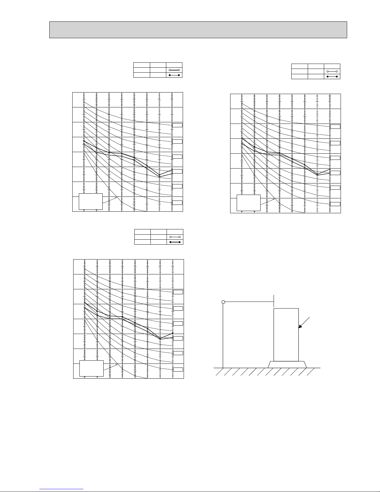
1.5m
1m
MICROPHONE
UNIT
GROUND
5-4.NOISE CRITERION CURVES
90
80
70
60
50
40
30
20
10
63 125 250 500 1000 2000 4000 8000
APPROXIMATE
THRESHOLD OF
HEARING FOR
CONTINUOUS
NOISE
OCTAVE BAND SOUND PRESSURE LEVEL, dB (0 dB = 0.0002 μbar)
BAND CENTER FREQUENCIES, Hz
NC-60
NC-50
NC-40
NC-30
NC-20
NC-70
PUMY-P100YHM
PUMY-P100YHM
1
PUMY-P100YHMA(-BS)
COOLING
MODE
HEATING
49
SPL(dB)
51
LINE
90
80
70
60
50
40
30
20
10
63 125 250 500 1000 2000 4000 8000
APPROXIMATE
THRESHOLD OF
HEARING FOR
CONTINUOUS
NOISE
OCTAVE BAND SOUND PRESSURE LEVEL, dB (0 dB = 0.0002 μbar)
BAND CENTER FREQUENCIES, Hz
NC-60
NC-50
NC-40
NC-30
NC-20
NC-70
PUMY-P125YHM
PUMY-P125YHM1
PUMY-P125YHMA(-BS)
COOLING
MODE
HEATING
50
SPL(dB)
52
LINE
90
80
70
60
50
40
30
20
10
63 125 250 500 1000 2000 4000 8000
APPROXIMATE
THRESHOLD OF
HEARING FOR
CONTINUOUS
NOISE
OCTAVE BAND SOUND PRESSURE LEVEL, dB (0 dB = 0.0002 μbar)
BAND CENTER FREQUENCIES, Hz
NC-60
NC-50
NC-40
NC-30
NC-20
NC-70
PUMY-P140YHM
PUMY-P140YHM
1
PUMY-P140YHMA(-BS)
COOLING
MODE
HEATING
51
SPL(dB)
53
LINE
18
6
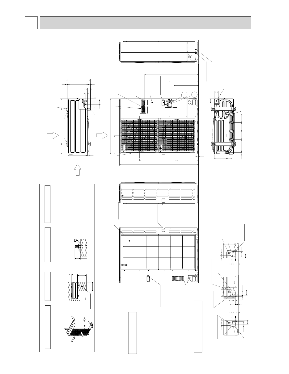
OUTLINES AND DIMENSIONS
Handle for moving
Side Air Intake
Front piping cover
Rear piping cover
Air intake
Rear Air Intake
Handle for moving
Handle for moving
Service panel
Handle for moving
Air Discharge
Rear Air Intake
Side Air Intake
14514522030 145
81 219
71
71
Bottom piping hole
(Knockout)
Drain hole
5-:33
600175 175
28 370
70
56
42
56
37
19
53
417
330
Installation Feet
2-12%36 Oval holes
(Foundation Bolt M10)
2-U Shaped notched holes
(Foundation Bolt M10)
30
920
322
635
371
950
23
1350
+1 423
+1 507
Handle for moving
1
2
( )
Left····· For the power supply
Center·····For the transmission line
Right····· For concentration control
Terminal connection
Ground for the transmission line
Ground for concentration control
Ground for the power supply
Over
Over
Over
Over
Less than
Piping and wiring connections
can be made from 4 directions:
front, right, rear and below.
4 PIPING-WIRING DIRECTIONS
3 FOUNDATION BOLTS2 SERVICE SPACE
1 FREE SPACE (Around the unit)
Please secure the unit firmly
with 4 foundation (M10) bolts.
(Bolts and washers must be
purchased locally.)
<Foundation bolt height>
Dimensions of space needed
for service access are
shown in the below diagram.
The diagram below shows a
basic example.
Explantion of particular details is
given in the installation manuals etc.
FREE
Over 10mm
Over 10mm
Over 150mm
Over 1000mm
30
FOUNDATION
10
500
500
150
Service space
Piping Knockout Hole Details
Example of Notes
···
Refrigerant GAS pipe connction (FLARE):15.88 (5/8 inch)
···
Refrigerant LIQUID pipe connection (FLARE): 9.52 (3/8 inch)
+1
···
Indication of STOP VALVE connection location.
637323
5527
92
65
4045
Power supply wiring hole
(2-:27Knockout)
Rear trunking hole
(Knockout)
Rear piping hole
(Knockout)
:92
922723
6373
4075
92
5519
Power supply wiring hole
(2-:27Knockout)
Right trunking hole
(Knockout)
Right piping hole
(Knockout)
:92
637323
5527
40 45
65
92
Power supply wiring hole
(2-:27Knockout)
Front trunking hole
(Knockout)
Front piping hole
(Knockout)
:92
PUMY-P100YHM PUMY-P100YHM1
PUMY-P125YHM PUMY-P125YHM1
PUMY-P140YHM PUMY-P140YHM1
Unit : mm

19
45 40
65
92
27 55
23 73 63
Rear piping hole
(Knockout)
Rear trunking hole
(Knockout)
Power supply wiring hole
(2-:27Knockout)
19 55
92
75 40
73 63
23 27
92
Right piping hole
(Knockout)
Right trunking hole
(Knockout)
Power supply wiring hole
(2-:27Knockout)
n92
92
65
4540
27 55
23 73 63
Front piping hole
(Knockout)
Front trunking hole
(Knockout)
Power supply wiring hole
(2-:27Knockout)
n92
14514522030 145
81 219
71
71
Bottom piping hole
(Knockout)
Drain hole
(5-:33)
600175 175
28 370
70
56
42
56
37
19
53
417
330
Installation Feet
2-12%36 Oval holes
(Foundation Bolt M10)
2-U Shaped notched holes
(Foundation Bolt M10)
30
1088
322
635371
950
23
1350
+1 423
+1 507
Handle for moving
1
2
Ground for the power supply
("GR"marking position)
Ground for the transmission line
Ground for concentration control
Terminal block
Left·········For the power supply
Center····For the transmission line
Right·······For concentration control
( )
Less than
Over
Over
Over
Over
Handle for moving
Side Air Intake
Front piping cover
Rear piping cover
Air intake
Rear Air Intake
Handle for moving
Handle for moving
Service panel
Handle for moving
The diagram below shows a
basic example.
Explantion of particular details is
given in the installation manuals etc.
Dimensions of space needed
for service access are
shown in the below diagram.
<Foundation bolt height>
Please secure the unit
firmly with 4 foundation (M10)
bolts.(Bolts and washers must
be purchased locally.)
Air Discharge
Rear Air Intake
Side Air Intake
Refrigerant GAS pipe connction(FLARE):15.88(5/8 inch)
Refrigerant LIQUID pipe connection(FLARE): 9.52(3/8 inch)
+1·····Indication of STOP VALVE connection location.
Example of Notes
Piping Knockout Hole Details
1 FREE SPACE (Around the unit)
2 SERVICE SPACE 3 FOUNDATION BOLTS
4 PIPING-WIRING DIRECTIONS
Piping and wiring connections
can be made from 4 directions:
front, right, rear and below.
30
FOUNDATION
150
500
500
10
Service space
Over 10
Over 10
FREE
Over 150Over 1000
:
92
PUMY-P100YHMA(-BS)
PUMY-P125YHMA(-BS)
PUMY-P140YHMA(-BS)
Unit : mm
20
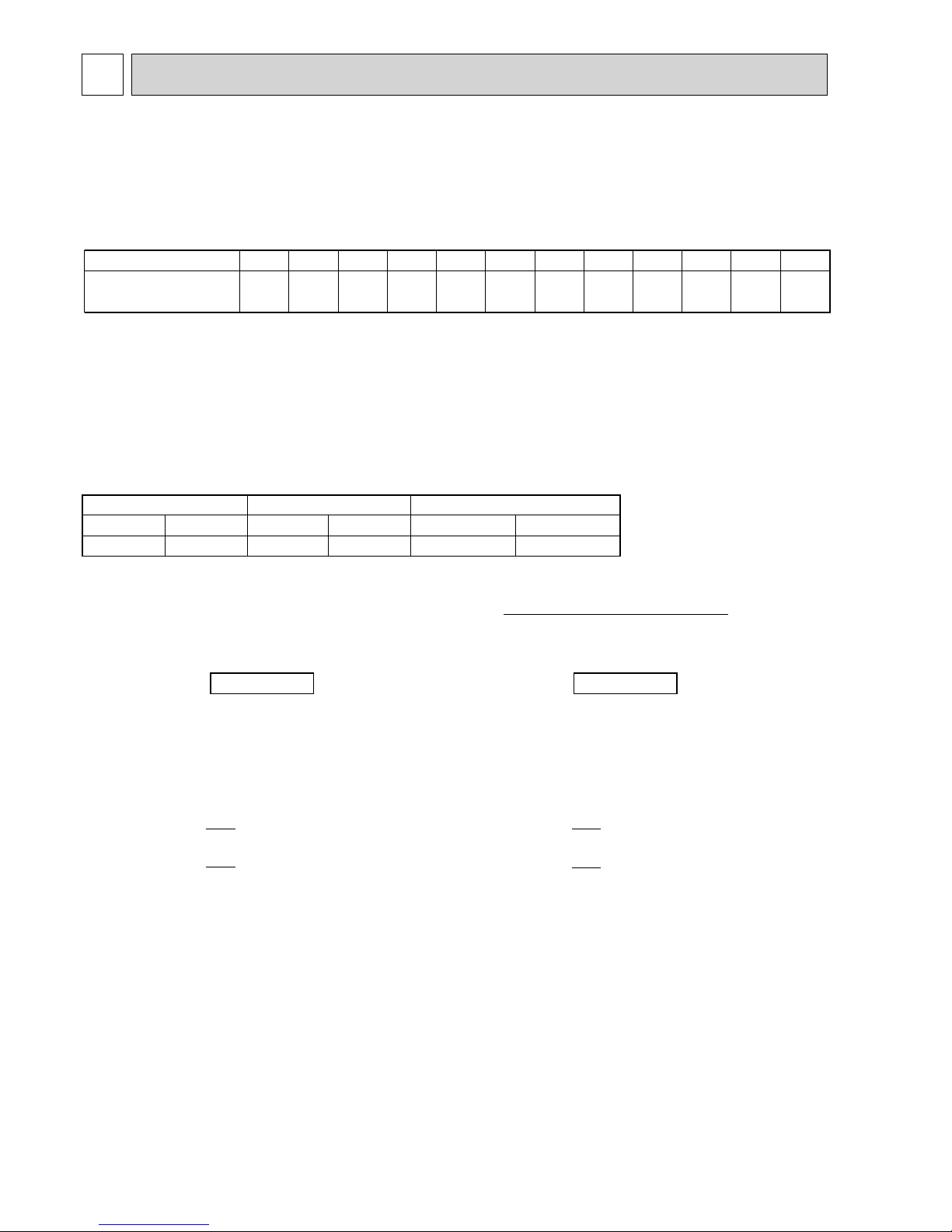
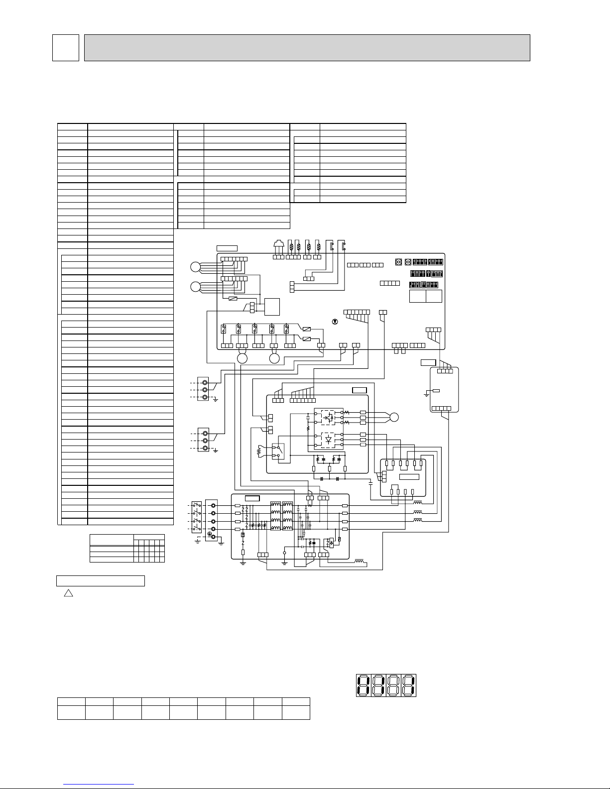
8
WIRING DIAGRAM
12345678
[Example]
When the compressor and
SV1 are turned on during cooling
operation.
Bit
Indication
1
Compressor
operated
2
52C321S44SV15(SV2)6—
7
—
8
Always lit
During normal operation
The LED indicates the drive state of the controller in the outdoor unit.
When fault requiring inspection has occurred,
the LED alternately indicates the inspection code and the location of the unit in which the fault has occurred.
NOTES:
1. Refer to the wiring diagrams of the indoor units for details on wiring of each indoor unit.
Self-diagnosis function
The indoor and outdoor units can be diagnosed automatically using the self-diagnosis switch
(SW1), LED1 and LED2 (LED indication) found on the multi-controller of the outdoor unit.
LED indication : Set all contacts of SW1 to OFF.
Cautions when Servicing
!
WARNING: When the main supply is turned off, the voltage [540 V] in the main capacitor will drop to 20 V in approx. 5 minutes (input voltage: 380 V).
When servicing, make sure that LED1 and LED2 on the outdoor circuit board goes out, and then wait for at least 5 minute.
Components other than the outdoor board may be faulty: Check and take corrective action, referring to the service manual.
Do not replace the outdoor board without checking.
1
MF1
4 5 6 7
CN2
(WHT)
CN4
(WHT)
CN51
(WHT)
1
MF2
4567
52C
(BLK)
3
X505
1
21S4
(GRN)
3 1
SV2
(BLU)
3 1
SV1
(WHT)
SS
(WHT)
21
2
1
21 21
3
1
21S4
SV1
76543 2 1
54321
21
LED3
SW6
SW2SW8SW1
SW7SW3SW4
+1
SW5
SWU2 SWU1
TRANS
LED2
88
LED1
88
12 1
2 1 234
CN3D
(WHT)
123
12
3
CN3S
(RED)
1 23
CN3N
(BLU)
123
3 1
31
CNAC
(RED)
CNS1
(RED)
CNS2
(YLW)
31
TH7TH6 TH3 TH463HS 63H63L
F1
F500
F2
X504
X503
X502
X501
CN102
(WHT)
CN41
(WHT)
CN40
(WHT)
4 321
4 3 2 14321
M-P.B.
P.B .
31
CN2
(WHT)
CN1
(WHT)
TP1
1234
M1
M2
S
TB3
TO INDOOR UNIT
CONNECTING WIRES
DC 30V(Non-polar)
FOR CENTRALIZED
CONTROL
DC 30V(Non-polar)
M1
M2
S
TB7
TB-W
TB-V
TB-U
TB-L3
TB-L2
TB-L1
(BLK)
(WHT)
(RED)
(BLK)
(BLK)
(BLU)
(WHT)
(WHT)
(RED)
(RED)
(BLK)
(BLU)
(WHT)
(RED)
L1
NO FUSE
BREAKER
POWER SUPPLY
3N~
AC380/400/415V 50Hz
L2
L3
N
MC
-
+
-
+
3 1 1 3 3 1
1 31 2
ACL4
+
+
+
CN2
(WHT)
CN7
(WHT)
CN4
(WHT)
CN7
(WHT)
CN5
(RED)
7 654321321
2 121
++
3 12
ACL1
ACL2
ACL3
CONV.B.
MULTI. B.
N.F.
TB1
CNF1
(WHT)
TH7/6
(RED)
TH3
(WHT)
TH4
(WHT)
63HS
(WHT)
63H
(YLW)
63L
(RED)
CNDC
(PNK)
CNF2
(WHT)
TB-P2
TB-C1
TB-N1
L1-IN
L1-A1
L3-OU
L3-A2
L2-OU
L1-OU
L2-A2
L1-A2
CK-OU
N-IN
CB1
CN5
(RED)
CNAC2
(RED)
CB2
CK
RS
LO1
LO2
LO3
NO
LI1
LI2
LI3
NI
GD1
GD2
CNAC1
(WHT)
CNDC
(PNK)
CNL
(BLU)
(BRN)
(BRN)
(ORN)
(ORN)
+1 MODEL SELECT 1:ON 0:OFF
MODELS
PUMY-P100YHM
PUMY-P125YHM
PUMY-P140YHM
110010
123456
SW4
110001
110011
SYMBOL NAME SYMBOL NAME SYMBOL NAME
TB1 Terminal Block <Power Supply>
TB3 Terminal Block <Transmission>
TB7
Terminal Block <Centralized Control>
MC Motor for Compressor
MF1,MF2 Fan Motor
21S4 Solenoid Valve<Four way valve>
SV1 Solenoid Valve<Bypass valve>
TH3
Thermistor<Outdoor Pipe Temperature>
TH4
Thermistor<Discharge Temperature>
TH6
Thermistor<Low Pressure Saturated Temperature>
TH7
Thermistor<Outdoor Temperature>
63HS
High Pressure Sensor<Discharge Pressure>
63H High Pressure Switch
63L Low Pressure Switch
CB1,CB2 Main Smoothing Capacitor
CK Capacitor
RS Rush Current Protect Resistor
P.B Power Circuit Board
Connection Terminal<U/V/W -Phase>
ACL1~ACL4
TB-U/V/W
MULTI.B.
CONV.B.
Multi Controller Board
Fuse<6.3A>
F1,F2
Fuse<3A>
F500
Switch<Display Selection>
SW1
Switch<Function Selection>
SW2
Switch<Test Run>
SW3
Switch<Model Selection>
SW4
Switch<Function Selection>
SW5
Switch<Function Selection>
SW6
Switch<Function Selection>
SW7
Switch<Function Selection>
SW8
Switch<Unit Address Selection, 1st digit>
SWU1
Switch<Unit Address Selection, 2nd digit>
SWU2
Transformer
TRANS
Digital Indicator<Operation Inspection Display>
LED1,2
LED<Power Supply to Main Microcomputer>
LED3
Connector<Multi System>
CNS1
Connector<Centralized Cotrol>
CNS2
Connector<To Noise Filter Circuit Board>
CNAC
Connector<To Noise Filter Circuit>
CNDC
Connector<To Power Circuit Board>
CN2
Connector<To Power Circuit Board>
CN4
Connector<Centralized Cotrol Power Supply>
CN40
Connector<For shorting Jumper Connector>
CN41
Connector<Thermistor>
TH3
Connector<Thermistor>
TH4
Connector<Thermistor>
TH7/6
Connector<High Pressure Sensor>
63HS
Connector<High Pressure Switch>
63H
Connector<Low Pressure Switch>
63L
Connector<Fan Motor>
CNF1,CNF2
Connector<Four-way Valve>
21S4
Connector<Bypass Valve>
SV1
Connector<For Option>
SS
Connector<For Option>
CN3D
Connector<For Option>
CN3S
Connector<For Option>
CN3N
Connector<For Option>
Connection Terminal<L1-Power Supply>
CN51
Relay
X501~505
Converter Circuit Board
L1-A1,L1-IN
N.F.
Connection Terminal<L1/L2/L3/N-Power Supply>
Noise Filter Circuit Board
LI1/LI2/LI3/NI
M-P.B.
Connector<To Noise Filter Circuit Board>
Transmission Power Board
CN1
Connector<To Multi Controller Board>
CN2
Connector<To Transmission Power Board>
CNAC1
Connector<To Multi Controller Board>
CNAC2
Connector<To Power Circuit Board>
CNCT
Connector<To Reactor>
CNL
Fuse<6.3A>
FUSE
Connection Terminal<L1/L2/L3/N-Power Supply>
LO1/LO2/LO3/NO
Connection Terminal<L1-Power Supply>
L1-A2,L1-OU
Connection Terminal<L2-Power Supply>
L2-A2,L2-OU
Connection Terminal<L3-Power Supply>
L3-A2,L3-OU
Connection Terminal
N-IN
Connection Terminal
CK-OU
Connector<To Power Circuit Board>
CN7
Connection Terminal<L1/L2/L3-Power Supply>
TB-L1/L2/L3
Connection Terminal
TB-P2
Connection Terminal
TB-C1
Connection Terminal
TB-N1
Connection <To Multi Controller Board>
CN2
Connection <To Multi Controller Board>
CN4
Connection <To Noise Filter Circuit Board>
CN5
Connection <To Multi Controller Board>
CNDC
Reactor
PUMY-P100YHM PUMY-P100YHM1
PUMY-P125YHM PUMY-P125YHM1
PUMY-P140YHM PUMY-P140YHM1
21
12345678
[Example]
When the compressor and
SV1 are turned on during cooling
operation.
Bit
Indication
1
Compressor
operated
2
52C321S44SV15(SV2)6—
7
—
8
Always lit
• During normal operation
The LED indicates the drive state of the controller in the outdoor unit.
• When fault requiring inspection has occurred,
the LED alternately indicates the inspection code and the location of the unit in which the fault has occurred.
NOTES:
1.Refer to the wiring diagrams of the indoor units for details on wiring of each indoor unit.
Self-diagnosis function
The indoor and outdoor units can be diagnosed automatically using the self-diagnosis switch
(SW1), LED1 and LED2 (LED indication) found on the multi-controller of the outdoor unit.
LED indication : Set all contacts of SW1 to OFF.
SYMBOL NAME
TB1
Terminal Block <Power Supply>
TB3
Terminal Block <Comunication Line>
TB7
Terminal Block <Centralized Control Line>
MC Motor For Compressor
MF1,MF2 Fan Motor
21S4 Solenoid Valve<Four-Way Valve>
SV1 Solenoid Valve<Bypass Valve>
TH3
Thermistor<Outdoor Pipe>
TH4 Thermistor<Discharge>
TH6 Thermistor<Low Pressure Saturated>
TH7 Thermistor<Outdoor>
63HS
63H High Pressure Switch
High Pressure Sensor
63L Low Pressure Switch
CB1,CB2 Main Smoothing Capacitor
CK Capacitor
RS Rush Current Protect Resistor
P.B. Power Circuit Board
C.B. Controller Circuit Board
Connection Terminal<U/V/W -Phase>
ACL1~ACL4
TB-U/V/W
CONV.B.
Fuse<T6.3AL250V>
F1,F2
Switch<Display Selection>
SW1
Switch<Function Selection>
SW2
Switch<Test Run>
SW3
Switch<Model Selection>
SW4
Switch<Function Selection>
SW5
Switch<Function Selection>
SW6
Switch<Function Selection>
SW7
Switch<Function Selection>
SW8
Switch<Unit Address Selection, 1st digit>
SWU1
Switch<Unit Address Selection, 2nd digit>
SWU2
LED<Operation Inspection Display>
LED1,LED2
LED<Power Supply to Main Microcomputer>
LED3
Connector<Connection For Option>
SS
Connector<Connection For Option>
CN3D
Connector<Connection For Option>
CN3S
Connector<Connection For Option>
CN3N
Connector<Connection For Option>
Connection Terminal<L1-Power Supply>
CN51
Relay
X52A
Relay
X501~X505
Connection Terminal<Ground>
Connection Terminal<Ground>
GD1,GD3
TP1
Converter Circuit Board
L1-A1/IN
N.F.
Connection Terminal<L1/L2/L3-Power Supply>
Noise Filter Circuit Board
LI1/LI2/LI3/NI
M-NET P.B.
M-NET Power Circuit Board
Connection Terminal<L1/L2/L3-Power Supply>
LO1/LO2/LO3/NO
Connection Terminal<L1-Power Supply>
L1-A2/OU
Connection Terminal<L2-Power Supply>
L2-A2/OU
Connection Terminal<L3-Power Supply>
L3-A2/OU
Connection Terminal
N-IN
Connection Terminal
CK-OU
Connection Terminal<L1/L2/L3-Power Supply>
TB-L1/L2/L3
Connection Terminal
TB-P2
Connection Terminal
TB-C1
Connection Terminal
TB-N1
Reactor
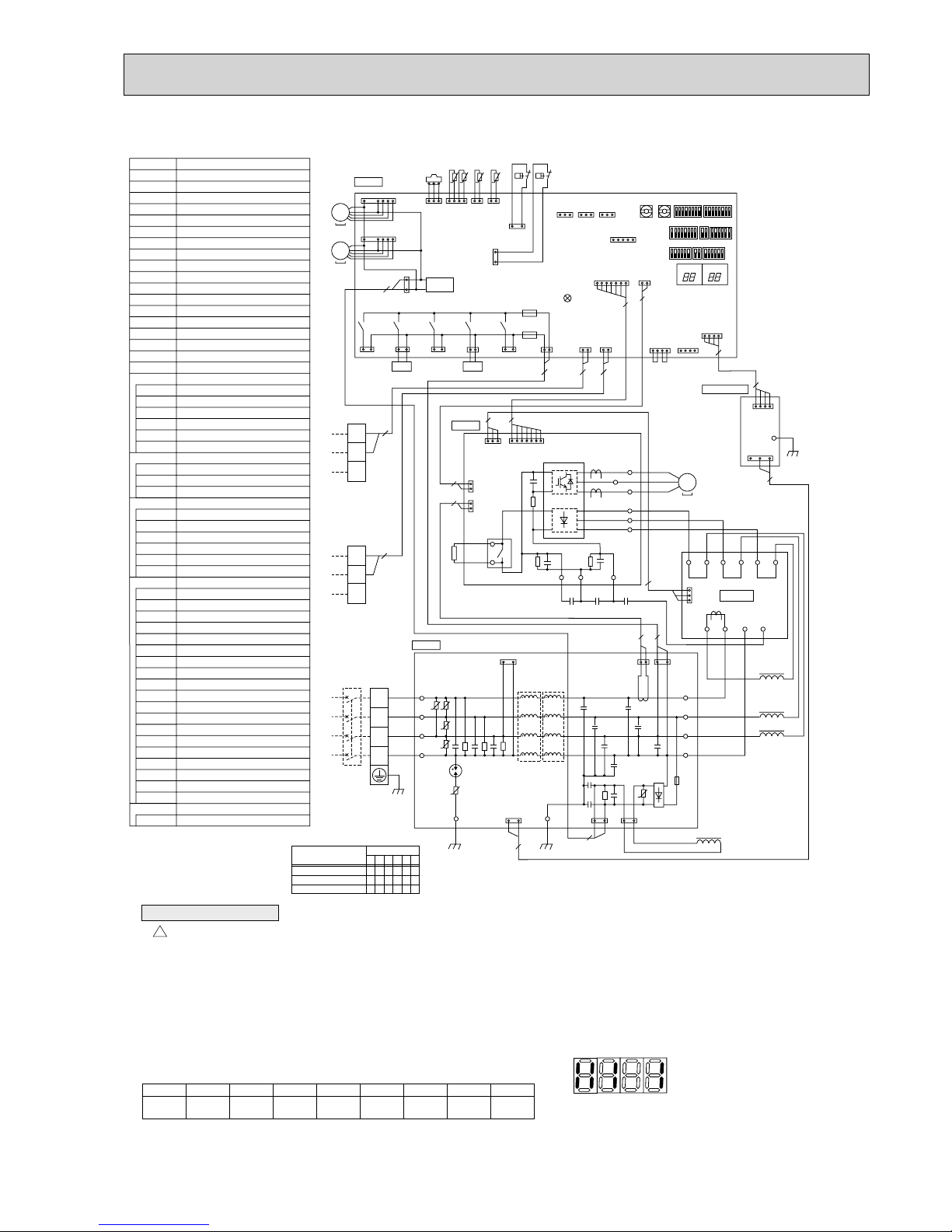
Cautions when Servicing
!
• WARNING: When the main supply is turned off, the voltage [570 V] in the main capacitor will drop to 20 V in approx. 5
minutes (input voltage: 400 V). When servicing, make sure that LED1 and LED2 on the outdoor circuit board goes out, and
then wait for at least 5 minute.
• Components other than the outdoor board may be faulty: Check and take corrective action, referring to the service manual.
Do not replace the outdoor board without checking.
+1 MODEL SELECT 1:ON 0:OFF
MODELS
PUMY-P100YHMA
PUMY-P125YHMA
PUMY-P140YHMA
123456
110010
110001
110011
SW4
CN51
(WHT)
SW6
SW2SW8SW1
SW7SW3SW4
+
1
SW5
SWU2SWU1
TRANS
LED1
CN2
(WHT)
CN4
(WHT)
LED3
CN3D
(WHT)
CN3S
(RED)
CN3N
(BLU)
CN2
(WHT)
CN1
(WHT)
TP1
BLK
M1
M2
S
TB3
TO INDOOR UNIT
CONNECTING WIRES
DC 30V(Non-polar)
FOR CENTRALIZED
CONTROL
DC 30V(Non-polar)
TB-W
TB-V
TB-U
TB-L3
TB-L2
TB-L1
BLK
BLK
WHT
W
V
U
WHT
RED
RED
BLK
BLK
BLK
WHT
WHT
RED
RED
RED
RED
ACL4
CN2
(WHT)
CN7
(WHT)
CN4
(WHT)
CN5
(RED)
RED
RED
X52A
CNDC
(PNK)
TB-P2
TB-C1
TB-N1
CB1
CNCT
(RED)
CNAC2
(RED)
CNAC1
(WHT)
CNAC1
(WHT)
CB2
CK
RS
GD3GD1
BLK
WHT
WHT
CNDC
(PNK)
CNL
(BLU)
t t t t
MF1
MS
3~
141
1
1
7
3
131313
113
3
13
1
3
3
3
13 13
1
3
2
1
3
1
3
13
3
2
2112
1
2
2
1
2
1
2
22
1
2
22
12 12
1
2
2
TH7 TH6 TH3 TH4
63HS
63H
63L
CNF1
(WHT)
MF2
MS
3~
1
7
1
7
7
1
5
CNF2
(WHT)
TH7/6
(RED)
TH3
(WHT)
TH4
(WHT)
63HS
(WHT)
63H
(YLW)
63L
(RED)
C. B.
LED2
P. B.
N. F.
M-NET P.B.
52C
(BLK)
1
3
1
3
1
3
X505
21S4
(GRN)
SV1
(WHT)
SV2
(BLU)
SS
(WHT)
21S4
SV1
CNAC
(RED)
CNS1
(RED)
CNS2
(YLW)
F1
F2
X504
X503
X502
X501
CN102
(WHT)
4
1
CN40
(WHT)
4
1
4
4
1
5
1
CN41
(WHT)
4
1
1
7
7
-
+
+
+
-
+
1
2
2
-
+
++
+
MC
MS
3~
4
2
M1
M2
S
TB7
2
2
BLK
BLU
WHT
RED
BLK
BLU
BLU
WHT
RED
LI1
POWER
SUPPLY
3N~
400V
50Hz
LI2
U
U
U
U
U
U
LI3
NI
TB1
L1
L2
L3
N
BLK
2
ACL1
ACL2
ACL3
LO1
LO2
LO3
NO
CN7
(WHT)
Conv.B.
L1-IN
L1-A1
L3-OU
L3-A2
L2-OU
L1-OU
L2-A2
L1-A2
CK-OU
N-IN
2
RED
YLW
YLW
GRN/YLW
RED
PUMY-P100YHMA(-BS) PUMY-P125YHMA(-BS) PUMY-P140YHMA(-BS)
22
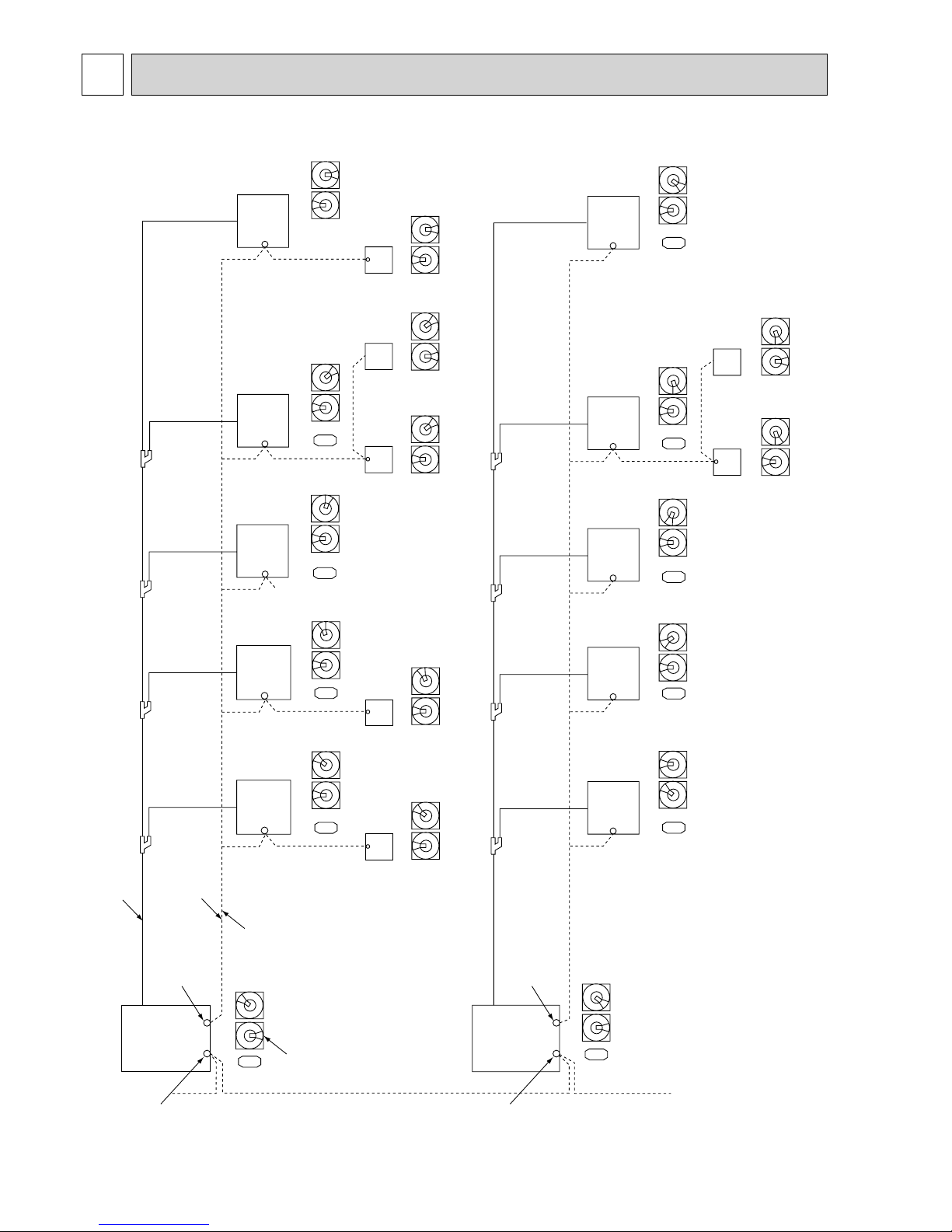
8
NECESSARY CONDITIONS FOR SYSTEM CONSTRUCTION
8-1. TRANSMISSION SYSTEM SETUP
0
1
2
3
4
5
6
7
8
9
0
1
2
3
4
5
6
7
8
9
0
1
2
3
4
5
6
7
8
9
0
1
2
3
4
5
6
7
8
9
0
1
2
3
4
5
6
7
8
9
0
1
2
3
4
5
6
7
8
9
051
0
1
2
3
4
5
6
7
8
9
0
1
2
3
4
5
6
7
8
9
056
001
0
1
2
3
4
5
6
7
8
9
0
1
2
3
4
5
6
7
8
9
010
101
1
0
1
2
3
4
5
6
7
8
9
0
1
2
3
4
5
6
7
8
9
0
1
2
3
4
5
6
7
8
9
0
1
2
3
4
5
6
7
8
9
002
102 104 154
1111
11
0
1
2
3
4
5
6
7
8
9
0
1
2
3
4
5
6
7
8
9
009
0
1
2
3
4
5
6
7
8
9
0
1
2
3
4
5
6
7
8
9
008
0
1
2
3
4
5
6
7
8
9
0
1
2
3
4
5
6
7
8
9
003
0
1
2
3
4
5
6
7
8
9
0
1
2
3
4
5
6
7
8
9
0
1
2
3
4
5
6
7
8
9
0
1
2
3
4
5
6
7
8
9
0
1
2
3
4
5
6
7
8
9
0
1
2
3
4
5
6
7
8
9
007
0
1
2
3
4
5
6
7
8
9
0
1
2
3
4
5
6
7
8
9
006
0
1
2
3
4
5
6
7
8
9
0
1
2
3
4
5
6
7
8
9
0
1
2
3
4
5
6
7
8
9
0
1
2
3
4
5
6
7
8
9
0
1
2
3
4
5
6
7
8
9
0
1
2
3
4
5
6
7
8
9
004
0
1
2
3
4
5
6
7
8
9
0
1
2
3
4
5
6
7
8
9
0
1
2
3
4
5
6
7
8
9
0
1
2
3
4
5
6
7
8
9
005
A transmission wire must be
connected to each refrigerant
system (outdoor and indoor).
Set addresses:
Outdoor unit ..............051-100
Indoor unit .................001-050
Remote controller .....101-200
PUMY has no 3rd digit switch.
The address automatically become
"100" if it is set as "01~50".
Remote
controller
Remote
controller
Remote
controller
Remote
controller
105
Remote
controller
157
Remote
controller
107
Remote
controller
For centralized
management
For remote
controller
Address SW Address SW Address SW Address SW Address SW
Piping
Outdoor unit
Outdoor unit
Indoor unit Indoor unit Indoor unit Indoor unit Indoor unit
Indoor unitIndoor unitIndoor unitIndoor unitIndoor unit
Address SW Address SW Address SW Address SW Address SW
Address SWAddress SWAddress SWAddress SWAddress SW
Address SWAddress SW
For centralized
management
For remote
controller
Transmission wire
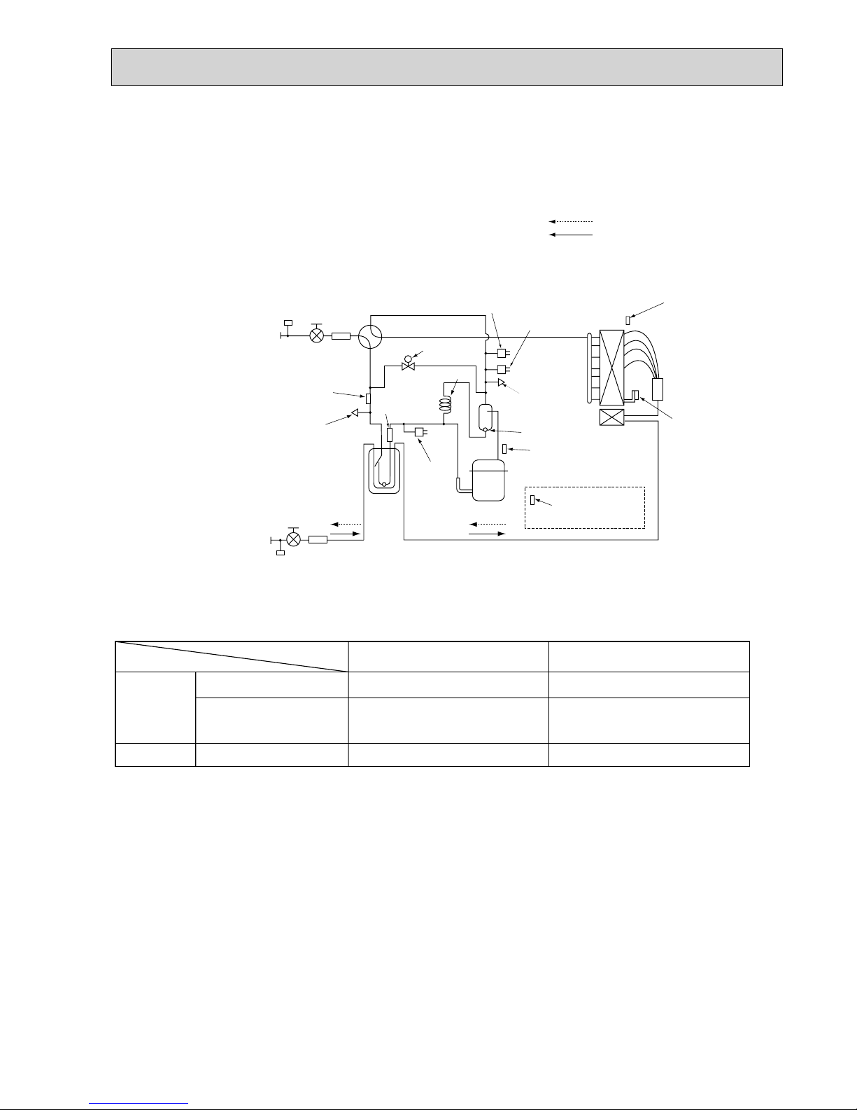
23
8-2. REFRIGERANT SYSTEM DIAGRAM Unit:mm<inch>
PUMY-P100YHM PUMY-P100YHM1 PUMY-P100YHMA(-BS)
PUMY-P125YHM PUMY-P125YHM
1 PUMY-P125YHMA(-BS)
PUMY-P140YHM PUMY-P140YHM
1 PUMY-P140YHMA(-BS)
Refrigerant Gas pipe
<5/8>
Refrigerant Liquid pipe
<3/8>
Check valve<Low pressure>
Accumulator
Thermistor<Saturation temperature
of suction pressure>(TH6)
Solenoid
valve(SV1)
Capillary tube
Check valve
<High pressure>
Pressure sensor
(63HS)
High pressure
switch(63H)
Low pressure
switch(63L)
Thermistor(TH7)
(Outdoor temperature)
(Pipe temperature)
Discharge
thermistor(TH4)
Heatsink
thermistor(TH8)
Thermistor(TH3)
Oil separator
Service port
Service
port
4-way valve
Strainer
Strainer
Strainer
Stop valve
Stop valve
Distributor
Compressor
Strainer
Refrigerant flow in cooling
Refrigerant flow in heating
Refrigerant pipng specifications <dimensions of flared connector>
Capillary tube for oil separator : :2.5 % :0.8 % L1000
Capacity
Item
Liquid piping Gas pipng
P15, P20, P25, P32, P40, P50
P63, P80, P100
P125, P140
P100, P125, P140
Indoor unit
Outdoor unit
:6.35<1/4>
:9.52<3/8>
:9.52<3/8>
:12.7<1/2>
:15.88<5/8>
:15.88<5/8>
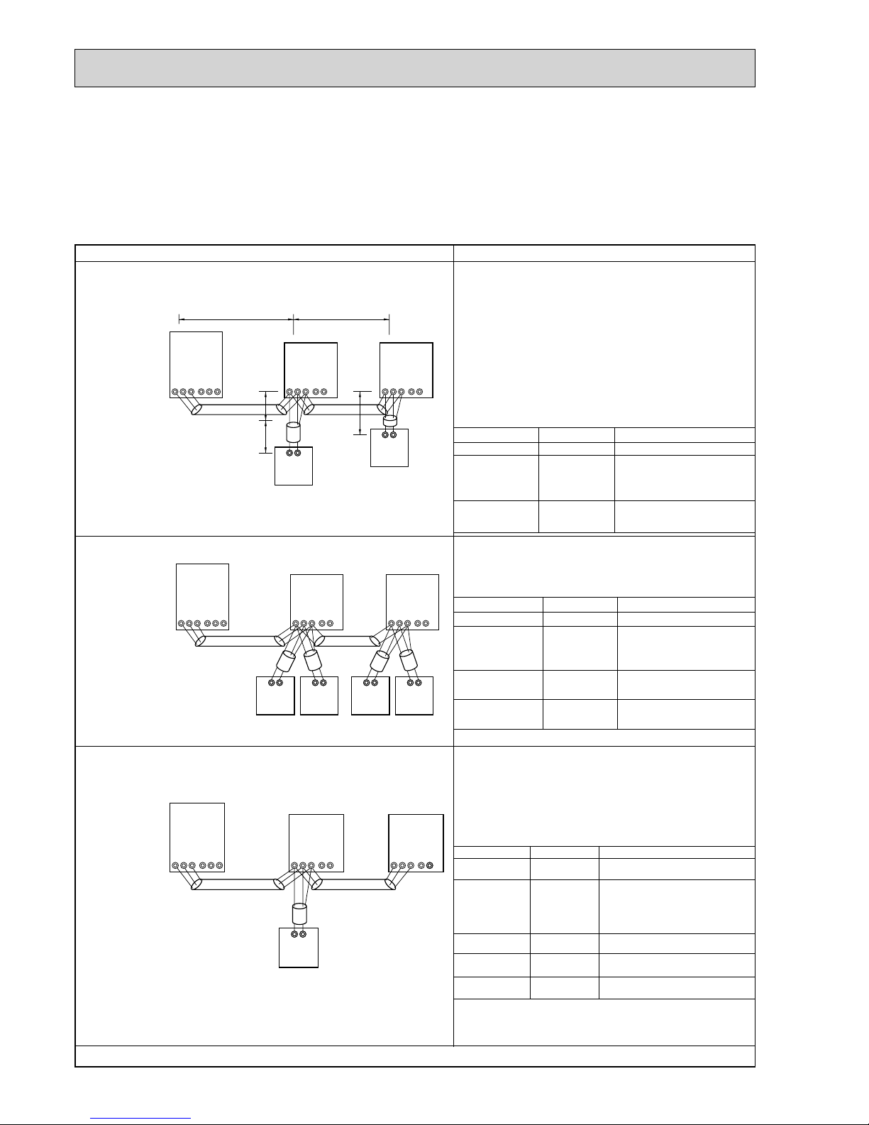
24
8-3. SYSTEM CONTROL
8-3-1. Example for the System
• Example for wiring control cables, wiring method and address setting, permissible lengths, and the prohibited items are listed
in the standard system with detailed explanation.
The explanation for the system in this section : Use 1 single outdoor unit and multiple outdoor units for M-NET remote control
system.
Use 1 single outdoor unit and multiple indoor units in the multiple outdoor
units for the M-NET remote control system.
A. Example of a M-NET remote controller system (address setting is necessary.)
Example of wiring control cables Wiring Method and Address Setting
• 1 remote controller for each
indoor unit.
• There is no need for setting the 100
position on the remote controller.
1. Standard operation
2. Operation using 2 remote controllers
• Using 2 remote controllers
for each indoor unit.
M1M2
TB5
S12
TB15
01
101
IC
AB
M1M2
TB3
SAB
TB7
51
OC
L
1
L3
L2
S
M1M2
TB5
S12
TB15
02
IC
RC
102
AB
RC
l1
l2
M1M2
TB5
S12
TB15
01
101
RC
(Main)
151
IC
M1M2
TB3
SAB
TB7
51
OC
S
M1M2
TB5
S12
TB15
02
IC
RC
(Sub)
102
RC
(Main)
152
RC
(Sub)
AB AB AB AB
M1M2
TB5
S12
TB15
01
101
IC(Main)
AB
M1M2
TB3
SAB
TB7
51
OC
S
M1M2
TB5
S122
TB15
02
IC(Sub)
RC
a. Use feed wiring to connect terminals M1 and M2 on
transmission cable block (TB3) for the outdoor unit
(OC) to terminals M1 and M2 on the transmission
cable block (TB5) of each indoor unit (IC). Use
non-polarized 2 wire.
b. Connect terminals M1 and M2 on transmission cable
terminal block (TB5) for each indoor unit with the
terminal block (TB6) for the remote controller (RC).
c. Set the address setting switch (on outdoor unit
P.C.B) as shown below.
3. Group operation
• Multiple indoor units operated
together by 1 remote controller
Unit
Indoor unit (IC)
Outdoor unit
(OC)
Remote
controller (RC)
Range
001 to 050
051 to 100
101 to 150
Setting Method
—
Use the smallest
address of all the indoor
unit plus 50.
Indoor unit address plus
100.
a. Same as above.
b. Same as above.
c. Set address switch (on outdoor unit P.C.B) as
shown below.
Unit
Indoor Unit (IC)
Outdoor unit
(OC)
Range
001 to 050
051 to 100
101 to 150
151 to 200
Setting Method
—
Use the smallest
address of all the indoor
units plus 50.
Indoor unit address plus
100.
Indoor unit address plus
150.
a. Same as above.
b. Connect terminals M1 and M2 on transmission cable
terminal block (TB5) of the IC main unit with the most
recent address within the same indoor unit (IC) group
to terminal block (TB6) on the remote controller.
c. Set the address setting switch (on outdoor unit P.C.B)
as shown below.
Unit
IC (Main)
IC (Sub)
Outdoor Unit
Main Remote
Controller
Sub Remote
Controller
Range
001 to 050
001 to 050
051 to 100
101 to 150
151 to 200
Setting Method
Use the smallest address within the
same group of indoor units.
Use an address, other than that of
the IC (Main) from among the units
within the same group of indoor
units. This must be in sequence with
the IC (Main).
Use the smallest address of all the
indoor units plus 50.
Set at an IC (Main) address within
the same group plus 100.
Set at an IC (Main) address within
the same group plus 150.
d. Use the indoor unit (IC) within the group with the
most functions as the IC (Main) unit.
Combinations of 1through 3 above are possible.
Main Remote
Controller (RC)
Sub Remote
Controller (RC)
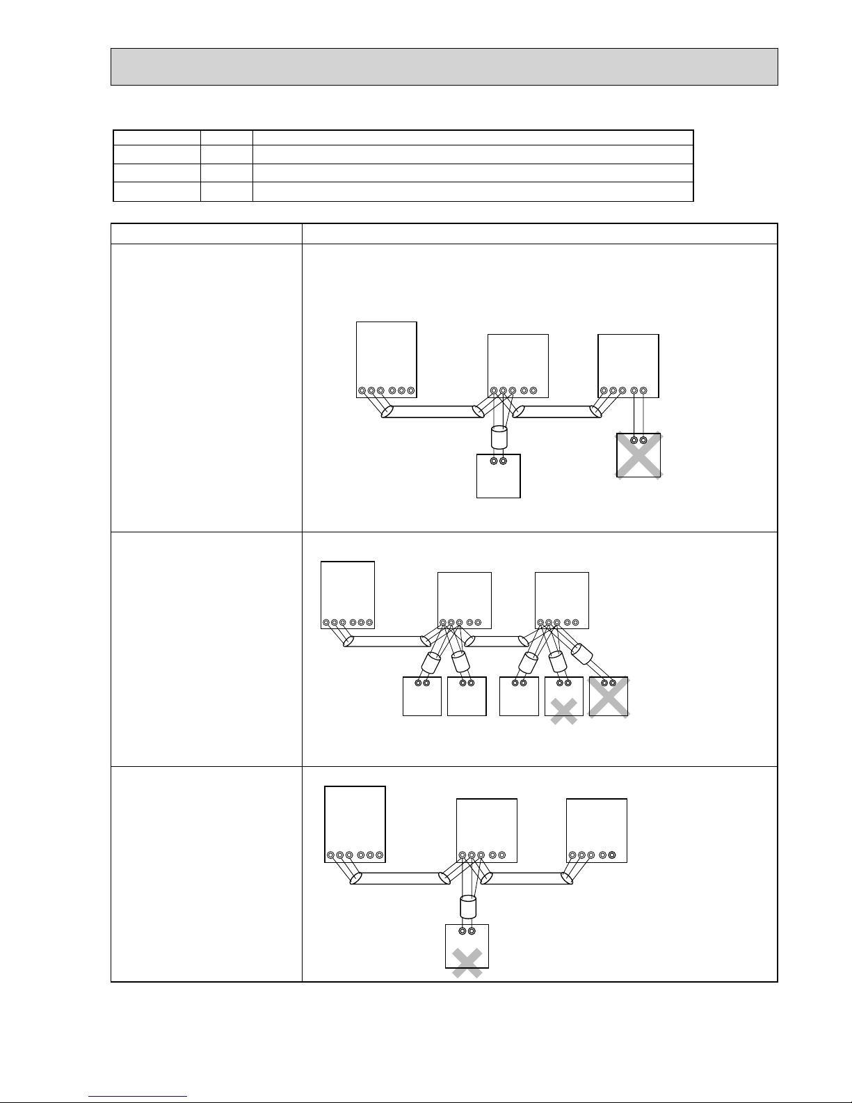
25
• Name, Symbol and the Maximum Remote controller Units for Connection
Name
Outdoor unit
Indoor unit
Symbol
OC
IC
RC
Maximum units for connection
Permissible Lengths Prohibited items
Longest transmission cable length
(1.25 mm2 )
L
1 + L2, L2 + L3, L3 + L1 [ 200m
Remote controller cable length
1. If 0.5 to 1.25 mm
2
R1, R2 [10m
2. If the length exceeds 10 meters,
the exceeding section should
be 1.25 mm
2
and that section
should be a value within the
total extension length of the
transmission cable and
maximum transmission cable
length. (L
3)
Same as above
Same as above
• Use the indoor unit(IC)
address plus 150 as
the sub remote controller
address. In this case, it
should be 152.
• 3 or more remote
controller (RC) cannot
be connected to 1
indoor unit.
• The remote controller
address is the indoor
unit main address plus
100. In this case, it
should be 101.
M1M2
TB5
S12
TB15
01
102
IC(Main)
AB
M1M2
TB3
SAB
TB7
51
OC
S
M1M2
TB5
S122
TB15
02
IC(Sub)
RC
M1M2
TB5
S12
TB15
01
101
RC
(Main)
151
IC
M1M2
TB3
SAB
TB7
51
OC
S
M1M2
TB5
S12
TB15
02
IC
RC
(Sub)
102
RC
(Main)
103
RC
(Sub)
104
RC
AB AB AB AB AB
1 OC unit can be connected to 1-8 IC units (P100 : 1-6 IC units)
Maximum 2 RC for 1 indoor unit, Maximum 16 RC for 1 OC
M-NET remote
controller
M1M2
TB5
S12
TB15
01
101
IC
AB
M1M2
TB3
SAB
TB7
51
OC
S
M1M2
TB5
S12
TB15
02
IC
RC
TB15
AB
MA
• M-NET remote controller(RC) and MA remote controller(MA) cannot be used together.
• Do not connect anything with TB15 of indoor unit(IC).
—
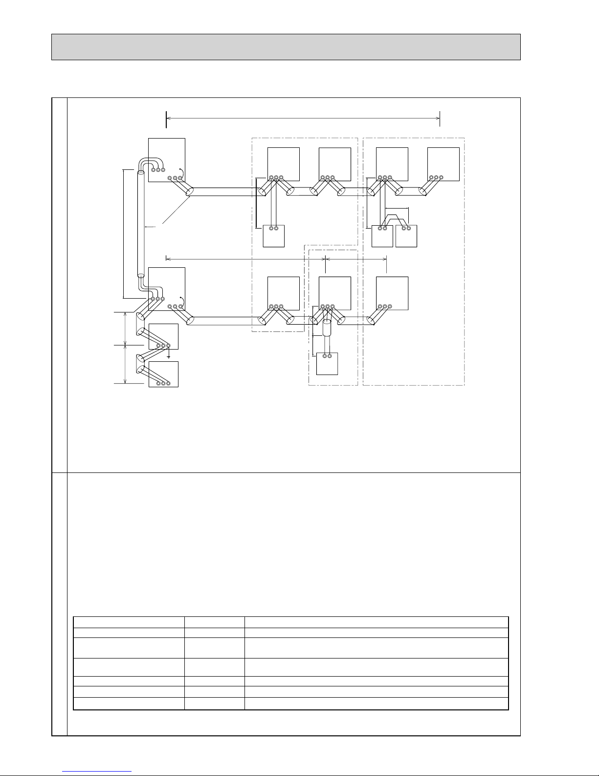
26
B. Example of a group operation system with 2 or more outdoor units and a M-NET remote controller.
(Address settings are necessary.)
Examples of Transmission Cable Wiring
M1M2S
M1 M2 S
TB7
TB3
IC
(51)
M1 M2 S
TB5
RC
(01)
IC
M1 M2 S
TB5
(03)
IC
M1 M2 S
TB5
(02)
IC
M1 M2 S
TB5
(04)
IC
M1 M2 S
TB5
(05)
IC
M1 M2 S
TB5
(07)
IC
M1 M2 S
TB5
(06)
L2
L1
(101)
RC
(105)
RC
(104)
RC
(155)
OC
M1 M2 S
TB7
(53)
OC
3
M1M2S
Power Supply
Unit
M1M2S
G-50A
L3
L6L7
L4
L5
2
4
1
AB AB AB
AB
M1M2 S
TB3
: Group 1
: Group 3
: Group 5
: Shielded Wire
: Sub Remote Controller
( ): Address
N
N
N
N
Wiring Method Address Settings
a. Always use shielded wire when making connections between the outdoor unit (OC) and the indoor unit (IC), as well
for all OC-OC, and IC-IC wiring intervals.
b. Use feed wiring to connect terminals M1 and M2 and the ground terminal on the transmission cable terminal block
(TB3) of each outdoor unit (OC) to terminals M1 and M2 on the terminal S on the transmission cable block of the
indoor unit (IC).
c. Connect terminals M1 and M2 on the transmission cable terminal block of the indoor unit (IC) that has the most
recent address within the same group to the terminal block on the remote controller (RC).
d. Connect together terminals M1, M2 and terminal S on the terminal block for central control (TB7) for the outdoor
unit (OC).
e. DO NOT change the jumper connector CN41 on MULTI controller board.
f. The earth processing of S terminal for the centralized control terminal block(TB7) is unnecessary.
Connect the terminal S on the power supply unit with the earth.
g. Set the address setting switch as follows.
h. The group setting operations among the multiple indoor units is done by the remote controller (RC) after the electrical
power has been turned on.
Unit
IC (Main)
IC (Sub)
Outdoor Unit
Main Remote Controller
Sub Remote Controller
MA Remote Controller
Range
01 to 00
01 to 50
51 to 100
101 to 150
151 to 200
—
Setting Method
Use the smallest address within the same group of indoor units.
Use an address, other than the IC (Main) in the same group of indoor units.
This must be in sequence with the IC (Main).
Use the smallest address of all the indoor units plus 50.
*The address automatically becomes “100” if it is set as “01 - 50”.
Set at an IC (Main) address within the same group plus 100.
Set at an IC (Main) address within the same group plus 150.
Unnecessary address setting (Necessary main/ sub setting)

27
• Name, Symbol, and the Maximum Units for Connection
Permissible Length
Prohibited items
• Longest length via outdoor units : L1+L2+L3+L4, L1+L2+L3+L5, L1+L2+L6+L7 [ 500 meters (1.25mm2)
• Longest transmission cable length : L
1, L3+L4, L3+L5, L6, L2+L6, L7 [ 200 meters (1.25mm
2
)
• Remote controller cable length : R
1,R2, R2+R3, R4 [ 10 meters (0.5 to 1.25mm
2
)
If the length exceeds 10 meters, use a 1.25 mm
2
shielded wire. The length of this sec-
tion (L
8) should be included in the calculation of the maximum length and overall length.
• Never connect together the terminal blocks (TB5) for transmission wires for indoor units (IC) that have been connected to
different outdoor units (OC).
• Set all addresses to ensure that they are not overlapped.
• M-NET remote controller and MA remote controller cannot be connected with the indoor unit of the same group wring
together
M1M2S
M1 M2 S
TB7
TB3
IC
(51)
M1 M2 S
TB5
RC
(01)
IC
M1 M2 S
TB5
(03)
IC
M1 M2 S
TB5
(02)
IC
M1 M2 S
TB5
(04)
IC
M1 M2 S
TB5
(05)
IC
M1 M2 S
TB5
(07)
IC
M1 M2 S
TB5
(06)
(101)
RC
(105)
RC
(104)
RC
(155)
OC
M1 M2 S
TB7
(53)
OC
M1M2S
Power Supply
Unit
M1M2S
G-50A
AB AB AB
AB
M1M2 S
TB3
: Group 1
: Group 3
: Group 5
: Shielded Wire
: Sub Remote Controller
( ): Address
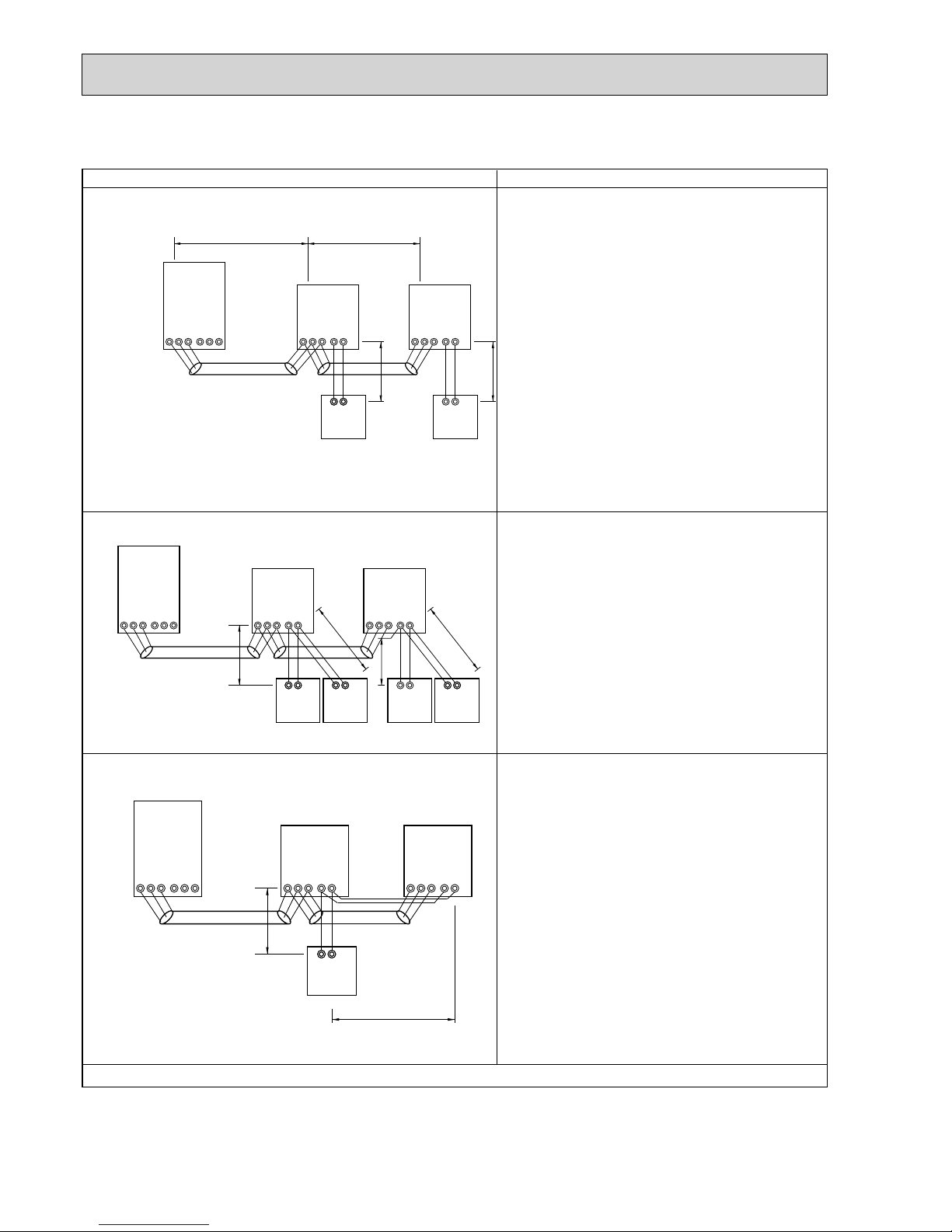
28
C. Example of a MA remote controller system (address setting is not necessary.)
NOTE : In the case of same group operation, need to set the address that is only main indoor unit.
Example of wiring control cables Wiring Method and Address Setting
• 1 remote controller for each
indoor unit.
1. Standard operation
2. Operation using two remote controllers
• Using 2 remote controllers
for each indoor unit.
M1M2
TB5
S12
TB15
00
IC
AB
M1M2
TB3
S
M1M2
TB7
00
OC
L
1 L2
S
M1M2
TB5
S12
TB15
00
IC
AB
MAMA
N1
N2
MA
M1M2
TB5
S12
TB15
00
IC
AB
M1M2
TB3
SM1M2
TB7
00
OC
S
M1M2
TB5
S12
TB15
00
IC
MA
AB AB
MA MA
N3
N4
N5
AB
N6
MA
M1M2
TB5
S12
TB15
00
IC
AB
M1M2
TB3
S
M1M2
TB7
00
OC
S
M1M2
TB5
S12
TB15
00
IC
N7
N8
a. Use feed wiring to connect terminals M1 and M2 on
transmission cable block (TB3) for the outdoor unit
(OC) to terminals M1 and M2 on the transmission
cable block (TB5) of each indoor unit (IC). Use
non-polarized 2 wire.
b. Connect terminals 1 and 2 on transmission cable
terminal block (TB15) for each indoor unit with the
terminal block for the MA remote controller (MA).
3. Group operation
• Multiple indoor units operated
together by 1 remote
controller
a. The same as above.
b. The same as above.
c. In the case of using 2 remote controllers, connect
terminals 1 and 2 on transmission cable terminal
block (TB15) for each indoor unit with the terminal
block for 2 remote controllers.
· Set the sub remote controller position for one of
MA remote controller’s main switch.
Refer to the installation manual of MA remote con-
troller
a. The same as above.
b. The same as above.
c. Connect terminals 1 and 2 on transmission cable ter-
minal block (TB15) of each indoor unit, which is doing
group operation with the terminal block the MA remote
controller. Use non-polarized 2 wire.
d. In the case of same group operation, need to set the
address that is only main indoor unit. Please set the
smallest address within number 01-50 of the indoor
unit with the most functions in the same group.
Combinations of 1through 3 above are possible.
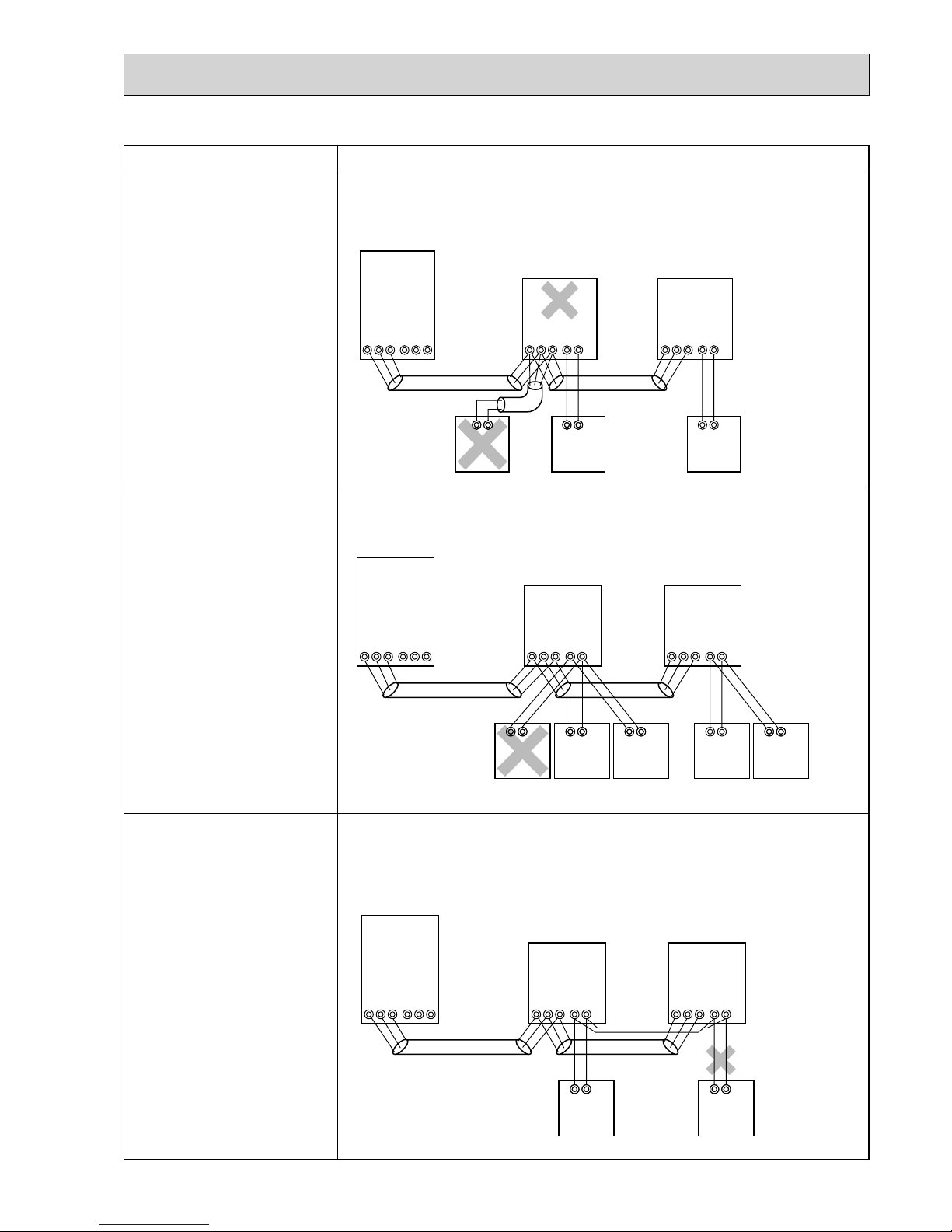
29
Permissible Lengths Prohibited items
Longest transmission cable length
L
1 + L2 [ 200m (1.25 mm
2
)
MA remote controller cable length
R
1, R2 [ 200m (0.3 ~ 1.25 mm
2
)
MA
M1M2
TB5
S12
TB15
00
IC
AB
M1M2
TB3
S
M1M2
TB7
00
OC
S
MA
M1M2
TB5
S12
TB15
00
IC
AB
MA
M1M2
TB5
S12
TB15
00
IC
AB
M1M2
TB3
S
M1M2
TB7
00
OC
S
M1M2
TB5
S12
TB15
00
IC
MA
AB AB
MA MAMA
AB AB
Longest transmission cable length
The same as above.
MA remote controller cable length
R
3 +R4, R5 +R6 [ 200m
(0.3 ~ 1.25 mm2)
Longest transmission cable length
The same as above.
MA remote controller cable length
R
7 +R8 [ 200m (0.3 ~ 1.25 mm
2
)
M1M2
TB5
S12
TB15
00
IC
AB
M1M2
TB3
S
M1M2
TB7
00
OC
S
M1M2
TB5
S12
TB15
00
IC
AB
MAMA
AB
RC
The MA remote controller and the
M-NET remote controller cannot be
used together with the indoor unit
of the same group.
3 MA remote controller or more
cannot be connected with the
indoor unit of the same group.
The second MA remote controller is connected with the terminal
block(TB15) for the MA remote controller of the same indoor unit(IC) as
the first remote control.
 Loading...