

SPLIT-TYPE, HEAT PUMP AIR CONDITIONERS
TECHNICAL & SERVICE MANUAL
Outdoor unit
[Model names] [Service Ref.]
PUMY-71VM PUMY-71VM
1999
No.OC183
REVISED EDITION-B
PUMY-71VM
1
PUMY-71VM2
PUMY-125VM PUMY-125VM
PUMY-125VM
1
PUMY-125VM2
PUMY-125YM PUMY-125YM
PUMY-125YM
PUMY-125YMA PUMY-125YMA
CONTENTS
1. TECHNICAL CHANGE ·····································2
2. OVERVIEW OF UNITS······································3
3. SPECIFICATIONS·············································6
4. DATA ·······························································12
5. OUTLINES AND DIMENSIONS······················32
6. WIRING DIAGRAM·········································34
7.
NECESSARY CONDITIONS FOR SYSTEM CONSTRUCTION
8. TROUBLESHOOTING ····································54
9. ELECTRICAL WIRING····································89
10. REFRIGERANT PIPING TASKS ·····················93
11. DISASSEMBLY················································98
12. PARTS LIST ··················································103
1
···42
Revision:
• PUMY-71VM2, PUMY-125VM2, PUMY-125YM1,
PUMY-125YMA are added in Revised Edition-B.
• Please destroy OC183 Revised Edition-A.
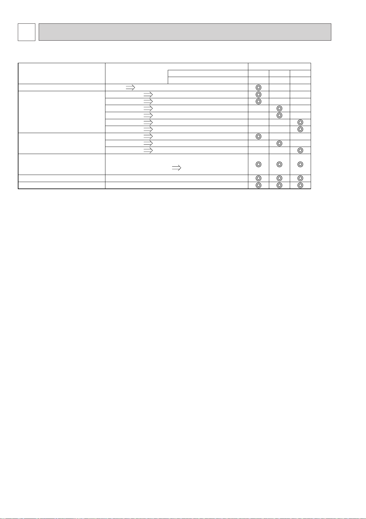
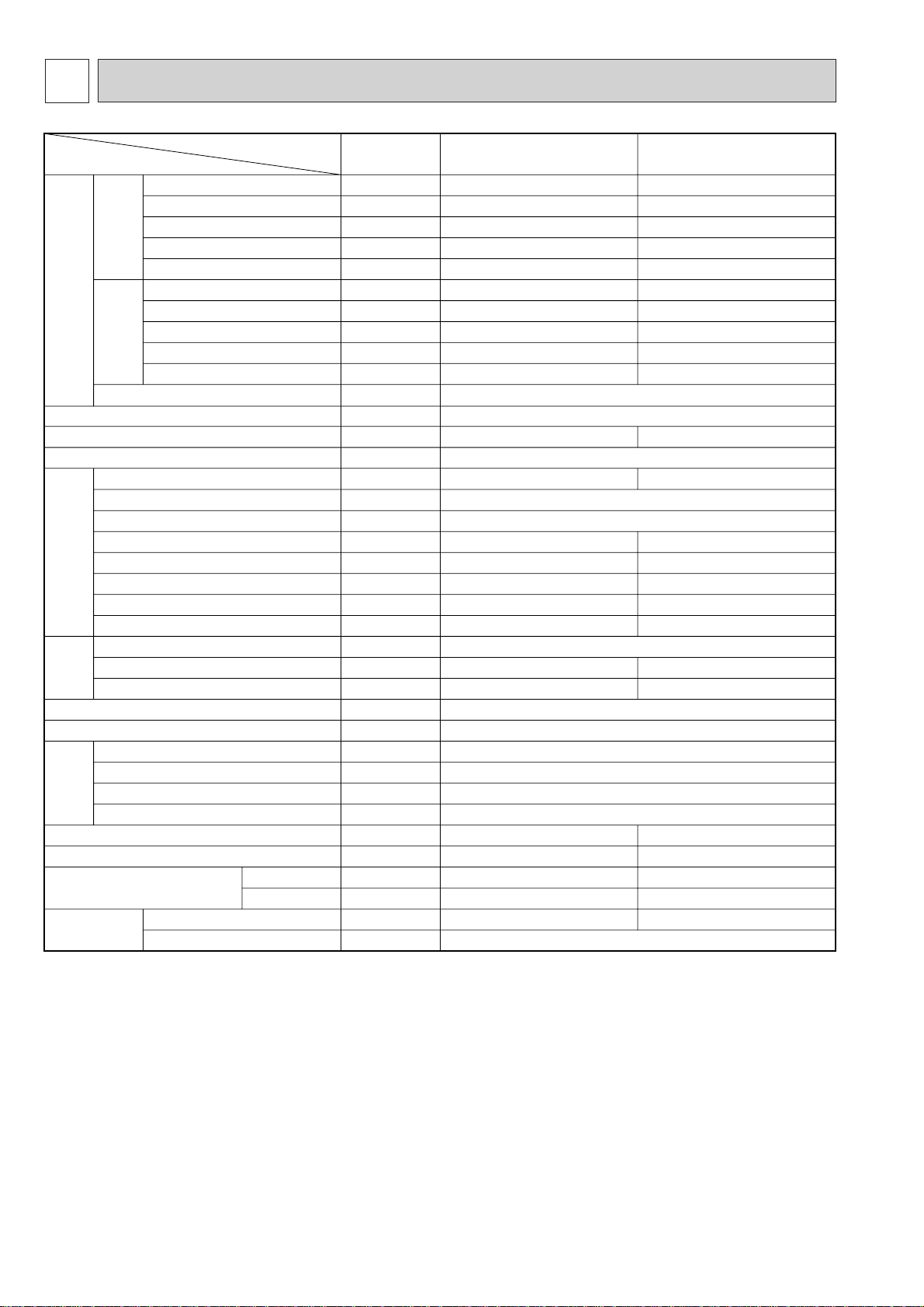
1 TECHNICAL CHANGE
CHANGE POINTS
CONTENTS
OF
CHANGE
Outdoor unit Service Ref.
Base outdoor unit Service Ref.
PUMY-
71VM
2
71VM1
125VM2
125VM1
125YM1
125YM
FAN MOTOR CAPACITOR
FAN MOTOR
COMPRESSOR
HIGH PRESSURE SENSOR
SEPARATOR ASSY
MULTI CONTROLLER BOARD
3.5+ 3.0+
PA6V40-UB PU6V60-GB
PA6V40-UA PU6V60-GA
PA6V60-UC PU6V60-GB
PA6V60-UB PU6V60-GA
PA6V60-UE PU6V60-GD
PA6V60-UD PU6V60-GC
CHV253FAA EHV33FAG
EHV46FAA EHV46FAG
EHV46FAD EHV46FAK
Maker change
Substrate connection
wiring is attached.
Change in accordance with high pressure sensor.
Change in accordance with high pressure sensor.
Substrate connection
wiring is not provided.
( ) ( )
—
—
—
—
—
—
—
—
—
—
—
—
—
—
—
—
—
—
—
—
Change of the service parts. Refer to the parts list for the details.
ww
Only PUMY-125YMA is new model.
2
2 OVERVIEW OF UNITS
20
25
32
40
50
63
71
80
100
125
-
32VKM
40VKM
50VKM
63VKM
80VAM
100VAM
125VAM
20VLMD
25VLMD
32VLMD
40VLMD
50VLMD
63VLMD
-
80VLMD
100VLMD
125VLMD
20VML / VMM
25VML / VMM
32VML / VMM
40VMH / VMM
50VMH / VMM
63VMH / VMM
71VMH / VMM
80VMH / VMM
100VMH / VMM
125VMH / VMM
20VM
25VM
32VM
40VM
50VM
63VM
71VM
80VM
100VM
125VM
20VAM
25VAM
32VGM
40VGM
50VGM
63VFM
-
-
100VFM
-
20VLEM
25VLEM
32VLEM
40VLEM
50VLEM
63VLEM
-
-
-
-
20VLRM
25VLRM
32VLRM
40VLRM
50VLRM
63VLRM
-
-
-
-
-
-
-
40VGM
-
63VGM
-
100VGM
125VGM
PLFY-P PLFY-P PEFY-P PDFY-P PKFY-P PCFY-P PFFY-P PFFY-P
Capacity
Model
Cassette Ceiling
4-way flow 2-way flow
20VBM
25VBM
32VBM
40VBM
-
-
-
-
-
-
PMFY-P
1-way flow
Ceiling
Concealed
Ceiling mounted
built-in
Ceiling
Suspended
Wall Mounted
Floor standing
Exposed Concealed
Remote
controller
Name
Model number
Functions
M-NET remote controller
PAR-F27MEA-E
• A handy remote controller for use in conjunction
with the Melans centralized management system.
• Addresses must be set.
• Addresses setting is not necessary.
•
Only the indoor unit for MA remote controller
(the end of model name is -A) can be used.
MA remote controller
PAR-20MAA-E
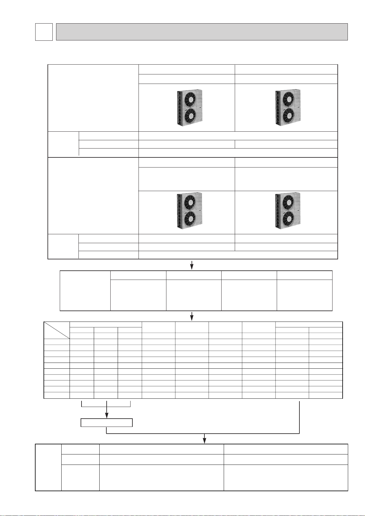
2-1. UNIT CONSTRUCTION
Outdoor unit
Indoor unit
that can be
connected
Outdoor unit
Indoor unit
that can be
connected
Capacity
Number of units
Total systemwide capacity
Capacity
Number of units
Total systemwide capacity
3HP
PUMY-71VM
2~4units
50~130% of outdoor unit capacity
3HP
PUMY-71VM
PUMY-71VM2
Type 20~Type 80
1~4units
50~130% of outdoor unit capacity
Type 20~Type 125
1
5HP
PUMY-125VM,PUMY-125YM
2~5units
5HP
PUMY-125VM1, PUMY-125YM
PUMY-125VM2, PUMY-125YM1
PUMY-125YMA
Type 20~Type 125
1~8units
CMY-Y62-C-E CMY-Y64-C CMY-Y68
Branching pipe
components
Branch header
(2 branches)
Branch header
(4 branches)
Branch header
(8 branches)
Decorative panel
3
CMY-S65
Multi distribution
Piping on outdoor
unit
(5 branches)
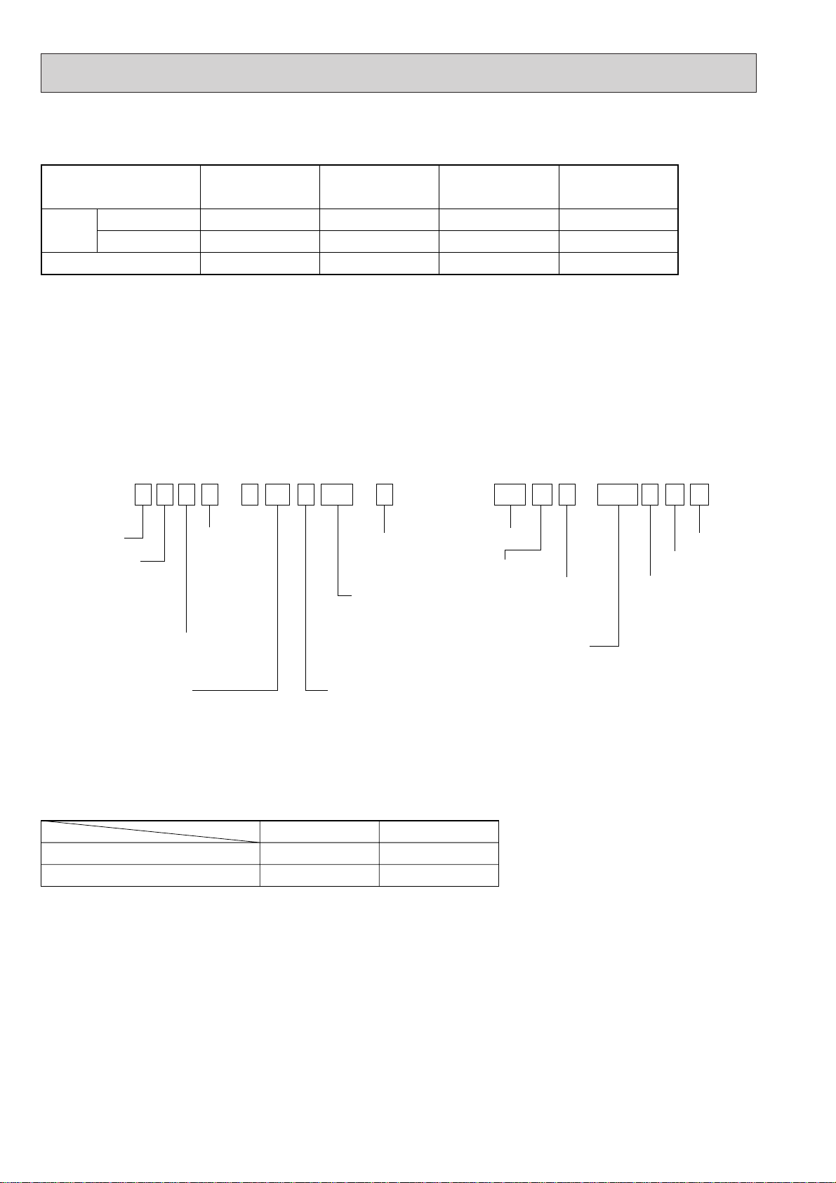
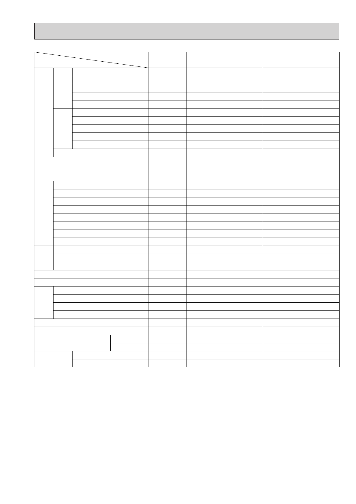
2-2. UNIT SPECIFICATIONS
P L F Y - P 80 V AM - A PU M Y - 125 Y M A
PAC type
AM
KM
M
KM
LMD
Frequency
conversion
controller
NEW frequency converter
one-to-many air conditioners
(flexible design type)
Indicates equivalent
to Cooling capacity
Indicates equivalent
to Cooling capacity
Power supply
V: Single phase
220/230/240V 50Hz
220V 60Hz
Power supply
V: Single phase
220/230/240V 50Hz
220V 60Hz
Y: 3-phase
380/400/415V 50Hz
380V 60Hz
L: Ceiling cassette
K: Wall-mounted type
E: Hidden skylight type
C: Ceiling suspended type
M: Ceiling cassette type
}
M-NET
control
M-NET control
MA control
Sub-number
Frequency
conversion
controller
Outdoor unit
MULTI-S
• Model 125 (5hp)..........For 5 rooms (VM)
...........For 8 rooms VM
1 YM
VM
2 YM1
YMA
( )
Service Ref.
w1
PUMY-71VM
PUMY-71VM
1
PUMY-71VM2 w2
w1
PUMY-125VM
PUMY-125VM
1
PUMY-125YM
w2
PUMY-125VM2
PUMY-125YM1
PUMY-125YMA
Capacity
Cooling (kW)
Heating (kW)
8.3
9.3
2.6
8.0
9.0
2.6
14.5
16.3
3.5
14.0
16.0
3.5Motor for compressor (kW)
Cooling
W.B. 15~24°C
D.B. -5~46°C
Heating
D.B. 15~27°C
W.B. -15~15.5°C
Indoor-side intake air temperature
Outdoor-side intake air temperature
(1) Outdoor Unit
Cooling / Heating capacity indicates the maximum value at operation under the following condition.
w1. Cooling Indoor : D.B. 27°C / W.B. 19.5°C
Outdoor : D.B. 35°C
Heating Indoor : D.B. 21°C
Outdoor : D.B. 9°C / W.B. 6°C
(2) Method for identifying MULTI-S model
■ Indoor unit < When using Model 80 >
w2. Cooling Indoor : D.B. 27°C / W.B. 19.0°C
Outdoor : D.B. 35°C
Heating Indoor : D.B. 20°C
Outdoor : D.B. 7°C / W.B. 6°C
■ Outdoor unit <When using model 125 >
(3) Operating temperature range
Notes D.B. : Dry Bulb Temperature
W.B. : Wet Bulb Temperature
4
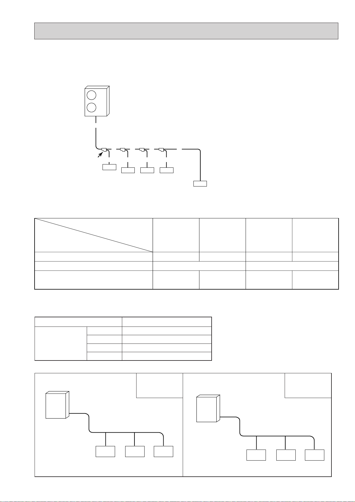
2-3. SYSTEM LAYOUT
A
B
a
indoor
1
C
b
indoor
2
D
c
indoor
3
e
d
indoor
4
indoor
5
First branch
(branching connector)
Outdoor unit
71
25 25 40
125
80 40 40
Outdoor unit
Indoor unit
Type 20 ~ Type 80 Type 20 ~ Type 125
PUMY-71VM
PUMY-71VM
1
PUMY-71VM2
PUMY-125VM
PUMY-125VM
1
PUMY-125VM2
PUMY-125YM
PUMY-125YM
1
PUMY-125YMA
1~8 units
63~163
2~4 units
35~92
2~5 units
63~163
1~4 units
35~92
Indoor unit that can connected
Available capacity of indoor unit
Total capacity of units that can be included system
(50-130% of outdoor unit capacity)
2-3-1. System layout
One outdoor unit using branching connectors can be connected to a maximum of five or eight indoor units.
■ Examples of a branching method
2-3-2. Notes on the connection of indoor and outdoor units
Note: When the total capacity of indoor units exceeds the capacity of the outdoor unit (more than 100%), the rated power of
each indoor unit will be less when they are running simultaneously.
2-3-3. Capacity for outdoor unit
(1) Branching pipe
Model
CMY-Y62C-E
Branching connector
(2) Examples of System Construction (All models)
PIping method
Indoor units
CMY-Y64-C
CMY-Y68
CMY-S65
Outdoor unit
NUMBER OF BRANCHING POINTS
2
4
8
5
Total capacity of
indoor units.
PIping method
90
5
Indoor units
Outdoor unit
Total capacity of
indoor units.
160
3 SPECIFICATIONS
Item
Rated Cooling capacity
Rated power consumption
Operating current
Operating power factor
Starting current
Rated Heating capacity
Rated power consumption
Operating current
Operating power factor
Standard performance
External finish (Munsell colour-coded markings)
Dimensions H o W o D (Note 1)
Heat exchanger type
Compressor
Fan
Defrost method
Pressure gauge
Protection
Noise level
Weight
Refrigerant pipe size
Refrigerant
Note 1: External dimensions in parentheses indicate the dimensions of protruding parts.
Note 2: Rating conditions (JIS B 8615)
Heating Cooling
Starting current
Rated power supply
Model
Type o quantity
Starting method
Motor output
Capacity control
Daily cooling capacity
Heater <crankcase>
Refrigerating oil (Model)
Type o quantity
Airflow
Motor output
High pressure protection
Compressor protection
Blower protection
devices
Frequency converter circuit
Type o charge amount
Control method
Cooling : Indoor : D.B. 27: W.B. 19.5:
: Outdoor : D.B. 35: W.B. 24:
Heating : Indoor : D.B. 21:
: Outdoor : D.B. 7: W.B. 6:
Service Ref
Gas
Liquid
kcal/h
kW
A
%
A
kcal/h
kW
A
%
A
mm
kW
%
Legal tons
W
L
k/min
W
dB
kg
[ mm
[ mm
kg
7,100
3.50
17.5-16.7-16.0
91
15.0
8,000
3.65
18.2-17.4-16.7
91
15.0
Single phase 220-230-240V 50Hz
Molten-galvanized steel plate (with polyester coating), ivory white <5Y 8/1>
1280 o 900 o 320 (+30) 1280 o 1020 o 350 (+30)
CHV253FAA
Fully enclosed type o 1
Frequency converter start
2.6
Cooling 27-100% Heating 24-100%
1.1 (110Hz)
25-28-30
1.07 (MS56)
Propeller (direct) o 2
95
40 o 2
High pressure pressure sensor (3.0MPa)
Overheating, excessive current protection
52
93
15.88
9.52
R22 o 5
PUMY-125VM PUMY-71VM Unit
12,500
6.57
34.9-33.5-32.2
85
22.0
14,000
6.10
32.6-31.2-29.9
85
22.0
Crossover fin
EHV46FAA
3.5
Cooling 27-100% Heating 25-100%
1.9 (104Hz)
38-41-45
1.4 (MS32)
90
60 o 2
Reverse cycle
—
Thermal switch
Thermal switch
54
130
19.05
9.52
R22 o 8.5
Expansion valve
6
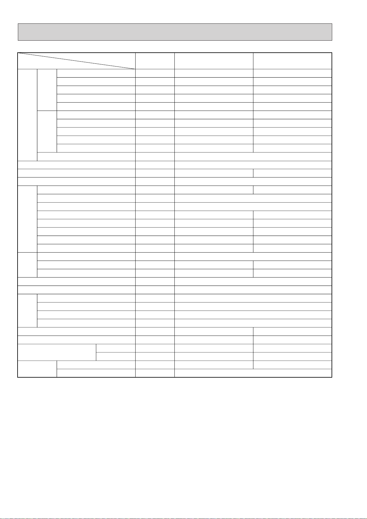
Item
Service Ref
Rated Cooling capacity
Rated power consumption
Operating current
Operating power factor
Starting current
Rated Heating capacity
Rated power consumption
Operating current
Operating power factor
Standard performance
Heating Cooling
Starting current
Rated power supply
External finish (Munsell colour-coded markings)
Dimensions H o W o D (Note 1)
Unit
kcal/h
kW
A
%
A
kcal/h
kW
A
%
A
mm
7,100
3.50 / 3.63
17.5-16.7-16.0 / 18.1
91
15.0
8,000
3.65 / 3.53
18.2-17.4-16.7 / 17.6
91
15.0
Single phase 220-230-240V 50Hz / 220V 60Hz
Molten-galvanized steel plate (with polyester coating), ivory white <5Y 8/1>
1280 o 900 o 320 (+30) 1280 o 1020 o 350 (+30)
Heat exchanger type
Model
Type o quantity
Starting method
Motor output
Capacity control
Compressor
Daily cooling capacity
Heater <crankcase>
Refrigerating oil (Model)
Type o quantity
Airflow
Fan
Motor output
kW
%
Legal tons
W
L
k/min
W
Cooling 27-100% Heating 24-100%
CHV253FAA
Fully enclosed type o 1
Frequency converter start
2.6
1.1 (110Hz)
—
1.07 (MS56)
Propeller (direct) o 2
95
40 o 2
Defrost method
Pressure gauge
High pressure protection
High pressure pressure sensor (3.0MPa)
Compressor protection
Blower protection
Protection
devices
Frequency converter circuit
Noise level
Weight
Refrigerant pipe size
Refrigerant
Type o charge amount
Control method
Gas
Liquid
dB
kg
[ mm
[ mm
kg
Overheating, excessive current protection
52
93
15.88
9.52
R22 o 5
Note 1: External dimensions in parentheses indicate the dimensions of protruding parts.
Note 2: Rating conditions (JIS B 8615)
Cooling: Indoor : D.B. 27: W.B. 19.5:
: Outdoor : D.B. 35: W.B. 24:
Heating : Indoor : D.B. 21:
: Outdoor : D.B. 7: W.B. 6:
Crossover fin
Cooling 27-100% Heating 25-100%
Reverse cycle
—
Thermal switch
Thermal switch
Expansion valve
PUMY-125VM
1 PUMY-71VM1
12,500
6.57 / 6.43
34.9-33.5-32.2 / 33.6
85 / 87
22.0
14,000
6.10 / 6.03
32.6-31.2-29.9 / 31.5
85 / 87
22.0
EHV46FAA
3.5
1.9 (104Hz)
—
1.4 (MS32)
90
60 o 2
54
130
19.05
9.52
R22 o 8.5
7
Item
Service Ref
Rated Cooling capacity
Rated power consumption
Operating current
Operating power factor
Starting current
Rated Heating capacity
Rated power consumption
Operating current
Operating power factor
Standard performance
Heating Cooling
Starting current
Rated power supply
External finish (Munsell colour-coded markings)
Dimensions H o W o D (Note 1)
Heat exchanger type
Model
Type o quantity
Starting method
Motor output
Capacity control
Daily cooling capacity
Compressor
Heater <crankcase>
Refrigerating oil (Model)
Type o quantity
Airflow
Fan
Motor output
Defrost method
Pressure gauge
High pressure protection
Compressor protection
Blower protection
Protection
devices
Frequency converter circuit
Noise level
Weight
Refrigerant pipe size
Refrigerant
Type o charge amount
Control method
Gas
Liquid
Unit
kW
kW
A
%
A
kW
kW
A
%
A
mm
kW
%
Legal tons
W
L
k/min
W
dB
kg
[ mm
[ mm
kg
2 PUMY-71VM2
8.0
3.50 / 3.63
17.5-16.7-16.0 / 18.1
91
15.0
9.0
3.65 / 3.53
18.2-17.4-16.7 / 17.6
91
15.0
PUMY-125VM
14.0
6.57 / 6.43
34.9-33.5-32.2 / 33.6
85 / 87
22.0
16.0
6.10 / 6.03
32.6-31.2-29.9 / 31.5
85 / 87
22.0
Single phase 220-230-240V 50Hz / 220V 60Hz
Molten-galvanized steel plate (with polyester coating), ivory white <5Y 8/1>
1280 o 900 o 320 (+30) 1280 o 1020 o 350 (+30)
Crossover fin
EHV33FAG
EHV46FAG
Fully enclosed type o 1
Frequency converter start
2.6
Cooling 36-100% Heating 32-100%
1.1 (83Hz)
—
1.4 (MS32)
Cooling 27-100% Heating 25-100%
3.5
1.9 (104Hz)
—
1.4 (MS32)
Propeller (direct) o 2
95
40 o 2
90
60 o 2
Reverse cycle
—
High pressure pressure sensor (3.0MPa)
Thermal switch
Thermal switch
Overheating, excessive current protection
52
102
15.88
9.52
R22 o 5
54
130
19.05
9.52
R22 o 8.5
Expansion valve
Note 1: External dimensions in parentheses indicate the dimensions of protruding parts.
Note 2: Rating conditions (JIS B 8616)
Cooling: Indoor : D.B. 27: W.B. 19.0:
: Outdoor : D.B. 35: W.B. 24:
Heating : Indoor : D.B. 20:
: Outdoor : D.B. 7: W.B. 6:
8
Item
Rated Cooling capacity
Rated power consumption
Operating current
Operating power factor
Starting current
Rated Heating capacity
Rated power consumption
Operating current
Operating power factor
Standard performance
External finish (Munsell colour-coded markings)
Dimensions H o W o D (Note 1)
Heat exchanger type
Compressor
Fan
Defrost method
Pressure gauge
Protection
Noise level
Weight
Refrigerant pipe size
Refrigerant
Note 1: External dimensions in parentheses indicate the dimensions of protruding parts.
Note 2: Rating conditions (JIS B 8615)
Cooling : Indoor : D.B. 27: W.B. 19.5:
Heating Cooling
Starting current
Rated power supply
Model
Type o quantity
Starting method
Motor output
Capacity control
Daily cooling capacity
Heater <crankcase>
Refrigerating oil (Model)
Type o quantity
Airflow
Motor output
High pressure protection
Compressor protection
Blower protection
devices
Frequency converter circuit
Type o charge amount
Control method
: Outdoor : D.B. 35: W.B. 24:
Heating : Indoor : D.B. 21:
: Outdoor : D.B. 7: W.B. 6:
Service Ref
Gas
Liquid
Unit
kcal/h
kW
A
%
A
kcal/h
kW
A
%
A
mm
kW
%
Legal tons
W
L
k/min
W
dB
kg
[ mm
[ mm
kg
3 phase 380-400-415V 50Hz
Molten-galvanized steel plate (with polyester coating), ivory white <5Y 8/1>
1280 o 1020 o 350 (+30)
Fully enclosed type o 1
Frequency converter start
Cooling 27-100% Heating 25-100%
Propeller (direct) o 2
High pressure pressure sensor (3.0MPa)
Overheating, excessive current protection
PUMY-125YM
12,500
5.95
9.6-9.1-8.8
94
8.0
14,000
5.58
9.0-8.6-8.3
94
8.0
Crossover fin
EHV46FAD
3.5
1.9 (104Hz)
—
1.4 (MS32)
90
60 o 2
Reverse cycle
—
Thermal switch
Thermal switch
54
127
19.05
9.52
R22 o 8.5
Expansion valve
9
Item
Rated Cooling capacity
Rated power consumption
Operating current
Operating power factor
Starting current
Rated Heating capacity
Rated power consumption
Operating current
Operating power factor
Standard performance
External finish (Munsell colour-coded markings)
Dimensions H o W o D (Note 1)
Heat exchanger type
Compressor
Fan
Defrost method
Pressure gauge
Protection
Noise level
Weight
Refrigerant pipe size
Refrigerant
Note 1: External dimensions in parentheses indicate the dimensions of protruding parts.
Note 2: Rating conditions (JIS B 8616)
Cooling : Indoor : D.B. 27: W.B. 19.0:
Heating Cooling
Starting current
Rated power supply
Model
Type o quantity
Starting method
Motor output
Capacity control
Daily cooling capacity
Heater <crankcase>
Refrigerating oil (Model)
Type o quantity
Airflow
Motor output
High pressure protection
Compressor protection
Blower protection
devices
Frequency converter circuit
Type o charge amount
Control method
: Outdoor : D.B. 35: W.B. 24:
Heating : Indoor : D.B. 20:
: Outdoor : D.B. 7: W.B. 6:
Service Ref
Gas
Liquid
Unit
kW
kW
A
%
A
kW
kW
A
%
A
mm
kW
%
Legal tons
W
L
k/min
W
dB
kg
[ mm
[ mm
kg
3 phase 380-400-415V 50Hz / 380V 60Hz
Molten-galvanized steel plate (with polyester coating), ivory white <5Y 8/1>
1280 o 1020 o 350 (+30)
Fully enclosed type o 1
Frequency converter start
Cooling 27-100% Heating 25-100%
Propeller (direct) o 2
High pressure pressure sensor (3.0MPa)
Overheating, excessive current protection
PUMY-125YM1
14.0
5.95
9.6-9.1-8.8 / 9.6
94
8.0
16.0
5.58
9.0-8.6-8.3 / 9.0
94
8.0
Crossover fin
EHV46FAK
3.5
1.9 (104Hz)
—
1.4 (MS32)
90
60 o 2
Reverse cycle
—
Thermal switch
Thermal switch
54
127
19.05
9.52
R22 o 8.5
Expansion valve
10
Item
Rated Cooling capacity
Rated power consumption
Operating current
Operating power factor
Starting current
Rated Heating capacity
Rated power consumption
Operating current
Operating power factor
Standard performance
External finish (Munsell colour-coded markings)
Dimensions H o W o D (Note 1)
Heat exchanger type
Compressor
Fan
Defrost method
Pressure gauge
Protection
Noise level
Weight
Refrigerant pipe size
Refrigerant
Note 1: External dimensions in parentheses indicate the dimensions of protruding parts.
Note 2: Rating conditions (JIS B 8616)
Cooling : Indoor : D.B. 27: W.B. 19.0:
Heating Cooling
Starting current
Rated power supply
Model
Type o quantity
Starting method
Motor output
Capacity control
Daily cooling capacity
Heater <crankcase>
Refrigerating oil (Model)
Type o quantity
Airflow
Motor output
High pressure protection
Compressor protection
Blower protection
devices
Frequency converter circuit
Type o charge amount
Control method
: Outdoor : D.B. 35: W.B. 24:
Heating : Indoor : D.B. 20:
: Outdoor : D.B. 7: W.B. 6:
Service Ref
Gas
Liquid
Unit
kW
kW
A
%
A
kW
kW
A
%
A
mm
kW
%
Legal tons
W
L
k/min
W
dB
kg
[ mm
[ mm
kg
3 phase 380-400-415V 50Hz
Molten-galvanized steel plate (with polyester coating), ivory white <5Y 8/1>
1280 o 1020 o 350 (+30)
Fully enclosed type o 1
Frequency converter start
Cooling 27-100% Heating 25-100%
Propeller (direct) o 2
High pressure pressure sensor (3.0MPa)
Overheating, excessive current protection
PUMY-125YMA
14.0
5.95
9.6-9.1-8.8
94
8.0
16.0
5.58
9.0-8.6-8.3
94
8.0
Crossover fin
EHV46FAK
3.5
1.9 (104Hz)
—
1.4 (MS32)
90
60 o 2
Reverse cycle
—
Thermal switch
Thermal switch
54
127
19.05
9.52
R22 o 8.5
Expansion valve
11
4 DATA
Model 20
Model Number for indoor unit
Model Capacity
Kcal/h
kW w
20
22
Model 25
25
28
Model 32
32
36
Model 40
40
45
Model 50
50
56
Model 63
63
71
Model 71
71
80
Model 80
80
90
Model 100
100
112
Model 125
125
140
4-1. COOLING AND HEATING CAPACITY AND CHARACTERISTICS
4-1-1. Method for obtaining system cooling and heating capacity:
To obtain the system cooling and heating capacity and the electrical characteristics of the outdoor unit, first add up the ratings
of all the indoor units connected to the outdoor unit (see table below), and then use this total to find the standard capacity with
the help of the tables on p.13~27.
(1) Capacity of indoor unit
w : Model of indoor unit “–A”
(2) Sample calculation
1System assembled from indoor and outdoor unit (in this example the total capacity of the indoor units is greater than that of
the outdoor unit)
• Outdoor unit PUMY-125YM
• Indoor unit PKFY-P25VAM o 2 , PLFY-P50VLMD o 2
2According to the conditions in 1, the total capacity of the indoor unit will be: 25 o 2 + 50 o 2 = 150
3The following figures are obtained from the 150 total capacity row of the standard capacity table (p.23):
Capacity (kcal/h)
Cooling
13,026
AB
Heating
14,288
Outdoor unit power consumption (kW)
Cooling
6.15
Heating
5.98
Outdoor unit current (A)
Cooling
9.4
Heating
9.2
4-1-2. Method for obtaining the heating and cooling capacity of an indoor unit:
(1) The capacity of each indoor unit (kcal/h) = the capacity A(or B) o
(2) Sample calculation (using the system described above in 4-1-1. (2) ):
During cooling: During heating:
• The total model capacity of the indoor unit is:
25 o 2 + 50 o 2=150kcal/h
Therefore, the capacity of PKFY-P25VAM and
PLFY-P50VLMD will be calculated as follows by
using the formula in 4-1-2. (1):
Model 25=13,026 o = 2,171kcal/h
Model 50=13,026 o = 4,342kcal/h
25
150
50
150
• The total model capacity of indoor unit is:
28 o 2 + 56 o 2=168kcal/h
Therefore, the capacity of PKFY-P25VAM and PLFYP50VLMD will be calculated as follows by using the formula in 4-1-2. (1):
Model 25=14,288 o = 2,381kcal/h
Model 50=14,288 o = 4,762kcal/h
total model capacity of all indoor units
model capacity
28
168
56
168
12
4-2. STANDARD CAPACITY DIAGRAM
• PUMY-71VM, PUMY-71VM1 STANDARD CAPACITY DIAGRAM
Total capacity of
indoor units(kcal/h)
40
41
42
43
44
45
46
47
48
49
50
51
52
53
54
55
56
57
58
59
60
61
62
63
64
65
66
67
68
69
70
71
72
73
74
75
76
77
78
79
80
81
82
83
84
85
86
87
88
89
90
91
92
93
Capacity (kcal/h) Power consumption (kW) Current (A)
Cooling Heating
4000
4100
4200
4300
4400
4500
4600
4700
4800
4900
5000
5100
5200
5300
5400
5500
5600
5700
5800
5900
6000
6100
6200
6300
6400
6500
6600
6700
6800
6900
7000
7100
7122
7144
7166
7189
7211
7223
7255
7277
7299
7322
7344
7366
7388
7410
7432
7455
7477
7499
7542
7543
7566
7588
4500
4610
4720
4830
4940
5050
5160
5270
5380
5490
5600
5715
5831
5946
6062
6177
6292
6408
6523
6638
6754
6869
6985
7100
7213
7325
7438
7550
7663
7775
7888
8000
8012
8024
8036
8049
8061
8073
8085
8097
8109
8121
8133
8146
8158
8170
8182
8194
8206
8218
8231
8243
8255
8267
Cooling Heating
2.02
2.07
2.12
2.17
2.22
2.27
2.31
2.36
2.41
2.46
2.51
2.55
2.59
5.64
2.69
2.74
2.79
2.83
2.88
2.93
2.98
3.02
3.07
3.11
3.16
3.21
3.26
3.31
3.36
3.40
3.45
3.50
3.50
3.51
3.51
3.52
3.52
3.53
3.53
3.54
3.54
3.55
3.55
3.56
3.56
3.57
3.57
3.58
3.58
3.59
3.60
3.60
3.61
3.61
2.41
2.45
2.49
2.53
2.58
2.63
2.67
2.71
2.75
2.79
2.83
2.87
2.92
2.96
3.00
3.04
3.08
3.12
3.16
3.20
3.24
3.28
3.31
3.35
3.39
3.42
3.46
3.49
3.54
3.58
3.61
3.65
3.64
3.63
3.61
3.60
3.58
3.57
3.55
3.54
3.52
3.51
3.48
3.47
3.45
3.44
3.42
3.41
3.39
3.38
3.36
3.35
3.33
3.32
220V, 50Hz
Cooling Heating
10.1
10.4
10.6
10.8
11.1
11.3
11.6
11.8
12.0
12.3
12.5
12.7
13.0
13.2
13.4
13.7
13.9
14.2
14.4
14.6
14.9
15.1
15.3
15.6
15.8
16.0
16.3
16.5
16.8
17.0
17.2
17.5
18.7
18.8
18.8
18.8
18.8
18.9
18.9
18.9
18.9
19.0
19.0
19.0
19.0
19.1
19.1
19.1
19.1
19.2
19.2
19.2
19.3
19.3
12.0
12.2
12.4
12.7
12.9
13.1
13.3
13.5
13.7
13.9
14.2
14.4
14.6
14.8
15.0
15.2
15.4
15.6
15.8
16.0
16.2
16.4
16.5
16.7
16.9
17.1
17.3
17.5
17.7
17.9
18.0
18.2
19.5
19.4
19.3
19.2
19.1
19.1
19.0
18.9
18.8
18.7
18.6
18.6
18.5
18.4
18.3
18.2
18.1
18.1
18.0
17.9
17.8
17.7
13
• PUMY-71VM1 STANDARD CAPACITY DIAGRAM
10.8
11.0
11.2
11.5
11.7
11.9
12.1
12.3
12.5
12.7
12.9
13.1
13.3
13.5
13.7
13.9
14.1
14.3
14.5
14.7
14.9
15.1
15.2
15.4
15.6
15.8
16.0
16.1
16.3
16.5
16.7
16.8
17.0
17.2
17.3
17.5
17.6
17.6
17.6
17.5
17.4
17.4
17.3
17.2
17.1
17.1
17.0
16.9
16.9
16.8
16.7
16.6
16.6
16.5
16.4
16.4
16.3
16.2
16.2
Total capacity of
indoor units(kcal/h)
Capacity (kcal/h) Power consumption (kW) Current (A)
Cooling Heating
Cooling Heating
Cooling Heating
35
36
37
38
39
40
41
42
43
44
45
46
47
48
49
50
51
52
53
54
55
56
57
58
59
60
61
62
63
64
65
66
67
68
69
70
71
72
73
74
75
76
77
78
79
80
81
82
83
84
85
86
87
88
89
90
91
92
93
3500
3600
3700
3800
3900
4000
4100
4200
4300
4400
4500
4600
4700
4800
4900
5000
5100
5200
5300
5400
5500
5600
5700
5800
5900
6000
6100
6200
6300
6400
6500
6600
6700
6800
6900
7000
7100
7122
7144
7166
7189
7211
7233
7255
7277
7299
7322
7344
7366
7388
7410
7432
7455
7477
7499
7521
7543
7566
7588
3906
4025
4144
4263
4381
4500
4610
4720
4830
4940
5050
5160
5270
5380
5490
5600
5715
5831
5946
6062
6177
6292
6408
6523
6638
6754
6869
6985
7100
7213
7325
7438
7550
7663
7775
7778
8000
8012
8024
8036
8049
8061
8073
8085
8097
8109
8121
8133
8146
8158
8170
8182
8194
8206
8218
8231
8243
8255
8267
1.86
1.91
1.96
2.01
2.06
2.10
2.15
2.20
2.25
2.30
2.35
2.40
2.45
2.50
2.55
2.60
2.64
2.69
2.74
2.79
2.84
2.89
2.94
2.99
3.04
3.09
3.13
3.18
3.23
3.28
3.33
3.38
3.43
3.48
3.53
3.58
3.63
3.63
3.64
3.64
3.65
3.65
3.66
3.66
3.67
3.67
3.68
3.68
3.69
3.69
3.70
3.70
3.71
3.71
3.72
3.73
3.73
3.74
3.74
2.11
2.15
2.19
2.24
2.28
2.33
2.37
2.41
2.45
2.50
2.54
2.58
2.62
2.66
2.70
2.74
2.78
2.82
2.86
2.90
2.94
2.98
3.02
3.06
3.09
3.13
3.17
3.20
3.24
3.28
3.31
3.35
3.38
3.42
3.46
3.49
3.53
3.52
3.51
3.49
3.48
3.46
3.45
3.43
3.42
3.40
3.39
3.37
3.36
3.34
3.33
3.31
3.30
3.28
3.27
3.25
3.24
3.22
3.21
9.6
9.8
10.1
10.3
10.6
10.8
11.0
11.3
11.5
11.8
12.0
12.2
12.5
12.7
13.0
13.2
13.4
13.7
13.9
14.2
14.4
14.6
14.9
15.1
15.3
15.6
15.8
16.0
16.3
16.5
16.7
17.0
17.2
17.4
17.7
17.9
18.1
18.2
18.2
18.2
18.2
18.3
18.3
18.3
18.3
18.4
18.4
18.4
18.4
18.5
18.5
18.5
18.5
18.6
18.6
18.6
18.6
18.7
18.7
220V, 60Hz
14
• PUMY-71VM2 STANDARD CAPACITY DIAGRAM
w Before calculating the sum of total capacity of indoor units, please convert
the valve into the kW model capacity following the table on page 12.
Total capacity of
w
indoor units(kW)
40
41
42
43
44
45
46
47
48
49
50
51
52
53
54
55
56
57
58
59
60
61
62
63
64
65
66
67
68
69
70
71
72
73
74
75
76
77
78
79
80
81
82
83
84
85
86
87
88
89
90
91
92
93
94
95
96
97
98
99
100
101
102
103
104
Capacity (kW)
Cooling Heating
4.00
4.10
4.20
4.30
4.40
4.50
4.60
4.70
4.80
4.90
5.00
5.10
5.20
5.30
5.40
5.50
5.60
5.70
5.80
5.90
6.00
6.10
6.20
6.30
6.40
6.50
6.60
6.70
6.80
6.90
7.00
7.10
7.20
7.30
7.40
7.50
7.60
7.70
7.80
7.90
8.00
8.02
8.05
8.07
8.09
8.12
8.14
8.16
8.19
8.21
8.23
8.25
8.28
8.30
8.32
8.35
8.37
8.39
8.41
8.44
8.46
8.48
8.51
8.53
8.55
4.44
4.56
4.67
4.78
4.89
5.00
5.12
5.24
5.35
5.47
5.59
5.71
5.83
5.94
6.06
6.18
6.30
6.41
6.53
6.64
6.75
6.87
6.98
7.10
7.20
7.32
7.43
7.54
7.66
7.77
7.88
8.00
8.11
8.22
8.33
8.44
8.56
8.67
8.78
8.89
9.00
9.01
9.03
9.04
9.05
9.06
9.08
9.09
9.10
9.11
9.13
9.14
9.15
9.16
9.18
9.19
9.20
9.21
9.23
9.24
9.25
9.26
9.28
9.29
9.30
Power consumption (kW)
Cooling Heating
1.83
1.87
1.91
1.95
1.99
2.03
2.08
2.12
2.15
2.21
2.25
2.29
2.33
2.37
2.41
2.45
2.50
2.54
2.57
2.62
2.66
2.70
2.75
2.78
2.82
2.87
2.91
2.95
2.99
3.03
3.08
3.13
3.17
3.20
3.25
3.29
3.33
3.38
3.41
3.45
3.50
3.50
3.50
3.51
3.51
3.52
3.52
3.53
3.53
3.54
3.54
3.55
3.55
3.56
3.56
3.57
3.57
3.58
3.58
3.59
3.59
3.59
3.59
3.60
3.60
220V, 50Hz 220V, 60Hz
2.05
2.09
2.13
2.16
2.20
2.24
2.27
2.30
2.35
2.39
2.42
2.27
2.50
2.53
2.57
2.62
2.66
2.68
2.73
2.77
2.81
2.86
2.90
2.93
2.98
3.02
3.05
3.10
3.14
3.18
3.23
3.27
3.31
3.35
3.39
3.43
3.48
3.53
3.56
3.61
6.65
6.65
3.63
3.62
3.60
3.58
3.57
3.55
3.54
3.53
3.52
3.51
3.49
3.48
3.46
3.44
3.41
3.40
3.39
3.38
3.37
3.36
3.33
3.33
3.31
Current (A)
Cooling Heating
9.1
9.3
9.5
9.8
10.0
10.2
10.4
10.6
10.8
11.0
11.2
11.4
11.6
11.8
12.0
12.2
12.5
12.7
12.8
13.1
13.3
13.5
13.7
13.9
14.1
14.3
14.6
14.8
15.0
15.2
15.4
15.6
15.8
16.0
16.2
16.4
16.6
16.9
17.0
17.2
17.5
17.5
17.5
17.5
17.5
17.6
17.6
17.6
17.6
17.7
17.7
17.7
17.7
17.8
17.8
17.8
17.8
17.9
17.9
17.9
17.9
17.9
17.9
18.0
18.0
Power consumption (kW)
Cooling Heating
10.3
10.5
10.6
10.8
11.0
11.2
11.4
11.5
11.7
11.9
12.1
12.3
12.5
12.6
12.8
13.1
13.3
13.4
13.6
13.8
14.0
14.3
14.5
14.7
14.9
15.1
15.2
15.5
15.7
15.9
16.1
16.3
16.5
16.8
16.9
17.1
17.4
17.6
17.8
18.0
18.2
18.2
18.1
18.1
18.0
17.9
17.8
17.8
17.7
17.6
17.6
17.5
17.4
17.4
17.3
17.2
17.0
17.0
16.9
16.9
16.8
16.8
16.7
16.6
16.5
1.90
1.94
1.98
2.02
2.07
2.11
2.16
2.20
2.23
2.29
2.33
2.37
2.41
2.45
2.50
2.54
2.59
2.63
2.66
2.72
2.76
2.80
2.85
2.89
2.93
2.98
3.02
3.06
3.11
3.15
3.19
3.24
3.28
3.32
3.37
3.41
3.45
3.50
3.54
3.58
3.63
3.63
3.63
3.64
3.64
3.65
3.65
3.66
3.66
3.67
3.67
3.68
3.68
3.69
3.69
3.70
3.70
3.71
3.71
3.72
3.72
3.72
3.72
3.73
3.73
1.99
2.02
2.06
2.09
2.13
2.16
2.20
2.23
2.27
2.31
2.34
2.20
2.42
2.45
2.49
2.53
2.57
2.60
2.64
2.68
2.72
2.76
2.80
2.84
2.88
2.92
2.95
2.99
3.04
3.08
3.12
3.16
3.20
3.24
3.28
3.32
3.36
3.41
3.45
3.49
3.53
3.53
3.51
3.50
3.48
3.47
3.46
3.44
3.43
3.41
3.40
3.39
3.37
3.36
3.35
3.33
3.30
3.29
3.28
3.27
3.26
3.25
3.23
3.22
3.20
220V, 50Hz/60Hz
Current (A)
Cooling Heating
9.5
9.7
9.9
10.1
10.3
10.5
10.8
11.0
11.2
11.4
11.6
11.8
12.1
12.3
12.5
12.7
12.9
13.2
13.3
13.6
13.8
14.0
14.3
14.4
14.6
14.9
15.1
15.3
15.5
15.7
15.9
16.2
16.4
16.6
16.8
17.0
17.2
17.5
17.7
17.9
18.1
18.1
18.1
18.2
18.2
18.2
18.2
18.3
18.3
18.3
18.3
18.4
18.4
18.4
18.4
18.5
18.5
18.6
18.6
18.6
18.6
18.6
18.6
18.7
18.7
9.9
10.1
10.3
10.4
10.6
10.8
11.0
11.1
11.4
11.5
11.7
11.9
12.1
12.2
12.4
12.6
12.8
13.0
13.2
13.4
13.6
13.8
14.0
14.2
14.4
14.6
14.7
15.0
15.2
15.4
15.6
15.8
16.0
16.2
16.4
16.6
16.8
17.0
17.2
17.4
17.6
17.6
17.5
17.5
17.4
17.3
17.3
17.2
17.1
17.0
17.0
16.9
16.8
16.8
16.7
16.6
16.5
16.4
16.4
16.3
16.3
16.2
16.1
16.1
16.0
15
• PUMY-125VM, PUMY-125VM1 STANDARD CAPACITY DIAGRAM
Total capacity of
indoor units(kcal/h)
63
64
65
66
67
68
69
70
71
72
73
74
75
76
77
78
79
80
81
82
83
84
85
86
87
88
89
90
91
92
93
94
95
96
97
98
99
100
101
102
103
104
105
106
107
108
109
110
111
112
113
114
115
116
117
118
Capacity (kcal/h)
Cooling
6300
6400
6500
6600
6700
6800
6900
7000
7100
7200
7300
7400
7500
7600
7700
7800
7900
8000
8100
8200
8300
8400
8500
8600
8700
8800
8900
9000
9100
9200
9300
9400
9500
9600
9700
9800
9900
10000
10100
10200
10300
10400
10500
10600
10700
10800
10900
11000
11100
11200
11300
11400
11500
11600
11700
11800
Heating
7100
7213
7325
7438
7550
7663
7776
7888
8000
8111
8222
8333
8445
8556
8667
8778
8889
9000
9110
9220
9330
9440
9550
9660
9770
9880
9990
10100
10210
10320
10430
10540
10650
10760
10870
10980
11090
11200
11312
11424
11536
11648
11760
11872
11984
12096
12208
12320
12432
12544
12656
12768
12880
12992
13104
13216
Power consumption (kW) Current (A)
Cooling
2.74
2.78
2.83
2.87
2.92
2.96
3.01
3.06
3.11
3.16
3.21
3.25
3.30
3.35
3.40
3.45
3.51
3.57
3.62
3.67
3.73
3.78
3.84
3.89
3.95
4.01
4.07
4.13
4.19
4.25
4.31
4.37
4.43
4.50
4.56
4.62
4.68
4.75
4.81
4.88
4.95
5.02
5.08
5.15
5.22
5.29
5.35
5.43
5.50
5.57
5.64
5.72
5.79
5.86
5.94
6.02
Heating
2.88
2.92
2.97
3.01
3.07
3.11
3.15
3.20
3.24
3.29
3.33
3.38
3.43
3.47
3.52
3.57
3.61
3.66
3.71
3.76
3.80
3.85
3.90
3.96
4.01
4.06
4.11
4.16
4.21
4.26
4.31
4.36
4.41
4.46
4.51
4.57
4.62
4.67
4.72
4.78
4.84
4.89
4.95
5.00
5.05
5.11
5.16
5.22
5.27
5.33
5.38
5.44
5.50
5.55
5.61
5.68
Cooling
14.6
14.9
15.1
15.4
15.6
15.8
16.1
16.3
16.6
16.9
17.2
17.4
17.6
17.9
18.2
18.5
18.8
19.1
19.3
19.6
19.9
20.2
20.5
20.8
21.1
21.4
21.7
22.1
22.4
22.7
23.1
23.4
23.7
24.0
24.4
24.7
25.0
25.4
25.7
26.1
26.4
26.8
27.2
27.5
27.9
28.3
28.6
29.0
29.4
29.8
30.2
30.6
31.0
31.4
31.7
32.2
220V, 50Hz
Heating
15.4
15.6
15.9
16.1
16.4
16.6
16.8
17.1
17.3
17.6
17.8
18.1
18.3
18.6
18.8
19.1
19.3
19.6
19.9
20.1
20.3
20.6
20.9
21.2
21.4
21.7
22.0
22.2
22.5
22.8
23.0
23.3
23.6
23.9
24.1
24.5
24.7
25.0
25.3
25.6
25.9
26.1
26.5
26.7
27.0
27.3
27.6
27.9
28.2
28.5
28.8
29.1
29.4
29.7
30.0
30.3
16
• PUMY-125VM, PUMY-125VM1 STANDARD CAPACITY DIAGRAM
Total capacity of
indoor units(kcal/h)
119
120
121
122
123
124
125
126
127
128
129
130
131
132
133
134
135
136
137
138
139
140
141
142
143
144
145
146
147
148
149
150
151
152
153
154
155
156
157
158
159
160
161
162
163
Capacity (kcal/h) Power consumption (kW) Current (A)
Cooling Heating
11900
12000
12100
12200
12300
12400
12500
12521
12542
12563
12584
12605
12626
12647
12668
12689
12710
12731
12753
12774
12795
12816
12837
12859
12879
12900
12921
12942
12963
12984
13005
13026
13047
13068
13089
13110
13131
13153
13174
13195
13216
13237
13258
13279
13300
13328
13440
13552
13664
13776
13888
14000
14012
14023
14035
14046
14058
14069
14081
14092
14104
14115
14127
14138
14150
14161
14173
14184
14196
14207
14219
14230
14242
14253
14265
14276
14288
14299
14311
14322
14334
14345
14357
14368
14380
14391
14403
14414
14426
14437
Cooling Heating
6.09
6.17
6.24
6.32
6.40
6.48
6.57
6.57
6.57
6.57
6.58
6.58
6.58
6.58
6.58
6.59
6.59
6.59
6.59
6.60
6.60
6.60
6.60
6.60
6.60
6.61
6.61
6.61
6.61
6.62
6.62
6.62
6.62
6.62
6.63
6.63
6.63
6.63
6.64
6.64
6.64
6.64
6.64
6.65
6.65
5.73
5.79
5.85
5.91
5.97
6.02
6.10
6.08
6.06
6.04
6.03
6.01
5.99
5.97
5.95
5.93
5.91
5.89
5.88
5.86
5.84
5.82
5.80
5.78
5.76
5.74
5.73
5.71
5.69
5.67
5.64
5.62
5.60
5.58
5.57
5.55
5.53
5.51
5.49
5.47
5.45
5.43
5.42
5.40
5.38
220V, 50Hz
Cooling Heating
32.6
33.0
33.4
33.8
34.2
34.6
34.9
34.9
34.9
34.9
35.2
35.2
35.2
35.2
35.2
35.2
35.2
35.2
35.2
35.3
35.3
35.3
35.3
35.3
35.3
35.4
35.4
35.4
35.4
35.4
35.4
35.4
35.4
35.4
35.5
35.5
35.5
35.5
35.5
35.5
35.5
35.5
35.5
35.6
35.6
30.6
30.9
31.3
31.6
31.9
32.2
32.6
32.5
32.4
32.3
32.2
32.1
32.0
31.9
31.8
31.7
31.6
31.5
31.4
31.3
31.2
31.1
31.0
30.9
30.8
30.7
30.6
30.5
30.4
30.3
30.2
30.1
30.0
29.9
29.8
29.7
29.6
29.5
29.4
29.3
29.2
29.0
29.0
28.9
28.8
17

• PUMY-125VM1 STANDARD CAPACITY DIAGRAM
15.1
15.3
15.5
15.8
16.0
16.2
16.4
16.7
16.9
17.1
17.4
17.6
17.9
18.1
18.3
18.6
18.8
19.1
19.3
19.6
19.8
20.1
20.3
20.6
20.8
21.1
21.3
21.6
21.9
22.1
22.4
22.6
22.9
23.2
23.4
23.7
24.0
24.2
24.5
24.8
25.1
25.3
25.6
25.9
26.2
26.5
26.7
27.0
27.3
27.6
27.9
28.2
28.5
28.7
29.0
29.3
29.6
Total capacity of
indoor units(kcal/h)
Capacity (kcal/h) Power consumption (kW) Current (A)
Cooling Heating
Cooling Heating
Cooling Heating
63
64
65
66
67
68
69
70
71
72
73
74
75
76
77
78
79
80
81
82
83
84
85
86
87
88
89
90
91
92
93
94
95
96
97
98
99
100
101
102
103
104
105
106
107
108
109
110
111
112
113
114
115
116
117
118
119
2.68
2.72
2.77
2.81
2.86
2.90
2.95
2.99
3.04
3.09
3.14
3.18
3.23
3.28
3.33
3.38
3.44
3.49
3.54
3.59
3.65
3.70
3.76
3.81
3.87
3.92
3.98
4.04
4.10
4.16
4.22
4.28
4.34
4.40
4.46
4.52
4.58
4.65
4.71
4.78
4.84
4.91
4.97
5.04
5.11
5.18
5.24
5.31
5.38
5.45
5.52
5.60
5.67
5.74
5.81
5.89
5.96
2.85
2.89
2.94
2.98
3.03
3.07
3.11
3.16
3.20
3.25
3.29
3.34
3.39
3.43
3.48
3.53
3.57
3.62
3.67
3.72
3.76
3.81
3.86
3.91
3.96
4.01
4.06
4.11
4.16
4.21
4.26
4.31
4.36
4.41
4.46
4.52
4.57
4.62
4.67
4.73
4.78
7.83
4.89
4.94
4.99
5.05
5.10
5.16
5.21
5.27
5.32
5.38
5.44
5.49
5.55
5.61
5.66
14.2
14.4
14.6
14.9
15.1
15.3
15.6
15.8
16.1
16.3
16.5
16.8
17.1
17.3
17.6
17.8
18.1
18.4
18.7
18.9
19.2
19.5
19.8
20.1
20.4
20.7
20.9
21.2
21.5
21.9
22.2
22.5
22.8
23.1
23.4
23.7
24.1
24.4
24.7
25.1
25.4
25.7
26.1
26.4
26.8
27.1
27.5
27.8
28.2
28.5
28.9
29.3
29.6
30.0
30.4
30.8
31.2
6300
6400
6500
6600
6700
6800
6900
7000
7100
7200
7300
7400
7500
7600
7700
7800
7900
8000
8100
8200
8300
8400
8500
8600
8700
8800
8900
9000
9100
9200
9300
9400
9500
9600
9700
9800
9900
10000
10100
10200
10300
10400
10500
10600
10700
10800
10900
11000
11100
11200
11300
11400
11500
11600
11700
11800
11900
7100
7213
7325
7438
7550
7663
7775
7888
8000
8111
8222
8333
8445
8556
8667
8778
8889
9000
9110
9220
9330
9440
9550
9660
9770
9880
9990
10100
10210
10320
10430
10540
10650
10760
10870
10980
11090
11200
11312
11424
11536
11648
11760
11872
11984
12096
12208
12320
12432
12544
12656
12768
12880
12992
13104
13216
13328
220V, 60Hz
18
• PUMY-125VM1 STANDARD CAPACITY DIAGRAM
Total capacity of
indoor units(kcal/h)
120
121
122
123
124
125
126
127
128
129
130
131
132
133
134
135
136
137
138
139
140
141
142
143
144
145
146
147
148
149
150
151
152
153
154
155
156
157
158
159
160
161
162
163
Capacity (kcal/h) Power consumption (kW) Current (A)
Cooling Heating
12000
12100
12200
12300
12400
12500
12521
12542
12563
12584
12605
12626
12647
12668
12689
12710
12731
12753
12774
12795
12816
12837
12858
12879
12900
12921
12942
12963
12984
13005
13026
13047
13068
13089
13110
13131
13153
13174
13195
13216
13237
13258
13279
13300
13440
13552
13664
13776
13888
14000
14012
14023
14035
14046
14058
14069
14081
14092
14104
14115
14127
14138
14150
14161
14173
14184
14196
14207
14219
14230
14242
14253
14265
14276
14288
14299
14311
14322
14334
14345
14357
14368
14380
14391
14403
14414
14426
14437
Cooling Heating
6.04
6.11
6.19
6.26
6.34
6.43
6.43
6.43
6.43
6.44
6.44
6.44
6.44
6.44
6.45
6.45
6.45
6.45
6.46
6.46
6.46
6.46
6.46
6.47
6.47
6.47
6.47
6.47
6.48
6.48
6.48
6.48
6.48
6.49
6.49
6.49
6.49
6.50
6.50
6.50
6.50
6.50
6.51
6.51
5.72
5.78
5.84
5.90
5.95
6.03
6.01
5.99
5.97
5.96
5.94
5.92
5.90
5.88
5.86
5.84
5.82
5.81
5.79
5.77
5.75
5.73
5.71
5.69
5.67
5.66
5.64
5.62
5.60
5.58
5.56
5.54
5.52
5.51
5.49
5.47
5.45
5.43
5.41
5.39
5.37
5.36
5.34
5.32
220V, 60Hz
Cooling Heating
31.5
31.9
32.3
32.7
33.1
33.6
33.6
33.6
33.6
33.6
33.6
33.6
33.6
33.6
33.6
33.6
33.7
33.7
33.7
33.7
33.7
33.7
33.7
33.7
33.7
33.8
33.8
33.8
33.8
33.8
33.8
33.8
33.8
33.8
33.9
33.9
33.9
33.9
33.9
33.9
33.9
33.9
33.9
33.9
29.9
30.2
30.5
30.8
31.1
31.5
31.4
31.3
31.2
31.1
31.0
30.9
30.8
30.7
30.6
30.5
30.5
30.4
30.3
30.2
30.1
30.0
29.9
29.8
29.7
29.6
29.5
29.4
29.3
29.2
29.1
29.0
28.9
28.8
28.7
28.6
28.5
28.4
28.3
28.2
28.1
28.0
27.9
27.9
19
• PUMY-125VM2 STANDARD CAPACITY DIAGRAM
w Before calculating the sum of total capacity of indoor units, please convert
the valve into the kW model capacity following the table on page 12.
Total capacity of
w
indoor units(kW)
70
71
72
73
74
75
76
77
78
79
80
81
82
83
84
85
86
87
88
89
90
91
92
93
94
95
96
97
98
99
100
101
102
103
104
105
106
107
108
109
110
111
112
113
114
115
116
117
118
119
120
121
122
123
124
125
126
127
128
Capacity (kW)
Cooling Heating
7.00
7.10
7.20
7.30
7.40
7.50
7.60
7.70
7.80
7.90
8.00
8.10
8.20
8.30
8.40
8.50
8.60
8.70
8.80
8.90
9.00
9.10
9.20
9.30
9.40
9.50
9.60
9.70
9.80
9.90
10.00
10.10
10.20
10.30
10.40
10.50
10.60
10.70
10.80
10.90
11.00
11.10
11.20
11.30
11.40
11.50
11.60
11.70
11.80
11.90
12.00
12.10
12.20
12.30
12.40
12.50
12.60
12.70
12.08
7.88
8.00
8.11
8.22
8.33
8.44
8.56
8.67
8.78
8.89
9.00
9.10
9.20
9.30
9.40
9.50
9.60
9.70
9.80
9.90
10.00
10.10
10.22
10.33
10.45
10.56
10.67
10.79
10.90
11.02
11.13
11.24
11.36
11.47
11.59
11.70
11.81
11.93
12.04
12.16
12.27
12.38
12.50
12.63
12.75
12.88
13.00
13.13
13.25
13.38
13.50
13.63
13.75
13.88
14.00
14.13
14.25
14.38
14.50
Power consumption (kW) Power consumption (kW)
Cooling
2.73
2.76
2.80
2.84
2.88
2.92
2.96
3.00
3.05
3.09
3.12
3.17
3.21
3.26
3.30
3.35
3.39
3.45
3.49
3.53
3.58
3.63
3.68
3.72
3.78
3.82
3.88
3.92
3.98
4.03
4.07
4.13
4.18
4.24
4.28
4.34
4.39
4.45
4.51
4.56
4.62
4.68
4.74
4.79
4.85
4.90
4.97
5.02
5.09
5.15
5.21
5.27
5.33
5.39
5.45
5.52
5.58
5.64
5.71
220V, 50Hz 220V, 60Hz
Current (A)
Heating
2.88
2.91
2.95
2.98
3.03
3.06
3.10
3.14
3.18
3.21
3.26
3.30
3.33
3.38
3.42
3.45
3.50
3.54
3.57
3.62
3.66
3.71
3.75
3.79
3.84
3.88
3.92
3.96
4.01
4.06
4.10
4.14
4.19
4.23
4.27
4.32
4.36
4.42
4.46
4.50
4.55
4.60
4.65
4.70
4.74
4.79
4.84
4.89
4.94
4.98
5.04
5.08
5.14
5.18
5.24
5.29
5.33
5.39
5.44
Cooling Heating
14.6
14.8
15.0
15.2
15.4
15.6
15.8
16.1
16.3
16.5
16.7
16.9
17.2
17.4
17.7
17.9
18.1
18.4
18.7
18.9
19.1
19.4
19.7
19.9
20.2
20.4
20.7
21.0
21.3
21.6
21.8
22.1
22.4
22.7
22.9
23.2
23.5
23.8
24.1
24.4
24.7
25.0
25.3
25.6
25.9
26.2
26.6
26.9
27.2
27.5
27.9
28.2
28.5
28.8
29.2
29.5
29.8
30.2
30.5
15.4
15.6
15.8
16.0
16.2
16.4
16.6
16.8
17.0
17.2
17.4
17.7
17.8
18.1
18.3
18.5
18.7
18.9
19.1
19.4
19.6
19.8
20.1
20.3
20.5
20.8
21.0
21.2
21.5
21.7
21.9
22.2
22.4
22.6
22.9
23.1
23.3
23.6
23.9
24.1
24.3
24.6
24.8
25.1
25.4
25.6
25.9
26.1
26.4
26.7
26.9
27.2
27.5
27.7
28.0
28.3
28.5
28.8
29.1
Cooling Heating
2.67
2.70
2.74
2.78
2.82
2.85
2.90
2.94
2.98
3.03
3.06
3.10
3.14
3.19
3.23
3.27
3.32
3.37
3.41
3.46
3.50
3.56
3.60
3.64
3.70
3.74
3.79
3.84
3.89
3.94
3.99
4.04
4.10
4.15
4.19
4.25
4.30
4.36
4.41
4.46
4.52
4.58
4.64
4.69
4.74
4.80
4.86
4.92
4.98
5.04
5.10
5.15
5.22
5.27
5.34
5.40
5.46
5.52
5.59
2.84
2.87
2.92
2.95
2.99
3.03
3.07
3.10
3.14
3.18
3.22
3.26
3.30
3.34
3.38
3.41
3.46
3.50
3.53
3.58
3.62
3.66
3.71
3.75
3.79
3.84
3.88
3.91
3.97
4.01
4.05
4.10
4.14
4.18
4.23
4.27
4.31
4.37
4.41
4.45
4.50
4.55
4.59
4.65
4.69
4.73
4.79
4.83
4.88
4.93
4.98
5.03
5.08
5.12
5.18
5.23
5.27
5.33
5.38
220V, 50Hz/60Hz
Current (A)
Cooling Heating
13.9
14.1
14.3
14.5
14.7
14.9
15.1
15.4
15.6
15.8
16.0
16.2
16.4
16.7
16.9
17.1
17.3
17.6
17.8
18.1
18.3
18.6
18.8
19.0
19.3
19.5
19.8
20.0
20.3
20.6
20.8
21.1
21.4
21.7
21.9
22.2
22.5
22.8
23.0
23.3
23.6
23.9
24.2
24.5
24.8
25.1
25.4
25.7
26.0
26.3
26.6
26.9
27.3
27.6
27.9
28.2
28.5
28.9
29.2
14.8
15.0
15.2
15.4
15.6
15.8
16.0
16.2
16.4
16.6
16.8
17.1
17.2
17.4
17.7
17.8
18.1
18.3
18.5
18.7
18.9
19.1
19.4
19.6
19.8
20.0
20.3
20.4
20.7
20.9
21.2
21.4
21.6
21.9
22.1
22.3
22.5
22.8
23.0
23.3
23.5
23.8
24.0
24.3
24.5
24.7
25.0
25.2
25.5
25.7
26.0
26.3
26.5
26.8
27.0
27.3
27.6
27.8
28.1
20
• PUMY-125VM2 STANDARD CAPACITY DIAGRAM
w Before calculating the sum of total capacity of indoor units, please convert
the valve into the kW model capacity following the table on page 12.
Total capacity of
w
indoor units(kW)
129
130
131
132
133
134
135
136
137
138
139
140
141
142
143
144
145
146
147
148
149
150
151
152
153
154
155
156
157
158
159
160
161
162
163
164
165
166
167
168
169
170
171
172
173
174
175
176
177
178
179
180
181
182
Capacity (kW)
Cooling Heating
12.90
13.00
13.10
13.20
13.30
13.40
13.50
13.60
13.70
13.80
13.90
14.00
14.02
14.04
14.06
14.08
14.10
14.12
14.15
14.17
14.19
14.21
14.23
14.25
14.27
14.30
14.32
14.34
14.36
14.38
14.40
14.42
14.45
14.47
14.49
14.51
14.53
14.55
14.57
14.60
14.62
14.64
14.66
14.68
14.70
14.72
14.75
14.77
14.79
14.81
14.83
14.85
14.87
14.89
14.63
14.75
14.88
15.00
15.13
15.25
15.38
15.50
15.63
15.75
15.88
16.00
16.01
16.02
16.03
16.04
16.06
16.07
16.08
16.09
16.10
16.12
16.13
16.14
16.15
16.16
16.17
16.19
16.20
16.21
16.22
16.23
16.25
16.26
16.27
16.28
16.29
16.31
16.32
16.33
16.34
16.35
16.36
16.38
16.39
16.40
16.41
16.42
16.44
16.45
16.46
16.47
16.48
16.50
Power consumption (kW) Power consumption (kW)
Cooling
5.77
5.84
5.91
5.97
6.04
6.11
6.17
6.24
6.30
6.37
6.45
6.57
6.58
6.58
6.58
6.59
6.59
6.59
6.60
6.60
6.60
6.61
6.61
6.61
6.61
6.63
6.63
6.63
6.64
6.64
6.64
6.65
6.65
6.65
6.66
6.66
6.66
6.66
6.67
6.67
6.67
6.68
6.68
6.68
6.69
6.69
6.69
6.70
6.70
6.70
6.70
6.71
6.71
6.71
220V, 50Hz 220V, 60Hz
Current (A)
Heating
5.50
5.54
5.60
5.65
6.71
6.76
5.82
5.86
5.91
5.97
6.02
6.10
6.09
6.07
6.05
6.03
6.01
6.00
5.98
5.97
5.95
5.94
5.91
5.89
5.88
5.86
5.85
5.83
5.82
5.79
5.77
5.76
5.74
5.73
5.71
5.70
5.67
5.65
5.64
5.62
5.61
5.59
5.58
5.55
5.53
5.52
5.50
5.49
5.47
5.46
5.43
5.41
5.40
5.38
Cooling Heating
30.9
31.2
31.6
31.9
32.3
32.7
33.0
33.4
33.7
34.1
34.5
34.9
35.2
35.2
35.2
35.3
35.3
35.3
35.3
35.3
35.3
35.4
35.4
35.4
35.4
35.4
35.4
35.4
35.5
35.5
35.5
35.5
35.5
35.5
35.6
35.6
35.6
35.6
35.7
35.7
35.7
35.7
35.7
35.7
35.8
35.8
35.8
35.8
35.8
35.8
35.8
35.9
35.9
35.9
29.4
29.6
29.9
30.2
30.5
30.8
31.1
31.2
31.6
31.9
32.2
32.6
32.6
32.4
32.3
32.3
32.2
32.1
32.0
31.9
31.8
31.7
31.6
31.5
31.5
31.3
31.3
31.2
31.1
31.0
30.9
30.8
30.7
30.6
30.5
30.5
30.3
30.2
30.2
30.0
30.0
29.9
29.8
29.7
29.6
29.5
29.4
29.3
29.2
29.2
29.1
28.9
28.9
28.8
Cooling Heating
5.65
5.72
5.78
5.85
5.91
5.98
6.04
6.11
6.17
6.24
6.31
6.43
6.44
6.44
6.44
6.45
6.45
6.45
6.46
6.46
6.46
6.47
6.47
6.47
6.47
6.48
6.48
6.48
6.49
6.49
6.49
6.51
6.51
6.51
6.52
6.52
6.52
6.52
6.53
6.53
6.53
6.54
6.54
6.54
6.55
6.55
6.55
6.56
6.56
6.56
6.56
6.57
6.57
6.57
5.44
5.48
5.53
5.59
5.64
5.70
5.75
5.79
5.85
5.90
5.95
6.03
6.02
6.00
5.98
5.97
5.94
5.93
5.91
5.90
5.88
5.87
5.85
5.82
5.81
5.79
5.78
5.76
5.75
5.73
5.71
5.70
5.67
5.66
5.64
5.63
5.61
5.59
5.58
5.55
5.54
5.52
5.51
5.49
5.47
5.46
5.44
5.42
5.40
5.39
5.37
5.35
3.34
5.32
220V, 50Hz/60Hz
Current (A)
Cooling Heating
29.5
29.9
30.2
30.5
30.9
31.2
31.6
31.9
32.2
32.6
33.0
33.6
33.7
33.7
33.7
33.7
33.7
33.7
33.8
33.8
33.8
33.8
33.8
33.8
33.8
33.9
33.9
33.9
33.9
33.9
33.9
34.0
34.0
34.0
34.0
34.0
34.0
34.0
34.1
34.1
34.1
34.2
34.2
34.2
34.2
34.2
34.2
34.3
34.3
34.3
34.3
34.3
34.3
34.3
28.4
28.6
28.9
29.2
29.5
29.8
30.0
30.3
30.5
30.8
31.1
31.5
31.4
31.3
31.2
31.2
31.1
31.0
30.9
30.8
30.7
30.7
30.5
30.4
30.4
30.3
30.2
30.1
30.0
29.9
29.8
29.8
29.6
29.6
29.5
29.4
29.3
29.2
29.1
29.0
29.0
28.9
28.8
28.7
28.6
28.5
28.4
28.3
28.2
28.2
28.1
27.9
27.9
27.8
21
• PUMY-125YM STANDARD CAPACITY DIAGRAM
Total capacity of
indoor units(kcal/h)
Capacity (kcal/h)
Power consumption (kW) Current (A)
Cooling
Heating
Cooling
Heating
Cooling
Heating
63
64
65
66
67
68
69
70
71
72
73
74
75
76
77
78
79
80
81
82
83
84
85
86
87
88
89
90
91
92
93
94
95
96
97
98
99
100
101
102
103
104
105
106
107
108
109
110
111
112
113
114
115
116
117
118
2.48
2.52
2.56
2.60
2.65
2.68
2.73
2.77
2.81
2.86
2.91
2.94
2.99
3.04
3.08
3.13
3.18
3.23
3.28
3.32
3.38
3.42
3.48
3.53
3.58
3.63
3.68
3.74
3.79
3.85
3.90
3.96
4.02
4.07
4.13
4.18
4.24
4.30
4.36
4.42
4.48
4.54
4.60
4.66
4.73
4.79
4.85
4.91
4.98
5.04
5.11
5.18
5.25
5.31
5.38
5.45
2.64
2.67
2.72
2.76
2.80
2.84
2.88
2.92
2.96
3.01
3.04
3.09
3.14
3.17
3.22
3.27
3.30
3.35
3.40
3.44
3.48
3.53
3.57
3.62
3.66
3.71
3.76
3.80
3.85
3.90
3.94
3.99
4.03
4.08
4.13
4.18
4.23
4.28
4.32
4.38
4.42
4.47
4.53
4.57
4.62
4.67
4.72
4.77
4.82
4.88
4.92
4.98
5.03
5.08
5.14
5.19
3.8
3.9
3.9
4.0
4.1
4.1
4.2
4.2
4.3
4.4
4.5
4.5
4.6
4.7
4.7
4.8
4.9
5.0
5.0
5.1
5.2
5.3
5.3
5.4
5.5
5.6
5.7
5.7
5.8
5.9
6.0
6.1
6.2
6.3
6.3
6.4
6.5
6.6
6.7
6.8
6.9
7.0
7.1
7.2
7.3
7.4
7.4
7.5
7.6
7.7
7.8
8.0
8.1
8.2
8.3
8.4
4.0
4.1
4.2
4.2
4.3
4.4
4.4
4.5
4.5
4.6
4.7
4.7
4.8
4.9
4.9
5.0
5.1
5.1
5.2
5.3
5.3
5.4
5.5
5.6
5.6
5.7
5.8
5.8
5.9
6.0
6.1
6.1
6.2
6.3
6.3
6.4
6.5
6.6
6.6
6.7
6.8
6.9
6.9
7.0
7.1
7.2
7.2
7.3
7.4
7.5
7.6
7.6
7.7
7.8
7.9
8.0
6300
6400
6500
6600
6700
6800
6900
7000
7100
7200
7300
7400
7500
7600
7700
7800
7900
8000
8100
8200
8300
8400
8500
8600
8700
8800
8900
9000
9100
9200
9300
9400
9500
9600
9700
9800
9900
10000
10100
10200
10300
10400
10500
10600
10700
10800
10900
11000
11100
11200
11300
11400
11500
11600
11700
11800
7100
7213
7325
7438
7550
7663
7776
7888
8000
8111
8222
8333
8445
8556
8667
8778
8889
9000
9110
9220
9330
9440
9550
9660
9770
9880
9990
10100
10210
10320
10430
10540
10650
10760
10870
10980
11090
11200
11312
11424
11536
11648
11760
11872
11984
12096
12208
12320
12432
12544
12656
12768
12880
12992
13104
13216
400V, 50Hz
22
• PUMY-125YM STANDARD CAPACITY DIAGRAM
Total capacity of
indoor units(kcal/h)
119
120
121
122
123
124
125
126
127
128
129
130
131
132
133
134
135
136
137
138
139
140
141
142
143
144
145
146
147
148
149
150
151
152
153
154
155
156
157
158
159
160
161
162
163
Capacity (kcal/h) Power consumption (kW) Current (A)
Cooling Heating
11900
12000
12100
12200
12300
12400
12500
12521
12542
12563
12584
12605
12626
12647
12668
12689
12710
12731
12753
12774
12795
12816
12837
12858
12879
12900
12921
12942
12963
12984
13005
13026
13047
13068
13089
13110
13131
13153
13174
13195
13216
13237
13258
13279
13300
13328
13440
13552
13664
13776
13888
14000
14012
14023
14035
14046
14058
14069
14081
14092
14104
14115
14127
14138
14150
14161
14173
14184
14196
14207
14219
14230
14242
14253
14265
14276
14288
14299
14311
14322
14334
14345
14357
14368
14380
14391
14403
14414
14426
14437
Cooling Heating
5.52
5.59
5.65
5.73
5.79
5.87
5.95
5.96
5.97
5.97
5.98
5.99
6.00
6.01
6.01
6.02
6.03
6.04
6.05
6.05
6.06
6.07
6.08
6.09
6.09
6.10
6.11
6.12
6.13
6.13
6.14
6.15
6.16
6.17
6.17
6.18
6.19
6.20
6.21
6.21
6.22
6.23
6.24
6.25
6.25
5.24
5.29
5.35
5.40
5.46
5.51
5.58
5.60
5.61
5.63
5.64
5.66
5.68
5.69
5.71
5.72
5.74
5.76
5.77
5.79
5.80
5.82
5.84
5.85
5.87
5.88
5.90
5.92
5.93
5.95
5.96
5.98
6.00
6.01
6.03
6.04
6.06
6.08
6.09
6.11
6.12
6.14
6.16
6.17
6.19
400V, 50Hz
Cooling Heating
8.5
8.6
8.7
8.8
8.9
9.0
9.1
9.1
9.1
9.1
9.2
9.2
9.2
9.2
9.2
9.2
9.3
9.3
9.3
9.3
9.3
9.3
9.3
9.3
9.4
9.4
9.4
9.4
9.4
9.4
9.4
9.4
9.5
9.5
9.5
9.5
9.5
9.5
9.5
9.5
9.6
9.6
9.6
9.6
9.6
8.0
8.1
8.2
8.3
8.4
8.5
8.6
8.6
8.6
8.6
8.7
8.7
8.7
8.7
8.8
8.8
8.8
8.8
8.9
8.9
8.9
8.9
9.0
9.0
9.0
9.0
9.1
9.1
9.1
9.1
9.2
9.2
9.2
9.2
9.3
9.3
9.3
9.3
9.4
9.4
9.4
9.4
9.5
9.5
9.5
23

• PUMY-125YM1, PUMY-125YMA STANDARD CAPACITY DIAGRAM
Total capacity of
indoor units(kW)
Capacity (kW)
Power consumption (kW) Current (A)
Cooling
Heating
Cooling
Heating
Cooling
Heating
2.47
2.50
2.54
2.57
2.61
2.64
2.68
2.72
2.76
2.80
2.83
2.87
2.91
2.95
2.99
3.03
3.07
3.12
3.16
3.20
3.24
3.29
3.33
3.37
3.42
3.46
3.51
3.55
3.60
3.65
3.69
3.74
3.79
3.84
3.88
3.93
3.98
4.03
4.08
4.13
4.18
4.24
4.29
4.34
4.39
4.44
4.50
4.55
4.61
4.66
4.72
4.77
4.83
4.88
4.94
5.00
2.63
2.66
2.70
2.73
2.77
2.80
2.84
2.87
2.91
2.94
2.98
3.02
3.05
3.09
3.13
3.16
3.20
3.24
3.27
3.31
3.35
3.39
3.43
3.47
3.51
3.55
3.59
3.62
3.67
3.71
3.75
3.79
3.83
3.87
3.91
3.95
3.99
4.04
4.08
4.12
4.16
4.21
4.25
4.30
4.34
4.38
4.43
4.47
4.52
4.56
4.61
4.65
4.70
4.74
4.79
4.84
3.8
3.9
3.9
4.0
4.0
4.1
4.1
4.2
4.2
4.3
4.3
4.4
4.4
4.5
4.6
4.6
4.7
4.8
4.8
4.9
5.0
5.0
5.1
5.2
5.2
5.2
5.3
5.4
5.4
5.5
5.6
5.7
5.7
5.8
5.9
5.9
6.0
6.1
6.2
6.2
6.3
6.3
6.4
6.5
6.6
6.6
6.7
6.8
6.9
7.0
7.1
7.1
7.2
7.3
7.4
7.5
4.1
4.1
4.2
4.2
4.3
4.3
4.4
4.4
4.4
4.5
4.6
4.6
4.7
4.7
4.8
4.8
4.9
5.0
5.0
5.1
5.1
5.2
5.2
5.3
5.4
5.4
5.4
5.5
5.5
5.6
5.7
5.7
5.8
5.9
5.9
6.0
6.0
6.1
6.2
6.2
6.3
6.3
6.4
6.4
6.5
6.6
6.6
6.7
6.8
6.8
6.9
7.0
7.0
7.1
7.2
7.2
70
71
72
73
74
75
76
77
78
79
80
81
82
83
84
85
86
87
88
89
90
91
92
93
94
95
96
97
98
99
100
101
102
103
104
105
106
107
108
109
110
111
112
113
114
115
116
117
118
119
120
121
122
123
124
125
7.00
7.10
7.20
7.30
7.40
7.50
7.60
7.70
7.80
7.90
8.00
8.10
8.20
8.30
8.40
8.50
8.60
8.70
8.80
8.90
9.00
9.10
9.20
9.30
9.40
9.50
9.60
9.70
9.80
9.90
10.00
10.10
10.20
10.30
10.40
10.50
10.60
10.70
10.80
10.90
11.00
11.10
11.20
11.30
11.40
11.50
11.60
11.70
11.80
11.90
12.00
12.10
12.20
12.30
12.40
12.50
7.88
8.00
8.11
8.22
8.33
8.44
8.56
8.67
8.78
8.89
9.00
9.10
9.20
9.30
9.40
9.50
9.60
9.70
9.80
9.90
10.00
10.10
10.22
10.33
10.45
10.56
10.67
10.79
10.90
11.02
11.13
11.24
11.36
11.47
11.59
11.70
11.81
11.93
12.04
12.16
12.27
12.38
12.50
12.63
12.75
12.88
13.00
13.13
13.25
13.38
13.50
13.63
13.75
13.88
14.00
14.13
w
w Before calculating the sum of total capacity of indoor units, please convert
the valve into the kW model capacity following the table on page 12.
415V, 50Hz
24
• PUMY-125YM1, PUMY-125YMA STANDARD CAPACITY DIAGRAM
Total capacity of
indoor units(kW)
Capacity (kW)
Power consumption (kW) Current (A)
Cooling
Heating
Cooling
Heating
Cooling
Heating
5.05
5.11
5.17
5.23
5.29
5.35
5.41
5.47
5.53
5.59
5.65
5.71
5.77
5.84
5.95
5.96
5.96
5.96
5.97
5.97
5.97
5.98
5.98
5.98
5.99
5.99
5.99
5.99
6.00
6.00
6.00
6.01
6.01
6.01
6.02
6.02
6.02
6.03
6.03
6.03
6.03
6.04
6.04
6.04
6.05
6.05
6.05
6.06
6.06
6.06
6.07
6.07
6.07
6.07
6.08
6.08
6.08
4.88
4.93
4.98
5.03
5.07
5.12
5.17
5.22
5.27
5.32
5.36
5.41
5.46
5.51
5.58
5.57
5.55
5.53
5.52
5.50
5.49
5.47
5.46
5.44
5.43
5.41
5.39
5.38
5.36
5.35
5.33
5.32
5.30
5.28
5.27
5.25
5.24
5.22
5.21
5.19
5.17
5.16
5.14
5.13
5.11
5.10
5.08
5.06
5.05
5.03
5.02
5.00
4.99
4.97
4.95
4.94
4.92
7.6
7.6
7.7
7.7
7.8
7.9
8.0
8.1
8.2
8.3
8.4
8.5
8.5
8.6
8.8
8.8
8.8
8.8
8.8
8.8
8.8
8.9
8.9
8.9
8.9
8.9
8.9
8.9
8.9
8.9
8.9
8.9
8.9
8.9
8.9
8.9
8.9
8.9
8.9
8.9
8.9
8.9
8.9
8.9
9.0
9.0
9.0
9.0
9.0
9.0
9.0
9.0
9.0
9.0
9.0
9.0
9.0
7.3
7.4
7.4
7.4
7.5
7.6
7.7
7.7
7.8
7.9
7.9
8.0
8.1
8.2
8.3
8.2
8.2
8.2
8.2
8.1
8.1
8.1
8.1
8.1
8.0
8.0
8.0
8.0
7.9
7.9
7.9
7.9
7.8
7.8
7.8
7.8
7.8
7.7
7.7
7.7
7.7
7.6
7.6
7.6
7.6
7.6
7.6
7.6
7.6
7.5
7.5
7.5
7.5
7.4
7.4
7.4
7.4
126
127
128
129
130
131
132
133
134
135
136
137
138
139
140
141
142
143
144
145
146
147
148
149
150
151
152
153
154
155
156
157
158
159
160
161
162
163
164
165
166
167
168
169
170
171
172
173
174
175
176
177
178
179
180
181
182
12.60
12.70
12.80
12.90
13.00
13.10
13.20
13.30
13.40
13.50
13.60
13.70
13.80
13.90
14.00
14.02
14.04
14.06
14.08
14.10
14.12
14.15
14.17
14.19
14.21
14.23
14.25
14.27
14.30
14.32
14.34
14.36
14.38
14.40
14.42
14.45
14.47
14.49
14.51
14.53
14.55
14.57
14.60
14.62
14.64
14.66
14.68
14.70
14.72
14.75
14.77
14.79
14.81
14.83
14.85
14.87
14.89
14.25
14.38
14.50
14.63
14.75
14.88
15.00
15.13
15.25
15.38
15.50
15.63
15.75
15.88
16.00
16.01
16.02
16.03
16.04
16.06
16.07
16.08
16.09
16.10
16.12
16.13
16.14
16.15
16.16
16.17
16.19
16.20
16.21
16.22
16.23
16.25
16.26
16.27
16.28
16.29
16.31
16.32
16.33
16.34
16.35
16.36
16.38
16.39
16.40
16.41
16.42
16.44
16.45
16.46
16.47
16.48
16.50
w
w Before calculating the sum of total capacity of indoor units, please convert
the valve into the kW model capacity following the table on page 12.
415V, 50Hzw
25
• PUMY-125YM1, PUMY-125YMA STANDARD CAPACITY DIAGRAM
Total capacity of
indoor units(kW)
Capacity (kW)
Power consumption (kW) Current (A)
Cooling
Heating
Cooling
Heating
Cooling
Heating
2.47
2.50
2.54
2.57
2.61
2.64
2.68
2.72
2.76
2.80
2.83
2.87
2.91
2.95
2.99
3.03
3.07
3.12
3.16
3.20
3.24
3.29
3.33
3.37
3.42
3.46
3.51
3.55
3.60
3.65
3.69
3.74
3.79
3.84
3.88
3.93
3.98
4.03
4.08
4.13
4.18
4.24
4.29
4.34
4.39
4.44
4.50
4.55
4.61
4.66
4.72
4.77
4.83
4.88
4.94
5.00
2.63
2.66
2.70
2.73
2.77
2.80
2.84
2.87
2.91
2.94
2.98
3.02
3.05
3.09
3.13
3.16
3.20
3.24
3.27
3.31
3.35
3.39
3.43
3.47
3.51
3.55
3.59
3.62
3.67
3.71
3.75
3.79
3.83
3.87
3.91
3.95
3.99
4.04
4.08
4.12
4.16
4.21
4.25
4.30
4.34
4.38
4.43
4.47
4.52
4.56
4.61
4.65
4.70
4.74
4.79
4.84
4.2
4.2
4.3
4.3
4.4
4.5
4.5
4.6
4.6
4.7
4.7
4.8
4.9
4.9
5.0
5.1
5.1
5.2
5.3
5.3
5.4
5.5
5.6
5.6
5.7
5.7
5.8
5.9
5.9
6.0
6.1
6.2
6.3
6.3
6.4
6.5
6.6
6.7
6.7
6.8
6.9
6.9
7.0
7.1
7.2
7.3
7.4
7.4
7.5
7.6
7.7
7.8
7.9
8.0
8.1
8.2
4.4
4.5
4.6
4.6
4.7
4.7
4.8
4.8
4.9
4.9
5.0
5.0
5.1
5.2
5.2
5.3
5.3
5.4
5.5
5.5
5.6
5.7
5.7
5.8
5.9
5.9
5.9
6.0
6.1
6.1
6.2
6.3
6.3
6.4
6.5
6.5
6.6
6.7
6.7
6.8
6.9
6.9
6.9
7.0
7.1
7.2
7.2
7.3
7.4
7.4
7.5
7.6
7.7
7.7
7.8
7.9
70
71
72
73
74
75
76
77
78
79
80
81
82
83
84
85
86
87
88
89
90
91
92
93
94
95
96
97
98
99
100
101
102
103
104
105
106
107
108
109
110
111
112
113
114
115
116
117
118
119
120
121
122
123
124
125
7.00
7.10
7.20
7.30
7.40
7.50
7.60
7.70
7.80
7.90
8.00
8.10
8.20
8.30
8.40
8.50
8.60
8.70
8.80
8.90
9.00
9.10
9.20
9.30
9.40
9.50
9.60
9.70
9.80
9.90
10.00
10.10
10.20
10.30
10.40
10.50
10.60
10.70
10.80
10.90
11.00
11.10
11.20
11.30
11.40
11.50
11.60
11.70
11.80
11.90
12.00
12.10
12.20
12.30
12.40
12.50
7.88
8.00
8.11
8.22
8.33
8.44
8.56
8.67
8.78
8.89
9.00
9.10
9.20
9.30
9.40
9.50
9.60
9.70
9.80
9.90
10.00
10.10
10.22
10.33
10.45
10.56
10.67
10.79
10.90
11.02
11.13
11.24
11.36
11.47
11.59
11.70
11.81
11.93
12.04
12.16
12.27
12.38
12.50
12.63
12.75
12.88
13.00
13.13
13.25
13.38
13.50
13.63
13.75
13.88
14.00
14.13
w
w Before calculating the sum of total capacity of indoor units, please convert
the valve into the kW model capacity following the table on page 12.
380V, 50Hz/60Hz
26
• PUMY-125YM1, PUMY-125YMA STANDARD CAPACITY DIAGRAM
Total capacity of
indoor units(kW)
Capacity (kW)
Power consumption (kW) Current (A)
Cooling
Heating
Cooling
Heating
Cooling
Heating
5.05
5.11
5.17
5.23
5.29
5.35
5.41
5.47
5.53
5.59
5.65
5.71
5.77
5.84
5.95
5.96
5.96
5.96
5.97
5.97
5.97
5.98
5.98
5.98
5.99
5.99
5.99
5.99
6.00
6.00
6.00
6.01
6.01
6.01
6.02
6.02
6.02
6.03
6.03
6.03
6.03
6.04
6.04
6.04
6.05
6.05
6.05
6.06
6.06
6.06
6.07
6.07
6.07
6.07
6.08
6.08
6.08
4.88
4.93
4.98
5.03
5.07
5.12
5.17
5.22
5.27
5.32
5.36
5.41
5.46
5.51
5.58
5.57
5.55
5.53
5.52
5.50
5.49
5.47
5.46
5.44
5.43
5.41
5.39
5.38
5.36
5.35
5.33
5.32
5.30
5.28
5.27
5.25
5.24
5.22
5.21
5.19
5.17
5.16
5.14
5.13
5.11
5.10
5.08
5.06
5.05
5.03
5.02
5.00
4.99
4.97
4.95
4.94
4.92
8.3
8.3
8.4
8.5
8.6
8.6
8.7
8.8
8.9
9.0
9.1
9.2
9.3
9.4
9.6
9.6
9.6
9.6
9.6
9.6
9.6
9.7
9.7
9.7
9.7
9.7
9.7
9.7
9.7
9.7
9.7
9.7
9.7
9.7
9.7
9.7
9.7
9.7
9.7
9.7
9.7
9.8
9.8
9.8
9.8
9.8
9.8
9.8
9.8
9.8
9.8
9.8
9.8
9.8
9.8
9.8
9.8
8.0
8.1
8.0
8.1
8.2
8.3
8.4
8.4
8.5
8.6
8.7
8.7
8.8
8.9
9.0
9.0
9.0
8.9
8.9
8.9
8.9
8.8
8.8
8.8
8.8
8.7
8.7
8.7
8.7
8.6
8.6
8.6
8.6
8.5
8.5
8.5
8.5
8.4
8.4
8.4
8.4
8.3
8.3
8.3
8.3
8.3
8.3
8.3
8.3
8.2
8.2
8.2
8.2
8.1
8.1
8.1
8.0
126
127
128
129
130
131
132
133
134
135
136
137
138
139
140
141
142
143
144
145
146
147
148
149
150
151
152
153
154
155
156
157
158
159
160
161
162
163
164
165
166
167
168
169
170
171
172
173
174
175
176
177
178
179
180
181
182
12.60
12.70
12.80
12.90
13.00
13.10
13.20
13.30
13.40
13.50
13.60
13.70
13.80
13.90
14.00
14.02
14.04
14.06
14.08
14.10
14.12
14.15
14.17
14.19
14.21
14.23
14.25
14.27
14.30
14.32
14.34
14.36
14.38
14.40
14.42
14.45
14.47
14.49
14.51
14.53
14.55
14.57
14.60
14.62
14.64
14.66
14.68
14.70
14.72
14.75
14.77
14.79
14.81
14.83
14.85
14.87
14.89
14.25
14.38
14.50
14.63
14.75
14.88
15.00
15.13
15.25
15.38
15.50
15.63
15.75
15.88
16.00
16.01
16.02
16.03
16.04
16.06
16.07
16.08
16.09
16.10
16.12
16.13
16.14
16.15
16.16
16.17
16.19
16.20
16.21
16.22
16.23
16.25
16.26
16.27
16.28
16.29
16.31
16.32
16.33
16.34
16.35
16.36
16.38
16.39
16.40
16.41
16.42
16.44
16.45
16.46
16.47
16.48
16.50
w
w Before calculating the sum of total capacity of indoor units, please convert
the valve into the kW model capacity following the table on page 12.
380V, 50Hz/60Hz
27
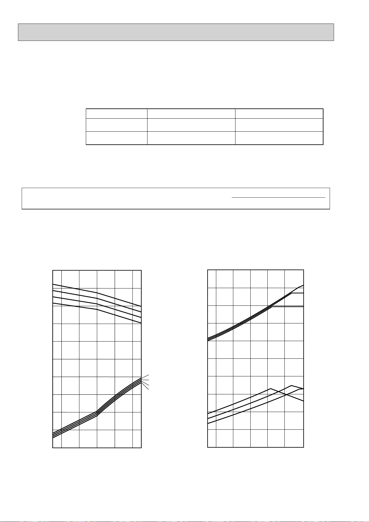
4-3. CORRECTING COOLING AND HEATING CAPACITY
0.4
-5 0 10 20 30 40 46
0.6
0.8
1.0
1.2
1.4
0.6
0.8
1.0
1.2
1.4
22
20
18
16
22
20
18
16
0.4
-12 -10 0 105-5 15
0.6
0.8
1.0
1.2
1.4
0.6
0.8
1.0
1.2
1.4
15
20
25
20
15
25
Service Ref PUMY-VM/VM1/YM PUMY-VM2/YM1/YMA
Rated cooling capacity
Rated heating capacity
Indoor D.B. 27°C / W.B. 19.5°C
Outdoor D.B. 35°C
Indoor D.B. 21°C
Outdoor D.B. 7°C / W.B. 6°C
Indoor D.B. 27°C / W.B. 19.0°C
Outdoor D.B. 35°C
Indoor D.B. 20°C
Outdoor D.B. 7°C / W.B. 6°C
4-3-1. Correcting Changes in Air Conditions
(1)The performance curve charts (Figure 1, 2, 3, 4) show the rated capacity (total capacity) under the stated conditions when
standard length for piping (5m) is used. The rated power is derived from the capacity ratio and power ratio obtained for the
indoor and outdoor intake temperatures at time 1.
• Standard conditions:
• Use the rated capacity and rated power values given in the characteristics table for each indoor unit.
• The capacity is the single value on the side of the outdoor unit; the capacity on the sides of each indoor unit must be
added to obtain the total capacity.
(2)The capacity of each indoor unit may be obtained by multiplying the total capacity obtained in (1) by the ratio between the
individual capacity at the rated time and the total capacity at the rated time.
Individual capacity under stated conditions = total capacity under the stated conditions o
(3)Capacity correction factor curve
individual capacity at the rated time
total capacity at the rated time
Figure 1. PUMY-VM Cooling performance curve Figure 2. PUMY-VM Heating performance curve
PUMY-VM
1 PUMY-VM1
PUMY-YM PUMY-YM
Heating
Capacity
(ratio)
Heating
Power
consumption
(ratio)
Cooling
Capacity
(ratio)
Cooling
Power
consumption
(ratio)
INDOOR
<W.B. :>
INDOOR
<W.B. :>
INDOOR
<D.B. :>
INDOOR
<D.B. :>
Outdoor <D.B. ::>
28
Outdoor <W.B. ::>
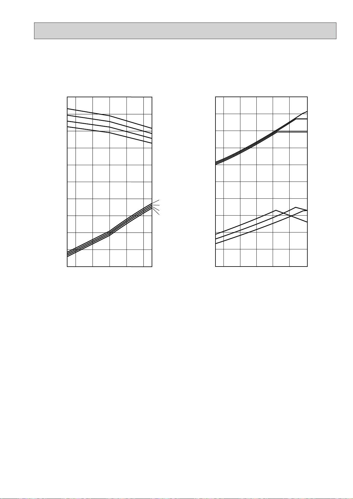
Figure 3. PUMY-VM2 Cooling performance curve Figure 4. PUMY-VM2 Heating performance curve
0.4
-5 0 10 20 30 40 46
0.6
0.8
1.0
1.2
1.4
0.6
0.8
1.0
1.2
1.4
22
20
18
16
22
20
18
16
0.4
-12 -10 0 105-5 15
0.6
0.8
1.0
1.2
1.4
0.6
0.8
1.0
1.2
1.4
15
20
25
20
15
25
PUMY-YM
1 PUMY-VM1
PUMY-YMA PUMY-YMA
Cooling
Capacity
(ratio)
Cooling
Power
consumption
(ratio)
INDOOR
<W.B. :>
INDOOR
<W.B. :>
Heating
Capacity
(ratio)
Heating
Power
consumption
(ratio)
INDOOR
<D.B. :>
INDOOR
<D.B. :>
Outdoor <D.B. ::>
Outdoor <W.B. ::>
29
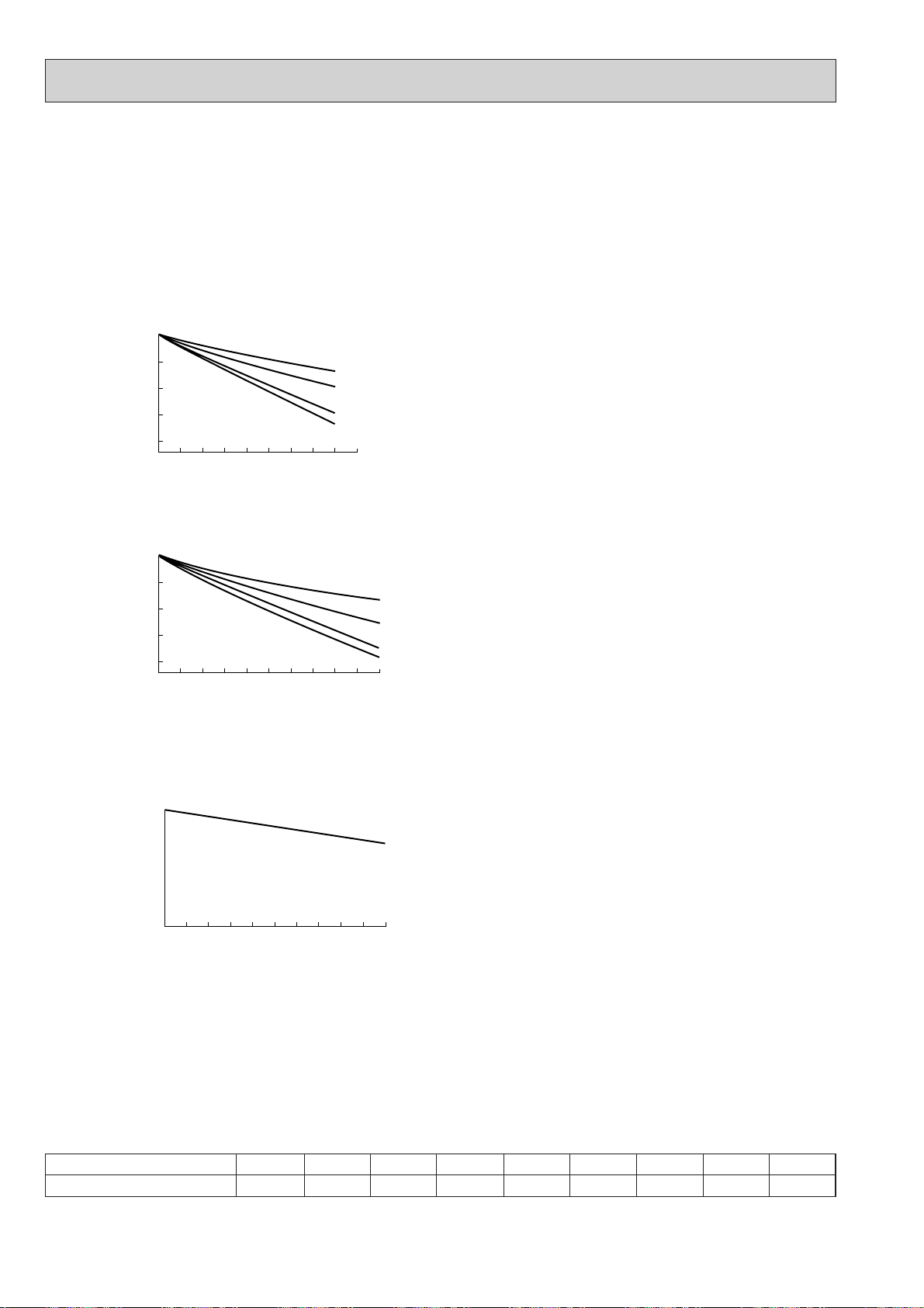
4-3-2. Correcting Capacity for Changes in the Length of Refrigerant Piping
1.0
0.95
0.9
5 10152025303540455055
1.0
35 (50%)
53 (75%)
71 (100%)
93 (130%)
0.95
0.9
0.85
0.8
5 101520253035404550
1.0
63 (50%)
94 (75%)
125 (100%)
163 (130%)
0.95
0.9
0.85
0.8
5 10152025303540455055
(1) During cooling, to obtain the ratio (and the equivalent piping length) of the outdoor units rated capacity and the total
in-use indoor capacity, first find the capacity ratio corresponding to the standard piping length (5m) from figures 5 and 6
at first, and then multiply by the cooling capacity from Figure 1 to obtain the actual capacity.
(2) During heating, to find the equivalent piping length, first find the capacity ratio corresponding to standard piping length (5m)
from Figure 7, and then multiply by the heating capacity from Figure 2 to obtain the actual capacity.
(1) Cooling capacity correction factor
Figure 5. PUMY-71VM, PUMY-71VM
Cooling
Capacity
(ratio)
piping length (m)
Figure 6. PUMY-125VM, PUMY-125VM1, PUMY-125YM, PUMY-125VM2, PUMY-125YM1, PUMY-125YMA
Cooling capacity correction curve
1, PUMY-71VM2 Cooling capacity correction curve
Total capacity for indoor unit
Total capacity for indoor unit
Cooling
Capacity
(ratio)
piping length (m)
(2) Heating capacity correction factor
Figure 7. PUMY Series Heating capacity correction curve
Heating
Capacity
(ratio)
piping length (m)
(3) Method for Obtaining the Equivalent Piping Length
Equivalent length for type 125 = (length of piping to farthest indoor unit) + (0.35 o number of bends in the piping) (m)
Length of piping to farthest indoor unit: type 125.....70m
4-3-3. Correction of Heating Capacity for Frost and Defrosting
If heating capacity has been reduced due to frost formation or defrosting, multiply the capacity by the appropriate correction
factor from the following table to obtain the actual heating capacity.
Correction factor diagram
Outdoor Intake temperature (°CWB)
Correction factor
6
1.0
4
0.98
2
0.89
0.88
30
0
-2
0.89
-4
0.9
-6
0.95
-8
0.95
-10
0.95

PUMY-71VM
PUMY-71VM1
PUMY-71VM2
90
NOTCH
Hi 52
SPL(dB) LINE
PUMY-125VM
PUMY-125VM
1/VM2
PUMY-125YM/YMA
90
NOTCH
Hi 54
SPL(dB) LINE
80
70
60
50
40
30
APPROXIMATE
20
THRESHOLD OF
OCTAVE BAND SOUND PRESSURE LEVEL, dB re 0.002 MICRO BAR
HEARING FOR
CONTINUOUS
NOISE
10
63 125 250 500 1000 2000 4000 8000
BAND CENTER FREQUENCIES, Hz
NC-70
NC-60
NC-50
NC-40
NC-30
NC-20
80
70
60
50
40
30
APPROXIMATE
20
THRESHOLD OF
OCTAVE BAND SOUND PRESSURE LEVEL, dB re 0.002 MICRO BAR
HEARING FOR
CONTINUOUS
NOISE
10
63 125 250 500 1000 2000 4000 8000
BAND CENTER FREQUENCIES, Hz
NC-70
NC-60
NC-50
NC-40
NC-30
NC-20
1m
MICROPHONE
1m
Ambient temperature 27:
Test conditions are based on JIS Z8731
31

5 OUTLINES AND DIMENSIONS
• OUTDOOR UNITS
PUMY-71VM
PUMY-71VM1
PUMY-71VM2
Optional parts
(base branching
pipe) installation
hole
Terminal block for transmission
Terminal block for central control
Terminal block for Power source
Gas refrigerant-pipe
connection {15.88(5/8F)
Liquid refrigerant-pipe
connection {9.52(3/8F)
Knock out hole for right piping
Knock out holes for power line 2-{27
unit : mm
shaped notched holes
(standard bolt M10)
Air intake
Air intake
Air outlet
Service panel
Handle for
Optional parts
moving
installation hole
Side air intake
Rear air intake
Handing for moving
Knock out holes for
power line 2-{27
Knock out hole
for front piping
Piping cover
Oval holes
(standard bolt M10)
Bottom piping hole
Drain hole
(3-{33 hole)
Handle for moving
32
Rear piping hole
when a piping cover is used for aesthetic reasons.
✻1...Indicates the dimensions of the cutoff valve connector.
✻2...Make sure that the panel can be easily removed for maintenance

PUMY-125VM
PUMY-125VM1
PUMY-125VM2
PUMY-125YM
PUMY-125YM1
PUMY-125YMA
Optional parts
(base branching
pipe) installation
hole
unit : mm
Knock out holes for power line 2-{29
Air intake
Terminal block for transmission
Terminal block for central control
Terminal block for power source
Air outlet
Handle for
Optional parts
installation hole
moving
Liquid refrigerant pipe
Gas refrigerant-pipe
connection {9.52 (3/8F)
connection {19.05 (3/4F)
Knock out hole for right piping
Knock out holes for
power line 2-{27
Knock out hole for
front piping
Oval holes
Piping cover
(standard bolt M10)
shaped notched holes
(standard bolt M10)
Bottom piping hole
Drain hole
(3-{33 hole)
Rear air intake
Side air intake
Handle for moving
33
Rear piping hole
when a piping cover is used for aesthetic reasons.
✻1...Indicates the dimensions of the cutoff valve connector.
✻2...Make sure that the panel can be easily removed for maintenance

6 WIRING DIAGRAM
21
2
1
5
4123
67
7
5
4321
CN2
6
1234
5
21
321
2
321
6
3
21
6
5
43 1263
7
321
54321
4321
6
V
U
U
W
WHT
12
3
6
C5
RED
RED
10
9652
1
7
3621
4
5
3
2123
1
1231121321
1
2
CN40
CN3D
(WHT)
(WHT)
C2
C1
ORN
ORN
RED
RED
WHT
WHT
BLU
WHT
MF1
MF2
CN41
<MULTI CONTROLLER BOARD>
TH1
26C
SLEV
TH5
63HS
TH6
TH2
SV152C
21S4
TB3
ON
OFF
CH
SW2
X3
X1
X2
TO INDOOR UNIT
CONNECTING WIRES
DC 30V (Non-polar)
FUSE2
(6A)
ORN
ORN
BRN
YLW
(WHT)
(GRN)
(GRN)
(WHT)
RED
RED
BLK
BLK
WHT
BLU
FOR CENTRALIZED
CONTROL
DC 30V (Non-polar)
2
RED
6
3
1
1
2
F.C
1234
CNCT
CN51
1
2
AC,CT
(YLW)
(YLW)
CNS2
(RED)
CNS1
(WHT)
(WHT)
(WHT)
(WHT) (WHT)
(BLK)
THHS
ON
OFF
SW5
FUSE1
(2A)
WHT
RED
YLW
645
12345678910
87654321
6
CN4
CN3
CN2
CN1
CN3
CN1
CN5
CN6
CH
CNA
52C 21S4
SV1
MF1
MF2
CND
<POWER SUPPLY BOARD>
SWU3
(3rd digit)
(2nd digit)
SWU2
(1st digit)
SWU1
LD1
(YLW)
(WHT)
(YLW)
(RED)
(WHT)
(YLW)
(RED)
(WHT)
(WHT)
(YLW)
26C
(BLK)
M1
M2
S
M1
1
3
RED
WHT
31
3
1
3
1
31
3
1
31
1
3
0
1
2
3
4
5
6
7
8
9
9
8
7
6
5
4
3
2
1
0
9
8
7
6
5
4
3
2
1
0
N(-)
P(+)
P(+)
N(-)
V
W
U
V
W
RED
WHT
BLU
63 7
CN4
CN6
CN5
<GATE AMP BOARD>
AC.CT
<IPM>
(YLW)
(WHT)
(WHT)
CNCT
RED
FUSE(30A)
3
4
1
NF1
2
N
TB1
L
TB7
POWER SUPPLY
BRN
RED
WHT
RED
WHT
GRN/YLW
M2
S
52C
RED
RED
R1
D1
+
C3
ZNR
DS
R2
DCL
RED
RED
WHT
WHT
RED
63HS
TH6 TH5
SLEV
TH2 TH1
THHS
MC
12 321
SW3
ON
OFF
SW4
4
SW1
OFF
ON
34567821
1[ 220-240V
50Hz
10
9652
1
NAME
SYMBOL
NAME NAME
SYMBOL SYMBOL
AC,CT
CH
CNA
CND
CNS1
CNS2
CN1
CN2
CN3
CN4
CN5
CN6
CN40
CN41
CN51
CN3D
CNCT
C1,2
C3
C5
DS
D1
DCL
F.C
FUSE1
FUSE2
FUSE
IPM
LD1
MC
MF1,2
NF1
R1
R2
SLEV
SV1
SW1
SW2
SW3
SW4
SW5
SWU1
SWU2
SWU3
TB1
TB3
TB7
THHS
TH1
TH2
TH5
TH6
X1
X2
X3
ZNR
21S4
26C
52C
63HS
CURRENT DETECTION
CRANKCASE HEATER
CONNECTOR <POWER SUPPLY>
CONNECTOR <DC POWER SUPPLY>
CONNECTOR <MULTI SYSTEM>
CONNECTOR <CENTRALIZED CONTROL>
CONNECTOR <CONTROLLER DRIVE CONTROL>
CONNECTOR <POWER SYNC SIGNAL , PROTECTION>
CONNECTOR <POWER SUPPLY 30V , 12V , 5V>
CONNECTOR <INVERTER SIGNAL 5V>
CONNECTOR <IPM POWER SUPPLY>
CONNECTOR <IPM POWER SUPPLY , TROUBLE OUTPUT>
CONNECTOR <CENTRALIZED CONTROL POWER SUPPLY>
CONNECTOR <FOR STORING JUMPER CONNECTOR>
CONNECTOR <COMPRESSOR DRIVE SIGNAL OUTPUT>
CONNECTOR <DEMAND SIGNAL,SILENT MODE INPUT>
CONNECTOR <CURRENT DETECTION>
FAN MOTOR CAPACITOR
CAPACITOR<SMOOTHING>
CAPACITOR<POWER FACTOR IMPROVEMENT>
DIODE STACK
DIODE <POWER FACTOR IMPROVEMENT>
REACTOR
FAN CONTROL
FUSE(2A)
FUSE(6A)
FUSE(30A)
INTELLIGENT POWER MODULE
DIGITAL INDICATION LED
<OPERATION INSPECTION INDICATION>
COMPRESSOR
FAN MOTOR (INNER THERMOSTAT)
NOISE FILTER
RESISTOR<RUSH CURRENT PROTECT>
RESISTOR<DISCHARGE>
EXPANSION VALVE
SOLENOID COIL <HOT GAS BYPASS>
SWITCH <DISPLAY SELECTION SELFDIAGNOSIS>
SWITCH <FUNCTION SELECTION>
SWITCH <TEST RUN>
SWITCH <MODEL SELECTION>
SWITCH <FUNCTION SELECTION>
SWITCH <UNIT ADDRESS SELECTION,1ST DIGIT>
SWITCH <UNIT ADDRESS SELECTION,2ND DIGIT>
SWITCH <UNIT ADDRESS SELECTION,3RD DIGIT>
TERMINAL BLOCK <POWER SUPPLY>
TERMINAL BLOCK <TRANSMISSION>
TERMINAL BLOCK
<TRANSMISSION> (CENTRALIZED CONTROL)
THERMISTOR
<IPM RADIATOR PANEL TEMPERATURE DETECTION>
THERMISTOR<DISCHARGE TEMPERA TURE DETECTION>
THERMISTOR
<LOW PRESSURE SATURATED TEMPERATURE DETECTION>
THERMISTOR
<PIPE TEMPERATURE DETECTION,JUDGING DEFROST>
THERMISTOR<OUTDOOR TEMPERA TURE DETECTION>
RELAY
<CRANKCASE HEATER,MAGNETIC CONTACTOR>
RELAY<4-WAY VALVE>
RELAY<SOLENOID VALVE>
VARISTOR
4-WAY COIL
THERMAL SWITCH <COMPRESSOR>
MAGNETIC CONTACTOR
<INVERTER MAIN CIRCUIT>
HIGH PRESSURE SENSOR
<DISCHARGE PRESSURE DETECTION>
Always lit
87
-
1
2
436
587
(Example)
When the compressor and SV1 are
turned during heating operation.
6
-
-
5
SV1
4
21S4
3
2
52C
1
Indication
Bit
•During normal operation
The LED indicates the drive state of the controller in the outdoor unit.
1.Refer to the wiring boards of the indoor units for details on wiring of each indoor unit.
2.The transmission line is two-wire type and has no polarity.
3.Mark shows the terminal board,mark the connector .Symbols in parentheses () show the colors of connectors.
4.Self-diagnosis function
The indoor and outdoor units can be diagnosed automatically using the self-diagnosis switch(SW1) and LD1(LED indication)
found on the multi-controller of the outdoor unit.
LED indication : Set all contacts of SW1 to OFF.
Compressor operated
PUMY-71VM
34

PUMY-125VM
SYMBOL
NAME NAME
SYMBOL
NAME
SYMBOL
AC,CT
AR
CB
CH
CNA
CND
CNS1
CNS2
CN1
CN2
CN3
CN4
CN5
CN6
CN40
CN41
CN51
CN3D
C1,2
C3,4
C5,6
C7
D
DB1,DB2
DCL
F.C
FUSE1
FUSE2
FUSE
IPM
LD1
MC
MF1,2
NF
RB
RS
SLEV
SV1
SW1
SW2
SW3
SW4
SW5
SWU1
SWU2
SWU3
TB1
CURRENT DETECTION
SURGE ABSORBER
SMOOTHING CAPACITOR
CRANKCASE HEATER
CONNECTOR <POWER SUPPLY>
CONNECTOR <DC POWER SUPPLY>
CONNECTOR <MULTI SYSTEM>
CONNECTOR <CENTRALIZED CONTROL>
CONNECTOR <CONTROLLER DRIVE CONTROL>
CONNECTOR <POWER SYNC SIGNAL , PROTECTION>
CONNECTOR <POWER SUPPLY 30V,12V,5V>
CONNECTOR <INVERTER SIGNAL 5V>
CONNECTOR <IPM POWER SUPPLY>
CONNECTOR <IPM POWER SUPPLY , TROUBLE OUTPUT>
CONNECTOR <CENTRALIZED CONTROL POWER SUPPLY>
CONNECTOR <FOR STORING JUMPER CONNECTOR>
CONNECTOR <COMPRESSOR DRIVE SIGNAL OUTPUT>
CONNECTOR <DEMAND SIGNAL , SILENT MODE INPUT>
FAN MOTOR CAPACITOR
CAPACITOR <POWER FACTOR IMPROVEMENT>
CAPACITOR
CAPACITOR <FILTER>
DIODE <POWER FACTOR IMPROVEMENT>
DIODE STACK
REACTOR
FAN CONTROL
FUSE(2A)
FUSE(6A)
FUSE(60A)
INTELLIGENT POWER MODULE
DIGITAL INDICATION LED
<OPERATIOIN INSPECTION INDICATION>
COMPRESSOR
FAN MOTOR (INNER THERMOSTAT)
NOISE FILTER
RESISTOR <DISCHARGE>
RESISTOR <RUSH CURRENT PROTECT>
EXPANSION VALVE
SOLENOID COIL <HOT GAS BYPASS>
SWITCH <DISPLAY SELECTION SELFDIAGNOSIS>
SWITCH <FUNCTION SELECTION>
SWITCH <TEST RUN>
SWITCH <MODEL SELECTION>
SWITCH <FUNCTION SELECTION>
SWITCH <UNIT ADDRES SELECTION , 1ST DIGIT>
SWITCH <UNIT ADDRESS SELECTION 2ND DIGIT>
SWITCH <UNIT ADDRESS SELECTION 3RD DIGIT>
TERMINAL BLOCK <POWER SUPPLY>
TB3
TB7
THHS
TH1
TH2
TH5
TH6
X1
X2
X3
X4
ZNR
21S4
26C
52C
63HS
TERMINAL BLOCK <TRANSMISSION>
TERMINAL BLOCK
<TRANSMISSION> (CENTRALIZED CONTROL)
THERMISTOR
<IPM RADIATOR PANEL TEMPERATURE DETECTION>
THERMISTOR <DISCHARGE TEMPERATURE DETECTION>
THERMISTOR
<LOW PRESSURE SATURATED TEMPERATURE DETECTION>
THERMISTOR
<PIPE TEMPERATURE DETECTION . JUDGING DEFROST>
THERMISTOR
<OUTDOOR TEMPERATURE DETECTION>
RELAY
< MAGNETIC CONTACTOR / CRANKCASE HEATER>
RELAY<4-WAY VALVE>
RELAY<SOLENOID VALVE>
RELAY
VARISTOR
4-WAY COIL
THERMAL SWITCH <COMPRESSOR>
MAGNETIC CONTACTOR
<INVERTER MAIN CIRCUIT>
HIGH PRESSURE SENSOR
<DISCHARGE PRESSURE DETECTION>
-
4.Self-diagnosis function
The indoor and outdoor units can be diagnosed automatically using the self-diagnosis switch(SW1) and LD1(LED indication)
found on the multi-controller of the outdoor unit.
LED indication:Set all contacts of SW1 to OFF.
1.Refer to the wiring diagrams of the indoor units for details on wiring of each indoor unit.
2.The transmission line is two-wire type and has no polarity.
3.Mark shows the terminal board, mark the connector. Symbols in parentheses() show the colors of connectors.
•During normal operation
The LED indicates the drive state of the controller in the outdoor unit.
Bit
Indication
Compressor operated
2
52C
3
4
5
6
78
1
21S4
SV1
-
-
Always lit
(Example)
When the compressor and SV1 are
turned during heating operation.
1
243658
7
THHS
CN40 CN51 CN3D
(WHT) (WHT)(WHT)
CNS2
1
(YLW)
2
CNS1
1
(RED)
2
8
SWU3
<MULTI CONTROLLER BOARD>
4321
CN41
(WHT)
LD1
0
0
0
1
1
9
2
3
7
4
6
5
(2nd digit)(3rd digit)
9
8
7
6
5
SWU2
2
3
4
9
8
7
6
SWU1
(1st digit)
321543214321
1
2
3
4
5
CN1
6
3
THHS
(BLK)
(RED)
2
2132311
TH6
TH5
(WHT)
(GRN)
SW1
ON
OFF
12 876543
SW4
SW3
ON
OFF
12 4321 12345678
(YLW)
CN2
3
1
2
6
5
4
26C
<POWER SUPPLY BOARD>
3
4
2
5
6
1
2
3
6
TB3
M1
M2
M1
M2
S
TB7
S
TB1
L
N
BRN
BRN
ORN
ORN
RED
RED
BLK
BLK
GRN
GRN/YLW
AR
RED
C5
FUSE(60A)
C6
RED
143
2
TO INDOOR UNIT
CONNECTING WIRES
DC 30V (Non-polar)
FOR CENTRALIZED
CONTROL
DC 30V (Non-polar)
NO FUSE BREAKER
30A
POWER SUPPLY
~ (1 PHASE)
220-240V
50Hz
L
N
NF
RED
BLK
GRN/YLW
FUSE2
(6A)
CNA
3
1
RED
BLU
3
WHT
CH
CH
1
WHT
DB1 DB2
YLW
X4
8
35
CH
2
3
1
X2X1X3
21S4
52C
1
3
1
3
YLW
52C SV1
YLW
7
3
YLW
RED
RED
21S4
BLK
RED
2
ZNR
3
RED
52C
1
BLK
X4
RS
3
BRN
BRN
SV1
1
RED
RED
DCL
C3
C4
5
CN1
(RED)
F.C
MF2
MF1
1
1
3
3
BLU
BLU
WHT
WHT
MF1
MF2
RED
RED
ORN
ORN
C2
C1
D
1
2
RED
WHT
3
RED
BLU
BLU
BLK
BLK
BRN
+
2
6
RB
CB
-
BLK
(YLW)
CND
2
1
RED
CN2
FUSE1
(2A)
3
BLK
RED
C7
BLK
<IPM>
(YLW)
CN5
2
1
2
1
CN5 CN6
(WHT) (WHT)
P(+)
N(-)
TH1
TH2TH5TH6
3121
TH2
TH1
(WHT)(GRN)
ON
OFF
ON
OFF
CN3
1
YLW
YLW
1
21
26C
(BLK)
(WHT)
CN6
10
9
6
5
6
5
10
6
9
<GATE AMP BOARD>
RED
WHT
V
U
W
MC
CN3
BLU
SW5
7
7
1
1
WVX4U
SW2
(WHT)
6
2
2
AC.CT
63HS
63HS
(WHT)
263
546
3
2
(WHT)
(WHT)
3
3
3
SLEV
3
6
456
123
321
SLEV
(WHT)
10987654321
1
1
CN4
657
AC.CT
(YLW)
(YLW)
213
4
2
1
RED
WHT
7
54362
1
7
CN4
(YLW)

PUMY-71VM1
21
2
1
5
4123
67
7
5
4321
CN2
6
1234
5
21
321
2
321
6
3
21
6
5
43 1263
7
321
54321
4321
6
V
U
U
W
WHT
12
3
6
C5
RED
RED
10
9652
1
7
3621
4
5
3
2123
1
1231
121321
1
2
CN40
CN3D
(WHT)
(WHT)
C2
C1
ORN
ORN
RED
RED
BLU
WHT
MF1
MF2
CN41
<MULTI CONTROLLER BOARD>
TH1
26C
SLEV
TH5
63HS
TH6
TH2
SV152C
21S4
ON
OFF
SW2
X3
X1
X2
FUSE2
(6A)
YLW
(WHT)
(GRN)
(GRN)
(WHT)
RED
RED
BLK
BLK
WHT
BLU
2
RED
6
3
1
1
2
F.C
1234
CNCT
CN51
1
2
AC,CT
(YLW)
(YLW)
CNS2
(RED)
CNS1
(WHT)
(WHT)
(WHT)
(WHT) (WHT)
(BLK)
THHS
ON
OFF
SW5
FUSE1
(2A)
WHT
RED
YLW
645
12345678910
87654321
6
CN4
CN3
CN2
CN1
CN3
CN1
CN5
CN6
CH
CNA
52C 21S4
SV1
MF1
MF2
CND
<POWER SUPPLY BOARD>
SWU3
(3rd digit)
(2nd digit)
SWU2
(1st digit)
SWU1
LD1
(YLW)
(WHT)
(YLW)
(RED)
(WHT)
(YLW)
(RED)
(WHT)
(WHT)
(YLW)
26C
(BLK)
1
3
RED
WHT
31
3
1
3
1
31
3
1
31
1
3
0
1
2
3
4
5
6
7
8
9
9
8
7
6
5
4
3
2
1
0
9
8
7
6
5
4
3
2
1
0
N(-)
P(+)
P(+)
N(-)
V
W
U
V
W
RED
WHT
BLU
63 7
CN4
CN6
CN5
<GATE AMP BOARD>
AC.CT
<IPM>
(YLW)
(WHT)
(WHT)
CNCT
FUSE(30A)
3
4
1
NF1
2
RED
WHT
52C
RED
RED
R1
D1
+
C3
ZNR
DS
R2
DCL
RED
RED
WHT
WHT
RED
63HS
TH6 TH5
SLEV
TH2 TH1
THHS
MC
12 321
SW3
ON
OFF
SW4
4
SW1
OFF
ON
34567821
10
9652
1
TB3
TO INDOOR UNIT
CONNECTING WIRES
DC 30V (Non-polar)
ORN
ORN
BRN
FOR CENTRALIZED
CONTROL
DC 30V (Non-polar)
M1
M2
S
M1
NN
TB1
LL
TB7
POWER SUPPLY
~ (1 PHASE)
220-240/220V
50/60Hz
NO FUSE BREAKER
30A
BRN
RED
WHT
RED
GRN/YLW
M2
S
NAME
SYMBOL
NAME NAME
SYMBOL SYMBOL
AC,CT
CNA
CND
CNS1
CNS2
CN1
CN2
CN3
CN4
CN5
CN6
CN40
CN41
CN51
CN3D
CNCT
C1,2
C3
C5
DS
D1
DCL
F.C
FUSE1
FUSE2
FUSE
IPM
LD1
MC
MF1,2
NF1
R1
R2
SLEV
SV1
SW1
SW2
SW3
SW4
SW5
SWU1
SWU2
SWU3
TB1
TB3
TB7
THHS
TH1
TH2
TH5
TH6
X1
X2
X3
ZNR
21S4
26C
52C
63HS
CURRENT DETECTION
CONNECTOR <POWER SUPPLY>
CONNECTOR <DC POWER SUPPLY>
CONNECTOR <MULTI SYSTEM>
CONNECTOR <CENTRALIZED CONTROL>
CONNECTOR <CONTROLLER DRIVE CONTROL>
CONNECTOR <POWER SYNC SIGNAL , PROTECTION>
CONNECTOR <POWER SUPPLY 30V , 12V , 5V>
CONNECTOR <INVERTER SIGNAL 5V>
CONNECTOR <IPM POWER SUPPLY>
CONNECTOR <IPM POWER SUPPLY , TROUBLE OUTPUT>
CONNECTOR <CENTRALIZED CONTROL POWER SUPPLY>
CONNECTOR <FOR STORING JUMPER CONNECTOR>
CONNECTOR <COMPRESSOR DRIVE SIGNAL OUTPUT>
CONNECTOR <DEMAND SIGNAL,SILENT MODE INPUT>
CONNECTOR <CURRENT DETECTION>
FAN MOTOR CAPACITOR
CAPACITOR<SMOOTHING>
CAPACITOR<POWER FACTOR IMPROVEMENT>
DIODE STACK
DIODE <POWER FACTOR IMPROVEMENT>
REACTOR
FAN CONTROL
FUSE(2A)
FUSE(6A)
FUSE(30A)
INTELLIGENT POWER MODULE
DIGITAL INDICATION LED
<OPERATION INSPECTION INDICATION>
COMPRESSOR
FAN MOTOR (INNER THERMOSTAT)
NOISE FILTER
RESISTOR<RUSH CURRENT PROTECT>
RESISTOR<DISCHARGE>
EXPANSION VALVE
SOLENOID COIL <HOT GAS BYPASS>
SWITCH <DISPLAY SELECTION SELFDIAGNOSIS>
SWITCH <FUNCTION SELECTION>
SWITCH <TEST RUN>
SWITCH <MODEL SELECTION>
SWITCH <FUNCTION SELECTION>
SWITCH <UNIT ADDRESS SELECTION,1ST DIGIT>
SWITCH <UNIT ADDRESS SELECTION,2ND DIGIT>
SWITCH <UNIT ADDRESS SELECTION,3RD DIGIT>
TERMINAL BLOCK <POWER SUPPLY>
TERMINAL BLOCK <TRANSMISSION>
TERMINAL BLOCK
<TRANSMISSION> (CENTRALIZED CONTROL)
THERMISTOR
<IPM RADIATOR PANEL TEMPERATURE DETECTION>
THERMISTOR<DISCHARGE TEMPERA TURE DETECTION>
THERMISTOR
<LOW PRESSURE SATURATED TEMPERATURE DETECTION>
THERMISTOR
<PIPE TEMPERATURE DETECTION,JUDGING DEFROST>
THERMISTOR<OUTDOOR TEMPERA TURE DETECTION>
RELAY <MAGNETIC CONTACTOR>
RELAY<4-WAY VALVE>
RELAY<SOLENOID VALVE>
VARISTOR
4-WAY COIL
THERMAL SWITCH <COMPRESSOR>
MAGNETIC CONTACTOR
<INVERTER MAIN CIRCUIT>
HIGH PRESSURE SENSOR
<DISCHARGE PRESSURE DETECTION>
Always lit
87
-
1
2
436
587
(Example)
When the compressor and SV1 are
turned during heating operation.
6
-
-
5
SV1
4
21S4
3
2
52C
1
Indication
Bit
•During normal operation
The LED indicates the drive state of the controller in the outdoor unit.
1.Refer to the wiring diagrams of the indoor units for details on wiring of each indoor unit.
2.The transmission line is two-wire type and has no polarity.
3.Mark shows the terminal board, mark the connector. Symbols in parentheses () show the colors of connectors.
4.Self-diagnosis function
The indoor and outdoor units can be diagnosed automatically using the self-diagnosis switch(SW1) and LD1(LED indication)
found on the multi-controller of the outdoor unit.
LED indication : Set all contacts of SW1 to OFF.
Compressor operated
36

PUMY-125VM1
SYMBOL
NAME
NAME
SYMBOL
NAME
SYMBOL
AC,CT
AR
CB
CNA
CND
CNS1
CNS2
CN1
CN2
CN3
CN4
CN5
CN6
CN40
CN41
CN51
CN3D
C1,2
C3,4
C5,6
C7
D
DB1,DB2
DCL
F.C
FUSE1
FUSE2
FUSE
IPM
LD1
MC
MF1,2
NF
RB
RS
SLEV
SV1
SW1
SW2
SW3
SW4
SW5
SWU1
SWU2
SWU3
CURRENT DETECTION
SURGE ABSORBER
SMOOTHING CAPACITOR
CONNECTOR <POWER SUPPLY>
CONNECTOR <DC POWER SUPPLY>
CONNECTOR <MULTI SYSTEM>
CONNECTOR <CENTRALIZED CONTROL>
CONNECTOR <CONTROLLER DRIVE CONTROL>
CONNECTOR <POWER SYNC SIGNAL , PROTECTION>
CONNECTOR <POWER SUPPLY 30V,12V,5V>
CONNECTOR <INVERTER SIGNAL 5V>
CONNECTOR <IPM POWER SUPPLY>
CONNECTOR <IPM POWER SUPPLY , TROUBLE OUTPUT>
CONNECTOR <CENTRALIZED CONTROL POWER SUPPLY>
CONNECTOR <FOR STORING JUMPER CONNECTOR>
CONNECTOR <COMPRESSOR DRIVE SIGNAL OUTPUT>
CONNECTOR <DEMAND SIGNAL , SILENT MODE INPUT>
FAN MOTOR CAPACITOR
CAPACITOR <POWER FACTOR IMPROVEMENT>
CAPACITOR
CAPACITOR <FILTER>
DIODE <POWER FACTOR IMPROVEMENT>
DIODE STACK
REACTOR
FAN CONTROL
FUSE(2A)
FUSE(6A)
FUSE(60A)
INTELLIGENT POWER MODULE
DIGITAL INDICATION LED
<OPERATIOIN INSPECTION INDICATION>
COMPRESSOR
FAN MOTOR (INNER THERMOSTAT)
NOISE FILTER
RESISTOR <DISCHARGE>
RESISTOR <RUSH CURRENT PROTECT>
EXPANSION VALVE
SOLENOID COIL <HOT GAS BYPASS>
SWITCH <DISPLAY SELECTION SELFDIAGNOSIS>
SWITCH <FUNCTION SELECTION>
SWITCH <TEST RUN>
SWITCH <MODEL SELECTION>
SWITCH <FUNCTION SELECTION>
SWITCH <UNIT ADDRES SELECTION , 1ST DIGIT>
SWITCH <UNIT ADDRESS SELECTION 2ND DIGIT>
SWITCH <UNIT ADDRESS SELECTION 3RD DIGIT>
TB1
TB3
TB7
THHS
TH1
TH2
TH5
TH6
X1
X2
X3
X4
ZNR
21S4
26C
52C
63HS
TERMINAL BLOCK <POWER SUPPLY>
TERMINAL BLOCK <TRANSMISSION>
TERMINAL BLOCK
<TRANSMISSION> (CENTRALIZED CONTROL)
THERMISTOR
<IPM RADIATOR PANEL TEMPERATURE DETECTION>
THERMISTOR <DISCHARGE TEMPERATURE DETECTION>
THERMISTOR
<LOW PRESSURE SATURATED TEMPERATURE DETECTION>
THERMISTOR
<PIPE TEMPERATURE DETECTION . JUDGING DEFROST>
THERMISTOR
<OUTDOOR TEMPERATURE DETECTION>
RELAY < MAGNETIC CONTACTOR>
RELAY <4-WAY VALVE>
RELAY <SOLENOID VALVE>
RELAY
VARISTOR
4-WAY COIL
THERMAL SWITCH <COMPRESSOR>
MAGNETIC CONTACTOR
<INVERTER MAIN CIRCUIT>
HIGH PRESSURE SENSOR
<DISCHARGE PRESSURE DETECTION>
-
4.Self-diagnosis function
The indoor and outdoor units can be diagnosed automatically using the self-diagnosis switch(SW1) and LD1(LED indication)
found on the multi-controller of the outdoor unit.
LED indication:Set all contacts of SW1 to OFF.
1.Refer to the wiring diagrams of the indoor units for details on wiring of each indoor unit.
2.The transmission line is two-wire type and has no polarity.
3.Mark shows the terminal board, mark the connector. Symbols in parentheses() show the colors of connectors.
•During normal operation
The LED indicates the drive state of the controller in the outdoor unit.
Bit
Indication
Compressor operated
2
52C
3
4
5
6
78
1
21S4
SV1
-
-
Always lit
(Example)
When the compressor and SV1 are
turned during heating operation.
1
243658
7
THHS
CN40 CN51 CN3D
(WHT) (WHT)(WHT)
CNS2
1
(YLW)
2
CNS1
1
(RED)
2
8
7
SWU3
<MULTI CONTROLLER BOARD>
4321
CN41
(WHT)
LD1
0
0
0
1
1
9
2
3
4
6
5
(2nd digit)(3rd digit)
9
8
7
6
5
SWU2
2
3
4
9
8
7
6
5
SWU1
(1st digit)
321543214321
1
2
3
4
CN1
6
3
THHS
(BLK)
(RED)
2
2132311
TH6
TH5
(WHT)
(GRN)
SW1
ON
OFF
12 876543
SW4
SW3
ON
OFF
12 4321 12345678
(YLW)
CN2
3
1
2
6
5
4
<POWER SUPPLY BOARD>
3
2
4
5
6
1
2
3
6
TB3
M1
M2
M2
M1
S
TB7
S
TB1
L
N
BRN
BRN
ORN
ORN
RED
RED
BLK
BLK
GRN
GRN/YLW
RED
C5
C6
AR
RED
FUSE(60A)
143
2
TO INDOOR UNIT
CONNECTING WIRES
DC 30V (Non-polar)
FOR CENTRALIZED
CONTROL
DC 30V (Non-polar)
NO FUSE BREAKER
30A
POWER SUPPLY
~ (1 PHASE)
220-240
50/60Hz
L
N
NF
RED
BLK
GRN/YLW
FUSE2
(6A)
3
1
RED
CNA
BLU
3
CH
1
DB1 DB2
YLW
X4
8
37
CH
2
3
1
X2X1X3
21S4
52C
1
3
1
3
YLW
YLW
RED
RED
21S4
52C SV1
BLK
RED
2
ZNR
3
52C
BLK
1
X4
RS
YLW
7
3
BRN
BRN
SV1
1
3
RED
RED
DCL
C3
BLU
C4
RED
5
CN1
(RED)
F.C
MF2
MF1
1
1
3
3
BLU
BLU
WHT
WHT
MF1
MF2
RED
RED
ORN
ORN
C2
C1
D
1
2
RED
WHT
3
RED
BLU
+
2
6
BLK
BLK
BRN
RB
CB
-
BLK
(YLW)
CN2
FUSE1
(2A)
(YLW)
CN5
CND
2
2
1
3
1
BLK
RED
2
1
CN5 CN6
(WHT) (WHT)
RED
P(+)
C7
BLK
N(-)
<IPM>
TH1
TH2TH5TH6
3121
TH2
(WHT)(GRN)
ON
OFF
ON
OFF
1
26C
YLW
YLW
1
21
26C
(BLK)
(WHT)
10
9
6
5
6
5
10
6
9
<GATE AMP BOARD>
RED
WHT
V
U
W
MC
TH1
CN3
CN3
CN6
BLU
7
7
1
1
SW5
6
WVX4U
63HS
63HS
(WHT)
SW2
(WHT)
3
(WHT)
(WHT)
2
3
2
AC.CT
263
546
2
3
3
SLEV
3
6
456
123
321
SLEV
(WHT)
10987654321
1
1
CN4
2
AC.CT
(YLW)
1
RED
(YLW)
213
4
657
WHT
7
54362
1
7
CN4
(YLW)

PUMY-71VM2
21
2
1
5
4123
6
7
7
5
4
3
2
1
CN2
6
1234
5
21
10
96521321
2
321
6
3
2
1
6
5
43
1263
7
321543214321
6
V
U
U
W
WHT
12
3
6
C5
10
9652
1
7
3621
4
5
3
2123
11231
121321
1
2
CN40
CN3D
(WHT)
(WHT)
C2
C1
ORN
ORN
RED
RED
BLU
WHT
MF1
MF2
CN41
<MULTI CONTROLLER BOARD>
TH1
26C
SLEV
TH5
63HS
TH6
TH2
SV152C
21S4
TB3
ON
OFF
SW2
X3
X1
X2
X4
TO INDOOR UNIT
CONNECTING WIRES
DC 30V (Non-polar)
FUSE2
(6A)
ORN
ORN
BRN
YLW
(WHT)
(GRN)
(GRN)
(WHT)
RED
RED
BLK
BLK
BLK
BLK
WHT
BLU
FOR CENTRALIZED
CONTROL
DC 30V (Non-polar)
2
RED
6
3
1
1
2
F.C
1234
CNCT
CN51
1
2
AC,CT
(YLW)
(YLW)
CNS2
(RED)
CNS1
(WHT)
(WHT)
(WHT)
(WHT) (WHT)
(BLK)
THHS
ON
OFF
SW5
FUSE1
(2A)
WHT
RED
YLW
645
12345678910
87654321
6
CN4
CN3
CN2
CN1
CN3
CN1
CN5
CN6
CH
CNA
52C 21S4
SV1
MF1
MF2
CND
<POWER SUPPLY BOARD>
SWU3
(3rd digit)
(2nd digit)
SWU2
(1st digit)
SWU1
LD1
(YLW)
(WHT)
(YLW)
(RED)
(WHT)
(YLW)
(RED)
(WHT)
(WHT)
(YLW)
26C
(BLK)
M1
M2
S
M1
1
3
RED
WHT
3
1
3
13
1
31
3
1
31
1
3
0
1
2
3
4
5
6
7
8
9
9
8
7
6
5
4
3
2
1
0
9
8
7
6
5
4
3
2
1
0
N(-)
P(+)
P(+)
N(-)
V
W
U
V
W
RED
WHT
BLU
63 7
CN4
CN6
CN5
<GATE AMP BOARD>
AC.CT
<IPM>
(YLW)
(WHT)
(WHT)
CNCT
FUSE(30A)
3
4
1
NF1
2
NN
TB1
LL
TB7
POWER SUPPLY
~ (1 PHASE)
220-240/220V
50/60Hz
NO FUSE BREAKER
30A
BRN
RED
WHT
REDRED
WHT
GRN/YLW
M2
S
52C
WHT BLU
YLW
R1
D1
+
C3
ZNR
DS
R2
DCL
RED
WHT BLU BLU
BLU
REDRED
63HS
TH6 TH5
SLEV
TH2 TH1
THHS
MC
12 321
SW3
ON
OFF
SW4
4
SW1
OFF
ON
34567821
NAMENAME NAME
SYMBOL SYMBOL
SYMBOL
AC,CT
CNA
CND
CNS1
CNS2
CN1
CN2
CN3
CN4
CN5
CN6
CN40
CN41
CN51
CN3D
CNCT
C1,2
C3
C5
DS
D1
DCL
F.C
FUSE1
FUSE2
FUSE
IPM
LD1
MC
MF1,2
NF1
R1
R2
SLEV
SV1
SW1
SW2
SW3
SW4
SW5
SWU1
SWU2
SWU3
TB1
TB3
TB7
THHS
TH1
TH2
TH5
TH6
X1
X2
X3
ZNR
21S4
26C
52C
63HS
X4
CURRENT DETECTION
CONNECTOR <POWER SUPPLY>
CONNECTOR <DC POWER SUPPLY>
CONNECTOR <MULTI SYSTEM>
CONNECTOR <CENTRALIZED CONTROL>
CONNECTOR <CONTROLLER DRIVE CONTROL>
CONNECTOR <POWER SYNC SIGNAL , PROTECTION>
CONNECTOR <POWER SUPPLY 30V , 12V , 5V>
CONNECTOR <INVERTER SIGNAL 5V>
CONNECTOR <IPM POWER SUPPLY>
CONNECTOR <IPM POWER SUPPLY , TROUBLE OUTPUT>
CONNECTOR <CENTRALIZED CONTROL POWER SUPPLY>
CONNECTOR <FOR STORING JUMPER CONNECTOR>
CONNECTOR <COMPRESSOR DRIVE SIGNAL OUTPUT>
CONNECTOR <DEMAND SIGNAL,SILENT MODE INPUT>
CONNECTOR <CURRENT DETECTION>
FAN MOTOR CAPACITOR
CAPACITOR<SMOOTHING>
CAPACITOR<POWER FACTOR IMPROVEMENT>
DIODE STACK
DIODE <POWER FACTOR IMPROVEMENT>
REACTOR
FAN CONTROL
FUSE(2A)
FUSE(6A)
FUSE(30A)
INTELLIGENT POWER MODULE
DIGITAL INDICATION LED
<OPERATION INSPECTION INDICATION>
COMPRESSOR
FAN MOTOR (INNER THERMOSTAT)
NOISE FILTER
RESISTOR<RUSH CURRENT PROTECT>
RESISTOR<DISCHARGE>
EXPANSION VALVE
SOLENOID COIL <HOT GAS BYPASS>
SWITCH <DISPLAY SELECTION SELFDIAGNOSIS>
SWITCH <FUNCTION SELECTION>
SWITCH <TEST RUN>
SWITCH <MODEL SELECTION>
SWITCH <FUNCTION SELECTION>
SWITCH <UNIT ADDRESS SELECTION,1ST DIGIT>
SWITCH <UNIT ADDRESS SELECTION,2ND DIGIT>
SWITCH <UNIT ADDRESS SELECTION,3RD DIGIT>
TERMINAL BLOCK <POWER SUPPLY>
TERMINAL BLOCK <TRANSMISSION>
TERMINAL BLOCK
<TRANSMISSION> (CENTRALIZED CONTROL)
THERMISTOR
<IPM RADIATOR PANEL TEMPERATUER DETECTION>
THERMISTOR<DISCHARGE TEMPERA TUER DETECTION>
THERMISTOR
<LOW PRESSURE SATURATED TEMPERATUER DETECTION>
THERMISTOR
<PIPE TEMPERATUER DETECTION,JUDGING DEFROST>
THERMISTOR<OUTDOOR TEMPERA TUER DETECTION>
RELAY<MAGNETIC CONTACTOR>
RELAY<4-WAY VALVE>
RELAY<SOLENOID VALVE>
VARISTOR
4-WAY COIL
THERMAL SWITCH <COMPRESSOR>
MAGNETIC CONTACTOR
<INVERTER MAIN CIRCUIT>
HIGH PRESSURE SENSOR
<DISCHARGE PRESSURE DETECTION>
RELAY
-
1.Refer to the wiring diagrams of the indoor units for details on wiring of each indoor unit.
2.The transmission line is two-wire type and has no polarity.
3.Mark shows the terminal block, mark the connector.Symbols in parentheses() show the colors of connectors.
4.Self-diagnosis function
The indoor and outdoor units can be diagnosed automatically using the self-diagnosis switch(SW1) and LD1(LED indication)
found on the multi-controller of the outdoor unit.
LED indication:Set all contacts of SW1 to OFF.
•During normal operation
The LED indicates the drive state of the controller in the outdoor unit.
Bit
Indication
Compressor operated
2
52C
3
4
5
6
78
1
21S4
SV1
-
-
Always lit
(Example)
When the compressor and SV1 are
turned during heating operation.
1
243658
7
38

PUMY-125VM2
SYMBOL SYMBOL
NAME NAME NAME
SYMBOL
AC,CT
AR
CB
CNA
CND
CNS1
CNS2
CN1
CN2
CN3
CN4
CN5
CN6
CN40
CN41
CN51
CN3D
C1,2
C3,4
C5,6
C7
D
DB1,DB2
DCL
F.C
FUSE1
FUSE2
FUSE
IPM
LD1
MC
MF1,2
NF
RB
RS
SLEV
SV1
SW1
SW2
SW3
SW4
SW5
SWU1
SWU2
SWU3
TB1
TB3
CURRENT DETECTION
SURGE ABSORBER
SMOOTHING CAPACITOR
CONNECTOR <POWER SUPPLY>
CONNECTOR <DC POWER SUPPLY>
CONNECTOR <MULTI SYSTEM>
CONNECTOR <CENTRALIZED CONTROL>
CONNECTOR <CONTROLLER DRIVE CONTROL>
CONNECTOR <POWER SYNC SIGNAL , PROTECTION>
CONNECTOR <POWER SUPPLY 30V,12V,5V>
CONNECTOR <INVERTER SIGNAL 5V>
CONNECTOR <IPM POWER SUPPLY>
CONNECTOR <IPM POWER SUPPLY , TROUBLE OUTPUT>
CONNECTOR <CENTRALIZED CONTROL POWER SUPPLY>
CONNECTOR <FOR STORING JUMPER CONNECTOR>
CONNECTOR <COMPRESSOR DRIVE SIGNAL OUTPUT>
CONNECTOR <DEMAND SIGNAL , SILENT MODE INPUT>
FAN MOTOR CAPACITOR
CAPACITOR <POWER FACTOR IMPROVEMENT>
CAPACITOR
CAPACITOR <FILTER>
DIODE <POWER FACTOR IMPROVEMENT>
DIODE STACK
REACTOR
FAN CONTROL
FUSE(2A)
FUSE(6A)
FUSE(60A)
INTELLIGENT POWER MODULE
DIGITAL INDICATION LED
<OPERATION INSPECTION INDICATION>
COMPRESSOR
FAN MOTOR (INNER THERMOSTAT)
NOISE FILTER
RESISTOR <DISCHARGE>
RESISTOR <RUSH CURRENT PROTECT>
EXPANSION VALVE
SOLENOID COIL <HOT GAS BYPASS>
SWITCH <DISPLAY SELECTION SELF DIAGNOSIS>
SWITCH <FUNCTION SELECTION>
SWITCH <TEST RUN>
SWITCH <MODEL SELECTION>
SWITCH <FUNCTION SELECTION>
SWITCH <UNIT ADDRESS SELECTION, 1ST DIGIT>
SWITCH <UNIT ADDRESS SELECTION, 2ND DIGIT>
SWITCH <UNIT ADDRESS SELECTION, 3RD DIGIT>
TERMINAL BLOCK <POWER SUPPLY>
TERMINAL BLOCK <TRANSMISSION>
TB7
THHS
TH1
TH2
TH5
TH6
X1
X2
X3
X4
ZNR
21S4
26C
52C
63HS
TERMINAL BLOCK
<TRANSMISSION> (CENTRALIZED CONTROL)
THERMISTOR
<IPM RADIATOR PANEL TEMPERATURE DETECTION>
THERMISTOR <DISCHARGE TEMPERATURE DETECTION>
THERMISTOR
<LOW PRESSURE SATURATED TEMPERATURE DETECTION>
THERMISTOR
<PIPE TEMPERATURE DETECTION . JUDGING DEFROST>
THERMISTOR
<OUTDOOR TEMPERATURE DETECTION>
RELAY<MAGNETIC CONTACTOR>
RELAY<4-WAY VALVE>
RELAY<SOLENOID VALVE>
RELAY
VARISTOR
4-WAY COIL
THERMAL SWITCH <COMPRESSOR>
MAGNETIC CONTACTOR
<INVERTER MAIN CIRCUIT>
HIGH PRESSURE SENSOR
<DISCHARGE PRESSURE DETECTION>
-
1.Refer to the wiring diagrams of the indoor units for details on wiring of each indoor unit.
2.The transmission line is two-wire type and has no polarity.
3.Mark shows the terminal block, mark the connector. Symbols in parentheses() show the colors of connectors.
4.Self-diagnosis function
The indoor and outdoor units can be diagnosed automatically using the self-diagnosis switch(SW1) and LD1(LED indication)
found on the multi-controller of the outdoor unit.
LED indication:Set all contacts of SW1 to OFF.
•During normal operation
The LED indicates the drive state of the controller in the outdoor unit.
Bit
Indication
Compressor operated
2
52C
3
4
5
6
78
1
21S4
SV1
-
-
Always lit
(Example)
When the compressor and SV1 are
turned during heating operation.
1
243658
7
THHS
TH1
TH2TH5TH6
63HS
3
CN40 CN51 CN3D
(WHT) (WHT)(WHT)
CNS2
1
(YLW)
2
CNS1
1
(RED)
2
SWU3
TB3
M1
TO INDOOR UNIT
CONNECTING WIRES
DC 30V (Non-polar)
FOR CENTRALIZED
CONTROL
DC 30V (Non-polar)
NO FUSE BREAKER
100A
POWER SUPPLY
~(1PHASE)
220-240/220V
50/60Hz
M2
M2
M1
S
S
LL
NN
TB7
TB1
BRN
BRN
ORN
ORN
RED
RED
RED
BLK
BLK
GRN
GRN/YLW
C5
C6
<MULTI CONTROLLER BOARD>
<POWER SUPPLY BOARD>
AR
RED
FUSE(60A)
NF
143
2
RED
BLK
GRN/YLW
4321
CN41
(WHT)
LD1
0
0
0
1
1
9
2
8
3
7
4
6
5
FUSE2
(6A)
CNA
3
11
RED
9
9
2
8
8
3
7
7
4
6
6
5
SWU1
SWU2
(1st digit)
(2nd digit)(3rd digit)
CH CN6
1
3
3
BLU
YLW
52C SV1
DB1 DB2
2
3
1
YLW
YLW
X4
7
8
39
1
2
3
4
5
52C
X2X1X3
YLW
21S4
RED
2
3
BLK
1
321543214321
21S4
1
3
RED
RED
BLK
ZNR
52C
RS
3
BRN
BRN
CN1
6
6
CN1
F.C
MF2
MF1
SV1
131
3
RED
X4
1
RED
DCL
C3
C4
5
3
RED
WHT
BLU
WHT
MF1
MF2
RED
RED
ORN
C2
C1
D
1
2
RED
WHT
3
RED
BLU
BLU
2
6
RB
BLK
BLK
BLK
BRN
2311
THHS
TH6
TH5
(WHT)
(GRN)
3
32
(RED)
BLU
ORN
+
–
(BLK)
(RED)
2
CB
SW1
ON
OFF
12 876543
SW3
ON
OFF
12 4321 12345678
(YLW)
CN2
5
1
6
3
4
6
1
45
3
(YLW)
CN2
FUSE1
(2A)
(YLW)
CN5
CND
32
1
1
RED
BLK
1
RED
P(+)
C7
BLK
N(–)
<IPM>
21
2
SW4
1
TH2
OFF
OFF
3121
TH1
(WHT)(GRN)
ON
ON
CN3
7
26C
YLW
YLW
2
2
1
(WHT)
5
7
21
26C
CN3
(BLK)
6
9
10
1
6
6
9
10
5
2
CN5 CN6
(WHT) (WHT)
1
<GATE AMP BOARD>
BLU
RED
WHT
V
U
W
MC
SW2
SW5
(WHT)
6
(WHT)
2
2
WVX4U
AC.CT
63HS
(WHT)
263
546
3
2
(WHT)
3
3
3
321
1
1
123
SLEV
SLEV
(WHT)
10987654321
7
456
CN4
6
657
(YLW)
AC.CT
(YLW)
4
4
5
CN4
(YLW)
7
362
2
1
RED
WHT
213
1

PUMY-125YM
SMOOTHING CAPACITOR
C03
CAPACITOR <FILTER>
C01,C02
CONNECTOR <DISCHARGE CIRCUIT,POWER SUPPLY>
CNR
RESISTOR <RUSH CURRENT PROTECT>
RS1
RESISTOR <DISCHARGE>
RB1,RB2
RESISTOR <VOLTAGE BALANCE ADJUSTMENT>
RD1,RD2
RELAYX
X73
RELAY <SOLENOID VALVE>
X72
RELAY <4-WAY VALVE>
TERMINAL BLOCK <TRANSMISSION>
C1,C2
FAN MOTOR CAPACITOR
SWITCH <UNIT ADDRESS SELECTION,3RD DIGIT>
SWITCH <UNIT ADDRESS SELECTION,2ND DIGIT>
SWU3
SWU2
SWITCH <UNIT ADDRESS SELECTION,1ST DIGIT>
SWU1
SWITCH <FUNCTION SELECTION>SW5
SWITCH <MODEL SELECTION>SW4
SWITCH <TEST RUN>SW3
THERMISTOR
<IPM RADIATOR PANEL TEMP. DETECTION>
THHS
INTELLIGENT POWER MODULEIPM
FAN CONTROL
F.C
CONNECTOR <CENTRALIZED CONTROL POWER SUPPLY>
CN40
CONNECTOR <FOR STORING JUMPER CONNECTOR>
CN41
CONNECTOR <COMPRESSOR DRIVE SIGNAL OUTPUT>
CN51
CONNECTOR <INVERTER SIGNAL 5V>
CN4
CONNECTOR <POWER SUPPLY 30V,12V,5V>
CN3
CONNECTOR <POWER SYNC SIGNAL,PROTECTION>
CN2
CONNECTOR <CONTROLLER DRIVE CONTROL>
CN1
CONNECTOR <POWER SUPPLY>
CNA
CURRENT DETECTION
ACCT
SYMBOL
NAME
SYMBOL
NAMESYMBOL
NAME
SW2
SW1
SWITCH <FUNCTION SELECTION>
SWITCH <DISPLAY SELECTION>
CONNECTOR <DEMAND SIGNAL/SILENT MODE INPUT>
CN3D
REACTOR
THERMAL SWITCH <COMPRESSOR>
TERMINAL BLOCK <CENTRALIZED CONTROL>
TH2
TH5
TH6
63HS
52C
21S4
TH1
SV1
SLEV
MF1,MF2
LD1
X71
CNS1
CNS2
ZNR
FUSE2
TB7
TB3
TB1
MC
DCL
NF
FUSE1
49C
CONNECTOR <MULTI SYSTEM>
CONNECTOR <CENTRALIZED CONTROL>
FUSE(2A)
DIGITAL INDICATION LED
<OPERATION INSPECTION INDICATION>
FAN MOTOR(INNER THERMOSTAT)
EXPANSION VALVE
SOLENOID COIL <HOT GAS BYPASS>
HIGH PRESSURE SENSOR
<DISCHARGE PRESSURE DETECTION>
MAGNETIC CONTACTOR
4-WAY COIL
RELAY <MAGNETIC CONTACTOR>
VARISTOR
FUSE(6.3A)
COMPRESSOR(INNER THERMOSTAT)
NOISE FILTER
TERMINAL BLOCK <POWER SUPPLY>
THERMISTOR <DISCHARGE TEMP. DETECTION>
THERMISTOR
<LOW PRESSURE SATURATED TEMP. DETECTION>
THERMISTOR <OUTDOOR TEMP. DETECTION>
THERMISTOR
<PIPE TEMP. DETECTION:JUDGING DEFROST>
CB1,CB2
DM
SMOOTHING CAPACITOR
DIODE MODULE
NAME
SYMBOL
9
8
7
6
5
4
3
2
1
0
NO FUSE BREAKER
25A
L1
L2
L3
N
X
X
1
RD2
1
(WHT)
CN3D
(WHT)
CN51
(WHT)
CN41
(WHT)
CN40
53214321
43214321
YLW
CB2
CB1
CNR
(WHT)
CNR
(WHT)
(RED)
CNA
<POWER SUPPLY BOARD>
(YLW)
49C
(RED)
CN1
FUSE1
(6.3A)
FUSE2
(2A)
SLEV
6
1
2
5764
49C
YLW
31 1234567
1234567
12367123456
1236
123671236
CN4
CN3
CN2
CN4CN3CN2
(YLW)
(YLW)
(WHT)
(YLW)
(RED)
(YLW) (WHT)
2
4321
12345678
10987654321
2876543
SW3
SW5
OFF
ON
OFF
ON
SW4
SW1
SW2
OFF
ON
1
1
ON
OFF
ON
OFF
(YLW)
ACCT
654321
132
CN1
3
63HS
654
1321231
13 2121
THHS
TH1TH2TH5TH6
63HS
THHS
TH2
TH6 TH5
TH1
(BLK) (WHT)
(GRN)
(GRN)
(WHT)
(WHT)
SLEV
(WHT)
BLU
-
+
~
~
~
LO1
LO2
LO3
LI3
E
N
LI2
LI1
(RED)
31
CNA
13
GRN
6
YLW
YLW
WHT
BLK
RS1
RB2
RB1
RD1
BLK
RED
BLU
WHT
GRN
E
P
N
C03
C02C01
N
P1PN1
10
3
5
6
8
10
3
568
+
–
IPM
WV
–
+
+
–
RED
WHT
BLK
31 13
31
(BLU)
52C
X71
YLW
YLW
52C
31
(GRN)
21S4
X72
BLU
BLU
21S4
SV1
RED
RED
13
(BLK)
SV1
(WHT)
MF2
(WHT)
MF1
MF1
C1
31
WHT
BLU
WHT
BLU
RED
ORN
RED
ORN
BLU
WHT
31
BLU
52C
N
BLU
L3
BLK
L1
RED
S
M1
M2
S
M2
M1
LD1
SWU1
(1rd digit)
SWU2
(2rd digit)(3rd digit)
SWU3
<RESISTOR BOARD>
CNS1
(RED)
CNS2
(YLW)
F.C
2
1
1
GRN/YLW
ZNR
–
+
BLU
BLK
2
FOR CENTRALIZED
CONTROL
DC 30V (Non-polar)
WHT
BLK
WHT
RED
WHT
ORN
ORN
BRN
BRN
GROUND
TO INDOOR UNIT
CONNECTING WIRES
DC 30V (Non-polar)
POWER SUPPLY
3N~
380/220-415/240V
50Hz
380/220
60Hz
W
V
U
U
X73
TB3
TB7
L2
TB1
MF2
C2
MC
DCL
DM
NF
<MULTI CONTROLLER BOARD>
9
8
7
6
5
4
3
2
1
0
9
8
7
6
5
4
3
2
1
0
1.Refer to the wiring diagrams of the indoor units for details on wiring of each indoor unit.
2.Symbols used in wiring diagram above are. :Terminal block, :Connector, :Insertion tab.
3.Self-diagnosis function
The indoor and outdoor units can be diagnosed automatically using the self-diagnosis switch(SW1) and LD1(LED indication)
found on the multi-controller of the outdoor unit.
LED indication : Set all contacts of SW1 to OFF.
78563421
(Example)
When the compressor and SV1 are
turned during heating operation.
Always lit---
SV1
21S4
1 8
7654
3
52C
2
Compressor operated
Indication
Bit
•During normal operation
The LED indicates the drive state of the controller in the outdoor unit.
40

PUMY-125YM1, PUMY-125YMA
SMOOTHING CAPACITOR
C03
CAPACITOR <FILTER>
C01,C02
CONNECTOR <DISCHARGE CIRCUIT,POWER SUPPLY>
CNR
RESISTOR <RUSH CURRENT PROTECT>
RS1
RESISTOR <DISCHARGE>
RB1,RB2
RESISTOR <VOLTAGE BALANCE ADJUSTMENT>
RD1,RD2
RELAYX
X73
RELAY <SOLENOID VALVE>
X72
RELAY <4-WAY VALVE>
TERMINAL BLOCK <TRANSMISSION>
C1,C2
FAN MOTOR CAPACITOR
SWITCH <UNIT ADDRESS SELECTION,3RD DIGIT>
SWITCH <UNIT ADDRESS SELECTION,2ND DIGIT>
SWU3
SWU2
SWITCH <UNIT ADDRESS SELECTION,1ST DIGIT>
SWU1
SWITCH <FUNCTION SELECTION>SW5
SWITCH <MODEL SELECTION>SW4
SWITCH <TEST RUN>SW3
THERMISTOR
<IPM RADIATOR PANEL TEMP. DETECTION>
THHS
INTELLIGENT POWER MODULEIPM
FAN CONTROL
F.C
CONNECTOR <CENTRALIZED CONTROL POWER SUPPLY>
CN40
CONNECTOR <FOR STORING JUMPER CONNECTOR>
CN41
CONNECTOR <COMPRESSOR DRIVE SIGNAL OUTPUT>
CN51
CONNECTOR <INVERTER SIGNAL 5V>
CN4
CONNECTOR <POWER SUPPLY 30V,12V,5V>
CN3
CONNECTOR <POWER SYNC SIGNAL,PROTECTION>
CN2
CONNECTOR <CONTROLLER DRIVE CONTROL>
CN1
CONNECTOR <POWER SUPPLY>
CNA
CURRENT DETECTION
ACCT
SYMBOL
NAME
SYMBOL
NAMESYMBOL
NAME
SW2
SW1
SWITCH <FUNCTION SELECTION>
SWITCH <DISPLAY SELECTION>
CONNECTOR <DEMAND SIGNAL/SILENT MODE INPUT>
CN3D
REACTOR
THERMAL SWITCH <COMPRESSOR>
TERMINAL BLOCK <CENTRALIZED CONTROL>
TH2
TH5
TH6
63HS
52C
21S4
TH1
SV1
SLEV
MF1,MF2
LD1
X71
CNS1
CNS2
ZNR
FUSE2
TB7
TB3
TB1
MC
DCL
NF
FUSE1
49C
CONNECTOR <MULTI SYSTEM>
CONNECTOR <CENTRALIZED CONTROL>
FUSE(2A)
DIGITAL INDICATION LED
<OPERATION INSPECTION INDICATION>
FAN MOTOR(INNER THERMOSTAT)
EXPANSION VALVE
SOLENOID COIL <HOT GAS BYPASS>
HIGH PRESSURE SENSOR
<DISCHARGE PRESSURE DETECTION>
MAGNETIC CONTACTOR
4-WAY COIL
RELAY <MAGNETIC CONTACTOR>
VARISTOR
FUSE(6.3A)
COMPRESSOR(INNER THERMOSTAT)
NOISE FILTER
TERMINAL BLOCK <POWER SUPPLY>
THERMISTOR <DISCHARGE TEMP. DETECTION>
THERMISTOR
<LOW PRESSURE SATURATED TEMP. DETECTION>
THERMISTOR <OUTDOOR TEMP. DETECTION>
THERMISTOR
<PIPE TEMP. DETECTION:JUDGING DEFROST>
CB1,CB2
DM
SMOOTHING CAPACITOR
DIODE MODULE
NAME
SYMBOL
9
8
7
6
5
4
3
2
1
0
NO FUSE BREAKER
25A
L1
L2
L3
N
X
X
1
RD2
1
(WHT)
CN3D
(WHT)
CN51
(WHT)
CN41
(WHT)
CN40
53214321
43214321
YLW
CB2
CB1
CNR
(WHT)
CNR
(WHT)
(RED)
CNA
<POWER SUPPLY BOARD>
(YLW)
49C
(RED)
CN1
FUSE1
(6.3A)
FUSE2
(2A)
SLEV
6
1
2
5764
49C
YLW
31 1234567
1234567
12367123456
1236
123671236
CN4
CN3
CN2
CN4CN3CN2
(YLW)
(YLW)
(WHT)
(YLW)
(RED)
(YLW) (WHT)
2
4321
12345678
10987654321
2876543
SW3
SW5
OFF
ON
OFF
ON
SW4
SW1
SW2
OFF
ON
1
1
ON
OFF
ON
OFF
(YLW)
ACCT
654321
132
CN1
3
63HS
654
1321231
13 2121
THHS
TH1TH2TH5TH6
63HS
THHS
TH2
TH6 TH5
TH1
(BLK) (WHT)
(GRN)
(GRN)
(WHT)
(WHT)
SLEV
(WHT)
BLU
-
+
~
~
~
LO1
LO2
LO3
LI3
E
N
LI2
LI1
(RED)
31
CNA
13
GRN
6
YLW
YLW
WHT
BLK
RS1
RB2
RB1
RD1
BLK
RED
BLU
WHT
GRN
E
P
N
C03
C02C01
N
P1PN1
10
3
5
6
8
10
3
568
+
–
IPM
WV
–
+
+
–
RED
WHT
BLK
31 13
31
(BLU)
52C
X71
YLW
YLW
52C
31
(GRN)
21S4
X72
BLU
BLU
21S4
SV1
RED
RED
13
(BLK)
SV1
(WHT)
MF2
(WHT)
MF1
MF1
C1
31
WHT
BLU
WHT
BLU
RED
ORN
RED
ORN
BLU
WHT
31
BLU
52C
N
BLU
L3
BLK
L1
RED
S
M1
M2
S
M2
M1
LD1
SWU1
(1rd digit)
SWU2
(2rd digit)(3rd digit)
SWU3
<RESISTOR BOARD>
CNS1
(RED)
CNS2
(YLW)
F.C
2
1
1
GRN/YLW
ZNR
–
+
BLU
BLK
2
FOR CENTRALIZED
CONTROL
DC 30V (Non-polar)
WHT
BLK
WHT
RED
WHT
ORN
ORN
BRN
BRN
GROUND
TO INDOOR UNIT
CONNECTING WIRES
DC 30V (Non-polar)
POWER SUPPLY
3N~
380/220-415/240V
50Hz
380/220V
60Hz
W
V
U
U
X73
TB3
TB7
L2
TB1
MF2
C2
MC
DCL
DM
NF
<MULTI CONTROLLER BOARD>
9
8
7
6
5
4
3
2
1
0
9
8
7
6
5
4
3
2
1
0
1.Refer to the wiring diagrams of the indoor units for details on wiring of each indoor unit.
2.Symbols used in wiring diagram above are. :Terminal block, :Connector, :Insertion tab.
3.Self-diagnosis function
The indoor and outdoor units can be diagnosed automatically using the self-diagnosis switch(SW1) and LD1(LED indication)
found on the multi-controller of the outdoor unit.
LED indication : Set all contacts of SW1 to OFF.
78563421
(Example)
When the compressor and SV1 are
turned during heating operation.
Always lit---
SV1
21S4
1 8
7654
3
52C
2
Compressor operated
Indication
Bit
•During normal operation
The LED indicates the drive state of the controller in the outdoor unit.
41

7
0
1
2
3
4
5
6
7
8
9
0
1
2
3
4
5
6
7
8
9
0
1
2
3
4
5
6
7
8
9
0
1
2
3
4
5
6
7
8
9
0
1
2
3
4
5
6
7
8
9
0
1
2
3
4
5
6
7
8
9
0
1
2
3
4
5
6
7
8
9
051
0
1
2
3
4
5
6
7
8
9
0
1
2
3
4
5
6
7
8
9
0
1
2
3
4
5
6
7
8
9
056
001
0
1
2
3
4
5
6
7
8
9
0
1
2
3
4
5
6
7
8
9
010
101
1
0
1
2
3
4
5
6
7
8
9
0
1
2
3
4
5
6
7
8
9
0
1
2
3
4
5
6
7
8
9
0
1
2
3
4
5
6
7
8
9
002
102 104 154
1111
11
0
1
2
3
4
5
6
7
8
9
0
1
2
3
4
5
6
7
8
9
009
0
1
2
3
4
5
6
7
8
9
0
1
2
3
4
5
6
7
8
9
008
0
1
2
3
4
5
6
7
8
9
0
1
2
3
4
5
6
7
8
9
003
0
1
2
3
4
5
6
7
8
9
0
1
2
3
4
5
6
7
8
9
0
1
2
3
4
5
6
7
8
9
0
1
2
3
4
5
6
7
8
9
0
1
2
3
4
5
6
7
8
9
0
1
2
3
4
5
6
7
8
9
007
0
1
2
3
4
5
6
7
8
9
0
1
2
3
4
5
6
7
8
9
006
0
1
2
3
4
5
6
7
8
9
0
1
2
3
4
5
6
7
8
9
0
1
2
3
4
5
6
7
8
9
0
1
2
3
4
5
6
7
8
9
0
1
2
3
4
5
6
7
8
9
0
1
2
3
4
5
6
7
8
9
004
0
1
2
3
4
5
6
7
8
9
0
1
2
3
4
5
6
7
8
9
0
1
2
3
4
5
6
7
8
9
0
1
2
3
4
5
6
7
8
9
005
1 A transmission wire must be
connected to each refrigerant
system (outdoor and indoor).
2 Set addresses:
Outdoor unit ................051-100
Indoor unit ...................001-050
Remote controller .......101-200
Remote
controller
Remote
controller
Remote
controller
Remote
controller
105
Remote
controller
157
Remote
controller
107
Remote
controller
For centralized
management
For remote
controller
Address SW Address SW Address SW Address SW Address SW
Piping
Outdoor unit
Outdoor unit
Indoor unit Indoor unit Indoor unit Indoor unit Indoor unit
Indoor unitIndoor unitIndoor unitIndoor unitIndoor unit
Address SW Address SW Address SW Address SW Address SW
Address SWAddress SWAddress SWAddress SWAddress SW
Address SWAddress SW
For centralized
management
For remote
controller
Transmission wire
2
1
NECESSARY CONDITIONS FOR SYSTEM CONSTRUCTION
7-1. TRANSMISSION SYSTEM SETUP
[Example : PUMY-125VM1]
42

7-2. REFRIGERANT SYSTEM DIAGRAM
Flare
Flare
Flare
Strainer
Strainer
Strainer
Strainer
Strainer
(Refrigerant flow)
Cooling
Heating
Strainer
Compressor
(MC)
Electronic expansion valve (SLEV)
Accumulator
Overcooling heat exchanger
Outdoor heat exchanger
Flare
Liquid pipe
Gas pipe
Connector
Connector
Service port
Service port
Thermistor TH23
for monitoring gas
pipe temperature
Thermistor
TH21 (intake
temperature
detection)
Thermistor
TH22 (piping
temperature
detection)
Indoor heat
exchanger
Linear expansion
valve (LEV)
Thermistor TH2
(Saturation temperature
of suction pressure)
Capillary
tube 2
Capillary
tube 3
Oil
separator
Check valve
(low pressure)
Thermistor THHS
(Radiator panel
temperature sensor)
Thermistor TH6
(outdoor air
temperature sensor)
4-way
valve
High-pressure sensor
discharge pressure sensor
(63HS)
Capillary
tube 1
Check valve
(High prssure)
Electromagnetic valve
(SV1)
Thermistor TH5
(pipng temperature
monitoring and
determination)
Thermistor
TH1 (discharge
temperature
sensor)
Indoor unit Outdoor unit
Refrigerant Piping Specifications (dimensions of flared connector)
Capacity
Indoor unit
Outdoor unit
PUMY-71VM
PUMY-71VM
Item
20 , 25 , 32 , 40
50 , 63 , 71, 80
100 , 125
71
125
Capillary tube 1(for return
of oil from oil separator)
1
{2.5 O {0.6 O 500r
Liquid piping Gas piping
{6.35 <1/4”>
{9.52 <3/8”>
{9.52 <3/8”>
{9.52 <3/8”>
{9.52 <3/8”>
Capillary tube 2
(for Evaporating temperature detection)
Capillary tube 3(for maintaining
equilibrium between upper and
lower coils)
{12.7 <1/2”>
{15.88 <5/8”>
{19.05 <3/4”>
{15.88 <5/8”>
{19.05 <3/4”>
({4 O {3.0 O 500r) O 2{2.5 O {0.6 O 500r
PUMY-71VM2
PUMY-125VM
PUMY-125VM
PUMY-125YM/YM1
PUMY-125YMA
1/VM2
{2.5 O {0.6 O 500r
({4 O {3.0 O 200r) O 2{2.5 O {0.6 O 500r
Concerning the Compressor
This system has a scroll compressor. This compressor uses a low pressure shell that typically has a temperature in the
range 30-80°C.
In addition, compressor wiring should be in the direction of rotation to the right. Wire colors are red (U), white(V),
blue or black (W), yellow and yellow (thermal switch).
43

7-3. SYSTEM CONTROL
For indoor-outdoor
transmission wire
Remote
control wire
indoor-outdoor trnasmission cable
2 remote controller
Group operation (maximum
16 indoor units)
Outdoor
unit
Indoor unit
Indoor unit Indoor unit
NR
NR
Remote controller
network
Indoor unit Indoor unit
NR NR NR
7-3-1. Operating a Single Refrigerant System
When operating either alone or as part of a group, a M-NET remote controller (NR) may be used to control a single
refrigerant system that does not overlap with any other system.
<Example of system arrangement>
Using a M-NET remote controller (NR)
✽ Address setting must be performed.
✽ The NR wire and indoor and outdoor transmission wires must be a non-polar two wire cable.
✽ One NR may be connected to a maximum of 16 indoor unit.
✽ Two NR units may be used to perform control tasks (the second one pressed will have priority if two are pressed
simultaneously).
✽ If the user plans to install multiple refrigerant
systems and a centralized controller in the
future, it is strongly suggested that a NR be
used.
44

7-3-2. System Controller (SC) to Perform Centralized Control
Transmission
wire for centralized control
<Room A>
For transmission
wire
PAC-SC33KUA
PAC-SC34KUA
<Room B>
<Room D> <Room E>
<Room C>
Outdoor
unit
Indoor unit
A
Indoor unit Indoor unit Indoor unit
Remote controller network
Remote control
wire
Indoor • outdoor transmission wire (Shielded wire)
SC: Centralized controller, linked system control board, group remote controller, etc.
A : M-NET or MA remote controller
(Coexistence of M-NET remote controller and MA remote controller is not admitted in the same system.)
Indoor unit
Indoor unitIndoor unitIndoor unitIndoor unitIndoor unit
Power supply installation
System controller
Outdoor
unit
Indoor • outdoor transmission wire (Shielded wire)
A
A
A
AA
<Example of System Arrangement>
The following diagram shows the use of system controller (SC) to control a system that includes the multiple outdoor unit.
Note 1) The NR, SC, indoor and outdoor unit all require address settings.
Indoor unit
Outdoor unit
M-NET R/C (Main)
M-NET R/C (Sub)
SC
MA Remote controller
Linked settings must be made within a group.
The lowest address of an indoor unit within a refrigerant system is +50.
The lowest address of an indoor unit within a group is +100.
The address of the main remote controller is +50.
Unnecessary address setting (Necessary main/sub set-
1 ~ 50
51 ~ 100
101 ~ 150
151 ~ 200
0 or 201 ~ 250
—
2) Indoor unit that may be connected with an SC are shown as follows.
Centralized controller
Multi-unit controller board
Group controller
3) There may be a maximum of two controllers when a group has 16 indoor units or less.
4) The transmission wire must have a power supply when an SC is used. Please connect the power supply for
the transmission wire to the centralized controller transmission wire.
SC with 2 units or less
SC with 3 to 5 units
5) Use a shielded wire (at least 1.25mm2)for the indoor, outdoor, and centralized controller transmission wires.
In addition, all shielded wires in a system must be grounded at one point. If the length of the remote control
wire exceeds 10m, use an insulated wire for the extra portion.
50 group /50 units
24 group /50 units
8 group /16 units
Power supply for transmission wire PAC-SC33KU
Power supply for transmission wire PAC-SC34KU
45

7-3-3. Example for the System
OC
IC
(051)
M1 M2
S
TB512TB15
12
TB15
NR
(001)
IC
M1 M2
S
TB5
(002)
NR
M1 M2 SM1 M2 S
TB3 TB7
L2
L1
r1 L3
r2
TB6
(101)
TB6
(102)
OC
(051)
IC
M1 M2 S
TB5
(001)
IC
TB5
(002)
NR
TB6
(101)
NR
TB6
(151)
NR
TB6
(102)
NR
TB6
(152)
M1 M2 S
M1 M2 SM1 M2 S
TB3 TB7
12
TB15
12
TB15
OC
IC
(051)
M1 M2 S
TB5
NR
(001)
IC
M1 M2 S
TB5
(002)
TB6
(101)
M1 M2 SM1 M2 S
TB3 TB7
Main
Sub
12
TB15
12
TB15
• Example for wiring control cables, wiring method and address setting, permissible lengths, and the prohibited items are listed
in the standard system with detailed explanation.
The explanation for the system in this section : Use one single outdoor unit and multiple outdoor units for M-NET remote
control system.
Use one single outdoor unit and multiple indoor units in the multiple outdoor
units for the M-NET remote control system.
A. Example of a M-NET remote controller system (address setting is necessary.)
Example of wiring control cables Wiring Method and Address Setting
1. Standard operation
a. Use feed wiring to connect terminals M1 and M2 on
transmission cable block (TB3) for the outdoor unit
(OC) to terminals M1 and M2 on the transmission
cable block (TB5) of each indoor unit (IC). Use
non-polarized two wire.
b. Connect terminals M1 and M2 on transmission
cable terminal block (TB5) for each indoor unit with
the terminal block (TB6) for the remote controller
(NR).
c. Set the address setting switch as shown below.
• One remote controller for each
indoor unit.
• Inside ( ) Address: There is no need
for setting the 100 position on the
remote controller.
2. Operation using two remote controllers
• Using two remote controllers
for each indoor unit.
Main
3. Group operation
• Multiple indoor units operated
together by one remote
controller
Combinations of 1through 3 above are possible.
Sub
Main
Sub
Unit
Indoor unit (IC)
Outdoor unit
(OC)
Remote
controller (NR)
Range
001 to 050
051 to 100
101 to 150
Setting Method
Use the most recent
address of all the indoor
unit plus 50.
Indoor unit address plus
100.
a. Same as above.
b. Same as above.
c. Set address switch as shown below.
Unit
Indoor Unit (IC)
Outdoor unit
(OC)
Main Remote
Controller (NR)
Sub Remote
Controller (NR)
Range
001 to 050
051 to 100
101 to 150
151 to 200
Setting Method
Use the most recent
address of all the indoor
units plus 50.
Indoor unit address plus
100.
Indoor unit address plus
150.
a. Same as above.
b. Connect terminals M1 and M2 on transmission cable
terminal block (TB5) of the IC main unit with the most
most recent address within the same indoor unit (IC)
group to terminal block (TB6) on the remote controller.
c. Set the address setting switch as shown below.
Unit
IC (Main)
IC (Sub)
Outdoor Unit
Main Remote
Controller
Sub Remote
Controller
Range
001 to 050
001 to 050
051 to 100
101 to 150
151 to 200
Use the most recent address within
the same group of indoor units.
Use an address, other than that of
the IC (Main) from among the units
within the same group of indoor
units. This must be in sequence with
the IC (Main).
Use the most recent address of all
the indoor units plus 50.
Set at an IC (Main) address within
the same group plus 100.
Set at an IC (Main) address within
the same group plus 150.
Setting Method
d. Use the indoor unit (IC) within the group with the
most functions as the IC (Main) unit.
46
—
—

• Name, Symbol and the Maximum Units for Connection
OC
IC
Main Sub
(051)
M1 M2 S
TB5
NR
(001)
IC
M1 M2 S
TB5
(002)
TB6
(102)
M1 M2 SM1 M2 S
TB3 TB7
1
2
TB15
1
2
TB15
1
2
TB15
1
2
TB15
IC
M1 M2
SM1 M2
S
TB5
(001)
IC
TB5
(002)
NR
Main Sub Main Sub
TB6
(101)
NR
TB6
(151)
NR
TB6
(102)
NR
TB6
(104)
NR
TB6
(103)
M1 M2 SM1 M2 S
TB3 TB7
OC
(051)
12
TB15
12
TB15
IC
M1 M2 S1
2M1 M2
S
TB5
TB6
TB15
1
2
TB15
(001)
IC
TB5
(002)
M1 M2 SM1 M2 S
TB3 TB7
OC
(051)
MANR
(101)
Name
Outdoor unit
Indoor unit
Network remote
controller
Symbol
OC
IC
NR
VM
VM1/VM2
YM/YM1/YMA
VM
VM1/VM2
YM/YM1/YMA
Maximum units for connection
One OC unit can be connect to 2-5 units (Type 71:2-4units)
One OC unit can be connect to 1-8 units (Type 71:1-4units)
One OC unit can be connect to 1-8 units
Maximum two units for one, Maximum 10 units for one OC (Type 71:8units)
Maximum two units for one, Maximum 10 units for one OC (Type 71:8units)
Maximum two units for one, Maximum 16 units for one OC
Permissible Lengths Prohibited items
Longest transmission cable length
(1.25 mm
L
1 + L2, L2 + L3, L3 + L1 [ 200m
2
)
Remote controller cable length
1. If 0.5 to 0.75 mm
2
R1, R2 [10m
2. If the length exceeds 10 meters,
the exceeding section should
be 1.25 mm
2
and that section
should be a value within the
total extension length of the
transmission cable and
maximum transmission cable
length. (L
3)
Same as above
• M-NET remote controller(NR) and MA remote controller(MA) cannot be used together.
• Do not connect anything with TB15 of indoor unit(IC).
• Use the indoor unit(IC)
address plus 150 as
the sub remote controller
address. In this case, it
should be 152.
• Three or more remote
controller (NR) cannot
be connected to one
indoor unit.
Same as above
• The remote controller
address is the indoor
unit main address plus
100. In this case, it
should be 101.
47

B. Example of a group operation system with two or more outdoor units and a M-NET remote controller.
M1 M2 S
M1 M2 S
TB7
TB3
IC
(051)
M1 M2 S
TB512TB15
12
TB15
12
TB15
12
TB15
12
TB15
12
TB15
12
TB15
NR
(001)
IC
M1 M2 S
TB5
(002)
IC
M1 M2 S
TB5
(004)
IC
M1 M2 S
TB5
(003)
IC
M1 M2 S
TB5
(005)
IC
M1 M2 S
TB5
(007)
IC
M1 M2 S
TB5
(006)
L1
L8
R1
R4
L9
L2 L3 L4
L5 L6 L7
TB6
(101)
NR
TB6
(105)
NR
TB6
(103)
NR
TB6
(155)
CN40
OC
Between
terminal blocks
M1 M2 S
M1 M2 S
TB7
TB3
(052)
OC
R2
R3
Shielded wire
(Shielding wires and address settings are necessary.)
Examples of Transmission Cable WiringWiring Method Address Settings
Group 3
Group 5Group 1
Sub remote
controller
( ) Address
a. Always use shielded wire when making connections between the outdoor unit (OC) and the indoor unit (IC), as well
for all OC-OC, and IC-IC wiring intervals.
b. Use feed wiring to connect terminals M1 and M2 and the ground terminal on the transmission cable terminal block
(TB3) of each outdoor unit (OC) to terminals M1 and M2 on the terminal S on the transmission cable block of the
indoor unit (IC).
c. Connect terminals M1 and M2 on the transmission cable terminal block of the indoor unit (IC) that has the most
recent address within the same group to the terminal block (TB6) on the remote controller (NR).
d. Connect together terminals M1, M2 and terminal S on the terminal block for central control (TB7) for the outdoor
unit (OC).
e. Use the grounded wire to connect the S-terminal on the transmission terminal of the outdoor unit (OC) and the
grounded terminal for the electrical components box.
f. On one outdoor unit only, change the jumper connector on the control panel from CN41 to CN40.
g. Connect the terminal S on the terminal block for central control (TB7) for the outdoor unit (OC) for the unit into which
the jumper connector was inserted into CN40 in Step above to the ground terminal ; in the electrical component
box.
h. Set the address setting switch as follows.
Unit
IC (Main)
IC (Sub)
Outdoor Unit
Main Remote Controller
Sub Remote Controller
i. The group setting operations among the multiple indoor units is done by the remote controller (NR) after the electrical
power has been turned on.
001 to 050
001 to 050
051 to 100
101 to 150
151 to 200
Range
Use the most recent address within the same group of indoor units.
Use an address, other than that of the IC (Main) from among the units within
the same group of indoor units. This must be in sequence with the IC (Main).
Use the most recent address of all the indoor units plus 50.
Set at an IC (Main) address within the same group plus 100.
Set at an IC (Main) address within the same group plus 150.
48
Setting Method

• Name, Symbol, and the Maximum Units for Connection
M1 M2 S
TB7
IC
(051)
M1 M2 S
TB512TB15
12
TB15
12
TB15
12
TB15
NR
Shielded wire
Remote
controller
(001)
IC
M1 M2 S
TB5
(002)
IC
M1 M2 S
TB5
(004)
IC
M1 M2 S
TB5
(003)
IC
M1 M2 S
TB5
(005)
IC
M1 M2 S
TB5
(007)
IC
M1 M2 S
TB5
(006)
TB6
(101)
NR
TB6
(105)
NR
TB6
(103)
NR
TB6
(155)
CN40
OC
M1 M2 S
TB7
(052)
OC
M1 M2 S
TB3
M1 M2 S
TB3
12
TB15
12
TB15
12
TB15
• Max length via outdoor units : L1+L2+L3+L4+L5+L6+L7+L9
L1+L2+L3+L4+L5+L6+L8+L9 [ 500 meters (1.25mm2)
• Max transmission cable length : L
• Remote controller cable length : R
1+L2+L3+L4, L5+L6+L7, L5+L6+L8, L7+L8 [ 200 meters (1.25mm
1,R2, R3, R4 [ 10 meters (0.5 to 0.75mm
If the length exceeds 10 meters, use a 1.25 mm
tion (L
Permissible Length
8) should be included in the calculation of the maximum length and overall length.
2
)
2
)
2
shielded wire. The length of this sec-
Prohibited items
Group 3
Group 5Group 1
• The terminal S on the terminal block (TB7) for the central control panel should be connected to the ground terminal ;
of the electric components box for one outdoor unit only.
• Never connect together the terminal blocks (TB5) for transmission wires for indoor units (IC) that have been connected to
different outdoor units (OC).
• Set all addresses to ensure that they are not overlapped.
• It cannot be connected M-NET remote controller and MA remote controller with indoor unit of the same group using
together.
49

C. Example of a MA remote controller system (address setting is not necessary.)
OC
IC
(000)
M1 M2
S 21 21
TB5 TB15 TB15
MA
(000)
IC
M1 M2
S
TB5
(000)
MA
M1 M2 SM1 M2 S
TB3 TB7
L2
L1
r1
r2
OC
(000)
IC
M1 M2 12 12S
TB5 TB15 TB15
(000)
IC
TB5
(000)
MA MA
M1 M2 S
M1 M2 SM1 M2 S
TB3 TB7
MA MA
r3
r5
r4
r6
r7
r7
OC
IC
(000)
M1 M2 S 1 2
TB5 TB15
12
TB15
MA
(000)
IC
M1 M2 S
TB5
(000)
M1 M2 SM1 M2 S
TB3 TB7
NOTE : In the case of same group operation, need to set the address that is only main indoor unit.
Example of wiring control cables Wiring Method and Address Setting
1. Standard operation
a. Use feed wiring to connect terminals M1 and M2 on
transmission cable block (TB3) for the outdoor unit
(OC) to terminals M1 and M2 on the transmission
cable block (TB5) of each indoor unit (IC). Use
non-polarized two wire.
b. Connect terminals 1 and 2 on transmission cable
terminal block (TB15) for each indoor unit with the
terminal block for the MA remote controller (MA).
• One remote controller for each
indoor unit.
• Inside ( ) Address: There is no need
for setting the 100 position on the
remote controller.
2. Operation using two remote controllers
• Using two remote controllers
for each indoor unit.
3. Group operation
• Multiple indoor units operated
together by one remote
controller
Combinations of 1through 3 above are possible.
a. The same as above.
b. The same as above.
c. In the case of using tow remote controllers, connect
terminals 1 and 2 on transmission cable terminal
block (TB15) for each indoor unit with the terminal
block for tow remote controllers.
· Set the sub remote controller position for one of
MA remote controller’s main switch.
Refer to the installation manual of MA remote
controller
a. The same as above.
b. The same as above.
c. Connect terminals 1 and 2 on transmission cable ter-
minal block (TB15) of each indoor unit, which is doing
group operation with the terminal block the MA remote
controller. Use non-polarized tow wire.
d. In the case of same group operation, need to set the
address that is only main indoor unit. Please set the
address of the indoor unit with the most functions in
the same group in the number that 01-50 is young.
50

Permissible Lengths Prohibited items
IC
M1 M2 S1
2M1 M2
S
TB5 TB15
1
2
TB15
(001)
IC
TB5
(002)
M1 M2 SM1 M2 S
TB3 TB7
OC
(051)
MAMA
IC
M1 M2 S1
2M1 M2
S
TB5 TB15
1
2
TB15
(000)
IC
TB5
(000)
M1 M2 SM1 M2 S
TB3 TB7
OC
(000)
MA MAMAMAMA
IC
M1 M2 S1
2M1 M2
S
TB5 TB15
1
2
TB15
(000)
IC
TB5
(000)
M1 M2 SM1 M2 S
TB3 TB7
OC
(000)
MAMANR
Longest transmission cable length
L
1 + L2 [ 200m (1.25 mm
2
)
MA remote controller cable length
R
1, R2 [ 200m (0.3 ~ 1.25 mm
2
Longest transmission cable length
The same as above.
MA remote controller cable length
R
3 +R4, R5 +R6 [ 200m
(0.3 ~ 1.25 mm
2
)
The MA remote controller and the
M-NET remote controller cannot be
used together with the indoor unit
)
the of the same group.
Three MA remote controller or
more cannot be connect with the
indoor unit of the same group.
Longest transmission cable length
The same as above.
MA remote controller cable length
R
7 +R8 [ 200m (0.3 ~ 1.25 mm
The second MA remote control is
connected with the terminal
block(TB15) for the MA remote con-
2
)
trol of the same indoor unit(IC) as
the first remote control.
51

D. Example of a group operation with two or more outdoor units and a MA remote controller.
M1 M2 S
M1 M2 S
TB7
TB3
IC
(051)
M1 M2 S 1 2
TB5 TB15
MA
(001)
IC
M1 M2 S
TB5
(002)
IC
M1 M2 S
TB5 TB15
(004)
IC
M1 M2 S
TB5
(003)
IC
M1 M2 S
TB5 TB15
(005)
IC
M1 M2 S
TB5 TB15TB15TB15
(007)
IC
M1 M2 S
TB5 TB15
(006)
L
1
L8
R1
R4
L9
L2 L3 L4
L5 L6 L7
MA
MA
MA
Sub remote
controller
CN40 CN41
CN41
OC
Between
terminal blocks
M1 M2 S
M1 M2 S
TB7
TB3
(052)
OC
R2
R3
Shielded wire
12
12
12 12
12 12
(Shielding wires and address settings are necessary.)
Examples of Transmission Cable WiringWiring Method Address Settings
Group 3
Group 5Group 1
( ) Address
a. Always use shielded wire when making connections between the outdoor unit (OC) and the indoor unit (IC), as well
for all OC-OC, and IC-IC wiring intervals.
b. Use feed wiring to connect terminals M1, M2 and S and the ground terminal on the transmission cable terminal block
(TB3) of each outdoor unit (OC) to terminals M1, M2 and S on the transmission cable block (TB15) of the
indoor unit (IC).
c. Connect terminals M1 and M2 on the transmission cable terminal block of the indoor unit (IC) that has the most
Unit
001 to 050
001 to 050
051 to 100
Range
Use the most recent address within the same group of indoor units.
Use an address, other than that of the IC (Main) from among the units within
the same group of indoor units. This must be in sequence with the IC (Main).
Use the most recent address of all the indoor units plus 50.
recent address within the same group to the terminal block on the remote controller (MA).
d. Connect together terminals M1, M2 and terminal S on the terminal block for central control (TB7) for the outdoor
unit (OC).
e. Use the grounded wire to connect the S-terminal on the transmission terminal of the outdoor unit (OC) and the
grounded terminal for the electrical components box.
f. On one outdoor unit only, change the jumper connector on the control panel from CN41 to CN40.
g. Connect the terminal S on the terminal block for central control (TB7) for the outdoor unit (OC) for the unit into which
the jumper connector was inserted into CN40 in Step above to the ground terminal ; in the electrical component box.
h. Set the address setting switch as follows.
IC (Main)
IC (Sub)
Outdoor Unit
Setting Method
52

• Name, Symbol, and the Maximum Units for Connection
M1 M2 S
TB7
IC
(051)
M1 M2 S 1 2 1 2 1 2
TB5 TB15
12
TB15 TB15 TB15
MA
Shielded wire
(001)
IC
M1 M2 S
TB5
(002)
IC
M1 M2 S
TB5
(004)
IC
M1 M2 S
TB5
(003)
IC
M1 M2 S
TB5
(005)
IC
M1 M2 S
TB5
(007)
IC
Group 1 Group 3 Group 5
M1 M2 S
TB5
(006)
MA
MA
MA
CN40
OC
M1 M2 S
TB7
(052)
OC
M1 M2 S
TB3
M1 M2 S
TB3
1212
TB15 TB15
12
TB15
• Max length via outdoor units : L1+L2+L3+L4+L5+L6+L7+L9
L1+L2+L3+L4+L5+L6+L8+L9 [ 500 meters (1.25mm2)
• Max transmission cable length : L
• Remote controller cable length : R
1+L2+L3+L4, L5+L6+L7, L5+L6+L8, L7+L8 [ 200 meters (1.25mm
1,R2, R3, R4 [ 10 meters (0.5 to 0.75mm
If the length exceeds 10 meters, use a 1.25 mm
tion (L
Permissible Length
8) should be included in the calculation of the maximum length and overall length.
2
)
2
)
2
shielded wire. The length of this sec-
Prohibited items
• The terminal S on the terminal block (TB7) for the central control panel should be connected to the ground terminal ;
of the electric components box for one outdoor unit only.
• Never connect together the terminal blocks (TB5) for transmission wires for indoor units (IC) that have been connected to
different outdoor units (OC).
• M-NET remote controller and MA remote controller cannot be connected with the indoor unit of the same group wring
together
53

8 TROUBLESHOOTING
PAR-20MAA
ON/OFF
TEST RUN
˚C
1Hr.
FILTER
CHECK TEST
TEMP.
TIMER SET
Check code indicator (see NOTE 1)
Test run remaining time indicator (see NOTE 3)
Display panel
On/Off button 9
On/Off LED (Lights up in operation)
Wind adiust button 6
Test run button 2
Air speed adjust button 5
Test run indicator
Indoor unit liquid pipe temperature indicator
(see NOTE 4)
Cooling/Heating
select button 3,4
Control panel
8-1. CHECK POINTS FOR TEST RUN
8-1-1. Procedures for test run
(1) Check after connection is completed: Check whether the installation, piping installation, electrical wiring is completed before test run.
• Installation: Check that the decorative panel of inset series is installed.
✻ The wires on the decorative panel cannot be operation if connection is not completed.
• Piping : Check that the refrigerant and the drain pipe are qualified for leakage test. Also, warm protection measures should
be adopted for connection parts.
✻ Check that additional charge for refrigerant is completed and to make sure that the liquid side and the gas side of the valve
is completely open.
• Electrical wiring: Check that the grounded wire, transmission wire, the remote controller wire and power supply cord are connected.
✻ Please check that the switch for the specific address setting, and the setting for optional specifications.
(2) Safety check: The resistance between the 500V Mega Ohm measurement table for power supply terminal block (twice for switch) and the
grounded wiring (the metal parts for refrigerant wiring and the electrical components box for machines) should be 1.0 MΩ or more.
✻ Do not contact the transmission wire and the remote controller wire, etc. with the 500V Mega Ohm table.
✻ Check all the wiring for outdoor/indoor unit and other linked installation.
✻ Do not continue any operation before confirming the insulated resistance (1.0 MΩ or more).
(3) Preparation for operation: Set the main switch of the remote controller circuit to the “ON” position.
1 Entries for the control system should be made on the remote controller.
✻ Refer to 2. Guide to special function operation and settings for entries of the control system (P.55).
2 Set the main switch of the outdoor unit to the “ON” position after entries are made.
✻ Do not operate the operate/stop switch on the remote controller.
Set the main switch of the outdoor switch to the “ON” position for 12 hours or above before operation starts.
The reason for setting the main switch to the “ON” position is to supply power to protect the compressor.
(4) Test run: Test run can be now started. Set all the main switch to the “ON” position.
• Fill in the test run performance report.
• Follow the instructions below for test run.
(5) Operating instructions: Hand in the operation manual and the report for test run performance to the client with a clear explanation for
proper use.
✻ If abnormalities are occurred during the test run, please refer to corrective measures for problems occurring during the test run
(Page 57).
✻ Refer to the internal switch function table (Page 80) for the outdoor internal switch function.
Operation procedure
1 Turn on universal power supply at least 12 hours before getting started ➔ displaying “HO” on display panel for about three minutes.
2 Press TEST RUN button twice ➔ displaying “TEST RUN” on display panel.
3 Press a select button ➔ check whether air is blowing out.
4 Press a select button to change from cooling to heating operation, and make sure that warm or cold air is blowing out.
5 Press l adjust button ➔ Check whether air speed is changed.
6 Press or k button to change wind ➔ Check whether horizontal or downward blow is adjustable.
7 Check whether outdoor unit fans operate normally.
8 Check whether interlocking devices such as ventilator operate normally if any.
9 Press ON/OFF button to cancel test run ➔ Stop operation.
NOTE 1: If check code is displayed on remote controller or remote controller does not operate normally, see page 57.
NOTE 2: Test run automatically stops operating after two hours by activation of timer set to two hours.
NOTE 3: During the test run, the test run remaining time is displayed on time display section.
NOTE 4: During the test run, temperature of liquid pipe in indoor unit is displayed on remote controller room temp,display section.
NOTE 5: When pressing adjust button, depending on the model, “This function is not available” may be displayed on remote
controller. However, it is not a malfunction.
54

8-1-2. Special Function Operation and Settings (for M-NET Remote Controller)
The addresses of indoor
unit and linked units are
displayed simultaneously.
(altenating
display)
These alternating IC or LC displays will appear
when entry is completed normally.
A flashing “88” will appear if there is a
problem with the entry (indicating that the
unit does not exist).
• It is necessary to perform “group settings” and “paired settings” when making group settings of different refrigerant
systems (multiple outdoor unit).
(A) Group settings: Enter the indoor unit controlled by the remote controller, check the content of entries, and clear
entries, etc.
(B) Paired settings: Used to set the linked operation of a Lossnay unit.
(1) Entering address: Follow the steps below to enter the addresses of the indoor unit using the remote controller.
■ Group settings
• Turning off the remote controller: Press the ON/OFF button to stop operation (the indicator light will go off).
• Changing to indoor unit address display mode: If the FILTER and k buttons on the remote controller are
pressed simultaneously and held for two seconds, the display shown in Figure 1 will appear.
• Changing address: Press the temperature adjustment buttons to change the displayed address to the
address to be entered.
• Entering the displayed address: Press the TEST RUN button to enter the indoor unit with the displayed address.
The type of the unit will be displayed as shown in Figure 2 if entry is completed normally.
If a selected indoor unit does not exist, an error signal will be displayed as shown in Figure 3. When this happens,
check whether the indoor unit actually exists and perform entry again.
• Returning to the normal mode after completing entry: Press the FILTER and k buttons simultaneously and
hold for two seconds to return to the normal mode.
Figure 1 (A) Group setting display
■ Paired Settings
• Turn off the remote controller: Press the remote controller’s ON/OFF button to turn it off (the indicator light will go off).
• Put in indoor unit address display mode: Press the FILTER and k buttons on the remote controller simultaneously
and hold for two seconds.
✻The above steps are the same as when making group settings (A).
• Changing to the linked operation unit address display state: The display shown in Figure 4 will appear when the
button on the remote control is pressed.
• Displaying the address of the Lossnay unit and linked indoor unit: In this situation, the indoor unit
number will be the lowest address of the group. The Lossnay unit will not operate if this setting is
incorrect.
✻If the temperature adjustment buttons are pressed, the address may be changed to the indoor unit that are
to be linked.
✻If the time setting buttons are pressed, the address of the linked units may be changed to the address where
it is desired to enter the Lossnay .
• Linking the Lossnay and the indoor unit: The display shown in Figure 5 will appear when the TEST RUN
button is pressed. The indoor unit whose address is displayed and the Lossnay unit with a linked address
will operate in a linked manner.
✻If it is desired to display the address of the Lossnay in the indoor unit address, display the indoor
unit address in the linked unit address, and the above content will also be recorded.
✻ Apart from the indoor unit with the lowest address in the group, display and enter the addresses of the other indoor unit
that are to be linked with the Lossnay unit.
• Returning to the normal mode after completing entry: Press the FILTER and k buttons on the remote controller
simultaneously and hold for two seconds to return to the normal mode.
Figure 2 Normal completion of entry
Figure 3 Entry error signal
Flashing “88” indicates entry errorType of unit is displayed
a
Figure 4 (B) Making paired settings
Figure 5 Completing normal entry
55

(2) Address check: Refer to section (1) concerning address entry.
"88" will appear in the room temperature display location.
"--" will appear in the room temperature
display location.
■ When making group settings:
• Turn off the remote controller: Press the remote controller's ON/OFF button to stop operation (the indicator light will go off).
• Locate the indoor unit address display mode: Press the FILTER and k buttons on the remote controller simultaneously
and hold for two seconds.
• Display indoor unit address: The entered indoor units address and type will be displayed each time the button is pressed.
✻ When one entry is made, only one address will be displayed no matter how many times the w button is pressed.
• Returning to the normal mode after completing check: Simultaneously press the FILTER and k buttons on the remote controller and
hold for two seconds to return to the normal mode.
■ When making paired settings:
• Turn off the remote controller: Press the remote controller's ON/OFF button to stop operation (the indicator light will go off).
• Put in indoor unit address display mode: Press the FILTER and k buttons on the remote controller simultaneously and hold for two
seconds.
• Changing to the linked operation unit address display state: Press the a button on the remote control.
• Displaying the address of the indoor unit to be checked: Change the address to that of the indoor unit to be checked by pressing the temperature adjustment buttons .
• Displaying the address of the linked Lossnay unit: Press the w button to display the addresses of the linked Lossnay and indoor unit in
alternation.
• Displaying the addresses of other entered units: The addresses of the other entered units will be displayed in alternating fashion after resting
the w button again.
• Returning to the normal mode after completing the check: Simultaneously press the FILTER and k buttons on the remote controller
and hold for two seconds to return to the normal mode.
(3) Clearing an address: Refer to section (1) regarding the address entry and section (2) regarding checking addresses.
■ When making group settings:
• Turn off the remote controller: The procedure is the same as in the ■ group settings part of section (1) on checking the address.
• Put in the indoor unit address display mode: The procedure is the same as in the group ■ settings part of section (2) on checking the
address.
• Displaying the indoor unit address to be cleared: The procedure is the same as in the group ■ settings part of section (2) on checking the
address.
• Clearing indoor unit address:.......Pressing the q button on the remote controller twice will clear the address entry of the
displayed indoor unit, resulting in the display shown in Figure 6.
The display shown in Figure 7 will appear if an abnormality occurs and the entry is not
cleared. Please repeat the clearing procedure.
• Returning to the normal mode after clearing an address: The procedure is the same as in the group ■ settings part of section (2) on
checking the address.
Figure 6 Display after address has been
cleared normally
Figure 7 Display when an abnormality
has occurred during clearing
■ When making paired settings:
• Turn off the remote controller: The procedure is the same as in the group ■ settings part of section (2) on checking the address.
• Put into the indoor unit address display mode: The procedure is the same as in the group ■ settings part of section (2) on checking the
address.
• Put into the linked unit address display mode: The procedure is the same as in the group ■ settings part of section (2) on checking the
address.
• Display the address of the Lossnay unit or the indoor unit to be cleared.
• Deleting the address of a linked indoor unit: Pressing the q button on the remote controller twice will clear the address entry of the dis-
played indoor unit, resulting in the display shown in Figure 8.
• Returning to the normal mode after clearing an address: The procedure is the same as in the group ■ settings part of section (2) on checking the address.
Figure 8 Display after address has been cleared normally
"--" will appear in the unit type display location when an address has
(altenating
display)
been cleared normally.
"88" will appear in the unit type display location when an abnormality
has occurred during clearing.
56

8-1-3. Corrective Measures for Symptom Occurring During Test Run
12 34 56 78 LD1
Check code Check codeTrouble Trouble
1102
1108
1302
1500
1501
1505
2502
2503
4115
4116
4220
4230
4250
5101
5102
5103
5105
5106
5110
Discharge temperature trouble
Compressor's inner thermal sensor trouble
High pressure trouble
Excessive refrigerant replenishment
Insufficient refrigerant
Vacuum operation protection
Drain pump trouble
Drain sensor trouble (THd)
Power synchronization signal trouble
Indoor unit fan rotation trouble
Inverter main voltage drop
Overheat protection of radiator panel
Multiple IPM errors
Intake thermistor trouble (TH21) or discharge
thermistor trouble (TH1)
Liquid pipe thermistor trouble (TH22) or intake pressure
saturation pressure thermistor trouble (TH2)
Gas pipe temperature sensor trouble (TH23)
Piping temperature sensor trouble (TH5)
Outdoor temperature sensor trouble (TH6)
IPM heat sink thermistor trouble (THHS)
Pressure sensor trouble (63HS)
Duplicated unit address setting
Transmission error (Transmission processor
hardware error)
Transmission error (Transmission route BUSY)
Transmission and reception error
(Communication trouble with transmission processor)
Transmission and reception error (No ACK error)
No response
MA communication receive signal error
(no receive signal)
MA communication send signal error
(starting bit detection error)
MA communication send error (H/W error)
MA communication receive error
(Synchronous recovery error)
total capacity error
Capacity code error
Connecting unit number error
Address set error
Remote controller sensor trouble
5201
6600
6602
6603
6606
6607
6608
6831
6832
6833
6834
7100
7101
7102
7105
7111
• If a problem occurs during test run, a code number will appear in the temperature display area on the remote controller
(or LD1 on the outdoor unit), and the air conditioning system will automatically cease operating.
Determine the nature of the abnormality and apply corrective measures.
The operational status of the outdoor unit controller is displayed on the LD1 of the outdoor unit under normal conditions (when
all SW1’s are OFF)
Field
Display item
Example: When the air conditioner is in the heating mode and the SV1 and compressor turned on.
1
Compressor
is operating
2
52C
3
21S4
4
SV1
52C : Compressor Contactor
21S4 : Four-way valve
SV1 : Bypass valve
57
5
6
7
8
Lit steadily

Display
1102
Meaning and detecting method
Discharge temperature abnormality
When the discharge temperature thermistor
1
(TH1) detects 125
the compressor stops and restarts operation
in 3 minutes.
2
When the thermistor detects 125
again (2nd detection) within 30 minutes
since the compressor has stopped, the
compressor stops and restarts operation in 3
minutes.
3
When the thermistor detects 125
again (3rd detection) within 30 minutes since
the compressor has stopped 2 times, the
compressor stops abnormally. <1102> is
displayed.
4
When the thermistor detects 125; or
more after 30 minutes since the
compressor has stopped (1st or 2nd time),
it becomes the 1st detection or the same
performance as above-mentioned 1.
5
It is being delay for abnormal stop during 30
minutes since the compressor has stopped.
In this time, check delay code <1202> will
be displayed.
;or more (1st detection),
;or more
;or more
Causes
1) Gas leakage, Gas shortage
2) Overloaded operation
3) Indoor linear expansion valve
operation defective
4) Ball valve operation defective
5) Outdoor fan block and defective of
fan motor (heating mode)
6) Gas leakage between high and low
pressure (Defective of 4-way valve or
compressor)
7) Solenoid valve (SV1) performance
defective (control failure to prevent the
discharge temp. from rising by SV1)
8) Thermistor defective
9) Input circuit defective of multi
controller board
Check points
Check the refrigerant amount.
Check the indoor/outdoor unit operating
condition and status.
Perform cool or heat operation to check
the condition.
Check ball valve is fully opened.
Check the outdoor fan motor.
Check the operating condition.
Check the solenoid valve performance.
Check the thermistor resistance.
Check the intake temperature in
discharge temperature thermistor (TH1)
by LD1. (See 5101 Discharge
temperature thermistor error)
1108
1302
Compressor inner thermo abnormality
When the inner thermo performs (1st
1
detection) during the compressor operation,
the compressor stops and restarts operation
in 3 minutes.
When the inner thermo performs again (2nd
2
detection) within 30 minutes since the
compressor has stopped, or does not
recover within 30 minutes, it stops
abnormally. In this time <1108> is displayed.
When the inner thermo performs after 30
3
minutes since the compressor has stopped
(1st stop), it is the 1st detection and
becomes the same performance as above-
mentioned
It is being delay for abnormal stop during
4
30 minutes since the compressor has
stopped. In this time, check delay code
<1208> will be displayed.
High-pressure pressure abnormality
When high-pressure pressure sensor
1
detects 2.94MPa or more (1st detection)
during the compressor operation, the
compressor stops and restarts operation in
3 minutes
1.
1) Low voltage supplied to power supply
terminal block
2) Power supply L2 or L3 phase is
opened. (When L1 phase is opened,
power supply of the micro computer is
not supplied.)
3) Compressor failure(Over current by
motor rare short, etc.)
4) Overloaded operation
5) Gas leakage, Gas shortage
6) Inner thermo defective
7) Input circuit defective of multi
controller board or power supply board
1) Indoor unit short cycle
2) Indoor unit filter clogging
3) Air flow capacity decrease due to
indoor fan dirt
4) Indoor heat exchanger dirt
Measure the terminal voltage.
Check the voltage reduction.
Check the open phase.
Check the coil resistance.
Check the indoor/outdoor unit operating
condition and status.
Check the refrigerant amount.
Check the current flows in inner thermo.
When the inner thermo is normal and
input circuit is defective, even if the
inner thermo performs, the compressor
does not operate and becomes error in
30 minutes.
Check the indoor unit.
Check the indoor unit filter.
Check the indoor fan.
Check the indoor unit heat exchanger.
58

Display
1302
Meaning and detecting method
2
When the sensor detects 2.94MPa or more
again (2nd detection) within 30 minutes
since the compressor has stopped, the
compressor stops again and restarts
operation in 3 minutes.
Causes
5) Indoor fan motor lock Check the indoor fan motor.
6) Indoor fan motor failure Check the indoor fan motor.
7) 4-way valve performance failure
(Stop in the middle of performance)
Change COOL/HEAT operation mode
to perform the 4-way valve. If any
defective, replace the 4-way valve.
Check points
When the sensor detects 2.94MPa or more
3
again (3rd detection) within 30 minutes
after second compressor stop, it stops
abnormally. In this time <1302> is
displayed.
When the sensor detects 2.94MPa or more
4
after 30 minutes since the compressor has
stopped (1st or 2nd time), it becomes the
1st detection or the same performance as
above-mentioned 1.
5
It is being delay for abnormal stop during
30 minutes since the compressor has
stopped. In this time, check delay code
<1402> will be displayed.
Note) For first 3 minutes in HEAT starting,
error detected pressure of high-pressure
pressure sensor is 3.14MPa.
8) Ball valve performance failure (not
full-opened)
9) Pipe clogged or broken
10) Indoor linear expansion valve
performance failure
11) Outdoor fan motor lock
12) Outdoor fan motor failure
13) Outdoor unit short cycle
14) Outdoor heat exchanger dirt
15) Decrease in airflow capacity which
the outdoor unit intakes because of
intake defective of outer temperature
thermistor. (Intake less than the actual
outer air)
16) Indoor unit capacity codes miss
setting (If the capacity code is set
greatly, initial frequency rises and highpressure is easy to rise.)
17) Solenoid valve (SV1) performance
failure (High-pressure pressure cannot
be controlled by SV1)
18) Indoor thermistor (liquid pipe
temperature detection) detecting failure
(thermistor removed) (Hot adjust time
becomes long.)
19) High-pressure pressure sensor
defective
Check the ball valve full-opened.
Repair the defective points.
Operate COOL or HEAT operation,
and check the operation condition.
Check the outdoor unit fan motor.
Check the outdoor unit fan motor.
Check the outdoor unit.
Check the outdoor unit heat
exchanger.
Check intake temperature of the outer
temperature thermistor by LD1.
(See 5106 Outer temperature
thermistor error)
Check the capacity set switch in the
indoor controller board. If it is wrong
setting reset it. Check is available for
the outdoor unit.
(See 7101 Capacity code error)
Check the solenoid valve
performance.
Check the thermistor installed
condition. Operate in trial mode and
check the pipe temperature change
by the remote controller.
Check the high-pressure pressure
sensor.
20) High-pressure pressure sensor
input circuit defective in multi controller
board.
1500 Refrigerant over charged abnormality 1) Refrigerant over charged Check the refrigerant amount.
When below 5 conditions are satisfied
1
during the compressor operation (1st
detection), the compressor stops and
restarts operation in 3 minutes.
1. Cool mode, outer temp. is 20
Heat mode, outer temp. is 15
; or more
; or less
2) Light-loaded operation (Wrong
determination)
3) Performance defective of the indoors
linear expansion valve and outdoors
electronic expansion valve.
Check the high-pressure pressure
sensor.
Check the indoor/outdoor unit
operating condition and status.
Perform cool or heat operation to
check the condition.
59

Display
1500 2. The compressor has operated
1501
Meaning and detecting method
consecutively 20 minutes or more, since
the indoor unit operation capacity had
changed (including the compressor
operation start).
3. Operation frequency is 80Hz or more.
4. Discharge super heat is below 10
5. Sub cool step continues for 5 minutes
or more by SN=4.
2
Same condition as 1 is satisfied again
within 60 minutes since the compressor
has stopped, it stops abnormally. In this
time, <1500> is displayed.
3
Same condition as 1 is satisfied again
after 60 minutes since the compressor has
stopped (1st time), it becomes the first
detection and same performance as 1.
It is being delay for abnormal stop during
4
60 minutes since the compressor has
stopped. In this time, check delay code
<1600> will be displayed.
Refrigerant shortage abnormality
When the conditions of below detecting
1
mode 1 or 2 are satisfied (1st detection)
during the compressor operation, the
compressor stops and restarts operation in
3 minutes.
<Detecting mode 1>
When the below conditions are satisfied
completely.
1. SW5-5 is OFF.
2. Compressor is operating in HEAT mode. 4) Error detection of discharge super
3. Discharge super heat is 70; or more.
4. Difference of outer temperature thermistor
(TH6) and outdoor piping temp.
thermistor(TH5) applies to the formula of
(TH6-TH5)<5
5. High-pressure pressure sensor is below
1.18MPa.
<Detecting mode 2>
When the below conditions are satisfied
completely.
1. Compressor is operating.
2. When cooling, discharge super heat is
; or more.
80
When heating, discharge super heat is 90;
or more.
When the conditions of detecting mode
2
1and 2are satisfied again (2nd detection)
within 30 minutes since the compressor has
stopped, it stops abnormally. In this time,
<1501> is displayed.
When the conditions of detecting mode
3
1and 2are satisfied again after 30 minutes
since the compressor has stopped (1st
time), it becomes the 1st detection and
same performance as above
It is being delay for abnormal stop during 30
4
minutes since the compressor has stopped.
In this time, check delay code <1600> will
be displayed.
;.
1.
;.
Causes
4) Discharge super heat detection error
1 High-pressure pressure sensor
failure
2 Discharge temperature thermistor
failure
3 Thermistor input circuit defective in
the multi controller board., and highpressure pressure sensor input circuit
failure
1) Gas leakage, Gas shortage Check the refrigerant amount.
2) When heating operation, refrigerant
shortage feeling operation
(When heating, air flow or thermo OFF
are mixed-operation, it cause a
refrigerant shortage operation.)
3) Ball valve performance failure (not
full opened.)
heat
1 High-pressure pressure sensor
defective
2 Discharge temperature thermistor
defective
3 Thermistor input circuit defective and
high-pressure pressure sensor
defective in multi controller board
5) Error detection of TH5/TH6
1
Check the high-pressure pressure
sensor.
Check the resistance of discharge
2
temp. thermistor.
Set the SW1 to and
3
check the high-pressure pressure
sensor level.
Set the SW1 to and
check the discharge temp. thermistor
level.
When the high-pressure pressure
sensor and discharge temp. thermistor
are normal, if the above mentioned
detecting pressure level and temp. are
big different from the actual pressure
and temp., replace the multi controller
board.
Check the operation condition and
refrigerant amount.
Check the ball valve is full opened.
Check the high-pressure pressure
1
sensor.
Check the resistance of discharge
2
temperature thermistor.
Set the SW1 to and
3
check the high-pressure pressure
sensor level.
Set the SW1 to and
check the discharge temp. thermistor
level.
When the high-pressure pressure
sensor and discharge temp. thermistor
are normal, if the above mentioned
detecting pressure level and temp. are
big different from the actual pressure
and temp. replace the multi controller
board.
Check the resistance of thermister.
1
Check points
21345678
on
21345678
on
21345678
on
21345678
on
1 Thermistor defective
21345678
2 Thermistor input circuit defective in
multi controller board
Set the SW1 to and
2
check the outdoor pipe temp.
thermistor level.
3
Set the SW1 to and
check the outer temp.
thermistor level.
on
21345678
on
60

Display
1505
Meaning and detecting method
Vacuum operation protection
When the suction pressure saturation
temperature thermistor(TH2) detects -20;
or less for 4 consecutive minutes or more
during the 1st COOL operation (compressor
operation) after power supply on, it stops
abnormally. In this time, <1505> is
displayed
Causes
1) Ball valve performance failure (not
full opened.)
2) Light-loaded operation (When outer
temperature is low, the operation is
liable to change to this mode.)
3) Low-pressure over suction by
refrigerant shortage
Check points
Check the ball valve is full opened.
Check the indoor/outdoor unit
operating condition and status.
Check the refrigerant amount.
2502 Drain pump abnormality
When either of the undermentioned
1
condition is satisfied (when determined
drain sensor goes under water) while the
indoor unit operation (excluding the case of
abnormal stop) and after 3minutes since the
drain pump has operated, the indoor unit
stops abnormally (however fan continues
the normal control). In this time, <2502> is
displayed.
· Turn on the side heater of drain sensor,
then when temperature up from the
detected temperature before turning on is
below 20; during 40 seconds.
· The detected temperature is below 63;
after 40seconds since the side heater of
drain sensor has turned on.
4) Pipe clogging and broken
5) Indoor linear expansion valve
performance defective
1) Drain pump trouble
2) Drain defective
· Drain pump clogging
· Drain pipe clogging
3) Open circuit of drain sensor side
heater
4) Contact failure of drain sensor
connector
5) Dew condensation on drain sensor
· Drain water descends along lead wire.
· Drain water waving due to filter
clogging.
Repair the defective points.
Perform cool or heat operation to
check the condition.
Check the drain pump.
Performance
Please confirm whether water can be
drained.
Confirm the resistance of the drain
sensor side heater. (approx. 82’ at
normal between connector CN50 1
and 3 in the indoor controller board)
Check the connector contact failure.
1
Check the drain sensor lead- wire
mounted.
Check the filter clogging
2
When condition which the outdoor unit is
2
stopped forcibly consists, or the drain
sensor detects continuously to go under
water 5 times, and also detects ''[liquid pipe
temperature-suction temperature][ -10deg''
for 30minutes continuously, the indoor unit
stops abnormally (however, fan operates by
normal control) that indoor unit and
excluding [Fan mode or OFF] in same
refrigerant system. Also, the outdoor unit
which is connected to that indoor unit with
refrigerant system stops abnormality
(compressor is inhibited to operation). In
this time, <2502> is displayed.
6) Indoor controller board defective
· Drain pump drive circuit failure
· Drain heater output circuit failure
7) Both of above mentioned 1)~6) and
the indoor linear expansion valve fullclosed failure (leakage) happens
synchronismtically.
If the above mentioned checkpoints
has any problem, replace the indoor
controller board.
Check whether the indoor linear
expansion valve leaks or not.
61

Display
2502 Drain pump abnormality
2503 Drain sensor (THd, DS) abnormality
Meaning and detecting method
(Note) Address/Attribute displayed on the
remote controller shows the indoor unit
which is cause of trouble.
<Detected timing>
Always detecting regardless of the indoor
unit status.
<Abnormality clear>
Abnormality is cleared by either of two of the
following;
· Reset power supply of the indoor unit and
outdoor unit in same refrigerant system,
which is the cause of trouble in the
refrigerant system.
· Reset power supply of the indoor unit,
which is the cause of trouble. (However,
power supply interception of 10 minutes or
more is necessary.)
(Note) Above 1 and 2 detects independently.
When the drain sensor detects short/open
while the operation.
Short: detection of 90; or more
Open: detection of -40; or less
Causes
1) Connector(CN50) contact failure
(insertion failure)
2) Thermistor wiring disconnection or
half disconnection
Check points
Check whether the indoor controller
1
board connector (CN50) is
disconnected or not.
2
Check whether the thermistor wiring is
disconnected or not.
4115
Power supply synchronous signal
abnormality
When power supply synchronous signal
1
(once a second) is not read, stop the
compressor and restarts operation in 3
minutes. (When the synchronous signal is
not read at just before of compressor start,
the compressor does not start and stops
operation 3 minutes.)
2
For 30minutes after the compressor stop, it
is being to delay abnormal stop. Then,
when SW1 is set, the outdoor units address
No. and check code <4165> blinks on the 4
digit digital display alternately.
SW1 setting
When power supply synchronous signal
3
(once a second) is not read again during
abnormal delay, the compressor stops
abnormally. Then, the outdoor units
address No. and check code <4115> blinks
on the 4 digit digital display alternately.
21345678
on
3) Thermistor defective
4) Indoor controller board (detecting
circuit) failure
1) Disconnection or contact failure by
loose of connector (CNA) is connected
to power supply board. (for VM type)
2) Disconnection or contact failure by
loose of connector (CN2) is connected
to power supply board.
3) Power supply synchronous detected
circuit failures in the power supply
board.
4) Power supply synchronous detected
circuit failure in the multi controller
board.
Check the resistance of thermistor.
3
0;···15k’
10;···9.6 k’
20;···6.3 k’
30;···4.3 k’
40;···3.0 k’
If abnormality is not found in the
4
method of the above-mentioned from
1 to 3, it is defective of the indoor
controller board.
Check the connector insertion.
Check the connector insertion.
Replace the power supply board.
Replace the multi controller board.
62

Display
4116 Fan rotational frequency abnormality
4220
Meaning and detecting method
(Detected only PKFY-P·VAM)
When rotational frequency of the fan is
1
detected 180rpm or less, or 2000rpm or
more (1st detection) while the indoor unit
fan operation, the fan stops for 30seconds.
When the rotational frequency of the fan is
2
detected 180rpm or less, or 2000rpm or
more again after the fan restarts, the indoor
unit stop abnormally (fan stops). In this
time, <4116> is displayed.
Shortage abnormality of inverter bus-bar
voltage
When direct current bus-bar voltage
1
reduces extremely during the compressor
operation, the compressor stops and
restarts operation in 3minutes.
Causes
1) Fan rotational frequency detecting
connector (CN33) disconnection in the
indoor controller board.
2) Fan output connector (FAN1)
disconnection in the indoor power
board.
3) Fan rotational frequency detecting
connector (CN33) wiring breakage in
the controller board or fan output
connector (FAN1) breakage in the
indoor power board
4) Filter clogging Check the filter.
5) Indoor fan motor trouble Check the indoor fan motor.
6) Fan rotational frequency detecting
circuit failure in the indoor controller
board or fan output circuit failure in the
indoor power board.
1) Power supply terminal voltage is low.
2) Power supply L2,L3-phase is
opened. [for YM type]
1
Check whether the connector (CN33)
in the indoor controller board is
disconnected or not.
Check whether the connector (FAN1)
2
in the indoor power board is
disconnected or not.
Check whether the wiring is
3
disconnected or not.
4
5
When there is no problem in the
6
above-mentioned from 1 to 5;
(1) In the case of abnormality after the
fan operation;
Replace the indoor controller board.
When the fan does not recover even if
the indoor controller board is replaced,
replace the indoor power board.
(2) In the case of abnormality without
fan operation, replace the indoor
power board.
Measure the terminal voltage, and
check whether the voltage decreases
or not.
Check the power supply is opened.
Check points
It is being delay to stop abnormally for 30
2
minutes after the compressor stop. Then,
when SW1 is set, the outdoor unit address
No. and check code <4320> blinks
alternately on the 4 digit digital display.
SW1 setting
When detecting abnormality of direct bus-
3
bar voltage decrease again during being
delay abnormality, it performs the same
action as 1. Also, when the abnormality is
not detected, it operates normally.
Hereafter, action 1 is repeated until 5th
abnormal detection.
4
When the 6th voltage decrease of direct
bus bar is detected during being delay
abnormality, it stops abnormally. In this
time, the outdoor unit address No. and
check code <4220> blinks alternately on
the 4 digit digital display.
21345678
on
3) Diode stack (Diode module)
defective.
4) Connector lead wire disconnection,
contact failure.
Power supply board connecting
connector (CND)-Between smoothing
capacitor (C3). (for 71VM type)
for 125VM : CND-CB
125YM : CND-CB1 and CB2
Power supply board connecting
connector (52C)-Between electro
magnetic contactor (52C)
5) Connector (CN2) disconnection,
contact failure.
Check the resistance of diode stack.
Check the defective points.
Check the connector insertion.
63

Display
Meaning and detecting method
Causes
Check points
4220 6) Instant power failure It happens by accident, and does not
have the possibility to happen again.
4230 Radiator panel shield temperature
1
When the radiator panel temperature
thermistor (THHS) detects abnormality (1st
detection) stops the outdoor unit once and
restarts operation in 3minutes.
2
It is being delay to stop abnormally for
30minutes after the compressor stop.
Then, when SW1 is set, outdoor unit
address No. and check delay code <4330>
blinks alternately on the 4 digit digital
display.
SW1 setting
When the radiation shield temperature
3
21345678
on
thermistor (THHS) detects abnormality
again (2nd detection) during delay
abnormality, perform the same action as
1.
When the radiation shield temperature
4
thermistor (THHS) detects abnormality on
3rd time during delay abnormality, it stops
abnormally. Then, the outdoor unit address
No. check code <4230> blinks alternately
on the 4 digit digital display.
Abnormality detecting temperature in
radiation shield temperature thermistor
Type
125
Abnormal temp.( )
71
73
84
7) Lightening serge, single interruption
by external noise.
8) Direct bus-bar voltage shortage
It happens by accident, and does not
have the possibility to happen again.
Replace the power supply board.
detecting circuit failure in power supply
board
1) Outdoor fan motor lock Check the outdoor fan motor.
2) Outdoor fan motor trouble Check the outdoor fan motor.
3) Block of duct which cooled air
passes
Check whether the air duct for cooling
is opened.
4) Surrounding temperature-rise Check whether there is a heat source
in surroundings of the outdoor unit.
(Surroundings temperature upper limit
is 46;)
5) Thermistor failure Check the resistance of thermistor.
1
(Use tester)
21345678
6) Thermistor input circuit failure in the
multi controller board
2
Change the SW1 to and
check the temperature in radiation
on
shield temperature thermistor.
When there is a big difference between
the detected temp. and thermistor
temp. replace the multi controller
board.
;
4250
IPM abnormality
Over current limited
(When the compressor is interrupted by
over current at its start-up.)
1
When over current limit is detected within
30seconds from start-up, the compressor
stops and restarts in 3minutes.
While the compressor stops for 3minutes,
2
confine the current-carry.
When SW1 setting during delay of
3
interruption abnormality stop, the outdoor
unit address No. and check delay code
<4350> blinks alternately on the 4 digit
digital display.
SW1 setting
21345678
on
1) Single interruption by external noise.
2) Single interruption by lightening
serge
3) Power supply abnormality
(a) Voltage decrease to 180V or less
for VM type.
Voltage decrease to 340V or less for
YM type.
(b) Power supply open-phase
(Current increase in the compressor by
the voltage decrease)
4) Diode stack defective
When it is opened-phase, same
phenomenon occurs as power supply
open-phase.
64
The interruption happens by accident.
Since the interception only once
returns automatically after restarting in
3minutes, the possibility to stop
abnormally is very few.
1
Measure a receiving voltage and
check the power supply capacity
Check whether the phase is opened
2
or not.
Check from 4) to 13) by following
procedure;

4250
When the compressor is interrupted again
by over current after restarting in 3minutes,
it stops and restarts in 3minutes. Perform
the same action as 2 and 3.
5) Disconnection of connector and
lead wire, and miss-wiring
For VM type
Start-up the compressor and check
the status of interrupting.
When the compressor is not interrupted
within 30seconds after restarting in 3minutes,
clear the delay of limited abnormal stop and
back to normal.
(a) Between power supply board
(CN5) and gate amplifier board (CN5)
(1) When the compressor stops
(output signal stop) after immediately
after output signal comes out and is
interrupted abnormally.
When the above action 4 is repeated and
the compressor is interrupted within
30seconds after 7th start-up, or the
compressor is interrupted during confined
the current-carry, it stops abnormally. Then,
the outdoor unit address No. and check
delay code <4250> blinks alternately on the
4 digit digital display.
(b) Between power supply board
(CN6) and gate amplifier board (CN6)
Generation of short-circuit
current is assumed.
(5),6),7),12),13))
(c) Between multi controller board
(CN4) and gate amplifier board (CN4)
(2) After 5seconds of start-up, when
the compressor stops by interruption,
being delay and repeats to confine
current-carry for 3minutes restartup interruption to confine
current-carry restart-up and
becomes interruption-abnormality
after approx. 18minutes from start-up.
(When the compressor is interrupted by
over current during the operation)
(d) Disconnection of connector and
lead wire in the multi controller board
(AC.CT)
For YM type
(e) Between multi controller board (CN4)
and power supply board (CN4)
The compressor is assumed not to
start-up by torque shortage or lock.
(5), 6), 7), 9), 10), 11), 12))
When over current limit is detected after
30seconds from start-up, the compressor
stops and restarts in 3minutes.
(3) When the compressor stops after
a while by the interception though the
compressor starts once, and restarts
in 3minutes.
The compressor is being delay to stop
abnormally for 8minutes after the
compressor stop. Then, the outdoor unit
address No. and check delay code <4350>
blinks alternately on the 4 digit digital
display.
It is presumed to stop since the
frequency goes up and the load grows
though the compressor starts. (4), 5),
6), 7), 8))
SW1 setting
Check the miss-wiring, terminal
loosing and disconnection of
connector and lead wire.
When the compressor is interrupted again
within 5minutes after restarting in
3minutes, it stops abnormally. Then, the
outdoor unit address No. and check delay
code <4250> blinks alternately on the 4
digit digital display.
Repair of defective points. (5), 11))
When the compressor is not interrupted
within 5minutes after restarting in
3minutes, it becomes the 1st detection
and performs the same action as 1 and
2.
Check the resistance of IPM.
In the case of abnormality, replace
the gate ampere board and IPM.
Check the resistance of diode stack.
6) IPM (intelligent power module)
drive circuit in the gate amplifier
defective
7) IPM (intelligent power module)
drive signal output circuit defective,
power factor detecting circuit failure
in the multi controller board.
8) Current detection defective
(AC,CT)
9) Compressor lock
10) Liquid sealing start-up of the
compressor
11) Open-phase at the compressor
side
12) IPM (intelligent power module)
failure
13) Power supply board abnormality
detecting circuit failure and IPM drive
power supply circuit failure
In the case of abnormality, replace
the diode stack.
When excluding of 234,
Switch off and disconnect the
connection of the compressor after
confirming charge of main circuit
electrolysis capacitor is discharged
enough. Then, switch on and operate
in no-load.
(1) When the compressor is interrupted
again.
Replace the gate amplifier board
(for VM type).
Replace the power supply board
when the compressor does not back to
normal even if the gate amplifier board
is replaced.
Replace the multi controller board
when the compressor does not back to
normal even if the power supply board
is replaced.
(2) Check the balance of inverter
output voltage. If it is unbalanced,···
Replace the gate amplifier board
(for VM type).
Replace the power supply board
when the compressor does not back to
normal even if the gate ampere is
replaced.
Replace the multi controller board
when the compressor does not back to
normal even if the power supply board
is replaced.
When not applying from 2 to 5, it
applies to 9) and 10).
Check the compressor.
In case of 10), recheck the compressor
again after 12 hours of current carrying to
the crank case heater.
1
2
3
4
5
4
6
1
2
3
4
5
6
Display
Meaning and detecting method
Causes
Check points
on
21345678
65

5101
Suction temperature thermistor (TH21)
abnormality
When controller detects short (high
temp.)/open (low temp.) in thermistor
during the operation, the operation stops
and the operation changes to protect
mode of restarting in 3minutes. If the
thermistor does not recover in 3minutes,
the operation stops abnormally. In this
time, <5101> is displayed. Then, if the
thermistor recover in 3minutes, it operates
normally.
1) Connector(CN20) contact failure Check whether the connector
(CN20) in the indoor controller board
is connected or not.
2) Thermistor wiring disconnection or
half disconnection
Check whether the thermistor wiring
is disconnected or not.
Short: Detected 90; or more
3) Thermistor failure Check the resistance of thermistor;
Open: Detected —40; or less
0;···15k’
10;···9.6k’
20;···6.3k’
30;···4.3k’
40;···3.0k’
4) Detecting circuit failure in the
indoor controller board
When there is no problem in above
mentioned 123,replace the indoor
controller board.
Discharge temperature thermistor (TH1)
abnormality
When controller detects short/open in
thermistor during the operation, the
outdoor unit stops once and restarts
operation in 3minutes.When the detected
temperature is normal at just before of
restarting, the outdoor unit restarts.
1) Connector (TH1) contact failure Check whether the connector (TH1)
in the multi controller board is
connected or not.
When controller detects short/open in
thermistor at just before of restarting, the
unit stops abnormally. In this time, <5101>
is displayed.
2) Thermistor wiring disconnection or
half disconnection
Check whether the thermistor wiring
is disconnected or not.
While the compressor is protected to
restart in 3minutes, the unit is delayed to
abnormal stop. Then, the outdoor unit
address No. and check delay code
<1202> blinks alternately on the 4 digit
digital display.
3) Thermistor failure Check the resistance of thermistor;
When the resistance is not below
value, replace the thermistor.
SW1 setting
0;··· about 700k’
For 10 minutes after starting compressor,
for defrosting or for 3minutes after recover
of defrosting, above-mentioned short/open
are not detected.
10;··· about 410k’
20;··· about 250k’
Short: 216;or more (1k’ )
30;··· about 160k’
Open: 0; or less (700k’ )
40;··· about 104k’
Note) When outer temperature thermistor
(TH6) is 5; or less on cooling, open
detecting is not determined as
abnormality.
4) Multi controller board input circuit
failure
Set the SW1 to
When the temperature in multi
controller board is not an actual
temperature, replace the multi
controller board.
-99.9: Open
999.9: Short
1
2
3
4
1
2
3
4
1
2
3
4
Display
Meaning and detecting method
Causes
Check points
on
21345678
on
21345678
66

Display
5102
Meaning and detecting method
Liquid pipe temperature thermistor (TH22)
abnormality
When the thermistor detects short/open
during the operation, the operation stops
and the operation changes to protect mode
of restarting in 3minutes. If the thermistor
does not recover in 3minutes, the
operation stops abnormally. In this time,
<5102> is displayed. Then, if the
thermistor recover in 3minutes, it operates
normally.
Short: Detected 90; or more
Open: Detected -40; or less
Causes
1) Connector(CN21) contact failure Check whether the connector
1
Check points
(CN21) in the indoor controller board
is connected or not.
2) Thermistor wiring disconnection or
half disconnection
3) Thermistor failure
2
Check whether the thermistor wiring
is disconnected or not.
3
Check the resistance of thermistor;
0;···15k’
10;···9.6k’
20;···6.3k’
30;···4.3k’
40;···3.0k’
Suction pressure saturation temperature
thermistor (TH2) abnormality
1
When controller detects short/open in
thermistor during the operation, the outdoor
unit stops once and restarts operation in
3minutes.When the detected temperature is
normal at just before of restarting, the
outdoor unit restarts.
2
When controller detects short/open in
thermistor at just before of restarting, the
unit stops abnormally. In this time, <5102>
is displayed.
While the compressor is protected to
3
restart in 3minutes, the unit is delayed to
abnormal stop. Then, the outdoor unit
address No. and check delay code <1211>
blinks alternately on the 4 digit digital
display.
SW1 setting
For 10 minutes after starting compressor,
4
21345678
on
for defrosting or for 3minutes after recover
of defrosting, above-mentioned short/open
are not detected.
Short: 100; or more (0.5k’ )
Open: -46; or less (200k’ )
4) Detecting circuit failure in the
indoor controller board
When there is no problem in above
4
mentioned 123,replace the indoor
controller board.
1) Connector (TH2) contact failure Check whether the connector (TH2)
1
in the multi controller board is
connected or not.
2) Thermistor wiring disconnection or
half disconnection
3) Thermistor failure Check the resistance of thermistor;
2
Check whether the thermistor wiring
is disconnected or not.
3
0;···15k’
10;···9.6k’
20;···6.3k’
30;···4.3k’
40;···3.0k’
21345678
4) Multi controller board input circuit
4
Set the SW1 to
on
failure
When the temperature in multi
controller board is not an actual
temperature, replace the multi
controller board.
-99.9: Open
999.9: Short
67

Display
Meaning and detecting method
5103 Gas pipe temperature thermistor (TH23)
abnormality
When the thermistor detects short/open
after 3minutes-continuous thermo ON
during cooling or dry operation, the
operation stops and the operation
changes to protect mode of restarting in
3minutes. If the thermistor does not
recover in 3minutes, the the operation
stops abnormally. In this time, <5103> is
displayed. Then, if the thermistor recover
in 3minutes, it operates normally.
Short: Detected 90; or more
Open: Detected -40; or less
Causes
1) Connector(CN29) contact failure Check whether the connector (CN29)
1
Check points
in the indoor controller board is
connected or not.
2) Thermistor wiring disconnection or
half disconnection
3) Thermistor failure Check the resistance of thermistor;
2
Check whether the thermistor wiring
is disconnected or not.
3
0;···15k’
10;···9.6k’
20;···6.3k’
30;···4.3k’
40;···3.0k’
5105
Condenser outlet temperature thermistor
(TH5) abnormality
1
When controller detects short/open in
thermistor during the operation, the outdoor
unit stops once and restarts operation in
3minutes.When the detected temperature
is normal at just before of restarting, the
outdoor unit restarts.
2
When controller detects short/open in
thermistor at just before of restarting, the
unit stops abnormally. In this time, <5105>
is displayed.
While the compressor is protected to
3
restart in 3minutes, the unit is delayed to
abnormal stop. Then, the outdoor unit
address No. and check delay code <1205>
blinks alternately on the 4 digit digital
display.
SW1 setting
21345678
on
4) Detecting circuit failure in the indoor
controller board
4
When there is no problem in above
mentioned 123,replace the indoor
controller board.
1) Connector (TH5) contact failure Check whether the connector (TH5)
1
in the multic controller board is
connected or not.
2) Thermistor wiring disconnection or
half disconnection
3) Thermistor failure Check the resistance of thermistor;
2
Check whether the thermistor wiring
is disconnected or not.
3
When the resistance is not below
value, replace the thermistor.
0;···15k’
10;···9.6k’
20;···6.3k’
30;···4.3k’
40;···3.0k’
For 10 minutes after starting compressor,
4
for defrosting or for 3minutes after recover
of defrosting, above-mentioned short/open
are not detected.
Short: 88; or more (0.4k’ )
Open: -39; or less (115k’ )
4) Multi controller board input circuit
failure
68
21345678
4
Set the SW1 to
on
When the temperature in multi
controller board is not an actual
temperature, replace the multi
controller board.
-99.9: Open
999.9: Short

Display
5106
Meaning and detecting method
Outer temperature thermistor (TH6)
abnormality
1
When controller detects short/open in
thermistor during the operation, the
outdoor unit stops once and restarts
operation in 3minutes.When the detected
temperature is normal at just before of
restarting, the outdoor unit restarts.
2
When controller detects short/open in
thermistor at just before of restarting, the
unit stops abnormally. In this time, <5106>
is displayed.
While the compressor is protected to
3
restart in 3minutes, the unit is delayed to
abnormal stop. Then, the outdoor unit
address No. and check delay code <1221>
blinks alternately on the 4 digit digital
display.
SW1 setting
4
For 10 minutes after starting compressor,
21345678
on
for defrosting or for 3minutes after recover
of defrosting, above-mentioned short/open
are not detected.
Short: 88; or more (0.4k’ )
Open: -39; or less (115k’ )
Causes
1) Connector (TH6) contact failure Check whether the connector (TH6)
1
Check points
in the multi controller board is
connected or not.
2) Thermistor wiring disconnection or
half disconnection
3) Thermistor failure Check the resistance of thermistor;
Check whether the thermistor wiring
2
is disconnected or not.
3
When the resistance is not below
value, replace the thermistor.
0;···15k’
10;···9.6k’
20;···6.3k’
30;···4.3k’
40;···3.0k’
21345678
4) Multi controller board input circuit
failure
4
Set the SW1 to
When the temperature in multi
on
controller board is not an actual
temperature, replace the multi
controller board.
-99.9: Open
999.9: Short
5110 IPM radiator panel temperature thermistor
(THHS) abnormality
When controller detects short/open in
1
thermistor during the operation, the
outdoor unit stops once and restarts
operation in 3minutes.When the detected
temperature is normal at just before of
restarting, the outdoor unit restarts.
2
When controller detects short/open in
thermistor at just before of restarting, the
unit stops abnormally. In this time, <5110>
is displayed.
3
While the compressor is protected to
restart in 3minutes, the unit is delayed to
abnormal stop. Then, the outdoor unit
address No. and check delay code <1214>
blinks alternately on the 4 digit digital
display.
SW1 setting
4
For 10 minutes after starting compressor,
21345678
on
for defrosting or for 3minutes after recover
of defrosting, above-mentioned short/open
are not detected.
Short:132; or more (1.2k’ )
Open: -30; or less (1200k’ )
1) Connector (THHS) contact failure Check whether the connector (THHS)
1
in the multi controller board is
connected or not.
2) Thermistor wiring disconnection or
half disconnection
3) Thermistor failure Check the resistance of thermistor;
Check whether the thermistor wiring
2
is disconnected or not.
3
When the resistance is not below
value, replace the thermistor.
0;···180k’
10;···105k’
20;···63k’
30;···39k’
4) Multi controller board input circuit
failure
40;···25k’
Set the SW1 to
4
When the temperature in multi
21345678
on
controller board is not an actual
temperature, replace the multi
controller board.
-99.9: Open
999.9: Short
69

Display
5201 Pressure sensor (63HS) abnormality
6600 Duplex address error
Meaning and detecting method
1
When detected pressure in high-pressure
pressure sensor is 1MPa or less during the
operation, the compressor stops and
restarts operation in 3minutes.
2
When the detected pressure is 1MPa or
less at just before of restarting, the
compressor stops abnormally. In this time,
<5201> is displayed.
For 3minutes after the compressor stops,
3
the unit delays to abnormal stop. Then, the
outdoor unit address No. and check delay
code <1402> blinks alternately on the
4digit digital display.
SW1 setting
For 3minutes after starting compressor,
4
for defrosting or for 3minutes after recover
of defrosting, abnormality is not
determined as abnormality.
Detected error when transmission of unit
with the same address is confirmed,
Note) Address/Attribute displayed on the
remote controller shows the controller
detecting abnormality.
21345678
on
Causes
1) High-pressure pressure sensor
failure
2) Internal pressure decrease by gas
leakage
3) Connector contact failure,
disconnection
4) Multi controller board input circuit
failure
1) There are 2units or more with the
same address among the outdoor unit
or indoor unit or lossnay controller,
remote controller.
Check points
1
Check the high-pressure pressure
sensor.
Check the internal pressure.
2
Check the high-pressure pressure
3
sensor.
Check the high-pressure pressure
4
sensor.
Look for the unit, which is source of
1
abnormality with the same address.
When the same address is found,
correct the address and turn off power
supply of outdoor unit, indoor unit,
and lossnay for 2minutes or more as
the same time. Then, turn on power
supply.
6602 Transmission processor H/W error
'' 1 '' shows on the transmission line though
the transmission processor transmitted '' 0''.
Note) Address/Attribute displayed on the
remote controller shows the controller
detecting abnormality.
2) When noise has occurred in the
transmission signal, and the signal has
changed.
1) When the wiring for either of the
indoor unit, the outdoor unit or
lossnay transmission line is
constructed or polarity is changed
with the power supply turned on, the
transmission waves change in case
that the transmission data collides
mutually. It causes to detect error.
2) Transmission processor circuit
failure
3) When the transmission data has
changed by the noise.
Check the transmitted wave and the
2
noise on the transmission line.
When the transmission line is
1
constructed with the current flowed,
turn off power supply of outdoor unit,
indoor unit and lossnay for 2minutes
or more as the same time. Then, turn
on power supply.
Check the transmitted wave and the
2
noise on the transmission line.
70

Display
6603 Transmission bus busy error
Meaning and detecting method
1
Over error by collision 1) The transmission processor cannot
Abnormality when the state, which cannot
be transmitted by collision of transmission,
is consecutive for 8 to 10minutes.
Causes
be transmitted since a short cycle
voltage of the noise etc. mixes on the
transmission line consecutively.
Check points
1
Check whether the transmission line
of the indoor unit, fresh master,
lossnay and remote controller is
connected to the outdoor unit terminal
board (TB7) for centralized controller
or not.
6606
2
The state that data cannot to be output to
the transmission line by the noise
happens for 8 to 10minutes consecutively.
Note) Address/Attribute displayed on the
remote controller shows the controller
detecting abnormality.
Signal communication error with
transmission processor
Signal communication error between unit
processor and transmission processor
Note) Address/Attribute displayed on the
remote controller shows the controller
detecting abnormality.
2) The transmission volume increases
and cannot be transmitted since the
wiring method is mistaken and the
routing technique to the terminal
board (TB3) for the transmission line
of the outdoor unit and the terminal
board (TB7) for centralized control
cannot be transmitted.
3) The share becomes high since the
data exists together to other
transmitted data by a defective
repeater (function which connects and
intercepts the transmission of
controlling system and centralized
control system), and it causes
abnormal detection.
1) It happened since the noise and
lightening serge that happened by
chance had not normally transmitted
the data of the unit/transmission
processor.
2
Check whether the transmission line
with the other refrigerant system of the
indoor unit and lossnay is connected to
the outdoor unit terminal board (TB3)
for transmission or not.
3
Check whether the outdoor unit
terminal board for transmission line
(TB3) and for centralized controller
(TB7) are connected or not.
4
Check the transmitted wave and the
noise on the transmission line.
Turn off power supply of outdoor unit,
indoor unit, and lossnay for 2minutes
or more at the same time. Then, turn
on power supply. It recovers normally
at the malfunction that happens by
chance. When same abnormality
occurs again, it is defective of a
generation former controller.
2) The address transmission from the
unit processor was not normally
transmitted by the hardware of
transmission processor defective.
71

Display
6607
Meaning and detecting method
No ACK
Abnormality which controller of the
1
sending side detects when there is no
answer (ACK) from other side though data
was transmitted once. It is detected 6
times every 30seconds continuously.
Note) Address/Attribute displayed on the
remote controller shows the controller,
which did not send back replay (ACK).
Causes
Factor that not related to origin
1) Since the address switch was
changed with the current passed, the
unit in the last address does not exist.
2) Decline of transmission voltage and
signal by transmission line tolerance
over
· The furthest point···200m
· Remote controller line···(12m) (See
page 28-33 for details)
3) Decline of transmission line voltage
and signal by unmatched kind of line.
Kind···Shield line-CVVS,CPEVS
No shield···VCTF, VCTFK,
CVV, CVS, VVR, VVF, VCT
Line diameter···1.25 e or more
4) Decline of transmission line voltage
and signal by a number of overconnected units.
5) Miss operation of origin controller,
which happens by chance.
6) Origin controller defective
Check points
1
Turn off power supply of outdoor unit,
indoor unit fresh master and lossnay
for 2minutes or more at the same
time. Then, turn on power supply. It
recovers normally at the malfunction
that happens by chance.
Check the address switch in the
2
address, which occurs abnormality.
3
Check whether the transmission line
is connected / loosen or not at origin.
(Terminal board or connector)
Check whether the transmission line
4
tolerance is over or not.
Check whether the kind of
5
transmission line is mistaken or not.
When there is any trouble from above
1-5, turn off power supply of outdoor
unit, indoor unit and lossnay for
2minutes or more at the same time.
Then, turn on power supply.
1) When the cause of displayed address
and attribute is on the outdoor unit side
(The indoor unit detects when there is no
reply (ACK) on transmitting from the
indoor unit to the outdoor unit.)
2) When the cause of displayed address
and attribute is on the indoor unit side
(The remote controller detects when
there is no reply (ACK) on transmitting
from the remote controller to the indoor
unit.)
1) Contact failure of outdoor unit or
indoor unit transmission line
2) Indoor unit transmission connector
(CN2M) disconnection
3) Sending/receiving signal circuit
failure in the indoor/outdoor unit
1) When operating with multi
refrigerant system indoor units, the
remote controller transmits the signal
to the indoor unit after the other
refrigerant system outdoor unit is
turned off or turned on again in
2minutes, and detects abnormality.
2) Contact failure of remote controller
or indoor unit transmission line.
3) Indoor unit transmission connector
(CN2M) disconnection.
4) Sending/receiving signal circuit
failure in the indoor / unit / remote
controller.
When there is not any trouble in
single refrigerant system (1outdoor
unit) from above1-5, controller
defective in displayed address and
attribute.
When there is not any trouble in
different refrigerant system (2outdoor
unit or more) from above1-5,
determine it after 6.
When the address, which should not
6
exist, is an origin, since there is the
indoor unit which memorizes the
address data, cancel the unnecessary
address data by the manual setting
function of remote controller.
However, they are limited to the
system, which sets the group between
different refrigerant systems, or which
fresh master /lossnay are connected.
When there is not any trouble from
above 1-6, replace the displayed
address/attribute controller board.
In this time, when the error does not
recover to normal, the outdoor unit
multi controller board (repeater circuit)
defective is expected.
Check the recovery by replacing the
multi controller board one by one.
72

Display
Meaning and detecting method
Causes
Check points
6607
3) When the cause of displayed address
and attribute is on the remote controller
side
(The indoor unit detects when there is no
reply (ACK) on transmitting from the indoor
unit to the remote controller unit.)
4) When the cause of displayed address
and attribute is on the fresh master side
(The indoor unit detects when there is no
reply (ACK) on transmitting from the indoor
unit to the fresh master
1) When operating with multi refrigerant
system indoor units, the indoor units
transmits the signal to the remote
controller after the other refrigerant
system outdoor unit is turned off or
turned on again in 2minutes, and
detects abnormality.
2) Contact failure of remote controller
or indoor unit transmission line
3) Indoor unit transmission connector
(CN2M) disconnection.
4) Sending/receiving signal circuit
failure in the indoor / unit / remote
controller.
1) When synchronized operating with
other refrigerant system fresh master,
the indoor units transmits the signal to
the fresh master after the fresh master
and same refrigerant system outdoor
unit is turned off or turned on again in
2minutes, and detects abnormality.
5) When the cause of displayed address
and attribute is on the lossnay side
(The indoor unit detects when there is no
reply (ACK) on transmitting from the indoor
unit to the lossnay.)
2) Contact failure of fresh master or
indoor unit transmission line
3) Indoor unit or fresh master
transmission connector (CN2M)
disconnection.
4) Sending/receiving signal circuit
failure in the indoor/fresh master.
1) When the lossnay power supply is
Off, the indoor unit detects abnormality
at signal transmitting to the lossnay.
73

Display
6607
Meaning and detecting method
Causes
2) When synchronized operating with
other refrigerant system lossnay, the
indoor units transmits the signal to the
lossnay after the lossnay and same
refrigerant system outdoor unit is
turned off or turned on again in
2minutes, and detects abnormality
3) Contact failure of lossnay or indoor
unit transmission line
4) Indoor unit transmission connector
(CN2M) disconnection.
5) Sending/receiving signal circuit
failure in the indoor/lossnay.
Check points
6608
6) When the controller of displayed
address and attribute is not recognized
No response
Though there was a replay (ACK) of
having received signal from the other
side, it is the abnormality when the
response command does not return.
The sending side detects the
abnormality continuously six times every
30 seconds.
Note) Address/Attribute displayed on the
remote controller shows the controller,
which did not response.
1) Since the address switch was
changed with the current passed, the
unit in the last address does not exist.
2) Since the fresh master/lossnay
address are changed after
synchronized setting of fresh master /
lossnay by the remote controller,
abnormality is detected at transmitting
from the indoor unit.
1) Transmission repeats the failure by
the noise etc.
2) Decline of transmission voltage and
signal by transmission line tolerance
over.
· The furthest point···200m
· Remote controller line···(12m)
(See page 44-53 for details)
Check the transmission wave and
1
noise on the transmission line.
Turn off power supply of outdoor unit,
2
indoor unit and lossnay for 2minutes or
more at the same time. Then, turn on
power supply again. It recovers
normally at the malfunction that
happens by chance. When same
abnormality occurs again, it is defective
of displayed address and attribute.
3) Decline of transmission line voltage
and signal by unmatched kind of line.
Kind···Shield wire-CVVS,CPEVS
No shield ···VCTF, VCTFK,
CVV, CVS, VVR, VVF, VCT
wire diameter···1.25eor more
4) Miss operation of origin controller,
which happens by chance.
74

Display
Meaning and detecting method
Causes
Check points
6810 UR communication abnormality (UR: Unit
Remote controller)
Communications between the unit remote
controller and indoor unit is not normal.
When there is no display of address and
attribute to the remote controller. (When
detecting by the unit remote controller)
1) It is abnormality though the unit remote
controller transmitted ''H'', when "L"
reception is detected continuously three
times.
2) It is abnormality when there is no
response from the indoor unit for 3
minutes against to ''monitor request'' from
the unit remote controller.
3) It is abnormality when there is no
response 3times continuously from the
indoor unit against to ''operation /setting''
from the unit remote controller.
When the cause of displayed address and
attribute is on the indoor unit side.
1) It is abnormality though the indoor unit
transmitted ''H'', when "L" reception is
detected continuously three times.
2) It is abnormality when the indoor units
cannot receive the transmission signal
from the unit remote controller for
3minutes.
1) Contact failure of the unit remote
controller transmission line in the unit
remote controller or indoor unit.
2) Decline of transmission voltage and
signal on the unit remote controller
transmission line by the unit remote
controller transmission line tolerance
over
3) When the transmission signal of unit
remote controller changes by noise.
4) Unit remote controller transmitting /
receiving signal circuit failure in the unit
remote controller or indoor unit.
1
Check whether the transmission line
of the indoor unit or unit remote
controller is connected / loosen or
not.
Check whether the unit remote
2
controller transmission line tolerance
is over or not.
Check the transmission wave and
3
noise on the transmission signal of
unit remote controller.
When there is not any trouble from
4
above 1-3, replace the indoor
controller board or unit remote
controller.
Check of following conditions is
available by LED1/LED2 in the indoor
controller board.
· When LED1 and 2 blinks at the
same time.
The indoor unit is transmitting to the
unit remote controller.
· When only LED2 blinks.
The unit remote controller is
transmitting to the indoor unit.
Or, other indoor unit is transmitting to
the unit remote controller.
·When LED1 and 2 does not blink.
The indoor unit and unit remote
controller is not transmitting.
6831
6834
6832
6833
Signal reception abnormality (Remote
controller)
Following symptoms are regarded as
abnormality.
1) When the remote controller cannot
receive the signal from indoor controller
normally even once for 3 minutes
2) When sub-remote controller cannot
receive the signal even once for 2 minutes
Signal transmission abnormality (Remote
controller)
Following symptoms are regarded as
abnormality.
1) When sub-remote controller cannot
transmit the signal to the transmission
path for 6 seconds
2) When the remote controller cannot
finish transmitting the signal for 30 times
on end
Defect of the transmission and reception
1
circuit of the remote controller.
Defect of the transmission and
2
reception circuit of the indoor controller
board
Noise occurs on the transmission line
3
of the remote controller
All remote controllers are set as
4
sub-remote controller.
Defect of the transmission and
1
reception circuit of the remote controller
Noise occurs on the transmission line
2
of the remote controller
There are two main remote controllers.
3
1~3
Perform a check of the remote
controller.
According to the results, perform the
following disposals.
• When "RC OK" is displayed
The remote controller is normal.
Turn off the power supply and turn it
on again.
If "HO" is displayed for 4 minutes or
more, replace the indoor controller
board.
• When "RC NG" is displayed
Replace the remote controller.
• When "RC 6832 or 6833" or "ERC
00-66" is displayed
These displays may be due to noise,
etc.
4 Set one remote controller to main
remote controller and the other to
sub-remote controller.
75
Display
7100
Meaning and detecting method
When connected total models of the
indoor units exceed the specified level
(130% of the outdoor unit models), error
code <7100> is displayed.
Causes
1) Connecting total models of the
indoor unit exceed the specified level.
71: Possible up to 93 (code 18)
125: Possible up to 163 (code 33)
Check points
1
Check the total models of connected
indoor unit.
Check the model code registration
2
switch (indoor controller board SW2)
of connected indoor unit.
7101 Capacity code error
When the connected indoor unit models
cannot be connected, <7101> is displayed.
2) There is a mistake in the registration
of model name code of the outdoor
unit.
The indoor unit models is not possible
to connect,
The indoor unit of 20-80 (code 4-16)
is possible to connect,
(PUMY-71VM,71VM1,125VM)
The indoor unit of 20-125(code 4-25)
is possible to connect.
(PUMY-125VM1,125YM)
Check the model code registration
switch (outdoor multi controller board
SW4) of the outdoor unit.
Check the model code registration
1
switch (indoor controller board SW2)
in the connected indoor unit.
The outdoor unit SW1 operation can
2
check model code of the connected
indoor units.
Code of indoor unit No.1
Code of indoor unit No.2
Code of indoor unit No.3
Code of indoor unit No.4
Code of indoor unit No.5
21345678
on
21345678
on
21345678
on
21345678
on
21345678
on
7102 Number of connecting unit over
When the connecting unit exceeds a
number of limitations, error code <7102> is
displayed.
Connecting unit exceeds a number of
limitations. It is assumed abnormality
excluding the following cases;
1) The indoor unit can be totally
connected up to 8 units.
The indoor unit can be
connected up to 8 units
(PUMY-125VM1,125YM)
2) The indoor unit can be connected 1
units or more.
(Only PUMY-71VM,125VM)
3) Ventilation unit connecting is only
1unit.
76
Code of indoor unit No.6
Code of indoor unit No.7
Code of indoor unit No.8
21345678
on
21345678
on
21345678
on
Check whether the connecting unit
exceeds a number of limitations or
not.

Display
7105 Address setting error
Meaning and detecting method
Address setting of the outdoor unit is
wrong.
Causes
Addresses miss setting of the outdoor
unit.
The outdoor unit is not set in 000 or in
the range of 51-100.
Check points
Check the address setting of the
outdoor unit. The address should be
set in 000 or 51-100.
When the setting is out of the range,
reset it, turn off power supply of the
outdoor unit, indoor unit and lossnay
for 2minutes or more at the same
time, and turn on power supply again.
7111 When an old type remote controller for
Remote controller sensor abnormality
In the case of network remote controller, it
is an abnormality when incapable
response returns from the net work remote
controller during the operation.
M-NET is used, and the remote
controller sensor is specified (SW1-1
is ON).
Replace the remote controller to net
work remote controller.
8-2. Remote controller diagnosis
• MA remote controller is equipped with the diagnosis function of the remote controller.
Check the remote controller with this function when the unit does not operate with the remote controller.
(1)
Electric current marker
(2)
(1) First, check the electricity current maker.
If the correct voltage (DC 8.7~13V) is not supplied on the
remote controller, the electric current marker will be lit.
If the electricity current marker is not lit, check the remote
controller wiring and the indoor units.
(2) Transfer to remote control diagnosis mode.
Hold down the CHECK button for five seconds or more to
display the diagram on the left.
Press the FILTER button to commence diagnosis of remote
controller.
(3)
a)
b)
(3) Remote controller diagnosis results.
a) The remote control is functioning correctly.
Check other possible causes as there are on problems
with the remote controller.
b) The remote controller has a nonconformity.
The remote controller must be replaced.
Error display 1 (“NG”) flashes to show a nonconformity
in the transmitter-receiver circuit.
To be continued on the next page.
77

PAR-20MAA
ON/OFF
CENTRALLY CONTROLLED
ERROR CODE
CLOCK
ON OFF
˚C
CHECK
CHECK MODE
FILTER
TEST RUN
FUNCTION
˚C
1Hr.
NOT AVAILABLE
STAND BY
DEFROST
FILTER
CHECK TEST
TEMP.
TIMER SET
“ ” indicator: Appears when current is carried.
Symptom or inspection code Cause Inspection method and solution
Though the content of operation is
displayed on the remote
controller, some indoor units do
not operate.
• The power supply of the indoor unit is not on.
•
The address of the indoor units in same group or the remote controller
is not set correctly.
•
The group setting between outdoor units is not registered to the remote
controller.
• The fuse on the indoor unit controller board is blown.
• Check the part where the
abnormality occurs.
1 The entire system
2 In the entire refrigerant system
3 In same group only
4 One indoor unit only
<In case of the entire system or in
the entire refrigerant system>
•
Check the self-diagnosis LED
of the outdoor unit.
• Check the items shown in the
left that are related to the
outdoor unit.
<In case of in same group only or
one indoor unit only>
• Check the items shown in the
left that are related to the
indoor unit.
Though the indoor unit operates,
the display of the remote controller
goes out soon.
• The power supply of the indoor unit is not on.
• The fuse on the indoor unit controller board is blown.
( ) is not displayed on the remote
controller.
(M-NET remote controller
is not fed.)
• The power supply of the outdoor unit is not on.
•
The number of connected indoor unit in the refrigeration system is over
the limit or the number of connected remote controller is over the limit.
•
M-NET remote controller is connected to MA remote controller cable.
• The transmission line of the indoor/outdoor unit is shorted or down.
• M-NET remote controller cable is shorted or down.
"HO" keeps being displayed or it
is displayed periodically. ("HO" is
usually displayed for 3 minutes at
the longest after the power supply
of the outdoor unit is on.)
• The power supply for the feeding expansion unit for the transmission
line is not on.
• The address of the outdoor unit remains "00".
•
The address of the indoor unit or the remote controller is not set correctly.
• MA remote controller is connected to the transmission line of the
indoor/outdoor unit.
The remote controller does not
operate though ( ) is displayed.
• The transmission line of the indoor/outdoor unit is connected to TB15.
• The transmission line of the indoor/outdoor unit is shorted, down or
badly contacted.
From the preceding page.
a)
Potential problems other than those diagnosed for the
remote controller.
a) Single transmission not possible if error display 2 (“6832
or 6833”) flashes. There is “noise” on the transmission
line, or damage of other remote controller for the indoor
units can be considered. Check the transmission path
and other controller
b)
• When the number of data errors generated is 02.
Remote controller transmission data
Transmission data at transmission path
8-3. Remote controller trouble
b) Data error has occurred when error display three shows
“ERC” and number of data errors.
Number of generated data error (maximum 66 errors).
The number of generated data error stands for the
difference in the number of bits of transmitted data from
the remote controller and the actual number of bits that
were transmitted along the transmission path. If this
error occurs, “noise”, etc., is interfering with the transmission
data. Check the transmission path.
(4) Cancel the remote controller diagnosis.
Hold down the CHECK button for five seconds or more to
cancel the remote controller diagnosis. The “HO” operation
lamp will flash, and the display screen will rectum to the
status before remote controller diagnosis in approximately
30 seconds.
(1) For M-NET remote controller systems
78

Symptom
Even the cooling (heating)
operation selection button
is pressed, the indoor unit
cannot be operated.
The auto vane runs freely.
Fan setting changes during
heating.
Fan stops during heating
operation.
Fan does not stop while
operation has been stopped.
No setting of fan while start
SW has been turned on.
Indoor unit remote controller
shows “HO” indicator for
about two minutes when turning ON power supply.
Drain pump does not stop
while unit has been stopped.
Drain pump continues to
operate while unit has been
stopped.
Display of remote controller
"Cooling (Heating)" blinks
Normal display
Normal display
"Defrost "
Light out
STAND BY
“HO” blinks
Light out
—
CAUSE
The indoor unit can not cool (heat) if other indoor units are heating
(cooling).
Because of the control operation of auto vane, it may change over
to horizontal blow automatically from the downward blow in cooling
in cause the downward blow operation has been continued for one
hour. At defrosting in heating, hot adjusting and thermostat OFF, it
automatically changes over to horizontal blow.
Ultra-low speed operation is commenced at thermostant OFF.
Light air automatically change over to set value by time or piping
temperature at thermostat ON.
The fan is to stop during defrosting.
Fan is to run for one minute after stopping to exhaust residual heat
(only in heating).
Utra-low speed operation for 5 minutes after SW ON or until piping
temperature becomes 35°C. There low speed operate for 2 minutes, and then set notch is commenced. (Hot adjust control)
System is being driven.
Operate remote controller again after “HO” disappears.
After a stop of cooling operation, unit continues to operate drain
pump for three minutes and then stops it.
Unit continues to operate drain pump if drainage is generated, even
during a stop.
(2) For MA remote controller systems
Symptom or inspection code Cause Inspection method and solution
Though the content of operation is
displayed on the remote controller,
some indoor units do not operate.
Though the indoor unit operates,
the display of the remote
controller goes out soon.
( ) is not displayed on the remote
controller. (MA remote controller is
not fed.)
"HO" keeps being displayed or it is
displayed periodically. ("HO" is
usually displayed for 3 minutes at
the longest after the power supply
of the outdoor unit is on.)
The
remote controller does not
operate though ( ) is displayed.
• The power supply of the indoor unit is not on.
• Wiring between indoor units in same group is not finished.
• The indoor unit and Slim model are connected to same group.
• The fuse on the indoor unit controller board is blown.
• The power supply of the indoor unit (Master) is not on.
• In case of connecting the system controller, the setting of the system
controller does not correspond to that of MA remote controller.
• The fuse on the indoor unit (Master) controller board is blown.
The remote controller is not fed until the power supply of both indoor unit
and outdoor unit is on and the start-up of both units is finished normally.
• The power supply of the indoor unit is not on.
• The power supply of the outdoor unit is not on.
• The number of connected remote controller is over the limit
(Maximum: 2 units) or the number of connected indoor unit that is
over the limit (Maximum: 16 units).
•
The address of the indoor unit is "00" and the address for the outdoor
unit is the one other than "00".
•
The transmission line of the indoor/outdoor unit is connected to TB15.
• MA remote controller is connected to the transmission line of the
indoor/outdoor unit .
• The remote controller cable is shorted or down.
• The power supply cable or the transmission line is shorted or down.
• The fuse on the indoor unit controller board is blown.
• The power supply of the outdoor unit is not on.
• The power supply of the feeding expansion unit for the transmission
line is not on.
• The setting of MA remote controller is not main remote controller, but
sub-remote controller.
• MA remote controller is connected to the transmission line of the
indoor/outdoor unit
• The power supply of the indoor unit (Master) is not on.
• The transmission line of the indoor/outdoor unit is connected to TB15.
• The transmission line of the indoor/outdoor unit is shorted, down or
badly contacted.
•The fuse on the indoor unit controller board is blown.
.
• Check the part where the
abnormality occurs.
1 The entire system
2 In the entire refrigerant system
3 In same group only
4 One indoor unit only
<In case of the entire system or in
the entire refrigerant system>
•
Check the self-diagnosis LED
of the outdoor unit.
• Check the items shown in the
left that are related to the
outdoor unit.
<In case of in same group only or
one indoor unit only>
• Check the items shown in the
left that are related to the
indoor unit.
8-4. The following Symptom do not represent trouble (emergency)
79

Outdoor unit
Switch
SW U1
1st digit
SW U2
2nd digit
SW U3
3rd digit
SW1 Digital
Display
Switching
SW2
function
Switching
SW5
function
switching
SW3 Trial
operation
SW4
Model
Switching
Step
Operation in Each Switch Setting
ON OFF When to Set
Remarks
Before turing
the power on
Before the power
is turned on.
Can be set when
off or during
operation
SWU3
(3rd digit)
Rotary switch
1
2
3
4
5
6
7
8
9
10
1
2
1
2
3
4
5
6
7
8
Function
1~8
1~4
Can be set
either during
operation or not.
Before turning the
power on
While unit stopping.
Any time after the
power is turned on.
OFF to ON any time after
the power is turned on.
Can be set during
compressor stopping.
Active
Active
Active
Enable
Inactive
Inactive
Active
Active
Pdm switching
ETm switching
Inactive
Inactive
Normal
Normal
Run
Fix
Fix
Stop
Disable
Inactive
Start upDoesn´t start up
Clear
Do not clear
Normal
Normal
Normal
Normal
Fix Normal
Enable Disable
Normal
Continuous
30 min.
(ordinary)
Clear abnormal data
Run adjustment mode.
Selects operating system startup
Connection Information Clear Switch
Abnormal data clear switch input
Refrigerant Volume Adjustment Operation
Linear expansion valve opening
setting of suspending indoor unit in
the heat mode.
Linear expansion valve opening
setting of FAN. COOL•HEAT thermo
OFF indoor unit in the heat mode.
Forced defrost
Cumulative
60 min.
Forced defrost
Defrost detection switching
Defrost disabled time selection
Linear expansion valve opening
setting of thermo OFF unit in the heat
mode.
Enable/disable operation from outdoor
unit
Run/stop from the outdoor unit.
<Factory Settings>
<Factory Settings>
<Factory Settings>
<Factory Settings>
<Factory Settings>
<Factory Settings>
Set for each capacity.
Fix the operation frequency
Fixing the indoor units linear expansion
valve opening
Fixing the outdoor unit electronic
expansion valve opening.
Enable fixing at the desired frequency
Maintain outdoor fan at fixed speed
and ignore outdoor temperature
sensor abnormality
Ignore refrigerant filling abnormality
Switching the target discharge pressure (Pdm)
Switching the target evaporation temperature (ETm)
0
1
2
3
4
5
6
7
8
9
SWU2
(2nd digit)
0
1
2
3
4
5
6
7
8
9
SWU1
(1st digit)
0
1
2
3
4
5
6
7
8
9
SWU3
(3rd digit)
0
1
2
3
4
5
6
7
8
9
SWU2
(2nd digit)
0
1
2
3
4
5
6
7
8
9
SWU1
(1st digit)
0
1
2
3
4
5
6
7
8
9
1
ON
OFF
2345678
1
ON
OFF
2345678
1
ON
OFF
2345678
1
ON
OFF
2345678910
1
ON
OFF
2
OFF ➔ ON, during
compressor running
in heating mode.
OFF ➔ ON while
compressor is not
operating
While unit stopping.
While unit stopping.
Service ref.
SW4
1
ON
OFF
234
Service ref.
SW4
PUMY-71VM
PUMY-71VM1
PUMY-125VM
PUMY-125VM1
PUMY-125YM
PUMY-125VM2
PUMY-125YM1
PUMY-125YMA
PUMY-71VM2
1
ON
OFF
234
1
ON
OFF
234 1
ON
OFF
234
8-5. INTERNAL SWITCH FUNCTION TABLE
Outdoor unit internal switch function table
80

8-6. HOW TO CHECK THE COMPONENTS
<Thermistor feature chart>
Low temperature thermistors
Saturation temperature of suction pressure thermistor (TH2)
Pipe temperature thermistor (TH5)
Outdoor temperature thermistor (TH6)
Thermistor R0 = 15k' ±3%
B constant = 3480k' ±2%
t =15exp{3480(
R
0: 15k'
10: 9.6k'
20: 6.3k'
25: 5.2k'
Medium temperature thermistor
Radiator panel temperature thermistor (THHS)
1 1
273+t – 273
30: 4.3k'
40: 3.0k'
)}
Thermistor R50 = 17k' ±2%
B constant = 4170k' ±3%
1
t =17exp{4170(
R
0: 180k'
25: 50k'
50: 17k'
70: 8k'
90: 4k'
High temperature thermistor
Discharge temperature thermistor (TH1)
Thermistor R120 = 7.465k' ±2%
B constant = 4057k' ±2%
t =7.465exp{4057(
R
20: 250k'
30: 160k'
40: 104k'
50: 70k'
60: 48k'
1
273+t – 323
1
273+t – 393
70: 34k'
80: 24k'
90: 17.5k'
100: 13.0k'
110: 9.8k'
)}
1
)}
81

Linear expansion valve (LEV: Indoor unit), Electronic expansion valve (SLEV: Outdoor unit)
M
LEV
SLEV
Blue
{4
{3
{2
{1
{4
{3
{2
{1
2
5
1
3
4
6
6
5
4
3
2
1
BRN
RED
BLU
ORN
YLW
WHT
Brown
Yellow
Red
White
Orange
1
5
2
3
6
4
Relay connector
(Only LEV)
Controller board
DC12V
Drive circuit
Connector (CN60)
(SLEV)
11
Notes on expansion valve action
• LEV/SLEV to stepping motor ON/OFF after indoor/outdoor controller board has received pulse signal.
• The valve position can be changed according to the pulse signal number ratio.
<connection between the LEV/SLEV and the indoor/outdoor controller board>
Note: Because the numbers of the relay connector and the connector on the controller board side are different, wiring work
must rely on the colors of the wires.
82

<Output pulse signal and valve action>
A
E
D
C
B
Closing
Opening
Completely sealed (80-100 pulses)
Number of pulses
Valve fully open
at 2,000 pulses
Valve position (volume)
Problem Check point Corrective measure
Remove the connector from the controller board and connect diagnostic
LEDs.
Pulses will be issued for 10 seconds when the power is turned on.
It indicates that there is an abnormality in the operating circuit if
any LEDs don't turn on or off.
If the linear expansion valve (indoor unit) or electronic expansion valve
(outdoor unit) becomes locked and the motor is still operating, the motor will
emit a clicking noise and will not function. This clicking noise indicates
an abnormality.
Use an all-purpose electrical meter to measure the resistance between the
different coils (red-white, red-orange, brown-yellow, brown-blue). Normal
resistance is within a range of 150’ ±10%.
In order to check the linear expansion valve, operate one indoor unit in the
fan mode and another in the cooling mode. Then, use the outdoor multi
controller board to operate the monitor and check the pipe temperature of the
indoor unit (liquid pipe temperature). The linear expansion valve should be
fully closed when the fan is operating. The temperature measured by the
temperature sensor will drop if there is any leakage.
If the measured temperature is significantly lower
than that on the remote controller, this indicates that
the valve is not closed. It is not necessary to replace
the linear expansion valve if the leak of refrigerant
is small and does not cause a malfunction.
1 Check improperly connected connector terminals and the wire colors.
2 Remove the connector on the controller board side and check electrical
conductance
Malfunction in microprocessor operating
circuit
Locked expansion
valve
Short circuit or broken
circuit in expansion
valve motor coil
Valve does no close
completely
Incorrect connection
or connection failure
Replace the indoor unit
controller board or
Replace the outdoor
multi controller board.
Replace the linear expansion valve or electronic
expansion valve
Replace the linear expansion valve or electronic
expansion valve
Replace the linear expansion valve if there is a
major leak of refrigerant.
Continuity check of
wrong part.
6
5
4
3
2
1
1k" LED
Temperature
sensor
<liquid pipe>
Linear expansion valve
Output
Output(phase)
{1
{2
{3
{4
1
ON
ON
OFF
OFF
23
OFF
ON
ON
OFF
2 LEV / SLEV action
OFF
OFF
ON
ON
4
ON
OFF
OFF
ON
Valve closing:1➔2➔3➔4➔1
Valve opening:4➔3➔2➔1➔4
The address of the pulse output is shifted using the procedures
mentioned earlier.
w1. All output phase will turn OFF when the LEV or SLEV
stops operating.
2. When the output phase is terminated or when the phase
shift is not according to frequency, the motor rotation will
become irregular, causing the motor to vibrate or lockup.
w When the power supply is on, the closing signal of 2,200
pulse will be transmitted to decide the position of the valve.
The valve position can be determined when point A is
reached.
The LEV(SLEV) will not vibrate or make noise when the
valve is operating smoothly. However, when the
number of pulses change from E to A ,or if the valve
lockup, there may be more noise than under normal
circumstances.
• The noise can be heard by resting your ear on the handle
of a screwdriver that is pressed against the top of the
LEV(SLEV) valve.
3 Troubleshooting
83

8-7. OUTDOOR UNIT FUNCTIONS
0
1
2
3
4
5
6
7
8
9
10
11
121314
15161718192021
2223242526
27
282930
SW1 setting
12345678
00000000
10000000
01000000
11000000
00100000
10100000
01100000
11100000
00010000
10010000
01010000
11010000
00110000
10110000
01110000
11110000
00001000
10001000
01001000
11001000
00101000
10101000
01101000
11101000
00011000
10011000
01011000
11011000
00111000
10111000
01111000
Relay output display
Check display
Indoor unit check
Protection input
Protection input
Protection input
Abnormality delay display 1
Abnormality delay display 2
Abnormality delay display 3
Abnormality delay history 1
Abnormality delay history 2
Abnormality delay history 3
Abnormality code history 1 (the latest)
Abnormality code history 2
Abnormality code history 3
Abnormality code history 4
Abnormality code history 5
Abnormality code history 6
Abnormality code history 7
Abnormality code history 8
Abnormality code history 9
Abnormality code history 10 (the oldest)
Cumulative time
Cumulative time
Outdoor unit operation display
Indoor unit mode
Indoor unit operation display
Capacity code (No. 1 indoor unit)
Capacity code (No. 2 indoor unit)
Capacity code (No. 3 indoor unit)
Capacity code (No. 4 indoor unit)
Capacity code (No. 5 indoor unit)
1
Compressor operation
No.1 unit check
High-pressure abnormality
TH1 abnormality
Abnormality in the number of linked units
High-pressure abnormality delay
TH1 abnormality delay
High-pressure abnormality delay
TH1 abnormality delay
2
52C
No.2 unit check
Discharge temperature abnormality
TH2 abnormality
Address double setting abnormality
Discharge temperature abnormality delay
TH2 abnormality delay
Discharge temperature abnormality delay
TH2 abnormality delay
Refrigerant overfilling delay
3
21S4
No.3 unit check
Inner thermostat abnormality
TH6 abnormality
Indoor unit capacity
Internal thermostat abnormality delay
TH6 abnormality delay
Internal thermostat abnormality delay
TH6 abnormality delay
4
SV
No.4 unit check
IPM abnormality
TH5 abnormality
Over capacity
IPM abnormality delay
TH5 abnormality
delay
IPM abnormality delay
TH5 abnormality delay
7
No.7 unit check
Power synchronization signal abnormality
Restrict power IPM abnormality
Refrigerant over charge
Power synchronization signal abnormality
Restrict power IPM abnormality
Refrigerant over charge
Power synchronization signal abnormality
Restrict power IPM abnormality
5
No.5 unit check
Radiator panel abnormality
Indoor unit address error
Radiator panel overheating delay
Radiator panel overheating delay
6
No.6 unit check
Vacuum operation abnormality
THHS abnormality
Outdoor unit address error
THHS abnormality
delay
THHS abnormality delay
8
Lighting always
No.8 unit check
63HS abnormality
Insufficient voltage abnormality
63HS sensor abnormality delay
Single-phase current (CT)
Insufficient voltage abnormality delay
63HS abnormality delay
Single-phase power delay (CT)
Insufficient voltage abnormality delay
ON: light on OFF: light off
•When abnormaility occurs, check display.
Check: light on Normal: light off
Display input microprocessor
protection (abnormality)
Display all abnoramlities
remaining in abnormality
delay
Display all abnormalities
remaining in abnormality
delay history
•Display abnormalities up to
present (including abnorma-
lity terminals)
•History record in 1 is the
latest; records become older
in sequence; history record
in 10 is the oldest.
Display of cumulative
compressor operating time
Cooling : light on Heating: light flashing Stop fan: light off
Thermo ON : light on Thermo OFF : light off
•Display of indoor unit
capacity code
•The no. 1 unit will start from
the address with the lowest
number
Notes
Alternating display of addresses
0000-9999 and abnormality code
(including abnormality delay code)
0~9999(unit::1-hour)
0~9999(unit::10-hour)
0~255
Excitation Current
No.1 unit mode
No.1 unit operation
Restart after 3 minutes
No.2 unit mode
No.2 unit operation
Compressor operation
No.3 unit mode
No.3 unit operation
Abnomality(detection)
No.4 unit mode
No.4 unit operation
No.5 unit mode
No.5 unit operation
No.6 unit mode
No.6 unit operation
No.7 unit mode
No.7 unit operation
No.8 unit mode
No.8 unit operation
0000~9999 (Alternating display of addresses and error code)
Display mode
Display on the LD1 (display data)
No.
Delay code
1202
1205
1208
1211
1214
1221
Delay code
1402
1600
1601
4165
4320
4330
4350
Abnormality delay
Discharge temperature abnormality
Discharge temperature sensor (TH1) abnormality
Intake outlet temperature sensor (TH5) abnormality
Compressor internal thermostat abnormality
Saturation temperature of suction pressuse sensor (TH2) abnormality
Radiator panel thermistor (THHS) abnormality
Outside air temperature sensor (TH6) abnormality
Abnormality delay
High-pressure abnormality
Pressure sensor (63HS) abnormality
Over charge refrigerant abnormality
Insufficient refrigerant abnormality
Power synchronization signal abnormality
Frequency converter insufficient wiring voltage abnormality
Radiator panel temperature abnormality
IPM abnormality
SW:setting
0....OFF
1....ON
84

Notes
•Display of indoor unit
operating mode
8
7
6
Heating
thermo
5
Heating
thermo
4
Cooling
thermo
OFF
ON
OFF
Light on/light off
Input: light off No input: light on
Display of communication demand capacity
Display of actual operating frequency
Display of target frequency
Display of number of outdoor
fan control steps (target)
Display of openness (pulses) of
3-min.delay/no
Excitation current/no
power/no
Refrigerant pull back/no
DEFROST/NO
outdoor SLEV and indoor LEV
Display of outdoor subcool
(SC) data and detection data
from high-pressure sensor and
each thermistor
Display on the LD1 (display data)
3
Cooling
thermo
ON
Abnormal/Normal
2
Night mode
Heating/Cooling
1
Display mode
SW1 setting
12345678
No.
OFF Fan
Indoor unit mode (No. 1 unit)
Indoor unit mode (No. 2 unit)
Indoor unit mode (No. 3 unit)
11111000
00000100
10000100
31
32
33
ON/OFF
Demand junction
Indoor unit mode (No. 4 unit)
Indoor unit mode (No. 5 unit)
Outdoor unit operational mode
External connection status
11000100
01000100
34
00100100
10100100
353637
0~255
0~FF(16 progressive)
0~255
0~20
Communication demand capacity
Operational frequency
Target frequency
Outdoor fan control step number
01100100
00000010
10000010
01000010
3864656667
0~2000
EER fan control step number (cooling)
Outdoor SLEV opening
Indoor LEV opening (No.1 unit)
Indoor LEV opening (No.2 unit)
Indoor LEV opening (No.3 unit)
11000010
00100010
68
10100010
11100010
01100010
6970717273
Indoor LEV opening (No.4 unit)
Indoor LEV opening (No.5 unit)
High-pressure sensor (Pd)
TH1(Td)
TH2(ET)
TH6
TH5
THHS
00010010
10010010
01010010
74
11010010
00110010
757677
01110010
10110010
788081
00001010
-99.9 ~ 999.9 (short circuit/open: -99.9 or 999.9)
TH23 (No.1 indoor unit)
TH23 (No.2 indoor unit)
TH23 (No.3 indoor unit)
TH23 (No.4 indoor unit)
TH23 (No.5 indoor unit)
TH22 (No.1 indoor unit)
TH22 (No.2 indoor unit)
11001010
10001010
01001010
82
838485
00101010
11101010
01101010
10101010
86
87
85

step data
Notes
Display of outdoor subcool
(SC) data and detection data
from high-pressure sensor and
each thermistor
678
45
3
subcool
Display of target
Display of indoor SC/SH data
Display of discharge superheat data
Display of all control target data
Display of actual frequency at time of abnormality delay
indoor LEV at time of abnormality
Display of fan step number at time of abnormality delay
delay
Display of openness (pulses) outdoor
SLEV and
Display on the LD1 (display data)
2
1
-99.9 ~ 999.9 (short circuit/open: -99.9 or 999.9)
Display mode
TH22 (No.3 indoor unit)
TH22 (No.4 indoor unit)
12345678
00011010
SW1 setting
No.
10011010
8889909192939495969798
TH22 (No.5 indoor unit)
TH21 (No.1 indoor unit)
TH21 (No.2 indoor unit)
TH21 (No.3 indoor unit)
TH21 (No.4 indoor unit)
TH21 (No.5 indoor unit)
01011010
11011010
00111010
10111010
01111010
11111010
0~4
-99.9 ~ 999.9 (short circuit/open: -99.9 or 999.9)
during heating: subcool (SC)/during cooling: superheat (SH)
Indoor SC/SH (No.1 indoor unit)
Indoor SC/SH (No.2 indoor unit)
Indoor SC/SH (No.3 indoor unit)
Outdoor SC (cooling)
Target subcool step
00000110
10000110
01000110
Indoor SC/SH (No.4 indoor unit)
11000110
00100110
10100110
99
100
101
-99.9~999.9
Pdm(0.0~22.0)
ETm(-1.0~8.0)
SCm(0.0~10.0)
SCm/SHm(0.0~14.0)
Indoor SC/SH (No.5 indoor unit)
Discharge superheat
Target Pd display (heating)
Target ET display (cooling)
Target outdoor SC (cooling)
Target indoor SC/SH (No.1 unit)
Target indoor SC/SH (No.2 unit)
Target indoor SC/SH (No.3 unit)
Target indoor SC/SH (No.4 unit)
01100110
11100110
10010110
01010110
11010110
00110110
10110110
01110110
11110110
111
102
103
105
106
107
108
109
110
0~FF(16 progressive)
0~20
Target indoor SC/SH (No.5 unit)
Actual frequency of abnormality delay
Fan step number at time of abnormality delay
00001110
00000001
10000001
112
128
129
0~2000
Valve position at abnormality delay (SLEV:outdoor unit)
Valve position at abnormality delay (LEV:No.1 Indoor unit)
Valve position at abnormality delay (LEV:No.2 Indoor unit)
Valve position at abnormality delay (LEV:No.3 Indoor unit)
01000001
11000001
00100001
10100001
130
131
132
133
Valve position at abnormality delay (LEV:No.4 Indoor unit)
Valve position at abnormality delay (LEV:No.5 Indoor unit)
01100001
11100001
134
135
86

Display of data from high-pressure sensor,
all thermistors, and SC/SH at abnormality
delay
78
Display on the LD1 (display data)
2345 6
1
-99.9 ~ 999.9 (short circuit/open: -99.9 or 999.9)
Display of actual frequency at time of abnormality
Display of fan step number at time of abnormality
Display of openness (pulses) of outdoor
SLEV and indoor LEV at time of abnormality
0~FF(16progressive)
0~20
0~2000
Display of data from high-pressure sensor
and all thermistors at time of abnormality
Display of data from SC/SH and all
thermistors at time of abnormality
-99.9 ~ 999.9 (short circuit/open: -99.9 or 999.9)
Display mode Notes
High-pressure sensor data at time of abnormality delay
TH1 sensor data at abnormality delay
TH2 sensor data at abnormality delay
12345678
00010001
10010001
SW1 setting
No.
136
01010001
137
138
TH5 sensor data at abnormality delay
THHS sensor data at abnormality delay
Outdoor SC (cooling) at abnormality delay
SC/SH (No.1 indoor unit) at abnormality delay
SC/SH (No.2 indoor unit) at abnormality delay
SC/SH (No.3 indoor unit) at abnormality delay
SC/SH (No.4 indoor unit) at abnormality delay
SC/SH (No.5 indoor unit) at abnormality delay
Actual frequency at time of abnormality
Fan step number at time of abnormality
11110001
00110001
10110001
141
01110001
142
143
144
00001001
10001001
01001001
145
146
00000011
192
10000011
193
11010001
139
140
sensor data at time of abnormality
Openness of outdoor SLEV at time of abnormality
Openness of LEV at time of abnormality (No.1 unit)
Openness of LEV at time of abnormality (No.2 unit)
Openness of LEV at time of abnormality (No.3 unit)
Openness of LEV at time of abnormality (No.4 unit)
Openness of LEV at time of abnormality (No.5 unit)
High-pressure sensor data at abnormality delay
TH 1 sensor data at time of abnormality
TH 2
01000011
194
11000011
195
00100011
196
197
11100011
01100011
10100011
198
199
00010011
200
10010011
201
202
sensor data at time of abnormality
sensor data at time of abnormality
Outdoor SC (Cooling) at time of abnormality
TH 5
THHS
11010011
01010011
203
204
Indoor SC/SH (No. 1) at time of abnormality
01110011
00110011
10110011
205
206
87
Indoor SC/SH (No. 2) at time of abnormality
Indoor SC/SH (No. 3) at time of abnormality
Indoor SC/SH (No. 4) at time of abnormality
Indoor SC/SH (No. 5) at time of abnormality
11110011
00001011
10001011
01001011
207
208
209
210

Display of indoor unit capacity mode
78
Display of indoor unit operating mode
Heating
Heating
Cooling
Display of openness (pulses) of outdoor
SLEV and indoor LEV
OFF
thermo
ON
thermo
OFF
thermo
Display of indoor SC/SH data
Display of all control target data
Display of openness (pulses) of indoor LEV
at time of abnormality
Display of opeeness (pulses) of indoor LEV
at time of abnormality
Display on the LD1 (display data)
2345 6
1
0~255
Display mode Notes
Capacity code (No.6 indoor unit)
Capacity code (No.7 indoor unit)
Capacity code (No.8 indoor unit)
ON
thermo
Cooling
OFF Fan
Indoor unit mode (No.6 unit)
Indoor unit mode (No.7 unit)
0~2000
Indoor unit mode (No.8 unit)
Indoor LEV opening (No.6 unit)
Indoor LEV opening (No.7 unit)
-99.9 ~ 999.9 (short circuit/open: -99.9 or 999.9)
Indoor LEV opening (No.8 unit)
TH23 (No.6 indoor unit)
TH23 (No.7 indoor unit)
TH23 (No.8 indoor unit)
TH22 (No.6 indoor unit)
TH22 (No.7 indoor unit)
TH22 (No.8 indoor unit)
TH21 (No.6 indoor unit)
TH21 (No.7 indoor unit)
-99.9 ~ 999.9 (short circuit/open: -99.9 or 999.9)
during heating:supercooling (SC)/during cooling:overtheating (SH)
TH21 (No.8 indoor unit)
Indoor SC/SH (No.6 indoor unit)
Indoor SC/SH (No.7 indoor unit)
SCm/SHm (0.0~14.0)
Indoor SC/SH (No.8 indoor unit)
Target indoor SC/SH (No.6 unit)
Target indoor SC/SH (No.7 unit)
0~2000
Target indoor SC/SH (No.8 unit)
Valve position at abnormality delay (LEV:No.6 Indoor unit)
Valve position at abnormality delay (LEV:No.7 Indoor unit)
-99.9 ~ 999.9 (short circuit/open: -99.9 or 999.9)
Valve position at abnormality delay (LEV:No.8 Indoor unit)
SC/SH (No.6 indoor unit) at abnormality delay
SC/SH (No.7 indoor unit) at abnormality delay
SC/SH (No.8 indoor unit) at abnormality delay
0~2000
Openness of LEV at time of abnormality (No.6 unit)
Openness of LEV at time of abnormality (No.7 unit)
-99.9 ~ 999.9 (short circuit/open: -99.9 or 999.9)
Openness of LEV at time of abnormality (No.8 unit)
Indoor SC/SH (No.6) at time of abnormality
Indoor SC/SH (No.7) at time of abnormality
Indoor SC/SH (No.8) at time of abnormality
11001011
00101011
12345678
SW1 setting
No.
211
212
10101011
213
01101011
214
11101011
215
00011011
216
10011011
217
01011011
218
11011011
219
00111011
220
10111011
221
01111011
222
11111011
223
00000111
224
10000111
225
01000111
226
11000111
227
00100111
228
88
10100111
229
01100111
230
11100111
231
00010111
232
10010111
233
01010111
234
11010111
235
00110111
236
10110111
237
01110111
238
11110111
239
00001111
240
10001111
241
01001111
242
11001111
243
00101111
244
10101111
245
01101111
246

9 ELECTRICAL WIRING
Outdoor unit
Indoor unit
Grounded
Grounded
Junction box
Circuit breaker
N
Power supply
MODEL : PUMY-VM
(single phase 220-230-240V, 50Hz)
(single phase 220V, 60Hz)
MODEL : PUMY-YM(A)
(3phase 380-400-415V, 50Hz)
(3phase 380V, 60Hz) : YM
1 only
Circuit breaker
Power supply
single phase
50Hz 220-230-240V
single phase
60Hz 220V
This chapter provides an introduction to electrical wiring for the MULTI-S series, together with notes concerning power wiring,
wiring for control (transmission wires and remote controller wires), and the frequency converter.
9-1. OVERVIEW OF POWER WIRING
(1) Please refer to your electric power company about the indoor wiring specifications for the power wire diameter
and capacity of protective devices (switches and leakage of breakers).
(2) Taking into consideration voltage drops caused by the length of the wires when operating devices installed
downstream, determine the specifications of wires able to handle the maximum current or voltage. In addition,
protective devices must be able to protect against current leakage or excessive current.
(3) It is generally necessary to include leakage breakers when installing wiring for the Mr. SLIM MULTI-S series.
Protective switches (excessive current protection) along main or branch lines should typically consist of fuseless
breakers (ELB).
(4) Please perform grounding.
(5) It is suggested that you consult with your electric power company concerning restrictions on electrical specifications.
9-2. WIRE DIAMETER AND MAIN POWER SWITCH CAPACITY
9-2-1. Wiring diagram for main power supply
9-2-2. Power supply wire diameter and capacity
Model
PUMY-71VM
PUMY-71VM
PUMY-125VM
PUMY-125VM
PUMY-125VM2
PUMY-125YM
Outdoor unit
PUMY-125YM
PUMY -125YMA
Model
All Models
Indoor unit
1
Minimum wire cross section area(mm2)
5.5
14
2.5
Branch line
–
–
–
Branch line
–
Grounded
3.5
5.5
2.5
Grounded
[1.6
Main line
1
1
Minimum wire cross section area(mm)
Main line
[1.6
Interrupting current
30A
100A
25A
Interrupting current
15A
89
Breaker
Performance characteristic
30A,30mA for 0.1 sec. or less
100A,100mA for 0.1 sec. or less
25A,30mA for 0.1 sec. or less
Breaker
Performance characteristic
15A, 30mA for 0.1 sec. or less

9-3. DESIGN FOR CONTROL WIRING
L2
Outdoor unit
L3
L1
L4
1.25mm
2
shielded
wire
R
R
Indoor unit
(Note 1)
(Note 2)
Grounded
Remote controller
Please note that the types and numbers of control wires needed by the Mr. SLIM MULTI-S series will depend on the remote
controllers and whether they are linked with the system.
9-3-1. Selection number of control wires
M-NET remote controller
Use
Remote controller ➔ indoor unit
Wires connecting ➔ indoor units
Wires connecting ➔ indoor units with outdoor units
Wires connecting ➔ outdoor units
wires
Transmission
9-3-2. Control signal wires
● Transmission wires
• Types of transmission wires: Design feeder control wires using the information in the following table.
• Diameter of wire size: 1.25E
Remote controller used in system control operations.
• Group operation involving different refrigerant systems.
• Linked operation with upper control system.
2 wires (non-polar)
System
Transmission wire length
Examples of suitable
environments
(determined according
to amount of noise)
Type of transmission wire
Suitable for single refrigerant system
Noise-free environment
such as residence or
free-standing store
VCTF, VCTFK, CVV,
CVS, VVR, VVF, VCT
120m or less
120m or longer
Clinics, hospitals, communications facilities, or office high-rises typically containing noise-producing equipment such as
frequency modulation devices, electrical generators, high-frequency medical
apparatus, and wireless communication
apparatus, etc.
Shielded wire CVVS,CPEVS
Multiple refrigerant system
regardless of length
All places
If the transmission distance is too long or if there is a source of noise close to an air conditioning unit, the noise problem can
be avoided by using shielded wire or moving the unit away from the source.
• The length of wire is 120m or longer.
• Air conditioning units used in hospitals, communications facilities, or office high-rises containing noise-producing equipment
such as frequency modulation devices, electrical generators, high-frequency medical apparatus, and wireless communication
apparatus.
9-3-3. Remote controller wiring
M-NET remote controller
Type
Wire cross section area
Length
Non-shielded wire may be used for 10m or less; shielded wire must be used if distance is greater than 10m (note 2)
0.5-0.75mm2or greater
Make sure that the greatest transmission distance is less than 200m. (shielded wire cross section area at least 1.25mm
9-3-4. Permissible length of control wiring
• Maximum extension length of wiring
(L1+L2+L3+L4).....less than 500m
• Maximum wire length
(L1+L2+L4 or L1+L3 or L2+L3+L4).....less than 200m
• Remote controller wire
(R)....network controller wire is less than 10m
Note 1: Please make sure that the transmission wire is
grounded at the outdoor unit ground terminal.
Note 2: If the remote controller wire is greater than 10m,
the excess portion should use shielded wire at
least 1.25mm
total length of the farthest wire is less than 200m.
2
in size. Please make sure that the
90
2
)

9-4. SYSTEM SWITCH SETTING
Outdoor
unit
Power supply
3 phase 4 wire.
50Hz 380-400-415V
Power supply
Single phase.
50Hz 220-230-240V
Grounded
Group operation
Remote controller wire
Junction box
Indoor unit
circuit breaker
L1,L2,L3
N
15A circuit breaker
[1.6mm ✕ 2
[1.6mm ✕ 2
0.5~0.75mm
2
✕ 2
1.25mm
2
✕ 2
In order to identify the destinations of signals to the outdoor units, indoor units, and remote controller of the MULTI-S
series, each microprocessor must be assigned an identification number (address). The addresses of outdoor units, indoor
units, and remote controller must be set using their settings switches. Please consult the installation manual that comes with
each unit for detailed information on setting procedures.
9-5. EXAMPLE EXTERNAL WIRING DIAGRAM FOR A BASIC SYSTEM (PUMY-125YM)
9-5-1. Example using a M-NET remote controller
9-6. METHOD FOR OBTAINING ELECTRICAL CHARACTERISTICS WHEN A CAPACITY
The electrical characteristics of connected indoor unit system for air conditioning systems, including the MULTI-S
series, will depend on the arrangement of the indoor and outdoor units.
First read the data on the selected indoor and outdoor units and then use the following formulas to calculate the electrical
characteristics before applying for a capacity agreement with the local electric power company.
9-6-1. Obtaining the electrical characteristics of a MULTI-S series system
(1)Procedure for obtaining total power consumption
✻1 Please note that the power consumption of the outdoor unit will vary depends on the total capacity of the selected
(2)Method of obtaining total current
✻2 Please note that the
AGREEMENT IS TO BE SIGNED WITH AN ELECTRIC POWER COMPANY
Total power consumption of each indoor unit
✻1 power consumption of outdoor unit
Total power consumption of system
indoor units.
Total current through each indoor unit
✻2 current through outdoor unit
current through system
Total
current through the outdoor unit will vary depending on the total capacity of the selected indoor units.
Page numbers in this technical manual
See the technical manual of each indoor unit
Standard capacity table—p.12-27
See the technical manual of each indoor unit
Page numbers in this technical manual
See the technical manual of each indoor unit
Standard capacity table—p.13-27
See the technical manual of each indoor unit
Power consumption
1
2
1+2 <kW>
Subtotal
1
2
1+2 <A>
91

(3) Method of obtaining system power factor
Use the following formula and the total power and current obtained in parts 1 and 2 on the previous page to calculate the
system
power factor.
System power factor =
(Total system power consumption)
(Total system current x voltage)
o 100%
9-6-2. Applying to an electric power company for power and total current
Calculations should be performed separately for heating and cooling employing the same methods; use the largest
resulting value in your application to the electric power company.
92

10 REFRIGERANT PIPING TASKS
Line-Branch Method
Connection Examples
(Connecting to Four Indoor Units)
Liquid Line
Gas Line
Piping Diameter (mm)Model
PUMY-71
PUMY-125
{9.52
{15.88
Liquid Line (mm) Gas Line (mm)Downstream Unit Model Total
80 or less
80 or more
{15.88
{19.05
{9.52
{9.52
Liquid Line
Gas Line
Liquid Line
Gas Line
Liquid Line
Gas Line
Piping Diameter (mm)
Model number
40 or lower
100, 125
50 to 80
{6.35
{12.7
{9.52
{15.88
{9.52
{19.05
Outdoor Unit
First Branch
Indoor unit
A
B
C
A+B+C+a+b+c+d is 100 meters or less (125 Type), 80 meters or less (71 Type)
A+B+C+d is 70 meters or less (125 Type), 50 meters (71 Type)
B+C+d is 30meters or less
30 meters or less (If the outdoor unit is lower, 20 meters or less)
12 meters or less
Use an optional branch piping kit (CMY-Y62-C-E).
Total Piping Length
Farthest Piping Length
Farthest Piping Length After First Branch
High/Low Difference in Indoor/Outdoor Section
High/Low Difference in Indoor/Indoor Section
Permissible
Length
Permissible High/
Low Difference
(L)
(R)
(H)
(h)
■ Selecting the Refrigerant Branch Kit
■ Select Each Section of Refrigerant Pipng
■ Additional refrigerant charge
Select the size from the table to the right.
(1) Refrigerant Piping Diameter In Section
From Outdoor Unit to First Branch (Outdoor Unit Piping Diameter)
(1) Section From Oudoor Unit
to First Branch (A)
(2) Sections From Branch to
Indoor Unit (a,b,c,d)
(3) Section From Branch to
Branch (B,C)
(3) Refrigerant Piping Diameter In Section
From Branch to Branch
(2) Refrigerant Piping Diameter In Section
From Branch to Indoor Unit (Indoor Unit
Piping Diameter)
Each
Section of
Piping
• Refrigerant of 3kg equivalent to 50-m total
extended piping length (model 125) or 2.4kg
equivalent to 40-m (model 71) is already included when the outdoor unit is shipped.
Thus, if the total extended piping length is
50m or less (model 125) or 40m or less
(model 71), there is no need to charge with
additional refrigerant.
• If the total extended piping length exceeds
50m (model 125) or 40m (model 71), calculate the required additional refrigerant charge
using the procedure shown on the right.
• If the calculated additional refrigerant charge
is a negative amount, do not charge with any
refrigerant.
<Additional Charge>
<Example>
Outdoor model : 71
Indoor 1 : 25 A : {9.52 10m a : {6.35 5m
2 : 20 B : {9.52 10m b : {6.35 10m
3 : 25 C : {9.52 10m c : {6.35 10m
4 : 20 d : {6.35 10m
The total length of each liquid line is as follows
{9.52 : A + B + C = 10 + 10 +10 = 30m
{6.35 : a + b + c + d = 5 + 10 + 10 + 10 = 35m
Therefore,
<Calculation example>
Additional
refrigerant charge = 30 ✕ 0.06 + 35 ✕ 0.024 – 2.4 = 0.3kg (rounded up)
Additional
refrigerant charge
(kg)
Liquid pipe size
Total length of
{9.52 ✕ 0.06
(m) ✕ 0.06 (kg/m)
=
Liquid pipe size
Total length of
{6.35 ✕ 0.024
(m) ✕ 0.024 (kg/m)
+
Refrigerant
amount for outdoor
unit
71: 2.4kg
125: 3.0kg
–
At the conditions
below:
Liquid Line
Gas Line
{9.52
{19.05
B
A
a
b
C
C
C
c
C
d
C
L
1
23
4
H
h
R
A
B
10-1. REFRIGERANT PIPING SYSTEM
93

Header-Branch Method
Connection Examples
(Connecting to Four Indoor Units)
A
A
L
B
H
R
Permissible
Length
Permissible High/
Low Difference
Farthest Piping Length
Farthest Piping Length After First Branch
High/Low Difference in Indoor/Outdoor Section
High/Low Difference in Indoor/Indoor Section
■ Selecting the Refrigerant Branch Kit
■ Select Each Section of Refrigerant Piping
Total Piping Length
(1) Section From Outdoor Unit
to First Branch (A)
(2) Sections From Branch to
Indoor Unit (a,b,c,d)
Each
Section of
Piping
Select the size from the table to the right.
■ Additional refrigerant charge
• Refrigerant of 3kg equivalent to 50-m total
extended piping length (model 125) or 2.4kg
equivalent to 40-m(model 71) is already
included when the outdoor unit is shipped.
Thus, if the total extended piping length is
50m or less (model 125) or 40m or less
(model71), there is no need to charge with
additional refrigerant.
• If the total extended piping length exceeds
50m (model 125) or 40m (model 71),
calculate the required additional refrigerant
charge using the procedure shown on the
right.
• If the calculated additional refrigerant charge
is a negative amount, do not charge with any
refrigerant.
a
C
1
h
c
b
C
C
2
3
d
C
4
A+a+b+c+d is 100 meters or less (125 Type), 80 meters or less (71Type)
(L)
A+d is 70 meters or less (125 Type), 50 meters (71Type)
(R)
d is 30 meters or less
(H)
30 meters or less (If the outdoor unit is lower, 20 meters or less)
(h)
12 meters or less
Please select branching kit, which is sold separately, from the table below.
(The kit comprises sets for use with liquid pipes and for use with gas pipes.)
•The CMY-Y68- cannot be connected with 100,125 type indoor units.
Branch header (4 branches)
CMY-Y64-C
(1) Refrigerant Piping Diameter In Section
From Outdoor Unit to First Branch (Outdoor Unit Piping Diameter)
Branch header (8 branches)
CMY-Y68
(2) Refrigerant Piping Diameter In Section
From Branch to Indoor Unit (Indoor Unit
Piping Diameter)
Piping Diameter (mm)Model
PUMY-71
PUMY-125
Liquid Line
Gas Line
Liquid Line
Gas Line
{9.52
{15.88
{9.52
{19.05
40 or lower
50 to 80
100,125
<Additional Charge>
Additional
refrigerant charge
(kg)
Liquid pipe size
Total length of
{9.52 ✕ 0.06
=
(m) ✕ 0.06 (kg/m)
Liquid pipe size
Total length of
{6.35 ✕ 0.024
+
(m) ✕ 0.024 (kg/m)
<Example>
Outdoor model : 125
Indoor 1 : 50 A : {9.52 30m a : {9.52 15m
2 : 40 b : {6.35 10m
3 : 25 c : {6.35 10m
At the conditions
below:
4 : 20 d : {6.35 20m
The total length of each liquid line is as follows
{9.52 : A + a = 30 + 15 = 45m
{6.35 : b + c + d = 10 + 10 + 20 = 40m
Therefore,
<Calculation example>
Additional
refrigerant charge = 45
✕ 0.06 + 40 ✕ 0.024 – 3.0 = 0.7kg (rounded up)
Outdoor Unit
A
First Branch
B
Indoor unit
C
Piping Diameter (mm)Model number
Liquid Line
Gas Line
Liquid Line
Gas Line
Liquid Line
Gas Line
Refrigerant
amount for outdoor
unit
–
125: 3.0kg
{6.35
{12.7
{9.52
{15.88
{9.52
{19.05
71:2.4kg
94

Method of Combined Branching of Lines and
Headers
Connection Examples
(Connecting to Five Indoor Units)
A
Note:Pipe re-branching after the header branching
is not possible.
A
C
B
H
B
C
1
c
3
D D D
L
R
b
a
D
Note:The total of downstream unit models in the
table is the total of models as seen from point
A in the figure above.
E
A
d e
4
2
G
5
Outdoor unit
A
First branching (branching
B
joint)
h
Branching joint
C
Indoor unit
D
Branching header
D
E
To downstream unit
F
Blind caps
G
F
Permissible
Length
Permissible High/
Low Difference
Total Piping Length
Farthest Piping Length
Farthest Piping Length After First Branch
High/Low Difference in Indoor/Outdoor Section
High/Low Difference in Indoor/Indoor Section
■ Selecting the Refrigerant Branch Kit
■ Select Each Section of Refrigerant Pipng
(1) Section From Outdoor Unit
to First Branch (A)
(2) Sections From Branch to
Indoor Unit (a,b,c,d,e)
(3) Section From Branch to
Each
Section of
Piping
Branch (B,C)
Select the size from the table to the right.
■ Additional refrigerant charge
• Refrigerant of 3kg equivalent to 50-m total
extended piping length (model 125) or 2.4kg
equivalent to 40-m (model 71) is already
included when the outdoor unit is shipped.
Thus, if the total extended piping length is
50m or less (model 125) or 40m or less
(model 71), there is no need to charge with
additional refrigerant.
• If the total extended piping length exceeds
50m (model 125) or 40m (model 71),
calculate the required additional refrigerant
charge using the procedure shown on the
right.
• If the calculated additional refrigerant charge
is a negative amount, do not charge with any
refrigerant.
A+B+C+a+b+c+d+e is 100 meters or less (125 Type), 80 meters or less (71 Type)
(L)
A+B+b is 70 meters or less (125 Type), 50 meters (71 Type)
(R)
B+b is 30 meters or less
(H)
30 meters or less (If the outdoor unit is lower, 20 meters or less)
(h)
12 meters or less
Please select branching kit, which is sold separately, from the table below.
(The kit comprises sets for use with liquid pipes and for use with gas pipes.)
Branch Joint
CMY-Y62-C-E
(1) Refrigerant Piping Diameter In Section
From Outdoor Unit to First Branch (Outdoor Unit Piping Diameter)
Piping Diameter (mm)Model
PUMY-71
PUMY-125
Liquid Line
Gas Line
Liquid Line
Gas Line
(3) Refrigerant Piping Diameter In Section
Branch Header (4 branches)
CMY-Y64-C
(2) Refrigerant Piping Diameter In Section
From Branch to Indoor Unit (Indoor Unit
Piping Diameter)
{9.52
{15.88
{9.52
40 or lower
50 to 80
{19.05
100,125
Branch Header (8 branches)
Piping Diameter (mm)Model number
Liquid Line
Gas Line
Liquid Line
Gas Line
Liquid Line
Gas Line
From Branch to Branch
Liquid Line (mm) Gas Line (mm)Downstream Unit Model Total
80 or less
80 or more
{9.52
{9.52
{15.88
{19.05
<Additional Charge>
Additional
refrigerant charge
(kg)
Liquid pipe size
Total length of
{9.52 ✕ 0.06
=
(m) ✕ 0.06 (kg/m)
Liquid pipe size
Total length of
{6.35 ✕ 0.024
+
(m) ✕ 0.024 (kg/m)
Refrigerant
amount for outdoor
unit
–
<Example>
Outdoor model : 125
Indoor 1 : 50 A : {9.52 10m a : {9.52 5m
2 : 40 B : {9.52 20m b : {6.35 10m
3 : 32 C : {9.52 10m c : {6.35 5m
At the conditions
below:
4 : 20 d : {6.35 5m
5 : 20 e : {6.35 5m
The total length of each liquid line is as follows
{9.52 : A + B + C + a = 10 + 20 +10 + 5 = 45m
{6.35 : b + c + d + e = 10 + 5 + 5 + 5 = 25m
Therefore,
<Calculation example>
Additional
refrigerant charge = 45 ✕ 0.06 + 25 ✕ 0.024 – 3.0 = 0.3kg (rounded up)
CMY-Y68
125: 3.0kg
{6.35
{12.7
{9.52
{15.88
{9.52
{19.05
71:2.4kg
95

Multi-distribution piping on outdoor unit
Connection Examples
(Connecting up to Five Indoor Units)
*If multi-distribution piping on outdoor unit is
done, a maximum of 5 indoor units can be
connected.
Total Piping Length
Permissible
Length
Permissible High/
Low Difference
Farthest Piping Length
High/Low Difference in Indoor/Outdoor Section
High/Low Difference in Indoor/Indoor Section
■ Selecting the Refrigerant Branch Kit
A
L
B
a
b
H
h
C
C
1
2
c
d
C
C
3
4
e
C
5
Cannot redistribute the piping.
a+b+c+d+e is 100 meters or less
(L)
e is 30 meters or less
(H)
30 meters or less (20 meters or less if the outdoor unit is below.)
(h)
12 meters or less
Use multi-distribution piping on outdoor unit kit CMY-S65 ( 5 branches).
*Cannot be connected with 100,125 type indoor units.
Outdoor Unit
A
First Branch
B
Indoor unit
C
■ Select Each Section of Refrigerant Pipng
• Section the piping size for each section from
the branch to the indoor unit (a,b,c,d,e) using
the chart on the right.
■ Additional refrigerant charge
• Refrigerant of 3kg equivalent to 50-m total
extended piping length (model 125) or 2.4kg
equivalent to 40-m (model 71) is already
included when the outdoor unit is shipped.
Thus, if the total extended piping length is
50m or less (model 125) or 40m or less
(model 71), there is no need to charge with
additional refrigerant.
• If the total extended piping length exceeds
50m (model 125) or 40m (model 71),
calculate the required additional refrigerant
charge using the procedure shown on the
right.
• If the calculated additional refrigerant charge
is a negative amount, do not charge with any
refrigerant.
• Refrigerant Piping Diameter In Section From Branch to Indoor Unit
(Indoor Unit Piping Diameter)
Model number
40 or lower
50 to 80
Piping Diameter (mm)
Liquid Line
Gas Line
Liquid Line
Gas Line
{6.35
{12.7
{9.52
{15.88
<Additional Charge>
Additional
refrigerant charge
(kg)
Liquid pipe size
Total length of
{9.52 ✕ 0.06
=
(m) ✕ 0.06 (kg/m)
Liquid pipe size
Total length of
{6.35 ✕ 0.024
+
(m) ✕ 0.024 (kg/m)
–
<Example>
Outdoor Unit: 125 Type
Indoor 1 : 20 a : {6.35 10m
2 : 20 b : {6.35 20m
3 : 20 c : {6.35 20m
4 : 50 d : {9.52 20m
5 : 50 e : {9.52 30m
The total length of each liquid line is as follows
{9.52 : d + e = 20 + 30 = 50m
{6.35 : a + b + c = 10 + 20 + 20 = 50m
Therefore,
Additional refrigerant charge = 50
✕ 0.06 + 50 ✕ 0.024 – 3.0 = 1.2kg (rounded up)
Refrigerant
amount for outdoor
unit
71:2.4kg
125: 3.0kg
96

10-2. PRECAUTIONS AGAINST REFRIGERANT LEAKAGE
Indoor unit
All refrigerant of this system will leak out to this
room if there is leakage at this indoor unit.
Direction
of refrigerant flow
Outdoor unit
10-2-1. Introduction
R-22 refrigerant of this air conditioner is non-toxic and nonflammable but leaking of large amount from an indoor unit
into the room where the unit is installed may be deleterious.
To prevent possible injury, the rooms should be large
enough to keep the R-22 concentration specified by KHK :
(a high pressure gas safety association) installation guidelines S0010 as follows.
✻ Maximum concentration
Maximum refrigerant concentration of R-22 of a room
is 0.3 kg/K accordance with the installation guidelines.
To facilitate calculation, the maximum concentration is
expressed in units of O/K ( kg of R-22 per K)
Maximum concentration of R-22: 0.3O/K
(KHK installation guidelines S0010)
(2) Calculate room volumes (in K) and find the room
with the smallest volume
The part with represents the room with the smallest
volume.
(a) Situation in which there are no partitions
(b) There are partitions, but there are openings that allow
the effective mixing of air.
Outdoor unit
Indoor unit
Outdoor unit
10-2-2. Confirming procedure of R-22 concentration
Follow 1) to 4) to confirm the R-22 concentration and take
appropriate treatment, if necessary.
(1) Calculate total refrigerant amount by each refrig-
erant system based on one indoor unit.
Total refrigerant amount is prechrged refrigerant
amount of the indoor unit at ex-factory plus additional charged amount at field installation.
Note:
When single refrigeration system is consists of several
independent refrigeration circuit, figure out the total refrigerant amount by each independent refrigerant circuit.
Indoor unit
Opening
Wall
(c) If the smallest room has mechanical ventilation appara-
tus that is linked to a household gas detection and
alarm device, the calculations should be performed for
the second smallest room.
Ventilation apparatus
The smallest
room
The second
smallest room
(situation in which there
are no door openings or
in which there are openings above and blow
doors that occupy at
least 0.15% of the floor
area)
Outdoor unit
Indoor unit
(3) Use the results of calculations (1)and (2) to calcu-
late the refrigerant concentration:
Total refrigerant in the refrigerating unit (O)
The smallest room in which an indoor
unit has been installed (K)
[ maximum concentration(O/K)
Maximum concentration of R-22:0.3O/K
If the calculation results do not exceed the maximum concentration, perform the same calculations for the larger second
and third room, etc., until it has been determined that nowhere
will the maximum concentration be exceeded.
97

11 DISASSEMBLY
Service Ref. : PUMY-71VM
OPERATING PROCEDURE PHOTOS
1. Side and top panel disassembly procedures:
(1) Remove the side panel screws (3 pcs : 5o10 screws)
so that the hanging portion on the right side can
be slid downward. Remove the side panel.
(2) Remove the top panel screws (5o10 screws :
3 pcs in front, 2 pcs in back) and take off the top panel.
<If the rear screws on the top panel cannot be
removed>
Remove the front screws on the top panel (3 pcs : 5o10
screws) and lift up the front part of the top
panel.
2. Fan and fan motor disassembly procedures:
(1) Remove the side panel (see 1)
(2) Remove the top panel (see 1)
(3) Remove the fan protection cover fixing screw
(15o15screw), and take off the fan guard by
rotating it to the left.
(4) Remove the fan motor wires (MF1) (MF2) from
the power supply board. Remove the capacitor
wires.
(5) Loosen the fan motor wire clips (3 pcs).
(6) Remove the propeller-type blower.
(7) Remove the fan motor screws (3 pcs : 5o16 screws)
and remove the fan motors.
✻ 1. Please pay attention to safety when assembling or disassembling heavy items.
2. The refrigerant system must be vacuum-pumped before performing piping maintenance.
Photo 1
Top panel
installation screw
Fan protection
cover
Fan protection
cover fixing screw
Front panel
Photo 2
Fan
Top panel
Side panel
installation
screw
Side panel (for service)
Power supply board
Multi-controller
board
3. Thermistor (TH6: outdoor air temperature sensor
detection) disassembly procedures:
(1) Remove the side panel (see 1)
(2) Remove the top panel (see 1)
(3) Open the Thermistor clip and remove the Thrermistor
(outdoor air temperature detection).
(4) Remove the TH6 wire from the multi-functional
controller board in the electrical box and pull out of the
electrical box.
Photo 3
98
Fan motor
Thermistor
(air temperature
detection)
Rear
panel
Electrical box
Thermistor holder
Heat
exchanger

OPERATING PROCEDURE PHOTOS
4. Electrical box disassembly procedures:
(1) Remove the side panel (see 1)
(2) Remove the top panel (see 1)
(3) Disconnect the following wires from the
multi controller board.
• Thermistor (discharge temperature detection):TH1
• Thermistor (Low pressure saturated temperature
detection):TH2
• Thermistor (pipe temperature, defection judging
defrost):TH5
• Thermistor (outdoor temperature detection): TH6
• High-pressure sensor: 63HS (discharge pressure
detection)
• Expansion valve: SLEV
(4) Disconnect the following wires from the power supply
board:
• Fan motor: MF1 and MF2
• Solenoid valve: SV1
• 4-way valve: 21S4
• Crankcase heater: CH
Pull wires out of the electrical box after disconnecting
them.
Photo 4
Power supply board
Electrical box
Rear panel
Multi-controller
board
Electric box
screw
(5) After removing the connector cover, remove the com-
presser wire and the inner thermostat terminal.
(6) Remove the electrical box screw (1 pc : 4 o 10).
(7) Remove the valve bed screws from the right side of
the valve bed (2 pcs : 4 o 10).
(8) Remove the electrical box after slightly loosening the
rear panel. The electrical box is held by two claws on
the left and one on the right.
5. Solenoid valve coil and 4-way valve coil
disassembly procedures:
(1) Remove the side panel (see 1).
(2) Remove the top panel (see 1).
(3) Remove the electrical box (see 3).
(4) Remove coil screws (Solenoid valve: 1 pc M4x6;
4-way valve: 1 pc M5x6), and remove the solenoid
valve (SV1) and 4-way valve (21S4) wires from the
power supply board.
Note: The 4-way valve coil screw cannot be
removed by using a screwdriver; an adjustable
or fixed wrench must be used.
Valve bed
screws
Connector cover Valve bed
Photo 5
4-way valve
4-way
valve coil
Solenoid valve
coil
99

OPERATING PROCEDURE PHOTOS
6. Thermistor disassembly procedures:
(1) Remove the side panel (see 1)
(2) Remove the top panel (see 1)
(3) Remove the electric box (see 4)
(4) Remove the Thermistor (discharge temperature
detection: TH1), (Low saturated pressure temperature
sensor: TH2), (Pipe temperature, detection,
judging defrost: TH5).
To remove TH1, cut the band holding it and remove
✻
the piping cover.
7. Compressor disassembly procedures:
(1) Remove the side panel (see 1)
(2) Remove the top panel (see 1)
(3) Remove the screws (2 pcs : 5o10, 1 pc : 4o10) and the
front panel.
(4) Remove the electrical box (see 4 above).
(5) Remove screws (3 pcs : 4o10, 4 pcs : 5o16) and the
valve bed (including the ball valve mounting portion).
(6) Remove the separator screws. (1 pc : 4o10)
(7) Remove the welded portions of the compressor
discharge and intake pipes.
(8) Remove the side of the separator and the compressor
leg cover. (1 pc : 4o10 screw)
(9) Remove the compressor leg mounting nuts (3 pcs).
(use an adjustable wrench)
(10)Move the separator to the left and remove the com-
presser.
Photo 6
Oil separator
Thermistor (TH2)
Thermistor
(TH5)
Photo 7
Thermistor
(TH1)
Band
Piping cover
Compressor
Installation
nuts
8. Accumulator disassembly procedures:
(1) Remove the compressor (see 7).
(2) Remove the welded portions of the accumulator.
(take care not to strike the rear panel)
(3) Lift up the accumulator and pull it out from the rear.
Separator
Separator installation screw
Photo 8
Accumulator
100
 Loading...