

Mitsubishi PU1 8EK-1, PL30FK2, PU30EK, PU30EK-1, PL36FK2 Service And Parts Manual
...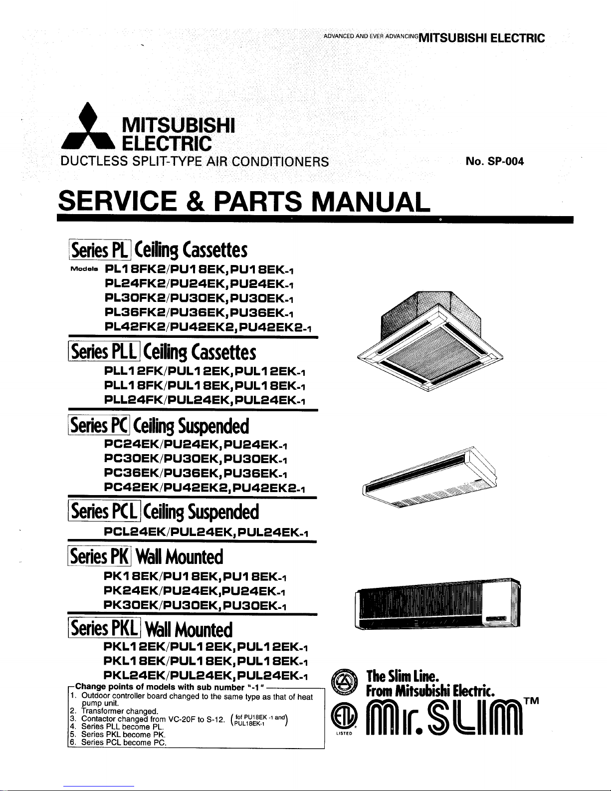
SERVICE
&
PARTS
MANUAL
1
Series PL] Ceiling Cassettes
~0d-l~
PL18FK2/PU18EK, PU1 8EK-I
PL24FK2/PU24EK, PU24EK-I
PL30FK2/PU30EK, PU30EK-I
PL36FK2/PU36EK,PU36EK-i
PL42FK21PU42EK2, PU42EK2-I
-1
Ceiling Cassettes
PLL12FK/PUL12EKJPUL1 2EK-I
PLLl8FK/PUL18EK, PULl 8EK-I
PLL24FK/PUL24EK, PUL24EK-I
Ceiling Suspended
I
Series PC
L
1
Ceiling Suspended
WKI
Wall
Mounted
PKI 8EK/PU18EK,PUI 8EK-I
PK24EK/PU24EK,PU24EK-l
PK30EK/PU30EK, PU30EK-I
Wall
Mounted
PKLI 2EK/PUL12EK, PULl 2EK-I
PKLI 8EK/PUL18EK, PULl 8EK-I
PKL24EK/PUL24EK, PUL24EK-I
@
The
Slim Line.
fof
PU18EK
I
and
PUL18EK-I
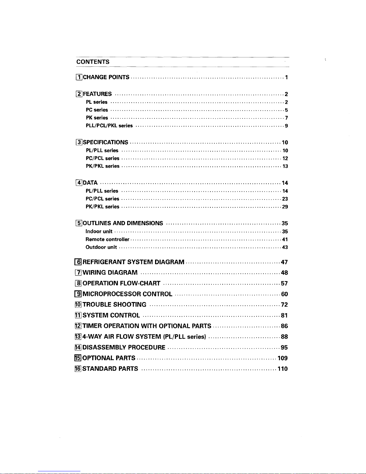
CONTENTS
REFRIGERANT SYSTEM DIAGRAM
..........................................
47
DWlRlNG DIAGRAM
..............................................................
48
QPERATION FLOW-CHART
.................................................
...
57
MICROPROCESSOR
CONTROL
...............................................
60
TROUBLE SHOOTING
..........................................................
72
SYSTEM CONTROL
.............................................................
81
MTIMER OPERATION WITH OPTIONAL PARTS
..............................
86
m4-WAY AIR FLOW SYSTEM (PL/PLL
series)
................................
88
/@
DISASSEMBLY PROCEDURE
..................................................
95
OPTIONAL PARTS
..............................................................
109
STANDARD PARTS
............................................................
110
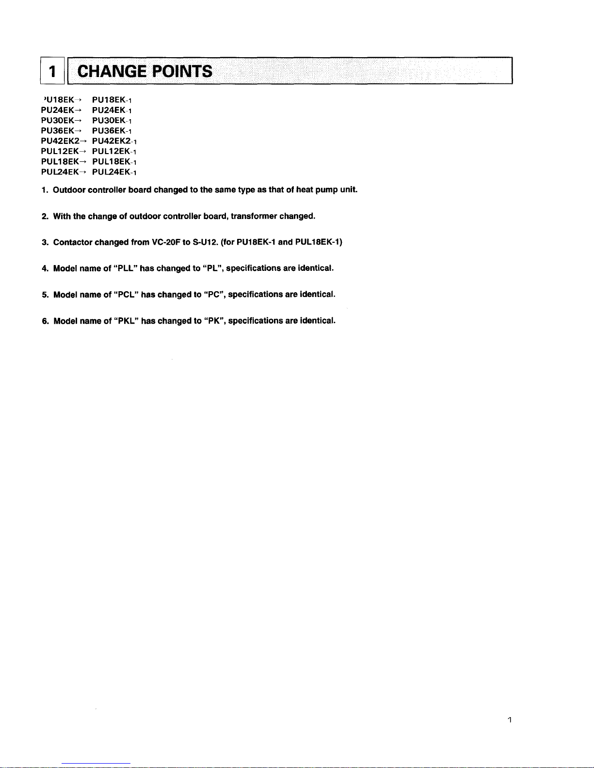
CHANGE
POINTS
1. Outdoor controller board changed to the same type as that of heat pump unit.
2. With the change of outdoor controller board, transformer changed.
3.
Contactor changed from VC-2OF to S-U12. (for PU18EK-1 and PUL18EK-1)
4.
Model name of "PLL" has changed to "PL", specifications are identical.
5.
Model name of "PCL" has changed to "PC", specifications are identical.
6.
Model name of "PKL" has changed to "PK", specifications are identical.
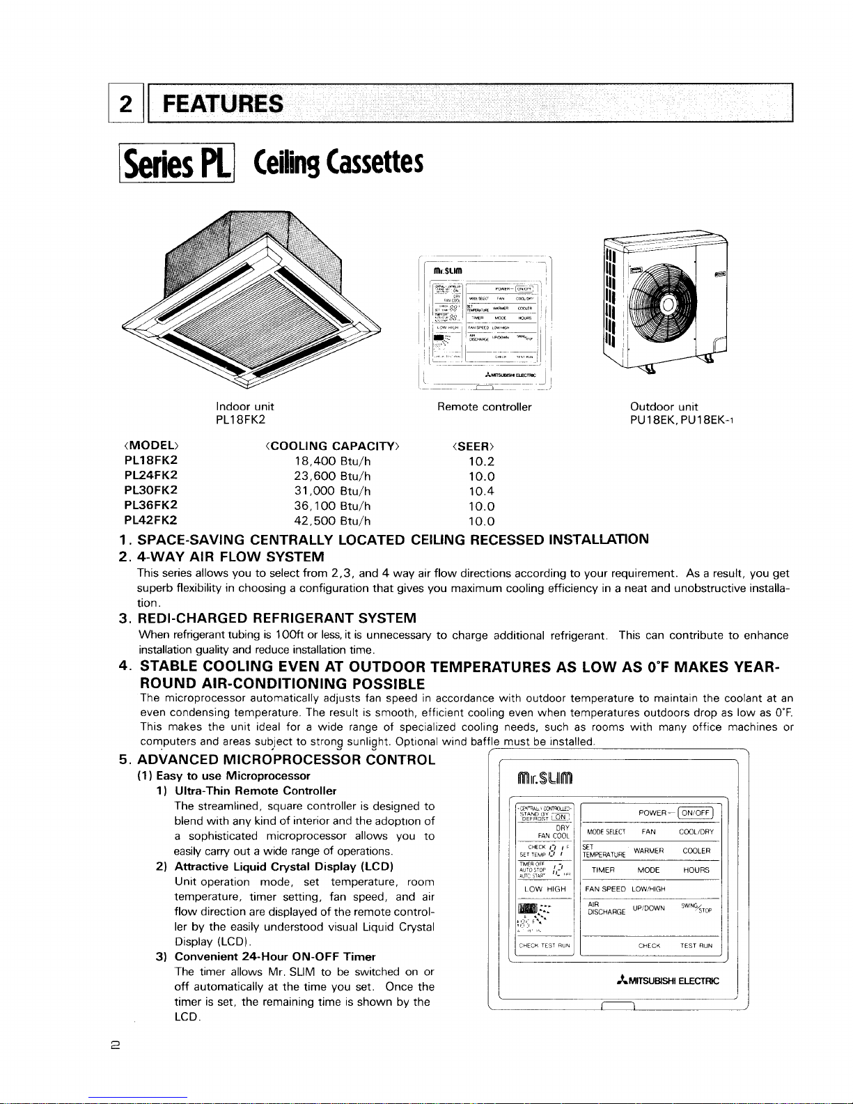
FEATURES
1
Series
pLI
Ceiling Cassettes
Indoor unit
PL18FK2
Remote controller Outdoor unit
PU 1 BEK, PU18EK-1
(MODEL) (COOLING CAPACITY) (SEER)
PL18FK2
18,400
Btu/h
10.2
PL24FK2
23,600
Btu/h
10.0
PL30FK2
31,000
Btu/h
10.4
PL36FK2
36,100
Btu/h
10.0
P L42 F K2
42,500
Btu/h
10.0
1.
SPACE-SAVING CENTRALLY LOCATED CEILING RECESSED INSTALLATION
2.
4-WAY AIR FLOW SYSTEM
This series allows you to select from
2,3,
and 4 way air flow directions according to your requirement. As a result, you get
superb flexibility in choosing a configuration that gives you maximum cooling efficiency in a neat and unobstructive installation.
3.
REDI-CHARGED REFRIGERANT SYSTEM
When refrigerant tubing is
1OOft
or less, it is unnecessary to charge additional refrigerant.
This can contribute to enhance
installation guality and reduce installation time.
4.
STABLE COOLING EVEN AT OUTDOOR TEMPERATURES AS LOW AS
0°F
MAKES YEAR-
ROUND AIR-CONDITIONING POSSIBLE
The microprocessor automatically adjusts fan speed in accordance with outdoor temperature to maintain the coolant at an
even condensing temperature. The result is smooth, efficient cooling even when temperatures outdoors drop as low as
0°F.
This makes the unit ideal for a wide range of specialized cooli
computers and areas subject to strong sunlight. Optional wind baf
5.
ADVANCED
MICROPROCESSOR
CONTROL
(1)
Easy to use Microprocessor
1) Ultra-Thin Remote Controller
The streamlined, square controller is designed to
blend with any kind of interior and the adopt~on of
a sophisticated microprocessor allows you to
easily carry out a wide range of operations.
2)
Attractive Liquid Crystal Display (LCD)
Unit operation mode, set temperature, room
temperature, timer setting, fan speed, and air
flow direction are displayed of the remote controller by the easily understood visual Liquid Crystal
Display (LCD).
3) Convenient 24-Hour ON-OFF Timer
The timer allows Mr. SLIM to be switched on or
off automatically at the time you set. Once the
timer is set, the remaining time is shown by the
LCD.
8
needs, such as rooms with many office machines
or
must be installed.
POWER-
(ON/OFF)
MODE
SELECT
FAN
COOLiDRY
SET
TEMPERATURE
WARMER
TIMER MODE HOURS
1
LOW HIGH
/
I
FAN
SPEED LOW!HIGH
1
AIR
UPIDOWN
STOP
1
TEST
WN
I
r--
CHECK
TEST
RUN
4) Self-Diagnostic Feature Indicates Faults Instantly
In the rare case when a problem occurs, the unit stops operating and the set temperature indicator changes to the
self-diagnostic indicator, indicating the location of the fault.
If the check switch is pressed twice, the unit stops operating and the check mode is initiated. The cause of the most
recent problem stored in the memory is displayed on the LCD. This is extremely useful for maintenance purposes.
5)
Useful Memory Feature for Storing Instructions
The previous set value is memorized so that constant temperature control can be obtained. This is convenient when,
for example, a power failure occurs.
(2)
Non-polar Two-Wire Remote Controller Cables
The non-polar, two-wire type remote controller cable is slim, installation is simple and troublefree. Remote controller wire
can be extended up to
550
yards.
6.
INNOVATIVE SYSTEM CONTROL BY MICROPROCESSORS
The most significant feature of the series PL is the advanced microprocessor system control. Behind the development of this
system is the recent world-wide trend in the air conditioning of larger buildings, away from centralized duct systems in favor
of a large number of individual split type units.
There are a number of reasons for this: first, costly troublesome duct
installation is eliminated: second, the overall air conditioning balance is excellent; and third, operation cost is low, since
flexible control of each unit is possible. This system control was developed exclusively by Mitsubishi in the light of this
demand. Microprocessor control makes possible individual control, group control, control using two remote controllers,
remote
on/off control and individual control without troublesome modifications to the equipment.
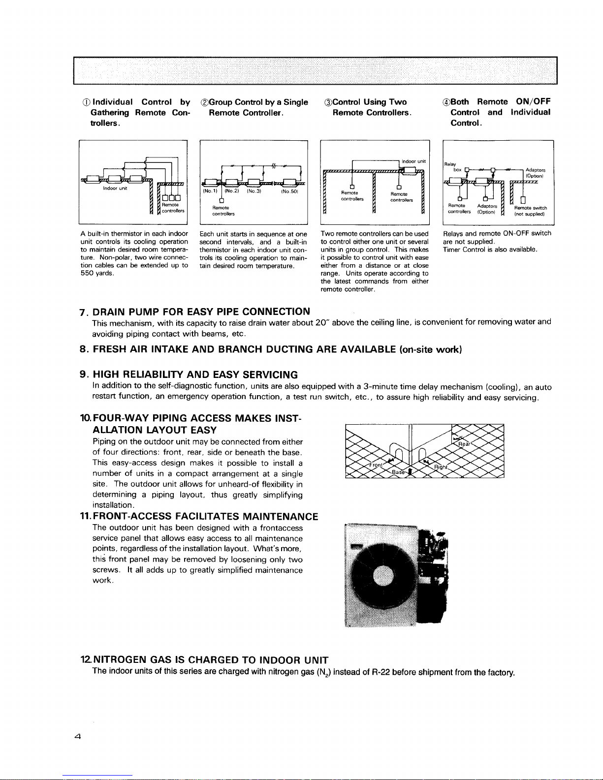
1)
Individual Control by Gathering Remote Controllers
A
Series PL unit is installed in each room, and the remote controllers are gathered together in a separate location, where
each unit is controlled individually.
Each remote controller is connected to its indoor unit by non-polar 2-wire cable to eliminate the possibility of miswiring.
Separation can be as much as
550
yards, making this type of control extremely easy to implement.
Thermistors in the indoor unit maintain each room at its own individually set temperature.
This control system is excellent for schools or kindergardens, where controls should be kept out of the reach of the pupils.
2)
Group Control by a Single Remote Controller
In an application requring a number of air conditioner units in a large area on a single floor, up to
50
Series PL units can
be centrally controlled using a single remote controller. The remote controller controls Power ON-OFF, set temperature,
fan speed, ON-OFF timer, and auto vane position of all units of the group. Obviously, if all the units started simultaneous-
ly, the surge current would be unacceptably high. Therefore the microprocessor board of each indoor unit has a 8-toggle
DIP switch that can be programmed to give sequential starting with up to
50
seconds delay. When the switch of the
remote controller is pressed, master unit comes on immediately, followed by the other units in the programmed order.
Thereafter the thermistor in each indoor unit controls compressor operation to keep the room at the set temperature.
The remote controller is connected to indoor units by non-polar 2-wire cable. Total cable length can be as much as
550
yards. This system can be applied to the air conditioning of large offices or conference rooms, supermarkets, etc.
3)
Control Using Two Remote Controllers
Two remote controllers can be used to control either one unit or several units in group control. This makes it possible
to control units with ease either from a distance or at close range. Units operate according to the last command from
either remote controller.
4) Both Remote
ON/OFF
Control and Individual Control
All units can be turned on and off simultaneously using the remote ON/OFF switch, and also individual units can be
controlled from the remote controllers.
This system is well suited to buildings having a large number of rooms. In offices, for example, all units can be started
together to cool the premises before workers arrive, operated as necessary by individual remote controllers during the day,
and stopped together at the end of business.
a
Individual Control
by
Gathering Remote Controllers.
@Group Control
by
a Single
Remote Controller.
I
(No
1)
1
(No
2)
IN0
3)
INo.50)
I
Remote
controllers
OControl Using Two
Remote Controllers.
I
11
Indoor
unlt
A
built-in thermistor in each indoor
unit controls its cooling operation
to maintain desired room temperature. Non-polar, two wire connection cables can be extended up to
550
yards.
Each unit starts in sequence at one
second intervals, and a built-in
thermistor in each indoor unit controls its cooling operation to maintain desired room temperature.
Two remote controllers can be used
to control either one unit or several
units in group control. This makes
it possible to control unit with ease
either from a distance or at close
range. Units operate according to
the latest commands from either
remote controller.
@Both Remote
ON/OFF
Control and Individual
Control.
I
Relays and remote ON-OFF switch
are not supplied.
Timer Control is also available.
7.
DRAIN PUMP FOR EASY PIPE CONNECTION
This mechanism, with its capacity to raise drain water about
20"
above the ceiling line, is convenient for removing water and
avoiding piping contact with beams, etc.
8.
FRESH AIR INTAKE AND BRANCH DUCTING ARE AVAILABLE
(oti-site
work)
9.
HIGH RELIABILITY AND EASY SERVICING
In addition to the self-diagnostic function, units are also equipped with a 3-minute time delay mechanism (cooling), an auto
restart function, an emergency operation function, a test run switch, etc., to assure high reliability and easy servicing.
10.
FOUR-WAY PIPING ACCESS MAKES INST-
ALLATION LAYOUT EASY
Piping on the outdoor unit may be connected from either
of four directions: front, rear, side or beneath the base.
This easy-access design makes it possible to install a
number of units in a compact arrangement at a single
site. The outdoor unit allows for unheard-of flexibility in
determining a piping layout, thus greatly simplifying
installation.
11.
FRONT-ACCESS FACILITATES MAINTENANCE
The outdoor unit has been designed with a frontaccess
service panel that allows easy access to all maintenance
points, regardless of the installation layout. What's more,
this front panel may be removed by loosening only two
screws. It all adds up to greatly simplified maintenance
work.
12.NITROGEN GAS IS CHARGED TO INDOOR UNIT
The indoor units of this series are charged with nitrogen gas
(N,)
instead of
R-22
before shipment from the factory.

Ceiling
Suspended
r-~
--
.
-
>--
Microprocessor
Indoor Unit
Remote controller
PU24EK.
PU24EK-I
Outdoor Unit
(Cooling Capacity>
(
24,000 Btu/h
31,000 Btu/h
36,500 Btu/h
42,500 Btu/h
1
.
ADVANCED MICROPROCESSOR CONTROL
(Please refer to page 2 -3 for the detail.)
(1)
Easy to use Microprocessor remote controller
1
)
Ultra-Thin Remote Controller
2) Attractive Liquid Crystal Display (LCD)
3) Convenient 24-Hour ON-OFF Timer
4) Self-Diagnistic Feature Indicates Faults Instantly
5)
Useful Memory Feature for Storing Instructions
(2) Non-polar Two-Wire Remote Controller Cables
2.
INNOVATIVE SYSTEM CONTROL BY MICROPROCESSORS
(Please refer to page 3 for the detail.)
1) Group Control by a Single Remote Controller
2) Control Using Two Remote ~ontrollkrs
3) Both Remote ON/OFF Control and lndividual Control
4) Individual Control by Gathering Remote Controllers
3.
REDI-CHARGED REFRIGERANT SYSTEM
When refrigerant tubing is 100ft or less, it is unnecessary to charge additional refrigerant.
This can contribute to enhance
installation quality and reduce installation time.
4.
MAXIMUM COMFORT AIR CONDITIONING
(1) Indoor Unit Changeable Air Outlet
PC-EK
series have changeable air outlet.
Downward air flow can be obtained at an
angle up to 30". Upward air flow at angle of
10" is able to stretch cool air in a room. This
function enables comfortable air distribution.
(2)
Swing Flow Louvers
The Swing Flow Louvers automatically change
the air flow direction for desirable air distribution.
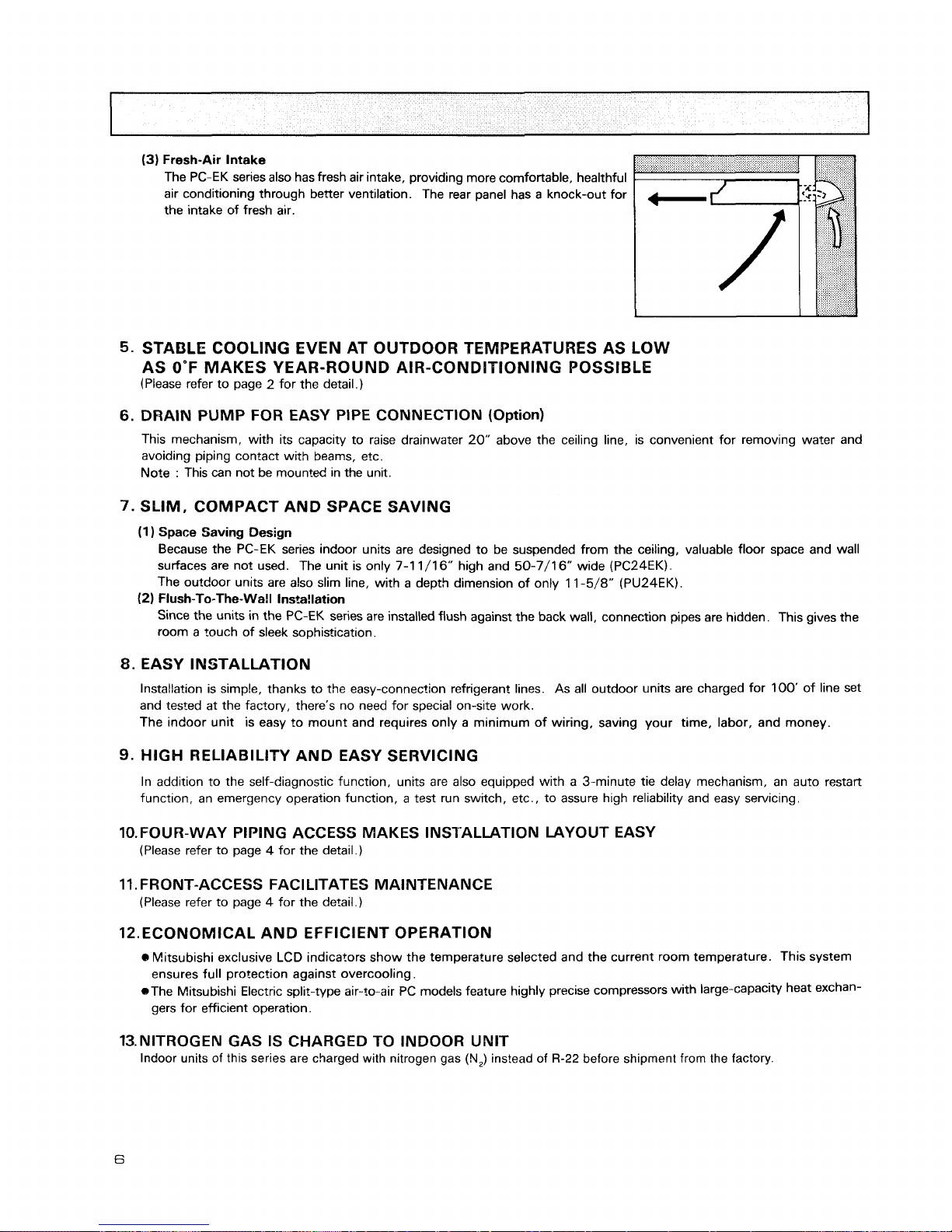
(3)
Fresh-Air Intake
The PC-EK series also has fresh air intake, providing more comfortable, healthful
air conditioning through better ventilation. The rear panel has a knock-out for
the intake of fresh air.
STABLE COOLING EVEN AT OUTDOOR TEMPERATURES AS LOW
AS
0°F
MAKES YEAR-ROUND AIR-CONDITIONING POSSIBLE
(Please refer to page 2 for the detail.)
DRAIN PUMP FOR EASY PIPE CONNECTION (Option)
This mechanism, with its capacity to raise drainwater 20" above the ceiling line, is convenient for removing water and
avoiding piping contact with beams, etc.
Note
:
This can not be mounted in the unit.
SLIM, COMPACT AND SPACE SAVING
(1
)
Space Saving Design
Because the PC-EK series indoor units are des~gned to be suspended from the ceiling, valuable floor space and wall
surfaces are not used. The unit is only 7-1 1/16" high and 50-7/16" wide
(PC24EK).
The outdoor units are also slim line, with a depth dimension of only
1
1
-5/8" (PU24EK).
(2)
Flush-To-The-Wall Installation
Since the units in the PC-EK series are installed flush against the back wall, connection pipes are hidden. This gives the
room a touch of sleek sophistication.
8.
EASY INSTALLATION
Installation is simple, thanks to the easy-connection refrigerant lines. As all outdoor units are charged for 100' of line set
and tested at the factory, there's no need for special on-site work.
The indoor unit is easy to mount and requires only a minimum of wiring, saving your time, labor, and money.
9.
HIGH
RELIABILITY AND EASY SERVICING
In addition to the self-diagnostic function, units are also equipped with a 3-minute tie delay mechanism, an auto restart
function, an emergency operation function, a test run switch, etc., to assure high reliability and easy servicing.
10.FOUR-WAY PIPING ACCESS MAKES INSTALLATION LAYOUT EASY
(Please refer to page 4 for the detail.)
11. FRONT-ACCESS FACILITATES MAINTENANCE
(Please refer to page 4 for the detail.)
12.ECONOMICAL AND EFFICIENT OPERATION
Mitsubishi exclusive LCD indicators show the temperature selected and the current room temperature.
This system
ensures full protection against overcooling.
@The Mitsubishi Electric split-type air-to-air PC models feature highly precise compressors with large-capacity heat exchan-
gers for efficient operation.
13.NlTROGEN GAS IS CHARGED TO INDOOR UNIT
Indoor units of this series are charged with nitrogen gas
(N,)
instead of
R-22
before shipment from the factory.
BK]
Wall
Mounted
PK24EK
Indoor unit
*umua*arsnr
-
M~croprocessor
remote controller
PU24EK. PU24EK-1
Outdoor unlt
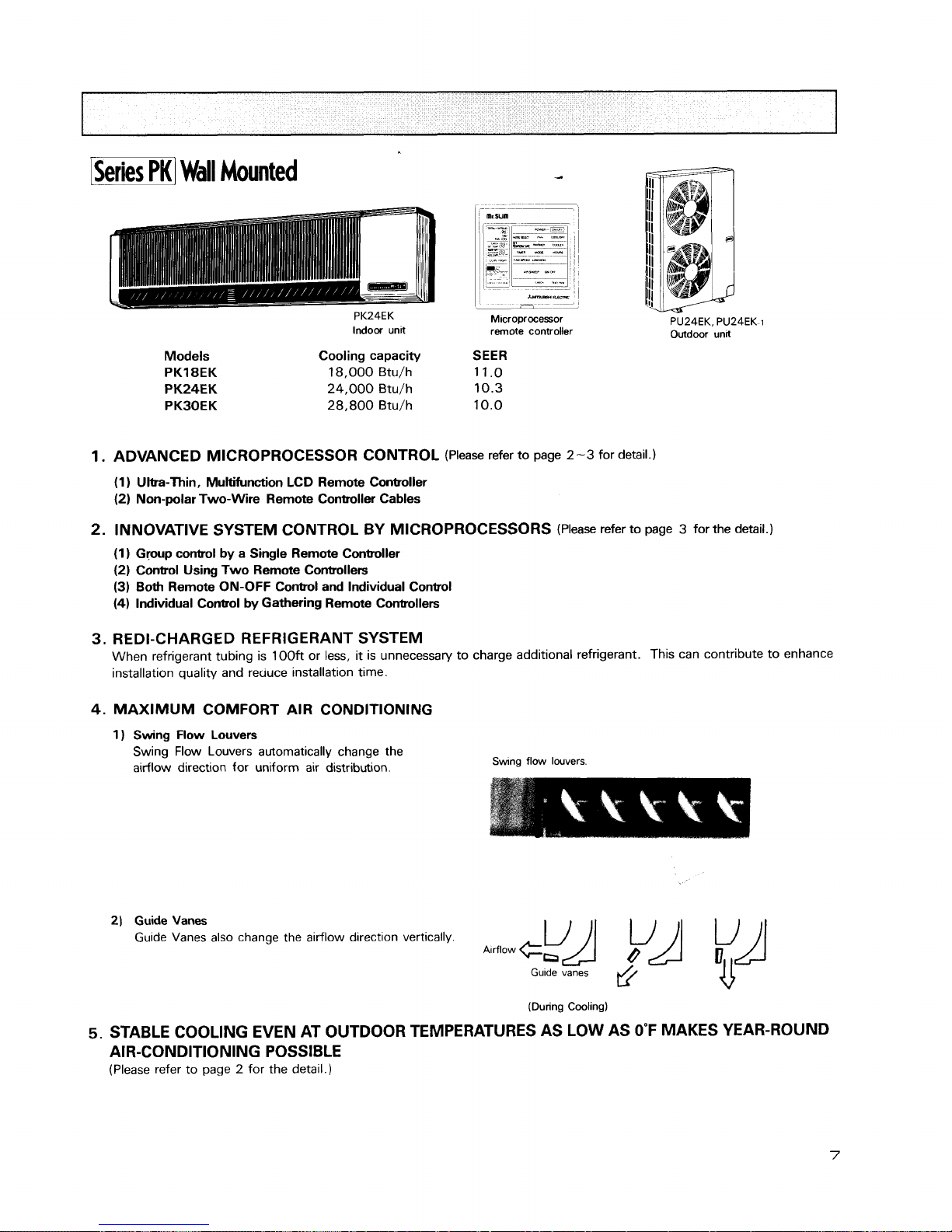
Models
PK18EK
PK24EK
PKBOEK
Cooling capacity SEER
18,000 Btu/h 11.0
24,000 Btu/h 10.3
28,800
Btu/h 10.0
1.
ADVANCED MICROPROCESSOR CONTROL
(Please refer to page
2-3
for detail.)
(1 ) Ultra-Thin, Multifunction LCD Remote Controller
(2) Non-polar Two-Wire Remote Controller Cables
2.
INNOVATIVE SYSTEM CONTROL BY MICROPROCESSORS
(Please refer to page 3 for the detail.)
(1) Gpup control by a Single Remote Controller
(2) Control Using Two Remote Controllers
(3)
Both Remote ON-OFF Control and Individual Conbol
(4)
Individual Control by Gathering Remote Controllers
3.
REDI-CHARGED REFRIGERANT SYSTEM
When refrigerant tubing is 100ft or less,
it
is unnecessary to charge additional refrigerant. This can contribute to enhance
installation quality and reuuce installation time.
4.
MAXIMUM COMFORT AIR CONDITIONING
1 ) Swing Flow Louvers
Swing Flow Louvers automatically change the
airflow direction for uniform air distribution.
Swng
flow louvers
2)
Guide
Vanes
Guide Vanes also change the airflow direction vertically.
(During Cooling)
5.
STABLE COOLING EVEN AT OUTDOOR TEMPERATURES AS LOW AS
0°F
MAKES YEAR-ROUND
AIR-CONDITIONING POSSIBLE
(Please refer to page 2 for the detail.)
6.
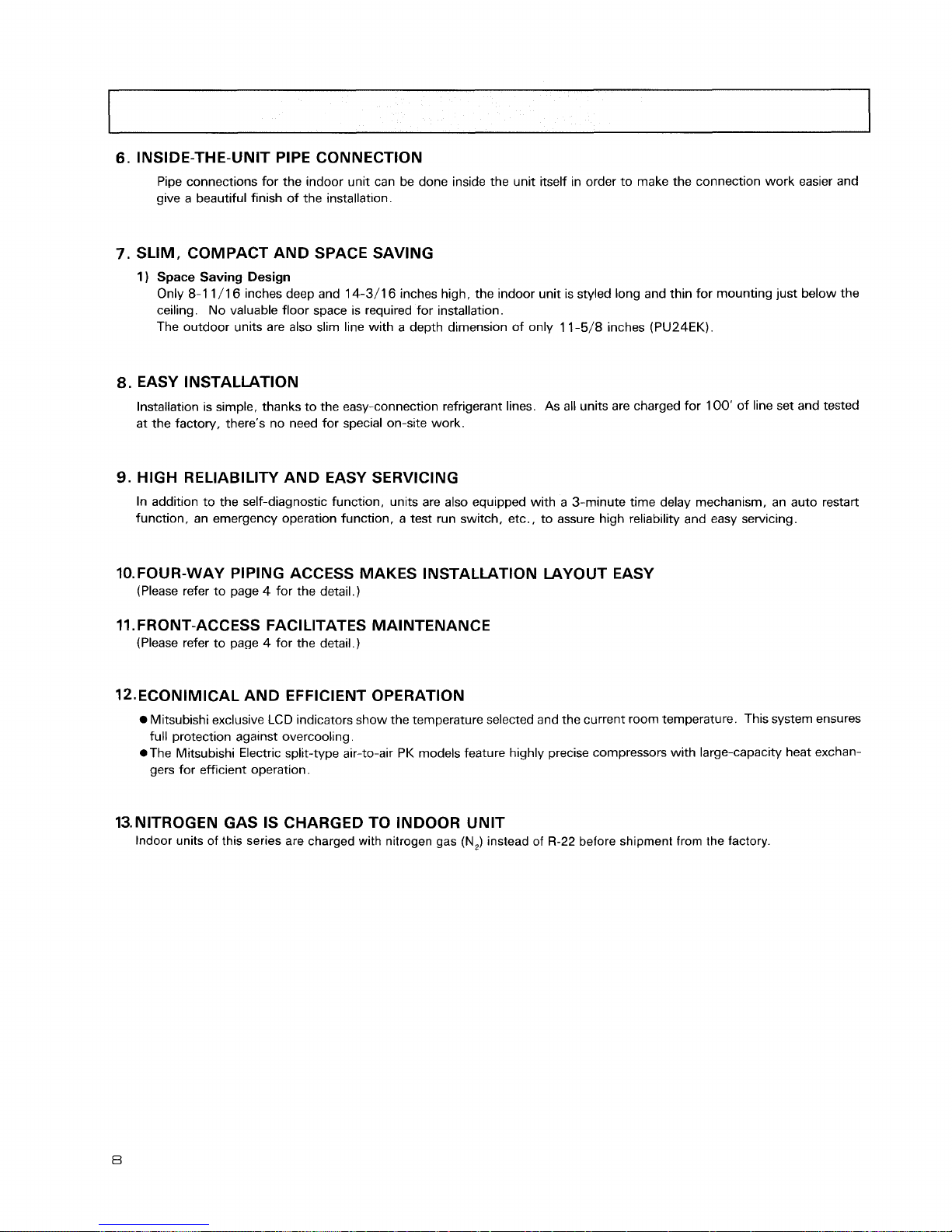
INSIDE-THE-UNIT PIPE CONNECTION
Pipe connections for the indoor unit can be done inside the unit itself in order to make the connection work easier and
give a beautiful finish of the installation.
7.
SLIM, COMPACT AND SPACE SAVING
1
)
Space
Saving Design
Only
8-1
1/16 inches deep and 14-3/16 inches high, the indoor unit is styled long and thin for mounting just below the
ceiling. No valuable floor space is required for installation.
The outdoor units are also slim line with a depth dimension of only 11-5/8 inches (PU24EK).
8.
EASY INSTALLATION
Installation is simple, thanks to the easy-connection refrigerant lines. As all units are charged for 100' of line set and tested
at the factory, there's no need for special on-site work.
9.
HIGH RELIABILITY AND EASY SERVICING
In addition to the self-diagnostic function, units are also equipped with a 3-minute time delay mechanism, an auto restart
function, an emergency operation function, a test run switch, etc., to assure high reliability and easy servicing.
10.FOUR-WAY PIPING ACCESS MAKES INSTALLATION LAYOUT EASY
(Please refer to page 4 for the detail.)
11. FRONT-ACCESS FACl LITATES MAINTENANCE
(Please refer to page 4 for the detail.)
12.ECONIMICAL AND EFFICIENT OPERATION
Mitsubishi exclusive
LCD
indicators show the temperature selected and the current room temperature. This system ensures
full protection against overcooling.
*The Mitsubishi Electric split-type air-to-air PK models feature highly precise compressors with large-capacity heat exchan-
gers for efficient operation.
13.NITROGEN GAS IS CHARGED TO INDOOR UNIT
Indoor units of this series are charged with nitrogen gas
(N,)
instead of
R-22
before shipment from the factory.
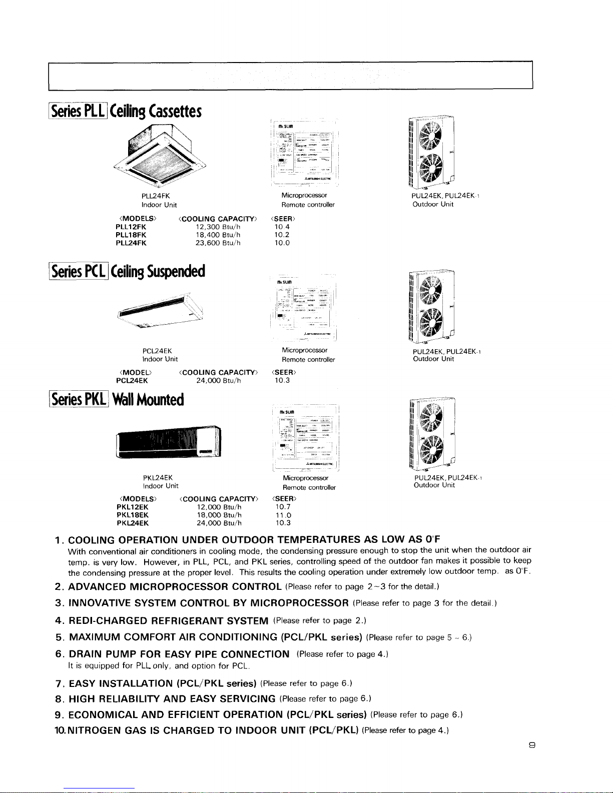
Series
Ceiling Cassettes
PLL24FK
lndoor Unit
(MODELS) (COOLING CAPACITY)
PLLIZFK 12,300 Btu/h
PLL18FK 18,400 Btu/h
PLL24FK 23,600 Btu/h
I
Series
PC
L
1
Ceiling Suspended
PCL24EK
lndoor Unit
(MODEL) (COOLING CAPACITY)
PCL24EK 24,000 Btu/h
1
Series
PKL
1
Wall
Mounted
*"?s,s3.-
-
--
-
-
M~croprocessor
Remote controller
(SEER)
10 4
10 2
10 0
Microprocessor
Remote controller
PK124EK
lndoor Unit
*--
I
I
-
,
Microprocessor
Remote controller
(MODELS) (COOLING CAPACITY)
(SEER:
PKLlZEK 12,000 Btu/h 10.7
PKL18EK 18,000 Btulh 11 .O
PKL24EK 24,000 Btu/h 10.3
PUL24EK. PUL24EK-1
Outdoor Unit
PU124EK. PUL24EK-1
Outdoor Unit
PUL24EK. PUL24EK-1
Outdoor Unlt
COOLING OPERATION UNDER OUTDOOR TEMPERATURES AS LOW AS OF
With conventional air conditioners in cooling mode, the condensing pressure enough to stop the unit when the outdoor air
temp. is very low. However, in PLL, PCL, and PKL series, controlling speed of the outdoor fan makes it possible to keep
the condensing pressure at the proper level. This results the cooling operation under extremely low outdoor temp. as
0°F.
ADVANCED MICROPROCESSOR CONTROL
(Please refer to page
2-3
for the detail.)
INNOVATIVE SYSTEM CONTROL BY MICROPROCESSOR
(Please refer to page 3 for the detail.)
REDI-CHARGED REFRIGERANT SYSTEM
(Please refer to page
2.)
MAXIMUM COMFORT AIR CONDITIONING
(PCLIPKL
series)
(Please refer to page
5
-
6.)
DRAIN PUMP FOR EASY PIPE CONNECTION
(Please refer to page
4.)
It is equipped for PLLonly, and option for PCL.
EASY INSTALLATION (PCL/PKL series)
(Please refer to page 6.)
HIGH RELIABILITY AND EASY SERVICING
(Please refer to page 6.)
ECONOMICAL AND EFFICIENT OPERATION (PCL/PKL series)
(Please refer to page
6.)
10.NlTROGEN GAS IS CHARGED TO INDOOR UNIT (PCL/PKL)
(Please refer to page
4.)
1
Operating range
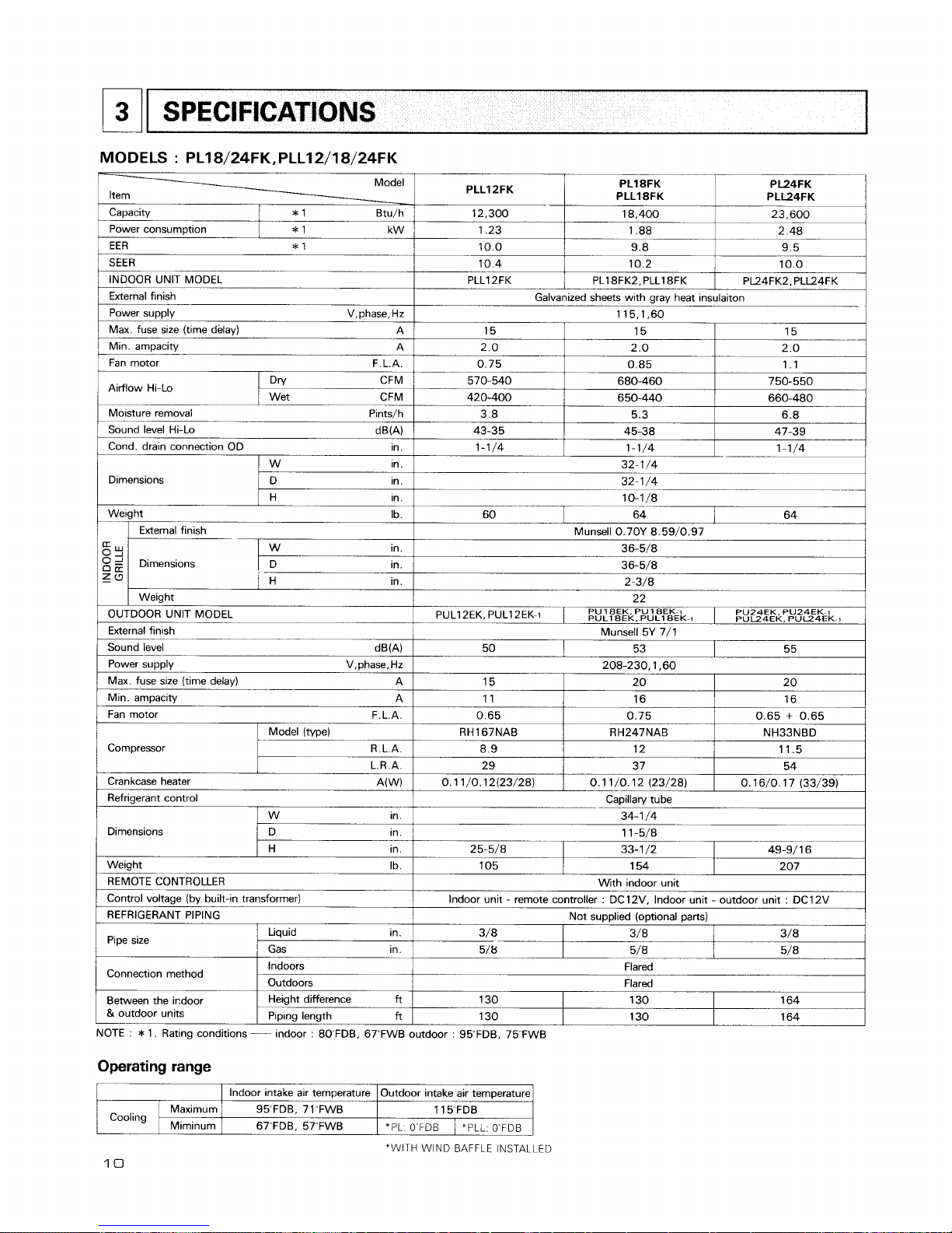
SPECIFICATIONS
MODELS : PL18/24FK,PLLl2/18/24FK
Model
Item
PLLIPFK
12,300
1.23
10.0
10.4
PLLl 2FK
Capacity
*
1 Btu/h
Cooling
PL18FK
PLL18FK
18.400
1.88
9.8
10.2
PL18FK2, PLL18FK
"WITH WIND BAFFLE INSTALLED
10
lndoor intake air temperature
95"FDB, 71~FWB
67~FDB. 57'FWB
Maximum
Miminum
PL24FK
PLL24FK
23,600
2.48
9.5
10.0
PL24FK2, PLL24FK
Power consumption
Galvanized sheets with gray heat insulaiton
115,1,60
*
1 kW
15
2.0
0.75
I
570-540
420-400
3.8
43-35
1-1/4
Outdoor intake air temperature
1 15"FDB
*PL 0"FDB
15
2.0
0.85
680-460
650-440
5.3
45-38
1-1/4
EER
*
1
SEER
INDOOR UNIT MODEL
External finish
Power supply V,phase,Hz
Max. fuse size (time delay) A
Min. ampacity A
Fan motor F.L.A.
Airflow Hi-Lo
I
Dn/
CFM
Wet CFM
Moisture removal Pints/h
Sound level Hi-Lo dm)
Cond. drain connection OD ~n.
"PLL. 0"FDB
15
2.0
1.1
750-550
660-480
6.8
47-39
1-1/4
Dimensions
32-1/4
32-1
/4
10-1/8
W ~n.
D ~n.
H in.
60
64
Weight Ib.
64
g
Y
O
2
0
a
Z
a
Munsell 0.70Y 8.59/0.97
36-51'8
36-5/8
2-3/8
22
PUL12EK. PUL12EK-1
1
PUL~~EK,
PU
18~~.
PU
PULI~EK-1
1
~EK-I
External finish
PU24EK. PU24EK~t
PUU4EK. PUU4EK-1
Dimensions
OUTDOOR UNIT MODEL
External finish
Sound level dB(A)
Power supply V,phase,Hz
Max. fuse size (time delay) A
Min. ampacity A
Fan motor F.L.A.
W
in.
D in.
H in.
Munsell 5Y 7/1
Compressor
Weight
50
Model (type)
R.L.A.
L.R.A.
53
Crankcase heater A(W)
Refrigerant control
55
208-230.1.60
Dimensions
15
11
0.65
RH167NAB
8.9
29
0.11/0.12(23/28)
W ~n.
D in.
H in.
20
16
0.75
RH247NAB
12
37
0.1 1 /O. 12 (23/28)
Weight Ib.
REMOTE CONTROLLER
Control voltage (by built-in transformer)
REFRIGERANT PIPING
20
16
0.65
+
0.65
NH33NBD
11.5
54
0.16/0.17 (33/39)
Capillan/ tube
34-1 /4
1 1 -5/8
Pipe size
Connection method
Between the indoor
&
outdoor units
25-5/8
Liquid in.
Gas in.
Indoors
Outdoors
Height difference
ft
Piping length
ft
NOTE
:
*
1. Rating conditions
----
indoor : 80FDB. 67~FWB
33-1 /2 49-9/ 1 6
105
154 207
With indoor unit
Indoor unit
-
remote controller : DC12V. Indoor unit - outdoor unit : DC12V
Not supplied (optional parts)
3/8 3/8 3/8
5/8- 5/8 5/8
Flared
Flared
130 130 164
130
outdoor
:
95"FDB. 75"FWB
130 164
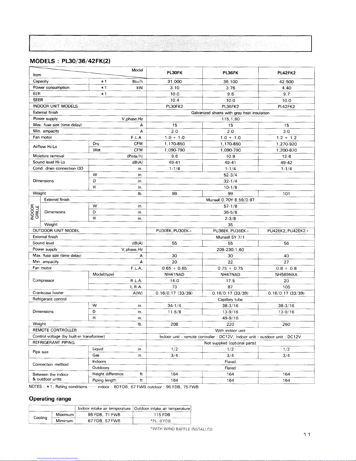
MODELS
:
PL30/36/42FK(2)
Model
Item
-
PWOFK
31,000
3.10
10.0
10.4
PL30FK2
Capacity
Moisture removal (Pints/h)
Fan motor F.L.A.
1
0.65 + 0.65
*
1 Btu/h
9.6
49-41
1-11'4
Sound level Hi-Lo
Cond. drain connection OD
Dimensions
compressor
PW6FK
36,100
3.76
9.6
10.0
PL36FK2
dw)
in.
W
~n.
D in.
H in.
0.75
+
0.75
Pipe slze
Operating range
PL42FK2
42,500
4.40
9.7
10.0
PL42FK2
Power consumption
Galvanized sheets with gray heat insulaiton
115,1,60
10.9
49-4 1
1-1/4
0.8
+
0.8
ModeKtype)
R.L.A.
L.R.A.
Connection method
Between the indoor
&
outdoor units
*
1 kW
15
2.0
1 .O
+
1 .O
1 ,170-850
1,090-790
12.6
49-42
1-1/4
52-3/4
32- 1
/4
10-1/8
Weight Ib.
Liquid in.
I
1 /2
"WITH
WIND BAFFLE INSTALLED
99
Sr
0
='
0
a
zu
-
NH41 NAD
14.0
73
Crankcase heater A(W)
Refrigerant control
NOTES
:
*
1. Rating conditions
--
indoor : 8OFDB. 67 FWB outdoor : 95 FDB, 75 FWB
Indoors
Outdoors
Height difference
fl
Piping length
ft
15
2.0
1.0+ 1.0
1,170-850
1,090-790
EER
*
1
SEER
INDOOR UNIT MODELS
External finish
Power supply V,phase, Hz
Max. fuse size (time delay)
A
Min. ampacity A
Fan motor F.L.A.
0.16/0. 17 (33/39)
Dimensions
1 /2
Cooling
15
3.0
1.2
+
1.2
1,270-920
1,200-870
Aidow Hi-Lo
99
OUTDOOR UNIT MODEL
External finish
Sound level dB(A)
Power supply V, phase, Hz
Max. fuse size (time delay)
A
Min.
ampacity A
External finish
NH47NAD
17.5
87
W in.
D ~n.
1 /2
Gas ~n.
-
Flared
Flared
lndoor intake air temperature
95 FDB, 71 FWB
67'FDB. 57"FWB
Maximum
Miminurn
Dnl CFM
Wet CFM
101
Dimensions
Munsell 0.70Y 8.59/0.97
57-1 /8
36-5/8
2-3/8
35
NH569NXA
20
105
0.16/0. 17 (33/39)
H in.
Weight Ib.
REMOTE CONTROLLER
Control voltage (by built-in transformer)
REFRIGERANT PIPING
164
Outdoor intake air temperature
115 FDB
*PL: O'FDB
W in.
D in.
H in.
PU30EK. PU30EK-1
0.16/0.17 (33/39)
Capillary tube
34-1/4
1
38-3/16
1
38-3/16
11-5/8
1
13-9/16
/
13-9/16
49-9/16
3/4
Weight
PU36EK. PU36EK-1
1
PU42EK2, PU42EK2-i
208
164
3/4
164
164
Munsell 5Y 7/1
With mdoor unit
-
Indoor unit - remote controller : DC12V, Indoor unit - outdoor unit : DC12V
Not supplied (optional parts)
220
3/4
164
---
164
55
260
55 56
208-230.1.60
30
I
30
1
40
20 22 2 7
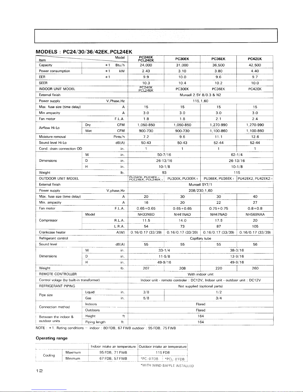
MODELS : PC24/30/36/42EK, PCL24EK
1
Power consurn~tion
1
*1 kWI 2.43
1
3.10
1
3.80
I
4.40
I
1
EER
*
1
1
9.9
I
10.0
1
9.6
1
9.7
I
-
Model
Item
-
Capacity
PC42EK
42,500
PC24EK
PCL24EK
24,000
*
1 Btu/h
SEER
INDOOR
UNlT MODEL
External finish
1
Max fuse size (time delay) A
/
15
1
15
I
15
1
15
I
Power supply V,Phase, Hz
PC30EK
31.000
10.3
PC24EK
PCL24EK
115,1,60
1
Fan motor F.L.A.
I
1.8
1
1.8
I
2.1
I
2.4
1
PC36EK
36,500
Min ampacity A
Munsell 2.5Y 8/0.3
&
N2
10.4
PC30EK
1
Sound level Hi-Lo dB(A)/ 50-43
1
50-43
1
52-44
1
52-44
1
3.0
Airflow Hi-Lo
1
Cond. drain connection OD in.
1
1
1
1
1
1
I
1
1
10.2
PC36EK
10.0
PC42EK
3.0
Dry CFM
Wet CFM
/
Weight Ib.
/
93
I
115
1
Pints/h
3.0
1,050-850
900-730
1
w
in.
/
power supply V,phase,Hz
/
208/230,1,60
I
3.0
7.2
50-7/16
26-1 3/16
10-11'8
Dlrnensions
OUTDOOR UNlT MODEL
External finish
/
Max. fuse size
(time
delavl
1,050-850
900-730
62-1
/4
26-13/16
10-1/8
D in.
H in.
I
Min. ampacity
9.6
I
1,270-990
1,100-860
PU24EK. PU24EK-7
~"124~~.
PU~~EK-,
1
Refrigerant control
1
Capillary tube
I
1,270-990
1,100-860
11.1
Sound level
12.6
Munsell 5Y7/1
PU30EK. PU30EK-1
Fan motor F.L.A.
0.65+0.65
NH33NBD
11.5
54
0.16/0. 17 (33/39)
Compressor
1
Welght
--
-
-
lbi
207
1
208
1
220
1
260j
--
With
Indoor unlt
--
lndoor unlt - remote controler DC12V. Indoor unlt - outdoor unit
DC12V
PU36EK. PU36EK-1
Model
R.L.A.
L.R.A.
dB(A)
in.
in.
1
REFRIGERANT PIPING
1
Not supplied (optional parts)
1
PU42EK2, PU42EK2-1
0.65+0.65
NH41 NAD
14.0
73
0.16/0. 17 (33/39)
Crankcase heater A(W)
Llquid
1
P~pe size
55
1
55
-.
33-1 /4
1 1 -5/8
0.75+0.75
NH47NAD
17.5
87
0.16/0. 17 (33/39)
38-3/ 1 6
13-9/16
in. 49-9/16
I
/
Connection
method
1
Indoors
--
.
I
Outdoors
0.8+0.8
NH569NXA
20
105
0.16/0. 17 (33/39)
49-9/16
~n.
Flared
3/8
Flared
Between the
mdoor
&
Pght-
9-
.
-
-
-
164
--
outdoor
units
'
Plplng length
ft
--
.
-
--
164
NOTE
*
1 Rat~ng condltlons - Indoor 80 FDB. 67 FWB outdoor 95 FDB 75 FWB
~n.
Operating range
5/8
--
-
--
--
-
-
--
-
-
-
1
Indoor ~ntake a~r temperature Outdoor lntake a~r temperature
7
95 FDB 71 FWB
Cooling
1
;'':;+--
115FDB
T
L---
1
67 FDB, 57 FW8
'PCL
OFDB
:
-
I--
*WITH
'SIIIND BAFFLE INSTALLED
12
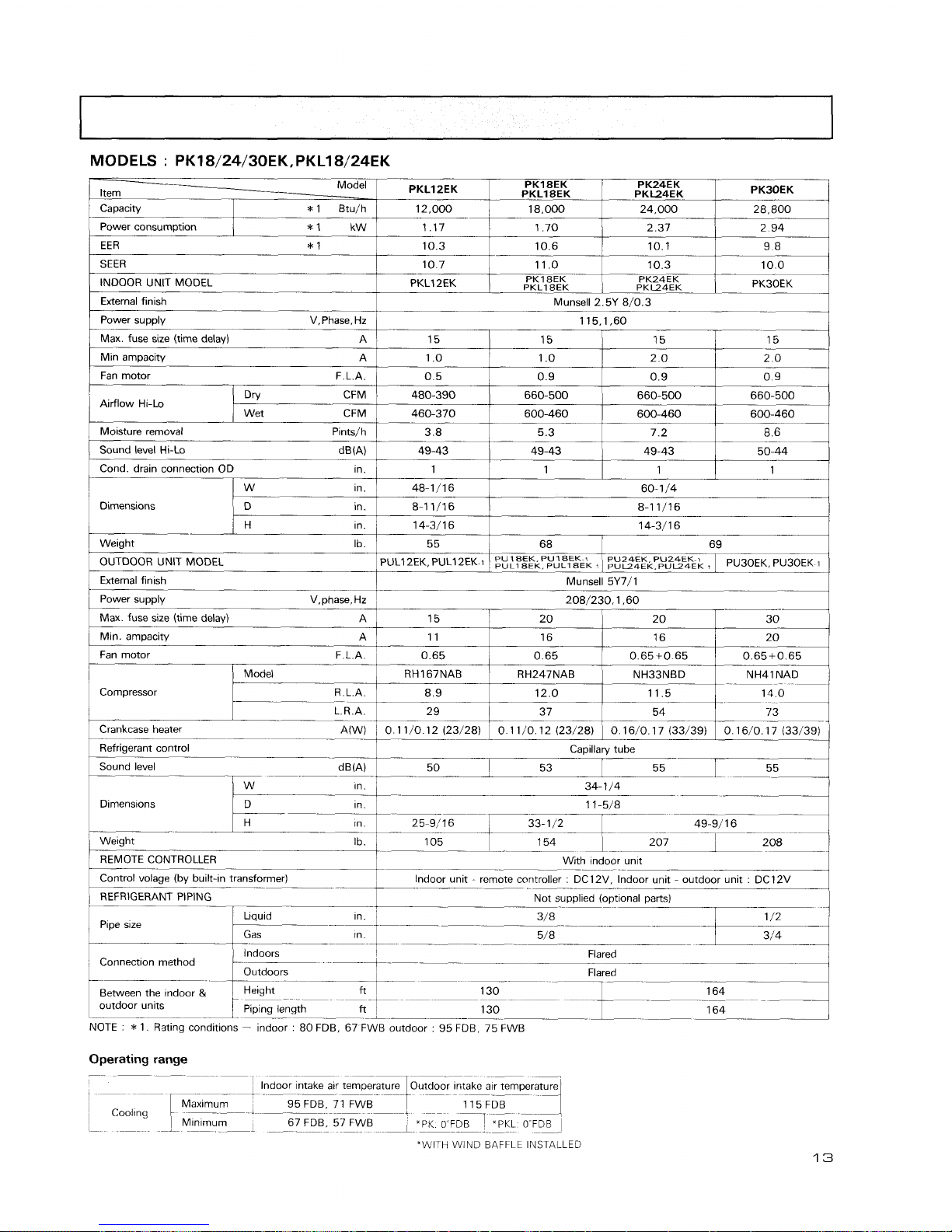
MODELS : PK18/24/30EKrPKL18/24EK
-
/
power supply V,Phase.Hz
/
115,1,60
I
PKLIZEK
Item
-
Power consumption
10.7
INDOOR UNIT MODEL PKL12EK
I
I
I
OUTDOOR UNIT MODEL
I
PULl2EK. PULl2EK
1
I
~~:~~~li.p~,"~&~
$1
P~~~&P,"~~Pu~oEK
1
PK18EK
PKLl8EK
External finish
MM
1.70
10.6
11 .O
PKl SEK
PKLZK
External finlsh
Munsell 5Y7/1
Power supplv V,phase,Hz
,
208/230.1.60
Capacity
Max. fuse size (time delay)
A
Min ampacity A
Fan motor F.L.A.
I
1
T
-
(
Max. fuse size (time delay) A
1
15 20 20 30
1
PK24EK
PKL24EK
2.37
10.1
10.3
PK24EK
PKL24EK
15
1 .O
0.5
480-390
460-370
3.8
49-43
1
48-1/16
8-1 1/16
14-311 6
55
Airflow Hi-Lo
PK30EK
*
1 Btu/h
/
12,000
2.94
9.8
10.0
PK3OEK
Dn! CFM
Wet CFM
I
/
Model
1
RH167NAB
1
RH247NAB
1
NH33NBD
1
NH41NAD
1
15
1 .O
0.9
660-500
600-460
5.3
49-43
1
Min.
arnpacity A
Fan motor
-
F.L.A.
Compressor 8 9 12 0 11 5
--
29 37 54 73
18,000
Moisture removal Pintsjh
Sound level Hi-Lo d Em)
Cond. drain connection OD ~n.
Crankcase heater
0 1 1
/0 12 (23128)
1
0 16/0 1 7 (33139) 1 0 16/0 17 (33139)
Capillary
tube
Sound level
-
--
--
53 55
I
34- 1 /4
---
Dlrnens~ons
--
1 1 -5/8
--
--
15
2.0
ppp
0.9
660-500
600-460
7.2
49-43
1
Dimensions
11
0.65
1
1n.1 25-9/16
1
33-112
1
49-91 1 6
I
24,000
15
2.0
0.9
660-500
600-460
8.6
50-44
1
W
in.
D in.
60-1
/4
8-1 1/16
14-3/16
Weight
-
.
REMOTE CONTROLLER
28.800
in.
Ib.
68
16
0.65
Control volage (by
built-ln transformer)
--
1
l"door unit - remote controller : DClIV, Indoor unit - outdoor unit : DCl2V
.
-
.
REFRIGERANT PIPING
Not su~olied lo~t~onal ~arts)
69
Pipe sue
16
0.65+0 65
/
Llquid in.
1
0.65+0.65
4
1
Gas ~n.
1
Connection
method
Indoors
--
Outdoors
Flared
Flared
Between the mdoor
&
I
Height
ft
1
outdoor unlts
1
Plplnq length
-7.7
-
NOTE
:
*
1. Rating conditions - indoor : 80 FDB, 67 FWB outdoor : 95 FDB, 75 FWB
Operating range
I
1
-
--
F
Max~mum 95 FDB, 71 FWB
--
--
,
-
--
115FDB
1
Cooling
i
-
Mlnlmurn 67 FDB, 57 FWB
I
-
--
-2
--
_-I
_
-
*PK
o
FDB
T
"PKL
OFDB
1
-I
-
_-
-
"WITH WIND BAFFLE INSTALLED
MODELS
:
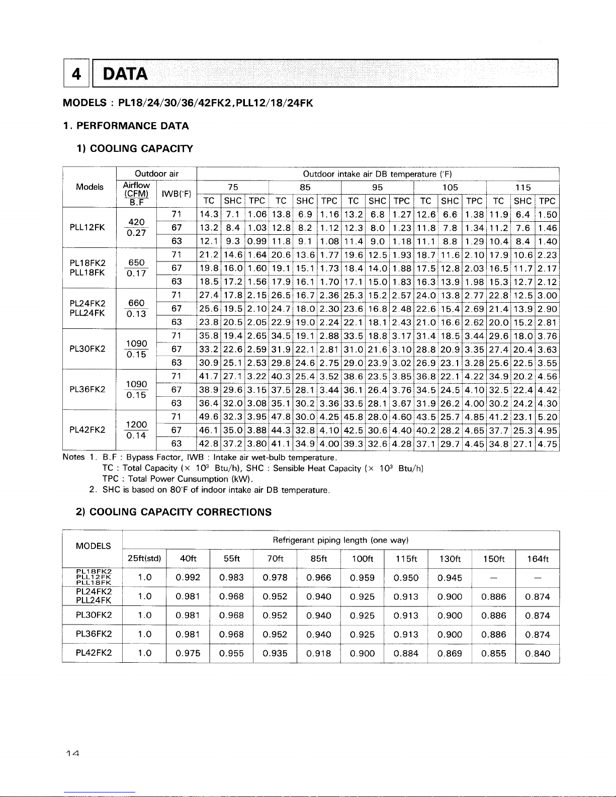
PL18/24/30/36/42FK2,PLL12/18/24FK
1.
PERFORMANCE DATA
1)
COOLING CAPACITY
1
Models
PLLI 2FK
DATA
PL18FK2
PLLI 8FK
-
Outdoor air
I
Outdoor mtake air DB temperature (OF)
1
75 8 5 95 105 115
TC
I
SHC / TPC I TC
SHC
/
TPC I TC I SHC I TPC / TC 1 SHC 1 TPC 1 TC 1 SHC I TPC
Notes 1. B.F
:
Bypass Factor, IWB : Intake air wet-bulb temperature.
TC
:
Total Capacity ( x
1 O3 Btu/h), SHC : Sensible Heat Capacity
(
x
1 O3 Btu/h)
TPC
:
Total Power Cunsumption (kW).
2. SHC is based on 80°F of indoor intake air DB temperature.
2)
COOLING CAPACITY CORRECTIONS
MODELS
PL18FK2
PLL12FK
PLL18FK
PL24FK2
PLL24FK
Refrigerant piping length (one way)
25ft(std)
1 .o
,0
40ft
0.992
0.981
5 5ft
0.983
0.968
7 Oft
0.978
0.952
8 5ft
0.966
0.940
1OOft
0.959
0.925
11 5ft
0.950
0.913
130ft
0.945
0.900
150ft
-
0.886
164ft
-
0.874
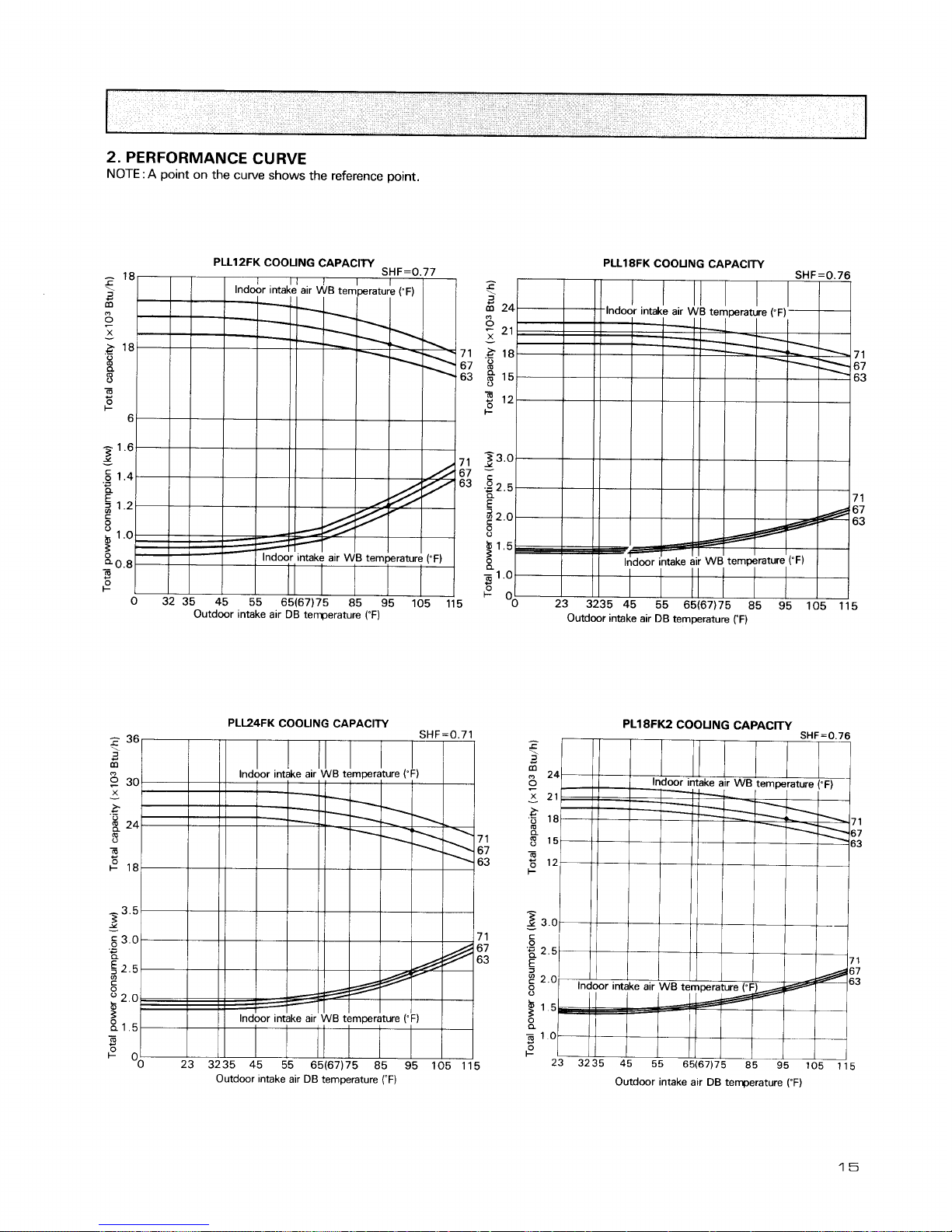
2.
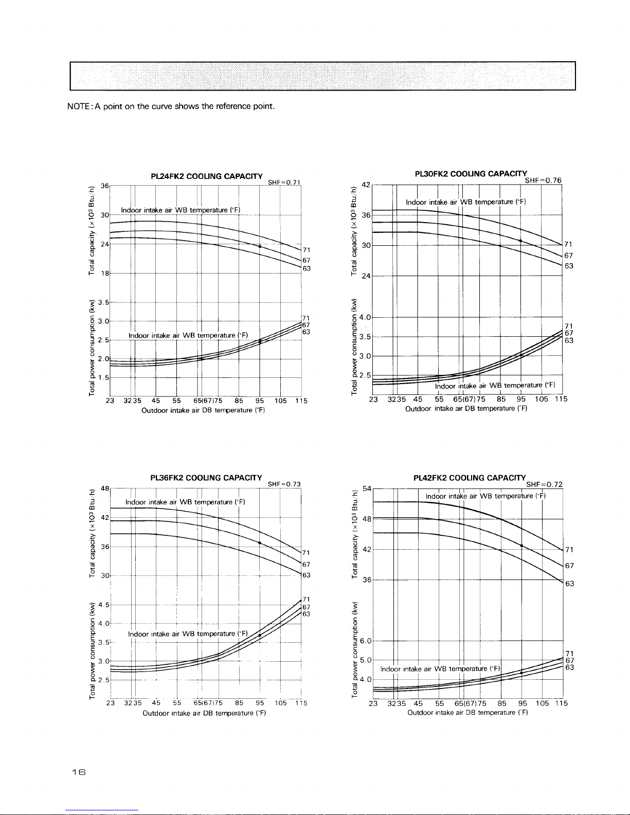
PERFORMANCE CURVE
NOTE
:
A
point on the curve shows the reference point.
PLL18FK COOUNG CAPACITY
Outdoor intake air
DB
temperature
('F)
PL18FK2
COOUNG
CAPACITY
Outdwr intake air
Dl3
temperature
rF)
Outdoor intake air
DB
terrperature
(OF)
NOTE
:
A
point on the curve shows the reference point.
Outdoor intake air DB temperature
(OF)
Outdoor intake alr
DB
temperature
("F)
?
lndoor
, ,
&take air WB temperature
(;FW
Outdoor ~ntake air DB temperature
(-F)
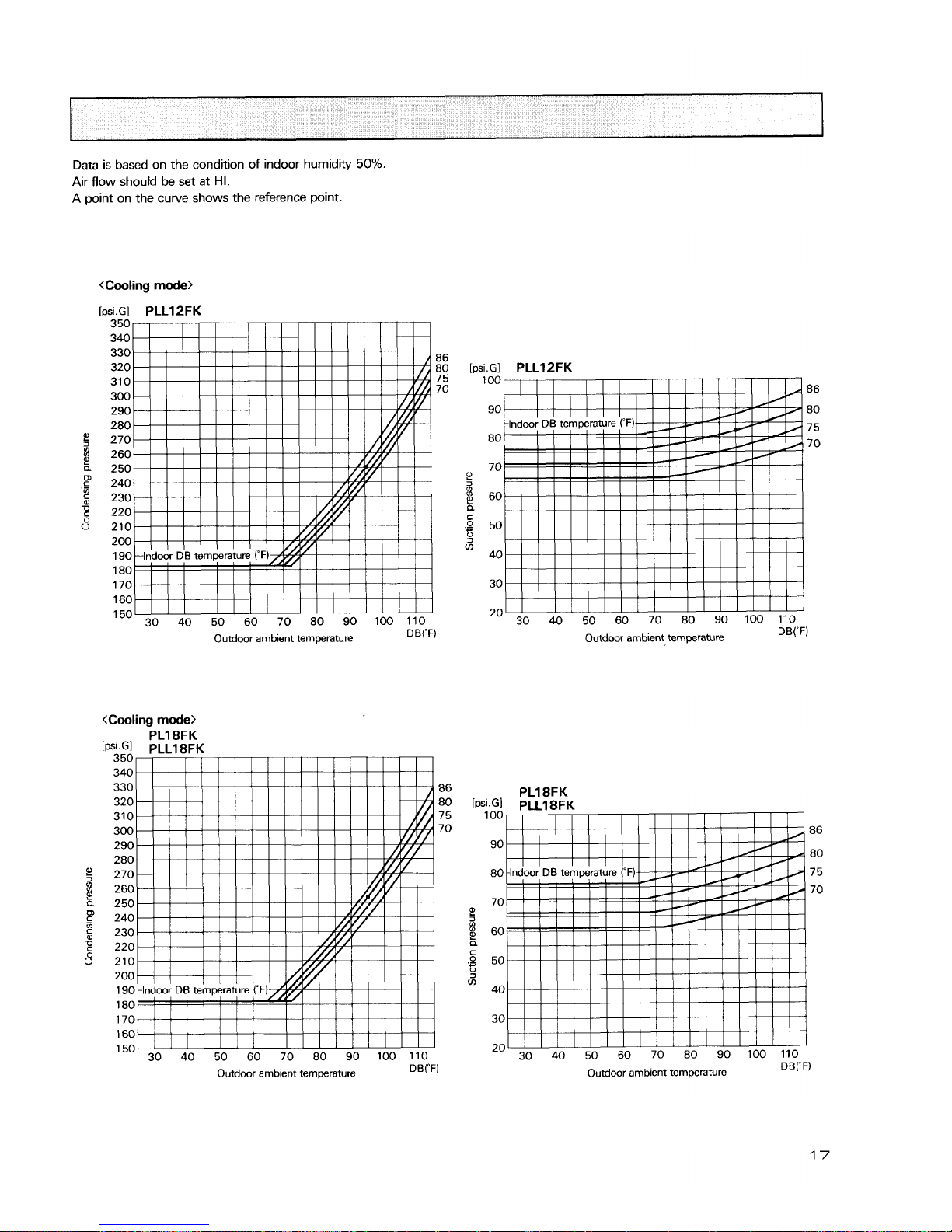
Data is based on the condition of indoor humidity
50%.
Air flow should be set at
HI.
A point on the curve shows the reference point.
<Cooling
mode>
[psiGI
PLLl 2FK
350
340
330
86
320 80
310 7 5
300
70
290
280
270
260
250
240
230
220
210
200
190
180
170
1
60
150 30 40 50 60 70 80 90 100 110
Outdoor ambient temperature
DB("F)
.
--
-~~
350
340
330 86
320 80
310 7 5
300 70
290
280
270
260
250
240
230
220
210
200
190
180
170
1
60
150
30 40 50 60 70 80 90 100 110
Outdoor ambient temperature
DB("F)
[psi.GI
PLLl2FK
100
86
90 80
7 5
80
70
70
e!
$
60
a
c
.g
50
0
V)
40
30
20
30 40 50 60 70 80 90 100 110
Outdoor ambient temperature DB("F)
PL18FK
[t~si.G]
PLL18FK
100
86
90
80
80 7 5
70
70
e!
$
60
a
.:
50
3
V)
40
30
20
30 40 50 60 70 80 90 100 110
Outdoor ambient temperature DB("F)
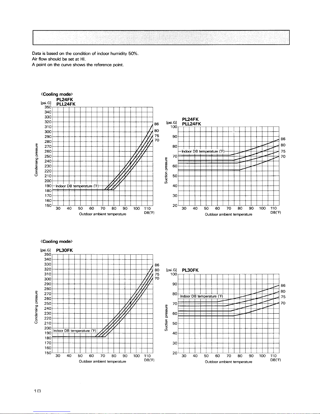
Data is based on the condition of indoor humidity
50%.
Air flow should be set at
HI.
A point on the curve shows the reference point.
35U
340
330
320
310
86
300 80
290 7 5
280
70
270
260
250
240
230
220
210
200
190
180
170
160
150 30 40 50 60 70 80 90 100 110
Outdoor ambient temperature
DB("F)
.
--
-
350
340
330 86
320 80
310 75
300 70
290
280
270
260
250
240
230
220
210
200
190
180
170
160
150
30 40 50 60 70 80 90 100 110
Outdoor ambient temperature
DB("F)
PL24FK
86
80
7 5
70
30 40 50 60 70 80 90 100 110
Outdoor ambient temperature
DB("F)
Outdoor amb~ent temperature
DBrF)
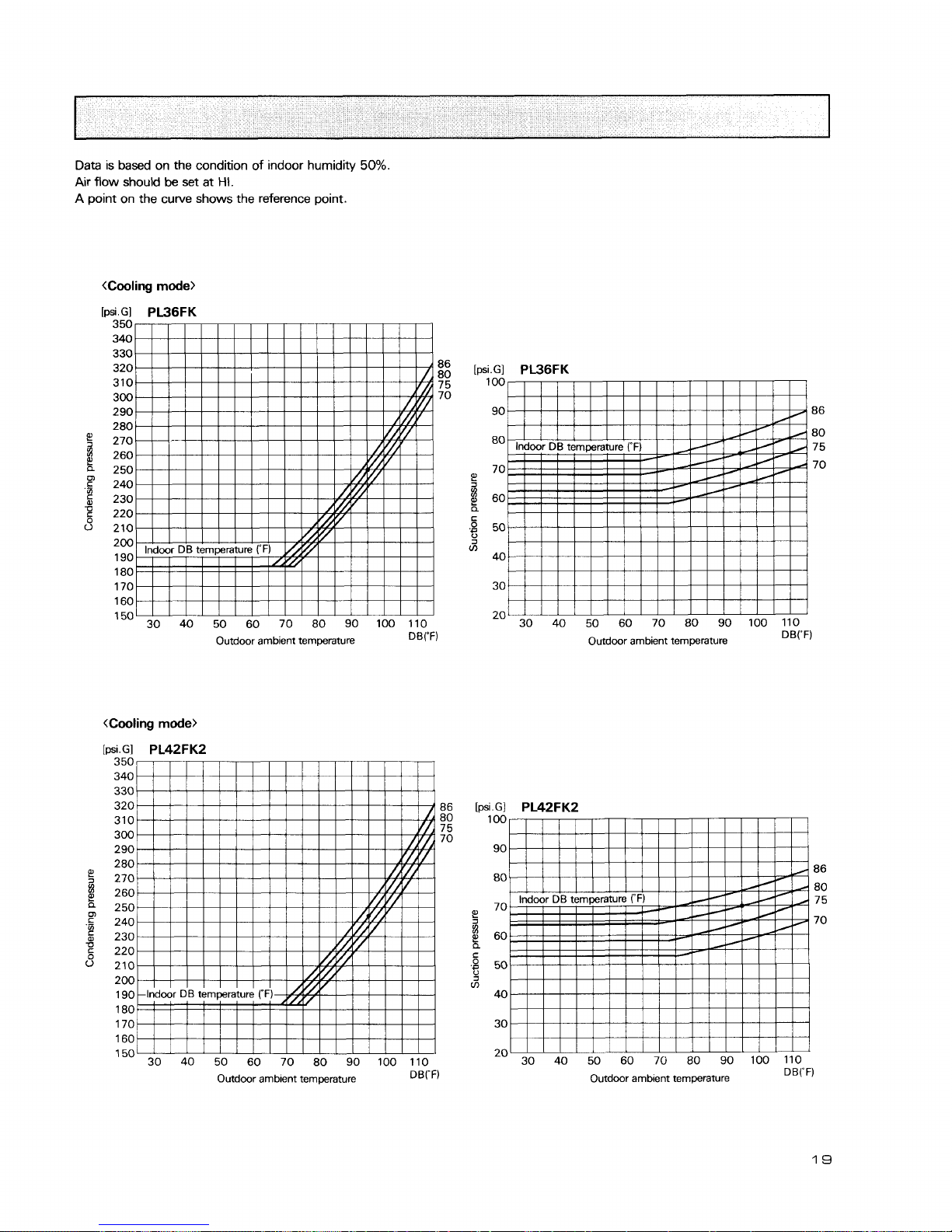
Data is based on the condition of indoor humidity
50%.
Air
flow should
be
set at
HI.
A
point on the curve shows the reference point.
[psi.Gl
PL36FK
350
340
330
320 86
310
80
7 5
300 70
290
280
270
260
250
m
c
240
'Si
230
g
220
0
210
200
190
180
170
160
150 30 40 50 60 70 80 90 100 110
Outdoor ambient temperature
DB("F)
Outdoor ambient temperature
DBrF)
[psi.GI
PL36FK
100
90 86
80
80
7 5
70
70
E'
g
60
a
C
.$
50
J
m
40
30
20
30 40 50 60 70 80 90 100 110
Outdoor ambient temperature
DB("F)
30 40 50 60 70 80 90 100 110
Outdoor ambient temperature
DB("F)
19
3.
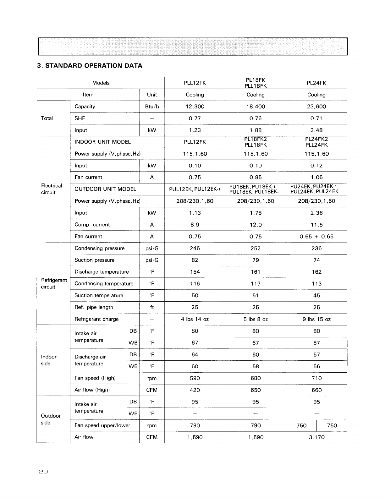
STANDARD OPERATION DATA
1
Unit
1
Cooling
Cooling
Cooling
1
Capacity
1
Btu/h
1
12,300
I
18,400
I
23,600
1
Total
1
SHF
1-1
0.77
I
0.76
I
0.71
I
1
lnput
I
kw
/
1.23
1
1.88
I
2.48
1
/
Power supply (V,phase,Hz)
1
115,1,60
1
115,1,60
1
115,1,60
1
I
INDOOR UNIT MODEL
I
Fan current
Electrical
circuit
PLLI 2FK
I
Power supply (V,phase, Hz)
1
208/230,1 ,60
1
208/230,1 ,60 208/230,1,60
/
PL18FK2
PLLI 8FK
I
OUTDOOR UNIT MODEL
PL24FK2
PLL24FK
I
Condensing pressure psisG
I
PUL1
2EKr
PUL1
2EK-1
Comp. current
Fan current
1
Suction pressure
1
Discharge temperature "F
I
1
A
A
PU24EK, PU24EK-i
PUY4EK, PUU4EK.i
1
Suction temperature
1
"F
I
50
1
5 1
1
45
1
8.9
0.75
Refrigerant
circuit
Ref. pipe length
f?
25
Refrigerant charge
-
4 Ibs 14 oz
5 Ibs 8 oz
12.0
0.75
Condensing temperature
Intake air
temperature
11.5
0.65
+
0.65
Indoor Discharge air
side temperature
"
F
Fan speed (High)
Air flow (High)
1
Intake air
1 16
temperature
Outdoor
1
I
Fan speed upper/lower
1
rprn
I
1 17
1
Air flow
1 13
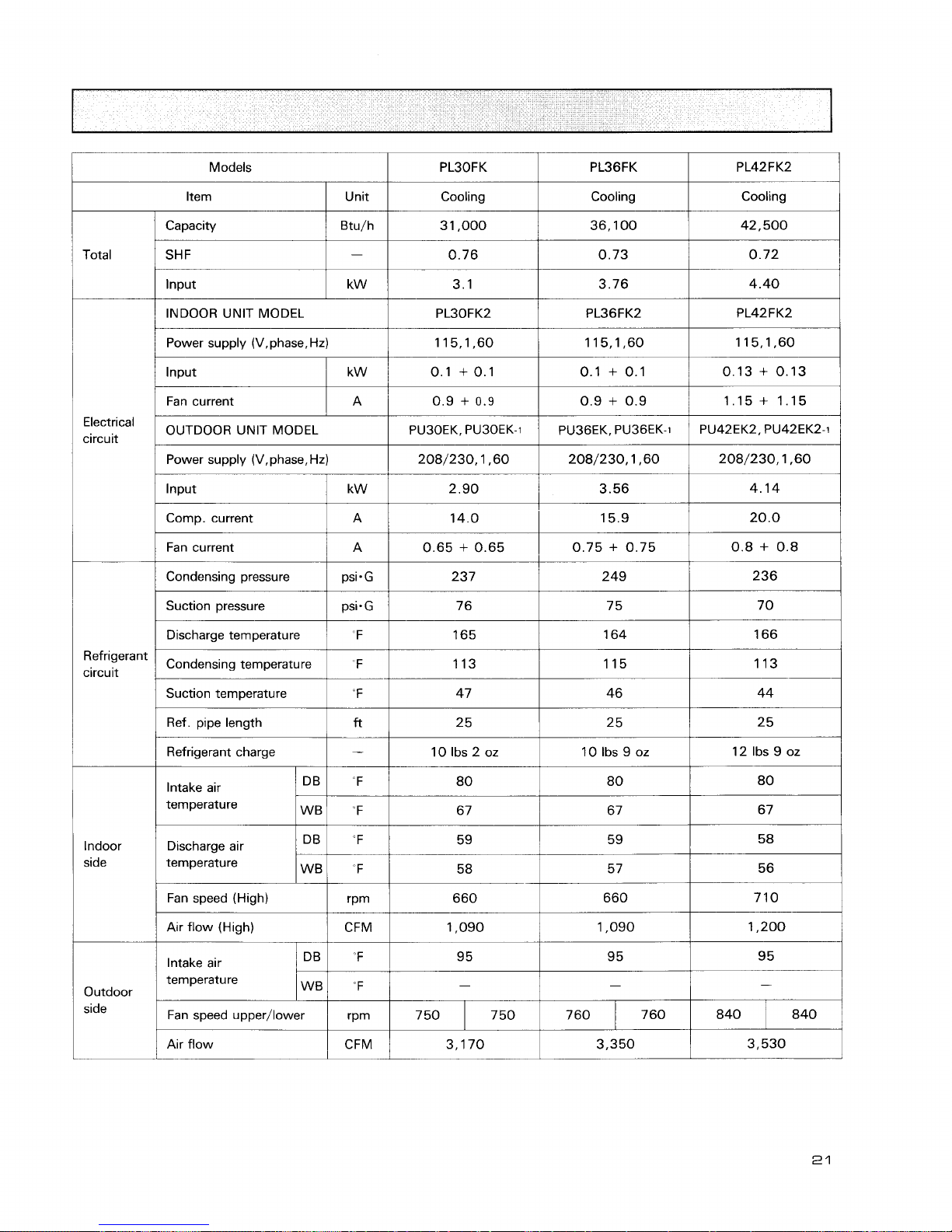
Models
kern
I
unit
I
Cooling
1
Cooling
I
Cooling
1
Capacity
/
Btu/h
I
3 1,000
1
36,100
1
42,500
I
Total
SHF
lnput
INDOOR UNIT MODEL
I
PL30FK2
1
Power supply (V,phase. Hz)
lnput
Fan current
Electrical
circuit
OUTDOOR
UNlT MODEL
camp.
current
I
A
I
14.0
i
15.9
I
20.0
I
Refrigerant
circuit
Power supply
(V,phase,Hz)
208/230,1,60
2.90
Input
Suction pressure
kW
Fan current
Condensing pressure
Dischargetemperature
1
I
208/230,1,60
3.56
Condensing temperature F
I
208/230,1,60
4.14
A
psi.
G
Suction temperature
Ref. pipe length
0.65 + 0.65
237
Refrigerant charge
0.75 + 0.75
249
Discharge air
temperature
0.8 + 0.8
236
Indoor
side
Intake air
temperature
Fan speed (High)
"F
"F
DB
WB
temperature
IWBI
"F
I
-
I
-
I
-
I
80
67
Outdoor
side
Air flow (High)
80
67
CFM
'F
Intake air
80
67
DB
I
Fan speed upper/lower
Air flow
1,090
95
rPm
CFM
1,090
95
1,200
9 5
7 50 750
760
3,170
840 7 60 840
3,350
3,530
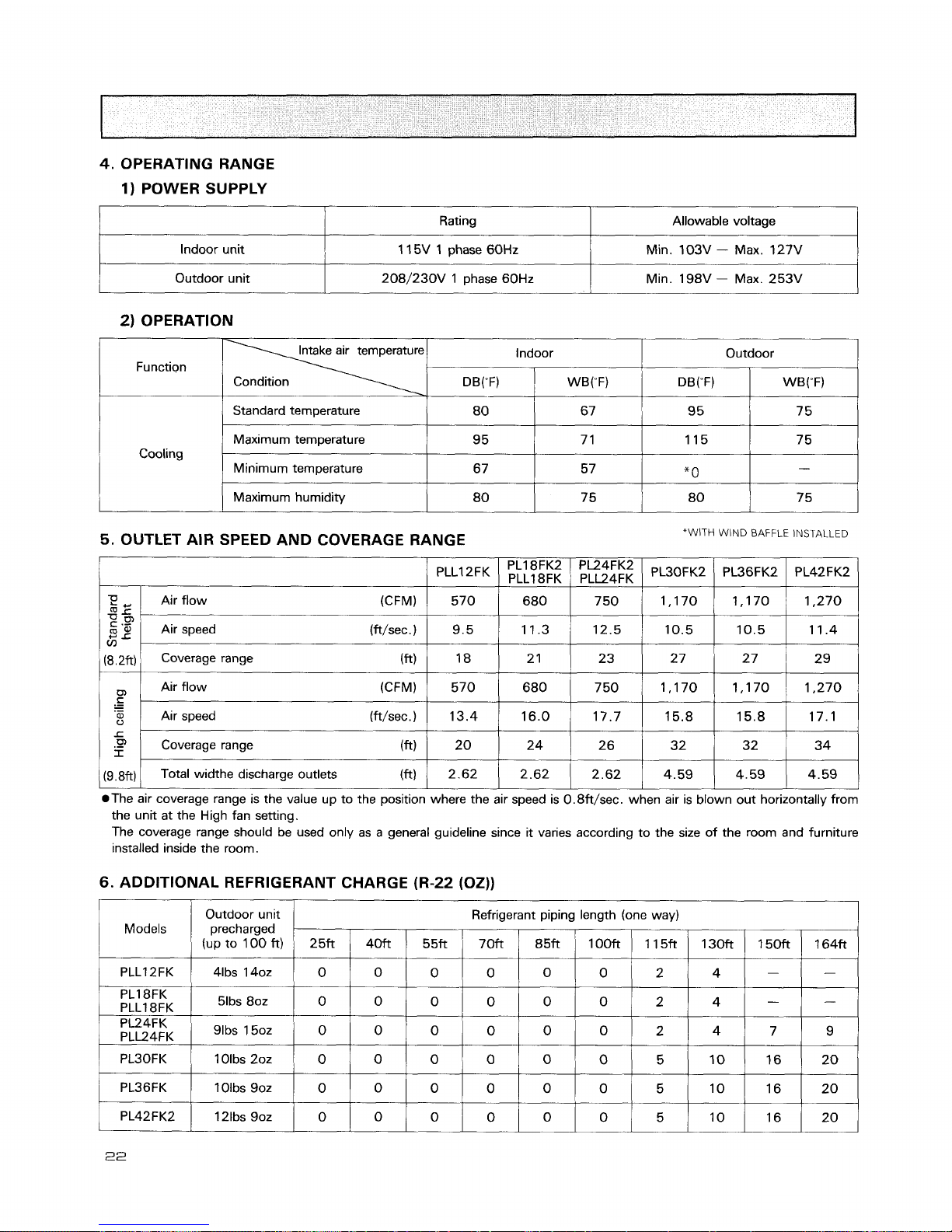
4.
OPERATING RANGE
1) POWER SUPPLY
1
Rating
Allowable voltage
2) OPERATION
Indoor unit
Outdoor unit
I
Standard temperature
1 15V 1 phase 60Hz
208/230V 1 phase 60Hz
Intake air temperature
Function
Condition
Min. 103V
-
Max. 127V
Min. 198V - Max. 253V
1
Maximum humidity
Indoor
DB(W
1
WB("F)
Cooling
5.
OUTLET AIR SPEED AND COVERAGE RANGE
*WITH
WIND
BAFFLE
INSTALLED
Outdoor
Maximum temperature
Minimum temperature
DB("F)
PLLI 2FK
@The air coverage range is the value up to the position where the air speed is 0.8ft/sec. when air is blown out horizontally from
the unit at the High fan setting.
The coverage range should be used only as a general guideline since it varies according to the size of the room and furniture
installed inside the room.
WB("F)
9 5
67
T!
dr'
c
.G'
V)
(8.2ft)
C
.-
-
.-
L
.P
I
(9.8ft)
6.
ADDITIONAL REFRIGERANT CHARGE (R-22 (OZ))
I
I
1
I
I I
I
7 1
57
PLl8FK2
PLLl
8FK
Air flow (CFM)
Air speed (ft/sec.)
Coverage range (ft)
Air flow (CFM)
Air speed (ft/sec.)
Coverage range
(
ft
Total widthe discharge outlets (ft)
PL36FK2
Models
PLLI 2FK
1 15
*
0
PL42FK2
PL24FK2
PLL24FK
570
9.5
18
570
13.4
20
2.62
PL18FK
PLLI 8FK
PL24FK
PLL24FK
7 5
-
PL30FK2
Outdoor unit
precharged
(up to 100 ft)
41bs 1402
PL30FK
PL36FK
680
11.3
2
1
680
16.0
24
2.62
51bs 80z
'Ibs
50z
Refrigerant piping length (one way)
1 Olbs 202
1 Olbs 902
7 50
12.5
23
7 50
17.7
2 6
2.62
2513
0
0
0
0
0
1,170
10.5
27
1,170
15.8
32
4.59
4Mt
0
0
0
0
0
1,170
10.5
2 7
1,170
15.8
32
4.59
55ft
0
0
0
1,270
11.4
2
9
1,270
17.1
34
4.59
0
0
70ft
0
0
0
0
0
85ft
0
0
0
0
0
100ft
0
0
0
0
0
2
2
115ft
2
5
5
150ft
-
130ft
4
I
4
4
164ft
-
10
10
-
7
-
9
16
16
20
2 0
M 0 D
E
LS : PC24/30/36/42 E
K,
PCK4E
K
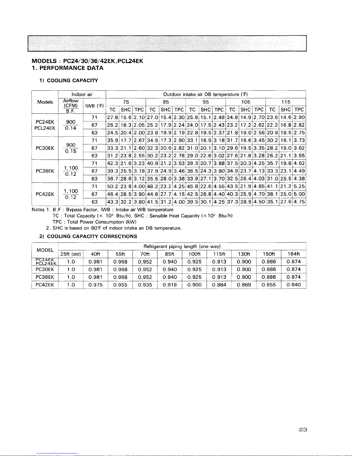
1.
PERFORMANCE DATA
1)
COOLING CAPACITY
2)
COOLING CAPACITY CORRECTIONS
PC42EK
Notes 1.
6.F : Bypass Factor, IWB : Intake air WB temperature
TC
:
Total Capacity
(x
lo3
Btu/h), SHC : Sensible Heat Capacity
(x
lo3
Btu/h)
TPC
:
Total Power Consumption
(kW)
2. SHC is based on 80°F of indoor intake air
DB
temperature.
A
loo
0.12
1
MODEL
Refrigerant piping length (one way)
25ft(std)I 40ft
I
55ft
I
70ft
I
85ft
I
10013
I
115ft
I
130ft
/
150ft
I
164ft
67
63
46.4
43.3
28.5
32.2
3.90
3.80
44.6
41.5
27.7
31.2
4.15
4.00
42.5
39.5
26.8
30.1
4.40
4.25
40.3
37.3
25.9
28.9
4.70
4.50
38.1
35.1
25.0
27.6
5.00
4.75
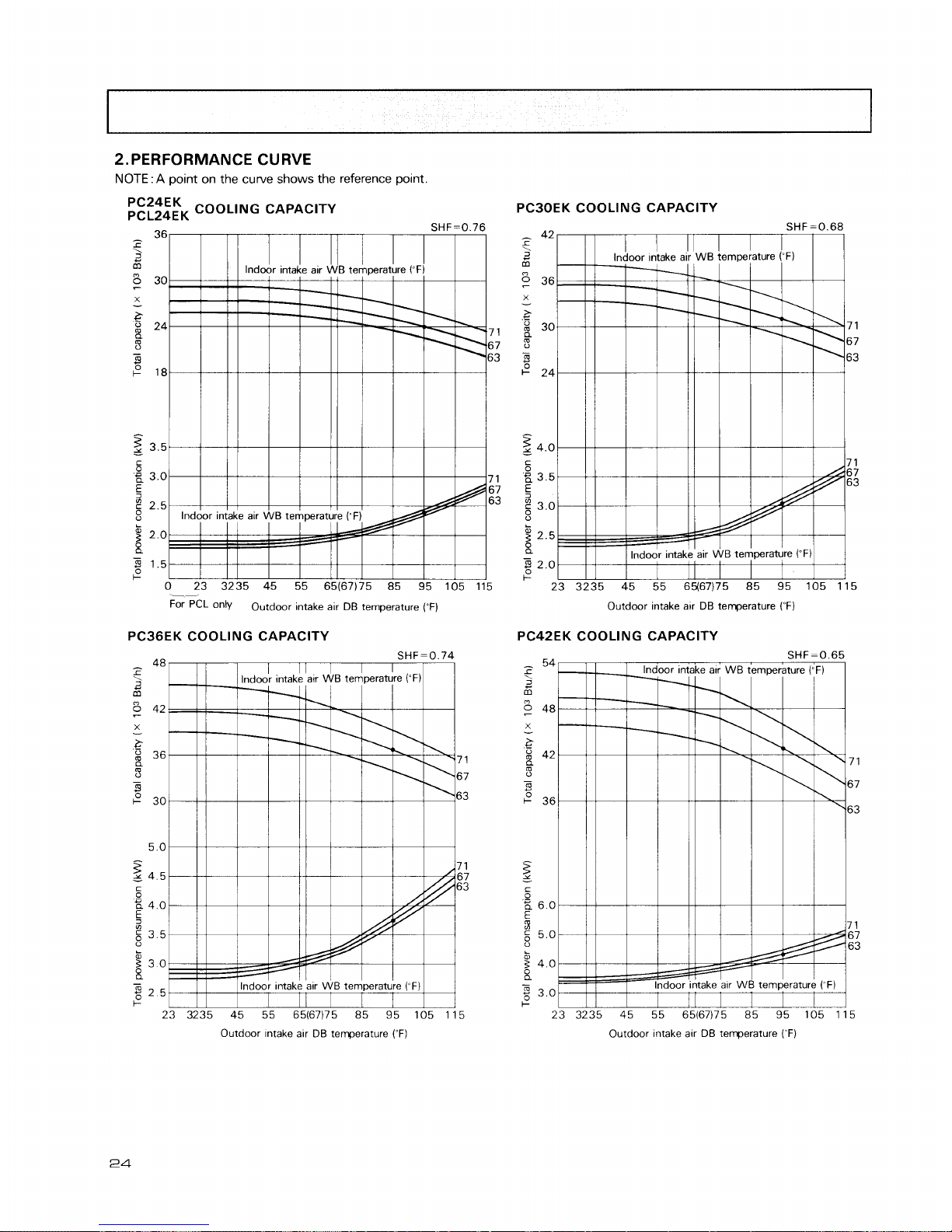
2.
PERFORMANCE CURVE
NOTE
: A point on the curve shows the reference point.
FE;;EFK
COOLING CAPACITY
36
SHF=0.76
-
r
\
6
5
30
X
-
g
24
7 1
-
67
8
63
+
18
z
3.5
-
5
P,
3.0 7 1
5
67
g
2.5
63
0
g
2.0
X
-
3
1.5
+
0 23 3235 45 55 65(67)75 85 95 105 115
--,
For
PCL
only
Outdoor intake air DB temperature
(-F)
PC36EK COOLING CAPACITY
Outdoor intake alr DB temperature
(OF)
PC42EK COOLING CAPACITY
?
atr
WB
tempe
1
\
3ke alr
WB
tern
n
i7)75 85
'
SHF=(
rature
("
F
\,
.
1
.
/
/
43
95 105
Outdoor Intake alr DB temperature
(OF)
Outdoor Intake alr
DB
temperature
(~F)
Data is based on the condition of indoor humidity
50%
Air flow should be set at HI.
A
point on the curve shows the reference point.
<Cooling
mode>
PC24EK
[PS~.GI
pCL24EK
350
340
330
320 86
310 80
300 75
290
70
280
5
270
8
260
a
250
0,
240
5
230
u
5
220
0
210
200
190
180
170
160
150 30 40 50 60 70 80 90 100 110
Outdoor amb~ent temperature
DBrF)
Outdoor ambient temperature
DB("F)
[psi.Gl
PC30EK
350
340
330 86
320 80
310 7 5
300 70
290
280
$
270
8
260
a
250
0,
.
240
230
g
220
0
210
200
190
180
Outdoor ambient temperature
DBrF)
170
160
-
150-
30 40 50 60 70 80 90 100 110
Outdoor ambient temperature
DB('F)
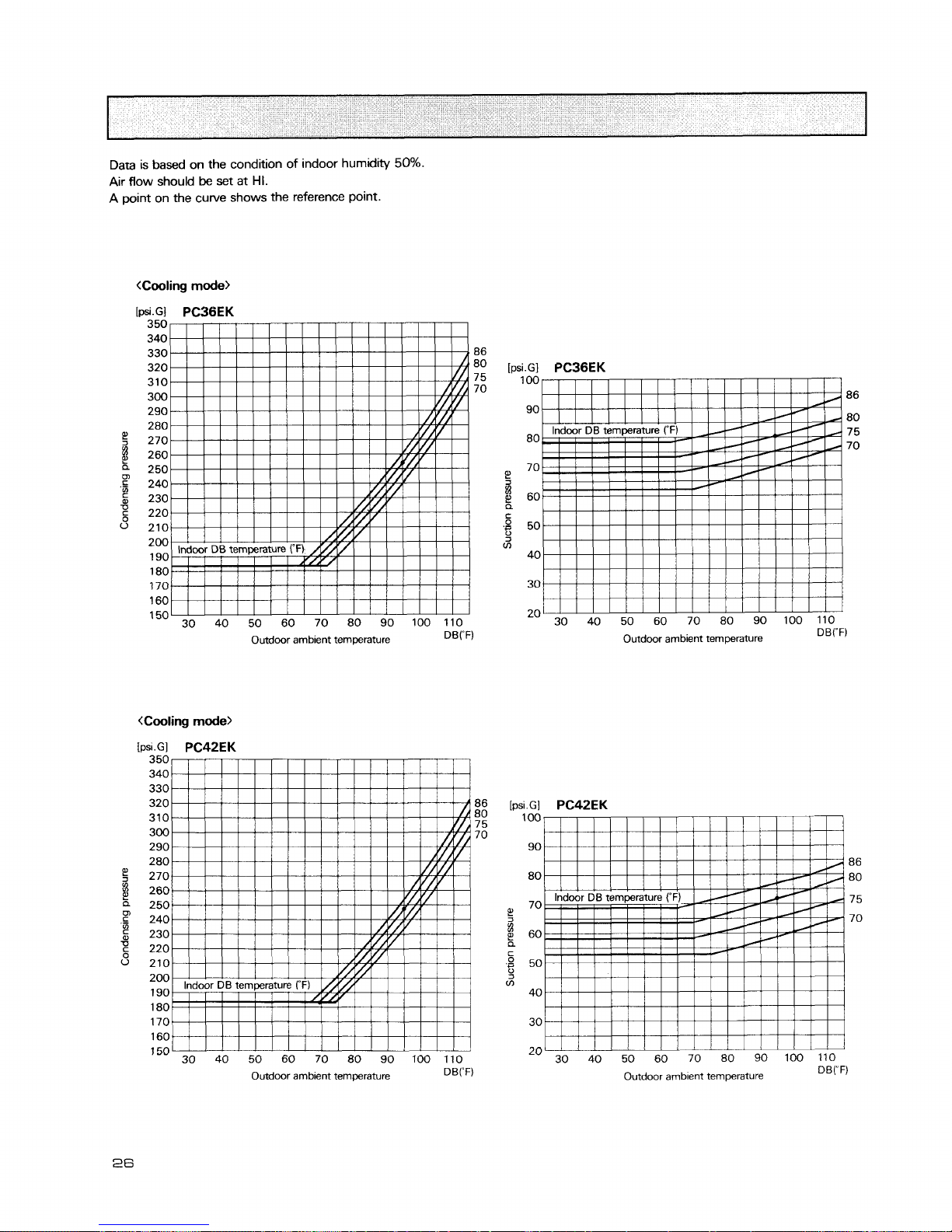
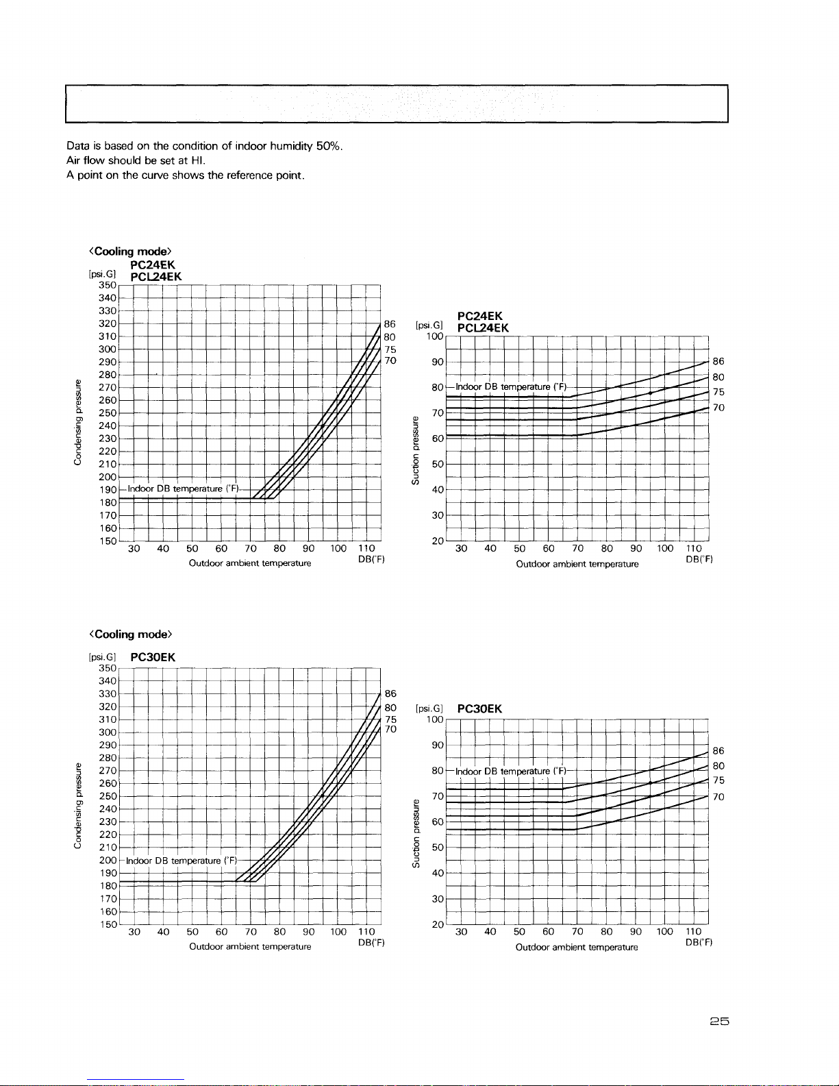
Data
is based on the condition of indoor humidity 50%.
Air flow should
be
set at
HI.
A
point on the curve shows the reference point.
<Cooling
mode>
[psi.Gl
PCBBEK
350
340
330 86
320
80
310
7 5
300
70
290
280
270
260
250
240
230
220
210
200
190
180
170
1 60
1
50
30 40 50 60 70 80 90 100 110
Outdoor ambient temperature
DB('F)
Outdoor ambient temperature
DB('F)
350
340
330
320
86
[psi.Gl
PC42EK
310
Em
100
7
5
300 70
290 90
280 86
270 80 80
260
250 70
7 5
240
2
70
230
8
60
220
a
C
210
.B
50
200
3
m
190 40
180
170 30
160
1
50
30 40 50 60 70 80 90 100110
20
30 40 50 60 70 80 90 100 110
Outdoor ambient temperature
D8('F)
Outdoor ambient temperature
DB('F)
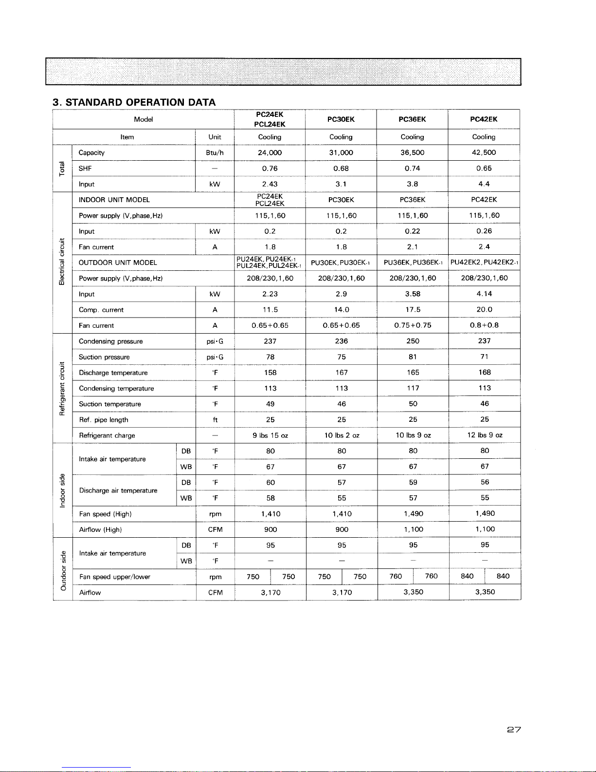
3.
STANDARD OPERATION DATA
Model
Item
/
Unit
1
Cooling
I
Cooling
I
Cooling
I
Cooling
I
lnput
Capacity
SHF
Power supply (V.phase.Hd
/
115.1.60
1
115.1.60
1
115,1,60
1
115,1*60
1
Btu/h
-
I I
1
I
I
Input
I
kw
1
0.2
I
0.2
1
0.22
1
0.26
1
INDOOR UNlT MODEL
Fan current
/
A
/
1.8
I
1.8
1
2.1
I
2.4
1
24,000
0.76
PC24EK
PCL24EK
Power supply (V,phase,Hz)
1
208/230,1,60
1
208/230,1,60
1
208/230,1,60
1
208/230,1,60
1
31.000
0.68
I I I
I
I
Input
/
kW
1
2.23
1
2.9
1
3.58
1
4.14
1
PC3OEK
Comp. current
I
A
1
11.5
/
14.0
1
17.5
1
20.0
/
36,500
0.74
PU42EK2, PU42EK2-1
OUTDOOR UNlT MODEL
Fan current
I
A
1
0.65+0.65
1
0.65+0.65
/
0.75+0.75
1
0.8+0.8
1
42,500
0.65
PC36EK
Condensing pressure
1
psi.G
1
237
I
236
1
250
I
237
1
PC42EK
PU24EK. PU24EK-1
PU~~EK,PU~~~K-~
Condensing temperature 113
/
113
1
117
1
113
/
PU30EK. PU30EK-1
Suction pressure
Discharge temperature
Suction temperature
1
"F
I
49
1
46
I
50
I
46
I
PU36EK, PU36EK-I
Ref. pipe length
/ftl
2 5
1
25
1
25
1
25
I
psi.G
'F
Refrigerant charge
I
-
1
9Ibs15oz
/
10Ibs2oz
1
10Ibs9oz
/
12Ibs9oz
I
Intake air temperature
78
158
Fan speed (High)
/
rpm
1
1,410
1
1,410
1
1,490
1
1,490
1
75
167
Discharge air temperature
Airflow (High)
I
CFM
/
900
I
900
1
1,100
1
1,100
1
8 1
165
I
I
I
I
I
Airflow
~CFM/
3,170
1
3,170
1
3.350
1
3.350
/
7 1
168
WB
Intake air temperature
DB
W8
"F
Fan speed upper/lower
57
OF
"F
55
58
rPm
55
95
-
95
-
750
7 50
95
-
7 50
95
-
7 50
760
840
760
840
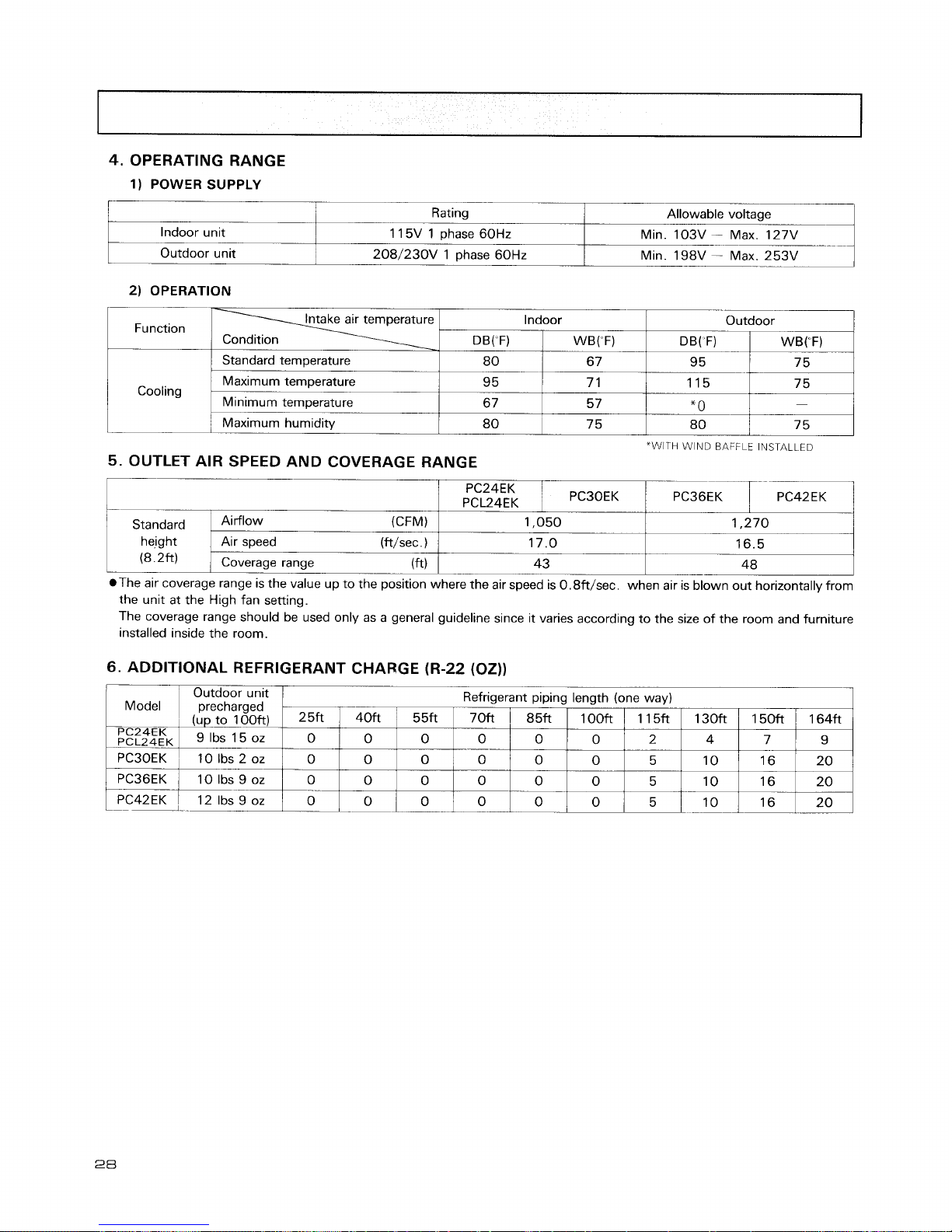
4.
OPERATING RANGE
1)
POWER SUPPLY
Indoor unlt
Outdoor unit
2)
OPERATION
The coverage range should be used only as a general guideline since it varies according to the size of the room and furniture
installed inside the room.
Rating
1 15V 1 phase 60Hz
208/230V 1 phase 60Hz
Function
Cooling
Standard
hejght
(8.2ft)
6.
ADDITIONAL REFRIGERANT CHARGE (R-22 (02))
Allowable voltage
Mm. 10%
-
Max 127V
Mm. 198V
ax.
253V
"WITH WIND
BAFFLE
INSTALLED
5.
OUTLET AIR SPEED AND COVERAGE RANGE
The air coverage range is the value up to the position where the air speed is 0.8ft/sec. when air is blown out horizontally from
the unit at the High fan setting.
(CFM)
Air speed (ft/sec
.
)
Coverage range
(
ft
Indoor
Outdoor unlt
Refrigerant plplng length (one way)
Model precharged
Outdoor
1,050
17.0
43
WB("F)
6 7
7 1
5 7
75
DB( F)
-
95
DB("F)
1,270
16.5
-
48
25ft
PC24EK
PCL24EK
Ibs
OZ
PC30EK 10 Ibs 2 oz
WB("F)
-
75
Standard temperature
Maximum temperature
Minimum temperature
Maximum humidity
40ft
0
0
0
0
PC36EK
PC42EK
1
80
9 5
6
7
80
115
*
0
--
80
55ft
0
0
0
0
10 Ibs
9
oz
-
12 Ibs 9 oz
75
-
7 5
0
--
L--
-1
70ft
0
0
0
0
0
85ft
0
0
0
0
1OOft
0
0
0
0
1 l5ft
2
5
5
5
130ft
4
10
10
--
10
150ft
7
16
16
--
16
164ft
9
20
20
2 0
 Loading...