

SERVICE
&
PARTS
MANUAL
1
Series PL] Ceiling Cassettes
~0d-l~
PL18FK2/PU18EK, PU1 8EK-I
PL24FK2/PU24EK, PU24EK-I
PL30FK2/PU30EK, PU30EK-I
PL36FK2/PU36EK,PU36EK-i
PL42FK21PU42EK2, PU42EK2-I
-1
Ceiling Cassettes
PLL12FK/PUL12EKJPUL1 2EK-I
PLLl8FK/PUL18EK, PULl 8EK-I
PLL24FK/PUL24EK, PUL24EK-I
Ceiling Suspended
I
Series PC
L
1
Ceiling Suspended
WKI
Wall
Mounted
PKI 8EK/PU18EK,PUI 8EK-I
PK24EK/PU24EK,PU24EK-l
PK30EK/PU30EK, PU30EK-I
Wall
Mounted
PKLI 2EK/PUL12EK, PULl 2EK-I
PKLI 8EK/PUL18EK, PULl 8EK-I
PKL24EK/PUL24EK, PUL24EK-I
@
The
Slim Line.
fof
PU18EK
I
and
PUL18EK-I
CONTENTS
REFRIGERANT SYSTEM DIAGRAM
..........................................
47
DWlRlNG DIAGRAM
..............................................................
48
QPERATION FLOW-CHART
.................................................
...
57
MICROPROCESSOR
CONTROL
...............................................
60
TROUBLE SHOOTING
..........................................................
72
SYSTEM CONTROL
.............................................................
81
MTIMER OPERATION WITH OPTIONAL PARTS
..............................
86
m4-WAY AIR FLOW SYSTEM (PL/PLL
series)
................................
88
/@
DISASSEMBLY PROCEDURE
..................................................
95
OPTIONAL PARTS
..............................................................
109
STANDARD PARTS
............................................................
110
CHANGE
POINTS
1. Outdoor controller board changed to the same type as that of heat pump unit.
2. With the change of outdoor controller board, transformer changed.
3.
Contactor changed from VC-2OF to S-U12. (for PU18EK-1 and PUL18EK-1)
4.
Model name of "PLL" has changed to "PL", specifications are identical.
5.
Model name of "PCL" has changed to "PC", specifications are identical.
6.
Model name of "PKL" has changed to "PK", specifications are identical.
FEATURES
1
Series
pLI
Ceiling Cassettes
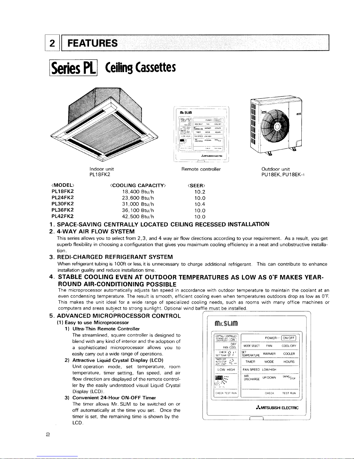
Indoor unit
PL18FK2
Remote controller Outdoor unit
PU 1 BEK, PU18EK-1
(MODEL) (COOLING CAPACITY) (SEER)
PL18FK2
18,400
Btu/h
10.2
PL24FK2
23,600
Btu/h
10.0
PL30FK2
31,000
Btu/h
10.4
PL36FK2
36,100
Btu/h
10.0
P L42 F K2
42,500
Btu/h
10.0
1.
SPACE-SAVING CENTRALLY LOCATED CEILING RECESSED INSTALLATION
2.
4-WAY AIR FLOW SYSTEM
This series allows you to select from
2,3,
and 4 way air flow directions according to your requirement. As a result, you get
superb flexibility in choosing a configuration that gives you maximum cooling efficiency in a neat and unobstructive installation.
3.
REDI-CHARGED REFRIGERANT SYSTEM
When refrigerant tubing is
1OOft
or less, it is unnecessary to charge additional refrigerant.
This can contribute to enhance
installation guality and reduce installation time.
4.
STABLE COOLING EVEN AT OUTDOOR TEMPERATURES AS LOW AS
0°F
MAKES YEAR-
ROUND AIR-CONDITIONING POSSIBLE
The microprocessor automatically adjusts fan speed in accordance with outdoor temperature to maintain the coolant at an
even condensing temperature. The result is smooth, efficient cooling even when temperatures outdoors drop as low as
0°F.
This makes the unit ideal for a wide range of specialized cooli
computers and areas subject to strong sunlight. Optional wind baf
5.
ADVANCED
MICROPROCESSOR
CONTROL
(1)
Easy to use Microprocessor
1) Ultra-Thin Remote Controller
The streamlined, square controller is designed to
blend with any kind of interior and the adopt~on of
a sophisticated microprocessor allows you to
easily carry out a wide range of operations.
2)
Attractive Liquid Crystal Display (LCD)
Unit operation mode, set temperature, room
temperature, timer setting, fan speed, and air
flow direction are displayed of the remote controller by the easily understood visual Liquid Crystal
Display (LCD).
3) Convenient 24-Hour ON-OFF Timer
The timer allows Mr. SLIM to be switched on or
off automatically at the time you set. Once the
timer is set, the remaining time is shown by the
LCD.
8
needs, such as rooms with many office machines
or
must be installed.
POWER-
(ON/OFF)
MODE
SELECT
FAN
COOLiDRY
SET
TEMPERATURE
WARMER
TIMER MODE HOURS
1
LOW HIGH
/
I
FAN
SPEED LOW!HIGH
1
AIR
UPIDOWN
STOP
1
TEST
WN
I
r--
CHECK
TEST
RUN
4) Self-Diagnostic Feature Indicates Faults Instantly
In the rare case when a problem occurs, the unit stops operating and the set temperature indicator changes to the
self-diagnostic indicator, indicating the location of the fault.
If the check switch is pressed twice, the unit stops operating and the check mode is initiated. The cause of the most
recent problem stored in the memory is displayed on the LCD. This is extremely useful for maintenance purposes.
5)
Useful Memory Feature for Storing Instructions
The previous set value is memorized so that constant temperature control can be obtained. This is convenient when,
for example, a power failure occurs.
(2)
Non-polar Two-Wire Remote Controller Cables
The non-polar, two-wire type remote controller cable is slim, installation is simple and troublefree. Remote controller wire
can be extended up to
550
yards.
6.
INNOVATIVE SYSTEM CONTROL BY MICROPROCESSORS
The most significant feature of the series PL is the advanced microprocessor system control. Behind the development of this
system is the recent world-wide trend in the air conditioning of larger buildings, away from centralized duct systems in favor
of a large number of individual split type units.
There are a number of reasons for this: first, costly troublesome duct
installation is eliminated: second, the overall air conditioning balance is excellent; and third, operation cost is low, since
flexible control of each unit is possible. This system control was developed exclusively by Mitsubishi in the light of this
demand. Microprocessor control makes possible individual control, group control, control using two remote controllers,
remote
on/off control and individual control without troublesome modifications to the equipment.
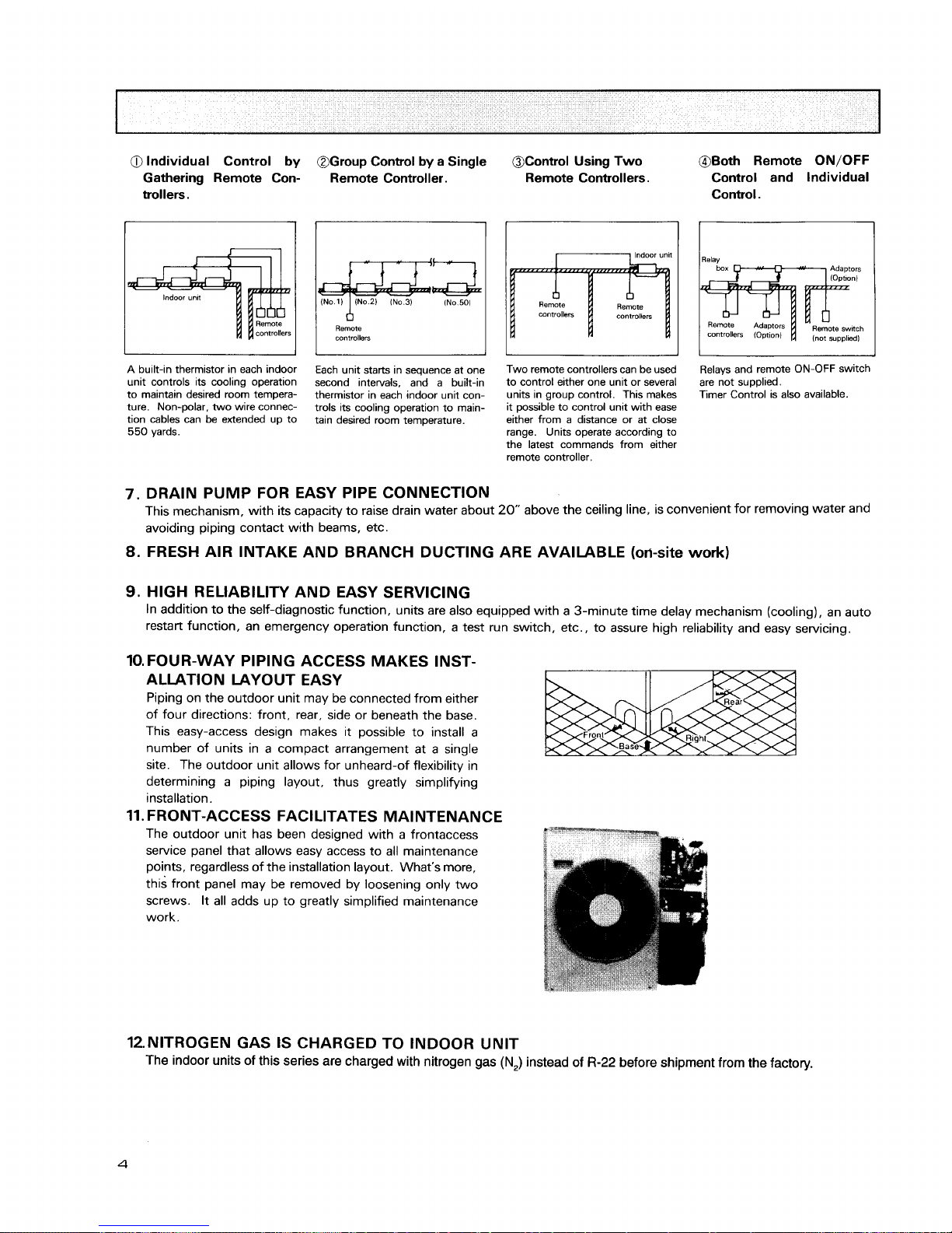
1)
Individual Control by Gathering Remote Controllers
A
Series PL unit is installed in each room, and the remote controllers are gathered together in a separate location, where
each unit is controlled individually.
Each remote controller is connected to its indoor unit by non-polar 2-wire cable to eliminate the possibility of miswiring.
Separation can be as much as
550
yards, making this type of control extremely easy to implement.
Thermistors in the indoor unit maintain each room at its own individually set temperature.
This control system is excellent for schools or kindergardens, where controls should be kept out of the reach of the pupils.
2)
Group Control by a Single Remote Controller
In an application requring a number of air conditioner units in a large area on a single floor, up to
50
Series PL units can
be centrally controlled using a single remote controller. The remote controller controls Power ON-OFF, set temperature,
fan speed, ON-OFF timer, and auto vane position of all units of the group. Obviously, if all the units started simultaneous-
ly, the surge current would be unacceptably high. Therefore the microprocessor board of each indoor unit has a 8-toggle
DIP switch that can be programmed to give sequential starting with up to
50
seconds delay. When the switch of the
remote controller is pressed, master unit comes on immediately, followed by the other units in the programmed order.
Thereafter the thermistor in each indoor unit controls compressor operation to keep the room at the set temperature.
The remote controller is connected to indoor units by non-polar 2-wire cable. Total cable length can be as much as
550
yards. This system can be applied to the air conditioning of large offices or conference rooms, supermarkets, etc.
3)
Control Using Two Remote Controllers
Two remote controllers can be used to control either one unit or several units in group control. This makes it possible
to control units with ease either from a distance or at close range. Units operate according to the last command from
either remote controller.
4) Both Remote
ON/OFF
Control and Individual Control
All units can be turned on and off simultaneously using the remote ON/OFF switch, and also individual units can be
controlled from the remote controllers.
This system is well suited to buildings having a large number of rooms. In offices, for example, all units can be started
together to cool the premises before workers arrive, operated as necessary by individual remote controllers during the day,
and stopped together at the end of business.
a
Individual Control
by
Gathering Remote Controllers.
@Group Control
by
a Single
Remote Controller.
I
(No
1)
1
(No
2)
IN0
3)
INo.50)
I
Remote
controllers
OControl Using Two
Remote Controllers.
I
11
Indoor
unlt
A
built-in thermistor in each indoor
unit controls its cooling operation
to maintain desired room temperature. Non-polar, two wire connection cables can be extended up to
550
yards.
Each unit starts in sequence at one
second intervals, and a built-in
thermistor in each indoor unit controls its cooling operation to maintain desired room temperature.
Two remote controllers can be used
to control either one unit or several
units in group control. This makes
it possible to control unit with ease
either from a distance or at close
range. Units operate according to
the latest commands from either
remote controller.
@Both Remote
ON/OFF
Control and Individual
Control.
I
Relays and remote ON-OFF switch
are not supplied.
Timer Control is also available.
7.
DRAIN PUMP FOR EASY PIPE CONNECTION
This mechanism, with its capacity to raise drain water about
20"
above the ceiling line, is convenient for removing water and
avoiding piping contact with beams, etc.
8.
FRESH AIR INTAKE AND BRANCH DUCTING ARE AVAILABLE
(oti-site
work)
9.
HIGH RELIABILITY AND EASY SERVICING
In addition to the self-diagnostic function, units are also equipped with a 3-minute time delay mechanism (cooling), an auto
restart function, an emergency operation function, a test run switch, etc., to assure high reliability and easy servicing.
10.
FOUR-WAY PIPING ACCESS MAKES INST-
ALLATION LAYOUT EASY
Piping on the outdoor unit may be connected from either
of four directions: front, rear, side or beneath the base.
This easy-access design makes it possible to install a
number of units in a compact arrangement at a single
site. The outdoor unit allows for unheard-of flexibility in
determining a piping layout, thus greatly simplifying
installation.
11.
FRONT-ACCESS FACILITATES MAINTENANCE
The outdoor unit has been designed with a frontaccess
service panel that allows easy access to all maintenance
points, regardless of the installation layout. What's more,
this front panel may be removed by loosening only two
screws. It all adds up to greatly simplified maintenance
work.
12.NITROGEN GAS IS CHARGED TO INDOOR UNIT
The indoor units of this series are charged with nitrogen gas
(N,)
instead of
R-22
before shipment from the factory.

Ceiling
Suspended
r-~
--
.
-
>--
Microprocessor
Indoor Unit
Remote controller
PU24EK.
PU24EK-I
Outdoor Unit
(Cooling Capacity>
(
24,000 Btu/h
31,000 Btu/h
36,500 Btu/h
42,500 Btu/h
1
.
ADVANCED MICROPROCESSOR CONTROL
(Please refer to page 2 -3 for the detail.)
(1)
Easy to use Microprocessor remote controller
1
)
Ultra-Thin Remote Controller
2) Attractive Liquid Crystal Display (LCD)
3) Convenient 24-Hour ON-OFF Timer
4) Self-Diagnistic Feature Indicates Faults Instantly
5)
Useful Memory Feature for Storing Instructions
(2) Non-polar Two-Wire Remote Controller Cables
2.
INNOVATIVE SYSTEM CONTROL BY MICROPROCESSORS
(Please refer to page 3 for the detail.)
1) Group Control by a Single Remote Controller
2) Control Using Two Remote ~ontrollkrs
3) Both Remote ON/OFF Control and lndividual Control
4) Individual Control by Gathering Remote Controllers
3.
REDI-CHARGED REFRIGERANT SYSTEM
When refrigerant tubing is 100ft or less, it is unnecessary to charge additional refrigerant.
This can contribute to enhance
installation quality and reduce installation time.
4.
MAXIMUM COMFORT AIR CONDITIONING
(1) Indoor Unit Changeable Air Outlet
PC-EK
series have changeable air outlet.
Downward air flow can be obtained at an
angle up to 30". Upward air flow at angle of
10" is able to stretch cool air in a room. This
function enables comfortable air distribution.
(2)
Swing Flow Louvers
The Swing Flow Louvers automatically change
the air flow direction for desirable air distribution.
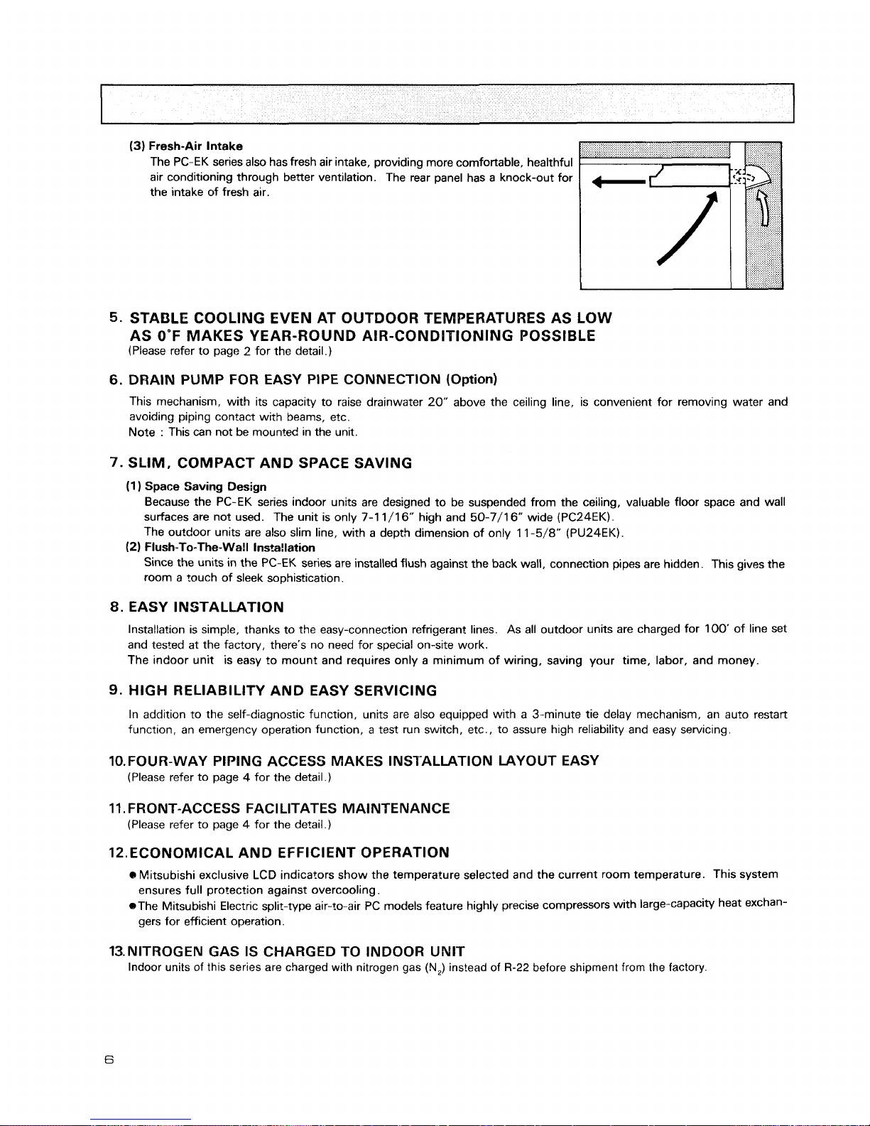
(3)
Fresh-Air Intake
The PC-EK series also has fresh air intake, providing more comfortable, healthful
air conditioning through better ventilation. The rear panel has a knock-out for
the intake of fresh air.
STABLE COOLING EVEN AT OUTDOOR TEMPERATURES AS LOW
AS
0°F
MAKES YEAR-ROUND AIR-CONDITIONING POSSIBLE
(Please refer to page 2 for the detail.)
DRAIN PUMP FOR EASY PIPE CONNECTION (Option)
This mechanism, with its capacity to raise drainwater 20" above the ceiling line, is convenient for removing water and
avoiding piping contact with beams, etc.
Note
:
This can not be mounted in the unit.
SLIM, COMPACT AND SPACE SAVING
(1
)
Space Saving Design
Because the PC-EK series indoor units are des~gned to be suspended from the ceiling, valuable floor space and wall
surfaces are not used. The unit is only 7-1 1/16" high and 50-7/16" wide
(PC24EK).
The outdoor units are also slim line, with a depth dimension of only
1
1
-5/8" (PU24EK).
(2)
Flush-To-The-Wall Installation
Since the units in the PC-EK series are installed flush against the back wall, connection pipes are hidden. This gives the
room a touch of sleek sophistication.
8.
EASY INSTALLATION
Installation is simple, thanks to the easy-connection refrigerant lines. As all outdoor units are charged for 100' of line set
and tested at the factory, there's no need for special on-site work.
The indoor unit is easy to mount and requires only a minimum of wiring, saving your time, labor, and money.
9.
HIGH
RELIABILITY AND EASY SERVICING
In addition to the self-diagnostic function, units are also equipped with a 3-minute tie delay mechanism, an auto restart
function, an emergency operation function, a test run switch, etc., to assure high reliability and easy servicing.
10.FOUR-WAY PIPING ACCESS MAKES INSTALLATION LAYOUT EASY
(Please refer to page 4 for the detail.)
11. FRONT-ACCESS FACILITATES MAINTENANCE
(Please refer to page 4 for the detail.)
12.ECONOMICAL AND EFFICIENT OPERATION
Mitsubishi exclusive LCD indicators show the temperature selected and the current room temperature.
This system
ensures full protection against overcooling.
@The Mitsubishi Electric split-type air-to-air PC models feature highly precise compressors with large-capacity heat exchan-
gers for efficient operation.
13.NlTROGEN GAS IS CHARGED TO INDOOR UNIT
Indoor units of this series are charged with nitrogen gas
(N,)
instead of
R-22
before shipment from the factory.
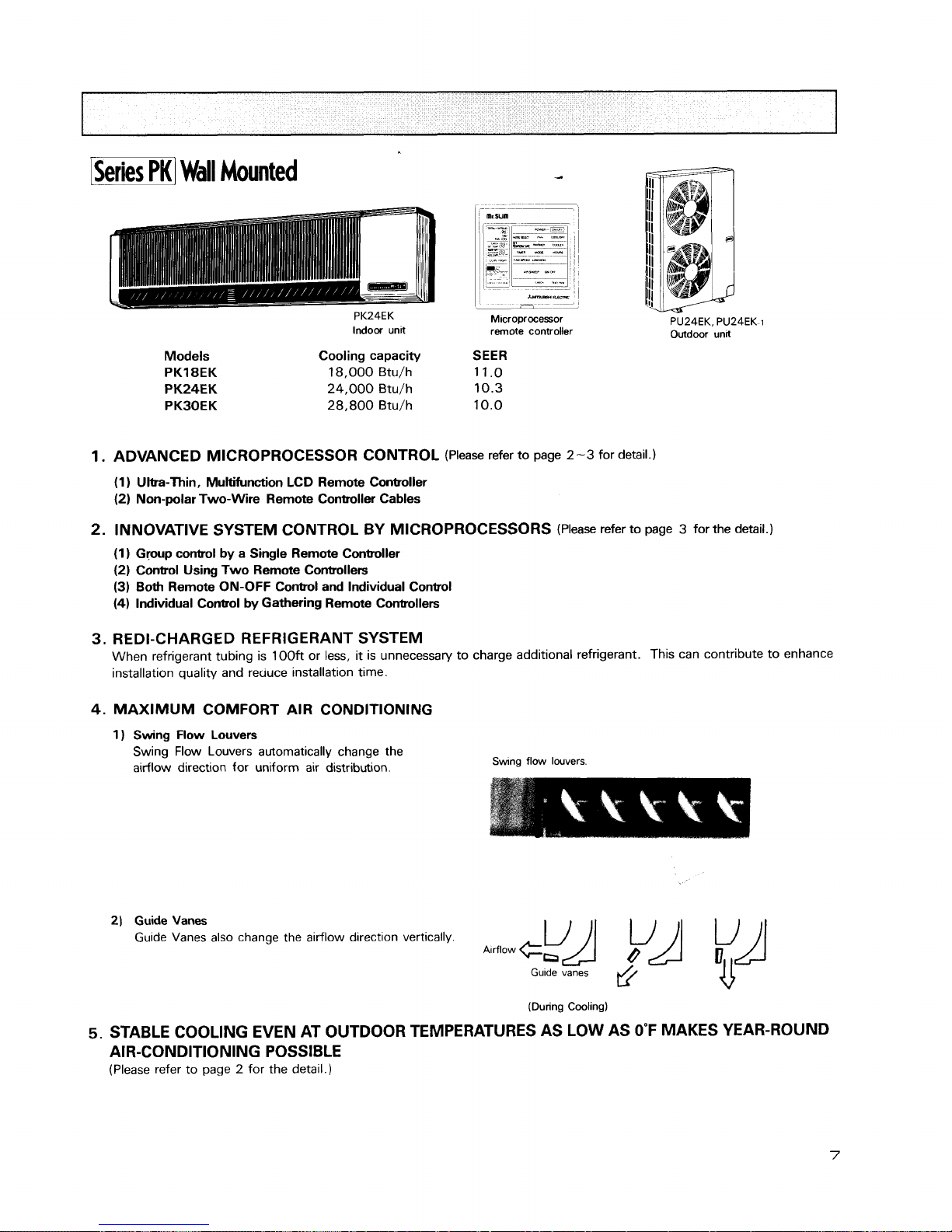
BK]
Wall
Mounted
PK24EK
Indoor unit
*umua*arsnr
-
M~croprocessor
remote controller
PU24EK. PU24EK-1
Outdoor unlt
Models
PK18EK
PK24EK
PKBOEK
Cooling capacity SEER
18,000 Btu/h 11.0
24,000 Btu/h 10.3
28,800
Btu/h 10.0
1.
ADVANCED MICROPROCESSOR CONTROL
(Please refer to page
2-3
for detail.)
(1 ) Ultra-Thin, Multifunction LCD Remote Controller
(2) Non-polar Two-Wire Remote Controller Cables
2.
INNOVATIVE SYSTEM CONTROL BY MICROPROCESSORS
(Please refer to page 3 for the detail.)
(1) Gpup control by a Single Remote Controller
(2) Control Using Two Remote Controllers
(3)
Both Remote ON-OFF Control and Individual Conbol
(4)
Individual Control by Gathering Remote Controllers
3.
REDI-CHARGED REFRIGERANT SYSTEM
When refrigerant tubing is 100ft or less,
it
is unnecessary to charge additional refrigerant. This can contribute to enhance
installation quality and reuuce installation time.
4.
MAXIMUM COMFORT AIR CONDITIONING
1 ) Swing Flow Louvers
Swing Flow Louvers automatically change the
airflow direction for uniform air distribution.
Swng
flow louvers
2)
Guide
Vanes
Guide Vanes also change the airflow direction vertically.
(During Cooling)
5.
STABLE COOLING EVEN AT OUTDOOR TEMPERATURES AS LOW AS
0°F
MAKES YEAR-ROUND
AIR-CONDITIONING POSSIBLE
(Please refer to page 2 for the detail.)
6.
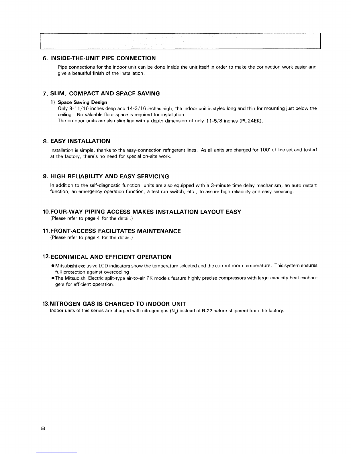
INSIDE-THE-UNIT PIPE CONNECTION
Pipe connections for the indoor unit can be done inside the unit itself in order to make the connection work easier and
give a beautiful finish of the installation.
7.
SLIM, COMPACT AND SPACE SAVING
1
)
Space
Saving Design
Only
8-1
1/16 inches deep and 14-3/16 inches high, the indoor unit is styled long and thin for mounting just below the
ceiling. No valuable floor space is required for installation.
The outdoor units are also slim line with a depth dimension of only 11-5/8 inches (PU24EK).
8.
EASY INSTALLATION
Installation is simple, thanks to the easy-connection refrigerant lines. As all units are charged for 100' of line set and tested
at the factory, there's no need for special on-site work.
9.
HIGH RELIABILITY AND EASY SERVICING
In addition to the self-diagnostic function, units are also equipped with a 3-minute time delay mechanism, an auto restart
function, an emergency operation function, a test run switch, etc., to assure high reliability and easy servicing.
10.FOUR-WAY PIPING ACCESS MAKES INSTALLATION LAYOUT EASY
(Please refer to page 4 for the detail.)
11. FRONT-ACCESS FACl LITATES MAINTENANCE
(Please refer to page 4 for the detail.)
12.ECONIMICAL AND EFFICIENT OPERATION
Mitsubishi exclusive
LCD
indicators show the temperature selected and the current room temperature. This system ensures
full protection against overcooling.
*The Mitsubishi Electric split-type air-to-air PK models feature highly precise compressors with large-capacity heat exchan-
gers for efficient operation.
13.NITROGEN GAS IS CHARGED TO INDOOR UNIT
Indoor units of this series are charged with nitrogen gas
(N,)
instead of
R-22
before shipment from the factory.
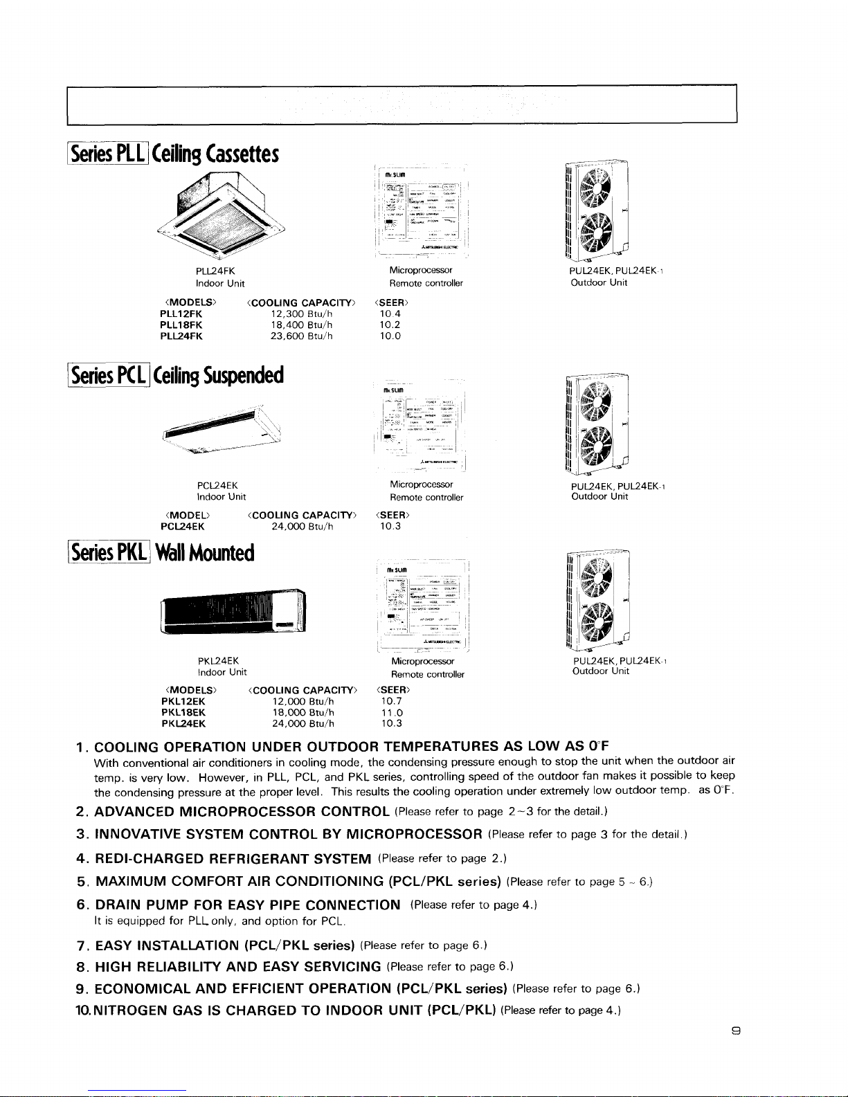
Series
Ceiling Cassettes
PLL24FK
lndoor Unit
(MODELS) (COOLING CAPACITY)
PLLIZFK 12,300 Btu/h
PLL18FK 18,400 Btu/h
PLL24FK 23,600 Btu/h
I
Series
PC
L
1
Ceiling Suspended
PCL24EK
lndoor Unit
(MODEL) (COOLING CAPACITY)
PCL24EK 24,000 Btu/h
1
Series
PKL
1
Wall
Mounted
*"?s,s3.-
-
--
-
-
M~croprocessor
Remote controller
(SEER)
10 4
10 2
10 0
Microprocessor
Remote controller
PK124EK
lndoor Unit
*--
I
I
-
,
Microprocessor
Remote controller
(MODELS) (COOLING CAPACITY)
(SEER:
PKLlZEK 12,000 Btu/h 10.7
PKL18EK 18,000 Btulh 11 .O
PKL24EK 24,000 Btu/h 10.3
PUL24EK. PUL24EK-1
Outdoor Unit
PU124EK. PUL24EK-1
Outdoor Unit
PUL24EK. PUL24EK-1
Outdoor Unlt
COOLING OPERATION UNDER OUTDOOR TEMPERATURES AS LOW AS OF
With conventional air conditioners in cooling mode, the condensing pressure enough to stop the unit when the outdoor air
temp. is very low. However, in PLL, PCL, and PKL series, controlling speed of the outdoor fan makes it possible to keep
the condensing pressure at the proper level. This results the cooling operation under extremely low outdoor temp. as
0°F.
ADVANCED MICROPROCESSOR CONTROL
(Please refer to page
2-3
for the detail.)
INNOVATIVE SYSTEM CONTROL BY MICROPROCESSOR
(Please refer to page 3 for the detail.)
REDI-CHARGED REFRIGERANT SYSTEM
(Please refer to page
2.)
MAXIMUM COMFORT AIR CONDITIONING
(PCLIPKL
series)
(Please refer to page
5
-
6.)
DRAIN PUMP FOR EASY PIPE CONNECTION
(Please refer to page
4.)
It is equipped for PLLonly, and option for PCL.
EASY INSTALLATION (PCL/PKL series)
(Please refer to page 6.)
HIGH RELIABILITY AND EASY SERVICING
(Please refer to page 6.)
ECONOMICAL AND EFFICIENT OPERATION (PCL/PKL series)
(Please refer to page
6.)
10.NlTROGEN GAS IS CHARGED TO INDOOR UNIT (PCL/PKL)
(Please refer to page
4.)
1
Operating range
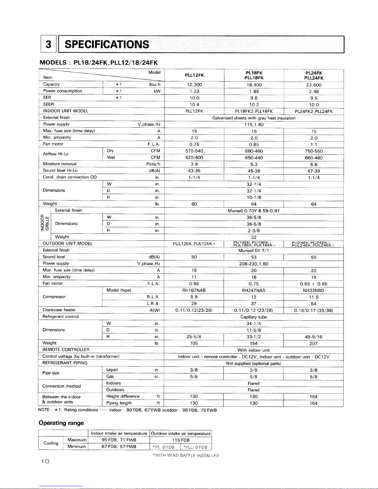
SPECIFICATIONS
MODELS : PL18/24FK,PLLl2/18/24FK
Model
Item
PLLIPFK
12,300
1.23
10.0
10.4
PLLl 2FK
Capacity
*
1 Btu/h
Cooling
PL18FK
PLL18FK
18.400
1.88
9.8
10.2
PL18FK2, PLL18FK
"WITH WIND BAFFLE INSTALLED
10
lndoor intake air temperature
95"FDB, 71~FWB
67~FDB. 57'FWB
Maximum
Miminum
PL24FK
PLL24FK
23,600
2.48
9.5
10.0
PL24FK2, PLL24FK
Power consumption
Galvanized sheets with gray heat insulaiton
115,1,60
*
1 kW
15
2.0
0.75
I
570-540
420-400
3.8
43-35
1-1/4
Outdoor intake air temperature
1 15"FDB
*PL 0"FDB
15
2.0
0.85
680-460
650-440
5.3
45-38
1-1/4
EER
*
1
SEER
INDOOR UNIT MODEL
External finish
Power supply V,phase,Hz
Max. fuse size (time delay) A
Min. ampacity A
Fan motor F.L.A.
Airflow Hi-Lo
I
Dn/
CFM
Wet CFM
Moisture removal Pints/h
Sound level Hi-Lo dm)
Cond. drain connection OD ~n.
"PLL. 0"FDB
15
2.0
1.1
750-550
660-480
6.8
47-39
1-1/4
Dimensions
32-1/4
32-1
/4
10-1/8
W ~n.
D ~n.
H in.
60
64
Weight Ib.
64
g
Y
O
2
0
a
Z
a
Munsell 0.70Y 8.59/0.97
36-51'8
36-5/8
2-3/8
22
PUL12EK. PUL12EK-1
1
PUL~~EK,
PU
18~~.
PU
PULI~EK-1
1
~EK-I
External finish
PU24EK. PU24EK~t
PUU4EK. PUU4EK-1
Dimensions
OUTDOOR UNIT MODEL
External finish
Sound level dB(A)
Power supply V,phase,Hz
Max. fuse size (time delay) A
Min. ampacity A
Fan motor F.L.A.
W
in.
D in.
H in.
Munsell 5Y 7/1
Compressor
Weight
50
Model (type)
R.L.A.
L.R.A.
53
Crankcase heater A(W)
Refrigerant control
55
208-230.1.60
Dimensions
15
11
0.65
RH167NAB
8.9
29
0.11/0.12(23/28)
W ~n.
D in.
H in.
20
16
0.75
RH247NAB
12
37
0.1 1 /O. 12 (23/28)
Weight Ib.
REMOTE CONTROLLER
Control voltage (by built-in transformer)
REFRIGERANT PIPING
20
16
0.65
+
0.65
NH33NBD
11.5
54
0.16/0.17 (33/39)
Capillan/ tube
34-1 /4
1 1 -5/8
Pipe size
Connection method
Between the indoor
&
outdoor units
25-5/8
Liquid in.
Gas in.
Indoors
Outdoors
Height difference
ft
Piping length
ft
NOTE
:
*
1. Rating conditions
----
indoor : 80FDB. 67~FWB
33-1 /2 49-9/ 1 6
105
154 207
With indoor unit
Indoor unit
-
remote controller : DC12V. Indoor unit - outdoor unit : DC12V
Not supplied (optional parts)
3/8 3/8 3/8
5/8- 5/8 5/8
Flared
Flared
130 130 164
130
outdoor
:
95"FDB. 75"FWB
130 164
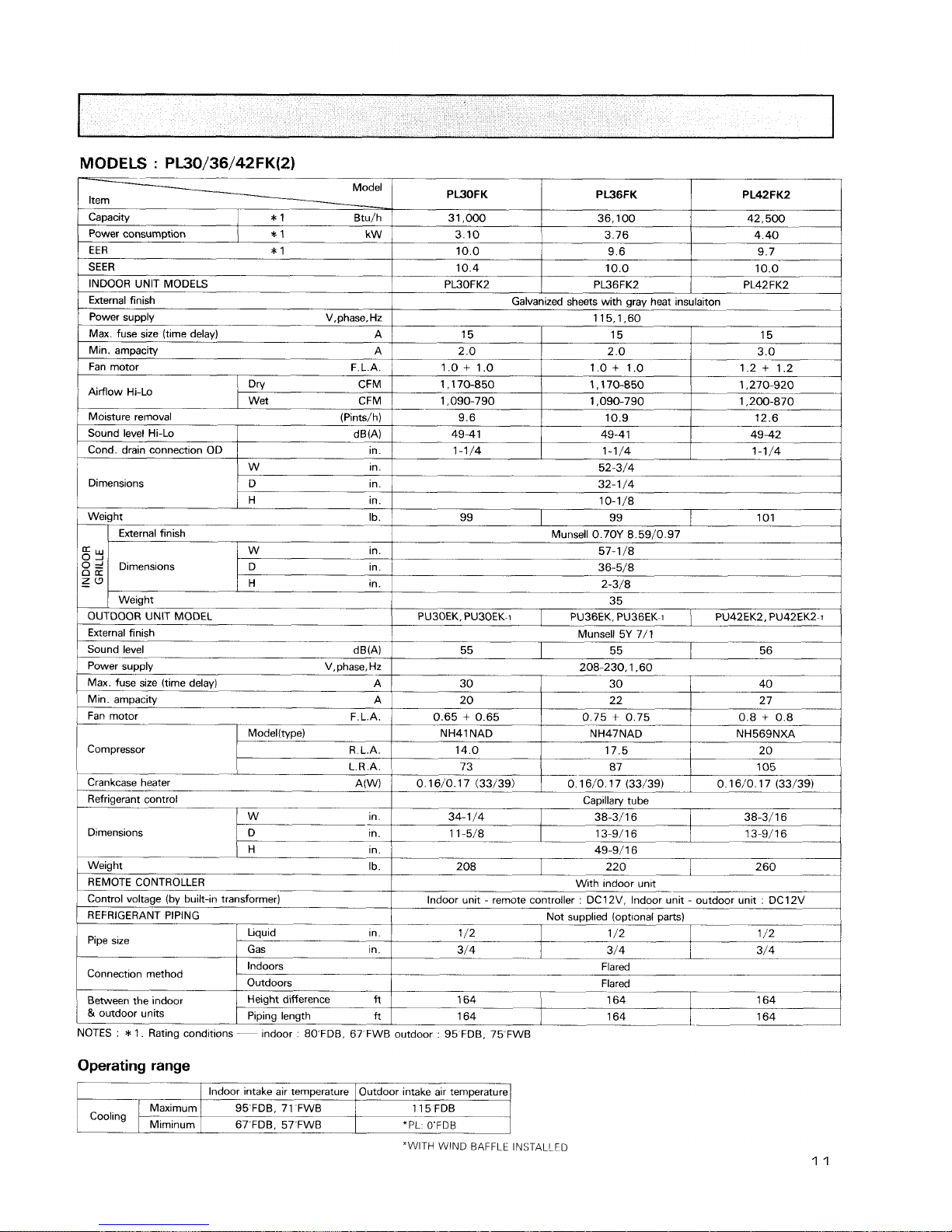
MODELS
:
PL30/36/42FK(2)
Model
Item
-
PWOFK
31,000
3.10
10.0
10.4
PL30FK2
Capacity
Moisture removal (Pints/h)
Fan motor F.L.A.
1
0.65 + 0.65
*
1 Btu/h
9.6
49-41
1-11'4
Sound level Hi-Lo
Cond. drain connection OD
Dimensions
compressor
PW6FK
36,100
3.76
9.6
10.0
PL36FK2
dw)
in.
W
~n.
D in.
H in.
0.75
+
0.75
Pipe slze
Operating range
PL42FK2
42,500
4.40
9.7
10.0
PL42FK2
Power consumption
Galvanized sheets with gray heat insulaiton
115,1,60
10.9
49-4 1
1-1/4
0.8
+
0.8
ModeKtype)
R.L.A.
L.R.A.
Connection method
Between the indoor
&
outdoor units
*
1 kW
15
2.0
1 .O
+
1 .O
1 ,170-850
1,090-790
12.6
49-42
1-1/4
52-3/4
32- 1
/4
10-1/8
Weight Ib.
Liquid in.
I
1 /2
"WITH
WIND BAFFLE INSTALLED
99
Sr
0
='
0
a
zu
-
NH41 NAD
14.0
73
Crankcase heater A(W)
Refrigerant control
NOTES
:
*
1. Rating conditions
--
indoor : 8OFDB. 67 FWB outdoor : 95 FDB, 75 FWB
Indoors
Outdoors
Height difference
fl
Piping length
ft
15
2.0
1.0+ 1.0
1,170-850
1,090-790
EER
*
1
SEER
INDOOR UNIT MODELS
External finish
Power supply V,phase, Hz
Max. fuse size (time delay)
A
Min. ampacity A
Fan motor F.L.A.
0.16/0. 17 (33/39)
Dimensions
1 /2
Cooling
15
3.0
1.2
+
1.2
1,270-920
1,200-870
Aidow Hi-Lo
99
OUTDOOR UNIT MODEL
External finish
Sound level dB(A)
Power supply V, phase, Hz
Max. fuse size (time delay)
A
Min.
ampacity A
External finish
NH47NAD
17.5
87
W in.
D ~n.
1 /2
Gas ~n.
-
Flared
Flared
lndoor intake air temperature
95 FDB, 71 FWB
67'FDB. 57"FWB
Maximum
Miminurn
Dnl CFM
Wet CFM
101
Dimensions
Munsell 0.70Y 8.59/0.97
57-1 /8
36-5/8
2-3/8
35
NH569NXA
20
105
0.16/0. 17 (33/39)
H in.
Weight Ib.
REMOTE CONTROLLER
Control voltage (by built-in transformer)
REFRIGERANT PIPING
164
Outdoor intake air temperature
115 FDB
*PL: O'FDB
W in.
D in.
H in.
PU30EK. PU30EK-1
0.16/0.17 (33/39)
Capillary tube
34-1/4
1
38-3/16
1
38-3/16
11-5/8
1
13-9/16
/
13-9/16
49-9/16
3/4
Weight
PU36EK. PU36EK-1
1
PU42EK2, PU42EK2-i
208
164
3/4
164
164
Munsell 5Y 7/1
With mdoor unit
-
Indoor unit - remote controller : DC12V, Indoor unit - outdoor unit : DC12V
Not supplied (optional parts)
220
3/4
164
---
164
55
260
55 56
208-230.1.60
30
I
30
1
40
20 22 2 7
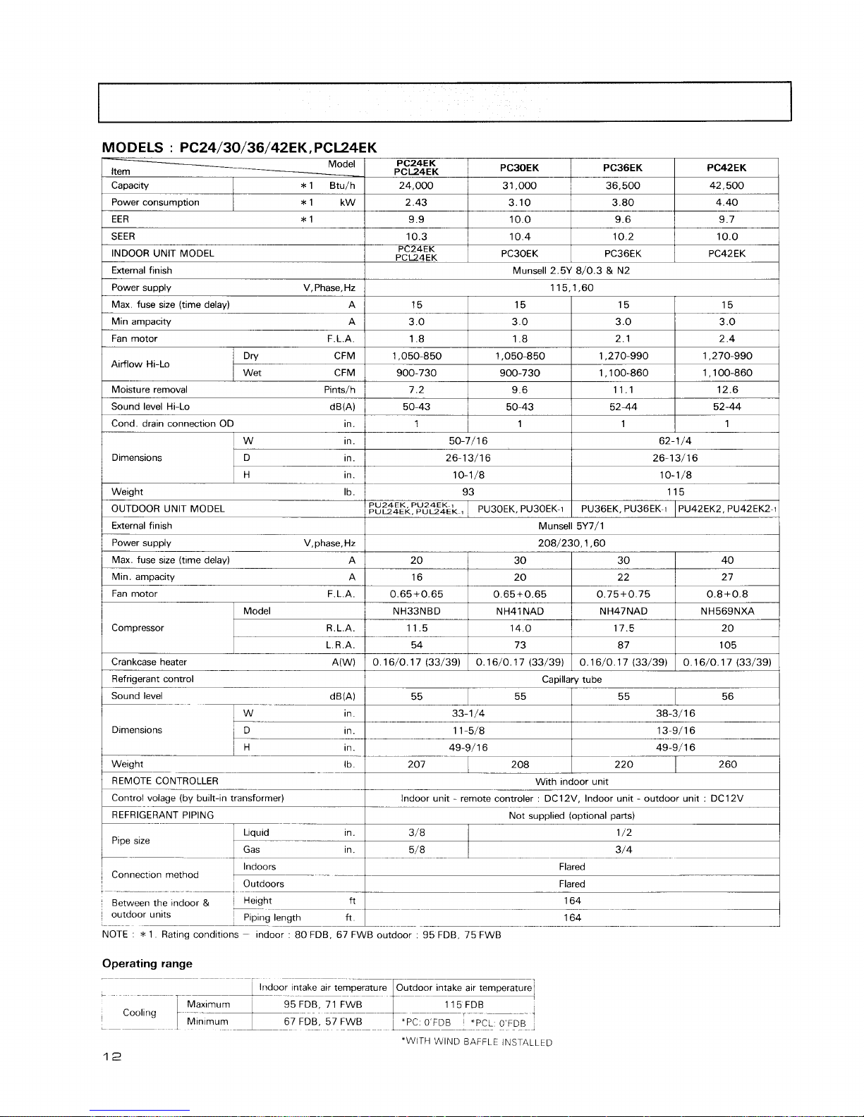
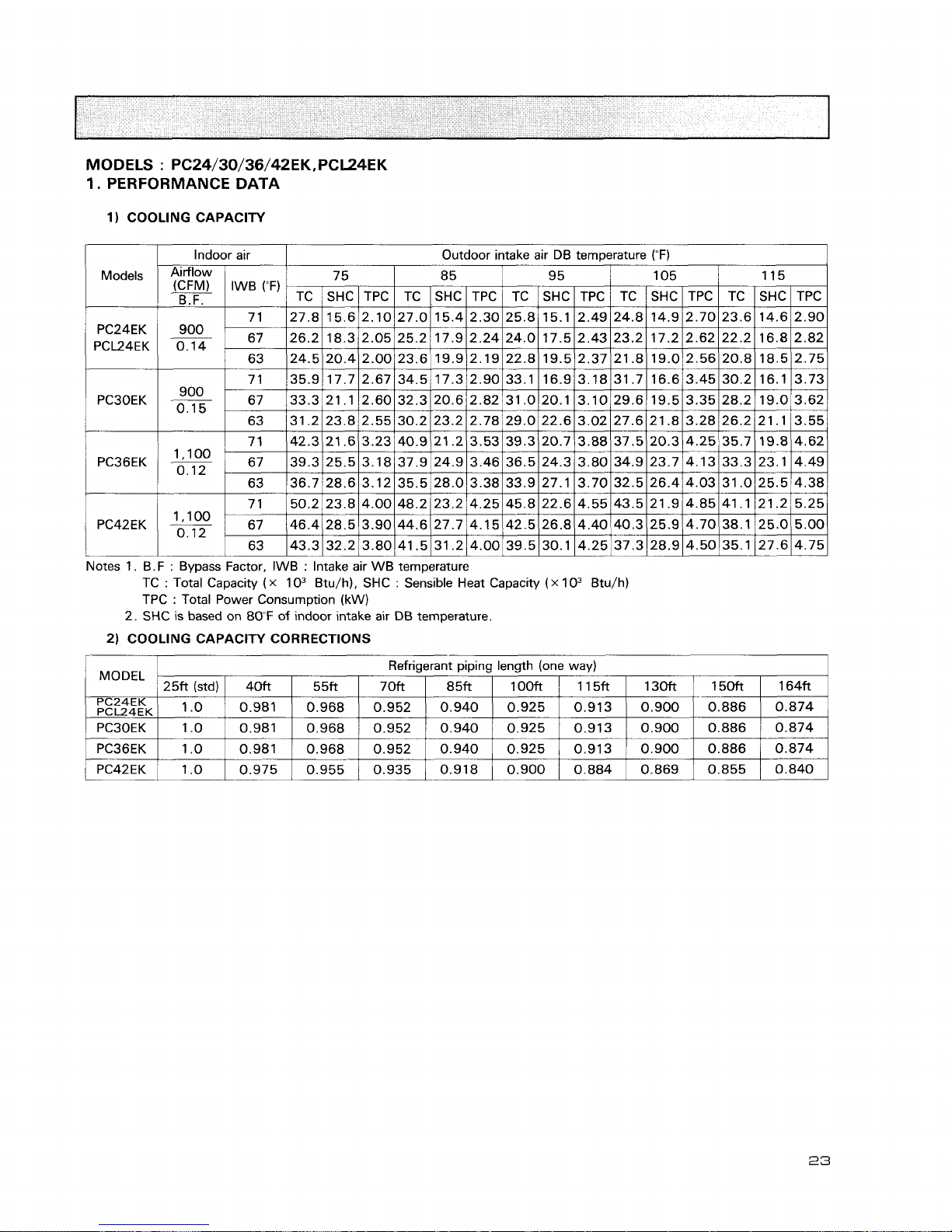
MODELS : PC24/30/36/42EK, PCL24EK
1
Power consurn~tion
1
*1 kWI 2.43
1
3.10
1
3.80
I
4.40
I
1
EER
*
1
1
9.9
I
10.0
1
9.6
1
9.7
I
-
Model
Item
-
Capacity
PC42EK
42,500
PC24EK
PCL24EK
24,000
*
1 Btu/h
SEER
INDOOR
UNlT MODEL
External finish
1
Max fuse size (time delay) A
/
15
1
15
I
15
1
15
I
Power supply V,Phase, Hz
PC30EK
31.000
10.3
PC24EK
PCL24EK
115,1,60
1
Fan motor F.L.A.
I
1.8
1
1.8
I
2.1
I
2.4
1
PC36EK
36,500
Min ampacity A
Munsell 2.5Y 8/0.3
&
N2
10.4
PC30EK
1
Sound level Hi-Lo dB(A)/ 50-43
1
50-43
1
52-44
1
52-44
1
3.0
Airflow Hi-Lo
1
Cond. drain connection OD in.
1
1
1
1
1
1
I
1
1
10.2
PC36EK
10.0
PC42EK
3.0
Dry CFM
Wet CFM
/
Weight Ib.
/
93
I
115
1
Pints/h
3.0
1,050-850
900-730
1
w
in.
/
power supply V,phase,Hz
/
208/230,1,60
I
3.0
7.2
50-7/16
26-1 3/16
10-11'8
Dlrnensions
OUTDOOR UNlT MODEL
External finish
/
Max. fuse size
(time
delavl
1,050-850
900-730
62-1
/4
26-13/16
10-1/8
D in.
H in.
I
Min. ampacity
9.6
I
1,270-990
1,100-860
PU24EK. PU24EK-7
~"124~~.
PU~~EK-,
1
Refrigerant control
1
Capillary tube
I
1,270-990
1,100-860
11.1
Sound level
12.6
Munsell 5Y7/1
PU30EK. PU30EK-1
Fan motor F.L.A.
0.65+0.65
NH33NBD
11.5
54
0.16/0. 17 (33/39)
Compressor
1
Welght
--
-
-
lbi
207
1
208
1
220
1
260j
--
With
Indoor unlt
--
lndoor unlt - remote controler DC12V. Indoor unlt - outdoor unit
DC12V
PU36EK. PU36EK-1
Model
R.L.A.
L.R.A.
dB(A)
in.
in.
1
REFRIGERANT PIPING
1
Not supplied (optional parts)
1
PU42EK2, PU42EK2-1
0.65+0.65
NH41 NAD
14.0
73
0.16/0. 17 (33/39)
Crankcase heater A(W)
Llquid
1
P~pe size
55
1
55
-.
33-1 /4
1 1 -5/8
0.75+0.75
NH47NAD
17.5
87
0.16/0. 17 (33/39)
38-3/ 1 6
13-9/16
in. 49-9/16
I
/
Connection
method
1
Indoors
--
.
I
Outdoors
0.8+0.8
NH569NXA
20
105
0.16/0. 17 (33/39)
49-9/16
~n.
Flared
3/8
Flared
Between the
mdoor
&
Pght-
9-
.
-
-
-
164
--
outdoor
units
'
Plplng length
ft
--
.
-
--
164
NOTE
*
1 Rat~ng condltlons - Indoor 80 FDB. 67 FWB outdoor 95 FDB 75 FWB
~n.
Operating range
5/8
--
-
--
--
-
-
--
-
-
-
1
Indoor ~ntake a~r temperature Outdoor lntake a~r temperature
7
95 FDB 71 FWB
Cooling
1
;'':;+--
115FDB
T
L---
1
67 FDB, 57 FW8
'PCL
OFDB
:
-
I--
*WITH
'SIIIND BAFFLE INSTALLED
12
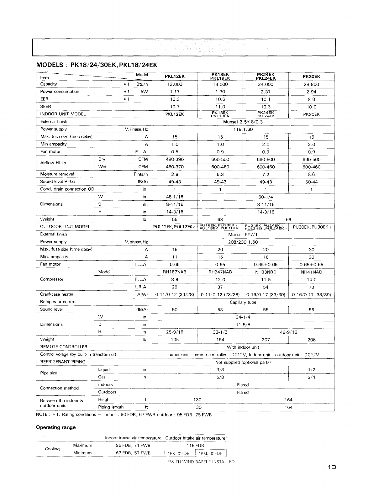
MODELS : PK18/24/30EKrPKL18/24EK
-
/
power supply V,Phase.Hz
/
115,1,60
I
PKLIZEK
Item
-
Power consumption
10.7
INDOOR UNIT MODEL PKL12EK
I
I
I
OUTDOOR UNIT MODEL
I
PULl2EK. PULl2EK
1
I
~~:~~~li.p~,"~&~
$1
P~~~&P,"~~Pu~oEK
1
PK18EK
PKLl8EK
External finish
MM
1.70
10.6
11 .O
PKl SEK
PKLZK
External finlsh
Munsell 5Y7/1
Power supplv V,phase,Hz
,
208/230.1.60
Capacity
Max. fuse size (time delay)
A
Min ampacity A
Fan motor F.L.A.
I
1
T
-
(
Max. fuse size (time delay) A
1
15 20 20 30
1
PK24EK
PKL24EK
2.37
10.1
10.3
PK24EK
PKL24EK
15
1 .O
0.5
480-390
460-370
3.8
49-43
1
48-1/16
8-1 1/16
14-311 6
55
Airflow Hi-Lo
PK30EK
*
1 Btu/h
/
12,000
2.94
9.8
10.0
PK3OEK
Dn! CFM
Wet CFM
I
/
Model
1
RH167NAB
1
RH247NAB
1
NH33NBD
1
NH41NAD
1
15
1 .O
0.9
660-500
600-460
5.3
49-43
1
Min.
arnpacity A
Fan motor
-
F.L.A.
Compressor 8 9 12 0 11 5
--
29 37 54 73
18,000
Moisture removal Pintsjh
Sound level Hi-Lo d Em)
Cond. drain connection OD ~n.
Crankcase heater
0 1 1
/0 12 (23128)
1
0 16/0 1 7 (33139) 1 0 16/0 17 (33139)
Capillary
tube
Sound level
-
--
--
53 55
I
34- 1 /4
---
Dlrnens~ons
--
1 1 -5/8
--
--
15
2.0
ppp
0.9
660-500
600-460
7.2
49-43
1
Dimensions
11
0.65
1
1n.1 25-9/16
1
33-112
1
49-91 1 6
I
24,000
15
2.0
0.9
660-500
600-460
8.6
50-44
1
W
in.
D in.
60-1
/4
8-1 1/16
14-3/16
Weight
-
.
REMOTE CONTROLLER
28.800
in.
Ib.
68
16
0.65
Control volage (by
built-ln transformer)
--
1
l"door unit - remote controller : DClIV, Indoor unit - outdoor unit : DCl2V
.
-
.
REFRIGERANT PIPING
Not su~olied lo~t~onal ~arts)
69
Pipe sue
16
0.65+0 65
/
Llquid in.
1
0.65+0.65
4
1
Gas ~n.
1
Connection
method
Indoors
--
Outdoors
Flared
Flared
Between the mdoor
&
I
Height
ft
1
outdoor unlts
1
Plplnq length
-7.7
-
NOTE
:
*
1. Rating conditions - indoor : 80 FDB, 67 FWB outdoor : 95 FDB, 75 FWB
Operating range
I
1
-
--
F
Max~mum 95 FDB, 71 FWB
--
--
,
-
--
115FDB
1
Cooling
i
-
Mlnlmurn 67 FDB, 57 FWB
I
-
--
-2
--
_-I
_
-
*PK
o
FDB
T
"PKL
OFDB
1
-I
-
_-
-
"WITH WIND BAFFLE INSTALLED
MODELS
:
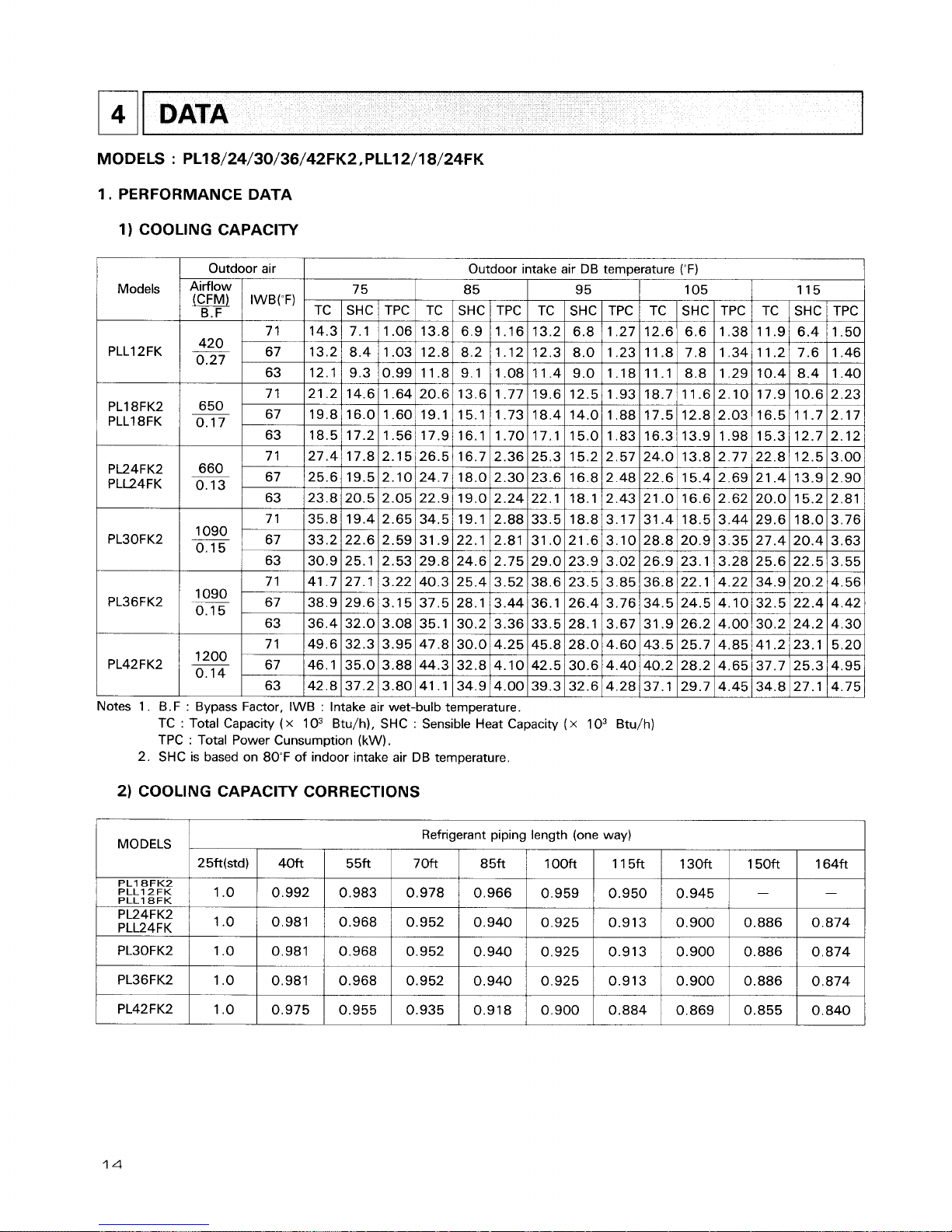
PL18/24/30/36/42FK2,PLL12/18/24FK
1.
PERFORMANCE DATA
1)
COOLING CAPACITY
1
Models
PLLI 2FK
DATA
PL18FK2
PLLI 8FK
-
Outdoor air
I
Outdoor mtake air DB temperature (OF)
1
75 8 5 95 105 115
TC
I
SHC / TPC I TC
SHC
/
TPC I TC I SHC I TPC / TC 1 SHC 1 TPC 1 TC 1 SHC I TPC
Notes 1. B.F
:
Bypass Factor, IWB : Intake air wet-bulb temperature.
TC
:
Total Capacity ( x
1 O3 Btu/h), SHC : Sensible Heat Capacity
(
x
1 O3 Btu/h)
TPC
:
Total Power Cunsumption (kW).
2. SHC is based on 80°F of indoor intake air DB temperature.
2)
COOLING CAPACITY CORRECTIONS
MODELS
PL18FK2
PLL12FK
PLL18FK
PL24FK2
PLL24FK
Refrigerant piping length (one way)
25ft(std)
1 .o
,0
40ft
0.992
0.981
5 5ft
0.983
0.968
7 Oft
0.978
0.952
8 5ft
0.966
0.940
1OOft
0.959
0.925
11 5ft
0.950
0.913
130ft
0.945
0.900
150ft
-
0.886
164ft
-
0.874
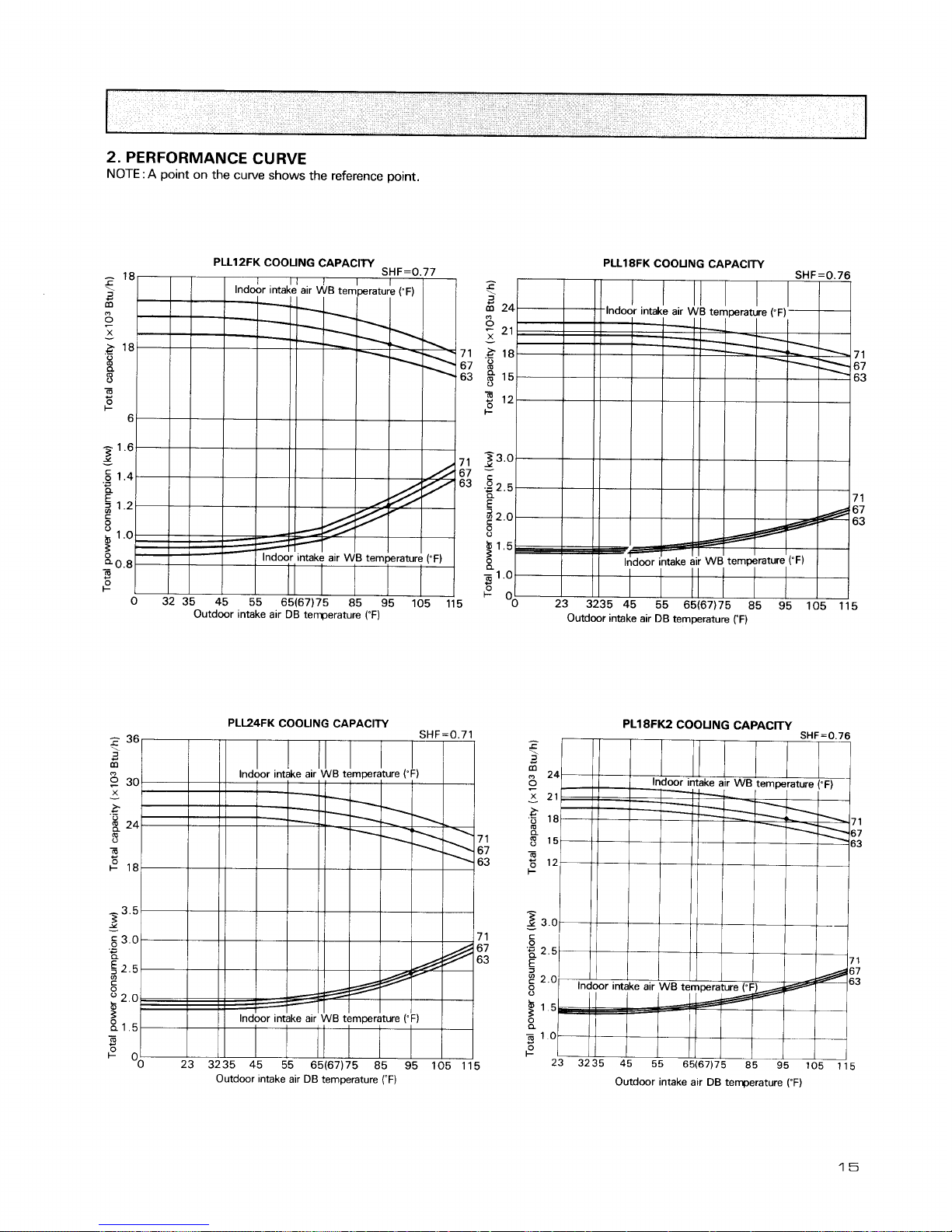
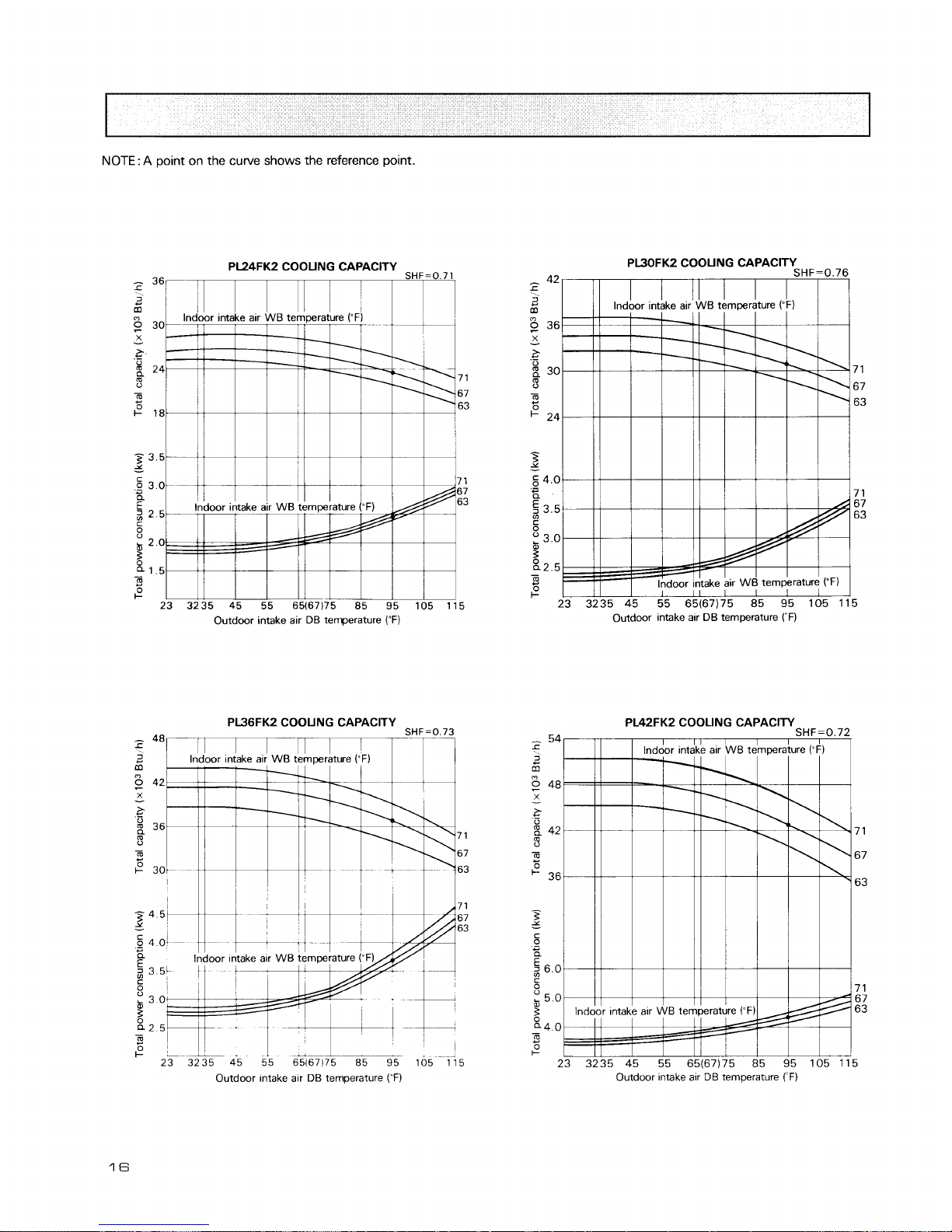
2.
PERFORMANCE CURVE
NOTE
:
A
point on the curve shows the reference point.
PLL18FK COOUNG CAPACITY
Outdoor intake air
DB
temperature
('F)
PL18FK2
COOUNG
CAPACITY
Outdwr intake air
Dl3
temperature
rF)
Outdoor intake air
DB
terrperature
(OF)
NOTE
:
A
point on the curve shows the reference point.
Outdoor intake air DB temperature
(OF)
Outdoor intake alr
DB
temperature
("F)
?
lndoor
, ,
&take air WB temperature
(;FW
Outdoor ~ntake air DB temperature
(-F)
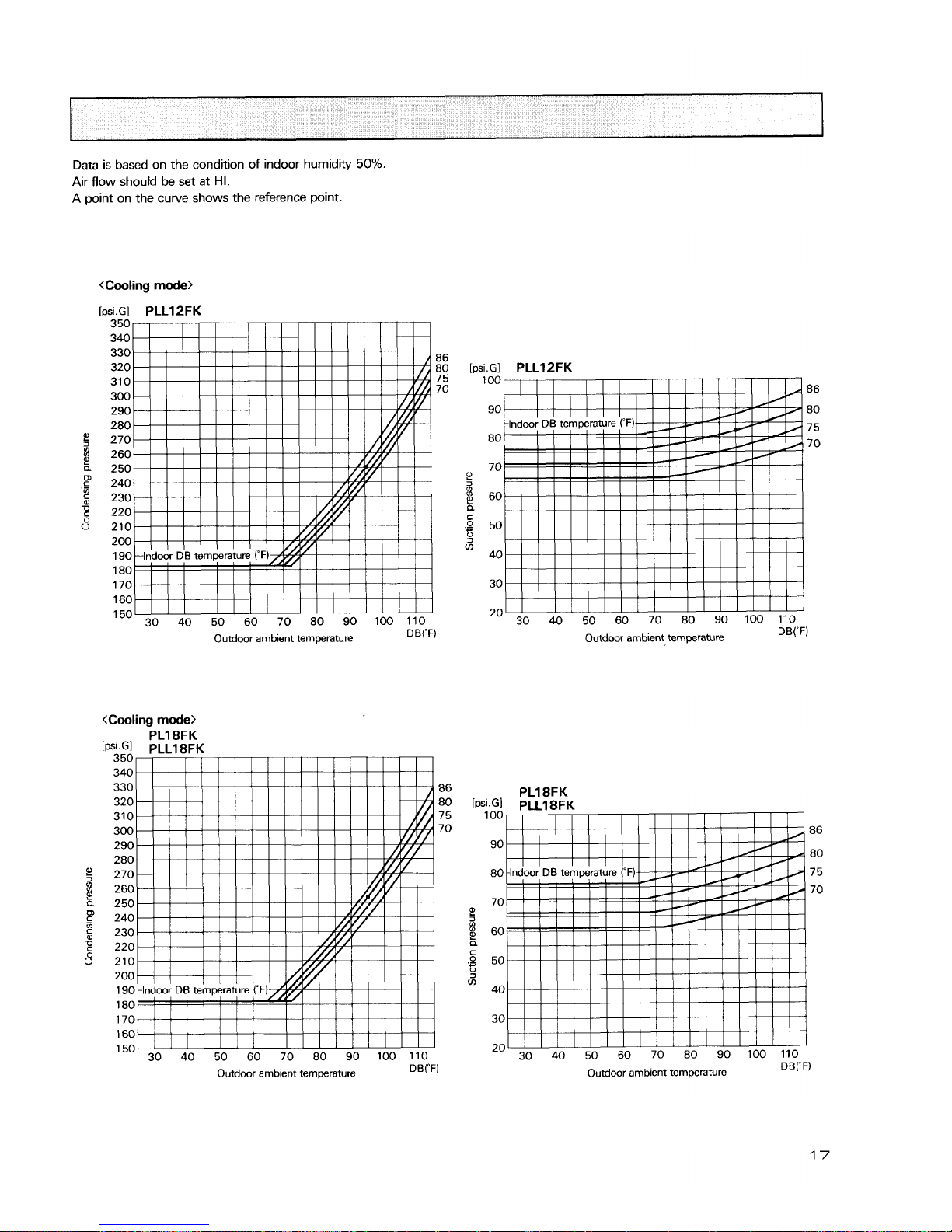
Data is based on the condition of indoor humidity
50%.
Air flow should be set at
HI.
A point on the curve shows the reference point.
<Cooling
mode>
[psiGI
PLLl 2FK
350
340
330
86
320 80
310 7 5
300
70
290
280
270
260
250
240
230
220
210
200
190
180
170
1
60
150 30 40 50 60 70 80 90 100 110
Outdoor ambient temperature
DB("F)
.
--
-~~
350
340
330 86
320 80
310 7 5
300 70
290
280
270
260
250
240
230
220
210
200
190
180
170
1
60
150
30 40 50 60 70 80 90 100 110
Outdoor ambient temperature
DB("F)
[psi.GI
PLLl2FK
100
86
90 80
7 5
80
70
70
e!
$
60
a
c
.g
50
0
V)
40
30
20
30 40 50 60 70 80 90 100 110
Outdoor ambient temperature DB("F)
PL18FK
[t~si.G]
PLL18FK
100
86
90
80
80 7 5
70
70
e!
$
60
a
.:
50
3
V)
40
30
20
30 40 50 60 70 80 90 100 110
Outdoor ambient temperature DB("F)
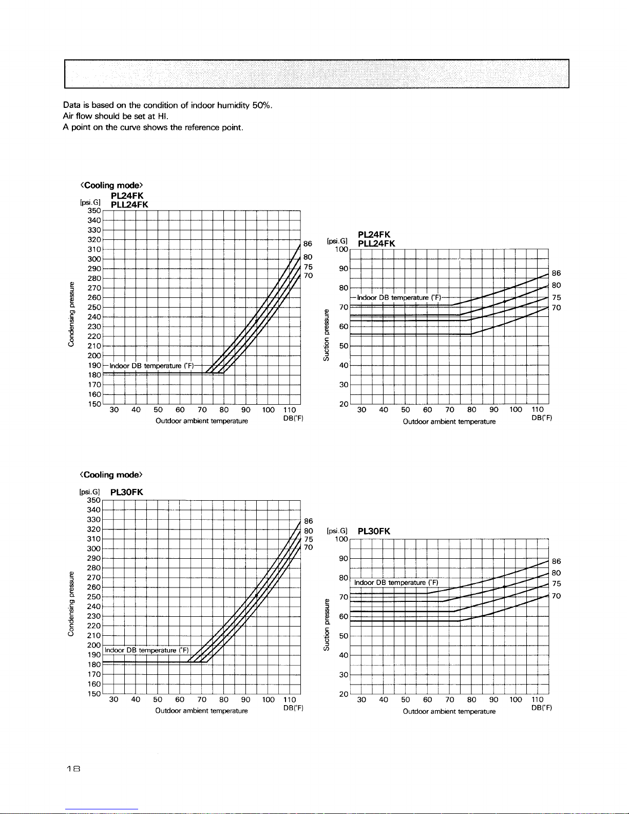
Data is based on the condition of indoor humidity
50%.
Air flow should be set at
HI.
A point on the curve shows the reference point.
35U
340
330
320
310
86
300 80
290 7 5
280
70
270
260
250
240
230
220
210
200
190
180
170
160
150 30 40 50 60 70 80 90 100 110
Outdoor ambient temperature
DB("F)
.
--
-
350
340
330 86
320 80
310 75
300 70
290
280
270
260
250
240
230
220
210
200
190
180
170
160
150
30 40 50 60 70 80 90 100 110
Outdoor ambient temperature
DB("F)
PL24FK
86
80
7 5
70
30 40 50 60 70 80 90 100 110
Outdoor ambient temperature
DB("F)
Outdoor amb~ent temperature
DBrF)
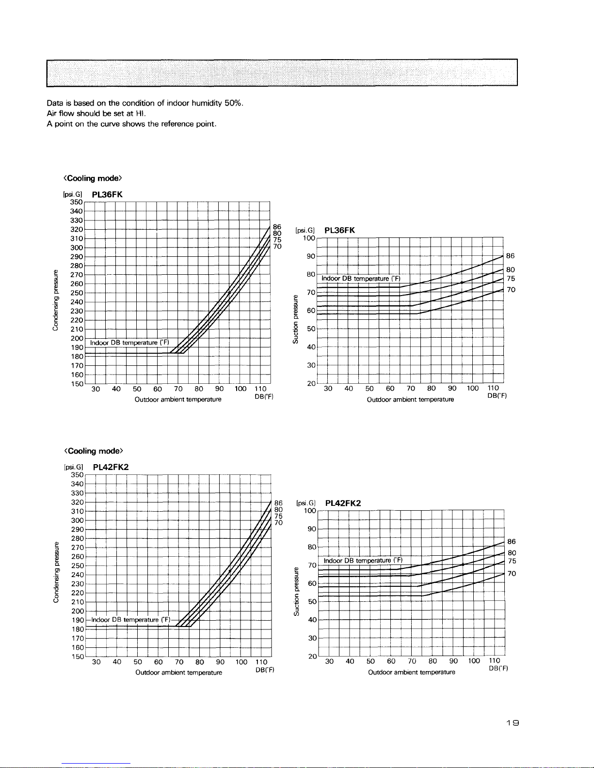
Data is based on the condition of indoor humidity
50%.
Air
flow should
be
set at
HI.
A
point on the curve shows the reference point.
[psi.Gl
PL36FK
350
340
330
320 86
310
80
7 5
300 70
290
280
270
260
250
m
c
240
'Si
230
g
220
0
210
200
190
180
170
160
150 30 40 50 60 70 80 90 100 110
Outdoor ambient temperature
DB("F)
Outdoor ambient temperature
DBrF)
[psi.GI
PL36FK
100
90 86
80
80
7 5
70
70
E'
g
60
a
C
.$
50
J
m
40
30
20
30 40 50 60 70 80 90 100 110
Outdoor ambient temperature
DB("F)
30 40 50 60 70 80 90 100 110
Outdoor ambient temperature
DB("F)
19
3.
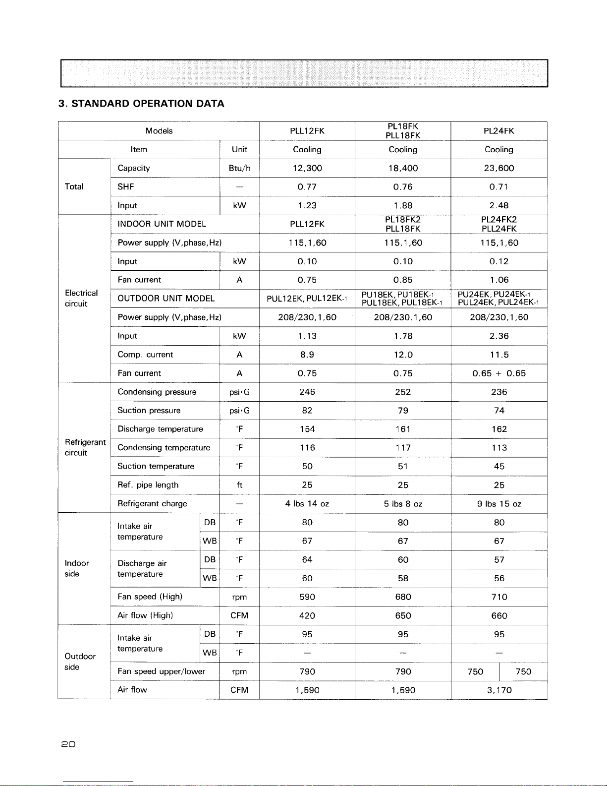
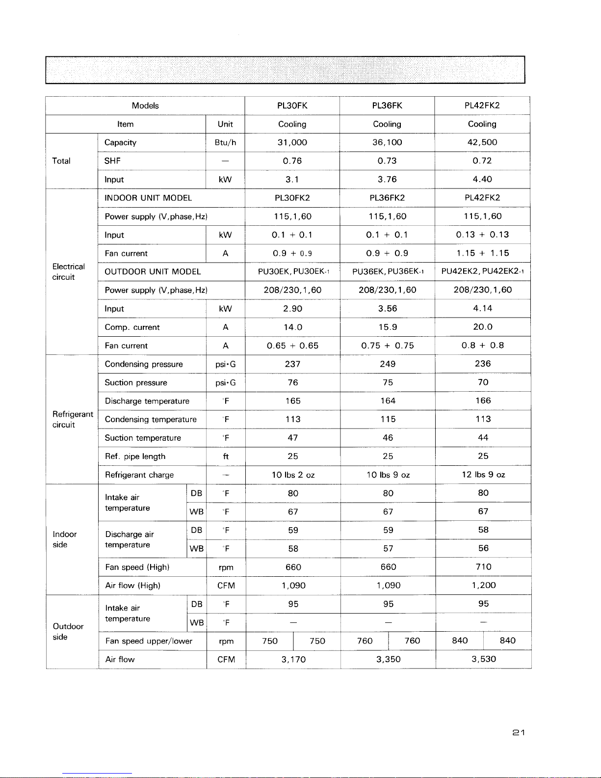
STANDARD OPERATION DATA
1
Unit
1
Cooling
Cooling
Cooling
1
Capacity
1
Btu/h
1
12,300
I
18,400
I
23,600
1
Total
1
SHF
1-1
0.77
I
0.76
I
0.71
I
1
lnput
I
kw
/
1.23
1
1.88
I
2.48
1
/
Power supply (V,phase,Hz)
1
115,1,60
1
115,1,60
1
115,1,60
1
I
INDOOR UNIT MODEL
I
Fan current
Electrical
circuit
PLLI 2FK
I
Power supply (V,phase, Hz)
1
208/230,1 ,60
1
208/230,1 ,60 208/230,1,60
/
PL18FK2
PLLI 8FK
I
OUTDOOR UNIT MODEL
PL24FK2
PLL24FK
I
Condensing pressure psisG
I
PUL1
2EKr
PUL1
2EK-1
Comp. current
Fan current
1
Suction pressure
1
Discharge temperature "F
I
1
A
A
PU24EK, PU24EK-i
PUY4EK, PUU4EK.i
1
Suction temperature
1
"F
I
50
1
5 1
1
45
1
8.9
0.75
Refrigerant
circuit
Ref. pipe length
f?
25
Refrigerant charge
-
4 Ibs 14 oz
5 Ibs 8 oz
12.0
0.75
Condensing temperature
Intake air
temperature
11.5
0.65
+
0.65
Indoor Discharge air
side temperature
"
F
Fan speed (High)
Air flow (High)
1
Intake air
1 16
temperature
Outdoor
1
I
Fan speed upper/lower
1
rprn
I
1 17
1
Air flow
1 13
Models
kern
I
unit
I
Cooling
1
Cooling
I
Cooling
1
Capacity
/
Btu/h
I
3 1,000
1
36,100
1
42,500
I
Total
SHF
lnput
INDOOR UNIT MODEL
I
PL30FK2
1
Power supply (V,phase. Hz)
lnput
Fan current
Electrical
circuit
OUTDOOR
UNlT MODEL
camp.
current
I
A
I
14.0
i
15.9
I
20.0
I
Refrigerant
circuit
Power supply
(V,phase,Hz)
208/230,1,60
2.90
Input
Suction pressure
kW
Fan current
Condensing pressure
Dischargetemperature
1
I
208/230,1,60
3.56
Condensing temperature F
I
208/230,1,60
4.14
A
psi.
G
Suction temperature
Ref. pipe length
0.65 + 0.65
237
Refrigerant charge
0.75 + 0.75
249
Discharge air
temperature
0.8 + 0.8
236
Indoor
side
Intake air
temperature
Fan speed (High)
"F
"F
DB
WB
temperature
IWBI
"F
I
-
I
-
I
-
I
80
67
Outdoor
side
Air flow (High)
80
67
CFM
'F
Intake air
80
67
DB
I
Fan speed upper/lower
Air flow
1,090
95
rPm
CFM
1,090
95
1,200
9 5
7 50 750
760
3,170
840 7 60 840
3,350
3,530
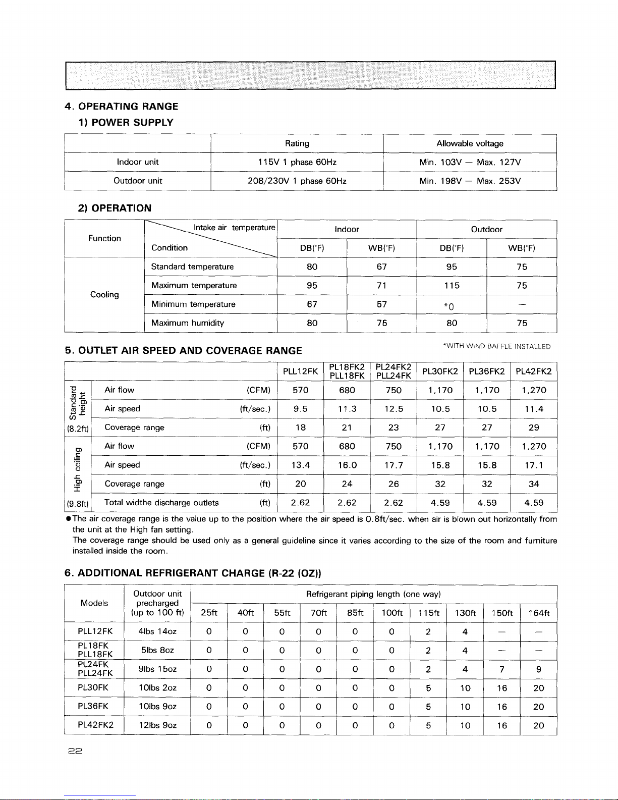
4.
OPERATING RANGE
1) POWER SUPPLY
1
Rating
Allowable voltage
2) OPERATION
Indoor unit
Outdoor unit
I
Standard temperature
1 15V 1 phase 60Hz
208/230V 1 phase 60Hz
Intake air temperature
Function
Condition
Min. 103V
-
Max. 127V
Min. 198V - Max. 253V
1
Maximum humidity
Indoor
DB(W
1
WB("F)
Cooling
5.
OUTLET AIR SPEED AND COVERAGE RANGE
*WITH
WIND
BAFFLE
INSTALLED
Outdoor
Maximum temperature
Minimum temperature
DB("F)
PLLI 2FK
@The air coverage range is the value up to the position where the air speed is 0.8ft/sec. when air is blown out horizontally from
the unit at the High fan setting.
The coverage range should be used only as a general guideline since it varies according to the size of the room and furniture
installed inside the room.
WB("F)
9 5
67
T!
dr'
c
.G'
V)
(8.2ft)
C
.-
-
.-
L
.P
I
(9.8ft)
6.
ADDITIONAL REFRIGERANT CHARGE (R-22 (OZ))
I
I
1
I
I I
I
7 1
57
PLl8FK2
PLLl
8FK
Air flow (CFM)
Air speed (ft/sec.)
Coverage range (ft)
Air flow (CFM)
Air speed (ft/sec.)
Coverage range
(
ft
Total widthe discharge outlets (ft)
PL36FK2
Models
PLLI 2FK
1 15
*
0
PL42FK2
PL24FK2
PLL24FK
570
9.5
18
570
13.4
20
2.62
PL18FK
PLLI 8FK
PL24FK
PLL24FK
7 5
-
PL30FK2
Outdoor unit
precharged
(up to 100 ft)
41bs 1402
PL30FK
PL36FK
680
11.3
2
1
680
16.0
24
2.62
51bs 80z
'Ibs
50z
Refrigerant piping length (one way)
1 Olbs 202
1 Olbs 902
7 50
12.5
23
7 50
17.7
2 6
2.62
2513
0
0
0
0
0
1,170
10.5
27
1,170
15.8
32
4.59
4Mt
0
0
0
0
0
1,170
10.5
2 7
1,170
15.8
32
4.59
55ft
0
0
0
1,270
11.4
2
9
1,270
17.1
34
4.59
0
0
70ft
0
0
0
0
0
85ft
0
0
0
0
0
100ft
0
0
0
0
0
2
2
115ft
2
5
5
150ft
-
130ft
4
I
4
4
164ft
-
10
10
-
7
-
9
16
16
20
2 0
M 0 D
E
LS : PC24/30/36/42 E
K,
PCK4E
K
1.
PERFORMANCE DATA
1)
COOLING CAPACITY
2)
COOLING CAPACITY CORRECTIONS
PC42EK
Notes 1.
6.F : Bypass Factor, IWB : Intake air WB temperature
TC
:
Total Capacity
(x
lo3
Btu/h), SHC : Sensible Heat Capacity
(x
lo3
Btu/h)
TPC
:
Total Power Consumption
(kW)
2. SHC is based on 80°F of indoor intake air
DB
temperature.
A
loo
0.12
1
MODEL
Refrigerant piping length (one way)
25ft(std)I 40ft
I
55ft
I
70ft
I
85ft
I
10013
I
115ft
I
130ft
/
150ft
I
164ft
67
63
46.4
43.3
28.5
32.2
3.90
3.80
44.6
41.5
27.7
31.2
4.15
4.00
42.5
39.5
26.8
30.1
4.40
4.25
40.3
37.3
25.9
28.9
4.70
4.50
38.1
35.1
25.0
27.6
5.00
4.75
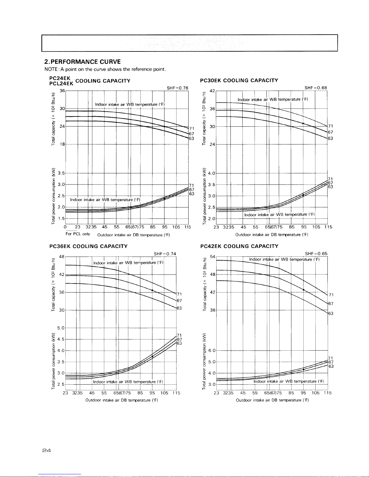
2.
PERFORMANCE CURVE
NOTE
: A point on the curve shows the reference point.
FE;;EFK
COOLING CAPACITY
36
SHF=0.76
-
r
\
6
5
30
X
-
g
24
7 1
-
67
8
63
+
18
z
3.5
-
5
P,
3.0 7 1
5
67
g
2.5
63
0
g
2.0
X
-
3
1.5
+
0 23 3235 45 55 65(67)75 85 95 105 115
--,
For
PCL
only
Outdoor intake air DB temperature
(-F)
PC36EK COOLING CAPACITY
Outdoor intake alr DB temperature
(OF)
PC42EK COOLING CAPACITY
?
atr
WB
tempe
1
\
3ke alr
WB
tern
n
i7)75 85
'
SHF=(
rature
("
F
\,
.
1
.
/
/
43
95 105
Outdoor Intake alr DB temperature
(OF)
Outdoor Intake alr
DB
temperature
(~F)
Data is based on the condition of indoor humidity
50%
Air flow should be set at HI.
A
point on the curve shows the reference point.
<Cooling
mode>
PC24EK
[PS~.GI
pCL24EK
350
340
330
320 86
310 80
300 75
290
70
280
5
270
8
260
a
250
0,
240
5
230
u
5
220
0
210
200
190
180
170
160
150 30 40 50 60 70 80 90 100 110
Outdoor amb~ent temperature
DBrF)
Outdoor ambient temperature
DB("F)
[psi.Gl
PC30EK
350
340
330 86
320 80
310 7 5
300 70
290
280
$
270
8
260
a
250
0,
.
240
230
g
220
0
210
200
190
180
Outdoor ambient temperature
DBrF)
170
160
-
150-
30 40 50 60 70 80 90 100 110
Outdoor ambient temperature
DB('F)
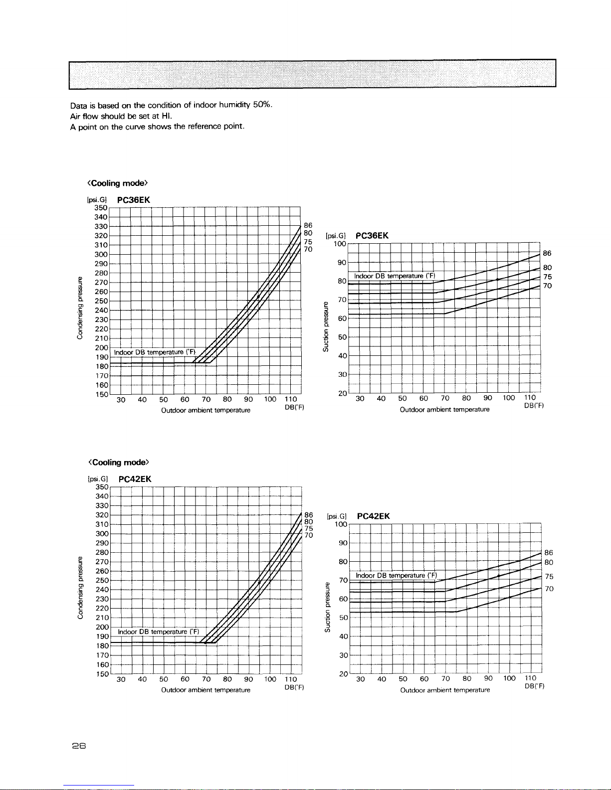
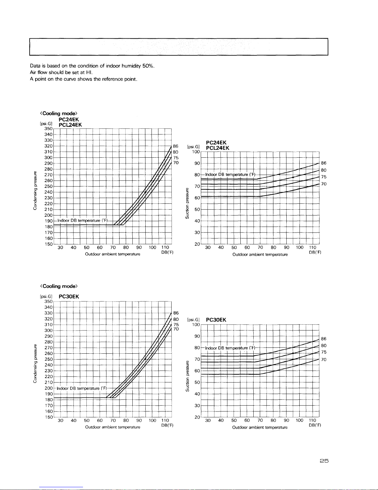
Data
is based on the condition of indoor humidity 50%.
Air flow should
be
set at
HI.
A
point on the curve shows the reference point.
<Cooling
mode>
[psi.Gl
PCBBEK
350
340
330 86
320
80
310
7 5
300
70
290
280
270
260
250
240
230
220
210
200
190
180
170
1 60
1
50
30 40 50 60 70 80 90 100 110
Outdoor ambient temperature
DB('F)
Outdoor ambient temperature
DB('F)
350
340
330
320
86
[psi.Gl
PC42EK
310
Em
100
7
5
300 70
290 90
280 86
270 80 80
260
250 70
7 5
240
2
70
230
8
60
220
a
C
210
.B
50
200
3
m
190 40
180
170 30
160
1
50
30 40 50 60 70 80 90 100110
20
30 40 50 60 70 80 90 100 110
Outdoor ambient temperature
D8('F)
Outdoor ambient temperature
DB('F)
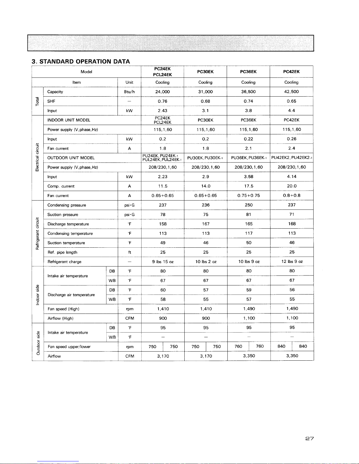
3.
STANDARD OPERATION DATA
Model
Item
/
Unit
1
Cooling
I
Cooling
I
Cooling
I
Cooling
I
lnput
Capacity
SHF
Power supply (V.phase.Hd
/
115.1.60
1
115.1.60
1
115,1,60
1
115,1*60
1
Btu/h
-
I I
1
I
I
Input
I
kw
1
0.2
I
0.2
1
0.22
1
0.26
1
INDOOR UNlT MODEL
Fan current
/
A
/
1.8
I
1.8
1
2.1
I
2.4
1
24,000
0.76
PC24EK
PCL24EK
Power supply (V,phase,Hz)
1
208/230,1,60
1
208/230,1,60
1
208/230,1,60
1
208/230,1,60
1
31.000
0.68
I I I
I
I
Input
/
kW
1
2.23
1
2.9
1
3.58
1
4.14
1
PC3OEK
Comp. current
I
A
1
11.5
/
14.0
1
17.5
1
20.0
/
36,500
0.74
PU42EK2, PU42EK2-1
OUTDOOR UNlT MODEL
Fan current
I
A
1
0.65+0.65
1
0.65+0.65
/
0.75+0.75
1
0.8+0.8
1
42,500
0.65
PC36EK
Condensing pressure
1
psi.G
1
237
I
236
1
250
I
237
1
PC42EK
PU24EK. PU24EK-1
PU~~EK,PU~~~K-~
Condensing temperature 113
/
113
1
117
1
113
/
PU30EK. PU30EK-1
Suction pressure
Discharge temperature
Suction temperature
1
"F
I
49
1
46
I
50
I
46
I
PU36EK, PU36EK-I
Ref. pipe length
/ftl
2 5
1
25
1
25
1
25
I
psi.G
'F
Refrigerant charge
I
-
1
9Ibs15oz
/
10Ibs2oz
1
10Ibs9oz
/
12Ibs9oz
I
Intake air temperature
78
158
Fan speed (High)
/
rpm
1
1,410
1
1,410
1
1,490
1
1,490
1
75
167
Discharge air temperature
Airflow (High)
I
CFM
/
900
I
900
1
1,100
1
1,100
1
8 1
165
I
I
I
I
I
Airflow
~CFM/
3,170
1
3,170
1
3.350
1
3.350
/
7 1
168
WB
Intake air temperature
DB
W8
"F
Fan speed upper/lower
57
OF
"F
55
58
rPm
55
95
-
95
-
750
7 50
95
-
7 50
95
-
7 50
760
840
760
840
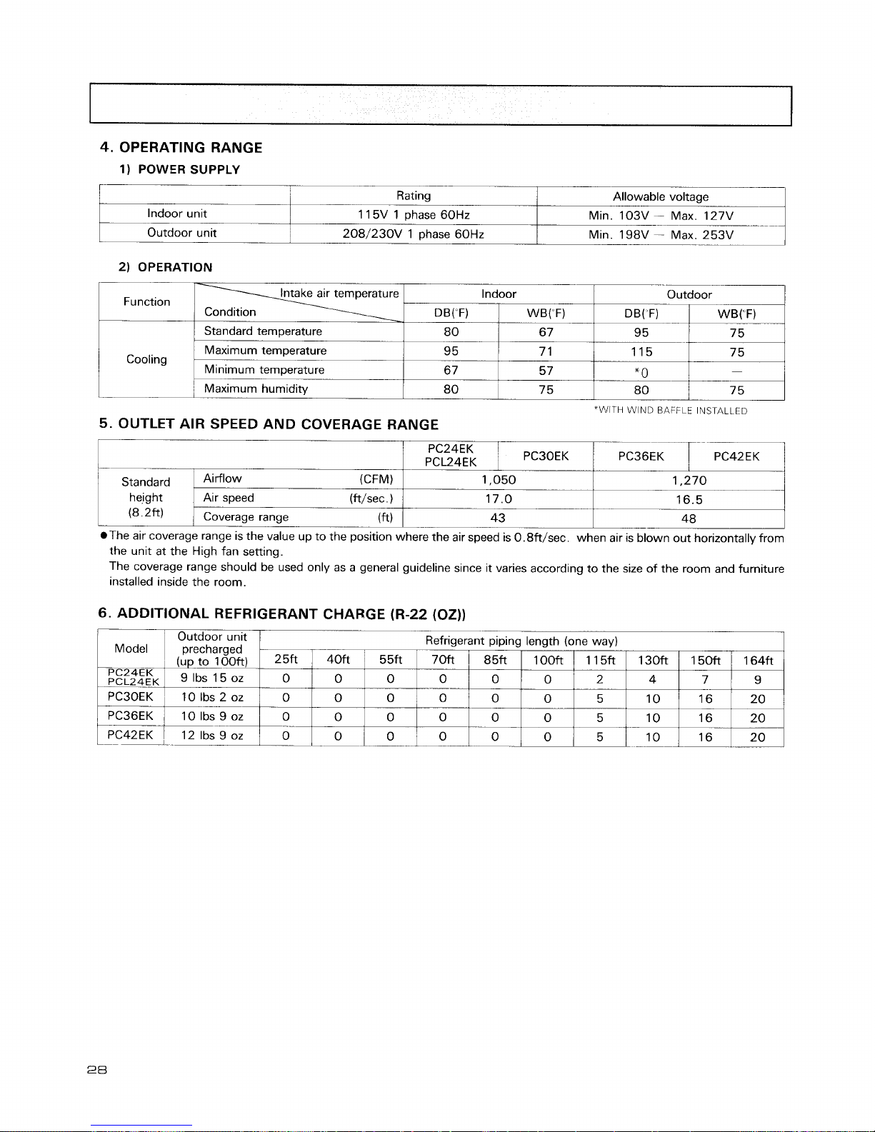
4.
OPERATING RANGE
1)
POWER SUPPLY
Indoor unlt
Outdoor unit
2)
OPERATION
The coverage range should be used only as a general guideline since it varies according to the size of the room and furniture
installed inside the room.
Rating
1 15V 1 phase 60Hz
208/230V 1 phase 60Hz
Function
Cooling
Standard
hejght
(8.2ft)
6.
ADDITIONAL REFRIGERANT CHARGE (R-22 (02))
Allowable voltage
Mm. 10%
-
Max 127V
Mm. 198V
ax.
253V
"WITH WIND
BAFFLE
INSTALLED
5.
OUTLET AIR SPEED AND COVERAGE RANGE
The air coverage range is the value up to the position where the air speed is 0.8ft/sec. when air is blown out horizontally from
the unit at the High fan setting.
(CFM)
Air speed (ft/sec
.
)
Coverage range
(
ft
Indoor
Outdoor unlt
Refrigerant plplng length (one way)
Model precharged
Outdoor
1,050
17.0
43
WB("F)
6 7
7 1
5 7
75
DB( F)
-
95
DB("F)
1,270
16.5
-
48
25ft
PC24EK
PCL24EK
Ibs
OZ
PC30EK 10 Ibs 2 oz
WB("F)
-
75
Standard temperature
Maximum temperature
Minimum temperature
Maximum humidity
40ft
0
0
0
0
PC36EK
PC42EK
1
80
9 5
6
7
80
115
*
0
--
80
55ft
0
0
0
0
10 Ibs
9
oz
-
12 Ibs 9 oz
75
-
7 5
0
--
L--
-1
70ft
0
0
0
0
0
85ft
0
0
0
0
1OOft
0
0
0
0
1 l5ft
2
5
5
5
130ft
4
10
10
--
10
150ft
7
16
16
--
16
164ft
9
20
20
2 0

MODELS : PKI 8/24/30EK, PKLI 2/18/24EK
1. PERFORMANCE DATA
1
)
COOLING CAPACITY
Models
r--
PKI 8EK
PKLI 8EK
Indoor air
I
Outdoor intake air DB tem~erature ("F)
1
Airflow
7 5 8 5 95 105
(CFM) IWB
(OF)
1 I5
R
F
TC I SHC/
TPC
TC
SHC / TPC
TC I SHC/
TPC
TC 1 SHC
TPC
TC
SHC / TPC
Notes
1.
B.F : Bypass Factor, IWB : Intake air wet-bulb temperature.
TC
:
Total Capacity
(
X
1
O3
Btu/h), SHC : Sensible Heat Capacity
(
x
I
O3
Btu/h)
TPC
:
Total Power Consumption (kW)
2.
SHC is based on
80°F
of
indoor intake air
DB
temperature.
2)
COOLING CAPACITY CORRECTIONS
MODEL
PKL12EK
PKl8EK
.
PKL18EK
PK24EK
pK,,,EK
PK30EK
-
--
Refrigerant piping length (one way)
25ft
(std)
1.0
.0
1
.O
1.0
40ft
0.992
0.992
0.981
0.981
5 5ft
0.983
0.983
-
0.968
0.968
7
Oft
0.978
0.978
0.952
0.952
8 5ft
0.966
0.966
0.940
0.940
1OOf3
0.959
0.959
0.925
0.925
.-
115ft
0.950
0.950
0.913
0.913
130ft
0.945
0.945
0.900
--
0.900
150ft
-
-
0.886
-
0.886
164ft
-
-
-
0.874
0.874

2.
PERFORMANCE CURVE
NOTE
:
A
point on the curve shows the reference point.
PKL12EK COOLING CAPACITY
take air WB temp
PKL
only
Outdoor intake air DB tewerature (OF)
;:::&
COOLING CAPACITY
nperature
&&
/
85
For
PKL
only
Outdoor intake air DB temperature ('F)
COOLING CAPACITY
v
For
PKL
only
Outdoor intake air DB temperature (OF)
PK30EK COOLING CAPACITY
SHF=0.63
Indoor intake air WB ternmrature ("F)

Data is based on the condition of indoor humidity
50%.
Air flow should be set at HI.
A point on the curve shows the reference point.
350
340
330 86
320
80
310
7 5
300
70
290
280
270
260
250
240
230
220
210
200
190
180
170
1 60
150
30 40 50 60 70 80 90 100 110
Outdoor ambient temperature
DB("F)
Outdoor ambient temperature
DBrF)
Outdoor ambient temperature
DB("F)
PK18EK
[psi.G]
PKLI 8EK
100
86
90 80
7 5
80
70
P
70
60
g
50
'5
m
40
30
20
30 40 50 60 70 80 90 100 110
Outdoor ambient temperature
DB("F)

Data is based on the condition of indoor humidity
50%.
Air flow should
be
set at
HI.
A point on the curve shows the reference point.
350
340
330
320
310
86
300
80
290
7 5
280
70
270
260
250
240
230
220
210
200
190
180
170
160
150
30 40 50 60 70 80 90 100 110
Outdoor ambient temperature
DB('F)
350
340
330 86
320 80
310
75
70
300
290
280
270
260
2
50
240
230
220
210
200
190
180
170
160
l5O3O 40 50 60 70 80 90 100110
Outdoor ambient temperature
DB(-F)
PK24EK
.GI
PKL24EK
00
90
86
80
80
7
5
70
70
60
50
40
30
20
30 40 50 60 70 80 90 100 110
Outdoor ambient temperature
DBYF)
bi.GI
PKBOEK
100
90
86
80
80
7 5
70
70
1
60
a
C
,g
50
3
40
30
20
30 40 50 60 70 80 90 100 110
Outdoor ambient temperature
DBrF)

3.
STANDARD OPERATION DATA
Model
kern
I
Unit
/
Cooling
I
Cooling
I
Cooling
I
Cooling
I
Capacity
/
~tu/h
1
12,000
1
18,000
1
24.000
1
28.800
1
Input
1
kW
I
1.17
/
1.70
/
2.37
1
2.94
1
I I
I
I
I
Power supply (V,phase, Hz)
/
208/230,1,60
1
208/230,1,60
1
208/230,1,60
1
208/230,1,60
1
INDOOR UNIT MODEL
Rwer supply (V,phase,Hz)
Condensing pressure Ipsi-GI 243
1
245
/
233
/
235
1
PKL12EK
115,1,60
0.06
Input
Input
Comp. current
Fan current
Suction pressure
I
psi.G
I
80
I
81
I
71
I
70
1
k W
Discharge temp.
1
"F
1
155
1
165
1
158
I
166
I
PKl8EK
PKL18EK
115.1.60
0.10
kW
A
A
Refrigerant charge
(
-
/
4Ibs14oz
/
5Ibs8oz
1
9Ibs15oz
/
10Ibs2oz
1
PK24EK
PKL24EK
115,1,60
0.10
1.11
8.9
0.65
Condensing temp.
Suction temp.
Ref. pipe length
PK3OEK
115,1,60
0.10
1.60
12.0
0.75
"F
"F
ft
Intake air temperature
Discharge air temperature
2.27
11.5
0.65+0.65
115
49
2 5
DB
WB
2.84
14.0
0.65+0.65
DB
WB
Airflow (High)
116
49
2 5
~F
-F
Fan speed (High)
CFM
'F
~F
rpm
CFM
Intake air temperature
'F
"F
DB
WB
112
43
25
80
67
rpm
460
95
-
720
1,590
Fan speed
upper/lower
Airflow
113
43
2
5
6 1
59
80
67
1,350
600
95
-
790
1,590
6 1
58
80
67
1,390
80
67
58
55
600
95
-
53
5 1
1,410
750
600
95
-
1,440
750 750
3,170
750
3,170

4.
OPERATING RANGE
1)
POWER SUPPLY
1 1
Rating
1
Allowable voltage
1
2)
OPERATION
Indoor unit
1 15V 1
phase
60Hz
--
208/230V
I
phase
60Hz
Function
-
"WITH WIND
BAFFLE
INSTALLED
5.
OUTLET AIR SPEED AND COVERAGE RANGE
Min.
103V
-
Max.
127V
Min.
198V
-
Max.
253V
Intake air temperature
\
1-4
DB(F)
1
Outdoor
Condition
Cooling
PKLI 2EK
The air coverage range is the value up to the position where the air speed is 0.8ft/sec. when air is blown out horizontally from
the unit at the High fan setting.
The coverage range should be used only as a general guideline since it varies according to the size of the room and furniture
installed inside the room.
Standard temperature
Maximum temperature
Standard
height
(8.2ft)
6.
ADDITIONAL REFRIGERANT CHARGE (R-22 (OZ))
67
-
Minimum temperature
-
PKI 8EK
PKLI 8EK
6 7
(CFM)
Air speed (ft/sec
.
)
Coverage range
(fd
95
Maximum humiditv
PK24EK
PKL24EK
7 5
7
1
5 7
v
75
80
PK30EK
480
13.8
3 1
75
660
14.1
3 6
1 15 75
*
0
-

5.1 Indoor unit PL18/24FK2, PLL12/18/24FK
Unit
:
inch
1
Note
1 For dralnage plplng use
PVC
plpe 1 Inch O.D.
2
For
suspension
bolts
use W3/8 or M 10 screws. (Actual arrangement)
3. F~gure 35-1 /16
*
35-1 /16celCng holes are standard but the cehg holes for 33.718
33-7/8 can also
be
~nstalled In th~s
case,
the ~nstallatlon and servlce are
a little more dicult.
OUTLINES AND DIMENSIONS
Fresh a" mtake
Electrical
box
Draw
-
-
W~nng arrangement openmg 1311 6,
1
35.1 /1 6 celhng hole 13/16
:I
-
i
-+-
?I
2-91'1 6 3-15/1612-9/16
Branch duct hole
ill
6:
1
- - -- - -
--
(knock out hole)
'
\
I1
'
I
25-7/8 lntake hole
;;I
-,I
*
I;
Cehg slde,
--
k
/
\Secure holes 61 /8
Deta~l draw~ng of fresh alr Intake
Bar rlng holes
Auto vane
i:
??
a
j
-I
\
Air
~ntake
Air
outlet
Bar rlng hole

Indoor
unit
P
L30136142
F
K2
Note
1 For dramage plplng use PVC plpe 1 Inch
0
D
2 For suspenwon bolts use W3/8 or MI0 screws (Actual arrangement)
3
F~gure 35-1/16* 55-1/2 cehg holes are standard but the cehg holesfor 33-7/8
*
54-5/16 can also
be
~nstalled In thls case, the ~nstallat~on and sewce are
shghtly more d~fficuk
YY;,
Refngerant p~pe
flared connectlon 1 /2F
Refngerant pipe flared
connection
3/4F/2-3/16
\
lnspectlon hole
(dram water Ilh-up
Unit
:
inch
n
Fresh alr Intake
Wlnng arrangement
openlng
Electrical
box
13/16
-
-7
-+
55-1/2 Cehg hole
1311 6
-
l
m'
Deta~l draw~ng of fresh alr Intake
-.
-
L
Celllng wde
Knock out hole for
51
\$I
-I
2'
N
Secure holes $1/8
I.
46-5/16
Fmh
alr Intake hole
Bar nng holes
I
43-5/16 Pur outlet
1
2-15/16
57-1/16
Pur oudet
fresh alr make
\
4-@1/8
Bar nng hde

NOTES.
1
Allow dimensions for protruded archrtectural members on celllng
2 For dramage piping use VP20 (OD1') PVC pipes.
3. For anchor bob use W3/8 screws.
UPPER PIPING
ARRANGEMENT POSITION
TOP VlEW
4
da
wan
h&kf
--
I
&45
13
16
twrrpnsm
bdl
mch
wnh
mountjng
ohre
on
(-1
1
]
'
5
6
l6
51
5
8(--nt&
VCh
w*h
mnW
Weon
oud!?
16r
RIGHT SlDE VlEW
KNOCK OUT HOLE
1
10
!il)rammgel
'
l6
POSITION FOR REAR PIPING HOLE POSITION FOR
Ebctrral
mx
REAR PIPING
BOlTOM VIEW
I
1
ODrainage pipe
connection
(1
inch
dm.
I.
D
.)
@Knock out hole for rear dramage piping arrangement
ORefngerant-p~pe
Rared
connection 5/8F(PC24EK,PCCZ4EK), 3/4F(PC30EK)
@Refwerant-pipe
%red
connection 3/8F(PC24EK,PCCZ4EK), 1/2F(PC30EK)
@Knock out hole for rear refngerant-piping arrangement
@Knock out hole for upper refngerant-piping arrangement
@)Knock out hole for right piping
(refrigerant,
drainage and wiring)
@Knock
out
hole for wiring arrangement
@Wall hole for piping arrangement
@Ceiling hole for p~ping arrangement
@Terminal
bed
for power line
@Terminal bed for indoor and outdoor units connewn
@Terminal
bed
for Remote controller
@Knock out hole for
fresh
air intake
SERVICE SPACE REQUIRED
AROUND INDOOR UNIT
For workability and safety of suspension work, leave as much
space as possible between one de of the unit and wall.
Space required for bottom and nght hand sde for piping and
wiring
maintenance
are shown above.
SUSPENSION BOLT INSIDE MOUNTING
I..
SUSPENSION BOLT OUTSIDE MOUNTING

Indoor unit
PC36/42EK
UNIT:
inch

Indoor unit
PKLl2EK
U
Uppet
surface
9.718 or more
Q
11-13/16or more
8
48-1/16
Front vtew
'
J
Rtght surface
Unit
:
inch
-
Lower surface
@
a
%.
@
@
@
@
@
0
@
@
Alr Intake grdk
Swtng louver
Inset
Knockout hole for rear wlrlng
(maon clrcutt)
Knockwt hole for rear wtrlng
(control c~rcult)
Wood screw holes
Bolt holes
Wall
ftnmg
6
hok for maln untts
Bolt 13/16 (max
)
Refrigerant
plpe flared connectlon
03
8
05
8
Dramage connectlon 01
-

Indoor
unit
PKl8/24/3OEK, PKLl8/24EK
Unit:
inch
Lower surface
u
9-718
or more
Upper surface
11-13/16
or more
I
Rlght surface
Front vlew
%
Mark
2
&
g
5
&
7
hole for rear wmg
-
(mar clrcutt)
Knockout hole for rear wlrmg
(control clrcultl
Wood screw holes
Name
Knock out hole for rear plplng
(refr~gerant dralnage)
--
MI~ of
9 718
servlce space
Knockout hole for upper plplng
(refrlgerant and wlnng)
Mln of
1
1
13/ 16
servtce space
Alr outlet
Air
Intake gr~lle
Swmg louver
4th holes
Wall fmng
10
6
hole for mam unlfs
1
Refrigerant-plpe
flared connectlon
--
Dramage connectlon
dl
I$
Bolt
13/16
Imax
I

5.2
Remote controller
(PL/PLL
series)
-CWIRULYCONIRJLED-
POWER-
[ON/OFF)
I
LOW
HIGH
/
I
FAN
SPEED LOWIHIGH
I
/
CHECK TEST
EW
I I
CHEW
TEST
RUN
1
Unit : inch
Rear side wiring arrangement opening

Remote controller
(PC/PCL/PK/PKL
series)
CHECK
lJ17
'F
SET
TEMP
1-10
I
LOW HIGH
/
I
CHECK
TEST
RUN
I
POWER-
[E)
I
MODESENT FAN COOLIDRY
I
WARMER
COOLER
I
I
TIMER MODE HOURS
I
FAN SPEED LOWIHIGH
I
AIR SWEEP ONIOFF
I
I
CHECK
TEST
RUN
Unit : inch
=I
A
Rear
sde wiring arrangement opening
r?


Outdoor
unit
PU18EK. PUL18EK. PU18EK-1, PUL18EK-1
Unit : inch
.\\\

I
Outdoor
unit
PU24130EK. PUL24EK. PU24130EK-I, PUL24EK-1
I
Unit
:
inch

Outdoor
unit
PU36EK, PU42EK2, PU36EK-I, PU42EK2-1
Unit
:
inch

11
lare red
connectron
'
1
Refrigerant plpe
piiGGiz
REFRIGERANT SYSTEM DIAGRAM
Accumulator
Compressor
Stra~ner
Cap~llary tube-
ii
l~
Flared connection
I
I
'
I
\
Refr~gerant plpe
Ball valve
%Capillary tube size (OD
x
ID x Length)
(Option)
(w~th
service
For PLL12FK. PKL12FK (40.126x q50.071 ~31.5)
@/a''
port)
For PL(L)18FK, PK(L)18EK (40.126~ 40.063~ 31.5) x2
sets
(with heat ~nsulator)
For PL(L)24FK, PC(L)24EK, PK(L)24EK (40. 126 x 40.063 x 17.3) x2 sets
-
Flow of refrigerant
Refrigerant pipe
pizzx
Outdoor
thermistor
(with heat insulator)
Flared connection
Flared connection
(Option)
(with service
For
PL30FK. PC30EK. PK3OEK (40.157~ 40.079~29.1) x2 sets
.$I
/2,'
port)
For PL36FK, PC36EK (40.157 x 40.079 x 17.7)
X
2 sets
(with heat insulator)
For
PL42FK2, PC42EK (40.1 57x 40.079~ 7.1)x2 sets
-
Flow of refrigerant
NOTE
:
The symbol 4 indicates the diameter.

MODELS:
PL18/24FK2, PLL12/18/24FK WIRING DIAGRAM
7
C1
CN1 (R.6)
CN2 tR.6)
CN51 t1.B:
DP
DS
F1 (1.6)
F2
H2
1.6
LCD
LS
MF1
MV
R.6
SW1 tl B)
SW2 (1.6)
SW3 (I B)
WIRING DIAGRAM
FAN MOTOR CAPACITOR
PROGRAM TIMER CONNECTOR
REMOTE SWITCH CONNECTOR
CENTRALLY CONTROL CONNECTOR
DRAIN PUMP
DRAIN SENSOR
FUSE (6A)
FUSE t0.5A>
DEW PREVENTION HEATER (GRILLE)
INDOOR CONTROLLER BOARD
LIQUID CRYSTAL DISPLAY
LIMIT SWITCH (VANE MOTOR)
FAN MOTOR (INNER THERMOSTAT)
VANE MOTOR (WITH LIMITSWITCH)
REMOTE CONTROLLER BOARD
MODE SELECTOR
ADDRESS SELECTOR
EMERGENCY OPERATION SWITCH
Remote controller
It-
TO
OUTDOOR
UNIT
CONNECTING
WIRES
12V
OC
Ipaarl
POWER
SUPPI
Y
115V
Iphare
MHz
MODEL SELECTOR
ON/OFF SWITCH
COOUNG/DRY OPERATION MODE SWATCH
FAN MODE SWITCH
SET TEMPERATURE UP SWITCH
SET TEMPERATURE DOWN SWITCH
TIMER TIME SWITCH
TIMER, CONTINUOUS AND ON/OFF
SWITCH
FAN SPEED HIGH/LOW SELECTOR
LOUVER SWING/STOP SELECTOR
AIR FLOW UP/DOWN DIRECTION
SELECTOR
TEST RUN SWITCH
INSPECTION SWITCH
ADDRESS SELECTOR
T
TB2.12
TB4
TB5.6
TH 1
TH2
XI tl.6)
X3 (1.6)
X5 (1.6)
X6 (1.6)
ZNR
54321
CNW
CN2O
CNZI
DRAIN
INTAKE
PIPE
TRANSFORMER
TERMINAL BLOCK (POWER)
TERMINAL BLOCK (INDOOR/OUT-
DOOR CONNECTING LINE)
TERMINAL BLOCK (REMOTE CONTROLLER TRANSMISSION LINE)
ROOM TEMPERATURE THERMISTOR
(32'F/15kn, 77"F/5.4kn)
INDOOR COIL THERMISTOR
(32 F/15kn. 77 F/5.4kn)
CONDENSATE PUMP AND DEW PREVENTION HEATER DELAY
VANE RELAY
FAN RELAY
FAN RELAY
VARISTOR
Notes
1
S~nce the outdoor stde electnc wlnng may change
be
sure to check the outdoor unlt electnc wmng for servlclng
2
Indoor and outdoor
connecting
wlres are made wlth polantles make wlnng to rnatch~ng term~nals
3 Symbols used In wmng d~agram above are
Term~nal block
1
connector n PC board tnsertlon tab

MODELS:PL30/36/42FK2
WIRING
DIAGRAM
F1 (1.B)
F2
HZ
1.B
LCD
LS
MF1.2
MV
R.B
SW1 (l.B>
SW2 (1.B)
SW3 (1.B)
FAN CAPACITOR
PROGRAM TIMER CONNECTOR
REMOTE SWITCH CONNECTOR
CENTRALLY CONTROL CONNECTOR
DRAIN PUMP
DRAIN SENSOR
FUSE
t6A)
FUSE <0.8A>
DEW PREVENTION HEATER (GRILLE)
INDOOR CONTROLLER BOARD
LIQUID CRYSTAL DISPLAY
LIMIT SWITCH (VANE MOTOR)
FAN MOTOR
(INNER THERMOSTAT)
VANE MOTOR (WITH
LIMIT SWITCH)
REMOTE CONTROLLER BOARD
MODE SELECTOR
ADDRESS SELECTOR
EMERGENCY OPERATION SWITCH
SW5
(1.B) MODEL SELECTOR
SW1 (R.B> ON/OFF SWITCH
SW3 (R.B> COOLING/DRY OPERATION MODE
SWITCH
SW4 <R.B) FAN MODE SWITCH
SW6
tR.B) SET TEMPERATURE
UP
SWITCH
SW7 (R.B) SET TEMPERATURE DOWN SWITCH
SW8 (R.B) TIMER TIME SWITCH
SW9 <R.B) TIMER, CONTINUOUS AND ON/OFF
SWITCH
SWlO<R.B) FAN SPEED HIGH/LOW SELECTOR
SW12 (R.B) LOUVER SWING/STOP SELECTOR
SW13 (R.8) AIR FLOW UP/DOWN DIRECTION
SELECTOR
SW14 (R.B> TEST RUN SWITCH
SW15 <R.B> INSPECTION SWITCH
SW17 (R.B) ADDRESS SELECTOR
X3
t1.B)
X5 (1.B)
X6 (1.B)
ZNR
TRANSFORMER
TERMINAL BLOCK (POWER)
TERMINAL BLOCK <INDOOR/OUT-
DOOR CONNECTING LINE)
TERMINAL BLOCK (REMOTE CONTROLLER TRANSMISSION LINE)
ROOM TEMPERATURE THERMISTOR
t32~F/15kR, 77"F/5.4kR>
INDOOR COIL THERMISTOR
t32F/15kR, 77~F/5.4kR>
CONDENSATE PUMP AND DEW PREVENTION HEATER DELAY
VANE RELAY
FAN RELAY
FAN RELAY
VARISTOR
POWER
SUPPLY
11%'
Iphase
KlHz
Notes
1 Smce the outdoor s~de electnc wlrlng may change be sure to check the outdoor unlt electr~c wlrlng for servlclng
2
Indoor and outdoor
connecting
wlres are made w~th polarmes, make wlrlng to match~ng temxnals
3
Symbols used In wlrlng d~agram above are
Termmal block
1
connector 0 PC board Insemon tab

MODELS: PC24/30/36/42EK, PCL24EK WIRING DIAGRAM
C
CN1 (R.B)
CN2 (R.B)
CN51 (1.B)
F (1.B)
1.B
LCD
M
F
ML
R.B
RT 1
RT2
FAN CAPACITOR
PROGRAM TIMER CONNECTOR
REMOTE SWITCH CONNECTOR
CENTRALLY CONTROL CONNECTOR
FUSE (6A)
INDOOR CONTROLLER BOARD
LIQUID CRYSTAL DISPLAY
FAN MOTOR (INNER THERMOSTAT)
LOUVER MOTOR
REMOTE CONTROLLER BOARD
ROOM TEMFfRATURETHERMbTOR
(32'F/15kQ,77F/5.4kQl
INDOOR COILTHERMISTOR (3TF/15kn,
77715
4kn)
SWl (1.B)
SW2 (1.B)
SW3 (I. B)
SW5 (1.B)
SWl (R.B)
SW3 (R.B)
SW4 (R.B)
SW6 (R.B)
SW7 (R.B)
SW8 (R.B)
SW9 (R.8)
SWlO (R.B)
MODE SELECTOR
ADDRESS SELECTOR
EMERGENCY SWITCH
MODEL SELECTOR
ON/OFF SWITCH
COOLINGIDRY OPERATION MODE SWITCH
FAN OPERATION MODE SWITCH
SET TEMPERATURE UP SWITCH
SET TEMPERATURE DOWN SWITCH
TIMER TIME SWITCH
TIMER CONTINUOUS AND ONIOFF SWITCH
FAN SPEED HIGHILOW SELECTOR
REMOTE CONTROLLER
INDOOR
UNIT
LOUVER ON/OFF SWITCH
TEST RUN SWITCH
INSPECTION SWITCH
ADDRESS SELECTOR
TRANSFORMER
TERMINAL BLOCK
LOUVER RELAY
FAN RELAY
FAN RELAY
VARISTOR
I.
B
/
SW2 SW5 CENTRALLY
mm
m@F
CONTROL
654321 4321 10987654321 4321
CN50 CN20 CN21
DRAIN
INTAXE
PIPE
D
ro
?EM)CON OUTWOR
.N22 CN30
TO OUTDOOR UNIT
CONNECTING WIRES
--
12VDCl~olar)
--
ON
I
I
1 YLW
TRANS
CN4T
LOUVER
.+-
"Fl
\,M
L
L
I
POWER SUPPLY
----
RED
115V 60Hz
1 PHASE
----
a
WIT
:,,,,--=jj
-
-
-
NOTES
:
1.
Since the outdoor side electric wiring may change be sure to check the outdoor unit electric wiring for servicing
2.
Indoor and outdoor connecting wires are made with polarities, make wiring to matching terminals.
3.
Symbols used in wiring diagram above are,
9
:
Terminal block,
rm
:
connector,
0
:
PC
board insertion tab.

MODELS: PK18/24/30EK, PKL12/18EK WIRING DIAGRAM
C
CN1 (R.B)
CN2 (R.6)
CN51 (1.B)
F (1.B)
1.B
LCD
MF
ML
R.B
SWl (1.B)
SW2 (1.B)
FAN MOTOR CAPACITOR
PROGRAM TIMER CONNECTOR
REMOTE SWITCH CONNECTOR
CENTRALLY CONTROL CONNECTOR
FUSE
(6A)
INDOOR CONTROLLER BOARD
LIQUID CRYSTAL DISPLAY
FAN MOTOR (INNER THERMOSTAT)
LOUVER MOTOR
REMOTE CONTROLLER BOARD
MODE SELECTOR SWITCH
ADDRESS SELECTOR SWITCH
EMERGENCY OPERATION SWITCH SW15 (R.6)
MODE SELECTOR SWITCH SWl7 (R.6)
ON/OFF SWITCH T
COOLINGIDRY OPERATION MODE SWITCH TB 1-4
FAN OPERATION MODE SWITCH
TH1
SET TEMPERATURE UP SWITCH TH2
SET TEMPERATURE DOWN SWITCH
X2 (1.B)
TIMER TIME SWITCH X5 (1.B)
TIMER. CONTINUOUS AND ONIOFF SWITCH X6 (1.B)
FAN SPEED HIGH/LOW SELECTOR SWITCH ZNR
LOUVER ON/OFF SWITCH
TEST RUN SWITCH
TO REMOCON OUTDOOR TRANS
CN22 CN30 CNU
I
INSPECTION SWITCH
ADDRESS SELECTOR SWITCH
TRANSFORMER
TERMINAL BLOCK
ROOM TEMP. THERMISTOR
132"F/15kn,
77F15.4M)
INDOOR COlLTHERMlSlOR (32F/15kn, 77715.4kn)
LOUVER MOTOR RELAY
FAN MOTOR RELAY
FAN MOTOR RELAY
VARISTOR
I
IIIII
I
B
CENTRALLY
\
654321 4321 10987654321 4321
CN50
CN20 CN21
REMOCON POWER
CN40
/
-
-
4'
YLW
-
TO OUTDOOR UNIT
CONNECTING WIRES
12V
DC
polar
NOTES
:
1.
Since the outdoor side electric wiring may change be sure to check the outdoor unit electric wiring for servicing.
2.
Indoor and outdoor connecting wires are made with polarities, make wiring to matching terminals.
3.
Symbols used in wiring diagram above are,
2
:
Terminal block,
:
connector,
0
:
PC
board insertion tab.

MODELS:PUL12EK WIRING DIAGRAM
C COMPRESSOR CAPACITOR
ID1 -LD8 LED (CHECK. SERVICE)
C3 FAN CAPACITOR
MC COMPRESSOR
CH
CRANKCASE HEATER MF3 OUTDOOR FAN MOTOR (INNER THRMOSTAT)
CN3 (0.6) CONNECTOR (CONNECTING WIRES
0.B OUTDOOR CONTROLLER BOARD
INDOOR/OUTDOOR> SW1.2.3 tO.B>SELECT SWITCH (CHECK, SERVICE)
CN6T (0.6) CONNECTOR <TRANSFORMER> T TRANSFORMER
FC
(0
€3) FAN CONTROLLER
F3 t0.B) FUSE <6A)
TH3
XI1 (0.B)
XI2
(0
B)
ZNR
52C
63H2
TB 1
TB3
51C
OUTDOOR
COIL THERMISTOR
CRANKCASE HEATER RELAY
COMPRESSOR RELAY
VARISTOR
CONTACTOR
HIGH PRESSURE SWITCH <PROTECT>
TERMINAL
BLOCK<POWERTERMINALBLocKo
SUPPLY)
TERMINAL BLOCK (CONNECTING
WIRES
INDOOR/OUTDOOR)
OVERCURRENT RELAY
Main functions of
LED
(when both Nos. 1 and 2 of
are
"OFF")
LD4
/
Compressor ON
/
63H2 finct~ons
LD5
Outdoor fan ON
1
-
1
LED NO
LDl
LD2
LD3
LD7
1
--
1
TH3 overheat
protection
LD8 I Crankcase heater
ON
I
Dnfert~ve
1nn61t
I
NOTE : If the operation stops to functlon of the protection dev~ce, the check d~splay flashes
Output d~splay (steady Ikght)
Compressor indoor command
-
-
How
to
use
SWl
and
2
OPressmg
erases the past check contents loaded on the mtcro-
Check d~splay Iflashlng)
-
-
Pipe temp. sensor shon/open
computer.
.The output dsplay (light) remalns durlng
operation
but presslng
dlsplays the past check contents In flash~ng mode Press~ng the swrtch
agaln returns to output d~splay Il~ght)
*
Wh~te connector
I
CAUTION FOR SERVICING
/
.The connector marked
41-
IS
to turn the compressor ON-OFF dunng servlclnq
\
A.
The compressor stops by d~sconnecting the whlte connector as shavn at the nght.
1
CAUTIONS FOR POWER SUPPLY WIRING
I
r
When power Supply
1s
208V
OSmce LD8 lights when normal power is turned "ON", check the power supply wlth the "ON" or "OFF " LO8
WHITE
DSmce the mdoor transformer (T)
IS
connected with 230V power, if 208V power is used, change the wmng
connection
in the followmg Procedure.
OS~nce the ~ndoor and outdoor connectmg wlres has
polarity,
make sure to connect the same termmal numbers (1. 2) for mdoor and outdoor unlts
52

M0DELS:PU 18EK,
PUL
18EK WIRING DIAGRAM
C
COMPRESSOR CAPACITOR LD1 -LDB LED (CHECK. SERVICE) TH3
OUTDOOR
COIL THERMISTOR
C3 FAN CAPACITOR
MC COMPRESSOR
XI 1 <O. B) CRANKCASE HEATER RELAY
CH
CRANKCASE HEATER M F3
OUTDOOR FAN MOTOR (INNER THRMOSTAT)
XI
2
(0. B) COMPRESSOR RELAY
CN3 t0.B)
CONNECTOR (CONNECTING WIRES
0.6
OUTDOOR CONTROLLER BOARD
ZN R VARISTOR
INDOOR/OUTDOOR) SWl.2.3(0.B)SELECT SWITCH (CHECK. SERVICE) 52C
CONTACTOR
CNGT t0.B) CONNECTOR (TRANSFORMER) T TRANSFORMER 63H2 HIGH PRESSURE SWITCH (PROTECT)
FC (0.6) FAN CONTROLLER TB 1 TERMINAL BLOCK<POWER, SUPPLY)
F3 t0.B) FUSE t6A) TB3 TERMINAL BLOCK (CONNECTING
WIRES
INDOOR/OUTDOOR)
51C
OVERCURRENT RELAY
RED
POWER
SUPPLY
WHT
110&~5f-D
Iphare
60H1
5O
BLU
RED
C
Main functions of LED
(when both Nos. 1 and 2 of are
"OFF'')
I
LED NO
1
Out~ut d~splav (steady bqht)
1
Check dlsplav (flashmg)
I
1
Compressor ON
1
63H2 functhons
Outdoor fan ON
LD1
LD2
1
I
n3
NOTE : If the operathon stops to functhon of the protecthon devlce, the check dhsplay Rashes
Compressor lndoor command
-
-
LD6
LD7
LD8
How to use SWl and
2
Pressmg erases the past check contents loaded on the
micro-
computer.
.The output daplay (hght) remalns dunng operat!on but presslng
[w
d~splays the past check contents In flash~ng mode. Press~ng the switch
-
-
P~ne temn sensor shodooen
aaam returns to output d~splav (I~ght)
-
-
Crankcase heater ON
I
CAUTION FOR SERVICING
I
-
TH3 overheat
protection
Defectwe lnput
*
Wh~te connector
A
.The connector marked
3
1
+
1s to turn the compressor ON-OFF durmg servlclng
The compressor stops by dlsconnectmg the wh~te connector as shown at the
right
-
-
*I
When power Supply
IS
208V
WCA
FOR POWER
SUPPLY WIRING
I
OS~nce LD8 l~ghts when normal power
IS
turned ON , check the power supply w~th the 'ON' or "OFF ' LD8
%S~nce the Indoor transformer (T) 1s connected w~th 230V power, ~f 208V power
IS
used, change the whnng
connection
In the follow~na Procedure
1
CAUTIONS FOR INDOOR AND OUTDOOR CONNECTING WIRES
/
~Smce the Indoor and outdoor
connecting
wlres has
polarity,
make sure to connect the same termma1 numbers (1, 2) for indoor and outdoor unlts

MODELSIPU 12/18EK-I PUL 12/ 18EK-1 WIRING DIAGRAM
C
COMPRESSOR CAPACITOR
LDI
-LD~
LED
(CHECK,
SERVICE>
C3
FAN CAPACITOR
MC COMPRESSOR
CH
CRANKCASE HEATER M F
OUrDOOR FAN MOTOR (INNER THRMOSTAT)
CN3 (0.B) CONNECTOR (CONNECTING WIRES
0.B OUTDOOR CONTROLLER BOARD
INDOOR/OUTDOOR)
SW1.2.3(0 BSELECT SWITCH (CHECK, SERVICE)
CN4T t0.B) CONNECTOR (TRANSFORMER) T TRANSFORMER
FC
t0.B) FAN CONTROLLER
F
(0
B) FUSE t6A)
TH3
XI1
(0
B)
X12 t0.B)
ZNR (0.B)
52C
63H2
TB
1
TB3
51C
OUTDOOR COIL THERMISTOR
CRANKCASE HEATER RELAY
COMPRESSOR RELAY
VARISTOR
CONTACTOR
HIGH PRESSURE SWITCH (PROTECT)
TERMINAL
BLOCK(POWERTERMINALBLOCK(POWER.SVPPLY,
SUPPLY)
TERMINAL BLOCK (CONNECTING
WIRES INDOOR/OUTDOOR)
OVERCURRENT RELAY
TB
1
208/230V
1ohas.e
60-
BLU
REO
RN
C
Main functions
of
LED
(when both Nos. 1 and 2 of are
"OFF")
LED NO.
LD1
LD2
LD3
LD4
LD5
NOTE
:
If the
operation
stops to function of the protection device. the check display flashes
Output display (steady Ihght)
Compressor mdoor command
-
How
to
use
SW1
and
2
Pressmg
erases the past check contents loaded on the micro-
computer
.The output d~splay (I~ght) rernalns dur~ng operation but pressmg
d~splays the past check contents In flash~ng mode. Pressng the switch
Check
d~splay (flash~ng)
-
-
-
Compressor ON
Outdoor fan ON
-
TH3 overheat
protection
Defectwe mput
LD6
LD7
LD8
again returns to output display
(I~ght)
/
CAUTION FOR SERVICING
I
TH3 short/open
63H2 funct~ons
-
-
-
Crankcase heater ON
%
Wh~te connector
A
,
.The connector marked
2
1
-
is to turn the compressor ON-OFF dunng servlclng
The compressor stops
by
dsconnect~ng the wh~te connector as shown at the r~ght
-
-
%When power Supply 1s
208V
I
CAUTIONS FOR POWER SUPPLY WIRING
1
OSmce LD8 l~ghts when normal power
IS
turned "ON'', check the power supply with the "ON" or "OFF " LD8
%S~nce the ~ndoor transformer (T)
IS
connected w~th 230V power, ~f 208V power
IS
used, change the winng
connection
In the followmq Procedure
.Since
the Indoor and outdoor connectmg wlres has
polarity,
make sure to connect the same termmal numbers
(1.
2) for Indoor and outdoor unlts
54

MODELS: PU24/30/36EK, PU42EK2, PUL24EK WIRING DIAGRAM
C COMPRESSOR CAPACiTOR
C3.4 FAN CAPACiTOR
CH CRANKCASE HEATER
CN3 t0.B) CONNECTOR (CONNECTING WIRES
INDOOR/OUTDOOR)
CN6T t0.B) CONNECTOR (TRANSFORMER)
FC t0.B) FAN CONTROLLER
F3 (0.6) FUSE t6A)
LD1 -LD8 LED (CHECK, SERVICE)
MC COMPRESSOR (INNER THRMOSTAT)
MF3.4 OUTDOOR FAN MOTOR (INNER MRMOSTAT)
0.B OUTDOOR CONTROLLER BOARD
SW1.2.3tO.B)SELECT SWITCH (CHECK, SERVICE>
T TRANSFORMER
TB
1
TERMINAL BLOCK<POWER SUPPLY)
TB3 TERMINAL BLOCK (CONNECTING
W{RES INDOOR/OUTDOOR)
OUTDOOR COIL THERMISTOR
CRANK CASE HEATER RELAY
COMPRESSOR RELAY
VARISTOR
CONTACTOR
HIGH PRESSURE SWITCH (PROTECT,
RESISTOR (PU42EK2)
COMPRESSOR START CAPACiTOR (PU42EK2)
COMPRESSOR START RELAY (PU42EK2)
,/:
:g",
;;
---
mmn
supplv
-
-
~2
m0/2w
wnr
1pM.e
Mnl
T
8LU
RED
C
LED NO.
I
Output display (steady light) Check display (flashing)
LD1
I
Compressor indoor command
-
52C
Pipe temp, sensor short/open
63H2 functions
Outdoor fan ON
LD6
LD7 TH3 overheat protection
Defective input
NOTE
:
If the operatton stops to function of the protection device, the check display flashes.
j
How
to
use
SW1 and
2
.Pressing erases the past check contents loaded on the micro-
.The output display (light) remains during operation but pressing
displays the past check contents in flashing mode. Pressing the switch
again returns to output display (I~ght)
1
CAUTION FOR SERVICING
I
I
Whlte connector
A
.The connector marked
-?I+
is to turn the compressor ON-OFF dunng servicing.
4D-L
The compressor stops by disconnecttng the white connector as shown at the nght.
'w?
*
When power Supply 1s
208V
1
CAUTIONS FOR POWER SUPPLY WIRING
I
.Since LD8 hghts when normal power is turned "ON", check the power supply with the "ON" or "OFF " LDB.
WHKE
PnStnce the tndoor transformer (T) is connected with 230V power, ~f 208V power
IS
used, change the wiring
connection
In the followina Procedure.
[
CAUTIONS FOR INDOOR AND OUTDOOR CONNECTING WIRES
]
oS1nce the indoor and outdoor connecting wires has polarity, make sure to connect the same terminal numberr
(1.
2) for indoor and outdoor units

MODELS:PU24/30/36EK-I, PU42EK2-I, PUL24EK-I WIRING DIAGRAM
C
COMPRESSOR CAPACITOR
LDl -LD8
LED (CHECK, SERVICE) TH3
OUTDOOR COIL THERMISTOR
C3 4 FAN CAPACITOR
M C
COMPRESSOR (INNER THRMOSTAT)
XI1
(0
B) CRANK CASE HEATER RELAY
C H CRANKCASE HEATER
MF1.2
OUTDOOR FAN MOTOR (INNER THRMOSTAT)
X12
(0
B) COMPRESSOR RELAY
CN3
(0
B)
CONNECTOR (CONNECTING WIRES
0
B
OUTDOOR CONTROLLER BOARD
ZN
R VARISTOR
INDOOR OUTDOOR)
SW1 2 310 B)SELECTSWlTCH (CHECK. SERVICE) 52C CONTACTOR
CN4T
(0
B) CONNECTOR (TRANSFORMER) T TRANSFORMER 63H2 HIGH PRESSURE SWITCH (PROTECT)
FC
(0
B> FAN CONTROLLER
F
(0
B> FUSE t6A)
FROM
INDOOR
UNIT
.
.
.
-I-
CONNECING
WIRES
.
2@=
12V DC
lpolarl
TH3
I'UWCR
SUPPLY
208/230V
I
onase
60~~
TB 1 TERMINAL BLOCKtPOWER SUPPLY) R RESISTOR
(PU42EK2-1)
783 TERMINAL BLOCK (CONNECTING C5 COMPRESSOR START CAPACITOR (PU42EK2 1)
WIRES INDOOR/OUTDOOR> 19 COMPRESSOR START RELAY (PU42EK2
1)
Mam funct~ons of
LED
(when both
Nos
1
and 2 of
[SW3]
are
'OFF
--
Output dlspldv (steddy Iiqht)
LED
NO
L
-
Check dlsplay (flash~ng)
--
--
LD1 Compressor ~ndoor command
--
-
-
--
--
--
A
TH3 short open
-
--
-- - -
-
63H2
functions
t-
-
--
2
-
-
LD6
-
--
--
--
--
*
--
LD8 Crankcase heater ON Defect~ve ~nput
RED
NOTE If the operatton stops to functlon of the protection dev~ce the check dlsplay flashes
How
to
use
SW1
and
2
OPresslng
[FCC
-
erases the pdst check contents loaded on the rnlcro
computer
.The output d~spla) (I~ght) remams durlng operatlon but pressmg SW2
dlsplays the past check contents In flash~ng mode Presslriq the sw~tcli
again returns to output
display
(Ilghti
WN
FORSERVLNG-;
Whirr
cunnertor
.The connector marked
-
1
1s to turn
the
compressor ON OFF durlrig servicinq
The compressor stops by disconnecting the whlte connector as shown at the nght
--
-
&
When
power Supply
IS
208V
EAUTIONS - FOR
--
POWER
SUF~LY
WIR~NG
OStnce LD8 lhahts when normal wwer
IS
tumed ON check the Dower suuulv with the ON or OFF LD8
aSlnce the Indoor transformer (T) is connected wlth 230V power
~f 208V power
IS
used chanqe the wlnng
connection In the follow~nq Procedure
OSlnce the Indoor and outdoor
connecting
wlres has polanty make sure to connect the same terminal numbers 11
21 for tndoor and outdoor unlts
56

MAIN OPERATION
1
Trouble
STOP
a
OPERATION FLOW-CHART
.->
COOL
oua
11
In add~t~on to remote controller centrailzed control and remote
ON-OFF
control are avadable
a2
Causes for enterlng check mode are lhsted below
€0
-
S~gnal transmlnlng/rece~v~ng error
P1 - Abnormal~ty of room temperature therm~stor
P2
-
Abnormality
of Indoor call therm~stor
P3
-
Slgnal transmlrt~ng/recew~ng error
P4 - Abnormal~w of dra~n sensor
P5
-
Abnormal~ty of dram pump
P6 - Cod frost
protection
P7 - System error
P8 - Outdoor unlt trouble
1x3
If check mode 1s set by check SW check polnt for error occurred In the past w~ll be d~splayed
1x4
When the unlt
IS
stopped after
COOL
mode or
DRY
mode the dram pump contmues to work for 3 mlnutes
a5
The 3 mlnutes tune delay
mechanism
funct~ons after compressor stops
a6
Fan speed and alr flow d~rect~on are set by r€rnt~tecontroller Compressor
IS
cont~nuously
ON

COOLING OPERATION
COOL
o.erati0n
,
COOLING
Vane lnml
<*
70
deg
downward
angl
z7
When operatlon stops or changes to cooling or dly mode, the auto vane turns to horizontal angle. If operatlon changes dur~ng auto vane SWING, the auto vane
continues
to swlng.
og
For TEST RUN the thermostat functlon
will
be ~gnored result~ng In contmuous thermostat ON.
og
After 3 mmute compressor operatlon, if the mdoor coil temperature
thermistor
reads
5°F
or below for 3 minutes, the compressor stops for 6 mlnutes
o
10
RANGE
C : Room temperature mlnus ~ndoor coil temperature
IS
more than 9 deg

DRY OPERATION
operation
v
Initial
Vane initial
setting notch setting
1
YES
NO
e
thermostat ON
oNo
time completes
~1
YES
I
1
0-minute compressor
OFF timer start
Compressor OFF
0
Fan STOP
e
3-minute
time delay
YES
thermostat
10-minute
compressor
<>-
Compressor ON
time set
1
4
Compressor ON
I
Fan speed LOW
d13
a7
- 8 Refer to page
58
a
11 When room temperature
IS
64 F or below, the compressor cannot operate
When room temperature rlses over 64 F, the compressor starts after 3-m~nute tlme delay
%
12 Compressor ON tlme
IS
dec~ded by room temperature
Refer to page 62
r
13 In dry operatlon. compressor ON makes the fan speed LOW and compressor OFF stops the fan
Fan speed senlng by remote controller
IS
not ava~lable

1. OUTLINE OF MICROPROCESSOR CONTROL
1
MICROPROCESSOR CONTROL
INPUT
u
Room temp. thermistor (TH
1,
RTI
)
Indoor coil thermistor (TH2, RT2)
Drain sensor
Remote controller
LCD indicator
,-
OFF-ON switching.
COOL/DRY-FAN selector switching.
Thermostat setting.
OUTPUT to indoor unit
Remote controller
MICROPROCESSOR Board
orders.
Processing and transmitting the
Fan
:
ON-OFF
*TIMER mode selector-switching and Timer
setting.
HIGH-LOW fan speed switching.
AUTO Vane SWING-STOP switching.
*AUTO Vane selector (AIR DISCHARGE)
switching.
*TEST RUN switching.
CHECK mode switching.
b
(Self diagnostic trouble shooting)
Indoor Unit
MICROPROCESSOR Board
Receiving the orders from remote controller
and temperature data from indoor unit
Processing the command and data
Control of indoor and outdoor operation
Self diagnostic function
*
System control operation
*
Emergency operation
*Set
by
switching on indoor unit microprocessor board.
*Transmitting the power to remote controller
mr.SLlm
POWER-
A-ELECTRK:
L
m
Fan speed : HIGH-LOW- (EXTRA LOW)
L
Autovane's angle setting
Drain pump : ON-OFF
Emergency all stop.
Polar Two-w~re cable
'7
Non-polar. Two-wlre cable
Outdoor unit
Compressor
protection
dev~ce work~ng
Fan speed control
Crankcase heater control
ON-OFF
Self d~agnost~c funct~on
o
c\l
F
I
I
$
.
Max. Dlstance
550
yards
@-~gna~

2.
COOLING OPERATION
(1
)
Thermostat function
During cooling operation, desired temperature can be set in the range from 66°F to 86°F. When room temperature falls
to the set temperature, the thermostat turns to OFF. After that, when the room temperature rises
2
deg. higher than the
set temperature, the thermostat turns ON.
(2)
Coil frost prevention
After 16-minute compressor continuous operation, if the indoor coil thermistor (RT2 or
TH2)
reads 34°F or below, the
compressor stops to prevent coil frosting. When the indoor coil temperature rises to 5OF, the coil frost prevention stops
and the compressor restarts after 3-minute time delay function.
%
1
%
1 After stop, the compressor does not restart for 3 minutes to prevent short cycle.
(3)
Coil frost protection
OAfter compressor continuous operation of at least 3 minutes, if the indoor coil temperature has been 5°F or below for
3 minutes, the coil frost protection mode starts.
QThe compressor stops, and restarts 6 minutes later. (6-minute time delay)
@The first 10 minutes after the compressor restart is an allowance period.
If the same conditons as a is satisfied in the allowance period, both indoor and outdoor units stop and check code
"P6" appears on the liquid crystal display (LCD) of the remote controller.
If the same conditons as @ is satisfied after the allowance period, 6-minute time delay functions and the allowance
period starts again.
@If the cooling mode stops or changes to other mode during 6-minute time delay or the allowance period, the coil frost
protection mode is canceled.
(4)
Outdoor unit abnormality detection
After 3-minute compressor continuous operation, if room temperature minus indoor coil temperature is less than
9
degrees for 1 minute, the fan speed turns to LOW. Five minutes later, if the difference is still less than 9 degrees, the
outdoor unit is regarded as abnormal. Then the compressor stops and the check code "P8" appears on LCD of the remote
controller.
(5)
Dew prevention heater
To prevent dew on the grill, the dew prevention heater is continuously ON during cooling operation, independant of the
thermostat ON or OFF.
(6)
Drain pump
Drain pump is ON during cooling operation. When cooling operation stops or changes to other mode, the pump continues
to operate for 3 minutes.
'I
:Drain pump abnormality
The drain pump is regarded as abnormal if the drain sensor is under water.
Whether the drain sensor is under water or not is judged by the temperature the drain sensor reads.
@The drain sensor is judged as out of water when
:
The drain sensor has sensed more than 40 degrees of temperature rise after the drain sensor heater ON, or the drain
sensor has read 145 F or above.
@The drain sensor is judged as under water when
:
Though more than 40 seconds have passed since the drain sensor heater turns to ON, the drain sensor has sensed
less than 40 degrees of temperature rise, or the drain sensor has read below 145°F.
In this case, the condensate pump is regarded as abnormal. The operation stops, and the check code "P5" appears
on the LCD of the remote controller.
{ClDrain sensor heater ON/OFF
@The drain sensor heater turns to ON when either of the conditions below is satisfied.
a) The drain sensor has read higher than the room temperature and the temperature difference is less than
9
degrees.
b) About
3
minutes have passed since the drain sensor heater turned to OFF.
However, the drain sensor heater does not turn to ON, if the drain sensor reads 145'F or above.
The drain sensor heater turns to OFF when either of the conditions below is satisfied.
a) The drain sensor has read more than 40 degrees of temperature rise after the drain sensor heater turned to ON.
b) The drain sensor has read
145 F or above.
c) Forty seconds have passed since the drain sensor heater turned to ON.

3.
DRY OPERATION
(1
)
Thermostat function and compressor control contents
I
Thermostat condition
I
Compressor control
1
Thermostat
1
Thermostat ON
/at OFF
/
Above 64°F 3 10
-7
1
%Compressor ON time depends on the room temperature after 3-minute compressor operation.
For example, after
3-minute compressor operation,
if
the room temperature is 85F, the compressor operates 6 minutes more. (9-3 =6)
(a) Three minutes after the compressor starts
:
If the thermostat is ON, the compressor continues ot run according to the above table.
If the thermostat is OFF, the compressor stops for next 10 minutes.
(b) Three minutes after the compressor stops
:
If the thermostat is ON, the compressor starts.
If
the thermostat is OFF, the compressor remains OFF. However, if the thermostat has been OFF for 10 minutes, the
compressor operates for 3 minutes.
(c)
If the room temperature is 64°F or below, the compressor does not work.
When the room temperature rises above 64°F
:
If the thermsotat is ON, the 3-minute time delay works.
If the thermostat is OFF, the 10-minute time delay works.
Room temperature after 3-minute compressor
operatron
82°F or above
79°F to 82°F
75°F to 79°F
3 min. 3 mln
3
min. 3 min.
9
min.
9
mln 7 min
5
min. To = Set temperature (66 to 86'F)
('F)
'
.
,
3min. 3min. 3min. 3mln.
86- Compressor ON
------
Compressor OFF
84-
82-
80-
79-
1'
8
7
7
-
-"
\
,I0
1
-
eCT
I
I
75
/
I
_---
I
-
73-
10
mtn.
Max.
6
mln.
-
3 min. 3 mln. 3 mln.
I
I
(2)
Fan control
While the compressor operates, the fan speed is LOW.
While the compressor stops, the fan stops. Fan speed setting
by the remote controller is not available.
(3)
Protection function
Coil frost protection is the same as that in cooling mode. But coil frost prevention and outdoor unit abnormality detection
do not work.
(4)
Dew prevention heater
Remains continuously ON while in dry mode.
%ON time
9 (min)
7
5
Below 75°F
OFF tlme
3
---
3
-
-
3
3 3

4.
AUTO
VANE
CONTROL (For series PLIPLL)
(1)
Frequency judgement
When the unit operates for the first time after the circuit breaker turned to ON, the frequency, 50Hz or 60Hz, is judged
by the
horizontality sensing switch. If the frequency cannot be judged immediately for some reason, the sensing
operation continues for 10 minutes with the vane motor at ON.
If the frequency cannot be judged yet after 10-minute sensing, the vane motor turns to OFF. But the AIR DISCHARGE
DIRECTION display continues to be indicated.
(2)
During cooling operation
When the cooling operation starts, the horizontal discharge is automatically set. However, the
desired discharge among four modes below-listed can be selected with the AIR DISCHARGE
UP/DOWN button on the remote controller.
020 deg. discharge
045 deg. downward discharge (only with the fan speed at HIGH)
See Fig.
I.
060 deg .downward discharge
@70 deg
.
downward discharge
direction turns to the horizontal discharge automatically.
and it continues for 1 hour.
I
When discharge
a
or @ continues for 1 hour with the fan speed at LOW, the discharge
NOTE
1
:
After that, the discharge @ or
@I
is available by setting with the remote controller,
NOTE
2:
If the discharge direction changes from
to
@I,
the direction returns to the
horizontal discharge when 1 hour has passed since the discharge
a
started.
NOTE
3:
If the discharge direction changes from @ (or
@I)
to the 20 deg. discharge, the
I
-hour timer to return the 20 deg. discharge is canceled at that time.
(3)
During the operation
OFF,
the auto vane is in the horizontal position.
(4)
Automatic swing mechanism
To enable the automatic swing mechanism, turn ON SW17-10 of the remote controller and SW5-1 of the indoor
controller board.
Singing air-flow or fixed air-flow can be selected by the AIR DISCHARGE
SWING/STOP button on the remote controller.
Swinging air-flow
:
The air flow swings between the horizontal discharge and the downward discharge.
Fixed air-flow
:
The air flow is fixed at the set discharge direction.
(5)
When the vane motor is out of order or the connector is badly connected, the air discharge display of the remote
controller continues.
Fig. 1
.
(Remote controller display>
--b
O
20 deg. discharge
I I
=&A&
@
45 deg. downward discharge
..
a
60 deg. downward discharge
4
Changes by pussing
the AIR DISCHARGE
UP/DOWN button.

5.
REMOTE CONTROL DISPLAY
All LCD are indicated for your reference.
I
PLIPLL
series
1
ON
Displayed during operation (ON).
FAN. COOL/DRY
FAN
c"o"?
Operation mode is displayed.
CHECK
I
SET
TEMP
1-1
I
.F
SET TEMP./CHECK
SET TEMP
:
The desired temperature settlng
IS
dlsplayed.
CHECK
When unit malfunctioning
occurs, thls dlsplay
IS
activated.
At this time, "Unlt address" and
"check-code" are alternately
dlsplayed, indicating the malfunctionmg unit and the cause.
TIMER OFF, AUTO STOP,
AUTO START (TIMER MODE)
TIMER OFF (continuous operation). AUTO
STOP, AUTO START mode are displayed.
In AUTO STOP/AUTO START mode, the set
timer is also displayed. Time setting is in
1
hour
units for up to 24 hours.
Fan speed (LOW, HIGH)
The fan speed (Low/High) is dlsplayed.
AUTO RETURN
(1
hour air discharge timer)
The display appears when the unit is set for
cooling or dry mode with low fan speed and
downward
airflow.
1
hour later it disappears.
POWER-
[ONIOFF
J
MODE SELECT FAN COOUDRY
SET
TEMPERATURE
WARMER
TIMER MODE HOURS
FAN
SPEED
LOWlHlGH
I
+.
LOW
HIGH
.;.
:+
+.
1 1 Cl
4,7:4:i
Cl
AUTO
RmRN
CHECK
TiST
RUN
i
J
A
MITSUWSHI
ELECTRIC
<
/
L
r
'I
J
AIR
DISCHARGE
SWING/
STOP
CHECK
TEST
RUN
AIR DISCHARGE
An auto vane angle/amount alrflow discharge display (indicated with dark triangles)
Room Temperature
Durlng operation, the room temperature is
J
displayed
(not displayed when not operating).
The room temperature's display range is 47'F
-
97°F. When this range is exceeded,
"V
47~F"
or
"A
97 F" is displayed.
CHECKA
Displayed
when 'sekdlagnostlc"
functlonlng occurs, and slmultaneously the check code 1s
dlsplayed In the 'set temp
"
TEST RUN
Displayed when test run operatton mode is functioning.
(Turned automatically off after
2 hours of
operation)
%NOTE
:
JlnCENTRALLY CONTROLLDED"
IS
dlsplayed for two seconds after
POWER bunon
IS
turned to on
Thls 1s not defectwe
@All LCD are off durlng power OFF
3)When a bunon on the operating
panel
IS
pressed, a beep sound
IS
heard
4
DO not operate the buttons wrth
something
sharp-po~nted, or the
operatlng panel
will
be demaged

All LCD are indicated for your reference.
I
PCIPCVPKIPKL
series
I
4
Operating
ON
Dsplayed during operation (ON).
POWER-
(ON/OFF]
1
1
DRY
I
I
MODE
SELECT FAN COOUDRY
I
FAN
COOi
CHECK
I-/#-/
SET TEMP
1212
'F
TIMER OFF
AUTO
STOP
,2
HR
AUTO
START
TEMPERATURE
WARMER COOLER
lST
TIMER MODE HOURS
FAN SPEED LOWtHIGH
FAN, COOL/DRY
--
Operation mode is displayed.
1
LOW
HIGH
I
I
AIR SWEEP ON/OFF
I
SET TEMP./CHECK
SET TEMP
:
I
CHECK
TEST
RUN
+
*
The des~red temperature setting
is displayed
CHECK
:
When unlt malfunct~on~ng
occurs, thls d~splay 1s activated
At th~s tlrne, "Unit address" and
"check-code" are alternately
d~splayed, ~nd~cat~ng the malfunctioning unlt and the cause.
TIMER OFF, AUTO STOP,
AUTO START (TIMER MODE)
Louver
ON/OFF
operation
%NOTE
:
@"CENTRALLY CONTROLLDED" is
displayed for two seconds after
POWER button is turned to on.
This is not defective.
OAll LCD are off during power OFF.
@When a bunon on the operating
panel is pressed, a beep sound is
heard.
;4
DO not operate the buttons with
something sharp-pointed, or the
operating panel will
be
demaged.
TIMER OFF (continuous operation), AUTC
STOP, AUTO START mode are dsplayed
In AUTO STOP/AUTO START mode, the sel
time is also displayed. Time setting is in
1
hou~
units for up to
24
hours.
Room Temperature
During operation, the room temperature is
displayed (not displayed when not operating).
The room temperature's display range is
47OF
-
97°F. When this range is exceeded,
'V
47'F"
or
"A
97°F" is displayed.
Fan speed (LOW, HIGH)
The fan speed (Low/High) is displayed.
CHECK
Displayed when "selfdiagnostic" functioning
occurs, and simultaneously
the check code is displayed in
the "set temp."
TEST RUN
Displayed when test run operation mode is functioning.
(Turned autornat~cally off after
2
hours of operation).

Remote control operation and Liquid Crystal Display
1)
ON/OFF
Press the
/ON/OFq
button to operate the unit.
2)
Operating mode selection
Select the desired operating mode with these buttons: [coOL/DRY~ or
FAN-1
3)
Room temperature setting
Each time the
I
WARMER1 button is pressed, the set temperature rises by 2 deg.
Each time the
-1
button is pressed, the set temperature falls by 2 deg.
If the
1
WARMER / or
j
button is continually pressed, the set temperature rises or falls by 2 deg. per
0.5
sec.
4)
Timer operation
alf the
-1
button is pressed, the modes change in the following order
:
(AUTO STOP) - (AUTO START) - (TIMER OFF), and the respective modes are displayed on the liquid crystal display
panel.
Air discharge display
(A)
20
deg. discharge
(B)
45 deg. downward discharge
(C)
60
deg. downward discharge
(D)
70
deg. downward discharge
OTime setting
Timer time can be set by the
[I
button. Each time the
/I
button is pressed, the time increases by
1
hour. If the
11
button is continually pressed, the time increases by 1 hour pr.
0.5
sec. Time setting is in 1 hour
units for up to 24 hours.
L-
J
In coollng mode, the 45 deg downward
discharge
IS
available
only whlle the fan speed
IS
HIGH
In this example, the AUTO STOP is selected and
8
hours later the air
conditioner will be turned to off. The time display will change in
1
hour
7)
Louver operation (AIR
SWEEP
(For
PC/PCL/PK/PKL
series))
Press the AIR SWEEP
/m/m
button to turn the louver operation (air sweep) ON or OFF.
BE#
During "AIR SWEEP" ON, the display alternates every second
:
.r,
-
8)
"Self-diagnostic" function
(WCHEl)
Press the
HECK^
button twice to start the "self-diagnostic" function. "Unit address" and "check code" are alternately
displayed in the set temperature display.
9)
"TEST RUN" mode
Press the
I
TEST RUN
/button twice to start the test run mode. The TEST RUN is easily available, regardless of season.
-
AUTO STOP
~/HRII~~~p
e~~~~~~er
units, showing the remaining time.
LCD
.The timer mode automatically memorizes the previous time setting. When the timer mode is repeatedly used, the
previous time setting is set automatically. (Use the
-1
button to change the time setting)
@Timer cancel device
To cancel the timer setting, push the POWER button.
5)
Fan speed
Press the
~LOW/HIGH/
button to change between low and high speed, "LOW" or "HIGH" is displayed according to the
mode.
6)
Air discharge selection (the angle of auto vane) (For PVPLL series)
Press the [UP/DOWN button to select the air discharge direction among the following air discharge setting.

5.TEST RUN FUNCTION
5-1
BEFORE TEST RUN
After finishing the outdoor and indoor installation, piping, and wiring, check for regrigerant leaks and looseness of power
supply cord and control wire.
And then, use the test run function.
The test run operates independantly of the thermostat function and the room
temperature. In case of the models with drain pump, it works during the test run.
5-2
HOW TO WORK TEST RUN OPERATION
(1 ) Turn the main breakers ON.
(2) Press the
I
TEST RUN I button twice, and "TEST RUN" appears on LCD of the remote controller.
NOTE1
:
During the remote ON-OFF control or the centrally control, ITEST RUN I button is not available.
NOTE2: After pressing
/
TEST RUN I button once, if a different button is pressed by mistake, the first pressing is cancelled.
(3) Press button and check if the air is discharged.
(4) Press button and check if the cool air is discharged.
(5) Check for the louver and the auto vane with
/
AIR DISCHARGE UP/DOWN I and I AIR SWEEP ] buttons.
(6) During the test run operation, the indoor coil temperature code is displayed at the room temperature display part on the
remote controller.
NOTE
:
The indoor coil temperature code is displayed in the range form 1 to 15, showing the temperature from -40°F to
194°F. See the below table.
To check the compressor operation, refer to this code.
In normal cooling operation, the code should be fall as time passes.
Thermistor
Indoorcoil temperature
1
-113°F
j
-122.F
j
--131sF
j
-140.F
j
-158°F
j
-194.F
jabnormaliwl
I
(7)
Check if the outdoor fan operates normally.
(8) As the test run operation has the 2-hour AUTO STOP timer, it stops 2 hours later automatically. To interrupt the test run
operation, press power
-1
button or timer
)
button.
CAUTION: If the unit is out of order during TEST RUN OPERATION, check the malfunction with SELF-DIAGNOSTIC
FUNCTION. (See page 73 to 78.)
If an emergency cooling is necessary for the customer, use the EMERGENCY OPERATION. (See the next page.)
6.
EMERGENCY OPERATION
When the remote controller or microprocessor is out of orderrand all other parts are normal, setting the dipswitch SW3 on
the indoor controller board enables the EMERGENCY OPERATION.
6-1
BEFORE EMERGENCY OPERATION
(1) Make sure that the compressor and the indoor fan are operating normally.
(2) Check for malfunctioning point with the SELF-DIAGNOSTIC FUNCTION. If the protection function, such as coil frost
protection, is found to be working, remove the sources to release the protection function before starting the EMERGENCY
OPERATION.
CAUTION
:
If the SELF-DIAGNOSTIC FUNCTION indicates "drain pump mulfunction" (P5) in the cooling mode, DO NOT use
the EMERGENCY OPERATION. Otherwise drain overflow may occur.
6-2
HOW TO WORK EMERGENCY OPERATION
(1) For emergency cooling, turn the SW3 levers 1,2, and 3 ON; and 4 OFF.
SW3 setting
emergency normal
cooling operation
6
Code
-
microprocessor board
7
5
1 3
81
2
4

(2)
Turn the outdoor unit breaker ON, and then turn the indoor unit breaker ON.
Now, the EMERGENCY OPERATION starts.
(3) During EMERGENCY OPERATION, the indoor fan operates at high speed, but the swing louvers and the auto vane do not
work.
(4)
To stop the EMERGENCY OPERATION, turn the indoor unit breaker OFF.
NOTE: The remote controller POWER ON/OFF button is not available to start/stop the EMERGENCY OPERATION.
CAUTION: Do not use the emergency cooling for more than 10 hours, or the indoor coil may frost.
7.
DIP SWITCH FUNCTIONS
Each figure shows the initial setting by factory.
1
On remote controller board
(1
)
SW 17 (Address selector
)
1234567890
SW17-1-6) For address setting
SW17-7)
When two remote controllers are used, this switch sets the controller function.
0FF:The remote controller is set as a main controller.
ON: The remote controller is set as a sub controller.
SW17-8) Back-up switch
This switch is not available for series PL/PLL/PC/PCL/PK/PKL.
SW17-9) Switch for temperature unit
OFF:
"C(Celsius)
ON: "F(Fahrenheit)
SW17-0) Switch for louvers
OFF: Unit with louvers (For PC/PCL/PK/PKL)
ON: Unit without louvers (For PL/PLL)
2
On indoor controller board
(1
)
SW1 (Mode selector
)
Switch to change over between FAN mode and AUTOMATIC COOLING-HEATING CHANGE OVER mode
-
OFF: Fan mode for cooling-only models including series PL/PLL/PC/PCL/PK/PKL.
ON: AUTOMATIC COOLING-HEATING CHANGE OVER mode for heat pump models
Switch to change over louver display
OFF: Swing
ON: Rotary
Switch for auto vane
OFF: Unit without auto vane (For
PC/PCL/PK/PKL)
ON: Unit with auto vane (For PL/PLL)
Switch for drain pump (Drain lift-up mechanism)
0FF:The drain pump works in only cooling mode.
ON: The drain pump works in both cooling and heating
mode.(For heat pump models)
Switch to change the temperature to start coil frost prevention
OFF: 36°F (For previous special models)
ON: 34°F (For all current models)
Switch for set temperature adjustment in heating mode
This is not available for series PL/'PLL/PC/PCL/PK/PKL.
Switch for fan speed during thermostat OFF in heating mode
This is not available for series PL/PLL/PC/PCL/PK/PKL.
Switch for fan motor operation in heating mode
This is not available for series PL/PLL/PC/PCL/PK/PKL.
Switch for outdoor unit abnormality detection
OFF: When abnormality occurs, it is detected.
ON: Even if abnormality occurs, it is not detected.
1-10) Switch for AUTO RESTART FUNCTION
0FF:This function does not work.
ON: This function works.

(2) SW2 (Address selector
)
123456
ON
rrrrrr
Use SW2 to set unit- address for group control.
For further information, refer to page
78.
(3)
SW3 (Emergency operation switch)
Normal operation (initial setting)
For emergency cooling
(4) SW5 (Model selector)
SW5-1) OFF: For models without automatic swing mechanism (For PC/PCL/PK/PKL)
ON: For models with automatic swing mechanism (For PL/PLL)
SW5-2) OFF: For models with heating mode and cooling mode
ON: For models with only cooling mode including
PL/PLL/PC/PCL/PK/PKL
SW5-3) OFF: For normal models
ON: For twin control models
SW5-4) OFF: For No.
I
unit of twin control
ON: For No.2 unit of twin control
8.0UTDOOR MICROPROCESSOR CONTROL
8-1
Protection function
(1) As soon as a reversed phase, an open phase, or a P.C. board trouble is sensed, the operation stops and the check code is
displayed by LED on the outdoor controller board.
(2) When a protection function such as high pressure switch and overcurrent relay works for the first time, the operation stops
and restarts after 3-minute time delay mode. When the second protection function works, the operation stops and the check
code is displayed by LED. This condition continues until the outdoor unit receives OFF command from the indoor controller
board. Check code indication continues until the outdoor unit receives the ON command from the indoor controller board.
(3) The second protection function is not necessary to be the same as the first one. The content of the second protection
function is loaded in the memory, which is cleared when
SW1 turns to ON or the next check mode starts.
8-2
Control
by
outdoor coil thermistor
(1
)
Unit control
Outdoor coil temperature range for control is from -40 to 194°F. When reading 194°F or above, the outdoor coil thermistor
is regarded as short-circuited. When reading -40°F or below, the outdoor coil thermistor is regarded as open-circuited.
An open circuit is not sensed for the first
7
min. after the compressor start up, but is sensed during defrosting operation or
for the first 10 seconds after the compressor start-up.
(2) Target temperature of outdoor coil temperature
Fan rotational frequency is controlled so that the outdoor coil temperature keeps 95°F
2
4°F.
8-3
Unit operation control
The compressor receives signal from the indoor unit and make the outdoor unit start or stop.
8-4
Fan control
Fan rotational frequency is phase-controlled so that the outdoor coil temperature reaches the target temperature. This control
enables cooling operation even if the outdoor temperature is low.
Fan rotational freqency is adjusted by fan output. Fan output
is divided into 256 steps from
0 to 255 and is controlled every 30seconds.

(I
)
Initial setting
When power is turned to on, or when the compressor restarts after interval of 30 minutes or more:
If the outdoor coil thermistor reads 46°F or above, the fan output step becomes 100.
If the outdoor coil thermistor reads below 46"F, the fan output step becomes 200.
When the compressor restarts within 30 minutes after stop, the fan output step is the same as the fan output before the
compressor stops.
When the operation mode is changed within 30 minutes after the compressor stops, the fan output step becomes 100.
When the operation mode is changed after the compressor interval of more than 30 minuted, the fan output step is the same
as described in
A.
(2) For the first 2 minutes after the compressor start-up, the fan operates at the initial setting output, and then every other 30
seconds, the fan output is adjusted depending on the difference between the outdoor coil temperature and the target
temperature. But as soon as the outdoor coil temperature becomes 122°F or above, the fan output step becomes 255.
(3) When the outdoor coil thermistor reads 122°F or above, the fan output step becomes 255.
(4)
When the high pressure switch (63H1) functions, the fan output step becomes 255. After that, when the switch returns,
the fan control returns to the normal control.
8-5
Crankcase heater control
(1) With jumper wire J3
The crankcase heater is ON from the power is turned to on till the compressor starts, and turns to ON 1 hour after the
compressor stop.
(2) Without jumper wire J3
The crankcase heater is ON from the power is turned to on till the compressor starts, and repeats
ON/OFF on a I-hour
schedule.
8-6
Fixed fan-output
While the compressor is operating and the fan output step is indicated by LED, pushing SW2 fixes the fan output of that time.
The fixed fan-output can be released when either of the following conditions is satisfied.
OSW2 is pushed again.
aSW3 setting is changed.
@The compressor stops.
@Defrosting operation starts. (for heat pump unit)
8-7
Function of switches on the outdoor controller board
SW1 : Clears the check code memory (push-button switch)
SW2: Switches the output state indication and the check code display (push-button switch)
SW3-1 ,2: Switches the output state indication items (dip switch)
For further information, plase refer to page 76.

8-8
Operation during the power-on-reset state
(1) When the circuit breaker is turned to ON, the microprocessor enters the power-on-reset state, which continues until the
direct current for the microprocessor control reaches 12V.
Then the microprocessor starts operation in the following order.
@Each
1/0
port clearance
OFunction input
Function depends on jumper wires set beforehand in the factory.
J
1
J2
8-9
100%
fan output
Fan output is fixed to 255 (100%) by shorting CN22.
However, the fan stops during compressor OFF or defrosting
operation.
Open circuit of CN22 enables the fan control to start.
Jumper
wlre
J
3
J4
8-1
0
Time shortening
Short circuit of CN21 shortens the time listed below.
1
)
Fan control period : 30 sec. + 3 sec.
2) Three-minute time delay function
: 3 min. - 3 sec.
3) Compressor ON/OFF time for bypass valve ON/OFF
:
30 min. + 3 sec.
4) Compressor ON time to start other functions
:
x
min. + x sec.
I
I
With jumper wire
Function
Reversed phase sensing
Without jumper wire
@Check for a reversed phase
@Check for an open phase (with J 1
)
@50/60Hz judgement
BEAROM data loading (check mode, and total time of compressor operation)
OCoil temperature initial input
(2) If an open phase or a reversed phase is sensed, LED blinks every other second.
NOTE
*If power is not supplied to the transformer and the microprocessor, the microprocessor does not work and can sense
neither a reversed phase nor an open phase.
*If a contact point of protective device such as the high pressure switch has already been opened in the power-on-reset
state, it is regarded as an open phase.
In this case, all LED are OFF.
*As for three-phase model, if phase R or
T
opens, microprocessor does not work due to abnormal voltage. In this case,
LED are all ON or all OFF.
Crankcase heater control
Target temperature of outdoor
coil ternperture
Not applied for series
PL/PLL/PC/PCL/PK/PKL.
Sensed
Not sensed
Refer to 8-5
(1)
on page 70.
86°F
For heat pump units
Refer to 8-5 (2) on page 70.
95°F
For cooling units

1.
REMOTE CONTROLLER DISPLAY ABNORMALITY
1-
Display abnormality
TROUBLE
SHOOTING
The display "centrally
controlled" on remote
controller does not disappear.
When remote controller
POWER switch is turned
to ON, the check code
"EO" appears.
When remote controller
POWER switch is turned
to ON, operating display
appears, but disappears
soon.
Cause
1
)
Wrong address setting of remote controller/indoor controller board.
2) Time adapter is connected to the
remote controller.
3) Signal transmission error between indoor unit and remote controller.
1) Signal transmission error between indoor unit and remote controller.
-
1 ) Short circuit of indoor/outdoor con-
necting wire
2) Short circuit of transmission wire
3)
Short circuit of drain sensor heater
circuit
4) Wrong operation of remote controller
due to infrared signal from other appliances.
Check points
Despite turning POWER
switch ON, the remote
controller display does not
appear.
1) Check the address setting of remote controller
and indoor controller.
2) Check if the timer adapter is used correctly.
1
)
Damaged remote controller
2) Short circuit of transmission wire
3) Bad contact of indoor CN40
4) CN40 is attached to a sub unit.
5) Damaged transformer
6) Bad contact of CN4T
7) Broken fuse
8) Circuit breaker OFF
3)OTurn another remote controller's DIP
SW17-7 ON to make
it
sub controller.
@Connect the
sub
controller to the unit, and turn circuit breaker
ON.
-
If the display "centrally controlled" disappear,
replace the former remote controller
If the display remains the same, replace the
indoor controller board.
1) @Connect a sub remote controller.
OTurn circuit breaker ON.
If the display "centrally controlled" remains,
replace the indoor controller board.
@If the display disappears, turn the remote
controller POWER switch ON and check as
follows.
1 1 1
Oprating Diopiayl EO Display
I
F$z:"J:y
1
Remote controller
/ 2 /
Operating
isp play
1
Operating ~isplayl
F,"~",~$n~Ier
1
Sub
remote controller
Operating
isp play
1
F,"J::,"E?IIer
/
Malfunct~on
3
11, 2) Check the wire.
3) Measure the resistance of the drain sensor
connector CN50
-
@.
If normal, the value
should be 820.
4) Turn the circuit breaker OFF, and then turn
ON.
If the remote controller remains abnormal, despite
the above measures, replace the indoor controller
board.
1) Measure the voltage between termanals of
remote controller. If no voltage, remove the
terminals and measure the voltage between
wires. If the voltage is between 6VDC and
12V, replace the remote controller.
2)
--
8) Check each point.
If normal, replace the indoor controller
board.
No
Display EO Display
Malfunct~on
of
Indoor Un~t and
Remote Controller

2.
SELF DIAGNOSTIC FUNCTION WITH REMOTE CONTROLLER
2-1
When malfunction occurs during operation
When malfunction occurs, the indoor and outdoor units stop and the malfunction is displayed on LCD of the remote
controller.
(A) At the set temperature display part, "CHECK" appears, and the unit
address and the check code are alternately at one-second intervals. (Check
mode)
Example Alternately
displayed
Unit address
CHECK
17
/
I-
I
Check code
(B)
When using one remote controller to control several units in the group
control, the LCD shows the unit address and the check code of the first
malfunct~oning unit.
(C) To cancel the check mode, press the POWER
DN/-OFF~
button. However,
CHECK mode
I I
/
1
AIR
SWEEP
ON
OFF
I
CKLK
(3
,,
--
--
A
SUBlSHl
ELECTRIC
L.
MOOE
SELECT
FAN
CWUDRY
yMEWITURE
WARMER COOLER
TIMER MODE HOURS
FAN
SPEED
LOWIHIGH
-
during the remote
ON/OFF
control or the centralized control, press the
CHECK
bunon
remote ON/OFF switch or turn the centralized contoller power button OFF.
CHECK
button
pressed
twice
NOTE:
The latest check code is memorized, even if the check code was cancelled by ways above-mentioned. It takes up to
60 seconds to display the memorized check code.
2-2
How to use the self diagnostic function in service
A.
For normal control with one unit and one remote controller
(1) Pressing the
/CHECK/
button on the remote controller twice starts the self diagnostic function.
(2) During the self diagnostic function, "CHECK" appears at two positions on the remote controller display. Then, at least
10 seconds later, the unit address and the check code are alternately displayed at one second intervals.
(3) Check and repair the unit according to the check code.
(Refer to the next page.)
2-3
For group control using one remote controller
(1
)
Press the
~GVRMERI
or
[COOLER]
button of the remote controller to advance or go back the unit address. Each time
WARMfl
button is pressed, the unit address advances by one. Each time EOOLER] button is pressed, the unit address
goes back by one.
The check code of the unit address appears after the unit address, and they alternate.
(2) The check code
"U8"
means there has been no malfunction since installation.
The check code "EO" means the following conditions:
.The unit address displayed on the remote controller does not apply to any unit.
Power is not supplied to the unit.
Signal transrnitting/receiving circuit is abnormal.
(3) Check and repair the unit according to the check code. (Refer to the next page.)

Check
code
Diagnosis of malfuncti
Signal
transmitting/recm
ing error
Indoor controller does
respond to remote cont
ler signal.
Abnormality of room tt
perature thermistor
(TH
1 or RTI
)
Abnormality of pipe tt
perature thermistor
(TH2 or RT2)
Signal transmission err1
(Remote controller doe
not respond to indoor c
troller signal
.)
Abnormality of drain
s
sor
on
eiv-
not
:rol-
3m-
-
3m-
or
!S
on-
ien-
Cause
During individual unit control
1
)
Bad contact of transmission
wire
2) Signal transmitting/receiving
circuit is abnormal.
1
)
Bad contact of thermistor
2) Damaged thermistor
1) Bad contact of transmission
wire
2) Signal transmitting/receiving
circuit is abnormal.
3) Wrong operation due to infrared signal from other appliances
1) Bad contact of transmission
wire
2) Damaged thermistor
Check points
1
)
Check the transmission wire.
2) Check with another remote controller. If
"EO"
is still indicated, replace the indoor controller
board.
If other check code appears, replace the former
remote controller.
1) Check the thermistor.
2) Measure the resistance of the thermistor. If
normal, it should be as follows.
32"F...15kn
50F...9.6ka
68"F,..6.3kn
86"F...4.3kn
1 04"F...3.Okn
If normal, replace the indoor controller board.
1
)
Check the transmission wire.
2) Check with another remote controller.
If 'P3" is still indicated, replace the indoor
board.
If other check code appears, replace the former
remote controller.
3) Short-circuit between
0
and a of CN40 and
attach CN40 to the following units
Second unit in twin control
Second and third units in triple control
@Sub units in group control
1
)
Check the connector.
2) Measure the resistance of the thermistor
@
-
0.
As for the normal resistance, refer to the case
PI.
If normal, replace the indoor controller board

Check
code
P5
P6
P7
P8
Diagnosis of malfunction
Malfunction of drain
Pump
Coil frost protection
has worked.
System error
Signal transmission error
In
twinttriple control, the
first unit has not received
signal from the second
unit or the third unit for
5
minutes.
Abnormality of outdoor
unit
Indoor board does not
see drop in indoor coil
temperature during call
for compressor
operation
Cause
1) Malfunction of drain pump
2) Damaged drain sensor
1)Short cycle of air cycle
2) Dirty air filter
3) Damaged fan
4) Abnormal refrigerant
1) Wrong address-setting
2) Signal transmittinglreceiving
circuit of remote controller is
abnormal.
3) Wrong SW6-setting
1) Bad contact of transmission
wire
2) Wrong operation due to infrared signal from other
appliances
If outdoor unit does not
function:
1) Wrong wiring of indoorloutdoor connecting wire
2) Reversed control wires.
3)
Protection device has worked
If outdoor unit functions
properly:
1) Damaged indoor pipe
thermistor
Check points
-
--
1) Check the drain pump.
2)
Check the drain sensor.
0
Check the drain sensor heater. If normal, its
resistance should be 82
0.
If normal, replace the indoor controller board.
1) Clear the obstruction form the air cycle
2)
Clean the air filter.
3) Check the fan.
4) Check the refrigerant temperature
1) Check the address-setting.
2) Check with another remote controller. If check
code other than
"Pi"' appears, replace the
former remote controller.
3) Check SW6 setting
1) Check the transmission wire
2)
Short-circuit between O and Q of CN40 and
attach CN40 to the following unit.
0
Second unit in twin control
0
Second and third units in triple control
0
Sub units in group control
1) Check the indoorloutdoor connecting wire.
2) Check the protection devices.
3) Measure the resistance of the indoor pipe
temperature thermistor.
4) Check for
12VDC between control wires 1
&
2 at the outdoor unit during a call for cooling
(P8
code must be reset).
a
If
12VDC is present check the wiring inside
the outdoor unit, transformer secondaries and
control fuse, if all
OK,
change outdoor board.
0
If 12VDC is not present check same wires at
indoor unit.
-
If
12VDC is present at the indoor, locate and
repair the broken control wire.

3.
SELF-DIAGNOSTIC FUNCTION WITH LED ON OUTDOOR CONTROLLER BOARD
Setting dip switchs SW2 and SW3 on the outdoor controller board enables LED to show the output state and check code.
Output state is shown by LED lighting, and check code by blinking.
SW1
:
Turning SW1 ON clears the check code. If SW1 is turned to ON during check code blinking, the indication changes.
to output state indication.
NOTE
:
SW1 is usually available independant of SW3 setting. As an exception, when the check code shows a
reversed phase or an open phase during the power-on-reset state, SW1 is not available.
SW2
:
SW2 is turned to ON by pushing, and OFF by releasing.
When SW3-1 and SW3-2 are OFF, pushing SW2 changes indication between output state and check code
alternately.
SW3
:
Output state indication items depend on combination of SW3-1 ON/OFF and SW3-2 ON/OFF.
r
Changed alternately by pushing SW2.
Check code
Outdoor
coil
Fan output step
Total time of
Output state
1
tem~~$ture
1
(bit)
1
com pressor
operation (Hr)
I
I I
I
I'
1
I I
I
I
Heating operation command
1
LD2 Open phase has been sensed.
indoor
controller
5%
I
2
1
2
1
512
ON
LED
LD1
LD3
1
Outdoor coil thermistor is
During 63H1 function
3%
abnormal.
/
4 4 11024
ON
ON
SW3-1
OFF
blinking
Reversed phase has been sen-
sed.
Overheat protection has wor-
LD7
ked.
/
Bypass valve ON
3%
/
64 64 16384
OFF
OFF
SW3-2
LD4
LD5
LD6
I
LD8
I
Input circuit on controller
Crankcase heater ON
board is abnormal.
OFF
OFF OFF
lighting
%Not applied to series PL/PLL/PC/PCL/PK/PKL.
ON
63H2 has worked.
51
CM
has worked.
26C has worked.
Comp. ON command from in-
door controller
1 1
Compressor ON
Outdoor fan ON
Reversing valve ON
5%
256
8
16
32
8
16
-
32
2048
4096
8192

Outdoor
coil
temperature
To obtain data of outdoor coil temperature, add the number of bits of lighting LEDs, and see the graph below.
can get the temperature.
Then you
3-2
Fan
output step
To obtain data of fan output step, add the number of bits of lighting LEDs. By seeing the graph below, you can get fan
rotational frequency corresponding to the fan output step.
Fan
output step (bit)
Fan
output step (bit)
3-3 Total time of compressor operation
Compressor operation time is indicated in 256 hours units. To obtain the compressor operation time, add the hours of
lighting LEDs. During the compressor operation time indication, SW2 is not available.
3-4
Check code indication
.The latest check code is indicated.
If the outdoor controller board receives the compressor
ON
command from the indoor controller board during check code
indication, the indication changes to output state indication.
.When the check code is indicated by pushing SW2 during normal operation, operation continues.
.When a protection function works for the first time during operation, the operation stops and restarts after the 3-minute
time delay mode. When the second protection function works, the operation stops and the check code is indicated.
However, unless both SW3-1 and SW3-2 are
OFF,
the check code is not indicated.

4.
TROUBLESHOOTING ACCORDING TO CHECK CODE
blinking
LED
Cause
Phases R,
S,
and T are con-
nected improperly.
Check points
Check the power supply connection.
Diagnosis of malfunction
Reversed phase has been
sensed.
Check the power supply.
@Check each protector. Take care of some
protectors that need long time to return.
Open phase has been sensed.
Phase S has opened.
Contact of protector such
as thermal switch has
opened when power turns
on.
Measure the resistance of the thermistor.
*Check the thermistor.
If normal, replace the
outdoor controller board.
Outdoor coil thermistor is
abnormal. (Open circuit or
short circuit has been sensed.
)
Pipe temperature thermis-
tor has broken.
*Thermistor is badly con-
nected.
63H2 is badly connected.
63H2 has worked.
-
--
Check 63H2 and the outdoor fan motor.
Check if refrigerant is short.
Check if air cycle is short-cycled.
Check 5lCM, the compressor, and power
supply.
High pressure switch (63H2)
has opened.
Overcurrent relay (51 CM)
opened.
5 1 CM is badly connected.
51 CM has worked.
Thermal switch (26C) has
opened.
%
*26C is badly connected.
e26C has worked.
Check 26C.
Check if refrigerant is short.
Check if the capillary tube is clogged.
Over heat protection has
worked.
*The thermistor has broken.
Pipe temperature has ex-
ceeded
1
52°F.
Measure the resistance of the thermistor.
Check the outdoor fan motor.
Check if air cycle is short-cycled.
Input circuit of outdoor controller board is abnormal.
Pulse input has been
abnormal.
Replace the outdoor controller board.
L
i
%Not applied to PL/PLL/PC/PCL/PK/PKL.
5.
WHEN OUTDOOR UNIT DOES NOT WORK
Cause
1
)
Indoor/outdoor connecting wires are badly connected.
(Refer to next page.)
2) Power supply is badly connected.
3) Connector or transformer has broken.
4)
Fuse (6A) in the outdoor controller board has blown.
Check points
1
)
Check the connecting wires.
2)
Check the power supply.
3) Check connectors and transformers.
4) Check the fuse.

6.
WRONG WIRING ON SITE
6-1
Between remote controller and indoor unit
If wire is disconnected between the remote controller and the indoor unit, the POWER ON display does not appear despite
turning the power switch ON. The beep sound is not heard, either.
6-2
Phenomena due to wrong wiring between indoor and outdoor units
Wrong wiring
1
Thermostat
Indoor unit Outdoor unit
Disconnect between 1 and 1 or
2
and
2.
1
OFF
Phenomena
The outdoor unit stops.
Operation stops.
9
minutes later, the check code "P8" appears on the
remote controller display.
Operation stops.
9
minutes later, the check code "P8" appears on the remote controller
display.

7.
OTHER TROUBLES AND CAUSES
1
Vanes do not work. Vane motor does not work.
a
Vane motor has broken.
Limit switch does not work. Vane motor relay has broken.
Connector is badly connected.
Limit switch has broken.
Vane motor is badly assembled.
ChI
size of cam is not proper.
lndoor controller board has broken.
--
Protection function has worked.
Refer to check code on remote controller display.
-
I
button is not available.
Horizontal angle has not
In this case, remote controller is
been detected.
-
/
operation
normal.
-
Power ON/OFF switch
See page
74
-
7
5.
If drain pump has broken or coil frost protection has
worked, operation does not stop only in
5
to
20
seconds.
lndoor controller has
broken.
Dip switch setting is
wrong.
lndoor controller has
Vane motor limit
broken.
switch has broken.
Vane motor has
Vane motor is broken.
broken.
Vane motor
limit
Badly connect
Disconnected
L
switch is badly con-
nected.
Auto vane is wired
after power is turned
to ON.
Beep sound is heard, but
Indoor/outdoor connect-
display is turned to OFF.
ing wire is wrong connected.
Indoor/outdoor connecting wire shorts.
Compressor protector has
broken.
Deicer han broken.
-Beep sound is not heard,
"L
Remote controller has
a
and display remains OFF. broken.
Transmission wire is
badly connected.
-"Centrally controlled" is displayed.
-Transmission wire has
broken.
-Connector is badly
connected.
-Indoor terminal block
is badly connected.
-
Remote controller
terminal block is
badly connected.

SYSTEM
CONTROL
1. VARIETY OF SYSTEM CONTROL FUNCTIONS
ITJGroup control by a
single remote controller.
(See page 82
.)
OControl using two
remote controllers
(See page 83.)
3160th remote ON/
OFF and individual
controls
(See page 83.)
qlndividual control by
gathering remote
controllers
(See page 84.)
QMultiple remote
control display
(See page
85.)
gAUTO RESTART
FUNCITON
(See page 85.)
Unit Unit Unit
Remote
controller
A number of units, installed at different locations can be
started and controlled with a single remote controller. The
remote controller can be mounted in a remote location
using a non-polar two-wire cable, which can be extended
up to
550
yards. A maximum of
50
units are controllable
by a single remote controller. All units operate in the same
mode.
u
Unit Unit Unit
Two remote controllers can be used to control either one
unit or several units in group control.
This enables to
control units with ease either from a distance or at close
range. Units operate according to the latest command
from either remote controller.
Remote
controller
Opt~onal
All units can be turned on or off simultaneously using the
adapter
Relay
box
remote ON-OFF switch. Besides each unit can be
controlled individually by each remote controller. During
remote ON-OFF control, a message of "CENTRALLY
CONTROLLED" is displayed on the LCD of the remote
controller.
Remote Remote
ON/OFF
This method is available for both one unit control and
controller
switch
several units control.
By gathering remote controllers to one place, several units
installed at different locations can be controlled individually, and operation conditions of all units are visible without a special control board. Control method is the same as
that of the single unit with a single remote controller.
Remote
controller
Several units can be controlled by remote control display
board. Operation conditions of all units are visible with the
remote control display board.
Individual control by each remote controller is also available.
Remote control Remote
display board controller
Units can be started or stopped by circuit breaker on or
nff
",,.
Circu~t breaker
Remote controller is also available.
By this function, when the power is restored after power
Remote
failure, the unit restarts automatically.
controller

2.
GROUP CONTROL
BY
A
SINGLE REMOTE CONTROLLER
A maximum of 50 units can be started in order according to
Figure 1
the dip switch setting.
2-1 How to wire
(1) Connect the remote controller to the double terminal block
on the indoor controller board of the master unit, that is,
No.0 unit. (See Figure 1
.)
(2) Connect the double terminal block of the master unit to the
double terminal block of No. 1 unit.
(3) Connect the double terminal block of No.
1
unit and the
double terminal block of No.2 unit.
controller
Master unit
electrical box
(4) Continue the process until all the units are connected with
Figure
two-wire cables. (See Figure 2.)
(5)
Remove the connector CN40 from the indoor controller
board of each unit except the master unit. (See Figure 3.)
(6) Set the unit-address of each unit with SW2 on the indoor
controller board following the instruction below.
2-2 How to set unit-address
Figure
3
The unit-address also serves as a successive-start timer which
controller
board
start each unit at intervals of 1 second. If two or more units have
the same unit-address in the group control, operation stops due to
system error. Be sure to set SW2 correctly following the instructions below.
(1)
Each lever of SW2 shows the number as follows.
SW2-1
:
1 SW2-4 : 8
SW2-2
:
2 SW2-5 : 16
SW2-3
:
4
SW2-6 : 32
(2) Total number of levers turned to ON shows the address of the
unit.
If you turn ON SW2-1 and SW2-2, the unit-address is set as
No.3.
(3) In this way, set from the master unit to the last unit.
Do not forget to set the master (No.0) unit.
Setting examples
I
/
ALL OFF
I
1 ON
I
Master
(No.0)
unlt
No.2 unit No.4 unit
+3oN
N~.
1
1
Unit address & start
delay
~n
seconds.
2-3 Unit control
The remote controller can control all unit ON/OFF, temperature, air flow, and swing louver. However, the thermostat in each
unit turns to ON or OFF individually to adjust the room temperature.
No.8 unit
0
-
4
ON 5 ON
No. 16 unit
No.32 unit

3.CONTROL USING TWO REMOTE CONTROLERS
Two remote controllers are available for control of either one unit or a group of units. Units operate according to the latest
command from either of the two remote controllers.
However, before
operation,
be sure to set one remote controller for 'main controller" and the other for "sub controller", using
dipswitch SW17-7 of the remote controller.
I
I
0
Individual
operation
Remote
&
controller
Remote
controller
3-1 How to set SW17-7
0
Multiple operation
I-
Remote
controller
Remote
controller
(1)
For the main remote controller, turn SW17-7 OFF. (See Figure
5.)
(2) For the sub remote controller, turn SW17-7 ON.
tin,
lrrr
K
Remote conrroller
0
my"'-
"
3-2 Remote controller
LCD
indication
(1) The same indication always appears on both main and sub remote
controllers,
excepting
in the timer operation.
(2) Timer operation can
be
set with either of the two remote controllers.
However, LCD indication appears only on the remote controller used for
timer setting.
(3)
If both remote controllers are set for timer operation with different
time-settings, the timer operation of shorter remaining-time is eftective.
(4)
Self-diagnostic function is available with either of two remote controllers.
If one of the remote controllers is used for self-diagnostic function, the
other remote controllers displays the self-diagnostic mode.
If the self-diagnostic function is reset by either of the two remote controllers, both remote controllers are reset.
Turn SW17-7
ON.
I
4.REMOTE ON-OFF AND INDIVIDUAL REMOTE CONTROLS
This method is available to control one unit or any number of units.
The following operations are available by connecting a relay, timer adapter, and remote ON/OFF switch to the system. Timer
adapter,
PAC-715AD, is an optional part. Other parts are on the market.
(A) To start all units in order by remote ON-OFF switch
(B)
To stop all units simultaneously by remote ON-OFF switch
(C) To switch from the remote ON-OFF control to the individual remote control
4-1 System
Figure 6 shows the case of three units as an example. The same is the case with any number of units.
Figure
6
I I
Power supply of
control crcuit
Timer adapter
PAC-7
1
5AD

NOTE1 : Install the relay box where you can service easily.
NOTE2: For control circuit wiring, use a wire of
No.
14 AWG or a control cable according to the power supply of control
circuit.
NOTE3: When the power supply of control circuit is 11 5/230V AC,
Do not connect the control circuit wire to the remote controller cable directly.
Do not place the control circuit wire and the remote controller cable into the same conduit tube.
4-2
Basic wiring
Caution: Before starting all units simultaneously by the remote ON-OFF switch, be sure to connect a sequence-start timer
into the remote ON-OFF circuit. Otherwise, rush of starting current exert a bad influence upon the power supply.
Remote
ON/OFF
No.1 unit No.2 unit
qwitrh
relay box relay box
-
. . . .
-.
.
Glow switch or pilot lamp
combined to easily ident
Next unit
To
No.
I
unit
1
1
1
Remote controller
Timer adapter cables
4-3
Switch function
of
remote
ON-OFF
switch
SW2
remote ON-OFF and individual control)
*
1After all units start together, if SW2 is turned to OFF, each unit can be individually stopped by each remote controller.
*
2After all units stop together, if SW2 is turned to ON, each unit can be individually started by each remote controller.
(Remote ON-OFF control)
5.1NDIVIDUAL CONTROL
BY
GATHERING REMOTE CONTROLLERS.
Gathering remote controllers allows controlling individually units installed
at different places and to monitor the operations without a special
control board.
Remote control cable is extendable up to 550 yards. When the cable
length exceeds
39
ft,
use the double-insulated two-core cable such
as Belden 9407, and the cable thickness must be No.22 AWG or
above.
When gathering the power ON/OFF switches of air conditioners near
the remote controllers, you should also install the power ON/OFF
switch near each unit to prevent electric trouble in servicing.
OFF
(Individual control)
Each unit can be controlled by
each remote controller.
Remote
ON-OFF
switch
is
not
available.
I-
remote
controller cable (2-core)
I(
A
SWl
(Switches between
remote
ON
and OFF,)
-
ON
(Start)
OFF
(Stop)
Remote controller
All units start together.
*
1
Individual control is not available.
All units stop together. *2
Individual control is not available.
I
UK

6.MULTIPLE REMOTE CONTROL DISPLAY
You can control several units by multiple remote control display, if
you wire an optional multiple display adapter (PAC-725AD) with
relays and lamps on the market.
6-1
How to wire
(1) Connect the multiple display adapter to the connector CN51 on the
indoor controller board.
(2) Wire three of the five wires from the multiple display adapter as shown in
the below figure.
(Wiring)
Power
ORANGE
SUPP~Y
+
---_--_--
1
I
--~------------.
connector (5P)
-@
1~-
Electrical insulation is needed.
C
optional multiple display wiring at the actual place
-4
adapter
The maximum distance between
indoor board and relav is 33 feet
Power 3wire
...
3 wire
.,,
3wire
,,;
controller (Field supply)
cable
n
n
I
Multiole Remote control
U
u
u
I
Indoor controller Board
[Notes on Signs]
XI
:Relay (for check lamp)
X2:
Relay (for operation lamp)
RL: Check Lamp
GL: Operation Lamp
[Field supplied parts]
Relays: DC
12V
with rated coil power
consumption below 0.9W.
Lamps: Matching to power supply voltage
ON-OFF
Display Remote Remote Remote
1
(Field supply)
I
controller controller controller
(Operation check)
controller adapter
Multiple Remote Control Display relay-box
7.AUTO RESTART FUNCTION
Unit can be started or stopped by power supply ON or OFF.
Therefore, after power failure, when the power is restored, the unit restarts
automatically.
To enable this function, turn ON the dipswitch SWI-10 on the indoor
controller board.
<Wiring>
I
Y
7
A . an optional tlmer adapter
B
:
a s~ngle-throw sw~tch
Brow
For remote control, connect the optional timer adapter (PAC-71 5AD.)

TIMER OPERATION
WITH
OPTIONAL PARTS
*The remote controller is equipped with 24-hour ON/OFF timer as standard. (See page 86.)
Optional program timer (PAC-SK65PT) can be connected to the remote controller.
*Timer on the market is available. In this case, optional timer adapter (PAC-71 5AD) is necessary.
1.
PROGRAM
TIMER
1-1
Feature of program timer
(1 ) Daily timer function
Twenty-four hours of a day are equally divided into 48 time-periods, that is, a time-period is 30 minutes
Each time-period can be set for unit ON, unit OFF, or setback operation.
(2) Setback operation
Set back operation is useful to reduce running cost.
e.g. At a hotel of the 24-hour system
8:00--23:OO Cooling operation with set temperature at 79°F
23:00--8:00 Setback operation with 2 degrees of setback
As shown in the right chart, the set temperature rises 2 degrees automati-
79.F
cally during the setback operation. When the setback operation ends,
I
I
I
normal operation starts.
8:OO 23:OO 8:OO
(3)
Weekly timer function
Normal Setback Normal
Daily timer function can apply to each day of the week.
operation operation operation
1-2
How to connect program timer
(1
)
Install the program timer next to the remote controller in the same way the remote controller is installed. The program timer
has the same dimensions as that of the remote controllers.
(2) Connect the program timer and the remote controller with 6-wire cable as shown in the below figure.
NOTE: While the program timer is con-
4
/
H
x W x
D
(~nch)
nected to the remote controller, the
4-3/4~4-3/4~5/8
24-hour ON/OFF timer of the
Remote Prograrn
remote controller is not available.
controller timer
I
Qr
I
6-wire cable
Connector CN
1
Connector CN
1
1-3
How to use program timer
/
iilil~r.SLlliilil
\
Square
a
shows switch and
'
"
means display.
I
*Mode selector switch : Use this switch to select
1
I
"SET".
"MONITOR" Displays the current timer setting status. All other
CLOCK
BACK AHEAD
switches except jMONITOR / are not available and this is the
normal status.
TODAY
"SET" Use this for setting of time, changing day of the week, daily and
WEEKLY
TIMER
weekly timer.
DEGREE
SET
BACK
CLOCK adjustment switch: Used for adjustment of current time.
DAILY
TIMER
TODAY (day of the week) set switch: Used for adjustment of day of the
Pressing
changes the day, in the order Mon, Tue,
Wed...
(7)
(El
coq
WEEKLY TIMER switch: Sets timer for a week.
9=18 deg
86
AM~~SUBISHI
ELECTRIC
\
DEGREE SET BACK switch: Sets the set back amount.
Set back can be set in
2
degree units in the range of 2 to 18 degrees.
i-----.
DAILY TIMER switch:Sets timer for SET BACK
1
=2
deg
1
day.
2=4
deg

(1)
Daily timer setting procedure
i
)Daily timer display
Each block shows timer setting of the time-period by three patterns of LED.
Lighting
......
Normal operation
Blinking
......
Setback operation
OFF
............
No operation
As an example, the left figure shows:
7.00 to 12:00, 13:30 to 2
1
:00 lighting
-
Normal operation
ii
)DAILY TIMER setting procedure
(1
)
Press I SET/MONITOR I and switchover to "set" mode.
(2) One block blinks to show the current tmie. Move the blinking block by
-1
or switch to the time to set.
(If there are blocks already set for "set back operation", the blocks are blinking more slowly than the current time block.)
(3) Set the timer for each block as follows
:
[For operation ON 1-presm+the block lights-the next block blinks.
[For SET BACK operation]-press
/
SET
BACK
1-the block blinks-the next .block blinks.
[For operation OFF ]-.press /-the block turns OFF-the next block blinks.
Continuous pattern setting can be done by pressing the switch continuously.
(2)
WEEKLY TIMER setting procedure
i
)Weekly timer display
Upper row
...
A lighting LED shows "today".
Lower row
...
Each LED displays if the daily timer is ON or OFF.
ii
)Weekly timer setting procedure
(1
)
Press 1 SET/MONITOR I and switch over to "SET mode.
(2) Today's LED blinks in the lower row. To apply the daily timer, press the WEEKLY TIMER
/ONI
switch. Not to apply the daily timer, press the WEEKLY TIMER switch.
(3) Then the next LED blinks. Set in the same way as (2).
(4)
Repeat procedure as described in (2) and (3) until all of 7 days are set.
(5)
When setting is completed, press I SET/MONITOR I switch to return to "MONITOR"
mode.
2.TIMER ADAPTER
With the optional timer adapter (PAC-71 5AD), a timer on the market can be connected. Connect the timer adapter to the
remote controller and wire as shown in the below figure. If more than 33 feet of wiring is needed to connect the remote
controller and the timer, use a relay.
NOTE: Be sure to use a non-voltage contact output timer with load and timer power supply having different circuits.
&/Timer Adapter
(Wiring) T...Timer Contact
ORANGE
. - -
- -
-
-
-
SW...Swit~h
remote From
l-q
.
--&j
1 Independent Timer Operation
controller
I
.
------
Remote controller operation switch becomes idle.
BROWN
2.Combined Use of Timer and Remote Controls
From
ORANGE
.
-------
SW ON Timer control
controller remote
RED+
---Ic+!
SW OFF Remote Control Operation
-E
BROWN
sw
*
--e\J

Using this grill enables to select the air discharge direction. The air flow can also be regulated by adjusting the widths of each
discharge outlet. Choose the adequate method according to the conditions in the room where the panel is to be installed.
*
For 2-direction discharge, the widths of the outlets must be under a fully opened condition.
-
Internal surface view of the grill
/'--",
4-WAY AIR
FLOW
SYSTEM (SERIES
PLIPLL)
[
The figures inside
(
)
are
/
1
for PL30/36/42FK2
~
When slide-shutter
Applied under
1 I 1
shipment from
factory.
11
)
I I
Slide-shutter fully closed
.-
I
When shde-shutter
1
Removmg
lnsulatlon used to close off the
sllde-shutter alr outlet
"
,
/
When slide-shutter
1
V
/when a~~lvina ins-
I
ulation used to close
I
o{L~-Y/
IOJ
Opening width
-
7-7/8(19-11/16)
Opening width
17-1 1/16 (35-7/16)
Adjusting the discharge outlets (Only when discharge outlets are fully opened or closed).
Remove slide-shutter by cutting into the broken-lines using a cutter. When doing so pay attention not to damage the
insulation around the slide-shutter
.
Locatlon where to cut into
A
Vane Slide-shutter

Opening
measurements
for
PU0/36/42FK2
are
within
(
).
.Adjustment examples of discharge direction
&
air
flow
l
Regular ceiling height
When ceiling is of regular height (For example 8.2ft) set each
outlet at a standard width (1 1-1 311 6).
l
Relatively high ceiling
Set the outlets during installation.
The outlet width can be adjusted in the range of 7-7/8 to
1 1-1 3/16 using the slide knob.
Unit
:
inch
High ceiling
Adjust each outlet width to 7-718 to enable air to reach
maximum distance. Applicable for rooms with ceiling height
of
9.8ft.
?
T
r.
T
9.8ft.
I
e4-direction air discharge
Remove slide-shutter at installation and adjust the outlet width
to 17-1 1
/I
6.
Close remaining outlets to selected width.
17-1 1/16 (35-7/16)
l
3-direction air discharge
During installation close one outlet and shield it with the
1
?
insulation panel. Adjust widths of remaining 3 outlets to
\
7
2
match the room space.
2
7
7
1
\
'T'
r.
f
?
T
T
r.
l
2-direction air discharge
During installation close two outlets and fully open ( 1 7-1 1 11 6
width) the remaining 2.
*For 30/36/42FK2, open the longer outlets and close the
shorter outlets.

Selecting arrangement
of
discharge
outlet
and adjusting
the
width
for
PL18/24FK2, PLLI 2/18/24FK.
Constrained Conditions When
Sefecting
Discharge Outlet Width.
(PLI 8/24FK2, PLL12/ 1 8/24FK).
Total
width
of
four outlets must exceeds 31 -1
/2.
Unit : inch
0-C
:
1 1-1 3/16 - 7-7/8
(2)When height exceeds 9.5fi
2
adjust
4
outlets to 7-7/8 each or 2
(I
:
1.5)
outlets to 17-1 1/16 each.
Discharge
outlet
(1: 1)
A
11-13/16
I
1
1
0
3
(1
:
2)
B
11-13/16
o
4
(1 : 1)
When ceiling height is 7.9 feet.
7.9
8.9
O
0
5
(1
:
1)
When ceiling height is 8 to 8.9 feet.
C
11-13/16
O
0
9-13/16
7.9
8.9
0
D
11-13/16
7.9
8.9
Examples of application Precautions
(1)WhentheoutletAisclosetoawin-
dow, widen A and narrow C to raise the
9-13/16
7-7/8
0
-
0
0
9-13/16
17-11/16
17-11/16
17-11/16
7-7/8
9-13/16
9-13/16
7-7/8
0
17-11/16
cOO1ingpOwerOfA.
e.g. O-A
:
11-13/16 - 17-1 1/16
17-1
6
11-13/16
17-11/16
17-11/16
0
When the outlet B is close to a window,
narrowDto11-13/16. However,is
case of
0,
do not narrow D.
7-7/8
11-13/16
In this case, other widths are not available.
Total width of all outlets must exceed
3 1-1 /2. The width of
B
and D is to be
9-1 3/16 when the ceiling height is
8,9ft.

Selecting arrangement of discharge outlet and adjusting the width
for
PW0/36/42FK(2).
Constrained conditions when selecting discharge outlet Width.
(PL30/36/42FK(2))
Total width of four outlets
must
exceed 55-1/8.
Unit
:
inch
6
1
I
I I I
I
I
dow, the longer outlet (B or
D)
must be
Discharge
outlet
ratio
of
room
length and width]
I
@
1
7.9
A
17-11/16
(1
:
1)
When ceiling height is 7.9 feet.
p3J
17-01
lo
(1 : 2)
When ceiling height is 8 to 8.9 feet.
B
25-9/16
@
0
C
17-11/16
8.9
-
D
25-9/16
11-13/16
Examples of application Precautions
Whentheunitisinstallednearawin-
9-1 311
6
19-11/16
35-711 6
11-13/16
9-1 311 6
19-11/16
7-7/8 is not available, as the total width
of ooened outlets must exceed 55-1
16.
indirectionofthewindow.

FRESH
AIR INTAKE (Installation at site)
1.
Location
for
installing fresh air intake
*The fresh air intake duct can be connected by removing the knockout holes on the casing of the indoor unit and attaching
the fresh air intake flange and duct. When applying fresh air intake, confirm that the mixed air is within applicable conditions
as the intake air mixes with the ambient air.
Figure is for
PL18/24FK2, PLL12/18/24FK.
/
Detail drawing
of
fresh air intake]
Fresh-&
P-V
curve
200
-I~I~I~P+
-20
Ambient air flow [CFM]
Be sure to secure insulation
-
<'%;.
-
3.
Sequential operation method with
duct
fan.
material by tape and such
,
,.
.
,
I
Indoor unlt
(Booster
fan)
I
I
I
microprocessor
-
I
I
Yellow
I
Have the duct fan 'ON' whenever indoor is in operation
gj:
---0:
:;
.-.
I
mode (air-conditioning and fan).
zqi&
Orange-
_,
.
- - -
-
,
,.,.I
Ix
,:MB\
.
.,
(1
)
Connect optional multiple remote controller adapter
Brown
,-
-
-
-
- - -
-1
(PAC-725AD) to indoor microprocessor board CN5 1
. Package side
1
Installation at site
(2) Drive the relay after connecting the DC12V relay
ic------
Adapter
T
(PAC-725AD)
\
Be sure to secure insulation
between the Yellow and Orange connector lines.
material by tape and such
(
*
)Use a relay under 1
W.
MB
:
Electromagnetic open/close power relay for duct fan.
Distance between indoor
X:Auxilian/ relay (DC12V LY-1
F).
microprocessor
board
and
relay must be within
30
feet.
(PAC-725AD)
air valve (CFM)
150
V:Fresh
100
area
2.
Air flow & static pressure conditions for fresh
air intake
0
Be sure to use a duct fan (booster fan) when applying fresh
air intake.
As
for sequential operation with the duct fan, see
Item
3.
g
-4
0
'5
e!
a
-8
-
E
3
-12
Booster fan required

BRANCH
DUCT
(Installation at site)
To discharge air from a branch duct, install it during the initial installation.
1
.
Branch Duct Installation Procedure
Install branch duct at site by following procedure
Remove insulation along the broken-lines on unit
sutface at the back-side of the indoor unit. Knock
out the branch duct connecting point.
Secure flange, procured locally, by twelve
ST
screws
(4.0 dia).
Connect flange to duct.
Tear off the insulation material on the surface of the
main body of the unit, push in the insulation and
secure it air tightly.
Cehg
surface
--
Refrigerant
plplng
//-
\
i2-ri/8
Burnng hole
3.
Air
Flow & Static Pressure Characteristics of Branch Duct
The air flow and static pressure characteristics of the branch duct when installing a standard panel
(4
direction discharge)
or when applying a 2-direction discharge is as follows.
Opening measurements for PL30/36/42FK(2) are within
(
).
Standard:
4
direction discharge
2
direction discharge
14
direction dischame
11 1-1 3/16 X 4
directions).
I
Stat~c pressure Static pressure
[ln.W.Gx 10-21 [in.W.Gx
11-l3/16x4directions
,
11-l3/16x4directions
12
direction discharge
(17-1 1 /16 X 2
directions).
I
Static pressure
(in.W.Gx
Static pressure
iin.W.Gx
Air capacrty
[CFM)
Air capacity
ICFMl
Air capacrty
(CFMI
Air capacrty
ICFMI

3
direction
discharge
25-911 6 X 2 directions
/
4direction
dischaw(l
I
-1 311 6 X 2 directions)
I
I
3directian discharge( 35-7/16 X 1 directions
11-13/16
X
2 directions
I
-
0
50 100 I50 200 250 300 350 400 450 500 550
0 50 100 50 ZOO 250 300 350 400 450 500 550
Air
capaclty Air capacity Air capacty Air capacity
(CFM)
(CFM) ICFM) [CFMI
I
Mirection discharge (1 1 -1 311 6
X
4
directions).
I
1
2-direction discharge (1 7-1 111 6 X 2 directions).
]
Static pressure
(in.W.Gx 10-21
Air capacity
(CFM)
Statlc pressure
(in.W.Gx 10-21
11-13/16~4d1reOona
Statlc pressure Static pressure
Static pressure
[in.W.Gx 10-2) (in.W.Gx 10-21
(in.W.Gx 10-2)
17-1 1/16 x2 directions
17-1
1/16x2 directtons
,,
11-13/16X4directions
HI
4
Lo
0 50 100 150
0
50 100 150 0
50 100 150 ZOO
Air capactty Air capactty
kr capacrty
ICFM] (CFM) (CFM)
Static pressure
(in.W.Gx 10-21
17-1 1 /16 x
2
d~rections
Air capacrty
(CFM)
Air capactty
(CFMI

14-1
Indoor
unit
(PL24FK2, PLL24FK)
OPERATING PROCEDURE
1
I
.
Removing the air intake grill
(1) Slide the lever in the direction of the arrow
0.
(2) Open it
90
deg.
(3)
Slide the intake grill in the direction of the arrow
@
and remove it.
(4) Slide the two knobs on the left and right in the
direction of the arrow
a
and remove the filter.
DISASSEMBLY PROCEDURE
2.
Removing the electrical box
(1) Pull the knob to remove the room temperature
thermistor.
(2) Remove the screw from the box cover.
(3)
Grasp the lead lines and pull them out.
(4) Remove the 2 mounting screws from the box.
(5)
Remove the connectors from the box.
(6)
Pull out the box.
Electrical parts inside the box
Controller board
Transformer
Relay
Terminal block
3.
Removing the
fan
motor
(1) Loosen two screws to remove the bell mouth.
(2) Remove the clamp screws
(2)
from the fan motor
lead.
(3)
Remove the capacitor wires.
(4)
Remove the fan motor setting screws
(3).
PHOTOS
81
ILLUSTRATIONS
Photo
1
lever
Photo
2
Bell mouth fixed screws
Box cover set screws
/
/
B&
set screws
Room temperature thermistor
Photo
3
\
Fan nut
Photo
4
Fan motor mounting screws

OPERATING PROCEDURE
4.
Removing the drain pump, drain sensor, and indoor
coil thermistor
( 1 )
Remove the fan (nut).
(2) Remove the electrical box (3 screws).
(3) Remove the
service panel screws (2 pcs).
(4)
Hold the knob and remove the service panel.
(5) Remove the drain pump set screws
(2
pcs).
(6) Remove the screw from the drain sensor assembly.
(7)
The indoor coil thermistor is inserted in the holder.
5.
Removing the panel
( 1 )
Remove the connectors.
(2) Remove the two of the panel set screws and loosen
the other two screws.
(3) Slide the panel slightly to remove it.
6.
Removing the drain pan and terminal box
( 1 )
Remove the panel.
(2) Remove the electrical box.
(3) Remove the bell mouth.
(4) Remove the DP and CB plates and cover
FA
screws
(2 screw each).
(5) Remove the drain pan support
(5
C-screws).
(6) Pull out the drain pan.
*Pull the left and right of the pan gradually. Be
careful not to crack or damage the pan.
(7)
Loosen the two screws on the terminal box cover.
(8)
Remove the cover.
7.
Removing the heat exchanger
(1) Remove the panel.
(2)
Remove the panel mouth.
(3)
Remove the turbo fan.
(4) Remove the electrical box.
(5) Remove the drain pan.
(6)
Remove the coil support.
(2
pcs.)
(7)
Remove the separator U-assembly (5 screws).
(8)
Remove the external piping cover (2 pcs.).
PHOTOS & ILLUSTRATIONS
Photo
5
Se~~ce
ane el
Photo
6
Indoor coil the;mistor
Dram sknsor set screw!
Photo
7
Panel set screws
Terminal box
"
cover screws
v
CB
plate
\
Cover
FA
Photo
9
Screws
(2)
I
Separator U-assembly set screws
Coil support

14-2
Indoor unit
(PC24EK)
OPERATING PROCEDURE
1 . Removing the air intake grille
(1)Unhook the clasps at the edge of the grille and
open the grill.
(2) Lift up the grill in direction of arrow in Fig.2.
(3) Pull the grill toward you to remove. (In direction of
arrow
O)
-
2.
Removing the s~de panels
(1)Remove a white screw of the side panel (RIGHT).
(2)Pull out the panel toward you to remove.
(3)Remove a white screw of the side panel (LEFT).
(4) Pull out the panel toward you to remove.
3. Removing the lower panel
(1
)
Remove the lower panel set screws. 2 pcs on each
side and 3 pcs at the rear. (total
7
pcs)
*
PC42EK has 4 pcs at the rear and 2 pcs on each
side. (total
8
pcs)
Removing the electrical box
(1)Remove the air intake grille. (Refer to 1
.)
(2)Remove the support bar set screw and remove
the bar. (See fig. 4)
(3)Loose the lead clamps (2 pcs) for the sirocco fan
and the louver motor. (See photo 1)
PHOTOS & ILLUSTLATIONS
Fig.
1
Fig.
2
Fig.
3
--
Fig.
4
Photo
1
Side
panel
(R)
\
Support bar
~lectr&l box
Clam~s for fan lead

--
OPERATING PROCEDURE
(4)
Remove the electrical box set screws.
(2
pcs) Pull
down the electrical box and hang it from the rear
panel using the
S
hooks located on the both sides of
the box.
(5)
The electrical box has two covers. (R and L)
Remove the
2
screws on the cover
(R),
and remove
the screw on the cover (L). Then remove the box
covers.
!6) Now you can check the inside of the electrical box.
(See fig. 6)
PHOTOS & ILLUSTLATIQNS
Fig.
5
Electrical box
Box
cover set screws
(3
pcs)
Set screws
(2
pcs)
Fig.
6
0
Fan lead wire
/
\
T~~~~-$~TJ
former
,
@
3
Louver motor
/
(Power)
Terminal block
(Control)
Terminal block
(Remote controller)
 Loading...