

Mitsubishi PUHZ-W85VHA(-BS), PUHZ-HW112YHA(-BS), PUHZ-HW140VHA(-BS), PUHZ-HW140YHA(-BS) Service Manual
AIR TO WATER HEAT PUMP
SERVICE MANUAL
R410A
[model name]
PUHZ-W50VHA
PUHZ-W50VHA-BS
PUHZ-W85VHA
PUHZ-W85VHA-BS
PUHZ-HW112YHA
PUHZ-HW112YHA-BS
PUHZ-HW140VHA
PUHZ-HW140VHA-BS
PUHZ-HW140YHA
PUHZ-HW140YHA-BS
[Service Ref.]
PUHZ-W50VHA
PUHZ-W50VHA-BS
PUHZ-W85VHA
PUHZ-W85VHA-BS
PUHZ-HW112YHA
PUHZ-HW112YHA-BS
PUHZ-HW140VHA
PUHZ-HW140VHA-BS
PUHZ-HW140YHA
PUHZ-HW140YHA-BS
September 2008
No. OCH439
REVISED EDITION-A
Revision:
• PUHZ-W50V/HW112Y/HW140V/
HW140YHA(-BS) and PUHZW85VHA-BS are added in
REVISED EDITION-A.
• Some descriptions have been
modified.
• Please void OCH439.
Note:
• This manual describes only
service data of outdoor unit.
• RoHS compliant products have
<G> mark on the spec name plate.
PUHZ-W85VHA
PUHZ-W85VHA-BS
CONTENTS
1. SAFETY PRECAUTION
2. SPECIFICATIONS
3. DATA
4. OUTLINES AND DIMENSIONS
5. WIRING DIAGRAM
6. WIRING SPECIFICATIONS
7. REFRIGERANT SYSTEM DIAGRAM
8. TROUBLESHOOTING
9. DISASSEMBLY PROCEDURE
.............................................................................
..........................................
.....................................................
..........................
.................................................
..................................
...........................................
...........................
PARTS CATALOG (OCB439)
...................
2
5
9
11
14
18
19
21
58
1
SAFETY PRECAUTION
1-1. ALWAYS OBSERVE FOR SAFETY
Before obtaining access to terminal, all supply circuits must be disconnected.
1-2. CAUTIONS RELATED TO NEW REFRIGERANT
Cautions for units utilizing refrigerant R410A
Do not use refrigerant other than R410A.
If other refrigerant (R22 etc.) is used, chlorine in refrigerant can cause deterioration of refrigerant oil etc.
Use a vacuum pump with a reverse flow check valve.
Vacuum pump oil may flow back into refrigerant cycle and that can cause deterioration of refrigerant oil etc.
Use the following tools specifically designed for use with R410A refrigerant.
The following tools are necessary to use R410A refrigerant.
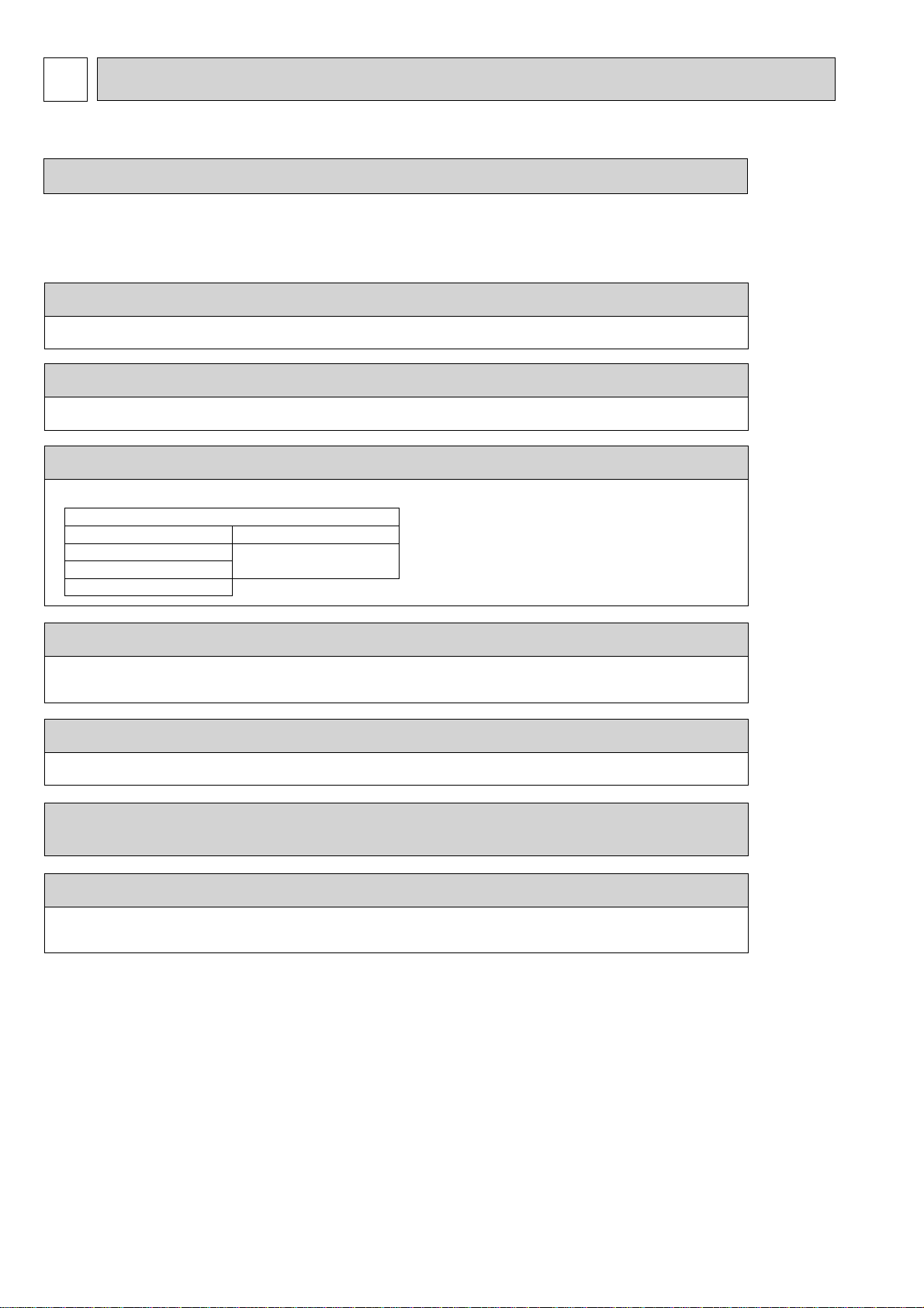
Tools for R410A
Gauge manifold
Charge hose
Gas leak detector
Torque wrench
Vacuum pump adaptor
Electronic refrigerant
charging scale
Keep tools with care.
If dirt, dust or moisture enters into refrigerant cycle, that can cause deterioration of refrigerant oil or malfunction
of compressor.
Do not use a charging cylinder.
If a charging cylinder is used, the composition of refrigerant will change and the efficiency will be lowered.
Ventilate the room if refrigerant leaks during operation. If refrigerant comes into contact with
a flame, poisonous gases will be released.
Charge refrigerant from liquid phase of gas cylinder.
If the refrigerant is charged from gas phase, composition change may occur in refrigerant and the efficiency
will be lowered.
[1] Cautions for service
(1) Perform service after recovering the refrigerant left in unit completely.
(2) Do not release refrigerant in the air.
(3) After completing service, charge the cycle with specified amount of refrigerant.
[2] Additional refrigerant charge
When charging directly from cylinder
· Check that cylinder for R410A on the market is syphon type.
· Charging should be performed with the cylinder of syphon stood vertically. (Refrigerant is charged from liquid phase.)
2
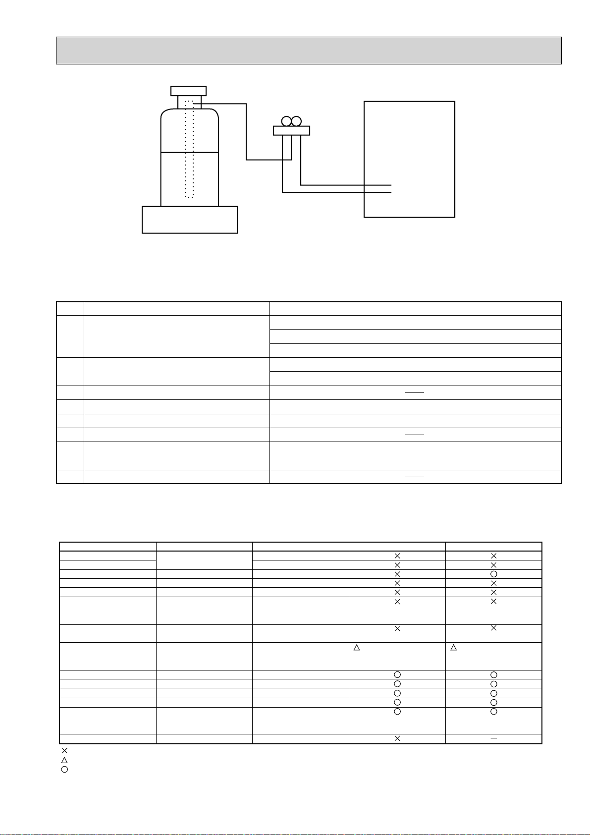
Unit
Gravimeter
[3] Service tools
Use the below service tools as exclusive tools for R410A refrigerant.
No. Tool name Specifications
1 Gauge manifold ·Only for R410A
·Use the existing fitting
·Use high-tension side pressure of 5.3 MPa·G or over.
2 Charge hose ·Only for R410A
·Use pressure performance of 5.09 MPa·G or over.
3 Electronic scale
4 Gas leak detector ·Use the detector for R134a, R407C or R410A.
5 Adaptor for reverse flow check ·Attach on vacuum pump.
6 Refrigerant charge base
7 Refrigerant cylinder ·Only for R410A Top of cylinder (Pink)
Cylinder with syphon
8 Refrigerant recovery equipment
specifications
. (UNF1/2)
1-3. CAUTIONS FOR REFRIGERANT PIPING WORK
Tools for R410A (The following table shows whether conventional tools can be used or not.)
Tools and materials Use R410A tools Can R22 tools be used?
Gauge manifold
Charge hose
Gas leak detector
Refrigerant recovery equipment
Refrigerant cylinder
Safety charger
Charge valve
Vacuum pump
Bender
Pipe cutter
Welder and nitrogen gas cylinder
Refrigerant charging scale
Vacuum gauge or thermistor vacuum gauge and
vacuum valve
Charging cylinder
: Prepare a new tool. (Use the new tool as the tool exclusive for R410A.)
: Tools for other refrigerants can be used under certain conditions.
: Tools for other refrigerants can be used.
Air purge, refrigerant charge
and operation check
Gas leak check
Refrigerant recovery
Refrigerant charge
Prevent compressor malfunction
when charging refrigerant by
spraying liquid refrigerant
Prevent gas from blowing out
when detaching charge hose
Vacuum drying and air
purge
Bend the pipes
Cut the pipes
Weld the pipes
Charge refrigerant
Check the degree of vacuum. (Vacuum
valve prevents back flow of oil and refrigerant to thermistor vacuum gauge)
Refrigerant charge
Tool exclusive for R410A
Tool exclusive for R410A
Tool for HFC refrigerant
Tool exclusive for R410A
Tool exclusive for R410A
Tool exclusive for R410A
Tool exclusive for R410A
Tools for other refrigerants can
be used if equipped with adopter for reverse flow check
Tools for other refrigerants can be used
Tools for other refrigerants can be used
Tools for other refrigerants can be used
Tools for other refrigerants can be used
Tools for other refrigerants
can be used
Tool exclusive for R410A
(Usable if equipped
with adopter for rever se flow)
Can R407C tools be used?
(Usable if equipped
with adopter for rever se flow)
33

1-4. PRECAUTIONS FOR SALT PROOF TYPE "-BS" MODEL
Although "-BS" model has been designed to be resistant to salt damage, observe the following precautions to maintain the
performance of the unit.
1. Avoid installing the uint in a location where it will be exposed directly to seawater or sea breeze.
2. If the cover panel may become covered with salt, be sure to install the unit in a location where the salt will be washed away by
rainwater. (If a sunshade is installed, rainwater may not clean the panel.)
3. To ensure that water does not collect in the base of the outdoor unit, make sure that the base is level, not at angle. Water
collecting in the base of the outdoor unit could cause rust.
4. If the unit is installed in a coastal area, clean the unit with water regularly to remove any salt build-up.
5. If the unit is damaged during installation or maintenance, be sure to repair it.
6. Be sure to check the condition of the unit regularly.
7. Be sure to install the unit in a location with good drainage.
4
2
(TH32)
SPECIFICATIONS
PUHZ-W50VHA(-BS)
1: , 230V, 50Hz
Nominal water flow rate (Heating mode) L/min
Heating
icapaC °C
(Min.1.50䌾) 5.00
(A7/W35)
(Min.1.50䌾) 5.00
Heating
capaC
Wkyti
(A2/W35)
Pressure difference (water circuit) 䇭 )teltuo/t
Heating pump input (based on EN14511) kW
Cooling
(COP) Water temperature (inlet/outlet) +12/+7°C
(A35/W7)
EER
Power input kW
Cooling
(COP) Outside air temperature (Wet-bulb) + 24°C
(A35/W18)
EER
Pressure difference (water circuit) 䇭kPa
Cooling pump input (based on EN14511) kW
Note: "COP" and "Power input" in the above table are values that contains the "pump input (based on EN 14511) ".
Model name
Running current Heating
Cooling
Power factor Heating
Cooling
(A7/W35)
(A35/W7)
(A7/W35)
(A35/W7)
PUHZ-W50VHA(-BS)
A
Atnerruc.xaM
feR
Linear expansion valve
Compressor
Model
Motor output kW
Start type
Protection devices
Comp. Surface thermo
Oil (Model) L
WretaehesacknarC
Heat exchanger Air
Water
Plate heat exchanger
Fan Fan(drive)×No.
Fan motor output
Air flow
kW
3
/min
m
(CFM)
Defrost method
Noise level
Heating dB (SPL)
Cooling dB
Dimensions Width mm (in.)
Depth mm (in.)
330 +30
Height mm (in.)
)sbl(gkthgieW
Refrigerant
Quantity kg (lbs)
Guaranteed operating Heating
range (Outdoor) Cooling
Outlet water temp. Heating
(Max in heating, Min in cooling)
Cooling
Return water Heating
temperature range Cooling
°C
°C
°C
°C
°C
°C
nim/LegnaretarwolfretaW
14.3
4.10
1.22
3.13
1.60
12
0.01
12.9
4.50
2.94
1.53
4.50
4.13
1.09
10
0.01
5.4
6.8
97
97
13.0
16
Galvanized plate
Munsell 3Y 7.8/1.1
Hermetic twin rotary
SNB130FGCM
0.9
Inverter
HP switch
Discharge thermo
0.35 (FV50S)
-
Plate fin coil
Propeller fan × 1
0.086
50
(1,760)
Reverse cycle
46
45
*1
*2
*2
950 (37-3/8)
*3
(13+1-3/16)
740 (29-3/16)
64 (141)
R410A
1.7 (3.7)
-15 ~ +35
*4
~ +46
-5
+60
+5
~
+5 +59
~
+8 +28
6.5 14.3
~
Heating(A7/W35)
Heating(A2/W35)
Cooling(A35/W7)
Cooling(A35/W18)
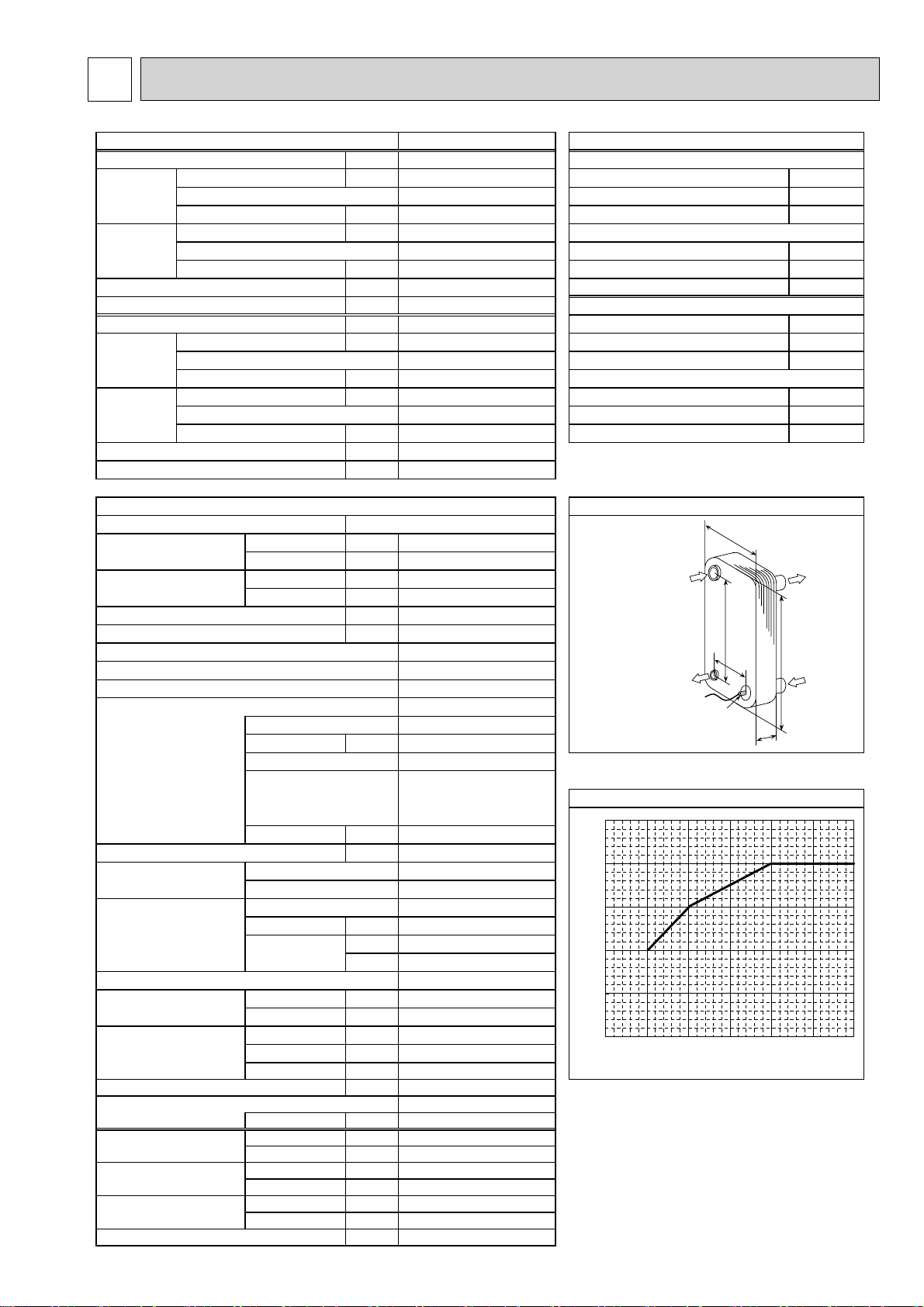
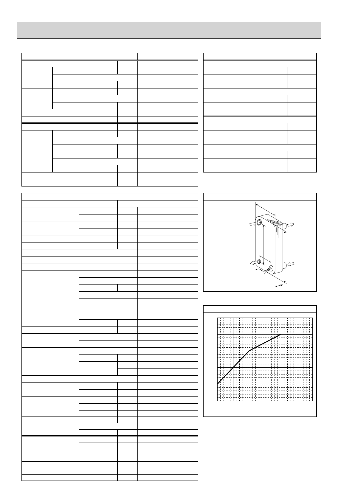
regnahcxetaehetalPsnoitacificepstinuroodtuO
ALFA LAVAL
03-03HCAA
Ref. IN
mm4.04:A%
(Heating)
mm2.862:B%
mm39:WAezisrekaerB
mm523:HgnisacretuO
mm45:DhsiniflanretxE
Ref. O UT
(Heating)
setalp03lortnoctnaregir
Maximum outlet water temperature
65
]
°C
60
55
50
45
Maximum outlet water temptemperature [
40
-20 -15 -10 -5 0 5 10
*1 Hot gas with four-way valve
*2 at distance of 1m from outdoor unit
*3 grill
*4 With the optional air outlet guide, the operation at
-15°C outdoor temperature is possible.
Ambient tem perature [°C]
noitidnocgnitarepolanimoN)ycneuqerF,egatloV,esahP(ylppusrewoP
7+)blub-yrD(erutarepmetriaedistuOWkyt
6+)blub-teW(erutarepmetriaedistuOPOC °C
53+/03+)teltuo/telni(erutarepmetretaWWktupnirewoP °C
2+)blub-yrD(erutarepmetriaedistuOPOC °C
1+)blub-teW(erutarepmetriaedistuOWktupnirewoP °C
elni(erutarepmetretaWaPk 䋭/+35°C
53+)blub-yrD(erutarepmetriaedistuOnim/L)edomgnilooC(etarwolfretawlanimoN °C
42+)blub-teW(erutarepmetriaedistuOWkyticapaC °C
53+)blub-yrD(erutarepmetriaedistuOWkyticapaC °C
1+/32+)teltuo/telni(erutarepmetretaWWktupnirewoP °C
8
W
Water OUT
B
A
Thermistor
H
Water IN
D
5
PUHZ-W85VHA(-BS)
1㱢, 230V, 50Hz
Nominal water flow rate (Heating mode) L/min
Heating
icapaC 㷄
(Min.2.70 䌾) 9.00
(A7/W35)
Heating
capaC
(Min.2.60 䌾) 8.50
Wkyti
(A2/W35)
Pressure difference (water circuit) 䇭 )teltuo/t
Heating pump input (based on EN14511) kW
Cooling
(COP) Water temperature (inlet/outlet) +12/+7㷄
(A35/W7)
EER
Power input kW
Cooling
(COP) Outside air temperature (Wet-bulb) + 24㷄
(A35/W18)
EER
Pressure difference (water circuit) 䇭kPa
Cooling pump input (based on EN14511) kW
Note: "COP" and "Power input" in the above table are values that contains the "pump input (based on EN 14511) ".
Model name
Running current Heating
Cooling
Power factor Heating
Cooling
(A7/W35) 04-03HCAA
(A35/W7) A
(A7/W35) mm4.04:A%
(A35/W7) mm2.862:B%
PUHZ-W85VHA(-BS)
Atnerruc.xaM
feR
Linear expansion valve
Compressor
Model
Motor output kW
Start type
Protection devices
Oil (Model) L
WretaehesacknarC
Heat exchanger Air
Water
Plate heat exchanger
Fan Fan(drive)×No.
Fan motor output
Air flow
kW
3
m
/min
(CFM)
Defrost method
Noise level Heating dB
(SPL)
Cooling dB
Dimensions Width mm (in.)
Depth mm (in.)
330 +30
Height mm (in.)
)sbl(gkthgieW
Refrigerant
Quantity kg (lbs)
Guaranteed operating Heating
range (Outdoor) Cooling
Outlet water temp. Heating
(Max in heating, Min in cooling)
Cooling
Return water Heating
temperature range Cooling
㷄
㷄
㷄
㷄
㷄
㷄
nim/LegnaretarwolfretaW
25.8
3.85
2.34
2.95
2.88
20
0.03
21.5
7.50
2.39
3.14
7.50
3.87
1.94
15
0.02
10.3
13.7
98
98
23.0
25
Galvanized plate
Munsell 3Y 7.8/1.1
Hermetic twin rotary
TNB220FLHM1
1.3
Inverter
HP switch
Discharge thermo
0.67 (FV50S)
-
Plate fin coil
Propeller fan × 1
0.060
55
(1,940)
Reverse cycle
48
48
*1
*2
*2
950 (37-3/8)
*3
(13+1-3/16)
943 (37-1/8)
77 (170)
R410A
2.4 (5.3)
-20 䌾 +35
*4
䌾 +46
-5
+60
+5
+5 䌾 +59
+8 䌾 +28
10.0 䌾 25.8
Heating(A7/W35)
Heating(A2/W35)
Cooling(A35/W7)
Cooling(A35/W18)
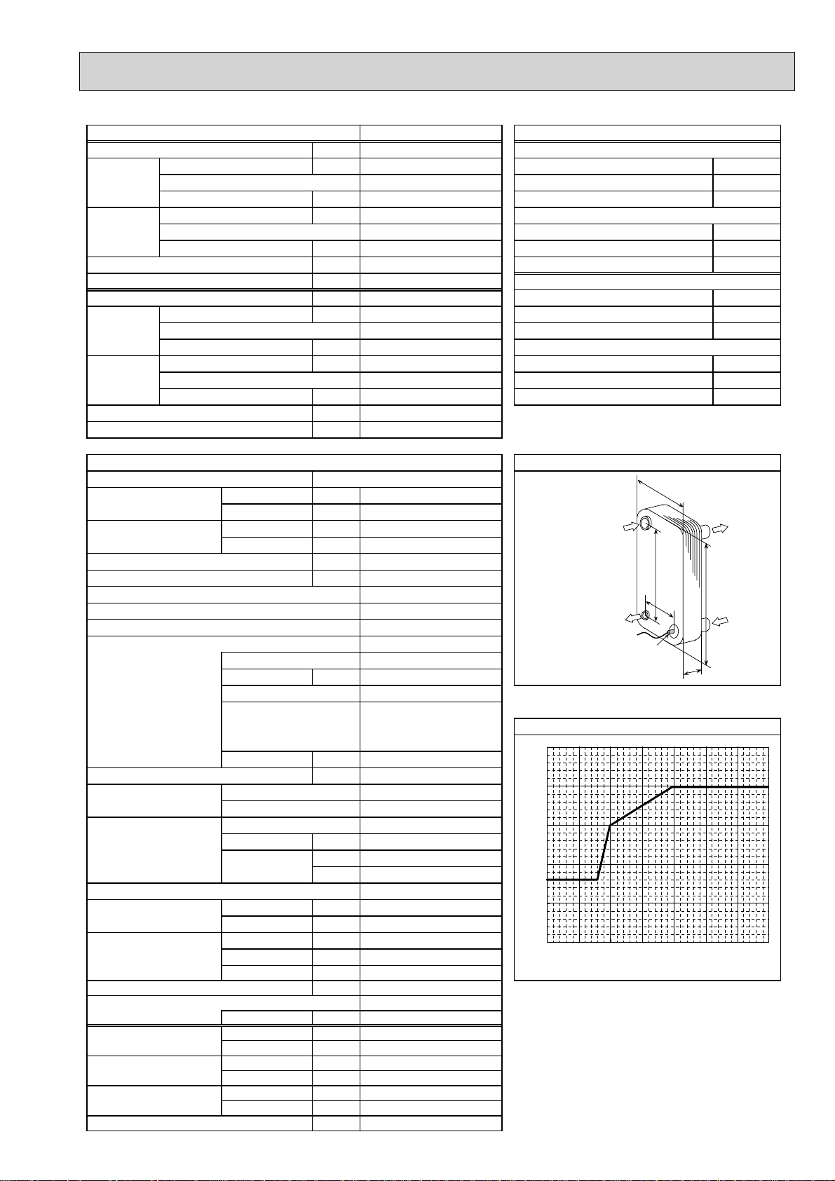
regnahcxetaehetalPsnoitacificepstinuroodtuO
ALFA LAVAL
Ref. IN
(Heating)
mm39:WAezisrekaerB
mm523:HgnisacretuO
mm96:DhsiniflanretxE
Ref. OUT
(Heating)
setalp04lortnoctnaregir
Maximum outlet water temperature
65
]
㷄
60
55
50
45
Maximum outlet water temptemperature [
40
-20 -15 -10 -5 0 5 10
*1 Hot gas with four-way valve
*2 at distance of 1m from outdoor unit
*3 grill
*4 With the optional air outlet guide, the operation at
-15㷄 outdoor temperature is possible.
Ambient temperature [㷄]
noitidnocgnitarepolanimoN)ycneuqerF,egatloV,esahP(ylppusrewoP
7+)blub-yrD(erutarepmetriaedistuOWkyt
6+)blub-teW(erutarepmetriaedistuOPOC 㷄
53+/03+)teltuo/telni(erutarepmetretaWWktupnirewoP 㷄
2+)blub-yrD(erutarepmetriaedistuOPOC 㷄
1+)blub-teW(erutarepmetriaedistuOWktupnirewoP 㷄
elni(erutarepmetretaWaPk 䋭/+35㷄
㷄
53+)blub-yrD(erutarepmetriaedistuOnim/L)edomgnilooC(etarwolfretawlanimoN
42+)blub-teW(erutarepmetriaedistuOWkyticapaC 㷄
53+)blub-yrD(erutarepmetriaedistuOWkyticapaC 㷄
81+/32+)teltuo/telni(erutarepmetretaWWktupnirewoP 㷄
W
Water OUT
B
H
Water IN
D
Thermistor
TH
2
A
6
PUHZ-HW112YHA(-BS)
3㱢, 400V, 50Hz
Nominal water flow rate (Heating mode) L/min
Heating
icapaC 㷄
(Min. 3.40 䌾) 11.20
(A7/W35)
Heating
capaC
(Min. 3.40 䌾) 11.20
Wkyti
(A2/W35)
Pressure difference (water circuit) 䇭 )teltuo/t
Heating pump input (based on EN14511) kW
Cooling
(COP) Water temperature (inlet/outlet) +12/+7㷄
(A35/W7)
EER
Power input kW
Cooling
(COP) Outside air temperature (Wet-bulb) + 24㷄
(A35/W18)
EER
Pressure difference (water circuit) 䇭kPa
Cooling pump input (based on EN14511) kW
Note: "COP" and "Power input" in the above table are values that contains the "pump input (based on EN 14511) ".
Model name
Running current Heating
Cooling
Power factor Heating
Cooling
(A7/W35) 05-05HCAA
(A35/W7) A
(A7/W35) mm05:A%
(A35/W7) mm664:B%
PUHZ-HW112YHA(-BS)
Atnerruc.xaM
feR
Linear expansion valve
Compressor
Model
Motor output kW
Start type
Protection devices
Oil (Model) L
WretaehesacknarC
Heat exchanger Air
Water
Plate heat exchanger
Fan Fan(drive)×No.
Fan motor output
Air flow
kW
3
m
/min
(CFM)
Defrost method
Noise level Heating dB
(SPL)
Cooling dB
Dimensions Width mm (in.)
Depth mm (in.)
330 +30
Height mm (in.)
)sbl(gkthgieW
Refrigerant
Quantity kg (lbs)
Guaranteed operating Heating
range (Outdoor) Cooling
Outlet water temp. Heating
(Max in heating, Min in cooling)
Cooling
Return water Heating
temperature range Cooling
㷄
㷄
㷄
㷄
㷄
㷄
nim/LegnaretarwolfretaW
32.1
4.24
2.64
3.01
3.72
6
0.01
28.7
10.00
2.72
3.68
10.00
4.07
2.46
5
0.01
4.0
5.6
95
95
13.0
16
Galvanized plate
Munsell 3Y 7.8/1.1
Hermetic scroll
ANB33FJFMT
2.5
Inverter
HP switch
LP switch
Discharge thermo
0.9 (FV50S)
-
Plate fin coil
Propeller fan × 2
0.074 x 2
100
(3,530)
Reverse cycle
53
53
*1
*2
*2
1020 (40-3/16)
*3
(13+1-3/16)
1350 (53-1/8)
148 (326)
R410A
4.0 (8.8)
-25 䌾 +35
*4
䌾 +46
-5
+60
+5
+5 䌾 +59
+8 䌾 +28
14.4 䌾 32.1
Heating(A7/W35)
Heating(A2/W35)
Cooling(A35/W7)
Cooling(A35/W18)
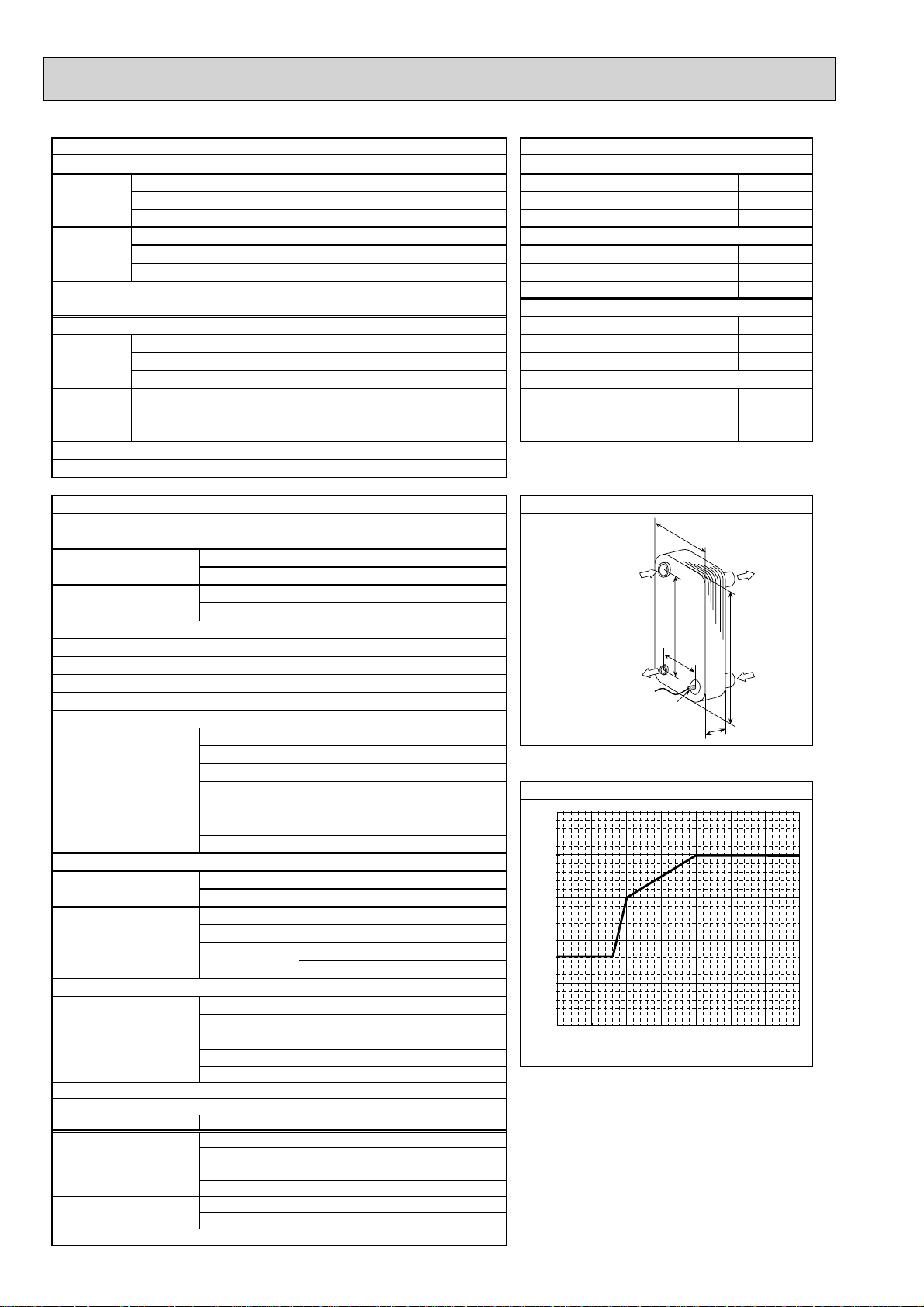
regnahcxetaehetalPsnoitacificepstinuroodtuO
ALFA LAVAL
Ref. IN
(Heating)
mm211:WAezisrekaerB
mm625:HgnisacretuO
mm031:DhsiniflanretxE
Ref. OUT
(Heating)
setalp05lortnoctnaregir
Maximum outlet water temperature
65
]
㷄
60
55
50
45
Maximum outlet water temptemperature [
40
-25 -20 -15 -10 -5 0 5 10
*1 Hot gas with four-way valve
*2 at distance of 1m from outdoor unit
*3 grill
*4 With the optional air outlet guide, the operation at
-15㷄 outdoor temperature is possible.
Ambient temperature [㷄]
noitidnocgnitarepolanimoN)ycneuqerF,egatloV,esahP(ylppusrewoP
7+)blub-yrD(erutarepmetriaedistuOWkyt
6+)blub-teW(erutarepmetriaedistuOPOC 㷄
53+/03+)teltuo/telni(erutarepmetretaWWktupnirewoP 㷄
2+)blub-yrD(erutarepmetriaedistuOPOC 㷄
1+)blub-teW(erutarepmetriaedistuOWktupnirewoP 㷄
elni(erutarepmetretaWaPk 䋭/+35㷄
㷄
53+)blub-yrD(erutarepmetriaedistuOnim/L)edomgnilooC(etarwolfretawlanimoN
42+)blub-teW(erutarepmetriaedistuOWkyticapaC 㷄
53+)blub-yrD(erutarepmetriaedistuOWkyticapaC 㷄
81+/32+)teltuo/telni(erutarepmetretaWWktupnirewoP 㷄
W
Water OUT
B
H
Water IN
D
Thermistor
TH
2
A
7
PUHZ-HW140VHA(-BS) PUHZ-HW140YHA(-BS)
1/3㱢, 230/400V, 50Hz
Nominal water flow rate (Heating mode) L/min
Heating
icapaC 㷄
(Min. 4.20 䌾 ) 14.00
(A7/W35)
(Min. 4.20 䌾 ) 14.00
Heating
capaC
Wkyti
(A2/W35)
Pressure difference (water circuit) 䇭 )teltuo/t
Heating pump input (based on EN14511) kW
Cooling
EER
(A35/W7)
(COP) Water temperature (inlet/outlet) +12/+7㷄
Power input kW
Cooling
EER
(A35/W18)
(COP) Outside air temperature (Wet-bulb) + 24㷄
Pressure difference (water circuit) 䇭kPa
Cooling pump input (based on EN14511) kW
Note: "COP" and "Power input" in the above table are values that contains the "pump input (based on EN 14511) ".
Model name
PUHZ-HW140VHA(-BS) /
PUHZ-HW140YHA(-BS)
Running current Heating
Power factor Heating
Refrigerant control
Cooling
Cooling
(A7/W35) A
(A35/W7) mm05:AA
(A7/W35) mm664:B%
(A35/W7) %
Linear expansion valve
Compressor
Model
ANB33FJGMT/ANB33FJFMT
Motor output kW
Start type
Oil (Model) L
WretaehesacknarC
Heat exchanger Air
Water
.oN×)evird(naFnaF
Fan motor output
Air flow
kW
3
m
/min
(CFM)
Defrost method
Noise level Heating dB
(SPL)
Cooling dB
Dimensions Width mm (in.)
Depth mm (in.)
330 +30
Height mm (in.)
)sbl(gkthgieW
Refrigerant
Quantity kg (lbs)
Guaranteed operating Heating
range (Outdoor) Cooling
Outlet water temp. Heating
(Max in heating, Min in cooling)
Cooling
Return water Heating
temperature range Cooling
㷄
㷄
㷄
㷄
㷄
㷄
nim/LegnaretarwolfretaW
40.1
4.19
3.34
2.69
5.21
9
0.02
35.8
12.50
2.59
4.82
12.50
4.01
3.12
7
0.02
14.9 / 5.1
21.5 / 7.3
97 / 95
97 / 95
35.0 / 13.0
40 / 16
Galvanized plate
Munsell 3Y 7.8/1.1
Hermetic scroll
2.5
Inverter
HP switch
LP switch
Discharge thermo
0.9 (FV50S)
-
Plate fin coil
Plate heat exchanger
Propeller fan × 2
0.074 x 2
100
(3,530)
Reverse cycle
53
53
1020 (40-3/16)
*3
*1
*2
*2
(13+1-3/16)
1350 (53-1/8)
134 (296) / 148 (326)
R410A
4.0 (8.8)
-25 䌾 +35
*4
-5
䌾 +46
+60
+5
+5 䌾 +59
+8 䌾 +28
17.9 䌾 40.1
Heating(A7/W35)
Heating(A2/W35)
Cooling(A35/W7)
Cooling(A35/W18)
regnahcxetaehetalPsnoitacificepstinuroodtuO
ALFA LAVAL
ACH50-50
Ref. IN
(Heating)
mm211:WAtnerruc.xaM
mm625:HAezisrekaerB
mm031:DgnisacretuO
Ref. OUT
(Heating)
setalp05hsiniflanretxE
eltuomumixaMsecivednoitcetorP
65
]
㷄
60
55
50
45
Maximum outlet water temptemperature [
40
-25 -20 -15 -10 -5 0 5 10
*1 Hot gas with four-way valve
*2 at distance of 1m from outdoor unit
*3 grill
*4 With the optional air outlet guide, the operation at
-15㷄 outdoor temperature is possible.
Ambient temperature [㷄]
noitidnocgnitarepolanimoN)ycneuqerF,egatloV,esahP(ylppusrewoP
7+)blub-yrD(erutarepmetriaedistuOWkyt
6+)blub-teW(erutarepmetriaedistuOPOC 㷄
53+/03+)teltuo/telni(erutarepmetretaWWktupnirewoP 㷄
2+)blub-yrD(erutarepmetriaedistuOPOC 㷄
1+)blub-teW(erutarepmetriaedistuOWktupnirewoP 㷄
elni(erutarepmetretaWaPk 䋭/+35㷄
㷄
53+)blub-yrD(erutarepmetriaedistuOnim/L)edomgnilooC(etarwolfretawlanimoN
42+)blub-teW(erutarepmetriaedistuOWkyticapaC 㷄
53+)blub-yrD(erutarepmetriaedistuOWkyticapaC 㷄
81+/32+)teltuo/telni(erutarepmetretaWWktupnirewoP 㷄
W
Water OUT
B
H
Water IN
D
Thermistor
TH
2
A
erutarepmetretawt
8
3
DATA
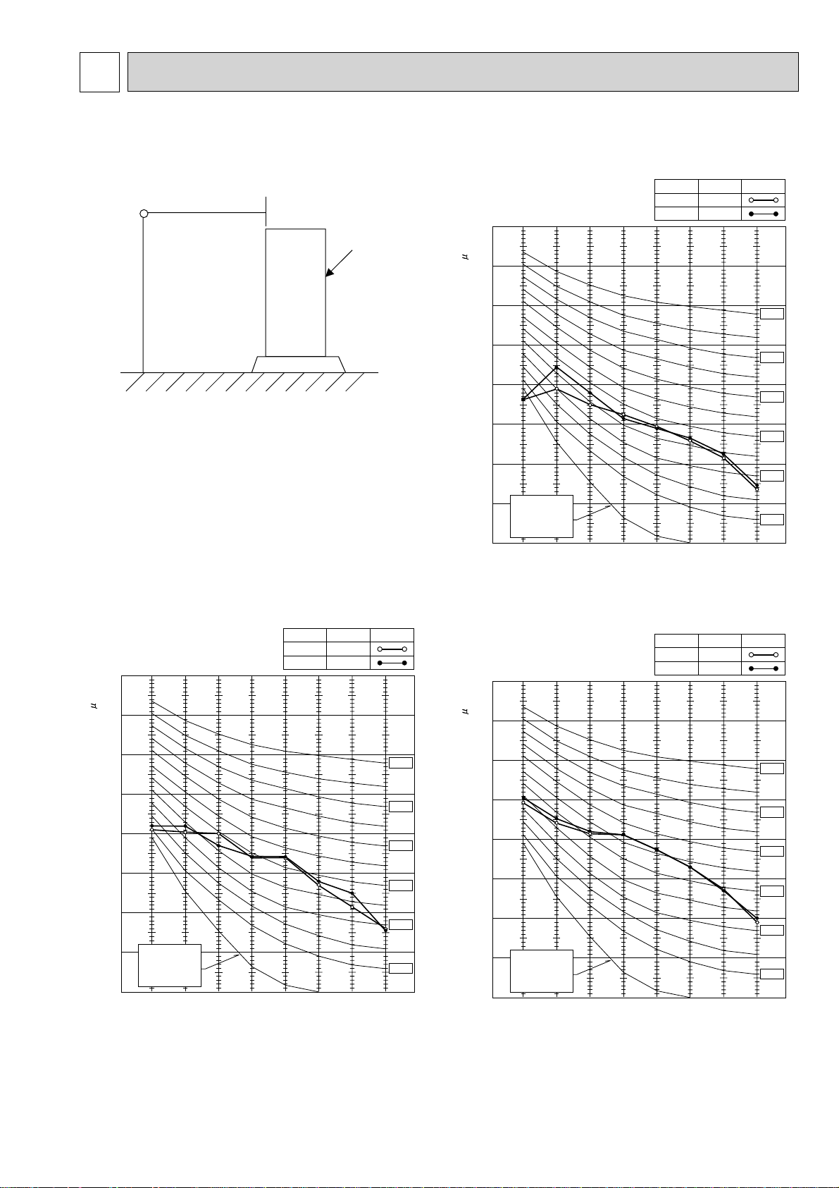
3-1. NOISE CRITERION CURVES
MICROPHONE
1m
UNIT
PUHZ-W50VHA(-BS)
90
80
MODE
COOLING
HEATING
SPL(dB)
45
46
LINE
1.5m
PUHZ-W85VHA(-BS)
90
MODE
COOLING
HEATING
SPL(dB)
48
48
GROUND
LINE
70
60
50
40
30
APPROXIMATE
20
THRESHOLD OF
HEARING FOR
CONTINUOUS
OCTAVE BAND SOUND PRESSURE LEVEL, dB (0 dB = 0.0002 bar)
PUHZ-HW112YHA(-BS)
PUHZ-HW140VHA(-BS)
PUHZ-HW140YHA(-BS)
NOISE
10
63 125 250 500 1000 2000 4000 8000
90
BAND CENTER FREQUENCIES, Hz
MODE
COOLING
HEATING
SPL(dB)
53
53
NC-70
NC-60
NC-50
NC-40
NC-30
NC-20
LINE
80
70
60
50
40
30
APPROXIMATE
20
THRESHOLD OF
HEARING FOR
CONTINUOUS
OCTAVE BAND SOUND PRESSURE LEVEL, dB (0 dB = 0.0002 bar)
NOISE
10
63 125 250 500 1000 2000 4000 8000
BAND CENTER FREQUENCIES, Hz
NC-70
NC-60
NC-50
NC-40
NC-30
NC-20
80
70
60
50
40
30
APPROXIMATE
20
THRESHOLD OF
HEARING FOR
CONTINUOUS
OCTAVE BAND SOUND PRESSURE LEVEL, dB (0 dB = 0.0002 bar)
NOISE
10
63 125 250 500 1000 2000 4000 8000
BAND CENTER FREQUENCIES, Hz
NC-70
NC-60
NC-50
NC-40
NC-30
NC-20
9
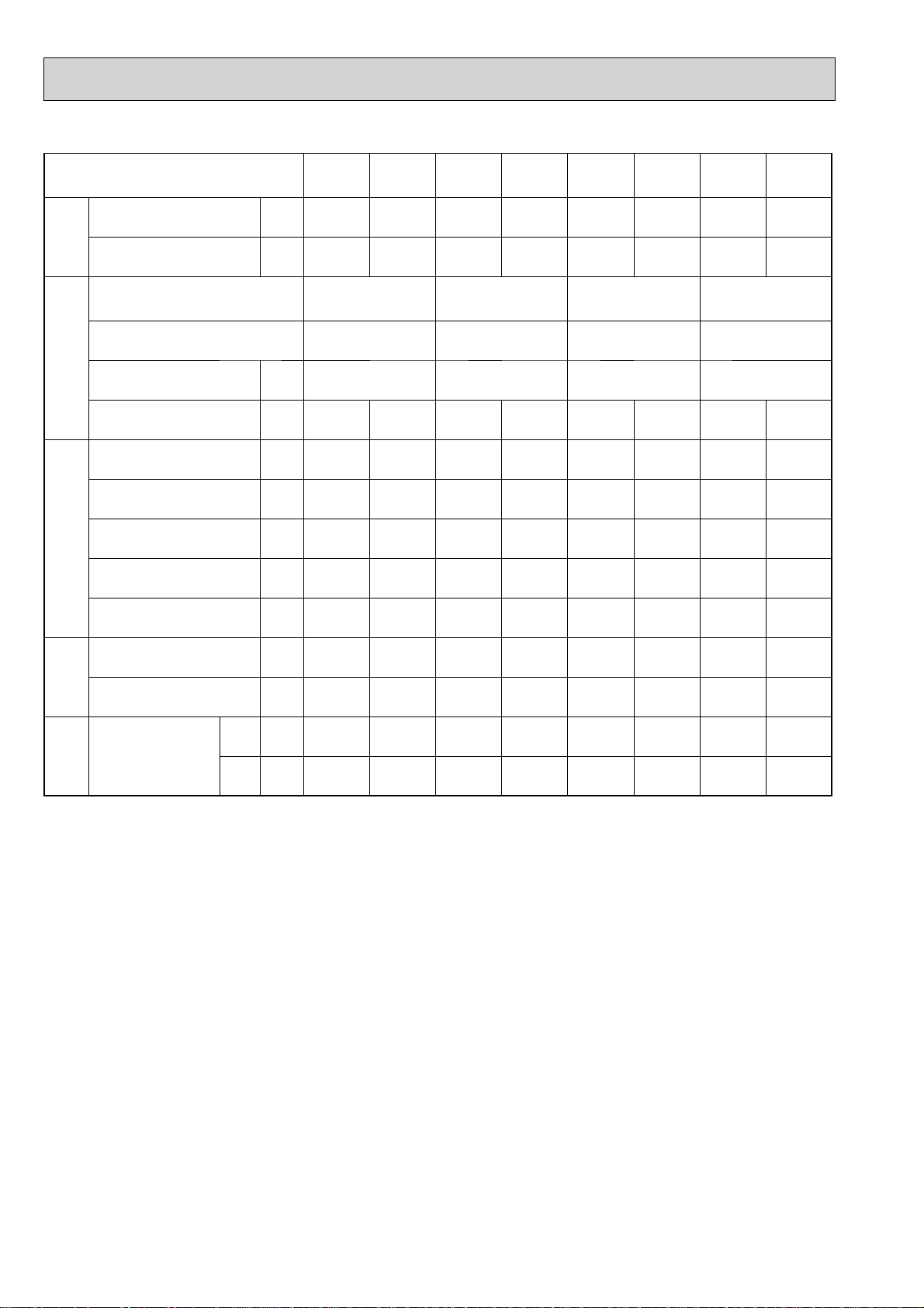
3-2. STANDARD OPERATION DATA
Mode
Capacity W 4,500 5,000 7,500 9,000 10,000 11,200 12,500 14,000
Total
Input kW 1.52 1.21 3.12 2.31 3.67 2.63 4.80 3.32
Cooling
(A35/W7)
Heating
(A7/W35)
Cooling
(A35/W7)
Heating
(A7/W35)
Cooling
(A35/W7)
Heating
(A7/W35)
Cooling
(A35/W7)
Heating
(A7/W35)
Outdoor unit PUHZ-W50VHA PUHZ-W85VHA PUHZ-HW112YHA
Phase, Hz 1, 50 1, 50 3, 50 1 / 3, 50
Voltage V 230 230 400 230 / 400
Electrical circuit
Current A 6.8 5.4 13.7 10.3 5.6 4.0 21.5 / 7.314.9 / 5.1
Discharge pressure MPa 2.51 2.13 2.81 2.21 2.63 2.07 2.81 2.11
Suction pressure MPa 0.83 0.68 0.73 0.64 0.78 0.69 0.78 0.66
Discharge temperature ºC 69 68 80 65 78 64 84 67
Condensing temperature
ºC 43 37 46 38 46 36 47 37
Refrigerant circuit
Suction temperature ºC 6 6 3 -1 9 5 11 3
Flow volume L/min 12.9 14.3 20.4 25.8 28.7 32.1 35.8 40.1
Water
Outlet water temperature
conditions
Intake air
temperature
Outdoor
conditions
The unit of pressure has been changed to MPa based on international SI system.
The conversion factor is: 1 (MPa) = 10.2 (kgf/cm
W.B. ºC 24 6 24 6 24 6 24 6
ºC735735735735
D.B. ºC 35 7 35 7 35 7 35 7
2
)
PUHZ-HW140VHA
/ PUHZ-HW140YHA
10
4
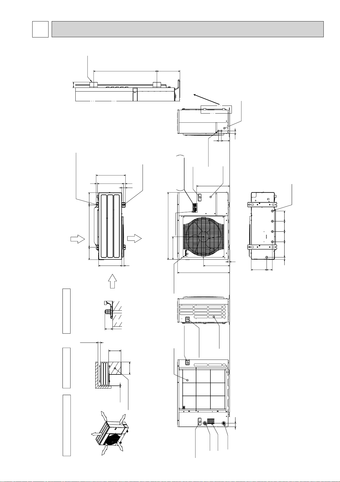
OUTLINES AND DIMENSIONS
PUHZ-W50VHA(-BS)
ISO 228/1-G1 B
24
19
2-U Shaped notched holes
(Foundfation Bolt M10)
417
37028
53
2-12 x 36 oval holes
(Foundation Bolt M10)
85 269
Terminal Connections
Left•••• Power supply wiring
Right•• Controller wiring
Detail
Power supply
wiring hole
Handle for moving
40
27Knock Out)
:
(2-
469
see Detail
34
119
Service panel
Front cover
Unit: mm
Drain hole
(5-:33)
Rear Air Intake
Installation Feet
175 175600
Please secure the unit firmly
with 4 foundation (M10) bolts.
(Bolts and washers must be
purchased locally.)
Over300
2 SERVICE SPACE 3 FOUNDATION BOLTS
Dimensions of space needed
for service access are
shown in the below diagram.
Air Discharge
33030
Side Air Intake
FOUNDATION
<Foundation bolt height>
30
500
Over
Less than
500
Over
950
Earth terminal
322
Handle for moving
Rear Air Intake
Handle for moving
Handle for moving
740
371
Side Air Intake
220 145145145
23
219
30
81
Over 300mm
FREE
1 FREE SPACE (Around the unit)
The diagram below shows a
basic example.
Explantion of particular details are
given in the installation manuals etc.
Over 10mm
Over10
Service space
Over 1
0mm
Over 500mm
11
Water OUT
Handle for moving
Air Intake
50
Water IN
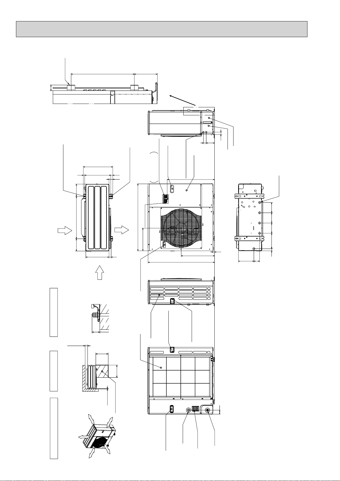
PUHZ-W85VHA(-BS)
Unit: mm
ISO 228/1-G1 B
24
2-U Shaped notched holes
(Foundfation Bolt M10)
Rear Air Intake
19
Installation Feet
417
37028
53
2-12 x 36 oval holes
(Foundation Bolt M10)
Air Discharge
950
Earth terminal
98 269
Detail
Handle for moving
Terminal Connections
Left...Power supply wiring
Right...Controller wiring
Power supply wiring hole
(2-:27 knockout)
Service panel
673
See Detail
34
40119
Rear cover
Front cover
Drain hole
(5-:33)
175 175600
Please secure the unit firmly
with 4 foundation (M10) bolts.
(Bolts and washers must be
purchased locally.)
Over300
2 SERVICE SPACE 3 FOUNDATION BOLTS
Dimensions of space needed
for service access are
shown in the below diagram.
33030
Side Air Intake
FOUNDATION
<Foundation bolt height>
30
Less than
500
Over
500
Over
Over10
Service space
322
Handle for moving
Side Air Intake
Rear Air Intake
943
Handle for moving
473
Handle for moving
220 145145145
23
219
57
30
81
Over 300mm
FREE
1 FREE SPACE (Around the unit)
The diagram below shows a
basic example.
Explantion of particular details are
given in the installation manuals etc.
Over 10mm
Over 10mm
Over 500mm
Water OUT
Handle for moving
12
Air Intake
Water IN
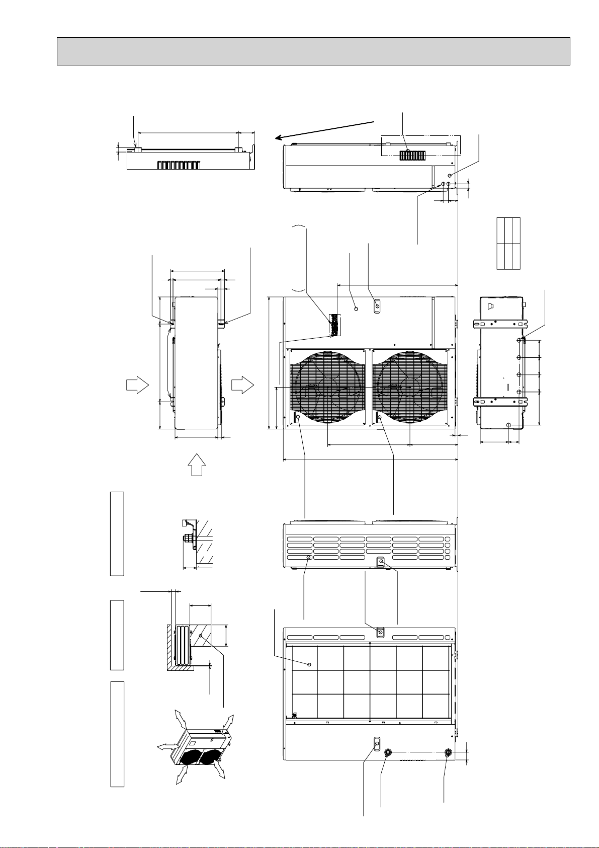
PUHZ-HW112YHA(-BS) PUHZ-HW140VHA(-BS) PUHZ-HW140YHA(-BS)
see Detail
Air Intake
34
74 40
24
ISO 228-1
G1 B
46674
Detail
Unit: mm
Front cover
2-U Shaped notched holes
(Foundfation Bolt M10)
Rear Air Intake
19
210
600210
Installation Feet
Side Air Intake
417
370
330
27Knock Out)
:
Power supply
wiring hole
(2-
Handle for moving
Terminal connections
Left••••• Power supply wiring
53
28
2-12×36 oval holes
(Foundation Bolt M10)
1020
Air Discharge
30
Right••• Controller wiring
Earth terminal
322
Handle for moving
Service panel
A
23
371 635
1350
Handle for moving
A
931
1079
VHA
YHA
33)
:
Drain hole
(5-
256 133 133 133
81 219
Please secure the unit firmly
with 4 foundation (M10) bolts.
(Bolts and washers must be
2 SERVICE SPACE 3 FOUNDATION BOLTS
Dimensions of space needed
for service access are
shown in the below diagram.
1 FREE SPACE (Around the unit)
The diagram below shows a
basic example.
Explantion of particular details are
<Foundation bolt height>
purchased locally.)
Over300
Over 300mm
FREE
given in the installation manuals etc.
Over 10mm
FOUNDATION
30
Less than
500
Over
Over
Over10
Service space
Over 10mm
500
00mm
Over 5
Rear Air Intake
13
Side Air Intake
Handle for moving
Handle for moving
Handle for moving
Water OUT
59
Water IN
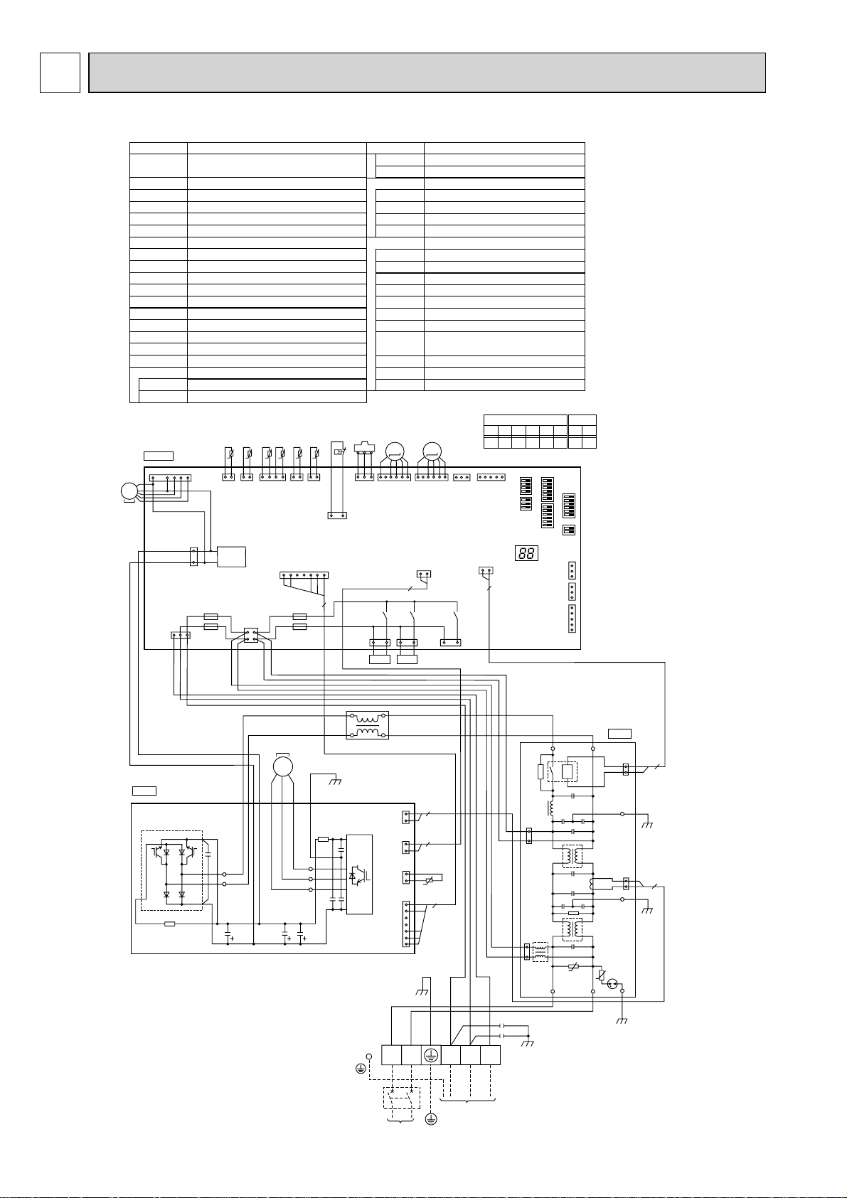
5 WIRING DIAGRAM
PUHZ-W50VHA(-BS)
SYMBOL NAME SYMBOL NAME
TB1
MC
MF1
21S4
SV Solenoid Valve<Bypass Valve>
63H
63HS
TH3
TH4
TH6
TH7
TH8
TH32 Thermistor<Inlet water>
TH33 Thermistor<Comp Surface>
LEV-A, LEV-B
ACL
CY1,CY2 Capacitor
P. B.
R/S
U/V/W
MF1
MS
3~
Terminal Block
Flow temp. controller>
Motor for Compressor
Fan Motor
Solenoid Valve<Four-Way Valve>
High Pressure Switch
High Pressure Sensor
Thermistor<Liquid>
Thermistor<Discharge>
Thermistor<Plate HEX Iiquid>
Thermistor<Ambient>
Thermistor<Heatsink>
Electronic Expansion Valve
Reactor
Power Circuit Board
Connection Terminal<L/N-Phase>
Connection Terminal<U/V/W-Phase>
TH32
7
3
1
CNDC
(PNK)
1
CNF1
(WHT)
F2
F1
TH33
t°
12
TH33
(YLW)
TRANS
12
C. B.
1
CNS
(WHT
)
3
<Power Supply,Interface unit /
TH6 TH3 TH4
TH7
t° t° t° t°
t°
TH7/6
TH32
(BLK)
CNAC
(WHT)
1
3
TH3
(RED)
(WHT)
CN2
(WHT)
17
F3
2
F4
4
TH4
(WHT)
Main Smocthing CapacitorCB1-3
Power ModulePFC/IPM
N.F.
LI,LO
NI,NO
EI,E2,E3
52C
C.B.
SW1
SW2
SW5
SW6
SW8
SW10
SV1
CNDM
LED3
F1~ F4
X52,X54, X55
63HS
63H
2
1
63H
(YLW)
5
3
21S4
(GRN)
11121
63HS
(WHT
LEV-A
34
LEV-A
(WHT)
)
21S4 SV
Noise Filter Circuit Board
Connection Terminal<L-Phase>
Connection Terminal<N-Phase>
Connection Terminal<Ground>
52C Relay
Controller Circuit Board
Switch<Function Switch>
Switch<Function Switch>
Switch<Function Switch>
Switch<Model Select>
Switch<Function Switch>
Switch<Model Select>
Connector<Connection for Option>
Connector
<Connection
for Option (Contact Input)>
LED<Operation/Inspection Indicators>
Fuse<T6.3AL250V>
Relay
*1 MODEL SELECT
LEV-B
M
X52
2
LEV-B
(RED)
CN4
(WHT)
12
X55
SV2
1313
(BLU)
M
1=ON, 0=OFF
1
1613
61
CNVMNT
CNMNT
(WHT)
(WHT)
CN52C
(RED)
12
2
X54
SV1
13
(GRY)
SW6
12345 6
00110 0
*1
5
SW5
SW6
SW8
SW2
SW1
LED3
CN3S
CNDM
CN51
SW10
*1
SW10
1
(WHT)
3
1
3
(WHT)
1
(WHT)
5
12
01
P. B .
PFC
W
BLK
TABR
RED
WHT
TABS
CB1 CB2 CB3
MS
3
V
~
WHT
MC
U
RED
TAB U
TABV
TABW
RED
WHT
ACL
IPM
RED
WHT
1
CN5
(RED)
2
1
CN4
(WHT)
2
1
CN3
(WHT)
2
1
CN2
(WHT)
7
BLU
RED
N
L
POWER SUPPLY
~ / N 230V 50Hz
2
2
TH8
t°
5
YLW
GRN/YLW
S2 S3
S1
Interface unit /
Flow temp. controller
ORN
BRN
CY1
CY2
TB1
RED
1
3
(RED)
CNAC2
1
3
(WHT)
CNAC1
WHT
N. F.
NO
LO
52C
U
LI
U
NI
1
2
1
2
BLK
(BLK)
CN52C
E3
CN5
(RED)
E2
EI
2
BLK
2
BLK
14
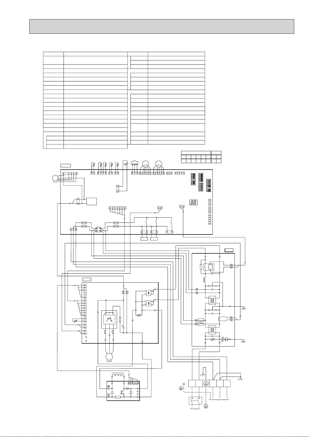
PUHZ-W85VHA(-BS)
SYMBOL NAME SYMBOL NAME
TB1
MC
MF1
21S4
SV Solenoid Valve <Bypass Valve>
63H
63HS
TH3
TH4
TH6
TH7
TH8
TH32 Thermistor <Inlet water>
LEV-A, LEV-B
DCL
ACTM Active Filter Module
CY1,CY2 Capacitor
P. B.
TABU/V/W
TABS/T
TABP1/P2
Terminal Block <Power Supply,Interface unit /
Flow temp. controller>
Motor for Compressor
Fan Motor
Solenoid Valve <Four-Way Valve>
High Pressure Switch
High Pressure Sensor
Thermistor <Liquid>
Thermistor <Discharge>
Thermistor <Plate HEX Liquid>
Thermistor <Ambient>
Thermistor <Heatsink>
Electronic Expansion Valve
Reactor
Power Circuit Board
Connection Terminal <U/V/W-Phase>
Connection Terminal <L/N-Phase>
Connection Terminal <DC Voltage>
C. B.
1
7
CNS
CNF1
(WHT)
3
2
1
CNDC
(PNK)
F2
F1
)
1
3
MF1
MS
3~
(WHT
TH32
12
TH32
(BLK)
TRANS
TH7
t° t° t° t°
t°
TH7/6
(RED)
CNAC
(WHT)
1
3
TH6 TH3 TH4
TH3
TH4
(WHT)
(WHT)
1
3
63H
(YLW)
CN2
(WHT)
17
F3
2
F4
4
2
63H
7
TABN1/N2
N.F.
LI,LO
NI,NO
EI,E2
52C
C.B.
SW1
SW2
SW5
SW6
SW8
SW10
SV1
CNDM
LED3
F1~ F4
X52,X54, X55
63HS
34
11121
63HS
(WHT
)
21S4
(GRN)
Connection Terminal <DC Voltage>
Diode bridgeDS2, DS3
Power ModuleIPM
Noise Filter Circuit Board
Connection Terminal <L-Phase>
Connection Terminal <N-Phase>
Connection Terminal <Ground>
52C Relay
Controller Circuit Board
Switch <Function Switch>
Switch <Function Switch>
Switch <Function Switch>
Switch <Model Select>
Switch <Function Switch>
Switch <Model Select>
Connector <Connection for Option>
Connector
<Connection
for Option(Contact Input)>
LED <Operation/ Inspection Indicators>
Fuse <T6.3AL250V>
Relay
1 MODEL SELECT
*
LEV-A
M
LEV-A
(WHT)
X52
21S4 SV
2
LEV-B
M
LEV-B
(RED)
CN4
(WHT)
12
1313
X55
SV2
(BLU)
61
CNVMNT
(WHT)
1613
12345 6
00101 0
1=ON, 0=OFF
1
CNMNT
(WHT)
CN52C
(RED)
12
2
X54
SV1
13
(GRY)
SW 6
SW10
12
00
1
SW5
SW8
LED3
*
SW6
SW1
CN3S
(WHT)
CNDM
(WHT)
CN51
(WHT)
SW2
SW10
*1
1
3
1
3
1
5
5
TH8
t°
N. F.
BLU
WHT
NO
LO
52C
P. B .
4
1
CNAF
(WHT)
6
7
1
CN2
IPM
(WHT)
7
TAB P2
RED
1
CN3
(WHT)
2
2
1
CN5
(RED)
2
2
1
CN4
(WHT)
2
TAB N
TAB P
TAB U
RED
U
RED
BLK
V
MS
3
DCL
TAB V
WHT
~
BLK
W
WHT
CNDC
(PNK)
MC
L1
TAB W
2
1
L2
ACTM
3
4
WHT
16
TAB T
WHT
TAB S
TABP1
BLU
WHT
RED
DS3
DS2
U
TAB N1
BLK
TAB N2
RED
P
N1
N2
WHT
Io
3
1
(RED)
CNAC2
3
1
(WHT)
CNAC1
BLU
RED
N
L
POWER SUPPLY
~ / N 230V 50Hz
U
LI
RED
YLW
GRN/YLW
S1
Interface unit /
Flow temp. controller
NI
U
BLU
ORN
S2 S3
BRN
1
2
E2
1
2
CN5
EI
(BLK)
CN52C
(RED)
CY1
CY2
TB1
2
BLK
2
BLK
1515
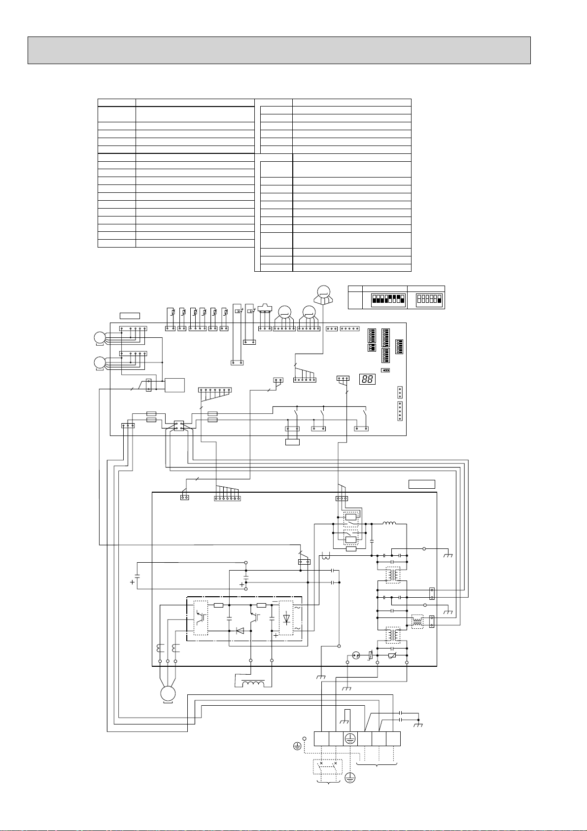
PUHZ-HW140VHA(-BS)
SYMBOL NAME
TB1
MC
MF1,MF2
21S4
63H
63L Low Pressure Switch
63HS
TH3
TH4
TH6 Thermistor<Plate HEX Liquid>
TH7
TH32 Thermistor<Return Water>
TH33 Thermistor<Suction>
LEV-A, LEV-B, LEV-C
DCL
CB Main Smoothing Capacitor
CY1,CY2 Capacitor
MF1
MS
3~
MF2
MS
3~
Terminal Block
Flow Temp. controller-Outdoor>
Motor for Compressor
Fan Motor
Solenoid Valve<Four-Way Valve>
High Pressure Switch
High Pressure Sensor
Thermistor<Liquid>
Thermistor<Discharge>
Thermistor<Ambient>
Electronic Expansion Valve
Reactor
C. B.
1
1
CNS
(WHT
CNF1
(WHT)
7
CNF2
(WHT)
7
3
2
1
CNDC
(PNK)
F2
)
F1
1
3
<Power Supply, Interface unit /
TH6TH3 TH4
TH32
TH33
TH7
t° t° t° t°
t°
t°
4
1121
12
13
TH33
(YLW)
TRANS
CNAC
(WHT)
1
3
TH32
(BLK)
2
4
2
TH7/6
TH3
(RED)
TH4
(WHT)
(WHT)
CN2
(WHT)
17
7
F3
F4
63H
1
63H
(YLW)
63L
1
63L
(RED)
3
P. B.
U/V/W
LI
NI
DCL1,DCL2
IGBT
EI,E2,E3,E4
C.B.
SW1
SW2
SW5
SW6
SW8
CN31
SS
SV1
CNDM
LED3
F1,F2,F3,F4
X51,X52, X54
63HS
3
1
3
63HS
(WHT
)
(WHT)
2
21S4
(GRN)
Power Circuit Board
Connection Terminal<U/V/W-Phase>
Connection Terminal<L-Phase>
Connection Terminal<N-Phase>
Connection Terminal<Reactor>
Power Module
Connection Terminal<Ground>
Controller Circuit Board
Switch<Manual Defrost, Defect History
Record Reset, Function Switch>
Switch<Function Switch>
Switch<Function Switch,Model Select>
Switch<Model Select>
Switch<Function Switch>
Connector<Emergency Operation>
Connector<Connection for Option>
Connector<Connection for Option>
Connector
<Connection
for Option(Contact Input)>
LED<Operation/Inspection Indicators>
Fuse<T6.3AL250V>
Relay
LEV-C
M
LEV-BLEV-A
M
M
1
1613
5
LEV-B
(RED)
LEV-C
(BLU)
X52
61
61
CNVMNT
(WHT)
CN52C
X54
SV1
1313
(GRY)
(RED)
1
LEV-A
(WHT)
CN4
12
21S4
1MODEL SELECT
*
MODEL
140V
*
CNMNT
(WHT)
3
3
SW6
ON
OFF
12345678
2. SW5 -1 to 5 : Function Switch
1
*1*
5
SW5SW8
SW6SW1
SW2
CN31
13
(WHT)
X51
1
(WHT)
3
CNDM
1
CN51
(WHT)
5
SS
LED3
ON
OFF
SW5-6*2
123456
2
P. B .
2
1
CN4
(WHT)
WHT
CB
RED
W
U
V
BLK
RED
WHT
V
W
U
MS
3~
7
1
CN2
(WHT)
2
DCL1
CNDC
(PNK)
IGBT
3
1
BLK
N2
P2
DCL2
DCL
MC
RED
L N S1 S2 S3
1
BLU
BLK
EI
E4
CN52C
(RED)
3
52C
52C
BLK
E3
(RED)
CNAC2
1
3
BLK
E2
1
RED
3
WHT
(WHT)
CNAC1
U
BRN
CY1
CY2
LINI
U
YLW
GRN/YLW
ORN
TB1
POWER SUPPLY
~/N 230V 50Hz
16
Interface unit /
Flow Temp. controller
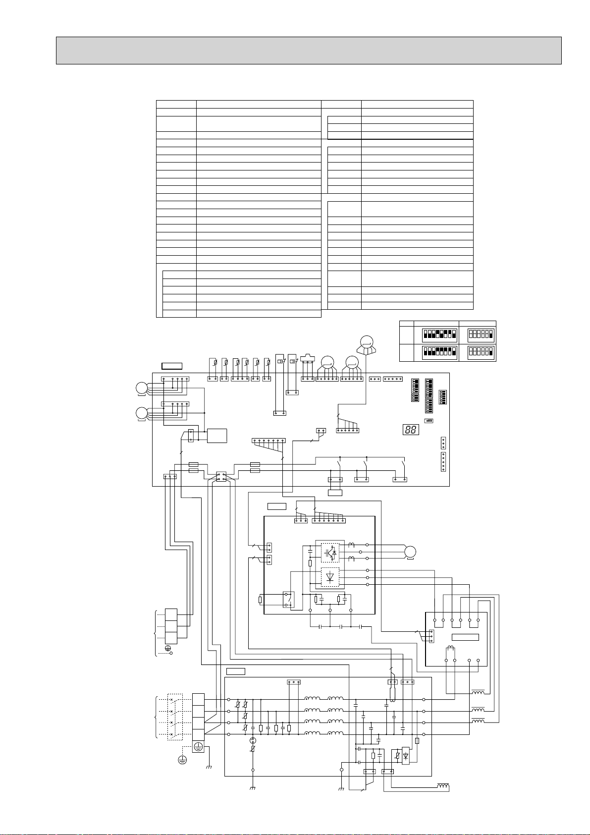
PUHZ-HW112YHA(-BS) PUHZ-HW140YHA(-BS)
SYMBOL NAME SYMBOL NAME
TB1 Terminal Block
TB2
MC
MF1,MF2
21S4
63H
63L Low Pressure Switch
63HS
TH3
TH4
TH6
TH7
TH32 Thermistor<Inlet Water>
TH33 Thermistor<Suction>
LEV-A, LEV-B, LEV-C
ACL1/2/3/4
RS
CB1,CB2
CK
P. B.
TB-U/V/W
TB-L1/L2/L3
TB-P2
TB-C1
TB-N1
X52A
C. B.
1
MF1
MS
3~
MF2
1
MS
3~
CNS
(WHT
)
3
Terminal Block
controller-Outdoor>
Motor for Compressor
Fan Motor
Solenoid Valve<Four-Way Valve>
High Pressure Switch
High Pressure Sensor
Thermistor<Liquid>
Thermistor<Discharge>
Thermistor<Plate HEX Liquid>
Thermistor<Ambient>
Electronic Expansion Valve
Reactor
Rush Current Protect Resistor
Main Smoothing Capacitor
Capacitor
Power Circuit Board
Connection Terminal<U/V/W-Phase>
Connection Terminal<L1/L2/L3-Power Supply>
Connection Terminal
Connection Terminal
Connection Terminal
52C Relay
TH33
CNF1
(WHT)
7
13
TH33
(YLW)
CNF2
(WHT)
7
3
TRANS
1
CNDC
2
(PNK)
F2
F1
1
<Power Supply>
<Interface unit /Flow Temp.
TH7
TH6 TH3 TH4
TH32
t° t° t° t°
t°
t°
4
12
112
TH7/6
TH3
(RED)
(WHT)
2
4
CNAC
(WHT)
1
3
TH32
(BLK)
63H
63L
12
1
TH4
(WHT)
63L
(RED)
1
3
63H
(YLW)
CN2
(WHT)
17
7
F3
F4
37
P.B .
3
63HS
1
63HS
(WHT
2
3
)
CN4
(WHT)
12
21S4
(GRN)
N.F.
LI1/LI2/LI3/NI
LO1/LO2/LO3/NO
GD1,GD3
CONV.B.
L1-A1/IN
L1-A2/OU
L2-A2/OU
L3-A2/OU
N-IN
CK-OU
C.B.
SW1
SW2
SW5
SW6
SW8
CN31
SS
SV1
CNDM
LED3
F1,F2,F3,F4
X51,X52, X54
LEV-B
LEV-A
M
LEV-A
LEV-B
(WHT)
(RED)
5
LEV-C
(BLU)
X52
21S4
Noise Filter Circuit Board
Connection Terminal<L1/L2/L3/N-Power Supply>
Connection Terminal<L1/L2/L3/N-Power Supply>
Connection Terminal<Ground>
Converter Circuit Board
Connection Terminal<L1-Power Supply>
Connection Terminal<L1-Power Supply>
Connection Terminal<L2-Power Supply>
Connection Terminal<L3-Power Supply>
Connection Terminal<N-Power Supply>
Connection Terminal
Controller Circuit Board
Switch<Manual Defrost, Defect History
Record Reset, Function Switch>
Switch<Function Switch>
Switch<Function Switch,Model Select>
Switch<Model Select>
Switch<Function Switch>
Connector<Emergency Operation>
Connector<Connection for Option>
Connector<Connection for Option>
Connector
<Connection
LED<Operation/Inspection Indicators>
Fuse<T6.3AL250V>
Relay
LEV-C
M
M
1613
61
CNVMNT
61
1313
for Option (Contact Input)>
*1MODEL SELECT
MODEL
112Y
140Y
*2. SW5 -1 to 5 : Function Switch
5
1
CNMNT
(WHT)
(WHT)
X54
SV1
(GRY)
LED3
13
(WHT)
SW5SW8
X51
SS
ON
OFF
ON
OFF
SW6
12345678
12345678
*1*1
SW6SW1
CN31
(WHT)
CNDM
CN51
(WHT)
SW2
1
3
1
5
ON
OFF
ON
OFF
SW5-6 *2
123456
123456
Interface
unit /
Flow temp.
controller
POWER
SUPPLY
3N~
400V 50Hz
TB2
31
CN7
2
1
2
1
RED
RED
CNAC1
(WHT)
CN4
(WHT)
CN5
(RED)
X52A
(WHT)
TB-P2
RED
1
3
2
2
RS
ORN
BRN
TB1
YLW
N.F.
LI1
RED
L1
LI2
WHT
L2
BLK
L3
N
BLU
GRN/YLW
UU
LI3
U
NI
U
U
GD1
BLK
S1
S2
S3
71
CN2
(WHT)
+
-
+
-
+
++
CB1 CB2 CK
WHT
GD3
TB-C1
+
BLK
TB-L3
TB-L2
TB-L1
TB-N1
BLK
CNDC
(PNK)
TB-V
TB-W
TB-U
2
BLK
W
MC
WHT
MS
V
3~
U
RED
BLK
WHT
RED
BLK
BLK
WHT
WHT
RED
RED
L2-A2
L2-OU
L1-IN
BLU
L1-OU
N-IN
ACL1
ACL2
ACL3
L1-A2
CK-OU
BLK
L3-A2
L3-OU
3
3
CONV.B.
CN7
1
(WHT)
CNAC2
(RED)
LO1
LO2
LO3
NO
RED
WHT
BLK
BLU
ACL4
L1-A1
RED
RED
2
CNCT
(RED)
+
1
3
3
BRN
3
1
1
2
+
U
--
1
CNL
(BLU)
WHT
17
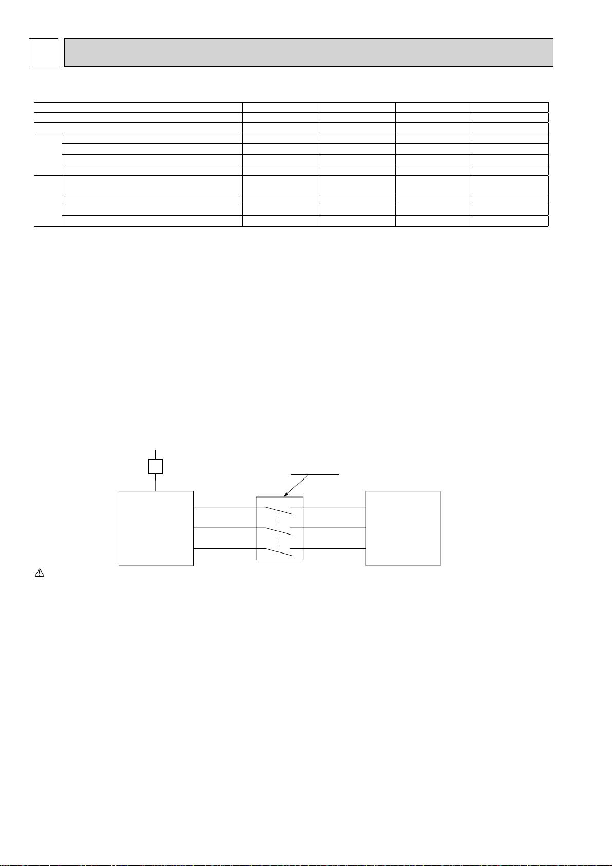
WIRING SPECIFICATIONS6
FIELD ELECTRICAL WIRING (power wiring specifications)
Outdoor unit power supply
Interface unit/Flow temp. controller-Outdoor unit *2 3 × 1.5 (polar) 3 × 1.5 (polar) 3 × 1.5 (polar) 3 × 1.5 (polar)
Interface unit/Flow temp. controller-Outdoor unit earth *2 1 × Min. 1.5 1 × Min. 1.5 1 × Min. 1.5 1 × Min. 1.5
Wiring
size (mm²)
Wire No. ×
Remote controller-Interface unit/Flow temp. controller 2 × 0.3 (Non-polar) 2 × 0.3 (Non-polar) 2 × 0.3 (Non-polar) 2 × 0.3 (Non-polar)
Outdoor unit L-N (single)
Outdoor unit L1-N, L2-N, L3-N (3phase)
Interface unit/Flow temp. controller-Outdoor unit S1-S2 *3 AC 230 V AC 230 V AC 230 V AC 230 V
Interface unit/Flow temp. controller-Outdoor unit S2-S3 *3 DC 24 V DC 24 V DC 24 V DC 24 V
Circuit rating
Remote controller-Interface unit/Flow temp. controller *3 DC 12 V DC 12 V DC 12 V DC 12 V
*1.A breaker with at least 3.0 mm contact separation in each poles shall be provided. Use earth leakage breaker (NV).
*2.Max. 80 m
*3.The gures are NOT always against the ground.
S3 terminal has DC 24 V against S2 terminal. However between S3 and S1, these terminals are NOT electrically insulated by the transformer or other device.
*3 AC 230 V AC 230 V AC 230 V AC 230 V
Notes: 1. Wiring size must comply with the applicable local and national codes.
2.
Power supply cables and the cables between Controller and Outdoor unit shall not be lighter than polychloroprene
sheathed fl exible cables.
(Design 60245 IEC 57
)
3. Be sure to connect the cables between Controller and Outdoor unit directly to the units (no intermediate connections are
allowed).
Intermediate connections may result in communication errors. If water enters at the intermediate connection point, it may
cause insuffi cient insulation to ground or a poor electrical contact .
(If an intermediate connection is necessary, be sure to take measures to prevent water from entering the cables.)
4. Install an earth longer than other cables.
05ledomtinuroodtuO V 85 V 140 V 112 Y,140 Y
~/N (single), 50 Hz, 230 V ~/N (single), 50 Hz, 230 V ~/N (single), 50 Hz, 230 V
3N~ (3phase), 50 Hz, 400 V
A61A04A52A611*yticapacrekaerBtiucriCtinuroodtuO
5.1.niM×56.niM×34.niM×35.1.niM×3htrae,ylppusrewoptinuroodtuO
Power supply
Isolator
S1
A-Control
Outdoor Unit
S2
S3
Warning:
In case of A-control wiring,
there is high voltage potential on the S3 terminal caused by electrical circuit design that has no electrical insulation between
power line and communication signal line. Therefore, please turn off the main power supply when servicing. And do not touch the S1, S2, S3 terminals
when the power is energized. If isolator should be used between Interface unit/Flow temp. controller and outdoor unit, please use 3-pole type.
3 poles isolator
S1
Interface unit/
S2
Flow temp. controller
S3
18
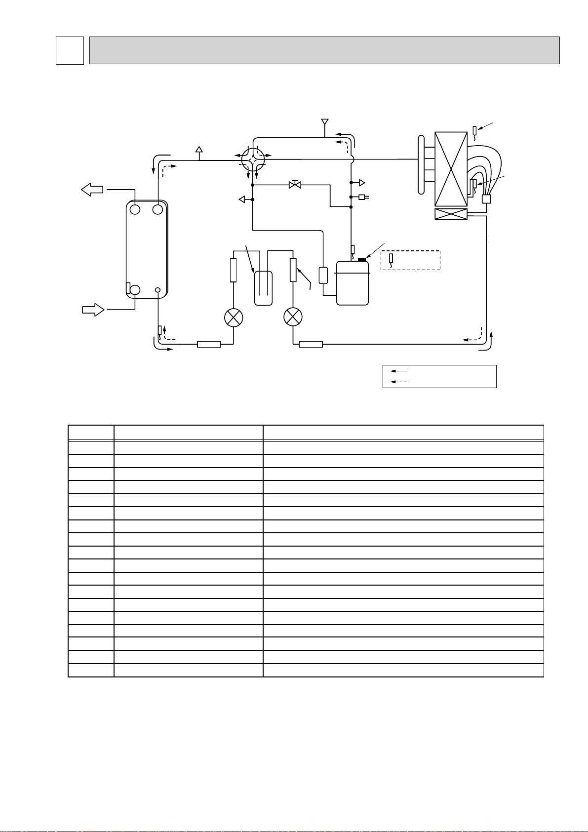
REFRIGERANT SYSTEM DIAGRAM7
PUHZ-W50VHA(-BS)
PUHZ-W85VHA(-BS)
P-Sensor
TH7
Water OUT
Plate HEX
Water IN
TH32
TH6
CHECK/V
CHECK/V
Receiver
Strainer
(#100)
LEV-B
Strainer(#100) Strainer(#100)
REV/V
S/V
Strainer
(#100)
LEV-A
COMP
CHECK/V
H/P SW
TH4
TH3
Distributor
TH33 (W50 only)
TH8 P/B
Refrigerant flow in heating
Refrigerant flow in cooling
Symbol
COMP
H/P SW
Plate HEX
REV/V
S/V
CHECK/V
P-Sensor
P/B
LEV-A
LEV-B
TH32
TH3
TH4
TH6
TH7
TH8
TH33
Receiver
Part name
Compressor
High pressure switch (63H)
Plate Heat Exchanger
Reversing (4-way) valve (21S4)
Solenoid valve
Check valve
Pressure sensor (63HS)
Power board
Linear expansion valve -A
Linear expansion valve -B
Inlet water temperature thermistor
Liquid temperature thermistor
Discharge temperature thermistor
Plate HEX liquid temperature thermistor
Ambient temperature thermistor
Heatsink temperature thermistor
Comp.shell temperature thermistor
Receiver
Detail
DC inverter twin rotary compressor (Mitsubishi Electric Corporation)
For protection (OFF:4.15MPa)
ACH30-30Plates(AlfaLaval):W50 / ACH30-40Plates(AlfaLaval):W85
Change the refrigerant circuit (Heating / Cooling) and for Defrosting
For production test use
High pressure / Low pressure / For production test use
For calculation of the condensing temperature from high pressure
Inverter power board
Heating:Secondary LEV Cooling:Primary LEV
Heating:Primary LEV Cooling:Secondary LEV
For freeze protection and for compressor frequency control
Heating:Evaporating temperature Cooling:Sub cool liquid temperature
For LEV control and for compressor protection
Heating:Sub cool liquid temperature Cooling:Evaporating temperature
For fan control and for compressor frequency control
For power board protection
For compressor protection
For accumulation of refrigerant
19
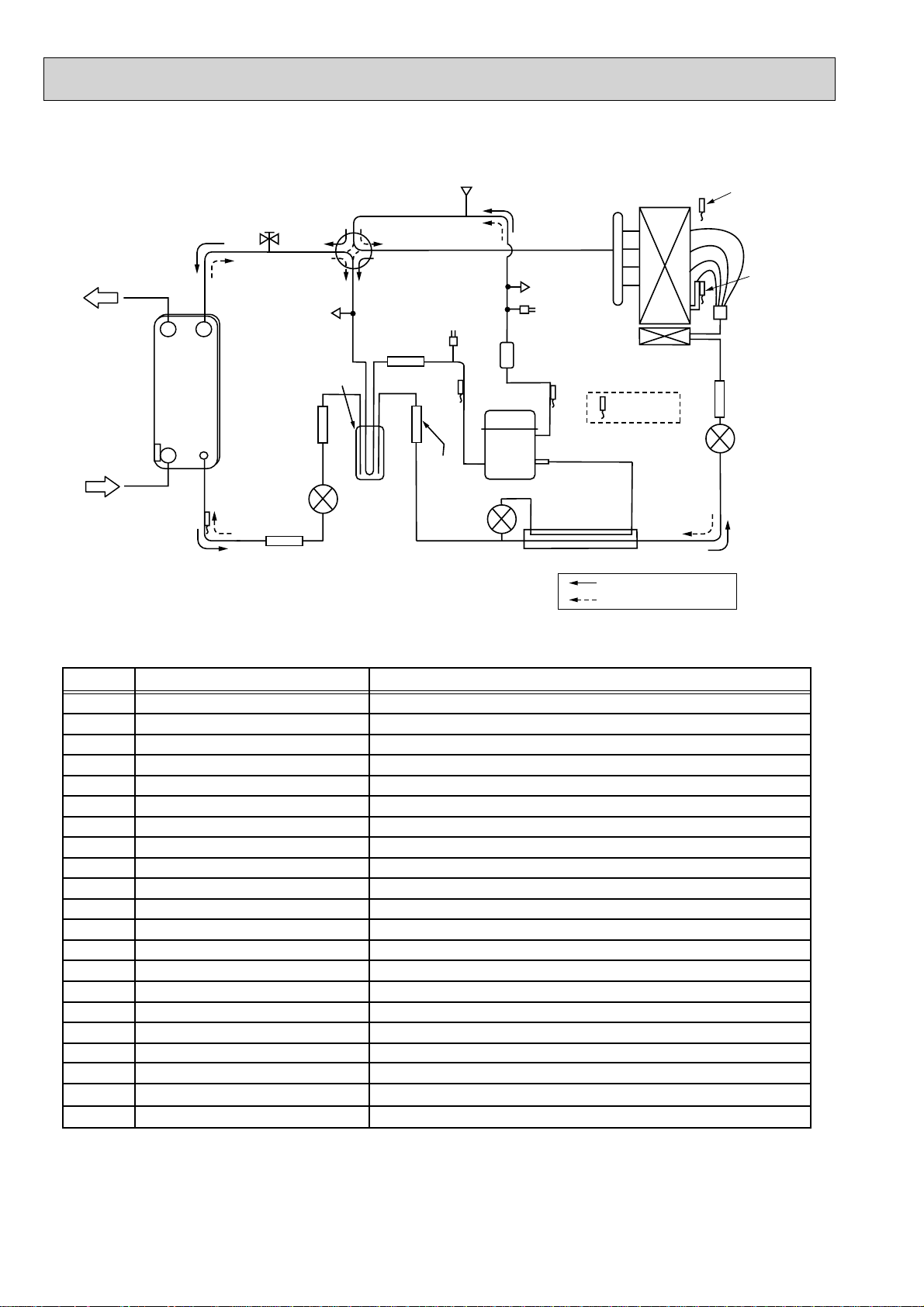
COMP
H/P SW
L/P SW
Plate HEX
REV/V
STOP VALVE
CHECK/V
P-Sensor
P/B
LEV-A
LEV-B
LEV-C
TH33
TH32
TH3
TH4
TH6
TH7
TH8
Power Receiver
HIC
DC inverter scroll compressor (Mitsubishi Electric Corporation)
For protection (OFF:4.15MPa)
For protection (OFF:-0.03MPa)
ACH50 - 50 Plates (Alfa Laval)
Change the refrigerant circuit (Heating / Cooling) and for Defrosting
For production test use
High pressure / Low pressure / For production test use
For calculation of the condensing temperature from high pressure
Inverter power board
Heating:Secondary LEV Cooling:Primary LEV
Heating:Primary LEV Cooling:Secondary LEV
For HIC (heating only)
For LEV control
For freeze protection and for compressor frequency control
Heating:Evaporating temperature Cooling:Sub cool liquid temperature
For LEV control and for compressor protection
Heating:Sub cool liquid temperature Cooling:Evaporating temperature
For fan control and for compressor frequency control
For power board protection
For accumulation of refrigerant
For high heating capacity
Compressor
High pressure switch (63H)
Low pressure switch (63L)
Plate Heat Exchanger
Reversing (4-way) valve (21S4)
Stop valve
Check valve
Pressure sensor (63HS)
Power board
Linear expansion valve -A
Linear expansion valve -B
Linear expansion valve -C
Suction temperature thermistor
Inlet water temperature thermistor
Liquid temperature thermistor
Discharge temperature thermistor
Plate HEX liquid temperature thermistor
Ambient temperature thermistor
Heatsink temperature thermistor
Power Receiver
Heat interchange circuit
Symbol
Part name
Detail
PUHZ-HW112YHA(-BS) PUHZ-HW140VHA(-BS) PUHZ-HW140YHA(-BS)
Water OUT
Plate HEX
Water IN
TH32
TH6
STOP VALVE
Strainer
(#100)
LEV-B
Strainer(#100)
CHECK/V
Power
Receiver
REV/V
Strainer
(#100)
P-Sensor
L/P SW
Strainer
(#100)
LEV-C
COMP
CHECK/V
H/P SW
MUFFLER
TH4TH33
INJ Port
TH8 P/B
HIC
Refrigerant flow in heating
Refrigerant flow in cooling
TH7
TH3
Distributor
Strainer(#100)
LEV-A
20
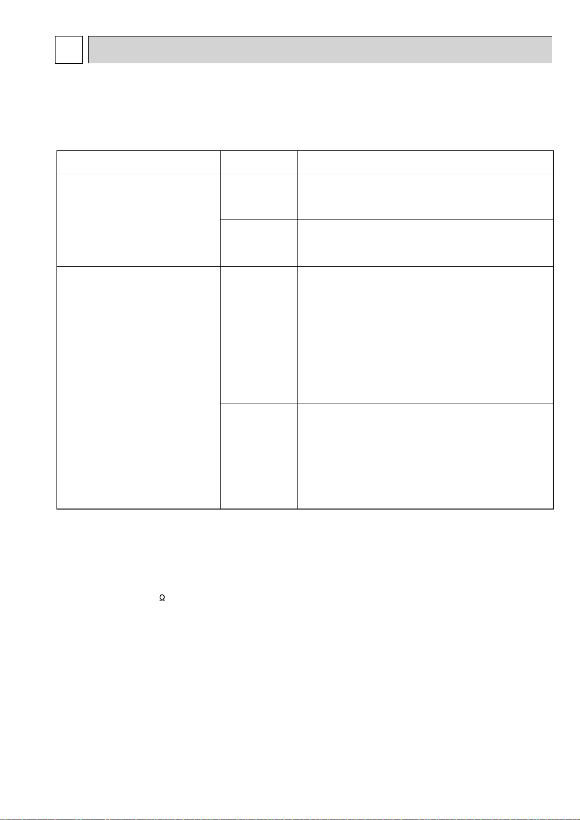
TROUBLESHOOTING8
8-1. TROUBLESHOOTING
<Error code display by self-diagnosis and actions to be taken for service (summary)>
Present and past error codes are logged and displayed on the control board of outdoor unit. Actions to be taken for service,
which depends on whether or not the trouble is reoccurring at service, are summarized in the table below. Check the contents
below before investigating details.
Unit conditions at service
The trouble is reoccurring.
The trouble is not reoccurring.
Error code
Displayed
Not displayed
Logged
Not logged
Actions to be taken for service (summary)
Judge what is wrong and take a corrective action according
to “8-3. Self-diagnosis action table”.
Conduct troubleshooting and ascertain the cause of the
trouble.
Consider the temporary defects such as the work of
protection devices in the refrigerant circuit including
compressor, poor connection of wiring, noise and etc.
Re-check the symptom, and check the installation
environment, refrigerant amount, weather when the
trouble occurred, matters related to wiring
and etc.
Reset error code logs and restart the unit after finishing
service.
There is no abnormality in electrical component,
controller board, and etc.
Re-check the abnormal symptom.
Conduct troubleshooting and ascertain the cause of the
trouble
Continue to operate unit for the time being if the cause
is not ascertained.
There is no abnormality concerning of parts such as
electrical component, controller board, and etc.
.
8-2. CHECK POINT UNDER TEST RUN
Before test run
• After installation of outdoor units, piping work and electric wiring work, re-check that there is no water leakage, loosened con-
nections and incorrect polarity.
• Measure impedance between the ground and the power supply terminal block (L, N) on the outdoor unit by 500 V Megger
and check that it is 1.0 M or over.
• Turn on power supply 12 hours before test run in order to protect compressor.
• Make sure to read operation manual before test run. (Especially items to secure safety.)
21
8-3. SELF-DIAGNOSIS ACTION TABLE
<Abnormalities detected when the power is turned on>
Error Code
None
Abnormal point and detection method
—
1 No voltage is supplied to termi-
nal block(TB1) of outdoor unit.
a) Power supply breaker is
b) Contact failure or disconnecc) Open phase (L or N phase)
2 Electric power is not charged to
power supply terminal of outdoor power circuit board.
a) Contact failure of power
b) Open phase on the outdoor
W50 :
W85 :
Disconnection of connector
HW140V :
3 Electric power is not supplied
to outdoor controller circuit
board.
a) Disconnection of connector
4 Disconnection of reactor (DCL
or ACL)
5 Disconnection of outdoor noise
filter circuit board or parts failure in outdoor noise filter circuit
board
Case
1 Check following items.
turned off.
tion of power supply terminal
2 Check following items.
supply terminal
power circuit board
Disconnection of connector R or S
TABT or TABS
Disconnection of connector LI, NI
(CNDC)
3 Check connection of the connector (CNDC)
Check connection of the connector, LD1 and
4 Check connection of reactor. (DCL or ACL)
W50 : Check connection of “LO” and
“NO” on the outdoor noise filter circuit board.
Check connection of “R” and “S” on the
outdoor power circuit board.
W85 : Check connection of “L1” and “L2” on
Refer to 8-6.
HW140V :
Check connection of "DCL1" and "DCL2" on
5 a) Check connection of outdoor noise filter
circuit board. Refer to 8-6.
b) Replace outdoor noise filter circuit board.
Judgment and action
a) Power supply breaker
b) Connection of power supply terminal
block.(TB1)
c) Connection of power supply terminal
block.(TB1)
a) Connection of power supply terminal
block.(TB1)
b) Connection of terminal on outdoor
power circuit board.
W50 :
Check connection of the connector R or S.
Refer to 8-6.
W85 :
Check connection of the connector TABT or TABS.
Refer to 8-6.
HW140V :
Check connection of the connector LI or NI.
Refer to 8-6.
on the outdoor controller circuit board.
LD2 for W50 and CNDC for W85/HW112/
HW140, on the outdoor power circuit board
(V) / noise filter(Y).Refer to 8-6.
.
the active filter module.(ACTM)
the outdoor power circuit board.
Refer to 8-6.
F3
63L connector open
Abnormal if 63L connector circuit is open
for 3 minutes continuously from being
switched on.
63L: Low-pressure switch
6 Defective outdoor power circuit
board
7 Defective outdoor controller
circuit board
1 Disconnection or contact failure
of 63L connector on outdoor
controller circuit board
2 Disconnection or contact failure
of 63L
3 63L is working due to refriger-
ant leakage or defective parts.
4 Defective outdoor controller
circuit board
22
6 Replace outdoor power circuit board.
7 Replace controller board (When items
above are checked but the units can not be
repaired.)
1 Check connection of 63L connector on
outdoor controller circuit board.
Refer to 8-6.
2 Check the 63L side of connecting wire.
3 Check refrigerant pressure.
Charge additional refrigerant.
Check continuity of 63L.
Replace low pressure switch if it is defective.
4 Replace outdoor controller circuit board.
 Loading...