

Mitsubishi Electric PUHZ-W50, PUHZ-W85 Installation Manual

Hot Water Heat Pump Installation Guide
If you have a PUHZ-W50 or PUHZ-W85 you have a Packaged type unit.
.i.e. The Heat Exchanger is enclosed inside the Outdoor Unit
Step 1 – Choose your system type (Page 4-5)
1, Simple System
The Operation of the Unit On/Off, Mode & Temperature is via the PAR-W21 Wall Controller supplied.
2, Basic System
The Operation of the Unit for On/Off & Mode is via an external input to the interface. (Supplied by
installer) While the Temperature setting is via the PAR-W21 Wall Controller supplied.
3, Analog Temp Setting
The Operation of the unit for On/Off, Mode and Temperature via an external input to the interface.
.i.e. Building management system (Supplied by installer)
Step 2 – Decide how power is to supplied (Page 6-7)
1, Power is supplied to the Outdoor and linked to the Interface unit.
2, Power is supplied separately to the Outdoor and the Interface unit.
Note: If power is supplied separately Dip Switch SW8-3 should be switched to ON & disconnect the
wire loop in CNS2 on right of outdoor terminals.
Step 3 – Install thermistor (Page 8)
Two Thermistors are supplied but only One is required. Both Thermistors are the same so any colour
can be used for the installation. TH1 is connected to the terminals on Interface Board and sensor
bulb must be installed on the Outlet side of the unit. (Detects Flow Water Temperature)
Step 4 – Install Wall Controller (Page 9)
Step 5 – Setting of Dip Switches (Page 10-12)
1, From the first table find: system type and On/Off input and Change Mode and Change Temp and
Package Type. Set the Dipswitches according to the Chart.
2, To disable Cooling mode: SW1-3 should be ON
3, Set Temperature Range. From the last table on page 10. Select your desired limits for Temperature
Range. .i.e. Underfloor Heating systems will require the lowest setting of 50°C set switches to SW1-6
OFF, SW1-7 OFF, SW1-8 ON.
4, If you want to have the Set Temperature Fixed. Table on top of page 11. You may choose to
permanently set Temperature setting to 40°C for the Outdoor unit. The Underfloor Heating Company
will control the room circuits via an external thermostat.
Step 6 – Optional: External Input / External Output (Page 11-12)
1, Connecting External Input. Table 4.5 bottom of Page 11 and 4.5.2 top of page 12.
2, Connecting External Output. Table 4.6 middle of page 12.
Step 7 – Check (Page 13)
Self test by pressing Check button twice.

FLOW TEMP. CONTROLLER (Cased)
PAC-IF021B-E
INSTALLATION MANUAL
For safe and correct use, read this manual thoroughly before installing the FTC unit.
OPERATION MANUAL
For safe and correct use, read this operation manual thoroughly before operating the air-conditioner unit.
FOR INSTALLER
English
FOR USER

Contents
1. Safety precautions .....................................................................................2
2. Installing the FTC unit ...............................................................................3
3. System ......................................................................................................4
4. Electrical work ...........................................................................................6
5. Check ......................................................................................................13
6. Remote controller operation ....................................................................13
7. Initial setting by remote controller ............................................................22
8. Defi nition of analog signal by remote controller ......................................24
9. Troubleshooting ......................................................................................25
Guide to plan local applications ....................................................................26
“FTC” is the abbreviation of “Flow Temperature Controller”, which is described as “FTC” in this manual.
1.Safety precautions
Before installing the FTC unit, make sure you read all the “Safety precautions”.
Please report to your supply authority or obtain their consent before
connecting this equipment to the power supply system.
Warning:
Precautions that must be observed to prevent injuries or death.
Caution:
Precautions that must be observed to prevent damages to the unit.
Warning:
• The unit must not be installed by the user. Ask an installer or an authorized
technician to install the unit. If the unit is installed improperly, electric
shock, or fi re may be caused.
• For installation work, follow the instructions in the Installation Manual and
use tools and pipe components specifi cally made for use with refrigerant
specifi ed in the outdoor unit installation manual.
• The unit must be installed according to the instructions in order to minimize the risk of damages by earthquakes, typhoons, or strong winds.
Improperly installed unit may fall down and cause damages or injuries.
•
The unit must be securely installed on a structure that can sustain its weight.
If the unit is mounted on an unstable structure, it may fall down and cause
damages or injuries.
• All electric work must be performed by a qualifi ed technician according to
local regulations and the instructions given in this manual. The unit must
be powered by dedicated power lines and the correct voltage and circuit
breakers must be used. Power lines with insuffi cient capacity or incorrect
electrical work may result in electric shock or fi re.
After installation, perform the test run to ensure normal operation. Then explain
your customer the “Safety Precautions,” use, and maintenance of the unit based on
the information in the Operation Manual provided by local application manufacture.
Both the Installation Manual and the Operation Manual must be given to the user.
These manuals must always be kept by the actual users.
: Indicates a part which must be grounded.
Warning:
Carefully read the labels attached to the unit.
• Only the specified cables can be used for wiring. Connections must be
made securely without tension on the terminals. If cables are connected or
installed improperly, It may result in overheating or fi re.
• Terminal block cover panel of the unit must be fi rmly fi xed. If the cover
panel is mounted improperly, dust and moisture may enter the unit, and it
may cause electric shock or fi re.
• Make sure to use accessories authorized by Mitsubishi Electric and ask
an installer or an authorized technician to install them. If accessories are
improperly installed, it may cause electric shock, or fi re.
• Do not remodel the unit. Consult an installer for repairs. If alterations or
repairs are not performed correctly, it may cause electric shock or fi re.
• The user should never attempt to repair the unit or transfer it to another
location. If the unit is installed improperly, it may cause electric shock or
fi re. If the FTC unit needs to be repaired or moved, ask an installer or an
authorized technician.
1.1. Before installation (Environment)
Caution:
• Do not install the FTC unit in outdoor location as it is designed for indoor
installation only. Otherwise electric shock or breakdown may be caused by
water drop, wind or dust.
•
Do not use the unit in an unusual environment. If the FTC unit is installed or
exposed to steam, volatile oil (including machine oil), or sulfuric gas, or exposed to briny air, the internal parts can be damaged.
• Do not install the unit where combustible gases may leak, be produced,
fl ow, or accumulate. If combustible gas accumulates around the unit, it may
cause fi re or explosion.
1.2. Before installation or relocation
Caution:
• Be fully careful when moving the units. Do not hold the packaging bands.
Wear protective gloves to unpack and to move it, in order to avoid your
hands be injured by parts.
1.3. Before electric work
Caution:
• Be sure to install a circuit breaker. If it is not installed, there may be a risk
to get an electric shock.
• For the power lines, use standard cables of suffi cient capacity. Otherwise,
it may cause a short circuit, overheating, or fi re.
• When installing the power lines, do not apply tension to the cables. The
cables may be cut or overheated resulting in a fi re.
1.4. Before starting the test run
Caution:
• Turn on the main power switch of the outdoor unit more than 12 hours
before starting operation. Starting operation immediately after turning on
the power switch can severely damage the internal parts. Keep the main
power switch turned on during the operation period.
• When installing the unit in a hospital or in a building where communications equipment are installed, you may need to take measure to noise and
electronic interference. Inverters, home appliances, high-frequency medical
equipment, and radio communications equipment can cause the FTC unit
to malfunction or to breakdown. At the same time, the noise and electric
interference from the FTC unit may disturb the proper operation of medical
equipment, and communications equipment.
• Be sure to safely dispose of the packaging materials. Packaging materials,
such as nails and other metal or wooden parts may cause injuries.
• Do not wash the FTC unit. You may receive an electric shock.
• Make sure to ground the unit. Do not connect the ground wire to gas or
water pipes, lightning rods, or telephone grounding lines. If the unit is not
properly grounded, there may be a risk to get an electric shock.
• Make sure to use circuit breakers (ground fault interrupter, isolating switch
(+B fuse), and molded case circuit breaker) with the specifi ed capacity. If
the circuit breaker capacity is larger than the specified capacity, breakdown or fi re may result.
• Before starting operation, check that all protective parts are correctly in-
stalled. Make sure not to get injured by touching high voltage parts.
• Do not touch any switch with wet hands. There may be a risk to get an
electric shock.
• After stopping operation, make sure to wait at least 5 minutes before turn-
ing off the main power. Otherwise, it may cause breakdown.
2
2. Installing the FTC unit
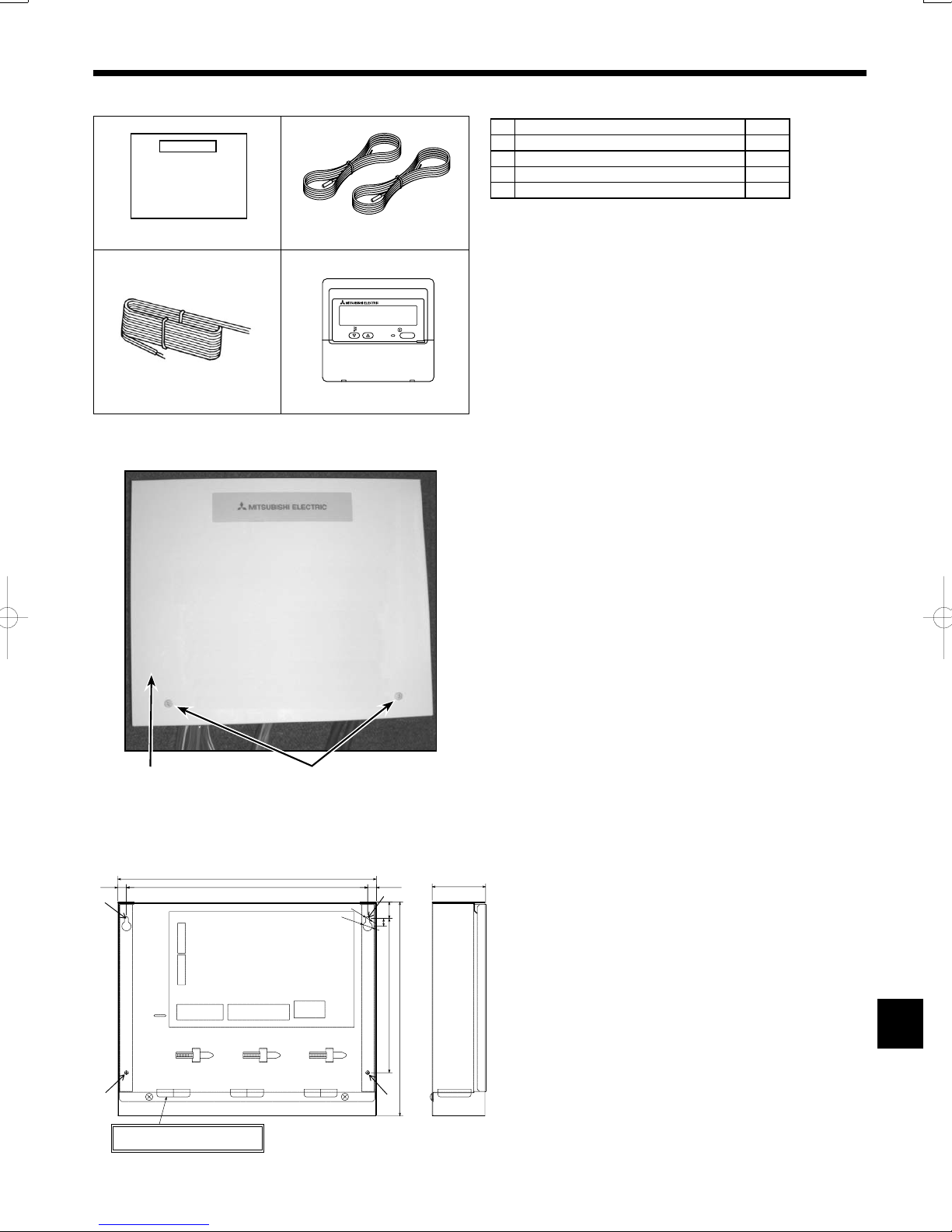
2.1. Check the parts (Fig. 2-1)
The FTC unit should be supplied with the following parts.
Part Name Q'ty
FTC unit 1
1
Thermistor 2
2
Remote controller cable(5m) 1
3
Remote controller 1
4
TEMP.
ON/OFF
Fig. 2-1
2.2. Choosing the FTC unit installation location
• Do not install the FTC unit in outdoor location as it is designed for in-
door installation only. (It is not waterproof against raindrop.)
• Avoid locations where the unit is exposed to direct sunlight or other
sources of heat.
• Select a location where easy wiring access to the power source is
available.
• Avoid locations where combustible gases may leak, be produced,
fl ow, or accumulate.
• Select a level location that can bear the weight and vibration of the
unit.
• Avoid locations where the unit is exposed to oil, steam, or sulfuric gas.
• Do not install in location that is hot or humid for long periods of time.
2.3. Installing the FTC unit (Fig. 2-2, Photo.2-1)
1. Remove 2 screws from FTC unit and remove the cover.
2. Install the 4 screws (locally supplied) in 4 holes.
Screw B Cover
A
Hole for installation
C
BA
Photo.2-1
11.5
336
313
TB61 TB62
TB6
TB141TB142
3-ELECTRIC WIRE INLET
When installed on a wall: Lower side
Fig.2-2
Unit:mm
(11.5)
:5
22
:12
10
200
278
69
3
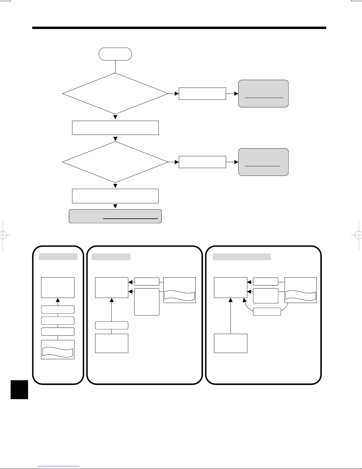
3. System
To start, check your system type by following the fl ow chart below.(FTC can be used for 3 types of systems.)
Start
Heat Pump switch ON/OFF
and the operation mode
change is done…
By remote controller
Your system is
SIMPLE SYSTEM.
By external signals from local controller
(non-voltage contact signals)
‘Target flow temperature’ is set…
By remote controller
Your system is
BASIC SYSTEM.
By external signals from local controller
(Analog signal:4-20mA/ 1-5V/ 0-10V)
Your system is ANALOG TEMP. SYSTEM.
SIMPLE SYSTEM BASIC SYSTEM ANALOG TEMP. SYSTEM
By Non-voltage
Contact signals
FTC PCB BOX FTC PCB BOX FTC PCB BOX
ON/OFF
Operation mode
Target flow temp.
Remote controller
End user interface
Target flow temp.
Remote controller
Topreset
- target temp. for each mode
- target temp. parameters
(See Page22-23 for details)
ON/OFF
Operation mode
- Heating
- Heating ECO
- Hot water
- Anti freeze
- Cooling
System controller
(locally supplied)
End user interface
Remote controller
Topreset
- analog signal parameters
(See Page24 for details)
By Non-voltage
Contact signals
ON/OFF
Operation mode
- Heating +
- Cooling
Target flow temp.
Analog signal
4-20mA/1-5V/0-10V
+In this system,
• Heating ECO mode of FTC is
not available.
• It is NOT necessary to switch
operation mode to realize
Hot water mode, Anti freeze
mode and Heating ECO mode.
Simply change the target temp.
by Analog signal.
System controller
(locally supplied)
End user interface
4
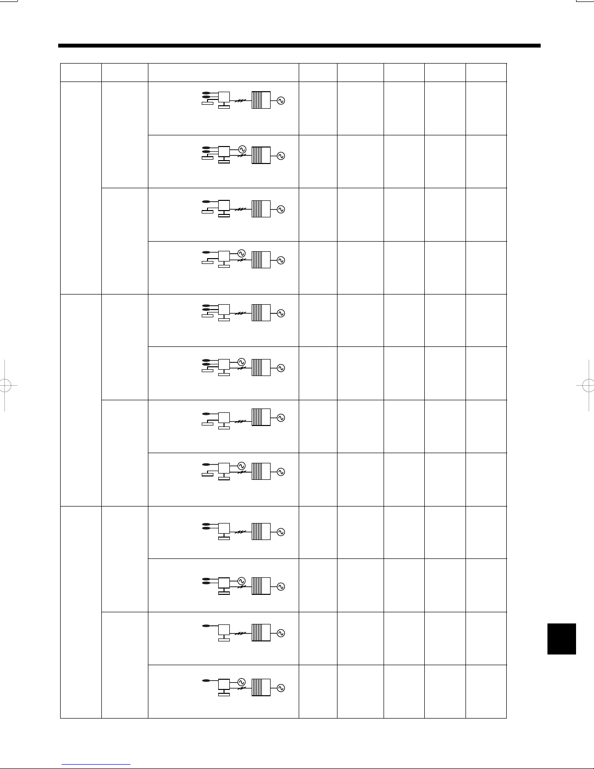
3. System
Refer to the relevant sections for details according to your system type.
System System diagram
BASIC
Outdoor
unit
SPLIT type
Local controller
ON/OFF
MODE
TH1
TH2
FTC Outdoor unit
FTC
Remote controller
(PAR-W21MAA)
Power
supplies
4.1
4.1.1
Thermistor
(TH1, TH2)
4.2.1
4.2.2
Switch
setting
4.4
External
input
4.5.1
External
output
4.6
ANALOG
TEMP.
PACKAGED
type
SPLIT type
PACKAGED
type
Local controller
ON/OFF
MODE
Local controller
ON/OFF
MODE
Local controller
ON/OFF
MODE
Local controller
ON/OFF
Temp.
Local controller
ON/OFF
Temp.
Local controller
ON/OFF
Temp.
TH1
TH2
TH1
TH1
TH1
TH2
TH1
TH2
TH1
FTC Outdoor unit
FTC
Remote controller
(PAR-W21MAA)
FTC Outdoor unit
FTC
Remote controller
(PAR-W21MAA)
FTC Outdoor unit
FTC
Remote controller
(PAR-W21MAA)
FTC Outdoor unit
FTC
Remote controller
(PAR-W21MAA)
FTC Outdoor unit
FTC
Remote controller
(PAR-W21MAA)
FTC Outdoor unit
FTC
Remote controller
(PAR-W21MAA)
4.1
4.1.2
4.1
4.1.1
4.1
4.1.2
4.1
4.1.1
4.1
4.1.2
4.1
4.1.1
4.2.1
4.2.2
4.2.1
4.2.1
4.2.1
4.2.2
4.2.1
4.2.2
4.2.1
4.4
4.4
4.4
4.4
4.4
4.4
4.5.1
4.5.1
4.5.1
4.5.1
4.5.2
4.5.1
4.5.2
4.5.1
4.5.2
4.6
4.6
4.6
4.6
4.6
4.6
TH1
Local controller
ON/OFF
Temp.
SIMPLE
SPLIT type
PACKAGED
type
TH1
TH2
TH1
TH2
TH1
TH1
SPLIT type : the standard outdoor unit without a plate HEX(Refrigetant-water HEX) inside
PACKAGED type : the Air to Water outdoor unit with a plate HEX(Refrigetant-water HEX) inside
FTC Outdoor unit
FTC
Remote controller
(PAR-W21MAA)
FTC Outdoor unit
FTC
Remote controller
(PAR-W21MAA)
FTC Outdoor unit
FTC
Remote controller
(PAR-W21MAA)
FTC Outdoor unit
FTC
Remote controller
(PAR-W21MAA)
FTC Outdoor unit
FTC
Remote controller
(PAR-W21MAA)
4.1
4.1.2
4.1
4.1.1
4.1
4.1.2
4.1
4.1.1
4.1
4.1.2
4.2.1
4.2.1
4.2.2
4.2.1
4.2.2
4.2.1
4.2.1
4.4
4.4
4.4
4.4
4.4
4.5.1
4.5.2
4.6
4.6
—
4.6
—
4.6
—
4.6
—
5
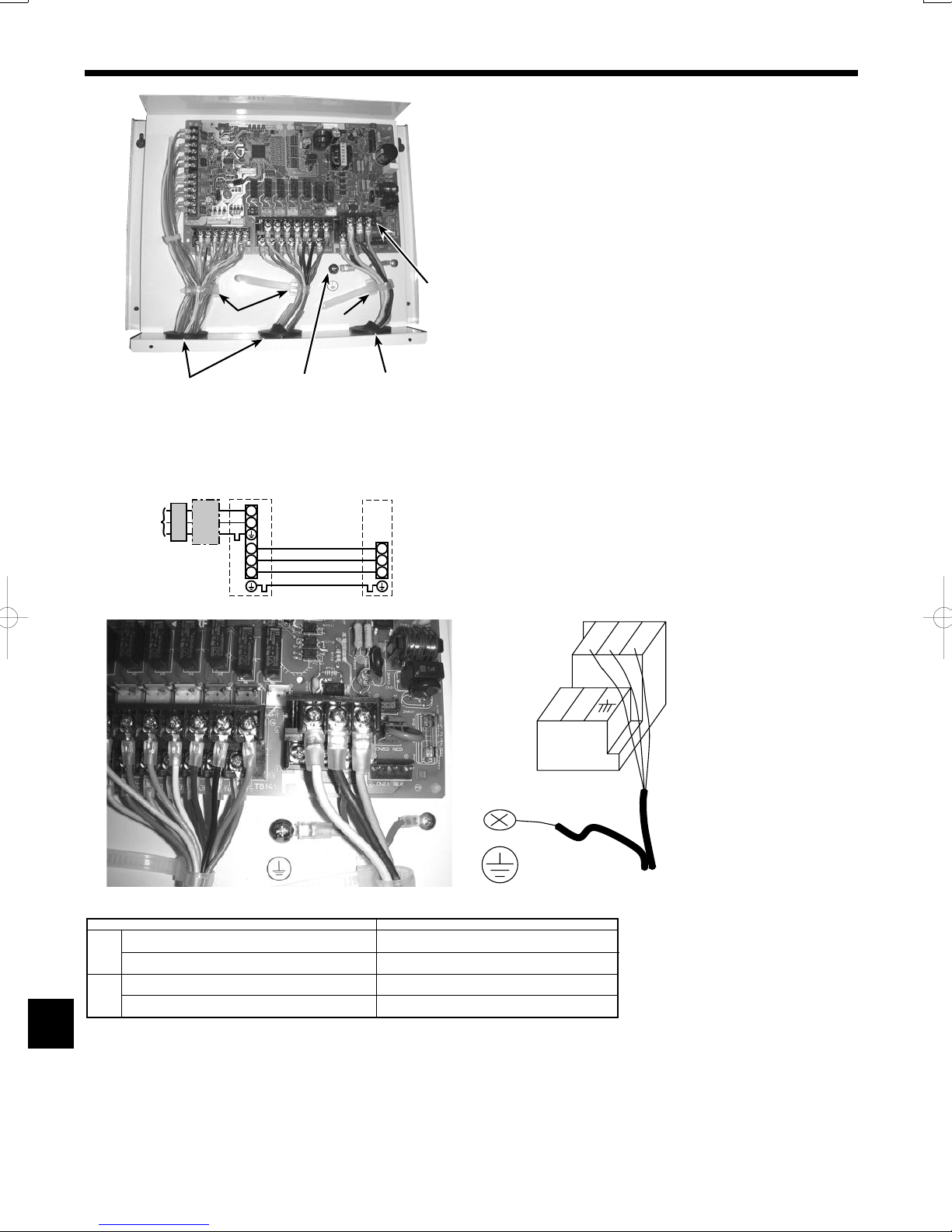
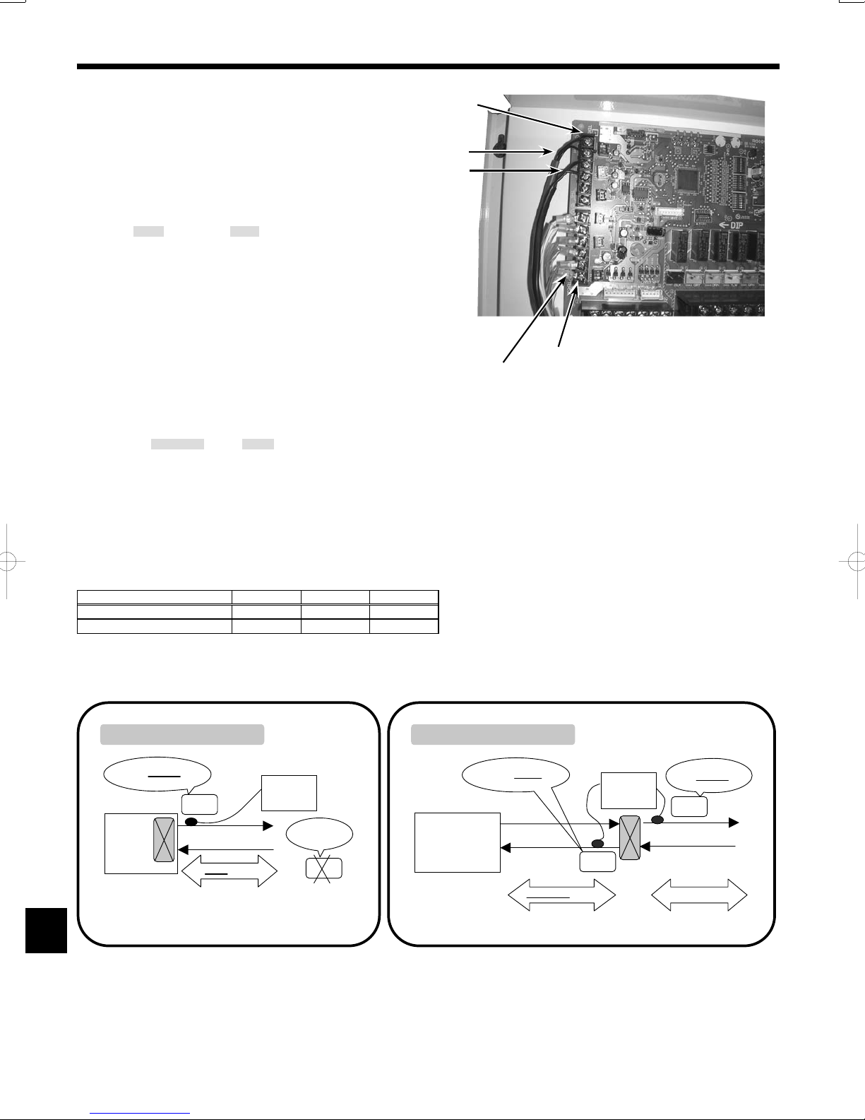
4. Electrical work
4.1. FTC (Photo. 4-1)
1. Remove the cover.
2. Wire the power cable and control cable separately through the respective wiring inlets given in the photo.
• Make sure to put screws tightly.
Inlet for control cable
A
Inlet for power
B
Clamp
C
FTC / Outdoor unit connecting terminals
D
Earth terminal
E
D
C
C
Photo.4-1
A
E
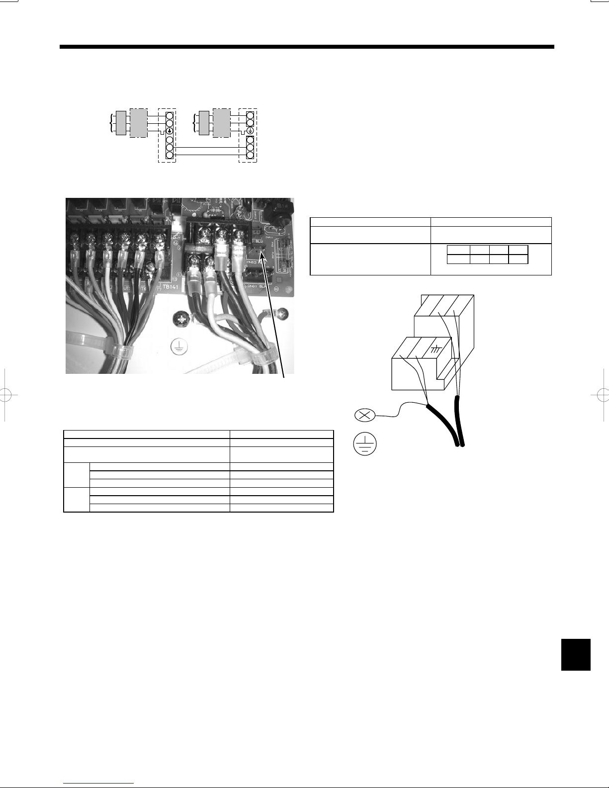
4.1.1. FTC unit power supplied from outdoor unit
The following connection patterns are available.
The outdoor unit must be powered properly.(Details are shown in its installation manual.)
D
L
ABC
N
S1
S2
S3
E
B
F
S1
S2
S3
A Outdoor unit power supply
B Earth leakage breaker
C Wiring circuit breaker or isolating switch
D Outdoor unit
E FTC unit/outdoor unit connecting cables
F FTC unit
TB6
S2 S3S1
NL
Photo.4-2
FTC unit model
FTC unit-Outdoor unit
)
2
(mm
Wiring
FTC unit-Outdoor unit earth
Wire No. × size
FTC unit-Outdoor unit S1-S2
rating
Circuit
FTC unit-Outdoor unit S2-S3
*1. Max. 80 m
*2. The fi gures are NOT always against the ground.
S3 terminal has DC 24 V against S2 terminal. However between S3 and S1, these terminals are not electrically insulated by the transformer or other device.
Notes: 1. Wiring size must comply with the applicable local and national codes.
2. Power supply cables and FTC unit/outdoor unit connecting cables shall not be lighter than polychloroprene sheathed fl exible ca-
ble. (Design 60245 IEC 57)
3. Install an earth wire longer than other cables.
6
E: FTC unit/outdoor unit
connecting cables
Earth cable
PAC-IF021B-E
*1
*1
*2
*2
3× 1.5 (polar)
1 × Min.1.5
AC 230 V
DC24 V
4. Electrical work
4.1.2. Separate FTC unit/outdoor unit power supplies
The following connection patterns are available.
The outdoor unit power must be powered properly(Details are shown in its installation manual).
D
L
N
A
CB
GEB
S1
S2
S3
F
L
N
C
S1
S2
S3
A Outdoor unit power supply
B Earth leakage breaker
C Wiring circuit breaker or isolating switch
D Outdoor unit
E FTC unit/outdoor unit connecting cables
F FTC unit
G FTC unit power supply
If the FTC and outdoor units have separate power supplies, refer to the
table below.
Separate power supply specifi cations
Disconnected
ON 3
OFF 1 2
Set the SW8-3 to ON.
S2 S3S1
NL
(SW8)
Photo.4-3
CNS2
FTC unit controller connector (CNS2)
connection change
Outdoor unit DIP switch settings (when
using separate FTC unit/outdoor unit
power supplies only)
TB6
E: FTC unit/outdoor unit
FTC unit model PAC-IF021B-E
FTC unit power supply ~/N (Single Phase), 50 Hz, 230 V
FTC unit input capacity
Main switch (Breaker)
)
2
FTC unit power supply & earth 3 × Min. 1.5
(mm
FTC unit-Outdoor unit *2 2 × Min. 0.3
Wiring
Wire No. ×
size
FTC unit-Outdoor unit earth –
FTC unit L-N *3 AC 230 V
FTC unit-Outdoor unit S1-S2 *3 –
rating
Circuit
FTC unit-Outdoor unit S2-S3 *3 DC24 V
*1. A breaker with at least 3.0mm contact separation in each pole shall be provided. Use earth leakage breaker (NV).
*2. Max. 120 m
*3. The fi gures are NOT always against the ground.
*1 16 A
Power Supply Cables
connecting cable
Notes: 1. Wiring size must comply with the applicable local and national code.
2. Power supply cables and FTC unit/outdoor unit connecting cables shall not be lighter than polychloroprene sheathed fl exible ca-
ble. (Design 60245 IEC 57)
3. Install an earth wire longer than other cables.
7
4. Electrical work
4.2. Connecting thermistor cable
Connect the thermistor 2 for the FTC controller.
4.2.1. Connecting the actual fl ow water temp. thermistor (TH1)
Connect the thermistor for the actual fl ow water temp. to 1 and 2 on the
terminal block (TB61) on the FTC controller.
When the thermistor cables are too long, cut them at the appropriate
length.
Do not bind them in the FTC unit.
TB61
TH1
TH2
<Thermistor position>
Put TH1 on
water piping (water outlet side).
Note: Be sure to attach the TH1 where it detects Flow temp.(Water
oulet side) correctly.
4.2.2. Connecting the pipe temp. thermistor (TH2)
Connect the thermistor for the refrigerant pipe temp. to 3 and 4 on the
terminal block (TB61) on the FTC (PCB).
For packaged Outdoor unit : It is not necessary to connect TH2.
For split Outdoor unit : Connect TH2.
When the thermistor cables supplied with FTC are too long, cut them to
TB62
Wired remote controller cable
Photo.4-4
the appropriate length.
Do not bind them in the FTC unit.
<Thermistor position>
Put the TH2 on refrigerant piping (Liquid side).
It is better to protect the thermistor with heat insulating materials not to be affected by the ambient temperature.
Note: Be sure to attach the TH2 where it detects Refrigerant piping temp. (Liquid side) correctly.
Caution:
Do not route the thermistor cables together with power cables.
The sensor part of the thermistor should be installed where user must not touch.
(It is separated by the supplementary insulation from where user may touch.)
<Thermistor position and necessity>
Outdoor unit TH1 TH2 TH5
PACKAGED type ΟХХ
SPLIT type ΟΟХ
Ο: Necessary. Connect the thermistor.
Х: Not necessary. The thermistor is not needed to connect.
PACKAGED type outdoor unit SPLIT type outdoor unit
Water OUTLET side
TH1
Outdoor unit
*1
Water piping
Packaged type
(with a refrigerant-water HEX inside)
FTC
*1 Refrigerant-water HEX
8
TH2:
not necessary
TH2
Refrigerant LIQUID side
Outdoor unit
SPLIT type
(without refrigerant-water
nside)
X i
HE
Refrigerant piping
TH2
FTC
Water OUTLET side
TH1
*1
Water piping
*1 Refrigerant-water HEX
 Loading...