


Air to Water Heat Pump
PUHZ-W
•
PUHZ-HW
INSTALLATION MANUAL
For safe and correct use, read this manual as well as the indoor unit installation manual thoroughly before installing the unit. English is original. The other languages versions are translation of the original.
INSTALLATIONSHANDBUCH
Aus Sicherheitsgründen und zur richtigen Verwendung vor der Installation die vorliegende Bedienungsanleitung und die Installationsanleitung
der Innenanlage gründlich durchlesen die Klimaanlage. Das Original ist in Englisch. Die anderen Sprachversionen sind vom Original übersetzt.
MANUEL D’INSTALLATION
Avant d’installer le climatiseur, lire attentivement ce manuel, ainsi que le manuel d’installation de l’appareil intérieur pour une
utilisation sûre et correcte. L’anglais est l’original. Les versions fournies dans d’autres langues sont des traductions de l’original.
INSTALLATIEHANDLEIDING
Lees deze handleiding en de installatiehandleiding van het binnenapparaat zorgvuldig door voordat u met het installeren
van de airconditioner begint. Het Engels is het origineel. De andere taalversies zijn vertalingen van het origineel.
MANUAL DE INSTALACIÓN
Para un uso correcto y seguro, lea detalladamente este manual y el manual de instalación de la unidad interior antes de instalar la unidad
de aire acondicionado. El idioma original del documento es el inglés. Las versiones en los demás idiomas son traducciones del original.
MANUALE DI INSTALLAZIONE
Per un uso sicuro e corretto, leggere attentamente il presente manuale ed il manuale d’installazione dell’unità interna prima di installare
il condizionatore d’aria. Il testo originale è redatto in lingua Inglese. Le altre versioni linguistiche rappresentano traduzioni dell’originale.
HA series
•
HA series
FOR INSTALLER
English
FÜR INSTALLATEURE
Deutsch
POUR L’INSTALLATEUR
Français
VOOR DE INSTALLATEUR
Nederlands
PARA EL INSTALADOR
Español
PER L’INSTALLATORE
Italiano
Η γλώσσα του πρωτοτύπου είναι η αγγλική. Οι εκδόσεις άλλων γλωσσών είναι μεταφράσεις του πρωτοτύπου.
Para uma utilização segura e correcta, leia atentamente este manual e o manual de instalação da unidade interior antes de instalar o
aparelho de ar condicionado. O idioma original é o inglês. As versões em outros idiomas são traduções do idioma original.
Læs af sikkerhedshensyn denne manual samt manualen til installation af indendørsenheden grundigt, før du
installerer klimaanlægget. Engelsk er originalen. De andre sprogversioner er oversættelser af originalen.
Läs bruksanvisningen och inomhusenhetens installationshandbok noga innan luftkonditioneringen installeras så att den används
på ett säkert och korrekt sätt. Engelska är originalspråket. De övriga språkversionerna är översättningar av originalet.
Emniyetli ve doğru kullanım için, klima cihazı nı monte etmeden önce bu kı lavuzu ve iç ünite montaj
kılavuzunu tamamıyla okuyun. Aslı İngilizce’dir. Diğer dillerdeki sürümler aslının çevirisidir.
Языком оригинала является английский. Версии на других языках являются переводом оригинала.
INSTALLASJONSHÅNDBOK
For å sikre trygg og riktig bruk skal denne håndboken samt installasjonshåndboken for innendørsenheten leses grundig
igjennom før enheten installeres. Engelsk er originalspråket. De andre språkversjonene er oversettelser av originalen.
ASENNUSOPAS
Turvallisen ja asianmukaisen käytön varmistamiseksi lue tämä opas sekä sisäyksikön asennusopas huolellisesti
ennen yksikön asentamista. Alkuperäiskieli on englanti. Muut kieliversiot ovat alkuperäisen käännöksiä.
FOR MONTØR
ASENTAJALLE
Dansk
Svenska
Norsk
Suomi
Contents
1. Safety precautions . . . . . . . . . . . . . . . . . . . . . . . . . . . . . . . . . . . . . . . . . . . . . . 2
2. Installation location . . . . . . . . . . . . . . . . . . . . . . . . . . . . . . . . . . . . . . . . . . . . . 3
3. Installation procedures . . . . . . . . . . . . . . . . . . . . . . . . . . . . . . . . . . . . . . . . . . . 4
4. Drainage piping work . . . . . . . . . . . . . . . . . . . . . . . . . . . . . . . . . . . . . . . . . . . . 5
5. Water piping work . . . . . . . . . . . . . . . . . . . . . . . . . . . . . . . . . . . . . . . . . . . . . . 5
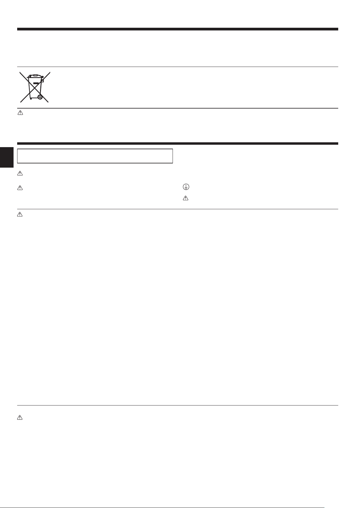
Note: This symbol mark is for EU countries only.
This symbol mark is according to the directive 2002/96/EC Article 10 Information for users and Annex IV.
Your MITSUBISHI ELECTRIC product is designed and manufactured with high quality materials and components which can be recycled and reused.
This symbol means that electrical and electronic equipment, at their end-of-life, should be disposed of separately from your household waste.
Please, dispose of this equipment at your local community waste collection/recycling centre.
In the European Union there are separate collection systems for used electrical and electronic product.
Please, help us to conserve the environment we live in!
Caution:
• Do not vent R410A into the Atmosphere:
• R410A is a Fluorinated Greenhouse gas, covered by the Kyoto Protocol, with a Global Warming Potential (GWP)=1975.
6. Electrical work . . . . . . . . . . . . . . . . . . . . . . . . . . . . . . . . . . . . . . . . . . . . . . . . . 5
7. Test run . . . . . . . . . . . . . . . . . . . . . . . . . . . . . . . . . . . . . . . . . . . . . . . . . . . . . . 7
8. Special functions . . . . . . . . . . . . . . . . . . . . . . . . . . . . . . . . . . . . . . . . . . . . . . . 7
9. System control . . . . . . . . . . . . . . . . . . . . . . . . . . . . . . . . . . . . . . . . . . . . . . . . . 7
10. Specifi cations . . . . . . . . . . . . . . . . . . . . . . . . . . . . . . . . . . . . . . . . . . . . . . . . . . 7
1. Safety precautions
►
Before installing the unit, make sure you read all the “Safety precau-
tions”.
Warning:
Precautions that must be observed to prevent injuries or death.
Caution:
Precautions that must be observed to prevent damages to the unit.
After installation, perform the test run to ensure normal operation. Then explain to
your customer the “Safety Precautions,” use, and maintenance of the unit based
on the information in the Operation Manual. Both the Installation Manual and the
Operation Manual must be given to the user. These manuals must always be kept
by the actual users.
: Indicates a part which must be grounded.
Warning:
Carefully read the labels attached to the unit.
Warning:
• The unit must not be installed by the user. Ask an installer or an authorized technician to install the unit. If the unit is installed improperly, water
leakage, electric shock, or fi re may be caused.
• The unit must be installed according to the instructions in order to minimize the risk of damages by earthquakes, typhoons, or strong winds.
An improperly installed unit may fall down and cause damages or injuries.
• The unit must be securely installed on a structure that can sustain its
weight. If the unit is mounted on an unstable structure, it may fall down
and cause damages or injuries.
• If the air to water heat pump is installed in an enclosed area, measures
must be taken to prevent the refrigerant concentration in the room in the
event of refrigerant leakage. Consult an installer regarding the appropriate
measures. Should the refrigerant leak and cause the concentration oxygen
in the room may lack.
• All electric work must be performed by a qualifi ed technician according to
local regulations and the instructions given in this manual. The units must
be powered by dedicated power lines and the correct voltage and circuit
breakers must be used. Power lines with insuffi cient capacity or incorrect
electrical work may result in electric shock or fi re.
• Use only specifi ed cables for wiring. The wiring connections must be made
securely with no tension applied on the terminal connections. Also, never
splice the cables for wiring (unless otherwise indicated in this document).
Failure to observe these instructions may result in overheating or a fi re.
• Terminal block cover panel of the outdoor unit must be fi rmly fi xed. If the
cover panel is mounted improperly, dust and moisture may enter the unit,
and it may cause electric shock or fi re.
•
When installing or moving the air to water heat pump, make sure to use the
specifi ed refrigerant (R410A) to charge the refrigerant lines. Do not either mix it
with any other refrigerant or allow air to remain within the pipes. Air enclosed in
the pipes can cause pressure peaks resulting in a rupture and other hazards.
• Make sure to use accessories authorized by Mitsubishi Electric and ask
an installer or an authorized technician to install them. If accessories are
improperly installed, it may cause water leakage, electric shock, or fi re.
• Do not remodel the unit. Consult an installer for repairs. If alterations or
repairs are not performed correctly, it may cause water leakage, electric
shock, or fi re.
• The user should never attempt to repair the unit or transfer it to another
location. If the unit is installed improperly, it may cause water leakage,
electric shock, or fi re. If the air to water heat pump needs to be repaired or
moved, ask an installer or an authorized technician.
•
After installation has been completed, make sure that refrigerant does not
leak. If refrigerant leaks into the room and comes into contact with the fl ame
of a heater or portable cooking range, poisonous gases will be released.
• Use clean enough water which meets water quality standards. The deterioration of water quality may result in the system breakdown or the water
leakage.
• Never use anything other than water as a medium. It may cause a fi re or an
explosion.
• Do not directly use heated or cooled water that is produced by the air to
water heat pump as drinking and cooking water, or swimming pool. There
is a risk to damage your health. There is also a risk that installing the water heat exchanger may corrode if the necessary water quality for the air
to water heat pump system cannot be maintained. If you wish to use the
heated or cooled water from the heat pump for these purposes, take measure such as to isolate the second heat exchanger within the water piping
system.
• When installing or relocating, or servicing the air conditioner, use only the
specifi ed refrigerant (R410A) to charge the refrigerant lines. Do not mix it
with any other refrigerant and do not allow air to remain in the lines.
If air is mixed with the refrigerant, then it can be the cause of abnormal
high pressure in the refrigerant line, and may result in an explosion and
other hazards.
The use of any refrigerant other than that specified for the system will
cause mechanical failure or system malfunction or unit breakdown. In the
worst case, this could lead to a serious impediment to securing product
safety.
1.1. Before installation
Caution:
• Do not use the unit in an unusual environment. If the air to water heat
pump is installed exposed to steam, volatile oil (including machine oil),
or sulfuric gas, or exposed to briny air, or covered with snow, the performance can be signifi cantly reduced and the internal parts can be damaged.
• Do not install the unit where combustible gases may leak, be produced,
flow, or accumulate. If combustible gas accumulates around the unit, it
may cause fi re or explosion.
• The outdoor unit produces condensate during the heating operation. Make
sure to provide drainage around the outdoor unit if such condensate is
likely to cause damage.
2
• When installing the unit in a hospital or in a building where communication
equipment is installed, you may need to take measures to reduce noise
and electronic interference. Inverters, home appliances, high-frequency
medical equipment, and radio communications equipment can cause the
air to water heat pump to malfunction or to breakdown. At the same time,
the noise and electronic interference from the air to water heat pump unit
may disturb the proper operation of medical equipment, and communications equipment.
1. Safety precautions
1.2. Before installation (relocation)
Caution:
• Be fully careful when moving the units. The unit must be carried by at least
2 people, as it weighs 20 kg or more. Do not hold the packaging bands.
Wear protective gloves to unpack and to move or install it, in order to
avoid your hands being injured by fi ns or the edge of other parts.
• Be sure to safely dispose of the packaging materials. Packaging materials,
such as nails and other metal or wooden parts may cause injuries.
• The base of the outdoor unit must be periodically checked to ensure it is
not loose, cracked or damaged. If such defects are left untreated, the unit
may fall down and cause damage or injuries.
• Do not wash the air to water heat pump unit. You may receive an electric
shock.
1.3. Before electric work
Caution:
• Be sure to install a circuit breaker. If it is not installed, there may be a risk
of an electric shock.
• For the power lines, use standard cables of suffi cient capacity. Otherwise,
it may cause a short circuit, overheating, or fi re.
• When installing the power lines, do not apply tension to the cables. The
cables may be cut or overheated resulting in a fi re.
1.4. Before starting the test run
Caution:
• Turn on the main power switch more than 12 hours before starting operation. Starting operation immediately after turning on the power switch can
severely damage the internal parts. Keep the main power switch turned on
during the operating period.
• Before starting operation, check that all panels, guards and other protective parts are correctly installed. Make sure not to get injured by touching
rotating, hot, or high voltage parts.
1.5. Using R410A refrigerant air to water heat pump
Caution:
• Use only R410A refrigerant. If another refrigerant is used, the chlorine will
let the oil deteriorate.
• Use the following tools specifically designed for R410A refrigerant use.
Contact your nearest installer for further details.
Tools (for R410A)
Gauge manifold Charge hose
Gas leak detector Vacuum pump adapter
Torque wrench Electronic refrigerant charging scale
• Make sure to ground the unit. Do not connect the ground wire to gas or
water pipes, lightning rods, or telephone grounding lines. If the unit is not
properly grounded, there may be a risk to get an electric shock.
• Make sure to use circuit breakers (ground fault interrupter, isolating switch
(+B fuse), and molded case circuit breaker) with the specifi ed capacity. If
the circuit breaker capacity is larger than the specified capacity, breakdown or fi re may result.
• Do not touch any switch with wet hands. There may be a risk of an electric
shock.
• Do not touch the refrigerant pipes with bare hands while unit is running.
The refrigerant pipes can be hot or cold depending on the condition of the
fl owing refrigerant. There may be a risk to get burn or frostbite.
• After stopping operation, make sure to wait at least five minutes before
turning off the main power. Otherwise, it may cause water leakage or
breakdown.
• Be sure to use the proper tools. If dust, debris, or moisture enters the refrigerant pipes, the refrigeration oil may deteriorate.
• Do not use a charging cylinder. If a charging cylinder is used, the composition of the refrigerant may change and the effi ciency will be worsened.
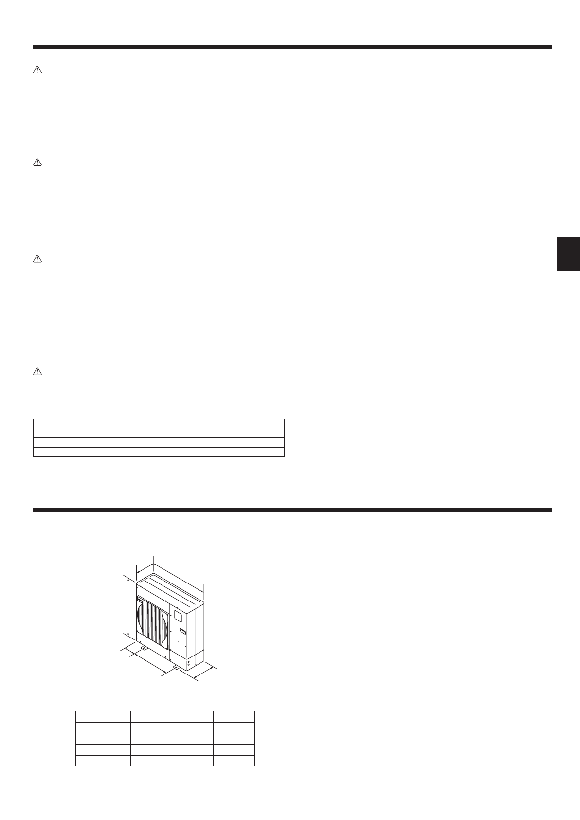
2. Installation location
330+30
A
C
600
Fig. 2-1
Models A(mm) B(mm) C(mm)
50 740 950 175
85 943 950 175
112 1350 1020 210
140 1350 1020 210
(mm)
B
370
2.1. Choosing the outdoor unit installation location
• Avoid locations where the unit is exposed to direct sunlight or other sources of
heat.
• Select a location where noise emitted by the unit does not disturb neighbors.
• Select a location where easy wiring and pipe access to the power source is
available.
• Avoid locations where combustible gases may leak, be produced, fl ow, or accu-
mulate.
• Note that condensate water may be produced by the unit during operation.
• Select a level location that can bear the weight and vibration of the unit.
• Avoid locations where the unit can be covered with snow. In areas where heavy
snow fall is anticipated, special precautions must be taken to prevent the snow
from blocking the air intake such as to install the unit at higher position or installing a hood on the air intake. This can reduce the airfl ow and the unit may not
operate properly.
• Avoid locations where the unit is exposed to oil, steam, or sulfuric gas.
• Make sure to hold the handles to transport the unit. Do not hold the base of the
unit, as there is a risk that hands or fi ngers may be pinched.
2.2. Outline dimensions (Outdoor unit) (Fig. 2-1)
3

2. Installation location
Fig. 2-2
Fig. 2-3
Fig. 2-4
2.3. Windy location installation
When installing the outdoor unit on a rooftop or other location where the unit is
exposed to strong wind, do not face the air outlet of the unit directly into the winds.
Strong wind entering the air outlet may impede the normal airfl ow and it may result
in a malfunction.
The following shows three examples of precautions against strong winds.
1 Face the air outlet towards the nearest available wall keeping about 50 cm dis-
tance. (Fig. 2-2)
2 Install an optional air guide if the unit is installed in a location where strong winds
such as a typhoon, etc. may directly blow to the air outlet. (Fig. 2-3)
A Air outlet guide
3 Position the unit so that the outlet air can blow at right angle to the seasonal
wind direction, if possible. (Fig. 2-4)
B Wind direction
2.4. NECESSARY SPACE TO INSTALL
2.4.1. When installing a single outdoor unit (Refer to the last page)
Minimum dimensions are as follows, except for Max., meaning Maximum dimensions, indicated.
The fi gures in parentheses are for 112/140 models.
Refer to the fi gures for each case.
1 Obstacles at rear only (Fig. 2-5)
2 Obstacles at rear and above only (Fig. 2-6)
3 Obstacles at rear and sides only (Fig. 2-7)
4 Obstacles at front only (Fig. 2-8)
* When using an optional air outlet guide, the clearance for 112/140 models is 500 mm or
more.
5 Obstacles at front and rear only (Fig. 2-9)
* When using an optional air outlet guide, the clearance for 112/140 models is 500 mm or
more.
6 Obstacles at rear, sides, and above only (Fig. 2-10)
• Do not install the optional air outlet guides for upward airfl ow.
2.4.2. When installing multiple outdoor units (Refer to the last page)
Leave 10 mm space or more between the units.
The fi gures in parentheses are for 112/140 models.
1 Obstacles at rear only (Fig. 2-11)
2 Obstacles at rear and above only (Fig. 2-12)
• No more than 3 units must be installed side by side. In addition, leave space as shown.
• Do not install the optional air outlet guides for upward airfl ow.
3 Obstacles at front only (Fig. 2-13)
* When using an optional air outlet guide, the clearance for 112/140 models is 1000 mm or
more.
4 Obstacles at front and rear only (Fig. 2-14)
* When using an optional air outlet guide, the clearance for 112/140 models is 1000 mm or
more.
5 Single parallel unit arrangement (Fig. 2-15)
* When using an optional air outlet guide installed for upward airfl ow, the clearance is 500
(1000) mm or more.
6 Multiple parallel unit arrangement (Fig. 2-16)
* When using an optional air outlet guide installed for upward airfl ow, the clearance is 1000
(1500) mm or more.
7 Stacked unit arrangement (Fig. 2-17)
• The units can be stacked up to 2 units high.
• No more than 2 stacked units must be installed side by side. In addition, leave space as
shown.
3. Installation procedures
A M10 (3/8") bolt
B Base
C As long as possible
D Vent
E Set deep in the ground
F Max.30
G Min.360
H Min.10
600 600
(mm)
• Be sure to install the unit in a solid, level surface to prevent rattling noises during
operation. (Fig. 3-1)
<Foundation specifi cations>
Foundation bolt M10 (3/8")
Thickness of concrete 120 mm
Length of bolt 70 mm
Weight-bearing capacity 320 kg
• Make sure that the length of the foundation bolt is within 30 mm from the surface
of the base.
• Secure the base of the unit fi rmly with 4 M10 foundation bolts in solid locations.
Installing the outdoor unit
• Do not block the vent. If the vent is blocked, operation will be hindered and the
unit may breakdown.
• If the additional fi xation of the unit is necessary, use the installation holes on the
back of the unit to attach wires, etc. with self-tapping screws (ø5 × 15 mm or
less).
Warning:
• The unit must be securely installed on a structure that can sustain its
weight. If the unit is mounted on an unstable structure, it may fall down and
cause damage or injuries.
• The unit must be installed according to the instructions in order to minimize
the risk of damage by earthquakes, typhoons, or strong winds. An improperly installed unit may fall down and cause damage or injuries.
* Figures in parentheses are for 112/140 unit types.
330
370
175
(210)
950(1020)
175
(210)
25
Fig. 3-1
4

L1 L2 L3 N
S1 S2 S3
4. Drainage piping work
Outdoor unit pipe connection
When drain piping is necessary, use the drain socket or the drain pan (option).
5. Water piping work
5.1. Water piping connection (Fig. 5-1)
• Connect the water pipes to the outlet and inlet pipes.
(Parallel male screw for 1-inch water pipe (ISO 228/1-G1B))
• Inlet and outlet pipes position is shown on the Fig. 5-1.
• Install the hydraulic fi lter at the water intake.
• Maximum allowable torque at the water piping connection is 50 N•m.
• Check if water leaks after installation.
• Inlet water gauge pressure must be between 0-0.3 MPa.
• Use the inlet water with a temperature lower than 55 ˚C.
Note :
• The water velocity in pipes should be kept within certain limits of material to avoid
erosion, corrosion and excessive noise generation.
Be aware, and take care of, that local velocities in small pipes, bends and similar
obstructions can exceed the values above.
e.g.) Copper : 1.5 m/s
• When connecting metal pipes made of different materials, be sure to insulate the
joint to prevent electrolytic etching.
• Set up a fi eld system so that the inlet water temperature and water fl ow rate can
be within the allowable range specifi ed in our technical data, etc.
If the unit is used out of the allowable range, the parts of unit might be damaged.
Optional parts name Model name
Drain socket PAC-SG61DS-E
Drain pan for 50/85 PAC-SG64DP-E
*There is no optional drain pan for 112/140.
* The drain socket is applicable only to W50, W85 and W112 and not compatible
with HW112 and HW140.
Fig. 5-1
5.2. Water quality condition
• The water in a system should be clean and with a pH value of 6.5-8.0.
• The followings are the maximum values;
Calcium : 100 mg/L
Chlorine : 100 mg/L
Iron/manganese : 0.5 mg/L
[Fig. 5-1]
A Water outlet
B Water inlet
5.3. Minimum water quantity
Following water quantity is required in the water circuit.
Model Minimum water quantity (L)
W50 40
W85 60
W112 80
HW112 80
HW140 100
6. Electrical work
6.1. Outdoor unit (Fig. 6-1, Fig. 6-2)
1 Remove the service panel.
2 Wire the cables referring to the Fig. 6-1 and the Fig. 6-2.
Note : Make sure to perform the frozen prevention measure for water pipe
system. (Water piping insulation, back-up pump system, using of a
certain % ethylene glycol instead of normal water )
Insulate the water piping properly. The performance can be poor if the
insulation is insuffi cient.
Warning:
As the outlet water temperature can reach 60ºC at maximum, do not touch
the water piping directly with a bare hand.
A Earth terminal
B Terminal block
C Clamp
D Service panel
E Wire the cables so that they
do not contact the center of
the service panel.
■
50-140V (Single phase)
A Interface unit/
Flow temp. controller
B Outdoor unit
C Remote controller
D Main switch (Earth leakage breaker)
E Earth
Fig. 6-1
Caution:
Be sure to install N-Line. Without N-Line, it could cause damage to unit.
LN
S1 S2 S3
■
112-140Y (3
phase)
Fig. 6-2
5

6. Electrical work
6.2. Field electrical wiring
Outdoor unit model 50V 85V 112V 140V
Outdoor unit power supply
Outdoor unit Circuit Breaker capacity *1 16 A 25 A 32 A 40 A 16 A
Outdoor unit power supply, earth 3 × Min. 1.5 3 × Min. 4 3 × Min. 4 3 × Min. 6 5 × Min. 1.5
Interface unit/Flow temp. controller-Outdoor unit *2 3 × 1.5 (polar) 3 × 1.5 (polar) 3 × 1.5 (polar) 3 × 1.5 (polar) 3 × 1.5 (polar)
Interface unit/Flow temp. controller-Outdoor unit earth *2 1 × Min. 1.5 1 × Min. 1.5 1 × Min. 1.5 1 × Min. 1.5 1 × Min. 1.5
Wiring
size (mm²)
Wire No. ×
Remote controller-Interface unit/Flow temp. controller 2 × 0.3 (Non-polar) 2 × 0.3 (Non-polar) 2 × 0.3 (Non-polar) 2 × 0.3 (Non-polar) 2 × 0.3 (Non-polar)
Outdoor unit L-N (single)
Outdoor unit L1-N, L2-N, L3-N (3 phase)
Interface unit/Flow temp. controller-Outdoor unit S1-S2 *3 AC 230 V AC 230 V AC 230 V AC 230 V AC 230 V
Interface unit/Flow temp. controller-Outdoor unit S2-S3 *3 DC 24 V DC 24 V DC 24 V DC 24 V DC 24 V
Circuit rating
Remote controller-Interface unit/Flow temp. controller *3 DC 12 V DC 12 V DC 12 V DC 12 V DC 12 V
*1. A breaker with at least 3.0 mm contact separation in each poles shall be provided. Use earth leakage breaker (NV).
*2. Max. 80 m
*3. The fi gures are NOT always against the ground.
S3 terminal has DC 24 V against S2 terminal. However between S3 and S1, these terminals are NOT electrically insulated by the transformer or other device.
Notes: 1. Wiring size must comply with the applicable local and national codes.
2.
Power supply cables and the cables between Interface unit/Flow temp. controller and outdoor unit shall not be lighter than polychloroprene sheathed
fl exible cables. (Design 60245 IEC 57
3. Be sure to connect the cables between
lowed).
Intermediate connections may result in communication errors. If water enters at the intermediate connection point, it may cause insuffi cient insula-
tion to ground or a poor electrical contact .
(If an intermediate connection is necessary, be sure to take measures to prevent water from entering the cables.)
4. Install an earth longer than other cables.
5. Do not construct a system with a power supply that is turned ON and OFF frequently.
)
Interface unit/Flow temp. controller
~/N (single),
50 Hz, 230 V
*3 AC 230 V AC 230 V AC 230 V AC 230 V AC 230 V
~/N (single),
50 Hz, 230 V
and outdoor unit directly to the units (no intermediate connections are al-
~/N (single),
50 Hz, 230 V
~/N (single),
50 Hz, 230 V
112Y, 140Y
3N~ (3 phase),
50 Hz, 400 V
Power
supply
Isolator
S1
Outdoor Unit
S2
S3
Warning:
In case of A-control wiring, there is high voltage potential on the S3 terminal caused by electrical circuit design that has no electrical insulation between power
line and communication signal line. Therefore, please turn off the main power supply when servicing. And do not touch the S1, S2, S3 terminals when the power
is energized. If isolator should be used between indoor unit and outdoor unit, please use 3-pole type.
Never splice the power cable or the indoor-outdoor connection cable, otherwise it may result in a smoke, a fi re or communication failure.
IMPORTANT
Make sure that the current leakage breaker is one compatible with higher harmonics.
Always use a current leakage breaker that is compatible with higher harmonics as this unit is equipped with an inverter.
The use of an inadequate breaker can cause the incorrect operation of inverter.
3 poles isolator
S1
S2
S3
Interface unit /
Flow temp.
controller
6

7. Test run
Before test run
►
After installation works are completed, check if there is no refrigerant leak-
age, no looseness in the power supply or control wiring, no wrong polarity,
and no disconnection of one phase in the supply.
►
Use a 500-volt megohmmeter to check that the resistance between the
power supply terminals and ground is at least 1 M
Warning:
Do not use the air to water heat pump if the insulation resistance is less than
1 M
"
.
Insulation resistance
When installed the power source to the unit has been cut for an extended period,
the insulation resistance may drop below 1 M
ant within the compressor. This is not a malfunction. Perform the following procedures.
1. Remove the wires from the compressor and measure the insulation resistance of
the compressor.
2. If the insulation resistance is below 1 M
ply the accumulation of refrigerant in the compressor makes the resistance drop.
3. After connecting the wires to the compressor, the compressor starts to warm
up once power is supplied. After supplying power for the times indicated below,
remove the wires from the compressor and measure the insulation resistance
again.
"
"
, the compressor may be faulty or sim-
"
.
due to the accumulation of refriger-
8. Special functions
A Circuit diagram example
(low noise mode)
B On-site arrangement
C External input adapter
(PAC-SC36NA-E)
SW1
CNDM
Fig. 8-1
D Outdoor unit control board
E Max. 10 m
F Red
G Brown
H Orange
• The insulation resistance drops due to the accumulation of refrigerant in the
compressor. The resistance will rise above 1 M
warmed up for 4 hours.
(The necessary time to warm up the compressor varies according to atmospheric conditions and refrigerant accumulation.)
• If the refrigerant accumulates within the compressor, the compressor must be
warmed up at least 12 hours before starting the operation to prevent breakdown.
4. If the insulation resistance rises above 1 M
Caution:
• The compressor does not operate if the power supply phase connection is
incorrect.
• Turn on the power at least 12 hours before starting operation.
- Starting operation immediately after turning on the main power switch can result
in severe damage to internal parts. Keep the power switch turned on during the
operating period.
Note : Occasionally, vapor that is made by the defrost operation may seem as
if smoke come up from the outdoor unit.
"
"
after the compressor is
, the compressor is not faulty.
8.1. Low noise mode (on-site modifi cation) (Fig. 8-1)
The low noise mode will be activated when a commercially available timer or the
contact input of an ON/OFF switch is added to the CNDM connector (option) on the
control board of the outdoor unit.
1 Complete the circuit as shown when using the external input adapter
(PAC-SC36NA-E). (Option)
2 SW1 ON: Low noise mode
SW1 OFF: Normal operation
Note:
• The ability varies according to the outdoor temperature and conditions, etc.
• When the ambient temperature is high, this function may not work.
9. System control
Set the refrigerant address using the Dip switch of the outdoor unit.
SW7 Function Setting
SW7 Setting
ON
OFF
34567
ON
OFF
34567
ON
OFF
34567
Refrigerant
address
00
01
02
SW7 Setting
ON
OFF
34567
ON
OFF
34567
ON
OFF
34567
Refrigerant
address
03
04
05
Note:
a) Up to 6 units can be connected.
b) Select one single model for all units.
c) SW7 Setting are applicable to the following models.
PUHZ-W50VHAR2
PUHZ-W85VHA2
PUHZ-W112VHA
PUHZ-HW112/140YHA2
PUHZ-HW140VHA2
d) For Dip switch settings for indoor unit, refer to the indoor unit’s
installation manual.
10. Specifi cations
Refrigerant R410A
CO
Sound Level (Measured under rated operating frequency.)
SPL Heating dB(A) 46 48 53 53 53 53
PWL Heating dB(A) 61 66 69 67 67 67
GWP 1975
Amount kg 1.7 2.4 4.0 4.0 4.0 4.3
2 equivalent kg 3358 4740 7900 7900 7900 8493
Cooling dB(A) 45 48 53 53 53 53
W50VHA W85VHA(2) W112VHA HW112YHA(2) HW140Y/VHA HW140Y/VHA2
Hermetically sealed
7

This product is designed and intended for use in the residential,
commercial and light-industrial environment.
The product at hand is
based on the following
EU regulations:
Please be sure to put the contact address/telephone number on
this manual before handing it to the customer.
• Low Voltage Directive 2006/95/ EC
• Electromagnetic Compatibility Directive
2004/108/ EC
• Machinery Directive 2006/42/EC
• RoHS Directive 2011/65/EU
• Year Of Manufacture *
* As indicated in front of the outdoor unit
HEAD OFFICE: TOKYO BLDG., 2-7-3, MARUNOUCHI, CHIYODA-KU, TOKYO 100-8310, JAPAN
BH79D067R02 Printed in Japan
Authorized representative in EU:
MITSUBISHI ELECTRIC EUROPE B.V.
HARMAN HOUSE, 1 GEORGE STREET, UXBRIDGE, MIDDLESEX UB8 1QQ, U.K.
 Loading...