

Mitsubishi PUHZ-SW75VHA, PUHZ-SW100YHA-BS, PUHZ-SW12, PUHZ-SW75VHA-BS, PUHZ-SW100VHA-BS Service Manual
...
SERVICE MANUAL
CONTENTS
1. TECHNICAL CHANGES
................................
2
2. REFERENCE MANUAL
.................................
3
3. SAFETY PRECAUTION
.................................
4
4. FEATURES
.....................................................
8
5. SPECIFICATIONS
..........................................
9
6. DATA
.............................................................
13
7. OUTLINES AND DIMENSIONS
...................
15
8. WIRING DIAGRAM
......................................
17
9. WIRING SPECIFICATIONS
..........................
24
10.
REFRIGERANT SYSTEM DIAGRAM
..............
25
11. TROUBLESHOOTING
..................................
27
12. DISASSEMBLY PROCEDURE
.....................
82
R410A
PUHZ-SW75VHA.UK
PUHZ-SW75VHA-BS.UK
Salt proof model
PUHZ-SW75VHA-BS
PUHZ-SW100VHA-BS
PUHZ-SW100YHA-BS
PUHZ-SW120VHA-BS
PUHZ-SW120YHA-BS
Note:
•
This manual describes
service data of the outdoor
units only.
PUHZ-SW75VHA-BS.UK PUHZ-SW75VHAR3-BS.UK
PUHZ-SW75VHAR4-BS.UK
PUHZ-SW100VHA-BS.UK PUHZ-SW100VHAR3-BS.UK
PUHZ-SW100VHAR4-BS.UK
PUHZ-SW100YHA-BS.UK PUHZ-SW100YHAR1-BS.UK
PUHZ-SW100YHAR3-BS.UK PUHZ-SW100YHAR4-BS.UK
PUHZ-SW120VHA-BS.UK PUHZ-SW120VHAR3-BS.UK
PUHZ-SW120VHAR4-BS.UK
PUHZ-SW120YHA-BS.UK PUHZ-SW120YHAR1-BS.UK
PUHZ-SW120YHAR3-BS.UK PUHZ-SW120YHAR4-BS.UK
Outdoor unit
[Model Name]
PUHZ-SW75VHA
PUHZ-SW100VHA
PUHZ-SW100YHA
PUHZ-SW120VHA
PUHZ-SW120YHA
[Service ref.]
PUHZ-SW75VHA.UK PUHZ-SW75VHAR3.UK
PUHZ-SW75VHAR4.UK
PUHZ-SW100VHA.UK PUHZ-SW100VHAR3.UK
PUHZ-SW100VHAR4.UK
PUHZ-SW100YHA.UK PUHZ-SW100YHAR1.UK
PUHZ-SW100YHAR3.UK PUHZ-SW100YHAR4.UK
PUHZ-SW120VHA.UK PUHZ-SW120VHAR3.UK
PUHZ-SW120VHAR4.UK
PUHZ-SW120YHA.UK PUHZ-SW120YHAR1.UK
PUHZ-SW120YHAR3.UK PUHZ-SW120YHAR4.UK
PARTS CATALOG (OCB533)
Revision:
• Added
PUHZ-SW75VHAR4.UK,
PUHZ-SW75VHAR4-BS.UK,
PUHZ-SW100VHAR4.UK,
PUHZ-SW100VHAR4-BS.UK,
PUHZ-SW100YHAR4.UK,
PUHZ-SW100YHAR4-BS.UK,
PUHZ-SW120VHAR4.UK,
PUHZ-SW120VHAR4-BS. UK,
PUHZ-SW120YHAR4.UK and
PUHZ-SW120YHAR4-BS.UK
in REVISED EDITION-D.
• Some descriptions have
been modified.
• Please void OCH533
REVISED EDITION-C.
No. OCH533
REVISED EDITION-D
August 2015
SPLIT-TYPE, AIR TO WATER HEAT PUMP
2
PUHZ-SW100YHA(-BS).UK PUHZ-SW100YHAR1(-BS).UK
PUHZ-SW120YHA(-BS).UK PUHZ-SW120YHAR1(-BS).UK
• Power circuit board (P.B.) has been changed.
1 TECHNICAL CHANGES
PUHZ-SW75VHA(-BS).UK PUHZ-SW75VHAR3(-BS).UK
PUHZ-SW100VHA(-BS).UK PUHZ-SW100VHAR3(-BS).UK
PUHZ-SW100YHAR1(-BS).UK PUHZ-SW100YHAR3(-BS).UK
PUHZ-SW120VHA(-BS).UK PUHZ-SW120VHAR3(-BS).UK
PUHZ-SW120YHAR1(-BS).UK PUHZ-SW120YHAR3(-BS).UK
• Added a new function "Energy Monitor" which allows remote controller to display power consumption and heat output.
Service ref. have been changed as follows.
PUHZ-SW75VHAR3(-BS).UK PUHZ-SW75VHAR4(-BS).UK
PUHZ-SW100VHAR3(-BS).UK PUHZ-SW100VHAR4(-BS).UK
PUHZ-SW100YHAR3(-BS).UK PUHZ-SW100YHAR4(-BS).UK
PUHZ-SW120VHAR3(-BS).UK PUHZ-SW120VHAR4(-BS).UK
PUHZ-SW120YHAR3(-BS).UK PUHZ-SW120YHAR4(-BS).UK
• A compliance with ErP directive Lot 1 has been authorized.
• All circuit boards (C.B./P.B./N.F./CONV.B) have been changed (including a change of production site).
OCH533D

3
2
REFERENCE MANUAL
INDOOR UNIT SERVICE MANUAL
Model name Service ref. Service manual No.
EHST20C-VM6HB
EHST20C-YM9HB
EHST20C-TM9HB
EHST20C-VM2B
EHST20C-VM6B
EHST20C-YM9B
EHST20C-VM6EB
EHST20C-YM9EB
EHST20C-VM6SB
EHST20C-VM6HB.UK
EHST20C-YM9HB.UK
EHST20C-TM9HB.UK
EHST20C-VM2B.UK
EHST20C-VM6B.UK
EHST20C-YM9B.UK
EHST20C-VM6EB.UK
EHST20C-YM9EB.UK
EHST20C-VM6SB.UK
OCH531
EHSC-VM2B
EHSC-VM6B
EHSC-YM9B
EHSC-TM9B
EHSC-VM6EB
EHSC-YM9EB
ERSC-VM2B
EHSC-VM2B.UK
EHSC-VM6B.UK
EHSC-YM9B.UK
EHSC-TM9B.UK
EHSC-VM6EB.UK
EHSC-YM9EB.UK
ERSC-VM2B.UK
OCH532
EHST20C-VM2C
EHST20C-VM6C
EHST20C-YM9C
EHST20C-TM9C
EHST20C-VM2EC
EHST20C-VM6EC
EHST20C-YM9EC
EHST20C-MHCW
EHST20C-MEC
ERST20C-VM2C
ERST20C-MEC
EHST20C-VM2C(R1).UK
EHST20C-VM6C(R1).UK
EHST20C-YM9C(R1).UK
EHST20C-TM9C(R1).UK
EHST20C-VM2EC(R1).UK
EHST20C-VM6EC(R1).UK
EHST20C-YM9EC(R1).UK
EHST20C-MHCW(R1).UK
EHST20C-MEC(R1).UK
ERST20C-VM2C(R1).UK
ERST20C-MEC(R1).UK
OCH570
EHSC-MEC
EHSC-VM2C
EHSC-VM2EC
EHSC-VM6C
EHSC-VM6EC
EHSC-YM9C
EHSC-YM9EC
EHSC-TM9C
ERSC-MEC
ERSC-VM2C
EHSC-MEC(R1).UK
EHSC-VM2C(R1).UK
EHSC-VM2EC(R1).UK
EHSC-VM6C(R1).UK
EHSC-VM6EC(R1).UK
EHSC-YM9C(R1).UK
EHSC-YM9EC(R1).UK
EHSC-TM9C(R1).UK
ERSC-MEC(R1).UK
ERSC-VM2C(R1).UK
OCH571
OCH533D
4
3 SAFETY PRECAUTION
Cautions for units utilizing refrigerant R410A
3-2. CAUTIONS RELATED TO NEW REFRIGERANT
Use new refrigerant pipes.
Make sure that the inside and outside of refrigerant piping is clean and it has no contamination
such as sulfur hazardous for use, oxides, dirt,
shaving particles, etc.
In addition, use pipes with specified thickness.
Store the piping indoors, and both ends of the
piping sealed until just before brazing.
(Leave elbow joints, etc. in their packaging.)
Use ester oil, ether oil or alkylbenzene oil (small
amount) as the refrigerant oil applied to flares
and flange connections.
In case of using the existing pipes for R22, be careful with
the following:
· Be sure to perform replacement operation before test run.
· Change flare nut to the one provided with this product.
Use a newly flared pipe.
· Avoid using thin pipes.
Do not use refrigerant other than R410A.
If other refrigerant (R22, etc.) is used, chlorine in refrigerant can cause deterioration of refrigerant oil etc.
Use a vacuum pump with a reverse flow check
valve.
Vacuum pump oil may flow back into refrigerant cycle and
that can cause deterioration of refrigerant oil, etc.
Use the following tools specifically designed for
use with R410A refrigerant.
The following tools are necessary to use R410A refrigerant.
Handle tools with care.
If dirt, dust or moisture enters into refrigerant cycle, that can
cause deterioration of refrigerant oil or malfunction of compressor.
Do not use a charging cylinder.
If a charging cylinder is used, the composition of refrigerant will change and the efficiency will be lowered.
Flare tool
Electronic refrigerant
charging scale
Vacuum pump adaptor
Size adjustment gauge
Gauge manifold
Torque wrench
Gas leak detector
Charge hose
Tools for R410A
Contamination inside refrigerant piping can cause deterioration of refrigerant oil, etc.
If dirt, dust or moisture enters into refrigerant cycle, that can
cause deterioration of refrigerant oil or malfunction of compressor.
If large amount of mineral oil enters, that can cause deterioration of refrigerant oil, etc.
Charge refrigerant from liquid phase of gas
cylinder.
If the refrigerant is charged from gas phase, composition
change may occur in refrigerant and the efficiency will be
lowered.
Ventilate the room if refrigerant leaks during
operation. If refrigerant comes into contact with
a flame, poisonous gases will be released.
Use the specified refrigerant only.
Never use any refrigerant other than that specified.
Doing so may cause a burst, an explosion, or fire when the
unit is being used, serviced, or disposed of.
Correct refrigerant is specified in the manuals and on the
spec labels provided with our products.
We will not be held responsible for mechanical failure,
system malfunction, unit breakdown or accidents caused
by failure to follow the instructions.
3-1. ALWAYS OBSERVE FOR SAFETY
Before obtaining access to terminal, all supply circuits must disconnected.
Preparation before the repair service.
• Prepare the proper tools.
• Prepare the proper protectors.
• Provide adequate ventilation.
• After stopping the operation of the air conditioner, turn off
the power-supply breaker.
• Discharge the condenser before the work involving
the electric parts.
Precautions during the repair service.
• Do not perform the work involving the electric parts
with wet hands.
• Do not pour water into the electric parts.
• Do not touch the refrigerant.
• Do not touch the hot or cold areas in the refrigerating cycle.
• When the repair or the inspection of the circuit needs to be
done without turning off the power,
exercise great caution not to touch the live parts.
OCH533D
5
Gravimeter
Unit
[3] Service tools
Use the below service tools as exclusive tools for R410A refrigerant.
[1] Cautions for service
(1) Perform service after recovering the refrigerant left in unit completely.
(2) Do not release refrigerant in the air.
(3) After completing service, charge the cycle with specified amount of refrigerant.
(4) When performing service, install a filter drier simultaneously.
Be sure to use a filter drier for new refrigerant.
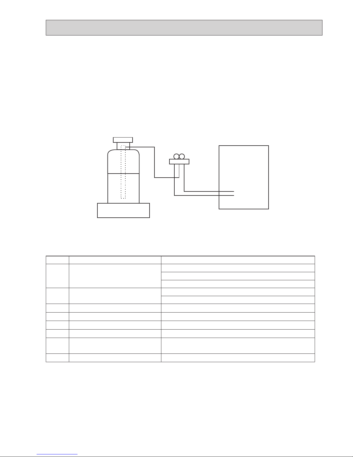
[2] Additional refrigerant charge
When charging directly from cylinder
· Check that cylinder for R410A on the market is a syphon type.
· Charging should be performed with the cylinder of syphon stood vertically. (Refrigerant is charged from liquid phase.)
No. Tool name Specifications
1
Gauge manifold · Only for R410A
· Use the existing fitting
specifications
. (UNF1/2)
· Use high-tension side pressure of 5.3MPa·G or over.
2
Charge hose · Only for R410A
· Use pressure performance of 5.09MPa·G or over.
3
Electronic scale
—
4
Gas leak detector
· Use the detector for R134a, R407C or R410A.
5
Adaptor for reverse flow check
· Attach on vacuum pump.
6
Refrigerant charge base
—
7
Refrigerant cylinder · Only for R410A · Top of cylinder (Pink)
· Cylinder with syphon
8
Refrigerant recovery equipment
—
OCH533D
6
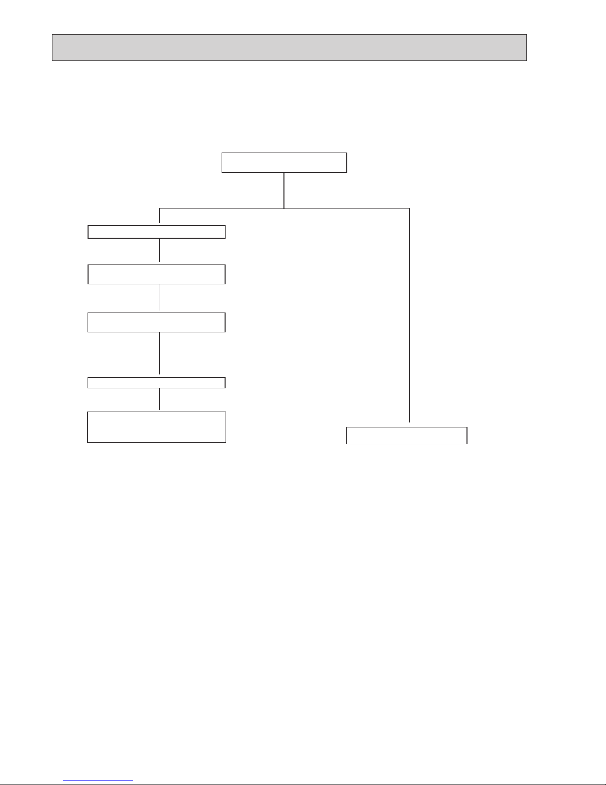
3-3. PRECAUTIONS WHEN REUSING EXISTING R22 REFRIGERANT PIPES
Flowchart
Perform the airtight test, vacuum air purging,
additional refrigerant charging (if necessary),
and gas leak check.
• Refer to the owchart below to determine if the existing pipes can be used and if it is necessary to use a lter dryer.
• If the diameter of the existing pipes is different from the specied diameter, refer to technological data materials to conrm if the pipes can be used.
▼
▼
▼
▼
▼
▼
Measure the existing pipe thickness and
check for damage.
The existing pipe thickness meets specications and the pipes are not damaged.
Check if the existing outdoor unit can operate.
After operating the cooling system for about 30
minutes, do a pump down work.
Disconnect the existing outdoor unit from the
pipes.
Attach the new outdoor unit
The existing pipes cannot be reused.
Use new pipes.
• If the existing outdoor unit cannot operate, use
a refrigerant recovery device to collect the refrigerant.
Use new pipes for SW75, SW100 and SW120 models.
The existing pipe thickness does not meet
specications or the pipes are damaged.
3-4. PRECAUTIONS FOR SALT PROOF TYPE "-BS" MODEL
Although "-BS" model has been designed to be resistant to salt damage, observe the following precautions to maintain the performance of the unit.
1. Avoid installing the unit in a location where it will be exposed directly to seawater or sea breeze.
2. If the cover panel may become covered with salt, be sure to install the unit in a location where the salt will be washed away
by rainwater. (If a sunshade is installed, rainwater may not clean the panel.)
3. To ensure that water does not collect in the base of the outdoor unit, make sure that the base is level, not at angle. Water
collecting in the base of the outdoor unit could cause rust.
4. If the unit is installed in a coastal area, clean the unit with water regularly to remove any salt build-up.
5. If the unit is damaged during installation or maintenance, be sure to repair it.
6. Be sure to check the condition of the unit regularly.
7. Be sure to install the unit in a location with good drainage.
OCH533D
7
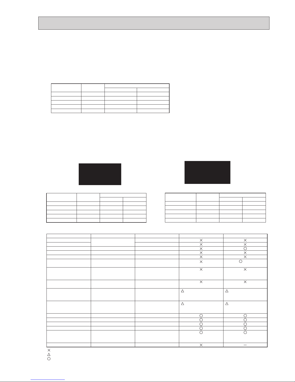
Cautions for refrigerant piping work
New refrigerant R410A is adopted for replacement inverter series. Although the refrigerant piping work for R410A is same
as for R22, exclusive tools are necessary so as not to mix with different kind of refrigerant. Furthermore as the working
pressure of R410A is 1.6 times higher than that of R22, their sizes of flared sections and flare nuts are different.
1 Thickness of pipes
Because the working pressure of R410A is higher compared to R22, be sure to use refrigerant piping with thickness
shown below. (Never use pipes of 0.7mm or below.)
2 Dimensions of flare cutting and flare nut
The component molecules in HFC refrigerant are smaller compared to conventional refrigerants. In addition to that,
R410A is a refrigerant, which has higher risk of leakage because its working pressure is higher than that of other refrigerants. Therefore, to enhance airtightness and strength, flare cutting dimension of copper pipe for R410A has been
specified separately from the dimensions for other refrigerants as shown below. The dimension B of flare nut for R410A
also has partly been changed to increase strength as shown below. Set copper pipe correctly referring to copper pipe
flaring dimensions for R410A below. For 1/2 and 5/8 inch pipes, the dimension B changes.
Use torque wrench corresponding to each dimension.
3 Tools for R410A (The following table shows whether conventional tools can be used or not.)
1/4
3/8
1/2
5/8
3/4
6.35
9.52
12.70
15.88
19.05
0.8
0.8
0.8
1.0
—
0.8
0.8
0.8
1.0
1.0
Nominal
dimensions(inch)
Diagram below: Piping diameter and thickness
Outside
diameter
(mm)
Thickness
(mm)
R410A R22
1/4
3/8
1/2
5/8
3/4
6.35
9.52
12.70
15.88
19.05
9.1
13.2
16.6
19.7
—
9.0
13.0
16.2
19.4
23.3
Nominal
dimensions(inch)
Flare cutting dimensions
Outside
diameter
Dimension A
( )
+0
-0.4
(mm)
R410A R22
1/4
3/8
1/2
5/8
3/4
6.35
9.52
12.70
15.88
19.05
17.0
22.0
26.0
29.0
—
17.0
22.0
24.0
27.0
36.0
Nominal
dimensions(inch)
Flare nut dimensions
Outside
diameter
Dimension B
(mm)
R410A R22
Gauge manifold
Charge hose
Gas leak detector
Refrigerant recovery equipment
Refrigerant cylinder
Applied oil
Safety charger
Charge valve
Vacuum pump
Flare tool
Bender
Pipe cutter
Welder and nitrogen gas cylinder
Refrigerant charging scale
Vacuum gauge or thermistor vacuum gauge and
vacuum valve
Charging cylinder
Air purge, refrigerant charge
and operation check
Gas leak check
Refrigerant recovery
Refrigerant charge
Apply to flared section
Prevent compressor malfunction
when charging refrigerant by
spraying liquid refrigerant
Prevent gas from blowing out
when detaching charge hose
Vacuum drying and air
purge
Flaring work of piping
Bend the pipes
Cut the pipes
Weld the pipes
Refrigerant charge
Check the degree of vacuum. (Vacuum
valve prevents back flow of oil and refrigerant to thermistor vacuum gauge)
Refrigerant charge
Tool exclusive for R410A
Tool exclusive for R410A
Tool for HFC refrigerant
Tool exclusive for R410A
Tool exclusive for R410A
Ester oil and alkylbenzene
oil (minimum amount)
Tool exclusive for R410A
Tool exclusive for R410A
Tools for other refrigerants can
be used if equipped with adapter for reverse flow check
Tools for other refrigerants
can be used by adjusting
flaring dimension
Tools for other refrigerants can be used
Tools for other refrigerants can be used
Tools for other refrigerants can be used
Tools for other refrigerants can be used
Tools for other refrigerants
can be used
Tool exclusive for R410A
Tools and materials Use R410A tools Can R22 tools be used?
(Usable if equipped
with adapter for rever se flow)
(Usable by adjusting
flaring dimension)
Can R407C tools be used?
Ester oil:
Alkylbenzene oil: minimum amount
(Usable if equipped
with adapter for rever se flow)
(Usable by adjusting
flaring dimension)
: Prepare a new tool. (Use the new tool as the tool exclusive for R410A.)
: Tools for other refrigerants can be used under certain conditions.
: Tools for other refrigerants can be used.
Dimension A
Dimension B
OCH533D
8
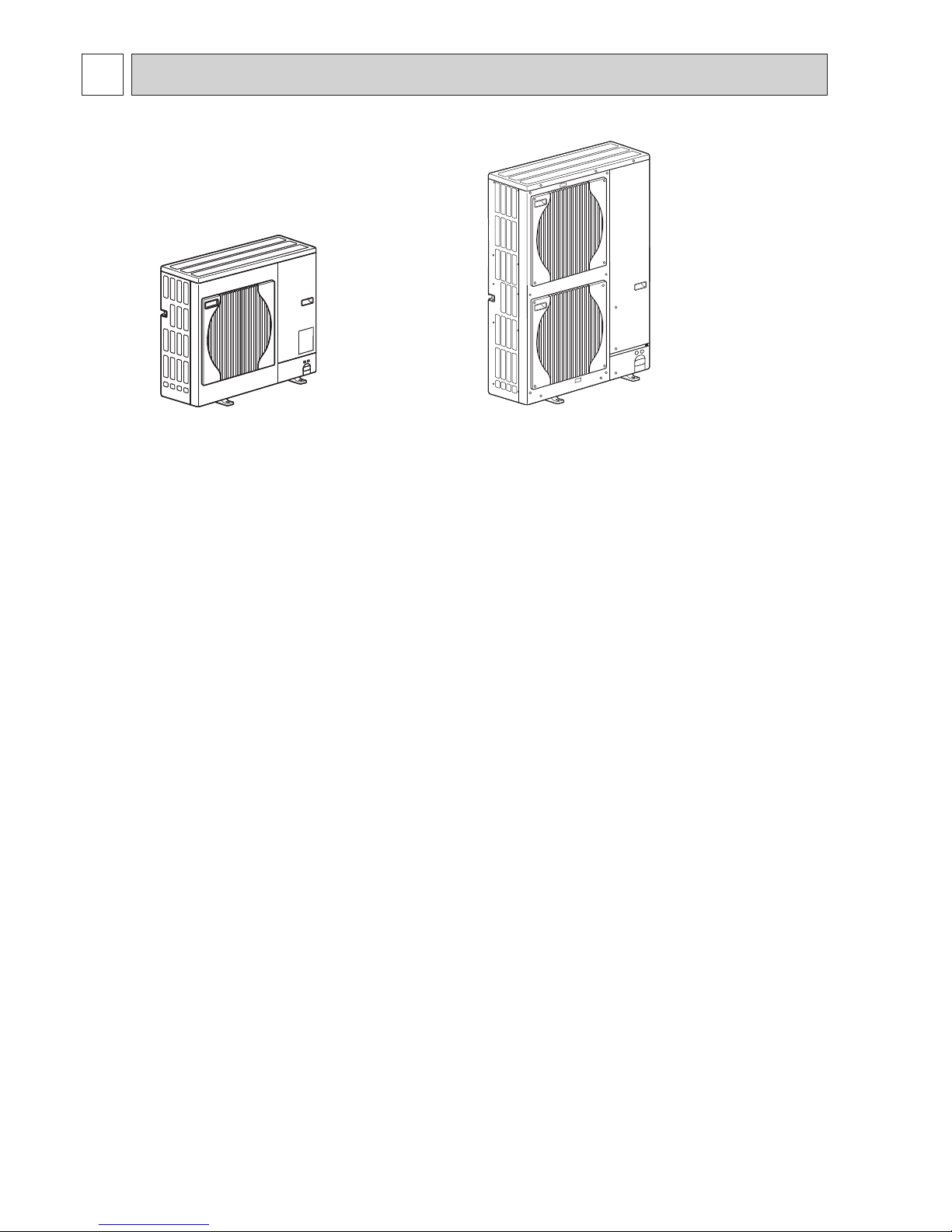
4 FEATURES
PUHZ-SW75VHA
PUHZ-SW75VHA-BS
CHARGELESS SYSTEM
PRE-CHARGED REFRIGERANT IS SUPPLIED FOR PIPING LENGTH AT SHIPMENT.
(Maximum 10 m (PUHZ-SW75–120))
The refrigerant circuit with LEV (Linear Expansion Valve) and accumulator always control the optimal refrigerant level regardless of the length (10 m maximum and 5 m minimum) of piping. The additional refrigerant charging work during installation often
causes problems. Heretofore it is completely eliminated. This unique system improves the quality and reliability of the work done.
It also helps to speed up the installation time.
PUHZ-SW100VHA
PUHZ-SW100YHA
PUHZ-SW120VHA
PUHZ-SW120YHA
PUHZ-SW100VHA-BS
PUHZ-SW100YHA-BS
PUHZ-SW120VHA-BS
PUHZ-SW120YHA-BS
OCH533D
9
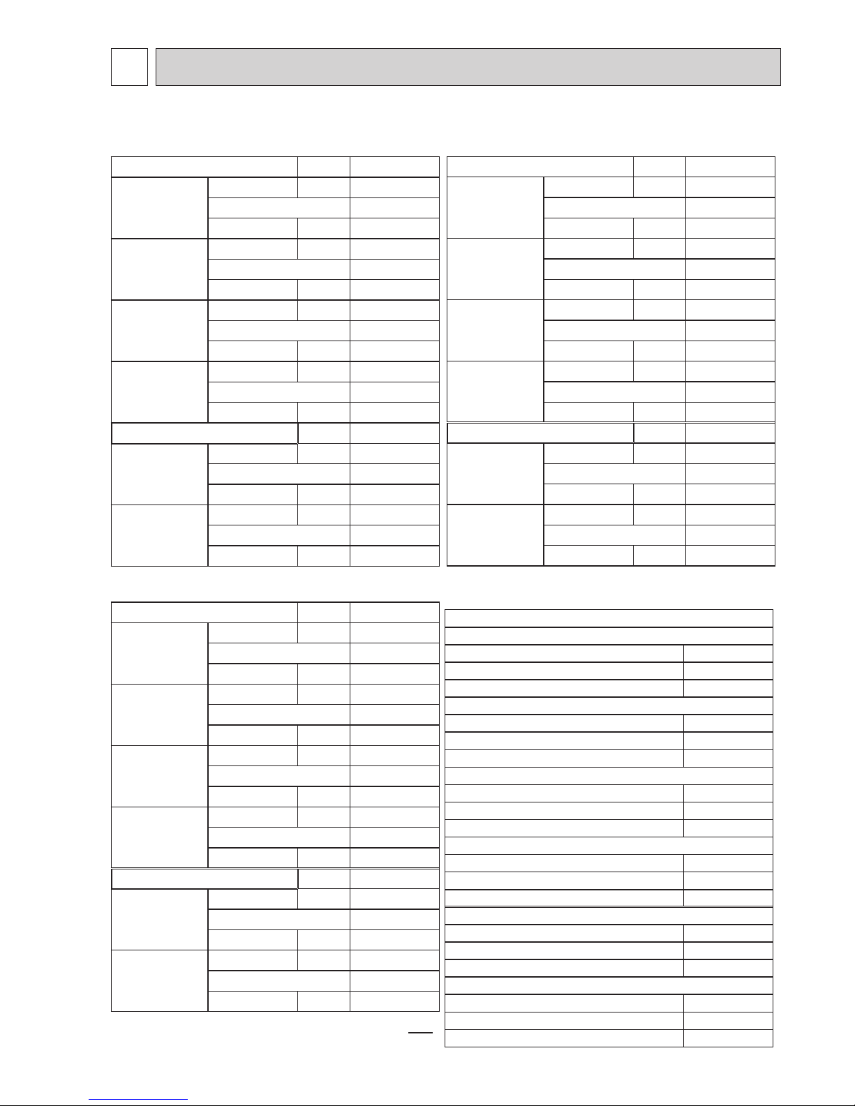
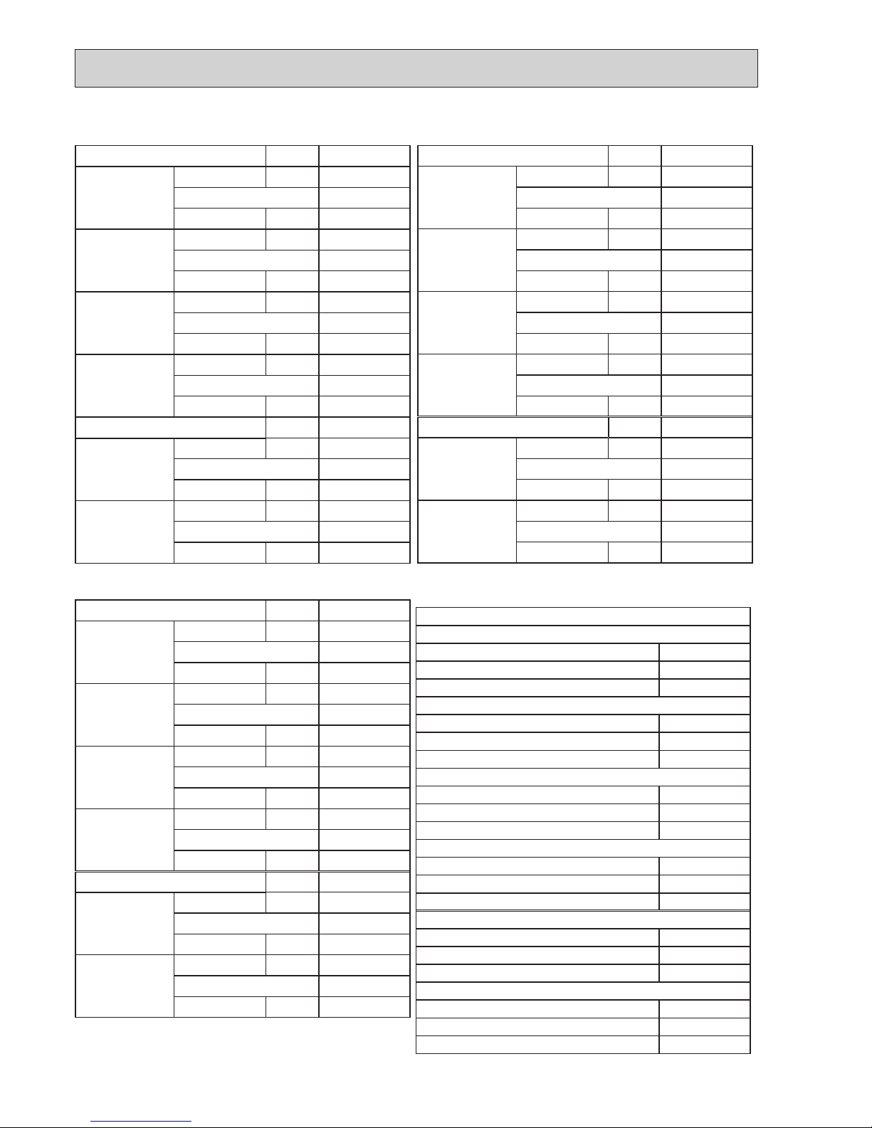
5 SPECIFICATIONS
<Reference data> Plate heat exchanger (ACH70-40 plates)
Nominal water ow L/min 22.9
Heating
(A7/W35)
Capacity kW 8.00
COP 4.40
Power input kW 1.82
Heating
(A7/W45)
Capacity kW 8.00
COP 3.40
Power input kW 2.35
Heating
(A2/W35)
Capacity kW 7.50
COP 3.40
Power input kW 2.20
Heating
(A2/W45)
Capacity kW 7.50
COP 2.83
Power input kW 2.65
Nominal water ow L/min 18.9
Cooling
(A35/W7)
Capacity kW 6.60
EER 2.55
Power input kW 2.59
Cooling
(A35/W18)
Capacity kW 7.10
EER 4.01
Power input kW 1.77
Rating conditions
Nominal operating condition
Heating (A7/W35)
Outside air temperature (Dry-bulb) + 7°C
Outside air temperature (Wet-bulb) + 6°C
Water temperature (inlet/outlet) + 30°C/+ 35°C
Heating (A7/W45)
Outside air temperature (Dry-bulb) + 7°C
Outside air temperature (Wet-bulb) + 6°C
Water temperature (inlet/outlet) + 40°C/+ 45°C
Heating (A2/W35)
Outside air temperature (Dry-bulb) + 2°C
Outside air temperature (Wet-bulb) + 1°C
Water temperature (inlet/outlet) + 30°C/+ 35°C
Heating (A2/W45)
Outside air temperature (Dry-bulb) + 2°C
Outside air temperature (Wet-bulb) + 1°C
Water temperature (inlet/outlet) + 40°C/+ 45°C
Cooling (A35/W7)
Outside air temperature (Dry-bulb) + 35°C
Outside air temperature (Wet-bulb) + 24°C
Water temperature (inlet/outlet) + 12°C/+ 7°C
Cooling (A35/W18)
Outside air temperature (Dry-bulb) + 35°C
Outside air temperature (Wet-bulb) + 24°C
Water temperature (inlet/outlet) + 23°C/+ 18°C
Note: "COP" and "Power input" in the above table do NOT
contain the "pump input (based on EN 14511)".
Nominal water ow L/min 32.1
Heating
(A7/W35)
Capacity kW 11.2
COP 4.45
Power input kW 2.51
Heating
(A7/W45)
Capacity kW 11.2
COP 3.42
Power input kW 3.27
Heating
(A2/W35)
Capacity kW 10.0
COP 3.32
Power input kW 3.02
Heating
(A2/W45)
Capacity kW 10.0
COP 2.66
Power input kW 3.76
Nominal water ow L/min 26.1
Cooling
(A35/W7)
Capacity kW 9.10
EER 2.75
Power input kW 3.31
Cooling
(A35/W18)
Capacity kW 10.0
EER 4.35
Power input kW 2.30
PUHZ-SW75VHA(-BS).UK
PUHZ-SW75VHAR3(-BS).UK
PUHZ-SW100VHA(-BS).UK PUHZ-SW100VHAR3(-BS).UK
PUHZ-SW100YHA(-BS).UK PUHZ-SW100YHAR1/R3(-BS).UK
PUHZ-SW120VHA(-BS).UK PUHZ-SW120VHAR3(-BS).UK
PUHZ-SW120YHA(-BS).UK PUHZ-SW120YHAR1/R3(-BS).UK
Nominal water ow L/min 45.9
Heating
(A7/W35)
Capacity kW 16.0
COP 4.10
Power input kW 3.90
Heating
(A7/W45)
Capacity kW 16.0
COP 3.23
Power input kW 4.95
Heating
(A2/W35)
Capacity kW 12.0
COP 3.24
Power input kW 3.70
Heating
(A2/W45)
Capacity kW 12.0
COP 2.52
Power input kW 4.76
Nominal water ow L/min 35.8
Cooling
(A35/W7)
Capacity kW 12.5
EER 2.32
Power input kW 5.38
Cooling
(A35/W18)
Capacity kW 14.0
EER 4.08
Power input kW 3.43
OCH533D
10
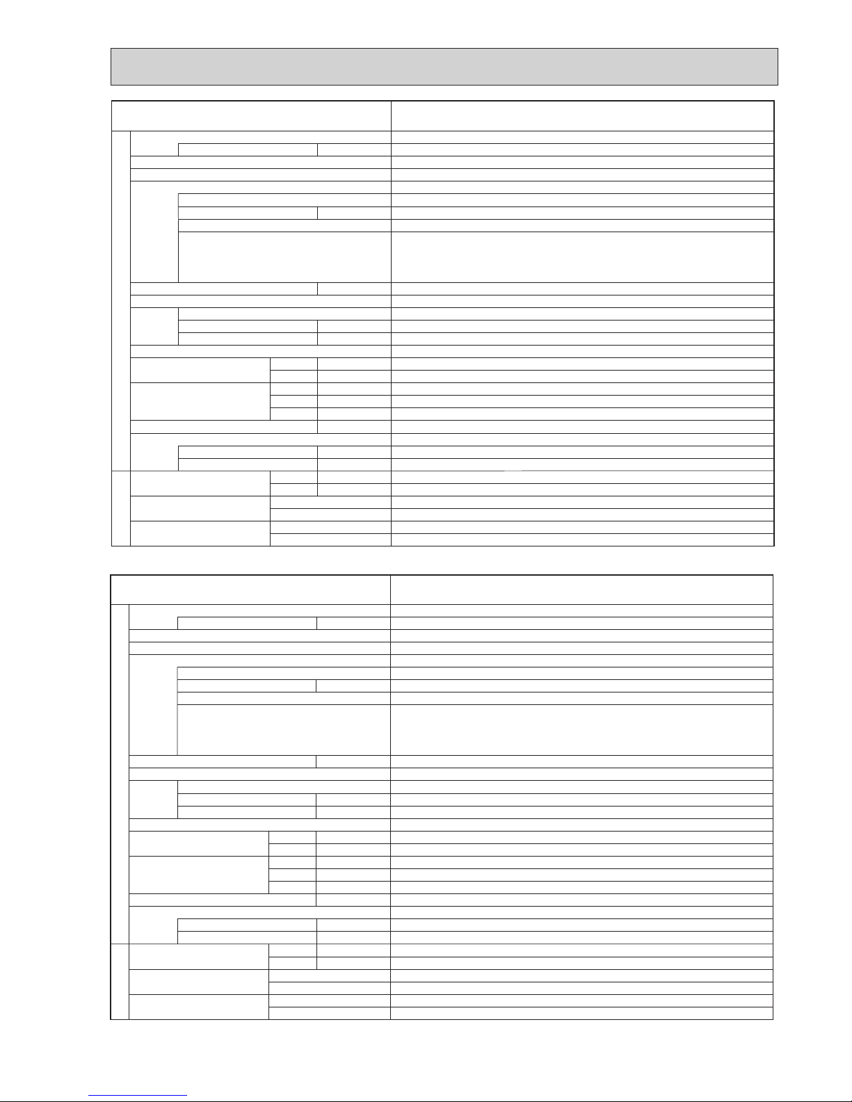
Nominal water ow L/min 22.9
Heating
(A7/W35)
Capacity kW 8.00
COP 4.40
Power input kW 1.82
Heating
(A7/W45)
Capacity kW 8.00
COP 3.40
Power input kW 2.35
Heating
(A2/W35)
Capacity kW 7.50
COP 3.40
Power input kW 2.20
Heating
(A2/W45)
Capacity kW 7.50
COP 2.83
Power input kW 2.65
Nominal water ow L/min 18.9
Cooling
(A35/W7)
Capacity kW 6.60
EER 2.86
Power input kW 2.31
Cooling
(A35/W18)
Capacity kW 7.10
EER 4.43
Power input kW 1.60
Rating conditions
Nominal operating condition
Heating (A7/W35)
Outside air temperature (Dry-bulb) + 7°C
Outside air temperature (Wet-bulb) + 6°C
Water temperature (inlet/outlet) + 30°C/+ 35°C
Heating (A7/W45)
Outside air temperature (Dry-bulb) + 7°C
Outside air temperature (Wet-bulb) + 6°C
Water temperature (inlet/outlet) + 40°C/+ 45°C
Heating (A2/W35)
Outside air temperature (Dry-bulb) + 2°C
Outside air temperature (Wet-bulb) + 1°C
Water temperature (inlet/outlet) + 30°C/+ 35°C
Heating (A2/W45)
Outside air temperature (Dry-bulb) + 2°C
Outside air temperature (Wet-bulb) + 1°C
Water temperature (inlet/outlet) + 40°C/+ 45°C
Cooling (A35/W7)
Outside air temperature (Dry-bulb) + 35°C
Outside air temperature (Wet-bulb) + 24°C
Water temperature (inlet/outlet) + 12°C/+ 7°C
Cooling (A35/W18)
Outside air temperature (Dry-bulb) + 35°C
Outside air temperature (Wet-bulb) + 24°C
Water temperature (inlet/outlet) + 23°C/+ 18°C
Nominal water ow L/min 32.1
Heating
(A7/W35)
Capacity kW 11.2
COP 4.45
Power input kW 2.51
Heating
(A7/W45)
Capacity kW 11.2
COP 3.42
Power input kW 3.27
Heating
(A2/W35)
Capacity kW 10.0
COP 3.32
Power input kW 3.01
Heating
(A2/W45)
Capacity kW 10.0
COP 2.66
Power input kW 3.76
Nominal water ow L/min 26.1
Cooling
(A35/W7)
Capacity kW 9.10
EER 2.75
Power input kW 3.31
Cooling
(A35/W18)
Capacity kW 10.0
EER 4.35
Power input kW 2.30
PUHZ-SW75VHAR4(-BS).UK
PUHZ-SW100VHAR4(-BS).UK
PUHZ-SW100YHAR4(-BS).UK
PUHZ-SW120VHAR4(-BS).UK
PUHZ-SW120YHAR4(-BS).UK
Nominal water ow L/min 45.9
Heating
(A7/W35)
Capacity kW 16.0
COP 4.10
Power input kW 3.90
Heating
(A7/W45)
Capacity kW 16.0
COP 3.23
Power input kW 4.95
Heating
(A2/W35)
Capacity kW 12.0
COP 3.24
Power input kW 3.70
Heating
(A2/W45)
Capacity kW 12.0
COP 2.52
Power input kW 4.76
Nominal water ow L/min 35.8
Cooling
(A35/W7)
Capacity kW 12.5
EER 2.32
Power input kW 5.39
Cooling
(A35/W18)
Capacity kW 14.0
EER 4.08
Power input kW 3.43
OCH533D
11
A
kW
W
kW
K
/min(CFM
)
dB
dB
mm (in)
mm (in)
mm (in)
kg (lb)
kg (lb)
L
mm (in)
mm (in)
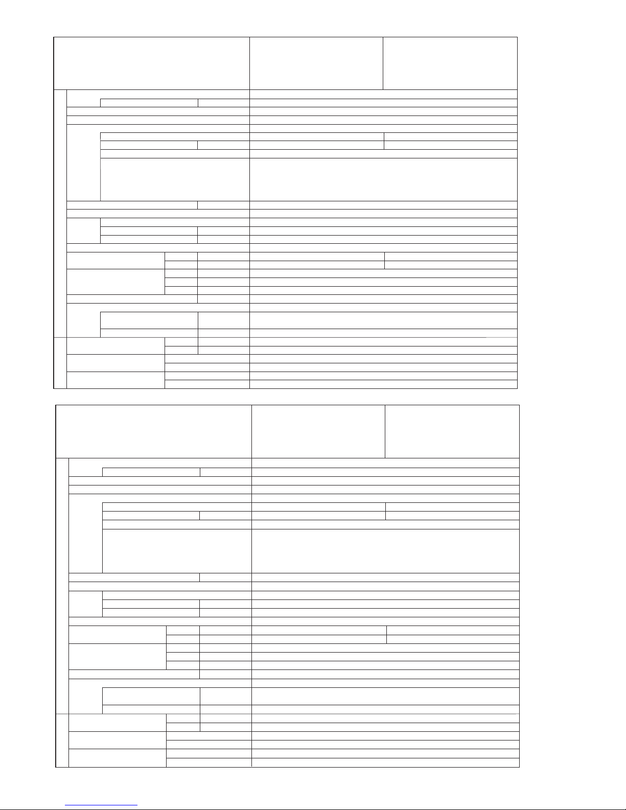
Power supply (phase, cycle, voltage)
Max. current
External finish
Refrigerant control
Compressor
Model
Motor output
Starter type
Protection devices
Crankcase heater
Heat exchanger
Fan Fan(drive) o No.
Fan motor output
Airflow
Defrost method
Noise level
Dimensions
Weight
Refrigerant
Charge
Oil (Model)
Pipe size O.D.
Connection method
Between the indoor &
outdoor unit
Cooling
Heating
W
D
H
Liquid
Gas
Indoor side
Outdoor side
Height difference
Piping length
Service Ref.
PUHZ-SW75VHA-BS.UK PUHZ-SW75VHAR3-BS.UK
PUHZ-SW75VHA.UK PUHZ-SW75VHAR3.UK
TNB220FLHMT
Propeller fan o 1
0.074
55(1,940)
48
51
943(37-1/8)
75(165)
3.2(7.0)
0.87(FV50S)
2 to 40 m
Munsell 3Y 7.8/1.1
Linear Expansion Valve
Hermetic
Inverter
—
Plate fin coil
Reverse cycle
950(37-3/8)
330+30(13+1-3/16)
R410A
9.52(3/8)
15.88(5/8)
Flared
Flared
Maximum 10 m
HP switch
Comp. surface thermo
Discharge thermo
Over current detection
Single, 50Hz, 230V
OUTDOOR UNIT
REFRIGERANT PIPING
1.3
19
A
kW
W
kW
K
/min(CFM
)
dB
dB
mm (in)
mm (in)
mm (in)
kg (lb)
kg (lb)
L
mm (in)
mm (in)
Power supply (phase, cycle, voltage)
Max. current
External finish
Refrigerant control
Compressor
Model
Motor output
Starter type
Protection devices
Crankcase heater
Heat exchanger
Fan Fan(drive) o No.
Fan motor output
Airflow
Defrost method
Noise level
Dimensions
Weight
Refrigerant
Charge
Oil (Model)
Pipe size O.D.
Connection method
Between the indoor &
outdoor unit
Cooling
Heating
W
D
H
Liquid
Gas
Indoor side
Outdoor side
Height difference
Piping length
Service Ref.
PUHZ-SW75VHAR4-BS.UK
PUHZ-SW75VHAR4.UK
SNB220FAGMC-L1
Propeller fan o 1
0.074
55(1,940)
48
51
943(37-1/8)
75(166)
3.2(7.0)
0.60(FV50S)
2 to 40 m
Munsell 3Y 7.8/1.1
Linear Expansion Valve
Hermetic
Inverter
—
Plate fin coil
Reverse cycle
950(37-13/32)
330+30(13+1-3/16)
R410A
9.52(3/8)
15.88(5/8)
Flared
Flared
Maximum 30 m
HP switch
Comp. surface thermo
Discharge thermo
Over current detection
Single, 50Hz, 230V
OUTDOOR UNIT
REFRIGERANT PIPING
1.5
17
OCH533D
12
3 phase, 50Hz, 400V
13
Munsell 3Y 7.8/1.1
Linear Expansion Valve
Hermetic
Inverter
—
Plate fin coil
Propeller fan o 2
0.074+0.074
100(3,353)
Reverse cycle
950(37-13/32)
330+30(13+1-3/16)
1,350(53-1/8)
130(287)
R410A
4.6(10.1)
1.40(FV50S)
9.52(3/8)
15.88(5/8)
Flared
Flared
Maximum 30 m
2 to 75 m
A
kW
W
kW
K
/min(CFM
)
dB
dB
m (in)
mm (in)
mm (in)
kg (lb)
kg (lb)
L
mm (in)
mm (in)
Power supply (phase, cycle, voltage)
Max. current
External finish
Refrigerant control
Compressor
Model
Motor output
Starter type
Protection devices
Crankcase heater
Heat exchanger
Fan Fan(drive) o No.
Fan motor output
Airflow
Defrost method
Noise level
Dimensions
Weight
Refrigerant
Charge
Oil (Model)
Pipe size O.D.
Connection method
Between the indoor &
outdoor unit
Cooling
Heating
W
D
H
Liquid
Gas
Indoor side
Outdoor side
Height difference
Piping length
Service Ref.
OUTDOOR UNIT
REFRIGERANT PIPING
ANB33FNDMT
2.5
ANB42FNDMT
2.5
HP switch
LP switch
Discharge thermo
Comp.surface thermo
Over current detection
50
54
51
54
PUHZ-SW100YHA.UK
PUHZ-SW120YHA.UK
PUHZ-SW100YHAR3.UK PUHZ-SW120YHAR3.UK
PUHZ-SW100YHAR4.UK PUHZ-SW120YHAR4.UK
PUHZ-SW120YHA-BS.UK
PUHZ-SW120YHAR3-BS.UK
PUHZ-SW120YHAR4-BS.UK
PUHZ-SW100YHA-BS.UK
PUHZ-SW100YHAR3-BS.UK
PUHZ-SW100YHAR4-BS.UK
A
kW
W
kW
K
/min(CFM
)
dB
dB
m (in)
mm (in)
mm (in)
kg (lb)
kg (lb)
L
mm (in)
mm (in)
Power supply (phase, cycle, voltage)
Max. current
External finish
Refrigerant control
Compressor
Model
Motor output
Starter type
Protection devices
Crankcase heater
Heat exchanger
Fan Fan(drive) o No.
Fan motor output
Airflow
Defrost method
Noise level
Dimensions
Weight
Refrigerant
Charge
Oil (Model)
Pipe size O.D.
Connection method
Between the indoor &
outdoor unit
Cooling
Heating
W
D
H
Liquid
Gas
Indoor side
Outdoor side
Height difference
Piping length
Service Ref.
50
54
Munsell 3Y 7.8/1.1
Linear Expansion Valve
Hermetic
Inverter
—
Plate fin coil
Propeller fan o 2
0.074+0.074
100(3,353)
Reverse cycle
950(37-13/32)
330+30(13+1-3/16)
1,350(53-1/8)
118(261)
R410A
4.6(10.2)
1.40(FV50S)
9.52(3/8)
15.88(5/8)
Flared
Flared
Maximum 30 m
2 to 75 m
29.5
HP switch
LP switch
Discharge thermo
Comp. surface thermo
Over current detection
Single 50Hz, 230V
OUTDOOR UNIT
REFRIGERANT PIPING
51
54
ANB42FNEMT
2.5
ANB33FNEMT
2.5
PUHZ-SW100VHAR4.UK
PUHZ-SW120VHAR4.UK
PUHZ-SW100VHA.UK PUHZ-SW120VHA.UK
PUHZ-SW100VHAR3.UK
PUHZ-SW120VHAR3.UK
PUHZ-SW100VHAR4-BS.UK
PUHZ-SW100VHA-BS.UK
PUHZ-SW100VHAR3-BS.UK
PUHZ-SW120VHAR4-BS.UK
PUHZ-SW120VHA-BS.UK
PUHZ-SW120VHAR3-BS.UK
OCH533D
13
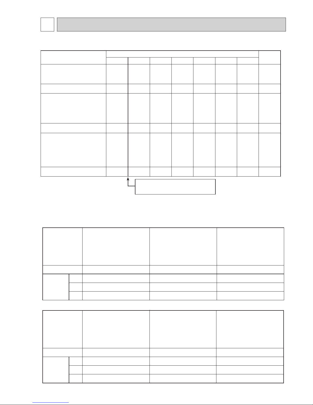
6 DATA
6-1. REFILLING REFRIGERANT CHARGE (R410A : kg)
6-2. COMPRESSOR TECHNICAL DATA
Service Ref.
Piping length (one way)
Initial
charged
10 m 20 m 30 m 40 m 50 m 60 m 75 m
PUHZ-SW75VHA(-BS).UK
PUHZ-SW75VHAR3(-BS).UK
3.2 3.6 4.0 4.6 — — — 3.2
PUHZ-SW75VHAR4(-BS).UK 3.2 3.35 3.5 4.1 — — — 3.2
PUHZ-SW100VHA(-BS).UK
PUHZ-SW100VHAR3(-BS).UK
PUHZ-SW100YHA(-BS).UK
PUHZ-SW100YHAR1(-BS).UK
PUHZ-SW100YHAR3(-BS).UK
4.6 4.8 5.0 5.6 6.2 6.8 7.4 4.6
PUHZ-SW100V/YHAR4(-BS).UK
4.6 4.8 5.0 5.6 6.2 6.8 7.5 4.6
PUHZ-SW120VHA(-BS).UK
PUHZ-SW120VHAR3(-BS).UK
PUHZ-SW120YHA(-BS).UK
PUHZ-SW120YHAR1(-BS).UK
PUHZ-SW120YHAR3(-BS).UK
4.6 4.8 5.0 5.6 6.2 6.8 7.4 4.6
PUHZ-SW120V/YHAR4(-BS).UK
4.6 4.8 5.0 5.6 6.2 6.8 7.5 4.6
U-V
U-W
W-V
Service Ref.
Compressor model
Winding
Resistance
( " )
U-V
U-W
W-V
Service Ref.
Compressor model
Winding
Resistance
( " )
ANB33FNEMT
(at 20°C)
(at 20°C)
0.19
0.19
0.19
PUHZ-SW100VHA.UK
PUHZ-SW100VHAR3.UK
PUHZ-SW100VHAR4.UK
PUHZ-SW100VHA-BS.UK
PUHZ-SW100VHAR3-BS.UK
PUHZ-SW100VHAR4-BS.UK
SNB220FAGMC-L1
0.95
0.95
0.95
PUHZ-SW75VHAR4.UK
PUHZ-SW75VHAR4-BS.UK
ANB33FNDMT
0.30
0.30
0.30
ANB42FNDMT
ANB42FNEMT
0.30
0.30
0.30
TNB220FLHMT
0.88
0.88
0.88
PUHZ-SW75VHA.UK
PUHZ-SW75VHAR3.UK
PUHZ-SW75VHA-BS.UK
PUHZ-SW75VHAR3-BS.UK
PUHZ-SW100YHA.UK
PUHZ-SW100YHAR1.UK
PUHZ-SW100YHAR3.UK
PUHZ-SW100YHAR4.UK
PUHZ-SW100YHA-BS.UK
PUHZ-SW100YHAR1-BS.UK
PUHZ-SW100YHAR3-BS.UK
PUHZ-SW100YHAR4-BS.UK
PUHZ-SW120YHA.UK
PUHZ-SW120YHAR1.UK
PUHZ-SW120YHAR3.UK
PUHZ-SW120YHAR4.UK
PUHZ-SW120YHA-BS.UK
PUHZ-SW120YHAR1-BS.UK
PUHZ-SW120YHAR3-BS.UK
PUHZ-SW120YHAR4-BS.UK
PUHZ-SW120VHA.UK
PUHZ-SW120VHAR3.UK
PUHZ-SW120VHAR4.UK
PUHZ-SW120VHA-BS.UK
PUHZ-SW120VHAR3-BS.UK
PUHZ-SW120VHAR4-BS.UK
0.19
0.19
0.19
Additional charge is required for pipes
longer than 10 m.
OCH533D
14
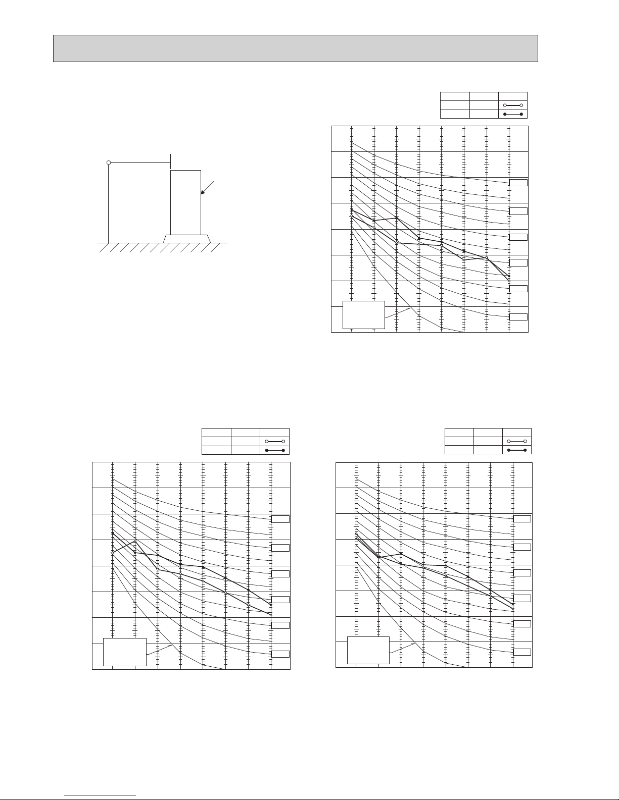
6-3. NOISE CRITERION CURVES
1.5m
1m
MICROPHONE
UNIT
GROUND
90
80
70
60
50
40
30
20
10
63 125 250 500 1000 2000 4000 8000
APPROXIMATE
THRESHOLD OF
HEARING FOR
CONTINUOUS
NOISE
NC-60
NC-50
NC-40
NC-30
NC-20
NC-70
OCTAVE BAND SOUND PRESSURE LEVEL, dB (0 dB = 0.0002 µbar)
BAND CENTER FREQUENCIES, Hz
PUHZ-SW75VHA(-BS).UK
PUHZ-SW75VHAR3(-BS).UK
PUHZ-SW75VHAR4(-BS).UK
COOLING
MODE
HEATING
48
SPL(dB)
51
LINE
90
80
70
60
50
40
30
20
10
63 125 250 500 1000 2000 4000 8000
APPROXIMATE
THRESHOLD OF
HEARING FOR
CONTINUOUS
NOISE
OCTAVE BAND SOUND PRESSURE LEVEL, dB (0 dB = 0.0002 µbar)
BAND CENTER FREQUENCIES, Hz
NC-60
NC-50
NC-40
NC-30
NC-20
NC-70
PUHZ-SW100VHA(-BS).UK
PUHZ-SW100VHAR3(-BS).UK
PUHZ-SW100VHAR4(-BS).UK
PUHZ-SW100YHA(-BS).UK
PUHZ-SW100YHAR1(-BS).UK
PUHZ-SW100YHAR3(-BS).UK
PUHZ-SW100YHAR4(-BS).UK
COOLING
MODE
HEATING
50
SPL(dB)
54
LINE
90
80
70
60
50
40
30
20
10
63 125 250 500 1000 2000 4000 8000
APPROXIMATE
THRESHOLD OF
HEARING FOR
CONTINUOUS
NOISE
OCTAVE BAND SOUND PRESSURE LEVEL, dB (0 dB = 0.0002 µbar)
BAND CENTER FREQUENCIES, Hz
NC-60
NC-50
NC-40
NC-30
NC-20
NC-70
PUHZ-SW120VHA(-BS).UK
PUHZ-SW120VHAR3(-BS).UK
PUHZ-SW120VHAR4(-BS).UK
PUHZ-SW120YHA(-BS).UK
PUHZ-SW120YHAR1(-BS).UK
PUHZ-SW120YHAR3(-BS).UK
PUHZ-SW120YHAR4(-BS).UK
COOLING
MODE
HEATING
51
SPL(dB)
54
LINE
OCH533D
15
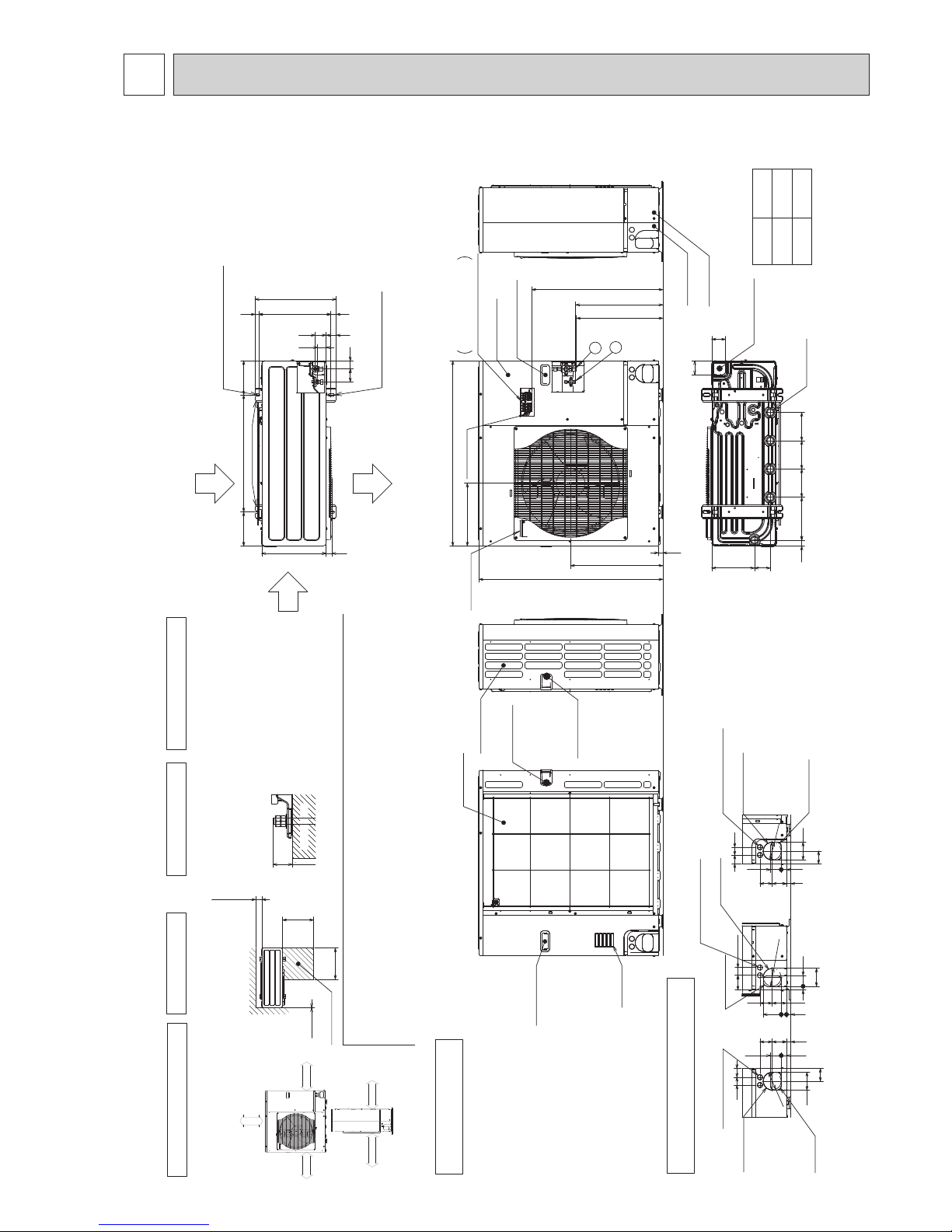
7 OUTLINES AND DIMENSIONS
Unit : mm
Air Intake
Rear Air Intake
Handle for moving
Handle for moving
322
950
473
943
23
*1 447
*1 431
A
2
1
Handle for moving
Handle for moving
Service panel
Earth terminal
Left···Power supply wiring
Right···Indoor/Outdoor wiring
Terminal Connections
Rear piping cover
Front piping cover
Side Air Intake
Handle for moving
40
54
28 370 19
417
53
57 41
600 175175
330
Rear Air Intake
Air Discharge
Side Air Intake
Installation Feet
2-U Shaped notched holes
(Foundation Bolt M10)
2-12 o 36 oval holes
(Foundation Bolt M10)
30
220 145 145 14530
81 219
71
71
Bottom piping hole
(Knockout)
Drain hole
(5-[33)
Piping Knockout Hole Details
19 55
23 27 92
92
4075
73 63
Right piping hole
(Knockout)
Right trunking hole
(Knockout)
Power supply wiring hole
(2-[27Knockout)
[92
27 55
7323 63
40
92
65
45
Front piping hole
(Knockout)
Front trunking hole
(Knockout)
Power supply wiring hole
(2-[27Knockout)
[92
4045
65
92
27 55
23 73 63
Rear piping hole
(Knockout)
Rear trunking hole
(Knockout)
Power supply wiring hole
(2-[27Knockout)
[92
Example of Notes
1 Refrigerant GAS pipe connection (FLARE)[15.88(5/8 inch)
2 Refrigerant LIQUID pipe connection (FLARE)[9.52(3/8 inch)
*1...Indication of STOP VALVE connection location.
Over
Over
Less than
Piping and wiring connections
can be made from 4 directions:
front, right, rear and below.
4 PIPING-WIRING DIRECTIONS
3 FOUNDATION BOLTS2 SERVICE SPACE
1 FREE SPACE (Around the unit)
The diagram below shows a
basic example.
Explanation of particular details is
given in the installation manuals etc.
Over10
500
500
Over100
Dimensions of space needed
for service access are
shown in the below diagram.
Service space
30
Please secure the unit firmly
with 4 foundation (M10) bolts.
(Bolts and washers must be
purchased locally.)
<Foundation bolt height>
FOUNDATION
over 100mm
over 500mm
over 10mm
FREE
over 10mm
VHA/R3
VHAR4
673A670
PUHZ-SW75VHA.UK PUHZ-SW75VHAR3.UK PUHZ-SW75VHAR4.UK
PUHZ-SW75VHA-BS.UK PUHZ-SW75VHAR3-BS.UK PUHZ-SW75VHAR4-BS.UK
OCH533D
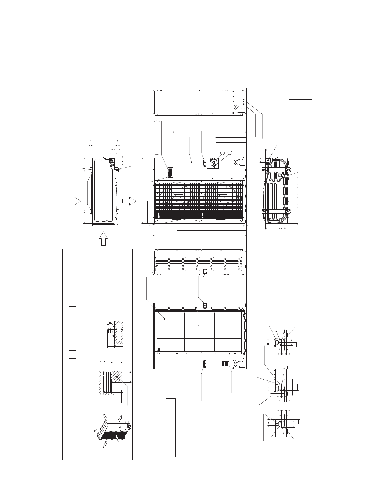
16
Handle for moving
Side Air Intake
Front piping cover
Rear piping cover
Air intake
Rear Air Intake
Handle for moving
Handle for moving
Terminal connection
Left···Power supply wiring
Right···Indoor/Outdoor wiring
Earth terminal
Service panel
Handle for moving
1
2
Air Discharge
Rear Air Intake
Side Air Intake
1····Refrigerant GAS pipe connection (FLARE){15.88(5/8 inch)
2····Refrigerant LIQUID pipe connection (FLARE){ 9.52(3/8 inch)
*1 ···Indication of STOP VALVE connection location.
Example of Notes
Piping Knockout Hole Details
600175 175
330
417
42
66
53 56
45
(19)28 370
2-U Shaped notched holes
(Foundation Bolt M10)
2-12 x 36 Oval holes
(Foundation Bolt M10)
Installation Feet
30
45 40
65
92
27 55
23 73 63
Rear piping hole
(Knockout)
Rear trunking hole
(Knockout)
Power supply wiring hole
(2-
{
27Knockout)
{
92
19 55
92
75 40
73 63
23 27 92
Right piping hole
(Knockout)
Right trunking hole
(Knockout)
Power supply wiring hole
(2-
{
27Knockout)
{
92
92
65
4540
27 55
23
73 63
Front piping hole
(Knockout)
Front trunking hole
(Knockout)
Power supply wiring hole
(2-
{
27Knockout)
{
92
14514522030 145
81 219
71
71
Bottom piping hole
(Knockout)
Drain hole
(5-{33)
1350
23
950
A
*1 447
*1 431
371 635
322
Handle for moving
VHA
YHA
1,079
A
930
Unit : mm
Over
Over
Over
Over
Less than
Piping and wiring connections
can be made from 4 directions:
front, right, rear and below.
4 PIPING-WIRING DIRECTIONS
3 FOUNDATION BOLTS2 SERVICE SPACE
1 FREE SPACE (Around the unit)
Please secure the unit firmly
with 4 foundation (M10) bolts.
(Bolts and washers must be
purchased locally.)
<Foundation bolt height>
Dimensions of space needed
for service access are
shown in the below diagram.
The diagram below shows a
basic example.
Explanation of particular details is
given in the installation manuals etc.
30
FOUNDATION
10
500
500
150
Service space
FREE
Over 10mm
Over 10mm
Over 150mm
Over 1000mm
PUHZ-SW100VHA.UK
PUHZ-SW100VHAR3.UK PUHZ-SW100VHAR4.UK
PUHZ-SW100VHA-BS.UK
PUHZ-SW100VHAR3-BS.UK PUHZ-SW100VHAR4-BS.UK
PUHZ-SW100YHA.UK
PUHZ-SW100YHAR1.UK PUHZ-SW100YHAR3.UK PUHZ-SW100YHAR4.UK
PUHZ-SW100YHA-BS.UK
PUHZ-SW100YHAR1-BS.UK PUHZ-SW100YHAR3-BS.UK PUHZ-SW100YHAR4-BS.UK
PUHZ-SW120VHA.UK
PUHZ-SW120VHAR3.UK PUHZ-SW120VHAR4.UK
PUHZ-SW120VHA-BS.UK
PUHZ-SW120VHAR3-BS.UK PUHZ-SW120VHAR4-BS.UK
PUHZ-SW120YHA.UK
PUHZ-SW120YHAR1.UK PUHZ-SW120YHAR3.UK
PUHZ-SW120YHAR4.UK
PUHZ-SW120YHA-BS.UK
PUHZ-SW120YHAR1-BS.UK PUHZ-SW120YHAR3-BS.UK PUHZ-SW120YHAR4-BS.UK
OCH533D
17
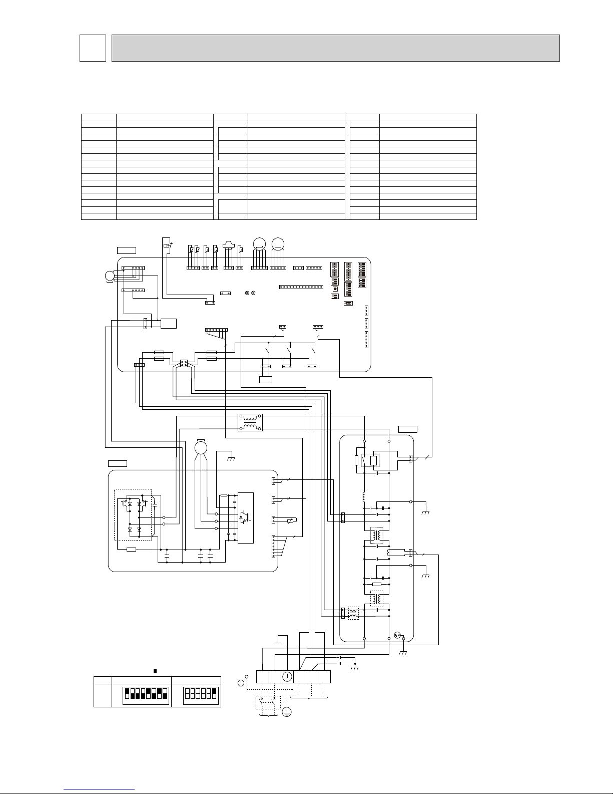
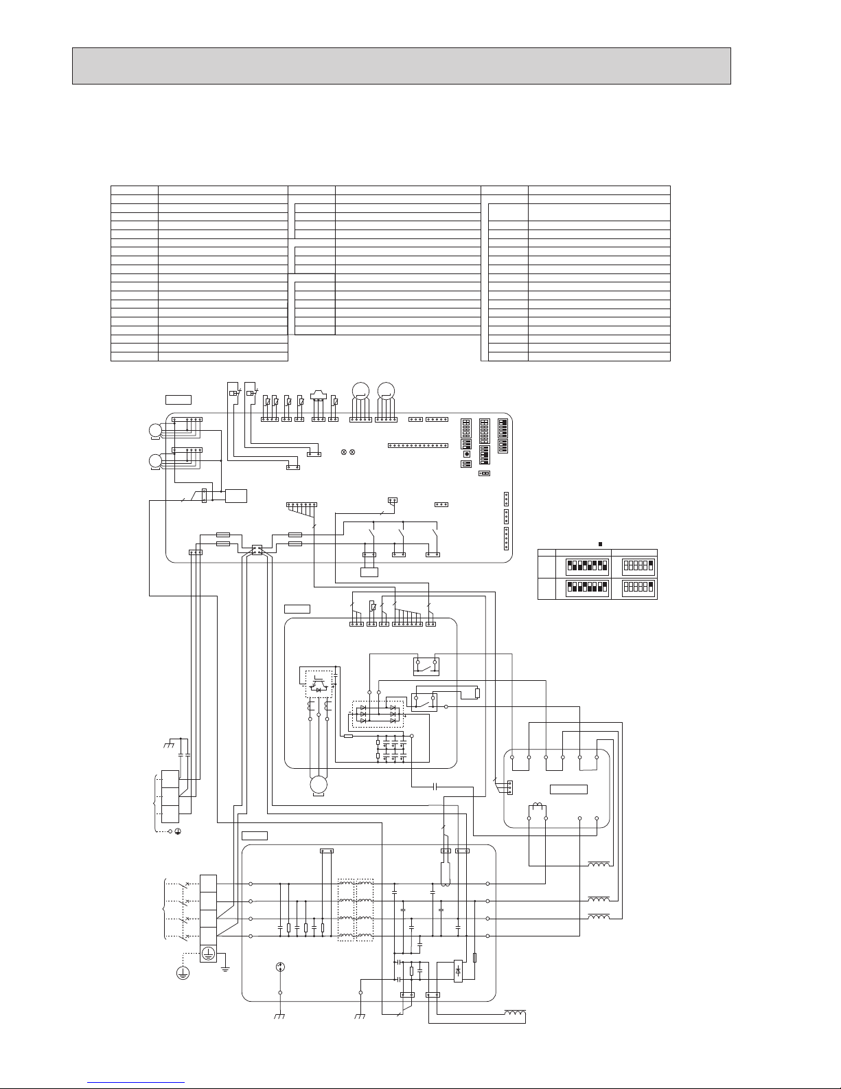
8 WIRING DIAGRAM
BH79B652H01
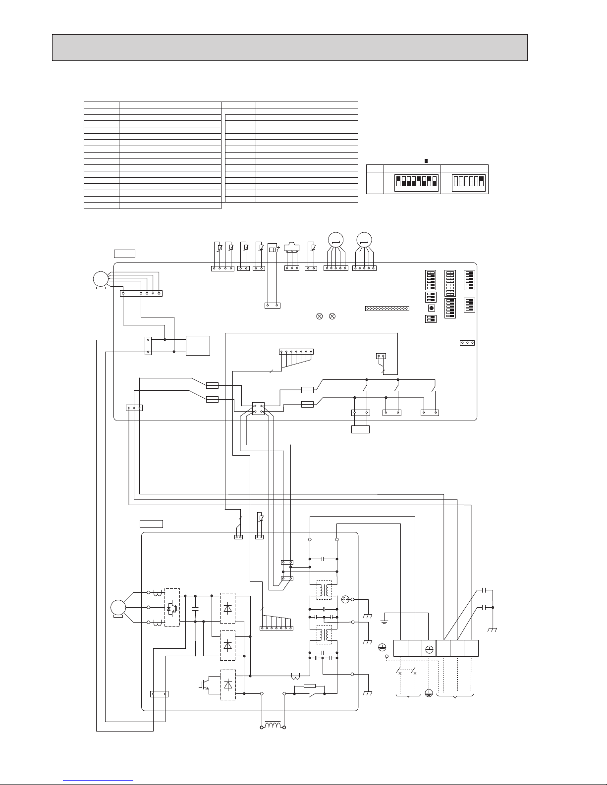
PUHZ−SW75VHA WIRING DIAGRAM
1 2 3 4 5 6 7 8
OFF
ON
75V
MODEL
SW6
*
1 MODEL SELECT
The black square ( ) indicates a switch position.
SW5-6
*
2
OFF
ON
1 2 3 4 5 6
*
2 SW5 -1 to 5 : Function Switch
SYMBOL NAME SYMBOL NAME SYMBOL NAME
TB1
MC
MF1
21S4
63H
63HS
TH3
TH4
TH6
TH7
TH8
TH34
LEV-A, LEV-B
ACL
CY1, CY2
Terminal Block <Power Supply, Indoor/Outdoor>
Motor for Compressor
Fan Motor
Solenoid Valve (Four-Way Valve)
High Pressure Switch
High Pressure Sensor
Thermistor <Liquid>
Thermistor <Discharge>
Thermistor <2-Phase Pipe>
Thermistor <Ambient>
Thermistor <Heat Sink>
Thermistor <Comp. Surface>
Linear Expansion Valve
Reactor
Capacitor
P. B.
N. F.
C. B.
Power Circuit Board
Connection Terminal <L/N-Phase>
Connection Terminal <U/V/W-Phase>
Power Module
Converter
Main Smoothing Capacitor
Noise Filter Circuit Board
Connection Terminal <L-Phase>
Connection Terminal <N-Phase>
Connection Terminal <Ground>
52C Relay
Controller Circuit Board
Switch <Manual Defrost, Defect History,
Record Reset, Refrigerant Address>
Switch <Test Operation>
R, S
U, V, W
IPM
PFC
CB1, CB2, CB3
LI, LO
NI, NO
EI, E2, E3
52C
SW1
SW4
SW5
SW6
SW7
SW8
SW9
SWP
CN31
CNDM
CN51
SV1/CH
SS
CNM
LED1, LED2
F1, F2, F3, F4
X51, X52, X54
Switch <Function Switch, Model Select>
Switch <Model Select>
Switch <Function Switch>
Switch <Function Switch>
Switch <Function Switch>
Switch <Pump Down>
Connector <Emergency Operation>
Connector <Connection for Option>
Connector <Connection for Option>
Connector <Connection for Option>
Connector <Connection for Option>
Connector <Connection for Option>
LED <Operation Inspection Indicators>
Fuse <T6.3AL250V>
Relay
C. B.
P. B.
TH8
TH6TH7 TH4TH3
U
CB3
N. F.
21S4
L N S1 S2 S3
INDOOR
UNIT
POWER SUPPLY
~/N 230V 50Hz
TB1
V
W
5
2
2
2
2
RED
WHT
BLK
t° t° t° t° t°
t°
M C
CN5
(RED)
CNAC2
(RED)
CNAC1
(WHT)
LO NO
LI N I
EI
CN52C
(BLK)
3
1
1
3
2
1
1
2
52C
CN2
(WHT)
CN3
(WHT)
CN5
(RED)
CN4
(WHT)
1
7
1
2
1
2
2
1
LEV-A
CNS
(WHT)
CNAC
(WHT)
CNDC
(PNK)
F2
F1
F3
F4
21S4
(GRN)
CN2
(WHT)
CN4
(WHT)
CN3S
(WHT)
TH7/6
(RED)
TH3
(WHT)
TH4
(WHT)
TR ANS
CN VM N T
(WHT)
CN M NT
(WHT)
CN M
(WHT)
LED1
LED2
X52
SV1
/CH
(GRY)
X54
63H
(YLW)
CN52C
(RED)
2
5
2
1 4 1 2 2 1
1
3
31 1 5
1
14
1
3
1 3
1 2
1 7
3
1
13
1 2
3 4
31 31
LEV-A
(WHT)
51
MS
3~
CB2CB1
R
S
U
V
W
PFC
IPM
AC L
E3E2
RED
BLU
RE D
W H T
RE D
W H T
YLW
ORN
BRN
RE D
W H T
RE D
W H T
CY1
CY2
GRN/YLW
SS
(WHT)
X51
31
MS
3~
MF1
CNF1
(WHT)
1
7
63H
31
TH34
2 1
TH34
(RED)
63HS
(WHT)
63HS
LEV-B
(RED)
M
LEV-B
51
M
CNDM
(WHT)
CN51
(WHT)
1
3
1
5
CN F2
(WHT)
1
7
63L
(RED)
1 3
+ + +
SW7
SW6SW1
SW9
CN31
*1*
1
SW5SW8SW4SWP
PUHZ-SW75VHA.UK PUHZ-SW75VHAR3.UK
PUHZ-SW75VHA-BS.UK PUHZ-SW75VHAR3-BS.UK
OCH533D
18
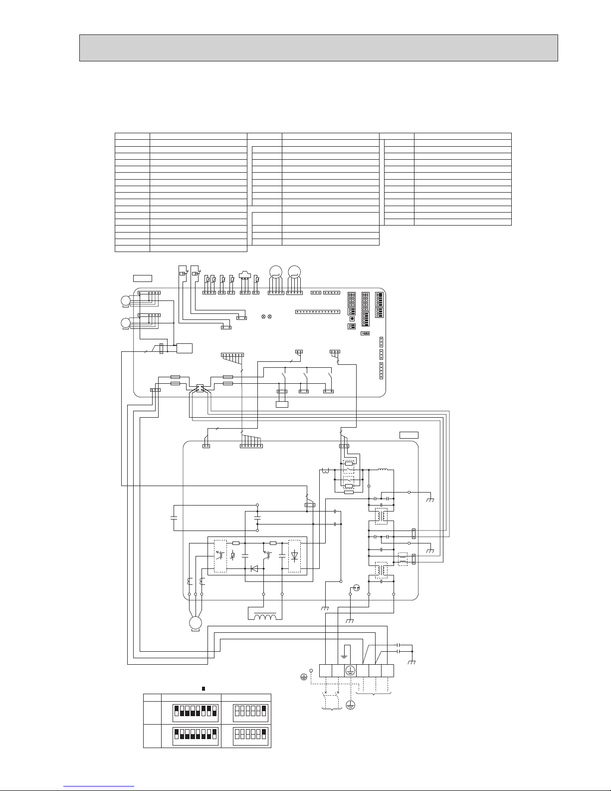
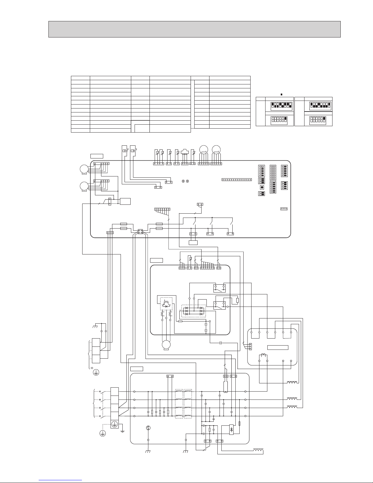
PUHZ-SW75VHAR4.UK PUHZ-SW75VHAR4-BS.UK
SYMBOL NAME SYMBOL NAME
TB1
MC
MF1
21S4
63H
63HS
TH3
TH4
TH6
TH7
TH8
TH34
LEV-A, LEV-B
ACL
CY1, CY2
P. B.
Terminal Block <Power Supply, Indoor/Outdoor>
Motor for Compressor
Fan Motor
Solenoid Valve (4-Way Valve)
High Pressure Switch
High Pressure Sensor
Thermistor <Liquid>
Thermistor <Discharge>
Thermistor <2-Phase Pipe>
Thermistor <Ambient>
Thermistor <Heat Sink>
Thermistor <Comp. Surface>
Linear Expansion Valve
Reactor
Capacitor
Power Circuit Board
C. B. Controller Circuit Board
Fuse <T6.3AL250V>
Switch <Manual Defrost, Defect History Record Reset,
Refrigerant Address>
Switch <Function Switch>
Switch <Function Switch, Model Select>
Switch <Model Select>
Switch <Function Switch>
Switch <Function Switch>
Switch <Function Switch>
Switch <Pump Down>
Connector <Connection for Option>
Connector <Connection for Option>
Connector <Connection for Option>
Connector <Connection for Option>
F1, F2, F3, F4
SW1
SW4
SW5
SW6
SW7
SW8
SW9
SWP
CNDM
SV1/CH
SV3/SS
CNM
1 2 3 4 5 6 7 8
OFF
ON
75V
MODEL
SW6
*
1 MODEL SELECT
The black square ( ) indicates a switch position.
SW5-6
*
2
OFF
ON
1 2 3 4 5 6
*
2 SW5 -1 to 5 : Function Switch
C. B.
P. B.
TH8
TH6TH7 TH4TH3
U
21S4
L N S1 S2 S3
TO
INDOOR UNIT
POWER SUPPLY
~/N 230V 50Hz
TB1
V
W
2
2
CY2
CY1
t° t° t° t° t°
t°
MC
CNAC2
(RD)
S/N1 R/L1
CN2
(RD)
CNDC
(PK)
CN4
(WH)
CN6
(WH)
1
7
1
1
3
3
CNAC1
(WH)
1
3
121
LEV-A
CNS
(WH)
CNAC
(WH)
CNDC
(PK)
F2
F1
F3
F4
21S4
(GN)
CN4
(WH)
TH7/6
(RD)
TH3
(WH)
TH4
(WH)
TR ANS
CN M
(WH)
LED1
LED2
X52
SV1/CH
(GY)
X54
63H
(YE)
2
1 4 1 2 2 1
1
3
1
14
1
3
1 3
1 2
7
3
1
13
1
2
3 4
7
1
31
LEV-A
(WH)
51
MS
3~
Uo
Vo
Wo
ACL
E3
EI
E4
RD
WH
RD
BK
WH
YE
OG
BN
BK
BK
BK
DB2
DB1
TBL2TBL4
GNYE
SV3/SS
(WH)
X51
31
MS
3~
MF1
CNF1
(WH)
1
7
63H
31
TH34
2 1
TH34
(RD)
63HS
(WH)
63HS
LEV-B
(RD)
M
LEV-B
51
M
CNDM
(WH)
+
+
+
–
–
–
~
~
~
~
~
~
+
IC710
Q600
DB3
7
CN2
(RD)
*1 *1
SW7
SW6SW1
SW9
SW5SW8SW4 SWP
OCH533D
19
PUHZ-SW100VHA.UK PUHZ-SW100VHAR3.UK
PUHZ-SW100VHA-BS.UK PUHZ-SW100VHAR3-BS.UK
PUHZ-SW120VHA.UK PUHZ-SW120VHAR3.UK
PUHZ-SW120VHA-BS.UK PUHZ-SW120VHAR3-BS.UK
BH79B653H01
100V
120V
SYMBOL NAME SYMBOL NAME SYMBOL NAME
TB1
MC
MF1, MF2
21S4
63H
63L
63HS
TH3
TH4
TH6
TH7
TH8
TH34
LEV-A, LEV-B
DCL
CB
CY1, CY2
Terminal Block <Power Supply, Indoor/Outdoor>
Motor for Compressor
Fan Motor
Solenoid Valve (Four-Way Valve)
High Pressure Switch
Low Pressure Switch
High Pressure Sensor
Thermistor <Liquid>
Thermistor <Discharge>
Thermistor <2-Phase Pipe>
Thermistor <Ambient>
Thermistor (internal) <Heat Sink>
Thermistor <Comp. Surface>
Linear Expansion Valve
Reactor
Main Smoothing Capacitor
Capacitor
P. B. Power Circuit Board
Connection Terminal <U/V/W-Phase>
Connection Terminal <L-Phase>
Connection Terminal <N-Phase>
Connection Terminal
Connection Terminal
Connection Terminal <Reactor>
Power Module
Connection Terminal <Ground>
52C Relay
Controller Circuit Board
Switch <Manual Defrost, Defect History,
Record Reset, Refrigerant Address>
Switch <Test Operation>
Switch <Function Switch, Model Select>
Switch <Model Select>
SW7
SW8
SW9
SWP
CN31
CNDM
CN51
SV1/CH
SS
CNM
LED1, LED2
F1, F2, F3, F4
X51, X52, X54
Switch <Function Switch>
Switch <Function Switch>
Switch <Function Switch>
Switch <Pump Down>
Connector <Emergency Operation>
Connector <Connection for Option>
Connector <Connection for Option>
Connector <Connection for Option>
Connector <Connection for Option>
Connector <Connection for Option>
LED <Operation Inspection Indicators>
Fuse <T6.3AL250V>
Relay
U, V, W
LI
NI
P2
N2
DCL1, DCL2
IGBT
EI, E2, E3, E4
52C
C. B.
SW1
SW4
SW5
SW6
POWER SUPPLY
~/N 230V 50Hz
INDOOR
UNIT
P. B.
W
DCL
CB
L N S1 S2 S3
TB1
V
U
2
RED
WHT
BLK
MC
CN2
(WHT)
CN4
(WHT)
1 7
21
3 1
RED
BLU
YLW
ORN
BRN
WHT
RED
GRN/YLW
BLK
(RED)
CNAC2
(WHT)
CNAC1
LINI
EI
E3
CN52C
(RED)
3
1
1
3
52C
52C
1 3
DCL1
DCL2
+
P2
N2
+
-
UVW
CNDC
(PNK)
+
BLK
2
MS
3~
E2
BLK
E4
BLK
CY1
CY2
IGBT
RE D
W H T
C. B.
TH6TH7 TH4TH3
21S4
t° t° t° t°
LEV-A
CNS
(WHT)
CNAC
(WHT)
CNDC
(PNK)
F2
F1
F3
F4
21S4
(GRN)
CN2
(WHT)
CN4
(WHT)
TH7/6
(RED)
TH3
(WHT)
TH4
(WHT)
TRANS
CNVMNT
(WHT)
CNMNT
(WHT)
CNM
(WHT)
LED1
LED2
X52
SV1
/CH
(GRY)
X54
63H
(YLW)
2
7
1 4 1 2 2 1
1 3
31 1 5
1 14
1 2
1 7
3
1
13
1
2
3 4
31 31
LEV-A
(WHT)
51
SS
(WHT)
X51
31
MS
3~
MF1
1
7
63L63H
63L
(RED)
1 3
31
TH34
t°
2 1
TH34
(RED)
63HS
(WHT)
63HS
LEV-B
(RED)
M
LEV-B
51
M
MF2
CNF2
(WHT)
CNF1
(WHT)
1
7
2
7
CN52C
(RED)
3
1 3
3
t°
TH8
CN3S
(WHT)
1
3
CNDM
(WHT)
CN51
(WHT)
1
3
1
5
~
~
MS
3~
1 2 3 4 5 6 7 8
OFF
ON
MODEL
SW6 SW5-6 *2
OFF
ON
1 2 3 4 5 6
1 2 3 4 5 6 7 8
OFF
ON
OFF
ON
1 2 3 4 5 6
*
2 SW5 -1 to 5 : Function Switch
SW7
SW6SW1
SW9
CN31
*1*
1
SW5SW8SW4 SWP
*
1 MODEL SELECT
The black square ( ) indicates a switch position.
OCH533D
20
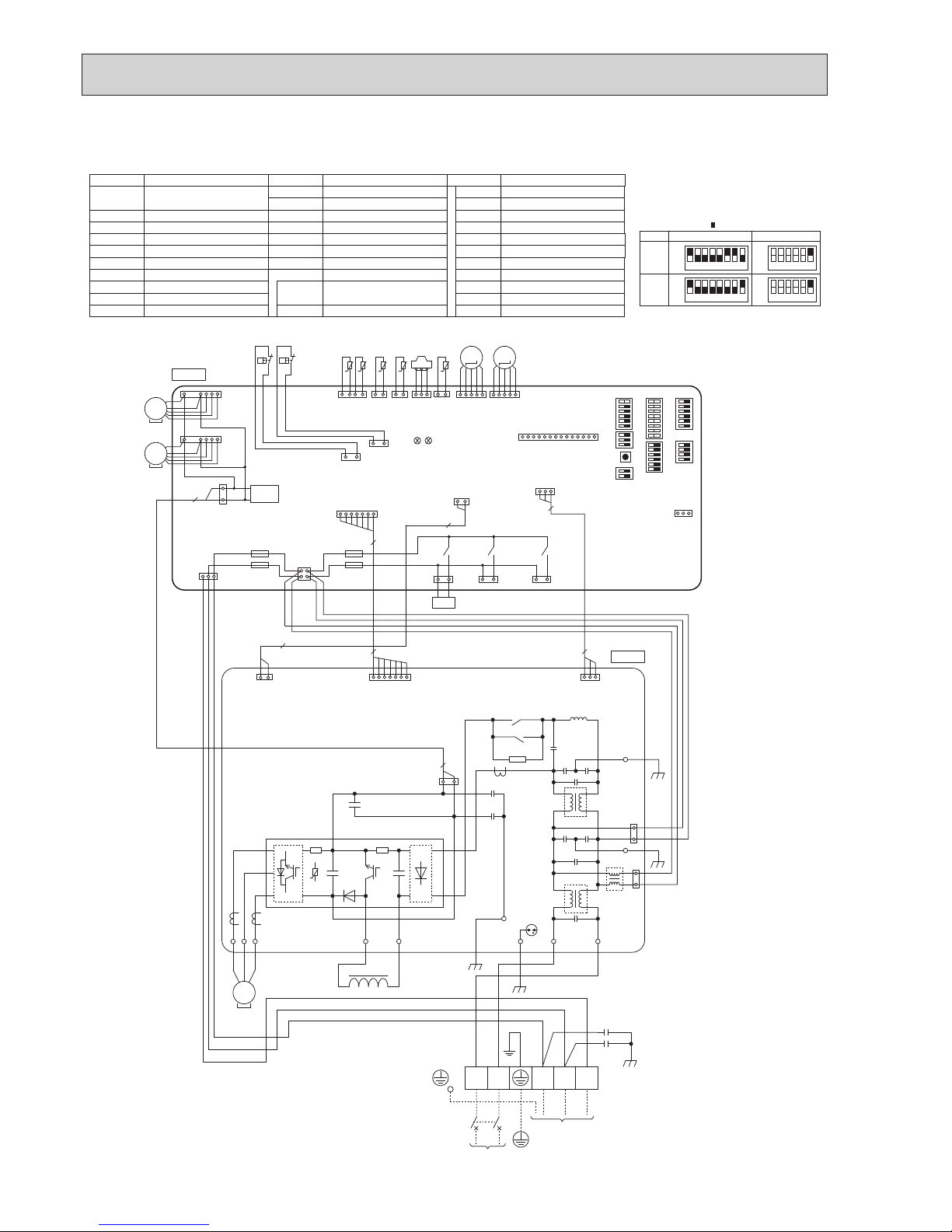
PUHZ-SW100VHAR4.UK PUHZ-SW120VHAR4.UK
PUHZ-SW100VHAR4-BS.UK PUHZ-SW120VHAR4-BS.UK
*1 *1
POWER SUPPLY
~/N 230V 50Hz
TO
INDOOR
UNIT
W
DCL
L
N S1 S2 S3
TB1
V
U
2
RD
WH
BK
MC
CN4
(WH)
3
1
RD
BU
YE
OG
BN
GNYE
BK
CNAC2
(RD)
CNAC1
(WH)
LINI
EI
E3
CN52C
(RD)
3
1
1
3
DCL1
DCL2
+
+
-
UVW
CNDC
(PK)
BK
2
MS
3~
E2
BK
E4
BK
CY1
CY2
IGBT
7
3
3
t°
TH8
~
~
CN52C
(RD)
P. B.
BK WH
C. B.
TH6TH7 TH4TH3
21S4
t°
t° t° t°
LEV-A
CNS
(WH)
CNAC
(WH)
CNDC
(PK)
F2
F1
F3
F4
21S4
(GN)
CN2
(RD)
CN4
(WH)
TH7/6
(RD)
TH3
(WH)
TH4
(WH)
TRANS
CNM
(WH)
LED1
LED2
X52
SV1/CH
(GY)
X54
63H
(YE)
2
7
1 4 1 2 2 1
1 3
1
14
1 2
1 7
1
3
13
1 2
3 4
31 31
LEV-A
(WH)
51
SV3/SS
(WH)
X51
31
MF1
CNF1
(WH)
1
7
63L63H
63L
(RD)
1 3
31
TH34
t°
2 1
TH34
(RD)
63HS
(WH)
63HS
LEV-B
(RD)
M
LEV-B
51
M
MF2
CNF2
(WH)
1
7
2
SW7
SW6SW1
SW9
SW5SW8SW4 SWP
31
CNDM
(WH)
MS
3~
MS
3~
1 2
CN2
(RD)
1 7
31
31
1 2 3 4 5 6 7 8
1 2 3 4 5 6 7 8
OFF
ON
100V
MODEL
SW6 SW5-6 *2
OFF
ON
OFF
ON
120V
OFF
ON
1 2 3 4 5 6
1 2 3 4 5 6
*1 MODEL SELECT
The black square (
) indicates a switch position.
*2 SW5 -1 to 5 : Function Switch
Thermistor <2-Phase Pipe>
TB1
MC
MF1, MF2
21S4
63H
63L
63HS
TH3
TH4
TH6
TH7
TH8
TH34
DCL
CY1, CY2
Terminal Block <Power
Supply, Indoor/Outdoor>
Motor for Compressor
Fan Motor
Solenoid Valve (4-Way Valve)
High Pressure Switch
Low Pressure Switch
High Pressure Sensor
Thermistor <Liquid>
Thermistor <Discharge>
Thermistor <Ambient>
Thermistor internal <Heat Sink>
Thermistor <Comp. Surface>
Linear Expansion Valve
Reactor
Capacitor
Power Circuit Board
P. B.
SYMBOL NAME SYMBOL NAME SYMBOL NAME
SW8
SW9
SWP
CNDM
SV1/CH
SV3/SS
CNM
F1, F2, F3, F4
Switch <Function Switch>
Switch <Function Switch>
Switch <Pump Down>
Connector <Connection for Option
>
Connector <Connection for Option
>
Connector <Connection for Option
>
Connector <Connection for Option
>
Fuse <T6.3AL250V>
LEV-A, LEV-B
Switch <Function Switch>
Switch <Function Switch, Model Select>
Switch <Model Select>
Switch <Function Switch>
SW4
SW1
Record Reset, Refrigerant Address
>
Controller Circuit Board
C. B.
SW5
SW6
SW7
Switch <Manual Defrost, Defect History
OCH533D
21
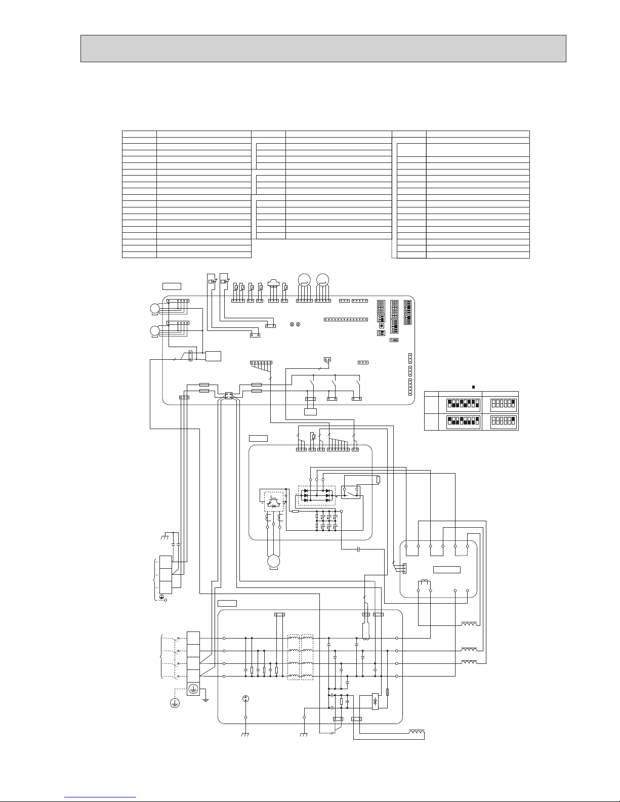
PUHZ-SW100/120YHA WIRING DIAGRAM
BH79B654H01
TB1
TB2
MC
MF1, MF2
21S4
63H
63L
63HS
TH3
TH4
TH6
TH7
TH8
TH34
LEV-A, LEV-B
ACL1, ACL2, ACL3, ACL4
CY1, CY2
CK
RS
Terminal Block <Power Supply>
Terminal Block <Indoor/Outdoor>
Motor for Compressor
Fan Motor
Solenoid Valve (Four-Way Valve)
High Pressure Switch
Low Pressure Switch
High Pressure Sensor
Thermistor <Liquid>
Thermistor <Discharge>
Thermistor <2-Phase Pipe>
Thermistor <Ambient>
Thermistor <Heat Sink>
Thermistor <Comp. Surface>
Linear Expansion Valve
Reactor
Capacitor
Capacitor
Rush Current Protect Resistor
Power Circuit Board
Connection Terminal <U/V/W-Phase>
P. B.
TB-U/V/W
Noise Filter Circuit Board
Connection Terminal
<L1/L2/L3/N-Power Supply
>
N. F.
LI1/LI2/LI3/NI
Connection Terminal
<L1/L2/L3/N-Power Supply
>
LO1/LO2/LO3/NO
Converter Circuit Board
CONV. B.
Connection Terminal <Ground>
GD1, GD3
Connection Terminal <L1-Power Supply>
L1-A1/IN
Connection Terminal <L1-Power Supply>
L1-A2/OU
Connection Terminal <L2-Power Supply>
L2-A2/OU
Connection Terminal <L3-Power Supply>
L3-A2/OU
Connection Terminal
N-IN
Connection Terminal
CK-OU
SYMBOL NAME SYMBOL NAME SYMBOL NAME
Connection Terminal
<L1/L2/L3-Power Supply
>
TB-L1/L2/L3
SW4
SW5
SW6
SW7
SW8
SW9
SWP
CN31
CNDM
CN51
SV1/CH
SS
CNM
LED1, LED2
F1, F2, F3, F4
X51, X52, X54
SW1
C. B.
Connection Terminal
TB-N
52C Relay
X52CA
Switch <Manual Defrost, Defect History,
Record Reset, Refrigerant Address>
Switch <Test Operation>
Switch <Function Switch, Model Select>
Switch <Model Select>
Switch <Function Switch>
Switch <Function Switch>
Switch <Function Switch>
Switch <Pump Down>
Connector <Emergency Operation>
Connector <Connection for Option>
Connector <Connection for Option>
Connector <Connection for Option>
Connector <Connection for Option>
Connector <Connection for Option>
LED <Operation Inspection Indicators>
FUSE <T6.3AL250V>
Relay
Controller Circuit Board
1 2 3 4 5 6 7 8
1 2 3 4 5 6 7 8
OFF
ON
100Y
MODEL
SW6 SW5-6 *2
OFF
ON
OFF
ON
120Y
OFF
ON
1 2 3 4 5 6
1 2 3 4 5 6
*
2 SW5 -1 to 5 : Function Switch
P. B.
U
POWER
SUPPLY
3N~
400V 50Hz
TB1
V
W
RED
WHT
BLK
MC
7
L1
L2
L3
N
N. F.
CNAC1
(WHT)
31
CNDC
(PNK)
31
CNL
(BLU)
13
CNAC2
(RED)
31
CNCT
(RED)
1 2
LO1
LO2
LO3
NO
GD1
NI
LI1
LI2
LI3
GD3
S1
S2
S3
CK
2
3
2
3
ACL4
ACL3
ACL2
ACL1
RED
WHT
BLK
BLU
RED
WHT
BLK
BLU
TB2
CN7
(WHT)
3
1
L3-OU
L3-A2
L2-OU
L2-A2
L1-OU
L1-A2
L1-A1
L1-IN
N-IN
CK-OU
X52CA
RED
RED
BLK
BLU
RED
RED
BLK
BLK
WHT
WHT
RED
WHT
BLK
YLW
ORN
BRN
BLK
RED
GRN/YLW
BLK
BLK
CONV. B.
BRN
INDOOR
UNIT
C. B.
TH6TH7
TH4TH3
21S4
t° t° t° t°
LEV-A
CNS
(WHT)
CNAC
(WHT)
CNDC
(PNK)
F2
F1
F3
F4
21S4
(GRN)
CN2
(WHT)
CN4
(WHT)
TH7/6
(RED)
TH3
(WHT)
TH4
(WHT)
TRANS
CNVMNT
(WHT)
CNMNT
(WHT)
CNM
(WHT)
LED1
LED2
X52
SV1
/CH
(GRY)
X54
63H
(YLW)
2
7
1 4 1 2 2 1
1 3
31 1 5
1 14
1 2
1 7
3
1
13
1 2
3 4
31 31
LEV-A
(WHT)
51
SS
(WHT)
X51
31
MS
3~
MF1
CNF1
(WHT)
1
7
63L63H
63L
(RED)
1 3
31
TH34
t°
2 1
TH34
(RED)
63HS
(WHT)
63HS
LEV-B
(RED)
M
LEV-B
51
M
MF2
CNF2
(WHT)
1
7
CN7
(WHT)
1 3 1 2
CN6
(WHT)
1 2
CN5
(RED)
CN2
(WHT)
1 7 1 2
CN4
(WHT)
TB-N
TB-U
TB-V
TB-W
TB-L3
TB-L2
TB-L1
TH8
t°
RS
RED
MS
3~
22
2
CN3S
(WHT)
1
3
CNDM
(WHT)
CN51
(WHT)
1
3
1
5
CN52C
(RED)
1 3
MS
3~
BRN
CY1
CY2
SW7
SW6SW1
SW9
CN31
*1*
1
SW5SW8SW4 SWP
+
-
+
*
1 MODEL SELECT
The black square ( ) indicates a switch position.
PUHZ-SW100YHA.UK PUHZ-SW120YHA.UK
PUHZ-SW100YHA-BS.UK PUHZ-SW120YHA-BS.UK
OCH533D
22
PUHZ-SW100/120YHA WIRING DIAGRAM
TB1
TB2
MC
MF1, MF2
21S4
63H
63L
63HS
TH3
TH4
TH6
TH7
TH8
TH34
LEV-A, LEV-B
ACL1, ACL2, ACL3, ACL4
CY1, CY2
CK
RS
Terminal Block <Power Supply>
Terminal Block <Indoor/Outdoor>
Motor for Compressor
Fan Motor
Solenoid Valve (Four-Way Valve)
High Pressure Switch
Low Pressure Switch
High Pressure Sensor
Thermistor <Liquid>
Thermistor <Discharge>
Thermistor <2-Phase Pipe>
Thermistor <Ambient>
Thermistor <Heat Sink>
Thermistor <Comp. Surface>
Linear Expansion Valve
Reactor
Capacitor
Capacitor
Rush Current Protect Resistor
Power Circuit Board
Connection Terminal <U/V/W-Phase>
P. B.
TB-U/V/W
Noise Filter Circuit Board
Connection Terminal
<L1/L2/L3/N-Power Supply
>
N. F.
LI1/LI2/LI3/NI
Connection Terminal
<L1/L2/L3/N-Power Supply
>
LO1/LO2/LO3/NO
Converter Circuit Board
CONV. B.
Connection Terminal <Ground>
GD1, GD3
Connection Terminal <L1-Power Supply>
L1-A1/IN
Connection Terminal <L1-Power Supply>
L1-A2/OU
Connection Terminal <L2-Power Supply>
L2-A2/OU
Connection Terminal <L3-Power Supply>
L3-A2/OU
Connection Terminal
N-IN
Connection Terminal
CK-OU
SYMBOL NAME SYMBOL NAME SYMBOL NAME
Connection Terminal
<L1/L2/L3-Power Supply
>
TB-L1/L2/L3
SW4
SW5
SW6
SW7
SW8
SW9
SWP
CN31
CNDM
CN51
SV1/CH
SS
CNM
LED1, LED2
F1, F2, F3, F4
X51, X52, X54
SW1
C. B.
Connection Terminal
TB-N
52C Relay
X52CA/B
Switch <Manual Defrost, Defect History,
Record Reset, Refrigerant Address>
Switch <Test Operation>
Switch <Function Switch, Model Select>
Switch <Model Select>
Switch <Function Switch>
Switch <Function Switch>
Switch <Function Switch>
Switch <Pump Down>
Connector <Emergency Operation>
Connector <Connection for Option>
Connector <Connection for Option>
Connector <Connection for Option>
Connector <Connection for Option>
Connector <Connection for Option>
LED <Operation Inspection Indicators>
FUSE <T6.3AL250V>
Relay
Controller Circuit Board
1 2 3 4 5 6 7 8
1 2 3 4 5 6 7 8
OFF
ON
100Y
MODEL
SW6 SW5-6 *2
OFF
ON
OFF
ON
120Y
OFF
ON
1 2 3 4 5 6
1 2 3 4 5 6
*
2 SW5 -1 to 5 : Function Switch
P. B.
U
POWER
SUPPLY
3N~
400V 50Hz
TB1
V
W
RED
WHT
BLK
MC
7
L1
L2
L3
N
N. F.
CNAC1
(WHT)
31
CNDC
(PNK)
31
CNL
(BLU)
13
CNAC2
(RED)
31
CNCT
(RED)
1 2
LO1
LO2
LO3
NO
GD1
NI
LI1
LI2
LI3
GD3
S1
S2
S3
CK
2
3
2
3
ACL4
ACL3
ACL2
ACL1
RED
WHT
BLK
BLU
RED
WHT
BLK
BLU
TB2
CN7
(WHT)
3
1
L3-OU
L3-A2
L2-OU
L2-A2
L1-OU
L1-A2
L1-A1
L1-IN
N-IN
CK-OU
X52CA
RED
RED
BLK
BLU
RED
RED
BLK
BLK
WHT
WHT
RED
BLK BLK
WHT
YLW
ORN
BRN
BLK
RED
GRN/YLW
BLK
BLK
CONV. B.
BRN
INDOOR
UNIT
C. B.
TH6TH7
TH4TH3
21S4
t° t° t° t°
LEV-A
CNS
(WHT)
CNAC
(WHT)
CNDC
(PNK)
F2
F1
F3
F4
21S4
(GRN)
CN2
(WHT)
CN4
(WHT)
TH7/6
(RED)
TH3
(WHT)
TH4
(WHT)
TRANS
CNVMNT
(WHT)
CNMNT
(WHT)
CNM
(WHT)
LED1
LED2
X52
SV1
/CH
(GRY)
X54
63H
(YLW)
2
7
1 4 1 2 2 1
1 3
31 1 5
1 14
1 2
1 7
3
1
13
1 2
3 4
31 31
LEV-A
(WHT)
51
SS
(WHT)
X51
31
MS
3~
MF1
CNF1
(WHT)
1
7
63L
63H
63L
(RED)
1 3
31
TH34
t°
2 1
TH34
(RED)
63HS
(WHT)
63HS
LEV-B
(RED)
M
LEV-B
51
M
MF2
CNF2
(WHT)
1
7
CN7
(WHT)
1 3 1 2
CN6
(WHT)
1 2
CN5
(RED)
CN2
(WHT)
1 7 1 2
CN4
(WHT)
TB-N
TB-U
TB-V
TB-W
L3IN
TB-L2
TB-L1
TH8
t°
RS
RED
MS
3~
22
2
CN3S
(WHT)
1
3
CNDM
(WHT)
CN51
(WHT)
1
3
1
5
CN52C
(RED)
1 3
MS
3~
BRN
CY1
CY2
SW7
SW6SW1
SW9
CN31
*1*
1
SW5SW8SW4 SWP
+
-
+
*
1 MODEL SELECT
The black square ( ) indicates a switch position.
X52CB
TB-L3L3OUT
PUHZ-SW100YHAR1.UK PUHZ-SW100YHAR3.UK
PUHZ-SW100YHAR1-BS.UK PUHZ-SW100YHAR3-BS.UK
PUHZ-SW120YHAR1.UK PUHZ-SW120YHAR3.UK
PUHZ-SW120YHAR1-BS.UK PUHZ-SW120YHAR3-BS.UK
OCH533D
23
PUHZ-SW100YHAR4.UK PUHZ-SW120YHAR4.UK
PUHZ-SW100YHAR4-BS.UK PUHZ-SW120YHAR4-BS.UK
TB1
TB2
MC
MF1, MF2
21S4
63H
63L
63HS
TH3
TH4
TH6
TH7
TH8
ACL1, ACL2,
ACL3, ACL4
CY1, CY2
CK
RS
Terminal Block <Power Supply>
Terminal Block <Indoor/Outdoor>
Motor for Compressor
Fan Motor
Solenoid Valve (4-Way Valve)
High Pressure Switch
Low Pressure Switch
High Pressure Sensor
Thermistor <Liquid>
Thermistor <Discharge>
Thermistor <2-Phase Pipe>
Thermistor <Ambient>
Thermistor <Heat Sink>
Linear Expansion Valve
Reactor
Capacitor
Capacitor
Rush Current Protect Resistor
Power Circuit Board
P. B.
Noise Filter Circuit Board
N. F.
Converter Circuit Board
CONV. B.
SYMBOL
NAME SYMBOL NAME SYMBOL NAME
SW5
SW6
SW7
SW8
SW9
SWP
CNDM
SV1/CH
SV3/SS
CNM
F1, F2, F3, F4
Switch <Function Switch, Model Select
>
Switch <Model Select>
Switch <Function Switch>
Switch <Function Switch>
Switch <Function Switch>
Switch <Pump Down>
Connector <Connection for Option
>
Connector <Connection for Option
>
Connector <Connection for Option
>
Connector <Connection for Option
>
Fuse <T6.3AL250V>
TH34
Thermistor <Comp. Surface>
LEV-A, LEV-B
SW4
SW1
Switch <Manual Defrost, Defect History
Record Reset, Refrigerant Address
>
Switch <Function Switch>
Controller Circuit Board
C. B.
*1 *1
U
POWER
SUPPLY
3N
~
400V 50Hz
TB1
V W
RD
WH
BK
MC
7
L1
L2
L3
N
CNAC1
(WH)
31
CNDC
(PK)
31
CNL
(BU)
13
CNAC2
(RD)
31
CNCT
(RD)
1
2
LO1
LO2
LO3
NO
GD1
NI
LI1
LI2
LI3
GD3
S1
S2
S3
CK
2
3
2
3
ACL4
ACL3
ACL2
ACL1
RD
WH
BK
BU
RD
WH
BK
BU
TB2
CN7
(WH)
3
1
L3-OU
L3-A2
L2-OU
L2-A2
L1-OU
L1-A2
L1-A1
L1-IN
N-IN
CK-OU
X52CA
X52CB
RD
RD
BK
BU
RD
RD
BK
BK
WH
WH
RD
RD
RD
WH
BK
BK
YE
OG
BN
BK
GNYE
BK
BK
TO
INDOOR
UNIT
C. B.
TH6TH7 TH4TH3
21S4
t°
t° t° t°
LEV-A
CNS
(WH)
CNAC
(WH)
CNDC
(PK)
F2
F1
F3
F4
21S4
(GN)
CN2
(RD)
CN4
(WH)
TH7/6
(RD)
TH3
(WH)
TH4
(WH)
TRANS
CNM
(WH)
LED1
LED2
X52
SV1/CH
(GY)
X54
63H
(YE)
2
7
1 4 1 2 2 1
1 3
1
14
1 2
1 7
1
3
13
1 2
3 4
31 31
LEV-A
(WH)
51
SV3/SS
(WH)
X51
31
MF1
CNF1
(WH)
1
7
63L63H
63L
(RD)
1 3
31
TH34
t°
2 1
TH34
(RD)
63HS
(WH)
63HS
LEV-B
(RD)
M
LEV-B
51
M
MF2
CNF2
(WH)
1
7
CN7
(WH)
1 3 1 2
CN6
(WH)
1 2
CN5
(RD)
CN2
(RD)
1 7 1 2
CN4
(WH)
TB-N
TB-U
TB-V
TB-W
TB-L3
TB-L1
L3OUT
TB-L2
L3IN
TH8
t°
RS
MS
3~
22
2
CY1
CY2
SW7
SW6SW1
SW9
SW5SW8SW4 SWP
+
-
+
31
CNDM
(WH)
+
+
+
~~~
~
~
P. B.
N. F.
CONV. B.
MS
3~
MS
3~
8
8
1 2 3 4 5 6 7
1 2 3 4 5 6 7
OFF
ON
100Y
MODEL
SW6
SW5-6 *2
SW5-6 *2
OFF
ON
OFF
ON
120Y
OFF
ON
1 2 3 4 5 6
1 2 3 4 5 6
MODEL
SW6
*1 MODEL SELECT
The black square ( ) indicates a switch position.
*2 SW5 -1 to 5 : Function Switch
OCH533D
24
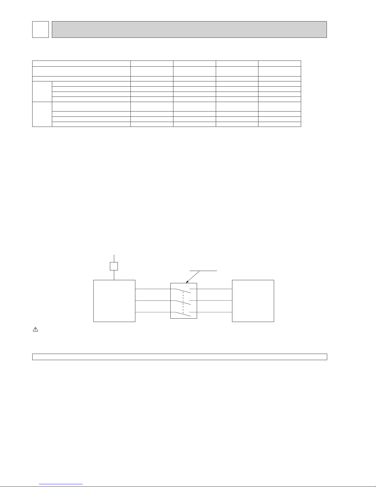
9 WIRING SPECIFICATIONS
FIELD ELECTRICAL WIRING (power wiring specifications)
Outdoor unit model
SW75V SW100V SW120V SW100, 120Y
Outdoor unit power supply
~/N (single),
50 Hz, 230 V
~/N (single),
50 Hz, 230 V
~/N (single),
50 Hz, 230 V
3N~ (3 ph 4-wires),
50 Hz, 400 V
Outdoor unit input capacity Main switch (Breaker) *1 25 A 32 A 40 A 16 A
Wiring
Wire No. ×
size (mm
2
)
Outdoor unit power supply 3 × Min. 2.5 3 × Min. 4 3 × Min. 6 5 × Min. 1.5
Indoor unit-Outdoor unit *2 3 × 1.5 (Polar) 3 × 1.5 (Polar) 3 × 1.5 (Polar) 3 × 1.5 (Polar)
Indoor unit-Outdoor unit earth *2 1 × Min. 1.5 1 × Min. 1.5 1 × Min. 1.5 1 × Min. 1.5
Remote controller-Indoor unit *3 2 × 0.3 (Non-polar) 2 × 0.3 (Non-polar) 2 × 0.3 (Non-polar) 2 × 0.3 (Non-polar)
Circuit rating
Outdoor unit L-N (single)
Outdoor unit L1-N, L2-N, L3-N (3 phase)
*4 230 V AC 230 V AC 230 V AC 230 V AC
Indoor unit-Outdoor unit S1-S2 *4 230 V AC 230 V AC 230 V AC 230 V AC
Indoor unit-Outdoor unit S2-S3 *4 24 V DC 24 V DC 24 V DC 24 V DC
Remote controller-Indoor unit *4 12 V DC 12 V DC 12 V DC 12 V DC
*1. A breaker with at least 3.0 mm contact separation in each pole shall be provided. Use earth leakage breaker (NV).
Make sure that the current leakage breaker is one compatible with higher harmonics.
Always use a current leakage breaker that is compatible with higher harmonics as this unit is equipped with an inverter.
The use of an inadequate breaker can cause the incorrect operation of inverter.
*2. Maximum 45 m
If 2.5 mm
2
is used, maximum 50 m.
If 2.5 mm
2
is used and S3 is separated, maximum 80 m.
*3. The 10 m wire is attached in the remote controller accessory.
*4. The gures are NOT always against the ground.
S3 terminal has 24 V DC against S2 terminal. However between S3 and S1, these terminals are NOT electrically insulated by the transformer or other device.
S1
S2
S3
S1
S2
S3
Warning:
· In case of A-control wiring, there is high voltage potential on the S3 terminal caused by electrical circuit design that has no electrical insulation
between power line and communication signal line. Therefore, please turn off the main power supply when servicing. And do not touch the S1, S2, S3
terminals when the power is energized. If isolator should be used between indoor unit and outdoor unit, please use 3-pole type.
Notes: 1. Wiring size must comply with the applicable local and national codes.
2.
Power supply cables and the cables between Interface unit/Flow temp. controller and outdoor unit shall not be lighter than polychloroprene
sheathed exible cables. (Design 60245 IEC 57
)
3. Be sure to connect the cables between
Interface unit/Flow temp. controller
and outdoor unit directly to the units (no intermediate connections
are allowed).
Intermediate connections may result in communication errors. If water enters at the intermediate connection point, it may cause insufcient
insulation to ground or a poor electrical contact .
(If an intermediate connection is necessary, be sure to take measures to prevent water from entering the cables.)
4. Install an earth longer than other cables.
5. Do not construct a system with a power supply that is turned ON and OFF frequently.
Outdoor Unit
3 poles isolator
Power
supply
Isolator
Indoor unit
(Interface unit /
Flow temp.
controller)
Never splice the power cable or the indoor-outdoor connection cable, otherwise it may result in smoke emission, a re or communication failure.
OCH533D
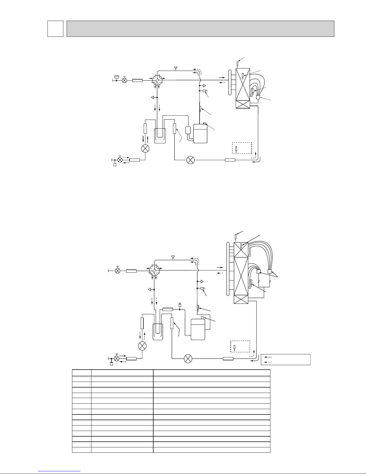
25
10 REFRIGERANT SYSTEM DIAGRAM
unit: mm (in)
Distributor
Thermistor TH7
(Ambient)
Heat
exchanger
Refrigerant LIQUID pipe
connection [9.52(3/8)
Stop valve
(with service port)
Strainer
#100
Power
receiver
Linear
expansion valve B
Linear expansion valve A
Strainer
#100
Thermistor TH6
(2-phase pipe)
Thermistor TH3
(Liquid)
High pressure
switch 63H
Thermistor TH4
(Discharge)
Thermistor TH34
P.B
TH8
(Comp. surface)
Compressor
Strainer
#50
Strainer
#100
Strainer
#100
4-way valve
Charge plug
(Low pressure)
Charge plug
(High pressure)
Stop valve
(with service port)
Refrigerant GAS pipe
connection [15.88(5/8)
Pressure
sensor 63HS
Distributor
Thermistor TH7
(Ambient)
Heat
exchanger
Refrigerant GAS pipe
connection ø15.88(5/8)
Refrigerant LIQUID pipe
connection ø9.52(3/8)
Stop valve
(with service port)
Strainer
#100
Power
receiver
Linear
expansion valve B
Linear expansion valve A
Strainer
#100
Strainer
#100
Thermistor TH6
(2-phase pipe)
Thermistor TH3
(Liquid)
Charge plug
(Low pressure)
Charge plug
(High pressure)
High pressure
switch 63H
Thermistor TH4
(Discharge)
Thermistor TH34
(Comp. surface)
Compressor
Strainer
#50
4-way valve
Strainer
#100
Strainer
#100
Ball valve
Refrigerant flow in cooling
Refrigerant flow in heating
Pressure
sensor 63HS
Low pressure
switch 63L
P.B
TH8
PUHZ-SW75VHA.UK PUHZ-SW75VHAR3.UK PUHZ-SW75VHAR4.UK
PUHZ-SW75VHA-BS.UK PUHZ-SW75VHAR3-BS.UK PUHZ-SW75VHAR4-BS.UK
COMP
H/P SW
L/P SW
REV/V
Charge plug
P-Sensor
LEV-A
LEV-B
TH3
TH4
TH6
TH7
TH34
DC inverter twin rotary compressor (Mitsubishi Electric Corporation)
For protection (OFF:4.15MPa)
For protection (OFF:-0.03MPa) (SW100/120)
Change the refrigerant circuit (Heating / Cooling) and for Defrosting
High pressure / Low pressure / For production test use
For calculation of the condensing temperature from high pressure
Heating:Secondary LEV Cooling:Primary LE
V
Heating:Primary LEV Cooling:Seconda
ry LEV
Heating:Evaporating temperature Cooling:Sub cool liquid temperature
For LEV control and for compressor protection
Outdoor 2-phase pipe temperature
For fan control and for compressor frequency control
For compressor protection
For accumulation of refrigerant
Compressor
High pressure switch (63H)
Low pressure switch (63L)
Reversing (4-way) valve (21S4)
Charge plug
Pressure sensor (63HS)
Linear expansion valve -A
Linear expansi
on valve -B
Liquid temperature thermistor
Discharge
temperature thermistor
2-phase pipe temperature thermistor
Ambient temperature thermistor
Comp.surface temperature thermistor
Power Receiver
Symbol Part name
Detail
Power Receiver
PUHZ-SW100VHA.UK
PUHZ-SW100VHAR3.UK PUHZ-SW100VHAR4.UK
PUHZ-SW100VHA-BS.UK
PUHZ-SW100VHAR3-BS.UK PUHZ-SW100VHAR4-BS.UK
PUHZ-SW100YHA.UK
PUHZ-SW100YHAR1.UK PUHZ-SW100YHAR3.UK PUHZ-SW100YHAR4.UK
PUHZ-SW100YHA-BS.UK
PUHZ-SW100YHAR1-BS.UK PUHZ-SW100YHAR3-BS.UK PUHZ-SW100YHAR4-BS.UK
PUHZ-SW120VHA.UK
PUHZ-SW120VHAR3.UK PUHZ-SW120VHAR4.UK
PUHZ-SW120VHA-BS.UK
PUHZ-SW120VHAR3-BS.UK PUHZ-SW120VHAR4-BS.UK
PUHZ-SW120YHA.UK
PUHZ-SW120YHAR1.UK PUHZ-SW120YHAR3.UK
PUHZ-SW120YHAR4.UK
PUHZ-SW120YHA-BS.UK
PUHZ-SW120YHAR1-BS.UK PUHZ-SW120YHAR3-BS.UK PUHZ-SW120YHAR4-BS.UK
OCH533D

26
10-1. REFRIGERANT COLLECTING (PUMP DOWN)
When relocating or disposing of the indoor/outdoor unit, pump down the system following the procedure below so that no refrigerant is released into the atmosphere.
1 Turn off the power supply (circuit breaker).
2 Connect the low-pressure valve on the gauge manifold to the charge plug (lowpressure side) on the outdoor unit.
3 Close the liquid stop valve completely.
4 Supply power (circuit breaker).
• Even if power can be supplied, the pump down procedure cannot be completed depending on the unit's status. For more
information, refer to the FTC Installation Manual or Service Manual.
• Startup of the indoor-outdoor communication takes about 3 minutes after the power (circuit breaker) is turned on. Start the
pump-down operation 3 to 4 minutes after the power (circuit breaker) is turned on.
5 Perform the refrigerant collecting operation (cooling test run).
• Push the pump-down SWP switch (push-button type) on the control board of the outdoor unit. The compressor and ventilators
(indoor and outdoor units) start operating (refrigerant collecting operation begins). (LED1 and LED2 on the control board of
the outdoor unit are lit.)
• Only push the pump-down SWP switch if the unit is stopped. However, even if the unit is stopped and the pump-down SWP
switch is pushed less than 3 minutes after the compressor stops, the refrigerant collecting operation cannot be performed.
Wait until the compressor has been stopped for 3 minutes and then push the pump-down SWP switch again.
6 Fully close the ball valve on the gas pipe side of the outdoor unit when the pressure gauge on the gauge manifold shows 0.05
to 0 MPa [Gauge] (approx. 0.5 to 0 kgf/cm²) and quickly stop the air conditioner.
• Since the unit automatically stops in about 3 minutes when the refrigerant collecting operation is completed (LED1 off, LED2
lit), be sure to quickly close the gas ball valve. However, if LED1 is lit, LED2 is off, and the unit is stopped, open the liquid
stop valve completely, close the valve completely after 3 minutes or more have passed, and then repeat step 5. (Open the
gas ball valve completely.)
• If the refrigerant collecting operation has been completed normally (LED1 off, LED2 lit), the unit will remain stopped until the
power supply is turned off.
• Note that when the extension piping is very long with a large refrigerant amount, it may not be possible to perform a pump-
down operation. In this case, use refrigerant recovery equipment to collect all of the refrigerant in the system.
7 Turn off the power supply (circuit breaker), remove the gauge manifold, and then disconnect the refrigerant pipes.
Warning:
When pumping down the refrigerant, stop the compressor before disconnecting the refrigerant pipes.
• If the refrigerant pipes are disconnected while the compressor is operating and the stop valve (ball valve) is open, the
pressure in the refrigeration cycle could become extremely high if air is drawn in, causing the pipes to burst, personal
injury, etc.
10-2. UNIT REPLACEMENT OPERATION
When reusing the existing pipes that carried R22 refrigerant for the SW75/100/120 models, replacement operation
must be performed before performing a test run.
1 If new pipes are used, these procedures are not necessary.
2 If existing pipes that carried R22 refrigerant are used for the SW75/100/120 models, these procedures are not necessary.
(The replacement operation cannot be performed.)
3 During replacement operation, “C5” is displayed on “A-Control Service Tool (PAC-SK52ST)”. (This is applied to only
SW75/100/120 models.)
OCH533D
27
11 TROUBLESHOOTING
11-1. TROUBLESHOOTING
<Check code displayed by self-diagnosis and actions to be taken for service (summary)>
Present and past check codes are logged, and they can be displayed on the control board of outdoor unit. Actions to be taken
for service, which depends on whether or not the trouble is reoccurring in the field, are summarized in the table below. Check
the contents below before investigating details.
Unit conditions at service Check code Actions to be taken for service (summary)
The trouble is reoccurring.
Displayed
Judge what is wrong and take a corrective action according to
“11-2. SELF-DIAGNOSIS ACTION TABLE”.
Not displayed
Conduct troubleshooting and ascertain the cause of the
trouble.
The trouble is not reoccurring.
Logged
1
Consider the temporary defects such as the work of
protection devices in the refrigerant circuit including
compressor, poor connection of wiring, noise, etc. Recheck the symptom, and check the installation environment,
refrigerant amount, weather when the trouble occurred,
matters related to wiring, etc.
2
Reset check code logs and restart the unit after nishing
service.
3
There is no abnormality in electrical component, controller
board, etc.
Not logged
1
Re-check the abnormal symptom.
2
Conduct troubleshooting and ascertain the cause of the
trouble.
3
Continue to operate unit for the time being if the cause is
not ascertained.
4
There is no abnormality concerning of parts such as
electrical component, controller board, etc.
OCH533D
28
11-2. SELF-DIAGNOSIS ACTION TABLE
<Abnormalities detected when the power is turned on>
Note: Refer to indoor unit section for code P and code E.
Check code
Abnormal point and detection method
Case
Judgment and action
None —
1
No voltage is supplied to terminal
block (TB1) of outdoor unit.
a) Power supply breaker is
turned off.
b) Contact failure or
disconnection of power
supply terminal
c) Open phase (L or N phase)
2 Electric power is not charged
to power supply terminal of
outdoor power circuit board.
a) Contact failure of power
supply terminal
b) Open phase on the outdoor
power circuit board
SW75V: Disconnection of
connector R or S
SW100/120V:
Disconnection of connector
LI or NI
3 Electric power is not supplied
to outdoor controller circuit
board.
a) Disconnection of connector
(CNDC)
4 Disconnection of reactor (DCL
or ACL)
5 Disconnection of outdoor noise
filter circuit board or parts failure
in outdoor noise filter circuit
board
As for SW75VHA(R3), it is
especially needed to check the
resistance RS on the noise filter
circuit board.
6 Defective outdoor power circuit
board
7 Defective outdoor controller
circuit board
1 Check following items.
a) Power supply breaker
b) Connection of power supply terminal block
(TB1)
c) Connection of power supply terminal block
(TB1)
2 Check following items.
a) Connection of power supply terminal block
(TB1)
b) Connection of terminal on outdoor power
circuit board
SW75V: Check connection of the connec-
tor R or S. Refer to "11-6. TEST
POINT DIAGRAM".
SW100/120V: Check connection of the
connector LI or NI.
Refer to "11-6. TEST POINT
DIAGRAM".
3 Check connection of the connector (CNDC)
on the outdoor controller circuit board.
Check connection of the connector, CNDC
on the outdoor power circuit board(V)/the
noise filter(Y). Refer to "11-6. TEST POINT
DIAGRAM".
4 Check connection of reactor. (DCL or ACL)
SW75VHA(R3)
:
Check connection of “LO” and
“NO” on the outdoor noise filter
circuit board. Check connection
of "R" and "S" on the outdoor
power circuit board.
Refer to
"11-6. TEST POINT DIAGRAM".
SW75VHAR4:Check connection of "TBL2" and
"TBL4" on the outdoor power circuit board.
"11-6. TEST POINT
DIAGRAM".
SW100/120V:
Check connection of "DCL1"
and "DCL2" on the outdoor
power circuit board. Refer to
"11-6. TEST POINT DIAGRAM".
5 a) Check connection of outdoor noise filter
circuit board.
b) Replace outdoor noise filter circuit board.
Refer to "11-6. TEST POINT DIAGRAM".
6 Replace outdoor power circuit board.
7 Replace controller board (When items above
are checked but the units cannot be repaired).
F5
63H connector open
Abnormal if 63H connector circuit is open for
3 minutes continuously after power supply.
63H: High-pressure switch
1 Disconnection or contact failure
of 63H connector on outdoor
controller circuit board
2 Disconnection or contact failure
of 63H
3 63H is working due to defective
parts.
4 Defective outdoor controller
circuit board
1 Check connection of 63H connector on
outdoor controller circuit board.
Refer to "11-6. TEST POINT DIAGRAM".
2 Check the 63H side of connecting wire.
3 Check continuity by tester.
Replace the parts if the parts are defective.
4 Replace outdoor controller circuit board.
F3
63L connector open (SW100/120 only)
Abnormal if 63L connector circuit is open for
3 minutes continuously after power supply.
63L: Low-pressure switch
1 Disconnection or contact failure
of 63L connector on outdoor
controller circuit board
2 Disconnection or contact failure
of 63L
3 63L is working due to
refrigerant leakage or defective
parts.
4 Defective outdoor controller
circuit board
1 Check connection of 63L connector on
outdoor controller circuit board.
Refer to "11-6. TEST POINT DIAGRAM".
2 Check the 63L side of connecting wire.
3 Check refrigerant pressure.
Charge additional refrigerant.
Check continuity by tester.
Replace the parts if the parts are defective.
4 Replace outdoor controller circuit board.
OCH533D

29
Check code
Abnormal point and detection method Judgment and action
Eb
Miswiring of indoor/outdoor unit
connecting wire (converse wiring or
disconnection)
Outdoor controller circuit board can
automatically set the unit number of indoor
units.
Abnormal if the indoor unit number cannot
be set within 4 minutes after power on
because of miswiring (converse wiring
or disconnection) of indoor/outdoor unit
connecting wire.
EC
Startup time over
The unit cannot finish startup process
within 4 minutes after power on.
Case
1 Contact failure of indoor/
outdoor unit connecting wire
2 Diameter or length of indoor/
outdoor unit connecting wire is
out of specified capacity.
7 2 or more outdoor units have
refrigerant address “0” .
(In case of group control)
8 Noise has entered into power
supply or indoor/outdoor unit
connecting wire.
1 Contact failure or miswiring of
indoor/outdoor unit connecting
wire
2 Diameter or length of indoor/
outdoor unit connecting wire is
out of specified capacity.
4 Defective transmitting receiving
circuit of outdoor controller circuit
board
5 Defective transmitting receiving
circuit of indoor controller board
6 Defective indoor power board
7 2 or more outdoor units have
refrigerant address “0” .
(In case of group control)
8 Noise has entered into power
supply or indoor/outdoor unit
connecting wire.
Indoor/outdoor unit connector
miswiring, excessive number of units (4
units or more)
1. Outdoor controller circuit board can
automatically check the number of
connected indoor units. Abnormal if the
number cannot be checked automatically
due to miswiring of indoor/outdoor unit
connecting wire and etc. after power is
turned on for 4 minutes.
2. Abnormal if outdoor controller circuit
board recognizes excessive number of
indoor units.
1 Check disconnection or looseness or polarity
of indoor/outdoor unit connecting wire of
indoor and outdoor units.
2 Check diameter and length of indoor/outdoor
unit connecting wire.
Total wiring length: 80 m
(including wiring connecting each indoor unit
and between indoor and outdoor unit)
Also check if the connection order of flat
cable is S1, S2, S3.
3 Check the number of indoor units that are
connected to one outdoor unit. (If EA is
detected)
4–6 Turn the power off once, and on again to
check.
Replace outdoor controller circuit board,
indoor controller board or indoor power
board if abnormality occurs again.
7
Check if refrigerant addresses (SW1-3 to
SW1-6 on outdoor controller circuit board) are
overlapping in case of group control system.
8 Check transmission path, and remove the
cause.
Note: The descriptions above, 1–8, are for
EA, Eb and EC.
1 Contact failure or miswiring of
indoor/outdoor unit connecting
wire
2 Diameter or length of indoor/
outdoor unit connecting wire is
out of specified capacity.
3 Excessive number of indoor
units are connected to 1
outdoor unit (2 units or more).
4 Defective transmitting receiving
circuit of outdoor controller
circuit board
5 Defective transmitting receiving
circuit of indoor controller board
6 Defective indoor power board
7 2 or more outdoor units have
refrigerant address “0” .
(In case of group control)
8 Noise has entered into power
supply or indoor / outdoor unit
connecting wire.
EA
F9
2 connector open (SW100/120 only)
Abnormal if both 63H and 63L connector
circuits are open for three minutes
continuously after power supply.
63H: High-pressure switch
63L: Low-pressure switch
1 Disconnection or contact failure
of connector (63H,63L) on
outdoor controller circuit board
2 Disconnection or contact failure
of 63H, 63L
3 63H and 63L are working due
to defective parts.
4 Defective outdoor controller
board
1 Check connection of connector (63H,63L) on
outdoor controller circuit board.
Refer to "11-6. TEST POINT DIAGRAM".
2 Check the 63H and 63L side of connecting
wire.
3 Check continuity by tester.
Replace the parts if the parts are defective.
4 Replace outdoor controller circuit board.
EE
Incorrect connection
The outdoor unit does not receive the signals of I/F or FTC.
1 A device other than Interface
unit or Flow temp. controller
unit is connected to the unit.
1 Connect I/F or FTC to the unit.
OCH533D
30
Check code
Abnormal point and detection method Judgment and action
U1
High pressure (High-pressure switch
63H operated)
Abnormal if high-pressure switch 63H
operated (4.15 MPa) during compressor
operation.
63H: High-pressure switch
1 Defective operation of stop
valve (Not fully open)
2 Clogged or broken pipe
3 Locked outdoor fan motor
4 Malfunction of outdoor fan
motor
5 Short cycle of outdoor unit
6 Dirt of outdoor heat exchanger
7 Decreased airflow caused by
defective inspection of outside
temperature thermistor
(It detects lower temperature
than actual temperature.)
8 Disconnection or contact failure
of connector (63H) on outdoor
controller board
9 Disconnection or contact failure
of 63H connection
0 Defective outdoor controller
board
1 Defective action of linear
expansion valve
2 Malfunction of fan driving circuit
1 Check if stop valve is fully open.
2 Check piping and repair defect.
3–6 Check outdoor unit and repair defect.
7 Check the detected temperature of outside
temperature thermistor on LED display.
(SW2 on A-Control Service Tool : Refer to
"11-7. FUNCTION OF SWITCHES,
CONNECTORS AND JUMPERS".)
8–0 Turn the power off and check F5 is
displayed when the power is turned again.
When F5 is displayed, refer to “Judgment
and action” for F5.
1 Check linear expansion valve.
Refer to "11-4. HOW TO CHECK THE
PARTS".
2 Replace outdoor controller board.
Case
U2
U3
Open/short circuit of discharge
temperature thermistor (TH4) / Comp.
surface temperature thermistor (TH34)
Abnormal if open (3: or less) or short
(217: or more) is detected during
compressor operation.
(Detection is inoperative for 10 minutes
of compressor starting process and for 10
minutes after and during defrosting.)
1 Disconnection or contact failure
of connector (TH4/TH34) on
the outdoor controller circuit
board
2 Defective thermistor
3 Defective outdoor controller
circuit board
1 Check connection of connector (TH4/TH34)
on the outdoor controller circuit board.
Check breaking of the lead wire for
thermistor (TH4/TH34). Refer to "11-6. TEST
POINT DIAGRAM".
2 Check resistance value of thermistor (TH4/
TH34) or temperature by microprocessor.
(Thermistor/TH4/TH34: Refer to "11-4. HOW
TO CHECK THE PARTS".)
(SW2 on A-Control Service Tool: Refer to
"11-7.
FUNCTION OF SWITCHES, CONNECTORS
AND JUMPERS".
)
3 Replace outdoor controller board.
<Abnormalities detected while unit is operating>
High discharge temperature
(1) Abnormal if discharge temperature
thermistor (TH4) exceeds 125: or
110: continuously for 5 minutes.
Abnormal if discharge temperature
thermistor (TH4) exceeds 110: or
more continuously for 30 seconds after
90 seconds have passed since the
defrosting operation started.
(2) Abnormal if discharge superheat
(Cooling: TH4−T
63HS /
Heating: TH4−T63HS) exceeds 70:
continuously for 10 minutes.
High comp. surface temperature
Abnormal if comp. surface temperature
(TH34) exceeds 125:. In the case of
high comp. surface temperature error,
compressor does not restart unless the
thermistor (TH34) becomes less than
95:.
1 Overheated compressor
operation caused by shortage
of refrigerant
2 Defective operation of stop
valve
3 Defective thermistor
4 Defective outdoor controller
board
5 Defective action of linear
expansion valve
6 Clogging with foreign objects in
refrigerant circuit
Note: Clogging occur in the parts
which become below
freezing point when water
enters in refrigerant circuit.
1 Check intake superheat.
Check leakage of refrigerant.
Charge additional refrigerant.
2 Check if stop valve is fully open.
34
Turn the power off and check if U3 is
displayed when the power is turned on again.
When U3 is displayed, refer to “Judgment
and action” for U3.
5 Check linear expansion valve.
Refer to "11-4. HOW TO CHECK THE
PARTS".
6 After recovering refrigerant, remove water
from entire refrigerant circuit under vacuum
more than 1 hour.
OCH533D
 Loading...