

Mitsubishi PUHZ-SW120YHA.UK, PUHZ-SW100VHA.UK, PUHZ-SW75VHA-BS.UK, PUHZ-SW100VHA-BS.UK, PUHZ-SW100YHA-BS.UK Service Manual
...
SERVICE MANUAL
CONTENTS
1. REFERENCE MANUAL
..................................
2
2. SAFETY PRECAUTION
..................................
3
3. FEATURES
......................................................
7
4. SPECIFICATIONS
...........................................
8
5. DATA
.............................................................
11
6. OUTLINES AND DIMENSIONS
....................
13
7. WIRING DIAGRAM
.......................................
15
8. WIRING SPECIFICATIONS
..........................
18
9.
REFRIGERANT SYSTEM DIAGRAM
...............
19
10. TROUBLESHOOTING
...................................
21
11. DISASSEMBLY PROCEDURE
.....................
65
No.OCH533
REVISED EDITION-A
SPLIT-TYPE, AIR TO WATER HEAT PUMP
R410A
October 2012
PUHZ-SW75VHA.UK
PUHZ-SW75VHA-BS.UK
Salt proof model
PUHZ-SW75VHA-BS
PUHZ-SW100VHA-BS
PUHZ-SW100YHA-BS
PUHZ-SW120VHA-BS
PUHZ-SW120YHA-BS
Note:
• This manual describes
only service data of the
outdoor units.
PUHZ-SW75VHA-BS.UK
PUHZ-SW100VHA-BS.UK
PUHZ-SW100YHA-BS.UK
PUHZ-SW120VHA-BS.UK
PUHZ-SW120YHA-BS.UK
Outdoor unit
[Model names]
PUHZ-SW75VHA
PUHZ-SW100VHA
PUHZ-SW100YHA
PUHZ-SW120VHA
PUHZ-SW120YHA
[Service ref.]
PUHZ-SW75VHA.UK
PUHZ-SW100VHA.UK
PUHZ-SW100YHA.UK
PUHZ-SW120VHA.UK
PUHZ-SW120YHA.UK
PARTS CATALOG (OCB533)
Revision:
•
The function description of
SW7-3, 7-4 and 7-5 (Page
52) have been corrected
in
REVISED EDITION-A.
• Please void OCH533.

2
1
REFERENCE MANUAL
INDOOR UNIT SERVICE MANUAL
Model name Service ref. Service manual No.
EHST20C-VM6HB
EHST20C-YM9HB
EHST20C-VM6B
EHST20C-YM9B
EHST20C-VM6EB
EHST20C-YM9EB
EHST20C-VM6SB
EHPT20X-VM2HB
EHPT20X-VM6HB
EHPT20X-YM9HB
EHPT20X-VM6B
EHPT20X-YM9B
EHST20C-VM6HB.UK
EHST20C-YM9HB.UK
EHST20C-VM6B.UK
EHST20C-YM9B.UK
EHST20C-VM6EB.UK
EHST20C-YM9EB.UK
EHST20C-VM6SB.UK
EHPT20X-VM2HB.UK
EHPT20X-VM6HB.UK
EHPT20X-YM9HB.UK
EHPT20X-VM6B.UK
EHPT20X-YM9B.UK
OCH531
EHSC-VM6B
EHSC-YM9B
EHSC-VM6EB
EHSC-YM9EB
EHPX-VM2B
EHPX-VM6B
EHPX-YM9B
ERSC-VM2B
EHSC-VM6B.UK
EHSC-YM9B.UK
EHSC-VM6EB.UK
EHSC-YM9EB.UK
EHPX-VM2B.UK
EHPX-VM6B.UK
EHPX-YM9B.UK
ERSC-VM2B.UK
OCH532
OCH533
A

3
2 SAFETY PRECAUTION
Cautions for units utilizing refrigerant R410A
2-2. CAUTIONS RELATED TO NEW REFRIGERANT
Use new refrigerant pipes.
Make sure that the inside and outside of refrigerant piping is clean and it has no contamination
such as sulfur hazardous for use, oxides, dirt,
shaving particles, etc.
In addition, use pipes with specified thickness.
Store the piping indoors, and both ends of the
piping sealed until just before brazing.
(Leave elbow joints, etc. in their packaging.)
Use ester oil, ether oil or alkylbenzene oil (small
amount) as the refrigerant oil applied to flares
and flange connections.
In case of using the existing pipes for R22, be careful with
the followings.
· Be sure to perform replacement operation before test run.
· Change flare nut to the one provided with this product.
Use a newly flared pipe.
· Avoid using thin pipes.
Do not use refrigerant other than R410A.
If other refrigerant (R22 etc.) is used, chlorine in refrigerant can cause deterioration of refrigerant oil etc.
Use a vacuum pump with a reverse flow check
valve.
Vacuum pump oil may flow back into refrigerant cycle and
that can cause deterioration of refrigerant oil etc.
Use the following tools specifically designed for
use with R410A refrigerant.
The following tools are necessary to use R410A refrigerant.
Handle tools with care.
If dirt, dust or moisture enters into refrigerant cycle, that can
cause deterioration of refrigerant oil or malfunction of compressor.
Do not use a charging cylinder.
If a charging cylinder is used, the composition of refrigerant will change and the efficiency will be lowered.
Flare tool
Electronic refrigerant
charging scale
Vacuum pump adaptor
Size adjustment gauge
Gauge manifold
Torque wrench
Gas leak detector
Charge hose
Tools for R410A
Contamination inside refrigerant piping can cause deterioration of refrigerant oil etc.
If dirt, dust or moisture enters into refrigerant cycle, that can
cause deterioration of refrigerant oil or malfunction of compressor.
If large amount of mineral oil enters, that can cause deterioration of refrigerant oil etc.
Charge refrigerant from liquid phase of gas
cylinder.
If the refrigerant is charged from gas phase, composition
change may occur in refrigerant and the efficiency will be
lowered.
Ventilate the room if refrigerant leaks during
operation. If refrigerant comes into contact with
a flame, poisonous gases will be released.
Use the specified refrigerant only.
Never use any refrigerant other than that specified.
Doing so may cause a burst, an explosion, or fire when the
unit is being used, serviced, or disposed of.
Correct refrigerant is specified in the manuals and on the
spec labels provided with our products.
We will not be held responsible for mechanical failure,
system malfunction, unit breakdown or accidents caused
by failure to follow the instructions.
2-1. ALWAYS OBSERVE FOR SAFETY
Before obtaining access to terminal, all supply circuits must disconnected.
Preparation before the repair service.
• Prepare the proper tools.
• Prepare the proper protectors.
• Provide adequate ventilation.
• After stopping the operation of the air conditioner, turn off
the power-supply breaker.
• Discharge the condenser before the work involving
the electric parts.
Precautions during the repair service.
• Do not perform the work involving the electric parts
with wet hands.
• Do not pour water into the electric parts.
• Do not touch the refrigerant.
• Do not touch the hot or cold areas in the refrigerating cycle.
• When the repair or the inspection of the circuit needs to be
done without turning off the power,
exercise great caution not to touch the live parts.
OCH533
A
4
Gravimeter
Unit
[3] Service tools
Use the below service tools as exclusive tools for R410A refrigerant.
No. Tool name Specifications
1 Gauge manifold ·Only for R410A
·Use the existing fitting
specifications
. (UNF1/2)
·Use high-tension side pressure of 5.3MPa·G or over.
2 Charge hose ·Only for R410A
·Use pressure performance of 5.09MPa·G or over.
3 Electronic scale
4 Gas leak detector ·Use the detector for R134a, R407C or R410A.
5 Adaptor for reverse flow check ·Attach on vacuum pump.
6 Refrigerant charge base
7 Refrigerant cylinder ·Only for R410A ·Top of cylinder (Pink)
·Cylinder with syphon
8 Refrigerant recovery equipment
[1] Cautions for service
(1) Perform service after recovering the refrigerant left in unit completely.
(2) Do not release refrigerant in the air.
(3) After completing service, charge the cycle with specified amount of refrigerant.
(4) When performing service, install a filter drier simultaneously.
Be sure to use a filter drier for new refrigerant.
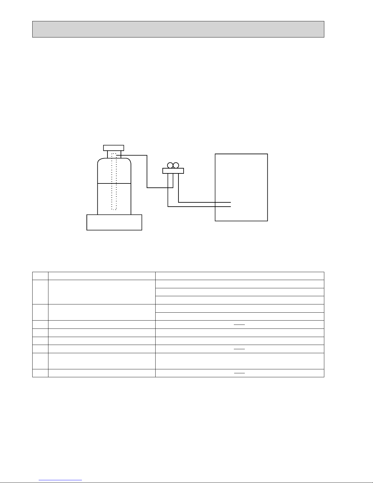
[2] Additional refrigerant charge
When charging directly from cylinder
· Check that cylinder for R410A on the market is syphon type.
· Charging should be performed with the cylinder of syphon stood vertically. (Refrigerant is charged from liquid phase.)
OCH533
A
5
2-3. PRECAUTIONS WHEN REUSING EXISTING R22 REFRIGERANT PIPES
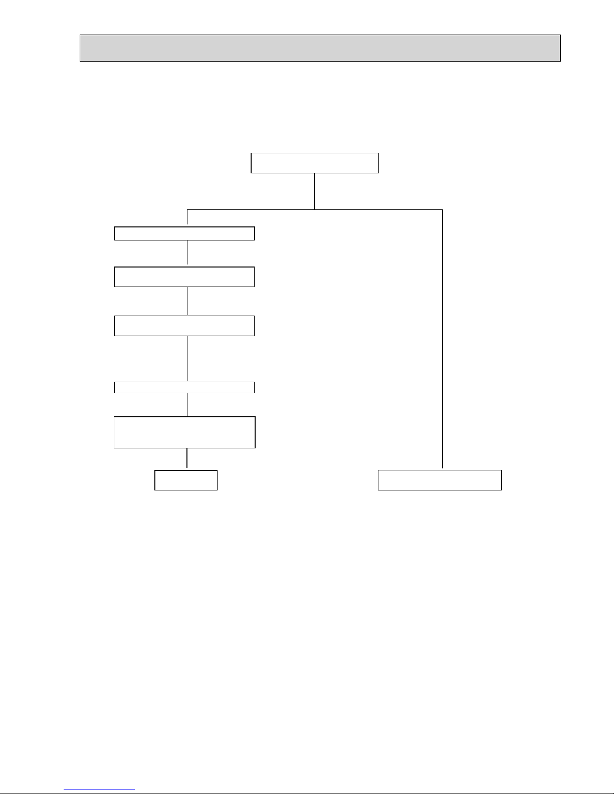
Flowchart
Perform the airtight test, vacuum air purging,
additional refrigerant charging (if necessary),
and gas leak check.
• Refer to the fl owchart below to determine if the existing pipes can be used and if it is necessary to use a fi lter dryer.
• If the diameter of the existing pipes is different from the specifi ed diameter, refer to technological data materials to confi rm if the pipes can be used.
Measure the existing pipe thickness and
check for damage.
The existing pipe thickness meets specifi cations and the pipes are not damaged.
Check if the existing outdoor unit can operate.
After operating the cooling system for about 30
minutes, do a pump down work.
Disconnect the existing outdoor unit from the
pipes.
Attach the new outdoor unit
Test run
* Refer to 10-2. TEST POINT UNDER TEST RUN.
The existing pipes cannot be reused.
Use new pipes.
* If the existing outdoor unit cannot operate, use
a refrigerant recovery device to collect the refrigerant.
Use new pipes for SW75, SW100 and SW120 models.
The existing pipe thickness does not meet
specifi cations or the pipes are damaged.
2-4. PRECAUTIONS FOR SALT PROOF TYPE "-BS" MODEL
Although "-BS" model has been designed to be resistant to salt damage, observe the following precautions to maintain the
performance of the unit.
1. Avoid installing the unit in a location where it will be exposed directly to seawater or sea breeze.
2. If the cover panel may become covered with salt, be sure to install the unit in a location where the salt will be washed away
by rainwater. (If a sunshade is installed, rainwater may not clean the panel.)
3. To ensure that water does not collect in the base of the outdoor unit, make sure that the base is level, not at angle. Water
collecting in the base of the outdoor unit could cause rust.
4. If the unit is installed in a coastal area, clean the unit with water regularly to remove any salt build-up.
5. If the unit is damaged during installation or maintenance, be sure to repair it.
6. Be sure to check the condition of the unit regularly.
7. Be sure to install the unit in a location with good drainage.
OCH533
A
6
Cautions for refrigerant piping work
New refrigerant R410A is adopted for replacement inverter series. Although the refrigerant piping work for R410A is same
as for R22, exclusive tools are necessary so as not to mix with different kind of refrigerant. Furthermore as the working
pressure of R410A is 1.6 times higher than that of R22, their sizes of flared sections and flare nuts are different.
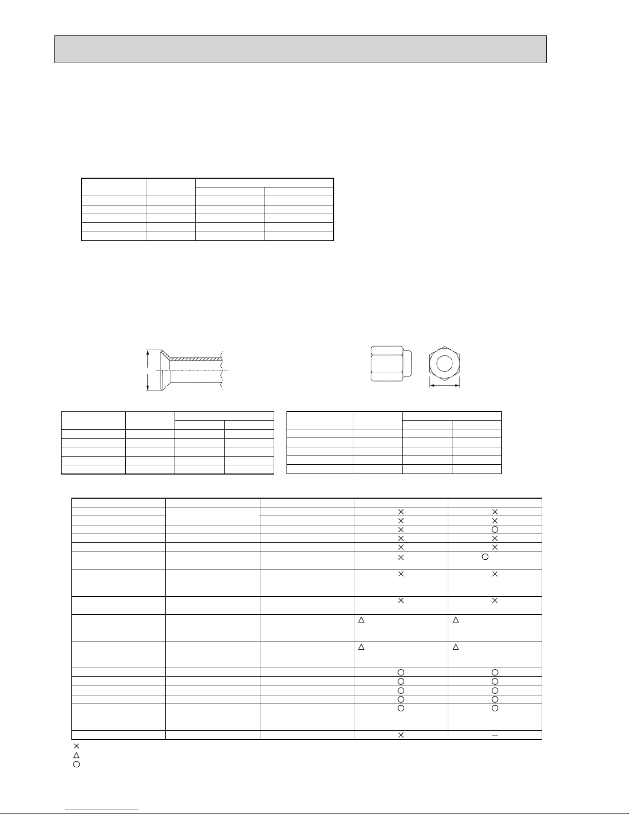
1 Thickness of pipes
Because the working pressure of R410A is higher compared to R22, be sure to use refrigerant piping with thickness
shown below. (Never use pipes of 0.7mm or below.)
2 Dimensions of flare cutting and flare nut
The component molecules in HFC refrigerant are smaller compared to conventional refrigerants. In addition to that,
R410A is a refrigerant, which has higher risk of leakage because its working pressure is higher than that of other refrigerants. Therefore, to enhance airtightness and intensity, flare cutting dimension of copper pipe for R410A has been
specified separately from the dimensions for other refrigerants as shown below. The dimension B of flare nut for R410A
also has partly been changed to increase intensity as shown below. Set copper pipe correctly referring to copper pipe
flaring dimensions for R410A below. For 1/2 and 5/8 inch, the dimension B changes.
Use torque wrench corresponding to each dimension.
3 Tools for R410A (The following table shows whether conventional tools can be used or not.)
1/4
3/8
1/2
5/8
3/4
6.35
9.52
12.70
15.88
19.05
0.8
0.8
0.8
1.0
—
0.8
0.8
0.8
1.0
1.0
Nominal
dimensions(inch)
Diagram below: Piping diameter and thickness
Outside
diameter
(mm)
Thickness
(mm)
R410A R22
1/4
3/8
1/2
5/8
3/4
6.35
9.52
12.70
15.88
19.05
9.1
13.2
16.6
19.7
—
9.0
13.0
16.2
19.4
23.3
Nominal
dimensions(inch)
Flare cutting dimensions
Outside
diameter
Dimension A
( )
+0
-0.4
(mm)
R410A R22
1/4
3/8
1/2
5/8
3/4
6.35
9.52
12.70
15.88
19.05
17.0
22.0
26.0
29.0
—
17.0
22.0
24.0
27.0
36.0
Nominal
dimensions(inch)
Flare nut dimensions
Outside
diameter
Dimension B
(mm)
R410A R22
Gauge manifold
Charge hose
Gas leak detector
Refrigerant recovery equipment
Refrigerant cylinder
Applied oil
Safety charger
Charge valve
Vacuum pump
Flare tool
Bender
Pipe cutter
Welder and nitrogen gas cylinder
Refrigerant charging scale
Vacuum gauge or thermistor vacuum gauge and
vacuum valve
Charging cylinder
Air purge, refrigerant charge
and operation check
Gas leak check
Refrigerant recovery
Refrigerant charge
Apply to flared section
Prevent compressor malfunction
when charging refrigerant by
spraying liquid refrigerant
Prevent gas from blowing out
when detaching charge hose
Vacuum drying and air
purge
Flaring work of piping
Bend the pipes
Cut the pipes
Weld the pipes
Refrigerant charge
Check the degree of vacuum. (Vacuum
valve prevents back flow of oil and refrigerant to thermistor vacuum gauge)
Refrigerant charge
Tool exclusive for R410A
Tool exclusive for R410A
Tool for HFC refrigerant
Tool exclusive for R410A
Tool exclusive for R410A
Ester oil and alkylbenzene
oil (minimum amount)
Tool exclusive for R410A
Tool exclusive for R410A
Tools for other refrigerants can
be used if equipped with adopter for reverse flow check
Tools for other refrigerants
can be used by adjusting
flaring dimension
Tools for other refrigerants can be used
Tools for other refrigerants can be used
Tools for other refrigerants can be used
Tools for other refrigerants can be used
Tools for other refrigerants
can be used
Tool exclusive for R410A
Tools and materials Use R410A tools Can R22 tools be used?
(Usable if equipped
with adopter for rever se flow)
(Usable by adjusting
flaring dimension)
Can R407C tools be used?
Ester oil:
Alkylbenzene oil: minimum amount
(Usable if equipped
with adopter for rever se flow)
(Usable by adjusting
flaring dimension)
: Prepare a new tool. (Use the new tool as the tool exclusive for R410A.)
: Tools for other refrigerants can be used under certain conditions.
: Tools for other refrigerants can be used.
Dimension A
Dimension B
OCH533
A
7
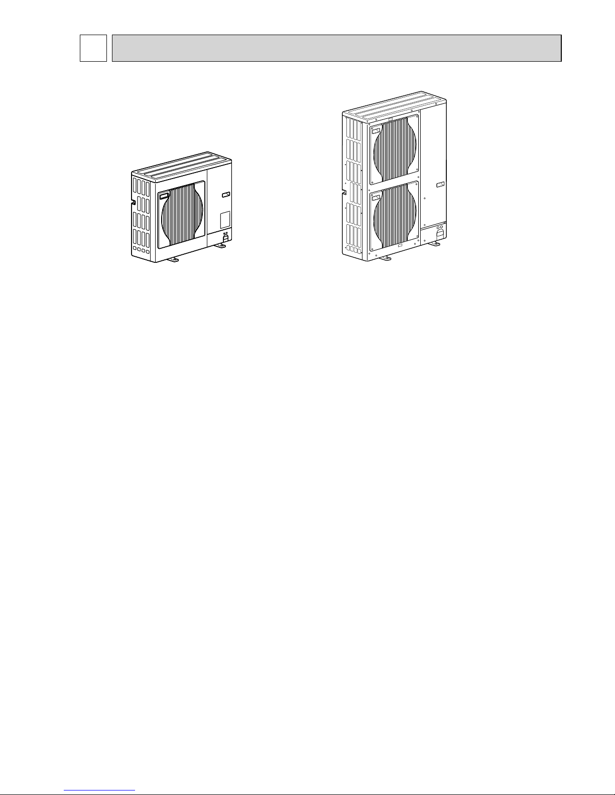
3 FEATURES
PUHZ-SW75VHA.UK
PUHZ-SW75VHA-BS.UK
CHARGELESS SYSTEM
PRE-CHARGED REFRIGERANT IS SUPPLIED FOR PIPING LENGTH AT SHIPMENT.
(Max. 10m (PUHZ-SW75-120))
The refrigerant circuit with LEV (Linear Expansion Valve) and Accumulator always control the optimal refrigerant level regardless
of the length (10m max. and 5m min.) of piping. The additional refrigerant charging work during installation often causes problems. Heretofore it is completely eliminated. This unique system improves the quality and reliability of the work done. It also helps
to speed up the installation time.
PUHZ-SW100VHA.UK
PUHZ-SW100VHA-BS.UK
PUHZ-SW100YHA.UK
PUHZ-SW100YHA-BS.UK
PUHZ-SW120VHA.UK
PUHZ-SW120VHA-BS.UK
PUHZ-SW120YHA.UK
PUHZ-SW120YHA-BS.UK
OCH533
A
8
4 SPECIFICATIONS
<Reference data> Plate heat exchanger (ACH70-40 plates)
Nominal water fl ow L/min 22.9
Heating
(A7/W35)
Capacity kW 8.00
COP 4.40
Power input kW 1.82
Heating
(A7/W45)
Capacity kW 8.00
COP 3.40
Power input kW 2.35
Heating
(A2/W35)
Capacity kW 7.50
COP 3.40
Power input kW 2.20
Heating
(A2/W45)
Capacity kW 7.50
COP 2.83
Power input kW 2.65
Nominal water fl ow L/min 18.9
Cooling
(A35/W7)
Capacity kW 6.60
EER 2.55
Power input kW 2.59
Cooling
(A35/W18)
Capacity kW 7.10
EER 4.01
Power input kW 1.77
Rating conditions
Nominal operating condition
Heating (A7/W35)
Outside air temperature (Dry-bulb) + 7 °C
Outside air temperature (Wet-bulb) + 6 °C
Water temperature (inlet/outlet) + 30 °C/+ 35 °C
Heating (A7/W45)
Outside air temperature (Dry-bulb) + 7 °C
Outside air temperature (Wet-bulb) + 6 °C
Water temperature (inlet/outlet) + 40 °C/+ 45 °C
Heating (A2/W35)
Outside air temperature (Dry-bulb) + 2 °C
Outside air temperature (Wet-bulb) + 1 °C
Water temperature (inlet/outlet) + 30 °C/+ 35 °C
Heating (A2/W45)
Outside air temperature (Dry-bulb) + 2 °C
Outside air temperature (Wet-bulb) + 1 °C
Water temperature (inlet/outlet) + 40 °C/+ 45 °C
Cooling (A35/W7)
Outside air temperature (Dry-bulb) + 35 °C
Outside air temperature (Wet-bulb) + 24 °C
Water temperature (inlet/outlet) + 12 °C/+ 7 °C
Cooling (A35/W18)
Outside air temperature (Dry-bulb) + 35 °C
Outside air temperature (Wet-bulb) + 24 °C
Water temperature (inlet/outlet) + 23 °C/+ 18 °C
Note: "COP" and "Power input" in the above table are values
that does NOT contains the "pump input (based on EN 14511)".
Nominal water fl ow L/min 32.1
Heating
(A7/W35)
Capacity kW 11.2
COP 4.45
Power input kW 2.51
Heating
(A7/W45)
Capacity kW 11.2
COP 3.42
Power input kW 3.27
Heating
(A2/W35)
Capacity kW 10.0
COP 3.32
Power input kW 3.02
Heating
(A2/W45)
Capacity kW 10.0
COP 2.66
Power input kW 3.76
Nominal water fl ow L/min 26.1
Cooling
(A35/W7)
Capacity kW 9.10
EER 2.75
Power input kW 3.31
Cooling
(A35/W18)
Capacity kW 10.0
EER 4.35
Power input kW 2.30
(SW75)
(SW100)
Nominal water fl ow L/min 45.9
Heating
(A7/W35)
Capacity kW 16.0
COP 4.10
Power input kW 3.90
Heating
(A7/W45)
Capacity kW 16.0
COP 3.23
Power input kW 4.95
Heating
(A2/W35)
Capacity kW 12.0
COP 3.24
Power input kW 3.70
Heating
(A2/W45)
Capacity kW 12.0
COP 2.52
Power input kW 4.76
Nominal water fl ow L/min 35.8
Cooling
(A35/W7)
Capacity kW 12.5
EER 2.32
Power input kW 5.38
Cooling
(A35/W18)
Capacity kW 14.0
EER 4.08
Power input kW 3.43
(SW120)
OCH533
A
9
A
kW
W
kW
*
/min(CFM
)
dB
dB
mm(in.)
mm(in.)
mm(in.)
kg(lbs)
kg(lbs)
L
mm(in.)
mm(in.)
Power supply (phase, cycle, voltage)
Max. current
External finish
Refrigerant control
Compressor
Model
Motor output
Starter type
Protection devices
Crankcase heater
Heat exchanger
Fan Fan(drive) % No.
Fan motor output
Airflow
Defrost method
Noise level
Dimensions
Weight
Refrigerant
Charge
Oil (Model)
Pipe size O.D.
Connection method
Between the indoor &
outdoor unit
Cooling
Heating
W
D
H
Liquid
Gas
Indoor side
Outdoor side
Height difference
Piping length
Service Ref.
PUHZ-SW75VHA-BS.UK
PUHZ-SW75VHA.UK
TNB220FLHMT
Propeller fan % 1
0.074
55(1,940)
48
51
943(37-1/8)
75(165)
3.2(7.0)
0.87(FV50S)
Max. 40m
Munsell 3Y 7.8/1.1
Linear Expansion Valve
Hermetic
Inverter
—
Plate fin coil
Reverse cycle
950(37-3/8)
330+30(13+1-3/16)
R410A
9.52(3/8)
15.88(5/8)
Flared
Flared
Max. 10m
HP switch
Comp. surface thermo
Discharge thermo
Over current detection
Single, 50Hz, 230V
OUTDOOR UNIT
REFRIGERANT PIPING
1.3
19
A
kW
W
kW
*
/min(CFM
)
dB
dB
mm(in.)
mm(in.)
mm(in.)
kg(lbs)
kg(lbs)
L
mm(in.)
mm(in.)
Power supply (phase, cycle, voltage)
Max. current
External finish
Refrigerant control
Compressor
Model
Motor output
Starter type
Protection devices
Crankcase heater
Heat exchanger
Fan Fan(drive) % No.
Fan motor output
Airflow
Defrost method
Noise level
Dimensions
Weight
Refrigerant
Charge
Oil (Model)
Pipe size O.D.
Connection method
Between the indoor &
outdoor unit
Cooling
Heating
W
D
H
Liquid
Gas
Indoor side
Outdoor side
Height difference
Piping length
Service Ref.
PUHZ-SW100VHA-BS.UK
50
54
Munsell 3Y 7.8/1.1
Linear Expansion Valve
Hermetic
Inverter
—
Plate fin coil
Propeller fan % 2
0.060+0.060
100(3,530)
Reverse cycle
950(37-3/8)
330+30(13+1-3/16)
1,350(53-1/8)
118(260)
R410A
4.6(10.1)
1.40(FV50S)
9.52(3/8)
15.88(5/8)
Flared
Flared
Max. 30m
Max. 75m
29.5
HP switch
LP switch
Discharge thermo
Comp. surface thermo
Over current detection
Single 50Hz, 230V
OUTDOOR UNIT
REFRIGERANT PIPING
51
54
ANB42FNEMT
2.5
ANB33FNEMT
2.5
PUHZ-SW120VHA-BS.UK
PUHZ-SW100VHA.UK
PUHZ-SW120VHA.UK
OCH533
A
10
3 phase, 50Hz, 400V
13
Munsell 3Y 7.8/1.1
Linear Expansion Valve
Hermetic
Inverter
—
Plate fin coil
Propeller fan % 2
0.060+0.060
100(3,530)
Reverse cycle
950(37-3/8)
330+30(13+1-3/16)
1,350(53-1/8)
130(287)
R410A
4.6(10.1)
1.40(FV50S)
9.52(3/8)
15.88(5/8)
Flared
Flared
Max. 30m
Max. 75m
PUHZ-SW100YHA-BS.UK
PUHZ-SW120YHA-BS.UK
PUHZ-SW100YHA.UK
PUHZ-SW120YHA
A
kW
W
kW
*
/min(CFM
)
dB
dB
mm(in.)
mm(in.)
mm(in.)
kg(lbs)
kg(lbs)
L
mm(in.)
mm(in.)
Power supply (phase, cycle, voltage)
Max. current
External finish
Refrigerant control
Compressor
Model
Motor output
Starter type
Protection devices
Crankcase heater
Heat exchanger
Fan Fan(drive) % No.
Fan motor output
Airflow
Defrost method
Noise level
Dimensions
Weight
Refrigerant
Charge
Oil (Model)
Pipe size O.D.
Connection method
Between the indoor &
outdoor unit
Cooling
Heating
W
D
H
Liquid
Gas
Indoor side
Outdoor side
Height difference
Piping length
Service Ref.
OUTDOOR UNIT
REFRIGERANT PIPING
ANB33FNDMT
2.5
ANB42FNDMT
2.5
HP switch
LP switch
Discharge thermo
Comp.surface thermo
Over current detection
49
51
50
52
OCH533
A
11
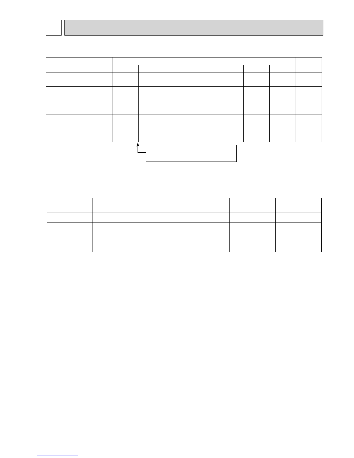
5 DATA
5-1. REFILLING REFRIGERANT CHARGE (R410A : kg)
5-2. COMPRESSOR TECHNICAL DATA
Service Ref.
Piping length (one way)
Initial
charged
10m 20m 30m 40m 50m 60m 75m
PUHZ-SW75VHA.UK
PUHZ-SW75VHA-BS.UK
3.2 3.6 4.0 4.6 — — — 3.2
PUHZ-SW100VHA.UK
PUHZ-SW100VHA-BS.UK
PUHZ-SW100YHA.UK
PUHZ-SW100YHA-BS.UK
4.6 4.8 5.0 5.6 6.2 6.8 7.5 4.6
PUHZ-SW120VHA.UK
PUHZ-SW120VHA-BS.UK
PUHZ-SW120YHA.UK
PUHZ-SW120YHA-BS.UK
4.6 4.8 5.0 5.6 6.2 6.8 7.5 4.6
U-V
U-W
W-V
Service Ref.
Compressor model
Winding
Resistance
( )
ANB33FNEMT
(at 20°C)
0.19
0.19
0.19
PUHZ-SW100VHA.UK
PUHZ-SW100VHA-BS.UK
ANB33FNDMT
0.30
0.30
0.30
ANB42FNDMTANB42FNEMT
0.30
0.30
0.30
PUHZ-SW100YHA.UK
PUHZ-SW100YHA-BS.UK
TNB220FLHMT
0.88
0.88
0.88
PUHZ-SW75VHA.UK
PUHZ-SW75VHA-BS.UK
PUHZ-SW120YHA.UK
PUHZ-SW120YHA-BS.UK
PUHZ-SW120VHA.UK
PUHZ-SW120VHA-BS.UK
0.19
0.19
0.19
Additional charge is required for pipes
longer than 10 m.
OCH533
A
12
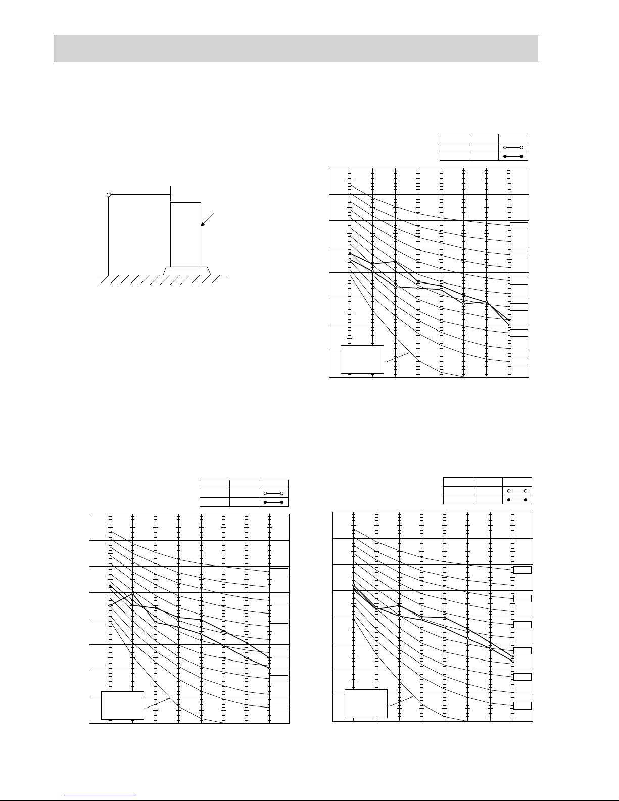
5-3. NOISE CRITERION CURVES
1.5m
1m
MICROPHONE
UNIT
GROUND
90
80
70
60
50
40
30
20
10
63 125 250 500 1000 2000 4000 8000
APPROXIMATE
THRESHOLD OF
HEARING FOR
CONTINUOUS
NOISE
NC-60
NC-50
NC-40
NC-30
NC-20
NC-70
OCTAVE BAND SOUND PRESSURE LEVEL, dB (0 dB = 0.0002 bar)
BAND CENTER FREQUENCIES, Hz
PUHZ-SW75VHA.UK
PUHZ-SW75VHA-BS.UK
COOLING
MODE
HEATING
48
SPL(dB)
51
LINE
90
80
70
60
50
40
30
20
10
63 125 250 500 1000 2000 4000 8000
APPROXIMATE
THRESHOLD OF
HEARING FOR
CONTINUOUS
NOISE
OCTAVE BAND SOUND PRESSURE LEVEL, dB (0 dB = 0.0002 bar)
NC-60
NC-50
NC-40
NC-30
NC-20
NC-70
PUHZ-SW100VHA.UK
PUHZ-SW100VHA-BS.UK
PUHZ-SW100YHA.UK
PUHZ-SW100YHA-BS.UK
COOLING
MODE
HEATING
50
SPL(dB)
54
LINE
90
80
70
60
50
40
30
20
10
63 125 250 500 1000 2000 4000 8000
APPROXIMATE
THRESHOLD OF
HEARING FOR
CONTINUOUS
NOISE
OCTAVE BAND SOUND PRESSURE LEVEL, dB (0 dB = 0.0002 bar)
NC-60
NC-50
NC-40
NC-30
NC-20
NC-70
PUHZ-SW120VHA.UK
PUHZ-SW120VHA-BS.UK
PUHZ-SW120YHA.UK
PUHZ-SW120YHA-BS.UK
COOLING
MODE
HEATING
51
SPL(dB)
54
LINE
OCH533
A
 Loading...