

Mitsubishi PUHZ-SP100YKA, PUHZ-SP125VKA.TH, PUHZ-SP125YKA, PUHZ-SP125YKA.TH, PUHZ-SP140YKA.TH Service Manual
...
SERVICE MANUAL
No.OCH671
SPLIT-TYPE AIR CONDITIONERS
R410A
September 2017
PARTS CATALOG (OCB671)
CONTENTS
1. REFERENCE MANUAL ···························· 2
2. SAFETY PRECAUTION ···························· 2
3. SPECIFICATIONS ··································· 6
4. DATA ····················································7
5. OUTLINES AND DIMENSIONS ················ 10
6. WIRING DIAGRAM ································ 11
7. WIRING SPECIFICATIONS ····················· 13
8.
REFRIGERANT SYSTEM DIAGRAM
·········· 18
9. TROUBLESHOOTING ···························· 20
10. FUNCTION SETTING ····························· 77
11.
MONITORING THE OPERATION DATA BY THE REMOTE CONTROLLER
····89
12. EASY MAINTENANCE FUNCTION ··········· 99
13. DISASSEMBLY PROCEDURE ················103
Outdoor unit
[Model Name]
PUHZ-SP125VKA
PUHZ-SP140VKA
PUHZ-SP100YKA
PUHZ-SP125YKA
PUHZ-SP140YKA
[Service Ref.]
PUHZ-SP125VKA.TH
PUHZ-SP140VKA.TH
PUHZ-SP100YKA.TH
PUHZ-SP125YKA.TH
PUHZ-SP140YKA.TH
2
OCH671
2-1. ALWAYS OBSERVE FOR SAFETY
Before obtaining access to terminal, all supply circuits must be disconnected.
INDOOR UNIT SERVICE MANUAL
Model name Service Ref.
Service
Manual No.
PLA-SM71/100/125/140EA* PLA-SM71/100/125/140EA.UK
OCH683
OCB683
PEAD-SM71/100/125/140JA(L) PEAD-SM71/100/125/140JA(L).UK —
* These models will be released on Dec/2017.
2
SAFETY PRECAUTION
2-2. CAUTIONS RELATED TO NEW REFRIGERANT
Cautions for units utilizing refrigerant R410A
Preparation before the repair service.
• Prepare the proper tools.
• Prepare the proper protectors.
• Provide adequate ventilation.
• After stopping the operation of the air conditioner, turn off
the power-supply breaker.
• Discharge the condenser before the work involving the
electric parts.
Precautions during the repair service.
• Do not perform the work involving the electric parts
with wet hands.
• Do not pour water into the electric parts.
• Do not touch the refrigerant.
• Do not touch the hot or cold areas in the refrigerating cycle.
• When the repair or the inspection of the circuit needs to be
done without turning off the power, exercise great caution
not to touch the live parts.
1
REFERENCE MANUAL
3
OCH671
[1] Cautions for service
(1) Perform service after recovering the refrigerant left in unit completely.
(2) Do not release refrigerant in the air.
(3) After completing service, charge the cycle with specified amount of refrigerant.
(4) If moisture or foreign matter might have entered the refrigerant piping during the service, ensure to remove them.
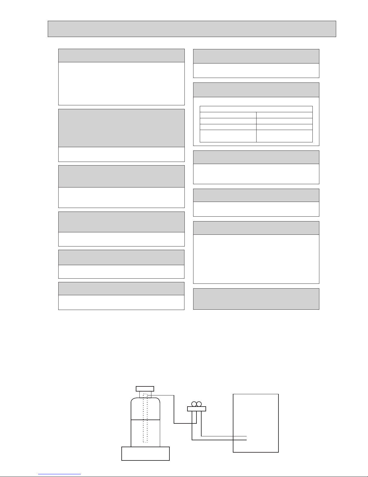
[2] Additional refrigerant charge
When charging directly from cylinder
(1) Check that cylinder for R410A on the market is syphon type.
(2) Charging should be performed with the cylinder of syphon stood vertically. (Refrigerant is charged from liquid phase.)
Electronic weighing scale
Unit
Make sure that the inside and outside of refrigerant piping is clean and it has no contaminants
such as sulfur, oxides, dirt, shaving particles, etc,
which are hazard to refrigerant cycle.
In addition, use pipes with specified thickness.
Contamination inside refrigerant piping can cause deterioration of refrigerant oil, etc.
Store the piping indoors, and both ends of the
piping sealed until just before brazing.
(Leave elbow joints, etc. in their packaging.)
If dirt, dust or moisture enters into refrigerant cycle, that can
cause deterioration of refrigerant oil or malfunction of compressor.
The refrigerant oil applied to flare and flange
connections must be ester oil, ether oil or
alkylbenzene oil in a small amount.
If large amount of mineral oil enters, that can cause deterioration of refrigerant oil, etc.
Use a vacuum pump with a reverse flow check
valve.
Vacuum pump oil may flow back into refrigerant cycle and
that can cause deterioration of refrigerant oil, etc.
Charge refrigerant from liquid phase of gas
cylinder.
If the refrigerant is charged from gas phase, composition change
may occur in refrigerant and the efficiency will be lowered.
Use new refrigerant pipes.
In case of using the existing pipes for R22, be careful with
the following.
• Be sure to clean the pipes and make sure that the insides
of the pipes are clean.
• Change flare nut to the one provided with this product.
Use a newly flared pipe.
• Avoid using thin pipes.
Do not use refrigerant other than R410A.
If other refrigerant (R22, etc.) is used, chlorine in refrigerant can cause deterioration of refrigerant oil, etc.
Handle tools with care.
If dirt, dust or moisture enters into refrigerant cycle, that can
cause deterioration of refrigerant oil or malfunction of compressor.
Do not use a charging cylinder.
If a charging cylinder is used, the composition of refrigerant will change and the efficiency will be lowered.
Use the following tools specifically designed for
use with R410A refrigerant.
The following tools are necessary to use R410A refrigerant.
Flare tool
Electronic refrigerant
charging scale
Vacuum pump adaptor
Size adjustment gauge
Gauge manifold
Torque wrench
Gas leak detector
Charge hose
Tools for R410A
Ventilate the room if refrigerant leaks during
operation. If refrigerant comes into contact with
a flame, poisonous gases will be released.
Never use any refrigerant other than that specified.
Doing so may cause a burst, an explosion, or fire when the
unit is being used, serviced, or disposed of.
Correct refrigerant is specified in the manuals and on the
spec labels provided with our products.
We will not be held responsible for mechanical failure,
system malfunction, unit breakdown or accidents caused
by failure to follow the instructions.
Use the specified refrigerant only.
4
OCH671
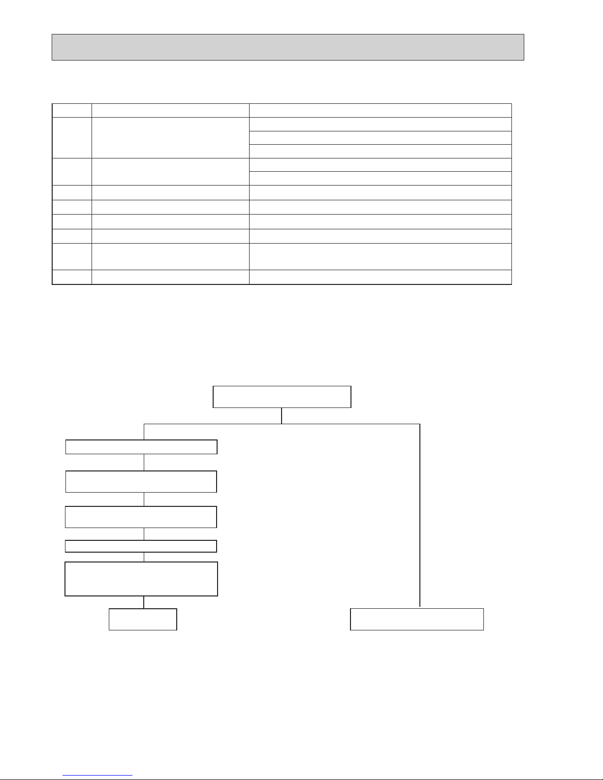
2-3. PRECAUTIONS WHEN REUSING EXISTING R22 REFRIGERANT PIPES
(1) Flowchart
[3] Service tools
Use the below service tools as exclusive tools for R410A refrigerant.
No. Tool name Specifications
1
Gauge manifold • Only for R410A
• Use the existing fitting
specifications
. (UNF1/2)
• Use high-tension side pressure of 5.3MPa·G or over.
2
Charge hose • Only for R410A
• Use pressure performance of 5.09MPa·G or over.
3
Electro
nic weighing s
cale
—
4
Gas leak detector
• Use the detector for R134a, R407C or R410A.
5
Adaptor for reverse flow check
• Attach on vacuum pump.
6
Refrigerant charge base
—
7
Refrigerant cylinder • Only for R410A · Top of cylinder (Pink)
• Cylinder with syphon
8
Refrigerant recovery equipment
—
Perform the airtight test, vacuum air purging,
additional refrigerant charging (if necessary),
and gas leak check.
• Refer to the owchart below to determine if the existing pipes can be used and if it is necessary to use a lter dryer.
• If the diameter of the existing pipes is different from the specied diameter, refer to technological data materials to conrm if
the pipes can be used.
▼
▼
▼
▼
▼
▼
▼
Measure the existing pipe thickness and
check for damage.
The existing pipe thickness meets specications and the pipes are not damaged.
Check if the existing air conditioner can operate.
After operating the cooling system for about 30
minutes, do a pump down work.
Disconnect the existing air conditioner from the
pipes.
Attach the new air conditioner
Test run
The existing pipes cannot be reused.
Use new pipes.
Note:
If the existing air conditioner cannot operate, use a
refrigerant recovery device to collect the refrigerant.
Note:
In case existing pipes were used for gas or oil heat
pump systems, be sure to clean the pipes.
The existing pipe thickness does not meet
specications or the pipes are damaged.
5
OCH671
(2) Cautions for refrigerant piping work
New refrigerant R410A is adopted for replacement inverter series. Although the refrigerant piping work for R410A is same
as for R22, exclusive tools are necessary so as not to mix with different kind of refrigerant. Furthermore as the working
pressure of R410A is 1.6 times higher than that of R22, their sizes of flared sections and flare nuts are different.
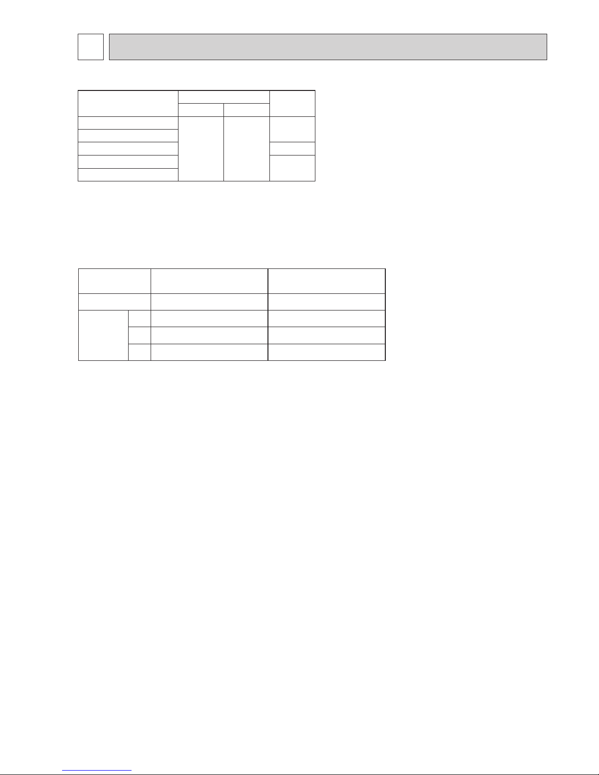
1 Thickness of pipes
Because the working pressure of R410A is higher compared to R22, be sure to use refrigerant piping with thickness
shown below. (Never use pipes of 0.7 mm or below.)
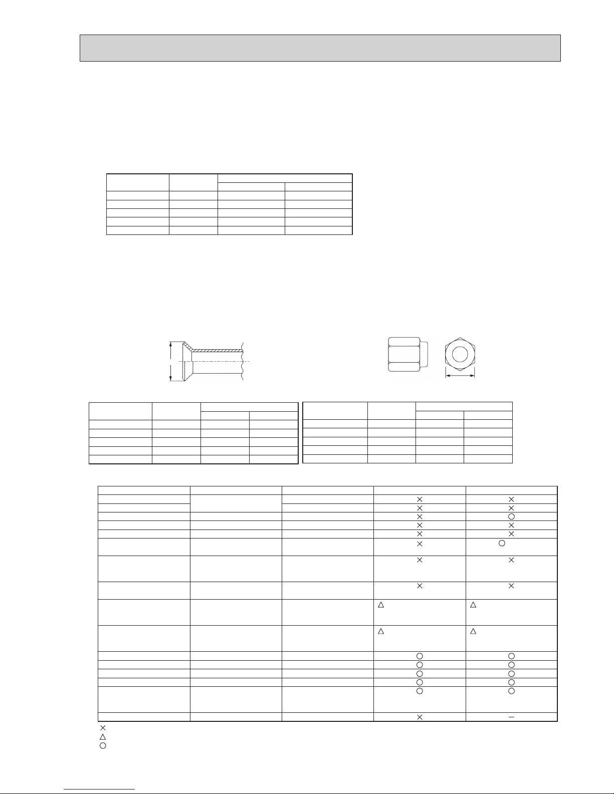
2 Dimensions of flare cutting and flare nut
The component molecules in HFC refrigerant are smaller compared to conventional refrigerants. In addition to that,
R410A is a refrigerant, which has higher risk of leakage because its working pressure is higher than that of other refrigerants. Therefore, to enhance airtightness and strength, flare cutting dimension of copper pipe for R410A has been specified separately from the dimensions for other refrigerants as shown below. The dimension B of flare nut for R410A also
has partly been changed to increase strength as shown below. Set copper pipe correctly referring to copper pipe flaring
dimensions for R410A below. For 1/2 and 5/8 inch pipes, the dimension B changes.
Use torque wrench corresponding to each dimension.
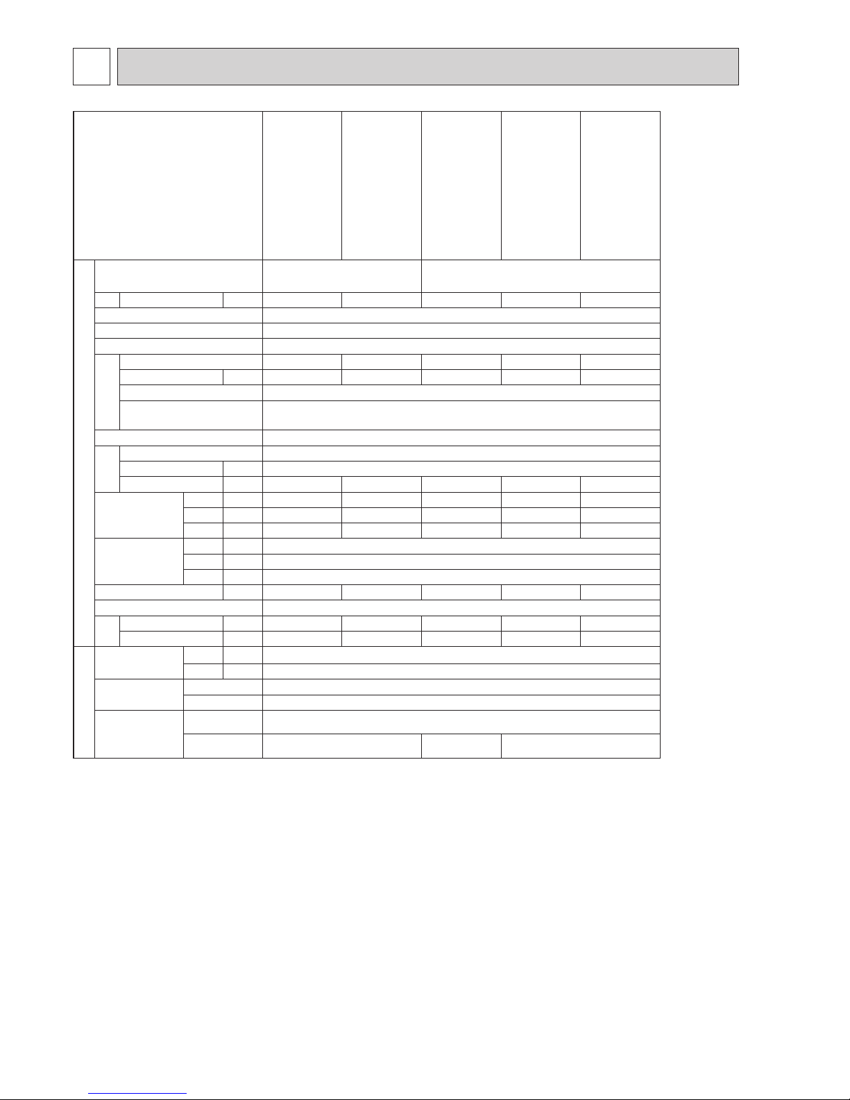
3 Tools for R410A (The following table shows whether conventional tools can be used or not.)
1/4
3/8
1/2
5/8
3/4
6.35
9.52
12.70
15.88
19.05
0.8
0.8
0.8
1.0
—
0.8
0.8
0.8
1.0
1.0
Nominal
dimensions(inch)
Diagram below: Piping diameter and thickness
Outside
diameter
(mm)
Thickness
(mm)
R410A R22
1/4
3/8
1/2
5/8
3/4
6.35
9.52
12.70
15.88
19.05
9.1
13.2
16.6
19.7
—
9.0
13.0
16.2
19.4
23.3
Nominal
dimensions(inch)
Flare cutting dimensions
Outside
diameter
Dimension A
( )
+0
-0.4
(mm)
R410A R22
(mm)
1/4
3/8
1/2
5/8
3/4
6.35
9.52
12.70
15.88
19.05
17.0
22.0
26.0
29.0 *
—
17.0
22.0
24.0
27.0
36.0
Nominal
dimensions(inch)
Flare nut dimensions
Outside
diameter
Dimension B
R410A
* 36.0mm for
indoor unit
R22
(mm)
(mm)
Gauge manifold
Charge hose
Gas leak detector
Refrigerant recovery equipment
Refrigerant cylinder
Applied oil
Safety charger
Charge valve
Vacuum pump
Flare tool
Bender
Pipe cutter
Welder and nitrogen gas cylinder
Refrigerant charging scale
Vacuum gauge or thermistor vacuum gauge and
vacuum valve
Charging cylinder
Air purge, refrigerant charge
and operation check
Gas leak check
Refrigerant recovery
Refrigerant charge
Apply to flared section
Prevent compressor malfunction
when charging refrigerant by
spraying liquid refrigerant
Prevent gas from blowing out
when detaching charge hose
Vacuum drying and air
purge
Flaring work of piping
Bend the pipes
Cut the pipes
Weld the pipes
Refrigerant charge
Check the degree of vacuum. (Vacuum
valve prevents back flow of oil and refrigerant to thermistor vacuum gauge)
Refrigerant charge
Tool exclusive for R410A
Tool exclusive for R410A
Tool for HFC refrigerant
Tool exclusive for R410A
Tool exclusive for R410A
Ester oil and alkylbenzene
oil (minimum amount)
Tool exclusive for R410A
Tool exclusive for R410A
Tools for other refrigerants can
be used if equipped with adapter for reverse flow check
Tools for other refrigerants
can be used by adjusting
flaring dimension
Tools for other refrigerants can be used
Tools for other refrigerants can be used
Tools for other refrigerants can be used
Tools for other refrigerants can be used
Tools for other refrigerants
can be used
Tool exclusive for R410A
Tools and materials Use R410A tools Can R22 tools be used?
(Usable if equipped
with adapter for rever se flow)
(Usable by adjusting
flaring dimension)
Can R407C tools be used?
Ester oil:
Alkylbenzene oil: minimum amount
(Usable if equipped
with adapter for rever se flow)
(Usable by adjusting
flaring dimension)
: Prepare a new tool. (Use the new tool as the tool exclusive for R410A.)
: Tools for other refrigerants can be used under certain conditions.
: Tools for other refrigerants can be used.
Dimension A
Dimension B
6
OCH671
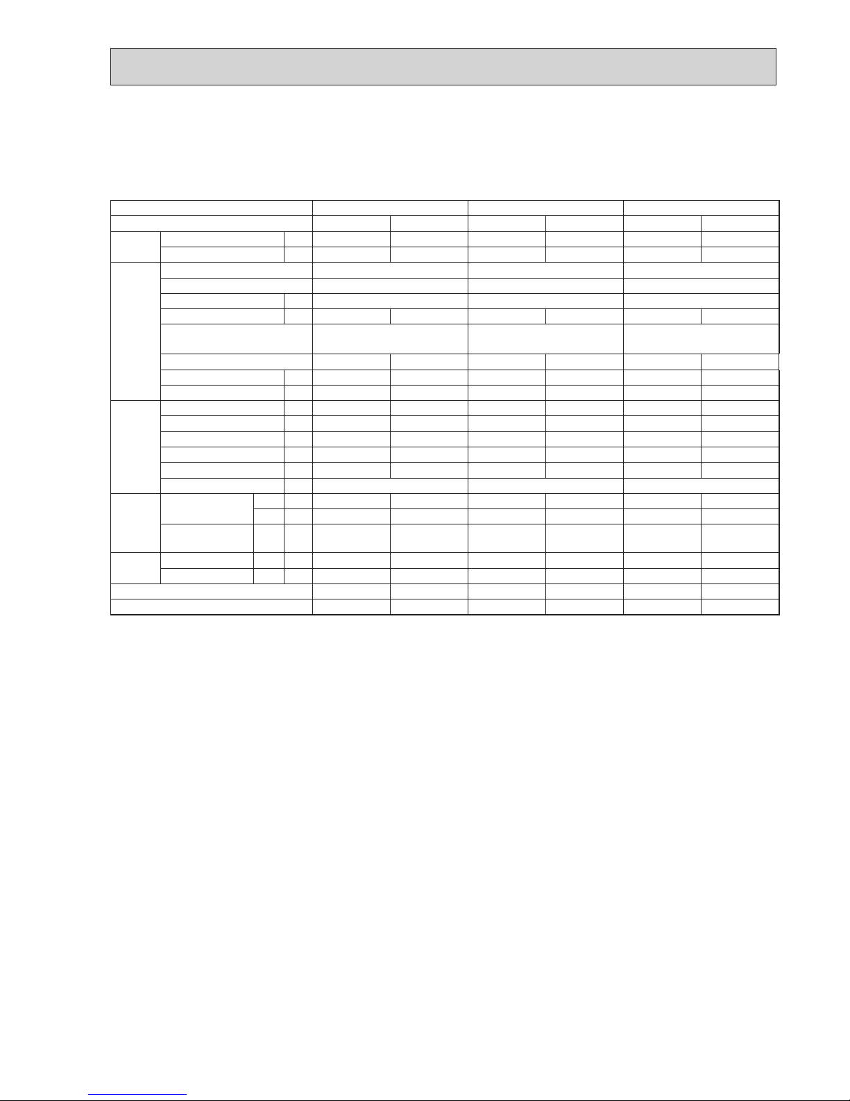
3 SPECIFICATIONS
Service Ref
PUHZ-SP125VKA.TH
PUHZ-SP140VKA.TH
PUHZ-SP100YKA.TH
PUHZ-SP125YKA.TH
PUHZ-SP140YKA.TH
Power supply
(phase,cycle,voltage)
Single phase, 50 Hz, 230 V 3-phase, 50 Hz, 400 V
Max. current A 26.5 30 11.5 11.5 11.5
External nish Munsell 3Y 7.8/1.1
Refrigerant control Linear Expansion Valve
Compressor Hermetic
Model
MNB33FBDMC-L MNB33FBDMC-L SNB220GBAMT MNB33FBDMC-L MNB33FBDMC-L
Motor output kW 2.5 2.5 1.5 2.5 2.5
Starter type Direct input
Protection devices Shell thermistor
H.P. switch
Heat exchanger Plate n coil
Fan Fan(drive) x No. Propeller fan x 1
Fan motor output
kW 0.200
Air volume
K
/min
87 87 79 87 87
Noise level
Cooling
SPL(db)
54 56 51 54 56
Heating
SPL(db)
56 57 54 56 57
Cooling
SPL(db)
72 75 70 72 75
Dimensions W
mm(inch)
1,050 (41-5/16)
D
mm(inch)
330+25 (13+1)
H
mm(inch)
981 (38-5/8)
Weight kg 84 84 78 85 85
Refrigerant R410A
Charge kg 3.8 3.8 3.3 3.8 3.8
Oil (Model) cc 1100 (FV50S) 1100 (FV50S) 700 (FV50S) 1100 (FV50S) 1100 (FV50S)
REFRIGERANT PIPING
Pipe size O.D Liquid
mm(inch)
9.52 (3/8)
Gas
mm(inch)
15.88 (5/8)
Connection method
Indoor side Flared
Outdoor side Flared
Between the indoor
& Outdoor unit
Height difference
Maximum 30 m
Piping length
Maximum 40 m
Maximum 30 m
Maximum 40 m
7
OCH671
4 DATA
4-1. REFILLING REFRIGERANT CHARGE (R410A : kg)
0.88
0.88
0.88
0.95
0.95
0.95
MNB33FBDMC-L
PUHZ-SP125/140VKA.TH
Service Ref.
Compressor model
(at 20°C)
U-V
U-W
W-V
Winding
Resistance
( " )
PUHZ-SP125/140YKA.TH
PUHZ-SP100YKA.TH
SNB220FBAMT
Service Ref.
Piping length (one way)
Initial
charged
30m 40m
PUHZ-SP125VKA.TH
0 0.6
3.8
PUHZ-SP140VKA.TH
PUHZ-SP100YKA.TH 3.3
PUHZ-SP125YKA.TH
3.8
PUHZ-SP140YKA.TH
4-2. COMPRESSOR TECHNICAL DATA
8
OCH671
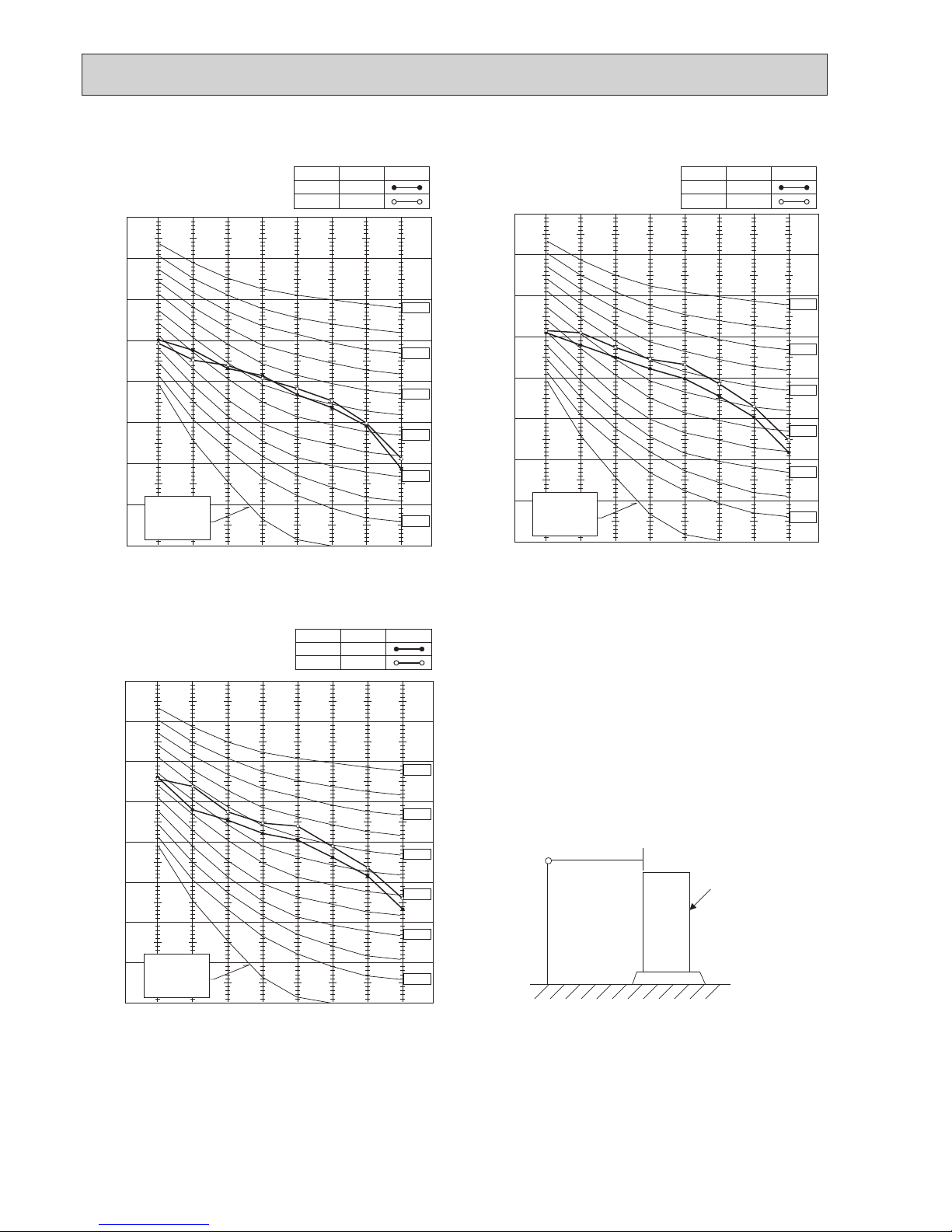
4-3. NOISE CRITERION CURVES
1.5m
1m
MICROPHONE
UNIT
GROUND
APPROXIMATE
THRESHOLD OF
HEARING FOR
CONTINUOUS
NOISE
NC-60
NC-50
NC-40
NC-30
NC-20
NC-70
90
80
70
60
50
40
30
20
10
63 125 250 500 1000 2000 4000 8000
BAND CENTER FREQUENCIES, Hz
OCTAVE BAND SOUND PRESSURE LEVEL, dB re 0.002 MICRO BAR
COOLING
HEATING
MODE
54
56
SPL(dB)
LINE
90
80
70
60
50
40
30
20
10
63 125 250 500 1000 2000 4000 8000
APPROXIMATE
THRESHOLD OF
HEARING FOR
CONTINUOUS
NOISE
NC-60
NC-50
NC-40
NC-30
NC-20
NC-70
BAND CENTER FREQUENCIES, Hz
OCTAVE BAND SOUND PRESSURE LEVEL, dB re 0.002 MICRO BAR
COOLING
HEATING
MODE
56
57
SPL(dB)
LINE
APPROXIMATE
THRESHOLD OF
HEARING FOR
CONTINUOUS
NOISE
NC-60
NC-50
NC-40
NC-30
NC-20
NC-70
90
80
70
60
50
40
30
20
10
63 125 250 500 1000 2000 4000 8000
BAND CENTER FREQUENCIES, Hz
OCTAVE BAND SOUND PRESSURE LEVEL, dB re 0.002 MICRO BAR
COOLING
HEATING
MODE
51
54
SPL(dB)
LINE
PUHZ-SP100YKA.TH PUHZ-SP125VKA.TH
PUHZ-SP125YKA.TH
PUHZ-SP140VKA.TH
PUHZ-SP140YKA.TH
9
OCH671
4-4. STANDARD OPERATION DATA
The unit of pressure has been changed to MPa based on international SI system.
The conversion factor is : 1(MPa)=10.2(kgf/cm²)
Representative matching PUHZ-SP100 PUHZ-SP125 PUHZ-SP140
Mode COOLING HEATING COOLING HEATING COOLING HEATING
Total Capacity W 9.4 11.2 12.1 13.5 13.6 15.0
input kW 3.29 3.48 4.23 4.18 5.63 4.81
Electrical
circuit
Indoor PLA-SM100EA.UK PLA-SM125EA.UK PLA-SM140EA.UK
Phase, Hz 1, 50 1, 50 1, 50
Voltage V 230 230 230
Current A 0.46 0.44 0.66 0.64 0.66 0.64
Outdoor PUHZ-SP100YKA PUHZ-SP125VKA
PUHZ-SP125YKA
PUHZ-SP140VKA
PUHZ-SP140YKA
Phase, Hz 1, 50 3, 50 1, 50 3, 50 1, 50 3, 50
Voltage V
230 400 230 400 230
400
Current A 14.0/5.0 14.0/5.0 18.0/6.5 17.5/6.5 23.5/9.0 20.5/7.5
Refrigerant
circuit
Discharge Pressure MPa 2.79 2.68 3.00 2.62 3.21 2.78
Suction pressure MPa 0.86 0.68 0.85 0.65 0.77 0.62
Discharge temperature
:
77.9 78.5 76.7 69.7 88.1 72.6
Condensing temperature
:
47.0 45.3 49.9 44.6 53.2 47.0
Suction temperature
:
12.6 3.0 7.5 −0.8 7.9 −2.0
Ref. pipe length m 7.5 7.5 7.5
Indoor
side
Intake air
temperature
DB
:
27 20 27 20 27 20
WB
:
19 14 19 14 19 14
Discharge air
temperature
DB
:
13.5 39.9 12.2 42.1 11.3 44.3
Outdoor
side
Intake air DB
:
35 7 35 7 35 7
temperature WB
:
24 6 24 6 24 6
SHF 0.77 — 0.73 — 0.70 —
BF 0.24 — 0.15 — 0.14 —
PUHZ-SP100YKA.TH
PUHZ-SP125VKA.TH PUHZ-SP125YKA.TH
PUHZ-SP140VKA.TH PUHZ-SP140YKA.TH
10
OCH671
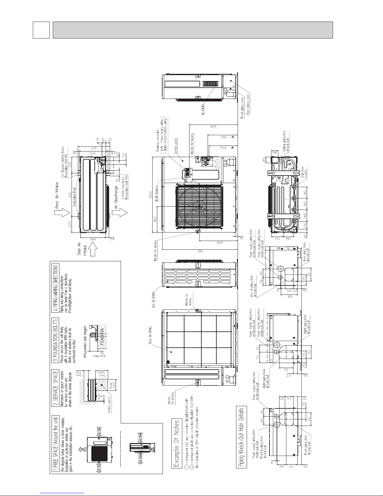
5 OUTLINES AND DIMENSIONS
Unit: mm
PUHZ-SP100YKA.TH
PUHZ-SP125VKA.TH PUHZ-SP125YKA.TH
PUHZ-SP140VKA.TH PUHZ-SP140YKA.TH

11
OCH671
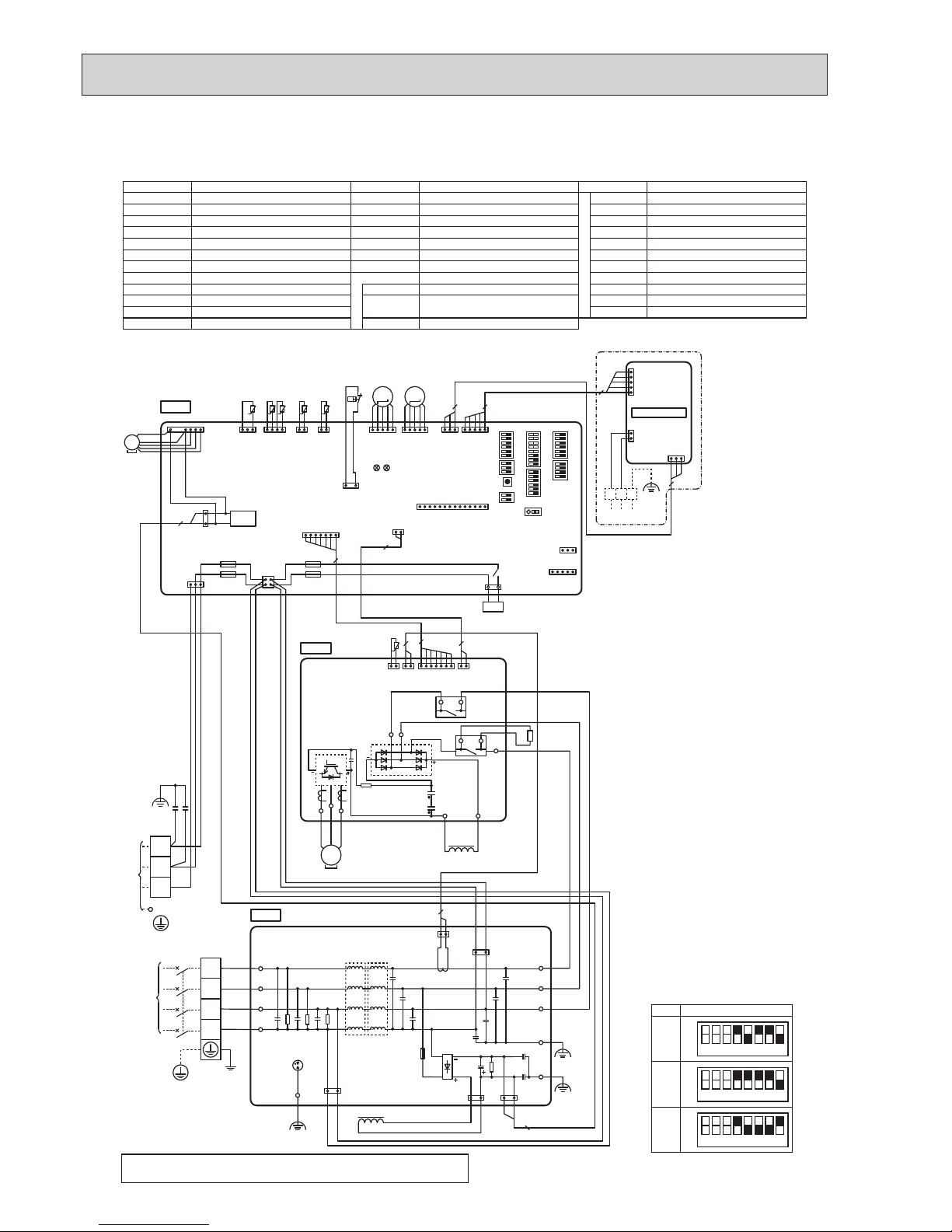
PUHZ-SP125VKA.TH
PUHZ-SP140VKA.TH
Terminal Block <Power Supply, Indoor/Outdoor>
Motor for Compressor
Fan Motor
High Pressure Switch
Thermistor <Liquid>
Thermistor <Discharge>
Thermistor <2-Phase Pipe>
Thermistor <Ambient>
Thermistor <Heat Sink>
Thermistor <Comp. Surface>
Linear Expansion Valve
21S4
DCL1, DCL2, DCL3
CY1, CY2
CX1
P.B.
C.B.
F1, F2, F3, F4
SW1
SW4
SW5
Solenoid Valve (4-Way Valve)
Reactor
Capacitor
Capacitor
Power Circuit Board
Controller Circuit Board
Fuse <T6.3AL250V>
Switch
<Manual Defrost, Defect History
Record Reset, Refrigerant Address>
Switch
<Function Switch>
Switch
<Function Switch>
SW6
SW7
SW8
SW9
SWP
CN31
CN51
CNDM
CNM
X52
Switch
<Model Select>
Switch <Function Switch>
Switch <Function Switch>
Switch <Function Switch>
Switch <Pump Down>
Connector <Emergency Operation>
Connector <Connection for Option>
Connector <Connection for Option>
Connector <Connection for Option>
Relay
SYMBOL
TB1
MC
MF1
63H
TH3
TH4
TH6
TH7
TH8
TH33
LEV-A, LEV-B
SYMBOL SYMBOLNAME NAME NAME
1 2 3 4 5 6 7 8
OFF
ON
1 2 3 4 5 6 7 8
OFF
ON
SW6-4, 5, 6, 7, 8 *2
MODEL
125V
140V
The black square (■) indicates a switch position.
*1. MODEL SELECT
*2. SW6-1 to 3: Function switch
P. B.
MS
3~
MC
CN6
(WH)
t°
2
1 2
CN4
(WH)
1 2
TH8
W
V
U
BK
WH
RD
W
V
U
IC600
CNDC
(PK)
1 3
2
CNAC2
(RD)
CNAC1
(WH)
LI NI
1 3 1 3
IC500
DS
E3E4 EI E2
BK
BK
BK
BK
CN2
(RD)
7
71
TB3B
TB1B
TB2B
TB1A
TB2A
TB3A
BK WH RD RD BKWH
DCL1
DCL2
DCL3
C. B.
TH6TH7 TH4TH3
t° t° t° t°
LEV-A
CNS
(WH)
CNAC
(WH)
CNDC
(PK)
F2
F1
F3
F4
TH7/6
(RD)
TH3
(WH)
TH4
(WH)
TRANS
CNVMNT
(WH)
CNMNT
(WH)
63H
(YE)
1 4 1 2 2 1
1 3
31 1
5
1
3
1
3
1 2
3
4
LEV-A
(WH)
51
21S4
(GN)
31
MS
3~
MF1
CNF1
(WH)
1
7
63H
LEV-B
(RD)
M
LEV-B
51
M
2
CNDM
(WH)
CN51
(WH)
31
51
31
TH33
(YE)
TH33
t°
When M-NET Adapter is connected
CN2M
(WH)
CN5
(WH)
CND
(WH)
M-NET
M-NET ADAPTER
5
1
5
1
2
13
3
3 5
CNM
(WH)
1 14
LED1
LED2
21S4
TB7
A B S
X52
L N S1 S2 S3
POWER SUPPLY
~/N 230V 50Hz
TB1
RD
BU
YE
OG
BN
GNYE
TO INDOOR
UNIT
CY1
CY2
CX1
CN2
(RD)
CN4
(WH)
2
7
1
1 7
2
Never splice the power cable or the indoor-outdoor connection cable, otherwise it may result in a smoke, a fire or communication failure.
*
1
SW5SW8SWP
SW4
SW1 SW6
SW9 SW7
CN31
6
WIRING DIAGRAM
12
OCH671
PUHZ-SP100YKA.TH
PUHZ-SP125YKA.TH
PUHZ-SP140YKA.TH
Terminal Block <Power Supply>
Terminal Block <Indoor/Outdoor>
Motor for Compressor
Fan Motor
High Pressure Switch
Thermistor <Liquid>
Thermistor <Discharge>
Thermistor <2-Phase Pipe>
Thermistor <Ambient>
Thermistor <Heat Sink>
Thermistor <Comp. Surface>
Linear Expansion Valve
21S4
ACL4
DCL
RS
CY1, CY2
P.B.
N.F.
C.B.
Solenoid Valve (4-Way Valve)
Reactor
Reactor
Resistor
Capacitor
Power Circuit Board
Noise Filter Circuit Board
Controller Circuit Board
Fuse <T6.3AL250V>
Switch
<Manual Defrost, Defect History
Record Reset, Refrigerant Address>
Switch <Function Switch>
SW5
SW6
SW7
SW8
SW9
SWP
CN31
CN51
CNDM
CNM
X52
F1, F2, F3, F4
S
W1
SW4
Switch
<Function Switch>
Switch
<Model Select>
Switch <Function Switch>
Switch <Function Switch>
Switch <Function Switch>
Switch <Pump Down>
Connector <Emergency Operation>
Connector <Connection for Option>
Connector <Connection for Option>
Connector <Connection for Option>
Relay
SYMBOL
TB1
TB2
MC
MF1
63H
TH3
TH4
TH6
TH7
TH8
TH33
LEV-A, LEV-B
SYMBOL SYMBOLNAME NAME NAME
1 2 3 4 5 6 7 8
OFF
ON
1 2 3 4 5 6 7 8
OFF
ON
SW6-4, 5, 6, 7, 8 *2
MODEL
100Y
1 2 3 4 5 6 7 8
OFF
ON
125Y
140Y
The black square (■) indicates a
switch position.
*1. MODEL SELECT
*2. SW6-1 to 3: Function switch
P.B.
U
POWER
SUPPLY
3N~
400V 50Hz
TB1
V
W
RDWHBK
MC
7
L1
L2
L3
N
N.F.
CNAC1
(WH)
13
CNDC
(PK)
13
CNL
(BU)
13
CNAC2
(RD)
13
CNCT
(RD)
1 2
LO1
LO2
LO3
EI
NI
LI1
LI2
LI3
E3
S1
S2
S3
2
RD
WH
BK
BU
RD
WH
BK
TB2
RD
WH
BK
YE
OG
BN
RD
GNYE
21S4
(GN)
31
21S4
X52
BK
E2
BKBK
TO INDOOR
UNIT
1 2
CN6
(WH)
1 2
CN5
(RD)
CN2
(RD)
1 7 1 2
CN4
(WH)
TB-U
TB-V
TB-W
L3IN
TB-L2
TB-L1
TH8
t°
RD
MS
3~
22
CY1
CY2
C. B.
TH6TH7 TH4
t° t° t°
CNS
(WH)
CNAC
(WH)
CNDC
(PK)
F2
F1
F3
F4
CN2
(RD)
CN4
(WH)
TH7/6
(RD)
TH4
(WH)
TRANS
CNVMNT
(WH)
CNMNT
(WH)
63H
(YE)
2
7
1 4 2 1
TH3
t°
TH3
(WH)
1 2
1 3
31 1
5
1 2
1
7
1
3
1
3
1 2
3
4
MS
3~
MF1
CNF1
(WH)
1
7
63H
LEV-B
(RD)
LEV-B
51
M
LEV-A
(WH)
LEV-A
51
M
2
CNDM
(WH)
CN51
(WH)
3
1
5
1
1 3
TH33
(YE)
TH33
t°
When M-NET adapter is connected
CN2M
(WH)
CN5
(WH)
CND
(WH)
M-NET
M-NET ADAPTER
TB7
A B S
5
1
5
1
2
13
3
3 5
CNM
(WH)
1 14
LED1
LED2
TB-L3
X52CB
L3OUT
DCL
RS
X52CA
TB-P1
TB-P3
BK
ACL4
2
*
1
SW5SW8SWP
SW4
SW1 SW6
SW9 SW7
CN31
RD RD
Never splice the power cable or the indoor-outdoor connection cable,
otherwise it may result in a smoke, a fire or communication failure.
13
OCH671
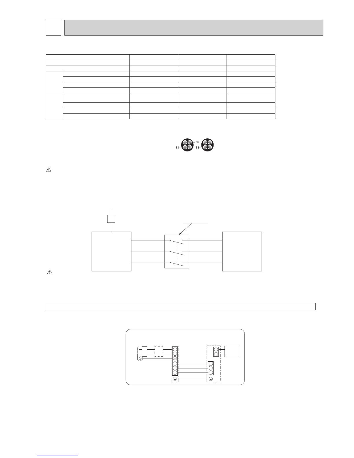
7 WIRING SPECIFICATIONS
1
2
S1
S2
S3
S1
S2
S3
Indoor/outdoor
unit connection
cable
Indoor
unit
Unit
power
supply
Outdoor
unit
Remote
controller
L
B
N
B Earth leakage breaker
C wiring circuit breaker or
isolating switch
C
1:1 system Electrical wiring
Notes: 1. Wiring size must comply with the applicable local and national code..
2. Power supply cables and Indoor/Outdoor unit connecting cables shall not be lighter than polychloroprene sheathed flexible cable.
3. Install an earth line longer than power cables.
Warning:
In case of A-control wiring, there is high voltage potential on the S3 terminal caused by electrical circuit design that has no electrical insulation between
power line and communication signal line. Therefore, please turn off the main power supply when servicing. And do not touch the S1, S2, S3 terminals
when the power is energized. If isolator should be used between indoor unit and outdoor unit, please use 3-pole type.
(Design 60245 IEC 57)
S1
S2
S3
S1
S2
S3
A-Control
Outdoor Unit
3 poles isolator
Power supply
Isolator
A-Control
Indoor Unit
Never splice the power cable or the indoor-outdoor connection cable, otherwise it may result in a smoke, a re or communication failure.
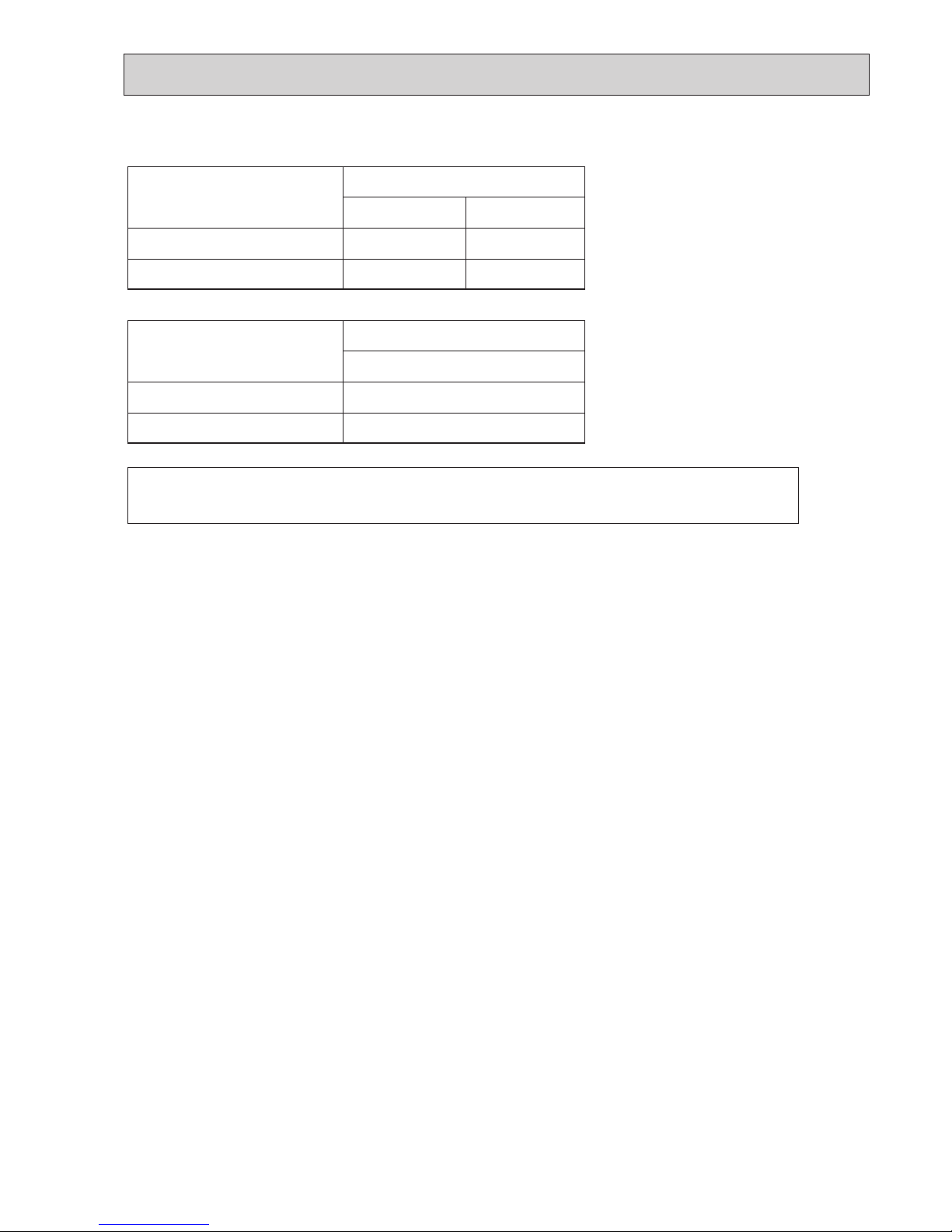
7-1. FIELD ELECTRICAL WIRING (power wiring specifications)
Outdoor unit model PUHZ-SP125VKA PUHZ-SP140VKA PUHZ-SP100/125/140YKA
Outdoor unit power supply ~/N (single), 50 Hz, 230 V ~/N (single), 50 Hz, 230 V
3N~ (3 ph 4-wires), 50 Hz, 400 V
Outdoor unit input capacity Main switch (Breaker) *1 32 A 40 A 16 A
Wiring Wire
No. × size
(mm
2
)
Outdoor unit power supply 3 × Min. 4 3 × Min. 6 5 × Min. 1.5
Indoor unit-Outdoor unit *2 3 × 1.5 (Polar) 3 × 1.5 (Polar) 3 × 1.5 (Polar)
Indoor unit-Outdoor unit earth *2 1 × Min. 1.5 1 × Min. 1.5 1 × Min. 1.5
Remote controller-Indoor unit *3 2 × 0.3 (Non-polar) 2 × 0.3 (Non-polar) 2 × 0.3 (Non-polar)
Circuit rating
Outdoor unit L-N (single)
Outdoor unit L1-N, L2-N, L3-N (3 phase)
*4 230 V AC 230 V AC 230 V AC
Indoor unit-Outdoor unit S1-S2 *4 230 V AC 230 V AC 230 V AC
Indoor unit-Outdoor unit S2-S3 *4 24 V DC 24 V DC 24 V DC
Remote controller-Indoor unit *4 12 V DC 12 V DC 12 V DC
*1. A breaker with at least 3.0 mm contact separation in each pole shall be provided. Use earth leakage breaker (NV).
Make sure that the current leakage breaker is one compatible with higher harmonics.
Always use a current leakage breaker that is compatible with higher harmonics as this unit is equipped with an inverter.
The use of an inadequate breaker can cause the incorrect operation of inverter.
*2. Max. 45 m
If 2.5 mm² used, Max. 50 m
If 2.5 mm² used and S3 separated, Max. 80 m
• Use one cable for S1 and S2 and another for S3 as shown in the picture.
• Max. 50 m Total Max. for PEY. Wiring size 3 × 1.5 (Polar).
*3. The 10 m wire is attached in the remote controller accessory.
*4. The gures are NOT always against the ground.
S3 terminal has DC 24 V against S2 terminal. However between S3 and S1, these terminals are NOT electrically insulated by the transformer or other device.
Caution: Be sure to install N-Line. Without N-Line, it could cause damage to the unit.
14
OCH671
7-2. SEPARATE INDOOR UNIT/ OUTDOOR UNIT POWER SUPPLIES
The following connection patterns are available.
The outdoor unit power supply patterns vary on models.
1:1 System
The optional indoor power supply terminal kit is required.
S1
S2
L
N
1
2
L
N
S1
S2
S3
S3
A
CB
D
J
E
F
G
H
Affix a label B that is included with the manuals near each wiring diagram for the indoor and outdoor units.
A Outdoor unit power supply
B Earth leakage breaker
C Wiring circuit breaker or isolating switch
D Outdoor unit
E Indoor unit/outdoor unit connecting cords
F Remote controller
G Indoor unit
H Option
J Indoor unit power supply
If the indoor and outdoor units have separate power supplies, refer to the table below.
If the optional indoor power supply terminal kit is used, change the indoor unit
electrical box wiring referring to the figure in the right and the DIP switch settings of
the outdoor unit control board.
Indoor power supply terminal kit (option)
Indoor unit electrical box connector connection change
Label affixed near each wiring diagram
for the indoor and outdoor units
Outdoor unit DIP switch settings (when
using separate indoor unit/outdoor unit
power supplies only)
Indoor unit specifications
Required
Required
Required
Electric heater
(For models with
heater)
Connectors (connections when shipped
from the factory are for indoor unit power
supplied from outdoor unit)
Indoor unit power supplied from outdoor unit
(when shipped from factory)
If the indoor and
outdoor units have
separate power
supplies, change the
connections of the
connectors as shown
in the following
figure.
Connectors
Indoor unit
control board
Separate indoor unit/outdoor unit power
supplies
Electric heater
(For models with
heater)
S1
S2
S3
L
N
BLUE
BLUE
YELLOW
YELLOW
CND
CN01
ORANGE
CN01
ORANGE
S1
S2
S3
L
N
YELLOW
BLUE
BLUE
YELLOW
CND
Indoor unit
control board
Note:
There are 3 types of labels (labels A, B, and C). Affix the appropriate labels to
the units according to the wiring method.
ON
OFF
Set the SW8-3 to ON.
1 2 (SW8)
3
CB
Simultaneous twin system
Affix a label B that is included with the manuals near each wiring diagram for the indoor and outdoor units.
<For models without heater>
The optional indoor power supply terminal kit is required.
A
B
C
D
E
F
G
H
J
Outdoor unit power supply
Earth leakage breaker
Wiring circuit breaker or isolating switch
Outdoor unit
Indoor unit/outdoor unit connecting cables
Remote controller
Indoor unit
Option
Indoor unit power supply
K
Indoor unit earth
E
F
D G
K K
H
G
H
G
H
L
N
L
N
S1
S2
S3
S1
S2
S3
1
2
L
N
S1
S2
S3
1
2
L
N
S1
S2
S3
1
2
A
B C B C
J
*1. A breaker with at least 3 mm contact separation in each pole shall be provided. Use earth leakage breaker (NV).
The breaker shall be provided to ensure disconnection of all active phase conductor of the supply.
*2. Max. 120 m
*3. Max. 500 m (Max. 200 m when 2 remote controllers are used)
*4.The figures are NOT always against the ground.
Notes: 1. Wiring size must comply with the applicable local and national code.
2. Power supply cables and indoor unit/outdoor unit connecting cables shall not be lighter than polychloroprene sheathed
flexible cable. (Design 60245 IEC 57)
3. Install an earth line longer than power cables.
Indoor unit model
Indoor unit power supply
Indoor unit input capacity
*1
Main switch (Breaker)
Indoor unit power supply
Indoor unit power supply earth
Indoor unit-Outdoor unit
*2
Indoor unit-Outdoor unit earth
Remote controller-Indoor unit
*3
Indoor unit L-N *4
Indoor unit-Outdoor unit S1-S2 *4
Indoor unit-Outdoor unit S2-S3 *4
Remote controller-Indoor unit *4
71–140
~/N (single), 50 Hz, 230 V
16 A
3 o Min. 1.5
1 o Min. 1.5
2 o Min. 0.3
–
2 o 0.3 (Non-polar)
230 V AC
–
24 V DC
12 V DC
Circuit
rating
Wiring
Wire No. o size
(mm
2
)
15
OCH671
7-3. INDOOR – OUTDOOR CONNECTING CABLE
The cable shall not be lighter than design 60245 IEC or 60227 IEC.
Note: The Max. cable length may vary depending on the condition of installation, humidity or materials, etc.
Indoor unit-Outdoor unit
Outdoor power supply
Max. 45m
3 o 1.5 (polar)
1 o Min. 1.5
Max. 50m
3 o 2.5 (polar)
1 o Min. 2.5
Indoor unit-Outdoor unit earth
Wire No. o Size (mm²)
Be sure to connect the indoor-outdoor connecting cables directly to the units (no intermediate connections).
Intermediate connections can lead to communication errors if water enters the cables and causes insufficient
insulation to ground or a poor electrical contact at the intermediate connection point.
Indoor unit-Outdoor unit
Indoor/Outdoor separate
power supply
Max. 120m
2 o Min. 0.3
—
Indoor unit-Outdoor unit earth
Wire No. o Size (mm²)
Note: The optional indoor power supply terminal kit is necessary
16
OCH671
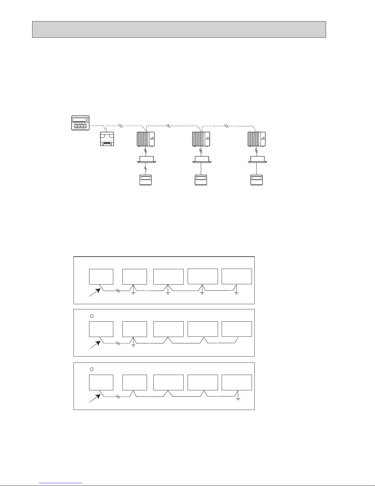
7-4. M-NET WIRING METHOD
(Points to note)
(1) Outside the unit, transmission wires should stay away from electric wires in order to prevent electromagnetic noise from
making an influence on the signal communication. Place them at intervals of more than 5 cm. Do not put them in the same
conduit tube.
(2) Terminal block (TB7) for transmission wires should never be connected to 220–240 V power supply. If it is connected,
electronic parts on M-NET P.C. board may burn out.
(3) Use 2-core × 1.25mm² shield wire (CVVS, CPEVS) for the transmission wire. Transmission signals may not be sent or
received normally if different types of transmission wires are put together in the same multi-conductor cable. Never do this
because this may cause a malfunction.
It would be acceptable if M-NET wire (non-polar, 2-cores) is arranged in addition to the wiring for A-control.
(4) Earth only one of any appliances through M-NET transmission wire (shield wire). Communication error may occur due to
the influence of electromagnetic noise.
“Ed” error will appear on the LED display of outdoor unit.
“0403” error will appear on the central-control remote controller.
If there are more than 2 earthing spots on the shield wire, noise may enter into the shield wire because the earth wire and
shield wire form 1 circuit and the electric potential difference occurs due to the impedance difference among earthing spots.
In case of single spot earthing, noise does not enter into the shield wire because the earth wire and shield wire do not form
1 circuit.
To avoid communication errors caused by noise, make sure to observe the single spot earthing method described in the
installation manual.
Group
remote
controller
Refrigerant
address 00
M-NET
address 01
A-control
remote
controller
A-control
remote
controller
A-control
remote
controller
Refrigerant
address 00
M-NET
address 02
Refrigerant
address 00
M-NET
address 03
Power
supply
unit for
transmission
wire
Central
remote
controller
M-NET transmission wire
×
Bad example (Multi spot earthing of shield wire)
Good example 1 (Single spot earthing of shield wire)
Power
supply
appliance
M-NET type
outdoor unit
Central
remote
controller
Power
supply
appliance
M-NET type
outdoor unit
M-NET type
outdoor unit
M-NET type
outdoor unit
M-NET transmission wire
M-NET type
outdoor unit
M-NET type
outdoor unit
Central
remote
controller
Power
supply
appliance
M-NET type
outdoor unit
M-NET transmission wire
M-NET type
outdoor unit
M-NET type
outdoor unit
Good example 2 (Single spot earthing of shield wire)
17
OCH671
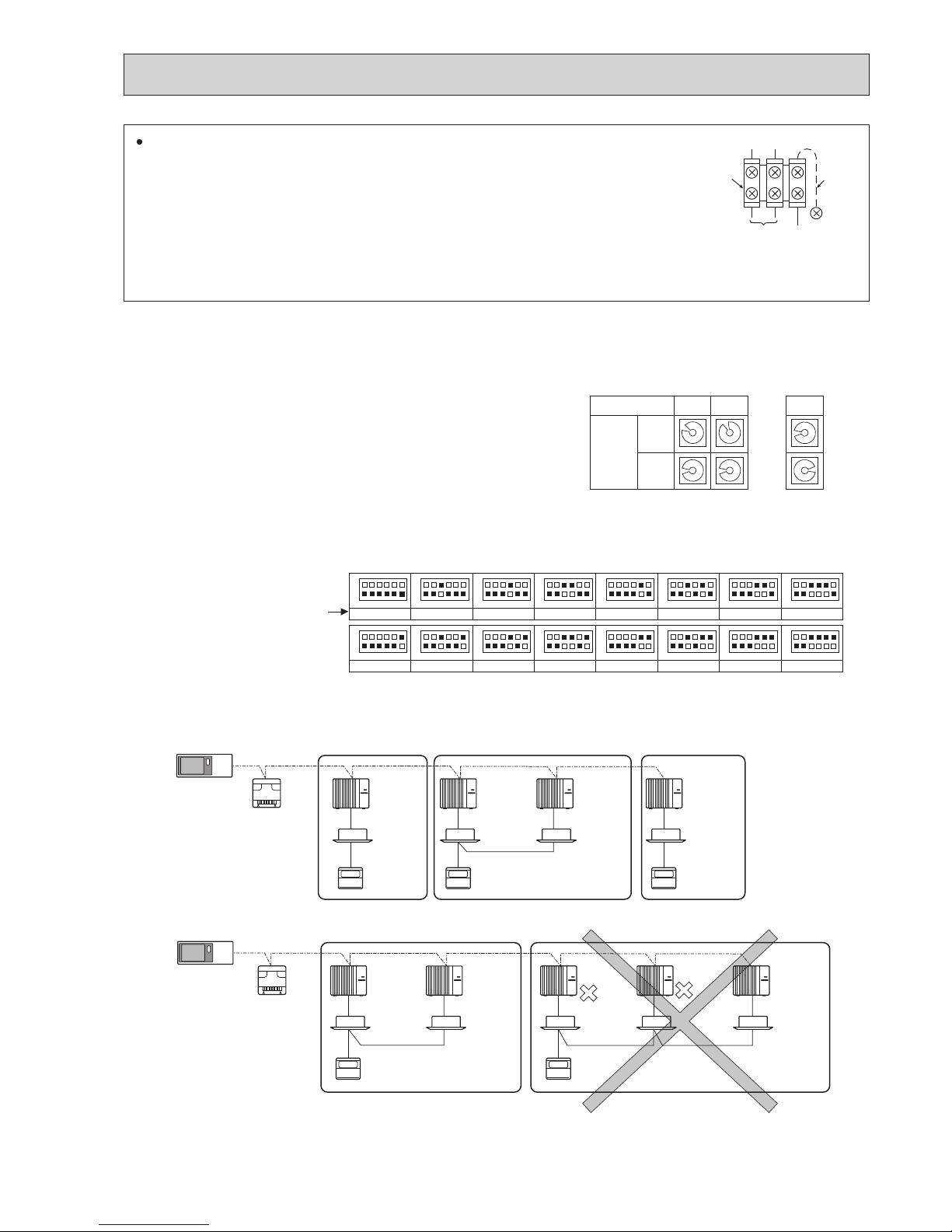
7-4-3. Regulations in address settings
In the case of multiple grouping system, M-NET and refrigerant address settings should be done as explained in the above
section. Set the lowest number in the group for the outdoor unit whose refrigerant address is “00” as its M-NET address.
Note: Refrigerant addresses can be overlapped if they are in the different group.
Note:
In group B, M-NET address of the outdoor unit whose refrigerant address is “00” is not set to the minimum in the group.
As “3” is right for this situation, the setting is wrong. Taking group A as a good sample, set the minimum M-NET address in
the group for the outdoor unit whose refrigerant address is “00”.
7-4-1. M-NET address setting
In A-control models, M-NET address and refrigerant address should be set only for the outdoor unit. Similar to CITY MULTI
system, there is no need to set the address of outdoor unit and remote controller. To construct a central control system, the
setting of M-NET address should be conducted only upon the outdoor unit. The setting range should be 1 to 50 (the same as
that of the indoor unit in CITY MULTI system), and the address number should be consecutively set in a same group.
Address number can be set by using rotary switches
(SW11 for 1st digit and SW12 for 2nd digit), which
is located on the M-NET board of outdoor unit.
(Initial setting: all addresses are set to “0”.)
7-4-2. Refrigerant address setting
In the case of multiple grouping system (multiple refrigerant circuits in 1 group), indoor units should be connected by remote
controller wiring (TB5) and the refrigerant address needs to be set. Leave the refrigerant addresses to “00” if the group setting is not conducted. Set the refrigerant address by using DIP SW1-3 to -6 on the outdoor controller board. [Initial setting: all
switches are OFF. (All refrigerant addresses are “00”.)]
1
2
3
4
5
6
7
8
9
0
1
2
3
4
5
6
7
8
9
0
1
2
3
4
5
6
7
8
9
0
1
2
3
4
5
6
7
8
9
0
1
2
3
4
5
6
7
8
9
0
1
2
3
4
5
6
7
8
9
0
1 2
~
50
M-NET Address No.
<Setting example>
Switch
setting
SW11
1st
digit
SW12
2nd
digit
OFF
ON
1
2
3
4
5
6
1
2
3
4
5
6
1
2
3
4
5
6
1
2
3
4
5
6
1
2
3
4
5
6
1
2
3
4
5
6
1
2
3
4
5
6
1
2
3
4
5
6
1
2
3
4
5
6
1
2
3
4
5
6
1
2
3
4
5
6
1
2
3
4
5
6
1
2
3
4
5
6
1
2
3
4
5
6
1
2
3
4
5
6
1
2
3
4
5
6
0
Refrigerant
address
OFF
ON
8
OFF
ON
1
OFF
ON
9
OFF
ON
10
OFF
ON
11
OFF
ON
12
OFF
ON
13
OFF
ON
14
OFF
ON
15
OFF
ON
2
OFF
ON
3
OFF
ON
4
OFF
ON
5
OFF
ON
6
OFF
ON
7
System
controller
A-control
remote
controller
Group A Group B Group C
A-control
remote
controller
TB5
A-control
remote
controller
Refrigerant
address 00
M-NET
address 01
Refrigerant
address 00
M-NET
address 02
Refrigerant
address 01
M-NET
address 03
Refrigerant
address 00
M-NET
address 04
Power
supply
unit for
transmission
wire
A-control
remote
controller
A-control
remote
controller
TB5
Group A Group B
Refrigerant
address 00
M-NET
address 01
Refrigerant
address 01
M-NET
address 02
Refrigerant
address 00
M-NET
address 04
Refrigerant
address 01
M-NET
address 03
Refrigerant
address 02
M-NET
address 05
System
controller
Power
supply
unit for
transmission
wire
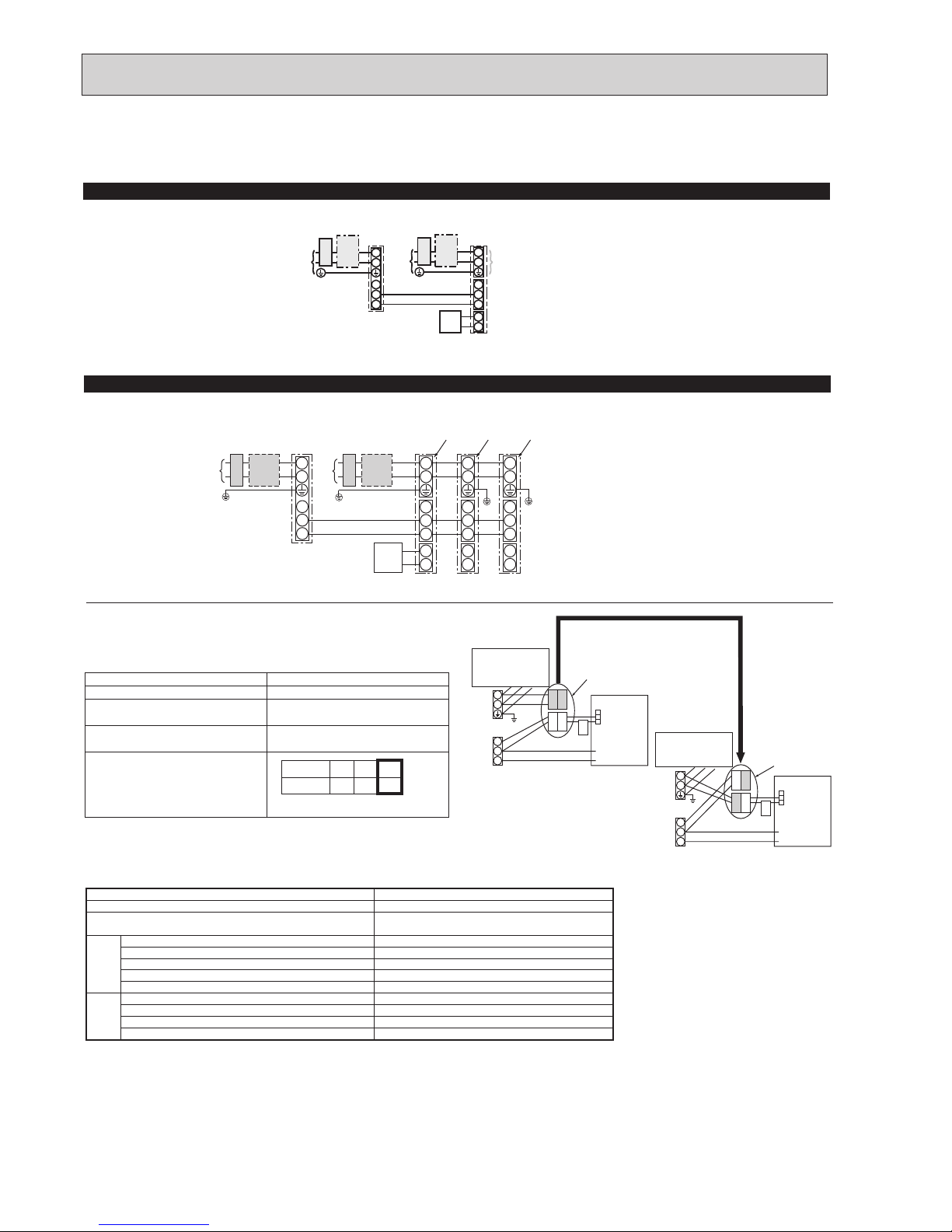
M-NET wiring
(1) Use 2-core × 1.25mm² shield wire for electric wires.
(Excluding the case connecting to system controller.)
(2) Connect the wire to the M-NET terminal block. Connect one core of the transmission
wire (non-polar) to A terminal and the other to B. Peel the shield wire, twist the shield
part to a string and connect it to S terminal.
(3) In the system which several outdoor units are being connected, the terminal (A, B,
S) on M-NET terminal block should be individually wired to the other outdoor unit’s
terminal, i.e. A to A, B to B and S to S. In this case, choose one of those outdoor units and drive a screw to fix an earth
wire on the plate as shown on the right figure.
Transmission
wire
Shield
part
M-NET
terminal
block
Earth
wire
A B S

18
OCH671
8 REFRIGERANT SYSTEM DIAGRAM
Unit : mm (inch)
Thermistor (TH8)
<Heat Sink>
Refrigerant LIQUID pipe
connection [9.52 (3/8)
Stop valve
(with charge plug)
Strainer
#100
Power
receiver
LEV-A
Strainer
#100
High pressure
switch 63H
Thermistor TH4
(Discharge)
Thermistor TH33
(Comp. surface)
Compressor
Strainer
#50
Strainer
#100
Strainer
#100
4-way valve
Muffler
Charge plug
Charge plug
Stop valve
Refrigerant GAS pipe
connection [15.88 (5/8)
Refrigerant flow in cooling
Refrigerant flow in heating
Heat exchanger
Thermistor TH6
(Condenser)
Thermistor TH7
(Ambient)
Thermistor TH3
(Liquid)
Distributor
LEV-B
PUHZ-SP100YKA.TH
PUHZ-SP125VKA.TH PUHZ-SP125YKA.TH
PUHZ-SP140VKA.TH PUHZ-SP140YKA.TH

19
OCH671
8-2. START AND FINISH OF TEST RUN
• Operation from the indoor unit
Execute the test run using the installation manual for the indoor unit.
• Operation from the outdoor unit
By using the DIP switch SW4 on the control board of outdoor unit, test run can be started and finished, and its operation
mode (cooling) can be set up.
1 Turn on SW4-1 to start test run.
2 Turn off SW4-1 to finish the test run.
• There may be a faint knocking sound around the machine room after power is supplied, but this is no problem with product
because the linear expansion pipe is just moving to adjust opening pulse.
• There may be a knocking sound around the machine room for several seconds after compressor starts operating, but this
is no problem with product because the check valve itself, generates the sound because pressure difference is small in the
refrigerant circuit.
8-1. REFRIGERANT COLLECTING (PUMP DOWN)
When relocating or disposing of the indoor/outdoor unit, pump down the system following the procedure below so that no refrigerant is released into the atmosphere.
1 Turn off the power supply (circuit breaker).
2 Connect the low pressure valve on the gauge manifold to the charge plug (low pressure side) on the outdoor unit.
3 Close the liquid stop valve completely.
4 Supply power (circuit breaker).
● When power is supplied, make sure that “CENTRALLY CONTROLLED” is not displayed on the remote controller. If “CENTRALLY CONTROLLED” is displayed, the refrigerant collecting (pump down) cannot be completed normally.
● Startup of the indoor-outdoor communication takes about 3 minutes after the power (circuit breaker) is turned on. Start the
pump-down operation 3 to 4 minutes after the power (circuit breaker) is turned on.
5 Perform the refrigerant collecting operation (cooling test run).
● Push the pump-down SWP switch (push-button type) on the control board of the outdoor unit. The compressor and ventilators (indoor and outdoor units) start operating (refrigerant collecting operation begins). (LED1 and LED2 on the control board
of the outdoor unit are lit.)
● Only push the pump-down SWP switch if the unit is stopped. However, even if the unit is stopped and the pump-down SWP
switch is pushed less than 3 minutes after the compressor stops, the refrigerant collecting operation cannot be performed.
Wait until the compressor has been stopped for 3 minutes and then push the pump-down SWP switch again.
6 Fully close the stop valve on the gas pipe side of the outdoor unit when the pressure gauge on the gauge manifold shows 0.05
to 0 MPa [Gauge] (approx. 0.5 to 0 kgf/cm²) and quickly stop the air conditioner.
● Because the unit automatically stops in about 3 minutes when the refrigerant collecting operation is completed (LED1 off,
LED2 lit), be sure to quickly close the gas stop valve. However, if LED1 is lit, LED2 is off, and the unit is stopped, open the
liquid stop valve completely, close the valve completely after 3 minutes or more have passed, and then repeat step 5. (Open
the gas stop valve completely.)
● If the refrigerant collecting operation has been completed normally (LED1 off, LED2 lit), the unit will remain stopped until the
power supply is turned off.
● Note that when the extension piping is very long with a large refrigerant amount, it may not be possible to perform a pump-
down operation. In this case, use refrigerant recovery equipment to collect all of the refrigerant in the system.
7 Turn off the power supply (circuit breaker), remove the gauge manifold, and then disconnect the refrigerant pipes.
Warning:
When pumping down the refrigerant, stop the compressor before disconnecting the refrigerant pipes.
• If the refrigerant pipes are disconnected while the compressor is operating and the stop valve is open, the pressure in
the refrigeration cycle could become extremely high if air is drawn in, causing the pipes to burst, personal injury, etc.
20
OCH671
9 TROUBLESHOOTING
<Check code display by self-diagnosis and actions to be taken for service (summary)>
Present and past check codes are logged, and they can be displayed on the wired remote controller and control board of outdoor unit. Actions to be taken for service, which depends on whether or not the trouble is reoccurring in the field, are summarized in the table below. Check the contents below before investigating details.
9-1. TROUBLESHOOTING
Unit conditions at service
Check code
Actions to be taken for service (summary)
The trouble is reoccurring.
Displayed
Not displayed
Judge what is wrong and take a corrective action according
to “9-4. SELF-DIAGNOSIS ACTION TABLE”.
Conduct trouble shooting and ascertain the cause of the
trouble according to “9-5. TROUBLESHOOTING OF
PROBLEMS”.
The trouble is not reoccurring.
Logged
Not logged
1Consider the temporary defects such as the work of
protection devices in the refrigerant circuit including
compressor, poor connection of wiring, noise and such.
Re-check the symptom, and check the installation
environment, refrigerant amount, weather when the
trouble occurred, and wiring related.
2Reset check code logs and restart the unit after finishing
service.
3There is no abnormality in electrical component,
controller board, remote controller, etc.
1Re-check the abnormal symptom.
2Conduct trouble shooting and ascertain the cause of the
trouble
according to “9-5. TROUBLESHOOTING
OF
PROBLEMS”.
3Continue to operate unit for the time being if the cause
is not ascertained.
4There is no abnormality concerning of parts such as
electrical component, controller board, remote controller,
etc.
9-2. CHECK POINT UNDER TEST RUN
9-2-1. Before test run
• After installation of indoor and outdoor units, piping work and electric wiring work, re-check that there is no refrigerant leak-
age, loosened connections and incorrect polarity.
• Measure impedance between the ground and the power supply terminal block (L, N) on the outdoor unit by 500 V Megger
and check that it is 1.0M" or over.
* Do not use 500 V Megger to indoor/outdoor connecting wire terminal block (S1, S2, S3) and remote controller terminal block
(1, 2). This may cause malfunction.
• Make sure that test run switch (SW4) is set to OFF before turning on power supply.
• Turn on power supply 12 hours before test run in order to protect compressor.
• For specific models which require higher ceiling settings or auto-recovery feature from power failure, make proper changes of
settings referring to the description of “10. FUNCTION SETTING”.
Make sure to read operation manual before test run. (Especially items to secure safety.)
21
OCH671
F1 F2 F3 F4
unem ecivreS
rosruC
:unem niaM
Test run
Input maintenance info.
Function setting
Check
Self check
F1 F2 F3 F4
Test run menu
Cursor
Service menu:
Test run
Drain pump test run
1
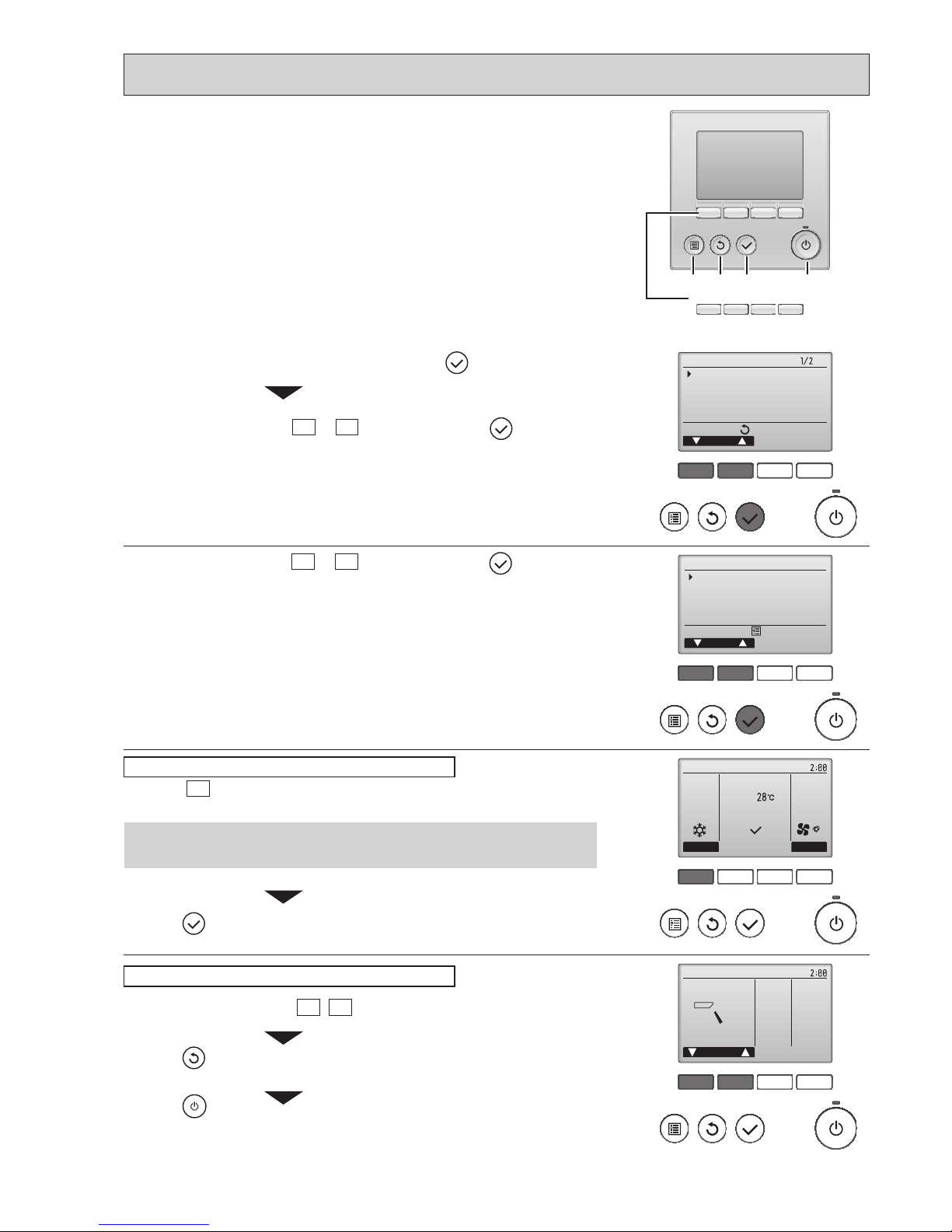
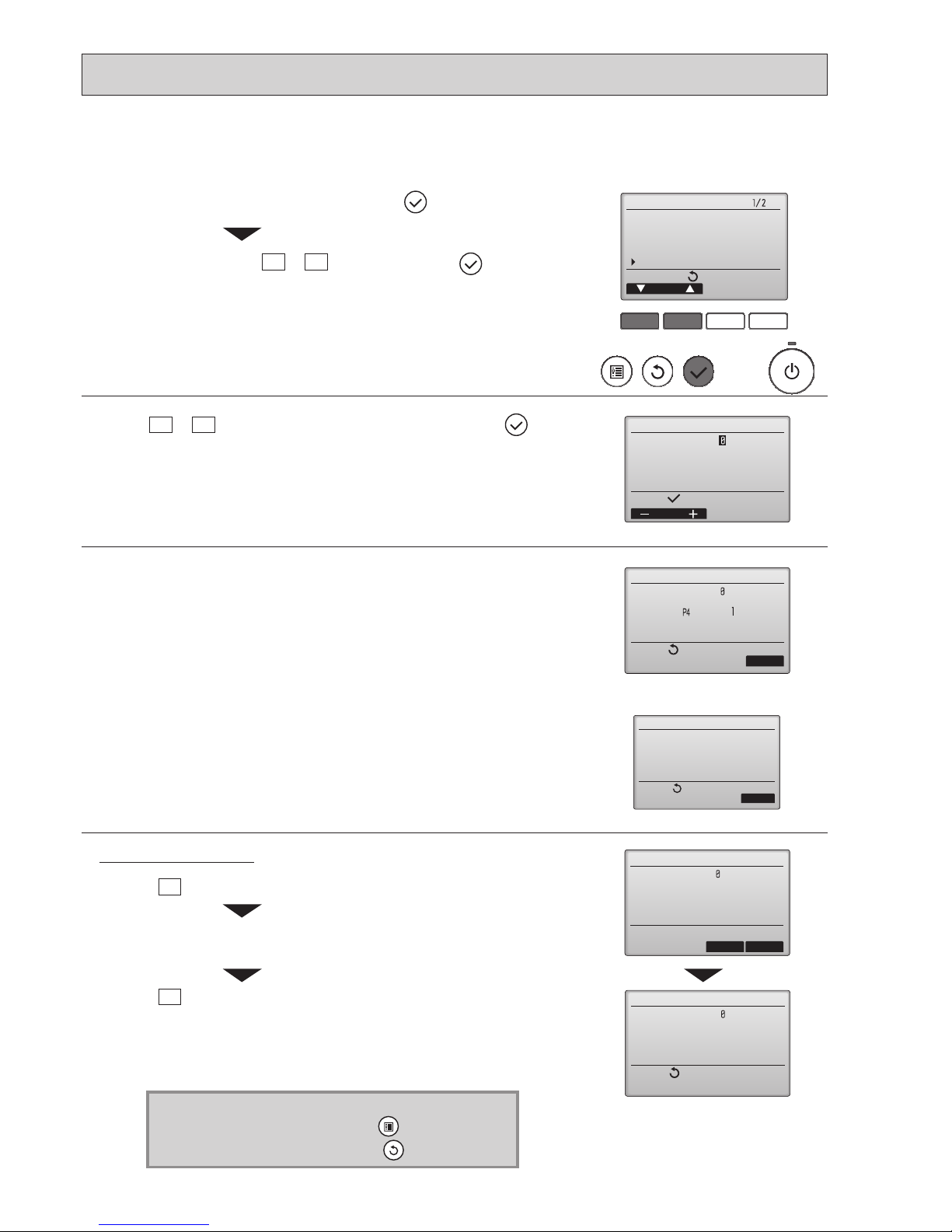
Select "Service" from the Main menu, and press the button.
2
Select "Test run" with the F1 or F2 button, and press the button.
Select "Test run" with the F1
or F2 button, and press the button.
F1 F2 F3 F4
Cool
Pipe
Auto
Switch disp.
Mode Fan
RemainTest run
F1 F2 F3 F4
Remain
Vane
Check the auto vane with the F1 F2 buttons.
Press the
button to return to “Test run operation”.
Press the
button.
When the test run is completed, the “Test run menu” screen will appear.
* The test run will automatically stop after two hours.
Test run operation
Auto vane check
Press the button and open the Vane setting screen.
Function buttons
F1 F2 F3 F4
MENU RETURN SELECT ON/OFF
9-2-2. Test run for wired remote controller
<PAR-3xMAA("x" represents 0 or later)>
* Check the operation of the outdoor unit’s fan.
Cool mode: Check the cold air blows out.
Heat mode: Check the heat blows out.
Press the F1
button to go through the operation modes in the order of "Cool
and Heat".
22
OCH671
F1 F2 F3 F4
Error information
Error code
Error unit IU
Ref. address Unt#
Model name
Serial No.
ResetPage
Error information
Contact information
Dealer
Tel
ResetPage
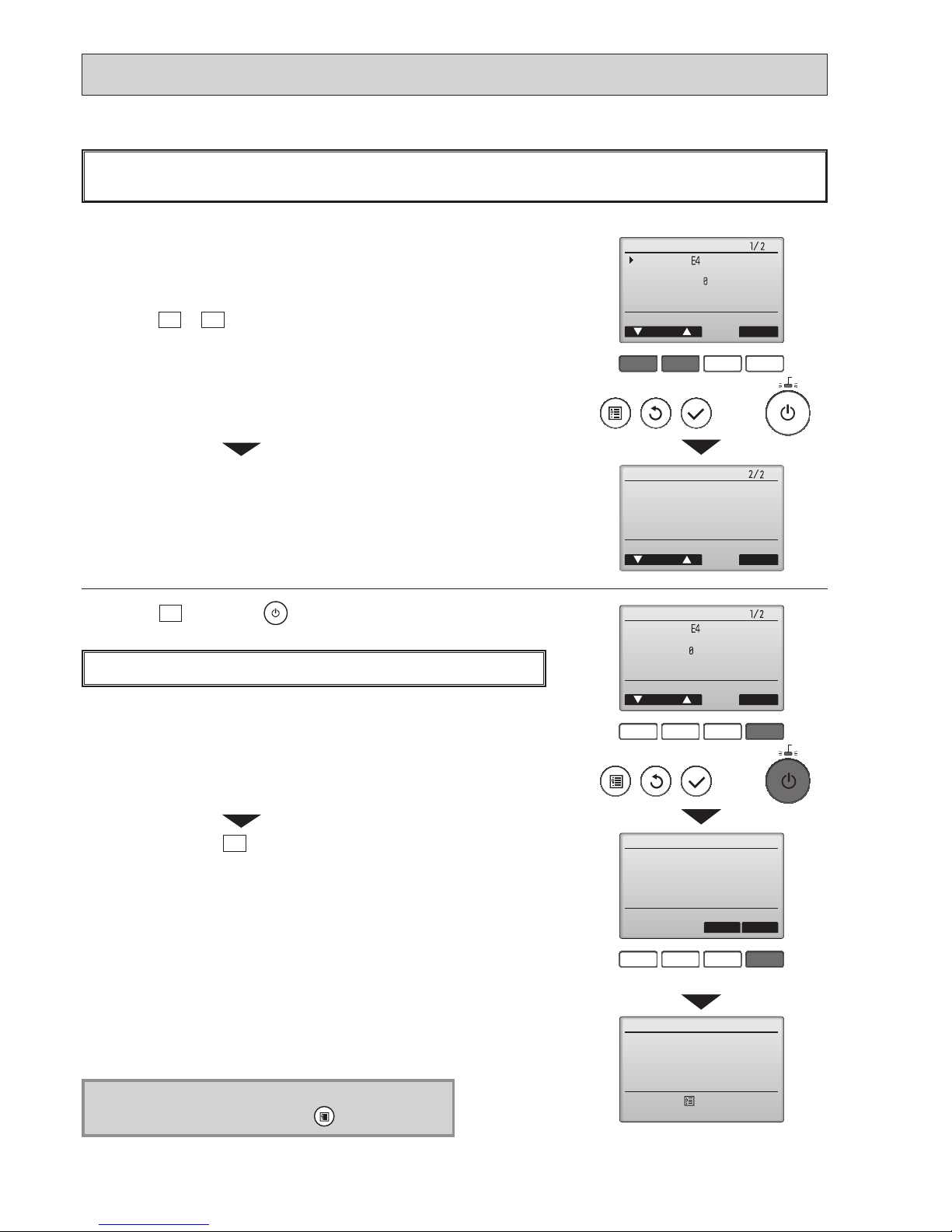
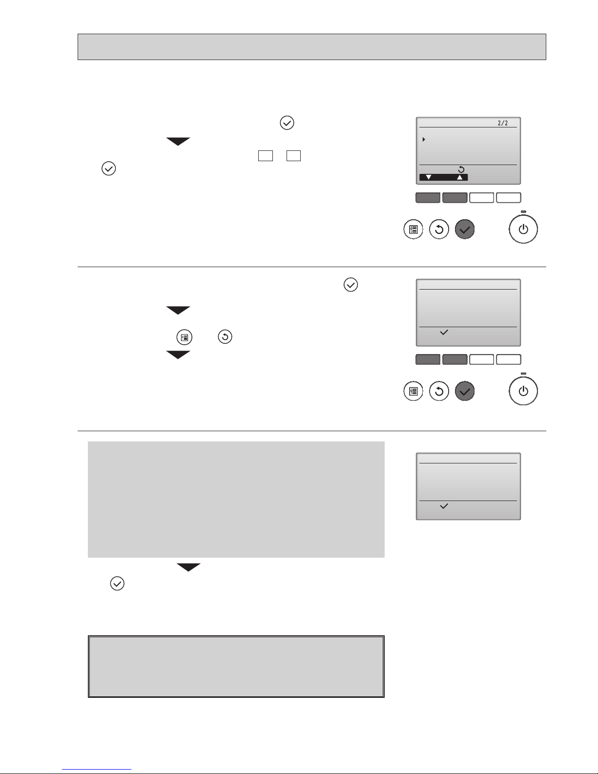
1
Reset error: Reset button
Reset error: Reset button
blinks
1
Check code, error unit, refrigerant address, unit model name, and serial
number will appear.
The model name and serial number will appear only if the information have
been registered.
Press the
F1
or
F2
button to go to the next page.
When an error occurs, the following screen will appear.
Check the error status, stop the operation, and consult your dealer.
Contact information (dealer's phone number) will appear if the information have
been registered.
F1 F2 F3 F4
F1 F2 F3 F4
1
Error information
Error reset
Error reset
Error code
Error unit IU
Ref. address Unt#
Model name
Serial No.
ResetPage
Reset current error?
Error reset
OKCancel
Main menu:
Reset error: Reset button
blinks
2
Press the
F4
button or the button to reset the error that is occurring.
Errors cannot be reset while the ON/OFF operation is prohibited.
Select "OK" with theF4button.
Navigating through the screens
• To go back to the Main menu ..........
button
<Error information>
23
OCH671
F1 F2 F3 F4
Main
Main display:
Cursor Page
Main menu
Restriction
Energy saving
Night setback
Filter information
Error information
blinks
While no errors are occurring, page 2/2 of the error information can be viewed by
selecting "Error information" from the Main menu.
Errors cannot be reset from this screen.
<Checking the error information>
<Error history>
F1 F2 F3 F4
unem ecivreS
rosruC
:unem niaM
Test run
Input maintenance info.
Function setting
Check
Self check
Check menu
Cursor
Service menu:
Error history
Refrigerant volume check
Refrigerant leak check
Smooth maintenance
Request code
F1 F2 F3 F4
Error history
Page
Delete
Check menu:
Error Unt#
dd/mm/yy
Error history
Cancel OK
Delete error history?
Error history
Check menu:
Error history deleted
2
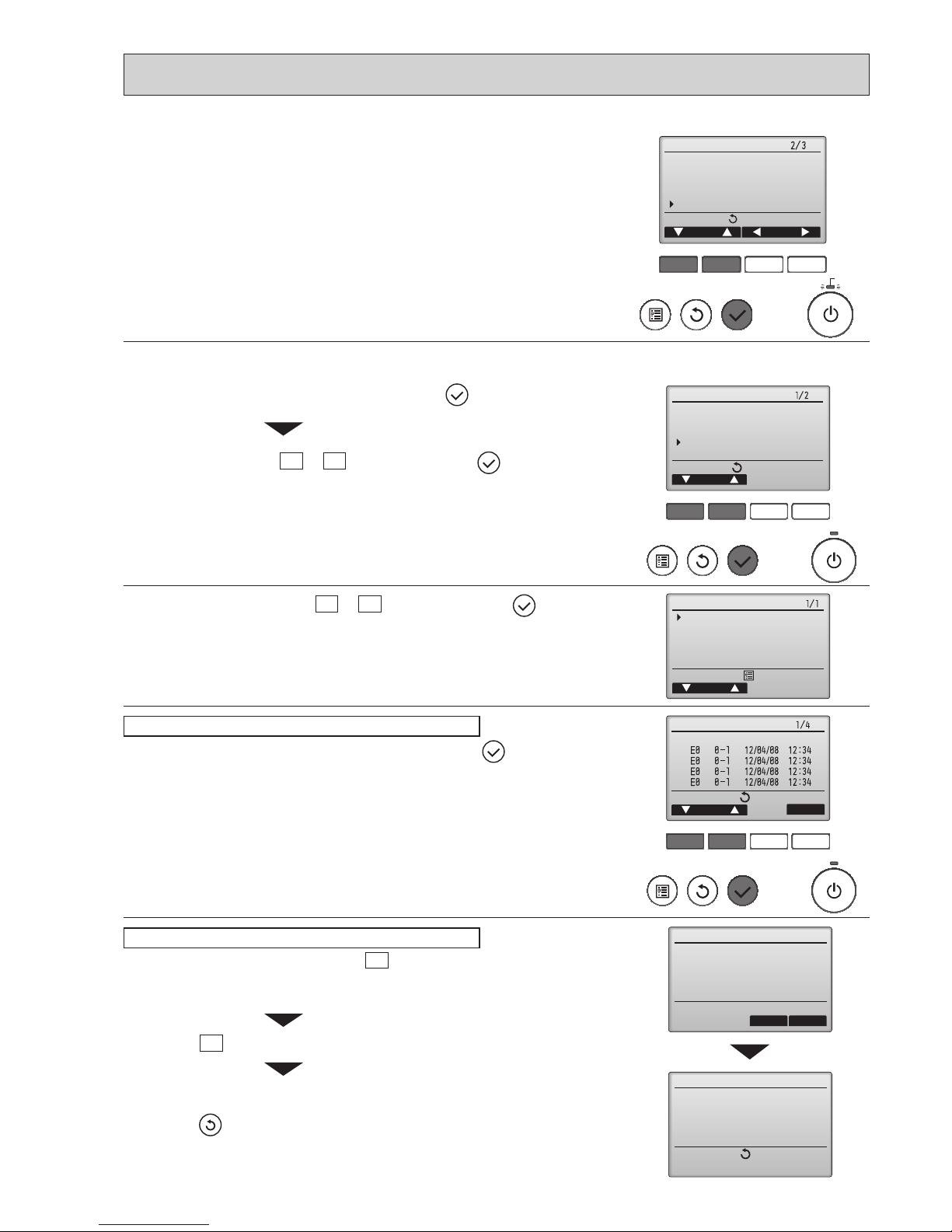
Select "Error history" with the F1 or F2 button, and press the button.
Select "Check" with the F1
or F2 button, and press the button.
3
Select "Error history" from the Check menu, and press the button to view
up to 16 error history records.
Four records are shown per page, and the top record on the rst page
indicates the latest check code record.
Error history
4
To delete the error history, press the F4 button (Delete) on the screen that
shows error history.
A conrmation screen will appear asking if you want to delete the error history.
Press the F4
button (OK) to delete the history.
"Error history deleted" will appear on the screen.
Press the
button to go back to the Check menu screen.
Deleting the error history
1
Select "Service" from the Main menu, and press the button.
24
OCH671
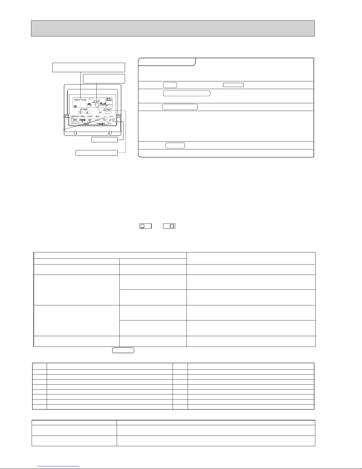
[TEST] button
Pipe (liquid) temperature
Displays the remaining
test run time.
"TEST RUN" and the currently selected
operation mode are displayed alternately.
A
B
C
• In case of test run, the OFF timer will be activated, and the test run will automatically stop after 2 hours.
• The room temperature display section shows the pipe temperature of indoor units during the test run.
• Check that all the indoor units are running properly in case of simultaneous twin and triple operation. Malfunctions may not
be displayed regardless of incorrect wiring.
*1 After turning on the power supply, the system will go into startup mode, “PLEASE WAIT” will blink on the display section of
the room temperature, and lamp (green) of the remote controller will blink.
As to INDOOR BOARD LED, LED1 will be lit up, LED2 will either be lit up in case the address is 0 or turned off in case the
address is not 0. LED3 will blink.
As to OUTDOOR BOARD LED, LED1 (green) and LED2 (red) will be lit up. (After the startup mode of the system finishes,
LED2 (red) will be turned off.)
If OUTDOOR BOARD LED is digital display, — and — will be displayed alternately every second.
• If one of the above operations does not function correctly, the causes written below should be considered. Find causes from
the symptoms.
The below symptoms are under test run mode. “Startup” in the table means the display status of *1 written above.
Remote Controller Display
Symptoms in test run mode
OUTDOOR BOARD LED Display
Cause
Remote controller displays “PLEASE
WAIT”, and
cannot be operated.
After power is turned on, “PLEASE WAIT”
is displayed for 3 minutes, then check code
is displayed.
No display appears even when remote
controller operation switch is turned on.
(Operation lamp does not light up.)
Display appears but soon disappears
even when remote controller is operated.
• After power is turned on, “PLEASE WAIT” is displayed for 2
minutes during
system startup. (Normal)
• Incorrect connection of outdoor terminal block (L
1, L2, L3 and
S1, S2, S3.)
• Outdoor unit’s protection devise connector is open.
• Incorrect wiring between the indoor and outdoor unit (Polarity
is wrong for S1, S2, S3.)
• Remote controller transmission wire short.
• There is no outdoor unit of address 0.
(Address is other than 0.)
• Remote controller transmission wire open.
• After canceling function selection, operation is not possible for
about 30 seconds. (Normal)
After “startup” is displayed, only
green lights up. <00>
After “startup” is displayed,
green(once) and red(once) blink
alternately. <F1>
After “startup” is displayed,
green(once) and red(twice) blink
alternately. <F3, F5, F9>
After “startup” is displayed,
green(twice) and red(once) blink
alternately. <EA. Eb>
After “startup” is displayed, only
green lights up. <00>
After “startup” is displayed, only
green lights up. <00>
< > indicates digital display.
2. Press TEST button twice.
1. Turn on the main power supply.
3. Press OPERATION SWITCH
button.
4. Press AIR DIRECTION button.
5. Check the outdoor unit fan for
correct running.
6. Press the ON/OFF button to reset the test run in progress.
7. Register the contact number.
While the room temperature display on the remote
controller is “PLEASE WAIT”, the remote controller is disabled.
Wait until “PLEASE WAIT” disappears before using remote controller.
“PLEASE WAIT” appears for about 2 minutes after power
supply is turned on. *1
The outdoor unit features automatic capacity control to
provide optimum fan speeds. Therefore, the fan keeps
running at a low speed to meet the current outside air
condition unless it exceeds its available maximum power.
Then, in actuality, the fan may stop or run in the reverse
direction depending on the outside air, but this does not
mean malfunction.
Check for correct motion of auto-vanes.
The TEST RUN appears on the screen.
Operating procedures
Cooling mode:
Check if cool air blows and water is drained.
Heating mode: Check if warm air blows. (It takes a little
while until warm air blows.)
B
C
A
Note: Press the remote controller’s CHECK button twice to perform self-diagnosis. See the table below for the contents of
LCD display.
LCD
Contents of trouble
P1
P2
P4
P5
P6
P8
P9
PL
Abnormality of room temperature thermistor
Abnormality of pipe temperature thermistor/Liquid
Abnormality of drain sensor/ Float switch connector open
Drain overflow protection is operating.
Freeze/overheat protection is operating.
Abnormality of pipe temperature
Abnormality of pipe temperature thermistor/Cond./Eva
Abnormality of refrigerant circuit
LCD
Contents of trouble
Fb
U1~UP
F3~F9
E0~E5
E6~EF
----
FFFF
PA
Abnormality of indoor controller board
Malfunction outdoor unit
Malfunction outdoor unit
Remote controller transmitting error
Indoor/outdoor unit communication error
No error history
No applied unit
Forced compressor stop(due to water leakage abnormality)
LED1
(microprocessor power supply)
LED2
(remote controller)
LED3
(indoor/outdoor communication)
Lights when power is supplied.
Lights when power is supplied for wired remote controller.
The indoor unit should be connected to the outdoor unit with address "0" setting.
Flashes when indoor and outdoor unit are communicating.
See the table below for details of the LED display (LED 1, 2, 3) on the indoor controller board.
9-2-3. Test run for wired remote controller <PAR-21MAA>
25
OCH671
ON/OFF
TEMP
FAN
VANE
MODE
CHECK
LOUVER
TEST RUN
AUTO STOP
AUTO START
h
min
TEST RUN
RESET
SET
CLOCK
6
4
5
2
3
MODE
COOL
TEST RUN
FAN
VANE
TEST RUN
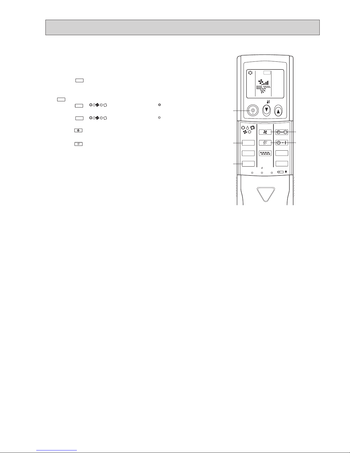
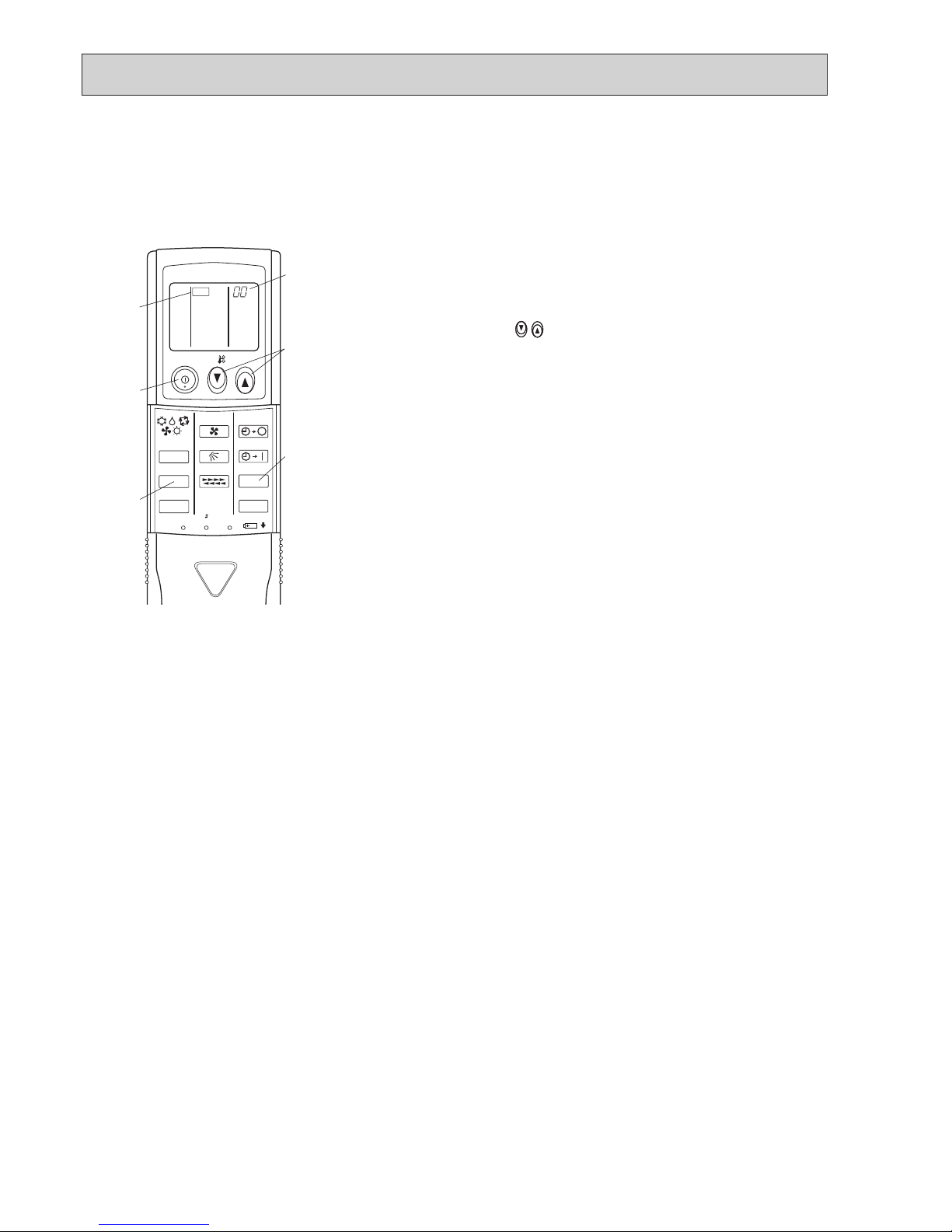
9-2-4. Test run for wireless remote controller
Measure an impedance between the power supply terminal block on
the outdoor unit and ground with a 500 V Megger and check that it is
equal to or greater than 1.0M".
1 Turn on the main power to the unit.
2 Press the button twice continuously.
(Start this operation from the status of remote controller display
turned off.)
A and current operation mode are displayed.
3 Press the ( ) button to activate mode, then
check whether cool air blows out from the unit.
4 Press the ( ) button to activate mode, then
check whether warm air blows out from the unit.
5 Press the button and check whether strong air blows out
from the unit.
6 Press the button and check whether the auto vane operates
properly.
7 Press the ON/OFF button to stop the test run.
Note:
• Point the remote controller towards the indoor unit receiver
while following steps 2 to 7.
• It is not possible to run in FAN, DRY or AUTO mode.
MODE
HEAT
26
OCH671
F1 F2 F3 F4
unem ecivreS
rosruC
:unem niaM
Test run
Input maintenance info.
Function setting
Check
Self check
kcehc fleS
:tceleS
Ref. address
sserddA
kcehc fleS
Ref. address
Return:
teseR
Error Unt # CI.prG
Self check
Return:
Reset
Ref. address 0
Error Grp.
--
-
Unt#
--
When there is no error history
Self check
Delete error history?
Ref. address
Cancel OK
Self check
Return:
Ref. address
Error history deleted
2
With theF1orF2button, enter the refrigerant address, and press the button.
Select "Self check" with the F1 or F2 button, and press the button.
1
Select "Service" from the Main menu, and press the button.
3
Check code, unit number, attribute will appear.
"-" will appear if no error history is available.
4
Resetting the error history.
Press the
F4
button (Reset) on the screen that shows the check code history.
A conrmation screen will appear asking if you want to delete the check code history.
Press theF4button (OK) to delete the check code history.
If deletion fails, "Request rejected" will appear.
"Unit not exist" will appear if no indoor units that are correspond to the entered
address are found.
Navigating through the screens
• To go back to the Main menu ..........
button
• To return to the previous screen .......
button
9-3. HOW TO PROCEED "SELF-DIAGNOSIS"
9-3-1. Self-diagnosis <PAR-31MAA>
27
OCH671
If operations cannot be completed with the remote controller, diagnose the remote controller with this function.
F1 F2 F3 F4
unem ecivreS
rosruC
:unem niaM
Maintenance password
Remote controller check
F1 F2 F3 F4
Remote controller check
:nigeB
Start checking?
Remote controller check
:nigeB
Start checking?
1
Select "Service" from the Main menu, and press the button.
Select "Remote controller check" with the F1
or F2 button, and press
the
button.
2
Select "Remote controller check" from the Service menu, and press the but-
ton to start the remote controller check and see the check results.
To cancel the remote controller check and exit the Remote controller check
menu screen, press the
or the button.
The remote controller will not reboot itself.
Check the remote controller display and see if anything is displayed
(including lines). Nothing will appear on the remote controller display
if the correct voltage (8.5 – 12 VDC) is not supplied to the remote controller. If this is the case, check the remote controller wiring and indoor
units.
OK: No problems are found with the remote controller. Check other
parts for problems.
E3, 6832: There is noise on the transmission line, or the indoor unit or another
remote controller is faulty. Check the transmission line and the
other remote controllers.
NG (ALL0, ALL1):
Send-receive circuit fault. Remote controller needs replacing.
ERC:
The number of data errors is the discrepancy between the number of
bits in the data transmitted from the remote controller and that of the
data that was actually transmitted over the transmission line. If data
errors are found, check the transmission line for external noise interference.
Remote controller check results screen
If the button is pressed after the remote controller check results are displayed, remote controller check will end, and the remote controller will automati-
cally reboot itself.
9-3-2. Remote controller check <PAR-31MAA>
3
28
OCH671
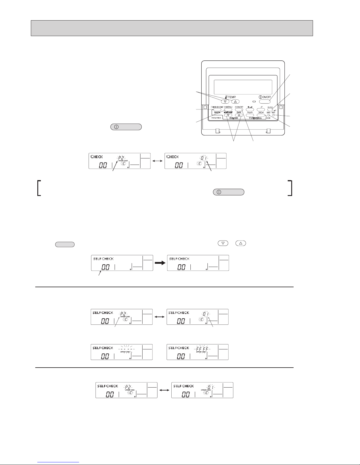
When a problem occurs to the air conditioner, the indoor and outdoor units will stop,
and the problem is shown in the remote controller display.
[CHECK] and the refrigerant address are displayed on the temperature
display, and the check code and unit number are displayed alternately as
shown below.
1. (If the outdoor unit is malfunctioning, the unit number will be "00".)
2. In the case of group control, for which one remote controller controls
multiple refrigerant systems, the refrigerant address and check code of the
unit that first experienced trouble (i.e., the unit that transmitted the check
code) will be displayed.
3. T
o clear the check code, press the
ON/OFF
button.
When using remote-/local-controller combined operation, cancel the check code after turning off remote operation.
During central control by a MELANS controller, cancel the check code by pressing the
ON/OFF
button.
Since each unit has a function that stores check codes, the latest check code can be recalled even if it is cancelled by the re
mote
controller or power is turned off.
Check the error history for each unit using the remote controller.
1. Switch to self-diagnosis mode.
Press the
CHECK
button (H
in the picture above) twice within 3 seconds.
The display content will change as shown below.
2. Set the unit number or refrigerant address you want to diagnose.
Press the [TEMP] buttons (
and ) (F in the picture above)
to select the desired number or address. The number (address) changes between
[01] and [50] or [00] and [15].
3. Display self-diagnosis results.
<When there is error history>
(For the definition of each check code, refer to the indoor unit's installation manual or service handbook.)
4. Reset the error history.
Display the error history in the diagnosis result display screen (see step
3 ).
F
E
G
C
D
H
B
A
I
Check code (2 or 4 digits)
(Alternating Display)
Address (3 digits) or unit number (2 digits)
The refrigerant address will begin to blink
approximately 3 seconds after being
selected and the self-diagnosis process will begin.
Unit number or refrigerant address
to be diagnosed
Check code (2 or 4 digits)
(Alternating Display)
Address (3 digits) or unit number (2 digits)
<When there is no error history> <When there is no corresponding unit>
9-3-3. Self-diagnosis <PAR-21MAA>
9-3-4. Self-Diagnosis During Maintenance or Service <PAR-21MAA>
29
OCH671
Transmission data from remote controller
Transmission data on transmission path
When the number of data errors is "02":
Press the
ON/OFF
button (D in the picture in the previous page) twice
within 3 seconds. The self-diagnosis address or refrigerant address will blink.
When the error history is reset, the display will look like the one shown below
.
However, if you fail to reset the error history, the error content will be displayed again.
5. Cancel self-diagnosis.
Self-diagnosis can be cancelled by the following 2 methods.
Press the
CHECK
button (H in the picture in the previous page.) → Self-diagnosis will be cancelled and the screen will return to the previous state in effect
before the start of self-diagnosis.
Press the
ON/OFF
button (D in the picture in the previous page.) → Self-diagnosis will be cancelled and the indoor unit will stop.
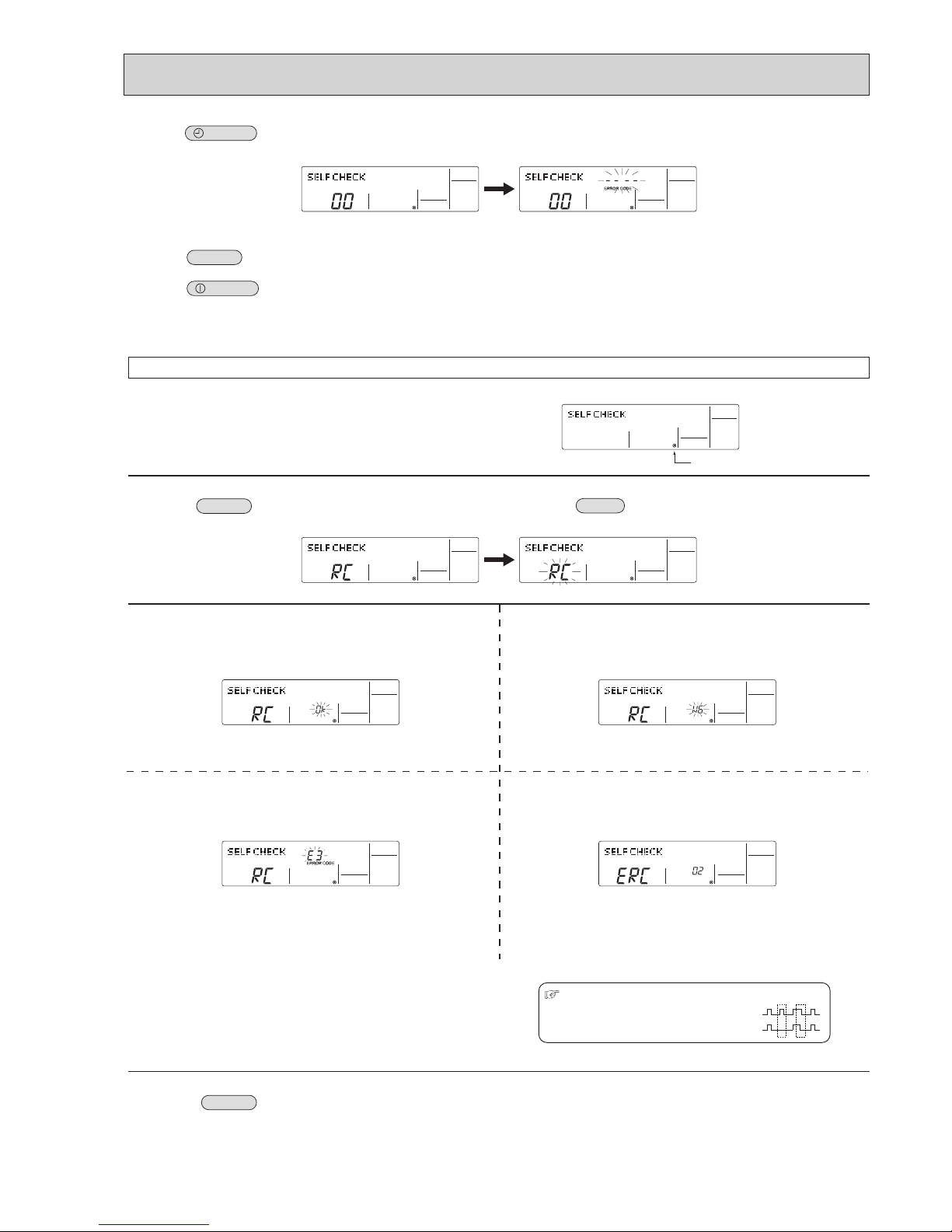
10-3-3. Remote Controller Diagnosis
If the air conditioner cannot be operated from the remote controller, diagnose the remote controller as explained below.
1. First, check that the power-on indicator is lit.
If the correct voltage (DC12 V) is not supplied to the remote controller, the
indicator will not light.
If this occurs, check the remote controller's wiring and the indoor unit.
2. Switch to the remote controller self-diagnosis mode.
Press the
CHECK
button (H in the picture in the previous page)
for 5 seconds or more. The display content will change as shown below.
Press the
FILTER
button (A in the picture in the previous page)
3. Remote controller self-diagnosis result
[When the remote controller is functioning correctly]
Check for other possible causes, as there is no problem with the remote
controller.
[When the remote controller malfunctions]
(Error display 1) "NG" blinks. → The remote controller's transmitting-receiv-
ing circuit is defective.
The remote controller must be replaced with a new one.
[Where the remote controller is not defective, but cannot be operated.]
(Error display 2) [E3], [6833] or [6832] blinks.
→ Transmission is not possible.
There might be noise or interference on the transmission path, or the indoor unit
or other remote controllers are defective. Check the transmission path and other
controllers.
(Error display 3)
"ERC" and the number of data errors are displayed.
→ Data error has occurred.
The number of data errors is the difference between the number of bits sent from
the remote controller and the number actually transmitted through the transmission path. If such a problem is occurring, the transmitted data is affected by noise,
etc. Check the transmission path.
4. To cancel remote controller diagnosis
Press the
CHECK
button (H in the picture in the previous page) for 5 seconds or more. Remote controller diagnosis will be cancelled,
"PLEASE WAIT" and operation lamp will blink. After approximately 30 seconds, the state in effect before the diagnosis will be restored.
Power on indicator
twice within 3 seconds.
to start self-diagnosis.
9-3-5. Remote controller check <PAR-21MAA>
30
OCH671
• "CHECK" lights, and refrigerant address
"00" flashes.
• Check that the remote controller's
display has stopped before continuing.
• Select the refrigerant address of the
indoor unit for the self-diagnosis.
Note: Set refrigerant address using the
outdoor unit’s DIP switch (SW1).
(For more information, see the
outdoor unit installation manual.)
• If an air conditioner error occurs, the
indoor unit's sensor emits an intermittent
buzzer sound, the operation light
flashes, and the check code is output.
(It takes 3 seconds at most for check
code to appear.)
• The check mode is cancelled.
[Procedure]
1. Press the CHECK button twice.
2. Press the temperature
buttons.
3. Point the remote controller at the
sensor on the indoor unit and
press the HOUR button.
4. Point the remote controller at the
sensor on the indoor unit and
press the ON/OFF button.
<Malfunction-diagnosis method at maintenance service>
9-3-6. Self-diagnosis <Wireless remote controller>
<In case of trouble during operation>
When a malfunction occurs to air conditioner, both indoor unit and outdoor unit will stop and operation lamp blinks to inform
unusual stop.
ON/OFF
TEMP
FAN
VANE
MODE
CHECK
LOUVER
TEST RUN
AUTO STOP
AUTO START
h
min
RESET
SET
CLOCK
CHECK
CHECK
display
Temperature
button
CHECK
button
Refrigerant
address
display
HOUR
button
ON/OFF
button
 Loading...