

Mitsubishi PUHZ-SP140VHA, PUHZ-SP140YHA, PUHZ-SP125VHA, PUHZ-SP125YHA, PUHZ-SP100VHA.UK Service Manual
...
SERVICE MANUAL
R410A
PUHZ-SP100VHA.UK
PUHZ-SP100YHA.UK
CONTENTS
1. REFERENCE MANUAL
.................................
2
2. SAFETY PRECAUTION
.................................
2
3. FEATURES
.....................................................
6
4. SPECIFICATIONS
..........................................
7
5. DATA
...............................................................
9
6. OUTLINES AND DIMENSIONS
...................
12
7. WIRING DIAGRAM
......................................
14
8. WIRING SPECIFICATIONS
..........................
17
9.
REFRIGERANT SYSTEM DIAGRAM
..............
22
10. TROUBLESHOOTING
..................................
24
11. FUNCTION SETTING
...................................
81
12. EASY MAINTENANCE FUNCTION
.............
91
13.
MONITORING THE OPERATION DATA BY THE REMOTE CONTROLLER
....
92
14. DISASSEMBLY PROCEDURE
...................
102
PARTS CATALOG (OCB566)
Outdoor unit
[Model Name]
PUHZ-SP100VHA
PUHZ-SP125VHA
PUHZ-SP140VHA
PUHZ-SP100YHA
PUHZ-SP125YHA
PUHZ-SP140YHA
[Service Ref.]
PUHZ-SP100VHA.UK
PUHZ-SP125VHA.UK
PUHZ-SP140VHA.UK
PUHZ-SP100YHA.UK
PUHZ-SP125YHA.UK
PUHZ-SP140YHA.UK
No. OCH566
REVISED EDITION-A
January 2015
SPLIT-TYPE, HEAT PUMP AIR CONDITIONERS
Notes:
• This manual describes service
data of the indoor units only.
• RoHS compliant products have
<G> mark on the spec name
plate.
• Please void OCH566.
Revision:
•
Modified some descriptions
in "8-1. FIELD ELECTRICAL
WIRING" and "8-2. SEPARATE
INDOOR UNIT/OUTDOOR
UNIT POWER SUPPLIES" in
REVISED EDITION-A.
• Some other descriptions have
been also modified.
2
1
REFERENCE MANUAL
INDOOR UNIT’S SERVICE MANUAL
2
SAFETY PRECAUTION
2-1. ALWAYS OBSERVE FOR SAFETY
Before obtaining access to terminal, all supply circuits must be disconnected.
Preparation before the repair service.
• Prepare the proper tools.
• Prepare the proper protectors.
• Provide adequate ventilation.
• After stopping the operation of the air conditioner, turn off the power-supply breaker.
• Discharge the condenser before the work involving the electric parts.
Precautions during the repair service.
• Do not perform the work involving the electric parts with wet hands.
• Do not pour water into the electric parts.
• Do not touch the refrigerant.
• Do not touch the hot or cold areas in the refrigerating cycle.
• When the repair or the inspection of the circuit needs to be done without turning off the power,
exercise great caution not to touch the live parts.
Model Name Service Ref. Service Manual No.
PLA-SP71/100/125/140BA PLA-SP71/100/125/140BA.UK
OCH565
OCB565
PEAD-SP100/125/140JA(L) PEAD-SP100/125/140JA(L).UK
―
BWE01408
OCH566A
3
Cautions for units utilizing refrigerant R410A
2-2. CAUTIONS RELATED TO NEW REFRIGERANT
Use new refrigerant pipes.
Store the piping indoors, and both ends of the
piping sealed until just before brazing.
(Leave elbow joints, etc. in their packaging.)
In case of using the existing pipes for R22, be careful with
the following:
· Be sure to clean the pipes and make sure that the insides
of the pipes are clean.
· Change flare nut to the one provided with this product.
Use a newly flared pipe.
· Avoid using thin pipes.
Charge refrigerant from liquid phase of gas
cylinder.
If the refrigerant is charged from gas phase, composition change
may occur in refrigerant and the efficiency will be lowered.
Do not use refrigerant other than R410A.
If other refrigerant (R22, etc.) is used, chlorine in refrigerant can cause deterioration of refrigerant oil etc.
Use a vacuum pump with a reverse flow check
valve.
Vacuum pump oil may flow back into refrigerant cycle and
that can cause deterioration of refrigerant oil, etc.
Use the following tools specifically designed for
use with R410A refrigerant.
The following tools are necessary to use R410A refrigerant.
Handle tools with care.
If dirt, dust or moisture enters into refrigerant cycle, that can
cause deterioration of refrigerant oil or malfunction of compressor.
Do not use a charging cylinder.
If a charging cylinder is used, the composition of refrigerant will change and the efficiency will be lowered.
Flare tool
Electronic refrigerant
charging scale
Vacuum pump adaptor
Size adjustment gauge
Gauge manifold
Torque wrench
Gas leak detector
Charge hose
Tools for R410A
Contamination inside refrigerant piping can cause deterioration of refrigerant oil, etc.
If dirt, dust or moisture enters into refrigerant cycle, that can
cause deterioration of refrigerant oil or malfunction of compressor.
If large amount of mineral oil enters, that can cause deterioration of refrigerant oil, etc.
Ventilate the room if refrigerant leaks during
operation. If refrigerant comes into contact with
a flame, poisonous gases will be released.
Make sure that the inside and outside of refrigerant piping is clean and it has no contaminants
such as sulfur, oxides, dirt, shaving particles, etc,
which are hazard to refrigerant cycle.
In addition, use pipes with specified thickness.
The refrigerant oil applied to flare and flange
connections must be ester oil, ether oil or
alkylbenzene oil in a small amount.
Never use any refrigerant other than that specified.
Doing so may cause a burst, an explosion, or fire when the
unit is being used, serviced, or disposed of.
Correct refrigerant is specified in the manuals and on the
spec labels provided with our products.
We will not be held responsible for mechanical failure,
system malfunction, unit breakdown or accidents caused
by failure to follow the instructions.
Use the specified refrigerant only.
OCH566A
4
Gravimeter
Unit
[3] Service tools
Use the below service tools as exclusive tools for R410A refrigerant.
[1] Cautions for service
(1) Perform service after recovering the refrigerant left in unit completely.
(2) Do not release refrigerant in the air.
(3) After completing service, charge the cycle with specified amount of refrigerant.
(4) When performing service, install a filter drier simultaneously.
Be sure to use a filter drier for new refrigerant.
[2] Additional refrigerant charge
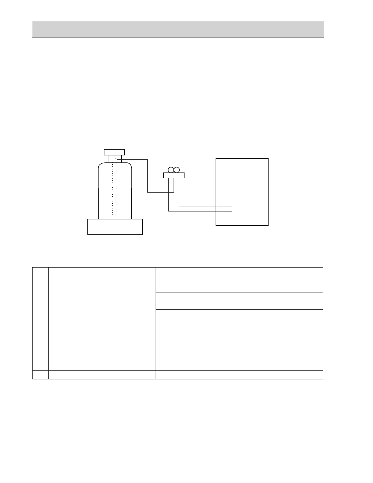
When charging directly from cylinder
· Check that cylinder for R410A on the market is a syphon type.
· Charging should be performed with the cylinder of syphon stood vertically. (Refrigerant is charged from liquid phase.)
No.
Tool name
Specifications
1
Gauge manifold
· Only for R410A
· Use the existing fitting
specifications
. (UNF1/2)
· Use high-tension side pressure of 5.3 MPa·G or over.
2
Charge hose
· Only for R410A
· Use pressure performance of 5.09 MPa·G or over.
3
Electronic scale
—
4
Gas leak detector · Use the detector for R134a, R407C or R410A.
5
Adaptor for reverse flow check · Attach on vacuum pump.
6
Refrigerant charge base
—
7
Refrigerant cylinder
· Only for R410A · Top of cylinder (Pink)
· Cylinder with syphon
8
Refrigerant recovery equipment
—
OCH566A
5
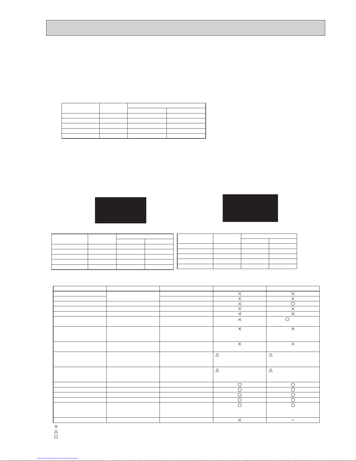
Cautions for refrigerant piping work
New refrigerant R410A is adopted for replacement inverter series. Although the refrigerant piping work for R410A is same
as for R22, exclusive tools are necessary so as not to mix with different kind of refrigerant. Furthermore, as the working
pressure of R410A is 1.6 times higher than that of R22, their sizes of flared sections and flare nuts are different.
1 Thickness of pipes
Because the working pressure of R410A is higher compared to R22, be sure to use refrigerant piping with thickness shown
below. (Never use pipes of 0.7 mm or below.)
2 Dimensions of flare cutting and flare nut
The component molecules in HFC refrigerant are smaller compared to conventional refrigerants. In addition to that,
R410A is a refrigerant, which has higher risk of leakage because its working pressure is higher than that of other refrigerants. Therefore, to enhance airtightness and strength, flare cutting dimension of copper pipe for R410A have been speci-
fied separately from the dimensions for other refrigerants as shown below. The dimension B of flare nut for R410A also
have partly been changed to increase strength as shown below. Set copper pipe correctly referring to copper pipe flaring
dimensions for R410A below. For 1/2 and 5/8 inch pipes, the dimension B changes. Use torque wrench corresponding to
each dimension.
3 Tools for R410A (The following table shows whether conventional tools can be used or not.)
1/4
3/8
1/2
5/8
3/4
6.35
9.52
12.70
15.88
19.05
0.8
0.8
0.8
1.0
—
0.8
0.8
0.8
1.0
1.0
Nominal
dimensions(inch)
Diagram below: Piping diameter and thickness
Outside
diameter
(mm)
Thickness
(mm)
R410A R22
1/4
3/8
1/2
5/8
3/4
6.35
9.52
12.70
15.88
19.05
9.1
13.2
16.6
19.7
—
9.0
13.0
16.2
19.4
23.3
Nominal
dimensions(inch)
Flare cutting dimensions
Outside
diameter
Dimension A
( )
+0
-0.4
(mm)
R410A R22
(mm)
1/4
3/8
1/2
5/8
3/4
6.35
9.52
12.70
15.88
19.05
17.0
22.0
26.0
29.0 *
—
17.0
22.0
24.0
27.0
36.0
Nominal
dimensions(inch)
Flare nut dimensions
Outside
diameter
Dimension B
(mm)
R410A
* 36.0mm for
indoor unit
of SP100,
125 and 140
R22
(mm)
Gauge manifold
Charge hose
Gas leak detector
Refrigerant recovery equipment
Refrigerant cylinder
Applied oil
Safety charger
Charge valve
Vacuum pump
Flare tool
Bender
Pipe cutter
Welder and nitrogen gas cylinder
Refrigerant charging scale
Vacuum gauge or thermistor vacuum gauge and
vacuum valve
Charging cylinder
Air purge, refrigerant charge and
Operation check
Gas leak check
Refrigerant recovery
Refrigerant charge
Apply to flared section
Prevent compressor malfunction
when charging refrigerant by
spraying liquid refrigerant
Prevent gas from blowing out
when detaching charge hose
Vacuum drying and air
purge
Flaring work of piping
Bend the pipes
Cut the pipes
Weld the pipes
Refrigerant charge
Check the degree of vacuum. (Vacuum
valve prevents back flow of oil and refrigerant to thermistor vacuum gauge)
Refrigerant charge
Tool exclusive for R410A
Tool exclusive for R410A
Tool for HFC refrigerant
Tool exclusive for R410A
Tool exclusive for R410A
Ester oil and alkylbenzene
oil (minimum amount)
Tool exclusive for R410A
Tool exclusive for R410A
Tools for other refrigerants can
be used if equipped with adapter for reverse flow check
Tools for other refrigerants
can be used by adjusting
flaring dimension
Tools for other refrigerants can be used
Tools for other refrigerants can be used
Tools for other refrigerants can be used
Tools for other refrigerants can be used
Tools for other refrigerants
can be used
Tool exclusive for R410A
Tools and materials Use R410A tools Can R22 tools be used?
(Usable if equipped
with adapter for rever se flow)
(Usable by adjusting
flaring dimension)
Can R407C tools be used?
Ester oil:
Alkylbenzene oil: minimum amount
(Usable if equipped
with adapter for rever se flow)
(Usable by adjusting
flaring dimension)
: Prepare a new tool. (Use the new tool as the tool exclusive for R410A.)
: Tools for other refrigerants can be used under certain conditions.
: Tools for other refrigerants can be used.
Dimension A
Dimension B
OCH566A
6
3 FEATURES
CHARGELESS SYSTEM
PRE-CHARGED REFRIGERANT IS SUPPLIED FOR PIPING LENGTH AT SHIPMENT.
(20 m (PUHZ-SP100), 30 m (PUHZ-SP125/140))
The refrigerant circuit with LEV (Linear Expansion Valve) and Accumulator always control the optimal refrigerant level regardless
of the length (20 or 30 m maximum and 5 m minimum) of piping. The additional refrigerant charging work during installation which
often caused problems heretofore is completely eliminated. This unique system improves the quality and reliability of the work
done. It also helps to speed up the installation time.
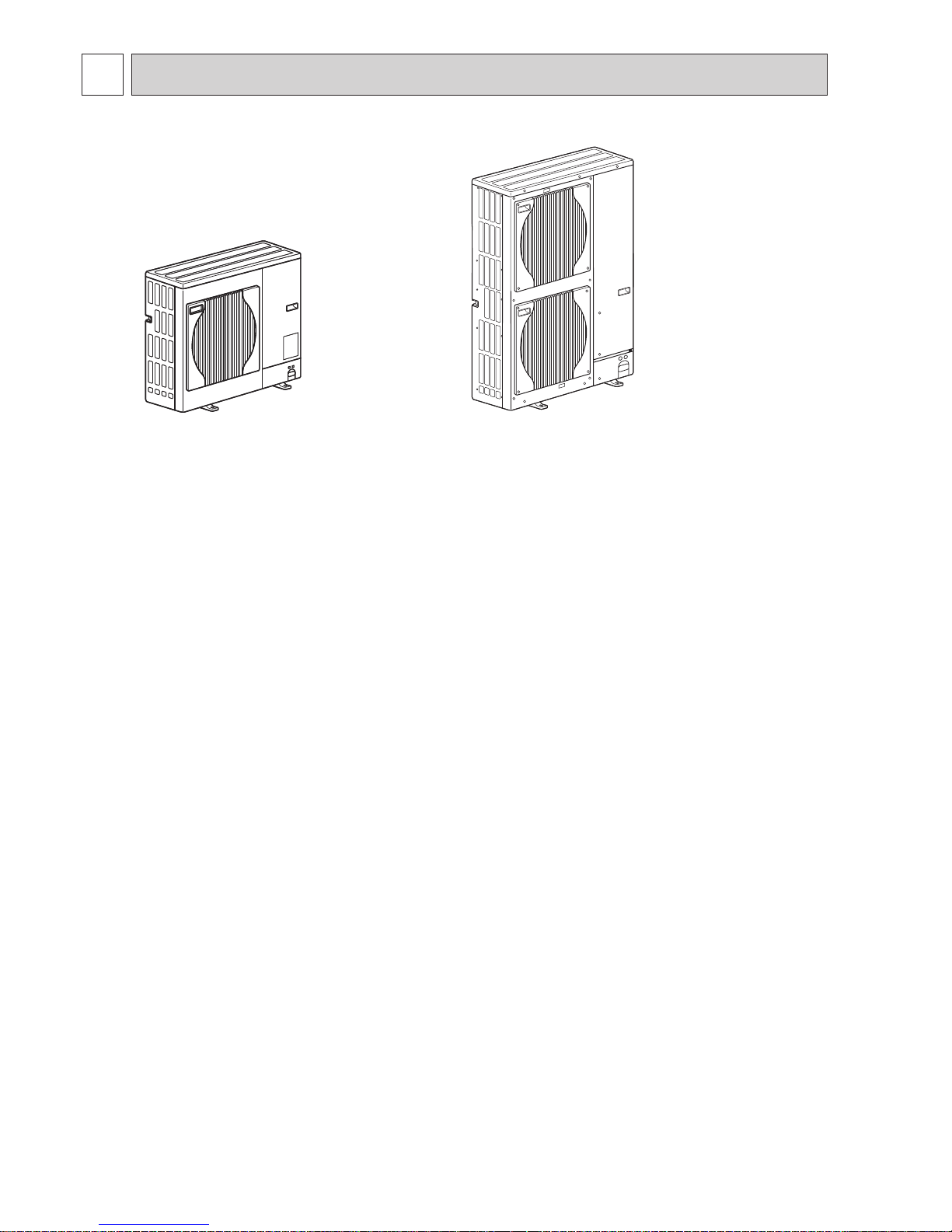
PUHZ-SP100VHA.UK
PUHZ-SP100YHA.UK
PUHZ-SP125VHA.UK
PUHZ-SP140VHA.UK
PUHZ-SP125YHA.UK
PUHZ-SP140YHA.UK
OCH566A
7
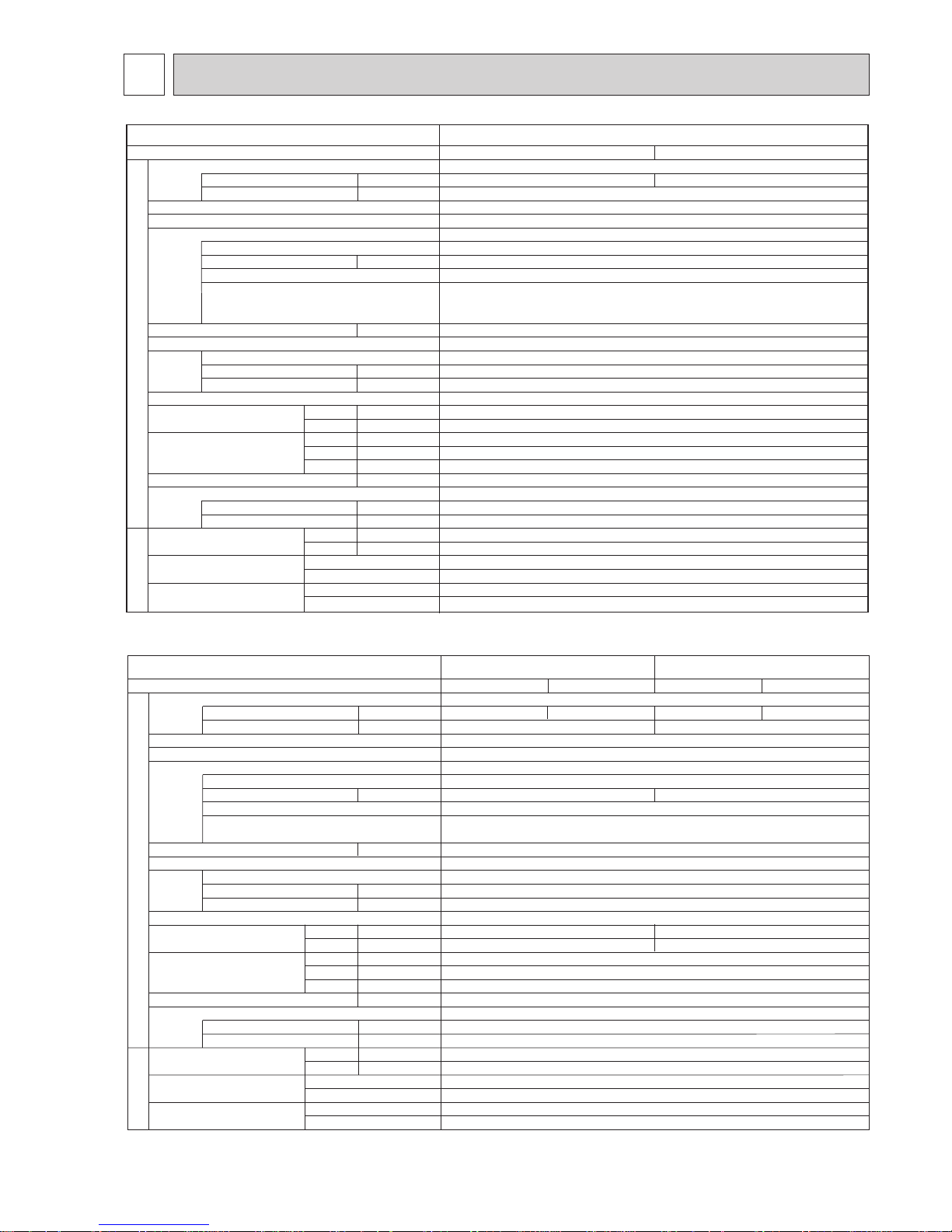
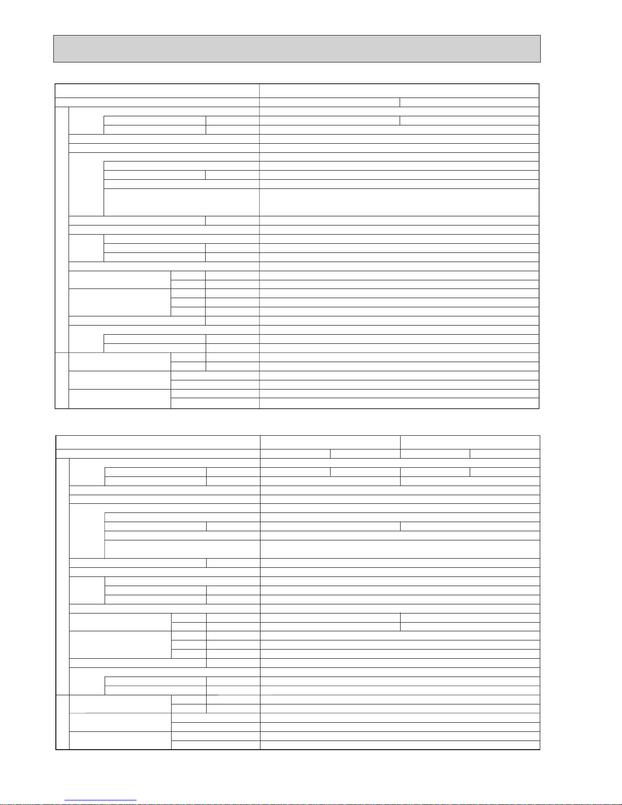
4 SPECIFICATIONS
A
A
kW
W
kW
K
/min(CFM
)
dB
dB
mm(in)
mm(in)
mm(in)
kg(lb)
kg(lb)
L
mm(in)
mm(in)
Power supply (phase, cycle, voltage)
Running current
Max. current
External finish
Refrigerant control
Compressor
Model
Motor output
Starter type
Protection devices
Crankcase heater
Heat exchanger
Fan Fan(drive) o No.
Fan motor output
Airflow
Defrost method
Noise level
Dimensions
Weight
Refrigerant
Charge
Oil (Model)
Pipe size O.D.
Connection method
Between the indoor &
outdoor unit
Mode
Cooling
Heating
W
D
H
Liquid
Gas
Indoor side
Outdoor side
Height difference
Piping length
Service Ref.
PUHZ-SP100VHA.UK
Cooling
13.36
Munsell 3Y 7.8/1.1
Linear Expansion Valve
Hermetic
TNB220FLHMT
2.9
Inverter
—
Plate fin coil
Propeller fan o 1
0.060
60(2120)
Reverse cycle
50
54
950(37-3/8)
330+30(13+1-3/16)
943(37-1/8)
75(165)
R410A
3.0(6.6)
0.87(FV50S)
9.52(3/8)
15.88(5/8)
Flared
Flared
Maximum 30m
Maximum 30m
Heating
15.02
HP switch
Comp. surface thermo
Single, 50Hz, 230V
OUTDOOR UNIT
REFRIGERANT PIPING
28
A
A
kW
W
kW
K
/min(CFM
)
dB
dB
mm(in)
mm(in)
mm(in)
kg(lb)
kg(lb)
L
mm(in)
mm(in)
Power supply (phase, cycle, voltage)
Running current
Max. current
External finish
Refrigerant control
Compressor
Model
Motor output
Starter type
Protection devices
Crankcase heater
Heat exchanger
Fan Fan(drive) o No.
Fan motor output
Airflow
Defrost method
Noise level
Dimensions
Weight
Refrigerant
Charge
Oil (Model)
Pipe size O.D.
Connection method
Between the indoor &
outdoor unit
Mode
Cooling
Heating
W
D
H
Liquid
Gas
Indoor side
Outdoor side
Height difference
Piping length
Service Ref.
PUHZ-SP140VHA.UK
PUHZ-SP125VHA.UK
Cooling
17.48
Munsell 3Y 7.8/1.1
Linear Expansion Valve
Hermetic
TNB306FPGMT
Inverter
30
Plate fin coil
Propeller fan o 2
0.060+0.060
100(3,530)
Reverse cycle
950(37-3/8)
330+30(13+1-3/16)
1,350(53-1/8)
99(218)
R410A
4.5(9.9)
0.87(FV50S)
9.52(3/8)
15.88(5/8)
Flared
Flared
Maximum 30m
Maximum 40m
Heating
16.95
Cooling
21.65
29.5
3.9
Heating
20.81
HP switch
Comp. surface thermo
Single 50Hz, 230V
OUTDOOR UNIT
REFRIGERANT PIPING
3.4
28
52
56
51
55
OCH566A
8
A
A
kW
W
kW
K
/min(CFM
)
dB
dB
mm(in)
mm(in)
mm(in)
kg(lb)
kg(lb)
L
mm(in)
mm(in)
Power supply (phase, cycle, voltage)
Running current
Max. current
External finish
Refrigerant control
Compressor
Model
Motor output
Starter type
Protection devices
Crankcase heater
Heat exchanger
Fan Fan(drive) o No.
Fan motor output
Airflow
Defrost method
Noise level
Dimensions
Weight
Refrigerant
Charge
Oil (Model)
Pipe size O.D.
Connection method
Between the indoor &
outdoor unit
Mode
Cooling
Heating
W
D
H
Liquid
Gas
Indoor side
Outdoor side
Height difference
Piping length
Service Ref.
PUHZ-SP100YHA.UK
Cooling
4.78
Munsell 3Y 7.8/1.1
Linear Expansion Valve
Hermetic
TNB220FLCMT
2.9
Inverter
—
Plate fin coil
Propeller fan o 1
0.060
60(2120)
Reverse cycle
50
54
950(37-3/8)
330+30(13+1-3/16)
943(37-1/8)
77(170)
R410A
3.0(6.6)
0.87(FV50S)
9.52(3/8)
15.88(5/8)
Flared
Flared
Maximum 30m
Maximum 30m
Heating
5.37
HP switch
Comp. surface thermo
3phase, 50Hz, 400V
OUTDOOR UNIT
REFRIGERANT PIPING
13
A
A
kW
W
kW
K
/min(CFM
)
dB
dB
mm(in)
mm(in)
mm(in)
kg(lb)
kg(lb)
L
mm(in)
mm(in)
Power supply (phase, cycle, voltage)
Running current
Max. current
External finish
Refrigerant control
Compressor
Model
Motor output
Starter type
Protection devices
Crankcase heater
Heat exchanger
Fan Fan(drive) o No.
Fan motor output
Airflow
Defrost method
Noise level
Dimensions
Weight
Refrigerant
Charge
Oil (Model)
Pipe size O.D.
Connection method
Between the indoor &
outdoor unit
Mode
Cooling
Heating
W
D
H
Liquid
Gas
Indoor side
Outdoor side
Height difference
Piping length
Service Ref.
PUHZ-SP140YHA.UKPUHZ-SP125YHA.UK
Cooling
6.18
Munsell 3Y 7.8/1.1
Linear Expansion Valve
Hermetic
TNB306FPNMT
Inverter
30
Plate fin coil
Propeller fan o 2
0.060+0.060
100(3,530)
Reverse cycle
950(37-3/8)
330+30(13+1-3/16)
1,350(53-1/8)
101(223)
R410A
4.5(9.9)
0.87(FV50S)
9.52(3/8)
15.88(5/8)
Flared
Flared
Maximum 30m
Maximum 40m
Heating
5.99
Cooling
7.58
13
3.9
Heating
7.36
HP switch
Comp. surface thermo
3phase, 50Hz, 400V
OUTDOOR UNIT
REFRIGERANT PIPING
3.4
13
52
56
51
55
OCH566A

9
5 DATA
5-1. REFILLING REFRIGERANT CHARGE (R410A : kg)
5-2. COMPRESSOR TECHNICAL DATA
Piping length (one way)
10 m
20 m
30 m
40 m
Initial
charged
2.9
4.3
4.3
3.0
4.4
4.4
3.6
4.5
4.5
—
5.1
5.1
3.0
4.5
4.5
Service Ref.
PUHZ-SP100VHA.UK
PUHZ-SP100YHA.UK
PUHZ-SP125VHA.UK
PUHZ-SP125YHA.UK
PUHZ-SP140VHA.UK
PUHZ-SP140YHA.UK
U-V
U-W
W-V
Service Ref.
Compressor model
Winding
Resistance
( " )
(at 20˚C)
TNB306FPGMT
0.53
0.53
0.53
TNB220FLHMT
0.88
0.88
0.88
PUHZ-SP100VHA.UK
PUHZ-SP125VHA.UK
PUHZ-SP140VHA.UK
U-V
U-W
W-V
Service Ref.
Compressor model
Winding
Resistance
( " )
PUHZ-SP100YHA.UK
PUHZ-SP125YHA.UK
PUHZ-SP140YHA.UK
TNB220FLCMT
1.41
1.41
1.41
TNB306FPNMT
1.02
1.02
1.02
Additional charge is required for pipes
longer than 20 or 30m.
OCH566A
10
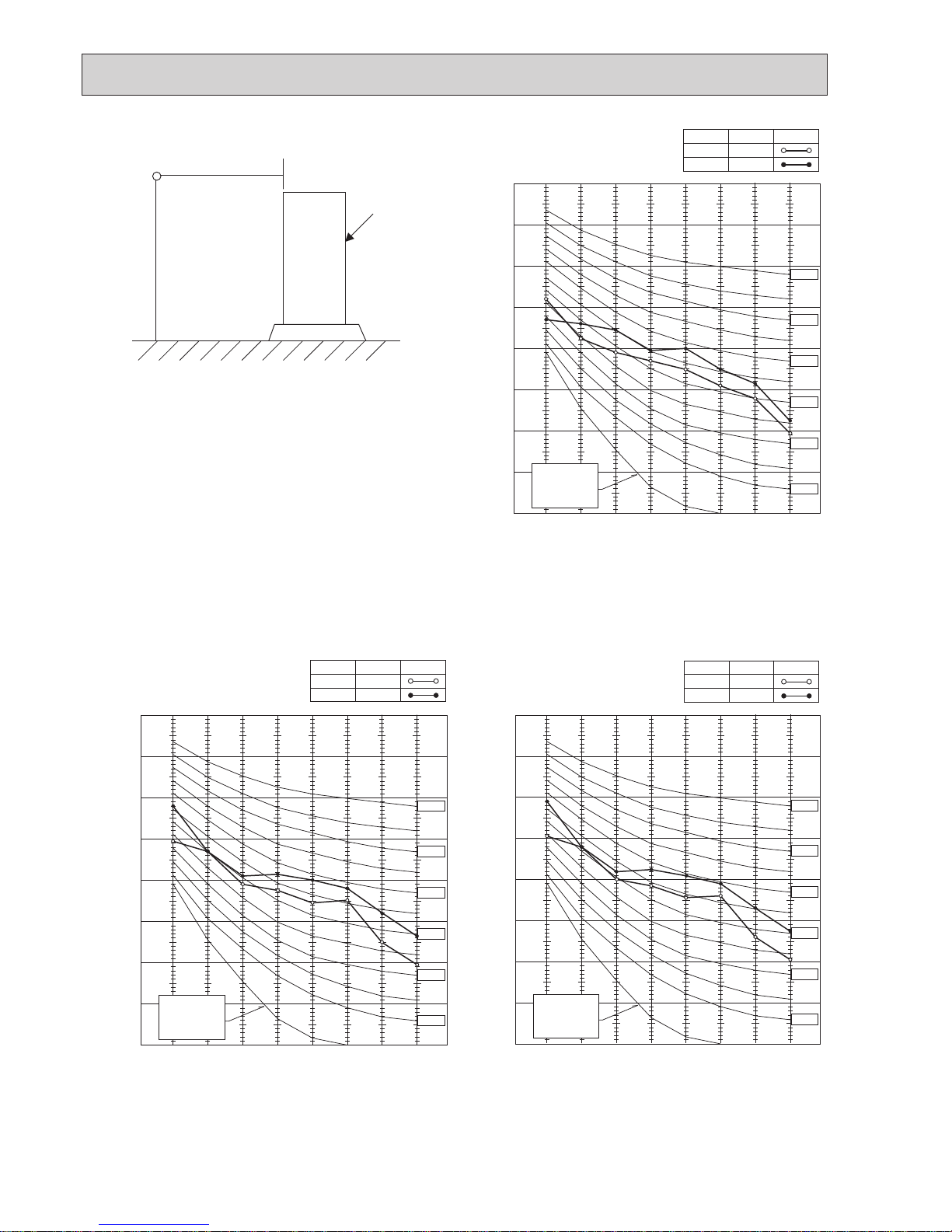
5-3. NOISE CRITERION CURVES
1.5m
1m
MICROPHONE
UNIT
GROUND
90
80
70
60
50
40
30
20
10
63 125 250 500 1000 2000 4000 8000
APPROXIMATE
THRESHOLD OF
HEARING FOR
CONTINUOUS
NOISE
NC-60
NC-50
NC-40
NC-30
NC-20
NC-70
OCTAVE BAND SOUND PRESSURE LEVEL, dB (0 dB = 0.0002 μbar)
BAND CENTER FREQUENCIES, Hz
PUHZ-SP100VHA.UK
PUHZ-SP100YHA.UK
COOLING
MODE
HEATING
50
SPL(dB)
54
LINE
90
80
70
60
50
40
30
20
10
63 125 250 500 1000 2000 4000 8000
APPROXIMATE
THRESHOLD OF
HEARING FOR
CONTINUOUS
NOISE
OCTAVE BAND SOUND PRESSURE LEVEL, dB (0 dB = 0.0002 μbar)
BAND CENTER FREQUENCIES, Hz
NC-60
NC-50
NC-40
NC-30
NC-20
NC-70
PUHZ-SP125VHA.UK
PUHZ-SP125YHA.UK
COOLING
MODE
HEATING
51
SPL(dB)
55
LINE
90
80
70
60
50
40
30
20
10
63 125 250 500 1000 2000 4000 8000
APPROXIMATE
THRESHOLD OF
HEARING FOR
CONTINUOUS
NOISE
OCTAVE BAND SOUND PRESSURE LEVEL, dB (0 dB = 0.0002 μbar)
BAND CENTER FREQUENCIES, Hz
NC-60
NC-50
NC-40
NC-30
NC-20
NC-70
PUHZ-SP140VHA.UK
PUHZ-SP140YHA.UK
COOLING
MODE
HEATING
52
SPL(dB)
56
LINE
OCH566A
11
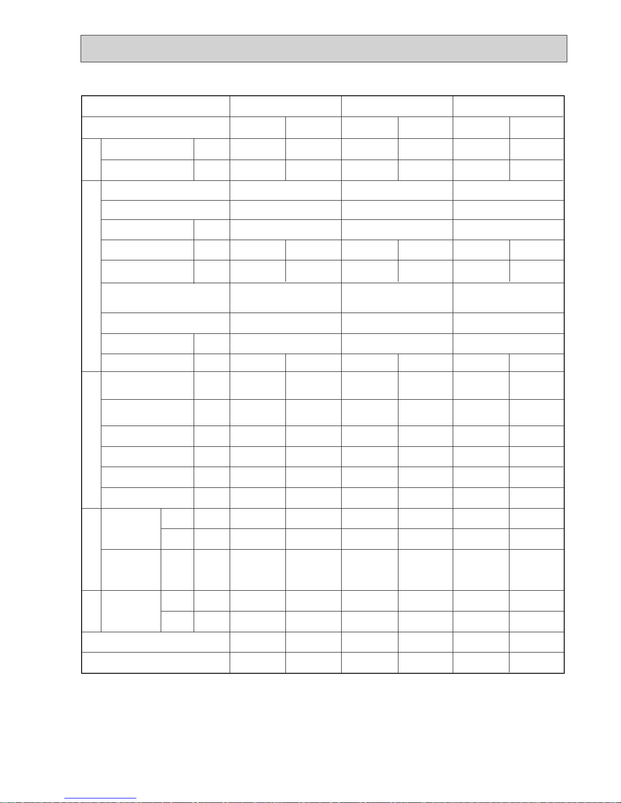
5-4. STANDARD OPERATION DATA
The unit of pressure has been changed to MPa based on international SI system.
The conversion factor is : 1 (MPa) = 10.2 (kgf/cm²)
TotalElectrical circuitRefrigerant circuitIndoor side
Outdoor
side
Representative matching
SHF
BF
W
kW
Mode
Capacity
Input
Amperes
Phase , Hz
Volts
Current
Discharge pressure
Suction pressure
Discharge temperature
Condensing temperature
Suction temperature
Ref. pipe length
Intake air
temperature
Discharge air
temperature
Intake air
temperature
V
MPa
(Of/F)
MPa
(Of/F)
°C
°C
°C
m
°C
°C
°C
°C
°C
Indoor unit
D.B.
W.B.
D.B.
D.B.
W.B.
PLA-SP125BA PLA-SP140BAPLA-SP100BA
PLA-SP100BA PLA-SP125BA PLA-SP140BA
Cooling
9,400
3.12
Heating
11,200
3.49
Cooling
12,300
4.08
Heating
13,500
3.96
Cooling
13,000
4.98
Heating
15,500
4.83
13.36 / 4.78
2.90
(29.6)
0.92
(9.4)
72.7
48.6
10.1
5
27
19
14.8
35
24
0.74
0.21
15.02 / 5.37
2.57
(26.2)
0.62
(6.3)
75.5
41.4
0.1
5
20
15
43.4
7
6
—
—
17.48/ 6.18
2.68
(27.3)
0.86
(8.8)
67.8
45.5
6.8
5
27
19
13.6
35
24
0.71
0.18
16.95 / 5.99
2.56
(26.1)
0.68
(6.9)
64.5
43.4
1.3
5
20
15
44.2
7
6
—
—
21.65 / 7.58
2.79
(28.5)
0.79
(8.1)
72.7
47.0
4.4
5
27
19
12.9
35
24
0.71
0.14
20.81 / 7.36
2.75
(28.1)
0.64
(6.5)
70.8
47.2
1.0
5
20
15
48.0
7
6
—
—
1 / 3, 50
230 / 400
1 / 3, 50
230 / 400
PUHZ-SP100VHA
PUHZ-SP100YHA
PUHZ-SP125VHA
PUHZ-SP125YHA
PUHZ-SP140VHA
PUHZ-SP140YHA
1 / 3 , 50
230 / 400
0.14
0.94
0.13
0.87
0.15
1.00
0.14
0.94
0.16
1.07
0.15
1.00
Outdoor unit
Phase , Hz
Volts
Input
V
kW
A
1 , 50
230
1 , 50
230
1 , 50
230
A
OCH566A
12
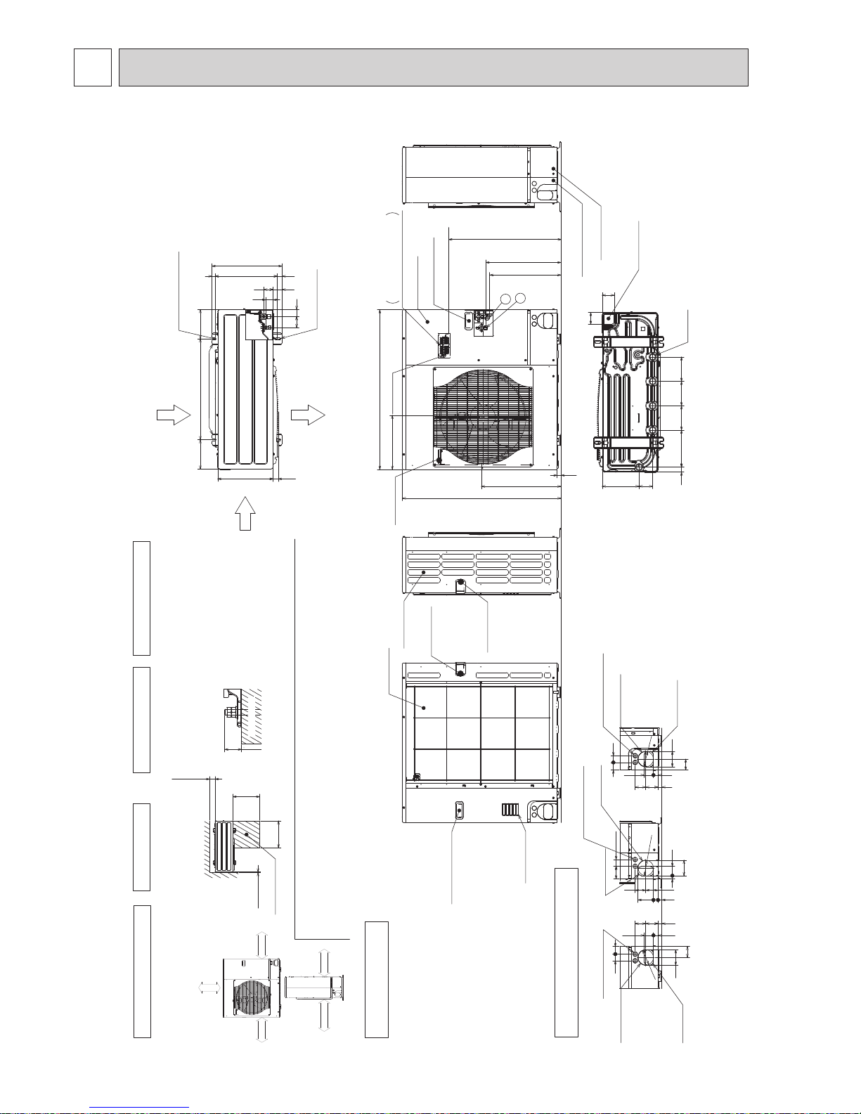
6 OUTLINES AND DIMENSIONS
Unit : mm
417
56 41
41
54
(19)37028
53
175600175
330
2-12o36 oval holes
(Foundation Bolt M10)
Air Discharge
Rear Air Intake
Side Air Intake
2-U Shaped notched holes
(Foundation Bolt M10)
Installation Feet
30
Over
Over
Less than
Piping and wiring connections
can be made from 4 directions:
front, right rear and below.
4 PIPING-WIRING DIRECTIONS
3 FOUNDATION BOLTS2 SERVICE SPACE
1 FREE SPACE (Around the unit)
Piping Knockout Hole Details
Example of Notes
1···Refrigerant GAS pipe connection (FLARE){15.88(5/8 inch)
2···Refrigerant LIQUID pipe connection (FLARE){ 9.52(3/8 inch)
w1 ···Indication of STOP VALVE connection location.
The diagram below shows a
basic example.
Explanation of particular details is
given in the installation manuals etc.
Over10
500
500
Over100
Dimensions of space needed
for service access are
shown in the below diagram.
Service space
30
Please secure the unit firmly
with 4 foundation (M10) bolts.
(Bolts and washers must be
purchased locally.)
<Foundation bolt height>
Handle for moving
Side Air Intake
Front piping cover
Rear piping cover
14522030 145
81 219
145
71
71
Drain hole
(5-{33)
Bottom piping hole
(Knockout)
Air Intake
Rear Air Intake
Handle for moving
Handle for moving
23
943
473
950
322
w1 447
w1 431
SP100VHA:670
SP100YHA:589
Terminal Connections
Left···Power supply wiring
Right···Indoor/Outdoor wiring
Earth terminal
Service panel
Handle for moving
Handle for moving
1
2
19 55
23 27 92
92
4075
73 63
Right piping hole
(Knockout)
Right trunking hole
(Knockout)
Power supply wiring hole
(2-{27Knockout)
{
92
27 55
732363
40
92
65
45
Front piping hole
(Knockout)
Front trunking hole
(Knockout)
Power supply wiring hole
(2-{27Knockout)
{
92
4045
65
92
27 55
23 73 63
Rear piping hole
(Knockout)
Rear trunking hole
(Knockout)
Power supply wiring hole
(2-{27Knockout)
{
92
FOUNDATION
over 100mm
over 500mm
over 10mm
FREE
over 10mm
PUHZ-SP100VHA.UK PUHZ-SP100YHA.UK
OCH566A
13
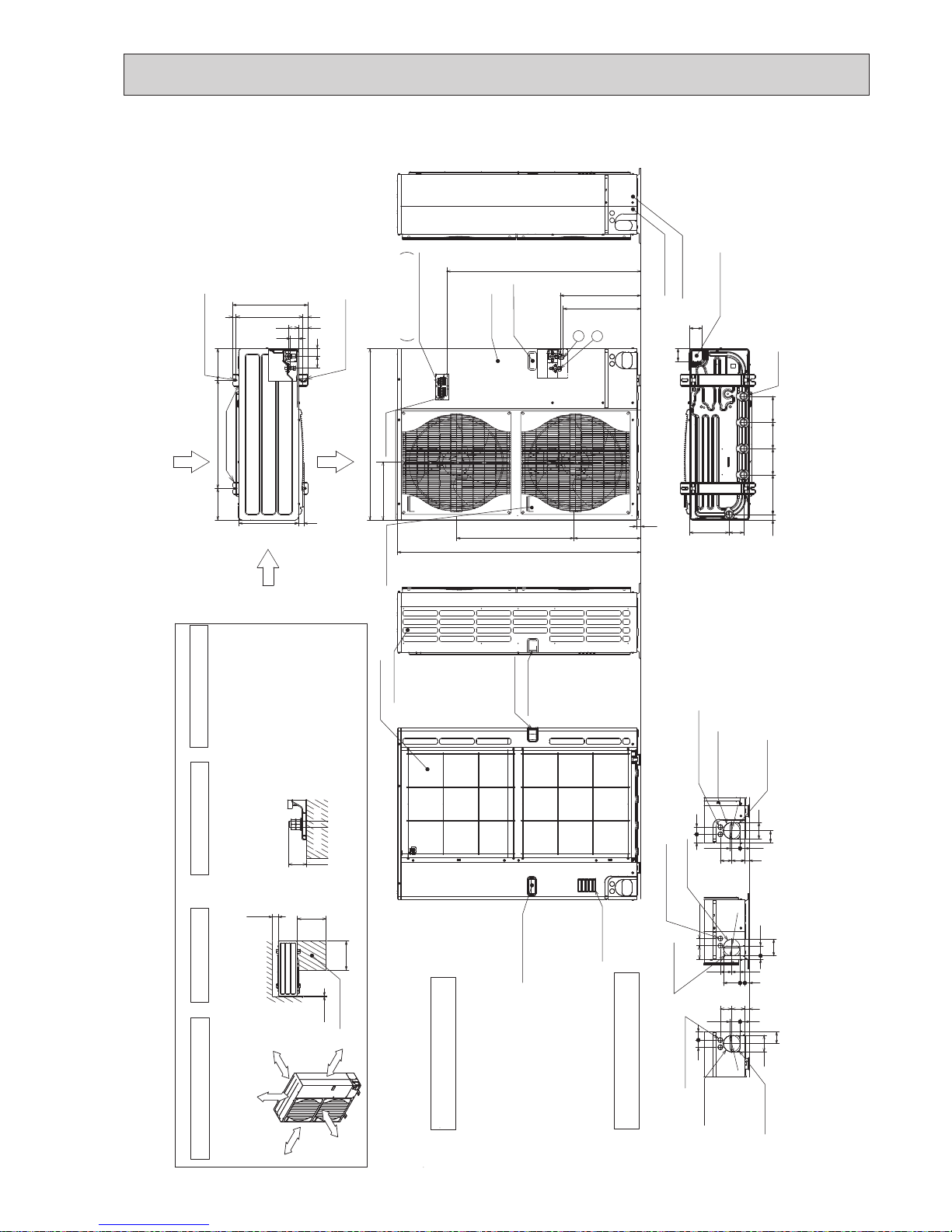
Unit : mm
Less than
Over
Over
Over
Over
Handle for moving
Side Air Intake
Front piping cover
Rear piping cover
Air intake
Rear Air Intake
Handle for moving
Handle for moving
Terminal connection
Left···Power supply wiring
Right···Indoor/Outdoor wiring
Earth terminal
Service panel
Handle for moving
1
2
The diagram below shows a
basic example.
Explanation of particular details is
given in the installation manuals etc.
Dimensions of space needed
for service access are
shown in the below diagram.
<Foundation bolt height>
Please secure the unit firmly
with 4 foundation (M10) bolts.
(Bolts and washers must be
purchased locally.)
Air Discharge
Rear Air Intake
Side Air Intake
1···Refrigerant GAS pipe connection (FLARE){15.88(5/8 inch)
2···Refrigerant LIQUID pipe connection (FLARE){ 9.52(3/8 inch)
w1 ···Indication of STOP VALVE connection location.
Example of Notes
Piping Knockout Hole Details
1 FREE SPACE (Around the unit)
2 SERVICE SPACE
3 FOUNDATION BOLTS
4 PIPING-WIRING DIRECTIONS
Piping and wiring connections
can be made from 4 directions:
front, right, rear and below.
30
FOUNDATION
150
500
500
10
Service space
600175 175
330
417
41
56
53 54
41
(19)28 370
2-U Shaped notched holes
(Foundation Bolt M10)
2-12 x 36 Oval holes
(Foundation Bolt M10)
Installation Feet
30
45 40
65
92
27 55
23 73 63
Rear piping hole
(Knockout)
Rear trunking hole
(Knockout)
Power supply wiring hole
(2-
{
27Knockout)
{
92
19 55
92
75 40
73 63
23 27 92
Right piping hole
(Knockout)
Right trunking hole
(Knockout)
Power supply wiring hole
(2-
{
27Knockout)
{
92
92
65
4540
27 55
23
73 63
Front piping hole
(Knockout)
Front trunking hole
(Knockout)
Power supply wiring hole
(2-
{
27Knockout)
{
92
14514522030 145
81 219
71
71
Bottom piping hole
(Knockout)
Drain hole
(5-{33)
1350
23
950
w1 447
w1 431
371 635
322
Handle for moving
Over 10mm
Over 10mm
Over 150mm
Over 1000mm
FREE
SP125/140VHA: 1076
SP125/140YHA: 994
PUHZ-SP125VHA.UK PUHZ-SP140VHA.UK
PUHZ-SP125YHA.UK PUHZ-SP140YHA.UK
OCH566A
14
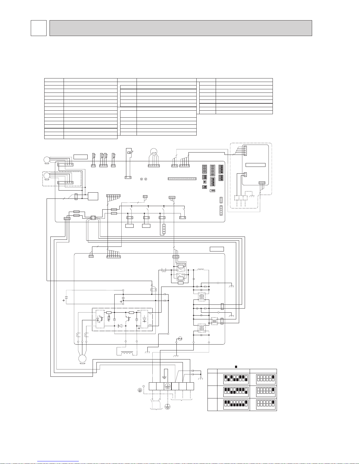
7 WIRING DIAGRAM
1 2 3 4 5 6 7 8
OFF
ON
100V
MODEL
SW6
*1 MODEL SELECT
*2 SW5 -1 to 5 : Function Switch
*3 SP125/140 only
SW5-6 *2
OFF
ON
1 2 3 4 5 6
1 2 3 4 5 6 7 8
OFF
ON
125V
OFF
ON
1 2 3 4 5 6
1 2 3 4 5 6 7 8
OFF
ON
140V
OFF
ON
1 2 3 4 5 6
TB1
MC
MF1, MF2
21S4
TH3
TH6
TH7
DCL
Terminal Block <Power Supply, Indoor/Outdoor>
Motor for Compressor
Fan Motor
Solenoid Valve (Four-Way Valve)
63H High Pressure Switch
Thermistor <Liquid>
Thermistor <2-Phase Pipe>
Thermistor <Ambient>
TH8 Thermistor (internal) <Heat Sink>
TH32 Thermistor <Comp. Surface>
Linear Expansion Valve
Reactor
CB
Main Smoothing Capacitor
CY1, CY2
Capacitor
SV
Solenoid Valve (Bypass Valve)
CH
Crankcase Heater
Controller Circuit Board
C.B.
SYMBOL NAME SYMBOL NAME SYMBOL NAME
Switch <Function Switch>
Switch <Manual Defrost, Defect History, Record
Reset, Refrigerant Address>
Switch <Test Operation>
Switch <Function Switch, Model Select>
Switch <Model Select>
SW7
SW1
SW4
SW5
SW6
Switch <Function Switch>
SW8
Switch <Pump Down>
SWP
Connector <Emergency Operation>
CN31
LED1, LED2
F1, F2, F3, F4
LED <Operation Inspection Indicators>
CNM
CNDM
Connector <Connection for Option>
Connector <Connection for Option>
Fuse <T6.3AL250V
>
X51, X52, X54, X55
Relay
SS
Connector <Connection for Option>
LEV-A
Power Module
Connection Terminal <Reactor>
Connection Terminal <Ground>
DCL1, DCL2
IGBT
EI, E2, E3, E4
P.B.
Power Circuit Board
Connection Terminal <U/V/W-Phase>
NI
Connection Terminal <N-Phase>
LI
Connection Terminal <L-Phase>
U/V/W
Switch <Function Switch>
SW9
*3
CN5
(WHT)
3 1
TB7
2
1
CND
(WHT)
CN2M
(WHT)
M-NET ADAPTER
M-NET
A B S
When M-NET adapter is connected
CNVMNT
(WHT)
31
CNDM
(WHT)
CN51
(WHT)
3
1
5
1
CNMNT
(WHT)
CNM
(WHT)
51
LEV-A
(WHT)
LEV-A
C. B.
3
5
TH7/6
(RED)
63H
(YLW)
TRANS
X51
TH3
(WHT)
CNDC
(PNK)
TH7 TH6 TH3
41 21
SW7
SW6SW1
SW9
CN31
141
M
CN2
(WHT)
CNS
(WHT)
CNAC
(WHT)
CN4
(WHT)
SS
(WHT)
21S4
(GRN)
2
1
LED1
LED2
X52
F1
F2
F4
F3
*1*1
21
43
SW5SW8SW4 SWP
21S4 SV
61
3
1
3
1
2
3 1
7
1
7
7
2
t° t° t°
TH32
(BLK)
TH32
21
t°
13
SV2
(BLU)
SV1
/CH
(GRY)
X5513X54
13 13
CN52C
(RED)
331
63H
5
3
5
1
DCL2
IGBT
N2
P2
MS
3~
U
U
V
V
W
W
CN2
(WHT)
CN4
(WHT)
1
7
1
2
2
P. B.
CNDC
(PNK)
BLK
WHT
CY1
CY2
LINI
EI
E4
E2
E3
POWER SUPPLY
~/N 230V 50Hz
INDOOR
UNIT
TB1
L N S1 S2 S3
MC
3
1
3
1
2
REDRED
CNAC1
(WHT)
CNAC2
(RED)
1
3
1
3
CN52C
(RED)
52C
52C
BLU
YLW
GRN/YLW
ORN
BRN
RED
WHT
RED
BLK
BLK
BLK
BLK
RED
BRN
ORN
WHT
DCL1
DCL
CB
t°
TH8
3
BLK
WHT
CH
*3
*3
MF1
CNF1
(WHT)
CNF2
(WHT)
7
1
MS
3~
MF2
7
1
MS
3~
The black square ( ) indicates a switch position.
PUHZ-SP100VHA.UK PUHZ-SP125VHA.UK PUHZ-SP140VHA.UK
OCH566A
15
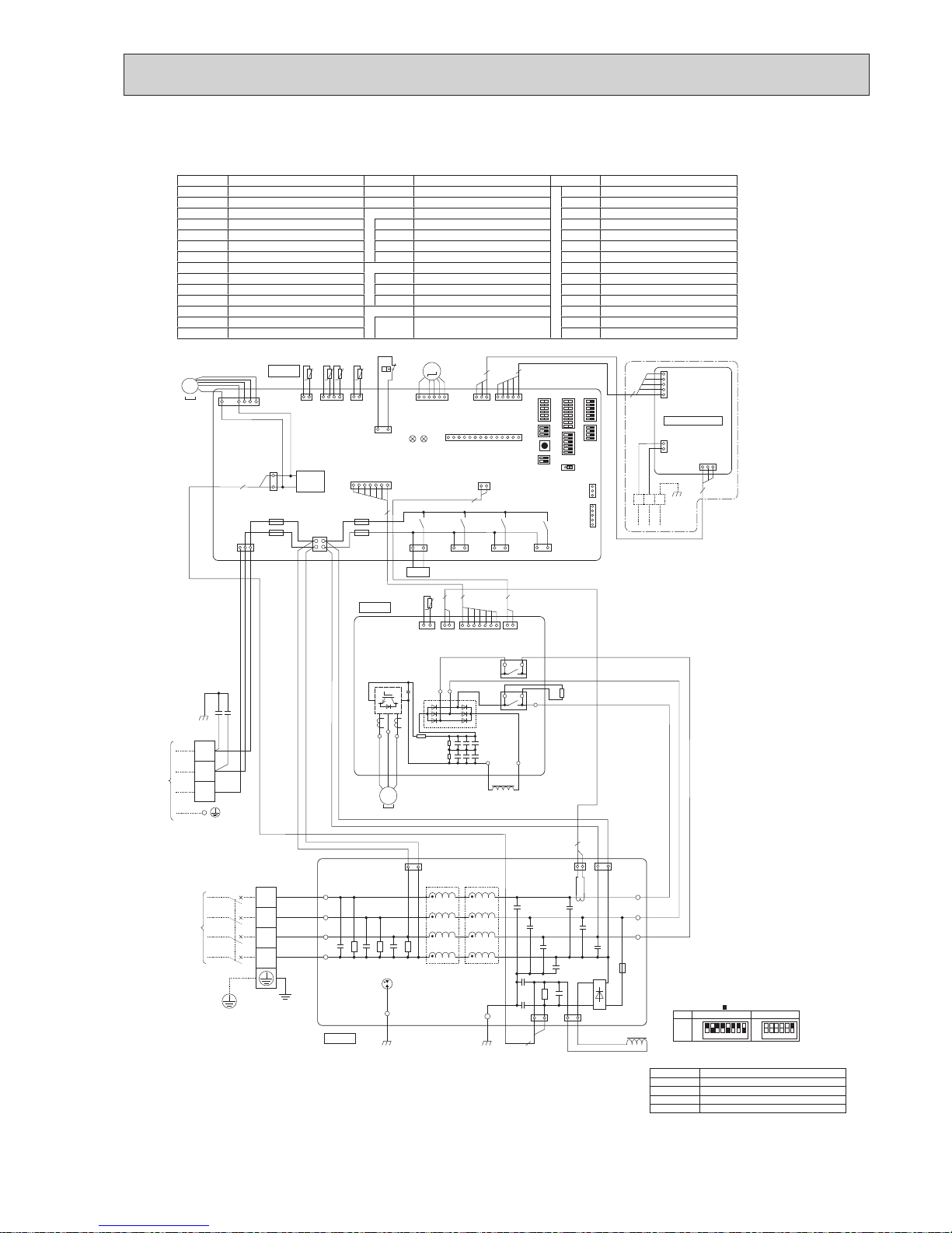
PUHZ-SP100YHA.UK
The black square ( ) indicates a switch position.
SYMBOL NAME SYMBOL NAME SYMBOL NAME
TB1 Terminal Block <Power Supply> RS Rush Current Protect Resistor SW4 Switch <Test Operation>
TB2 Terminal Block <Indoor/Outdoor> CY1, CY2 Capacitor SW5 Switch <Function Switch, Model Select>
MC Motor for Compressor P.B. Power Circuit Board SW6 Switch <Model Select>
MF1 Fan Motor TB-U/V/W
Connection Terminal
<U/V/W-Phase> SW7 Switch <Function Switch>
21S4 Solenoid Valve (Four-Way Valve)
TB-L1/L2/L3 Connection Terminal <L1/L2/L3-Power Supply>
SW8 Switch <Function Switch>
63H High Pressure Switch TB-P1/P3
Connection Terminal
SW9 Switch <Function Switch>
TH3 Thermistor <Liquid>
X52CA/B
52C Relay SWP Switch <Pump Down>
TH6 Thermistor <2-Phase Pipe> N.F. Noise Filter Circuit Board CN31 Connector <Emergency Operation>
TH7 Thermistor <Ambient>
LI1/LI2/LI3/NI
Connection Terminal <L1/L2/L3/N-Power Supply>
SS Connector <Connection for Option>
TH8 Thermistor <Heat Sink>
LO1/LO2/LO3
Connection Terminal <L1/L2/L3-Power Supply>
CNDM Connector <Connection for Option>
TH32 Thermistor <Comp. Surface> GD1, GD2
Connection Terminal
<Ground> CNM Connector <Connection for Option>
LEV-A Linear Expansion Valve C.B. Controller Circuit Board
LED1, LED2
LED <Operation Inspection Indicators>
DCL Reactor
SW1
Switch <Manual Defrost, Defect History,
Record Reset, Refrigerant Address>
F1, F2, F3, F4
Fuse <T6.3AL250V>
ACL4 Reactor
X51, X52, X54, X55
Relay
TB7 Terminal Block <M-NET connection>
SYMBOL NAME
CN5
Connector <Transmission>
CND
Connector <Power Supply>
CN2M
Connector <M-NET communication>
M-NET ADAPTER
TH8
t°
LEV-A
(WHT)
61
3
CNVMNT
(WHT)
CN4
(WHT)
CNMNT
(WHT)
3151
CN5
(WHT)
3 1
TB7
5
1
2
5
1
CND
(WHT)
CN2M
(WHT)
M-NET
When M-NET adapter is connected
1
2
3
4
CNS
(WHT)
13
21S4
(GRN)
MF1
TRANS
CNF1
(WHT)
1
3
CNDC
(PNK)
CN2
(WHT)
CNAC
(WHT)
13
SV2
(BLU)
X55
X51
X52
13
SS
(WHT)
ACL4
BLK
BLK
WHT
WHT
WHT
RED
BLK
BLU
GRN/YLW
WHT
RED
CNAC1
(WHT)
CNCT
(RED)
CNAC2
(RED)
CNL
(BLU)
CNDC
(PNK)
P.B.
C.B.
N.F.
LO1
GD2
LO2
LO3
LI1
LI2
LI3
NI
TB1
TB2
POWER
SUPPLY
3N~
400V 50Hz
INDOOR
UNIT
1
F2
F1
F3
F4
TH7/6
(RED)
63H
(YLW)
TH3
(WHT)
TH7 TH6 TH3
41 21
3
1
t° t° t°
TH32
(BLK)
TH32
21
t°
63H
2
2
1
7
2
3
72 2
7
1
71
3121
LEV-A
M
LED1
LED2
CNM
(WHT)
1
14
3
1
5
1
3
5
CNDM
(WHT)
CN51
(WHT)
SW7
SW6SW1
SW9
CN31
*1*
1
SW5SW8SW4 SWP
21S4
A B S
+
+
1331
31
L1
L2
L3
N
S1
S2
S3
YLW
CY2
CY1
ORN
BLK
BRN
MS
3~
2
2
M-NET ADAPTER
BLK
GD1
13
SV1
/CH
(GRY)
X54
1 2 3 4 5 6 7 8
OFF
ON
100Y
MODEL
SW6
*
1 MODEL SELECT
*
2 SW5 -1 to 5 : Function Switch
SW5-6 *2
OFF
ON
1 2 3 4 5 6
RS
CN6
(WHT)
CN5
(RED)
CN2
(WHT)
CN4
(WHT)
TB-U
TB-V
TB-W
U
W
V
DCL
RED
WHT
BLK
MC
WHT
RED
BLK
RED
RED
X52CA
BLK
-
MS
3~
71 2122 11
TB-P3
TB-P1
TB-L3
TB-L2
L3IN
TB-L1
+
-
+-
+ + +
+ + +
X52CB
L3OUT
OCH566A
16
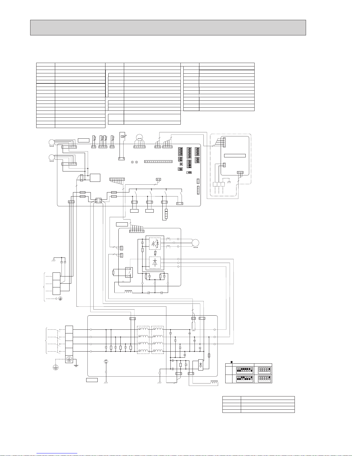
PUHZ-SP125YHA.UK PUHZ-SP140YHA.UK
TB1
MC
MF1, MF2
21S4
TH3
TH6
TH7
LEV-A
ACL4
Terminal Block<Power Supply >
TB2 Terminal Block<Indoor/Outdoor >
Motor for Compressor
Fan Motor
Solenoid Valve (Four-Way Valve)
63H High Pressure Switch
CH
Crankcase Heater
SV
Solenoid Valve (Bypass Valve)
Thermistor<Liquid>
Thermistor<2-Phase Pipe>
Thermistor<Ambient>
TH8 Thermistor (internal) <Heat Sink>
TH32 Thermistor<Comp. Surface>
Electronic Expansion Valve
Reactor
DCL
Reactor
RS
Rush Current Protect Resistor
CY1,CY2
Capacitor
CB1, CB2
Main Smoothing Capacitor
Power Circuit Board
Connection Terminal<U/V/W-Phase>
P.B.
TB-U/V/W
Noise Filter Circuit Board
Connection Terminal
<L1/L2/L3/N-Power Supply
>
N.F.
LI1/LI2/LI3/NI
Connection Terminal
<L1/L2/L3/N-Power Supply
>
LO1/LO2/LO3
Controller Circuit Board
SW8
Connector<Emergency Operation>
CN31
C.B.
Connection Terminal<Ground>
GD1, GD2
SYMBOL NAME SYMBOL NAME SYMBOL NAME
Connection Terminal
TB-P1
Connection Terminal
<L1/L2/L3-Power Supply
>
TB-L1/L2/L3
Switch<Function Switch>
SW9
Switch<Pump Down>
SWP
Switch<Manual Defrost, Defect History, Record
Reset, Refrigerant Address>
Switch<Function Switch, Model Select>
Switch<Function Switch>
Switch<Function Switch>
SW1
SW5
Switch<Model Select>
SW6
SW7
Switch<Test Operation>
SW4
LED1,LED2
LED<Operatiion Inspection Indicators>
CNM
Connector<Connection for Option>
SS
Connector<Connection for Option>
CNDM
Connector<Connection for Option>
FUSE<T6.3AL250V>
F1,F2,F3,F4
Connection Terminal
TB-P2
Connection Terminal
TB-C1
Connection Terminal
TB-N1
52C Relay
X52A
X51,X52,X54,X55
Relay
TB7 Terminal Block <M-NET connection>
SYMBOL NAME
CN5
Connector <Transmission>
CND
Connector <Power Supply>
CN2M
Connector <M-NET communication>
M-NET ADAPTER
1 2 3 4 5 6 7 8
1 2 3 4 5 6 7 8
MODEL
SW6
*1 MODEL SELECT
*2 SW5 -1 to 5 : Function Switch
SW5-6 *2
OFF
ON
125Y
OFF
ON
OFF
1 2 3 4 5 6
1 2 3 4 5 6
OFF
ON
140Y
ON
is the switch position
LEV-A
(WHT)
61
3
CNVMNT
(WHT)
CN4
(WHT)
CNMNT
(WHT)
3151
71
2
1
2
1
1
2
3
4
CNS
(WHT)
13
21S4
(GRN)
MF1
TRANS
CNF1
(WHT)
CNF2
(WHT)
1
3
CNDC
(PNK)
CN2
(WHT)
CNAC
(WHT)
13
SV2
(BLU)
X55
X51
X52
13
SS
(WHT)
+
--
--
+
+ +
+
+
ACL4
DCL
X52A
TB-P1
CN2
(WHT)
TB-P2
CB1 CB2
TB-C1 TB-N1
TB-W
BLK
WHT
RED
RED
BLK
WHT
RED
BLK
BLK
BLK
WHT
WHT
WHT
RED
BLK
BLU
GRN/YLW
WHT
RED
TB-V
TB-U
TB-L3
TB-L2
TB-L1
W
V
U
MC
CN4
(WHT)
CNAC1
(WHT)
CN5
(RED)
CNCT
(RED)
CNAC2
(RED)
CNL
(BLU)
CNDC
(PNK)
RS
P.B.
C.B.
N.F.
LO1
GD1
GD2
LO2
LO3
LI1
LI2
LI3
NI
TB1
TB2
POWER
SUPPLY
3N~
400V 50Hz
INDOOR
UNIT
1
F2
F1
F3
F4
TH7/6
(RED)
63H
(YLW)
TH3
(WHT)
TH7 TH6 TH3
41 21
3
1
t° t° t°
TH32
(BLK)
TH32
21
t°
63H
2
2
1
7
2
7
RED
WHT
BLK
7
1
71
BLK
BLK
3121
LEV-A
M
LED1
LED2
CNM
(WHT)
1
14
3
1
5
1
3
5
CNDM
(WHT)
CN51
(WHT)
SW7
SW6SW1
SW9
CN31
*1*1
SW5SW8SW4 SWP
SV21S4
MS
3~
+
1331
31
L1
L2
L3
N
S1
S2
S3
YLW
CY2
CY1
ORN
BRN
MS
3~
2
2
2
2
13
SV1
/CH
(GRY)
X54
CH
CN5
(WHT)
3 1
TB7
5
1
2
5
1
CND
(WHT)
CN2M
(WHT)
M-NET
When M-NET adapter is connected
3
A B S
M-NET ADAPTER
t°
TH8
MF2
7
1
MS
3~
+
--
OCH566A
17
8 WIRING SPECIFICATIONS
Outdoor unit model
Outdoor unit power supply
Outdoor unit input capacity
*1
Main switch (Breaker)
Outdoor unit power supply
Indoor unit-Outdoor unit *2
Indoor unit-Outdoor unit earth *2
Remote controller-Indoor unit *3
Outdoor unit L-N (single)
*4
Outdoor unit L1-N, L2-N, L3-N (3 phase)
Indoor unit-Outdoor unit S1-S2 *4
Indoor unit-Outdoor unit S2-S3 *4
Remote controller-Indoor unit *4
Wiring
Wire No. o
size (mm
2
)
Circuit rating
SP100, 125V SP140V
~/N (single), 50 Hz, ~/N (single), 50 Hz,
230 V 230 V
32 A 40 A
3 o Min. 4 3 o Min. 6
3 o 1.5 (Polar) 3 o 1.5 (Polar)
1 o Min. 1.5 1 o Min. 1.5
2 o 0.3 (Non-polar) 2 o 0.3 (Non-polar)
230 V AC
24 V DC
SP100/125/140Y
3N~ (3ph,4-wires),
50Hz, 400 V
16 A
5 o Min. 1.5
3 o 1.5 (Polar)
1 o Min. 1.5
2 o 0.3 (Non-polar)
*1. A breaker with at least 3 mm contact separation in each pole shall be provided. Use earth leakage breaker(NV).
*2. Refer to “8-3. INDOOR – OUTDOOR CONNECTING CABLE”.
*3. The 10 m wire is attached in the remote controller accessory.
*4. The figures are NOT always necessarily the voltage to ground.
S3 terminal has 24 V DC against S2 terminal. However between S3 and S1, these terminals are NOT electrically insulated by the transformer or other device.
Notes: 1. Wiring size must comply with the applicable local and national code.
2. Power supply cords and Indoor/Outdoor unit connecting cords shall not be lighter than polychloroprene sheathed flexible cord. (Design 60245 IEC 57)
3. Install an earth longer than other cables.
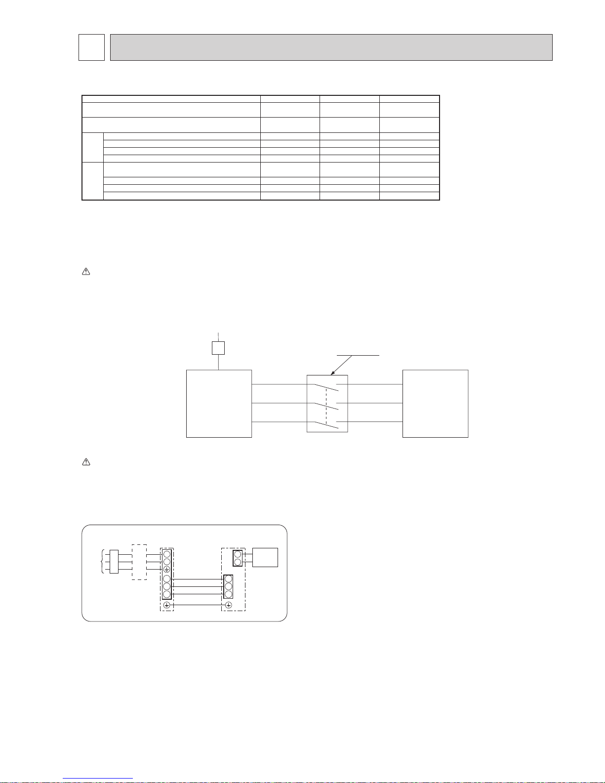
Warning:
In case of A-control wiring, there is high v oltage potential on the S3 terminal caused by electrical circuit design that has no electrical insulation between po wer line
and communication signal line. Therefore, please turn off the main power supply when servicing. And do not touch the S1, S2, S3 terminals when the power is
energized. If isolator should be used between indoor unit and outdoor unit, please use 3-pole type.
S1
S2
S3
S1
S2
S3
A-Control
Outdoor Unit
3 poles isolator
Power supply
Isolator
A-Control
Indoor Unit
Caution: Be sure to install N-Line. Without N-Line, it could cause damage to the unit.
Make sure that the current leakage breaker is one compatible with higher harmonics.
Always use a current leakage breaker that is compatible with higher harmonics as this unit is equipped with an inverter.
The use of an inadequate breaker can cause the incorrect operation of inverter.
230 V AC
230 V AC
230 V AC 230 V AC 230 V AC
24 V DC
24 V DC
12 V DC
12 V DC
12 V DC
8-1. FIELD ELECTRICAL WIRING (power wiring specifications)
1
2
S1
S2
S3
S1
S2
S3
Indoor/outdoor
unit connection
cable
Indoor
unit
Unit
power
supply
Outdoor
unit
Remote
controller
L
B
N
B Earth leakage breaker
C wiring circuit breaker or
isolating switch
C
1:1 system
OCH566A
18
The following connection patterns are available.
The outdoor unit power supply patterns vary on models.
1:1 System
<For models without heater>
The optional indoor power supply terminal kit is required.
S1
S2
L
N
1
2
L
N
S1
S2
S3
S3
A
CB
D
JEB
C
F
G
H
Affix a label B that is included with the manuals near each wiring diagram for the indoor and outdoor units.
A Outdoor unit power supply
B Earth leakage breaker
C Wiring circuit breaker or isolating switch
D Outdoor unit
E Indoor unit/outdoor unit connecting cords
F Remote controller
G Indoor unit
H Option
J Indoor unit power supply
If the indoor and outdoor units have separate power supplies, refer to the table below.
If the optional indoor power supply terminal kit is used, change the indoor unit
electrical box wiring referring to the figure in the right and the DIP switch settings of
the outdoor unit control board.
ON
OFF 1 2
(SW8)
3
Indoor power supply terminal kit (option)
Indoor unit electrical box connector connection change
Label affixed near each wiring diagram
for the indoor and outdoor units
Outdoor unit DIP switch settings (when
using separate indoor unit/outdoor unit
power supplies only)
Indoor unit specifications
Required
Required
Required
*1. A breaker with at least 3 mm contact separation in each pole shall be provided. Use earth leakage breaker (NV).
*2. Maximum 120 m
*3. The 10 m wire is attached in the remote controller accessory. Maximum 500 m
*4. The figures are NOT always necessarily the voltage to ground.
Notes: 1. Wiring size must comply with the applicable local and national code.
2. Power supply cords and indoor unit/outdoor unit connecting cords shall not be lighter than polychloroprene sheathed flexible cord.
(Design 60245 IEC 57)
3. Install an earth longer than other cables.
Indoor unit model
Indoor unit power supply
Indoor unit input capacity
*1
Main switch (Breaker)
Indoor unit power supply
Indoor unit power supply earth
Indoor unit-Outdoor unit
*2
Indoor unit-Outdoor unit earth
Remote controller-Indoor unit
*3
Indoor unit L-N *4
Indoor unit-Outdoor unit S1-S2 *4
Indoor unit-Outdoor unit S2-S3 *4
Remote controller-Indoor unit *4
SP100/125/140
~/N (single), 50 Hz, 230 V
16 A
2 o Min. 1.5
1 o Min. 1.5
2 o Min. 0.3
–
2 o 0.3 (Non-polar)
230 V DC
–
24 V DC
12 V DC
Circuit
rating
Wiring
Wire No. o size
(mm
2
)
Electric heater
(For models with
heater)
Connectors (connections when shipped
from the factory are for indoor unit power
supplied from outdoor unit)
Indoor unit power supplied from outdoor unit
(when shipped from factory)
If the indoor and
outdoor units have
separate power
supplies, change the
connections of the
connectors as shown
in the following
figure.
Connectors
Indoor unit
control board
Separate indoor unit/outdoor unit power
supplies
Electric heater
(For models with
heater)
S1
S2
S3
L
N
BLUE
BLUE
YELLOW
YELLOW
CND or
CN01
S1
S2
S3
L
N
YELLOW
BLUE
BLUE
YELLOW
Indoor unit
control board
There are three types of labels (labels A, B and C). Affix the appropriate labels to
the units according to the wiring method.
Set the SW8-3 to ON.
;
;
CND or
CN01
Note:
8-2. SEPARATE INDOOR UNIT/OUTDOOR UNIT POWER SUPPLIES
OCH566A
19
8-3. INDOOR – OUTDOOR CONNECTING CABLE
Note: The Max. cable length may vary depending on the condition of installation, humidity or materials, etc.
Indoor unit-Outdoor unit
Outdoor power supply
Max. 45m
3 o 1.5 (polar)
1 o Min. 1.5
Max. 50m
3 o 2.5 (polar)
1 o Min. 2.5
Max. 80m
3 o 2.5 (polar) and S3 separated
1 o Min. 2.5
Indoor unit-Outdoor unit earth
Wire No. o Size (E)
Be sure to connect the indoor-outdoor connecting cables directly to the units (no intermediate connections).
Intermediate connections can lead to communication errors if water enters the cables and causes insufficient insulation to
earth or a poor electrical contact at the intermediate connection point.
Indoor unit-Outdoor unit
Indoor/Outdoor separate
power supply
Max. 120m
2 o Min. 0.3
—
Indoor unit-Outdoor unit earth
Wire No. o Size (E)
*Note: The optional indoor power supply terminal kit is necessary.
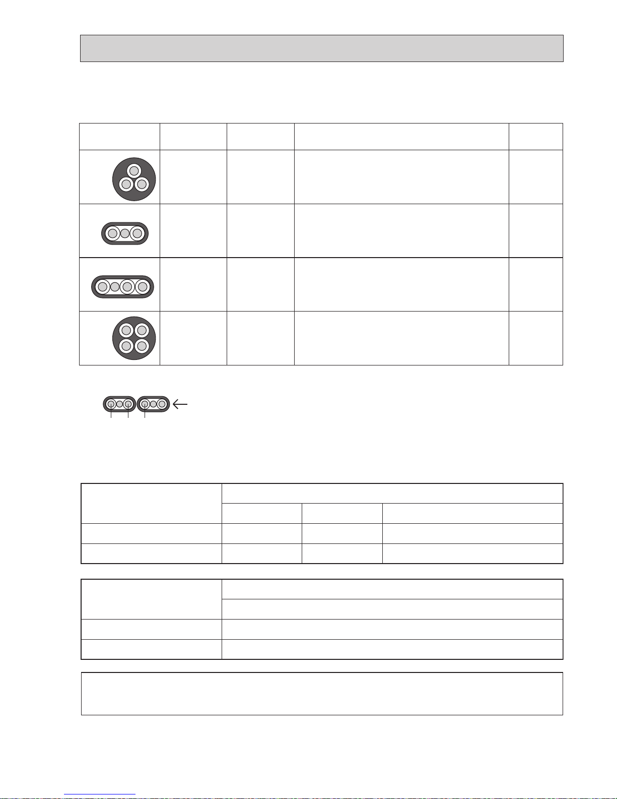
*1 : In case that cable with stripe of yellow and green is available.
*2 : In case that the flat cables are connected as this picture, they can be used up to 80m.
*3 : In case of regular polarity connection (S1-S2-S3), wire size is 1.5mm
2
.
*4 : In case of regular polarity connection (S1-S2-S3)
*5 : Mentioned cable length is just a reference value.
It may be different depending on the condition of installation, humidity or materials, etc.
The cable length may vary depending on the condition of installation, humidity or materials, etc.
The cable shall not be lighter than design 60245 IEC or 60227 IEC.
Cross section
of cable
Round
2.5
2.5
1.5
2.5
3
3
4
4
50
*1
45
*3
60
*4
Not
applicable
*2
Flat
Flat
Round
Wire size
(mm
2
)
Number
of wires
Clockwise : S1-S2-S3
Clockwise : S1-S2-S3-Open
Connect S1 and S3 to the opposite angle
Not applicable
(Because center wire has no cover finish)
From left to right : S1-Open-S2-S3
Polarity L(m) *5
(3C Flat cable × 2)
S1 S2 S3
OCH566A
20
8-4. M-NET WIRING METHOD
(Points to note)
(1) Outside the unit, transmission wires should stay away from electric wires in order to prevent electromagnetic noise from
making an influence on the signal communication. Place them at intervals of more than 5 cm. Do not put them in the same
conduit tube.
(2) Terminal block (TB7) for transmission wires should never be connected to V power supply. If it is connected, electronic
parts on M-NET P.C. board may burn out.
(3) Use 2-core × 1.25 mm² shield wire (CVVS, CPEVS) for the transmission wire. Transmission signals may not be sent or
received normally if different types of transmission wires are put together in the same multi-conductor cable. Never do this
because this may cause a malfunction.
It would be ok if M-NET wire (non-polar, 2-cores) is arranged in addition to the wiring for A-control.
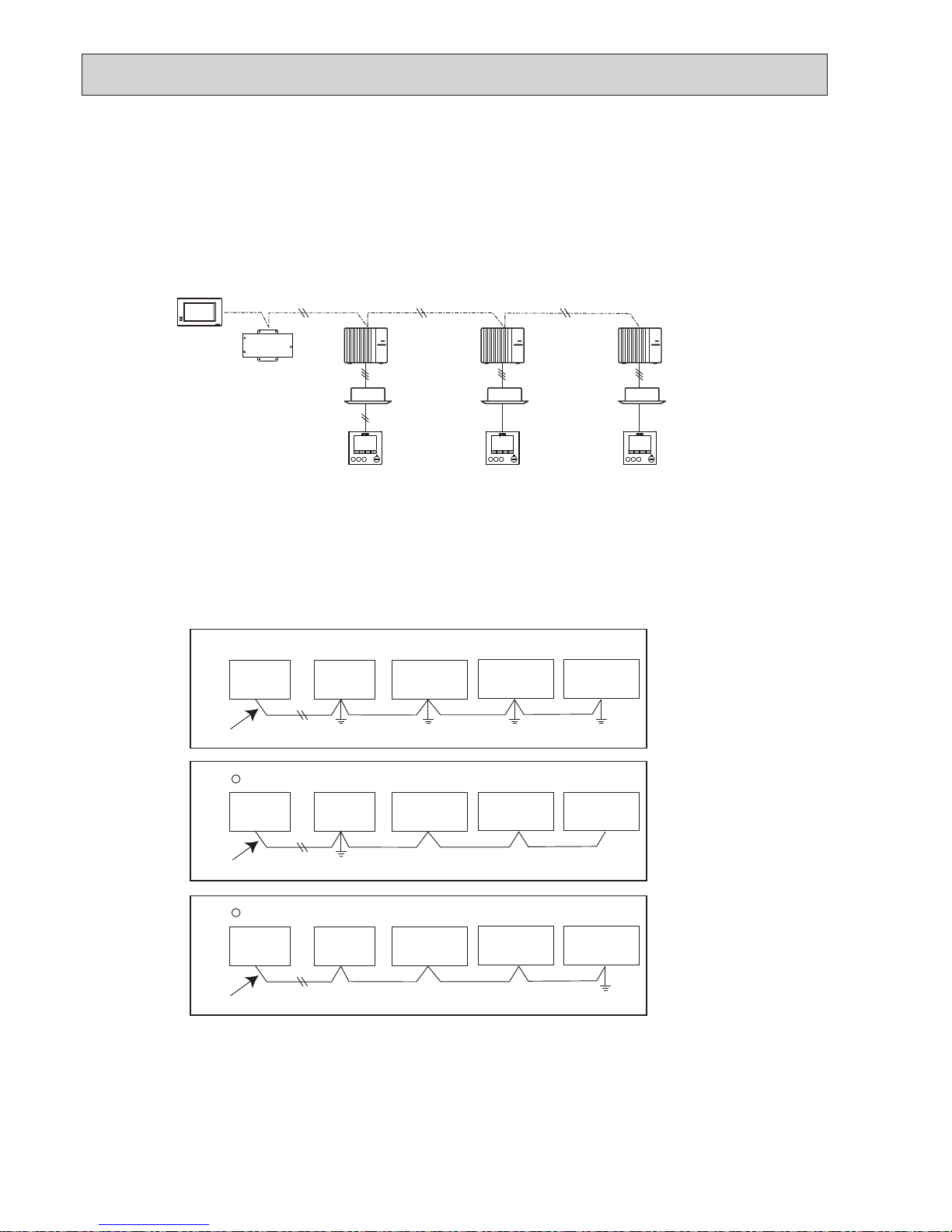
(4) Earth only one of any appliances through M-NET transmission wire (shield wire). Communication error may occur due to
the influence of electromagnetic noise.
“Ed” error will appear on the LED display of outdoor unit.
“0403” error will appear on the central-control remote controller.
If there are more than 2 grounding spots on the shield wire, noise may enter into the shield wire because the earth wire
and shield wire form 1 circuit and the electric potential difference occurs due to the impedance difference among earthing
spots. In case of single spot grounding, noise does not enter into the shield wire because the earth wire and shield wire do
not form 1 circuit.
To avoid communication errors caused by noise, make sure to observe the single spot grounding method described in the
installation manual.
Centralized
controller
Refrigerant
address 00
M-NET
address 01
A-control
remote
controller
A-control
remote
controller
A-control
remote
controller
Refrigerant
address 00
M-NET
address 02
Refrigerant
address 00
M-NET
address 03
Power
supply unit
Centralized
controller
M-NET transmission wire
5 Bad example (Multi spot earthing of shield wire)
Good example 1 (Single spot earthing of shield wire)
Power
supply unit
M-NET type
outdoor unit
M-NET type
outdoor unit
M-NET type
outdoor unit
M-NET type
outdoor unit
M-NET transmission wire
M-NET type
outdoor unit
M-NET type
outdoor unit
M-NET type
outdoor unit
M-NET transmission wire
M-NET type
outdoor unit
M-NET type
outdoor unit
Good example 2 (Single spot earthing of shield wire)
Centralized
controller
Centralized
controller
Power
supply unit
Power
supply unit
OCH566A
21
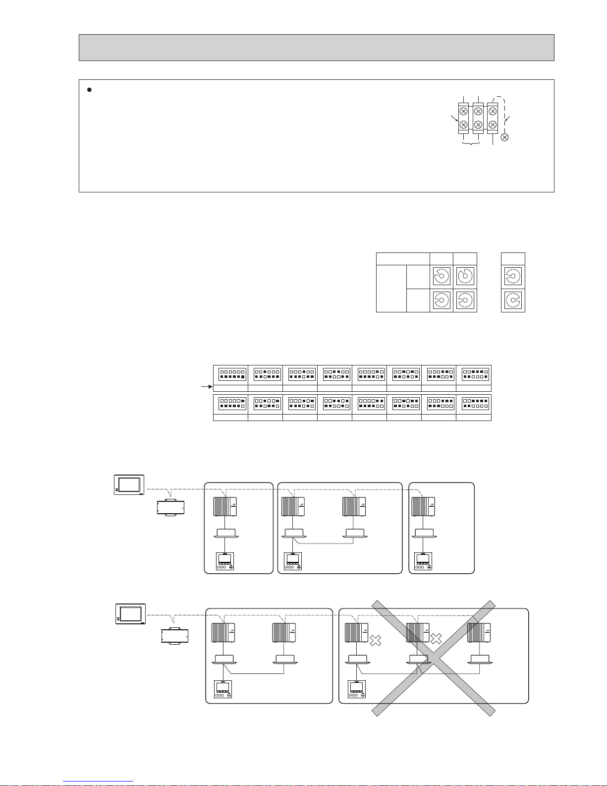
8-4-3. Regulations in address settings
In the case of multiple grouping system, M-NET and refrigerant address settings should be done as explained in the above
section. Set the lowest number in the group for the outdoor unit whose refrigerant address is “00” as its M-NET address.
* Refrigerant addresses can be overlapped if they are in the different group.
* In group B, M-NET address of the outdoor unit whose refrigerant address is “00” is not set to the minimum in the group. As
“3” is right for this situation, the setting is wrong. Taking group A as a good sample, set the minimum M-NET address in the
group for the outdoor unit whose refrigerant address is “00”.
8-4-1. M-NET address setting
In A-control models, M-NET address and refrigerant address should be set only for the outdoor unit. Similar to CITY MULTI
system, there is no need to set the address of outdoor unit and remote controller. To construct a central control system, the
setting of M-NET address should be conducted only upon the outdoor unit. The setting range should be 1 to 50 (the same as
that of the indoor unit in CITY MULTI system), and the address number should be consecutively set in a same group.
Address number can be set by using rotary switches
(SW11 for 1s digit and SW12 for 10s digit), which
is located on the M-NET board of outdoor unit.
(Factory setting: all addresses are set to “0”.)
8-4-2. Refrigerant address setting
In the case of multiple grouping system (multiple refrigerant circuits in one group), indoor units should be connected by
remote controller wiring (TB5) and the refrigerant address needs to be set. Leave the refrigerant addresses to “00” if the
group setting is not conducted. Set the refrigerant address by using DIP SW1-3 to -6 on the outdoor controller board. [Initial
setting: all switches are OFF. (All refrigerant addresses are “00”.)]
1
2
3
4
5
6
7
8
9
0
1
2
3
4
5
6
7
8
9
0
1
2
3
4
5
6
7
8
9
0
1
2
3
4
5
6
7
8
9
0
1
2
3
4
5
6
7
8
9
0
1
2
3
4
5
6
7
8
9
0
1 2
~
50
M-NET Address No.
<Setting example>
Switch
setting
SW11
1s
digit
SW12
10s
digit
OFF
ON
1
2
3
4
5
6
1
2
3
4
5
6
1
2
3
4
5
6
1
2
3
4
5
6
1
2
3
4
5
6
1
2
3
4
5
6
1
2
3
4
5
6
1
2
3
4
5
6
1
2
3
4
5
6
1
2
3
4
5
6
1
2
3
4
5
6
1
2
3
4
5
6
1
2
3
4
5
6
1
2
3
4
5
6
1
2
3
4
5
6
1
2
3
4
5
6
0
Refrigerant
address
The black square (
■
) indicates a switch position.
OFF
ON
8
OFF
ON
1
OFF
ON
9
OFF
ON
10
OFF
ON
11
OFF
ON
12
OFF
ON
13
OFF
ON
14
OFF
ON
15
OFF
ON
2
OFF
ON
3
OFF
ON
4
OFF
ON
5
OFF
ON
6
OFF
ON
7
A-control
remote
controller
Group A Group B Group C
A-control
remote
controller
TB5
A-control
remote
controller
Refrigerant
address 00
M-NET
address 01
Refrigerant
address 00
M-NET
address 02
Refrigerant
address 01
M-NET
address 03
Refrigerant
address 00
M-NET
address 04
Power
supply unit
Centralized
controller
Power
supply unit
A-control
remote
controller
A-control
remote
controller
TB5
Group A Group B
Refrigerant
address 00
M-NET
address 01
Refrigerant
address 01
M-NET
address 02
Refrigerant
address 00
M-NET
address 04
Refrigerant
address 01
M-NET
address 03
Refrigerant
address 02
M-NET
address 05
Centralized
controller
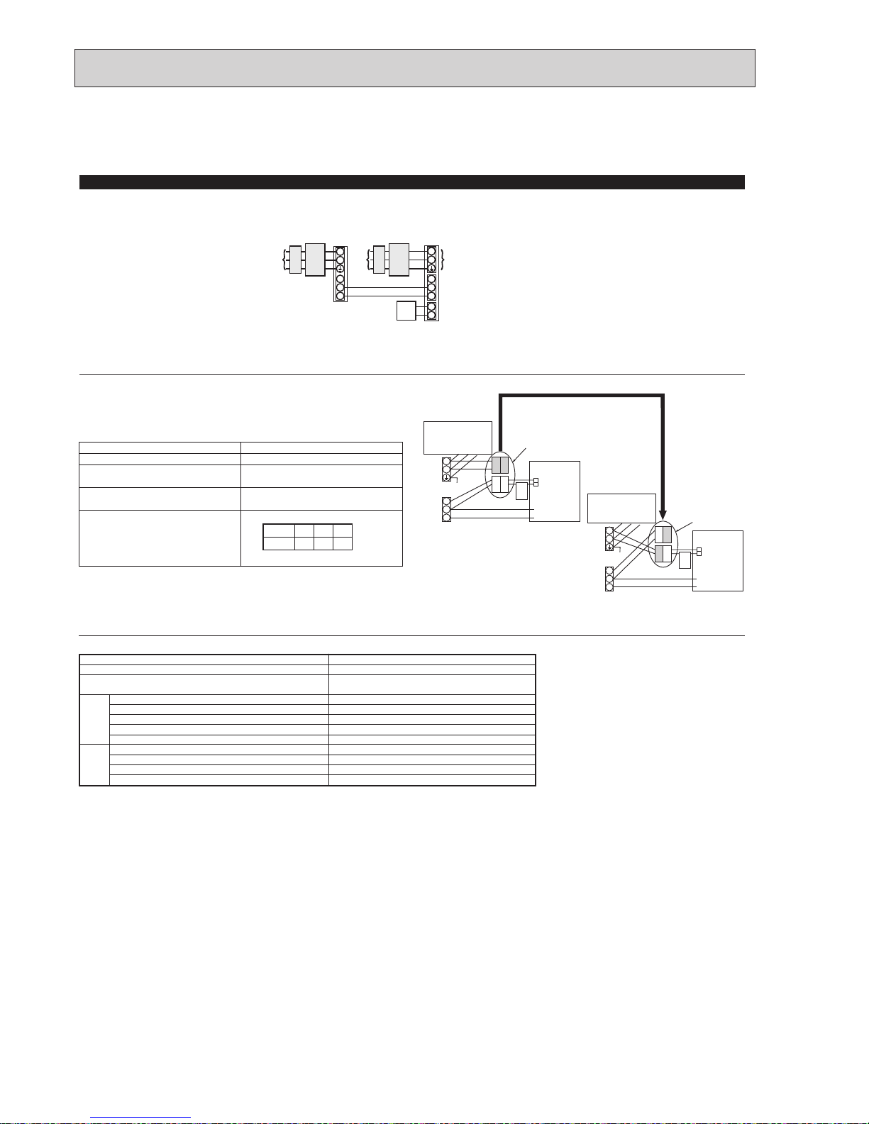
M-NET wiring
(1) Use 2-core × 1.25 mm² shield wire for electric wires.
(Excluding the case connecting to system controller.)
(2) Connect the wire to the M-NET terminal block. Connect one core of the trans-
mission wire (no-polarity) to A terminal and the other to B. Peel the shield wire,
twist the shield part to a string and connect it to S terminal.
(3) In the system which several outdoor units are being connected, the terminal
(A, B, S) on M-NET terminal block should be individually wired to the other
outdoor unit’s terminal, i.e. A to A, B to B and S to S. In this case, choose one of those outdoor units and drive a screw
to fix an ground wire on the plate as shown on the right figure.
Transmission
wire
Shield
part
M-NET
terminal
block
Earth
wire
A B S
OCH566A
22
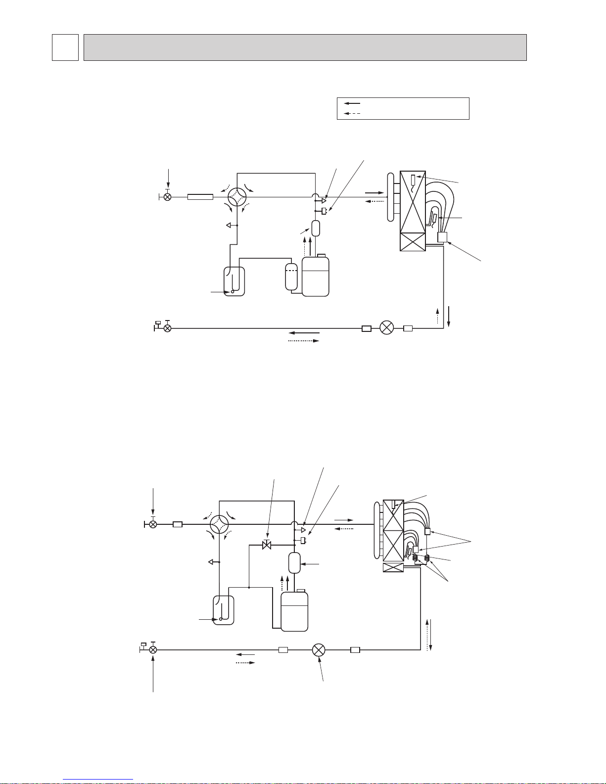
9 REFRIGERANT SYSTEM DIAGRAM
Unit : mm (inch)
Accumulator
Compressor
Refrigerant GAS pipe
15.88
mm([
5/8)
Refrigerant LIQUID pipe
9.52
mm([
3/8)
4-way
valve
Service port
(check)
High pressure protect switch
Linear expansion valve
Muffler
Stop valve
(#50)
Strainer
Strainer
(#100)
Strainer
(#100)
Stop valve
(with service port)
Strainer
(#40)
Thermistor (TH3)
Capillary tube
(
[
4.0o[3.0o-L200)o2
Thermistor
(TH6)
Distributor
Bypass valve
Outdoor heat exchanger
Thermistor
(TH3)
Thermistor
(TH6)
Distributor
Service
port
(check)
Service
port
(check)
Accumulator
Compressor
Refrigerant GAS pipe
15.88mm([5/8)
Refrigerant LIQUID pipe
9.52mm([3/8)
Stop valve
(with service port)
4-way valve
Service
port
(check)
High pressure
protect switch
Linear expansion valve
Thermistor
(TH32)
Thermistor
(TH32)
Muffler
Stop valve
(#50)
Strainer
(#100)
Strainer
Strainer
(#40)
(#100)
Strainer
Refrigerant flow in cooling
Refrigerant flow in heating
PUHZ-SP100VHA.UK
PUHZ-SP100YHA.UK
PUHZ-SP125VHA.UK PUHZ-SP140VHA.UK
PUHZ-SP125YHA.UK PUHZ-SP140YHA.UK
OCH566A

23
9-2. START AND FINISH OF TEST RUN
• Operation from the indoor unit
Execute the test run using the installation manual for the indoor unit.
• Operation from the outdoor unit
By using the DIP switch SW4 on the control board of outdoor unit, test run can be started and finished, and its operation
mode (cooling/heating) can be set up.
1 Set the operation mode (cooling/heating) using SW4-2.
2 Turn on SW4-1 to start the test run with the operation mode set by SW4-2.
3 Turn off SW4-1 to finish the test run.
•
There may be a faint knocking sound around the machine room after power is supplied. However,
this is not a problem with product because the linear expansion pipe is just moving to adjust opening pulse.
•
There may be a knocking sound around the machine room for several seconds after compressor
starts operating. However, this is not a problem with product because the check valve itself gener-
ates the sound due to small pressure difference in the refrigerant circuit.
Note:
The operation mode cannot be changed by SW4-2 during test run. (To change test run mode,
stop the unit by SW4-1, change the operation mode and restart the test run by SW4-1.)
OFF
1 2
ON
<SW4>
A B
C D
A Stop C
Operation
B Cooling D Heating
9-1. REFRIGERANT COLLECTING (PUMP DOWN)
When relocating or disposing of the indoor/outdoor unit, pump down the system following the procedure below so that no refriger-
ant is released into the atmosphere.
1 Turn off the power supply (circuit breaker).
2 Connect the low-pressure valve on the gauge manifold to the charge plug (lowpressure side) on the outdoor unit.
3 Close the liquid stop valve completely.
4 Supply power (circuit breaker).
• When power is supplied, make sure that “CENTRALLY CONTROLLED” is not displayed on the remote controller. If “CEN-
TRALLY CONTROLLED” is displayed, the refrigerant collecting (pump down) cannot be completed normally.
• Start-up of the indoor-outdoor communication takes about 3 minutes after the power (circuit breaker) is turned on. Start the
pump-down operation 3 to 4 minutes after the power (circuit breaker) is turned on.
5 Perform the refrigerant collecting operation (cooling test run).
• Push the pump-down SWP switch (push-button type) on the control board of the outdoor unit. The compressor and ventilators
(indoor and outdoor units) start operating (refrigerant collecting operation begins). (LED1 and LED2 on the control board of
the outdoor unit are lit.)
• Only push the pump-down SWP switch if the unit is stopped. However, even if the unit is stopped and the pump-down SWP
switch is pushed less than 3 minutes after the compressor stops, the refrigerant collecting operation cannot be performed.
Wait until the compressor has been stopped for 3 minutes and then push the pump-down SWP switch again.
6 Fully close the stop valve on the gas pipe side of the outdoor unit when the pressure gauge on the gauge manifold shows 0.05
to 0 MPa [Gauge] (approx. 0.5 to 0 kgf/cm²) and quickly stop the air conditioner.
• Because the unit automatically stops in about 3 minutes when the refrigerant collecting operation is completed (LED1 off,
LED2 lit), be sure to quickly close the gas stop valve. However, if LED1 is lit, LED2 is off, and the unit is stopped, open the
liquid stop valve completely, close the valve completely after 3 minutes or more have passed, and then repeat step 5. (Open
the gas ball valve completely.)
• If the refrigerant collecting operation has been completed normally (LED1 off, LED2 lit), the unit will remain stopped until the
power supply is turned off.
• Note that when the extension piping is very long with a large refrigerant amount, it may not be possible to perform a pumpdown operation. In this case, use refrigerant recovery equipment to collect all of the refrigerant in the system.
7 Turn off the power supply (circuit breaker), remove the gauge manifold, and then disconnect the refrigerant pipes.
Warning:
When pumping down the refrigerant, stop the compressor before disconnecting the refrigerant pipes.
• If the refrigerant pipes are disconnected while the compressor is operating and the stop valve (ball valve) is open, the
pressure in the refrigeration cycle could become extremely high if air is drawn in, causing the pipes to burst, personal
injury, etc.
OCH566A
24
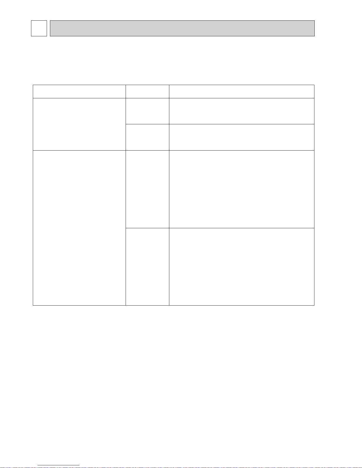
10 TROUBLESHOOTING
<Check code displayed by self-diagnosis and actions to be taken for service (summary)>
Present and past check codes are logged, and they can be displayed on the wired remote controller and control board of outdoor unit. Actions to be taken for service, which depends on whether or not the trouble is reoccurring in the field, are summa-
rized in the table below. Check the contents below before investigating details.
10-1. TROUBLESHOOTING
Unit conditions at service
Check code
Actions to be taken for service (summary)
The trouble is reoccurring.
Displayed
Not displayed
Judge what is wrong and take a corrective action according
to “10-4. SELF-DIAGNOSIS ACTION TABLE”.
Conduct trouble shooting and ascertain the cause of the
trouble according to “10-5. TROUBLESHOOTING OF
PROBLEMS”.
The trouble is not reoccurring.
Logged
Not logged
1Consider the temporary defects such as the work of
protection devices in the refrigerant circuit including
compressor, poor connection of wiring, noise, etc.
Re-check the symptom, and check the installation
environment, refrigerant amount, weather when the
trouble occurred, matters related to wiring, etc.
2Reset check code logs and restart the unit after finishing
service.
3There is no abnormality concerning of parts such as
electrical component, controller board, remote controller,
etc.
1Re-check the abnormal symptom.
2Conduct trouble shooting and ascertain the cause
of the trouble
according to “10-5. TROUBLESHOOTING
OF PROBLEMS”.
3Continue to operate unit for the time being if the cause
is not ascertained.
4There is no abnormality concerning of parts such as
electrical component, controller board, remote controller,
etc.
10-2. CHECK POINT UNDER TEST RUN
10-2-1. Before test run
• After installation of indoor and outdoor units, piping work and electric wiring work, re-check that there is no refrigerant leak-
age, loosened connections and incorrect polarity.
• Measure impedance between the ground and the power supply terminal block (L, N) on the outdoor unit by 500 V Megger
and check that it is 1.0 M" or over.
*Do not use 500V Megger to indoor/outdoor connecting wire terminal block (S1, S2, S3) and remote controller terminal block
(1,2). This may cause malfunction.
• Make sure that test run switch (SW4) is set to OFF before turning on power supply.
• Turn on power supply 12 hours before test run in order to protect compressor.
• For specific models which requires higher ceiling settings or auto-recovery feature from power failure, make proper changes
of settings referring to the description of “Selection of Functions through Remote Controller”.
Make sure to read operation manual before test run. (Especially items to secure safety.)
OCH566A
25
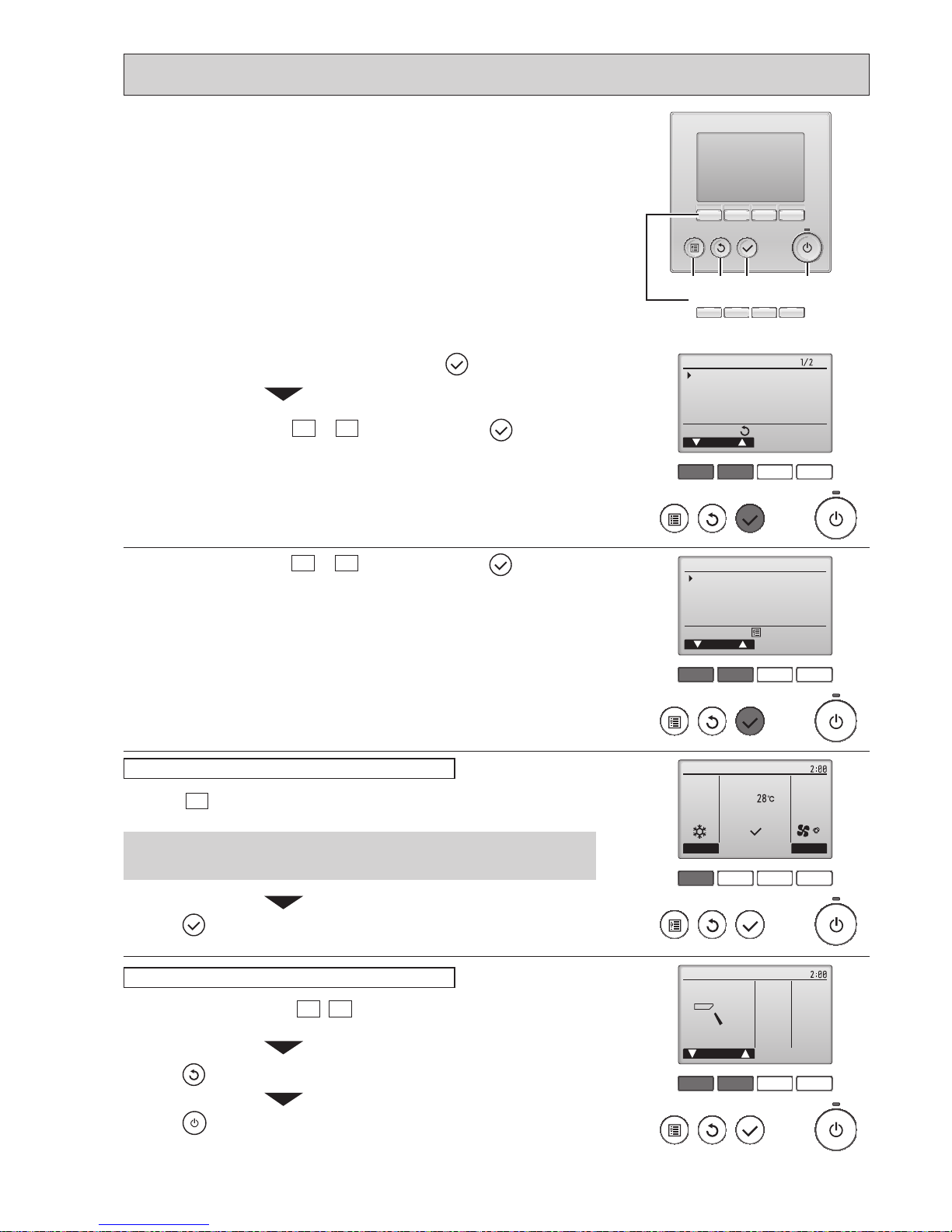
F1 F2 F3 F4
unem ecivreS
rosruC
:unem niaM
Test run
Input maintenance info.
Function setting
Check
Self check
F1 F2 F3 F4
Test run menu
Cursor
Service menu:
Test run
Drain pump test run
1
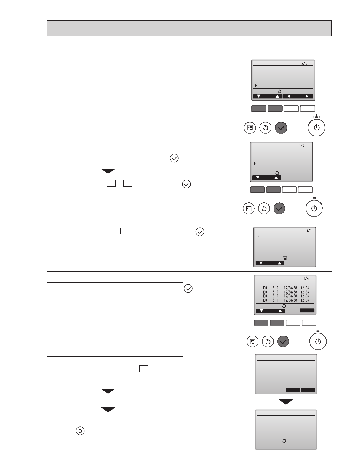
Select "Service" from the Main menu, and press the button.
2
Select "Test run" with the F1 or F2 button, and press the button.
Select "Test run" with the F1
or F2 button, and press the button.
F1 F2 F3 F4
Cool
Pipe
Auto
Switch disp.
Mode Fan
RemainTest run
F1 F2 F3 F4
Remain
Vane
Cool mode: Check the cold air blow off.
Heat mode: Check the heat blow off.
Press the F1
button to go through the operation modes in the order of "Cool
and Heat".
Check the auto vane with the F1
F2 buttons.
Press the
button to return to “Test run operation”.
Press the
button.
When the test run is completed, the “Test run menu” screen will appear.
The test run will automatically stop after two hours.
Test run operation
Auto vane check
Press the button and open the Vane setting screen.
Function buttons
F1 F2 F3 F4
MENU RETURN SELECT ON/OFF
10-2-2. Test run for wired remote controller <PAR-31MAA>
Check the operation of the outdoor unit’s fan.
OCH566A
26
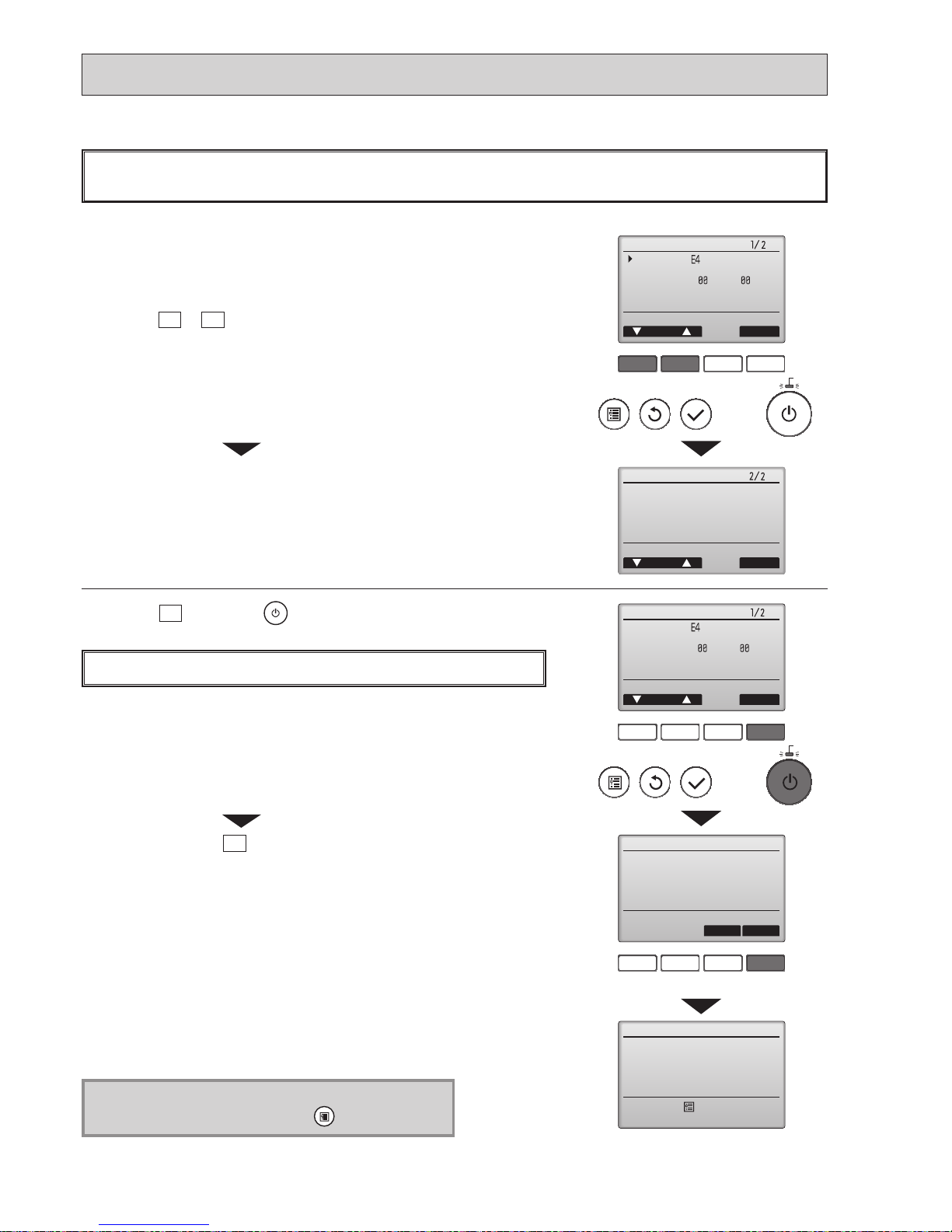
F1 F2 F3 F4
Error information
Error code
Error unit IU
Ref. address Unt#
Model name
Serial No.
ResetPage
Error information
Contact information
Dealer
Tel
ResetPage
Reset error: Reset button
Reset error: Reset button
blinks
1
Check code, error unit, refrigerant address, unit model name, and serial
number will appear.
The model name and serial number will appear only if the information have
been registered.
Press the
F1
or
F2
button to go to the next page.
When an error occurs, the following screen will appear.
Check the error status, stop the operation, and consult your dealer.
Contact information (dealer's phone number) will appear if the information have
been registered.
F1 F2 F3 F4
F1 F2 F3 F4
Error information
Error reset
Error reset
Error code
Error unit IU
Ref. address Unt#
Model name
Serial No.
ResetPage
Reset current error?
Error reset
OKCancel
Main menu:
Reset error: Reset button
blinks
2
Press the
F4
button or the button to reset the error that is occurring.
Errors cannot be reset while the ON/OFF operation is prohibited.
Select "OK" with the
F4
button.
Navigating through the screens
• To go back to the Main menu ..........
button
<Error information>
OCH566A
27
F1 F2 F3 F4
Main
Main display:
Cursor Page
Main menu
Restriction
Energy saving
Night setback
Filter information
Error information
blinks
While no errors are occurring, page 2/2 of the error information can be viewed by
selecting "Error information" from the Main menu.
Errors cannot be reset from this screen.
<Checking the error information>
<Error history>
F1 F2 F3 F4
unem ecivreS
rosruC
:unem niaM
Test run
Input maintenance info.
Function setting
Check
Self check
Check menu
Cursor
Service menu:
Error history
Refrigerant volume check
Refrigerant leak check
Smooth maintenance
Request code
F1 F2 F3 F4
Error history
Page
Delete
Check menu:
Error Unt#
dd/mm/yy
Error history
Cancel OK
Delete error history?
Error history
Check menu:
Error history deleted
2
Select "Error history" with the F1 or F2 button, and press the button.
Select "Check" with the F1
or F2 button, and press the button.
3
Select "Error history" from the Check menu, and press the button to view
up to 16 error history records.
Four records are shown per page, and the top record on the rst page
indicates the latest error record.
Error history
4
To delete the error history, press the F4 button (Delete) on the screen that
shows error history.
A conrmation screen will appear asking if you want to delete the error history.
Press the F4
button (OK) to delete the history.
"Error history deleted" will appear on the screen.
Press the
button to go back to the Check menu screen.
Deleting the error history
1
Select "Service" from the Main menu, and press the button.
OCH566A
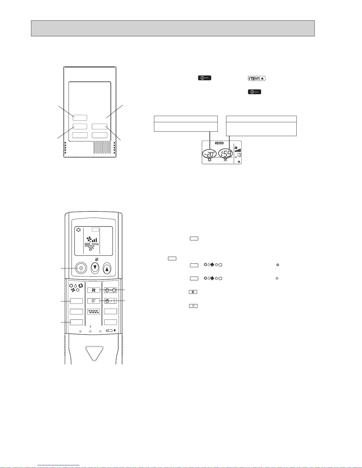
28
ON/OFF
TEMP
FAN
VANE
MODE
CHECK
LOUVER
TEST RUN
AUTO STOP
AUTO START
h
min
TEST RUN
RESET
SET
CLOCK
7
5
6
2
3,4
Measure an impedance between the power supply terminal block on
the outdoor unit and ground with a 500V Megger and check that it is
equal to or greater than 1.0 M".
1 Turn on the main power to the unit.
2 Press the button twice continuously.
(Start this operation from the status of remote controller display
turned off.)
and current operation mode are displayed.
3 Press the ( ) button to activate mode, then
check whether cool air blows out from the unit.
4 Press the ( ) button to activate mode, then
check whether warm air blows out from the unit.
5 Press the button and check whether strong air blows out
from the unit.
6 Press the button and check whether the auto vane operates
properly.
7 Press the ON/OFF button to stop the test run.
Note:
• Point the remote controller towards the indoor unit receiver
while following steps 2 to 7.
• It is not possible to run in FAN, DRY or AUTO mode.
MODE
MODE
COOL
HEAT
TEST RUN
FAN
VANE
TEST RUN
10-2-3. Test run for wired remote controller <PAC-YT52CRA>
1 Before making a test run, refer to the “Test Run” section of the
indoor unit installation manual.
2 When the A button and B button are pressed
simultaneously for 2 seconds or
longer, test run is performed.
3 Stop the test run by pressing the A button.
4 If trouble occurred during the test run, refer to the “Test Run”
section of the indoor unit installation manual.
.
Indoor unit piping temperature
Display range: -20ºC (-4ºF) to 70ºC (158ºF)
“-20ºC” or “70ºC” flashes on the display.
Test run time
The remaining time for test run is displayed.
Display range: 2:00 to 0:01
After two hours, the test run stops automatically.
ON
OFF
ON
OFF
10-2-4. Test run for wireless remote controller
B
C
D
A
OCH566A
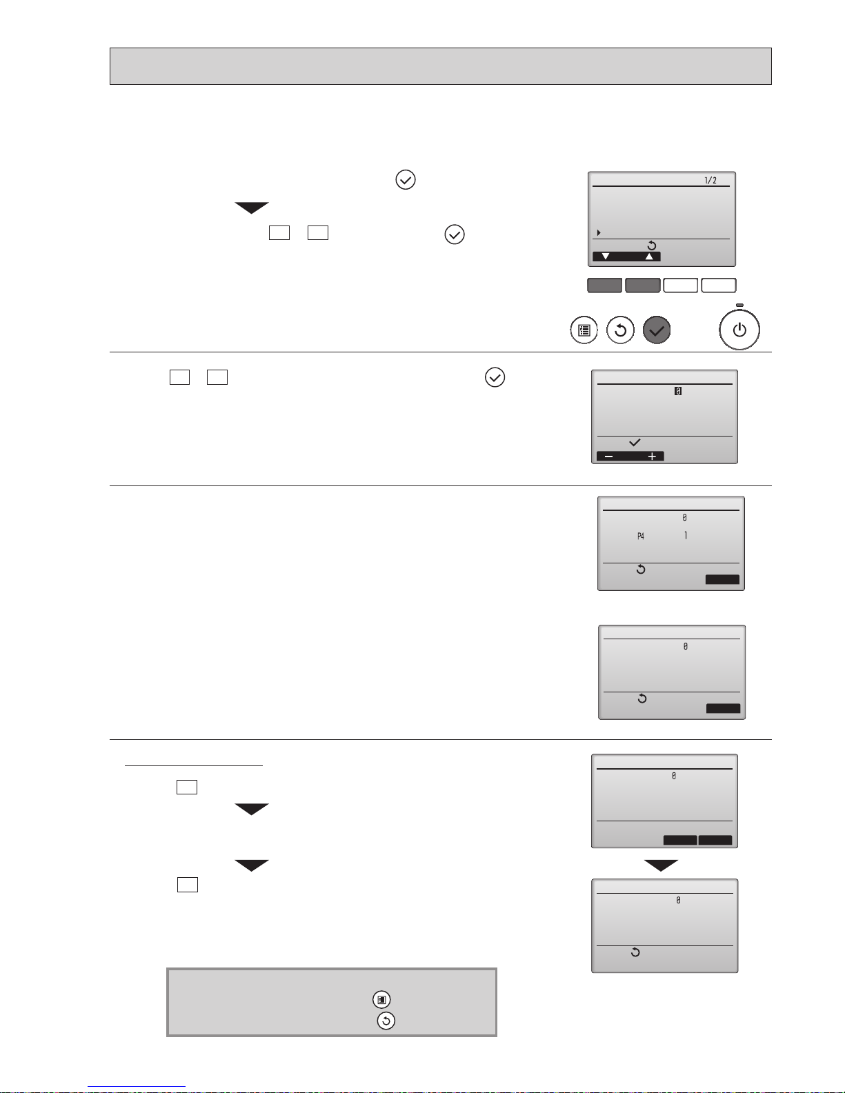
29
F1 F2 F3 F4
unem ecivreS
rosruC
:unem niaM
Test run
Input maintenance info.
Function setting
Check
Self check
kcehc fleS
:tceleS
Ref. address
sserddA
kcehc fleS
Ref. address
Return:
teseR
Error Unt #
CI.prG
Self check
Return:
Reset
Grp.
-
Error Unt #
--
--
Ref. address
When there is no error history
Self check
Delete error history?
Ref. address
Cancel OK
Self check
Return:
Ref. address
Error history deleted
2
With theF1orF2button, enter the refrigerant address, and press the button.
Select "Self check" with the F1 or F2 button, and press the button.
1
Select "Service" from the Main menu, and press the button.
3
Check code, unit number, attribute will appear.
"-" will appear if no error history is available.
4
Resetting the error history.
Press theF4button (Reset) on the screen that shows the error history.
A conrmation screen will appear asking if you want to delete the error history.
Press the
F4
button (OK) to delete the error history.
If deletion fails, "Request rejected" will appear.
"Unit not exist" will appear if no indoor units that are correspond to the entered
address are found.
Navigating through the screens
• To go back to the Main menu ..........
button
• To return to the previous screen .......
button
10-3. HOW TO PROCEED "SELF-DIAGNOSIS"
10-3-1. Self-diagnosis <PAR-31MAA>
OCH566A
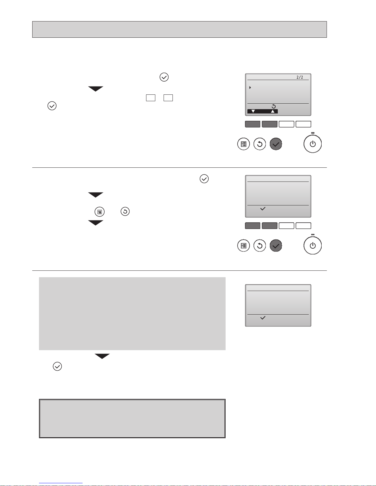
30
If operations cannot be completed with the remote controller, diagnose the remote controller with this function.
F1 F2 F3 F4
unem ecivreS
rosruC
:unem niaM
Maintenance password
Remote controller check
F1 F2 F3 F4
Remote controller check
:nigeB
Start checking?
Remote controller check
:nigeB
Start checking?
1
Select "Service" from the Main menu, and press the button.
Select "Remote controller check" with the F1
or F2 button, and press
the
button.
2
Select "Remote controller check" from the Service menu, and press the but-
ton to start the remote controller check and see the check results.
To cancel the remote controller check and exit the Remote controller check
menu screen, press the
or the button.
The remote controller will not reboot itself.
Check the remote controller display and see if anything is displayed
(including lines). Nothing will appear on the remote controller display
if the correct voltage (8.5 – 12 VDC) is not supplied to the remote controller. If this is the case, check the remote controller wiring and indoor
units.
OK: No problems are found with the remote controller. Check other
parts for problems.
E3, 6832: There is noise on the transmission line, or the indoor unit or another
remote controller is faulty. Check the transmission line and the
other remote controllers.
NG (ALL0, ALL1):
Send-receive circuit fault. Remote controller needs replacing.
ERC:
The number of data errors is the discrepancy between the number of
bits in the data transmitted from the remote controller and that of the
data that was actually transmitted over the transmission line. If data
errors are found, check the transmission line for external noise inter-
ference.
Remote controller check results screen
If the button is pressed after the remote controller check results are displayed, remote controller check will end, and the remote controller will automati-
cally reboot itself.
10-3-2. Remote controller check <PAR-31MAA>
3
OCH566A
 Loading...