

Mitsubishi PUHZ-SHW80VHA-BS, PUHZ-SHW112VHA, PUHZ-SHW112VHA-BS, PUHZ-SHW112YHA-BS, PUHZ-SHW140YHA-BS Service Manual
...
SERVICE MANUAL
No.OCH526
REVISED EDITION-B
SPLIT-TYPE, HEAT PUMP AIR CONDITIONERS
R410A
December 2013
Revision:
• Added
PUHZ-SHW80/112VHAR2(-BS).UK
and
PUHZ-SHW112/140YHAR2(-BS).UK
in REVISED EDITION-B.
• Some descriptions have been
modified.
PARTS CATALOG (OCB526B)
Outdoor unit
[Model Name]
PUHZ-SHW80VHA
PUHZ-SHW112VHA
PUHZ-SHW112YHA
PUHZ-SHW140YHA
Salt proof model
PUHZ-SHW80VHA-BS
PUHZ-SHW112VHA-BS
PUHZ-SHW112YHA-BS
PUHZ-SHW140YHA-BS
[Service Ref.]
PUHZ-SHW80VHA
PUHZ-SHW80VHAR2.UK
PUHZ-SHW112VHA
PUHZ-SHW112VHAR2.UK
PUHZ-SHW112YHA
PUHZ-SHW112YHAR1
PUHZ-SHW112YHAR2.UK
PUHZ-SHW140YHA
PUHZ-SHW140YHAR1
PUHZ-SHW140YHAR2.UK
PUHZ-SHW80VHAR2-BS.UK
PUHZ-SHW112VHAR2-BS.UK
PUHZ-SHW112YHAR2-BS.UK
PUHZ-SHW140YHAR2-BS.UK
CONTENTS
1. TECHNICAL CHANGES ······························· 2
2. REFERENCE MANUAL ································ 2
3. SAFETY PRECAUTION ······························· 3
4. SPECIFICATIONS ········································7
5. DATA ····························································· 9
6. OUTLINES AND DIMENSIONS··················10
7. WIRING DIAGRAM ····································· 12
8. WIRING SPECIFICATIONS ························ 17
9. REFRIGERANT SYSTEM DIAGRAM ········ 18
10. TROUBLESHOOTING ································ 20
11. FUNCTION SETTING ································· 82
12.
MONITORING THE OPERATION DATA BY THE REMOTE CONTROLLER
···· 95
13. EASY MAINTENANCE FUNCTION ········· 106
14. DISASSEMBLY PROCEDURE ················· 113
Note:
• This manual describes service data
of the outdoor units only.
• RoHS compliant products have
<G> mark on the spec name plate.
• Please void OCH526 REVISED
EDITION-A.
2
INDOOR UNIT SERVICE MANUAL
2-1. FOR AIR TO WATER SYSTEM
Model name Service ref. Service manual No.
EHST20C-VM6HB
EHST20C-YM9HB
EHST20C-TM9HB
EHST20C-VM2B
EHST20C-VM6B
EHST20C-YM9B
EHST20C-VM6EB
EHST20C-YM9EB
EHST20C-VM6SB
EHPT20X-VM2HB
EHPT20X-VM6HB
EHPT20X-YM9HB
EHPT20X-TM9HB
EHPT20X-VM6B
EHPT20X-YM9B
EHST20C-VM6HB.UK
EHST20C-YM9HB.UK
EHST20C-TM9HB.UK
EHST20C-VM2B.UK
EHST20C-VM6B.UK
EHST20C-YM9B.UK
EHST20C-VM6EB.UK
EHST20C-YM9EB.UK
EHST20C-VM6SB.UK
EHPT20X-VM2HB.UK
EHPT20X-VM6HB.UK
EHPT20X-YM9HB.UK
EHPT20X-TM9HB.UK
EHPT20X-VM6B.UK
EHPT20X-YM9B.UK
OCH531
EHSC-VM2B
EHSC-VM6B
EHSC-YM9B
EHSC-TM9B
EHSC-VM6EB
EHSC-YM9EB
EHPX-VM2B
EHPX-VM6B
EHPX-YM9B
ERSC-VM2B
EHSC-VM2B.UK
EHSC-VM6B.UK
EHSC-YM9B.UK
EHSC-TM9B.UK
EHSC-VM6EB.UK
EHSC-YM9EB.UK
EHPX-VM2B.UK
EHPX-VM6B.UK
EHPX-YM9B.UK
ERSC-VM2B.UK
OCH532
2-2. FOR AIR TO AIR SYSTEM
Model name Service Ref. Service manual No.
PLA-RP71/125BA2 PLA-RP71/125BA2.UK
OCH412
OCB412
PLA-RP100BA3 PLA-RP100BA3
OCH459
OCB459
PLA-ZRP35/50/60/71/125BA PLA-ZRP35/50/60/71/125BA
OCH535
OCB535
PLA-ZRP100BA PLA-ZRP100BA
OCH529
OCB529
PKA-RP100KAL PKA-RP100KAL.TH
OCH452
OCB452
PKA-RP60/100FAL PKA-RP50FAL2 PKA-RP60/100FAL PKA-RP50FAL2 OC331
PKA-RP50HAL PKA-RP50HAL
OCH453
OCB453
PEAD-RP50/60/71/100/125/JA(L) PEAD-RP50/60/71/100/125/JA(L)(R1).UK
HWE08130
BWE09220
BWE09240
PEAD-RP50/60/71/100/125/JA(L)Q PEAD-RP50/60/71/100/125/JA(L)Q.UK BWE10160
2
REFERENCE MANUAL
1
TECHNICAL CHANGES
PUHZ-SHW80VHA PUHZ-SHW80VHAR2(-BS).UK
PUHZ-SHW112VHA PUHZ-SHW112VHAR2(-BS).UK
PUHZ-SHW112YHAR1
PUHZ-SHW112YHAR2(-BS).UK
PUHZ-SHW140YHAR1 PUHZ-SHW140YHAR2(-BS).UK
• Controller circuit board (C.B.) has been changed.
PUHZ-SHW112YHA PUHZ-SHW112YHAR1
PUHZ-SHW140YHA PUHZ-SHW140YHAR1
• Power circuit board (P.B.) has been changed.
OCH526B
3
3
SAFETY PRECAUTION
3-2. CAUTIONS RELATED TO NEW REFRIGERANT
Cautions for units utilizing refrigerant R410A
Use new refrigerant pipes.
Make sure that the inside and outside of refrigerant piping is clean and it has no contaminants
such as sulfur, oxides, dirt, shaving particles, etc,
which are hazard to refrigerant cycle.
In addition, use pipes with specified thickness.
Store the piping to be used indoors during installation, and keep both ends of the piping sealed
until just before brazing. (Leave elbow joints, etc.
in their packaging.)
The refrigerant oil applied to flare and flange
connections must be ester oil, ether oil or
alkylbezene oil in a small amount.
In case of using the existing pipes for R22, be careful with
the followings.
· Be sure to perform replacement operation before test run.
· Change flare nut to the one provided with this product.
Use a newly flared pipe.
· Avoid using thin pipes.
Charge refrigerant from liquid phase of gas
cylinder.
If the refrigerant is charged from gas phase, composition change
may occur in refrigerant and the efficiency will be lowered.
Use a vacuum pump with a reverse flow check
valve.
Vacuum pump oil may flow back into refrigerant cycle and
that can cause deterioration of refrigerant oil etc.
Use the following tools specifically designed for
use with R410A refrigerant.
The following tools are necessary to use R410A refrigerant.
Handle tools with care.
If dirt, dust or moisture enters into refrigerant cycle, that can
cause deterioration of refrigerant oil or malfunction of compressor.
Do not use a charging cylinder.
If a charging cylinder is used, the composition of refrigerant will change and the efficiency will be lowered.
Flare tool
Electronic refrigerant
charging scale
Vacuum pump adaptor
Size adjustment gauge
Gauge manifold
Torque wrench
Gas leak detector
Charge hose
Tools for R410A
Contamination inside refrigerant piping can cause deterioration of refrigerant oil etc.
If dirt, dust or moisture enters into refrigerant cycle, that can
cause deterioration of refrigerant oil or malfunction of compressor.
If large amount of mineral oil enters, that can cause deterioration of refrigerant oil etc.
Ventilate the room if refrigerant leaks during
operation. If refrigerant comes into contact with
a flame, poisonous gases will be released.
Use the specified refrigerant only.
Never use any refrigerant other than that specified.
Doing so may cause a burst, an explosion, or fire when the
unit is being used, serviced, or disposed of.
Correct refrigerant is specified in the manuals and on the
spec labels provided with our products.
We will not be held responsible for mechanical failure,
system malfunction, unit breakdown or accidents caused
by failure to follow the instructions.
Do not use refrigerant other than R410A.
If other refrigerant (R22 etc.) is used, chlorine in refrigerant can cause deterioration of refrigerant oil etc.
3-1. ALWAYS OBSERVE FOR SAFETY
Before obtaining access to terminal, all supply circuits must be disconnected.
Preparation before the repair service.
• Prepare the proper tools.
• Prepare the proper protectors.
• Provide adequate ventilation.
• After stopping the operation of the air conditioner, turn off the power-supply breaker.
• Discharge the condenser before the work involving the electric parts.
Precautions during the repair service.
• Do not perform the work involving the electric parts with wet hands.
• Do not pour water into the electric parts.
• Do not touch the refrigerant.
• Do not touch the hot or cold areas in the refrigerating cycle.
• When the repair or the inspection of the circuit needs to be done without turning off the power,
exercise great caution not to touch the live parts.
OCH526B
4
Gravimeter
Unit
[3] Service tools
Use the below service tools as exclusive tools for R410A refrigerant.
[4] Refrigerant leakage detection function
This air conditioner can detect refrigerant leakage which may happen during a long period of use. In order to enable the
leakage detection, settings are required to let the unit memorize the initial conditions (initial learning).
Refer to 13-4. INITIAL SETTINGS FOR REFRIGERANT LEAKAGE DETECTION FUNCTION.
[1] Cautions for service
(1) Perform service after recovering the refrigerant left in unit completely.
(2) Do not release refrigerant in the air.
(3) After completing service, charge the cycle with specified amount of refrigerant.
(4) When performing service, install a filter drier simultaneously.
Be sure to use a filter drier for new refrigerant.
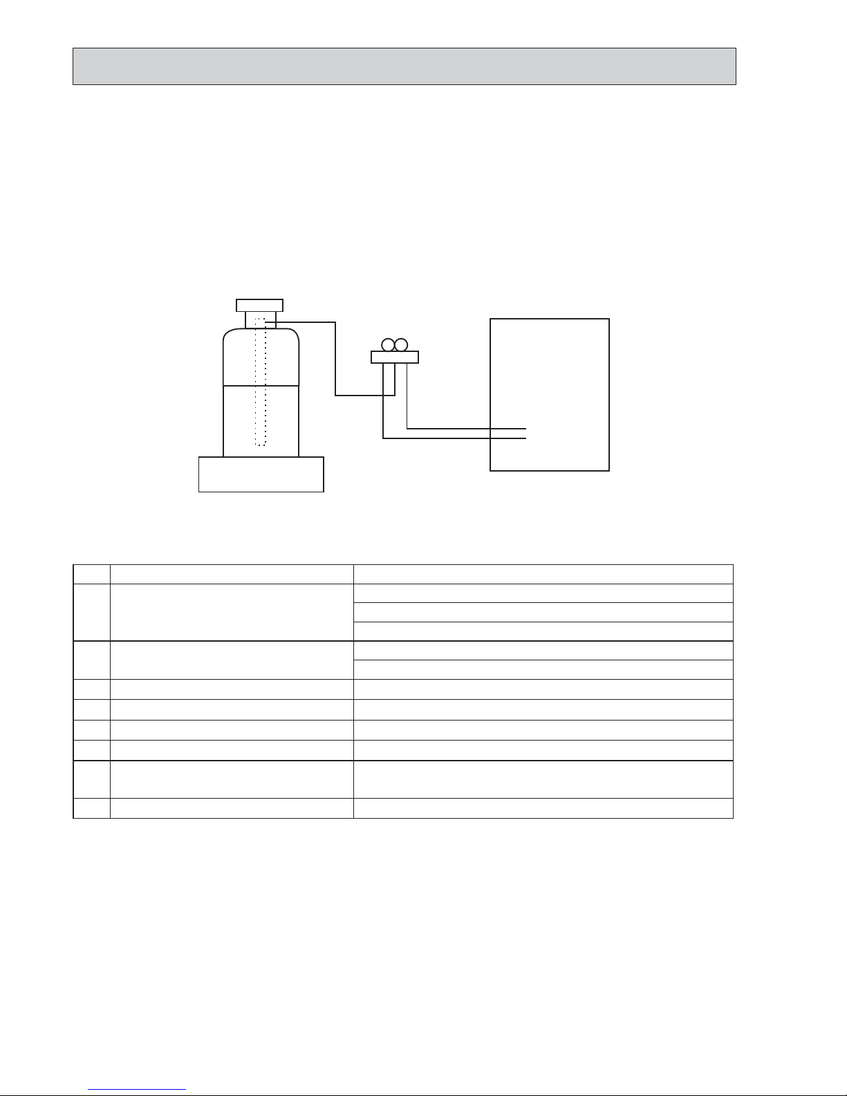
[2] Additional refrigerant charge
When charging directly from cylinder
· Check that cylinder for R410A on the market is syphon type.
· Charging should be performed with the cylinder of syphon stood vertically. (Refrigerant is charged from liquid phase.)
No.
Tool name
Specifications
1
Gauge manifold
· Only for R410A
· Use the existing fitting
specifications
. (UNF1/2)
· Use high-tension side pressure of 5.3 MPa·G or over.
2
Charge hose
· Only for R410A
· Use pressure performance of 5.09 MPa·G or over.
3
Electronic scale
—
4
Gas leak detector · Use the detector for R134a, R407C or R410A.
5
Adaptor for reverse flow check · Attach on vacuum pump.
6
Refrigerant charge base
—
7
Refrigerant cylinder
· Only for R410A · Top of cylinder (Pink)
· Cylinder with syphon
8
Refrigerant recovery equipment
—
OCH526B
5
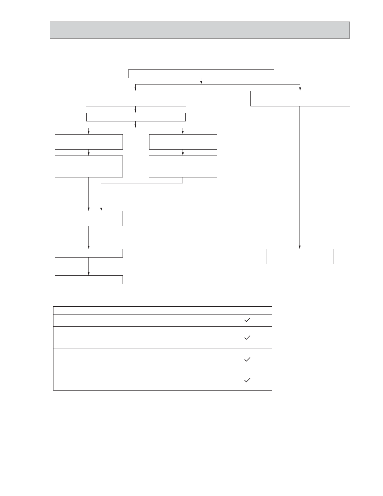
3-3. PRECAUTIONS WHEN REUSING EXISTING R22 REFRIGERANT PIPES
(1) Flowchart
Connecting a new air conditioner
1 Flaring work should be done so that flare meets the dimension for R410A.
Use flare nut provided with indoor and outdoor unit.
2 When using gas piping of [19.05mm for SHW112, 140.
Make sure that DIP SW8-1 on outdoor unit controller board is set to ON. This is to keep
the pressure on pipes within permissible range.
Ɣ8VHGLIIHUHQWGLDPHWHUMRLQWRUDGMXVWWKHSLSLQJVL]HE\EUD]LQJ
3:KHQXVLQJSLSHVODUJHUWKDQVSHFLILHGVL]HIRU6+:
Make sure that DIP SW8-1 on outdoor unit controller board is set to ON.
This is to
prevent oil flow ratio from lowering due to the decrease in flowing refrigerant.
Ɣ8VHGLIIHUHQWGLDPHWHUMRLQWRUDGMXVWWKHSLSLQJVL]HE\EUD]LQJ
4:KHQH[LVWLQJSLSHVDUHVSHFLILHGVL]H
The pipes can be reused.
Ɣ8VHGLIIHUHQWGLDPHWHUMRLQWRUDGMXVWWKHSLSLQJVL]HE\EUD]LQJ
SHW·HA
Measure the existing pipe thickness and check for damage.
Check if existing air conditioner can operate.
Existing air conditioner can
operate.
Disconnect existing air conditioner from piping.
Existing pipes can be reused.
Perform cooling operation
for about 30 minutes and
then do a pump down work.
Use a refrigerant recovery
equipment to recover the
refrigerant.
Existing air conditioner
cannot operate.
The existing pipe thickness meets specifications and the pipes are not damaged.
The existing pipe thickness does not meet
specifications or the pipes are damaged.
Connect a new air conditioner.
Ɣ7KHDLUFRQGLWLRQHUDXWRPDWLFDOO\SHUIRUPVFRROLQJRSHUDWLRQWKURXJKUHSODFHILOWHUIRUDERXWKRXUV
Existing pipes cannot be
reused. Use new pipes.
Note:
In case existing pipes were used
for gas or oil heat pump system,
be sure to clean the pipes.
OCH526B
6
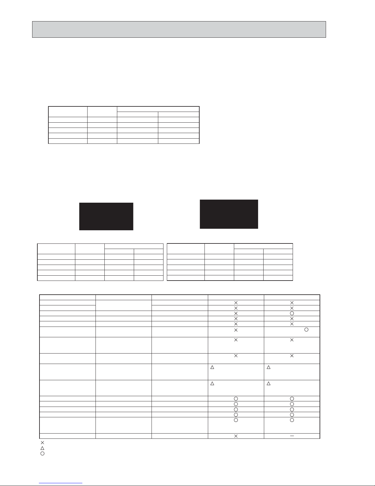
(2) Cautions for refrigerant piping work
New refrigerant R410A is adopted for replacement inverter series. Although the refrigerant piping work for R410A is same
as for R22, exclusive tools are necessary so as not to mix with different kind of refrigerant. Furthermore as the working
pressure of R410A is 1.6 times higher than that of R22, their sizes of flared sections and flare nuts are different.
1 Thickness of pipes
Because the working pressure of R410A is higher compared to R22, be sure to use refrigerant piping with thickness
shown below. (Never use pipes of 0.7 mm or below.)
2 Dimensions of flare cutting and flare nut
The component molecules in HFC refrigerant are smaller compared to conventional refrigerants. In addition to that,
R410A is a refrigerant, which has higher risk of leakage because its working pressure is higher than that of other refrigerants. Therefore, to enhance airtightness and intensity, flare cutting dimension of copper pipe for R410A has been
specified separately from the dimensions for other refrigerants as shown below. The dimension B of flare nut for R410A
also has partly been changed to increase intensity as shown below. Set copper pipe correctly referring to copper pipe
flaring dimensions for R410A below. For 1/2 and 5/8 inch, the dimension B changes.
Use torque wrench corresponding to each dimension.
3 Tools for R410A (The following table shows whether conventional tools can be used or not.)
1/4
3/8
1/2
5/8
3/4
6.35
9.52
12.70
15.88
19.05
0.8
0.8
0.8
1.0
—
0.8
0.8
0.8
1.0
1.0
Nominal
dimensions(inch)
Diagram below: Piping diameter and thickness
Outside
diameter
(mm)
Thickness
(mm)
R410A R22
1/4
3/8
1/2
5/8
3/4
6.35
9.52
12.70
15.88
19.05
9.1
13.2
16.6
19.7
—
9.0
13.0
16.2
19.4
23.3
Nominal
dimensions(inch)
Flare cutting dimensions
Outside
diameter (mm)
Dimension A
( )
+0
-0.4
R410A R22
1/4
3/8
1/2
5/8
3/4
6.35
9.52
12.70
15.88
19.05
17.0
22.0
26.0
29.0
-
17.0
22.0
24.0
27.0
36.0
Nominal
dimensions(inch)
Flare nut dimensions
Outside
diameter (mm)
Dimension B
(mm)
R410A
*
* 36.0mm for
indoor unit
of RP100,
125 and 140
R22
(mm)
Gauge manifold
Charge hose
Gas leak detector
Refrigerant recovery equipment
Refrigerant cylinder
Applied oil
Safety charger
Charge valve
Vacuum pump
Flare tool
Bender
Pipe cutter
Welder and nitrogen gas cylinder
Refrigerant charging scale
Vacuum gauge or thermistor vacuum gauge and
vacuum valve
Charging cylinder
Air purge, refrigerant charge
and operation check
Gas leak check
Refrigerant recovery
Refrigerant charge
Apply to flared section
Prevent compressor malfunction
when charging refrigerant by
spraying liquid refrigerant
Prevent gas from blowing out
when detaching charge hose
Vacuum drying and air
purge
Flaring work of piping
Bend the pipes
Cut the pipes
Weld the pipes
Charge refrigerant
Check the degree of vacuum. (Vacuum
valve prevents back flow of oil and refrigerant to thermistor vacuum gauge)
Refrigerant charge
Tool exclusive for R410A
Tool exclusive for R410A
Tool for HFC refrigerant
Tool exclusive for R410A
Tool exclusive for R410A
Ester oil, ether oil and alkylbenzene oil (minimum amount)
Tool exclusive for R410A
Tool exclusive for R410A
Tools for other refrigerants can
be used if equipped with adapter for reverse flow check
Tools for other refrigerants
can be used by adjusting
flaring dimension
Tools for other refrigerants can be used
Tools for other refrigerants can be used
Tools for other refrigerants can be used
Tools for other refrigerants can be used
Tools for other refrigerants
can be used
Tool exclusive for R410A
Tools and materials Use R410A tools Can R22 tools be used?
(Usable if equipped
with adapter for rever se flow)
(Usable by adjusting
flaring dimension)
Can R407C tools be used?
Ester oil, ether oil:
Alkylbenzene oil: minimum amount
(Usable if equipped
with adapter for rever se flow)
(Usable by adjusting
flaring dimension)
: Prepare a new tool. (Use the new tool as the tool exclusive for R410A.)
: Tools for other refrigerants can be used under certain conditions.
: Tools for other refrigerants can be used.
Dimension A
Dimension B
OCH526B
7
A
kW
W
kW
K
/min (CFM
)
dB
dB
mm (in)
mm (in)
mm (in)
kg (lb)
kg (lb)
L
mm (in)
mm (in)
Power supply (phase, cycle, voltage)
Max. current
External finish
Refrigerant control
Compressor
Model
Motor output
Starter type
Protection devices
Crankcase heater
Heat exchanger
Fan Fan(drive) o No.
Fan motor output
Airflow
Defrost method
Noise level
Dimensions
Weight
Refrigerant
Charge
Oil (Model)
Pipe size O.D.
Connection method
Between the indoor &
outdoor unit
Cooling
Heating
W
D
H
Liquid
Gas
Indoor side
Outdoor side
Height difference
Piping length
Service Ref.
PUHZ-SHW112VHA
Munsell 3Y 7.8/1.1
Linear Expansion Valve
Hermetic
ANB33FJMMT
Inverter
—
Plate fin coil
Propeller fan o 2
0.074+0.074
100 (3,530)
Reverse cycle
950 (37-3/8)
330+30 (13+1-3/16)
1,350 (53-1/8)
120 (265)
R410A
5.5 (12.1)
1.40 (FV50S)
9.52 (3/8)
15.88 (5/8)
Flared
Flared
Max. 30 m
Max. 75 m
HP switch, LP switch
Discharge thermo, Comp. surface thermo
Single 50 Hz, 230V
OUTDOOR UNIT
REFRIGERANT PIPING
2.5
PUHZ-SHW80VHA
29.5 35
50
51
51
52
A
kW
W
kW
K
/min (CFM
)
dB
dB
mm (in)
mm (in)
mm (in)
kg (lb)
kg (lbs)
L
mm (in)
mm (in)
Power supply (phase, cycle, voltage)
Max. current
External finish
Refrigerant control
Compressor
Model
Motor output
Starter type
Protection devices
Crankcase heater
Heat exchanger
Fan Fan(drive) o No.
Fan motor output
Airflow
Defrost method
Noise level
Dimensions
Weight
Refrigerant
Charge
Oil (Model)
Pipe size O.D.
Connection method
Between the indoor &
outdoor unit
Cooling
Heating
W
D
H
Liquid
Gas
Indoor side
Outdoor side
Height difference
Piping length
Service Ref.
PUHZ-SHW112YHA
PUHZ-SHW140YHA
PUHZ-SHW112YHAR1
PUHZ-SHW140YHAR1
13
Munsell 3Y 7.8/1.1
Linear Expansion Valve
Hermetic
ANB33FJLMT
2.5
Inverter
—
Plate fin coil
Propeller fan o 2
0.074+0.074
100 (3,530)
Reverse cycle
950 (37-3/8)
330+30 (13+1-3/16)
1,350 (53-1/8)
134 (295)
R410A
5.5 (12.1)
1.40 (FV50S)
9.52 (3/8)
15.88 (5/8)
Flared
Flared
Max. 30 m
Max. 75 m
3phase, 50 Hz, 400V
OUTDOOR UNIT
REFRIGERANT PIPING
51
52
HP switch, LP switch
Discharge thermo, Comp. surface thermo
4
SPECIFICATIONS
OCH526B
8
A
kW
W
kW
K
/min (CFM
)
dB
dB
mm (in)
mm (in)
mm (in)
kg (lb)
kg (lb)
L
mm (in)
mm (in)
Power supply (phase, cycle, voltage)
Max. current
External finish
Refrigerant control
Compressor
Model
Motor output
Starter type
Protection devices
Crankcase heater
Heat exchanger
Fan Fan(drive) o No.
Fan motor output
Airflow
Defrost method
Noise level
Dimensions
Weight
Refrigerant
Charge
Oil (Model)
Pipe size O.D.
Connection method
Between the indoor &
outdoor unit
Cooling
Heating
W
D
H
Liquid
Gas
Indoor side
Outdoor side
Height difference
Piping length
Service Ref.
PUHZ-SHW112VHAR2(-BS).UK
Munsell 3Y 7.8/1.1
Linear Expansion Valve
Hermetic
ANB33FJRMT
Inverter
—
Plate fin coil
Propeller fan o 2
0.074+0.074
100 (3,530)
Reverse cycle
950 (37-3/8)
330+30 (13+1-3/16)
1,350 (53-1/8)
120 (265)
R410A
5.5 (12.1)
1.40 (FVC68D)
9.52 (3/8)
15.88 (5/8)
Flared
Flared
Max. 30 m
Max. 75 m
HP switch, LP switch
Discharge thermo, Comp. surface thermo
Single 50 Hz, 230V
OUTDOOR UNIT
REFRIGERANT PIPING
2.5
PUHZ-SHW80VHAR2(-BS).UK
29.5 35
50
51
51
52
A
kW
W
kW
K
/min (CFM
)
dB
dB
mm (in)
mm (in)
mm (in)
kg (lb)
kg (lb)
L
mm (in)
mm (in)
Power supply (phase, cycle, voltage)
Max. current
External finish
Refrigerant control
Compressor
Model
Motor output
Starter type
Protection devices
Crankcase heater
Heat exchanger
Fan Fan(drive) o No.
Fan motor output
Airflow
Defrost method
Noise level
Dimensions
Weight
Refrigerant
Charge
Oil (Model)
Pipe size O.D.
Connection method
Between the indoor &
outdoor unit
Cooling
Heating
W
D
H
Liquid
Gas
Indoor side
Outdoor side
Height difference
Piping length
Service Ref.
PUHZ-SHW112YHAR2(-BS).UK
PUHZ-SHW140YHAR2(-BS).UK
13
Munsell 3Y 7.8/1.1
Linear Expansion Valve
Hermetic
ANB33FJQMT
2.5
Inverter
—
Plate fin coil
Propeller fan o 2
0.074+0.074
100(3,530)
Reverse cycle
950(37-3/8)
330+30(13+1-3/16)
1,350(53-1/8)
134(295)
R410A
5.5(12.1)
1.40(FVC68D)
9.52(3/8)
15.88(5/8)
Flared
Flared
Max. 30 m
Max. 75 m
3phase, 50Hz, 400V
OUTDOOR UNIT
REFRIGERANT PIPING
51
52
HP switch, LP switch
Discharge thermo, Comp. surface thermo
OCH526B

9
5
DATA
5-1. REFILLING REFRIGERANT CHARGE (R410A: kg)
5-2. COMPRESSOR TECHNICAL DATA
Piping length (one way)
10 m
20 m
30 m
40 m
50 m
Factory
charged
5.1
5.1
5.1
5.3
5.3
5.3
5.5
5.5
5.5
6.1
6.1
6.1
6.7
6.7
6.7
60 m
7.3
7.3
7.3
75 m
7.9
7.9
7.9
5.5
5.5
5.5
Service Ref.
PUHZ-SHW80VHA
PUHZ-SHW80VHAR2(-BS).UK
PUHZ-SHW112VHA
PUHZ-SHW112YHA
PUHZ-SHW112YHAR1
PUHZ-SHW112VHAR2(-BS).UK
PUHZ-SHW112YHAR2(-BS).UK
PUHZ-SHW140YHA
PUHZ-SHW140YHAR1
PUHZ-SHW140YHAR2(-BS).UK
U-V
U-W
W-V
Service Ref.
Compressor model
Winding
Resistance
( " )
ANB33FJLMT ANB33FJRMT ANB33FJQMT
(at 20:)
0.302
0.302
0.302
0.188
0.188
0.188
0.305
0.305
0.305
ANB33FJMMT
0.188
0.188
0.188
PUHZ-SHW80VHA
PUHZ-SHW112VHA
PUHZ-SHW80VHAR2(-BS).UK
PUHZ-SHW112VHAR2(-BS).UK
PUHZ-SHW112YHAR2(-BS).UK
PUHZ-SHW140YHAR2(-BS).UK
PUHZ-SHW112YHA
PUHZ-SHW140YHA
PUHZ-SHW112YHAR1
PUHZ-SHW140YHAR1
Additional charge is required for pipes
longer than 10 m.
5-3. NOISE CRITERION CURVES
PUHZ-SHW80VHA
PUHZ-SHW80VHAR2(-BS).UK
PUHZ-SHW112YHA
PUHZ-SHW112YHAR1
PUHZ-SHW112YHAR2(-BS).UK
PUHZ-SHW112VHA
PUHZ-SHW112VHA2(-BS).UK
PUHZ-SHW140YHA
PUHZ-SHW140YHAR1
PUHZ-SHW140YHAR2(-BS).U
K
1.5m
1m
MICROPHONE
UNIT
GROUND
NC-60
NC-50
NC-40
NC-30
NC-20
NC-70
90
80
70
60
50
40
30
20
10
OCTAVE BAND SOUND PRESSURE LEVEL, dB (0 dB = 0.0002 μbar)
63 125 250 500 1000 2000 4000 8000
APPROXIMATE
THRESHOLD OF
HEARING FOR
CONTINUOUS
NOISE
BAND CENTER FREQUENCIES, Hz
COOLING
MODE
HEATING
51
SPL(dB)
52
LINE
OCH526B
10
6
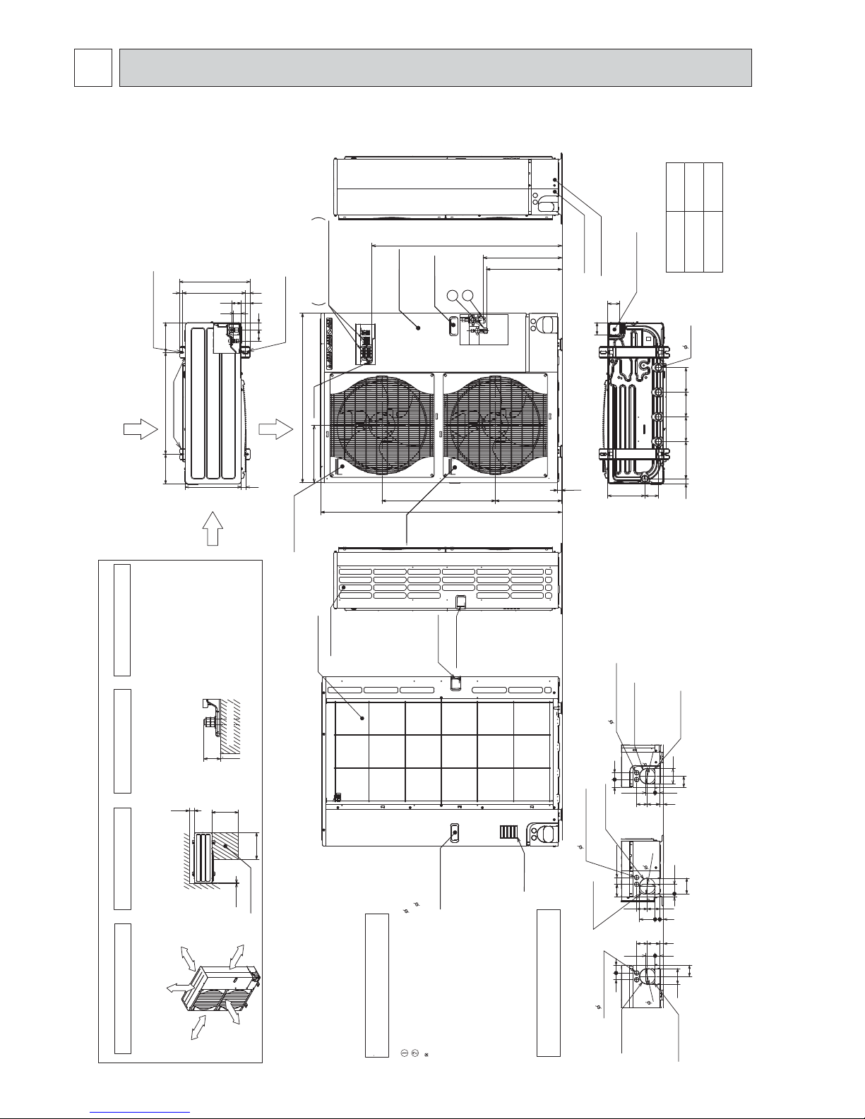
OUTLINES AND DIMENSIONS
PUHZ-SHW80VHA
PUHZ-SHW112VHA
PUHZ-SHW112YHA
PUHZ-SHW140YHA
PUHZ-SHW112YHAR1
PUHZ-SHW140YHAR1
Unit: mm
Handle for moving
Side Air Intake
Front piping cover
Rear piping cover
Air intake
Rear Air Intake
Handle for moving
Air Discharge
Rear Air Intake
Side Air Intake
···Refrigerant GAS pipe connection (FLARE) 15.88(5/8 inch)
···Refrigerant LIQUID pipe connection (FLARE)
9.52(3/8 inch)
1 ···Indication of STOP VALVE connection location.
Example of Notes
Piping Knockout Hole Details
600175
175
330
417
42
66
53 56
45
(19)28 370
2-U Shaped notched holes
(Foundation Bolt M10)
2-12 x 36 Oval holes
(Foundation Bolt M10)
Installation Feet
30
45
40
65
92
27 55
23 73 63
Rear piping hole
(Knockout)
Rear trunking hole
(Knockout)
Power supply wiring hole
(2-
27Knockout)
92
19 55
92
75 40
73 63
23 27 92
Right piping hole
(Knockout)
Right trunking hole
(Knockout)
Power supply wiring hole
(2-
27Knockout)
92
92
65
45
40
27 55
23
73 63
Front piping hole
(Knockout)
Front trunking hole
(Knockout)
Power supply wiring hole
(2-
27Knockout)
92
14514522030 145
81 219
71
71
Bottom piping hole
(Knockout)
Drain hole
(5-
33)
23
SHW·VHA
SHW·YHA
1,079
A
930
Over
Over
Over
Over
Less than
Piping and wiring connections
can be made from 4 directions:
front, right, rear and below.
4 PIPING-WIRING DIRECTIONS
3 FOUNDATION BOLTS
2 SERVICE SPACE
1 FREE SPACE (Around the unit)
Please secure the unit firmly
with 4 foundation (M10) bolts.
(Bolts and washers must be
purchased locally.)
<Foundation bolt height>
Dimensions of space needed
for service access are
shown in the below diagram.
The diagram below shows a
basic example.
Explanation of particular details is
given in the installation manuals etc.
30
FOUNDATION
10
500
500
150
Service space
Handle for moving
Handle for moving
Service panel
A
2
1
+1 443
+1 447
635
371
1350
322
950
Handle for moving
Handle
for
moving
Earth terminal
Terminal connection
Left ····Power supply wiring
Right··· Indoor/Outdoor wiring
Over 10mm
Over 10mm
Over 150mm
Over 1000mm
FREE
OCH526B
11
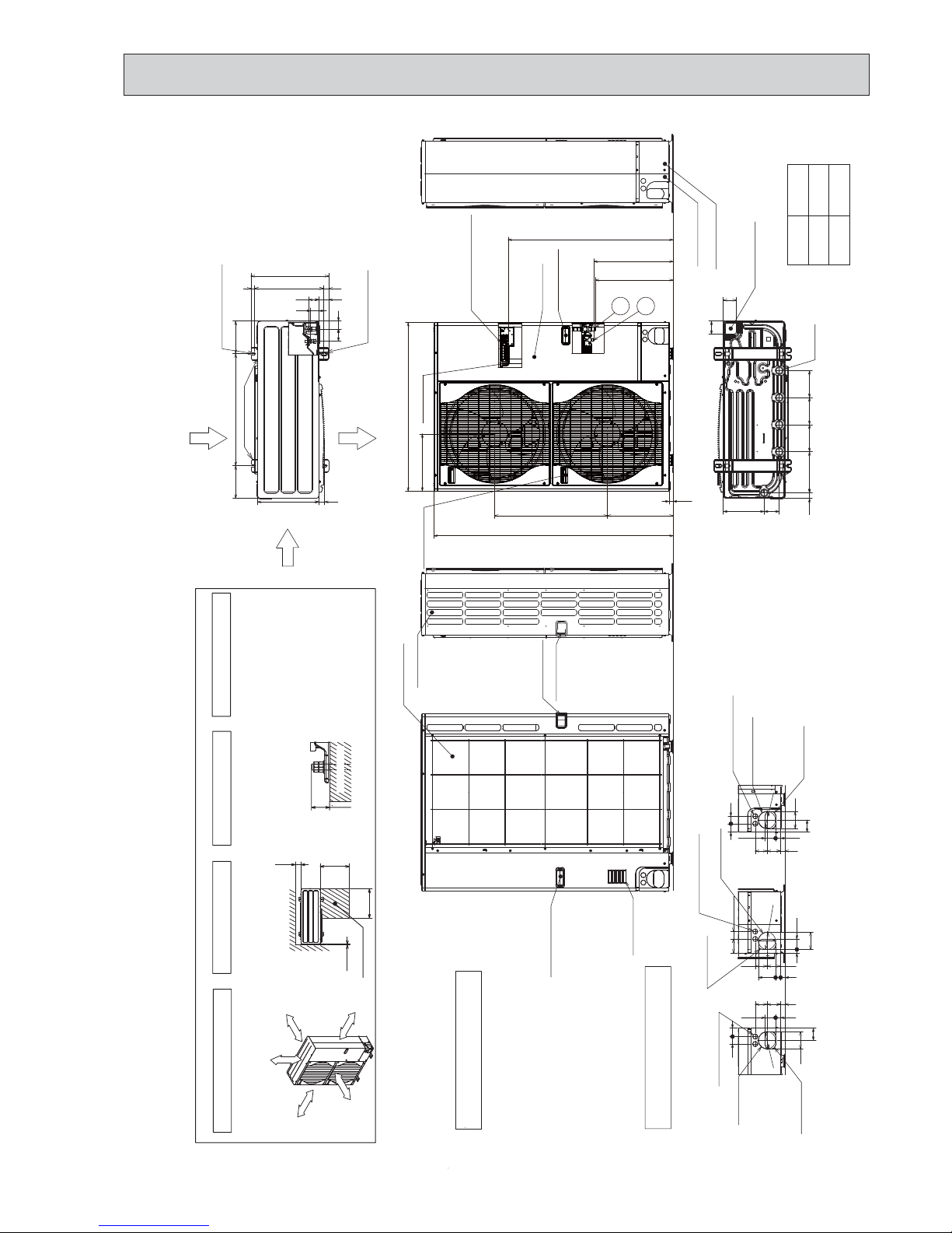
PUHZ-SHW80VHAR2(-BS).UK
PUHZ-SHW112VHAR2(-BS).UK
PUHZ-SHW112YHAR2(-BS).UK
PUHZ-SHW140YHAR2(-BS).UK
Unit: mm
Handle for moving
Side Air Intake
Front piping cover
Rear piping cover
Air intake
Rear Air Intake
Handle for moving
Handle for moving
Air Discharge
Rear Air Intake
Side Air Intake
1····Refrigerant GAS pipe connection (FLARE){15.88(5/8 inch)
2····Refrigerant LIQUID pipe connection (FLARE){ 9.52(3/8 inch)
*1 ···Indication of STOP VALVE connection location.
Example of Notes
Piping Knockout Hole Details
600175 175
330
417
42
66
53 56
45
(19)28 370
2-U Shaped notched holes
(Foundation Bolt M10)
2-12 x 36 Oval holes
(Foundation Bolt M10)
Installation Feet
30
45 40
65
92
27 55
23 73 63
Rear piping hole
(Knockout)
Rear trunking hole
(Knockout)
Power supply wiring hole
(2-
{
27Knockout)
{
92
19 55
92
75 40
73 63
23 27 92
Right piping hole
(Knockout)
Right trunking hole
(Knockout)
Power supply wiring hole
(2-
{
27Knockout)
{
92
92
65
4540
27 55
23 73 63
Front piping hole
(Knockout)
Front trunking hole
(Knockout)
Power supply wiring hole
(2-
{
27Knockout)
{
92
14514522030 145
81 219
71
71
Bottom piping hole
(Knockout)
Drain hole
(5-{33)
VHA
YHA
1,079
A
930
Handle for moving Earth terminal
Terminal connection
Left・・・Power supply wiring
Right・・Indoor/Outdoor wiring
Handle for moving
Service panel
2
1
*1 431
1350
635371
23
A
322
950
*1447
(
)
Over
Over
Over
Over
Less than
Piping and wiring connections
can be made from 4 directions:
front, right, rear and below.
4 PIPING-WIRING DIRECTIONS
3 FOUNDATION BOLTS
2 SERVICE SPACE
1 FREE SPACE (Around the unit)
Please secure the unit firmly
with 4 foundation (M10) bolts.
(Bolts and washers must be
purchased locally.)
<Foundation bolt height>
Dimensions of space needed
for service access are
shown in the below diagram.
The diagram below shows a
basic example.
Explanation of particular details is
given in the installation manuals etc.
30
FOUNDATION
10
500
500
150
Service space
Over 10mm
Over 10mm
Over 150mm
Over 1000mm
FREE
OCH526B
12
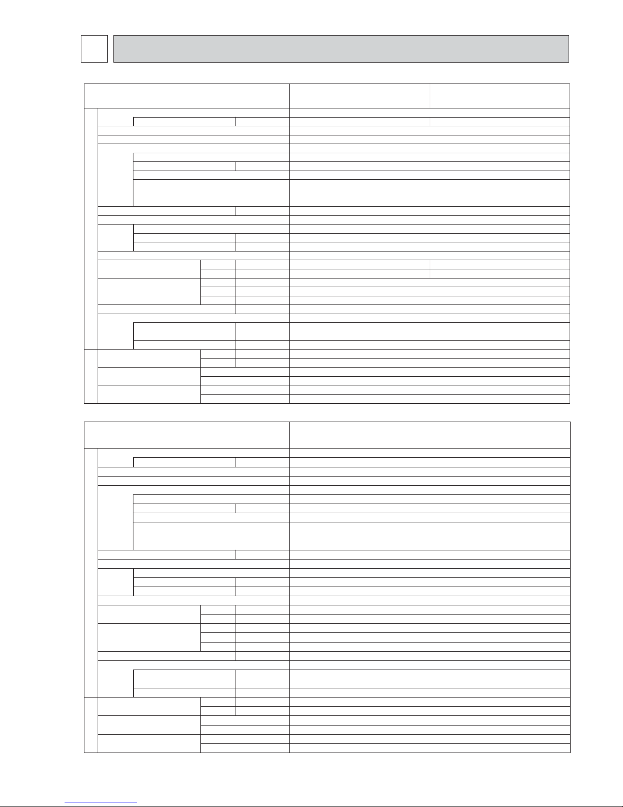
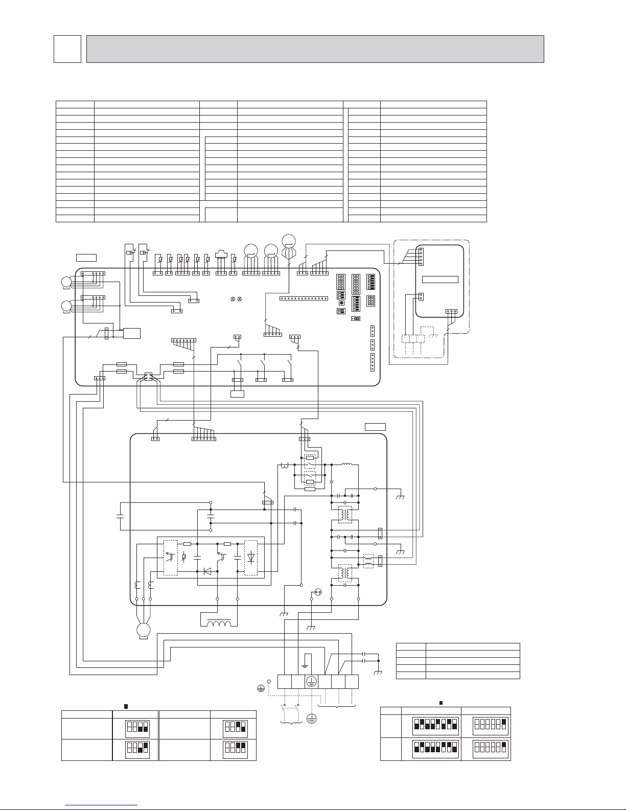
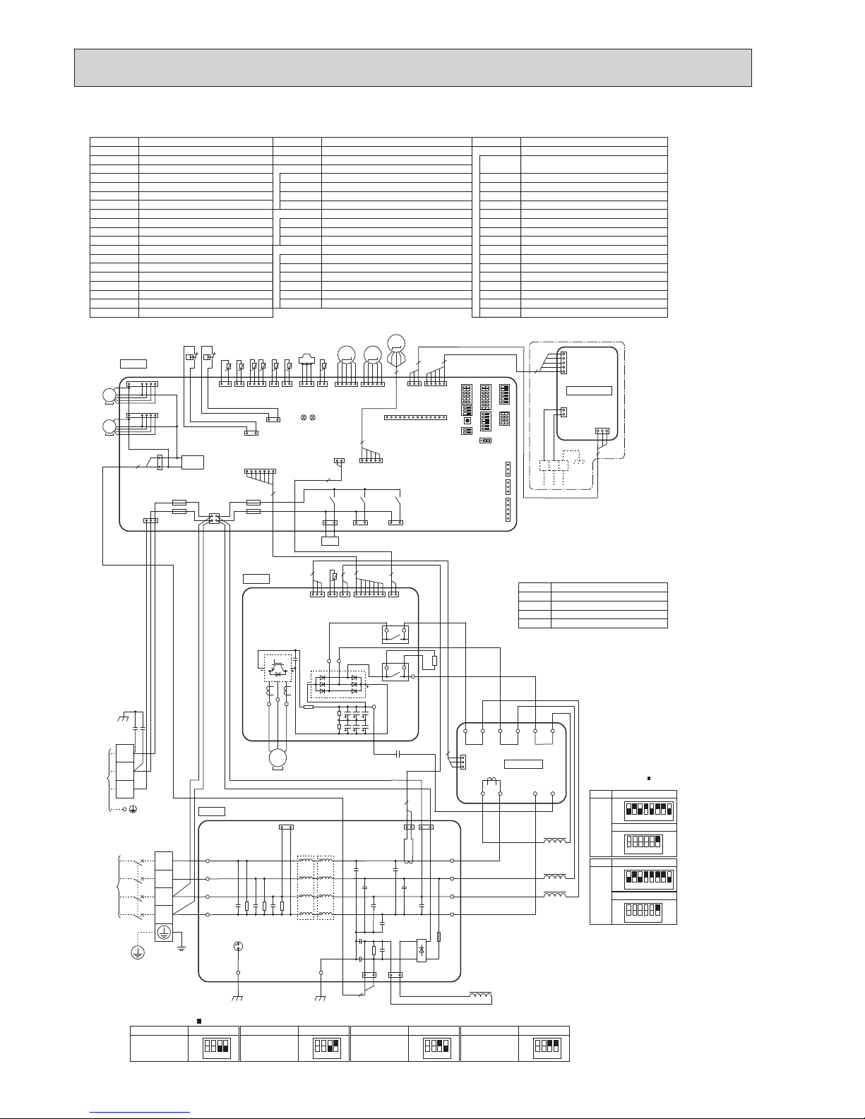
PUHZ-SHW80VHA PUHZ-SHW112VHA
SYMBOL
M-NET ADAPTER
NAME
TB7
CN5
CND
CN2M
Terminal Block<M-NET connection>
Connector<Transmission>
Connector<Power Supply>
Connector<M-NET communication>
POWER SUPPLY
~/N 230V 50Hz
INDOOR
UNIT
3
5
CN5
(WHT)
31
TB7
2
1
CND
(WHT)
CN2M
(WHT)
M-NET
ABS
When M-NET adapter is connected
5
3
5
1
M-NET ADAPTER
5
LEV-C
(BLU)
5
1
5
TH33 Thermistor<Ref. check>
TH32 Thermistor<Suction>
SYMBOL NAME SYMBOL NAME SYMBOL NAME
TB1
MC
MF1, MF2
21S4
63H
63L
63HS
TH3
TH4
TH6
TH7
TH8
TH34
LEV-A, LEV-B, LEV-C
DCL
CB
CY1, CY2
Terminal Block<Power Supply, Indoor/Outdoor
>
Motor for Compressor
Fan Motor
Solenoid Valve (Four-Way Valve)
High Pressure Switch
Low Pressure Switch
High Pressure Sensor
Thermistor<Liquid>
Thermistor<Discharge>
Thermistor<2-Phase Pipe>
Thermistor<Ambient>
Thermistor (internal) <Heat Sink>
Thermistor<Comp. Surface>
Linear Expansion Valve
Reactor
Main Smoothing Capacitor
Capacitor
P. B. Power Circuit Board
Connection Terminal<U/V/W-Phase>
Connection Terminal<L-Phase>
Connection Terminal<N-Phase>
Connection Terminal
Connection Terminal
Connection Terminal<Reactor>
Power Module
Connection Terminal<Ground>
52C Relay
Controller Circuit Board
Switch<Manual Defrost, Defect History,
Record Reset, Refrigerant Address
>
SW7
SW8
SW9
SWP
CN31
CNDM
CN51
SV1/CH
SS
CNM
LED1, LED2
F1, F2, F3, F4
X51, X52, X54
Switch<Function Switch>
Switch<Function Switch>
Switch<Function Switch>
Switch<Pump Down>
Connector<Emergency Operation>
Connector<Connection for Option>
Connector<Connection for Option>
Connector<Connection for Option>
Connector<Connection for Option>
Connector<Connection for Option>
LED<Operation Inspection Indicators>
Fuse<T6.3AL250V>
Relay
U, V, W
LI
NI
P2
N2
DCL1, DCL2
IGBT
EI, E2, E3, E4
52C
C. B.
SW1
Switch<Test Operation>
Switch<Function Switch, Model Select
>
Switch<Model Select>
SW4
SW5
SW6
P. B.
W
DCL
CB
L N S1 S2 S3
TB1
V
U
2
RED
WHT
BLK
MC
CN2
(WHT)
CN4
(WHT)
17
21
31
RED
BLU
YLW
ORN
BRN
WHT
RED
GRN/YLW
BLK
(RED)
CNAC2
(WHT)
CNAC1
LINI
EI
E3
CN52C
(RED)
3
1
1
3
52C
52C
13
DCL1
DCL2
+
P2
N2
+
-
UVW
CNDC
(PNK)
+
BLK
2
MS
3~
E2
BLK
E4
BLK
CY1
CY2
IGBT
RE D
WHT
C. B.
TH6TH7 TH4TH3
21S4
t° t° t° t°
LEV-A
CNS
(WHT)
CNAC
(WHT)
CNDC
(PNK)
F2
F1
F3
F4
21S4
(GRN)
CN2
(WHT)
CN4
(WHT)
TH7/6
(RED)
TH3
(WHT)
TH4
(WHT)
TRANS
CNVMNT
(WHT)
CNMNT
(WHT)
CNM
(WHT)
LED1
LED2
X52
SV1
/CH
(GRY)
X54
63H
(YLW)
2
7
141221
13
311 5
114
12
17
3
1
13
1
2
34
31 31
LEV-A
(WHT)
51
SS
(WHT)
X51
31
MS
3~
MF1
1
7
63L63H
63L
(RED)
13
31
TH34
t°
21
TH34
(RED)
63HS
(WHT)
TH32
(BLK)
TH33
(YLW)
63HS
LEV-B
(RED)
M
LEV-B
51
M
MF2
CNF2
(WHT)
CNF1
(WHT)
1
7
2
7
CN52C
(RED)
3
13
3
t°
TH8
CN3S
(WHT)
1
3
CNDM
(WHT)
CN51
(WHT)
1
3
1
5
31
TH32
t°
TH33
t°
12
~
~
MS
3~
SW7
SW6SW1
SW9
CN31
SW5SW8SW4 SWP
12345678
12345678
OFF
ON
80V
MODEL
SW6 SW5-6 *2
OFF
ON
OFF
ON
112V
OFF
ON
123456
123456
*1 MODEL SELECT
The black square ( ) indicates a switch position.
*2 SW5 -1 to 5 : Function Switch
*3 Ambient temp. of ZUBADAN Flash Injection becomes effective.
The black square ( ) indicates a switch position.
1234
OFF
ON
1234
OFF
ON
SW9-3,4 *4
Ambient temp.
*4 SW9-1 to 2 : Function Switch
1234
OFF
ON
1234
OFF
ON
SW9-3,4 *4
Ambient temp.
3°C or less
(lnitial setting)
0°C or less
–3°C or less
–6°C or less
*1 *1
*3
LEV-C
M
7
WIRING DIAGRAM
OCH526B
13
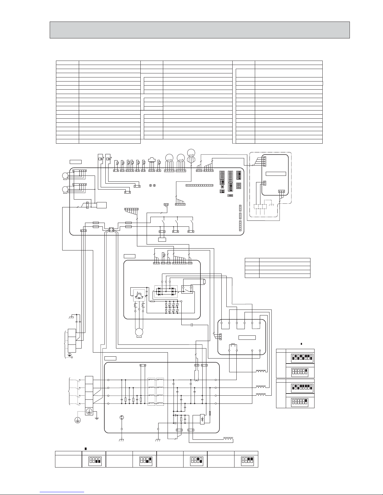
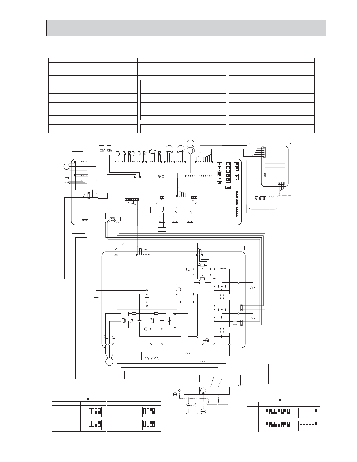
PUHZ-SHW112YHA PUHZ-SHW140YHA
TB1
TB2
MC
MF1, MF2
21S4
63H
63L
63HS
TH3
TH4
TH6
TH7
TH8
TH34
ACL1, ACL2, ACL3, ACL4
CY1, CY2
CK
RS
Terminal Block<Power Supply>
Terminal Block<Indoor/Outdoor>
Motor for Compressor
Fan Motor
Solenoid Valve (Four-Way Valve)
High Pressure Switch
Low Pressure Switch
High Pressure Sensor
Thermistor<Liquid>
Thermistor<Discharge>
Thermistor<2-Phase Pipe>
Thermistor<Ambient>
Thermistor<Heat Sink>
Thermistor<Comp. Surface>
Linear Expansion Valve
Reactor
Capacitor
Capacitor
Rush Current Protect Resistor
Power Circuit Board
Connection Terminal<U/V/W-Phase
>
P. B .
TB-U/V/W
Noise Filter Circuit Board
Connection Terminal
<L1/L2/L3/N-Power Supply
>
N. F.
LI1, LI2. LI3, NI
Connection Terminal
<L1/L2/L3/N-Power Supply
>
LO1, LO2, LO3, NO
Converter Circuit Board
CONV. B.
Connection Terminal<Ground>
GD1, GD3
Connection Terminal<L1-Power Supply
>L1-A1/IN
Connection Terminal<L1-Power Supply
>L1-A2/OU
Connection Terminal<L2-Power Supply
>L2-A2/OU
Connection Terminal<L3-Power Supply
>L3-A2/OU
Connection Terminal
N-IN
Connection Terminal
CK-OU
SYMBOL NAME SYMBOL NAME SYMBOL NAME
Connection Terminal
<L1/L2/L3-Power Supply
>
TB-L1/L2/L3
SW4
SW5
SW6
SW7
SW8
SW9
SWP
CN31
CNDM
CN51
SV1/CH
SS
CNM
LED1, LED2
F1, F2, F3, F4
X51, X52, X54
SW1
C. B.
Connection Terminal
TB-N
52C Relay
X52CA
Switch<Manual Defrost, Defect History,
Record Reset, Refrigerant Address
>
Switch<Test Operation
>
Switch<Function Switch, Model Select
>
Switch<Model Select
>
Switch<Function Switch
>
Switch<Function Switch
>
Switch<Function Switch
>
Switch<Pump Down
>
Connector<Emergency Operation
>
Connector<Connection for Option
>
Connector<Connection for Option
>
Connector<Connection for Option
>
Connector<Connection for Option
>
Connector<Connection for Option
>
LED<Operation Inspection Indicators
>
FUSE<T6.3AL250V
>
Relay
Controller Circuit Board
TH33 Thermistor<Ref. check>
TH32 Thermistor<Suction>
LEV-A, LEV-B, LEV-C
SYMBOL
M-NET ADAPTER
NAME
TB7
CN5
CND
CN2M
Terminal Block<M-NET connection>
Connector<Transmission>
Connector<Power Supply>
Connector<M-NET communication>
P. B .
U
POWER
SUPPLY
3N~
400V 50Hz
TB1
V
W
RED
WHT
BLK
MC
7
L1
L2
L3
N
N. F.
CNAC1
(WHT)
31
CNDC
(PNK)
31
CNL
(BLU)
13
CNAC2
(RED)
31
CNCT
(RED)
12
LO1
LO2
LO3
NO
GD1
NI
LI1
LI2
LI3
GD3
S1
S2
S3
CK
2
3
2
3
ACL4
ACL3
ACL2
ACL1
RED
WHT
BLK
BLU
RED
WHT
BLK
BLU
TB2
CN7
(WHT)
3
1
L3-OU
L3- A2
L2-OU
L2- A2
L1-OU
L1- A2
L1-A1
L1-IN
N-IN
CK-OU
X52CA
RED
RED
BLK
BLU
RED
RED
BLK
BLK
WHT
WHT
RED
WHT
BLK
YLW
ORN
BRN
BLK
RED
GRN/YLW
BLK
BLK
CONV. B.
WHT
INDOOR
UNIT
C. B.
TH6TH7
TH4TH3
21S4
t° t° t° t°
LEV-A
CNS
(WHT)
CNAC
(WHT)
CNDC
(PNK)
F2
F1
F3
F4
21S4
(GRN)
CN2
(WHT)
CN4
(WHT)
TH7/6
(RED)
TH3
(WHT)
TH4
(WHT)
TRANS
CNM
(WHT)
LED1
LED2
X52
SV1
/CH
(GRY)
X54
63H
(YLW)
2
7
141221
13
114
12
17
3
1
13
12
34
31 31
LEV-A
(WHT)
51
SS
(WHT)
X51
31
MS
3~
MF1
CNF1
(WHT)
1
7
63L63H
63L
(RED)
13
31
TH34
t°
21
TH34
(RED)
63HS
(WHT)
63HS
LEV-B
(RED)
M
LEV-B
51
M
MF2
CNF2
(WHT)
1
7
CN7
(WHT)
1312
CN6
(WHT)
12
CN5
(RED)
CN2
(WHT)
1712
CN4
(WHT)
TB-N
TB-U
TB-V
TB-W
TB-L3
TB-L2
TB-L1
TH8
t°
RS
RED
MS
3~
22
2
CN3S
(WHT)
1
3
CNDM
(WHT)
CN51
(WHT)
1
3
1
5
MS
3~
BRN
CY1
CY2
SW7
SW6SW1
SW9
CN31
SW5SW8SW4 SWP
+
-
+
TH32
(BLK)
TH33
(YLW)
31
TH32
t°
TH33
t°
12
12345678
12345678
OFF
ON
112Y
MODEL
SW6
SW5-6 *2
SW5-6 *2
OFF
ON
OFF
ON
140Y
OFF
ON
123456
123456
MODEL
SW6
*1 MODEL SELECT
The black square( )indicates
a switch position.
*2
SW5 -1 to 5 : Function Switch
*3 Ambient temp. of ZUBADAN Flash Injection becomes effective.
The black square( )indicates a switch position.
*4 SW9-1 to 2 : Function Switch
1234
OFF
ON
1234
OFF
ON
SW9-3,4 *4
Ambient temp.
3°C or less
(lnitial setting)
0°C or less
SW9-3,4 *4
Ambient temp.
SW9-3,4 *4
Ambient temp.
–3°C or less
–6°C or less
1234
OFF
ON
1234
OFF
ON
SW9-3,4 *4
Ambient temp.
*1 *1
*3
CNVMNT
(WHT)
CNMNT
(WHT)
311 5
CN5
(WHT)
31
TB7
2
1
CND
(WHT)
CN2M
(WHT)
M-NET
ABS
When M-NET adapter is connected
5
3
5
1
M-NET ADAPTER
3
5
5
LEV-C
(BLU
)
5
1
LEV-C
5
M
OCH526B
14
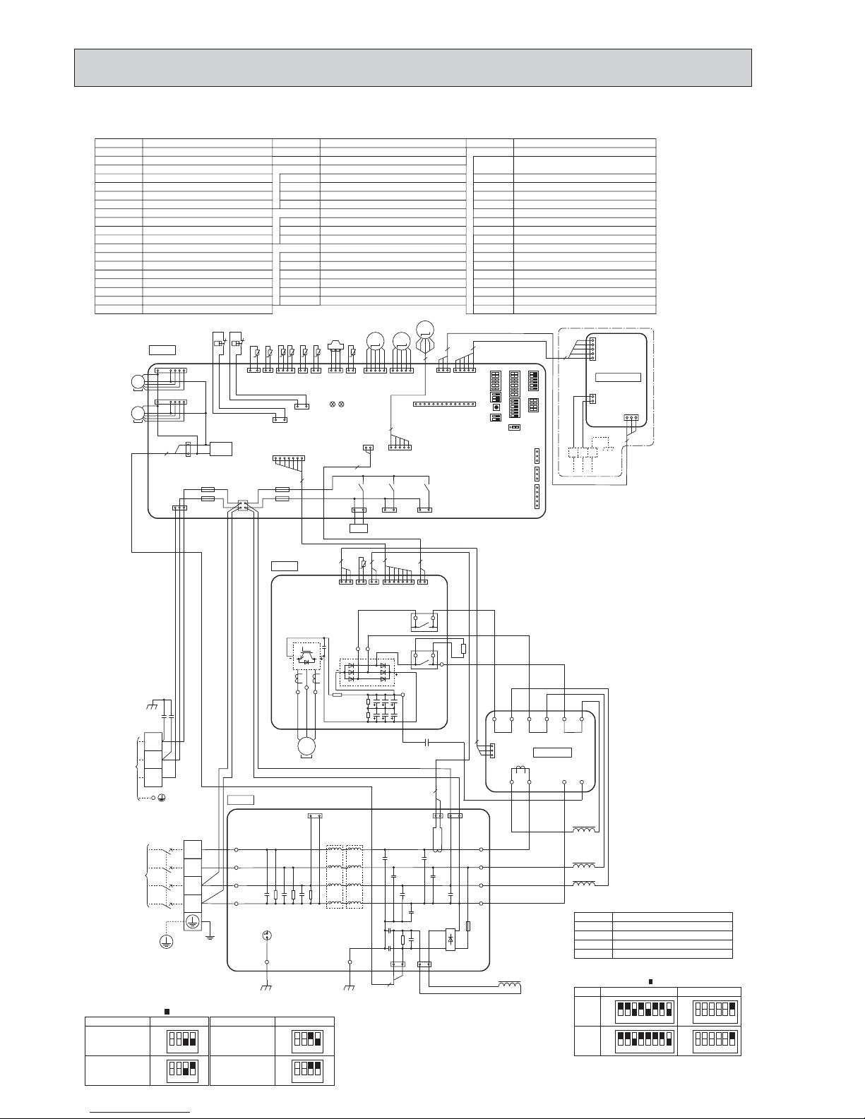
PUHZ-SHW112YHAR1 PUHZ-SHW140YHAR1
TB1
TB2
MC
MF1, MF2
21S4
63H
63L
63HS
TH3
TH4
TH6
TH7
TH8
TH34
ACL1, ACL2, ACL3, ACL4
CY1, CY2
CK
RS
Terminal Block <Power Supply>
Terminal Block <Indoor/Outdoor>
Motor for Compressor
Fan Motor
Solenoid Valve (Four-Way Valve)
High Pressure Switch
Low Pressure Switch
High Pressure Sensor
Thermistor <Liquid>
Thermistor <Discharge>
Thermistor <2-Phase Pipe>
Thermistor <Ambient>
Thermistor <Heat Sink>
Thermistor <Comp. Surface>
Linear Expansion Valve
Reactor
Capacitor
Capacitor
Rush Current Protect Resistor
Power Circuit Board <L1/L2/L3-Power Supply
>
Connection Terminal <U/V/W-Phase
>
P. B.
TB-U/V/W
Noise Filter Circuit Board
Connection Terminal
<
L1/L2/L3/N-Power Supply
>
N. F.
LI1, LI2. LI3, NI
Connection Terminal <L1/L2/L3/N-Power Supply
>
LO1, LO2, LO3, NO
Converter Circuit Board
CONV. B.
Connection Terminal <Ground
>GD1, GD3
Connection Terminal <L1-Power Supply
>L1-A1/IN
Connection Terminal <L1-Power Supply
>L1-A2/OU
Connection Terminal <L2-Power Supply
>L2-A2/OU
Connection Terminal <L3-Power Supply
>L3-A2/OU
Connection Terminal
N-IN
Connection Terminal
CK-OU
SYMBOL NAME SYMBOL NAME SYMBOL NAME
Connection Terminal
TB-L1/L2/L3
SW4
SW5
SW6
SW7
SW8
SW9
SWP
CN31
CNDM
CN51
SV1/CH
SS
CNM
LED1, LED2
F1, F2, F3, F4
X51, X52, X54
SW1
C. B.
Connection Terminal
TB-N
52C Relay
X52CA/B
Switch <Manual Defrost, Defect History,
Record Reset, Refrigerant Address
>
Switch <Test Operation
>
Switch <Function Switch, Model Select
>
Switch <Model Select
>
Switch <Function Switch
>
Switch <Function Switch
>
Switch <Function Switch
>
Switch <Pump Down
>
Connector <Emergency Operation
>
Connector <Connection for Option
>
Connector <Connection for Option
>
Connector <Connection for Option
>
Connector <Connection for Option
>
Connector <Connection for Option
>
LED <Operation Inspection Indicators
>
FUSE <T6.3AL250V
>
Relay
Controller Circuit Board
TH33 Thermistor <Ref. check>
TH32 Thermistor <Suction>
LEV-A, LEV-B, LEV-C
SYMBOL
M-NET ADAPTER
NAME
TB7
CN5
CND
CN2M
Terminal Block <M-NET connection>
Connector <Transmission>
Connector <Power Supply>
Connector <M-NET communication>
P. B .
U
POWER
SUPPLY
3N~
400V 50Hz
TB1
VW
RED
WHT
BLK
MC
7
L1
L2
L3
N
N. F.
CNAC1
(WHT)
31
CNDC
(PNK)
31
CNL
(BLU)
13
CNAC2
(RED)
31
CNCT
(RED)
12
LO1
LO2
LO3
NO
GD1
NI
LI1
LI2
LI3
GD3
S1
S2
S3
CK
2
3
2
3
ACL4
ACL3
ACL2
ACL1
RED
WHT
BLK
BLU
RED
WHT
BLK
BLU
TB2
CN7
(WHT)
3
1
L3-OU
L3- A2
L2-OU
L2- A2
L1-OU
L1- A2
L1-A1
L1-IN
N-IN
CK-OU
X52CA
X52CB
RED
RED
BLK
BLU
RED
RED
BLK
BLK
WHT
WHT
RED
RED
RED
WHT
BLK BLK
YLW
ORN
BRN
BLK
GRN/YLW
BLK
BLK
CONV. B.
WHT
INDOOR
UNIT
C. B.
TH6TH7
TH4TH3
21S4
LEV-A
CNS
(WHT)
CNAC
(WHT)
CNDC
(PNK)
F2
F1
F3
F4
21S4
(GRN)
CN2
(WHT)
CN4
(WHT)
TH7/6
(RED)
TH3
(WHT)
TH4
(WHT)
TRANS
CNM
(WHT)
LED1
LED2
X52
SV1
/CH
(GRY)
X54
63H
(YLW)
2
7
141221
13
114
12
17
3
1
13
12
34
31 31
LEV-A
(WHT)
51
SS
(WHT)
X51
31
MS
3~
MF1
CNF1
(WHT)
1
7
63L63H
63L
(RED)
13
31
TH34
21
TH34
(RED)
63HS
(WHT)
63HS
LEV-B
(RED)
M
LEV-B
51
M
MF2
CNF2
(WHT)
1
7
CN7
(WHT)
1312
CN6
(WHT)
12
CN5
(RED)
CN2
(WHT)
1712
CN4
(WHT)
TB-N
TB-U
TB-V
TB-W
TB-L3
TB-L1
L3OUT
TB-L2
L3IN
TH8
RS
MS
3~
22
2
CN3S
(WHT)
1
3
CNDM
(WHT)
CN51
(WHT)
1
3
1
5
MS
3~
BRN
CY1
CY2
SW7
SW6SW1
SW9
CN31
SW5SW8SW4 SWP
+
-
+
t°
TH32
(BLK)
TH33
(YLW)
31
TH32
TH33
t° t° t° t° t° t° t°
12
12345678
12345678
OFF
ON
112Y
MODEL
SW6
SW5-6
*
2
SW5-6
*
2
OFF
ON
OFF
ON
140Y
OFF
ON
123456
123456
MODEL
SW6
*
1 MODEL SELECT
The black square ( ) indicates
a switch position.
*
2
SW5 -1 to 5 : Function Switch
*
3 Ambient temp. of ZUBADAN Flash Injection becomes effective.
The black square ( ) indicates a switch position.
*
4 SW9-1 to 2 : Function Switch
1234
OFF
ON
1234
OFF
ON
SW9-3,4 *4
Ambient temp.
3°C or less
(lnitial setting)
0°C or less
SW9-3,4 *4
Ambient temp.
SW9-3,4 *4
Ambient temp.
-3°C or less
-6°C or less
1234
OFF
ON
1234
OFF
ON
SW9-3,4 *4
Ambient temp.
*1*
1
*
3
CNVMNT
(WHT)
CNMNT
(WHT)
311 5
CN5
(WHT)
31
TB7
2
1
CND
(WHT)
CN2M
(WHT)
M-NET
ABS
When M-NET adapter is connected
5
3
5
1
M-NET ADAPTER
3
5
5
LEV-C
(BLU)
5
1
LEV-C
5
M
OCH526B
15
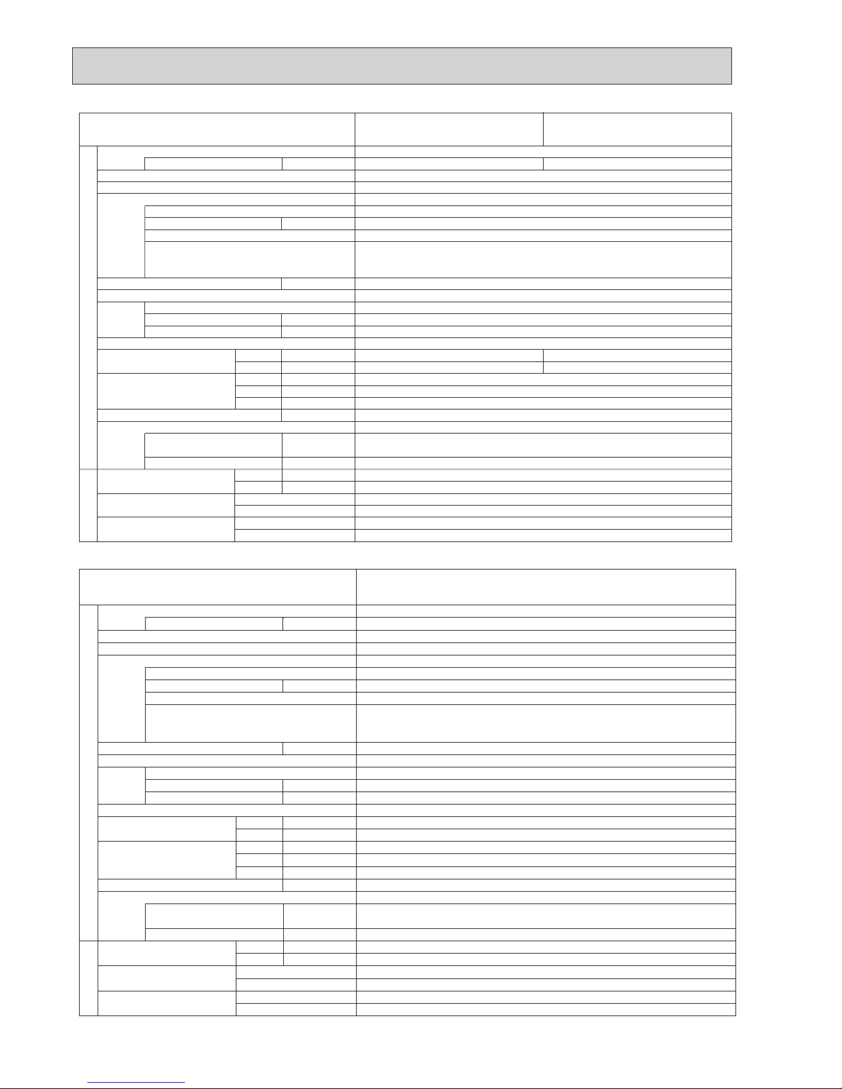
PUHZ-SHW80VHAR2(-BS).UK PUHZ-SHW112VHAR2(-BS).UK
SYMBOL
M-NET ADAPTER
NAME
TB7
CN5
CND
CN2M
Terminal Block <M-NET connection>
Connector <Transmission>
Connector <Power Supply>
Connector <M-NET communication>
POWER SUPPLY
~/N 230V 50Hz
INDOOR
UNIT
3
5
CN5
(WHT)
31
TB7
2
1
CND
(WHT)
CN2M
(WHT)
M-NET
A B S
When M-NET adapter is connected
5
3
5
1
M-NET ADAPTER
5
LEV-C
5
1
5
TH33 Thermistor <Ref. check>
TH32 Thermistor <Suction>
SYMBOL NAME SYMBOL NAME SYMBOL NAME
TB1
MC
MF1, MF2
21S4
63H
63L
63HS
TH3
TH4
TH6
TH7
TH8
TH34
LEV-A, LEV-B, LEV-C
DCL
CB
CY1, CY2
Terminal Block <Power Supply, Indoor/Outdoor
>
Motor for Compressor
Fan Motor
Solenoid Valve (Four-Way Valve)
High Pressure Switch
Low Pressure Switch
High Pressure Sensor
Thermistor <Liquid>
Thermistor <Discharge>
Thermistor <2-Phase Pipe>
Thermistor <Ambient>
Thermistor (internal) <Heat Sink>
Thermistor <Comp. Surface>
Linear Expansion Valve
Reactor
Main Smoothing Capacitor
Capacitor
P. B. Power Circuit Board
Connection T erminal <U/V/W-Phase>
Connection T erminal <L-Phase>
Connection T erminal <N-Phase>
Connection T erminal
Connection T erminal
Connection T erminal <Reactor>
Power Module
Connection T erminal <Ground>
52C Relay
Controller Circuit Board
Switch <Manual Defrost, Defect History,
Record Reset, Refrigerant Address
>
SW7
SW8
SW9
SWP
CN31
CNDM
CN51
SV1/CH
SS
CNM
LED1, LED2
F1, F2, F3, F4
X51, X52, X54
Switch <Function Switch>
Switch <Function Switch>
Switch <Function Switch>
Switch <Pump Down>
Connector <Emergency Operation>
Connector <Connection for Option>
Connector <Connection for Option>
Connector <Connection for Option>
Connector <Connection for Option>
Connector <Connection for Option>
LED <Operation Inspection Indicators>
Fuse <T6.3AL250V>
Relay
U, V, W
LI
NI
P2
N2
DCL1, DCL2
IGBT
EI, E2, E3, E4
52C
C. B.
SW1
Switch <Test Operation>
Switch <Function Switch, Model Select
>
Switch <Model Select>
SW4
SW5
SW6
P. B.
W
DCL
CB
L N S1 S2 S3
TB1
V
U
2
RED
WHT
BLK
MC
CN2
(WHT)
CN4
(WHT)
17
21
31
RED
BLU
YLW
ORN
BRN
WHT
RED
GRN/YLW
BLK
(RED)
CNAC2
(WHT)
CNAC1
LINI
EI
E3
CN52C
(RED)
3
1
1
3
52C
52C
13
DCL1
DCL2
+
P2
N2
+
-
UVW
CNDC
(PNK)
+
BLK
2
MS
3~
E2
BLK
E4
BLK
CY1
CY2
IGBT
RE D
WHT
C. B.
TH6TH7 TH4TH3
21S4
t° t° t° t°
LEV-A
CNS
(WHT)
CNAC
(WHT)
CNDC
(PNK)
F2
F1
F3
F4
21S4
(GRN)
CN2
(WHT)
CN4
(WHT)
TH7/6
(RED)
TH3
(WHT)
TH4
(WHT)
TRANS
CNVMNT
(WHT)
CNMNT
(WHT)
CNM
(WHT)
LED1
LED2
X52
SV1
/CH
(GRY)
X54
63H
(YLW)
2
7
141221
13
311 5
114
12
17
3
1
13
1
2
34
31 31
LEV-A
(WHT)
51
SS
(WHT)
X51
31
MS
3~
MF1
1
7
63L63H
63L
(RED)
13
31
TH34
t°
21
TH34
(RED)
63HS
(WHT)
TH32
(BLK)
TH33
(YLW)
63HS
LEV-B
(RED)
M
LEV-B
51
M
MF2
CNF2
(WHT)
CNF1
(WHT)
1
7
2
7
CN52C
(RED)
3
13
3
t°
TH8
CN3S
(WHT)
1
3
CNDM
(WHT)
CN51
(WHT)
1
3
1
5
31
TH32
t°
TH33
t°
12
~
~
MS
3~
SW7
SW6SW1
SW9
CN31
SW5SW8SW4 SWP
12345678
12345678
OFF
ON
80V
MODEL
SW6 SW5-6 *2
OFF
ON
OFF
ON
112V
OFF
ON
123456
123456
*1 MODEL SELECT
The black square ( ) indicates a switch position.
*2 SW5 -1 to 5 : Function Switch
*3 Ambient temp. of ZUBADAN Flash Injection becomes effective.
The black square ( ) indicates a switch position.
1234
OFF
ON
1234
OFF
ON
SW9-3,4 *4
Ambient temp.
*4 SW9-1 to 2 : Function Switch
1234
OFF
ON
1234
OFF
ON
SW9-3,4 *4
Ambient temp.
3: or less
(lnitial setting)
0: or less
-3: or less
-6: or less
*1*
1
*
3
LEV-C
M
(BLU)
OCH526B
16
PUHZ-SHW112YHAR2(-BS).UK PUHZ-SHW140YHAR2(-BS).UK
SYMBOL
M-NET ADAPTER
NAME
TB7
CN5
CND
CN2M
Terminal Block <M-NET connection>
Connector <Transmission>
Connector <Power Supply>
Connector <M-NET communication>
*3 Ambient temp. of ZUBADAN Flash Injection becomes effective.
The black square ( ) indicates a switch position.
1234
OFF
ON
1234
OFF
ON
SW9-3,4 *4
Ambient temp.
*4 SW9-1 to 2 : Function Switch
1234
OFF
ON
1234
OFF
ON
SW9-3,4 *4
Ambient temp.
3: or less
(lnitial setting)
0: or less
-3: or less
-6: or less
TB1
TB2
MC
MF1, MF2
21S4
63H
63L
63HS
TH3
TH4
TH6
TH7
TH8
TH34
ACL1, ACL2, ACL3, ACL4
CY1, CY2
CK
RS
Terminal Block 〈Power Supply〉
Terminal Block 〈Indoor/Outdoor〉
Motor for Compressor
Fan Motor
Solenoid Valve (Four-Way Valve)
High Pressure Switch
Low Pressure Switch
High Pressure Sensor
Thermistor 〈Liquid〉
Thermistor 〈Discharge〉
Thermistor 〈2-Phase Pipe〉
Thermistor 〈Ambient〉
Thermistor 〈Heat Sink〉
Thermistor 〈Comp. Surface〉
Linear Expansion Valve
Reactor
Capacitor
Capacitor
Rush Current Protect Resistor
Power Circuit Board 〈L1/L2/L3-Power Supply
〉
Connection Terminal 〈U/V/W-Phase
〉
P. B .
TB-U/V/W
Noise Filter Circuit Board
Connection Terminal
〈
L1/L2/L3/N-Power Supply
〉
N. F.
LI1, LI2. LI3, NI
Connection Terminal 〈L1/L2/L3/N-Power Supply
〉
LO1, LO2, LO3, NO
Converter Circuit Board
CONV. B.
Connection Terminal 〈Ground
〉GD1, GD3
Connection Terminal 〈L1-Power Supply
〉L1-A1/IN
Connection Terminal 〈L1-Power Supply
〉L1-A2/OU
Connection Terminal 〈L2-Power Supply
〉L2-A2/OU
Connection Terminal 〈L3-Power Supply
〉L3-A2/OU
Connection Terminal
N-IN
Connection Terminal
CK-OU
SYMBOL NAME SYMBOL NAME SYMBOL NAME
Connection Terminal
TB-L1/L2/L3
SW4
SW5
SW6
SW7
SW8
SW9
SWP
CN31
CNDM
CN51
SV1/CH
SS
CNM
LED1, LED2
F1, F2, F3, F4
X51, X52, X54
SW1
C. B.
Connection Terminal
TB-N
52C Relay
X52CA/B
Switch 〈Manual Defrost, Defect History,
Record Reset, Refrigerant Address
〉
Switch 〈Test Operation
〉
Switch 〈Function Switch, Model Select
〉
Switch 〈Model Select
〉
Switch 〈Function Switch
〉
Switch 〈Function Switch
〉
Switch 〈Function Switch
〉
Switch 〈Pump Down
〉
Connector 〈Emergency Operation
〉
Connector 〈Connection for Option
〉
Connector 〈Connection for Option
〉
Connector 〈Connection for Option
〉
Connector 〈Connection for Option
〉
Connector 〈Connection for Option
〉
LED 〈Operation Inspection Indicators
〉
FUSE 〈T6.3AL250V
〉
Relay
Controller Circuit Board
TH33 Thermistor 〈Ref. check〉
TH32 Thermistor 〈Suction〉
LEV-A, LEV-B, LEV-C
P. B.
U
POWER
SUPPLY
3N~
400V 50Hz
TB1
VW
RED
WHT
BLK
MC
7
L1
L2
L3
N
N. F.
CNAC1
(WHT)
31
CNDC
(PNK)
31
CNL
(BLU)
13
CNAC2
(RED)
31
CNCT
(RED)
12
LO1
LO2
LO3
NO
GD1
NI
LI1
LI2
LI3
GD3
S1
S2
S3
CK
2
3
2
3
ACL4
ACL3
ACL2
ACL1
RED
WHT
BLK
BLU
RED
WHT
BLK
BLU
TB2
CN7
(WHT)
3
1
L3-OU
L3-A2
L2-OU
L2-A2
L1-OU
L1-A2
L1-A1
L1-IN
N-IN
CK-OU
X52CA
X52CB
RED
RED
BLK
BLU
RED
RED
BLK
BLK
WHT
WHT
RED
RED
RED
WHT
BLK BLK
YLW
ORN
BRN
BLK
GRN/YLW
BLK
BLK
CONV. B.
WHT
INDOOR
UNIT
C. B.
TH6TH7
TH4TH3
21S4
t° t° t° t°
LEV-A
CNS
(WHT)
CNAC
(WHT)
CNDC
(PNK)
F2
F1
F3
F4
21S4
(GRN)
CN2
(WHT)
CN4
(WHT)
TH7/6
(RED)
TH3
(WHT)
TH4
(WHT)
TRANS
CNM
(WHT)
LED1
LED2
X52
SV1
/CH
(GRY)
X54
63H
(YLW)
2
7
141221
13
114
12
17
3
1
13
12
34
31 31
LEV-A
(WHT)
51
SS
(WHT)
X51
31
MS
3~
MF1
CNF1
(WHT)
1
7
63L63H
63L
(RED)
13
31
TH34
t°
21
TH34
(RED)
63HS
(WHT)
63HS
LEV-B
(RED)
M
LEV-B
51
M
MF2
CNF2
(WHT)
1
7
CN7
(WHT)
1312
CN6
(WHT)
12
CN5
(RED)
CN2
(WHT)
1712
CN4
(WHT)
TB-N
TB-U
TB-V
TB-W
TB-L3
TB-L1
L3OUT
TB-L2
L3IN
TH8
t°
RS
MS
3~
22
2
CN3S
(WHT)
1
3
CNDM
(WHT)
CN51
(WHT)
1
3
1
5
MS
3~
BRN
CY1
CY2
SW7
SW6SW1
SW9
CN31
SW5SW8SW4 SWP
+
-
+
TH32
(BLK)
TH33
(YLW)
31
TH32
t°
TH33
t°
12
*1*
1
*
3
CNVMNT
(WHT)
CNMNT
(WHT)
311 5
CN5
(WHT)
31
TB7
2
1
CND
(WHT)
CN2M
(WHT)
M-NET
ABS
When M-NET adapter is connected
5
3
5
1
M-NET ADAPTER
3
5
5
LEV-C
(
BLU
)
5
1
LEV-C
5
M
12345678
12345678
OFF
ON
112Y
MODEL
SW6 SW5-6 *2
OFF
ON
OFF
ON
140Y
OFF
ON
123456
123456
*1 MODEL SELECT
The black square ( ) indicates a switch position.
*2 SW5 -1 to 5 : Function Switch
OCH526B
17
8
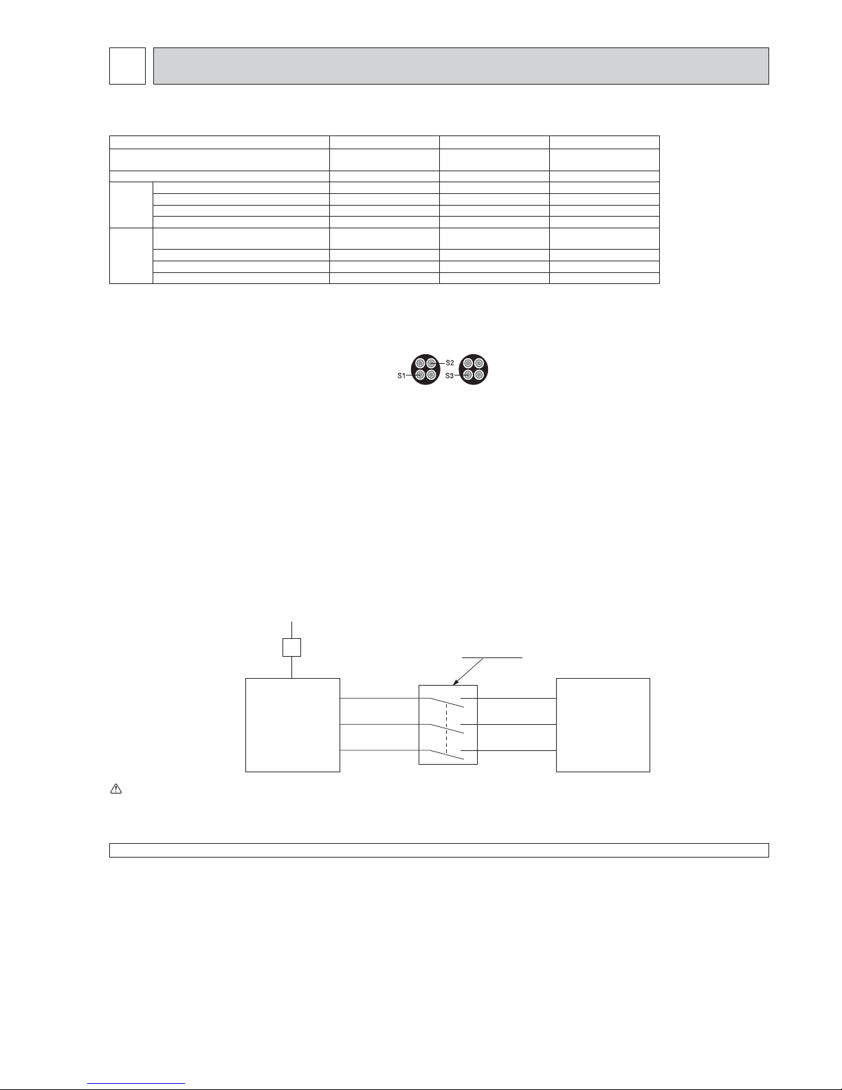
WIRING SPECIFICATIONS
FIELD ELECTRICAL WIRING (power wiring specifications)
Outdoor unit model
SHW80V SHW112V SHW112, 140Y
Outdoor unit power supply
~/N (single),
50 Hz, 230 V
~/N (single),
50 Hz, 230 V
3N~ (3 ph 4-wires),
50 Hz, 400 V
Outdoor unit input capacity Main switch (Breaker) *1 32 A 40 A 16 A
Wiring
Wire No. ×
size (mm
2
)
Outdoor unit power supply 3 × Min. 4 3 × Min. 6 5 × Min. 1.5
Indoor unit-Outdoor unit *2 3 × 1.5 (Polar) 3 × 1.5 (Polar) 3 × 1.5 (Polar)
Indoor unit-Outdoor unit earth *2 1 × Min. 1.5 1 × Min. 1.5 1 × Min. 1.5
Remote controller-Indoor unit *3 2 × 0.3 (Non-polar) 2 × 0.3 (Non-polar) 2 × 0.3 (Non-polar)
Circuit rating
Outdoor unit L-N (single)
Outdoor unit L1-N, L2-N, L3-N (3 phase)
*4 AC 230 V AC 230 V AC 230 V
Indoor unit-Outdoor unit S1-S2 *4 AC 230 V AC 230 V AC 230 V
Indoor unit-Outdoor unit S2-S3 *4 DC 24 V DC 24 V DC 24 V
Remote controller-Indoor unit *4 DC 12 V DC 12 V DC 12 V
*1. A breaker with at least 3.0 mm contact separation in each pole shall be provided. Use earth leakage breaker (NV).
Make sure that the current leakage breaker is one compatible with higher harmonics.
Always use a current leakage breaker that is compatible with higher harmonics as this unit is equipped with an inverter.
The use of an inadequate breaker can cause the incorrect operation of inverter.
*2. (SHW80 - 140)
Max. 45 m
If 2.5 mm² used, Max. 50 m
If 2.5 mm² used and S3 separated, Max. 80 m
*3. The 10 m wire is attached in the remote controller accessory.
*4. The fi gures are NOT always against the ground.
S3 terminal has DC 24 V against S2 terminal. However between S3 and S1, these terminals are NOT electrically insulated by the transformer or other device.
S1
S2
S3
S1
S2
S3
Warning:
· In case of A-control wiring, there is high voltage potential on the S3 terminal caused by electrical circuit design that has no electrical insulation
between power line and communication signal line. Therefore, please turn off the main power supply when servicing. And do not touch the S1, S2, S3
terminals when the power is energized. If isolator should be used between indoor unit and outdoor unit, please use 3-pole type.
Notes: 1. Wiring size must comply with the applicable local and national codes.
2.
Power supply cables and the cables between Interface unit/Flow temp. controller and outdoor unit shall not be lighter than polychloroprene
sheathed fl exible cables. (Design 60245 IEC 57
)
3. Be sure to connect the cables between
Interface unit/Flow temp. controller
and outdoor unit directly to the units (no intermediate connections
are allowed).
Intermediate connections may result in communication errors. If water enters at the intermediate connection point, it may cause insuffi cient
insulation to ground or a poor electrical contact .
(If an intermediate connection is necessary, be sure to take measures to prevent water from entering the cables.)
4. Install an earth longer than other cables.
5. Do not construct a system with a power supply that is turned ON and OFF frequently.
Outdoor Unit
3 poles isolator
Power
supply
Isolator
Indoor unit
(Interface unit /
Flow temp.
controller)
Never splice the power cable or the indoor-outdoor connection cable, otherwise it may result in a smoke, a fi re or communication failure.
OCH526B
18
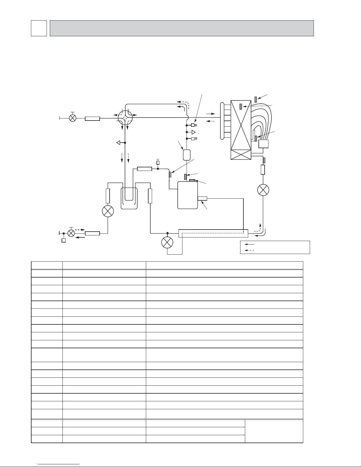
9 REFRIGERANT SYSTEM DIAGRAM
PUHZ-SHW80VHA PUHZ-SHW112VHA
PUHZ-SHW80VHAR2(-BS).UK PUHZ-SHW112VHAR2(-BS).UK
PUHZ-SHW112YHA PUHZ-SHW140YHA
PUHZ-SHW112YHAR1 PUHZ-SHW140YHAR1
PUHZ-SHW112YHAR2(-BS).UK PUHZ-SHW140YHAR2(-BS).UK
Distributor
TH7
(Ambient)
Heat exchanger
Refrigerant
GAS pipe
connection
(5/8 inch)
Refrigerant
LIQUID pipe
connection
(3/8 inch)
Stop valve
(with service port)
Strainer
#100
Power
receiver
LEV-B
LEV-C
LEV-A
Strainer
#100
Strainer
#100
TH6
(2-phase pipe)
TH3
(Liquid)
Charge plug
(Low pressure)
Charge plug
(High pressure)
HIC
TH4
(Discharge)
TH34
(Comp. surface)
COMP
Injection port
Strainer
#50
REV/N
Strainer
#100
Strainer
#100
Muffler
Ball valve
TH33
(Ref. check)
TH32
(Suction)
L/P SW
H/P SW
Refrigerant flow in cooling
Refrigerant flow in heating
P-sensor
Symbol Parts name Detail
COMP Compressor DC inverter scroll compressor (Mitsubishi Electric Corporation)
H/P SW High pressure switch (63H) For protection (OFF: 4.15MPa)
L/P SW Low pressure switch (63L) For protection (OFF: -0.03MPa)
REV/V Reversing (4-way) valve (21S4) Change the refrigerant circuit (Heating / Cooling) and for Defrosting
Charge plug Charge plug High pressure / Low pressure / For production test use
P-Sensor Pressure sensor (63HS) For calculation of the condensing temperature from high pressure
LEV-A Linear expansion valve -A Heating:Secondary LEV Cooling:Primary LEV
LEV-B Linear expansion valve -B Heating:Primary LEV Cooling:Secondary LEV
LEV-C Linear expansion valve -C For HIC (heating only)
TH32 Suction temperature thermistor For LEV control
TH33
Refrigerant leakage detection
(Ref. check) thermistor
For refrigerant leakage detection
TH3 Liquid temperature thermistor Heating:Evaporating temperature Cooling:Sub cool liquid temperature
TH4 Discharge temperature thermistor For LEV control and for compressor protection
TH6
2-phase pipe temperature thermistor
Outdoor 2-phase pipe temperature
TH7 Ambient temperature thermistor For fan control and for compressor frequency control
TH34 Comp. surface temperature thermistor For protection
Power Receiver
Power Receiver For accumulation of refrigerant
HIC Heat interchange circuit For high heating capacity
Plate HEX Plate Heat Exchanger MWA2-38PA (MITSUBISHI)
<Reference>
System example
TH1
Outlet water temperature thermistor For fl ow temp. controller
TH2
Liquid pipe temperature thermistor For fl ow temp. controller
OCH526B

19
9-3. START AND FINISH OF TEST RUN
• Operation from the indoor unit
Execute the test run using the installation manual for the indoor unit.
• Operation from the outdoor unit
By using the DIP switch SW4 on the control board of outdoor unit, test run can be started and finished, and its operation
mode (cooling/heating) can be set up.
1 Set the operation mode (cooling/heating) using SW4-2.
2 Turn on SW4-1 to start test run with the operation mode set by SW4-2.
3 Turn off SW4-1 to finish the test run.
• There may be a faint knocking sound around the machine room after power is supplied, but this is
no problem with product because the linear expansion pipe is just moving to adjust opening pulse.
• There may be a knocking sound around the machine room for several seconds after compressor
starts operating. However, this is not a problem with product because it is generated by the check
valve itself due to a small pressure difference in the refrigerant circuit.
OFF
12
ON
<SW4>
Stop Operation
Cooling Heating
9-2. UNIT REPLACEMENT OPERATION
When reusing the existing pipes that carried R22 refrigerant for the SW75/100/120 models, replacement operation
must be performed before performing a test run.
1 If new pipes are used, these procedures are not necessary.
2 If existing pipes that carried R22 refrigerant are used for the SW75/100/120 models, these procedures are not necessary.
(The replacement operation cannot be performed.)
3 During replacement operation, “C5” is displayed on “A-Control Service Tool (PAC-SK52ST)”. (This is applied to only
SW75/100/120 models.)
Note:
The operation mode cannot be changed by SW4-2 during test run. (To change test run mode, stop the unit by SW4-1,
change the operation mode and restart the test run by SW4-1.)
9-1. REFRIGERANT COLLECTING (PUMP DOWN)
When relocating or disposing of the indoor/outdoor unit, pump down the system following the procedure below so that no refrigerant is released into the atmosphere.
1 Turn off the power supply (circuit breaker).
2 Connect the low-pressure valve on the gauge manifold to the charge plug (low-pressure side) on the outdoor unit.
3 Close the liquid stop valve completely.
4 Supply power (circuit breaker).
• When power is supplied, make sure that “CENTRALLY CONTROLLED” is not displayed on the remote controller. If “CENTRALLY CONTROLLED” is displayed, the refrigerant collecting (pump down) cannot be completed normally.
• Start-up of the indoor-outdoor communication takes about 3 minutes after the power (circuit breaker) is turned on. Start the
pump-down operation 3 to 4 minutes after the power (circuit breaker) is turned on.
5 Perform the refrigerant collecting operation (cooling test run).
• Push the pump-down SWP switch (push-button type) on the control board of the outdoor unit. The compressor and ventilators
(indoor and outdoor units) start operating (refrigerant collecting operation begins). (LED1 and LED2 on the control board of
the outdoor unit are lit.)
• Only push the pump-down SWP switch if the unit is stopped. However, even if the unit is stopped and the pump-down SWP
switch is pushed less than 3 minutes after the compressor stops, the refrigerant collecting operation cannot be performed.
Wait until the compressor has been stopped for 3 minutes and then push the pump-down SWP switch again.
6 Fully close the ball valve on the gas pipe side of the outdoor unit when the pressure gauge on the gauge manifold shows 0.05
to 0 MPa [Gauge] (approx. 0.5 to 0 kgf/cm²) and quickly stop the air conditioner.
• Because the unit automatically stops in about 3 minutes when the refrigerant collecting operation is completed (LED1 off,
LED2 lit), be sure to quickly close the gas ball valve. However, if LED1 is lit, LED2 is off, and the unit is stopped, open the
liquid stop valve completely, close the valve completely after 3 minutes or more have passed, and then repeat step 5. (Open
the gas ball valve completely.)
• If the refrigerant collecting operation has been completed normally (LED1 off, LED2 lit), the unit will remain stopped until the
power supply is turned off.
• Note that when the extension piping is very long with a large refrigerant amount, it may not be possible to perform a pumpdown operation. In this case, use refrigerant recovery equipment to collect all of the refrigerant in the system.
7 Turn off the power supply (circuit breaker), remove the gauge manifold, and then disconnect the refrigerant pipes.
Warning:
When pumping down the refrigerant, stop the compressor before disconnecting the refrigerant pipes.
• If the refrigerant pipes are disconnected while the compressor is operating and the stop valve (ball valve) is open, the
pressure in the refrigeration cycle could become extremely high if air is drawn in, causing the pipes to burst, personal
injury, etc.
OCH526B
20
10 TROUBLESHOOTING
10-1. TROUBLESHOOTING
<Error code display by self-diagnosis and actions to be taken for service (summary)>
Present and past error codes are logged and displayed on the wired remote controller and control board of outdoor unit.
Actions to be taken for service, which depends on whether or not the trouble is reoccurring at service, are summarized in the
table below. Check the contents below before investigating details.
Unit conditions at service
Error code
Actions to be taken for service (summary)
The trouble is reoccurring.
Displayed
Not displayed
Judge what is wrong and take a corrective action according
to “10-4. Self-diagnosis action table”.
Conduct troubleshooting and ascertain the cause of the
trouble according to “10-5. Troubleshooting of problems”.
The trouble is not reoccurring.
Logged
Not logged
Consider the temporary defects such as the work of
protection devices in the refrigerant circuit including
compressor, poor connection of wiring, noise and etc.
Re-check the symptom, and check the installation
environment, refrigerant amount, weather when the
trouble occurred, matters related to wiring and etc.
Reset error code logs and restart the unit after finishing
service.
There is no abnormality in electrical component,
controller board, remote controller and etc.
Re-check the abnormal symptom.
Conduct trouble shooting and ascertain the cause of the
trouble
according to “10-5. Troubleshooting
of problems”.
Continue to operate unit for the time being if the cause
is not ascertained.
There is no abnormality concerning of parts such as
electrical component, controller board, remote controller
and etc.
10-2. CHECK POINT UNDER TEST RUN
10-2-1. Before test run
(1) Before test run
• After installation of indoor and outdoor units, piping work and electric wiring work, re-check that there is no refrigerant
leakage, loosened connections and incorrect polarity.
• Measure impedance between the ground and the power supply terminal block (L, N) on the outdoor unit by 500V Megger
and check that it is 1.0M" or over.
•
Do not use 500V Megger to indoor/outdoor connecting wire terminal block (S1, S2, S3) and remote controller terminal block
(1,
2). This may cause malfunction.
• Make sure that test run switch (SW4) is set to OFF before turning on power supply.
• Turn on power supply for 12 hours before test run in order to protect compressor.
• For specific models which requires higher ceiling settings or power failure automatic recovery, make proper changes of
settings referring to the description of “Selection of Functions through Remote Controller”.
Make sure to read operation manual before test run. (Especially items to secure safety.)
OCH526B
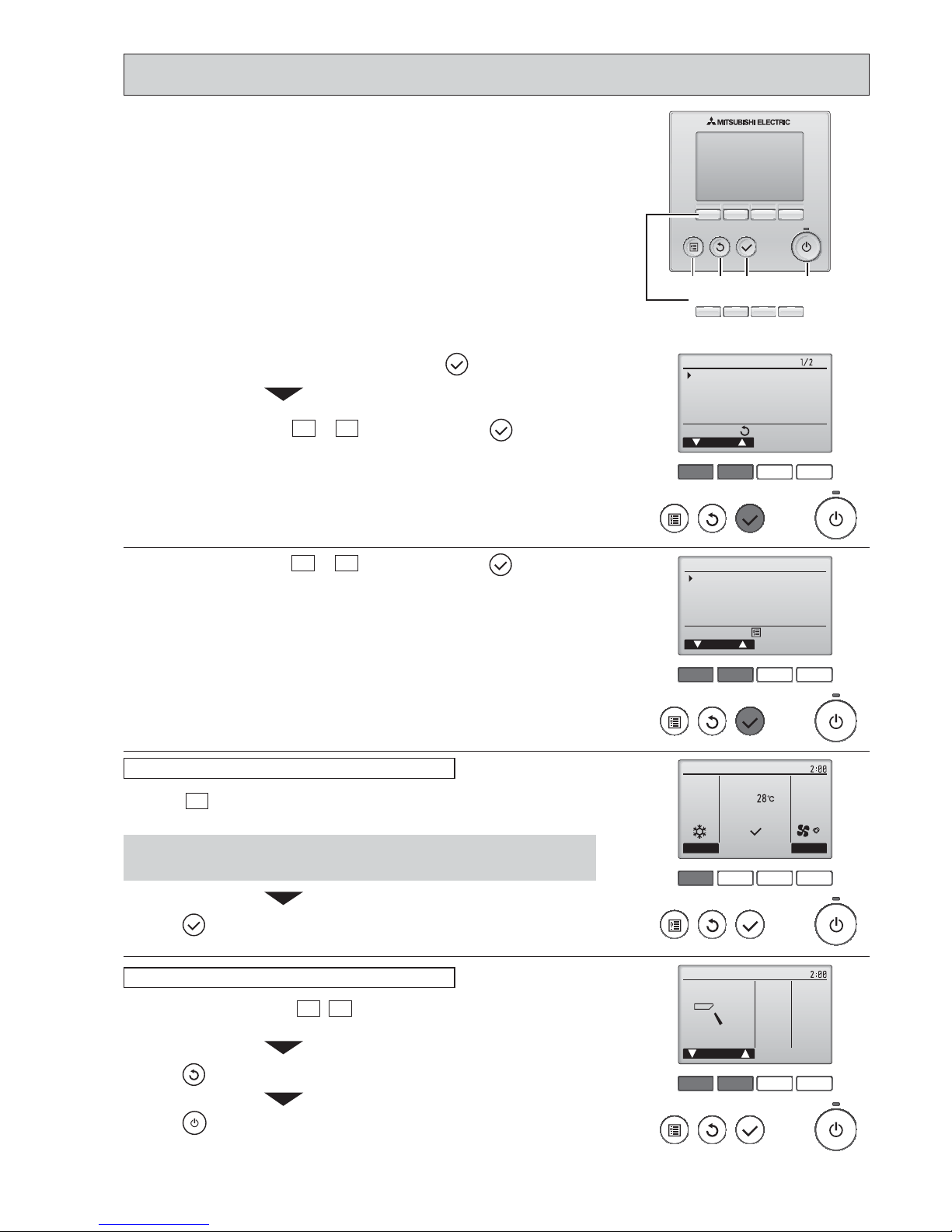
21
F1 F2 F3 F4
unem ecivreS
rosruC
:unem niaM
Test run
Input maintenance info.
Function setting
Check
Self check
F1 F2 F3 F4
Test run menu
Cursor
Service menu:
Test run
Drain pump test run
1
Select "Service" from the Main menu, and press the button.
2
Select "Test run" with the F1 or F2 button, and press the button.
Select "Test run" with the F1
or F2 button, and press the button.
F1 F2 F3 F4
Cool
Pipe
Auto
Switch disp.
Mode Fan
RemainTest run
F1 F2 F3 F4
Remain
Vane
Cool mode: Check the cold air blow off.
Heat mode: Check the heat blow off.
Press the F1
button to go through the operation modes in the order of "Cool
and Heat".
Check the auto vane with the F1
F2 buttons.
• Check the operation of the outdoor unit’s fan.
Press the
button to return to “Test run operation”.
Press the
button.
When the test run is completed, the “Test run menu” screen will appear.
• The test run will automatically stop after two hours.
Test run operation
Auto vane check
Press the button and open the Vane setting screen.
Function buttons
F1 F2 F3 F4
MENU RETURN SELECT ON/OFF
10-2-2. Test run for wired remote controller <PAR-31MAA>
OCH526B

22
F1 F2 F3 F4
Error information
Error code
Error unit IU
Ref. address Unt# 1
Model name
Serial No.
ResetPage
Error information
Contact information
Dealer
Tel
ResetPage
Reset error: Reset button
Reset error: Reset button
blinks
1
Error code, error unit, refrigerant address, unit model name, and serial
number will appear.
The model name and serial number will appear only if the information have
been registered.
Press the
F1
or
F2
button to go to the next page.
When an error occurs, the following screen will appear.
Check the error status, stop the operation, and consult your dealer.
Contact information (dealer's phone number) will appear if the information have
been registered.
F1 F2 F3 F4
F1 F2 F3 F4
Error information
Error reset
Error reset
Error code
Error unit IU
Ref. address Unt# 1
Model name
Serial No.
ResetPage
Reset current error?
Error reset
OKCancel
Main menu:
Reset error: Reset button
blinks
2
Press the
F4
button or the button to reset the error that is occurring.
Errors cannot be reset while the ON/OFF operation is prohibited.
Select "OK" with theF4button.
Navigating through the screens
• To go back to the Main menu ..........
button
<Error information>
OCH526B
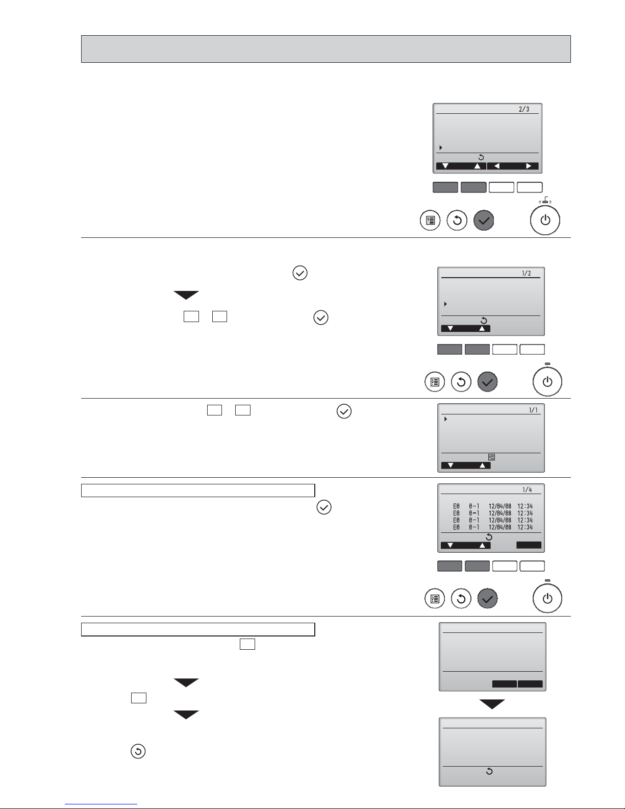
23
F1 F2 F3 F4
Main
Main display:
Cursor Page
Main menu
Restriction
Energy saving
Night setback
Filter information
Error information
blinks
While no errors are occurring, page 2/2 of the error information can be viewed by
selecting "Error information" from the Main menu.
Errors cannot be reset from this screen.
<Checking the error information>
<Error history>
F1 F2 F3 F4
unem ecivreS
rosruC
:unem niaM
Test run
Input maintenance info.
Function setting
Check
Self check
Check menu
Cursor
Service menu:
Error history
Refrigerant volume check
Refrigerant leak check
Smooth maintenance
Request code
F1 F2 F3 F4
Error history
Page
Delete
Check menu:
Error Unt#
dd/mm/yy
Error history
Cancel OK
Delete error history?
Error history
Check menu:
Error history deleted
2
Select "Error history" with the F1 or F2 button, and press the button.
Select "Check" with the F1
or F2 button, and press the button.
3
Select "Error history" from the Check menu, and press the button to view
up to 16 error history records.
Four records are shown per page, and the top record on the fi rst page
indicates the latest error record.
Error history
4
To delete the error history, press the F4 button (Delete) on the screen that
shows error history.
A confi rmation screen will appear asking if you want to delete the error history.
Press the F4
button (OK) to delete the history.
"Error history deleted" will appear on the screen.
Press the
button to go back to the Check menu screen.
Deleting the error history
1
Select "Service" from the Main menu, and press the button.
OCH526B
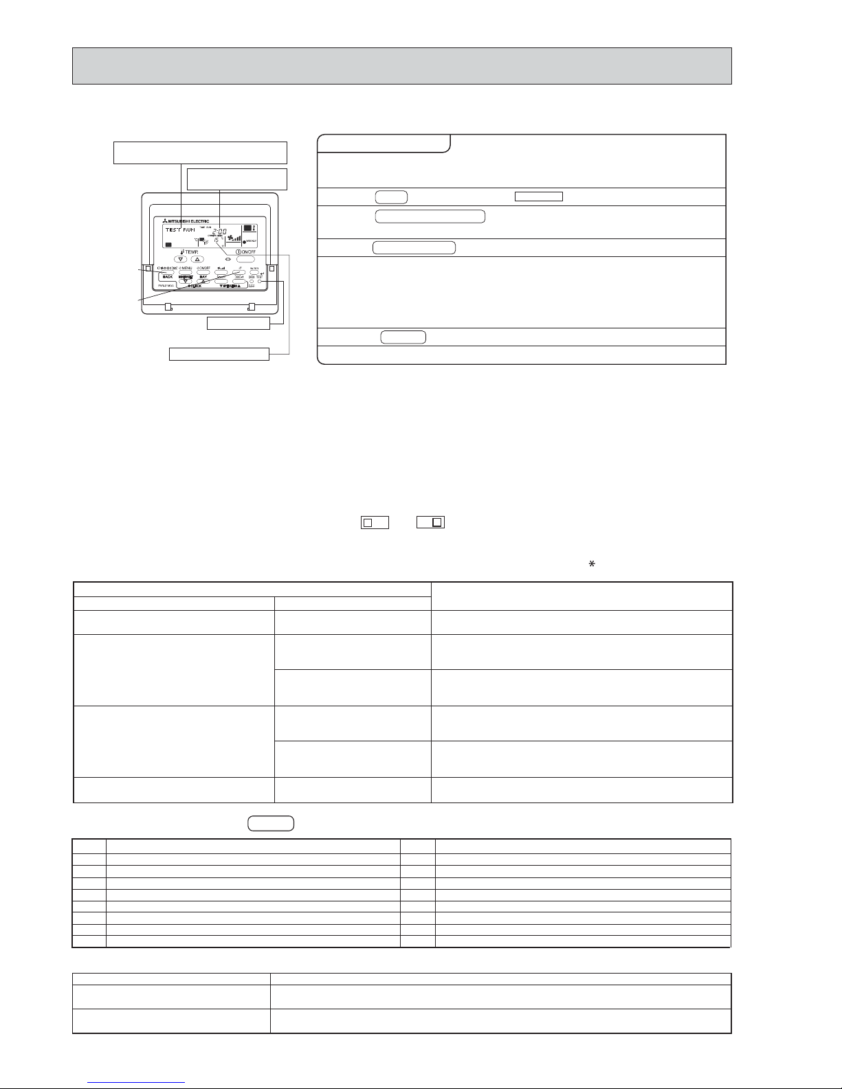
24
[TEST] button
Pipe (liquid) temperature
Displays the remaining
test run time.
"TEST RUN" and the currently selected
operation mode are displayed alternately.
• In case of test run, the OFF timer will be activated, and the test run will automatically stop after 2 hours.
• The room temperature display section shows the pipe temperature of indoor units during the test run.
• Check that all the indoor units are running properly in case of simultaneous twin operation. Malfunctions may not be
displayed regardless of incorrect wiring.
* After turning on the power supply, the system will go into startup mode, “PLEASE WAIT” will blink on the display section
of the room temperature, and lamp (green) of the remote controller will flash.
As to INDOOR BOARD LED, LED1 will be lit up, LED2 will either be lit up in case the address is 0 or turned off in case
the address is not 0. LED3 will blink.
As to OUTDOOR BOARD LED, LED1 (green) and LED2 (red) will be lit up. (After the startup mode of the system
finishes, LED2 (red) will be turned off.)
In case OUTDOOR BOARD LED is digital display, — and — will be displayed alternately every second.
• If one of the above operations does not function correctly, the causes written below should be considered. Find causes from
the symptoms.
The below symptoms are under test run mode. “startup” in the table means the display status of (
) written above.
Remote Controller Display
Symptoms in test run mode
OUTDOOR BOARD LED Display
Cause
Remote controller displays “PLEASE
WAIT”, and
cannot be operated.
After power is turned on, “PLEASE WAIT”
is displayed for 3 minutes, then error code
is displayed.
No display appears even when remote
controller operation switch is turned on.
(Operation lamp does not light up.)
Display appears but soon disappears
even when remote controller is operated.
• After power is turned on, “PLEASE WAIT” is displayed for 2
minutes during
system startup. (Normal)
• Incorrect connection of outdoor terminal block (L
1, L2, L3 and
S1, S2, S3.)
• Outdoor unit’s protection device connector is open.
• Incorrect wiring between the indoor and outdoor unit (Polarity
is wrong for S1, S2, S3.)
• Remote controller transmission wire is short.
• There is no outdoor unit of address 0.
(Address is other than 0.)
• Remote controller transmission wire is open.
• After canceling function selection, operation is not possible for
about 30 seconds. (Normal)
After “startup” is displayed, only
green lights up. <00>
After “startup” is displayed,
green(once) and red(once) blink
alternately. <F1>
After “startup” is displayed,
green(once) and red(twice) blink
alternately. <F3, F5, F9>
After “startup” is displayed,
green(twice) and red(once) blink
alternately. <EA. Eb>
After “startup” is displayed, only
green lights up. <00>
After “startup” is displayed, only
green lights up. <00>
< > indicates digital display.
2. Press TEST button twice.
1. Turn on the main power supply.
3. Press OPERATION SWITCH
button.
4. Press AIR DIRECTION button.
5. Check the outdoor unit fan for
correct running.
6. Press the ON/OFF button to reset the test run in progress.
7. Register the contact number.
While the room temperature display on the remote
controller is “PLEASE WAIT”, the remote controller is disabled.
Wait until “PLEASE WAIT” disappears before using remote controller.
“PLEASE WAIT” appears for about 2 minutes after power
supply is turned on. *
The outdoor unit features automatic capacity control to
provide optimum fan speeds. Therefore, the fan keeps
running at a low speed to meet the current outside air
condition unless it exceeds its available maximum power.
Then, in actuality, the fan may stop or run in the reverse
direction depending on the outside air, but this does not
mean malfunction.
Check for correct motion of auto-vanes.
Cooling mode:
Check if cool air blows and water is drained.
Heating mode: Check if warm air blows. (It takes a little
while until warm air blows.)
The TEST RUN appears on the screen.
Operating procedures
B
C
A
Note: Press the remote controller’s CHECK button twice to perform self-diagnosis. See the table below for the contents of LCD display.
LCD
Contents of inferior phenomena
P1
P2
P4
P5
P6
P8
P9
Fb
Abnormality of room temperature thermistor
Abnormality of pipe temperature thermistor/Liquid
Abnormality of drain sensor/ Float switch connector open
Drain overflow protection is operating.
Freezing/overheating protection is operating.
Abnormality of pipe temperature
Abnormality of pipe temperature thermistor/Cond./Eva
Abnormality of indoor controller board
LCD
Contents of inferior phenomena
U1~UP
F3~F9
E0~E5
E6~EF
----
FFFF
PA
PL
Malfunction outdoor unit
Malfunction
outdoor unit
Remote controller transmitting error
Indoor/outdoor unit communication error
No error history
No applied unit
Forced compressor stop(due to water leakage abnormality)
Abnormality of refrigerant
LED1
(microprocessor power supply)
LED2
(remote controller)
LED3
(indoor/outdoor communication)
Lights when power is supplied.
Lights
when power is supplied for wired remote controller.
The indoor unit should be connected to the outdoor unit with address “0” setting.
Flashes when indoor and outdoor unit are communicating.
See the table below for details of the LED display (LED 1, 2, 3) on the indoor controller board.
10-2-3. Test run for wired remote controller <PAR-21MAA>
OCH526B
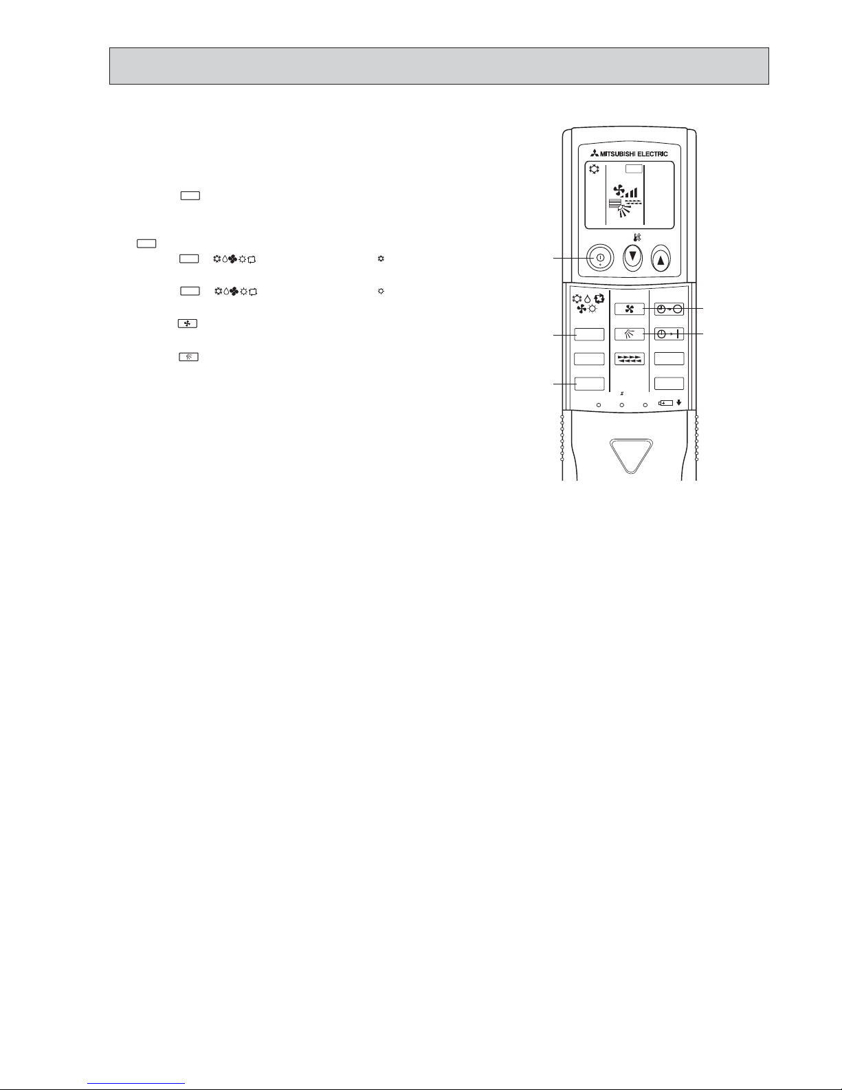
25
ON/OFF
TEMP
FAN
VAN E
MODE
CHECK
LOUVER
TEST RUN
AUTO STOP
AUTO START
h
min
TEST RUN
RESET
SET
CLOCK
,
10-2-4. Test run for wireless remote controller
Measure an impedance between the power supply terminal block on
the outdoor unit and ground with a 500V Megger and check that it is
equal to or greater than 1.0M".
1 Turn on the main power to the unit.
2 Press the
TEST RUN
button twice continuously.
(Start this operation from the status of remote controller display
turned off.)
A
TEST RUN
and current operation mode are displayed.
3 Press the
MODE
( ) button to activate
COOL
mode, then
check whether cool air is blown out from the unit.
4 Press the
MODE
( ) button to activate
HEAT
mode, then
check whether warm air is blown out from the unit.
5 Press the
FAN
button and check whether strong air is blown out
from the unit.
6 Press the
VANE
button and check whether the auto vane operates
properly.
7 Press the ON/OFF button to stop the test run.
Note:
• Point the remote controller towards the indoor unit receiver
while following steps 2 to 7.
• It is not possible to run in FAN, DRY or AUTO mode.
OCH526B

26
F1 F2 F3 F4
unem ecivreS
rosruC
:unem niaM
Test run
Input maintenance info.
Function setting
Check
Self check
kcehc fleS
:tceleS
Ref. address
sserddA
kcehc fleS
Ref. address
Return:
teseR
Error Unt # CI.prG
Self check
Return:
Reset
M-NET address
Grp.
-
Error Unt #
--
--
When there is no error history
Self check
Delete error history?
Ref. address
Cancel OK
Self check
Return:
Ref. address
Error history deleted
2
With theF1or
F2
button, enter the refrigerant address, and press the button.
Select "Self check" with the F1 or F2 button, and press the button.
1
Select "Service" from the Main menu, and press the button.
3
Error code, unit number, attribute will appear.
"-" will appear if no error history is available.
4
Resetting the error history.
Press the
F4
button (Reset) on the screen that shows the error history.
A confi rmation screen will appear asking if you want to delete the error history.
Press the
F4
button (OK) to delete the error history.
If deletion fails, "Request rejected" will appear.
"Unit not exist" will appear if no indoor units that are correspond to the entered
address are found.
Navigating through the screens
• To go back to the Main menu ..........
button
• To return to the previous screen .......
button
10-3. HOW TO PROCEED "SELF-DIAGNOSIS"
10-3-1. Self-diagnosis <PAR-31MAA>
OCH526B
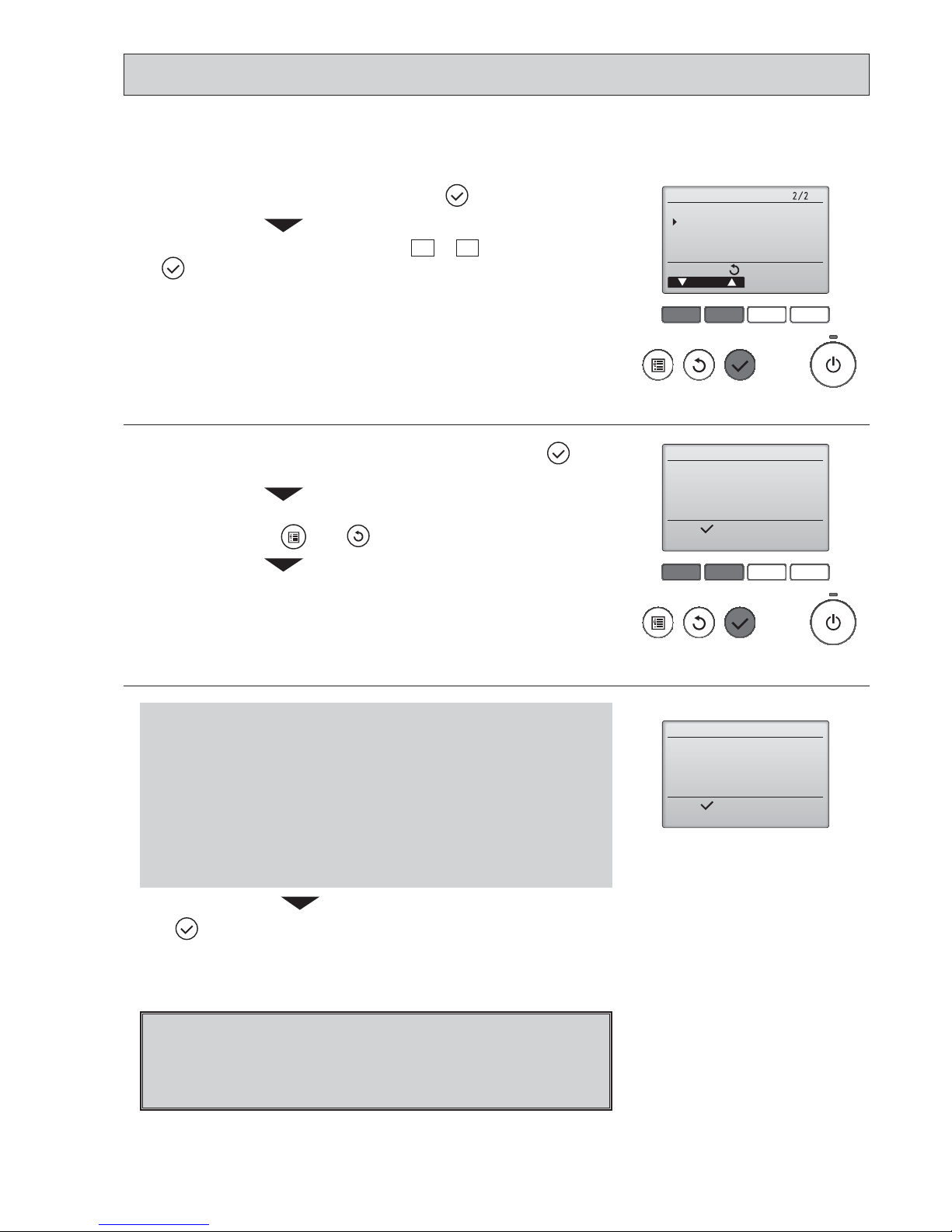
27
If operations cannot be completed with the remote controller, diagnose the remote controller with this function.
F1 F2 F3 F4
unem ecivreS
rosruC
:unem niaM
Maintenance password
Remote controller check
F1 F2 F3 F4
Remote controller check
:nigeB
Start checking?
Remote controller check
:nigeB
Start checking?
1
Select "Service" from the Main menu, and press the button.
Select "Remote controller check" with the F1
or F2 button, and press
the
button.
2
Select "Remote controller check" from the Service menu, and press the but-
ton to start the remote controller check and see the check results.
To cancel the remote controller check and exit the Remote controller check
menu screen, press the
or the button.
The remote controller will not reboot itself.
Check the remote controller display and see if anything is displayed
(including lines). Nothing will appear on the remote controller display
if the correct voltage (8.5 – 12 VDC) is not supplied to the remote controller. If this is the case, check the remote controller wiring and indoor
units.
OK: No problems are found with the remote controller. Check other
parts for problems.
E3, 6832: There is noise on the transmission line, or the indoor unit or another
remote controller is faulty. Check the transmission line and the
other remote controllers.
NG (ALL0, ALL1):
Send-receive circuit fault. Remote controller needs replacing.
ERC:
The number of data errors is the discrepancy between the number of
bits in the data transmitted from the remote controller and that of the
data that was actually transmitted over the transmission line. If data
errors are found, check the transmission line for external noise interference.
Remote controller check results screen
If the button is pressed after the remote controller check results are displayed, remote controller check will end, and the remote controller will automati-
cally reboot itself.
10-3-2. Remote controller check <PAR-31MAA>
3
OCH526B
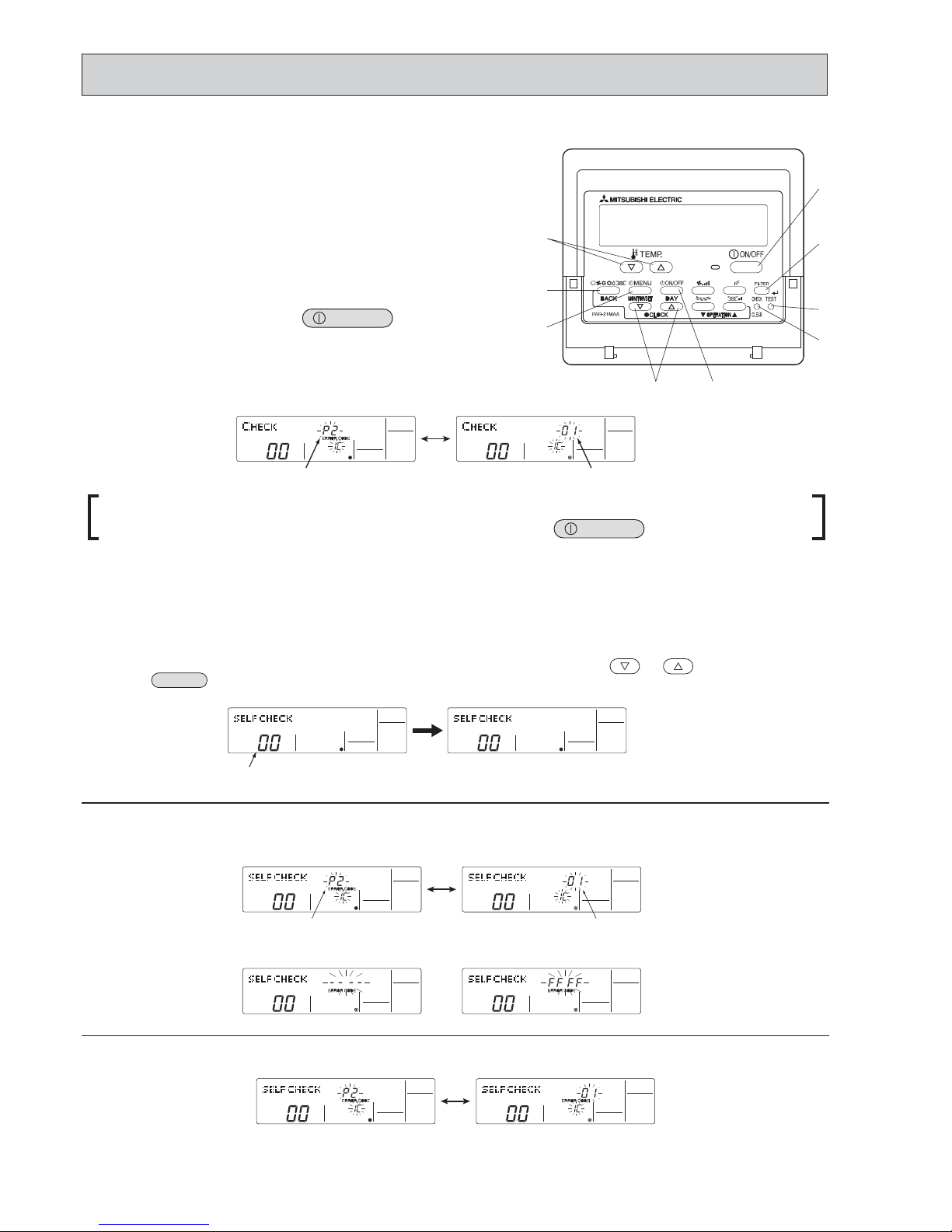
28
ON/OFF
When using remote-/local-controller combined operation, cancel the error code after turning off remote operation. During
central control by a MELANS controller, cancel the error code by pressing the
ON/OFF
button.
Since each unit has a function that stores error codes, the latest check code can be recalled even if it is cancelled by the remote
controller or power is turned off.
Check the error code history for each unit using the remote controller.
Switch to self-diagnosis mode.
Press the
CHECK
button twice within 3 seconds. The display content
will change as shown below.
Set the unit number or refrigerant address you want to diagnose.
Press the [TEMP] buttons ( and ) to select the desired number
or address. The number (address) changes between [01] and [50] or [00]
Display self-diagnosis results.
<When there is error code history>
(For the definition of each error code, refer to the indoor unit's installation manual or service handbook.)
Reset the error history.
Display the error history in the diagnosis result display screen (see step
).
Error code (2 or 4 digits)
(Alternating Display)
Address (3 digits) or unit number (2 digits)
The refrigerant address will begin to blink
approximately 3 seconds after being
selected and the self-diagnosis process will begin.
Unit number or refrigerant address
to be diagnosed
Error code (2 or 4 digits)
(Alternating Display)
Address (3 digits) or unit number (2 digits)
<When there is no error code history> <When there is no corresponding unit>
and
[15].
If a problem occurs in the air conditioner, the indoor and outdoor units will stop,
and the problem is shown in the remote controller display.
[CHECK] and the refrigerant address are displayed on the
temperature display, and the error code and unit number are
displayed alternately as shown below. (If the outdoor unit is
malfunctioning, the unit number will be “00”.)
In the case of group control, for which one remote controller controls
multiple refrigerant systems, the refrigerant address and error code of
the unit that first experienced trouble (i.e., the unit that transmitted
the error code) will be displayed.
To clear the error code, press the button.
10-3-3. Self-diagnosis <PAR-21MAA>
10-3-4. Self-Diagnosis During Maintenance or Service <PAR-21MAA>
OCH526B
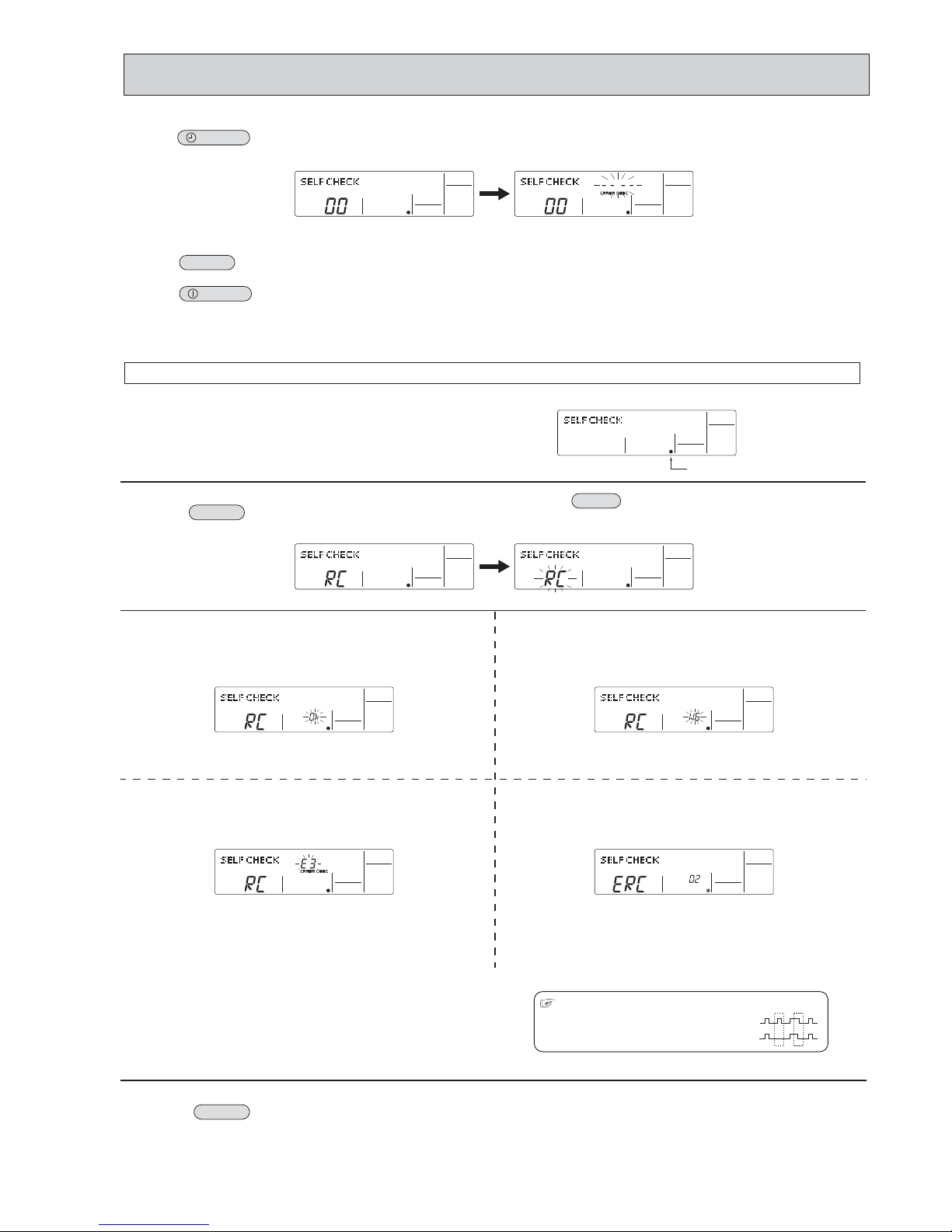
29
Transmission data from remote controller
Transmission data on transmission path
When the number of data errors is "02":
Press the
ON/OFF
button twice within 3 seconds. The self-diagnosis
address or refrigerant address will blink.
When the error history is reset, the display will look like the one shown below.
However, if you fail to reset the error history, the error content will be displayed
again.
Cancel self-diagnosis.
Self-diagnosis can be cancelled by the following 2 methods.
Press the
CHECK
button twice within 3 seconds. Self-diagnosis will be cancelled and the screen will return to the previous state in effect before the
start of self-diagnosis.
Press the
ON/OFF
button. Self-diagnosis will be cancelled and the indoor unit will stop.
If the air conditioner cannot be operated from the remote controller, diagnose the remote controller as explained below.
First, check that the power-on indicator is lit.
If the correct voltage (DC12 V) is not supplied to the remote controller, the
indicator will not light.
If this occurs, check the remote controller's wiring and the indoor unit.
Switch to the remote controller self-diagnosis mode.
Press the
CHECK
button for 5 seconds or more. The display content will
change as shown below.
Press the
FILTER
button to start self-diagnosis.
Remote controller self-diagnosis result
[When the remote controller is functioning correctly]
Check for other possible causes, as there is no problem with the remote
controller.
[When the remote controller malfunctions]
(Error display 1) "NG" blinks. ©The remote controller's transmitting-receiv-
ing circuit is defective.
The remote controller must be replaced with a new one.
[Where the remote controller is not defective, but cannot be operated.]
(Error display 2) [E3], [6833] or [6832] blinks.© Transmission is not
There might be noise or interference on the transmission path, or the indoor
unit or other remote controllers are defective. Check the transmission path
and other controllers.
(Error display 3)
"ERC" and the number of data errors are displayed.
© Data error has occurred.
The number of data errors is the difference between the number of bits sent
from the remote controller and the number actually transmitted through the
transmission path. If such a problem is occurring, the transmitted data is
affected by noise, etc. Check the transmission path.
To cancel remote controller diagnosis
Press the
CHECK
button for 5 seconds or more. Remote controller diagnosis will be cancelled, "PLEASE WAIT" and operation lamp will blink. After
approximately 30 seconds, the state in effect before the diagnosis will be restored.
Power on indicator
possible.
10-3-5. Remote controller check <PAR-21MAA>
OCH526B
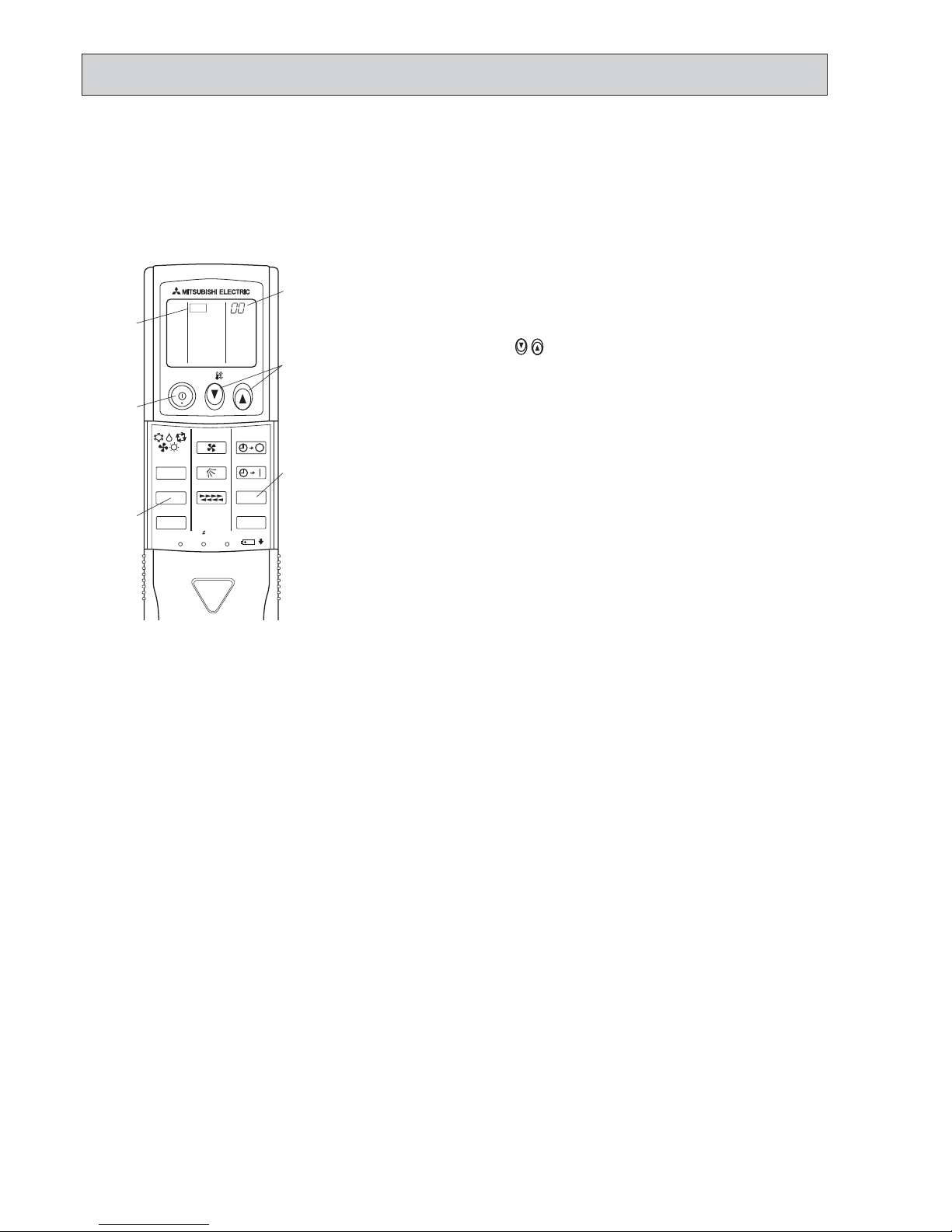
30
• "CHECK" lights, and refrigerant address
"00" blinks.
• Check that the remote controller's
display has stopped before continuing.
• Select the refrigerant address of the
indoor unit for the self-diagnosis.
Note: Set refrigerant address using the
outdoor unit’s DIP switch (SW1).
( For more information, see the
outdoor unit installation manual.)
• If an air conditioner error occurs, the
indoor unit's sensor emits an intermittent buzzer sound, the operation lamp
blinks, and the error code is output.
(It takes 3 seconds at most for error
code to appear.)
• The check mode is cancelled.
[Procedure]
1. Press the CHECK button twice.
2. Press the temperature
buttons.
3. Point the remote controller at the
sensor on the indoor unit and
press the HOUR button.
4. Point the remote controller at the
sensor on the indoor unit and
press the ON/OFF button.
<Malfunction-diagnosis method at maintenance service>
10-3-6. Self-diagnosis <Wireless remote controller>
<In case of trouble during operation>
When a malfunction occurs to air conditioner, both indoor unit and outdoor unit will stop and operation lamp blinks to inform
unusual stop.
ON/OFF
TEMP
FAN
VAN E
MODE
CHECK
LOUVER
TEST RUN
AUTO STOP
AUTO START
h
min
RESET
SET
CLOCK
CHECK
CHECK
display
Temperature
button
CHECK
button
Refrigerant
address
display
HOUR
button
ON/OFF
button
OCH526B
 Loading...