

Mitsubishi Electric PUHZ-SHW230YKA2 Service Manual
SERVICE MANUAL
CONTENTS
TECHNICAL CHANGES
......................................
2
1. SAFETY PRECAUTION
...................................
3
2. SPECIFICATIONS
............................................
5
3. DATA
...............................................................
7
4. OUTLINES AND DIMENSIONS
.......................
9
5. WIRING DIAGRAM
........................................
10
6. WIRING SPECIFICATIONS
...........................
12
7. REFRIGERANT SYSTEM DIAGRAM
...........
14
8. TROUBLESHOOTING
...................................
15
9. DISASSEMBLY PROCEDURE
......................
57
Note:
• This manual describes
service data of the outdoor
unit only.
R410A
PARTS CATALOG (OCB594)
[Model Name]
PUHZ-SHW230YKA2
[Service Ref.]
PUHZ-SHW230YKA2
PUHZ-SHW230YKA2R1
PUHZ-SHW230YKA2R2
SPLIT-TYPE, AIR CONDITIONER
No. OCH594
REVISED EDITION-B
December 2018
OCH594 REVISED EDITION-A
is void.
Revision:
• Added
PUHZ-SHW230YKA2R2
in REVISED EDITION-B.
• Some descriptions have
been modified.

2
OCH594B
TECHNICAL CHANGES
Service ref. have been changed as follows.
PUHZ-SHW230YKA2
PUHZ-SHW230YKA2R1
• A compliance with ErP directive Lot6 has been authorized.
PUHZ-SHW230YKA2R1 PUHZ-SHW230YKA2R2
• Power board, controller board and noise filter board have been changed.
• Quantity of refrigerant has been changed.
• Unit weight has been changed.
3
OCH594B
SAFETY PRECAUTION
1
Cautions for units utilizing refrigerant R410A
1-2. CAUTIONS RELATED TO NEW REFRIGERANT
1-1. ALWAYS OBSERVE FOR SAFETY
Before obtaining access to terminal, all supply circuits must be disconnected.
Use a vacuum pump with a reverse flow check
valve.
Vacuum pump oil may flow back into refrigerant cycle and
that can cause deterioration of refrigerant oil, etc.
Use the following tools specifically designed for
use with R410A refrigerant.
The following tools are necessary to use R410A refrigerant.
Handle tools with care.
If dirt, dust or moisture enters into refrigerant cycle, that can
cause deterioration of refrigerant oil or malfunction of compressor.
Do not use a charging cylinder.
If a charging cylinder is used, the composition of refrigerant will change and the efficiency will be lowered.
Electronic refrigerant
charging scale
Vacuum pump adaptor
Gauge manifold
Torque wrench
Gas leak detector
Charge hose
Tools for R410A
Charge refrigerant from liquid phase of gas cylinder.
If the refrigerant is charged from gas phase, composition
change may occur in refrigerant and the efficiency will be
lowered.
Ventilate the room if refrigerant leaks during
operation. If refrigerant comes into contact with
a flame, poisonous gases will be released.
Do not use refrigerant other than R410A.
If other refrigerant (R22, etc.) is used, chlorine in refrigerant can cause deterioration of refrigerant oil, etc.
Use the specified refrigerant only.
Never use any refrigerant other than that specified.
Doing so may cause a burst, an explosion, or fire when the
unit is being used, serviced, or disposed of.
Correct refrigerant is specified in the manuals and on the
spec labels provided with our products.
We will not be held responsible for mechanical failure,
system malfunction, unit breakdown or accidents caused
by failure to follow the instructions.
Preparation before the repair service.
• Prepare the proper tools.
• Prepare the proper protectors.
• Provide adequate ventilation.
• After stopping the operation of the air conditioner, turn off the power-supply breaker.
• Discharge the condenser before the work involving the electric parts.
Precautions during the repair service.
• Do not perform the work involving the electric parts with wet hands.
• Do not pour water into the electric parts.
• Do not touch the refrigerant.
• Do not touch the hot or cold areas in the refrigerating cycle.
• When the repair or the inspection of the circuit needs to be done without turning off the power,
exercise great caution not to touch the live parts.
[1] Cautions for service
(1) Perform service after recovering the refrigerant left in unit completely.
(2) Do not release refrigerant in the air.
(3) After completing service, charge the cycle with specified amount of refrigerant.
4
OCH594B
[2] Additional refrigerant charge
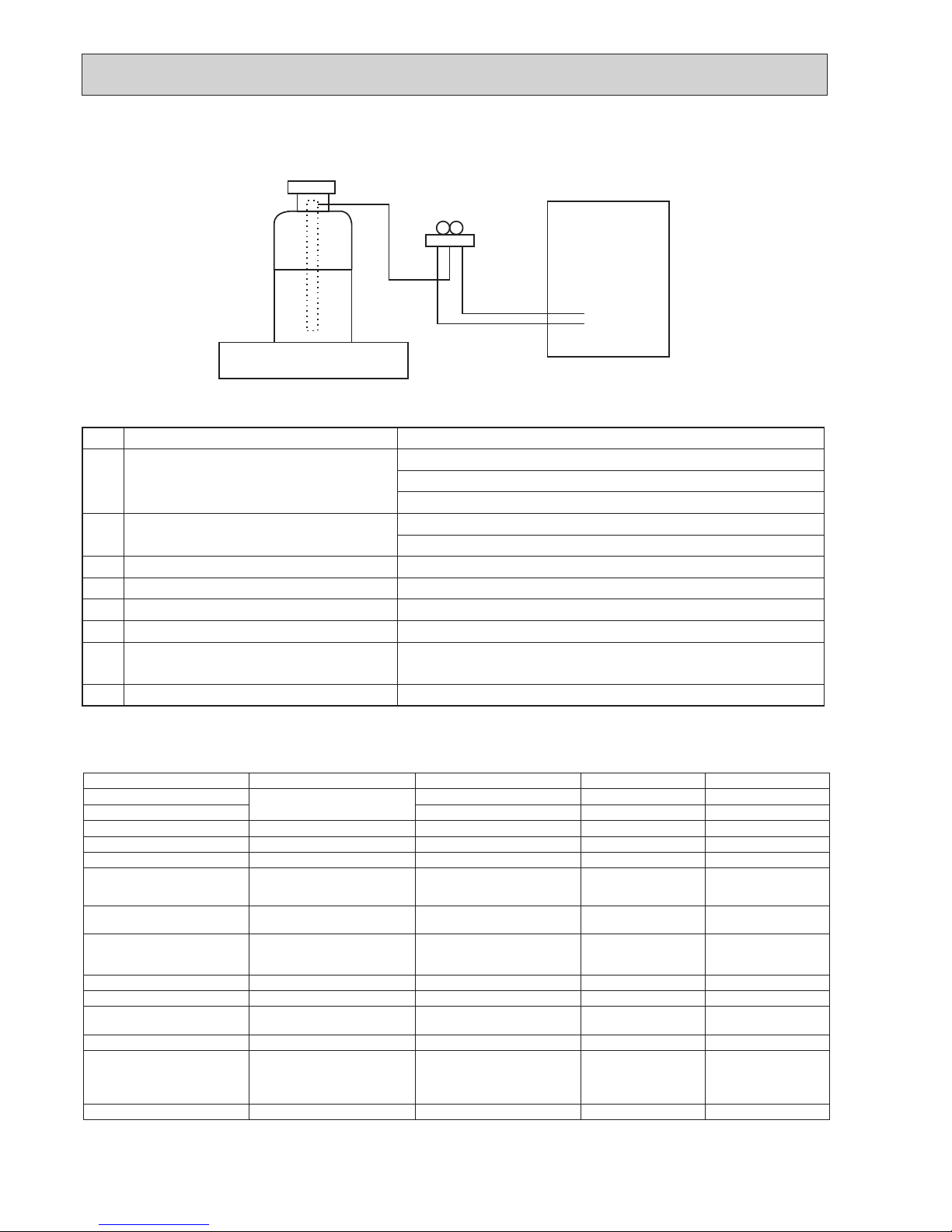
When charging directly from cylinder
· Check that cylinder for R410A on the market is a syphon type.
· Charging should be performed with the cylinder of syphon stood vertically. (Refrigerant is charged from liquid phase.)
Electronic weighing scale
Unit
[3] Service tools
Use the below service tools as exclusive tools for R410A refrigerant.
No. Tool name Specifications
1
Gauge manifold · Only for R410A
· Use the existing fitting
specifications
. (UNF1/2)
· Use high-tension side pressure of 5.3 MPa·G or over.
2
Charge hose · Only for R410A
· Use pressure performance of 5.09 MPa·G or over.
3
Electronic weighing scale
—
4
Gas leak detector · Use the detector for R134a, R407C or R410A.
5
Adaptor for reverse flow check · Attach on vacuum pump.
6
Refrigerant charge base
—
7
Refrigerant cylinder · Only for R410A Top of cylinder (Pink)
Cylinder with syphon
8
Refrigerant recovery equipment
—
1-3. CAUTIONS FOR REFRIGERANT PIPING WORK
Tools for R410A (The following table shows whether conventional tools can be used or not.)
Tools and materials Use R410A tools
Can R22 tools be used?
Can R407C tools be used?
Gauge manifold Air purge, refrigerant charge
and operation check
Tool exclusive for R410A × ×
Charge hose Tool exclusive for R410A × ×
Gas leak detector Gas leak check Tool for HFC refrigerant × ○
Refrigerant recovery equipment
Refrigerant recovery Tool exclusive for R410A × ×
Refrigerant cylinder Refrigerant charge Tool exclusive for R410A × ×
Safety charger
Prevent compressor malfunction
when charging refrigerant by
spraying liquid refrigerant
Tool exclusive for R410A
× ×
Charge valve Prevent gas from blowing out
when detaching charge hose
Tool exclusive for R410A
× ×
Vacuum pump Vacuum drying and air purge Tools for other refrigerants
can be used if equipped with
adapter for reverse ow check
Δ(Usable if equipped
with adapter for
reverse flow)
Δ(Usable if equipped
with adapter for
reverse flow)
Bender Bend the pipes
Tools for other refrigerants can be used
○ ○
Pipe cutter Cut the pipes
Tools for other refrigerants can be used
○ ○
Welder and nitrogen gas
cylinder
Weld the pipes
Tools for other refrigerants can be used
○ ○
Refrigerant charging scale Charge refrigerant
Tools for other refrigerants can be used
○ ○
Vacuum gauge or thermistor
vacuum gauge and vacuum
valve
Check the degree of vacuum.
(Vacuum valve prevents back
ow of oil and refrigerant to
thermistor vacuum gauge)
Tools for other refrigerants can be used
○ ○
Charging cylinder Refrigerant charge Tool exclusive for R410A × -
×
: Prepare a new tool. (Use the new tool as the tool exclusive for R410A.)
Δ: Tools for other refrigerants can be used under certain conditions.
○
: Tools for other refrigerants can be used.
5
OCH594B
SPECIFICATIONS
2
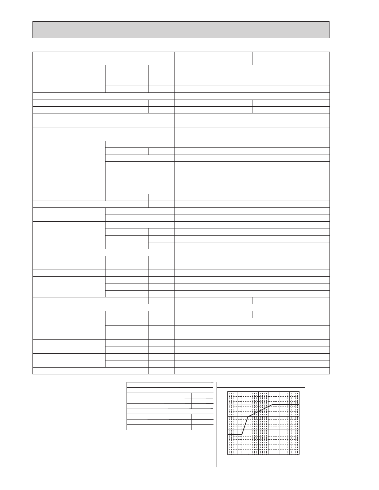
2-1. SPECIFICATION
2-1-1. PUHZ-SHW230YKA2
<Reference data> Plate heat exchanger (MWA2-38PA) *2 pcs [connected in parallel]
Nominal water ow L/min 65.9
Heating
(A7/W35)
Capacity kW 23.0
COP 3.65
Power input kW 6.31
Heating
(A7/W45)
Capacity kW 23.0
COP 3.02
Power input kW 7.62
Heating
(A2/W35)
Capacity kW 23.0
COP 2.37
Power input kW 9.71
Heating
(A2/W45)
Capacity kW 22.9
COP 2.02
Power input kW 11.32
Nominal water ow L/min 57.3
Cooling
(A35/W7)
Capacity kW 20.00
EER 2.22
Power input kW 9.01
Cooling
(A35/W18)
Capacity kW 20.00
EER 3.55
Power input kW 5.63
Rating conditions
Nominal operating condition
Heating (A2/W35)
Outside air temperature (Dry-bulb) + 2°C
Outside air temperature (Wet-bulb) + 1°C
Water temperature (inlet/outlet) + 30°C/+ 35°C
Heating (A2/W45)
Outside air temperature (Dry-bulb) + 2°C
Outside air temperature (Wet-bulb) + 1°C
Water temperature (inlet/outlet) + 40°C/+ 35°C
Heating (A7/W35)
Outside air temperature (Dry-bulb) + 7°C
Outside air temperature (Wet-bulb) + 6°C
Water temperature (inlet/outlet) + 30°C/+ 35°C
Heating (A7/W45)
Outside air temperature (Dry-bulb) + 7°C
Outside air temperature (Wet-bulb) + 6°C
Water temperature (inlet/outlet) + 40°C/+ 45°C
Cooling (A35/W7)
Outside air temperature (Dry-bulb) + 35 °C
Outside air temperature (Wet-bulb) + 24 °C
Water temperature (inlet/outlet) + 12 °C/+ 7 °C
Cooling (A35/W18)
Outside air temperature (Dry-bulb) + 35°C
Outside air temperature (Wet-bulb) + 24°C
Water temperature (inlet/outlet) + 23°C/+ 18°C
Note: "COP" and "Power input" in the above table are the values that do NOT contain the "pump input (based on EN 14511)".
6
OCH594B
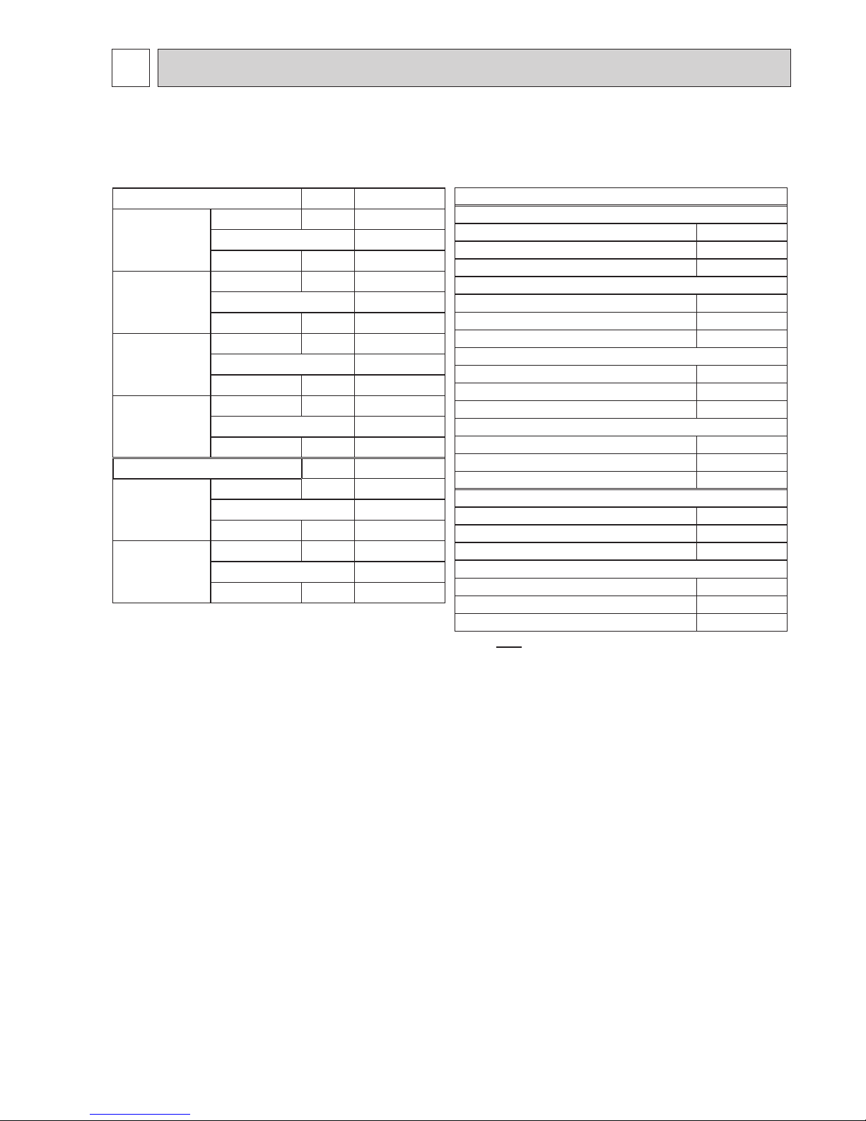
2-1-2. Outdoor unit
Maximum outlet water temperature
*1 Hot gas with 4-way valve
*2 At distance of 1 m from outdoor unit
*3 grill
*4 With the optional air outlet guide, the operation at
−15℃ outdoor temperature is possible.
40
45
50
55
60
65
−25 −20 −15 −10 −5 0 5 10
Ambient temperature [°C]
Maximum outlet water temperature [
°C
]
*5 A weighted sound power level in accordance
with ISO9614-1 for EN14511 testing is
*6 Lower limit of use is −5
℃ for EN14511 testing purpose.
75 dBA.
noitidnoc gnitarepo lanimoN
Heating(A7/W35)
7 +)blub-yrD( erutarepmet ria edistuO ℃
6 +)blub-teW( erutarepmet ria edistuO ℃
53+/03+)teltuo/telni( erutarepmet retaW ℃
Cooling(A35/W7)
53+)blub-yrD( erutarepmet ria edistuO ℃
42 +)blub-teW( erutarepmet ria edistuO ℃
7+/21+)teltuo/telni( erutarepmet retaW ℃
Service Ref. PUHZ-SHW230YKA2
PUHZ-SHW230YKA2R1
PUHZ-SHW230YKA2R2
Running current Heating(A7/W35) A 9.6
Cooling(A35/W7) A 9.6
Power factor Heating(A7/W35) % 95
Cooling(A35/W7) % 95
Power supply (phase, voltage, cycle) 3 phase, 400 V, 50 Hz
Max. current A 26.0 20
Breaker size A 32 25
Outer casing Galvanized plate
External nish Munsell 3Y 7.8/1.1
Refrigerant control Liner expansion valve
Compressor Hermetic scroll
Model ANB66FJNMT
Motor output kW 4.7
Start type Inverter
Protection devices HP switch
LP switch
Discharge thermo
Overcurrent detection
Comp. surface thermo
Oil (Model) L 1.7 (FV50S)
Crankcase heater W —
Heat exchanger Air Plate n coil
Water Plate heat exchanger
Fan Fan (drive) × No. Propeller fan × 2
Fan motor output kW 0.150 × 2
Airow m³/min 140
(CFM) (4,940)
Defrost method Reverse cycle *
1
Noise level (SPL) Heating dB 59 *2 *
5
Cooling dB 58 *
2
Noise level (PWL) Heating dB 75
Dimensions Width mm (in) 1050 (41-5/16)
Depth mm (in) 330 + 30(*
3
) (13+1-3/16)
Height mm (in) 1338 (52-11/16)
Weight kg (lbs) 149 (328) 143 (315)
Refrigerant R410A
Quantity kg (lbs) 7.7 (17.0) 7.1 (15.7)
Guaranteed operating range
(Outdoor)
Heating °C
−25(*
6)
to +21
DHW °C −25 to +35
Cooling °C
−5(*
4)
to +46
Outlet water temp.
(Max. in heating, Min. in cooling)
Heating °C +60
Cooling °C +5
Nominal return water
temperature range
Heating °C +10 to +59
Cooling °C +8 to +28
Water ow rate range L/min 28.7 to 65.9
7
OCH594B
DATA
3
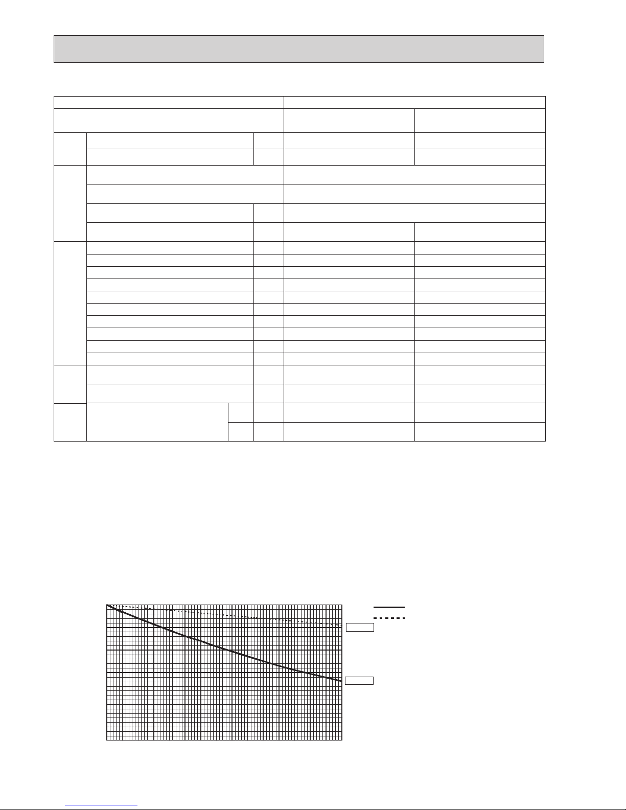
1.5m
1m
MICROPHONE
UNIT
GROUND
90
80
70
60
50
40
30
20
10
63 125 250 500 1000 2000 4000 8000
APPROXIMATE
THRESHOLD OF
HEARING FOR
CONTINUOUS
NOISE
OCTAVE BAND SOUND PRESSURE LEVEL, dB (0 dB = 0.0002 µbar)
BAND CENTER FREQUENCIES, Hz
NC-60
NC-50
NC-40
NC-30
NC-20
NC-70
PUHZ-SHW230YKA2
COOLING
MODE
HEATING
58
SPL(dB)
59
LINE
PUHZ-SHW230YKA2R1
PUHZ-SHW230YKA2R2
3-3. NOISE CRITERION CURVES
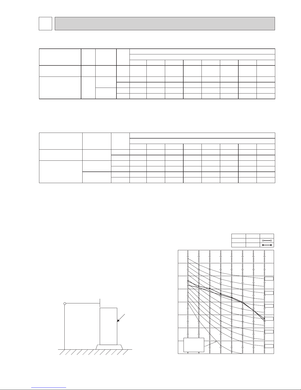
3-1. Additional refrigerant charge (R410A)
Service Ref.
Initial
charge
(kg)
Operation
method
Liquid
pipe
size
Total piping length (one way)
Amount of additional refrigerant charge (kg)
2 - 10 m
11 - 20 m 21 - 30 m 31 - 40 m 41–50 m 51–60 m 61–70 m 71–80 m
PUHZ-SHW230YKA2
PUHZ-SHW230YKA2R1
7.7
ATW/ATA/
AHU
- - - - 1.2 2.4 3.6 4.8 5.2
PUHZ-SHW230YKA2R2*17.1
ATW
ø12.7 - - - 1.4 2.8 4.2 5.6 7.0
ø9.52 - - - - 0.8 1.7 2.6 3.5
ATA/AHU
ø12.7 - - 1.4 2.8 4.2 5.6 7.0 8.4
ø9.52 - - - 0.8 1.7 2.6 3.5 4.4
*1 Set the SW8-2 on controller board ON when the piping length is 10 m or less. (for models from PUHZ-SHW230YKA2R2)
3-2. Recharge refrigerant amount (R410A)
Service Ref.
Operation
method
Liquid
pipe
size
Total piping length (one way)
Amount of recharge refrigerant (kg)
2 - 10 m
11 - 20 m 21 - 30 m 31 - 40 m 41–50 m 51–60 m 61–70 m 71–80 m
PUHZ-SHW230YKA2
PUHZ-SHW230YKA2R1
ATW/ATA/
AHU
ø12.7 5.5 6.6 7.7 8.9 10.1 11.3 12.5 12.9
ø9.52 5.4 6.3 6.7 8.3 9.4 10.4 11.5 11.8
PUHZ-
SHW230YKA2R2
*1
ATW
ø12.7 5.9 6.5 7.1 8.5 9.9 11.3 12.7 14.1
ø9.52 5.7 6.1 6.5 7.1 7.9 8.8 9.7 10.6
ATA/AHU
ø12.7 6.5 7.1 8.5 9.9 11.3 12.7 14.1 15.5
ø9.52 6.1 6.5 7.1 7.9 8.8 9.7 10.6 11.5
*1 Set the SW8-2 on controller board ON when the piping length is 10 m or less. (for models from PUHZ-SHW230YKA2R2)
8
OCH594B
3-5. CAPACITY CORRECTION (Refrigerant piping length)
Cooling and heating capacity is lowered according to the piping length. Capacity can be obtained by referring to the following
capacity curves.
Corrected pipe length (m) = actual pipe length (m) + number of bends × 0.3 (m)
Cooling
Heating
HRP200
HRP200
5 10 15 20 25 30 35 40 45 50 55 60 65 70 75 80
70
75
80
85
90
95
100
Corrected pipe length [m]
Capacity ratio [%]
SHW230
SHW230
3-4. Standard operation data Reference data (connect to Plate HEX)
(MWA2-38PA) o 2 pcs [connected in parallel]
Mode
Cooling
(A35/W7)
Heating
(A7/W35)
Total
Capacity W 20,000 23,000
Input kW 9.01 6.31
Electrical circuit
Outdoor unit PUHZ-SHW230YKA2
Phase, Hz 3, 50
Voltage V 400
Current A 13.7 9.6
Refrigerant circuit
Discharge pressure MPa 3.0 2.0
Suction pressure MPa 0.7 0.6
Discharge temperature ºC 79 73
Condensing temperature
ºC 49 35
Suction temperature ºC 8 8
Evaporating temperature
ºC 6 2
Evaporator inlet temperature
ºC 7 ——
Evaporator outlet temperature
ºC 6 ——
Condenser inlet temperature
ºC —— 65
Condenser outlet temperature
ºC —— 34
Water
conditions
Flow volume L/min 57.3 65.9
Outlet water temperature
ºC 7 35
Outdoor
conditions
Intake air
temperature
D.B. ºC 35 7
W.B. ºC 24 6
Piping length : Main 2.5 m, Branch 2.5 m/2.5 m
The unit of pressure has been changed to MPa based on international SI system.
The conversion factor is: 1 (MPa) = 10.2 (kgf/cm²)
9
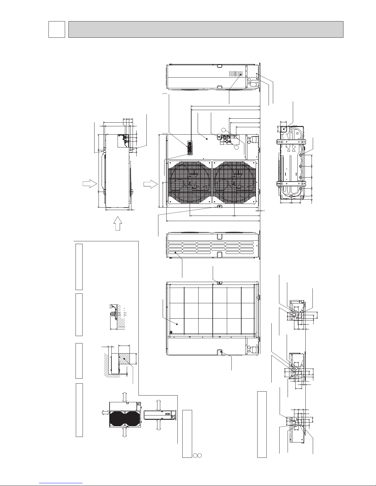
OCH594B
OUTLINES AND DIMENSIONS
4
Unit: mm
PUHZ-SHW230YKA2
PUHZ-SHW230YKA2R1
PUHZ-SHW230YKA2R2
FOUNDATION
30
Service space
150
500
500
10
The diagram below shows a
basic example.
Explanation of particular details are
given in the installation manuals etc.
Dimensions of space needed
for service access are
shown in the below diagram.
<Foundation bolt height>
Please secure the unit firmly
with 4 foundation (M10) bolts.
(Bolts and washers must be
purchased locally.)
1 FREE SPACE (Around the unit)
2 SERVICE SPACE
3 FOUNDATION BOLTS
4 PIPING-WIRING DIRECTIONS
Piping and wiring connections
can be made from 4 directions:
FRONT,Right,Rear and Below.
Less than
Over
Over
Over
Over
Over 10mm
Over 10mm
FREE
Over 150mm
Over 1000mm
···Refrigerant GAS pipe connection (attached JOINT)ø25.4(Brazing locally)
···Refrigerant LIQUID pipe connection (FLARE) ø 12.7(1/2F)
*1···Indication of STOP VALVE connection location.
*2···(FLARE)ø 19.05(3/4F)
1
2
Example of Notes
Piping Knockout Hole Details
Power supply wiring hole
(ø27Knockout)
Front piping hole
(Knockout)
Front trunking hole
(Knockout)
Power supply wiring hole
(ø40Knockout)
60 55
6373
55
27
26
75
92
60
ø92
Power supply wiring hole
(ø27Knockout)
Right piping hole
(Knockout)
Right trunking hole
(Knockout)
Power supply wiring hole
(ø40Knockout)
75 50
26
27
63
73
29 92
55
92
60
ø92
Power supply wiring hole
(ø27Knockout)
Rear piping hole
(Knockout)
Rear trunking hole
(Knockout)
Power supply wiring hole
(ø40Knockout)
75
6055
6373
26
55
27
60
92
ø92
Drain hole
(5-ø33)
Bottom piping hole
(Knockout)
81
45
154136
110 160 160 160
86
1050
Rear Air Intake
Air Discharge
Side Air Intake
Installation Feet
2-U Shaped notched holes
(Foundation Bolt M10)
2-12×36 Oval holes
(Foundation Bolt M10)
28
370
60
30
225
225
330
600
417
19
70
42
405356
0
Handle for
moving
Rear Air Intake
Side Air Intake
Handle for
moving
632
369
26
1338
Handle for moving
Handle for moving
Earth terminal
362
Brazing
Service panel
Terminal connection
Left···Power supply wiring
Right···Indoor/Outdoor wiring
*1,*2 : 442
982
986
*1 450
342
Air intake
2
1
Front piping cover
Rear piping cover
10
OCH594B
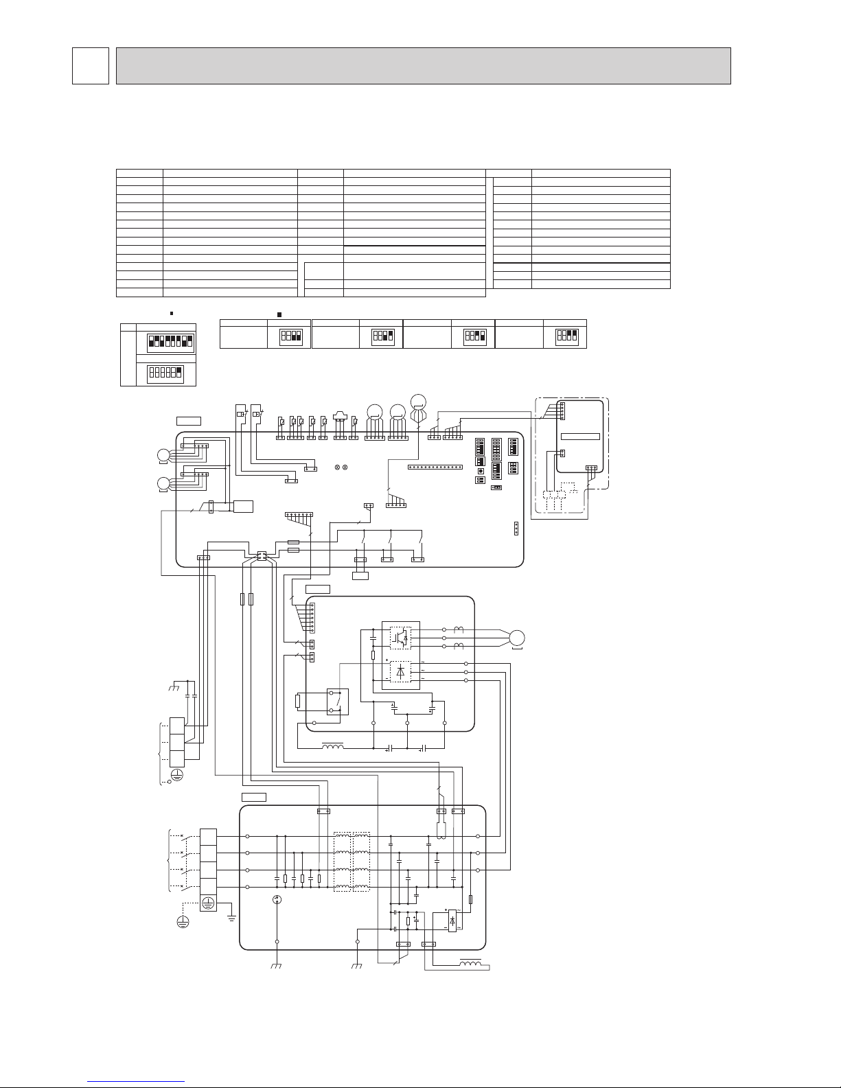
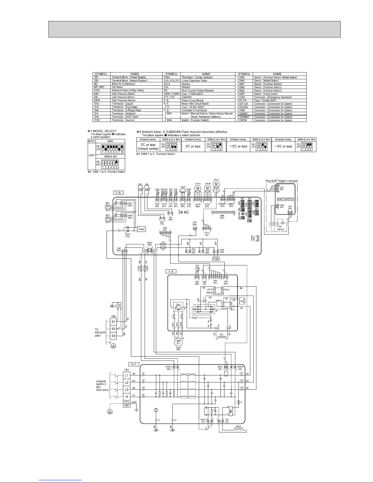
5 WIRING DIAGRAM
PUHZ-SHW230YKA2 PUHZ-SHW230YKA2R1
FUSE1, FUSE2
TB1
MC
MF1,MF2
21S4
63H
TH3
TH4
TH6
TH7
LEV-A, LEV-B, LEV-C
DCL
Terminal Block<Power Supply>
TB2 Terminal Block<Indoor/Outdoor>
Motor for Compressor
Fan Motor
Solenoid Valve (4-Way Valve)
High Pressure Switch
63L Low Pressure Switch
63HS High Pressure Sensor
Thermistor<Suction>
TH32
Fuse
<T15AL250V
>
Linear Expansion Valve
Reactor
ACL4
Reactor
P. B.
Power Circuit Board
RS
Rush Current Protect Resistor
CB1, CB2
Main Smoothing Capacitor
Noise Filter Circuit Board
N. F.
Controller Circuit Board
C. B.
SYMBOL NAME SYMBOL NAME SYMBOL NAME
Switch<Manual Defrost, Defect History Record
Reset, Refrigerant Address>
Switch<Test Operation>
Switch<Function Switch, Model Select>
SW1
SW4
SW5
SW9
Switch<Pump Down>
SWP
Connector<Emergency Operation>
CN31
F3, F4
CNMNT
CNVMNT
CNDM
Fuse<T6.3AL250V
>
CNM
SV3/SS
Connector<Connection for Option>
Connector<Connection for Option>
SV1/CH
Connector<Connection for Option>
Connector<Connection for Option>
Connector<Connection for Option>
Connector<Connection for Option>
Capacitor
CY1, CY2
TH34
Thermistor<Liquid>
Thermistor<Discharge>
Thermistor<2-Phase Pipe>
Thermistor<Ambient>
Thermistor<Comp. Surface>
Switch<Function Switch>
Switch<Function Switch>
Switch<Model Select>
SW6
SW8
Switch<Function Switch>
SW7
CN2
(WH)
7
7
1
P. B.
2
2
1
2
2
1
CN4
(WH)
CN5
(RD)
WH
FUSE1
FUSE2
WH
RD
RD
MS
3
~
POWER
SUPPLY
3N
~
400V 50Hz
TO
INDOOR
UNIT
TB1
L3
L2
L1
N
31
2
2
13
CNDC
(PK)
CNL
(BU)
311 2
CNCT
(RD)
CNAC2
(RD)
31
CNAC1
(WH)
BK
BK
LO1
LO2
LO3
LI1
LI2
LI3
NI
RD
WH
BU
BK
GNYE
GD2GD1
RD
WH
BK
N. F.
TB2
DCL
ACL4
S3
S2
S1
OG
YE
CY2
CY1
BN
RD
RD
RS
RD
WH
WH
WH
BK
BK
BK
X52A
BK
BK
TB-P2
TB-P1
TB-C1 TB-N1
CB1 CB2
W
V
MC
U
TB-L1
TB-L2
TB-L3
SC-U
SC-V
SC-W
RD
TH6TH7 TH4TH3
21S4
t˚ t˚ t˚ t˚
LEV-A
CNS
(WH)
CNAC
(WH)
CNDC
(PK)
F3
F4
21S4
(GN)
CN2
(WH)
CN4
(WH)
TH7/6
(RD)
TH3
(
WH
)
TH4
(WH)
TRANS
CNM
(WH)
LED1
LED2
X52
SV1
/CH
(GY)
X54
63H
(YE)
2
7
1 4 1 2 2 1
1 3
1 14
1 2
1 7
3
1
13
1 2
3 4
31 31
LEV-A
(WH)
51
SV3
/SS
(WH)
X51
31
MF1
CNF1
(WH)
1
7
63L
63H
63L
(RD)
1 3
31
TH34
t˚
2 1
TH34
(RD)
63HS
(WH)
63HS
LEV-B
(RD)
M
LEV-B
51
M
MF2
CNF2
(WH)
1
7
2
CNDM
(WH)
1
3
SW7
SW6SW1
SW9
CN31
SW5
SW8SW4
SWP
C. B.
TH32
(BK)
TH32
t˚
1 2
*1*
1
*
3
CNVMNT
(WH)
CNMNT
(WH)
31 1 5
5
LEV-C
(BU)
5
1
LEV-C
5
M
MS
3~
MS
3~
3
5
CN5
(WH)
3 1
TB7
2
1
CND
(WH)
CN2M
(WH)
M-NET
A B S
When M-NET Adapter is connected
5
3
5
1
M-NET ADAPTER
MODEL
SW6
SW5-6
*
2
1 2 3 4 5 6 7 8
*
2
SW5 -1 to 5 : Function Switch.
OFF
1 2 3 4 5 6
OFF
ON
230Y
ON
*
1 MODEL SELECT
The black square ( ) indicates
a switch position.
1 2 3 4
OFF
ON
1 2 3 4
OFF
ON
SW9-3, 9-4 *4
Ambient temp.
3ºC or less
(Default setting
)
*
4 SW9-1 to 2 : Function Switch
0ºC or less
SW9-3, 9-4 *4
Ambient temp.
−3ºC or less
−6ºC or less
1 2 3 4
OFF
ON
1 2 3 4
OFF
ON
SW9-3, 9-4 *4
Ambient temp.
SW9-3, 9-4 *4
Ambient temp.
*
3 Ambient temp. of ZUBADAN Flash Injection becomes effective.
The black square ( ) indicates a switch position.
11
OCH594B
PUHZ-SHW230YKA2R2

12
OCH594B
WIRING SPECIFICATIONS6
FIELD ELECTRICAL WIRING (power wiring specifications)
S1
Power supply
3 poles isolator
A-Control
Indoor Unit
A-Control
Outdoor Unit
Isolator
S2
S3
S1
S2
S3
Outdoor unit model SHW230Y
Outdoor unit power supply
3N~ (3 ph 4-wires),
50 Hz, 400 V
Outdoor unit input capacity Main switch (Breaker) *1
YKA2/YKA2R1: 32 A
YKA2R2: 25A
Wiring
Wire No. ×
size (mm
2
)
Outdoor unit power supply 5 × Min. 4
Indoor unit-Outdoor unit *2
Cable length 50 m: 3×4 (Polar)/
Cable length 80 m: 3×6 (Polar)
Indoor unit-Outdoor unit earth *2 1 × Min. 2.5
Remote controller-Indoor unit *3 2 × 0.3 (Non-polar)
Circuit rating
Outdoor unit L-N (single)
Outdoor unit L1-N, L2-N, L3-N (3 phase)
*4 230 V AC
Indoor unit-Outdoor unit S1-S2 *4 230 V AC
Indoor unit-Outdoor unit S2-S3 *4 24 V DC
Remote controller-Indoor unit *4 12 V DC
*1. A breaker with at least 3.0 mm contact separation in each poles shall be provided. Use earth leakage breaker (NV).
Make sure that the current leakage breaker is one compatible with higher harmonics.
Always use a current leakage breaker that is compatible with higher harmonics as this unit is equipped with an inverter.
The use of an inadequate breaker can cause the incorrect operation of inverter.
*2. Maximum 80 m. Total maximum including all indoor/indoor connection is 80 m.
• Use one cable for S1 and S2 and another for S3 as shown in the picture.
*3. The 10 m wire is attached in the remote controller accessory.
*4. The gures are NOT always against the ground.
S3 terminal has 24 V DC against S2 terminal. However between S3 and S1, these terminals are NOT electrically insulated by the transformer or other device.
Notes: 1. Wiring size must comply with the applicable local and national code.
2.
Power supply cords and Indoor/Outdoor unit connecting cords shall not be lighter than polychloroprene sheathed exible cord.
(Design 60245 IEC 57
)
3. Use an earth wire which is longer than the other cords so that it will not become disconnected when tension is applied.
Caution: Be sure to install N-line. Without N-line, it could cause damage to the unit.
S3
S3
S2
S1
S2S1
N
L1 L2 L3
C
A Indoor unit
B Outdoor unit
C Remote controller
D Main switch (Breaker)
E Earth
A
B
D
D
A
A
A
B
C
E
E
E
For Power
For Power
E
Warning:
· In case of A-control wiring, there is high voltage potential on the S3 terminal caused by electrical circuit design that has no electrical insulation
between power line and communication signal line. Therefore, please turn off the main power supply when servicing. And do not touch the S1, S2, S3
terminals when the power is energized. If isolator should be used between indoor unit and outdoor unit, please use 3-pole type.
· Turn on the main power when the ambient temperature is −20°C or higher.
· In below −20°C condition, it needs at least 12 hrs standby to operate in order to warm the electrical parts.
Note: When multiple indoor units (hydroboxes) are connected to the outdoor unit, wire the PCB of either one of the indoor unit and the outdoor unit
(S1,S2,S3).
It is impossible to connect the PCBs of multiple indoor units to the outdoor unit.
Twin or triple system construction of the hydrobox is not
allowed.
When the hydrobox is constructed as a slave, remote
controller must be connected by crossover wiring.
13
OCH594B
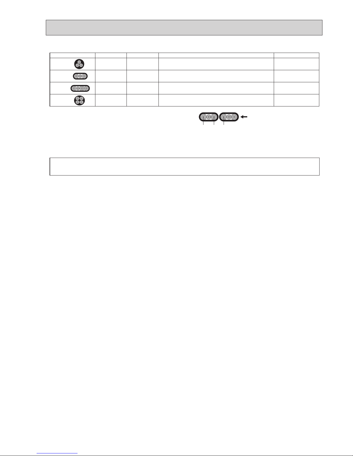
INDOOR-OUTDOOR CONNECTING CABLE
Cross section of cable Wire size (mm2) Number of wires Polarity L (m)*
5
Round
2.5 3
Clockwise : S1-S2-S3
(Pay attention to stripe of yellow and green.)
(30)*
1
Flat
2.5 3
Not applicable
(Since center wire has no cover finish.)
Not applicable*
4
Flat
1.5 4
From left to right: S1-Open-S2-S3
(18)*
2
Round
2.5 4
Clockwise : S1-S2-S3-Open
(Connect S1 and S3 to the opposite angle.)
(30)*
3
Note: Power supply cords of appliances shall not be lighter than design 60245 IEC or
227 IEC.
*
1
In case that cable with stripe of yellow and green is available.
*
2
In case of regular polarity connection (S1-S2-S3), wire size is 1.5 mm
2
.
*3 In case of regular polarity connection (S1-S2-S3).
*
4
In the flat cables are connected as this picture, they can be used up to 30 m.
*
5
Mentioned cable length is just a reference value.
It may be different depending on the condition of installation, humidity or
materials, etc.
(3C Flat cable × 2)
Be sure to connect the indoor-outdoor connecting cables directly to the units (no intermediate connections).
Intermediate connections can lead to communication error if water enters the cables and causes insufficient insulation to ground or a poor electrical contact at
the intermediate connection point.
S1
S3S2
14
OCH594B
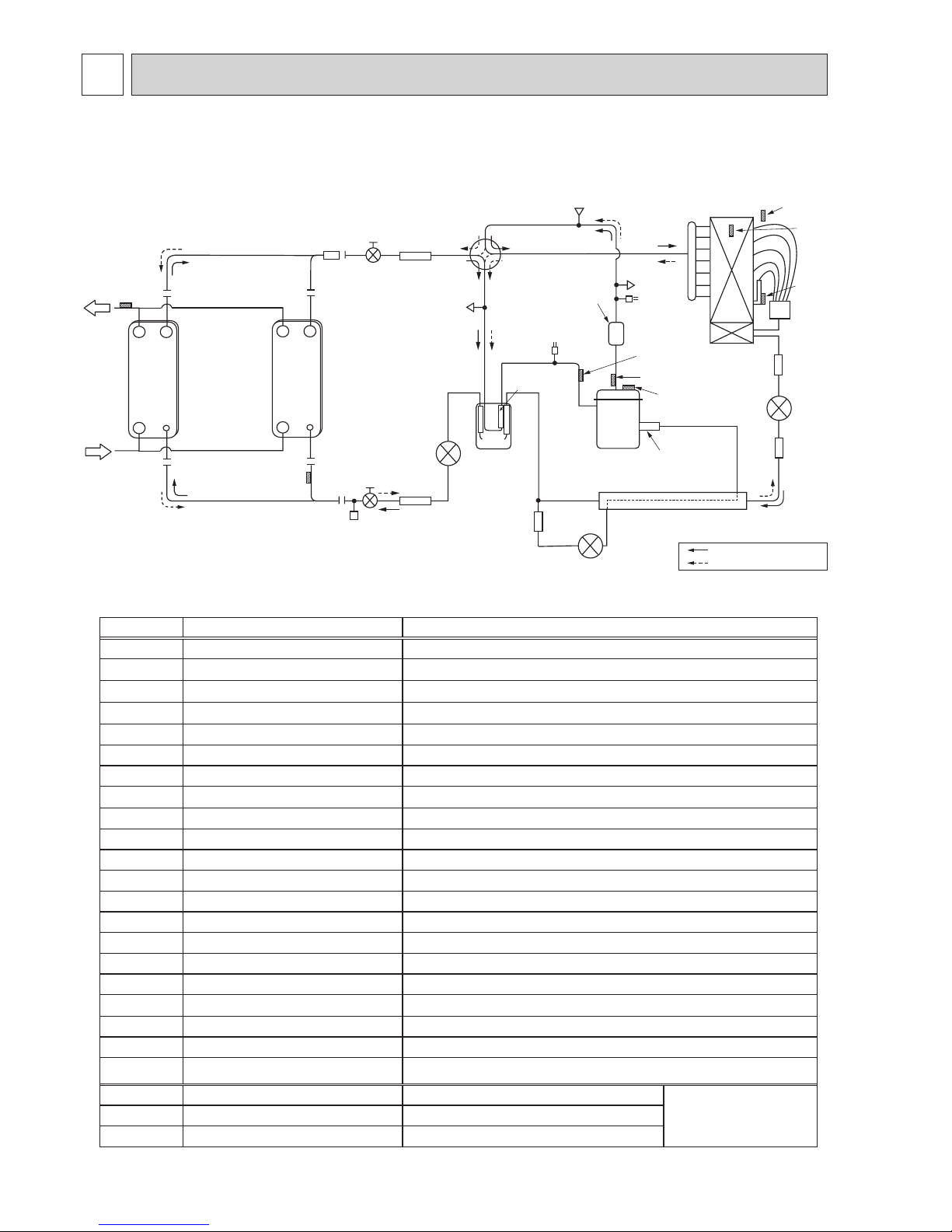
REFRIGERANT SYSTEM DIAGRAM7
Distributor
TH7
HEX
Refrigerant
GAS pipe
connection
(1 inch)
Refrigerant
LIQUID pipe
connection
(1/2 inch)
Stop valve
(with service port)
Strainer
#100
Power
receiver
LEV-B
Strainer
#100
Strainer
#100
TH6
TH3
Charge plug
(Low pressure)
Charge plug
(High pressure)
HIC
TH4
TH34
COMP
INJ. port
Strainer
#50
REV/V
Strainer
#100
Strainer
#100
Muffler
P-sensor
Ball valve
TH32
L/P SW
H/P SW
Refrigerant flow in cooling
Refrigerant flow in heating
TH2
TH1
Plate HEX
Strainer
#100
Strainer
#100
Plate HEX
Water IN
Water OUT
Joint pipe
(Brazing)
LEV-C
LEV-A
PUHZ-SHW230YKA2 PUHZ-SHW230YKA2R1 PUHZ-SHW230YKA2R2
<Reference> System example: Plate HEX (MWA2 * 2 pcs) + FTC (TH1/2)
Symbol Part name Detail
COMP Compressor DC inverter scroll compressor (Mitsubishi Electric Corporation)
INJ. port Compressor Injection port
Muffler Discharge mufer
HEX Heat exchanger
H/P SW High pressure switch (63H) For protection (OFF: 4.15MPa)
L/P SW Low pressure switch (63L) For protection (OFF: -0.03MPa)
REV/V Reversing (4-way) valve (21S4) Change the refrigerant circuit (Heating / Cooling) and for Defrosting
CHECK/V Check valve
P-Sensor Pressure sensor (63HS) For calculation of the condensing temperature from high pressure
LEV-A Linear expansion valve -A Heating:Secondary LEV Cooling:Primary LEV
LEV-B Linear expansion valve -B Heating:Primary LEV Cooling:Secondary LEV
LEV-C Linear expansion valve -C For HIC (heating only)
TH32 Suction temperature thermistor For LEV control
TH3 Liquid temperature thermistor Heating:Evaporating temperature Cooling:Sub cool liquid temperature
TH4 Discharge temperature thermistor For LEV control and for compressor protection
TH6
2-phase pipe temperature thermistor
Outdoor 2-phase pipe temperature
TH7 Ambient temperature thermistor For fan control and for compressor frequency control
TH8 Heat sink temperature
TH34 Comp. surface temperature thermistor For protection
Power Receiver
Power Receiver For accumulation of refrigerant
HIC Heat interchange circuit For high heating capacity
Plate HEX Plate Heat Exchanger MWA2-38PA (MITSUBISHI)
<Reference>
System example
TH1
Outlet water temperature thermistor For ow temp. controller
TH2
Liquid pipe temperature thermistor For ow temp. controller
15
OCH594B
TROUBLESHOOTING8
<Check code displayed by self-diagnosis and actions to be taken for service (summary)>
Present and past check codes are logged, and they can be displayed on the control board of outdoor unit. Actions to be taken
for service, which depends on whether or not the trouble is reoccurring in the field, are summarized in the table below. Check
the contents below before investigating details.
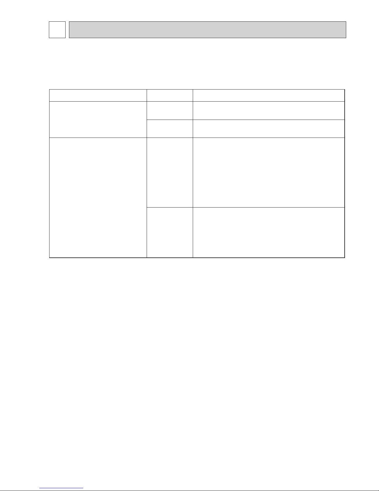
8-1. TROUBLESHOOTING
Unit conditions at service Check code Actions to be taken for service (summary)
The trouble is reoccurring.
Displayed
Judge the problem and take a corrective action according to
“8-3. SELF-DIAGNOSIS ACTION TABLE”.
Not displayed
Conduct troubleshooting and ascertain the cause of the
trouble.
The trouble is not reoccurring.
Logged
1
Consider the temporary defects such as the work of
protection devices in the refrigerant circuit including
compressor, poor connection of wiring, noise, etc. Recheck the symptom, and check the installation environment,
refrigerant amount, weather when the trouble occurred,
matters related to wiring, etc.
2
Reset check code logs and restart the unit after nishing
service.
3
There is no abnormality in electrical component, controller
board, etc.
Not logged
1
Re-check the abnormal symptom.
2
Conduct troubleshooting and ascertain the cause of the
trouble.
3
Continue to operate unit for the time being if the cause is
not ascertained.
4
There is no abnormality concerning of parts such as
electrical component, controller board, etc.
16
OCH594B
8-2. CHECKPOINT UNDER TEST RUN
Before test run
• After installation of outdoor unit, piping work and electric wiring work, re-check that there is no water leakage, loosened con-
nections and incorrect polarity.
• Measure impedance between the ground and the power supply terminal block (L, N) on the outdoor unit by 500 V Megger
and check that it is 1.0 M
or over.
• Turn on power supply 12 hours before test run in order to protect compressor.
• Make sure to read operation manual before test run. (Especially items to secure safety.)
Warning:
Do not use the system if the insulation resistance is less than 1.0 MΩ.
Caution:
Do not carry out this test on the control wiring (low voltage circuit) terminals.
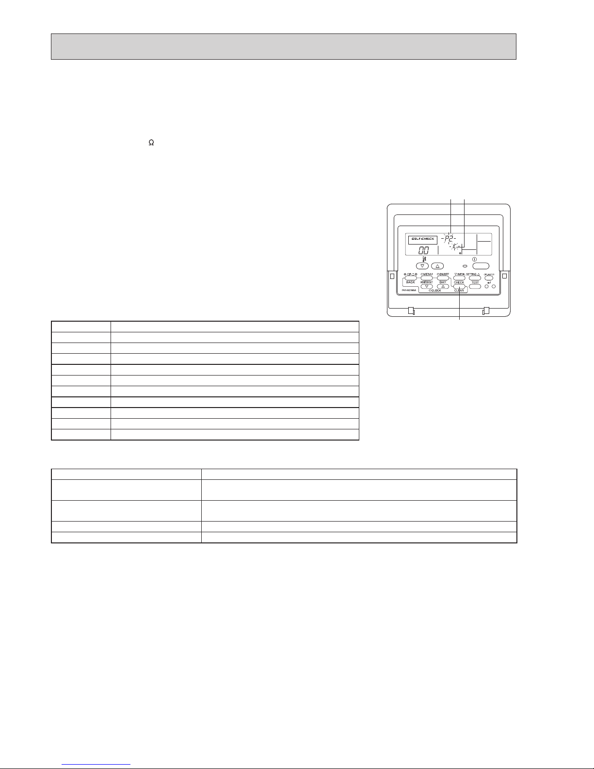
Self-check
1
Turn on the power.
2
Press [CHECK] button twice.
3
Press [CHECK] button twice to nish self-check.
A
CHECK button B IC : Interface or FTC unit OC : Outdoor unit C Check code
Check code Symptom
P1 Flow water (TH1) sensor error
P2 Refrigerant liquid Pipe (TH2) sensor error
P6 Freezing/Overheating protection operation
P9 Actual tank temp. (TH5)/ (THW5 for FTC2B) sensor error
Fb FTC unit control system error (memory error, etc.)
E0–E5 Signal transmission failure between remote controller and FTC.
E6–EF Signal transmission failure between outdoor unit and FTC.
– – – – No trouble generated in the past.
FFFF No corresponding unit
U*, F* Outdoor unit failure. Refer to the outdoor unit wiring diagram.
For description of each LED (LED1–5) provided on the FTC, refer to the following table.
LED 1 (Power for microprocessor) Indicates whether control power is supplied. Make sure that this LED is always lit.
LED 2 (Power for remote controller) Indicates whether power is supplied to the remote controller. This LED lights only in
the case of the FTC unit which is connected to the outdoor unit refrigerant address “0“.
LED 3 (Communication between FTC
and outdoor unit)
Indicates state of communication between the FTC and outdoor unit. Make sure that
this LED is always blinking.
LED 4 —
LED 5 —
ON/OFF
TEMP.
ERROR CODE
B
A
C
17
OCH594B
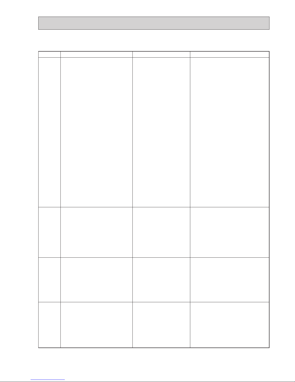
8-3. SELF-DIAGNOSIS ACTION TABLE
<Abnormalities detected when the power is turned on>
Check Code
Abnormal point and detection method
Case
Judgment and action
None —
1 No voltage is supplied to termi-
nal block (TB1) of outdoor unit.
a) Power supply breaker is
turned off.
b) Contact failure or disconnec-
tion of power supply terminal
c) Open phase (L or N phase)
2 Electric power is not charged to
power supply terminal of outdoor power circuit board.
a) Contact failure of power
supply terminal
b) Open phase on the outdoor
power circuit board
3 Electric power is not supplied
to outdoor controller circuit
board.
a) Disconnection of connector
(CNDC)
4 Disconnection of reactor (DCL)
5 Disconnection of outdoor noise
filter circuit board or parts failure in outdoor noise filter circuit
board
6
Defective outdoor power circuit board
7
Open of rush current resistor (RS)
(Only for YKA2R2 type)
8 Defective outdoor controller cir-
cuit board
1 Check following items.
a) Power supply breaker
b) Connection of power supply terminal block
(TB1)
c) Connection of power supply terminal block
(TB1)
2 Check following items.
a) Connection of power supply terminal block
(TB1)
b) Connection of terminal on outdoor
power circuit board
3 Check connection of the connector (CNDC)
on the outdoor controller circuit board.
Check connection of the connector CNDC on
the outdoor noise filter. Refer to "8-7. TEST
POINT DIAGRAM".
4 Check connection of reactor. (DCL)
5 a) Check connection of outdoor noise filter
circuit board.
b) Replace outdoor noise filter circuit board.
Refer to "8-7. TEST POINT DIAGRAM".
6 Replace outdoor power circuit board.
7 Replace rush current protect resistor (RS).
Power circuit board might be short-circuit.
Check the power circuit board.
(Refer to "8-7. TEST POINT DIAGRAM".)
(Only for YKA2R2 type)
8 Replace controller board (When items above
are checked but the units cannot be repaired).
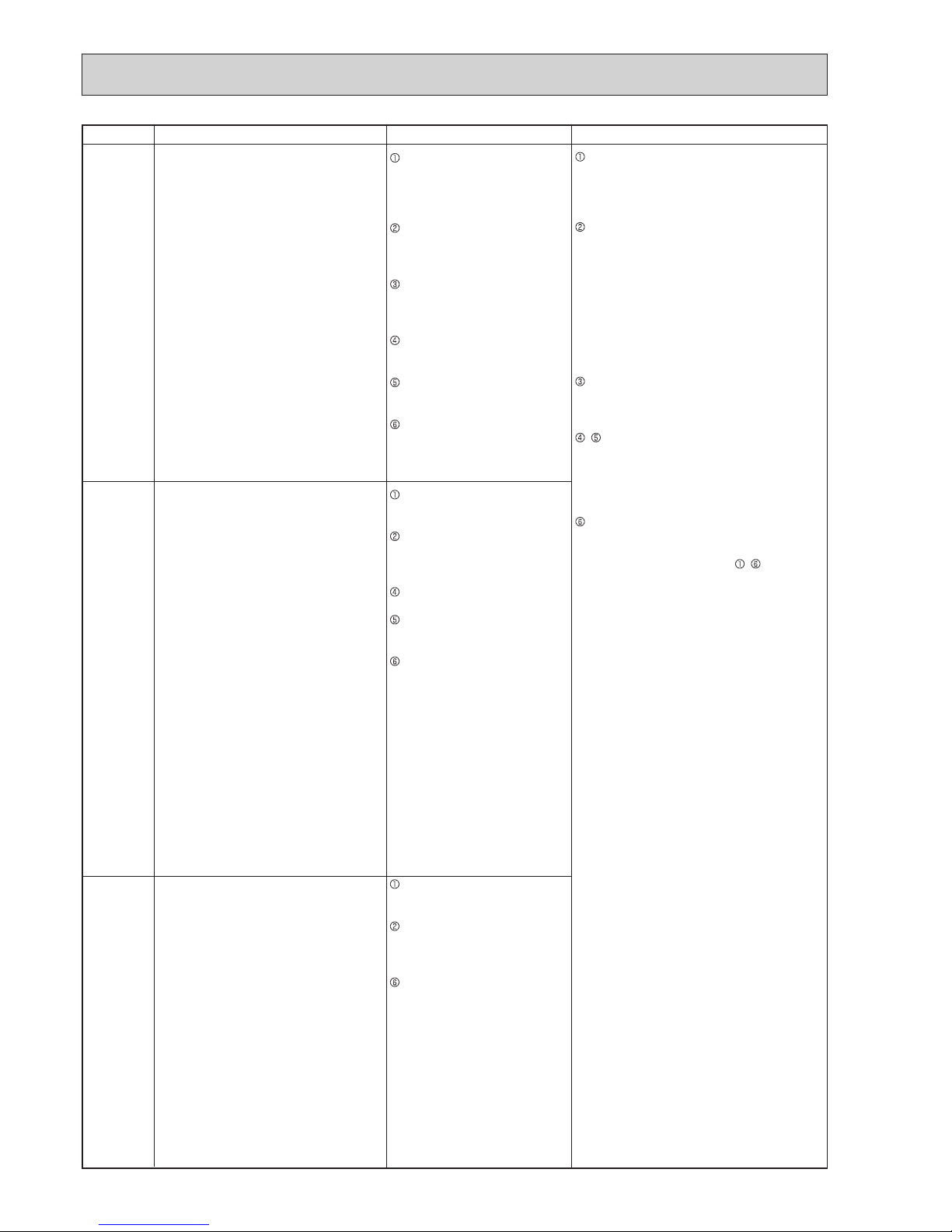
F5
63H connector open
Abnormal if 63H connector circuit is open
for 3 minutes continuously after power supply.
63H: High pressure switch
1 Disconnection or contact failure
of 63H connector on outdoor
controller circuit board
2 Disconnection or contact failure
of 63H
3 63H is working due to defective
parts.
4 Defective outdoor controller cir-
cuit board
1 Check connection of 63H connector on out-
door controller circuit board.
Refer to "8-7. TEST POINT DIAGRAM".
2 Check the 63H side of connecting wire.
3 Check continuity by tester.
Replace the parts if the parts are defective.
4 Replace outdoor controller circuit board.
F3
63L connector open
Abnormal if 63L connector circuit is open
for 3 minutes continuously after power supply.
63L: Low pressure switch
1 Disconnection or contact failure
of 63L connector on outdoor
controller circuit board
2 Disconnection or contact failure
of 63L
3 63L is working due to refriger-
ant leakage or defective parts.
4 Defective outdoor controller cir-
cuit board
1 Check connection of 63L connector on
outdoor controller circuit board.
Refer to "8-7. TEST POINT DIAGRAM".
2 Check the 63L side of connecting wire.
3 Check refrigerant pressure.
Charge additional refrigerant.
Check continuity by tester.
Replace the parts if the parts are defective.
4 Replace outdoor controller circuit board.
F9
2 connector open
Abnormal if both 63H and 63L connector
circuits are open for three minutes continuously after power supply.
63H: High pressure switch
63L: Low pressure switch
1 Disconnection or contact failure
of connector (63H,63L) on outdoor controller circuit board.
2 Disconnection or contact failure
of 63H, 63L
3 63H and 63L are working due
to defective parts.
4 Defective outdoor controller
board.
1 Check connection of connector (63H,63L) on
outdoor controller circuit board.
Refer to "8-7. TEST POINT DIAGRAM".
2 Check the 63H and 63L side of connecting
wire.
3 Check continuity by tester.
Replace the parts if the parts are defective.
4 Replace outdoor controller circuit board.
18
OCH594B
Abnormal point and detection method
Judgment and action
Case
Eb
Miswiring of Interface unit/Flow temp.
controller-outdoor unit connecting wire
(reverse wiring or disconnection)
Outdoor controller circuit board can automatically set the unit number of Interface
unit/Flow temp. controller.
Abnormal if the Interface unit/Flow temp.
controller number cannot be set within 4
minutes after power on because of miswiring (reverse wiring or disconnection) of
Interface unit/Flow temp. controller-outdoor
unit connecting wire.
EC
Startup time over
The unit cannot finish start up process
within 4 minutes after power on.
Contact failure of Interface unit
/Flow temp. controller-outdoor
unit connecting wire
Diameter or length of Interface
unit/Flow temp. controlleroutdoor unit connecting wire is
out of specified capacity.
Noise has entered into power supply or Interface unit/Flow temp.
controller-outdoor unit connecting
wire.
Contact failure or miswiring of
Interface unit/Flow temp. control
-
ler-outdoor unit connecting wire
Diameter or length of Interface
unit/Flow temp. controller-outdoor unit connecting wire is out
of specified capacity.
Defective transmitting receiving circuit
of outdoor controller circuit board
Defective transmitting receiving
circuit of Interface/Flow temp.
controller board
Noise has entered into power supply
or Interface unit/Flow temp. control
-
ler-outdoor unit connecting wire.
Miswiring of Interface unit/Flow temp.
controller-outdoor unit connecting wire
1. Outdoor controller circuit board can
automatically check the number of connected Interface unit/Flow temp. controller. Abnormal if the number cannot be
checked automatically due to miswiring
of Interface unit/Flow temp. controlleroutdoor unit connecting wire, etc. after
power is turned on for 4 minutes.
2. Abnormal if outdoor controller circuit
board recognizes excessive number of
Interface unit/Flow temp. controller.
Check disconnection or looseness or polarity
of Interface unit/Flow temp. controller-outdoor
unit connecting wire of Interface unit/Flow
temp. controller and outdoor units.
Check diameter and length of Interface unit/
Flow temp. controller-outdoor unit connecting
wire.
Total wiring length: 80 m
(Including wiring connecting each Interface
unit/Flow temp. controller unit and between
Interface unit/Flow temp. controller and out-
door unit)
Also check if the connection order of flat
cable is S1, S2, S3.
Check the number of Interface unit/Flow
temp. controller that is connected to 1 out-
door unit. (If EA is detected.)
– Turn the power off once, and on again to
check.
Replace outdoor controller circuit board
or Interface/Flow temp. controller board if
abnormality occurs again.
Check transmission path, and remove the
cause.
Note: The descriptions above,
– , are for EA,
Eb and EC.
Contact failure or miswiring of
Interface unit/Flow temp. controlleroutdoor unit connecting wire
Diameter or length of Interface
unit/Flow temp. controller-outdoor unit connecting wire is out
of specified capacity.
Excessive number of Interface
unit/Flow temp. controller is
connected to 1 outdoor unit.
(2 units or more)
Defective transmitting receiv-
ing circuit of outdoor controller
circuit board
Defective transmitting receiving
circuit of Interface/Flow temp.
controller board
Noise has entered into power
supply or Interface/Flow temp.
controller-outdoor unit connecting wire.
EA
Check Code

19
OCH594B
Abnormal point and detection method Judgment and action
U1
High pressure (High pressure switch
63H operated)
Abnormal if high pressure switch 63H operated(*) during compressor operation.
*4.15 MPa
63H: High pressure switch
1 Short cycle of indoor unit
2 Clogged filter of indoor unit
3 Decreased airflow caused by
dirt of indoor fan
4 Dirt of indoor heat exchanger
5 Locked indoor fan motor
6 Malfunction of indoor fan motor
7 Defective operation of stop
valve (Not full open)
8 Clogged or broken pipe
9 Locked outdoor fan motor
0 Malfunction of outdoor fan
motor
1 Short cycle of outdoor unit
2 Dirt of outdoor heat exchanger
3 Decreased airflow caused by
defective inspection of outside
temperature thermistor
(It detects lower temperature
than actual temperature.)
4 Disconnection or contact failure
of connector (63H) on outdoor
controller board
5 Disconnection or contact failure
of 63H connection
6 Defective outdoor controller
board
7 Defective action of linear
expansion valve
8 Malfunction of fan driving circuit
1–6 Check indoor unit and repair defectives.
7 Check if stop valve is fully open.
8 Check piping and repair defect.
9–2 Check outdoor unit and repair defect.
3 Check the detected temperature of outside
temperature thermistor on LED display.
(SW2 on A-Control Service Tool : Refer
to "8-8. FUNCTION OF SWITCHES,
CONNECTORS AND JUMPERS".)
4–6 Turn the power off and check F5 is dis-
played when the power is turned again.
When F5 is displayed, refer to “Judgment
and action” for F5.
7 Check linear expansion valve.
Refer to "8-6. HOW TO CHECK THE
COMPONENTS".
8 Replace outdoor controller board.
Case
U2
<Abnormalities detected while unit is operating>
U3
Open/short circuit of discharge
temperature thermistor (TH4)/Comp.
surface temperature thermistor (TH34)
Abnormal if open (3: or less) or short
(217: or more) is detected during
compressor operation.
(Detection is inoperative for 10 minutes
of compressor starting process and for 10
minutes after and during defrosting.)
1 Disconnection or contact
failure of connector (TH4/
TH34) on the outdoor
controller circuit board
2 Defective thermistor
3
Defective outdoor controller circuit board
1 Check connection of connector (TH4/TH34)
on the outdoor controller circuit board.
Check breaking of the lead wire for
thermistor (TH4/TH34). Refer to "8-7. TEST
POINT DIAGRAM".
2 Check resistance value of thermistor (TH4/
TH34) or temperature by microprocessor.
(Thermistor/TH4, TH34: Refer to "8-4.
TROUBLESHOOTING".)
(SW2 on A-Control
Service Tool: Refer to "8-8. FUNCTION OF
SWITCHES, CONNECTORS AND JUMPERS".)
3 Replace outdoor controller board.
High discharge temperature
(1) Abnormal if discharge temperature ther-
mistor (TH4) exceeds 125: or 110:
continuously for 5 minutes.
Abnormal if discharge temperature ther-
mistor (TH4) exceeds 110: or more
continuously for 30 seconds after 90
seconds have passed since the defrosting operation started.
(2) Abnormal if discharge superheat
(Cooling: TH4−T
63HS /
Heating: TH4−T63HS)
exceeds 70: continuously for 10 min-
utes.
High comp. surface temperature
Abnormal if comp. surface temperature
(TH34) exceeds 125:.
In the case of high comp. surface
temperature error, compressor does
not restart unless the thermistor (TH34)
becomes less than 95:.
1 Overheated compressor opera-
tion caused by shortage of
refrigerant
2 Defective operation of stop
valve
3 Defective thermistor
4 Defective outdoor controller
board
5 Defective action of linear
expansion valve
6 Clogging with foreign objects in
refrigerant circuit
Note: Clogging occurs in the
parts which become below
freezing point when water
enters in refrigerant circuit.
7 In the case of the unit does not
restart:
Detection temp. of thermistor
(TH34) ] 95:
1 Check intake superheat.
Check leakage of refrigerant.
Charge additional refrigerant.
2 Check if stop valve is fully open.
34 Turn the power off and check if U3 is dis-
played when the power is turned on again.
When U3 is displayed, refer to “Judgment
and action” for U3.
5 Check linear expansion valve.
Refer to "8-6. HOW TO CHECK THE
COMPONENTS".
6 After recovering refrigerant, remove water
from entire refrigerant circuit under vacuum
more than 1 hour.
Check Code
20
OCH594B
Abnormal point and detection method
Case
Judgment and action
U5
Temperature of heat sink
Abnormal if heat sink thermistor (TH8)
detects 95:
1 The outdoor fan motor is
locked.
2 Failure of outdoor fan motor
3 Airflow path is clogged.
4 Rise of ambient temperature
5 Defective thermistor
6 Defective input circuit of
outdoor power circuit board
7
Failure of outdoor fan drive circuit
12 Check outdoor fan.
3 Check airflow path for cooling.
4 Check if there is something which causes
temperature rise around outdoor unit.
(Upper limit of ambient temperature is 46:.)
Turn off power, and on again to check if U5 is
displayed within 30 minutes.
If U4 is displayed instead of U5, follow the
action to be taken for U4.
5 Check the thermistor (TH8) temperature by
microprocessor.
(SW2 on A-Control Service
Tool: Refer to
"8-7. TEST POINT DIAGRAM".
)
6 Replace outdoor power circuit board.
7 Replace outdoor controller circuit board.
U4
Open/short of outdoor unit thermistors
(TH3, TH32, TH6, TH7 and TH8)
Abnormal if open or short is detected
during compressor operation.
Open detection of thermistors TH3, TH32
and TH6 is inoperative for 10 seconds to
10 minutes after compressor starting and
10 minutes after and during defrosting.
Notes: 1. Check which unit has abnormality in
its thermistor by switching the mode of
SW2. (PAC-SK52ST) (Refer to "8-7.
TEST POINT DIAGRAM".)
2.
Heat sink thermistor (TH8) is in the
power module. (YKA2/YKA2R1)
1
Check connection of connector (TH3, TH32,
TH7/6) on the outdoor controller circuit board.
Check connection of connector (CN3) on the
outdoor power circuit board. Check break
ing of the lead wire for thermistor (TH3, TH32,
TH6,TH7,TH8).
Refer to "8-7. TEST POINT DIAGRAM".
2
Check resistance value of thermistor (TH3, TH32,
TH6,TH7,TH8) or check temperature by micro
processor. (Thermistor/TH3,TH6,TH7,TH32,TH8:
Refer to "8-5. HOW TO CHECK THE PARTS".)
(SW2 on A-Control Service Tool: Refer to "8-8.
FUNCTION OF SWITCHES, CONNECTORS
AND JUMPERS".)
3 Replace outdoor controller circuit board.
1 Disconnection or contact failure
of connectors
Outdoor controller circuit board
:
TH3, TH32, TH7/6
Outdoor power circuit board
:
CN3
2 Defective thermistor
3 Defective outdoor controller
circuit board
( )
U6
Power module
Check abnormality by driving power module
in case overcurrent is detected.
(UF or UP error condition)
1 Outdoor stop valve is closed.
2 Decrease of power supply voltage
3 Looseness, disconnection or
reverse of compressor wiring
connection
4 Defective compressor
5 Defective outdoor power circuit board
1 Open stop valve.
2 Check facility of power supply.
3 Correct the wiring (U
•V•
W phase) to
compressor. Refer to "8-7. TEST POINT
DIAGRAM" (Outdoor power circuit board).
4 Check compressor referring to "8-5. HOW TO
CHECK THE PARTS".
5 Replace outdoor power circuit board.
U7
Too low superheat due to low discharge
temperature
Abnormal if discharge superheat is
continuously detected less than or equal
to −15: for 3 minutes even though linear
expansion valve has minimum open pulse
after compressor starts operating for 10
minutes.
1 Disconnection or loose
connection of discharge
temperature thermistor (TH4)
2 Defective holder of discharge
temperature thermistor
3 Disconnection or loose connection
of linear expansion valve’s coil
4 Disconnection or loose
connection of linear expansion
valve’s connector
5 Defective linear expansion valve
12 Check the installation conditions of
discharge temperature thermistor (TH4).
3 Check the coil of linear expansion valve.
Refer to "8-6. HOW TO CHECK THE COMPONENTS".
4
Check the connection or contact of LEV-A
and LEV-B on outdoor controller circuit board.
5 Check linear expansion valve.
Refer to "8-6. HOW TO CHECK THE COMPONENTS".
Thermistors
Open detection Short detection
Symbol Name
TH3 Thermistor <Liquid> −40°C or below 90°C or above
TH32 Thermistor <Suction> −40°C or below 90°C or above
TH6 Thermistor <2-phase pipe> −40°C or below 90°C or above
TH7 Thermistor <Ambient> −40°C or below 90°C or above
TH8 (YKA2/YKA2R1) Internal thermistor −35°C or below 170°C or above
TH8 (YKA2R2) Thermistor <Heat sink> −34°C or below 102°C or above
U8
Outdoor fan motor
Abnormal if rotational frequency of the fan
motor is not detected during DC fan motor
operation.
Fan motor rotational frequency is abnormal
if;
• 100 rpm or below detected continuously
for 15 seconds at 20: or more outside
air temperature.
• 50 rpm or below or 1500 rpm or more
detected continuously for 1 minute.
1 Failure in the operation of the
DC fan motor
2 Failure in the outdoor circuit
controller board
1 Check or replace the DC fan motor.
2 Check the voltage of the outdoor circuit
controller board during operation.
3 Replace the outdoor circuit controller board.
(When the failure is still indicated even after
performing the action 1 above.)
Check Code
 Loading...