

Page 1
Air-Conditioners
PUHZ-RP•HA4
PUHZ-RP•KA
INSTALLATION MANUAL
For safe and correct use, read this manual and the indoor unit installation manual thoroughly before installing
the air-conditioner unit.
INSTALLATIONSHANDBUCH
Aus Sicherheitsgründen und zur richtigen Verwendung vor der Installation die vorliegende Bedienungsanleitung
und die Installationsanleitung der Innenanlage gründlich durchlesen die Klimaanlage.
MANUEL D’INSTALLATION
Avant d’installer le climatiseur, lire attentivement ce manuel, ainsi que le manuel d’installation de l’appareil
intérieur pour une utilisation sûre et correcte.
INSTALLATIEHANDLEIDING
Lees deze handleiding en de installatiehandleiding van het binnenapparaat zorgvuldig door voordat u met het
installeren van de airconditioner begint.
MANUAL DE INSTALACIÓN
Para un uso correcto y seguro, lea detalladamente este manual y el manual de instalación de la unidad interior
antes de instalar la unidad de aire acondicionado.
MANUALE DI INSTALLAZIONE
Per un uso sicuro e corretto, leggere attentamente il presente manuale ed il manuale d’installazione dell’unità
interna prima di installare il condizionatore d’aria.
MANUAL DE INSTALAÇÃO
Para uma utilização segura e correcta, leia atentamente este manual e o manual de instalação da unidade
interior antes de instalar o aparelho de ar condicionado.
INSTALLATIONSMANUAL
Læs af sikkerhedshensyn denne manual samt manualen til installation af indendørsenheden grundigt, før du
installerer klimaanlægget.
INSTALLATIONSMANUAL
Läs bruksanvisningen och inomhusenhetens installationshandbok noga innan luftkonditioneringen installeras
så att den används på ett säkert och korrekt sätt.
FOR INSTALLER
FÜR INSTALLATEURE
POUR L’INSTALLATEUR
VOOR DE INSTALLATEUR
PARA EL INSTALADOR
PER L’INSTALLATORE
PARA O INSTALADOR
TIL INSTALLATØREN
FÖR INSTALLATÖREN
English
Deutsch
Français
Nederlands
Español
Italiano
Eλληνικά
Português
Dansk
Svenska
Emniyetli ve doğru kullanım için, klima cihazını monte etmeden önce bu kılavuzu ve iç ünite montaj kılavuzunu
tamamıyla okuyun.
Türkçe
Page 2
Contents
1. Safety precautions.................................................. 2
2. Installation location................................................. 3
3. Installing the outdoor unit............................................ 5
4. Installing the refrigerant piping........................................ 5
5. Drainage piping work................................................ 9
Note: This symbol mark is for EU countries only.
This symbol mark is according to the directive 2002/96/EC Article 10 Information for users and Annex IV.
Your MITSUBISHI ELECTRIC product is designed and manufactured with high quality materials and components which can be recycled and reused.
This symbol means that electrical and electronic equipment, at their end-of-life, should be disposed of separately from your household waste.
Please, dispose of this equipment at your local community waste collection/recycling centre.
In the European Union there are separate collection systems for used electrical and electronic product.
Please, help us to conserve the environment we live in!
Caution:
• Do not vent R410A into the Atmosphere:
• R410A is a Fluorinated Greenhouse gas, covered by the Kyoto Protocol, with a Global Warming Potential (GWP)=1975.
6. Electrical work . . . . . . . . . . . . . . . . . . . . . . . . . . . . . . . . . . . . . . . . . . . . . . . . . . 10
7. Test run . . . . . . . . . . . . . . . . . . . . . . . . . . . . . . . . . . . . . . . . . . . . . . . . . . . . . . . 12
8. Initial settings for refrigerant leakage detection function . . . . . . . . . . . . . . . . . . 12
9. Special Functions . . . . . . . . . . . . . . . . . . . . . . . . . . . . . . . . . . . . . . . . . . . . . . . 13
10. System control (Fig. 10-1) . . . . . . . . . . . . . . . . . . . . . . . . . . . . . . . . . . . . . . . . 13
1. Safety precautions
►
Before installing the unit, make sure you read all the “Safety precautions”.
► Please report to or take consent by the supply authority before connec-
tion to the system.
► Equipment complying with IEC/EN 61000-3-12
(PUHZ-RP100/125/140VKA)
► PUHZ-RP200/250Y
“This equipment complies with IEC 61000-3-12 provided that the short-
circuit power S
between the user’s supply and the public system. It is the responsibility
of the installer or user of the equipment to ensure, by consulation with
the distribution network operator if necessary, that the equipment is
connected only to a supply with a short-circuit power S
equal to S
S
sc (*1)
sc is greater than or equal to Ssc (*1) at the interface point
sc greater than or
sc (*1)”
Model Ssc (MVA)
PUHZ-RP200Y 1.35
PUHZ-RP250Y 1.49
Warning:
Describes precautions that must be observed to prevent danger of injury or
death to the user.
Caution:
Describes precautions that must be observed to prevent damage to the unit.
After installation work has been completed, explain the “Safety Precautions,” use,
and maintenance of the unit to the customer according to the information in the
Operation Manual and perform the test run to ensure normal operation. Both the
Installation Manual and Operation Manual must be given to the user for keeping.
These manuals must be passed on to subsequent users.
: Indicates a part which must be grounded.
Warning:
Carefully read the labels affi xed to the main unit.
Warning:
• The unit must not be installed by the user. Ask a dealer or an authorized
technician to install the unit. If the unit is installed incorrectly, water leakage, electric shock, or fi re may result.
• For installation work, follow the instructions in the Installation Manual and
use tools and pipe components specifi cally made for use with R410A re-
frigerant. The R410A refrigerant in the HFC system is pressurized 1.6 times
the pressure of usual refrigerants. If pipe components not designed for
R410A refrigerant are used and the unit is not installed correctly, the pipes
may burst and cause damage or injuries. In addition, water leakage, electric shock, or fi re may result.
• The unit must be installed according to the instructions in order to minimize the risk of damage from earthquakes, typhoons, or strong winds. An
incorrectly installed unit may fall down and cause damage or injuries.
• The unit must be securely installed on a structure that can sustain its
weight. If the unit is mounted on an unstable structure, it may fall down
and cause damage or injuries.
• If the air conditioner is installed in a small room, measures must be taken
to prevent the refrigerant concentration in the room from exceeding the
safety limit in the event of refrigerant leakage. Consult a dealer regarding
the appropriate measures to prevent the allowable concentration from being exceeded. Should the refrigerant leak and cause the concentration limit
to be exceeded, hazards due to lack of oxygen in the room may result.
• Ventilate the room if refrigerant leaks during operation. If refrigerant comes
into contact with a fl ame, poisonous gases will be released.
• All electric work must be performed by a qualifi ed technician according to
local regulations and the instructions given in this manual. The units must
be powered by dedicated power lines and the correct voltage and circuit
breakers must be used. Power lines with insuffi cient capacity or incorrect
electrical work may result in electric shock or fi re.
1.1. Before installation
Caution:
• Do not use the unit in an unusual environment. If the air conditioner is
installed in areas exposed to steam, volatile oil (including machine oil), or
sulfuric gas, areas exposed to high salt content such as the seaside, or
areas where the unit will be covered by snow, the performance can be signifi cantly reduced and the internal parts can be damaged.
• Do not install the unit where combustible gases may leak, be produced,
fl ow, or accumulate. If combustible gas accumulates around the unit, fi re
or explosion may result.
• Use C1220 copper phosphorus, for copper and copper alloy seamless
pipes, to connect the refrigerant pipes. If the pipes are not connected correctly, the unit will not be properly grounded and electric shock may result.
• Use only specifi ed cables for wiring. The connections must be made se-
curely without tension on the terminals. If the cables are connected or
installed incorrectly, overheating or fi re may result.
• The terminal block cover panel of the outdoor unit must be fi rmly attached.
If the cover panel is mounted incorrectly and dust and moisture enter the
unit, electric shock or fi re may result.
• When installing or moving the air conditioner, use only the specifi ed refrig-
erant (R410A) to charge the refrigerant lines. Do not mix it with any other
refrigerant and do not allow air to remain in the lines. Air enclosed in the
lines can cause pressure peaks resulting in a rupture and other hazards.
• Use only accessories authorized by Mitsubishi Electric and ask a dealer
or an authorized technician to install them. If accessories are incorrectly
installed, water leakage, electric shock, or fi re may result.
• Do not alter the unit. Consult a dealer for repairs. If alterations or repairs
are not performed correctly, water leakage, electric shock, or fi re may re-
sult.
• The user should never attempt to repair the unit or transfer it to another
location. If the unit is installed incorrectly, water leakage, electric shock,
or fi re may result. If the air conditioner must be repaired or moved, ask a
dealer or an authorized technician.
• After installation has been completed, check for refrigerant leaks. If refrigerant leaks into the room and comes into contact with the fl ame of a heater
or portable cooking range, poisonous gases will be released.
• The outdoor unit produces condensation during the heating operation.
Make sure to provide drainage around the outdoor unit if such condensation is likely to cause damage.
• When installing the unit in a hospital or communications office, be prepared for noise and electronic interference. Inverters, home appliances,
high-frequency medical equipment, and radio communications equipment
can cause the air conditioner to malfunction or breakdown. The air conditioner may also affect medical equipment, disturbing medical care, and
communications equipment, harming the screen display quality.
2
Page 3
1. Safety precautions
1.2. Before installation (relocation)
Caution:
• Be extremely careful when transporting or installing the units. Two or
more persons are needed to handle the unit, as it weighs 20 kg or more.
Do not grasp the packaging bands. Wear protective gloves to remove the
unit from the packaging and to move it, as you can injure your hands on
the fi ns or the edge of other parts.
• Be sure to safely dispose of the packaging materials. Packaging materials,
such as nails and other metal or wooden parts may cause stabs or other
injuries.
1.3. Before electric work
Caution:
• Be sure to install circuit breakers. If not installed, electric shock may result.
• For the power lines, use standard cables of suffi cient capacity. Otherwise,
a short circuit, overheating, or fi re may result.
• When installing the power lines, do not apply tension to the cables. If the
connections are loosened, the cables can snap or break and overheating
or fi re may result.
1.4. Before starting the test run
Caution:
• Turn on the main power switch more than 12 hours before starting operation. Starting operation just after turning on the power switch can severely
damage the internal parts. Keep the main power switch turned on during
the operation season.
• Before starting operation, check that all panels, guards and other protective parts are correctly installed. Rotating, hot, or high voltage parts can
cause injuries.
• Do not touch any switch with wet hands. Electric shock may result.
• The base and attachments of the outdoor unit must be periodically
checked for looseness, cracks or other damage. If such defects are left uncorrected, the unit may fall down and cause damage or injuries.
• Do not clean the air conditioner unit with water. Electric shock may result.
• Tighten all fl are nuts to specifi cation using a torque wrench. If tightened
too much, the fl are nut can break after an extended period and refrigerant
can leak out.
• Be sure to ground the unit. Do not connect the ground wire to gas or water
pipes, lightning rods, or telephone grounding lines. If the unit is not properly grounded, electric shock may result.
• Use circuit breakers (ground fault interrupter, isolating switch (+B fuse),
and molded case circuit breaker) with the specifi ed capacity. If the circuit
breaker capacity is larger than the specifi ed capacity, breakdown or fi re
may result.
• Do not touch the refrigerant pipes with bare hands during operation. The
refrigerant pipes are hot or cold depending on the condition of the fl owing
refrigerant. If you touch the pipes, burns or frostbite may result.
• After stopping operation, be sure to wait at least fi ve minutes before turn-
ing off the main power switch. Otherwise, water leakage or breakdown may
result.
1.5. Using R410A refrigerant air conditioners
Caution:
• Use C1220 copper phosphorus, for copper and copper alloy seamless
pipes, to connect the refrigerant pipes. Make sure the insides of the pipes
are clean and do not contain any harmful contaminants such as sulfuric
compounds, oxidants, debris, or dust. Use pipes with the specifi ed thick-
ness. (Refer to 4.1.) Note the following if reusing existing pipes that carried
R22 refrigerant.
- Replace the existing fl are nuts and fl are the fl ared sections again.
- Do not use thin pipes. (Refer to 4.1.)
• Store the pipes to be used during installation indoors and keep both ends
of the pipes sealed until just before brazing. (Leave elbow joints, etc. in
their packaging.) If dust, debris, or moisture enters the refrigerant lines, oil
deterioration or compressor breakdown may result.
• Use ester oil, ether oil, alkylbenzene oil (small amount) as the refrigeration
oil applied to the fl ared sections. If mineral oil is mixed in the refrigeration
oil, oil deterioration may result.
Fig. 1-1
• Do not use refrigerant other than R410A refrigerant. If another refrigerant is
used, the chlorine will cause the oil to deteriorate.
• Use the following tools specifi cally designed for use with R410A refrigerant.
The following tools are necessary to use R410A refrigerant. Contact your
nearest dealer for any questions.
Gauge manifold Flare tool
Charge hose Size adjustment gauge
Gas leak detector Vacuum pump adapter
Torque wrench Electronic refrigerant charging scale
• Be sure to use the correct tools. If dust, debris, or moisture enters the re-
frigerant lines, refrigeration oil deterioration may result.
• Do not use a charging cylinder. If a charging cylinder is used, the compo-
sition of the refrigerant will change and the effi ciency will be lowered.
Tools (for R410A)
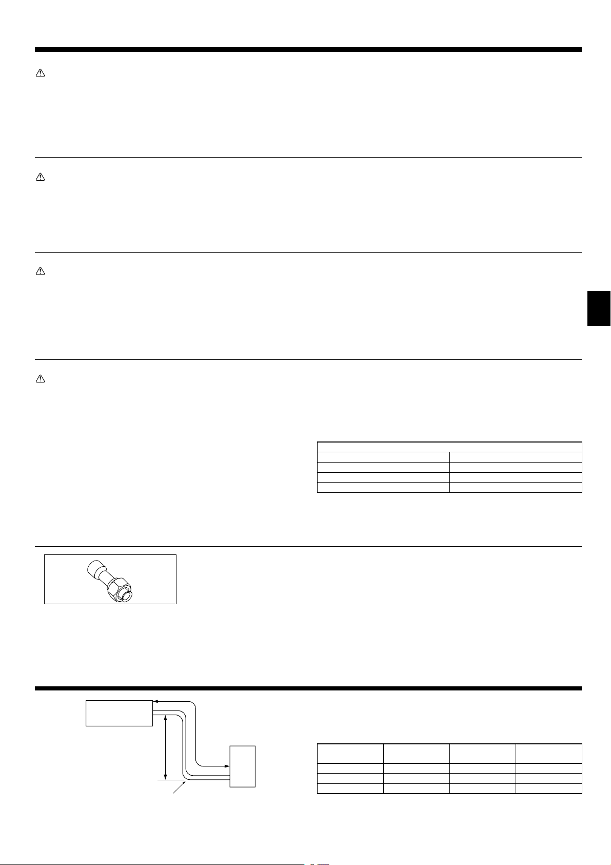
1.6. Accessories of outdoor unit (Fig. 1-1) (RP200/250)
The parts show in the left are the accessories of this unit, which are affi xed to the
inside of the service panel.
1 Joint pipe
.........
×1
2. Installation location
D
B
Fig. 2-1
A
E
2.1. Refrigerant pipe (Fig. 2-1)
► Check that the difference between the heights of the indoor and outdoor
units, the length of refrigerant pipe, and the number of bends in the pipe
are within the limits shown below.
Models
RP35, 50, 60, 71 Max. 50 m Max. 30 m Max. 15
RP100, 125, 140 Max. 75 m Max. 30 m Max. 15
RP200, 250 Max. 120 m Max. 30 m Max. 15
A Pipe length
(one way)
B Height
difference
C
Number of bends
(one way)
C
• Height difference limitations are binding regardless of which unit, indoor or out-
door, is positioned higher.
D Indoor unit
E Outdoor unit
3
Page 4
2. Installation location
■
RP35, 50
300+23
600
150
500
■
RP100, 125, 140, 200, 250
800
69
Fig. 2-3
330
225
3
1338
30+25
600
Fig. 2-2
■
RP60, 71
330+30
943
175
1050
600
70
3
Fig. 2-4
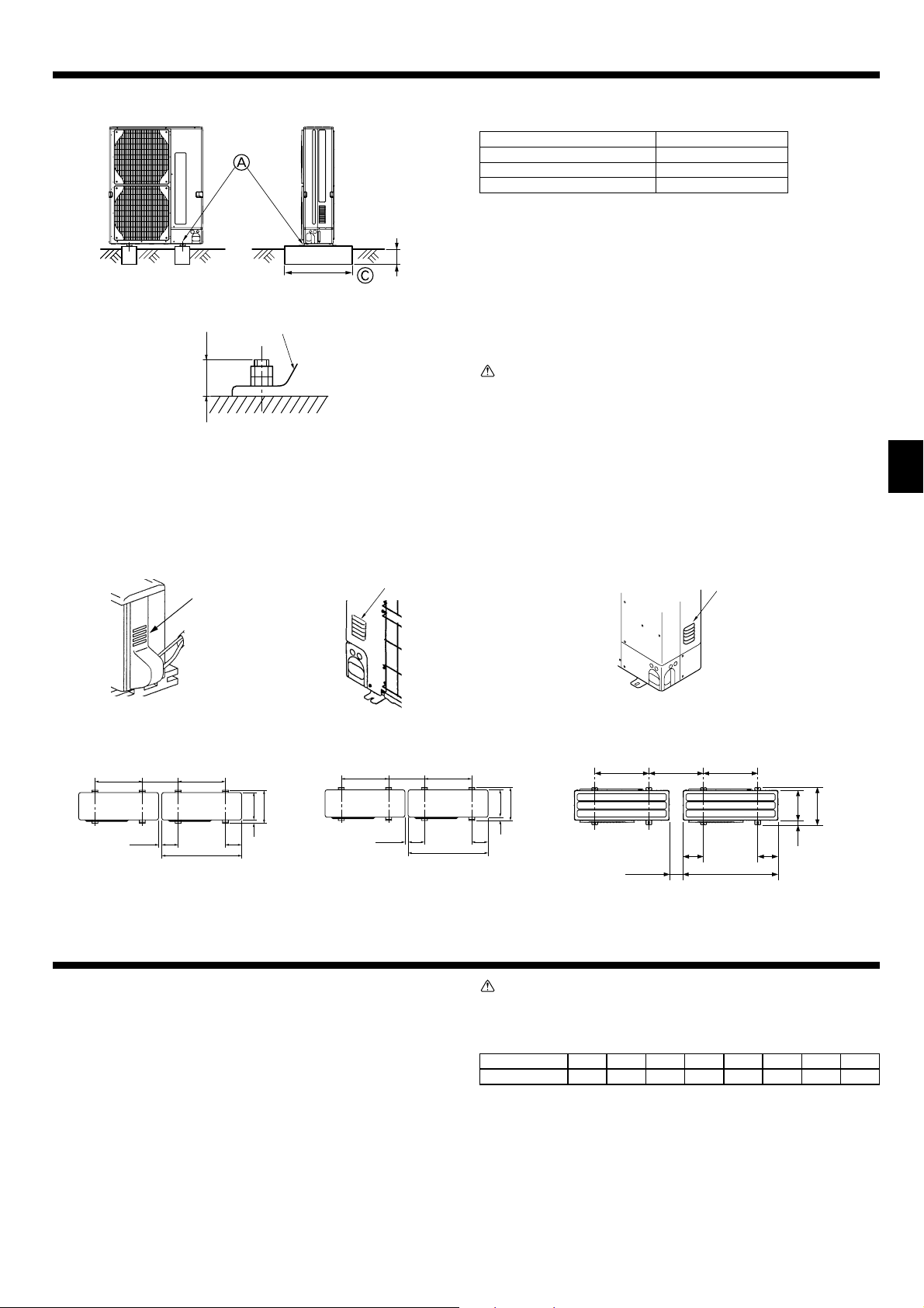
2.2. Choosing the outdoor unit installation location
• Avoid locations exposed to direct sunlight or other sources of heat.
• Select a location from which noise emitted by the unit will not inconvenience
neighbors.
• Select a location permitting easy wiring and pipe access to the power source
950
370
and indoor unit.
• Avoid locations where combustible gases may leak, be produced, fl ow, or accu-
mulate.
• Note that water may drain from the unit during operation.
• Select a level location that can bear the weight and vibration of the unit.
• Avoid locations where the unit can be covered by snow. In areas where heavy
snow fall is anticipated, special precautions such as raising the installation location or installing a hood on the air intake must be taken to prevent the snow from
blocking the air intake or blowing directly against it. This can reduce the airfl ow
and a malfunction may result.
• Avoid locations exposed to oil, steam, or sulfuric gas.
• Use the transportation handles of the outdoor unit to transport the unit. If the unit
is carried from the bottom, hands or fi ngers may be pinched.
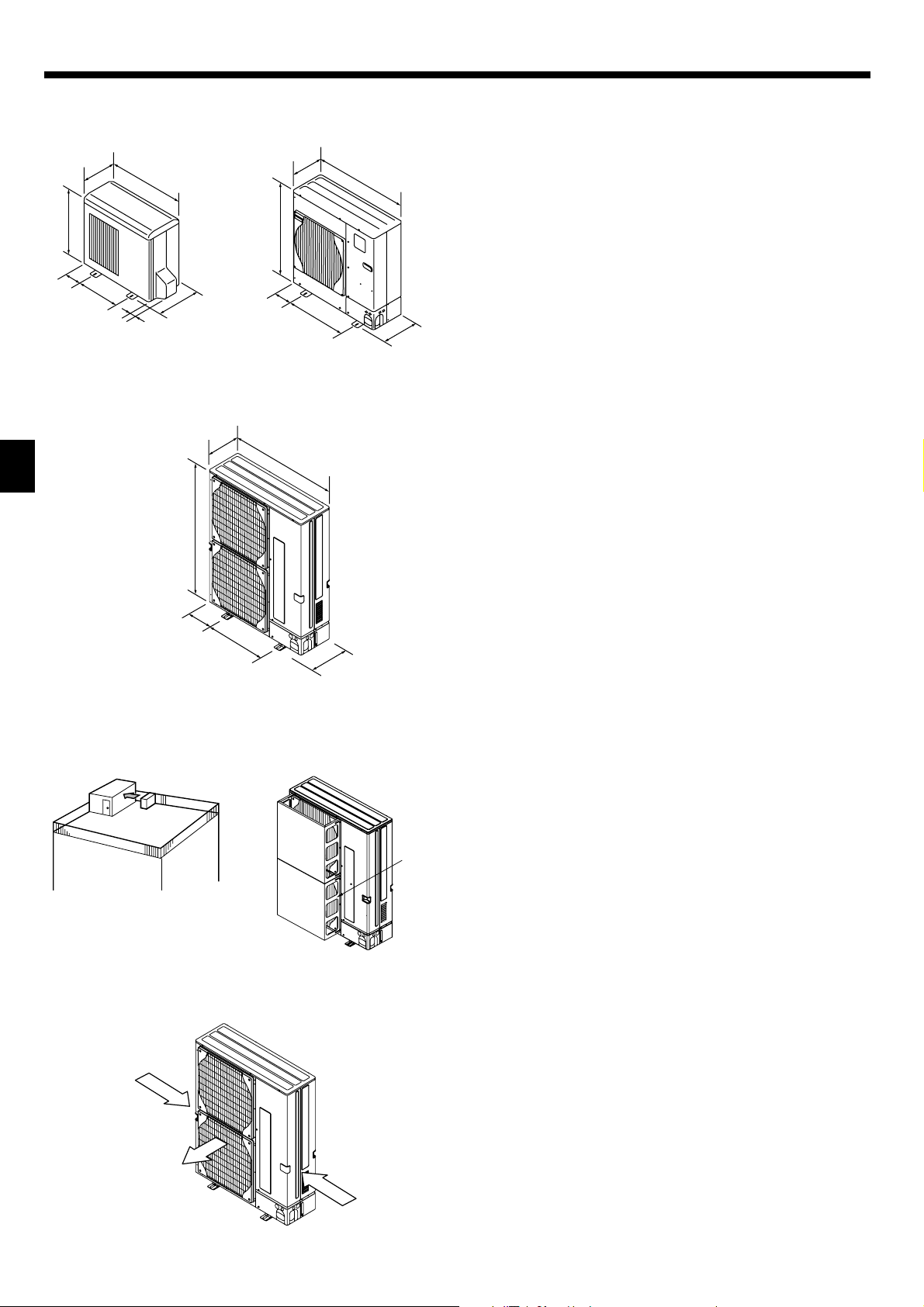
2.3. Outline dimensions (Outdoor unit) (Fig. 2-2)
2.4. Ventilation and service space
2.4.1. Windy location installation
When installing the outdoor unit on a rooftop or other location unprotected from
the wind, situate the air outlet of the unit so that it is not directly exposed to strong
winds. Strong wind entering the air outlet may impede the normal airflow and a
malfunction may result.
The following shows three examples of precautions against strong winds.
1 Face the air outlet towards the nearest available wall about 50 cm away from the
wall. (Fig. 2-3)
2 Install an optional air guide if the unit is installed in a location where strong winds
from a typhoon, etc. may directly enter the air outlet. (Fig. 2-4)
A Air outlet guide
3 Position the unit so that the air outlet blows perpendicularly to the seasonal wind
direction, if possible. (Fig. 2-5)
B Wind direction
2.4.2. When installing a single outdoor unit (Refer to the last page)
Minimum dimensions are as follows, except for Max., meaning Maximum dimensions, indicated.
The fi gures in parentheses are for RP100-250 models.
Refer to the fi gures for each case.
1
Obstacles at rear only (Fig. 2-6)
2
Obstacles at rear and above only (Fig. 2-7)
3
Obstacles at rear and sides only (Fig. 2-8)
* 350 for RP35, 50.
4
Obstacles at front only (Fig. 2-9)
* When using an optional air outlet guide, the clearance for RP100-250 models is 500 mm or
more.
5
Obstacles at front and rear only (Fig. 2-10)
* When using an optional air outlet guide, the clearance for RP100-250 models is 500 mm or
A
B
more.
6
Obstacles at rear, sides, and above only (Fig. 2-11)
* 350 for RP35, 50.
• Do not install the optional air outlet guides for upward airfl ow.
2.4.3. When installing multiple outdoor units (Refer to the last page)
Leave 350 mm for RP35, 50 and 10 mm for RP60-250 space or more between the
units.
The fi gures in parentheses are for RP100-250 models.
1
Obstacles at rear only (Fig. 2-12)
2
Obstacles at rear and above only (Fig. 2-13)
• No more than 3 units must be installed side by side. In addition, leave space as shown.
• Do not install the optional air outlet guides for upward airfl ow.
3
Obstacles at front only (Fig. 2-14)
* When using an optional air outlet guide, the clearance for RP100-250 models is 1000 mm
or more.
4
Obstacles at front and rear only (Fig. 2-15)
* When using an optional air outlet guide, the clearance for RP100-250 models is 1000 mm
or more.
5
Single parallel unit arrangement (Fig. 2-16)
* When using an optional air outlet guide installed for upward airfl ow, the clearance is
500 (1000) mm or more.
6
Multiple parallel unit arrangement (Fig. 2-17)
* When using an optional air outlet guide installed for upward airfl ow, the clearance is
1000 (1500) mm or more.
7
Stacked unit arrangement (Fig. 2-18)
• The units can be stacked up to two units high.
• No more than 2 stacked units must be installed side by side. In addition, leave space as
shown.
Fig. 2-5
4
Page 5
3. Installing the outdoor unit
Max. 18 for RP35, 50
Max. 30 for RP60-250
M10 (3/8") bolt
Base
As long as possible.
Vent
Set deep in the ground
(mm)
• Be sure to install the unit in a sturdy, level surface to prevent rattling noises
during peration. (Fig. 3-1)
<Foundation specifi cations>
Foundation bolt M10 (3/8")
Thickness of concrete 120 mm
Length of bolt 70 mm
Weight-bearing capacity 320 kg
• Make sure that the length of the foundation bolt is within 30 mm of the bottom
surface of the base.
• Secure the base of the unit fi rmly with four-M10 foundation bolts in sturdy loca-
tions.
Installing the outdoor unit
• Do not block the vent. If the vent is blocked, operation will be hindered and
breakdown may result.
• In addition to the unit base, use the installation holes on the back of the unit to
attach wires, etc., if necessary to install the unit. Use self-tapping screws (ø5 ×
15 mm or less) and install on site.
Warning:
• The unit must be securely installed on a structure that can sustain its
weight. If the unit is mounted on an unstable structure, it may fall down
and cause damage or injuries.
• The unit must be installed according to the instructions in order to minimize the risk of damage from earthquakes, typhoons, or strong winds. An
incorrectly installed unit may fall down and cause damage or injuries.
■
RP35, 50
■
RP35, 50
500
Min. 350
Min. 650
150
500
800
150
300
15
330
■
RP60, 71
■
RP60, 71
600 600Min. 360
175 175
Min. 10
950
Fig. 3-1
4. Installing the refrigerant piping
4.1. Precautions for devices that use R410A refrigerant
• Refer to 1.5. for precautions not included below on using air conditioners
with R410A refrigerant.
• Use ester oil, ether oil, alkylbenzene oil (small amount) as the refrigeration oil
applied to the fl ared sections.
• Use C1220 copper phosphorus, for copper and copper alloy seamless pipes,
to connect the refrigerant pipes. Use refrigerant pipes with the thicknesses
specified in the table to the below. Make sure the insides of the pipes are
clean and do not contain any harmful contaminants such as sulfuric compounds, oxidants, debris, or dust.
Always apply no-oxidation brazing when brazing the pipes, otherwise, the
compressor will be damaged.
■
RP100-250
■
RP100-250
600 600
Min. 460
330
370
25
225 225
1050Min. 10
Warning:
When installing or moving the air conditioner, use only the specifi ed refriger-
ant (R410A) to charge the refrigerant lines. Do not mix it with any other refrigerant and do not allow air to remain in the lines. Air enclosed in the lines can
cause pressure peaks resulting in a rupture and other hazards.
Pipe size (mm)
Thickness (mm) 0.8 0.8 0.8 1.0 1.0 1.0 1.0 1.0
• Do not use pipes thinner than those specifi ed above.
• Use 1/2 H or H pipes if the diameter is 22.2 mm or larger.
• For RP250, use 1/2 H or H pipes if the diameter is 19.05 mm or larger.
[6.35 [9.52 [12.7 [15.88 [19.05 [22.2 [25.4 [28.58
33025
370
5
Page 6
4. Installing the refrigerant piping
A B
o
0.5
90op
A Flare cutting dimensions
B Flare nut tightening torque
A (Fig. 4-1)
Copper pipe O.D.
(mm)
ø6.35 8.7 - 9.1
ø9.52 12.8 - 13.2
ø12.7 16.2 - 16.6
ø15.88 19.3 - 19.7
ø19.05 23.6 - 24.0
B (Fig. 4-1)
Copper pipe O.D.
(mm)
ø6.35 17 14 - 18
ø6.35 22 34 - 42
ø9.52 22 34 - 42
ø12.7 26 49 - 61
ø12.7 29 68 - 82
ø15.88 29 68 - 82
ø15.88 36 100 - 120
ø19.05 36 100 - 120
øA
45op 2o
A
R0.4~R0.8
C
Fig. 4-1
Flare dimensions
øA dimensions (mm)
Flare nut O.D.
(mm)
A
B
A Die
B Copper pipe
Fig. 4-2
D
Tightening torque
(N·m)
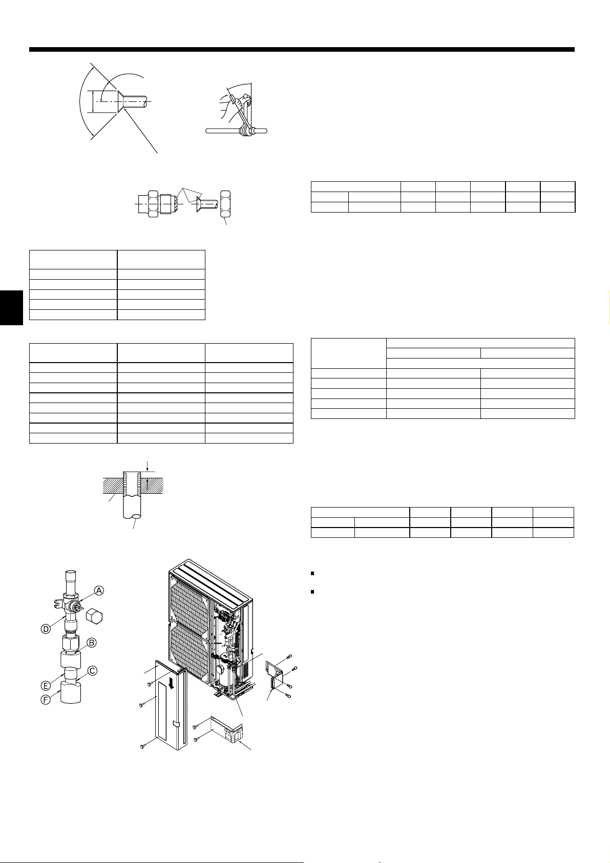
4.2. Connecting pipes (Fig. 4-1)
• When commercially available copper pipes are used, wrap liquid and gas pipes
with commercially available insulation materials (heat-resistant to 100 °C or
more, thickness of 12 mm or more).
• The indoor parts of the drain pipe should be wrapped with polyethylene foam
insulation materials (specifi c gravity of 0.03, thickness of 9 mm or more).
• Apply thin layer of refrigerant oil to pipe and joint seating surface before tightening fl are nut.
• Use two wrenches to tighten piping connections.
• Use leak detector or soapy water to check for gas leaks after connections are
completed.
• Apply refrigerating machine oil over the entire fl are seat surface.
• Use the fl are nuts for the following pipe size.
Gas side Pipe size (mm)
Liquid side Pipe size (mm)
• When bending the pipes, be careful not to break them. Bend radii of 100 mm to
150 mm are suffi cient.
• Make sure the pipes do not contact the compressor. Abnormal noise or vibration
may result.
1 Pipes must be connected starting from the indoor unit.
Flare nuts must be tightened with a torque wrench.
2 Flare the liquid pipes and gas pipes and apply a thin layer of refrigeration oil (Ap-
plied on site).
• When usual pipe sealing is used, refer to Table 1 for fl aring of R410A refrigerant
pipes.
The size adjustment gauge can be used to confi rm A measurements.
Table 1 (Fig. 4-2)
Copper pipe O.D.
ø6.35 (1/4") 0 - 0.5 1.0 - 1.5
ø9.52 (3/8") 0 - 0.5 1.0 - 1.5
ø12.7 (1/2") 0 - 0.5 1.0 - 1.5
ø15.88 (5/8") 0 - 0.5 1.0 - 1.5
ø19.05 (3/4") 0 - 0.5 1.0 - 1.5
3 Use the following procedure for connecting the gas-side piping. (Fig.4-3)
1 Braze the E Joint pipe provided to the outdoor unit using locally procured braz-
ing materials and C Local piping without oxygen.
2 Connect the E Joint pipe to the gas-side Stop valve.
Use 2 wrenches to tighten the fl are nut.
* If order is reversed, refrigerant leak occurs because of the part damaging by
brazinig fi re.
• For PEA-RP200, 250, 400, 500GA
The method of pipe connection is brazing connection.
Gas side Pipe size (mm)
Liquid side Pipe size (mm)
(mm)
A
RP35, 50 RP60, 71
[12.7 [15.88 [15.88 [25.4 [25.4
[6.35 [9.52 [9.52 [9.52 [12.7
Flare tool for R410A Flare tool for R22·R407C
PEA-200 PEA-250 PEA-400 PEA-500
[25.4 [25.4 [25.4 [25.4
[9.52 [12.7 [9.52 [12.7
B
D
RP100-140
A (mm)
Clutch type
C
RP200 RP250
AStop valve
BSeal section
CLocal piping
DDouble spanner section
EJoint pipe
FPipe cover
Fig. 4-3
6
AFront piping cover
BPiping cover
CStop valve
DService panel
EBend radius : 100mm -150mm
Fig. 4-4
4.3. Refrigerant piping (Fig. 4-4)
For RP35, 50
Remove the service panel D (1 screw).
For RP60-250
Remove the service panel D (3 screws) and the front piping cover A (2 screws)
and rear piping cover B (2 screws:RP60, 71) (4 screws:RP100-250).
1 Perform refrigerant piping connections for the indoor/outdoor unit when the out-
door unit’s stop valve is completely closed.
2 Vacuum-purge air from the indoor unit and the connection piping.
3 After connecting the refrigerant pipes, check the connected pipes and the indoor
unit for gas leaks. (Refer to 4.4 Refrigerant pipe airtight testing method)
4 A high-performance vacuum pump is used at the stop valve service port to main-
tain a vacuum for an adequate time (at least one hour after reaching –101 kPa
(5 Torr)) in order to vacuum dry the inside of the pipes. Always check the degree
of vacuum at the gauge manifold. If there is any moisture left in the pipe, the degree of vacuum is sometimes not reached with short-time vacuum application.
After vacuum drying, completely open the stop valves (both liquid and gas) for
the outdoor unit. This completely links the indoor and outdoor refrigerant circuits.
•
If the vacuum drying is inadequate, air and water vapor remain in the refrigerant circuits and can cause abnormal rise of high pressure, abnormal drop of
low pressure, deterioration of the refrigerating machine oil due to moisture, etc.
• If the stop valves are left closed and the unit is operated, the compressor and
control valves will be damaged.
• Use a leak detector or soapy water to check for gas leaks at the pipe connec-
tion sections of the outdoor unit.
• Do not use the refrigerant from the unit to purge air from the refrigerant lines.
• After the valve work is completed, tighten the valve caps to the correct torque:
20 to 25 N·m (200 to 250 kgf·cm).
Failure to replace and tighten the caps may result in refrigerant leakage. In
addition, do not damage the insides of the valve caps as they act as a seal to
prevent refrigerant leakage.
5 Use sealant to seal the ends of the thermal insulation around the pipe connec-
tion sections to prevent water from entering the thermal insulation.
Page 7
4. Installing the refrigerant piping
A
B
D
C
A Stop valve <Liquid side>
B Stop valve <Gas side>
C Service port
D Open/Close section
Fig. 4-5
(1) (2)
Fig. 4-6 Fig. 4-7
A Valve
B Unit side
C Handle
D Cap
E Local pipe side
F Pipe cover
G Service port
H Wrench hole
I Double spanner section
(Do not apply a spanner other than to this section.
Doing so would cause coolant leaks.)
J Seal section
(Seal the end of the heat insulation material at
the pipe connection section with whatever seal
material you have on hand so that water does not
infi ltrate the heat insulation material.)
A
C
D
E
F
G
E Local pipe
F Sealed, same way for gas side
G Pipe cover
H Do not use a wrench here.
Refrigerant leakage may result.
I Use two wrenches here.
B
H
I
4.4. Refrigerant pipe airtight testing method (Fig.4-5)
(1)
Connect the testing tools.
• Make sure the stop valves
• Add pressure to the refrigerant lines through the service port C of the liquid
stop valve A.
(2)
Do not add pressure to the specifi ed pressure all at once; add pressure little by
little.
1 Pressurize to 0.5 MPa (5 kgf/cm
pressure does not decrease.
2 Pressurize to 1.5 MPa (15 kgf/cm
pressure does not decrease.
3 Pressurize to 4.15 MPa (41.5 kgf/cm
perature and refrigerant pressure.
(3)
If the specifi ed pressure holds for about one day and does not decrease, the
pipes have passed the test and there are no leaks.
• If the surrounding temperature changes by 1 °C, the pressure will change by
about 0.01 MPa (0.1 kgf/cm
(4)
If the pressure decreases in steps (2) or (3), there is a gas leak. Look for the
source of the gas leak.
are closed and do not open them.
A B
2
G), wait five minutes, and make sure the
2
G), wait fi ve minutes, and make sure the
2
G) and measure the surrounding tem-
2
G). Make the necessary corrections.
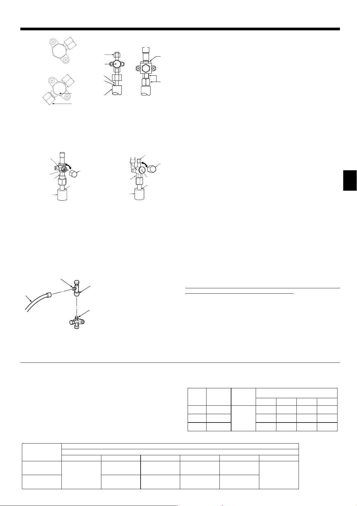
4.5. Stop valve opening method
The stop valve opening method varies according to the outdoor unit model. Use the
appropriate method to open the stop valves.
(1)
Gas side of RP100-250 (Fig. 4-6)
1 Remove the cap, pull the handle toward you and rotate 1/4 turn in a counter-
clockwise direction to open.
2 Make sure that the stop valve is open comletely, push in the handle and rotate
the cap back to its original position.
(2)
Liquid side of RP100-250 and Gas/Liquid side of RP35-71 (Fig. 4-7)
1 Remove the cap and turn the valve rod counterclockwise as far as it will go with
the use of a 4 mm hexagonal wrench. Stop turning when it hits the stopper.
(ø9.52: Approximately 10 revolutions)
2 Make sure that the stop valve is open completely, push in the handle and rotate
the cap back to its original position.
Refrigerant pipes are protectively wrapped for RP60-250
• The pipes can be protectively wrapped up to a diameter of ø90 before or after
connecting the pipes. Cut out the knockout in the pipe cover following the groove
and wrap the pipes.
Pipe inlet gap for RP60-250
• Use putty or sealant to seal the pipe inlet around the pipes so that no gaps re-
main. (If the gaps are not closed, noise may be emitted or water and dust will
enter the unit and breakdown may result.)
B
A
C
* The fi gure to the left is an example only.
The stop valve shape, service port position,
etc., may vary according to the model.
* Turn section A only.
(Do not further tighten sections A and B
D
together.)
C Charge hose
D Service port
Precautions when using the charge valve (Fig.4-8)
Do not tighten the service port too much when installing it, otherwise, the valve core
could be deformed and become loose, causing a gas leak.
After positioning section B in the desired direction, turn section A only and tighten it.
Do not further tighten sections A and B together after tightening section A.
Fig. 4-8
4.6. Addition of refrigerant
• Additional charging is not necessary if the pipe length does not exceed 30 m.
• If the pipe length exceeds 30m, charge the unit with additional R410A refrigerant
according to the permitted pipe lengths in the chart below.
* When the unit is stopped, charge the unit with the additional refrigerant
through the liquid stop valve after the pipe extensions and indoor unit have
been vacuumized.
When the unit is operating, add refrigerant to the gas check valve using a
safety charger. Do not add liquid refrigerant directly to the check valve.
* After charging the unit with refrigerant, note the added refrigerant amount on
the service label (attached to the unit).
Refer to the “1.5. Using R410A refrigerant air conditioners” for more informa-
tion.
Outdoor unit
RP200
RP250 1.2 kg 2.4 kg 3.6 kg 4.8 kg
30 m andless 31-40 m andless 41-50 m and less 51-60 m and less 61-70 m andless 71-120 m and less
No additional
charge necessary
0.9 kg 1.8 kg 2.7 kg 3.6 kg
Amount of additionalrefrigerant charge (kg)
• Be careful when installing multiple units. Connecting to an incorrect indoor unit
can lead to abnormally high pressure and have a serious effect on operation
performance.
Model
RP35, 50
RP60, 71
RP100-140
A+B+C+D
Permitted
pipe
length
-50 m
-50 m 0.6 kg 1.2 kg — —
-75 m 0.6 kg 1.2 kg 1.8 kg 2.4 kg
Permitted
vertical
difference
-30 m
Additional refrigerant charging amount
31 - 40 m 41 - 50 m 51 - 60 m 61 - 75 m
0.2 kg 0.4 kg — —
Calculate the
amount of additional
refrigerant charge
using formula pro
vided next page
-
7
Page 8
4. Installing the refrigerant piping
When length exceeds 70 m
When the total length of the piping exceeds 70 m, calculate the amount of additional charge based on the following requirements.
Note: If the calculation produces a negative number (i.e. a “minus” charge), of if calculation results in an amount that is less than the “Additional charage amount for 70 m”,
perform the additional charge using the amount shown in “Additional charge amount for 70 m”.
Main piping:
Amount of additional
charge
(kg)
Additional charge amount
for 70 meters
Max. 1m
Liquid line size
ø12.7 overall length ×
=
0.11
(m) × 0.11 (kg/m)
RP200 3.6 kg
RP250 4.8 kg
Fig. 4-9
Maximum pipe length (RP200·RP250)
Liquid
pipe
(mm)
Gas
pipe
(mm)
O.D.
Thick-
ness
O.D.
Thick-
ness
:19.05
t1.0
:22.2
t1.0
:9.52
t0.8
:25.4
t1.0
Main piping:
Liquid line size
ø9.52 overall length ×
+++–
0.09 (Gas line: ø25.4)
(m) × 0.09 (kg/m)
Indoor unit
Outdoor unit
Main piping
Branch piping
Multi distribution
pipe (option)
:28.58
t1.0
:19.05
t1.0
Branch piping:
Liquid line size
ø9.52 overall length ×
0.06 (Gas line: ø15.88)
(m) × 0.06 (kg/m)
Outdoor unit : RP250 A: ø12.7 ... 65 m
Indoor unit 1 : RP71 B: ø9.52 ... 5 m
Indoor unit 2 : RP71 C: ø9.52 ... 5 m
Indoor unit 3 : RP71 D: ø9.52 ... 5 m
Main piping ø12.7 is A = 65 m
Branch piping ø9.52 is B + C + D = 15 m
Therefore, the amount of additional charge is: 65 × 0.12 + 15 × 0.06 - 3.6 = 5.1(kg)
(Fractions are rounded up)
:12.7
t0.8
:22.2
t1.0
:25.4
t1.0
:28.58
t1.0
Branch piping:
Liquid line size
ø6.35 overall length ×
0.02
(m) × 0.02 (kg/m)
:15.88
t1.0
:22.2
t1.0
:25.4
t1.0
:28.58
t1.0
3.6 (kg)
:31.75
t1.1
Standard size
RP200
20m
[20m]
50m
[30m]
120m
[30m]
120m
[30m]
20m
[20m]
50m
[30m]
Standard size
RP250
20m
[20m]
50m
[30m]
120m
[30m]
120m
[30m]
20m
[20m]
50m
[30m]
Note : Be sure to use hard (tempered) one for pipe over :22.2.
<Marks in the table above>
: It can be used.
: Cooling capacity is lowered.
: Additional refrigerant charge is required when
the pipe length exceeds 20m.
120m
[30m]
The maximum pipe length
Charge-less pipe length
RP200, 250
Additional refrigerant amount when the liquid pipe of the larger diameter is used.
1:1 system
Liquid pipe When the pipe length exceeds 20 m
[15.88
w (g) 0 : Additional charge is not necessary.
*
Additional refrigerant amount w (g) =180 × Pipe length (m) - 3000
Simultaneous twin/triple/quadruple system
When the pipe length (main piping and branch piping) exceeds 20 m
Additional refrigerant amount w (g) =(180 × L1)+(120
×
L2) +(90
×
L3)+(30
×
L4) - 3000
L1 : [15.88 liquid pipe length (m) L2 : [12.7 liquid pipe length (m)
L3 : [9.52 liquid pipe length (m) L4 : [6.35 liquid pipe length (m)
w (g) 0 : Additional charge is not necessary.
*
120m
[30m]
120m
[30m]
120m
[30m]
120m
[30m]
50m
[20m]
50m
[20m]
50m
[20m]
50m
[20m]
50m
[20m]
50m
[20m]
50m
[20m]
50m
[20m]
8
Page 9
4. Installing the refrigerant piping
4.7. Precautions when reusing existing R22 refrigerant pipes
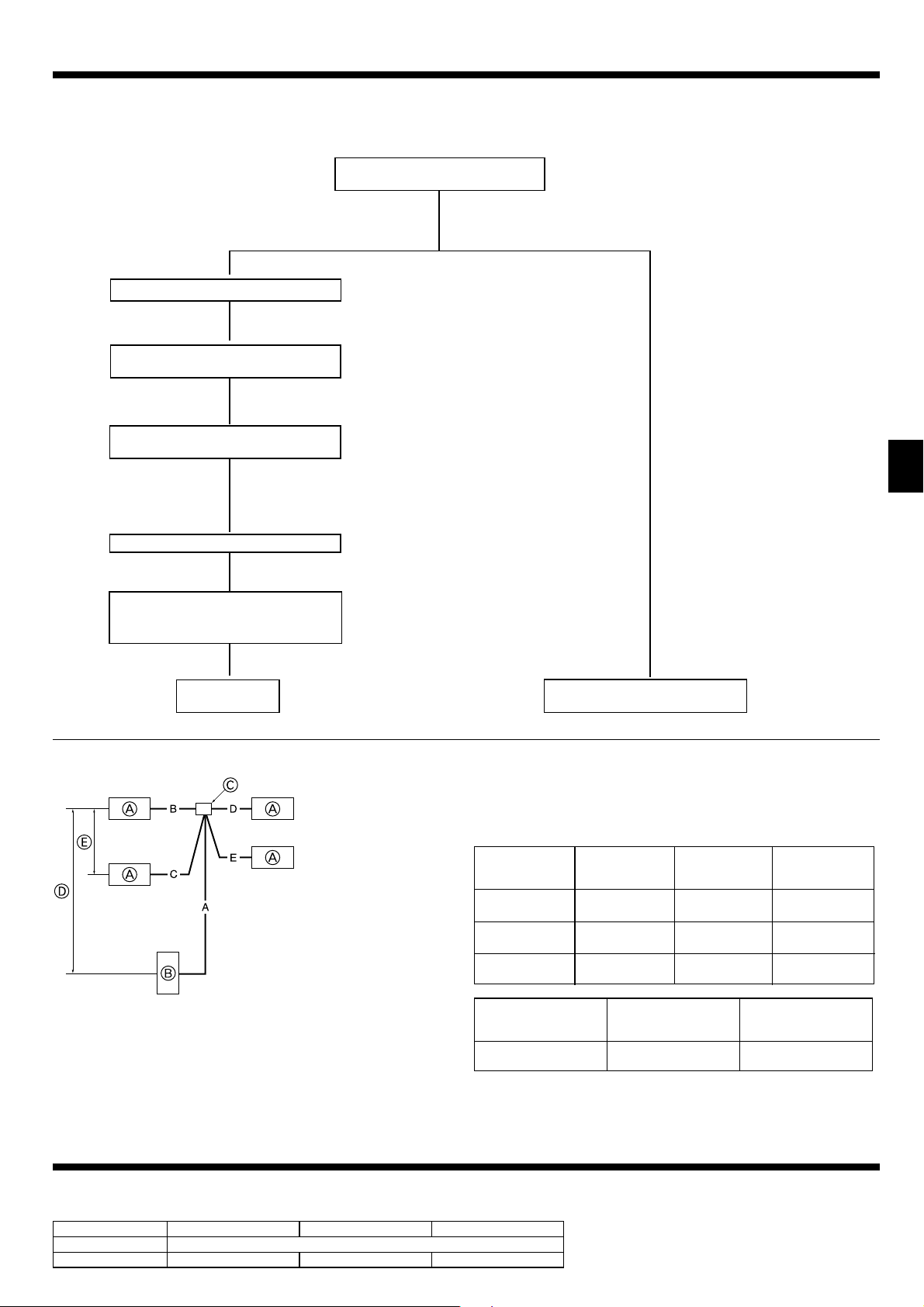
• Refer to the fl owchart below to determine if the existing pipes can be used and if it is necessary to use a fi lter dryer.
• If the diameter of the existing pipes is different from the specifi ed diameter, refer to technological data materials to confi rm if the pipes can be used.
Measure the existing pipe thickness and
check for damage.
The existing pipe thickness meets specifi ca-
tions and the pipes are not damaged.
▼
Check if the existing air conditioner can operate.
▼
After operating the cooling system for about 30
minutes, do a pump down work.
▼
Disconnect the existing air conditioner from the
pipes.
▼
Attach the new air conditioner
▼
Perform the airtight test, vacuum air purging,
additional refrigerant charging (if necessary),
and gas leak check.
The existing pipe thickness does not meet
specifi cations or the pipes are damaged.
* If the existing air conditioner cannot operate, use
a refrigerant recovery device to collect the refrigerant.
* In case existing pipes were used for gas or oil
heat pump systems, be sure to clean the pipes
for RP100-250 models.
Use new pipes for RP35-71 models.
Test run
* Refer to 7.2.
<Limits of refrigerant piping installation>
RP71 : A+B+C 50 m
RP100-140 : A+B+C(+D) 75 m
RP200, 250 : A+B+C(+D)(+E) 120 m
* “D” is for triple“.
* “E” is for four (quadruple).
▼ ▼
The existing pipes cannot be reused.
Use new pipes.
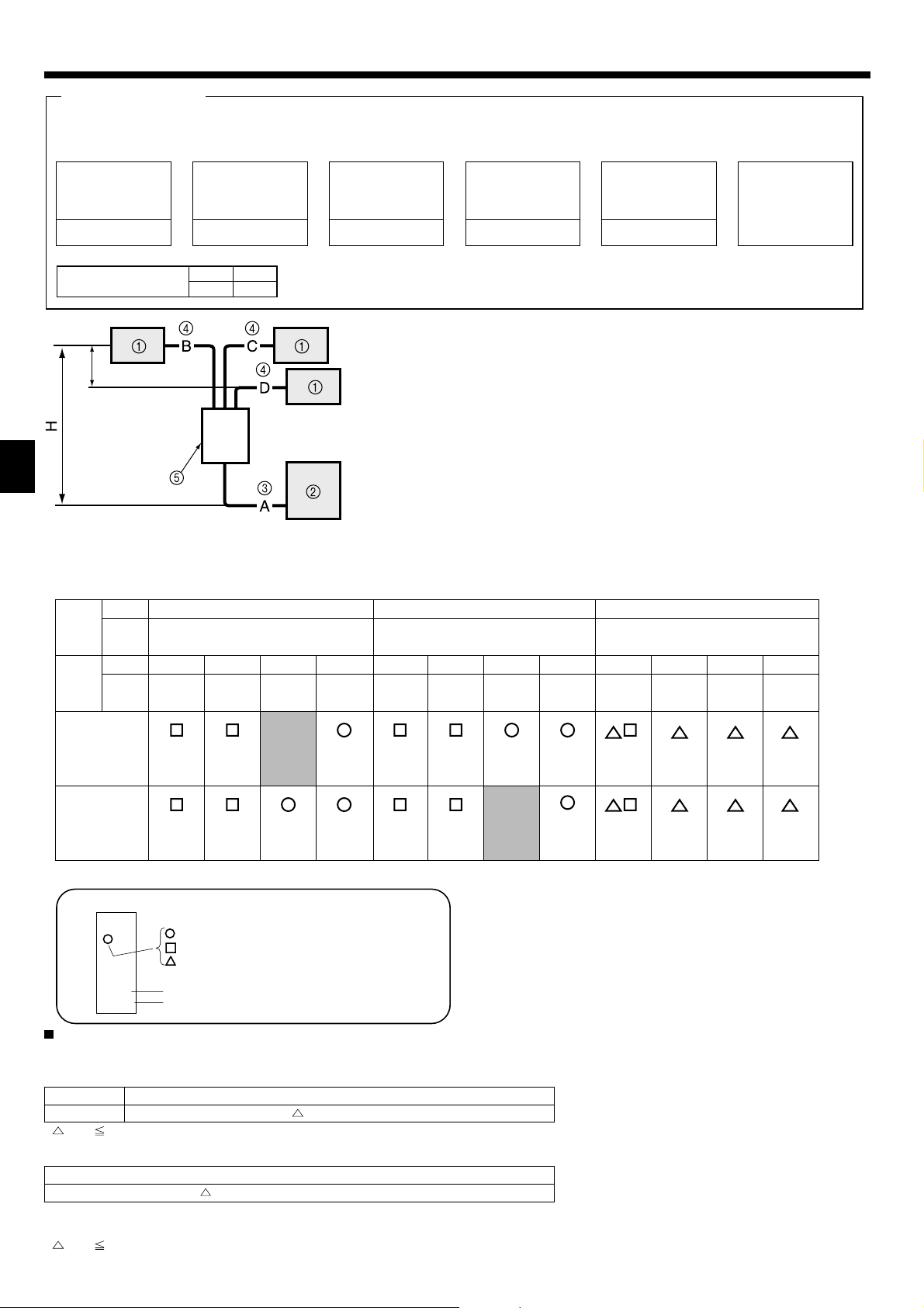
4.8. For twin/triple/quadruple combination (Fig. 4-10)
• When this unit is used as a FREE COMPO MULTI unit, install the refrigerant
piping with the restrictions indicated in the drawing on the left. In addition, if the
restrictions are going to be exceeded, or if there are going to be combinations of
indoor and outdoor units, refer to installation instructions for the indoor unit for
Indoor unit
Outdoor unit
Multi distribution pipe (option)
Height difference (Indoor unit-
Outdoor unit) Max. 30 m
Height difference (Indoor unit-
Indoor unit) Max. 1 m
A: Main piping
B, C, D, E: Branch piping
details about the installation.
Outdoor unit
RP71
RP100-140
RP200
RP250
Outdoor unit
RP71 - 250
Permissible total
piping length
A+B+C+D+E
50 m and less
75 m and less
120 m and less
|
B-C|or|B-D|or
|
B-E|or|C-D|or
|
C-E|or|D-E
8 m and less
Fig. 4-10
A+B or A+C
or
A+D or A+E
—
—
100 m and less
|
Charge-less
piping length
A+B+C+D+E
30 m and less
30 m and less
30 m and less
No. of bends
Within 15
5. Drainage piping work
Outdoor unit drainage pipe connection
When drain piping is necessary, use the drain socket or the drain pan (option).
RP35, 50 RP60, 71 RP100-250
Drain socket PAC-SG61DS-E
Drain pan PAC-SG63DP-E PAC-SG64DP-E PAC-SH97DP-E
9
Page 10

6. Electrical work
6.1. Outdoor unit (Fig. 6-1, Fig. 6-2)
1 Remove the service panel.
2 Wire the cables referring to the Fig. 6-1 and the Fig. 6-2.
* Except PEA-RP200, 250, 400, 500GA
L
N
D
For Heater
* With Heater
model only
S1
S2
S3
A
B
S3
S2S1LN
C
D
For Power For Power
For Heater For Heater For Heater
D D D D
E
C
Fig. 6-1
* In case of PEA-200, 250
PUHZ-200, 250
A Indoor unit
B Outdoor unit
C Remote controller
D Main switch (Breaker)
E Earth
EE
PEA-200, 250
E
■
■
RP35, 50
RP35, 50
■
RP60-250
RP60-140V
LN
S1 S2 S3
AAAB
RP100-250Y
L1 L2 L3 N
S1 S2 S3
Fig. 6-2
F Termial block
G Indoor/Outdoor connection terminal block (S1, S2, S3)
H Service panel
I Clamp
* Clamp the cables so that they do not contact the center of the service panel or the gas valve.
J Earth terminal
Note :
If the protective sheet for the electrical box is removed during servicing, be sure to
reinstall it.
Caution:
Be sure to install N-Line. Without N-Line, it could cause damage to unit.
* In case of PEA-400, 500
(No.1 Outdoor)
PUHZ-200, 250 PEA-400, 500
(No.2 Outdoor)
PUHZ-200, 250
* In case of PEA-200, 250 * In case of PEA-400, 500
! $
)2-4BT()1-4BT(
!" #$
Power supply
Earth leakage breaker
Circuit breaker or local switch
LCD remote controller
Outdoor unit
Indoor unit
Power cable wiring
Indoor/outdoor connection wiring
Grounding
Main remote controller
Subordinate remote controller
Standard (Refrigerant address = 00)
Refrigerant address = 01
! Refrigerant address = 02
" Refrigerant address = 03
# Refrigerant address = 14
$ Refrigerant address = 15
10
Fig. 6-3
Page 11

6. Electrical work
6.2. Field electrical wiring
Outdoor unit model RP35, 50V RP60, 70V RP100,125V
Outdoor unit power supply
Outdoor unit input capacity Main switch (Breaker) *1 16 A 25 A 32 A 40 A 16 A 32 A
*1. A breaker with at least 3.0 mm contact separation in each poles shall be provided. Use earth leakage breaker (NV).
*2. (RP35-140)
Max. 45 m
If 2.5 mm
If 2.5 mm
(RP200, 250)
Max. 80 m Total Max. including all indoor/indoor connection is 80 m.
*3. The 10 m wire is attached in the remote controller accessory.
*4. The fi gures are NOT always against the ground.
S3 terminal has DC 24 V against S2 terminal. However between S3 and S1, these terminals are NOT electrically insulataed by the transformer or other device.
Outdoor unit power supply 3 × Min. 1.5 3 × Min. 2.5 3 × Min. 4 3 × Min. 6 5 × Min. 1.5 5 × Min. 4
)
2
Indoor unit-Outdoor unit *2 3 × 1.5 (Polar) 3 × 1.5 (Polar) 3 × 1.5 (Polar) 3 × 1.5 (Polar) 3 × 1.5 (Polar)
Wiring
Indoor unit-Outdoor unit earth *2 1 × Min. 1.5 1 × Min. 1.5 1 × Min. 1.5 1 × Min. 1.5 1 × Min. 1.5 1 × Min. 2.5
Wire No. ×
size (mm
Remote controller-Indoor unit *3 2 × 0.3 (Non-polar) 2 × 0.3 (Non-polar) 2 × 0.3 (Non-polar) 2 × 0.3 (Non-polar) 2 × 0.3 (Non-polar) 2 × 0.3 (Non-polar)
Outdoor unit L-N (single)
Outdoor unit L1-N, L2-N, L3-N (3 phase)
Indoor unit-Outdoor unit S1-S2 *4 AC 230 V AC 230 V AC 230 V AC 230 V AC 230 V AC 230 V
Indoor unit-Outdoor unit S2-S3 *4 DC 24 V DC 24 V DC 24 V DC 24 V DC 24 V DC 24 V
Circuit rating
Remote controller-Indoor unit *4 DC 12 V DC 12 V DC 12 V DC 12 V DC 12 V DC 12 V
2
used, Max. 50 m
2
used and S3 separated, Max. 80 m
• Use one cable for S1 and S2 and another for S3 as shown in the picture.
• Max. 50 m Total Max. for PEA. Wiring size 3 × 1.5 (Polar).
~/N (single), 50 Hz,
230 V
*4 AC 230 V AC 230 V AC 230 V AC 230 V AC 230 V AC 230 V
~/N (single), 50 Hz,
230 V
~/N (single), 50 Hz,
230 V
Notes: 1. Wiring size must comply with the applicable local and national code.
2.
Power supply cords and Indoor/Outdoor unit connecting cords shall not be lighter than polychloroprene sheathed fl exible cord. (Design 60245 IEC 57
3. Use an earth wire which is longer than the other cords so that it will not become disconnected when tension is applied.
RP140V RP100, 125, 140Y RP200, 250
~/N (single), 50 Hz,
230 V
3N~ (3 ph 4-wires),
50 Hz, 400 V
3N~ (3 ph 4-wires),
Cable length 50m:3×4(Polar)/
Cable length 80m:3×6(Polar)
50 Hz, 400 V
)
Power supply
A-Control
Outdoor Unit
Isolator
S1
S2
S3
3 poles isolator
S1
S2
S3
A-Control
Indoor Unit
Warning:
· In case of A-control wiring, there is high voltage potential on the S3 terminal caused by electrical circuit design that has no electrical insulation between
power line and communication signal line. Therefore, please turn off the main power supply when servicing. And do not touch the S1, S2, S3 terminals when
the power is energized. If isolator should be used between indoor unit and outdoor unit, please use 3-pole type.
INDOOR-OUTDOOR CONNECTING CABLE (RP200,250)
Cross section of cable Wire size (mm2) Number of wires Polarity L (m)*6
Round
Flat
Flat
Round
2.5 3
2.5 3
1.5 4
2.5 4
Clockwise : S1-S2-S3
*Pay attention to stripe of yellow and green
Not applicable
(Because center wire has no cover finish)
From left to right : S1-Open-S2-S3
Clockwise : S1-S2-S3-Open
*Connect S1 nad S3 to the opposite angle
(30)
*2
Not applicable
*5
(18)
*3
(30)
*4
*1 :Power supply cords of appliances shall not be lighter than design 60245 IEC or
227 IEC.
*2 :In case that cable with stripe of yellow and green is available.
*3 :In case of regular polarity connection (S1-S2-S3), wire size is 1.5 mm
2
.
*4 :In case of regular polarity connection (S1-S2-S3).
*5 :In the flat cables are connected as this picture, they can be used up to 30 m.
S1
S2
S3
*6 :Mentioned cable length is just a reference value.
It may be different depending on the condition of installation, humidity or
materials, etc.
(3C Flat cable × 2)
Be sure to connect the indoor-outdoor connecting cables directly to the units (no intermediate connections).
Intermediate connections can lead to communication error if water enters the cables and causes insufficient insulation to ground or a poor electrical contact at the intermediate connection point.
11
Page 12

7. Test run
7.1. Before test run
► After completing installation and the wiring and piping of the indoor and
outdoor units, check for refrigerant leakage, looseness in the power supply or control wiring, wrong polarity, and no disconnection of one phase in
the supply.
► Use a 500-volt megohmmeter to check that the resistance between the
power supply terminals and ground is at least 1.0M".
► Do not carry out this test on the control wiring (low voltage circuit) termi-
nals.
Warning:
Do not use the air conditioner if the insulation resistance is less than 1.0M".
Insulation resistance
After installation or after the power source to the unit has been cut for an extended
period, the insulation resistance will drop below 1 M" due to refrigerant accumulating in the compressor. This is not a malfunction. Perform the following procedures.
1. Remove the wires from the compressor and measure the insulation resistance of
the compressor.
2. If the insulation resistance is below 1 M", the compressor is faulty or the resistance dropped due the accumulation of refrigerant in the compressor.
3. After connecting the wires to the compressor, the compressor will start to warm
up after power is supplied. After supplying power for the times indicated below,
measure the insulation resistance again.
7.2. Test run
7.2.1. Using SW4 in outdoor unit
SW4-1 ON
SW4-2 OFF
SW4-1 ON
SW4-2 ON
* After performing the test run, set SW4-1 to OFF.
• After power is supplied, a small clicking noise may be heard from the inside of
the outdoor unit. The electronic expansion valve is opening and closing. The unit
is not faulty.
Cooling operation
Heating operation
• The insulation resistance drops due to accumulation of refrigerant in the compressor. The resistance will rise above 1 M" after the compressor is warmed
up for four hours.
(The time necessary to warm up the compressor varies according to atmo-
spheric conditions and refrigerant accumulation.)
• To operate the compressor with refrigerant accumulated in the compressor,
the compressor must be warmed up at least 12 hours to prevent breakdown.
4. If the insulation resistance rises above 1 M", the compressor is not faulty.
Caution:
• The compressor will not operate unless the power supply phase connec-
tion is correct.
• Turn on the power at least 12 hours before starting operation.
- Starting operation immediately after turning on the main power switch can result
in severe damage to internal parts. Keep the power switch turned on during the
operational season.
► The followings must be checked as well.
• The outdoor unit is not faulty. LED1 and LED2 on the control board of the out-
door unit fl ash when the outdoor unit is faulty.
• Both the gas and liquid stop valves are completely open.
• A protective sheet covers the surface of the DIP switch panel on the control
board of the outdoor unit. Remove the protective sheet to operate the DIP
switches easily.
• A few seconds after the compressor starts, a clanging noise may be heard from
the inside of the outdoor unit. The noise is coming from the check valve due to
the small difference in pressure in the pipes. The unit is not faulty.
The test run operation mode cannot be changed by DIP switch SW4-2 during
the test run. (To change the test run operation mode during the test run, stop
the test run by DIP switch SW4-1. After changing the test run operation mode,
resume the test run by switch SW4-1.)
7.2.2. Using remote controller
Refer to the indoor unit installation manual.
Note : Occasionally, vapor that is made by the defrost operation may seem
as if smoke come up from the outdoor unit.
8.Initial settings for refrigerant leakage detection function
Remote control button positions
Outdoor unit information
C B
Indoor unit information
Activate/cancel maintenance mode
A
D
Compressor information
Operation mode
Fig. 8-1
A
D
Refrigerant
leakage detection
(initial teaching)
GAS LEAK
TEST START
[Display ]
[Display ] Waiting for stabilization
Fig. 8-3
Confirm
Refrigerant leakage
detection judgment
GAS LEAK
JUDGE
Fig. 8-2
Stabilized
After 45 minutes
This air conditioner (outdoor unit) can detect refrigerant leakage which may happen
during a long period of use. In order to enable the leakage detection, the following
settings are required to let the unit memorize the initial conditions (initial learning).
* Except RP200, 250.
Caution:
Make sure to perform the “7. Test run” and confi rm the unit works without
any problems, before starting the following settings.
► How to select the “Refrigerant Leakage Detection” mode
Detection is possible regardless the unit’s operation (ON or OFF).
1 Press button for more than three seconds to switch to the maintenance
TEST
mode.
[Display ]
A
► How to start the initial learning
2 Press button and select the [GAS LEAK TEST START] (Fig. 8-2)
CLOCK
* The initial learning for the leakage detection is always done once after the new
installation or the data reset.
Press
FILTER
How to finish the initial learning
Once the unit’s operation is stabilized, the initial learning is completed.
Press
TEST
The initial learning can also be cancelled by pressing
* Refer to the T echnical Manual f or the refrigerant leakage detection judgment method.
MAINTENANCE
( ) button to confirm. (Fig. 8-3)
button for more than three seconds to cancel the initial learning.
button.
ON/OFF
12
Page 13

9. Special Functions
A
X
SW1
A Circuit diagram example (low noise mode)
B On-site arrangement
C External input adapter (PAC-SC36NA)
X: Relay
X
A
X
Y
SW2
SW3
A Circuit diagram example (Demand function)
B On-site arrangement
X, Y: Relay
X
Y
C D
Orange
Brown
Red
D Outdoor unit control board
E Max. 10 m
F Power supply for relay
C
Orange
Brown
Red
C External input adapter (PAC-SC36NA)
D Outdoor unit control board
E Max. 10 m
F Power supply for relay
CNDM
D
CNDM
1
3
1
3
Fig. 9-1
Fig. 9-2
9.3. Refrigerant collecting (pump down)
Perform the following procedures to collect the refrigerant when moving the indoor
unit or the outdoor unit.
1 Supply power (circuit breaker).
* When power is supplied, make sure that “CENTRALLY CONTROLLED” is not
displayed on the remote controller. If “CENTRALLY CONTROLLED” is displayed, the refrigerant collecting (pump down) cannot be completed normally.
2 After the gas stop valve is closed, set the SWP switch on the control board of the
outdoor unit to ON. The compressor (outdoor unit) and ventilators (indoor and
outdoor units) start operating and refrigerant collecting operation begins. LED1
and LED2 on the control board of the outdoor unit are lit.
* Only set the SWP switch (push-button type) to ON if the unit is stopped. How-
ever, even if the unit is stopped and the SWP switch is set to ON less than
three minutes after the compressor stops, the refrigerant collecting operation
cannot be performed. Wait until compressor has been stopped for three minutes and then set the SWP switch to ON again.
9.1. Low noise mode (on-site modifi cation) (Fig. 9-1)
By performing the following modifi cation, operation noise of the outdoor unit can be
reduced by about 3-4 dB.
The low noise mode will be activated when a commercially available timer or the
contact input of an ON/OFF switch is added to the CNDM connector (option) on the
control board of the outdoor unit.
• The ability varies according to the outdoor temperature and conditions, etc.
1 Complete the circuit as shown when using the external input adapter
(PAC-SC36NA). (Option)
2 SW7-1 (Outdoor unit control board): OFF
3 SW1 ON: Low noise mode
SW1 OFF: Normal operation
9.2. Demand function (on-site modifi cation) (Fig. 9-2)
By performing the following modifi cation, energy consumption can be reduced to 0
–100% of the normal consumption.
The demand function will be activated when a commercially available timer or the
contact input of an ON/OFF switch is added to the CNDM connector (option) on the
control board of the outdoor unit.
1 Complete the circuit as shown when using the external input adapter
(PAC-SC36NA). (Option)
2 By setting SW7-1 on the control board of the outdoor unit, the energy consump-
tion (compared to the normal consumption) can be limited as shown below.
SW7-1 SW2 SW3 Energy consumption
Demand
function
ON
3 Because the unit automatically stops in about two to three minutes after the
refrigerant collecting operation (LED1 and LED2 are lit), be sure to quickly close
the gas stop valve. When LED1 and LED2 are lit and the outdoor unit is stopped,
open the liquid stop valve completely, and then repeat step 2 after three minutes have passed.
* If the refrigerant collecting operation has been completed normally (LED1 and
LED2 are lit), the unit will remain stopped until the power supply is turned off.
4 Turn off the power supply (circuit breaker).
* Note that when the length of the extension piping is long, it may not be pos-
sible to perform a pump-down operation. When performing the pump-down
operation, make sure that the low pressure is lowered to near 0 MPa (gauge).
OFF OFF 100%
ON OFF 75%
ON ON 50%
OFF ON 0% (Stop)
10. System control (Fig. 10-1)
E SW 1 - 3 ~ 6
F SW 1 - 3 ~ 6
G SW 1 - 3 ~ 6
TB1
TB4
TB5
ON
OFF
3 4 5 6
ON
OFF
3 4 5 6
ON
OFF
3 4 5 6
TB1 TB1
TB4
B B B B B
2
TB5
1
2
1
DC
A Outdoor unit
B Indoor unit
C Master remote controller
D Subordinate remote controller
E Standard 1:1 (Refrigerant address = 00)
F Simultaneous twin (Refrigerant address = 01)
G Simultaneous triple (Refrigerant address = 02)
A GFAA E
TB4 TB4
TB5
Fig. 10-1
TB4 TB4
* Set the refrigerant address using the DIP switch of the outdoor unit.
1 Wiring from the Remote Control
This wire is connected to TB5 (terminal board for remote controller) of the indoor
unit (non-polar).
2 When a Different Refrigerant System Grouping is Used.
Up to 16 refrigerant systems can be controlled as one group using the slim MA remote controller.
Note:
In single refrigerant system (twin/triple), there is no need of wiring 2.
SW1
Function table
B
<SW1>
ON
OFF
123456
SW1
function
settings
Function
1 Compulsory
defrosting
2 Error history
clear
3
Refrigerant
4
system ad-
5
dress setting
Operation according to switch setting
ON OFF
Start Normal
Clear Normal
Settings for outdoor unit addresses
0 to 15
6
13
Page 14

Содержание
1. Меры предосторожности.....................................................................134
2. Место установки ..................................................................................135
3. Установка наружного прибора ............................................................137
4. Прокладка труб хладагента ................................................................137
5. Дренажные трубы ................................................................................141
Осторожно:
• Не выпускайте R410A в атмосферу:
• R410A является фторированным парниковым газом, использование которого ограничивается Киотским протоколом; потенциал глобального потепления
(GWP) данного газа равен 1975.
6. Электрические работы ........................................................................142
7. Выполнение испытания.......................................................................144
8.
Первый обучающий прогон функции обнаружения утечки хладагента
9. Специальные функции ........................................................................145
10. Управление системой (Fig. 10-1) ........................................................145
...144
1. Меры предосторожности
► До установки прибора убедитесь, что Вы прочли все “Меры предо-
сторожности”.
► Пожалуйста, проконсультируйтесь с органами электроснабжения до
подключения системы.
►
Оборудование соответствует IEC/EN 61000-3-12 (PUHZ-RP100/125/140VKA)
► PUHZ-RP250/250Y
“Данное оборудование соответствует требованиям IEC 61000-3-12
при условии, что мощность короткого замыкания S
или равняется S
теля с системой энергоснабжения. Лицо, устанавливающее или использующее оборудование, обязано убедиться, что оборудование
подключено к источнику питания, мощность короткого замыкания
которого превышает или равна Ssc (*1), а в случае необходимос-
S
sc
ти проконсультироваться с оператором распределительных сетей.”
Ssc (*1)
Модель S
PUHZ-RP200 1,35
PUHZ-RP250 1,49
(*1) в точке контакта источника питания пользова-
sc
(MVA)
sc
превышает
sc
Предупреждение:
Описывает меры предосторожности, необходимые для предотвращения
получения травмы или гибели пользователя.
Осторожно:
Описывает меры предосторожности, необходимые для предотвращения
повреждения прибора.
После окончания установочных работ проинструктируйте пользователя относительно правил эксплуатации и обслуживания аппарата, а также ознакомьте с
разделом “Мера предосторожности” в соответствии с информацией, приведенной в Руководстве по использованию
аппарата для того, чтобы убедиться, что он работает нормально. Обязательно
передайте пользователю на хранение экземпляры Руководства по установке
и Руководства по эксплуатации. Эти Руководства должны быть переданы и
последующим пользователям данного прибора.
: Указывает, что данная часть должна быть заземлена.
Предупреждение:
Внимательно прочтите текст на этикетках главного прибора.
аппарата, и выполните тестовый прогон
Предупреждение:
• Прибор не должен устанавливаться пользователем. Для выполнения уста-
новки прибора обратитесь к дилеру или сертифицированному техническому
специалисту. Неправильная установка аппарата может повлечь за собой
протечку воды, удар электрическим током или возникновение пожара.
• При установочных работах следуйте инструкциям в Руководстве по установке. Используйте инструменты и детали трубопроводов, специально предна
значенные для использования с хладагентом марки R410A. Хладагент R410A
в HFC-системе находится под давлением в 1,6 раза большим, чем давление,
создаваемое при использовании обычных хладагентов. Если компоненты
трубопроводов не предназначены для использования с хладагентом R410A,
и аппарат установлен неправильно, трубы могут лопнуть и причинить повреждение или нанести травму. Кроме того, это может привести
поражению электрическим током или возникновению пожара.
• Прибор должен быть установлен согласно инструкциям, чтобы свести к
минимуму риск повреждения от землетрясений, тайфунов или сильных
порывов ветра. Неправильно установленный прибор может упасть и
причинить повреждение или нанести травму.
• Прибор должен быть установлен на конструкции, способной выдержать
его вес.
упасть и причинить повреждение или нанести травму.
• Если кондиционер установлен в небольшом помещении, необходимо
принять меры для предотвращения концентрации хладагента свыше
безопасных пределов в случае утечки хладагента. Проконсультируйтесь у дилера относительно соответствующих мер, предотвращающих
превышение допустимой концентрации. В случае утечки хладагента и
превышении
помещении может произойти несчастный случай.
• Если во время работы прибора произошла утечка хладагента, проветрите помещение. При контакте хладагента с пламенем образуются ядовитые газы.
• Все электроработы должны выполняться квалифицированным техническим
специалистом в соответствии с местными правилами и инструкциями, приведенными в данном
ально выделенным линиям электропитания с соответствующим напряжением
через автоматические выключатели. Использование линий электропитания
недостаточной мощности или неправильно проведенных линий может привести
к поражению электрическим током или возникновению пожара.
Прибор, установленный на неустойчивой конструкции, может
допустимой его концентрации из-за нехватки кислорода в
Руководстве. Приборы должны быть подключены к специ-
к утечке воды,
• Для соединения медных или медносплавных бесшовных труб, предназначенных для хладагента, используйте медный фосфор C1220. Если
трубы соединены неправильно, прибор не будет должным образом
заземлен, что может привести к поражению электрическим током.
• Используйте только указанные кабели для электропроводки. Соединения
должны быть выполнены надежно, без натяжения около клемм. Если
-
кабели подключены или укреплены неправильно, это может привести к
перегреву или возникновению пожара.
• Крышка наружного прибора должна
бору. Если крышка установлена неправильно, в прибор могут попасть
пыль и влага, что может привести к поражению электрическим током или
возникновению пожара.
• При монтаже или перемещении кондиционера используйте только указанный
хладагент (R410A) для заполнения трубопроводов хладагента. Не смешивайте
его ни с каким другим хладагентом и не
роводах. Наличие воздуха в трубопроводах может вызывать скачки давления,
в результате которых может произойти разрыв или другие повреждения.
• Используйте только те дополнительные принадлежности, на которые
имеется разрешение от Mitsubishi Electric; для их установки обратитесь к
дилеру или уполномоченному техническому специалисту. Неправильная
установка дополнительных принадлежностей может привести к
воды, поражению электрическим током или возникновению пожара.
• Не изменяйте конструкцию прибора. При необходимости ремонта обратитесь к дилеру. Если изменения или ремонт выполнены неправильно,
это может привести к протечке воды, удару электрическим током или
возникновению пожара.
• Пользователю не следует пытаться ремонтировать прибор или перемещать его на другое место
привести к утечке воды, удару электрическим током или возникновению
пожара. Если необходимо отремонтировать или переместить кондиционер,
обратитесь к дилеру или уполномоченному техническому специалисту.
• По окончании установки убедитесь в отсутствии утечки хладагента. Если хладагент проникнет в помещение и произойдет контакт его с пламенем
или переносного пищевого нагревателя, образуются ядовитых газов.
. Если прибор установлен неправильно, это может
быть надежно присоединена к при-
допускайте наличия воздуха в трубоп-
протечке
обогревателя
1.1. Перед установкой
Осторожно:
• Не используйте прибор в нестандартной окружающей среде. Установка
кондиционера в местах, подверженных воздействию пара, летучих масел
(включая машинное масло) или сернистых испарений, местах с повышенной
концентрацией соли (таких, как берег моря), или местах, где прибор будет
засыпан снегом, может привести к значительному снижению эффективности
работы прибора или повреждению его
• Не устанавливайте прибор в местах, где возможна утечка, возникновение,
приток или накопление горючих газов. Если горючий газ будет накапливаться вокруг прибора, это может привести к возникновению пожара или
взрыву.
внутренних частей.
134
• При использовании режима обогрева на наружном приборе образуется конденсат. Удостоверьтесь, что обеспечен хороший дренаж в районе наружного
прибора, если этот конденсат может принести какой-либо вред.
• При монтаже прибора в больнице или центре
шумовое и электронное воздействие. Работа таких устройств, как инверторы, бытовые приборы, высокочастотное медицинское оборудование и
оборудование радиосвязи может вызвать сбои в работе кондиционера или
его поломку. Кондиционер также может повлиять на работу медицинского
оборудования и медицинское обслуживание, работу коммуникационного
оборудования, вызывая искажение изображения на дисплее.
связи примите во внимание
Page 15

1. Меры предосторожности
1.2. Перед установкой (перемещением)
Осторожно:
• Соблюдайте особую осторожность при транспортировке или установке
приборов. Прибор должны переносить два или более человека, поскольку
он весит не менее 20 кг. Не поднимайте прибор за упаковочные ленты. При
извлечении прибора из упаковки или при его перемещении используйте
защитные перчатки, во избежание травмирования рук о пластины или о
другие выступающие
• Утилизируйте упаковочные материалы надлежащим образом. Упаковочные
материалы, такие, как гвозди и другие металлические или деревянные части,
могут поранить или причинить другие травмы.
1.3. Перед электрическими работами
Осторожно:
• Обязательно установите автоматические выключатели. В противном
случае возможно поражение электрическим током.
• Используйте для электропроводки стандартные кабели, рассчитанные
на соответствующую мощность. В противном случае может произойти
короткое замыкание, перегрев или пожар.
• При монтаже кабелей питания не прикладывайте растягивающих усилий.
Если соединения ненадежны, кабель может отсоединиться или порвать-
может привести к перегреву или возникновению пожара.
ся, что
1.4. Перед тестовым прогоном
Осторожно:
• Включайте главный выключатель питания не позднее, чем за 12 часов до
начала эксплуатации. Запуск прибора сразу после включения выключателя
питания может серьезно повредить внутренние части. Держите главный
выключатель питания включенным в течение всего времени работы.
• Перед началом эксплуатации проверьте, что все пульты, щитки и другие
защитные части правильно установлены. Вращающиеся
находящиеся под напряжением части могут нанести травмы.
• Не прикасайтесь ни к каким выключателям влажными руками. Это может
части.
, нагретые или
• Необходимо периодически производить проверку основного блока наружного
прибора и установленных на нем компонентов на разболтанность, наличие
трещин или других повреждений. Если такие дефекты оставить неисправленными, прибор может упасть и причинить повреждение или нанести травму.
• Не мойте кондиционер водой. Это может привести к поражению электрическим током.
• Затягивайте все
ключ с регулируемым усилием. Слишком сильно затянутый хомут муфты по прошествии некоторого времени может сломаться, что вызовет утечку хладагента.
• Обязательно заземлите прибор. Не присоединяйте провод заземления
к газовым или водопроводным трубам, громоотводам или телефонным
линиям заземления. Отсутствие надлежащего заземления может привести
к поражению электрическим током.
• Используйте автоматические выключатели (прерыватель утечки тока на землю, разъединитель (плавкий предохранитель +B) и предохранитель корпуса)
с указанным предельным током. Если предельный ток автоматического вы
ключателя больше, чем необходимо, может произойти поломка или пожар.
привести к поражению электрическим током.
• Не прикасайтесь к трубам с хладагентом голыми руками во время работы прибора. Трубы с хладагентом при работе прибора нагреваются или
охлаждаются в зависимости от состояния циркулирующего хладагента.
Прикосновение к трубам может привести к ожогу или обморожению.
• После остановки прибора обязательно подождите по крайней мере
минут перед выключением главного выключателя питания. В противном
случае возможна протечка воды или поломка прибора.
хомуты на муфтах в соответствии со спецификациями, используя
пять
-
1.5.
Использование кондиционеров с хладагентом R410A
Осторожно:
• Для соединения медных или медносплавных бесшовных труб, предназначенных для хладагента, используйте медный фосфор C1220. Удостоверьтесь, что
изнутри трубы чисты и не содержат никаких вредных загрязнителей, таких как
соединения серы, окислители, мелкий мусор или пыль. Используйте трубы
указанной толщины. (См. 4.1.) При использовании имеющихся труб, которые
применялись для хладагента R22, обратите внимание
- Замените хомуты на муфтах и перезатяните соединенные секции.
- Не используйте тонкие трубы. (См. 4.1.)
• Храните трубы, предназначенные для установки в закрытом помещении,
запечатанными, а также оставьте запечатанными их концы; распаковывайте их непосредственно перед пайкой. (Оставьте коленчатые трубы и т.д. в
упаковке.) Если пыль, мелкий мусор или
хладагента, может произойти порча масла или поломка компрессора.
• Используйте в качестве масла охлаждения для покрытия соединительных муфт масло сложного или простого эфира или алкинбензол (в
небольшом количестве). Если в масле охлаждения присутствует минеральное масло, может произойти порча масла.
• Используйте только хладагент R410A. В случае использования
хладагента хлор может испортить масло.
влага попадут в трубопроводы
на следующее.
другого
Fig. 1-1
• Используйте нижеперечисленные инструменты, специально предназначенные для работы с хладагентом R410A. Для работы с хладагентом
R410A необходимы следующие инструменты. При возникновении каких-
либо вопросов обратитесь к ближайшему дилеру.
Инструменты (для R410A)
Набор шаблонов Инструмент для затяжки муфт
Шланг зарядки Калибр регулирования размера
Детектор утечки газа Адаптер вакуумного насоса
Ключ с регулируемым усилием Электронный измеритель
• Используйте только
мусора или влаги в трубопроводы хладагента может привести к порче масла
охлаждения.
• Не используйте для зарядки баллон. Использование баллона для зарядки
приведет к изменению состава хладагента и снижению эффективности
работы прибора.
специальные инструменты. Попадание пыли, мелкого
зарядки хладагента
1.6. Принадлежности наружного прибора (Fig. 1-1)
(RP200/250)
Детали, показанные слева, являются принадлежностями к данному прибору,
и крепятся внутри сервисной панели.
1 Соединительная труба......... ×1
2. Место установки
D
B
C
Fig. 2-1
A
E
2.1. Трубы хладагента (Fig. 2-1)
► Убедитесь в том, что перепад высоты между внутренним и наружным
приборами, длина трубы хладагента и число изгибов в трубе не превышают указанных ниже пределов.
Модели
RP35, 50, 60, 71 макс. 50 м макс. 30 м макс. 15
RP100, 125, 140 макс. 75 м макс. 30 м макс. 15
RP200, 250 макс. 120 м макс. 30 м макс. 15
• Соблюдение ограничений по перепаду высоты является обязательным вне за-
висимости от того, какой прибор, - внутренний или наружный - устанавливается
выше.
D
Внутренний прибор
E Наружный прибор
A Длина трубы
(в одну сторону)
B Перепад
высоты
C Число изгибов
(в одну сторону)
135
Page 16

2. Место установки
■
RP35, 50
300+23
600
150
500
■
RP100, 125, 140, 200, 250
800
69
Fig. 2-3
330
225
330+25
1338
600
Fig. 2-2
■
RP60, 71
330+30
943
175
1050
600
2.2. Выбор места установки наружного прибора
• Не устанавливайте прибор в местах, подверженных воздействию прямых
солнечных лучей или других источников нагрева.
• Выберите такое размещение, чтобы шум при работе прибора не беспокоил окружающих.
• Выберите место, удобное для проведения кабелей и трубопроводов к источнику
950
370
питания и внутреннему прибору.
• Не устанавливайте прибор в местах, где возможна утечка, возникновение,
приток
или накопление горючих газов.
• Примите во внимание, что во время работы прибора из него может капать вода.
• Выберите место, способное выдержать вес и вибрацию прибора.
• Не устанавливайте прибор в местах, где он может быть засыпан снегом. В тех
регионах, где возможны сильные снегопады, требуется принять специальные
меры предосторожности (например
тировать на воздухозаборнике козырек) с целью предотвращения закупорки
воздухозаборника снегом или прямого воздействия ветра. В противном случае
возможно уменьшение потока воздуха, что может привести к сбою.
• Не устанавливайте прибор в местах, подверженных влиянию летучих масел,
пара или сернистых испарений.
• Для транспортировки наружного прибора используйте
женные на приборе слева, справа, спереди и сзади. При переносе прибора за
нижнюю часть можно придавить руки или пальцы.
, разместить прибор повыше или смон-
четыре ручки, располо-
2.3. Контурные габариты (Наружный прибор) (Fig. 2-2)
2.4. Вентиляция и сервисное пространство
2.4.1. Установка в местах, где возможен сильный ветер
При монтаже наружного прибора на крыше или другом месте, не защищенном от ветра, расположите вентиляционную решетку прибора так, чтобы она не подвергалась
воздействию сильного ветра. Сильный ветер, дующий прямо в выходное отверстие,
может препятствовать нормальному потоку воздуха, что может привести к сбою.
Ниже приведены три примера соблюдения мер предосторожности против
сильного ветра.
1 Расположите прибор так, чтобы выходное отверстие было направлено к самой
близкой из доступных стен на расстоянии около 50 см от стены. (Fig. 2-3)
2 Установите дополнительный воздуховод, если прибор установлен в месте,
где сильный ветер от тайфуна и т.д. может попадать непосредственно в
вентиляционную решётку. (Fig. 2-4)
A
Воздуховод
3 По возможности разместите прибор так, чтобы воздух из выходного отверстия выду-
вался в направлении, перпендикулярном к сезонному направлению ветра. (Fig. 2-5)
B
Направление ветра
70
3
2.4.2. При установке одиночного наружного прибора (См.
последнюю стр.)
Минимальные размеры включают, за исключением указанных Макс., значит
Максимальных размеров, следующие размеры.
Цифры в скобках относятся к моделям RP100-250.
См. соответствующие значения для каждого случая.
1 Окружающие предметы - только сзади (Fig. 2-6)
2 Окружающие предметы - только сзади и сверху (Fig. 2-7)
3 Окружающие предметы - только сзади и с боковых сторон (Fig. 2-8)
* 350 для RP35, 50
4 Окружающие предметы - только спереди (Fig. 2-9)
* При использовании дополнительного выходного воздуховода, расстояние для моделей
RP100-250 должно быть 500 мм или более.
5 Окружающие предметы - только спереди и сзади (Fig. 2-10)
A
* При использовании дополнительного выходного воздуховода, расстояние для моделей
RP100-250 должно быть 500 мм или более.
6
Окружающие предметы - только сзади, с боковых сторон и сверху (Fig. 2-11)
* 350 для RP35, 50
• Не используйте дополнительные воздуховоды для восходящего потока воздуха.
136
Fig. 2-5
Fig. 2-4
B
2.4.3. При установке нескольких наружных приборов
(См. последнюю стр.)
Между приборами необходимо оставить 350 мм свободного пространства для
RP35, 50 и 10 мм для RP60-250 или более.
Цифры в скобках относятся к моделям RP100-250.
1 Окружающие предметы - только сзади (Fig. 2-12)
2 Окружающие предметы - только сзади и сверху (Fig. 2-13)
• Не следует устанавливать рядом более трех приборов. Приборы должны находиться
на указанном расстоянии друг от друга.
• Не используйте дополнительные воздуховоды для восходящего потока воздуха.
3 Окружающие предметы - только спереди (Fig. 2-14)
* При использовании дополнительного воздуховода выходного отверстия, расстояние
для моделей RP100-250 должно быть 1000 мм или более.
4 Окружающие предметы - только спереди и сзади (Fig. 2-15)
* При использовании дополнительного воздуховода выходного отверстия, расстояние
для моделей RP100-250 должно быть 1000 мм или более.
5 Расположение приборов в один горизонтальный ряд (Fig. 2-16)
* При использовании дополнительного воздуховода выходного отверстия для восходя-
щего потока воздуха, расстояние должно быть 500 (1000) мм или больше.
6 Расположение приборов в несколько горизонтальных рядов (Fig. 2-17)
* При использовании дополнительного воздуховода выходного отверстия для восходя-
щего потока воздуха расстояние должно быть 1000 (1500) мм или более.
7 Расположение приборов вертикальными рядами (Fig. 2-18)
• Можно вертикально расположить до двух приборов.
• Рядом должно быть установлено не более двух вертикальных рядов. Приборы должны
находиться на указанном расстоянии друг от друга.
Page 17

3. Установка наружного прибора
Max. 18 for RP35, 50
Max. 30 for RP60-250
Макс. 18 для RP35, 50
Макс. 30 для RP60-250
A Болт М10 (3/8”)
M10 (3/8") bolt
B Основание
Base
C Максимально возможная длина.
As long as possible.
D Вентиль
Vent
E Установите глубоко в грунт
Set deep in the ground
(MM)
• Обязательно устанавливайте прибор на твердой ровной поверхности для
предотвращения его дребезжания во время эксплуатации. (Fig. 3-1)
<Требования к фундаменту>
Фундаментный болт M10 (3/8”)
Толщина бетона 120 мм
Длина болта 70 мм
Несущая способность 320 кг
• Убедитесь в том, что фундаментный болт в пределах 30 мм от нижней
поверхности основания.
• Надежно прикрепите основание прибора с помощью четырех фундаментных болтов М10 к твердой поверхности.
Установка наружного прибора
• Не блокируйте вентиль. Если вентиль заблокирован, это будет препятствовать работе, что может привести к поломке.
• Кроме предусмотренных изначально,
в задней стенке прибора для подсоединения проводов и т.д., если возникнет
такая необходимость. Для установки на место используйте шурупы-саморезы (ø5 × Не более 15 мм).
Предупреждение:
• Прибор должен быть установлен на конструкции, способной выдер-
жать его вес. Прибор, установленный на неустойчивой конструкции,
может упасть и причинить повреждение
• Прибор должен быть установлен согласно инструкциям, чтобы свести к
минимуму риск повреждения от землетрясений, тайфунов или сильных
порывов ветра. Неправильно установленный прибор может упасть и
причинить повреждение или нанести травму.
используйте установочные отверстия
или нанести травму.
■
RP35, 50
■
RP35, 50
500
Мин.350
Мин.650
150
500
800
150
300
15
330
■
RP60, 71
■
RP60, 71
600 600Мин. 36 0
175 175
Мин. 10
950
Fig. 3-1
4. Прокладка труб хладагента
4.1. Меры предосторожности для устройств, в
которых используется хладагент марки R410A
• См. 1.5. на которой приведены не перечисленные ниже меры предосто-
рожности относительно использования кондиционеров с хладагентом
R410A.
• Используйте в качестве масла охлаждения для покрытия соедини-
тельных муфт масло сложного или простого эфира или алкинбензол
(небольшое количество).
• Для соединения медных или медносплавных бесшовных труб, предназна-
ченных для хладагента, используйте медный фосфор C1220.
трубы для хладагента соответствующей толщины для каждого случая;
значения толщины приведены в таблице ниже. Удостоверьтесь, что изнутри трубы чисты и не содержат никаких вредных загрязнителей, таких,
как соединения серы, окислители, мелкий мусор или пыль.
Во время твердой пайки труб всегда используйте неокисляющийся припой, иначе компрессор выйдет из строя
.
Используйте
■
RP100-250
■
RP100-250
600 600
Мин. 460
330
370
25
225 225
1050Мин. 10
Предупреждение:
При монтаже или перемещении кондиционера используйте только
указанный хладагент (R410A) для заполнения трубопроводов хладагента. Не смешивайте его ни с каким другим хладагентом и не допускайте
наличия воздуха в трубопроводах. Наличие воздуха в трубопроводах
может вызывать скачки давления, в результате которых может произойти разрыв или другие повреждения.
Размер трубы (мм)
Толщина (мм) 0,8 0,8 0,8 1,0 1,0 1,0 1,0 1,0
• Не используйте трубы более тонкие, чем указано выше.
• Используйте трубы 1/2 H или H, если диаметр составляет 22,2 мм или
больше.
• Для RP250 используйте трубы 1/2 H или H, если диаметр составляет
19,05 мм или больше.
ø6,35 ø9,52 ø12,7 ø15,88 ø19,05 ø22,2 ø25,4 ø28,58
33025
370
137
Page 18

4. Прокладка труб хладагента
A B
45op 2o
o
0,5
øA
90op
Раструбный стык - размеры
A
B Момент затяжки гайки раструбного стыка
A (Fig. 4-1)
Медная труба O.D.
ø15,88 19,3 - 19,7
ø19,05 23,6 - 24,0
B (Fig. 4-1)
Медная труба O.D.
ø15,88 29 68 - 82
ø15,88 36 100 - 120
ø19,05 36 100 - 120
(мм)
ø6,35 8,7 - 9,1
ø9,52 12,8 - 13,2
ø12,7 16,2 - 16,6
(мм)
ø6,35 17 14 - 18
ø6,35 22 34 - 42
ø9,52 22 34 - 42
ø12,7 26 49 - 61
ø12,7 29 68 - 82
A
A Запорный кран
B Секция уплотнения
C Местная труба
D Сдвоенная секция для .
гаечного ключа
E Соединительная труба
F Изоляция трубы
Fig. 4-3
138
R0,4~R0,8
C
Fig. 4-1
Размеры раструба,
диаметр А (мм)
Гайка раструбного
стыка O.D. (мм)
A
A Патрубок
B Медная труба
B
A Передняя крышка трубопровода
B
C
D
E
Fig. 4-2
Крышка трубопровода
Запорный кран
Эксплуатационная панель
Радиус изгиба: 100-150 мм
Fig. 4-4
D
Момент затяжки
(Н·м)
4.2. Соединение труб (Fig. 4-1)
• При использовании медных труб, имеющихся в продаже, оберните трубы
для жидкости и газа имеющимися в продаже изоляционными материалами (с
теплозащитой от 100°С или выше, толщиной не менее 12 мм).
• Внутренняя часть дренажной трубы должна быть обернута в пенополиэтиленовый изолирующий материал (удельный вес 0,03; толщина 9 мм или более).
• Нанесите тонкий слой
соединений перед тем, как затягивать гайку с фланцем.
• Для затягивания трубных соединений используйте два гаечных ключа.
• Используйте детектор утечки или мыльный раствор для проверки утечки газа
после завершения всех соединений.
• Нанесите машинное масло охлаждения на всю поверхность области присоединения муфты.
• Используйте гайки раструбного стыка для следующего размера трубы.
Сторона газа
Сторона жидкости
• При изгибе труб будьте осторожны, чтобы не допустить их поломки. Рекомендуются радиусы изгиба от 100 мм до 150 мм.
• Удостоверьтесь, что трубы не соприкасаются с компрессором. Так ое соприкосновение может вызывать лишний шум или вибрацию.
1 Соединение труб производиться, начиная от внутреннего прибора.
2 Установите трубы для жидкости и для газа и нанесите тонкий слой масла
• В случае использования обычного уплотнения трубы, обратитесь к таблице 1
для справки о соединении труб для хладагента R410A.
Для проверки размеров A можно использовать шаблон подгонки размера.
Таблица 1 (Fig. 4-2)
Медная труба O.D.
3 Для соединения труб со стороны газа необходимо выполнить следующие
операции. (Fig. 4-3)
1 Припаяйте соединительную трубу E, предназначенную для присоедине-
ния к наружному прибору, используя твёрдый припой местного производства, и местную трубу C из бескислородной меди.
2 Присоедините соединительную трубу E к запорному крану со стороны газа.
Используйте два ключа, чтобы затянуть
* IЕсли выполнить операции в обратном порядке, произойдёт утечка хлада-
• Для PEA-RP200, 250, 400, 500GA
Способ соединения труб - твердый припой.
Сторона газа
Сторона жидкости
Размер трубы (мм)
Размер трубы (мм)
Хомуты на муфтах следует затягивать с помощью ключа с регулируемым усилием.
охлаждения (на соответствующее место).
(мм)
ø6,35 (1/4”) 0 - 0,5 1,0 - 1,5
ø9,52 (3/8”) 0 - 0,5 1,0 - 1,5
ø12,7 (1/2”) 0 - 0,5 1,0 - 1,5
ø15,88 (5/8”) 0 - 0,5 1,0 - 1,5
ø19,05 (3/4”) 0 - 0,5 1,0 - 1,5
гента из-за повреждения деталей огнём паяльной лампы.
Размер трубы (мм)
Размер трубы (мм)
масла хладагента на контактную поверхность труб и
A
C
RP35, 50 RP60, 71
[12,7 [15,88 [15,88 [25,4 [25,4
[6,35 [9,52 [9,52 [9,52 [12,7
стыка для R410A стыка для R22·R407C
Инструмент раструбного
PEA-200 PEA-250 PEA-400 PEA-500
[25,4 [25,4 [25,4 [25,4
[9,52 [12,7 [9,52 [12,7
RP100-140
A (мм)
гайку с фланцем.
RP200 RP250
B
D
4.3. Прокладка труб хладагента (Fig. 4-4)
Для RP35, 50
Снимите эксплуатационную панель D (1 винт).
Для RP60-250
Снимите эксплуатационную панель
трубопровода
71) (4 винта: RP100-250).
1 Подсоедините трубопроводы хладагента к устройству, предназначенному
для установки внутри/вне помещения, при полностью закрытом запорном
вентиле устройства для установки вне помещения.
2 Произведите вакуумную продувку воздуха из внутреннего прибора и труб
соединения.
3 После соединения труб хладагента проверьте соединенные трубы и внутрен-
ний прибор на наличие утечек газа. (См. 4.4. “Метод проверки герметичности
трубопровода хладагента”.)
4
Высокопроизводительный вакуумный насос установлен у сервисного порта запорного клапана для поддержания вакуума в течение соответствующего времени (по
крайней мере, в течение одного часа после достижения разрежения в -101 кПа (5
торр)), чтобы обеспечить вакуумную сушку внутри труб. Всегда проверяйте степень
вакуума в коллекторе манометра. Если в трубе имеются остатки влажности, степень
вакуума при использовании кратковременного разрежения не достигается.
После вакуумной сушки, полностью откройте запорные клапаны (и жидкос-
тный, и газовый) наружного прибора. Эта процедура завершает соединение
контуров охлаждающих жидкостей внутреннего и наружного приборов.
• Если не произвести вакуумную сушку надлежащим образом, в контурах охлаждения останется воздух и пары воды, что может привести к ненормальному
подъему высокого давления, ненормальному
ухудшению масла охлаждающего агрегата по причине влаги и т.д.
• Если оставить закрытыми запорные краны и включить прибор, это приведет
к повреждению компрессора и крана контроля.
• Проверьте места соединения труб наружного прибора на наличие утечек
с помощью детектора утечки или мыльной воды.
• Не используйте хладагент из
водов хладагента.
• По окончании всех операций с кранами закрутите колпачки кранов до
соответствующего усилия: от 20 до 25 Н·м (от 200 до 250 кгс·см).
Неправильная замена и закрытие колпачков могут привести к утечке хладаген-
та. Кроме того, не повредите внутренние детали колпачков кранов, поскольку
они
5 Для предотвращения пропитывания изоляционного материала на торцах труб
водой произведите уплотнение соединений трубопроводов герметиком.
(2 винта) и заднюю крышку трубопровода B (2 винта: RP60,
A
служат уплотнителями, предотвращающими утечку хладагента.
(3 винта), а также переднюю крышку
D
падению низкого давления,
прибора для удаления воздуха из трубопро-
Page 19

4. Прокладка труб хладагента
A
C
D
B
E
F
D
G
C
A
Запорный кран <для жидкости>
B Запорный кран <для газа>
C Стык для техобслуживания
D Секция открытия/закрытия
E Местная труба
(1) (2)
Fig. 4-5
Fig. 4-6 Fig. 4-7
A Кран
B Со стороны блока
C Ручка
D Колпачок
E Со стороны местной трубы
F Изоляция трубы
G Стык для техобслуживания
H Отверстие под ключ
B
C
I Сдвоенная секция для гаечного ключа
(Затягивайте ключом только эту секцию.
J Уплотнительная секция
(Уплотните конец теплоизоляционного
A
D
Fig. 4-8
A
B
H
I
F Герметизация, таким же образом для
газовой стороны
G Покрытие трубы
H Не используйте здесь ключ.
Иначе может произойти утечка хлада-
гента.
I Здесь используйте два ключа.
Если использовать ключ с другими секциями, это приведет к утечкам хладагента.)
материала у секции трубного соединения
любым уплотнительным материалом,
имеющимся под рукой, чтобы вода не
проникала в изоляционный материал.)
* Рисунок, расположенный слева,
приведён в качестве примера.
Форма запорного клапана,
положение сервисного порта и т.д.
могут отличаться в зависимости от
модели.
* Поверните только секцию
(Дополнительного затягивания
секций
требуется.)
C Шланг заправки хладагента
D Сервисный порт
и B друг с другом не
A
.
A
4.4. Метод проверки герметичности трубопровода
хладагента (Fig. 4-5)
(1) Подсоедините проверочные инструменты.
• Убедитесь в том, что запорные краны
• Подайте давление в трубопроводы хладагента через служебное отверстие
запорного крана A.
C
(2) Не следует сразу подавать указанное давление полностью; увеличивайте
давление постепенно.
1 Увеличьте давление до 0,5 Мпа (5 кгс/см
удостоверьтесь, что давление не снизилось.
2 Увеличьте давление до 1,5 МПа (15 кгс/см
удостоверьтесь, что давление не снизилось.
3 Увеличьте давление до 4,15 МПа (41,5 кгс/см
окружающего воздуха и давление хладагента.
(3) Если указанное давление держится в течение приблизительно одного дня и
не уменьшается, то трубы выдержали испытание и утечек нет.
• При изменении температуры окружающего воздуха на 1°C давление
изменяется приблизительно на 0,01 Мпа (0,1 кгс/см
необходимые подстройки.
(4) Если на этапах (2) или (3) наблюдается снижение давления, происходит
утечка газа. Найдите источник утечки газа.
4.5. Способ открытия запорного крана
Метод открытия запорного клапана изменяется в зависимости от модели наружного прибора. Используйте надлежащий метод открытия запорных клапанов.
(1) Сторона с газом RP100-250 (Fig. 4-6)
1 Снимите колпачок, потяните ручку на себя и поверните на 1/4 оборота
против часовой стрелки для открытия.
2 Убедитесь в том, что запорный кран полностью открыт, надавите на ручку
и поверните колпачок в первоначальное положение.
(2)
Сторона с жидкостью RP100-250 и сторона с газом/жидкостью RP35-71 (Fig. 4-7)
1 Снимите колпачок и поверните шток золотника против часовой стрелки
до упора, используя для этой цели 4 мм шестиугольный гаечный ключ.
Прекратите поворачивать шток в момент, когда тот достигнет стопора.
(ø9,52: Приблизительно 10 оборотов)
2 Убедитесь в том, что запорный кран полностью открыт, надавите на ручку
и поверните колпачок в первоначальное положение.
Трубы хладагента с защитным покрытием для RP60-250
• Трубы могут быть обернуты защитной изоляцией до диаметра ø90 до или после
соединения. Вырежьте кусок в покрытии трубы по канавке и оберните трубы.
Входной зазор трубы для RP60-250
•
Используйте замазку или герметик, чтобы загерметизировать входное отверстие для трубы и ликвидировать все щели.
(Если имеются незакрытые отверстия, прибор может издавать шум, а также в
него могут проникнуть вода и пыль, что может привести к поломке.)
Меры предосторожности при использовании клапана заправки хладагента
(Fig. 4-8)
Не затягивайте сервисный порт слишком сильно при установке, в противном
случае возможна деформация сердечника клапана и его ослабление, что может
стать причиной утечки газа.
После установки секции
и затяните ее.
A
Дополнительного затягивания секций
секции
не требуется.
A
в необходимое положение, поверните только секцию
B
и B закрыты, и не открывайте их.
A
2
G), подождите пять минут и
2
G), подождите пять минут и
2
G) и измерьте температуру
2
G). Произведите
и B друг с другом после затягивания
A
4.6. Добавление хладагента
• Данный прибор не нуждается в дополнительной зарядке, если длина трубы
не превышает 30 м.
• Если длина трубы превышает 30 м, дополнительно зарядите устройство
хладагентом R410A. Допустимые длины труб указаны ниже.
* При выключенном приборе заряжайте его добавочным количеством
хладагента через жидкостный запорный кран после вакуумной продувки
труб и внутреннего прибора.
При включенном приборе
используя прибор безопасной зарядки. Не добавляйте жидкий хладагент
непосредственно через кран контроля.
* После зарядки прибора хладагентом обратите внимание на количество до-
бавочного хладагента на служебной метке (присоединенной к прибору).
Дополнительная информация содержится в разделе “1.5. Использование
кондиционеров с хладагентом R410A”.
Наружный прибор
Outdoor unit
RP200
RP250 1.2 kg 2.4 kg 3.6 kg 4.8 kg
добавляйте хладагент через кран контроля газа,
Amount of additionalrefrigerant charge (kg)
30 м и меньше
30 m andless 31-40 m andless 41-50 m and less 51-60 m and less 61-70 m andless 71-120 m and less
Дополнительная
No additional
загрузка не
charge necessary
требуется
31-40 м и меньше
Количество дополнительно загружаемого хладагента (кг)
0,9 кг
0.9 kg 1.8 kg 2.7 kg 3.6 kg
1,2 кг
41-50 м и меньше
1,8 кг
2,4 кг
• Будьте осторожны при установке нескольких приборов. Присоединение не
к нужному внутреннему прибору может привести к ненормально высокому
давлению и оказать существенное влияние на эксплуатационные показатели
прибора.
Модель
RP35, 50
RP60, 71
RP100-140
A+B+C+D
51-60 м и меньше
Разрешен-
ная длина
2,7 кг
3,6 кг
трубы
-50
м
-50
м
-75
м
61-70 м и меньше
Разре-
шенный
перепад
высоты
-30
3,6 кг
4,8 кг
Количество добавочного хладагента
31 - 40 м41 - 50 м51 - 60 м61 - 75
0,2 кг 0,4 кг ——
м
0,6 кг 1,2 кг ——
0,6 кг 1,2 кг 1,8 кг 2,4 кг
71-120 м и меньше
Рассчитайте количество
amount of additional
refrigerant charge
хладагента с помощью
using formula pro
формулы, приведенной
на следующей странице
vided next page
для зарядки
Calculate the
дополнительно
загружаемого
-
м
139
Page 20

4. Прокладка труб хладагента
Если длина превышает 70 м
When length exceeds 70 m
Если общая длина трубопровода превышает 70 м, рассчитайте количество дополнительной загрузки с учетом следующих требований.
When the total length of the piping exceeds 70 m, calculate the amount of additional charge based on the following requirements.
Примечание: Если при расчете получается отрицательное число (т.е., “минус” загрузки), или если результат расчетов меньше, чем “Количество дополнительной загрузки для 70 м”,
Note: If the calculation produces a negative number (i.e. a “minus” charge), of if calculation results in an amount that is less than the “Additional charage amount for 70 m”,
осуществите дополнительную загрузку, используя “Количество дополнительной загрузки для 70 м”.
perform the additional charge using the amount shown in “Additional charge amount for 70 m”.
Главный трубопровод:
Main piping:
Размер жидкостной
Amount of additional
Количество допол-
charge
нительной загрузки
(кг)
(kg)
Количество дополнительной
Additional charge amount
загрузки для 70 метров
for 70 meters
Max. 1m
Макс. 1м
Liquid line size
ø12.7 overall length ×
линии ø12,7 общая
=
0.12
длина × 0,11
(м) × 0,11 (кг/м)
(m) × 0.11 (kg/m)
3,6 кг
RP200 3.6 kg
4,8 кг
RP250 4.8 kg
+++–
Fig. 4-9
Максимальная длина трубы (RP200·RP250)
Maximum pipe length (RP200·RP250)
Труба
Liquid
для
жидкос-
(mm)
ти (мм)
Труба
для
газа
(mm)
(мм)
pipe
Gas
pipe
RP200
RP250
O.D.
Тол-
Thick-
щина
ness
O.D.
Тол-
Thick-
щина
ness
:19,05
t1,0
20м
[20м]
20м
[20м]
:22,2
t1,0
50м
[30м]
50м
[30м]
:9,52
t0.8
:25,4
t1,0
Стандартный
Standard size
размер
120м
[30м]
120м
[30м]
Главный трубопровод:
Main piping:
Liquid line size
Размер жидкостной линии
ø9.52 overall length ×
ø9,52 общая длина × 0,09
0.09 (Gas line: ø28.58)
(Газовая линия: ø25,4)
(м) × 0,09 (кг/м)
(m) × 0.09 (kg/m)
1 Внутренний прибор
Indoor unit
2 Наружный прибор
Outdoor unit
3
Главный трубоп ровод
Main piping
4
Отводной трубопровод
Branch piping
5 Распределительная
Multi distribution
труба для
pipe (option)
нескольких приборов
(дополнительно)
:28,58
120м
[30м]
120м
[30м]
t1,0
:19,05
t1,0
20м
[20м]
20м
[20м]
Отводной трубопровод:
Branch piping:
Liquid line size
Размер жидкостной линии
ø9.52 overall length ×
ø9,52 общая длина ×0,06
0.06 (Gas line: ø15.88)
(Газовая линия: ø15,88)
(м) × 0,06 (кг/м) (м) × 0,02 (кг/м)
(m) × 0.06 (kg/m)
Наружный прибор : RP250 A: ø12,7 .....65 м
Outdoor unit : RP250 A: ø12.7 ... 65 m
Внутренний прибор 1 : RP71 B: ø9,52 .....5 м
Indoor unit 1 : RP71 B: ø9.52 ... 5 m
Внутренний прибор 2 : RP71 C: ø9,52 .....5 м
Indoor unit 2 : RP71 C: ø9.52 ... 5 m
Внутренний прибор 3 : RP71 D: ø9,52 .....5 м
Indoor unit 3 : RP71 D: ø9.52 ... 5 m
Главный трубопровод ø12,7 равен A = 65 м
Main piping ø12.7 is A = 65 m
Отводной трубопровод ø9,52 равен B + C + D = 15 м
Branch piping ø9.52 is B + C + D = 15 m
Следовательно, количество дополнительной загрузки составляет:
Therefore, the amount of additional charge is: 65 × 0.12 + 15 × 0.06 - 3.6 = 5.1(kg)
65 × 0,12 + 15 × 0,06 -3,6=5,1 (кг) (дробные части округляются)
(Fractions are rounded up)
:12,7
t0.8
:22,2
t1,0
50м
[30м]
50м
[30м]
:25,4
t1,0
120м
[30м]
Стандартный
Standard size
размер
120м
[30м]
:28,58
t1,0
120м
[30м]
120м
[30м]
Отводной трубопровод:
Branch piping:
Размер жидкостной
Liquid line size
ø6.35 overall length ×
линии
0.02 (Gas line: ø15.88)
ø6,35 общая длина ×0,02
(m) × 0.02 (kg/m)
:15,88
t1.0
:22,2
t1,0
50м
[20м]
50м
[20м]
:25,4
t1,0
50м
[20м]
50м
[20м]
:28,58
t1,0
50м
[20м]
50м
[20м]
3.6 (kg)
3,6 (кг)
:31,75
t1,1
50м
[20м]
50м
[20м]
Примечание: Труб ы, диаметр которых превышает [22,2, должны быть изготовлены из закаленного (с последующим отпуском) металла.
Note : Be sure to use hard (tempered) one for pipe over :22.2.
<Marks in the table above>
<Обозначения, используемые в вышеприведенной таблице>
: It can be used.
Можно использовать
: Cooling capacity is lowered.
Охлаждающая способность снижена.
: Additional refrigerant charge is required when
Дополнительная загрузка хладагента необходима,
the pipe length exceeds 20m.
120
[30м]
м
если длина трубы превышает 20 м.
The maximum pipe length
Максимальная длина трубы
Charge-less pipe length
Длина труб без загрузки
RP200, 250
Количество дополнительного хладагента при использовании трубы для жидкости большего диаметра
Cистема 1:1
Труба для жидкости
[15,88
w (g) 0 : Дополнительная загрузка не требуется.
*
Если общая длина трубопровода превышает 20 м
Количество дополнительной загрузки
w (g) =180 × Длина трубы (м) - 3000
Одновременная двойная/тройная/четверная система
Если общая длина трубопровода превышает 20 м (главный трубопровод и отводной трубопровод)
Количество дополнительной загрузки
w (g) =(180 × L1)+(120
×
L2) +(90
×
L3)+(30
×
L4) - 3000
L1 : [15,88 длина трубы для жидкости (м) L2 : [12,7 длина трубы для жидкости (м)
L3 : [9,52 длина трубы для жидкости (м) L4 : [6,35 длина трубы для жидкости (м)
*
w (g) 0 : Дополнительная загрузка не требуется.
140
Page 21

4. Прокладка труб хладагента
4.7. Предосторожности при использовании существующих труб для хладагента R22
• Чтобы определить, можно ли использовать существующие трубы и требуется ли устанавливать осушитель фильтра, обратитесь к таблице ниже.
• Если диаметр существующих труб отличается от указанного диаметра, обратитесь к материалам по технологическим данным, чтобы определить, можно ли
использовать эти трубы.
Измерьте толщину существующей трубы
и проверьте, нет ли в ней повреждений.
Толщина существующей трубы соответствует
спецификации, и трубы не повреждены.
Проверьте, работает ли существующий
кондиционер.
После работы системы охлаждения в течение
приблизительно 30 минут восстановите
хладагент.
Отсоедините существующий кондиционер от
труб.
Подсоедините новый кондиционер.
Выполните проверку герметичности, вакуумную продувку воздуха, зарядку дополнительного хладагента (при необходимости) и
проверку утечки газа.
Процедура замены
* См. 7.2.
Толщина существующей трубы не соответствует
спецификации, или в трубах имеются повреждения.
* Если существующий кондиционер не рабо-
тает, используйте устройство восстановления хладагента, чтобы собрать хладагент.
* Если имеющиеся трубы применялись в
системах с насосами газового или масляного нагрева, обязательно очистите трубы для
моделей RP100- 250.
Используйте новые трубы для моделей
RP35-71.
Существующие трубы нельзя использовать.
Используйте новые трубы.
<Ограничения по прокладке труб хладагента>
<Limits of refrigerant piping installation>
4.8. Для двойной/тройной/четверной комбинации
(Fig. 4-10)
• Если данный прибор используется в качестве прибора УСТРОЙСТВО МНО-
ГОКРАТНОГО СОРТИРОВАНИЯ, проложите трубы хладагента с учетом ограничений, указанных на чертеже слева. Кроме того, если предполагается,
A Внутренний блок
Indoor unit
B Наружный блок
Outdoor unit
C Распределительная труба .
Multi distribution pipe (option)
(опция)
Height difference (Indoor unit-
D
Разность высоты (внутренний блок
Outdoor unit) Max. 30 m
- наружный блок) макс. 30 м.
Height difference (Indoor unit-
E
Разность высоты (внутренний блок
Indoor unit) Max. 1 m
- внутренний блок) макс. 1 м.
A: Главный трубопровод
A: Main piping
B, C, D, E: Отводной трубопровод
B, C, D, E: Branch piping
что ограничения будут превышены, или если будут комбинации из внутренних и наружных приборов, см. дополнительную информацию по монтажу в
инструкциях по установке внутреннего
Наружный
прибор
RP71 50 м и меньше — 30 м и меньше
RP100-140 75 м и меньше — 30 м и меньше
RP200
RP250
Наружный прибор
RP71 : A+B+C 50 м
RP100-140 : A+B+C(+D) 75 м
RP200, 250 : A+B+C(+D)(+E) 120 м
* “D” означает “три”.
* “D” is for triple“.
* “E” означает “четыре” (четверной).
* “E” is for four (quadruple).
Fig. 4-10
RP71-250 8 м и меньше В пределах 15
5. Дренажные трубы
Соединение дренажных труб наружного прибора
При необходимости дренажа используйте сливное гнездо или дренажный поддон (дополнительно).
прибора.
Допустимая общая .
длина труб
A+B+C+D+E
A+B или A+C
или
A+D или A+E
Длина труб . без
загрузки
A+B+C+D+E
120 м и меньше 100 м и меньше 30 м и меньше
| B-C | или | B-D | или
| B-E | или | C-D | или
Кол-во сгибов
| C-E | или | D-E |
Сливное гнездо
Дренажный поддон
RP35, 50 RP60, 71 RP100-250
PAC-SG61DS-E
PAC-SG63DP-E PAC-SG64DP-E PAC-SH97DP-E
141
Page 22

6. Электрические работы
6.1. Наружный прибор (Fig. 6-1, Fig. 6-2)
1 Снимите защитную панель.
2 Подсоедините кабели, как указано на Fig. 6-1 и Fig. 6-2.
* Кроме PEA-RP200, 250, 400, 500GA
L
* Только с моделью
D
Для обогревателя
B
D
Для питанияДля питания
S3
S2S1LN
N
нагревателя
S1
S2
S3
A
A Внутренний прибор
B Наружный прибор
C Пульт дистанционного
D Основной выключатель
C
Для
обогревателя
E Устройство заземление
Для
обогревателя
D D D D
E
C
EE
Fig. 6-1
* В случае с PEA-200, 250
* In case of PEA-200, 250
PUHZ-200, 250
управления
(Прерыватель)
Для
обогревателя
PEA-200, 250
■
■
RP35, 50
RP35, 50
■
RP60-250
RP60-140V
LN
S1 S2 S3
AAAB
E
RP100-250Y
L1 L2 L3 N
S1 S2 S3
Fig. 6-2
F Клеммная колодка
G Клеммная колодка внутреннего/наружного подключения (S1, S2, S3)
H Сервисная панель
I Клемма
* Прокладывайте кабели таким образом, чтобы они не соприкасались с центром экс-
плуатационной панели или с газовым клапаном.
J Клеммы заземления
Примечание:
Если при обслуживании был снят защитный лист распределительной коробки, обязательно установите его на место.
Осторожно:
Обязательно установите N-линию. Отсутствие N-линии может привести к повреждению устройства.
* In case of PEA-400, 500
* В случае с PEA-400, 500
(No.1 Наружный)
(No.1 Outdoor)
PUHZ-200, 250 PEA-400, 500
(No.2 Outdoor)
(No.2 Наружный)
PUHZ-200, 250
* В случае с PEA-200, 250
* In case of PEA-200, 250 * In case of PEA-400, 500
! $
)2-4BT()1-4BT(
* В случае с PEA-400, 500
!" #$
A Источник питания
B Выключатель тока утечки на землю
C Прерыватель цепи или выключатель на объекте
D Пульт дистанционного управления ЖК-дисплеем
E Наружный блок
F Внутренний блок
G Силовые кабели
H Проводка внутреннего/наружного подключения
I Заземление
J Главный пульт дистанционного уп- равления
K Подчиненный пульт дистанционного управления
L Стандарт (Адрес хладагента = 00)
M Адрес хладагента = 01
N Адрес хладагента = 02
O Адрес хладагента = 03
P Адрес хладагента = 14
Q Адрес хладагента = 15
Power supply
Earth leakage breaker
Circuit breaker or local switch
LCD remote controller
Outdoor unit
Indoor unit
Power cable wiring
Indoor/outdoor connection wiring
Grounding
Main remote controller
Subordinate remote controller
Standard (Refrigerant address = 00)
Refrigerant address = 01
! Refrigerant address = 02
" Refrigerant address = 03
# Refrigerant address = 14
$ Refrigerant address = 15
142
Fig. 6-3
Page 23

6. Электрические работы
6.2. Электропроводка на месте монтажа
Модель наружного прибора
Наружный прибор Электропитание
Входная мощность внутреннего прибора
Главный выключать (Прерыватель)
*1. Используйте выключатель тока утечки на землю (NV) с расстоянием между контактами по крайней мере 3 мм для каждого полюса.
*2. (RP35-140)
Макс. 45 м
Если используется 2,5 мм
Если используется 2,5 мм
(RP200, 250)
Макс. 80 м Предельный макс, включая все внутренние/ внутренние соединения составляет 80 м.
*3. К аксессуару пульта дистанционного управления прилагается провод 10 м.
*4. Величины НЕ
Разница потенциалов выводов S3 и S2 составляет 24 В постоянного тока. Между выводами S3 и S1 нет электрической изоляции с помощью трансформатора или другого устройства.
Примечания: 1. Диаметр проводов должен соответствовать применимым местным и национальным нормам.
2. Силовые кабели и кабели соединения Внутреннего/Наружного прибора не должны быть легче экранированного гибкого провода из
Наружный прибор Электропитание
)
2
Внутренний прибор-Наружный прибор
водка
Заземление внутреннего/наружного прибора
Электропро-
Провод No ×
размер (мм
Пульт дистанционного управления - Внутренний прибор
Наружный прибор L-N (однофазный)
Наружный прибор L1-N, L2-N, L3-N (3 фазы)
Внутренний прибор-Наружный прибор S1-S2
цепи
Внутренний прибор-Наружный прибор S2-S3
Мощность
Пульт дистанционного управления - Внутренний прибор
2
, макс. 50 м
2
и отдельный S3, макс. 80 м
• Используйте один кабель для S1 и S2 и другой кабель для S3, как показано на рисунке.
• Макс. 50 м - Полная макс. длина для PEA. Диаметр проводов 3 х 1,5 (полярный).
всегда измерены относительно земли.
полихлоропрена (модель 60245 IEC 57).
RP35, 50V RP60, 70V RP100,125V
~/N (однофазный),
50 Hz, 230 V
*1 16 A 25 A 32 A 40 A 16 A 32 A
3 × Мин. 1.5 3 × Мин. 2.5 3 × Мин. 4 3 × Мин. 6 5 × Мин. 1.5 5 × Мин. 4
*2 3 × 1.5 (полярный) 3 × 1.5 (полярный) 3 × 1.5 (полярный) 3 × 1.5 (полярный) 3 × 1.5 (полярный)
*2 1 × Мин. 1.5 1 × Мин. 1.5 1 × Мин. 1.5 1 × Мин. 1.5 1 × Мин. 1.5 1 × Мин. 2.5
*3 2 × 0.3 (неполярный) 2 × 0.3 (неполярный) 2 × 0.3 (неполярный) 2 × 0.3 (неполярный) 2 × 0.3 (неполярный) 2 × 0.3 (неполярный)
*4 AC 230 V AC 230 V AC 230 V AC 230 V AC 230 V AC 230 V
*4 AC 230 V AC 230 V AC 230 V AC 230 V AC 230 V AC 230 V
*4 DC 24 V DC 24 V DC 24 V DC 24 V DC 24 V DC 24 V
*4 DC 12 V DC 12 V DC 12 V DC 12 V DC 12 V DC 12 V
~/N (однофазный),
50 Hz, 230 V
~/N (однофазный),
50 Hz, 230 V
3. Воспользуйтесь проводом заземления, который длиннее других проводов, чтобы он не отключился при подаче напряжения.
RP140V RP100, 125, 140Y RP200, 250
~/N (однофазный),
50 Hz, 230 V
3N~ (3 ф 4 провода),
50 Hz, 400 V
3N~ (3 ф 4 провода),
Длина кабеля 50 м : 3 × 4 (полярный)/
Длина кабеля 80 м : 3 × 6 (полярный)
50 Hz, 400 V
Источник питания,
однофазный
Изолятор
“A-Контроль”
наружного
прибора
S1
S2
S3
Изолятор с 3 выводами
S1
“A-Контроль”
S2
внутреннего
прибора
S3
Предупреждение:
• В случае прокладки кабелей A-управления на выводе S3 имеется высоковольтный потенциал, связанный с конструкцией электрической цепи, в
которой отсутствует изоляция между силовой линией и линией сигнала связию. Поэтому при проведении сервисного обслуживания отключите основной источник питания. Не прикасайтесь к контактам S1, S2, S3, когда подается питание. Если требуется использовать изолятор между наружным
и внутренним блоками, используйте 3-полюсного типа.
КАБЕЛЬ ПОДКЛЮЧЕНИЯ ВНУТРЕННЕГО И ВНЕШНЕГО БЛОКОВ (RP200, 250)
Поперечное сечение кабеля Размер провода (мм²) Количество проводов Полярность L (M)*6
Круглый
Плоский
Плоский
Круглый
2,5 3
2,5 3
1,5 4 Слева направо : S1-разомкнуто-S2-S3
2,5 4
*1 : Шнуры питания устройств должны отвечать, по меньшей мере, требовани-ям 60245 IEC или 227 IEC.
*2: В случае если имеется кабель с желтой и зеленой полосками.
По часовой стрелке : S1-S2-S3
* Обратите внимание на желтую и зеленую полоски
Неприменимо
(Потому что центральный провод не имеет отделочной изоляции)
По часовой стрелке : S1-S2-S3-разомкнуто
* Подсоедините S1 b S3 на противоположном углу
(30)
*2
Неприменимо
*5
(18)
*3
(30)
*4
(3C Плоский кабель × 2)
*3: В случае подсоединения с обычной полярностью (S1-S2-S3), размер про-вода равен 1,5 мм².
*4: В случае подсоединения с обычной полярностью (S1-S2-S3).
*5: Если плоские кабели подсоединяются так, как показано на данном рисун-
ке, их длина может составлять 30 м.
*6: Указанная длина кабеля приведена только в качестве справочного значе- ния. Она может отличаться в зависимости от условий монтажа, влажности или ма-
териалов и т.п.
Обязательно подключайте соединительные кабели внутреннего и наружного приборов непосредственно к самим приборам (без промежуточных соединений).
Промежуточные соединения могут привести к ошибкам связи, если в кабели попадет вода, которая приведет к недостаточной изоляции заземления или плохому электрическому контакту в точке промежуточного соединения.
143
Page 24

7. Выполнение испытания
7.1. Перед пробным прогоном
► После завершения установки, прокладки труб и электропроводки
внутреннего и наружного приборов проверьте отсутствие утечки хладагента, слабых соединений кабеля питания или проводов управления
и неправильной полярности, а также убедитесь, что все фазы питания
подключены.
► Измерьте сопротивление между терминалами источника электро-
питания и заземлением с использованием 500-вольтного меггера и
убедитесь
► Запрещается выполнять этот замер на терминалах проводах управле-
ния (цепь низкого напряжения).
Предупреждение:
Не пользуйтесь кондиционером воздуха, если сопротивление изоляции
ниже 1,0 М".
Сопротивление изоляции
После установки или длительного отключения источника питания от прибора,
сопротивление изоляции падает ниже 1 М" вследствие накопления хладагента
в компрессоре. Это не является неисправностью. Выполните следующие
действия.
1. Отключите от компрессора провода и измерьте сопротивление изоляции
компрессора.
2. Если сопротивление изоляции ниже 1 М", то компрессор неисправен или
сопротивление упало вследствие накопления хладагента в компрессоре.
3. После подсоединения проводов к компрессору при подаче питания он
начнет нагреваться. После подачи питания в
одов времени, измерьте сопротивление изоляции еще раз.
, что сопротивление составляет не менее 1,0 М".
течение нижеуказанных пери-
• Сопротивление изоляции понижается из-за накопления хладагента в
компрессоре. Сопротивление поднимется выше 1 М" после прогрева
компрессора в течение 4 часов.
(Время, в течение которого необходимо прогревать компрессор, зависит
от атмосферных условий и количества накопленного хладагента.)
• Чтобы использовать компрессор, в котором скопился хладагент, компрессор необходимо прогреть в течение по крайней
предотвратить поломку.
4. Если сопротивление изоляции возрастает до значения свыше 1 М", то
компрессор исправен.
Bниманиа:
• Компрессор не будет работать при неправильном подсоединении фаз
источника электропитания.
• Подключите электропитание прибора не менее чем за 12 часов до
начала работы.
- Запуск прибора сразу после подключения сетевого питания может серь-
езно повредить внутренние части прибора. Сетевой выключатель должен
оставаться во включенном положении в течение всего периода эксплуатации
прибора.
► Выполните проверку следующего.
• Наружный прибор исправен. Если наружный прибор неисправен, на пульте
управления наружного прибора мигают индикаторы LED1 и LED2.
• Запорные краны газа и жидкости полностью открыты.
• Защитный лист закрывает поверхность панели DIP-
пульте управления наружного прибора. Для облегчения работы с DIP-переключателями удалите защитный лист.
мере 12 часов, чтобы
переключателей на
7.2. Выполнение испытания
7.2.1. Использование SW4 в наружном блоке
SW4-1 ON (Вкл.)
SW4-2 OFF (Выкл.)
SW4-1 ON (Вкл.)
SW4-2 ON (Вкл.)
* После выполнения пробного прогона, установите SW4-1 на OFF (Выкл.).
• После подачи питания внутри наружного прибора могут появиться шумы
(легкие щелчки). Это работа электронного клапана расширения (открытие и
закрытие). Это не является неисправностью.
• Через несколько секунд после запуска компрессора
прибора может появиться шум (лязг). Этот шум исходит от контрольного
крана вследствие небольшого перепада давления в трубах. Это не является
неисправностью.
Работа в режиме охлаждения
Работа в режиме охлаждения
внутри наружного
Режим тестового прогона во время его выполнения невозможно изменить DIP-переключателем SW4-2. (Для смены режима тестового прогона
во время его выполнения прервите выполнение с помощью DIP-переключателя SW4-1. После
тестового прогона, включив DIP-переключатель SW4-1.)
7.2.2. Использование пульта дистанционного управления
См. руководство по установке внутреннего блока.
Примечание:
Иногда при возникновении испарений в процессе оттаивания может казаться, что наружный прибор дымится.
смены режима продолжайте выполнение
8. Первый обучающий прогон функции обнаружения утечки хладагента
Remote control button positions
■ Расположение кнопок на пульте дистанционного управления
Outdoor unit information
C B
Indoor unit information
Confirm
Activate/cancel maintenance mode
A
D
Compressor information
Operation mode
Fig. 8-1
Обнаружение
[Display ]
[Индикация A]
[Display ] Waiting for stabilization
[Индикация
Refrigerant
A
утечки хладагента
leakage detection
(первое обучение)
(initial teaching)
GAS LEAK
TEST START
] Ожидание стабилизации
D
Оценка обнаружения
Refrigerant leakage
утечки хладагента
detection judgment
GAS LEAK
JUDGE
Через 45 минут
After 45 minutes
Fig. 8-2
Fig. 8-3
Стабилизация
Stabilized
достигнута
Данный кондиционер может обнаруживать утечку хладагента после длительного использования. Для активации этой функции необходимо выполнить
обучающий прогон, чтобы сохранить в памяти начальное состояние после
установки. Для использования этой функции обязательно выполните первый
обучающий прогон, описание которого приведено ниже.
* Кроме RP200,250.
Bниманиа:
Перед выполнением этой операции обязательно выполните “7. Выполнение испытания
” для проверки правильности функционирования.
► Переключение в режим обнаружения утечки хладагента
Функцию обнаружения утечки хладагента можно выполнить как в режиме
работы кондиционера, так и при его остановке (ON или OFF).
1 Нажмите кнопку
TEST
и удерживайте ее три секунды или дольше, чтобы
включить режим обслуживания.
[Индикация
A
]
MAINTENANCE
► Прогон (первый обучающий) функции обнаружения утечки хладагента
2 Нажмите кнопку
CLOCK
ПУСК ПРОВЕРКИ УТЕЧКИ ГАЗА). (Fig. 8-2)
и выберите [GAS LEAK TEST START] (ЗА-
* Первой операцией, которую необходимо выполнить после новой установки
или сброса данных первого обучения, является первый обучающий прогон
функции обнаружения утечки хладагента.
3 Нажмите кнопку
FILTER
для подтверждения настройки. (Fig. 8-3)
( )
► Завершение обнаружения утечки хладагента (первое обучение)
Первый обучающий прогон завершается при достижении стабилизации
функционирования.
4 Нажмите кнопку
нажмите кнопку
TEST
и удерживайте ее три секунды или дольше, или
ON/OFF
для отмены (первого обучающего) прогона функ-
ции обнаружения утечки хладагента.
* Подробнее о методе оценки обнаружения утечки хладагента см. в техничес-
ком руководстве.
144
Page 25

9. Специальные функции
A
X
SW1
A Пример коммутационной схемы
(режим низкого шума)
Размещение на месте
B
Внешний входной адаптер (PAC-SC36NA)
C
X
A
X
Y
SW2
SW3
Пример коммутационной схемы
A
(Специальные функции)
Размещение на месте
B
Внешний входной адаптер (PAC-SC36NA)
C
X
Y
C D
Оранжевый
Orange
Brown
Коричневый
Red
Красный
X: Реле
D Пульт управления наружным прибором
Максимум 10 м.
E
F Питание на реле
C
Оранжевый
Orange
Коричневый
Brown
Red
Красный
X, Y: Реле
D Пульт управления наружным прибором
Максимум 10 м.
E
F Питание на реле
CNDM
D
CNDM
1
3
1
3
Fig. 9-1
Fig. 9-2
9.1. Режим низкого шума (модификация “на месте”)
(Fig. 9-1)
После выполнения нижеприведенной модификаций шум работы наружного
прибора может быть уменьшен примерно на 3-4 дБ.
Режим низкого шума активизируется после подключения отдельно поставляемого
таймера или подключения контактного входа переключателя “ON/OFF” к разъему
CNDM (также поставляется отдельно) на пульте управления наружного прибора.
• Эта возможность зависит от температуры и условий окружающей среды и т.д
1 При использовании внешнего входного адаптера (P AC-SC36NA) (поставляется
отдельно) дополните электросхему как показано ниже.
2 SW7-1 (Пульт управления наружным прибором): OFF
3 SW1 в положении ON: режим низкого шума
SW1 в положении OFF: обычный режим
9.2. Специальные функции (модификация “на месте”)
(Fig. 9-2)
После выполнения следующей модификации потребление электроэнергии
можно снизить на 0-100% от обычного потребления.
Специальная функция активизируется после подключения отдельно поставляемого таймера или контактного входа переключателя ON/OFF к разъёму
CNDM (также поставляется отдельно) на пульте управления наружного
прибора.
1 При использовании внешнего входного адаптера (PAC-SC36NA) (поставля-
ется отдельно) дополните электросхему как показано ниже.
2 Путём переключения SW7-1 на пульте управления наружного прибора, пот-
ребление электроэнергии (по сравнению с обычным потреблением) можно
ограничить следующим образом.
Потребление электроэнергии
Специальные
функции
SW7-1 SW2 SW3
OFF OFF 100%
ON
ON OFF 75%
ON ON 50%
OFF ON 0% (Останов)
.
9.3. Восстановление хладагента (откачка)
После перемещения внутреннего или наружного прибора выполните следующие
действия для восстановления хладагента:
1 Включите питание (автоматическим выключателем).
* После подачи питания удостоверьтесь, что на пульте дистанционного
управления не отображается сообщение “CENTRALLY CONTROLLED”.
Если отображается сообщение “CENTRALLY CONTROLLED”, то процедуру
восстановления хладагента нельзя завершить обычным путем.
2 После закрытия запорного крана газа установите переключатель SWP на
пульте управления наружного прибора в положение ON. Компрессор (наружный прибор) и вентиляторы (внутренний и наружный приборы) начинают
работать, и начинается процедура восстановления хладагента. На пульте
управления наружного прибора горят индикаторы LED1 и LED2.
* Устанавливайте переключатель SWP (кнопочного типа) в положение ON
только при выключенном приборе. Однако
переключатель SWP установлен в положение ON менее чем через три минуты
после остановки компрессора, процедура восстановления хладагента не может
быть выполнена. Подождите три минуты с момента остановки компрессора, и
затем вновь установите переключатель SWP в положение ON.
даже если прибор остановлен, но
10. Управление системой (Fig. 10-1)
E SW 1 - 3 ~ 6
F SW 1 - 3 ~ 6
G SW 1 - 3 ~ 6
TB1
TB4
TB5
ON
OFF
3 4 5 6
ON
OFF
3 4 5 6
ON
OFF
3 4 5 6
TB1 TB1
TB4
B B B B B
2
TB5
1
2
1
DC
A Наружный прибор
B Внутренний прибор
C Главный пульт дистанционного управления
D Подчиненный пульт дистанционного
управления
E Стандарт 1:1 (Адрес хладагента = 00)
F Одновременный двойник
(Адрес хладагента = 01)
G Одновременный тройник
(Адрес хладагента = 02)
A GFAA E
TB4 TB4
TB5
TB4 TB4
Fig. 10-1
B
3 Поскольку прибор автоматически останавливается через приблизительно
две-три минуты после процедуры восстановления хладагента (индикаторы
LED1 и LED2 горят), необходимо быстро закрыть запорный клапан газа. Пока
индикаторы LED1 и LED2 горят и наружный прибор остановлен, полностью
откройте запорный клапан жидкости и через три минуты повторите шаг (2).
* Если процедура восстановления хладагента завершилась нормально
(индикаторы LED1 и
LED2 горят), прибор останется остановленным до
выключения питания.
4 Отключите питание (автоматическим выключателем).
* Обратите внимание на то, что, если дополнительная труба длинная,
возможно, операцию откачки выполнить не удастся. При осуществлении
операции откачки, убедитесь, что низкое давление упало примерно до 0
МПа (маном.).
* Установите адрес хладагента, используя ДИП-переключатель на наружном приборе.
1 Электропроводка от пульта дистанционного управления
Данный провод подсоединен к ТВ5 (щит терминалов для пульта дистанционного управления) наружного прибора (неполярный).
2 При использовании другой схемы группировки системы хладагента.
С помощью одного тонкого пульта дистанционного управления MА можно
управлять до 16 системами хладагента, как одной группой.
Примечание:
В схеме с одной системой хладагента (двойная/утроенная), выполнение
электропроводки
SW1
Таблица функций
<SW1>
ON
OFF
123456
не требуется.
2
SW1 - настройка
функций
Функция
1 Принудительное
размораживание
2 Сброс хроноло-
гии ошибок
3 Установка
адреса системы
4
охлаждения
5
6
Работа в соответствии с по-
ложением переключателей
ON OFF
Пуск Нормальный
Сброс Нормальный
Установка адресов наружных блоков - от 0 до 15
145
Page 26

Page 27

Max. 500
1000
100
(
200
)
100
(
200
)*
100
(
150
)
200
(
300
)
Fig. 2-6 Fig. 2-7 Fig. 2-8
500
Max.
)
150
500
1000
(
(
100
500
1000
(
)
)
150
(
250
)
150
(
250
)*
Fig. 2-9 Fig. 2-10 Fig. 2-11
)
1500
Max. 300
(
300
(
200
1000(1500
300(500
)
)
)
1000
1000
(
1500
)
300
(
Fig. 2-12 Fig. 2-13 Fig. 2-14
Fig. 2-15 Fig. 2-16
200
1000
1500
(
)
500
(
300
)
)
)
500
(
300
100
)
2000
(
1000
)
600
(
400
)
1000
(
500
150
(
)
1500
(
1000
)
)
500
(
300
)
3000
(
2000
1000
1500
(
)
600
(
)
400
1000
(
1500
)
Fig. 2-17 Fig. 2-18
500
150
800
(
)
Page 28

This product is designed and intended for use in the residential,
commercial and light-industrial environment.
The product at hand is
based on the following
EU regulations:
• Low Voltage Directive 2006/95/ EC
• Electromagnetic Compatibility Directive
2004/ 108/ EC
HEAD OFFICE: TOKYO BLDG., 2-7-3, MARUNOUCHI, CHIYODA-KU, TOKYO 100-8310, JAPAN
Authorized representative in EU:
BH79D132H01 Printed in Japan
MITSUBISHI ELECTRIC EUROPE B.V.
HARMAN HOUSE, 1 GEORGE STREET, UXBRIDGE, MIDDLESEX UB8 1QQ, U.K.
 Loading...