

Mitsubishi PUHZ-W50VHAR1, PUHZ-W85VHA, PUHZ-W50VHAR2, PUHZ-W50VHAR3, PUHZ-HW112YHA Service Manual
...
SPLIT-TYPE, AIR TO WATER HEAT PUMP
April 2019
No. OCH439
REVISED EDITION-M
SERVICE MANUAL
[Model Name]
PUHZ-W50VHA
PUHZ-W85VHA
PUHZ-HW112YHA
PUHZ-HW112YHA2
PUHZ-HW140VHA
PUHZ-HW140YHA
PUHZ-HW140VHA2
PUHZ-HW140YHA2
[Service Ref.]
Refer to page 2.
PUHZ-W50VHA-BS
PUHZ-W85VHA-BS
PUHZ-HW112YHA-BS
PUHZ-HW112YHA2-BS
PUHZ-HW140VHA-BS
PUHZ-HW140YHA-BS
PUHZ-HW140VHA2-BS
PUHZ-HW140YHA2-BS
R410A
Revision:
• Added
PUHZ-HW112YHA2R7,
PUHZ-HW112YHA2R7-BS,
PUHZ-HW140VHA2R7,
PUHZ-HW140VHA2R7-BS,
PUHZ-HW140YHA2R7 and
PUHZ-HW140YHA2R7-BS in
REVISED EDITION-M.
• Some descriptions have been
modified.
• OCH439 REVISED EDITION-L
is void.
Notes:
• This manual describes service
data of outdoor unit only.
PUHZ-W85VHA(R1)
PUHZ-W85VHA(R1)-BS
CONTENTS
1. TECHNICAL CHANGES
2. SAFETY PRECAUTION
3. SPECIFICATIONS
4. DATA
5. OUTLINES AND DIMENSIONS
6. WIRING DIAGRAM
7. WIRING SPECIFICATIONS
8. REFRIGERANT SYSTEM DIAGRAM
9. TROUBLESHOOTING
10. DISASSEMBLY PROCEDURE
.............................................................
..................................
...................................
............................................
.....................
........................................
...........................
...................................
....................
PARTS CATALOG (OCB439)
...............
3
5
8
31
34
37
49
50
52
103

[Service Ref.]
PUHZ-W50VHA
PUHZ-W50VHAR1
PUHZ-W50VHAR2
PUHZ-W50VHAR3
PUHZ-W85VHA
PUHZ-W85VHAR1
PUHZ-HW112YHA
PUHZ-HW112YHA2
PUHZ-HW112YHA2R1
PUHZ-HW112YHA2R3
PUHZ-HW112YHA2R4
PUHZ-HW112YHA2R5
PUHZ-HW112YHA2R6
PUHZ-HW112YHA2R7
PUHZ-HW140VHA
PUHZ-HW140YHA
PUHZ-HW140VHA2
PUHZ-HW140VHA2R1
PUHZ-HW140VHA2R3
PUHZ-HW140VHA2R4
PUHZ-HW140VHA2R5
PUHZ-HW140VHA2R6
PUHZ-HW140VHA2R7
PUHZ-HW140YHA2
PUHZ-HW140YHA2R1
PUHZ-HW140YHA2R3
PUHZ-HW140YHA2R4
PUHZ-HW140YHA2R5
PUHZ-HW140YHA2R6
PUHZ-HW140YHA2R7
PUHZ-W50VHA-BS
PUHZ-W50VHAR1-BS
PUHZ-W50VHAR2-BS
PUHZ-W50VHAR3-BS
PUHZ-W85VHA-BS
PUHZ-W85VHAR1-BS
PUHZ-HW112YHA-BS
PUHZ-HW112YHA2-BS
PUHZ-HW112YHA2R1-BS
PUHZ-HW112YHA2R3-BS
PUHZ-HW112YHA2R4-BS
PUHZ-HW112YHA2R5-BS
PUHZ-HW112YHA2R6-BS
PUHZ-HW112YHA2R7-BS
PUHZ-HW140VHA-BS
PUHZ-HW140YHA-BS
PUHZ-HW140VHA2-BS
PUHZ-HW140VHA2R1-BS
PUHZ-HW140VHA2R2-BS
PUHZ-HW140VHA2R3-BS
PUHZ-HW140VHA2R4-BS
PUHZ-HW140VHA2R5-BS
PUHZ-HW140VHA2R6-BS
PUHZ-HW140VHA2R7-BS
PUHZ-HW140YHA2-BS
PUHZ-HW140YHA2R1-BS
PUHZ-HW140YHA2R3-BS
PUHZ-HW140YHA2R4-BS
PUHZ-HW140YHA2R5-BS
PUHZ-HW140YHA2R6-BS
PUHZ-HW140YHA2R7-BS
OCH439M
2

1
TECHNICAL CHANGES
PUHZ-HW112YHA2R6(-BS) PUHZ-HW112YHA2R7(-BS)
PUHZ-HW140VHA2R6(-BS) PUHZ-HW140VHA2R7(-BS)
PUHZ-HW140YHA2R6(-BS) PUHZ-HW140YHA2R7(-BS)
1. Plate heat exchanger has been changed.
PUHZ-HW112YHA2R5(-BS) PUHZ-HW112YHA2R6(-BS)
PUHZ-HW140VHA2R5(-BS) PUHZ-HW140VHA2R6(-BS)
PUHZ-HW140YHA2R5(-BS) PUHZ-HW140YHA2R6(-BS)
1. Compressor oil has been added.
2. The installation direction of LEV-B assy has been changed to reduce high frequency noise.
3. Outdoor controller board has been changed.
PUHZ-HW112YHA2R4(-BS) PUHZ-HW112YHA2R5(-BS)
PUHZ-HW140VHA2R4(-BS) PUHZ-HW140VHA2R5(-BS)
PUHZ-HW140YHA2R4(-BS) PUHZ-HW140YHA2R5(-BS)
1. A compliance with ErP directive Lot 1 has been authorized.
2. Outdoor controller board has been changed.
3. Outdoor power board has been changed.
PUHZ-W50VHAR2(-BS) PUHZ-W50VHAR3(-BS)
PUHZ-HW112YHA2R3(-BS) PUHZ-HW112YHA2R4(-BS)
PUHZ-HW140VHA2R3(-BS) PUHZ-HW140VHA2R4(-BS)
PUHZ-HW140YHA2R3(-BS) PUHZ-HW140YHA2R4(-BS)
1. Added a new function "Energy Monitor" which allows remote controller to display power consumption and heat output.
PUHZ-W50VHAR1(-BS) PUHZ-W50VHAR2(-BS)
1. Plate heat exchanger has been changed.
2. Outdoor controller board has been changed.
PUHZ-HW112YHA2R1(-BS) PUHZ-HW112YHA2R3(-BS)
PUHZ-HW140YHA2R1(-BS) PUHZ-HW140YHA2R3(-BS)
PUHZ-HW140VHA2R1 PUHZ-HW140VHA2R3
PUHZ-HW140VHA2R2-BS PUHZ-HW140VHA2R3-BS
1. Heat exchanger has been changed.
2. Outdoor controller board has been changed.
3. Outdoor power board has been changed. (Only HW140V)
4. Comp. surface thermistor (TH34) has been added.
5. Compressor has been changed.
HW112Y:ANB33FJFMT→ANB33FJJMT
HW140Y:ANB42FJFMT→ANB42FJJMT
HW140V:ANB42FJGMT→ANB42FJKMT
PUHZ-HW112YHA2(-BS) PUHZ-HW112YHA2R1(-BS)
PUHZ-HW140YHA2(-BS) PUHZ-HW140YHA2R1(-BS)
PUHZ-HW140VHA2 PUHZ-HW140VHA2R1
PUHZ-HW140VHA2R1-BS PUHZ-HW140VHA2R2-BS
1. Plate heat exchanger has been changed.
PUHZ-W50VHA(-BS) PUHZ-W50VHAR1(-BS)
1. Heat exchanger has been changed.
PUHZ-HW140VHA2-BS PUHZ-HW140VHA2R1-BS
1. Controller circuit board (C.B.) has been changed. (S/W version up)
OCH439M
3

PUHZ-HW112YHA(-BS) PUHZ-HW112YHA2(-BS)
PUHZ-HW140VHA(-BS) PUHZ-HW140VHA2(-BS)
PUHZ-HW140YHA(-BS) PUHZ-HW140YHA2(-BS)
1. Heat exchanger has been changed.
2. Compressor has been changed. (only HW140)
HW140V:ANB33FJGMT→ANB42FJGMT
HW140Y:ANB33FJFMT→ANB42FJFMT
3. Refrigerant charge has been changed. (only HW140)
4.0kg→4.3kg
4. Plate heat exchanger has been changed.
ACH50→ACH70
5. Muffler has been deleted.
6. Outdoor controller board (C.B.) has been changed. (S/W version up)
7. Outdoor power board (P.B.) has been changed.
8. Liner expansion valves (for LEV-A,B) have been changed.
9.Chargeplug(highpressureside)hasbeenchanged.(Straighttype→Bendtype)
PUHZ-W85VHA PUHZ-W85VHAR1
PUHZ-W85VHA-BS PUHZ-W85VHAR1-BS
1. Comp. surface thermistor (TH33) has been added.
2. Discharge thermistor (TH4) has been changed.
3. Controller circuit board (C.B.) has been changed. (S/W version up)
OCH439M
4
2
SAFETY PRECAUTION
2-1. ALWAYS OBSERVE FOR SAFETY
Before obtaining access to terminal, all supply circuits must be disconnected.
Preparation before the repair service.
• Prepare the proper tools.
• Prepare the proper protectors.
• Provide adequate ventilation.
• After stopping the operation of the air conditioner, turn off the power-supply breaker.
• Discharge the condenser before the work involving the electric parts.
Precautions during the repair service.
• Do not perform the work involving the electric parts with wet hands.
• Do not pour water into the electric parts.
• Do not touch the refrigerant.
• Do not touch the hot or cold areas in the refrigerating cycle.
• When the repair or the inspection of the circuit needs to be done without turning off the power,
exercise great caution not to touch the live parts.
2-2. CAUTIONS RELATED TO NEW REFRIGERANT
Cautions for units utilizing refrigerant R410A
Do not use refrigerant other than R410A.
If other refrigerant (R22, etc.) is used, chlorine in refrigerant can cause deterioration of refrigerant oil, etc.
Use a vacuum pump with a reverse flow check valve.
Vacuum pump oil may flow back into refrigerant cycle and that can cause deterioration of refrigerant oil, etc.
Use the following tools specifically designed for use with R410A refrigerant.
The following tools are necessary to use R410A refrigerant.
Tools for R410A
Gauge manifold
Charge hose
Gas leak detector
Handle tools with care.
If dirt, dust or moisture enters into refrigerant cycle, that can cause deterioration of refrigerant oil or malfunction of compressor.
Do not use a charging cylinder.
If a charging cylinder is used, the composition of refrigerant will change and the efficiency will be lowered.
Vacuum pump adaptor
Electronic refrigerant charging scale
Torque wrench
Ventilate the room if refrigerant leaks during operation. If refrigerant comes into contact with
a flame, poisonous gases will be released.
Charge refrigerant from liquid phase of gas cylinder.
If the refrigerant is charged from gas phase, composition change may occur in refrigerant and the efficiency will be lowered.
Use the specified refrigerant only.
Never use any refrigerant other than that specified.
Doing so may cause a burst, an explosion, or fire when the unit is being used, serviced, or disposed of.
Correct refrigerant is specified in the manuals and on the spec labels provided with our products.
We will not be held responsible for mechanical failure, system malfunction, unit breakdown or accidents caused
by failure to follow the instructions.
OCH439M
5
[1] Cautions for service
(1) Perform service after recovering the refrigerant left in the unit completely.
(2) Do not release refrigerant in the air.
(3) After completing service, charge the cycle with specified amount of refrigerant.
[2] Additional refrigerant charge
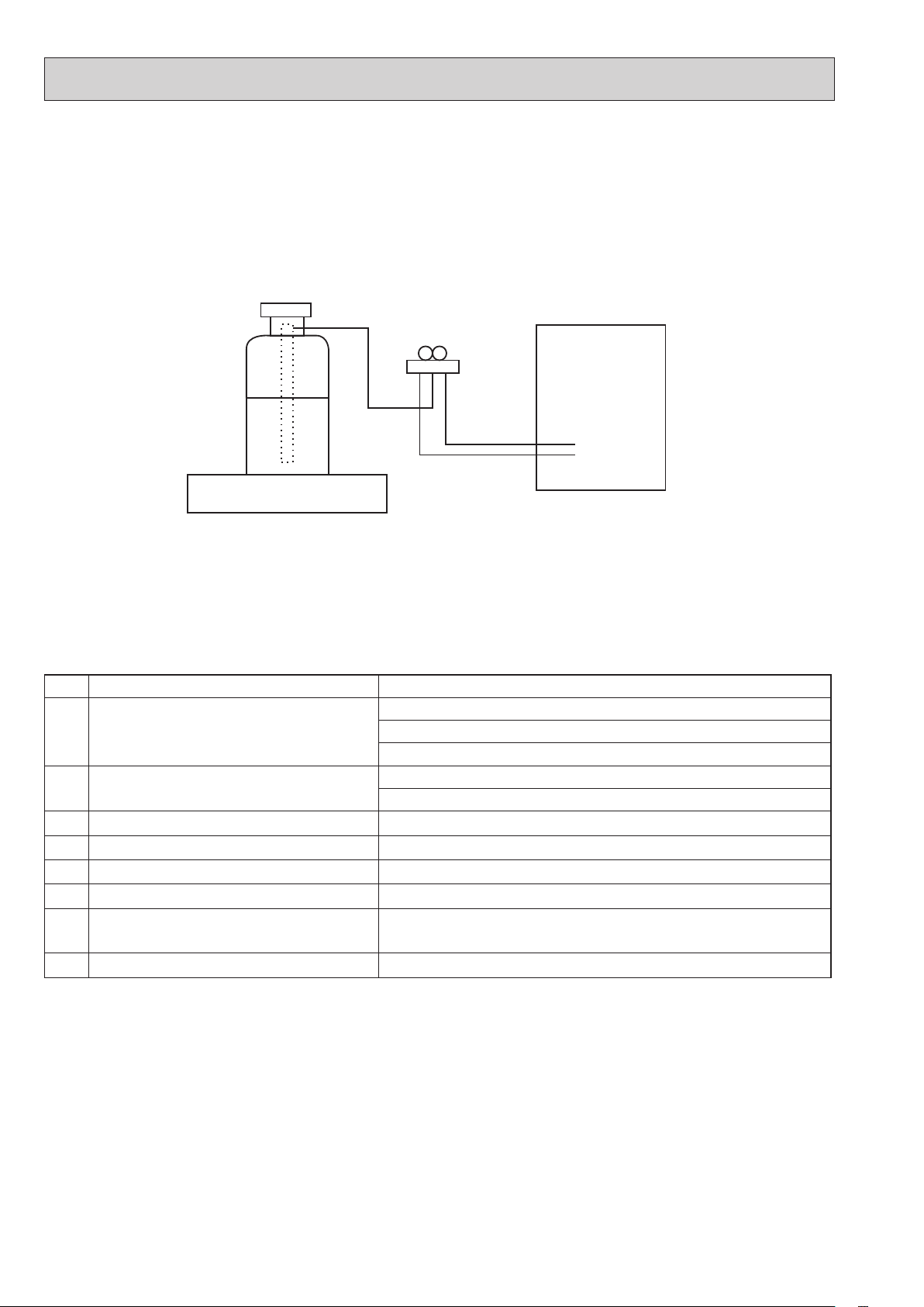
When charging directly from cylinder
· Check that cylinder for R410A on the market is a syphon type.
· Charging should be performed with the cylinder of syphon stood vertically. (Refrigerant is charged from liquid phase.)
Unit
Electronic weighing scale
[3] Service tools
Use the below service tools as exclusive tools for R410A refrigerant.
No.
Gauge manifold
1
Charge hose
2
Electronic weighing scale
3
Gas leak detector · Use the detector for R134a, R407C or R410A.
4
Adaptor for reverse flow check · Attach on vacuum pump.
5
Refrigerant charge base
6
Refrigerant cylinder
7
Refrigerant recovery equipment
8
Tool name
· Only for R410A
· Use the existing fitting
· Use high-tension side pressure of 5.3 MPa·G or over.
· Only for R410A
· Use pressure performance of 5.09 MPa·G or over.
· Only for R410A · Top of cylinder (Pink)
· Cylinder with syphon
Specifications
specifications
—
—
—
. (UNF1/2)
OCH439M
6

2-3. CAUTIONS FOR REFRIGERANT PIPING WORK
Tools for R410A (The following table shows whether conventional tools can be used or not.)
Tools and materials Use R410A tools
Gauge manifold
Charge hose Tool exclusive for R410A
Gas leak detector Gas leak check Tool for HFC refrigerant
Refrigerant recovery equipment Refrigerant recovery Tool exclusive for R410A
Refrigerant cylinder Refrigerant charge Tool exclusive for R410A
Safety charger
Charge valve
Vacuum pump Vacuum drying and air purge
Bender Bend the pipes
Pipe cutter Cut the pipes
Welder and nitrogen gas
cylinder
Refrigerant charging scale Refrigerant charge
Vacuum gauge or thermistor
vacuum gauge and vacuum
valve
Charging cylinder Refrigerant charge Tool exclusive for R410A
×
: Prepare a new tool. (Use the new tool as the tool exclusive for R410A.)
Air purge, refrigerant charge
and operation check
Prevent compressor malfunction
when charging refrigerant by
spraying liquid refrigerant
Prevent gas from blowing out
when detaching charge hose
Weld the pipes
Check the degree of vacuum. (Vacuum
valvepreventsbackowofoilandre
frigerant to thermistor vacuum gauge)
Tool exclusive for R410A
Tool exclusive for R410A
Tool exclusive for R410A
Tools for other refrigerants
can be used if equipped with
adapterforreverseowcheck
Tools for other refrigerants can be used
Tools for other refrigerants can be used
Tools for other refrigerants can be used
Tools for other refrigerants can be used
-
Tools for other refrigerants can be used
Δ: Tools for other refrigerants can be used under certain conditions.
: Tools for other refrigerants can be used.
○
Can R22 tools be
used?
× ×
× ×
× ○
× ×
× ×
× ×
× ×
Δ(Usableifequipped
with adapter for
reverse flow)
○ ○
○ ○
○ ○
○ ○
○ ○
× -
Can R407C tools be used?
Δ(Usableifequippedwith
adapter for reverse flow)
2-4. PRECAUTIONS FOR SALT PROOF TYPE "-BS" MODEL
Although "-BS" model has been designed to be resistant to salt damage, observe the following precautions to maintain the
performance of the unit.
1. Avoid installing the unit in a location where it will be exposed directly to seawater or sea breeze.
2. If the cover panel may become covered with salt, be sure to install the unit in a location where the salt will be washed away by
rainwater. (If a sunshade is installed, rainwater may not clean the panel.)
3. To ensure that water does not collect in the base of the outdoor unit, make sure that the base is level, not at angle. Water
collecting in the base of the outdoor unit could cause rust.
4. If the unit is installed in a coastal area, clean the unit with water regularly to remove any salt build-up.
5. If the unit is damaged during installation or maintenance, be sure to repair it.
6. Be sure to check the condition of the unit regularly.
7. Be sure to install the unit in a location with good drainage.
OCH439M
7
3
(TH32)
SPECIFICATIONS
3-1. SPECIFICATIONS
PUHZ-W50VHA PUHZ-W50VHA-BS PUHZ-W50VHAR1 PUHZ-W50VHAR1-BS
)ycneuqerF ,egatloV ,esahP( ylppus rewoP
Nominal water flow rate (Heating mode) L/min
Heating
(A7/W35)
Heating
WkyticapaC
(A2/W35)
Pressure difference (water circuit) )teltuo/telni( erutarepmet retaWaPk -/+35°C
Heating pump input (based on EN14511) kW
Cooling
(A35/W7)
EER (COP) Water temperature (inlet/outlet) +12/+7°C
Power input kW
Cooling
(A35/W18)
EER (COP) Outside air temperature (Wet-bulb) + 24°C
Pressure difference (water circuit) kPa
Cooling pump input (based on EN14511) kW
Note: "COP" and "Power input" in the above table are values that contains the "pump input (based on EN 14511) ".
snoitacificeps tinu roodtuO
Service ref.
Running current Heating
Cooling
Power factor Heating
Cooling
(A7/W35)
(A35/W7)
(A7/W35)
(A35/W7)
A
A
%
%
Atnerruc .xaM
Aezis rekaerB
gnisac retuO
hsinif lanretxE
lortnoc tnaregirfeR
Compressor
Model
Motor output kW
Start type
Protection devices
Oil (Model) L
Wretaeh esacknarC
Heat exchanger Air
Water
Fan Fan(drive)×No.
Fan motor output
Airflow
kW
3
/min
m
(CFM)
Defrost method
Noise level
Heating dB (SPL)
Cooling dB
Dimensions Width mm (in)
Depth mm (in)
Height mm (in)
Refrigerant
Quantity kg (lb)
Guaranteed operating Heating
range (Outdoor) Cooling
Outlet water temp. Heating
(Max in heating, Min in cooling)
Nominal return water
Cooling
Heating
temperature range Cooling
°C
°C
°C
°C
°C
°C
egnar etar wolf retaW
1[, 230 V, 50 Hz
14.3
5.00
4.10
1.22
5.00
3.13
1.60
12
0.01
12.9
4.50
2.94
1.53
4.50
4.13
1.09
10
0.01
PUHZ-W50VHA
PUHZ-W50VHA-BS
PUHZ-W50VHAR1
PUHZ-W50VHAR1-BS
5.4
6.8
97
97
13.0
16
Galvanized plate
Munsell 3Y 7.8/1.1
Linear expansion valve
Hermetic twin rotary
SNB130FGCM
0.9
Inverter
HP switch
Discharge thermo
Comp. Surface thermo
Overcurrent detection
0.35 (FV50S)
-
Plate fin coil
Plate heat exchanger
Propeller fan × 1
0.086
50
(1,760)
Reverse cycle
*2
46
*2
45
950 (37-3/8)
*3
330 +30
(13+1-3/16)
740 (29-3/16)
)bl( gkthgieW
64 (141)
R410A
1.7 (3.7)
−15 to +21
(*4)
to +46
−5
+60
+5
+9 to +59
+8 to +28
nim/L
6.5 to 14.3
noitidnoc gnitarepo lanimoN
Heating(A7/W35)
7 +)blub-yrD( erutarepmet ria edistuOWkyticapaC °C
6 +)blub-teW( erutarepmet ria edistuOPOC °C
Heating(A2/W35)
2 +)blub-yrD( erutarepmet ria edistuOPOC °C
1 +)blub-teW( erutarepmet ria edistuOWktupni rewoP °C
Cooling(A35/W7)
Onim/L)edom gnilooC( etar wolf retaw lanimoN °C
53+)blub-yrD( erutarepmet ria edistu
42 +)blub-teW( erutarepmet ria edistuOWkyticapaC °C
Cooling(A35/W18)
53+)blub-yrD( erutarepmet ria edistuOWkyticapaC °C
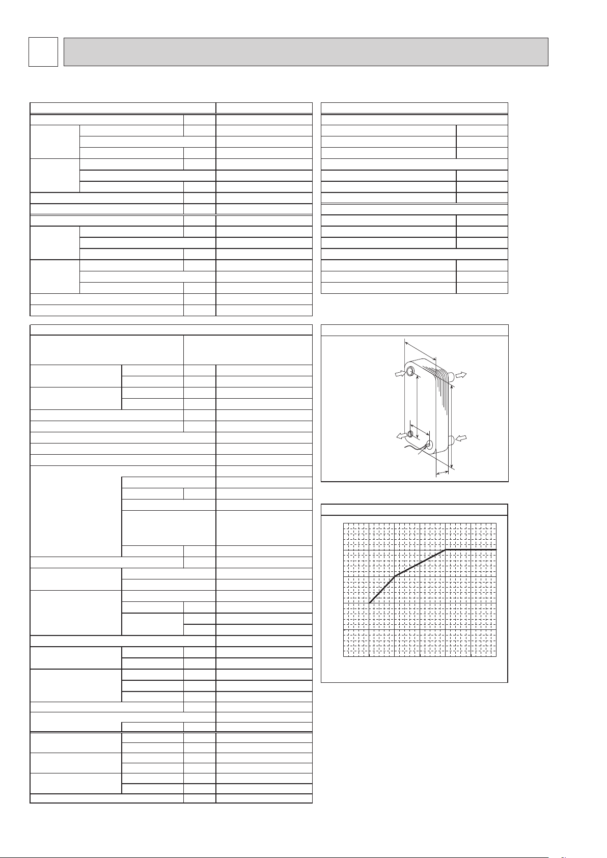
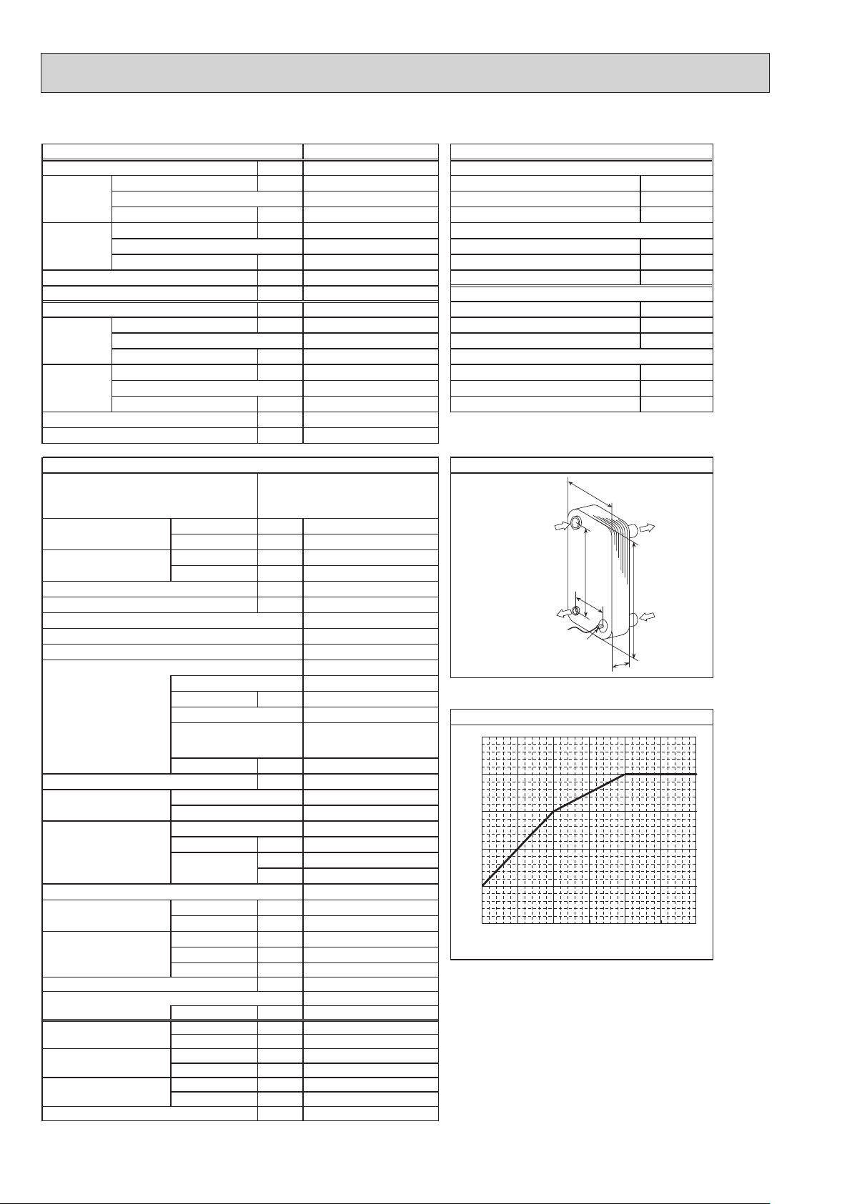
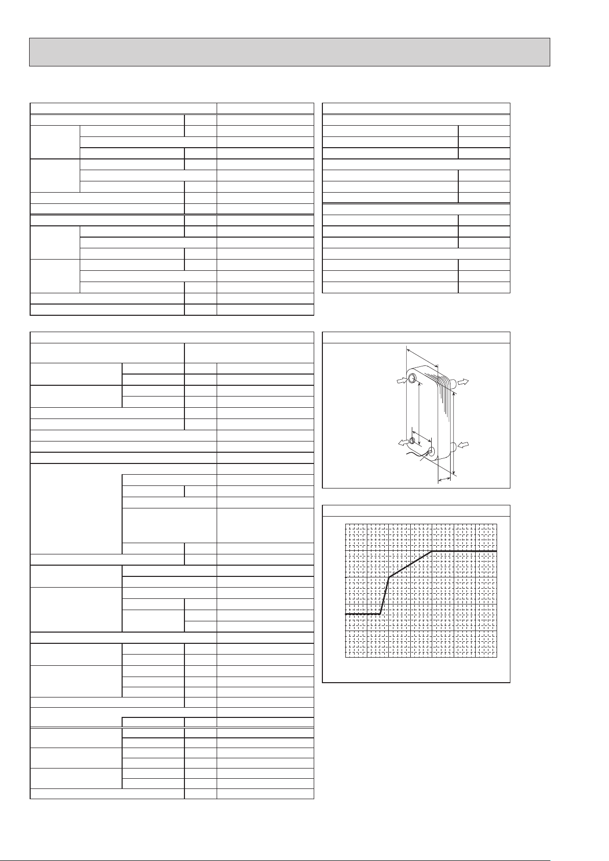
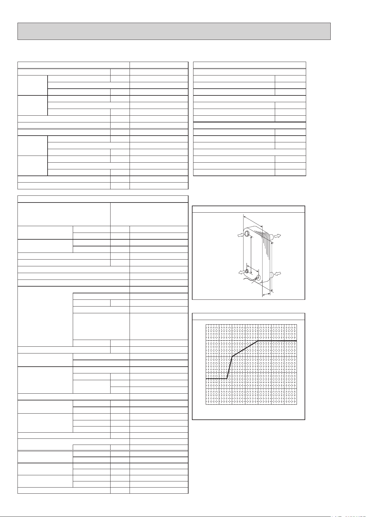
regnahcxe taeh etalP
ALFA LAVAL
03-03HCA
mm4.04:A
mm39:W
mm523:H
mm45:D
setalp 03
mm2.862:B
Ref. IN
(Heating)
Ref. OUT
(Heating)
B
Thermistor
W
Water OUT
A
H
Water IN
D
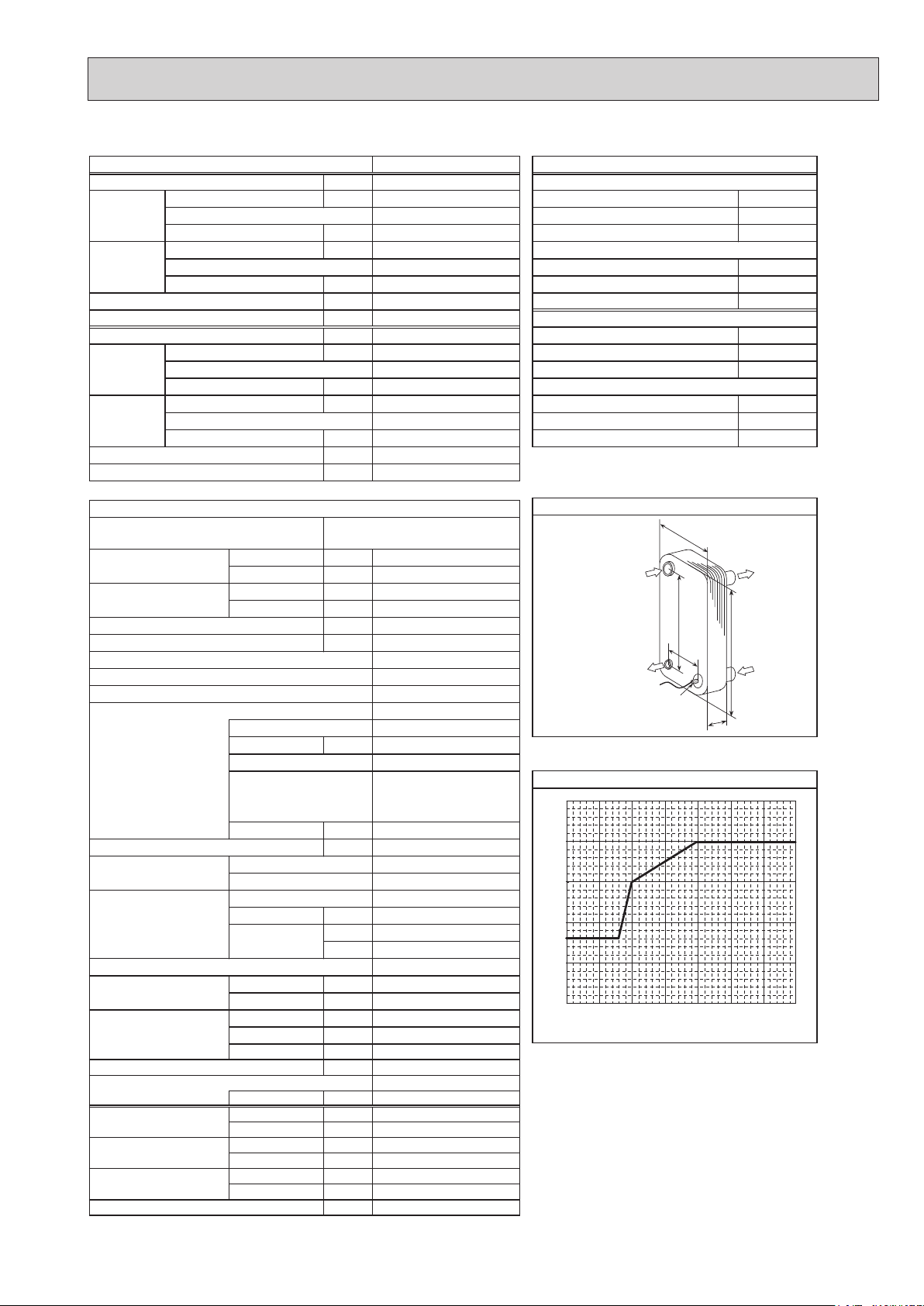
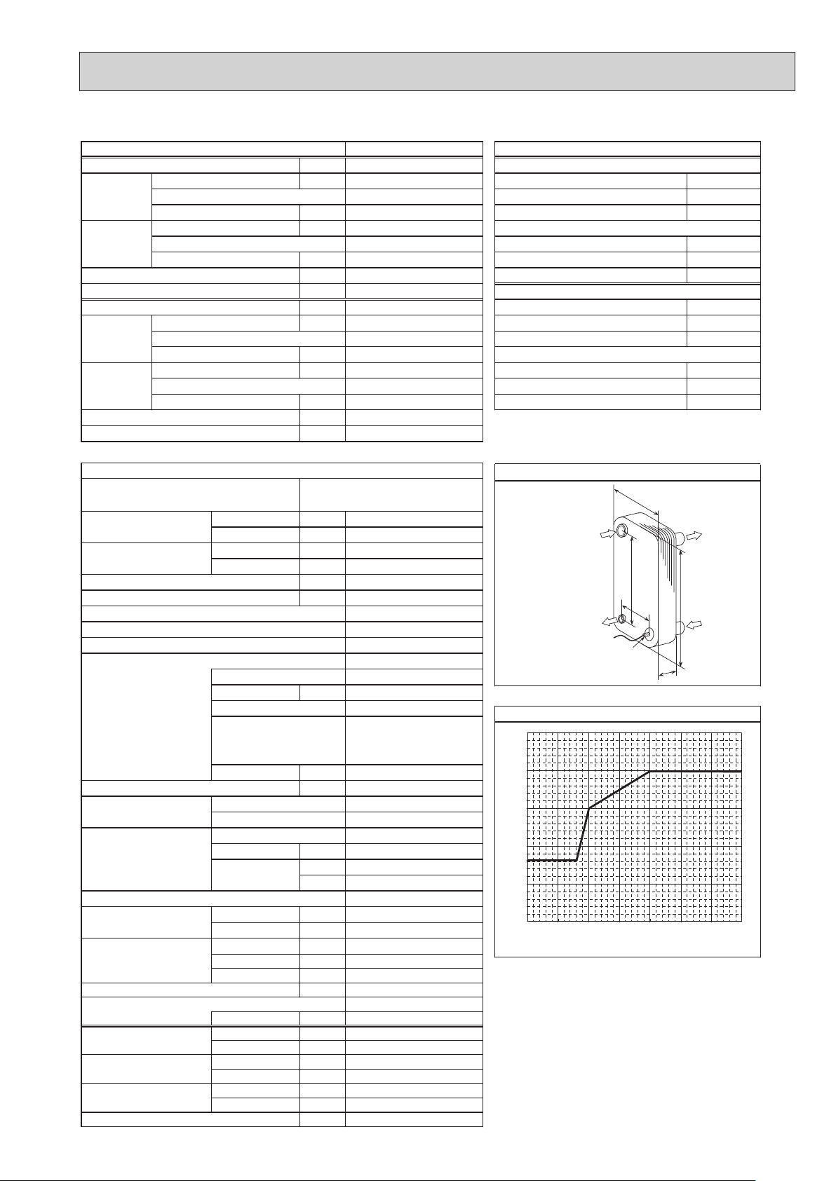
Maximum outlet water temperature
65
]
°C
60
55
50
*1
*5
45
Maximum outlet water temperature [
40
−20 −15 −10 −5
Ambient temperature [°C]
*1
Hot gas with 4-way valve
*2
at distance of 1m from outdoor unit
*3
grille
*4
With the optional air outlet guide, the operation at
−15°C outdoor temperature is possible.
*5
For details of the minute return water temperature at
each water flow rate, refer to 3-2. AVAILABLE RANGE
(WATER FLOW RATE, RETURN WATER TEMP.)”
0 5 1
53+/03+)teltuo/telni( erutarepmet retaWWktupni rewoP °C
81+/32+)teltuo/telni( erutarepmet retaWWktupni rewoP °C
0
OCH439M
8
(TH32)
PUHZ-W50VHAR2 PUHZ-W50VHAR2-BS PUHZ-W50VHAR3 PUHZ-W50VHAR3-BS
)ycneuqerF ,egatloV ,esahP( ylppus rewoP
Nominal water flow rate (Heating mode) L/min
Heating
(A7/W35)
Heating
WkyticapaC
(A2/W35)
Pressure difference (water circuit) )teltuo/telni( erutarepmet retaWaPk -/+35°C
Heating pump input (based on EN14511) kW
Cooling
(A35/W7)
EER (COP) Water temperature (inlet/outlet) +12/+7°C
Power input kW
Cooling
(A35/W18)
EER (COP) Outside air temperature (Wet-bulb) + 24°C
Pressure difference (water circuit) kPa
Cooling pump input (based on EN14511) kW
Note: "COP" and "Power input" in the above table are values that contains the "pump input (based on EN 14511) ".
1[, 230 V, 50 Hz
14.3
5.00
4.10
1.22
5.00
3.13
1.60
12
0.01
12.9
4.50
2.94
1.53
4.50
4.13
1.09
10
0.01
noitidnoc gnitarepo lanimoN
Heating(A7/W35)
7 +)blub-yrD( erutarepmet ria edistuOWkyticapaC °C
6 +)blub-teW( erutarepmet ria edistuOPOC °C
Heating(A2/W35)
2 +)blub-yrD( erutarepmet ria edistuOPOC °C
1 +)blub-teW( erutarepmet ria edistuOWktupni rewoP °C
Cooling(A35/W7)
Onim/L)edom gnilooC( etar wolf retaw lanimoN °C
53+)blub-yrD( erutarepmet ria edistu
42 +)blub-teW( erutarepmet ria edistuOWkyticapaC °C
Cooling(A35/W18)
53+)blub-yrD( erutarepmet ria edistuOWkyticapaC °C
53+/03+)teltuo/telni( erutarepmet retaWWktupni rewoP °C
81+/32+)teltuo/telni( erutarepmet retaWWktupni rewoP °C
snoitacificeps tinu roodtuO
Service ref.
Running current Heating
Cooling
Power factor Heating
Cooling
(A7/W35)
(A35/W7)
(A7/W35)
(A35/W7)
A
A
%
%
Atnerruc .xaM
Aezis rekaerB
gnisac retuO
hsinif lanretxE
regirfeR
lortnoc tna
Compressor
Model
Motor output kW
Start type
Protection devices
Oil (Model) L
Wretaeh esacknarC
Heat exchanger Air
Water
Fan Fan(drive)×No.
Fan motor output
Airflow
kW
3
/min
m
(CFM)
Defrost method
Noise level
Heating dB (SPL)
Cooling dB
Dimensions Width mm (in)
Depth mm (in)
Height mm (in)
Refrigerant
Quantity kg (lb)
Guaranteed operating Heating
range (Outdoor) Cooling
Outlet water temp. Heating
(Max in heating, Min in cooling)
Nominal return water
Cooling
Heating
temperature range Cooling
°C
°C
°C
°C
°C
°C
egnar etar wolf retaW
PUHZ-W50VHAR2
PUHZ-W50VHAR2-BS
PUHZ-W50VHAR3
PUHZ-W50VHAR3-BS
5.4
6.8
97
97
13.0
16
Galvanized plate
Munsell 3Y 7.8/1.1
Linear expansion valve
Hermetic twin rotary
SNB130FGCM
0.9
Inverter
HP switch
Discharge thermo
Comp. Surface thermo
Overcurrent detection
0.35 (FV50S)
Plate fin coil
Plate heat exchanger
Propeller fan × 1
0.086
50
(1,760)
Reverse cycle
46
45
950 (37-3/8)
*3
330 +30
(13+1-3/16)
740 (29-3/16)
)bl( gkthgieW
64 (141)
R410A
1.7 (3.7)
−15 to +21
(*4)
−5
+60
+5
+9 to +59
+8 to +28
nim/L
6.5 to 14.3
-
*2
*2
to +46
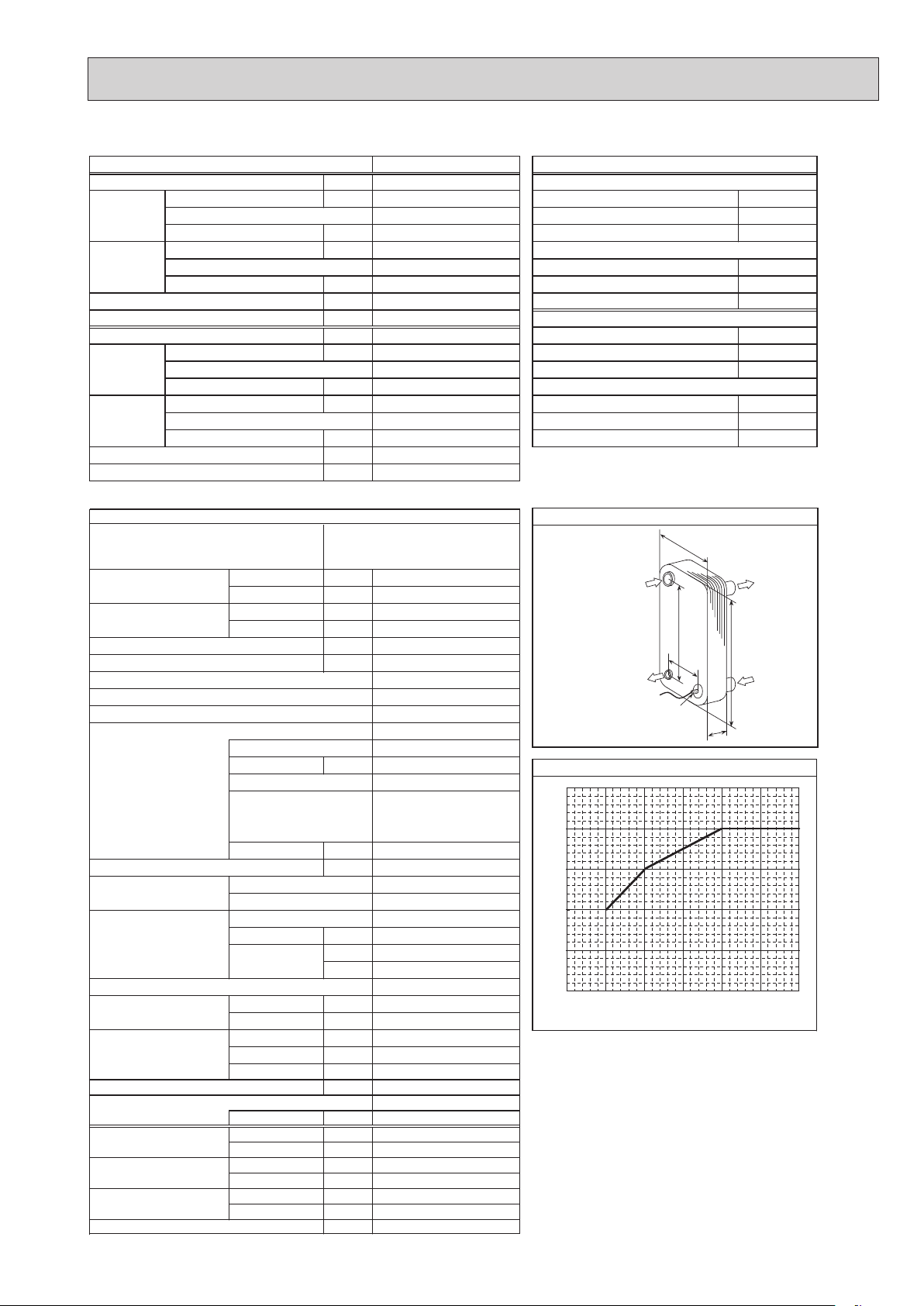
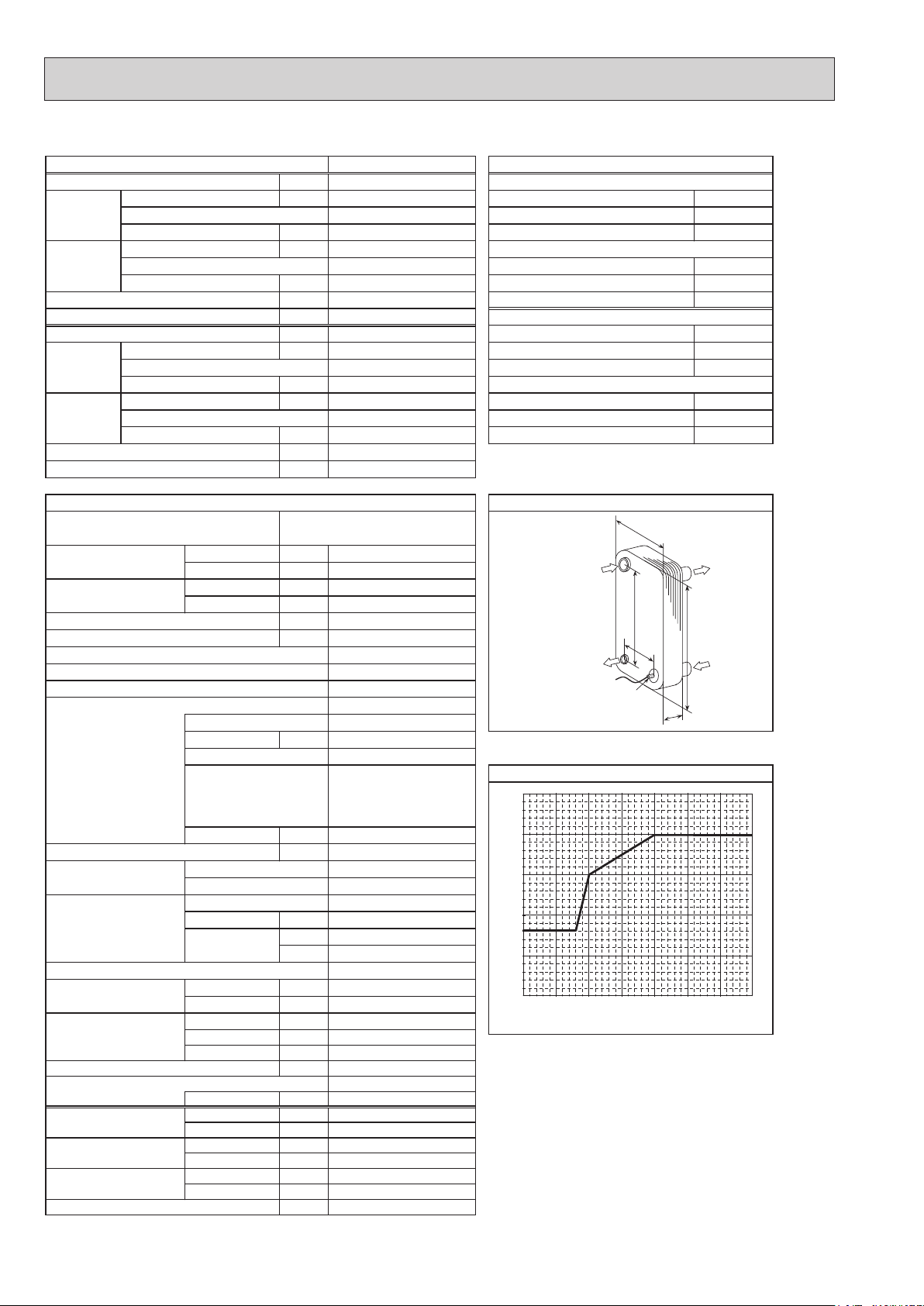
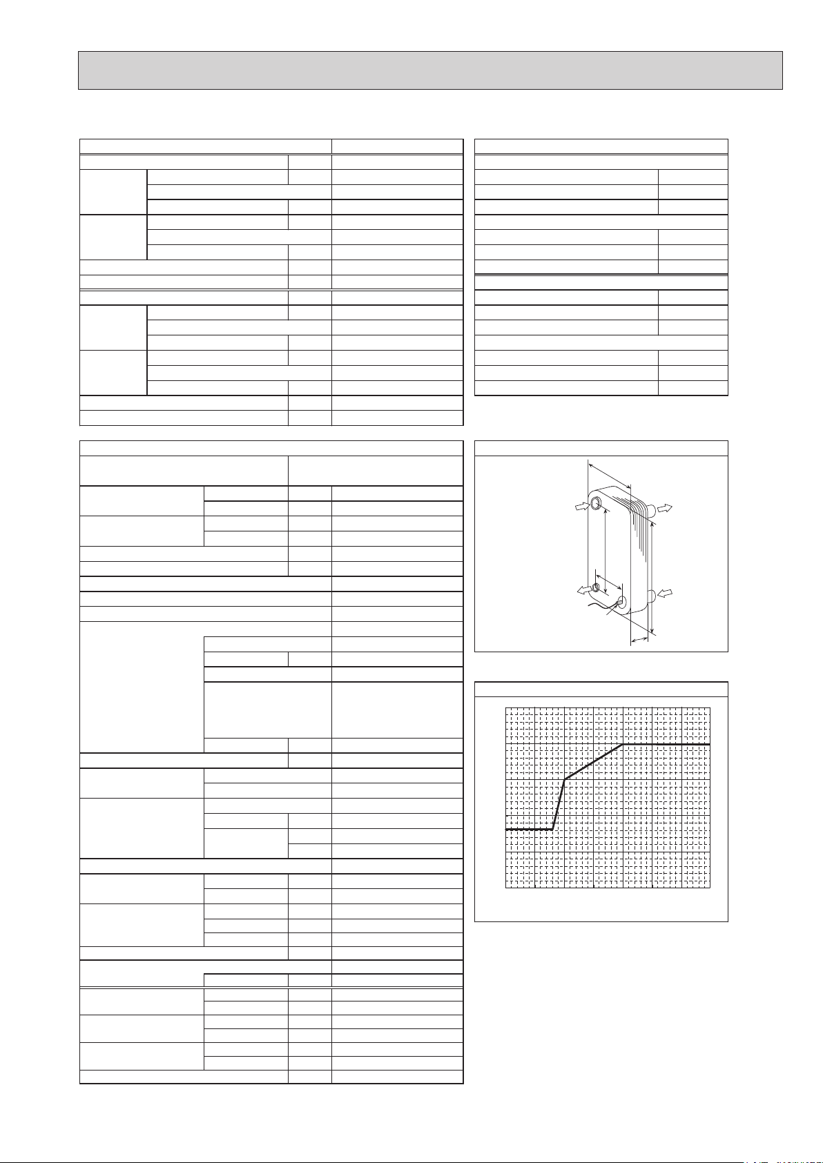
regnahcxe taeh etalP
MITSUBISHI
MWA1-28LM
mm39:A
mm39:W
mm523:H
mm2.45:D
setalp 28
mm2.862:B
Ref. IN
(Heating)
Ref. OUT
(Heating)
Thermistor
W
Water OUT
B
A
H
Water IN
D
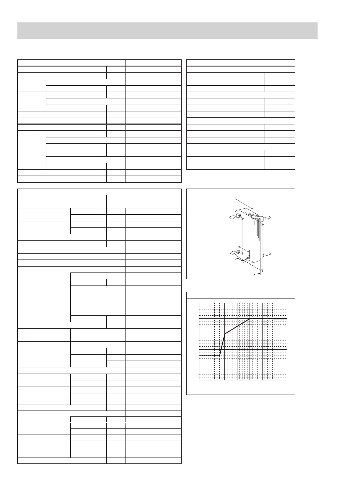
Maximum outlet water temperature
65
]
°C
60
55
50
45
*1
*5
Maximum outlet water temperature [
40
−20 −15 −10 −5 0 5 10
Ambient temperature [°C]
*1
Hot gas with 4-way valve
*2
at distance of 1 m from outdoor unit
*3
grille
*4
With the optional air outlet guide, the operation at
−15°C outdoor temperature is possible.
*5
For details of the minute return water temperature at
each water flow rate, refer to “3-2. AVAILABLE RANGE
(WATER FLOW RATE, RETURN WATER TEMP.)”.
OCH439M
9
PUHZ-W85VHA PUHZ-W85VHA-BS PUHZ-W85VHAR1 PUHZ-W85VHAR1-BS
1φ, 230 V, 50 Hz
Nominal water flow rate (Heating mode) L/min
Heating
(A7/W35)
25.8
9.00
3.85
Heating(A7/W35)
2.34
Heating
(A2/W35)
WkyticapaC
8.50
2.95
Heating(A2/W35)
2.88
Pressure difference (water circuit) )teltuo/telni( erutarepmet retaWaPk -/+35℃
Heating pump input (based on EN14511) kW
Cooling
(COP) Water temperature (inlet/outlet) +12/+7℃
(A35/W7)
EER
Power input kW
Cooling
(COP) Outside air temperature (Wet-bulb) + 24℃
(A35/W18)
EER
20
0.03
21.5
7.50
2.39
3.14
7.50
3.87
Cooling(A35/W7)
Onim/L)edom gnilooC( etar wolf retaw lanimoN ℃
Cooling(A35/W18)
1.94
Pressure difference (water circuit) kPa
Cooling pump input (based on EN14511) kW
Note: "COP" and "Power input" in the above table are values that contains the "pump input (based on EN 14511) ".
PUHZ-W85VHA
Service ref.
Running current Heating
Cooling
Power factor Heating
Cooling
(A7/W35)
(A35/W7) A
(A7/W35)
(A35/W7)
PUHZ-W85VHA-BS
PUHZ-W85VHAR1
PUHZ-W85VHAR1-BS
A
%
%
Atnerruc .xaM
Aezis rekaerB
gnisac retuO
hsinif lanretxE
lortnoc tnaregirfeR
Compressor
Linear expansion valve
Hermetic twin rotary
Model
Motor output kW
Start type
Protection devices
Overcurrent detection
Oil (Model) L
Wretaeh esacknarC
Heat exchanger Air
Water
Plate heat exchanger
Fan Fan(drive)×No.
Fan motor output
Airflow
kW
3
/min
m
(CFM)
Defrost method
Noise level Heating dB
(SPL)
Cooling dB
Dimensions Width mm (in)
Depth mm (in)
330 +30
Height mm (in)
)bl( gkthgieW
Refrigerant
Quantity kg (lb)
Guaranteed operating Heating
range (Outdoor) Cooling
Outlet water temp. Heating
(Max in heating, Min in cooling)
Nominal return water
Cooling
Heating
temperature range Cooling
℃
℃
℃
℃
℃
℃
nim/Legnar etar wolf retaW
15
0.02
10.3
13.7
98
98
23.0
25
Galvanized plate
Munsell 3Y 7.8/1.1
TNB220FLHM1
1.3
Inverter
HP switch
Discharge thermo
0.67 (FV50S)
-
Plate fin coil
Propeller fan × 1
0.060
55
(1,940)
48
48
*1
*2
*2
Reverse cycle
950 (37-3/8)
*3
(13+1-3/16)
943 (37-1/8)
77 (170)
R410A
2.4 (5.3)
−20 to +21
(*4)
−5
to +46
+60
+5
+9 to +59
+8 to +28
10.0 to 25.8
*5
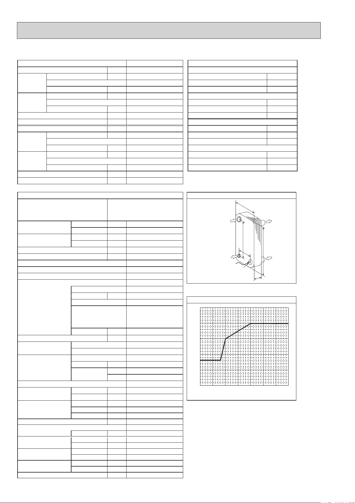
ALFA LAVAL
04-03HCA
Ref. IN
mm4.04:A
(Heating)
mm2.862:B
mm39:W
mm523:H
mm96:D
Ref. OUT
(Heating)
setalp 04
Maximum outlet water temperature
65
]
℃
60
55
50
45
Maximum outlet water temperature [
40
−20 −15 −10 −5
Ambient temperature [℃]
*1
Hot gas with 4-way valve
*2
at distance of 1m from outdoor unit
*3
grille
*4
With the optional air outlet guide, the operation at
−15℃ outdoor temperature is possible.
*5
For details of the minute return water temperature at
each water flow rate, refer to “3-2. AVAILABLE RANGE
(WATER FLOW RATE, RETURN WATER TEMP.)”
regnahcxe taeh etalPsnoitacificeps tinu roodtuO
Thermistor
(TH32)
noitidnoc gnitarepo lanimoN)ycneuqerF ,egatloV ,esahP( ylppus rewoP
W
B
A
7 +)blub-yrD( erutarepmet ria edistuOWkyticapaC ℃
6 +)blub-teW( erutarepmet ria edistuOPOC ℃
2 +)blub-yrD( erutarepmet ria edistuOPOC ℃
1 +)blub-teW( erutarepmet ria edistuOWktupni rewoP ℃
53+)blub-yrD( erutarepmet ria edistu
42 +)blub-teW( erutarepmet ria edistuOWkyticapaC ℃
53+)blub-yrD( erutarepmet ria edistuOWkyticapaC ℃
Water OUT
H
Water IN
D
0 5 1
53+/03+)teltuo/telni( erutarepmet retaWWktupni rewoP ℃
81+/32+)teltuo/telni( erutarepmet retaWWktupni rewoP ℃
0
OCH439M
10
PUHZ-HW112YHA PUHZ-HW112YHA-BS
3φ, 400 V, 50 Hz
Nominal water flow rate (Heating mode) L/min
Heating
(A7/W35)
32.1
11.20
4.24
Heating(A7/W35)
2.64
Heating
(A2/W35)
WkyticapaC
11.20
3.01
Heating(A2/W35)
3.72
Pressure difference (water circuit) )teltuo/telni( erutarepmet retaWaPk -/+35℃
Heating pump input (based on EN14511) kW
Cooling
(COP) Water temperature (inlet/outlet) +12/+7℃
(A35/W7)
EER
Power input kW
Cooling
(COP) Outside air temperature (Wet-bulb) + 24℃
(A35/W18)
EER
6
0.01
28.7
10.00
2.72
3.68
10.00
4.07
Cooling(A35/W7)
Onim/L)edom gnilooC( etar wolf retaw lanimoN ℃
Cooling(A35/W18)
2.46
Pressure difference (water circuit) kPa
Cooling pump input (based on EN14511) kW
Note: "COP" and "Power input" in the above table are values that contains the "pump input (based on EN 14511) ".
5
0.01
snoitacificeps tinu roodtuO
Service ref.
Running current Heating
Cooling
Power factor Heating
Cooling
(A7/W35)
(A35/W7) A
(A7/W35)
(A35/W7)
A
%
%
Atnerruc .xaM
Aezis rekaerB
gnisac retuO
hsinif lanretxE
lo
rtnoc tnaregirfeR
Compressor
Model
Motor output kW
Start type
Protection devices
Oil (Model) L
Wretaeh esacknarC
Heat exchanger Air
Water
Fan Fan(drive)×No.
Fan motor output
Airflow
kW
3
/min
m
(CFM)
Defrost method
Noise level Heating dB
(SPL)
Cooling dB
Dimensions Width mm (in)
Depth mm (in)
Height mm (in)
Refrigerant
Quantity kg (lb)
Guaranteed operating Heating
range (Outdoor) Cooling
Outlet water temp. Heating
(Max in heating, Min in cooling)
Cooling
Nominal return water Heating
temperature range Cooling
℃
℃
℃
℃
℃
℃
PUHZ-HW112YHA
PUHZ-HW112YHA-BS
4.0
5.6
95
95
13.0
16
Galvanized plate
Munsell 3Y 7.8/1.1
Linear expansion valve
Hermetic scroll
ANB33FJFMT
2.5
Inverter
HP switch
LP switch
Discharge thermo
Overcurrent detection
0.9 (FV50S)
-
Plate fin coil
Plate heat exchanger
Propeller fan × 2
0.074 x 2
100
(3,530)
Reverse cycle
*2
53
*2
53
1020 (40-3/16)
*3
330 +30
(13+1-3/16)
1350 (53-1/8)
)bl( gkthgieW
148 (326.3)
R410A
4.0 (8.8)
−25 to +21
(*4)
−5
to +46
+60
+5
+11 to +59
+8 to +28
nim/Legnar etar wolf retaW
14.4 to 32.1
*1
*5
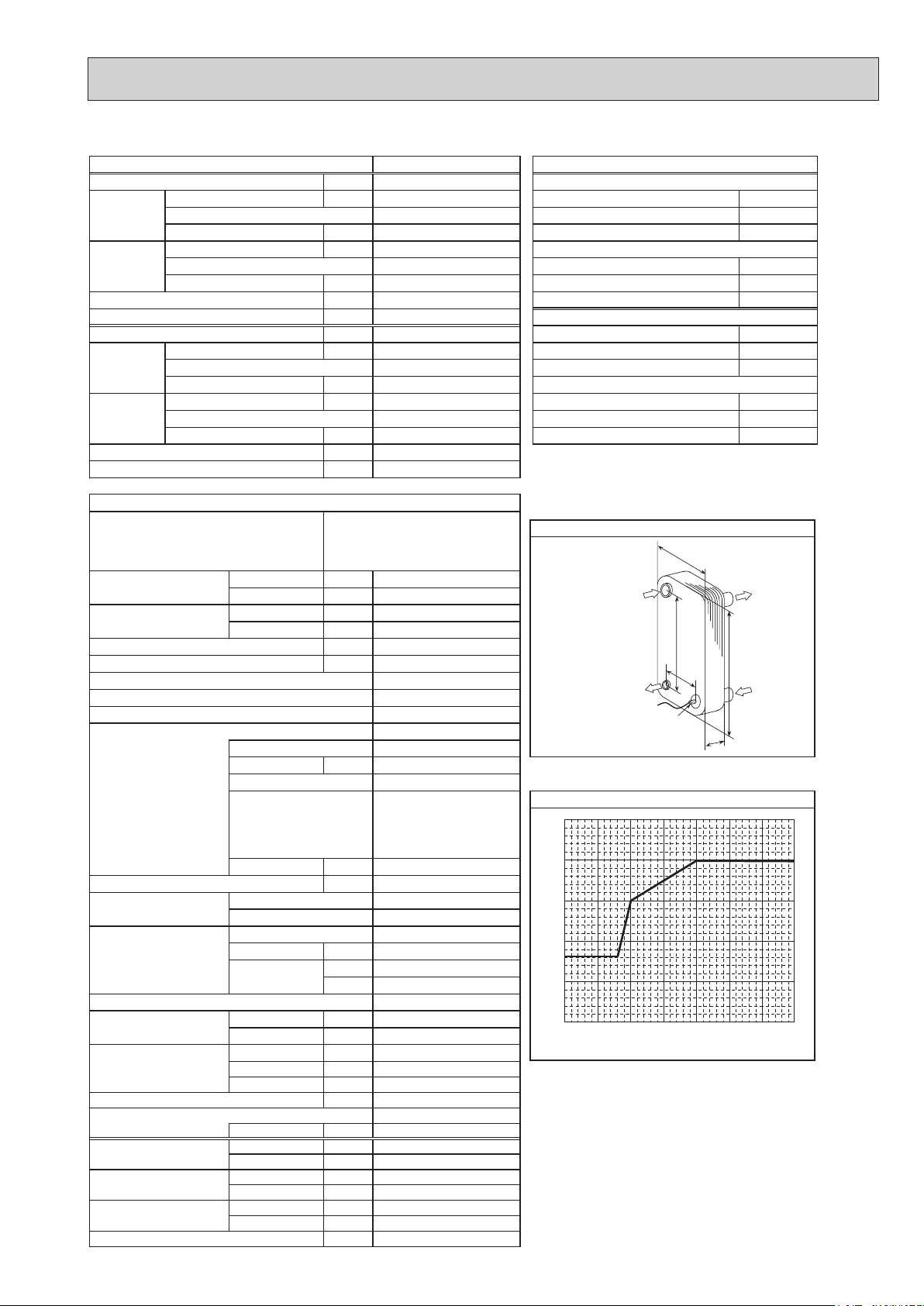
ALFA LAVAL
05-05HCA
Ref. IN
mm05:A
(Heating)
mm664:B
mm211:W
mm625:H
mm031:D
Ref. OUT
(Heating)
setalp 05
Maximum outlet water temperature
65
]
℃
60
55
50
45
Maximum outlet water temperature [
40
−25 −20 −15 −10 −5 0 5 10
*1
Hot gas with 4-way valve
*2
at distance of 1m from outdoor unit
*3
grille
*4
With the optional air outlet guide, the operation at
−15℃ outdoor temperature is possible.
*5
For details of the minute return water temperature at
each water flow rate, refer to “3-2. AVAILABLE RANGE
(WATER FLOW RATE, RETURN WATER TEMP.)”
Ambient temperature [℃]
regnahcxe taeh etalP
Thermistor
noitidnoc gnitarepo lanimoN)ycneuqerF ,egatloV ,esahP( ylppus rewoP
7 +)blub-yrD( erutarepmet ria edistuOWkyticapaC ℃
6 +)blub-teW( erutarepmet ria edistuOPOC ℃
2 +)blub-yrD( erutarepmet ria edistuOPOC ℃
1 +)blub-teW( erutarepmet ria edistuOWktupni rewoP ℃
53+)blub-yrD( erutarepmet ria edistu
42 +)blub-teW( erutarepmet ria edistuOWkyticapaC ℃
53+)blub-yrD( erutarepmet ria edistuOWkyticapaC ℃
W
Water OUT
B
A
TH
2
H
Water IN
D
53+/03+)teltuo/telni( erutarepmet retaWWktupni rewoP ℃
81+/32+)teltuo/telni( erutarepmet retaWWktupni rewoP ℃
OCH439M
11
PUHZ-HW140VHA PUHZ-HW140VHA-BS
1φ, 230 V, 50 Hz
Nominal water flow rate (Heating mode) L/min
Heating
(A7/W35)
40.1
14.00
4.19
Heating(A7/W35)
3.34
Heating
(A2/W35)
WkyticapaC
14.00
2.69
Heating(A2/W35)
5.21
Pressure difference (water circuit) )teltuo/telni( erutarepmet retaWaPk -/+35℃
Heating pump input (based on EN14511) kW
Cooling
(COP) Water temperature (inlet/outlet) +12/+7℃
(A35/W7)
EER
Power input kW
Cooling
(COP) Outside air temperature (Wet-bulb) + 24℃
(A35/W18)
EER
9
0.02
35.8
12.50
2.59
4.82
12.50
4.01
Cooling(A35/W7)
Onim/L)edom gnilooC( etar wolf retaw lanimoN ℃
Cooling(A35/W18)
3.12
Pressure difference (water circuit) kPa
Cooling pump input (based on EN14511) kW
Note: "COP" and "Power input" in the above table are values that contains the "pump input (based on EN 14511) ".
Service ref.
PUHZ-HW140VHA
PUHZ-HW140VHA-BS
Cooling
Cooling
(A7/W35) A
(A35/W7) mm05:A A
(A7/W35) mm664:B %
(A35/W7) %
Linear expansion valve
Running current Heating
Power factor Heating
Refrigerant control
Compressor
Model
Motor output kW
Start type
7
0.02
14.9
21.5
97
97
35.0
40
Galvanized plate
Munsell 3Y 7.8/1.1
Hermetic scroll
ANB33FJGMT
2.5
Inverter
ALFA LAVAL
ACH50-50
mm211:W Atnerruc .xaM
mm625:H Aezis rekaerB
mm031:D gnisac retuO
setalp 05hsinif lanretxE
Ref. IN
(Heating)
Ref. OUT
(Heating)
HP switch
Oil (Model) L
Wretaeh esacknarC
Heat exchanger Air
Water
.oN×)evird(naFnaF
Fan motor output
Airflow
kW
3
m
/min
(CFM)
Defrost method
Noise level Heating dB
(SPL)
Cooling dB
Dimensions Width mm (in)
Depth mm (in)
Height mm (in)
Refrigerant
Quantity kg (lb)
Guaranteed operating Heating
range (Outdoor) Cooling
Outlet water temp. Heating
(Max in heating, Min in cooling)
Nominal return water
Cooling
Heating
temperature range Cooling
℃
℃
℃
℃
℃
℃
LP switch
Discharge thermo
Overcurrent detection
0.9 (FV50S)
Plate fin coil
Plate heat exchanger
Propeller fan × 2
0.074 × 2
Reverse cycle
1020 (40-3/16)
330 +30
1350 (53-1/8)
)bl( gkthgieW
134 (295.4)
4.0 (8.8)
−25 to +21
−5
+10 to +59
+8 to +28
nim/Legnar etar wolf retaW
17.9 to 40.1
-
100
(3,530)
*2
53
*2
53
*3
(13+1-3/16)
R410A
(*4)
to +46
+60
+5
*1
*5
65
]
℃
60
55
50
45
Maximum outlet water temperature [
40
−25 −20 −15 −10 −5 0 5 10
*1
Hot gas with 4-way valve
*2
at distance of 1m from outdoor unit
*3
grille
*4
With the optional air outlet guide, the operation at
−15 ℃ outdoor temperature is possible.
*5
For details of the minute return water temperature at
each water flow rate, refer to “3-2. AVAILABLE RANGE
(WATER FLOW RATE, RETURN WATER TEMP.)”
noitidnoc gnitarepo lanimoN)ycneuqerF ,egatloV ,esahP( ylppus rewoP
regnahcxe taeh etalPsnoitacificeps tinu roodtuO
W
B
A
Thermistor
TH
2
D
tarepmet retaw teltuo mumixaMsecived noitcetorP
eru
Ambient temperature [℃]
7 +)blub-yrD( erutarepmet ria edistuOWkyticapaC ℃
6 +)blub-teW( erutarepmet ria edistuOPOC ℃
2 +)blub-yrD( erutarepmet ria edistuOPOC ℃
1 +)blub-teW( erutarepmet ria edistuOWktupni rewoP ℃
53+)blub-yrD( erutarepmet ria edistu
42 +)blub-teW( erutarepmet ria edistuOWkyticapaC ℃
53+)blub-yrD( erutarepmet ria edistuOWkyticapaC ℃
Water OUT
H
Water IN
53+/03+)teltuo/telni( erutarepmet retaWWktupni rewoP ℃
81+/32+)teltuo/telni( erutarepmet retaWWktupni rewoP ℃
OCH439M
12

PUHZ-HW140YHA PUHZ-HW140YHA-BS
3φ, 400 V, 50 Hz
Nominal water flow rate (Heating mode) L/min
Heating
(A7/W35)
40.1
14.00
4.19
Heating(A7/W35)
3.34
Heating
(A2/W35)
WkyticapaC
14.00
2.69
Heating(A2/W35)
5.21
Pressure difference (water circuit) )teltuo/telni( erutarepmet retaWaPk -/+35℃
Heating pump input (based on EN14511) kW
Cooling
(COP) Water temperature (inlet/outlet) +12/+7℃
(A35/W7)
EER
Power input kW
Cooling
(COP) Outside air temperature (Wet-bulb) + 24℃
(A35/W18)
EER
9
0.02
35.8
12.50
2.59
4.82
12.50
4.01
Cooling(A35/W7)
Onim/L)edom gnilooC( etar wolf retaw lanimoN ℃
Cooling(A35/W18)
3.12
Pressure difference (water circuit) kPa
Cooling pump input (based on EN14511) kW
Note: "COP" and "Power input" in the above table are values that contains the "pump input (based on EN 14511) ".
Service ref.
Running current Heating
Cooling
Power factor Heating
Cooling
Refrigerant control
(A7/W35) A
(A35/W7) mm05:A A
(A7/W35) mm664:B %
(A35/W7) %
PUHZ-HW140YHA
PUHZ-HW140YHA-BS
Linear expansion valve
Compressor
Model
Motor output kW
Start type
7
0.02
5.1
7.3
95
95
13.0
16
Galvanized plate
Munsell 3Y 7.8/1.1
Hermetic scroll
ANB33FJFMT
2.5
Inverter
ALFA LAVAL
ACH50-50
mm211:W Atnerruc .xaM
mm625:H Aezis rekaerB
mm031:D gnisac retuO
setalp 05hsinif lanretxE
Ref. IN
(Heating)
Ref. OUT
(Heating)
HP switch
Oil (Model) L
Wretaeh esacknarC
Heat exchanger Air
Water
.oN×)evird(naFnaF
Fan motor output
Airflow
kW
3
m
/min
(CFM)
Defrost method
Noise level Heating dB
(SPL)
Cooling dB
Dimensions Width mm (in)
Depth mm (in)
Height mm (in)
Refrigerant
Quantity kg (lb)
Guaranteed operating Heating
range (Outdoor) Cooling
Outlet water temp. Heating
(Max in heating, Min in cooling)
Nominal return water
Cooling
Heating
temperature range Cooling
℃
℃
℃
℃
℃
℃
LP switch
Discharge thermo
Overcurrent detection
0.9 (FV50S)
Plate fin coil
Plate heat exchanger
Propeller fan × 2
0.074 × 2
Reverse cycle
1020 (40-3/16)
330 +30
1350 (53-1/8)
)bl( gkthgieW
148 (326.3)
4.0 (8.8)
−25 to +21
−5
+10 to +59
+8 to +28
nim/Legnar etar wolf retaW
17.9 to 40.1
-
100
(3,530)
*2
53
*2
53
*3
(13+1-3/16)
R410A
(*4)
to +46
+60
+5
*1
*5
65
]
℃
60
55
50
45
Maximum outlet water temperature [
40
−25 −20 −15 −10 −5 0 5 10
*1
Hot gas with 4-way valve
*2
at distance of 1m from outdoor unit
*3
grille
*4
With the optional air outlet guide, the operation at
−15℃ outdoor temperature is possible.
*5
For details of the minute return water temperature at
each water flow rate, refer to “3-2. AVAILABLE RANGE
(WATER FLOW RATE, RETURN WATER TEMP.)”
Ambient temperature [℃]
regnahcxe taeh etalPsnoitacificeps tinu roodtuO
Thermistor
noitidnoc gnitarepo lanimoN)ycneuqerF ,egatloV ,esahP( ylppus rewoP
7 +)blub-yrD( erutarepmet ria edistuOWkyticapaC ℃
6 +)blub-teW( erutarepmet ria edistuOPOC ℃
2 +)blub-yrD( erutarepmet ria edistuOPOC ℃
1 +)blub-teW( erutarepmet ria edistuOWktupni rewoP ℃
53+)blub-yrD( erutarepmet ria edistu
42 +)blub-teW( erutarepmet ria edistuOWkyticapaC ℃
53+)blub-yrD( erutarepmet ria edistuOWkyticapaC ℃
W
Water OUT
B
A
TH
2
H
Water IN
D
tarepmet retaw teltuo mumixaMsecived noitcetorP
eru
53+/03+)teltuo/telni( erutarepmet retaWWktupni rewoP ℃
81+/32+)teltuo/telni( erutarepmet retaWWktupni rewoP ℃
OCH439M
13
(TH32)
PUHZ-HW112YHA2 PUHZ-HW112YHA2-BS
3 φ, 400 V, 50 Hz
Nominal water flow rate (Heating mode) L/min
Heating
(A7/W35)
32.1
11.20
4.42
Heating(A7/W35)
2.53
Heating
(A2/W35)
WkyticapaC
11.20
Heating(A2/W35)
3.11
3.60
Pressure difference (water circuit) )teltuo/telni( erutarepmet retaWaPk -/+35℃
Heating pump input (based on EN14511) kW
nim/L)edom gnilooC( etar wolf retaw lanimoN ℃
Cooling
(COP) Water temperature (inlet/outlet) +12/+7℃
(A35/W7)
EER
Power input kW
Cooling
(COP) Outside air temperature (Wet-bulb) + 24℃
(A35/W18)
EER
6
0.01
28.7
10.00
2.78
3.60
10.00
4.10
Cooling(A35/W7)
Cooling(A35/W18)
2.44
Pressure difference (water circuit) kPa
Cooling pump input (based on EN14511) kW
Note: "COP" and "Power input" in the above table are values that contains the "pump input (based on EN 14511) ".
Service ref.
Running current Heating
Cooling
Power factor Heating
Cooling
Refrigerant control
(A7/W35) A
(A35/W7) mm05:A A
(A7/W35) mm664:B %
(A35/W7) %
PUHZ-HW112YHA2
PUHZ-HW112YHA2-BS
Linear expansion valve
Compressor
Model
Motor output kW
Start type
5
0.01
4.0
5.6
95
95
13.0
16
Galvanized plate
Munsell 3Y 7.8/1.1
Hermetic scroll
ANB33FJFMT
2.5
Inverter
ALFA LAVAL
ACH70-52
mm211:W Atnerruc .xaM
mm625:H Aezis rekaerB
mm031:D gnisac retuO
setalp 25hsinif lanretxE
Ref. IN
(Heating)
Ref. OUT
(Heating)
HP switch
Oil (Model) L
Wretaeh esacknarC
Heat exchanger Air
Water
.oN×)evird(naFnaF
Fan motor output
Airflow
kW
3
m
/min
(CFM)
Defrost method
Noise level Heating dB
(SPL)
Cooling dB
Dimensions Width mm (in)
Depth mm (in)
Height mm (in)
Refrigerant
Quantity kg (lb)
Guaranteed operating Heating
range (Outdoor) Cooling
Outlet water temp. Heating
(Max in heating, Min in cooling)
Nominal return water
Cooling
Heating
temperature range Cooling
℃
℃
℃
℃
℃
℃
LP switch
Discharge thermo
Overcurrent detection
0.9 (FV50S)
Plate fin coil
Plate heat exchanger
Propeller fan × 2
0.074 × 2
Reverse cycle
1020 (40-3/16)
330 +30
1350 (53-1/8)
)bl( gkthgieW
148 (326.3)
4.0 (8.8)
−25 to +21
−5
+11 to +59
+8 to +28
nim/Legnar etar wolf retaW
14.4 to 32.1
-
100
(3,530)
*2
53
*2
53
*3
(13+1-3/16)
R410A
(*4)
to +46
+60
+5
*1
*5
65
]
℃
60
55
50
45
Maximum outlet water temperature [
40
−25−20−15−
*1
Hot gas with 4-way valve
*2
at distance of 1m from outdoor unit
*3
grille
*4
With the optional air outlet guide, the operation at −15 °C
outdoor temperature is possible.
*5
For details of the minute return water temperature at
each water flow rate, refer to “3-2. AVAILABLE RANGE
(WATER FLOW RATE, RETURN WATER TEMP.)”
noitidnoc gnitarepo lanimoN)ycneuqerF ,egatloV ,esahP( ylppus rewoP
regnahcxe taeh etalPsnoitacificeps tinu roodtuO
W
B
A
Thermistor
D
erut
arepmet retaw teltuo mumixaMsecived noitcetorP
10−5 0 5 10
Ambient temperature [℃]
7 +)blub-yrD( erutarepmet ria edistuOWkyticapaC ℃
6 +)blub-teW( erutarepmet ria edistuOPOC ℃
2 +)blub-yrD( erutarepmet ria edistuOPOC ℃
1 +)blub-teW( erutarepmet ria edistuOWktupni rewoP ℃
53+)blub-yrD( erutarepmet ria edistuO
42 +)blub-teW( erutarepmet ria edistuOWkyticapaC ℃
53+)blub-yrD( erutarepmet ria edistuOWkyticapaC ℃
Water OUT
H
Water IN
53+/03+)teltuo/telni( erutarepmet retaWWktupni rewoP ℃
81+/32+)teltuo/telni( erutarepmet retaWWktupni rewoP ℃
OCH439M
14

(TH32)
PUHZ-HW140VHA2 PUHZ-HW140VHA2-BS PUHZ-HW140VHA2R1-BS
1φ, 230 V, 50 Hz
Nominal water flow rate (Heating mode) L/min
Heating
(A7/W35)
40.1
14.00
4.25
Heating(A7/W35)
3.29
Heating
(A2/W35)
WkyticapaC
14.00
3.11
Heating(A2/W35)
4.50
Pressure difference (water circuit) )teltuo/telni( erutarepmet retaWaPk -/+35℃
Heating pump input (based on EN14511) kW
Cooling
(COP) Water temperature (inlet/outlet) +12/+7℃
(A35/W7)
EER
Power input kW
Cooling
(COP) Outside air temperature (Wet-bulb) + 24℃
(A35/W18)
EER
9
0.02
35.8
12.50
2.50
5.00
12.50
3.60
Cooling(A35/W7)
Onim/L)edom gnilooC( etar wolf retaw lanimoN ℃
Cooling(A35/W18)
3.47
Pressure difference (water circuit) kPa
Cooling pump input (based on EN14511) kW
Note: "COP" and "Power input" in the above table are values that contains the "pump input (based on EN 14511) ".
7
0.02
snoitacificeps tinu roodtuO
Service ref.
PUHZ-HW140VHA2
PUHZ-HW140VHA2-BS
ALFA LAVAL
ACH70-52
PUHZ-HW140VHA2R1-BS
Ref. IN
mm05:A
(Heating)
mm664:B
mm211:W
mm625:H
mm031:D
Ref. OUT
(Heating)
setalp 25
Ambient temperature [℃]
Cooling
Cooling
(A7/W35) A
(A35/W7)
(A7/W35)
(A35/W7) %
A
%
Running current Heating
Power factor Heating
Atnerruc .xaM
Aezis rekaerB
gnisac retuO
hsinif lanretxE
Refrigerant control
Compressor
Model
Motor output kW
Start type
secived noitcetorP
Oil (Model) L
Wretaeh esacknarC
Heat exchanger Air
Water
.oN×)evird(naFnaF
Fan motor output
Airflow
kW
3
m
/min
(CFM)
Defrost method
Noise level Heating dB
(SPL)
Cooling dB
Dimensions Width mm (in)
Depth mm (in)
Height mm (in)
Refrigerant
Quantity kg (lb)
Guaranteed operating Heating
range (Outdoor) Cooling
Outlet water temp. Heating
(Max in heating, Min in cooling)
Nominal return water
Cooling
Heating
temperature range Cooling
℃
℃
℃
℃
℃
℃
14.4
22.2
35.0
Galvanized plate
Munsell 3Y 7.8/1.1
Linear expansion valve
Hermetic scroll
ANB42FJGMT
Inverter
HP switch
LP switch
Discharge thermo
Overcurrent detection
0.9 (FV50S)
Plate fin coil
Plate heat exchanger
Propeller fan × 2
0.074 × 2
(3,530)
Reverse cycle
53
53
1020 (40-3/16)
*3
330 +30
1350 (53-1/8)
)bl( gkthgieW
134 (295.4)
R410A
4.3 (9.5)
−25 to +21
(*4)
−5
+10 to +59
+8 to +28
nim/Legnar etar wolf retaW
17.9 to 40.1
97
97
40
3.0
-
100
*1
*2
*2
(13+1-3/16)
to +46
+60
+5
*5
65
]
℃
60
55
50
45
Maximum outlet water temperature [
40
−25−20−15−10−
*1
Hot gas with 4-way valve
*2
at distance of 1m from outdoor unit
*3
grille
*4
With the optional air outlet guide, the operation at −15 °C
outdoor temperature is possible.
*5
For details of the minute return water temperature at
each water flow rate, refer to “3-2. AVAILABLE RANGE
(WATER FLOW RATE, RETURN WATER TEMP.)”.
regnahcxe taeh etalP
Thermistor
noitidnoc gnitarepo lanimoN)ycneuqerF ,egatloV ,esahP( ylppus rewoP
W
B
A
H
D
eru
tarepmet retaw teltuo mumixaM
5 0 5 10
7 +)blub-yrD( erutarepmet ria edistuOWkyticapaC ℃
6 +)blub-teW( erutarepmet ria edistuOPOC ℃
2 +)blub-yrD( erutarepmet ria edistuOPOC ℃
1 +)blub-teW( erutarepmet ria edistuOWktupni rewoP ℃
53+)blub-yrD( erutarepmet ria edistu
42 +)blub-teW( erutarepmet ria edistuOWkyticapaC ℃
53+)blub-yrD( erutarepmet ria edistuOWkyticapaC ℃
Water OUT
Water IN
53+/03+)teltuo/telni( erutarepmet retaWWktupni rewoP ℃
81+/32+)teltuo/telni( erutarepmet retaWWktupni rewoP ℃
OCH439M
15
(TH32)
PUHZ-HW140YHA2 PUHZ-HW140YHA2-BS
3φ, 400 V, 50 Hz
Nominal water flow rate (Heating mode) L/min
Heating
(A7/W35)
40.1
14.00
4.25
Heating(A7/W35)
3.29
Heating
(A2/W35)
WkyticapaC
14.00
3.11
Heating(A2/W35)
4.50
Pressure difference (water circuit) )teltuo/telni( erutarepmet retaWaPk -/+35℃
Heating pump input (based on EN14511) kW
Cooling
(COP) Water temperature (inlet/outlet) +12/+7℃
(A35/W7)
EER
Power input kW
Cooling
(COP) Outside air temperature (Wet-bulb) + 24℃
(A35/W18)
EER
9
0.02
35.8
12.50
2.50
5.00
12.50
3.60
Cooling(A35/W7)
Onim/L)edom gnilooC( etar wolf retaw lanimoN ℃
Cooling(A35/W18)
3.47
Pressure difference (water circuit) kPa
Cooling pump input (based on EN14511) kW
Note: "COP" and "Power input" in the above table are values that contains the "pump input (based on EN 14511) ".
7
0.02
snoitacificeps tinu roodtuO
Service ref.
Running current Heating
Cooling
Power factor Heating
Cooling
(A7/W35) A
(A35/W7)
(A7/W35)
(A35/W7) %
PUHZ-HW140YHA2
PUHZ-HW140YHA2-BS
A
%
Atnerruc .xaM
Aezis rekaerB
gnisac retuO
hsinif lanretxE
Refrigerant control
Compressor
Model
Motor output kW
Start type
secived noitcetorP
Oil (Model) L
Wretaeh esacknarC
Heat exchanger Air
Water
.oN×)evird(naFnaF
Fan motor output
Airflow
kW
3
m
/min
(CFM)
Defrost method
Noise level Heating dB
(SPL)
Cooling dB
Dimensions Width mm (in)
Depth mm (in)
Height mm (in)
Refrigerant
Quantity kg (lb)
Guaranteed operating Heating
range (Outdoor) Cooling
Outlet water temp. Heating
(Max in heating, Min in cooling)
Nominal return water
Cooling
Heating
temperature range Cooling
℃
℃
℃
℃
℃
℃
5.0
7.6
13.0
Galvanized plate
Munsell 3Y 7.8/1.1
Linear expansion valve
Hermetic scroll
ANB42FJFMT
Inverter
HP switch
LP switch
Discharge thermo
Overcurrent detection
0.9 (FV50S)
Plate fin coil
Plate heat exchanger
Propeller fan × 2
0.074 × 2
100
(3,530)
Reverse cycle
53
53
1020 (40-3/16)
*3
330 +30
1350 (53-1/8)
)bl( gkthgieW
148 (326.3)
R410A
4.3 (9.5)
−25 to +21
(*4)
−5
+60
+10 to +59
+8 to +28
nim/Legnar etar wolf retaW
17.9 to 40.1
95
95
16
3.0
-
*1
*2
*2
(13+1-3/16)
to +46
+5
*5
ALFA LAVAL
ACH70-52
Ref. IN
mm05:A
(Heating)
mm664:B
mm211:W
mm625:H
mm031:D
Ref. OUT
(Heating)
setalp 25
65
]
℃
60
55
50
45
Maximum outlet water temperature [
40
−25−20−15−10−
*1
Hot gas with 4-way valve
*2
at distance of 1m from outdoor unit
*3
grille
*4
With the optional air outlet guide, the operation at −15 °C
outdoor temperature is possible.
*5
For details of the minute return water temperature at
each water flow rate, refer to “3-2. AVAILABLE RANGE
(WATER FLOW RATE, RETURN WATER TEMP.)”.
noitidnoc gnitarepo lanimoN)ycneuqerF ,egatloV ,esahP( ylppus rewoP
regnahcxe taeh etalP
W
B
A
Thermistor
D
tarepmet retaw teltuo mumixaM
eru
5 0 5 10
Ambient temperature [℃]
7 +)blub-yrD( erutarepmet ria edistuOWkyticapaC ℃
6 +)blub-teW( erutarepmet ria edistuOPOC ℃
2 +)blub-yrD( erutarepmet ria edistuOPOC ℃
1 +)blub-teW( erutarepmet ria edistuOWktupni rewoP ℃
53+)blub-yrD( erutarepmet ria edistu
42 +)blub-teW( erutarepmet ria edistuOWkyticapaC ℃
53+)blub-yrD( erutarepmet ria edistuOWkyticapaC ℃
Water OUT
H
Water IN
53+/03+)teltuo/telni( erutarepmet retaWWktupni rewoP ℃
81+/32+)teltuo/telni( erutarepmet retaWWktupni rewoP ℃
OCH439M
16
(TH32)
PUHZ-HW112YHA2R1 PUHZ-HW112YHA2R1-BS
3 φ, 400 V, 50 Hz
Nominal water flow rate (Heating mode) L/min
Heating
(A7/W35)
32.1
11.20
4.42
Heating(A7/W35)
2.53
Heating
(A2/W35)
WkyticapaC
11.20
3.11
Heating(A2/W35)
3.60
Pressure difference (water circuit) )teltuo/telni( erutarepmet retaWaPk -/+35℃
Heating pump input (based on EN14511) kW
Cooling
(COP) Water temperature (inlet/outlet) +12/+7℃
(A35/W7)
EER
Power input kW
Cooling
(COP) Outside air temperature (Wet-bulb) + 24℃
(A35/W18)
EER
6.3
0.01
28.7
10.00
2.78
3.60
10.00
4.10
Cooling(A35/W7)
Onim/L)edom gnilooC( etar wolf retaw lanimoN ℃
Cooling(A35/W18)
2.44
Pressure difference (water circuit) kPa
Cooling pump input (based on EN14511) kW
Note: "COP" and "Power input" in the above table are values that contains the "pump input (based on EN 14511) ".
Service ref.
PUHZ-HW112YHA2R1
PUHZ-HW112YHA2R1-BS
Cooling
Cooling
(A7/W35) A
(A35/W7) mm05:A A
(A7/W35) mm664:B %
(A35/W7) %
Linear expansion valve
Running current Heating
Power factor Heating
Refrigerant control
Compressor
Model
Motor output kW
Start type
5
0.01
4.0
5.6
95
95
13.0
16
Galvanized plate
Munsell 3Y 7.8/1.1
Hermetic scroll
ANB33FJFMT
2.5
Inverter
MITSUBISHI
MWA2-46LM
setalp 46hsinif lanretxE
mm8.601:W Atnerruc .xaM
mm2.625:H Aezis rekaerB
mm129.1:D gnisac retuO
Ref. IN
(Heating)
Ref. OUT
(Heating)
HP switch
Oil (Model) L
Wretaeh esacknarC
Heat exchanger Air
Water
.oN×)evird(naFnaF
Fan motor output
Airflow
kW
3
m
/min
(CFM)
Defrost method
Noise level Heating dB
(SPL)
Cooling dB
Dimensions Width mm (in)
Depth mm (in)
Height mm (in)
Refrigerant
Quantity kg (lb)
Guaranteed operating Heating
range (Outdoor) Cooling
Outlet water temp. Heating
(Max in heating, Min in cooling)
Nominal return water
Cooling
Heating
temperature range Cooling
℃
℃
℃
℃
℃
℃
LP switch
Discharge thermo
Overcurrent detection
0.9 (FV50S)
Plate fin coil
Plate heat exchanger
Propeller fan × 2
0.074 × 2
Reverse cycle
1020 (40-3/16)
330 +30
1350 (53-1/8)
)bl( gkthgieW
148 (326.3)
4.0 (8.8)
−25
−5
(*7)
+5
+8 to +28
nim/Legnar etar wolf retaW
14.4 to 32.1
-
100
(3,530)
*2 *3
53
*2
53
*4
(13+1-3/16)
R410A
(*5)
to +21
(*6)
to +46
+60
+5
to +59
*1
*8
65
]
℃
60
55
50
45
Maximum outlet water temperature [
40
−25−20−15−
Ambient temperature [℃]
*1
Hot gas with 4-way valve
*2
at distance of 1 m from outdoor unit
*3
A weighted sound power level in accordance with ISO9614-1
for EN14511 testing is 67 dBA.
*4
grille
*5
Lower limit of use is −5°C for EN14511 testing purposes.
*6
With the optional air outlet guide, the operation at −15 °C
outdoor temperature is possible.
*7
Lowest entering temperature is 12 °C for EN14511 testing
purposes.
*8
For details of the minute return water temperature at
each water flow rate, refer to “3-2. AVAILABLE RANGE
(WATER FLOW RATE, RETURN WATER TEMP.)”.
noitidnoc gnitarepo lanimoN)ycneuqerF ,egatloV ,esahP( ylppus rewoP
regnahcxe taeh etalPsnoitacificeps tinu roodtuO
W
B
A
Thermistor
epmet retaw teltuo mumixaMsecived noitcetorP
10−5 0 5 10
H
D
erutar
7 +)blub-yrD( erutarepmet ria edistuOWkyticapaC ℃
6 +)blub-teW( erutarepmet ria edistuOPOC ℃
2 +)blub-yrD( erutarepmet ria edistuOPOC ℃
1 +)blub-teW( erutarepmet ria edistuOWktupni rewoP ℃
53+)blub-yrD( erutarepmet ria edistu
42 +)blub-teW( erutarepmet ria edistuOWkyticapaC ℃
53+)blub-yrD( erutarepmet ria edistuOWkyticapaC ℃
Water OUT
Water IN
53+/03+)teltuo/telni( erutarepmet retaWWktupni rewoP ℃
81+/32+)teltuo/telni( erutarepmet retaWWktupni rewoP ℃
OCH439M
17
(TH32)
PUHZ-HW112YHA2R3 PUHZ-HW112YHA2R3-BS PUHZ-HW112YHA2R4 PUHZ-HW112YHA2R4-BS
3 φ, 400V, 50Hz
Nominal water flow rate (Heating mode) L/min
Heating
(A7/W35)
32.1
11.20
4.42
Heating(A7/W35)
2.53
Heating
(A2/W35)
WkyticapaC
11.20
3.11
Heating(A2/W35)
3.60
Pressure difference (water circuit) )teltuo/telni( erutarepmet retaWaPk -/+35℃
Heating pump input (based on EN14511) kW
Cooling
(COP) Water temperature (inlet/outlet) +12/+7℃
(A35/W7)
EER
Power input kW
Cooling
(COP) Outside air temperature (Wet-bulb) + 24℃
(A35/W18)
EER
6.3
0.01
28.7
10.00
2.78
3.60
10.00
4.10
Cooling(A35/W7)
Onim/L)edom gnilooC( etar wolf retaw lanimoN ℃
Cooling(A35/W18)
2.44
Pressure difference (water circuit) kPa
Cooling pump input (based on EN14511) kW
Note: "COP" and "Power input" in the above table are values that contains the "pump input (based on EN 14511) ".
5
0.01
snoitacificeps tinu roodtuO
Service ref.
Cooling
Cooling
(A7/W35) A
(A35/W7)
(A7/W35)
(A35/W7) %
A
%
Running current Heating
Power factor Heating
Atnerruc .xaM
Aezis rekaerB
gnisac retuO
hsinif lanretxE
Refrigerant control
Compressor
Model
Motor output kW
Start type
seci
ved noitcetorP
Oil (Model) L
Wretaeh esacknarC
Heat exchanger Air
Water
.oN×)evird(naFnaF
Fan motor output
Airflow
kW
3
m
/min
(CFM)
Defrost method
Noise level Heating dB
(SPL)
Cooling dB
Dimensions Width mm (in)
Depth mm (in)
Height mm (in)
Refrigerant
Quantity kg (lb)
Guaranteed operating Heating
range (Outdoor) Cooling
Outlet water temp. Heating
(Max in heating, Min in cooling)
Nominal return water
Cooling
Heating
temperature range Cooling
℃
℃
℃
℃
℃
℃
PUHZ-HW112YHA2R3
PUHZ-HW112YHA2R3-BS
PUHZ-HW112YHA2R4
PUHZ-HW112YHA2R4-BS
4.0
5.6
95
95
13.0
16
Galvanized plate
Munsell 3Y 7.8/1.1
Linear expansion valve
Hermetic scroll
ANB33FJJMT
2.5
Inverter
HP switch
LP switch
Discharge thermo
Comp. surface thermo
Overcurrent detection
0.9 (FV50S)
-
Plate fin coil
Plate heat exchanger
Propeller fan × 2
0.074 × 2
100
(3,530)
53
53
*1
*2 *3
*2
Reverse cycle
1020 (40-3/16)
*4
330 +30
(13+1-3/16)
1350 (53-1/8)
)bl( gkthgieW
148 (326.3)
R410A
4.0 (8.8)
(*5)
−25
to +21
(*6)
−5
to +46
+60
+5
(*7)
to +59
+5
nim/Legnar etar wolf retaW
14.4 to 32.1
+8 to +28
*8
MITSUBISHI
MWA2-46LM
Ref. IN
mm05:A
(Heating)
mm664:B
mm8.601:W
mm2.625:H
mm129.1:D
Ref. OUT
(Heating)
setalp 46
65
]
℃
60
55
50
45
Maximum outlet water temperature [
40
−25−20−15−10−
Ambient temperature [℃]
*1
Hot gas with 4-way valve
*2
at distance of 1 m from outdoor unit
*3
A weighted sound power level in accordance with ISO9614-1
for EN14511 testing is 67 dBA.
*4
grille
*5
Lower limit of use is −5°C for EN14511 testing purposes.
*6
With the optional air outlet guide, the operation at −15°C
outdoor temperature is possible.
*7
Lowest entering temperature is 12°C for EN14511 testing
purposes.
*8
For details of the minute return water temperature at
each water flow rate, refer to “3-2. AVAILABLE RANGE
(WATER FLOW RATE, RETURN WATER TEMP.)”.
regnahcxe taeh etalP
Thermistor
noitidnoc gnitarepo lanimoN)ycneuqerF ,egatloV ,esahP( ylppus rewoP
W
B
A
H
D
erutarepmet retaw teltuo mumixaM
5 0 5 10
7 +)blub-yrD( erutarepmet ria edistuOWkyticapaC ℃
6 +)blub-teW( erutarepmet ria edistuOPOC ℃
53+/03+)teltuo/telni( erutarepmet retaWWktupni rewoP ℃
2 +)blub-yrD( erutarepmet ria edistuOPOC ℃
1 +)blub-teW( erutarepmet ria edistuOWktupni rewoP ℃
53+)blub-yrD( erutarepmet ria edistu
42 +)blub-teW( erutarepmet ria edistuOWkyticapaC ℃
53+)blub-yrD( erutarepmet ria edistuOWkyticapaC ℃
81+/32+)teltuo/telni( erutarepmet retaWWktupni rewoP ℃
Water OUT
Water IN
OCH439M
18
(TH32)
PUHZ-HW112YHA2R5 PPUHZ-HW112YHA2R6
UHZ-HW112YHA2R5-BS PUHZ-HW112YHA2R6-BS
3 φ, 400 V, 50Hz
Nominal water flow rate (Heating mode) L/min
Heating
(A7/W35)
32.1
11.20
4.43
Heating(A7/W35)
2.53
Heating
(A2/W35)
WkyticapaC
11.20
3.11
Heating(A2/W35)
3.60
Pressure difference (water circuit) )teltuo/telni( erutarepmet retaWaPk -/+35℃
Heating pump input (based on EN14511) kW
Cooling
(COP) Water temperature (inlet/outlet) +12/+7℃
(A35/W7)
EER
Power input kW
Cooling
(COP) Outside air temperature (Wet-bulb) + 24℃
(A35/W18)
EER
6.3
0.01
28.7
10.00
2.78
3.60
10.00
4.10
Cooling(A35/W7)
Onim/L)edom gnilooC( etar wolf retaw lanimoN ℃
Cooling(A35/W18)
2.44
Pressure difference (water circuit) kPa
Cooling pump input (based on EN14511) kW
Note: "COP" and "Power input" in the above table are values that contains the "pump input (based on EN 14511) ".
6
0.01
snoitacificeps tinu roodtuO
Service ref.
PUHZ-HW112YHA2R5(-BS)
PUHZ-HW112YHA2R6(-BS)
MITSUBISHI
MWA2-46LM
Running current Heating
Power factor Heating
gnisac retuO
hsinif lanretxE
Refrigerant control
Compressor
Heat exchanger Air
Defrost method
Noise level Heating dB
(SPL)
Dimensions Width mm (in)
Refrigerant
Guaranteed operating Heating
range (Outdoor) Cooling
Outlet water temp. Heating
(Max in heating, Min in cooling)
Nominal return water
temperature range Cooling
(A7/W35) A
Cooling
Cooling
(A35/W7)
(A7/W35)
(A35/W7) %
A
%
Atnerruc .xaM
Aezis rekaerB
Model
Motor output kW
Start type
seci
ved noitcetorP
Oil (Model) L
Wretaeh esacknarC
Water
.oN×)evird(naFnaF
Fan motor output
Airflow
kW
3
m
/min
(CFM)
Cooling dB
Depth mm (in)
Height mm (in)
Quantity kg (lb)
℃
℃
℃
Cooling
Heating
℃
℃
℃
4.0
5.6
13.0
Galvanized plate
Munsell 3Y 7.8/1.1
Linear expansion valve
Hermetic scroll
ANB33FJJMT
2.5
Inverter
HP switch
LP switch
Discharge thermo
Comp. surface thermo
Overcurrent detection
R5:0.9, R6:1.4 (FV50S)
Plate fin coil
Plate heat exchanger
Propeller fan × 2
0.074 × 2
100
(3,530)
Reverse cycle
53
53
1020 (40-3/16)
*4
330 +30
1350 (53-1/8)
)bl( gkthgieW
148 (326)
R410A
4.0 (8.8)
(*5)
−25
(*6)
−5
+60
(*7)
+5
+8 to +28
nim/Legnar etar wolf retaW
14.4 to 32.1
95
95
16
-
*1
*2 *3
*2
(13+1-3/16)
to +21
to +46
+5
to +59
*8
Ref. IN
mm05:A
(Heating)
mm664:B
mm801:W
mm225:H
mm132:D
Ref. OUT
(Heating)
setalp 46
65
]
℃
60
55
50
45
Maximum outlet water temperature [
40
−25−20−15−10−
Ambient temperature [℃]
*1
Hot gas with 4-way valve
*2
at distance of 1 m from outdoor unit
*3
A weighted sound power level in accordance with ISO9614-1
for EN14511 testing is 67 dBA.
*4
grille
*5
Lower limit of use is −5°C for EN14511 testing purposes.
*6
With the optional air outlet guide, the operation at −15°C
outdoor temperature is possible.
*7
Lowest entering temperature is 12°C for EN14511 testing
purposes.
*8
For details of the minute return water temperature at
each water flow rate, refer to “3-2. AVAILABLE RANGE
(WATER FLOW RATE, RETURN WATER TEMP.)”.
regnahcxe taeh etalP
Thermistor
noitidnoc gnitarepo lanimoN)ycneuqerF ,egatloV ,esahP( ylppus rewoP
W
B
A
H
D
erutarepmet retaw teltuo mumixaM
5 0 5 10
7 +)blub-yrD( erutarepmet ria edistuOWkyticapaC ℃
6 +)blub-teW( erutarepmet ria edistuOPOC ℃
2 +)blub-yrD( erutarepmet ria edistuOPOC ℃
1 +)blub-teW( erutarepmet ria edistuOWktupni rewoP ℃
53+)blub-yrD( erutarepmet ria edistu
42 +)blub-teW( erutarepmet ria edistuOWkyticapaC ℃
53+)blub-yrD( erutarepmet ria edistuOWkyticapaC ℃
Water OUT
Water IN
53+/03+)teltuo/telni( erutarepmet retaWWktupni rewoP ℃
81+/32+)teltuo/telni( erutarepmet retaWWktupni rewoP ℃
OCH439M
19
PUHZ-HW112YHA2R7 PUHZ-HW112YHA2R7-BS
(TH32)
3 φ, 400 V, 50Hz
Nominal water flow rate (Heating mode) L/min
Heating
(A7/W35)
32.1
11.20
4.43
Heating(A7/W35)
2.53
Heating
(A2/W35)
WkyticapaC
11.20
3.11
Heating(A2/W35)
3.60
Pressure difference (water circuit) )teltuo/telni( erutarepmet retaWaPk -/+35℃
Heating pump input (based on EN14511) kW
Cooling
(COP) Water temperature (inlet/outlet) +12/+7℃
(A35/W7)
EER
Power input kW
Cooling
(COP) Outside air temperature (Wet-bulb) + 24℃
(A35/W18)
EER
6
0.01
28.7
10.00
2.78
3.60
10.00
4.10
Cooling(A35/W7)
Onim/L)edom gnilooC( etar wolf retaw lanimoN ℃
Cooling(A35/W18)
2.44
Pressure difference (water circuit) kPa
Cooling pump input (based on EN14511) kW
Note: "COP" and "Power input" in the above table are values that contains the "pump input (based on EN 14511) ".
5
0.01
snoitacificeps tinu roodtuO
Service ref.
PUHZ-HW112YHA2R7(-BS)
ALFA LAVAL
ACH-70X-52H
Running current Heating
Power factor Heating
gnisac retuO
hsinif lanretxE
Refrigerant control
Compressor
Heat exchanger Air
Defrost method
Noise level Heating dB
(SPL)
Dimensions Width mm (in)
Refrigerant
Guaranteed operating Heating
range (Outdoor) Cooling
Outlet water temp. Heating
(Max in heating, Min in cooling)
Nominal return water
temperature range Cooling
(A7/W35) A
Cooling
Cooling
(A35/W7)
(A7/W35)
(A35/W7) %
A
%
Atnerruc .xaM
Aezis rekaerB
Model
Motor output kW
Start type
secived noitcetorP
Oil (Model
) L
Wretaeh esacknarC
Water
.oN×)evird(naFnaF
Fan motor output
Airflow
kW
3
m
/min
(CFM)
Cooling dB
Depth mm (in)
Height mm (in)
Quantity kg (lb)
℃
℃
℃
Cooling
Heating
℃
℃
℃
4.0
5.6
13.0
Galvanized plate
Munsell 3Y 7.8/1.1
Linear expansion valve
Hermetic scroll
ANB33FJJMT
Inverter
HP switch
LP switch
Discharge thermo
Comp. surface thermo
Overcurrent detection
R5:0.9, R6:1.4 (FV50S)
Plate fin coil
Plate heat exchanger
Propeller fan × 2
0.074 × 2
100
(3,530)
Reverse cycle
53
53
1020 (40-3/16)
*4
330 +30
1350 (53-1/8)
)bl( gkthgieW
148 (326)
R410A
4.0 (8.8)
(*5)
−25
(*6)
−5
+60
(*7)
+5
+8 to +28
nim/Legnar etar wolf retaW
14.4 to 32.1
95
95
16
2.5
-
*1
*2 *3
*2
(13+1-3/16)
to +21
to +46
+5
to +59
*8
65
]
℃
60
55
50
45
Maximum outlet water temperature [
40
−25−20−15−10−
*1
Hot gas with 4-way valve
*2
at distance of 1 m from outdoor unit
*3
A weighted sound power level in accordance with ISO9614-1
for EN14511 testing is 67 dBA.
*4
grille
*5
Lower limit of use is −5°C for EN14511 testing purposes.
*6
With the optional air outlet guide, the operation at −15°C
outdoor temperature is possible.
*7
Lowest entering temperature is 12°C for EN14511 testing
purposes.
*8
For details of the minute return water temperature at
each water flow rate, refer to “3-2. AVAILABLE RANGE
(WATER FLOW RATE, RETURN WATER TEMP.)”.
Ref. IN
mm05:A
(Heating)
mm664:B
mm111:W
mm625:H
mm0.631:D
Ref. OUT
(Heating)
setalp 25
Ambient temperature [℃]
regnahcxe taeh etalP
Thermistor
noitidnoc gnitarepo lanimoN)ycneuqerF ,egatloV ,esahP( ylppus rewoP
W
B
A
H
D
erutarepmet retaw teltuo mumixaM
5 0 5 10
7 +)blub-yrD( erutarepmet ria edistuOWkyticapaC ℃
6 +)blub-teW( erutarepmet ria edistuOPOC ℃
2 +)blub-yrD( erutarepmet ria edistuOPOC ℃
1 +)blub-teW( erutarepmet ria edistuOWktupni rewoP ℃
53+)blub-yrD( erutarepmet ria edistu
42 +)blub-teW( erutarepmet ria edistuOWkyticapaC ℃
53+)blub-yrD( erutarepmet ria edistuOWkyticapaC ℃
Water OUT
Water IN
53+/03+)teltuo/telni( erutarepmet retaWWktupni rewoP ℃
81+/32+)teltuo/telni( erutarepmet retaWWktupni rewoP ℃
OCH439M
20
(TH32)
(WATER FLOW RATE, RETURN WATER TEMP.)”.
PUHZ-HW140VHA2R1 PUHZ-HW140VHA2R2-BS
1φ, 230V, 50Hz
Nominal water flow rate (Heating mode) L/min
Heating
(A7/W35)
40.1
14.00
4.25
Heating(A7/W35)
3.29
Heating
(A2/W35)
WkyticapaC
14.00
3.11
Heating(A2/W35)
4.50
Pressure difference (water circuit) )teltuo/telni( erutarepmet retaWaPk -/+35℃
Heating pump input (based on EN14511) kW
Cooling
(COP) Water temperature (inlet/outlet) +12/+7℃
(A35/W7)
EER
Power input kW
Cooling
(COP) Outside air temperature (Wet-bulb) + 24℃
(A35/W18)
EER
9.6
0.02
35.8
12.50
2.50
5.00
12.50
3.60
Cooling(A35/W7)
Onim/L)edom gnilooC( etar wolf retaw lanimoN ℃
Cooling(A35/W18)
3.47
Pressure difference (water circuit) kPa
Cooling pump input (based on EN14511) kW
Note: "COP" and "Power input" in the above table are values that contains the "pump input (based on EN 14511) ".
7.7
0.02
snoitacificeps tinu roodtuO
Service ref.
Running current Heating
Cooling
Power factor Heating
Cooling
(A7/W35) A
(A35/W7) A
(A7/W35) %
(A35/W7) %
PUHZ-HW140VHA2R1
PUHZ-HW140VHA2R2-BS
Atnerruc .xaM
Aezis rekaerB
gnisac retuO
hsinif lanretxE
Refrigerant control
Compressor
Model
Motor output kW
Start type
secived noitcetorP
Oil (Model) L
Wretaeh esacknarC
Heat exchanger Air
Water
.oN×)evird(naFnaF
Fan motor output
Airflow
kW
3
m
/min
(CFM)
Defrost method
Noise level Heating dB
(SPL)
Cooling dB
Dimensions Width mm (in)
Depth mm (in)
Height mm (in)
Refrigerant
Quantity kg (lb)
Guaranteed operating Heating
range (Outdoor) Cooling
Outlet water temp. Heating
(Max in heating, Min in cooling)
Nominal return water
Cooling
Heating
temperature range Cooling
℃
℃
℃
℃
℃
℃
14.4
22.2
97
97
35.0
40
Galvanized plate
Munsell 3Y 7.8/1.1
Linear expansion valve
Hermetic scroll
ANB42FJGMT
Inverter
HP switch
LP switch
Discharge thermo
Overcurrent detection
0.9 (FV50S)
Plate fin coil
Plate heat exchanger
Propeller fan × 2
0.074 × 2
100
(3,530)
Reverse cycle
53
53
1020 (40-3/16)
*4
330 +30
1350 (53-1/8)
)bl( gkthgieW
134 (295.4)
R410A
4.3 (9.5)
(*5)
−25
(*6)
−5
+60
(*7)
+5
+8 to +28
nim/Legnar etar wolf retaW
17.9 to 40.1
2.5
-
*1
*2 *3
*2
(13+1-3/16)
to +21
to +46
+5
to +59
*8
MITSUBISHI
MWA2-46LM
Ref. IN
mm05:A
(Heating)
mm664:B
mm8.601:W
mm2.625:H
mm129.1:D
Ref. OUT
(Heating)
setalp 46
65
]
℃
60
55
50
45
Maximum outlet water temperature [
40
−25−20−15−10−
Ambient temperature [℃]
*1
Hot gas with 4-way valve
*2
at distance of 1m from outdoor unit
*3
A weighted sound power level in accordance with ISO9614-1
for EN14511 testing is 67 dBA.
*4
grille
*5
Lower limit of use is −5 °C for EN14511 testing purposes.
*6
With the optional air outlet guide, the operation at −15 °C
outdoor temperature is possible.
*7
Lowest entering temperature is 12 °C for EN14511 testing
purposes.
*8
For details of the minute return water temperature at
each water flow rate, refer to “3-2. AVAILABLE RANGE
regnahcxe taeh etalP
Thermistor
noitidnoc gnitarepo lanimoN)ycneuqerF ,egatloV ,esahP( ylppus rewoP
W
B
A
H
D
erutarepmet retaw teltuo mumixaM
5 0 5 10
7 +)blub-yrD( erutarepmet ria edistuOWkyticapaC ℃
6 +)blub-teW( erutarepmet ria edistuOPOC ℃
2 +)blub-yrD( erutarepmet ria edistuOPOC ℃
1 +)blub-teW( erutarepmet ria edistuOWktupni rewoP ℃
53+)blub-yrD( erutarepmet ria edistu
42 +)blub-teW( erutarepmet ria edistuOWkyticapaC ℃
53+)blub-yrD( erutarepmet ria edistuOWkyticapaC ℃
Water OUT
Water IN
53+/03+)teltuo/telni( erutarepmet retaWWktupni rewoP ℃
81+/32+)teltuo/telni( erutarepmet retaWWktupni rewoP ℃
OCH439M
21
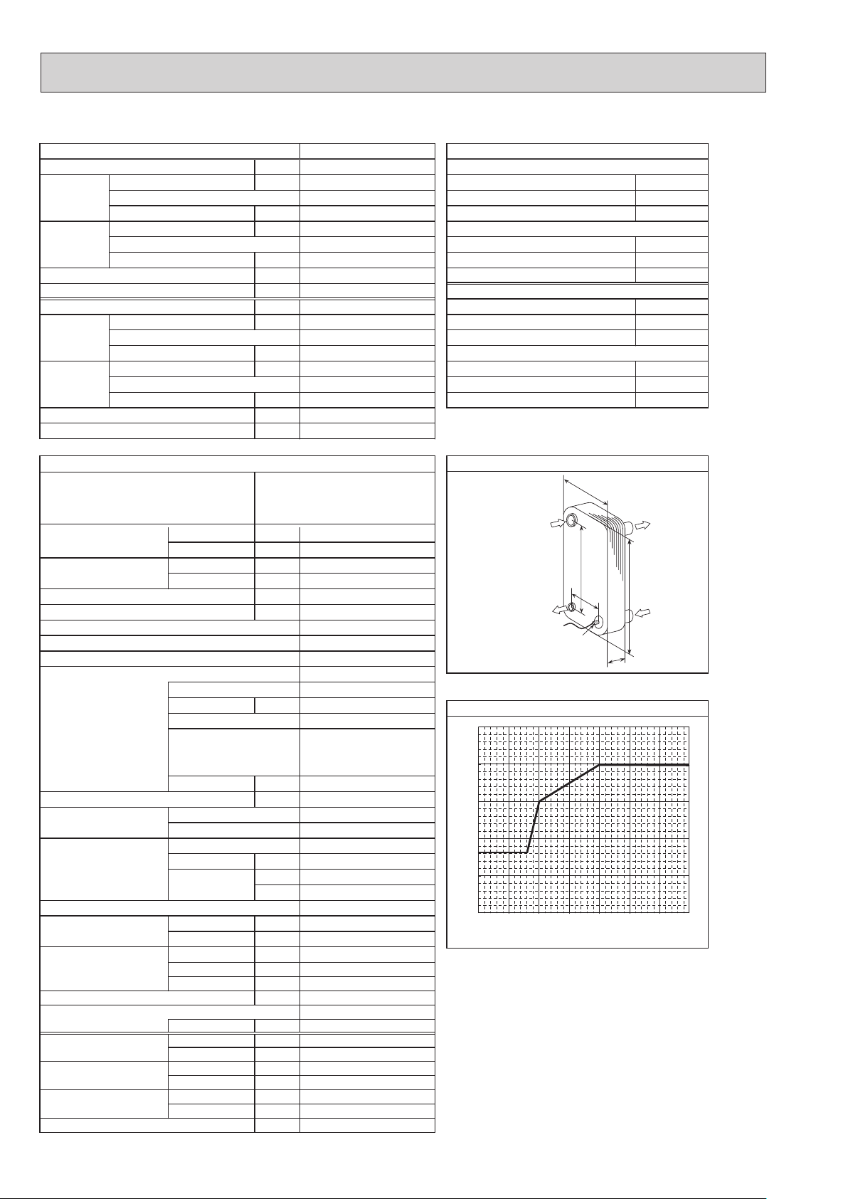
(TH32)
PUHZ-HW140VHA2R3 PUHZ-HW140VHA2R3-BS PUHZ-HW140VHA2R4 PUHZ-HW140VHA2R4-BS
1φ, 230V, 50Hz
Nominal water flow rate (Heating mode) L/min
Heating
(A7/W35)
40.1
14.00
4.25
Heating(A7/W35)
3.29
Heating
(A2/W35)
WkyticapaC
14.00
3.11
Heating(A2/W35)
4.50
Pressure difference (water circuit) )teltuo/telni( erutarepmet retaWaPk -/+35℃
Heating pump input (based on EN14511) kW
Cooling
(COP) Water temperature (inlet/outlet) +12/+7℃
(A35/W7)
EER
Power input kW
Cooling
(COP) Outside air temperature (Wet-bulb) + 24℃
(A35/W18)
EER
9.6
0.02
35.8
12.50
2.50
5.00
12.50
3.60
Cooling(A35/W7)
Onim/L)edom gnilooC( etar wolf retaw lanimoN ℃
Cooling(A35/W18)
3.47
Pressure difference (water circuit) kPa
Cooling pump input (based on EN14511) kW
Note: "COP" and "Power input" in the above table are values that contains the "pump input (based on EN 14511) ".
7.7
0.02
snoitacificeps tinu roodtuO
Service ref.
Running current Heating
Cooling
Power factor Heating
Cooling
(A7/W35) A
(A35/W7) A
(A7/W35) %
(A35/W7) %
PUHZ-HW140VHA2R3
PUHZ-HW140VHA2R3-BS
PUHZ-HW140VHA2R4
PUHZ-HW140VHA2R4-BS
Atnerruc .xaM
Aezis rekaerB
gnisac retuO
hsinif lanretxE
Refrigerant control
Compressor
Model
Motor output kW
Start type
secived noitcetorP
Oil (Model) L
Wretaeh esacknarC
Heat exchanger Air
Water
.oN×)evird(naFnaF
Fan motor output
Airflow
kW
3
m
/min
(CFM)
Defrost method
Noise level Heating dB
(SPL)
Cooling dB
Dimensions Width mm (in)
Depth mm (in)
Height mm (in)
Refrigerant
Quantity kg (lb)
Guaranteed operating Heating
range (Outdoor) Cooling
Outlet water temp. Heating
(Max in heating, Min in cooling)
Nominal return water
Cooling
Heating
temperature range Cooling
℃
℃
℃
℃
℃
℃
14.4
22.2
35.0
Galvanized plate
Munsell 3Y 7.8/1.1
Linear expansion valve
Hermetic scroll
ANB42FJKMT
Inverter
HP switch
LP switch
Discharge thermo
Comp. surface thermo
Overcurrent detection
0.9 (FV50S)
Plate fin coil
Plate heat exchanger
Propeller fan × 2
0.074 × 2
(3,530)
Reverse cycle
53
53
1020 (40-3/16)
*4
330 +30
1350 (53-1/8)
)bl( gkthgieW
134 (295.4)
R410A
4.3 (9.5)
(*5)
−25
(*6)
−5
(*7)
+5
+8 to +28
nim/Legnar etar wolf retaW
17.9 to 40.1
97
97
40
2.5
-
100
*1
*2 *3
*2
(13+1-3/16)
to +21
to +46
+60
+5
to +59
*8
MITSUBISHI
MWA2-46LM
Ref. IN
mm05:A
(Heating)
mm664:B
mm8.601:W
mm2.625:H
mm129.1:D
Ref. OUT
(Heating)
setalp 46
65
]
℃
60
55
50
45
Maximum outlet water temperature [
40
−25−20−15−10−
*1
Hot gas with 4-way valve
*2
at distance of 1 m from outdoor unit
*3
A weighted sound power level in accordance with ISO9614-1
for EN14511 testing is 67 dBA.
*4
grille
*5
Lower limit of use is −5°C for EN14511 testing purposes.
*6
With the optional air outlet guide, the operation at −15°C
outdoor temperature is possible.
*7
Lowest entering temperature is 12 °C for EN14511 testing
purposes.
*8
For details of the minute return water temperature at
each water flow rate, refer to “3-2. AVAILABLE RANGE
(WATER FLOW RATE, RETURN WATER TEMP.)”.
Ambient temperature [℃]
regnahcxe taeh etalP
Thermistor
noitidnoc gnitarepo lanimoN)ycneuqerF ,egatloV ,esahP( ylppus rewoP
W
B
A
H
D
erutarepmet retaw teltuo mumixaM
5 0 5 10
7 +)blub-yrD( erutarepmet ria edistuOWkyticapaC ℃
6 +)blub-teW( erutarepmet ria edistuOPOC ℃
53+/03+)teltuo/telni( erutarepmet retaWWktupni rewoP ℃
2 +)blub-yrD( erutarepmet ria edistuOPOC ℃
1 +)blub-teW( erutarepmet ria edistuOWktupni rewoP ℃
53+)blub-yrD( erutarepmet ria edistu
42 +)blub-teW( erutarepmet ria edistuOWkyticapaC ℃
53+)blub-yrD( erutarepmet ria edistuOWkyticapaC ℃
81+/32+)teltuo/telni( erutarepmet retaWWktupni rewoP ℃
Water OUT
Water IN
OCH439M
22
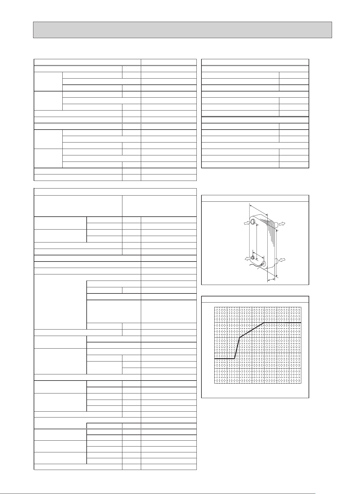
(TH32)
PUHZ-HW140VHA2R5 PUHZ-HW140VHA2R6
PUHZ-HW140VHA2R5-BS PUHZ-HW140VHA2R6-BS
1φ, 230 V, 50 Hz
Nominal water flow rate (Heating mode) L/min
Heating
(A7/W35)
40.1
14.00
4.25
Heating(A7/W35)
3.29
Heating
(A2/W35)
WkyticapaC
14.00
3.11
Heating(A2/W35)
4.50
Pressure difference (water circuit) )teltuo/telni( erutarepmet retaWaPk -/+35℃
Heating pump input (based on EN14511) kW
Cooling
(COP) Water temperature (inlet/outlet) +12/+7℃
(A35/W7)
EER
Power input kW
Cooling
(COP) Outside air temperature (Wet-bulb) + 24℃
(A35/W18)
EER
9
0.02
35.8
12.50
2.50
5.00
12.50
3.60
Cooling(A35/W7)
Onim/L)edom gnilooC( etar wolf retaw lanimoN ℃
Cooling(A35/W18)
3.47
Pressure difference (water circuit) kPa
Cooling pump input (based on EN14511) kW
Note: "COP" and "Power input" in the above table are values that contains the "pump input (based on EN 14511) ".
7
0.02
snoitacificeps tinu roodtuO
Service ref.
Running current Heating
Power factor Heating
Cooling
Cooling
(A7/W35) A
(A35/W7) A
(A7/W35) %
(A35/W7) %
gnisac retuO
hsinif lanretxE
Refrigerant control
Compressor
Model
Motor output kW
Start type
Oil (Model) L
Heat exchanger Air
Water
Fan motor output
Airflow
Defrost method
Noise level Heating dB
(SPL)
Cooling dB
Dimensions Width mm (in)
Depth mm (in)
Height mm (in)
Refrigerant
Quantity kg (lb)
Guaranteed operating Heating
range (Outdoor) Cooling
Outlet water temp. Heating
(Max in heating, Min in cooling)
Nominal return water
Cooling
Heating
temperature range Cooling
PUHZ-HW140VHA2R5(-BS)
PUHZ-HW140VHA2R6(-BS)
Atnerruc .xaM
Aezis rekaerB
Linear expansion valve
secived noitcetorP
Comp. surface thermo
Overcurrent detection
R5: 0.9, R6: 1.4 (FV50S)
Wretaeh esacknarC
Plate heat exchanger
.oN×)evird(naFnaF
kW
3
m
/min
(CFM)
330 +30
)bl( gkthgieW
℃
℃
℃
℃
℃
℃
nim/Legnar etar wolf retaW
14.4
22.2
97
97
35.0
40
Galvanized plate
Munsell 3Y 7.8/1.1
Hermetic scroll
ANB42FJKMT
2.8
Inverter
HP switch
LP switch
Discharge thermo
-
Plate fin coil
Propeller fan × 2
0.074 × 2
100
(3,530)
Reverse cycle
53
53
*1
*2 *3
*2
1020 (40-3/16)
*4
(13+1-3/16)
1350 (53-1/8)
134 (296)
R410A
4.3 (9.5)
(*5)
−25
to +21
(*6)
−5
to +46
+60
+5
(*7)
to +59
+5
+8 to +28
17.9 to 40.1
*8
MITSUBISHI
MWA2-46LM
Ref. IN
mm05:A
(Heating)
mm664:B
mm8.601:W
mm2.625:H
:D
132 mm
65
]
℃
60
55
50
45
Maximum outlet water temperature [
40
−25−20−15−10−
*1
Hot gas with 4-way valve
*2
at distance of 1 m from outdoor unit
*3
A weighted sound power level in accordance with ISO9614-1
for EN14511 testing is 67 dBA.
*4
grille
*5
Lower limit of use is −5°C for EN14511 testing purposes.
*6
With the optional air outlet guide, the operation at −15°C
outdoor temperature is possible.
*7
Lowest entering temperature is 12 °C for EN14511 testing
purposes.
*8
For details of the minute return water temperature at
each water flow rate, refer to “3-2. AVAILABLE RANGE
(WATER FLOW RATE, RETURN WATER TEMP.)”.
Ref. OUT
(Heating)
setalp 46
Ambient temperature [℃]
regnahcxe taeh etalP
Thermistor
noitidnoc gnitarepo lanimoN)ycneuqerF ,egatloV ,esahP( ylppus rewoP
W
B
A
H
D
erutarepmet retaw teltuo mumixaM
5 0 5 10
7 +)blub-yrD( erutarepmet ria edistuOWkyticapaC ℃
6 +)blub-teW( erutarepmet ria edistuOPOC ℃
2 +)blub-yrD( erutarepmet ria edistuOPOC ℃
1 +)blub-teW( erutarepmet ria edistuOWktupni rewoP ℃
53+)blub-yrD( erutarepmet ria edistu
42 +)blub-teW( erutarepmet ria edistuOWkyticapaC ℃
53+)blub-yrD( erutarepmet ria edistuOWkyticapaC ℃
Water OUT
Water IN
53+/03+)teltuo/telni( erutarepmet retaWWktupni rewoP ℃
81+/32+)teltuo/telni( erutarepmet retaWWktupni rewoP ℃
OCH439M
23
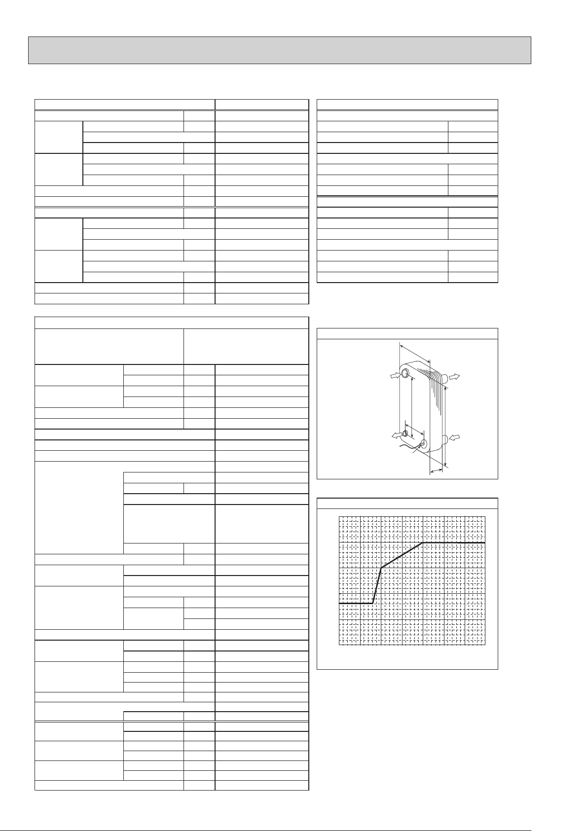
PUHZ-HW140VHA2R7 PUHZ-HW140VHA2R7-BS
(TH32)
1φ, 230 V, 50 Hz
Nominal water flow rate (Heating mode) L/min
Heating
(A7/W35)
40.1
14.00
4.25
Heating(A7/W35)
3.29
Heating
(A2/W35)
WkyticapaC
14.00
3.11
Heating(A2/W35)
4.50
Pressure difference (water circuit) )teltuo/telni( erutarepmet retaWaPk -/+35℃
Heating pump input (based on EN14511) kW
Cooling
(COP) Water temperature (inlet/outlet) +12/+7℃
(A35/W7)
EER
Power input kW
Cooling
(COP) Outside air temperature (Wet-bulb) + 24℃
(A35/W18)
EER
9
0.02
35.8
12.50
2.50
5.00
12.50
3.60
Cooling(A35/W7)
Onim/L)edom gnilooC( etar wolf retaw lanimoN ℃
Cooling(A35/W18)
3.47
Pressure difference (water circuit) kPa
Cooling pump input (based on EN14511) kW
Note: "COP" and "Power input" in the above table are values that contains the "pump input (based on EN 14511) ".
7
0.02
snoitacificeps tinu roodtuO
Service ref.
PUHZ-HW140VHA2R7(-BS)
Running current Heating
Power factor Heating
Cooling
Cooling
(A7/W35) A
(A35/W7) A
(A7/W35) %
(A35/W7) %
Atnerruc .xaM
Aezis rekaerB
gnisac retuO
hsinif lanretxE
Refrigerant control
Compressor
Model
Motor output kW
Start type
secived noitcetorP
Oil (Model) L
Wretaeh esacknarC
Heat exchanger Air
Water
.oN×)evird(naFnaF
Fan motor output
Airflow
kW
3
m
/min
(CFM)
Defrost method
Noise level Heating dB
(SPL)
Cooling dB
Dimensions Width mm (in)
Depth mm (in)
Height mm (in)
Refrigerant
Quantity kg (lb)
Guaranteed operating Heating
range (Outdoor) Cooling
Outlet water temp. Heating
(Max in heating, Min in cooling)
Nominal return water
Cooling
Heating
temperature range Cooling
℃
℃
℃
℃
℃
℃
14.4
22.2
97
97
35.0
40
Galvanized plate
Munsell 3Y 7.8/1.1
Linear expansion valve
Hermetic scroll
ANB42FJKMT
2.8
Inverter
HP switch
LP switch
Discharge thermo
Comp. surface thermo
Overcurrent detection
R5: 0.9, R6: 1.4 (FV50S)
-
Plate fin coil
Plate heat exchanger
Propeller fan × 2
0.074 × 2
100
(3,530)
Reverse cycle
53
53
1020 (40-3/16)
*4
330 +30
(13+1-3/16)
1350 (53-1/8)
)bl( gkthgieW
134 (296)
R410A
4.3 (9.5)
(*5)
−25
to +21
(*6)
−5
to +46
+60
+5
(*7)
to +59
+5
+8 to +28
nim/Legnar etar wolf retaW
17.9 to 40.1
*1
*2 *3
*2
*8
ALFA LAVAL
ACH-70X-52H
Ref. IN
mm05:A
(Heating)
mm664:B
*1
Hot gas with 4-way valve
*2
at distance of 1 m from outdoor unit
*3
A weighted sound power level in accordance with ISO9614-1
for EN14511 testing is 67 dBA.
*4
grille
*5
Lower limit of use is −5°C for EN14511 testing purposes.
*6
With the optional air outlet guide, the operation at −15°C
*7
Lowest entering temperature is 12 °C for EN14511 testing
purposes.
*8
For details of the minute return water temperature at
mm111:W
mm625:H
mm0.631:D
Ref. OUT
(Heating)
setalp 25
65
]
℃
60
55
50
45
Maximum outlet water temperature [
40
−25−20−15−10−
outdoor temperature is possible.
each water flow rate, refer to “3-2. AVAILABLE RANGE
(WATER FLOW RATE, RETURN WATER TEMP.)”.
noitidnoc gnitarepo lanimoN)ycneuqerF ,egatloV ,esahP( ylppus rewoP
regnahcxe taeh etalP
W
B
A
Thermistor
D
erutarepmet retaw teltuo mumixaM
5 0 5 10
Ambient temperature [℃]
Water OUT
H
Water IN
7 +)blub-yrD( erutarepmet ria edistuOWkyticapaC ℃
6 +)blub-teW( erutarepmet ria edistuOPOC ℃
53+/03+)teltuo/telni( erutarepmet retaWWktupni rewoP ℃
2 +)blub-yrD( erutarepmet ria edistuOPOC ℃
1 +)blub-teW( erutarepmet ria edistuOWktupni rewoP ℃
53+)blub-yrD( erutarepmet ria edistu
42 +)blub-teW( erutarepmet ria edistuOWkyticapaC ℃
53+)blub-yrD( erutarepmet ria edistuOWkyticapaC ℃
81+/32+)teltuo/telni( erutarepmet retaWWktupni rewoP ℃
OCH439M
24
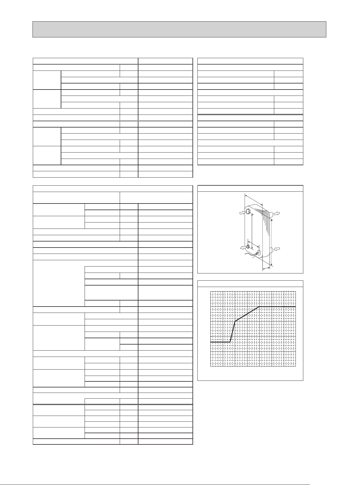
(TH32)
(WATER FLOW RATE, RETURN WATER TEMP.)”.
PUHZ-HW140YHA2R1 PUHZ-HW140YHA2R1-BS
3φ, 400V, 50Hz
Nominal water flow rate (Heating mode) L/min
Heating
(A7/W35)
40.1
14.00
4.25
Heating(A7/W35)
3.29
Heating
(A2/W35)
WkyticapaC
14.00
3.11
Heating(A2/W35)
4.50
Pressure difference (water circuit) )teltuo/telni( erutarepmet retaWaPk -/+35℃
Heating pump input (based on EN14511) kW
Cooling
(COP) Water temperature (inlet/outlet) +12/+7℃
(A35/W7)
EER
Power input kW
Cooling
(COP) Outside air temperature (Wet-bulb) + 24℃
(A35/W18)
EER
9.6
0.02
35.8
12.50
2.50
5.00
12.50
3.60
Cooling(A35/W7)
Onim/L)edom gnilooC( etar wolf retaw lanimoN ℃
Cooling(A35/W18)
3.47
Pressure difference (water circuit) kPa
Cooling pump input (based on EN14511) kW
Note: "COP" and "Power input" in the above table are values that contains the "pump input (based on EN 14511) ".
7.7
0.02
snoitacificeps tinu roodtuO
Service ref.
Running current Heating
Cooling
Power factor Heating
Cooling
(A7/W35) A
(A35/W7) A
(A7/W35) %
(A35/W7) %
PUHZ-HW140YHA2R1
PUHZ-HW140YHA2R1-BS
Atnerruc .xaM
Aezis rekaerB
gnisac retuO
hsinif lanretxE
Refrigerant control
Compressor
Model
Motor output kW
Start type
secived noitcetorP
Oil (Model) L
Wretaeh esacknarC
Heat exchanger Air
Water
.oN×)evird(naFnaF
Fan motor output
Airflow
kW
3
m
/min
(CFM)
Defrost method
Noise level Heating dB
(SPL)
Cooling dB
Dimensions Width mm (in)
Depth mm (in)
Height mm (in)
Refrigerant
Quantity kg (lb)
Guaranteed operating Heating
range (Outdoor) Cooling
Outlet water temp. Heating
(Max in heating, Min in cooling)
Nominal return water
Cooling
Heating
temperature range Cooling
℃
℃
℃
℃
℃
℃
13.0
Galvanized plate
Munsell 3Y 7.8/1.1
Linear expansion valve
Hermetic scroll
ANB42FJFMT
Inverter
HP switch
LP switch
Discharge thermo
0.9 (FV50S)
Plate fin coil
Plate heat exchanger
Propeller fan × 2
0.074 × 2
(3,530)
Reverse cycle
1020 (40-3/16)
*4
330 +30
1350 (53-1/8)
)bl( gkthgieW
148 (326.3)
R410A
4.3 (9.5)
(*5)
−25
−5
(*7)
+5
+8 to +28
nim/Legnar etar wolf retaW
17.9 to 40.1
5.0
7.6
95
95
16
2.5
-
100
*1
*2 *3
53
*2
53
(13+1-3/16)
to +21
(*6)
to +46
+60
+5
to +59
*8
MITSUBISHI
MWA2-46LM
Ref. IN
mm05:A
(Heating)
mm664:B
mm8.601:W
mm2.625:H
mm129.1:D
Ref. OUT
(Heating)
setalp 46
65
]
℃
60
55
50
45
Maximum outlet water temperature [
40
−25−20−15−10−
*1
Hot gas with 4-way valve
*2
at distance of 1 m from outdoor unit
*3
A weighted sound power level in accordance with ISO9614-1
for EN14511 testing is 67 dBA.
*4
grille
*5
Lower limit of use is −5°C for EN14511 testing purposes.
*6
With the optional air outlet guide, the operation at −15°C
outdoor temperature is possible.
*7
Lowest entering temperature is 12 °C for EN14511 testing
purposes.
*8
For details of the minute return water temperature at
each water flow rate, refer to “3-2. AVAILABLE RANGE
Ambient temperature [℃]
regnahcxe taeh etalP
Thermistor
noitidnoc gnitarepo lanimoN)ycneuqerF ,egatloV ,esahP( ylppus rewoP
W
B
A
H
D
erutarepmet retaw teltuo mumixaM
5 0 5 10
7 +)blub-yrD( erutarepmet ria edistuOWkyticapaC ℃
6 +)blub-teW( erutarepmet ria edistuOPOC ℃
2 +)blub-yrD( erutarepmet ria edistuOPOC ℃
1 +)blub-teW( erutarepmet ria edistuOWktupni rewoP ℃
53+)blub-yrD( erutarepmet ria edistu
42 +)blub-teW( erutarepmet ria edistuOWkyticapaC ℃
53+)blub-yrD( erutarepmet ria edistuOWkyticapaC ℃
Water OUT
Water IN
53+/03+)teltuo/telni( erutarepmet retaWWktupni rewoP ℃
81+/32+)teltuo/telni( erutarepmet retaWWktupni rewoP ℃
OCH439M
25
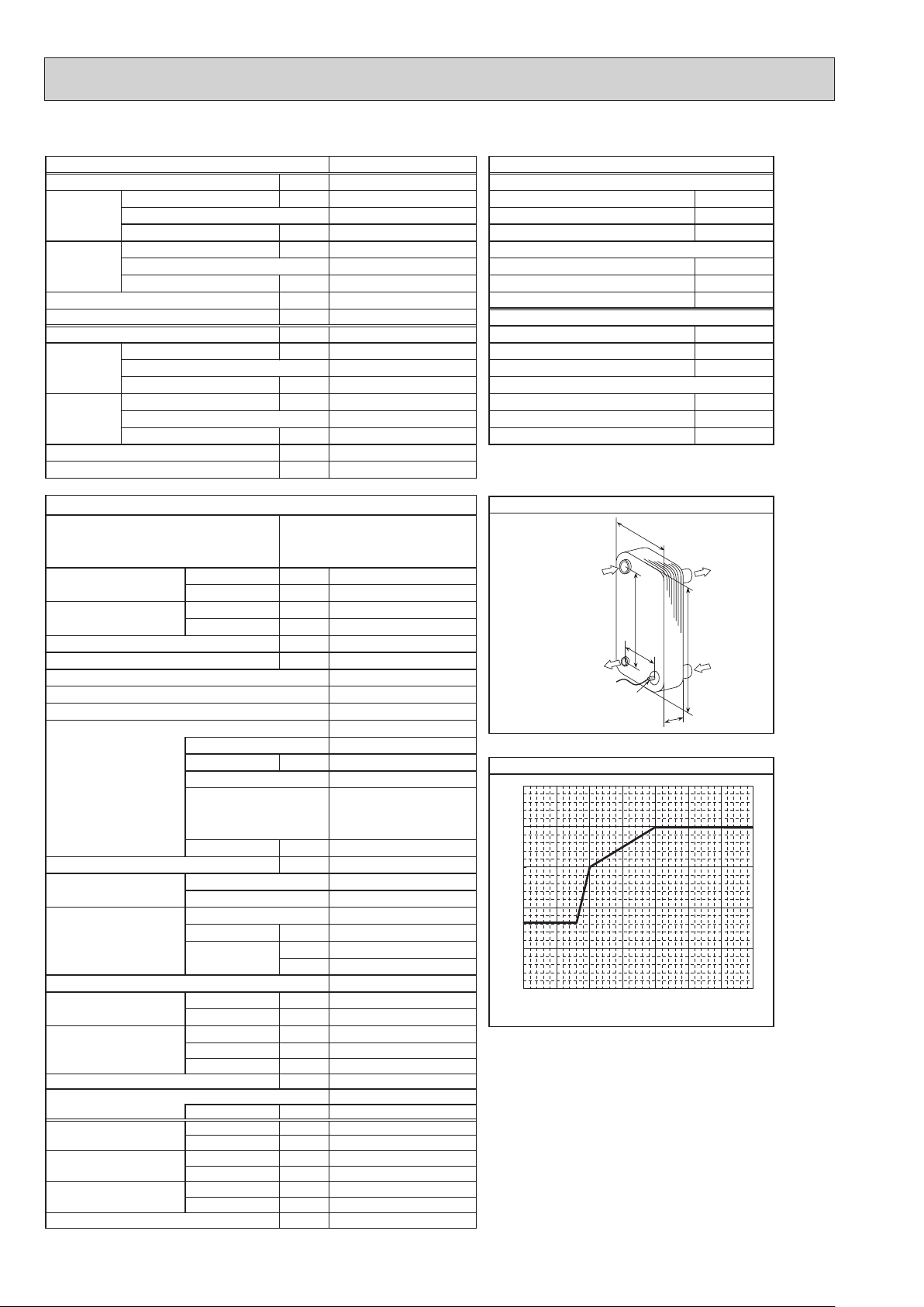
(TH32)
PUHZ-HW140YHA2R3 PUHZ-HW140YHA2R3-BS PUHZ-HW140YHA2R4 PUHZ-HW140YHA2R4-BS
3φ, 400 V, 50 Hz
Nominal water flow rate (Heating mode) L/min
Heating
(A7/W35)
40.1
14.00
4.25
Heating(A7/W35)
3.29
Heating
(A2/W35)
WkyticapaC
14.00
3.11
Heating(A2/W35)
4.50
Pressure difference (water circuit) )teltuo/telni( erutarepmet retaWaPk -/+35℃
Heating pump input (based on EN14511) kW
Cooling
(COP) Water temperature (inlet/outlet) +12/+7℃
(A35/W7)
EER
Power input kW
Cooling
(COP) Outside air temperature (Wet-bulb) + 24℃
(A35/W18)
EER
9.6
0.02
35.8
12.50
2.50
5.00
12.50
3.60
Cooling(A35/W7)
Onim/L)edom gnilooC( etar wolf retaw lanimoN ℃
Cooling(A35/W18)
3.47
Pressure difference (water circuit) kPa
Cooling pump input (based on EN14511) kW
Note: "COP" and "Power input" in the above table are values that contains the "pump input (based on EN 14511) ".
7.7
0.02
snoitacificeps tinu roodtuO
Service ref.
Running current Heating
Cooling
Power factor Heating
Cooling
(A7/W35) A
(A35/W7) A
(A7/W35) %
(A35/W7) %
PUHZ-HW140YHA2R3
PUHZ-HW140YHA2R3-BS
PUHZ-HW140YHA2R4
PUHZ-HW140YHA2R4-BS
Atnerruc .xaM
Aezis rekaerB
gnisac retuO
hsinif lanretxE
Refrigerant control
Compressor
Model
Motor output kW
Start type
secived noitcetorP
Oil (Model) L
Wretaeh esacknarC
Heat exchanger Air
Water
.oN×)evird(naFnaF
Fan motor output
Airflow
kW
3
m
/min
(CFM)
Defrost method
Noise level Heating dB
(SPL)
Cooling dB
Dimensions Width mm (in)
Depth mm (in)
Height mm (in)
Refrigerant
Quantity kg (lb)
Guaranteed operating Heating
range (Outdoor) Cooling
Outlet water temp. Heating
(Max in heating, Min in cooling)
Nominal return water
Cooling
Heating
temperature range Cooling
℃
℃
℃
℃
℃
℃
5.0
7.6
13.0
Galvanized plate
Munsell 3Y 7.8/1.1
Linear expansion valve
Hermetic scroll
ANB42FJJMT
Inverter
HP switch
LP switch
Discharge thermo
Comp. surface thermo
Overcurrent detection
0.9 (FV50S)
Plate fin coil
Plate heat exchanger
Propeller fan × 2
0.074 × 2
100
(3,530)
Reverse cycle
53
53
1020 (40-3/16)
*4
330 +30
1350 (53-1/8)
)bl( gkthgieW
148 (326.3)
R410A
4.3 (9.5)
(*5)
−25
to +21
(*6)
−5
+60
(*7)
+5
+8 to +28
nim/Legnar etar wolf retaW
17.9 to 40.1
95
95
16
2.5
-
*1
*2 *3
*2
(13+1-3/16)
to +46
+5
to +59
*8
MITSUBISHI
MWA2-46LM
Ref. IN
mm05:A
(Heating)
mm664:B
mm8.601:W
mm2.625:H
mm129.1:D
Ref. OUT
(Heating)
setalp 46
65
]
℃
60
55
50
45
Maximum outlet water temperature [
40
−25−20−15−10−
Ambient temperature [℃]
*1
Hot gas with 4-way valve
*2
at distance of 1 m from outdoor unit
*3
A weighted sound power level in accordance with ISO9614-1
for EN14511 testing is 67 dBA.
*4
grille
*5
Lower limit of use is −5°C for EN14511 testing purposes.
*6
With the optional air outlet guide, the operation at −15°C
outdoor temperature is possible.
*7
Lowest entering temperature is 12°C for EN14511 testing
purposes.
*8
For details of the minute return water temperature at
each water flow rate, refer to “3-2. AVAILABLE RANGE
(WATER FLOW RATE, RETURN WATER TEMP.)”.
regnahcxe taeh etalP
Thermistor
noitidnoc gnitarepo lanimoN)ycneuqerF ,egatloV ,esahP( ylppus rewoP
W
B
A
D
erutarepmet retaw teltuo mumixaM
5 0 5 10
7 +)blub-yrD( erutarepmet ria edistuOWkyticapaC ℃
6 +)blub-teW( erutarepmet ria edistuOPOC ℃
53+/03+)teltuo/telni( erutarepmet retaWWktupni rewoP ℃
2 +)blub-yrD( erutarepmet ria edistuOPOC ℃
1 +)blub-teW( erutarepmet ria edistuOWktupni rewoP ℃
53+)blub-yrD( erutarepmet ria edistu
42 +)blub-teW( erutarepmet ria edistuOWkyticapaC ℃
53+)blub-yrD( erutarepmet ria edistuOWkyticapaC ℃
81+/32+)teltuo/telni( erutarepmet retaWWktupni rewoP ℃
Water OUT
H
Water IN
OCH439M
26
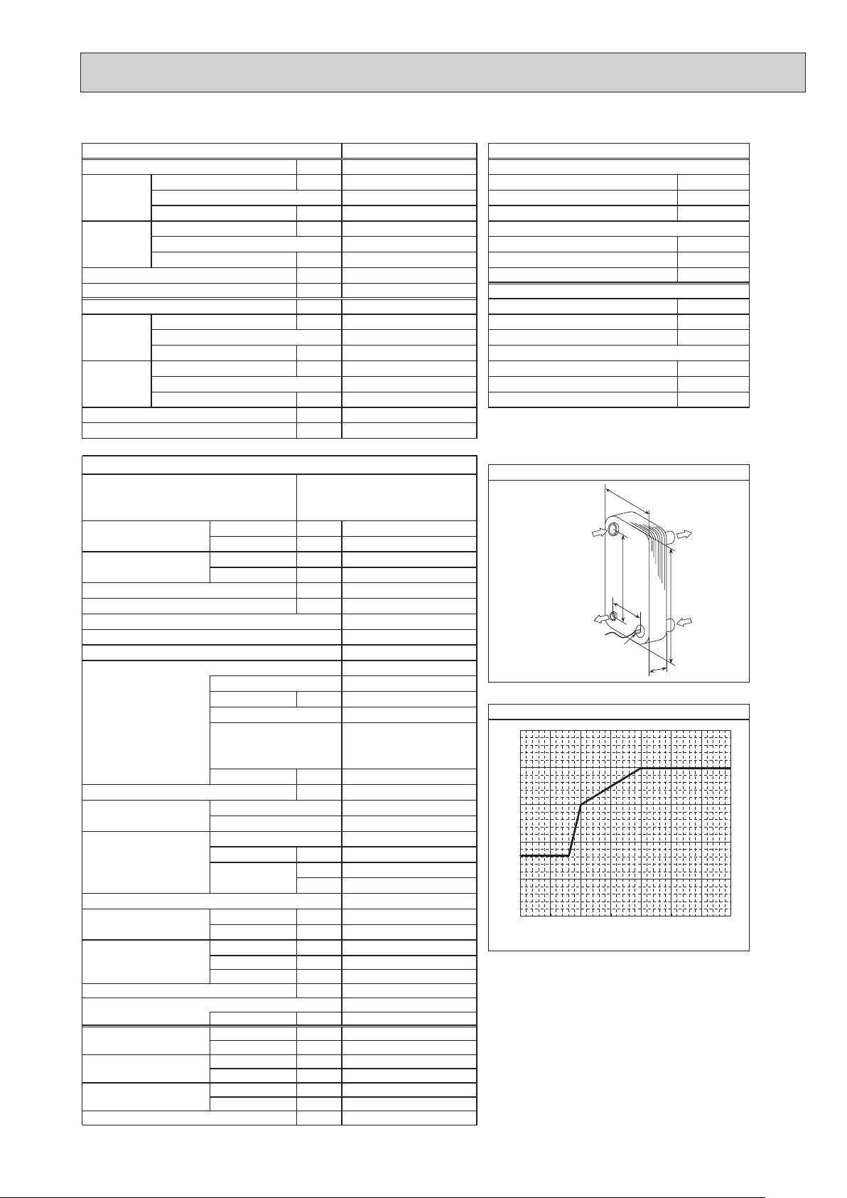
(TH32)
PUHZ-HW140YHA2R5 PUHZ-HW140YHA2R6
PUHZ-HW140YHA2R5-BS PUHZ-HW140YHA2R6-BS
Nominal water flow rate (Heating mode) L/min
Heating
(A7/W35)
3φ, 400 V, 50 Hz
40.1
14.00
4.25
Heating(A7/W35)
noitidnoc gnitarepo lanimoN)ycneuqerF ,egatloV ,esahP( ylppus rewoP
7 +)blub-yrD( erutarepmet ria edistuOWkyticapaC ℃
6 +)blub-teW( erutarepmet ria edistuOPOC ℃
3.29
Heating
WkyticapaC
(A2/W35)
Pressure difference (water circuit) )teltuo/telni( erutarepmet retaWaPk -/+35℃
Heating pump input (based on EN14511) kW
Cooling
(COP) Water temperature (inlet/outlet) +12/+7℃
(A35/W7)
EER
Power input kW
Cooling
(COP) Outside air temperature (Wet-bulb) + 24℃
(A35/W18)
EER
14.00
3.11
4.50
0.02
35.8
12.50
2.50
5.00
12.50
3.60
Heating(A2/W35)
2 +)blub-yrD( erutarepmet ria edistuOPOC ℃
1 +)blub-teW( erutarepmet ria edistuOWktupni rewoP ℃
9
Cooling(A35/W7)
Onim/L)edom gnilooC( etar wolf retaw lanimoN ℃
53+)blub-yrD( erutarepmet ria edistu
42 +)blub-teW( erutarepmet ria edistuOWkyticapaC ℃
Cooling(A35/W18)
53+)blub-yrD( erutarepmet ria edistuOWkyticapaC ℃
3.47
Pressure difference (water circuit) kPa
Cooling pump input (based on EN14511) kW
Note: "COP" and "Power input" in the above table are values that contains the "pump input (based on EN 14511) ".
snoitacificeps tinu roodtuO
Service ref.
Cooling
Cooling
(A7/W35) A
(A35/W7) A
(A7/W35) %
(A35/W7) %
Running current Heating
Power factor Heating
gnisac retuO
hsinif lanretxE
Refrigerant control
Compressor
Model
Motor output kW
Start type
Oil (Model) L
Heat exchanger Air
Water
Fan motor output
Airflow
Defrost method
Noise level Heating dB
(SPL)
Cooling dB
Dimensions Width mm (in)
Depth mm (in)
Height mm (in)
Refrigerant
Quantity kg (lb)
Guaranteed operating Heating
range (Outdoor) Cooling
Outlet water temp. Heating
(Max in heating, Min in cooling)
Nominal return water
Cooling
Heating
temperature range Cooling
PUHZ-HW140YHA2R5
PUHZ-HW140YHA2R5-BS
PUHZ-HW140YHA2R6
PUHZ-HW140YHA2R6-BS
Atnerruc .xaM
Aezis rekaerB
Linear expansion valve
secived noitcetorP
Comp. surface thermo
Overcurrent detection
R5: 0.9, R6: 1.4 (FV50S)
Wretaeh esacknarC
Plate heat exchanger
.oN×)evird(naFnaF
kW
3
m
/min
(CFM)
330 +30
)bl( gkthgieW
℃
℃
℃
℃
℃
℃
nim/Legnar etar wolf retaW
7
0.02
5.0
7.6
95
95
13.0
16
Galvanized plate
Munsell 3Y 7.8/1.1
Hermetic scroll
ANB42FJJMT
2.8
Inverter
HP switch
LP switch
Discharge thermo
-
Plate fin coil
Propeller fan × 2
0.074 × 2
100
(3,530)
Reverse cycle
53
53
*1
*2 *3
*2
1020 (40-3/16)
*4
(13+1-3/16)
1350 (53-1/8)
148 (326.3)
R410A
4.3 (9.5)
(*5)
−25
to +21
(*6)
−5
to +46
+60
+5
(*7)
to +59
+5
+8 to +28
17.9 to 40.1
*8
regnahcxe taeh etalP
MITSUBISHI
MWA2-46LM
Ref. IN
mm05:A
(Heating)
mm664:B
mm8.601:W
mm2.625:H
mm132:D
Ref. OUT
(Heating)
setalp 46
65
]
℃
60
55
50
45
Maximum outlet water temperature [
40
−25−20−15−10−
Ambient temperature [℃]
*1
Hot gas with 4-way valve
*2
at distance of 1 m from outdoor unit
*3
A weighted sound power level in accordance with ISO9614-1
for EN14511 testing is 67 dBA.
*4
grille
*5
Lower limit of use is −5°C for EN14511 testing purposes.
*6
With the optional air outlet guide, the operation at −15°C
outdoor temperature is possible.
*7
Lowest entering temperature is 12°C for EN14511 testing
purposes.
*8
For details of the minute return water temperature at
each water flow rate, refer to “3-2. AVAILABLE RANGE
(WATER FLOW RATE, RETURN WATER TEMP.)”.
Thermistor
W
B
A
H
D
erutarepmet retaw teltuo mumixaM
5 0 5 10
Water OUT
Water IN
53+/03+)teltuo/telni( erutarepmet retaWWktupni rewoP ℃
81+/32+)teltuo/telni( erutarepmet retaWWktupni rewoP ℃
OCH439M
27
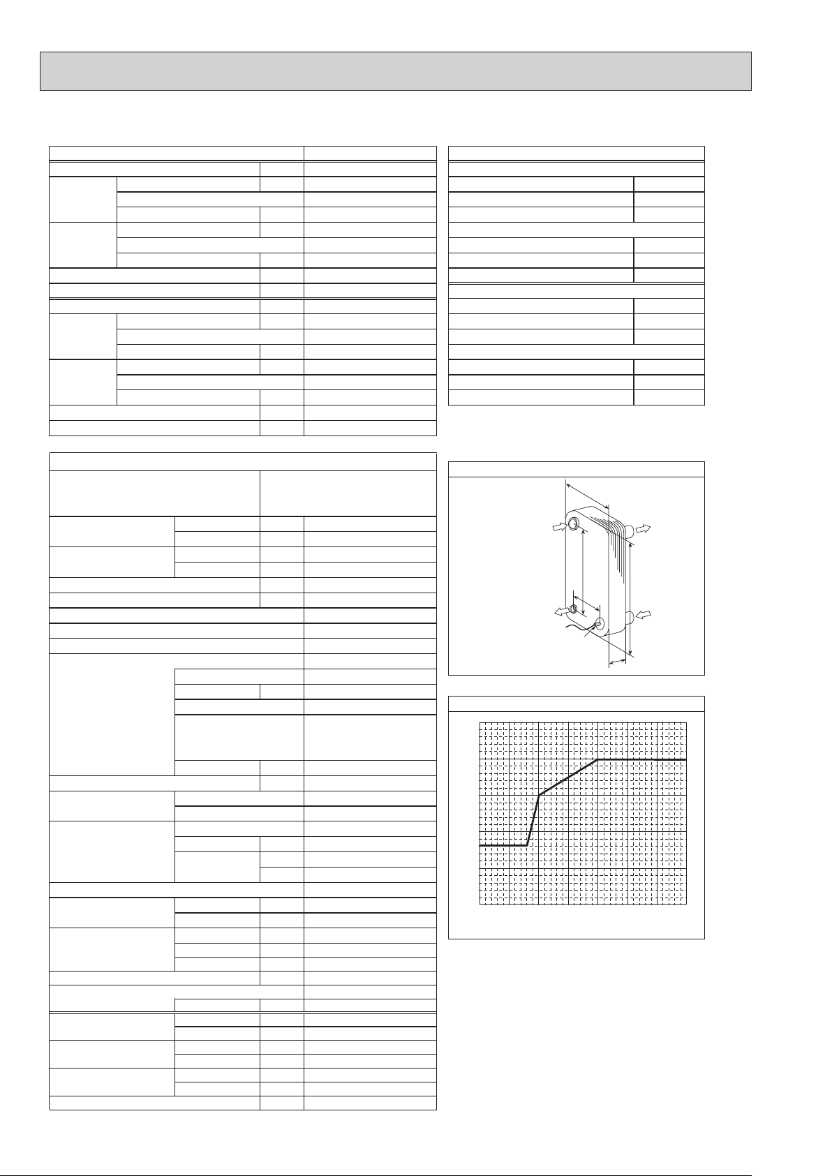
PUHZ-HW140YHA2R7 PUHZ-HW140YHA2R7-BS
(TH32)
Nominal water flow rate (Heating mode) L/min
Heating
(A7/W35)
3φ, 400 V, 50 Hz
40.1
14.00
4.25
Heating(A7/W35)
noitidnoc gnitarepo lanimoN)ycneuqerF ,egatloV ,esahP( ylppus rewoP
7 +)blub-yrD( erutarepmet ria edistuOWkyticapaC ℃
6 +)blub-teW( erutarepmet ria edistuOPOC ℃
3.29
Heating
WkyticapaC
(A2/W35)
Pressure difference (water circuit) )teltuo/telni( erutarepmet retaWaPk -/+35℃
Heating pump input (based on EN14511) kW
Cooling
(COP) Water temperature (inlet/outlet) +12/+7℃
(A35/W7)
EER
Power input kW
Cooling
(COP) Outside air temperature (Wet-bulb) + 24℃
(A35/W18)
EER
14.00
3.11
4.50
0.02
35.8
12.50
2.50
5.00
12.50
3.60
Heating(A2/W35)
2 +)blub-yrD( erutarepmet ria edistuOPOC ℃
1 +)blub-teW( erutarepmet ria edistuOWktupni rewoP ℃
9
Cooling(A35/W7)
Onim/L)edom gnilooC( etar wolf retaw lanimoN ℃
53+)blub-yrD( erutarepmet ria edistu
42 +)blub-teW( erutarepmet ria edistuOWkyticapaC ℃
Cooling(A35/W18)
53+)blub-yrD( erutarepmet ria edistuOWkyticapaC ℃
3.47
Pressure difference (water circuit) kPa
Cooling pump input (based on EN14511) kW
Note: "COP" and "Power input" in the above table are values that contains the "pump input (based on EN 14511) ".
snoitacificeps tinu roodtuO
Service ref.
Cooling
Cooling
(A7/W35) A
(A35/W7) A
(A7/W35) %
(A35/W7) %
Running current Heating
Power factor Heating
gnisac retuO
hsinif lanretxE
Refrigerant control
Compressor
Model
Motor output kW
Start type
Oil (Model) L
Heat exchanger Air
Water
Fan motor output
Airflow
Defrost method
Noise level Heating dB
(SPL)
Cooling dB
Dimensions Width mm (in)
Depth mm (in)
Height mm (in)
Refrigerant
Quantity kg (lb)
Guaranteed operating Heating
range (Outdoor) Cooling
Outlet water temp. Heating
(Max in heating, Min in cooling)
Nominal return water
Cooling
Heating
temperature range Cooling
PUHZ-HW140YHA2R7
PUHZ-HW140YHA2R7-BS
Atnerruc .xaM
Aezis rekaerB
Linear expansion valve
secived noitcetorP
Comp. surface thermo
Overcurrent detection
R5: 0.9, R6: 1.4 (FV50S)
Wretaeh esacknarC
Plate heat exchanger
.oN×)evird(naFnaF
kW
3
m
/min
(CFM)
330 +30
)bl( gkthgieW
℃
℃
℃
℃
℃
℃
nim/Legnar etar wolf retaW
7
0.02
5.0
7.6
95
95
13.0
16
Galvanized plate
Munsell 3Y 7.8/1.1
Hermetic scroll
ANB42FJJMT
2.8
Inverter
HP switch
LP switch
Discharge thermo
-
Plate fin coil
Propeller fan × 2
0.074 × 2
100
(3,530)
Reverse cycle
53
53
*1
*2 *3
*2
1020 (40-3/16)
*4
(13+1-3/16)
1350 (53-1/8)
148 (326.3)
R410A
4.3 (9.5)
(*5)
−25
to +21
(*6)
−5
to +46
+60
+5
(*7)
to +59
+5
+8 to +28
17.9 to 40.1
*8
regnahcxe taeh etalP
ALFA LAVAL
ACH-70X-52H
Ref. IN
mm05:A
65
]
℃
60
55
50
45
Maximum outlet water temperature [
40
−25−20−15−10−
*1
Hot gas with 4-way valve
*2
at distance of 1 m from outdoor unit
*3
A weighted sound power level in accordance with ISO9614-1
for EN14511 testing is 67 dBA.
*4
grille
*5
Lower limit of use is −5°C for EN14511 testing purposes.
*6
With the optional air outlet guide, the operation at −15°C
outdoor temperature is possible.
*7
Lowest entering temperature is 12°C for EN14511 testing
purposes.
*8
For details of the minute return water temperature at
each water flow rate, refer to “3-2. AVAILABLE RANGE
(WATER FLOW RATE, RETURN WATER TEMP.)”.
(Heating)
mm664:B
mm111:W
mm625:H
mm0.631:D
Ref. OUT
(Heating)
setalp 25
Ambient temperature [℃]
B
Thermistor
W
A
H
D
erutarepmet retaw teltuo mumixaM
5 0 5 10
Water OUT
Water IN
53+/03+)teltuo/telni( erutarepmet retaWWktupni rewoP ℃
81+/32+)teltuo/telni( erutarepmet retaWWktupni rewoP ℃
OCH439M
28
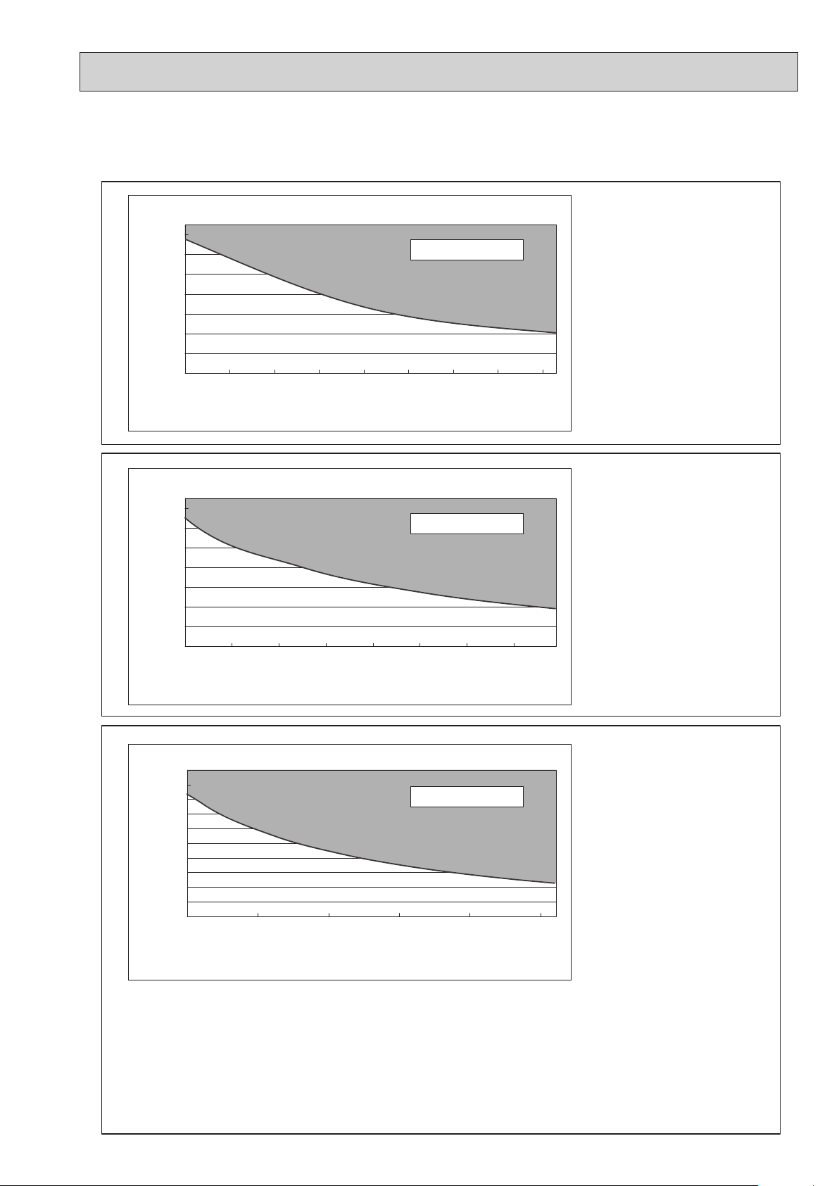
3-2. AVAILABLE RANGE (WATER FLOW RATE, RETURN WATER TEMP.)
Note: If using the unit out of the available range, the parts of unit might be damaged.
<Heating>
<Applicable Models>
19.0
17.0
15.0
13.0
11.0
9.0
Return water temp [:]
7.0
5.0
6.0 7.0 8.0 9.0 10.0
19.0
17.0
15.0
13.0
11.0
9.0
Return water temp [:]
7.0
5.0
10.0
12.0 14.0 16.0 18.0 20.0 22.0 24.0
Available range
11.0
Water flow rate [L/min]
Table 1
Available range
Water flow rate [L/min]
Table 2
12.0 13.0 14.0
• PUHZ-W50VHA(-BS)
• PUHZ-W50VHAR1(-BS)
• PUHZ-W50VHAR2(-BS)
• PUHZ-W50VHAR3(-BS)
<Applicable Models>
• PUHZ-W85VHA(-BS)
• PUHZ-W85VHAR1(-BS)
25.0
23.0
21.0
19.0
17.0
15.0
13.0
11.0
9.0
Return water temp [:]
7.0
5.0
14.0 19.0 24.0 29.0 34.0 39.0
Water flow rate [L/min]
Table 3
Available range
<Applicable Models>
• PUHZ-HW112YHA(-BS)
• PUHZ-HW112YHA2(-BS)
• PUHZ-HW112YHA2R1(-BS)
• PUHZ-HW112YHA2R3(-BS)
• PUHZ-HW112YHA2R4(-BS)
• PUHZ-HW112YHA2R5(-BS)
• PUHZ-HW112YHA2R6(-BS)
• PUHZ-HW112YHA2R7(-BS)
• PUHZ-HW140VHA(-BS)
• PUHZ-HW140VHA2(-BS)
• PUHZ-HW140VHA2R1(-BS)
• PUHZ-HW140VHA2R2-BS
• PUHZ-HW140VHA2R3(-BS)
• PUHZ-HW140VHA2R4(-BS)
• PUHZ-HW140VHA2R5(-BS)
• PUHZ-HW140VHA2R6(-BS)
• PUHZ-HW140VHA2R7(-BS)
• PUHZ-HW140YHA(-BS)
• PUHZ-HW140YHA2(-BS)
• PUHZ-HW140YHA2R1(-BS)
• PUHZ-HW140YHA2R3(-BS)
• PUHZ-HW140YHA2R4(-BS)
• PUHZ-HW140YHA2R5(-BS)
• PUHZ-HW140YHA2R6(-BS)
• PUHZ-HW140YHA2R7(-BS)
OCH439M
29
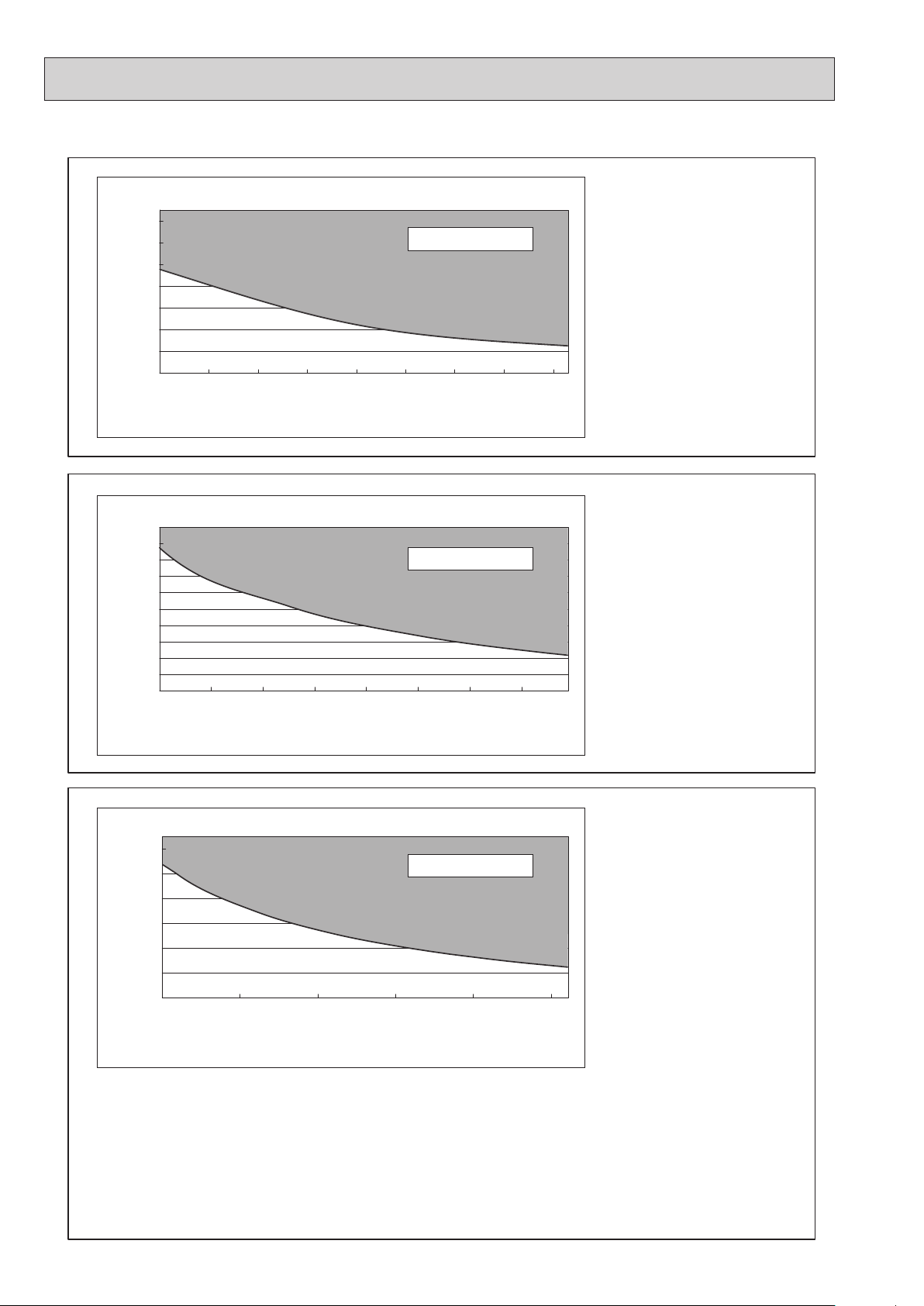
<Cooling>
Return water temp [:]
19.0
17.0
15.0
13.0
11.0
9.0
7.0
5.0
7.06.0 8.0 9.0 10.0
Water flow rate [L/min]
Table 4
Available range
11.0
12.0 13.0 14.0
<Applicable Models>
• PUHZ-W50VHA(-BS)
• PUHZ-W50VHAR1(-BS)
• PUHZ-W50VHAR2(-BS)
• PUHZ-W50VHAR3(-BS)
15.0
14.0
13.0
12.0
11.0
10.0
9.0
8.0
7.0
Return water temp [:]
6.0
5.0
12.010.0 14.0 16.0 18.0
17.0
15.0
13.0
11.0
9.0
Return water temp [:]
7.0
5.0
14.0 19.0 24.0
20.0
Water flow rate [L/min]
Table 5
29.0
Water flow rate [L/min]
Table 6
Available range
22.0 24.0
Available range
34.0 39.0
<Applicable Models>
• PUHZ-W85VHA(-BS)
• PUHZ-W85VHAR1(-BS)
<Applicable Models>
• PUHZ-HW112YHA(-BS)
• PUHZ-HW112YHA2(-BS)
• PUHZ-HW112YHA2R1(-BS)
• PUHZ-HW112YHA2R3(-BS)
• PUHZ-HW112YHA2R4(-BS)
• PUHZ-HW112YHA2R5(-BS)
• PUHZ-HW112YHA2R6(-BS)
• PUHZ-HW112YHA2R7(-BS)
• PUHZ-HW140VHA(-BS)
• PUHZ-HW140VHA2(-BS)
• PUHZ-HW140VHA2R1(-BS)
• PUHZ-HW140VHA2R2-BS
• PUHZ-HW140VHA2R3(-BS)
• PUHZ-HW140VHA2R4(-BS)
• PUHZ-HW140VHA2R5(-BS)
• PUHZ-HW140VHA2R6(-BS)
• PUHZ-HW140VHA2R7(-BS)
• PUHZ-HW140YHA(-BS)
• PUHZ-HW140YHA2(-BS)
• PUHZ-HW140YHA2R1(-BS)
• PUHZ-HW140YHA2R3(-BS)
• PUHZ-HW140YHA2R4(-BS)
• PUHZ-HW140YHA2R5(-BS)
• PUHZ-HW140YHA2R6(-BS)
• PUHZ-HW140YHA2R7(-BS)
OCH439M
30
 Loading...