

Mitsubishi PEAD-RP·JA, PEAD-RP·EA, PLA-RP-BA2, PEAD-RP-EA2, PEAD-RP·GA Technical Data Book
...
TECHNICAL DATA BOOK
CONTENTS
1. REFERENCE SERVICE MANUAL ············································· 2
2. SPECIFICATIONS ······································································ 3
3. OUTLINES AND DIMENSIONS ···············································12
4. WIRING DIAGRAM ··································································· 24
5. REFRIGERANT SYSTEM DIAGRAM ······································ 36
6. PERFORMANCE CURVES ······················································ 38
7. CORRECTION FACTORS ························································ 40
8. APPLICABLE EXTENSION PIPE FOR EACH MODEL ·········· 41
9. AIR FLOW DA TA ······································································44
10. NOISE CRITERION CURVES ··················································60
11. OPTIONAL PARTS ············································································74
<Indoor unit>
[Model names]
R410A
PLA-RP·BA/BA2/BA3
PEAD-RP·JA(L)
PEAD-RP·EA(2)
PEAD-RP·GA
PKA-RP·HAL
PKA-RP·KAL
PKA-RP·GAL
PKA-RP·FAL(2)
<Outdoor unit>
[Model names]
SPLIT-TYPE, HEAT PUMP AIR CONDITIONERS
PUHZ-HRP71/100VHA
PUHZ-HRP100/125YHA
PUHZ-HRP71/100VHA2
PUHZ-HRP100/125YHA2
March 2010
INVERTER
Zubadan
No. OCS11
REVISED EDITION-B
• Please void OCS11
REVISED EDITION-A.
Revision :
• PLA-RP·BA3, PKA-RP·HAL/KAL
and PEAD-RP·JA(L) are added,
and the data of PUHZ-HRP·HA2
has been modified in REVISED
EDITION-B.
• Some descriptions have been
modified.
2
1
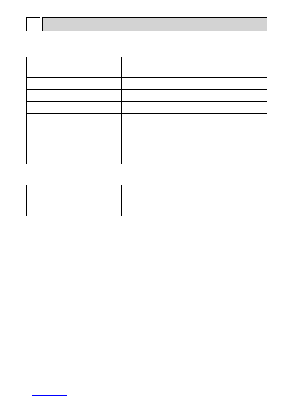
REFERENCE SERVICE MANUAL
For information on service, please refer to the service manual as follows.
1-1. INDOOR UNIT
Model Name Service Ref. Service Manual No.
PLA-RP35/50/60/100/125BA
PLA-RP71/100/125BA2
PLA-RP35/50/60/100/125BA#2.UK
PLA-RP71/100/125BA2.UK
OCH412
OCB412
PLA-RP100BA3 PLA-RP100BA3
OCH459
OCB459
PKA-RP35/50HAL PKA-RP35/50HAL
OCH453
OCB453
PKA-RP60/100KAL PKA-RP60/100KAL.TH
OCH452
OCB452
PEAD-RP35/50/60/71/100/125JA(L) PEAD-RP35/50/60/71/100/125JA(L).UK
HWE08130
BWE08240
PKA-RP35/50GAL PKA-RP35/50GAL#1 OC330
PKA-RP60/100FAL
PKA-RP50FAL2
PKA-RP60/100FAL#1
PKA-RP50FAL2#1
OC331
PEAD-RP50/60/71/125EA
PEAD-RP35/100EA2
PEAD-RP50/60/71/125EA#1.UK
PEAD-RP35/100EA2#1.UK
HWE0521
PEAD-RP60/71/100GA PEAD-RP60/71/100GA#1.UK HWE0506
1-2. OUTDOOR UNIT
Model Name Service Ref. Service Manual No.
PUHZ-HRP71/100VHA
PUHZ-HRP100/125YHA
PUHZ-HRP71/100VHA2
PUHZ-HRP100/125YHA2
PUHZ-HRP71/100VHA
PUHZ-HRP100/125YHA
PUHZ-HRP71/100VHA2R1
PUHZ-HRP100/125YHA2R1
OCH425
OCB425
3
2
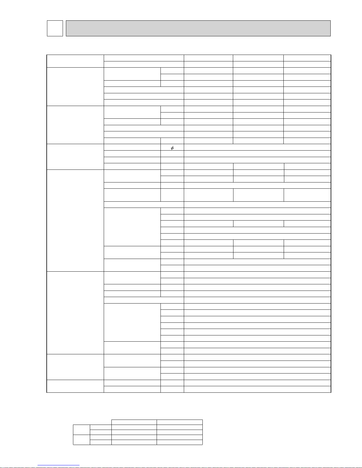
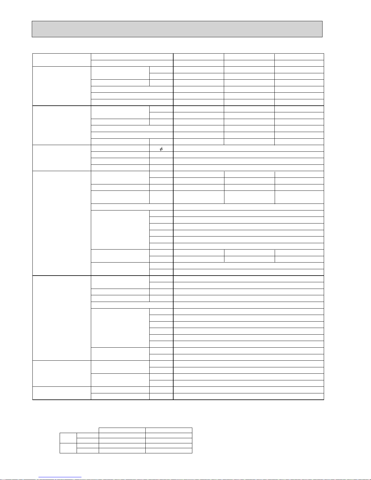
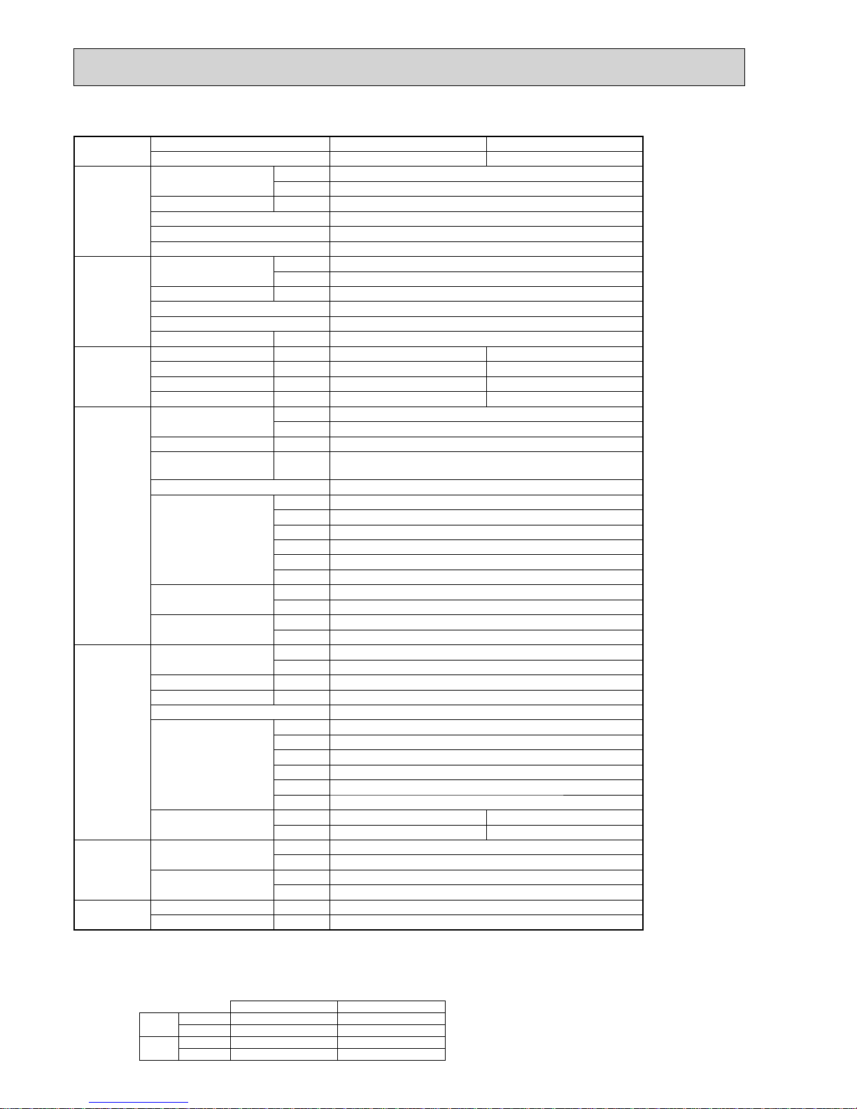
SPECIFICATIONS
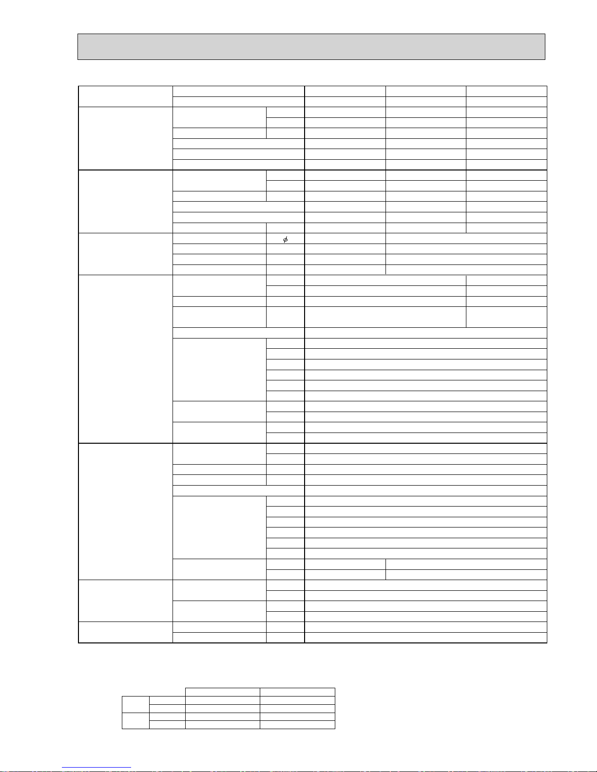
2-1. CEILING CASSETTE TYPE
Model name Indoor unit
Outdoor unit
Cooling Capacity Btu/h
kW
Total input kW
EER
Energy label class
SHF
Heating Capacity Btu/h
kW
Total input kW
COP
Energy label class
Booster heater kW
Power supply Phase
Cycle Hz
Voltage V
Breaker size A
Indoor unit Air flow CMM
(Low-Medium2-Medium1-High)
CFM
External pressure Pa
Sound level
dB(A)
(Low-Medium2-Medium1-High)
External finish (Panel)
Dimension W : mm
Unit (Panel) D : mm
H : mm
W : inch
D : inch
H : inch
Weight kg
Unit (Panel) lbs
Field drain pipe O.D. mm
inch
Outdoor unit Air flow CMM
CFM
Sound level at cooling
dB(A)
Sound level at heating
dB(A)
External finish
Dimension W : mm
D : mm
H : mm
W : inch
D : inch
H : inch
Weight kg
lbs
Refrigerant pipe size Gas side O.D. mm
inch
Liquid side O.D. mm
inch
Refrigerant pipe length
Height difference
m
Length
m
PLA-RP71BA2 PLA-RP100BA2
PUHZ-HRP71VHA2 PUHZ-HRP100VHA2
24,200 34,100
7.1 ( 4.9 - 8.1 ) 10.0 ( 4.9 - 11.4 )
1.94 2.44
3.66 4.10
AA
0.73 0.74
27,300 38,200
8.0 ( 4.5 - 10.2 ) 11.2 ( 4.5 - 14.0 )
1.90 2.54
4.21 4.41
AA
-1
50
230
32 40
14 - 16 - 18 - 21
495 - 565 - 635 - 740
20 - 23 - 26 - 30
710 - 810 - 920 - 1060
0
32 - 34 - 37 - 4028 - 30 - 32 - 34
White Munsell 6.4Y 8.9/0.4
840 (950)
840 (950)
298 (35)258 (35)
33-1/16 (37-3/8)
33-1/16 (37-3/8)
10-3/16 (1-3/8) 11-3/4 (1-3/8)
23 (6)
51 (13)
27 (6)
60 (13)
32
1-1/4
100
3,530
51
52
Ivory Munsell 3Y 7.8/1.1
950
330+30
1,350
37-3/8
13 + 1-3/16
53-1/8
120
265
15.88
5/8
9.52
3/8
Max. 30
Max. 75
PLA-RP100BA3
PUHZ-HRP100VHA2
34,100
10.0 ( 4.9 - 11.4 )
2.44
4.10
A
0.74
38,200
11.2 ( 4.5 - 14.0 )
2.54
4.41
A
-
40
20 - 23 - 26 - 30
710 - 810 - 920 - 1060
32 - 34 - 37 - 40
298 (35)
11-3/4 (1-3/8)
26 (6)
57 (13)
NOTE: 1. Rating conditions (ISO T1)
Cooling Indoor : D.B. 27°C (80°F) W.B. 19°C (66°F) Outdoor : D.B. 35°C (95°F) W.B. 24°C (75°F)
Heating Indoor: D.B. 20°C (68°F) Outdoor : D.B. 7°C (45°F) W.B. 6°C (43°F)
Refrigerant piping length (one way) : 5m (16ft.)
2. Guaranteed operating range
Indoor Outdoor
Cooling
Upper limit
D.B. 32°C, W.B. 23°C
D.B. 46°C
Lower limit
D.B. 19°C, W.B. 15°C D.B. -5°C *
Heating
Upper limit
D.B. 28°C
D.B. 21°C, W.B. 15°C
Lower limit
D.B. 17°C
D.B. -25°C, W.B. -25°C
4. Above data are based on the indicated voltage.
* If optional air protect guide is installed : D.B.-18°C
Indoor unit Single phase 230V 50Hz
Single phase 230V 50Hz
Outdoor unit
3. Guaranteed voltage
198~264V, 50Hz
4
Model name Indoor unit
Outdoor unit
Cooling Capacity Btu/h
kW
Total input kW
EER
Energy label class
SHF
Heating Capacity Btu/h
kW
Total input kW
COP
Energy label class
Booster heater kW
Power supply Phase
Cycle Hz
Voltage V
Breaker size A
Indoor unit Air flow CMM
(Low-Medium2-Medium1-High)
CFM
External pressure Pa
Sound level
dB(A)
(Low-Medium2-Medium1-High)
External finish (Panel)
Dimension W : mm
Unit (Panel) D : mm
H : mm
W : inch
D : inch
H : inch
Weight kg
Unit (Panel) lbs
Field drain pipe O.D. mm
inch
Outdoor unit Air flow CMM
CFM
Sound level at cooling
dB(A)
Sound level at heating
dB(A)
External finish
Dimension W : mm
D : mm
H : mm
W : inch
D : inch
H : inch
Weight kg
lbs
Refrigerant pipe size Gas side O.D. mm
inch
Liquid side O.D. mm
inch
Refrigerant pipe length
Height difference
m
Length
m
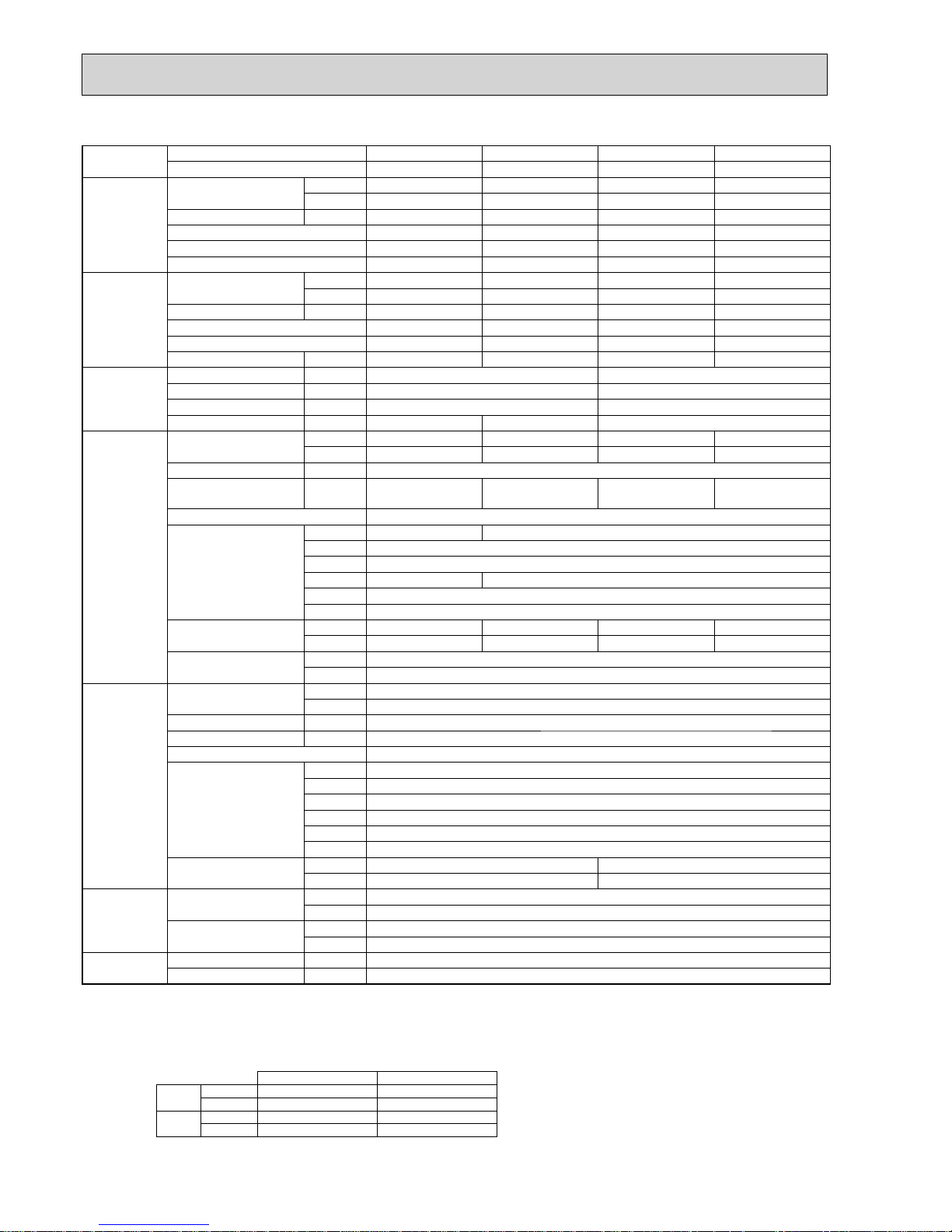
PLA-RP100BA2 PLA-RP125BA2
PUHZ-HRP100YHA2 PUHZ-HRP125YHA2
34,100 42,700
10.0 ( 4.9 - 11.4 ) 12.5 ( 5.5 - 14.0 )
2.50 3.79
4.00 3.30
AA
0.74 0.71
38,200 47,800
11.2 ( 4.5 - 14.0 ) 14.0 ( 5.0 - 16.0 )
2.60 3.57
4.31 3.92
AA
-3
50
400
16
20 - 23 - 26 - 30 22 - 25 - 28 - 31
710 - 810 - 920 - 1060 780 - 880 - 990 - 1090
00
32 - 34 - 37 - 40 34 - 36 - 39 - 41
White Munsell 6.4Y 8.9/0.4
840 (950)
840 (950)
298 (35)
33-1/16 (37-3/8)
33-1/16 (37-3/8)
11-3/4 (1-3/8)
27 (6)
60 (13)
32
1-1/4
100
3,530
51
52
Ivory Munsell 3Y 7.8/1.1
950
330+30
1,350
37-3/8
13 + 1-3/16
53-1/8
134
295
15.88
5/8
9.52
3/8
Max. 30
Max. 75
PLA-RP100BA3
PUHZ-HRP100YHA2
34,100
10.0 ( 4.9 - 11.4 )
2.50
4.00
A
0.74
38,200
11.2 ( 4.5 - 14.0 )
2.60
4.31
A
-
20 - 23 - 26 - 30
710 - 810 - 920 - 1060
0
32 - 34 - 37 - 40
27 (6)
60 (13)
26 (6)
57 (13)
NOTE: 1. Rating conditions (ISO T1)
Cooling Indoor : D.B. 27°C (80°F) W.B. 19°C (66°F) Outdoor : D.B. 35°C (95°F) W.B. 24°C (75°F)
Heating Indoor: D.B. 20°C (68°F) Outdoor : D.B. 7°C (45°F) W.B. 6°C (43°F)
Refrigerant piping length (one way) : 5m (16ft.)
2. Guaranteed operating range
Indoor Outdoor
Cooling
Upper limit
D.B. 32°C, W.B. 23°C
D.B. 46°C
Lower limit
D.B. 19°C, W.B. 15°C D.B. -5°C *
Heating
Upper limit
D.B. 28°C
D.B. 21°C, W.B. 15°C
Lower limit
D.B. 17°C
D.B. -25°C, W.B. -25°C
4. Above data are based on the indicated voltage.
* If optional air protect guide is installed : D.B.-18°C
Indoor unit Single phase 230V 50Hz
3 phase 400V 50Hz
Outdoor unit
3. Guaranteed voltage
198~264V, 50Hz(HRP100, 125Y : 342~457V, 50Hz)
5
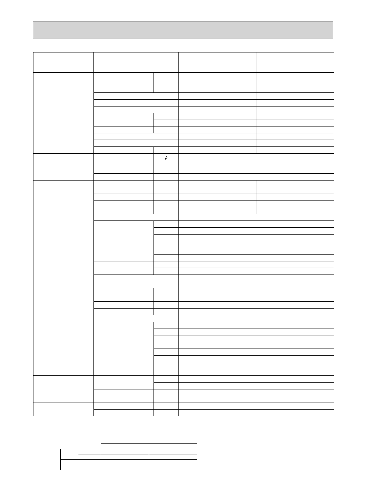
Model name Indoor unit
Outdoor unit
Cooling Capacity Btu/h
kW
Total input kW
EER
Energy label class
SHF
Heating Capacity Btu/h
kW
Total input kW
COP
Energy label class
Booster heater kW
Power supply Phase
Cycle Hz
Voltage V
Breaker size A
Indoor unit Air flow CMM
(Low-Medium2-Medium1-High)
CFM
External pressure Pa
Sound level
dB(A)
(Low-Medium2-Medium1-High)
External finish (Panel)
Dimension W : mm
Unit (Panel) D : mm
H : mm
W : inch
D : inch
H : inch
Weight kg
Unit (Panel) lbs
Field drain pipe O.D. mm
inch
Outdoor unit Air flow CMM
CFM
Sound level at cooling
dB(A)
Sound level at heating
dB(A)
External finish
Dimension W : mm
D : mm
H : mm
W : inch
D : inch
H : inch
Weight kg
lbs
Refrigerant pipe size Gas side O.D. mm
inch
Liquid side O.D. mm
inch
Refrigerant pipe length
Height difference
m
Length
m
PLA-RP100BA PLA-RP100BA PLA-RP125BA
PUHZ-HRP100VHA PUHZ-HRP100YHA PUHZ-HRP125YHA
34,100 34,100 42,700
10.0 ( 4.9 - 11.4 ) 10.0 ( 4.9 - 11.4 ) 12.5 ( 5.5 - 14.0 )
3.02 3.02 3.87
3.31 3.31 3.23
AAA
0.74 0.74 0.71
38,200 38,200 47,800
11.2 ( 4.5 - 14.0 ) 11.2 ( 4.5 - 14.0 ) 14.0 ( 5.0 - 16.0 )
3.10 3.10 3.88
3.61 3.61 3.61
AAA
---
13
50 50
230 400
32 16
20 - 23 - 26 - 30 22 - 25 - 28 - 31
710 - 810 - 920 - 1060 780 - 880 - 990 - 1090
00
32 - 34 - 37 - 40 34 - 36 - 39 - 41
White Munsell 6.4Y 8.9/0.4
840 (950)
840 (950)
298 (35)
33-1/16 (37-3/8)
33-1/16 (37-3/8)
11-3/4 (1-3/8)
25 (6)
55 (13)
32
1-1/4
100
3,530
52
53
Ivory Munsell 3Y 7.8/1.1
950
330+30
1,350
37-3/8
13 + 1-3/16
53-1/8
120 134
265 295
15.88
5/8
9.52
3/8
Max. 30
Max. 75
NOTE: 1. Rating conditions (ISO T1)
Cooling Indoor : D.B. 27°C (80°F) W.B. 19°C (66°F) Outdoor : D.B. 35°C (95°F) W.B. 24°C (75°F)
Heating Indoor: D.B. 20°C (68°F) Outdoor : D.B. 7°C (45°F) W.B. 6°C (43°F)
Refrigerant piping length (one way) : 5m (16ft.)
2. Guaranteed operating range
Indoor Outdoor
Cooling
Upper limit
D.B. 32°C, W.B. 23°C
D.B. 46°C
Lower limit
D.B. 19°C, W.B. 15°C D.B. -5°C *
Heating
Upper limit
D.B. 28°C
D.B. 21°C, W.B. 15°C
Lower limit
D.B. 17°C
D.B. -25°C, W.B. -25°C
4. Above data are based on the indicated voltage.
* If optional air protect guide is installed : D.B.-18°C
Indoor unit Single phase 230V 50Hz
V:Single phase 230V 50Hz, Y:3 phase 400V 50Hz
Outdoor unit
3. Guaranteed voltage
198~264V, 50Hz(HRP100, 125Y : 342~457V, 50Hz)
6
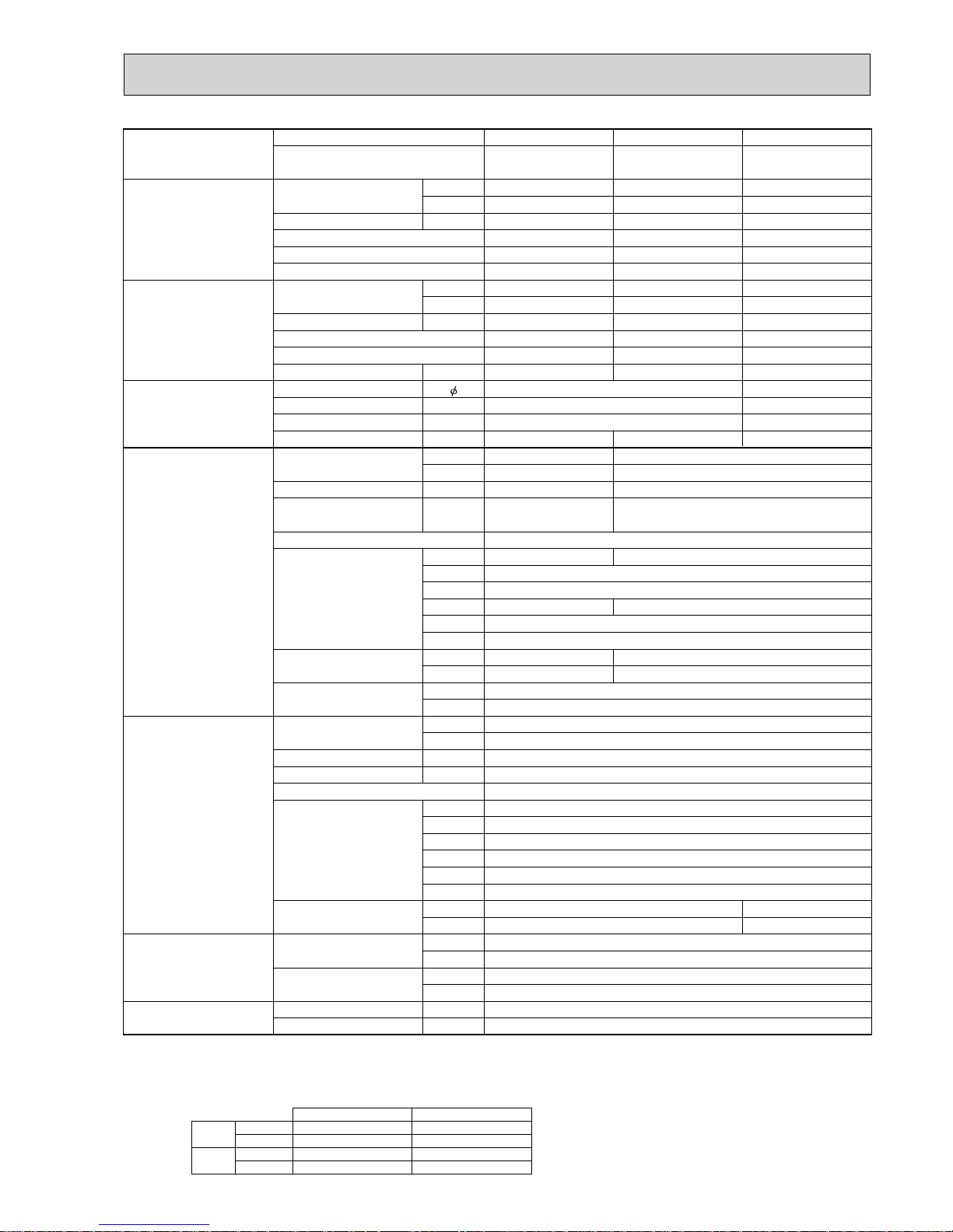
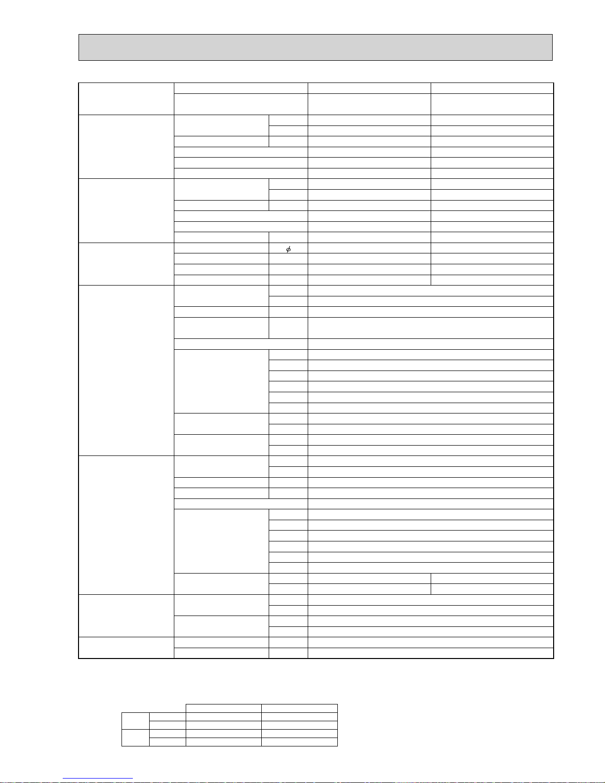
2-2. CEILING-CONCEALED TYPE
Model Name Indoor Unit PEAD-RP71JA(L) PEAD-RP100JA(L) PEAD-RP100JA(L) PEAD-RP125JA(L)
Outdoor Unit
PUHZ-HRP71VHA2 PUHZ-HRP100VHA2 PUHZ-HRP100YHA2 PUHZ-HRP125YHA2
Cooling Capacity Btu/h 24,200 34, 100 34, 100 42,700
kW 7.1 (3.3 - 8.1) 10.0 (4.9 - 11.4) 10.0 (4.9 - 11.4) 12.5 (5.5 - 14.0)
Total Input kW 2.15 (2.13) 3.06 (3.04) 3.06 (3.04) 3.89 (3.87)
EER 3.30 (3.33) 3.27 (3.29) 3.27 (3.29) 3.21 (3.23)
Energy label class A A A A
SHF 0.83 0.82 0.82 0.84
Heating Capacity Btu/h 27,300 38,200 38,200 47,800
kW 8.0 (3.5 - 10.2) 11.2 (4.5 - 14.0) 11.2 (4.5 - 14.0) 14.0 (5.0 - 16.0)
Total Input kW 2.34 3.10 3.10 3.88
COP 3.42 3.61 3.61 3.61
Energy label class B A A A
Booster heater kW ----
Power supply Phase
[
13
Cycle Hz 50 50
Voltage V 230 400
Breaker size A 32 40 16
Indoor unit Air fl ow
(Low - Middle - High)
CMM 17.5 - 21 - 25 24 - 29 - 34 24 - 29 - 34 29.5 - 35.5 - 42
CFM 618 - 742 - 883 847 - 1,024 - 1,201 847 - 1,024 - 1,201 1,042 - 1,253 - 1,483
External pressure Pa 35 / 50 / 70 / 100 / 150
Sound level
(Low - Middle - High/50Pa)
dB(A) 26 - 30 - 34 29 - 34 - 38 29 - 34 - 38 33 - 36 - 40
External fi nish Galvanized sheets
Dimension W : mm 1,100 1,400
D : mm 732
H : mm 250
W : inch 43-5/16 55-1/8
D : inch 28-7/8
H : inch 9-7/8
Weight kg 33 (32) 41 (40) 41 (40) 43 (42)
lbs 73 (71) 91 (89) 91 (89) 95 (93)
Field drain pipe O.D. mm 32
inch 1-1/4
Outdoor Unit Air fl ow CMM 100
CFM 3,530
Sound level at cooling dB(A) 51
Sound level at heating dB(A) 52
External fi nish Ivory Munsell 3Y 7.8/1.1
Dimension W : mm 950
D : mm 330 + 30
H : mm 1,350
W : inch 37-3/8
D : inch 13 + 1-3/16
H : inch 53-1/8
Weight kg 120 134
lbs 265 295
Refrigerant
pipe size
Gas side O.D. mm 15.88
inch 5/8
Liquid side O.D. mm 9.52
inch 3/8
Refrigerant
pipe length
Height difference m Max. 30
Length m Max. 75
NOTE: 1. Rating conditions (ISO T1)
Cooling Indoor : D.B. 27°C (80°F) W.B. 19°C (66°F) Outdoor : D.B. 35°C (95°F) W.B. 24°C (75°F)
Heating Indoor: D.B. 20°C (68°F) Outdoor : D.B. 7°C (45°F) W.B. 6°C (43°F)
Refrigerant piping length (one way) : 5m (16ft.)
2. Guaranteed operating range
Indoor Outdoor
Cooling
Upper limit
D.B. 32°C, W.B. 23°C
D.B. 46°C
Lower limit
D.B. 19°C, W.B. 15°C D.B. -5°C *
Heating
Upper limit
D.B. 28°C
D.B. 21°C, W.B. 15°C
Lower limit
D.B. 17°C
D.B. -25°C, W.B. -25°C
4. Above data are based on the indicated voltage.
* If optional air protect guide is installed : D.B.-18°C
Indoor unit Single phase 230V 50Hz
(V) Single phase 230V 50Hz
Outdoor unit
3. Guaranteed voltage
Indoor unit : 198 ~ 264V, 50Hz
Outdoor unit : 198 ~ 264V, 50Hz (V)
342 ~ 457V, 50Hz (Y)
(Y) 3 phase 400V 50Hz

7
Model name Indoor unit
Outdoor unit
Cooling Capacity Btu/h
kW
Total input kW
EER
Energy label class
SHF
Heating Capacity Btu/h
kW
Total input kW
COP
Energy label class
Booster heater kW
Power supply Phase
Cycle Hz
Voltage V
Breaker size A
Indoor unit Air flow CMM
(Low-High)
CFM
External pressure Pa
Sound level
dB(A)
(Low-High)
External finish (Panel)
Dimension W : mm
Unit (Panel) D : mm
H : mm
W : inch
D : inch
H : inch
Weight kg
Unit (Panel) lbs
Unit drain pipe
Outdoor unit Air flow CMM
CFM
Sound level at cooling
dB(A)
Sound level at heating
dB(A)
External finish
Dimension W : mm
D : mm
H : mm
W : inch
D : inch
H : inch
Weight kg
lbs
Refrigerant pipe size Gas side O.D. mm
inch
Liquid side O.D. mm
inch
Refrigerant pipe length
Height difference
m
Length
m
PEAD-RP71EA PEAD-RP100EA2
PUHZ-HRP71VHA PUHZ-HRP100VHA
PUHZ-HRP71VHA2 PUHZ-HRP100VHA2
24,200 34,100
7.1 (4.9 - 8.1 ) 10.0 ( 4.9 - 11.4 )
2.15 3.06
3.30 3.27
AA
0.83 0.86
27,300 38,200
8.0 ( 4.5 - 10.2 ) 11.2 ( 4.5 - 14.0 )
2.34 3.10
3.42 3.61
BA
-1
50
230
32 (VHA)/ 40 (VHA2)32
20 - 25 33.5 - 42
706 - 883 1,183 - 1,483
70 70
37-41 44-50
Galvanized sheets
1,175 1,415
740
325
46-1/8 55-11/16
29-1/8
12-13/16
44 65
97 143
R1 (External thread)
100
3,530
52 (VHA)/ 51 (VHA2)
53 (VHA)/ 52 (VHA2)
Ivory Munsell 3Y 7.8/1.1
950
330+30
1,350
37-3/8
13 + 1-3/16
53-1/8
120
265
15.88
5/8
9.52
3/8
Max. 30
Max. 75
NOTE: 1. Rating conditions (ISO T1)
Cooling Indoor : D.B. 27°C (80°F) W.B. 19°C (66°F) Outdoor : D.B. 35°C (95°F) W.B. 24°C (75°F)
Heating Indoor: D.B. 20°C (68°F) Outdoor : D.B. 7°C (45°F) W.B. 6°C (43°F)
Refrigerant piping length (one way) : 5m (16ft.)
2. Guaranteed operating range
Indoor Outdoor
Cooling
Upper limit
D.B. 32°C, W.B. 23°C
D.B. 46°C
Lower limit
D.B. 19°C, W.B. 15°C D.B. -5°C *
Heating
Upper limit
D.B. 28°C
D.B. 21°C, W.B. 15°C
Lower limit
D.B. 17°C
D.B. -25°C, W.B. -25°C
4. Above data are based on the indicated voltage.
* If optional air protect guide is installed : D.B.-18°C
Indoor unit Single phase 230V 50Hz
Single phase 230V 50Hz
Outdoor unit
3. Guaranteed voltage
198~264V, 50Hz
8
Model name Indoor unit
Outdoor unit
Cooling Capacity Btu/h
kW
Total input kW
EER
Energy label class
SHF
Heating Capacity Btu/h
kW
Total input kW
COP
Energy label class
Booster heater kW
Power supply Phase
Cycle Hz
Voltage V
Breaker size A
Indoor unit Air flow CMM
(Low-High)
CFM
External pressure Pa
Sound level
dB(A)
(Low-High)
External finish (Panel)
Dimension W : mm
Unit (Panel) D : mm
H : mm
W : inch
D : inch
H : inch
Weight kg
Unit (Panel) lbs
Unit drain pipe
Outdoor unit Air flow CMM
CFM
Sound level at cooling
dB(A)
Sound level at heating
dB(A)
External finish
Dimension W : mm
D : mm
H : mm
W : inch
D : inch
H : inch
Weight kg
lbs
Refrigerant pipe size Gas side O.D. mm
inch
Liquid side O.D. mm
inch
Refrigerant pipe length
Height difference
m
Length
m
PEAD-RP100EA2 PEAD-RP125EA
PUHZ-HRP100YHA PUHZ-HRP125YHA
PUHZ-HRP100YHA2 PUHZ-HRP125YHA2
34,100 42,700
10.0 ( 4.9 - 11.4 ) 12.5 ( 5.5 - 14.0 )
3.06 3.89
3.27 3.21
AA
0.86 0.82
38,200 47,800
11.2 ( 4.5 - 14.0 ) 14.0 ( 5.0 - 16.0 )
3.10 3.88
3.61 3.61
AA
-3
50
400
16
33.5 - 42 33.5 - 42
1,183 - 1,483 1,183 - 1,483
70 70
44 - 50 44 - 50
Galvanized sheets
1,415
740
325
55-11/16
29-1/8
12-13/16
65
143
R1 (External thread)
100
3,530
52 (YHA)/ 51 (YHA2)
53 (YHA)/ 52 (YHA2)
Ivory Munsell 3Y 7.8/1.1
950
330+30
1,350
37-3/8
13 + 1-3/16
53-1/8
134
295
15.88
5/8
9.52
3/8
Max. 30
Max. 75
NOTE: 1. Rating conditions (ISO T1)
Cooling Indoor : D.B. 27°C (80°F) W.B. 19°C (66°F) Outdoor : D.B. 35°C (95°F) W.B. 24°C (75°F)
Heating Indoor: D.B. 20°C (68°F) Outdoor : D.B. 7°C (45°F) W.B. 6°C (43°F)
Refrigerant piping length (one way) : 5m (16ft.)
2. Guaranteed operating range
Indoor Outdoor
Cooling
Upper limit
D.B. 32°C, W.B. 23°C
D.B. 46°C
Lower limit
D.B. 19°C, W.B. 15°C D.B. -5°C *
Heating
Upper limit
D.B. 28°C
D.B. 21°C, W.B. 15°C
Lower limit
D.B. 17°C
D.B. -25°C, W.B. -25°C
4. Above data are based on the indicated voltage.
* If optional air protect guide is installed : D.B.-18°C
Indoor unit Single phase 230V 50Hz
3 phase 400V 50Hz
Outdoor unit
3. Guaranteed voltage
Indoor unit:198~264V, 50Hz Outdoor unit:342~457V, 50Hz
9
Model name Indoor unit
Outdoor unit
Cooling Capacity Btu/h
kW
Total input kW
EER
Energy label class
SHF
Heating Capacity Btu/h
kW
Total input kW
COP
Energy label class
Booster heater kW
Power supply Phase
Cycle Hz
Voltage V
Breaker size A
Indoor unit Air flow CMM
(Low-High)
CFM
External pressure Pa
Sound level
dB(A)
(Low-High)
External finish (Panel)
Dimension W : mm
Unit (Panel) D : mm
H : mm
W : inch
D : inch
H : inch
Weight kg
Unit (Panel) lbs
Unit drain pipe mm
inch
Outdoor unit Air flow CMM
CFM
Sound level at cooling
dB(A)
Sound level at heating
dB(A)
External finish
Dimension W : mm
D : mm
H : mm
W : inch
D : inch
H : inch
Weight kg
lbs
Refrigerant pipe size Gas side O.D. mm
inch
Liquid side O.D. mm
inch
Refrigerant pipe length
Height difference
m
Length
m
PEAD-RP71GA PEAD-RP100GA PEAD-RP100GA
PUHZ-HRP71VHA PUHZ-HRP100VHA PUHZ-HRP100YHA
PUHZ-HRP71VHA2 PUHZ-HRP100VHA2 PUHZ-HRP100YHA2
24,200 34,100 34,100
7.1 ( 4.9 - 8.1 ) 10.0 ( 4.9 - 11.4 ) 10.0 ( 4.9 - 11.4 )
2.15 3.08 3.08
3.30 3.25 3.25
AAA
0.83 0.86 0.86
27,300 38,200 38,200
8.0 ( 4.5 - 10.2 ) 11.2 ( 4.5 - 14.0 ) 11.2 ( 4.5 - 14.0 )
2.34 3.28 3.28
3.42 3.41 3.41
BBB
--13
50 50
230 400
32 (VHA)/ 40 (VHA2)32 16
20-25 26.5-33
706-883 935-1,165
10/50/70 10/50/70
35-38/37-41/37-43 40-43/42-45/42-46
Galvanized sheets
1,171 1,411
740
275
46-1/8 55-9/16
29-1/8
10-13/16
42 50
93 111
R1 (External thread)
1-1/4
100
3,530
52 (VHA, YHA)/ 51 (VHA2, YHA2)
53 (VHA, YHA)/ 52 (VHA2, YHA2)
Ivory Munsell 3Y 7.8/1.1
950
330+30
1,350
37-3/8
13 + 1-3/16
53-1/8
120 134
265 295
15.88
5/8
9.52
3/8
Max. 30
Max. 75
NOTE: 1. Rating conditions (ISO T1)
Cooling Indoor : D.B. 27°C (80°F) W.B. 19°C (66°F) Outdoor : D.B. 35°C (95°F) W.B. 24°C (75°F)
Heating Indoor: D.B. 20°C (68°F) Outdoor : D.B. 7°C (45°F) W.B. 6°C (43°F)
Refrigerant piping length (one way) : 5m (16ft.)
2. Guaranteed operating range
Indoor Outdoor
Cooling
Upper limit
D.B. 32°C, W.B. 23°C
D.B. 46°C
Lower limit
D.B. 19°C, W.B. 15°C D.B. -5°C *
Heating
Upper limit
D.B. 28°C
D.B. 21°C, W.B. 15°C
Lower limit
D.B. 17°C
D.B. -25°C, W.B. -25°C
4. Above data are based on the indicated voltage.
* If optional air protect guide is installed : D.B.-18°C
Indoor unit Single phase 230V 50Hz
V:Single phase 230V 50Hz, Y:3 phase 400V 50Hz
Outdoor unit
3. Guaranteed voltage
198~264V, 50Hz(HRP100Y : 342~457V, 50Hz)
10
Model Name
Indoor Unit PKA-RP100KAL PKA-RP100KAL
Outdoor Unit PUHZ-HRP100VHA2 PUHZ-HRP100YHA2
Cooling
Capacity Btu/h 34,100
kW 10.0 (4.9 - 11.4)
Total Input kW 2.93
EER 3.41
Energy label class A
SHF 0.73
Heating
Capacity Btu/h 38,200
kW 11.2 (4.5 - 14.0)
Total Input kW 3.10
COP 3.61
Energy label class A
Booster heater kW -
Power supply
Phase
[
13
Cycle Hz 50 50
Voltage V 230 400
Breaker size A 40 16
Indoor unit
Air fl ow
(Low - Middle - High)
CMM 20 - 23 - 26
CFM 705 - 810 - 920
External pressure Pa 0
Sound level
(Low - Middle - High/50Pa)
dB(A) 41 - 45 - 49
External fi nish Munsell 1.0Y 9.2/0.2
Dimension W : mm 1,170
D : mm 295
H : mm 365
W : inch 46-1/16
D : inch 11-5/8
H : inch 14-3/8
Weight kg 21
lbs 46
Field drain pipe O.D. mm 16
inch 5/8
Outdoor Unit
Air fl ow CMM 100
CFM 3,530
Sound level at cooling dB(A) 51
Sound level at heating dB(A) 52
External fi nish Ivory Munsell 3Y 7.8/1.1
Dimension W : mm 950
D : mm 330 + 30
H : mm 1,350
W : inch 37-3/8
D : inch 13 + 1-3/16
H : inch 53-1/8
Weight kg 120 134
lbs 265 295
Refrigerant
pipe size
Gas side O.D. mm 15.88
inch 5/8
Liquid side O.D. mm 9.52
inch 3/8
Refrigerant
pipe length
Height difference m Max. 30
Length m MAx. 75
NOTE: 1. Rating conditions (ISO T1)
Cooling Indoor : D.B. 27 (80°F) W.B. 19 (66°F) Outdoor : D.B. 35 (95°F) W.B. 24 (75°F)
Heating Indoor: D.B. 20 (68°F) Outdoor : D.B. 7 (45°F) W.B. 6 (43°F)
Refrigerant piping length (one way) : 5m (16ft.)
2. Guaranteed operating range
Indoor Outdoor
Cooling
Upper limit
D.B. 35°C, W.B. 22.5°C
D.B. 46°C
Lower limit
D.B. 19°C, W.B. 15°C D.B. -5°C +1
Heating
Upper limit
D.B. 28°C
D.B. 21°C, W.B. 15°C
Lower limit
D.B. 17°C
D.B. -15°C, W.B. -15°C
4. Above data are based on the indicated voltage.
+1. If optional air protect guide is installed : D.B.-15
Indoor unit Single phase 230V 50Hz
V : Single phase 230V 50Hz
Y : 3 phase 400V 50Hz
Outdoor unit
3. Guaranteed voltage
198~264V, 50Hz (V) / 342~457V, 50Hz (Y)
2-3. WALL-MOUNTED TYPE
11
Model name Indoor unit
Outdoor unit
Cooling Capacity Btu/h
kW
Total input kW
EER
Energy label class
SHF
Heating Capacity Btu/h
kW
Total input kW
COP
Energy label class
Booster heater kW
Power supply Phase
Cycle Hz
Voltage V
Breaker size A
Indoor unit Air flow CMM
(Low-High)
CFM
External pressure Pa
Sound level
dB(A)
(Low-High)
External finish (Panel)
Dimension W : mm
Unit (Panel) D : mm
H : mm
W : inch
D : inch
H : inch
Weight kg
Unit (Panel) lbs
Field drain pipe I.D.
Outdoor unit Air flow CMM
CFM
Sound level at cooling
dB(A)
Sound level at heating
dB(A)
External finish
Dimension W : mm
D : mm
H : mm
W : inch
D : inch
H : inch
Weight kg
lbs
Refrigerant pipe size Gas side O.D. mm
inch
mm
inch
Liquid side O.D. mm
inch
Refrigerant pipe length
Height difference
m
Length
m
PKA-RP100FAL PKA-RP100FAL
PUHZ-HRP100VHA PUHZ-HRP100YHA
PUHZ-HRP100VHA2 PUHZ-HRP100YHA2
34,100 34,100
10.0 ( 4.9 - 11.4 ) 10.0 ( 4.9 - 11.4 )
2.93 2.93
3.41 3.41
AA
0.77 0.77
38,200 38,200
11.2 ( 4.5 - 14.0 ) 11.2 ( 4.5 - 14.0 )
3.10 3.10
3.61 3.61
AA
--
13
50 50
230 400
32 (VHA)/ 40 (VHA2) 16
22 - 28
780 - 990
0
41 - 46
White Munsell 3.4Y 7.7/0.8
1680
235
340
66-1/8
9-1/4
13-3/8
28
62
20
13/16
100
3,530
52
(VHA, YHA)/ 51 (VHA2, YHA2)
53 (VHA, YHA)/ 52 (VHA2, YHA2)
Ivory Munsell 3Y 7.8/1.1
950
330+30
1,350
37-3/8
13 + 1-3/16
53-1/8
120 134
265 295
15.88
5/8
9.52
3/8
Max. 30
Max. 75
NOTE: 1. Rating conditions (ISO T1)
Cooling Indoor : D.B. 27°C (80°F) W.B. 19°C (66°F) Outdoor : D.B. 35°C (95°F) W.B. 24°C (75°F)
Heating Indoor: D.B. 20°C (68°F) Outdoor : D.B. 7°C (45°F) W.B. 6°C (43°F)
Refrigerant piping length (one way) : 5m (16ft.)
2. Guaranteed operating range
Indoor Outdoor
Cooling
Upper limit
D.B. 32°C, W.B. 23°C
D.B. 46°C
Lower limit
D.B. 19°C, W.B. 15°C D.B. -5°C *
Heating
Upper limit
D.B. 28°C
D.B. 21°C, W.B. 15°C
Lower limit
D.B. 17°C
D.B. -25°C, W.B. -25°C
4. Above data are based on the indicated voltage.
* If optional air protect guide is installed : D.B.-18°C
Indoor unit Single phase 230V 50Hz
V:Single phase 230V 50Hz, Y:3 phase 400V 50Hz
Outdoor unit
3. Guaranteed voltage
198~264V, 50Hz(HRP100Y : 342~457V, 50Hz)
12
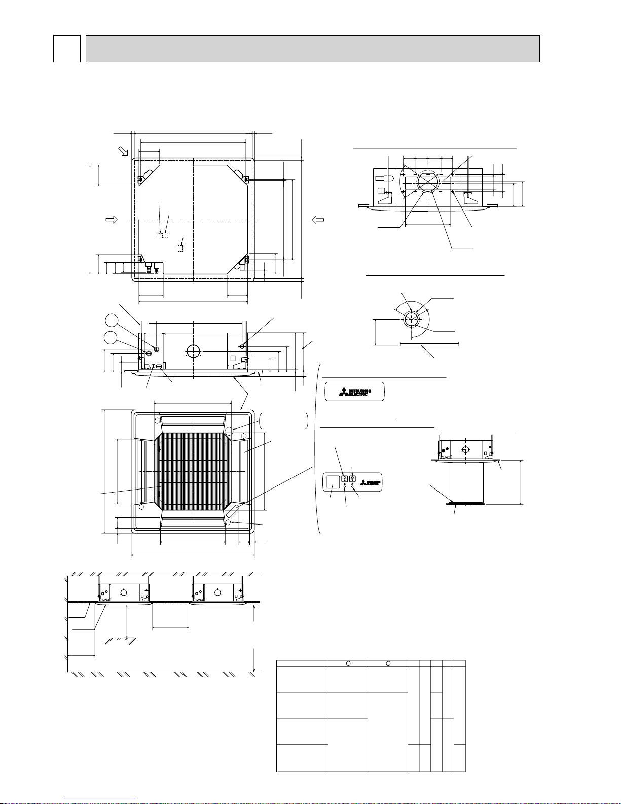
3
OUTLINES AND DIMENSIONS
37728460
()
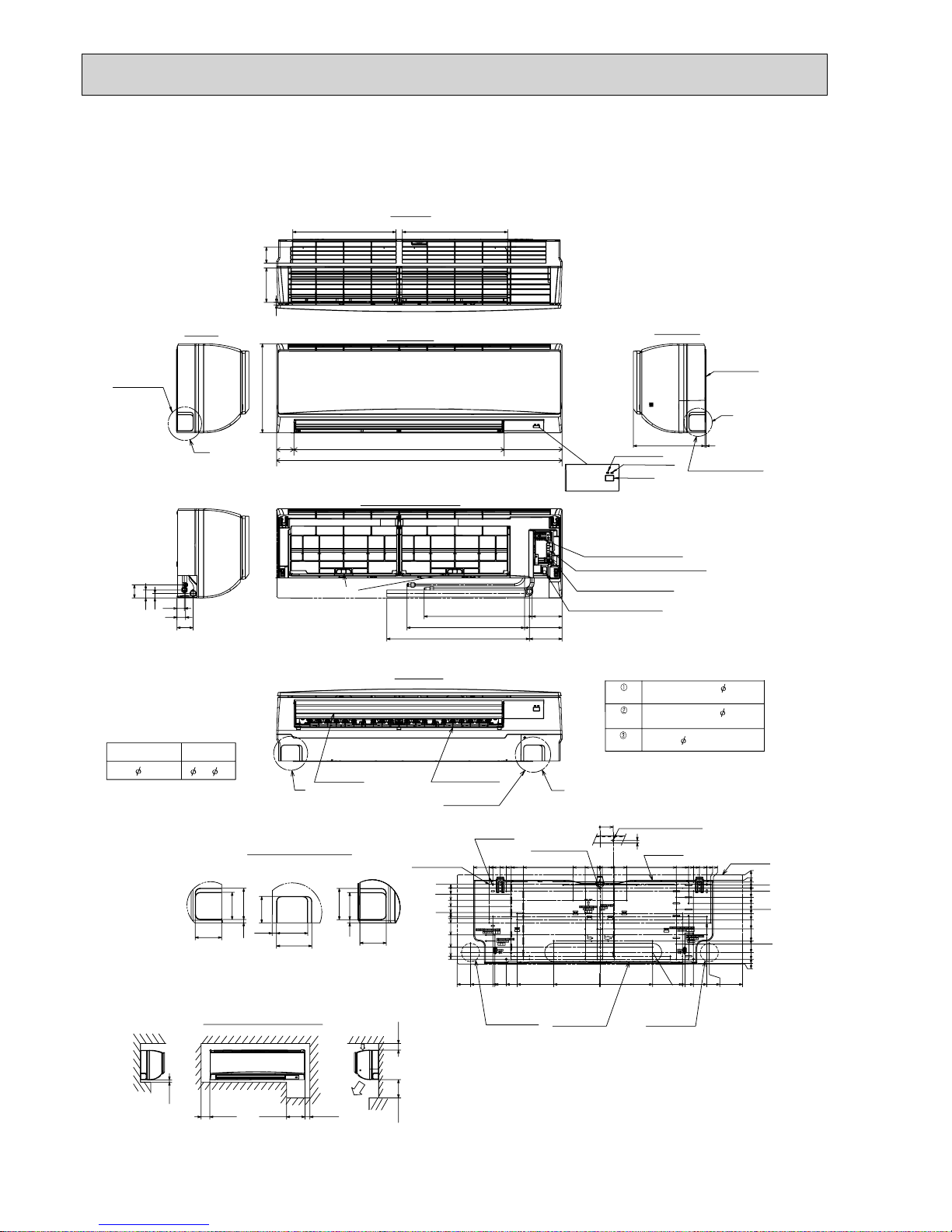
Ceiling hole
Branch duct hole
Drain pipe
connected to VP-25
Ceiling
Grille
Drain hole
Models
Auto vane
(Air outlet)
Air intake grille
Ceiling
Cut out hole
Cut out hole
Cut out hole
Burring hole pitch
Burring hole pitch
Burring hole
Burring hole
Power supply wire,
Indoor unit/Outdoor unit
connecting wire entry
Indoor unit/Outdoor unit
connecting terminal block
Indoor power supply
terminal block(Option part)
Control wire entry
Air intake hole
Air intake hole
Air outlet hole
Air outlet hole
Connected the attached
socket.
Keep approximately
10 to 15mm space
between unit ceiling
and ceiling slab.
Branch duct hole
Fresh air
intake hole
Ceiling hole
Suspension bolt pitch
Suspension bolt pitch
Remote controller
terminal block
Suspension bolt
M10 or W3/8
(7.5)(7.5)
605
+35
- 5
620
DEFROST/STAND BY lamp
Receiver
Operation lamp
In case of standard grille : PLP-6BA / PLP-6BAMD
In case of wireless remote controller : PLP-6BALM
Auto Grille
Air intake grille up/down discharge
Emergency operation
switch<Cooling>and
Emergency Up/Down switch<Up>
160
160
500
500
597
83 36
950
8336
950
597
A
17
+5
0
B
35
190
156
105
140
50~70
160
840
150
90
C
D
840
187.5
20~45
860~910
20~45
810
20~45860~910
20~45
24
160
++
+
+
+
+
+
M
M
M
M
120°
120°
:175
:125
167
158
Vane motor
2
1
Drain pump clean hole
and Drain emergency
drainage hole
130
100
70°
155
350
90 100 100 90
BA CDE
241 258
80
87
74
400
298
85 77
440281
2
1
Refrigerant pipe
···:6.35
Flared connection
···1/4F
Refrigerant pipe
···:9.52
Flared connection
···3/8F
Refrigerant pipe
···:12.7
Flared connection
···1/2F
Refrigerant pipe
···:15.88
Flared connection
···5/8F
Refrigerant pipe
:6.35 / :9.52
Flared connection
1/4F / 3/8F
(compatible)
PLA-RP35/50BA
PLA-RP60BA
PLA-RP71BA,BA2
PLA-RP100,125BA
PLA-RP100BA3
PLA-RP100, 125,140BA2
Detail drawing of fresh air intake hole
Detail connecting of Branch duct(Both aspects)
3-:2.8
14-:2.8
:150
:100
Emergency operation
switch<Heating>and
Emergency Up/Down switch<Down>
In case of Auto-Grille : PLP-6BAJ
Suspension bolt
lower edge
170
+
+
+
Ceiling
Air intake grille
Max. 4.0m
L.L Filter
Ceiling
Grille
Indoor unit
1500mm
or more
1000mm
or more
3000mm or more
1800mm or more
from floor
For high
attachment
Indoor unit
Obstacle
Floor
Note1. Please choose the Grille from a standard grille, Auto-Grille.
2. As for drain pipe, please use VP-25(O.D. :32 PVC TUBE).
Drain pump is included.
Raise is max 850mm from the ceiling.
3. As for suspension bolt, please use M10 or W3/8.
(Procured at local site)
4. Electrical box may be removed for the service purpose.
Make sure to slack the electrical wire little bit for control/ power wires connection.
5. The height of the indoor unit is able to be adjusted with the grille attached.
6. For the installation of the optional high efficiency filter or optional multi-functional casement.
1) Requires E or more space between transom and ceiling for the installation.
2) Add 135 mm to the dimensions + marked on the figure.
3) The optional high efficiency filter must be used jointly with optional multi-functional casement,
7. When installing the branch ducts, be sure to insulate adequately.
Otherwise condensation and dripping may occur.
(It becomes the cause of dew drops/Water dew.)
8. As for necessary installation/service space, please refer to left figure.
INDOOR UNIT
PLA-RP35BA PLA-RP50BA PLA-RP60BA PLA-RP71BA PLA-RP100BA PLA-RP125BA
PLA-RP71BA2 PLA-RP100BA2 PLA-RP100BA3 PLA-RP125BA2
Unit : mm
13
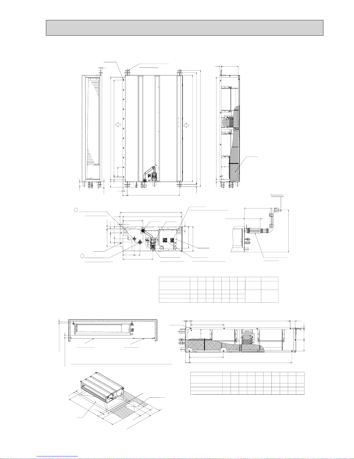
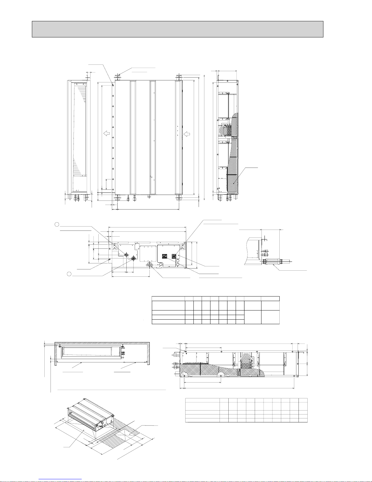
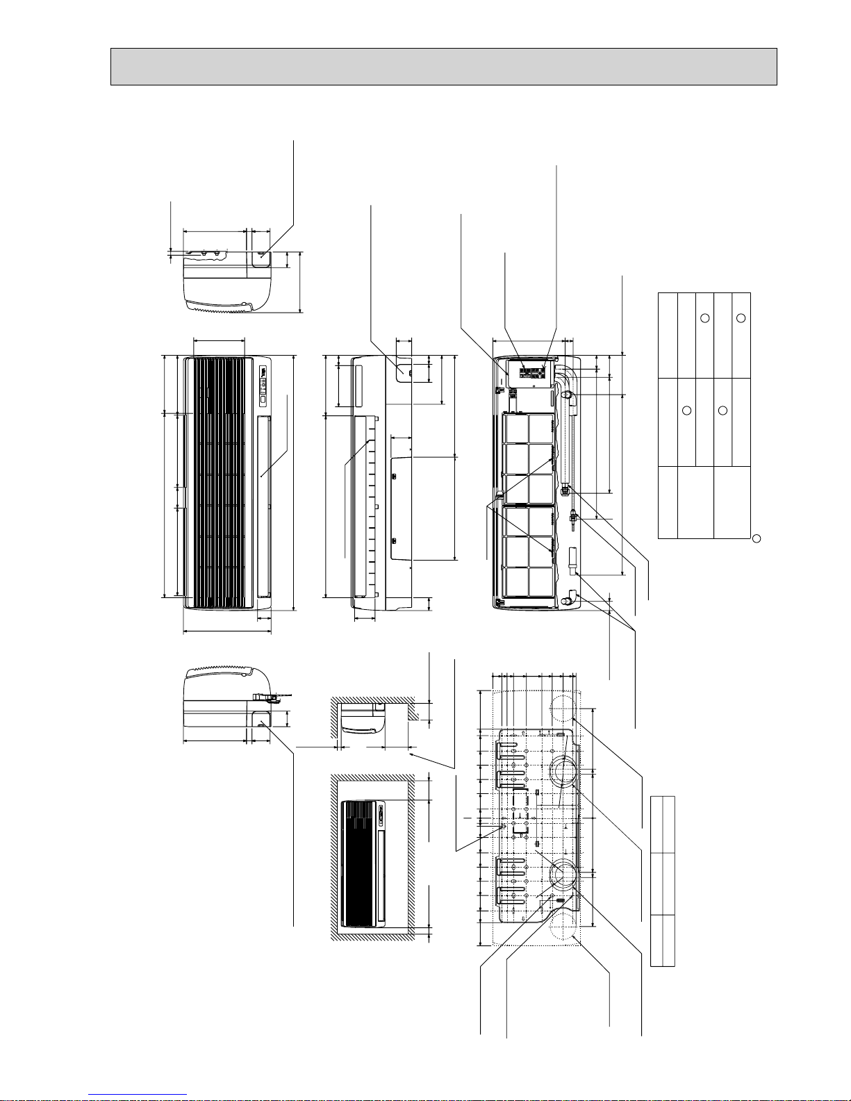
PEAD-RP35, 50, 60, 71, 100, 125JA
Unit : mm
Air Filter
Suspension bolt hole
4-14x30 Slot
Air
outlet
Air
inlet
2xE-
:
2.9
2×2-:2.9
Refrigerant piping
Flare connection (liquid)
2
1
Refrigerant piping
Flare connection (gas)
Drain pump
Control box
Terminal block
(Indoor/Outdoor connecting line)
Terminal block
(Remote controller transmission line)
Drain pipe(O.D.:32)
(Spontaneous draining)
Drain pipe
(O.D.:32)
:15.88
:9.52
:6.35
:12.7
Liquid pipe
Gas pipe
1558
1358
1500
1300
Model A
1200
900 954 860 9
E11D
1060
C
1100B1154
PEAD-RP140JA
PEAD-RP100,125JA
PEAD-RP60,71JA
PEAD-RP35,50JA
1400
1600
1454
1654
1500
1700
1360
15601416
1000
1000
F
858800
G
1058
40
21018
G21
250
122
33
15
58
57
10
100
100x(E-1)=F
A
B(Suspension bolt pitch)
C
23
643 (Suspension bolt pitch)
30
57
20
D (Duct)
178 (Duct)
40
23
10
238
32
700
732
136
67
356
100
41
217
NOTE 1. Use M10 screw for the Suspension bolt (field supply).
2. Keep the service space for the maintenance at the bottom.
3. This chart indicates for PEAD-RP60
•71•
100•125•140JA
models,which have 2 fans. PEAD-RP35
•
50JA models have 1 fan.
4. In case of the inlet duct is used,remove the air filter
(supply with the unit), then install the filter
(field supply) at suction side.
Less than 300mm
175±5mm
Less than 700mm
Drain hose (I.D.:32)
<accessory>
(Actual length)
1520
1320
1020
819
JQS
340
R
54 260 4 780 10 40.5 273 4
440
P10N
990
M4L49K
330
5
5380
5454320
37055
1280
148012124040
330
1700
1500
PEAD-RP35,50JA
PEAD-RP60,71JA
PEAD-RP100,125JA
PEAD-RP140JA
1200
1000
HModel
N-
:
2.9
K
Kx(L-1)=M
J
112 112
11
Q
Qx(R-1)=S
P
J
6
More than 20mm
More than 10mm
Make the access door at the appointed position properly for service maintenance.
Ceiling surface
Access door
50
250~300
450
50
H
777
450
More than 300
Access door
Note2
Required space for service and maintenance
14
PEAD-RP35, 50, 60, 71, 100, 125JAL
Unit : mm
Air Filter
:15.88
:9.52
:6.35
:12.7
Liquid pipe
Gas pipe
1558
1358
1500
1300
Model A
1200
900 954 860 9
E11D
1060
C
1100B1154
PEAD-RP140JAL
PEAD-RP100,125JAL
PEAD-RP60,71JAL
PEAD-RP35,50JAL
1400
1600
1454
1654
1500
1700
1360
15601416
1000
1000
F
858800
G
1058
40
21018
G
21
15
58
NOTE 1. Use M10 screw for the Suspension bolt (field supply).
2. Keep the service space for the maintenance at the bottom.
3. This chart indicates for PEAD-RP60
•71•
100•125•140JAL
models,which have 2 fans. PEAD-RP35
•
50JAL models have 1 fan.
4. In case of the inlet duct is used,remove the air filter
(supply with the unit), then install the filter
(field supply) at suction side.
1520
1320
1020
819
JQS
340
R
54 260 4 780 10 40.5 273 4
440
P10N
990
M4L49K
330
5
5380
5454320
37055
1280
148012124040
330
1700
1500
PEAD-RP35,50JAL
PEAD-RP60,71JAL
PEAD-RP100,125JAL
PEAD-RP140JAL
1200
1000
HModel
N-
:
2.9
K
Kx(L-1)=M
J
112 112
11
Q
Qx(R-1)=S
P
J
6
More than 20mm
More than 10mm
Make the access door at the appointed position properly for service maintenance.
Ceiling surface
Access door
50
250~300
450
50
H
777
450
More than 300
Access door
Note2
Required space for service and maintenance
Suspension bolt hole
4-14x30 Slot
Air
outlet
Air
inlet
2xE-:2.9
57
10
100
100x(E-1)=F
A
B(Suspension bolt pitch)
C
23
643 (Suspension bolt pitch)
30
57
20
D (Duct)
Drain pipe(O.D.:32)
2×2-
:
2.9
Refrigerant piping
Flare connection (liquid)
2
1
Refrigerant piping
Flare connection (gas)
Control box
Terminal block
(Indoor/Outdoor connecting line)
Terminal block
(Remote controller transmission line)
250
33
122
178 (Duct)
40
23
10
32
700
732
136
67
356
100
217
175±5mm
<accessory>
Drain hose (I.D.
:
32)
(Actual length)
15
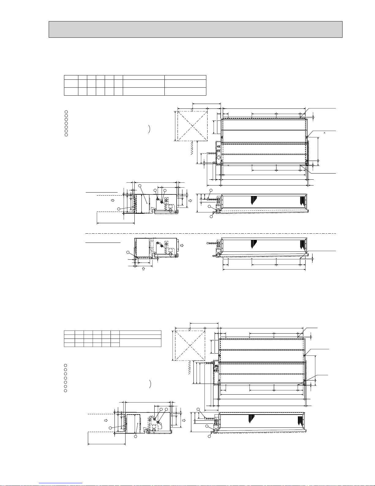
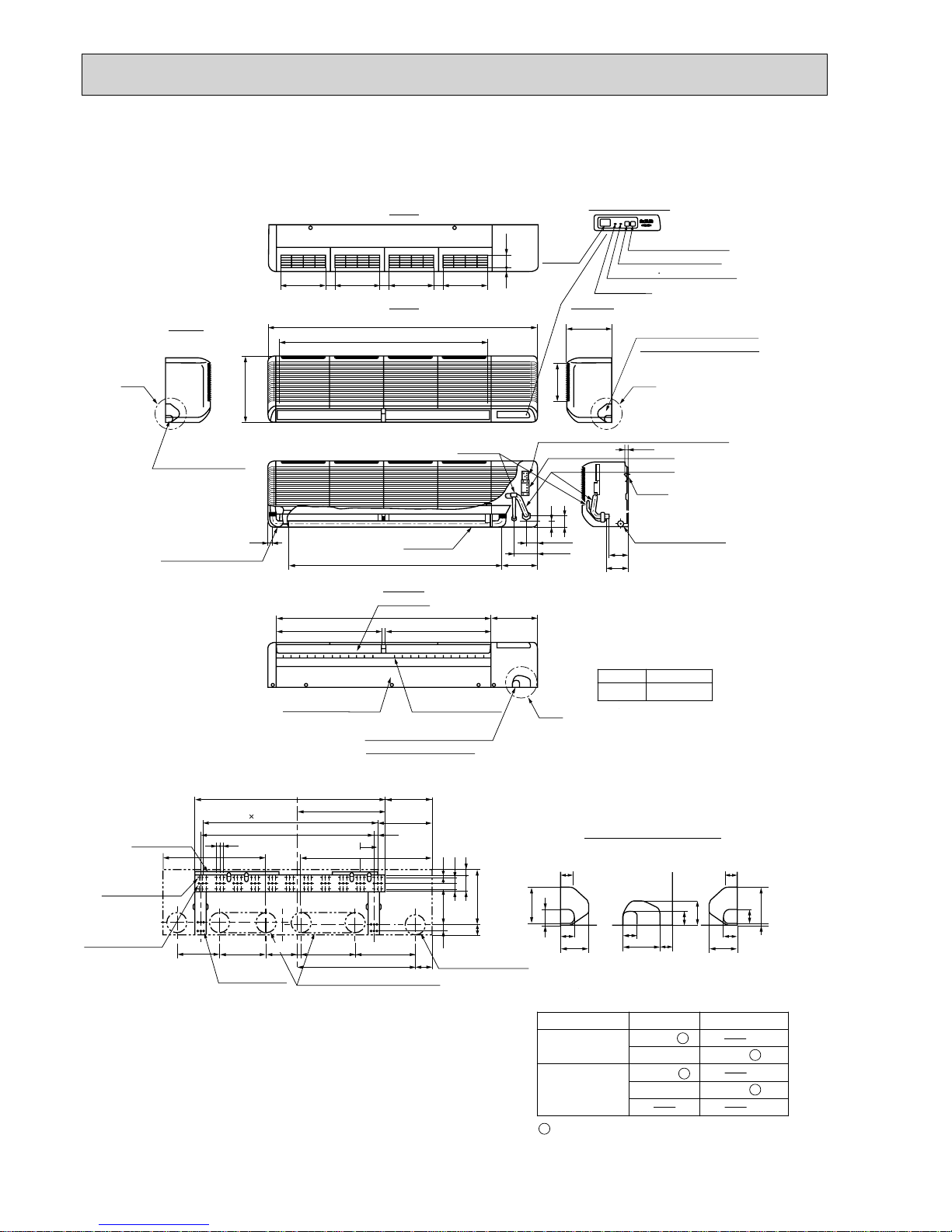
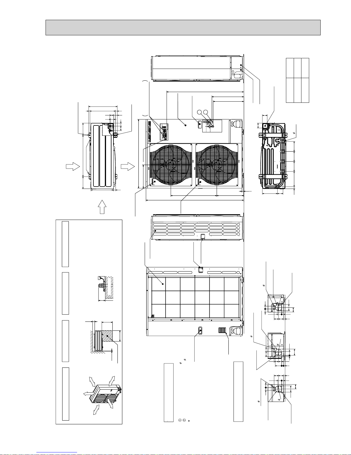
PEAD-RP35EA2
PEAD-RP50EA
PEAD-RP60EA
PEAD-RP71EA
PEAD-RP100EA2
PEAD-RP125EA
2
1
3
4
5
6
7
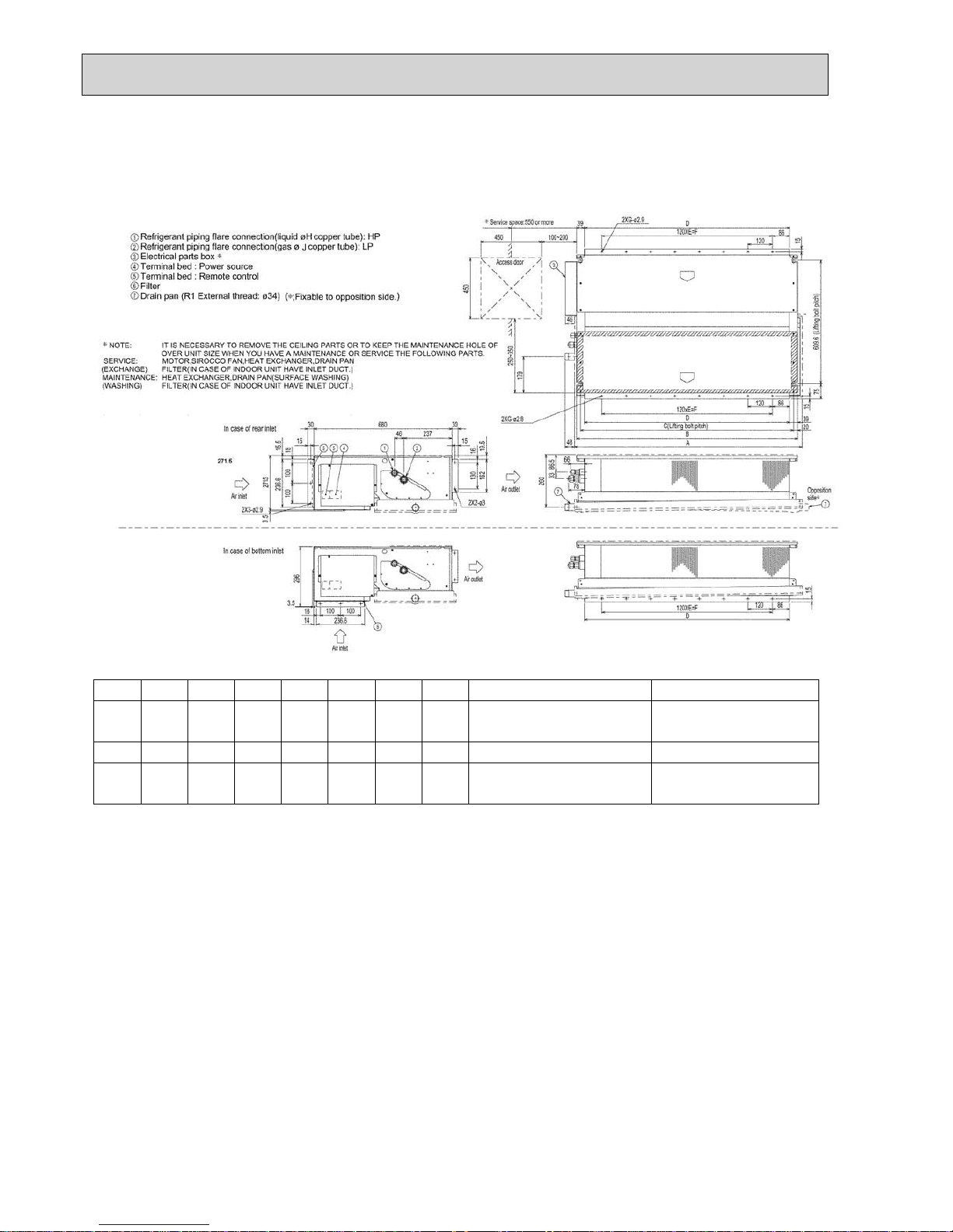
Refrigerant piping flare connection (liquid : F copper tube):HP
Refrigerant piping flare connection (gas :G copper tube):LP
Drain R1(External thread)
Electrical parts box
Drain Pump (Option)
Drain Pipe (Option) ... Flexible joint VP-25(I.D.
:
32)
Filter
R407C Outdoor unit : 9.52
F
R410A Outdoor unit : 6.35 +
R407C Outdoor unit : 9.52 +
Outdoor unit (SUZ) : 6.35
EDCBA
804830
-
305772
Model
RP60
R407C Outdoor unit : 15.88
G
R410A Outdoor unit : 12.7 +
15.88
104410702902801012
RP35,50
+ Initial setting
2
1
3
4
Air inlet
Air outlet
Access door
55
50~150
81
197
Service space:500 or more
Keep duct-work length 850mm or more.
Be sure to apply the air filter
near the air inlet grille.
5
6
75
44
18
365~465
B 81
10
56 355
7
159
243
Air outlet
Air inlet
7
Lifting bolt hole
(1422)
10-:3 (RP35,50)
12-:3 (RP60)
In case of rear inlet
In case of bottom inlet
10-:3 (RP35,50)
12-
:
3 (RP60)
D
30
C
10
81BC
A
450
450
10-:3 (RP35,50)
12-
:
3 (RP60)
176
40
288
256
3.5
3.5
10
109
179
10
35
24
30640
30
21
277
80
45
282
13
13E
A
61 227
29
85
40
176
10
15
3.5
256
BC 81
10
81
A
Set
R407C outdoor unit : 19.05158416104704601552RP140
15.8810441070290
F
R410A Outdoor unit : 15.88 +
EDCBA
12841310370360
2801012
1252
Model
RP100,125
RP71
+ Initial s
etting
7
44
243
308
323
75
6
5
13
Refrigerant piping flare connection (liquid :9.52 copper tube):HP
Refrigerant piping flare connection (gas :F copper tube):LP
Drain R1 (External thread)
Electrical parts box
Drain Pump (Option)
Drain Pipe (Option) ... Flexible joint VP25(I.D.:32)
Filter
Service space:500 or more
81
365~465
197
81
50~150
55
29
Access door
Air outlet
Air inlet
4
3
1
2
7
6
5
4
3
2
1
113
307
122
12-:3
(14x22)
Lifting bolt hole
45
Set
210
12-:3
450
450
140
282
680
3.5
3.5
30
319
261
181
40
30
A
CB
81
10
375
10
80
CB81
A
E13
30D
20
35
30
1053 169
Keep duct-work length 850mm or more.
Be sure to apply the air filter
near the air inlet grille.
Unit : mm
16
PEAD-RP60GA
PEAD-RP71GA
PEAD-RP100GA
Unit : mm
Model A B C D E
7
7
9
8
9.52
9.52
15.88
15.88
8
10
FG H J
RP60
RP71
RP100
1125
1125
1365
1090
1090
1330
1050
1050
1290
1012
1012
1252
840
840
1080
Outdoor unit(SUZ) : 6.35
Other outdoor unit : 9.52
*
R410A Outdoor unit : 15.88 *
R407C Outdoor unit : 19.05
*
Initial setting
17
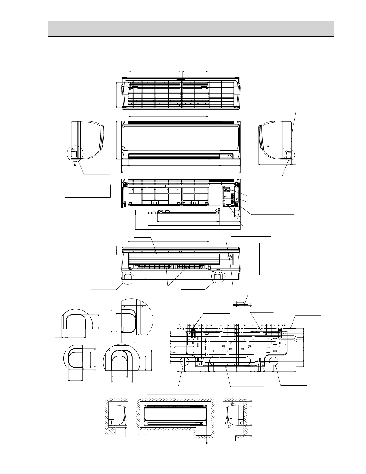
197
387
192
599
Top side
Front side
155
688
898
55
295
Front side (Grille open)
169
158
184
457 Gas pipe
539 Liquid pipe
610 Drain hose
Terminal block for outdoor unit
Terminal block for power supply (option)
Terminal block for
MA-remote controller (option)
Emergency operation switch
(cooling/heating)
Under side
Vane (auto)
Operation lamp
612
DEFROST/STAND BY lamp
Receiver
Knockout hole
for lower piping
Louver (manual)
Knockout hole
for lower piping
C
8
B
Size
Refrigerant pipe : :6.35
Flared connection : 1/4F
Refrigerant pipe : :12.7
Flared connection : 1/2F
:16 O.D
Liquid pipe
Gas pipe
Drain hose
Knockout hole
for right piping
Right side
Mount board
21.8
0
20
32.7
53.5
66
128.5
153.5
231.5
273.2
449
281
193.5
180.3
278.3
167
140
115
0
174
213
238
394
449
253.5
232.5
203.5
178.5
166
103.5
91
78.5
116
41
28.5
16
0
372.3
356.3
327.5
291.5
265
225
200
1257015
0
15
70
125
200
225
265
238
291.5
327.5
372.3
356.3
Indoor unit outline
Mount board
4-:9 Bolt hole
77-:5.1
Tapping
screw hole
0
58
3.8
Center measurement hole :2.5
A
B
43
6
60
46
56
46
43
59
C
56
12.5
43
D
43
6
56
69
Knockout hole for piping
Knockout hole
for left piping
Left side
Sleeve
(purchased locally)
:65~:80
:65~:80
Through hole
249
A
5
Min.7
250mm or greater with optional
drain pump installation.
Required space (Indoor unit)
Min.50
Min.220
Min.150
550mm or greater with optional
drain pump installation.
Min.250
Min.50
55mm or greater with left
or rear left piping or drain
pump installation.
Wall hole for
right rear piping
Knockout hole for
left rear piping (70 × 310)
Wall hole for
left piping
Air inlet
Air inlet
Air outlet
PKA-RP35HAL
PKA-RP50HAL
Unit : mm
18
PKA-RP60KAL
PKA-RP100KAL
Unit : mm
Refrigerant pipe : 9.52
Flared connection : 3/8F
16 O.D
Liquid pipe
Gas pipe
Drain hose
Sleeve
(purchased locally)
75
75~ 80
Through hole
53
32
18
30
66
35
65.2
423.7
1170
123
154
B
B
134
431.7
11
140.3
365
A
5
C
295
75-W5.1
Tapping screw hole
4-W9 Bolt hole
Center measurement hole W2.5
0
314
364
384
408.5
439
454
517.4
585
439
384
339
189
0
216.5
R37.5
339
384
585
439
349.2
449.2
430.5
530.5
110
110
314
54
15.5
0
50
75
117
125
142
292
279.5
242
192
25
100
32
25
37.5
62.5
104.5
129.5
167
217
264
292
308.5
311
0
12.5
12.5
87.5
229.5
364
384.5
408.5
439
454
465.5
60
60
01010
54
3
C
65
67
65
67
77
77
7.8
7.8
10.7
87
77
65
BA
Top side
Front side
Front side (Grille open)
Terminal block for outdoor unit
Terminal block for power supply (option)
Terminal block for
MA-remote controller (option)
Emergency operation switch
(cooling/heating)
Operation lamp
DEFROST/STAND BY lamp
Receiver
Knockout hole for
right piping
Mount board
Right side
444 (Gas pipe)
482 (Liquid pipe)
585 (Drain hose)
Filter hook
Under side
Vane (auto)
Knockout hole
for lower piping
Louver (manual)
Piping connection department
Indoor unit outline
Wall hole for
right rear piping
Knockout hole for
left rear piping
(75×480)
Wall hole for
left rear piping
Mount board
Temporarily fixing hole
108 mm or greater with left or
rear left piping or drain pump
installation
Min. 48
Min. 250
Air outlet
Air inlet
Min. 50.5
Min. 220Min. 72.4
550 mm or greater with optional
drain pump installation
265 mm or greater with optional
drain pump installation
Min. 7
Required space (Indoor unit)
Knockout hole for piping
Knockout hole
for left piping
Left side
Refrigerant pipe : 15.88
Flared connection : 5/8F
74
(855)
241
19
PKA-RP35GAL PKA-RP50GAL Unit : mm
Knockout hole for
right piping
Refrigerant pipe.
Drain pipe.
Wiring hole
21
Right side
Less than 15
70
245
60
235
Auto vane
Front view
Air intake
Air intake
Air intake
Air intake
198
53
340
715 225
340 80 280 233
990
21
Left side
Knock out hole for left piping
Refrigerant pipe.Drain pipe.Wiring hole.
60
70
245
(Necessary clearance for
unit installation)
Right side
Allowing clearances
Front view
Less than 130
50 or more 150 or more
180 or more 30 or more
for bolts
Left-rear
piping hole
left-rear piping
R52.5
R52.5
Installation plate
balance point hole
Details of installation plate
49-:5hole
for tapping screw
Knockout hole for
right-rear piping
Right-rear
piping hole
Unit center
14-:14hole
Knockout hole for
425
420
170
190
210
230
0
322
0355580130
190
230
272
310
0
35
95
150
205
260
320
345
495
20
75
135
190
245
300
360
405
495
32
0
+1 Sleeves are available on the market.
+2 This size shows the lower end of through hole.
:90~:100:90
Through hole
Sleeve +1
35, 50
Model
R52.5
R52.5
Gas pipe
Liquid pipe
Terminal block for
Terminal block to
outdoor unit
Filter grip
Service panel
(Power supply access)
(Flexible hose total length800)
(Right side piping
installation)
(Left side piping
installation)
Unit drain pipe O.D.20
Front view(to open the grille)
700
449
86
581 54
31 280
35
Knockout hole for under piping
Refrigerant piping.Drain pipe.
Wiring hole
12-Louvers(manual)
Air outlet
Lower side
80
50
395400
190
60
70 35
79
160 40
235
705
power supply
(Heater (PKH-P35, 50GALH only))
153
GAS SIDE
LIQUID SIDE
RP35, 50
P35, 50
:6.35
:9.52
:12.7
:15.88
—
:9.52—:15.88
Use the current nuts meeting the pipe size of the outdoor unit.
Available pipe size
: Initial flare nut size
20
PKA-RP50FAL2 Unit : mm
PKA-RP60FAL
235
45
235
45
235
45
235
62.5
13
58
42
340
197
Top
Front
Right side
Left side
1400
1090
Air intake
235
C
Knockout hole for right piping
Refrigerant pipe. Drain pipe
Knockout hole for
left piping
Drain hose for
left-hand side piping
Drain hose
Lower side
Auto vanes
(Gas pipe)
Drain hose O.D.20
Bolt
Gas pipe
15
(Liquid pipe)
Liquid pipe :9.52(3/8F)
Gas pipe :15.88(5/8F)
Liquid pipe
A
30
32
39
98
37
74
439
100
30
37
74
4
2980
280
3030
18430
60
10
39
37
65
100
AB C
Knockout hole for wiring
25
1110
183
240
B
1120
552
55
120
107
111
Air outlet
552
Air outlet
Louvers (manual)
Under panel
Removable at left-hand
side piping
Knockout hole for under-piping
Refrigerant pipe. Drain pipe
Rear piping opening
Range for left rear piping opening
12-ø6 hole for
tapping screw
66-ø6 hole for
tapping screw
Wall fixture
Unit center
32-ø12 hole for bolt
225
18
18
91
900
990
455
285
245
19
240 280 314
610
90
Drainage range
on left-hand side
Drainage range
on right-hand side
10 91=(910)
180
Terminal block for heater (PKH only)
Terminal block for indoor/outdoor connecting line
Display section
Receiving
section
Power lamp
Emergency switch(Heat)
Emergency switch(Cool)
Defrosting Initial heating lamp
GAS SIDE
LIQUID SIDE
RP50
:6.35
:9.52
:
15.88
:12.7
:9.52
:
15.88
:90
RP60,71 / P60,71
+1 Sleeves are available on the market.
Use the current nuts meeting
the pipe size of the outdoor unit.
Sleeve +1
Through hole
:90~ :100
Available pipe size
: Initial flare nut size

21
PKA-RP100FAL Unit : mm
235
45
235
45
235
45
235
45
235
62.5
13
58
42
340
197
Top
Front
Right side
Display section
Receiving
section
Power lamp
Emergency switch(Heat)
Emergency switch(Cool)
Defrosting Initial heating lamp
Left side
1680
1370
Air intake
235
C
Knockout hole for right piping
Knockout hole for left piping
Drain hose for left-hand side piping
Drain hose
Drain hose
Lower side
Auto vane
(Gas pipe)
Bolt
Gas pipe
15
(Liquid pipe)
Liquid pipe
A
30
32
39
98
37
74
439
100
30
37
74
4
2980
280
3030
18430
60
10
39
37
65
100
AB C
Knockout hole for wiring
25
1110
183
240
B
1400
55
120
102
111
694
Air outlet
694
Air outlet
Louvers (manual)
Under panel
(Removable at left-hand side piping)
Knockout hole for under-piping
Refrigerant pipe. Drain pipe
Rear piping opening
Range for left rear piping openingRange for left rear piping opening
12-ø6 hole for tapping screw
84-ø6 hole for
tapping screw
Wall fixture
Unit out line
Unit center
41-ø12 hole
for bolt
295 225
18
18
91
900
1270
595
285
245
19
240 280 314
750
90
Drainage range
on right-hand side
13 91=(1183)
180
Drainage range
on left-hand side
Terminal block for heater (PKH only)
Terminal block for indoor/outdoor connecting line
Drain hose O.D.20
:Initial flare nut size
GAS SIDE
LIQUID SIDE
RP100
:9.52
:15.88
:19.05
P100
:9.52
:19.05
Use the current nuts meeting the pipe size
of the outdoor unit.
Available pipe size
22
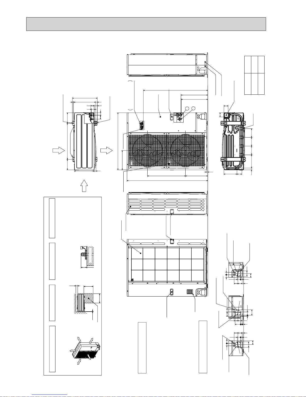
Handle for moving
Side Air Intake
Front piping cover
Rear piping cover
Terminal connection
Left···Power supply wiring
Right···Indoor/Outdoor wiring
Earth terminal
Service panel
Handle for moving
1
2
Air Discharge
Rear Air Intake
Side Air Intake
···Refrigerant GAS pipe connection (FLARE)W15.88(5/8 inch)
···Refrigerant LIQUID pipe connection (FLARE)W 9.52(3/8 inch)
+1 ···Indication of STOP VALVE connection location.
Example of Notes
Piping Knockout Hole Details
600175 175
330
417
42
66
53 56
45
(19)
28 370
2-U Shaped notched holes
(Foundation Bolt M10)
2-12 x 36 Oval holes
(Foundation Bolt M10)
Installation Feet
30
45 40
65
92
27 55
23 73 63
Rear piping hole
(Knockout)
Rear trunking hole
(Knockout)
Power supply wiring hole
(2-
W
27Knockout)
W
92
19 55
92
75
40
73 63
23
27 92
Right piping hole
(Knockout)
Right trunking hole
(Knockout)
Power supply wiring hole
(2-
W
27Knockout)
W
92
92
65
45
40
27 55
23
73 63
Front piping hole
(Knockout)
Front trunking hole
(Knockout)
Power supply wiring hole
(2-
W
27Knockout)
W
92
14514522030 145
81 219
71
71
Bottom piping hole
(Knockout)
Drain hole
(5-W33)
1350
23
950
A
+1 447
+1 443
371
635
322
Handle for moving
HRP·VHA
HRP·YHA
1,079
A
930
Air intake
Rear Air Intake
Handle for moving
Handle for moving
Over
Over
Over
Over
Less than
Piping and wiring connections
can be made from 4 directions:
front, right, rear and below.
4 PIPING-WIRING DIRECTIONS
3 FOUNDATION BOLTS
2 SERVICE SPACE
1 FREE SPACE (Around the unit)
Please secure the unit firmly
with 4 foundation (M10) bolts.
(Bolts and washers must be
purchased locally.)
<Foundation bolt height>
Dimensions of space needed
for service access are
shown in the below diagram.
The diagram below shows a
basic example.
Explanation of particular details are
given in the installation manuals etc.
30
FOUNDATION
10
500
500
150
Service space
FREE
Over 10mm
Over 10mm
Over 150mm
Over 1000mm
OUTDOOR UNIT Unit : mm
PUHZ-HRP71VHA
PUHZ-HRP100VHA
PUHZ-HRP100YHA
PUHZ-HRP125YHA
23
Handle for moving
Side Air Intake
Front piping cover
Rear piping cover
Air intake
Rear Air Intake
Handle for moving
Air Discharge
Rear Air Intake
Side Air Intake
···Refrigerant GAS pipe connection (FLARE) 15.88(5/8 inch)
···Refrigerant LIQUID pipe connection (FLARE) 9.52(3/8 inch)
1 ···Indication of STOP VALVE connection location.
Example of Notes
Piping Knockout Hole Details
600175 175
330
417
42
66
53 56
45
(19)28 370
2-U Shaped notched holes
(Foundation Bolt M10)
2-12 x 36 Oval holes
(Foundation Bolt M10)
Installation Feet
30
45 40
65
92
27 55
23 73 63
Rear piping hole
(Knockout)
Rear trunking hole
(Knockout)
Power supply wiring hole
(2- 27Knockout)
92
19 55
92
75 40
73 63
23 27 92
Right piping hole
(Knockout)
Right trunking hole
(Knockout)
Power supply wiring hole
(2- 27Knockout)
92
92
65
4540
27 55
23 73 63
Front piping hole
(Knockout)
Front trunking hole
(Knockout)
Power supply wiring hole
(2- 27Knockout)
92
14514522030 145
81 219
71
71
Bottom piping hole
(Knockout)
Drain hole
(5- 33)
23
HRP·VHA2
HRP·YHA2
1,079
A
930
Over
Over
Over
Over
Less than
Piping and wiring connections
can be made from 4 directions:
front, right, rear and below.
4 PIPING-WIRING DIRECTIONS
3 FOUNDATION BOLTS
2 SERVICE SPACE
1 FREE SPACE (Around the unit)
Please secure the unit firmly
with 4 foundation (M10) bolts.
(Bolts and washers must be
purchased locally.)
<Foundation bolt height>
Dimensions of space needed
for service access are
shown in the below diagram.
The diagram below shows a
basic example.
Explanation of particular details is
given in the installation manuals etc.
30
FOUNDATION
10
500
500
150
Service space
Handle for moving
Handle for moving
Service panel
A
2
1
+1 443
+1 447
635
371
1350
322
950
Handle for moving
Handle
for
moving
Earth terminal
Terminal connection
Left ····Power supply wiring
Right··· Indoor/Outdoor wiring
Over 10mm
Over 10mm
Over 150mm
Over 1000mm
FREE
Unit : mm
PUHZ-HRP71VHA2
PUHZ-HRP100VHA2
PUHZ-HRP100YHA2
PUHZ-HRP125YHA2
 Loading...