

Mitsubishi Electric PUHZ-BP·HA Installation Manual
Air-Conditioners
PUHZ-BP·HA
INSTALLATION MANUAL
For safe and correct use, read this manual and the indoor unit installation manual thoroughly before installing
the air-conditioner unit.
FOR INSTALLER
English
Contents
1. Safety precautions . . . . . . . . . . . . . . . . . . . . . . . . . . . . . . . . . . . . . . . . . . . . . . 2
2. Installation location . . . . . . . . . . . . . . . . . . . . . . . . . . . . . . . . . . . . . . . . . . . . . 3
3. Installing the outdoor unit . . . . . . . . . . . . . . . . . . . . . . . . . . . . . . . . . . . . . . . . . 4
4. Installing the refrigerant piping . . . . . . . . . . . . . . . . . . . . . . . . . . . . . . . . . . . . . 5
5. Drainage piping work . . . . . . . . . . . . . . . . . . . . . . . . . . . . . . . . . . . . . . . . . . . . 7
1. Safety precautions
► Before installing the unit, make sure you read all the “Safety
precautions”.
► Please report to or take consent by the supply authority before
connection to the system.
Warning:
Describes precautions that must be observed to prevent danger of injury or
death to the user.
Caution:
Describes precautions that must be observed to prevent damage to the unit.
Warning:
• The unit must not be installed by the user. Ask a dealer or an authorized
technician to install the unit. If the unit is installed incorrectly, water leakage, electric shock, or fi re may result.
• For installation work, follow the instructions in the Installation Manual and
use tools and pipe components specifi cally made for use with R410A re-
frigerant. The R410A refrigerant in the HFC system is pressurized 1.6 times
the pressure of usual refrigerants. If pipe components not designed for
R410A refrigerant are used and the unit is not installed correctly, the pipes
may burst and cause damage or injuries. In addition, water leakage, electric shock, or fi re may result.
• The unit must be installed according to the instructions in order to mini-
mize the risk of damage from earthquakes, typhoons, or strong winds. An
incorrectly installed unit may fall down and cause damage or injuries.
• The unit must be securely installed on a structure that can sustain its
weight. If the unit is mounted on an unstable structure, it may fall down
and cause damage or injuries.
• If the air conditioner is installed in a small room, measures must be taken
to prevent the refrigerant concentration in the room from exceeding the
safety limit in the event of refrigerant leakage. Consult a dealer regarding
the appropriate measures to prevent the allowable concentration from being exceeded. Should the refrigerant leak and cause the concentration limit
to be exceeded, hazards due to lack of oxygen in the room may result.
• Ventilate the room if refrigerant leaks during operation. If refrigerant comes
into contact with a fl ame, poisonous gases will be released.
• All electric work must be performed by a qualifi ed technician according to
local regulations and the instructions given in this manual. The units must
be powered by dedicated power lines and the correct voltage and circuit
breakers must be used. Power lines with insuffi cient capacity or incorrect
electrical work may result in electric shock or fi re.
6. Electrical work . . . . . . . . . . . . . . . . . . . . . . . . . . . . . . . . . . . . . . . . . . . . . . . . . 7
7. Test run . . . . . . . . . . . . . . . . . . . . . . . . . . . . . . . . . . . . . . . . . . . . . . . . . . . . . . 9
8. Special Functions . . . . . . . . . . . . . . . . . . . . . . . . . . . . . . . . . . . . . . . . . . . . . . 10
9. System control (Fig. 9-1) . . . . . . . . . . . . . . . . . . . . . . . . . . . . . . . . . . . . . . . . 10
After installation work has been completed, explain the “Safety Precautions,” use,
and maintenance of the unit to the customer according to the information in the
Operation Manual and perform the test run to ensure normal operation. Both the
Installation Manual and Operation Manual must be given to the user for keeping.
These manuals must be passed on to subsequent users.
: Indicates a part which must be grounded.
Warning:
Carefully read the labels affi xed to the main unit.
• Use C1220 copper phosphorus, for copper and copper alloy seamless
pipes, to connect the refrigerant pipes. If the pipes are not connected correctly, the unit will not be properly grounded and electric shock may result.
• Use only specifi ed cables for wiring. The connections must be made se-
curely without tension on the terminals. If the cables are connected or
installed incorrectly, overheating or fi re may result.
• The terminal block cover panel of the outdoor unit must be fi rmly attached.
If the cover panel is mounted incorrectly and dust and moisture enter the
unit, electric shock or fi re may result.
• When installing or moving the air conditioner, use only the specifi ed refrig-
erant (R410A) to charge the refrigerant lines. Do not mix it with any other
refrigerant and do not allow air to remain in the lines. Air enclosed in the
lines can cause pressure peaks resulting in a rupture and other hazards.
• Use only accessories authorized by Mitsubishi Electric and ask a dealer
or an authorized technician to install them. If accessories are incorrectly
installed, water leakage, electric shock, or fi re may result.
• Do not alter the unit. Consult a dealer for repairs. If alterations or repairs
are not performed correctly, water leakage, electric shock, or fi re may re-
sult.
• The user should never attempt to repair the unit or transfer it to another
location. If the unit is installed incorrectly, water leakage, electric shock,
or fi re may result. If the air conditioner must be repaired or moved, ask a
dealer or an authorized technician.
• After installation has been completed, check for refrigerant leaks. If refrigerant leaks into the room and comes into contact with the fl ame of a heater
or portable cooking range, poisonous gases will be released.
1.1. Before installation
Caution:
• Do not use the unit in an unusual environment. If the air conditioner is
installed in areas exposed to steam, volatile oil (including machine oil), or
sulfuric gas, areas exposed to high salt content such as the seaside, or
areas where the unit will be covered by snow, the performance can be signifi cantly reduced and the internal parts can be damaged.
• Do not install the unit where combustible gases may leak, be produced,
fl ow, or accumulate. If combustible gas accumulates around the unit, fi re
or explosion may result.
1.2. Before installation (relocation)
Caution:
• Be extremely careful when transporting the units. Two or more persons
are needed to handle the unit, as it weighs 20 kg or more. Do not grasp
the packaging bands. Wear protective gloves to remove the unit from the
packaging and to move it, as you can injure your hands on the fins or
other parts.
• Be sure to safely dispose of the packaging materials. Packaging materials,
such as nails and other metal or wooden parts may cause stabs or other
injuries.
2
• The outdoor unit produces condensation during the heating operation.
Make sure to provide drainage around the outdoor unit if such condensation is likely to cause damage.
• When installing the unit in a hospital or communications office, be prepared for noise and electronic interference. Inverters, home appliances,
high-frequency medical equipment, and radio communications equipment
can cause the air conditioner to malfunction or breakdown. The air conditioner may also affect medical equipment, disturbing medical care, and
communications equipment, harming the screen display quality.
• The base and attachments of the outdoor unit must be periodically
checked for looseness, cracks or other damage. If such defects are left uncorrected, the unit may fall down and cause damage or injuries.
• Do not clean the air conditioner unit with water. Electric shock may result.
• Tighten all fl are nuts to specifi cation using a torque wrench. If tightened
too much, the fl are nut can break after an extended period and refrigerant
can leak out.
1. Safety precautions
1.3. Before electric work
Caution:
• Be sure to install circuit breakers. If not installed, electric shock may result.
• For the power lines, use standard cables of suffi cient capacity. Otherwise,
a short circuit, overheating, or fi re may result.
• When installing the power lines, do not apply tension to the cables. If the
connections are loosened, the cables can snap or break and overheating
or fi re may result.
1.4. Before starting the test run
Caution:
• Turn on the main power switch more than 12 hours before starting operation. Starting operation just after turning on the power switch can severely
damage the internal parts. Keep the main power switch turned on during
the operation season.
• Before starting operation, check that all panels, guards and other protective parts are correctly installed. Rotating, hot, or high voltage parts can
cause injuries.
1.5. Using R410A refrigerant air conditioners
Caution:
• Use new refrigerant pipes.
Note the following if reusing existing pipes that carried R22 refrigerant.
- Be sure to clean the pipes and make sure that the insides of the pipes are clean.
- Replace the existing fl are nuts and fl are the fl ared sections again.
- Do not use thin pipes. (Refer to page 5)
• Use C1220 copper phosphorus, for copper and copper alloy seamless
pipes, to connect the refrigerant pipes. Make sure the insides of the pipes
are clean and do not contain any harmful contaminants such as sulfuric
compounds, oxidants, debris, or dust. Use pipes with the specifi ed thick-
ness. (Refer to page 5)
• Store the pipes to be used during installation indoors and keep both ends
of the pipes sealed until just before brazing. (Leave elbow joints, etc. in
their packaging.) If dust, debris, or moisture enters the refrigerant lines, oil
deterioration or compressor breakdown may result.
• Use ester oil, ether oil, alkylbenzene oil (small amount) as the refrigeration
oil applied to the fl ared sections. If mineral oil is mixed in the refrigeration
oil, oil deterioration may result.
• Do not use refrigerant other than R410A refrigerant. If another refrigerant
is used, the chlorine will cause the oil to deteriorate.
• Be sure to ground the unit. Do not connect the ground wire to gas or water
pipes, lightning rods, or telephone grounding lines. If the unit is not properly grounded, electric shock may result.
• Use circuit breakers (ground fault interrupter, isolating switch (+B fuse),
and molded case circuit breaker) with the specifi ed capacity. If the circuit
breaker capacity is larger than the specifi ed capacity, breakdown or fi re
may result.
• Do not touch any switch with wet hands. Electric shock may result.
• Do not touch the refrigerant pipes with bare hands during operation. The
refrigerant pipes are hot or cold depending on the condition of the fl owing
refrigerant. If you touch the pipes, burns or frostbite may result.
• After stopping operation, be sure to wait at least fi ve minutes before turn-
ing off the main power switch. Otherwise, water leakage or breakdown may
result.
• Use a vacuum pump with a reverse fl ow check valve.
If the vacuum pump oil fl ows backward into the refrigerant lines, refriger-
ant oil deterioration may result.
• Use the following tools specifi cally designed for use with R410A refriger-
ant. The following tools are necessary to use R410A refrigerant. Contact
your nearest dealer for any questions.
Gauge manifold Flare tool
Charge hose Size adjustment gauge
Gas leak detector Vacuum pump adapter
Torque wrench Electronic refrigerant charging scale
• Be sure to use the correct tools. If dust, debris, or moisture enters the refrigerant lines, refrigeration oil deterioration may result.
• Do not use a charging cylinder. If a charging cylinder is used, the composition of the refrigerant will change and the effi ciency will be lowered.
Tools (for R410A)
1
2. Installation location
E
Fig. 2-1
■BP100-BP140
■BP170-BP250
C
D
Fig. 1-1
B
A
F
(mm)
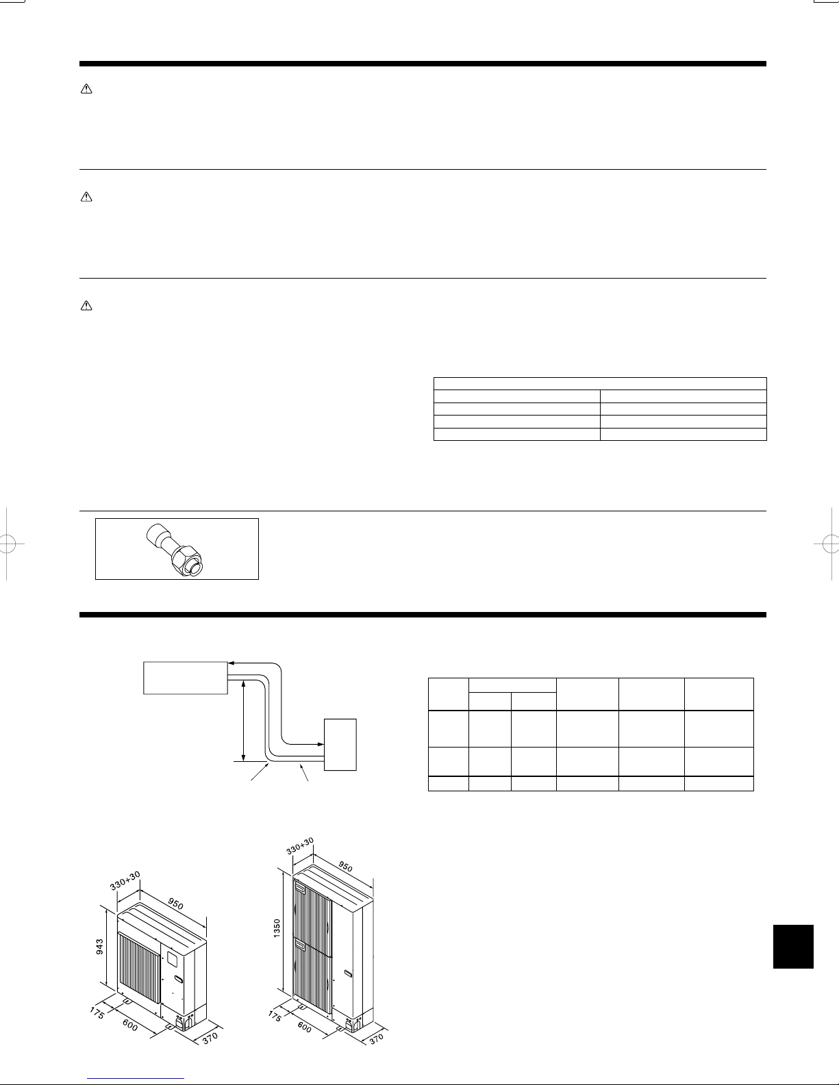
1.6. Accessories of outdoor unit (Fig. 1-1)
<BP170-BP250 only>
The parts show in the left are the accessories of this unit, which are affi xed to
the inside of the service panel.
1 Joint pipe.........×1
2.1. Refrigerant pipe (Fig. 2-1)
► Check that the difference between the heights of the indoor and outdoor
units, the length of refrigerant pipe, and the number of bends in the pipe are
within the limits shown below.
Models
• Height difference limitations are binding regardless of which unit, indoor or out-
E Indoor unit
2.2. Choosing the outdoor unit installation location
•
• Select a location from which noise emitted by the unit will not inconvenience
• Select a location permitting easy wiring and pipe access to the power source and
• Avoid locations where combustible gases may leak, be produced, fl ow, or accu-
• Note that water may drain from the unit during operation.
• Select a level location that can bear the weight and vibration of the unit.
• Avoid locations where the unit can be covered by snow. In areas where heavy
• Avoid locations exposed to oil, steam, or sulfuric gas.
• Use the transportation handles of the outdoor unit to transport the unit. If the unit
A Pipe size(mm)
Gas side
P100
P125
P140
BP170
BP200
BP250 Ø25.4 Ø12.7 Max. 70 m Max. 30m Max. of 15
door, is positioned higher.
Liquid side
Ø15.88 Ø9.52 Max. 50 m Max. 30m Max. of 15
Ø25.4
F Outdoor unit
Avoid locations exposed to direct sunlight or other sources of heat.
neighbors.
indoor unit.
mulate.
snow fall is anticipated, special precautions such as raising the installation location or installing a hood on the air intake and air outlet must be taken to prevent
the snow from blocking the air intake or blowing directly against it. This can reduce the airfl ow and a malfunction may result.
is carried from the bottom, hands or fi ngers may be pinched.
Ø9.52
B
Pipe length
(one way)
Max. 70 m Max. 30m Max. of 15
Height
C
difference
D
Number of bends
(one
way)
Fig. 2-2
2.3. Outline dimensions(Outdoor unit) (Fig.2-2)
3
2. Installation location
Fig. 2-3
Fig. 2-4
Fig. 2-5
2.4. Ventilation and service space
2.4.1. Windy location installation
When installing the outdoor unit on a rooftop or other location unprotected
from the wind, situate the air outlet of the unit so that it is not directly exposed
to strong winds. Strong wind entering the air outlet may impede the normal
airfl ow and a malfunction may result.
The following shows 3 examples of precautions against strong winds.
1 Face the air outlet towards the nearest available wall about 50 cm away
from the wall. (Fig. 2-3) [for BP170-BP250 models : 100cm]
2 Install an optional air guide if the unit is installed in a location where strong
winds from a typhoon, etc. may directly enter the air outlet. (Fig. 2-4)
A Air outlet guide
3 Position the unit so that the air outlet blows perpendicularly to the seasonal
wind direction, if possible. (Fig. 2-5)
B Wind direction
3. Installing the outdoor unit
2.4.2. When installing a single outdoor unit (Refer to the last page)
Minimum dimensions are as follows, except for Max., meaning Maximum dimensions, indicated.
The fi gures in parentheses are for BP125- BP250 models.
1 Obstacles at rear only (Fig. 2-6)
2 Obstacles at rear and above only (Fig. 2-7)
3 Obstacles at rear and sides only (Fig. 2-8)
4 Obstacles at front only (Fig. 2-9)
5 Obstacles at front and rear only (Fig. 2-10)
• When using an optional air outlet guide, the clearance for BP125-BP250 models is
500 mm or more.
6 Obstacles at rear, sides, and above only (Fig. 2-11)
• Do not install the optional air outlet guides for upward airfl ow.
2.4.3. When installing multiple outdoor units (Refer to the last page)
Leave 10 mm space or more between the units.
1 Obstacles at rear only (Fig. 2-12)
2 Obstacles at rear and above only (Fig. 2-13)
• No more than 3 units must be installed side by side. In addition, leave space as
shown.
• Do not install the optional air outlet guides for upward airfl ow.
3 Obstacles at front only (Fig. 2-14)
•
When using an optional air outlet guide, the clearance for BP125-BP250 models is
1000 mm or more.
4 Obstacles at front and rear only (Fig. 2-15)
•
When using an optional air outlet guide, the clearance for BP125-BP250 models is
1000 mm or more.
•
When using an optional air outlet guide installed for upward airfl ow, the clearance is
500 (1000) mm or more.
6 Multiple parallel unit arrangement (Fig. 2-17)
•
When using an optional air outlet guide installed for upward airfl ow, the clearance is
1000 (1500) mm or more.
7 Stacked unit arrangement (Fig. 2-18)
• The units can be stacked up to 2 units high.
• No more than 2 stacked units must be installed side by side. In addition, leave
space as shown.
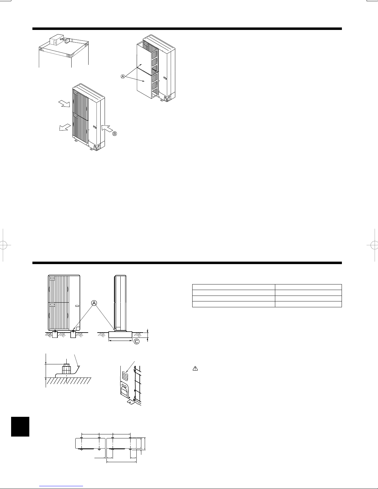
B
Max. 30
A
M10 (3/8") bolt
B Base
C As long as possible.
D Vent
E Set deep in the ground.
Fig. 3-1
600 600
Min. 360
Min. 10
175 175
950
(mm)
D
330
370
25
• Be sure to install the unit in a sturdy, level surface to prevent rattling noises dur-
ing operation. (Fig. 3-1)
<Foundation specifi cations>
Foundation bolt M10 (3/8")
Thickness of concrete 120 mm
Length of bolt 70 mm
Weight-bearing capacity 320 kg
• Make sure that the length of the foundation bolt is within 30 mm of the bottom
surface of the base.
• Secure the base of the unit fi rmly with 4-M10 foundation bolts in sturdy locations.
Installing the outdoor unit
• Do not block the vent. If the vent is blocked, operation will be hindered and
breakdown may result.
• In addition to the unit base, use the installation holes it fi xes top panel on the
back of the unit to attach wires, etc., if necessary to install the unit. Use selftapping screws (ø5 × 15 mm or less) and install on site.
Warning:
• The unit must be securely installed on a structure that can sustain its
weight. If the unit is mounted on an unstable structure, it may fall down
and cause damage or injuries.
• The unit must be installed according to the instructions in order to mini-
mize the risk of damage from earthquakes, typhoons, or strong winds. An
incorrectly installed unit may fall down and cause damage or injuries.
4
 Loading...